
Rear Propeller Shaft and Universal Joints 4C1 – 1
4C1 – 1
Section 4C1
Rear Propeller Shaft & Universal Joints
ATTENTION
Before performing any Service Operation or other procedure described in this Section, refer to Section 00
Warnings, Cautions and Notes for correct workshop practices with regard to safety and/or property damage.
1 General Information ...............................................................................................................................3
2 Service Operations.................................................................................................................................7
2.1 Propeller Shaft ....................................................................................................................................................... 7
Remove................................................................................................................................................................... 7
All VZ.................................................................................................................................................................. 7
All VZ With IRS Except AWD Wagon................................................................................................................. 8
VZ AWD Wagon............................................................................................................................................... 10
VZ AWD With Leaf Spring Rear Suspension ................................................................................................... 11
Reinstall................................................................................................................................................................ 12
All VZ With IRS Except AWD Models............................................................................................................... 12
VZ AWD Wagon............................................................................................................................................... 13
VZ With Leaf Spring Rear Suspension............................................................................................................. 14
2.2 Rubber Coupling.................................................................................................................................................. 15
Replace................................................................................................................................................................. 15
2.3 Centre Constant Velocity Joint (Plunge Type) – AWD Wagon......................................................................... 17
Remove................................................................................................................................................................. 17
Disassemble......................................................................................................................................................... 20
Inspect .................................................................................................................................................................. 21
Propeller Shaft and Boot.................................................................................................................................. 21
Constant Velocity Joint..................................................................................................................................... 21
Reassemble.......................................................................................................................................................... 22
Method 1 .......................................................................................................................................................... 22
Method 2 .......................................................................................................................................................... 22
Reinstall................................................................................................................................................................ 23
2.4 Centre Constant Velocity Joint (Fixed Type) – Live Axle Models.................................................................... 26
Remove................................................................................................................................................................. 26
Inspect .................................................................................................................................................................. 28
Reassemble.......................................................................................................................................................... 29
Reinstall................................................................................................................................................................ 31
2.5 Centre Bearing Assembly ................................................................................................................................... 33
All VZ With V6 Engine and IRS (Except AWD Wagon)...................................................................................... 33
Remove............................................................................................................................................................ 33
Reinstall ........................................................................................................................................................... 35
AWD Wagon Models............................................................................................................................................ 37
Remove............................................................................................................................................................ 37
Reinstall ........................................................................................................................................................... 38
All VZ With a Live Axle........................................................................................................................................ 39
Remove............................................................................................................................................................ 39
Replace............................................................................................................................................................ 41

Rear Propeller Shaft and Universal Joints 4C1 – 2
4C1 – 2
2.6 Fixed, Rear Constant Velocity Joint................................................................................................................... 43
Remove................................................................................................................................................................. 43
Inspect .................................................................................................................................................................. 44
Propeller Shaft and Boot.................................................................................................................................. 44
Constant Velocity Joint..................................................................................................................................... 45
Reassemble.......................................................................................................................................................... 46
Reinstall................................................................................................................................................................ 48
2.7 Rear Plunge Type Constant Velocity Joint – Live Axle Models....................................................................... 49
Remove................................................................................................................................................................. 49
Inspect .................................................................................................................................................................. 51
Disassemble......................................................................................................................................................... 52
Reassemble.......................................................................................................................................................... 53
Reinstall................................................................................................................................................................ 53
3 Specifications.......................................................................................................................................55
4 Torque Wrench Specifications............................................................................................................56
5 Special Tools ........................................................................................................................................57

Rear Propeller Shaft and Universal Joints 4C1 – 3
4C1 – 3
1 General Information
There are a number of rear prope ller shaft assembly variants fitted to the MY2005 VZ range of vehicles. These variati ons
are due to the different engines, transmissions, exhaust and drive systems employed within the vehicle range.
The only common factors being that each propeller shaft assembly is of a two piece tubular design, incorporating a
sealed-for-life centre support bearing. The centre support bearing is a fully seale d ball be aring, mounted in a reinforced
rubber cup. This centre bearing rubber cup is supported in a cup guide and attached to a carrier, which is bolted to the
vehicle underbod y brac e. Depending on the exhaust system fitted to the vehicle and/or wheth er a specific tow bar
package is fitted, a heat shield may also be fitted to the centre bearing carrier. No periodic servicing of the centre bearing
nor any universal joint, is required .
For those MY2005 VZ vehicles with independent coil spring rear suspension (except V6 engined, six speed manual and
five speed automatic transmission models), servicing of the centre bearing is not possible. The reason for the non-
serviceability is that the interfe rence fit of the splin ed joint between the front and rear propeller shaft halves is such that
special tools and high press forces are re quired to separate the two shafts. As this operation would also require the re-
balancing of the propeller sha ft assembly, the centre bearing assembly and/or slinger are also non-servi ceable.
For those MY2005 VZ models fitted with the V6 engine and six speed manual or five speed automatic transmission, the
centre bearing assembl y, slip joint bo ot and clamp are serviced.
Other variations can be summarised by the following descriptions:
Front Universal Joint: While all propeller shafts have a rubber coupling in this location, dependent upon the
transmission, the coupling may be attached to the transmission output shaft, by a special thread formed bolt to the
transmission output flange (V6 Manual T r ansmission), b y nuts over special thread forme d stud (AWD transfer case), by a
bolt and nut (V6 5L40-E – automatic transmission) or by being bolted to a slip yoke that is splined to the output shaft
(GEN III V8 and manual or automatic transmission or V6 and 4L60-E four speed automatic transmission).
Centre Universal Joint: This design can b e a conventional cross type universal joint (Hooke’s joint) mou nted behind the
centre bearing, a plunge design constant velocity joint (AWD Wagon) or a fixed design constant velocity joint (those
vehicles with a live axle and leaf spring re ar suspension).
The cross type universal joint t ype is non-ser v iceable, as the bearing cups are set and retained by staking. T his requires
sophisticated equipment to ensure concentricity of the installed universal joi nt.
Rear Universal Joint: Again a number of variants are possible, depe nding on the application. For all independent coil
spring rear suspensions, except AWD Wagon, a rubber coupling is fixed to the rear final drive pinion flange by three
special thread formed bolts. The AWD Wagon has a fixed constant velocity joint and al l live axle with leaf spring
suspension vehicles have a plunge design constant velocity joint. Either of the constant velocity universal joints is fixed to
the final drive pinion by six bolts.
Provided the service information contained in this Section is followed, all constant velocity joints are able to be serviced.
Rear Propeller Shaft and Universal Joints 4C1 – 4
4C1 – 4
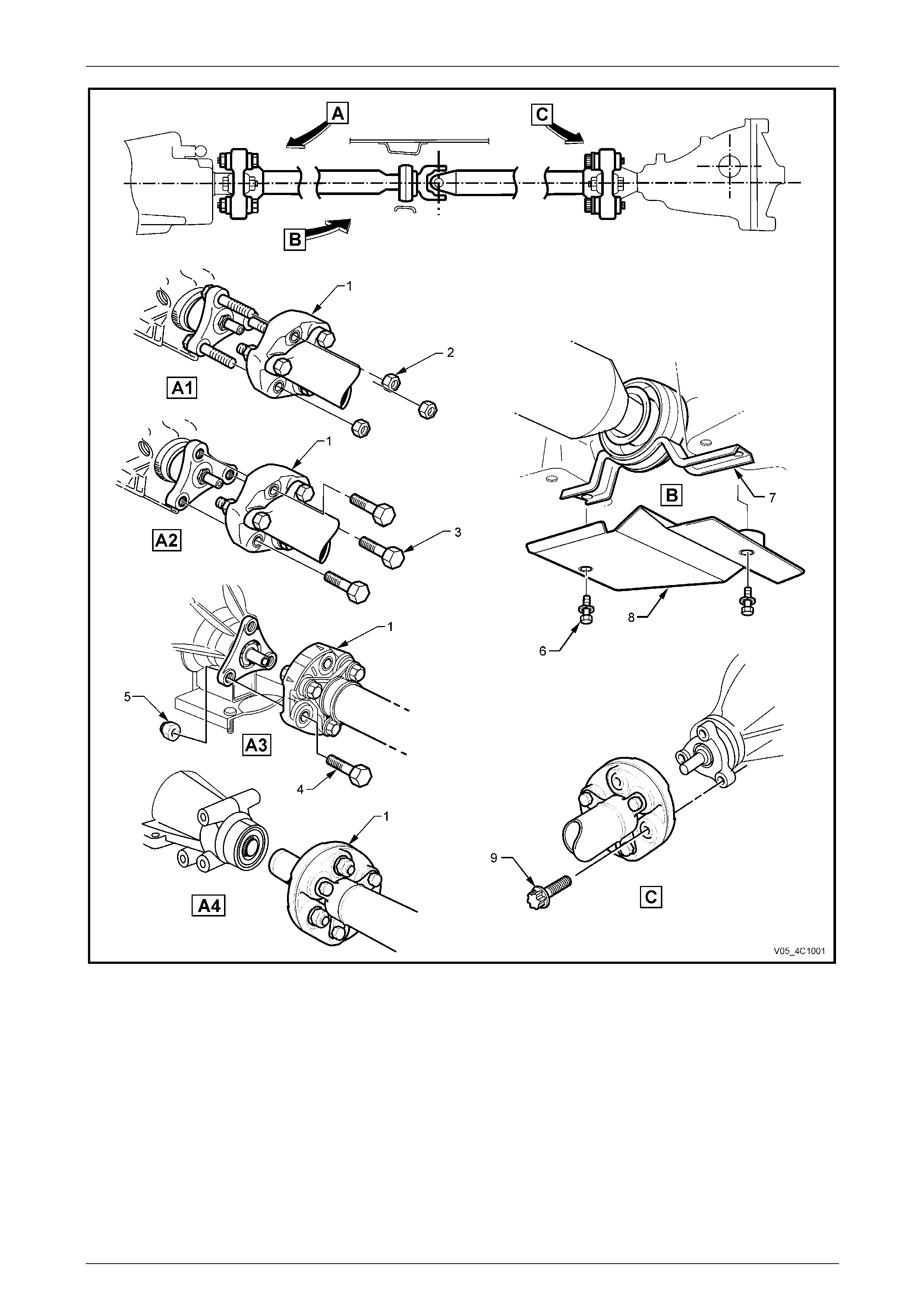
Figure 4C1 – 1 – All With IRS Except AWD Wagon
Legend
A1 Front Coupling – V6, 5L40-E Automatic Transmission (Early)
A2 Front Coupling – V6 Manual Transmission
A3 Front Coupling – V6, 5L40-E Automatic Transmission (Late)
A4 Front Coupling – GEN III V8 Manual/Automatic and V6,
4L60-E Automatic Transmission
B Centre Bearing
C Rear Coupling to Final Drive Pinion Flange
1 Front Rubber Coupling
2 Coupling to Transmission Stud Nut (3 Places)
3 Coupling to Transmission Flange Bolt (3 Places)
4 Coupling to Transmission Flange Bolt (3 Places)
5 Coupling to Transmission Flange Nut (3 Places)
6 Centre Bearing Cup Guide to Underfloor Bolt (2 Places)
7 Centre Bearing Cup Guide
8 Heat Shield – Centre Bearing (Where Fitted)
9 Rear Coupling To Final Drive Opinion Flange Bolt (3 Places)
Rear Propeller Shaft and Universal Joints 4C1 – 5
4C1 – 5
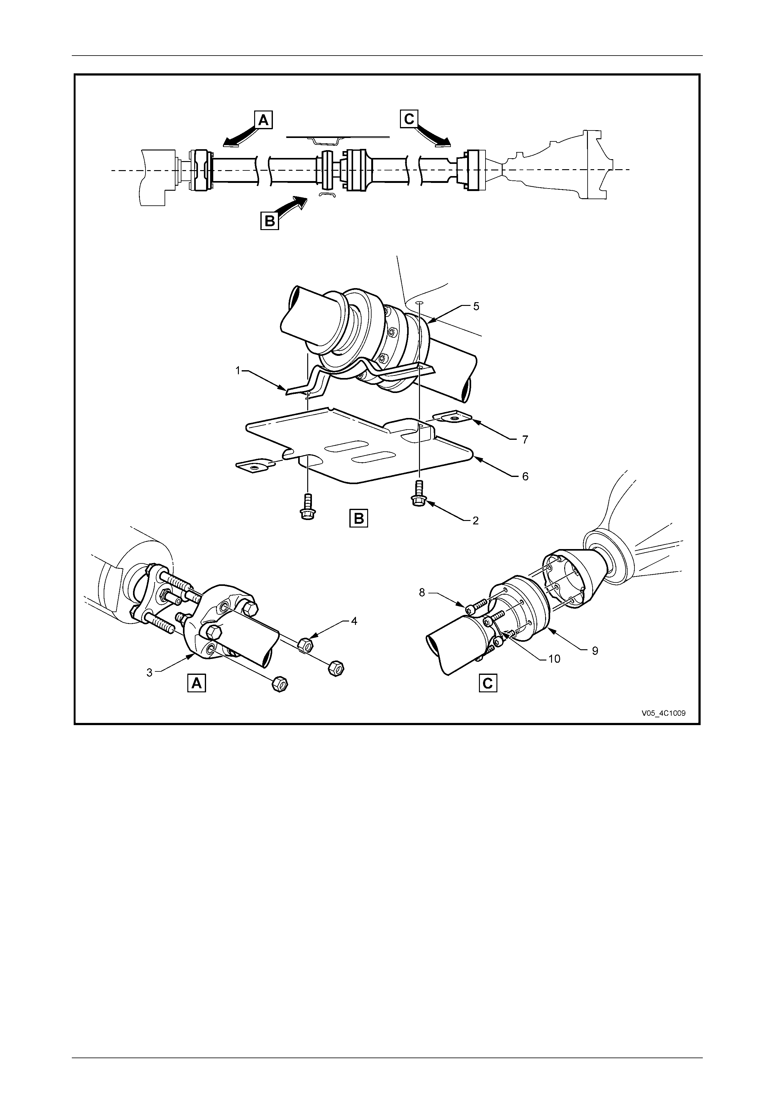
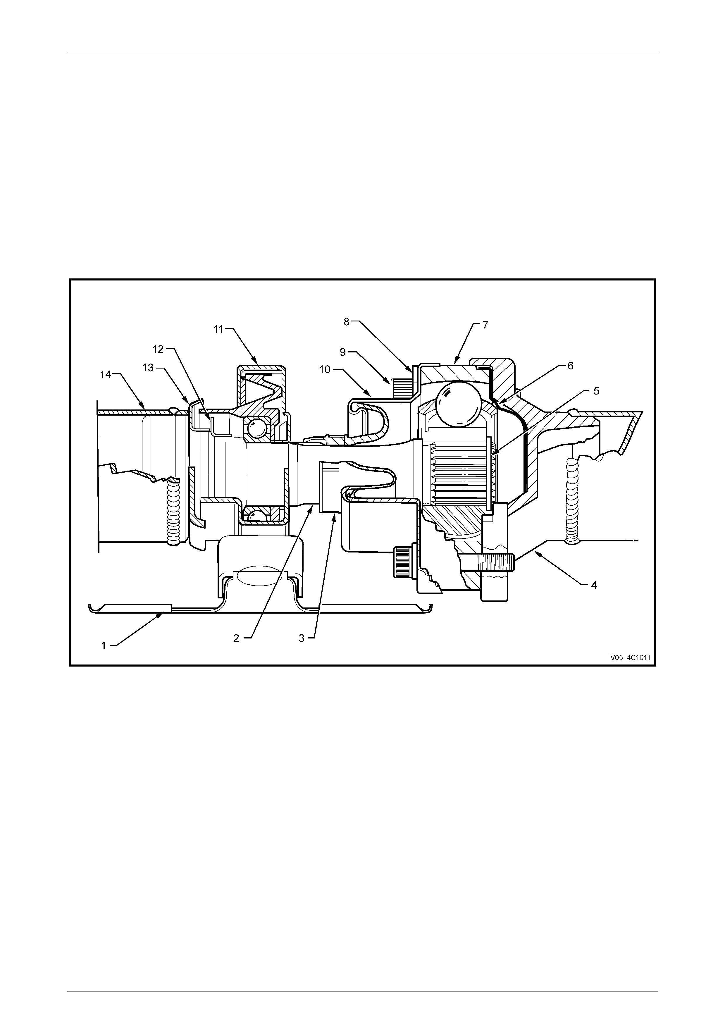
Figure 4C1 – 2 – AWD Wago n
Legend
1 Centre Bearing Carrier Assembly
2 Centre Bearing Carrier Retaining Bolt (2 Places)
3 Front Rubber Coupling
4 Front Coupling Retaining Nut (3 Places)
5 Front Constant Velocity Joint (Plunge Type)
6 Heat Shield
7 Heat Shield Retaining Clip (2 Places)
8 Rear Constant Velocity Joint Retaining Bolts (6 Places)
9 Rear Constant Velocity Joint (Fixed Type)
10 Locking Plate (3 Places)
Rear Propeller Shaft and Universal Joints 4C1 – 6
4C1 – 6
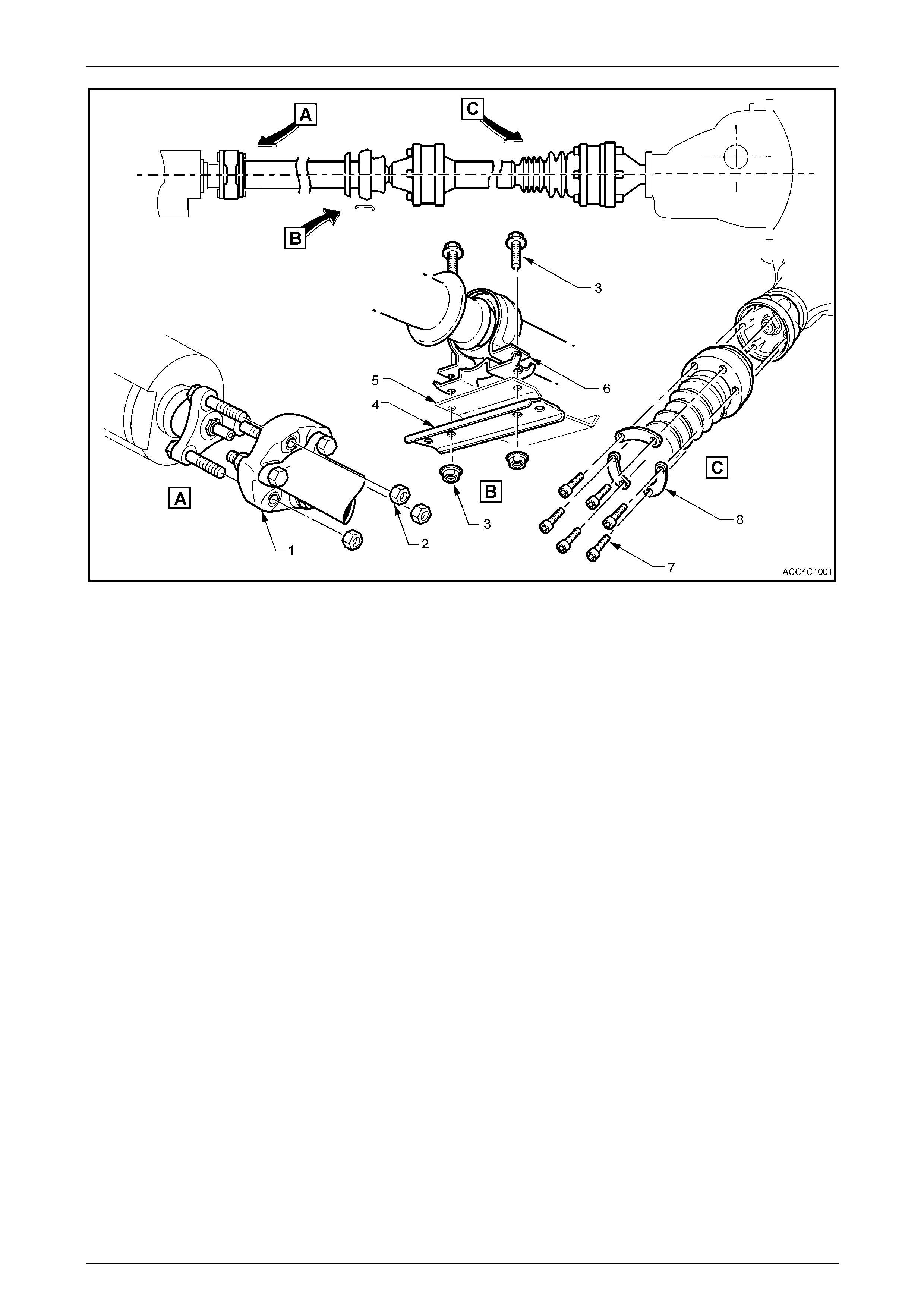
Figure 4C1 – 3 – Leaf Spring Rear Suspension
Legend
1 Front Rubber Coupling
2 Front Coupling to Transfer Case Flange Nuts (3 Places)
3 Centre Bearing Carrier Attaching Bolts and Nuts (2 Places)
4 Centre Bearing Carrier
5 Heat Shield (Where fitted)
6 Centre Bearing Cup Guide - Upper and Lower
7 Rear Constant Velocity Joint, Torx Headed Bolts (6 Places)
8 Rear Constant Velocity Joint Attaching Bolt Lock Plates
(3 Places)

Rear Propeller Shaft and Universal Joints 4C1 – 7
4C1 – 7
2 Service Operations
ATTENTION
All fasteners are important attaching parts as they affect the performance of vital components and/or could
result in major repair expense. W here specified in this Section, fasteners MUST be replaced w ith parts of the
same part number or an approved equivalent. Do not use fasteners o f an inferior quality or substitute design.
Torque values must be used as specified during reassembly to ensure proper retention of all components.
Throughout this Section, fastener torque wrench specifications may be accompanied with the following
identification marks:
Fasteners must be repl aced after loosening.
Vehicle must be at curb height before final tightening.
Fasteners either have micro encapsulated sealant applied or incorporate a mechanical thread lock and
should only be re-used once. If in doubt, replacement is recommended.
If one or more of these identification marks is present alongside a fastener torque wrench specification, the
recommendation regarding that fastener must be adhered to.
2.1 Propeller Shaft
LT Section No. – 05-050
ATTENTION
The following fasteners have either micro encapsulation or incorporate a mechanical thread lock and should
only be used once. If in doubt , rep lacement is recommended when performing these operations:
Propeller shaft rear constant velocity joint to pinion flange bolts.
The following fasteners MUST be replaced when performin g these operations:
Rubber coupling to transmission/transfer case, rear output flange retaining bolts and nuts.
Remove
All VZ
1 Raise the vehicle and suppor t in a safe manner. Refer to Section 0A General Information for location of jacking and
support points.
2 To provide access to the propeller shaft fasteners, it is recommend ed that the intermediate exhaust pipe,
intermediate and rear muffler assemblies be removed. For information regarding the removal and installation
procedures for these components, refer to Section 8B Exhaust System.
Rear Propeller Shaft and Universal Joints 4C1 – 8
4C1 – 8
All VZ With IRS Except AWD Wagon
Front Coupling Attached to the Transmissi on/Transfer Case Output Flange
A number of different methods of attaching
the front coupling to the transmission output
flange can be noted:
• Hexagon headed bolts into threaded
flange holes. With this method, the output
flange threads are of the 'Spiralock' form
that can only be loosened/tightened a
maximum of ten times. Because of the
safety factor involved, if the complete
vehicle service history is not known, then
both the flange and the bolts MUST be
replaced on reassembly.
• Studs installed into the transmission
output flange facing rearward, with the
flange being secured by nuts.
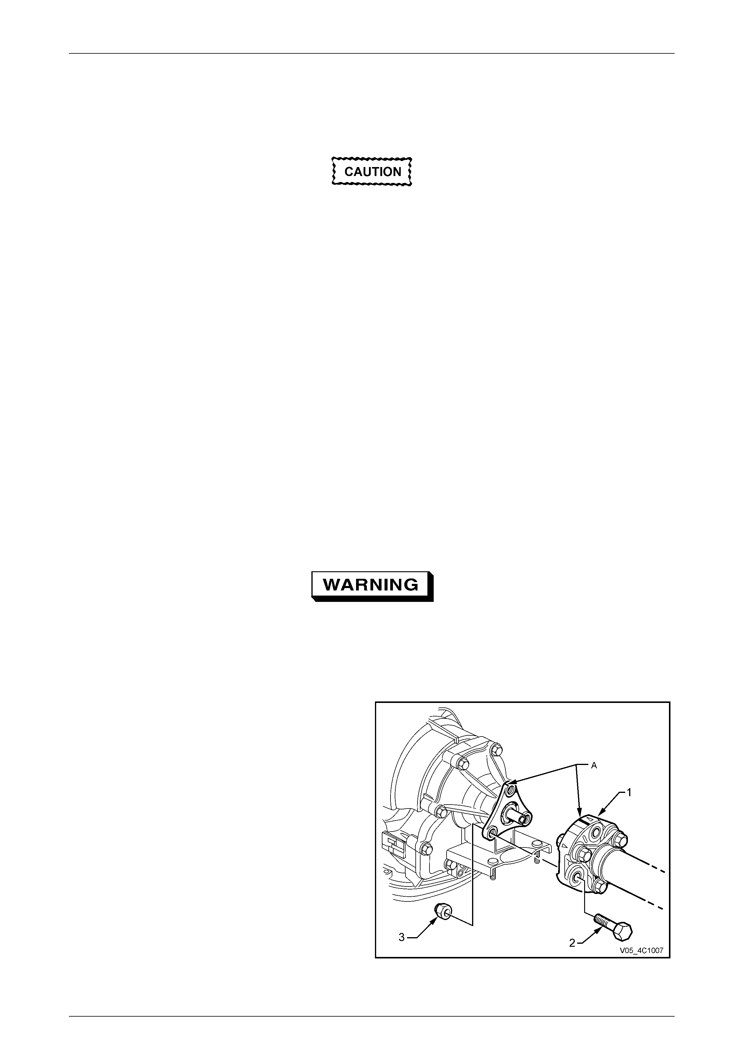
• Hexagon headed bolts and nuts.
Figure 4C1 – 4 shows this method.
NOTE
If the reason for removing the propeller shaft is
not related to the front rubber coupling, then it is
recommended that the three bolts and nuts
securing the propeller shaft to the front coupling
be removed, leaving the coupling attached to the
transmission output shaft flange.
Release the park brake to relax any ‘wind-up’
in the flexible rubber coupling. Otherwise,
when the propeller shaft bolts are released
from the final drive pinion flange, personal
injury may result.
3 Select the Park/1st gear position with the transmission selector lever.
4 To enable the propell er shaft to be reinsta lled in the
original position relative to the transmissi on output
shaft flange, use a felt tipped pen or similar t o ide ntify
the relationship (‘A’) of the t wo components.
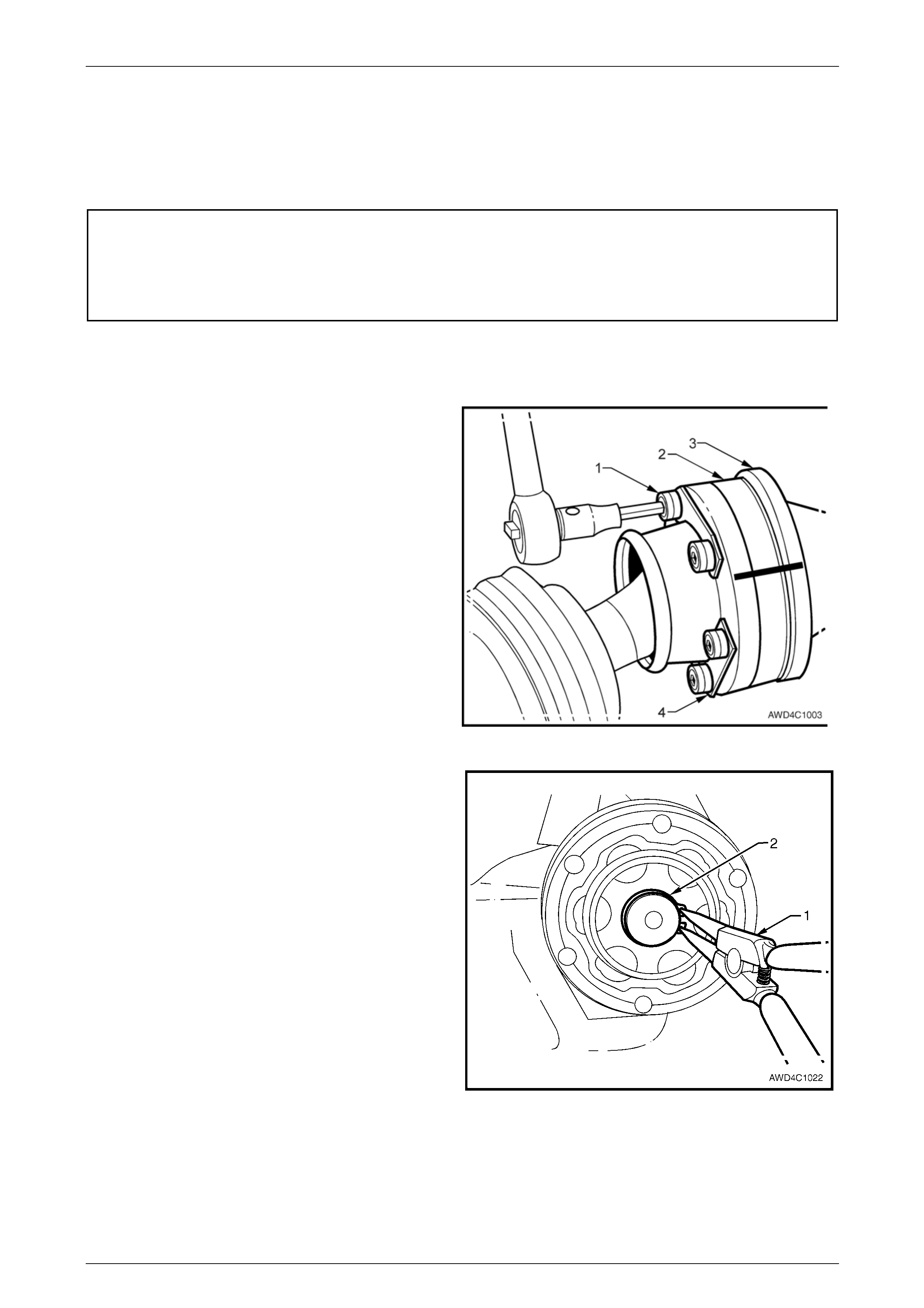
5 Using suitable socket equipment, loosen the three
bolts (2) and nuts (3) and securing the front coupling
(1) to the transmission output flange
6 With the transmission shift lever in the Neutral position
and the park brake released, remove the three Torx
headed bolts.
Figure 4C1 – 4
Rear Propeller Shaft and Universal Joints 4C1 – 9
4C1 – 9
All VZ With IRS Except AWD Wagon
7 To enable the propell er shaft to be reinsta lled in the
original position relative to the final drive pinion flange,
use a felt tipped pen or similar to identify the
relationship (‘A’) of the two components.
8 With the transmission in the Park/1st gear position,
check that the park brake is firmly applied.
9 Use Torx socket K04425E20 or a commercially
available E20 Torx equivalent to loosen the three Torx
headed bolts (1) securing the propeller shaft rear
rubber coupling (2) to the pini on flange (3).
10 Release the park brake to relieve any torque loading
on the rubber coupling, then remove the three Torx
headed bolts (1)
Figure 4C1 – 5
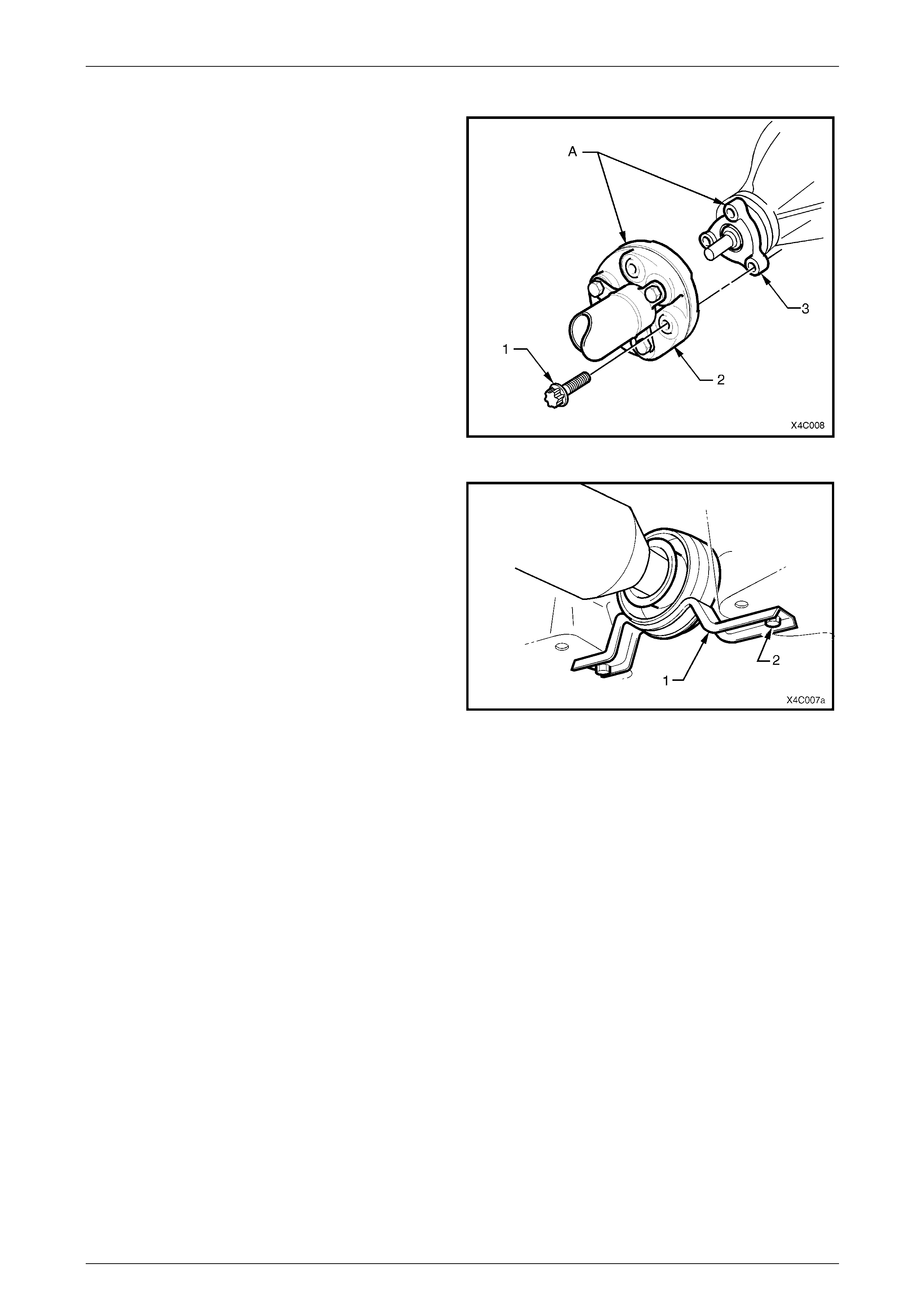
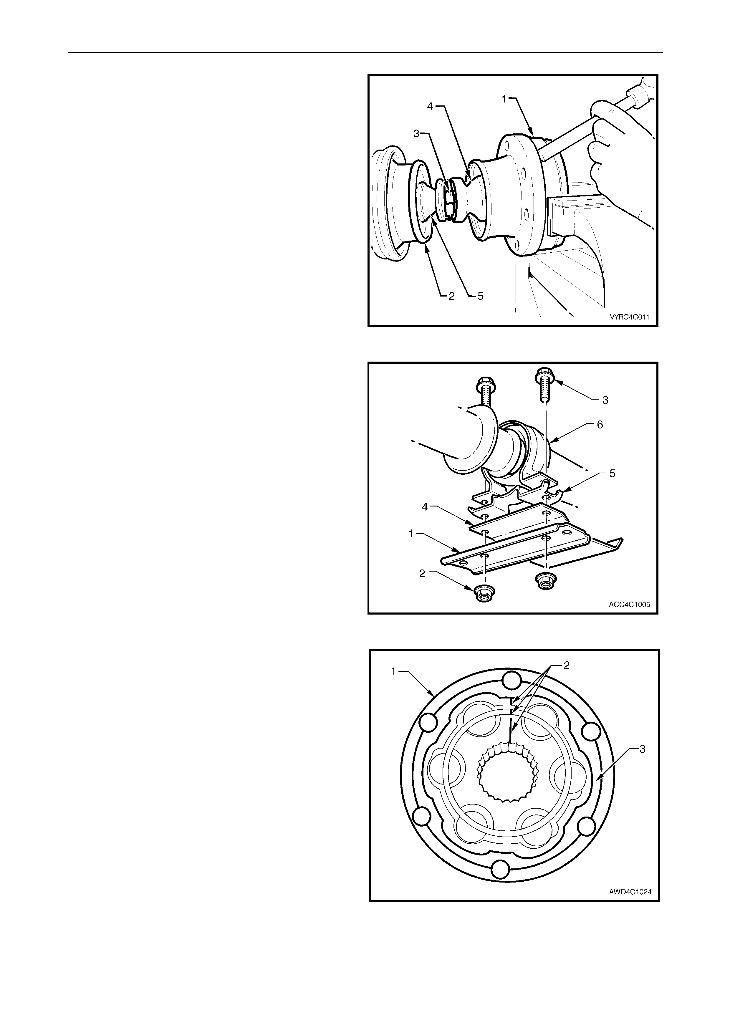
11 Remove the two centre bearing carrier (1) to
underbody reinforcement bolts (2).
12 While supporting the centre beari ng section, slide the
propeller shaft assembly forward to disengage from
the final drive pinion support pin, then lower the
assembly at the rear, sliding rearward to disengage
the front coupling.
13 Remove the propeller shaft assembly from the vehicle.
Figure 4C1 – 6
For VZ Series Models with a Sliding Front Y oke:
14 After completing all Steps except 4 to 6 inclusive, slide the propeller shaft assemb ly rearward to disengage the front
yoke from the transmission output shaft splines. Durin g this process:
a Locate a clean drain tray under the rear of the transmission to catch any spilled lubricant when the propeller
shaft is removed.
b Take care to protect the outer diameter of the front yoke. Nicks or abrasions will damage the transmission
extension seal during reassembly and result in subsequ ent lubricant leakage from this area.
c Insert a suitable plug in the end of the transmission re ar extension to prevent loss of transmission lubric ant.
Rear Propeller Shaft and Universal Joints 4C1 – 10
4C1 – 10
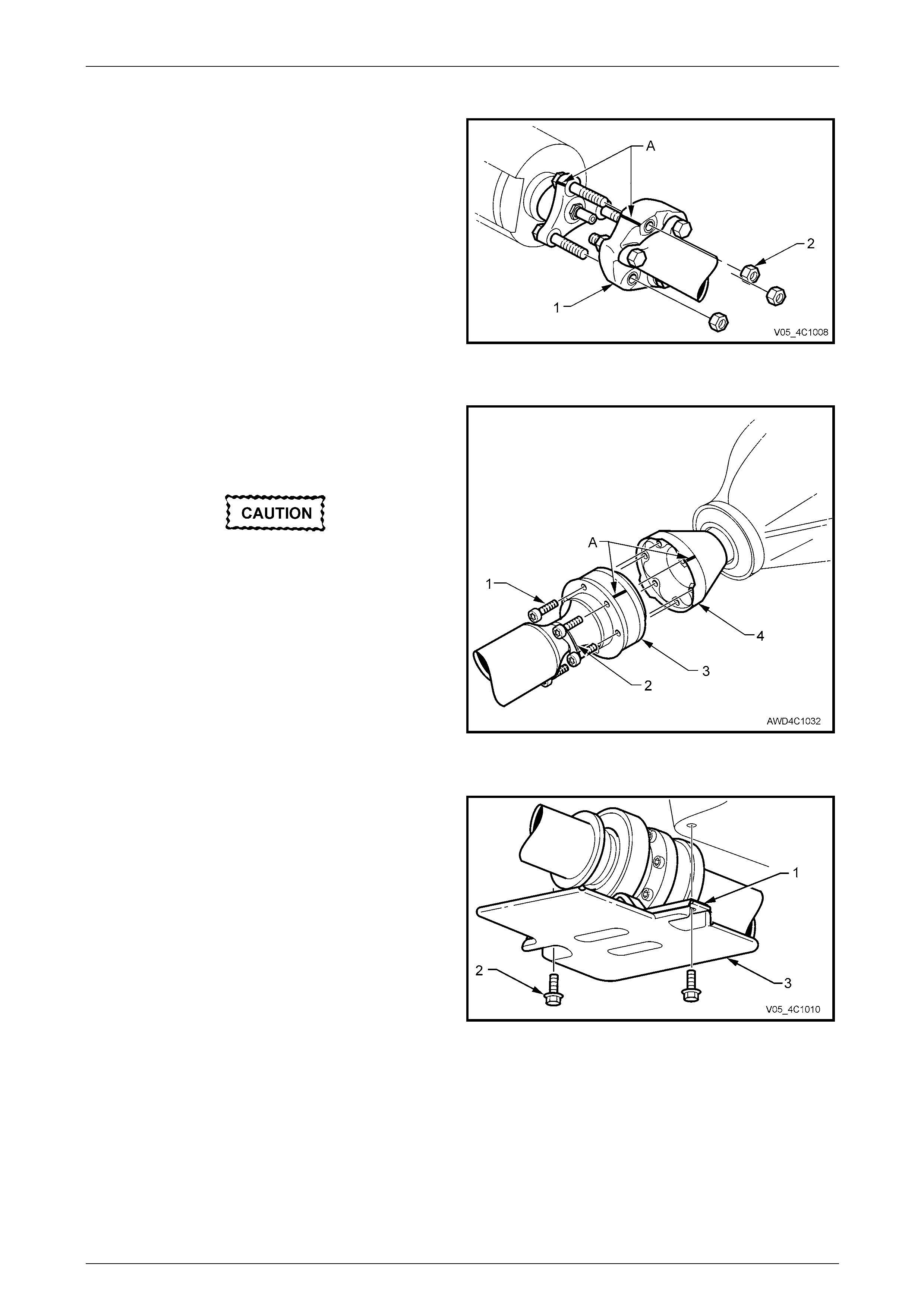
VZ AWD Wagon
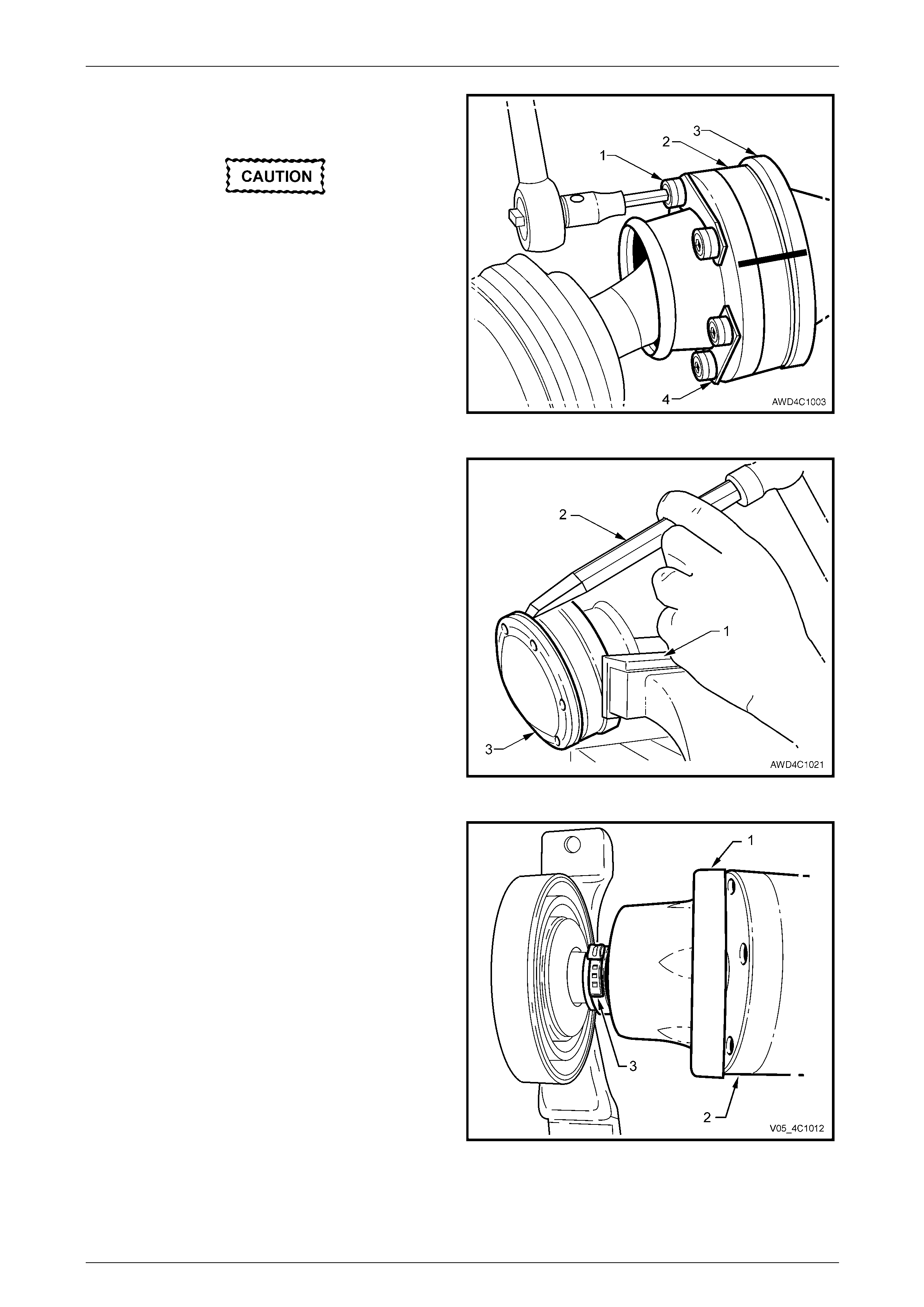
1 Select the Park position with the transmission selector
lever.
2 To enable the propell er shaft to be reinsta lled in the
original position relative to the transfer case output
shaft flange, use a felt tipped pen or similar t o ide ntify
the relationship (‘A’) of the t wo components.
3 Using suitable socket equipment, loosen the three
nuts (2) and securing the front coupling (1) to the
transfer case output flange.
4 With the transmission shift lever in the Neutral position
and the park brake released, remove and discard the
removed nuts (2) as they must be replaced o n
reassembly.
Figure 4C1 – 7
5 To enable the propell er shaft to be installed in the
original position relative to the pinion flange, use a felt
tipped pen or similar (e.g. whiteout) to ide ntify the
relationship of the two components (‘A’).
If all six bolts are removed, the rear of the
propeller shaft must be supported using tie
wire or similar. Do not allow the propeller
shaft to hang, placing undue stress on the
front constant velocity joint and/or boot.
6 With the transmission in the ‘Park’ position and the
park brake firmly applied, loosen the six Torx bit
headed bolts (1), using a T 50 Torx bit and suitable
socket equipment.
7 Remove five of the six bolts and two locking plates (2)
securing the propeller shaft rear constant vel ocity joint
(3) to the final drive pinion flange (4). Do not remove
the sixth bolt at this time. Figure 4C1 – 8
8 Remove the two centre bearing carrier (1) to
underbody reinforcement bolts (2).
9 While supporting the centre beari ng section, remove
the final bolt (and locking plate) from the pinion flange.
10 Slide the propeller shaft assembly forward to
disengage from the final drive pinion flange, then lower
the assembly at the rear, sliding rearward to
disengage the front rubber coupling from the transfer
case output flange studs.
11 Remove the propeller shaft assembly from the vehicle.
Figure 4C1 – 9
Rear Propeller Shaft and Universal Joints 4C1 – 11
4C1 – 11
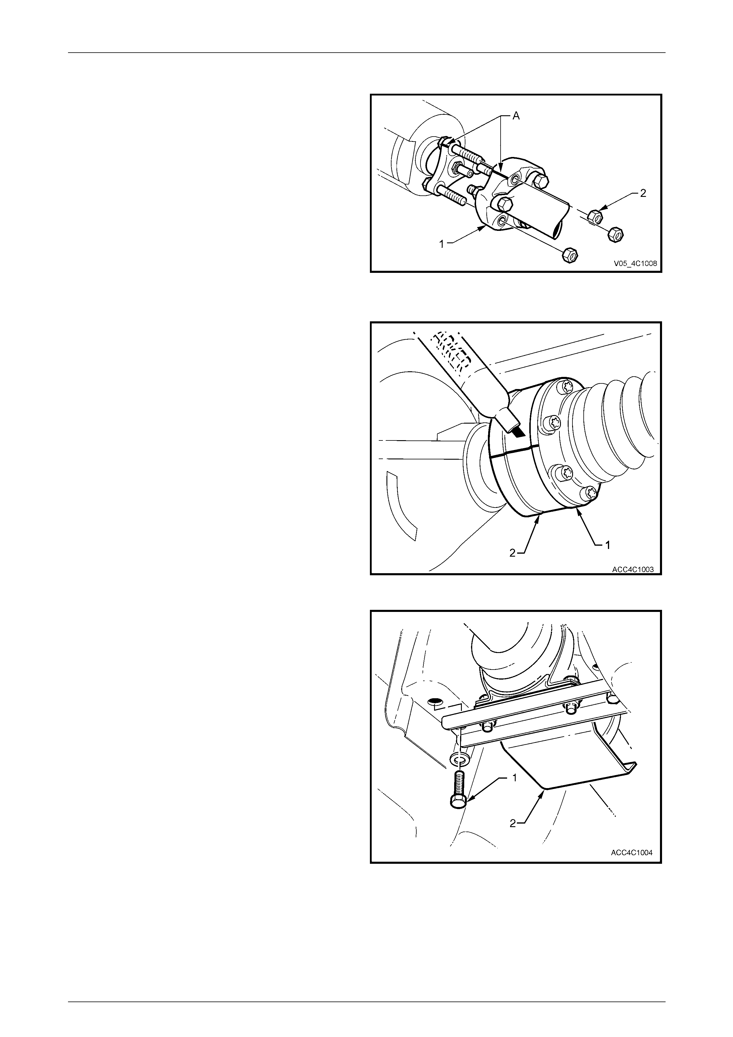
VZ AWD With Leaf Spring Rear Suspension
1 Select the Park position with the transmission selector
lever.
2 To enable the propell er shaft to be reinsta lled in the
original position relative to the transfer case output
shaft flange, use a felt tipped pen or similar t o ide ntify
the relationship (‘A’) of the t wo components.
3 Using suitable socket equipment, loosen the three
nuts (2) and securing the front coupling (1) to the
transfer case output flange.
4 With the transmission shift lever in the Neutral position
and the park brake released, remove and discard the
removed nuts (2) as they must be replaced o n
reassembly.
Figure 4C1 – 10
5 Use a suitable felt tipped marking pen to ma rk the
relationship of the rear constant velocit y joint (1) to the
rear axle pinion flange (2).
6 Remove the propeller shaft rear constant vel ocity joint
(1) to rear axle pinion flange (2) attaching bo lts and
locking plates.
NOTE
When removing the rear constant velocity joint
from the rear axle pinion flange, take care no t to
disturb the end cap of the constant velocity joint.
The end cap has a gask et to prevent the entr y of
foreign matter.
Figure 4C1 – 11
7 Loosen but do not fully remove the centre bearing
carrier bracket attaching bolts (1).
8 To remove the propeller shaft assembly from the
vehicle:
a Carefully prise the rear const ant velocity joint to
free it from the rear axle pinion flange, then push
forward to free the constant velocity joint from
the pinion flange lip.
b While supporting the rear propeller shaft half and
the centre bearing, fully remove both centre
bearing carrier bolts.
c Lower the rear of the propeller shaft and move
rearward to free the front coupling from the
transfer case studs.
d Continue to move the propeller shaft rearwards,
manoeuvring past the exhaust system, then
remove the propeller shaft assembly from the
vehicle. Figure 4C1 – 12
Rear Propeller Shaft and Universal Joints 4C1 – 12
4C1 – 12
Reinstall
All VZ With IRS Except AWD Models
Reinstallation is the reverse of removal procedures, except for the following items:
1 Lubricate the transmission rear output shaft and final drive pinion spigots with a molybdenum disulphide grease
such as an NLGI No. 2 lithium soap based EP grease with molybdenum disulphide, such as Shell Retinax HDX2
grease or BP Energrease LMS-EP 23 (or eq uivalent).
2 Reinstall the front of the propeller shaft assembly first, supporting the centre and rear sections.
3 Align the marks made before removal (refer to Figure 4C1 – 4) temporarily install either a coupling to flan ge bolt
and nut or nut to secure the propeller sh aft in this position.
4 While supporting the rear section, raise the centre bearing assembly and install the bolts and spring washers to
secure to the underbody r einforcement. Tighten both bolts to the correct torque specification.
Centre bearing carrier to underbody
reinforcement bolt torque specification ................22 N.m
5 Before installing the rear coupling to fin al drive flange bolts, align the marks made before remova l, refer to
Figure 4C1-5.
6 Provided no thread damage is evident, reinstall the original rear propeller shaft coupling to the final drive pinion
flange, Torx headed bo lts, tightening to the correct torque specification.
Propeller shaft rear coupling to pinion
flange bolt torque specification...........................115 N.m
Front Coupling Attached to the Transmission Output Flange
7 If bolts are used to secure the coupling to the transmission output flange, provid ed no thread damage is evident,
the original front propeller shaft coupling bolts may be re-used up to a maximum of ten times:
a Reinstall the three bolts and tighten to the correct torque specification.
b If bolts and nuts are used to secure the coupling to the tran smission output flange, install NEW bolts and nuts
and tighten to the correct torque specification.
Front coupling to transmission output
flange bolt torque specification...........................115 N.m
Front coupling to transmission output
flange bolt and nut torque specification..............115 N.m
c If nuts are used to secure the front coupling to the transmission output flange studs, insta ll NEW nuts and
tighten to the correct torque specification.
Front coupling to transmission output
flange nut torque specification .............................85 N.m
For VZ Models with a Sliding Front Yoke:
8 Clean the sliding yoke bearing surface, inspect for nicks or other damage.
9 If considered serviceable, lubricate the sli ding yoke with the recommended transmission lubricant, reinstall to the
transmission output shaft splines.
10 Lubricate the final drive pinion spigot with a molybdenum disulphide grease such as an NLGI No. 2 lithium soap
based EP grease with molybdenum disulph id e, such as Shell Retinax HDX2 grease or BP Energrease LMS-EP 23
(or equivalent).
11 While supporting the centre beari ng offer the rear coupling up to the final drive pinion flange and temporarily install
one of the retaining bolts to secure in this position.
Rear Propeller Shaft and Universal Joints 4C1 – 13
4C1 – 13
12 Raise the centre bearing assembly and install the bolts with spring washers to secure to the underbody
reinforcement. Tighten both bolts to the correct torque specification.
Centre bearing carrier to underbody
reinforcement bolt torque specification ................22 N.m
13 Before installing the rear coupling to fin al drive flange bolts, align the marks made before removal, refer to
Figure 4C1-5.
14 Provided no thread damage is evident, reinstall the original rear propeller shaft coupling to the final drive pinion
flange, Torx headed bo lts, tightening to the correct torque specification.
Rear coupling to pinion flange
bolt torque specification.....................................115 N.m
15 Reinstall the exhaust system, refer to Section 8B Exhaust System, for the procedures an d clearances.
16 Road test the vehicle to check for correct operation.
VZ AWD Wagon
Reinstallation is the reverse of removal procedures, except for the following items:
1 Lubricate the transfer case out put spigot with a molybdenum disulphide gr ease such as an NLGI No. 2 lithium soap
based EP grease with molybdenum disulph id e, such as Shell Retinax HDX2 grease or BP Energrease LMS-EP 23
(or equivalent).
2 Align the transfer case output flange studs with the rubber coupling, while supporting the centre and rear sections.
3 While supporting the rear section, raise the centre bearing assembly, reinstall the t wo bolts and spring washers to
secure to the vehicle underbody reinforcement and tighten to the correct torque specification.
Centre bearing carrier to underbody
reinforcement bolt torque specification ................22 N.m
4 Slide the propeller shaft assembly forward to allow engagement of the rear constant velocity joint to the final drive
pinion flange, then slide rearward to fully engage.
5 Before reinstalling the attaching bolts and locking plates into the rear constant veloc ity joint and pinion flange, align
the marks on the pinion flange and rear joint, that were made prior to removal, refer to Figure 4C1-8.
6 Clean the threads of the six, rear constant velocity joint to pinion flange bolts, apply a thread sealant such as
Loctite 242 or equivalent, the n reinsta ll with locking plates and tighten to the correct torque specification, using a
T50 Torx bit and suitable sock et equipment.
( ) Rear constant velocity joint to
pinion flange bolt torque specif ication
(V6)...................38 N.m
(GEN III V8)......68 N.m
7 Reinstall NEW retaining nuts to secure the front rubber coupling to the transfer case rear output flange studs.
8 Tighten the coupling nuts to the correct torq ue specification.
( ) Rubber coupling to transfer case
output shaft flange retaining
nut torque specification........................................85 N.m
9 Reinstall the exhaust system, refer to Section 8B Exhaust System for the procedures and clearances.
Rear Propeller Shaft and Universal Joints 4C1 – 14
4C1 – 14
VZ With Leaf Spring Rear Suspension
Reinstallation of the propeller shaft assembly is the reverse of the removal procedure noting the following points:
NOTE
Dependent upon a range of variables relating to
engine and transmissio n combinations, a number
of front rubber coupling attachment means are
possible.
Front Coupling Attached to the Transmissi on/Transfer Case Output Flange
1 Lubricate the transmission/transfer case output spigot with a molybdenum disulphide grease such as an NLGI No.
2 lithium soap based EP grease with molybd enum disulphide, such as Shell Retinax HDX2 grease or BP
Energrease LMS-EP 23 (or equivalent).
2 If bolts are used to secure the coupling to the transmission output flange, provid ed no thread damage is evident,
the original front propeller shaft coupling bolts may be re-used up to a maximum of ten times:
a Reinstall the three bolts and tighten to the correct torque specification.
b If bolts and nuts are used to secure the coupling to the tran smission output flange, install NEW bolts and nuts
and tighten to the correct torque specification.
Front coupling to transmission output
flange bolt torque specification...........................115 N.m
Front coupling to transmission output
flange bolt and nut torque specification..............115 N.m
c If nuts are used to secure the front coupling to the transmission output flange studs, insta ll NEW nuts and
tighten to the correct torque specification.
Front coupling to transmission output
flange nut torque specification .............................85 N.m
For MY 2005 VZ Models with a Sliding Fr ont Yoke:
3 Clean the sliding yoke bearing surface, inspect for nicks or other damage.
4 If considered serviceable, lubricate the sli ding yoke with the recommended transmission lubric ant, then reinstall the
slip yoke to the transmission output shaft splines.
For all VZ With Leaf Spring Rear Suspens ion
5 While supporting the rear section of the propeller shaft, raise the centre bearing assembly and install the two bolts
with spring washers, tightening to the correct torque specification.
Centre bearing carrier to underbody
reinforcement bolt torque specification ................22 N.m
6 Before reinstalling the attaching bolts and locking plates into the rear constant veloc ity joint and pinion flange, align
the marks on the pinion flange and rear joint, that were made prior to removal, refer to Figure 4C1-11.
NOTE
Take care not to disturb the end cap of the
constant velocity joint. The end cap has a gasket
to prevent contamination by foreign material.
7 Clean the threads of the six, rear constant velocit y joint to pinion flange bolts, then apply a thread sealant such as
Loctite 242 or equivalent.
8 Reinstall the six bolts and locking plates.
9 Gradually tighten the six rear constant velocity joint to rear final drive pinion flange bolts, working in an opposite
pattern to draw the constant velocity joint into the rear axle pinion flange until it is fully installed.
10 Finally, tighten the six bolts to the correct torque specification.
() Rear constant velocity joint to the
pinion flange bot torque specif ication:
V6 Engine ....................38 N.m
GEN III V8 Engine........68 N.m
11 If removed, reinstall the exhaust system, refer to Section 8B Exhaust System, for the procedures an d clearances.
12 Road test the vehicle to check for correct operation.
Rear Propeller Shaft and Universal Joints 4C1 – 15
4C1 – 15
2.2 Rubber Coupling
LT Section No. – 05-050
ATTENTION
The following fasteners have either micro encapsulation or incorporate a mechanical thread lock and should
only be used once. If in doubt , rep lacement is recommended when performing these operations:
Propeller shaft rear constant velocity joint to final drive pinion flange (where applicable).
The following fasteners MUST be replaced when performin g these operations:
Rubber coupling to transmission output flange/transfer case flange, slip joint or final drive pinion flange
bolts and nuts.
NOTE
While this operation details the procedure to
replace a rubber coupling where a slip yoke is
fitted, the procedure for all couplings is similar.
Replace
1 Remove the propeller shaft. Refer to 2.1 Propeller Shaft in this Section.
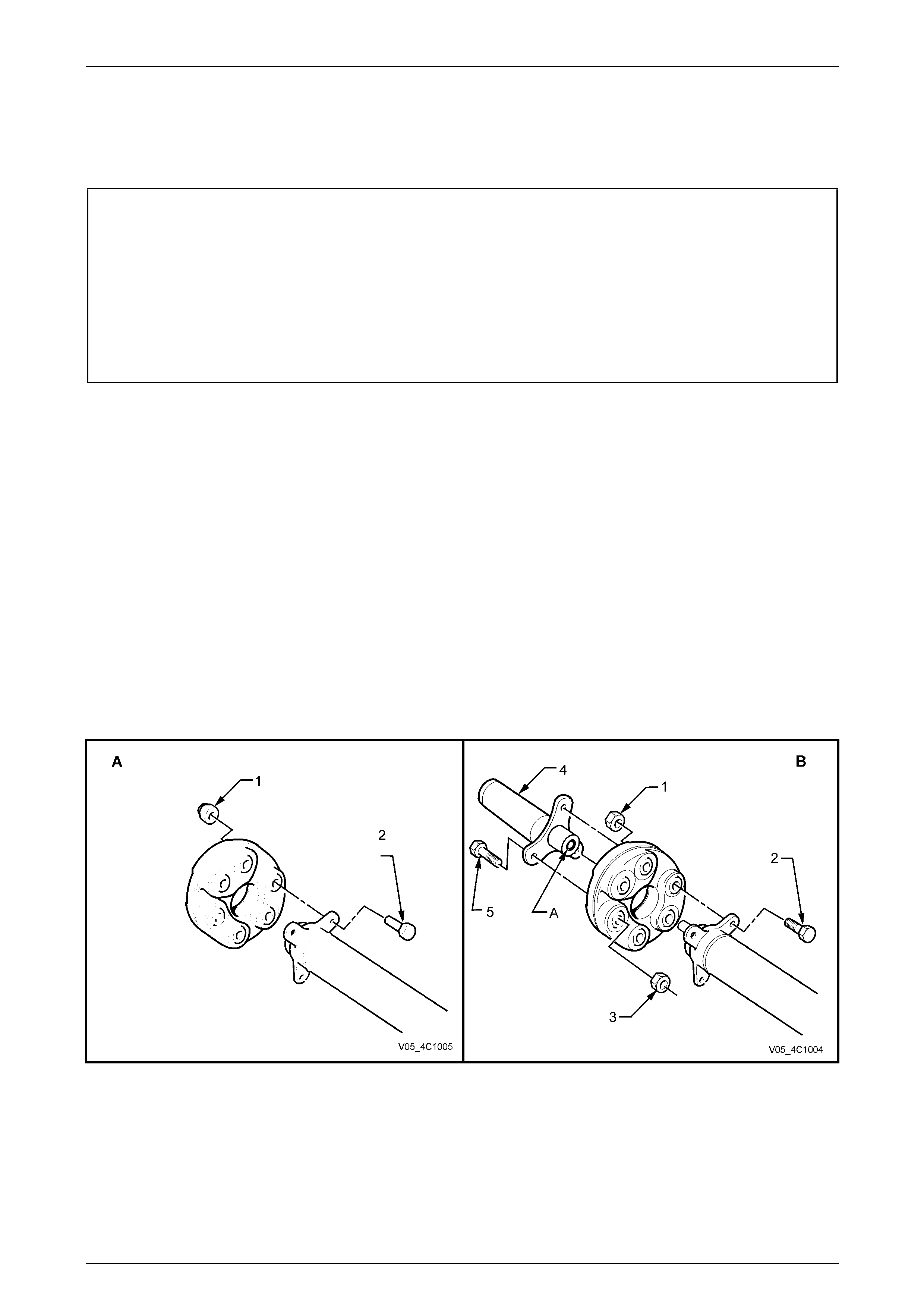
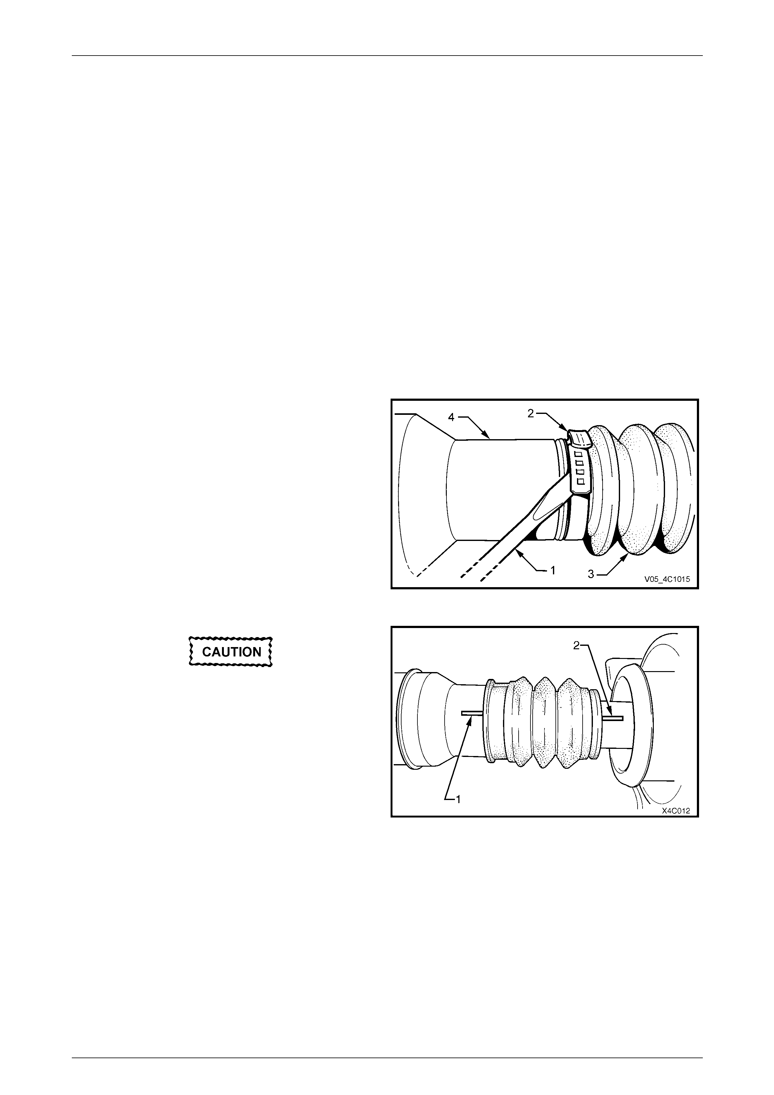
2 Using a back-up spanner on each of the three propeller shaft to coupling bolts (2), loosen then remove the nuts (1).
Discard the removed bolts and nuts. Remove the coupling from the front of the propeller shaft.
NOTE
View ‘A’ shows the rubber coupling to flange
arrangement (front or rear) while view ‘B’ shows
the front coupling arrangement when a slip yoke
is utilised.
Figure 4C1 – 13
Legend
1 Nut – Coupling to Propeller Shaft (3 Places)
2 Bolt – Coupling to Propeller Shaft (3 Places)
3 Nut – Coupling to Slip Yoke (3 Places)
4 Slip Yoke Flange
5 Bolt – Coupling to Slip Yoke (3 Places)
A Spigot Bush Requiring Lubrication
Rear Propeller Shaft and Universal Joints 4C1 – 16
4C1 – 16
3 Referring to view ‘B’, use a back-up spanner on each of the three, propeller shaft slip yoke bolts (5), loosen then
remove the nuts (3). Discard the removed bolts and nuts. Remove the sliding yoke from the coupling.
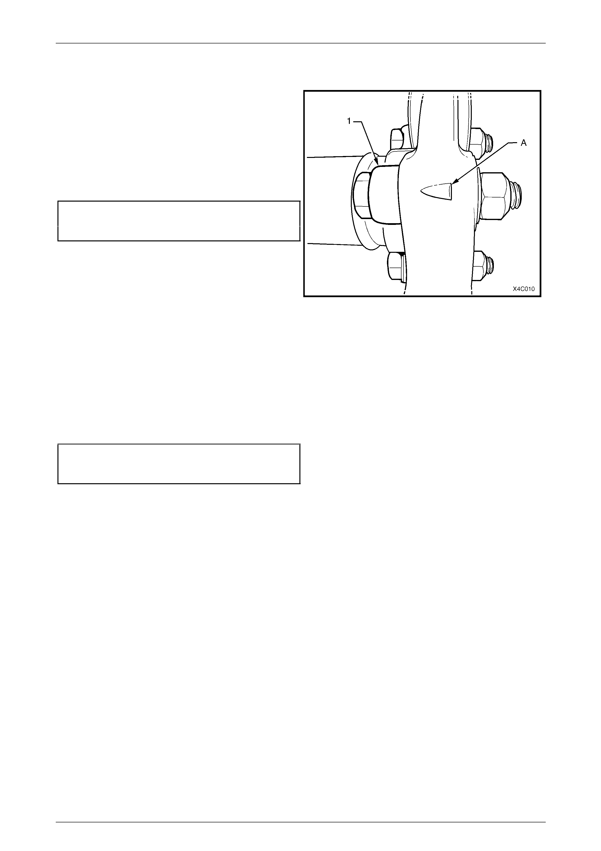
4 Install a replacement rubber coupling onto the end of
the propeller shaft, aligning the holes in such a way
that the triangular shape (‘A’) on the coupling ‘points’
to the propeller shaft flange lug (1), as shown.
5 Install NEW bolts and nuts to secure the couplin g to
the propeller shaft flange and tighten to the correct
torque specification, using a back-up sp anner on the
bolt head and angle wrench E 7115 to measure the
turn angle.
( ) Propeller shaft to rubber coupling
nut torque specification.......................................20 N.m,
then 55° turn angle
6 Lubricate the spigot bush in the propeller shaft end (or
the slip yoke bushing) with 0.5 gm of a molybdenum
disulphide grease such as an NLGI No. 2 lithi um soap
based EP grease with molybdenum disulph id e, such
as Shell Retinax HDX2 grease or BP Energrease
LMS-EP 23 (or equivalent). Figure 4C1 – 14
7 Reinstall the sliding yoke bush onto the propeller shaft spigot and align the three bolt holes.
NOTE
If the rear bolts were placed correctly (refer to
Step 4), the triangular shapes (’A’) will ‘point’ to
the sliding yoke flange bo lt holes.
8 Install NEW bolts and nuts to secure the couplin g to the slip yoke flange and tighten to the correct torque
specification, using a back-up spanner on the bolt head and angle wrench E 7115 to measure the turn a ngle.
Propeller shaft to rubber coupling
nut torque specification.......................................20 N.m,
then 55° turn angle
9 Reinstall the propeller shaft, Refer to 2.1 Propeller Shaft in this Sectio n.
Rear Propeller Shaft and Universal Joints 4C1 – 17
4C1 – 17
2.3 Centre Constant Velocity Joint (Plunge
Type) – AWD Wagon
LT Section No. – 05-050
There are two repair kits available, for this centre, constant velocity joint repairs:
a A DUST SHIELD KIT, which contains dust shield, gasket, strap, and tubes of grease and sealant (or gasket).
b A CONSTANT VELOCITY JOINT KIT, which contains the same items as in the DUST SHIELD KIT, plus the
constant velocity joint and appropriate retaining circlips.
Remove
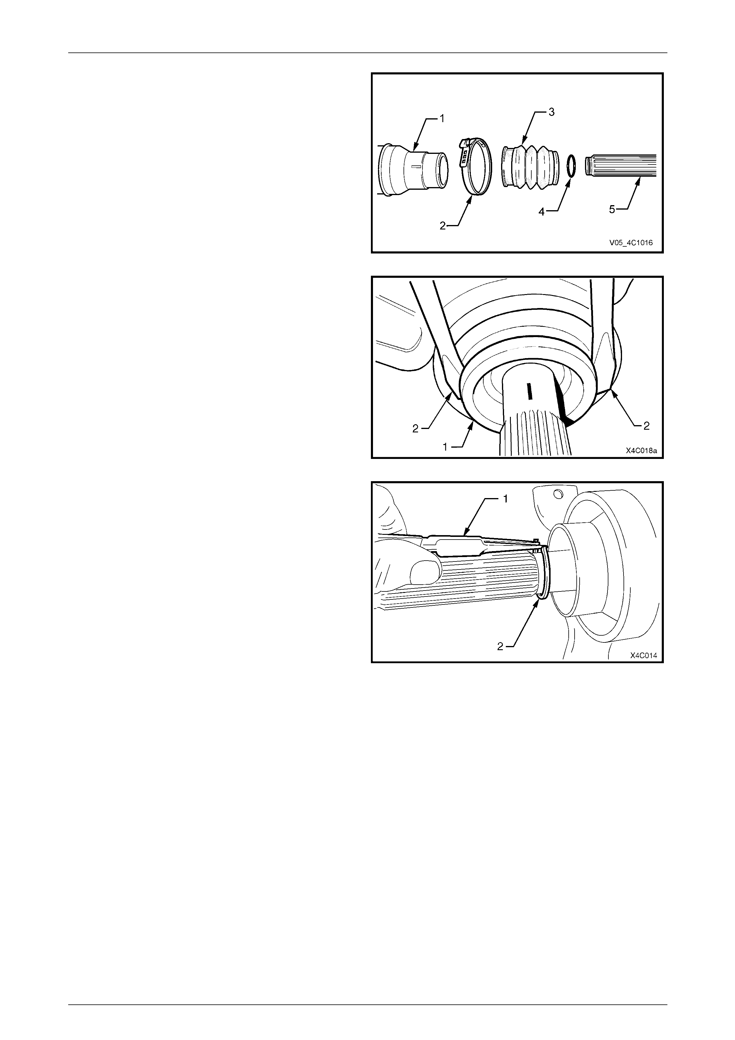
Figure 4C1 – 15
Legend
1 Heat Shield
2 Propeller Shaft Splined Shaft – Front Section
3 Boot Clamp
4 Propeller Shaft – Rear Section
5 Circlip
6 Grease Cover
7 Front Constant Velocity Joint Assembly
8 Locking Plate (3 Places)
9 Allen Key Headed Screws - 6 Places
10 Dust Shield and Boot Assembly
11 Centre Bearing and Support Bracket Assembly
12 Inner Slinger
13 Outer Slinger
14 Propeller Shaft Tube – Front Section
1 Remove propeller shaft. Refer to 2.1 Propeller Shaft in this Section.
Rear Propeller Shaft and Universal Joints 4C1 – 18
4C1 – 18
2 To ensure correct alignment of parts at reassembly,
scribe an aligning mark on constant velocity joint (2)
and the rear propeller shaft mounti ng flange (3).
During the disassembly process, the front
propeller shaft half must be supported (e.g.
lay on the bench top) to avoid an excessive
joint angle.
3 While holding the rear half of the pro peller shaft in a
vice fitted with soft jaws, remove the six, 6 mm Allen
key headed screws (1) and three lock plates (4), using
suitable socket equipment.
4 If necessary, tap the sides of the constant velocity joint
(2) to free it from the rear section mounting flange (3).
Figure 4C1 – 16
5 Secure the constant velocity joint in a vice fitted with
soft jaws (1).
6 Using a cold chisel (2) and hammer, dislodge and
remove the grease cover (3) from the end of the
constant velocity joint.
7 Discard the removed cover.
Figure 4C1 – 17
8 Reposition the constant velocit y joint in the soft faced
vice jaws, then use a brass drift and hammer to tap
constant velocity joint dust shield (1) to dislodge it from
the constant velocity joint (2).
9 Using a small bladed screwdriver, lever the clamp tang
(3) upward releasing it from the clamp barbs. Remove
and discard the clamp.
Figure 4C1 – 18
Rear Propeller Shaft and Universal Joints 4C1 – 19
4C1 – 19
10 Wipe excess lubricant from the constant velocity joint,
then remove the retaining circlip (1).
Figure 4C1 – 19
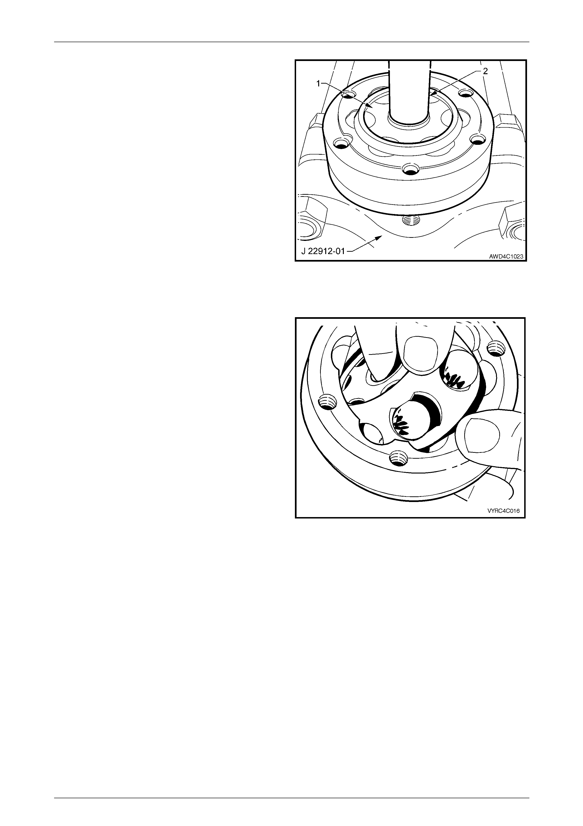
11 Pull back constant velocit y joint outer race. Install
suitable press plates (approximately 8 mm thick),
between dust shield and constant velocity joint, to
support inner joint race (1). Press the front half of
propeller shaft from constant velocity joint, using a
suitable drift (2).
NOTE
Press plates J22912-01 are too thick to fit
between the constant velocity joint and the dust
shield.
12 Clean old gasket material from dust shield a nd
constant velocity joint mating surfaces. Figure 4C1 – 20
Rear Propeller Shaft and Universal Joints 4C1 – 20
4C1 – 20
Disassemble
Disassembly of the constant velocity joint is
not recommended. The internal components
are a precision fit and develop their own
characteristic wear patterns. Intermixing
components could result in looseness,
binding and/or subsequent premature failure
of the joint. However, if disassembly must be
attempted, then it is vital that the following
procedure is carefully followed.
1 Obtain a piece of wood or suitable tray with enou gh depressions in the surface to accommodate the six balls of the
constant velocity joint, marking one divot to indic ate the ball closest to the alig nment marks to retain the original
orientation of each ball to its working components.
2 Remove the excess lubricant from the constant
velocity joint, wipe clean and mark the relationship of
the inner race, ball guide a nd outer race, using
correction fluid.
Figure 4C1 – 21
3 Pivot inner race and ball guide at 90° to centre line of
outer race as shown, and lift inner race, ball guide and
six balls as an assembly, from outer race.
NOTE
Even with grease surrounding the constant
velocity joint components, be careful not to allo w
any balls to slip from the cage. Each ball must
be reinstalled in its original position.
Figure 4C1 – 22
Rear Propeller Shaft and Universal Joints 4C1 – 21
4C1 – 21
4 Using a small screwdriver, lever balls from guide, as
shown. Keep balls in order, relative to the alignment
marks made in Step 1, for reassembly.
NOTE
Dependent on the length of time the constant
velocity joint has been in ser vice, individual balls
could slip from the cage and not require prising
to release.
5 Lift the inner race from the ball guide.
Figure 4C1 – 23
Inspect
Propeller Shaft and Boot
1 Clean propeller shaft, boot and dust shield in a suitable cleaning solvent.
2 Inspect propeller shaft for visible damage and twisting, cracking or excessive spline wear.
NOTE
If any damage is evident then the propeller shaft
must be replaced.
3 Inspect boot and dust shield, replacing if split, fatigued, cracked or worn.
4 Check that the vent hole in the front flange of the rear propeller shaft half, is clear and not blocked with mud or
other debris.
Constant Velocity Joint
1 Inspect the grease in the joint for contamination and/or dirt ingress. If either of these conditions is evident, then the
constant velocity joint will most probab ly have suffered damage and should be replac ed. If inspection shows that
the joint has not been contaminated, clean the joint by soaking in a suitable cleaning solvent.
2 Clean all components in suitable solvent, ensuring that the part relationships remain undisturbed.
3 Carefully inspect all compo ne nts for signs of severe p itting, galling, play between balls and the cage windows, any
cracking or damage to cage, pitting or galling or chips i n race ways. Repla ce the constant velocity joint if any of
these conditions are evident.
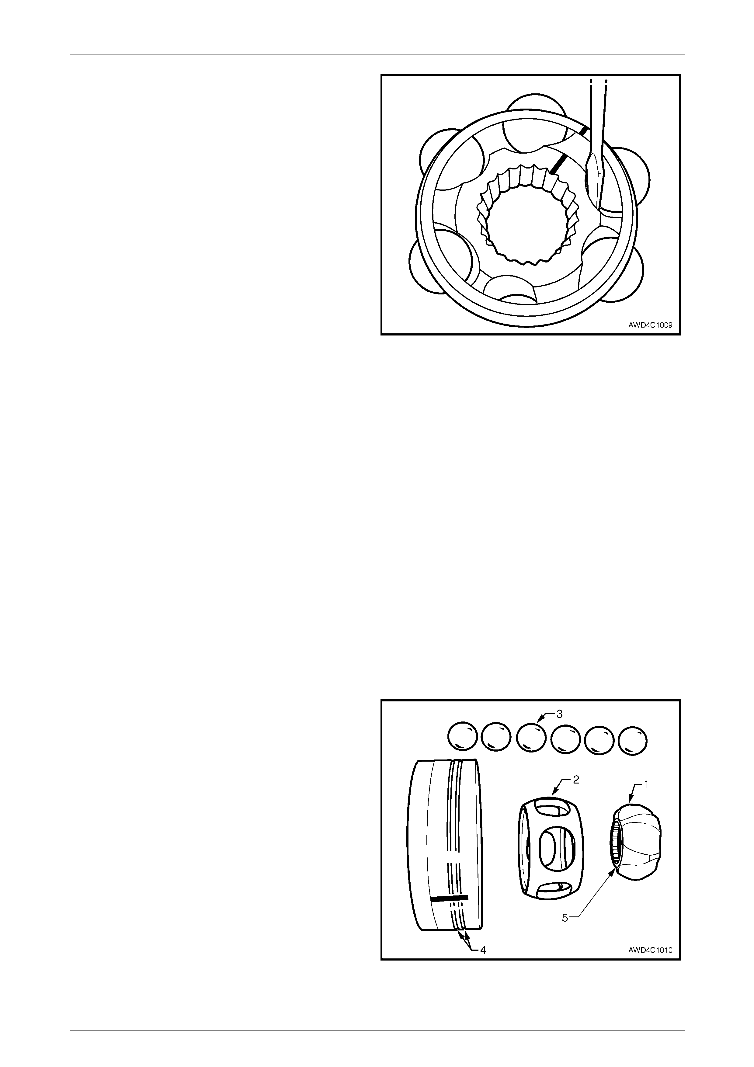
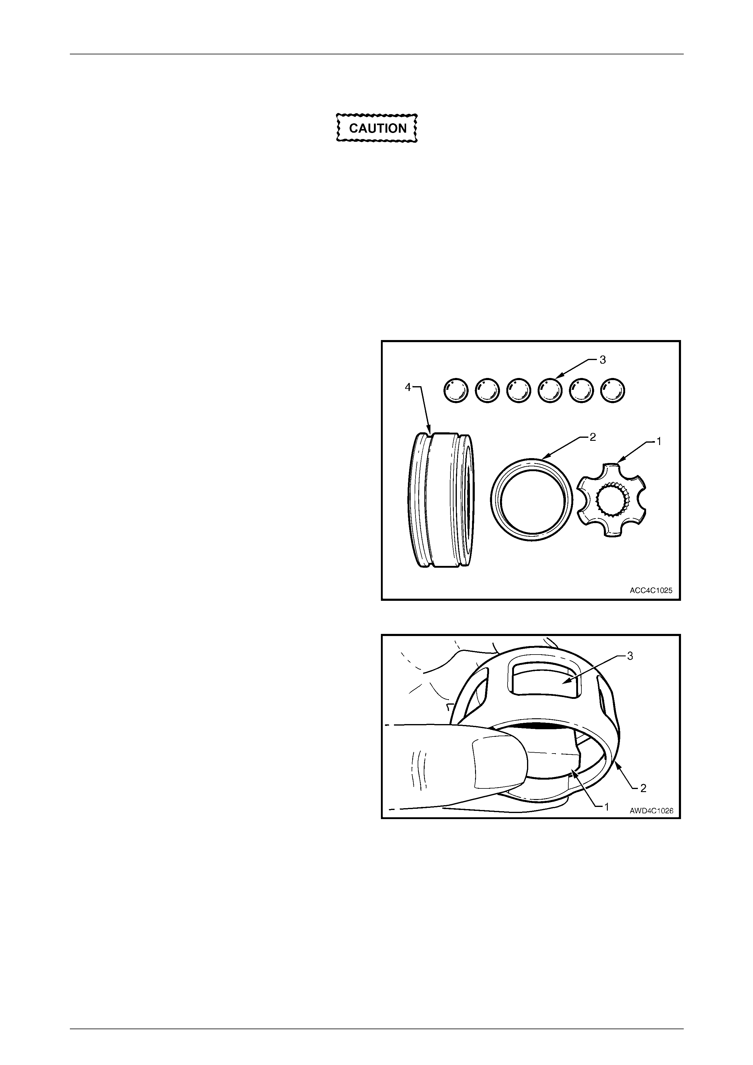
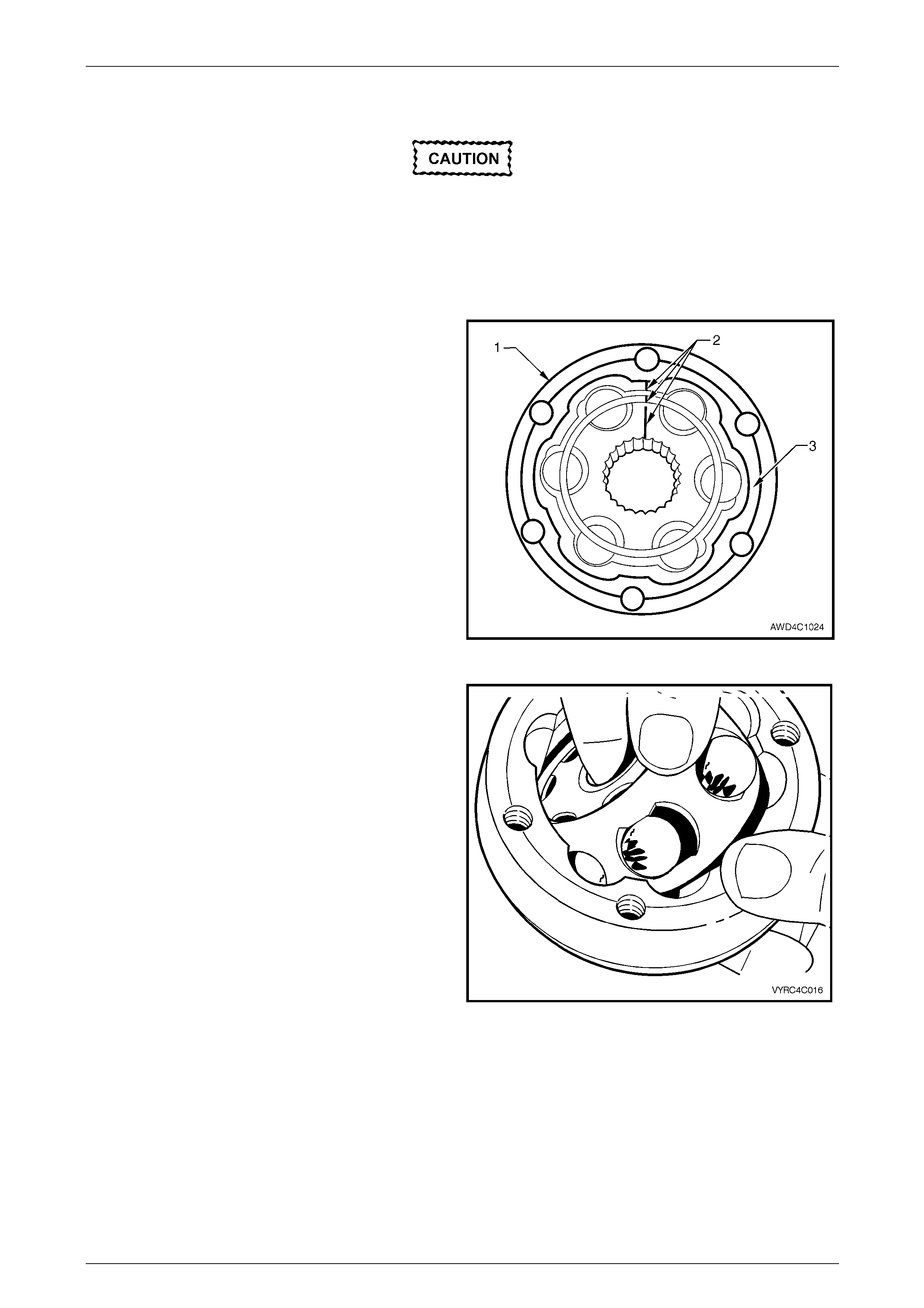
Shown is an exploded view of the centre propeller shaft
constant velocity joint. Note the two identification grooves on
the outer race (4) and the step (5) on the inner race (1).
These features and the angled ball tracks, identify that this
is a ‘plunge’ joint, when assembled.
NOTE
• The inner race (1) and cage (2), together with
the individual balls (3), must be maintained in
their original locations to minimise the
creation of a noisy joint.
• Under no circumstances are components
from one constant velocity joint to be mixed
with components from another constant
velocity joint.
Figure 4C1 – 24
Rear Propeller Shaft and Universal Joints 4C1 – 22
4C1 – 22
Reassemble
Method 1
1 Provided the balls are held captive in the ball cage when installed, reinstall each in its correct position.
2 While holding the inner race, cage and the six balls in position, reinstall to the outer race by turning the inner
assembly at 90° to the outer race, reinstall the two balls in their raceways, then rotate the inner assembly, to fully
reinstall. Refer to Figure 4C1- 27.
3 Check that the relationship marks are ali gned, refer to Figure 4C1-26.
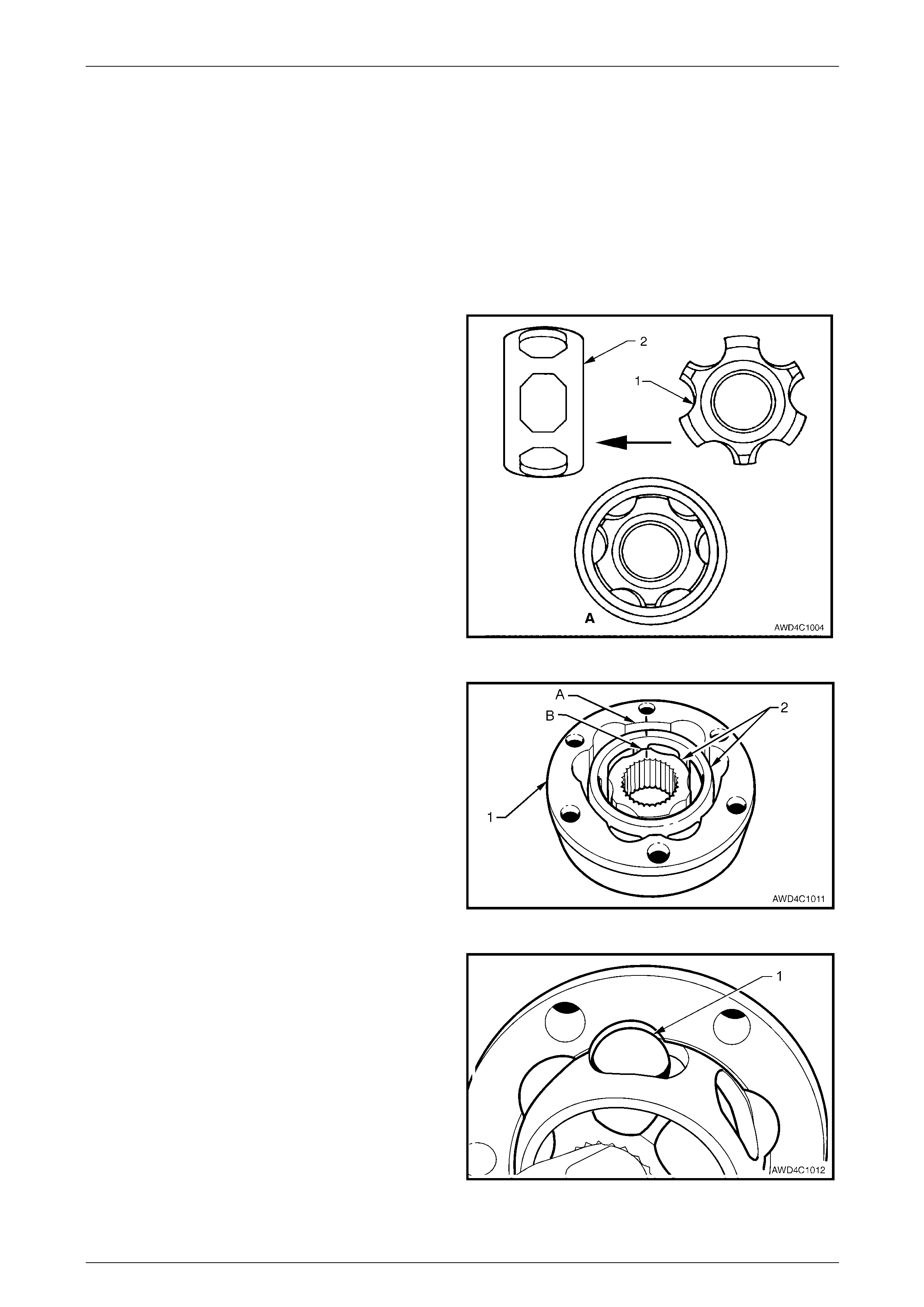
Method 2
1 Place the inner race (1) into the cage (2) and position
centrally within the cage, as sho wn in vie w ‘A’. Align
the relationship marks to confirm correct installation
NOTE
The flange on the inner diameter of the inner
race should be on the s ame side as the chamfer
on the inner edge of the ball c age.
Figure 4C1 – 25
2 Place the inner race and cage (2) into the outer race
(1), as shown.
3 Align a thick section (A) on the outer race, with a
narrow one (B) on the inner race. Note that the
relationship marks are also in alignment
Figure 4C1 – 26
4 Tilt the cage and inner race as shown, and fit the first
ball (1) in its original location.
Repeat this process for the remaining five balls.
Figure 4C1 – 27

Rear Propeller Shaft and Universal Joints 4C1 – 23
4C1 – 23
5 When assembly of the constant velocity joint is
complete, check for plunge movement of the inner
members (1), indicated by ‘A’. If NO plunge movement
can be achieved, then the constant velocity joint has
NOT been correctly assembled.
If such a situation occurs, the constant velocity joint
must be disassembled and the assemb ly process
repeated until such time that the required plunge
movement is achieved.
NOTE
The total plunge movement for the centre
constant velocity joint should be approximately
28 mm.
Figure 4C1 – 28
Reinstall
Installation is the reverse of removal procedure, noting the following points:
1 Cleanliness of constant velocity joint and associated parts is vital to ensure maximum life.
2 Install a new boot clamp at the small end of the dust boot.
3 From the 45 grams of lubricant suppli ed with the constant velocity joint repair kit for this application, insert
approximately 20 grams into the boot, half of the remainder into the joint itself and the final quarter into the dust
cap. Avoid having any grease in the centre of the dust cap, over the breather hole.
4 Clean mating surfaces of constant velocity joint, dust shield and rear propeller shaft companion flange.
5 Apply a 2 mm bead (1) of Loc tite 510 High
Temperature Gasket Eliminator sealant or equivalent
to the dust shield and boot assembly mating surface.
Take care not to contaminate the constant velocity
joint grease with sealant.
6 Install a new boot clamp over the propeller shaft
splines.
7 Install the dust shield and boot assembly over the
propeller shaft splines, taking care not to damage the
boot in the process.
Figure 4C1 – 29
Rear Propeller Shaft and Universal Joints 4C1 – 24
4C1 – 24
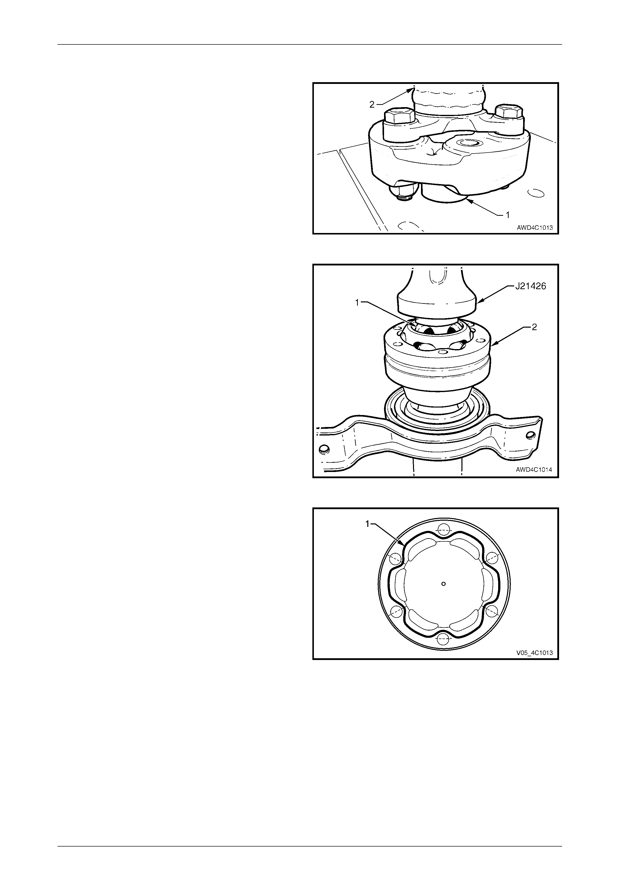
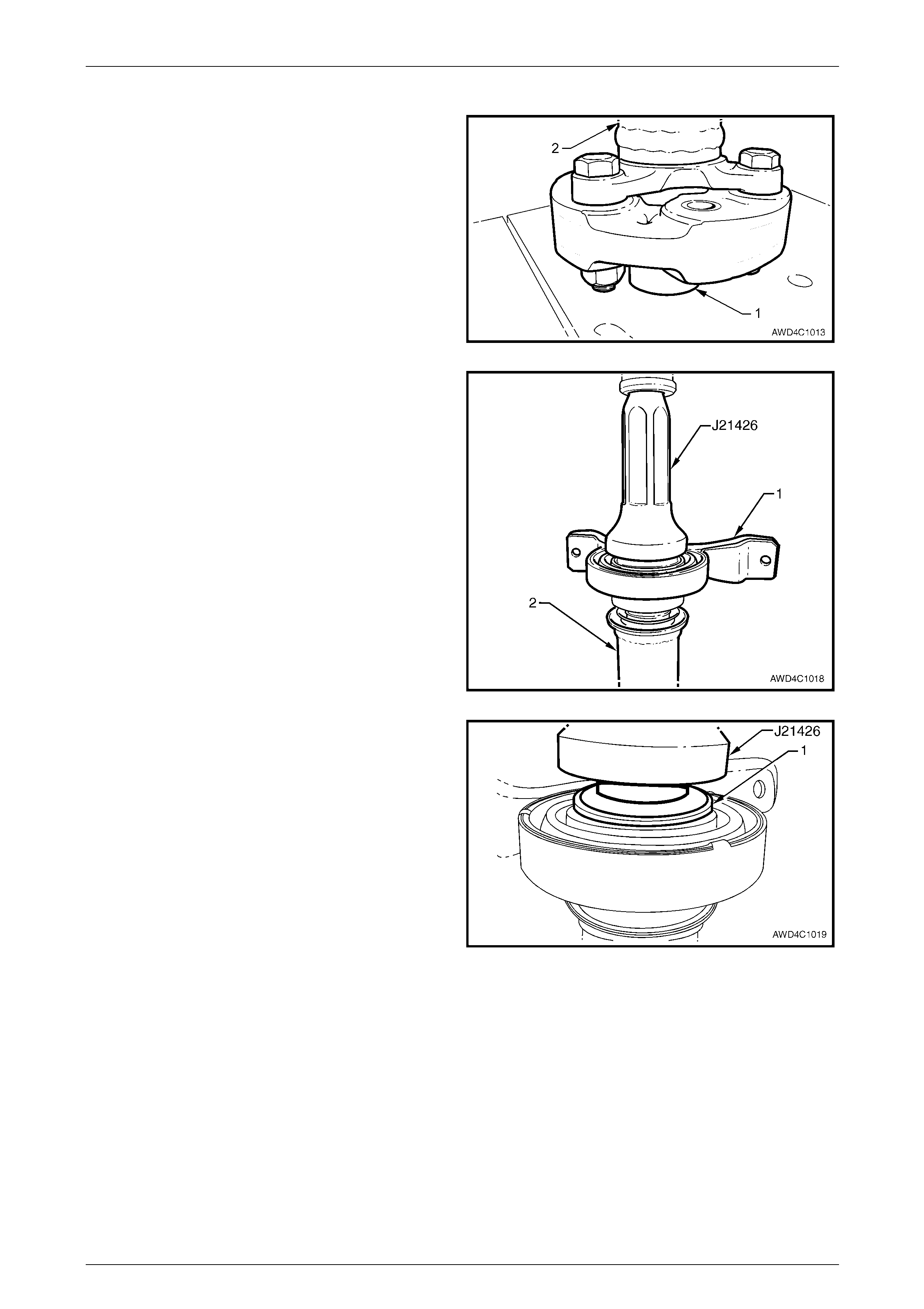
8 Before pressing the constant velocity joint onto the
splined propeller shaft, support the shaft end (2) with a
suitable length of tube (1) of dimensions 48 mm OD,
32 mm ID and at least 30 mm long.
Figure 4C1 – 30
9 Press constant velocity joint (2) onto shaft using
installer J21426 or a suitable size socket or tube.
Ensure that the press force is applied to the inner rac e
(1), as shown.
10 Using circlip pliers, install a ne w circ lip to retain the
constant velocity joint. Be careful not to over-expand
the circlip during the installati on process.
11 Insert three attaching bolts through the dust shield
flange to align with the constant velocity joint, then tap
the dust boot flange assembly into place.
Figure 4C1 – 31
12 Apply Loctite 510 High Temperature Gasket Eliminator
sealant or equivalent, to the flanged area of propeller
dust cover, taking care not to contaminate the
constant velocity joint grease with sealant.
Figure 4C1 – 32
Rear Propeller Shaft and Universal Joints 4C1 – 25
4C1 – 25
13 With the three attaching bolts (2) still installed through
the dust boot flange and constant velocity joint, install
then tap a new dust boot cover (1) into place, over the
constant velocity joint.
14 Clean threads in rear propeller shaft companion flange
and the six Allen head bolts. Apply Loctite 242 or
equivalent thread sealant to the bo lt threads.
Figure 4C1 – 33
15 Ensure that the relationship marks on the constant velocity joint, dust boot flange and rear propeller shaft flange
(made before disassembly), are all aligned.
16 Reinstall and tighten the six Allen headed screws to the correct torque spe cification.
( ) Centre constant velocity joint to
rear propeller shaft flange
bolt torque specification.......................................35 N.m
17 After locating the boot into the recess in the dust boot
groove, engage the strap of the clam p with the barb.
18 Tighten the new clamp (1) usi ng keystone clamp pliers
such as J 22610 or commercial equivale nt.
19 Reinstall propeller shaft. Refer to 2.1 Propeller Shaft in
this Section.
Figure 4C1 – 34
Rear Propeller Shaft and Universal Joints 4C1 – 26
4C1 – 26
2.4 Centre Constant Velocity Joint (Fixed
Type) – Live Axle Models
LT Section No: 05-050-1
ATTENTION
The following fasteners have either micro encapsulation or incorporate a mechanical thread lock and should
only be used once. If in doubt, replacement is recommended when performing this operation:
Constant velocity joint to rear propeller shaft attaching bolts.
Remove
1 Remove the propeller shaft. Refer to 2.1 Propeller Shaft in this Section.
2 To ensure correct alignment of parts at reassembly,
scribe an aligning mark (or use a felt tipped pen) on
the constant velocity joint (2) and the rear propeller
shaft mounting flange (3).
3 While holding the rear half of the pro peller shaft in a
vice fitted with soft jaws, remove the six, 6 mm Allen
key headed screws (1) and three lock plates (4),
using suitable socket equipm ent.
4 Using a plastic hammer, tap the sides of the propeller
shaft rear half, companion flange (3) to break the
paint seal, then separate the two propeller sh aft
halves.
Figure 4C1 – 35
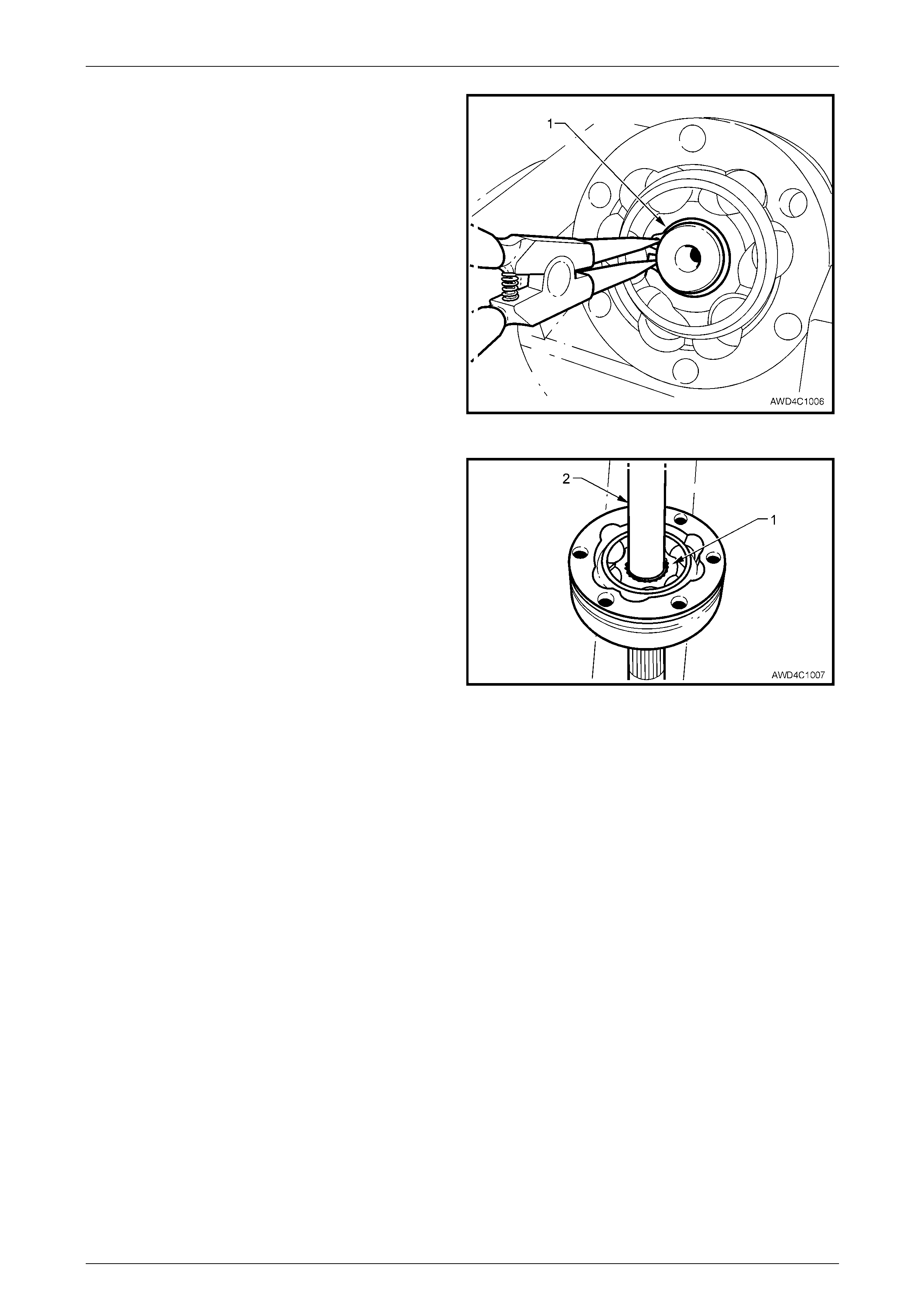
5 Using suitable circlip pliers (1), remove the constant
velocity joint, retaining circlip (2) from the front
propeller shaft spindle.
Figure 4C1 – 36
Rear Propeller Shaft and Universal Joints 4C1 – 27
4C1 – 27
6 Support the constant velocity joint body (1) in a vice
fitted with soft jaws. Using a brass drift and hammer
gently tap the dust cover and rubber boot assembly
(4) from the body of the constant velocity joint.
7 Remove the retaining clamp (3) attaching the rubber
boot (4) to the front propeller shaft spindle (5) by
releasing the clamp tang with a small bladed
screwdriver.
8 Push the dust cover and rubber boot assembly (4)
back toward the propeller shaft centre bearing (2).
Figure 4C1 – 37
9 Remove the centre bearing ca rrier retaining nuts (2)
and bolts (3), the support carrier strap (1) and the
heat shield (4), if fitted.
10 Separate the centre bearing cup guide halves (5 and
6), removing them from the centre bearing assembl y.
Figure 4C1 – 38
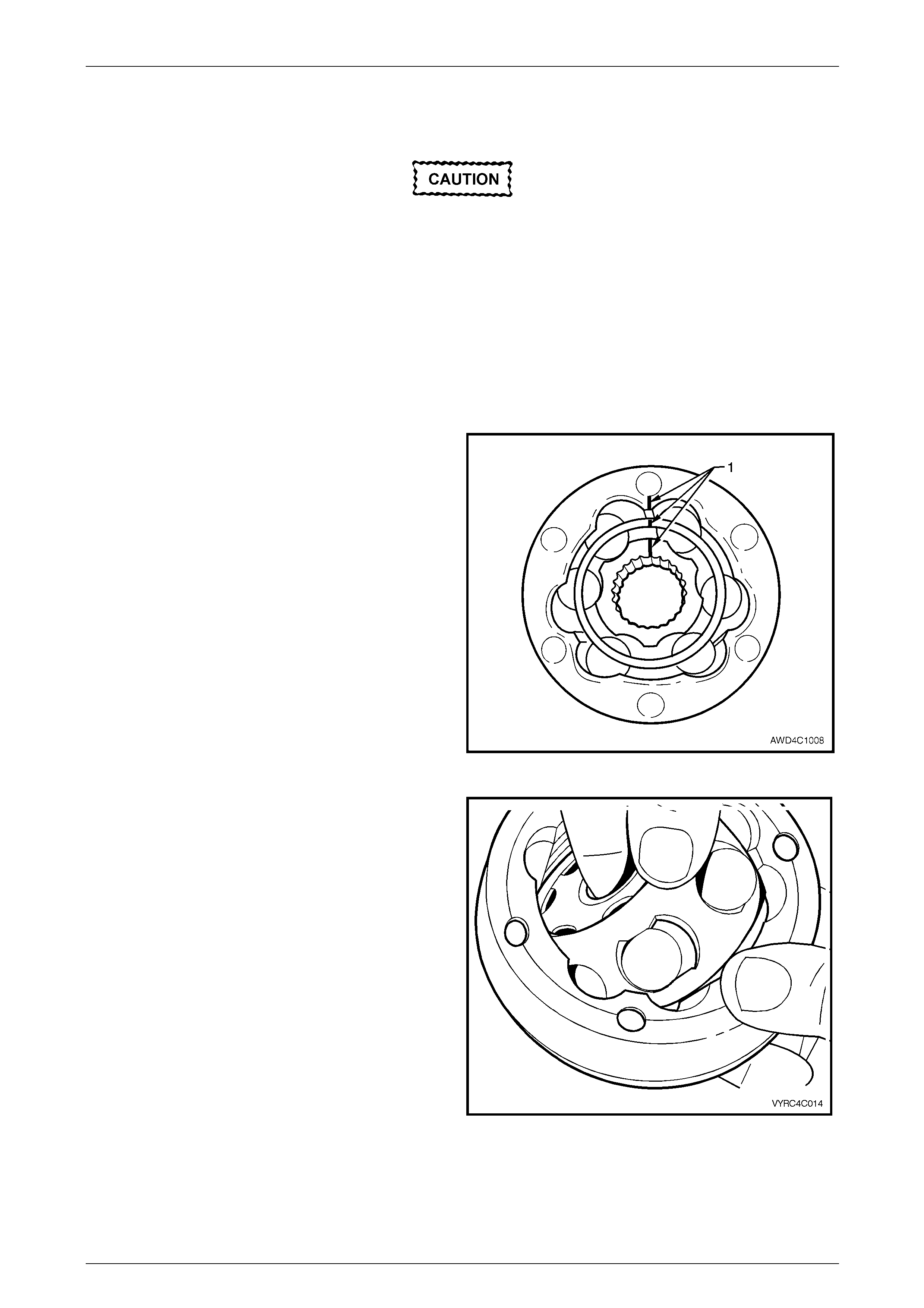
11 Remove the excess lubricant from the constant
velocity joint (1), wipe clean, then use a felt tipped pen
or correction fluid (2), to identify the relations hip of the
three joint components.
12 Remove the gasket (3) bet ween the propelle r shaft
companion flange and the constant velocity joint.
Discard the removed gasket.
Figure 4C1 – 39
Rear Propeller Shaft and Universal Joints 4C1 – 28
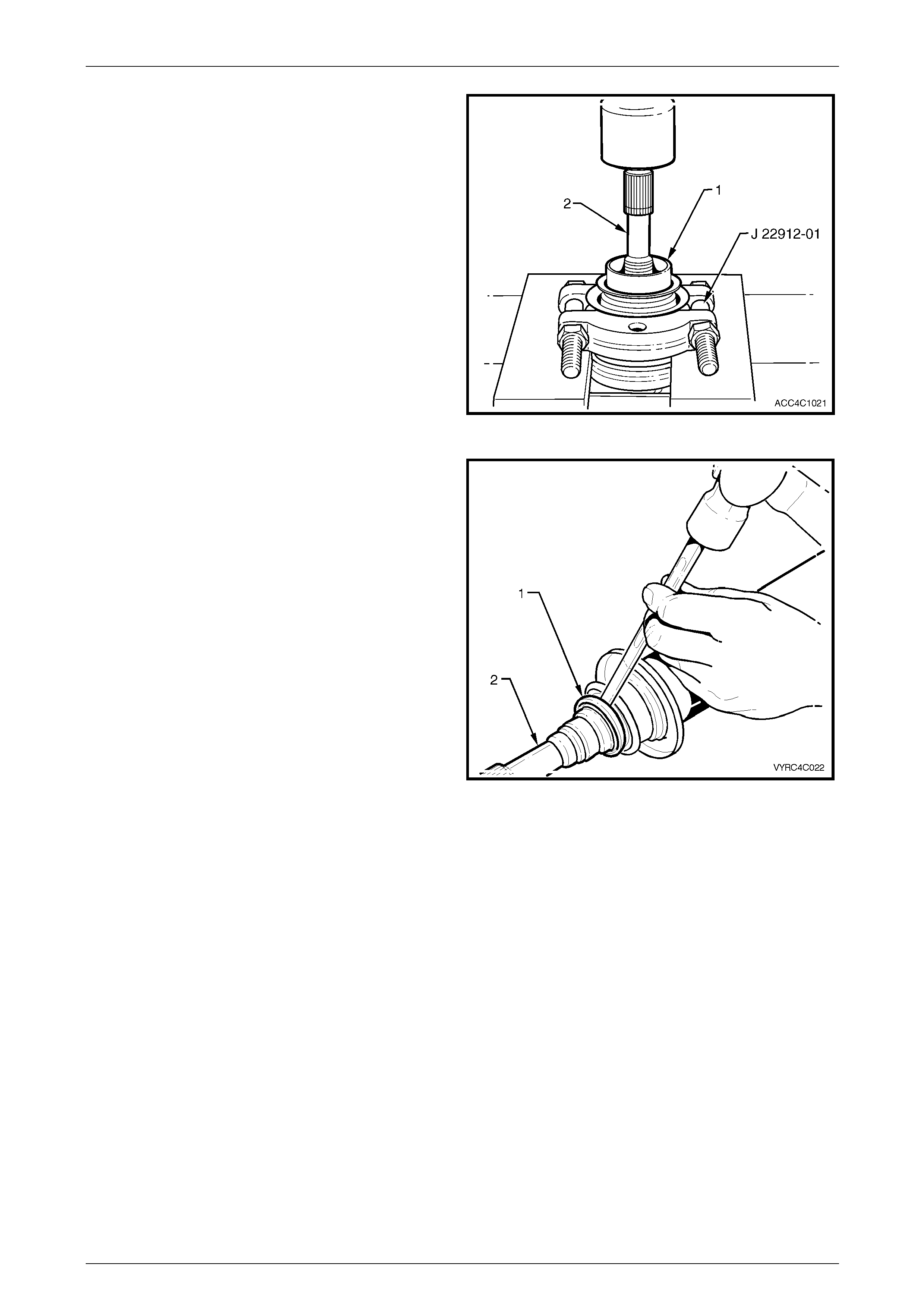
4C1 – 28
13 Push the cap and boot back along the propeller shaft,
enough to allow the fitment of press plates such as
J 22912-01.
14 Support the constant velocity joint inner race (1) with
the press plates (J 22912-01) then, using a suitable
mandrel (2), press the propeller shaft from the
constant velocity joint.
15 Remove the boot and dust shield from the propeller
shaft, being careful not to damage the boot on the
propeller shaft splines.
Figure 4C1 – 40
Inspect
1 Inspect the grease in the joint for signs of
contamination. If contamination is evident, then the
constant velocity joint will probably have suffered
damage, and should be replaced.
2 If inspection shows that contamination has not
occurred, clean the joint by soaking it in a s uitab le
cleaning solvent.
If there is severe pitting, galling, play between
the balls and the cage windows, cracking or
damage to the cage, pitting or galling or c hips in
the raceways, replace the constant velocity joint.
3 Inspect the internal components b y tilting the inner
race to one side to expose each bal l individually, while
observing the condition of each component.
NOTE
Take care that no bal ls becom e dis lod ged d u ring
this inspection process. Figure 4C1 – 41
Rear Propeller Shaft and Universal Joints 4C1 – 29
4C1 – 29
Reassemble
During the removal, cleaning, inspection or
replacement of a constant velocity joint, it is
possible for the joint to become
disassembled. Should an inadvertent
disassembly of a constant velocity joint
occur, and notwithstanding the earlier
recommendation, it is possible to reassemble
the constant velocity joint, provided the
following procedure is followed EXACTLY.
1 Obtain a piece of wood or suitable tray with enou gh depressions in the surface to accommodate the six balls of the
constant velocity joint, marking one divot to indic ate the ball closest to the alig nment marks to retain the original
orientation of each ball to its working components.
As shown in the exploded view of the fixed constant velocity
joint, the groove (4) is provided on the outer race to receive
the dust cover and boot assembly.
The fact that the ball grooves in both the outer and inner
races (1) are equally spaced, identifies this constant velocity
joint as a “fixed” type. Note also the fine gr oove on the front
edge of the ball cage (2) and the larger, plain chamfer on
the rear edge.
NOTE
• The inner race (1) and cage (2), together with
the individual balls (3), must be maintain ed in
their original locations to minimise the
creation of a noisy or binding joint.
• Under no circumstances are components
from one constant velocity joint to be mixed
with components from another constant
velocity joint.
Figure 4C1 – 42
2 With the inner race (1) at 90° to the ball cage (2),
insert one 'leg' (3) of the inner race into one of the ball
holes, then manipulate the inner race unti l installed
inside the ball cage. Check that the relatio nship marks
are both on the same side.
NOTE
The fine groove on the inner edge of the ball
cage and the chamfered spline edge, should
both be opposite the relationship marks.
Figure 4C1 – 43
Rear Propeller Shaft and Universal Joints 4C1 – 30
4C1 – 30
3 Reinstall the ball cage and in ner race into the outer
race, following this next procedure:
a Locate the two reliefs in the ball grooves in the
outer race, indicated by 'A'. There will be similar
reliefs on the opposite side.
Figure 4C1 – 44
b With the ball cage and inner race at 90° to the
outer race, install at the relief points (as shown),
then manipulate the ball cage to fit inside the
outer race. Ensure that the relationship marks
are all on the same side and aligned.
Figure 4C1 – 45
4 Tilt the ball cage and inner race as shown, and fit the
balls, in their correct order, one at a time.
5 Check that the three relationship marks (1) are in
alignment.
6 Check that axial movement is minimal.
Figure 4C1 – 46
Rear Propeller Shaft and Universal Joints 4C1 – 31
4C1 – 31
Reinstall
Reinstallation is the reverse of removal procedure, noting the following points:
1 Cleanliness of the constant velocity joint and associated parts is of prime importance to ensure maximum life of the
joint assembly.
2 Install a new small boot clamp over the spl in ed propeller shaft splines, then install the boot and dust shi eld
assembly, taking care not to damage the boot on the propeller shaft splines.
3 Pack the constant velocity joint with 32 g of lubricant supplied in either of the two available Repair Kits, to the fixed
joint. Work joint by hand to distribute grease onto all surfaces inside the joint. Pack the remaining 5 g of the
lubricant into the tube adaptor recess.
4 Clean mating surfaces of constant velocity joint, dust shield and rear propeller shaft companion flange.
5 Apply a 2 mm bead (1) of Loc tite 510 High
Temperature Gasket Eliminator sealant or equivalent,
to the grease cover mating surface. Take care not to
contaminate the constant velocity joint grease with
sealant.
Figure 4C1 – 47
6 Before pressing the constant velocity joint onto the
front propeller shaft half splines, ensure that the front
of the propeller shaft (2) is supported on a suitable
length of tube (1) (dimensions; 48 mm OD, 32 mm ID
and at least 30 mm long), as shown.
Figure 4C1 – 48
Rear Propeller Shaft and Universal Joints 4C1 – 32
4C1 – 32
7 Press constant velocity joint onto the rear propeller
shaft splines, using a suitable size socket or tube.
Ensure that socket or tube presses on inner race of
joint.
8 Secure the constant velocity joint with a new circlip,
being careful not to over-exp and the circlip during the
installation process.
9 Install at least three of the constant velocity joint Allen
key headed bolts aligning the dust shield and boot
assembly to the constant velocity joint.
10 Using a plastic faced hammer, install the dust cap to
the constant velocity joint.
11 Reinstall new gasket to end of constant vel ocity joint.
Figure 4C1 – 49
12 Clean threads in rear propeller shaft companion flange and the six Allen he ad bolts. Apply Loctite 242 or equivalent
thread sealant to the bolt threads.
13 Ensure that the relationship marks on the constant velocity joint, dust boot flange and rear propeller shaft flange
(made before disassembly), are all aligned.
14 Apply thread sealant such as Loctite 242 or equivalent o th e cleaned threads of the six Allen headed screws
15 Reinstall and tighten the six Allen headed screws to the correct torque spe cification.
( ) Centre constant velocity joint to
rear propeller shaft flange bolt
torque specification..............................................35 N.m
16 After locating the boot into the recess in the dust boot groove, install and tighten the new clamp, using keystone
clamp pliers such as J 22610 or commercial equivalent.
17 Reinstall propeller shaft. Refer to 2.1 Propeller Shaft in this Section.
Rear Propeller Shaft and Universal Joints 4C1 – 33
4C1 – 33
2.5 Centre Bearing Assembly
LT Section No. – 05-050
All VZ With V6 Engine and IRS (Except AWD Wagon)
NOTE
• This operation is not possible with the
propeller shaft fitted to GEN III V8 vehicles.
Refer to 1.1 Service Notes, in this Section for
further information.
• During the removal process described, the
rubber bearing support will be damaged,
resulting in the requirement for the complete
centre bearing assembl y to be replaced.
Remove
1 Remove the propeller shaft. Refer to 2.1 Propeller Shaft in this Section.
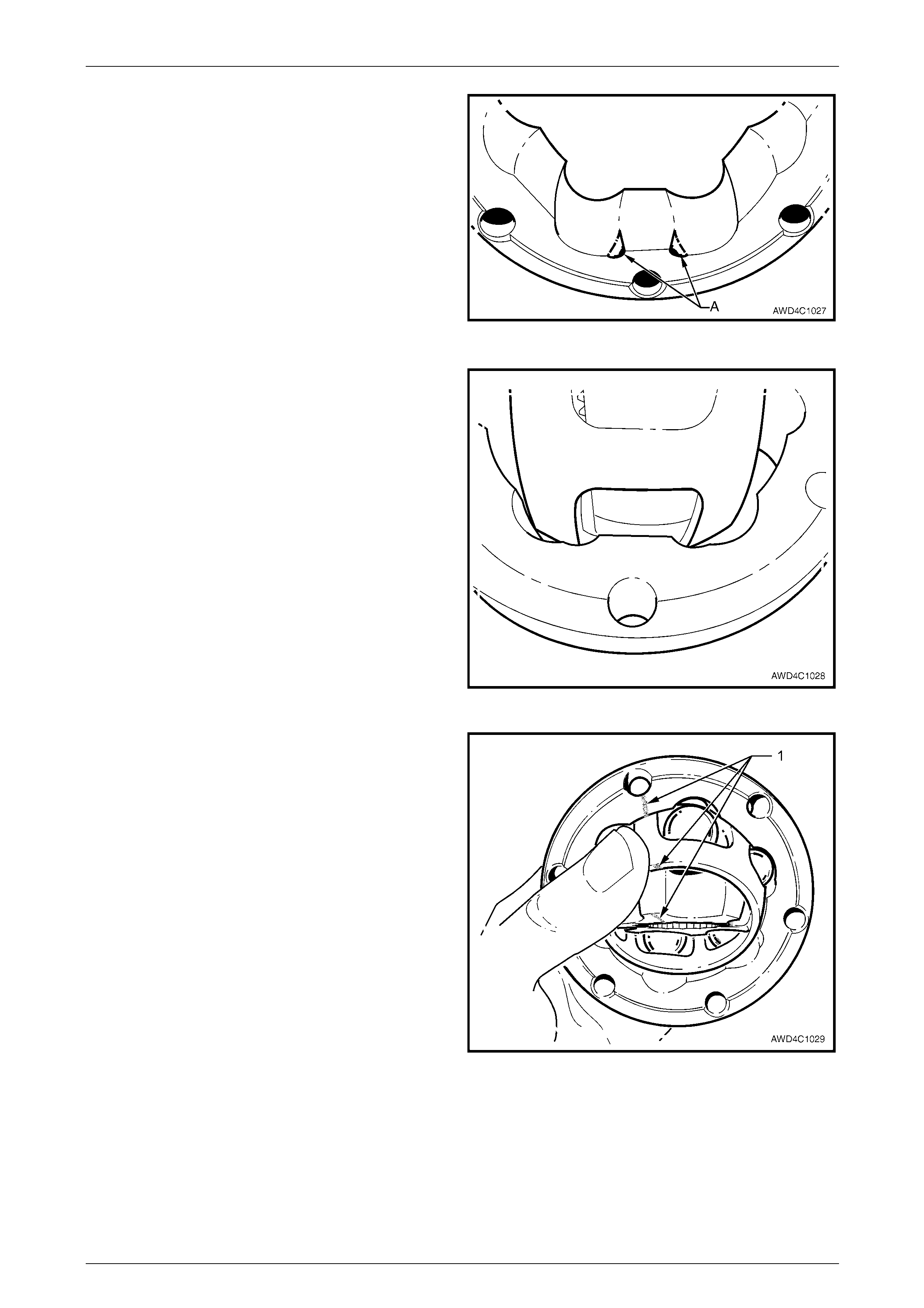
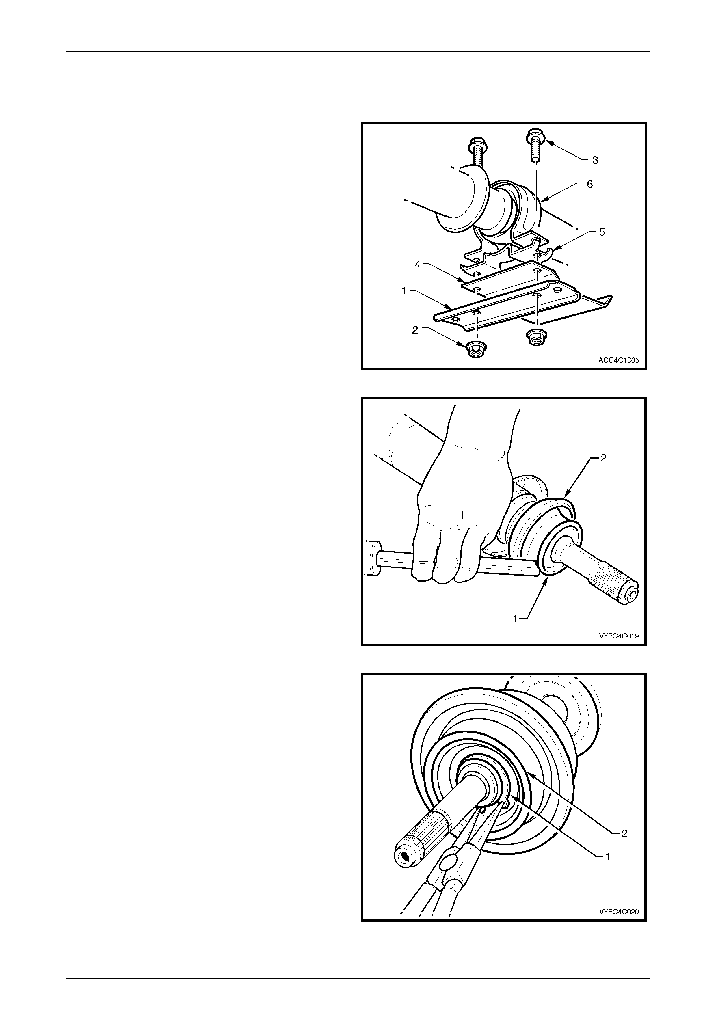
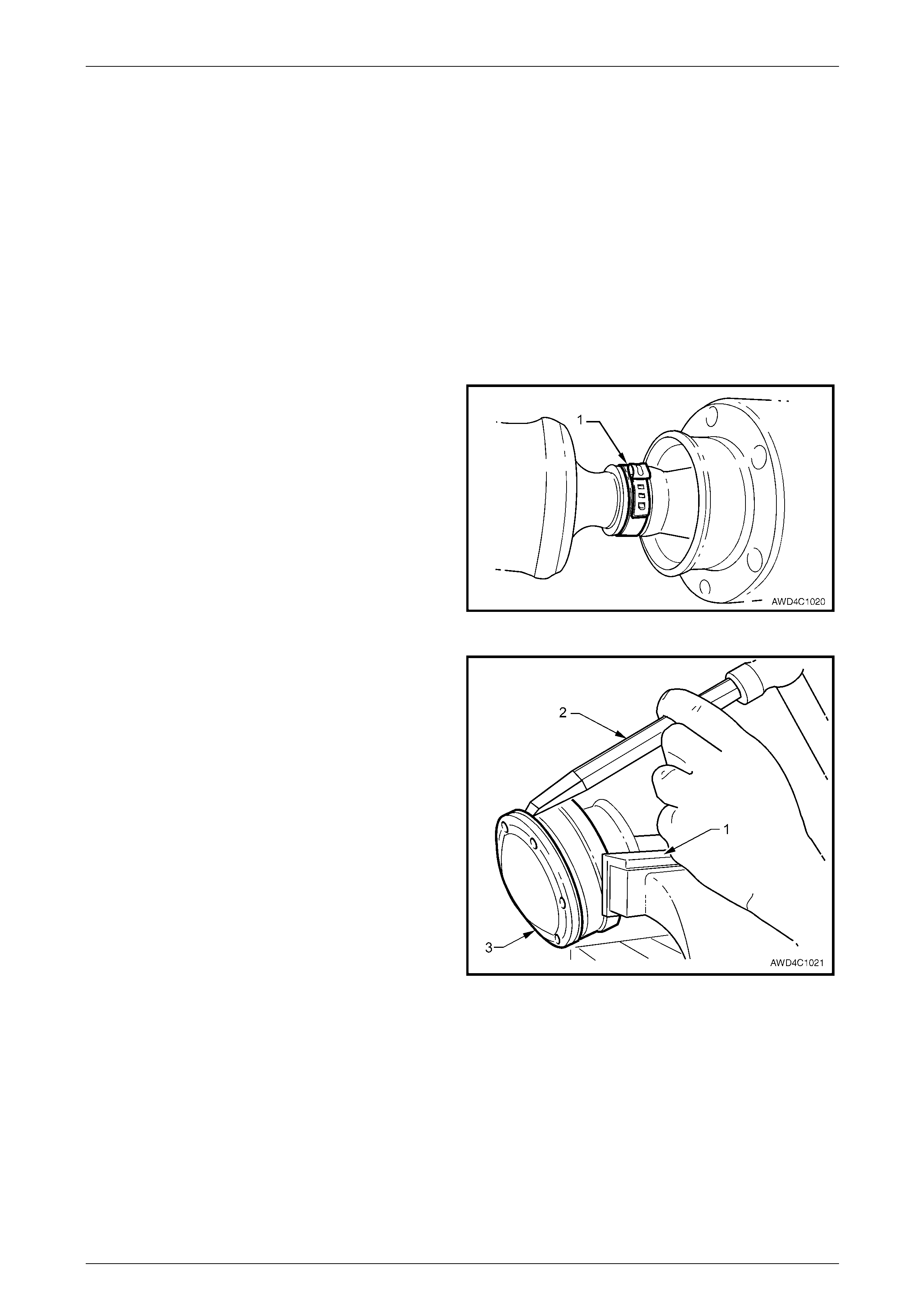
2 With the propeller shaft assembly (4) laying on a
bench, use a scre wdriver (1) or similar and l ever up o n
the boot clamp (2) strap, releasing the tension.
Figure 4C1 – 50
This is a critical operation, as propeller shaft
phasing and balance will be affected if the
two propeller shaft halves are not aligned
correctly on reassembly.
3 Extend the sliding joint until re sistance is felt, then use
a felt tipped pen or similar to mark alignment marks on
the front propeller shaft section (1) and the rear (2)
Figure 4C1 – 51
Rear Propeller Shaft and Universal Joints 4C1 – 34
4C1 – 34
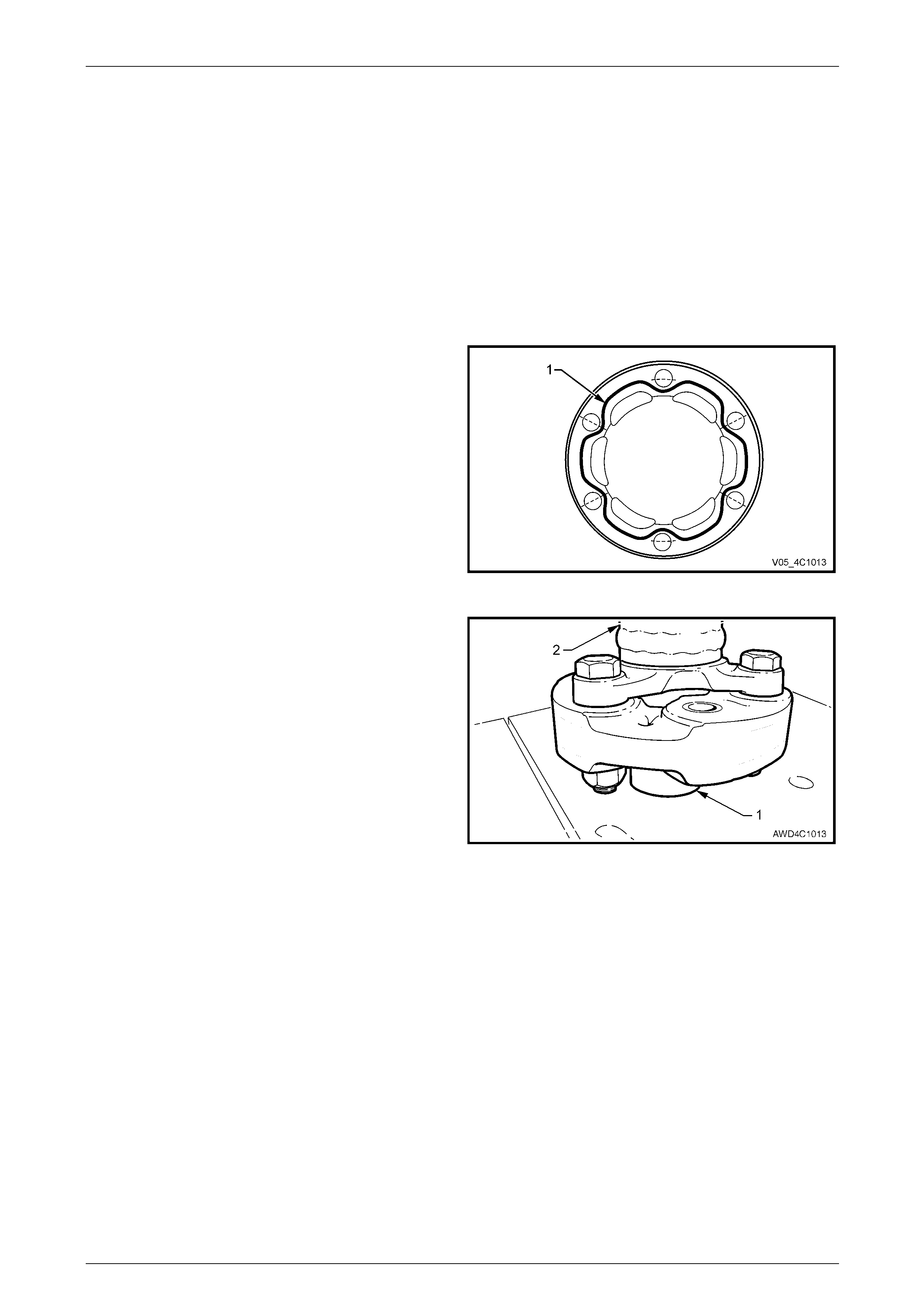
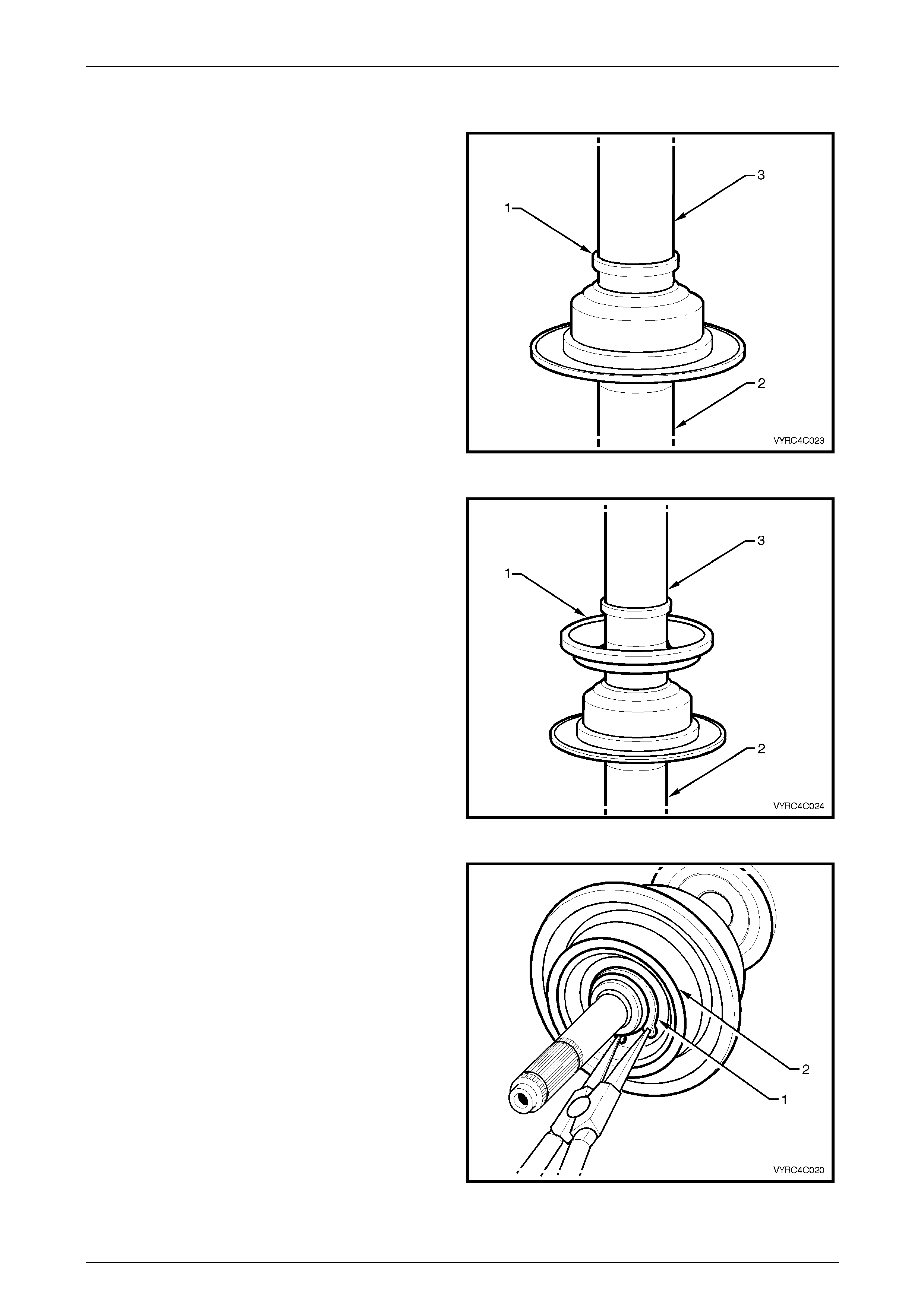
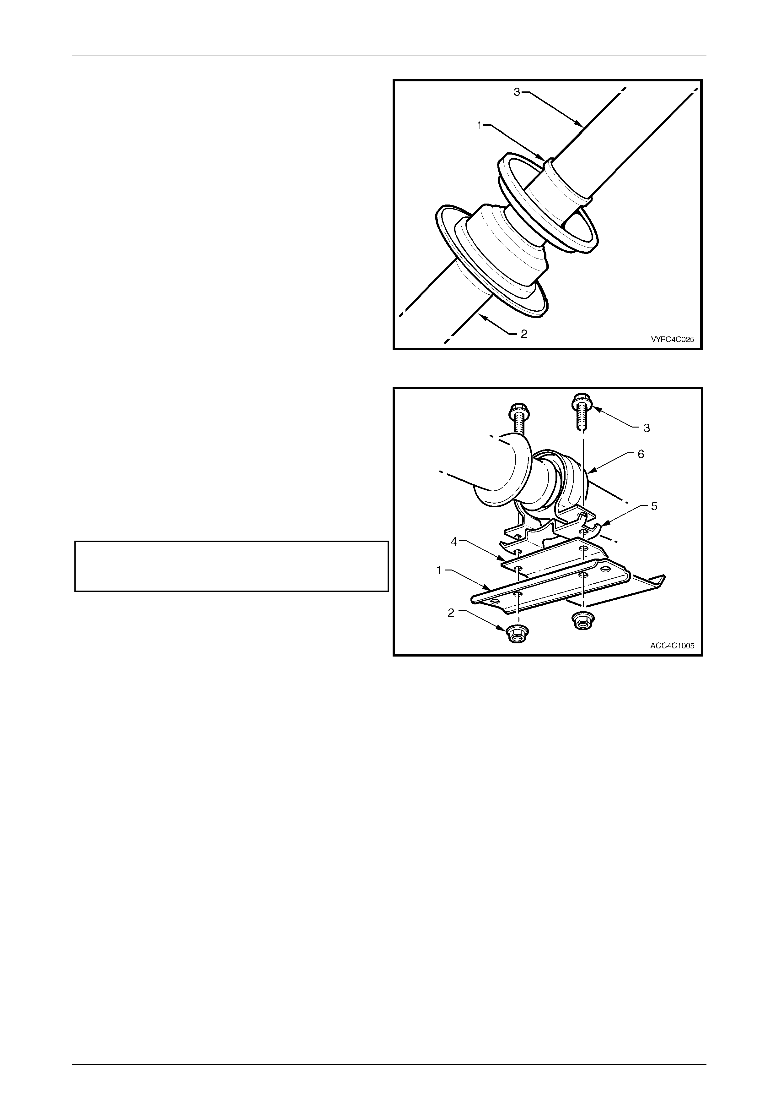
4 With the two propeller shaft halves extended, a snap
action is required to separate them, because of the O-
ring seal (3) mounted on the end of the re ar shaft (1).
5 Once separated, the ribbed boot (3) and O-ring seal
(4) are released. NOTE
Once separated, the O-ring seal (4) may be
retained in the propeller shaft front half (1).
Retrieve by inserting a hooked piece of wire.
Figure 4C1 – 52
6 Remove the slinger (1), by levering off, using two
similar sized screwdrivers (2) or similar, as sho wn.
NOTE
Removal of the slinger is requir ed to gain access
to a circlip underneath.
Figure 4C1 – 53
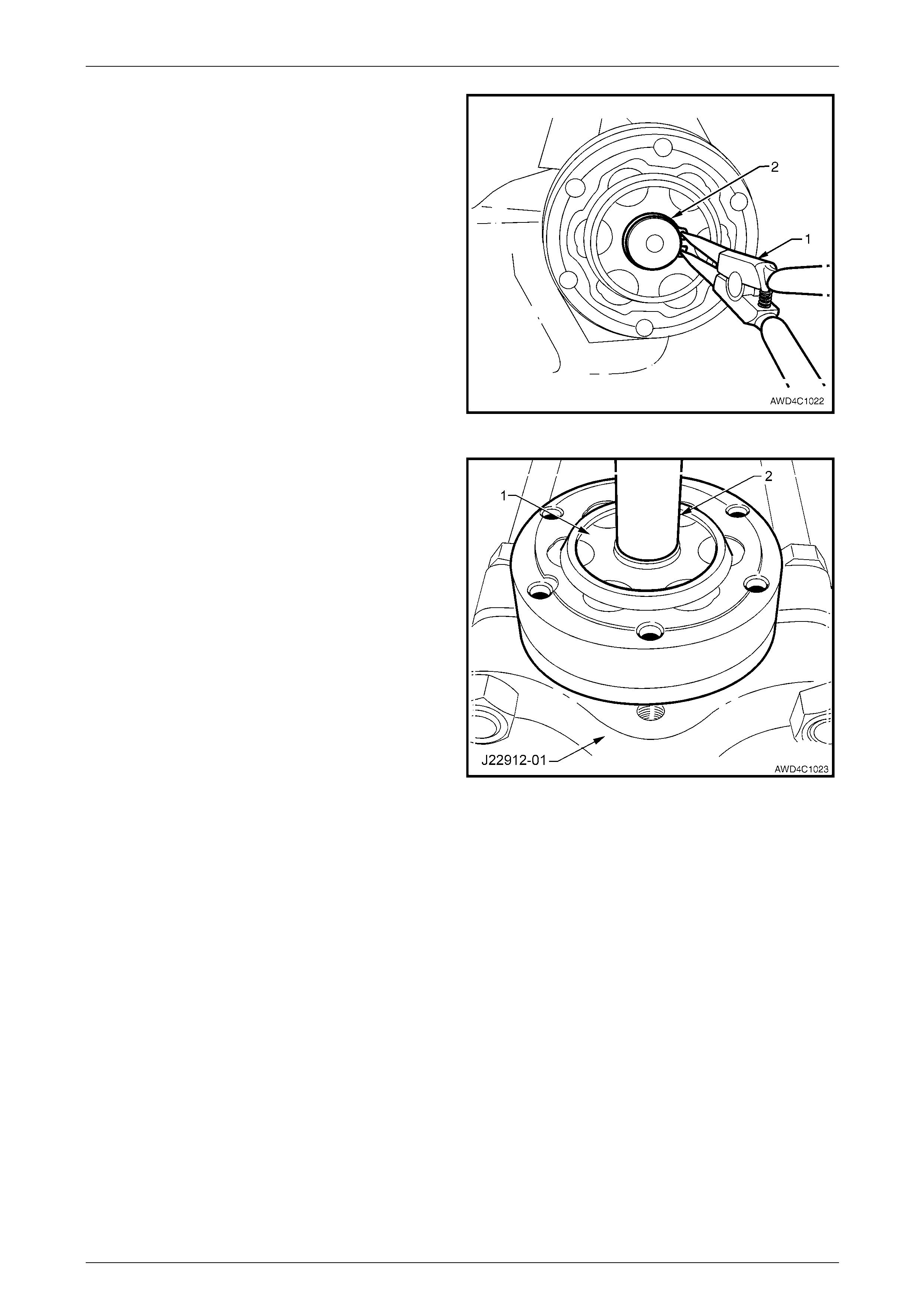
7 Using suitable, commercial ly available circlip pliers (1),
remove the circlip (2) securing the centre bearing.
Figure 4C1 – 54
Rear Propeller Shaft and Universal Joints 4C1 – 35
4C1 – 35
8 Install suitable press plates such as J 22912-01 under
the centre bearing, carrier (1) and rubb er support, with
the flat face towards the bearing and carrier (1).
9 Tighten the clamp nuts on the press plates until the
two halves are firmly secure around the bearing.
10 Support the press plates on the bed of an hydraulic
press and press the rear propeller shaft, splined shaft
from the centre bearing.
NOTE
This operation will damage the rubber bearing
support, requiring the cent re bearing, rubber and
carrier assembly to be replaced.
Figure 4C1 – 55
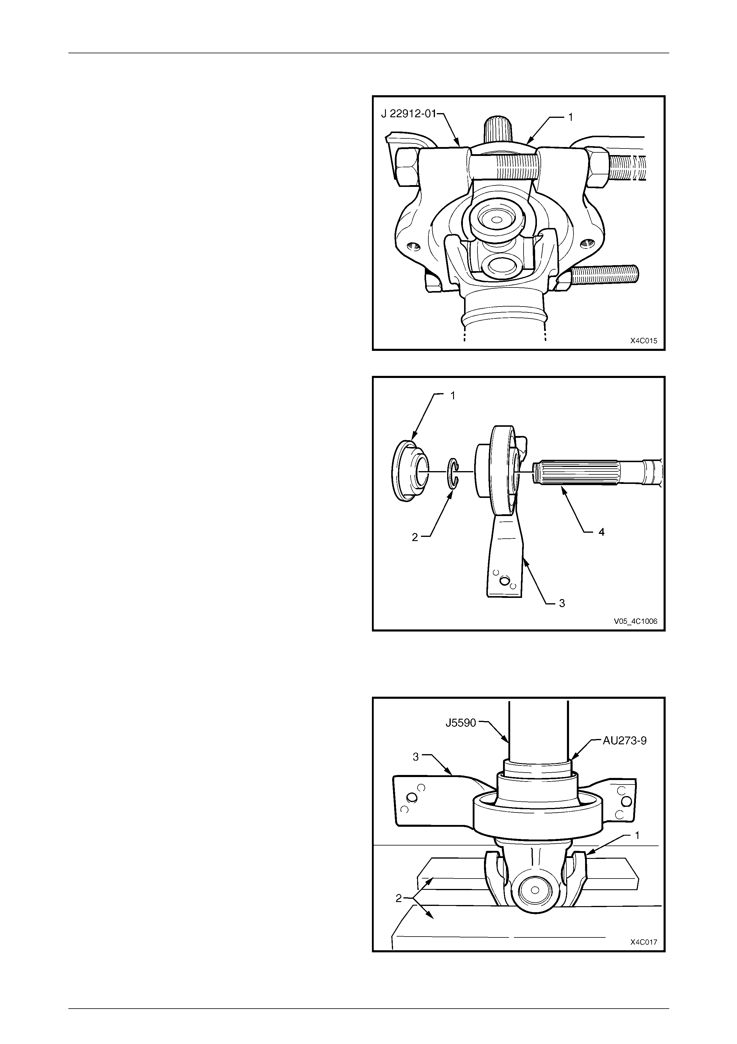
11 Shown is the relationship of the centre bear ing
assembly (3) to the rear propeller shaft (4), together
with the slinger (1) and the retaining circlip (2).
Figure 4C1 – 56
Reinstall
1 With the front universal joint ‘ears’ (1) supported on
press plates (2), press a NEW centre bearing
assembly (3) onto the front section of the rear
propeller shaft, using press tube J5590 and adaptor
AU273-9.
NOTE
If these tools are not available, then a 150 mm
length of pipe with an ID of 30 mm (and a wall
thickness of 5 mm), can be used as a substitute.
Figure 4C1 – 57
Rear Propeller Shaft and Universal Joints 4C1 – 36
4C1 – 36
2 Install a NEW centre bearing retaining circlip (2), using
commercially available circlip pliers (1), taking care not
to over-stretch the circlip.
3 Install a NEW slinger, using press tool J5590.
Figure 4C1 – 58
4 Install a NEW boot and ring assembly over the splines
of the rear propeller shaft.
5 Lubricate the splines of the rear prop eller shaft with
approximately 1 – 2 gm of molybdenum disulphide
grease (such as Molybond GA10 or Shell ML10).
6 Install a NEW O-ring seal onto the nos e of the rear
propeller shaft.
7 Taking care to align the two propeller shaft halves with
the marks made before disassembly (1 and 2), push
the two halves together until the O-ring seal clears the
inner splines of the front half.
NOTE
At this time it should be possi ble to slide the two
halves back and forth with little resistance.
Figure 4C1 – 59
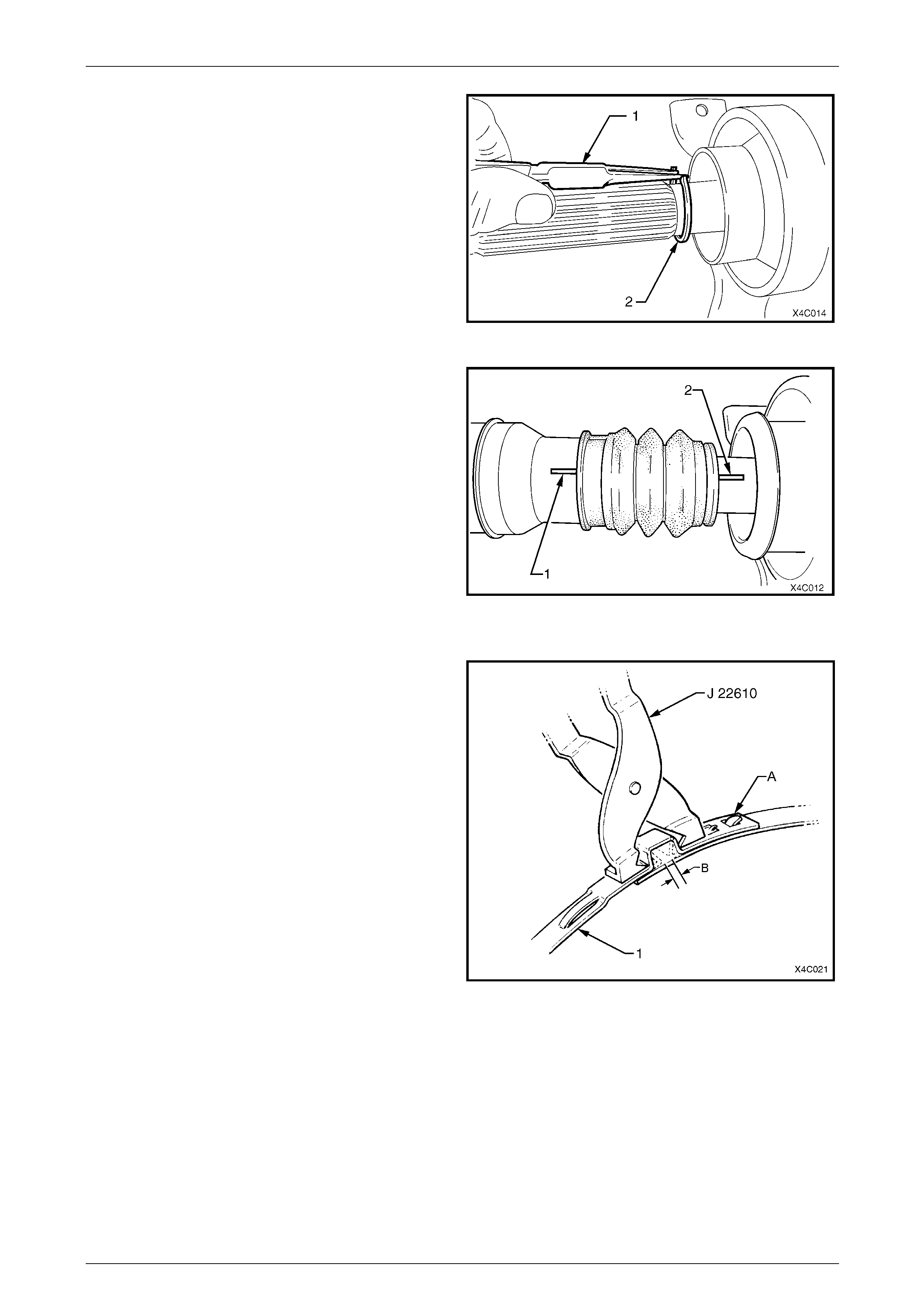
8 With the boot and ring assembly located correctly in
the grooved section of the front propeller shaft, install
a NEW retaining clamp to secure.
9 After installing a new clamp around the boot and ring
assembly bend the tab over as shown by ‘A’ in Figure
4C1-60.
10 Using keystone clamp pliers such as J 22610 (Also
released as E1896 and 3A13) or commercial
equivalent, tighten the clamp (1) until the g ap ‘B’ is
from 1 – 2 mm.
11 Install the propeller shaft assembly.
Refer to 2.1 Propeller Shaft, in this Section.
Figure 4C1 – 60
Rear Propeller Shaft and Universal Joints 4C1 – 37
4C1 – 37
AWD Wagon Models NOTE
• This bearing cannot be removed from the
propeller shaft without causin g damage to the
rubber ball race carrier and housing
assembly. New parts must be installed when
the propeller shaft is being reassembled.
• The replacement centre bearing kit contains
front and rear dust slingers, centre bearing
and rubber cup assembly.
Remove
1 Remove propeller shaft, refer to 2.1 Propeller Shaft in this Section.
2 Remove constant velocity joint, refer to 2.3 Centre Constant Velocity Joint (Plunge Type) –AWD Wagon, in this
Section.
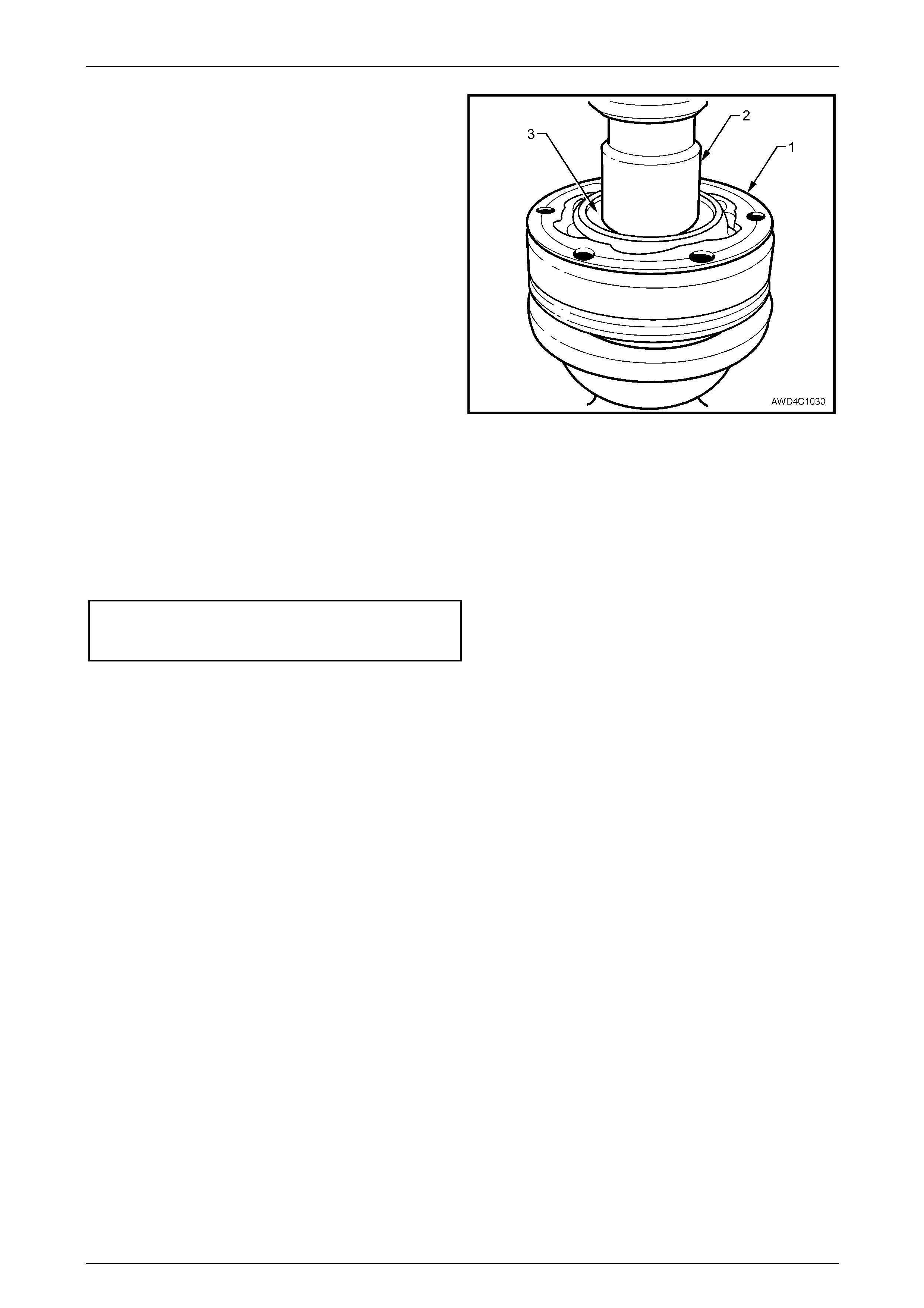
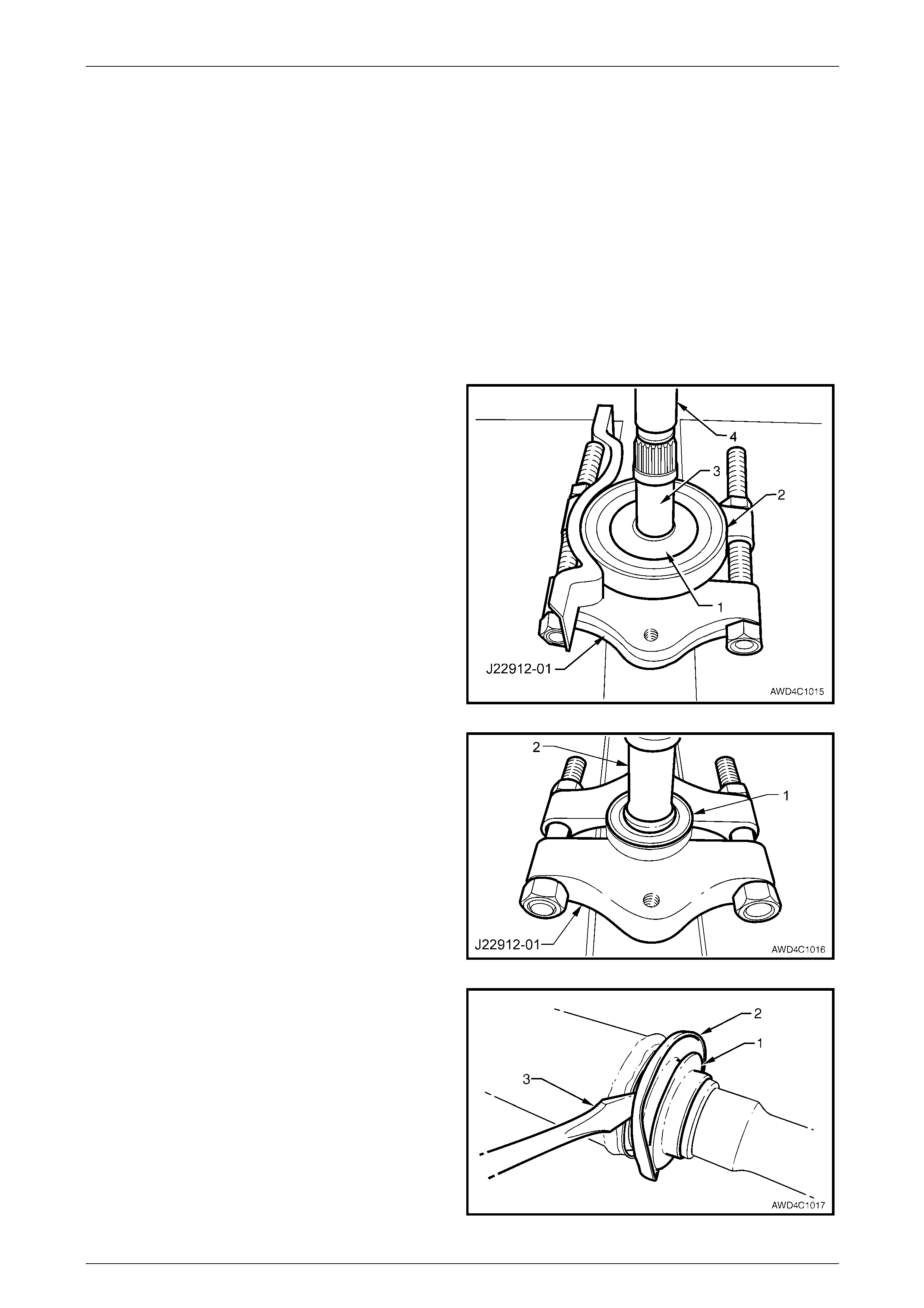
3 Using suitable press plates, such as J22 91 2-01 or
equivalent and a suitable drift (4), support rubber ball
race carrier and housing asse mbly (2), then press the
propeller shaft (3) from the rear slinger (1) and rubber
ball race carrier and housi ng assembly (2).
NOTE
This action will separate the bearing from the
rubber support, requiring the replacement of the
complete assembly.
Figure 4C1 – 61
4 Support the centre bearing (1 ) with suitable press
plates such as J22912-01, then press the propeller
shaft front half (2) from the bearing. Discard the
bearing (1) following removal.
Figure 4C1 – 62
5 If required, remove centre bearing front slingers (1 and
2), using a suitable lever (3), such as a flat bladed
screwdriver. NOTE
The slingers will be distorted during remov al and
must be replaced with new parts on reassembly.
Figure 4C1 – 63
Rear Propeller Shaft and Universal Joints 4C1 – 38
4C1 – 38
Reinstall
1 Install new front slingers (one at a time), onto front half
of the propeller shaft using J5590 or a suitable sized
tube.
During this reinstallation proce ss, ensure that th e
front of the propeller shaft (2) is supported on a
suitable length of tube (1) (dimensions; 48 mm
OD, 32 mm ID and at least 30 mm long), as
shown.
Figure 4C1 – 64
2 Reinstall new centre bearing assembly (1) to propeller
shaft (2) using installer J21426 or a suitable size tube.
NOTE
Only apply press force to the centre ball race.
Figure 4C1 – 65
3 Again using installer J2 1426 or a suitable size tube,
install a new slinger (1) to the centre be aring, as
shown.
Figure 4C1 – 66
4 Reinstall centre constant velocity joint. Refer to 2.3 Centre Constant Velocity Joint (Plunge Type) –AWD Wagon, in
this Section.
5 Reinstall the rear propeller sh aft assembly. Refer 2.1 Propeller Shaft in this Section.
Rear Propeller Shaft and Universal Joints 4C1 – 39
4C1 – 39
All VZ With a Live Axle
Remove
NOTE
The centre bearing cannot be removed from the
propeller shaft without causing damage to the
ball race and dust slinger. New parts must be
installed when the propeller shaft is being
reassembled.
1 Remove the propeller shaft.
Refer to 2.1 Propeller Shaft in this Section.
2 Remove the centre constant velocity joint, rubber b oot
and dust shield. Refer to 2.4 Centre Constant Velocity
Joint (Fixed Type) – Live Axle Models) in this Section.
3 Remove the centre bearing ca rrier retaining nuts (2)
and bolts (3), the support carrier strap (1) and the heat
shield (4), if fitted.
4 Separate the centre bearing cup guide halves (5 and
6), then remove them from the centre bearing
assembly. Figure 4C1 – 67
NOTE
The centre bearing rear slinger once removed,
must be discarded. A new part MUST be
installed when the propeller shaft is being
reassembled.
5 Using a hammer and suitable punch, remove the rear
slinger (1) by tapping the edge of the slin ger evenly
away from the centre bearing (2).
Figure 4C1 – 68
6 Remove the retaining circlip (1) from the centre
bearing (2), using suitable circlip pliers.
Figure 4C1 – 69
Rear Propeller Shaft and Universal Joints 4C1 – 40
4C1 – 40
7 Using Tool No. J 22912-01 to support the centre
bearing (1), press the propeller shaft spindle (2) from
the centre bearing (1).
Figure 4C1 – 70
NOTE
The centre bearing front slinger once removed
must be discarded. A new part MUST be
installed when the propeller shaft is being
reassembled.
8 Using a hammer and suitable punch, remove the front
slinger (1) by tapping the edge of the slin ger evenly
away from propeller shaft spindle (2).
Figure 4C1 – 71
Rear Propeller Shaft and Universal Joints 4C1 – 41
4C1 – 41
Replace
1 Install a new front slinger (1) onto the propeller shaft
spindle (2) using a suitable tub e (3).
Figure 4C1 – 72
2 Install a new centre bearing (1) onto the propeller shaft
spindle (2) using a suitable tub e (3).
Figure 4C1 – 73
3 Install a new retaining circlip (1) to the centre bearing
(2).
Figure 4C1 – 74
Rear Propeller Shaft and Universal Joints 4C1 – 42
4C1 – 42
NOTE
Ensure the rear slinger is not installed too far
onto the propeller shaft spindle, as the slinger
and centre-bearing cup will rub.
4 Install a new rear slinger (1) onto the propeller shaft
spindle (2) using a suitable tub e (3).
Figure 4C1 – 75
5 Install the centre constant velocity joint, rubber boot
and dust shield. Refer to 2.4 Centre Constant Velocity
Joint (Fixed Type) – Live Axle Models) in this Section.
6 Assemble the centre bearing cup gu ide halves (5 and
6), install the heat shield (4) (if removed) and support
carrier strap (1), securing all with the two bolts (3) and
nuts (2).
7 Tighten the carrier bracket attaching bolts (3) and nuts
(2) to the correct torque specification.
Centre bearing upper carrier bracket to
lower carrier bracket attaching
bolt torque specification.......................................25 N.m
8 Reinstall the propeller shaft.
Refer to 2.1 Propeller Shaft in this Section.
Figure 4C1 – 76
Rear Propeller Shaft and Universal Joints 4C1 – 43
4C1 – 43
2.6 Fixed, Rear Constant Velocity Joint
LT Section No. – 05-050
NOTE
The rear propeller shaft, rear constant velocity
joint (constant velocity joint), fitted to AWD
Wagon models, is a “fixed” joint, which means
that any axial end play is minimal.
Remove
1 Remove rear propeller shaft from the vehicle. Refer to 2.1 Propeller Shaft, in this Section.
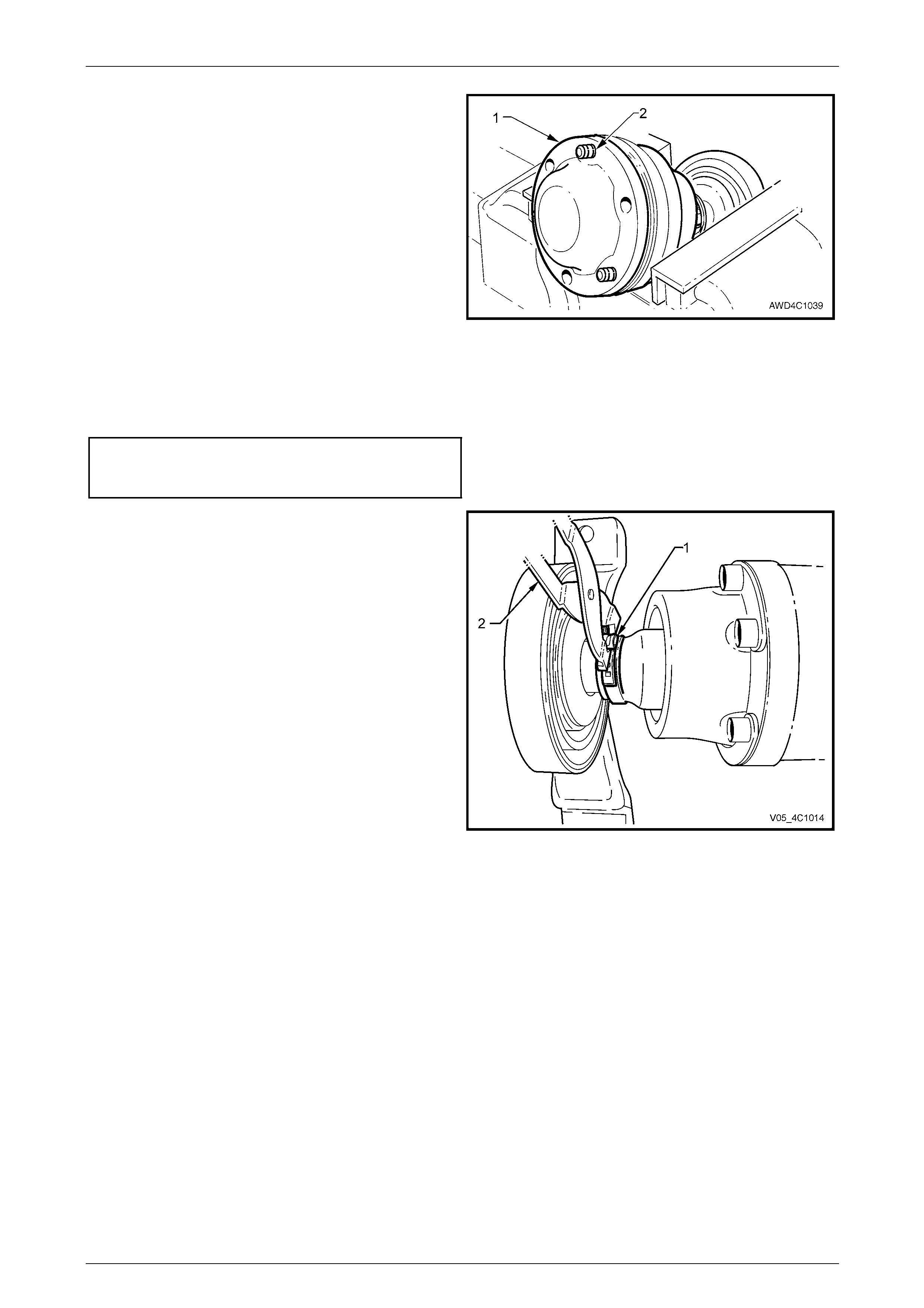
2 Using a small bladed screwdriver, lever up the boot
clamp tang to release, then remove and discard the
boot clamp (1).
Figure 4C1 – 77
3 Grip the constant velocity joint in a vice fitted with soft
jaws.
4 Using a suitable cold chisel and hammer, dislodge and
remove the crimped end cap from the end of the
constant velocity joint. Discard the removed end cap.
5 Reposition the constant velocity joint in the vice, to
allow access to the crimped dust boot cap, then
dislodge it, using the same cold chisel and hammer.
NOTE
Assuming that the constant velocity joint is to be
reinstalled, be careful not to damage the outer
race, during the cap removal process.
Figure 4C1 – 78
Rear Propeller Shaft and Universal Joints 4C1 – 44
4C1 – 44
6 Using suitable circlip pliers (1), remove the circlip (2)
from the end of the propeller shaft and discard.
NOTE
Do not re-use the circlip once it has been
removed. Always fit a new part on reassembly.
Figure 4C1 – 79
7 Push the cap and boot back along the propeller shaft,
enough to allow the fitment of press plates such as
J22912-01.
8 Support the constant velocity joint inner race (1) with
the press plates (22912-01) then, using a suitable
mandrel (2), press the propeller shaft from the
constant velocity joint.
9 Remove the boot and dust shield from the propeller
shaft, being careful not to damage the boot on the
propeller shaft splines.
Figure 4C1 – 80
Inspect
Propeller Shaft and Boot
1 Clean propeller shaft splines and boot, using suitable cleaning solv ent.
2 Inspect the propeller shaft splines for twisting, cracking or excessive wear. If any of these conditions are observed,
then the propeller shaft must be replaced.
3 Carefully inspect the boot and replace if split, fatigued, cracked or worn.
Rear Propeller Shaft and Universal Joints 4C1 – 45
4C1 – 45
Constant Velocity Joint
Complete disassembly of the constant
velocity joint is not recommended. The
internal components are a precision fit and
develop their own characteristic wear
patterns. The inter-mixing of components
could result in looseness, binding and/or
premature failure of th e jo int.
1 Remove the excess lubricant from the constant
velocity joint (1), wipe clean, then use correc t ion fluid
(2), to identify the relationship of the three joint
components.
2 Remove gasket (3) and discard.
Figure 4C1 – 81
3 Inspect grease in joint, and if obviousl y contaminated
and/or been subjected to dirt ingress, the joint has in
all likelihood suffered damage and should be replaced.
If inspection reveals that the joint has not been
contaminated, clean joint by soaking in a suitable
cleaning solvent.
4 Once grease has been removed, insp ect internal
components by tilting inner race to one si de to expose
each ball.
NOTE
Take care not to pivot the inner race too sha rply,
as the balls can become dislodged. If this does
occur and the original l ocation of the balls is lost,
then the constant velocity joint should be
replaced.
5 Replace joint assembly if there is severe pitting,
galling, play bet ween balls and the cage windows, any
cracking or damage to cage, pitting or galling or chips
in raceways. Figure 4C1 – 82
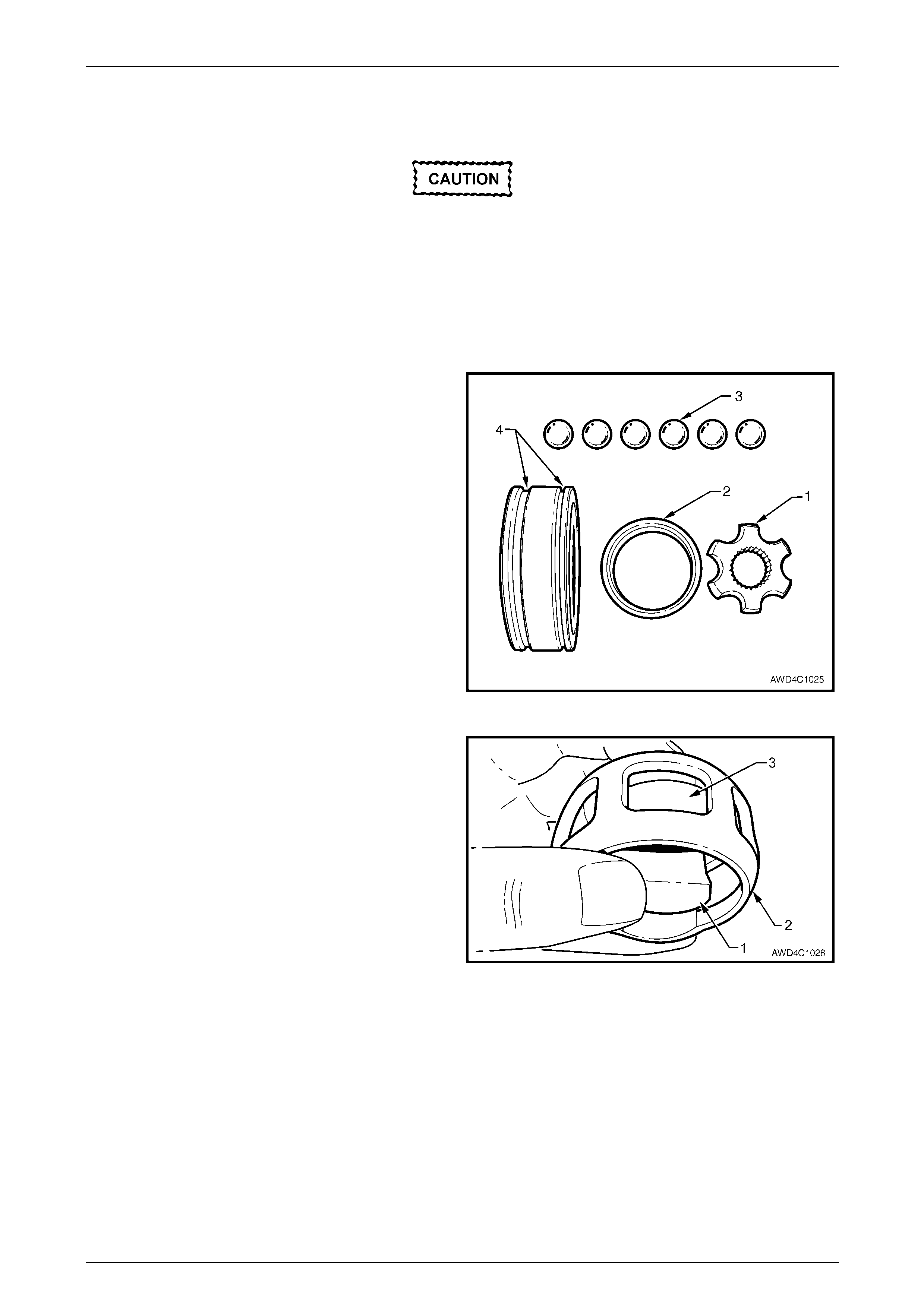
Rear Propeller Shaft and Universal Joints 4C1 – 46
4C1 – 46
Reassemble
During the removal, cleaning, inspection or
replacement of a constant velocity joint, it is
possible for the joint to become
disassembled. Should an inadvertent
disassembly of a constant velocity joint
occur, and notwithstanding the earlier
recommendation, it is possible to reassemble
the constant velocity joint, provided the
following procedure is followed EXACTLY.
As shown in the exploded view of the fixed constant velocity
joint, two grooves (4) are provided on the outer race for the
crimped dust covers – the wide one is to receive the front
cover and boot assembly, while the narrow groove is for the
rear cover.
The fact that the ball grooves in both the outer and inner
races are equally spaced, identifies this con s tant velocity
joint as a “fixed” type. Note also the fine gr oove on the front
edge of the ball cage and the larger, plain chamfer on the
rear.
NOTE
• The inner race (1) and cage (2), together with
the individual balls (3), must be maintained in
their original locations to minimise the
creation of a noisy joint.
• Under no circumstances are components
from one constant velocity joint to be mixed
with components from another constant
velocity joint. Figure 4C1 – 83
1 With the inner race (1) at 90° to the ball cage (2),
insert one 'leg' (3) of the inner race into one of the ball
holes, then manipulate the inner race unti l installed
inside the ball cage. Check that the relatio nship marks
are both on the same side.
NOTE
The fine groove on the inner edge of the ball
cage and the chamfered spline edge, should
both be opposite the relationship marks.
Figure 4C1 – 84
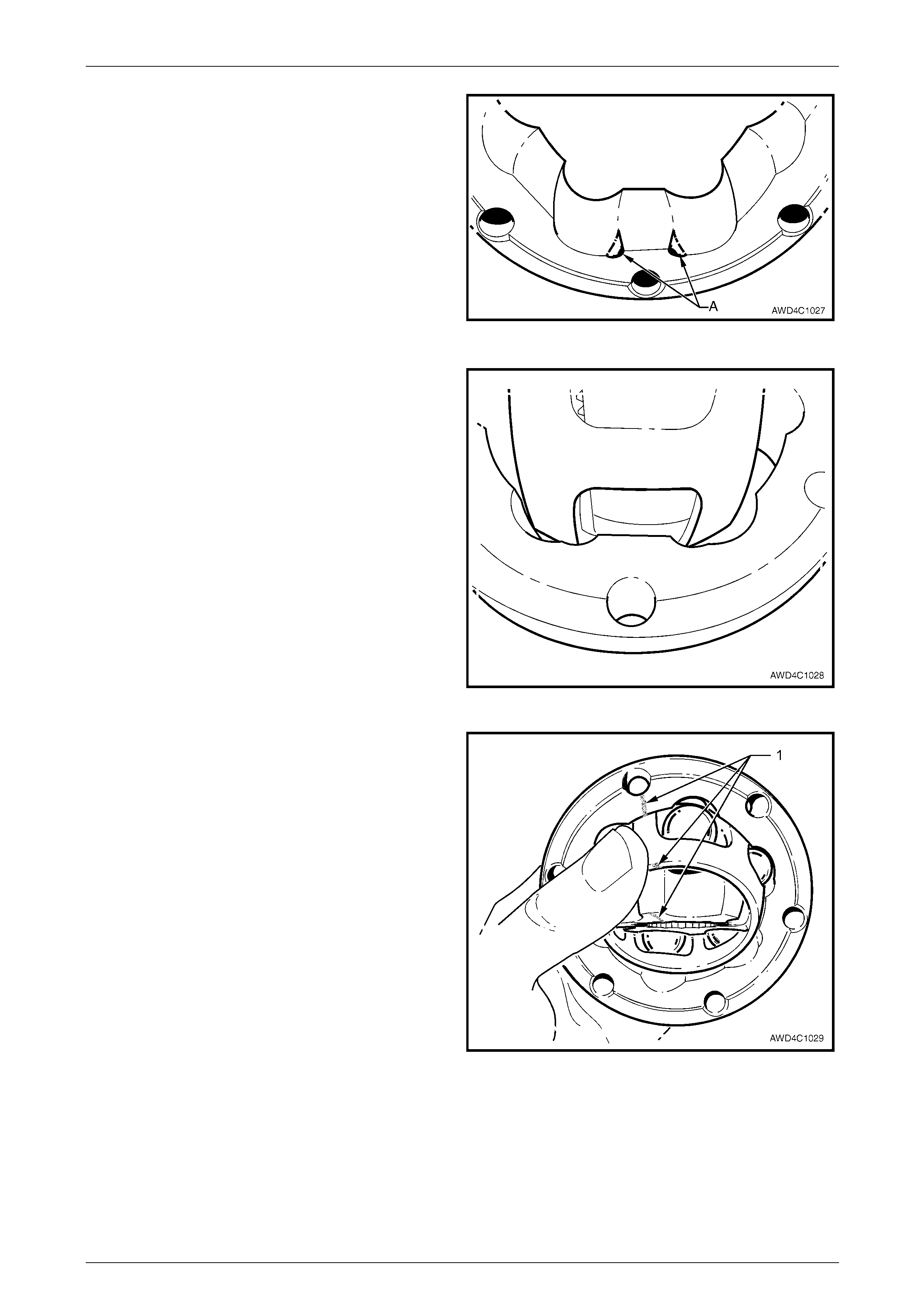
Rear Propeller Shaft and Universal Joints 4C1 – 47
4C1 – 47
2 Reinstall the ball cage and in ner race into the outer
race, following this next procedure:
a Locate the two reliefs in the ball grooves in the
outer race, indicated by 'A'. There will be similar
reliefs on the opposite side.
Figure 4C1 – 85
b With the ball cage and inner race at 90° to the
outer race, install at the relief points (as shown),
then manipulate the ball cage to fit inside the
outer race. Ensure that the relationship marks
are all on the same side and aligned.
Figure 4C1 – 86
3 Tilt the ball cage and inner race as shown, and fit the
balls, in their correct order, one at a time.
4 Check that the three relationship marks (1) are in
alignment.
5 Check that axial movement is minimal.
Figure 4C1 – 87
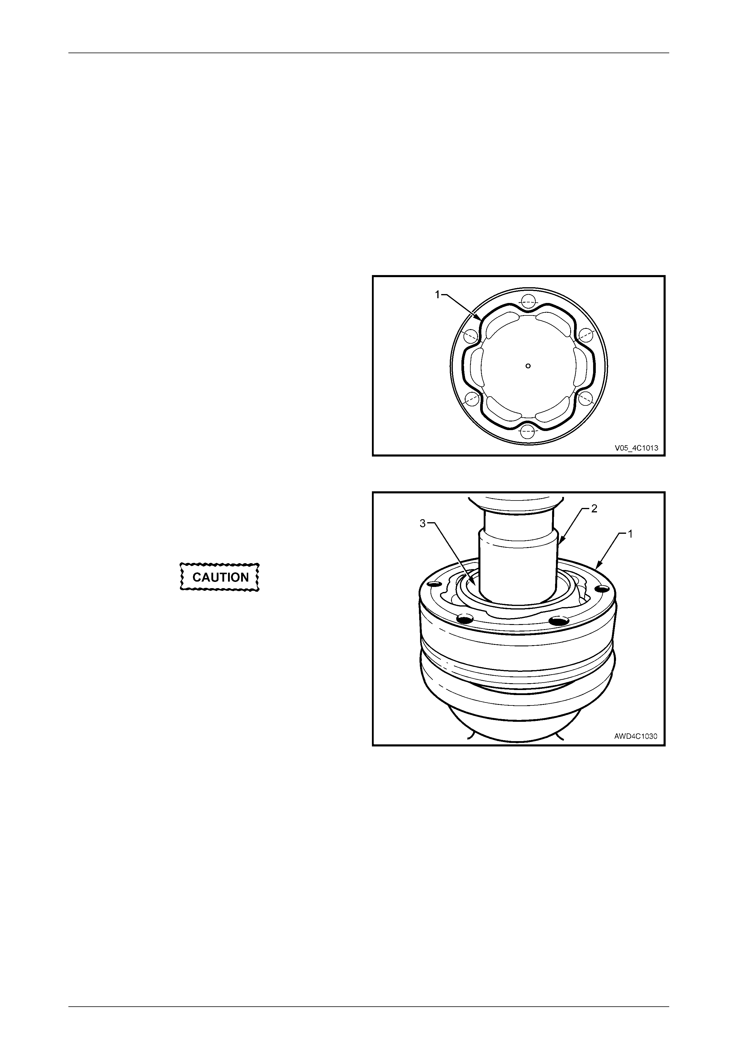
Rear Propeller Shaft and Universal Joints 4C1 – 48
4C1 – 48
Reinstall
Reinstallation is the reverse of removal procedure, noting the following points:
1 Cleanliness of constant velocity joint and associated parts is of prime importance to ensure maximum life of the
assembly.
2 Install a new small boot clamp over the spl in ed propeller shaft splines, then install the boot and dust shi eld
assembly, taking care not to damage the boot on the propeller shaft splines.
3 Pack the constant velocity joint with the majority of the 29 g lubricant supplied in either o f the two available Repair
Kits. Work joint by hand to distribute grease onto all surfaces inside the joint. Apply the remainder to the dust cover,
ensuring that the vent hole is not blocked with grease.
4 Clean mating surfaces of constant velocity joint, dust shield and rear propeller shaft companion flange.
5 Apply a 2 mm bead (1) of Loc tite 510 High
Temperature Gasket Eliminator sealant or equivalent,
to the grease cover mating surface. Take care not to
contaminate the constant velocity joint grease with
sealant.
Figure 4C1 – 88
6 Press constant velocity joint onto the rear propeller
shaft splines, using a suitable size socket or tube.
Ensure that socket or tube presses on inner race of
joint.
During this pressing operation, ensure that
the outer surface of the centre constant
velocity joint is supported by press plates
such as J22912-01 or equ ivalent.
7 Secure the constant velocity joint with a new circlip,
being careful not to over-exp and the circlip during the
installation process.
8 Install at least three of the rear constant velocity joint
Allen key headed bolts aligning the dust shield to the
constant velocity joint.
Figure 4C1 – 89
9 Using a plastic faced hammer, install the dust cap to the constant velocity joint.
10 Use keystone clamp pliers such as J22610 o r commercial equivale nt, to tighten the small boot clamp.
11 Reinstall new gasket to end of constant vel ocity joint.
12 Press the outer cover into place over the guide bolts, with press plates such as J22910-01 (or equivalen t)
supporting the dust shield, with a suitable sized sleeve acting on the outer edges of the end cap.
13 Reinstall propeller shaft. Refer to 2.1 Propeller Shaft, in this Section.
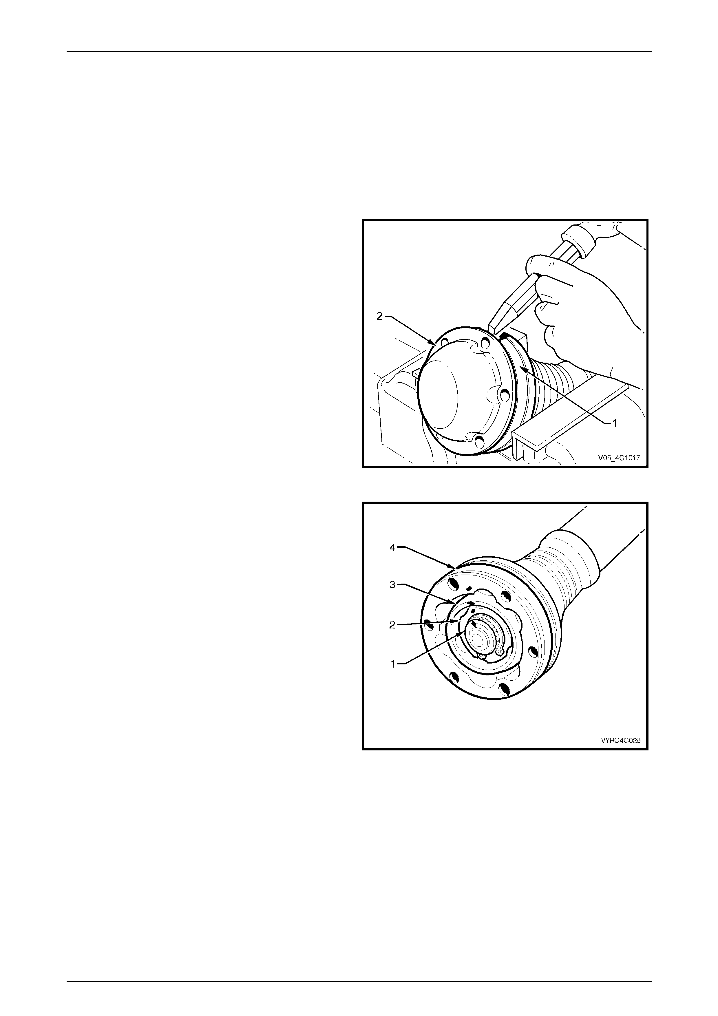
Rear Propeller Shaft and Universal Joints 4C1 – 49
4C1 – 49
2.7 Rear Plunge Type Constant Velocity
Joint – Live Axle Models
LT Section No: 05-050-1
Remove
1 Remove the propeller shaft. Refer to 2.1 Propeller Shaft in this Section.
2 Support the constant velocity joint body (1) in a vice
fitted with protective soft metal jaws.
3 Using a suitable cold chisel and hammer, dislodge and
remove the crimped end cap from the end of the
constant velocity joint. Discard the removed end cap.
Figure 4C1 – 90
4 Remove excess grease and wipe clean before placing
a daub of paint to mark the relationships of the
propeller shaft spindle (1), inner race (2), ball guide (3)
and outer race (4).
Figure 4C1 – 91
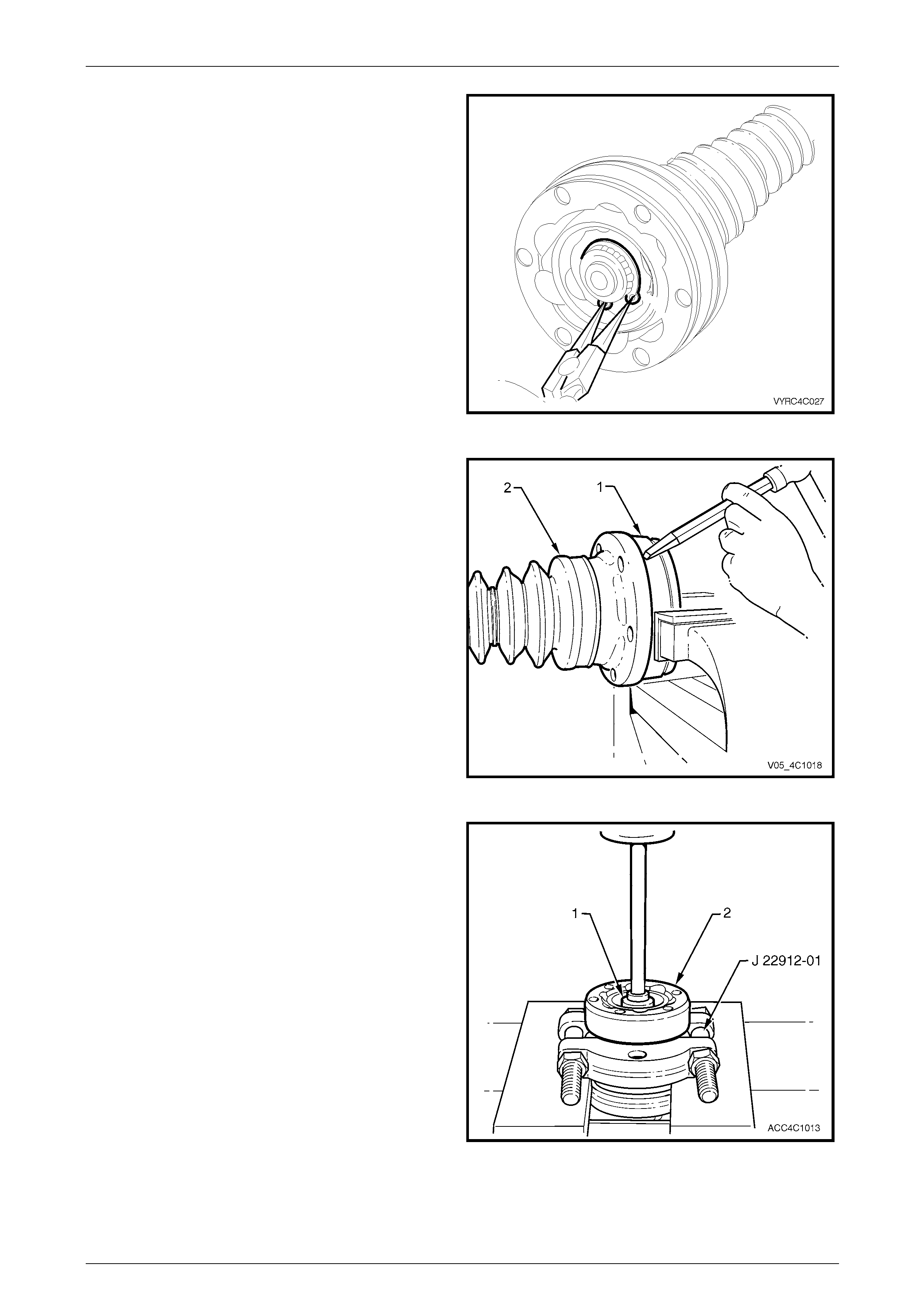
Rear Propeller Shaft and Universal Joints 4C1 – 50
4C1 – 50
5 Using suitable circlip pliers, re move the constant
velocity joint, rear-retaining circlip.
Figure 4C1 – 92
6 Support the constant velocity joint body (1) in a vice
fitted with protective soft metal jaws, with the
remainder of the propeller shaft resting on the bench
top.
7 Using a suitable cold chisel and hammer, dislodge and
remove the dust cover and rubber boot assembly (2)
from the body of the constant velocity joint (1).
8 Push the dust cover and rubber boot assembl y back
toward the propeller shaft centre bearing.
Figure 4C1 – 93
9 Support the constant velocity joint with press plates,
Tool No J 22912-01 and pr ess the propeller shaft
spindle (1) from the constant velocity joint (2).
Figure 4C1 – 94
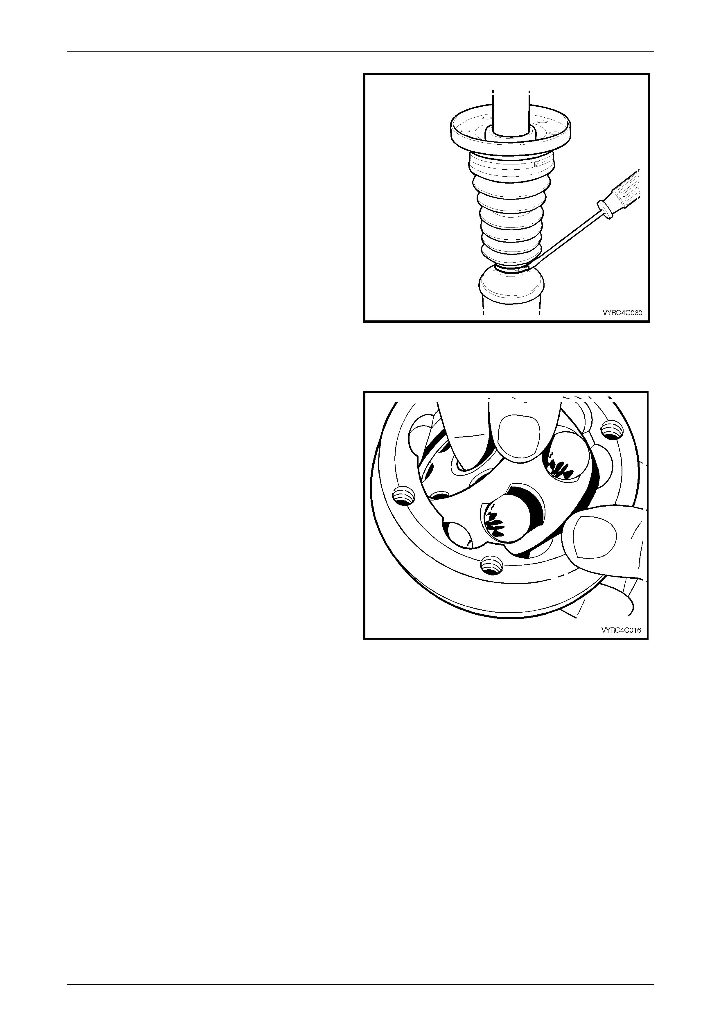
Rear Propeller Shaft and Universal Joints 4C1 – 51
4C1 – 51
10 Remove the dust shield and rubber boot assembly
retaining clamp. Remove the boot and dust shield
assembly from the propeller shaft.
Figure 4C1 – 95
Inspect
1 Inspect the grease in the joint for signs of
contamination. If contamination is present then the
constant velocity joint will hav e probably suffered
damage and should be replaced.
2 If no contamination is evident , clean the joint by
soaking it in a suitable cleaning solvent.
NOTE
If there is severe pitting, galling, play between
the balls and the cage windows, cracking or
damage to the cage, pitting or gall ing or chips in
the raceways, replace the constant velocity joint.
3 Inspect the internal components b y tilting the inner
race to one side to expose each bal l individually, while
observing the condition of each component.
Figure 4C1 – 96
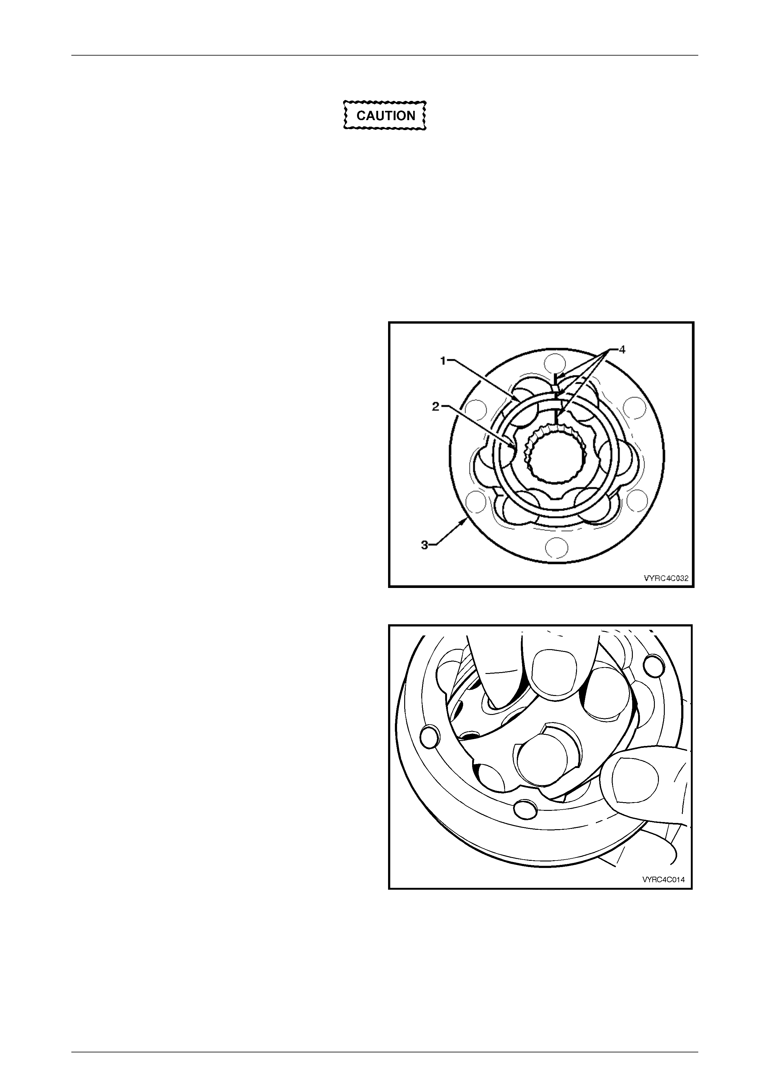
Rear Propeller Shaft and Universal Joints 4C1 – 52
4C1 – 52
Disassemble
Disassembly of the constant velocity joint
beyond this point is not recommended. The
internal components are a precision fit and
during operation develop their own
characteristic wear patterns. Intermixing of
components could result in looseness,
binding and/or subsequent premature failure
of the constant velocity joint.
If disassembly must be attempted, then each
component of the joint must be returned to its
original orientation.
1 Ensure the aligning marks (4) made in step four of the
removal procedure are maintained at all times during
this procedure.
2 Obtain a piece of wood or suitable tray with enou gh
depressions in the surface to accommodate the six
balls of the joint, marking one divot to indicate the ball
closest to the alignment marks to retain the or iginal
orientation of each ball to joint.
Figure 4C1 – 97
3 Taking care not to dislodge any b alls from the joint,
pivot the inner race and ball guide at 90º to the centre
line of the outer race and lift the inner race and ball
guide from the outer race.
Figure 4C1 – 98
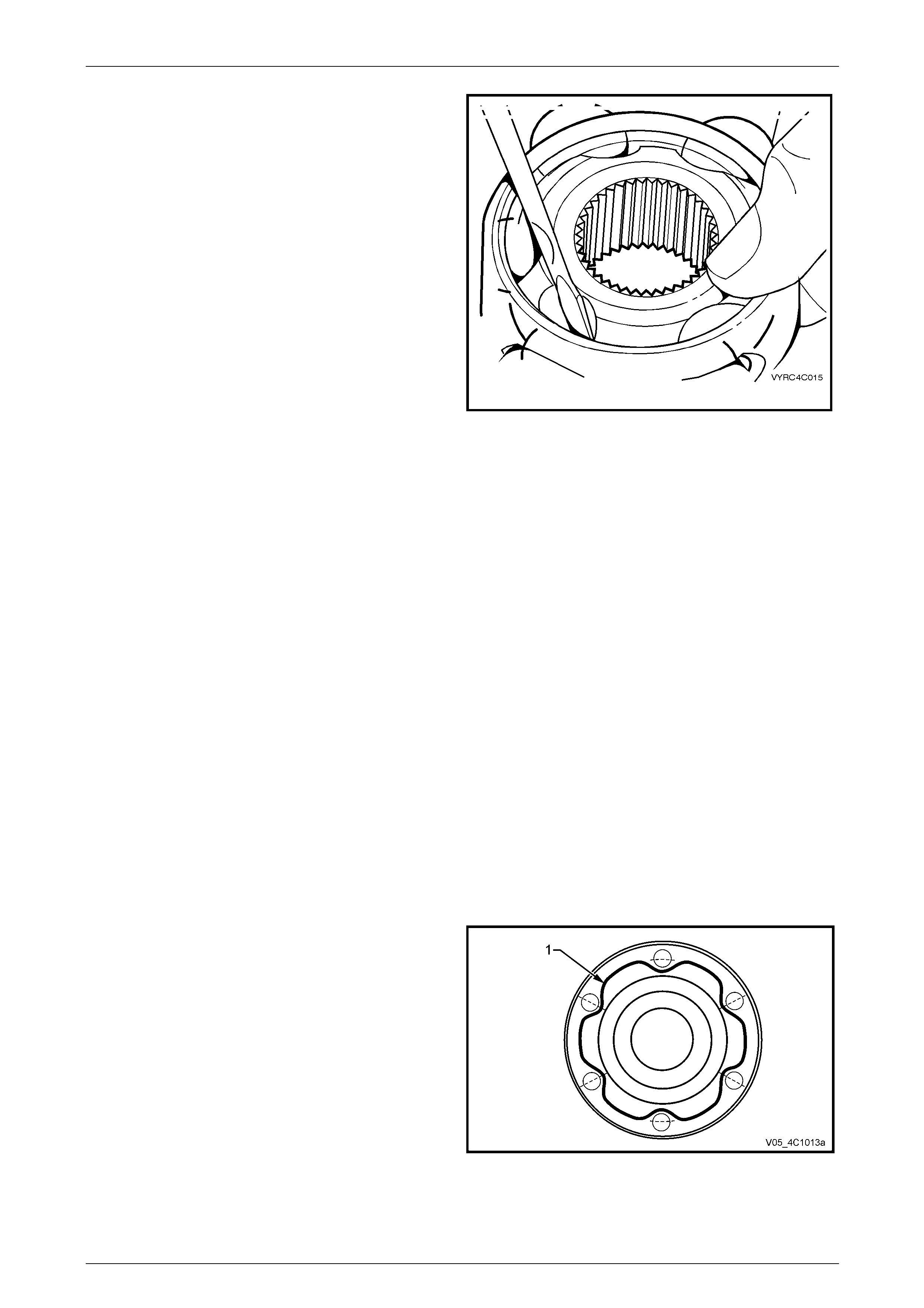
Rear Propeller Shaft and Universal Joints 4C1 – 53
4C1 – 53
4 Using a screwdriver if required as a lever, remove
each ball in order from the ball guide an d place the
balls on to the previously obtain piece of wood or tray
as detailed in step 2 of this procedure.
5 Pivot the inner race 90º to the centre line of the ball
guide and lift the inner race from the ball gui de.
Figure 4C1 – 99
Reassemble
The reassembly procedure for the constant velocity joint is the reverse of the disassembly procedure, noting the following
points:
1 Ensure all alignment marks are ali gned to return all components to their original orientation.
2 Check the multi-direction movement of the constant velocity joint for binding or restriction.
3 Check the plunge movement for the constant velocity joint.
4 Ensure the reassembled constant velocity joint is kept free from contamination until required for reinstallation to the
propeller shaft.
Reinstall
The installation procedure is the reverse of the removal procedure, noting the following points:
1 Ensure the constant velocity joint and associated parts are clean to ensure maximum life expectancy.
2 Inspect the dust shield and boot assembly for cracks, tears or damage, replacing if necessary, then install it and a
new small clamp to the front propeller shaft spindle.
3 Pack half (~105 g) of the lubricating grease supplied with the kit, into the boot, then work approximately 120 g
thoroughly into the constant v elocity joint. Apply the remaining 5 g of lubricant into the end grease cover, ensuring
that the vent hole is not covered.
4 Prior to pressing the constant velocity joint onto the front propeller shaft spindle, ensure all alignment marks are in
their original orientation.
5 Ensure the mating surfaces of the constant velocity
joint, dust shield and rubber boot assembly are clean.
6 Apply a 2 mm bead (1) of Loc tite 510 High
Temperature Gasket Eliminator sealant or equivalent,
to the grease cover mating surface. Take care not to
contaminate the constant velocity joint grease with
sealant.
Figure 4C1 – 100
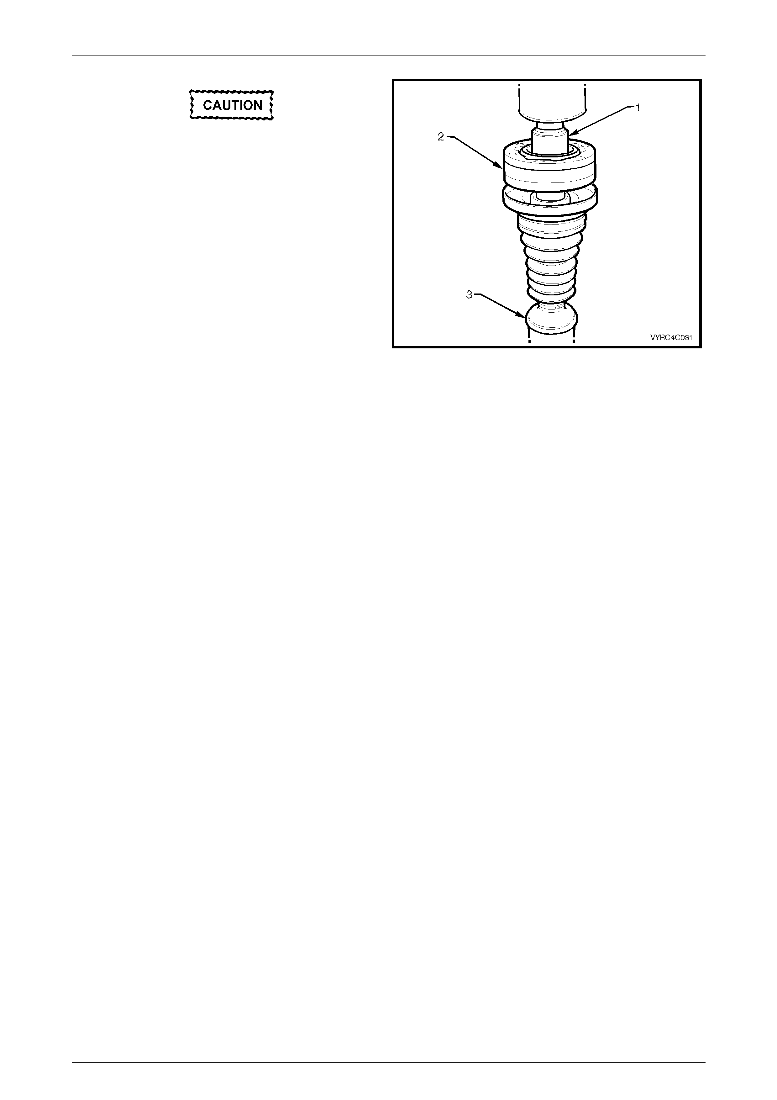
Rear Propeller Shaft and Universal Joints 4C1 – 54
4C1 – 54
Support the centre constant velocity joint
with press plate such as J 22912-01, under
the six Allen key headed attaching bolts
before pressing the rear constant velocity
joint onto the rear propeller shaft half.
7 Using a suitable socket or tube (1), press the constant
velocity joint (2) onto the propeller s haft (3), spindle
while ensuring the socket or tube presses on the inner
race of the joint only.
8 Secure the constant velocity joint with a new circlip,
being careful not to over-exp and the circlip during the
installation process.
Figure 4C1 – 101
9 Install at least three of the rear constant velocity joint Torx bit head ed bolts to align the dust shield and boot
assembly to the constant velocity joint.
10 Using a plastic faced hammer, install the dust cap to the constant velocity joint.
11 Install a new gasket between the consta nt velocity joint and the rear grease cover.
12 Install the rubber boot to propeller shaft spin dle retaining clamp.
13 After locating the boot into the recess in the dust boot groove, install and tighten the new clamp, using keystone
clamp pliers such as J 22610 or commercial equivalent.
14 Press the grease cover into place over the g uid e bolts, with press plates such as J 22912-01 (or equivalent)
supporting the dust shield, with a suitable sized sleeve acting on the outer edges of the end cap.
15 Reinstall the propeller shaft, as detailed in 2.1 Propeller Shaft in this Section.
Rear Propeller Shaft and Universal Joints 4C1 – 55
4C1 – 55
3 Specifications
Propeller Shaft Identification
Refer to the digit identification letters on the tag attached to the rear propeller shaft tube and the following table.
Body Style Engine Transmission I.D. Code
SWB Sedan/Coupe Alloytec (LE0) 6 Speed Manual (MV5) NH
Station Wagon (2WD)/ Utility Alloytec (LE0) 6 Speed Manual (MV5) NJ
SWB Sedan/Coupe Alloytec (LE0) or
Alloytec 190 (LY7) 4L60-E Automatic (M30) NW
Station Wagon (2WD)/ Utility Alloytec (LE0) or
Alloytec 190 (LY7) 4L60-E Automatic (M30) NX
SWB Sedan/Coupe GEN III V8 (LS1) 6 Speed Manual (MM6)/4L60-E Automatic (M30) NE
Station Wagon (2WD)/ Utility GEN III V8 (LS1) 6 Speed Manual (MM6)/4L60-E Automatic (M30) NF
SWB Sedan/Coupe Alloytec 190 (LY7) 5L40-E Automatic Transmission (M82) NZ
Regular Cab/Cre w Cab (2WD) Alloytec (LE0) 4L60-E Automatic (M30) NN
Regular Cab/Crew Cab (2WD) Alloytec (LE0) 6 Speed Manual (MV5) NT
Regular Cab/Crew Cab (2WD) GEN III V8 (LS1) 4L65-E Automatic (M32) JV
Regular Cab/Cre w Cab (AWD) Alloytec (LE0) 4L60-E Automatic (MK2) 6827U
Regular Cab/Crew Cab (AWD) GEN III V8 (LS1) 6 Speed Manual (MM6) MG
Regular Cab/Crew Cab (AWD) GEN III V8 (LS1) 4L65-E Automatic (MD6) 6827U
AWD Wagon Alloytec 190 (LY7) 5L40-E Automatic Transmission (M82) JY
AWD Wagon GEN III V8 (LS1) 4L60-E Automatic (M30) JY
Centre Bearing
Type.........................................................................Rubber Mounted – Single Row Ball Race
Lubrication.........................................................................................................Sealed for Life
Universal Joints
Front (All Model Variants) .......................................................................................Rubber Coupling
Centre (All Models with RWD and IRS)..................................................Non-Serviceable Cross Type
Constant Velocity (AWD Wagon).......................................................Plunge Type with 6 Balls
Constant Velocity (Live Axle Variants).................................................Fixed Type with 6 Balls
Rear (All Models with RWD and IRS).....................................................................Rubber Coupling
Constant Velocity (AWD Wagon).........................................................Fixed Type with 6 Balls
Constant Velocity (Live Axle Variants)...............................................Plunge Type with 6 Balls
Constant Velocity Joint – Lubricant Quantity
Centre Plunge Type .....................................................................................................45 ± 2.5 grams
Fixed Type........................................................................................................36 ± 2.5 grams
Rear Fixed Type........................................................................................................29 ± 2.5 grams
Plunge Type ....................................................................................................230 ± 10 grams
Sealants and Thread Sealing Compound
Constant Velocity Joint to Dust Shield...............................................Loctite 510 or equivalent
Propeller Shaft Fasteners (refer to text).............................................Loctite 242 or equivalent

Rear Propeller Shaft and Universal Joints 4C1 – 56
4C1 – 56
4 Torque Wrench Specifications
ATTENTION
Fasteners must be repl aced after loosening.
Vehicle must be at curb height before final tightening.
Fasteners either have micro encapsulated sealant applied or incorporate a mechanical thread lock and
should only be re-used once. If in doubt, replacement is recommended.
Centre Bearing Carrier to Underbody Reinforcement Bolt............................ 22 N.m
Centre bearing upper carrier bracket to lower bracket attaching bolt ...........25 N.m
Centre Constant Velocity Joint to Rear Propeller Shaft Flange Bolt.............35 N.m
Front Rubber Coupling to Transmission Output Flange Bolt......................115 N.m
Front Rubber Coupling to Transmission Output Flange Bolt and Nut.........115 N.m
Front Rubber Coupling to Transmission Output Flange Nut.........................85 N.m
Propeller Shaft To Rubber Coupling Nut.................... 20 N.m , then 55° turn angle
Rear Constant Velocity Joint to Pinion Flange Bolt (V6 Engine).................38 N.m
(GEN III V8 Engine)....68 N.m
Rear Rubber Coupling to Pinion Flange Bolt..............................................115 N.m
Rubber Coupling to Transfer Case Output Shaft Flange Nut .......................85 N.m
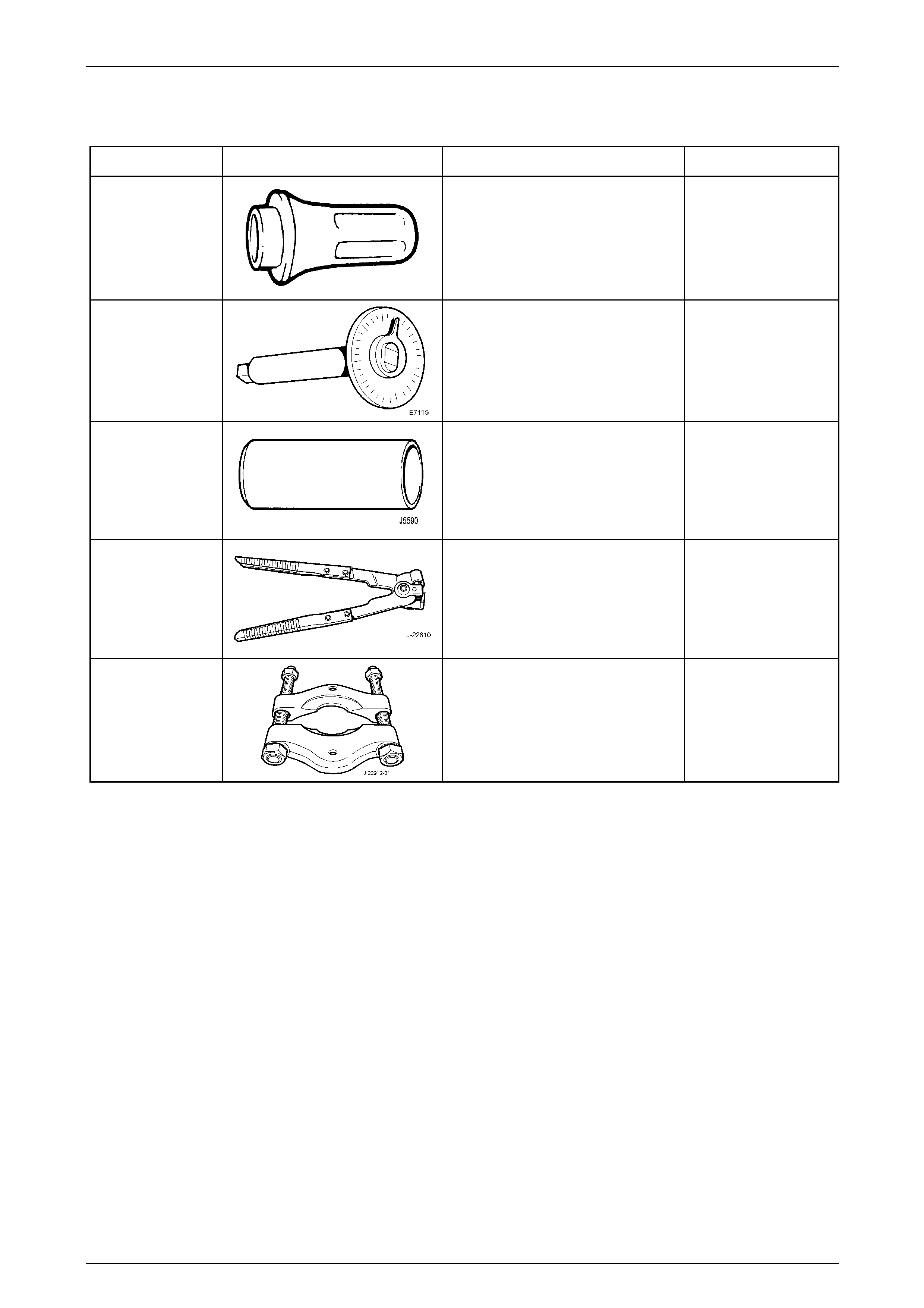
Rear Propeller Shaft and Universal Joints 4C1 – 57
4C1 – 57
5 Special Tools
Tool Number Illustration Description Tool Classification
J21426
Installer
Used to install the centre bearing and
outer slinger to the rear propeller
shaft.
Previously released.
Unique
E7115
Angle Wrench
Used to tighten fasteners when an
angle torque is specified. Also
released as BT 8653-A
Previously released.
Unique
J5590
Press Tube
Used to install centre bearing slingers.
Previously released.
Unique
J22610
Keystone Clamp Pliers
Used to tighten the constant velocity
joint boot clamps. Also released as
E 1896 and 3A13.
Previously released
Desirable
J22912-01
Press Plates
Also released as E6673
Previously released.
Desirable