
Leaf Spring Rear Suspension Page 4A2 – 1
Section 4A2
Leaf Spring Rear Suspension
ATTENTION
Before performing any Service Operation or other procedure described in this Section, refer to Section 00
Warnings, Cautions and Notes for correct workshop practices with regard to safety and/or property damage.
1 General Information ...............................................................................................................................2
1.1 Mass Dampers........................................................................................................................................................ 3
2 Service Operations.................................................................................................................................4
2.1 Service Warnings, Cautions and Notes............................................................................................................... 4
2.2 Suspension and Trim Height, Check.................................................................................................................... 5
2.3 Mass Dampers........................................................................................................................................................ 6
Remove................................................................................................................................................................... 6
Reinstall.................................................................................................................................................................. 7
2.4 Rear Axle Rear Cover............................................................................................................................................ 8
3 Specifications.........................................................................................................................................9
4 Torque Wrench Specifications............................................................................................................10
Page 4A2 – 1
Leaf Spring Rear Suspension Page 4A2 – 2
1 General Information
The rear suspension fitted to MY 2006 VZ Update Models with a live axle, incorporates two multiple leaf spring
assemblies in conjunction with shock absorbers as standard equipment. The rear suspension system pr ovides support
and control of the movement of the rear axle assembly during vehicle motion and when stationary.
Compared to earlier models, there have been some revisions made to the rear suspension fitted to Crew Cab vehicles to
improve noise and vibration characteristics.
These changes are:
• Deletion of the rear stabiliser bar on a ll Crew Cab variants.
• V6 Crew Cab vehicles have had the mass dampers moved from the leaf springs to the final drive rear cover. T his
has involved the fitment of a modified IRS design, final drive cover to provide the mo unting point for the dampers,
in conjunction with a ‘C’ brack et.
• Modifications have also been made to the front suspension (refer to Section 3A Front Suspension).
The final drive ratio on V6 Cre w Cab with manual transmission has reverted to a ratio of 3.08:1 (refer to Section 4B2
Rear Final Drive and Live A xl e). This commonises the ratio between the automatic and manual transmission variants of
V6 Crew Cab vehicles.
Apart from the changes enumerated above, the remainder of the rear suspension carries over from earli er mode ls.
Therefore for service operations not detailed here, refer to MY2005 VZ, Section 4A2 Leaf Spring Rear Suspension or
with Independent Rear Suspension models, refer to Section 4A1 Rear Suspension.
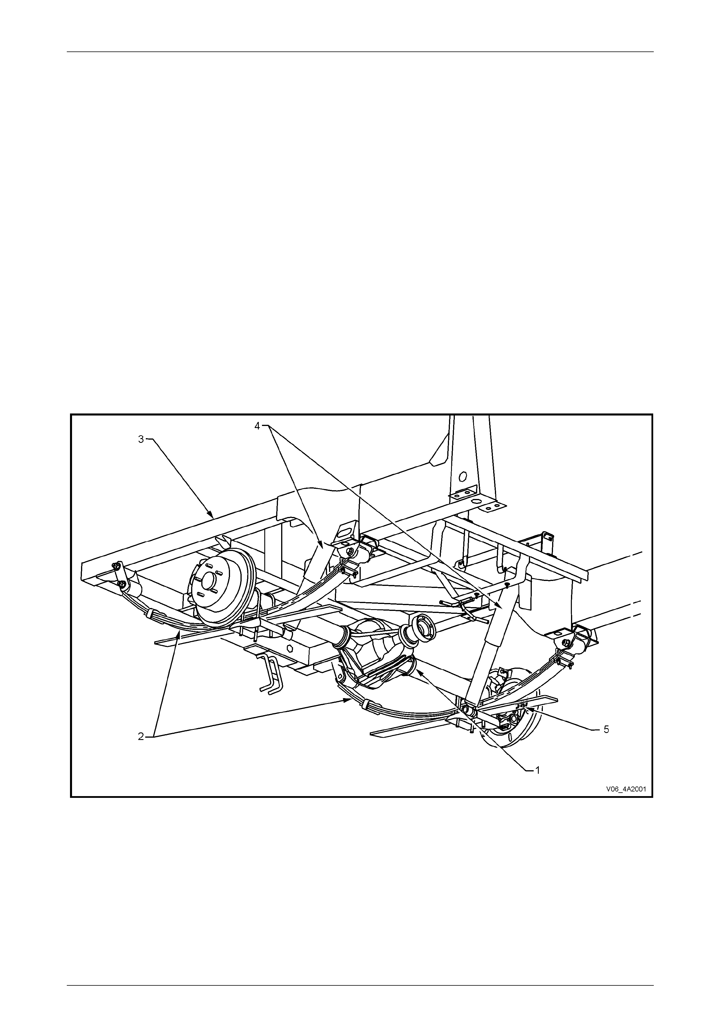
Figure 4A2 – 1
Legend
1 Rear Axle Assembly
2 Rear Leaf Spring Assembly
3 Rear Chassis
4 Rear Shock Absorber
5 Rear ABS Sensor
Page 4A2 – 2
Leaf Spring Rear Suspension Page 4A2 – 3
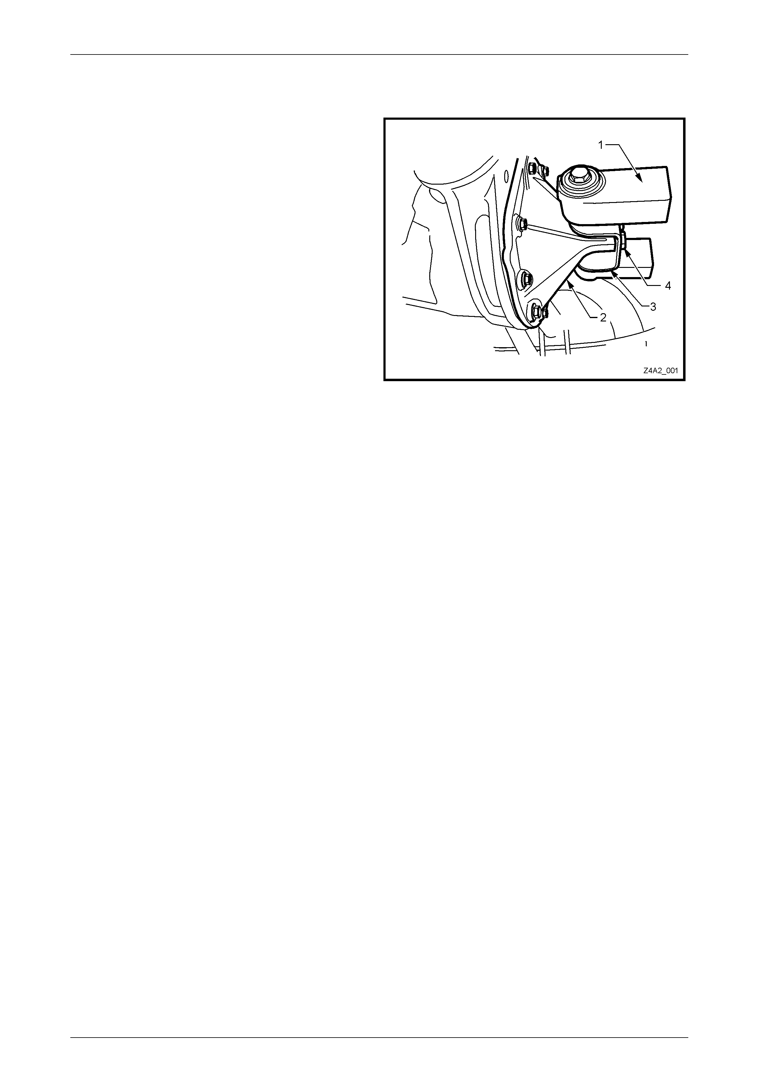
1.1 Mass Dampers
As stated, V6 Crew Cab V6 engined vehic les have had the
mass dampers (1) moved from the leaf springs to the rear
axle rear cover (2). This has involved the fitment of a
modified IRS design, final drive cover (2) to provide the
mounting point for the damper s, in conjunction with a ‘C’
bracket (3).
This ‘C’ bracket is secured to the rear axle rear cover by two
bolts (4), that are the same as those used in this location on
IRS rear suspension vehicles.
Figure 6A4 – 1
Page 4A2 – 3
Leaf Spring Rear Suspension Page 4A2 – 4
2 Service Operations
2.1 Service Warnings, Cautions and Notes
ATTENTION
All fasteners are important attaching parts as they affect the performance of vital components and/or could
result in major repair expense. W here specified in this section, fasteners MUST be replaced w ith parts of the
same part number or an app roved equivalent. Do not use fasteners of an inferior quality or substitute design.
Torque values must be used as specified during reassembly to ensure proper retention of all components.
Throughout this section, fastener torque wrench specifications may be accompanied with the following
identification marks:
Fasteners must be repl aced after loosening.
Vehicle must be at curb height before final tightening.
Fasteners either have micro encapsulated sealant applied or incorp orate a mechanical thread lock and
should only be re-used once. If in doubt, replacement is recommended.
If one of these identification marks is present alongside a fastener torque wrench specification, the
recommendation regarding that fastener must be adhered to.
ABS Components
• Whenever any component that forms part of the ABS (if fitted) is disturbed during Service
Operations, it is vital that the complete ABS system be checked, refer to Section 5B ABS.
Road Wheels
• Whenever a road w heel and/or brake di sc is removed from the vehicle, the relatio nship of the road
wheel and the disc to the hub MUST be marked with a felt tipped pen or similar, to allow those
parts to be reinstalled in their original positions. This is critical to minimise the brake disc and
road wheel runout dimension.
• When reinstalling road wheels, do not use
an impact gun to tighten wheel nuts
unless the impact gun is fitted with a
torque limiter socket (Tool No. AU 534 or
a commercial equivalent). Failure to
correctly tighten w heel nuts to the correct
torque specification and in the correct
order (as shown), may result in a
distorted brake disc, leading to the
development of brake shudder.
Road wheel attaching nut
torque specification.............................................. 125 Nm
Figure 4A2 – 2
Page 4A2 – 4

Leaf Spring Rear Suspension Page 4A2 – 6
2.3 Mass Dampers
LT Section No: 07-150
NOTE
Mass dampers are fitted to Crew Cab 2WD
vehicles fitted with the HFV6 engine and either
automatic or manual transmission var iants.
Remove
1 Using a floor jack under the centre of the rear axle assembly, raise the rear of vehicle and support on safety stands
under the rear axle tubes.
Take care when removing the last bracket
bolt, as the assembly is quite heavy.
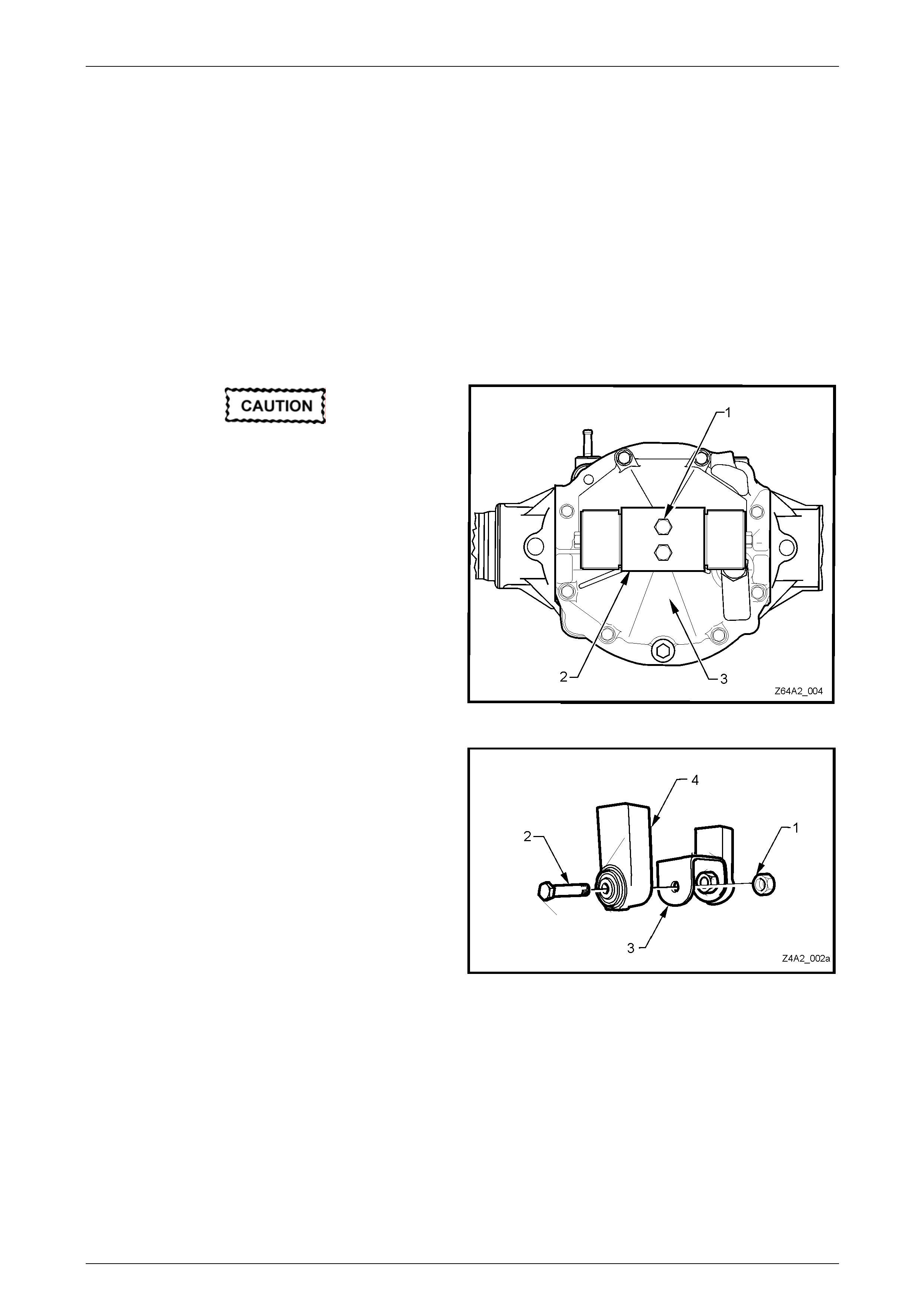
2 Remove the two bolts (1) holding the mounting bracket
and mass dampers (2) to the rear axle rear cover (3).
3 Remove the mass damper assembly (2) from the
vehicle.
NOTE
While the mass dampers can be replaced with
the mounting bracket still bolted to the rear
cover, it is recommended that the assembly be
removed and the damper/s be replaced while
working on the bench.
Figure 4A2 – 3
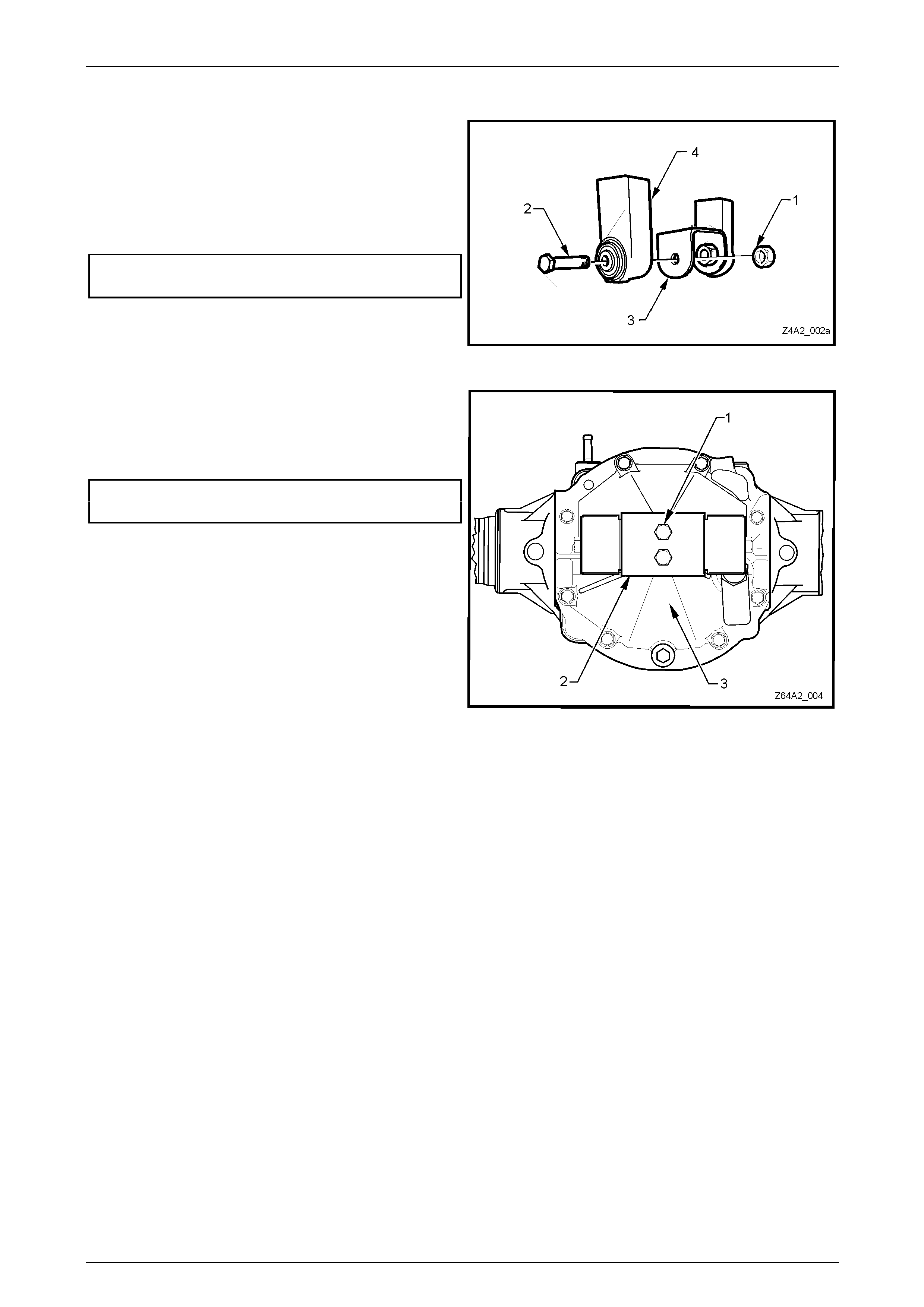
4 While supporting the mass damper (4), use suitable
spanners to remove the mass damper attach ing nut
(1) and bolt (2).
NOTE
The mass damper bushings are not serviced
separately. If not considered to be serviceable,
replace the mass damper assembly.
5 Inspect the ‘C’ bracket (3) for cracking or other
damage.
6 Replace components as required.
1403319
Figure 6A4 – 2
Page 4A2 – 6
Leaf Spring Rear Suspension Page 4A2 – 7
Reinstall
1 Loosely install a mass damper (4) to the ‘C’ bracket
(3), retaining with bolt (2) and nut (1).
2 Repeat for the second mass damper, as required.
3 While maintaining each damper at right angles to the
vertical face of the ‘C’ bracket, tighten each retain ing
bolt and nut to the correct torque specification.
Mass damper retaining bolt
and nut torque specification..................................90 Nm
Figure 4A2 – 4
4 Reinstall the mass damper as sembly (2) to the rear
axle rear cover (3) and secure with the two mounting
bolts (1).
5 Tighten both bolts to the correct torque specification.
Mass damper bracket attaching
bolt torque specification........................................95 Nm
6 Lower the vehicle to the ground.
Figure 4A2 – 5
Page 4A2 – 7


Leaf Spring Rear Suspension Page 4A2 – 9
3 Specifications
General
Rear Suspension Assembly.............................................................................................Dana
Type..............................................................Hotchkiss Drive with Semi-elliptical leaf springs)
Number of Primary Leaves.....................................................................................................3
Number of Secondary Leaves ................................................................................................1
Shock Absorber
Hydraulic (non-adjustable)..................................................................................Double acting
Broadcast Code (Crew Cab – V6) ......................................................................................WA
Page 4A2 – 9

Leaf Spring Rear Suspension Page 4A2 – 10
4 Torque Wrench Specifications
ATTENTION
Fasteners must be repl aced after loosening.
Vehicle must be at curb height and weight before final tightening.
Fasteners either have micro encapsulated sealant applied or incorp orate a mechanical thread lock and
should only be re-used once. If in doubt, replacement is recommended.
Mass Damper to ‘C’ Bracket Attaching Bolt and Nut.....................................90 Nm
Mass Damper ‘C’ Bracket to Final Drive Cover Attaching Bolt .....................95 Nm
Final Drive Rear Cover Attaching Bolt...........................................................28 Nm
Page 4A2 – 10