Rear Final Drive and Live Axle Page 4B2 – 1
Section 4B2
Rear Final Drive and Live Axle
ATTENTION
Before performing any Service Operation or other procedure described in this Section, refer to Section 00
Warnings, Cautions and Notes for correct workshop practices with regard to safety and/or property damage.
1 General Information ...............................................................................................................................2
1.1 General Description............................................................................................................................................... 2
Cone Type Limited Slip Differential – M78 Series............................................................................................... 3
1.2 Alloytec Engined Rear Axle Assembly Identification......................................................................................... 4
Rear Axle Label...................................................................................................................................................... 5
2 Minor Service Operations......................................................................................................................6
2.1 Service Warnings, Cautions and Notes............................................................................................................... 6
2.2 Rear Axle Assembly Minor Maintenance............................................................................................................. 7
2.3 Checking Rear Axle Lubricant Level.................................................................................................................... 8
2.4 Changing/Flushing Rear Axle Lubricant.............................................................................................................. 9
2.5 Rear Final Drive Rear Cover................................................................................................................................ 10
Remove................................................................................................................................................................. 10
Clean and Inspect................................................................................................................................................ 10
Reinstall................................................................................................................................................................ 11
3 Specifications.......................................................................................................................................12
4 Torque Wrench Specifications............................................................................................................13
5 Special Tools ........................................................................................................................................14
Page 4B2 – 14
Rear Final Drive and Live Axle Page 4B2 – 2
1 General Information
1.1 General Description
The rear final drive and live ax le assembly fitted to those MY 2006 VZ Update Series vehicles with the HFV6 engine and
the live rear axle with leaf springs, is a Salisbury (Unitised carrier) type rigid live axle, mounted to a leaf spring rear
suspension system with tubular shock absorbers, as standard equipment. Crew Cab models d o not have a rear stabiliser
bar fitted.
On V6 models, the mass dampers have been relocated from the springs to the rear of the final dr ive housing. This has
meat that an aluminium cover is now fitted, instead of the pressed stee l cover, used previously. Apart from this change,
all subsequent service operations not d etaile d here, remain as detailed in the MY 2005 VZ series fitted with a live axle. In
these instances refer to Section 4B2 Rear Final Drive an d Live Axle, in the MY2005 VZ Service Information.
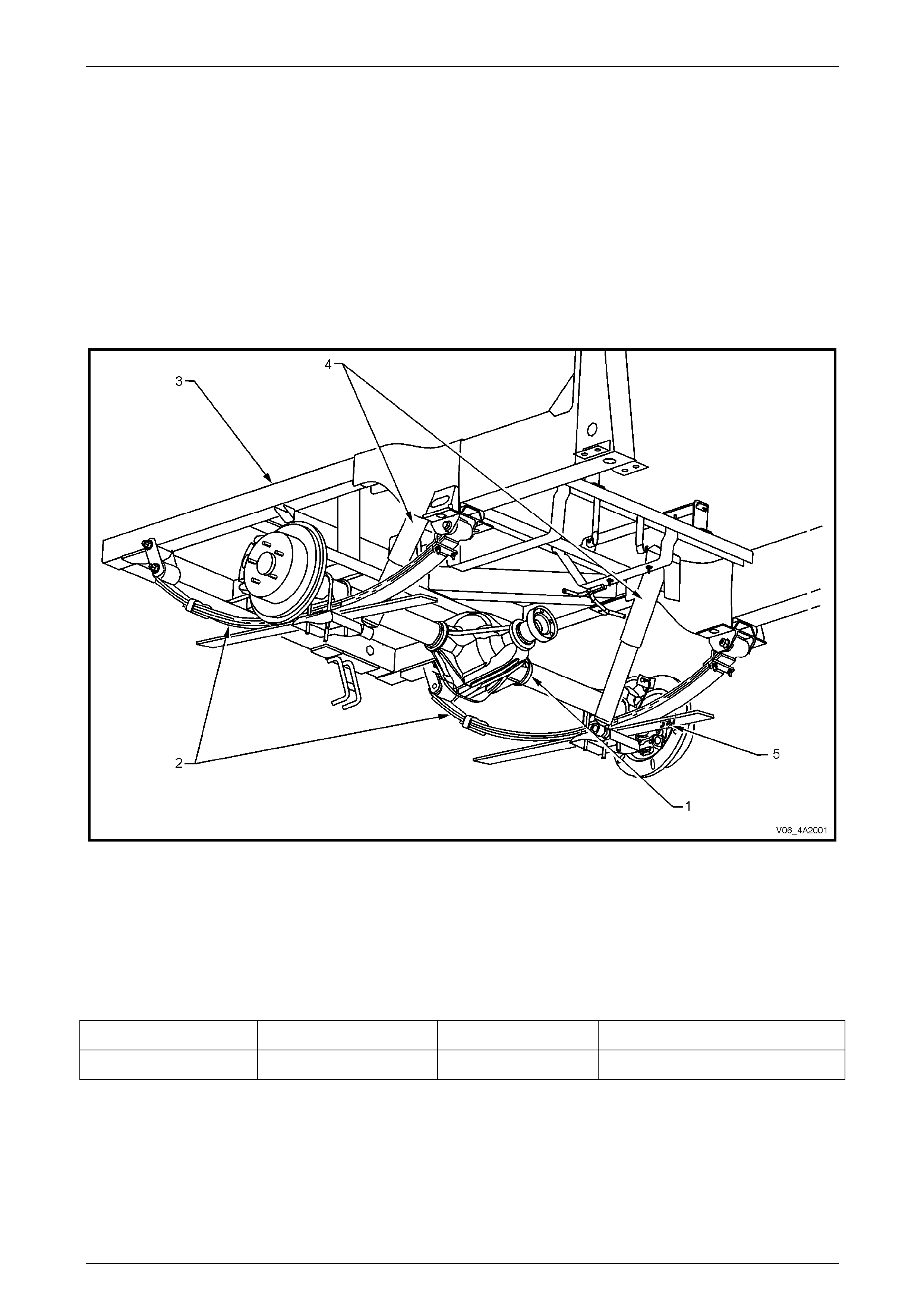
Figure 4B2 – 1
Legend
1 Rear Axle Assembly
2 Rear Leaf Spring Assembly
3 Rear Shock Absorber
4 Chassis Frame
5 Rear ABS Sensor
The range of final drive variants in the MY2006 VZ Update models with Alloytec engines can best described in tabular
form:
Production Option # Ring Gear Diameter Final Drive Ratio Application
GU4 197 mm 3.08:1 V6 – Auto and Manual Trans, RWD
Production option G80, Limited Slip Differential (LSD), (also referred to as Spin Resistant Differential – ‘SRD’) is
available as an option on al l V6 models.
No changes have been made to the rear final drive on GEN IV models, with the live axle.
The rear axle assembly is mounted to the ch assis via leaf springs, ‘U’ bolts, spring shackles and spring eye bus hings.
The differential case, hypoid ri ng gear and pinion are mounted with opposing taper ed roller bearings in the rear ax le
housing. Differential side bearing preload adjustment is controlled by shims located between the tapered roller bearing
cups and the sides of the rear axle housing. A collapsible spacer and companion flange retaining nut provide pinion
bearing preload.
Page 4B2 – 14
Rear Final Drive and Live Axle Page 4B2 – 3
Torque is transferred from the propeller shaft to the rear axle assembl y via the pinion flange, which is spline d to the
hypoid pinion gear. The torque is then transferred from the hypoid pi nion gear through the hypoid ring gear, differential
case, differential pinion cross shafts, differential pinion gears, side gears and then via splines on the axle shafts to the
road wheels.
Cone Type Limited Slip Differential – M78 Series
The M78 Series Limited Slip Differential (LSD), used with V6 models, performs the same functions as the conventional
type differential but in addition, transfers driving force to the wheel with traction, should the opposite wheel begin to spin.
The differential case houses two cone type clutches behind the side gears that are splined to the inner ends of the axle
shafts and their tapered faces contact corresponding faces in the differential case.
On this LSD, the cones form an integral part of the side gears. The four pinion type LSD has three preload springs
enclosed in the centre of the pinion cross shaft. The LSD directs the major driving force to the wheel with the greater
amount of traction, but will not interfere with steering characteristics or differential action. The inhere nt separating forces
between the side gears and pinions automatically increase the partial locking action, due to the spring load on the cones,
which progressively increases the resistance in the differe ntial as applied torque is increased.
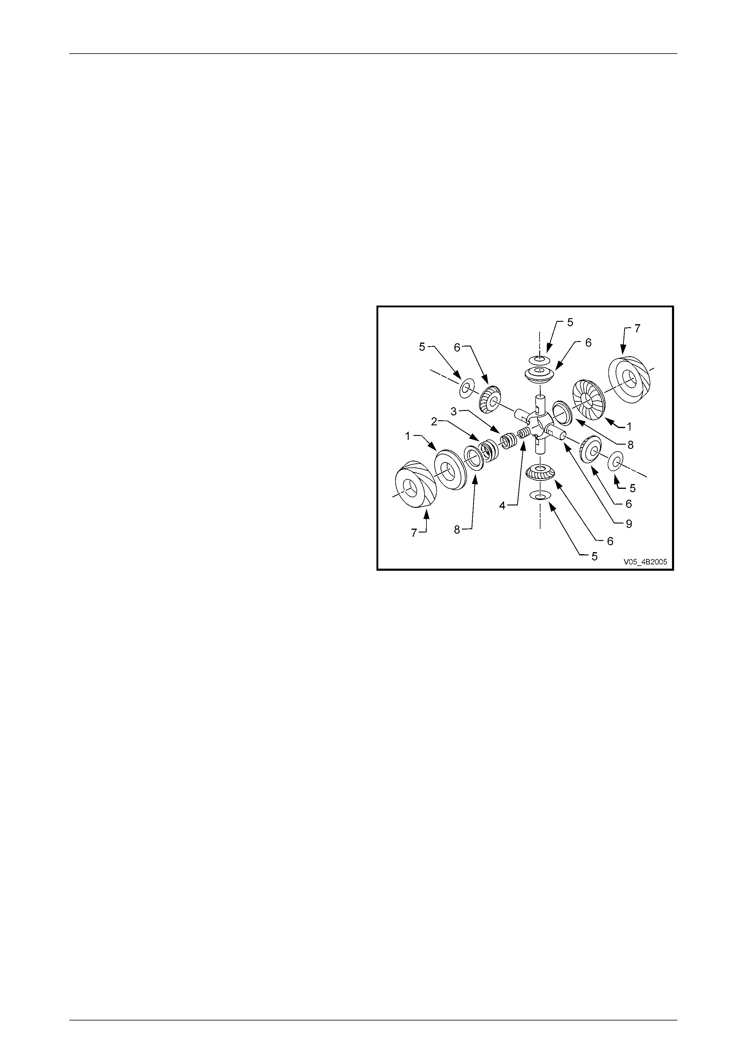
Legend
1 Gear – Differential Side
2 Spring – Outer, Differential Preload
3 Spring – Intermediate, Differential Preload
4 Spring – Inner, Differential Preload
5 Washer – Thrust, Differential Pinion Gear
6 Gear – Differential Pinion
7 Cone – Clutch
8 Plate – Thrust, Spring
9 Shaft – Differential Pinion Cross
Figure 4A2 – 2
When the rear wheels are under extremely unbalanced conditio ns, such as a wheel on a dry road and the other in mud
or ice, with the standard differential, wheel spin easily occurs if over-acceleration is attempted. However, with a LSD,
when the tendency for wheel spin occurs, the friction generated inside the case, therefore transfers greater driving force
to the non-spinning wheel. In the event of continued spinning, a whirring sound from the over-running cones is produced
but this condition/sound does not indicate failure of the unit.
Page 4B2 – 14
Rear Final Drive and Live Axle Page 4B2 – 4
1.2 Alloytec Engined Rear Axle Assembly
Identification
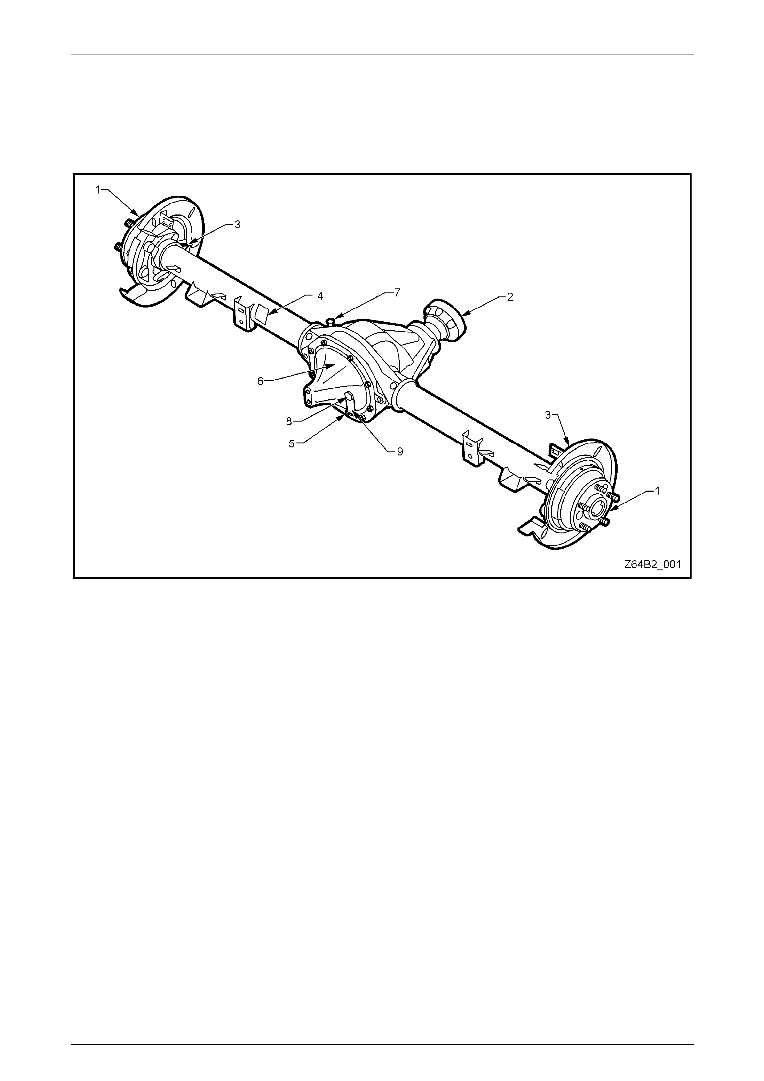
The type of differential fitted to the rear axle assembly can be identified by referring to either the identification label (4)
attached to the LHS of the axle housing or from the lubrication tag (9) under the filler plug (8) on the rear cover.
Figure 4B-3
Legend
1 Rear Axle Shaft
2 Pinion Flange
3 Rear ABS Sensor Mount
4 Identification Label
5 Drain Plug
6 Rear Cover
7 Breather
8 Filler Plug
9 Lubrication Tag
Page 4B2 – 14
Rear Final Drive and Live Axle Page 4B2 – 5
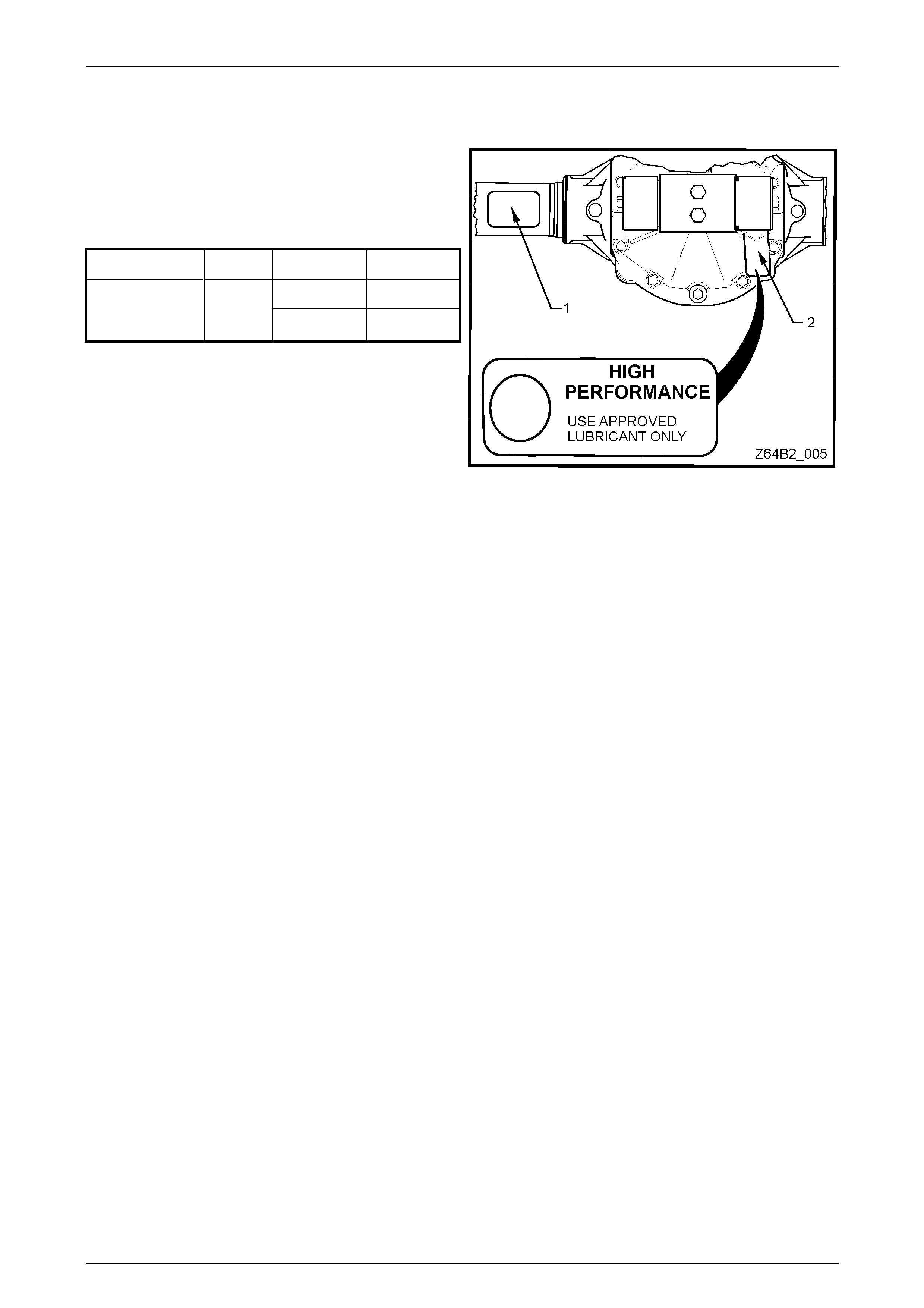
Rear Axle Label
The locations of the identification label (1) and lubrication tag (2) are shown next.
The identification label (1) car r ies the rear axle assembly
part number, the rear axle ratio, the serial number and the
I.D. code of the assembly.
The code number and bar co de is used for production
identification of the rear axle assembly.
Usage Ratio Type I.D. Code
ABS (Std) TYV
V6 with Manual
or Automatic
Transmission 3.08:1 LSD & ABS TYU
Figure 4A2 – 4
Page 4B2 – 14
Rear Final Drive and Live Axle Page 4B2 – 6
2 Minor Service Operations
2.1 Service Warnings, Cautions and Notes
ATTENTION
All fasteners are important attaching parts as they affect the performance of vital components and/or could
result in major repair expense. W here specified in this section, fasteners MUST be replaced w ith parts of the
same part number or an app roved equivalent. Do not use fasteners of an inferior quality or substitute desig n.
Torque values must be used as specified during reassembly to ensure proper retention of all components.
Throughout this section, fastener torque wrench specifications may be accompanied with the following
identification marks:
Fasteners must be repl aced after loosening .
Vehicle must be at curb height before final tightening.
Fasteners either have micro encapsulated sealant applied or incorporate a mechanic al thread lock and
should only be re-used once. If in doubt, replacement is recommended.
If one of these identification marks is present alongside a fastener torque wrench specification, the
recommendation regarding that fastener must be adhered to.
ABS Components
• Whenever any component that forms part of the ABS (if fitted) is disturbed during Service
Operations, it is vital that the complete ABS system be checked, refer to Section 5B ABS.
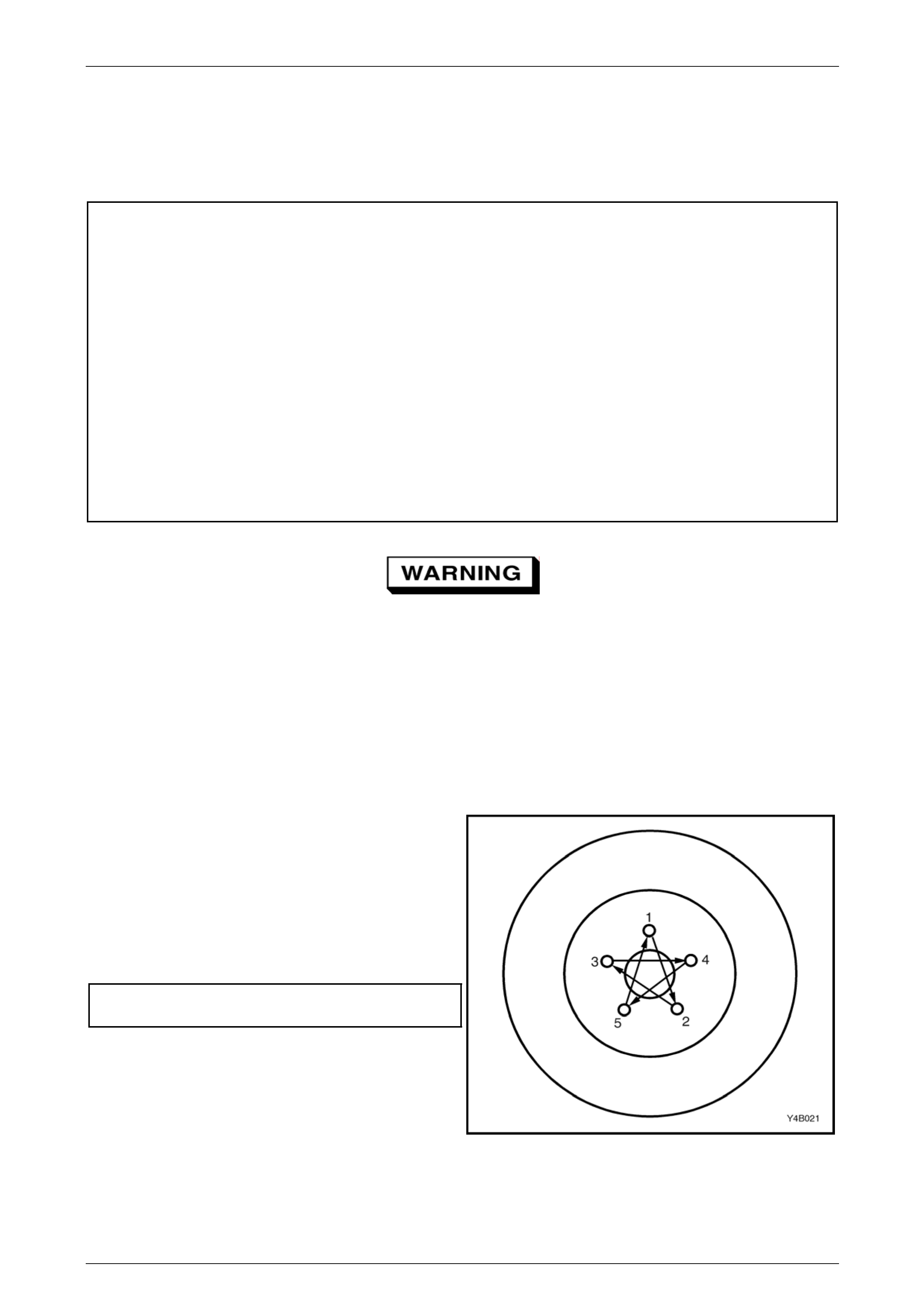
Road Wheels
• Whenever a road w heel and/or brake di sc is removed from the vehicle, the relatio nship of the road
wheel and the disc to the hub MUST be marked with a felt tipped pen or similar, to allow those
parts to be reinstalled in their original positions. This is critical to minimise the brake disc and
road wheel runout dimension.
• When reinstalling road wheels, do not use
an impact gun to tighten wheel nuts
unless the impact gun is fitted with a
torque limiter socket (Tool No. AU 534 or
a commercial equivalent). Failure to
correctly tighten w heel nuts to the correct
torque specification and in the correct
order (as shown), may result in a
distorted brake disc, leading to the
development of brake shudder.
Road wheel attaching nut
torque specification.................................... 110 – 140 Nm
Figure 4B2 – 5
Page 4B2 – 14

Rear Final Drive and Live Axle Page 4B2 – 7
2.2 Rear Axle Assembly Minor Maintenance
For procedures on any of the following minor servicing items, refer to Section 4B2 Rear Final Drive and Live Axl e in the
MY2005 VZ Service Information:
• Rear Axle Shaft Check For Run-Out and End Float
• Rear Axle Shaft Wheel Studs
• Combined Rear Axle B acklash Check
• Limited Slip Differential Torque Check
• Rear Axle Shaft Assembly
• Rear Axle Shaft, ABS Pulse Ring, Oil Seal, Bearing and Retainer Collar
• Pinion Oil Seal
• Pinion Flange
Page 4B2 – 14
Rear Final Drive and Live Axle Page 4B2 – 8
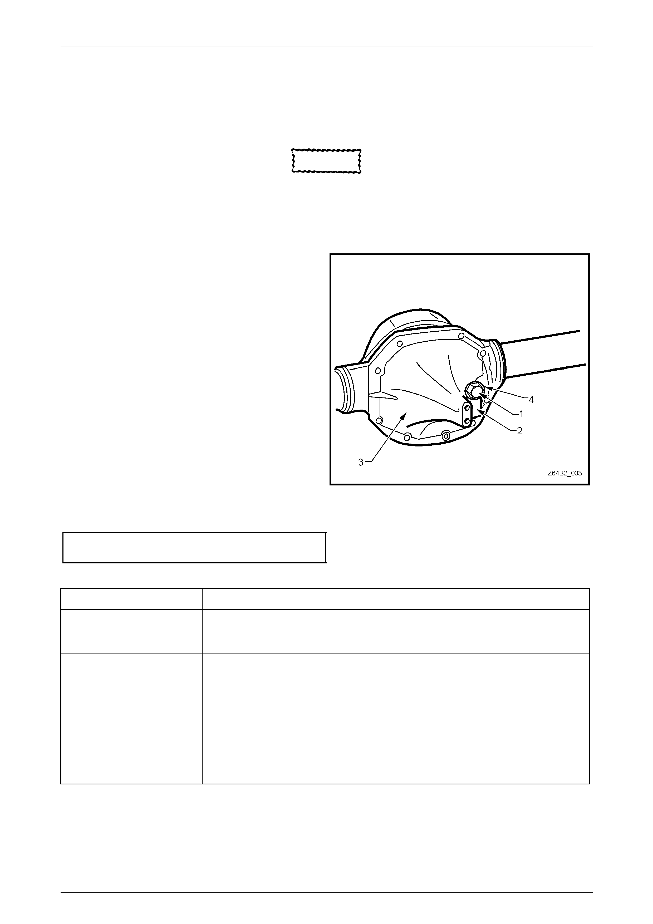
2.3 Checking Rear Axle Lubricant Level
LT Section No: 05-400
CAUTION
When servicing any rear axle assembly fitted
with a Limited Slip Differential (LSD), gloves
and safety glasses are recommended when
handling the lubrication additive to prevent
any possible irritation of the skin or eyes.
1 Check that the vehicle is level and resting on all four
wheels.
2 Clean area around filler plug (1).
3 Remove filler plug (1) from rear cover (3) (do not lose
the lubrication tag (2) from the plug, if fitted).
4 The lubricant level is to be maintaine d at the bottom
edge of the filler plug hole.
NOTE
• The rear axle lubricant level MUST be
checked when the rear axle is cold, or
overfilling and oil leaks ma y occur.
• Use only the recommended lubricant.
5 Inspect filler plug (1) and sealing washer (4) for
damage, if OK, reinstall to the rear cover (3) (includi ng
the lubrication tag (2). If damaged, replac e plug and
the sealing washer.
6 Tighten filler plug (1) to the correct torque
specification.
Rear axle filler plug
torque specification...............................................28 Nm
Figure 4A2 – 6
Engine & Axle Type Recommended Lubricant
V6
M78 Series
Non LSD
Synthetic Hypoid Gear Oil, such as; MOBIL Mobilube SHC ID, CASTROL SAF-XA or
equivalent lubricant to Holden's Specification HN2040.
V6
M78 Series LSD
(Cone Type)
Synthetic Hypoid Gear Oil, such as; MOBIL Mobilube SHC ID, CASTROL SAF-XA or
equivalent lubricant to Holden's Specification HN2040.
In addition to the synthetic, hypoid gear oil, additive kit (part number 92 145121) must
also be used.
The additive kit consists of:
• LSD Sturaco Additive – 100 ml special conta iner
• Material Safety Data Sheet
• Lubrication ID Tag
Page 4B2 – 14
Rear Final Drive and Live Axle Page 4B2 – 9
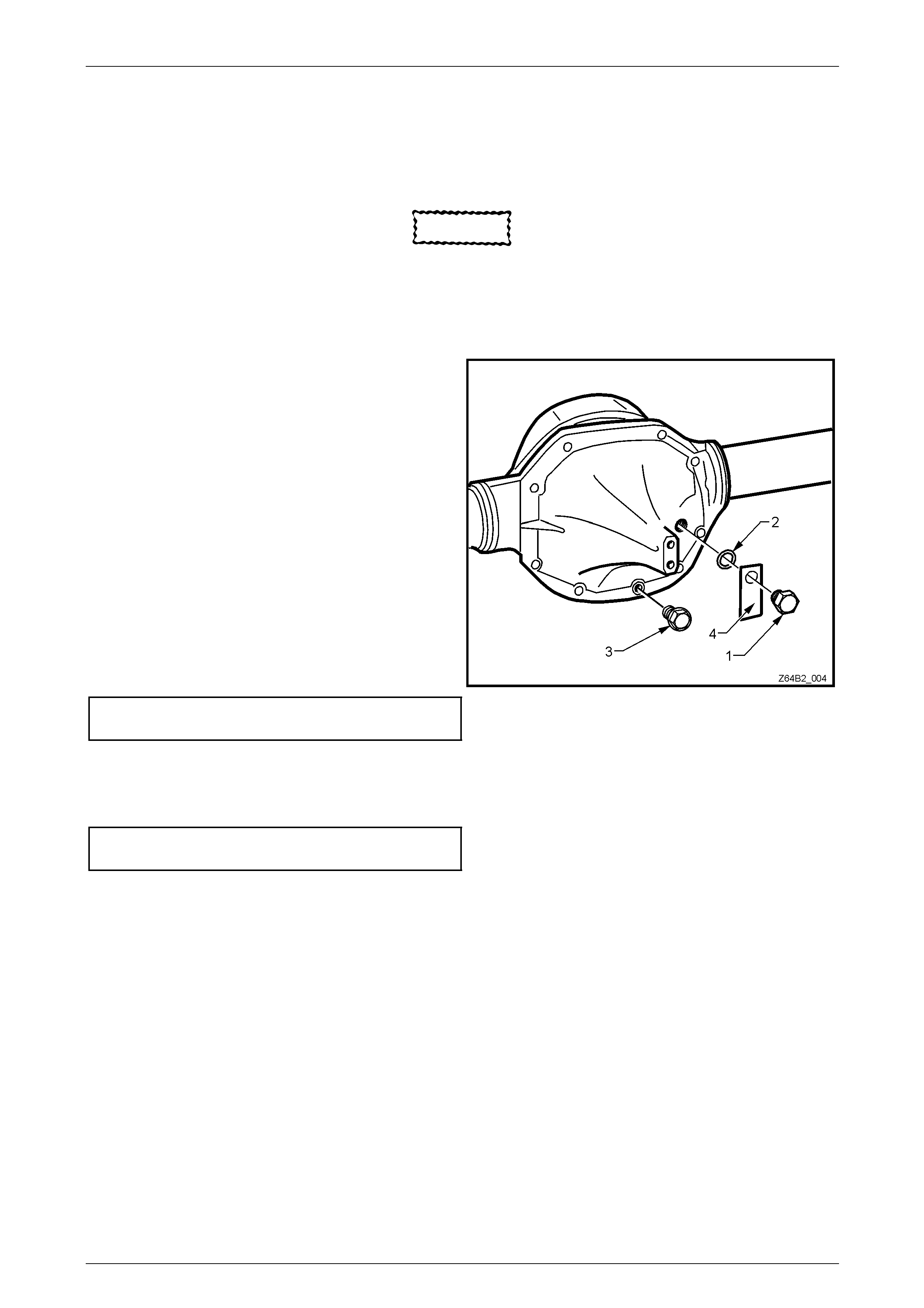
2.4 Changing/Flushing Rear Axle Lubricant
LT Section No: 05-400
CAUTION
When servicing any rear axle assembly fitted
with a Limited Slip Differential (LSD), gloves
and safety glasses are recommended when
handling the lubrication additive to prevent
any possible irritation of the skin or eyes.
1 Place a clean container under the rear axle with a
2 litre minimum capacity.
NOTE
Draining warm oil takes less time and is more
complete than for cold oil.
2 Remove the filler plug (1), lubrication tag (4), sealing
washer (2) and the drain plug (3).
3 Allow the (preferably warm) lubricant to drain into the
container.
4 If flushing is required, use an undiluted quantity of the
recommended lubricant for the operation.
5 When the draining (and flushing if required) operation
is complete, apply thread-sealing tape to drain plug (3)
thread. Install and tighten drain plug (3) to the correct
torque specification.
Rear axle drain plug
torque specification...............................................28 Nm Figure 4B2 – 7
6 Fill the rear axle assembly with a total of 1.7 litres of the recommended lub r ic ant (or 1.6 litres of lubricant plus 100
ml of LSD additive, as appropriate), install the filler plug (1) wit h the sealing washer (2) and lubricati on tag (4).
7 Tighten the filler plug to the correct torque specification.
Rear axle filler plug
torque specification...............................................28 Nm
Page 4B2 – 14
Rear Final Drive and Live Axle Page 4B2 – 10
2.5 Rear Final Drive Rear Cover
Remove
1 Raise the rear of the vehicle and support in a safe manner.
2 Because of the weight involved, it is recommend ed that the mass dampers are removed. Refer to
Section 4A2 Rear Leaf Spring Suspension for details.
3 Remove the filler and drai n plugs and drain the oil (prefera bly warm) from the final drive assembly, refer to
2.4 Changing/Flushing Rear Axle Lubricant.
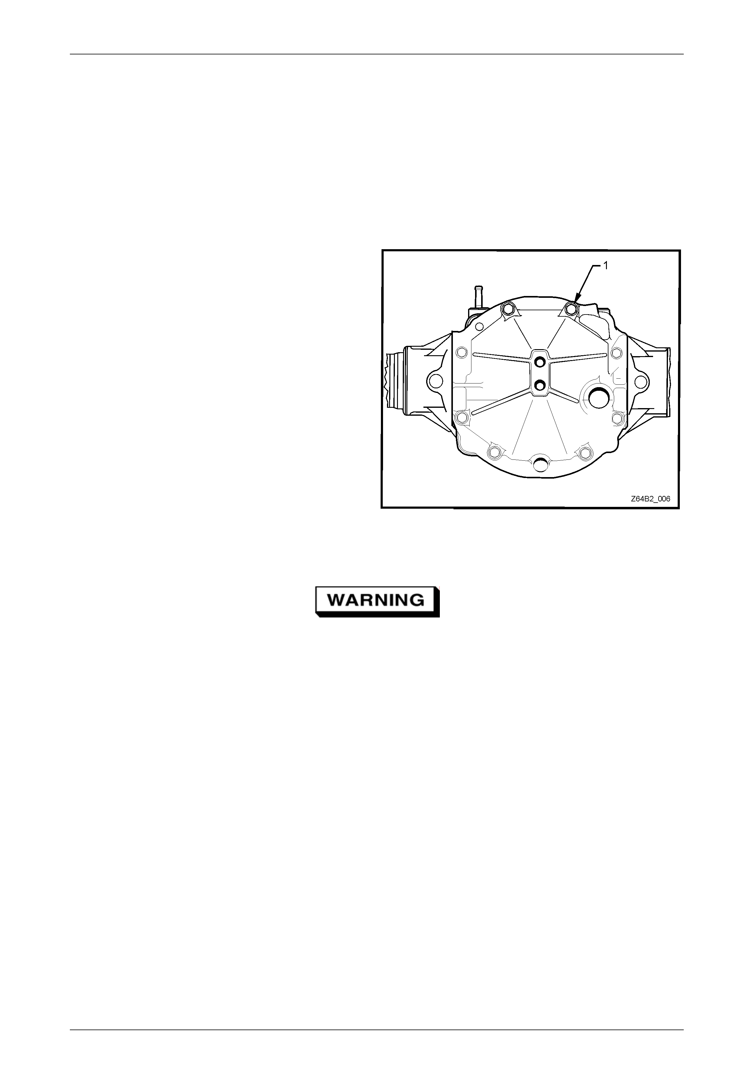
4 Using suitable socket equipment, remove the rear
cover to final drive housing bolts (1), in eight places.
5 Tap the side of the cover with a soft faced hammer to
break the sealant seal, then remove the cover.
Figure 4B2 – 1
Clean and Inspect
Wear eye protection to prevent potential
injury when using compressed air.
1 Using a plastic scraper, clean sealant residue from the final drive housing and the cover.
2 Using a wire brush, clean all traces of thread sealant from the bolt threads.
3 Wash the cover with suitable cleaning solvent and dry usin g compressed air.
4 Inspect the bolt threads for a sound thread condition, replacing any that are damag ed.
5 Inspect the final drive housing bolt threads for damage repairing, as required.
6 Check the rear cover for any warpage and/or damage to the drain plug threads. Re place the cover if any of this
defects are found.
Page 4B2 – 14
Rear Final Drive and Live Axle Page 4B2 – 11
Reinstall
1 Apply a 1 mm bead of sealan t such as Loctite 525 (or equivalent) to the rear cover, ensuring that the sealant bead
flows on the inside of each bolt hole.
2 Reinstall the cover and secure by installing the eight bo lts that have had sealant such as Loctite 525 (or equivalent)
applied to cleaned threads.
3 Tighten the cover bolts to the correct torque specification.
Rear axle rear cover attaching
bolts torque specification ......................................28 Nm
4 Reinstall the drain plug and tighten to the correct torque spe cification.
Rear axle drain plug
torque specification...............................................28 Nm
5 Refill the final drive with the correct lubricant, refer to 2.4 Changing/Flushing Rear Axle Lubricant.
Page 4B2 – 14

Rear Final Drive and Live Axle Page 4B2 – 12
3 Specifications
NOTE
Only those specifications that are of a general
nature or relate to the service operations
described here, are shown. For all remaining
specifications, refer to Section 4B2 Rear Final
Drive and Live Axle in the MY2006 VZ Service
Information.
General
Rear Axle Assembly ....................................................V6 – Dana/Spicer – SAA – M78 Series
Axle Type............................................................................................................Semi Float ing
Housing Type .............................................................................Unitised Carrier Construction
Standard and LSD Axles
Gear Type......................................................................................................................Hypoid
Gear Ratio (See I.D. label on axle tube housing) ...............V6 Automatic/V6 Manual – 3.08:1
3.08:1
No. of Teeth – Ring Gear......................................................................................................40
No. of Teeth Drive Pinion Gear.............................................................................................13
Ring Gear Diameter..........................................................................................................7.75”
No. Teeth – Differential Pinion Gear.....................................................................................10
Differential Side Gear........................................................................................16
Lubricants
Total Rear Axle Lubricant Capacity ...........................................................................1.7 Litres
NOTE
For rear axles with LSD the lubricant fill
comprises of 1.6 Litres of rear axle lubricant and
100 ml of Sturaco LSD additive.
Rear Axle Lubricant Type ................................................................Synthetic Hypoid Gear Oil
Holden Specification HN2040 or Mobilube SHC ID
LSD Additive........................................................................................................Sturaco 7098
Pre-lubricant as Specified in Text...................NLGI No. 2 lithium soap based EP grease with
molybdenum disulphide, such as Shell Retinax HDX2
grease or BP Energrease LMS-EP 23 (or eq uivalent).
Sealants and Thread Locking Compound
Rear Cover to Carrier Housing ..................................... Loctite 587 ('Ultra Blue') or equivalent
Rear Axle Fasteners, Pinion Nut and Breather...............Loctite 262 or commercial equivalent
to GM Specification 9985283.
Page 4B2 – 14
Rear Final Drive and Live Axle Page 4B2 – 13
4 Torque Wrench Specifications
ATTENTION
Fasteners must be repl aced after loosening .
Vehicle must be at curb height before final tightening.
Fasteners either have micro encapsulated sealant applied or incorporate a mechanical thread lock and
should only be re-used once. If in doubt, replacement is recommended.
NOTE
Only those torque specifications that relate to the
service operations described here, are shown.
For the remaining torque specifications, refer to
Section 4B2 Rear Final Drive and Liv e Axle in the
MY2006 VZ Service Information.
Rear Axle Drain Plug...........................................................................................28 Nm
Rear Axle Filler Plug ...........................................................................................28 Nm
Rear Cover to Carrier Housing Bolts...................................................................28 Nm
Page 4B2 – 14
Rear Final Drive and Live Axle Page 4B2 – 14
5 Special Tools
Tool Number Illustration Description Tool Classification
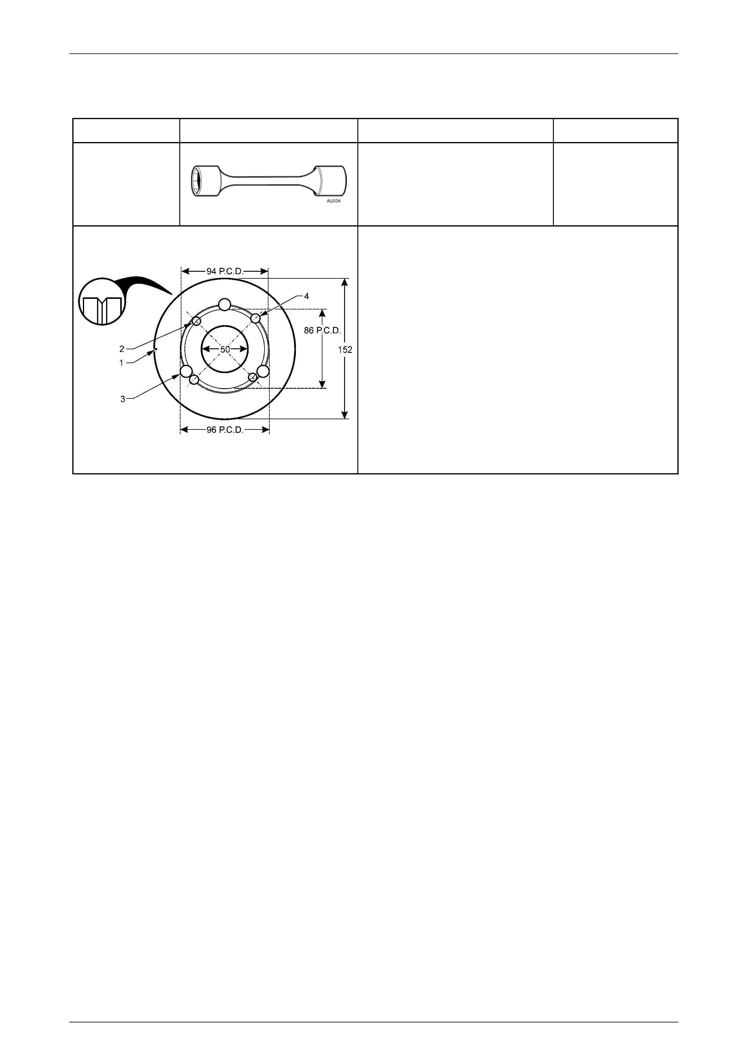
AU534
Torque Limiting Socket
Used in conjunction with an impact
gun to tighten wheel nuts.
Previously released.
Mandatory
Pinion Flange Pulley
Fabricate this pulley to incl ude all VZ applications.
1 152 mm diameter pulley made from a 13 mm thick piece
of wood with a 1 mm deep groove (inset) turned around
the circumference.
2 Drill a small hole at '1' and attach a one metre length of
string at this point, looped at one end, knotted at the
other.
3 Drill two, 8.5 mm holes (2) opposite to each other on a
pitch circle diameter of 86 mm (AWD Wagon).
4 Drill three, 13 mm holes (3) on a pitch circle diameter of
96 mm, 120 mm apart (All VZ models with IRS).
5 Drill two, 10 mm holes (4) opposite to each other on a
pitch circle diameter of 94 mm (All VZ Live Axle models).
Page 4B2 – 14