
Starting System – V6 Page 6D1-2–1
Section 6D1-2
Starting System – V6
ATTENTION
Before performing any service operation or other procedure described in this Section, refer to Section 00
Warnings, Cautions and Notes for correct workshop practices with regard to safety and/or property damage.
1 General Information ...............................................................................................................................3
1.1 Components........................................................................................................................................................... 3
Starting System Components...............................................................................................................................3
Starter Motor and Solenoid Switch Components................................................................................................ 3
Solenoid Switch.................................................................................................................................................. 3
Planetary Drive Train.......................................................................................................................................... 3
Armature ............................................................................................................................................................ 4
Brushes .............................................................................................................................................................. 4
1.2 System Operation.................................................................................................................................................. 5
Operation ........................................................................................................................................................... 5
Auto Start Feature .............................................................................................................................................. 5
Clutch Pedal Switch (Manual Only) .................................................................................................................... 5
Sequence of Operation ...................................................................................................................................... 5
2 Diagnostics.............................................................................................................................................6
2.1 Diagnostic General Information............................................................................................................................ 6
Basic Diagnostic Tools Required......................................................................................................................... 6
2.2 Tech 2 Data List ..................................................................................................................................................... 7
2.3 Diagnostic Systems Check................................................................................................................................... 8
2.4 Wiring Diagram ...................................................................................................................................................... 9
2.5 Starting System Inoperative / Malfunctioning................................................................................................... 10
Circuit Description ............................................................................................................................................ 10
Diagnostic Table Notes .................................................................................................................................... 10
Diagnostic Table............................................................................................................................................... 10
Diagnostic Table – Slow Cranking, Solenoid Clicks or Chatters....................................................................... 14
3 Minor Service Operations....................................................................................................................15
3.1 Safety Precautions............................................................................................................................................... 15
3.2 Maintenance......................................................................................................................................................... 16
Regular Checks.................................................................................................................................................... 16
3.3 On-Vehicle Testing .............................................................................................................................................. 17
Prerequisites........................................................................................................................................................ 17
Bad Connection Test........................................................................................................................................... 17
Starter Motor Ground Test.................................................................................................................................. 18
Switching Circuit Test......................................................................................................................................... 18
Cranking Voltage Test......................................................................................................................................... 19
Current Draw Test................................................................................................................................................ 19
Clutch Pedal Switch............................................................................................................................................. 20
Remove............................................................................................................................................................ 20
Test .................................................................................................................................................................. 20
Reinstall ........................................................................................................................................................... 20
4 Major Service Operations....................................................................................................................21
4.1 Starter Motor – RWD............................................................................................................................................ 21
Remove................................................................................................................................................................. 21
Reinstall................................................................................................................................................................ 22
Page 6D1-2–1

Starting System – V6 Page 6D1-2–2
4.2 Starter Motor – AWD............................................................................................................................................ 23
Remove................................................................................................................................................................. 23
Reinstall................................................................................................................................................................ 24
4.3 Starter Motor Bench Tests.................................................................................................................................. 25
Preliminary Checks.............................................................................................................................................. 25
Pull-in Test............................................................................................................................................................ 25
Hold-in Test.......................................................................................................................................................... 26
Drive Assembly Return Test............................................................................................................................... 26
No Load Test........................................................................................................................................................ 26
4.4 Starter Motor Disassemble and Reassembl e .................................................................................................... 28
Disassemble......................................................................................................................................................... 28
Reassemble.......................................................................................................................................................... 29
4.5 Solenoid Switch Tests......................................................................................................................................... 30
Test the Solenoid Switch.................................................................................................................................. 30
5 Specifications.......................................................................................................................................33
6 Torque Wrench Specifications............................................................................................................34
7 Special Tools ........................................................................................................................................35
Page 6D1-2–2

Starting System – V6 Page 6D1-2–3
1 General Information
All V6 engines are fitted with a Mitsubishi starter motor. This consists of a solenoid switch on a DC motor. The motor has
permanent magnet excitation, which has the advantage of low weight a with high output torque and is visually identifiable
by the absence of pole-shoe retaining screws.
The starter motor does not have field coil windings or pole shoes. These parts have been replaced by six permanent
magnets that are held in the pole housing by clips. The positive brushes are now part of the brush plate assembly.
If the engine does not start during initial cranking, the starter motor will continue to crank for a maximum of 4 seconds
with the ignition switch returned to the ON position. This is a normal function of the starting system on the V6 engine.
The solenoid switch is the only component of the starter motor assembly that is serviced separately. If any other parts
require replacement, the starter motor must be replaced.
1.1 Components
Starting System Components
The main components of the starting system are:
• battery,
• wiring,
• ignition switch,
• remote coded key,
• theft deterrent engine crank inhibitor (a function of the theft deterrent system),
• park / neutral and back-up switch (on vehicles with 4 speed automatic transmission),
• transmission manual shift shaft switch assembly (on vehicles with 5 speed automatic transmission),
• clutch pedal position switch (on vehicles fitted with manual transmission),
• engine control module (ECM),
• start relay,
• solenoid switch, and
• starter motor.
Starter Motor and Solenoid Switch Components
Solenoid Switch
The solenoid switch is used to activate the DC motor and has two windings; the pull-in winding and the hold-in winding.
The pull-in winding has heavier wire and is grounded through the DC motor winding and brushes. The hold-in winding is
grounded through the solenoid casing.
Planetary Drive Train
The planetary drive train consists of an internally toothed ring gear and three planetary gear wheels, which rotate on
sleeve bearings on the planetary drive shaft. The ring gear is keyed into the drive-end housing and is made from
high-grade polyamide with mineral additives.
When the starter motor operates, the armature turns the planetary gears inside the fixed planetary ring gear. This drives
the planetary shaft at a reduced speed ratio which turns the drive assembly. A fork lever in the drive-end housing forces
the drive assembly forward to engage with the flexplate / flywheel ring gear on the engine and transmit cranking torque.
An internal clutch allows the drive assembly pinion gear to rotate freely when the engine starts. This prevents the
armature from being driven at excessive speed by the engine.
Page 6D1-2–3
Starting System – V6 Page 6D1-2–4
Armature
The armature shaft is supported at each end by oil absorbent, sintered metal bushes; one in the commutator end shield
and one in the planetary drive shaft. The front end of the armature has a gear profile. This meshes with the three
planetary gear wheels. These in turn, mesh with the internal teeth of the ring gear.
Brushes
A brush plate supports four commutator brushes. This plate is fixed to the commutator end shield with two retaining
screws. Two negative brushes are grounded to the pole housing. The two positive brushes are insulated from the pole
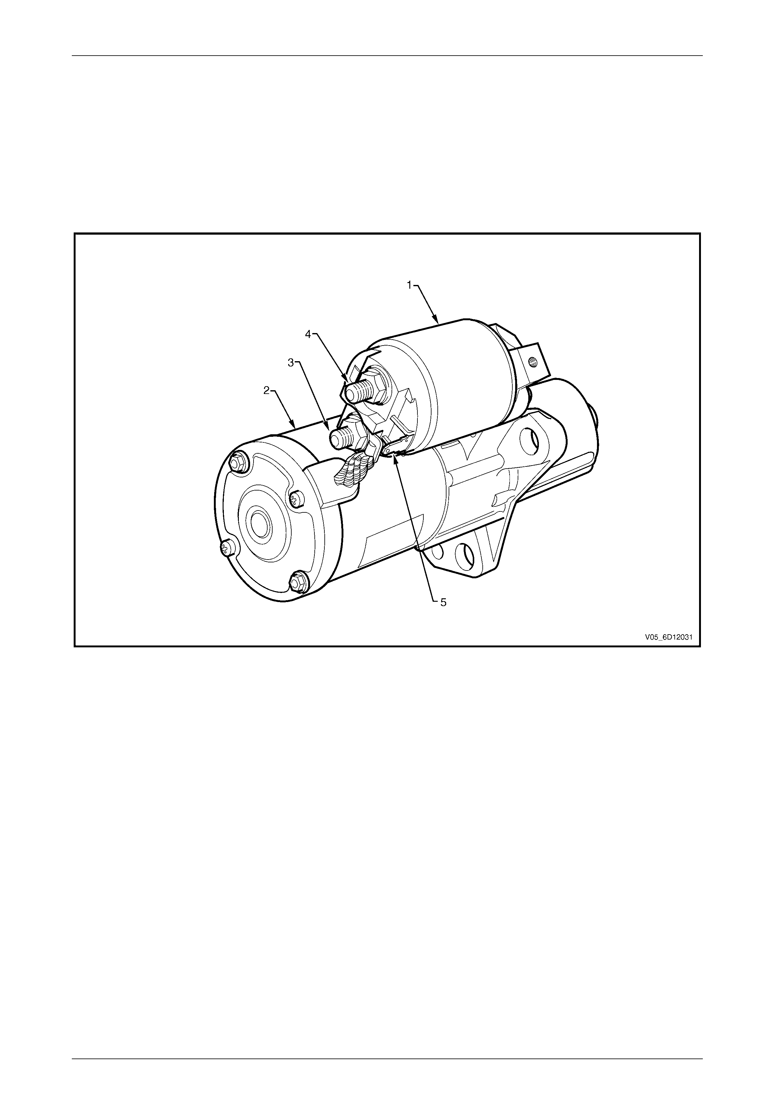
housing and connected to the solenoid switch M terminal, refer to Figure 6D1-2 – 1
Figure 6D1-2 – 1
Legend
1 Solenoid Switch
1 Starter Motor
3 Starter Motor terminal M
4 Connector M15 – X2 pin A
5 Connector M15 – X1 pin A
Page 6D1-2–4

Starting System – V6 Page 6D1-2–5
1.2 System Operation
Operation
The ECM controls the activation of the start relay in response to inputs from:
• ignition switch,
• battery,
• theft deterrent engine crank inhibitor (a function of the theft deterrent system),
• park / neutral and back-up switch (on vehicles with 4 speed automatic transmission),
• transmission manual shift shaft switch assembly (on vehicles with 5 speed automatic transmission), and
• clutch pedal position switch (on vehicles with manual transmission).
The start relay controls the operation of the start solenoid.
The start solenoid controls operation of the starter motor and the drive assembly.
Auto Start Feature
Vehicles fitted with the V6 engine have a new feature; Auto Start. Once the ignition switch has been turned to the START
position, the starter motor will crank the engine.
If the ignition switch is returned to the ON position before the engine has started, the starter motor will continue to
operate until the engine starts. If the engine fails to start, cranking will continue for approximately 4 seconds from when
the ignition switch was returned to the ON position.
Turning the ignition switch to the OFF position will cancel the Auto Start and the starter motor will stop cranking.
Clutch Pedal Switch (Manual Only)
The clutch pedal position switch provides an input to the ECU to ensure the clutch pedal is depressed while the vehicle is
being started. This switch is normally open when the clutch pedal is at rest, closing when the pedal is pressed. Activation
of this switch sends a signal to the ECM which will then allow operation of the starter motor.
Sequence of Operation
1 When the ignition switch is turned to the START position, a signal is sent to the ECM to request engine cranking.
a For automatic vehicles the transmission must be in either park (P) or neutral (N) for the ECM to allow
cranking to commence.
b For manual vehicles the clutch pedal must be depressed.
c The ECM will only allow cranking if the battery voltage is above the minimum battery voltage threshold value,
refer to Section 6C1-1 Engine Management – V6 – General Information for further information.
2 The ECM operates the start relay which provides power to the pull-in winding of the start solenoid.
3 Current flow to the pull-in winding develops powerful magnetism which pulls in the solenoid switch plunger.
4 The plunger closes the switch contacts connecting battery voltage to the DC motor and pivots the fork lever to
engage the drive assembly to the flexplate / flywheel ring gear. Closing the solenoid switch contacts deactivates
the pull-in winding, the hold-in winding remains active.
5 With the solenoid switch contacts closed, current flows from the battery through the DC motor, which rotates the
armature at high speed and provides cranking torque.
6 The ECM will initially allow cranking for up to 1 second to allow time for the validation of the security code data
output from the remote coded key to be completed.
7 Once the security code serial data output from the remote coded key is validated by the ECM, the theft deterrent
system is disarmed and cranking will continue. For further information on the theft deterrent system refer to
Section 12J Body Control Module.
Page 6D1-2–5

Starting System – V6 Page 6D1-2–6
2 Diagnostics
2.1 Diagnostic General Information
NOTE
There is a minimum battery voltage threshold
value. If the battery voltage is below the set
value, the ECU will inhibit cranking. Refer to
Section 6C1-1 Engine Management – V6 –
General Information for further information.
Basic Diagnostic Tools Required
Use of incorrect electrical circuit diagnostic
tools when performing the cruise control
diagnostic procedures could result in
incorrect diagnostic results or damage to
components.
The following electrical circuit testing tools are required to perform the diagnostic procedures detailed in this Section:
• digital multimeter with 10 mega ohms impedance, and
• connector test adapter kit Tool No. KM609.
For further information on the use of these tools, refer to Section 12P Wiring Diagrams.
Page 6D1-2–6

Starting System – V6 Page 6D1-2–7
2.2 Tech 2 Data List
The Tech 2 displays the status of certain starting system parameters.
To view the data list:
1 Connect Tech 2 to the DLC.
2 On Tech 2 select:
Engine / V6 Engine / Data Display / Data List / Electrical/Theft Data.
Tech 2 Parameter Units Displayed Typical Display Values
Crank Request Inactive / Active Inactive
Starter Relay Off / On Off
3 (For manual vehicles only) On Tech 2 select:
Engine / V6 Engine / Data Display / Data List / Engine Data 1.
Tech 2 Parameter Units Displayed Typical Display Values
Clutch Pedal Switch Inactive / Active Inactive
Page 6D1-2–7

Starting System – V6 Page 6D1-2–8
2.3 Diagnostic Systems Check
Step Action Yes No
1 Is the fault specifically isolated to this system / module?
Go to Step 2
Go to
0D Vehicle
Diagnostics
2 1 Connect Tech 2 to the DLC.
2 Ignition ON, engine OFF.
3 On Tech 2 select:
Engine / V6 Engine / Diagnostic Trouble codes / Read
DTC’s.
Are there any set DTC’s?
Go to the
appropriate DTC
table in 6C1-2
Engine
Management – V6
– Diagnostics.
Refer to
2.5 Starting
System Inoperative /
Malfunctioning
Page 6D1-2–8
Starting System – V6 Page 6D1-2–9
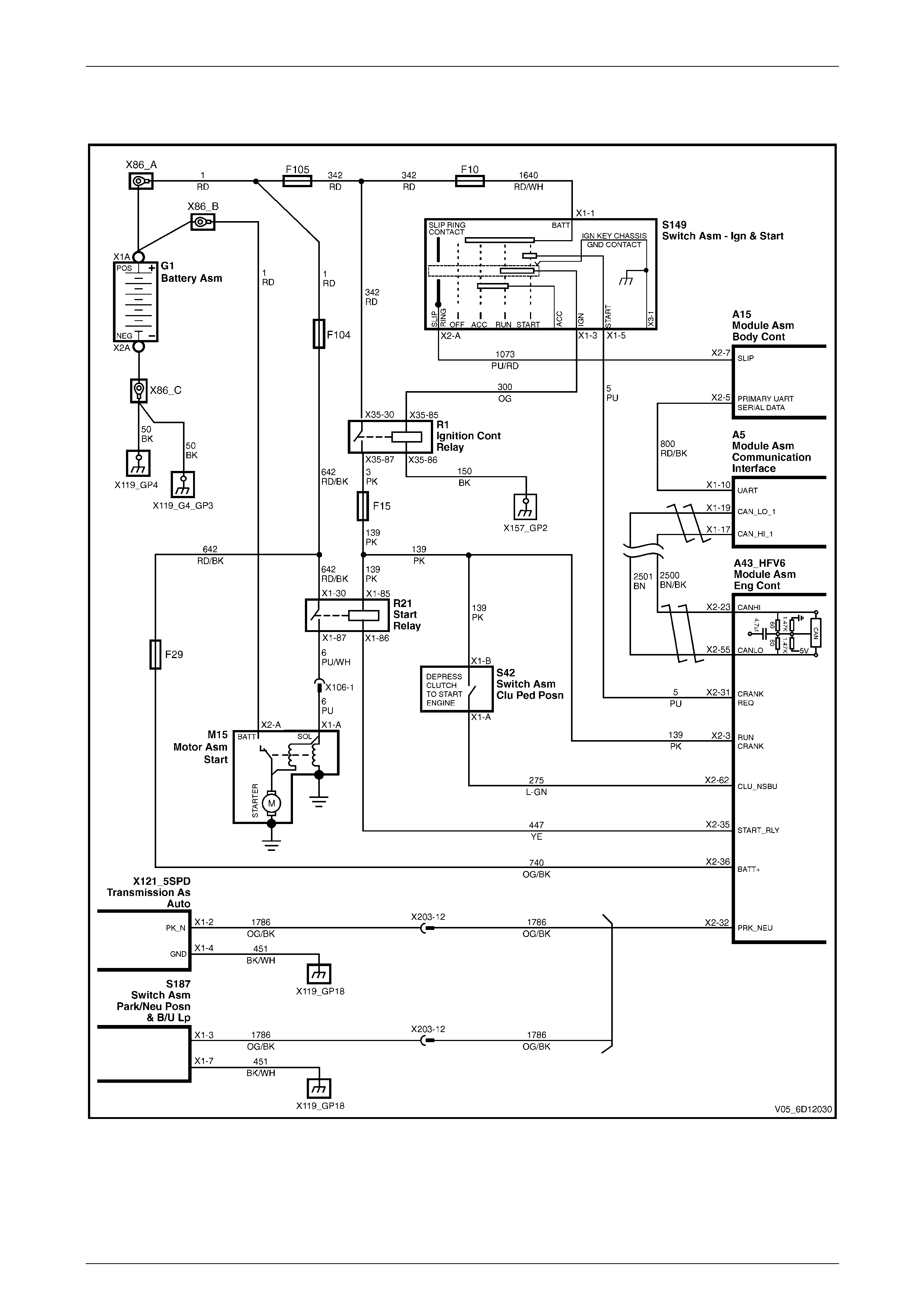
2.4 Wiring Diagram
Figure 6D1-2 – 2
Page 6D1-2–9

Starting System – V6 Page 6D1-2–10
2.5 Starting System Inoperative /
Malfunctioning
Circuit Description
The battery cable supplies a constant connection from the battery to starter solenoid connector M15 – X2 pin A
(circuit 1).
When the ignition switch is turned to the START position, 12 V is applied to the ECM connector A43 – X1 pin 32
(circuit 5).
For vehicles with 4 speed automatic transmission, when the transmission is in park (P) or neutral (N), the park / neutral
and back-up switch grounds ECM connector A43 – X2 pin 32 (circuit 1786).
For vehicles with 5 speed automatic transmission, when the transmission is in park (P) or neutral (N), the transmission
manual shift shaft switch assembly grounds ECM connector A43 – X2 pin 32 (circuit 1786).
For manual vehicles the clutch pedal position switch applies 12 V to ECM connector A43 – X2 pin 62 (circuit 275) when
the clutch pedal is depressed.
The ECM provides a ground for the start relay, ECM connector A43 – X2 pin 35 to start relay connector X100 – X1 pin 86
(circuit 447).
When activated the start relay provides 12 V to starter solenoid connector M15 – X1 pin A (circuit 6).
The solenoid closes its switch contacts to connect the battery voltage at the solenoid switch terminal M15 – X2 to the DC
motor. The pull-in winding of the solenoid switch is grounded through the DC motor winding and brushes. The hold-in
winding is grounded through the solenoid casing. The DC motor is grounded through the starter motor casing.
Security code data is exchanged between the remote key and the ECM via the ignition switch slip ring, ignition switch
connecter A149 – X2 pin A and BCM connecter A15 – X2 pin 7 (circuit 1073). The data is sent via the tertiary UART
serial data circuit from the BCM to PIM (circuit 800) and then to the ECM using the GM LAN serial data circuits, (circuits
2500 and 2501).
Refer to 2.4 Wiring Diagram to aid in diagnosis.
Diagnostic Table Notes
Reference to following information will assist when diagnosing starting circuit faults:
1 If the battery, starter motor and fuel system are deemed as serviceable and a ‘no crank’ and / or ‘no start’ condition
exists, refer to the following Sections as required:
a Section 12J Body Control Module for theft deterrent engine crank inhibitor related faults
b Section 6C1-2 Engine Management – V6 – Diagnostics for starter relay circuit faults
2 For all wiring harness fault diagnoses, refer to Section 12P Wiring Diagrams.
3 For wiring harness repairs, refer to Section 12P Wiring Diagrams.
4 Refer to Section 12O Fuses, Relays and Wiring Harnesses for harness routeing.
5 Ensure the battery, cables and connections are in good order. Refer to Section 12A Battery.
Diagnostic Table
Step Action Yes No
1 Did you review 1.2 System Operation?
Go to Step 2
Go to
1.2 System
Operation
2 Did you read 2.3 Diagnostic Systems Check
Go to Step 3
Go to
2.3 Diagnostic
Systems Check
3 Turn the ignition switch to the START position and then release it.
Did the engine crank or were there any clicking or chattering sounds
from the solenoid?
Go to Diagnostic
Table – Slow
Cranking, Solenoid
Clicks or Chatters Go to Step 4
Page 6D1-2–10

Starting System – V6 Page 6D1-2–11
Step Action Yes No
4 Inspect fusible link F104, refer to 12O Fuses, Relays and Wiring
Harnesses.
Is fusible link F104 blown?
Replace the faulty
fusible link
(refer to Note 3).
If the fusible link
blows again, repair
or replace circuit 1
(refer to Note 2) Go to Step 5
5 Inspect fusible link F105, refer to 12O Fuses, Relays and Wiring
Harnesses.
Is fusible link F105 blown?
Replace the faulty
fusible link
(refer to Note 3).
If the fusible link
blows again, repair
or replace circuit
342 (refer to Note 2) Go to Step 6
6 Inspect fuse F10, refer to 12O Fuses, Relays and Wiring Harnesses.
Is fuse F10 blown?
Replace the
faulty fuse
(refer to Note 3).
If the fuse blows
again, repair or
replace circuit 1640
(refer to Note 2) Go to Step 7
7 Inspect fuse F15, refer to 12O Fuses, Relays and Wiring Harnesses.
Is fuse F15 blown?
Replace the
faulty fuse
(refer to Note 3).
If the fuse blows
again, repair or
replace circuit 139
(refer to Note 2) Go to Step 8
8 NOTE
On manual vehicles ensure the clutch pedal is depressed
during this step. On automatic vehicles ensure that park
(P) or neutral (N) is selected.
Turn the headlamps on.
Turn the dome lamps on.
Turn the ignition switch to the START position.
Do the lamps dim? Go to Step 9 Go to Step 10
9 Perform the 3.3 On-Vehicle Testing.
Did you correct the condition?
Go to Step 24 Go to Step 2
10 1 Connect Tech 2 to the DLC.
2 Ignition on, engine off.
3 On Tech 2 select:
Engine / V6 Engine / Data Display / Data List /
Electrical/Theft Data.
4 On Tech 2 scroll to Crank Request
5 While monitoring Tech 2, turn the ignition switch to START.
Does Tech 2 display the following:
Inactive with the ignition switch in the ON position, Active with the
ignition switch in the START position? Go to Step 15 Go to Step 11
Page 6D1-2–11

Starting System – V6 Page 6D1-2–12
Step Action Yes No
11 1 Disconnect the ECM connector A43 – X2.
2 Using a multimeter set to measure voltage, back probe between
the harness connector A43 – X2 pin 31 and ground.
3 With the aid of an assistant, monitor the voltage on the
multimeter and turn the ignition switch to START.
• With the ignition switch in the START position, the
multimeter should display battery voltage
• With the ignition switch in the ON position, the multimeter
should display 0 V
Does the multimeter display as described?
Refer to
6C1 - 3 Engine
Management – V6 –
Service Operations
for further diagnosis.
Go to Step 24 Go to Step 12
12 Test the ignition switch, refer to 9 Steering.
Is the ignition switch serviceable?
Go to Step 13
Replace the faulty
ignition switch.
Refer to
9 Steering
Go to Step 24
13 Check for short to ground or open circuit in circuit 5.
Was the circuit serviceable?
Go to Step 14
Repair as required
(refer to Note 2).
Go to Step 24
14 Check for short to ground or open circuit in circuit 1640.
Was the circuit serviceable?
Go to Step 2
Repair as required
(refer to Note 2).
Go to Step 24
15 NOTE
This procedure is only required on vehicles fitted with
manual transmissions. If the vehicle is fitted with an
automatic transmission, go to Step 18
1 Scroll to Starter Relay
2 Ensure the clutch pedal is fully depressed.
3 While monitoring Tech 2, turn the ignition switch to START.
Does Tech 2 display the following:
Off with the ignition switch in the ON position,
On with the ignition switch in the START position? Go to Step 21 Go to Step 16
16 1 Disconnect the ECM connector A43 – X2.
2 Using a multimeter set to measure voltage, back probe between
the harness connector A43 – X2 pin 62 and ground.
3 With the aid of an assistant, monitor the voltage on the
multimeter fully depress the clutch pedal.
• With the clutch pedal fully depressed, the multimeter
should display battery voltage
• With the clutch pedal released, the multimeter should
display 0 V
Does the multimeter display as described?
ECU problem.
Refer to
6C1 - 3 Engine
Management – V6 –
Service Operations
for further diagnosis.
Go to Step 24 Go to Step 17
17 Remove and test the clutch pedal position switch, refer to Clutch Pedal
Switch.
Was the switch serviceable? Go to Step 18
Replace as
required.
Go to Step 24
Page 6D1-2–12

Starting System – V6 Page 6D1-2–13
Step Action Yes No
18 Check for short to ground or open circuit in circuits 139 and 275.
Was the circuit serviceable?
Go to Step 2
Repair as required
(refer to Note 2).
Go to Step 24
19 1 Scroll to Starter Relay
2 Ensure the transmission is in park (P) or neutral (N).
3 While monitoring Tech 2, turn the ignition switch to START.
Does Tech 2 display the following:
Off with the ignition switch in the ON position,
On with the ignition switch in the START position? Go to Step 21 Go to Step 20
20 1 Disconnect the ECM connector A43 – X2.
2 Using a multimeter set to measure voltage, back probe between
the harness connector A43 – X2 pin 32 and ground.
3 With the aid of an assistant, monitor the voltage on the
multimeter.
• With the place the transmission in park (P), the multimeter
should display 0 V
• With the place the transmission in neutral (N), the
multimeter should display 0 V
Does the multimeter display as described?
Refer to
6C1 - 3 Engine
Management – V6 –
Service Operations
for further diagnosis.
Go to Step 24
For vehicles fitted
with the 4 speed
automatic
transmission refer
to 7C4 Automatic
Transmission –
4L60E – On-vehicle
Servicing for further
diagnosis of the
park / neutral and
back-up switch.
For vehicles fitted
with the 5 speed
automatic
transmission refer
to 7D4 Automatic
Transmission –
5L40E – On-vehicle
Servicing for further
diagnosis of the
transmission
manual shift shaft
switch assembly
Go to Step 24
21 Test the starter relay.
Refer to 6C1-2 Engine Management – V6 – Diagnostics.
Is the starter relay serviceable? Go to Step 22
Repair or replace
as required
Go to Step 24
22 1 Using a multimeter set to measure voltage, back probe between
the harness connector M15 – X1 pin A and ground.
2 With the aid of an assistant, monitor the voltage on the
multimeter.
• Turn the ignition switch to START, the multimeter should
display 7.0 V
Does the multimeter display as described?
Repair or replace
the starter motor as
required.
Refer to
4 Major Service
Operations.
Go to Step 24 Go to Step 23
23 Check for short to ground or open circuit in circuits 6 and 275.
Was the circuit serviceable?
Go to Step 2
Repair as required
(refer to Note 2).
Go to Step 24
24 Operate the system in order to verify the repair.
Did you correct the condition? System OK Go to Step 2
When all diagno sis and repairs are completed, check the system for correct operation.
Page 6D1-2–13

Starting System – V6 Page 6D1-2–14
Diagnostic Table – Slow Cranking, Solenoid Clicks or Chatte rs
Step Action Yes No
1 Did you review 1.2 System Operation? Go to Step 2 Go to
1.2 System
Operation.
2 Did you read 2.3 Diagnostic Systems Check Go to Step 3 Go to
2.3 Diagnostic
Systems Check.
3 Perform the 3.3 On-Vehicle Testing.
Did you correct the condition?
Go to Step 4 Repair or replace
the starter motor.
Refer to
4 Major
Service Operations.
Go to Step 4
4 Operate the system in order to verify the repair.
Did you correct the condition? System OK Go to Step 2
When all diagno sis and repairs are completed, check the system for correct operation.
Page 6D1-2–14

Starting System – V6 Page 6D1-2–15
3 Minor Service Operations
3.1 Safety Precautions
Observe the following precautions. Failure to observe these precautions can result in serious damage to components.
• Refer to Section 00 Warnings, Cautions and Notes in this Service Information before disconnecting the battery.
• Use the starter motor on a negative ground system only.
• When installing a battery, attach the positive (+) cable to the battery first. Then attach the negative cable.
• When using a slave battery for starting purposes, ensure that both batteries are connected in parallel, that is.
positive to positive terminals and negative to negative terminals.
• Only use jumper leads that have surge protection.
Page 6D1-2–15

Starting System – V6 Page 6D1-2–16
3.2 Maintenance
Regular Checks
Check the following at regular intervals:
• Starter motor terminals – for corrosion and loose connectors.
• Wiring – for damaged insulation
• Mounting bolts – for tightness
• Battery terminals – for clean and secure connections.
Page 6D1-2–16
Starting System – V6 Page 6D1-2–17
3.3 On-Vehicle Testing
NOTE
The battery must be fully charged and in
serviceable condition before beginning these
tests, refer to Section 12A Battery.
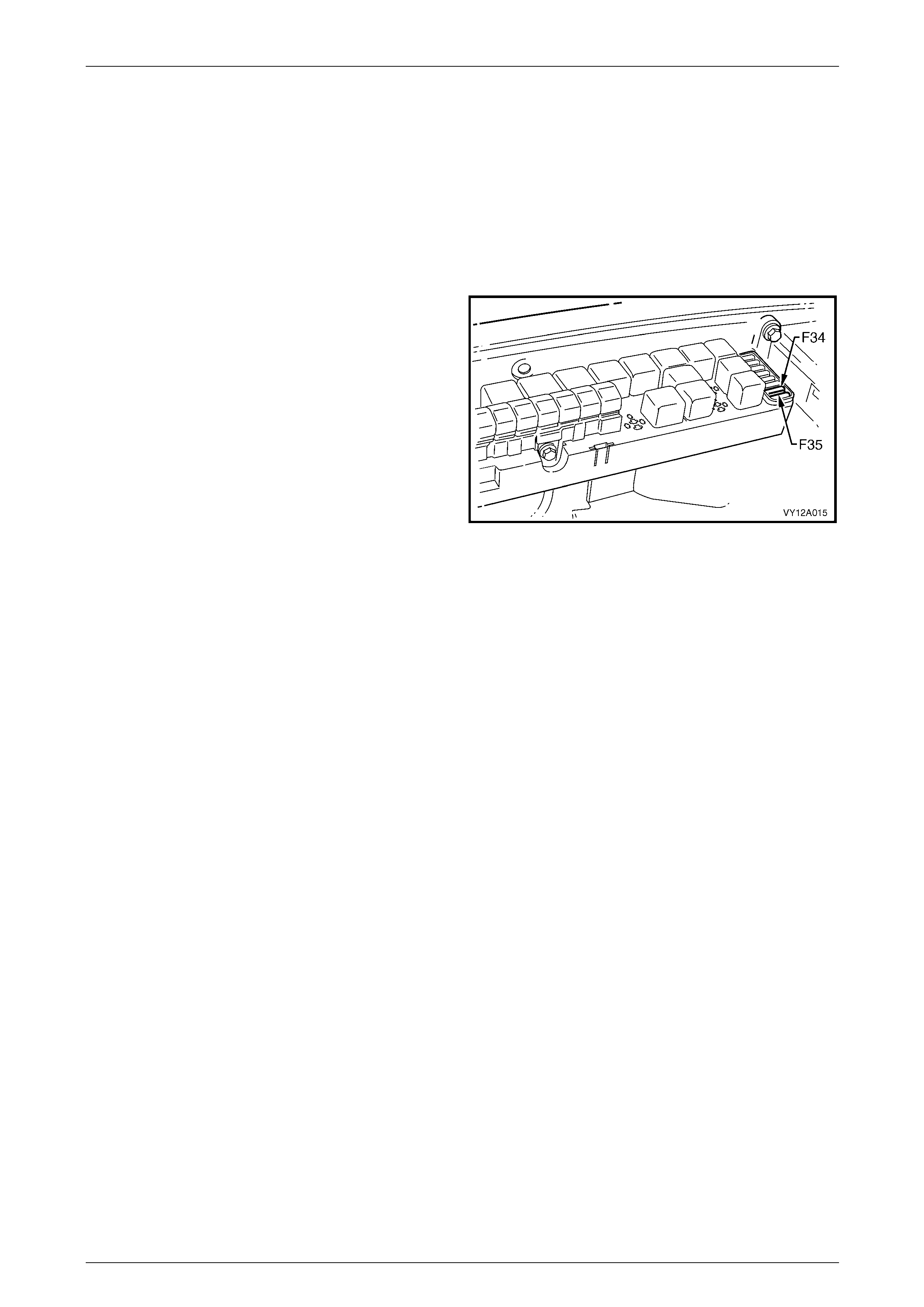
Prerequisites
1 Remove fuses F34 and F35 from the engine
compartment fuse box to disable the ignition and
prevent the engine from starting, refer to
Section 12O Fuses, Relays and Wiring Harnesses.
Figure 6D1-2 – 1
1 Chock the wheels.
2 For vehicles fitted with automatic transmission ensure the transmission is in P (park) or N (neutral) and the hand
brake is applied.
3 For manual vehicles ensure the clutch is depressed when cranking the engine.
4 Ensure the engine is at room temperature or normal operating temperature and in good working order.
Bad Connection Test
A bad connection appears as a voltage reading when the multimeter leads are connected to two different positive (or
negative) connections.
1 Using a multimeter set to measure voltage, connect the multimeter’s positive lead to the positive battery post.
2 Connect the multimeter’s negative lead to the starter motor M terminal.
3 Record the voltage that displayed during cranking.
4 Repeat this with the multimeter’s negative lead connected to the solenoid switch connector M15 – X2 pin A
(circuit 1).
5 Also repeat this connecting the multimeter’s negative lead to the battery cable strands (circuit 1).
6 Restore all connections that show a significant resistance (voltage reading).
Page 6D1-2–17
Starting System – V6 Page 6D1-2–18
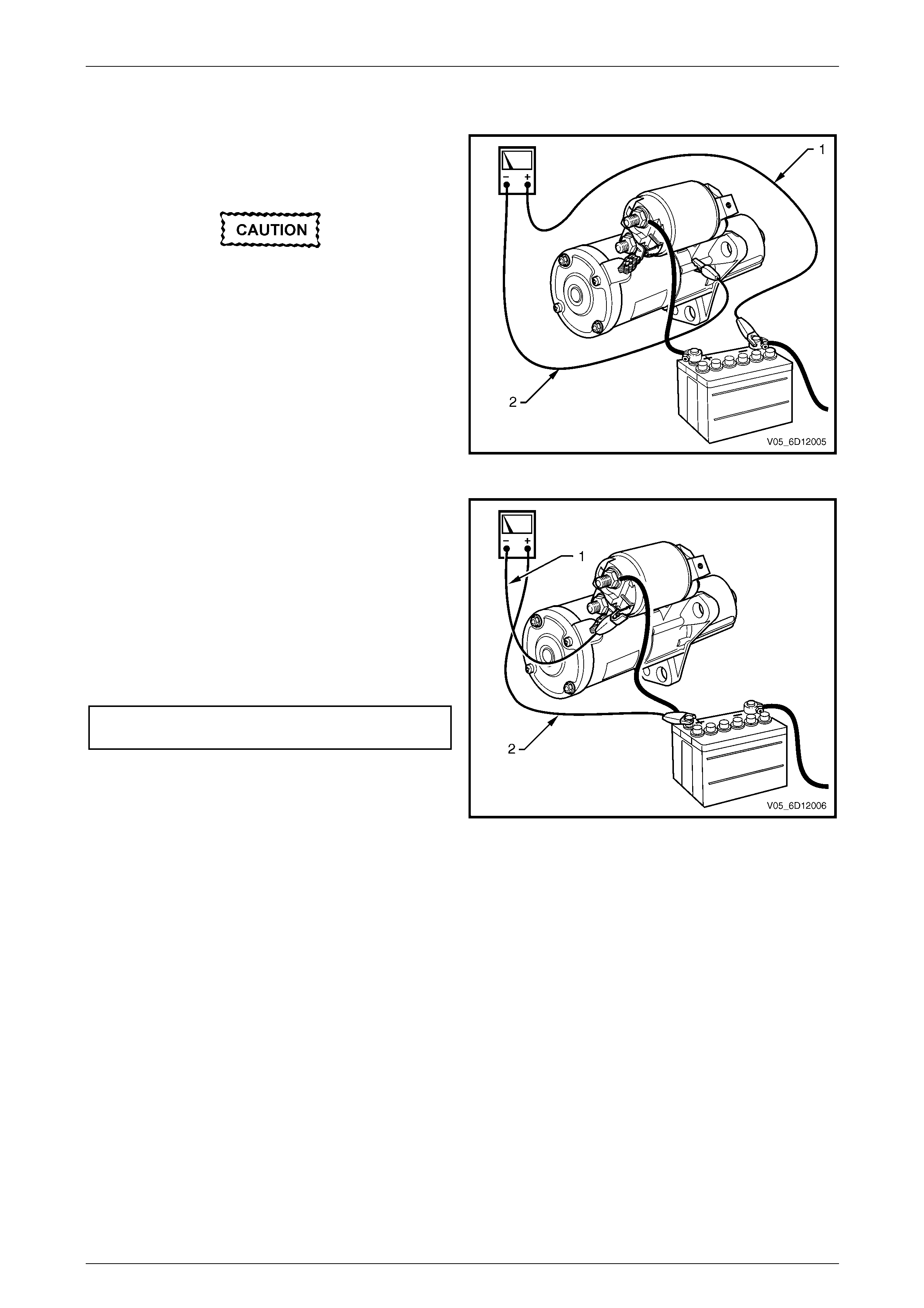
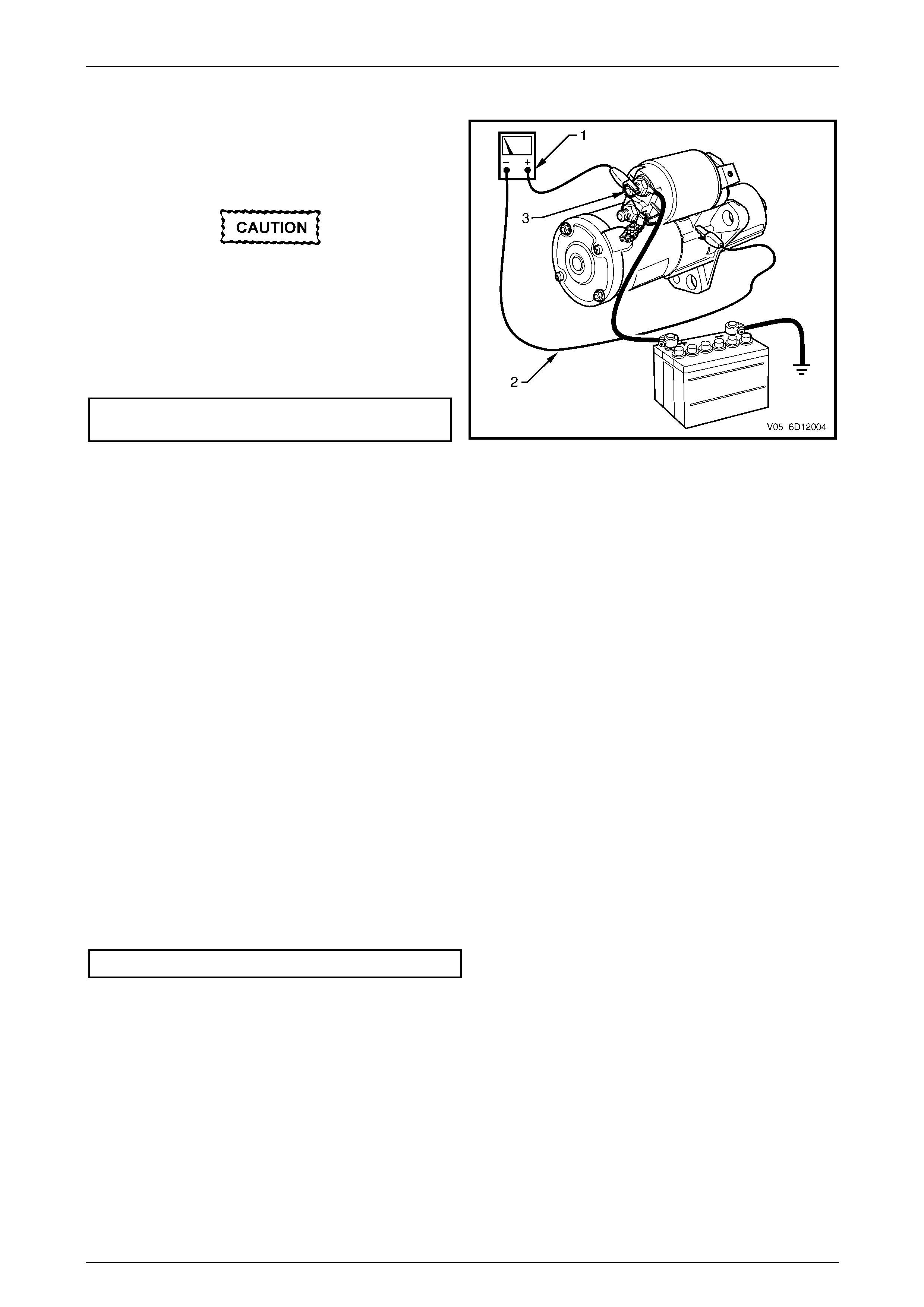
Starter Motor Ground Test
1 Using a multimeter set to measure voltage, connect
the multimeter’s positive lead (1) to the negative
battery post.
Connect the lead to the actual battery post
and not to the cable or connector.
2 Connect the multimeter’s negative lead (2) to the
starter motor housing.
3 Record the voltage that displayed during cranking.
4 Repeat this connecting the multimeter’s negative
lead to the battery cable strands (circuit 50).
5 Restore all ground connections that show a
significant resistance.
Figure 6D1-2 – 2
Switching Circuit Test
1 Using a multimeter set to measure voltage, connect
the multimeter’s negative lead (1) to the solenoid
switch connector M15 – X1 pin A (circuit 6).
2 Connect the multimeter‘s positive lead (2) to the
positive battery post.
3 Crank the engine.
4 Record the voltage that displayed during cranking.
Maximum switching
circuit voltage difference .........................................2.5 V
5 If the voltage is above the specification, test the
solenoid switching circuit to locate the cause of the
high resistance and restore the connection.
Figure 6D1-2 – 3
Page 6D1-2–18
Starting System – V6 Page 6D1-2–19
Cranking Voltage Test
1 Using a multimeter set to measure voltage, attach
the multimeter’s negative lead to ground and the
multimeter’s positive lead to starter solenoid
connector M15 – X1 pin A (3) of the solenoid switch.
Do not crank the engine for more than
30 seconds at a time. Allow 2 minutes for
the starter motor to cool down between
tests.
3 Crank the engine.
4 Record the voltage that displayed during cranking.
Minimum cranking
voltage ....................................................................9.0 V
5 Remove and repair or replace the starter motor
and solenoid switch if the voltage is below the
specifications and cranks poorly. Refer to
4 Major Service Operations.
Figure 6D1-2 – 4
Current Draw Test
1 Using a multimeter set to measure voltage, attach the multimeter’s positive lead to the positive battery post.
2 Attach the same multimeter’s negative lead to the negative battery post.
3 Using a multimeter set to measure current, attach the multimeter’s positive lead to the battery post.
4 Connect the negative lead of the multimeter set to measure current to a battery loading device, for example a
carbon pile.
5 Connect the free lead of the battery loading device to the negative battery terminal.
6 Set the battery loading device to maximum resistance (open).
7 Crank the engine.
8 Record the voltage that displayed during cranking.
9 With the ignition in the OFF position, adjust the battery loading device so the reading of the multimeter set to
measure voltage matches the reading recorded in the last step.
10 Record the current draw from the battery loading device.
11 Set the battery loading device back to ‘open’.
12 Check the current draw is within specifications.
Cranking current range ................................100 – 140 A
13 Remove and repair or replace the starter motor and solenoid switch if the current draw is outside the specification.
Refer to 4 Major Service Operations.
Page 6D1-2–19
Starting System – V6 Page 6D1-2–20
Clutch Pedal Switch
Remove
NOTE
V6 Vehicles are fitted with two clutch pedal switch
assemblies. The wiring diagrams treat both
physical switches as one assembly designated as
S42, Clutch Pedal Position Switch Assembly.
However these are two physical switches with
separate functions. One ensures the engine can
only be cranked with the clutch pedal depressed.
The switch mounted closest to the firewall is the
switch which has input to the starting system.
1 Disconnect the wiring harness connectors from the switch.
2 Turn the switch 90°, then pull the switch assembly out from the support to remove.
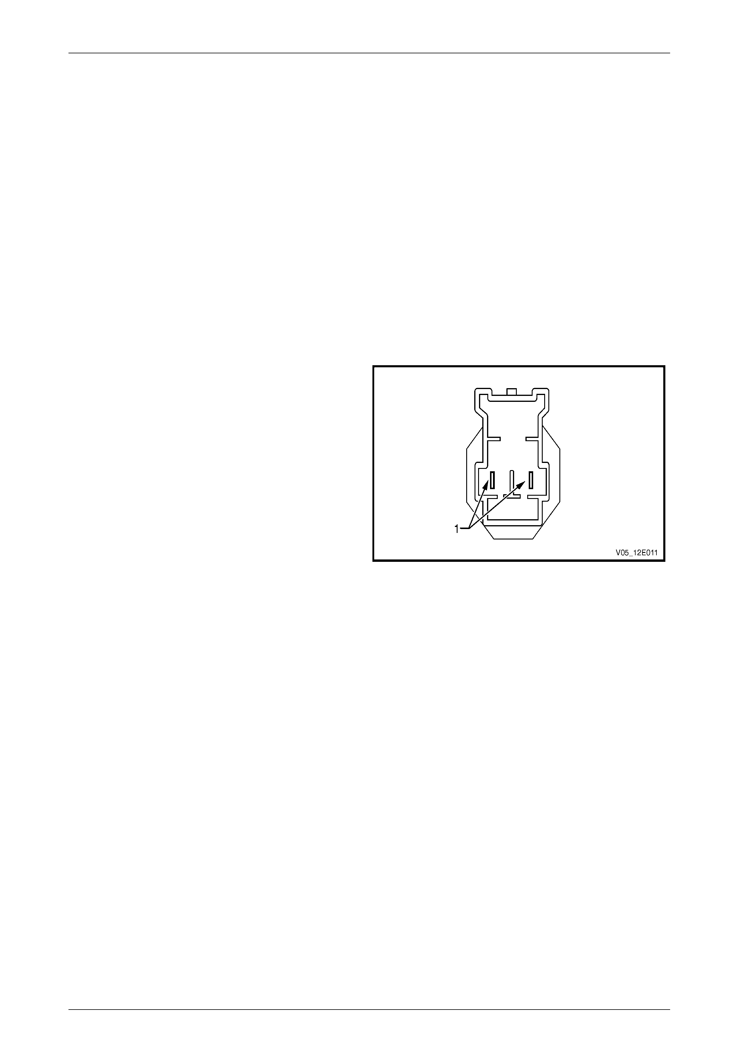
Test
1 Using a multimeter, probe the pins (1) of the switch
assembly.
2 In the neutral position (plunger extended) there should
be an open circuit across the switch.
3 In the active position (plunger depressed) there should
be continuity across the switch.
4 Replace the switch as per the following reinstall
procedure if the tests prove the switch to be faulty.
5 If the test proves the switch to be serviceable,
reinstall it as per the following procedure.
Figure 6D1-2 – 5
Reinstall
1 Install the switch by pushing the switch assembly through the support and turning the switch 90°.
2 Connect the wiring harness connectors to the clutch switch.
3 Verify the operation of the clutch switch by operating the starting system and checking the clutch switch prevents
operation of the starter motor when the clutch pedal is not pressed.
Page 6D1-2–20
Starting System – V6 Page 6D1-2–21
4 Major Service Operations
Disconnection of the battery affects certain
vehicle electronic systems. Refer to
Section 00 Warnings, Cautions and Notes
before disconnecting the battery.
4.1 Starter Motor – RWD
LT Section – 02-070
Remove
The starter motor is in close proximity to the
left-hand side exhaust manifold and engine
pipe. Allow the engine to cool before
attempting to remove the starter motor.
1 Refer to Section 00 Warnings, Cautions and Notes in this Service Information before disconnecting the battery.
2 Disconnect the battery ground lead.
3 Raise the front of the vehicle. For jacking locations, refer to Section 0A General Information.
4 Put safety stands in place.
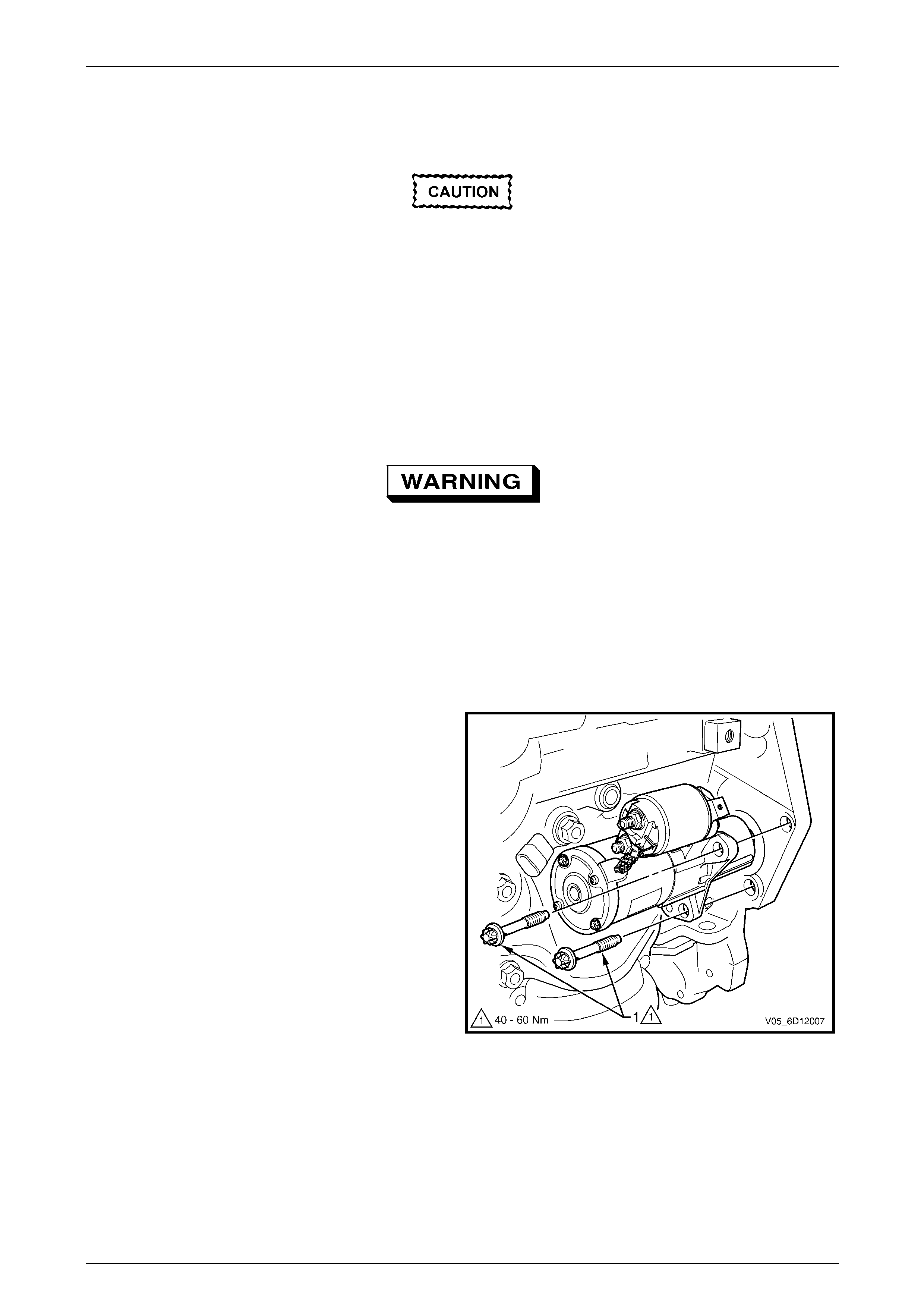
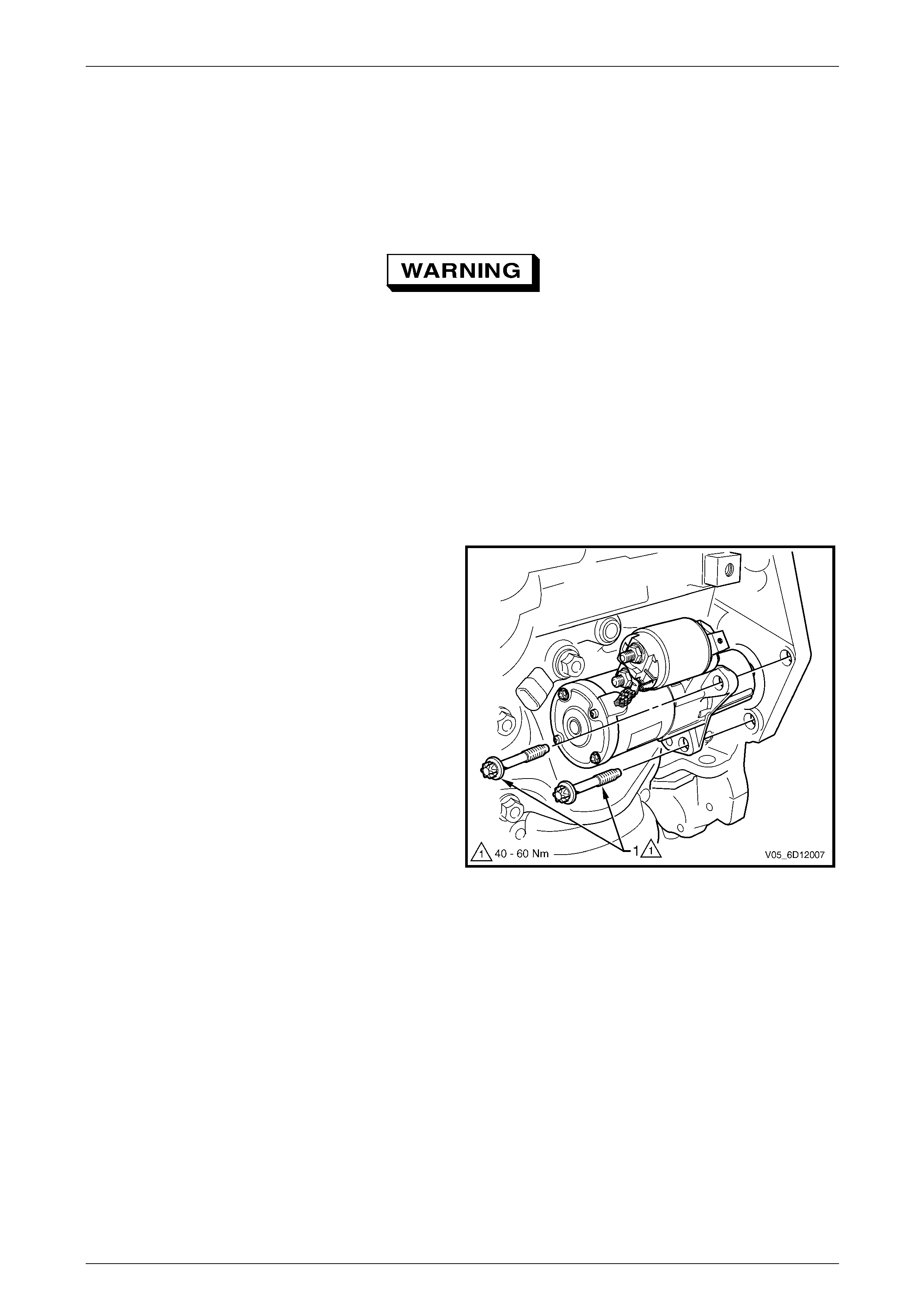
5 Remove the starter motor mounting bolts (1).
6 Remove the starter motor from the engine block and
lower the starter motor as far as possible to gain
access to the wiring harness connections.
Figure 6D1-2 – 6
Page 6D1-2–21
Starting System – V6 Page 6D1-2–22
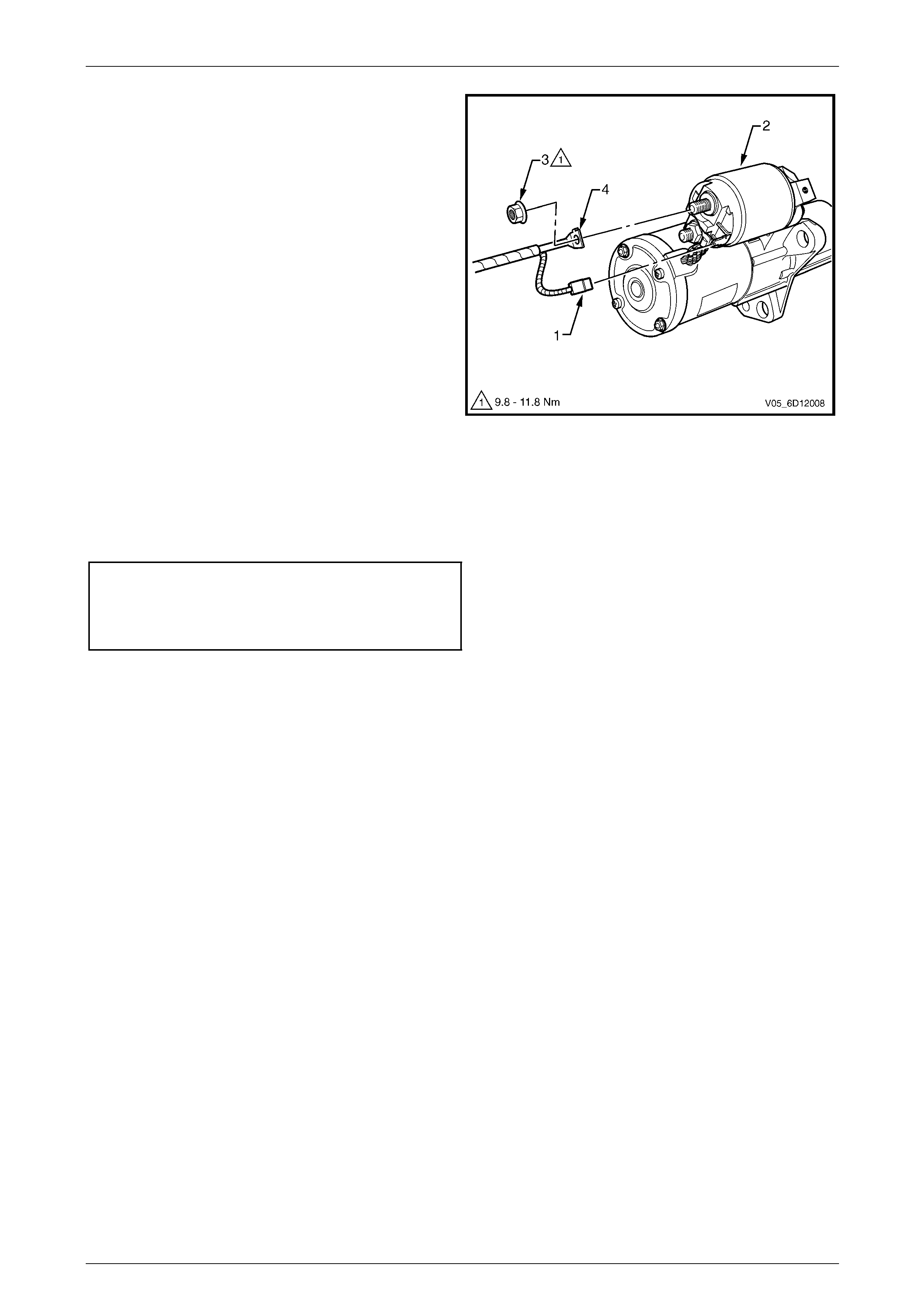
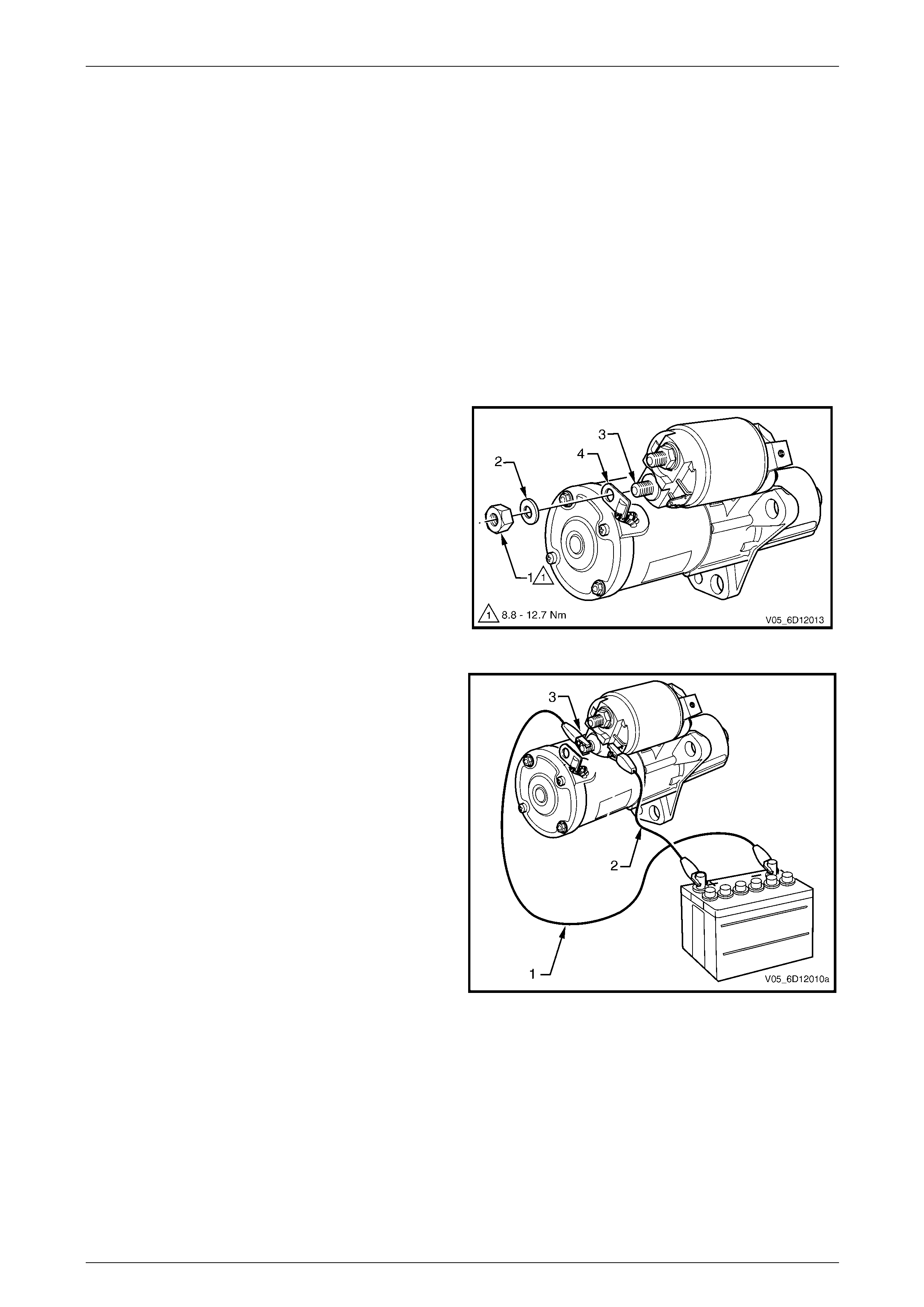
7 Remove the wiring harness connector M15 – X1 (1)
from the solenoid switch (2).
8 Remove the nut (3) and battery lead connector
M15 – X2 (4) from solenoid switch.
9 Remove the starter motor from below the vehicle
between the catalytic converter and transmission bell
housing.
Figure 6D1-2 – 7
Reinstall
Reinstallation of the starter motor is the reverse of the removal procedure noting the following:
1 Tighten all fasteners to the correct torque specification.
Starter motor mounting bolt
torque specification .................................40.0 – 60.0 Nm
Solenoid switch connector M15 – X2 nut (B+)
torque specification ...................................9.8 – 11.8 Nm
2 Check the starter motor operates correctly.
Page 6D1-2–22
Starting System – V6 Page 6D1-2–23
4.2 Starter Motor – AWD
LT Section – 02-070
Remove
The starter motor is in close proximity to the
left-hand side exhaust manifold and engine
pipe. Allow the engine to cool before
attempting to remove the starter motor.
1 Refer to Section 00 Warnings, Cautions and Notes in this Service Information before disconnecting the battery.
2 Disconnect the battery ground lead.
3 Raise the front of the vehicle. For jacking locations, refer to Section 0A General Information.
4 Put safety stands in place.
5 Remove the front constant velocity joint from the front final drive pinion flange.
Refer to Section 4C2 Front Propeller Shaft and Universal Joints.
6 Remove the starter motor mounting bolts (1).
7 Remove the starter motor from the engine block and
lower the starter motor as far as possible to gain
access to the wiring harness connections.
NOTE
The starter motor is most easily removed from its
installed position by tilting the front upwards and
rotating the assembly so the solenoid switch
moves toward the engine.
Figure 6D1-2 – 8
Page 6D1-2–23

Starting System – V6 Page 6D1-2–24
8 Remove the wiring harness connector M15 – X1 (1)
from the solenoid switch (2).
9 Remove the nut (3) and battery lead connector
M15 – X2 (4) from solenoid switch.
10 Remove the starter motor.
Figure 6D1-2 – 9
Reinstall
Reinstallation of the starter motor is the reverse of the removal procedure noting the following:
1 Tighten all fasteners to the correct torque specification.
Starter motor mounting bolt
torque specification .................................40.0 – 60.0 Nm
Solenoid switch connector M15 – X2 nut (B+)
torque specification ...................................9.8 – 11.8 Nm
2 Check the starter motor operates correctly.
Page 6D1-2–24
Starting System – V6 Page 6D1-2–25
4.3 Starter Motor Bench Tests
LT Section – 02-070
Preliminary Checks
1 Check the drive assembly is fully retracted.
2 Check the drive assembly pinion turns freely on the planetary drive shaft.
3 Perform the No Load Test (as outlined in this Section) if the drive assembly is not fully retracted.
4 Disassemble and service the starter motor if it fails the No Load test, refer to 4.4 Starter Motor Disassemble and
Reassemble in this Section.
Pull-in Test
1 Clamp the starter motor, by the mounting lug in the
drive-end housing, in a vice with soft jaws.
2 Remove the nut (1) and washer (2) from the
solenoid switch M terminal (3).
3 Remove the braided cable (4) from the solenoid
switch M terminal.
Figure 6D1-2 – 10
4 Connect the starter motor to an auxiliary battery, as
follows:
a Connect the test lead (1) between the battery
negative post to the solenoid switch M terminal
(3).
b Connect the test lead (2) battery positive post.
5 Momentarily hold the free end of test lead (2) to
solenoid switch terminal M15 – X1.
6 Check the solenoid switch activates and the drive
assembly moves outward.
7 Disassemble and service the starter motor if the
solenoid switch activates but the drive assembly
does not move, refer to 4.4 Starter Motor
Disassemble and Reassemble in this Section.
8 Replace the solenoid switch if it does not activate
(there is no sound or movement).
Figure 6D1-2 – 11
Page 6D1-2–25
Starting System – V6 Page 6D1-2–26
Hold-in Test
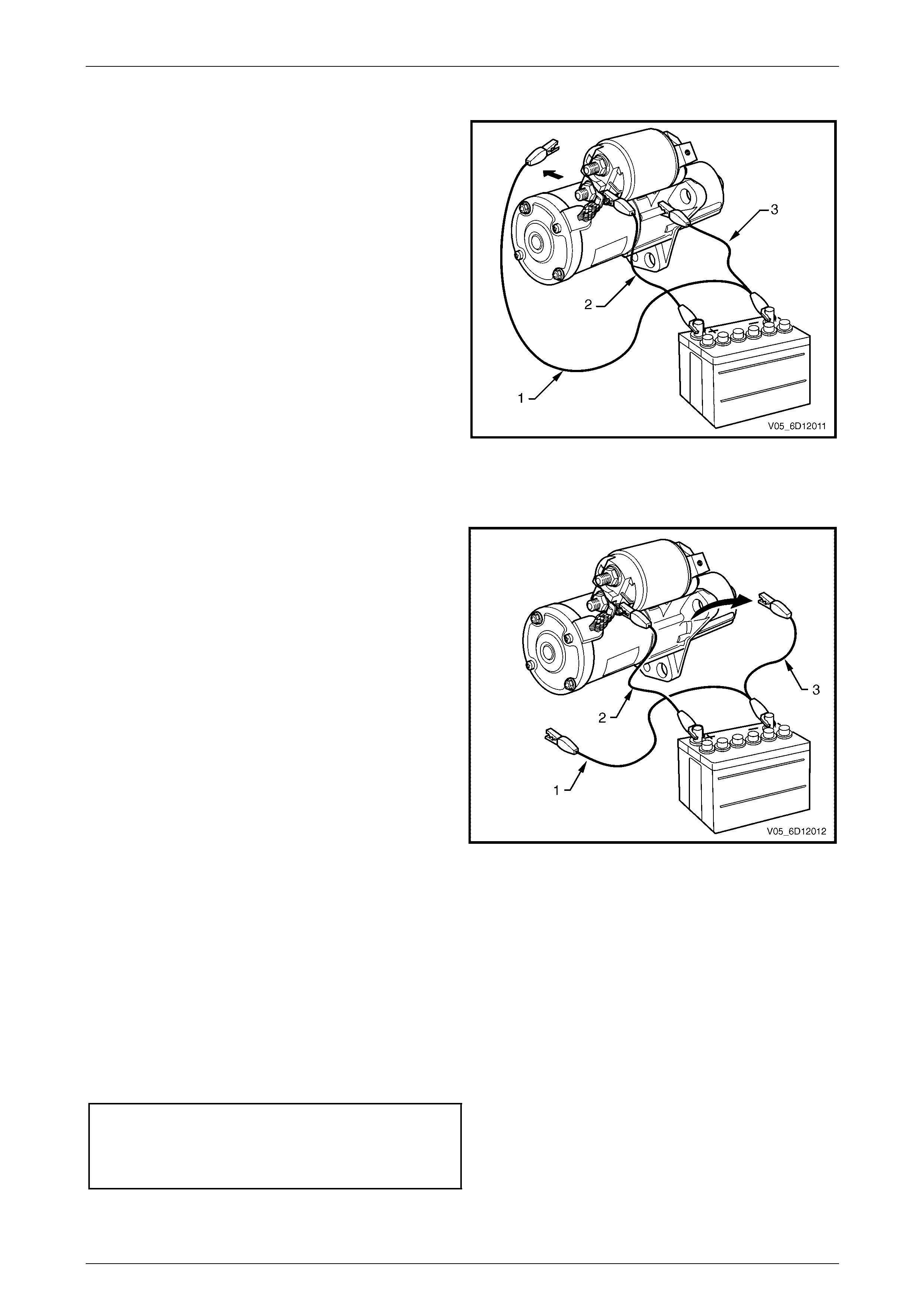
1 Connect the starter motor to an auxiliary battery, as
follows:
a Connect the test lead (1) between the battery
negative post to the solenoid switch M terminal.
b Connect the test lead (2) from the battery
positive post to solenoid switch terminal
M15 – X1.
c Connect the test lead (3) to the starter motor
casing.
2 Disconnect the test lead (1) from the M terminal of
the solenoid switch.
3 Check the drive assembly remains extended.
4 Replace the solenoid switch if the drive assembly
returns back into the starter motor.
Figure 6D1-2 – 12
Drive Assembly Return Test
1 Connect the starter motor to an auxiliary battery, as
follows:
a Connect the test lead (1) between the battery
negative post to the solenoid switch M
terminal.
b Connect the test lead (2) from the battery
positive post to solenoid switch terminal
M15 – X1.
c Connect the test lead (3) to the starter motor
casing.
2 Disconnect the test lead (1) from the M terminal of
the solenoid switch.
3 Disconnect the negative lead (2) from the starter
motor casing.
4 Check the drive assembly returns back into the
starter motor.
5 Replace the solenoid switch if the drive assembly
does not retract.
Figure 6D1-2 – 13
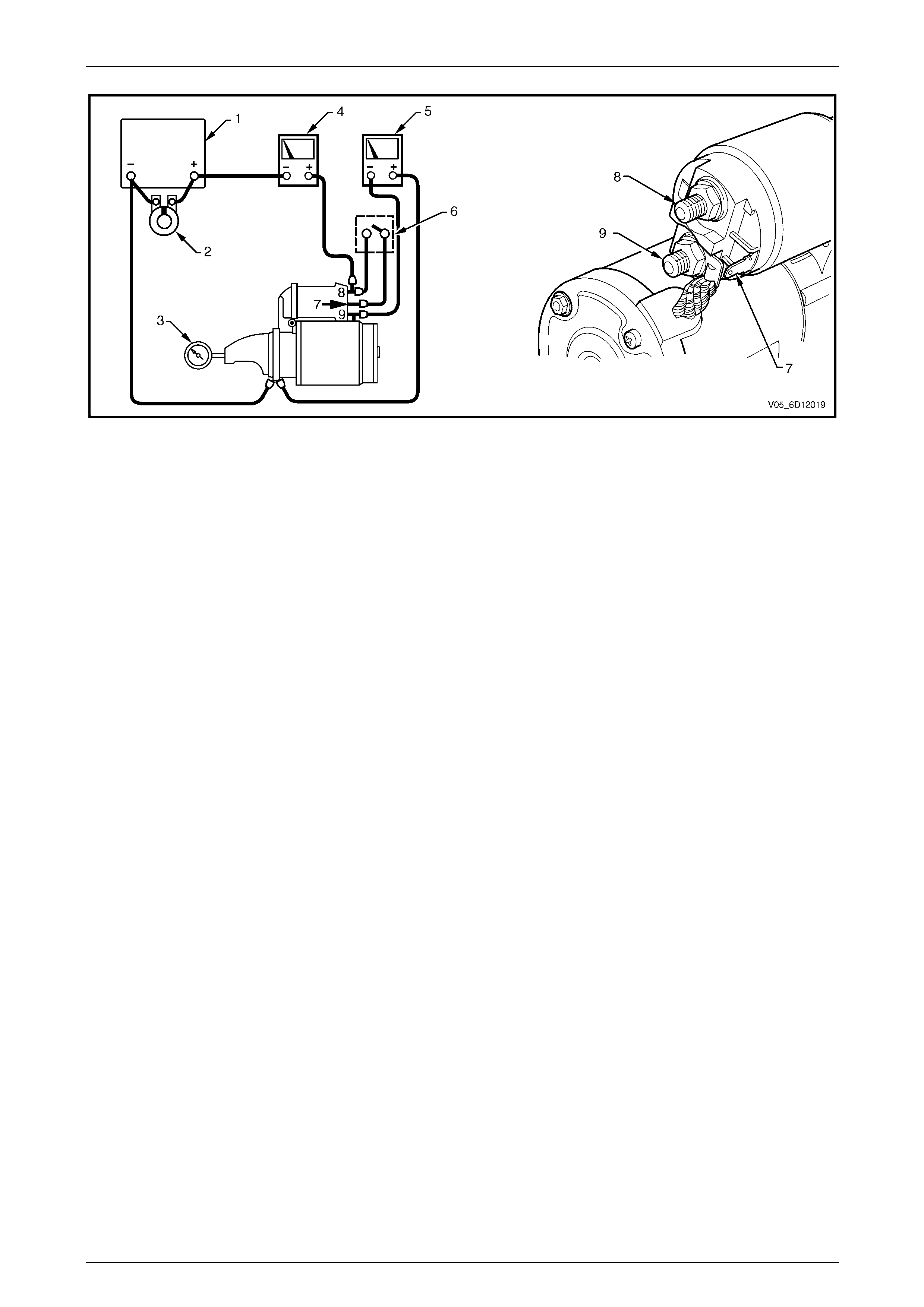
No Load Test
1 Clamp the starter motor securely to a test bench.
2 Connect the starter motor as shown in Figure 6D1-2 – 14.
3 Close the start switch to activate the starter motor.
4 Record the speed of the planetary drive shaft, current draw and the voltage.
5 Check the readings are within the specifications.
Minimum r.p.m. ....................................................... 2370
Maximum current draw ............................................65 A
M Terminal voltage .........................................12 ± 0.1 V
6 Disassemble and service the starter motor if the readings are not within the specifications, refer to
4.4 Starter Motor Disassemble and Reassemble.
Page 6D1-2–26
Starting System – V6 Page 6D1-2–27
Figure 6D1-2 – 14
Legend
1 Battery
2 Carbon Pile
3 Shaft Speed Indicator
4 Multimeter set to measure current
5 Multimeter set to measure voltage
6 Start Switch
7 Solenoid Switch M15 – X1 pin A
8 Solenoid Switch M15 – X2 pin A
9 Solenoid Switch M terminal
Page 6D1-2–27

Starting System – V6 Page 6D1-2–28
4.4 Starter Motor Disassemble and
Reassemble
LT Section – 02-070
Disassemble
1 Clamp the starter motor, by the mounting lug in the
drive-end housing, in a vice with soft jaws.
2 Remove the nut (1) and washer (2) from the
solenoid switch M terminal (3).
3 Remove the braided cable (4) from the M terminal.
Figure 6D1-2 – 15
4 Scribe aligning marks (1) on the drive-end
housing (2) and the solenoid switch housing (3) to
aid reassembly.
When using an impact driver, avoid
damaging the drive-end housing or
rounding the screw slots of the solenoid
switch mounting screws.
5 Remove the two solenoid switch mounting
screws (4). It may be necessary to loosen the
mounting screws using an impact driver.
Figure 6D1-2 – 16
6 Remove the solenoid switch from the drive-end
housing.
Do not lose the plunger return spring.
7 Unhook and remove the solenoid switch plunger (1)
from the drive assembly fork lever (2).
Figure 6D1-2 – 17
Page 6D1-2–28

Starting System – V6 Page 6D1-2–29
Reassemble
1 Reassemble the solenoid in the reverse order of the disassembly procedure noting the following points.
Dry all parts thoroughly before assembly,
taking care not to breathe in any vapours.
2 Lightly coat the solenoid switch plunger with 10% molybdenum disulphide grease.
Excess grease can en ter the contact chamber
of the solenoid switch and cause contact
problems. Do not use too much grease.
3 Hook the plunger over the fork lever.
4 Insert the return spring into the plunger.
5 Slide solenoid switch over the plunger.
6 Align the solenoid switch with drive-end housing ensuring the solenoid switch terminal M15 – X2 faces away from
the pole housing.
7 Install and tighten the solenoid switch mounting screws.
Solenoid switch mounting screw
torque specification .....................................4.1 – 7.6 Nm
8 With the starter motor reassembled, perform a No Load Test, refer to 4.3 Starter Motor Bench Tests.
9 If the starter motor fails the No Load Test specification, replace the starter motor.
Page 6D1-2–29
Starting System – V6 Page 6D1-2–30
4.5 Solenoid Switch Tests
LT Section – 02-070
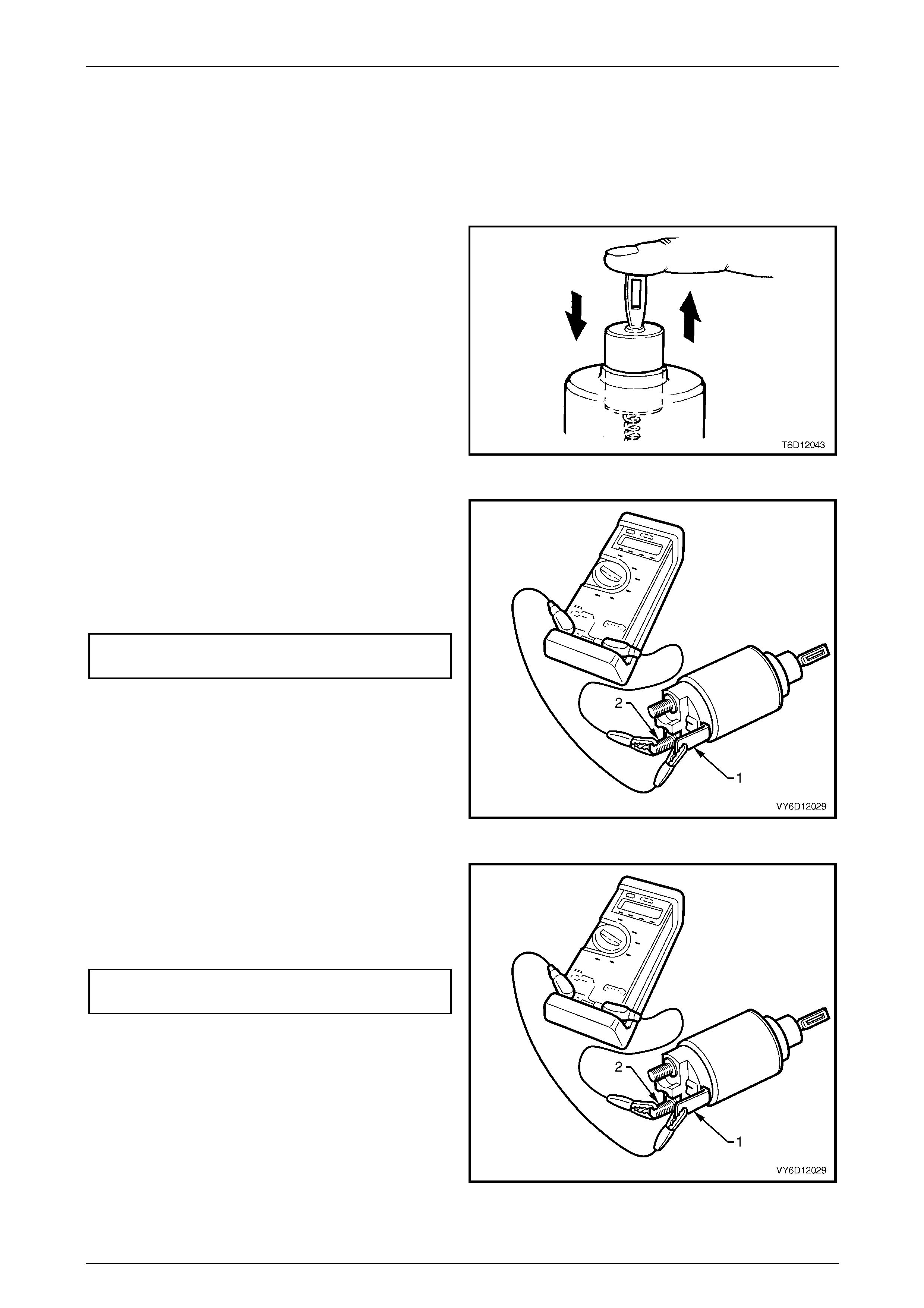
Test the Solenoid Switch
1 Inspect the solenoid switch for any external damage.
2 Replace the solenoid switch if it displays significant
damage.
3 Install the return spring and plunger into the solenoid
switch.
4 Check the movement of the plunger, as follows:
a Depress the plunger fully.
b Release the plunger.
c If the plunger sticks or binds in the switch bore,
clean or replace the solenoid switch assembly
as required.
Figure 6D1-2 – 18
5 Connect a multimeter set to measure resistance
between the solenoid switch M terminal (1) and the
solenoid switch terminal M15 – X1 (2).
6 Record the resistance reading.
7 Replace the solenoid switch if the resistance is
outside the specification.
Pull-in winding resistance
@ 20° C .....................................................0.33 – 0.37 Ω
Figure 6D1-2 – 19
8 Connect a multimeter set to measure resistance
between the solenoid switch housing (1) and the
solenoid switch terminal M15 – X1 (2).
9 Replace the solenoid switch if the resistance is
outside the specification.
Hold-in winding resistance
@ 20° C .....................................................0.75 – 0.87 Ω
Figure 6D1-2 – 20
Page 6D1-2–30
Starting System – V6 Page 6D1-2–31
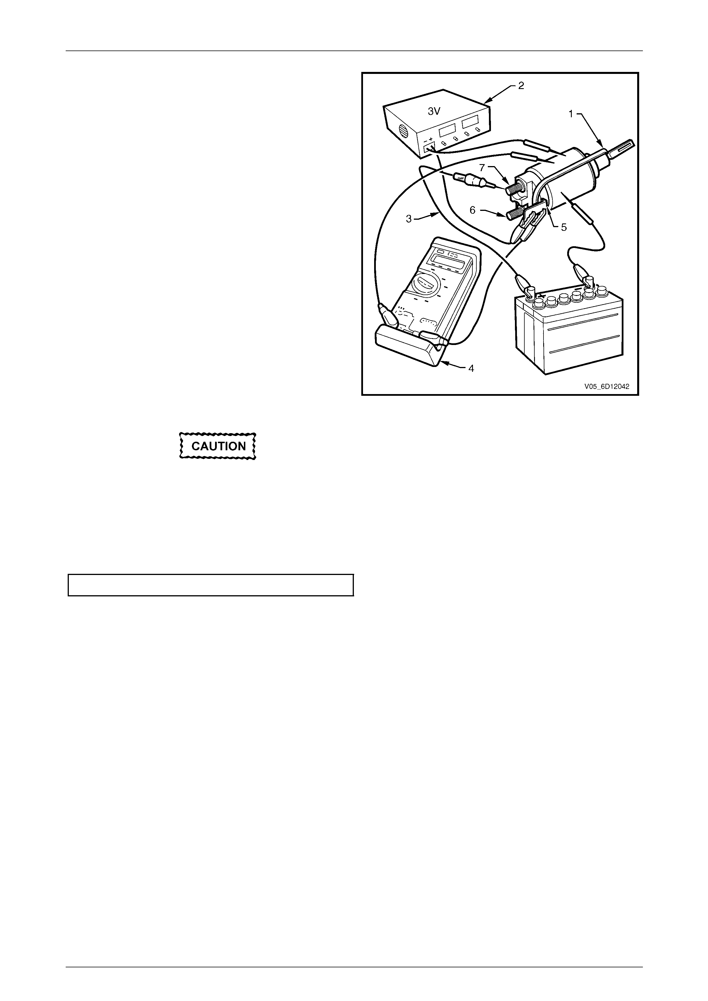
10 Fit a rubber band (1) around the plunger and switch
housing to avoid ejecting the plunger.
11 Hold the solenoid switch vertically with the plunger
pointing upwards.
12 Use a power supply (2) capable of supplying 30 A or
use a battery and a variable resistor.
13 Set the power supply to 3.0 V.
14 Connect the power supply negative lead to the
solenoid switch body.
15 Connect the power supply positive lead to the
solenoid switch terminal M15 – X1 (5).
16 Connect a test lamp (3) between the solenoid switch
terminal M15 – X2 (7) and the battery.
17 Connect a multimeter set to measure voltage (4)
between the solenoid switch terminal M15 – X1 (5)
and the solenoid switch housing.
18 Press the solenoid plunger in until the test lamp
illuminates.
19 Allow the plunger to move out by 8 – 10 mm.
20 Hold the plunger in this position.
The test duration for the following step
should be no more than 2 seconds.
Figure 6D1-2 – 21
21 Slowly increase the power supply voltage on the solenoid switch terminal M15 – X1 until the plunger pulls in.
22 Record the multimeter reading and reduce the voltage applied to the solenoid switch terminal M15 – X1.
23 Replace the solenoid switch if the voltage reading is significantly higher than the specification.
Pull-in voltage @ 20°C............................................7.8 V
24 Check the continuity across the main contacts in the switch.
25 Increase the voltage on the solenoid switch terminal M15 – X1 (5) until the plunger pulls in.
26 Ensure the test lamp illuminates fully.
27 Replace the solenoid switch if the test lamp illuminates poorly.
Page 6D1-2–31
Starting System – V6 Page 6D1-2–32
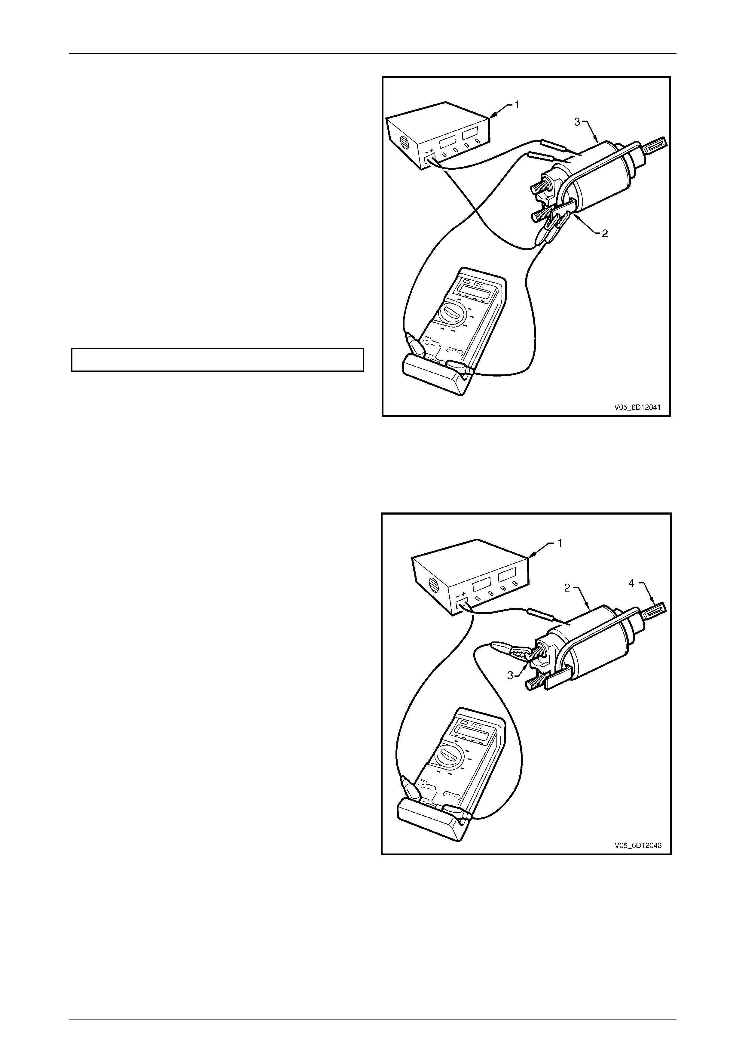
28 Set the power supply to 12 V (1).
29 Connect the power supply positive lead to the
solenoid switch terminal M15 – X1 (2).
30 Connect the power supply negative lead to the
solenoid switch housing (3).
31 Press the plunger in fully.
32 Release the plunger. The hold-in winding should
hold the plunger in.
33 Replace the solenoid switch if the winding does not
hold the plunger in.
34 Decrease the voltage until the plunger releases.
35 Record the multimeter reading.
36 Replace the solenoid switch if the voltage reading is
significantly higher than the specification.
Hold-in voltage @ 20°C .................................0.2 – 2.0 V
37 Connect a test lamp between the solenoid switch
terminal M15 – X2 and the 12 volt power supply.
38 Press the plunger in until the test lamp illuminates.
39 Attempt to press the plunger into the solenoid switch
housing a further 1 mm.
40 Replace the solenoid switch if the plunger cannot
move at least a further 1 mm.
Figure 6D1-2 – 22
41 Connect the positive lead of a 24 volt power
supply (1) to the positive lead of a multimeter set to
measure voltage.
42 Connect the negative lead of a 24 volt power supply
to the solenoid switch housing (2).
43 Connect the multimeter negative lead to the solenoid
switch terminal M15 – X2.(3)
44 Press the plunger (4) in fully.
45 Release the plunger. The plunger should return to its
rest position.
46 Replace the solenoid switch if the plunger does not
return.
NOTE
This indicates the windings have an internal
winding short circuit. When the solenoid switch
is connected in this way, the winding fields are
in opposition to each other.
Figure 6D1-2 – 23
Page 6D1-2–32

Starting System – V6 Page 6D1-2–33
5 Specifications
Type............................................... Six Pole Permanent Magnet, Four Brush, Planetary Drive
Rotation (Drive-End View) ....................................................................................... Clockwise
Number of Pinion Teeth........................................................................................................12
No load:
Minimum RPM ..................................................................................................................2370
Maximum Current Draw............................................................................ 65 A at 12.0 ± 0.1 V
M Terminal Voltage......................................................................................................12 ± 1 V
Locked:
Maximum Current (Including Solenoid Switch) ............................................................... 780 A
M Terminal Voltage............................................................................................................. 4 V
Minimum Torque............................................................................................................ 20 Nm
Solenoid detached:
Pull-in Winding Resistance @ 20°C ................................................................... 0.33 – 0.37 Ω
Hold-in Winding Resistance @ 20°C .................................................................. 0.75 – 0.87 Ω
Pull-in Voltage @ 20°C..........................................................................................8 V @ 20°C
Hold-in Voltage @ 20°C...........................................................................................1.7 – 3.0 V
Page 6D1-2–33

Starting System – V6 Page 6D1-2–34
6 Torque Wrench Specifications
Nm
Solenoid Switch Mounting Screw .........................................................4.1 – 7.6
Solenoid Switch Terminal M Nut ........................................................8.8 – 12.7
Starter Motor Mounting Bolt..............................................................40.0 – 60.0
Solenoid Switch Terminal M15 – X1A Nut..........................................9.8 – 11.8
Page 6D1-2–34
Starting System – V6 Page 6D1-2–35
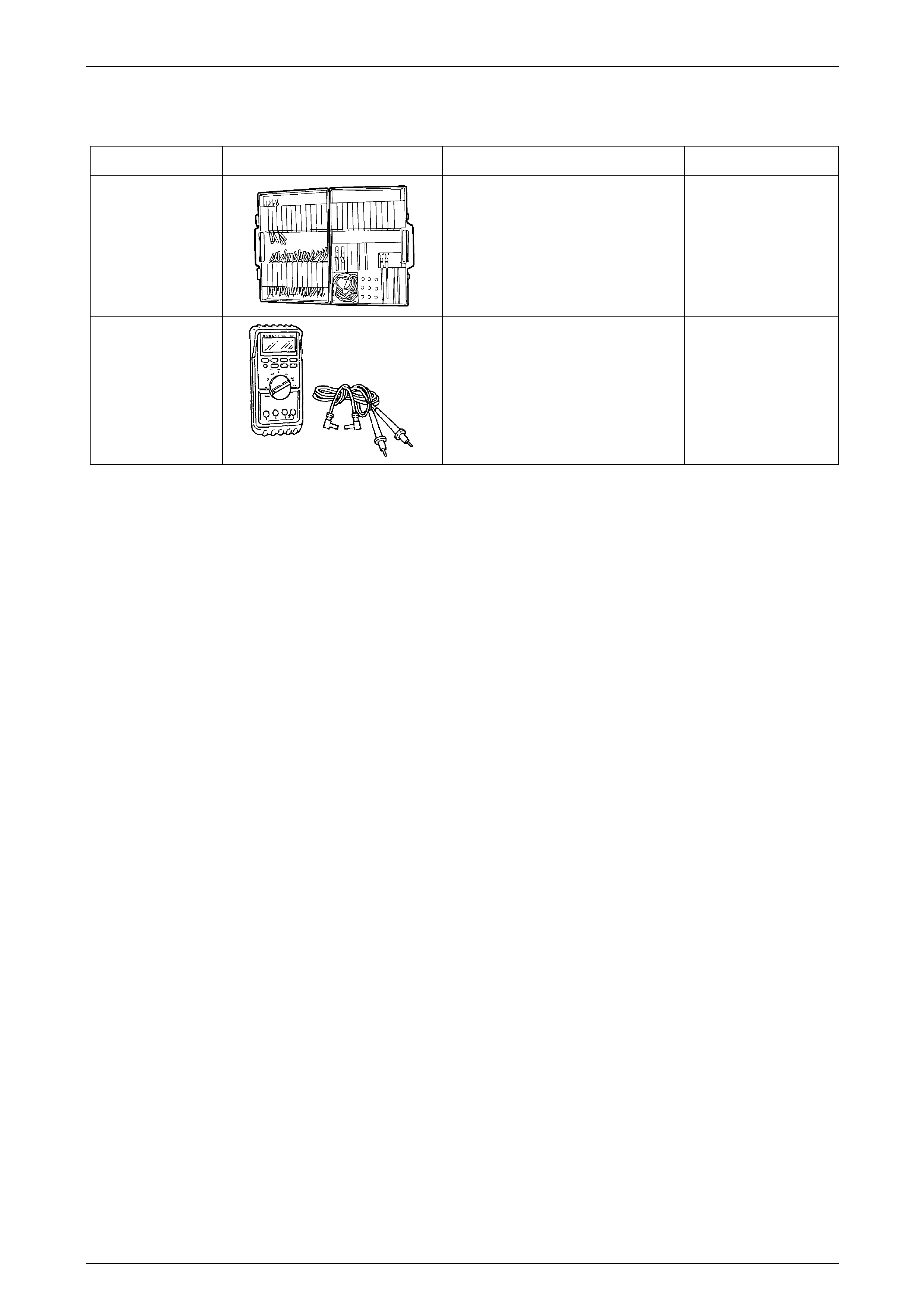
7 Special Tools
Tool Number Illustration Description Tool Classification
KM609
Connector Test Adaptor Kit
Used when carrying out electrical
diagnostic circuit checks.
Previously released
Desirable
3588
(J39200)
Digital Multimeter
Must have at least 10 MΩ input
impedance and be capable of reading
frequencies.
Previously released.
Available
Page 6D1-2–35