
Charging System – GEN III V8 Page 6D3-1–1
Page 6D3-1–1
Section 6D3-1
Charging System – GEN III V8
ATTENTION
Before performing any service operation or other procedure described in this Section, refer to Section 00
Warnings, Cautions and Notes for correct workshop practices with regard to safety and/or property damage.
1 General Information ...............................................................................................................................2
1.1 Components........................................................................................................................................................... 2
Generator................................................................................................................................................................ 2
Voltage Regulator.................................................................................................................................................. 3
1.2 System Operation.................................................................................................................................................. 4
Circuit Overview..................................................................................................................................................... 4
Alternator Warning ................................................................................................................................................ 4
2 Diagnosis ................................................................................................................................................5
2.1 Diagnostic General Information............................................................................................................................ 5
Basic Diagnostic Tools Required......................................................................................................................... 5
2.2 Tech 2 Data List ..................................................................................................................................................... 6
2.3 Diagnostic System Check..................................................................................................................................... 7
2.4 Wiring Diagram ...................................................................................................................................................... 8
2.5 Charging System Inoperative / Malfunctioning................................................................................................... 9
Notes.................................................................................................................................................................. 9
Diagnostic Table................................................................................................................................................. 9
3 Minor Service Operations....................................................................................................................10
3.1 Safety Precautions............................................................................................................................................... 10
3.2 Maintenance......................................................................................................................................................... 11
Regular Checks.................................................................................................................................................... 11
3.3 On-vehicle Testing............................................................................................................................................... 12
On-vehicle Checks............................................................................................................................................... 12
Prerequisites .................................................................................................................................................... 12
Generator Test................................................................................................................................................. 12
Charging Circuit Voltage Drop Test................................................................................................................... 14
Prerequisites .................................................................................................................................................... 14
Test.................................................................................................................................................................. 15
4 Major Service Operations....................................................................................................................16
4.1 Generator.............................................................................................................................................................. 16
Remove................................................................................................................................................................. 16
Disassemble......................................................................................................................................................... 18
Component Checking.......................................................................................................................................... 19
Check the Brushes........................................................................................................................................... 19
Reassemble.......................................................................................................................................................... 20
Reinstall................................................................................................................................................................ 21
5 Specifications.......................................................................................................................................23
6 Torque Wrench Specifications............................................................................................................24
7 Special Tools ........................................................................................................................................25
Charging System – GEN III V8 Page 6D3-1–2
Page 6D3-1–2
1 General Information
1.1 Components
Generator
The GEN III V8 engine is fitted with a Mitsubishi 140 amp generator and is mounted on the lower left-hand side of the
engine. It has an internally mounted regulator.
The three phase generator h as a rotor with six pole pairs and two internal cooling fans; one on the drive end and one on
the slip-ring end. The rotor is supported by ball bearing races in both the drive and slip-ring end housin gs. The stator
surrounds the rotor and has a three-p hase delta connected output winding on a ring shap ed lamination pack.
The output of the stator winding is rectified b y six diodes within the slip-ring end housing. Excitation current is supplied to
the rotor field coil via the voltage regulat or, the brush es and slip-rings.
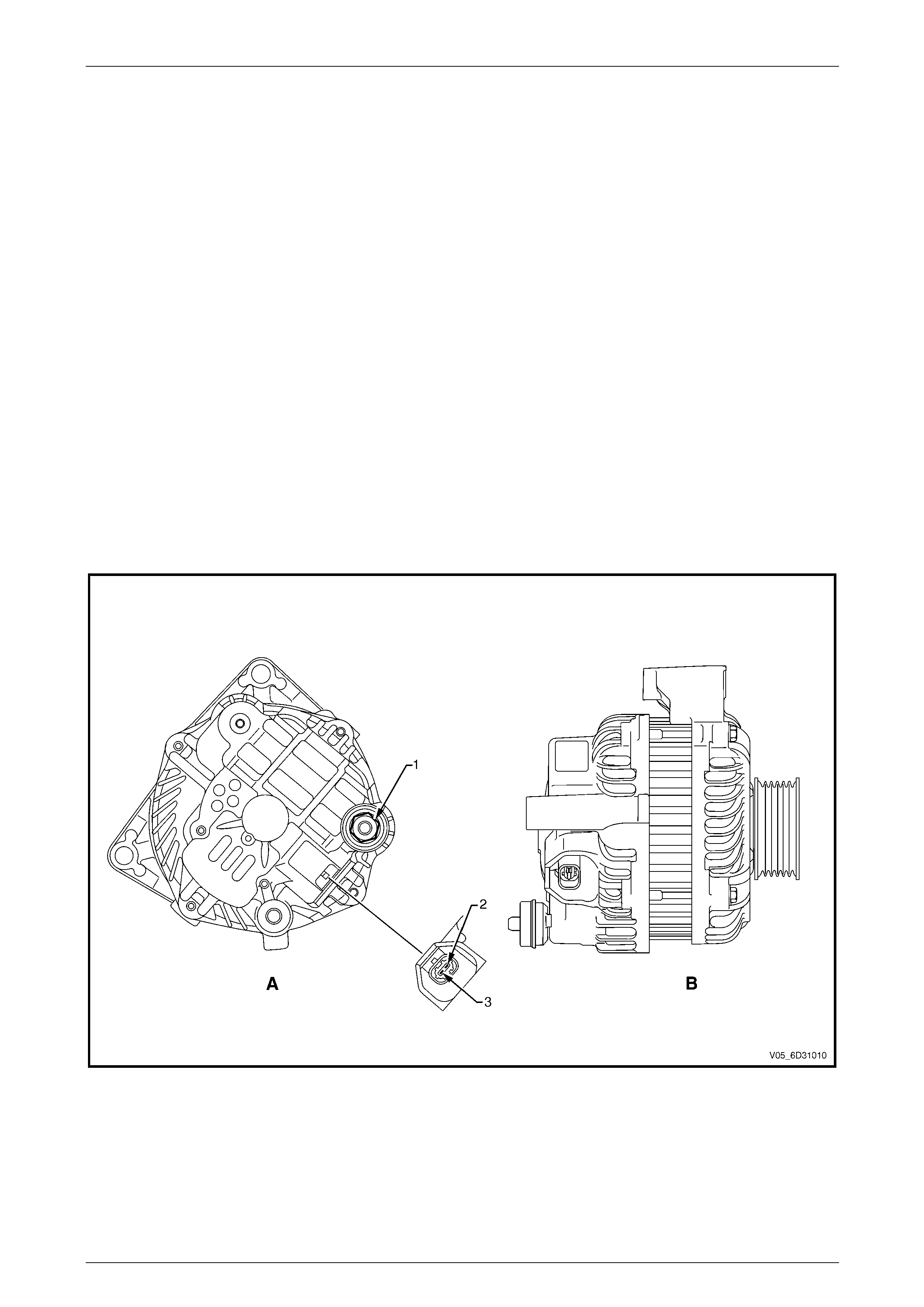
The generator has four extern al connections, refer to Figure 6D3-1 – 1:
• G8 – X1 pin A, connection to the battery positive terminal X86 –B (circuit 1) – battery charging,
• G8 – X2 pin 1, connection to the powertrain control module (PCM) connector A84 – X2 pin 15
(circuit 225) – regulator monitoring,
• G8 – X2 pin 2, connection to the powertrain control module (PCM) connector A84 – X2 pin 52
(circuit 23) – battery voltage sensing, and
• ground connection via the installation bolts.
Figure 6D3-1 – 1
Legend
A Rear View
B Side View
1 G8 – X1 pin A
2 G8 – X2 pin 1
3 G8 – X2 pin 2
Charging System – GEN III V8 Page 6D3-1–3
Page 6D3-1–3
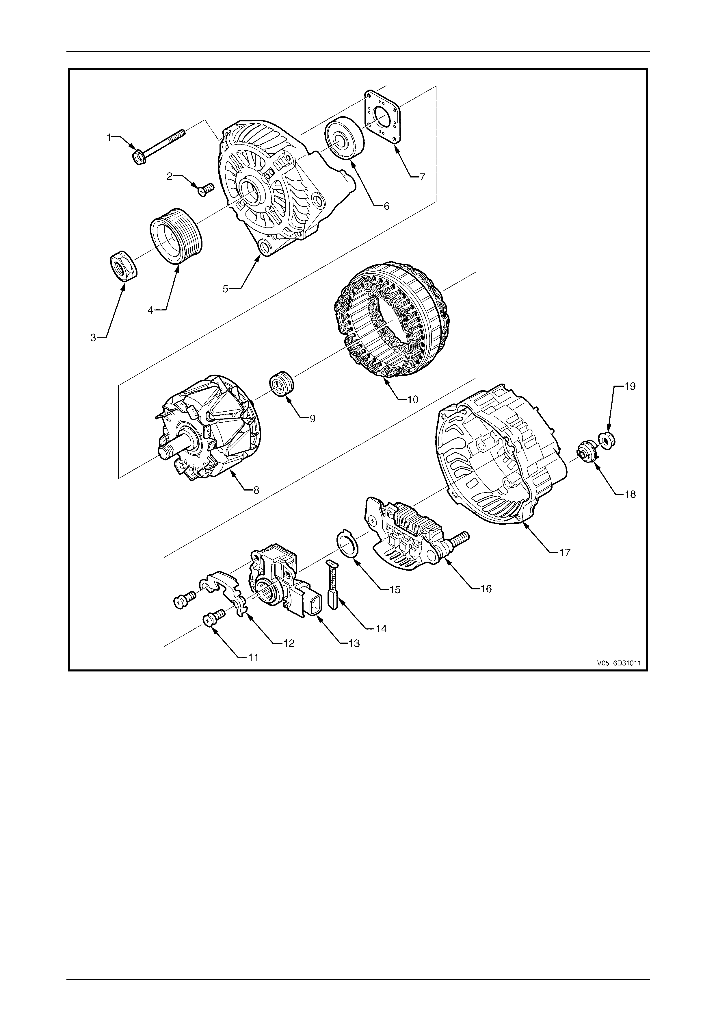
Figure 6D3-1 – 2
NOTE
Only items 3 and 4 are serviced as spare pa rts.
Legend
1 Through-bolt
2 Bearing Retaining Plate Screw
3 Nut
4 Drive Pulley
5 Front-end Housing
6 Front Bearing
7 Bearing Retaining Plate
8 Rotor
9 Rear Bearing
10 Stator
11 Regulator and Brush Screws
12 Brush Retaining Plate
13 IC Regulator
14 Brush
15 Thrust Washer
16 Rectifier Assembly
17 Rear-end Housing
18 Terminal Cover Bush
19 Nut
Voltage Regulator
The generator’s internal electronic voltage regulator requires no adjustment in service.

Charging System – GEN III V8 Page 6D3-1–4
Page 6D3-1–4
1.2 System Operation
Circuit Overview
With the ignition switch it the ON position and the engine at rest, current is supplied via the regulator to G8 – X2 pin 1
(circuit 225) to the power control module (PCM) at connecto r A84 – X2 pin 15. Refer to 2.4 Wiring Diagram. This initiates
current flow (within the regulator) from the generator G8 – X1 pin A to the brushes and rotor winding, to excite the circuit.
The current in the rotor winding creates magnetic fields between adjacent rotor poles.
With the engine running, the rotor spins, the stator windings cut through this field at right angl es and induce voltage. As
the engine speed increases, this in duced voltage increases. Current then flows through the three-phase diode bridge in
the rectifier to convert the AC voltage to DC. This is supplied to the G8 – X1 pin A output and then to the battery terminal
X86 – B (circuit 1).
The regulator monitors the voltag e to the battery. When this voltage reaches approximately 14.5 V, the regulator opens
the circuit through the rotor winding, ca using the generator output voltage to drop. When the regulator senses a voltage
below a preset value, the regulator closes the circuit through the rotor winding and voltage to the battery again incr eases.
This cycle repeats very rapidly.
Current does not flow through the rotor winding when the engine is cranking.
Alternator Warning
NOTE
All generator faults are displayed as
Check Alternator Warning on the instrument
cluster multi-function display (MFD), refer to
Section 12C Instrumentation.
The PCM monitors the voltage on circuit 23 at A84 – X2 pin 52 an d circuit 225 at A84 – X2 pin 15.
The G8 – X2 pin 1 (circuit 23) will rem ain low when a fault condition is detected in the generator or associated external
circuits. The voltage remains low until all faults are repaired.
Fault conditions include the fo llowing:
• open circuit or excessive voltage drop in circuit 1,
• open circuit in the generator phase connection,
• overcharging cond itions,
• short circuit in the regulator output stage,
• open circuit in the rotor winding,
• poor contact between the rectifier and the regulator, and / or
• poor contact between the battery terminals and cables.

Charging System – GEN III V8 Page 6D3-1–5
Page 6D3-1–5
2 Diagnosis
2.1 Diagnostic General Information
Basic Diagnostic Tools Required
Use of incorrect electrical circuit diagnostic
tools when performing the generator
diagnostic procedures could result in
incorrect diagnostic results or damage to
components.
The following electrical circuit testing tools are required to perform the diagnostic procedures detailed i n this Sectio n:
• Digital multimeter with 10 MΩ impedance, and
• Connector test adapter kit Tool No. KM609.
For further information on the use of these tools, refer to Section 12P Wirin g diagrams.

Charging System – GEN III V8 Page 6D3-1–6
Page 6D3-1–6
2.2 Tech 2 Data List
Tech 2 displays the status of certain charging s ystem parameters.
To view the data list:
1 Connect Tech 2 to the DLC.
2 On Tech 2 select:
Engine / V8 Gen III / Data Display / Engine Data 2 /.
Tech 2 Parameter Units Displayed Typical Display Values
Alternator L Terminal C Off / On On

Charging System – GEN III V8 Page 6D3-1–7
Page 6D3-1–7
2.3 Diagnostic System Check
Step Action Yes No
1 Is the fault specifically isolated to this system / module? Go to Step 2 Go to Section 0D
Vehicle Diagnostics
2 1 Connect Tech 2 to the DLC.
2 Switch the ignition on, with the engine off.
3 On Tech 2 select:
Engine / V8 Gen III / Diagnostic Trouble codes / Read DTC’s.
Does Tech 2 display a ny DTC’s?
Refer to Section
6C3-2 Powertrain
Management – GEN
III V8 – Diagnostics.
Refer to 2.5
Charging System
Inoperative /
Malfunctioning
Reference to following information will assist when diagnos ing charging circuit faults:
• for battery testing, refer to Section 12A Battery,
• for wiring diagram details, refer to 2.4 Wiring Diagram, and
• for electrical component locations, refer to Section 12O Fuses, Relays and Wiring Harnesses.
Charging System – GEN III V8 Page 6D3-1–8
Page 6D3-1–8
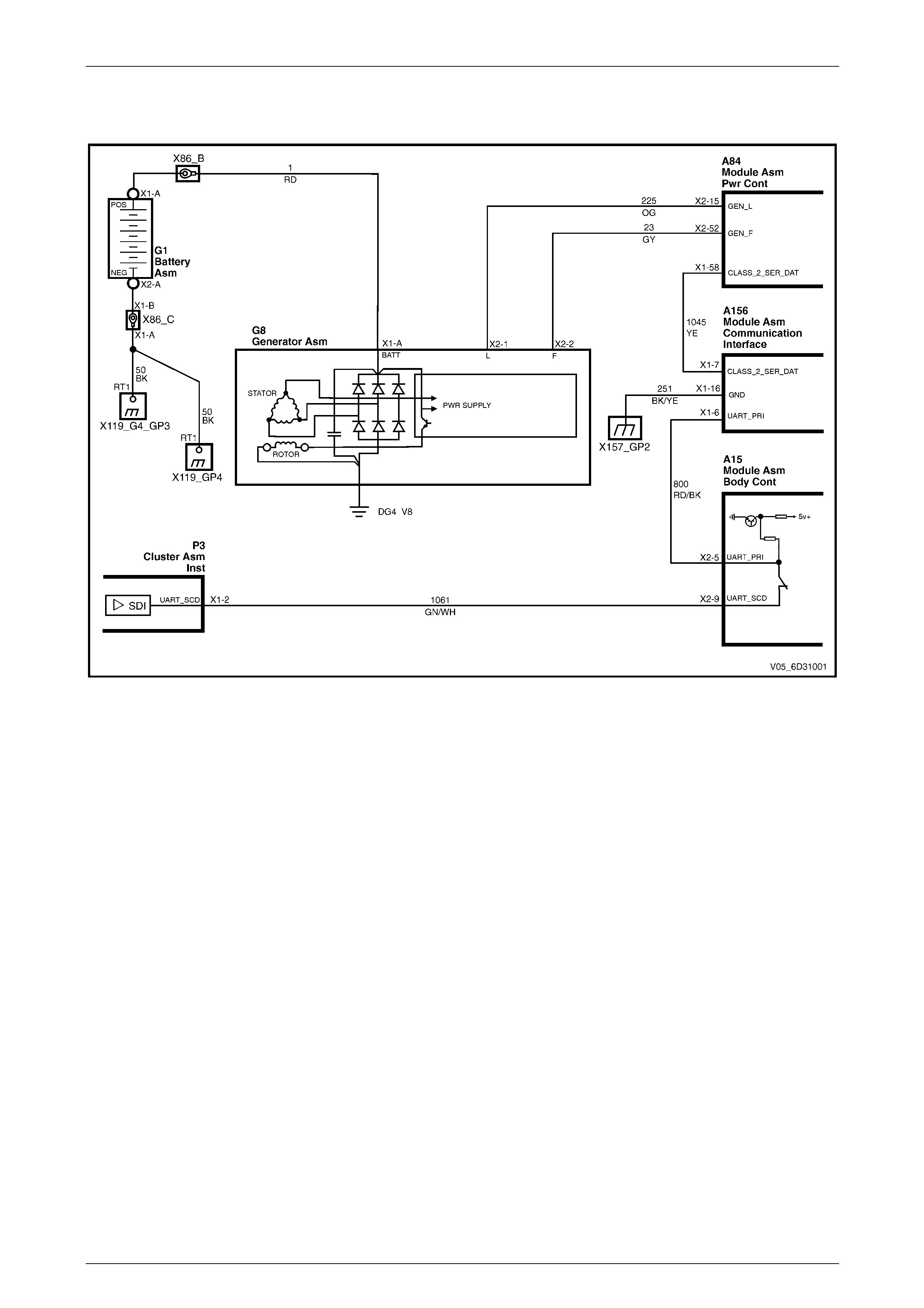
2.4 Wiring Diagram
Figure 6D3-1 – 3

Charging System – GEN III V8 Page 6D3-1–9
Page 6D3-1–9
2.5 Charging System Inoperative /
Malfunctioning
Notes
Reference to following information will assist when diagnos ing charging system faults.
1 For all wiring harness fault diagnoses, refer to Section 12P Wiring diagrams.
2 For wiring harness repairs, refer to Section 12P Wiring diag rams.
3 Refer to Section 12O Fuses, Relays and Wiring Harnesses for harness routeing.
4 Ensure the battery, cables and connections are in good order, refer to Section 12A Battery.
Diagnostic Table
Step Action Yes No
1 Did you review 1.2 System Operation? Go to Step 2 Go to 1.2 System
Operation
2 Has the diagnostic system check been performed?
Go to Step 3
Go to 2.3
Diagnostic System
Check
3 Perform the On-vehicle Checks, refer to 3.3 On-vehicle Testing.
Was the generator serviceable? Go to Step 4
Replace the
generator.
Go to Step 5
4 Perform the Charging Circuit Voltage Drop Test, refer to 3.3 On-
vehicle Testing.
Was the wiring serviceable?
Go to Section 12C
Instrumentation
Go to Step 5
Repair as required
(refer to Note 2).
Go to Step 5
5 Operate the system to verify the repair.
Does the system function correctly? System OK Go to Step 2
When all diagno sis an d repairs are completed, check the system for correct operation.

Charging System – GEN III V8 Page 6D3-1–10
Page 6D3-1–10
3 Minor Service Operations
3.1 Safety Precautions
Failure to observe the following precautions will result in serious damage to the generator:
• apply the generator and voltage reg ulator only on a negative ground system,
• when installing a battery, fit the positive (+) cabl e to the battery before fitting the negative cable,
• when a slave battery is used for starting purp oses, ensure that both batteries are connected in parallel, positive
terminals connected and neg ative termin als connected,
• only use jumpe r leads that have surge protection,
• disconnect both battery cables when charging the battery to isolate the generator from the battery and from the
external chargi ng equipment,
• do not operate the generator within an open circuit or without a battery in the circuit,
• do not disconnect the battery while the generator is running,
• do not attempt to polarise the generator,
• do not connect generator con nector G8 – X2 pin 1 to 12 V (the battery or ignition circuits), and
• some battery powered timing lights can pr oduce high transient voltages when connected or disconnected, only
disconnect or connect timing lights when the engine is switched off.
Ensure the generator connector G8 – X2 pin 1
has a maximum sinking current of 50mA.

Charging System – GEN III V8 Page 6D3-1–11
Page 6D3-1–11
3.2 Maintenance
Regular Checks
Check the following at regular intervals:
• generator terminals – for corrosion and loose connections,
• wiring – for damaged insulation,
• mounting bolts – for tightness,
• Accessory drive belt – for alignment and wear, and
• Accessory drive belt pulley – for damage.
NOTE
The accessory drive belt for the engin e ancillaries
(i.e. generator and water pump) is adjusted by a
spring-loaded tensi oner and belt does not require
manual adjustment. For further information refer
to Section 6A3 Engine Mechanical – GEN III V8.
Charging System – GEN III V8 Page 6D3-1–12
Page 6D3-1–12
3.3 On-vehicle Testing
LT Section No. — 02–140
On-vehicle Checks
Prerequisites
Before testing the generator output, ensur e that:
• all generator circuit connectio ns are cle an and tight,
• the generator is always connected to the battery during testing to prevent damage to the diodes,
• the battery is fully charged, and
• the specific gravity does not var y more than 0.025 between cells. It is recommended the average specific gravity is
1.260 or higher, refer to Section 12A Battery.
Carry out a load test on the battery to determine its ability to supply and accept current. This is a good indicator of the
general condition of the battery. For details o f battery testing, refer to Section 12A Battery.
Inspect the drive belt and tensioner markings to determine if the drive belt is within operating limits.
Replace the belt if it is excessively worn or outside the opera t ing range of the tensioner. For further details,
refer to Section 6A3 Engine Mechanical – GEN III V8.
Generator Test
Regulating Voltage T est
NOTE
Leave the generator wiring harness connector
G8 – X2 connected. Circuit 22 5, G8 – X2 pin 1, is
necessary as it provides initial field excitation .
1 Ensure the ignition switch is in the OFF position and
all electrical equipment is turned off.
Disconnection of the battery affects certain
vehicle electric systems. Refer to
Section 00 Warnings, Cautions and Notes
before disconnecting the battery.
2 Disconnect the battery ground cable at the b attery.
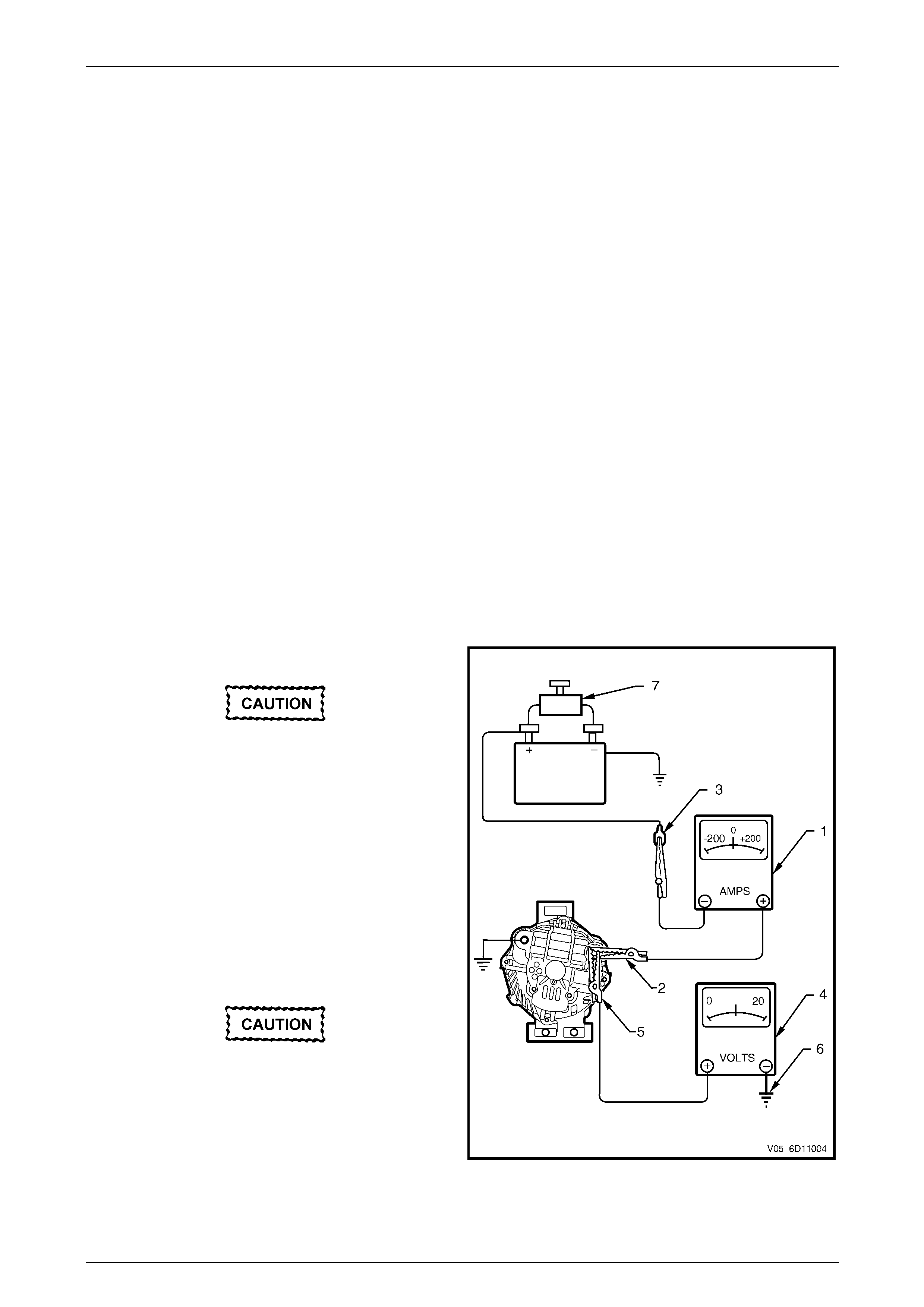
3 Disconnect the generator positive lead (circuit 1) from
the generator G8 – X1 pin A. Connect the positive lead
of a multimeter set to measure current (1) to G8 –
X1 pin A (2).
4 Connect that multimeter’s negative lead to the
disconnected gener ator positive lead (3).
5 Connect the positive lead of a multimeter set to
measure voltage, (4) to G8 – X1 pin A (5).
6 Connect that multimeter’s negative lead to a good
ground connection on the gen erator housing (6).
Insulate the terminal of the generator positive
lead (circuit 1) to prevent contact with any
metal part of the vehicle. If the terminal is
grounded, damage to the charging circuit can
result when the battery is reconnected.
Figure 6D3-1 – 1
7 Reconnect the battery ground cable.
8 Fit a loading device (7) across the battery terminals, e.g. an adjustable carbon p ile.
Charging System – GEN III V8 Page 6D3-1–13
Page 6D3-1–13
The loading device must have a minimum
power consumptio n of 1000 W.
9 Record the voltage reading before starting the engine. (This reading should increase when the engine is running,
indicating generator output).
10 Start the engine.
11 Increase the engine speed to the value outlined in the chart below.
12 Using the reading from the multimeter set to measure curre nt, adjust the loading device to apply a load within the
range outlined in the chart below.
13 Using the multimeter set to measure voltage, check the generator output voltage against the specification.
Engine RPM ...........................................................1300
Load................................................................5.0 – 10 A
Output Voltage...........................................13.8 – 15.4 V
Load Regulation Test
NOTE
The decrease in the voltage recorded during this
test should not exceed 0.5 V from the readings
obtained for the Regulating Voltage Test. If the
decrease in the regulating voltage is gr eater than
0.5 V, the regulator is defective. Replace the
regulator.
1 Increase the engine speed to the value specified in the chart below.
2 Using the reading from the multimeter set to measure curre nt, adjust the loading device to apply a load of about
90% of the generator’s full output.
3 Using the multimeter set to measure voltage, check the generator output voltage against the specification.
Engine RPM ...........................................................1900
Load.......................................................................126 A
Output Voltage...........................................13.8 – 15.4 V
Maximum Decrease in Voltage...............................0.5 V
Full Load Output Test
Keep the time for this test to a minimum to
avoid undue heating and high engine speeds.
1 Increase the engine speed to the value specified in the chart below.
2 Using the reading from the multimeter set to measure volta ge, adjust the loading device, increasing the load
applied until the generator output voltage drops to 13.5 V.
3 Record the current reading displayed on the multimeter set to measure current.
Charging System – GEN III V8 Page 6D3-1–14
Page 6D3-1–14
NOTE
Full output current, spec ifie d i n the chart b el o w, is
required.
On completion of the generator output test,
return the engine to idle and disconnect the
loading device from the battery terminals.
This prevents excessive battery discharge.
4 Reduce the engine speed to i dle.
5 Stop the engine.
6 Disconnect the battery ground cable (circuit 50) at the battery.
7 Remove all the multimeters.
8 Reconnect the generator positive lead (circuit 1) to G8 – X1 pin A.
9 Reconnect the battery ground cable (circuit 50) to the battery.
Engine RPM............................................................ 2350
Load.......................................................................140 A
Output Voltage......................................................13.5 V
Output Current.......................................................140 A
Charging Circuit Voltage Drop Test
Prerequisites
Before testing the generator output, ensur e that:
• all generator circuit connectio ns are cle an and tight,
• the generator is always connected to the battery during testing to prevent damage to the diodes,
• the battery is fully charged, and
• the specific gravity does not var y more than 0.025 between cells. It is recommended the average specific gravity is
1.260 or higher, refer to Section 12A Battery.
Carry out a load test on the battery to determine its ability to supply and accept current. This is a good indicator of the
general condition of the battery. For details o f battery testing, refer to Section 12A Battery.
Inspect the accessory drive belt and tensioner markings to determine if the drive belt is within operating limits.
Replace the belt if it is excessively worn or outside the opera t ing range of the tensioner. For further details,
refer to Section 6A3 Engine Mechanical – GEN III V8.

Charging System – GEN III V8 Page 6D3-1–15
Page 6D3-1–15
Test
Ensure the generator connections are clean
and tight.
1 Connect the positive lead of a multimeter set to measure vo ltage to G8 – X1 pin A.
2 Connect the negative lead of the multimeter to the battery positive post.
3 Switch the headlamps on.
4 Start the engine.
5 Increase the engine speed to approximately 2500 r.p.m.
6 Record the voltage readi ng.
7 Reduce the engine speed to i dle.
8 Connect the positive lead of a multimeter set to measure voltage to the battery negative post.
9 Connect the negative lead of the multimeter to the generator housing.
9 Increase the engine speed to approximately 2500 r.p.m.
10 Record the voltage readi ng.
11 Reduce the engine speed to i dle.
12 Check the two readings. If the readings exc eed 0.3 V, there is a high resistance in the charging circuit.
13 Trace the cause and correct the problem, refer to Section 12P Wiring diagrams.
Charging System – GEN III V8 Page 6D3-1–16
Page 6D3-1–16
4 Major Service Operations
4.1 Generator
LT Section No. — 02–140
Remove
The generator is in close proximity to an
exhaust manifold. Allow the engine to cool
before removing the generator.
Disconnection of the battery affects certain
vehicle electric systems. Refer to
Section 00 Warnings, Cautions and Notes
before disconnecting the battery.
1 Refer to Section 00 Warnings, Cautio ns and Notes before disconnecting the battery.
2 Disconnect the battery ground lead.
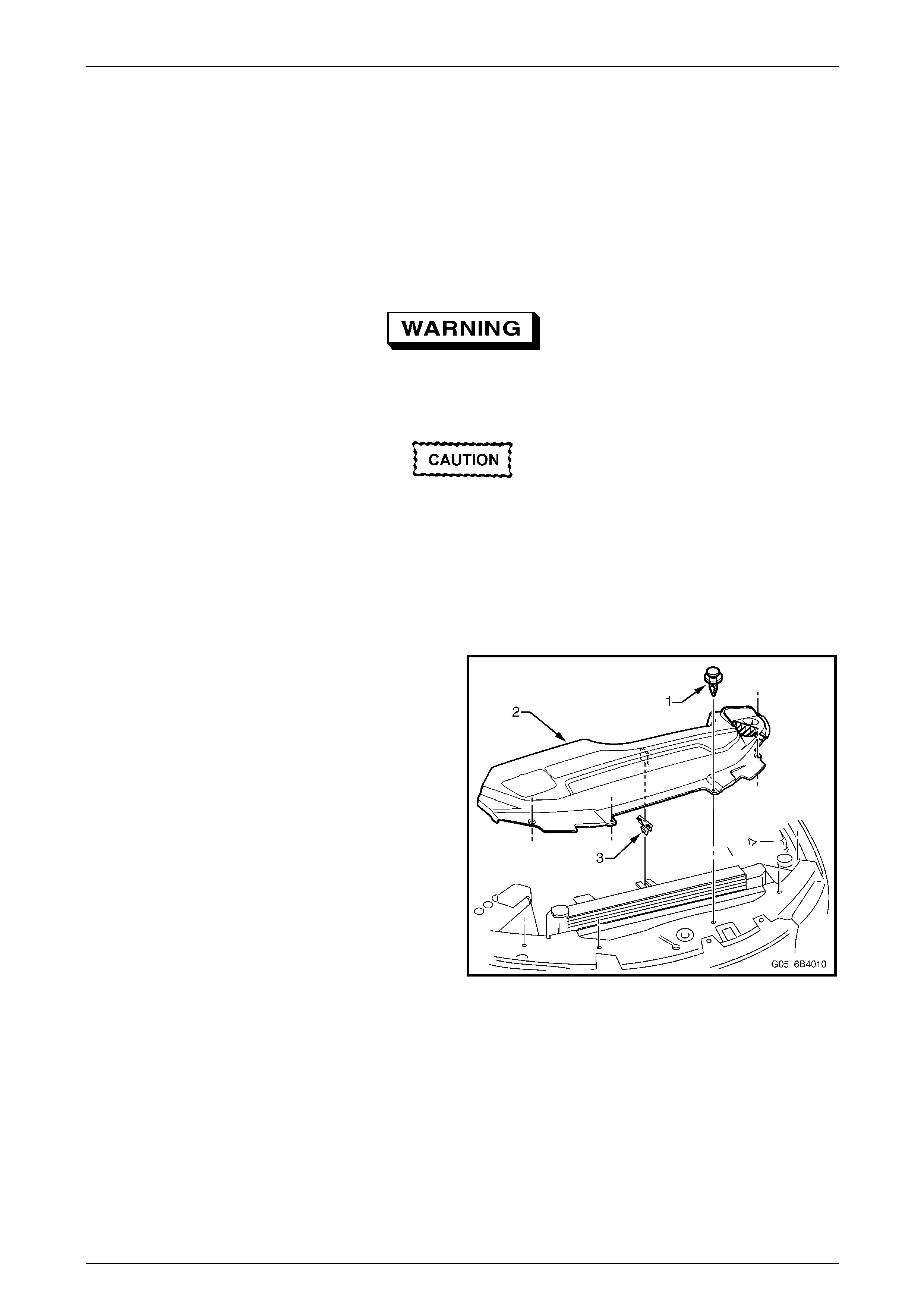
3 Remove the radiator shroud as follows. Using a fine,
flat-blade screwdriver, prise the centre pin of the
retainer (1) upward and remove the retainer, five
places.
4 Lift up the upper radiator shroud (2) to disen gage the
retaining clip (3) and remove the shroud.
Figure 6D3-1 – 4
Charging System – GEN III V8 Page 6D3-1–17
Page 6D3-1–17
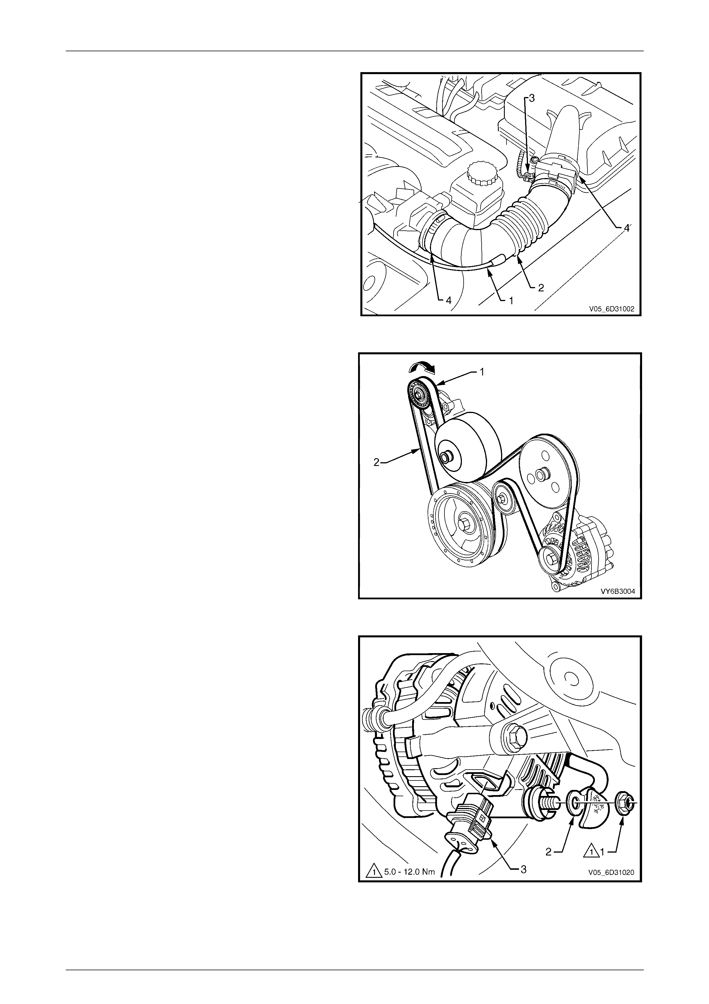
5 Remove the crankcase ventilation tube (1) from the air
intake duct (2).
6 Disconnect the mass air flow (MAF) sensor wiring
connector (3).
7 Loosen the two intake duct clam ps (4), one at the
throttle body and the other at the air clean er
connection and remove the intake duct and MAF as an
assembly.
Figure 6D3-1 – 5
8 Using a 15 mm ring spanner, rotate the en gine
accessory drive belt tensioner (1) in the direction
indicated, to reduce belt (2) tension.
9 While holding the tensi on er in the reduced tension
position, remove the accessory drive belt from the
generator drive pulle y, taking note of the belt routing.
Turn the assembly and remove the drive bel t from the
generator drive pulle y.
10 Release the drive belt tensioner.
11 Remove the power steering pump and reservoir, refer
to Section 9 Steering.
Figure 6D3-1 – 6
12 Pull the battery harness cap back from terminal G8 –
X1 pin A and remove the nut (1) and positive lead (2).
13 Press the connector retainer tab to release and
remove the G8 – X2 connector (3) from the gener ator
assembly.
Figure 6D3-1 – 7
Charging System – GEN III V8 Page 6D3-1–18
Page 6D3-1–18
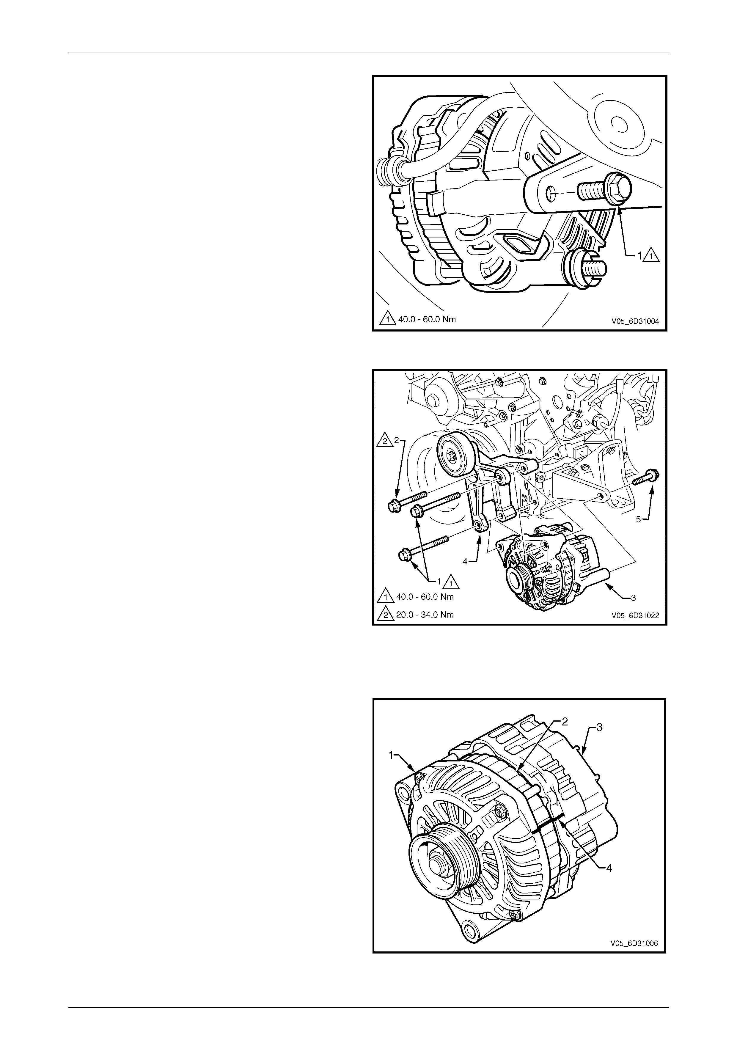
14 Remove the bolt (1) from the rear mounting bracket of
the generator.
Figure 6D3-1 – 8
15 Remove the generator and mounting bracket bolts (1)
and mounting bracket bolt (2) securin g the g enerator
(3) and mounting bracket (4) to the engine.
NOTE
Item 5 in Figure 6D3-1 – 9 is the bolt remov ed in
Step 15.
16 Separate the generator from the mountin g bracket and
lower the generator down onto the stabiliser bar.
17 Remove the mounting bracke t and idler pulley
assembly.
18 Lift the generator up and out from between the engine
and the radiator.
Figure 6D3-1 – 9
Disassemble
1 Using a permanent marking pen, mark the re lative
positions of the front-end housing (1), the stator frame
(2) and the rear-end housing ( 3), for example, (4).
Figure 6D3-1 – 10
Charging System – GEN III V8 Page 6D3-1–19
Page 6D3-1–19
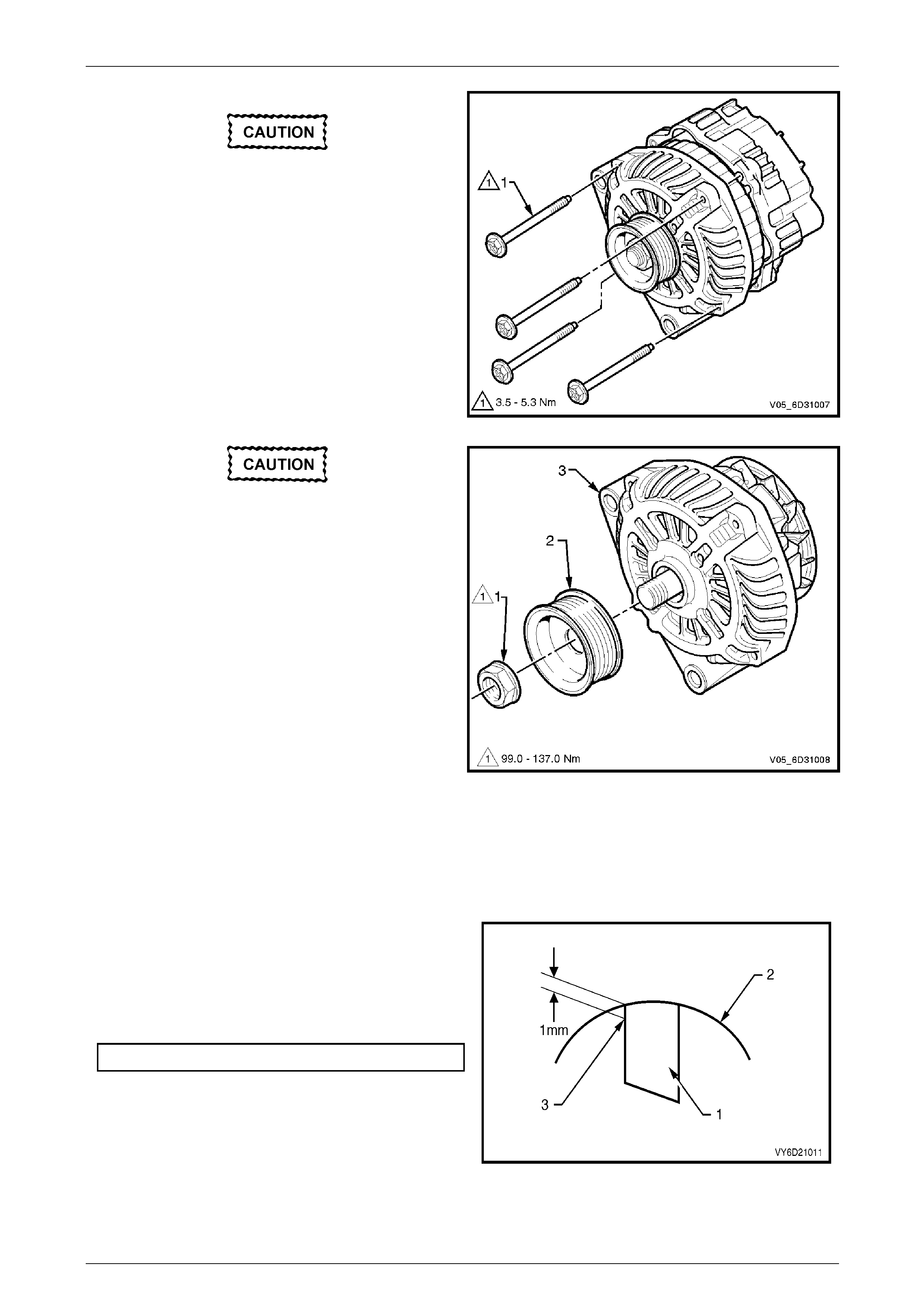
2 Remove the four through-bolts (1).
Do not lever against, or put strain on, the
stator windings.
3 Carefully separate the rear-end housing and stator (as
an assembly) from the rotor and front-end housing.
Figure 6D3-1 – 11
Do not distort or damage the rotor poles.
4 Clamp the rotor in a vice that has soft-jaws.
5 Remove the drive pulley attaching nut (1).
6 Remove the drive pulle y (2).
Figure 6D3-1 – 12
Component Checking
NOTE
If the brush length is less than specified or s hows
abnormal wear or cracks or if the brush springs
do not function correctly, replace the generator.
Check the Brushes
1 Check the length of each brush (1) protruding from
the regulator brush holder (2).
2 Measure along the cent re line of each brush.
3 Check the brushes for abnorm al wear or cracks.
Minimum brush length ........................................... 5 mm
Figure 6D3-1 – 13
Charging System – GEN III V8 Page 6D3-1–20
Page 6D3-1–20
4 Clean the brushes and brush holder with a clean cloth.
5 Check the brush holder for cra cks and damage.
6 Check the brush springs function correctl y, as follows:
a Push the brush into the brush holder until the wear limit line of the brush protrudes 1 mm from the brush
holder moulding (3).
b Release the brush.
c Repeat this action to ensure the spring returns fully and smoothly.
Reassemble
NOTE
Do not lubricate the bearings; they are
pre-lubricated.
Refer to Figure 6D3-1 – 2 for identification of components.
Reassembly of the generator is the reverse of the disassembly procedure, noting the follo wing:
1 Check the bearing box for oil and comp letely remove any oil on the bearing box to prevent bearing creep.
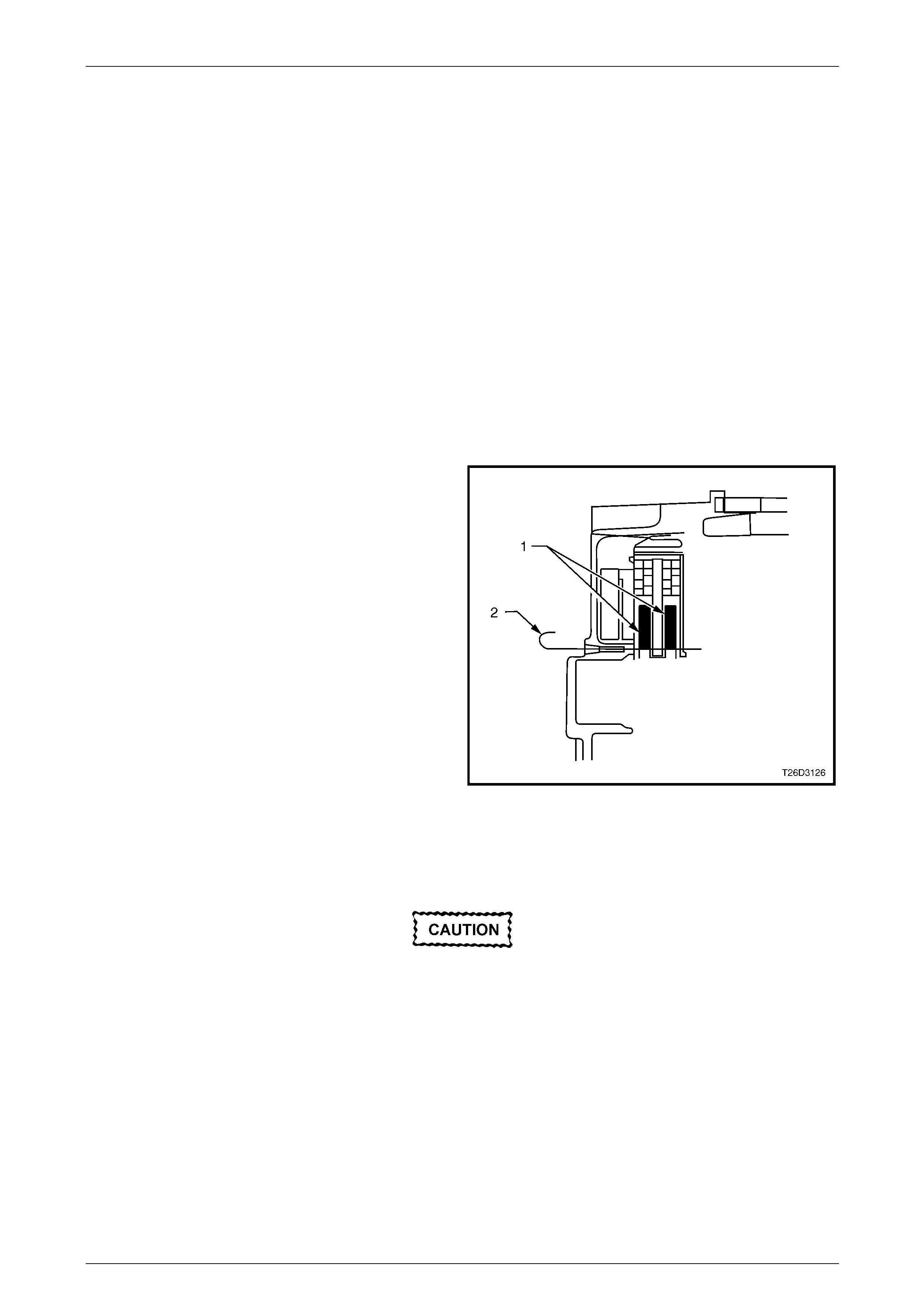
2 Install the rotor and front bracket assembly in the
follows.
a Push the brushes (1) fully back into the brus h
holder in the rear bracket assembly.
b Insert a suitable wire (2) from the outside of the
rear bracket assembly to hold the brushes in the
retracted position.
c Carefully heat the area around the rear bracket
bearing box to 50 – 60°C. This aids in assembly and
avoids damaging the tight fitting components.
3 Install the rotor into the rear bracket assembly.
4 Align the front bracket, stator frame and rear bracket
accurately. Use the markings made prior to
disassembly.
NOTE
When removing the wire, listen for both brushes
to click into position on the slip-ring.
5 Remove the wire.
Figure 6D3-1 – 14
6 After assembly, rotate the pulley slowly by hand to ensure th e rotor turns smoothly.
Do not over-tighten the G8 – X1 connector
nut. This action will damage the insulating
washer.

Charging System – GEN III V8 Page 6D3-1–21
Page 6D3-1–21
7 Tighten all fasteners to the correct torque specifications.
Drive pulley attaching nut
torque specification.....................................99 – 137 Nm
Through-bolt
torque specification.....................................3.5 – 5.3 Nm
Bearing retainer screw
torque specification.....................................2.9 – 4.9 Nm
Brush holder retaining screw
torque specification.....................................2.9 – 4.9 Nm
Rectifier retaining screw
torque specification.....................................2.9 – 4.9 Nm
Connector G8 – X1 nut
torque specification.................................12.8 – 18.6 Nm
Reinstall
Reinstallation of the generator is the reverse of the removal procedure, noting the follo wing:
1 Tighten the fasteners to the correct torque specifications.
Rear mounting bracket bolt
torque specification.................................40.0 – 60.0 Nm
Generator and mounting bracket bolt
torque specification.................................40.0 – 60.0 Nm
Mounting bracket bolt
torque specification.................................20.0 – 34.0 Nm
Battery harness to
terminal G8 – X1 nut
torque specification...................................7.1 – 13.3 Nm
2 Install the power steering pump, refer to Section 9 Steering.
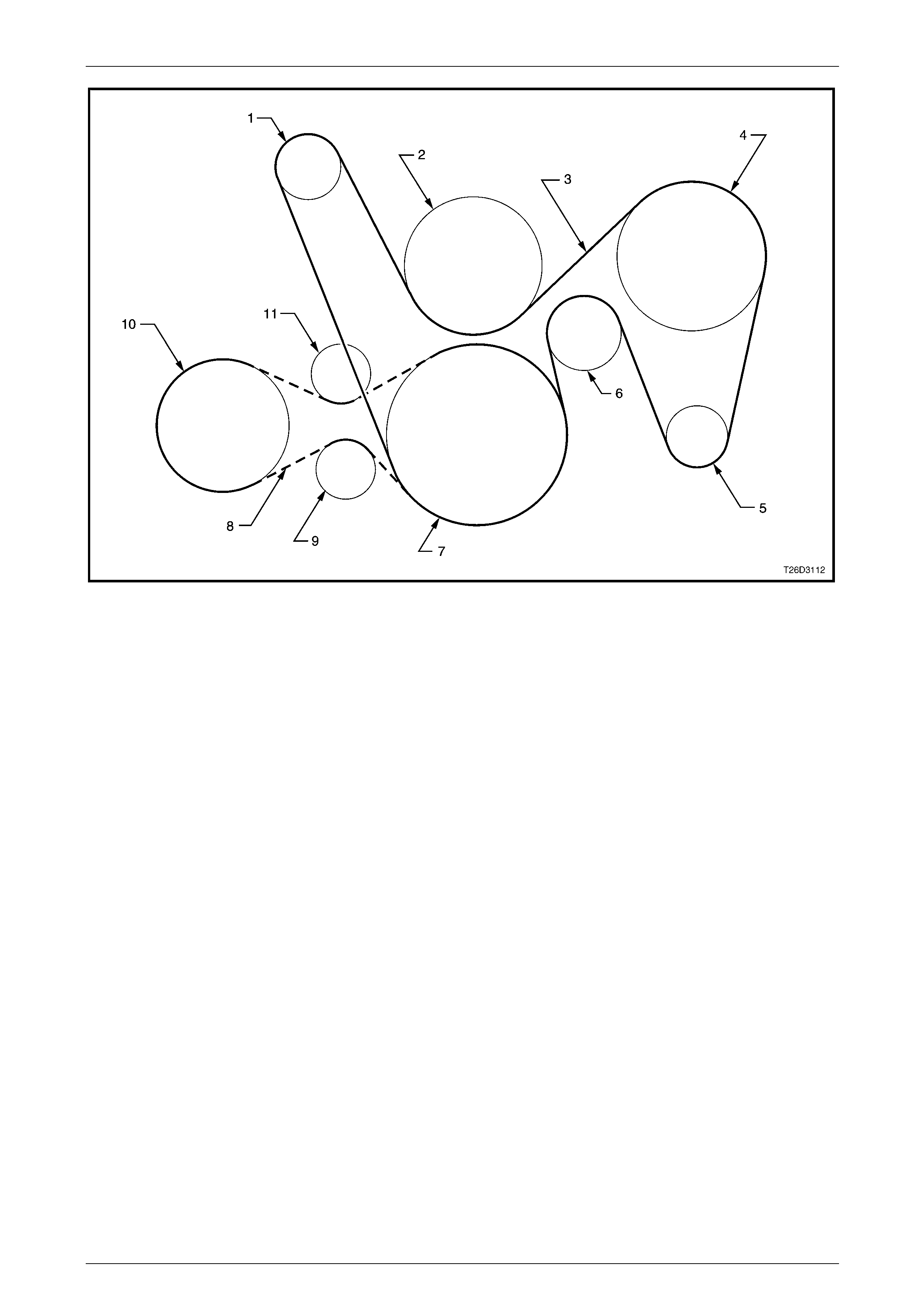
3 Carefully and accurately route the accessory drive belt, refer to Figure 6D3-1 – 15.
Charging System – GEN III V8 Page 6D3-1–22
Page 6D3-1–22
Figure 6D3-1 – 15
Legend
1 Tensioner Pulley
2 Water Pump Pulley
3 Accessory Drive Belt Pulley
4 Power Steering Pump
5 Generator Pulley
6 Idler Pulley
7 Crankshaft Pulley
8 Drive Belt (A/C Compressor)
9 Tensioner (A/C Compressor) Pulley
10 Compressor Pulley
11 Idler (A/C Compressor Drive Belt) Pulley
4 Using a 15 mm ring spanner o n the tensioner pulley pivot bolt, rotate the tensioner pulley clockwise and install the
drive belt onto:
a the power steering pump pulley
b the generator pulley
c the idler pulleys.
5 Check the drive belt ribs are correctly positioned in all of the drive belt grooves.
6 Install the cap over the G8 – X1 connector.
7 Reconnect the battery ground lead.
8 Start the engine.
9 Check the drive belt alignment.
10 Check the generator warning lamp operati on.
11 Check the generator output and voltage reg ulator o peration, refer to 3.3 On-vehicle Testing.

Charging System – GEN III V8 Page 6D3-1–23
Page 6D3-1–23
5 Specifications
Ground Polarity...........................................................................................................Negative
Nominal Voltage ............................................................................................................ 12.0 V
Nominal Output............................................................................................................ 140.0 A
Voltage Regulator Setting....................................................................................14.2 – 14.8 V
Stator Winding Resistance @ 20°C.............................................................................0.098 Ω
Rotor Winding Resistance @ 20°C..................................................................................2.1 Ω
Slip-ring Outer Diameter.............................................................................................22.7 mm
Slip-ring Service Limit.................................................................................................22.1 mm
Brush Length New......................................................................................................18.5 mm
Brush Length Service Limit...........................................................................................5.0 mm
Direction of Rotation (viewed from pulley)................................................................Clockwise

Charging System – GEN III V8 Page 6D3-1–24
Page 6D3-1–24
6 Torque Wrench Specifications
Terminal G8 – X1 Nut........................................................................................ 5.0 – 12.0 Nm
Rear Mounting Bracket Bolt............................................................................. 40.0 – 60.0 Nm
Generator and Mounting Bracket Bolt.............................................................. 40.0 – 60.0 Nm
Mounting Bracket Bolt...................................................................................... 20.0 – 34.0 Nm
Connector G8 – X1 Nut ................................................................................... 12.8 – 18.6 Nm
Through-bolt ........................................................................................................ 3.5 – 5.3 Nm
Drive Pulley Attaching Nut............................................................................. 99.0 – 137.0 Nm
Charging System – GEN III V8 Page 6D3-1–25
Page 6D3-1–25
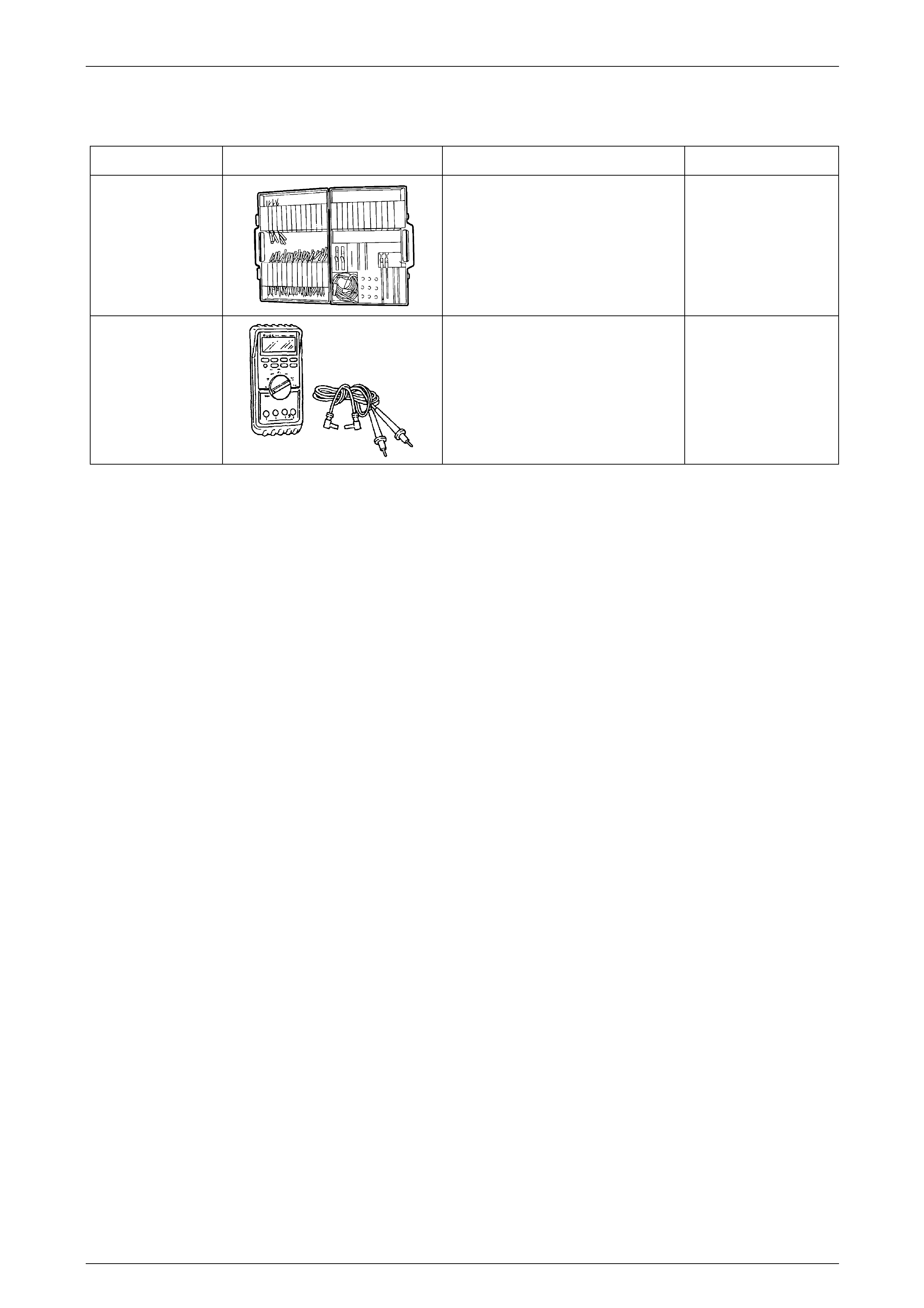
7 Special Tools
Tool Number Illustration Description Tool Classification
J35616-A
(KM609)
Connector Test Adaptor Kit
Used when carrying out electric al
diagnostic circuit checks.
Previously released.
Desirable
3588
(J39200)
Digital Multimeter
Must have at least 10 MΩ input
impedance and be capable of reading
frequencies.
Previously released.
Available