
Starting System – GEN III V8 Page 6D3-2 – 1
Page 6D3-2 – 1
Section 6D3-2
Starting System – GEN III V8
ATTENTION
Before performing any service operation or other procedure described in this Section, refer to Section 00
Warnings, Cautions and Notes for correct workshop practices w i th regard to safety and / or property damage.
1 General Information...............................................................................................................................3
1.1 Components........................................................................................................................................................... 3
Starting System Components............................................................................................................................... 3
Starter Motor and Solenoid Components............................................................................................................ 3
Solenoid Switch.................................................................................................................................................. 3
Planetary Drivetrain............................................................................................................................................ 3
Armature ............................................................................................................................................................ 3
Brushes.............................................................................................................................................................. 4
1.2 System Operation .................................................................................................................................................. 6
System Operation .................................................................................................................................................. 6
Operation ........................................................................................................................................................... 6
Sequence of Operation ...................................................................................................................................... 6
2 Diagnostics.............................................................................................................................................7
2.1 Diagnostic General Information............................................................................................................................ 7
Basic Diagnostic Tools Required......................................................................................................................... 7
2.2 Tech 2 Data List ..................................................................................................................................................... 8
2.3 Diagnostic System Check..................................................................................................................................... 9
2.4 Wiring Diagram .................................................................................................................................................... 10
2.5 Starting System Inoperative / Malfunctioning................................................................................................... 11
Circuit Description............................................................................................................................................... 11
Diagnostic Table Notes ....................................................................................................................................... 11
Diagnostic Table.................................................................................................................................................. 11
3 Minor Service Operations....................................................................................................................14
3.1 Safety Precautions............................................................................................................................................... 14
3.2 Maintenance......................................................................................................................................................... 15
Regular Checks.................................................................................................................................................... 15
3.3 On-vehicle Testing............................................................................................................................................... 16
Prerequisites........................................................................................................................................................ 16
Poor Connection Test.......................................................................................................................................... 16
Starter Motor Ground Test.................................................................................................................................. 16
Sw itching Ci rcuit Test......................................................................................................................................... 17
Cranking Voltage Test......................................................................................................................................... 17
Current Draw Test................................................................................................................................................ 18

Starting System – GEN III V8 Page 6D3-2 – 2
Page 6D3-2 – 2
4 Major Service Operations....................................................................................................................19
4.1 Starter Motor ........................................................................................................................................................ 19
Remove................................................................................................................................................................. 19
Reinstall................................................................................................................................................................ 21
4.2 Starter Motor Bench Tests.................................................................................................................................. 22
Preliminary Checks.............................................................................................................................................. 22
Solenoid Switch Tests......................................................................................................................................... 22
Pull-in Test ....................................................................................................................................................... 22
Hold-in Test...................................................................................................................................................... 23
Drive Assembly Return Test............................................................................................................................. 23
No Load Test........................................................................................................................................................ 24
4.3 Starter Motor Disassemble and Reassemble .................................................................................................... 25
Disassemble......................................................................................................................................................... 25
Cleaning and Inspection ..................................................................................................................................... 28
Pole Housing Check......................................................................................................................................... 28
Armature Check ............................................................................................................................................... 28
Commutator Check .......................................................................................................................................... 29
Brushes Check................................................................................................................................................. 30
Brush Plate Assembly Check........................................................................................................................... 31
Drive Assembly Check ..................................................................................................................................... 31
Bush Check...................................................................................................................................................... 31
Solenoid Switch Check..................................................................................................................................... 32
Reassemble.......................................................................................................................................................... 35
5 Specifications.......................................................................................................................................37
6 Torque Wrench Specifications ...........................................................................................................38
7 Special Tools ........................................................................................................................................39

Starting System – GEN III V8 Page 6D3-2 – 3
Page 6D3-2 – 3
1 General Information
The GEN III V8 engine is fitted with a Mitsubishi six-pole, four-brush starter motor. This consists of a solenoid switch on a
DC motor that has permanent magnet excitation and has the advantage of low weight with high output torque.
The starter motor does not have field coil windings or pole shoes. These parts have been replaced by permanent
magnets that are held in the pole housing by clips. The positive brushes are now part of the brush plate assembly.
1.1 Components
Starting System Components
The main components of the starting system are:
• battery,
• wiring,
• ignition switch and remote coded key,
• theft deterrent engine crank inhibitor (a function of the theft deterrent system),
• body control module (BCM)
• park / neutral and back-up lamp switch (vehicles fitted with automatic transmission only),
• powertrain control module,
• start relay,
• solenoid switch, and
• starter motor.
Starter Motor and Solenoid Components
Solenoid Switch
The solenoid switch is used to activate the DC motor and has two windings; the pull-in winding and the hold-in winding.
The pull-in winding has heavier wire and is grounded through the DC motor winding and brushes. The hold-in winding is
grounded to the solenoid casing.
Planetary Drivetrain
The planetary drivetrain consists of an internally toothed ring gear and three planetary gear wheels which rotate on
sleeve bearings on the planetary drive shaft. The ring gear is keyed into the drive-end housing and is made from high-
grade polyamide with mineral additives.
When the starter motor is operated, the armature turns the planetary gears inside the fixed planetary ring gear. This
drives the planetary shaft at a reduced speed ratio (approximately 6.86:1) which turns the drive assembly. A fork lever in
the drive end housing forces the drive assembly to slide forward and engage with the engine flexplate / flywheel ring gear
to transmit cranking torque.
An internal clutch allows the drive assembly pinion gear to rotate freely when the engine starts. This prevents the
armature from being driven at excessive speed by the engine.
Armature
The armature shaft is supported at each end by oil absorbent sintered metal bushes; one in the commutator end shield
and one in the planetary drive shaft. These bushes require lubrication only at the time of overhaul. The front end of the
armature has a gear profile. This meshes with the three planetary gear wheels. These in turn, mesh with the internal
teeth of the ring gear.
Starting System – GEN III V8 Page 6D3-2 – 4
Page 6D3-2 – 4
Brushes
A brush plate supports four commutator brushes. This plate is fixed to the commutator end shield with two retaining
screws. Two negative brushes are grounded to the pole housing. The two positive brushes are insulated from the pole
housing and connected to the solenoid switch M terminal.
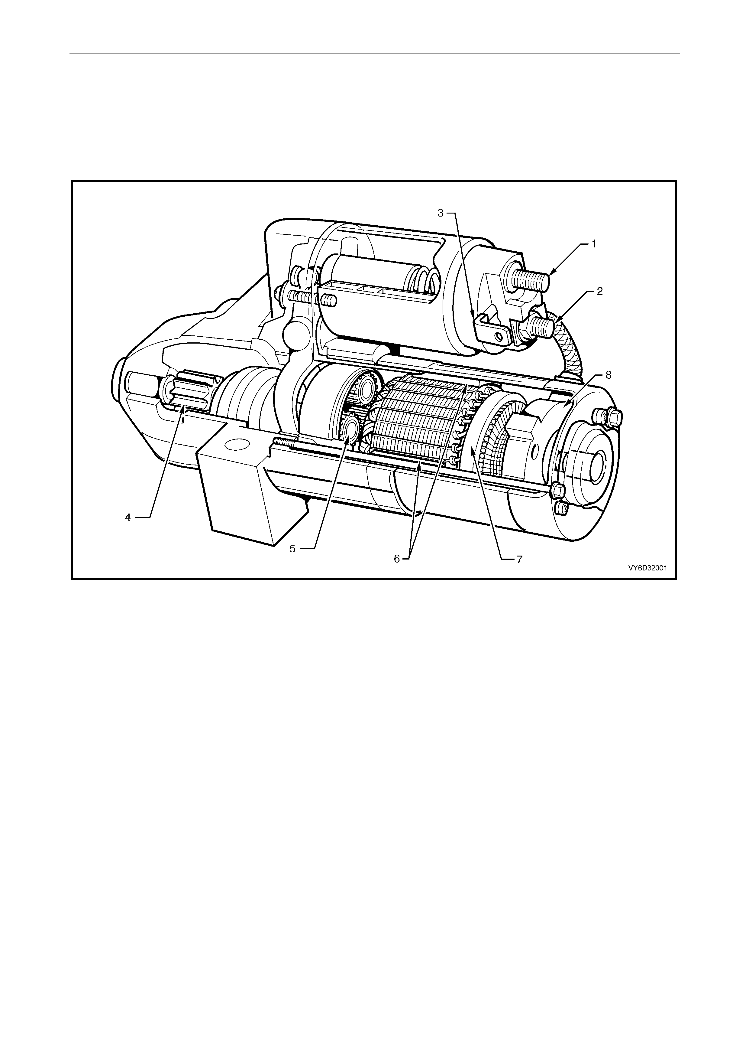
Figure 6D3-2 – 1 shows a cut away view of the starter motor as fitted to GEN III V8 engines.
Figure 6D3-2 – 1
Legend
1 Solenoid Terminal M15 – X2 pin A (Battery)
2 Solenoid M Terminal (Motor)
3 Solenoid connector M15 – X1 pin A
4 Drive Assembly
5 Planetary Gears
6 Permanent Magnets
7 Armature
8 Brush Assembly
Starting System – GEN III V8 Page 6D3-2 – 5
Page 6D3-2 – 5
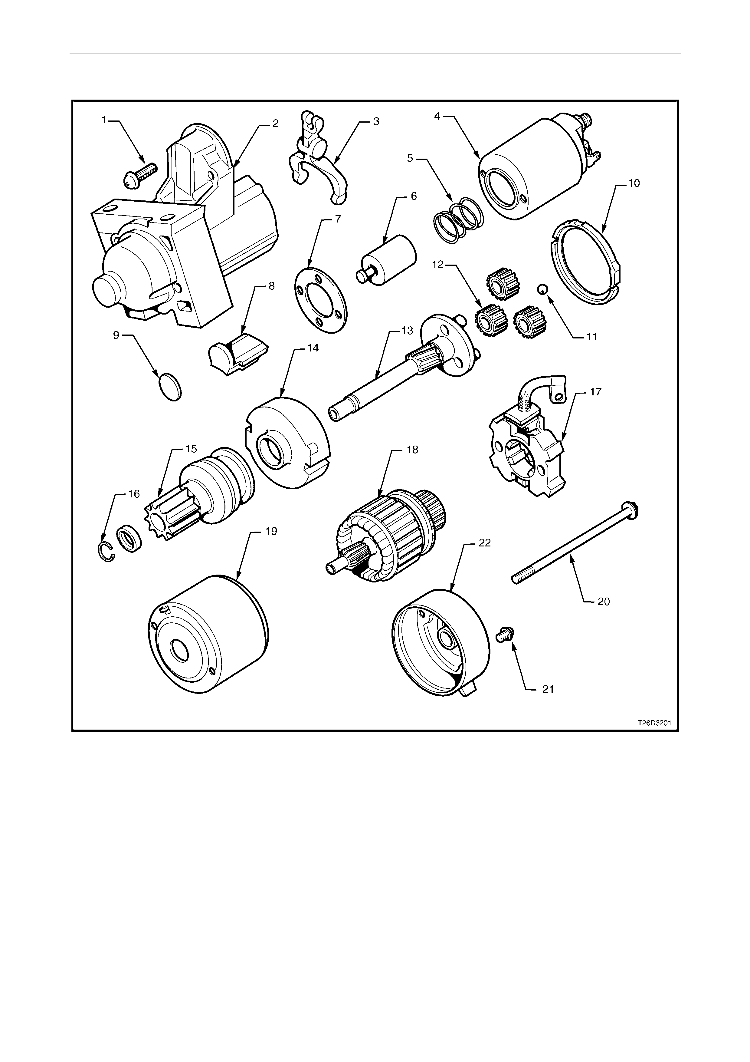
Figure 6D3-2 – 2 shows an exploded view of the starter motor.
Figure 6D3-2 – 2
Legend
1 Solenoid Switch Mounting Screw
2 Drive-end Housing
3 Fork Lever
4 Solenoid Switch
5 Return Spring
6 Solenoid Plunger
7 Solenoid Switch Spacer
8 Rubber Seal
9 Lever Plate
10 Sealing Ring
11 End Float Ball
12 Planetary Gears
13 Drive Shaft Assembly
14 Gear Assembly Cover
15 Clutch Gear Assembly Pinion
16 Stopper Ring and Retainer
17 Brush Holder Assembly
18 Armature
19 Field Housing
20 Through-bolt
21 Brush Holder Retaining Screw
22 Commutator End Shield

Starting System – GEN III V8 Page 6D3-2 – 6
Page 6D3-2 – 6
1.2 System Operation
System Operation
Operation
The operation of the start relay is controlled by:
• ignition switch,
• neutral / back-up lamp switch (on vehicles fitted with automatic transmission), and
• powertrain interface module (PIM)
The start relay controls operation of the start solenoid.
The start solenoid controls operation of the starter motor and drive assembly.
Sequence of Operation
1 When the ignition switch is turned to the START position, battery voltage is supplied to the start relay. Ground for
the relay is provided by the powertrain interface module (PIM). On vehicles fitted with an automatic transmission,
the normally open neutral / back-up lamp switch must be closed by selecting either park (P) or neutral (N) to
complete this ground circuit.
2 The PIM will initially allow cranking for up to 1 second. This allows time for validation of the security code data
output from the remote coded key to be completed.
3 Once the security code serial data is validated, the theft deterrent system is disarmed and cranking will continue.
For further information on the theft deterrent system, refer to Section 12J Body Control Module.

Starting System – GEN III V8 Page 6D3-2 – 7
Page 6D3-2 – 7
2 Diagnostics
2.1 Diagnostic General Information
Basic Diagnostic Tools Required
Use of incorrect electrical circuit diagnostic
tools when performing the starting system
diagnostic procedures could result in
incorrect diagnostic results or damage to
components.
The following electrical tools are required to perform the diagnostic procedures detailed in this Section:
• digital multimeter with 10 MΩ impedance, and
• connector test adapter kit Tool No. KM609.
For further information on the use of these tools, refer to Section 12P Wiring Diagrams.

Starting System – GEN III V8 Page 6D3-2 – 8
Page 6D3-2 – 8
2.2 Tech 2 Data List
Tech 2 displays the status of certain starting system parameters.
To view the data list:
1 Connect Tech 2 to the DLC.
2 On Tech 2 select:
Body / Powertrain Interface Module / Data Display / Data List
Tech 2 Parameter Units Displayed Typical Display Values
Starter Relay Off / On On

Starting System – GEN III V8 Page 6D3-2 – 9
Page 6D3-2 – 9
2.3 Diagnostic System Check
Step Action Yes No
1 Is the fault specifically isolated to this system / module? Go to Step 2 Go to Section 0D
Vehicle Diagnostics
2 1 Connect Tech 2 to the DLC.
2 Switch the ignition on, with the engine off.
3 On Tech 2 select:
Engine / GEN III V8 Engine / Diagnostic Trouble codes /
Read DTCs.
Does Tech 2 display any DTCs?
Refer to Section
6C3-2 Powertrain
Management – GEN
III V8 – Diagnostics
Refer to 2.5
Starting System
Inoperative /
Malfunctioning
Starting System – GEN III V8 Page 6D3-2 – 10
Page 6D3-2 – 10
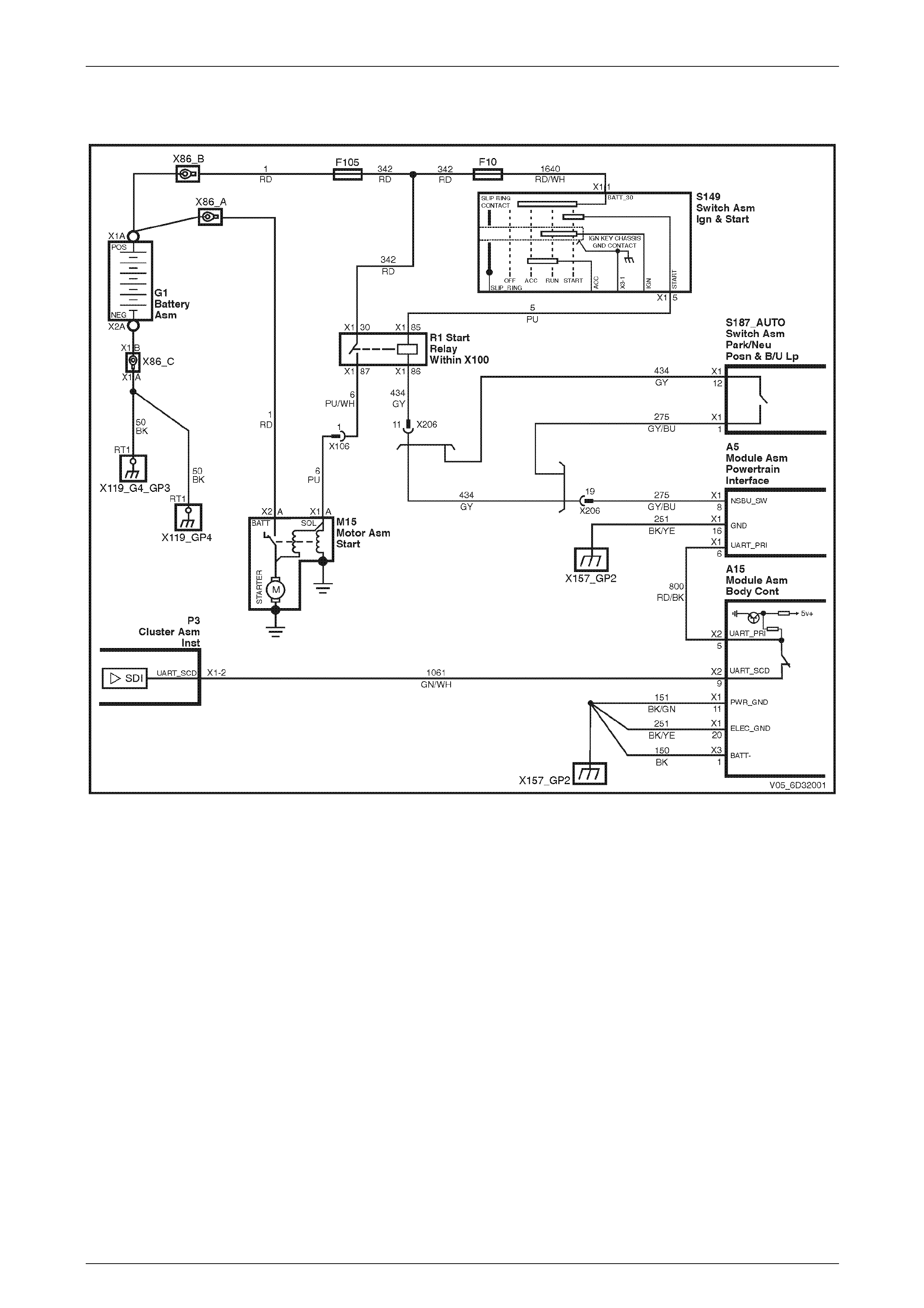
2.4 Wiring Diagram
Figure 6D3-2 – 3

Starting System – GEN III V8 Page 6D3-2 – 11
Page 6D3-2 – 11
2.5 Starting System Inoperative /
Malfunctioning
Circuit Description
The battery cable supplies a constant connection from the battery to connector M15 – X2 pin A of the solenoid switch
(circuit 1), refer to 2.4 Wiring Diagram.
The ignition switch, powertrain interface module (PIM) and neutral-start switch (for automatic vehicles) control activation
of the start relay.
With the ignition switch in the START position, voltage is supplied to connector R1 – X1 pin 85 (circuit 5). The ground
connection to the relay at connector R1 – X1 pin 86 is controlled by the PIM and, for automatic vehicles, the neutral /
back-up lamp switch (circuits 434 and 275).
When the start relay activates current flows from connector R1 – X1 pin 87 to connector M15 – X1 pin A of the solenoid
switch. This activates the solenoid switch windings. The pull-in winding causes powerful magnetism to pull in the solenoid
switch plunger. The hold-in winding holds the plunger in and the pull-in winding deactivates.
The solenoid switch simultaneously closes the switch contacts to connect M15 – X2 pin A to the DC motor and pivots the
fork lever to engage the drive assembly to the flexplate / flywheel ring gear.
With the solenoid switch contacts closed, current flows from the battery through the DC motor, which rotates the
armature at high speed and provides cranking torque.
Diagnostic Table Notes
Reference to following information will assist when diagnosing starting circuit faults:
1 If the battery, starter motor and fuel system are deemed as serviceable and a no crank and / or no start condition
exists, refer to Section 12J Body Control Module for theft deterrent engine crank inhibitor related faults.
2 For all wiring harness fault diagnoses, refer to Section 12P Wiring Diagrams.
3 For wiring harness repairs, refer to Section 12P Wiring Diagrams.
4 Refer to Section 12O Fuses, Relays and Wiring Harnesses for harness routeing.
5 Ensure the battery, cables and connections are in good order. Refer to Section 12A Battery.
Diagnostic Table
Step Action Yes
No
1 Did you review 1.2 System Operation? Go to Step 2 Go to 1.2 System
Operation
2 Has the diagnostic system check been performed?
Go to Step 3
Go to 2.3
Diagnostic System
Check
3 NOTE
On automatic vehicles ensure that park (P) or neutral (N) is
selected.
Turn the ignition switch to the START position and then release it.
Does the engine crank or are there any clicking or chattering sounds
from the solenoid? Go to Step 8 Go to Step 4

Starting System – GEN III V8 Page 6D3-2 – 12
Page 6D3-2 – 12
Step Action Yes
No
4 Inspect fusible link F105, refer to Section 12O Fuses, Relays and
Wiring Harnesses.
Is fusible link F105 serviceable?
Go to Step 5
Replace the faulty
fusible link (refer to
Note 3).
If the fusible link
fails again, repair
circuit 342
(refer to Note 2).
Go to Step 18
5 Inspect fuse F10, refer to Wiring Diagrams.
Is fuse F10 serviceable?
Go to Step 6
Replace the faulty
fuse (refer to
Note 3).
If the fuse blows
again, repair circuit
1640 (refer to
Note 2).
Go to Step 18
6 Check Relay R1, refer to Section 12O Fuses, Relays and Wiring
Harnesses.
Is the relay serviceable? Go to Step 7 Replace the relay.
Go to Step 18
7 1 Turn the headlamps on.
2 Turn the dome lamps on.
3 Turn the ignition switch to the START position.
Do the lamps dim? Go to Step 8 Go to Step 9
8 Perform the 3.3 On-vehicle Testing.
Was any fault found and rectified? Go to Step 18 Go to Step 2
9 1 Disconnect the start relay.
2 Using a multimeter set to measure voltage, probe between the
connector X100 – X1 pin 85 and ground.
3 With the aid of an assistant, monitor the voltage displayed on the
multimeter and turn the ignition switch to start.
• With the ignition switch in the START position, the
multimeter should display battery voltage.
• With the ignition switch in the ON position, the multimeter
should display 0 V.
Does the multimeter display as described? Go to Step 16 Go to Step 11
10 1 Using a multimeter set to measure voltage probe between
connector X100 – X1 pin 85 and connector X100 – X1 pin 86.
2 With the aid of an assistant, monitor the voltage displayed on the
multimeter and turn the ignition switch to start.
• With the ignition switch in the START position, the
multimeter should display battery voltage.
• With the ignition switch in the ON position, the multimeter
should display 0 V.
3 Refit the start relay.
Does the multimeter display as described? Go to Step 8 Go to Step 13

Starting System – GEN III V8 Page 6D3-2 – 13
Page 6D3-2 – 13
Step Action Yes
No
11 Test the ignition switch, refer to Section 9 Steering.
Is the ignition switch serviceable?
Go to Step 12
Replace the faulty
ignition switch.
Refer to Section 9
Steering.
Go to Step 18
12 Check for short to ground or open circuit in circuit 5.
Was the circuit serviceable? Go to Step 13
Repair as required
(refer to Note 2).
Go to Step 18
13 1 Using a multimeter set to measure voltage, back probe between
the PIM wiring connector A5 – X1 pin 8 and a known good 12V
supply.
2 With the aid of an assistant, monitor the voltage on the
multimeter and turn the ignition switch to start.
• With the ignition switch in the START position, the
multimeter should display battery voltage.
• With the ignition switch in the ON position, the multimeter
should display 0 V.
Does the multimeter display as described? Go to Step 14
Replace the PIM,
refer to Section 6E3
Powertrain
Interface Module –
GEN III V8.
Go to Step 18
14 NOTE
This procedure is only required on vehicles fitted with an
automatic transmission. If the vehicle is fitted with a manual
transmission, go to Step 15.
Test the park / neutral and back-up lamp switch, refer to Section 7C4
Automatic Transmission – 4L60E – On-vehicle Servicing.
Is the park / neutral and back-up lamp switch serviceable? Go to Step 15
Replace the faulty
park / neutral and
back-up lamp
switch.
Refer to Section
7C4 Automatic
Transmission –
4L60E – On-vehicle
Servicing.
Go to Step 18
15 Check for open circuit in circuits 434 and 275.
Is the circuit serviceable? Go to Step 8
Repair as required
(refer to Note 2).
Go to Step 18
16 1 Using a multimeter set to measure voltage, back probe between
the harness connector M15 – X1 pin A and ground.
2 With the aid of an assistant, monitor the voltage on the
multimeter.
3 Turn the ignition switch to the START position.
Does the multimeter display at least 7.0 V?
Repair or replace
the starter motor as
required.
Refer to Major
Service Operations.
Go to Step 18 Go to Step 17
17 Check for short to ground or open circuit in circuits 6 and 342.
Is the circuit serviceable? Go to Step 8
Repair as required
(refer to Note 2).
Go to Step 18
18 Operate the system to verify the repair.
Does the system function correctly? System OK Go to Step 2
When all diagnosis and repairs are completed, check the system for correct operation.

Starting System – GEN III V8 Page 6D3-2 – 14
Page 6D3-2 – 14
3 Minor Service Operations
3.1 Safety Precautions
Failure to observe the following precautions can result in serious damage to the starter motor.
Disconnecting the battery affects
certain vehicle systems. Refer to
Section 00 Warnings, Cautions and Notes in
this Service Information before disconnecting
the battery.
• Use the starter motor on a negative ground system only.
• When installing a battery, attach the positive (+) cable to the battery first. Then attach the negative cable.
• When using a slave battery for starting purposes, ensure that both batteries are connected in parallel, i.e. positive
to positive terminals and negative to negative terminals.
• Only use jumper leads that have surge protection.

Starting System – GEN III V8 Page 6D3-2 – 15
Page 6D3-2 – 15
3.2 Maintenance
Regular Checks
Check the following at regular intervals:
• Starter motor terminals – for corrosion and loose connectors.
• Wiring – for damaged insulation.
• Mounting bolts – for tightness.
• Battery terminals – for clean and secure connections.
Starting System – GEN III V8 Page 6D3-2 – 16
Page 6D3-2 – 16
3.3 On-vehicle Testing
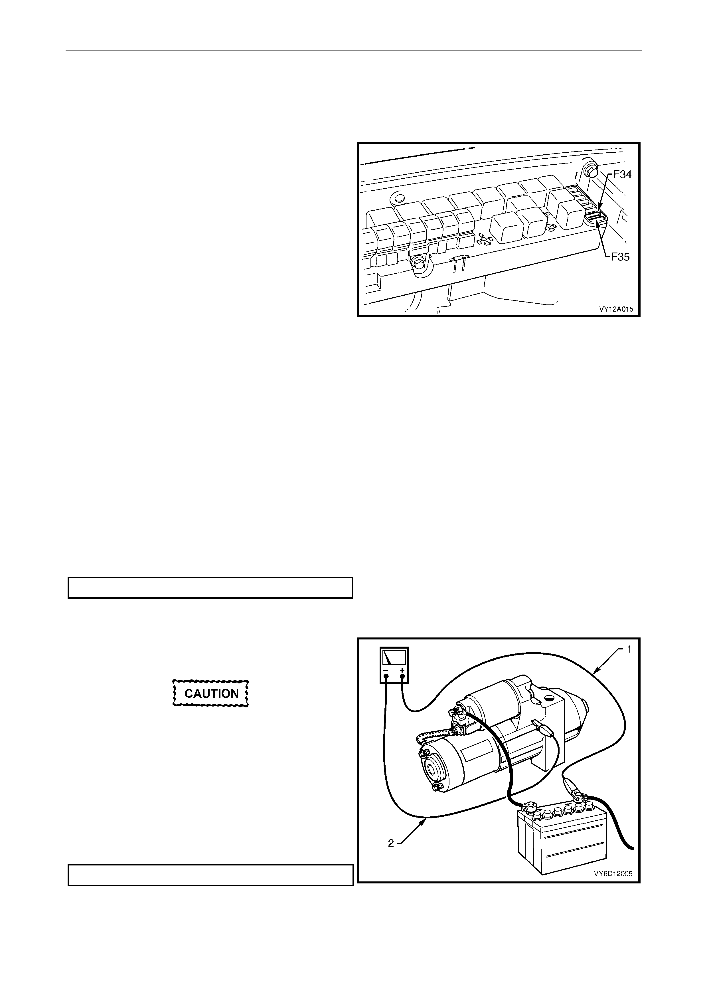
Prerequisites
1 Turn all electrical loads off e.g. lights, fans,
entertainment system, etc.
2 Remove fuses F34 and F35 from the engine
compartment fuse box to disable the ignition and
prevent the engine from starting. Refer to
Section 12O Fuses, Relays and Wiring Harnesses.
3 Chock the wheels.
4 Ensure the handbrake is applied.
5 On vehicles fitted with an automatic transmission,
ensure the transmission is in P (park) or N (neutral).
Figure 6D3-2 – 4
NOTE
The battery must be fully charged and in
serviceable condition before beginning these
tests
Poor Connection Test
A poor connection is indicated by a higher than expected voltage difference between two points on the same circuit. The
voltage difference is measured by connecting a multimeter’s leads to the two points of the circuit.
1 Using a multimeter set to measure voltage, connect the multimeter’s positive lead to the positive battery post.
2 Connect the multimeter’s negative lead to the starter motor M terminal.
3 Record the voltage displayed during cranking.
4 Repeat this with the multimeter’s negative lead connected to the solenoid switch connector M15 – X2 pin A
(circuit 1).
5 Also repeat this connecting the multimeter’s negative lead to the battery cable strands (circuit 1).
6 Repair all connections that show a voltage difference higher than specified.
Maximum circuit voltage difference.........................2.5 V
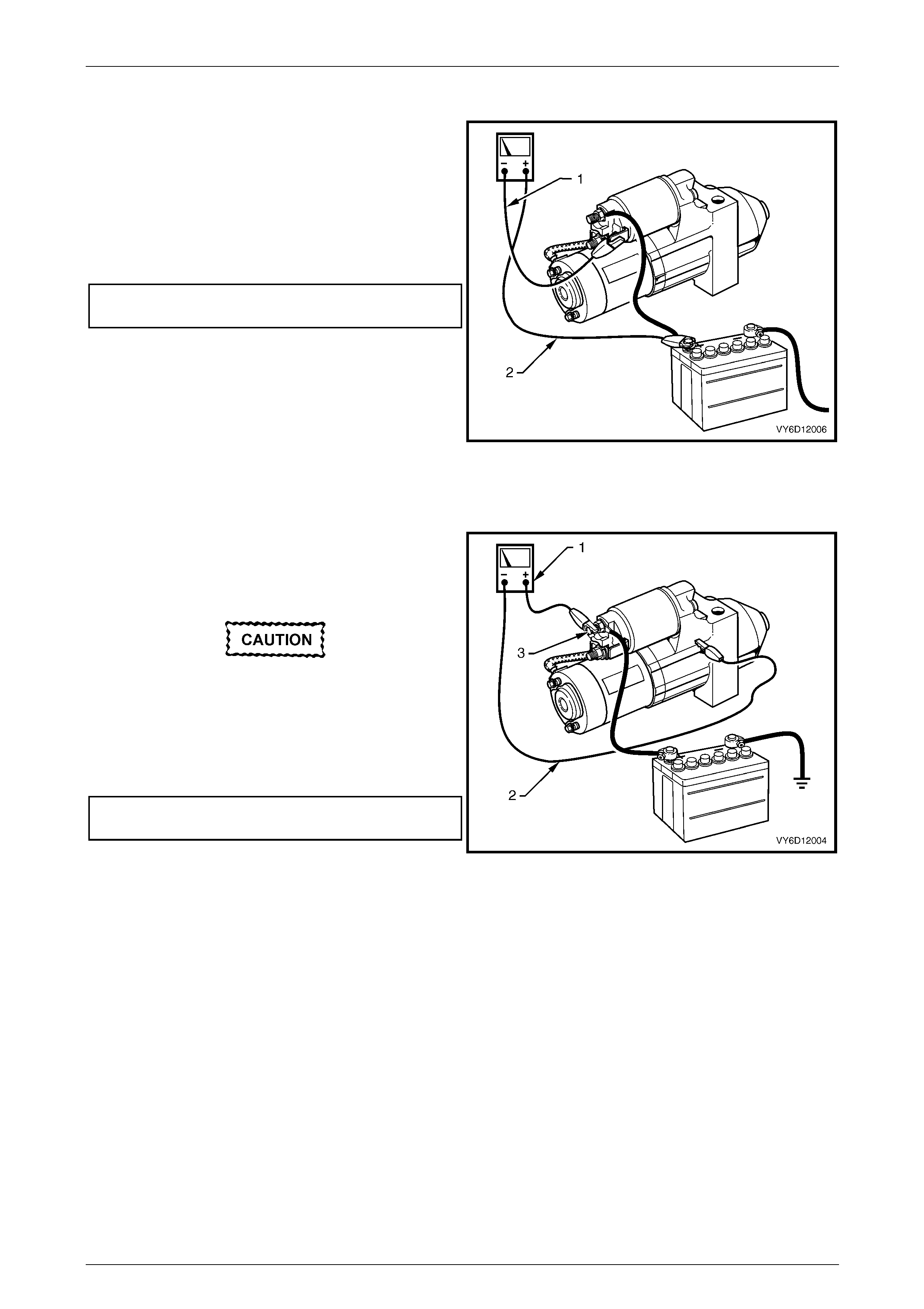
Starter Motor Ground Test
1 Using a multimeter set to measure voltage, connect
the multimeter’s positive lead (1) to the negative
battery post.
Connect the lead to the actual battery post
and not to the cable or connector.
2 Connect the multimeter’s negative lead (2) to the
starter motor housing.
3 Record the voltage that is displayed during cranking.
4 Repeat this connecting the multimeter’s negative lead
to the battery cable strands (circuit 50).
5 Record the voltage that is displayed during cranking.
6 Repair all ground connections that show a voltage
difference higher than specified.
Maximum circuit voltage difference.........................2.5 V
Figure 6D3-2 – 5
Starting System – GEN III V8 Page 6D3-2 – 17
Page 6D3-2 – 17
Switching Circuit Test
1 Using a multimeter set to measure voltage, connect
the multimeter’s negative lead (1) to the solenoid
switch connector M15 – X1 pin A (circuit 6).
2 Connect the multimeter‘s positive lead (2) to the
positive battery post.
3 Crank the engine.
4 Record the voltage that displayed during cranking.
Maximum switching
circuit voltage difference .........................................2.5 V
5 If the voltage is above the specification, test the
solenoid switching circuit to locate the cause of the
high resistance and restore the connection.
Figure 6D3-2 – 6
Cranking Voltage Test
1 Using a multimeter set to measure voltage (1), attach
the multimeter’s negative lead (2) to ground and the
multimeter’s positive lead to starter solenoid connector
M15 – X2 pin A (3) of the solenoid switch.
Do not crank the engine for more than
30 seconds at a time. Allow 2 minutes for the
starter motor to cool do wn b etween tests.
2 Crank the engine.
3 Record the voltage that displayed during cranking.
Minimum cranking
voltage ....................................................................9.0 V
4 Remove and repair or replace the starter motor and
solenoid switch if the voltage is below the
specifications and cranks poorly.
Refer to 4 Major Service Operations.
Figure 6D3-2 – 7
Starting System – GEN III V8 Page 6D3-2 – 18
Page 6D3-2 – 18
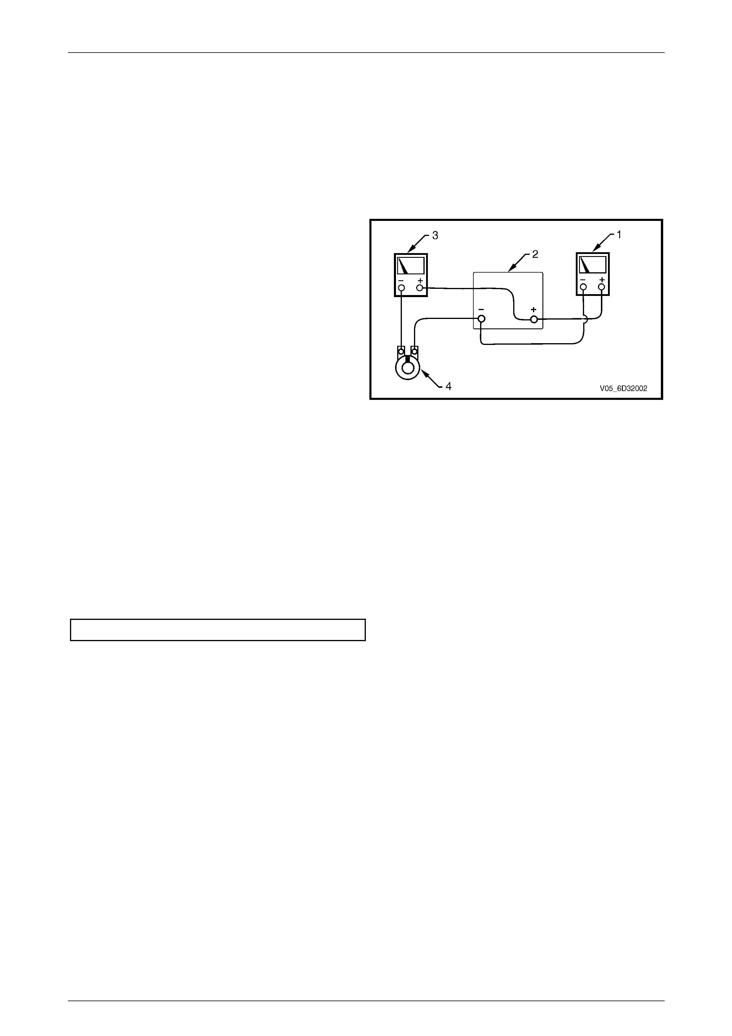
Current Draw Test
The current draw can be measured using a current clamp in association with a multimeter or calculated as outlined in the
following procedure.
NOTE
The battery must be fully charged and in
serviceable condition before beginning this test.
1 Using a multimeter (1) set to measure voltage, attach
the multimeter’s positive lead to the battery’s (2)
positive post.
2 Attach the same multimeter’s negative lead to the
negative battery post.
3 Using a multimeter (3) set to measure current, attach
the multimeter’s positive lead to the battery post.
4 Connect the negative lead of the multimeter set to
measure current to a battery loading device (4), for
example a carbon pile.
5 Connect the free lead of the battery loading device to
the negative battery terminal.
6 Set the battery loading device to maximum resistance
(open).
Figure 6D3-2 – 8
7 Crank the engine.
8 Record the voltage that is displayed during cranking.
9 With the ignition in the OFF position, adjust the battery loading device so the reading of the multimeter set to
measure voltage (1) matches the reading recorded in the last step.
10 Record the current draw due to the load applied by the battery loading device, from the reading of the multimeter
set to measure current (3).
11 Set the battery loading device back to open.
12 Check the current draw is within specifications.
Cranking current draw..................................100 – 140 A
13 Remove and repair or replace the starter motor and solenoid switch if the current draw is outside the specification.
Refer to 4 Major Service Operations.

Starting System – GEN III V8 Page 6D3-2 – 19
Page 6D3-2 – 19
4 Major Service Operations
ATTENTION
All fasteners are important attaching parts as they affect the performance of vital components and/or could
result in major repair expense. Where sp ecified in this Section, fasteners MUST be replaced w ith parts o f the
same part number or an approved equivalent. Do not use fasteners of an inferior quality or substitute design.
Torque values must be used as specified during reassembly to ensure proper retention of all steering
components.
Through out this Section, fastener torque wrench specifications may be accompanied with the following
Identification marks:
Fasteners must be replaced after loosening.
If one of these identification marks is present alongside a fastener torque wrench specification, the
recommendation regarding that fastener must be adhered to.
4.1 Starter Motor
LT Section — 02–070
Remove
The steering gear coupling will be
disconnected when removing the
starter motor. When carrying out procedures
where the steering gear coupling will
be disconnected, remove the ignition key
from the igni tion lock and ensure the steering
column is locked. If this operation is
not carried out and the steering wheel is
spun, damage to the occupant protection
system clock spring can result, rendering the
system inoperative. Ensure the clock spring
remains in its centred position. Refer to
Section 12M Occupant Protection System.
Disconnecting the battery affects
certain vehicle systems. Refer to
Section 00 Warnings, Cautions and Notes in
this Service Information before disconnecting
the battery.
1 Disconnect the battery ground lead.
2 Jack up the front of the vehicle. For jacking locations, refer to Section 0A General Information.
3 Put safety stands in place.
4 Remove the right-hand side exhaust engine pipe, refer to Section 8B Exhaust System.
Techline

Starting System – GEN III V8 Page 6D3-2 – 20
Page 6D3-2 – 20
5 Remove the steering column coupling crimp nut (1).
6 Remove the steering column coupling cam bolt (2).
7 Disengage the retaining clip (3) and slide the coupling
(4) away from the steering gear pinion shaft.
Figure 6D3-2 – 9
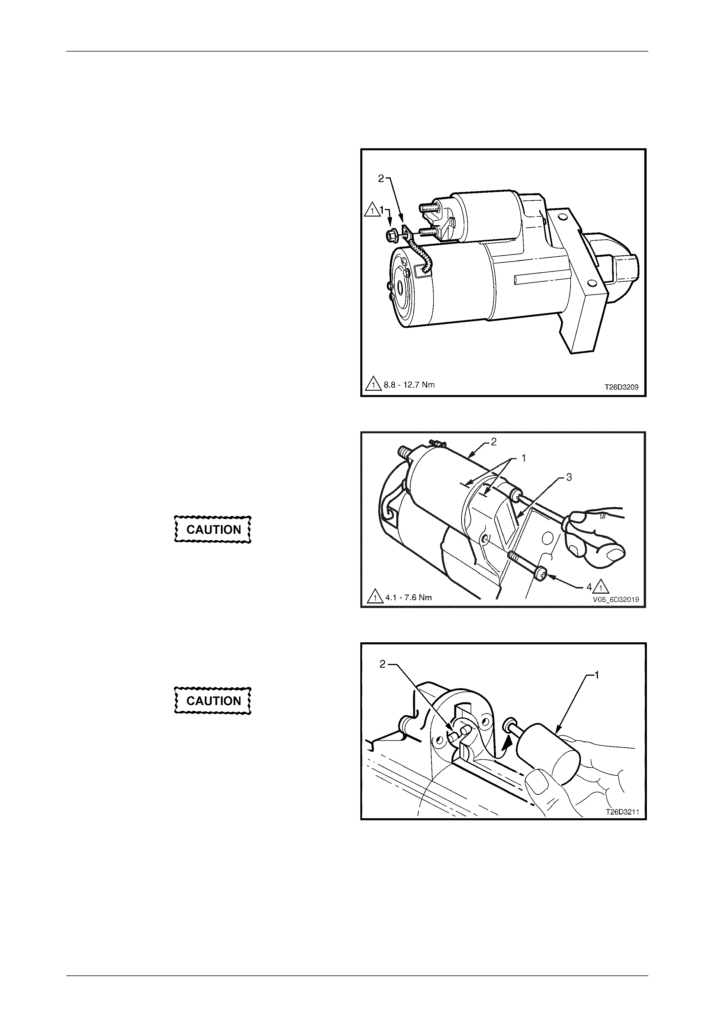
8 Remove the bolt securing the starter motor heat shield
to the mounting bracket (1).
9 Unclip the heat shield (2) from the starter motor
solenoid.
10 Remove the heat shield.
11 Remove the two bolts (3) securing the heat shield
mounting bracket (4) to the transmission bell-housing.
12 Remove the mounting bracket.
Figure 6D3-2 – 10
13 Remove the wiring harness connector from M15 – X1
pin A (1) of the solenoid switch.
14 Remove the nut (2), washer (3) and battery lead (4)
from M15 – X2 pin A of the solenoid switch.
Figure 6D3-2 – 11
Starting System – GEN III V8 Page 6D3-2 – 21
Page 6D3-2 – 21
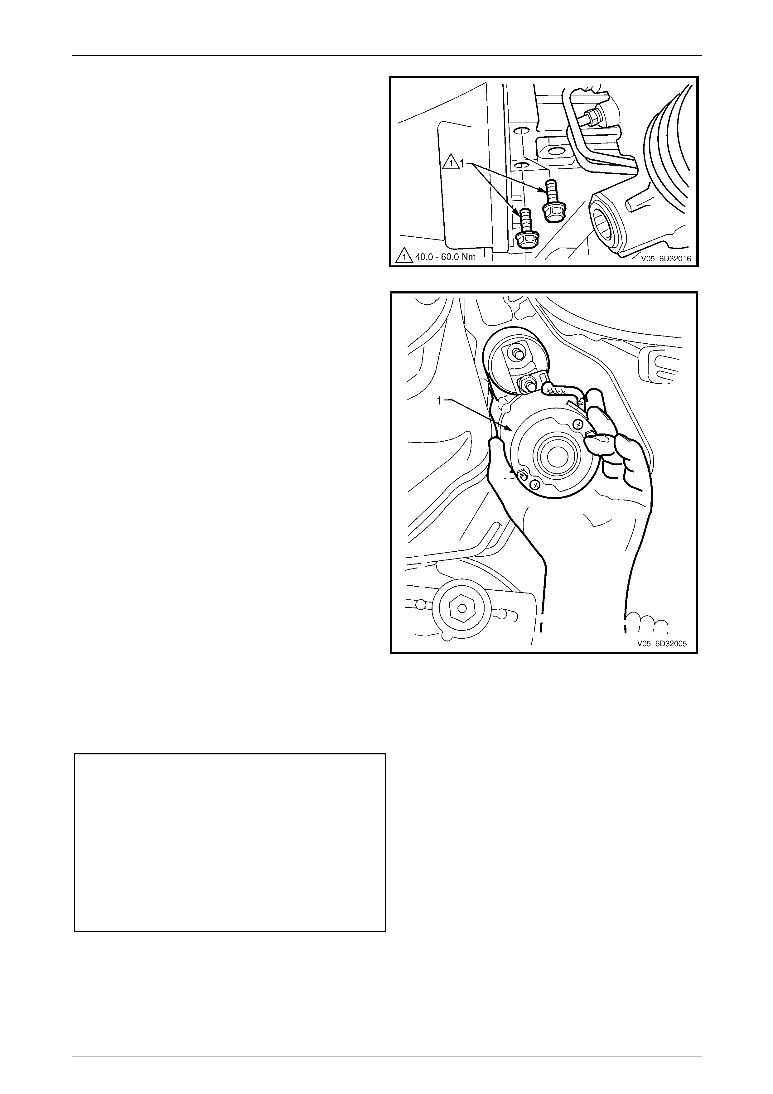
15 Remove the starter motor mounting bolts (1).
Figure 6D3-2 – 12
16 Manoeuvre the starter motor out (1) and down
between the transmission bell-housing and body
sub-frame.
Figure 6D3-2 – 13
Reinstall
Reinstallation of the starter motor is the reverse of the removal procedure, noting the following:
1 Tighten all fasteners to the correct torque specification.
Starter motor mounting bolt
torque specification.................................40.0 – 60.0 Nm
Solenoid Connector
M15 – X2 pin A nut (B+)
torque specification...................................9.8 – 11.8 Nm
Starter motor heat shield bolt
torque specification...................................8.0 – 12.0 Nm
Heat shield mounting bracket bolt
torque specification...................................8.0 – 12.0 Nm
Steering column coupling
crimp nut torque specification .................25.0 – 30.0 Nm
2 Install the exhaust engine pipe ensuring the engine pipe is clear of any underbody components.
Refer to Section 8B Exhaust System.
3 Assemble the steering components, in accordance with Section 9 Steering.
4 Check the starter motor operates correctly.

Starting System – GEN III V8 Page 6D3-2 – 22
Page 6D3-2 – 22
4.2 Starter Motor Bench Tests
Preliminary Checks
1 Check the drive assembly is fully retracted.
2 Check the drive assembly pinion turns freely on the planetary drive shaft.
3 If the drive assembly is not fully retracted, perform the No Load Test.
4 Disassemble and service the starter motor if it fails the No Load test,
refer to 4.3 Starter Motor Disassemble and Reassemble.
Solenoid Switch Tests
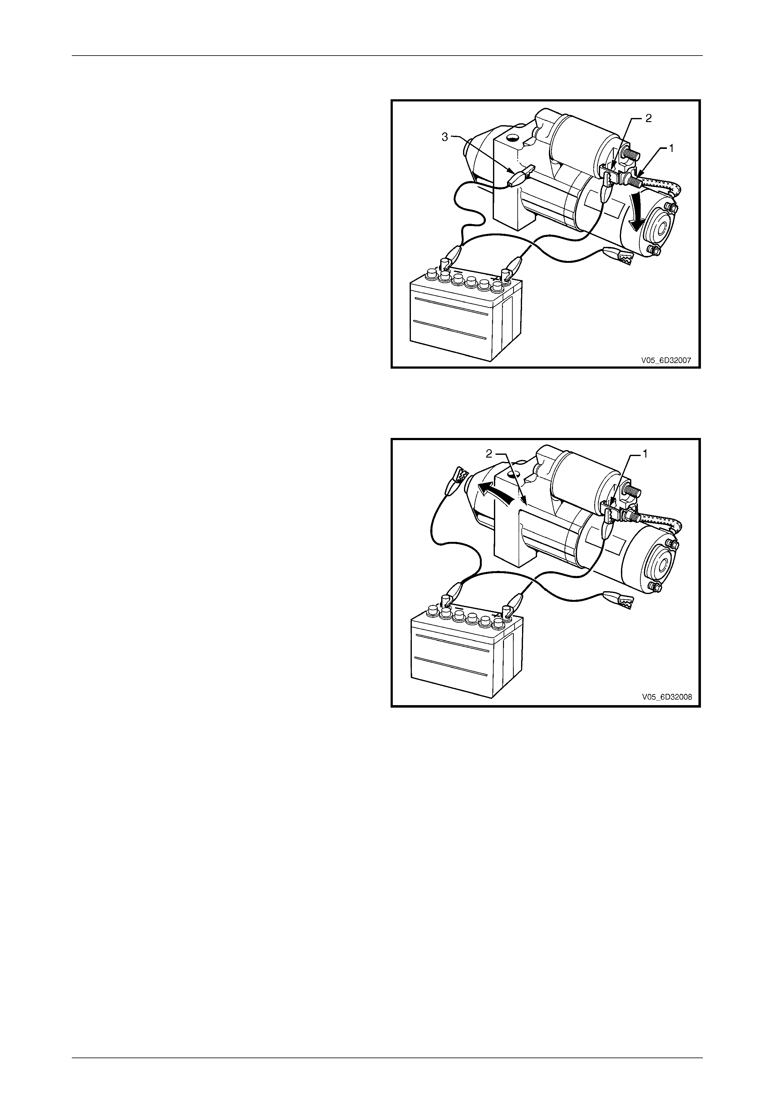
Pull-in Test
1 Clamp the starter motor by the mounting lug in the
drive end housing in a vice with soft jaws.
2 Remove the nut and washer from the M terminal (1) of
the solenoid switch.
3 Remove the braided cable from the M terminal.
4 Insulate the braided cable.
5 Connect the starter motor to an auxiliary battery, as
follows:
a Use a test lead to connect the battery negative
post to the starter motor housing (2).
b Use another test lead to connect the battery
negative post to the M terminal of the solenoid
switch (1).
c Connect a third test lead to the battery positive
post.
6 Connect the free end of the test lead attached to the
battery positive post to terminal M15 – X1 pin A of the
solenoid switch (3).
Figure 6D3-2 – 14
7 Check the solenoid switch activates and the drive assembly moves outward.
8 Disassemble and service the starter motor if the solenoid switch activates but the drive assembly does not move,
refer to 4.3 Starter Motor Disassemble and Reassemble.
9 Replace the solenoid switch if it does not activate (there is no sound or movement).
Starting System – GEN III V8 Page 6D3-2 – 23
Page 6D3-2 – 23
Hold-in Test
1 With the battery connections to the starter motor and
solenoid switch as described for the Pull-in test,
disconnect the test lead from of the M terminal of the
solenoid switch (1).
2 Check the drive assembly remains extended.
3 Replace the solenoid switch if the drive assembly
retracts back into the starter motor.
Figure 6D3-2 – 15
Drive Assembly Return Test
1 With the battery connections to the starter motor and
solenoid switch as described for the Hold-in test,
disconnect the test lead from of the starter motor
housing (2).
2 Check the drive assembly retracts back into the starter
motor.
3 Replace the solenoid switch if the drive assembly does
not retract.
Figure 6D3-2 – 16
Starting System – GEN III V8 Page 6D3-2 – 24
Page 6D3-2 – 24
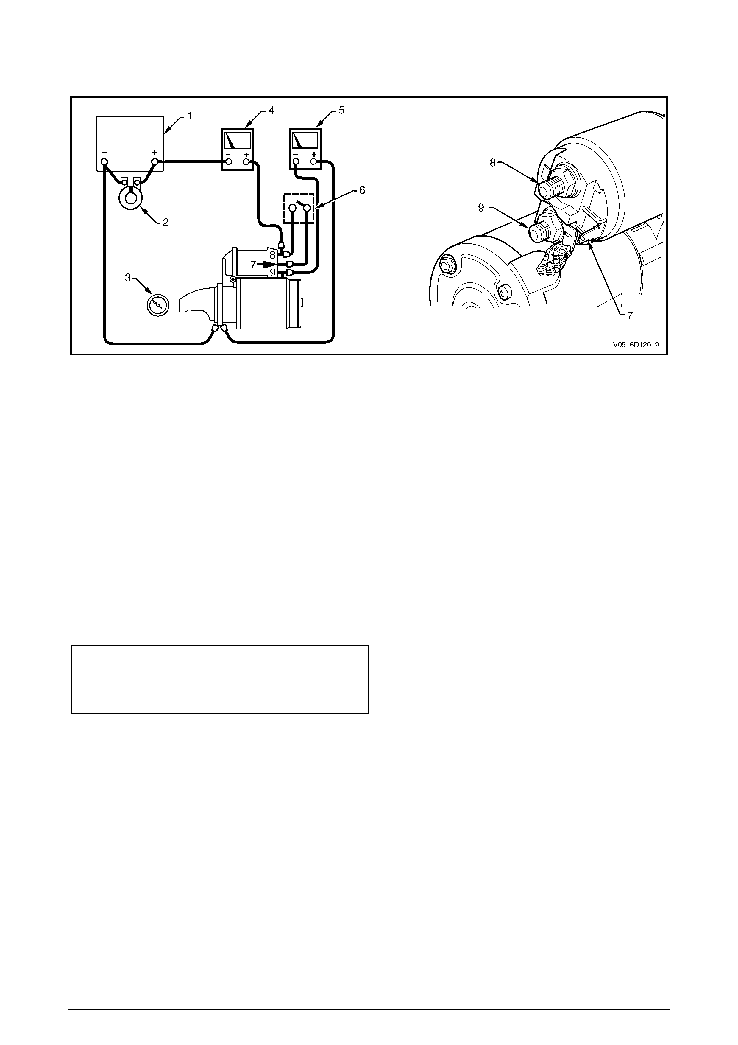
No Load Test
Figure 6D3-2 – 17
Legend
1 Battery
2 Carbon Pile
3 Shaft Speed Indicator
4 Multimeter set to measure current
5 Multimeter set to measure voltage
6 Start Switch
7 Solenoid Switch M15 – X1 pin A
8 Solenoid Switch M15 – X2 pin A
9 Solenoid Switch M terminal
1 Clamp the starter motor securely to a test bench.
2 Connect the starter motor as shown in Figure 6D3-2 – 17.
3 Close the start switch to activate the starter motor.
4 Record the speed of the planetary drive shaft, current draw and the voltage.
5 Check the readings are within the specifications.
Minimum RPM ........................................................2370
Maximum current draw.............................................90 A
M Terminal voltage ..................................................11 V
6 Disassemble and service the starter motor if the readings are not within the specifications.
Refer to 3 Major Service Operations.
Starting System – GEN III V8 Page 6D3-2 – 25
Page 6D3-2 – 25
4.3 Starter Motor Disassemble and
Reassemble
Disassemble
1 Clamp the starter motor, by the mounting lug in the
drive-end housing, in a vice with soft jaws.
2 Remove the nut (1) and braided cable (2) from the
solenoid switch M terminal.
Figure 6D3-2 – 18
3 Scribe aligning marks (1) on the drive-end housing (2)
and the solenoid switch housing (3) to aid reassembly.
4 Remove the two solenoid switch mounting screws (4).
It may be necessary to loosen the mounting screws
using an impact driver.
When using an impact driver, avoid
damaging the drive-end housing or rounding
the screw slots of the solenoid switch
mounting screws
Figure 6D3-2 – 19
5 Remove the solenoid switch from the drive-end
housing.
Do not lose the plunger return spring from
within the housing.
6 Unhook and remove the solenoid switch plunger (1)
from the drive assembly fork lever (2).
Figure 6D3-2 – 20
Starting System – GEN III V8 Page 6D3-2 – 26
Page 6D3-2 – 26
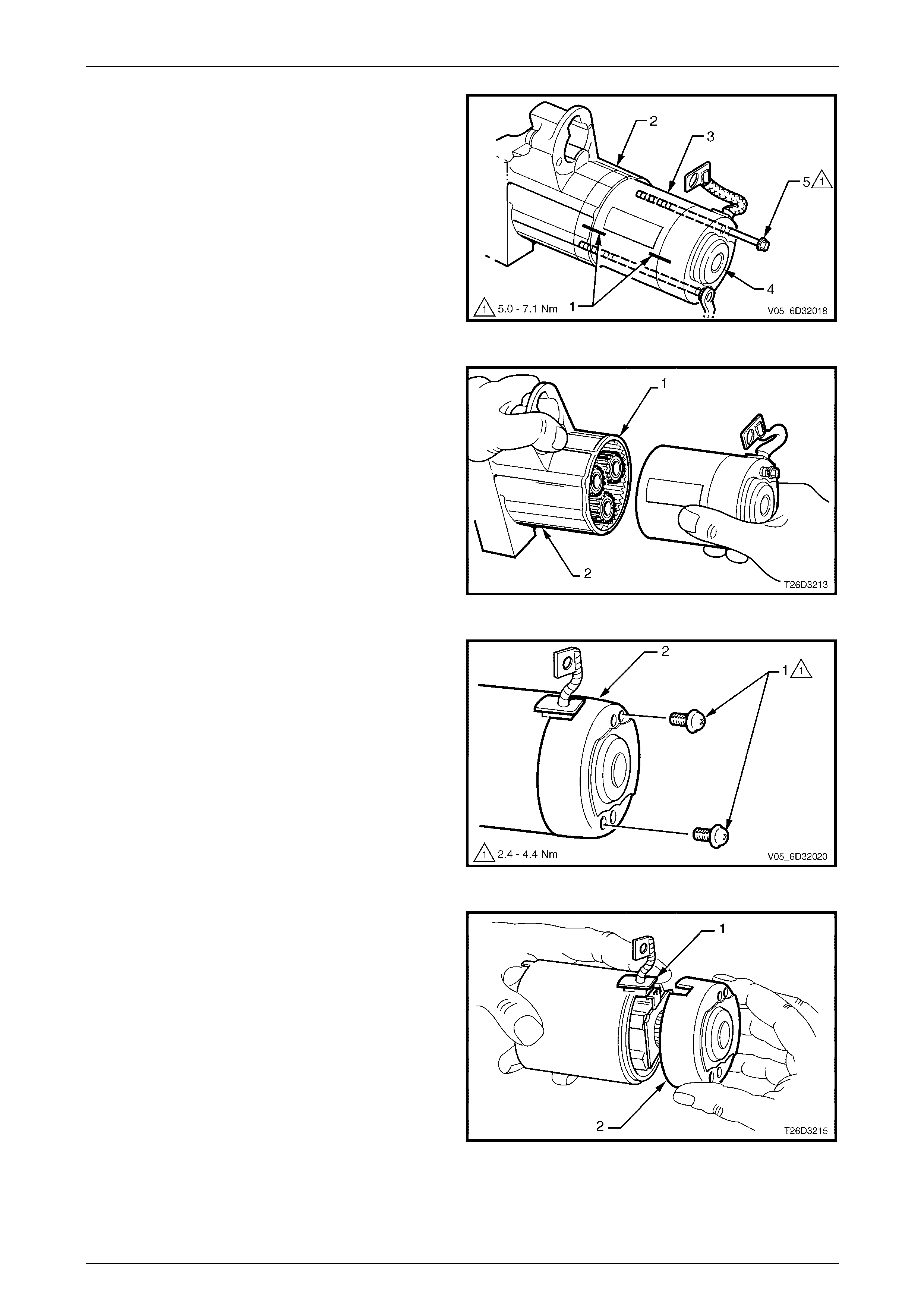
7 Scribe aligning marks (1) on the drive-end housing (2),
pole housing (3) and commutator end shield (4) to aid
reassembly.
8 Remove the two through-bolts (5).
Figure 6D3-2 – 21
9 Hold the rubber seal (1) and the drive-end housing (2)
securely.
10 Remove the pole housing complete with the armature
(not shown) and commutator end shield.
Figure 6D3-2 – 22
11 Remove the two screws (1) securing the end
shield (2).
Figure 6D3-2 – 23
12 While holding the braided cable and rubber seal (1),
remove the commutator end shield (2).
Figure 6D3-2 – 24
Starting System – GEN III V8 Page 6D3-2 – 27
Page 6D3-2 – 27
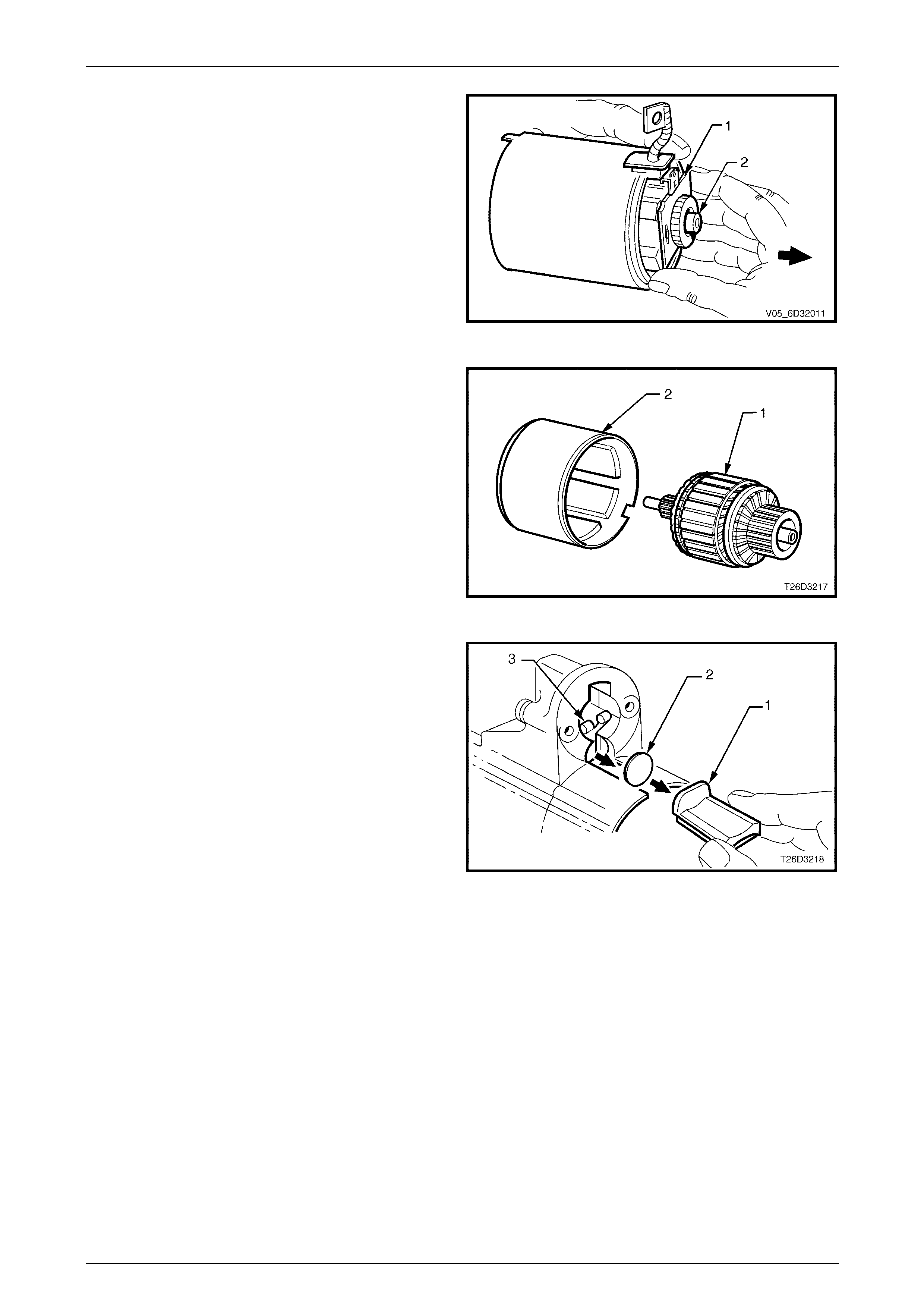
13 Carefully remove the brush holder (1) from the partially
exposed armature (2).
Figure 6D3-2 – 25
14 Remove the armature (1) from the pole housing (2).
Figure 6D3-2 – 26
15 Take note of how the rubber seal (1) is installed.
16 Remove the rubber seal from drive-end housing.
17 Remove the fork lever plate (2).
18 Remove the stopper ring and retainer. Refer to item 16
in Figure 6D3-2 – 2.
19 Remove the planetary drive assembly. Refer to items
12, 13 and 14 in Figure 6D3-2 – 2.
20 Remove the drive pinion assembly with the fork
lever (3). Refer to items 3 and 15 in
Figure 6D3-2 – 2.
21 Take note of the orientation of the fork lever.
22 Remove the fork lever from the drive assembly. Figure 6D3-2 – 27
Starting System – GEN III V8 Page 6D3-2 – 28
Page 6D3-2 – 28
Cleaning and Inspection
1 Clean and thoroughly inspect the disassembled components.
Use a non-volatile agent in a well ventilated
area. Observe the safety regulations and
precautions issued by the man ufactu rer of th e
cleaning agent.
• Do not clean the armature or permanent
magnets with cleaning solvent. This can
damage the insulation or contaminate the
surfaces.
• Do not clean the drive pinion assembly in
solvent. This w ashes out the lubricant and
can cause the drive assembly to slip.
2 Wash all components (except the armature, brushes, solenoid switch and drive assembly) in a suitable cleaning
agent.
3 Clean the armature and permanent magnets with clean shop rags and compressed air.
Pole Housing Check
1 Inspect the pole housing and permanent magnet assembly for signs of damage, cracks and chips.
2 Replace the assembly as required.
Armature Check
1 Check the armature insulation resistance to ground
using a Megga or similar tester. A reading of 1 MΩ or
greater is required.
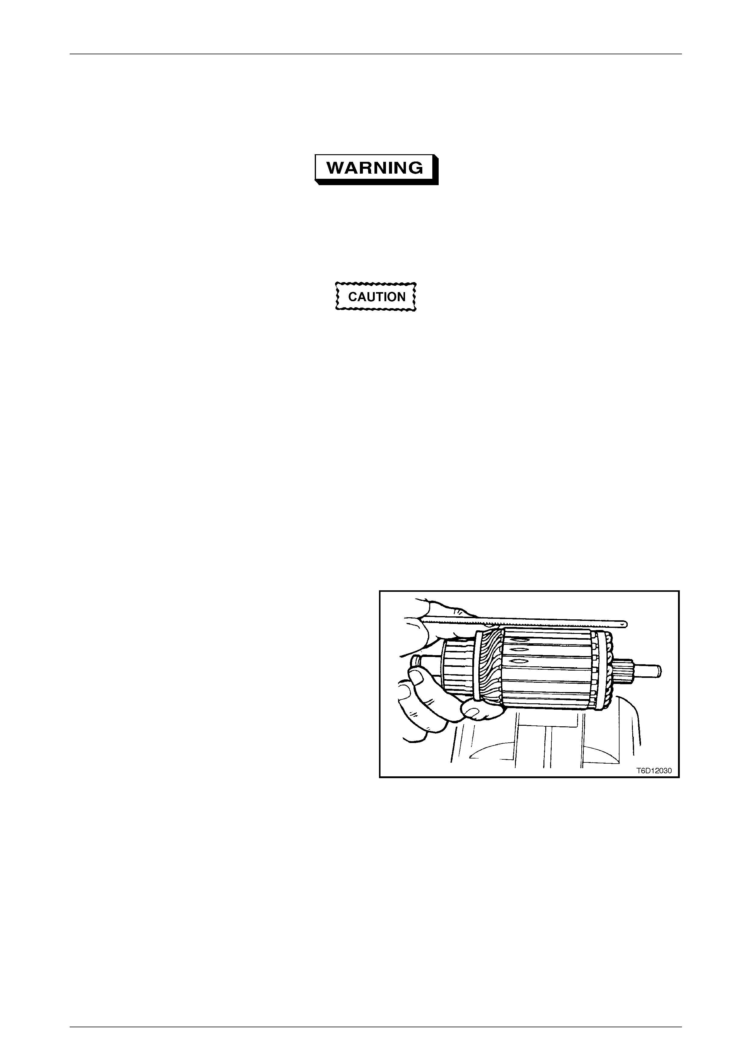
2 Check the armature for a short circuit.
3 Place the armature on a growler.
4 Switch the growler on.
5 Hold a hacksaw blade approximately 6 mm above
armature core and rotate the armature.
6 If the hacksaw blade vibrates significantly, undercut
the commutator, as follows:
a Use a suitable small file.
b Undercut between each commutator segment to
a depth of approximately 0.8 mm.
c Re-check the armature in the growler.
Figure 6D3-2 – 28
7 Replace the armature if the hacksaw blade still vibrates significantly.
8 Examine the commutator for burnt or darkened segments. This indicates an open circuit winding relative to that
segment.
9 Replace the armature if a segment is burnt or darkened.
Starting System – GEN III V8 Page 6D3-2 – 29
Page 6D3-2 – 29
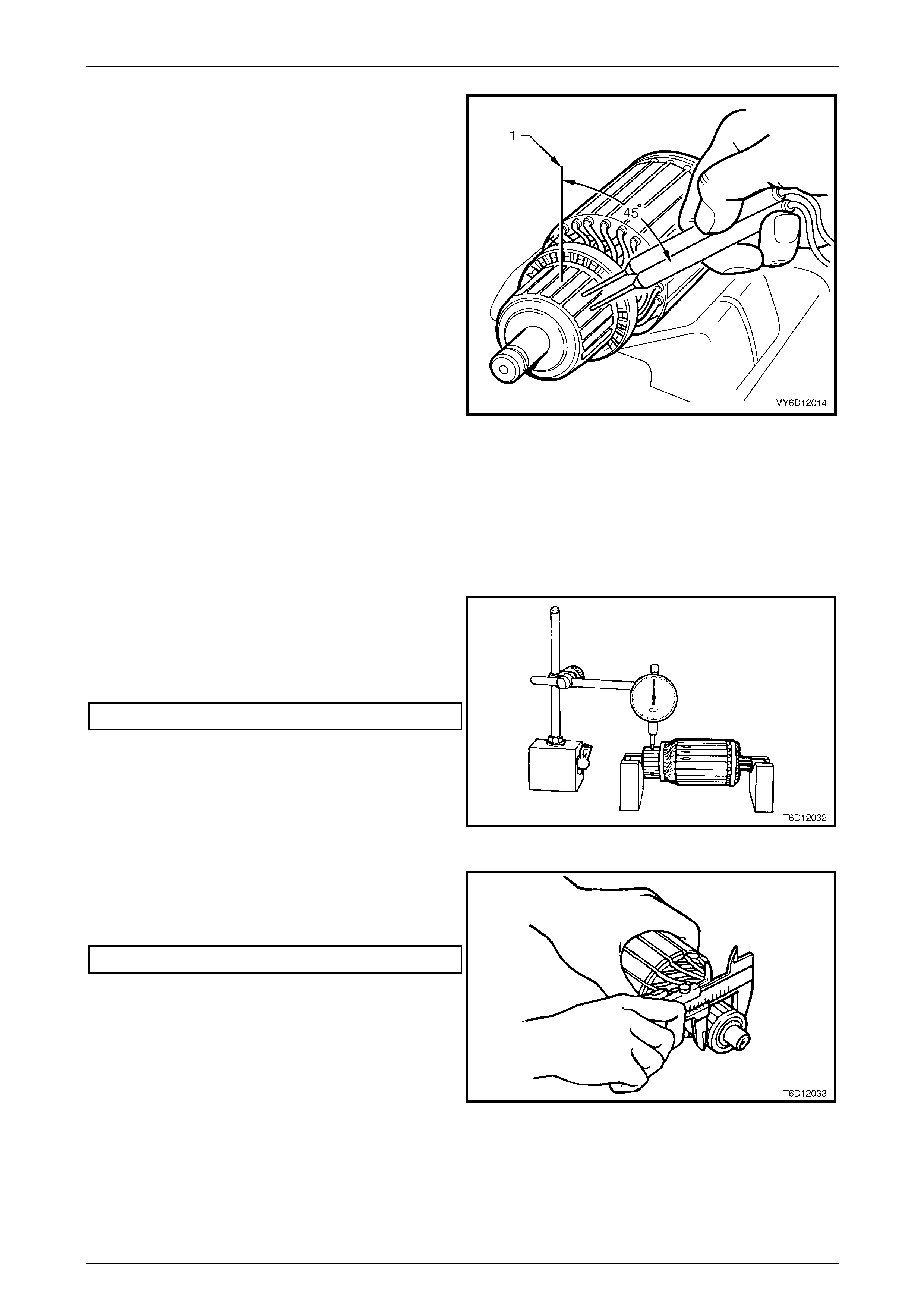
10 Place the armature on a growler.
11 Use a multimeter set to measure voltage, measure the
voltage induced into the armature windings, as follows:
a Choose two adjacent segments that are
approximately 45 degrees from the top of the
commutator (1).
b Connect the multimeter between the two
commutator segments.
12 Record the reading.
13 Rotate the armature in the growler so the next two
commutator segments are in the same position as the
previous two.
14 Measure the voltage across these segments.
15 Record the reading.
16 Repeat these steps to measure the voltage reading of
all adjacent segments. The voltage reading should be
the same for each pair when positioned in the growler
in the equivalent location.
17 Replace the armature if a voltage reading across any
adjacent set of segments differs significantly. This
indicates the armature winding has an open circuit.
Figure 6D3-2 – 29
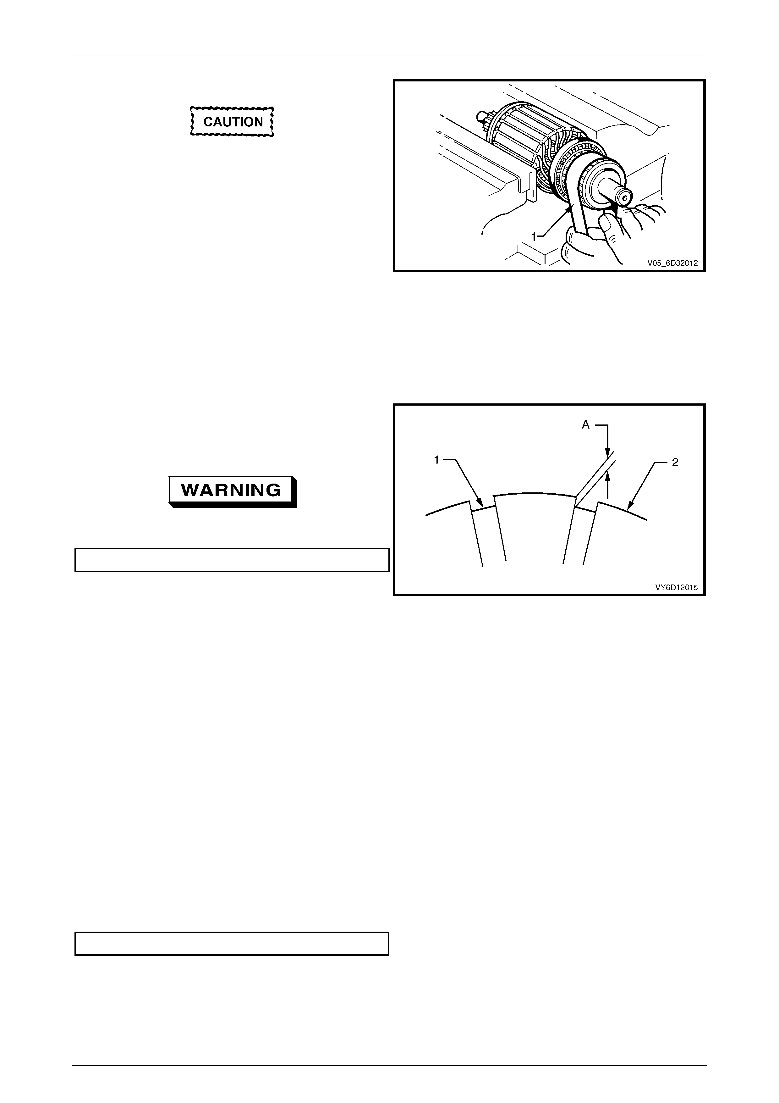
Commutator Check
1 Check the commutator for worn or burnt segments,
high insulation between the segments and for out-of-
round.
2 Machine the commutator if any flaws exist or the out-
of-round value is outside specification.
Maximum out-of-round of commutator................. 0.1mm
Figure 6D3-2 – 30
3 Check the commutator diameter.
4 Replace the armature if the commutator diameter is
below the specification.
Minimum commutator diameter......................... 28.8 mm
Figure 6D3-2 – 31
Starting System – GEN III V8 Page 6D3-2 – 30
Page 6D3-2 – 30
5 Machine the commutator, as follows:
Do not clamp the armature by the laminations
w hen machining the commutato r.
a Turn the commutator in two stages; pre-turning
and finish turning.
b Finish cut the commutator using a fine tool of no
more than 0.03 mm.
c Polish the surface using 500 – 600 grade emery
cloth (1).
d Brush out the commutator segment slots using a
stiff brush.
e Check the diameter of the commutator.
6 Replace the armature if the diameter of the
commutator is less than the specification.
Figure 6D3-2 – 32
7 Check the depth of the insulating mica (1) from
commutator surface (2).
8 Undercut the mica if the depth (A) is less than 0.2 mm.
Use dust extraction w h en undercutting.
Depth of undercut ..................................... 0.5 to 0.8 mm
9 Clean all dirt and debris from the commutator segment
slots.
10 Lightly polish the commutator to remove any burrs.
11 Clean the commutator and armature thoroughly with
compressed air.
Figure 6D3-2 – 33
Brushes Check
1 Check the brush holder springs for breakage and corrosion.
2 Replace the brush holder springs as required.
3 Check that each brush slides smoothly in the holder.
4 Check the brush connections are sound.
5 Check the brushes are clean.
6 Check the brushes are not chipped.
7 Replace all of the brushes if a fault exists in any one of the brushes.
8 Check the length of each brush.
9 Replace all of the brushes if any brush is below specification.
Minimum brush length......................................... 7.0 mm
Starting System – GEN III V8 Page 6D3-2 – 31
Page 6D3-2 – 31
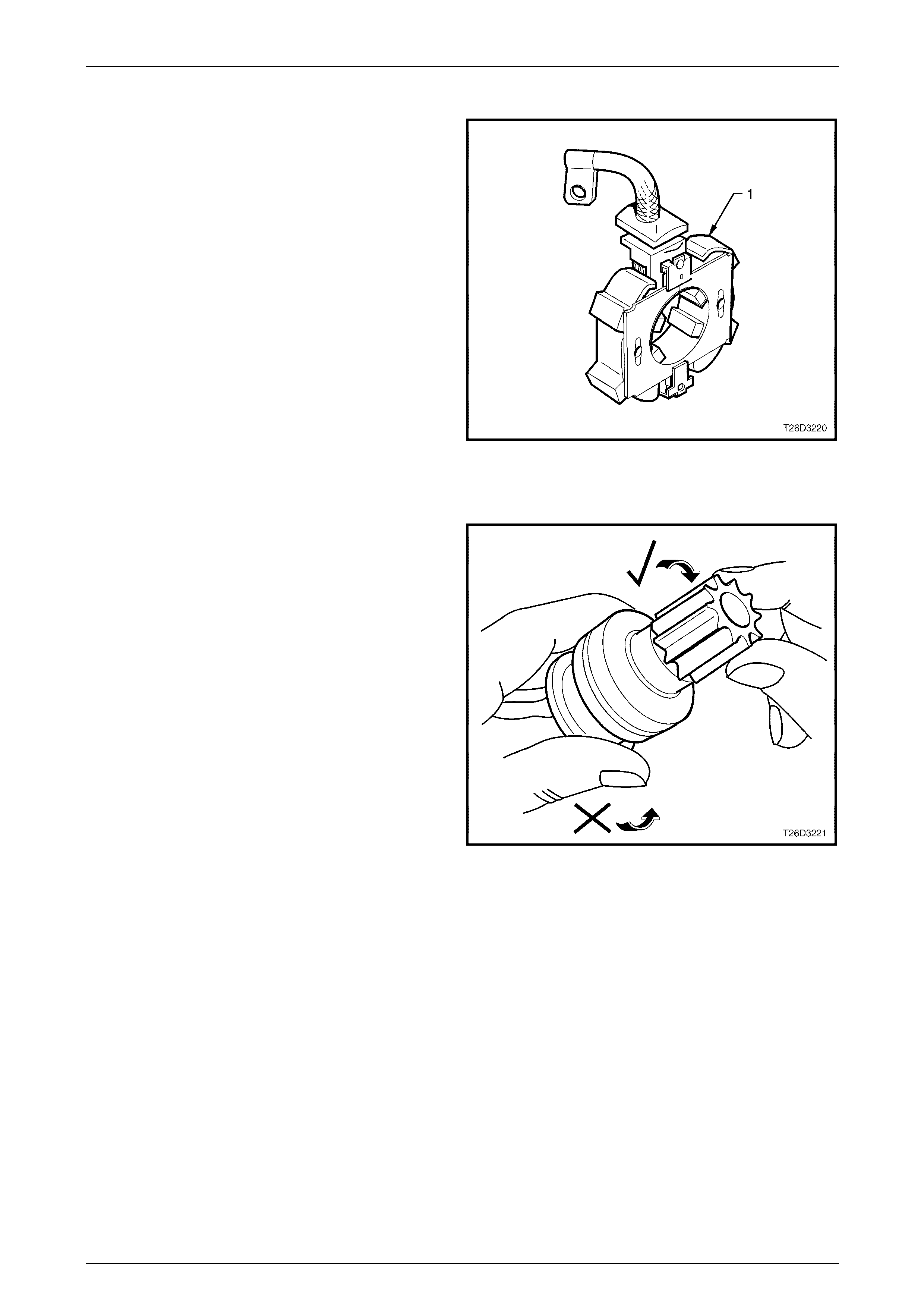
Brush Plate Assembly Check
1 Check the brush holder assembly (1) for cracks or
damage.
2 Replace the brush holder assembly as necessary.
3 Using a multimeter set to measure resistance check
for continuity between a negative and a positive brush
holder.
4 There must be no continuity (an open circuit) between
the negative and positive brush holders.
5 Replace the brush plate assembly if there is any
continuity between the negative and positive brush
holders.
Figure 6D3-2 – 34
Drive Assembly Check
1 Inspect the drive assembly pinion gear for worn or
chipped teeth or burrs.
2 Replace the drive assembly and inspect the
flexplate / flywheel ring gear teeth if the pinion
gear is damaged or broken. Refer to
Section 6A3 Engine Mechanical – GEN III V8.
3 Check the operation of the pinion gear. Ensure that it
rotates freely and smoothly in only one direction.
4 Examine the internal bush of the pinion for wear or
scoring.
5 Replace the drive assembly if there is any sign of
damage or it rotates in both directions.
6 Inspect the fork lever contact surfaces and pivots.
7 Replace the fork lever if it is damaged or significantly
worn.
Figure 6D3-2 – 35
Bush Check
1 Check the fit of the armature shaft in the commutator end shield.
2 Check the fit of the planetary drive shaft in the drive-end housing.
3 Replace the commutator end shield and / or drive end housing if bushes are damaged or excessively worn.
4 Check the bush housings for wear from the shaft and for out-of-round.
5 Replace the housing if it is damaged or out-of-round.
Starting System – GEN III V8 Page 6D3-2 – 32
Page 6D3-2 – 32
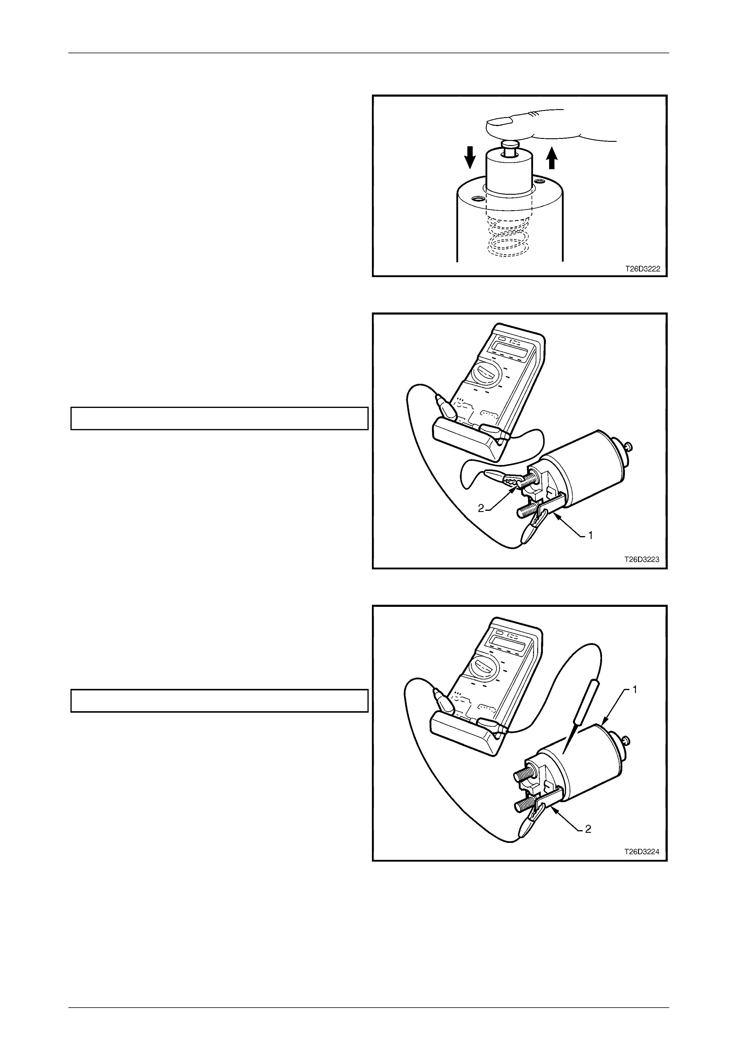
Solenoid Switch Check
1 Inspect the solenoid switch for any external damage
and replace if required.
2 Install the return spring and plunger into the solenoid
switch and check the movement of the plunger as
follows:
a Depress the plunger fully.
b Release the plunger.
c If the plunger sticks or binds in the switch bore,
clean or replace the solenoid switch assembly as
required.
Figure 6D3-2 – 36
3 Connect a multimeter set to measure resistance
between M15 – X1 pin A (1) and the M terminal (2).
4 Record the resistance reading.
5 Replace the solenoid switch if the resistance is outside
the specification.
Pull-in coil resistance @ 20°C....................0.33 – 0.37 Ω
Figure 6D3-2 – 37
6 Connect a multimeter set to measure resistance
between the solenoid switch housing (1) and M15 – X1
pin A (2).
7 Replace the solenoid switch if the resistance is outside
the specification.
Hold-in coil resistance @ 20° C .................0.75 – 0.87 Ω
Figure 6D3-2 – 38
Starting System – GEN III V8 Page 6D3-2 – 33
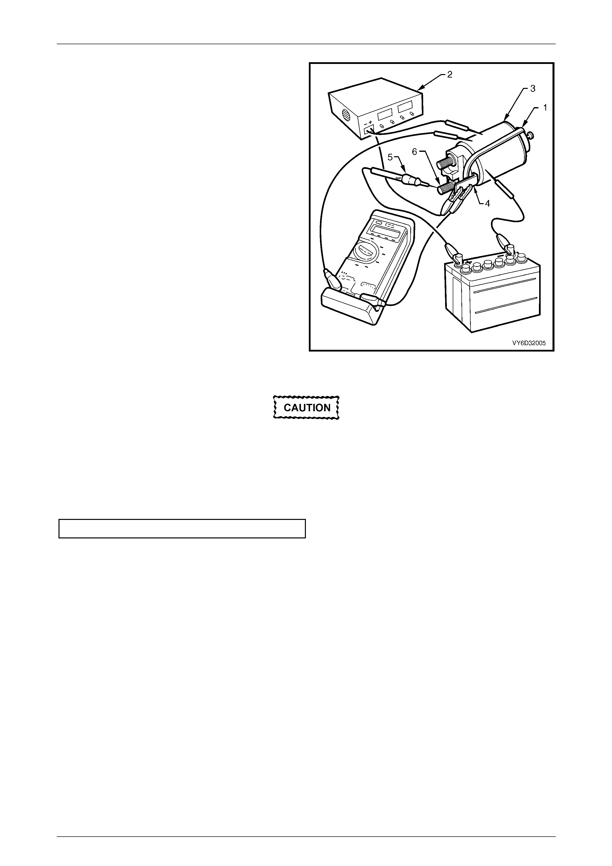
Page 6D3-2 – 33
8 Fit a rubber band (1) around the plunger and switch
housing to avoid ejecting the plunger.
9 Hold the solenoid switch vertically with the plunger
pointing upwards.
10 Use a power supply (2) capable of supplying 30 A or
use a battery and a variable resistor.
11 Set the power supply to 3.0 V.
12 Connect the power supply negative lead to the
solenoid switch body (3).
13 Connect the power supply positive lead to M15 – X1
pin A (4).
14 Connect a 12 volt test lamp (5) between M15 – X2 pin
A (6) and the battery positive post.
15 Connect a multimeter set to measure voltage between
M15 – X1 pin A and the solenoid switch housing.
16 Press the solenoid plunger in until the test lamp
illuminates.
17 Allow the plunger to move out by 8 – 10 mm.
18 Hold the plunger in this position.
Figure 6D3-2 – 39
The test duration for the following step
should be no more than tw o seconds.
19 Slowly increase the voltage on M15 – X1 pin A until the plunger pulls in.
20 Record the multimeter reading and reduce the voltage applied to M15 – X1 pin A.
21 Replace the solenoid switch if the voltage reading is significantly higher than the specification.
Pull-in voltage @ 20°C............................................8.0 V
22 Check the continuity across the main contacts in the switch.
23 Increase the voltage on M15 – X1 pin A until the plunger pulls in.
24 Ensure the test lamp illuminates fully.
25 Replace the solenoid switch if the test lamp illuminates poorly.

Starting System – GEN III V8 Page 6D3-2 – 34
Page 6D3-2 – 34
26 Set the power supply (1) to 24.0 V.
27 Connect the power supply positive lead to M15 – X1
pin A (2).
28 Connect the power supply negative lead to the
solenoid switch housing.
29 Press the plunger in fully.
30 Release the plunger. The hold-in winding should hold
the plunger in.
31 Replace the solenoid switch if the winding does not
hold the plunger.
32 Decrease the voltage until the plunger releases.
33 Record the multimeter reading.
34 Replace the solenoid switch if the voltage reading is
significantly higher than the specification.
Hold-in voltage specification @ 20°C.............1.7 – 3.0 V Figure 6D3-2 – 40
35 Connect a 12 volt test lamp between M15 – X2 pin A and the 12 volt power supply.
36 Press the plunger in until the test lamp illuminates.
37 Attempt to press the plunger into the solenoid switch housing a further 1 mm.
38 Replace the solenoid switch if the plunger can not move at least a further 1 mm.
39 Connect the positive lead of a 24 volt power supply (1)
to the multimeter positive lead.
40 Connect the negative lead of a 24 volt power supply to
the solenoid switch housing.
41 Connect the multimeter negative lead to M15 – X2 pin
A of the solenoid (2).
42 Press the plunger in fully.
43 Release the plunger. The plunger should return to its
rest position.
44 Replace the solenoid switch if the plunger does not
return. This indicates the windings have inter-winding
short circuit. When the solenoid switch is connected in
this way, the winding fields are in opposition to each
other.
Figure 6D3-2 – 41
Starting System – GEN III V8 Page 6D3-2 – 35
Page 6D3-2 – 35
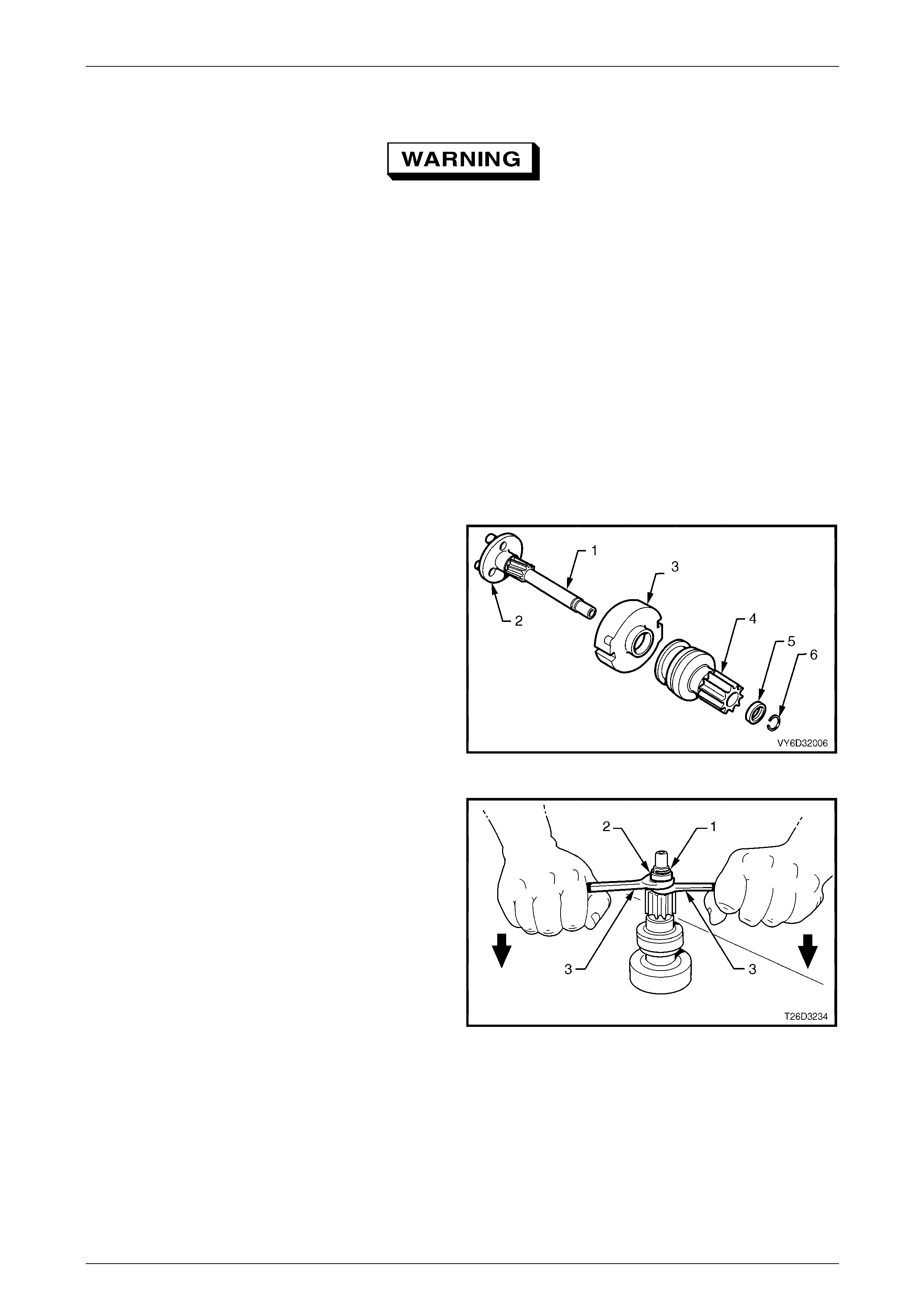
Reassemble
Dry all parts thoroughly before assembly,
taking care not to breathe in any vapours.
NOTE
Refer to Figure 6D3-2 – 2 for identification of
components.
Reassembly the starter motor is the reverse order of the disassembly procedure, noting the following:
1 Lubricate the following drive end housing, commutator end shield and the drive assembly to planetary drive bush
with clean engine oil.
2 Lightly coat the following parts with 10% molybdenum disulphide grease:
a drive shaft assembly helix, and
b inside of the gear assembly cover.
3 Half fill the commutator end shield with grease.
4 Assemble the drive components onto the planetary
drive shaft (1) as follows:
a drive assembly bush (2),
b gear assembly cover (3),
c drive assembly (4),
d stop ring retainer (5), and
e stop ring (6).
Figure 6D3-2 – 42
5 Secure the stop ring (1) with the stop ring retainer (2),
as follows:
a Place the drive assembly on a firm surface.
b Slide the stop ring retainer up to the stop ring.
c Fit two open-end spanners (3 ) in between the
stop ring retainer and the drive assembly.
d Lever the spanners against the retainer until it
clicks over the stop ring.
6 Check the drive assembly moves freely up and down
the planetary drive shaft.
7 Check the drive assembly clutch action.
8 Fit the fork lever.
Figure 6D3-2 – 43
9 Slide the planetary drive assembly into the drive end housing.
10 Rotate the planetary drive ring-gear to position it correctly in the drive end housing.
11 Position the fork lever pivot into the drive end housing.
12 Install the lever plate and sealing rubber behind the fork lever pivot ensuring the sealing rubber is aligned correctly.
13 Assemble planetary gears and sealing ring.
Starting System – GEN III V8 Page 6D3-2 – 36
Page 6D3-2 – 36
14 Assemble the armature into the field housing with the commutator at the rear of the housing.
15 Install the brush plate assembly onto the commutator, as follows:
a Lightly grip the armature shaft in a vice with soft jaws.
b Push two adjacent brushes into the brush holders.
c Angle the brush plate assembly onto the commutator.
d Press the remaining brushes into the brush holders.
e Carefully manoeuvre the assembly onto the commutator.
Do not use force when fitting the brush
assembly.
16 Slide the commutator end shield onto the armature shaft.
17 Align the screw holes in the commutator end shield with the brush plate assembly.
18 Install the end shield retaining screws.
End shield securing screw
torque specification.....................................2.4 – 4.4 Nm
19 Assemble the field housing to the drive-end housing.
20 Check the marks made prior to disassembly align.
21 Fit the armature into the planetary drive.
22 Rotate the pinion gear slightly to engage the armature gear.
23 Align the cut-out in the field housing with the sealing rubber in the drive end housing.
24 Install the through-bolts.
25 Tighten the through-bolts to the correct torque specification.
Through-bolt torque specification................5.0 – 7.1 Nm
26 Lightly coat the solenoid switch plunger with 10% molybdenum disulphide grease.
If too much grease is applied, it can enter the
contact chamber and cause contact
problems.
27 Assemble the return spring and plunger into the solenoid switch.
28 Pull the pinion gear forward to make the fork lever more accessible.
29 Assemble the solenoid plunger onto the fork lever and into the drive-end housing.
30 Install the solenoid switch housing onto the drive-end housing ensuring the marks made prior to disassembly align.
(solenoid connector M15 – X2 pin A faces away from the field housing.)
31 Install and tighten the solenoid switch mounting screws to the correct torque specification.
Solenoid switch mounting screw
torque specification.....................................4.1 – 7.6 Nm
32 Fit the braided cable onto the M terminal.
33 Fit the washer and nut to the M terminal and tighten the nut to the correct torque specification.
Threaded M Terminal nut
torque specification...................................8.8 – 12.7 Nm
34 With the starter motor reassembled, perform a No Load Test. Refer to 4.2 Starter Motor Bench Tests.
35 If the starter motor fails the No Load Test specification, check for tight brushes, dirty brushes and high resistance
connections.
36 Diagnose and repair all faults.

Starting System – GEN III V8 Page 6D3-2 – 37
Page 6D3-2 – 37
5 Specifications
Type............................................................................................................. Mitsubishi P-R/D3
Description.................................................................Six-pole, four brush, planetary drivetrain
Rotation (drive end view)..........................................................................................Clockwise
Number of pinion teeth .........................................................................................................10
No Load Test:
Minimum cranking voltage............................................................................................... 9.0 V
Maximum current............................................................................................90.0 A at 11.0 V
Minimum RPM..................................................................................................................2370
Maximum Switching Circuit Voltage Difference................................................................ 2.5 V
Lock test:
Maximum current (including solenoid) ............................................................................ 780 A
Volts................................................................................................................................. 4.0 V
Minimum Torque.........................................................................................................20.0 Nm
Cranking current range....................................................................................100.0 – 140.0 A
Solenoid Test (Solenoid detached from starter motor):
Pull in voltage .....................................................................................................8.0 V @ 20°C
Hold-in voltage...........................................................................................1.7 – 3.0 V @ 20°C
Hold-in winding resistance.....................................................................0.75 – 0.87 Ω @ 20°C
Pull-in winding resistance .......................................................................0.33 – 0.37 Ω@ 20°C
Commutator:
Maximum permissible out-of-round...............................................................................0.1 mm
New diameter..............................................................................................................29.4 mm
Minimum diameter......................................................................................................28.8 mm
Depth of undercut................................................................................................0.5 – 0.8 mm
Brushes:
Minimum length ............................................................................................................7.0 mm

Starting System – GEN III V8 Page 6D3-2 – 38
Page 6D3-2 – 38
6 Torque Wrench Specifications
ATTENTION
All fasteners are important attaching parts as they affect the performance of vital components and/or could
result in major repair expense. Where specified in this Section, fasteners must be replaced with parts of the
same part number or an approved equivalent. Do not use fasteners of an inferior quality or substitute design.
Torque values must be used as specified du ring reassembl y to ensure proper retention of all Starting System,
GEN III V8, components.
Throughout this Section, fastener torque w rench specifications may be preceded by the following symbols:
Fasteners must be replaced after loosening.
If one of these symbols p recedes a fastener torque w rench specification, the recommendation regarding that
fastener must be adhered to.
Starter Motor Heat Shield Bolt.....................................................8.0 – 12.0 Nm
Heat Shield Mounting Bracket Bolt..............................................8.0 – 12.0 Nm
Connector M15 – X2 pin A Nut....................................................9.8 – 11.8 Nm
Starter Motor Mounting Bolt.......................................................40.0 – 60.0 Nm
Steering Column Coupling Crimp Nut....................................23.0 – 30.0 Nm
Threaded M Terminal Nut............................................................8.8 – 12.7 Nm
Solenoid Switch Mounting Screw...................................................4.1 – 7.6 Nm
Through-bolt..................................................................................5.0 – 7.1 Nm
End Shield Securing Screw...........................................................2.4 – 4.4 Nm
Starting System – GEN III V8 Page 6D3-2 – 39
Page 6D3-2 – 39
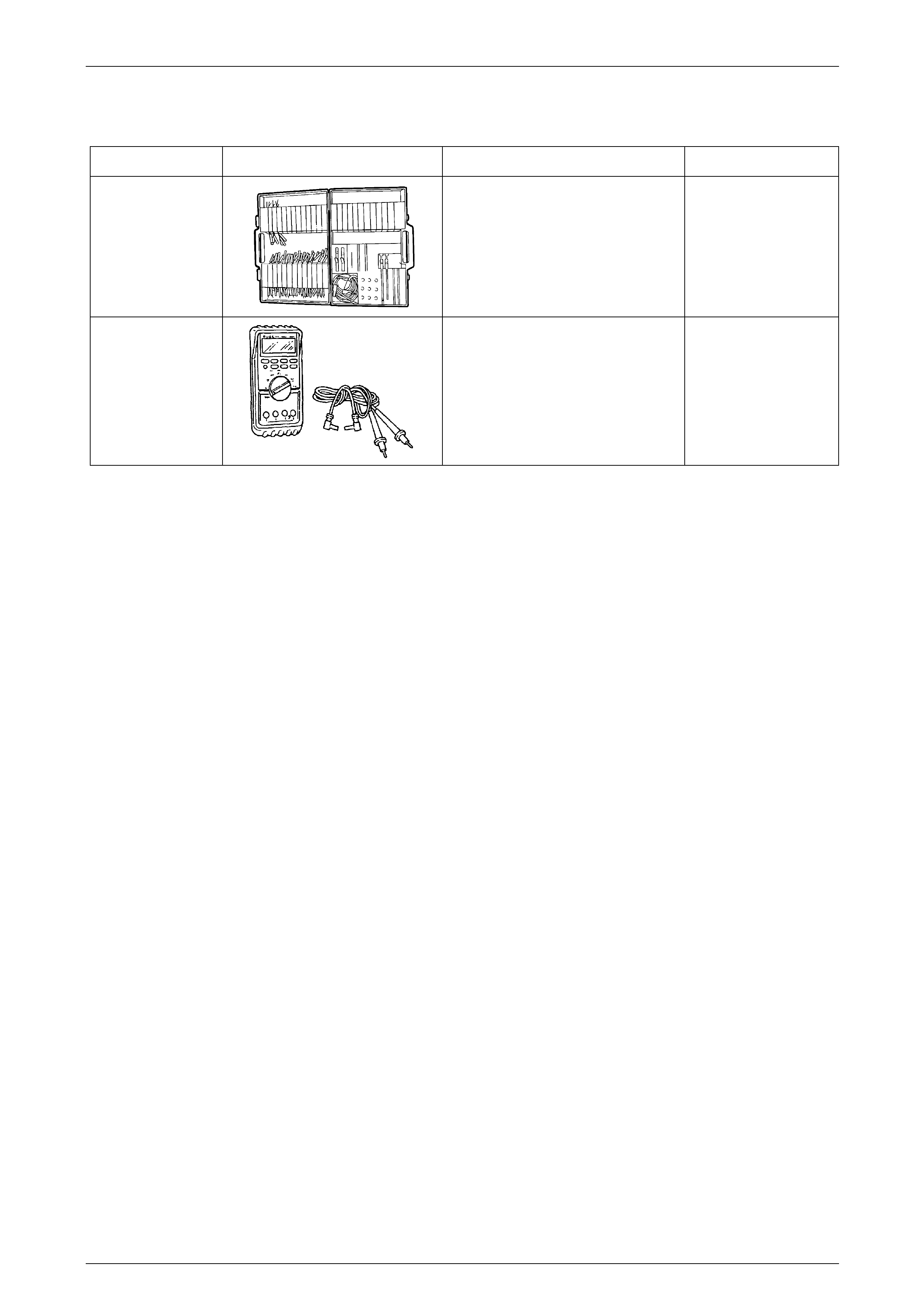
7 Special Tools
Tool Number Illustration Description Tool Classification
J35616-A
(KM609)
Connector Test Adaptor Kit
Used when carrying out electrical
diagnostic circuit checks.
Previously released
Desirable
3588
(J39200)
Digital Multimeter
Must have at least 10 MΩ input
impedance and be capable of reading
frequencies.
Previously released.
Available