
Manual Transmission – V6 Engine 7B1-1
7B1-1
Section 7B1
Manual Transmission – V6 Engine
ATTENTION
Before performing any Service Operation or other procedure described in this Section, refer to Section 00
WARNINGS, CAUTIONS AND NOTES for correct workshop practices with regard to safety and/or property
damage.
1. General Information ...............................................................................................................................3
1.1 General Description............................................................................................................................................... 4
Synchroniser Assemblies.....................................................................................................................................4
Synchroniser Action ........................................................................................................................................... 4
Reverse Gear.......................................................................................................................................................... 4
Bearing Support..................................................................................................................................................... 4
Lubrication ............................................................................................................................................................. 4
Selector Mechanism .............................................................................................................................................. 4
Shift Pattern............................................................................................................................................................ 5
Transmission Exploded Views ............................................................................................................................. 6
Case Components.............................................................................................................................................. 6
Countershaft Components ................................................................................................................................. 7
Input Shaft Components..................................................................................................................................... 8
Selector Components......................................................................................................................................... 9
1.2 Power Flows......................................................................................................................................................... 10
Neutral.............................................................................................................................................................. 10
First Gear......................................................................................................................................................... 10
Second Gear.................................................................................................................................................... 10
Third Gear........................................................................................................................................................ 10
Fourth Gear...................................................................................................................................................... 10
Fifth Gear......................................................................................................................................................... 11
Sixth Gear ........................................................................................................................................................ 11
Reverse Gear................................................................................................................................................... 11
1.3 Transmission Serial Number .............................................................................................................................. 12
2 Servicing Information ..........................................................................................................................13
2.1 Recommended Lubricant and Quantity............................................................................................................. 13
2.2 Checking Transmission Lubricant Level........................................................................................................... 14
2.3 Draining and Refilling Transmission.................................................................................................................. 15
3 Minor Service Operations....................................................................................................................16
3.1 Back-Up Lamp Switch ......................................................................................................................................... 16
Replace................................................................................................................................................................. 16
3.2 Speed Sensor....................................................................................................................................................... 17
Replace................................................................................................................................................................. 17
3.3 Shift Shaft Detent Plug, Spring and Plunger..................................................................................................... 18
Replace................................................................................................................................................................. 18
3.4 Transmission Support Mount............................................................................................................................. 20
Replace................................................................................................................................................................. 20
3.5 Gearshift Lever Knob and Boot Assembly........................................................................................................ 21
Replace................................................................................................................................................................. 21
3.6 Gearshift Lever..................................................................................................................................................... 22
Replace................................................................................................................................................................. 22
Techline
Techline
Techline

Manual Transmission – V6 Engine 7B1-2
7B1-2
4 Major Service Operations....................................................................................................................24
4.1 General Service Information............................................................................................................................... 24
4.2 Transmission Extension Housing, Oil Seal and/or Speed Sensor Toothed Ring .......................................... 25
Remove................................................................................................................................................................. 25
Alternative Method ........................................................................................................................................... 27
Reinstall................................................................................................................................................................ 29
Output Shaft Taper Roller Bearings Preload Procedure................................................................................... 30
4.3 Transmission Assembly...................................................................................................................................... 32
Remove................................................................................................................................................................. 32
Reinstall................................................................................................................................................................ 34
4.4 Transmission Disassembly................................................................................................................................. 36
5 Diagnosis ..............................................................................................................................................37
5.1 Symptoms – Manual Transmission.................................................................................................................... 37
Strategy Based Diagnostics................................................................................................................................ 37
Visual/Physical Inspection.................................................................................................................................. 37
Intermittent........................................................................................................................................................... 37
Symptom List....................................................................................................................................................... 37
5.2 Transmission Fluid Leak Diagnosis................................................................................................................... 38
5.3 Transmission Shifts Hard ................................................................................................................................... 41
5.4 Transmission Gear Clash When Shifting Gears................................................................................................ 43
5.5 Transmission Noisy............................................................................................................................................. 45
5.6 Transmission Does Not Shift Into One Gear ..................................................................................................... 47
5.7 Transmission Locked in One Gear..................................................................................................................... 48
5.8 Transmission Jumps Out of Gear ...................................................................................................................... 49
5.9 Transmission Clunk on Acceleration or Deceleration...................................................................................... 51
6 Specifications.......................................................................................................................................52
7 Torque Wrench Specifications............................................................................................................53
8 Special Tools ........................................................................................................................................54
Manual Transmission – V6 Engine 7B1-3
7B1-3
1. General Information
The Aisin AI Co. manufactured, AY6 (prod uction option MV5) manual shift transmission is a 6-speed assembly, with 6th
gear being an overdrive ratio. All gear positions (including Reverse) are sync hronised. The transmission has a reluctor
wheel on the output shaft for the vehicle speed sensor. The transmission is made up from 4 aluminium housings; the
front case, intermediate case, rear case and the extension housing.
Plain roller, tapered roller, and ball bearings are used to support the input shaft, countershaft, and output shaft. No
shimming is required. The output shaft bearing support is by taper roller bearings, the preload for which is governed by a
collapsible spacer. All constant mesh spee d gears are supported on needle roller bearings.
To optimise clearance control due to established and accepted manufacturing tolerances, selective thickness retaining
rings are used throughout, to secure various gears to their respective shafts.
This transmission (AY6) uses a uniqu e lubricant.
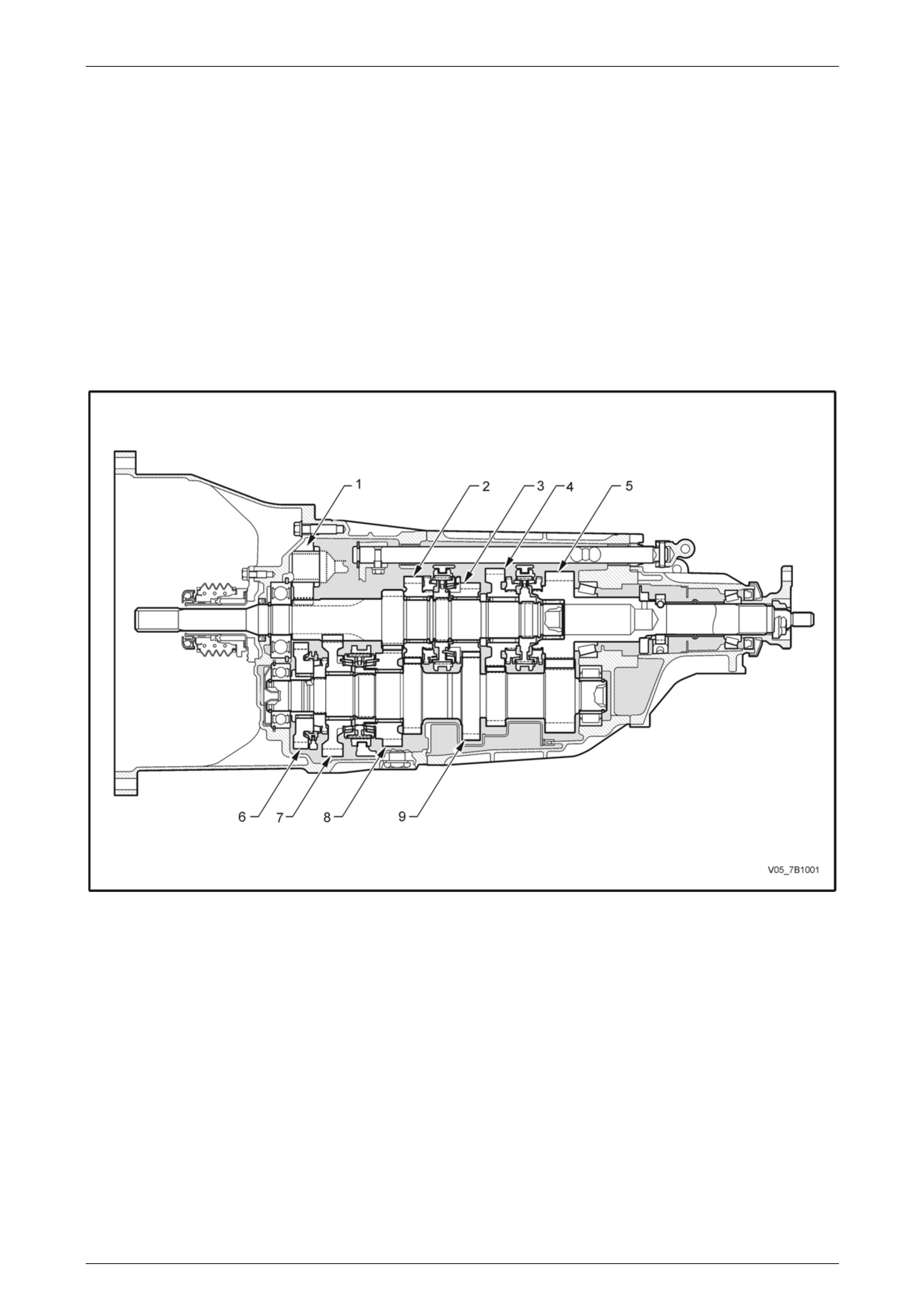
A sectioned view of the transmission is shown next.
Figure 7B1 – 1 – Sectioned Side View
Legend
1 Reverse Idler Gear
2 4th Speed Constant Mesh Gear
3 3rd Speed Constant Mesh Gear
4 6th Speed Constant Mesh Gear
5 Output Shaft Gear
6 Reverse Constant Mesh Gear
7 1st Speed Constant Mesh Gear
8 2nd Speed Constant Mesh Gear
9 Countershaft Gear

Manual Transmission – V6 Engine 7B1-4
7B1-4
1.1 General Description
Synchroniser Assemblies
Each of the four synchroniser hubs are splined to their respective shafts; Reverse and 1st/2nd are sp lined to the
countershaft gear, while 3rd/4th and 5th/6th are splined to the input shaft. All synchroniser hubs are secured by a
selective thickness snap ring.
The blocking rings used on 1s t and 2nd gears are of a triple cone construction, 3rd and 4th gears use single cone rings
with carbon fibre frictional material on one side of the inner member. The synchroniser blocking rings used for 5th, 6th
speed and Reverse gears are a single brass ring. The purpose of all synchr oniser assemblies is to permit clutching to the
required gear, without gear clash.
Synchroniser Action
During synchroniser operation , the synchroniser ring is moved into engagement by the appropri ate fork, carrying with it,
three spring loaded synchr oniser inserts and balls, located in slots in the synchro niser h u b.
The outer synchroniser ring, together with the inserts, is moved along the hub, placing a load on the three lugs of the
blocking ring.
This initial force is sufficient to seat the blocking ring and start pre-synchronisation because of the friction between the
cone on the constant mesh gear and the blocking ring/s.
At this stage, gear engagement is prevented as long as there is a difference in spe ed between the mating surfaces of the
blocking ring and cone of the constant mesh gear. As the speeds between the blocking ring and the gear cone b ecome
synchronised, the teeth on the blocking rin g a nd gear cone line up with the internal splines of the ring, allowing the outer
synchroniser ring to engage the teeth o n the gear being engaged, completing gear selection.
Reverse Gear
The reverse idler gear is in constant mesh with the input shaft spur gear and the reverse gear, mounted on the front of
the countershaft gear. When reverse gear is selected, the single, brass reverse synchromesh blocking ring engages the
reverse constant mesh gear, locking it to the countershaft gear, completing the selection.
Bearing Support
Input Shaft. Supported at the front by a substantial ball race, the input shaft is supported at the rear by a plain roller
bearing mounted in the output shaft recess.
Output Shaft. Two opposed, substantial taper roller bearings support the output shaft and also provide support for the
long input shaft. Bearing preload is set by the use of a collapsible spacer mounted on the output shaft, between the two
bearings.
Countershaft Gear. Support at the front is by ball race, while supports at the rear is by a plain roller race.
Constant Mesh Gears. Each of the constant mesh gears (including Reverse) is supported b y cage d needle roller
bearings, except for the reverse idler gear that has a twin, caged needle roller bearing running on the reverse idler gear
shaft.
Lubrication
Lubrication of all internal components is by splash feed, provided by the rotating countershaft gear and constant mesh
gears of reverse, first and second gears. Lubricatio n splash is controlled by an oil separator around the countershaft gear
and the oil distribution channels mounted throughout the transmission.
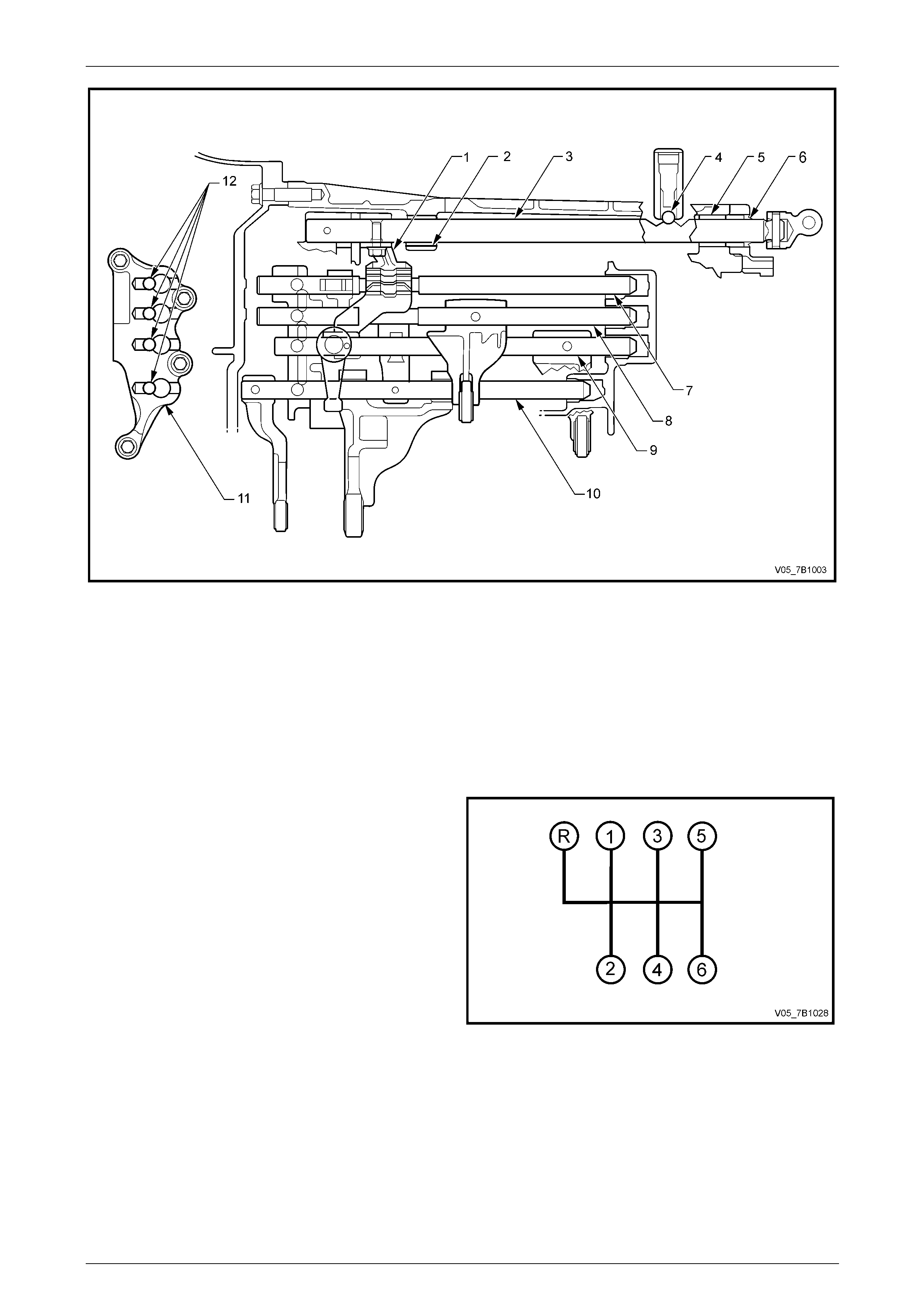
Selector Mechanism
The floor mounted, gearshift control lever op erates through a remote lever arrangement onto a single rail mechan ism
which extends through the extension housing and into the transmission rear case.
A shift and select control lever (1) is locked to the en d of the shift select shaft (3). Working through a system of levers ,
the control lever engages with each of the four shift shafts (7, 8, 9, 10), as the shift select shaft is rotated by the gearshift
control lever, operating in the Neutral plane.
The shift select shaft is supported by a bearin g (2) in the intermediate case and a bushing (5) in the rear case. A lip seal
(6) in the extension housing prevents the loss of transmission lubricant. A shift shaft detent (4) provides a positive ‘feel’
when the gearshift lever is moved from the Neutral position into the forward or rearward positions.
Each of the four shift shafts(7, 8, 9, 10) is supported at one end by the interlock bracket (11) that is secured to the front
case by four screws. Support at the rear is by bushings mounted in the end case.
A shift interlock system located in the interlock bracket, prevents engagement of more than one gear at any one time.
The system consists of a series of pins and balls that only allows one shift shaft to be moved at any one time. Only when
Neutral is selected, can another shift select shaft can be selected. Spring l oaded balls (12) in the interlock bracket (11),
provide positive detent ‘feel’ whenever a shift shaft is moved.
Manual Transmission – V6 Engine 7B1-5
7B1-5
Figure 7B1 – 2 – Shift Select Mechanism
Legend
1 Lever – Shift and Select
2 Bearing – Shift and Select Shaft
3 Shaft – Shift and Select
4 Plunger and Spring – Shift Detent
5 Bushing – Shift and Select Shaft
6 Seal – Shift and Select Shaft Oil
7 Shaft – Gearshift Fork #1
8 Shaft – Gearshift #2
9 Shaft – Gearshift Fork #3
10 Shaft – Gearshift #4
11 Bracket – Interlock
12 Ball – Shift Detent
Shift Pattern
The shift pattern is as shown, with Reverse gear beside 1st,
which minimises the chance of an accidental selection while
travelling in a forward directio n.
Figure 7B1 – 3
Manual Transmission – V6 Engine 7B1-6
7B1-6
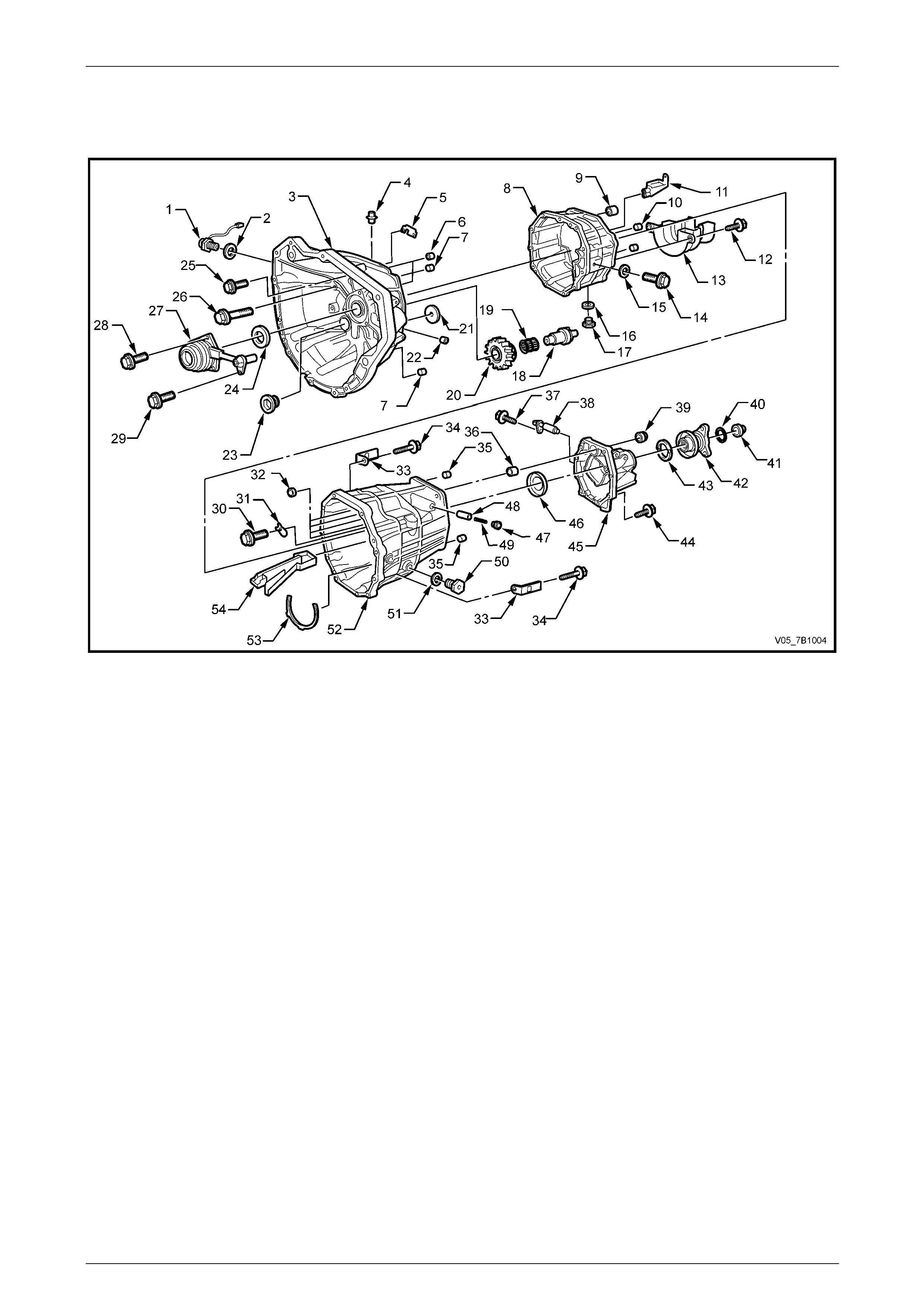
Transmission Exploded Views
Case Components
Figure 7B1 – 4
Legend
1 Switch – Back-up Lamp
2 Gasket
3 Case – Transmission Front
4 Plug
5 Plate – Oil Control
6 Pin – Rolled
7 Pin – Dowel
8 Case – Transmission Front
9 Bearing – Shift and Select Shaft
10 Pin – Dowel
11 Tray – Oil Distribution
12 Bolt – Flanged Head
13 Separator – Transmission Oil
14 Bolt – Reverse idler Shaft Locating
15 Gasket
16 Gasket
17 Plug Magnetic Drain
18 Shaft – Reverse Idler Gear
19 Bearing – Roller Double Row
20 Gear – Reverse Idler
21 Tube – Oil Distribution
22 Plug
23 Plug – Flanged and Threaded
24 Seal – Input Shaft Oil
25 Screw – Flanged Head
26 Bolt – Flanged Head
27 Cylinder – Central Clutch Actuating
28 Screw – Flanged Head
29 Screw – Flanged Head
30 Bolt and Flat Washer
31 Plate – Bearing Retaining
32 Bush – Selector Shaft (4 places)
33 Bracket – Wiring Harness Attaching
34 Bolt – Rear to Front Transmission Case
35 Pin – Dowel
36 Bush – Shift and Select Shaft
37 Screw – Flanged Head
38 Sensor – Vehicle Speed
39 Seal – Shift and Select Shaft Oil
40 O-ring
41 Nut – Flanged
42 Flange – Transmission Output Shaft
43 Seal – Output Shaft Oil
44 Bolt – Flanged Head
45 Housing – Extension
46 Slinger – Oil
47 Plug – Flanged and Threaded
48 Pin – Locked Ball
49 Spring – Compression
50 Plug – Filler
51 Gasket
52 Case – Transmission Rear
53 Seal
54 Tray – Oil Distribution
Manual Transmission – V6 Engine 7B1-7
7B1-7
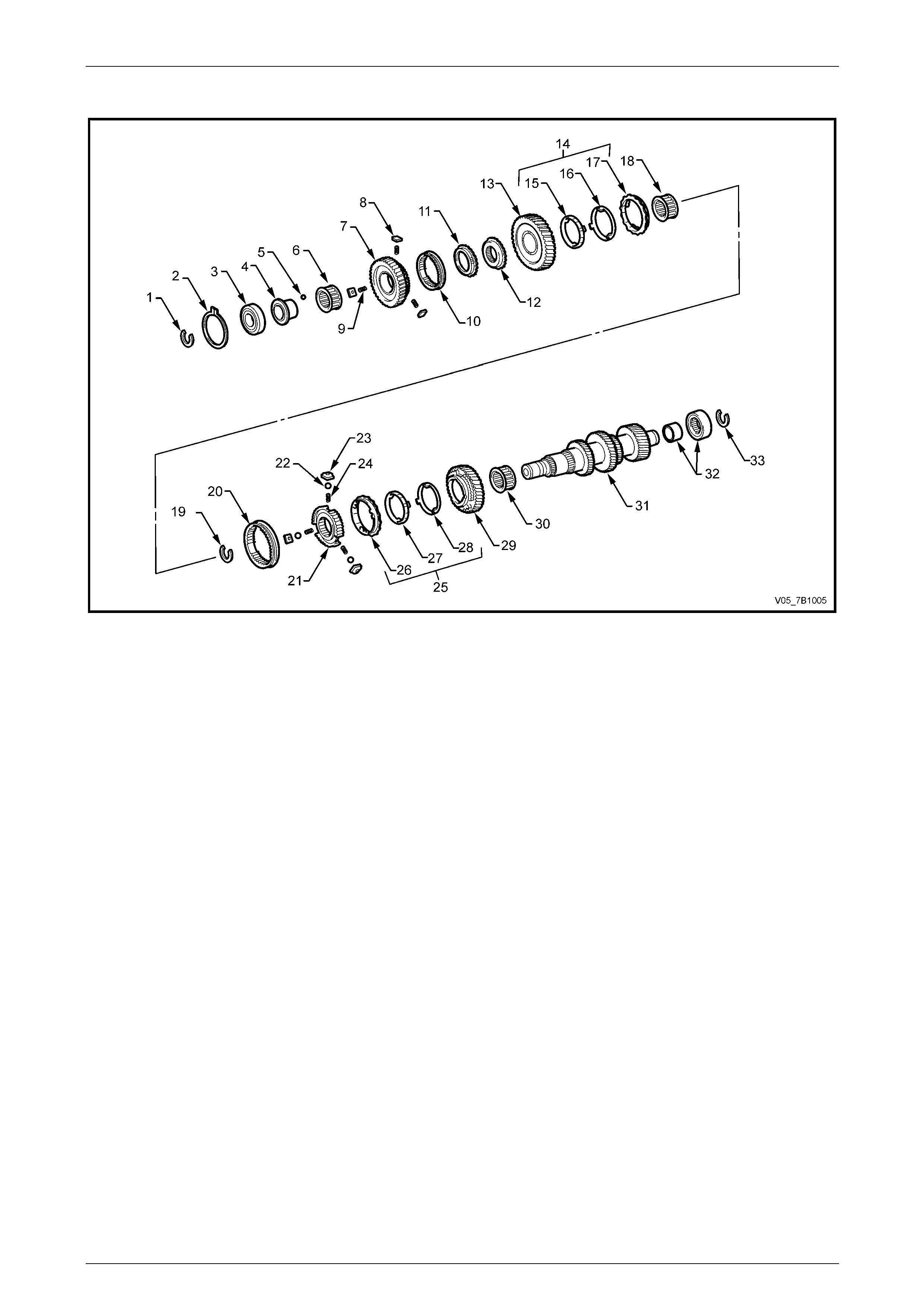
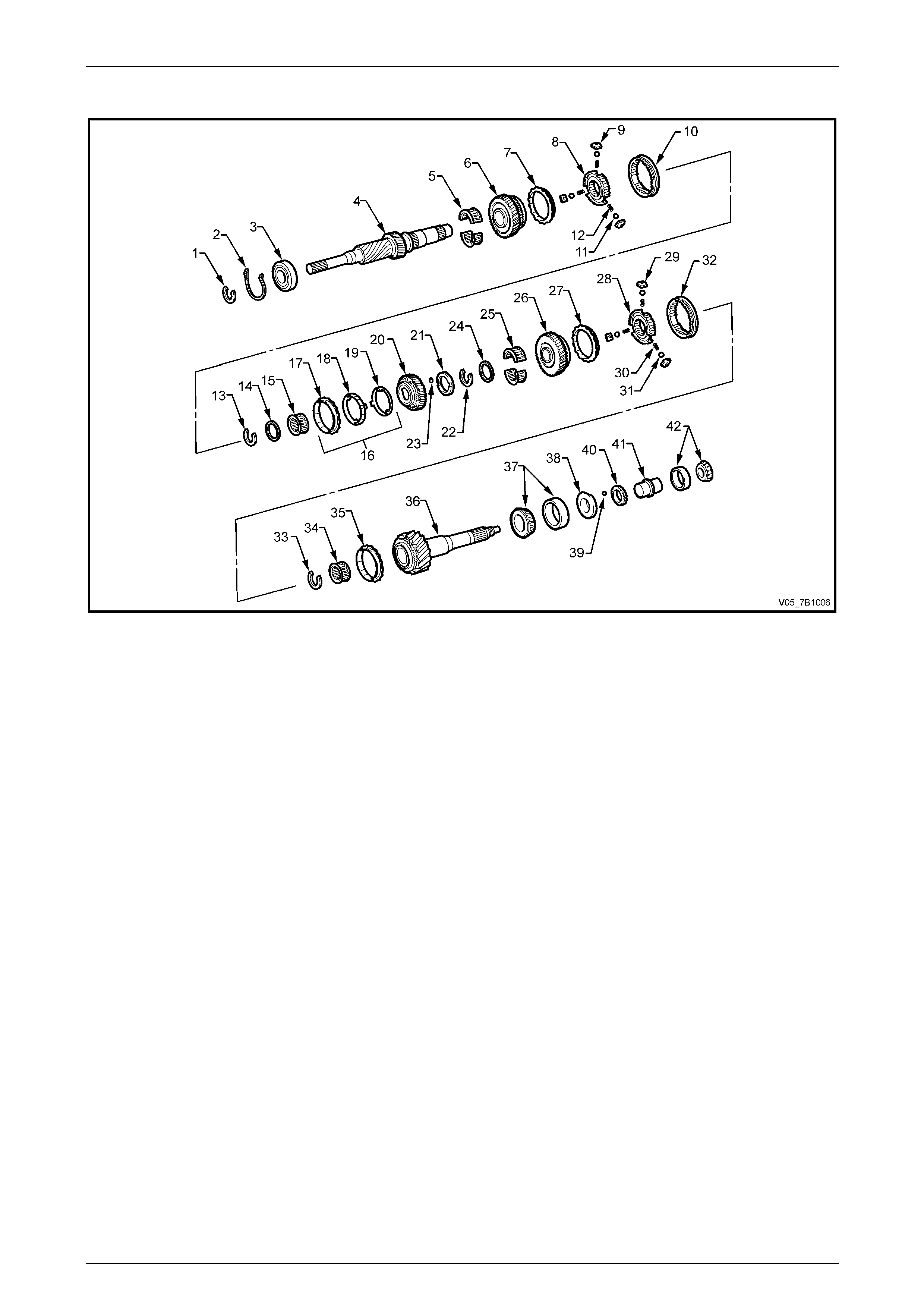
Countershaft Components
Figure 7B1 – 5
Legend
1 Ring – Front Bearing Snap
2 Circlip – Front Bearing Locating
3 Bearing – Front Countershaft Ball
4 Race – Reverse Gear Bearing
5 Ball – Bearing Race Retaining
6 Bearing – Gear Needle
7 Gear – Reverse Countershaft
8 Key – Reverse Synchromesh
9 Spring – Compression
10 Sleeve – Reverse Synchromesh
11 Ring – Reverse Synchromesh Blocking
12 Gear – Reverse Inner Splined
13 Gear – First Countershaft
14 Assembly – 1st Synchromesh Rings
15 Ring – Synchromesh – Inner
16 Ring – Synchromesh – Middle
17 Ring – Synchromesh – Outer
18 Bearing – Needle Roller
19 Ring – Synchromesh Assembly Snap
20 Ring – Synchromesh Assembly
21 Hub – 1st/2nd Synchromesh
22 Ball
23 Key – 1st/2nd Synchromesh
24 Spring – Compression
25 Assembly – 2nd Synchromesh Rings
26 Ring – Synchromesh – Outer
27 Ring – Synchromesh – Middle
28 Ring – Synchromesh – Inner
29 Gear – Second Countershaft
30 Bearing – Needle Roller
31 Gear – Countershaft
32 Bearing – Rear Countershaft
33 Ring – Rear Bearing Snap
Manual Transmission – V6 Engine 7B1-8
7B1-8
Input Shaft Components
Figure 7B1 – 6
Legend
1 Ring – Snap
2 Circlip – Bearing Locating
3 Bearing – Input Shaft Front Ball
4 Shaft – Input
5 Bearing – Split Caged Needle Roller
6 Gear – 4th Speed Constant Mesh
7 Ring – 4th Speed Blocking
8 Hub – 3rd/4th Synchromesh
9 Key – Synchromesh Assembly
10 Ring – 3rd/4th Synchromesh
11 Ball – Synchromesh Assembly
12 Spring – Compression
13 Ring – Snap
14 Washer – Spacer
15 Bearing – Caged Needle Roller
16 Assembly – 3rd Synchromesh Rings
17 Ring – Synchromesh – Outer
18 Ring – Synchromesh – Middle
19 Ring – Synchromesh – Inner
20 Gear – 3rd Speed Constant Mesh
21 Washer – 3rd Gear Thrust
22 Ring – Snap
23 Ball – Locating
24 Washer – Spacer
25 Bearing – Split Caged Needle Roller
26 Gear – 6th Speed Constant Mesh
27 Ring – 6th Speed Blocking
28 Hub – 5th/6th Synchromesh
29 Key – Synchromesh Assembly
30 Spring – Compression
31 Ball – Synchromesh Assembly
32 Ring – 3rd/4th Synchromesh
33 Ring – Snap
34 Bearing – Caged Needle Roller
35 Ring – 5th Speed Blocking
36 Shaft – Output
37 Bearing – Taper Roller Assembly
38 Ring – Oil Control
39 Ball – Locating
40 Reluctor – Speed Sensor
41 Spacer – Collapsible
42 Bearing – Taper Roller Assembly
Manual Transmission – V6 Engine 7B1-9
7B1-9
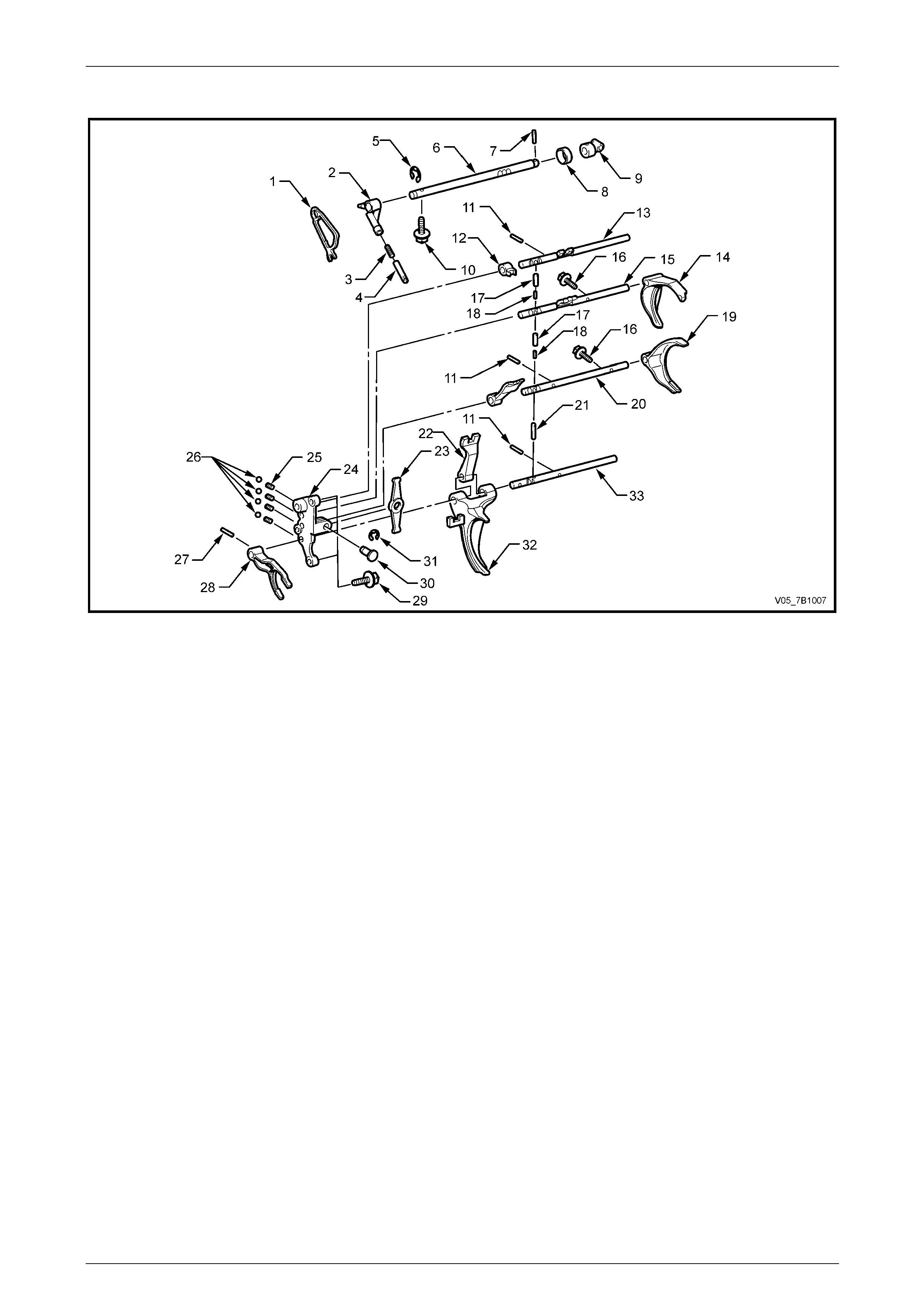
Selector Components
Figure 7B1 – 7
Legend
1 Cam – Shift and Select
2 Lever – Shift and Select
3 Spring – Compression
4 Pin – Lock Ball
5 E-Clip
6 Shaft – Shift and Select
7 Pin – Straight
8 Ring – Securing
9 Trunnion – Shift Control
10 Bolt – Flange
11 Pin –Spring Roll
12 Head – Gearshift #3
13 Shaft Gearshift Fork #1
14 Fork – Gearshift #2
15 Shaft – Gearshift #2
16 Bolt – Washer Based
17 Pin – Straight
18 Pin – Straight
19 Fork – Shift #3
20 Shaft – Gearshift Fork #3
21 Pin – Roll
22 Head – Gearshift #2
23 Arm – Shift
24 Bracket – Interlock
25 Spring – Compression
26 Ball
27 Pin – Spring Roll
28 Fork – Gearshift #4
29 Bolt – Flange (4 places)
30 Pivot – Shift Arm
31 E-Clip
32 Fork – Gearshift #1
33 Shaft – Gearshift #4

Manual Transmission – V6 Engine 7B1-10
7B1-10
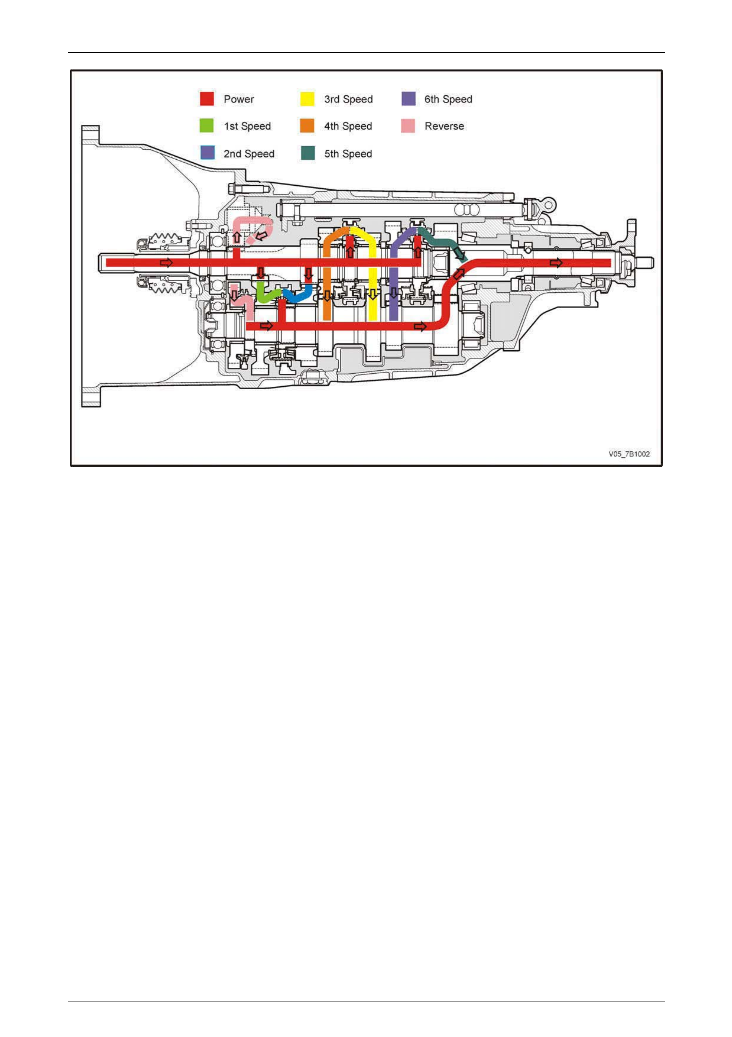
1.2 Power Flows
The input shaft spur gear, third, fourth and sixth sp eed gears are in constant mesh with the countershaft gear. As the
reverse constant mesh gear, mounted on the counters haft gear is in constant mesh with the revers e idler gear that is in
turn meshed with the input shaft spur gear, the reverse gear train rotates with the input shaft. With the first and second
constant mesh gears also mounted on the countershaft gear, these gears also rotates with the input shaft.
Therefore, when the engine is running with the clutch engaged, engine torque is transferred to the input shaft and the n
through the countershaft mounted reverse, first and second speed constant mesh gears, at all times.
Neutral
In neutral, with the clutch engaged, the input shaft rotates each of the cons tant mesh gears. As the countershaft gear is
only in constant mesh with the output shaft gear, when in neutral and the vehicle stationary, it is the rotation of the
reverse, first and second constant mesh gears that lubricate the transmission by splash feed.
First Gear
In first gear, the first/second speed synchroni ser ring is moved forward to engage the first speed constant mesh gear,
that is being turned by the input shaft spur gear. Because the first/second speed synchroniser hub is splined to the
countershaft gear, torque is transferred from the input shaft through the s ynchroniser ring and hub, down the
countershaft gear to the meshed output shaft gear at a speed reduction of 4.475:1.
Second Gear
In second gear, the first/second speed s ynchr oniser ring is moved rearward to engage the second speed gear, which is
being turned by the input shaft gear. With the first/second speed synchroniser hub splined to the counters haft gear,
torque is transferred to the countershaft gear from the input shaft second speed gear, down the countershaft gear to the
meshed output shaft gear at a speed reduction of 2.577:1
Third Gear
In selecting third gear, the first/second speed synchroniser ring moves to the neutral position and the third/fourth speed
synchroniser ring is moved forward to enga ge the third speed constant mesh gear. As the third/fourth speed
synchroniser hub is splined to the input shaft, torque is transferred from the input shaft, through the countershaft gear
and out through the meshed output shaft gear at a speed reduction of 1.632:1.
Fourth Gear
In fourth gear, the third/fourth speed synchroniser ring is moved rearward to engage the fourth speed constant mesh
gear. As the third/fourth speed synchroniser hub is splined to the input shaft, torque is transferred from the input shaft,
through the countershaft gear and out thro ugh the meshed output shaft gear at a speed reduction of 1.193:1.
Manual Transmission – V6 Engine 7B1-11
7B1-11
Figure 7B1 – 8
Fifth Gear
To achieve direct drive in fifth gear, the fifth/sixth speed synchroniser ring is moved rearward, to engage the output shaft
gear. With this engagement, torque flows directly through the input shaft and the linked output shaft to provide a direct
ratio of 1:000:1. As the output shaft gear is in constant mesh with the countershaft gear, splash lubricati on of the
transmission is assured.
Sixth Gear
In sixth gear, the fifth/sixth speed synchroniser ring is moved forward to engage the sixth speed constant mesh gear. As
the fifth/sixth speed synchroniser hub is splined to the input shaft, this engagement allows torque to be transferred from
the input shaft to the countershaft gear and the meshed output shaft gear at a speed increase of 0.751:1.
Reverse Gear
In reverse gear, the reverse synchroniser ring is moved forward to engage the reverse constant mesh gear. This allows
torque to be transferred from the input shaft spur gear through the reverse idler gear (reversing direction of rotation) to
the constant mesh, reverse driven gear. As the reverse synchromesh hub is splined to the countershaft gear, this causes
the countershaft gear to rotate in the same direction as the input shaft. Output is achieved via the meshed output shaft
gear and the countershaft gear, causin g the output shaft to rotate in the opposite direction to the input shaft and provide
a speed reduction of 3.954:1.
Manual Transmission – V6 Engine 7B1-12
7B1-12
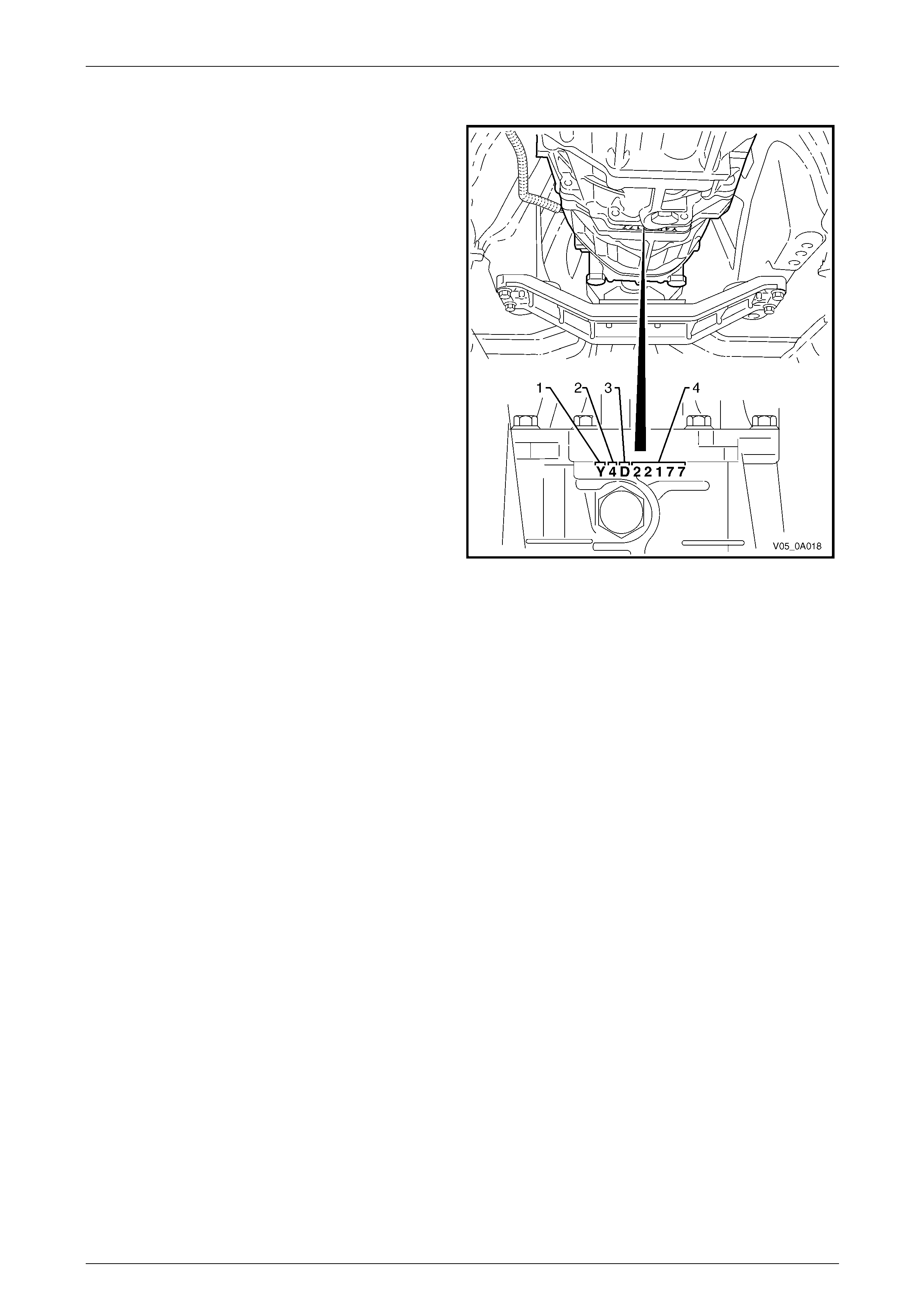
1.3 Transmission Serial Number
The transmission serial numb er is stamped into the
intermediate transmission case at the interface between the
intermediate case and the transmission rear case.
Breakdown of the numbering system can be explained by
using the following example of the 131st transmission built
in August, 2004:
Y4H00131
Breakdown:
Y ‘AY6’ transmission type
4 Year of manufacture
H Month of manufacture (August)
(e.g. ‘A’ = January Æ ‘L’ = December)
00131 131st transmission built that Month
Figure 7B1 – 9

Manual Transmission – V6 Engine 7B1-13
7B1-13
2 Servicing Information
2.1 Recommended Lubricant and Quantity
This transmission is a ‘fill for life’ assembl y, with a lubrica nt capacity of 1.8 litres. The lubricant is a unique product, is
rated as GL-3, with a viscosity rating of 75W-90.
Manual Transmission – V6 Engine 7B1-14
7B1-14
2.2 Checking Transmission Lubricant Level
1 Raise the vehicle and suppor t in a safe manner. Refer to Section 0A General Information in this Service Information
for the location of recommended lifting and supp ort points.
Ensure that the transmission lubricant is at
ambient temperature.
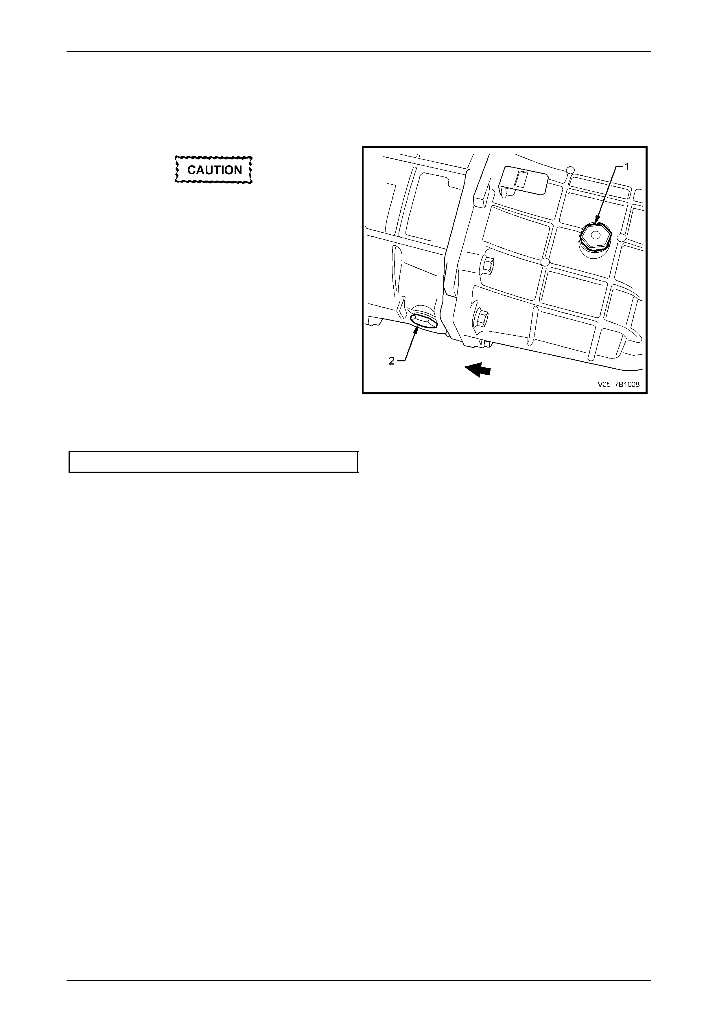
2 Using a 24 mm (15/16”) socket and suitable
equipment, remove the transmission filler p lug (1) and
sealing washer from the left side of the rear
transmission case. Discard the removed washer.
NOTE
Ensure that the vehicle is level before checking
the lubricant level.
3 Use a finger tip or a piece of bent wire, check that the
lubricant is level with the lower edge of the filler plug
hole in the transmission rear case.
Figure 7B1 – 10
4 Install a new sealing washer to the filler plug, then reinstall the plug, tightening to the correct torque specificatio n.
Filler plug torque specification..............................37 N.m

Manual Transmission – V6 Engine 7B1-15
7B1-15
2.3 Draining and Refilling Transmission
1 Raise the vehicle and suppor t in a safe manner. Refer to Section 0A General Information in this Service Information
for the location of recommended lifting and supp ort points.
2 Referring to Figure 7B1-10, use a 24 mm (15/16”) socket and suitable equipment, remove the transmission filler
plug (1) and sealing washer. Discard the filler plug washer.
3 Using the same socket equipment, remove the drain plug (2) and sealing washer. Discard the drai n plug washer.
4 Allow the transmission lubricant to drain into a clean container of at least 2 litre capacity.
NOTE
• The lubricant will drain more completely and
quickly if it is warm.
• Carefully inspect the drain plug magnet and
the drained lubricant for foreign matter such
as metal particles, etc.
5 Reinstall the drain plug, using a new sealing washer and tighten to the correct torque specification.
Filler plug torque specification..............................37 N.m
6 Fill the transmission with 1.8 litres of the recommended lubricant,
refer to 2.1 Recommended Lubricant and Quantity, in this Section.
7 With the vehicle in a level attitude, check the lubricant level, refer to 2.2 Checking Transmission Lubricant Level, in
this Section.
8 Lower the vehicle to the ground an d road test to check for correct vehicle operation.
Manual Transmission – V6 Engine 7B1-16
7B1-16
3 Minor Service Operations
3.1 Back-Up Lamp Switch
LT Section No. – 04-075
Replace
1 Raise the vehicle and suppor t in a safe manner. Refer to Section 0A General Information in this Service Information
for the location of recommended lifting and supp ort points.
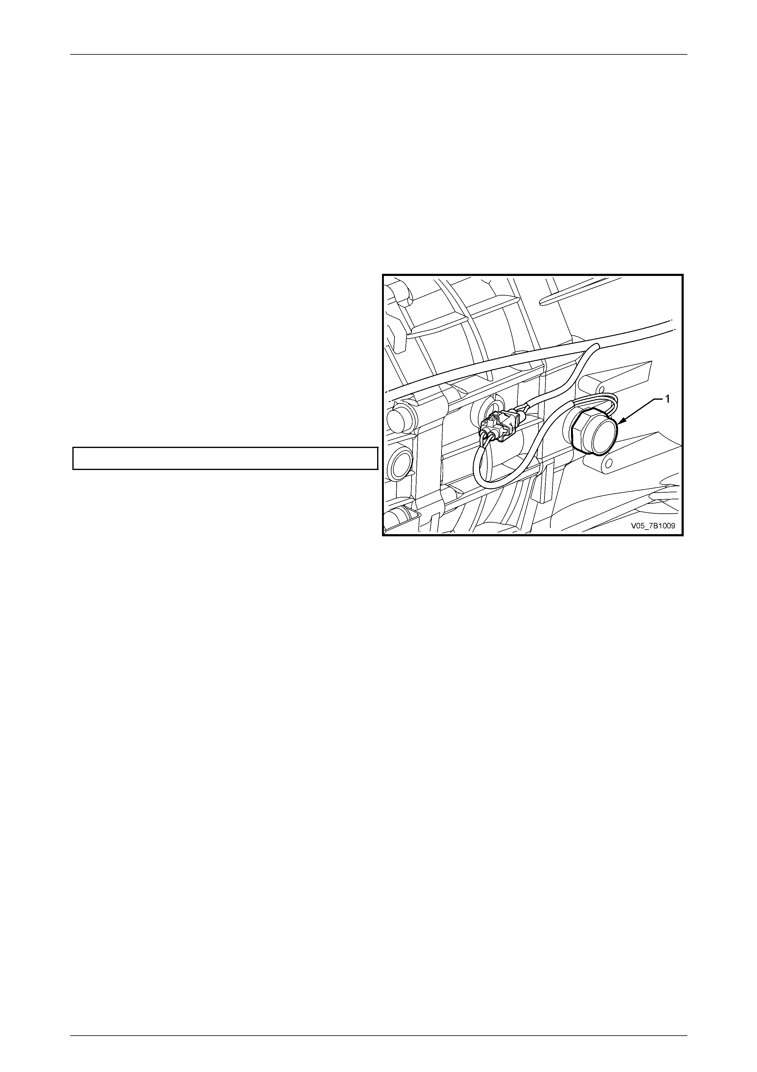
2 Disconnect the back-up lamp s witch wiring harness
connector.
3 Using a suitable sized set spanner, remove the back-
up lamp switch (1) and sealing washer from the right
side of the front transmission case. Discard the
removed washer.
4 Reinstall the back-up lamp switch (1), with a new
sealing washer fitted.
5 Tighten the back-up lamp switch to the correct torque
specification.
Back-up lamp switch torque specification............44 N.m
Figure 7B1 – 11
Manual Transmission – V6 Engine 7B1-17
7B1-17
3.2 Speed Sensor
Replace
1 Raise the vehicle and suppor t in a safe manner. Refer to Section 0A General Information in this Service Information
for the location of recommended lifting and supp ort points.
2 Disconnect the speed sensor wiring harness
connector.
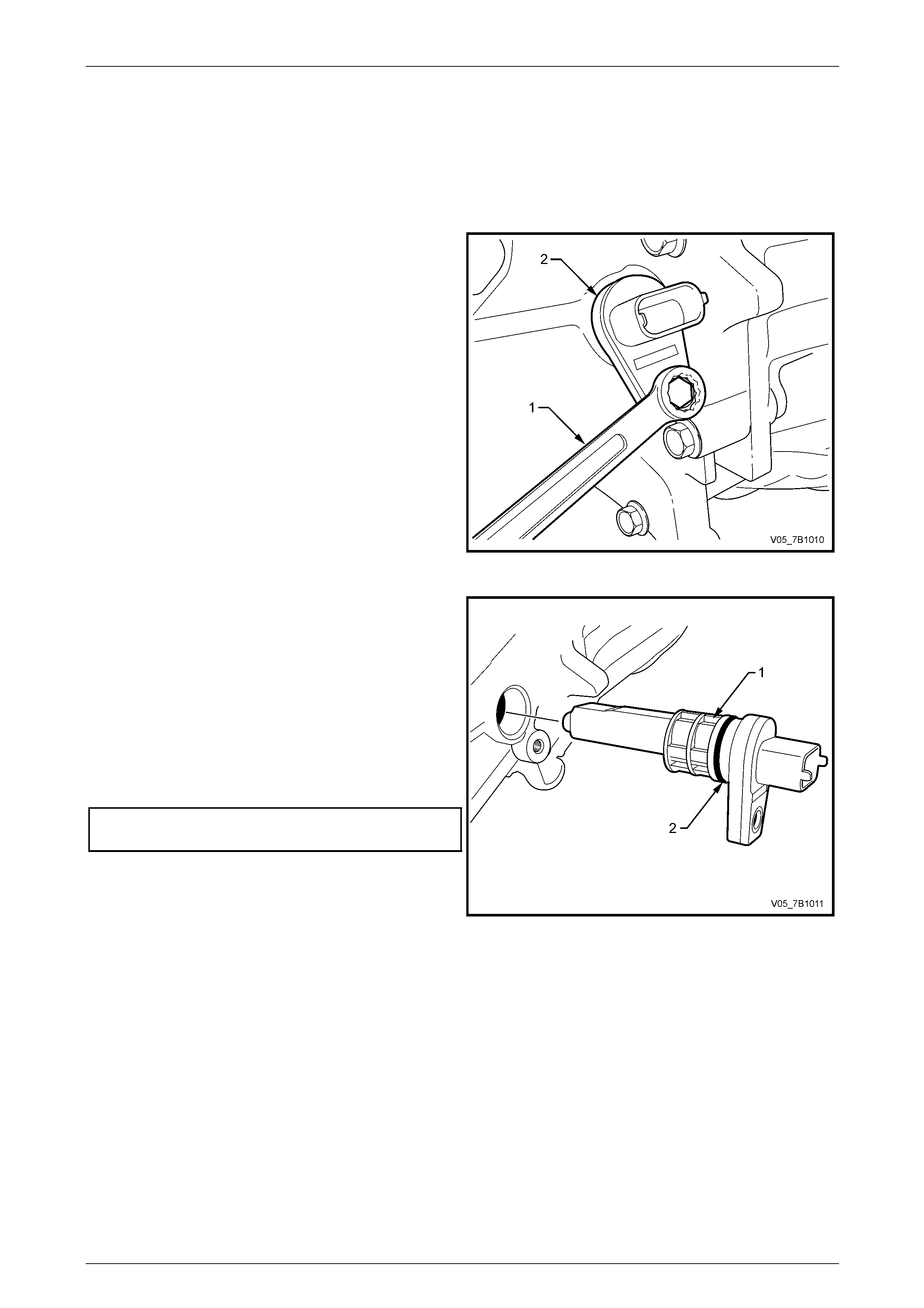
3 Using a 10 mm spanner (1), remove the sensor (2)
retaining screw from the right side of the extension
housing.
Figure 7B1 – 12
4 Pull and rotate the sensor (1) to remove from the
extension housing.
5 Lubricate a new speed sensor O-ring (2) with
transmission lubricant and install onto the speed
sensor.
6 Reinstall the speed sensor to the extension housing,
aligning the sensor retainer with the threaded hole in
the extension housing.
7 Reinstall the retaining screw and tighten to the correct
torque specification.
Speed sensor retaining screw
torque specification................................................8 N.m
Figure 7B1 – 13
Manual Transmission – V6 Engine 7B1-18
7B1-18
3.3 Shift Shaft Detent Plug, Spring and
Plunger
LT Section No. – 04-020
ATTENTION
The following fasteners either have micro encapsulated sealant applied .
Shift select shaft detent plug.
Replace
1 Raise vehicle and support in a safe manner. Refer to Section 0A General Information, for the location of jacking
and support points.
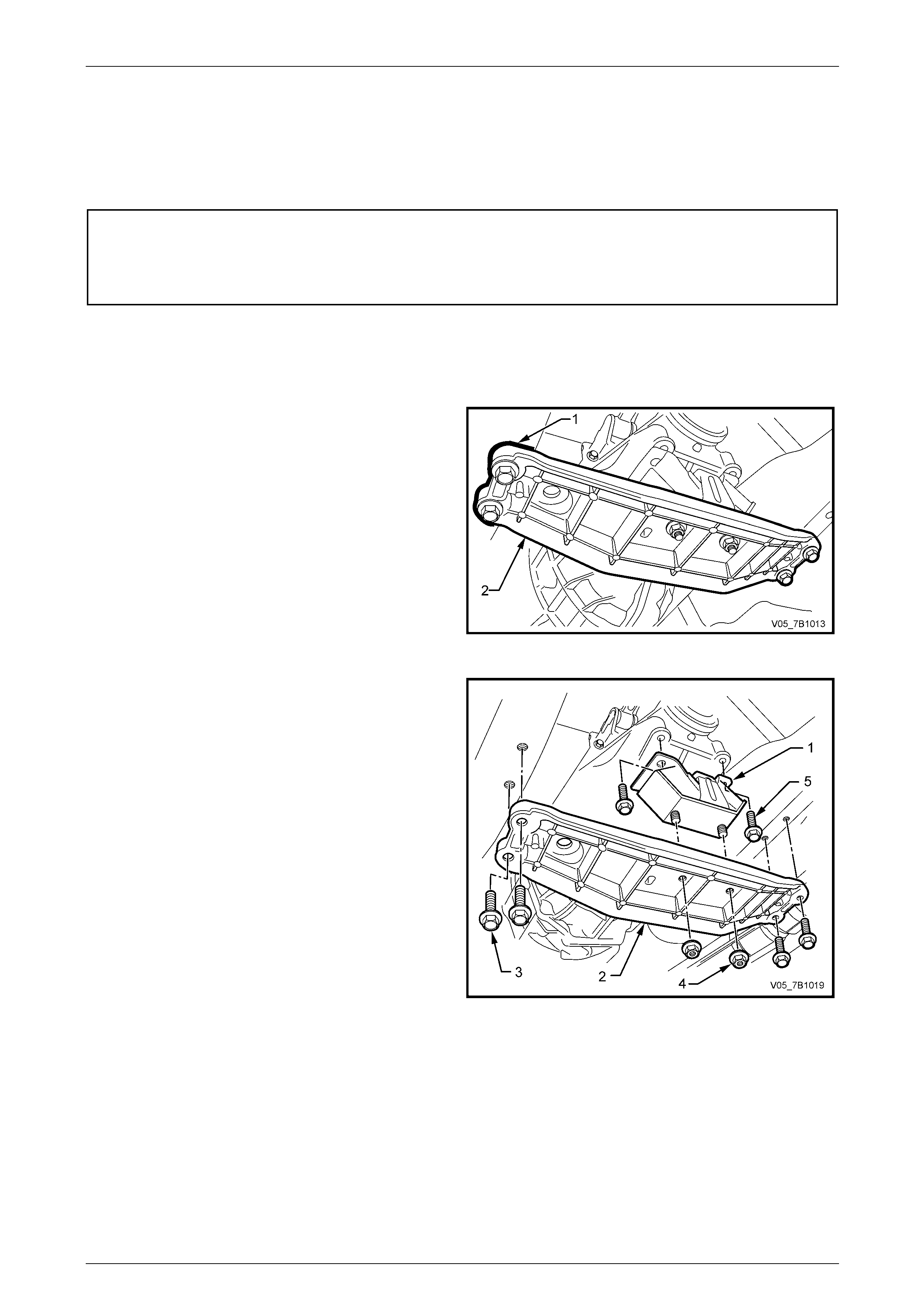
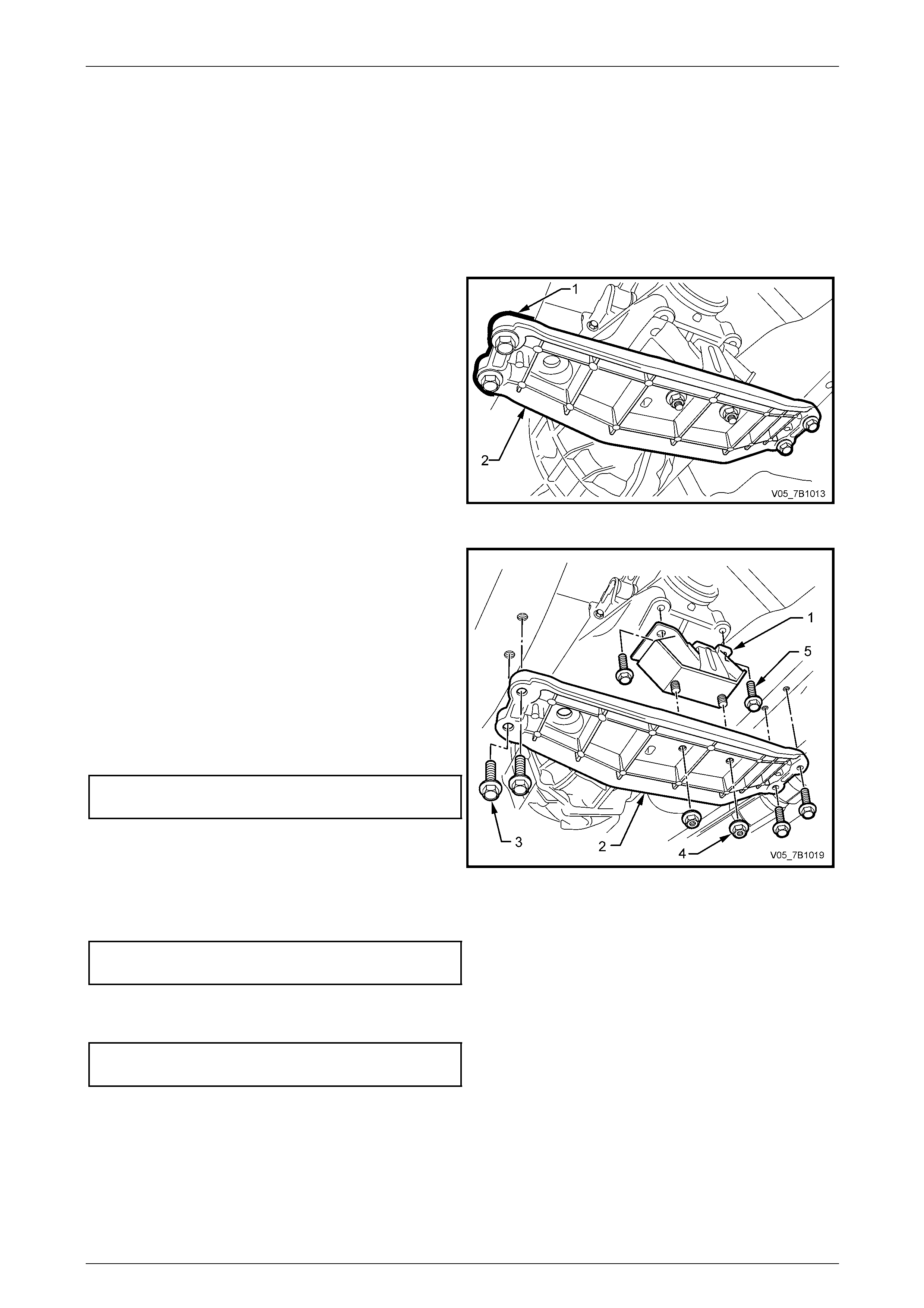
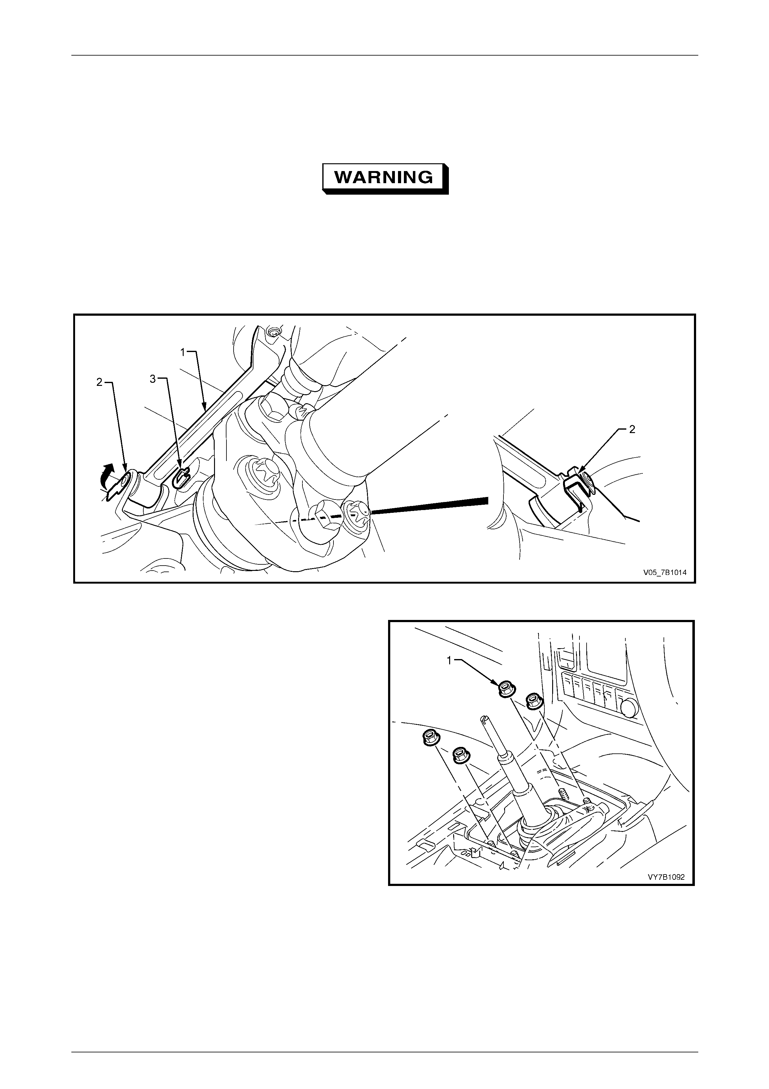
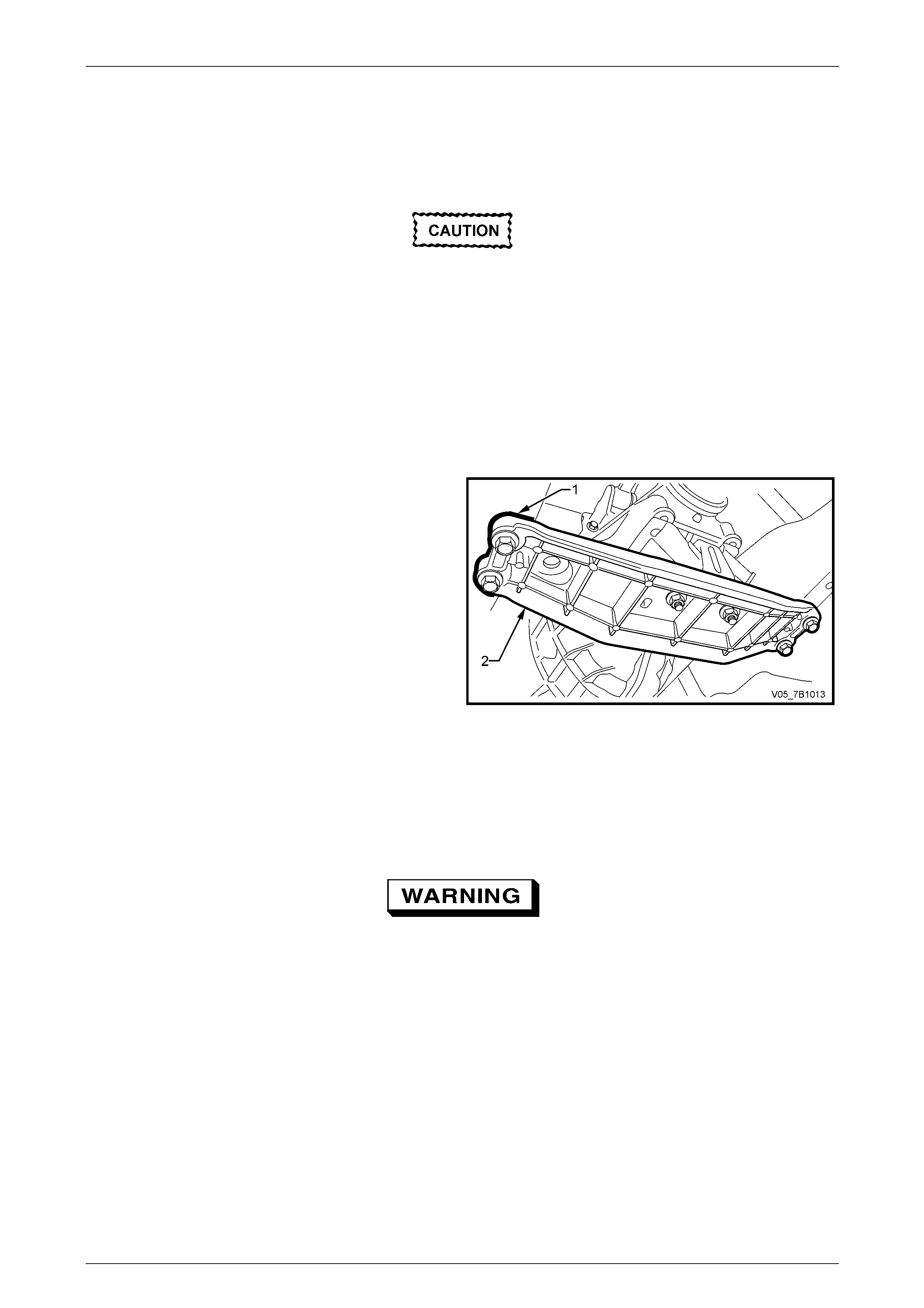
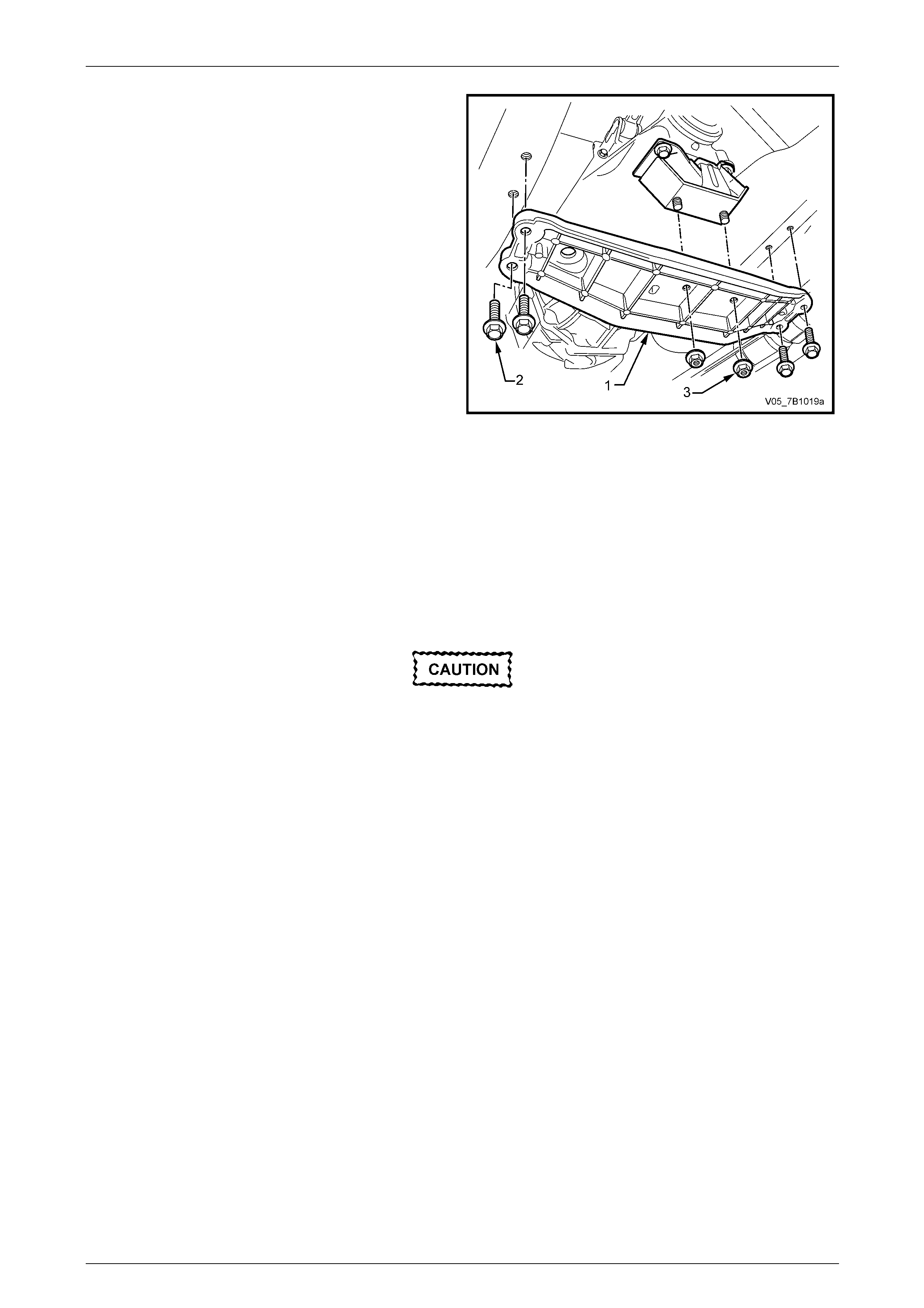
2 Using a felt tipped pen or correction pen (i.e.
Whiteout™), mark the position (1) of the rear support
crossmember (2) to the side frame.
NOTE
This step is critical to the correct powertrain
alignment on reassembly. If not carried out, the n
vehicle vibration and/or handling problems may
result.
Figure 7B1 – 14
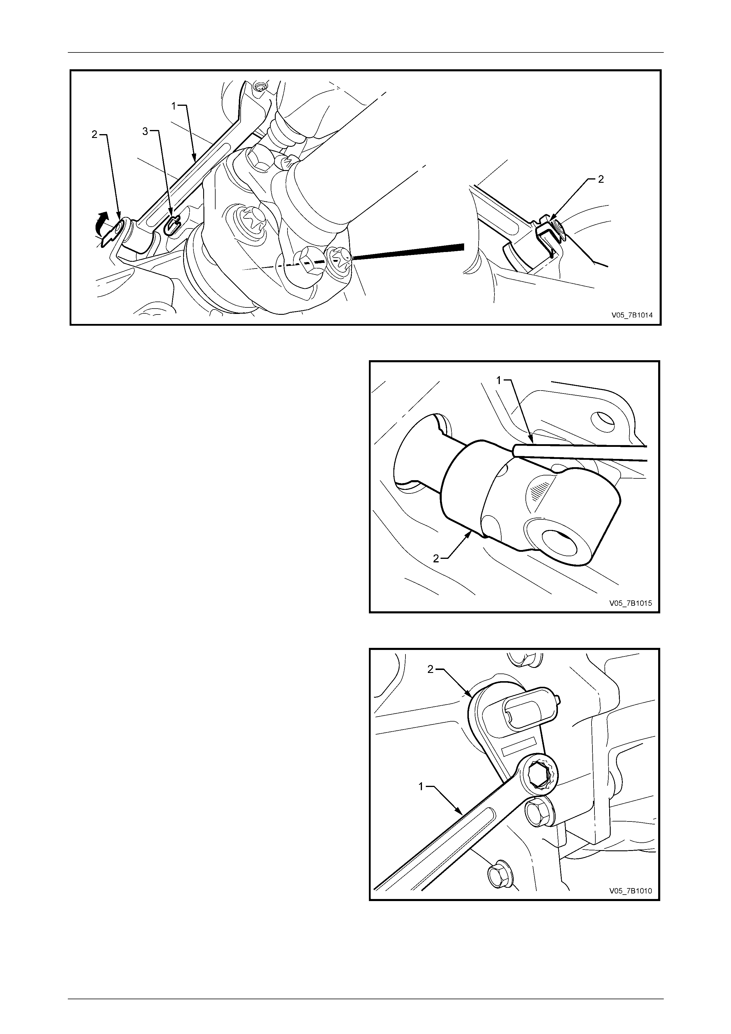
3 Support the transmission with a suitable lifting devic e,
then remove the four bolts (3).
4 Lower the transmission slightly, then remove the two
rear mount to crossmember nuts (4)). Set the
crossmember to one side.
5 Lower the rear of the transmission eno ugh to gain
access to the shift select shaft detent plug at the upper
left side of the rear transmission case.
Figure 7B1 – 15
Manual Transmission – V6 Engine 7B1-19
7B1-19
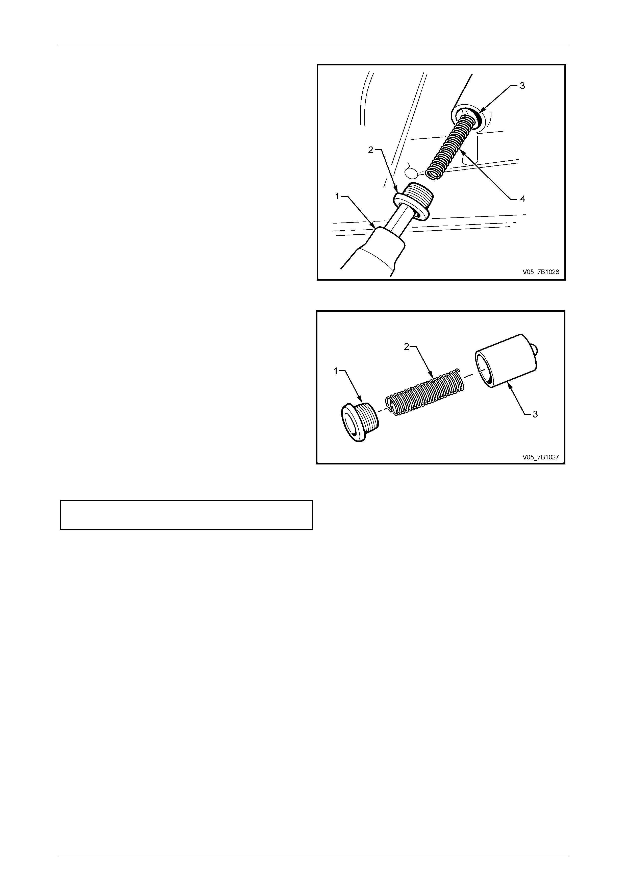
6 Using a 10 mm Allen key socket (1) and suitable
socket equipment remove the shift select shaft detent
plug (2).
NOTE
Sealant on the plug thread will cause some
resistance to removal.
7 Remove the spring (4) and plu nger (3), using a pencil
magnet to remove the plunger and ball assembly, as
required.
Figure 7A2 – 16
8 Inspect the plug for thread damage, the spring for
breakage or distortion and the plunger for damage or
scoring.
9 Replace parts as required.
10 Clean thread sealant from the plug, using a wire
brush.
11 Lubricate the detent plunger with clean transmission
lubricant and reinstall into the plug bore.
12 Apply Loctite 565 or equi valent (GM P/N 12346004) to
the threads of the plug.
13 Reinstall the spring and s ecure with the plug.
14 Tighten the plug to the correct torque specific ation
Shift select shaft detent plunger
plug torque specification......................................25 N.m
Figure 7A2 – 17
15 With the vehicle in a level attitude check the transmission lubricant level,
refer to 2.2 Checking Transmission Lubricant Level, in this Section.
16 Lower the vehicle to the ground an d road test to check for correct selector operation.
Manual Transmission – V6 Engine 7B1-20
7B1-20
3.4 Transmission Support Mount
LT Section No. – 04-020
Replace
1 Raise front of vehicle and support on safet y stands. Refer to Section 0A General Information, for the location of
jacking and support points.
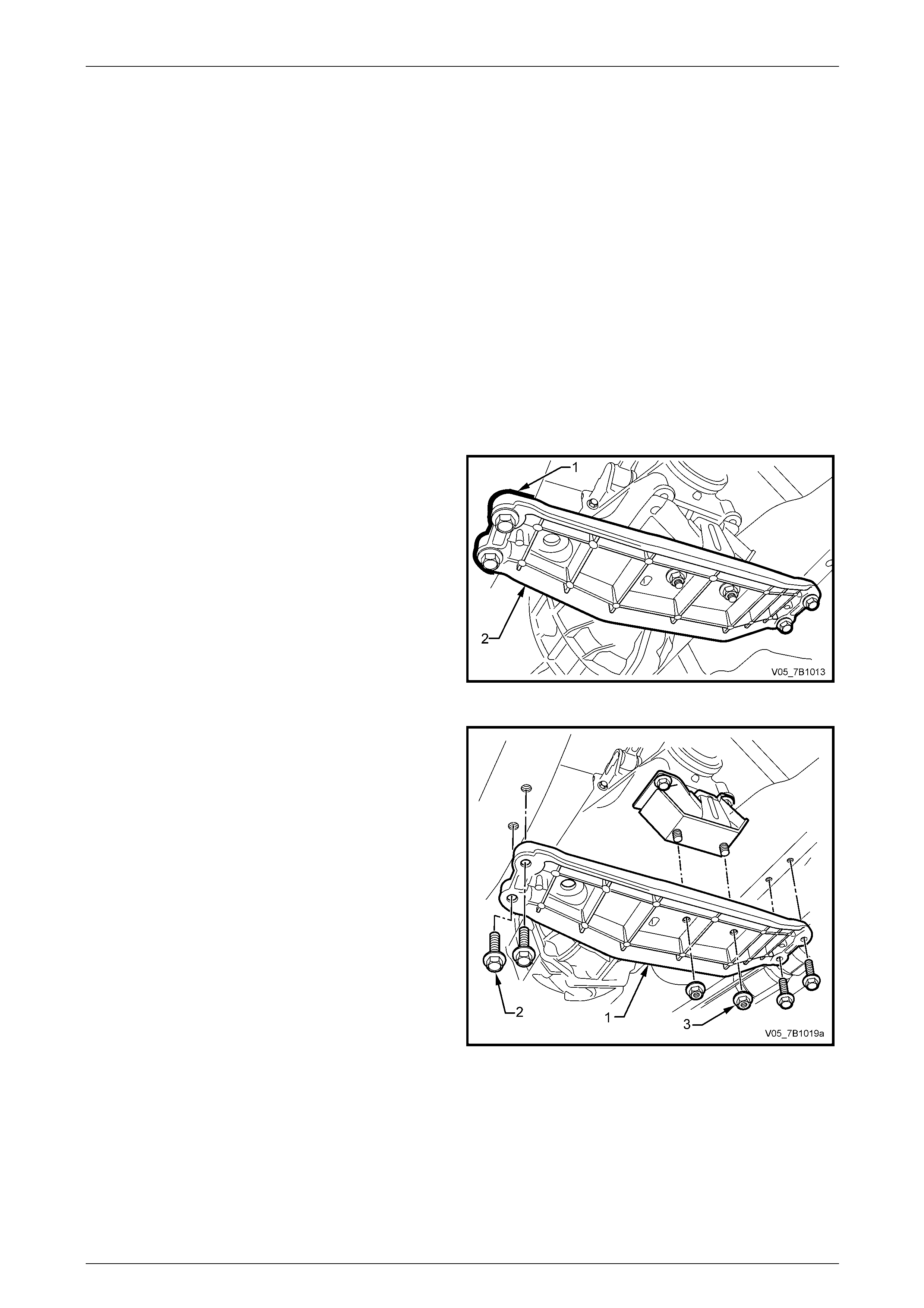
2 Using a felt tipped pen or correction pen (i.e.
Whiteout™), mark the position (1) of the rear support
crossmember (2) to the side frame.
NOTE
This step is critical to the correct powertrain
alignment on reassembly. If not carried out, the n
vehicle vibration and/or handling problems may
result.
Figure 7B1 – 18
3 Support the transmission with a suitable lifting devic e,
then remove the four bolts (3).
4 Lower the transmission slightly, then remove the two
rear mount to crossmember nuts (4)). Set the
crossmember to one side.
5 Remove the two bolts (5) securing the mount (1) to the
transmission extension housing, then remove the
mount (1) from the vehicle.
6 Reinstall the mount (1) to the transmission e x tension
housing, install the t wo bolts (5) and tighten to the
correct torque specification.
Transmission support mount
bolt torque specification.......................................25 N.m
7 Raise the transmission slightly, then reinstall the
transmission support crossmember, alignin g the
scribed lines made prior to disassembly. Figure 7B1 – 19
8 Reinstall the four crossmember to side frame bolts (3) and tighten to the correct torque specification.
Rear crossmember to side frame
member bolt torque specification.........................58 N.m
9 Remove the lifting device from the transmission, centralise the rear mount studs in the crossmember holes, then
reinstall the nuts (4), tightening to the correct torque specification.
Rear crossmember to transmission
support mount nut torque specification................25 N.m
10 Lower the vehicle and road test to check correct vehicle op eration.
Manual Transmission – V6 Engine 7B1-21
7B1-21
3.5 Gearshift Lever Knob and Boot
Assembly
LT Section No. – 04-060
Replace
NOTE
Do not attempt to separate the gearshift lever
knob from the boot. The knob and boot as an
assembly, can be replaced, using the following
procedure.
1 Remove the floor console cover assembl y.
Refer to Section 1A3 Instrument Panel and Console.
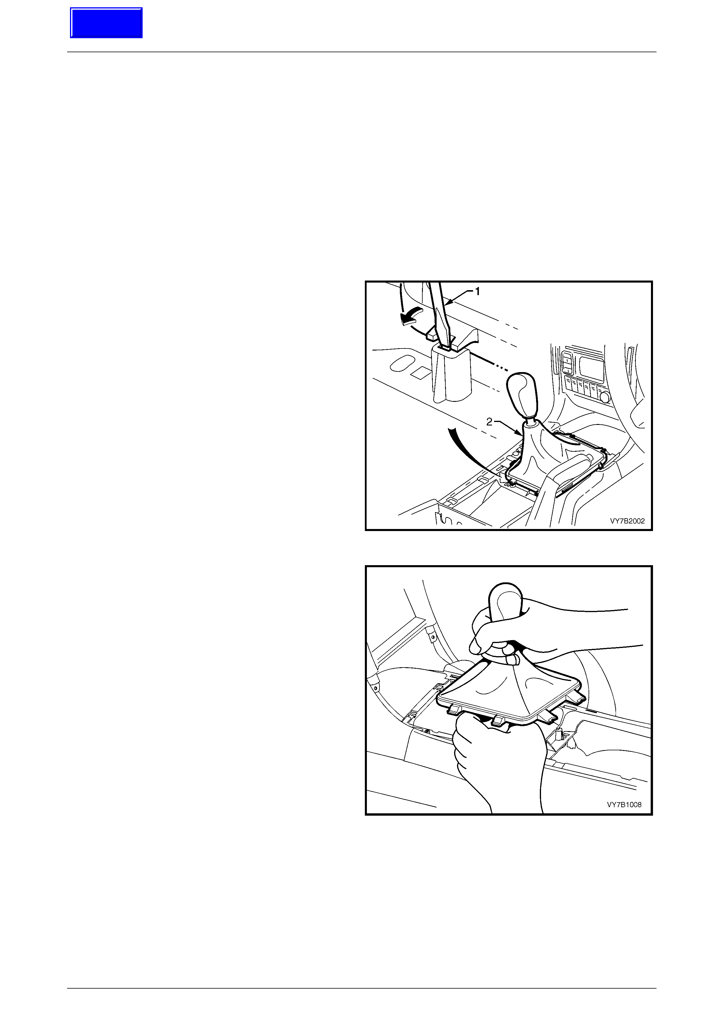
2 Using a fine bladed screwdriver, release each locking
tab, while exerting an upward force on the boot carrier.
Lift the gearshift boot retainer free from the floor
console
Figure 7B1 – 20
3 Lift the gearshift lever boot enough to enable a firm
grasp to be made on the gearshift lever with the left
hand, then grasp the gearshift knob with the right.
4 While rocking the knob sideways, and with an upward
force applied, dislodge the knob retainin g claws from
the lever.
5 Remove the gearshift lever knob and boot assembly,
from the gearshift lever.
6 Reinstall the knob and b oot assembly over the
gearshift lever, align the knob in the correct a ttitude
and then bump the knob onto the gearshift lever until
the retaining cla ws engage with the groove in the
lever.
7 Align the boot retaining clips with the hole in the
console cap, then carefully seat the boot reta iners into
the console cap until each clip engages correctly.
8 Reinstall the floor console cover assembly.
Refer to Section 1A3 Instrument Panel and Console. Figure 7B1 – 21
Techline
Manual Transmission – V6 Engine 7B1-22
7B1-22
3.6 Gearshift Lever
LT Section No. – 04-060
Replace
NOTE
There are no serviced components in the
gearshift lever assembly. Should parts require
replacement through wear or accident damage,
then the assembly must be replaced.
1 Remove the gearshift lever knob and boot assembly, from the gearshift lever.
Refer to 3.4 Gearshift Lever Knob and Boot Assembly, for the necessary procedure.
2 Raise the vehicle and suppor t in a safe manner. Refer to Section 0A General Information for the location of
recommended lifting and support points.
3 Remove the propeller shaft. Refer to Section 4C1 Rear Propeller Shaft and Universal Joints.
4 Support the transmission rear case with suitable lifting
equipment.
5 Using a felt tipped pen or correction pen (i.e.
Whiteout™), mark the position (1) of the rear support
crossmember (2) to the side frame.
NOTE
This is necessary to mai ntain driveline align ment
overcoming a potential, driveline vibration
condition on reassembly.
Figure 7B1 – 22
6 Support the transmission with a suitable lifting devic e,
then remove the four bolts (2).
7 Lower the transmission slightly, then remove the two
rear mount to crossmember nuts (3)). Set the
crossmember (1) to one side.
Figure 7B1 – 23
Manual Transmission – V6 Engine 7B1-23
7B1-23
8 Lower the rear of the transmission to prov ide working clearance around the shift select rod and brace (1). Refer to
Figure 7B1-24.
9 Prise the shift lever brace retainer (2) free from the transmis sion lug, using a screw driver or suitable leve r.
10 Repeat Step 8 for the second brace.
Wear eye protection to avoid injury, should
the shift select lever pin 'E' clip fly off when
released.
11 Using a small scre wdriver, release the 'E' clip (3) securing the shift select lever rod to the transmission trunnion.
12 Using a pin punch and hammer, dislodge the pin, then remove from the gearshift shift select rod and transmissio n
trunnion.
Figure 7B1 – 24
13 Remove the four gearshift lever bracket, mountin g
nuts (1) from inside the vehicle.
14 From under the vehicle, lower the gearsh ift lever
assembly and remove from the vehicle.
Figure 7A2 – 25

Manual Transmission – V6 Engine 7B1-24
7B1-24
4 Major Service Operations
4.1 General Service Information
1 The use of power tools to disassemble and/or reassemble this transmission is not recommended. Apart from the
fact that thread stripping is most likely when incorrect torque values are applied to fasteners, there are components
within the transmission that must be tightened in sequence.
2 It is particularly important during the dis asse mbly processes described in this Section, that orientation of
components to each other and the alignment of certain other parts is observed. While these observations are
generally noted in the text, it is also important that the individual performing the unit re pair work also applies some
initiative in this respect. There may be some situations where correct workshop practices are assumed and not
highlighted.
3 Particularly when the transmission is disass embled for the first time, it is vital for correct reassembly that
components removed, are laid out in seque nce and in the same attitude (e.g. as removed, face down). Complying
with this aspect will ensure that the reassem bl y process proceeds without error and the reassembled transmission
will perform as designed.
Manual Transmission – V6 Engine 7B1-25
7B1-25
4.2 Transmission Extension Housing, Oil
Seal and/or Speed Sensor Toothed Ring
LT Section No. – 04-100
A collapsible sleeve is used to maintain
transmission bearing preload. Once the
output flange nut is loosened, a new
collapsible sleeve must be fitted during the
reassembly process.
Remove
1 Raise the vehicle and suppor t in a safe manner. Refer to Section 0A General Information in this Service Information
for the location of recommended lifting and supp ort points.
2 Remove the propeller shaft. Refer to Section 4C1 Front Propeller Shaft and Universal Joints.
3 Support the transmission rear case with suitable lifting
equipment.
4 Using a felt tipped pen or correction pen (i.e.
Whiteout™), mark the position of the rear support
crossmember to the side frame.
NOTE
This is necessary to mai ntain driveline align ment
overcoming a potential, driveline vibration
condition on reassembly.
5 Remove the rear support mount crossmember to side
frame bolts.
6 Remove the rear support mount crossmember to rear
support mount nuts, then remove the crossmember
from the vehicle.
Figure 7B1 – 26
7 Lower the rear of the transmission to prov ide working clearance around the shift select rod and brace (1). Refer to
Figure 7B1-24.
8 Prise the shift lever brace retainer (2) free from the transmis sion lug, using a screw driver or suitable leve r.
9 Repeat Step 8 for the second brace.
Wear eye protection to avoid injury, should
the shift select lever pin 'E' clip fly off when
released.
10 Using a small scre wdriver, release the 'E' clip (3) securing the shift select lever rod to the transmission trunnion.
11 Using a pin punch and hammer, dislodge the pin, then remove from the gearshift shift select rod and transmissio n
trunnion.
Manual Transmission – V6 Engine 7B1-26
7B1-26
Figure 7B1 – 27
12 Using a pin punch (1) and ha mmer, dislodge the
crimped sleeve (2) from the shift select rod trunnion.
13 Use a bent piece of wire to dislodge the p in securing
the trunnion to the shift rod, in an upward direction.
14 Use long nosed pliers to remove the pin.
15 Remove the trunnion from the shift select rod.
Figure 7B1 – 28
16 Remove the screw securing the speed sensor (2) to
the right side of the transmission extension housing.
17 Twist and pull on the sensor at the same time to
remove from the transmission ext ension housing.
Figure 7B1 – 29
Manual Transmission – V6 Engine 7B1-27
7B1-27
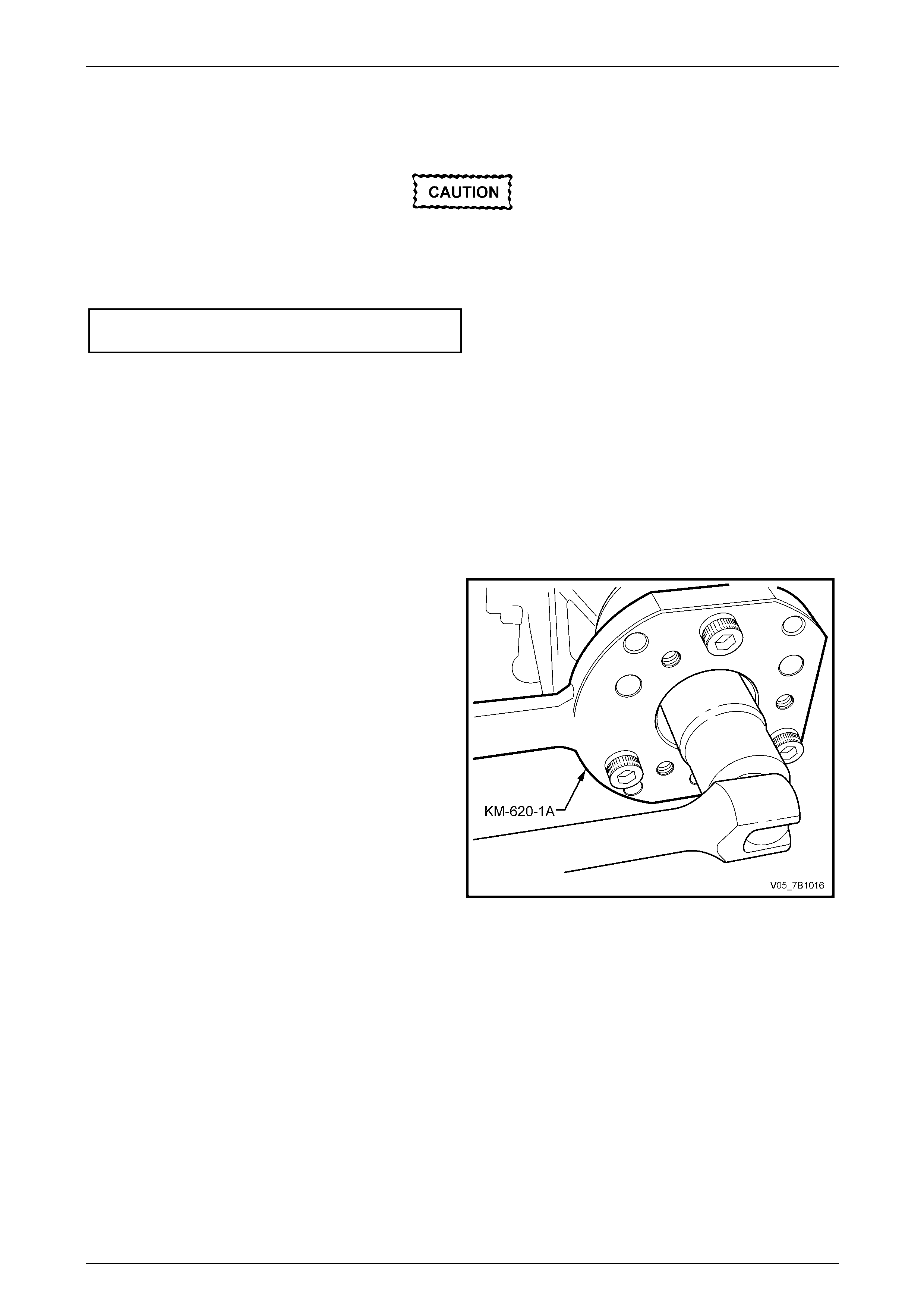
18 Using a suitable pin punch, release the transmission
output flange nut staking.
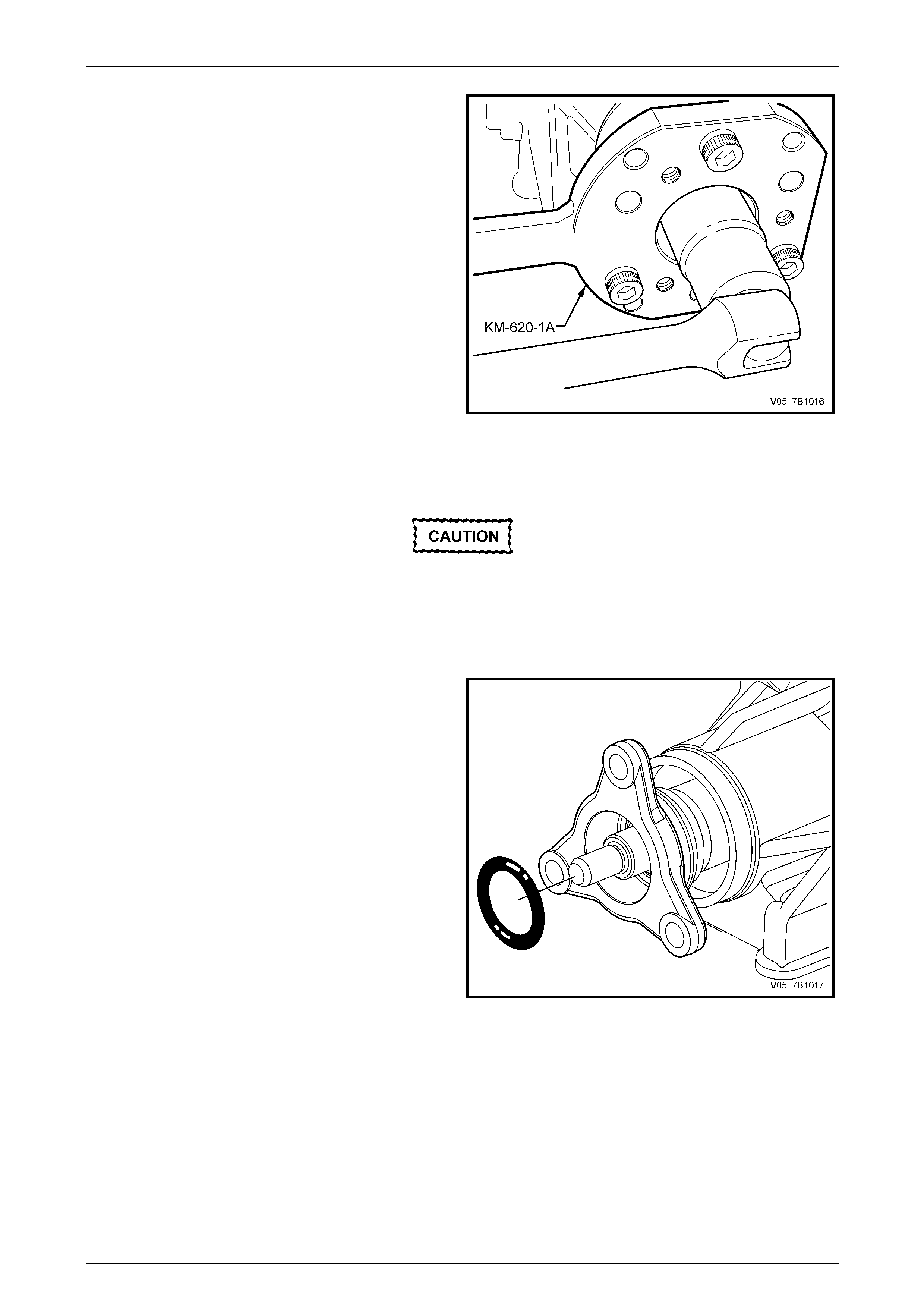
19 Install holding tool DT-47735 (or KM-620-1A) to the
transmission output flange and secure with the three
removed propeller shaft coupling attaching bolts.
NOTE
It will be necessary to use packing pieces (i.e.
flat washers) over the studs to allow the holding
tool to be firmly clamped to the output flange.
20 With a piece of piping inst alled over the tang of the
holding tool DT-47735, use a 30 mm deep socket and
suitable equipment to loose n then remove the flange
nut. Discard the removed nut.
Figure 7B1 – 30
Alternative Method
If this alternative method is adopted, an
impact gun must not be used to loosen the
output shaft nut. Internal transmission
damage may otherwise result.
21 An alternative method of holding the rear flange while loosening the output shaft nut, is to select 1st gear.
22 Place a clean drain tray under the rear of the
transmission.
23 Slide the transmission output flange and O-ring seal
from the transmission output shaft.
Figure 7B1 – 31
Manual Transmission – V6 Engine 7B1-28
7B1-28
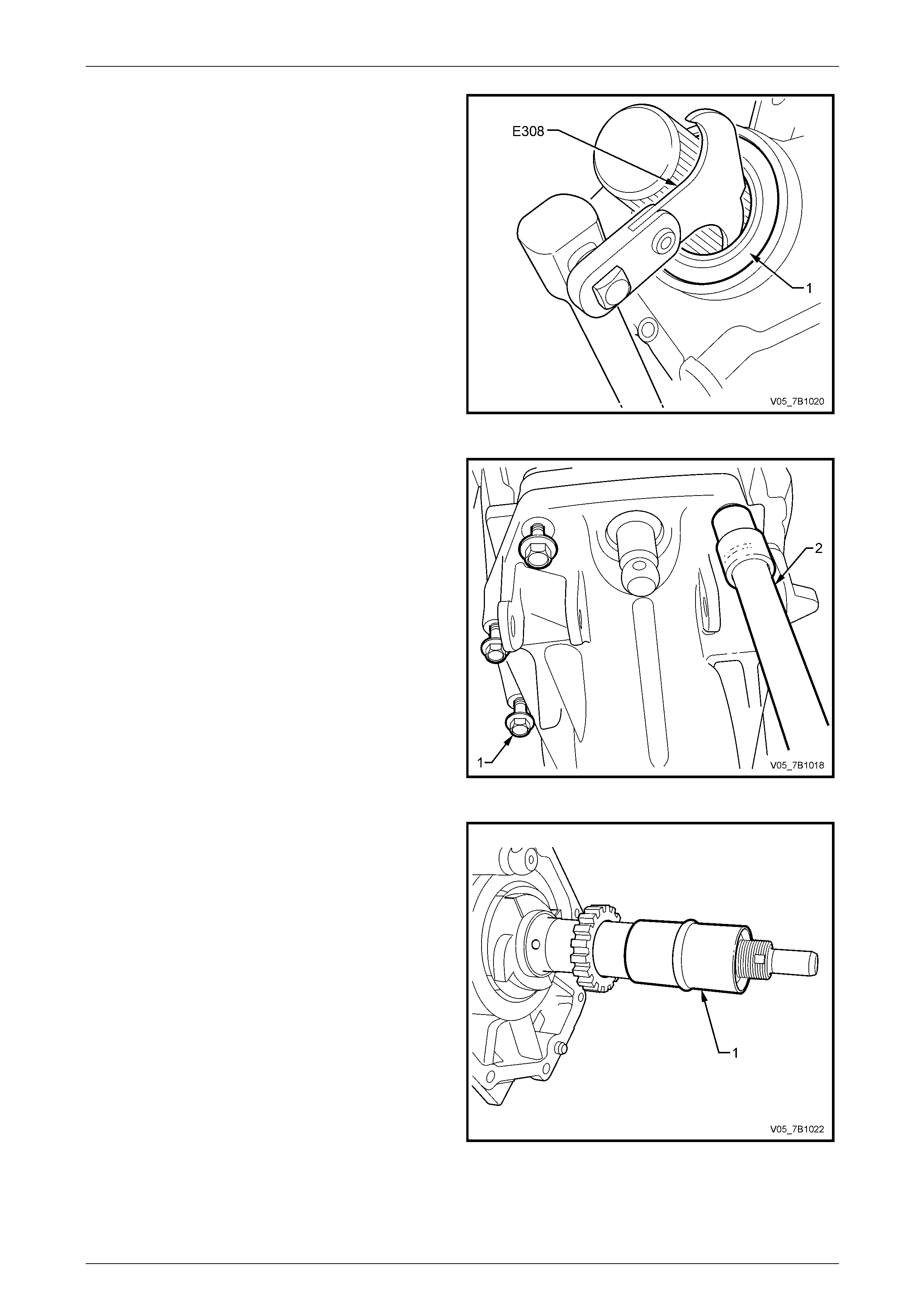
24 Remove the rear flange oil se al (1), using Tool No.
E308 or commercial equivalent.
Figure 7B1 – 32
25 Remove the eight bolts attaching (1) the extension
housing to the rear transmission case, using suitable
socket equipment (2).
26 Tap the extension housing with a rubber hammer to
break the sealant seal and dislodge the housing from
its alignment dowels.
27 Remove the extension housing and rear output shaft
taper roller bearing from the rear of the transmission.
Figure 7A2 – 33
28 Slide the collapsible sleeve from the transmission
output shaft assembly. Discard the removed sleev e.
NOTE
Take care not to dislodge the speed sensor
reluctor as, the drive ball may fall and be lost.
Figure 7B1 – 34
Manual Transmission – V6 Engine 7B1-29
7B1-29
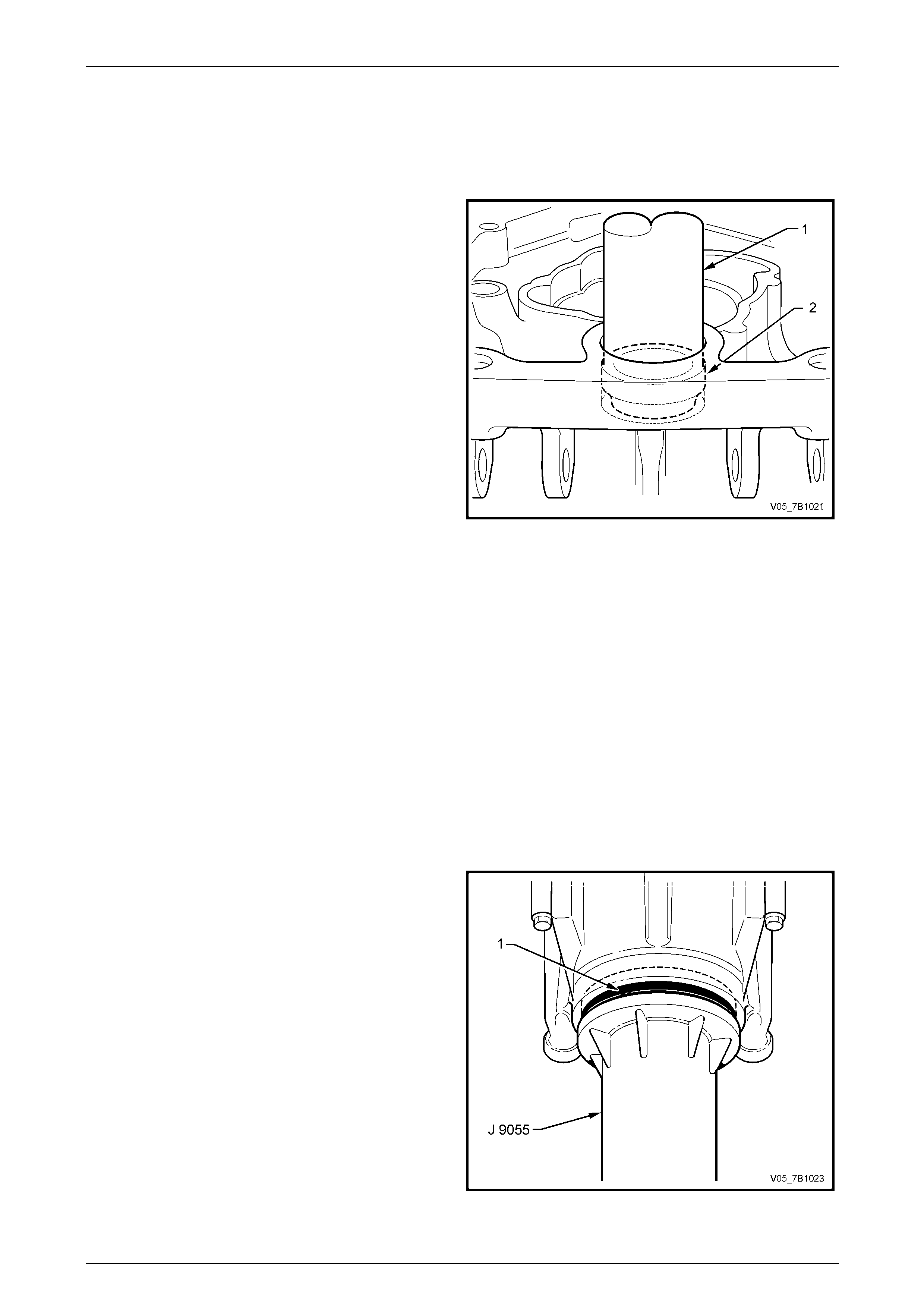
NOTE
Regardless of the reason for removing the
extension housing, it is strongly recommended
that both the output flange and shift shaft oil seals
are replaced.
29 Use a suitable tube (or socket) (1) (shaft diameter =
18 mm seal OD = 27.8 mm) to remove the shift and
select shaft oil seal (2) from the transmission
extension hous ing, working from front to rear.
Figure 7B1 – 35
Reinstall
1 Use a plastic scraper to remove residual sealant from the rear face of the rear transmission case and the mating
surface of the extension housing (if not being replaced).
2 Lubricate a new shift shaft oil seal with clean transmission lubricant.
3 Install the seal into the extension ho using using a suitable length and size of tubing, unti l the seal is flush against
the rear transmission housing.
4 After assessing the serviceability of the taper roller
bearing, lubricate the bearing with clean transmission
lubricant, then reinstall to the bear ing cup located in
the extension housing.
5 Lubricate a new output flange oil seal (1) with clean
transmission lubricant and install to the extension
housing, using Tool No. J 9055.
Figure 7B1 – 36
Manual Transmission – V6 Engine 7B1-30
7B1-30
6 Apply a continuous 1 mm bead of sealant such as Loctite 598HB 'Ultrablack' or equivalent (GM P/N 1234 5739), to
one of the mating surfaces, applied inside e ach of the bolt holes and the locating dowel pins.
7 Install a new collapsible sleeve to the mainshaft.
During the process of reinstalling the
extension housing, take care not to damage
the two new oil seals.
8 Reinstall the extension housing, secure with the eight retaining bolts and tighten to the correct torque specification.
Extension housing to transmission
rear case bolt torque specification .......................29 N.m
9 With the rear of the transmission lowered to allow access, install a NEW retaining sleeve to the shift select shaft,
then reinstall the shift select shaft trunnion, securing with the pin.
10 Slide the retaining sleeve over the trunnion and secure by squeezing the sleeve into the two grooves in the
trunnion, using circlip pliers.
11 Reinstall the output flange and a new O-ring seal.
12 Reinstall a new flange retain ing nut but do not fully tighten at this stage.
13 Set the taper roller bearing preload.
Output Shaft Taper Roller Bearings Preload Procedure
14 To set the bearing preload, it will be necessary to hold
the output shaft flange:
a Install holding tool KM-620-1A to the output
flange, and secure with the three removed
propeller shaft coupling bolts.
NOTE
It will be necessary to use packing pieces (i.e.
flat washers) over the bolts to allow the holding
tool to be firmly secured to the output shaft
flange.
b Install a length of pipe over the tang of the
holding tool KM-620-1A.
15 Using a 30 mm deep socket a nd suitable equipment,
temporarily tighten the lock nut until the flange just has
end float.
Figure 7B1 – 37
16 Remove the pipe, then rotate the flange several turns to sea t the bearings.
17 Check the rotational drag usin g a dial type torque wrench. Note the reading.
18 Reinstall the pipe to holding tool KM-620-1-A, then tighten the flange nut. Target torque is from 220 – 565 N.m.
19 Gradually increase torqu e but do not exceed the maximum specified val ue. If exceeded, then the collapsible spacer
must be replaced.
Manual Transmission – V6 Engine 7B1-31
7B1-31
20 Remove the pipe, then rotate the output flange several times to settle the bearings.
21 Re-check the flange rotational torque, then subtract the first reading from this. The difference should be between
0.45 and 1.35 N.m.
22 Stake the flange nut.
Wear eye protection to avoid injury, should
the shift select lever pin 'E' clip fly off when
released.
23 Reinstall the shift select lever yoke to the trunnion and secure with the pin, previously lubricated with an NLGI No. 2
lithium soap based EP grease with molybdenum disulphide, such as Shell Retin ax HDX2 grease or BP Energrease
LMS-EP 23 (or equivalent).
24 Install a new 'E' clip to secure the pin.
25 Engage each of the selector brace bushed ends with the lugs on the extension housin g. Align the holes and secure
with a brace pin and retainer assemb ly, ensuring that the retainer is fully engaged, in ea ch instance.
26 Apply a smear of transmission lubric ant to the speed sensor O-ring, then reinstall the speed sensor to the right side
of the extension housin g, securing with the screw, tightened to the correct torque specification.
Speed sensor retaining
screw torque specification...................................... 8 N.m
27 Reinstall the propeller shaft, refer to Section 4C1 Rear Propeller Shaft & Universal Joints.
28 Reinstall the transmission re ar support crossmember and the four crossmember to side rail bolts. Align the
crossmember to the witness marks made before removal and tighten bolts to the correct torque specification.
Rear crossmember to side frame
member bolt torque specification.........................58 N.m
29 Centralise the two rear transmission support mount studs in the crossmember holes.
30 Reinstall the two transmission support mount to crossmember retaining nut s and tighten to the correct torque
specification.
Transmission rear support mount to
crossmember nut torque specification .................25 N.m
31 With the vehicle in a level position, check th e transmission lubricant level, topping up as required.
Refer to 2.2 Checking Transmission Lubricant Level, in this Section.
32 Road test the vehicle to ensure correct operation.

Manual Transmission – V6 Engine 7B1-32
7B1-32
4.3 Transmission Assembly
Remove
Disconnection of the battery affects certain
vehicle electronic systems. Refer to
Section 00 Warnings, Cautions and Notes,
before removing the ground lead.
1 Disconnect the battery ground lead.
2 Raise the vehicle and suppor t in a safe manner. Refer to Section 0A General Information in this Service Information
for the location of recommended lifting and supp ort points.
3 Drain transmission lubricant into a clean container with at least 2 litres capacity.
Refer to 2.3 Draining and Refilling Transmission, in this Section.
4 Remove the propeller shaft. Refer to Section 4C1 Rear Propeller Shaft and Universal Joints.
5 While not essential, it is strongly recommended that the engine exhaust pi pes are removed:
a Disconnect the oxygen sensor s.
b Remove the two intermediate pipe flange bolts on each side.
c remove the exhaust pipe flange nuts from each e xhaust manifold.
d Carefully remove each of the eng ine exhaust pipes and set to one side, taking care not to damage the
oxygen sensors.
6 Using a felt tipped pen or correction pen (i.e.
Whiteout™), mark the position (1) of the rear support
crossmember (2) to the side frame.
NOTE
This is necessary to mai ntain driveline align ment
overcoming a potential, driveline vibration
condition on reassembly.
Figure 7B1 – 38
Manual Transmission – V6 Engine 7B1-33
7B1-33
7 Support the transmission rear case with suitable lifting
equipment.
8 Remove the rear support mount crossmember to side
frame bolts (2).
9 Remove the rear support mount crossmember to rear
support mount nuts (3), then remove the crossmember
(1) from the vehicle and set to one side.
Figure 7A2 – 39
10 Disconnect the back-up lamp s witch wiring harness connector.
11 Disconnect the wiring harness connector from the vehicle speed sensor.
12 Cut cable ties to free the transmission harness.
13 Remove the screw securing the right side close out cover to the front of the transmission front housin g.
14 Remove the close-out cover and set to one side.
15 Remove the starting motor, refer to Section 6D1-2 Starting Motor – V6.
When lowering the transmission at the rear,
ensure that the rear of the engine does not
foul or damage components such as pipes,
harnesses etc, on the engine side of the
cockpit module.
16 Lower the rear of the transmission as far as possible with causing damage and support in this position.
17 Use a small flat bladed screwdriver, release the quick connect wire clip securing the clutch h ydraulic fluid hose to
the clutch actuating cylinder adaptor fluid fee d pip e.
18 Immediately plug both open h ose/pipe ends to minimise fluid loss and prevent the entry of foreign matter.
Manual Transmission – V6 Engine 7B1-34
7B1-34
19 If the exhaust pipes were not removed as
recommended, disconnect the oxygen sensor leads at
the wiring harness connectors .
Take care not to break the wiring harness
retainers when prising loose.
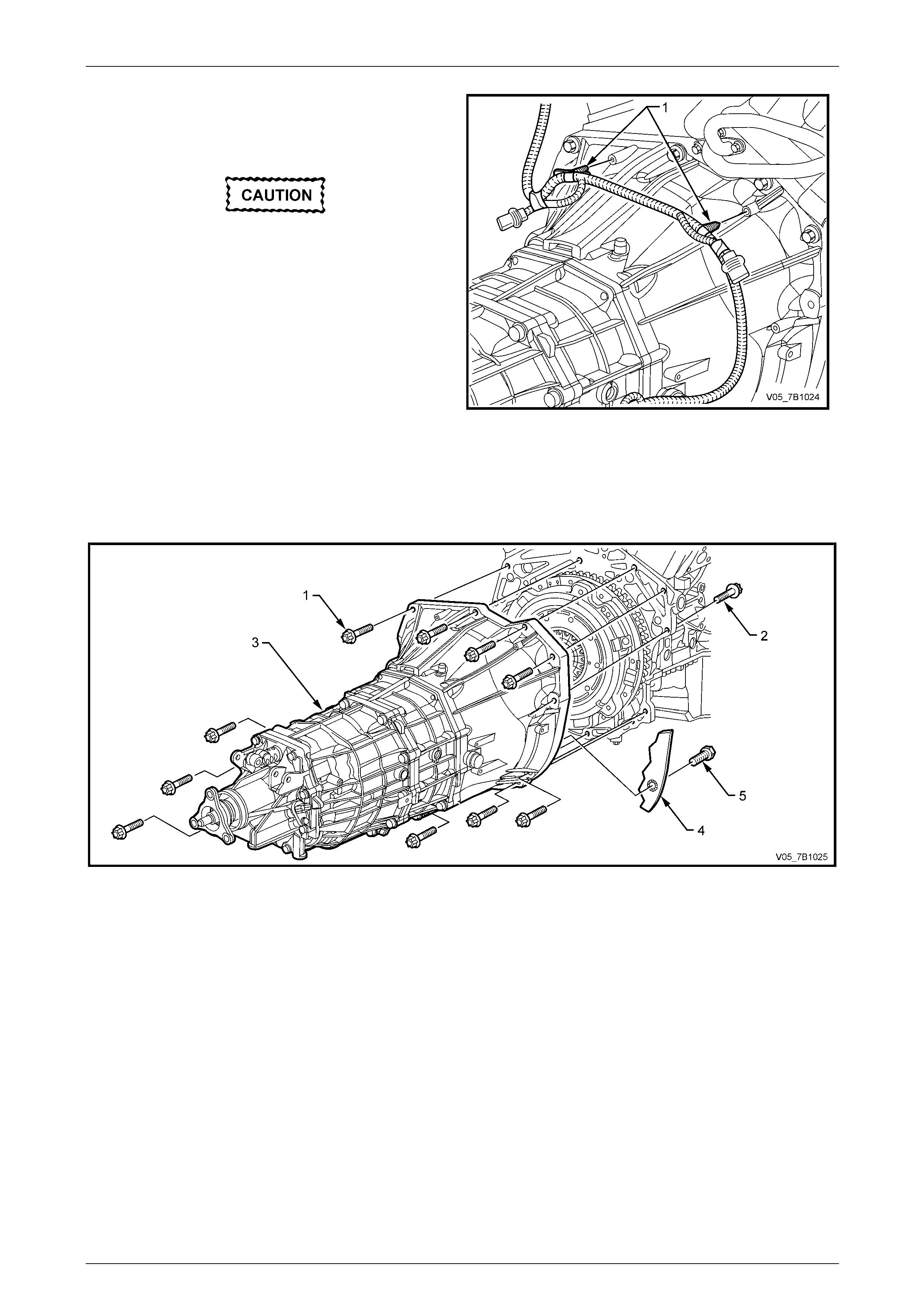
20 Using a flat bladed screwdriver, dislodge the wiring
harness retaining tabs (1) from the transmiss ion front
case.
Figure 7A2 – 40
21 Remove the screw (5) securing the close-out cover (4) to the front of the transmission case, then remove the cover
and set to one side.
22 Using a suitable sized Torx so cket and suitable socket equipment, loosen then remove the 11 bolts (1) securi ng the
transmission (3) to the rear of the engine block and oil pan.
Figure 7A2 – 41
23 Shake the rear of the transmission to separate the front case from the loca ting dowels.
24 Carefully slide the transmission rearward, taking care not to allow the transmission inp ut shaft to drag or hang on
the clutch driven plate.
25 When the input shaft is clear from the clutch pressure plate, the transmission can be lowered and removed from the
vehicle.
Reinstall
While the reinstallation process is largely the reverse to the removal procedure, there are some specific requirements
that are detailed here:
1 Before installing the transmission, select fifth or sixth gear, to all ow movement of the input shaft to align the splines
with the clutch driven plate.
2 Sparingly lubricate the cleaned, transmission input shaft splines (maximum of 0.5 gm), using an NLGI No. 2 lithium
soap based EP grease with molybdenum disulphide, such as Shell Retinax HDX2 grease or BP Energrease LMS-
EP 23 (or equivalent).
Manual Transmission – V6 Engine 7B1-35
7B1-35
Do not allow the input shaft to ‘hang’ on the
clutch driven plate as the resultant distortion
will cause a clutch malfunction.
3 Reinstall the transmission, ta king care to keep the front transmission case, square to the rear of the engine.
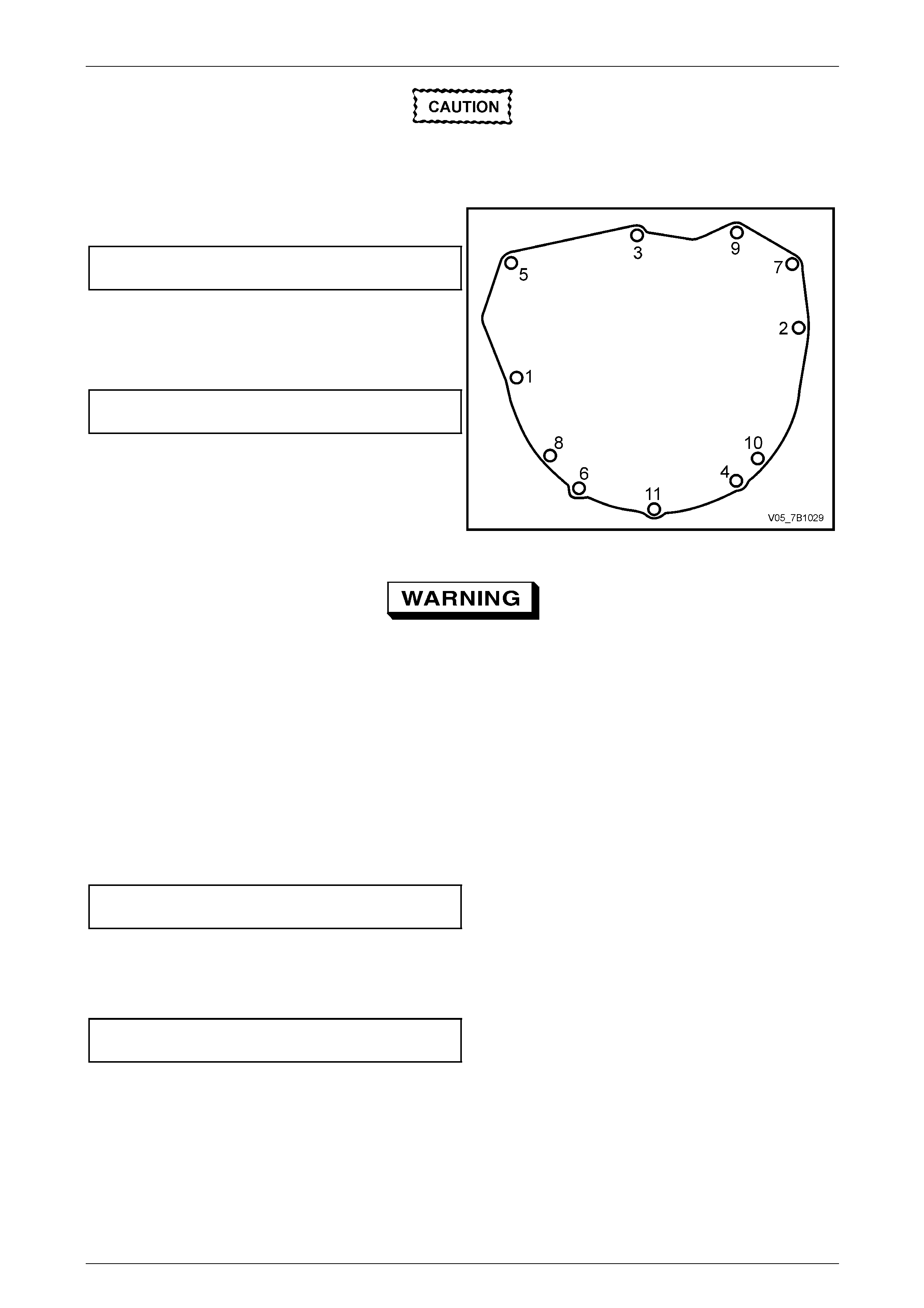
4 Reinstall the 11 Torx head ed bolts, tightening in the
sequence shown, to the correct torque spec ification.
Transmission to engine
bolt torque specification.......................................55 N.m
5 Reinstall the wiring harness retaining clip pegs to the
holes provided in the front transmission case.
6 Reinstall the close-out cover to the right front of the
transmission front case and secure with a screw,
tightened to the correct torque specification.
Transmission close- out cover
screw torque specification....................................14 N.m
7 Reinstall the starting motor, refer to
Section 6D1-2 Starting Motor – V6.
8 Reinstall the wiring harness connectors to the back-up
lamp switch and to the speed sensor.
Figure 7A2 – 42
9 Secure the transmission wiring harness to the transmission lugs using cable ties.
Wear eye protection to avoid injury, should
the shift select lever pin 'E' clip fly off when
released.
10 Reinstall the shift select lever yoke to the trunnion and secure with the pin, previously lubricated with an NLGI No. 2
lithium soap based EP grease with molybdenum disulphide, such as Shell Retin ax HDX2 grease or BP Energrease
LMS-EP 23 (or equivalent).
11 Install a new 'E' clip to secure the pin.
12 Engage each of the selector brace bushed ends with the lugs on the extension housin g. Align the holes and secure
with a brace pin and retainer assemb ly, ensuring that the retainer is fully engaged, in ea c h instance.
13 Reinstall the propeller shaft, refer to Section 4C1 Rear Propeller Shaft & Universal Joints.
14 Raise the transmission to just above the installed level.
15 Align the transmission rear support crossme mber to the witness marks on the side rails, made before removal.
16 Reinstall and tighten the four crossmember to side rail bolts to the correct torque specification.
Rear crossmember to side frame
member bolt torque specification.........................58 N.m
17 Remove the transmission support.
18 Centralise the two rear transmission support mount studs in the crossmember holes.
19 Reinstall the two transmission support mount to crossmember retaining nut s and tighten to the correct torque
specification.
Transmission rear support mount to
crossmember nut torque specification .................25 N.m
20 Reinstall the t wo engine exhaust pipes, using new gaskets at each flange to intermediate pipe junction,
refer to Section 8B Exhaust System, for the necessary procedures and clearances.
21 Tighten all reinstalled exhaust system fasteners to the correct torque specificatio ns,
refer to Section 8B Exhaust System
22 Reinstall the oxygen sensor wiring harness connectors.
23 With the vehicle in a level position, check th e transmission lubricant level, topping up as required.
Refer to 2.2 Checking Transmission Lubricant Level, in this Section.
24 Road test the vehicle to ensure correct operation.

Manual Transmission – V6 Engine 7B1-36
7B1-36
4.4 Transmission Disassembly
Should a transmission require disassembly during the vehicle warranty period, contact the appropriate Zone office for the
procedure to obtain a replacement transmission.

Manual Transmission – V6 Engine 7B1-37
7B1-37
5 Diagnosis
5.1 Symptoms – Manual Transmission
Strategy Based Diagnostics
Review the system operations in order to familiarise yourself with the system functions. Refer to 1.1 General Description.
Visual/Physical Inspection
• Inspect the easily accessible or visible system components for obvious damage or conditions which could cause
the symptom.
• Inspect the manual transmission for the correct fluid level.
• Inspect the manual transmission for fluid leak s.
• Inspect the manual transmission for broken or loose n transmission mounts.
Intermittent
Test the vehicle under the same cond itions that the customer reported, to verify the system is operating properly.
Symptom List
Refer to a symptom diagnostic procedure from the following list to diagnose the symptom:
• Transmission Fluid Leak Diagnosis
• Transmission Shifts Hard
• Transmission Gear Clash W hen Shifting Gears
• Transmission Noisy
• Transmission Does Not Shift into One Gear
• Transmission Locked in One Gear
• Transmission Jumps Out of Gear
• Transmission Clunk on Acceleration or Deceleration
Manual Transmission – V6 Engine 7B1-38
7B1-38
5.2 Transmission Fluid Leak Diagnosis
Diagnostic Aids
Using the incorrect type of transmission fluid may affect the sealing a bility of the seals. Ensure the use of the correct type
of transmission fluid. Also, the incorrect type of sealer may not be compatible with the transmission fluid or may not have
the correct characteristics for sealing the affected components. Ensure the use of the correct type of sealers.
Refer to 6 Specifications for details of the recommended Sealers, Adhesives, and Lubricants.
Test Description
The number below refers to the step number on the diagnostic table.
5 Use an approved method to clean the transmission to ensure the leak location is corr ectly identified. If using a
powder method or dye method ensure the pr oducts are compatible with the transmission fluid.
Step Action Yes No
Definition: Visible sign of the transmission fluid leaking from the transmission
1 Did you review the manua l transmission symptoms and perform the
necessary inspections? Go to Step 2
Go to Symptoms –
Manual
Transmission
2 1 Inspect for the transmission fluid level higher than the
recommended level. Refer to 2.1 Tr ansmission F luid Level
Inspection.
2 Adjust the transmission level if incorrect.
Was the transmission fluid level too high? Go to Step 25 Go to Step 3
3 1 Inspect the transmission vent for a blockage.
Is the transmission vent blocked? Go to Step 4 Go to Step 5
4 1 Repair or replace the transmission vent. Refer to Transmission
Vent Replacement in the T ransmission Unit Repair.
Did you find and repair the condition? Go to Step 25 Go to Step 5
5 1 Verify the location of the leak:
a Clean the transmission assembly.
B Operate the ve hicle for 24 km or until normal operating
temperatures are reached.
C Visual inspect or use the powder method or dye and black
light method to locate the leak.
Is the leak occurring at the drain or fill plug? Go to Step 6 Go to Step 7
6 1 Replace the drain or filler plug. Refer to Transmission Fluid
Replacement.
Did you find and repair the condition? Go to Step 25 Go to Diagnostic
Aids
7 1 Is the leak at the transmission output shaft seal? Go to Step 8 Go to Step 9

Manual Transmission – V6 Engine 7B1-39
7B1-39
Step Action Yes No
8 1 Remove the output shaft oil seal and ins pect for the following.
Refer to Mainshaft Rear Oil Seal Replacement.
• Damaged or worn seal.
• Damaged seal bore.
• Improper installation.
• Cracks in the component.
• Propeller shaft yoke sealing surface is scratched, nicked,
damaged, or worn.
• Loose or worn bearing causing excessive seal wear.
• Yoke flange nut loose.
Did you find and repair the condition? Go to Step 25 Go to Diagnostic
Aids
9 Is the leak at the shift lever area? Go to Step 10 Go to Step 11
10 1 Inspect the shift control lever lower boot for damage.
Did you find and repair the condition? Go to Step 25 Go to Diagnostic
Aids
11 1 Is the leak at the front of the transmission? Go to Step 12 Go to Step 15
12 1 Remove the transmission. Refer to
2 Inspect the input shaft for leaking.
3 Remove the Clutch Actuating Assembly. Refer to 7A1 Clutch –
V6.
Did you find and repair the condition? Go to Step 25 Go to Step 13
13 1 Inspect for the leak at the input shaft seal.
2 Inspect for the following if the input shaft seal is leaking:
• Damaged or worn seal.
• Damaged seal bore
• Improper installation
• Cracks in the component
• Input shaft sealing surface is scratched, nicked, damag ed,
or worn
• Loose or worn bearing causing excessive seal wear
3 Replace the clutch actuating cylinder assembly. Refer to 7A1
Clutch – V6.
Did you find and repair the condition? Go to Step 25 Go to Step 14
14 1 Inspect the case for cracks or porosity.
2 If cracks and or porosity are found replace the transmission.
Refer to 4.3 Transmission Assembly.
Did you find and repair the condition? Go to Step 25 Go to Diagnostic
Aids
15 Is the leak at the vehicle speed sensor (VSS)? Go to Step 16 Go to Step 17

Manual Transmission – V6 Engine 7B1-40
7B1-40
Step Action Yes No
16 1 Remove the VSS. Refer to 3.2 Speed Sensor.
2 Inspect for the following:
• Cut or damaged O-ring seal
• VSS over tightened causing deformation in the VSS
• VSS bore scratched or damaged
Did you find and repair the condition? Go to Step 25 Go to Step 1
17 Is the leak at the backup light switch? Go to Step 18 Go to Step 19
18 1 Remove the backup light switch. Refer to 3.1 Backup Lamp
Switch.
2 Inspect for the following:
• Cross threaded or damaged threads
• Insufficient sealant
• Leaking switch
• Improper installation
Did you find and repair the condition? Go to Step 25 Go to Step 1
19 Is the leak at the shift shaft detent plug? Go to Step 20 Go to Step 21
20 1 Remove the shift shaft detent plug. Refer to 3.3 Shift Shaft
Detent.
2 Inspect for the following:
• Loose, not installed pro perly
• Insufficient sealant
• Cracked case
• Improper installation
Did you find and repair the condition? Go to Step 25 Go to Step 1
21 Is the leak at the sealing flanges of the transmission cases? Go to Step 22 Go to Step 23
22 1 Replace the transmission. Refer to 4.3 Transmission Assembly
Did you correct the conditi on? Go to Step 25 Go to Step 23
23 Is the leak coming from a crack or porosity in the transmission case? Go to Step 24
24 1 Replace the transmission. Refer to 4.3 Transmission Assembly
Did you correct the conditi on? Go to Step 25 Go to Diagnostic
Aids
25 1 Operate the system to verify the repair.
Did you correct the conditi on? System OK Go to Step 1
Manual Transmission – V6 Engine 7B1-41
7B1-41
5.3 Transmission Shifts Hard
Diagnostic Aids
An intermittent hard shift may be caused by an intermittent clutch condition. With an y clutch, if the centre splines jam on
the transmission input shaft splines because sa y, the spline s are damaged, the clutch may not release immediatel y. Also
contamination of the clutch driven plate facings with a fluid, can also cause the plate to stick on either th e flywheel or
pressure plate faces.
Test Description
The numbers below refer to the step numbers on the diagnostic table:
3 A static shift test is performed by shifting into all of the gear positions with the engine not operating. While
performing the test one should note how the shift lever movement is felt. Also while shifting from one gear to the
other feel for binding in the shi ft rails. You should be able to feel the detent plungers operating when coming out of
a gear and going into a gear.
5 A dynamic shift test is performed by shifting into the gear positions with the engine operati ng. Test for the correct
mesh of the synchronisers and for the clutch releasing correctly. When shifting into a nd out of a gear, feel for the
shift detent plungers and for the synchronisers sleeve for moving freely.
7 The transmission uses a synthetic transmission fluid that allows proper synchroniser operation. The incorrect fluid
may cause hard shifting by varnish build up, or not enough lubrication for proper synchroniser operation.
Step Action Yes No
Definition: The transmission does not shift smoothly, or without difficulty, from one gear to the other.
1 1 Did you review the Symptoms – Manual Transmission, and
perform the necessary inspections? Go to Step 2
Go to Symptoms -
Manual
Transmission
2 1 Inspect the clutch system for proper operation. Refer to Clutch
System Description and Operation in this Section.
Did you find or repair the con dition? Go to Step 11 Go to Step 3
3 1 Perform a static shift test on the transmission.
2 Test for the following:
• Blockage preventing full shift lever movement.
• Excessive movement in the shift lever.
• Binding in the shift lever.
• Detent plungers or shift rails binding.
Are you able to shift into all gears? Go to Step 5 Go to Step 4
4 1 Inspect the removed gearshift lever and check for worn or faulty
components. Refer to 3.6 Gearshift Lever, in this Section.
Did you find and repair the condition? Go to Step 11 Go to Step 5

Manual Transmission – V6 Engine 7B1-42
7B1-42
Step Action Yes No
5 1 Perform a dynamic shift test on the transmission.
2 Test for the following:
• Detent plungers or shift rails binding.
• Synchroniser sleeve bin ding.
• Gear clash into only one gear.
• Gear clash into all gears.
Did the transmission shift hard into all g ears? Go to Step 6 Go to Step 10
6 1 Inspect the transmission for the correct fluid level and type of the
transmission fluid. Refer to Transmission Fluid Re placement.
Is the transmission at the correct level and proper fluid being used? Go to Step 8 Go to Step 7
7 1 Drain and refill the transmission with the correct type fluid. Refer
to 2.3 Draining and Refilling Transmission, in this Section.
Did you find and repair the condition? Go to Step 11 Go to Step 8
8 1 move the transmission. Refer to 4.3 Transmission Assembly, in
this Section.
2 Inspect the clutch pressure plate and/or clutch driven plate.
Is the clutch pressure plate and/or clutch driven plate worn or faulty? Go to Step 9 Go to Step 10
9 1 Replace the clutch assembly. Refer to 7A1 Clutch – V6
Did you find and repair the condition? Go to Step 11 Go to Step 10
10 1 Replace the transmission. Refer to 4.3 Transmission Assembly,
in this Section.
Is the replacement complete? Go to Step 11 –
11 1 Operate the system in order to verify the repair.
Did you correct the conditi on? System OK Go to Step 1
Manual Transmission – V6 Engine 7B1-43
7B1-43
5.4 Transmission Gear Clash When Shifting
Gears
Diagnostic Aids
Gear clashing may be caused by shifting at too high of an engine RPM or by rushing the shift. If gear clashing is
occurring in more than one gear, the clutch may not be releasing properl y for proper synchroniser operation.
Test Description
The numbers below refer to the step numbers on the diagnostic table:
2 This step tests for the proper releasing of the clutch. If the clutch reserve is not correct, the mainshaft gears may
still be turning causing the ge ar clash ing.
5 This step inspects for the proper transmission fluid. A special fluid is required for the correct lubrication of the
synchronisers.
7 A static shift test is performed by shifting into all of the gear positions with the engine not operating. While
performing the test, you should note how the shift lever movement is felt. Also, while shifting from one gear to
another, feel for binding in the shift rails. You should be able to feel the detent plungers operating when comin g out
of a gear and going into a gear. Excessive play in the gear shift lever may prevent the shift forks from fully
engaging the synchroniser.
9 A dynamic shift test is performed by shifting into all of the gear positions with the engine operating. Test for the
correct mesh of the synchronisers, and for the clutch releasing correctly. Move the shift lever and fee l for the
synchroniser sleeve to just release from the gear, then l et up on the cl utch pedal. Depress the clutch pedal and
move the shift lever to re-engage that gear. If it shifts back into the gear without clashing, the clutch is releasing
correctly and the synchronise r is working. If clashing occurs, test on another gear. If all gears clash, the clutch is
not releasing correctly.
Step Action Yes No
Definition: Noise from the transmission when shifting gears. A grinding or gratin g sound, when the synchroniser sleeve
is engaging with the selector teeth on the speed gear. A suspected internal transmission condition, if the nois e only
occurs in one gear.
1 Did you review the Symptoms – Manual Transmission, and perform
the necessary inspections ? Go to Step 2
Go to Symptoms –
Manual
Transmission
2 With the engine operating, does the transmission shift from neutral to
any gear, without the vehicle lurching or gear clashing? Go to Step 5 Go to Step 3
3 1 Inspect for proper clutch operation. Refer to 7A1 Clutch – V6.
Does the clutch operate properl y? Go to Step 5 Go to Step 4
4 1 Repair the clutch system. Refer to 7A1 Clutch – V6 in this
Section.
Did you find and repair the condition? Go to Step 11 Go to Step 5
5 1 Inspect for the correct transmission fluid level and the proper
fluid. Refer to 2.2 Checking Transmission L ubricant Level, in this
Section.
Is the transmission fluid level correct and at the proper level? Go to Step 7 Go to Step 6
6 1 Fill the transmission to the correct level, or change the
transmission fluid if it is not the correct type.
Does the transmission still have gear clash ? Go to Step 7 Go to Step 11

Manual Transmission – V6 Engine 7B1-44
7B1-44
Step Action Yes No
7 1 Perform a static shift test on the transmission.
2 Test for the following:
• Blockage preventing full shift lever movement.
• Excessive movement in the shift lever.
• Binding in the shift lever.
• Detent plungers or shift rails binding.
Did the transmission shift smoothly into th e gear that is clashing? Go to Step 9 Go to Step 8
8 1 Remove the shift lever and inspect for dama ge or worn
components. Refer to 3.6 Gearshift Lever, in this Section.
Did you find and repair the condition? Go to Step 11 Go to Step 9
9 1 Perform a dynamic shift test on the transmission.
2 Test for the following:
• Detent plungers or shift rails binding.
• Synchroniser sleeve bin ding.
• Gear clashing in more than the suspected gear.
Is the transmission hard to shift into all gears? Go to Transmission
Shifts Hard Go to Step 10
10 1 Replace the transmission. Refer to 4.3 Transmission Assembly,
in this Section.
Is the replacement complete? Go to Step 11 –
11 1 Operate the system and verify the repair.
Did you correct the conditi on? System OK Go to Step 1
Manual Transmission – V6 Engine 7B1-45
7B1-45
5.5 Transmission Noisy
Diagnostic Aids
Should the transmission be in neutra l with the engine operating, and a whirring kind of a noise, neutral gear rattle, is
heard outside the vehicle, this is a normal condition.
Test Description
The numbers below refer to the step numbers on the diagnostic table.
3 This step inspects for vibration causing a no ise. If the vehicle is equipped with an aftermarket box, or is carrying a
certain load, the driveline axle may not be correct, and could cause a vibration. The vibration mayb e resonating into
the transmission, causing a noise.
7 This step inspects for the correct transmission fluid level. If the transmissio n fluid level is excessively low, damage
may have occurred to the transmission components.
9 This step inspects for the correct type of transmission fluid. The transmission uses a special fluid. If the incorrect
fluid was used, there may have been an overheating problem. Overheating may cause damage to the transmission
components.
11 This step inspects for noise coming into the dr iver compartment. Improper sealing of the gearshift lever may be
allowing normal transmission noise to be heard by the driver.
14 This step tests to determine if clutch components are making the noise. Depress the clutch pedal slowly and listen
for the change in noise. If the noise cha nges while pressing the pedal, it may be a faulty clutch component. If the
noise does not change until the clutch is completely disengaged, the transmission component is faulty.
Step Action Yes No
Definition: The transmission is making a noise. The different noises may be a whine or a growl from faulty bearings or
gears. The noise may also be caused from a faulty component causing a vibration noise or rattle.
1 Did you review the Symptoms – Manual Transmission, and perform
the necessary inspections ? Go to Step 2
Go to Symptoms –
Manual
Transmission
2 Is the noise present at a certain road speed, or with a certain load? Go to Step 3 Go to Step 4
3 Is the noise present in all gears? Go to Step 5 Go to Step 4
4 Is the noise present in just one gear? Go to Step 13 Go to Step 5
5 1 Inspect the transmission fluid level.
Is the fluid level correct? Go to Step 7 Go to Step 6
6 1 Add transmission fluid.
Did you find and repair the condition? Go to Step 14 Go to Step 7
7 1 Inspect the transmission for the correct fluid type. Refer to 2.1
Recommended Lubricant an d Quantity, in this Section.
Is the transmission fluid the correct type? Go to Step 9 Go to Step 8

Manual Transmission – V6 Engine 7B1-46
7B1-46
Step Action Yes No
8 1 Drain and refill the transmission with the correct type fluid. Refer
to 2.3 Draining and Refilling Transmission, in this Section.
Did you find and repair the condition? Go to Step 14 Go to Step 9
9
1 Inspect for engine to transmission alignme nt.
2 Inspect for loose transmission mounting bolts.
Are there any loose transmission mounting bolts? Go to Step 10 Go to Step 11
10 1 Replace and tighten the transmission mounting bolts. Refer to
Transmission Assembly, Reinstall, in this Section.
Is the noise still present? Go to Step 11 Go to Step 14
11 1 With the engine operating, depress the clutch pedal.
Is the noise still present? Go to Step 12 Go to Step 13
12
1 Remove the clutch. Refer to 7A1 Clutch – V6.
2 Inspect the following components for being the cause of the
noise:
• The release bearing.
• The dual mass flywheel.
• The pressure plate.
• The clutch disc.
• The input shaft bearing.
• The engine crankshaft end play.
Did you find and repair the condition? Go to Step 14 Go to Step 13
13 1 Replace the transmission. Refer to 4.3 Transmission Assembly,
in this Section.
Is the replacement complete? Go to Step 14 –
14 1 Operate the system to verify the repair.
Did you correct the conditi on? System OK Go to Step 1
Manual Transmission – V6 Engine 7B1-47
7B1-47
5.6 Transmission Does Not Shift Into One
Gear
Diagnostic Aids
If the transmission shifts into gear and then jumps out of gear, refer to Transmission Jumps Out of Gear. If it is an
intermittent condition, other driveline components may be faulty.
Test Description
The numbers below refer to the step numbers on the diagnostic table.
2 This step is to confirm that the clutch is not slipping. During certain conditions, the clutch may slip, and feel as
though the transmission is not in gear.
3 A static shift test is performed by shifting into all gears with the engine not operating. W hile performing the test, you
should note how the shift lever movement feels. Also, feel for the shift rails moving freely, the detent plungers
operating when coming out of a gear and going in the next gear, and the synchroniser sl eeve movement.
5 A dynamic shift test is performed by shifting into all gears with the engine operating. Test for the correct mesh of
the synchronisers sleeve and the speed gear selector teeth. Move the shift lever and feel for the synchroniser
sleeve to just release from the gear, then let up on the cl utch pedal. Depress the clutch pedal and move the shift
lever to re-engage that gear, to ensure full travel of the shift components.
Step Action Yes No
Definition: The shift lever will not move into a particular gear position, or when it is in a gear position, power is not
delivered through the transmission.
1 Did you review the Symptoms - Manual Transmission, and perform
the necessary inspections ? Go to Step 2
Go to Symptoms –
Manual
Transmission
2 1 Inspect the clutch system for slipping.
Is the clutch working properly? Go to Step 3 Go to
7A1 Clutch – V6
3 1 Perform a static shift test on the transmission.
2 Test for the following:
• Interference, preventing full shift lever movem ent.
• Excessive movement in the shift lever.
• Binding in the shift lever.
• Detent plungers or shift rails binding.
• Synchroniser sleeve movin g o n the hub and synchroniser
keys.
Were you able to shift into the gear position that has the concern ? Go to Step 5 Go to Step 4
4 1 Remove the gearshift lever and inspect for worn or faulty
components Refer to 3.6 Gearshift Lever, in this Section.
Did you find and repair the condition? Go to Step 7 Go to Step 5
5 1 Perform a dynamic shift test on the transmission.
2 Test for the following:
• Detent plungers or shift rails binding.
• Synchroniser sleeve bin ding.
• Synchroniser sleeve en gaging on the speed gear selector
teeth.
Were you able to shift into the gear position that has the concern? Go to Step 7 Go to Step 6
6 1 Replace the transmission. Refer to 4.3 Transmission Assembly,
in this Section.
Is the replacement complete? Go to Step 7 –
7 1 Operate the system in order to verify the repair.
Did you correct the conditi on? System OK Go to Step 1

Manual Transmission – V6 Engine 7B1-48
7B1-48
5.7 Transmission Locked in One Gear
Test Description
The numbers below refer to the step numbers on the diagnostic table.
2 This step is to ensure the use of the proper transmission fluid. A special fluid is used to ensure proper synchroniser
operation, and for sufficient lubricati on. Improper fluid may cause the synchronisers to stick or the transmission
components to overheat.
4 A static shift test is performed by shifting into all gears with the engine not operating. By confirming that the
transmission can be shifted into all pos itions, ensures that the shift lever is not excessively worn or damaged.
6 A dynamic shift test is performed by shifting into all of the gear positions with the engine operating. Test to ensure
that the internal shift components are functioning properly.
Step Action Yes No
Definition: The transmission cannot be shifted out of a gear, or the vehicle will not move because the transmission is
locked.
1 Did you review the Symptoms - Manual Transmission, and perform
the necessary inspections ? Go to Step 2
Go to Symptoms –
Manual
Transmission
2 1 Check for the correct type of transmission fluid.
Is the correct type transmission fluid be ing used? Go to Step 4 Go to Step 3
3 1 Drain the transmission, and refill with the correct type of fluid.
Refer to 2.3 Draining and Fil ling Transmission, in this Section.
Did you find and repair the co ndition? Go to Step 9 Go to Step 4
4 1 Perform a static shift test on the transmission.
2 Test for the shift lever moving to all positio ns.
Were you able to shift into all positions? Go to Step 6 Go to Step 5
5 1 Remove the gearshift lever.
2 Inspect for worn or faulty components. Refer to Gearshift Lever,
in this Section.
Did you find and repair the conditions? Go to Step 9 Go to Step 6
6 1 Perform a dynamic shift test on the transmission.
2 Test for being able to shift in and out of the gear with the
concern.
Were you able to shift the transmission correctly? Go to Step 7 Go to Step 8
7 1 Remove the transmission. Refer to
2 Inspect the clutch system for the clutch not releasing properly.
Refer to 7A1 Clutch – V6.
Did you find and repair the condition? Go to Step 9 Go to Step 8
8 1 Replace the transmission. 4.3 Transmission Assembly, in this
Section.
Is the replacement complete? Go to Step 9 –
9 1 Operate the system in order to verify the repair.
Did you correct the conditi on? System OK Go to Step 1
Manual Transmission – V6 Engine 7B1-49
7B1-49
5.8 Transmission Jumps Out of Gear
Diagnostic Aids
If the transmission jumps out of gear during deceleration, inspect the components that may allow for the gears or shafts
to tip. If the gears or shafts tip, the synchroniser sleeve can disengage from the selector teeth on the speed gear. If the
transmission jumps out of gear during accele ration, inspect the components that may not allow full engagement of the
synchroniser sleeve to the selector teeth on the speed gear. Insufficient engagement of the selector teeth under torque
may cause the transmission to jump out of gear.
Test Description
The numbers below refer to the step numbers on the diagnostic table:
2 A static shift test is performed by shifting into all gear positions with the engine not operating. While performing the
test, slowly move the shift lever. Feel for proper movement of the shift lever and transmission internal shift
components.
4 A dynamic shift test is performed by shifting into all gear positions with the engine operating. Test for the correct
mesh of the synchronisers sleeve and the speed g ear selector teeth. Move the shift lever, and feel for the
synchroniser sleeve to release form the gear, and then let up on the clutch pedal. Depress the clutch pedal and
move the shift lever to re-engage the gear, to ensure full travel of the shift components.
5 This step inspects for worn or damaged trans mission or engine mounts. Loose mounts may cause a shock on the
transmission allowing for gear disengagement.
6 This step inspects for the misalignment of the clutch to transmission. Misali gnment may put a bind on the input
shaft, allowing for the input shaft or the mainshaft to tip.
8 This step inspects the pilot bearing and the pilot bearing journal on the input shaft. A worn pilot bearing or input
shaft may allow the input shaft to tip, causing gear disengagement.
Step Action Yes No
Definition: Gear disengagement occurs during acce leration or deceleration.
1 Did you review the Symptoms - Manual Transmission, and perform
the necessary inspections ? Go to Step 2
Go to Symptoms –
Manual
Transmission
2 1 Perform a static shift test.
2 Test for the following:
• Interference preventing full shift lever movement.
• Excessive movement in the gearshift lever.
• Detent plungers engaging in the shift rails.
• Synchroniser detent springs and balls on the synchroniser
sleeves
Did the transmission shift completel y into all gears? Go to Step 4 Go to Step 3
3 1 Remove the gearshift lever assembly and inspect for worn or
faulty components. Refer to 3.6 Gearshift Lever, in this Section.
Did you find and repair the condition? Go to Step 10 Go to Step 4

Manual Transmission – V6 Engine 7B1-50
7B1-50
Step Action Yes No
4 1 Perform a dynamic shift test on the transmission.
2 Test for the following:
• Synchroniser sleeve en gagement to the speed gear
selector teeth.
• Detent plungers engaging in the shift rails.
Did the transmission shift completel y into all gears? Go to Step 5 Go to Step 8
5 1 Inspect the engine and/or transmission mounts. Refer to 3.4
Transmission Support Mount, in this Section.
Did you find and repair the condition? Go to Step 10 Go to Step 6
6 1 Inspect the clutch housing for loose b olts or misali gnment.
Are there any loose bolts or misalignment? Go to Step 7 Go to Step 8
7 1 Align the housing, if required.
2 Tighten any loose housing bolts.
Did you find and repair the condition Go to Step 10 Go to Step 8
8 1 Remove the transmission. Refer to
2 Check the input shaft for excessive lateral m ovement, indicating
a failed front ball race.
Did you find and repair the condition? Go to Step 10 Go to Step 9
9 1 Replace the transmission. Refer to 4.3 Transmission Assembly,
Remove, in this Section.
Is the replacement complete? Go to Step 10 –
10 1 Operate the system to verify the repair.
Did you correct the conditi on? System OK Go to Step 1

Manual Transmission – V6 Engine 7B1-51
7B1-51
5.9 Transmission Clunk on Acceleration or
Deceleration
Diagnostic Aids
All manual transmissions have gear play that might cause a clunk. If the transmission is suspected of causing the clunk,
compare it with a similar vehicle. An internal clunk in the transmission is usually caused by wear between two
components, or from improper assembly, which would also cause other symptoms.
Step Action Yes No
Definition: A clunk is heard and/or felt on acceleration or deceleration.
1 Did you review the Symptoms - Manual Transmission, and perform
the necessary inspections ? Go to Step 2
Go to Symptoms –
Manual
Transmission
2 1 Inspect the engine mounts for being loose o r damaged. Refer to
6A1 Engine Mechanical – V6
Did you find and repair the condition? Go to Step 8 Go to Step 3
3 1 Inspect the transmission mount for being loose or damaged .
Refer to 3.4 Transmission Support Mount, in this Section.
Did you find and repair the condition? Go to Step 8 Go to Step 4
4
1 Inspect the transmission to engine fasteners for being loose or
missing. Refer to 7 Torque Wrench Specifications, in this
Section.
Did you find and repair the condition? Go to Step 8 Go to Step 5
5
1 Inspect the exhaust hanger mounting bracket on the
transmission for being loose or for missing fasteners. Refer to
8B Exhaust System.
Did you find and repair the condition? Go to Step 8 Go to Step 6
6 1 Inspect the driveline for causing the clunk. Refer to 4C1 Rear
Propeller Shaft and Universal Joints.
Did you find and repair the condition? Go to Step 8 Go to Step 7
7 1 Replace the transmission. Refer to
Is the replacement complete? Go to Step 8 –
8 1 Operate the system to verify the repair.
Did you correct the conditi on? System OK Go to Step 1

Manual Transmission – V6 Engine 7B1-52
7B1-52
6 Specifications
General
Type.............................................................. Aisin ‘AY6’ 6 Speed, Synchromesh on all Gears
Production Option............................................................................................................. MV5
Transmission Ratios:
1st.................................................................................................................................4.475:1
2nd................................................................................................................................2.577:1
3rd ................................................................................................................................1.632:1
4th.................................................................................................................................1.193:1
5th.................................................................................................................................1.000:1
6th.................................................................................................................................0.751:1
Reverse........................................................................................................................3.954:1
Number Of Teeth:
Input Shaft
Spur Gear .......................................................................................................................13
Second Constant Mesh...................................................................................................21
Constant Mesh Gears
1st (Mounted on Countershaft Gear) ..............................................................................43
2nd (Mounted on Countershaft Gear) .............................................................................40
3rd (Mounted on Input Shaft)..........................................................................................29
4th (Mounted on Input Shaft) ..........................................................................................34
6th (Mounted on Input Shaft) ..........................................................................................45
Reverse (Mounted on Countershaft Gear)......................................................................38
Reverse Idler Gear..........................................................................................................25
Countershaft Gear
3rd...................................................................................................................................35
4th...................................................................................................................................30
6th...................................................................................................................................25
Constant Mesh (With Output Shaft Gear) .......................................................................17
Output Shaft
Constant Mesh (With Countershaft Gear).......................................................................23
Lubricants:
Transmission .......................................................................................GL-3, viscosity 75W-90
Capacity (Nominal).....................................................................................................1.8 litres
Transmission input shaft splines grease (0.5 gm maximum)...NLGI No. 2 lithium soap based
EP grease with molybdenum disulphide,
such as Shell Retinax HDX2 grease or
BP Energrease LMS-EP 23 (or equivalent).
Grease (where specified in text).....................NLGI No. 2 lithium soap based EP grease with
molybdenum disulphide, such as Shell Retinax HDX2
or BP Energrease LMS-EP 23 (or equivalent).
Sealants:
Screw Plugs (where specified in the text).........Loctite 565 or equivalent (GM P/N 12346004)
Extension Housing to Rear Case...............................Loctite 598HB “Ultrablack” or equivalent
(GM P/N 12345739)

Manual Transmission – V6 Engine 7B1-53
7B1-53
7 Torque Wrench Specifications
ATTENTION
Fasten ers must be replaced after loosen in g.
Vehicle must be at curb height before final tightening.
Fasteners either have micro encapsu lated sealant ap plied or in corporate a mech anical thread lock and
should only be re-used once. If in doubt, replacement is recommended.
NOTE
Only those torque wrench specifications referred
to in this text, are stated here. For others not
included, refer to the appropriate section.
Filler plug................................................................................................37 N.m
Back-Up lamp switch..............................................................................44 N.m
Drain plug...............................................................................................37 N.m
Extension housing to transmission rear case bolt ..................................29 N.m
Rear crossmember to side frame bolt ....................................................58 N.m
Rear crossmember to transmission support mount nut..........................25 N.m
Shift select shaft detent plug ..................................................................25 N.m
Speed sensor retaining screw..................................................................8 N.m
Transmission close-out cover screw ......................................................14 N.m
Transmission front case to engine block bolt (in sequence)...................55 N.m
Transmission support mount bolt ...........................................................25 N.m
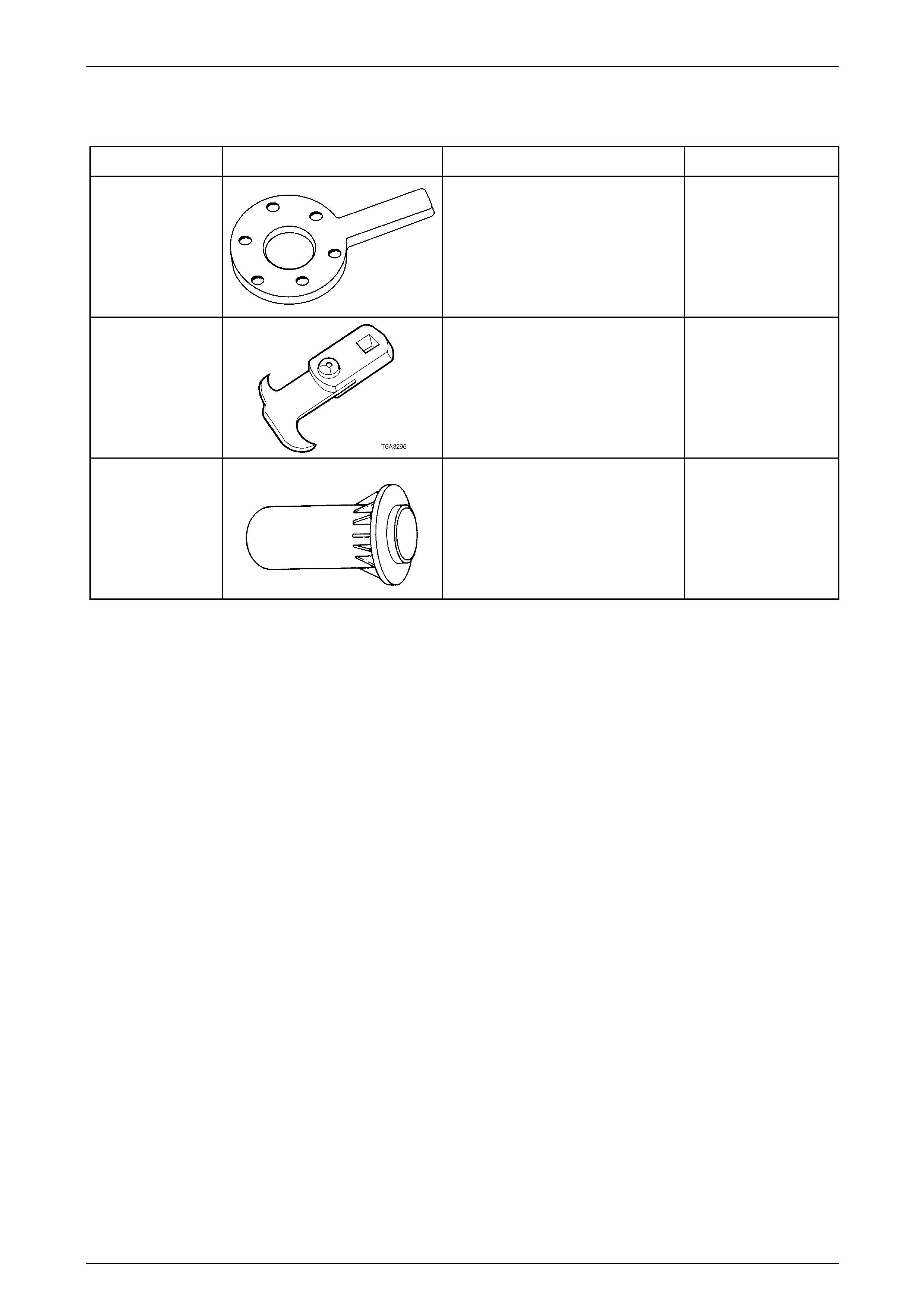
Manual Transmission – V6 Engine 7B1-54
7B1-54
8 Special Tools
Tool Number Illustration Description Tool Classification
DT-47735 Holding Too l
Used to hold the final drive pin ion
flange when loosening/ti ghtening the
pinion nut.
New release
Unique
E 308
Seal Remover
Used as a universal seal remover.
Also released as 56750.
Previously released.
Available
J 9055
Oil Seal Installer
Used to install the extension housi ng
oil seal. Also released as 17-010A.
Previously released.
Unique