
Automatic Transmission – 5L40–E – Unit Repair 7E5 – 1
7E5 – 1
Section 7E5
Hydra-Matic 5L40–E Automatic Transmission –
Unit Repair
ATTENTION
Before performing any Service Operation or other procedure described in this Section, refer to Section 00
WARNINGS, CAUTIONS AND NOTES for correct workshop practices with regard to safety and/or property
damage.
1 Transmission Disassemble...................................................................................................................4
1.1 General Service Information................................................................................................................................. 4
Teflon Sealing Rings .............................................................................................................................................4
Thrust Washer Surfaces........................................................................................................................................ 4
1.2 Transmission Preparation..................................................................................................................................... 5
Torque Converter Assembly Removal................................................................................................................. 5
Holding Fixture Installation................................................................................................................................... 5
Draining Transmission Fluid................................................................................................................................. 6
1.3 Extension Housing ................................................................................................................................................ 7
Remove................................................................................................................................................................... 7
1.4 Pan and Filter Assembly ....................................................................................................................................... 8
Removal.................................................................................................................................................................. 8
1.5 Wiring Harness....................................................................................................................................................... 9
Remove................................................................................................................................................................... 9
1.6 Control Valve Body and Accumulator Assembly.............................................................................................. 10
Remove................................................................................................................................................................. 10
1.7 Output Shaft Speed Sensor ................................................................................................................................ 12
Remove................................................................................................................................................................. 12
1.8 Input Speed Sensor............................................................................................................................................. 13
Remove................................................................................................................................................................. 13
1.9 Torque Converter Housing.................................................................................................................................. 14
Removal................................................................................................................................................................ 14
1.10 Direct and Reverse Clutch - Forward and Coast Clutch................................................................................... 15
Remove................................................................................................................................................................. 15
1.11 Input Sun Gear Shaft........................................................................................................................................... 16
Remove................................................................................................................................................................. 16
1.12 Direct Clutch Hub................................................................................................................................................. 17
Remove................................................................................................................................................................. 17
1.13 Intermediate Clutch Sprag Assembly ................................................................................................................ 18
Remove................................................................................................................................................................. 18
1.14 Overdrive Clutch Housing................................................................................................................................... 19
Remove................................................................................................................................................................. 19
1.15 Low Clutch Sprag ................................................................................................................................................ 20
Removal................................................................................................................................................................ 20
1.16 Centre Support..................................................................................................................................................... 21
Remove................................................................................................................................................................. 21
1.17 Input and Reaction Carrier.................................................................................................................................. 22
Remove................................................................................................................................................................. 22
1.18 Output Shaft......................................................................................................................................................... 23
Remove................................................................................................................................................................. 23
1.19 Park System Components .................................................................................................................................. 24
Remove................................................................................................................................................................. 24
1.20 Transmission Case Assembly............................................................................................................................ 26
Inspect .................................................................................................................................................................. 26
Techline

Automatic Transmission – 5L40–E – Unit Repair 7E5 – 2
7E5 – 2
1.21 Transmission Case Components....................................................................................................................... 27
Disassemble......................................................................................................................................................... 27
Reassemble.......................................................................................................................................................... 27
1.22 Park System Components .................................................................................................................................. 28
Reinstall................................................................................................................................................................ 28
1.23 Output Shaft and Rear Internal Ring Gear......................................................................................................... 30
Disassemble......................................................................................................................................................... 30
Reassemble.......................................................................................................................................................... 30
1.24 Input and Reaction Carrier.................................................................................................................................. 32
Disassemble......................................................................................................................................................... 32
Reassemble.......................................................................................................................................................... 32
1.25 Centre Support..................................................................................................................................................... 35
Disassemble......................................................................................................................................................... 35
Reassemble.......................................................................................................................................................... 38
Alternative Reassembly Method....................................................................................................................... 42
1.26 Low Clutch Sprag ................................................................................................................................................ 43
Reassemble.......................................................................................................................................................... 43
1.27 Overdrive and Intermediate Clutch .................................................................................................................... 44
Disassemble......................................................................................................................................................... 44
Reassemble.......................................................................................................................................................... 46
1.28 Intermediate Clutch Sprag .................................................................................................................................. 53
Inspect .................................................................................................................................................................. 53
Reassemble.......................................................................................................................................................... 54
1.29 Direct Clutch Hub................................................................................................................................................. 55
Reassemble.......................................................................................................................................................... 55
1.30 Input Sun Gear Shaft........................................................................................................................................... 56
Disassemble......................................................................................................................................................... 56
Reassemble.......................................................................................................................................................... 57
1.31 Forward and Coast Clutch .................................................................................................................................. 59
Disassemble......................................................................................................................................................... 59
Reassemble.......................................................................................................................................................... 60
1.32 Direct and Reverse Clutch .................................................................................................................................. 65
Disassemble......................................................................................................................................................... 65
Reassemble.......................................................................................................................................................... 67
1.33 Direct and Reverse Clutch - Forward and Coast Clutch................................................................................... 70
Reinstall................................................................................................................................................................ 70
Alternative Reassembly Method....................................................................................................................... 70
1.34 Fluid Pump ........................................................................................................................................................... 72
Remove................................................................................................................................................................. 72
Disassemble......................................................................................................................................................... 74
1.35 Torque Converter Seal ........................................................................................................................................ 76
Remove................................................................................................................................................................. 76
1.36 Fluid Pump ........................................................................................................................................................... 77
Reassemble.......................................................................................................................................................... 77
1.37 Torque Converter Housing.................................................................................................................................. 83
Reinstall................................................................................................................................................................ 83
1.38 Torque Converter Seal ........................................................................................................................................ 85
Reinstall................................................................................................................................................................ 85
1.39 Control Valve Body and Accumulator Assembly.............................................................................................. 86
Disassemble......................................................................................................................................................... 86
Rear Control Valve Body Inspection.................................................................................................................. 92
Rear Control Valve Body Disassemble.............................................................................................................. 92
Rear Control Valve Body Assemble................................................................................................................... 95
Front Control Valve Body Inspection................................................................................................................. 97
Front Control Valve Body Disassemble............................................................................................................. 98
Front Control Valve Body Assemble.................................................................................................................. 99
Control Valve Body and Accumulator Assembly............................................................................................ 101
Assemble ....................................................................................................................................................... 101
1.40 Input Speed Sensor Installation ....................................................................................................................... 106
1.41 Output Shaft Speed Sensor Installation .......................................................................................................... 107

Automatic Transmission – 5L40–E – Unit Repair 7E5 – 3
7E5 – 3
1.42 Control Valve Body and Accumulator Assembly............................................................................................ 108
Reinstall.............................................................................................................................................................. 108
1.43 Wiring Harness................................................................................................................................................... 110
Reinstall.............................................................................................................................................................. 110
1.44 Pan and Filter Assembly................................................................................................................................... 111
Reinstall.............................................................................................................................................................. 111
1.45 Extension Housing ............................................................................................................................................ 112
Reinstall.............................................................................................................................................................. 112
1.46 Propeller Shaft Flange....................................................................................................................................... 115
Reassemble........................................................................................................................................................ 115
1.47 Holding Fixture Removal................................................................................................................................... 116
1.48 Torque Converter Assembly............................................................................................................................. 117
Reinstall.............................................................................................................................................................. 117
2 Transmission Reference Diagrams..................................................................................................118
3 Specifications.....................................................................................................................................138
4 Torque Wrench Specifications..........................................................................................................143
5 Special Tools ......................................................................................................................................144

Automatic Transmission – 5L40–E – Unit Repair 7E5 – 4
7E5 – 4
1 Transmission Disassemble
1.1 General Service Information
The use of air powered tools to disassemble or reassemble this transmission is not recommended. Apart from the fact
that thread stripping is most likely when incorrect torque values are applied to fasteners, component parts can be
distorted to the point where malfunctions will occur.
Teflon Sealing Rings
If any sealing rings are found to be damaged, cut or do not rotate freely in their groove, check that the ring groov e has no
trapped debris, is not burred or damaged in such a way that early failure of a replaceme nt ring will occur.
Thrust Washer Surfaces
On inspection, thrust washer bearing surfaces may appear to be polished at points of contact. This is a normal condition
and should not be considered as damage, requiring replacement.
Automatic Transmission – 5L40–E – Unit Repair 7E5 – 5
7E5 – 5
1.2 Transmission Preparation
Machined surfaces on alloy castings have
extremely sharp edges that can easily cause
injury and blood loss, through severe cuts.
Take extreme care when working under these
conditions.
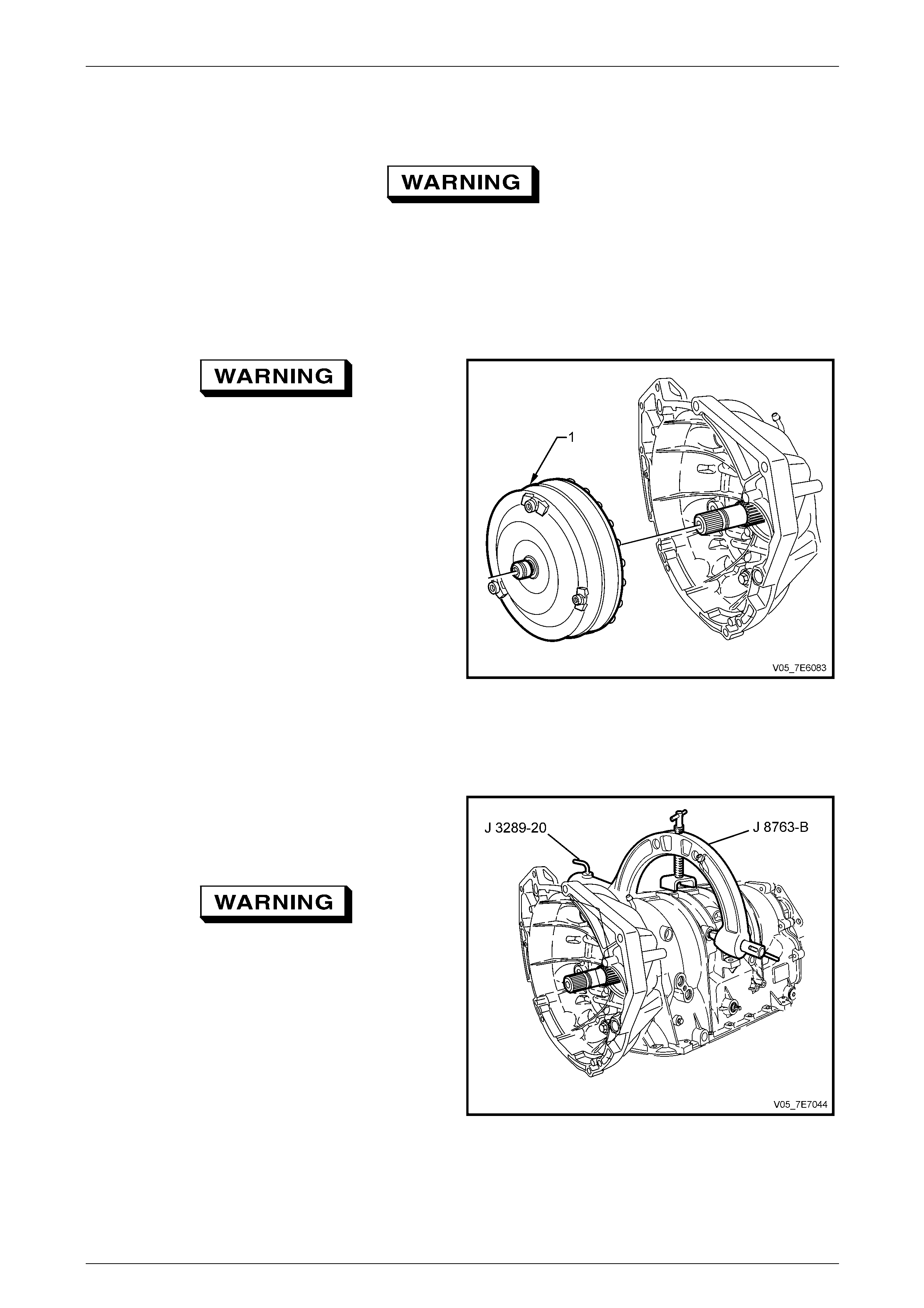
Torque Converter Assembly Removal
Take care when removing the torque
converter as it is a heavy assembly
(approximately 12 kilograms) and personal
injury may result if lifted incorrectly.
1 Remove the torque converter assembl y (1) by sliding
clear of input turbine shaft. Drain stored converter fluid
into a suitable container.
Figure 7E5 – 1
Holding Fixture Installation
1 Plug all transmission ope nings and thoroughly clean
the exterior of the transmission.
2 Install the transmission holding fixture (2) J 8763-02
(or E1363) as shown onto the transmission assembly.
Take care when installing the transmission to
the tool base. Use suitable lifting equipment
as the transmission assembly without the
torque converter is still a heavy assembly
(approximately 70 kilograms) and personal
injury may result if lifted incorrectly.
Also, be mindful that the weight of the
transmission, could tip the workbench over.
3 Install the transmission assembl y and holding fixture
into the tool base and use the pin (1) to lock the
holding fixture i n place. Figure 7E5 – 2

Automatic Transmission – 5L40–E – Unit Repair 7E5 – 6
7E5 – 6
4 Using a fine bladed screwdriver, lever out and remove
the input turbine shaft seal (430).
NOTE
If the O-ring seal is not removed at this time,
then removal of the torque co nverter housing will
not be possible.
Figure 7E5 – 3
Draining Transmission Fluid
1 Using a T-45 Torx bit and suitable equipment, remove
the fluid pan drain plug (63) a nd seal (64), and allow
the transmission fluid to drain in to a suitable sized
container (approximatel y 6 litr es).
Figure 7E5 – 4
2 Put transmission in Park.
3 Remove the propeller shaft flange n ut (34), u s ing a 30
mm deep socket and suitable equ ipment.
4 Remove the dished washer (33) from the transmission
output shaft.
5 Remove the propeller shaft flange (3 1) and O-ring seal
(32) from the transmission output shaft. Using a small
screwdriver blade, remove the O-ring seal (3 2) and
discard.
6 Remove holding fixture tool base pin and slowly rotate
the transmission and holding fixture to a vertic al
position, with the torque converter housin g facing up.
Re–insert tool base pin with transmission in this
position and allow any excess fluid to drain into the
suitable container.
Figure 7E5 – 5
Automatic Transmission – 5L40–E – Unit Repair 7E5 – 7
7E5 – 7
1.3 Extension Housing
Remove
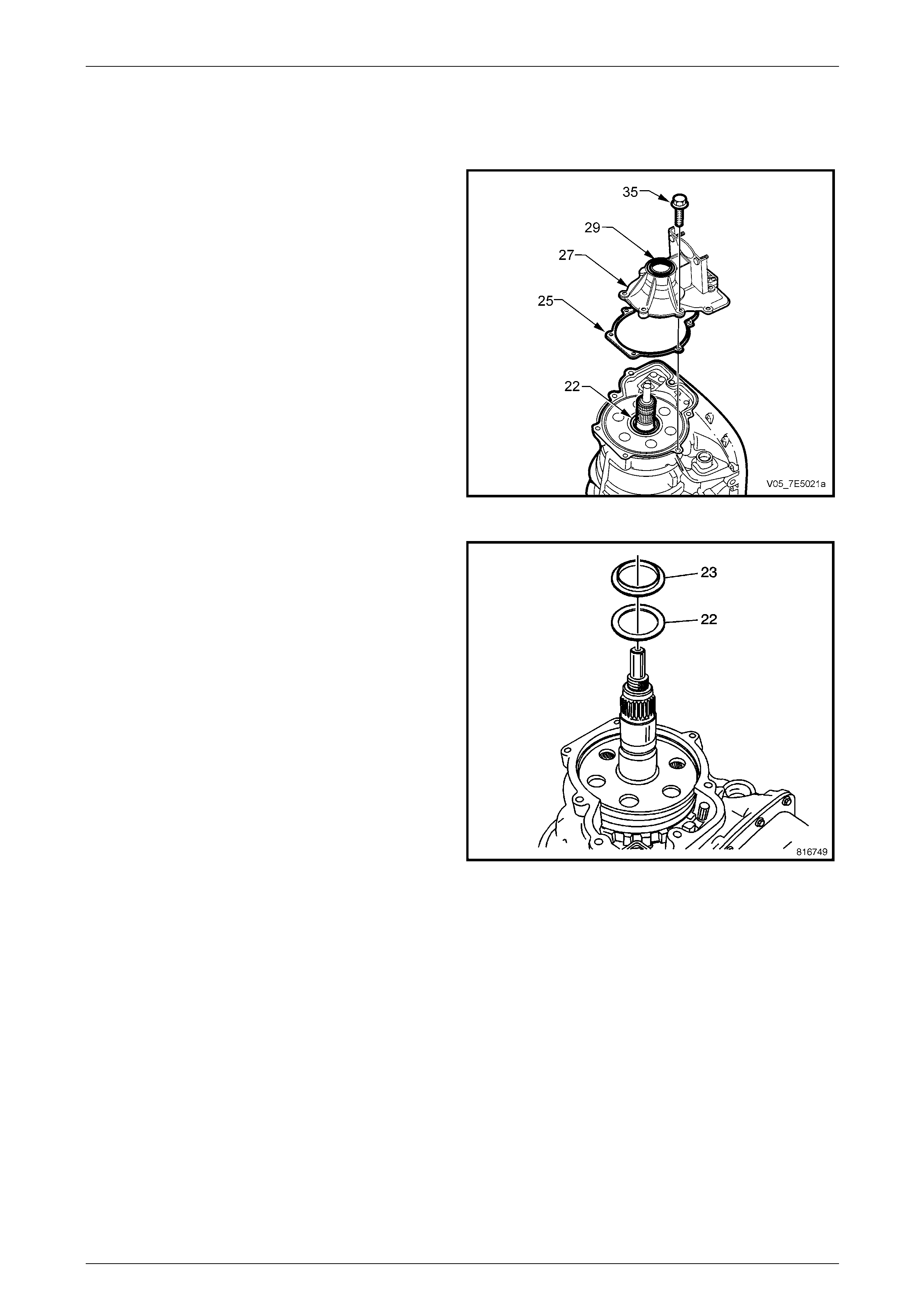
1 Rotate the transmission through 180° to a vertical
position with the extension housing facing up.
2 Using seal remover E308 (or commercial equivalent)
and suitable socket equipment, remove the propeller
shaft flange oil seal (29).
3 Using suitable snap ring pliers remove the output shaft
assembly retainer (30) (refer Figure 7E5-5).
4 Remove the extension housin g bolts (35).
5 Remove the extension housin g (27).
6 Remove the extension housing gasket (25).
Figure 7E5 – 6
7 If not retained in the extension housing on removal,
remove the input and reaction carrier thrust bearing
(23) and selective washer (22), from the output shaft
assembly.
NOTE
If the thrust bearing and washer are not removed
at this time, they will probably fall off when the
transmission is rotated for other procedures.
Figure 7E5 – 7
Automatic Transmission – 5L40–E – Unit Repair 7E5 – 8
7E5 – 8
1.4 Pan and Filter Assembly
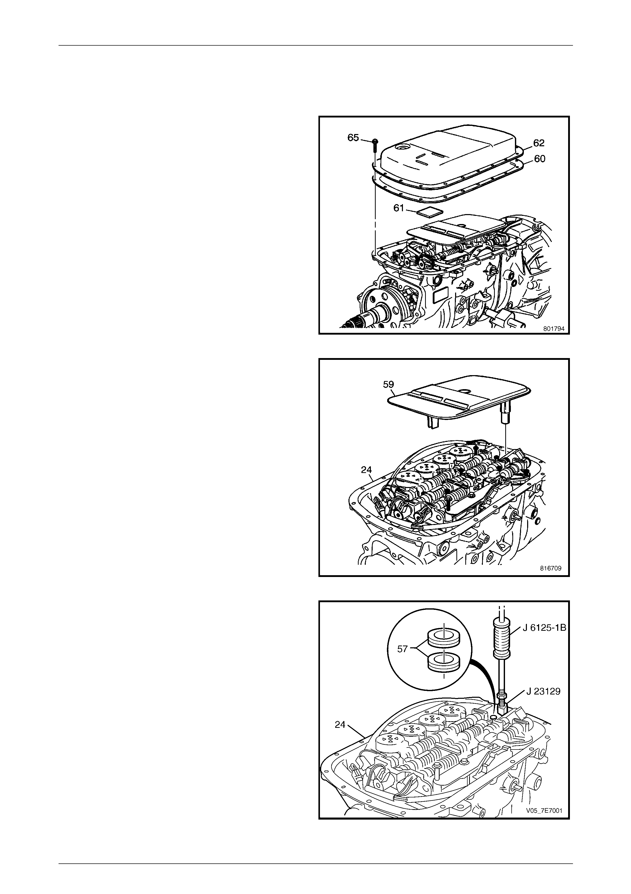
Removal
1 Remove holding fixture tool base pin and slowly rotate
the transmission and holding fixture so that the fluid
pan (62) is facing up.
Re–insert tool base pin with transmission in this
position.
2 Remove the 10 mm hexagon headed fluid pan bolts
(65), the fluid pan (62) and the gasket (60).
Figure 7E5 – 8
3 Remove the fluid filter (59) from the case (24).
NOTE
Fluid seals (57) will probably remain in the
transmission case (24) after fluid filter (59) has
been removed.
Figure 7E5 – 9
4 Assemble universal seal remover tool J 23129 and
slide hammer tool J 6125-1B together to remove the
fluid filter seals (57) from the case (24).
Figure 7E5 – 10
Automatic Transmission – 5L40–E – Unit Repair 7E5 – 9
7E5 – 9
1.5 Wiring Harness
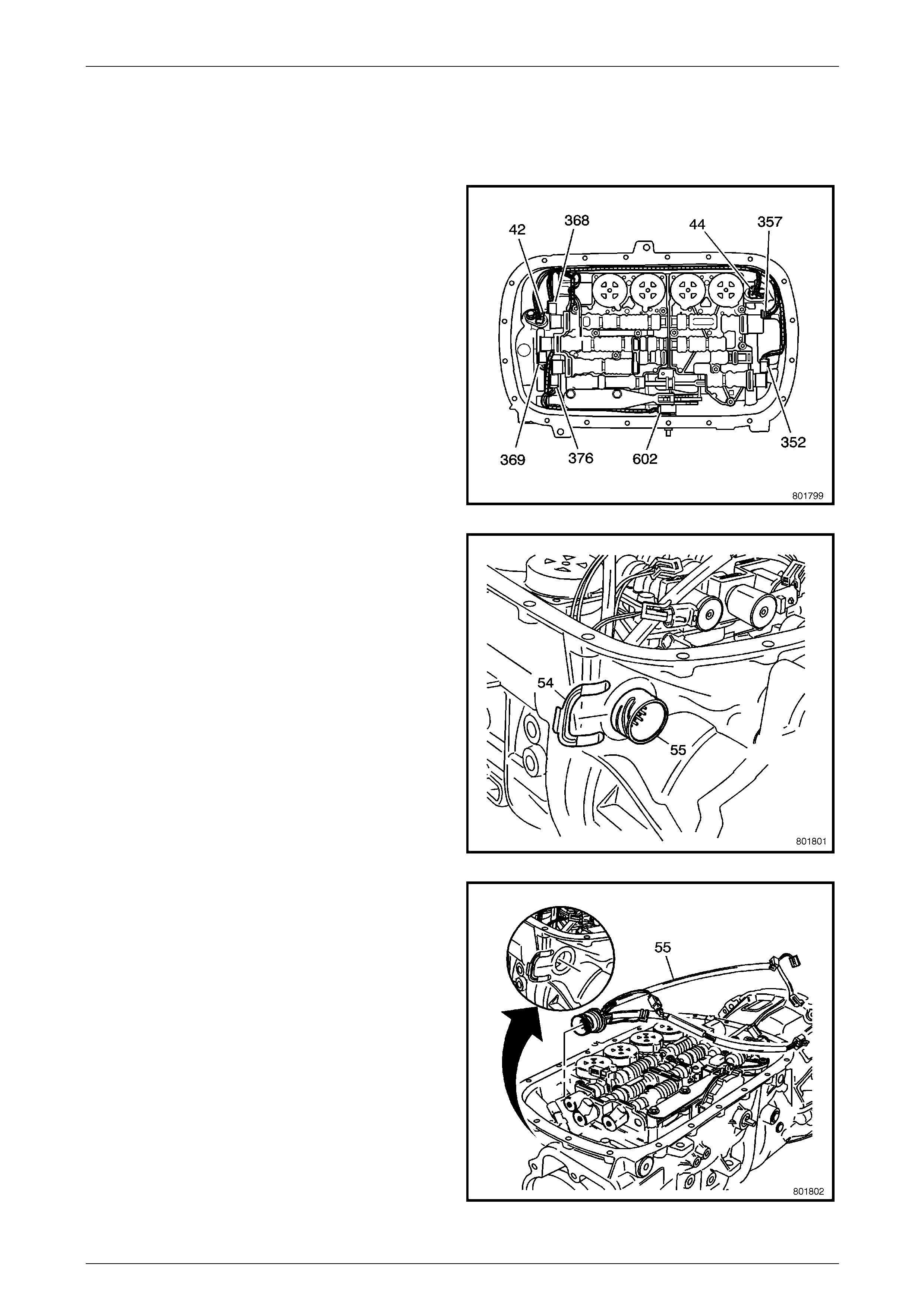
Remove
1 Using a small scre wdriver to lift the transmission
connector locking tangs, remove the wiring harness
connectors from the following components:
• Pressure Control Solenoid (3 57)
• TCC PWM Solenoid (352)
• 1–2 Shift Solenoid (368)
• 2–3 Shift Solenoid (369)
• 4–5 Shift Solenoid (376)
• Manual Shift Shaft Switch (602)
• Input Speed Sensor (44)
• Output Speed Sensor (42)
Figure 7E5 – 11
2 Using a flat bladed screwdriver, remove the connector
retainer (54) from the transmission case (24).
Figure 7E5 – 12
3 Remove the wiring harness (55) from the transmission
case (24).
Figure 7E5 – 13
Automatic Transmission – 5L40–E – Unit Repair 7E5 – 10
7E5 – 10
1.6 Control Valve Body and Accumulator
Assembly
Remove
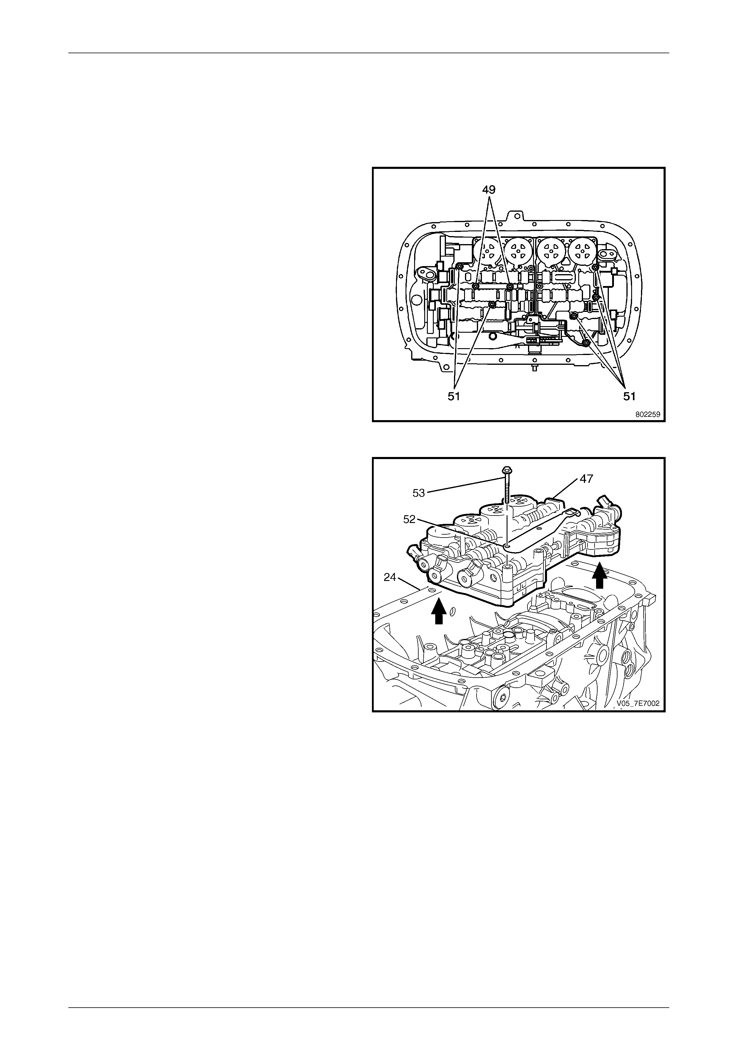
1 Remove the E8 Torx headed control valve body bolts
(49, 51).
NOTE
Only remove the bolts (49, 51) nominated in
Figure 7E5-13. Do not remov e the t wo remaining
TX-30 Torx screws at this stage.
Figure 7E5 – 14
2 Remove the 10 mm hexagon headed control valve
body bolts (53).
3 Remove the manual shaft detent lever sprin g
assembly (52).
4 Remove the control valve body and accumulator
assembly (47) from the transmission case (24).
Figure 7E5 – 15
Automatic Transmission – 5L40–E – Unit Repair 7E5 – 11
7E5 – 11
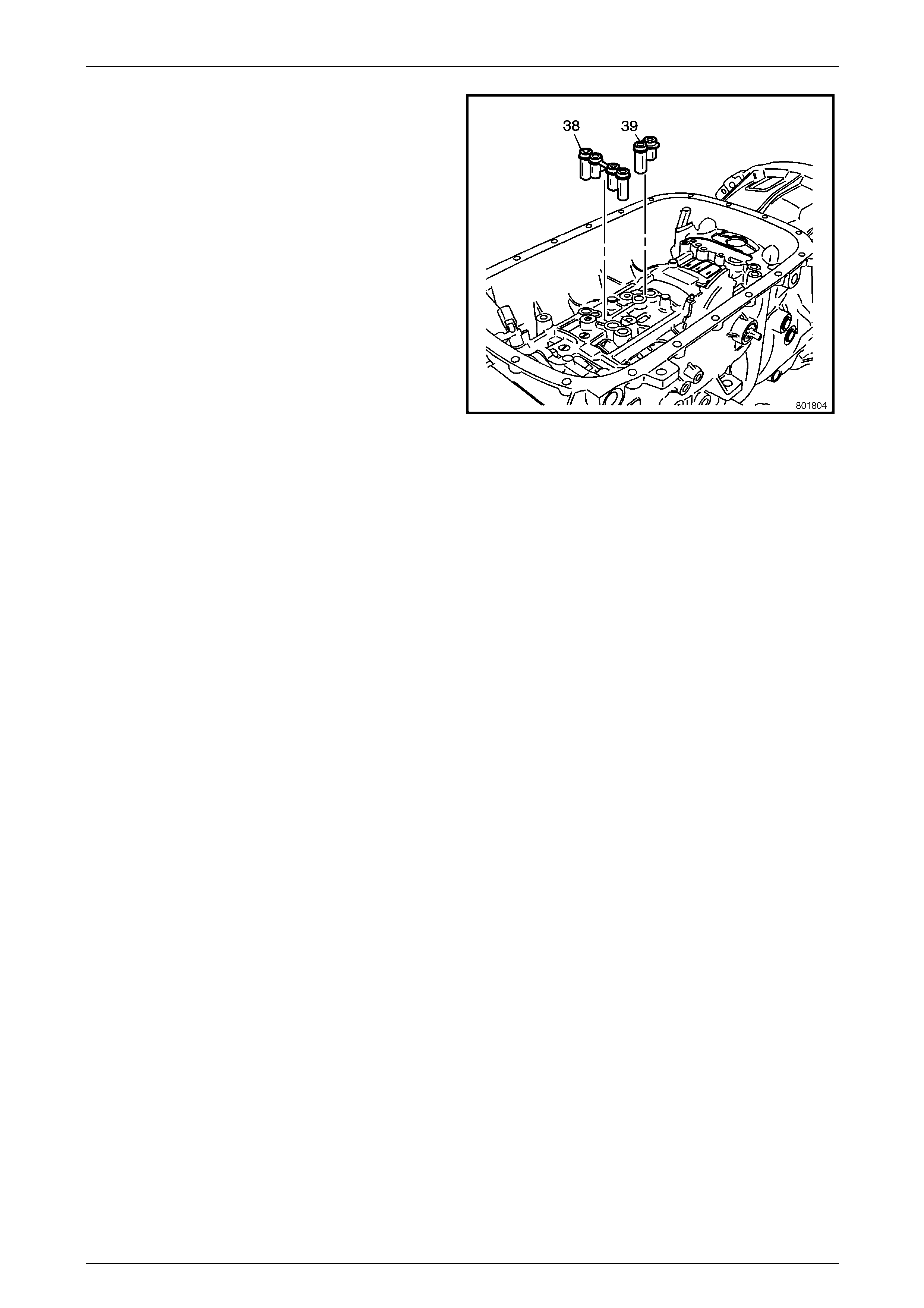
5 Remove the centre support fluid pass ag e sle eve (38)
and the overdrive clutch fluid passage sleeve (39)
from the transmission case (24).
Figure 7E5 – 16
Automatic Transmission – 5L40–E – Unit Repair 7E5 – 12
7E5 – 12
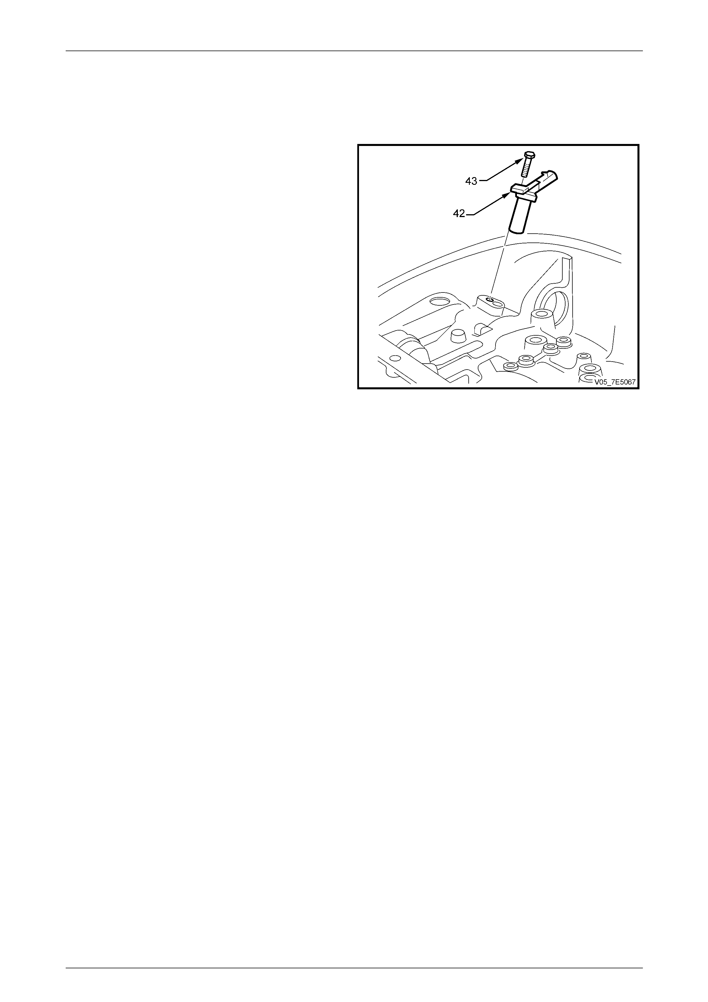
1.7 Output Shaft Speed Sensor
Remove
1 Remove the 10 mm headed output speed sensor
screw (43).
2 Remove the output speed sensor (42).
Figure 7E5 – 17
Automatic Transmission – 5L40–E – Unit Repair 7E5 – 13
7E5 – 13
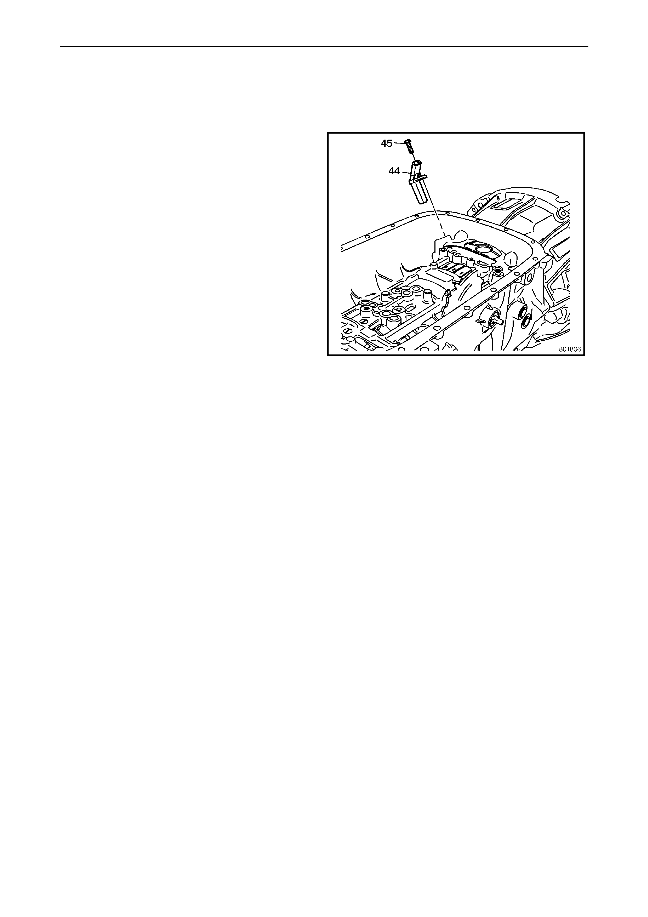
1.8 Input Speed Sensor
Remove
1 Remove the 10 mm hexagon headed input speed
sensor bolt (45).
2 Remove the input speed sensor (44) from the case
(24).
Figure 7E5 – 18
Automatic Transmission – 5L40–E – Unit Repair 7E5 – 14
7E5 – 14
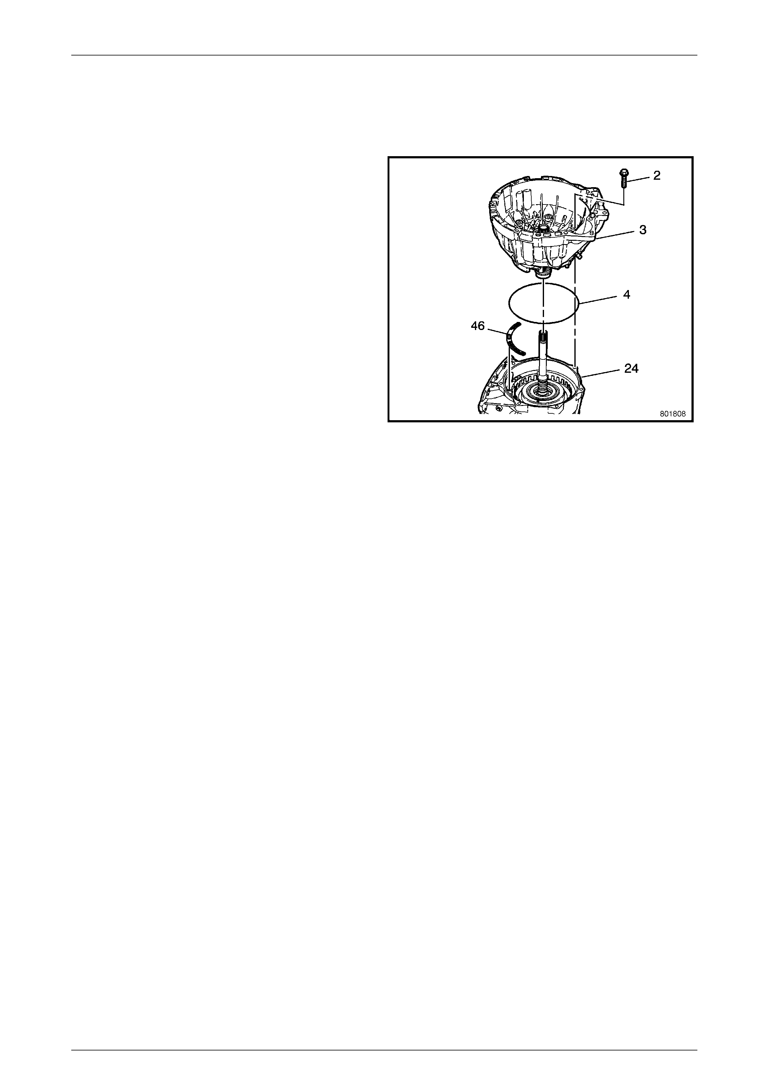
1.9 Torque Converter Housing
Removal
1 Rotate the transmission assembly 90° so the torque
converter housing is facing up . Remove the torque
converter housing to transmission case bolts (2) from
the torque converter housing (3).
2 Remove the torque converter housing assembly (3)
from the transmission case (24).
NOTE
The transmission fluid pump is attached to the
torque converter housing, making the assembly
heavier than expected.
3 Remove the torque converter housing fluid seal
assembly (4).
4 Remove the fluid pump cover gasket (46).
Figure 7E5 – 19
Automatic Transmission – 5L40–E – Unit Repair 7E5 – 15
7E5 – 15
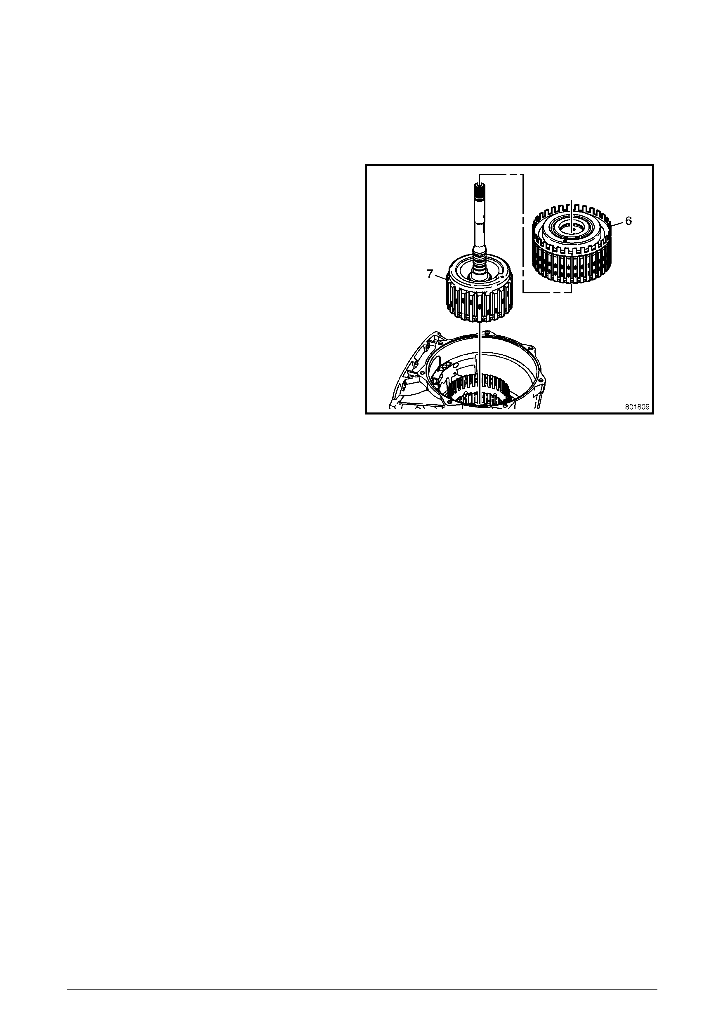
1.10 Direct and Reverse Clutch - Forward and
Coast Clutch
Remove
1 Remove the forward and coast clutch assembly (7)
and the direct and reverse clutch assembly (6) from
the case (24).
NOTE
Do not damage the input shaft fluid seals when
removing or installing the direct and reverse
coast clutch assembly.
2 Lift the direct and reverse clutch assembly (6) off of
the forward and coast clutch assembly (7).
Figure 7E5 – 20
Automatic Transmission – 5L40–E – Unit Repair 7E5 – 16
7E5 – 16
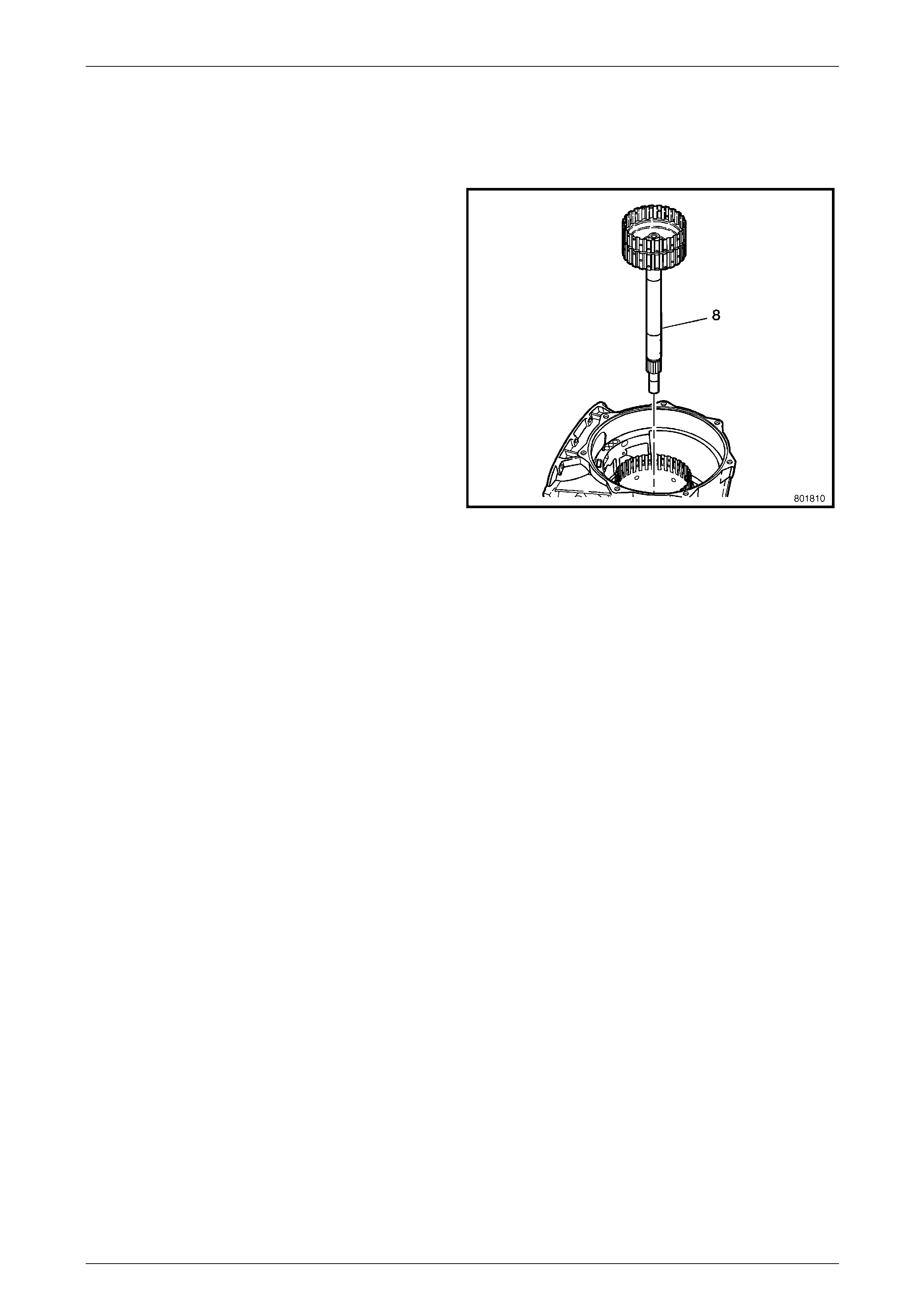
1.11 Input Sun Gear Shaft
Remove
1 Remove the input sun gear shaft (8) from the case
(24).
Figure 7E5 – 21
Automatic Transmission – 5L40–E – Unit Repair 7E5 – 17
7E5 – 17
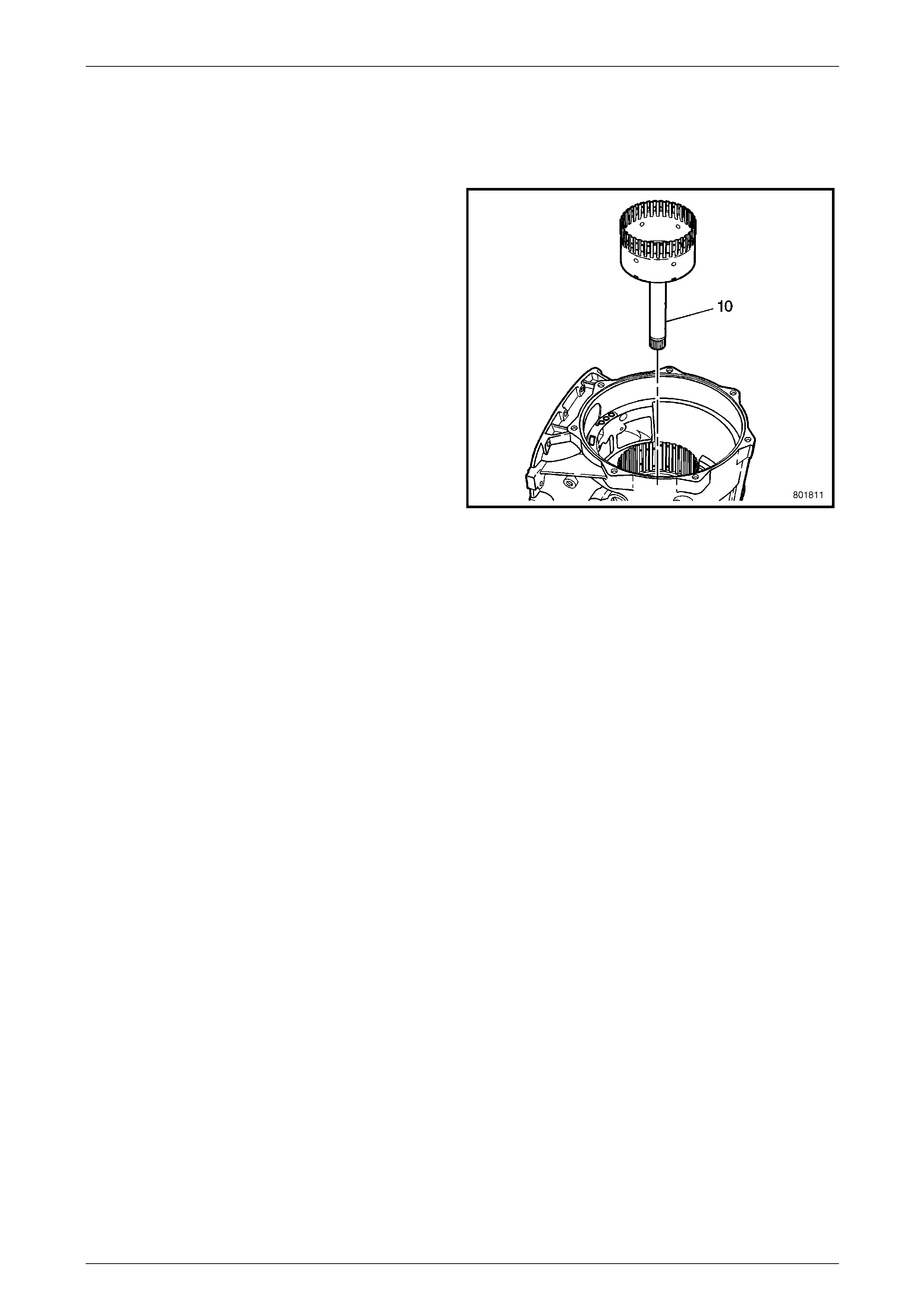
1.12 Direct Clutch Hub
Remove
1 Remove the direct clutch hub assembly (10) from the
case (24).
Figure 7E5 – 22
Automatic Transmission – 5L40–E – Unit Repair 7E5 – 18
7E5 – 18
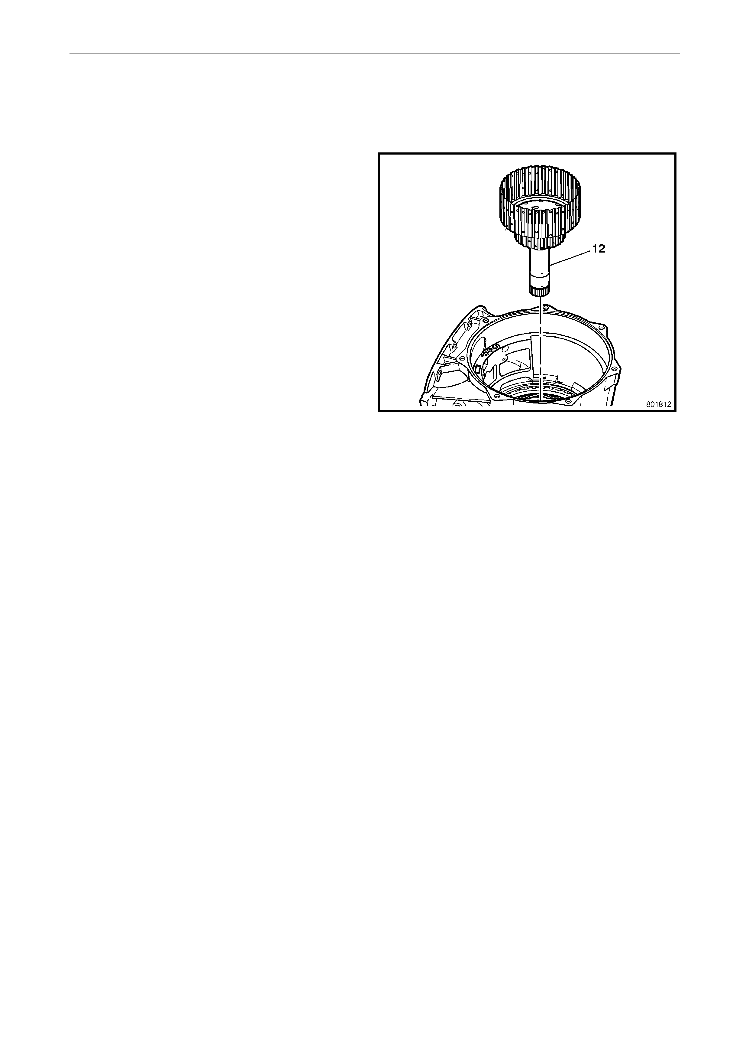
1.13 Intermediate Clutch Sprag Assembly
Remove
1 Remove the intermediate clutch sprag assembly (12)
from the case (24).
Figure 7E5 – 23
Automatic Transmission – 5L40–E – Unit Repair 7E5 – 19
7E5 – 19
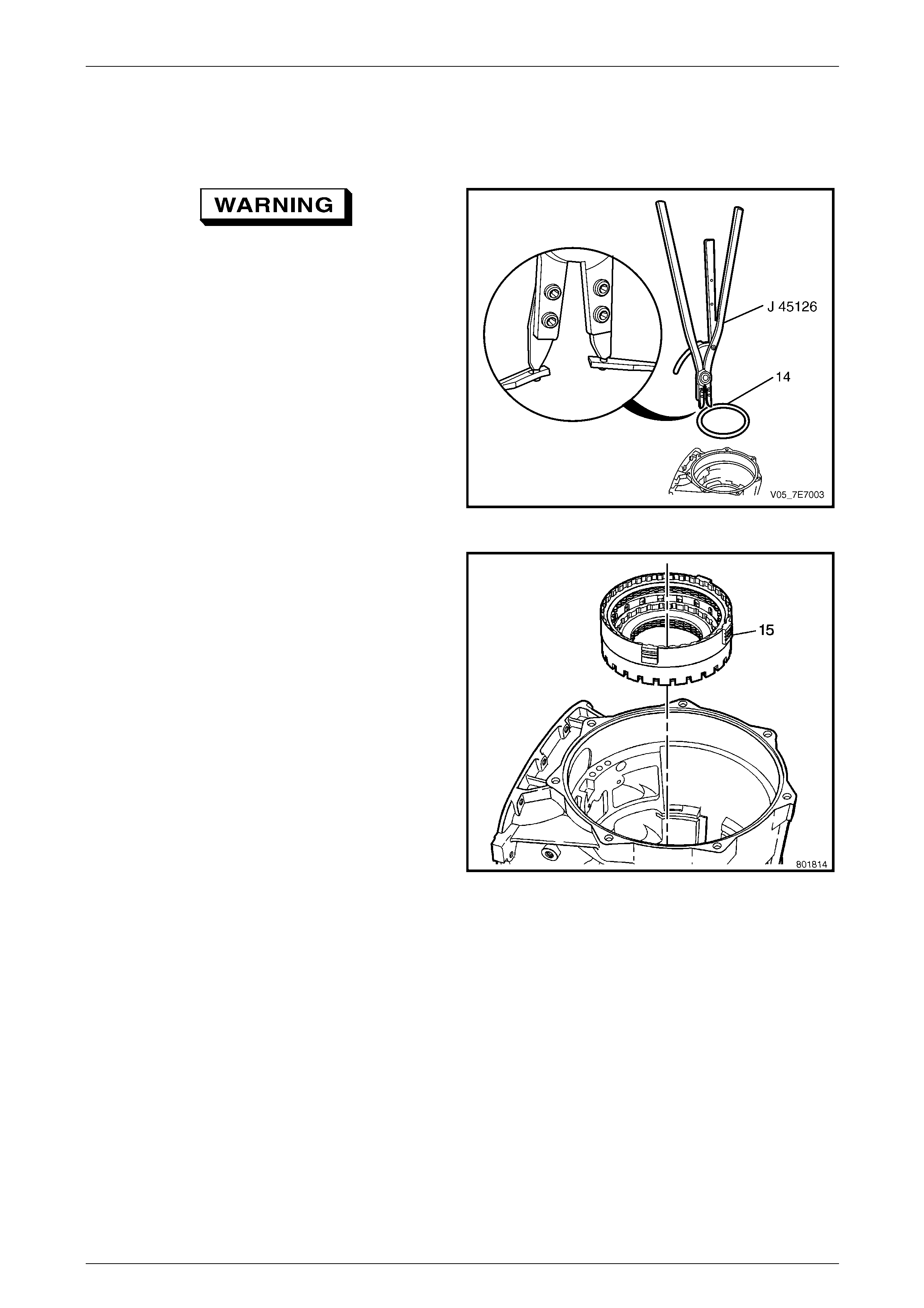
1.14 Overdrive Clutch Housing
Remove
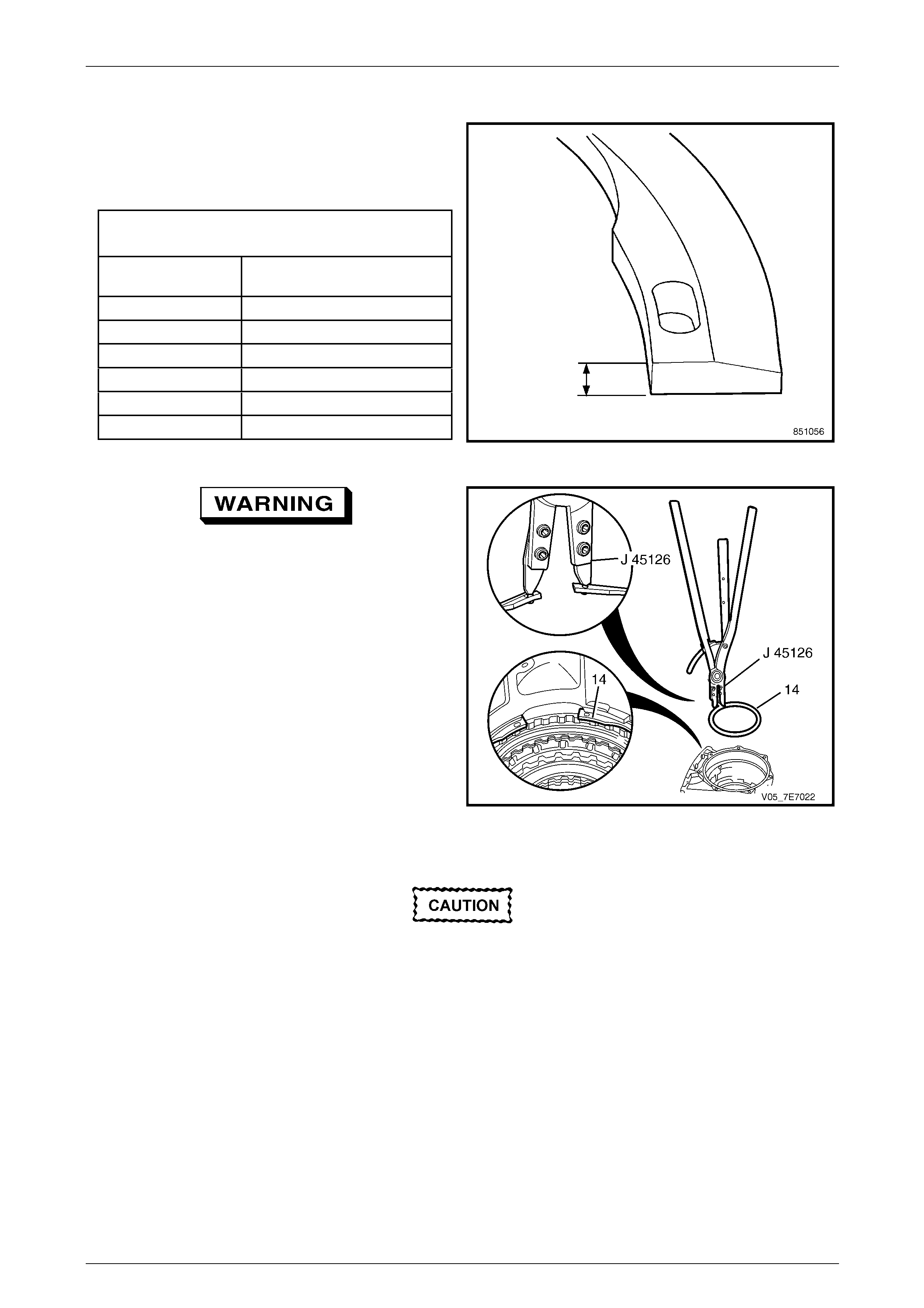
Use care when removing or installing the
snap ring. Be sure the J 45126 snap ring
pliers are installed properly onto the retainer
ring or bodily injury may occur.
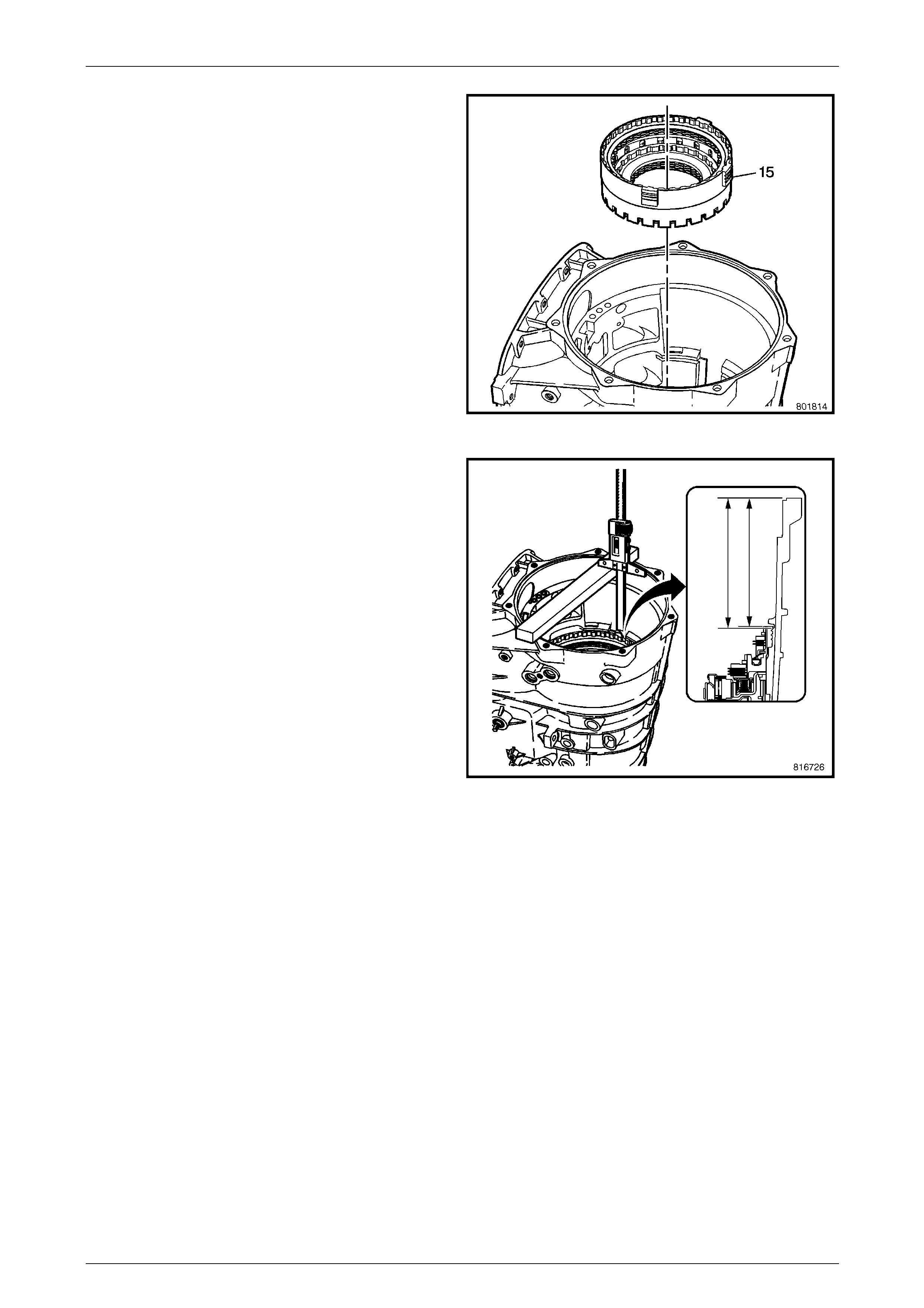
1 Using suitable snap ring pliers such as J 45126 or
equivalent, remove overdrive clutch housing to
transmission case retainer ring (14).
Figure 7E5 – 24
2 Lift out the overdrive clutch housing (15) from the
transmission case (24).
Figure 7E5 – 25
Automatic Transmission – 5L40–E – Unit Repair 7E5 – 20
7E5 – 20
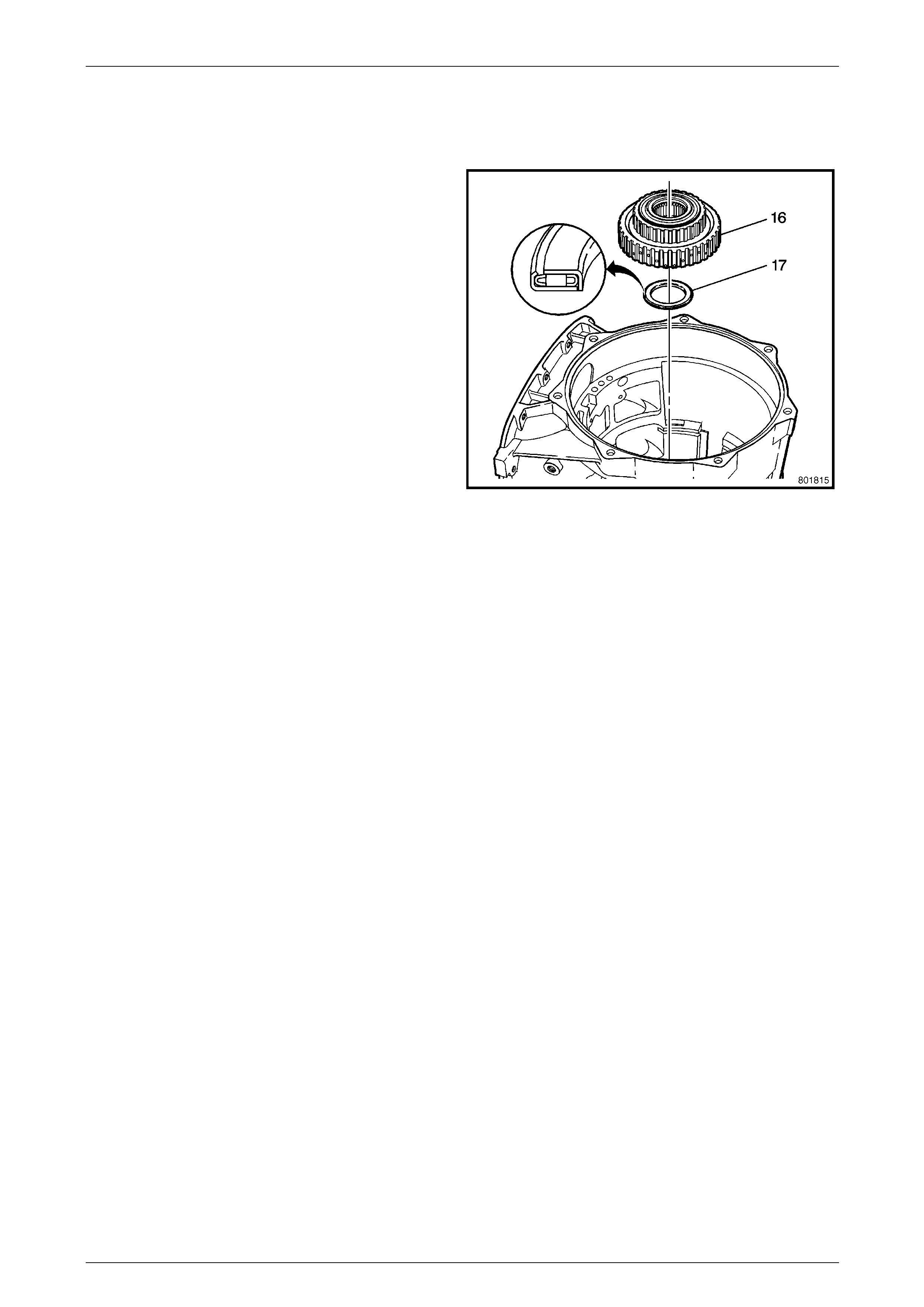
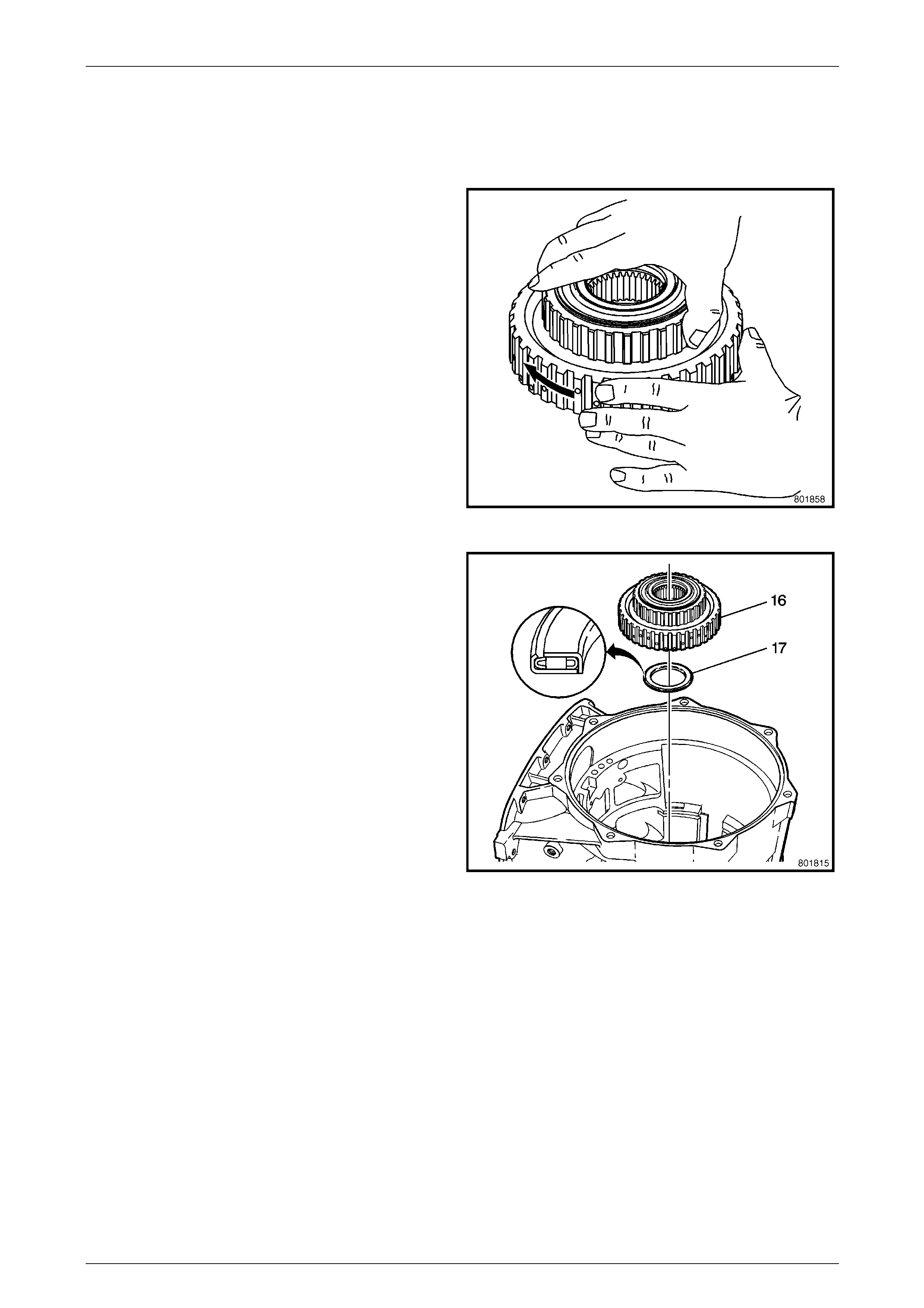
1.15 Low Clutch Sprag
Removal
1 Remove the low clutch sprag assembly (16) from the
transmission case (24).
2 Remove the low clutch roller thrust bearing (17).
Figure 7E5 – 26
Automatic Transmission – 5L40–E – Unit Repair 7E5 – 21
7E5 – 21
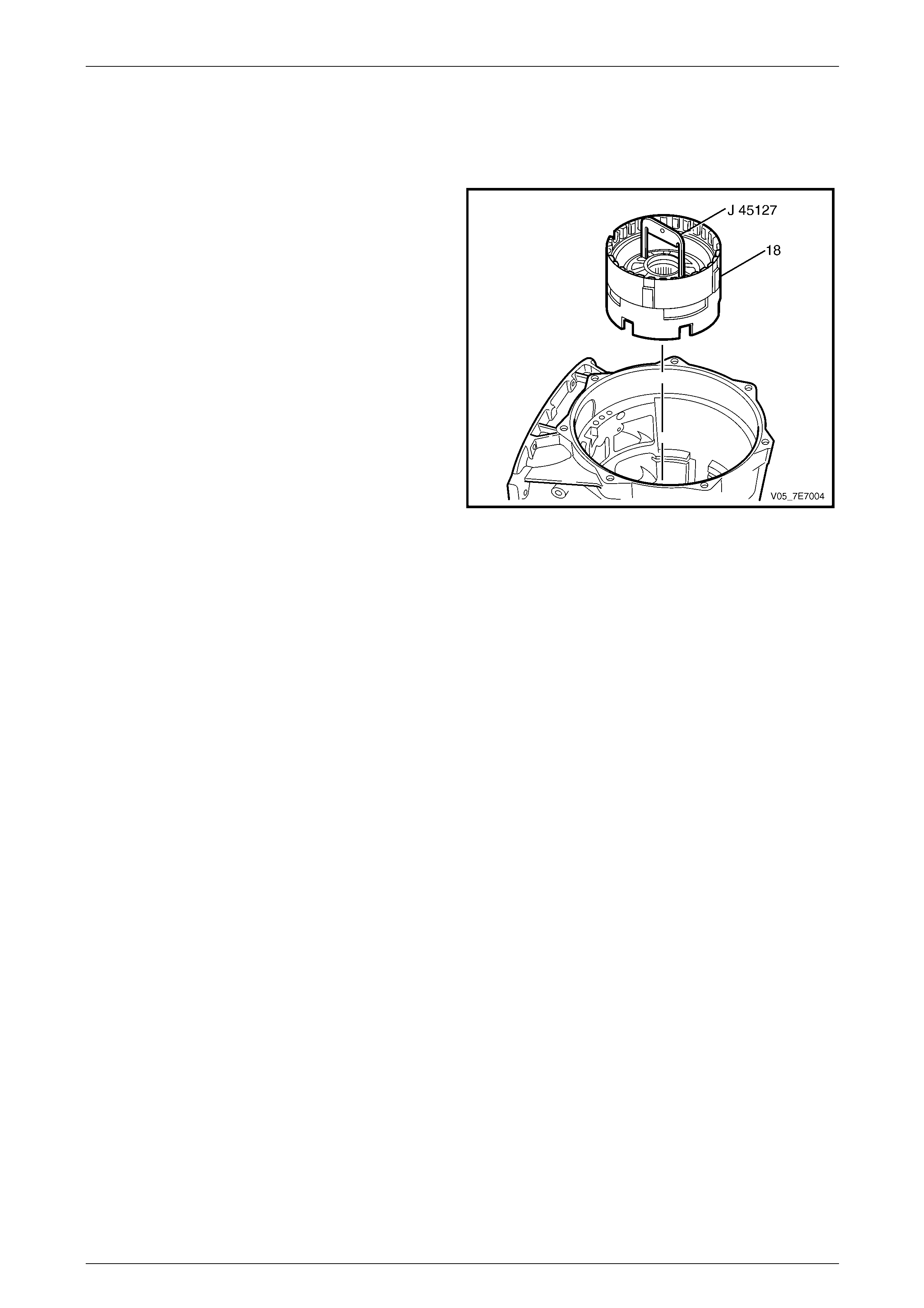
1.16 Centre Support
Remove
1 Using centre support removal tool J 45127, engage
and lift out centre support (18) from the transmission
case (24).
Figure 7E5 – 27
Automatic Transmission – 5L40–E – Unit Repair 7E5 – 22
7E5 – 22
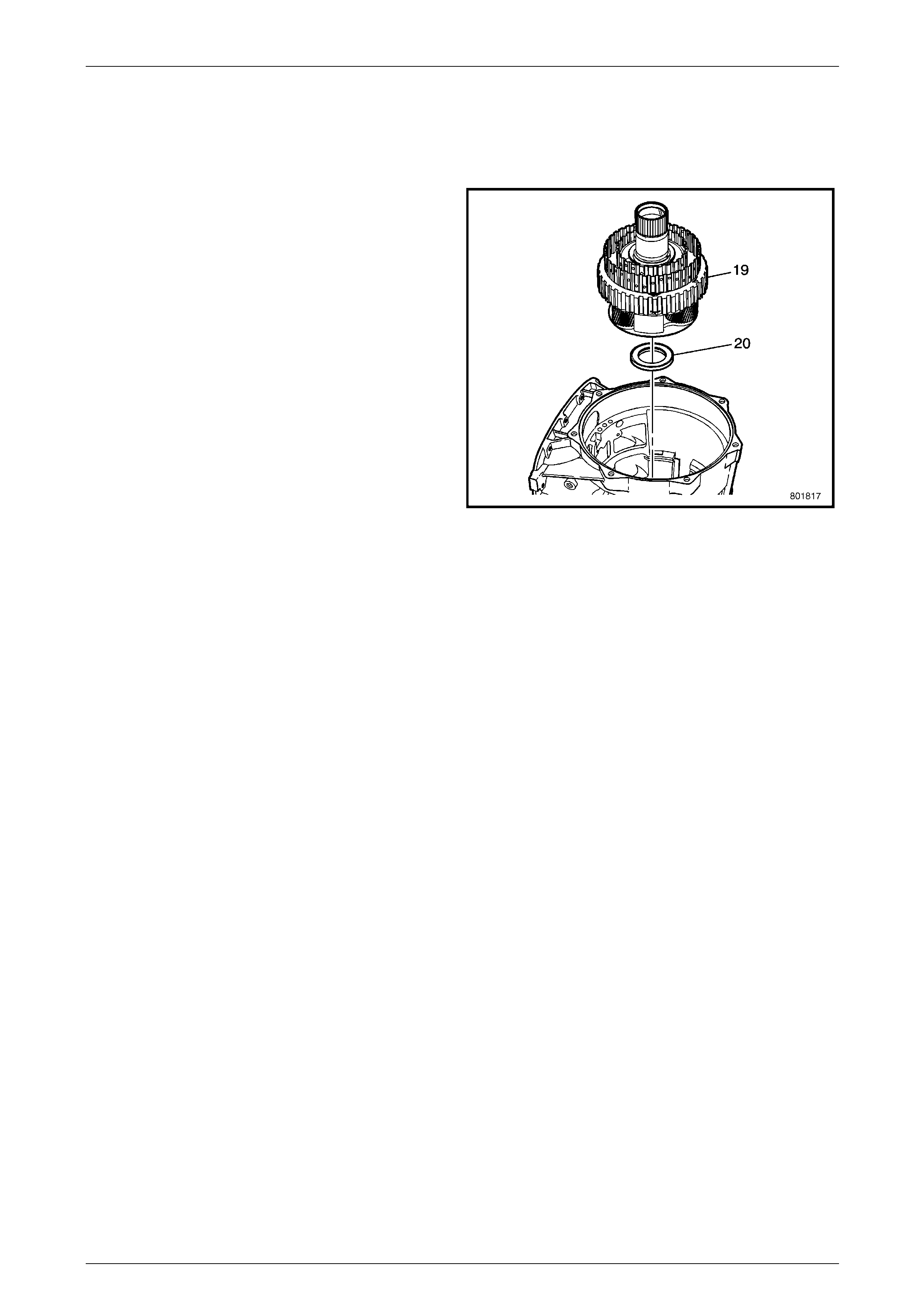
1.17 Input and Reaction Carrier
Remove
1 Remove the input and reaction carrier (19) from the
transmission case (24).
2 Remove the input and reaction carrier thrust bearing
(20) from the case (24).
Figure 7E5 – 28
Automatic Transmission – 5L40–E – Unit Repair 7E5 – 23
7E5 – 23
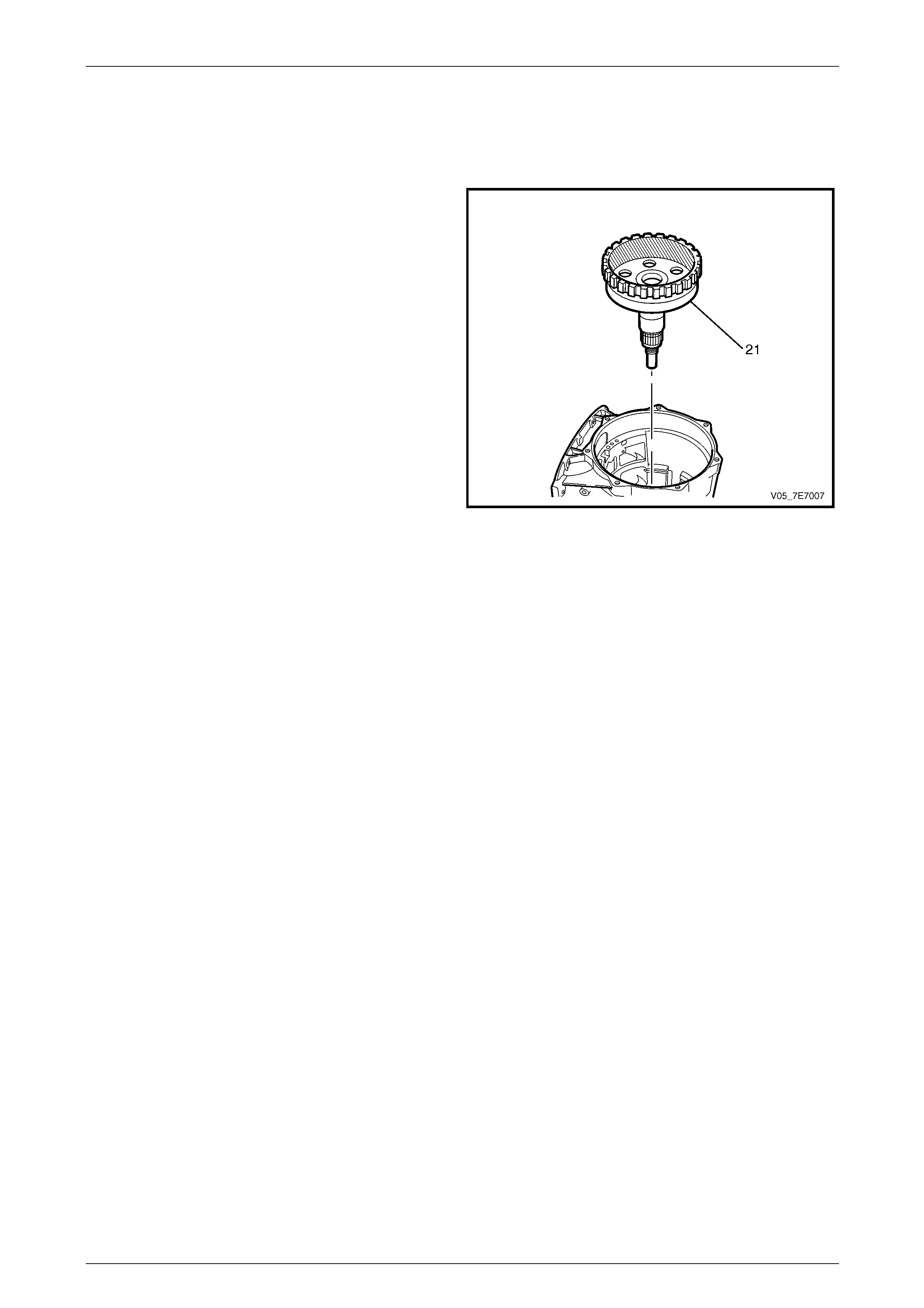
1.18 Output Shaft
Remove
1 Remove the output shaft assembly (21) from the
transmission case (24).
NOTE
The input and r eaction carrier thrust bearin g (23)
and selective washer (22), have already been
removed, refer to 1.3 Extension Housing, in this
Section.
Figure 7E5 – 29
Automatic Transmission – 5L40–E – Unit Repair 7E5 – 24
7E5 – 24
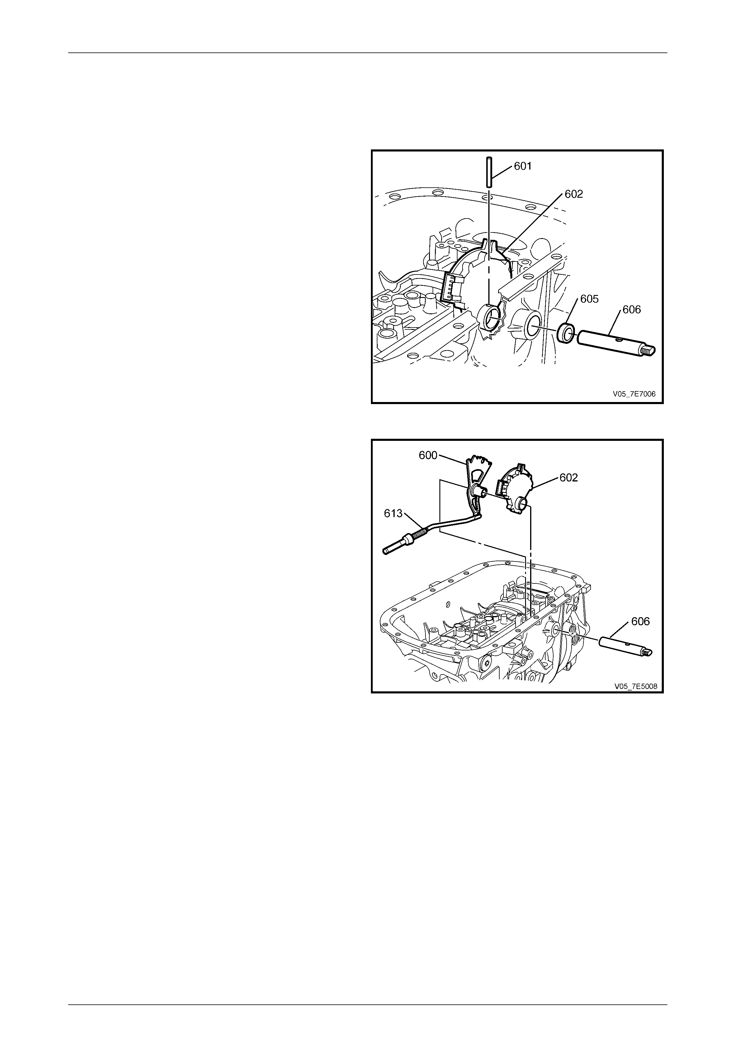
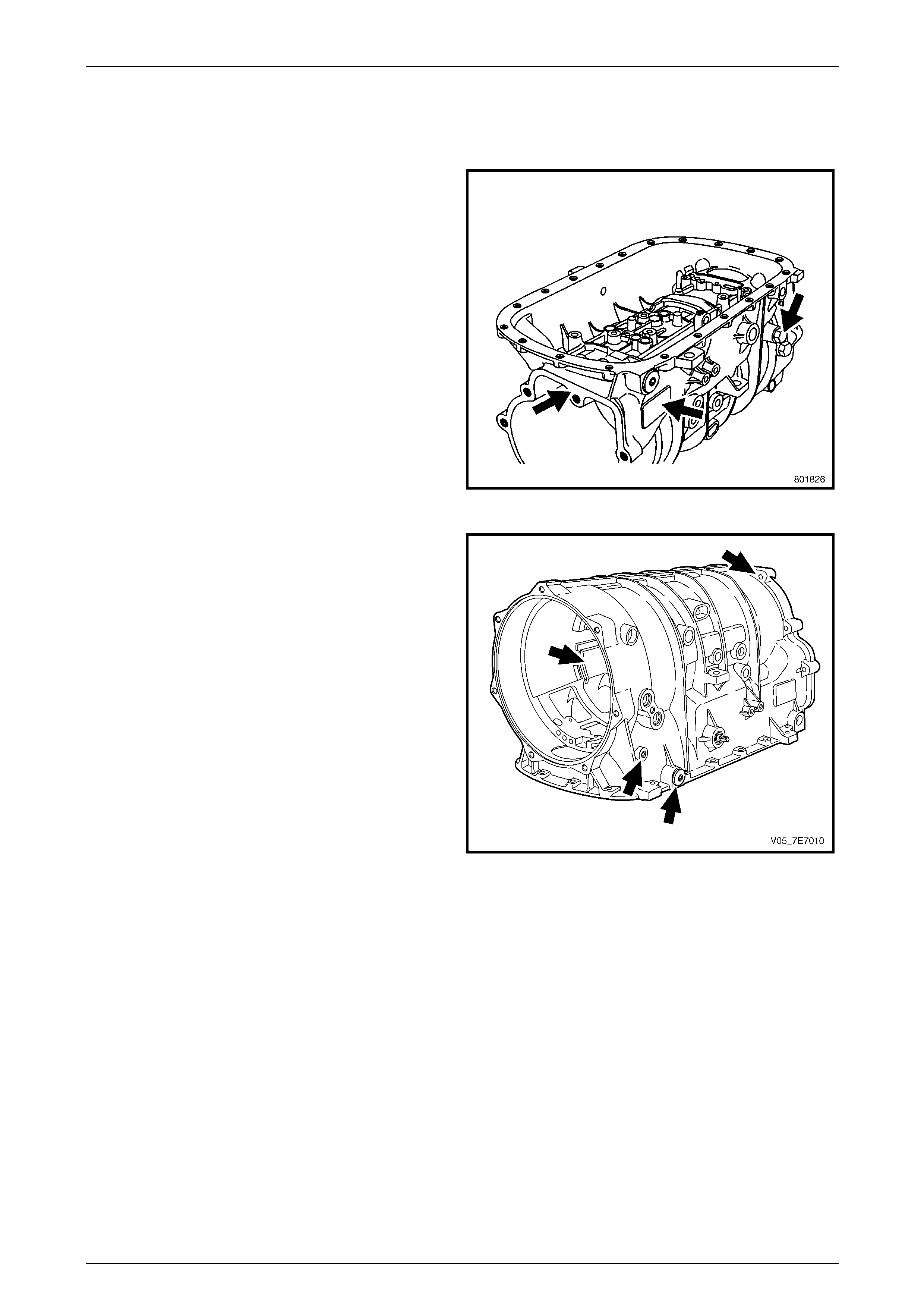
1.19 Park System Components
Remove
1 Rotate the transmission 90 degrees, so the underside
of the transmission case is facing up ward.
2 Using a suitable sized pin punch and hammer,
carefully knock out the manual shaft detent le ver pin
(601) from the manual shaft (606).
Figure 7E5 – 30
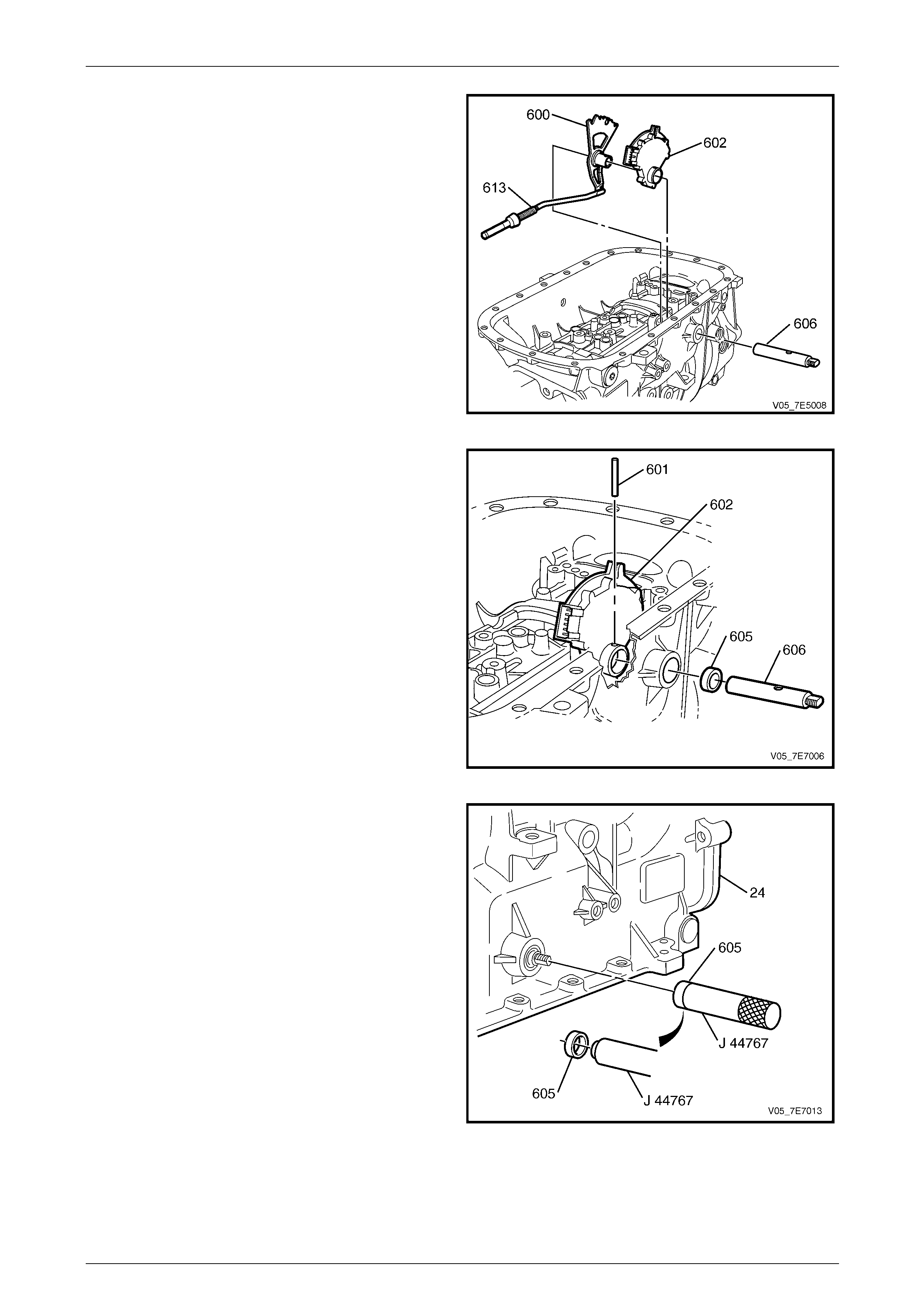
3 Remove the manual shift shaft (606) from the
transmission case (24).
4 Remove the manual shaft detent lever (600), the
manual shaft shift switch assembly (602) and park
pawl actuator assembly (613) from the transmission
case (24).
5 Disconnect the park pawl actuator (613) from the
manual shaft detent lever (600).
Figure 7E5 – 31
Automatic Transmission – 5L40–E – Unit Repair 7E5 – 25
7E5 – 25
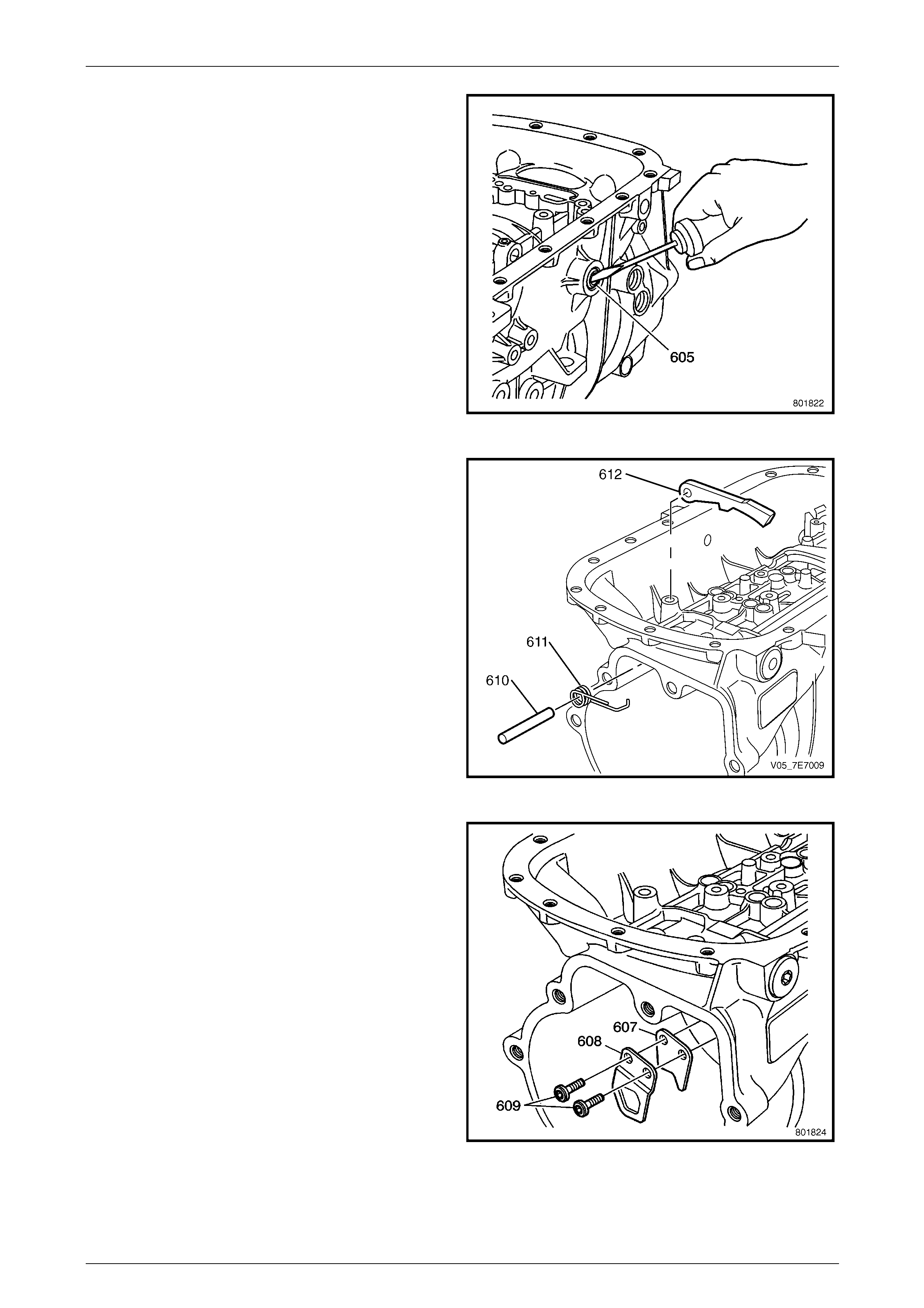
6 Using a small scre wdriver, prise the manu al shaft shift
seal (605) from the transmission case (24).
Figure 7E5 – 32
7 Release the park pawl spring t ension, then remove the
spring (611) from the park pawl shaft (610).
8 Remove the park pawl shaft (610) and the park pawl
(612) from the transmission case (24).
Figure 7E5 – 33
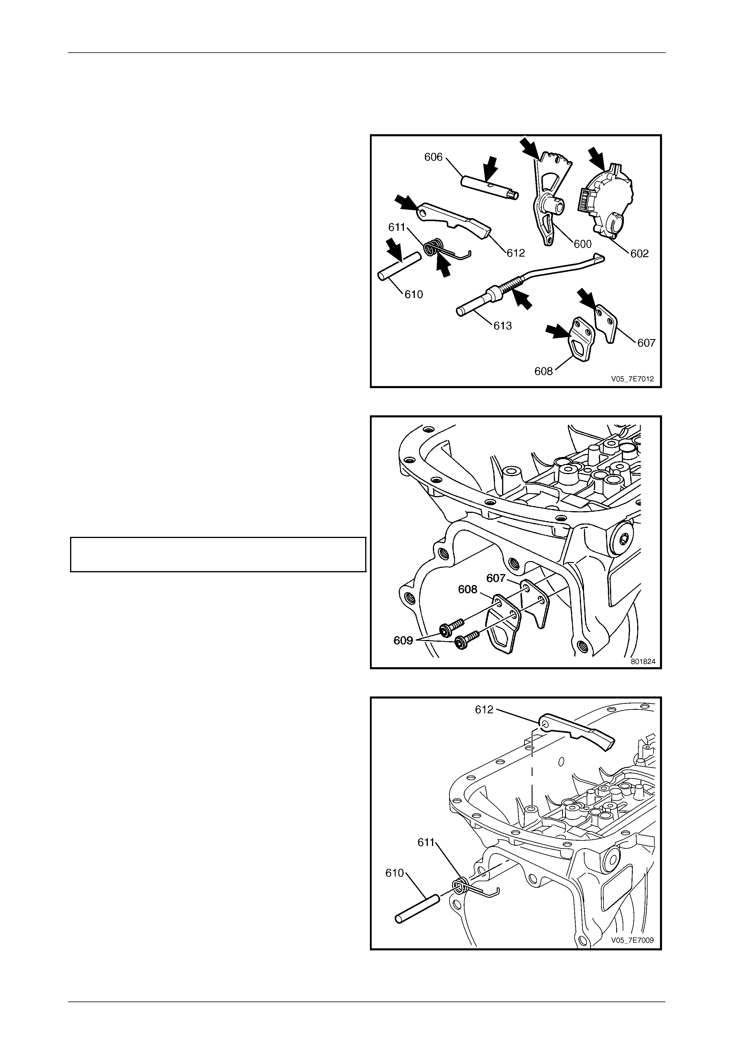
9 Remove the park pawl actuator bracket, internal T45
Torx headed bolts (609) from the transmissi on case
(24).
10 Remove the park pawl actuator brackets (607, 608)
from the transmission case (24).
Figure 7E5 – 34
Automatic Transmission – 5L40–E – Unit Repair 7E5 – 26
7E5 – 26
1.20 Transmission Case Assembly
Inspect
1 Inspect the components that are still on the
transmission case for the following conditions:
• Loose, cross-threaded, or damage d threads on
the transmission oil cooler fittings.
• A loose, missing, or damaged transmission
name plate.
Figure 7E5 – 35
2 Inspect the transmission case for the following
conditions:
• Gasket sealing surfaces that are damaged or
have porosity.
• Bolt and screw holes that are stripped or
damaged – repair with thread insert.
• Damaged or porous case and fluid passages.
• Damaged snap ring grooves or housing splines.
• A loose, cross threaded, or damaged pressure
test plug and fluid level hole plug.
Figure 7E5 – 36
Automatic Transmission – 5L40–E – Unit Repair 7E5 – 27
7E5 – 27
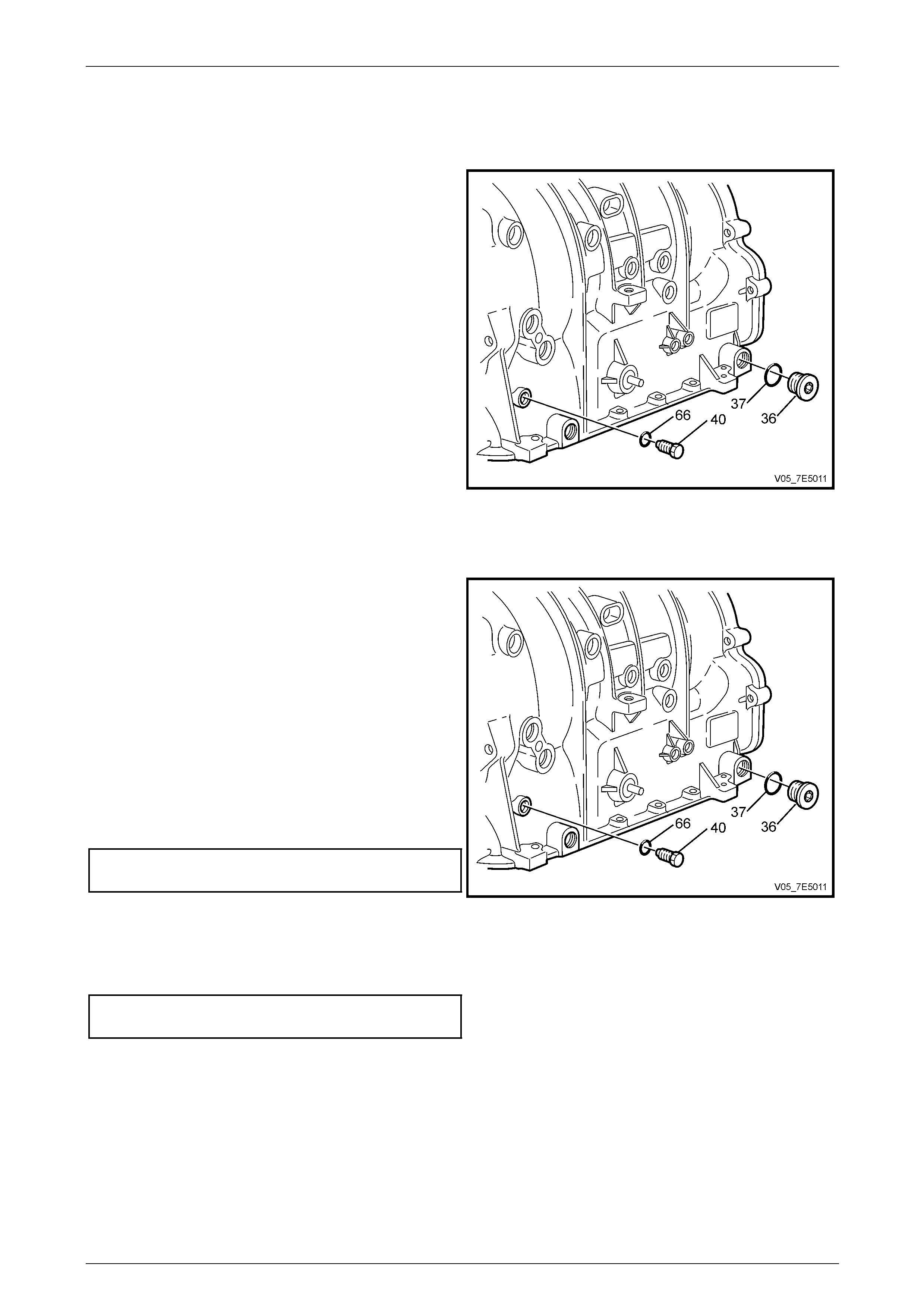
1.21 Transmission Case Components
Disassemble
1 Using a 5 mm Allen key socket and suitable
equipment, remove the pressure test plug (40) and O-
ring seal (66).
2 Use a T45 Torx bit and suit able equipment to remove
the level hole plug (36) and O-ring (3 7) from the
transmission case (24).
Figure 7E5 – 37
Reassemble
NOTE
Refer to 4.30 Fasteners in Section 00 Warnings,
Cautions and Notes of this Service Information.
NOTE
If the pressure test plug (40), O-ring (66), level
hole plug (36) and O-rin g (37) are not damaged,
they may be reused.
1 Inspect the pressure test hole plug (40) and O-ring
(66) for damage.
2 Install the pressure test plug (40) and O-ring (66), then
tighten the plug to the correct torque specification.
Transmission pressure test plug
to case torque specification..................................11 N.m
3 Inspect the level hole plug (36) and O-ring (37) for
damage. Figure 7E5 – 38
4 Reinstall the transmission flu id level hole plug O-ring (37) and the transmission level hole plug (36), then tighten the
plug to the correct torque specification.
Transmission level hole plug
to case torque specification..................................11 N.m
Automatic Transmission – 5L40–E – Unit Repair 7E5 – 28
7E5 – 28
1.22 Park System Components
Reinstall
1 Inspect the park system components for the following:
• Worn park pawl actuator brackets (607, 608).
• A damaged or bent park pa wl actuator assembl y
(613).
• A damaged manual shaft detent lever (600).
• A damaged manual shaft shift switch assembly
(602).
• A worn or stripped manual shaft (606).
• A worn or damaged park pawl shaft (610), park
pawl spring (611), and park pawl (612).
Figure 7E5 – 39
2 Install the park pawl actuator brackets (607, 608) onto
the case (24).
NOTE
Refer to 4.30 Fasteners in Section 00 Warnings,
Cautions and Notes of this Service Information.
3 Reinstall the bracket bolts (609) and tighten to the
correct torque specification.
Park pawl actuator bracket to transmission
case bolt torque specification...............................22 N.m
Figure 7E5 – 40
4 Install the park pawl (612), the park pawl shaft (610)
and the park pawl spring (611) into the case (24).
Figure 7E5 – 41
Automatic Transmission – 5L40–E – Unit Repair 7E5 – 29
7E5 – 29
5 Assemble the park pawl actuator (613) to the detent
lever (600).
6 Assemble the shift switch assembly (602) to the detent
lever (600).
7 Reinstall the shift switch assembly (602), detent lever
(600) and park pawl actuator (613) into the
transmission case (24).
8 Reinstall the manual sh aft (606) into the case (24).
Figure 7E5 – 42
9 Align the groove for a NEW manual shaft pin (601)
with the pin hole in the detent lever/shift switch
assembly.
10 Install the NEW manual shaft pin (601) into the manual
shift shaft (606), using a suitable sized pin punch and
hammer.
Figure 7E5 – 43
11 Install a NEW manual shaft seal (605) onto J 44767.
12 Use J 44767 to install the NEW manual shaft seal
(605) into the case (24).
Figure 7E5 – 44
Automatic Transmission – 5L40–E – Unit Repair 7E5 – 30
7E5 – 30
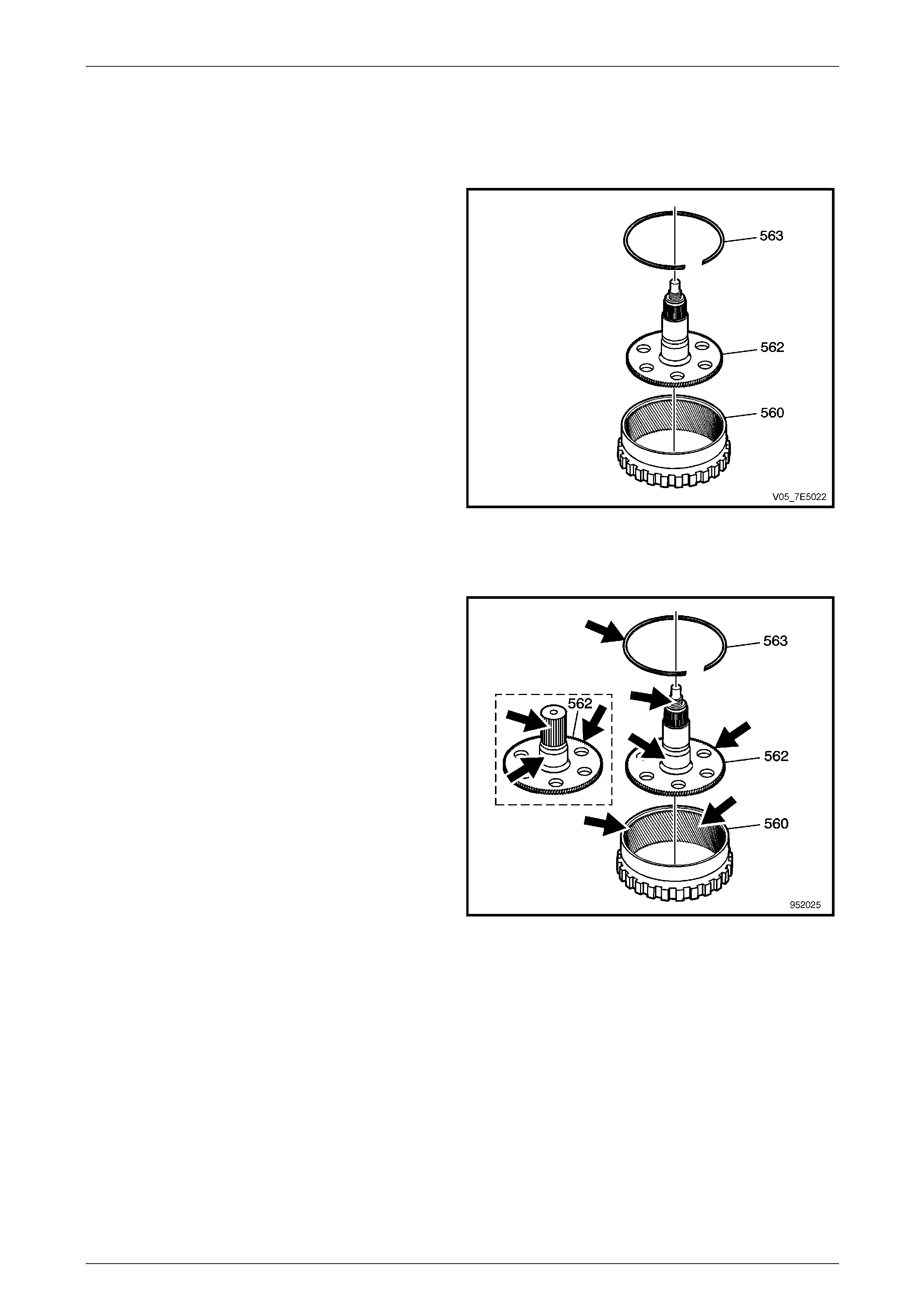
1.23 Output Shaft and Rear Internal Ring Gear
Disassemble
1 Remove the snap ring (563).
2 Remove the output shaft (562) from the rear internal
gear (560).
Figure 7E5 – 45
Reassemble
1 Inspect the output shaft (562) and the rear internal
gear (560) for the following:
• Damaged or worn bushings
• Damaged splines
• Damaged or worn snap ring (563)
• Damaged or worn gear teeth
• Damaged or worn snap ring groove
• Damaged or cross-threaded threads
• Damaged or worn bearings
Figure 7E5 – 46
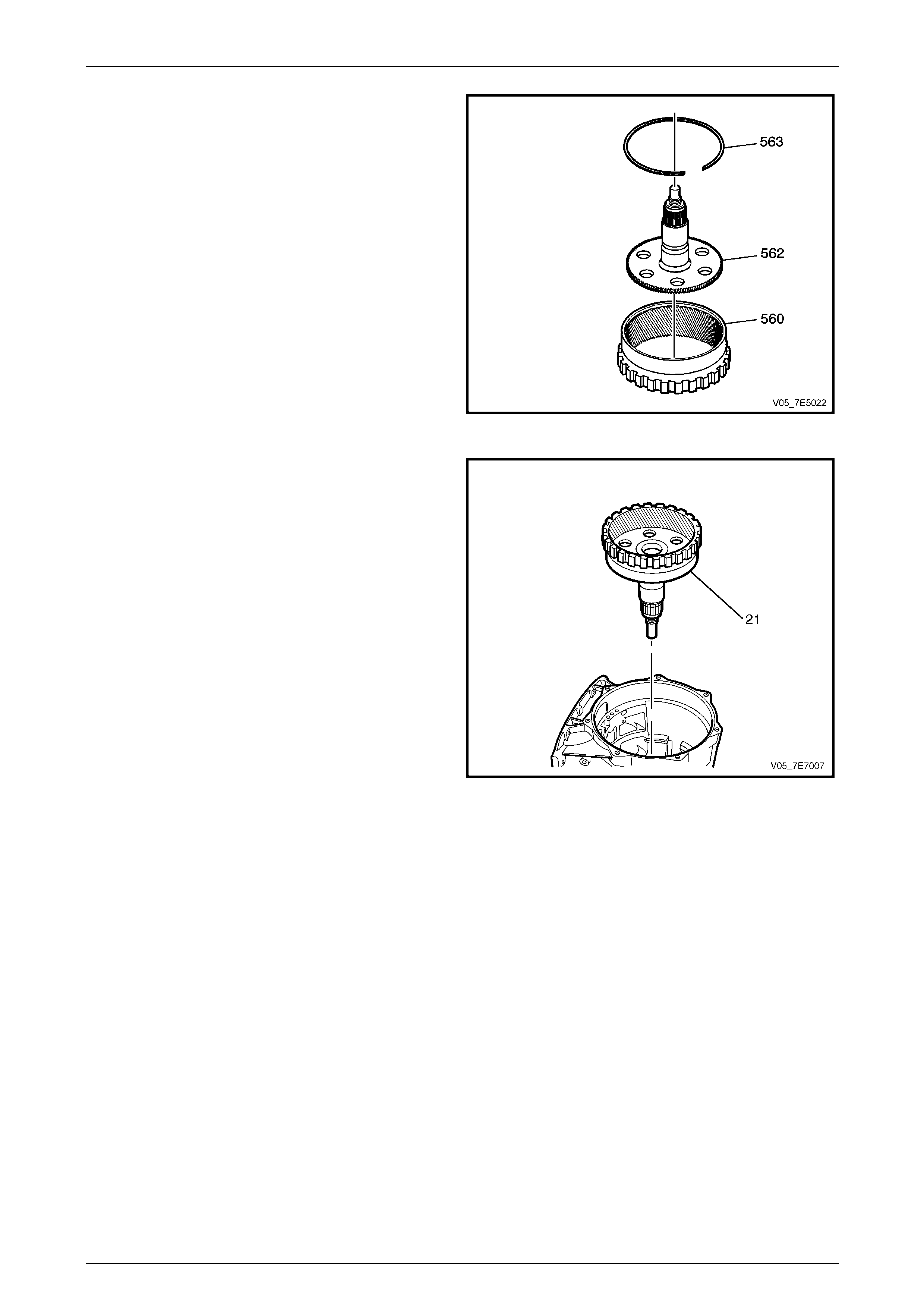
Automatic Transmission – 5L40–E – Unit Repair 7E5 – 31
7E5 – 31
2 Install the output shaft (562) onto the rear internal gear
(560).
3 Install the snap ring (563) onto the rear internal rin g
gear (560). Be sure it is seated in the groove.
Figure 7E5 – 47
4 Rotate the transmission 90° so the main ope nin g of
the transmission case is facing upward.
5 Install the output shaft assembly (21) into the case
(24).
Figure 7E5 – 48
Automatic Transmission – 5L40–E – Unit Repair 7E5 – 32
7E5 – 32
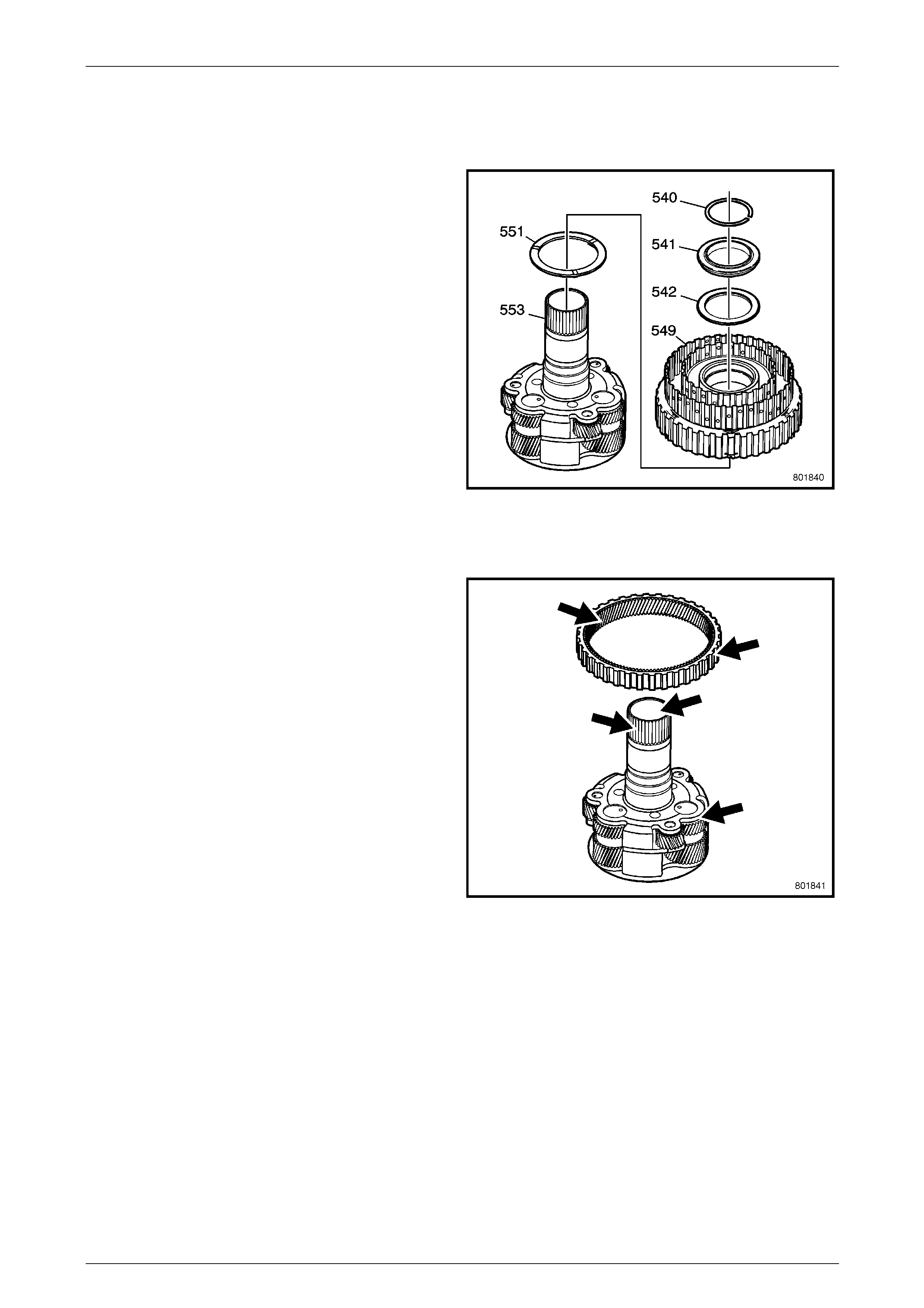
1.24 Input and Reaction Carrier
Disassemble
1 Remove the snap ring (540) and discard.
2 Remove the input and reaction bear ing (541).
3 Remove the 2nd clutch roller inner race bearing (542).
4 Remove the 2nd clutch sprag (549).
5 Remove the reaction internal gear flange washer
(551).
Figure 7E5 – 49
Reassemble
1 Inspect the reaction internal gear and the 2nd clutch
sprag for the following:
• Damaged or worn gear teeth
• Damaged or worn splines
2 Inspect the input and reaction carrier for the follo wing:
• Damaged or worn teeth
• Damaged or worn splines
• Worn or nicked bushings
• Worn or damaged bearings
Figure 7E5 – 50
Automatic Transmission – 5L40–E – Unit Repair 7E5 – 33
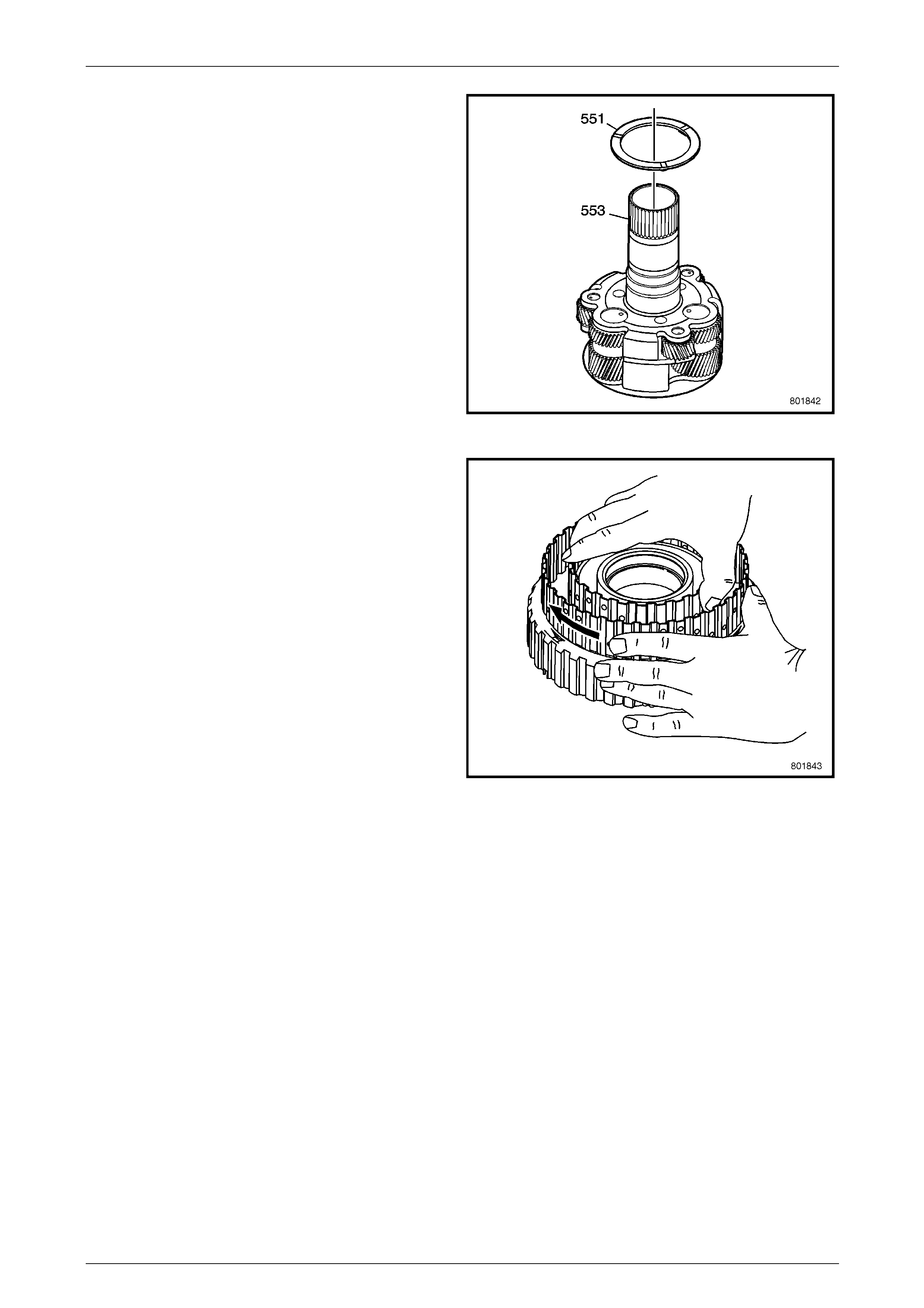
7E5 – 33
3 Lightly coat the reaction internal gear flan ge washer
(551) with petroleum jelly and install onto the front of
the input and reaction carrier assembly.
Figure 7E5 – 51
4 While holding the inner member, check that the outer
member of the 2nd clutch sprag free wheels (arrow)
and locks up in the opposite direction.
Figure 7E5 – 52

Automatic Transmission – 5L40–E – Unit Repair 7E5 – 34
7E5 – 34
5 Install the 2nd clutch sprag (549) onto the input and
reaction carrier (553).
6 Install the 2nd clutch roller inner race bearing
assembly (542) onto the input and reaction carrier
(553).
7 Install the input and reaction bearing assembly (541)
onto the input and reaction carrier (553).
8 Install the NEW input and reaction carrier outer ring
(540) onto the input and reaction carrier (553 ).
Figure 7E5 – 53
9 Install the input and reaction c arrier thrust be aring (20)
into the front of the output shaft and rear internal ri ng
gear assembly (21).
10 Install the input and reaction c arrier (19) into the case
(24), engaging the mating gear teeth.
Figure 7E5 – 54
Automatic Transmission – 5L40–E – Unit Repair 7E5 – 35
7E5 – 35
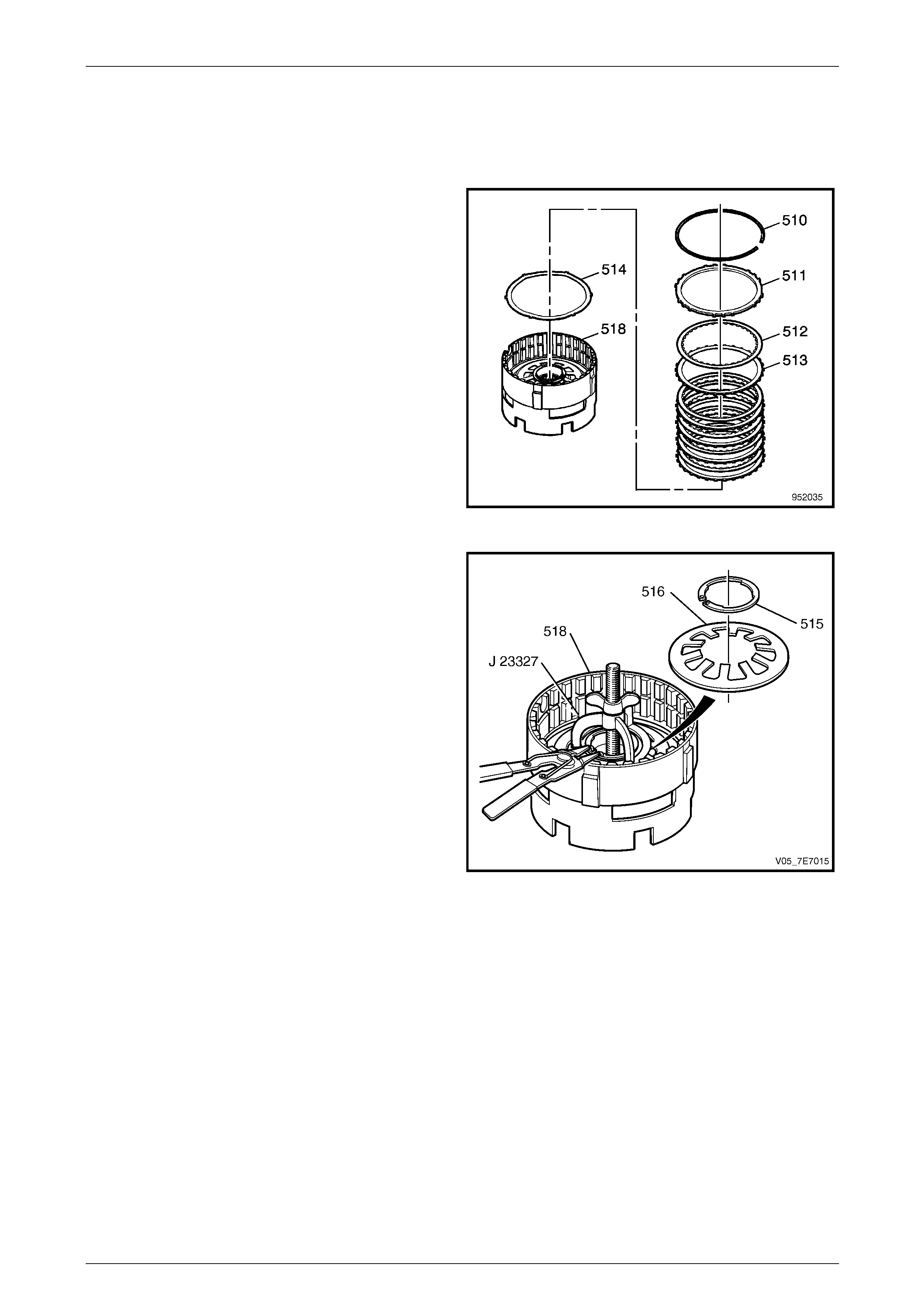
1.25 Centre Support
Disassemble
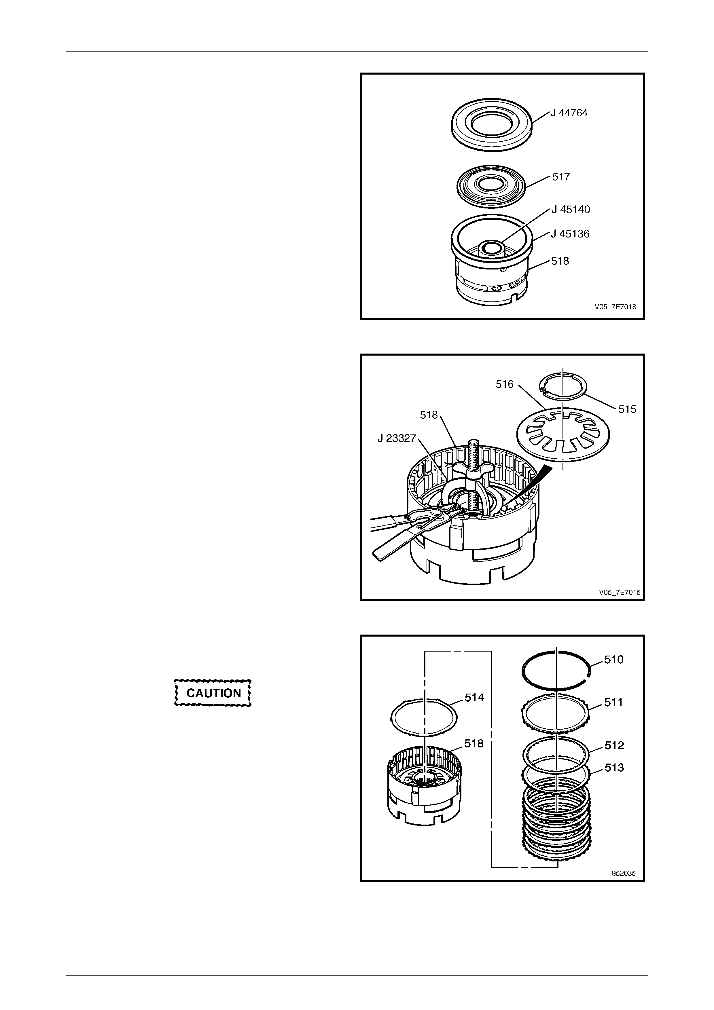
1 Using a flat bladed screwdriver, remove the snap ring
(510) from the centre support.
2 Remove the low and reverse backing plate (511).
3 Remove the clutch plates (512, 513), five inner spl ined
plates and five outer splined pl ates (all models).
NOTE
Each clutch plate has a composition lining on
one side while the other is plai n steel.
4 Remove the low and reverse, waved apply plate (514).
Figure 7E5 – 55
5 Using Tool J 23327, compres s the low and reverse
clutch spring (516).
6 Using suitable snap ring pliers, remove the low
reverse clutch spring retainer ring (515) from the
centre support retaining groove.
7 Loosen and remove T ool J 23327 from the centre
support (518).
8 Remove the low and reverse clutch spri ng retainer ring
(515) and clutch spring (516) from the centre supp ort
(518).
Figure 7E5 – 56
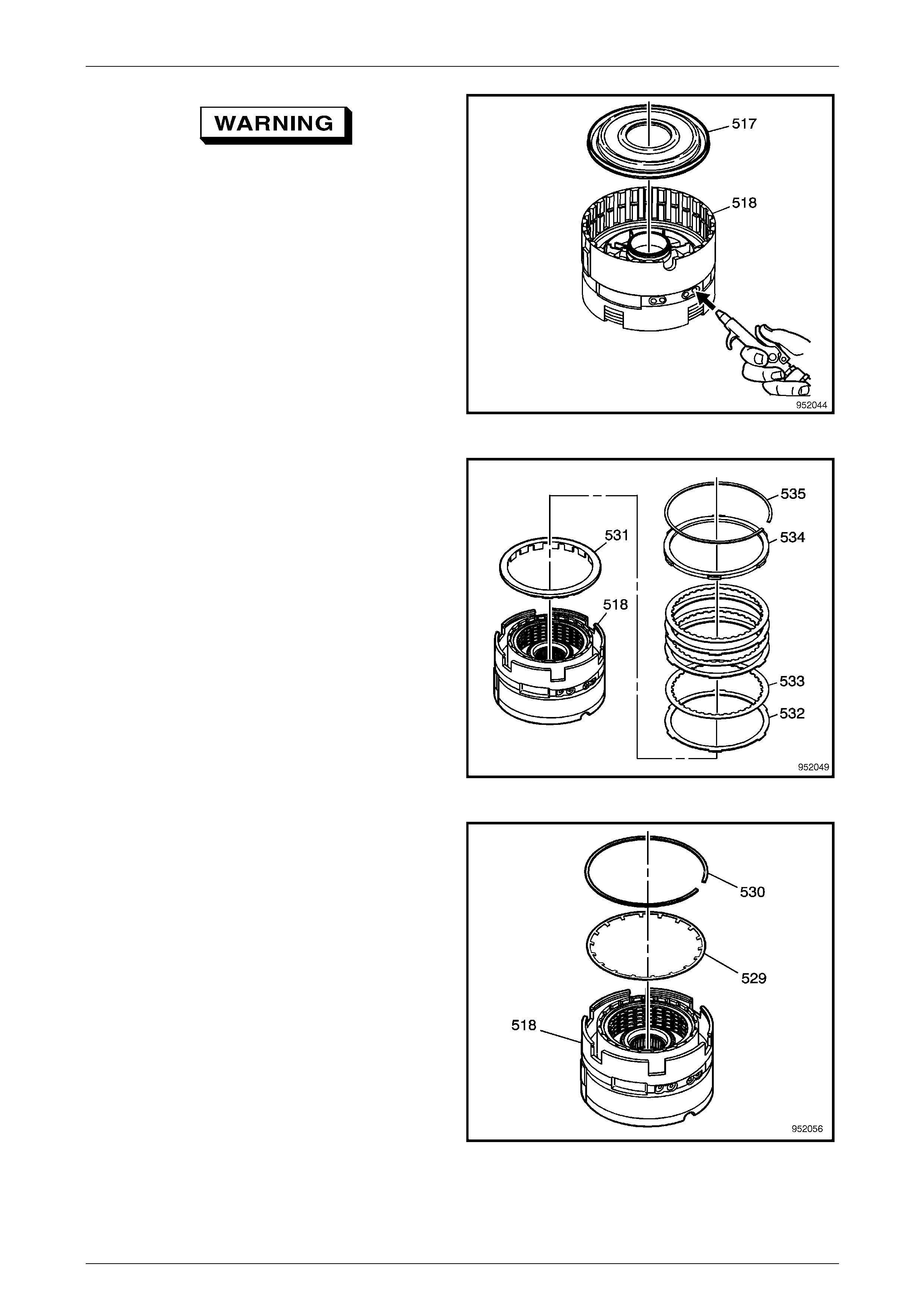
Automatic Transmission – 5L40–E – Unit Repair 7E5 – 36
7E5 – 36
Wear eye protection to prevent potential
injury.
9 Remove the low and reverse piston (517) from the
centre support (518).
NOTE
It may be necessary to apply air pressure to the
centre support port as shown, to assist in piston
removal.
Figure 7E5 – 57
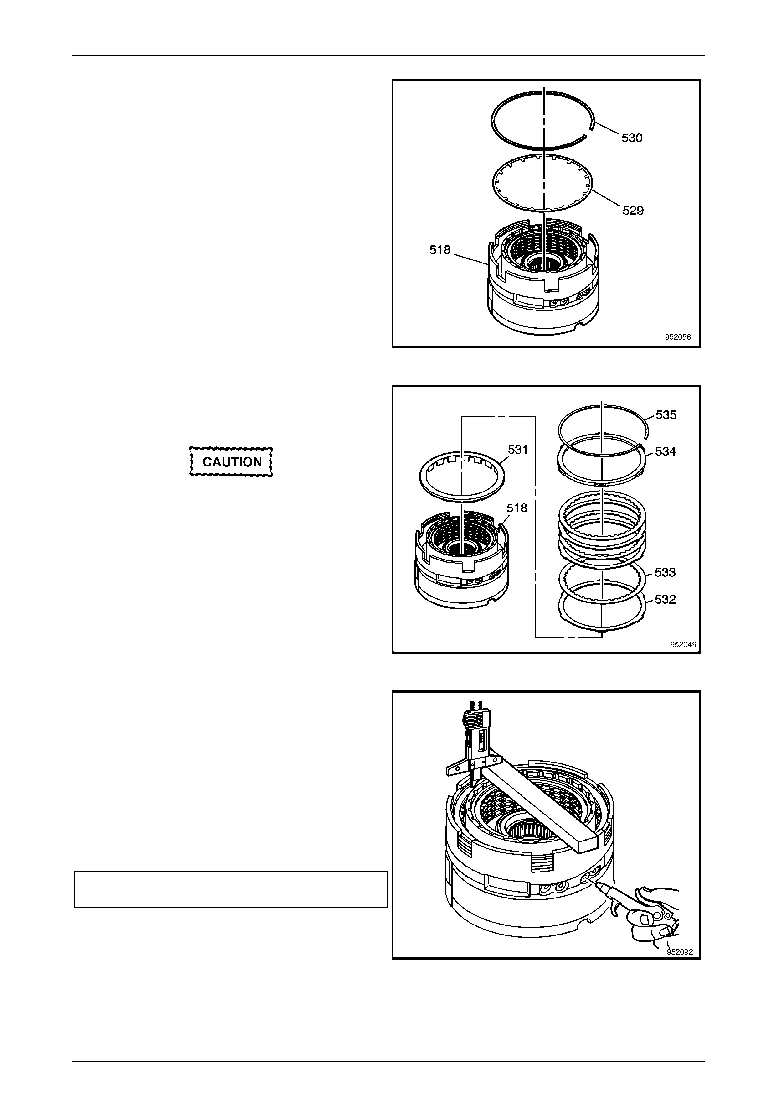
10 Turn the centre support assembly over and using a
fine bladed screwdriver, remove the 2nd coast clutch
plate retainer ring (535) from the centre support (518).
11 Remove the 2nd coast clutch backing plate (534) from
the centre support (518).
12 Remove the clutch plates (532, 533), three (two for
5HEG) inner splined plates and three (two for 5HEG)
outer splined plates.
NOTE
Each clutch plate has a composition lining on
one side while the other is plai n steel.
13 Remove the 2nd coast clutch spacer (531) from the
centre support (518).
Figure 7E5 – 58
14 Using a flat bladed screwdrive r , remove the 2nd coast
clutch spring retainer (530).
15 Remove the 2nd coast clutch spring (529) from the
centre support (518).
Figure 7E5 – 59
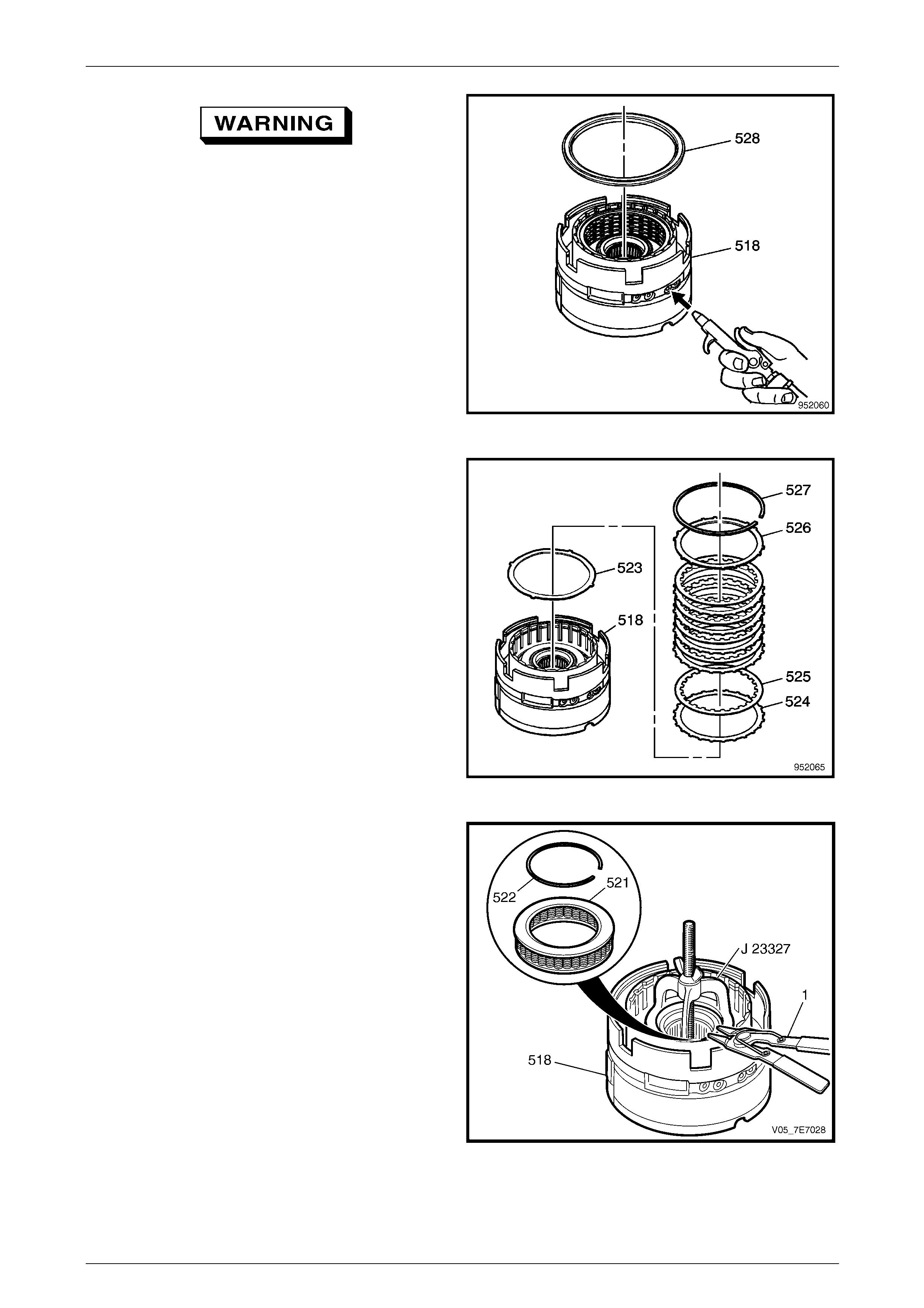
Automatic Transmission – 5L40–E – Unit Repair 7E5 – 37
7E5 – 37
Wear eye protection to prevent potential
injury.
16 Remove the 2nd coast clutch piston (528) fro m the
centre support (518).
NOTE
It may be necessary to apply air pressure to the
centre support port as shown, to assist in the
removal of the piston.
Figure 7E5 – 60
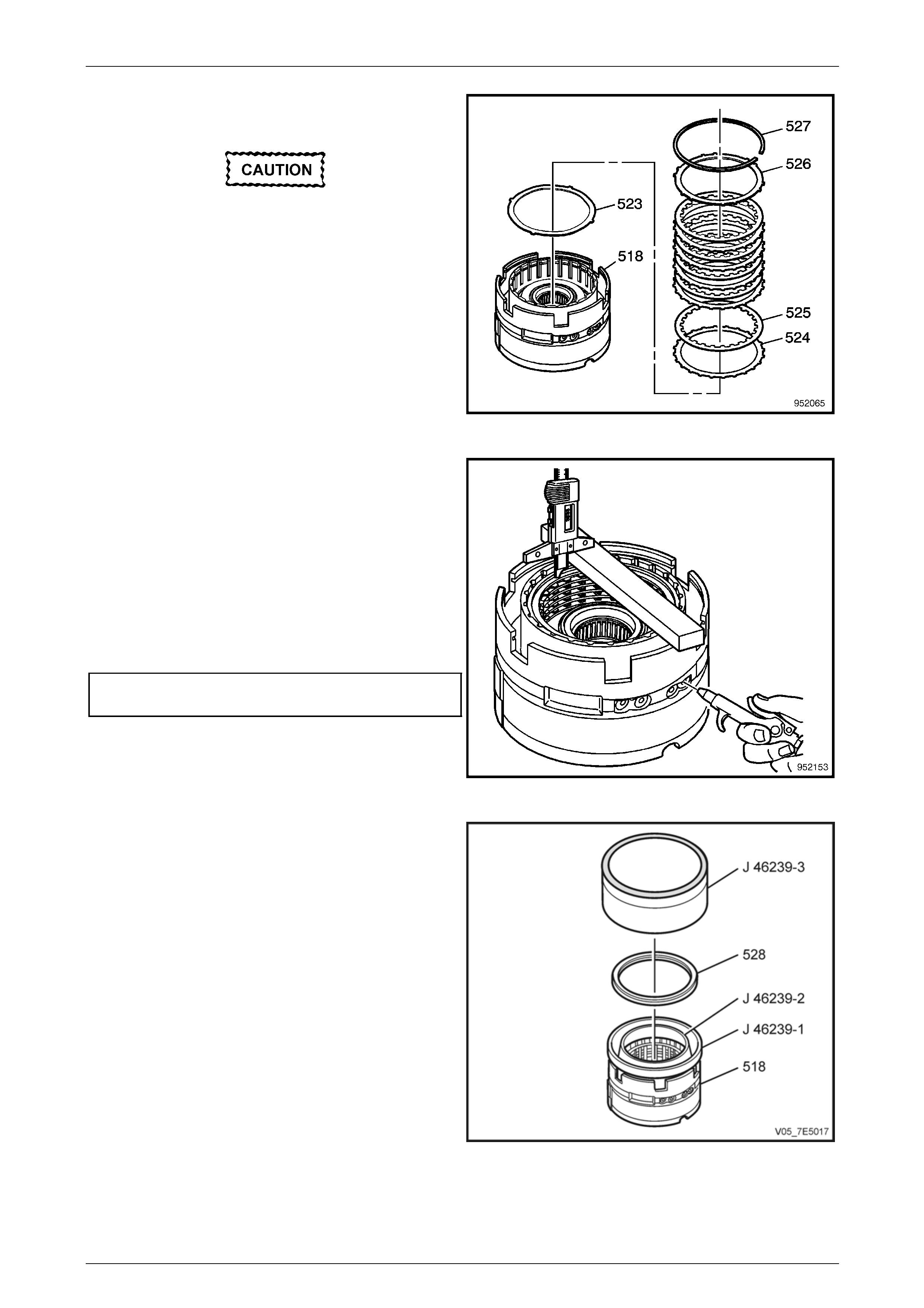
17 Using a flat bladed screwdriver, remove the retainer
ring (527) from the centre support (518).
18 Remove the 2nd clutch backing plate (526) from the
centre support (518).
19 Remove the clutch plates (524, 525), five inner spl ined
plates and five outer splined pl ates (all models) from
the centre support (518).
20 Remove the 2nd clutch apply plate (523) from the
centre support (518).
Figure 7E5 – 61
21 Using Tool J 23327, compres s the 2nd clutch piston
spring (521).
22 Using suitable snap ring pliers, remove the retainer
ring (522) from the centre support (518) retai nin g
groove.
23 Loosen and remove T ool J 23327 from the centre
support (518).
24 Remove the 2nd clutch piston spring (521) fro m the
centre support (518).
Figure 7E5 – 62
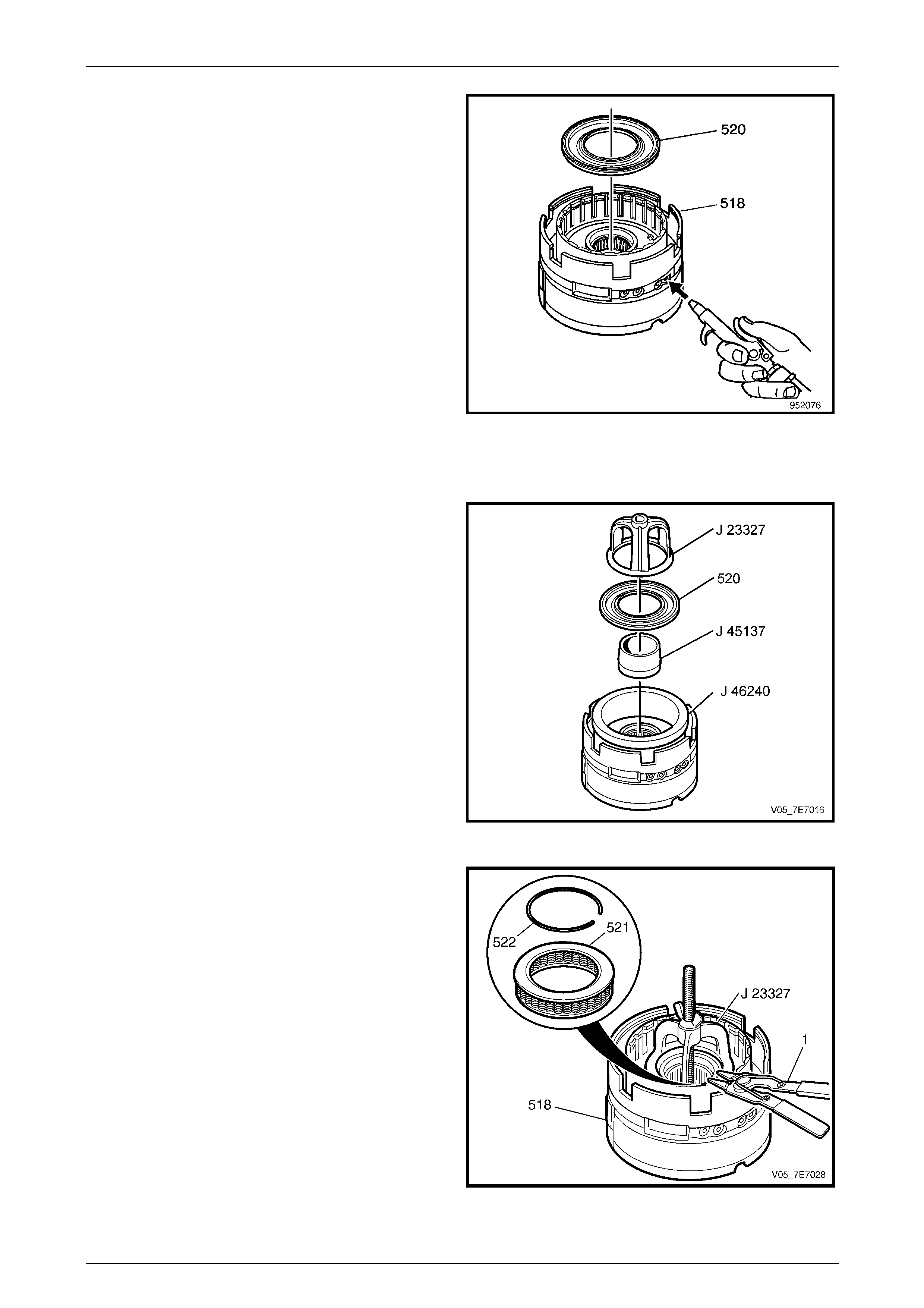
Automatic Transmission – 5L40–E – Unit Repair 7E5 – 38
7E5 – 38
25 Remove the 2nd clutch piston (520) from the centre
support (518).
NOTE
It may be necessary to apply air pressure to the
centre support port as shown, to assist in the
piston removal.
Figure 7E5 – 63
Reassemble
1 Inspect the centre support components for the
following:
• Plugged fluid passages
• Worn or damaged splines
• Worn or damaged pistons
• Worn or damaged clutch plates
2 Install 2nd clutch inner seal protector (Tool J 45137)
and piston protector (Tool J 46240), into the centre
support.
3 Lubricate the 2nd clutch piston and protectors with
clean transmission lubric ant. Install the 2nd clutch
piston (520) into the centre support, using J 233 27 to
assist in the installation process.
Remove Tools J 46240 an d J 45137 once 2nd clutch
piston is installed. Figure 7E5 – 64
4 Install the 2nd clutch piston spring (521) into the
centre support (518), and place the 2nd clutch spring
retainer snap ring (522) on top of the piston spring.
5 Using Tool J 23327, compres s the 2nd clutch piston
spring (521).
6 Using suitable snap ring pliers, install a NEW 2nd
clutch spring retainer ring (522) into the centre support
(518) retaining groove.
7 Loosen and remove T ool J 23327 from the centre
support (518).
Figure 7E5 – 65
Automatic Transmission – 5L40–E – Unit Repair 7E5 – 39
7E5 – 39
8 Install the 2nd clutch apply plate (523) into the centre
support (518).
Ensure that the composition side of each
plate faces upwards.
9 Install the 2nd clutch plates. Start by installing the 2n d
clutch plate (524) with external splines.
Alternate with the 2nd clutch plate (525) with internal
splines.
10 Install the 2nd clutch backing plate (526) into the
centre support (518).
11 Install the 2nd clutch backing plate retainer ring (527)
into the centre support (518).
Figure 7E5 – 66
12 Measure the distance between the 2nd clutch backing
plate and the bottom of the gauge bar. Measure three
times in different locations on the backing pla t e.
Record this as H1.
13 Apply air pressure – 450 kPa, to the specified port.
Measure the distance between the 2nd clutch backing
plate and the bottom of the gauge bar. Measure three
times in different locations on the backing pla t e.
Record this as H2.
14 Subtracting H2 from H1 will give the clutch pack travel
dimension.
2nd Clutch Pack
Travel Specification................................ 1.47 – 1.92 mm
Figure 7E5 – 67
15 Install inner piston seal protector (Tool J 46239-2) and
outer piston seal protector (J 46239-1) into the centre
support (518).
16 Coat inner and outer piston seal surfac es with
petroleum jelly (e.g. Vaseli ne™ or equivalent), then
install the 2nd coast piston (528), using installer (Tool
J 48239-3), into the centre support (518).
Figure 7E5 – 68
Automatic Transmission – 5L40–E – Unit Repair 7E5 – 40
7E5 – 40
17 Install the 2nd coast clutch spring (529) into the centre
support (518), with the inner tangs facing downward.
18 Install one end of the coast clutch spring retai ner (530)
into the centre support groove.
19 Using a screwdriver blade as needed, fully install the
retainer by working around its len gth, until the retainer
is fully engaged.
Figure 7E5 – 69
20 Install the 2nd coast clutch spacer (531) into the
centre support (518), checking that the support cut-
outs straddle the coast clutch spring legs.
Ensure that the composition side of each
plate faces upwards.
21 Install the 2nd coast clutch plates, starting with the 2nd
coast clutch plate (532) with external splines. Alternate
with the 2nd coast clutch plate (533) with internal
splines.
22 Install the 2nd coast clutch backing p late (5 34).
23 Install the 2nd coast clutch backing plate retainer ring
(535).
Figure 7E5 – 70
24 Measure the distance between the 2nd coast clutch
backing plate and the bottom of the gauge bar.
Measure three times in different locations on the
backing plate. Record this as H1.
25 Apply air pressure – 450 kPa, to the specified port.
Measure the distance between the 2nd coast clutch
backing plate and the bottom of the gauge bar.
Measure three times in different locations on the
backing plate. Record this as H2.
26 Subtracting H2 from H1 will give the clutch pack travel
dimension.
2nd Coast Clutch Pack
Travel Specification................................ 0.94 – 1.39 mm
Figure 7E5 – 71
Automatic Transmission – 5L40–E – Unit Repair 7E5 – 41
7E5 – 41
27 Using Tool J 45140 inner seal protector, and Tool J
45136 outer seal protector, install the lo w and reverse
clutch piston (517) into the centre support (518), using
J 44764 to assist.
Figure 7E5 – 72
28 Assemble low and reverse clutch spring (51 6) and a
NEW retainer ring (515) onto the low and reverse
clutch piston.
29 Using Tool J 23327, spring compressor, compress the
low and reverse clutch piston spring (516).
30 Using suitable circlip pliers, install the low and reverse
clutch spring retainer circlip (515) into the centre
support (518) retaining groove.
Loosen and remove T ool J 23327 once circlip (515) is
installed.
Figure 7E5 – 73
31 Install the low and reverse apply pl ate (514) into the
centre support (518).
Ensure that the composition side of each
plate faces upwards.
32 Install the low and reverse clutch plates. Start with the
low and reverse clutch plate (513) with external
splines. Alternate with the low and reverse clutch plate
(512) with internal splines.
NOTE
The external splined plates (513) with the
missing spline, aligns with the large centre
support lug.
33 Install the low and reverse clutch backing p late (511)
and the retainer ring (510) into the centre support
(518). Figure 7E5 – 74
Automatic Transmission – 5L40–E – Unit Repair 7E5 – 42
7E5 – 42
34 Measure the distance between the low and reverse
clutch backing plate and the bottom of the ga uge bar.
Measure three times in different locations on the
backing plate. Record this as H1.
35 Apply air pressure – 450 kPa, to the specified port.
Measure the distance between the low and reverse
clutch backing plate and the bottom of the ga uge bar.
Measure three times in different locations on the
backing plate. Record this as H2.
36 Subtracting H2 from H1 will give the clutch pack travel
dimension.
Low and Reverse Clutch Pack
Travel Specification................................ 1.72 – 2.17 mm
Figure 7E5 – 75
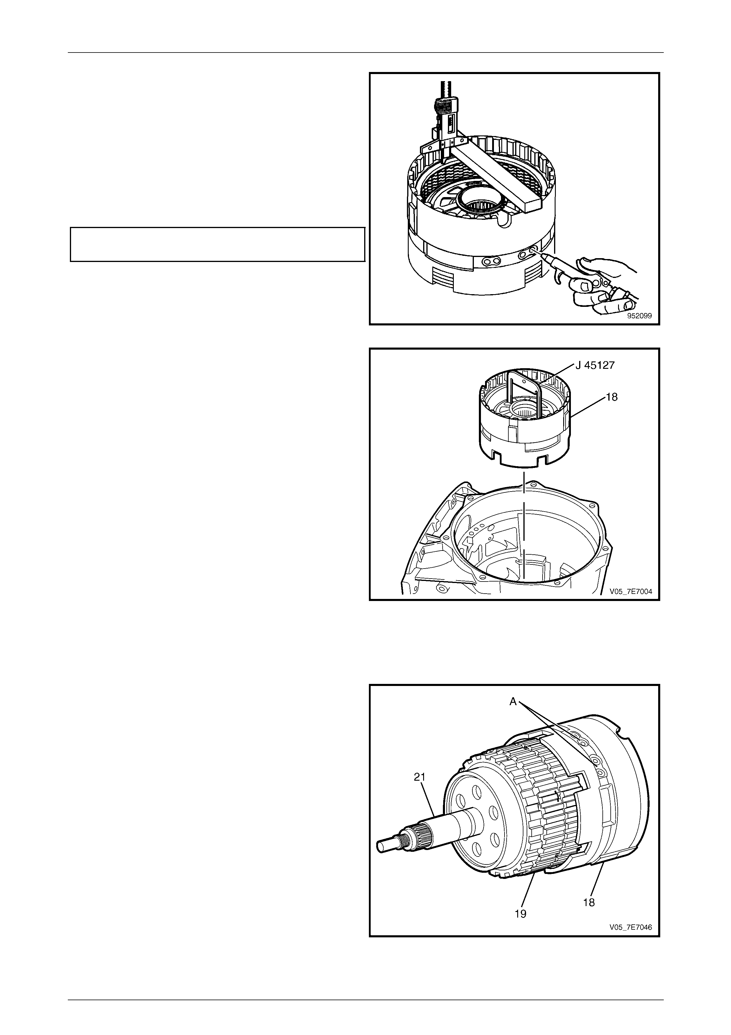
37 Using Tool J 45127, install the centre support
assembly (18) into the transmission case (24),
ensuring that the 2nd clutch and 2n d coast clutch
plates fully engage over the mating splines on the
second clutch sprag assembly (545 and 54 9).
Figure 7E5 – 76
Alternative Reassembly Method
Rather than install the individual transmission components described to this point, the following procedure may be more
convenient.
1 Assemble the centre support assembly (18) to the
planetary carrier and 2nd clutch sprag assemblies (19)
and the rear internal gear output shaft (21).
2 With the transmission case in a horizontal position,
install the pre-assembled compon ents into the case.
NOTE
If all clutch plates are correctly engaged, the flui d
passage access holes in the centre support (A),
will be aligned with those in the transmission
case.
Figure 7E5 – 77
Automatic Transmission – 5L40–E – Unit Repair 7E5 – 43
7E5 – 43
1.26 Low Clutch Sprag
Reassemble
1 Inspect the low clutch sprag for the follo wing:
• Worn or damaged splines
• Scoring on the inside diameter of the races
• Wear or cracks
2 Check that the low clutch sprag rotation freewheels
and locks up in the correct direction.
Figure 7E5 – 78
3 Install the low clutch roller thrust bearing (17 ).
4 Install the low clutch sprag (16) into the transmission
case (24), ensure that the splines on the inner race
(505) engage fully with the low and reverse clutch
plates (512).
Figure 7E5 – 79
Automatic Transmission – 5L40–E – Unit Repair 7E5 – 44
7E5 – 44
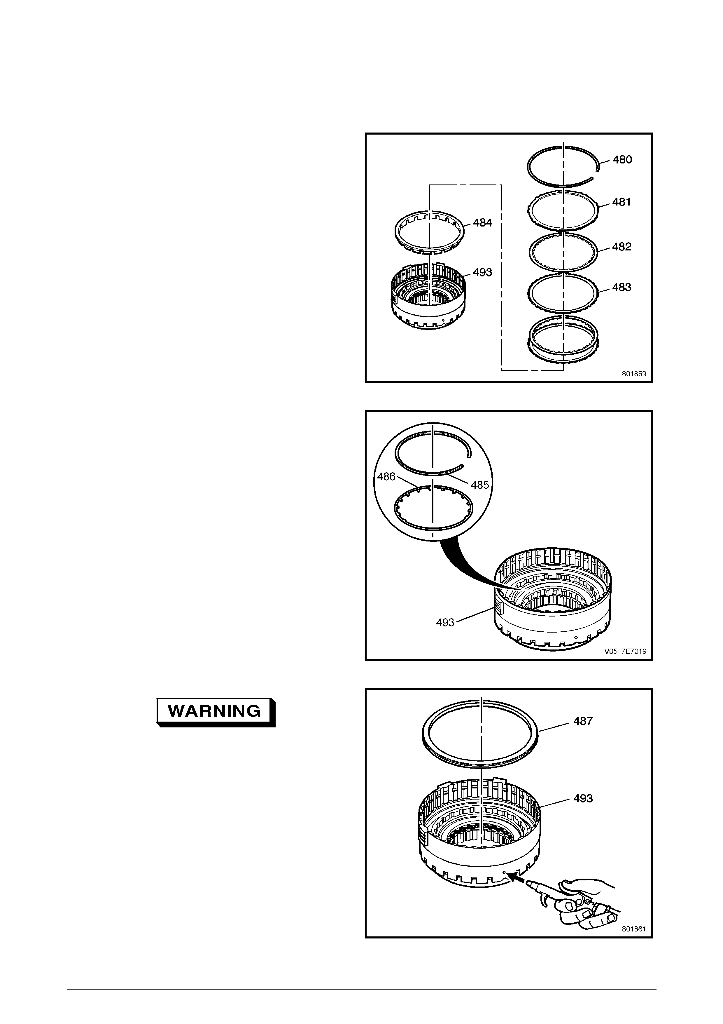
1.27 Overdrive and Intermediate Clutch
Disassemble
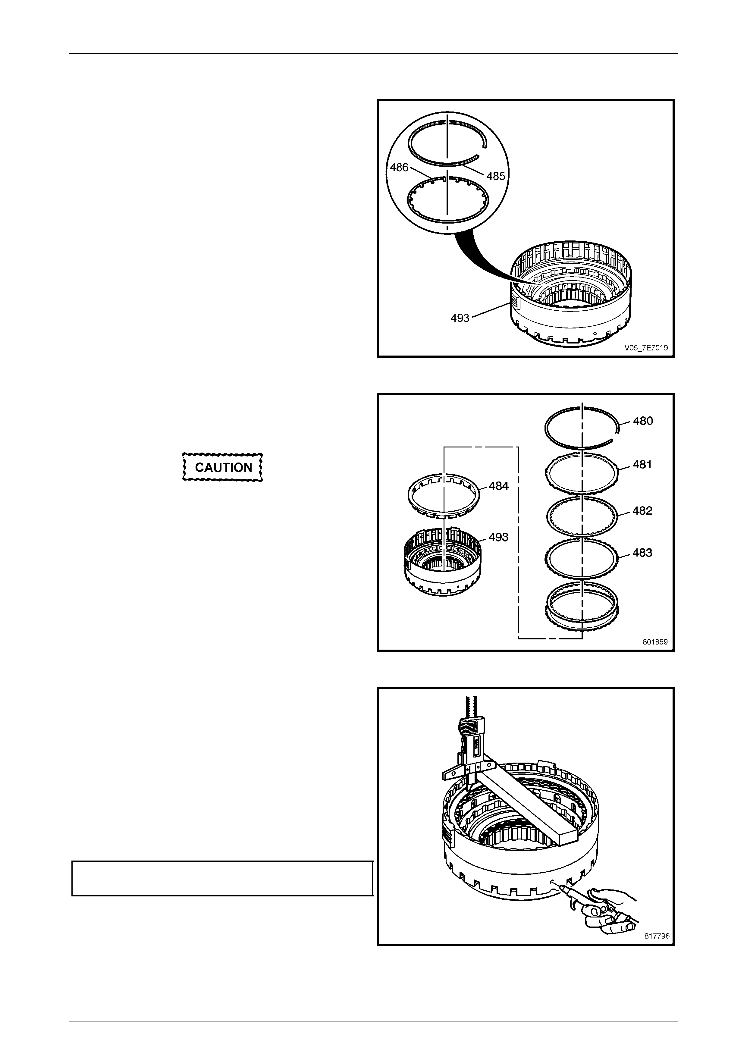
1 Using a flat bladed screwdriver, remove the overdrive
clutch retainer (480) from the overdrive clutch housing
(493).
2 Remove the overdrive clutch backin g plate (481) from
the overdrive clutch housing (493).
3 Remove the overdrive clutch plates (48 2, 483 ), three
inner splined plates and three outer splined plates (all
models).
4 Remove the overdrive clutch spacer (484) from the
overdrive clutch housin g (493).
Figure 7E5 – 80
5 Using a bladed screwdriver, r ele ase one end of the
clutch piston spring retainer ring (485), then gradually
release the ring remainder until free from the retaining
groove in the overdrive clutch housing (493).
6 Remove the retainer ring (485 ) and the overdrive
clutch spring (486) from the overdrive clutch h ousing
(493).
Figure 7E5 – 81
Wear eye protection to prevent potential
injury.
7 Remove the overdrive clutch piston (48 7) from the
overdrive clutch housin g (493).
NOTE
It may be necessary to apply air pressure to the
overdrive clutch housi ng port as sho wn, to assist
in piston removal.
Figure 7E5 – 82
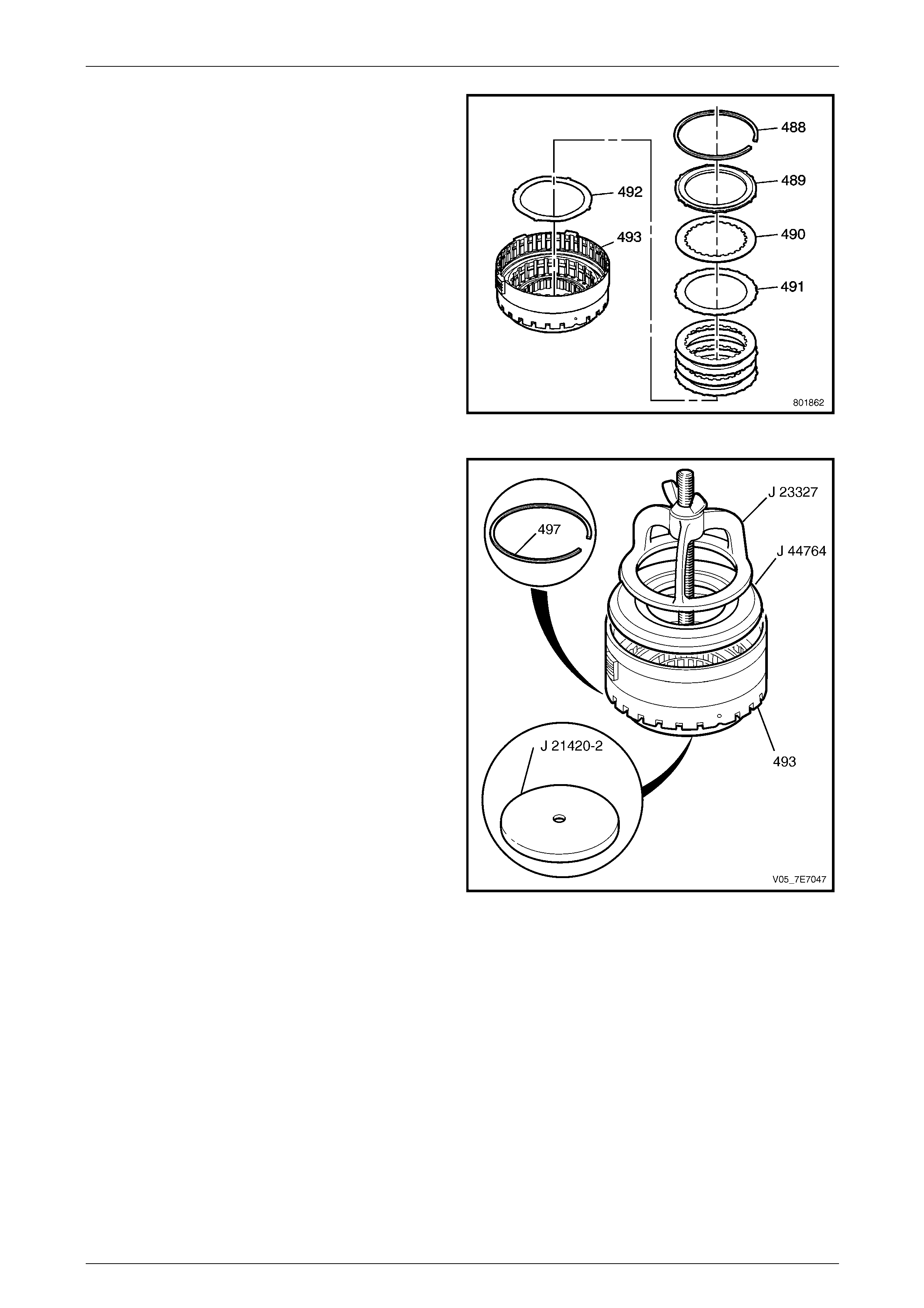
Automatic Transmission – 5L40–E – Unit Repair 7E5 – 45
7E5 – 45
8 Using a fine bladed screwdriver, remove the
intermediate clutch backing pl ate retainer ring (488)
from the overdrive clutch housing (493).
9 Remove the intermediate clutch backing plate (489)
from the overdrive clutch housing (493).
10 Remove the intermediate clutc h plates (4 90, 491), four
(three for 5HEG) inner splined plates and four (three
for 5HEG) outer splined plates from the overd r ive
clutch housing (493).
11 Remove the intermediate clutch apply plate (492) from
the overdrive clutch housing (493).
Figure 7E5 – 83
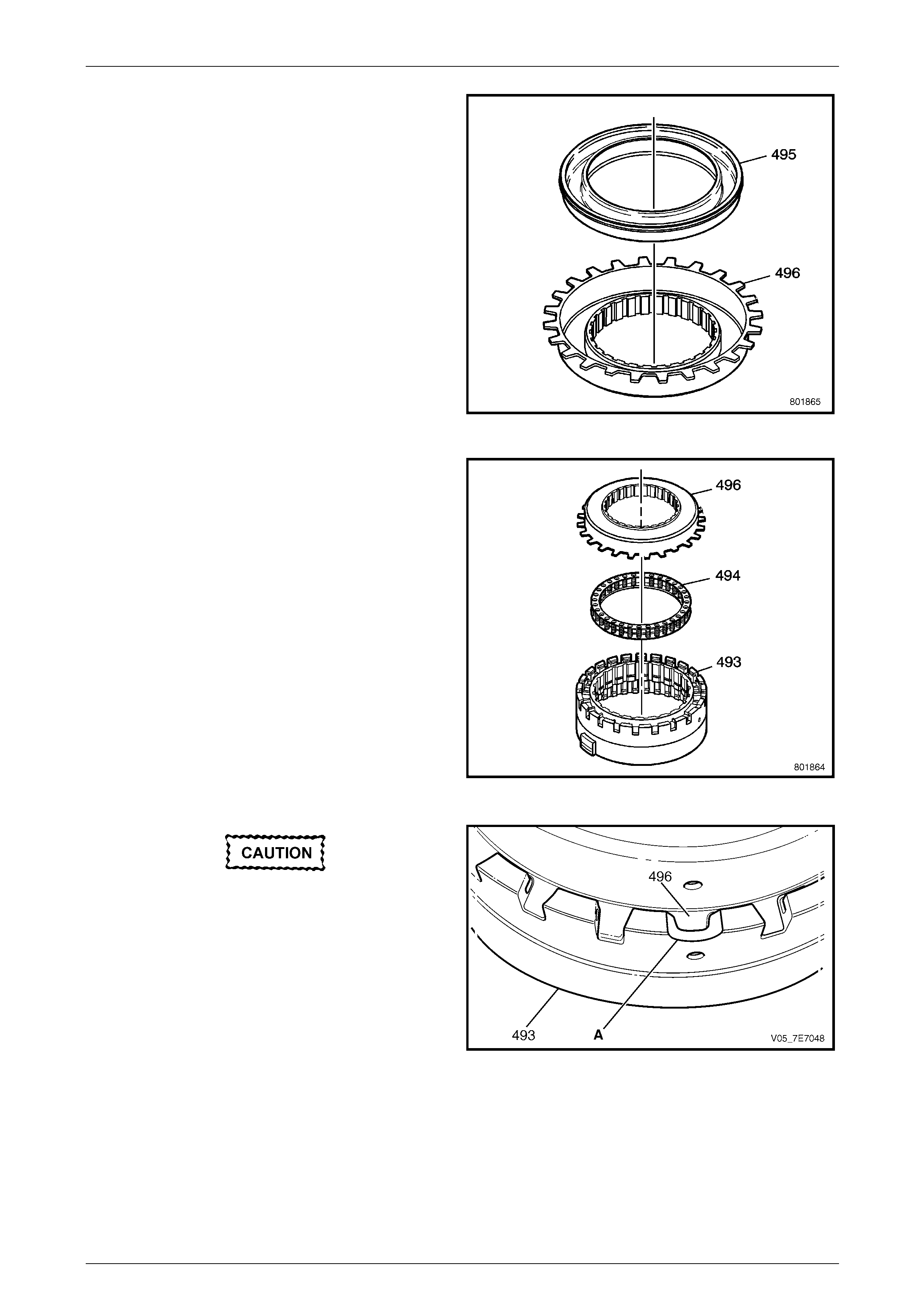
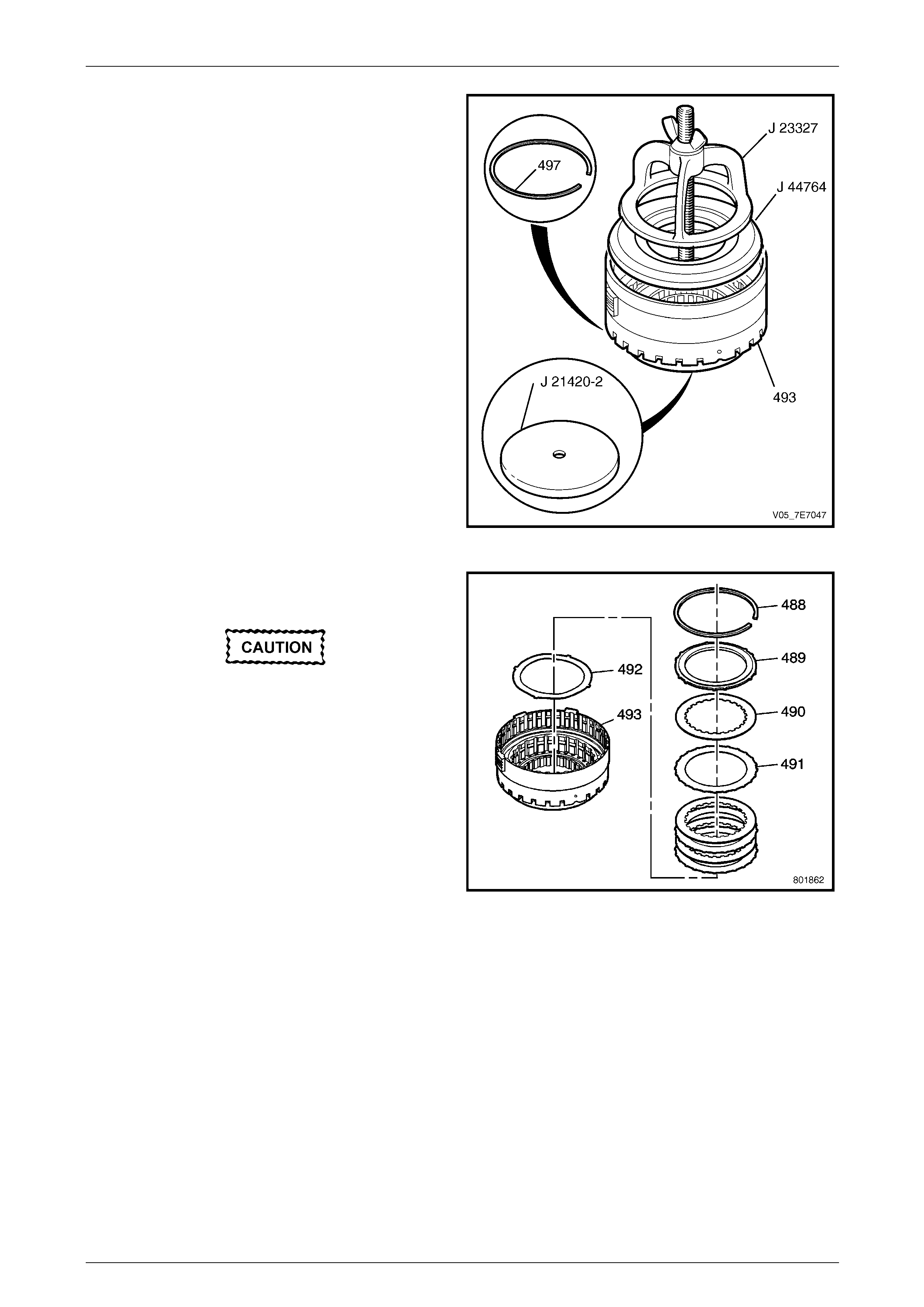
12 Assemble plate, Tool J 2142 0-02 against the
intermediate clutch cover (496) and Tools J 447 64 and
J 23327 to the overdrive housing (49 3) and tighten
wing nut to draw in the intermediate clutch housing
(496).
13 Using a flat bladed screwdriver, remove the
intermediate clutch housing retain er ring (497) from
the overdrive clutch housing (493).
Figure 7E5 – 84
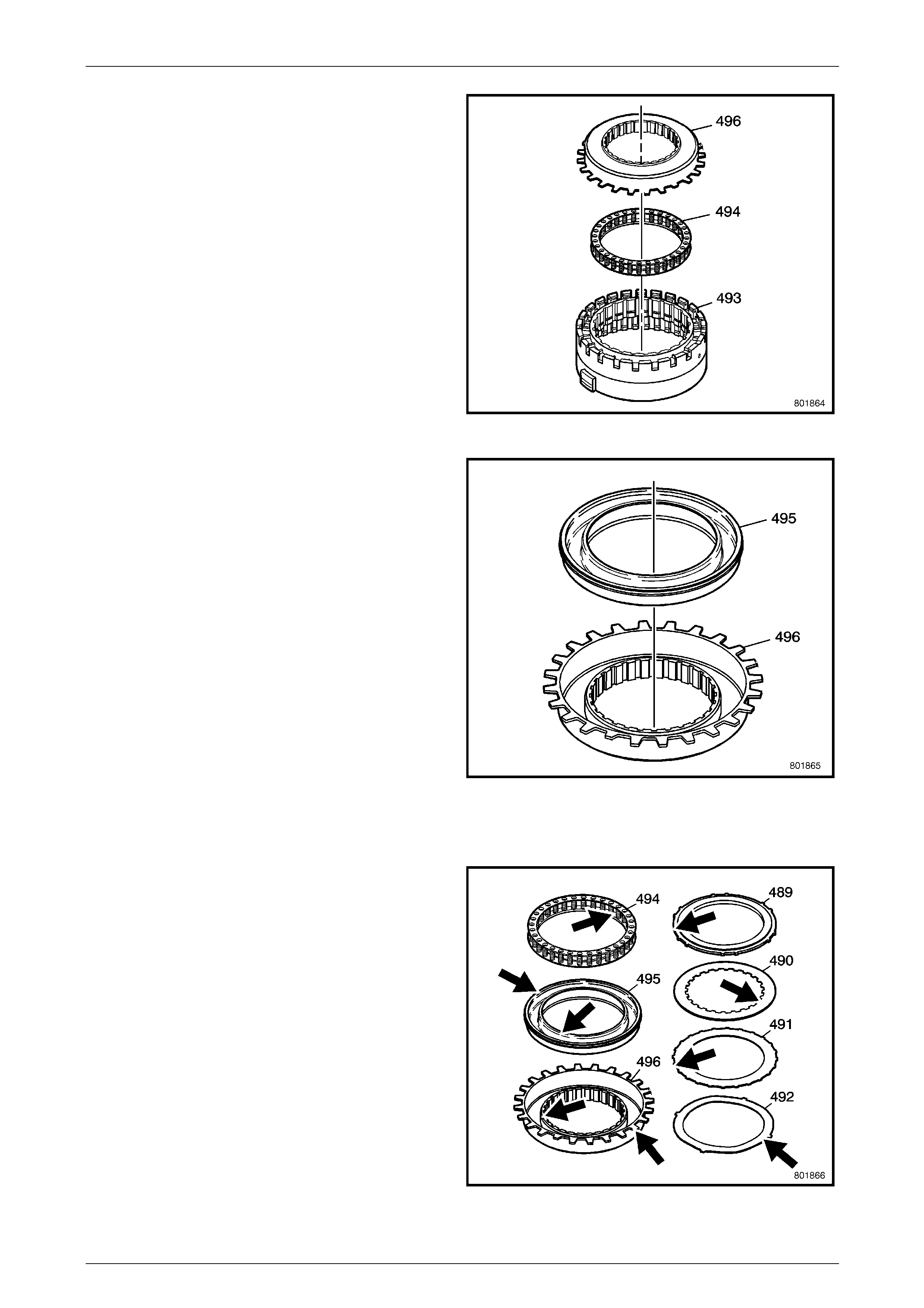
Automatic Transmission – 5L40–E – Unit Repair 7E5 – 46
7E5 – 46
14 Loosen and remove Tools J 44764 and J 23327 from
the overdrive clutch housing (493).
15 Remove the intermediate clutch housing (496), and
the intermediate clutch spring (494) from the overdrive
clutch housing (493).
Figure 7E5 – 85
16 Remove the intermediate clutc h piston (495) from the
overdrive clutch housin g (496).
Figure 7E5 – 86
Reassemble
1 Inspect the housing for the following:
• Plugged feed passages
• Worn or damaged splines
• Damaged or worn springs
• Damaged or worn pistons
• Worn or damaged clutch plates
Figure 7E5 – 87
Automatic Transmission – 5L40–E – Unit Repair 7E5 – 47
7E5 – 47
2 After lubricating the inner and outer sealing lips of the
intermediate piston (495) with clean transmission fluid,
install piston (495) into the intermedi ate clutch housing
(496).
Figure 7E5 – 88
3 Install the intermediate clutch spring (494) into the
overdrive clutch housin g (493).
4 Install the intermediate housing (496) into the
overdrive clutch housin g (493).
Figure 7E5 – 89
Align the short tang on the intermediate
housing (496) with the semi-circular cut-out
(A) in the overdrive clutch housing (493).
Figure 7E5 – 90
Automatic Transmission – 5L40–E – Unit Repair 7E5 – 48
7E5 – 48
5 Assemble plate, Tool J 2142 0-02 against the
intermediate clutch cover and Tools J 4476 4 and
J 23327 to the overdrive housing (49 3) and tighten the
wing nut to draw in the intermediate clutch housing
(496).
6 Install the intermediate clutch housing retainer ring
(497) to the retaining groove in the overdrive housing
(493).
7 Loosen and remove all tools.
Figure 7E5 – 91
8 Install the intermediate clutch, waved apply plate
(492).
Ensure that the composition side of each
plate faces upwards.
9 Install the intermediate clutch plates. Starting with the
intermediate clutch plates (491) with external splines.
Alternating with the intermediate clutch pl ates (490)
internal splines.
10 Install the backing plate (489) wit h the recessed edge
facing outward.
11 Install the intermediate backing plate retainer ring
(488) into the overdrive housing (493) retaining
groove. Figure 7E5 – 92
Automatic Transmission – 5L40–E – Unit Repair 7E5 – 49
7E5 – 49
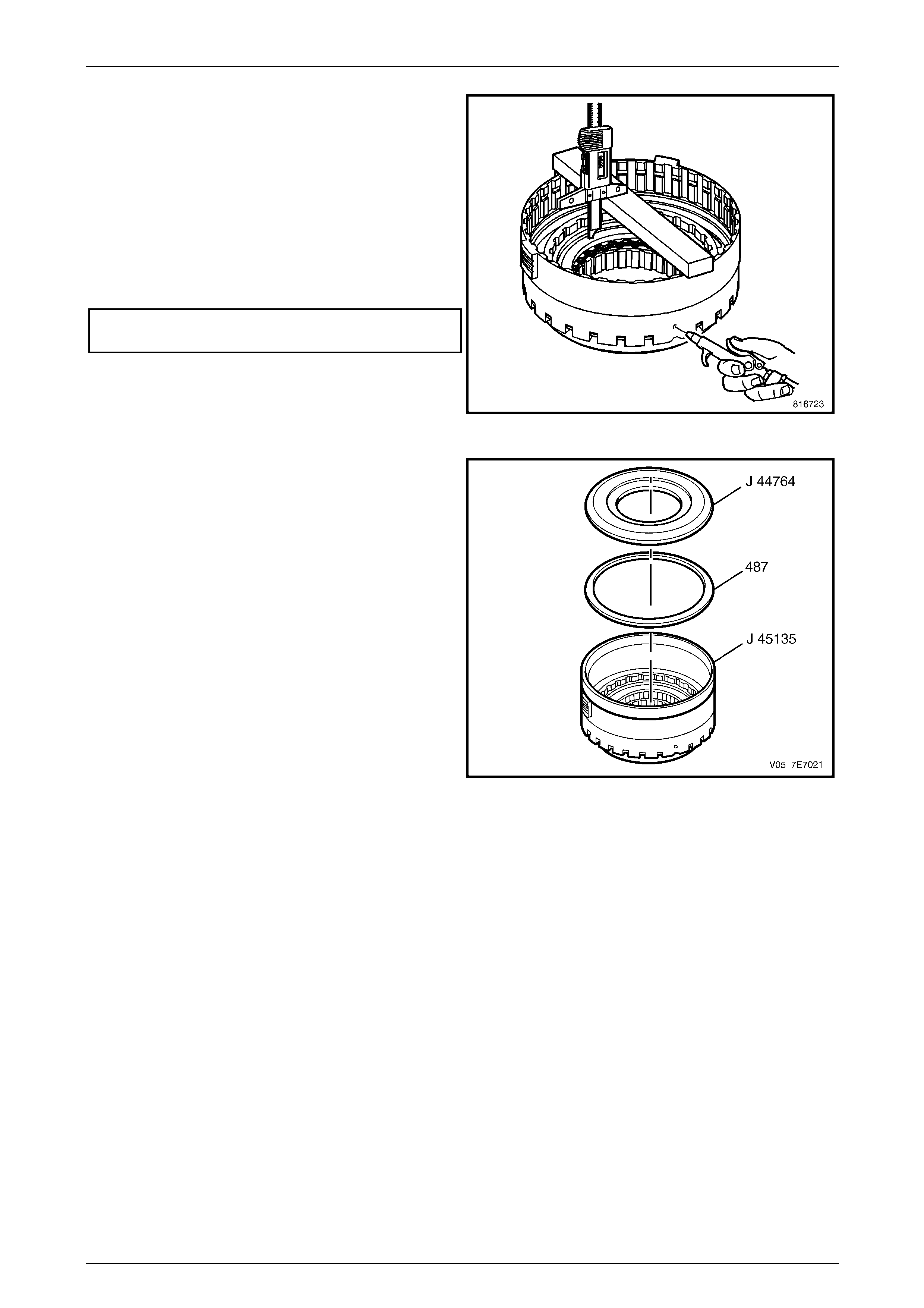
12 Measure the distance between the intermediate clutch
backing plate and the bottom of the gauge bar.
Measure three times in different locations on the
backing plate. Record this as H1.
13 Apply air pressure – 450 kPa, to the specified port.
Measure the distance between the intermediate clutch
backing plate and the bottom of the gauge bar.
Measure three times in different locations on the
backing plate. Record this as H2.
14 Subtracting H2 from H1 will give the clutch pack travel
dimension.
Intermediate Clutch Pack
Travel Specification................................ 1.13 – 1.58 mm
Figure 7E5 – 93
15 Assemble Tools J 45135 and J 44764 to the overdrive
clutch housing. Coat the piston and to ols using the
correct transmission lubricant and install th e overdrive
piston (487).
Remove tools once piston in correctly install ed.
Figure 7E5 – 94
Automatic Transmission – 5L40–E – Unit Repair 7E5 – 50
7E5 – 50
16 Install the overdrive piston spr ing (4 86) into the
overdrive clutch housing, with the inner tangs facing
downward.
17 Install one end of the coast clutch spring retai ner into
the centre support groove then, using a screwdriver
blade as needed, fully install the retainer by working
around its length, until the retainer is fully engaged.
Figure 7E5 – 95
18 Install the overdrive clutch spacer (484), ensuring that
the spacer cut-outs straddle the overdrive clutch piston
spring blades.
Ensure that the composition side of each
plate faces upwards.
19 Install the overdrive clutch plat es. Starting with the
overdrive clutch plates (483) with e xternal splines.
Alternate with the overdrive clutch plates (48 2) with
internal splines.
20 Install the overdrive backing plate (481).
21 Install the overdrive clutch retainer ring (480).
Figure 7E5 – 96
22 Measure the distance between the overdrive clutch
backing plate and the bottom of the gauge bar.
Measure three times in different locations on the
backing plate. Record this as H1.
23 Apply air pressure – 450 kPa, to the specified port.
Measure the distance between the overdrive clutch
backing plate and the bottom of the gauge bar.
Measure three times in different locations on the
backing plate. Record this as H2.
24 Subtracting H2 from H1 will give the clutch pack travel
dimension.
Overdrive Clutch Pack
Travel Specification................................ 1.60 – 2.05 mm
Figure 7E5 – 97
Automatic Transmission – 5L40–E – Unit Repair 7E5 – 51
7E5 – 51
25 With the transmission case rotated to a vertical
position as shown, install the overdrive clutch housing
(15) into the transmission case (24).
Check that the mating splines on the intermediate
clutch plates (490) engage fully over the low and
reverse sprag assembly outer race (505).
Figure 7E5 – 98
26 Measure the distance from the bottom of the gaug e
bar to the top of the overdrive and intermedia t e clutch.
Record this as M1.
27 Measure the distance from the bottom of the gaug e
bar to the bottom of the intermediate and overdrive
retainer ring groove in the case. Record this as M2.
28 Subtract M2 from M1. This will be Dimension 'M' .
Figure 7E5 – 99
Automatic Transmission – 5L40–E – Unit Repair 7E5 – 52
7E5 – 52
29 Measure the intermediate and overdrive clutch
housing retaini ng ring (14).
Refer to the following Intermediate and Overdrive
Clutch Housing Retaining Rin g Specifications for the
correct size retainer ring to use.
Intermediate and Overdrive Clutch Housing
Retainer Ring Specification
Dimension 'M' Retainer Ring Thickn ess
(mm)
0.75 mm–0.85 mm 3.90–4.00
0.85 mm–0.95 mm 3.80–3.90
0.95 mm–1.05 mm 3.70–3.80
1.05 mm–1.15 mm 3.60-3.70
1.15 mm–1.25 mm 3.50–3.60
1.25 mm–1.35 mm 3.40–3.50
Figure 7E5 – 100
Use care when removing or installing the
circlip (14). Be sure the circlip pliers are
installed properly onto the circlip 'eyes' or
bodily injury may occur.
NOTE
If any of the following components are replaced,
then an end play measurement must be taken
(refer to 1.45 Extension Housing, in this
Section.):
15 Overdrive Clutch Housing
16 Low Clutch Sprag Assembly
17 Low Clutch Roller Thrust Bearing
18 Centre Support
19 Input and Reaction Carrier Assembly
Figure 7E5 – 101
It is critical that the ends of the circlip are
aligned with the opening in the transmission
case. Otherwise the control valve body
cannot be installed.
30 Using suitable circlip pliers such as Tool J 45126 or equivalent, install the intermediate and overdrive clutch
housing retaining circlip (14) into the transmission case (24). Ensure that the ends of the circlip are positio ned as
shown.
Automatic Transmission – 5L40–E – Unit Repair 7E5 – 53
7E5 – 53
1.28 Intermediate Clutch Sprag
Inspect
1 Inspect the intermediate sprag clutch for the following
conditions:
• Scoring.
• Wear or cracks.
Figure 7E5 – 102
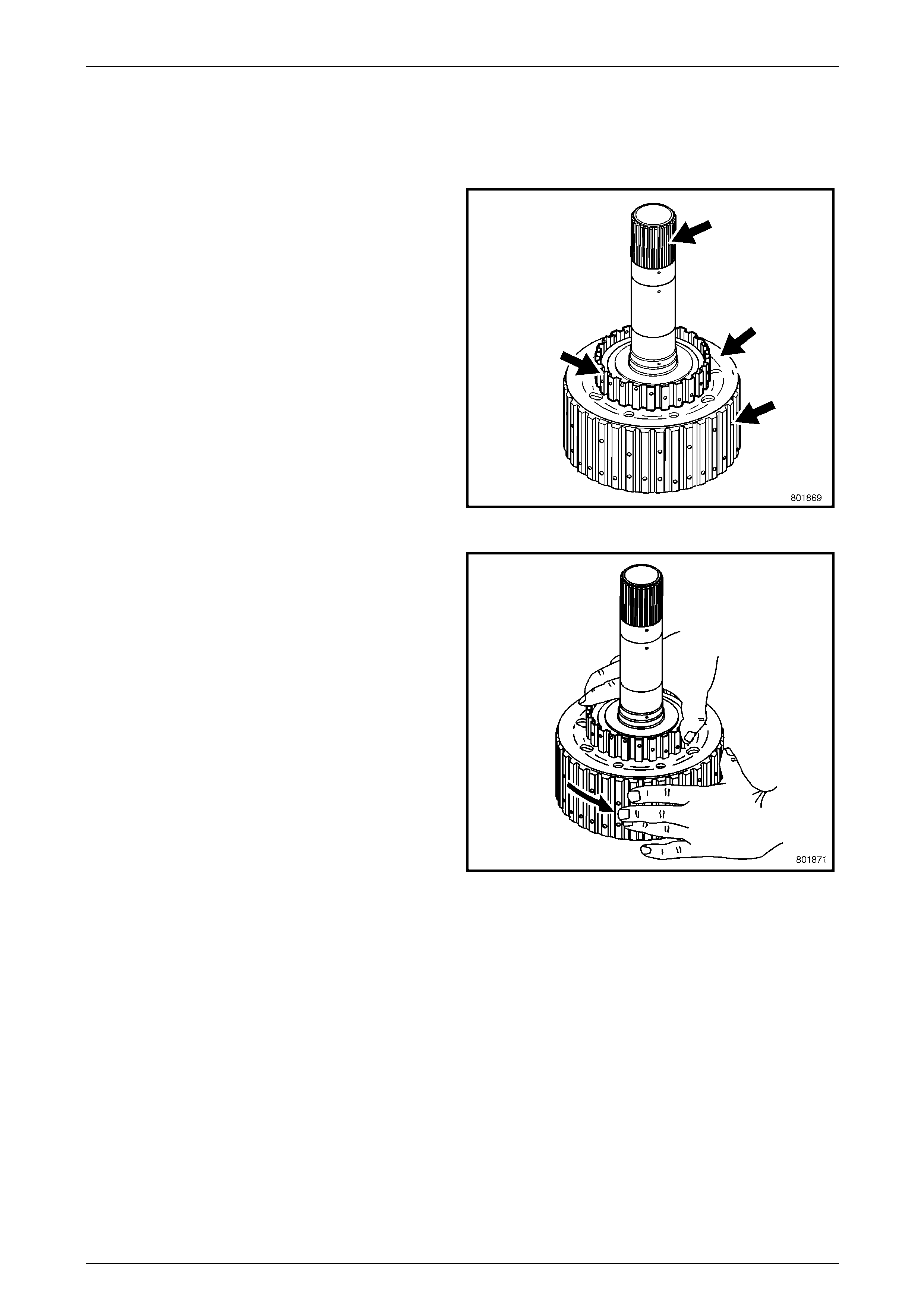
2 Check that the intermediate sprag clutch rotation
freewheels and locks up in the correct direction.
Figure 7E5 – 103
Automatic Transmission – 5L40–E – Unit Repair 7E5 – 54
7E5 – 54
Reassemble
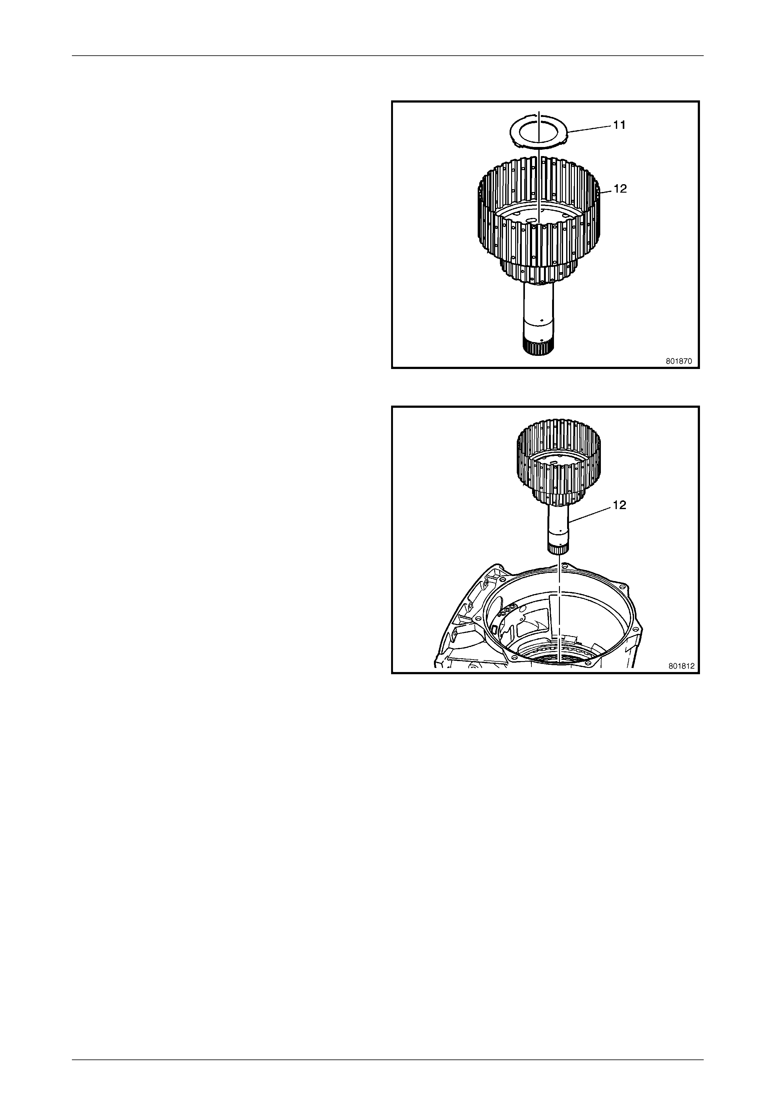
1 Apply some petroleum jelly to the input and reaction
carrier inner shaft thrust washer (11) and install into
the intermediate sprag clutch assembly (12).
Figure 7E5 – 104
2 Install the intermediate sprag clutch assem bly (12) into
the transmission case (24), ensuring that the mating
splines on the intermediate sprag clutch (1 2) engage
fully over both the overdrive clutch plates (482) and
the intermediate clutch plates (490).
Figure 7E5 – 105
Automatic Transmission – 5L40–E – Unit Repair 7E5 – 55
7E5 – 55
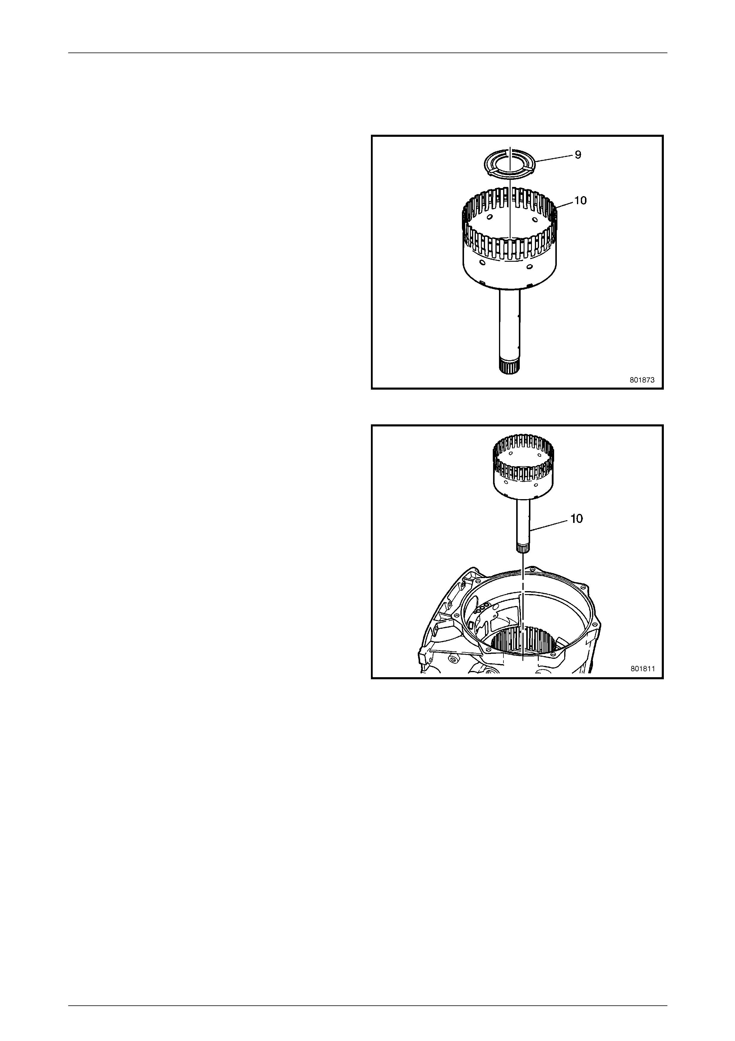
1.29 Direct Clutch Hub
Reassemble
1 Inspect the drum for the following:
• Worn or damaged splines
• Worn or damaged bushings
• Wear, cracks and scoring on the shaft
2 Install the direct clutch drum hub thrust washer (9) into
the drum (10).
Figure 7E5 – 106
3 Install the direct clutch drum (10) into the transmission
case (24).
Figure 7E5 – 107
Automatic Transmission – 5L40–E – Unit Repair 7E5 – 56
7E5 – 56
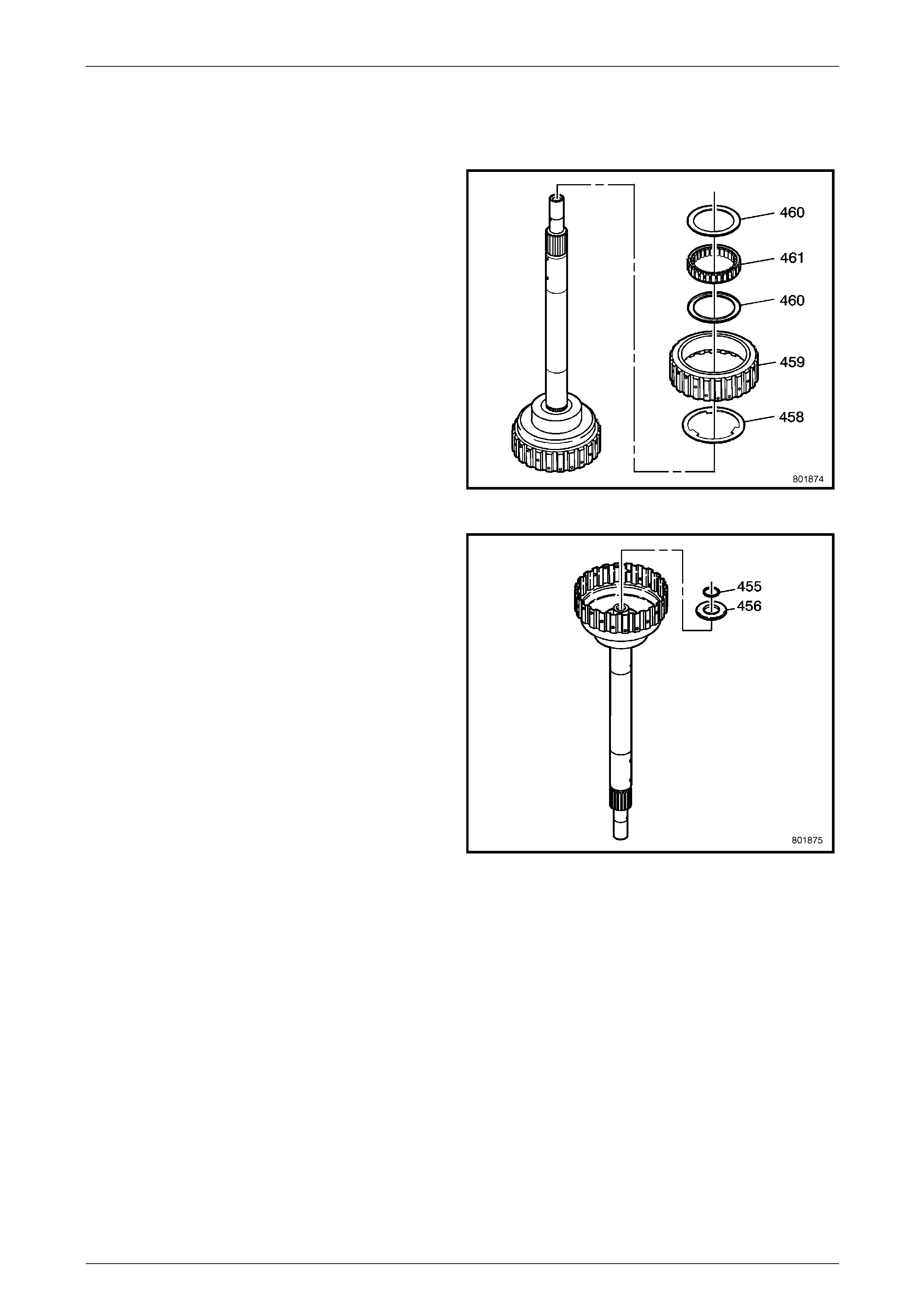
1.30 Input Sun Gear Shaft
Disassemble
1 Remove the forward clutch sprag outer race (459).
2 Remove the forward clutch outer race washer (458).
3 Remove the forward clutch sprag assembly retaining
rings (460).
4 Remove the forward clutch sprag (461).
Figure 7E5 – 108
5 Remove the forward clutch roller inner thrust race
thrust snap ring (455), using suitable snap ring pliers.
6 Remove the inner thrust bearing (456).
Figure 7E5 – 109
Automatic Transmission – 5L40–E – Unit Repair 7E5 – 57
7E5 – 57
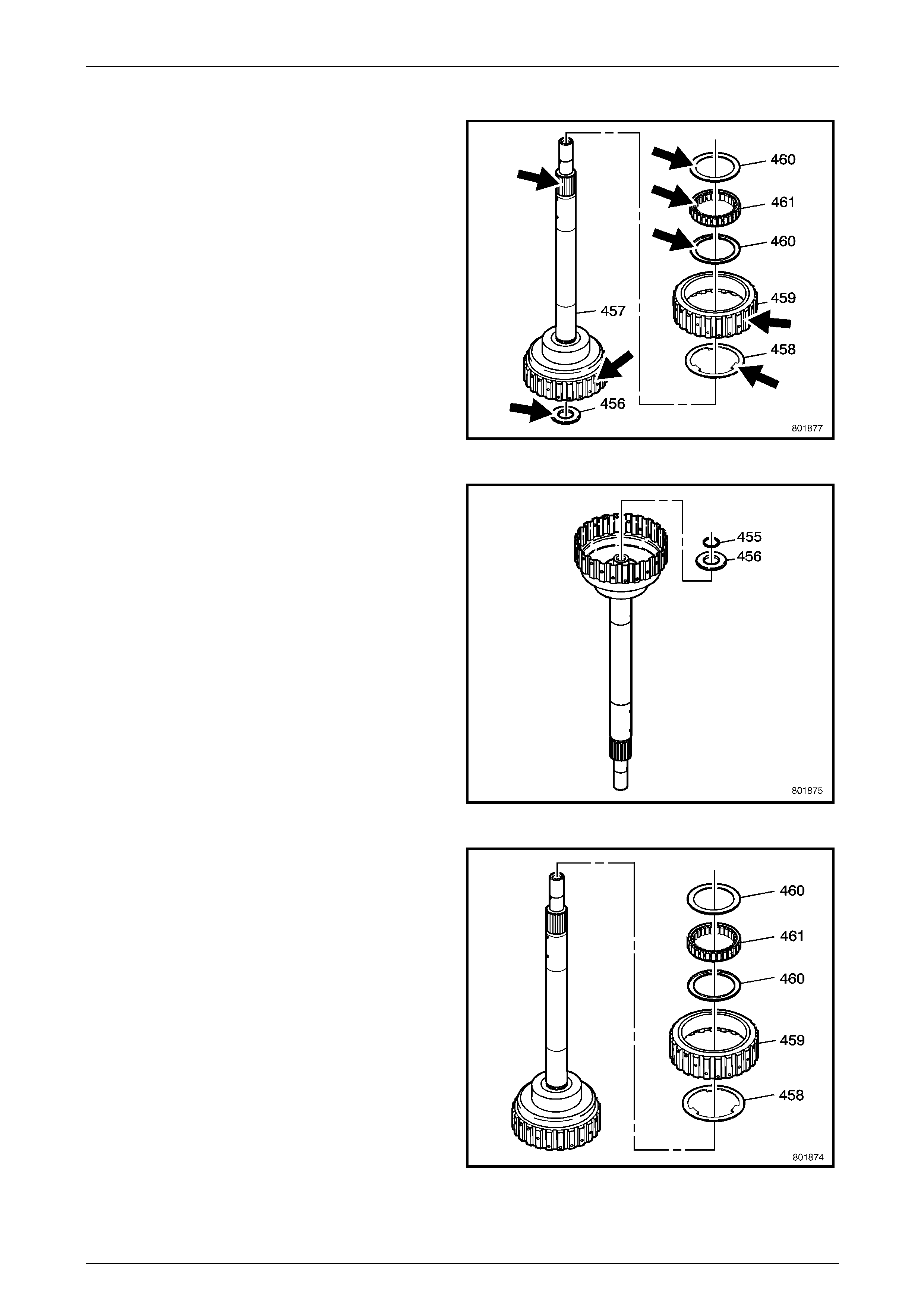
Reassemble
1 Inspect the outer race and input shaft for the following:
• Worn or damaged splines
• Scoring inside the diameter of the race
• Wear or cracks
2 Inspect the sprag elements for flat spots.
3 Inspect the cage for distortion or broken ribbon tabs.
4 Inspect the inner bearing for cracks.
Figure 7E5 – 110
5 Install the forward clutch roller inner thrust beari ng
(456).
6 Install a NEW inner race snap ring (455).
Figure 7E5 – 111
7 Install the outer race washer (458) onto the outer race
(459).
8 Install the retaining rings (460) and the forward clutch
sprag (461) onto the outer race (459).
9 Install the sprag assembly (460, 461, 459) onto the
sun gear shaft (457).
Figure 7E5 – 112
Automatic Transmission – 5L40–E – Unit Repair 7E5 – 58
7E5 – 58
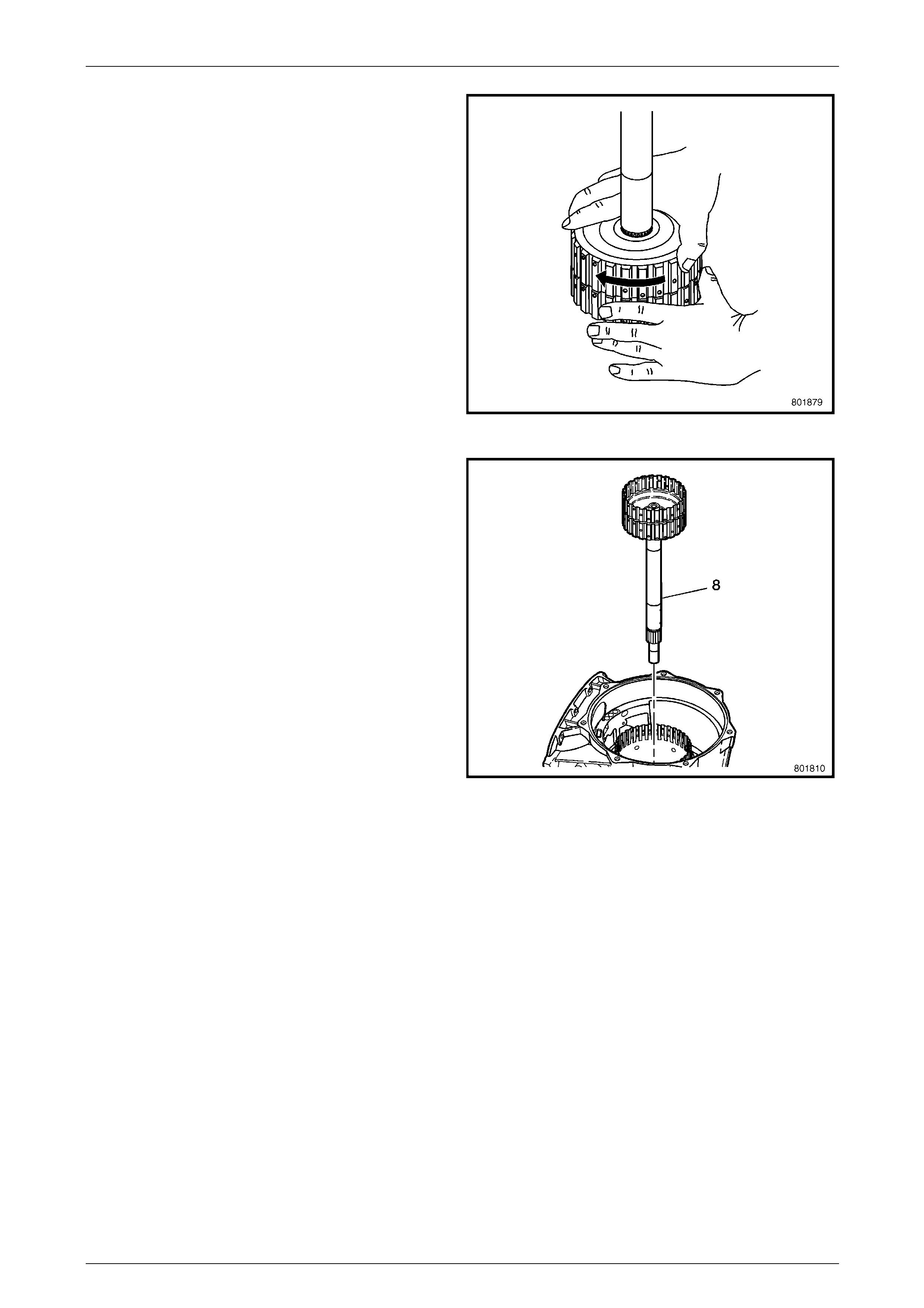
10 While holding the forward clutch sprag race with the
left hand, check that the sun gear shaft (457) rotates in
the direction shown and locks in the reverse direction.
Figure 7E5 – 113
11 Install the input sun gear shaft (8) into the
transmission (24).
Figure 7E5 – 114
Automatic Transmission – 5L40–E – Unit Repair 7E5 – 59
7E5 – 59
1.31 Forward and Coast Clutch
Disassemble
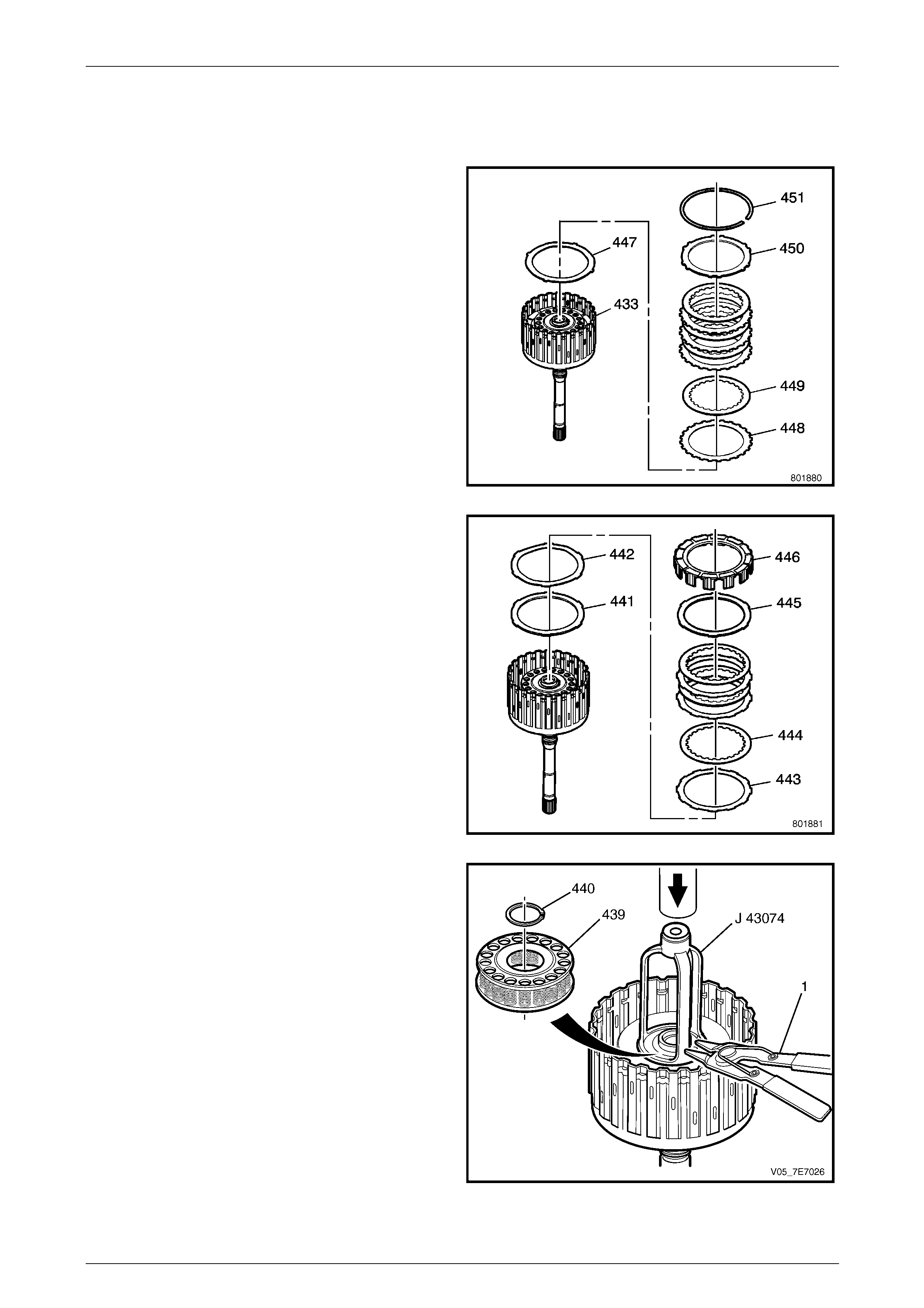
1 Using a flat bladed screwdriver, remove the forward
clutch backing plate retainer ring (45 1).
2 Remove the forward clutch backing plate (450).
3 Remove the forward clutch plates (448, 449) .
4 Remove the forward apply p late (447).
Figure 7E5 – 115
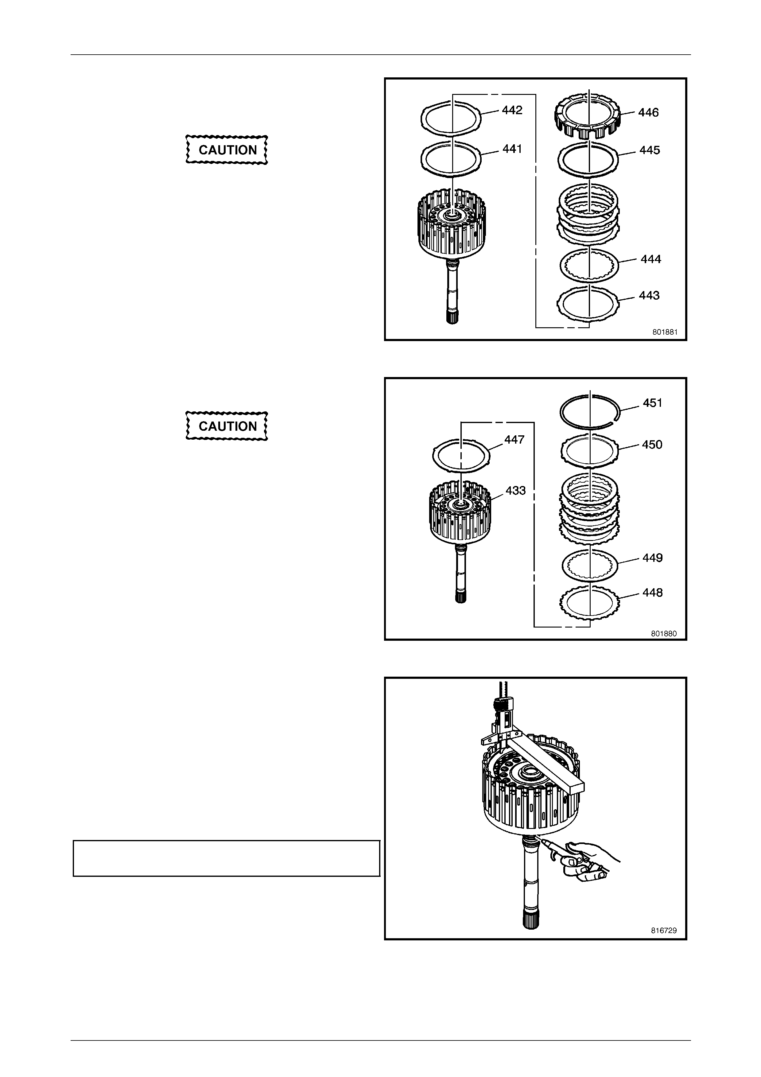
5 Remove the coast clutch housing (4 46).
6 Remove the coast backing plat e (445).
7 Remove the coast clutch plates (443, 444).
8 Remove the coast apply plate (442).
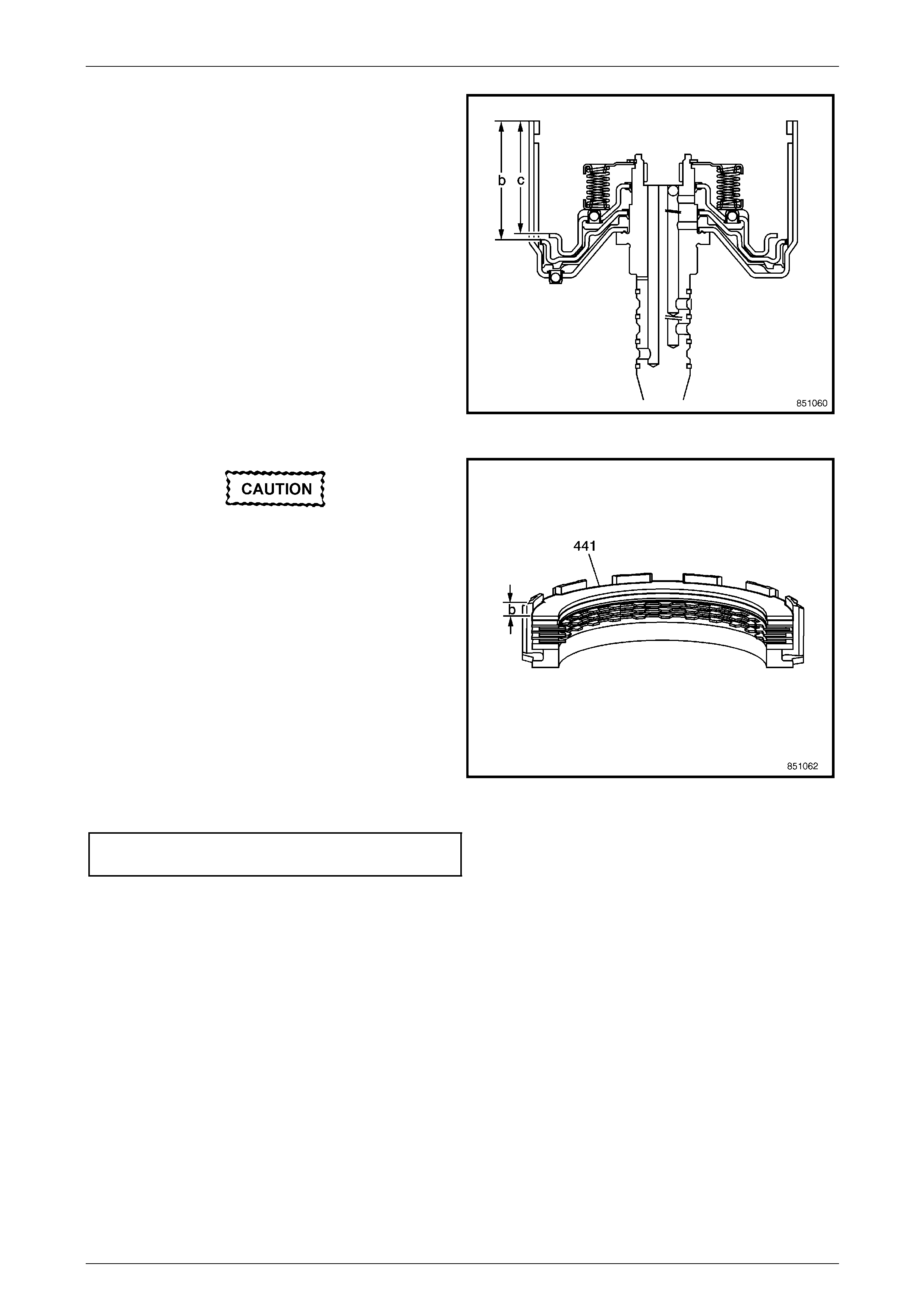
9 Remove the coast clutch spacer plate (441).
Figure 7E5 – 116
10 Position the forward clutch housing assembly (433) on
suitable flat press plates and place in a press.
Using Tool J 43074, clutch spring compressor, press
down on the forward and coast clutch spring (439) just
enough to allow access to the retaining circlip (440).
NOTE
As an alternative to J 43074, using J 23327-1
and adaptor plate J 25018-A is also effective .
11 Using suitable circlip pliers, re move the retaining
circlip (440) from the forward clutch housing retainer
ring groove.
12 Release the press and remove Tool J 43074 (or
J 23327-1 / J 25018-A).
13 Remove the forward clutch housing assembly (433)
from the press and remove the clutch spring (439).
Figure 7E5 – 117
Automatic Transmission – 5L40–E – Unit Repair 7E5 – 60
7E5 – 60
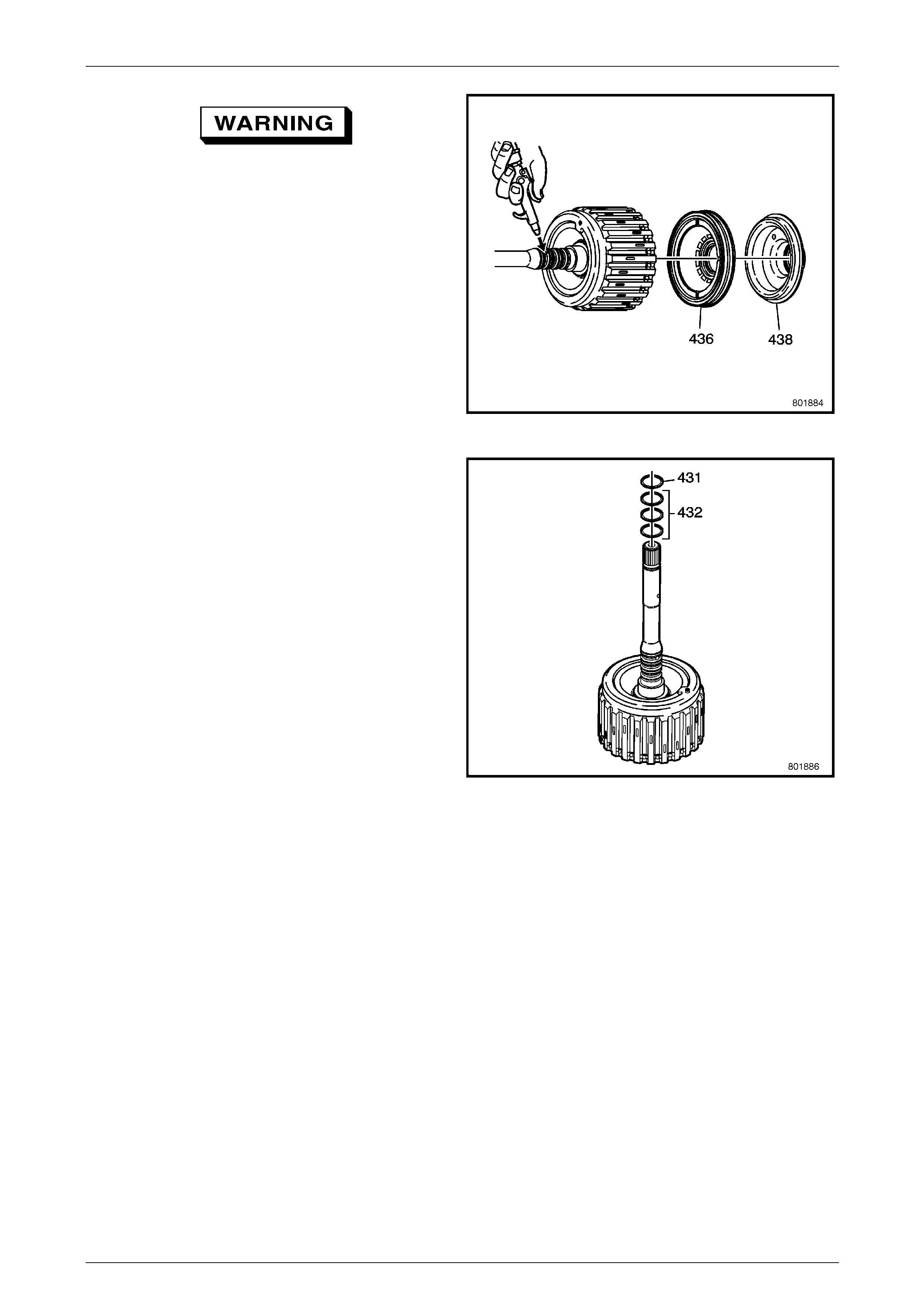
Wear eye protection to prevent potential
injury.
14 Remove the coast clutch piston (438).
15 Remove the forward clutch piston (436).
NOTE
It may be necessary to apply air pressure to the
forward clutch housing assembly port as shown,
to assist in the removal of the pistons.
Figure 7E5 – 118
16 Remove the solid input shaft fluid seal (431) by
carefully cutting the seal ring.
17 Remove the three scarf cut input shaft fluid seals
(432).
Figure 7E5 – 119
Reassemble
1 Inspect the forward clutch housing (433) for the following:
• Plugged feed passages.
• Damaged ball check valve (434).
• Worn or damaged splines.
• Seal ring groove nicks or burrs.
• Cracked or blocked fluid passages in the input shaft.
• Worn or damaged clutch plates.
Automatic Transmission – 5L40–E – Unit Repair 7E5 – 61
7E5 – 61
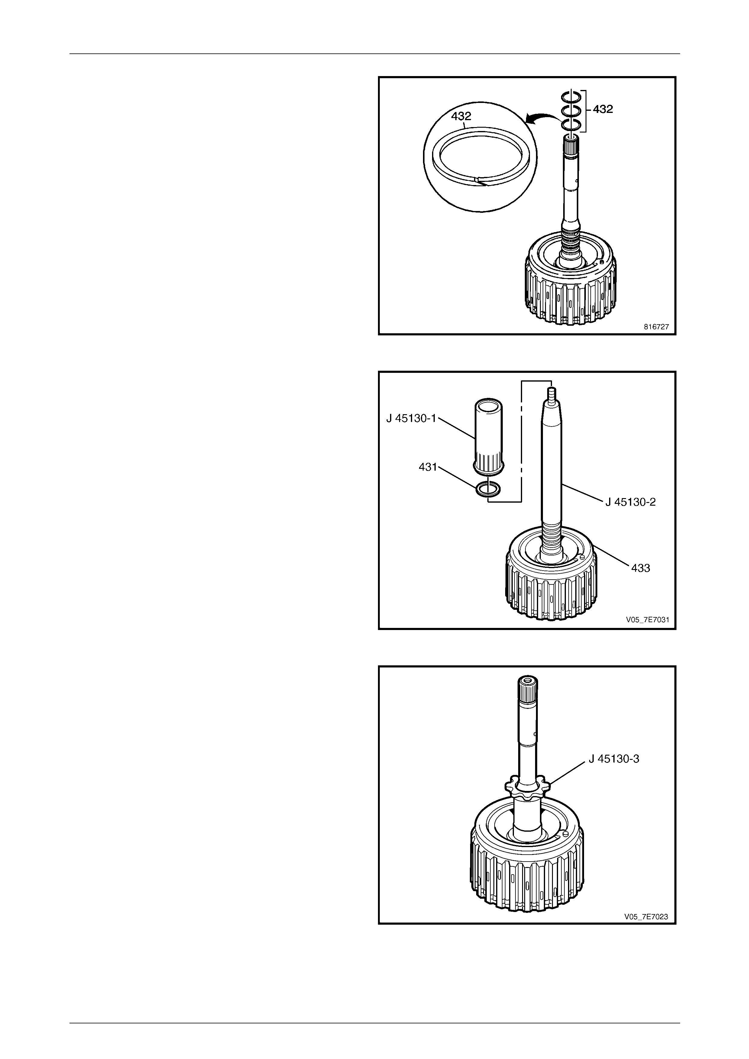
2 Inspect the NEW input shaft fluid seals (431, 432) for
damage.
3 After lubricating with clean transmission flui d, carefully
install the NEW input shaft fluid seals (432), installing
the one closest to the forward clutch housi ng (433)
first, then work outwards.
Figure 7E5 – 120
4 Slide Tool J 45130-2 over the input shaft. Adjust the
position of Tool J 45130-2 b y twisting the adjusting
screw at the top of the tool so that the bottom end is at
the seal groove furthest from the housin g. Coat J
45130-2 with clean transmission fluid.
5 Guide a NEW seal (431) onto T ool J 45130-2 and
slide the seal into the groove with T ool J 45130-1.
6 Remove Tool J 45130-2.
Figure 7E5 – 121
7 After lubricating the inner surface of Tool J 45130-3
with clean transmission lubricant, size the seals (431,
432) by carefully install the sizing Too J 45130-3 over
them.
8 Leave Tool J 45130-3 in place for at least five minutes.
If possible, leave Tool J 45130-3 in place until you
install the assembly into the transmission case.
Figure 7E5 – 122
Automatic Transmission – 5L40–E – Unit Repair 7E5 – 62
7E5 – 62
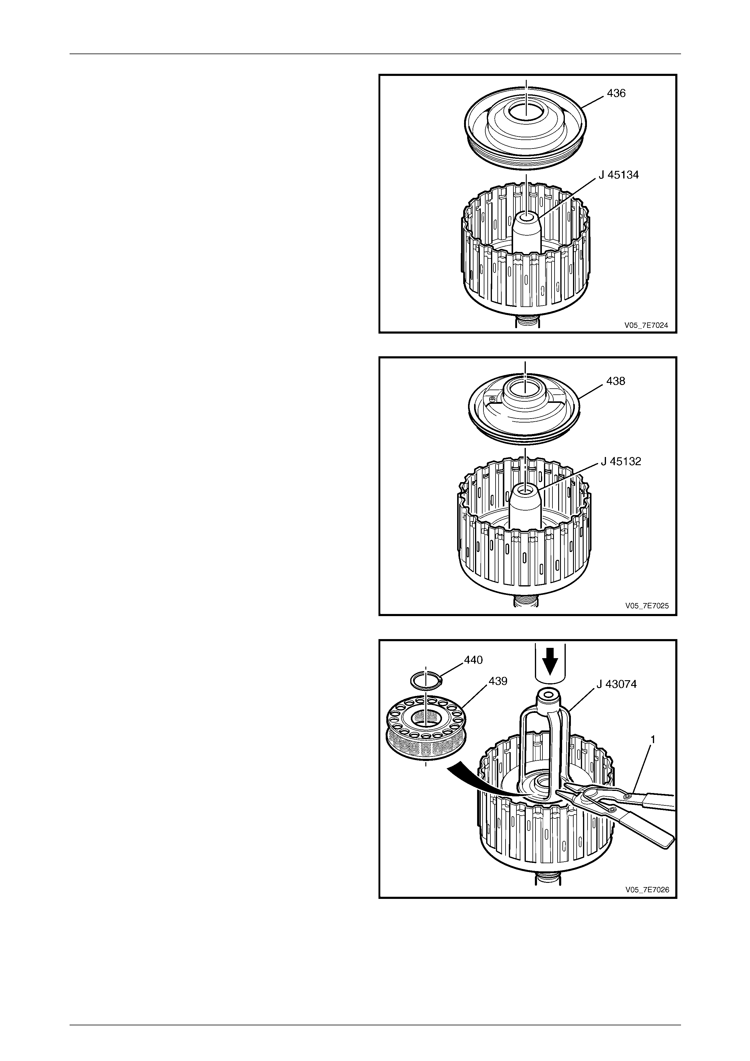
9 Inspect the forward piston and the coast clutch piston
for the following:
• Cracks or damage to seal grooves.
• Wear on the piston.
• Worn or damaged clutch plates.
10 Use Tool J 45134 to install the forward clutch piston
(436). Coat Tool J 45134 and the for ward clutch piston
seals with clean transmission fluid. Assembly the
forward clutch piston over the tool and push down into
the forward clutch housing.
Remove Tool J 45134.
Figure 7E5 – 123
11 Use Tool J 45132 to install the coast clutch piston
(438). Coat Tool J 45132 and the coast clutch piston
seals with clean transmission fluid. Assembly the
coast clutch piston over the tool and push do wn into
the forward clutch housing.
Remove Tool J 45132.
Figure 7E5 – 124
12 Inspect the forward and coast clutch piston spring for
the following:
• Damaged cage.
• Distorted or missing springs.
13 Install the piston spring (439).
14 Position the forward clutch housing assembly (433) on
suitable flat press plates and place in a press.
Using Tool J 43074 (J , clutch spring com pre ssor,
press down on the forward and coast clutch spring
(439) just enough to allo w access to the retaining
circlip groove. NOTE
As an alternative to J 43074, using J 23327-1
and adaptor plate J 25018-A is also effective .
15 Using suitable circlip pliers, install the retaining circlip
(440) to the forward clutch housing retainer ring
groove.
16 Release the press and remove Tool J 43074 (or
J 23327-1 / J 25018-A).
17 Remove the forward clutch housing from the press.
Figure 7E5 – 125
Automatic Transmission – 5L40–E – Unit Repair 7E5 – 63
7E5 – 63
18 Measure the distance from the top of the forward
clutch housing to the coast clutch piston (438), record
this as dimension C.
19 Measure the distance from the top of the forward
clutch housing to the forward clutch pisto n (4 36),
record this as dimension B.
20 Subtract dimension C from dimension B. This is now
dimension A.
21 Install the coast clutch backing plate (445) into the
coast clutch housing (446).
Figure 7E5 – 126
Ensure that the composition side of each
plate faces upwards.
22 Install the coast clutch plates into the coast clutch
housing (446). Starting with the coast clutch plate
(443) with outer splines. Alternating with the coast
clutch plate (444) with inner splines.
23 Install the coast clutch apply plate into the coast clutch
housing (446).
24 Install the coast clutch spacer plate (441) into the
coast clutch housing (446).
25 Measure the distance from the top of the coast clutch
housing (446) to the top of the coast clutch spacer
plate (441), record this as dimension B.
26 Subtract dimension B from dimension A, this is clutch
pack travel.
Coast Clutch Pack
Travel Specification................................ 1.17 – 1.67 mm
Figure 7E5 – 127
Automatic Transmission – 5L40–E – Unit Repair 7E5 – 64
7E5 – 64
27 Install the coast clutch spacer plate (441).
28 Install the coast clutch waved appl y plate (442).
Ensure that the composition side of each
plate faces upwards.
29 Install the coast clutch plates, starting with the coast
clutch plate (443) with the outer splines, alternating
with the coast clutch plate (444) with inner splines.
30 Install the coast clutch backing plate (445).
31 Install the coast clutch housing (446).
Figure 7E5 – 128
32 Install the forward clutch apply plate (447).
Ensure that the composition side of each
plate faces upwards.
33 Install the forward clutch plates. Starting with the
forward clutch plate (448) with outer splines.
Alternating with the forward clutch plate (449) with
inner splines.
34 Install the forward clutch backing plate (450).
35 Install the forward clutch backing plate retainer ring
(451).
Figure 7E5 – 129
36 Measure the distance between the forward clutch
backing plate and the bottom of the gauge bar.
Measure three times in different locations on the
backing plate. Record this as H1.
37 Apply air pressure to the specified port. Measure the
distance between the forward clutch backing plate and
the bottom of the gauge bar. Measure three times in
different locations on the backing plate. Record this as
H2.
38 Subtract H2 from H1 this is the clutch pack travel.
Forward Clutch Pack
Travel Specification................................ 1.20 – 1.65 mm
39 At this time you do not install the forward and coast
clutch assembly (7) into the transmission case. Set
aside until told to do so.
Figure 7E5 – 130
Automatic Transmission – 5L40–E – Unit Repair 7E5 – 65
7E5 – 65
1.32 Direct and Reverse Clutch
Disassemble
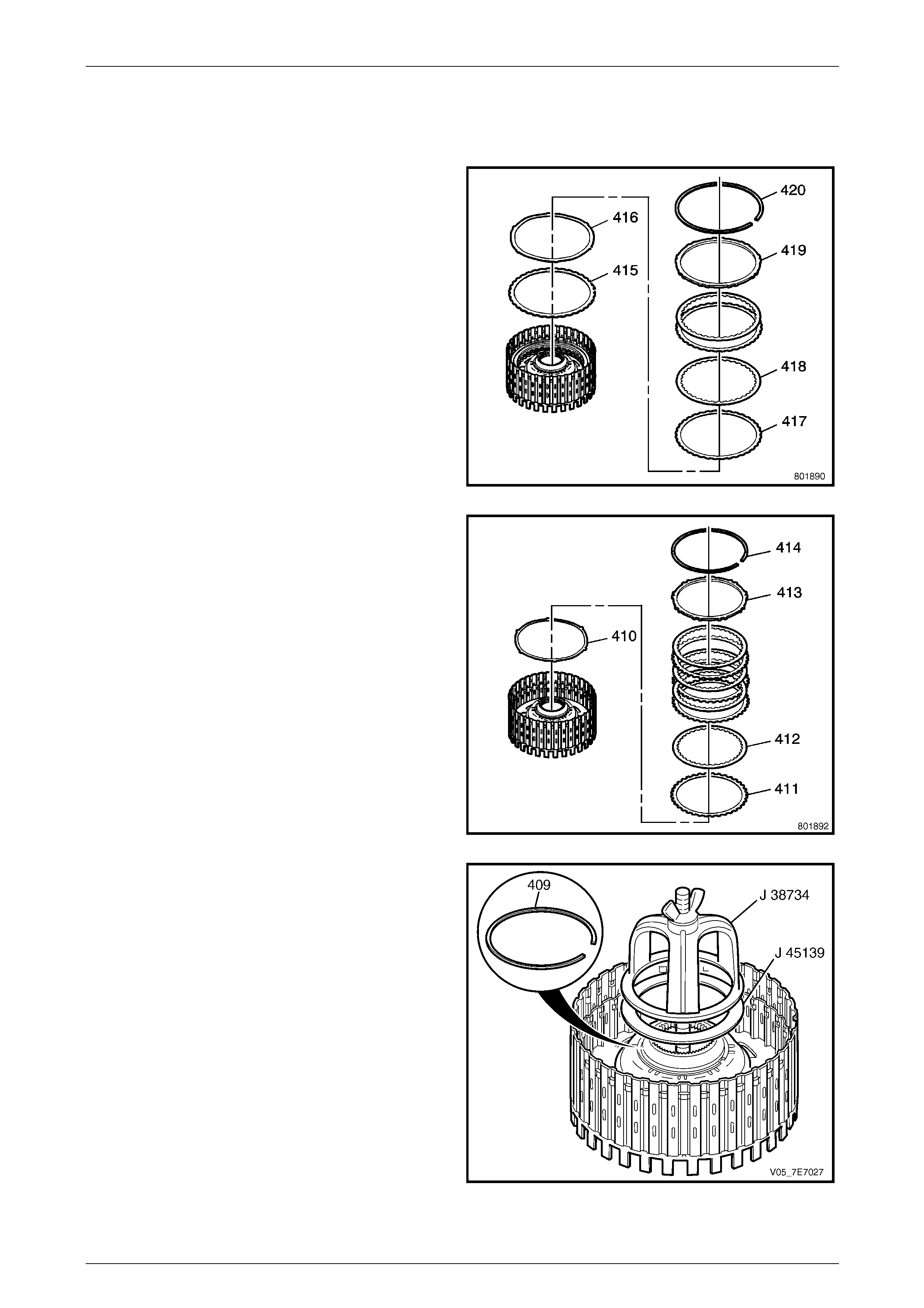
1 Using a fine bladed screwdriver, remove the reverse
clutch backing plate retainer ring (42 0).
2 Remove the backing plate (419).
3 Remove the clutch plates (418, 417).
4 Remove the apply plate (416).
5 Remove the reverse clutch spacer (415).
Figure 7E5 – 131
6 Remove the direct clutch backing plate reta iner ring
(414).
7 Remove the backing plate (413).
8 Remove the clutch plates (412, 411).
9 Remove the apply plate (410).
Figure 7E5 – 132
10 Using Tools J 38734 and J 45139, compress the direct
and reverse piston spring (407).
11 Using suitable snap ring pliers, remove the direct and
reverse clutch spring retainer ring (409).
12 Loosen and remove J 387 34 and J 45139.
Figure 7E5 – 133
Automatic Transmission – 5L40–E – Unit Repair 7E5 – 66
7E5 – 66
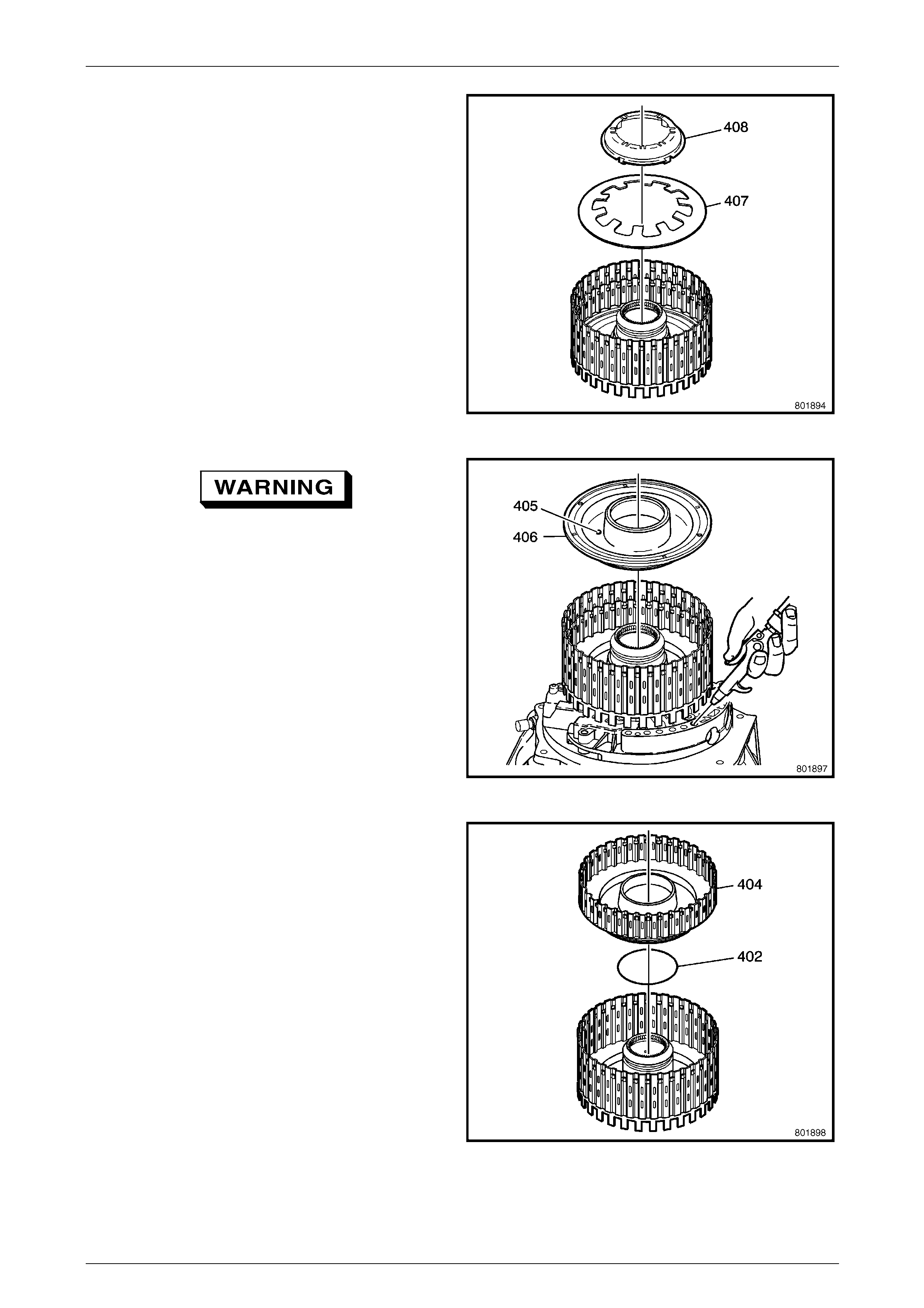
13 Remove the spring retainer (408).
14 Remove the spring (407).
Figure 7E5 – 134
Wear eye protection to prevent potential
injury.
15 To remove the direct clutch piston (406), assembl e the
reverse clutch housing to the fluid pump assembly.
Then apply air pressure to the fluid pump assembly
port as shown, to remove the piston.
Figure 7E5 – 135
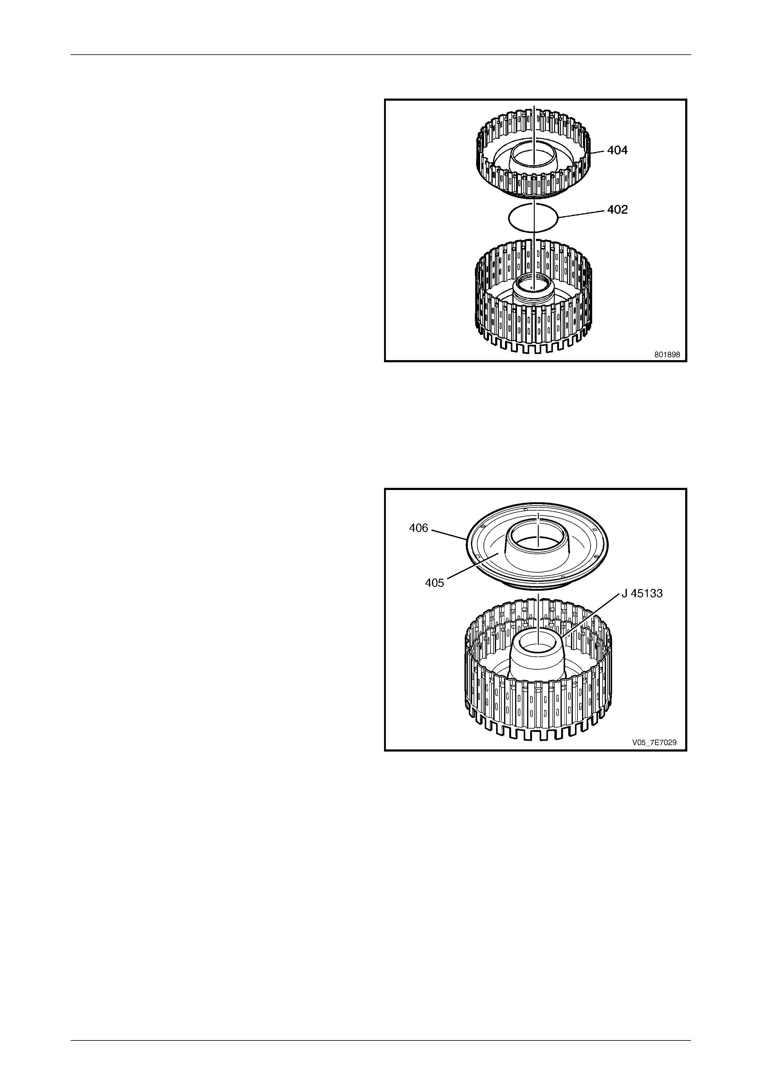
16 Remove the reverse clutch piston (404).
17 Remove the reverse clutch piston inner O-ring sea l
(402).
Figure 7E5 – 136
Automatic Transmission – 5L40–E – Unit Repair 7E5 – 67
7E5 – 67
Reassemble
1 Inspect the reverse clutch housing (401) for the
following:
• Plugged feed passages
• Worn or damaged splines
• Seal ring groove nicks or burrs
• Cracked or blocked fluid passages
• Worn or damaged bushing
2 Inspect the reverse clutch piston and the direct clutch
piston for the following:
• Cracks or damage to seal grooves
• Wear on the piston
• Inner seal damage
• Damaged ball check valve (405)
• Worn or damaged clutch plates
3 Install a NEW reverse clutch piston inner O-ring seal
(402).
4 After lubricating with petroleum jelly, install the reverse
clutch piston (404).
Figure 7E5 – 137
5 Install Tool J 45133 onto the direct an d reverse clutch
housing (401).
6 Coat Tool J 45133 and the direct clutch piston (406)
seals with petroleum jelly. Assemble the dir ect clutch
over the tool and push down into the direct and
reverse clutch housing.
Figure 7E5 – 138
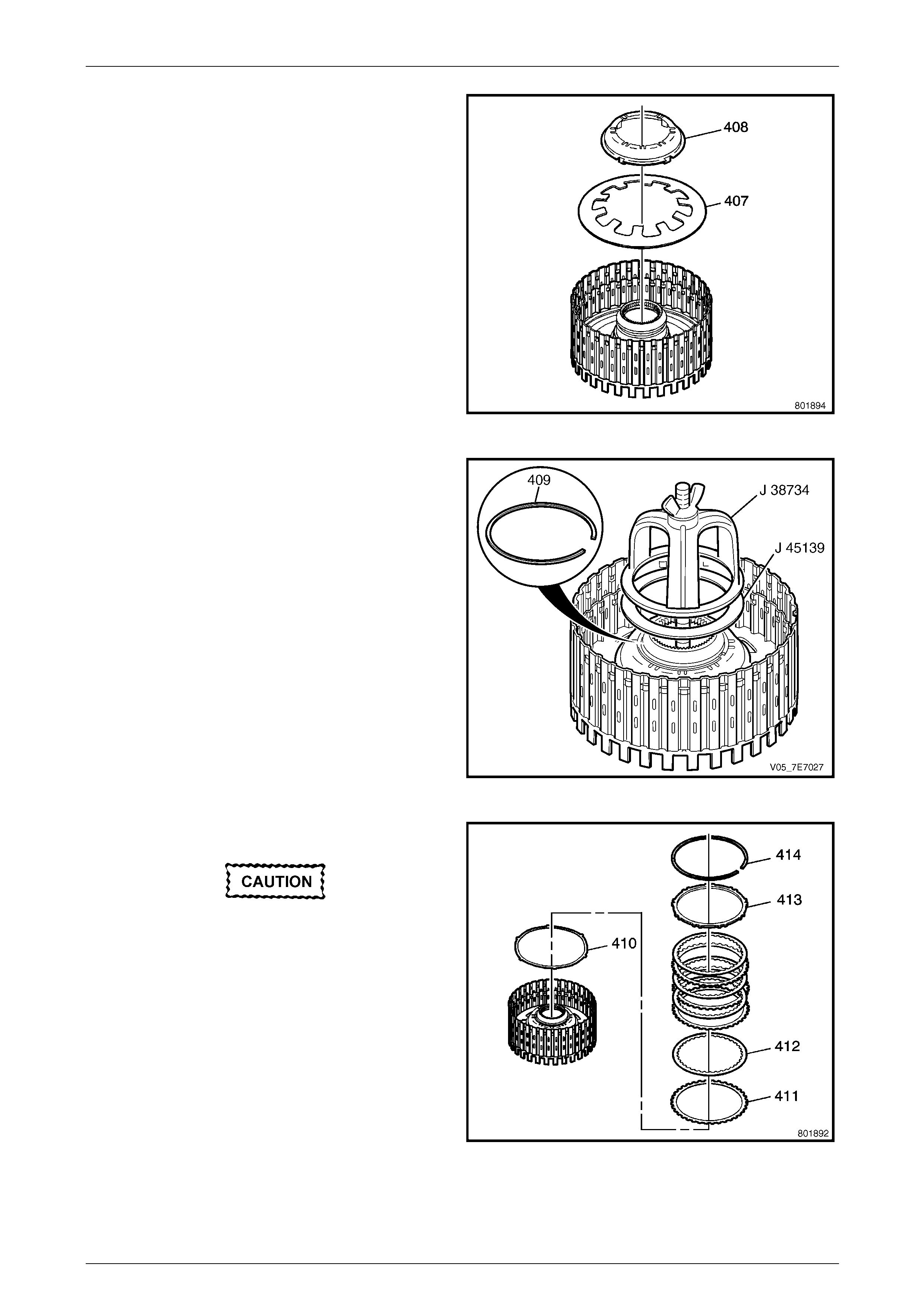
Automatic Transmission – 5L40–E – Unit Repair 7E5 – 68
7E5 – 68
7 Install the piston spring (407).
8 Install the piston spring retainer (408).
Place new direct and reverse clutch spri ng retainer
ring (409) on top of piston spring retainer (408).
Figure 7E5 – 139
9 Using Tools J 38734 (1) and J 45139 (2), compress
the direct and reverse piston spring (407).
10 Using suitable snap ring pliers, install the new direct
and reverse clutch spring retainer ring (409).
Figure 7E5 – 140
11 Install the direct clutch apply plate (410).
Ensure that the composition side of each
plate faces upwards.
12 Install the clutch plates (412, 411), starting with the
direct clutch plate (411) with outer splines, alternating
with the direct clutch plate (412) with inner splines.
13 Install the backing plate (413).
14 Install the backing plate retainer (414).
Figure 7E5 – 141
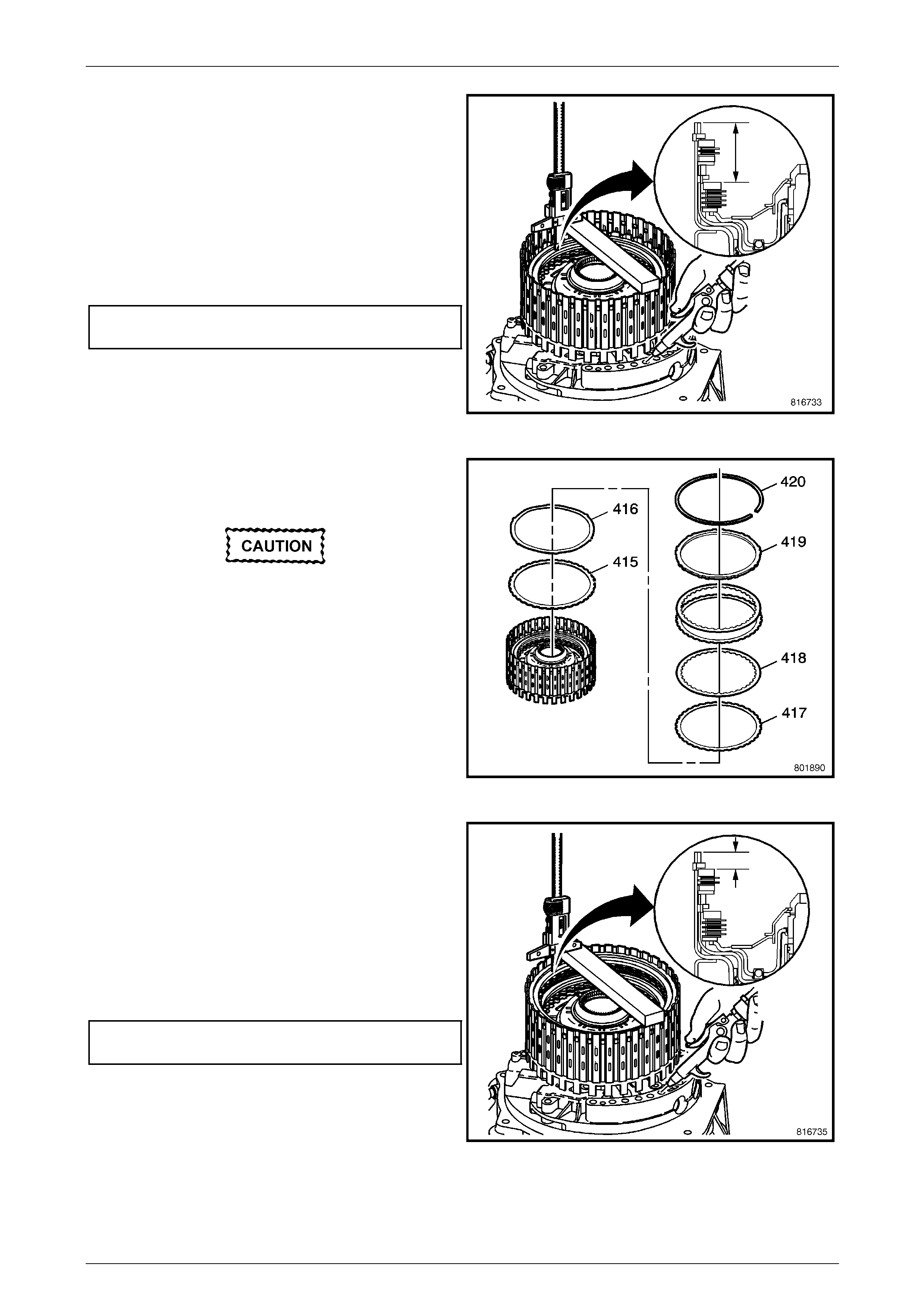
Automatic Transmission – 5L40–E – Unit Repair 7E5 – 69
7E5 – 69
15 Measure the distance between the direct clutch
backing plate and the bottom of the gauge bar.
Measure three times in different locations on the
backing plate. Record this as H1.
16 Apply air pressure – 450 kPa, to the specified port.
Measure the distance between the direct clutch
backing plate and the bottom of the gauge bar.
Measure three times in different locations on the
backing plate. Record this as H2.
17 Subtract H2 from H1 this is the clutch pack travel.
Direct Clutch Pack
Travel Specification................................ 1.41 – 1.86 mm
Figure 7E5 – 142
18 Install the reverse clutch spacer (415).
19 Install the apply plate (416).
Ensure that the composition side of each
plate faces upwards.
20 Install the clutch plates (417, 418), starting with clutch
plates (417) with outer splines, alternating with clutch
plates (418) with inner splines.
21 Install the reverse clutch backing plate (419).
22 Install the reverse clutch backing plate retainer (420).
Figure 7E5 – 143
23 Measure the distance between the reverse clutch
backing plate and the bottom of the gauge bar.
Measure three times in different locations on the
backing plate. Record this as H1.
24 Apply air pressure – 450 kPa, to the specified port.
Measure the distance between the reverse clutch
backing plate and the bottom of the gauge bar.
Measure three times in different locations on the
backing plate. Record this as H2.
25 Subtract H2 from H1 this is the clutch pack travel.
Reverse Clutch Pack
Travel Specification................................ 0.98 – 1.43 mm
Figure 7E5 – 144
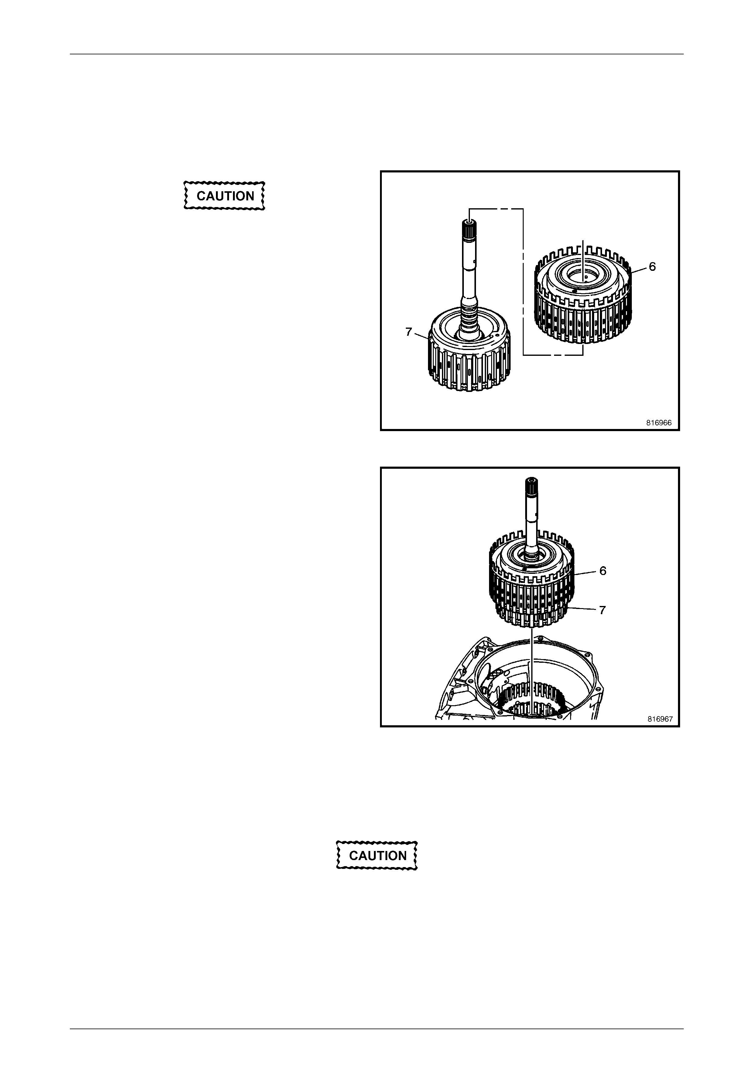
Automatic Transmission – 5L40–E – Unit Repair 7E5 – 70
7E5 – 70
1.33 Direct and Reverse Clutch - Forward and
Coast Clutch
Reinstall
Do not damage the input shaft fluid seals
when removing or installing the direct and
reverse coast clu t ch assembly.
1 Place the direct and reverse clutch assembly (6) onto
the forward and coast clutch assembly (7).
Figure 7E5 – 145
2 Install the direct and reverse clutch assembly (6) and
the forward and coast clutch assembly (7) into the
case (24).
Figure 7E5 – 146
Alternative Reassembly Method
1 Pre-assemble the input sun gear shaft (457) and sprag clutch (459) assembly to the forward and coast clutch
assembly (7).
Do not damage the input shaft fluid seals
when removing or installing the direct and
reverse coast clu t ch assembly.
2 Install the direct and reverse clutch (6) over the input shaft and engage the direct and reverse clutch plates with the
splines on the forward and coast clutch assembly (7).
3 Install the direct clutch assembl y (10) over the inp ut sun gear shaft (8).
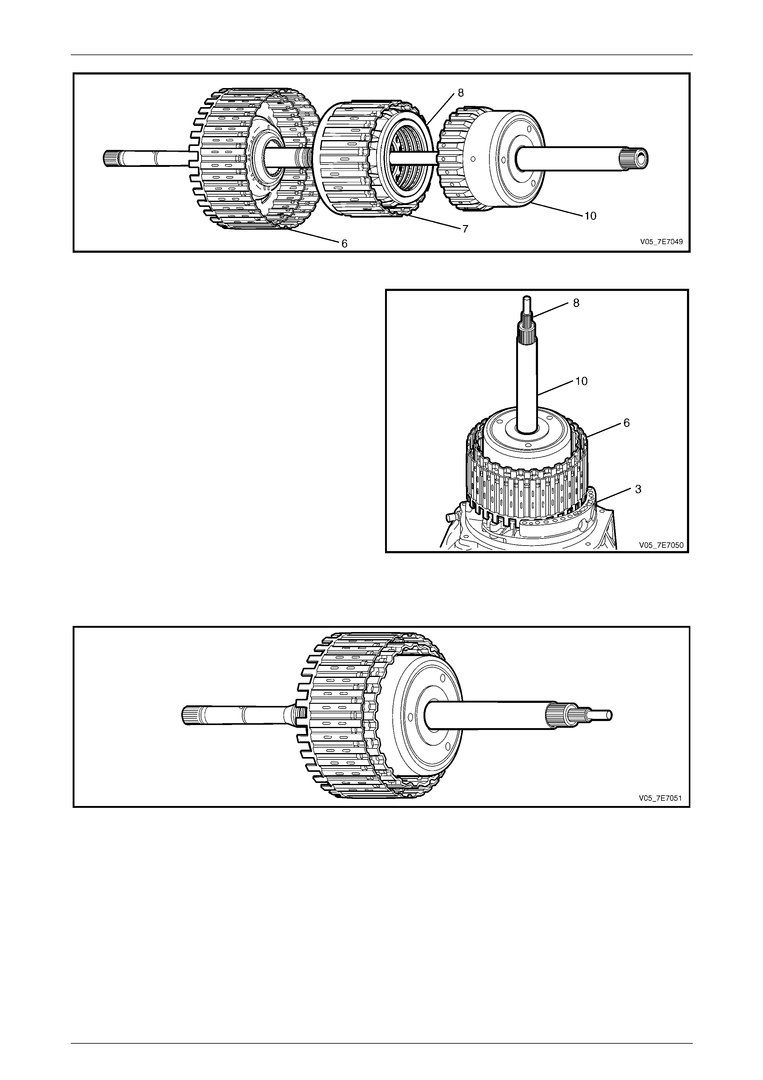
Automatic Transmission – 5L40–E – Unit Repair 7E5 – 71
7E5 – 71
Figure 7E5 – 147
NOTE
This assembling process will be easier, if the
separate assemblies are mounted on the torque
converter housing and fluid pump assembly (3).
Figure 7E5 – 148
4 With the transmission case rotated to the horizontal position (fluid pan side up), remove the pre-assembled
components from the torque converter housing (3) and install them into the transmission case (24).
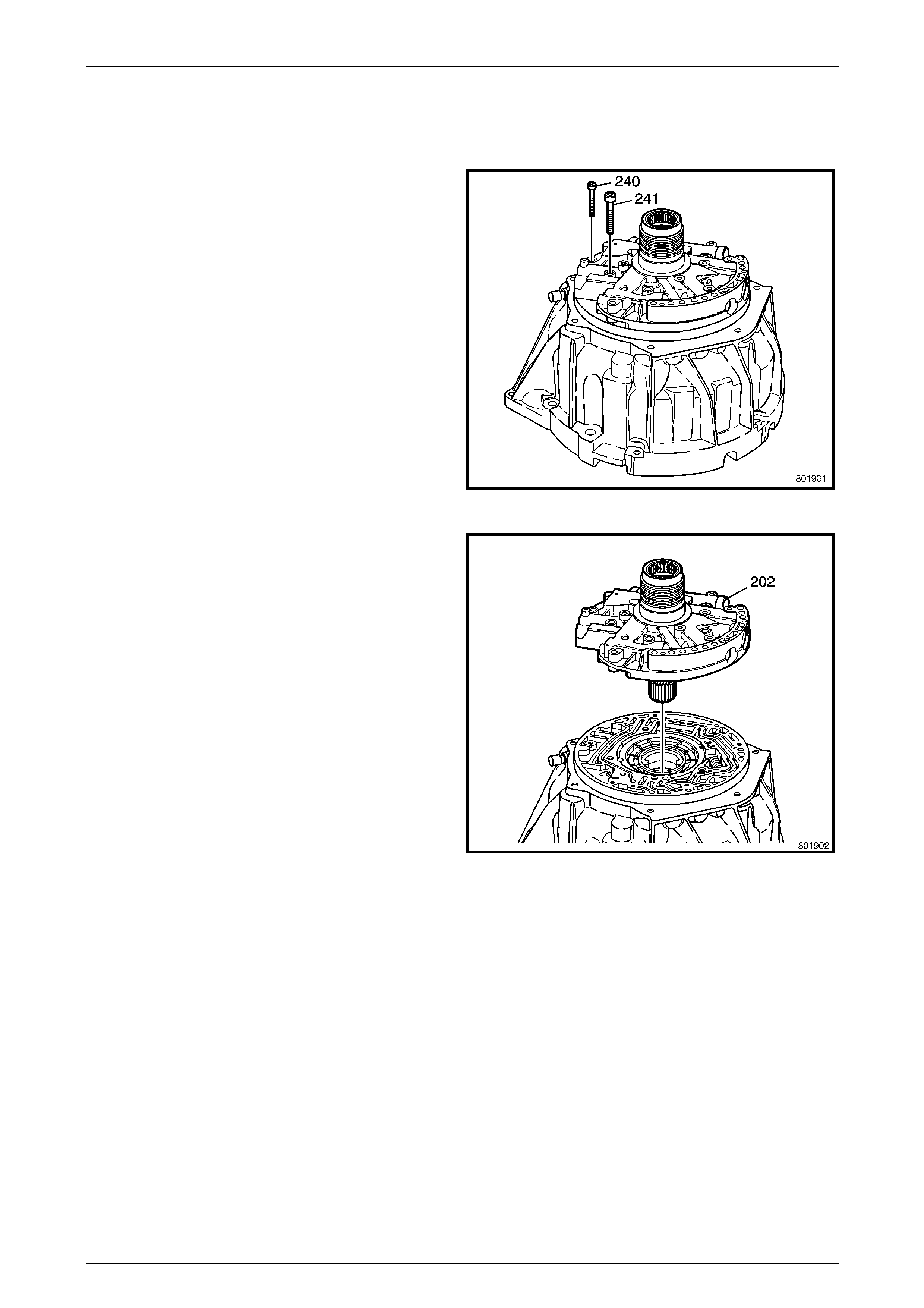
Automatic Transmission – 5L40–E – Unit Repair 7E5 – 72
7E5 – 72
1.34 Fluid Pump
Remove
1 Remove the fluid pump to torque converter housing
bolts (240, 241).
NOTE
Bolts '240' are T30 Torx bit headed, while bolts
'241' are Torx bit heade d T45.
Figure 7E5 – 149
2 Remove the fluid pump cover (202).
Figure 7E5 – 150
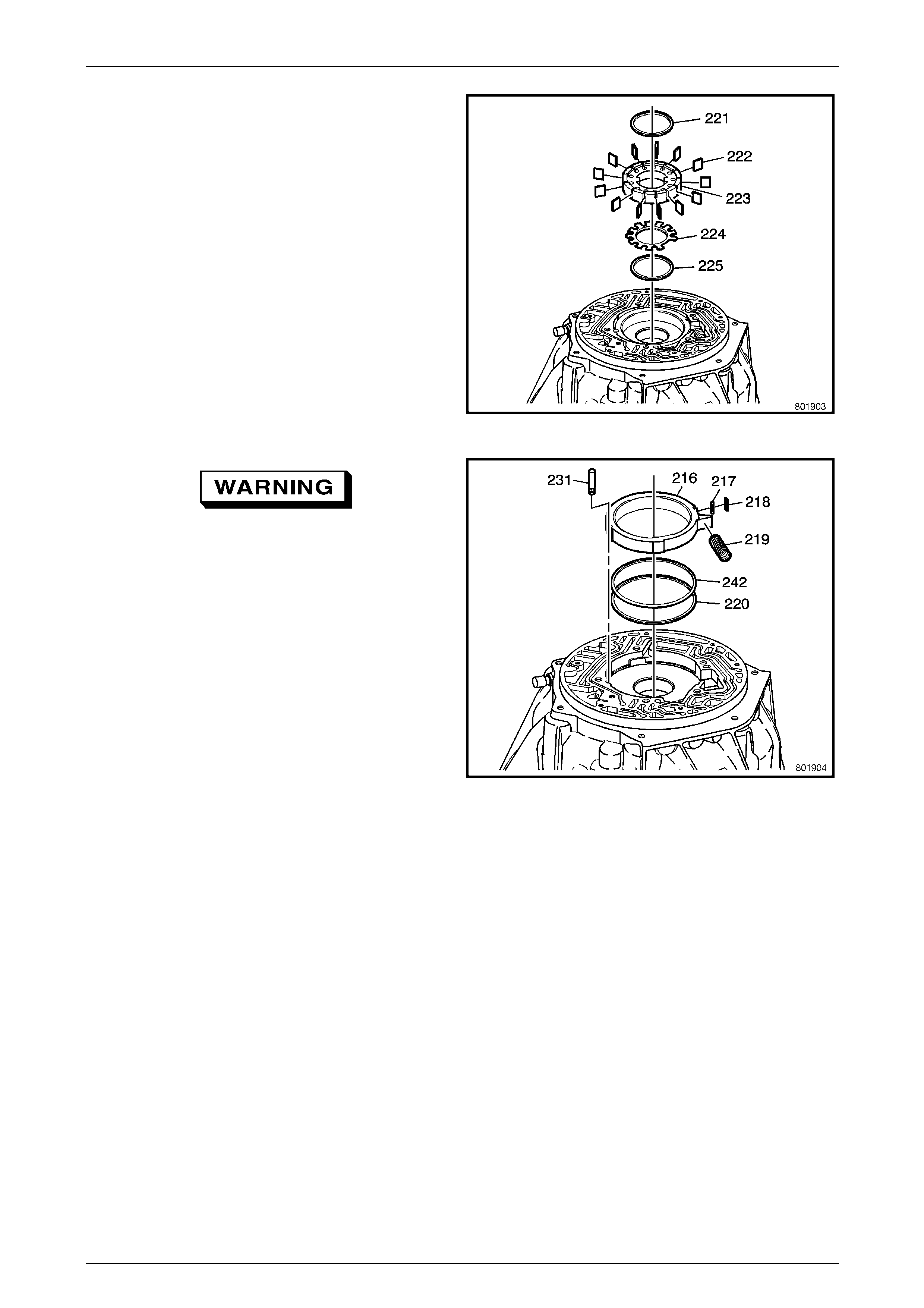
Automatic Transmission – 5L40–E – Unit Repair 7E5 – 73
7E5 – 73
3 Remove the pump vane ring (221).
4 Remove the pump vanes (222).
NOTE
If not replacing pump components, remove
vanes and keep in their original relationships
with the pump rotor (223.
5 Remove the pump rotor (223).
6 Remove the pump rotor guide (224).
7 Remove the pump vane ring (225).
Figure 7E5 – 151
The pump slide spring (219) is under a high
load. Wear eye protection and place a rag
over the spring before and during removal, to
prevent possible injury.
8 Remove the pump slide spring (219).
9 Remove the pump slide (216).
10 Remove the fluid pump slide pin (231).
11 Remove the pump slide ring (220, 242).
12 Remove the fluid pump suppo r t (217) and the fluid
pump slide seal (218).
Figure 7E5 – 152
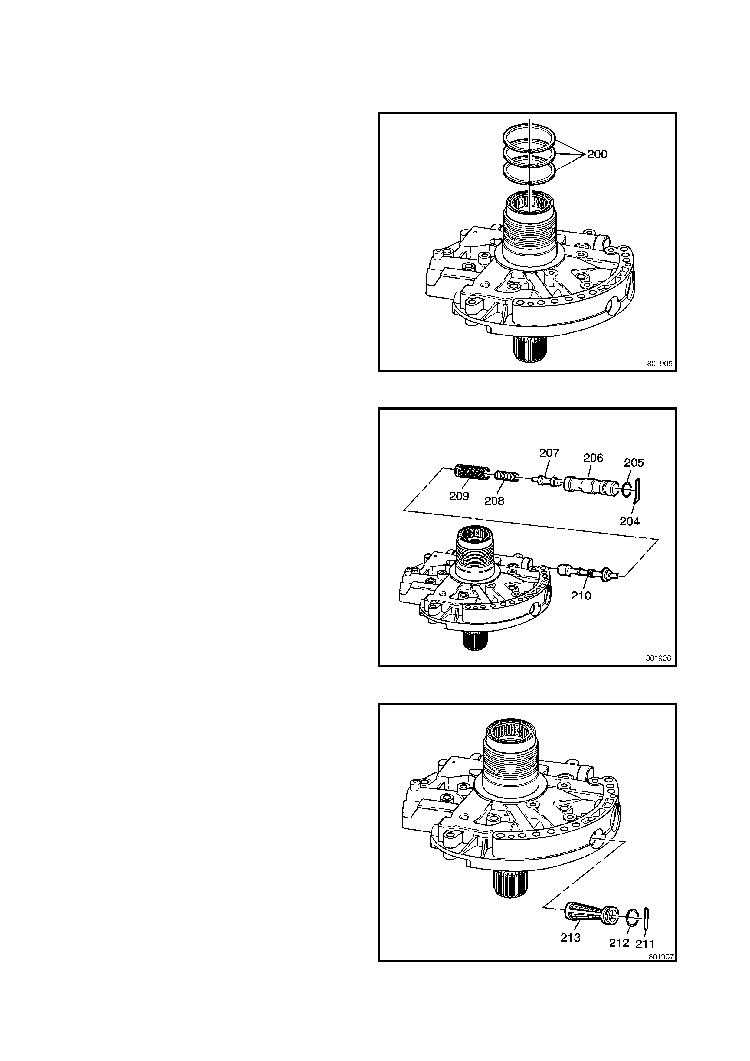
Automatic Transmission – 5L40–E – Unit Repair 7E5 – 74
7E5 – 74
Disassemble
1 Remove the reverse clutch housing seal rings (200).
Figure 7E5 – 153
2 Remove the line boost valve retainer (20 4).
3 Remove the line boost valve bushing (206) and the
line boost valve (207).
4 Remove the line boost valve bushing seal (205).
5 Remove the line boost valve s prin g (208) and the
pressure regulator valve spring (209).
6 Remove the pressure regulator valve (210).
Figure 7E5 – 154
7 Remove the fluid pump cover screen pin (211).
NOTE
The pin hole has been staked to prevent
accidental pin loss.
8 Remove the pump cover screen (213).
9 Remove the fluid pump cover O-ring seal (212).
Figure 7E5 – 155
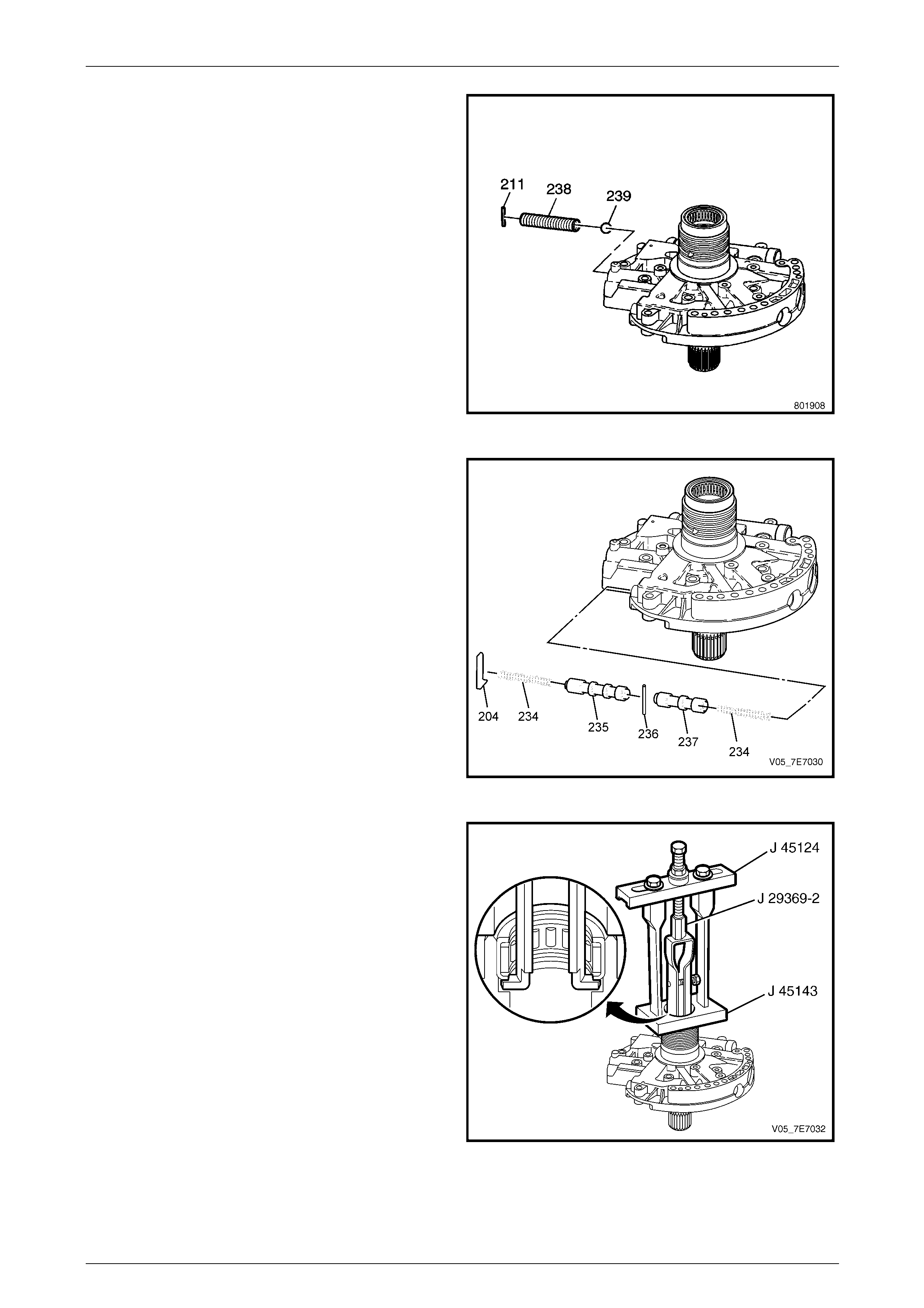
Automatic Transmission – 5L40–E – Unit Repair 7E5 – 75
7E5 – 75
10 Remove the pressure relief ball pi n (211).
11 Remove the pressure relief spring (2 38) and the
pressure relief ball (239).
Figure 7E5 – 156
12 Remove the TCC control valve pin (2 04).
13 Remove the TCC control valve sprin g (234) and the
TCC control valve (235).
Figure 7E5 – 157
14 Inspect the input shaft bearing (201) for the following:
• Damaged bearing cage
• Pitted bearings
• Scored bearings
15 If the bearing is damaged, inst all Tool J 45143 onto
the fluid pump.
16 Assemble Tools J 29369-2 on to J 45124 together and
install into the fluid pump and tighten J 29369-2.
17 Tighten J 45124 to remove the input shaft beari ng
(201).
Figure 7E5 – 158
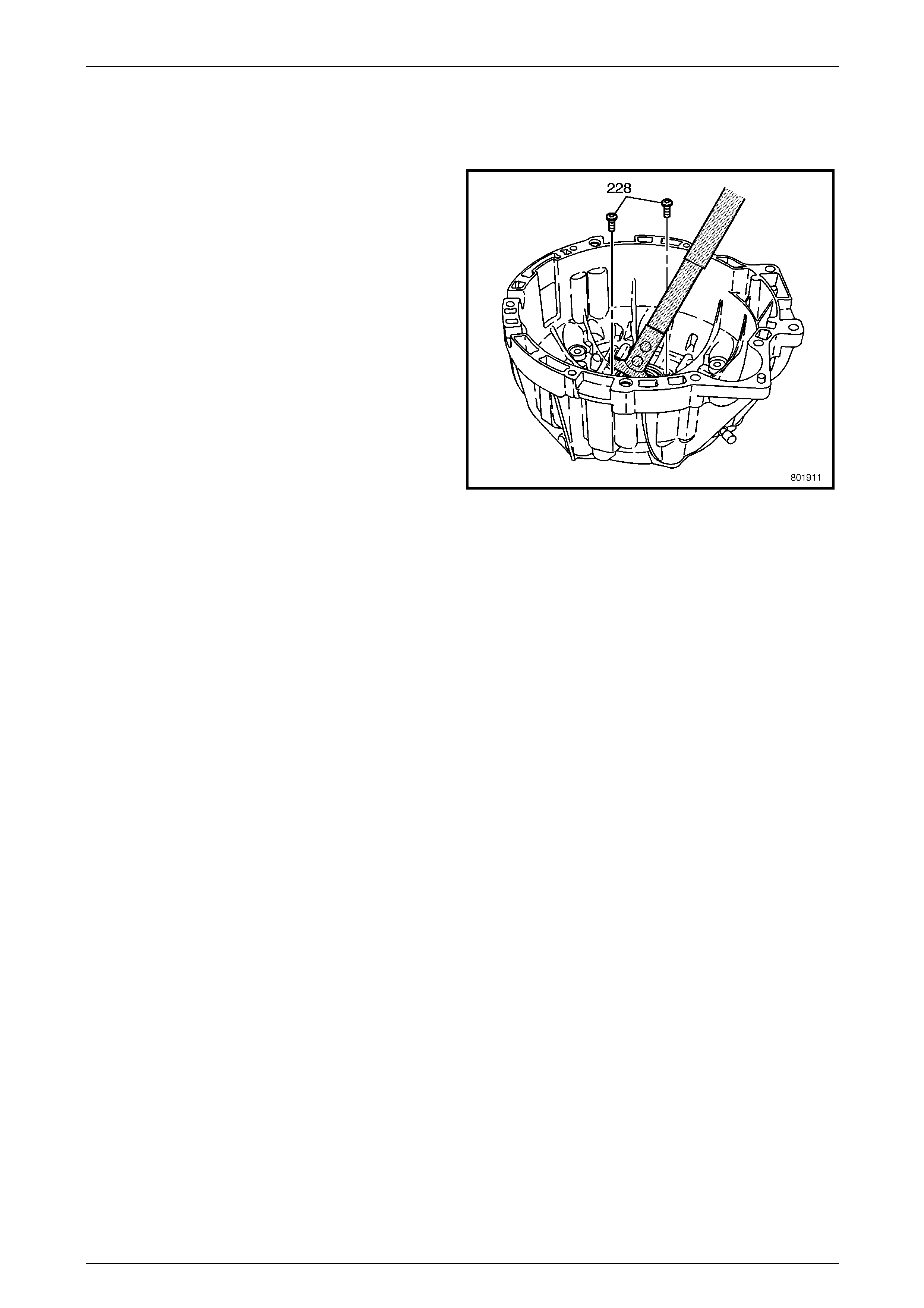
Automatic Transmission – 5L40–E – Unit Repair 7E5 – 76
7E5 – 76
1.35 Torque Converter Seal
Remove
1 Remove the two screws (228), using Torx bit T20 and
suitable equipment.
2 Remove the torque converter seal using Tool J 45000
(as shown), E308 or commercial equivalent.
Figure 7E5 – 159
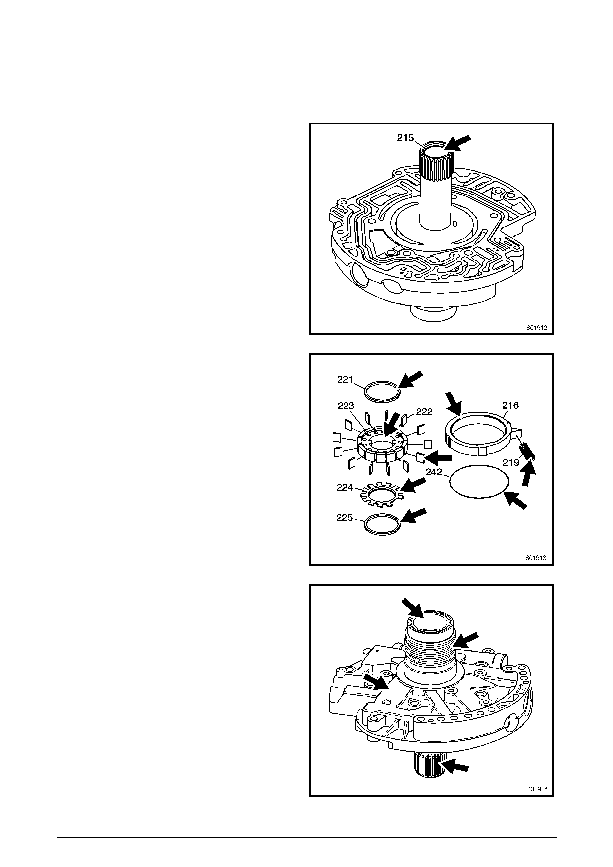
Automatic Transmission – 5L40–E – Unit Repair 7E5 – 77
7E5 – 77
1.36 Fluid Pump
Reassemble
1 Inspect the bushing (215) for wear – not serviced
separately. If found to be faulty or excessively worn,
replace the fluid pump assembly.
Figure 7E5 – 160
2 Inspect the oil pump parts for the following:
• Worn, scored or gouged pump slide (216).
• Cracks, wear or damage to the rotor (223),
vanes (222), rotor guide (224) or vane guide
rings (221, 225).
• Cuts or damage to the fluid pump slide O-ring
seal (242 and slide seal (not shown).
• Broken or distorted pump slide spring (21 9).
Figure 7E5 – 161
3 Inspect the oil pump housing for the following:
• Porosity.
• Interconnected oil passages.
• Damaged machined surfaces.
Figure 7E5 – 162
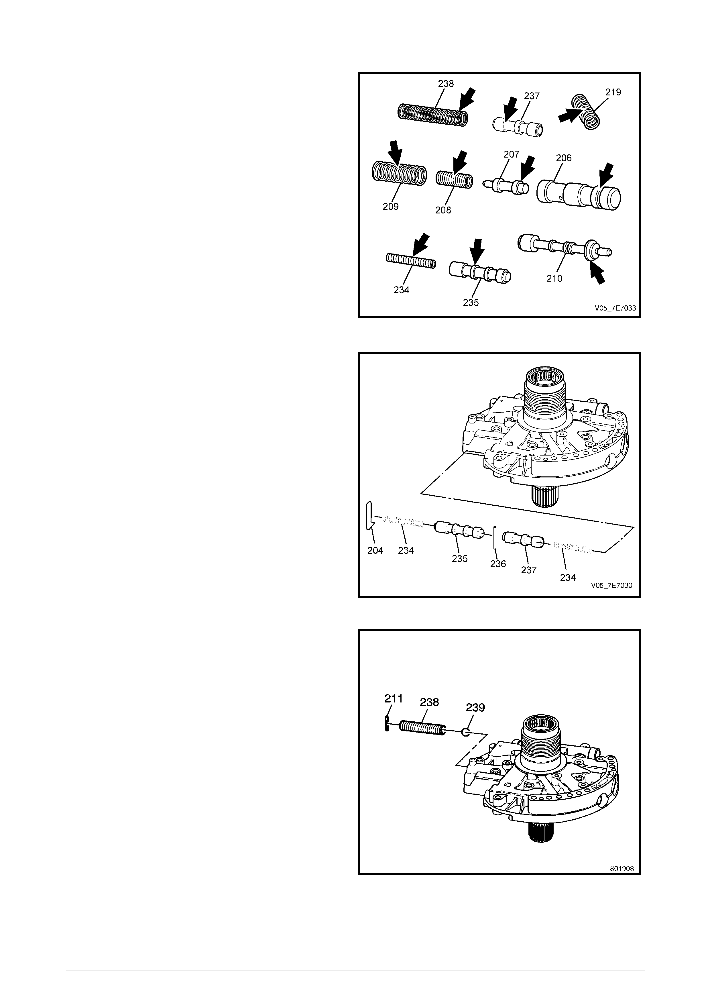
Automatic Transmission – 5L40–E – Unit Repair 7E5 – 78
7E5 – 78
4 The bushing (206), valves 207, 210, 235 and 237 for
nicks or burrs.
5 Inspect springs 208, 209, 219, 234 (2 places) and 238,
for wear, distortion or cracks.
Figure 7E5 – 163
6 Install the TCC control valve spring (234), TCC enable
valve (237) and secure with pin (236.
7 Install the TCC control valve (235) and the TCC
control valve spring (234).
8 Install the TCC control valve spring retainer (204).
Figure 7E5 – 164
9 Install the pressure relief valve bal l (239) and spring
(238).
10 Compress the pressure valve spring, then ins t all the
retainer (211).
Figure 7E5 – 165
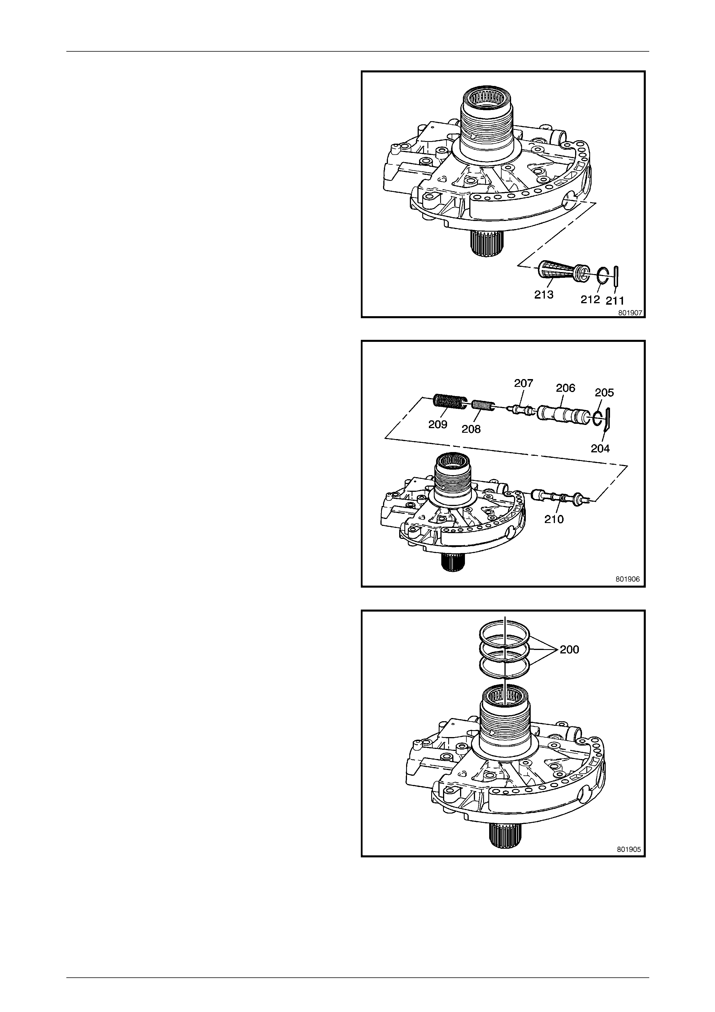
Automatic Transmission – 5L40–E – Unit Repair 7E5 – 79
7E5 – 79
11 Install the new pump cover O-ring (212) onto a NEW
pump cover screen (213).
12 Install the pump cover screen (213) assembly.
13 Install the pump cover screen pin (211), then lightly
stake the housing to retain.
Figure 7E5 – 166
14 Install the pressure regulator valve (210), the pressure
regulator valve spring (209), a nd the line boost valve
spring (208).
15 Install the line boost valve bushing O-ring (205) onto
the bushing (206).
16 Install the line boost valve (207) into the bushing
(206), then install the sub-assembl y.
17 Apply a load to the bushing, then install the line boost
valve bushing retainer (204).
Figure 7E5 – 167
18 Install the reverse clutch housing fluid seal rings (200).
Figure 7E5 – 168
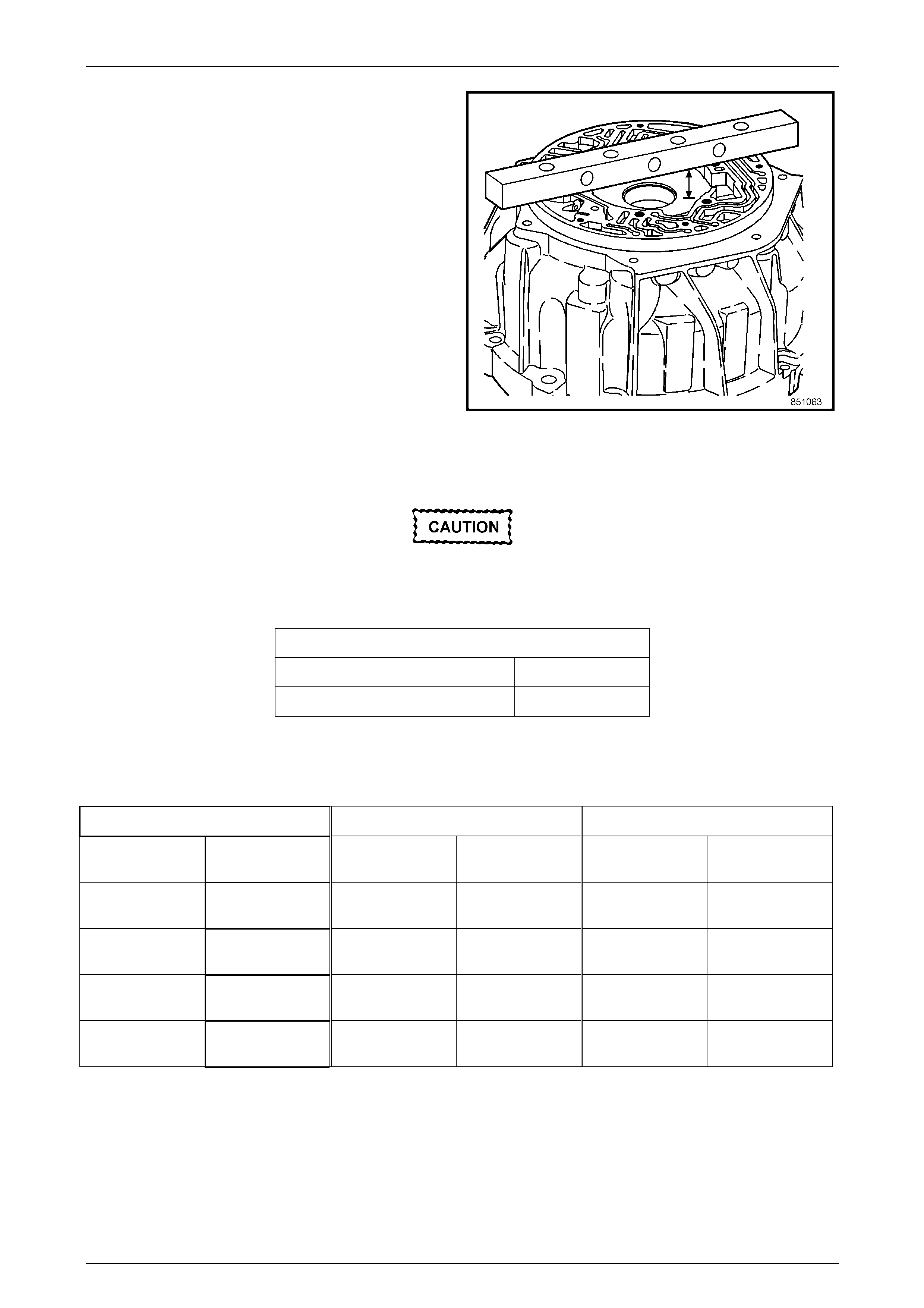
Automatic Transmission – 5L40–E – Unit Repair 7E5 – 80
7E5 – 80
19 Measure the distance from the bottom of the gaug e
bar to the pump body. Refer to the following Fluid
Pump Specifications Chart.
20 Measure the thickness of pump slide (216).
21 Select the proper size. Refer to the following Fluid
Pump Specifications Chart.
22 Measure the thickness of the pump rotor (223).
23 Select the proper size rotor, refer to the follo wing Fluid
Pump Specifications Chart.
Figure 7E5 – 169
Fluid Pump Specifications Chart
Rotor and slide must be chosen from the
same size classification as the fluid pump
body.
Allowable rotor and slide to fluid pump body end play is as follows:
Rotor and Slide to Fluid Pump Body End Play
Slide to Fluid Pump Body End Pla y – 0.030–0.051 mm
Rotor to Fluid Pump Body End Pla y –0.030 –0.051 mm
The fluid pump assembly has a selectiv e rotor and slide components. These compone nts are chosen based on pump
body dimensions. Fluid pump rotor and slide components ar e available in five size classifications (1, 2, 3, 4, and 5) with
the following tolerances.
Rotor Selection Slide Selection Fluid Pump Body Depth
1 17.948–17.961
mm 1 17.948–17.961
mm 1 17.978–18.012
mm
2 17.961–17.974
mm 2 17.961–17.974
mm 2 17.978–18.025
mm
3 17.974–17.987
mm 3 17.974–17.987
mm 3 18.004–18.038
mm
4 17.987–18.000
mm 4 17.987–18.000
mm 4 18.017–18.051
mm
5 18.000–18.013
mm 5 18.000–18.013
mm 5 18.030–18.064
mm
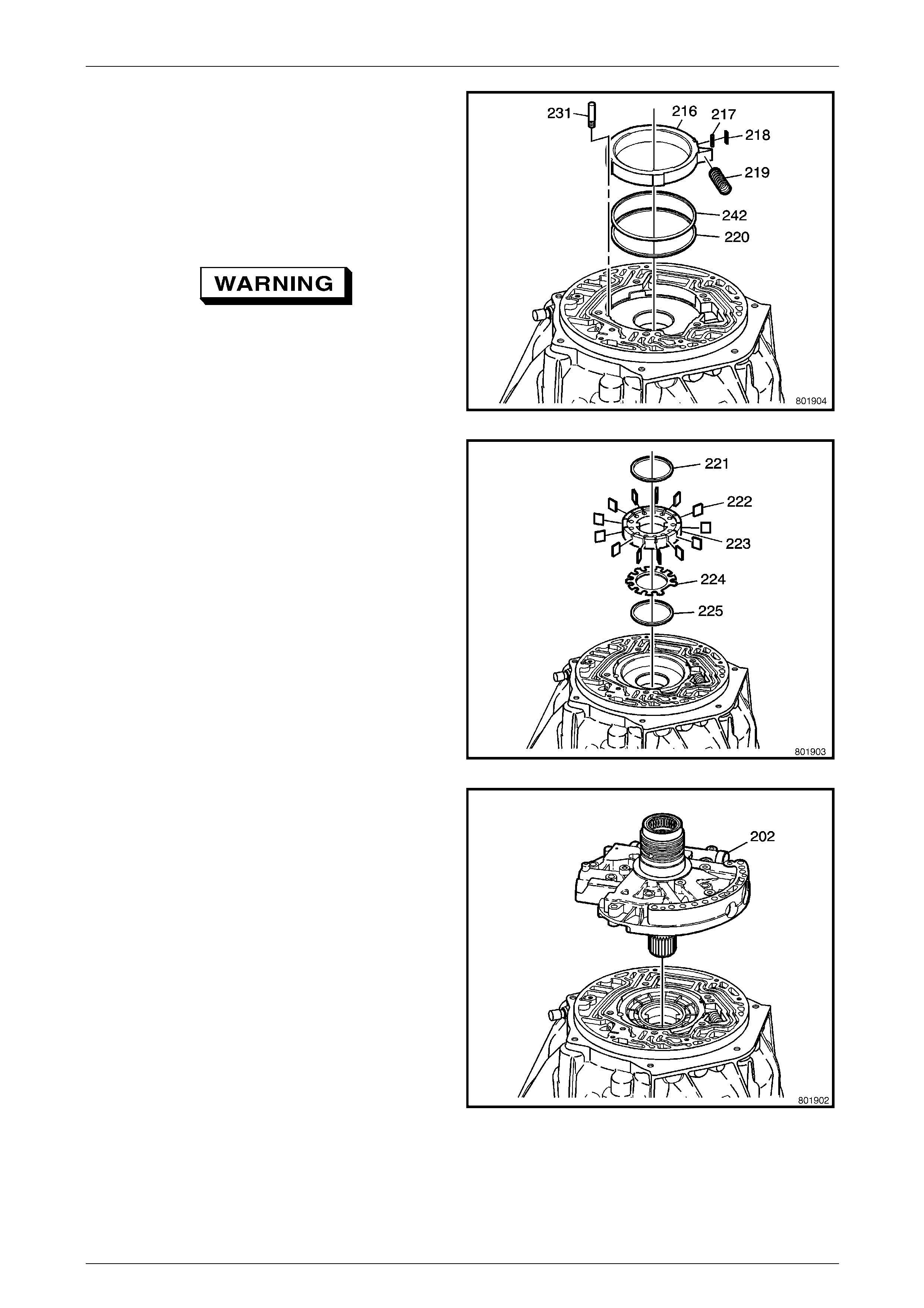
Automatic Transmission – 5L40–E – Unit Repair 7E5 – 81
7E5 – 81
24 Install the fluid pump support (217), the sli de seal
(218) and the fluid pump slide rings (220), and the fluid
pump slide O-ring seal (242) onto the pump slide
(216).
25 Install the slide pin (231).
26 Install the pump slide (216).
NOTE
The fluid pump side (216) is selective, refer to
Step 20 in this procedure.
Wear eye protection to prevent potential
injury.
27 Using a wide bladed screwdriver (or a section of
hacksaw blade), install the slide spring (219).
Figure 7E5 – 170
28 Install the fluid pump vane ring (225).
29 Install the pump rotor guide (224).
NOTE
The fluid pump rotor guide (224) can only be
installed one way.
30 Install the pump rotor (223).
NOTE
The fluid pump rotor (223) is selective, refer to
Step 20 in this procedure.
31 Install the pump vanes (222).
32 Install the pump vane ring (221).
Figure 7E5 – 171
33 Install the pump cover housing (202) onto the
converter housing (224).
Figure 7E5 – 172
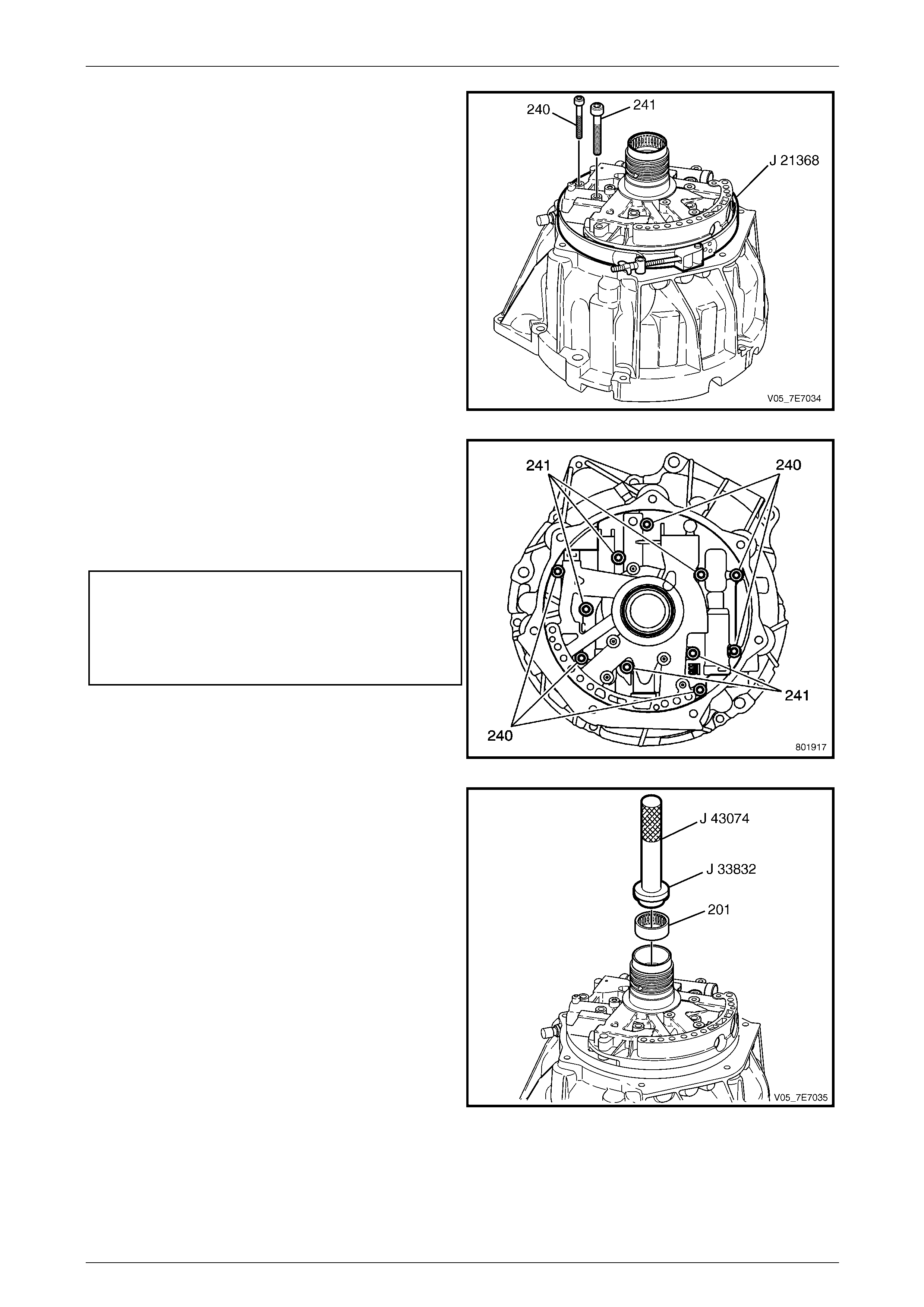
Automatic Transmission – 5L40–E – Unit Repair 7E5 – 82
7E5 – 82
34 Loosely install the fluid pump cover to torque converter
housing bolts (240, 241) but do not tighten at this time.
35 Install Tool J 21368.
Figure 7E5 – 173
NOTE
Refer to Fastener note under 4. Safety and
Service Guidelines in Section 00 Warnings,
Cautions and Notes of this Service Information.
36 Tighten the fluid pump cover to torque converter
housing bolts (240, 24 1) to the correct torque
specifications.
Transmission fluid pump cov er to torque
converter housing bolts (240)
torque specification..............................................11 N.m
Transmission fluid pump cov er to torque
converter housing bolts (241)
torque specification..............................................22 N.m
37 Remove Tool J 21368.
Figure 7E5 – 174
38 Assemble Tools J 33832 (2) and J 8092 (1). Press the
input shaft bearing assembly (201).
Figure 7E5 – 175
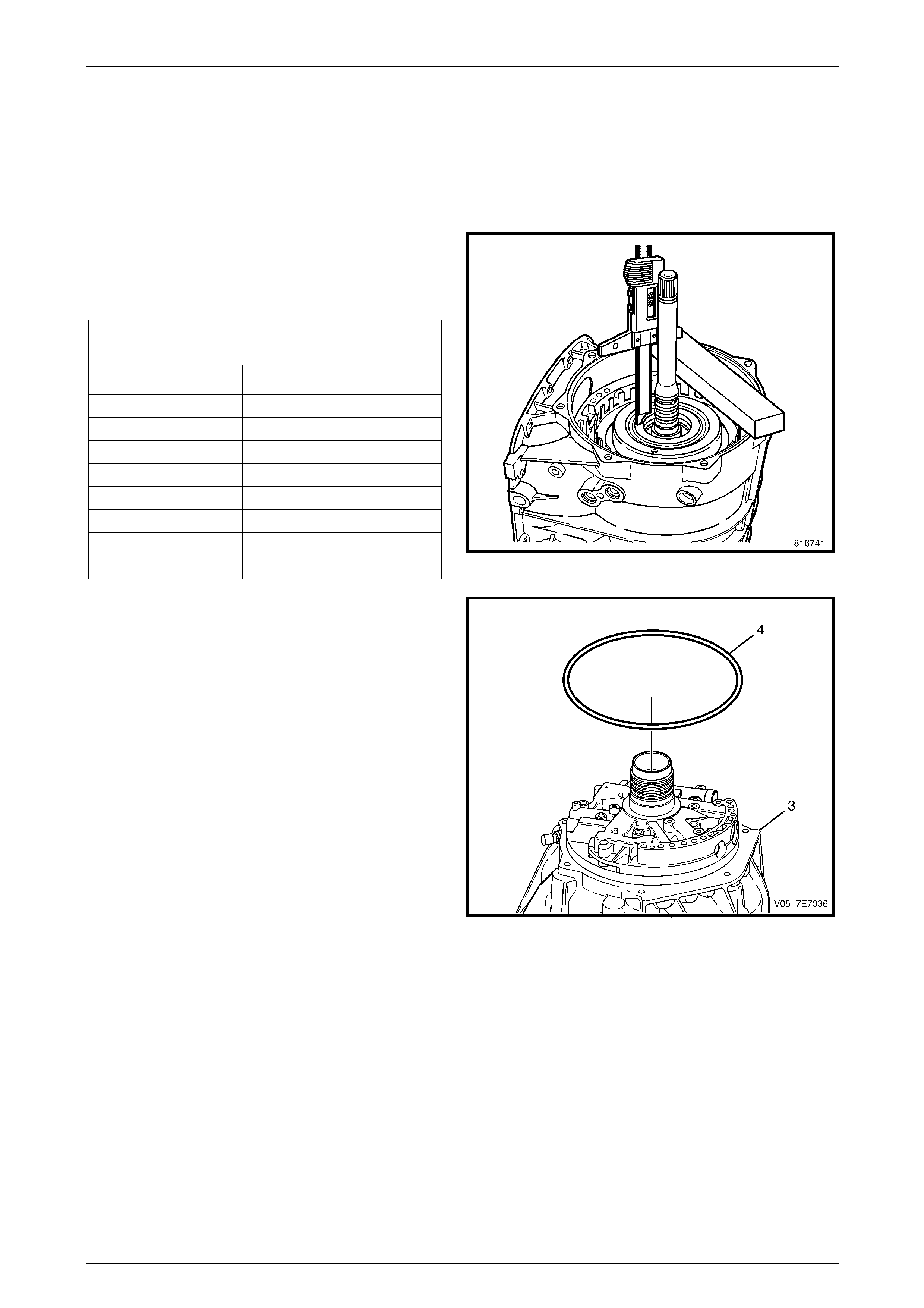
Automatic Transmission – 5L40–E – Unit Repair 7E5 – 83
7E5 – 83
1.37 Torque Converter Housing
Reinstall
1 Inspect the transmission vent pipe for damage or being plugged. If the vent pipe is damaged, the torque converter
housing (227) must be replaced.
2 Measure the distance from the bottom of the gauge
bar to the top of the direct and reverse clutch
assembly (6). Record this as dimension 'X'. Refer to
the following specifications chart to determi ne the
correct size to use.
Reverse Clutch Hou sing Selective Thrust Washer
Specification.
Dimension 'X' Washer Thickness (mm)
50.18 mm–50.36 mm 2.53–2.68
50.36 mm–50.54 mm 2.71–2.86
50.54 mm–50.72 mm 2.89–3.04
50.72 mm–50.90 mm 3.05–3.20
50.90 mm–51.08 mm 3.25–3.40
51.08 mm–51.26 mm 3.43–3.58
51.26 mm–51.44 mm 3.61–3.76
51.44 mm–51.62 mm 3.79–3.94
Figure 7E5 – 176
3 Apply petroleum jell y to a NEW torque converter fluid
O-ring seal (4), and install seal onto the torqu e
converter housing (3).
Figure 7E5 – 177
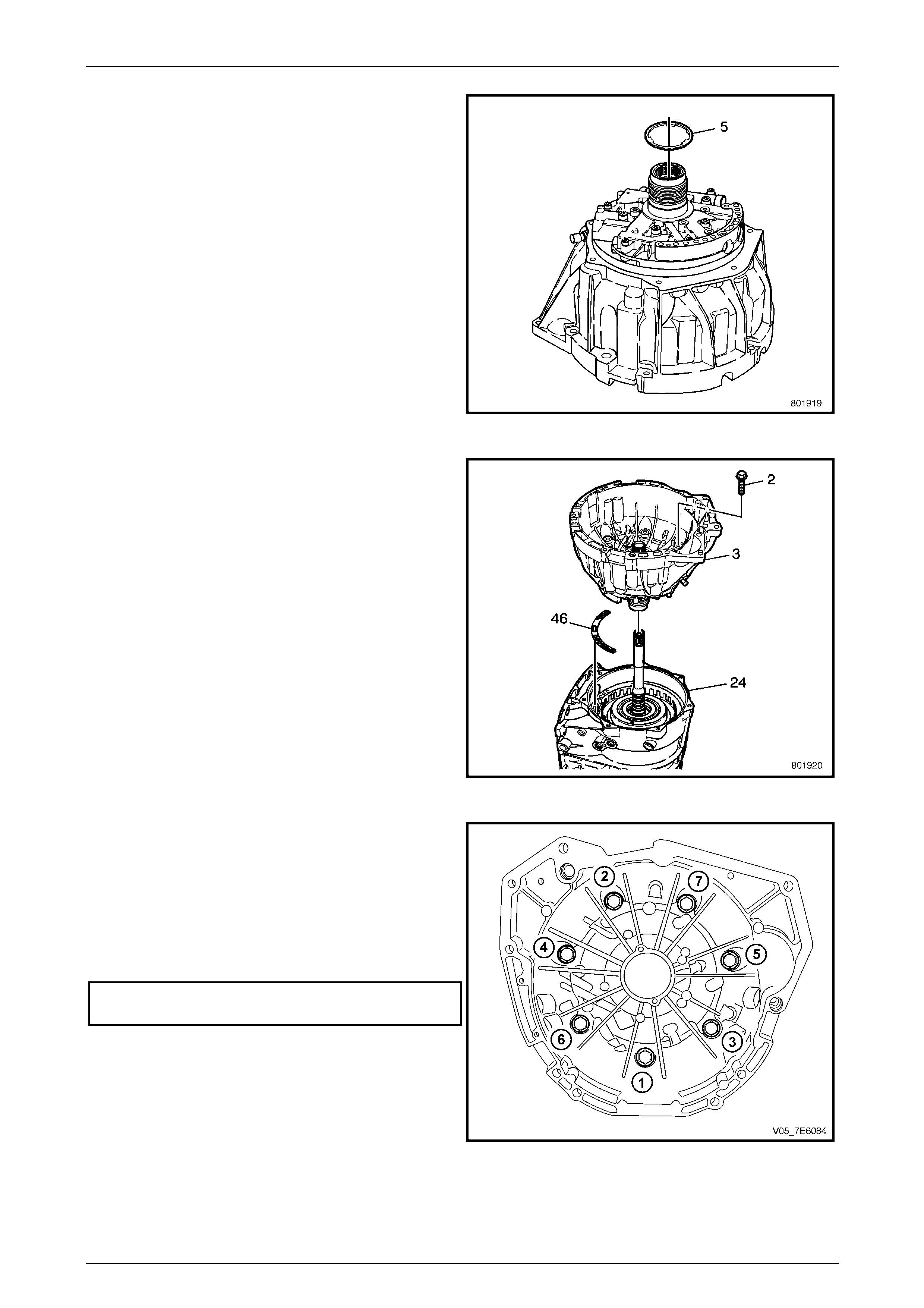
Automatic Transmission – 5L40–E – Unit Repair 7E5 – 84
7E5 – 84
4 Apply petroleum jell y the reverse clutch housing thrust
washer (5) and install onto the fluid pump (20 2).
Figure 7E5 – 178
5 Install the NEW fluid pump cover gasket (46).
6 Install the torque converter housing (3) o nto the
transmission case (24).
7 Install the torque converter housing b olts (2) and hand
tighten.
Figure 7E5 – 179
NOTE
Refer to Fastener note under 4. Safety and
Service Guidelines in Section 00 Warnings,
Cautions and Notes of this Service Information.
8 Tighten the torque converter housing bolts in the
correct sequence as shown and to the correct torque
specification.
Torque converter housing to transmission
case bolt torque specification...............................22 N.m
Figure 7E5 – 180
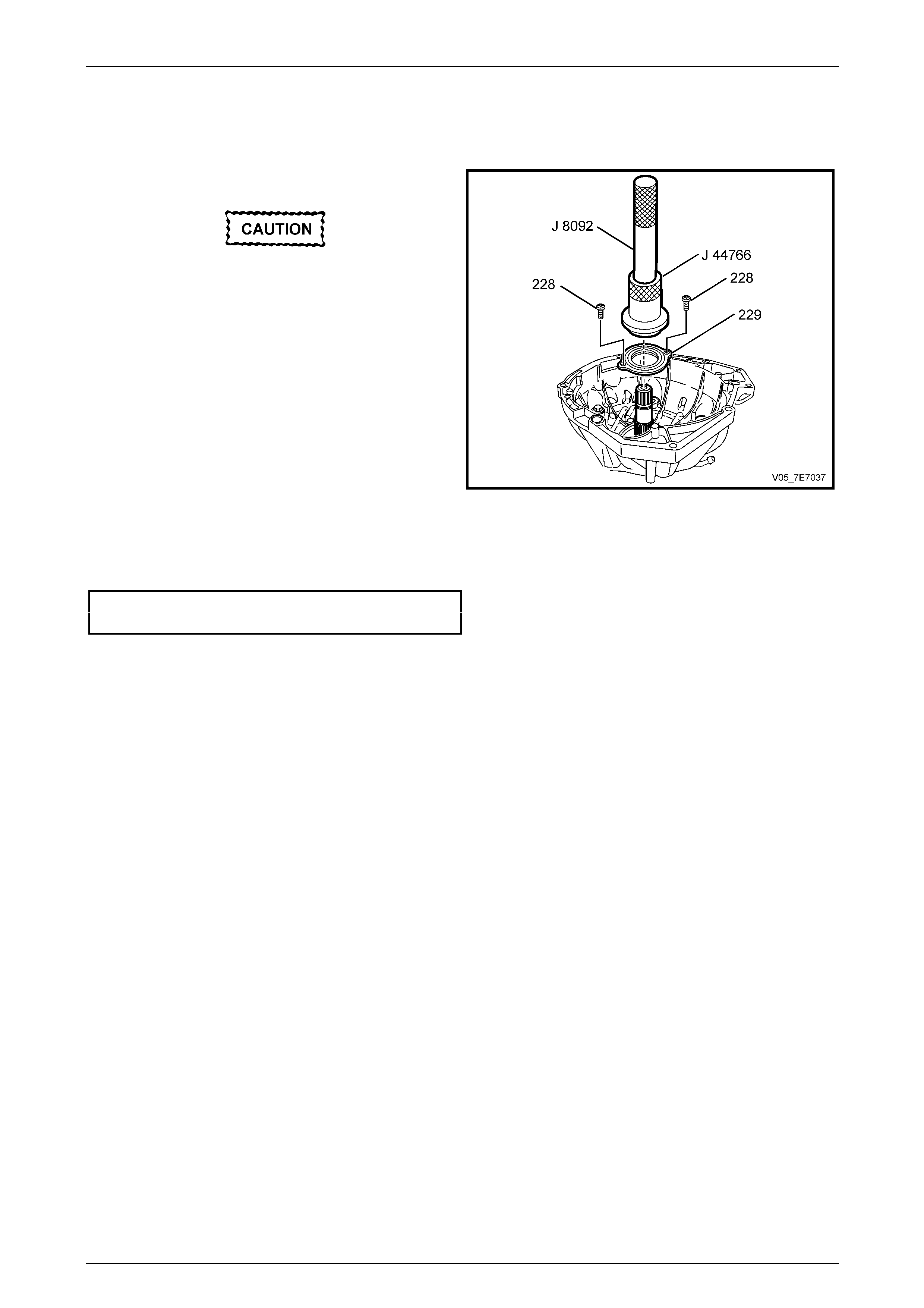
Automatic Transmission – 5L40–E – Unit Repair 7E5 – 85
7E5 – 85
1.38 Torque Converter Seal
Reinstall
1 Assemble Tool J 8092 into Tool J 44766.
Install the seal onto the installation tool
before installing into the case to prevent
damage to the seal.
2 Install the seal (229) onto installer, Tool J 44766.
NOTE
Align the torque converter seal with the bolt
holes
3 Install the NEW seal (229) into the housing (3).
NOTE
Refer to Fastener note under 4. Safety and
Service Guidelines in Section 00 Warnings,
Cautions and Notes of this Service Information.
4 Install NEW seal screws (228) and tighten to the
correct torque specification.
Torque converter seal to housing screw
torque specification.............................................3.6 N.m
Figure 7E5 – 181
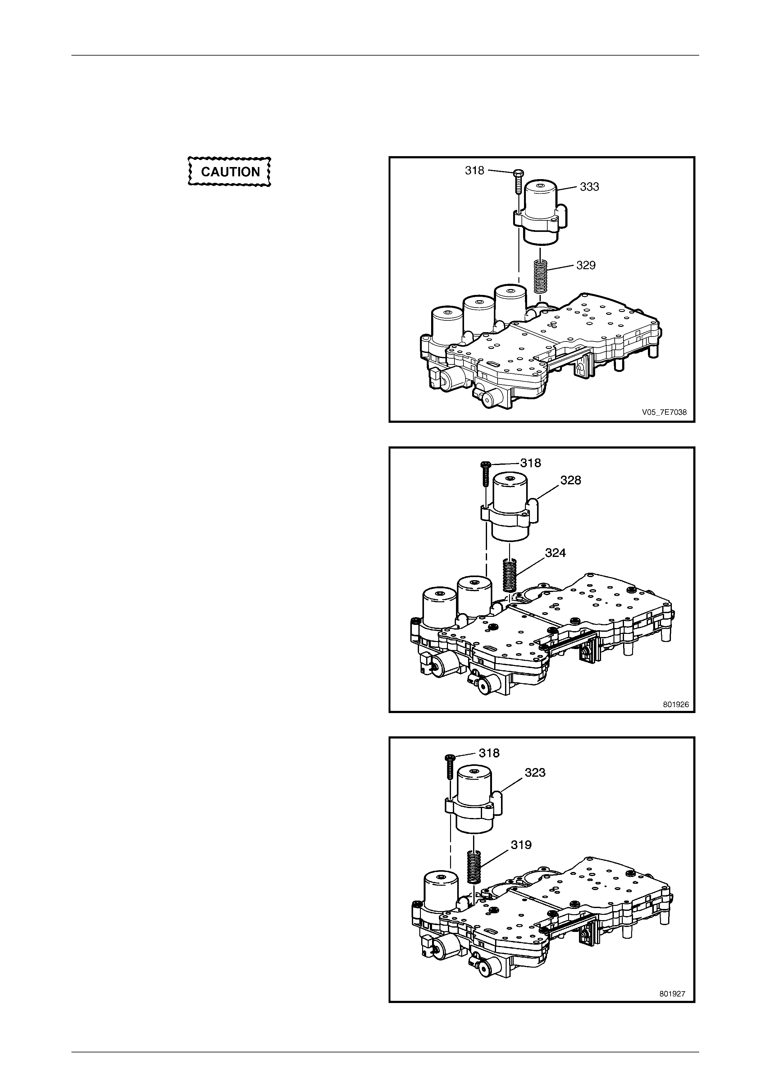
Automatic Transmission – 5L40–E – Unit Repair 7E5 – 86
7E5 – 86
1.39 Control Valve Body and Accumulator
Assembly
Disassemble
Note the position of each accumulator
before removal. The accumulators must
be assembled in the same positions, or
damage may occur.
1 Remove the 2nd clutch accumulator housing bolts
(318).
2 Remove the 2nd clutch accumulator housi ng (333),
piston (inside housing) and spring (329).
Figure 7E5 – 182
3 Remove the intermediate clutc h housing bolts (318).
4 Remove the intermediate clutch accumulator housing
(328), piston (inside housing) and spring (324).
Figure 7E5 – 183
5 Remove the overdrive clutch accumulator housing
bolts (318).
6 Remove the overdrive clutch accumulator housing
(323), piston (inside housing) and spring (319).
Figure 7E5 – 184
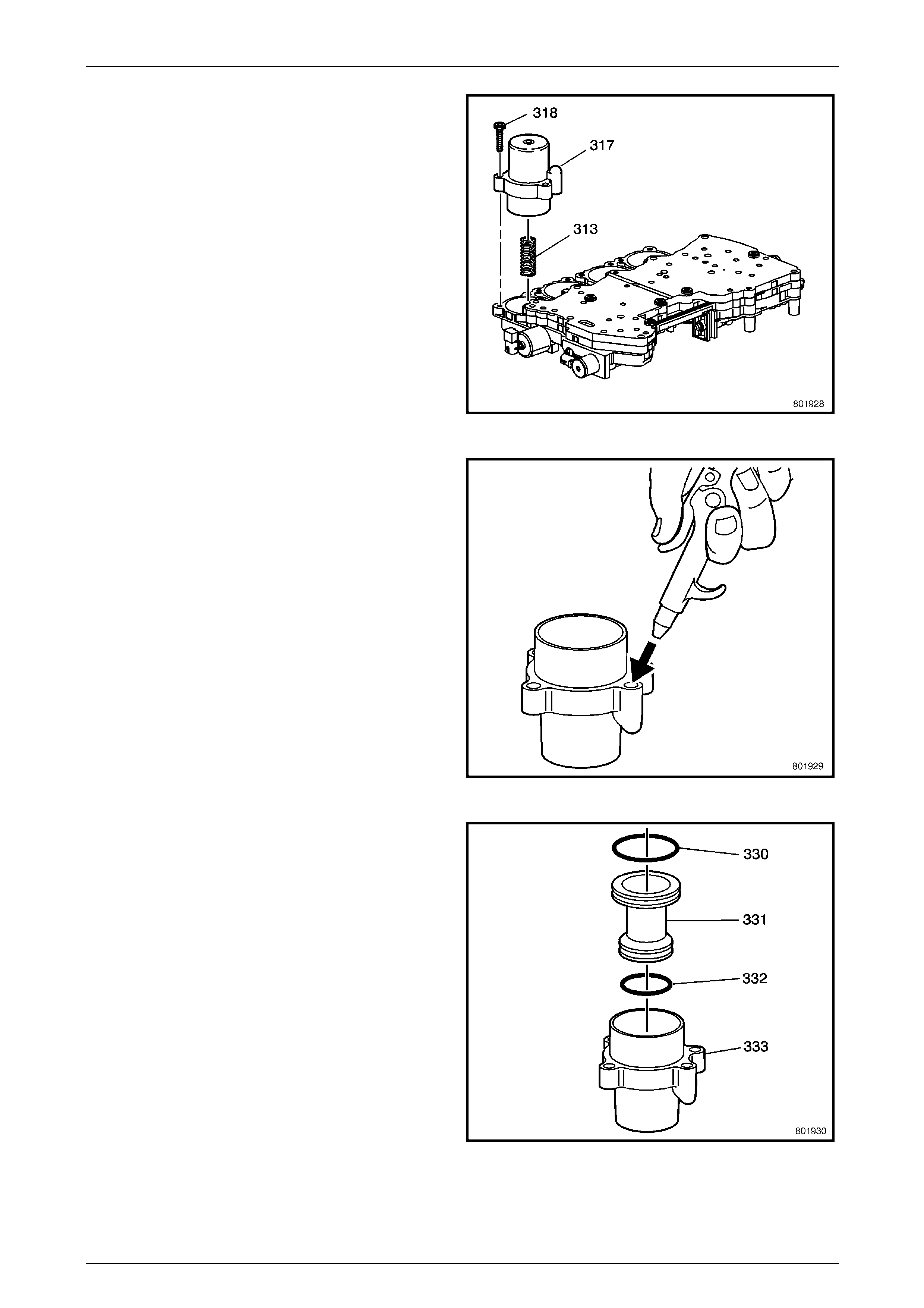
Automatic Transmission – 5L40–E – Unit Repair 7E5 – 87
7E5 – 87
7 Remove the direct clutch accumulator housi ng bolts
(318).
8 Remove the direct accumulator housing (317), piston
(inside housing) and spri ng (313).
Figure 7E5 – 185
NOTE
It may be necessary to use air pressure to
remove the piston.
9 Release the piston with air pressure.
Figure 7E5 – 186
10 Remove the 2nd clutch accumulator piston (331) from
the 2nd clutch accumulator housi ng (333).
11 Remove the 2nd clutch accumulator piston rings (332,
330).
Figure 7E5 – 187

Automatic Transmission – 5L40–E – Unit Repair 7E5 – 88
7E5 – 88
NOTE
It may be necessary to use air pressure to
remove the piston.
12 Release the piston with air pressure.
Figure 7E5 – 188
13 Remove the intermediate clutc h accumu lator piston
(326) from the intermediate clutch accumulator
housing (328).
14 Remove the intermediate clutc h accumu lator piston
fluid seal rings (325, 327).
Figure 7E5 – 189
NOTE
It may be necessary to use air pressure to
remove the piston.
15 Release the piston with air pressure.
Figure 7E5 – 190
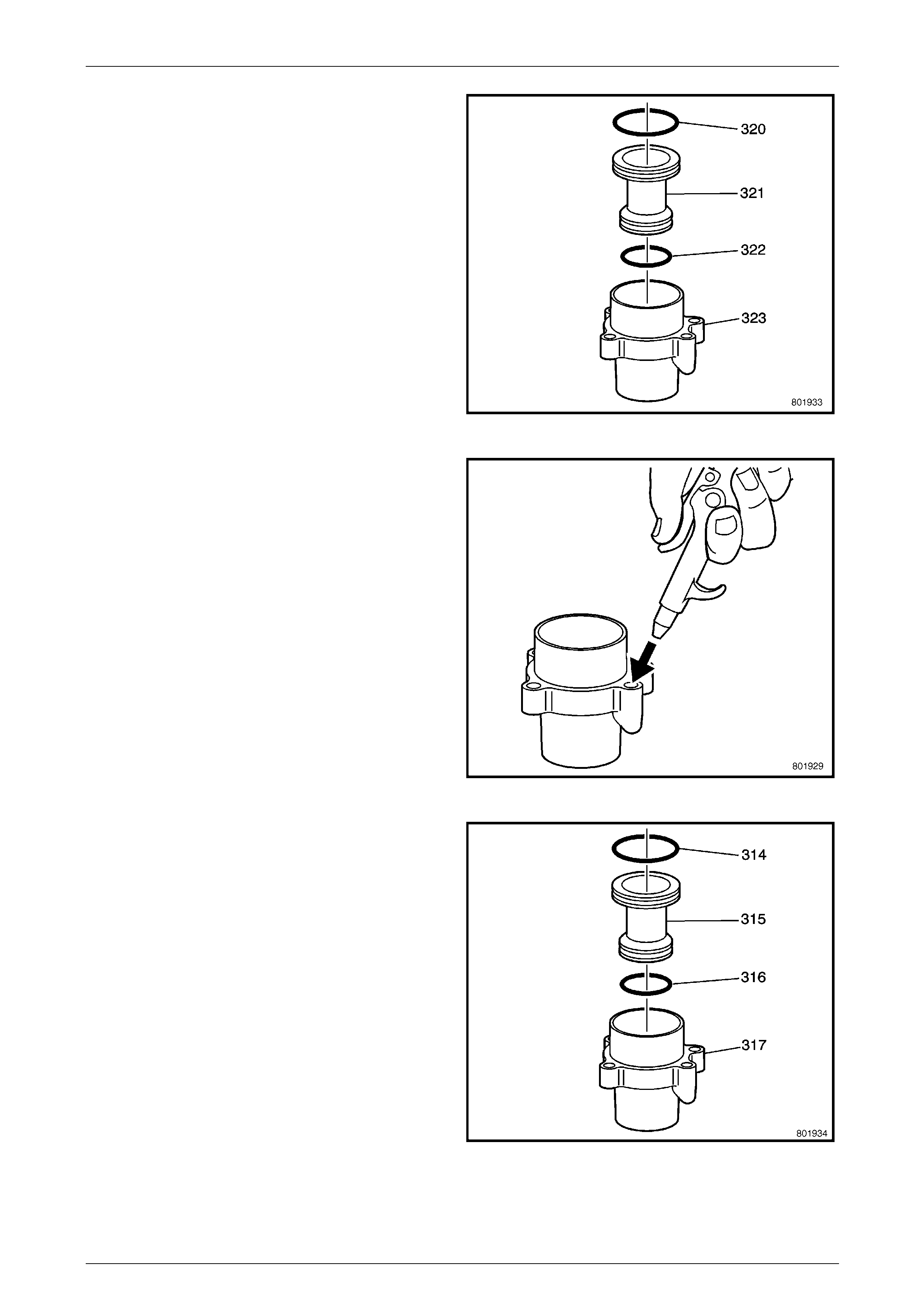
Automatic Transmission – 5L40–E – Unit Repair 7E5 – 89
7E5 – 89
16 Remove the overdrive clutch accumulator piston (321)
from the overdrive clutch accumulator housing (323).
17 Remove the overdrive clutch accumulator piston fluid
seal ring (320, 322).
Figure 7E5 – 191
NOTE
It may be necessary to use air pressure to
remove the piston.
18 Release the piston with air pressure.
Figure 7E5 – 192
19 Remove the direct accumulator housing piston (315)
from the direct accumulator housing (317).
20 Remove the direct clutch accumulator piston fluid seal
rings (314, 316).
Figure 7E5 – 193
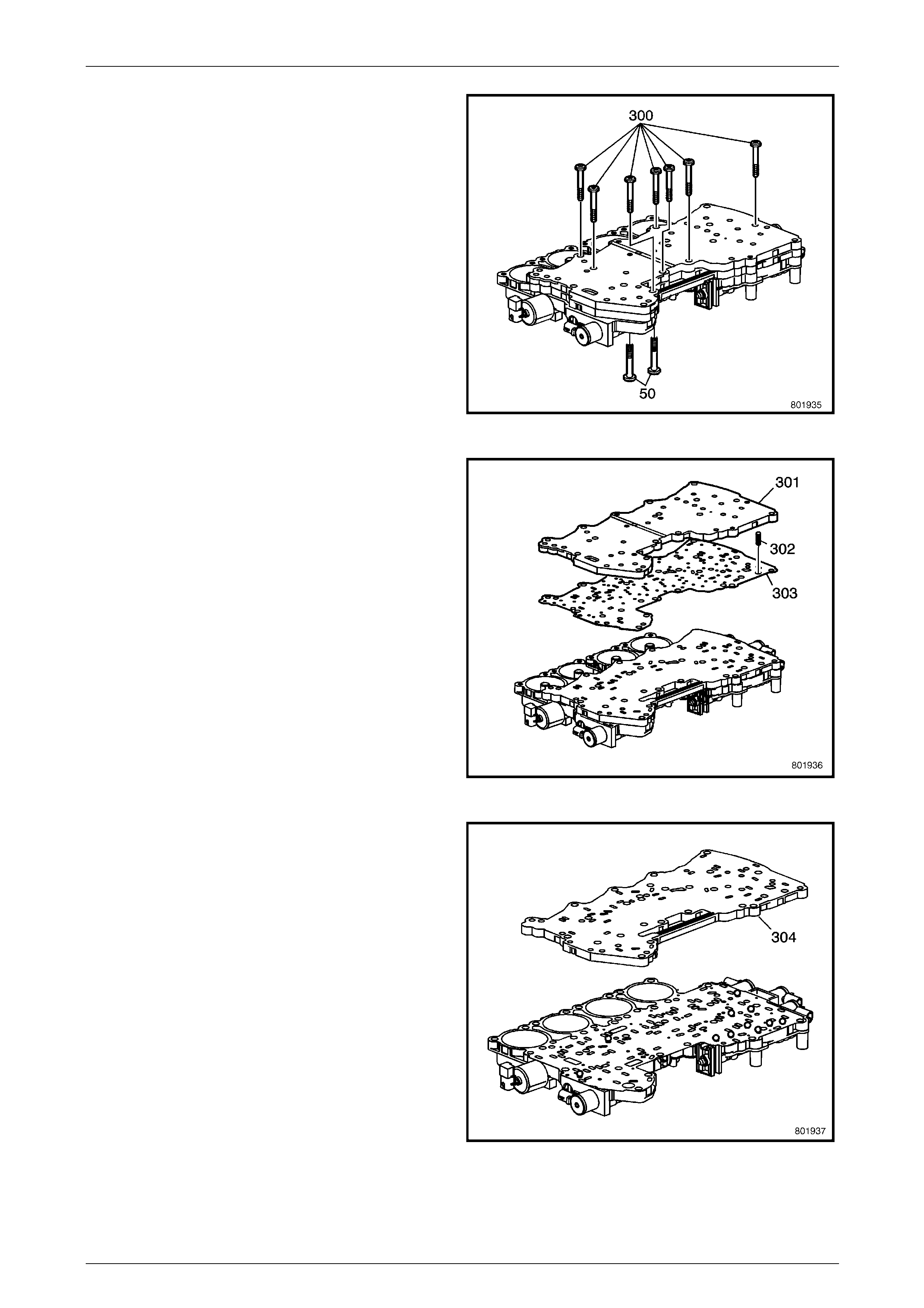
Automatic Transmission – 5L40–E – Unit Repair 7E5 – 90
7E5 – 90
21 Remove the control valve bod y bolts (50, 30 0).
Figure 7E5 – 194
22 Remove the control valve bod y channel plate (301).
23 Remove the channel plate ba ll check spring (302) and
the gasket (303).
Figure 7E5 – 195
24 Remove the control valve bod y channel plate (304).
Figure 7E5 – 196
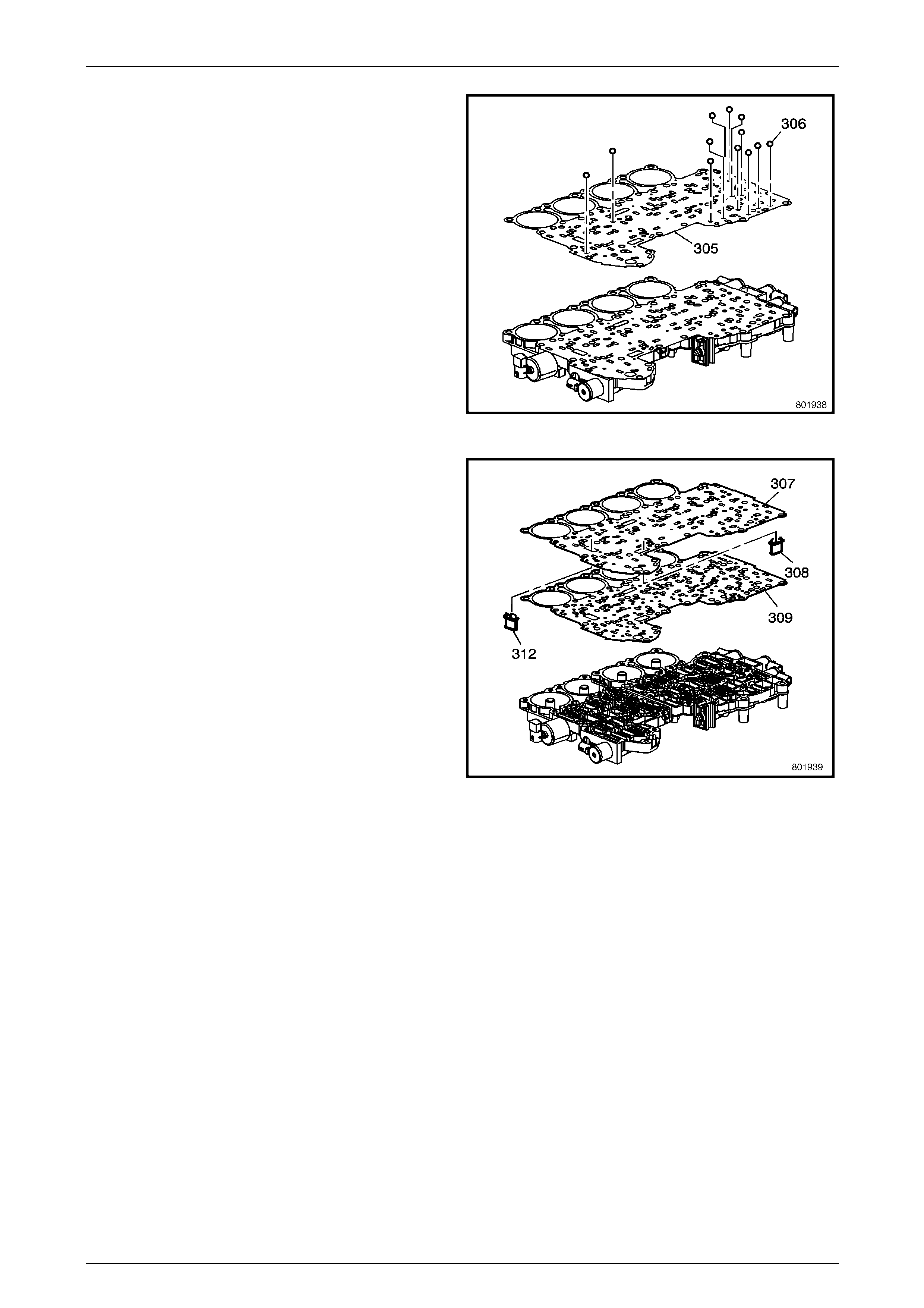
Automatic Transmission – 5L40–E – Unit Repair 7E5 – 91
7E5 – 91
25 Remove the checkballs (306) and the gasket (305).
NOTE
The checkballs (306) may be inside the bottom
channel plate (304), or may be sitting on gasket
(305).
Figure 7E5 – 197
26 Remove the control valve bod y spacer plate (307).
27 Remove the filters (308, 312).
28 Remove the spacer plate gasket (309).
Figure 7E5 – 198
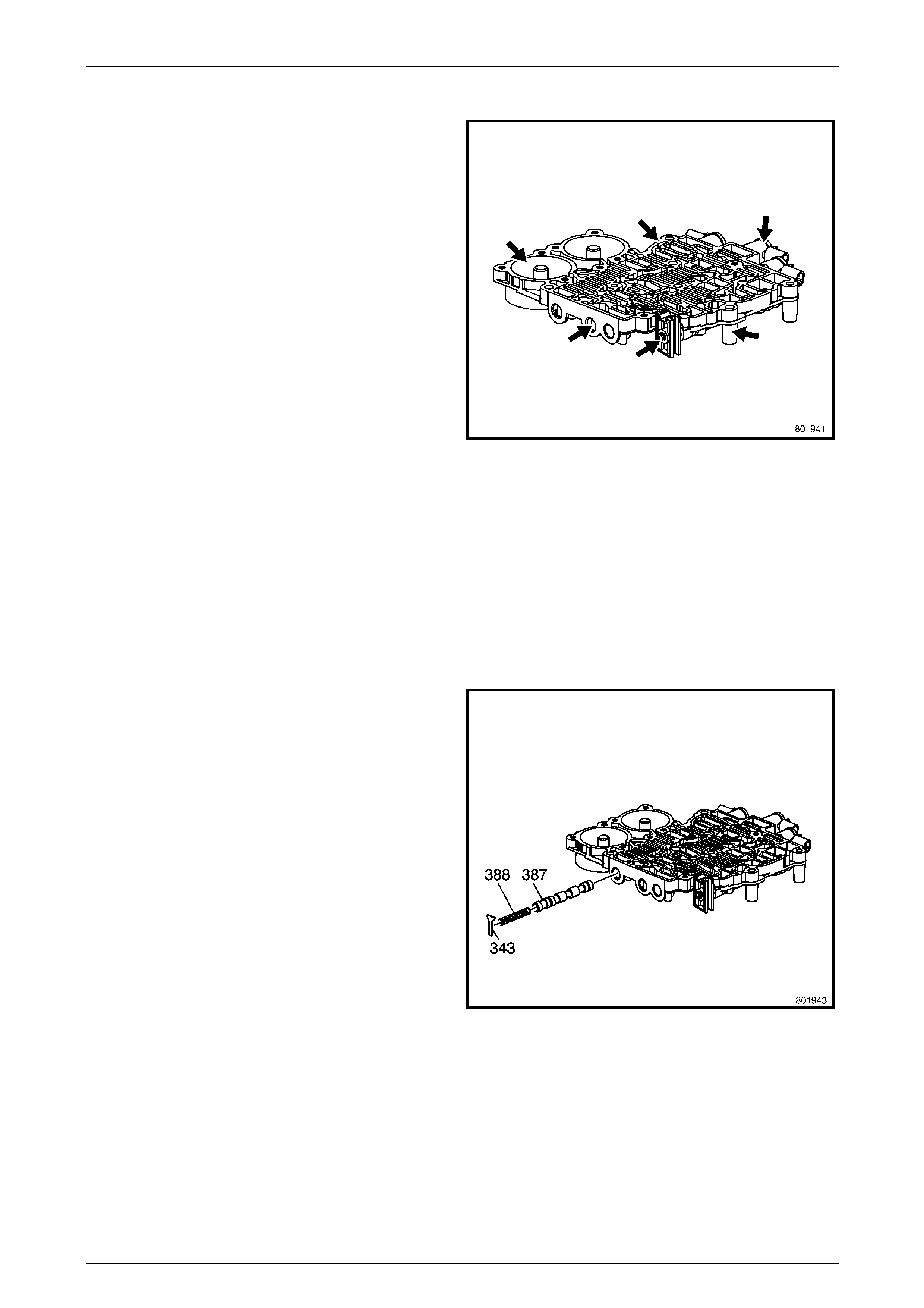
Automatic Transmission – 5L40–E – Unit Repair 7E5 – 92
7E5 – 92
Rear Control Valve Body Inspection
1 Inspect the rear control valve body (365) for the
following conditions:
• Damaged or porous casting.
• Damaged sealing surfaces.
• Debris in fluid passages.
2 Use a small pick or screwdriver , before disassembly,
to inspect the rear control valve body (365)
components for the following conditions:
• Valves binding or sticking in their bores or
bushings.
• Broken missing or damaged springs.
• Missing or damaged retainers.
• Damaged solenoid valves.
• Debris in valve line ups or solenoid valves.
3 During disassembly, inspect the rear control valve
body (365) for the follo wing conditi ons:
• Worn or damaged valves, valve bores or
bushings.
• Broken, missing or damaged springs.
• Missing or damaged retainers.
• Damaged solenoid valves.
• Debris in valve line ups or solenoid valve.
Figure 7E5 – 199
Rear Control Valve Body Disassemble
1 Remove the 1–2 shift valve retainer (343).
2 Remove the 1–2 shift valve spring (388).
3 Remove the 1–2 shift valve (387).
Figure 7E5 – 200
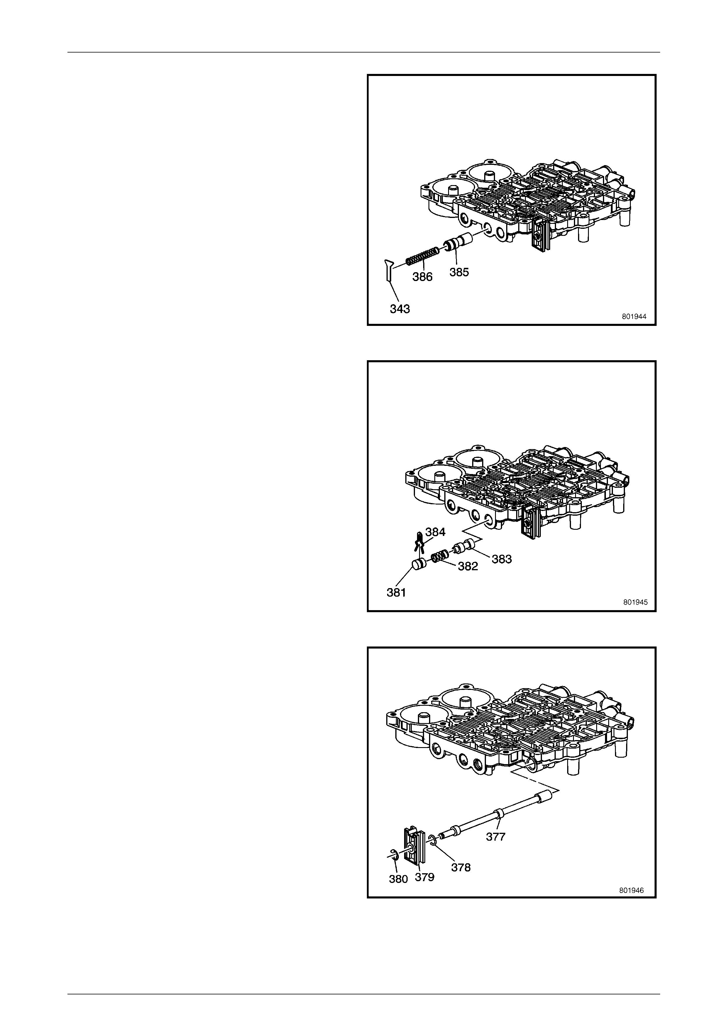
Automatic Transmission – 5L40–E – Unit Repair 7E5 – 93
7E5 – 93
4 Remove the reverse lock out valve retainer (343).
5 Remove the reverse lock out spring (386).
6 Remove the reverse lock out valve (385).
Figure 7E5 – 201
7 Remove the low pressure cont rol valve bore retainer
(384).
8 Remove the bore plug (381).
9 Remove the low pressure control valve spring (382).
10 Remove the low pressure cont rol valve (383).
Figure 7E5 – 202
11 Remove the manual valve link retainer (380).
12 Remove the manual valve link (379).
13 Remove the manual valve link retainer (378).
14 Remove the manual valve (377).
Figure 7E5 – 203
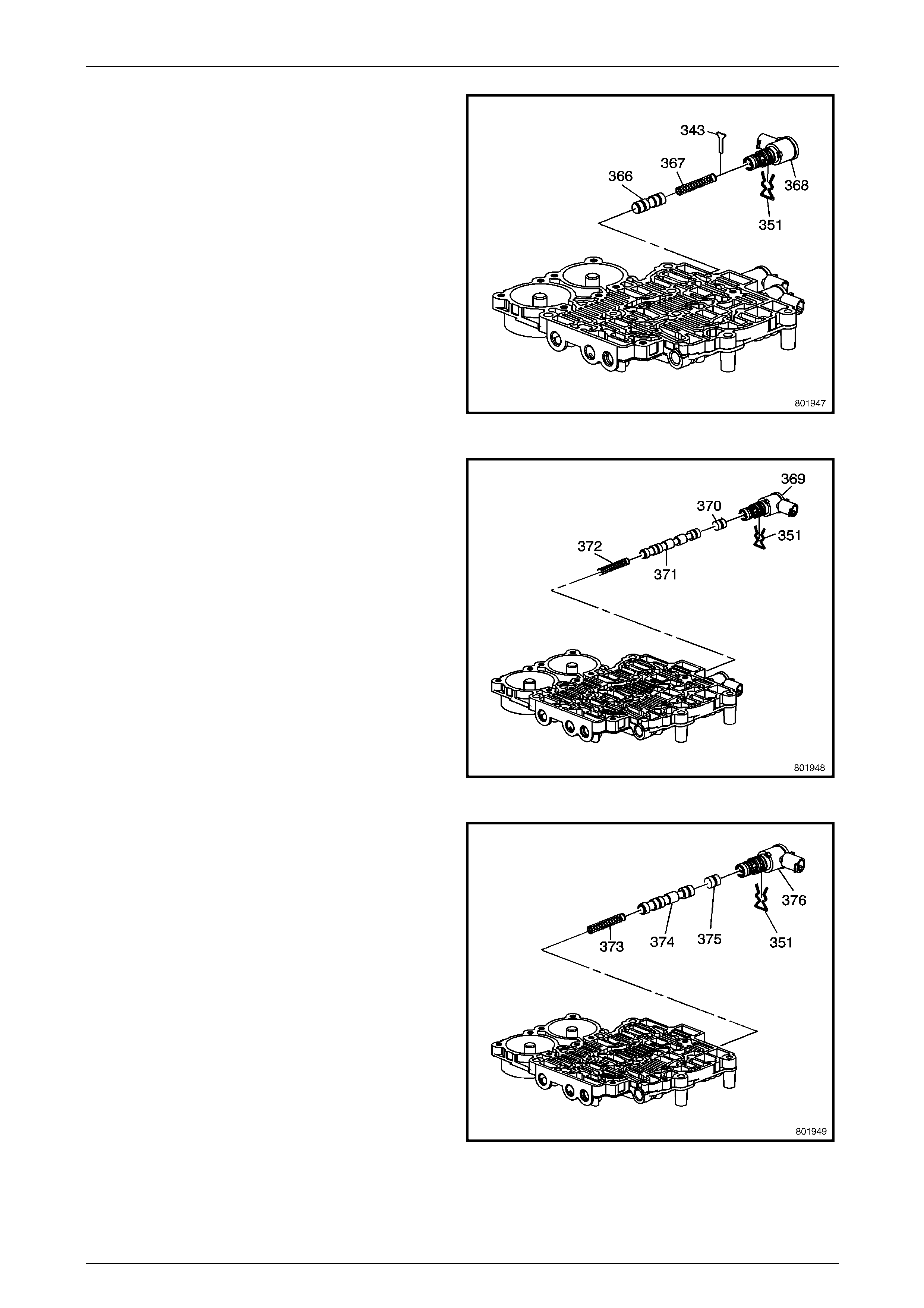
Automatic Transmission – 5L40–E – Unit Repair 7E5 – 94
7E5 – 94
15 Remove the 1–2 shift solenoid retainer (351).
16 Remove the 1–2 shift solenoid (368).
17 Remove the 1–2 shift control valve retainer (343).
18 Remove the 1–2 shift control valve spring (3 67).
19 Remove the 1–2 shift control valve (366).
Figure 7E5 – 204
20 Remove the 2–3 shift solenoid retainer (351).
21 Remove the 2–3 shift solenoid (369).
22 Remove the 2–3 shift control valve (370).
23 Remove the 2–3 shift valve (371).
24 Remove the 2–3 shift valve spring (372).
Figure 7E5 – 205
25 Remove the 4–5 shift solenoid retainer (351).
26 Remove the 4–5 shift solenoid (376).
27 Remove the 4–5 shift control valve (375).
28 Remove the 4–5 shift valve (374).
29 Remove the 4–5 shift valve spring (373).
Figure 7E5 – 206
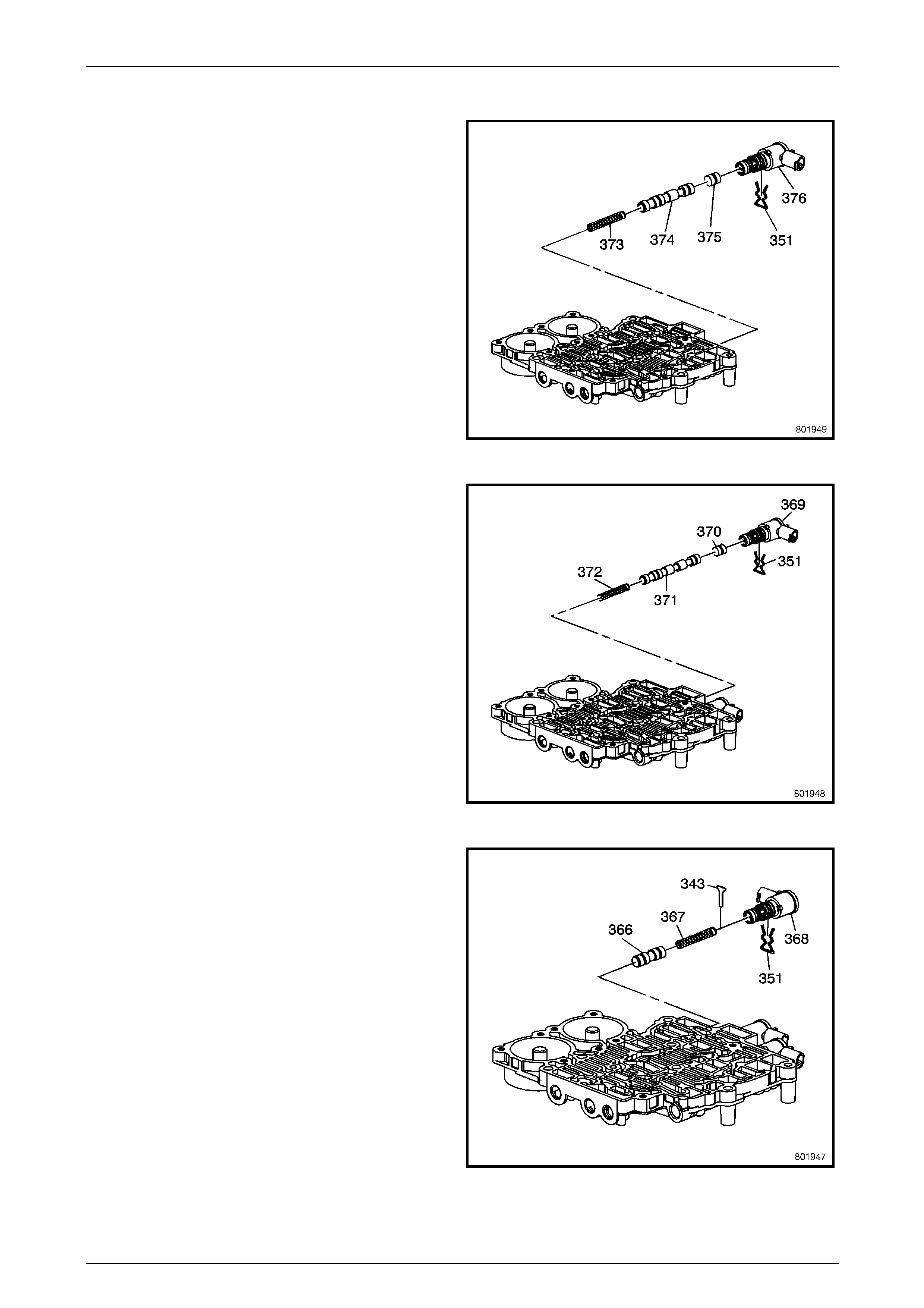
Automatic Transmission – 5L40–E – Unit Repair 7E5 – 95
7E5 – 95
Rear Control Valve Body Assemble
1 Install the 4–5 shift valve spring (373).
2 Install the 4–5 shift valve (374).
3 Install the 4–5 shift control valve (375).
4 Install the 4–5 shift solenoid (376).
5 Install the 4–5 shift solenoid retainer (35 1).
Figure 7E5 – 207
6 Install the 2–3 shift valve spring (372).
7 Install the 2–3 shift valve (371).
8 Install the 2–3 shift control valve (370).
9 Install the 2–3 shift solenoid (369).
10 Install the 2–3 shift solenoid retainer (35 1).
Figure 7E5 – 208
11 Install the 1–2 shift control valve (366).
12 Install the 1–2 shift control valve spring (367).
13 Install the 1–2 shift control valve retainer (34 3).
14 Install the 1–2 shift solenoid (368).
15 Install the 1–2 shift solenoid retainer (35 1).
Figure 7E5 – 209
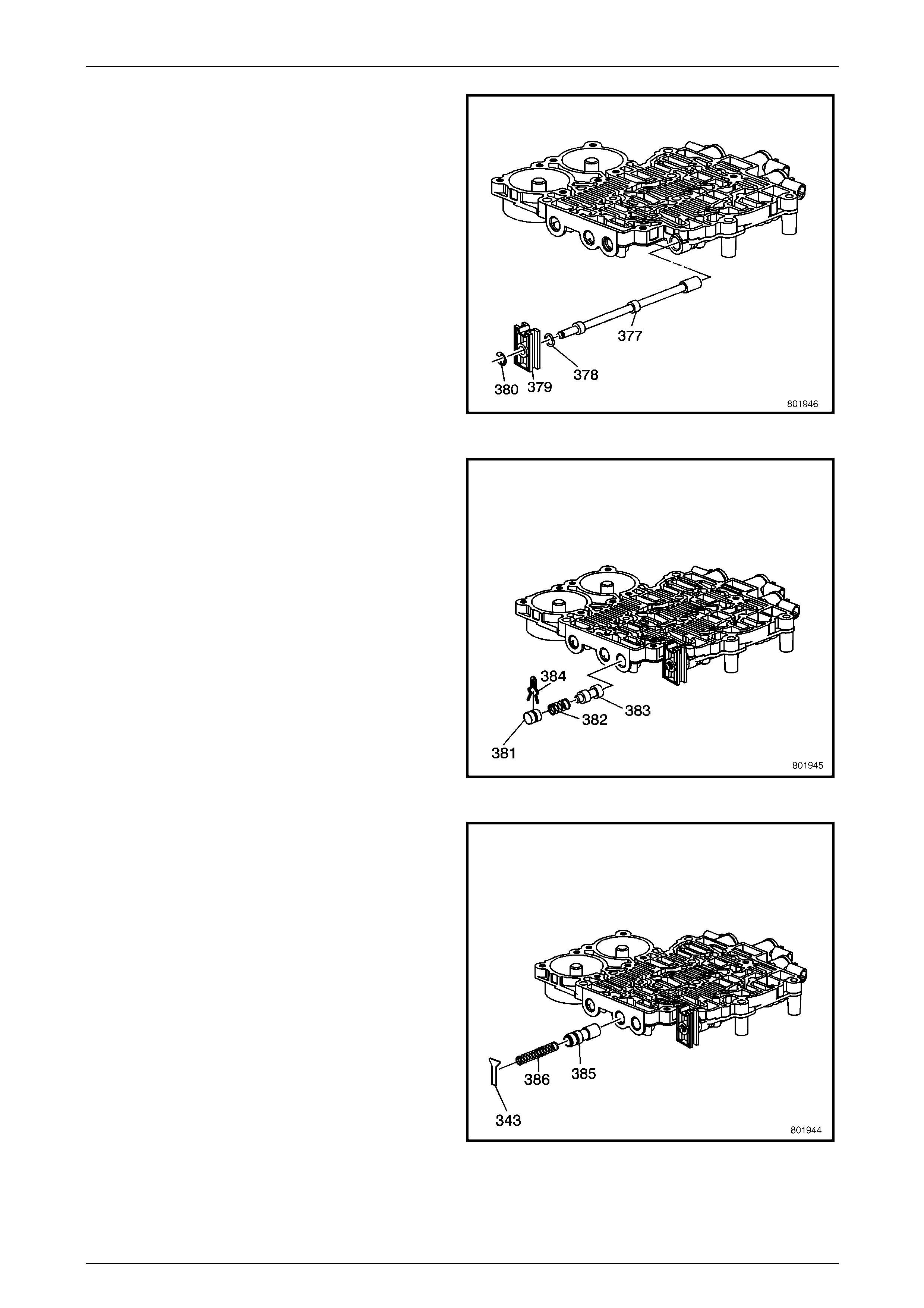
Automatic Transmission – 5L40–E – Unit Repair 7E5 – 96
7E5 – 96
16 Install the manual valve link retainer (378) to the
manual valve (377).
17 Install the manual valve link (379) to the manual valve
(377).
18 Install the manual valve link retainer (380) to the
manual valve (377).
19 Install the manual valve (377) sub-assem bly, to the
rear control valve body.
Figure 7E5 – 210
20 Install the low pressure control valve (383).
21 Install the low pressure control valve spring (382).
22 Install the bore plug (381).
23 Install the low pressure control valve bore retainer
(384).
Figure 7E5 – 211
24 Install the reverse lock out valve (385).
25 Install the reverse lock out spring (386).
26 Install the reverse lock out valve retainer (343).
Figure 7E5 – 212
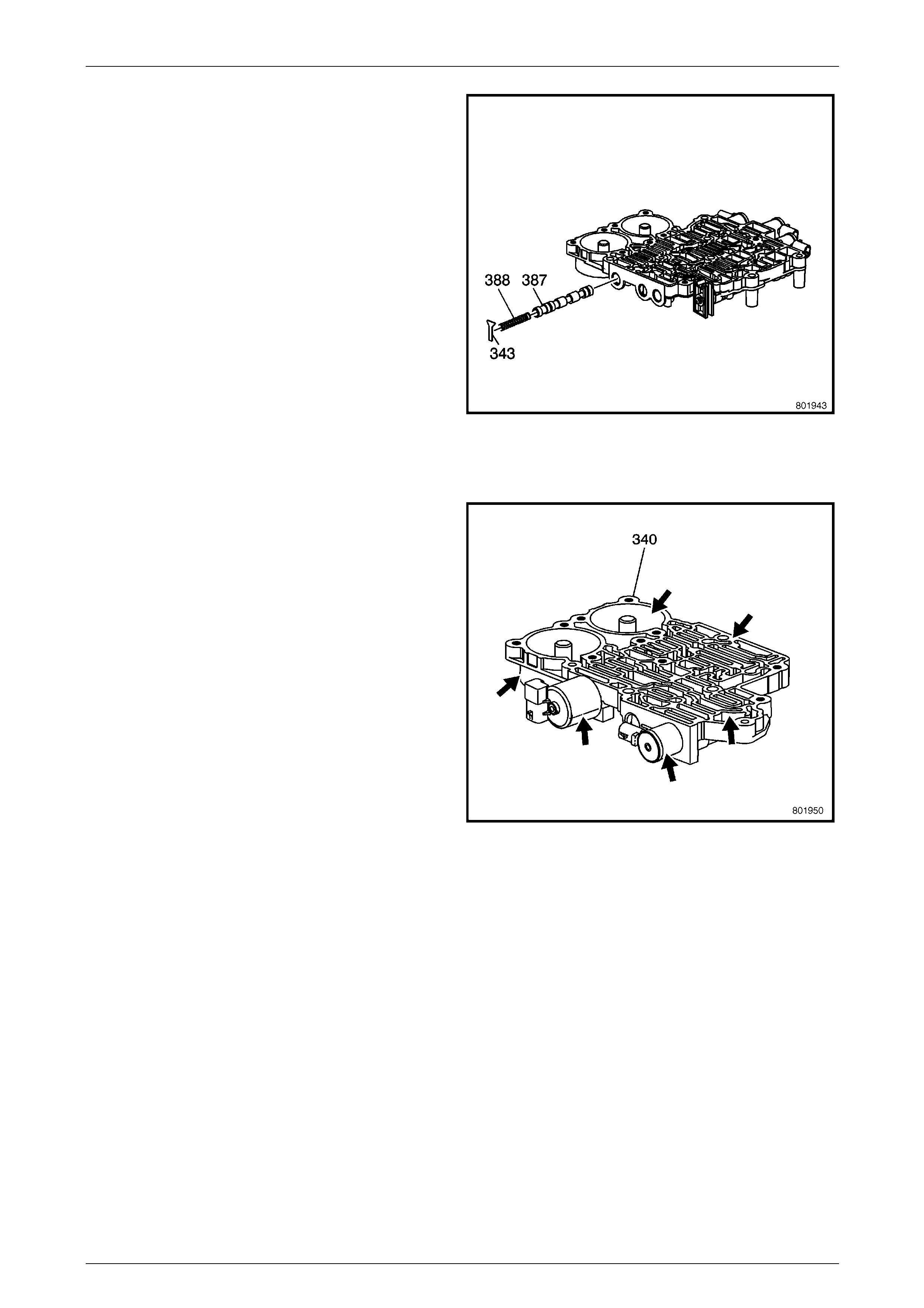
Automatic Transmission – 5L40–E – Unit Repair 7E5 – 97
7E5 – 97
27 Install the 1–2 shift valve (387).
28 Install the 1–2 shift valve spring (388).
29 Install the 1–2 shift valve retainer (343).
Figure 7E5 – 213
Front Control Valve Body Inspection
1 Inspect the front control valve body (340) for the
following conditions:
• Damaged or porous casting.
• Damaged sealing surfaces.
• Debris in fluid passages.
2 Use a small pick or screwdriver , before disassembly,
to inspect the front control valve bod y (340)
components for the following conditions:
• Valves binding or sticking in their bores or
bushings.
• Broken missing or damaged springs.
• Missing or damaged retainers.
• Damaged solenoid valves.
• Debris in valve line ups or solenoid valves.
3 During disassembly, inspect the front control valve
body for the following conditions:
• Worn or damaged valves, valve bores or
bushings.
• Broken, missing or damaged springs.
• Missing or damaged retainers.
• Damaged solenoid valves.
• Debris in valve line ups or solenoid valve.
Figure 7E5 – 214
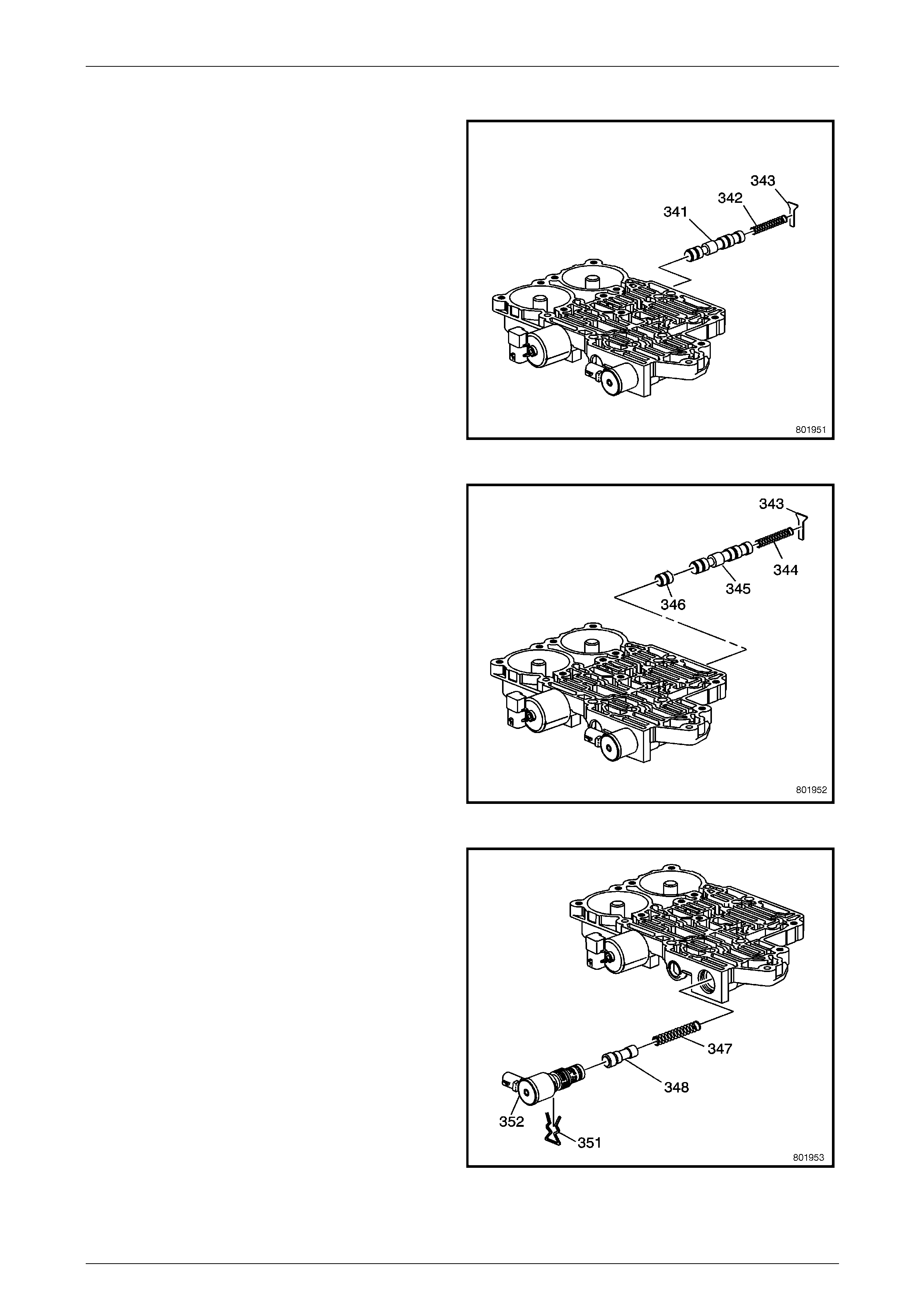
Automatic Transmission – 5L40–E – Unit Repair 7E5 – 98
7E5 – 98
Front Control Valve Body Disassemble
1 Remove the safety mode valve retainer (343).
2 Remove the safety mode valve spring (342).
3 Remove the safety mode valve (341).
Figure 7E5 – 215
4 Remove the 3–4 shift valve retainer (343).
5 Remove the 3–4 shift valve spring (344).
6 Remove the 3–4 shift valve (345).
7 Remove the 3–4 shift control valve (346).
Figure 7E5 – 216
8 Remove the TCC PWM solenoid valve retainer (351).
9 Remove the TCC PWM solenoid (352).
10 Remove the TCC regulator apply valve (348).
11 Remove the TCC regulator apply valve spring (347).
Figure 7E5 – 217
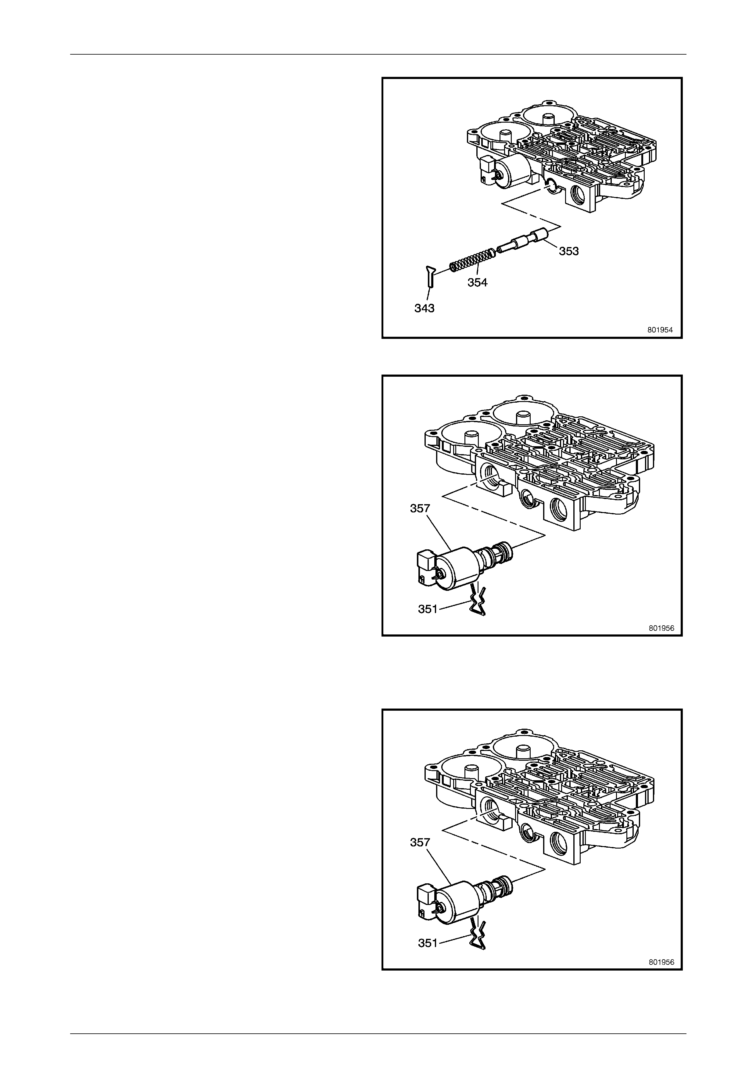
Automatic Transmission – 5L40–E – Unit Repair 7E5 – 99
7E5 – 99
12 Remove the feed limit valve retainer (343).
13 Remove the feed limit valve spring (354).
14 Remove the feed limit valve (353).
Figure 7E5 – 218
15 Remove the pressure control solenoid retainer (351).
16 Remove the pressure control solenoid (357).
Figure 7E5 – 219
Front Control Valve Body Assemble
1 Install the pressure control solenoid (35 7).
2 Install the pressure control solenoid retainer (351).
Figure 7E5 – 220
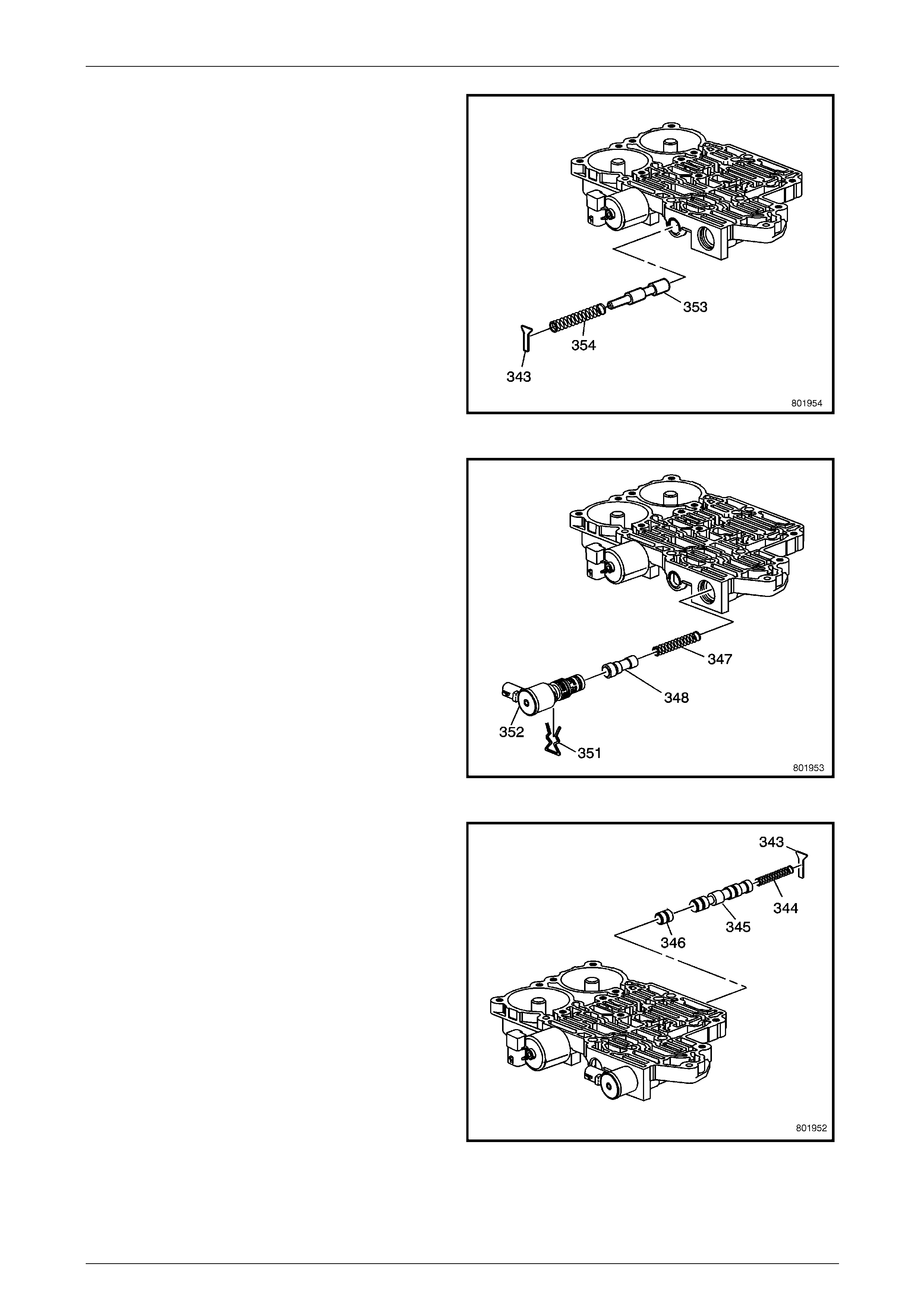
Automatic Transmission – 5L40–E – Unit Repair 7E5 – 100
7E5 – 100
3 Install the feed limit valve (353).
4 Install the feed limit valve spring (354).
5 Install the feed limit valve retainer (343).
Figure 7E5 – 221
6 Install the TCC PWM solenoid valve spring (347).
7 Install the TCC regulator apply valve (348).
8 Install the TCC PWM solenoid (352).
9 Install the TCC PWM solenoid retainer (351).
Figure 7E5 – 222
10 Install the 3–4 shift control valve (346).
11 Install the 3–4 shift valve (345).
12 Install the 3–4 shift valve spring (344).
13 Install the 3–4 shift control valve retainer (34 3).
Figure 7E5 – 223
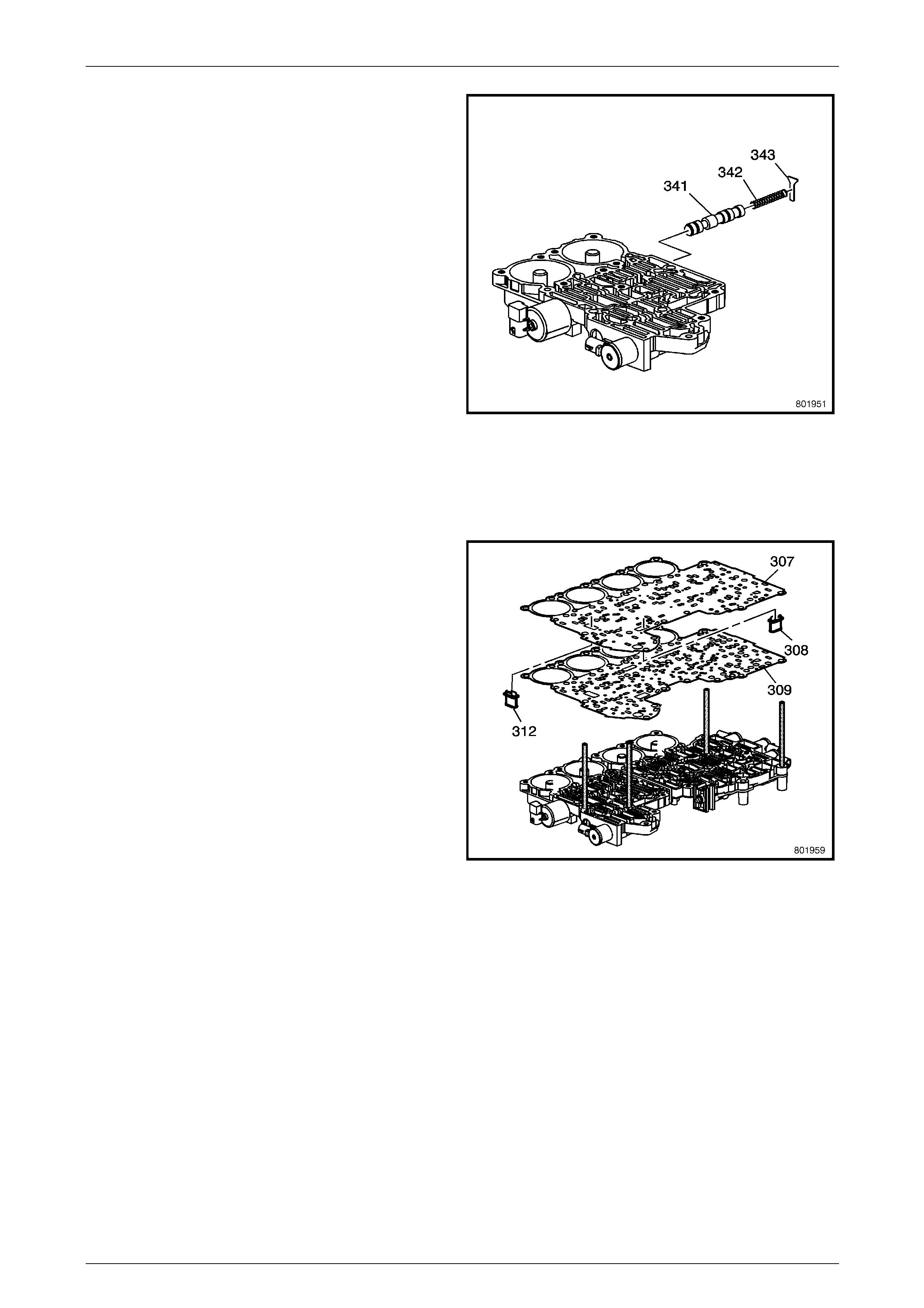
Automatic Transmission – 5L40–E – Unit Repair 7E5 – 101
7E5 – 101
14 Install the safety mode valve (341).
15 Install the safety mode valve spring (342).
16 Install the safety mode valve retainer (343).
Figure 7E5 – 224
Control Valve Body and Accumulator Assembly
Assemble
1 Install guide pins, Tool J 39068 (or 6 mm ro d, 75 mm
in length) into the front and rear control va lve bodies,
in the positions shown.
2 Install NEW control valve body spacer plate gasket
(309) onto the valve bodies.
3 Install NEW solenoid valve filter assemb lies (308, 312)
onto the control valve body spacer plate (307).
4 Install the control valve bod y spacer p late (3 07) onto
the valve bodies.
Figure 7E5 – 225
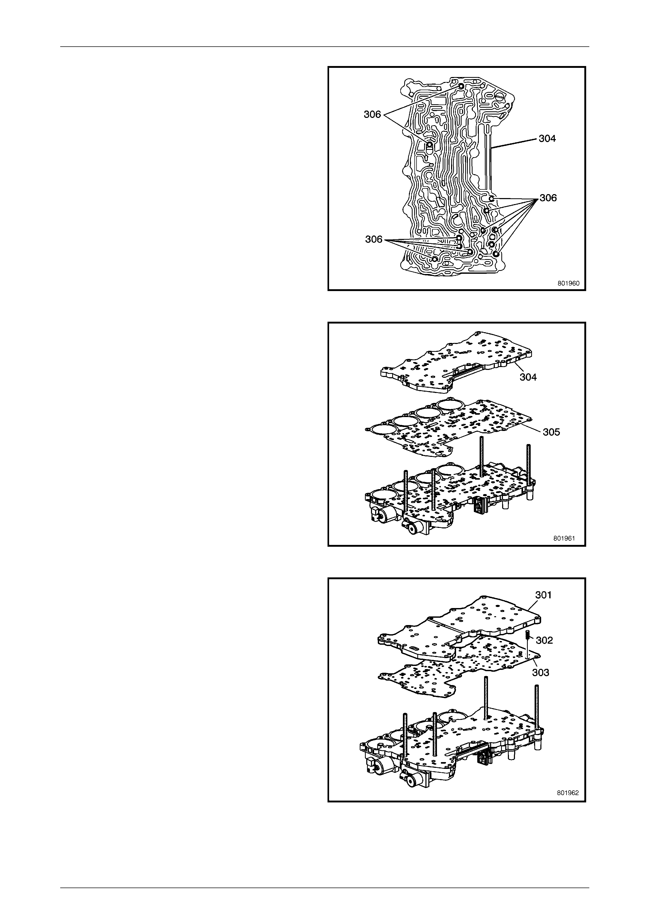
Automatic Transmission – 5L40–E – Unit Repair 7E5 – 102
7E5 – 102
5 Use petroleum jelly to install and hold the 12
checkballs (306) into the spacer plate (3 04), in the
positions shown.
Figure 7E5 – 226
6 Install the new control valve body gasket (30 5) onto
the spacer plate (307).
7 Install the control valve body channel plate (304).
Figure 7E5 – 227
8 Use petroleum jelly to install a nd hold the control valve
channel plate check ball spring (302) onto the channel
plate (304).
9 Install the NEW control valve bod y channel plate
gasket (303) onto the channel plate (304).
10 Install the control valve channel plate (301) onto the
channel plate gasket (303).
Figure 7E5 – 228
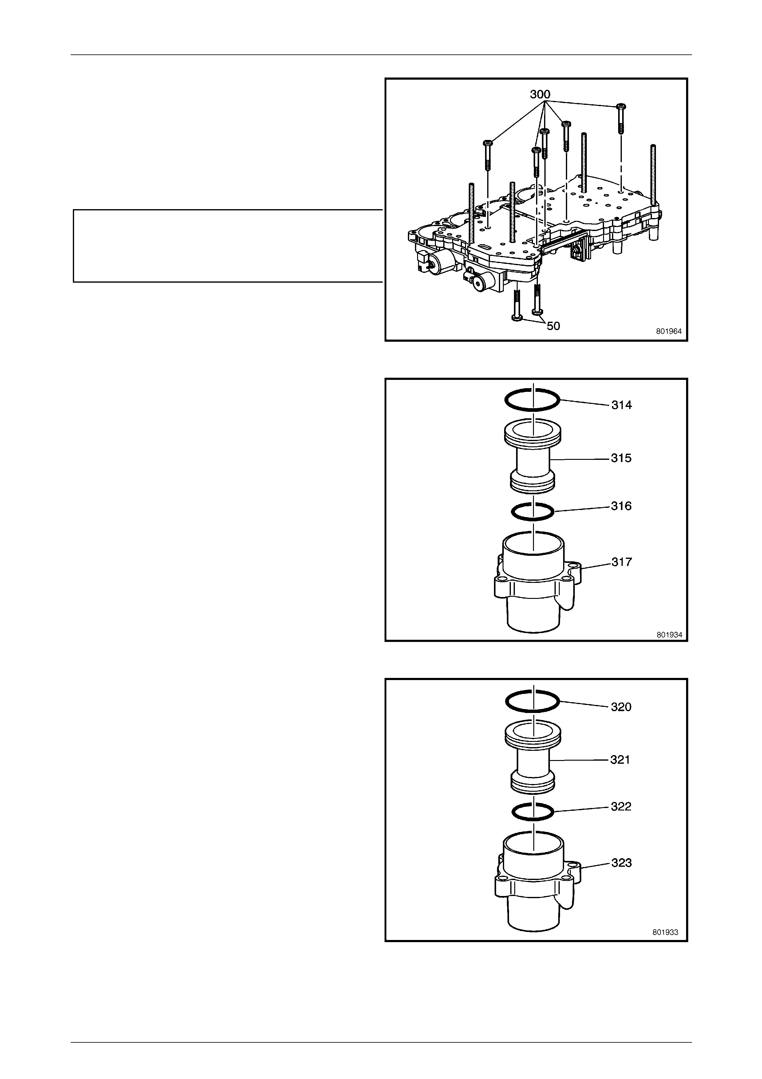
Automatic Transmission – 5L40–E – Unit Repair 7E5 – 103
7E5 – 103
NOTE
Refer to Fastener note under 4. Safety and
Service Guidelines in Section 00 Warnings,
Cautions and Notes of this Service Information.
11 Install the control valve body bolts (50, 300) i nto the
valve body and tighten to the correct torque
specifications.
Front valve body to channel plate bolt (50)
torque specification..............................................11 N.m
Channel plate to front and rear valve body
bolt (300) torque specification..............................11 N.m
12 Remove the guide pins, Tool J 39068 from the valve
body (47).
Figure 7E5 – 229
13 Install the direct clutch accumulator p iston flu id seal
rings (314, 316) onto the direct clutch accumulator
piston (315).
14 Install the direct clutch accumulator p iston (3 15) into
the direct clutch accumulator housing (317).
Figure 7E5 – 230
15 Install the overdrive clutch accumul ator pisto n fluid
seal rings (320, 322) onto the overdrive clutch
accumulator piston (321).
16 Install the overdrive accumulator piston (321) into the
overdrive clutch accumulator housing (323).
Figure 7E5 – 231
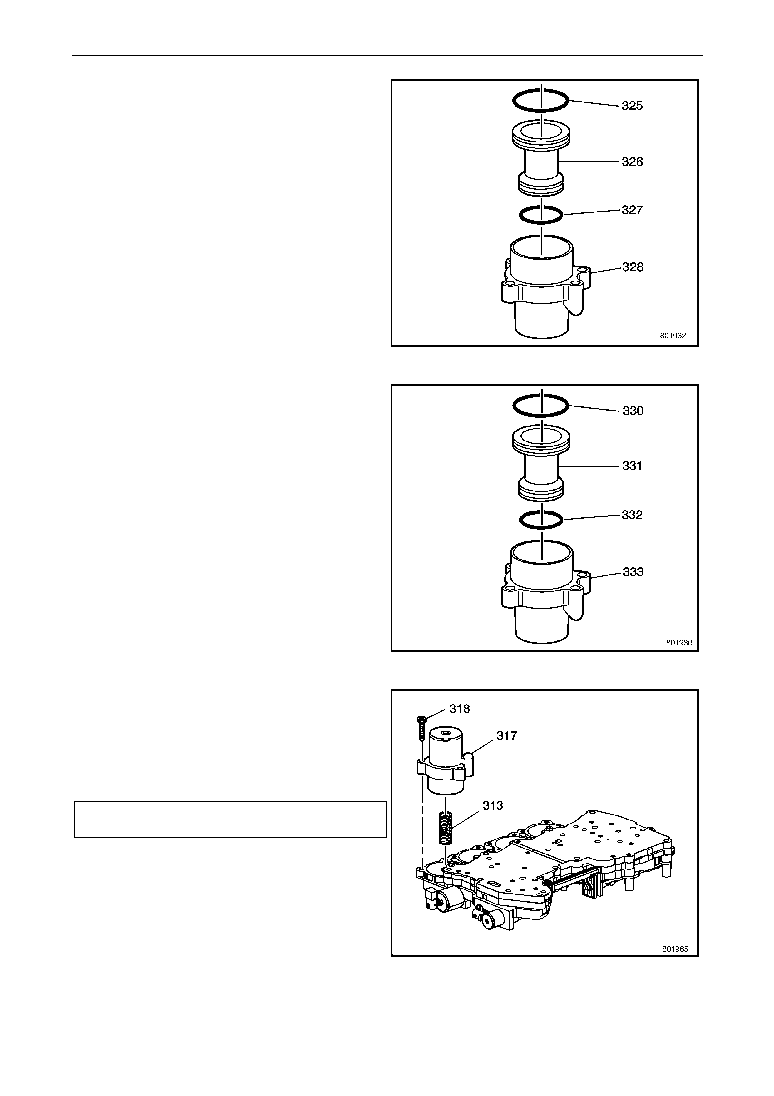
Automatic Transmission – 5L40–E – Unit Repair 7E5 – 104
7E5 – 104
17 Install the intermediate clutch accumulator fluid seal
rings (325, 327) onto the intermediate clutch
accumulator piston (326).
18 Install the intermediate clutch accumulator piston (326)
into the intermediate clutch accumulator ho using
(328).
Figure 7E5 – 232
19 Install the 2nd clutch accumulator piston fluid seal
rings (330, 332) onto the 2nd clutch accum ul ator
piston (331).
20 Install the 2nd clutch accumulator piston (331) into the
2nd clutch accumulator housing (333).
Figure 7E5 – 233
21 Install the direct clutch accumulator spring (313).
22 Install the direct clutch accumulator h ousing (317) onto
the valve body (47).
23 Install the direct clutch accumulator h ousing bolts
(318) into the front valve body (47) and tighten to the
correct torque specification.
Direct clutch accumulator housing to front
valve body bolt torque specification.....................11 N.m
Figure 7E5 – 234
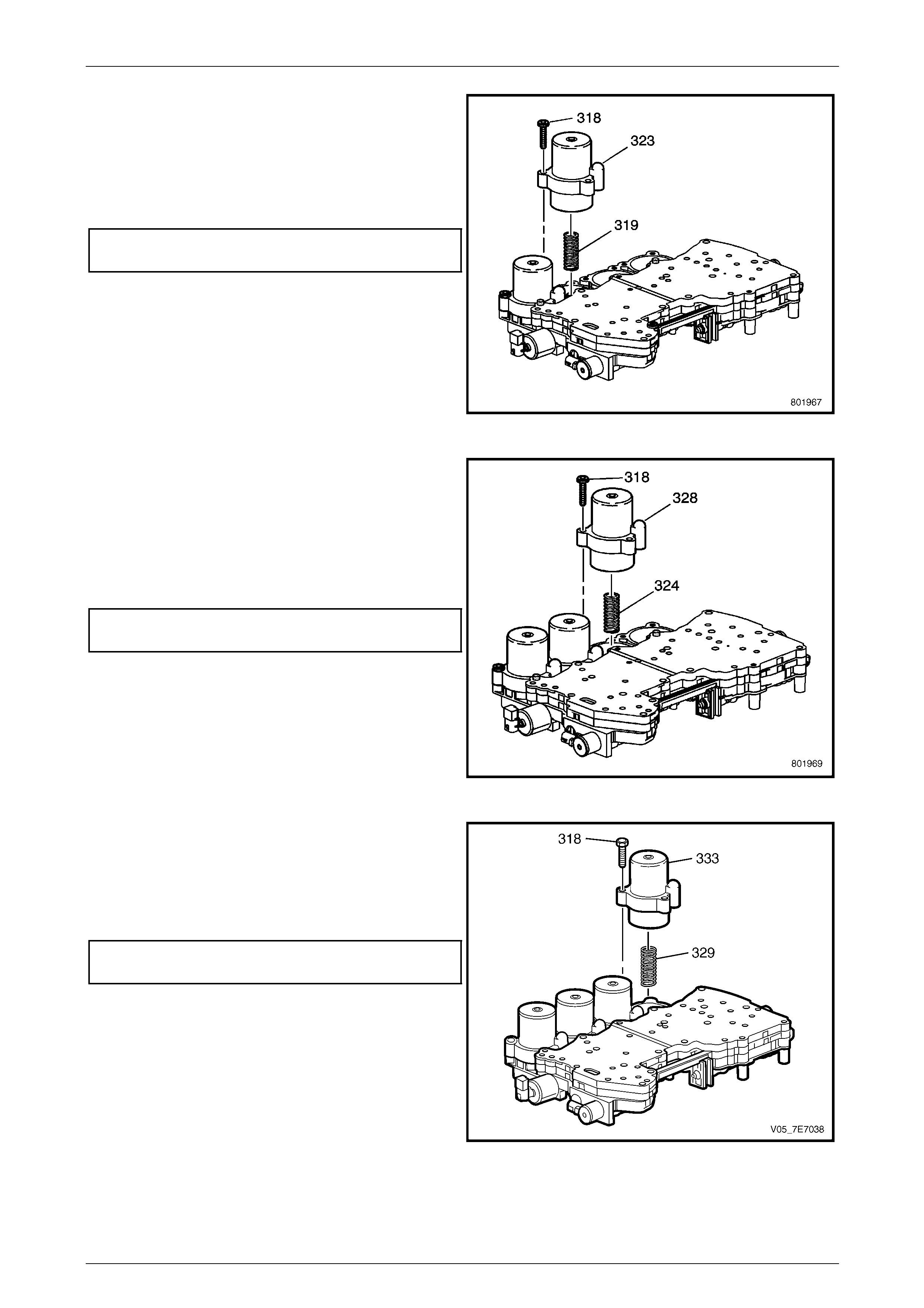
Automatic Transmission – 5L40–E – Unit Repair 7E5 – 105
7E5 – 105
24 Install the overdrive clutch accumul ator spri ng (319).
25 Install the overdrive clutch accumul ator hou sing (323)
onto the front valve body (47).
26 Install the overdrive clutch accumul ator hou sing bolts
(318) into the valve body (47) and tighten to the
correct torque specification.
Overdrive clutch accumulator housing to front
valve body bolt torque specification.....................11 N.m
Figure 7E5 – 235
27 Install the intermediate clutch accumulator spring
(324).
28 Install the intermediate clutch accumulator housing
(328) onto the valve body (47).
29 Install the intermediate clutch accumulator housing
bolts (318) into the rear valve body (47) and tighten to
the correct torque specification.
Intermediate clutch accumulator housing to rear
valve body bolt torque specification.....................11 N.m
Figure 7E5 – 236
30 Install the 2nd clutch accumulator spring (32 9).
31 Install the 2nd clutch accumulator housing (333) onto
the valve body (47).
32 Install the 2nd clutch accumulator housing bolts (318)
into the valve body (47).
2nd clutch accumulator housing to rear
valve body bolt torque specification.....................11 N.m
Figure 7E5 – 237
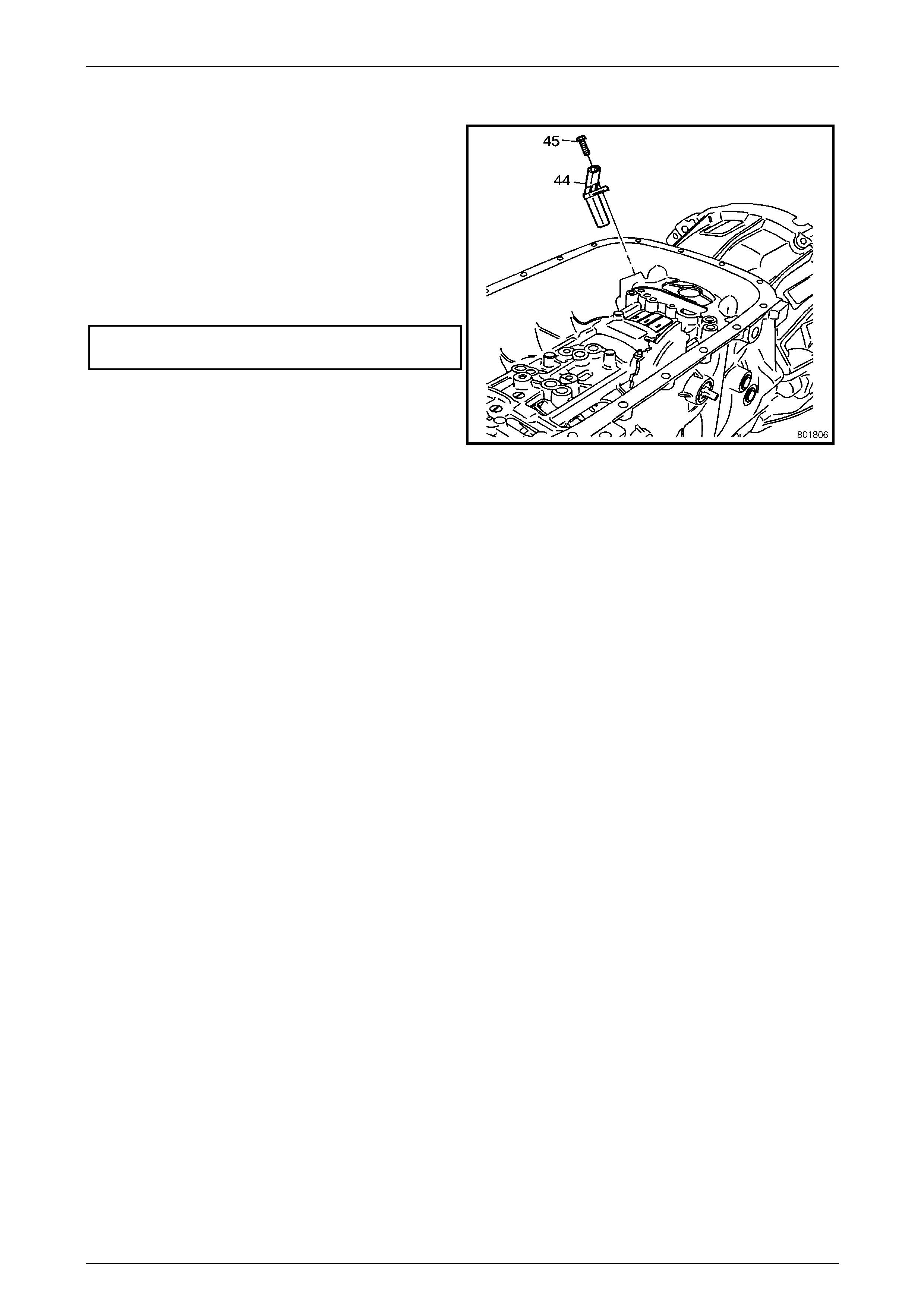
Automatic Transmission – 5L40–E – Unit Repair 7E5 – 106
7E5 – 106
1.40 Input Speed Sensor Installation
1 Rotate the transmission 90 degrees.
2 Install the input speed sensor (44) into the case (24).
NOTE
Refer to Fastener note under 4. Safety and
Service Guidelines in Section 00 Warnings,
Cautions and Notes of this Service Information.
3 Install the input speed sensor screw (45) into the case
(24) and tighten to the correct torque specification.
Input speed sensor to transmission case
bolt torque specification.......................................11 N.m
Figure 7E5 – 238
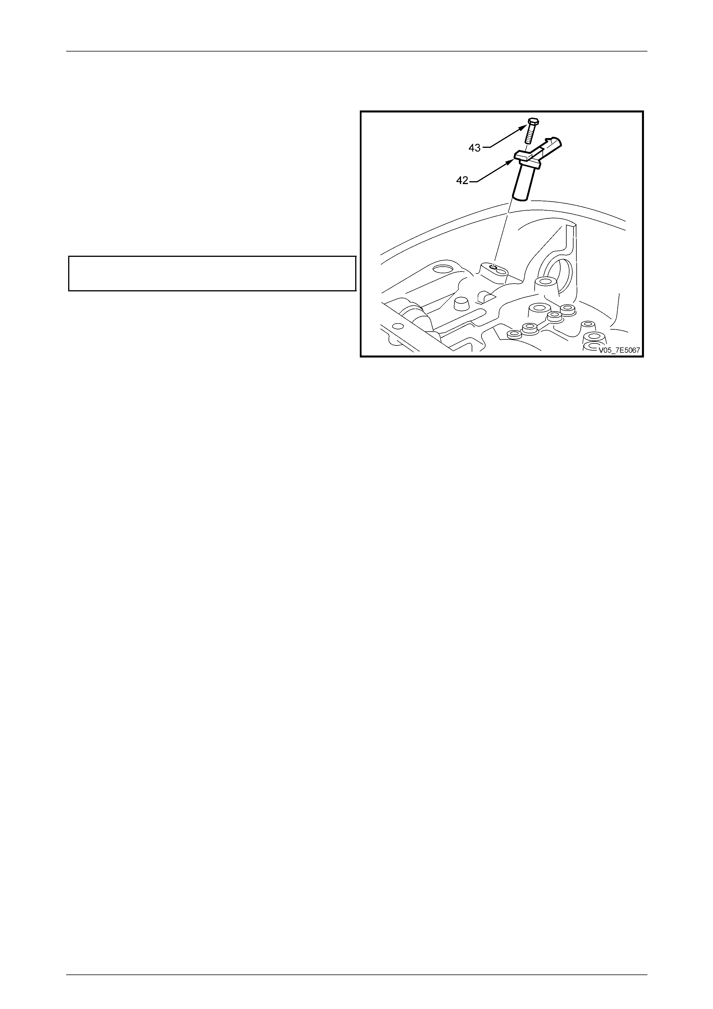
Automatic Transmission – 5L40–E – Unit Repair 7E5 – 107
7E5 – 107
1.41 Output Shaft Speed Sensor Installation
1 Install the output speed sensor (42) into the case (24).
NOTE
Refer to Fastener note under 4. Safety and
Service Guidelines in Section 00 Warnings,
Cautions and Notes of this Service Information.
2 Install the output speed sensor screw (43) into the
case (24) and tighten to the correct torque
specification.
Output speed sensor to transmission case
bolt torque specification......................................11 N.m.
Figure 7E5 – 239
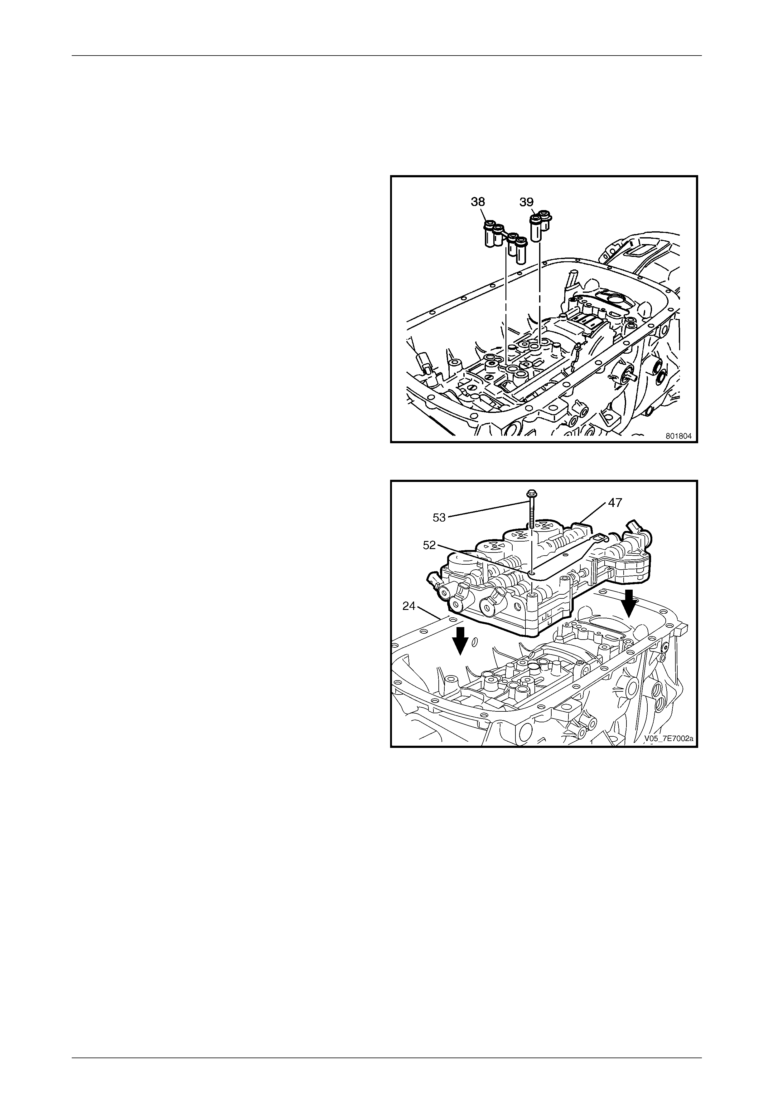
Automatic Transmission – 5L40–E – Unit Repair 7E5 – 108
7E5 – 108
1.42 Control Valve Body and Accumulator
Assembly
Reinstall
1 Install a NEW overdrive clutch fluid passa ge sleeve
(39) into the case (24).
2 Install a NEW centre support fluid passage sleeve (38)
into the case (24).
Figure 7E5 – 240
3 Install the control valve body and accumulator
assembly (47) onto the case (24), ensuring that the
manual valve link engag es the manual shaft detent
lever locating pin.
4 Install the detent lever spring (52), ensuring that the
detent spring roller is properly engaged with the
manual shift shaft switch.
5 Install the control valve body bolts (53) into the case
(24) and hand tighten.
Figure 7E5 – 241
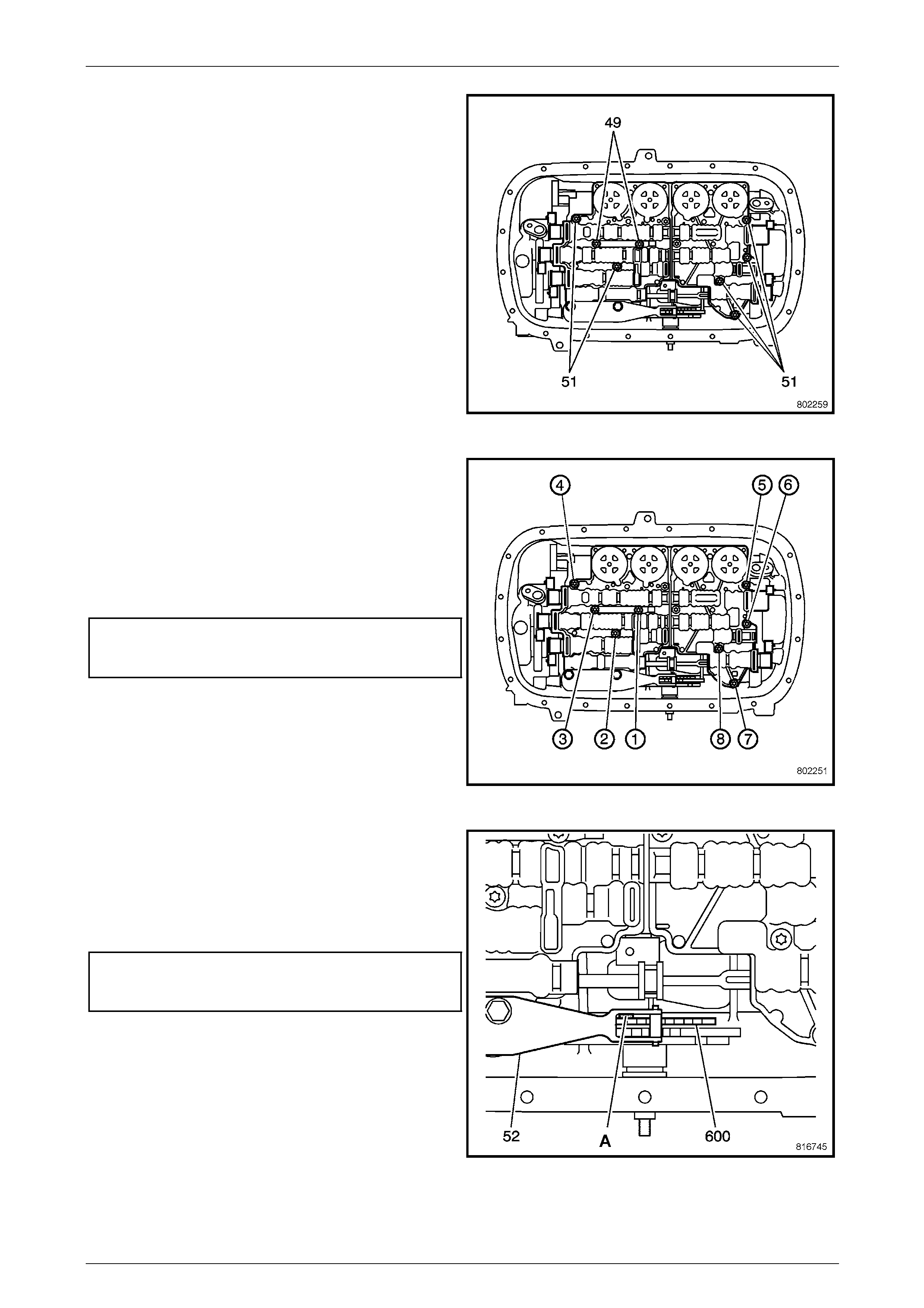
Automatic Transmission – 5L40–E – Unit Repair 7E5 – 109
7E5 – 109
6 Install the control valve body and accumulator
assembly bolts (49, 51) into the case (24) and hand
tighten.
Figure 7E5 – 242
NOTE
Refer to Fastener note under 4. Safety and
Service Guidelines in Section 00 Warnings,
Cautions and Notes of this Service Information.
7 Tighten the control valve bo dy and accumulator to
case bolts (49, 50, 51) in the correct sequence as
shown and to the correct torque specificatio n.
Control valve body and accumulator to
transmission case bolt torque
specification.........................................................11 N.m
Figure 7E5 – 243
8 Install a 0.8 mm spacer (A) between the manual shaft
detent lever (600) and the manual shaft detent lever
spring (52).
9 Tighten the manual shaft detent lever spri ng and
control valve body to transmission case bolts (53) to
the correct torque specification.
Manual shaft detent lever spring and
control valve body to transmission
case bolt torque specification...............................11 N.m
10 Remove the spacer (A).
Figure 7E5 – 244
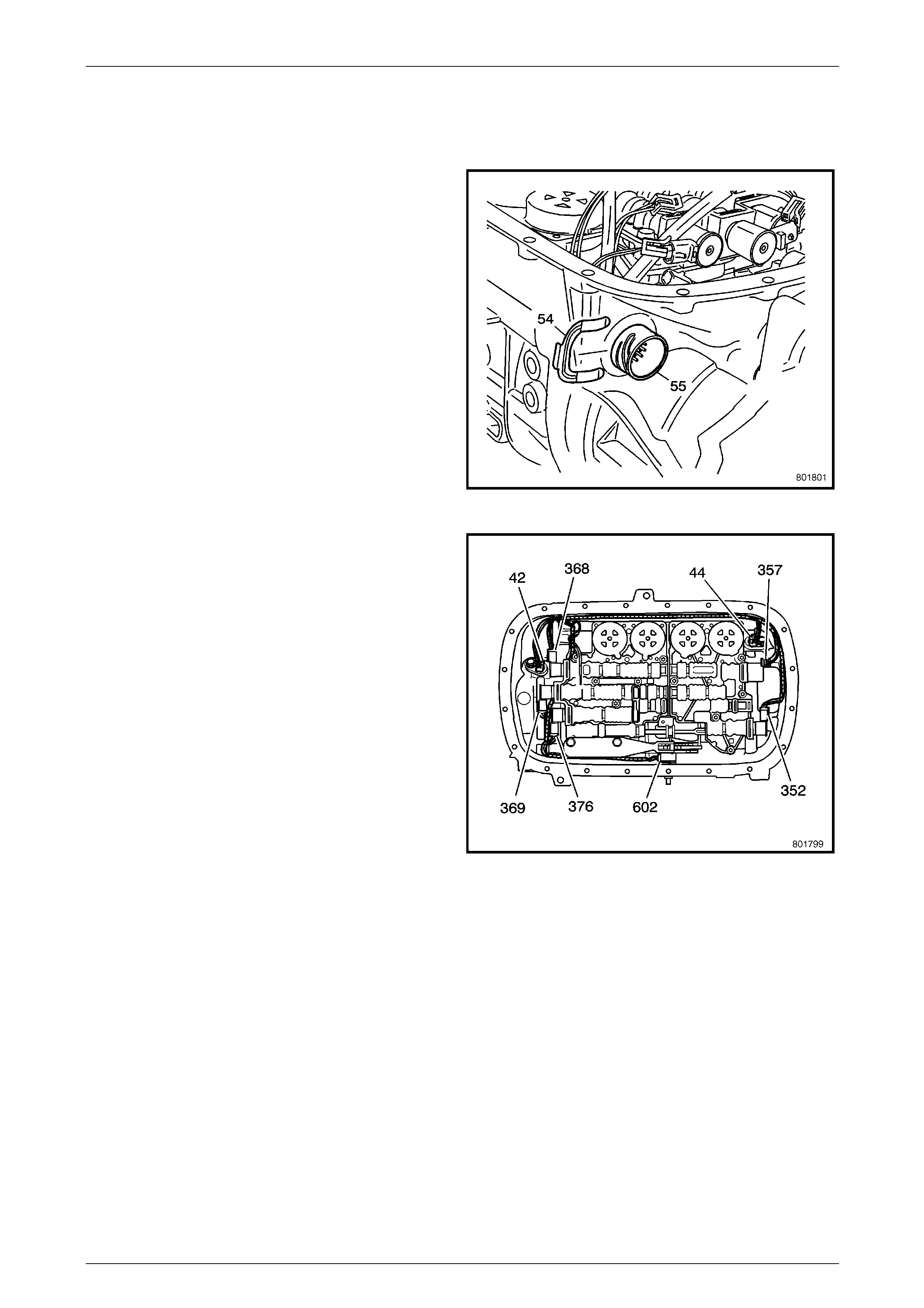
Automatic Transmission – 5L40–E – Unit Repair 7E5 – 110
7E5 – 110
1.43 Wiring Harness
Reinstall
1 Install the wiring harness connector (55) thru the case
(24). Hold the connector and install the wiring harness
connector retainer (54).
Figure 7E5 – 245
2 Route the harness to the valve body a nd connect the
following components:
• Pressure Control Solenoid (357).
• TCC PWM Solenoid (352).
• 1–2 Shift Solenoid (368).
• 2–3 Shift Solenoid (369).
• 4–5 Shift Solenoid (376).
• Internal Mode Switch – IMS (602).
• Input Speed Sensor (44).
• Output Speed Sensor (42).
Figure 7E5 – 246
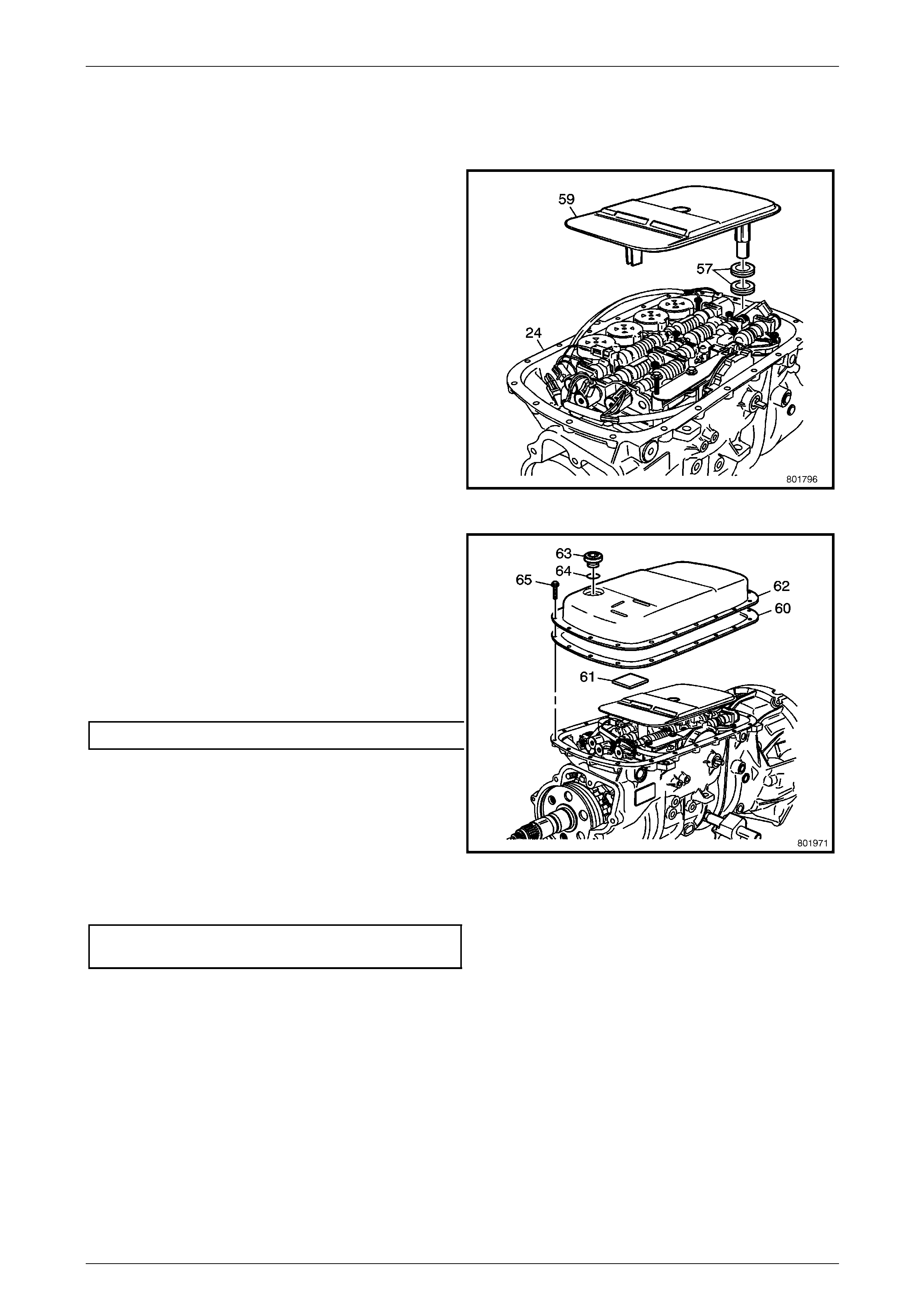
Automatic Transmission – 5L40–E – Unit Repair 7E5 – 111
7E5 – 111
1.44 Pan and Filter Assembly
Reinstall
1 Inspect the following components:
• Transmission fluid pan (62) for distortion, cracks,
score marks
• Inspect the fluid pan bolts (65) for thread
damage
• Inspect the transmission pan magnet (61) for
cracks and tears
2 Install the transmission fluid filt er (59) and fluid filters
seals (57) into the case (24).
Figure 7E5 – 247
3 Install the NEW drain plug seal (64) into the fluid pan
drain plug (63).
NOTE
Refer to Fastener note under 4. Safety and
Service Guidelines in Section 00 Warnings,
Cautions and Notes of this Service Information.
4 Install the NEW fluid pan dra in plug (63) and tighten to
the correct torque specification.
Fluid pan drain plug torque specification..............20 N.m
5 Install the fluid pan magn et (61) onto the fluid pan
(62).
6 Install the NEW fluid pan gasket (60) onto the flui d pan
(62).
7 Install the fluid pan (62) onto t he case (24).
8 Install the fluid pan bolts (65) into the case (24) and
tighten to the correct torque specification.
Fluid pan to transmission case
bolt torque specification.......................................11 N.m
Figure 7E5 – 248
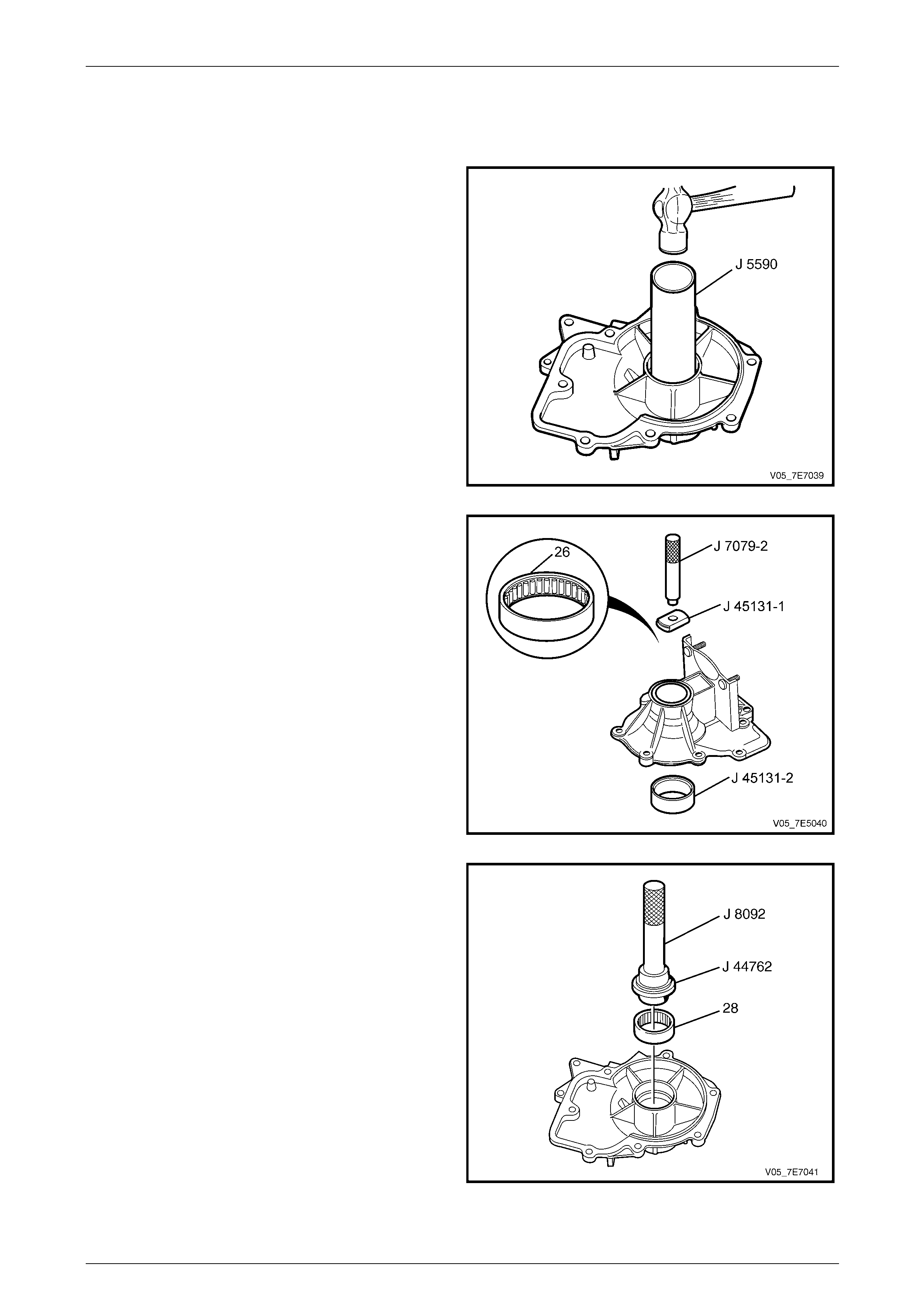
Automatic Transmission – 5L40–E – Unit Repair 7E5 – 112
7E5 – 112
1.45 Extension Housing
Reinstall
1 Inspect both inner (26) and outer (28) output shaft
bearings for the following:
• Damaged cage.
• Roller pitted.
2 Use Tool J 5590 to remove the outer output shaft
bearing if it is damaged.
Figure 7E5 – 249
3 Place Tool J 45131-1 onto the inner output shaft
bearing (26). Place the case extension on Tool J
45131-2.
4 Insert Tool J 7079-2 into Tool J 45131-1 and remove
the inner output shaft bearing (26).
Figure 7E5 – 250
5 Install driver, Tool J 8092 into installer, Tool J 44762,
then install the outer output shaft bearing (28) into the
extension housing, with numbers on the bearing facing
up.
Figure 7E5 – 251
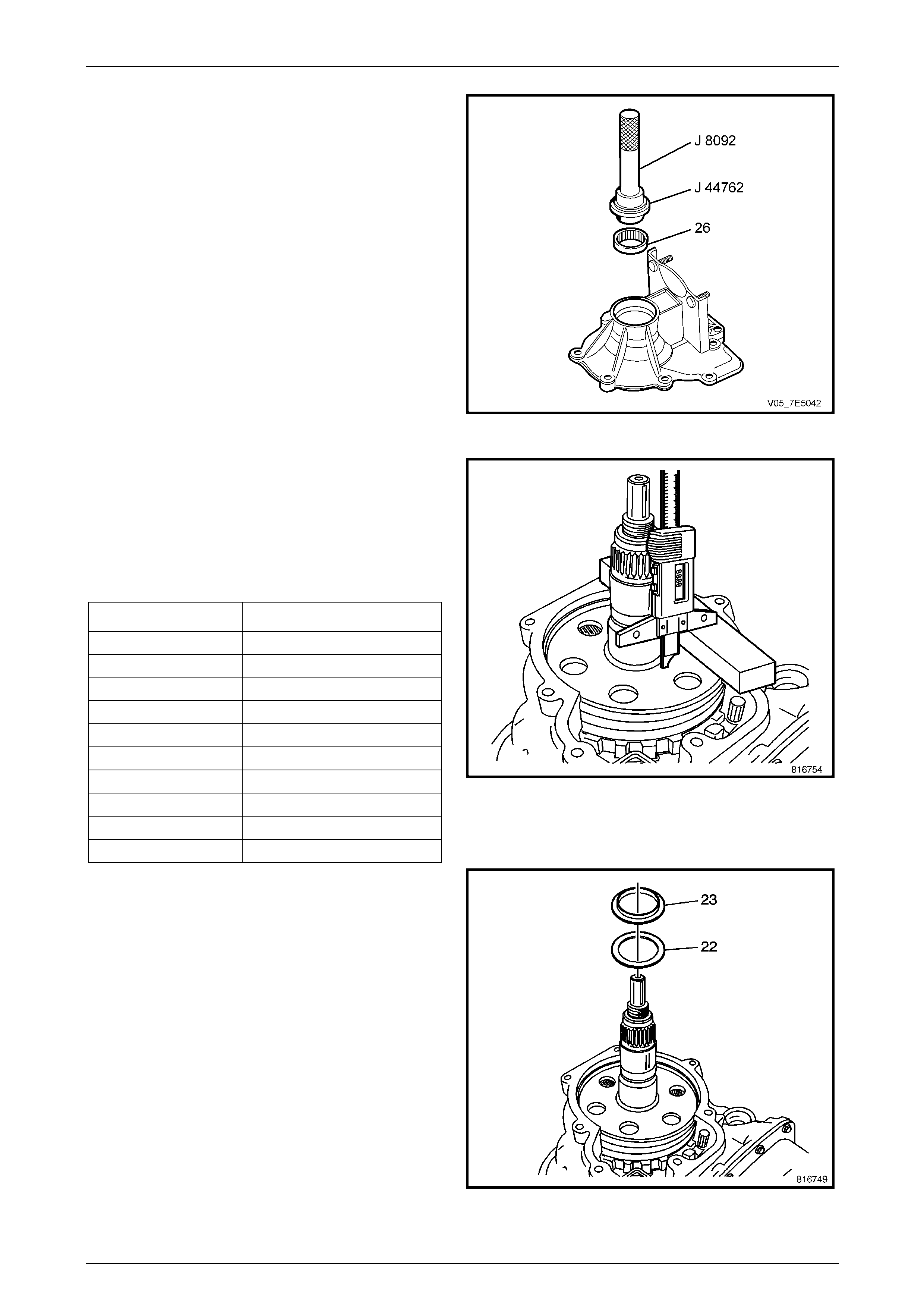
Automatic Transmission – 5L40–E – Unit Repair 7E5 – 113
7E5 – 113
6 Reverse the extension ho using position, then with
driver, Tool J 8092 installed into installer, Tool J 44762
press the inner output shaft bearing (26) i nto the
extension housing, with numbers on bearing facing up.
Figure 7E5 – 252
7 Rotate the transmission 90 degrees with the output
shaft facing upward.
8 Measure from the bottom of the transmission case to
the face of the output shaft. Record this as Dimension
'B'. Refer to following Output Shaft End Play Chart to
determine the correct washer size.
OUTPUT SHAFT END PLAY CHART
Dimension B Washer Thickness (mm)
15.99 mm–16.27 mm 0.95–1.05
16.27 mm–16.47 mm 1.15–1.25
16.47 mm–16.67 mm 1.35–1.45
16.67 mm–16.87 mm 1.55–1.65
16.87 mm–17.07 mm 1.75–1.85
17.07 mm–17.27 mm 1.95–2.05
17.27 mm–17.47 mm 2.15–2.25
17.47 mm–17.67 mm 2.35–2.45
17.67 mm–17.87 mm 2.55–2.65
17.87 mm–18.07 mm 2.75–2.85
Figure 7E5 – 253
9 Install the input and reaction c arrier washer (22).
10 Install the input and reaction c arrier thrust be aring (23)
onto the extension housing.
Figure 7E5 – 254
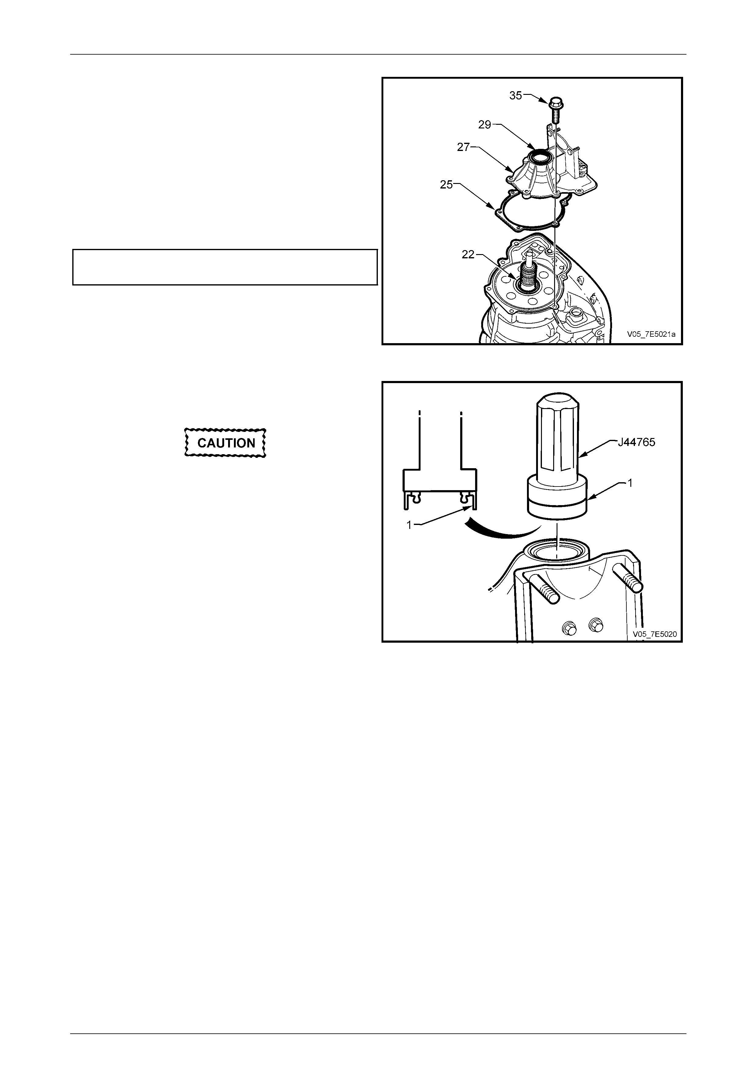
Automatic Transmission – 5L40–E – Unit Repair 7E5 – 114
7E5 – 114
11 Install the extension housing gasket (25) onto the
extension housing (27).
12 Install the extension housing (27) onto the case (24).
NOTE
Refer to Fastener note under 4. Safety and
Service Guidelines in Section 00 Warnings,
Cautions and Notes in this Service Information.
13 Install the extension housing bolts (35) and tighten to
the correct torque specification.
Extension housing to transmission case
bolt torque specification.......................................22 N.m
Figure 7E5 – 255
14 Using suitable snap ring pliers, install a NEW output
shaft snap ring retainer (3), refer to Figure 7E5-257.
Install the seal onto the tool before installing
into the extension housing to prevent
damage to the seal lips.
15 Using seal installer, Tool J 44765, install the propeller
shaft flange seal (29).
Figure 7E5 – 256
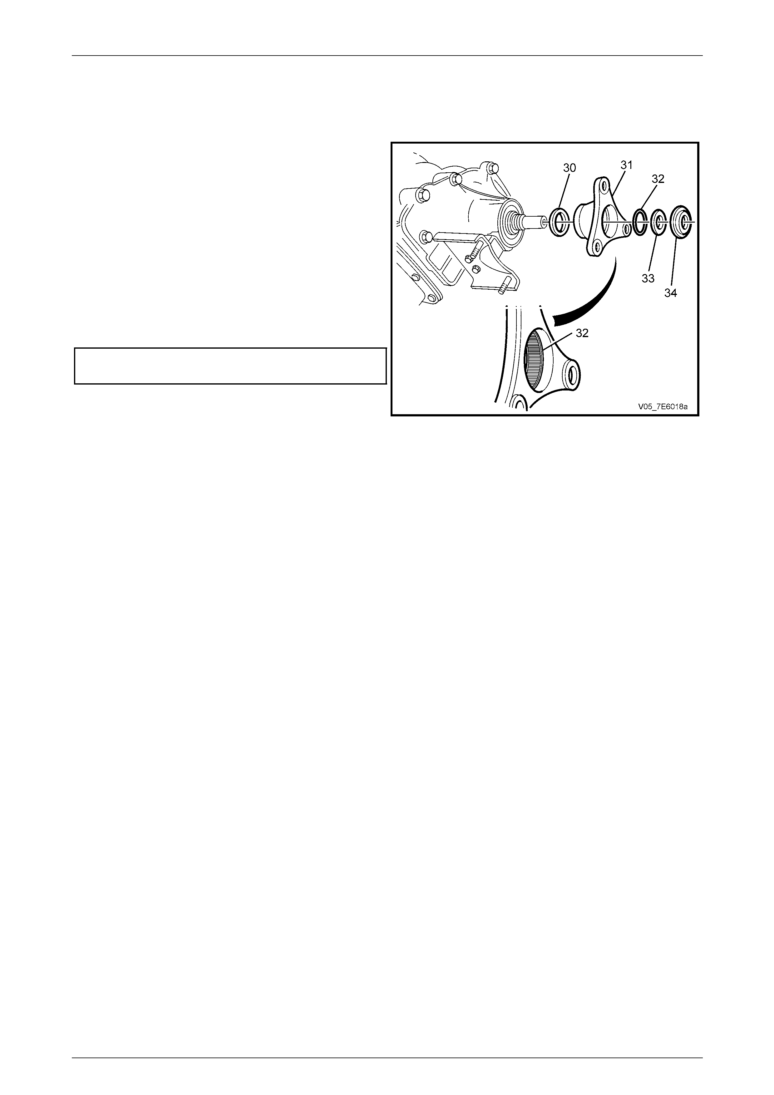
Automatic Transmission – 5L40–E – Unit Repair 7E5 – 115
7E5 – 115
1.46 Propeller Shaft Flange
Reassemble
1 Install the NEW propeller shaft flange O-ring seal (32)
into the prop shaft flange (31).
2 Install the propeller shaft flange (31).
3 Put the transmission in Park.
NOTE
Refer to Fastener note under 4. Safety and
Service Guidelines in Section 00 Warnings,
Cautions and Notes of this Service Information.
4 Install a NEW dished thrust washer (33) and NEW
propeller shaft flange nut (34). Tighten nut to the
correct torque specification.
Propeller shaft flange to output shaft
nut torque specification........................................57 N.m
Figure 7E5 – 257
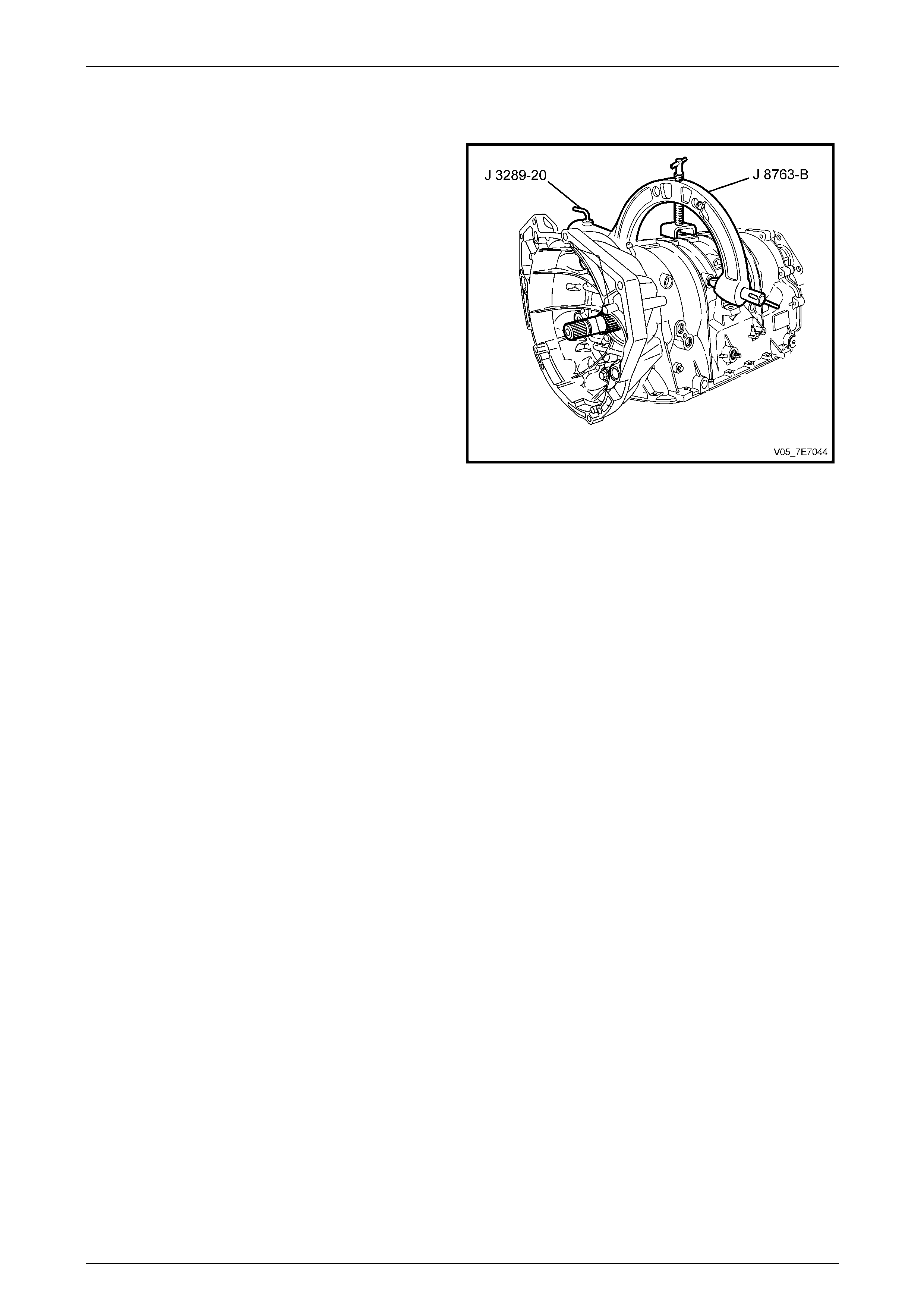
Automatic Transmission – 5L40–E – Unit Repair 7E5 – 116
7E5 – 116
1.47 Holding Fixture Removal
1 Using suitable lifting equipment, remove the
transmission and the holding fixture, Tool J 8763-B
from the bench bracket, Tool J 3289-20.
2 Remove Tool J 8763-B from the transmissio n.
Figure 7E5 – 258

Automatic Transmission – 5L40–E – Unit Repair 7E5 – 117
7E5 – 117
1.48 Torque Converter Assembly
Reinstall
1 Lubricate a NEW input shaft O-ring seal (43 0) with
transmission fluid and install to the groove provided.
Figure 7E5 – 259
Take care when installing the torque
converter as it is a heavy assembly
(approximately 12 kilograms) and personal
injury may result if lifted incorrectly.
2 Install the torque converter assembly (1).
Figure 7E5 – 260
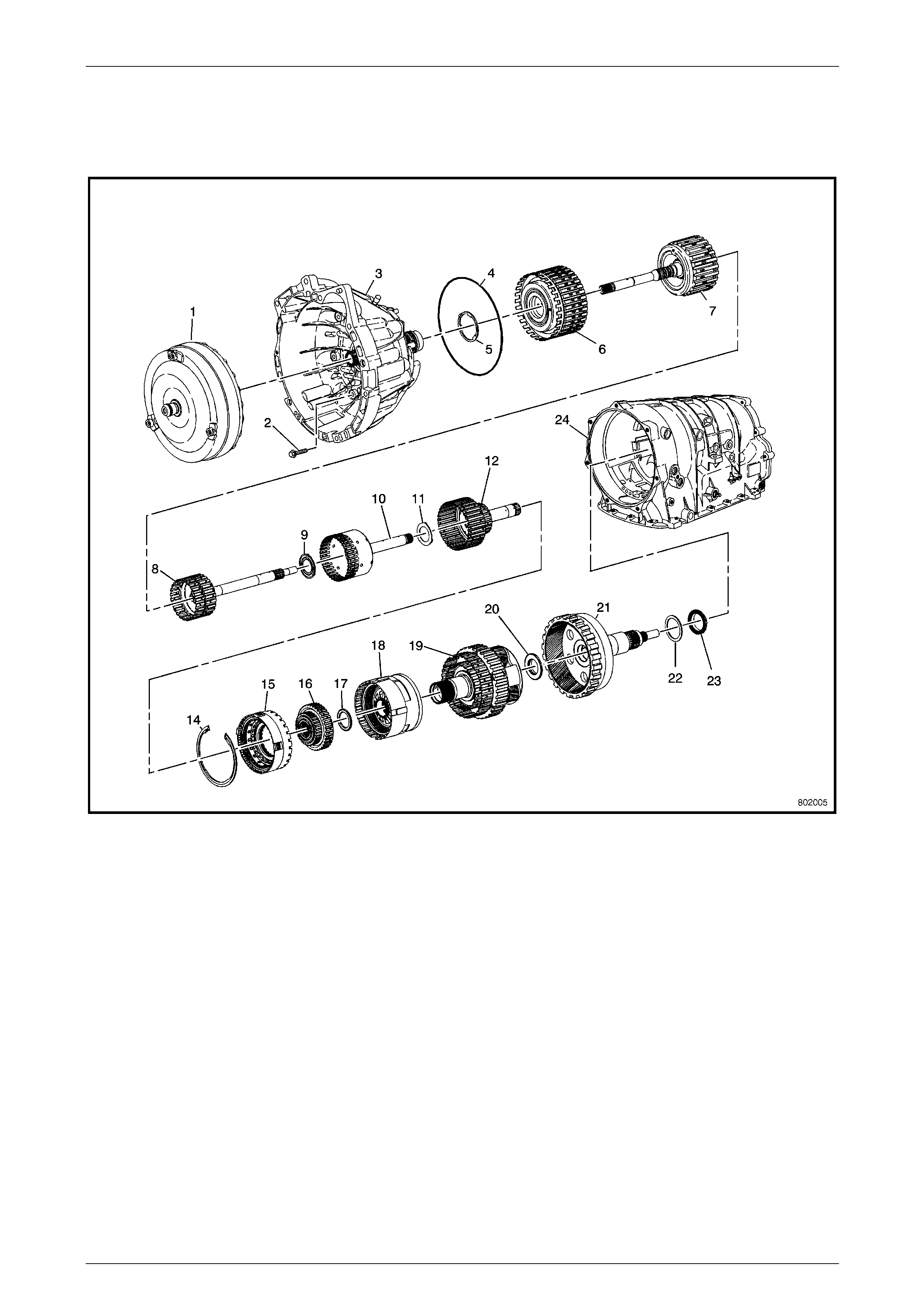
Automatic Transmission – 5L40–E – Unit Repair 7E5 – 118
7E5 – 118
2 Transmission Reference
Diagrams
Figure 7E5 – 261 Case and Associated Parts (1 of 2)
Legend
1 Torque Converter Assembly 14 Intermediate and Overdrive Clutch Housing Retainer Ring
2 Torque Converter Housing to Main Case Bolt 15 Overdrive Clutch Housing Assembly
3 Torque Converter Housing Assembly 16 Low Clutch Sprag Assembly
4 Torque Converter Housing Fluid Seal Assembly 17 Low Clutch Roller Thrust Bearing
5 Reverse Clutch Housing Thrust Washer – Selective 18 Centre Support
6 Direct and Reverse Clutch Assembly 19 Input and Reaction Carrier Assembly
7 Forward and Coast Clutch Assembly 20 Input and Reaction Carrier Thrust Bearing
8 Input Sun Gear with Forward Clutch Roller Inner Race Shaft 21 Output Shaft Assembly – W/Rear Internal Gear
9 Direct Clutch Hub Thrust Washer 22 Input and Reaction Carrier Washer – Selective
10 Direct Clutch Assembly with Input and Reaction Carrier 23 Input and Reaction Carrier Thrust Bearing
11 Input and Reaction Carrier Inner Shaft Thrust Washer 24 Automatic Transmission Case Assembly
12 Intermediate Clutch Sprag Assembly
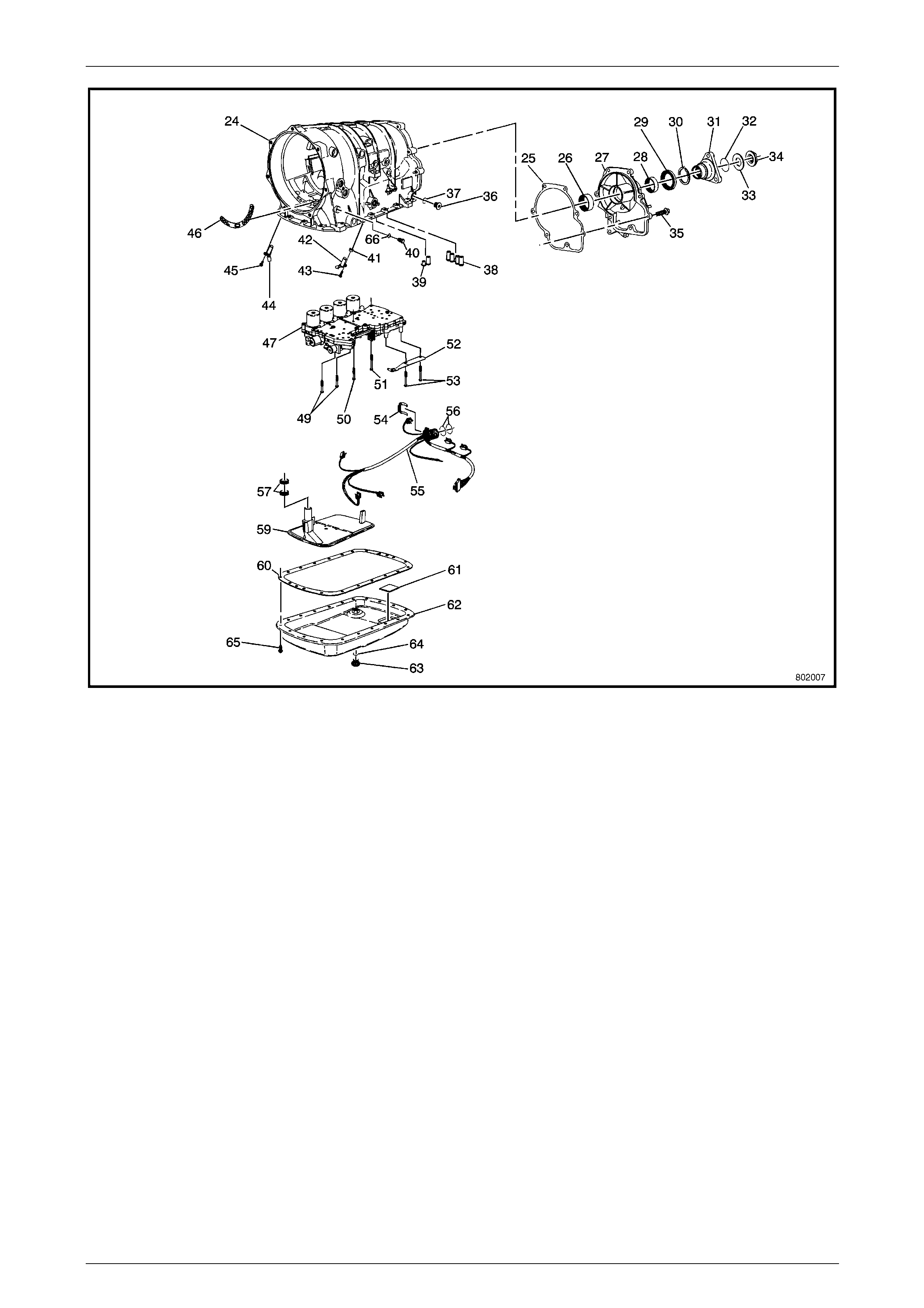
Automatic Transmission – 5L40–E – Unit Repair 7E5 – 119
7E5 – 119
Figure 7E5 – 262 Case and Associated Parts (2 of 2)
Legend
24 Automatic Transmission Case Assembly 45 Input Speed Sensor Bolt
25 Automatic Transmission Case Extension Gasket 46 Automatic Transmission Fluid Pump Cover Gasket
26 Output Shaft Bearing 47 Control Valve Body and Accumulator Assembly
27 Automatic Transmission Case Extension 49 Control Valve Body Bolt M6 x 1.0 x 50
28 Output Shaft Bearing 50 Control Valve Body Bolt M6 x 1.0 x 38
29 Automatic Transmission Propeller Shaft Flange Seal 51 Control Valve Body Bolt M6 x 1.0 x 50
30 Output Shaft Assembly Retainer 52 Manual Shaft Detent Assembly
31 Automatic Transmission Propeller Shaft Flange 53 Control Valve Body Bolt M6 x 1.0 x 68
32 Propeller Shaft Flange – O-ring Seal 54 Wiring Harness Clip
33 Automatic Transmission Propeller Shaft Thrust Washer 55 Automatic Transmission Wiring Harness
34 Propeller Shaft Flange Nut 56 Automatic Transmission Wiring Harness – O-ring seal – 2
35 Automatic Transmission Case Extension Bolt 57 Automatic Transmission Filter Seal – 2
36 Automatic Transmission Fluid Level Hole Plug 59 Automatic Transmission Fluid Filter
37 Automatic Transmission Fluid Level Hole Plug O-ring Seal 60 Automatic Transmission Fluid Pan Gasket
38 Centre Support Fluid Passage Sleeve 61 Automatic Transmission Fluid Pan Magnet
39 Overdrive Clutch Fluid Passage Sleeve 62 Automatic Transmission Fluid Pan Assembly
40 Automatic Transmission Pressure Test Plug 63 Automatic Transmission Fluid Pan Drain Plug
41 Output Speed Sensor Spacer 64 Automatic Transmission Fluid Pan Drain Plug Seal
42 Output Speed Sensor 65 Automatic Transmission Fluid Pan Bolt
43 Output Speed Sensor Bolt M6 x 1.0 x 50 66 Automatic Transmission Pressure Test Plug O-ring Seal
44 Input Speed Sensor
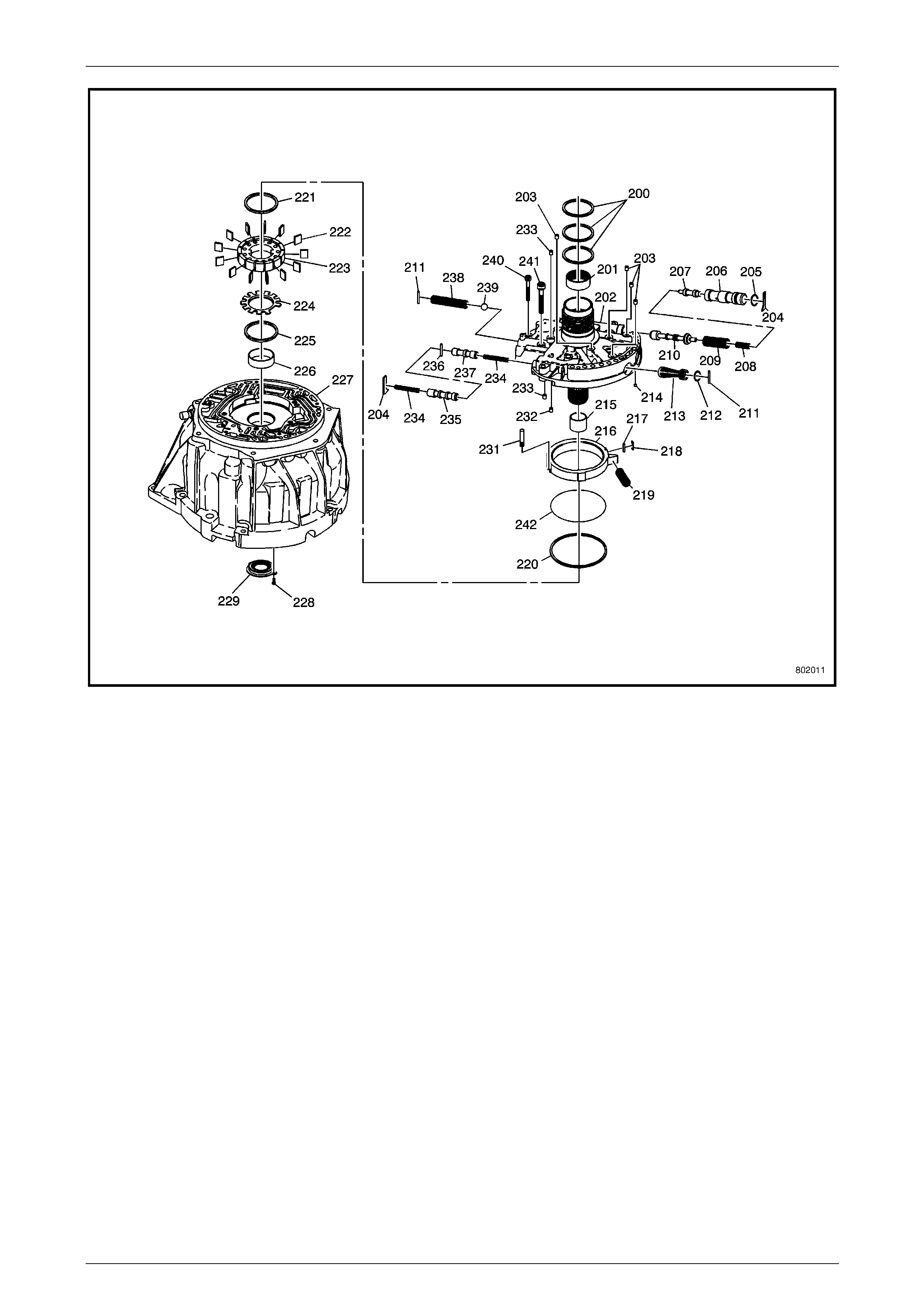
Automatic Transmission – 5L40–E – Unit Repair 7E5 – 120
7E5 – 120
Figure 7E5 – 263 Fluid Pu mp Assembly
Legend
200 Reverse Clutch Housing Fluid Seal Ring - 3 221 Automatic Transmission Fluid Pump Vane Ring
201 Input Shaft Bearing Assembly 222 Automatic Transmission Fluid Pump Vane
202 Automatic Transmission Fluid Pump Cover Assembly 223 Automatic Transmission Fluid Pump Rotor – Selective
203 Check Valve Retainer and Ball Assembly 224 Automatic Transmission Fluid Pump Rotor Guide
204 Valve Bushing/Spring Retainer 225 Automatic Transmission Fluid Pump Vane Ring
205 Line Boost Valve Bushing Seal 226 Torque Converter Bushing
206 Line Boost Valve Bushing 227 Torque Converter Housing
207 Line Boost Valve 228 Torque Converter Housing Seal Bolt M4 x 0.7 x 10.0 - 4
208 Line Boost Valve Spring 229 Torque Converter Housing Seal
209 Pressure Regulator Valve Spring 231 Automatic Transmission Fluid Pump Slide Pin Assembly
210 Pressure Regulator Valve 232 Orifice Sleeve
211 Automatic Transmission Fluid Pump Retainer Pin 233 Orifice Cup Plug - 2
212 Automatic Transmission Pump Cover Seal 234 TCC Control Valve Spring
213 Automatic Transmission Fluid Pump Screen Assembly 235 TCC Control Valve
214 Brass Orifice Insert 236 Automatic Transmission Fluid Pump Retainer Pin
215 Turbine Shaft Bushing 237 TCC Enable Valve
216 Automatic Transmission Fluid Pump Slide – Selective 238 Pressure Relief Ball Valve Spring
217 Automatic Transmission Fluid Pump Slide Seal Support 239 Pressure Relief Ball Valve
218 Automatic Transmission Fluid Pump Slide Seal 240 Automatic Transmission Fluid Pump Bolt M6 x 1.0 x 40
219 Automatic Transmission Fluid Pump Slide Ring 241 Automatic Transmission Fluid Pump Bolt M8 x 1.25 x 40
220 Automatic Transmission Fluid Pump Slide Ring 242 Automatic Transmission Fluid Pump Slide O-ring Seal
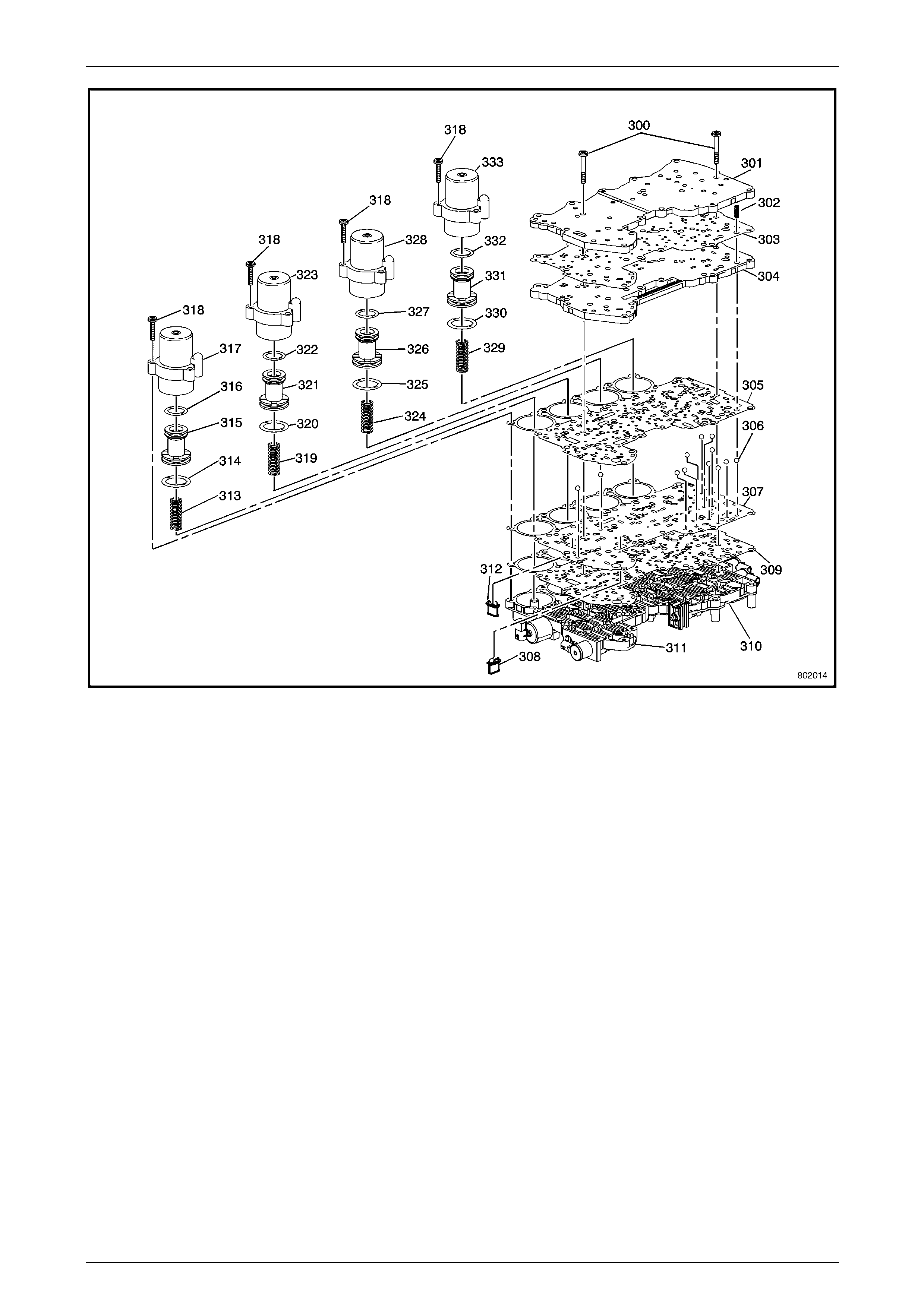
Automatic Transmission – 5L40–E – Unit Repair 7E5 – 121
7E5 – 121
Figure 7E5 – 264 Control Valve Body and Accumulator Assembly
Legend
300 Control Valve Body Bolt M6 x 1.0 x 38 - 7 317 Direct Clutch Accumulator Housing
301 Control Valve Top Channel Plate 318 Accumulator Housing Bolt M6 x 1.0 x 30 - 12
302 Control Valve Channel Plate Ball Check Spring 319 Overdrive Clutch Accumulator Piston Spring
303 Control Valve Channel Plate Gasket 320 Overdrive Clutch Accumulator Piston Fluid Seal Ring
304 Control Valve Bottom Channel Plate 321 Overdrive Clutch Accumulator Piston
305 Control Valve Body Gasket 322 Overdrive Clutch Accumulator Piston Fluid Seal Ring
306 Control Valve Body Ball Check Valve 323 Overdrive Clutch Accumulator Housing
307 Control Valve Body Spacer Plate 324 Intermediate Clutch Accumulator Piston Spring
308 TCC PWM Solenoid Valve Filter Assembly 325 Intermediate Clutch Accumulator Piston Fluid Seal Ring
309 Control Valve Body Spacer Plate Gasket 326 Intermediate Clutch Accumulator Piston
310 Control Valve Rear Body Assembly 327 Intermediate Clutch Accumulator Piston Fluid Seal Ring
311 Control Valve Front Body Assembly 328 Intermediate Clutch Accumulator Housing
312 Pressure Control Solenoid Valve Filter Assembly 329 2nd Clutch Accumulator Piston Spring
313 Direct Clutch Accumulator Piston Spring 330 2nd Clutch Accumulator Piston Seal Ring
314 Direct Clutch Accumulator Piston Fluid Seal Ring 331 2nd Clutch Accumulator Piston
315 Direct Clutch Accumulator Piston 332 2nd Clutch Accumulator Piston Seal Ring
316 Direct Clutch Accumulator Piston Fluid Seal Ring 333 2nd Clutch Accumulator Housing
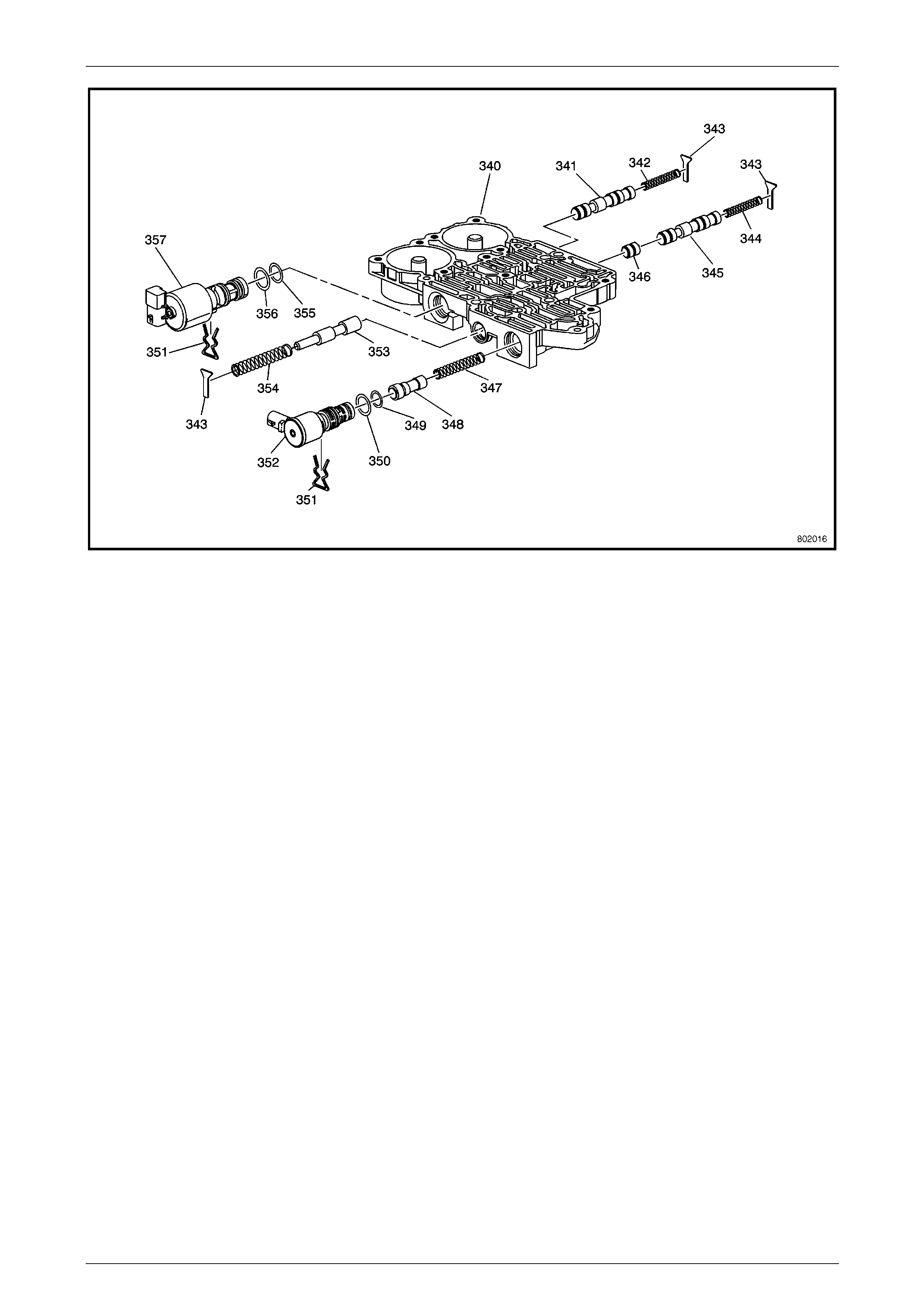
Automatic Transmission – 5L40–E – Unit Repair 7E5 – 122
7E5 – 122
Figure 7E5 – 265 Front Co ntrol Valve Body
Legend
340 Front Control Valve Body 349 Solenoid Valve – O-ring Seal
341 Safety Mode Valve 350 Solenoid Valve – O-ring Seal
342 Safety Mode Valve Spring 351 Solenoid Valve Retainer - 2
343 Valve Spring Retainer - 3 352 TCC PWM Solenoid Valve
344 3–4 Shift Valve Spring 353 Feed Limit Valve
345 3–4 Shift Valve 354 Feed Limit Valve Spring
346 3–4 Shift Control Valve 355 Pressure Control Solenoid – O-ring Seal
347 TCC Regulator Apply Valve Spring 356 Pressure Control Solenoid – O-ring Seal
348 TCC Regulator Apply Valve 357 Pressure Control (PC) Solenoid Assembly
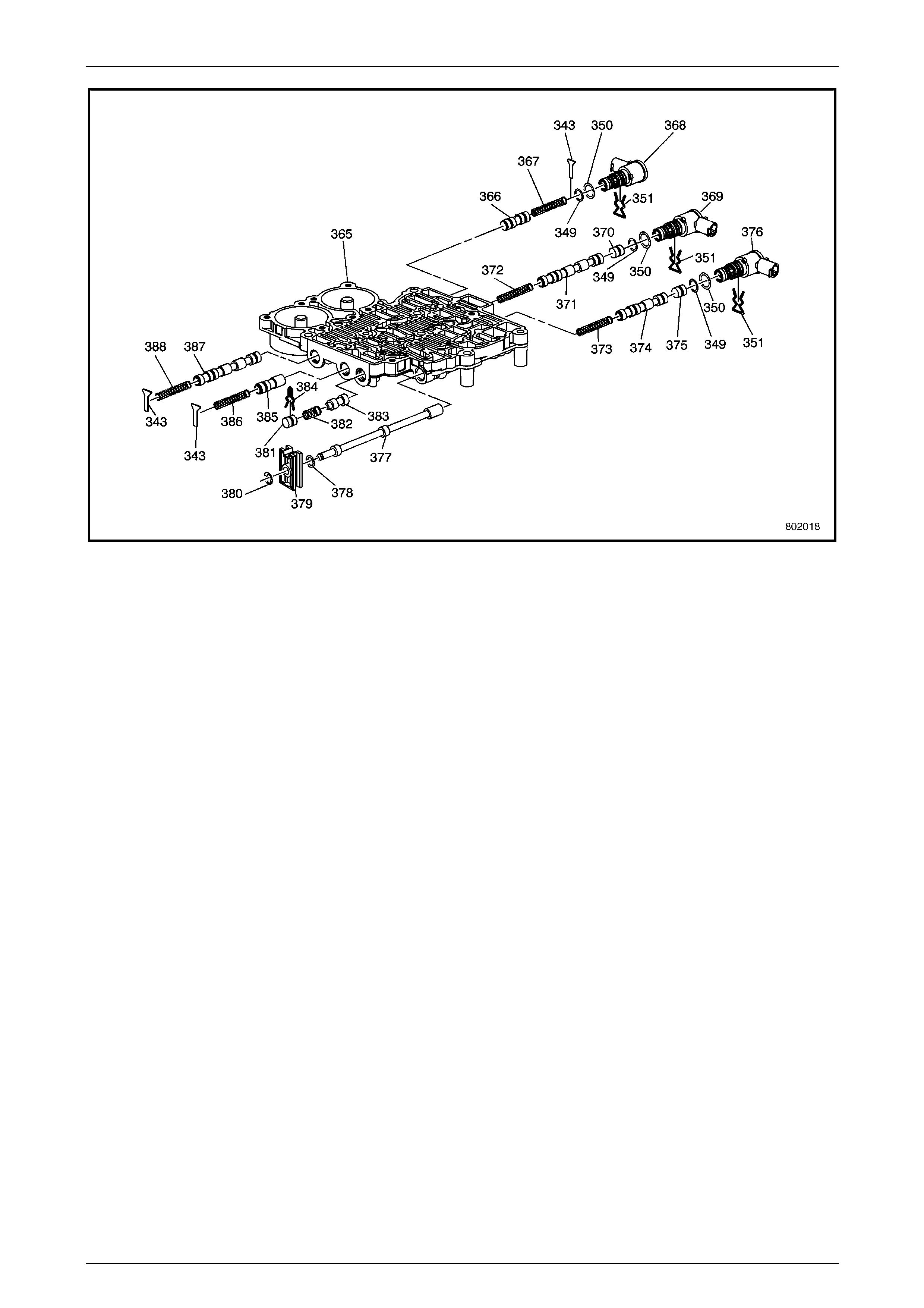
Automatic Transmission – 5L40–E – Unit Repair 7E5 – 123
7E5 – 123
Figure 7E5 – 266 Rear Con t ro l Valve Body
Legend
343 Valve Spring Retainer 375 4–5 Shift Control Valve
349 Solenoid Valve – O-ring Seal 376 4–5 Shift Solenoid (SS) Valve Assembly
350 Solenoid Valve – O-ring Seal 377 Manual Valve
351 Solenoid Valve Retainer 378 Manual Valve Link Washer – Waved
365 Rear Control Valve Body 379 Manual Valve Link
366 1–2 Shift Control Valve 380 Manual Valve Link Retainer
367 1–2 Shift Control Valve Spring 381 Low Pressure Control Valve Bore Plug
368 1–2 Shift Solenoid (SS) Valve Assembly 382 Low Pressure Control Valve Spring
369 2–3 Shift Solenoid (SS) Valve Assembly 383 Low Pressure Control Valve
370 2–3 Shift Control Valve 384 Low Pressure Control Valve Bore Retainer
371 2–3 Shift Valve 385 Reverse Lockout Valve
372 2–3 Shift Valve Spring 386 Reverse Lockout Valve Spring
373 4–5 Shift Valve Spring 387 1–2 Shift Valve
374 4–5 Shift Valve 388 1–2 Shift Valve Spring
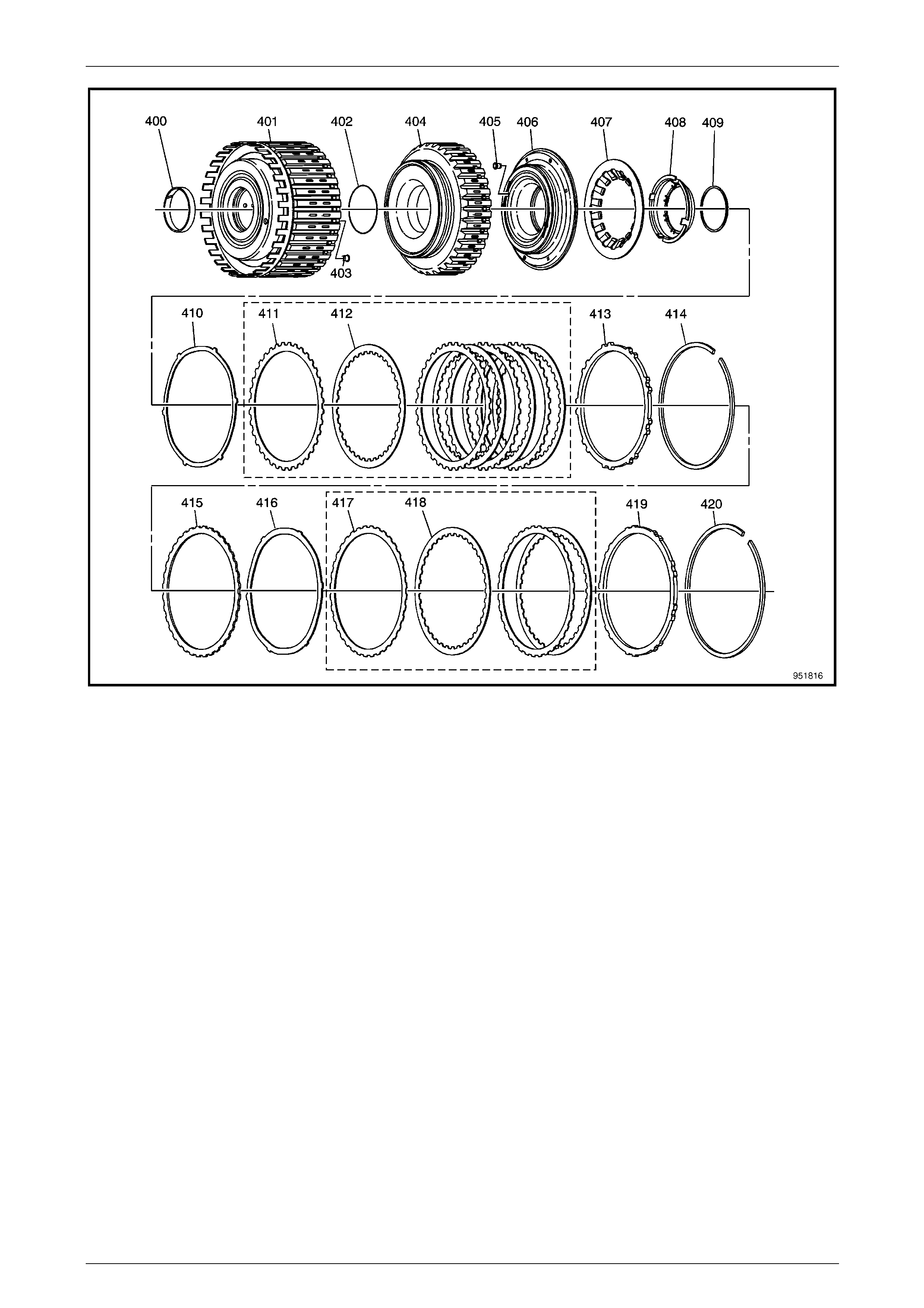
Automatic Transmission – 5L40–E – Unit Repair 7E5 – 124
7E5 – 124
Figure 7E5 – 267 Direct and Reverse Clutch Assembly
Legend
400 Reverse Clutch Housing Bushing 411 Direct Clutch Plate Assembly – Outer Spline
401 Reverse Clutch – W/Input Housing Assembly 412 Direct Clutch Plate Assembly – In ner Spline
402 Reverse Clutch Piston Inner Seal 413 Direct Clutch Backing Plate
403 Reverse Clutch Housing Ball Check Valve 414 Direct Clutch Backing Plate Retainer Ring – Selective
404 Reverse Clutch Piston 415 Reverse Clutch Spacer
405 Direct Clutch Housing Ball Check Valve 416 Reverse Clutch Apply Plate
406 Direct Clutch Piston Assembly 417 Reverse Clutch Plate Assembly – Outer Spline
407 Direct and Reverse Clutch Spring 418 Reverse Clutch Plate Assembly – Inner Spline
408 Direct and Reverse Clutch Spring Retainer 419 Reverse Clutch Backing Plate
409 Direct and Reverse Clutch Spring Retainer Ring 420 Reverse Clutch Backing Plate Retainer Ring – Selective
410 Direct Clutch Apply Plate
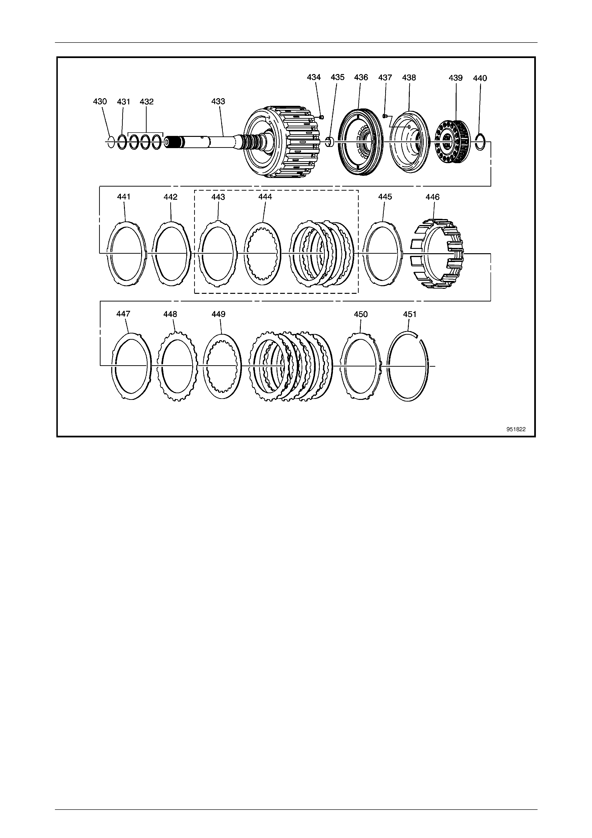
Automatic Transmission – 5L40–E – Unit Repair 7E5 – 125
7E5 – 125
Figure 7E5 – 268 Forward and Coast Clutch Assembly
Legend
430 Input Shaft – O-ring Seal 441 Coast Clutch Spacer Plate – Selective
431 Input Shaft Fluid Seal Ring 442 Coast Clutch Apply Plate
432 Input Shaft Fluid Seal Ring – 3 places 443 Coast Clutch Plate Assembly – Outer Spline
433 Forward Clutch – W/Input Housing Assembly 444 Coast Clutch Plate Assembly – Inner Spline
434 Forward Clutch Housing Ball Check Valve Assembly 445 Coast Clutch Backing Plate
435 Forward Clutch Bushing 446 Coast Clutch Housing
436 Forward Clutch Piston Assembly 447 Forward Clutch Apply Plate
437 Coast Clutch Piston Ball Check Valve Assembly 448 Forward Clutch Plate Assembly – Outer Spline
438 Coast Clutch Piston Assembly 449 Forward Clutch Plate Assembly – Inner Spline
439 Forward and Coast Clutch Spring 450 Forward Clutch Backing Plate
440 Forward and Coast Clutch Spring Retainer Ring 451 Forward Clutch Backing Plate Retainer Ring – Selective
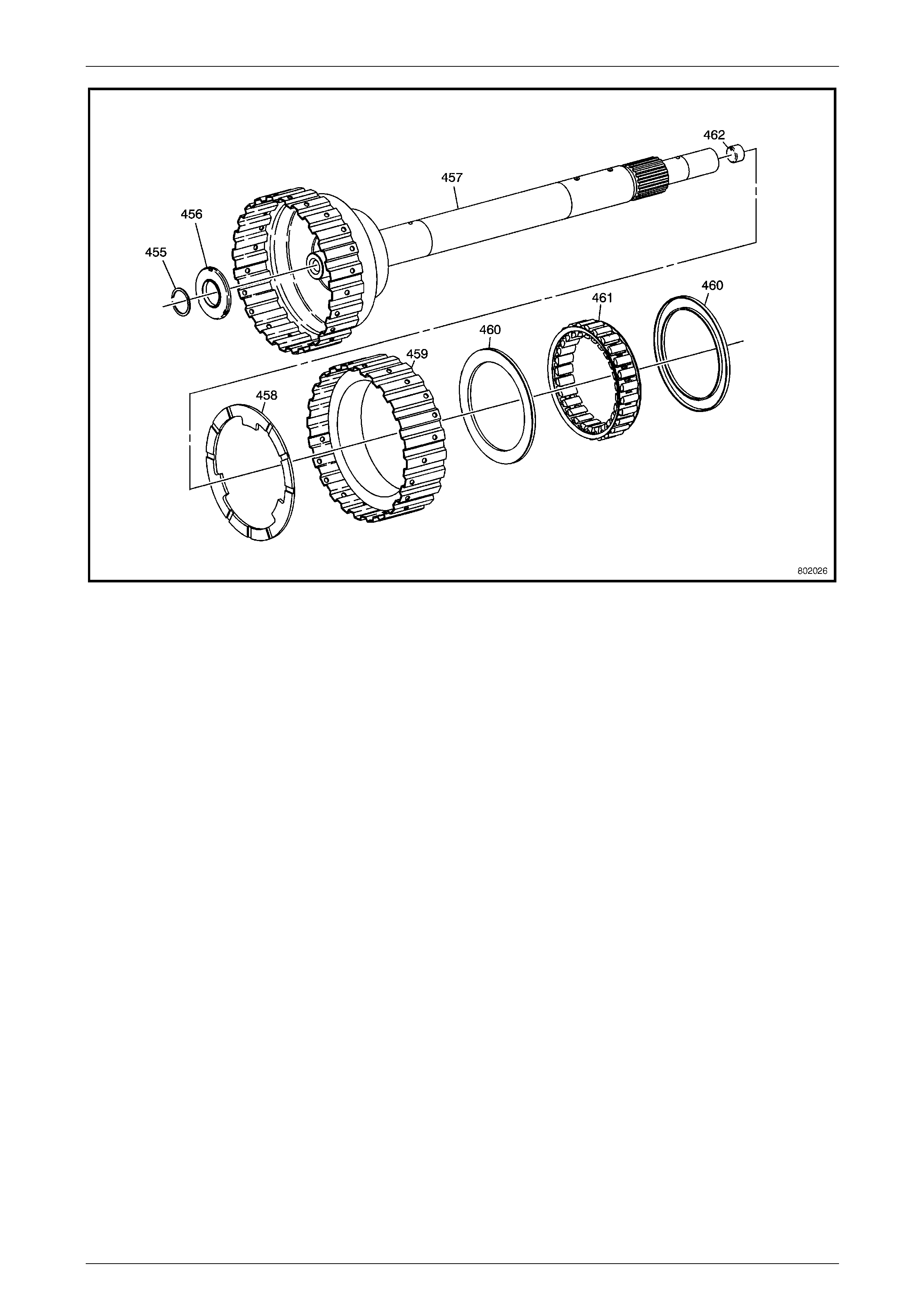
Automatic Transmission – 5L40–E – Unit Repair 7E5 – 126
7E5 – 126
Figure 7E5 – 269 Input Sun Gear and Forward Sprag Clutch Assembly
Legend
455 Forward Clutch Roller Inner Race Thrust Ring 459 Forward Clutch Sprag Outer Race
456 Forward Clutch Roller Inner Bearing 460 Forward Clutch Sprag Assembly Retainer Rings - 2
457 Input Sun Gear Shaft Assembly 461 Forward Clutch Sprag Assembly
458 Forward Clutch Roller Outer Race Washer 462 Orificed Cup Plug – Lube
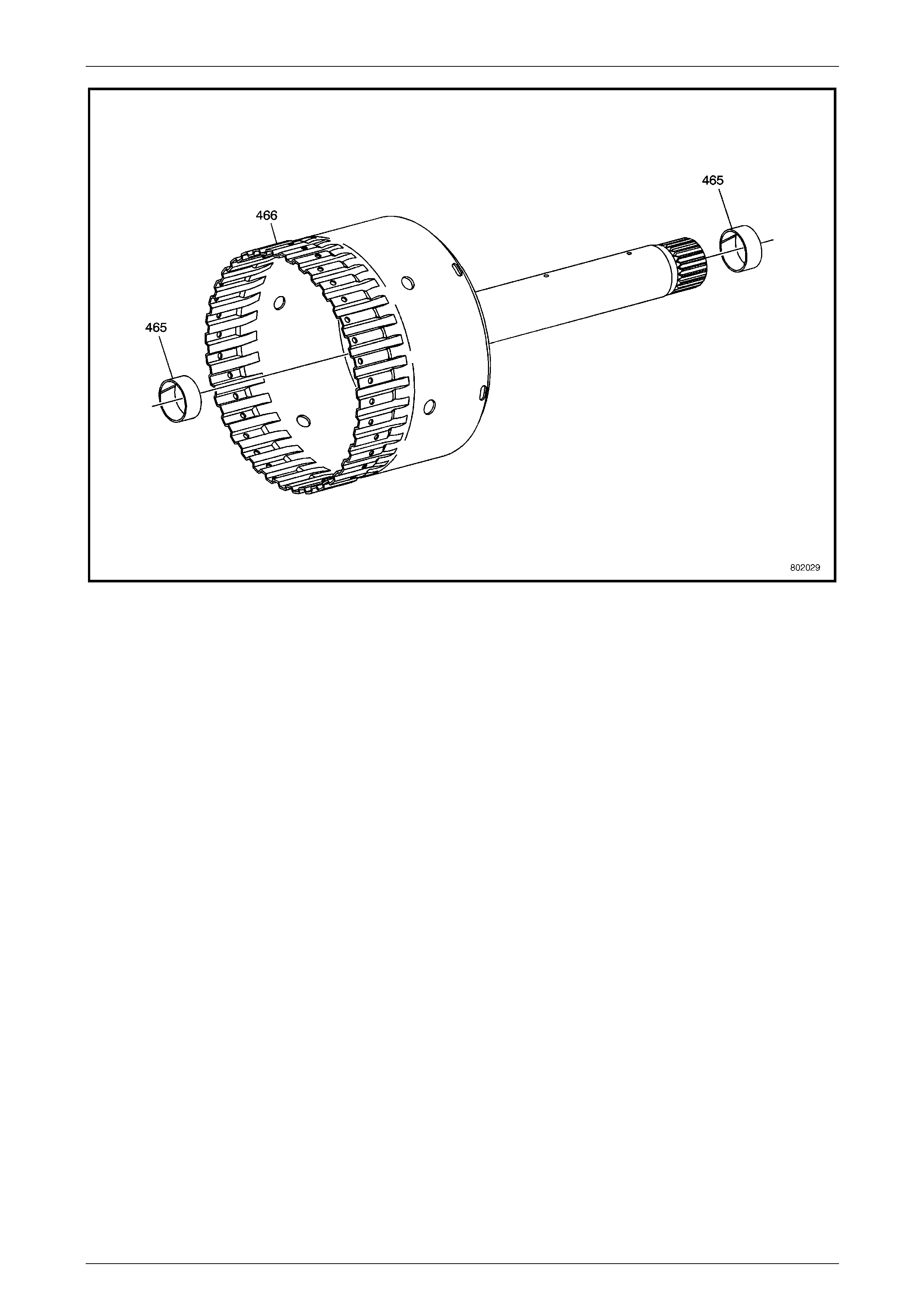
Automatic Transmission – 5L40–E – Unit Repair 7E5 – 127
7E5 – 127
Figure 7E5 – 270 Direct Clutch Drum and Shaft Assembly
Legend
465 Input and Reaction Carrier Bushing- 2 466 Direct Clutch Drum
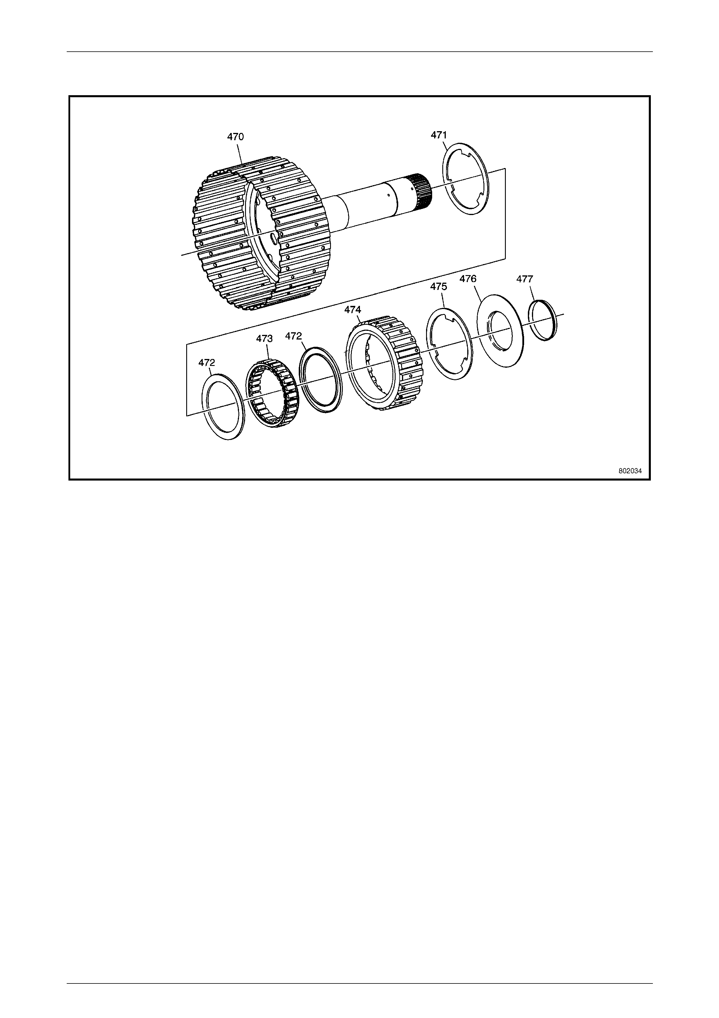
Automatic Transmission – 5L40–E – Unit Repair 7E5 – 128
7E5 – 128
Figure 7E5 – 271 Intermediate Sprag Clutch Assembly
Legend
470 Overdrive and Reverse Clutch – W/Hub Assembly 474 Intermediate Clutch Sprag Outer Race
471 Intermediate Clutch Roller Thrust Washer 475 Intermediate Clutch Roller Thrust Washer
472 Intermediate Clutch Sprag Assembly Retainer Rings - 2 476 Intermediate Clutch Roller Thrust Bearing
473 Intermediate Clutch Sprag Assembly 477 Intermediate Clutch Roller Thrust Bearing Retainer
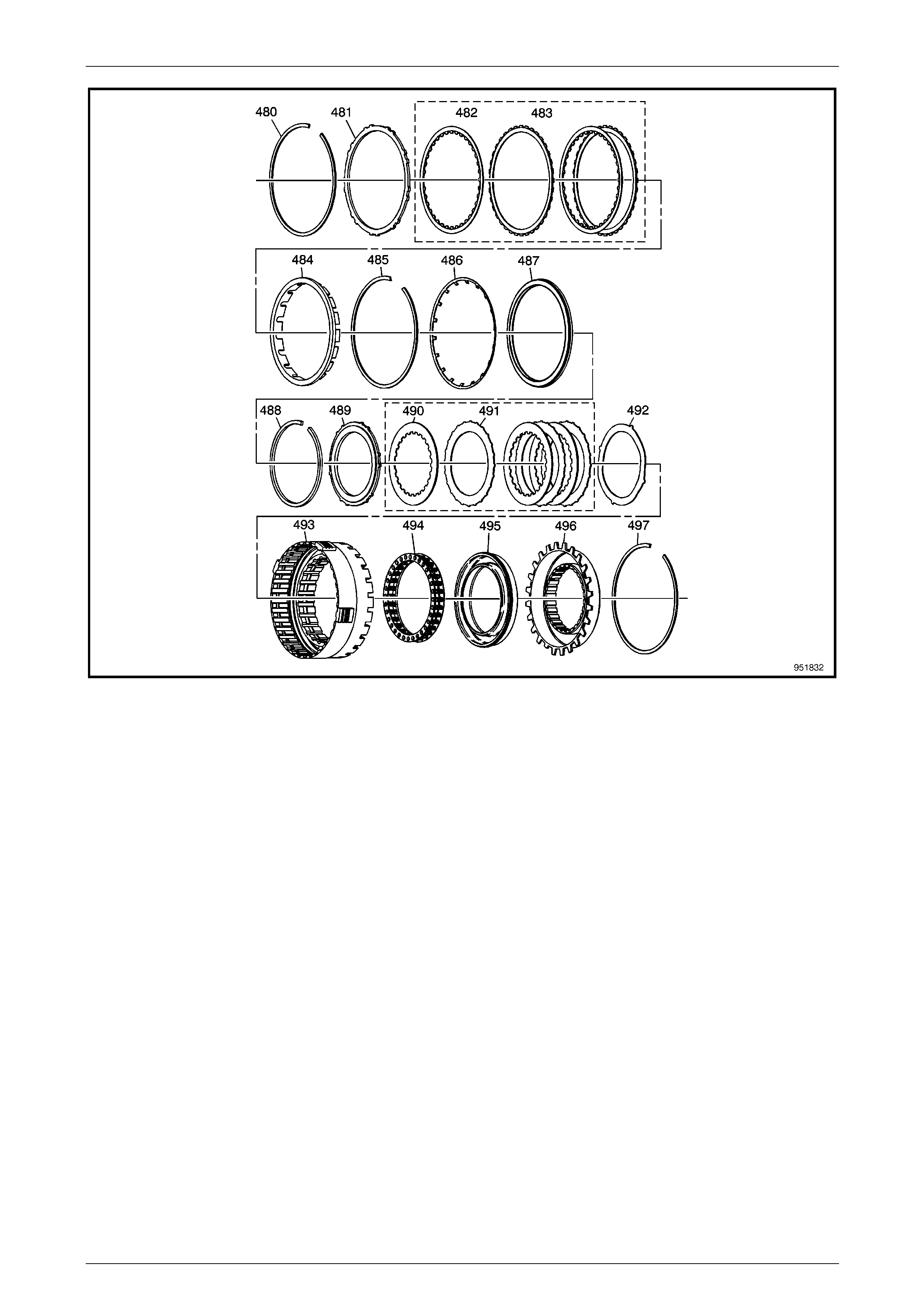
Automatic Transmission – 5L40–E – Unit Repair 7E5 – 129
7E5 – 129
Figure 7E5 – 272 Overdrive and Intermediate Clutch Assembly
Legend
480 Overdrive Clutch Backing Plate Retainer Ring – Selective 489 Intermediate Clutch Backing Plate
481 Overdrive Clutch Backing Plate 490 Intermediate Clutch Plate Assembly – Inner Spline
482 Overdrive Clutch Plate Assembly – Inner Spline 491 Intermediate Clutch Plate Assembly – Outer Spline
483 Overdrive Clutch Plate Assembly – Outer Spline 492 Intermediate Clutch Apply Plate
484 Overdrive Clutch Spacer 493 Overdrive Clutch Housing
485 Overdrive Clutch Spring Retainer Ring 494 Intermediate Clutch Spring
486 Overdrive Clutch Piston Spring 495 Intermediate Clutch Piston Assembly
487 Overdrive Clutch Piston Assembly 496 Intermediate Clutch Housing
488 Intermediate Clutch Backing Plate Retainer Ring – Selective 497 Intermediate Clutch Housing Retainer Ring
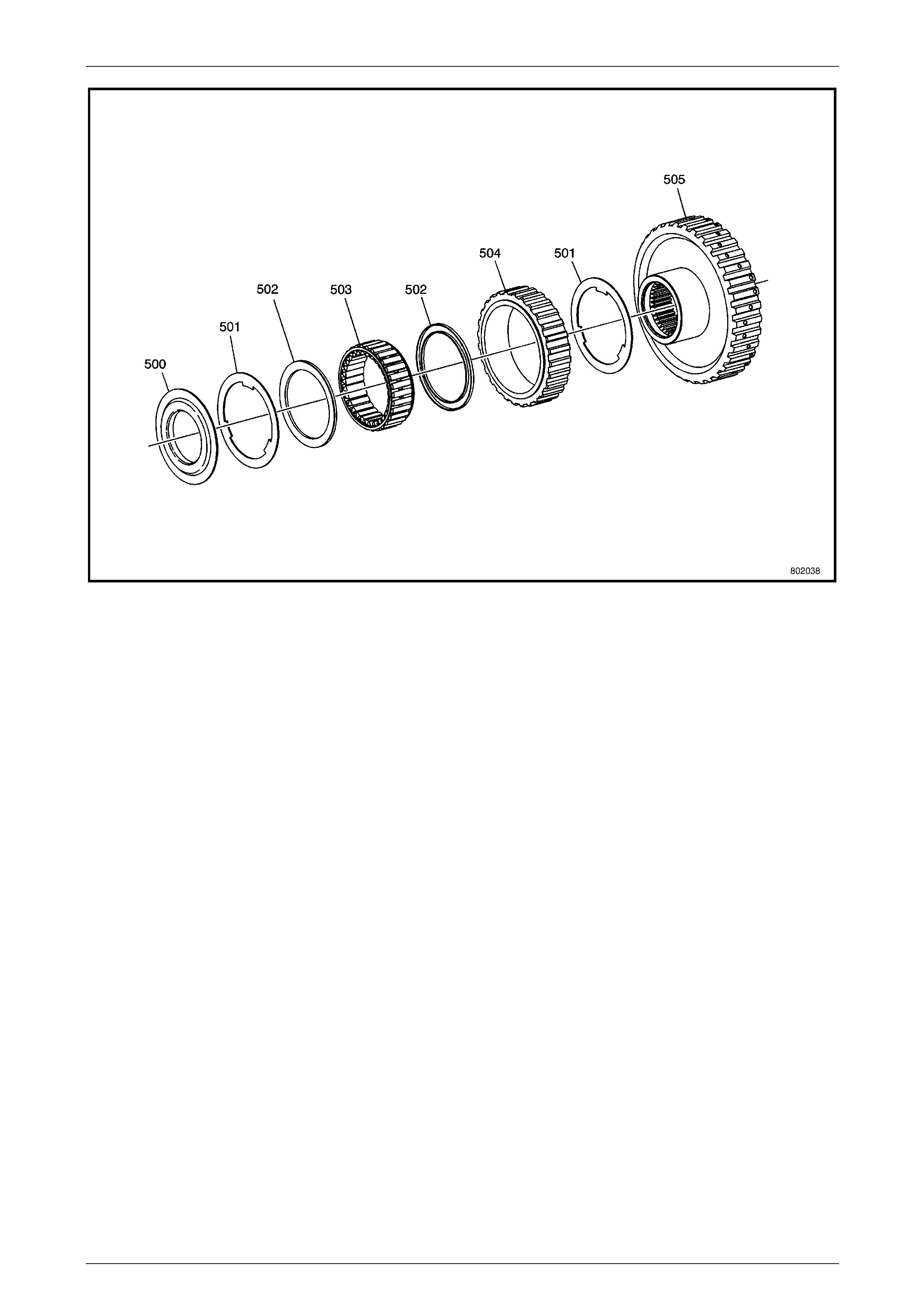
Automatic Transmission – 5L40–E – Unit Repair 7E5 – 130
7E5 – 130
Figure 7E5 – 273 Low Clutch Sprag Assembly
Legend
500 Low Clutch Roller Retainer 503 Low Clutch Sprag Assembly
501 Low Clutch Roller Thrust Washer 504 Low Clutch Sprag Outer Race
502 Low Clutch Sprag Assembly Retainer Rings - 2 505 Low Clutch Sprag Inner Race
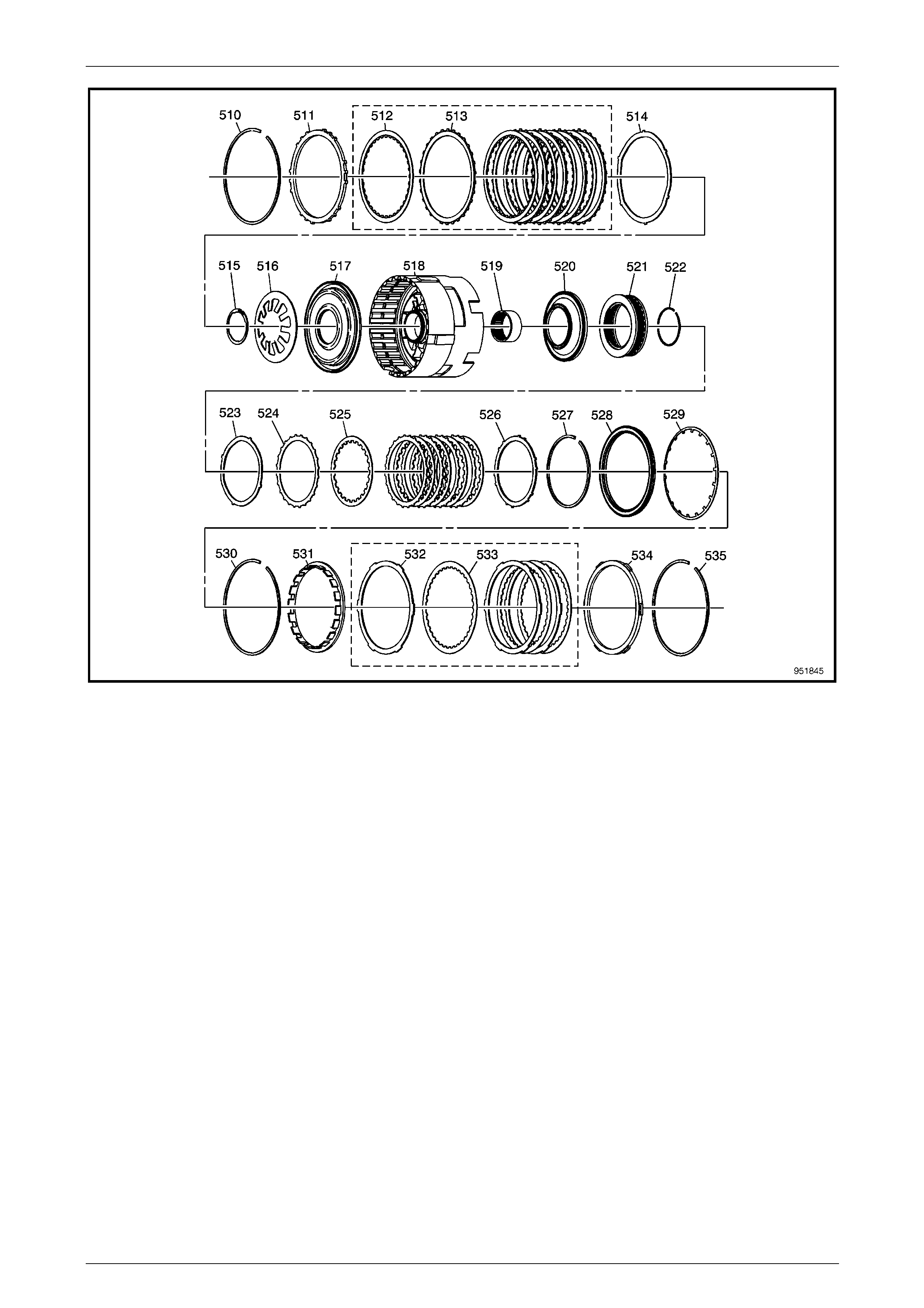
Automatic Transmission – 5L40–E – Unit Repair 7E5 – 131
7E5 – 131
Figure 7E5 – 274 Centre Support Assembly
Legend
510 Low and Reverse Clutch Plate Retainer Ring – Selective 523 2nd Clutch Apply Plate
511 Low and Reverse Clutch Backing Plate 524 2nd Clutch Plate Assembly – Outer Spline
512 Low and Reverse Clutch Plate Assembly – Inner Spline 525 2nd Clutch Plate Assembly – Inner Spline
513 Low and Reverse Clutch Plate Assembly – Outer Spline 526 2nd Clutch Backing Plate
514 Low and Reverse Clutch Apply Plate 527 2nd Clutch Backing Plate Retainer Ring – Selective
515 Low and Reverse Clutch Spring Retainer Ring 528 2nd Coast Clutch Piston Assembly
516 Low and Reverse Clutch Spring 529 2nd Coast Clutch Spring
517 Low and Reverse Clutch Piston 530 2nd Coast Clutch Spring Retainer Ring
518 Centre Support 531 2nd Coast Clutch Spacer
519 Input and Reaction Bearing Assembly 532 2nd Coast Clutch Plate Assembly – Outer Spline
520 2nd Clutch Piston 533 2nd Coast Clutch Plate Assembly – Inner Spline
521 2nd Clutch Spring 534 2nd Coast Clutch Backing Plate
522 2nd Clutch Spring Retainer Ring 535 2nd Coast Clutch Plate –Backing Plate – Retainer Ring
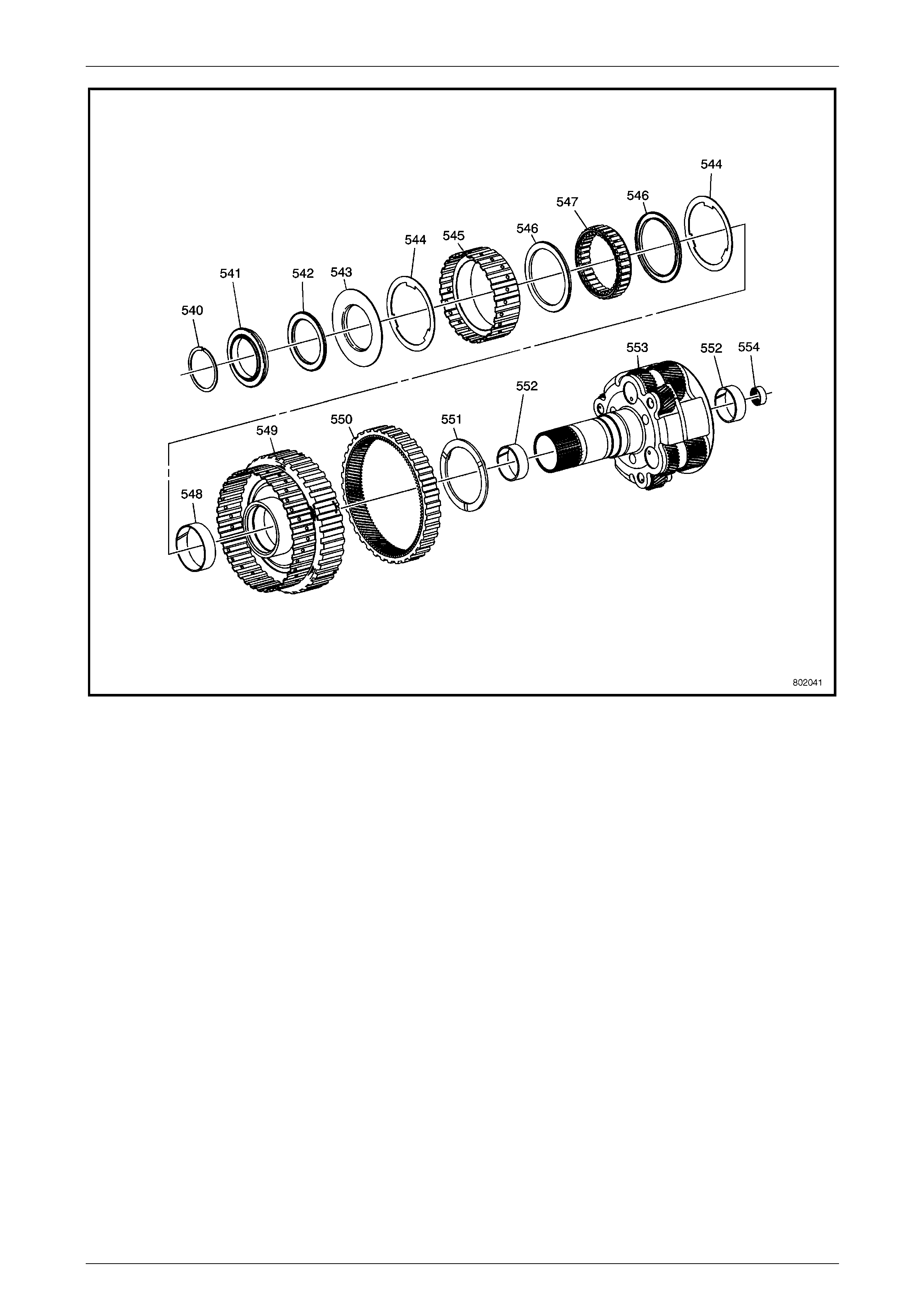
Automatic Transmission – 5L40–E – Unit Repair 7E5 – 132
7E5 – 132
Figure 7E5 – 275 Planetary Carrier Assembly
Legend
540 Input and Reaction Carrier Outer Retainer Ring 548 Input and Reaction Carrier Bushing
541 Input and Reaction Bearing Assembly 549 2nd Clutch Sprag Inner Race
542 2nd Clutch Roller Inner Race Bearing Assembly 550 Reaction Internal Gear
543 2nd Clutch Sprag Retainer 551 Reaction Internal Gear Flange Washer
544 2nd Clutch Roller Outer Race Washer 552 Reaction Carrier Bushing – 2
545 2nd Clutch Sprag Outer Race 553 Input and Reaction Carrier
546 2nd Clutch Sprag Assembly Retainer - 2 554 Input and Reaction Bearing Assembly
547 2nd Clutch Sprag Assembly
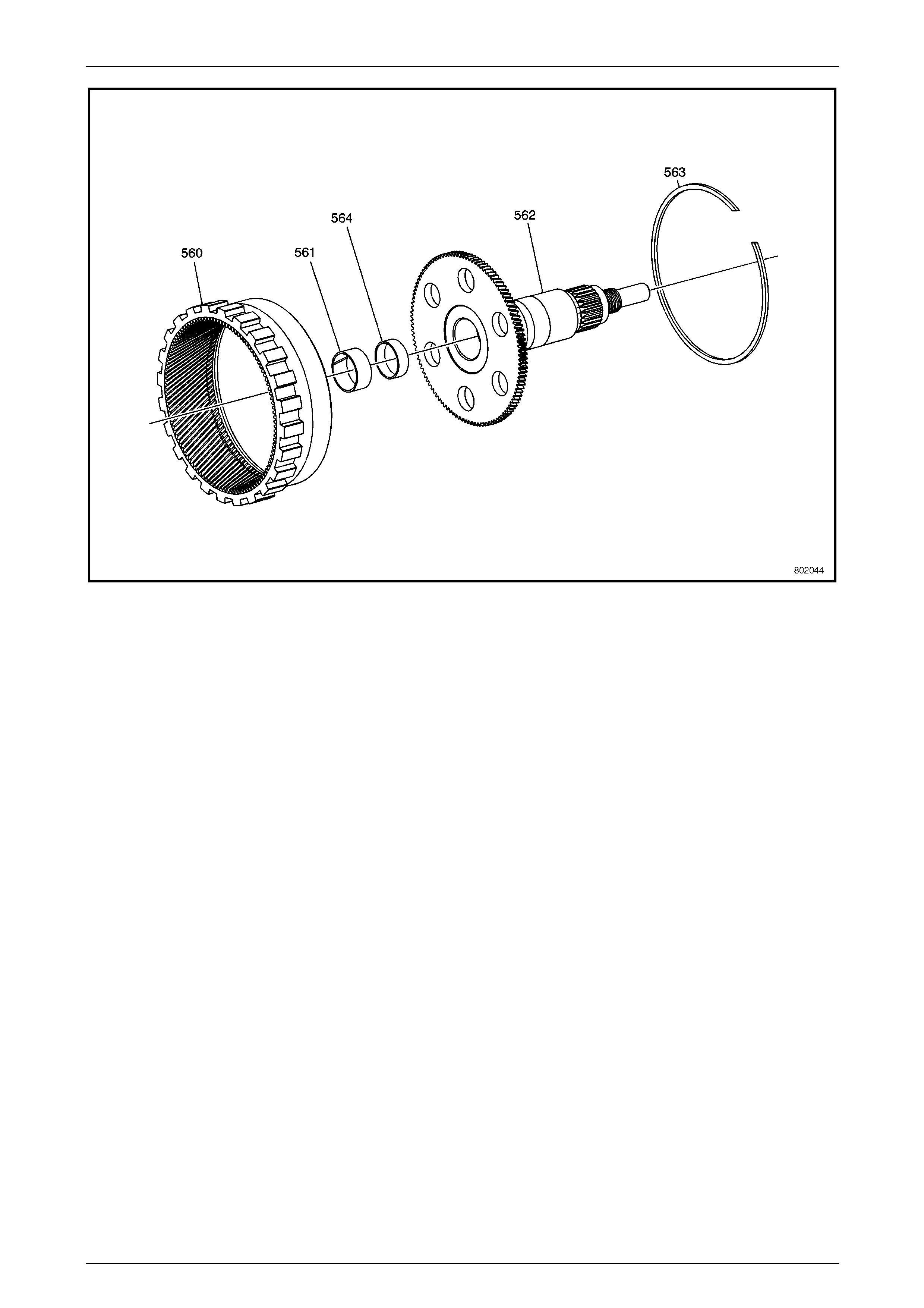
Automatic Transmission – 5L40–E – Unit Repair 7E5 – 133
7E5 – 133
Figure 7E5 – 276 Rear Internal Gear Output Sh aft Assembly
Legend
560 Rear Internal Gear 563 Rear Internal Retainer Ring
561 Input and Reaction Carrier Bushing 564 Cup Plug
562 Output Shaft Assembly
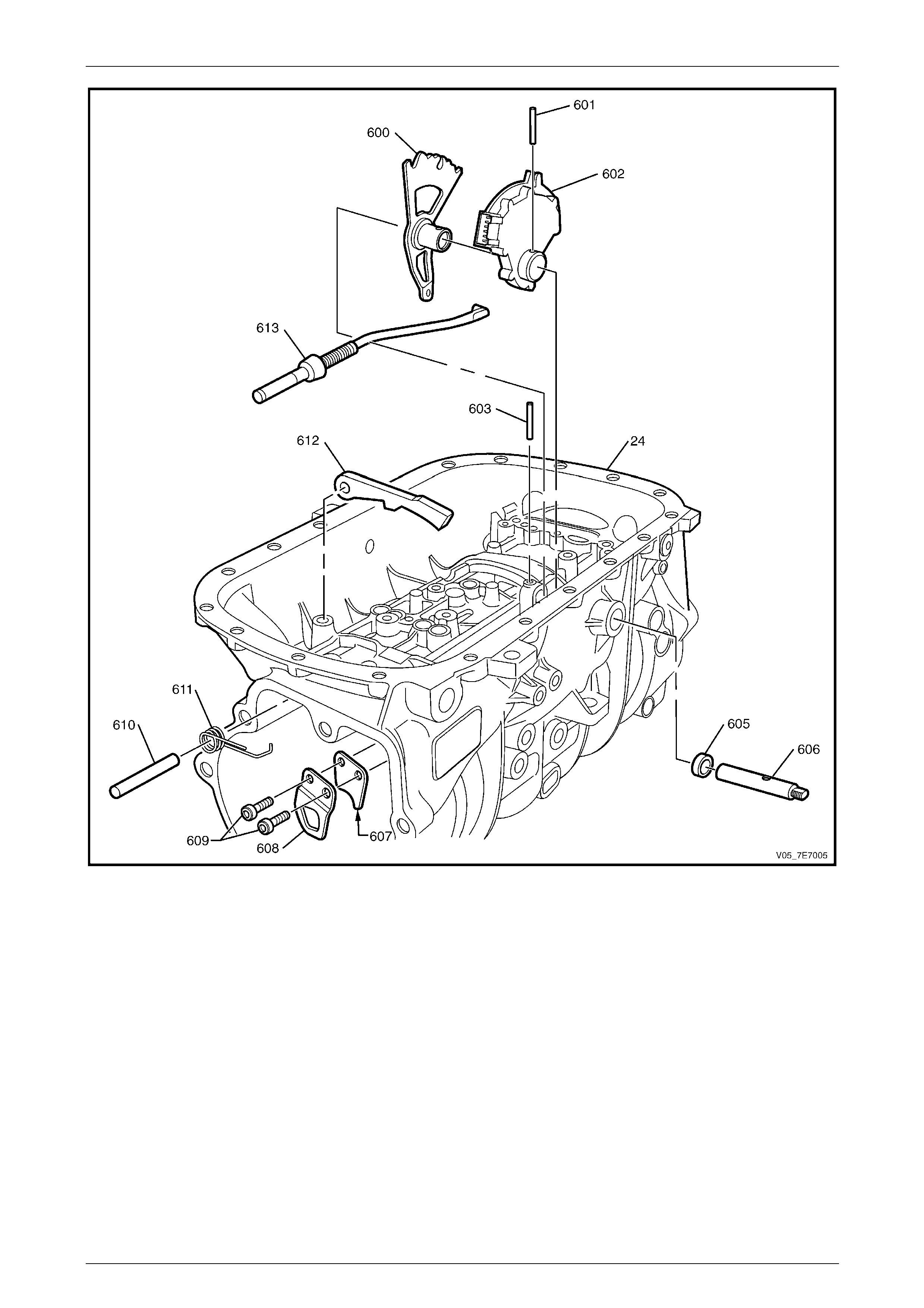
Automatic Transmission – 5L40–E – Unit Repair 7E5 – 134
7E5 – 134
Figure 7E5 – 277 Park Pawl Assembly
Legend
24 Transmission Case 608 Park Pawl Actuator Bracket (Outer)
600 Manual Shaft Detent Lever 609 Park Pawl Actuator Bracket Bolt M8 x 1.25 x 25 - 2
601 Manual Shaft Detent Lever Pin 610 Park Pawl Shaft
602 Transmission Manual Shift Shaft Switch Assembly 611 Park Pawl Spring
605 Manual Shift Shaft Seal 612 Park Pawl
606 Manual Shift Shaft 613 Park Pawl Actuator Assembly
607 Park Pawl Actuator Bracket (Inner)

Automatic Transmission – 5L40–E – Unit Repair 7E5 – 135
7E5 – 135
Figure 7E5 – 278 Automatic Transmission Electronic Component Locations
Legend
42 Output Speed Sensor (OSS) 368 1–2 Shift Solenoid (SS) Valve Assembly
44 Input Speed Sensor (ISS) 369 2–3 Shift Solenoid (SS) Valve Assembly
55 Transmission Fluid Temperature (TFT) Sensor 376 4–5 Shift Solenoid (SS) Valve Assembly
352 TCC PWM Solenoid Valve 602 Transmission Manual Shift Shaft Switch Assembly
357 Pressure Control Solenoid (PCS) Assembly
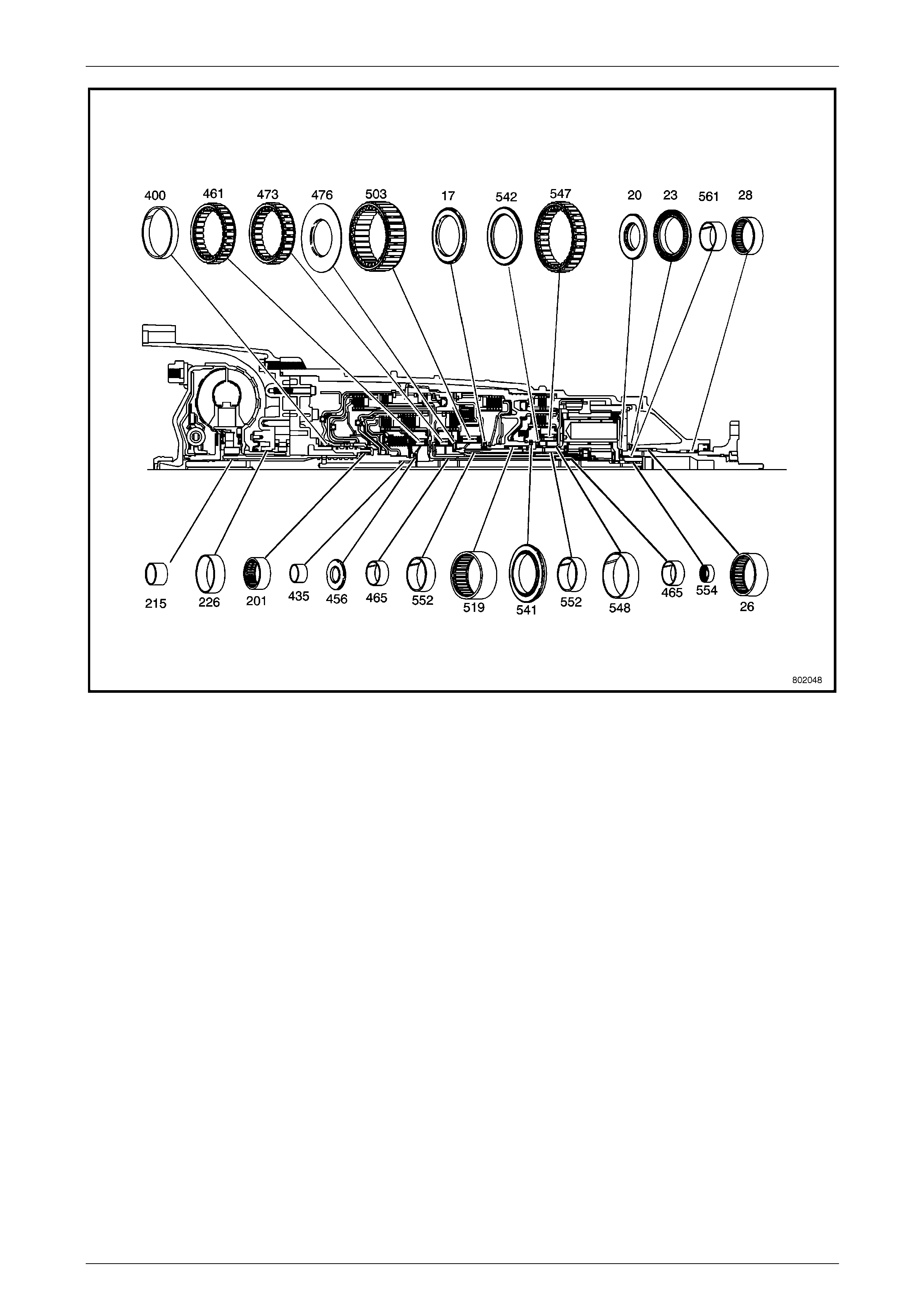
Automatic Transmission – 5L40–E – Unit Repair 7E5 – 136
7E5 – 136
Figure 7E5 – 279 Bushing and Bearing Locations
Legend
17 Low Clutch Roller Thrust Bearing 465 Input and Reaction Carrier Bushing Assembly - 2
20 Input and Reaction Carrier Thrust Bearing 473 Intermediate Clutch Sprag Assembly
23 Input and Reaction Carrier Thrust Bearing 476 Inte rmediate Clutch Roller Thrust Bearing Assembly
26 Output Shaft Bearing 503 Low Clutch Sprag Assembly
28 Output Shaft Bearing 519 Input and R eaction Bearing Assembly
201 Input Shaft Bearing Assembly 541 Input and Reaction Bearing Assembly
215 Turbine Shaft Bushing 542 2nd Clutch Roller Inner Race Bearing Assembly
226 Torque Converter Bushing 547 2nd Clutch Sprag Assembly
400 Reverse Clutch Housing Bushing 548 Input and Reaction Carrier Bushing
435 Forward Clutch Bushing 552 Reaction Carrier Bushing - 2
456 Forward Clutch Roller Inner Bearing 554 Input and Reaction Bearing (561) and Carrier Bushing
461 Forward Clutch Sprag Assembly 561 Input and Reaction Carrier Bushing
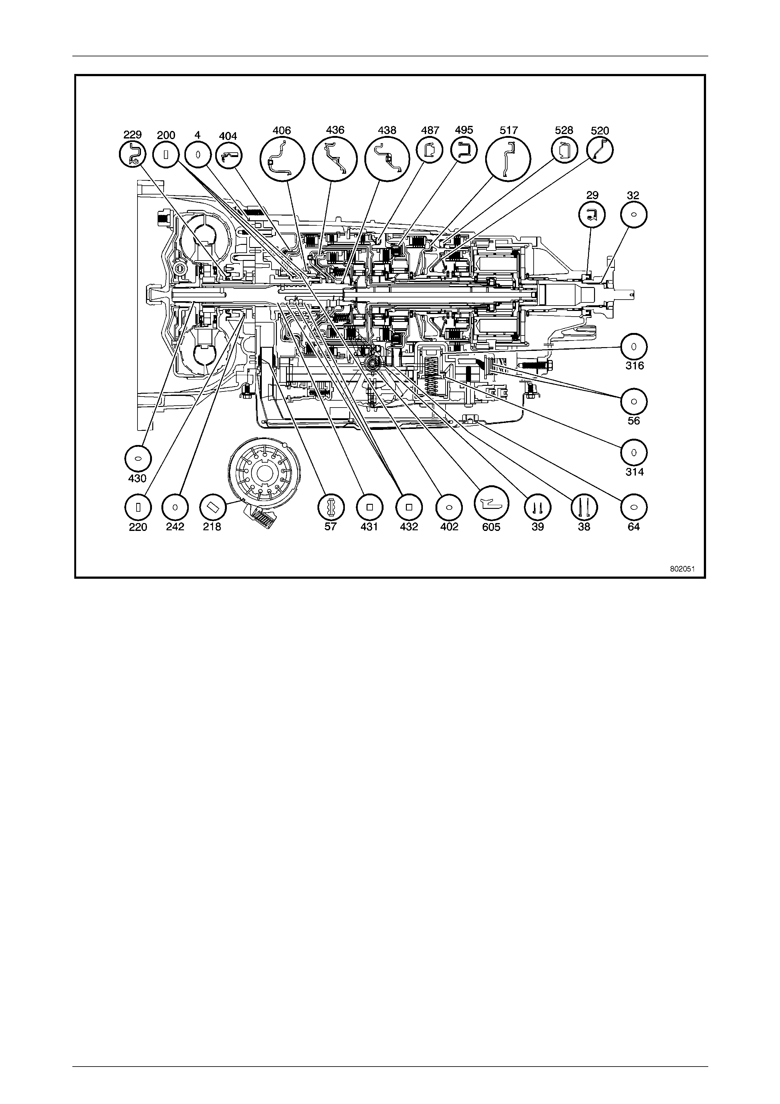
Automatic Transmission – 5L40–E – Unit Repair 7E5 – 137
7E5 – 137
Figure 7E5 – 280 Seal Locations
Legend
4 Torque Converter Housing Fluid Seal Assembly 402 Reverse Clutch Piston Inner Seal
29 Transmission Propeller Shaft Flange Seal 404 Reverse Clutch Piston
32 Transmission Propeller Shaft Flange – O-ring Seal 406 Direct Clutch Piston Assembly
38 Centre Support Fluid Passage Sleeve 430 Input Shaft – O-ring Seal
39 Overdrive Clutch Fluid Passage Sleeve 431 Input Shaft Fluid Seal Ring
56 A/Transmission Wiring Harness – O-ring Seal – 2 432 Input Shaft Fluid Seal Ring - 3
57 Automatic Transmission Filter Seal – 2 436 Forward Clutch Piston Assembly
64 Automatic Transmission Fluid Pan Drain Plug Seal 438 Coast Clutch Piston Assembly
200 Reverse Clutch Housing Fluid Seal Ring - 3 487 Overdrive Clutch Piston Assembly
218 Automatic Transmission Fluid Pump Slide Seal 495 Intermediate Clutch Piston Assembly
220 Automatic Transmission Fluid Pump Slide Ring 517 Low and Reverse Clutch Piston
229 Torque Converter Housing Seal 520 2nd Clutch Piston
242 Automatic Transmission Fluid Pump Slide O-ring Seal 528 2nd Coast Clutch Piston Assembly
314 Clutch Accumulator Piston Fluid Seal Ring 605 Manual Shift Shaft Seal
316 Clutch Accumulator Piston Fluid Seal Ring

Automatic Transmission – 5L40–E – Unit Repair 7E5 – 138
7E5 – 138
3 Specifications
General
Type......................................................................................................... Hydra-matic 5L40–E
Transmission Model Application HFV6 3.6 litre Petrol (P/O LY7).................................5HAG
HFV6 2.8 litre Petrol (P/O LP1).................................5HEG
Special Features....Electronically controlled shift pattern, feel and torque converter operation
Selector Location................................................................................. Floor mounted console
Transmission Weight Dry.................................................................................................73 kg
Transmission Net Weight..............................................................................................80.5 kg
Gear Ratios
Park (P) ..................................................................................................................................–
Reverse (R) ....................................................................................................................3.03:1
Neutral (N)..............................................................................................................................–
5th Gear..........................................................................................................................0.75:1
4th Gear..........................................................................................................................1.00:1
3rd Gear .........................................................................................................................1.60:1
2nd Gear.........................................................................................................................2.21:1
1st Gear..........................................................................................................................3.42:1
Shift Speeds
Refer to charts in Section 7E3 Automatic Transmission – 5L40-E – Hydraulic/Mechanical Diagnosis.
Fluid Pressure
Refer to procedure in Section 7E3 Automatic T r ansmission – 5L40-E – Hydraulic/Mechanical Diagnosis.
Torque Converter
Number of Elements..................................................................3 plus torque converter clutch
Maximum Torque Ratio at Stall HFV6 3.6 litre petrol engine (P/O LY7).........1.90:1 (k=149)
HFV6 2.8 litre petrol engine (P/O LP1).........1.76:1 (k=163)
Nominal Diameter HFV6 3.6 litre petrol engine (P/O LY7)...................258 mm
HFV6 2.8 litre petrol engine (P/O LP1)...................245 mm
Automatic Transmission Fluid
Type Recommended ..............................................................................................Dexron® III
Level Check.....Refer to Section 7E4 Automatic Transmission – 5L40 – On-Vehicle Servicing
Refill (Approximate for an 'On-Car' situation).............................................................. 4.6 litres
Complete Overhaul (Dry)............................................................................................ 8.5 litres
Direct Clutch
Type................................................................................................................Multiple wet disc
Clutch Pack
Internal Splines – Steel/Composition Combination (5HAG) .........................................5
(5HEG) .........................................4
External Splines – Steel/Composition Combination (5HAG) .........................................5
(5HEG) .........................................4
Belleville (waved)....................................................................................................................1
Backing Plate..........................................................................................................................1
Clutch Travel Specification ..............................................................................1.41 – 1.86 mm
Refer to checking procedure in 1.32 Direct and Reverse Clutch – Reassemble in this Section
Techline

Automatic Transmission – 5L40–E – Unit Repair 7E5 – 139
7E5 – 139
Reverse Clutch
Type................................................................................................................Multiple wet disc
Clutch Pack
Internal Splines – Steel/Composition Combination (All Models).....................................3
External Splines – Steel/Composition Combination (All Models) ...................................3
Belleville (waved)....................................................................................................................1
Backing Plate..........................................................................................................................1
Clutch Travel Specification ..............................................................................0.98 – 1.43 mm
Refer to checking procedure in 1.32 Direct and Reverse Clutch – Reassemble in this Section
Coast Clutch
Type................................................................................................................Multiple wet disc
Clutch Pack
Internal Splines – Steel/Composition Combination (All Models).....................................3
External Splines – Steel/Composition Combination (All Models) ...................................3
Belleville (waved)....................................................................................................................1
Backing Plate..........................................................................................................................1
Clutch Travel Specification ..............................................................................1.17 – 1.93 mm
Refer to checking procedure in 1.31 Forward and Coast Clutch – Reassemble in this Section
Forward Clutch
Type................................................................................................................Multiple wet disc
Clutch Pack
Internal Splines – Steel/Composition Combination (5HAG) .........................................4
(5HEG) .........................................3
External Splines – Steel/Composition Combination (5HAG) .........................................5
(5HEG) .........................................3
Belleville (waved)....................................................................................................................1
Backing Plate..........................................................................................................................1
Clutch Travel Specification ..............................................................................1.20 – 1.65 mm
Refer to checking procedure in 1.31 Forward and Coast Clutch – Reassemble in this Section
Overdrive Clutch
Type................................................................................................................Multiple wet disc
Clutch Pack
Internal Splines – Steel/Composition Combination (All Models).....................................3
External Splines – Steel/Composition Combination (All Models) ...................................3
Belleville (waved) .............................................................................................................none
Backing Plate .........................................................................................................................1
Clutch Travel Specification .............................................................................1.60 – 2.05 mm
Refer to checking procedure in 1.27 Overdri v e and Intermediate Clutch – Reassemble in this Section
Intermediate Clutch
Type................................................................................................................Multiple wet disc
Clutch Pack
Internal Splines – Steel/Composition Combination (5HAG) .........................................4
(5HEG) .........................................3
External Splines – Steel/Composition Combination (5HAG) .........................................4
(5HEG) .........................................3
Belleville (waved)....................................................................................................................1
Backing Plate..........................................................................................................................1
Clutch Travel Specification ..............................................................................1.13 – 1.58 mm
Refer to checking procedure in 1.27 Overdri v e and Intermediate Clutch – Reassemble in this Section
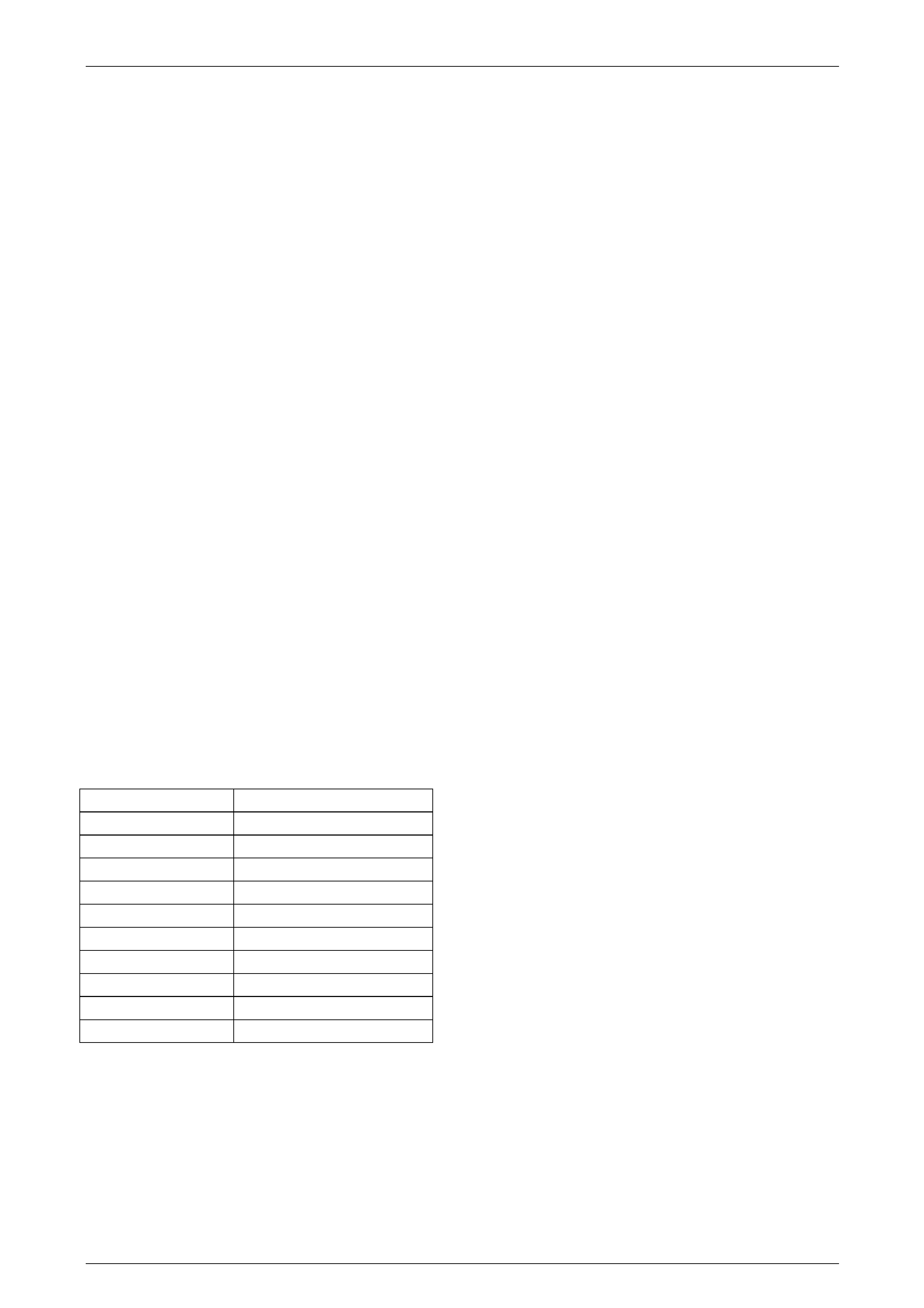
Automatic Transmission – 5L40–E – Unit Repair 7E5 – 140
7E5 – 140
Low and Reverse Clutch
Type................................................................................................................Multiple wet disc
Clutch Pack
Internal Splines – Steel/Composition Combination ........................................................5
External Splines – Steel/Composition Combination.......................................................5
Belleville (waved)....................................................................................................................1
Backing Plate..........................................................................................................................1
Clutch Travel Specification ..............................................................................1.72 – 2.17 mm
Refer to checking procedure in 1.25 Ce ntre Support – Reassemble in this Section
2nd Clutch
Type................................................................................................................Multiple wet disc
Clutch Pack
Internal Splines – Steel/Composition Combination (All Models).....................................5
External Splines – Steel/Composition Combination (All Models) ...................................5
Belleville (waved)....................................................................................................................1
Backing Plate..........................................................................................................................1
Clutch Travel Specification ..............................................................................1.47 – 1.92 mm
Refer to checking procedure in 1.25 Ce ntre Support – Reassemble in this Section
Second Coast Clutch
Type................................................................................................................Multiple wet disc
Clutch Pack
Internal Splines – Steel/Composition Combination (5HAG) .........................................3
(5HEG) .........................................2
External Splines – Steel/Composition Combination (5HAG) .........................................3
(5HEG) .........................................2
Belleville (waved)..............................................................................................................none
Backing Plate..........................................................................................................................1
Clutch Travel Specification ..............................................................................0.94 – 1.39 mm
Refer to checking procedure in 1.25 Ce ntre Support – Reassemble in this Section
Output Shaft End Play
Refer to procedure in 1.45 Extension Ho using – Reinstall in this Section.
Dimension B Washer Thickness (mm)
15.99 mm–16.27 mm 0.95–1.05
16.27 mm–16.47 mm 1.15–1.25
16.47 mm–16.67 mm 1.35–1.45
16.67 mm–16.87 mm 1.55–1.65
16.87 mm–17.07 mm 1.75–1.85
17.07 mm–17.27 mm 1.95–2.05
17.27 mm–17.47 mm 2.15–2.25
17.47 mm–17.67 mm 2.35–2.45
17.67 mm–17.87 mm 2.55–2.65
17.87 mm–18.07 mm 2.75–2.85
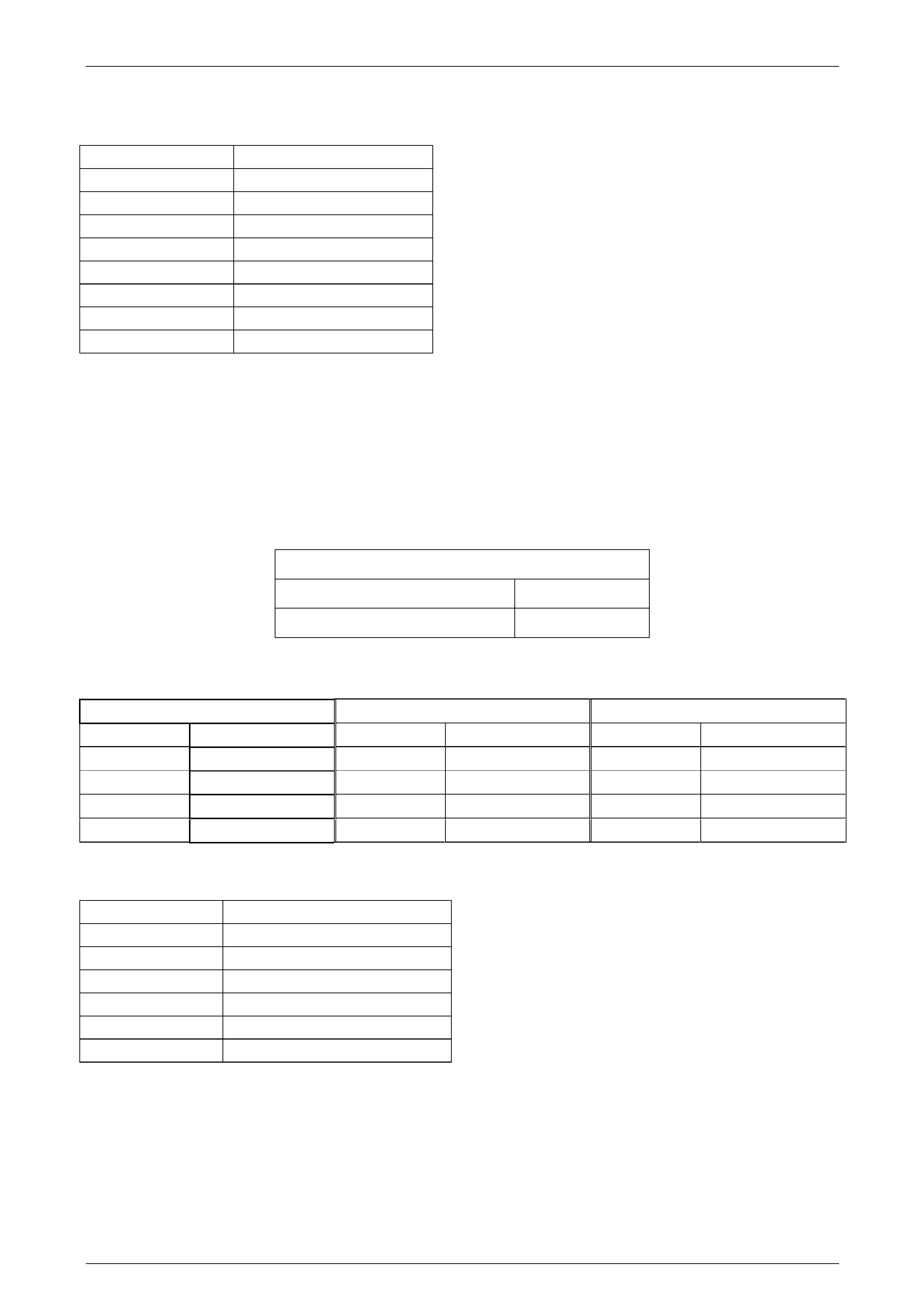
Automatic Transmission – 5L40–E – Unit Repair 7E5 – 141
7E5 – 141
Reverse Clutch Housing Selective Thrust Washer Chart
Refer to procedure in 1.37 Torque Converter Housing – Reinstall in this Section.
Dimension X Washer Thickness (mm)
50.18 mm–50.36 mm 2.53–2.68
50.36 mm–50.54 mm 2.71–2.86
50.54 mm–50.72 mm 2.89–3.04
50.72 mm–50.90 mm 3.05–3.20
50.90 mm–51.08 mm 3.25–3.40
51.08 mm–51.26 mm 3.43–3.58
51.26 mm–51.44 mm 3.61–3.76
51.44 mm–51.62 mm 3.79–3.94
Fluid Pump Clearance Specifications
Refer to procedure in 1.36 Fluid Pump – Re assemble in this Section.
NOTE
• Rotor and slide must be chosen from the
same size classification as the fluid pump
body.
• Allowable rotor and slide to fluid pump body
end play is as follows:
Rotor and Slide to Fluid Pump Body End Play
Slide to Fluid Pump Body End Pla y – 0.030–0.051 mm
Rotor to Fluid Pump Body End Pla y –0.030 –0.051 mm
The fluid pump assembly has a selectiv e rotor and slide components. These compone nts are chosen based on pump
body dimensions. Fluid pump rotor and slide components ar e available in five size classifications (1, 2, 3, 4, and 5) with
the following tolerances.
Rotor Selection Slide Selection Fluid Pump Body Depth
1 17.948–17.961 mm 1 17.948–17.961 mm 1 17.978–18.012 mm
2 17.961–17.974 mm 2 17.961–17.974 mm 2 17.978–18.025 mm
3 17.974–17.987 mm 3 17.974–17.987 mm 3 18.004–18.038 mm
4 17.987–18.000 mm 4 17.987–18.000 mm 4 18.017–18.051 mm
5 18.000–18.013 mm 5 18.000–18.013 mm 5 18.030–18.064 mm
Intermediate and Overdrive Clutch Housing Retainer Ring Specification
Refer to procedure in 1.27 Overdrive and Intermediate Clutch – Reassemble in this Section.
Dimension M Retainer Ring Thickness (mm)
0.75 mm–0.85 mm 3.90–4.00
0.85 mm–0.95 mm 3.80–3.90
0.95 mm–1.05 mm 3.70–3.80
1.05 mm–1.15 mm 3.60-3.7 0
1.15 mm–1.25 mm 3.50–3.60
1.25 mm–1.35 mm 3.40–3.50

Automatic Transmission – 5L40–E – Unit Repair 7E5 – 142
7E5 – 142
Electrical Component Resistance Specifications
Component Circuit
Number Wire
Colour
Inline
Connector
Pin
Resistance at
20°C Resistance at
70°C
Resistance to
Ground –
Transmission Case
1525 WH 17
1 – 2 Shift
Solenoid Valve 1222 BK 14 15.0 – 17.0 Ω 17.9 – 20.3 Ω Greater than 50 kΩ
1525 WH 17
2 – 3 Shift
Solenoid Valve 1223 BU 9 15.0 – 17.0 Ω 17.9 – 2 0.3 Ω Greater than 50 kΩ
1525 WH 17
4 – 5 Shift
Solenoid Valve 898 GY 5 15.0 – 1 7.0 Ω 17.9 – 20.3 Ω Greater than 50 kΩ
1228 GN 13
Pressure Control
Solenoid Valve 1229 WH 8 3.5 – 4.6 Ω 4.2 – 5.5 Ω Greater than 50 kΩ
1525 WH 17
TCC PWM
Solenoid Valve 422 YE 20 10.0 – 1 1.5 Ω 11.8 – 13.6 Ω Greater than 50 kΩ
1230 YE 18
Input Speed
Sensor 1231 WH 15 325 – 485 Ω 385 – 575 Ω Greater than 50 kΩ
400 OR 1
Output Speed
Sensor 401 WH 3 325 – 485 Ω 385 – 575 Ω Greater than 50 kΩ
1227 RD 10
TFT Sensor 2762 WH 6 Refer to following chart for TFT Sensor Resistance
Specifications
All wire colours are internal to the transmission
Transmission Fluid Temperature (TFT) Sensor Resistance Specifications
Temperature °C Minimum
Resistance Ω Nominal
Resistance Ω Maximum
Resistance Ω
-40 89 500 100 000 110 500
-30 46 419 51 400 56 381
-20 25 120 27 610 30 100
-10 14 160 15 450 16 740
0 8 278 8 972 9 666
10 5 005 5 391 5 777
20 3 120 3 342 3 564
30 2 000 2 132 2 264
40 1 317 1 397 1 477
50 888 938 988
60 613 645 677
70 432 453 474
80 310 324 338
90 228 237 246
100 170 176 182
110 128 132 136
120 98 101 104
130 77 79 81
140 60 62 64
150 48 49 50

Automatic Transmission – 5L40–E – Unit Repair 7E5 – 143
7E5 – 143
4 Torque Wrench Specifications
NOTE
Only those torque specifications quoted in this
Section are listed her e.
Channel plate to front and rear valve body bolt......................................11 N.m
Clutch accumulator housings to valve body bolt.....................................11 N.m
Control valve body and accumulator to transmission case bolt..............11 N.m
Extension housing to transmission case bolt..........................................22 N.m
Fluid pan drain plug................................................................................20 N.m
Fluid pan to transmission case bolt........................................................11 N.m
Front valve body to channel plate bolt....................................................11 N.m
Input speed sensor to transmission case bolt.........................................11 N.m
Manual shift detent lever spring and control valve body to
transmission case bolt............................................................................11 N.m
Output speed sensor to transmission case bolt......................................11 N.m
Park pawl actuator bracket to transmission case bolt .............................22 N.m
Propeller shaft flange to output shaft nut................................................57 N.m
Torque converter seal to housing bolt ...................................................3.6 N.m
Transmission converter housing to transmission case bolt ....................22 N.m
Transmission fluid pump cover to torque converter
housing bolts (240).................................................................................11 N.m
Transmission fluid pump cover to torque converter
housing bolts (241).................................................................................22 N.m
Transmission level hole plug to case......................................................11 N.m
Transmission pressure test plug to case................................................11 N.m
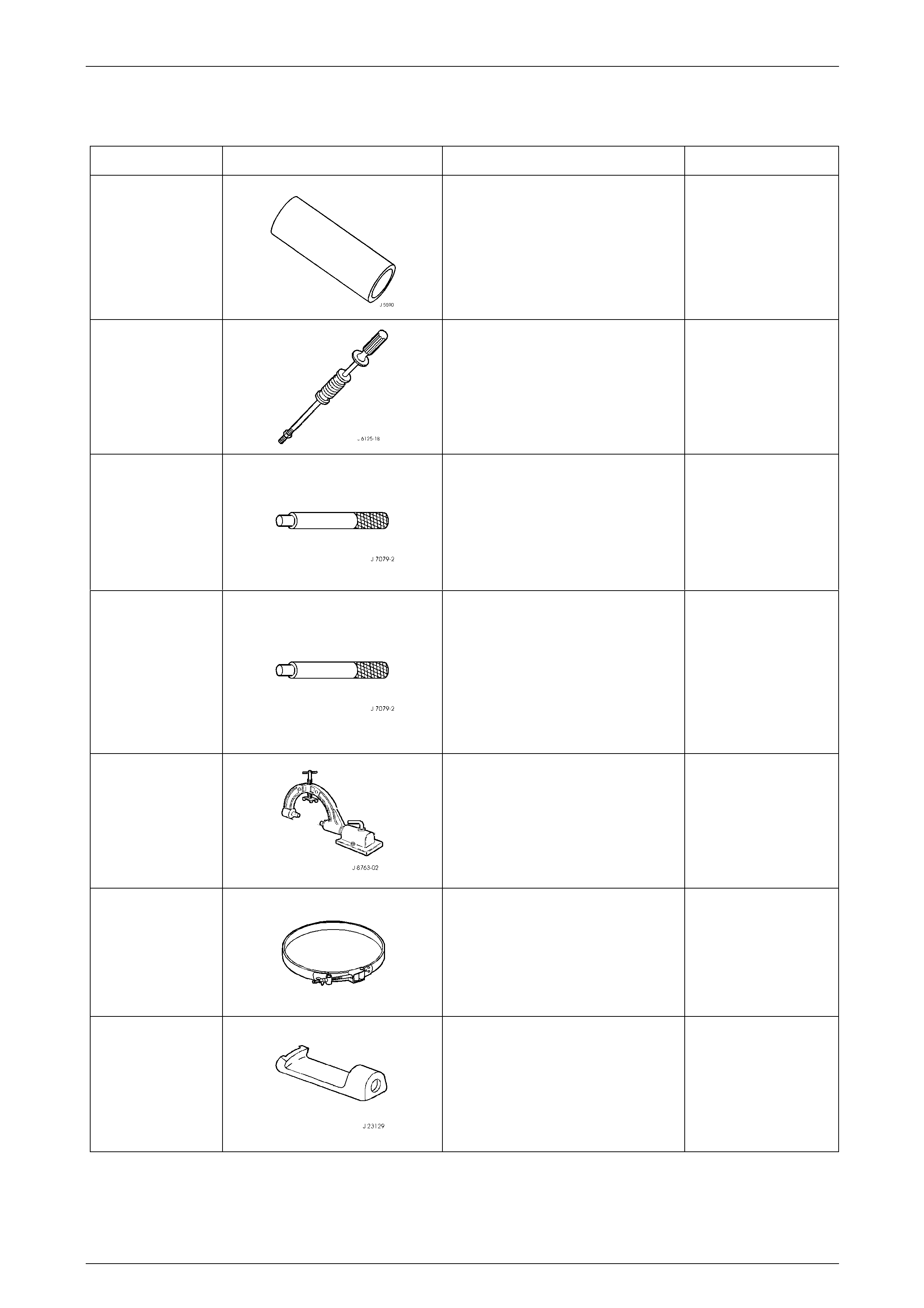
Automatic Transmission – 5L40–E – Unit Repair 7E5 – 144
7E5 – 144
5 Special Tools
Tool Number Illustration Description Tool Classification
J 5590
Bearing Installer/Remover
Used to remove outer output shaft
bearings from extension housing.
Previously released.
Unique
J 6125-1B
Slide Hammer Adapter
Used in conjunction with seal removal
tool J 23129 to remove fluid filter
seals from transmission case.
Previously released.
Unique
J 7079–2
Universal Driver Handle
Used in conjunction with J 45131–1
and J 45131–2 to remove the inner
output shaft bearing from the
extension housing.
New release.
Unique
J 8092
Universal Driver Handle
Used in conjunction with J 33832 to
install new input shaft bearing into the
fluid pump.
Used in conjunction with J 44766 to
install new torque converter seal.
Previously released.
Unique
J 8763–02
Holding Fixture and Base
Used to mount and hold transmission
assembly during unit repair
procedures. Comprises fixture J 8763-
B and bench mount J 3289-20 .
Previously released.
Unique
J 21368
Pump Body Cover Alignment Band
Used in assembly and alignment to of
the fluid pump to the torque converter
housing.
Previously released.
Unique
J 23129
Universal Seal Remover
Used in conjunction with slide
hammer J 6125–1B to remove fluid
filter seals from transmission case.
New release.
Unique
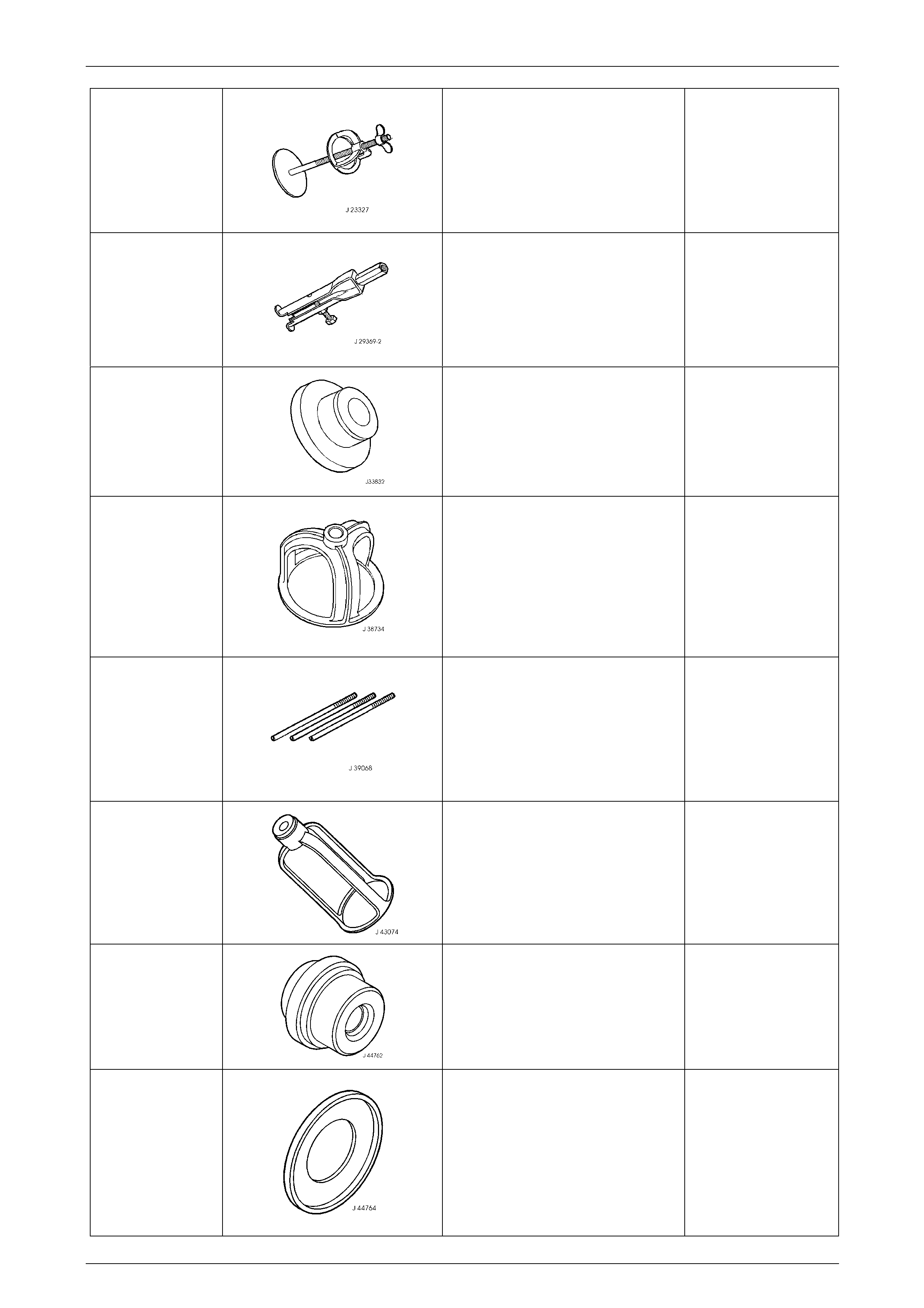
Automatic Transmission – 5L40–E – Unit Repair 7E5 – 145
7E5 – 145
J 23327
Clutch Spring Compressor
Used to compress various clutch drum
piston springs.
Previously released.
Unique
J 29369–2
Bushing and Bearing Remover
Used in conjunction with J 45143 and
J 45124 to remove input shaft bearing
from the fluid pump.
Previously released.
Unique
J 33832
Bearing Installer
Used in conjunction with J 33832 to
install new input shaft bearing into the
fluid pump.
New release.
Unique
J 38734
Intermediate Spring Compressor
Adapter
Used in conjunction with the bolt,
washer and nut from compressor J
23327, and J 45139 to compress the
direct and reverse clutch piston
spring.
New release.
Unique
J 39068
Valve Body Guide Pins
Used in the assembly and alignment
of the valve body components as well
as installation of the valve body to the
transmission case.
New release.
Available
J 43074
Clutch Spring Compressor
Used to compress the forward and
coast clutch spring retainer to enable
snap ring removal.
New release.
Unique
J 44762
Bearing Installer
Used to install output shaft bearings
into the extension housing.
New release.
Unique
J 44764
Clutch Spring Compressor
Used in conjunction with spring
compressor J 23327 to compress
overdrive clutch piston and
intermediate clutch housing sprin gs.
Used in conjunction with J 45135 to
install the overdrive clutch housin g.
New release.
Unique
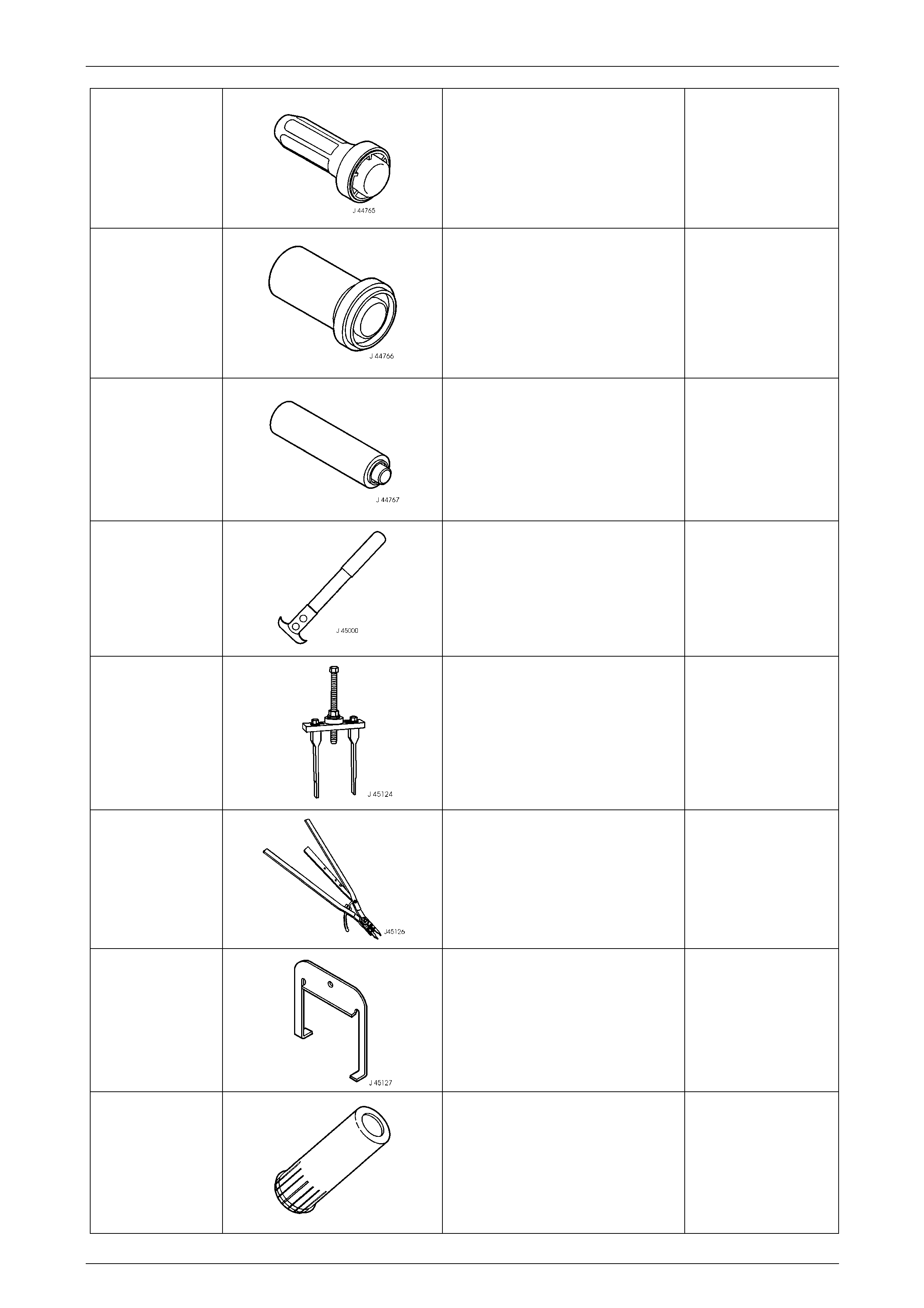
Automatic Transmission – 5L40–E – Unit Repair 7E5 – 146
7E5 – 146
J 44765
Seal Installer
Used to install extension housing
propeller shaft flange seal.
New release.
Unique
J44766
Seal Installer
Used in conjunction with driver handle
J 8092 to install new torque converter
seal.
New release.
Unique
J 44767
Seal Installer
Used to install new manual shift shaft
seal into the transmission case.
New release.
Unique
J 45000
Seal Remover
Used to remove lipped seals.
Also released as E308 and suitable
lever bar.
New release.
Available
J 45124
Removal Bridge
Used in conjunction with J 45143 and
J 29369–2 to remove input shaft
bearing from the fluid pump.
New release.
Unique
J 45126
Snap Ring Pliers
Used for removing and installing
various snap rings with the
transmission assembly.
New release.
Unique
J 45127
Centre Support Removal Tool
Used to assist in the removal and
installation of the centre support.
New release.
Unique
J 45130–1
Seal Installer Pusher
Used in conjunction with J 45130–2 to
install new input shaft fluid seals.
New release.
Unique
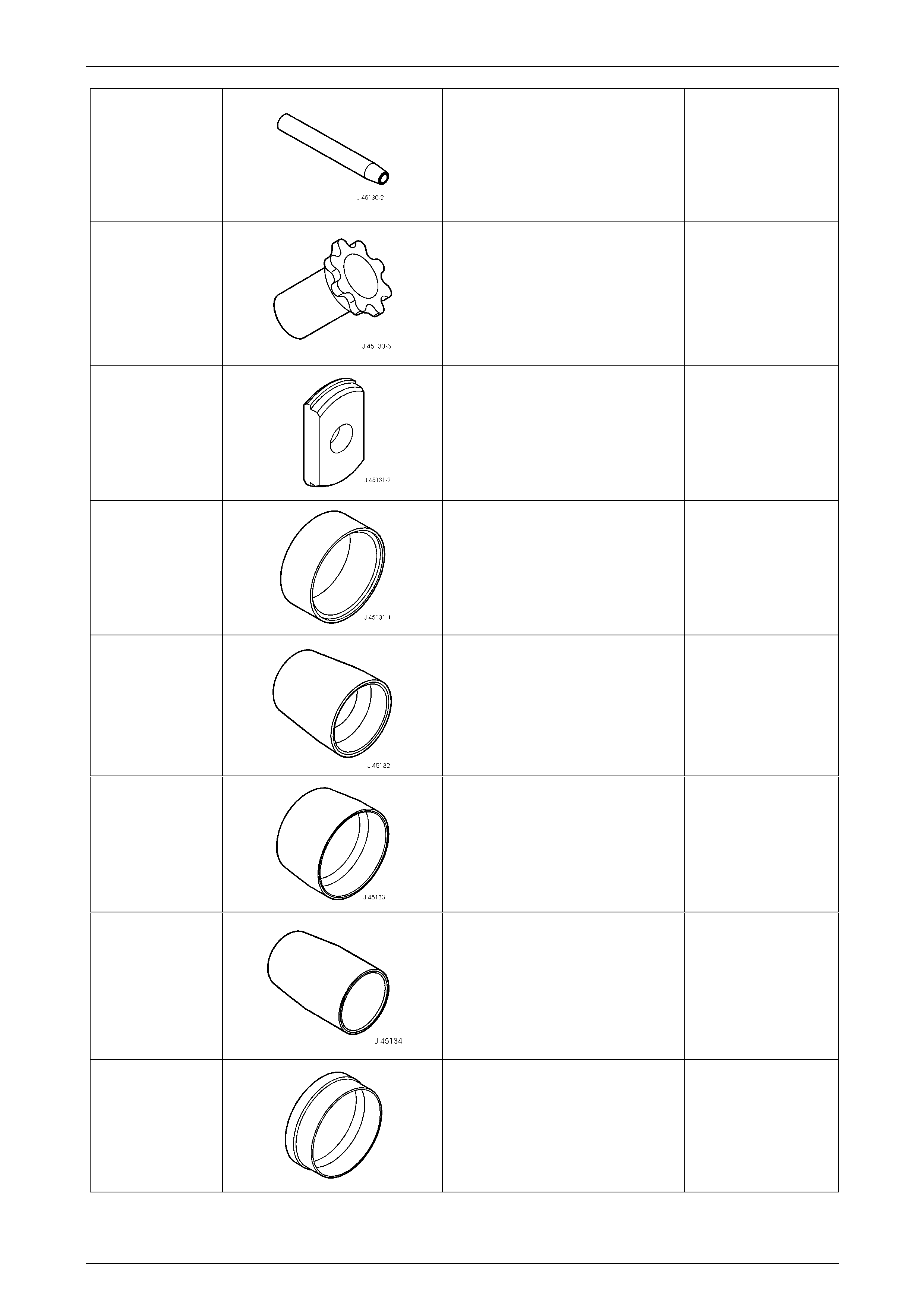
Automatic Transmission – 5L40–E – Unit Repair 7E5 – 147
7E5 – 147
J 45130–2
Seal Protector
Used in conjunction with J 45130–1 to
install new input shaft fluid seals.
New release.
Unique
J 45130–3
Seal Installer Sizer
Used to size new input shaft fluid
seals once installed.
New release.
Unique
J 45131–1
Bearing Remover
Used in conjunction with J 45131–1
and driver handle J 7079–2 to remove
the inner output shaft bearing from the
extension housing.
New release.
Unique
J 45131–2
Bearing Receiver
Used in conjunction with J 45131–and
driver handle J 7079–2 to remove the
inner output shaft bearing from the
extension housing.
New release.
Unique
J 45132
Seal Protector
Used to protect the coast clutch piston
seal when installing into clutch drum.
New release.
Unique
J 45133
Seal Protector
Used to install the direct clutch piston
into the direct and reverse clutch
housing.
New release.
Unique
J 45134
Seal Protector
Used to protect the forward clutch
piston seal when installing into clutch
drum.
New release.
Unique
J 45135
Seal Protector
Used in conjunction with J 44764 to
install the overdrive clutch housin g.
New release.
Unique
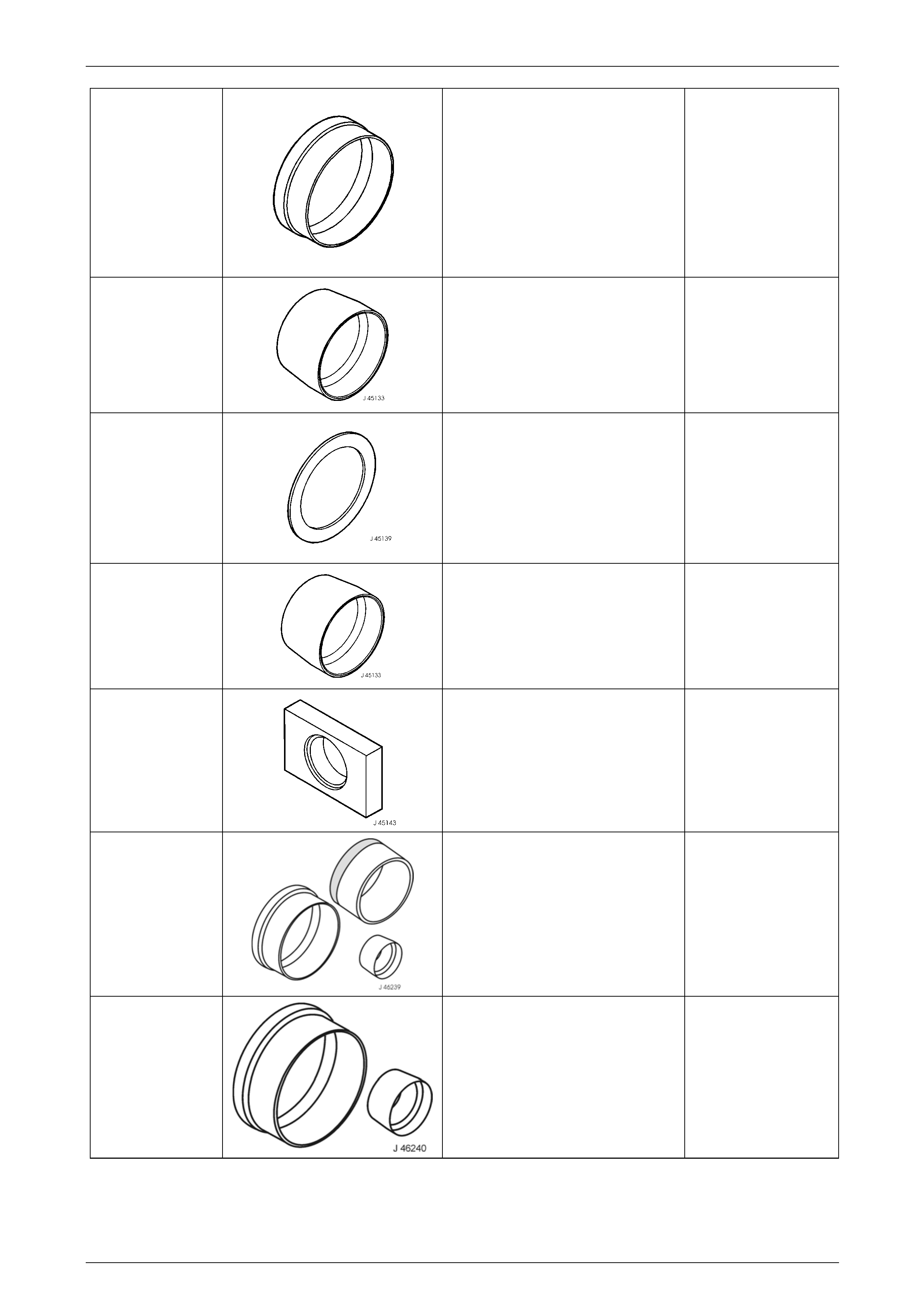
Automatic Transmission – 5L40–E – Unit Repair 7E5 – 148
7E5 – 148
J 45136
Seal Protector
Used for installing the 2nd coast
clutch piston in the centre support.
Used in conjunction with J45136 to
install the low and reverse clutch
piston into the centre support.
Used in conjunction with J 44764 to
install the overdrive clutch housin g.
New release.
Unique
J 45137
Seal Protector
Used in conjunction with J 46240
when installing the 2nd clutch piston
into the centre support.
New release.
Unique
J 45139
Compressor Plate
Used in conjunction with the bolt,
washer and nut from compressor J
23327, and J 38734 to compress the
direct and reverse clutch piston
spring.
New release.
Unique
J 45140
Seal Protector
Used in conjunction with J45136 to
install the low and reverse clutch
piston into the centre support.
New release.
Unique
J 45143
Fluid Pump Bearing Remover Plate
Used in conjunction with J 45124 and
J 29369–2 to remove input shaft
bearing from the fluid pump.
New release.
Unique
J 46239
Piston Seal Protector
Comprised of three parts – J 46239-1,
J 46239-2 and J 46239-3, to i nstall
the 2nd Coast Clutch Piston
New release.
Unique
J 46240
Piston Seal Protector
Comprised of two parts – J 46240-1
and J 46240-2, to install the 2nd
clutch piston.
Unique