
7D5 Automatic Transmission – 4L65E – Unit Repair Page 7D5–1
15–DEC–2005 Page 7D5–1
Section 7D5
Automatic Transmission – 4L65E –
Unit Repair
ATTENTION
Before performing any service operation or other procedure described in this Section, refer to 00 Warnings,
Cautions and Notes for correct workshop practices with regard to safety and/or property damage.
1 General Information ...............................................................................................................................5
1.1 Service Information ............................................................................................................................................... 5
1.2 General Description............................................................................................................................................... 6
1.3 Rebuilding Tips...................................................................................................................................................... 7
Teflon Sealing Rings.......................................................................................................................................... 7
Thrust Washer Surfaces..................................................................................................................................... 7
2 Transmission Disassembly...................................................................................................................8
2.1 Transmission Preparation..................................................................................................................................... 8
2.2 2 – 4 Servo Assembly............................................................................................................................................ 9
Remove................................................................................................................................................................... 9
Disassemble......................................................................................................................................................... 10
Servo Pin Length ................................................................................................................................................. 11
2.3 Speed Sensor and Extension Housing.............................................................................................................. 12
Remove................................................................................................................................................................. 12
2.4 Oil Pan and Filter Assembly................................................................................................................................ 14
Remove................................................................................................................................................................. 14
2.5 Control Valve Body And Wiring Harness........................................................................................................... 15
Remove................................................................................................................................................................. 15
2.6 Torque Converter Housing.................................................................................................................................. 16
Remove................................................................................................................................................................. 16
2.7 Transmission End Play Check............................................................................................................................ 17
2.8 Oil Pump Assembly ............................................................................................................................................. 18
Remove................................................................................................................................................................. 18
2.9 Reverse Input Clutch, Input Clutch, 2-4 Band and Input Gear Set .................................................................. 19
Remove................................................................................................................................................................. 19
2.10 Reaction Gear Set................................................................................................................................................ 21
Remove................................................................................................................................................................. 21
2.11 Low and Reverse Clutch Assembly ................................................................................................................... 25
Remove................................................................................................................................................................. 25
2.12 Manual Shaft, Inner Linkage and Seal................................................................................................................ 27
Remove................................................................................................................................................................. 27
3 Component Disassembly, Inspection, Reassembly.........................................................................29
3.1 Transmission Case.............................................................................................................................................. 29
Inspect .................................................................................................................................................................. 29
3.2 Third Accumulator Retainer and Ball Assembly............................................................................................... 32
Inspect .................................................................................................................................................................. 32
Replace................................................................................................................................................................. 32
3.3 Transmission Case Bush.................................................................................................................................... 34
Replace................................................................................................................................................................. 34
3.4 2-4 Servo Assembly............................................................................................................................................. 35
Inspect .................................................................................................................................................................. 35
Techline

7D5 Automatic Transmission – 4L65E – Unit Repair Page 7D5–2
15–DEC–2005 Page 7D5–2
3.5 Low and Reverse Clutch Assembly ................................................................................................................... 36
Inspect .................................................................................................................................................................. 36
Spacer Plate Selection ........................................................................................................................................ 37
3.6 Low and Reverse Clutch ..................................................................................................................................... 38
Support Assembly............................................................................................................................................... 38
3.7 Reaction Internal Gear and Carrier Assembly................................................................................................... 39
Inspect .................................................................................................................................................................. 39
3.8 Reaction Sun Gear and Shell.............................................................................................................................. 41
Inspect .................................................................................................................................................................. 41
Sun Gear Bush – Replace ................................................................................................................................... 42
3.9 Input Internal Gear and Output Shaft................................................................................................................. 43
Inspect .................................................................................................................................................................. 43
Reaction Carrier Shaft Bushes – Replace ......................................................................................................... 44
3.10 Transmission Output Speed Sensor Ring......................................................................................................... 46
Replace................................................................................................................................................................. 46
3.11 Input Carrier and Sun Gear................................................................................................................................. 47
Inspect .................................................................................................................................................................. 47
Input Sun Gear Bushes – Replace...................................................................................................................... 48
3.12 Input Clutch Housing Assembly......................................................................................................................... 49
Exploded View...................................................................................................................................................... 49
Disassemble......................................................................................................................................................... 50
3 – 4 Clutch...................................................................................................................................................... 50
Forward Clutch Assembly ................................................................................................................................ 51
Overrun Clutch Assembly................................................................................................................................. 52
3 – 4 Clutch Assembly...................................................................................................................................... 53
Inspect .................................................................................................................................................................. 53
Forward Clutch Sprag Assembly........................................................................................................................ 57
Disassemble..................................................................................................................................................... 57
Inspect.............................................................................................................................................................. 58
Reassemble ..................................................................................................................................................... 59
Reassemble.......................................................................................................................................................... 60
3-4 Clutch Assembly ........................................................................................................................................ 60
Overrun Clutch Assembly................................................................................................................................. 63
Forward Clutch Assembly ................................................................................................................................ 65
3-4 Clutch......................................................................................................................................................... 66
Input Clutch Housing Air Checks....................................................................................................................... 67
Reinstall Turbine Shaft Sealing Rings............................................................................................................... 68
3.13 Reverse Input Clutch Assembly......................................................................................................................... 69
Disassemble......................................................................................................................................................... 69
Inspect .................................................................................................................................................................. 70
Reverse Input Clutch Housing Bushes – Replace............................................................................................ 71
Reassemble.......................................................................................................................................................... 73
Reverse Input Clutch Air Check ......................................................................................................................... 75
3.14 2-4 Band................................................................................................................................................................ 76
Inspect .................................................................................................................................................................. 76
3.15 Oil Pump Assembly............................................................................................................................................. 77
Disassemble......................................................................................................................................................... 77
Oil Pump Assembly.......................................................................................................................................... 77
Oil Pump Body ................................................................................................................................................. 78
Input Speed Sensor.......................................................................................................................................... 79
Oil Pump Cover................................................................................................................................................ 80
Inspect .................................................................................................................................................................. 81
Oil Pump Bushes – Replace................................................................................................................................ 82
Pump Body Bush.............................................................................................................................................. 82
Pump Cover Bushes ........................................................................................................................................ 83
Reassemble.......................................................................................................................................................... 85
Oil Pump Body ................................................................................................................................................. 85
Oil Pump Cover................................................................................................................................................ 87
Input Speed Sensor.......................................................................................................................................... 88
Oil Pump Assembly.......................................................................................................................................... 89

7D5 Automatic Transmission – 4L65E – Unit Repair Page 7D5–3
15–DEC–2005 Page 7D5–3
Oil Pump Air Checks ........................................................................................................................................... 89
Introduction ...................................................................................................................................................... 89
Air Checks Table.............................................................................................................................................. 89
3.16 Control Valve Body.............................................................................................................................................. 91
Exploded Views.................................................................................................................................................... 91
View A.............................................................................................................................................................. 91
View B.............................................................................................................................................................. 92
Disassemble......................................................................................................................................................... 93
Clean and Inspect................................................................................................................................................ 94
Control Valve Body........................................................................................................................................... 94
Spacer Plate Evaluation................................................................................................................................... 94
Reassemble.......................................................................................................................................................... 95
4 Transmission Reassembly..................................................................................................................97
4.1 Manual Shaft, Inner Linkage and Seal................................................................................................................ 97
Reinstall................................................................................................................................................................ 97
4.2 Low and Reverse Clutch Piston ......................................................................................................................... 98
Reinstall................................................................................................................................................................ 98
4.3 Reaction Planetary Gear Set............................................................................................................................. 100
Reinstall.............................................................................................................................................................. 100
4.4 Low and Reverse Clutch Plates and Support Assembly................................................................................ 101
Reinstall.............................................................................................................................................................. 101
4.5 Reaction Gear, Input Gear and Output Shaft................................................................................................... 104
Reinstall.............................................................................................................................................................. 104
4.6 Reverse Input Clutch, Input Clutch and Input Gear Set ................................................................................. 107
Reinstall.............................................................................................................................................................. 107
4.7 2-4 Band Assembly............................................................................................................................................ 109
Reinstall.............................................................................................................................................................. 109
4.8 Oil Pump............................................................................................................................................................. 110
Reinstall.............................................................................................................................................................. 110
4.9 Torque Converter Housing................................................................................................................................ 113
Reinstall.............................................................................................................................................................. 113
4.10 Control Valve Body and Wiring Harness ......................................................................................................... 114
Reinstall.............................................................................................................................................................. 114
4.11 Oil Filter and Oil Pan.......................................................................................................................................... 115
Reinstall.............................................................................................................................................................. 115
4.12 Extension Housing and Speed Sensor ............................................................................................................ 116
Inspect ................................................................................................................................................................ 116
Extension Housing Bush – Replace................................................................................................................. 116
Reinstall.............................................................................................................................................................. 117
4.13 2-4 Servo Assembly........................................................................................................................................... 119
Servo Pin Length – Check................................................................................................................................. 119
Reassemble........................................................................................................................................................ 120
Reinstall.............................................................................................................................................................. 121
4.14 Neutral Start & Back-Up Lamp Sw itch Assembly ........................................................................................... 122
Reinstall.............................................................................................................................................................. 122
4.15 Torque Converter............................................................................................................................................... 123
Inspect ................................................................................................................................................................ 123
End Play Check.................................................................................................................................................. 123
Reinstall.............................................................................................................................................................. 124
4.16 Transmission Fixture Removal......................................................................................................................... 125
5 Transmission Diagrams.....................................................................................................................126
5.1 Transmission Case and External Parts............................................................................................................ 126
5.2 Control Valve Body Assembly.......................................................................................................................... 128
5.3 Control Valve Identification............................................................................................................................... 130
5.4 Control Valve Spring Identification.................................................................................................................. 132
5.5 Seal Location and Orientation.......................................................................................................................... 133
5.6 Bush/Bearing Location and Orientation .......................................................................................................... 134

7D5 Automatic Transmission – 4L65E – Unit Repair Page 7D5–4
15–DEC–2005 Page 7D5–4
6 Specifications.....................................................................................................................................135
7 Torque Wrench Specifications..........................................................................................................136
8 Special Tools ......................................................................................................................................137

7D5 Automatic Transmission – 4L65E – Unit Repair Page 7D5–5
15–DEC–2005 Page 7D5–5
1 General Information
This Section describes the disassembly and reassembly procedures of the four spee d 4L65E hydra-matic automatic
transmission as well as the associated components, with the transmission removed from the vehicle.
1.1 Service Information
Throughout the service operations within this
Section, when handling retaining clips, using
compressed air o r cleaning flu ids, w ear safety
equipment to avoid personal injury.
Refer to Section 7D1 Automatic Transmission – 4L65E – General Informat ion for the following:
• information relating to mechanical and electrical operations,
• abbreviations, transmission specificati ons, special tools and torque wrench specifications,
• servicing, cleaning and inspe c tion procedure recommendations.
It is essential to read and understand the General Information, Warnings, Cautions and Service Notes contained in that
same Section, before any service operation is performed on the four speed 4L65E hydra-matic automatic transmission or
any associated components.
Failure to comply with the procedur es and service notes can affect the reliable and efficient operation of this automatic
transmission.

7D5 Automatic Transmission – 4L65E – Unit Repair Page 7D5–6
15–DEC–2005 Page 7D5–6
1.2 General Description
The four speed 4L65E hydra- matic automatic transmission, although similar to the 4L60E automatic tra nsmissio n, has
been up-graded to cater for high torque and load demands.
The four speed 4L65E hydra- matic automatic transmission features the following:
• The input carrier is up-grade d to a five pinion gear construction.
• The reaction carrier is up-graded to a five pi nion gear construction.
• The sun reaction shell thrust washer is up-graded to a thru st needle bearing construction.
• An oil deflector is added for the five pinion re action carrier.
• The output shaft sleeve and output shaft seal are uni que to cater for the five pinion carrier.
• The input housing and sh aft assembly is unique to cater for high torque and load demands.
• The O-ring seal for the input shaft is unique.
• The quantity of composition pl ates and st eel plates for the 3-4 clutch plate assembly, has been increased to seven
and six respectively.
• A new selective backing plate for the 3-4 clutch assembly, has been introduced to cater for the increased qua ntity
of plates within the 3-4 clutch plate assembly.
• The control valve body gaskets and spacer plate are unique and h ave identification marking VB, CA and IPU
respectively.
• For MY06 vehicles an Input Speed Sensor (ISS) has bee n fitted
The additional pini on gear spreads torque lo ads around to reduce the load supporte d by each gear, in both compression
and bending. The 3-4 clutch has now seven friction plates, this cha ng e results in higher shift energy capacity. A heavy
duty needle bearing is now used for the interface between the reaction shaft and the reacti on sun gear and shell to
withstand increased loads.

7D5 Automatic Transmission – 4L65E – Unit Repair Page 7D5–7
15–DEC–2005 Page 7D5–7
1.3 Rebuilding Tips
The use of air powered tools to disassemble or reassemble this transmission is not recommended. Apa rt from the fact
that thread stripping is more likely when inc orrect torque values are applied to fasteners, component parts can be
distorted to the point where malfunctions will occur.
Teflon Sealing Rings
If any sealing rings are damaged, cut or do not rotate freely in their groove, check if the ring groove has no trapped
debris, is not burred or damaged in such a wa y that it would cause earl y failure of a replacement ring.
Thrust Washer Surfa ces
On inspection, thrust washer and thrust bear ing surfaces may appear to be polished at points of contact. This is a normal
condition and should not be considered as damage requirin g replacement.
7D5 Automatic Transmission – 4L65E – Unit Repair Page 7D5–8
15–DEC–2005 Page 7D5–8
2 Transmission Disassembly
2.1 Transmission Preparation
LT Section No. — 04–200
Take care when lifting or handling the
transmission as it is a heavy assembly and
personal injury may result if lifted incorrectly.
Use appropriate lifting gear.
1 Thoroughly clean exterior of transmission.
2 If the removal of the control valve body harness is
anticipated, its connector should be pushed into the
transmission case before fitting the holding fixture.
Use the connector release, Tool No. 700-4208, to
compress the connector four retaining tangs, push ing
down squarely on the connect or.
NOTE
Alternatively a 1 5/16" socket (¾" drive) may be
used.
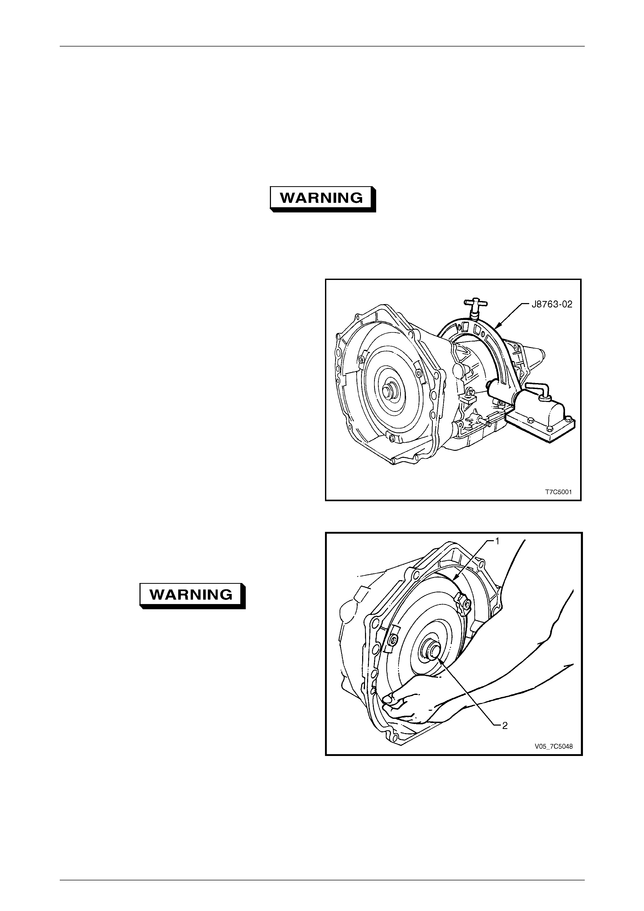
3 Install the transmission holding fixture, Tool No.
J8763-02, as shown and mount the fixture into the
base, Tool No. J3289-20, the 2-4 servo facing away
from the workbench.
Figure 7D5 – 1
4 Remove the torque converter (1) by sliding it clear of
the input shaft (2). Drain stored converter fluid into a
suitable container.
Take care when removing the torque
converter as it is a heavy assembly and
personal injury may result if lifted incorrectly.
NOTE
Ensure the container has the capacity to hold at
least 8 litres.
5 Rotate the transmission so the converter housing
faces upward and drain the fluid from the extension
housing.
Figure 7D5 – 2
7D5 Automatic Transmission – 4L65E – Unit Repair Page 7D5–9
15–DEC–2005 Page 7D5–9
2.2 2 – 4 Servo Assembly
LT Section No. — 04–200
Remove
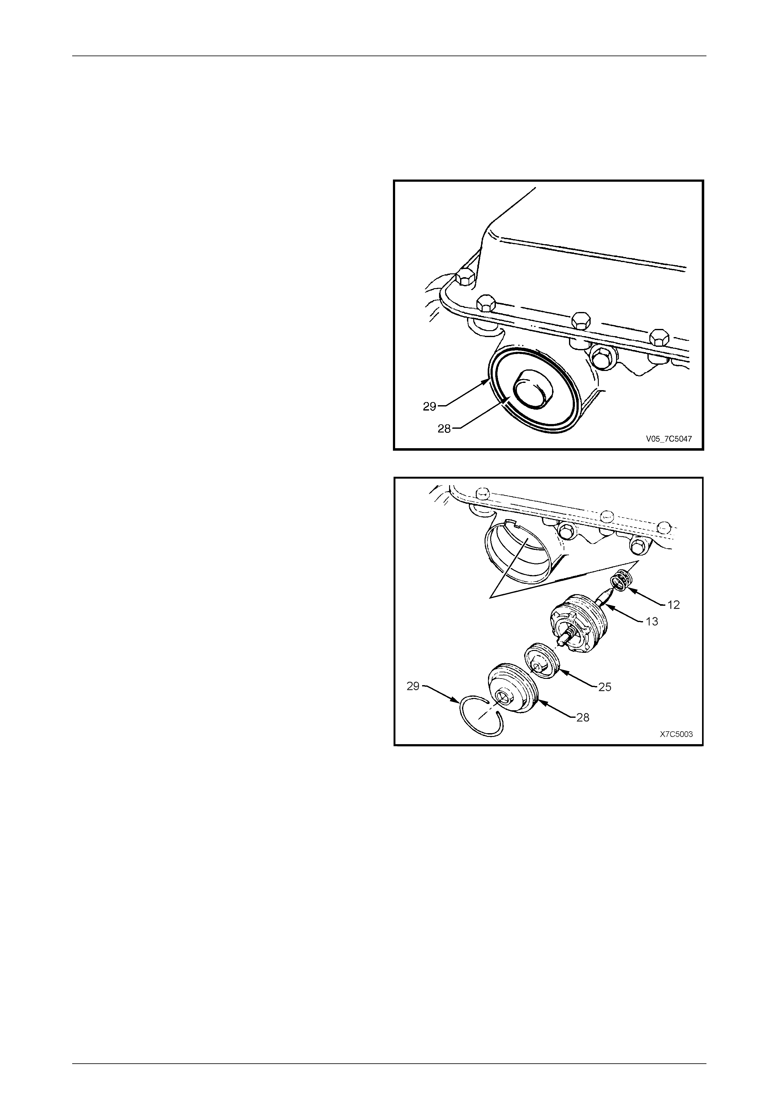
1 Depress the 2-4 servo cover (28) with a hammer
handle and hold.
2 Remove the cover retainer ring (29).
Figure 7D5 – 3
3 To remove the cover (28), either cut the O-ring seal
(not shown) and remove with thin nosed pliers first, or
stretch the O-ring by pulling it throug h one of the two
openings, while removing the cover.
NOTE
The fourth apply piston (25) may come out with
the cover (28). If so, and the piston accidentally
falls to the floor, ensure the teflon ring grooves
have not been damaged to the point where ring
binding and/or damage could occur.
4 Remove the fourth apply piston (25) from the second
apply piston assembly.
5 Remove the second apply piston and servo pin
assembly (13).
6 Remove the servo return spring (12).
Figure 7D5 – 4
7D5 Automatic Transmission – 4L65E – Unit Repair Page 7D5–10
15–DEC–2005 Page 7D5–10
Disassemble
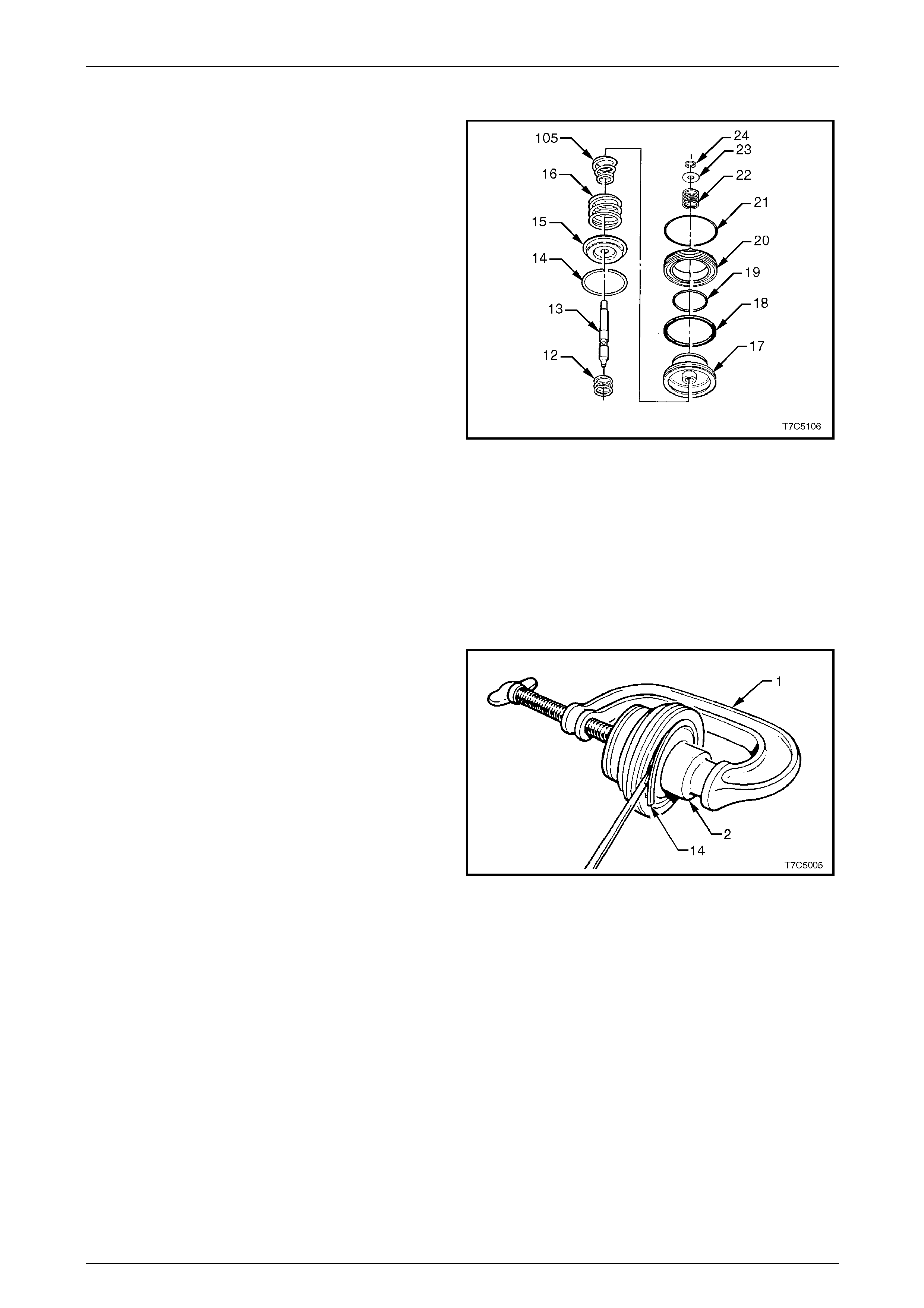
Components identification:
12 spring, servo return
13 pin, 2nd apply piston
14 ring, retainer (2nd apply piston)
15 retainer, servo cushion spring
16 spring, servo cushion (outer)
105 spring, servo cushion (inner) (V6 eng ine only).
17 piston, 2nd apply
18 ring, oil seal (2nd apply piston - outer)
19 ring, oil seal (2nd apply piston - inner)
20 housing, servo piston (inner)
21 seal, O-ring
22 spring, servo apply p in
23 washer, servo apply pin
24 C-clip retainer, servo apply pin.
1 Remove the servo pin retainer clip (24) from the
second apply piston pi n (13).
2 Remove the washer (23) and apply pin spring (22).
3 Remove second apply piston pin.
Figure 7D5 – 5
4 Fit a suitable G-clamp (1) and socket (2), to the
second apply piston assembly, as shown.
5 Use this arrangement to compress the piston
assembly.
6 Remove the second apply piston retainer ring (14).
7 Remove the G-clamp and socket.
NOTE
The tapered cushion spring (105) is not fitted to
transmission with GEN III V8 engine.
8 Remove the cushion spring (16), tapered cushion
spring (105) and retainer (15), refer to Figure 7D5 – 5.
NOTE
The reassembly of the 2 – 4 Servo is carried out
on transmission reassembly, refer to
4.13 2-4 Servo Assembly.
Figure 7D5 – 6
7D5 Automatic Transmission – 4L65E – Unit Repair Page 7D5–11
15–DEC–2005 Page 7D5–11
Servo Pin Length
NOTE
At this stage, it is advisable to measure the
length of the installed servo pin. If the pin is too
short or too long, look closely at the 2-4 band
and reverse input drum for wear and/or damage,
once the transmission has been disassembled.
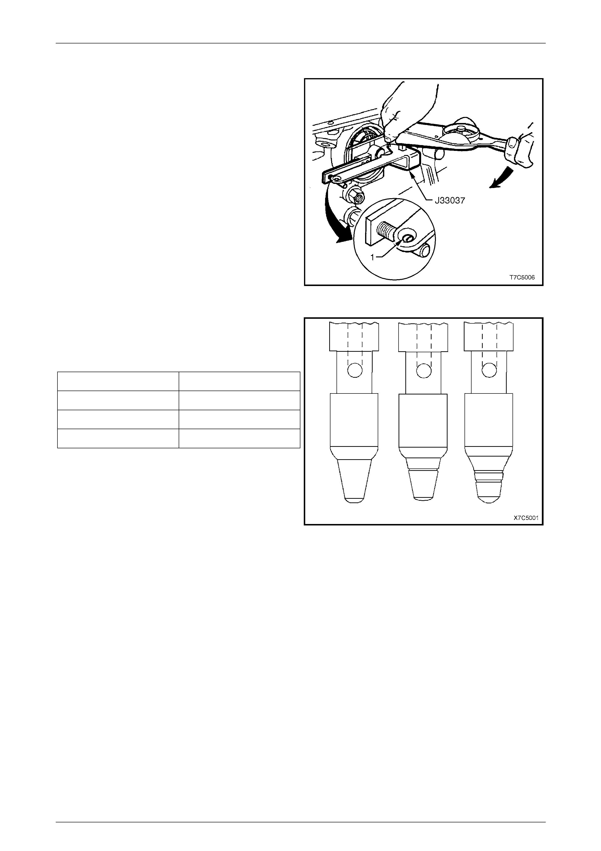
1 Install the pin, tapered end first.
2 Install Tool No. J33037 as shown, and refit the servo
cover retaining ring to secure the tool.
3 Apply 11 Nm torque to the tool arm.
• If a white line appears in the gauge e yelet (1),
the pin length is correct.
• If the white line does not appear in the gauge
eyelet, the pin may require replac ement.
4 Remove Tool No. J33037 and the second apply piston
pin from the transmission case. Figure 7D5 – 7
5 Measure the pin length and re cord.
6 If the pin length is incorrect and requires replacement,
use the following selection table to determine the
correct pin length.
Pin Length (mm) Identification
65.82 – 66.12 1 Groove
67.23 – 67.53 2 Grooves
68.64 – 68.94 No Groove
Figure 7D5 – 8
7D5 Automatic Transmission – 4L65E – Unit Repair Page 7D5–12
15–DEC–2005 Page 7D5–12
2.3 Speed Sensor and Extension Housing
LT Section No. — 04–200
Remove
For service procedures of the adaptor housing and speed sensor fitted to AWD vehicles, refer to Section 7F Transfer
Case and Adaptor Housing.
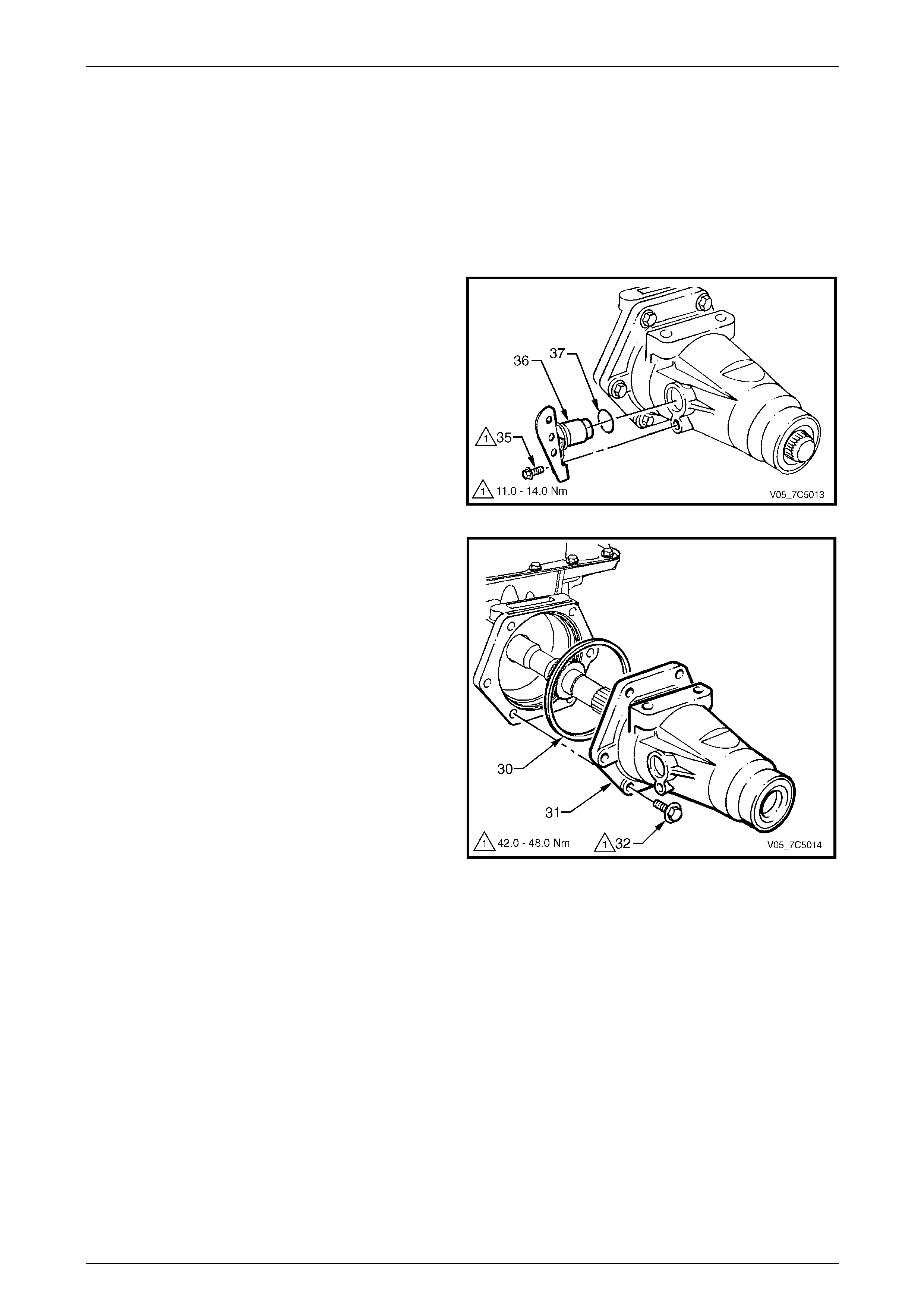
1 Remove the speed sensor retaining screw (35) from
the extension housing, then remove the sensor (36)
and O-ring (37).
Figure 7D5 – 9
2 If required, remove the extension housing seal, using
a suitable seal removing tool, such as Tool No. E308
or similar.
3 Remove the extension housin g bolt (32), six places.
4 Remove the extension housin g (31) and O-ring
seal (30).
Figure 7D5 – 10
7D5 Automatic Transmission – 4L65E – Unit Repair Page 7D5–13
15–DEC–2005 Page 7D5–13
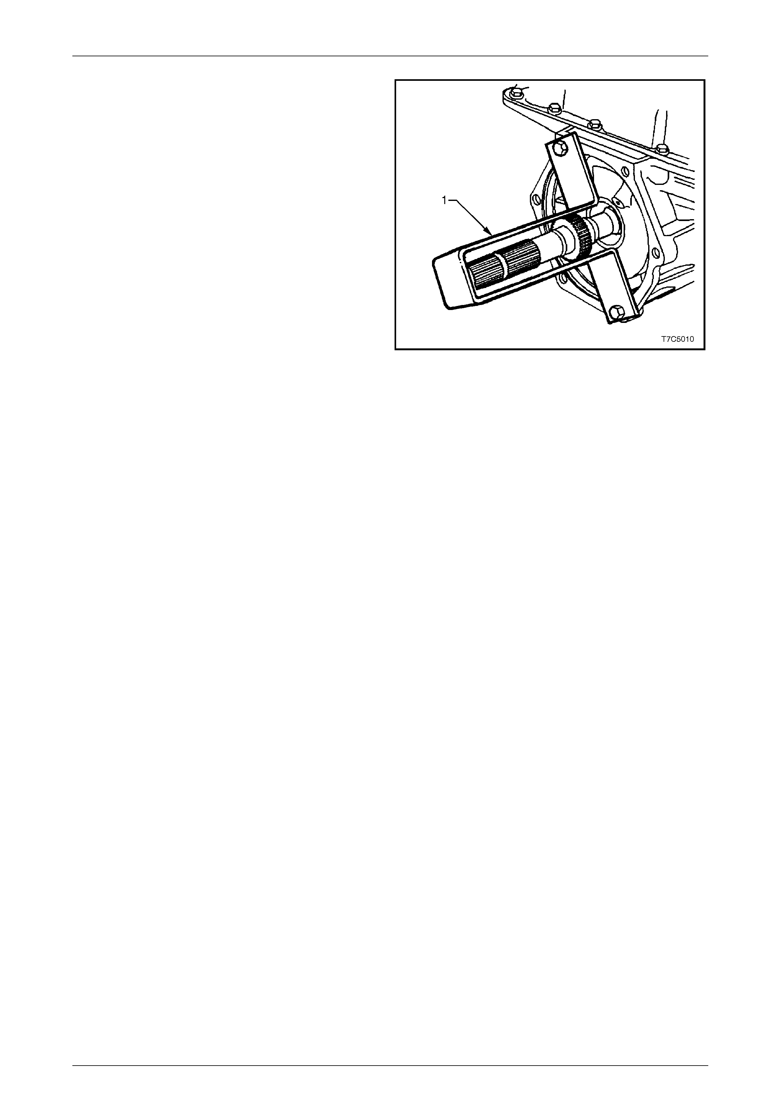
5 To support and stop the output shaft falling from the
transmission at a later point in the disassembly
process, fabricate a support bracket (1) from a strip of
suitable sheet metal (as shown). Install the bracket
using two extension housin g bolts.
Figure 7D5 – 11


7D5 Automatic Transmission – 4L65E – Unit Repair Page 7D5–16
15–DEC–2005 Page 7D5–16
2.6 Torque Converter Housing
LT Section No. — 04–200
Remove
1 Rotate the transmission assembly until the torqu e
converter housing is facing up ward as sh own, then
lock the assembly in that position.
Do not use a standard , # 50 Torx® bit, as the
bolt design is such that only the Torx Plus®
bit is capable of ap pl ying sufficien t loo sening
torque without bolt damage.
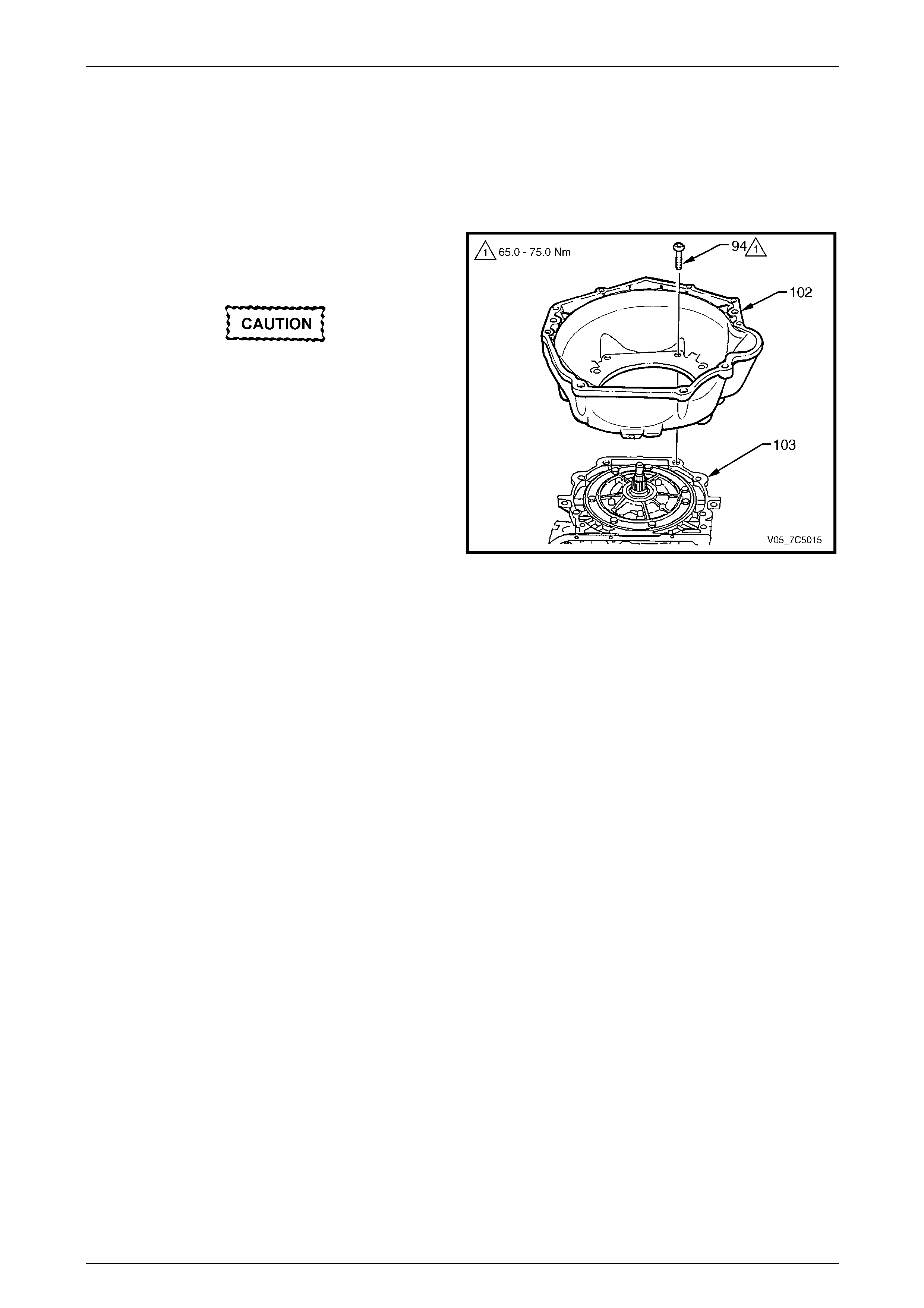
2 Using Torx Plus® bit, Tool No. J41510 or commercial
equivalent, progressivel y loosen and remove the
bolts (94) attaching the torque converter housing.
3 Remove the torque converter housing (102) from the
transmission case (103).
NOTE
The torque converter housing shown is ‘typical’
and is not intended to be specific to any
particular engine applic ation.
Figure 7D5 – 12
7D5 Automatic Transmission – 4L65E – Unit Repair Page 7D5–17
15–DEC–2005 Page 7D5–17
2.7 Transmission End Play Check
LT Section No. — 04–200
To assist in the diagnostic process, check the transmission end play prior to removing interna l components.
If the measured end play is outside specifications, it is corrected when reinstalli ng the selective thrust washer (616) onto
the input housing and shaft assembly (621), refer to 4.6 Reverse Input Clutch, Input Clutch and Input Gear Set.
Carry out the end play check as follows:
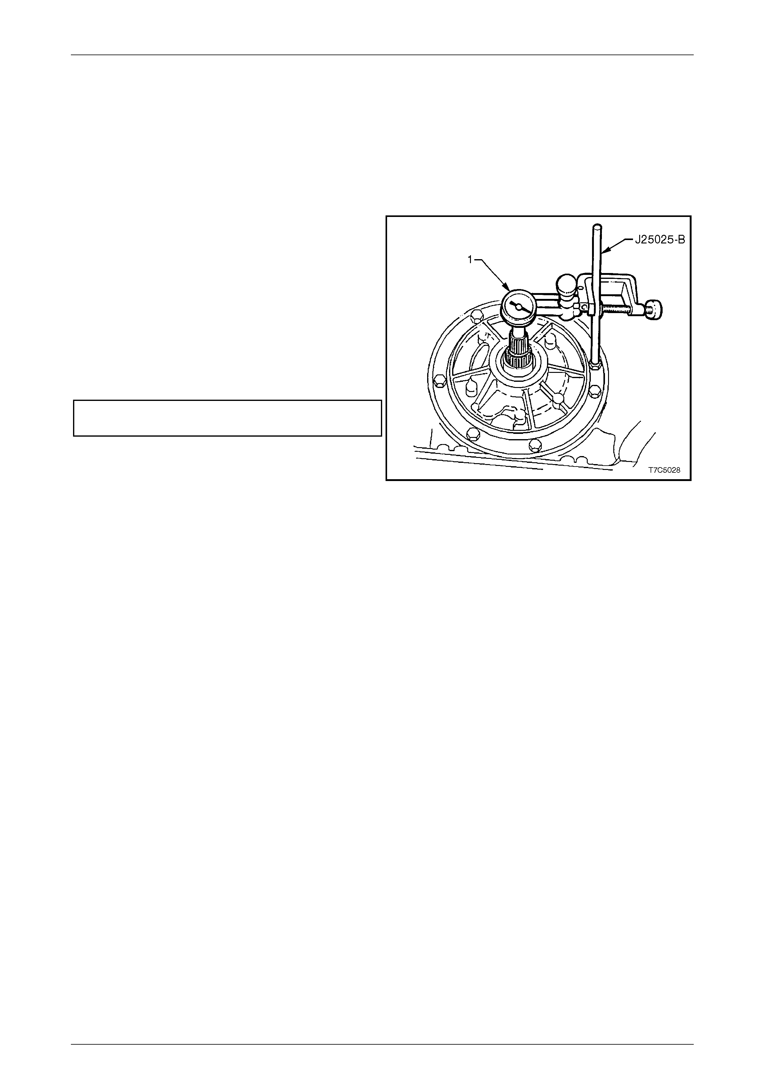
1 Leave the transmission with the input shaft in a vertical
position.
2 Remove one oil pump attaching bolt, install Tool No.
J25025-B and secure with the locknut.
3 Install a dial indicator (1) using a commercially
available clamp on Tool No. J25025-B. Set to zero the
dial indicator contacting the end of input shaft.
4 Pull up the input shaft by hand to measure the end
play.
Transmission end play
specification........................................... 0.13 – 0.92 mm
5 Remove the dial indicator and T ool No. J25025-B.
Figure 7D5 – 13
7D5 Automatic Transmission – 4L65E – Unit Repair Page 7D5–18
15–DEC–2005 Page 7D5–18
2.8 Oil Pump Assembly
LT Section No. — 04–200
Remove
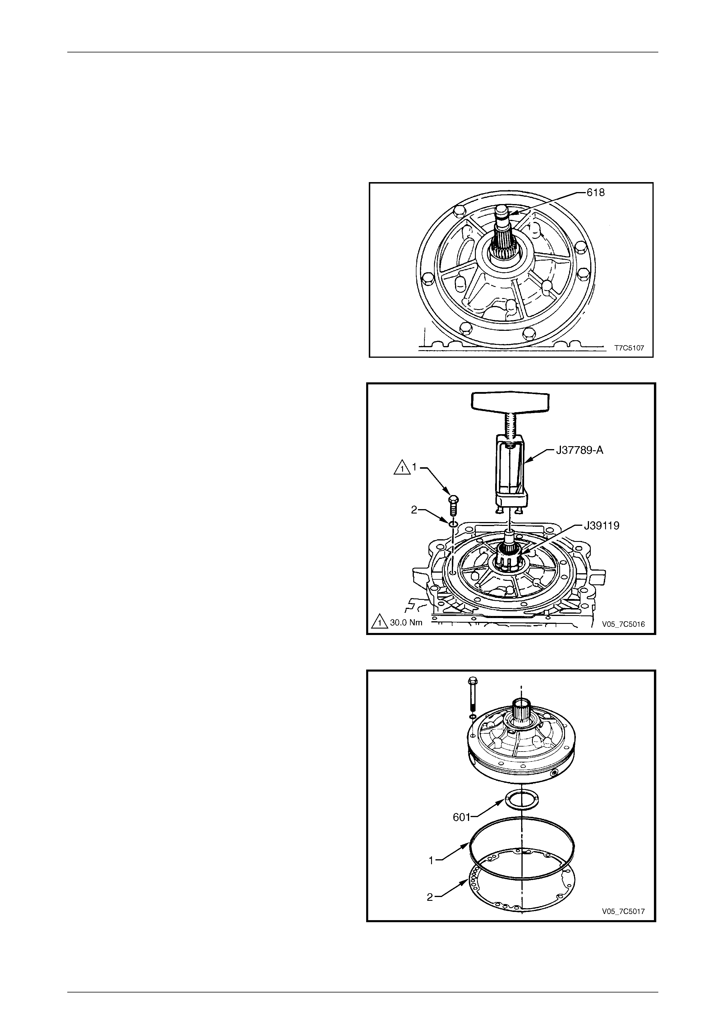
1 Remove the input shaft O-ring (618) from the turbine
shaft.
2 Prise the front helix seal retainer from the oil pump
housing.
3 Using a suitable seal removing tool, such as Tool
No. E308 or similar, extract the seal and discard.
Figure 7D5 – 14
4 Remove the remaining oil pump bolt (1) and seal (2),
seven places in total.
5 Slide Tool No. J39119 over the stator shaft until it
locks under the splines. Install Tool No. J37789-A over
Tool No. J39119 and tighten the clamp bolt. Unseat
the oil pump assembly by turning the forcing screw
against the input shaft. Remove the oil pump
assembly from the transmission case.
6 Remove the special tools from the oil pump.
Figure 7D5 – 15
7 Remove the oil pump to case seal (1) and g asket (2).
8 Remove the reverse input clutch to oil pump thrust
washer (601).
NOTE
The thrust washer is selectable to obtain
correct transmission end play, measured in
2.7 Transmission End Play Check.
Figure 7D5 – 16
7D5 Automatic Transmission – 4L65E – Unit Repair Page 7D5–19
15–DEC–2005 Page 7D5–19
2.9 Reverse Input Clutch, Input Clutch, 2-4
Band and Input Gear Set
LT Section No. — 04–200
Remove
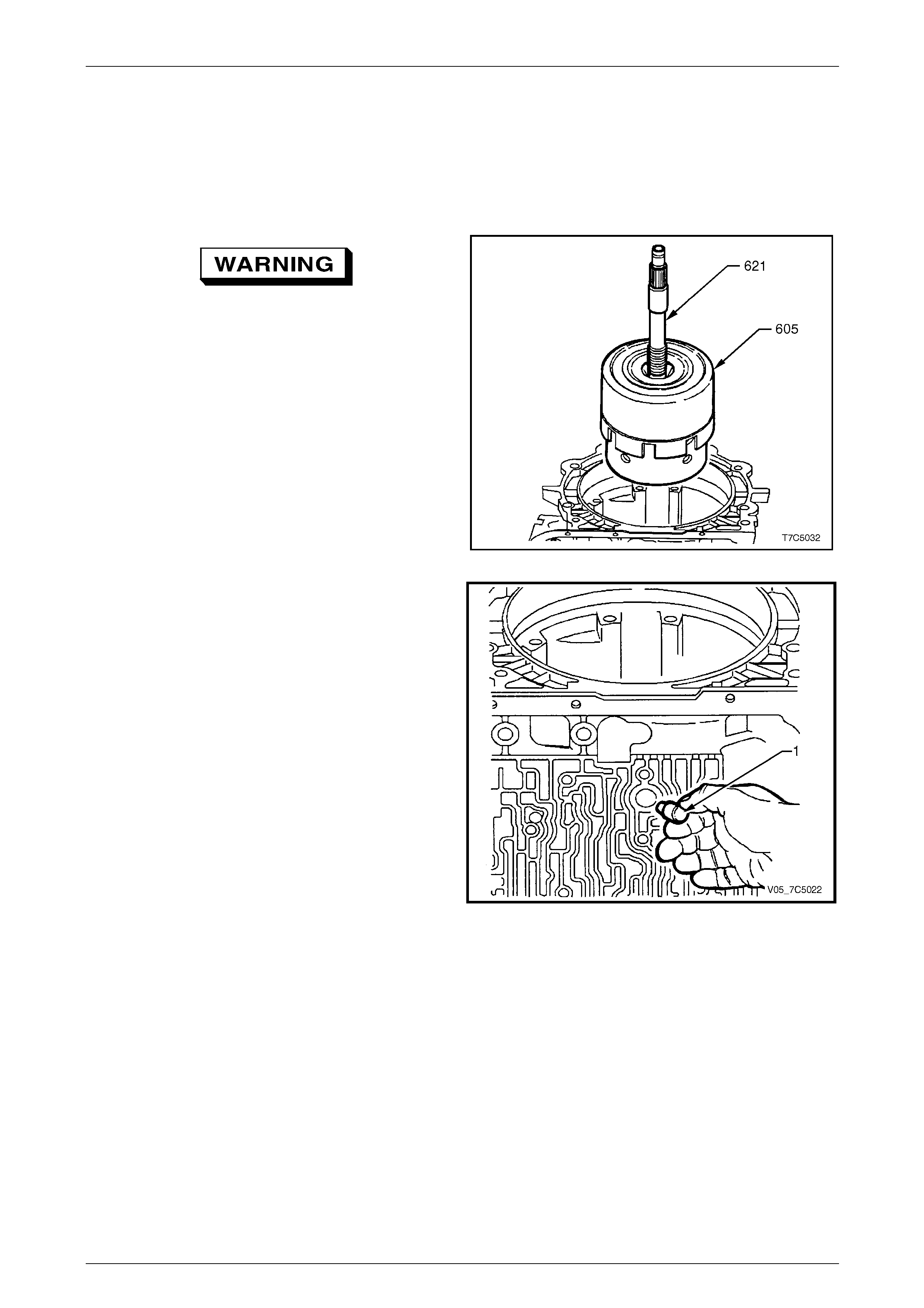
Take care when removing the input clutch
assembly as it is a heavy assembly and
personal injury may result if lifted incorrectly.
1 Remove reverse input clutch (605) and i nput clutch
assembly by grasping input shaft (621) and
withdrawing the assembl y from the transmis sion case.
Figure 7D5 – 17
2 Remove the 2-4 band anc hor pin (1) from the
transmission case.
Figure 7D5 – 18
7D5 Automatic Transmission – 4L65E – Unit Repair Page 7D5–20
15–DEC–2005 Page 7D5–20
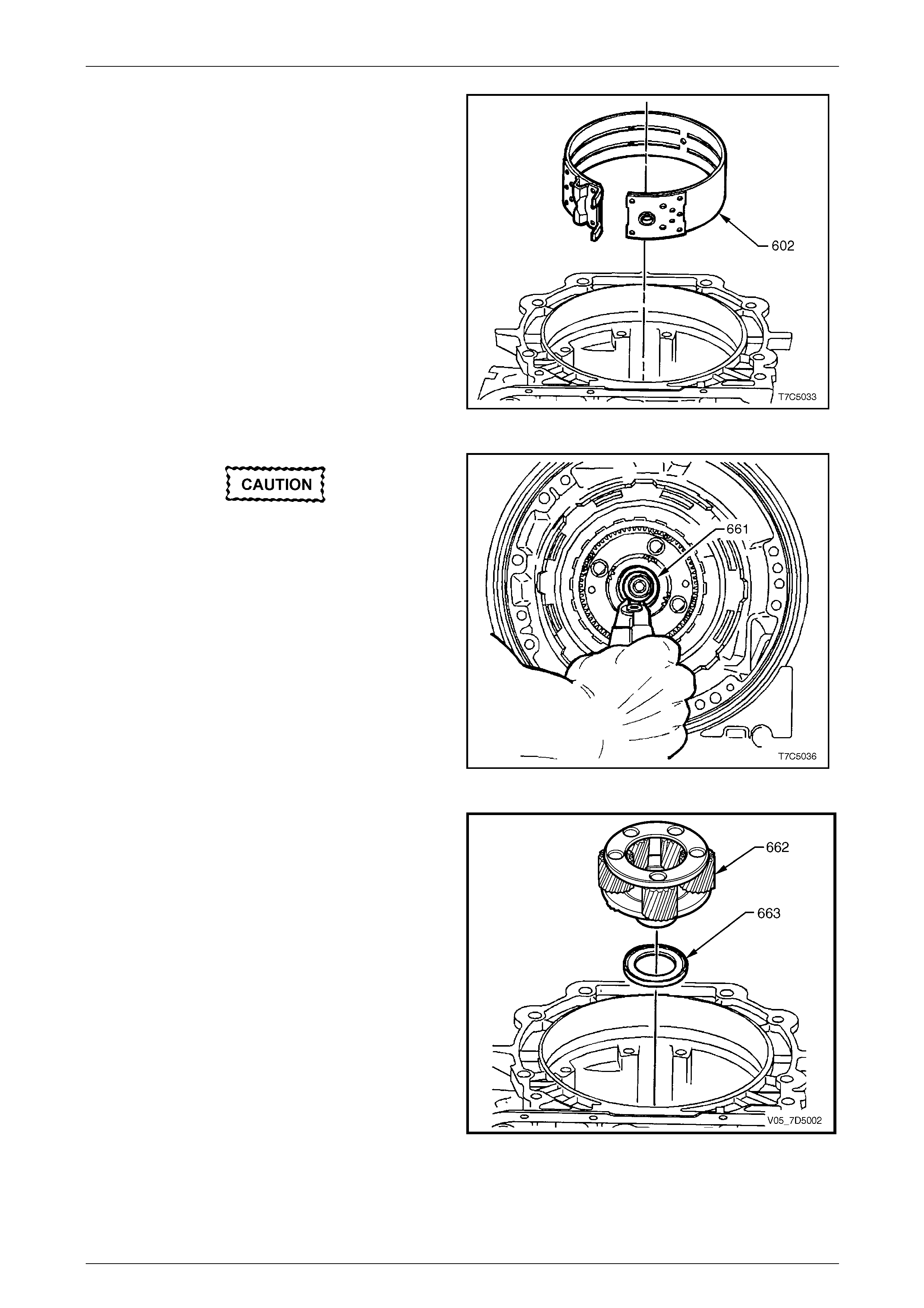
3 Remove the 2-4 band assembly (602).
Figure 7D5 – 19
When removing the snap ring note the
following:
• Do not over expand snap ring.
• Using the snap ring pliers, Tool No.
J34627, will make the removal easier and
reduce the risk of over expanding the
snap ring.
• Unless a fabricated b racket was fitted, the
output shaft will tend to fall out of the
transmission. Refer to 2.3 Speed Sensor
and Extension Housing.
4 Remove the input carrier to output shaft retaining
ring (661) using Tool No. J34627 or suitable snap ring
pliers.
Figure 7D5 – 20
5 Remove the input carrier assembly (662).
6 Remove the thrust bearing (663).
Figure 7D5 – 21
7D5 Automatic Transmission – 4L65E – Unit Repair Page 7D5–21
15–DEC–2005 Page 7D5–21
2.10 Reaction Gear Set
LT Section No. — 04–200
Remove
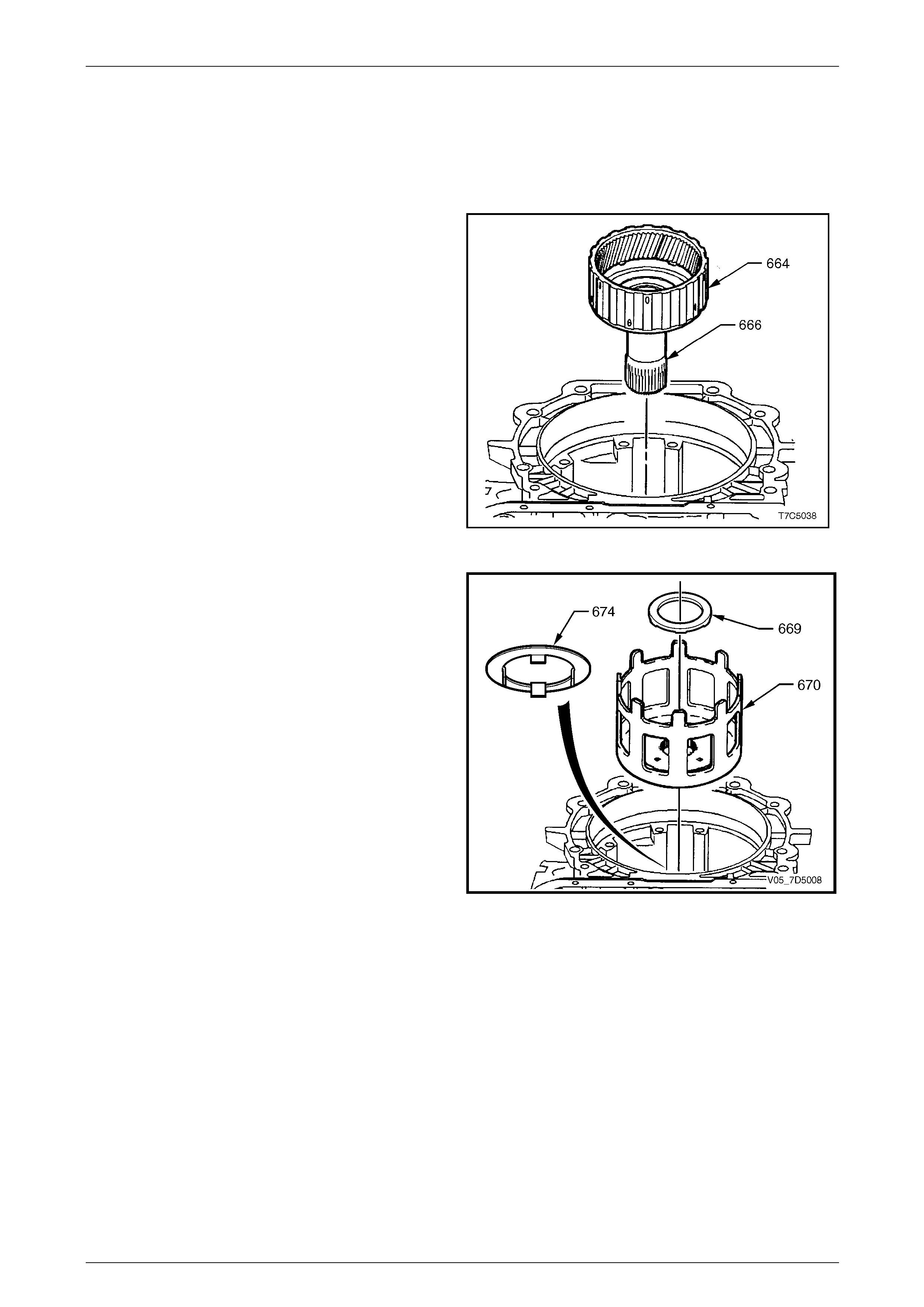
1 Remove the input internal gear (664) a nd the reaction
carrier shaft (666).
Figure 7D5 – 22
2 Remove the reaction shaft/shell thrust bearing (669)
and the reaction sun shell (670).
Figure 7D5 – 23

7D5 Automatic Transmission – 4L65E – Unit Repair Page 7D5–22
15–DEC–2005 Page 7D5–22
3 Remove the reaction sun gear (673).
4 Remove the race/reaction shell thrust washer (674).
5 Remove the low and reverse roller cl utch race (675),
by holding the inner surface a nd turning the race in the
clockwise (free) direction.
Figure 7D5 – 24
6 Remove the low and reverse support to case retaining
ring (676).
7 Remove the fabricated bracket, refer to
2.3 Speed Sensor and Ext ension Housing, and
withdraw the output shaft .
NOTE
Depending on the distance the transmission has
travelled, there may be some resistance to
removal of the mainshaft from the input carri er. If
so, tap the inboard end of the output shaft with a
plastic faced hammer to dislodge.
Figure 7D5 – 25
8 Reinsert the mainshaft and push up to dislo dge the
low and reverse clutch support assembly (679).
9 Remove the low and reverse clutch support from the
transmission case.
Figure 7D5 – 26
7D5 Automatic Transmission – 4L65E – Unit Repair Page 7D5–23
15–DEC–2005 Page 7D5–23
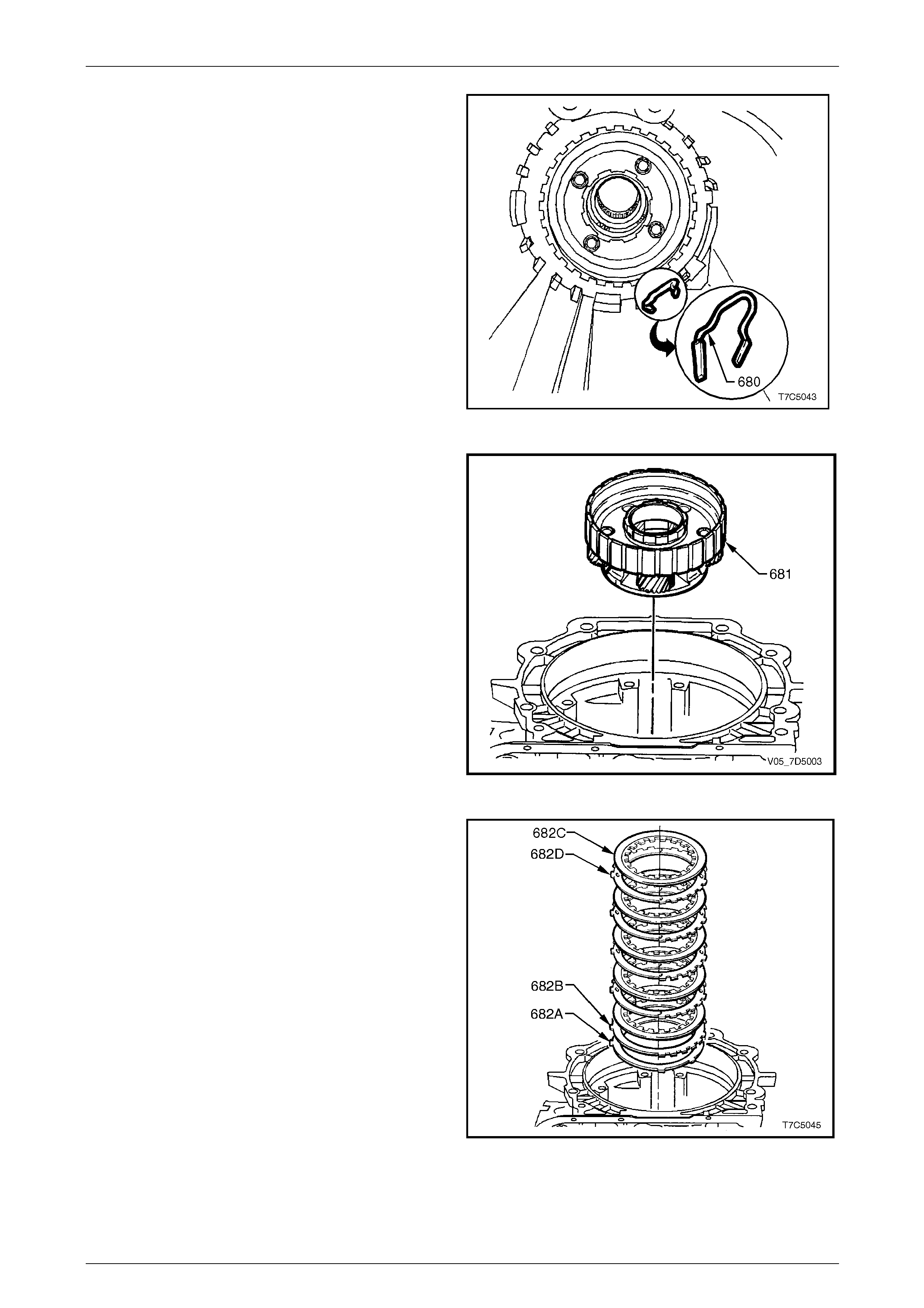
10 Remove the low and reverse clutch support retainer
spring (680).
Figure 7D5 – 27
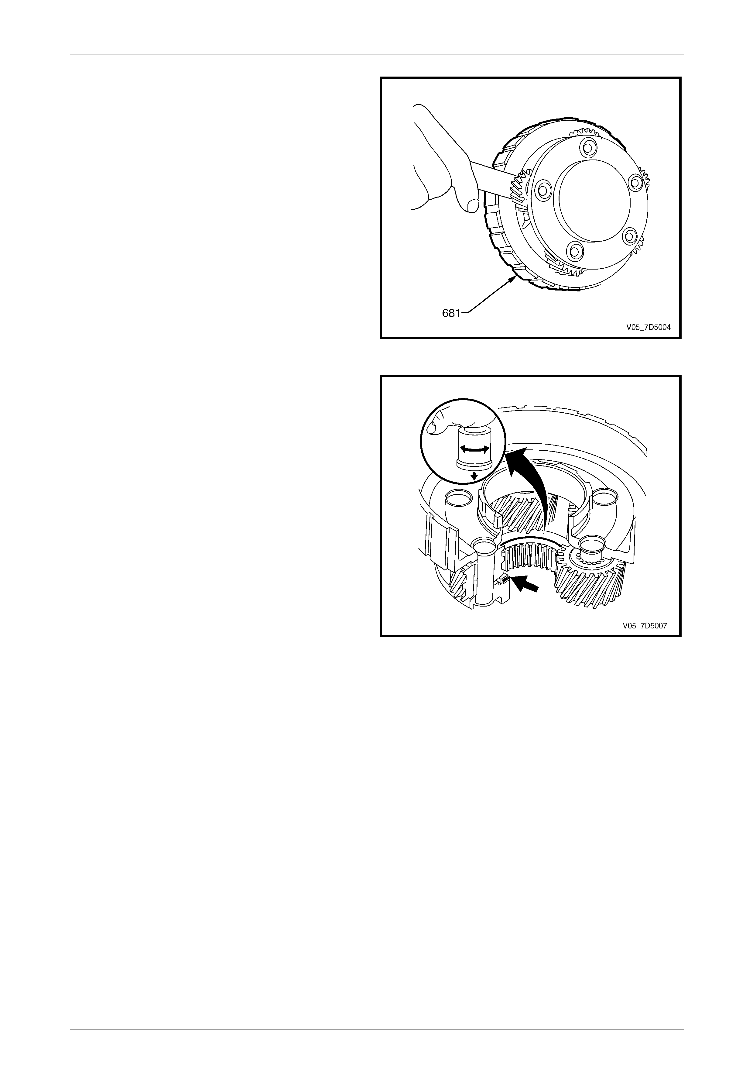
11 Remove the reaction carrier a ssembly (681).
Figure 7D5 – 28
12 Remove low and reverse clutch plate assembly:
• 682C Composition plates
• 682D Steel plates
• 682B Selective spacer plate
• 682A Wave plate.
Figure 7D5 – 29
7D5 Automatic Transmission – 4L65E – Unit Repair Page 7D5–24
15–DEC–2005 Page 7D5–24
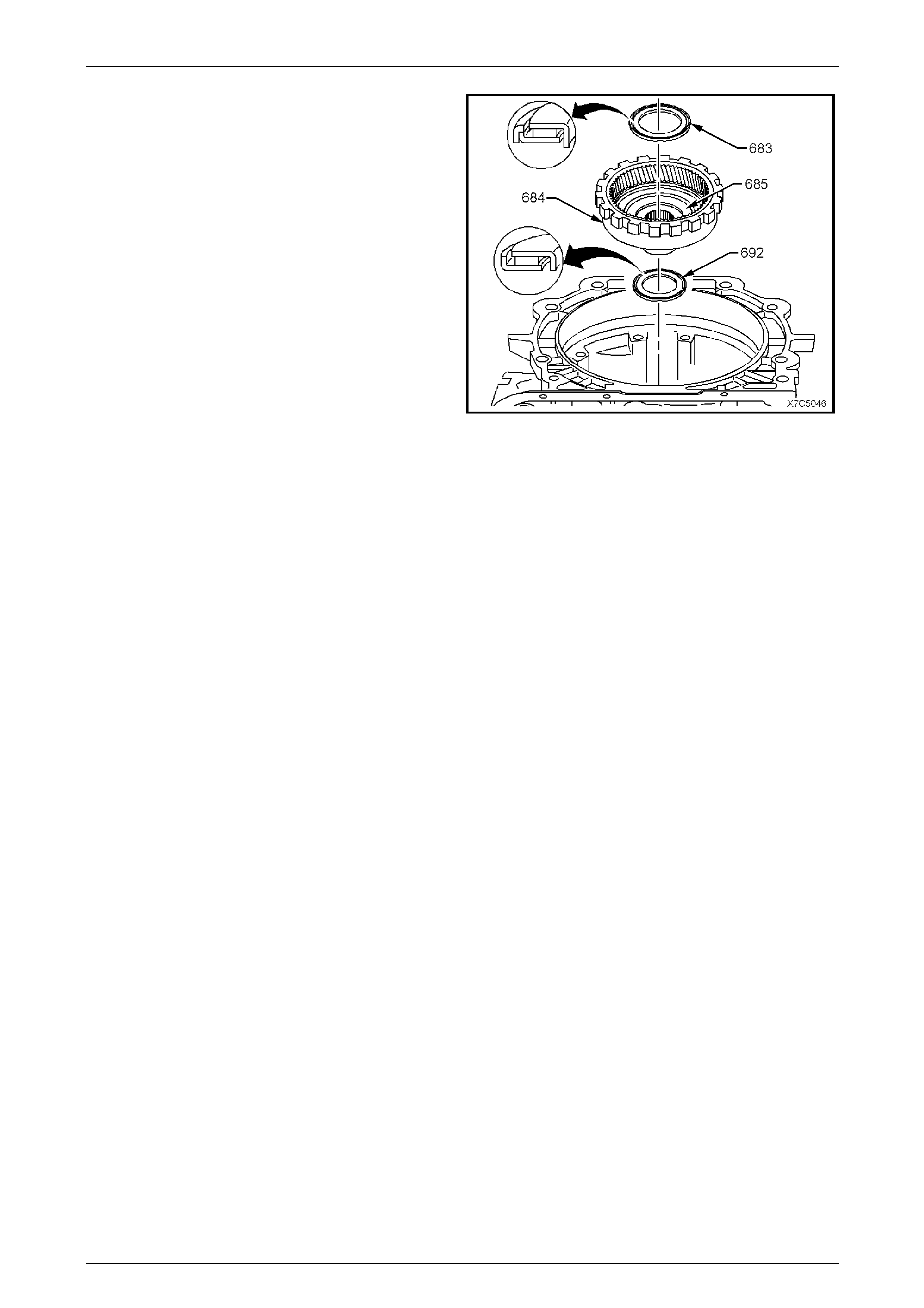
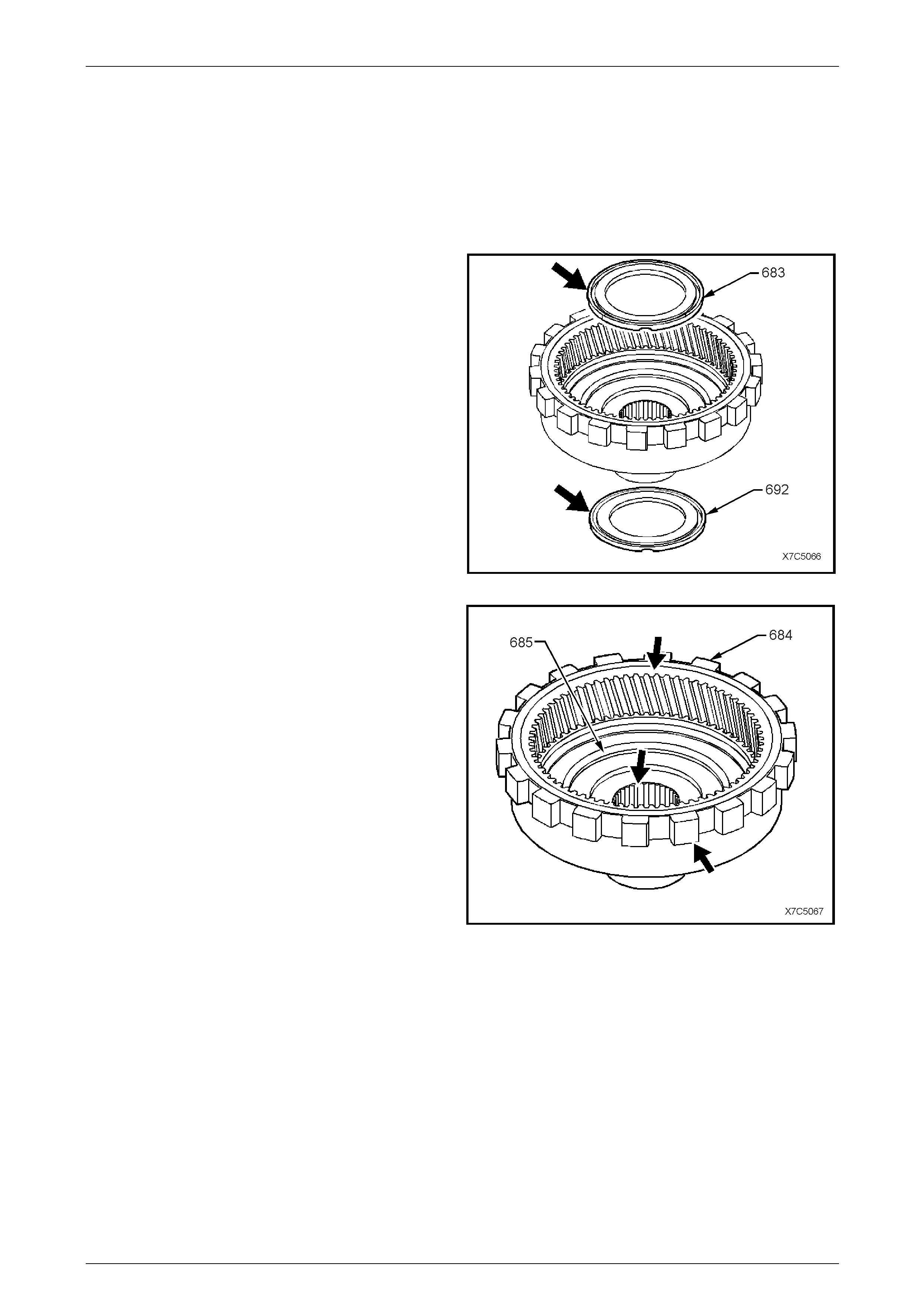
NOTE
Take note of the two thrust bearings orientation
for correct reassembly.
13 Remove the reaction carrier to supp ort thrust
bearing (683), the reaction interna l gear (6 84) and the
support assembly (685).
14 Remove the reaction gear support to case bearing
assembly (692).
Figure 7D5 – 30
7D5 Automatic Transmission – 4L65E – Unit Repair Page 7D5–25
15–DEC–2005 Page 7D5–25
2.11 Low and Reverse Clutch Assembly
LT Section No. — 04–200
Remove
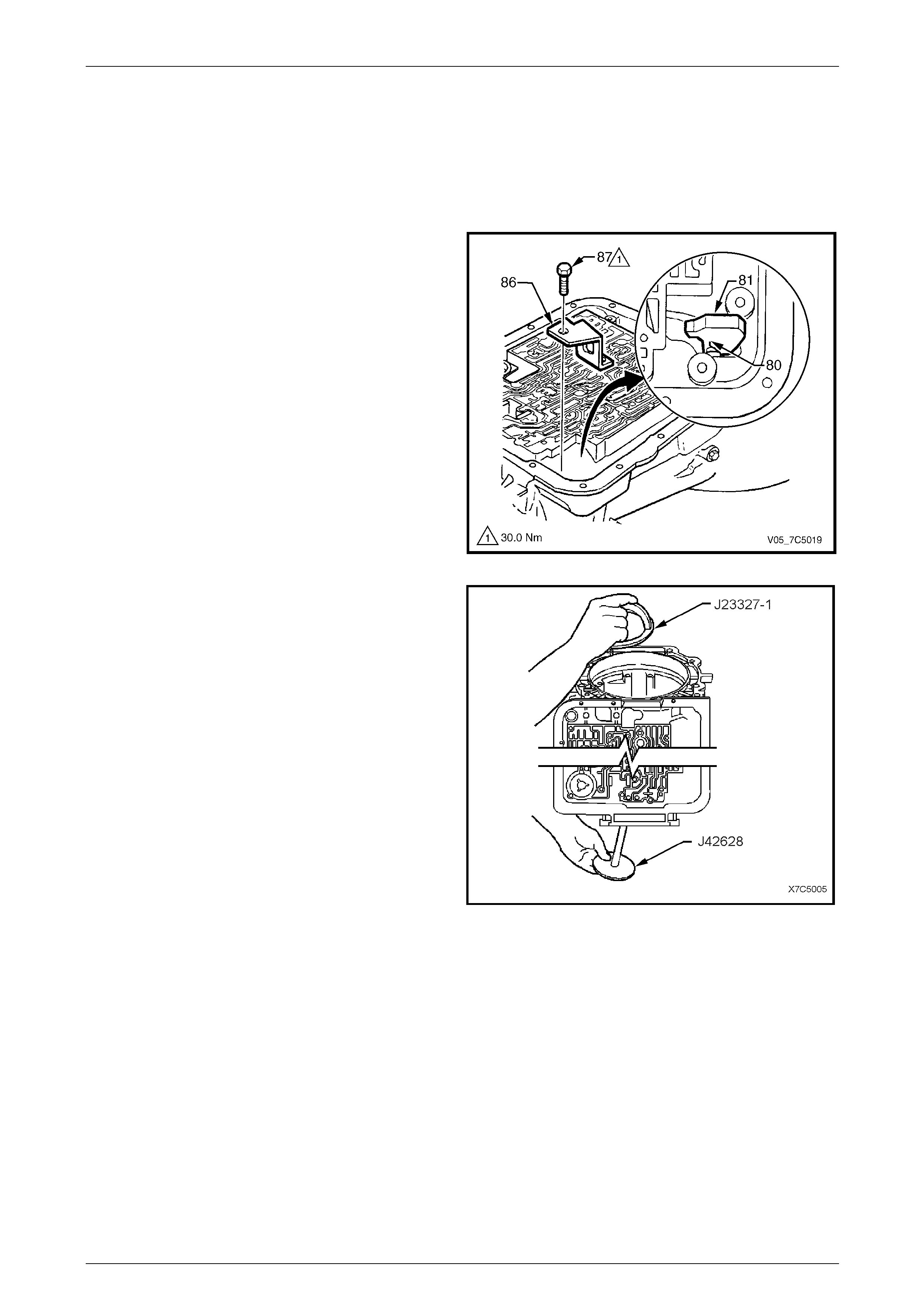
1 Remove the bolt (87), two places, securing the parki ng
pawl bracket (86). This will allow the spring (80) to
retract the parking pawl (81), providing clearance to
remove the low and reverse clutch.
NOTE
If the parking pawl needs to be removed
completely because of interference, follow the
next three steps. Otherwise, continue the
disassembly from step 5.
2 Remove the pawl shaft plug (not shown) with a
suitable screw extractor.
3 Use a magnet to remove the pa wl pivot shaft (not
shown).
4 Remove the parking pa wl bracket, pawl and spring.
Figure 7D5 – 31
5 Install the forcing bolt of Tool No. J23327- 1 through
plate, Tool No. J42628, then install into the rear of the
transmission case.
6 Install the press cage of Tool No. J23327-1 into the
transmission case, over the forcing bolt and secure
with the provided wing nut.
Figure 7D5 – 32
7D5 Automatic Transmission – 4L65E – Unit Repair Page 7D5–26
15–DEC–2005 Page 7D5–26
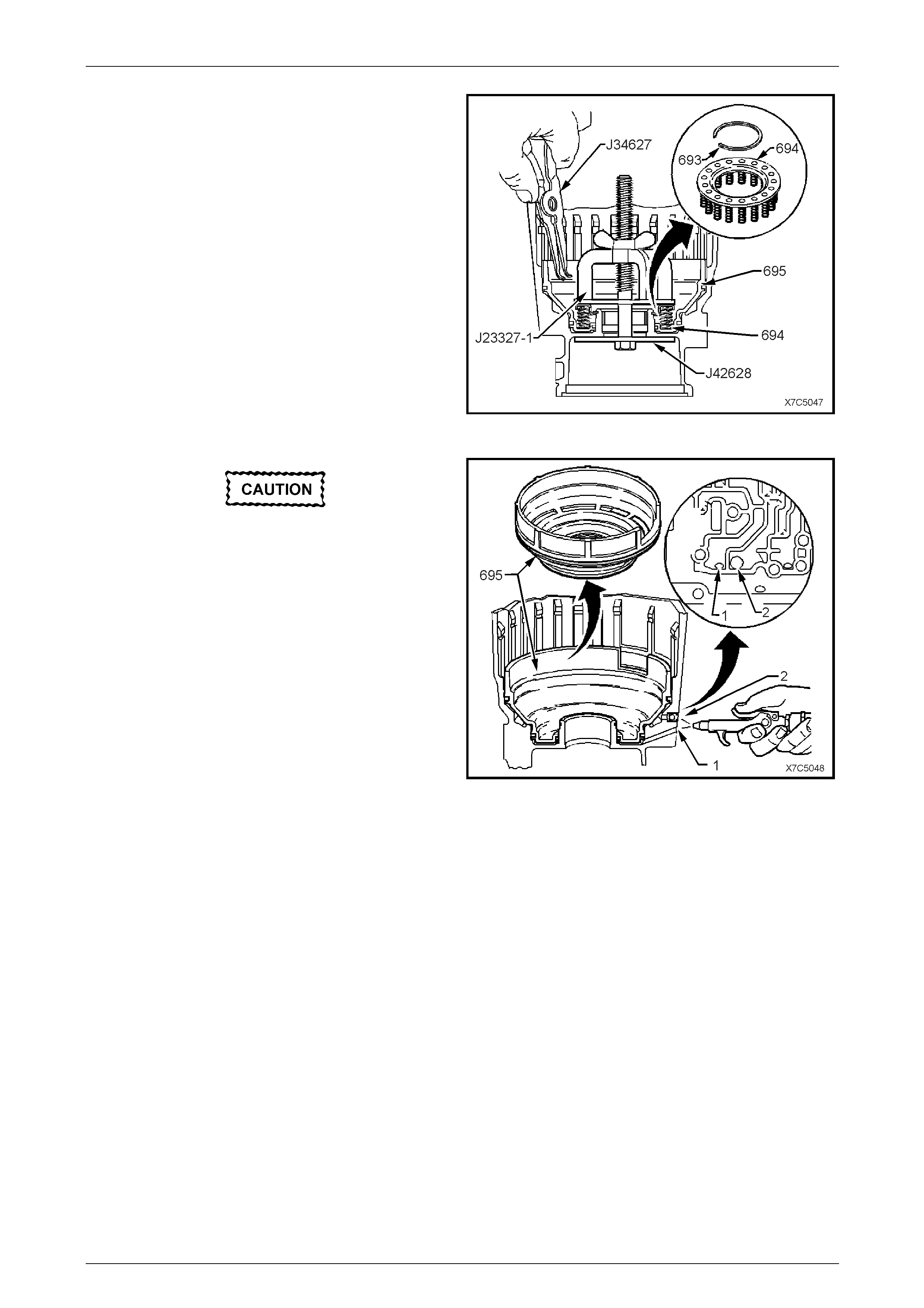
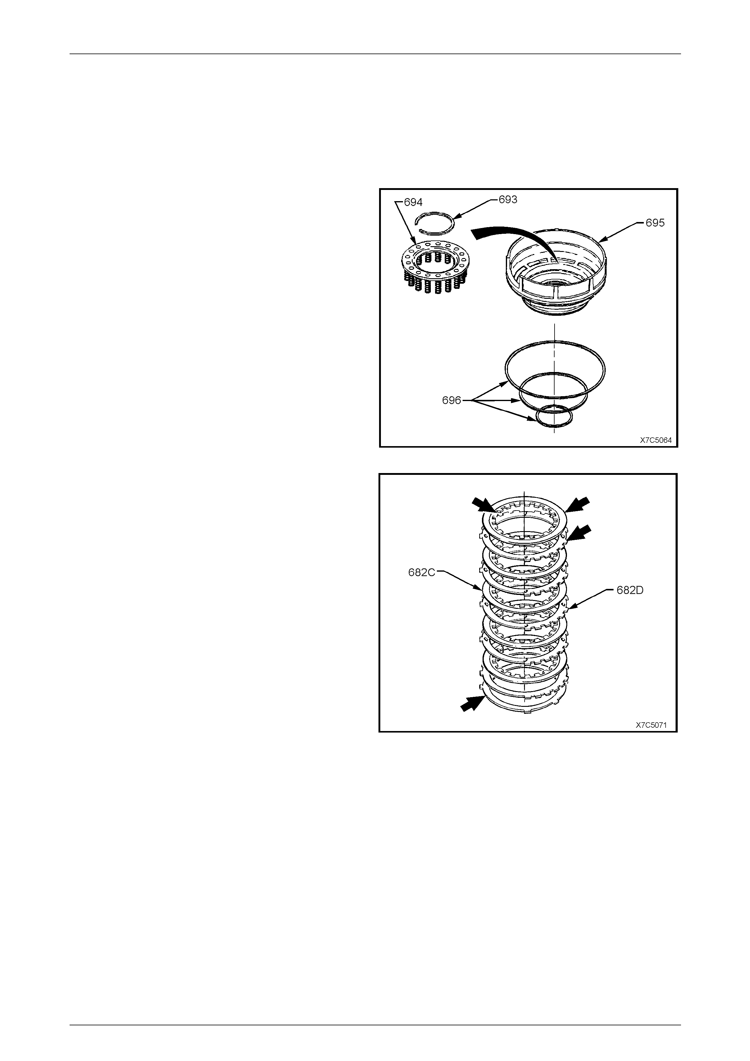
7 Tighten the wing nut of Tool No. J23327-1 to
compress the low and reverse clutch spring s (694)
and clear access to the retaining sna p rin g (6 93).
8 Remove the low and reverse clutch retaining snap
ring (693) using snap ring pliers, Tool No. J34627, or
equivalent.
9 Remove Tool No. J23327-1 and the low and reverse
clutch spring assembly (694).
Figure 7D5 – 33
To reduce the possibility of injury, do not use
air pressure in excess of 70 kPa for this
operation.
10 Apply lo w pressure air to either the low feed
passage (1) or the reverse feed passage (2), as
shown, to assist in the removal of the low and reverse
clutch piston (695) and remove the piston.
Figure 7D5 – 34
7D5 Automatic Transmission – 4L65E – Unit Repair Page 7D5–27
15–DEC–2005 Page 7D5–27
2.12 Manual Shaft, Inner Linkage and Seal
LT Section No. — 04–190
Remove
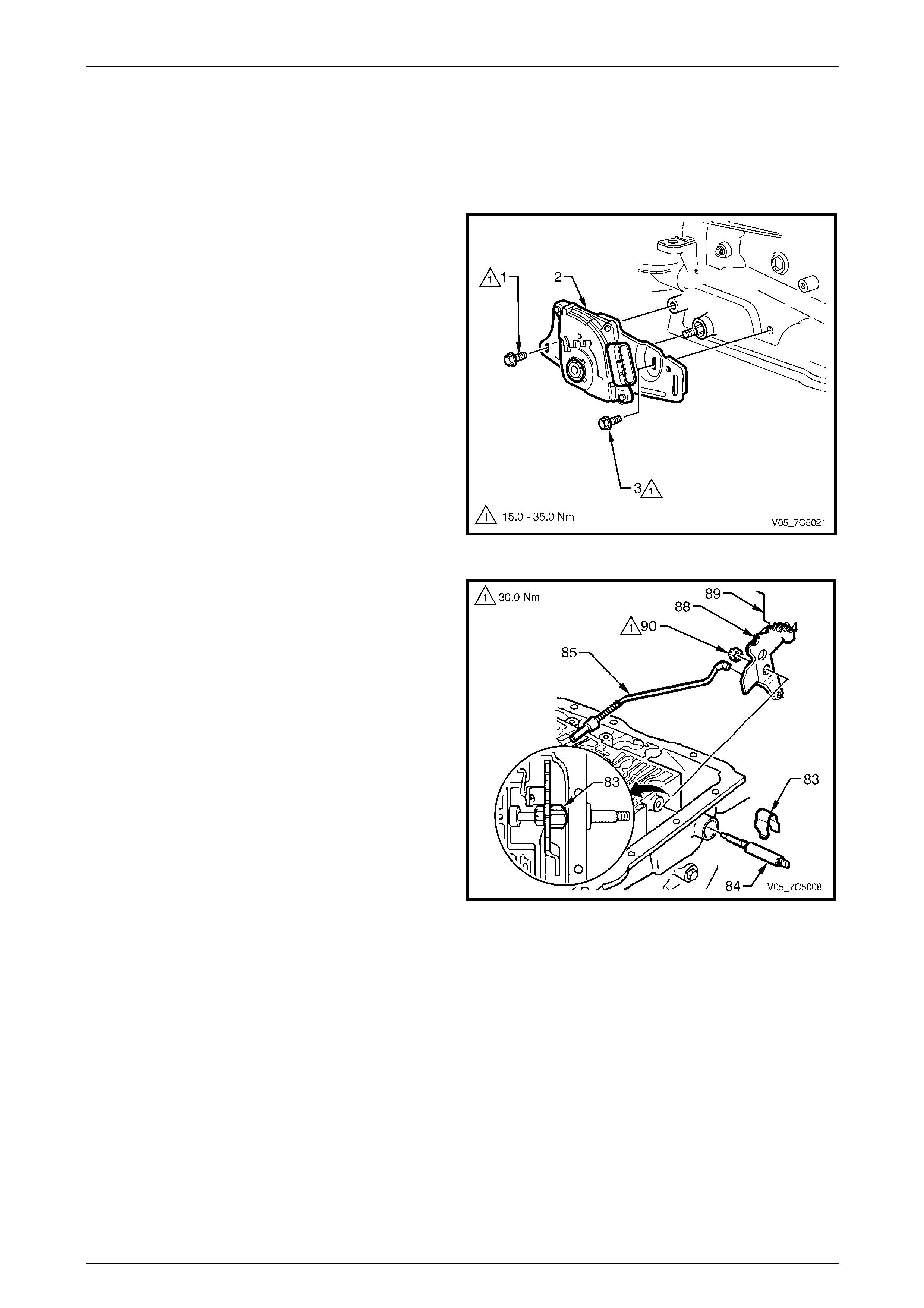
1 Remove the two screws (1 and 3) securing the neutral
start and back-up lamp s witch (2), then remove the
switch from the transmission case.
Figure 7D5 – 35
2 Remove the nut (90) securing the inner detent
lever (88) to the manual shaft (84).
3 Remove the inner detent lever and parking pawl
actuator rod (85).
4 Remove the retaining clip (83) from the manual
shaft (84).
5 Withdraw the manual shaft from the transmission
case.
Figure 7D5 – 36
7D5 Automatic Transmission – 4L65E – Unit Repair Page 7D5–28
15–DEC–2005 Page 7D5–28
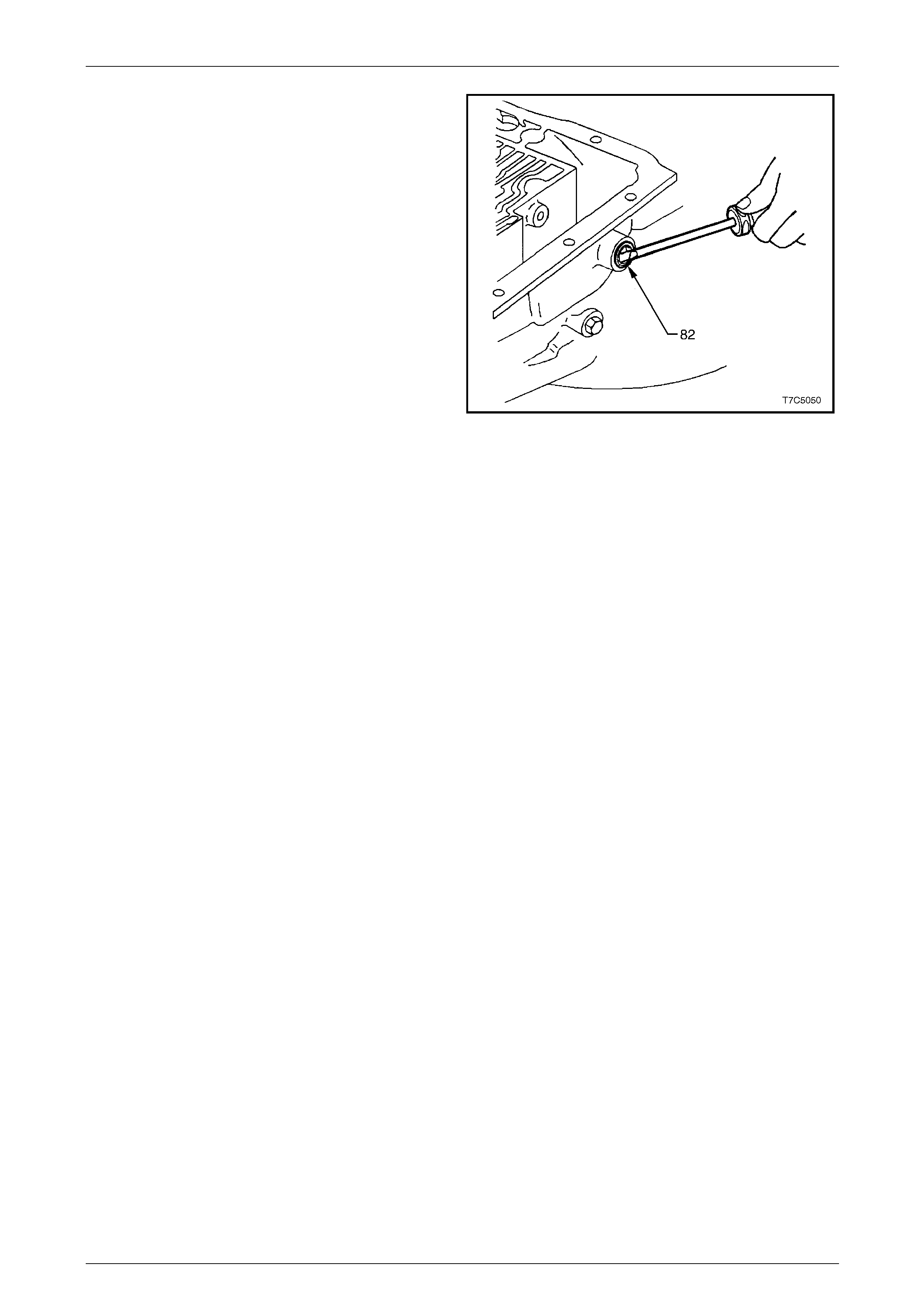
NOTE
An alternative method to remove the seal is to
use special Tool No. AU583 as described in
7D4 Automatic Transmission – 4L65E –
On-vehicle Servicing.
6 Pry out the manual shaft seal (82) from the
transmission case with a suitable screwdriv er.
Figure 7D5 – 37
7D5 Automatic Transmission – 4L65E – Unit Repair Page 7D5–29
15–DEC–2005 Page 7D5–29
3 Component Disassembly,
Inspection, Reassembly
3.1 Transmission Case
LT Section No. — 04–200
Inspect
1 Wash the transmission case thoroughly with solvent,
dry with air and blow out all oil passages.
NOTE
Do not use cloth to dry the transmission case.
2 Inspect the case for cracks or porosity.
3 Check the case to valve body face for damage,
distortion and inter-connected oil passages.
NOTE
Face flatness can be checked by inspecting the
case and spacer plate gasket for complete
witness marks. If the marks are incomplete, an
uneven case surface, or cross chann el leaks are
indicated.
When using compressed air, wear safety
equipment to avoid personal injury.
4 Using compressed air, check all oi l passages. For
identification of the transmission case fluid passages,
refer to Section 7D3 Automatic Transmission – 4L65E
– Hydraulic and Mechanical Diagnosis.
Figure 7D5 – 38
7D5 Automatic Transmission – 4L65E – Unit Repair Page 7D5–30
15–DEC–2005 Page 7D5–30
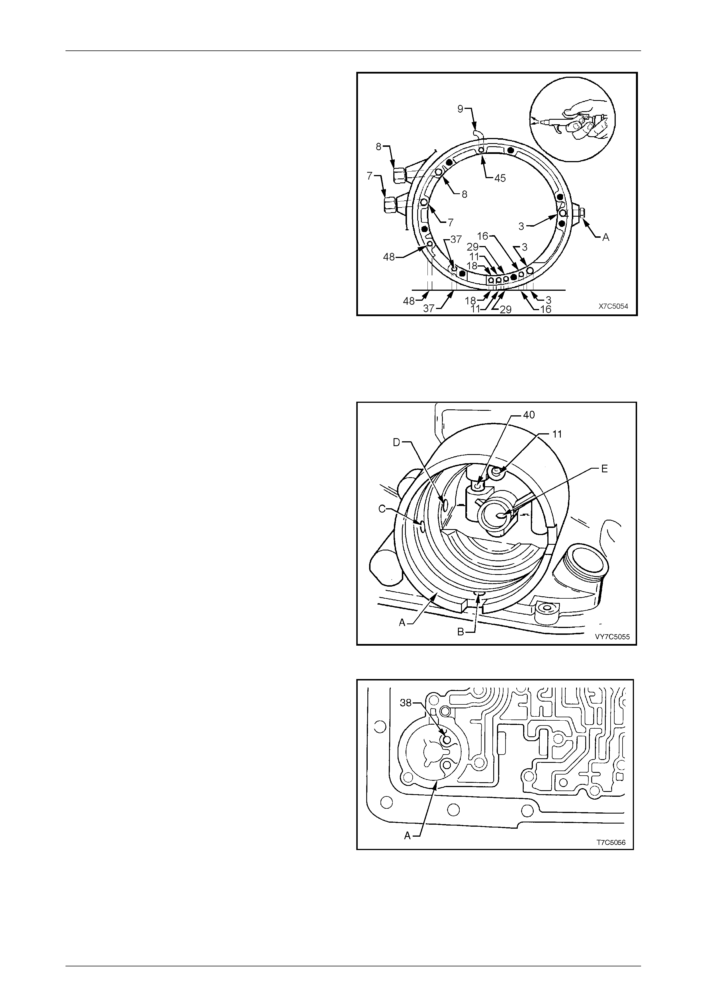
5 Check the vent tube located at the top of the
transmission case (9) for damage and/or blockage.
6 Check the oil pump fluid passages b y blowing low
pressure compressed air into the passages.
Fluid passages identification:
3 line pressure
7 quick connect fitting to external cooler
8 quick connect fitting from external cooler
11 torque signal
16 reverse input clutch
18 forward clutch feed
29 3-4 clutch
37 overrun clutch
45 vent
48 torque converter clutch regul ated apply
A line pressure plug.
Figure 7D5 – 39
7 Inspect the 2-4 servo bore (A) for damage or poros ity.
Ensure all slots and passages are clear, check for
sharp edges. Check the orifice cup plug in the servo
bore (11) for debris or damage.
Bore passages identification:
A 2-4 servo bore
B servo exhaust hole
C 2-4 band apply passage (2nd gear)
D 3rd accumulator pressure tap passage
E 2-4 band apply passage (4th gear)
11 orifice cup plug
40 3rd accumulator retainer and ball assembly.
Figure 7D5 – 40
8 Inspect the 3-4 accumulator bore (A) and orifice cup
plug (38) for damage or porosity. Ensure all slots and
passages are clear, check for sharp edg es. Check for
pin damage.
9 Inspect the vehicle speed sender unit bore for damage
or porosity.
10 Inspect all bolt holes and oil cooler pipe connections
for thread damage. Repair with thread inserts or
equivalent, as necessary.
Figure 7D5 – 41
7D5 Automatic Transmission – 4L65E – Unit Repair Page 7D5–31
15–DEC–2005 Page 7D5–31
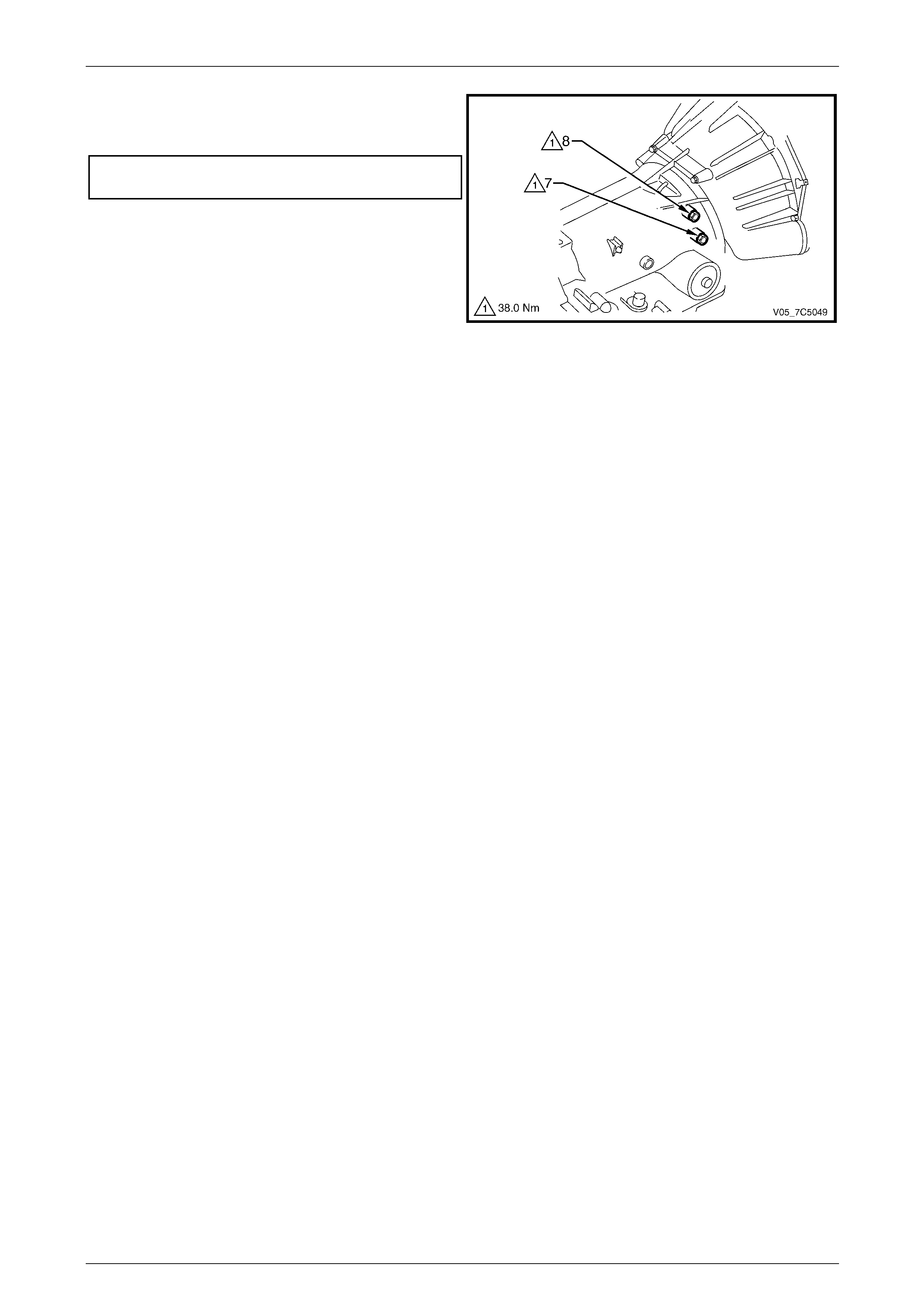
11 If removed, refit and tighten the oil cooler pipe quick
connect fittings (7 and 8) to the correct torque
specification.
Oil cooler pipe quick connect fitting
torque specification............................................38.0 Nm
Figure 7D5 – 42
12 Inspect the case interior for:
a damaged ring grooves or casting flash,
b clutch plate lugs worn or damage d,
c worn or damaged bushes.
7D5 Automatic Transmission – 4L65E – Unit Repair Page 7D5–32
15–DEC–2005 Page 7D5–32
3.2 Third Accumulator Retainer and Ball
Assembly
LT Section No. — 04–200
Inspect
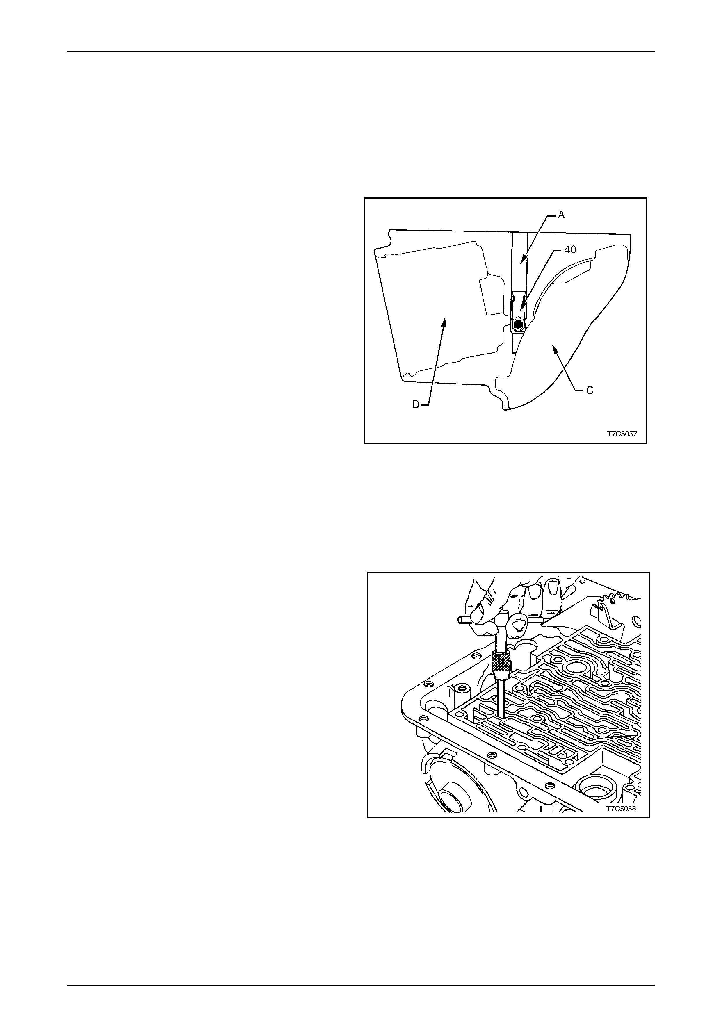
1 Inspect the third accumulator ball and retainer (40) for:
a ball missing, damaged or sticking
b retainer loose or not seated correctly
c feed slots restricted.
2 Check the third accumulator ball ass embl y for leakage
as follows:
a Reinstall the assembled 2-4 s ervo components,
including cover and retaining ring, into the 2-4
servo bore (D).
b Pour a suitable solvent into the third accumul ator
bore (A).
c Watch for leakage into the case interior (C).
NOTE
Because fluid will flow from the orific e in the case
servo plug (11), careful observation of the fluid
leakage source will be required, refer to Figure
7D5 – 40.
d Remove the 2-4 servo components.
Figure 7D5 – 43
Replace
If leakage is coming from the third accumulator bal l
assembly, replace as follows:
1 Remove the old assembly with a suitab le screw
extractor (6.3 mm or #4).
Figure 7D5 – 44
7D5 Automatic Transmission – 4L65E – Unit Repair Page 7D5–33
15–DEC–2005 Page 7D5–33
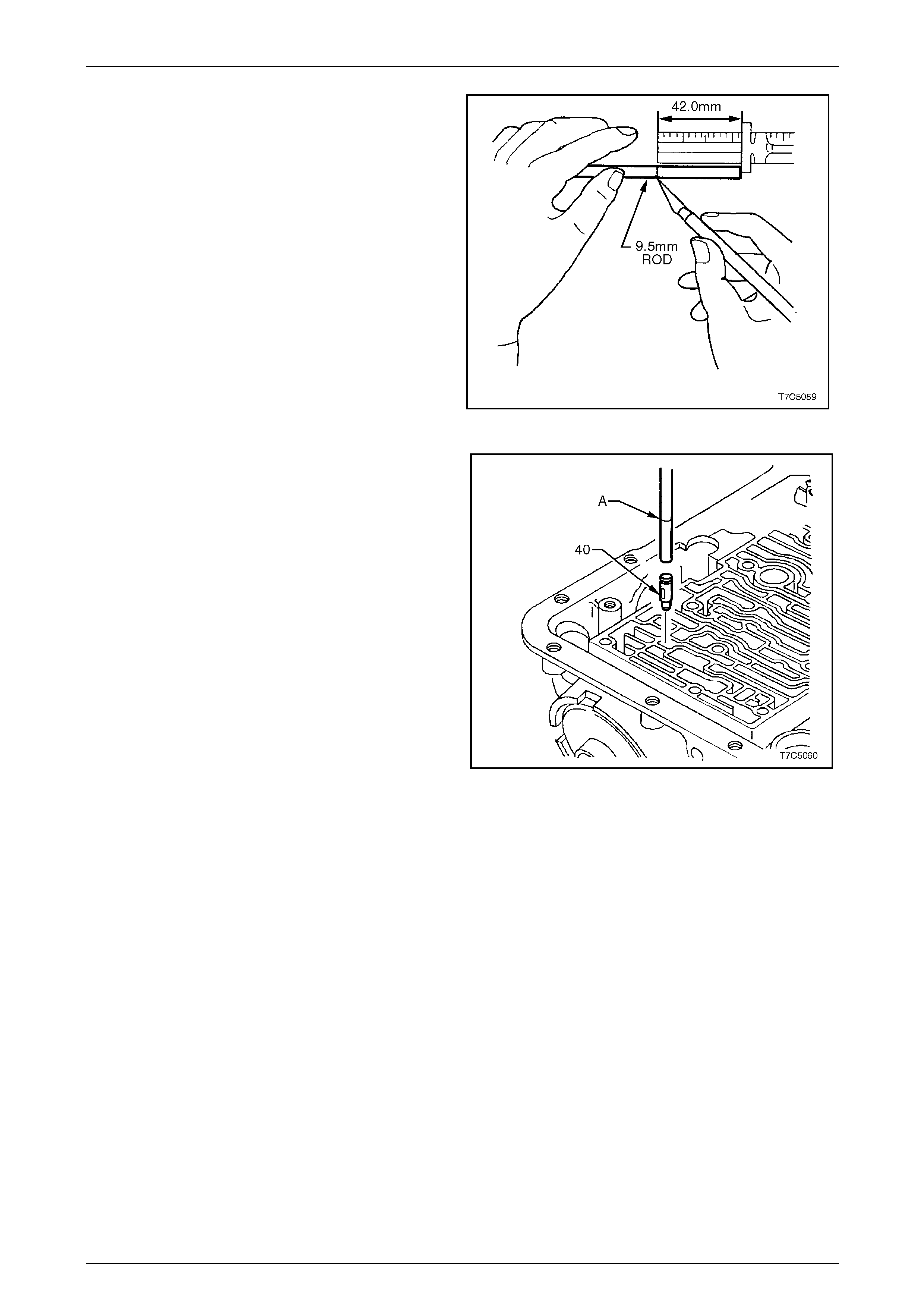
2 Select a suitable length of 9.5 mm rod and scribe a
mark, 42 mm from its squared end, to indicate the
correct depth of installation.
Figure 7D5 – 45
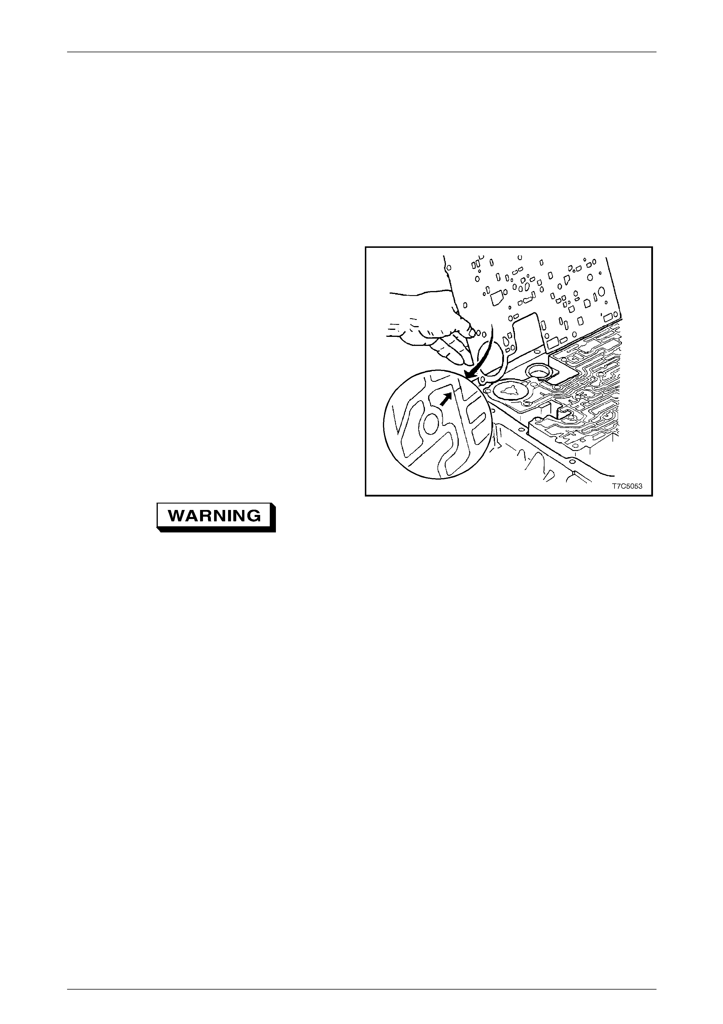
3 Using the 9.5 mm rod, install a new 3rd accumulator
retainer and ball check assem bly (40).
4 Align the oil feed slots with the servo bore (40), refer to
Figure 7D5 – 40.
5 Install the 3rd accumulator ball and retainer assembly
until the scribe mark (A) on the rod, is level with the
case face.
Figure 7D5 – 46
7D5 Automatic Transmission – 4L65E – Unit Repair Page 7D5–34
15–DEC–2005 Page 7D5–34
3.3 Transmission Case Bush
LT Section No. — 04–200
Replace
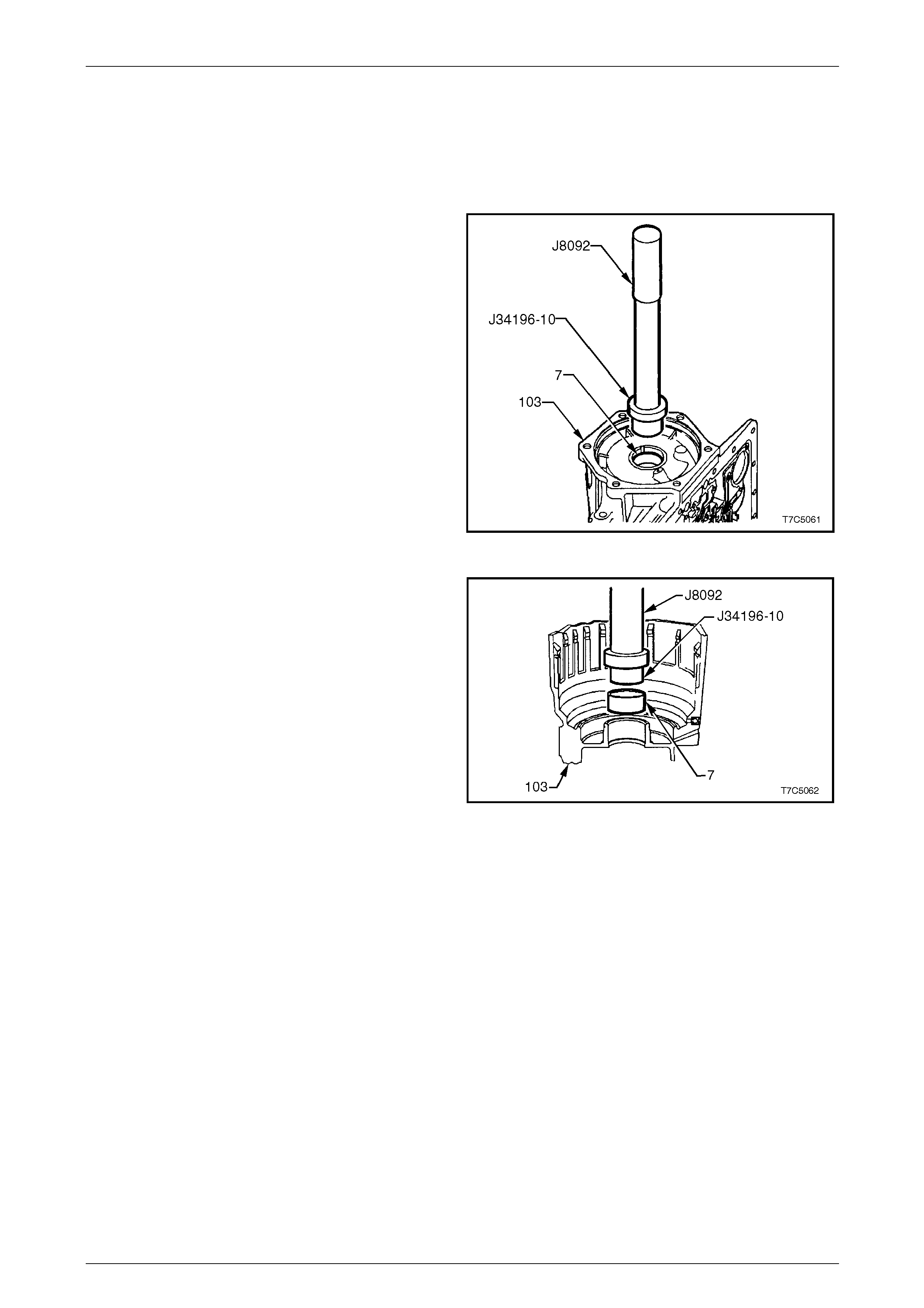
1 Using the bush remover, T ool No. J34196-10 (part of
set, Tool No. J34196-B) and driver handle, Tool No.
J8092, press the rear bush from the transmission
case (103).
Figure 7D5 – 47
2 Install a new bush (7) into the transmission case (103)
using the same tools as for removal.
Figure 7D5 – 48

7D5 Automatic Transmission – 4L65E – Unit Repair Page 7D5–35
15–DEC–2005 Page 7D5–35
3.4 2-4 Servo Assembly
LT Section No. — 04–200
Inspect
1 Inspect components for wear or damage, check springs for broken coils and/or distortion. For parts identif ication,
refer to 2.2 2 – 4 Servo Assembly.
2 Inspect bore in transmission case for any sharpn ess that may damage servo seals.
7D5 Automatic Transmission – 4L65E – Unit Repair Page 7D5–36
15–DEC–2005 Page 7D5–36
3.5 Low and Reverse Clutch Assembly
LT Section No. — 04–200
Inspect
1 Inspect the piston (695) for porosit y or damage.
2 Inspect the spring assembly (694) for damage.
3 Inspect the retaining ring (693) for distortion.
4 Remove the piston seals (696) and discard. Lubricate
new seals with transmission fluid and i nstall on piston.
Figure 7D5 – 49
5 Inspect the low and reverse clutch plates as follows:
a Check the composition plates (682C) for wear,
heat damage or delami nation.
b Check the steel plates (682D) for heat dam age
or surface finish damage.
Figure 7D5 – 50
7D5 Automatic Transmission – 4L65E – Unit Repair Page 7D5–37
15–DEC–2005 Page 7D5–37
Spacer Plate Selection
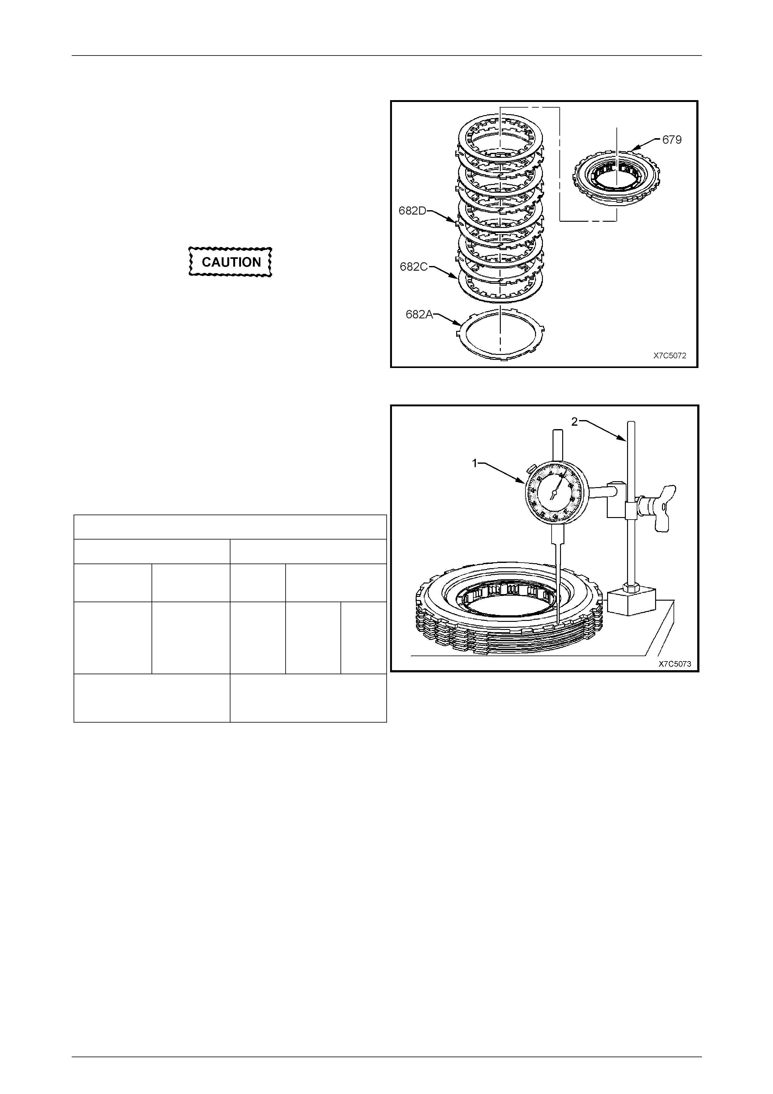
1 Stack the low and reverse clutch plates on a flat
surface in the following order:
a one waved plate (682A),
b five fibre plates (682C) and four steel
plates (682D), starting with a fibre (composition)
plate and alternating with a steel plate, etc.
c low and reverse clutch support (679).
Excessive pressure will start to flatten the
wave plate, resulting in an incorrect
measurement.
2 Apply a light (approx. 2 kg), evenl y distributed load to
the low and reverse support assembly.
Figure 7D5 – 51
3 Using a commerciall y available dial indicator (1) and
magnetic stand (2), measure height of plates pack
from work surface to top of low and reverse clutch
support, noting the dimension, with the light load
applied.
4 Use the following selection chart to select the correct
spacer plate, relative to the measured height.
Low and Reverse Clutch Sp acer Plate Selection
If pack height is Use this selective plate
From (mm) To (mm) Identity Plate thickness
(mm)
27.54
28.06
27.03
28.06
28.59
27.54
None
0
1
1.68
1.17
2.20
1.83
1.31
2.34
Overall clutch pack height
(including spacer plate)
29.22 – 29.90 mm
NOTE
When referring to the above Selection Chart:
• The selective plate shown as 'None' refers to
a fifth, steel reaction plate, which is to be
used as the spacer plate.
• Should a measurement fall in an overlap,
either the thinner or thicker selective plate
can be fitted.
• Regardless of the combinations used, the
critical specification that must be achi eved, is
the overall clutch pack height (including the
spacer plate), which is to be between
29.22 mm and 29.90 mm.
5 Install the correct spacer plate bet ween the wave plate
and first composition clutch plate with identification
side facing upwards.
Figure 7D5 – 52
7D5 Automatic Transmission – 4L65E – Unit Repair Page 7D5–38
15–DEC–2005 Page 7D5–38
3.6 Low and Reverse Clutch
LT Section No. — 04–200
Support Assembly
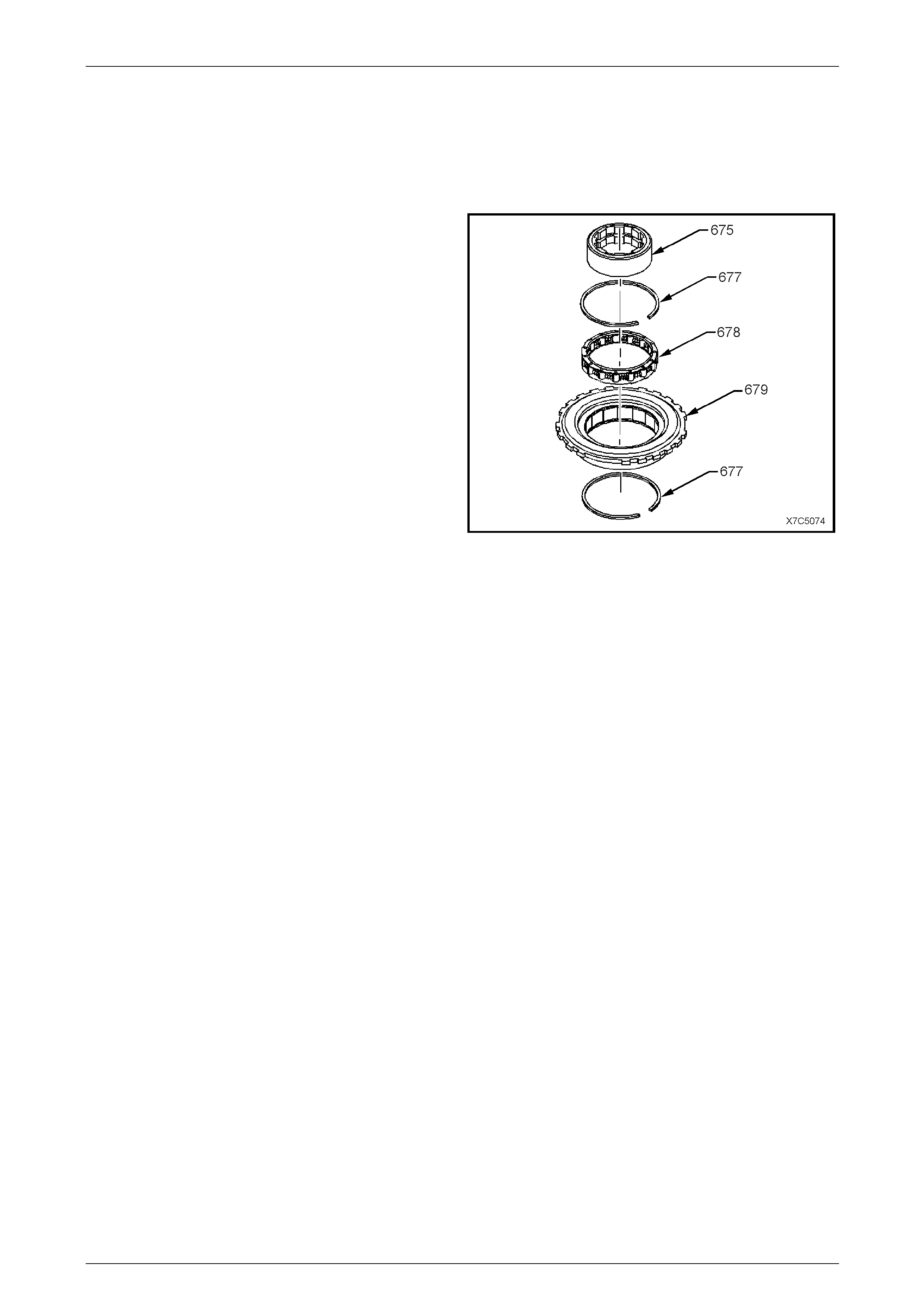
1 Disassemble the low and rev erse sup port assembly as
follows:
a remove inner race (675),
b remove one retaining ring (677) and
c remove roller clutch assembly (678).
2 Inspect the inner race for damage.
3 Inspect roller clutch assembly for damaged rollers or
broken springs.
4 Inspect the support assembly for loose cams, cracks
or damage.
NOTE
The low and reverse support assembly is
reassembled during transmission reassembly,
refer to 4.4 Low and Reverse Clutch P lates and
Support Assembly. Figure 7D5 – 53
7D5 Automatic Transmission – 4L65E – Unit Repair Page 7D5–39
15–DEC–2005 Page 7D5–39
3.7 Reaction Internal Gear and Carrier
Assembly
LT Section No. — 04–200
Inspect
1 Inspect both the reaction to support thrust bearing
assembly (683) and the reaction gear to support case
bearing assembl y (692) for da mage.
Figure 7D5 – 54
2 Inspect the reaction internal gear (684) and
support (685) for correct assembly, stripped splines,
cracks, teeth or lug damage.
Figure 7D5 – 55
7D5 Automatic Transmission – 4L65E – Unit Repair Page 7D5–40
15–DEC–2005 Page 7D5–40
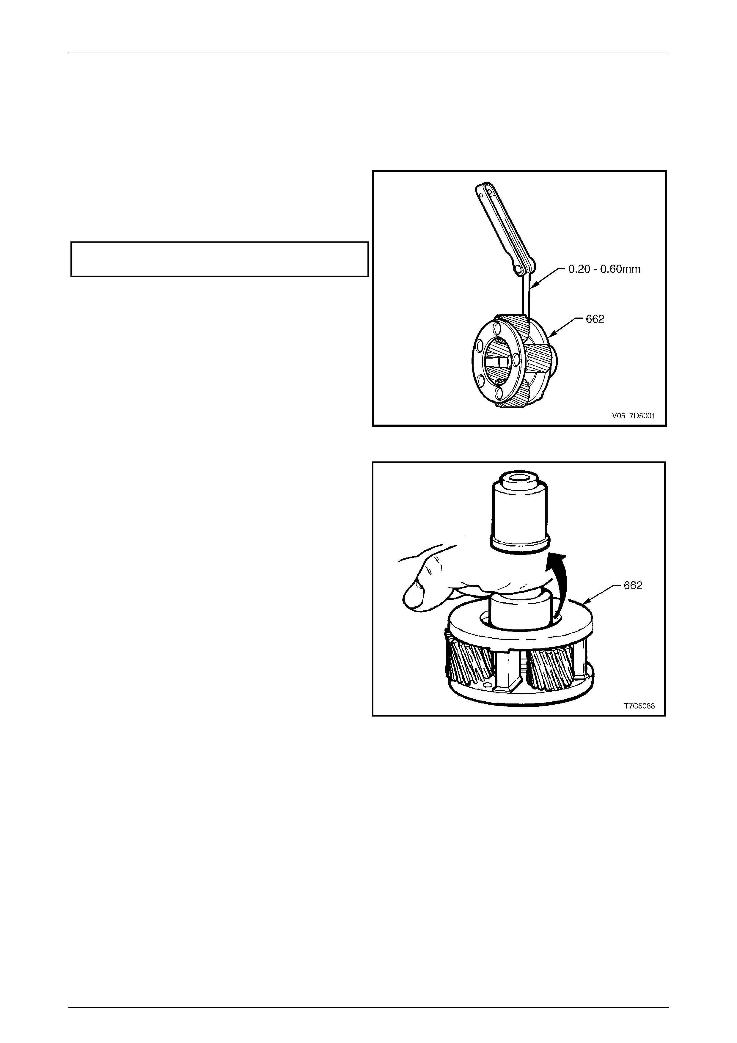
3 Inspect the reaction carrier assembly (681) for pin ion
gear wear, proper pinion staking an d free turning of
pinions.
4 Check for excessive pinion washer wear by measuring
pinion end play. End play should be 0.20 to 0.60 mm.
The reaction carrier assembly is serviced a s a
complete assembly and should be replaced if worn or
defective.
Figure 7D5 – 56
5 Check the carrier assembly captive thrust be aring
(lower arrow) as follows:
a Place a suitable bush (or socket) on bearing race
(do not contact pinion gears) and turn the bush
with the palm of your hand.
b Any imperfections will be felt through the bush.
Figure 7D5 – 57
7D5 Automatic Transmission – 4L65E – Unit Repair Page 7D5–41
15–DEC–2005 Page 7D5–41
3.8 Reaction Sun Gear and Shell
LT Section No. — 04–200
Inspect
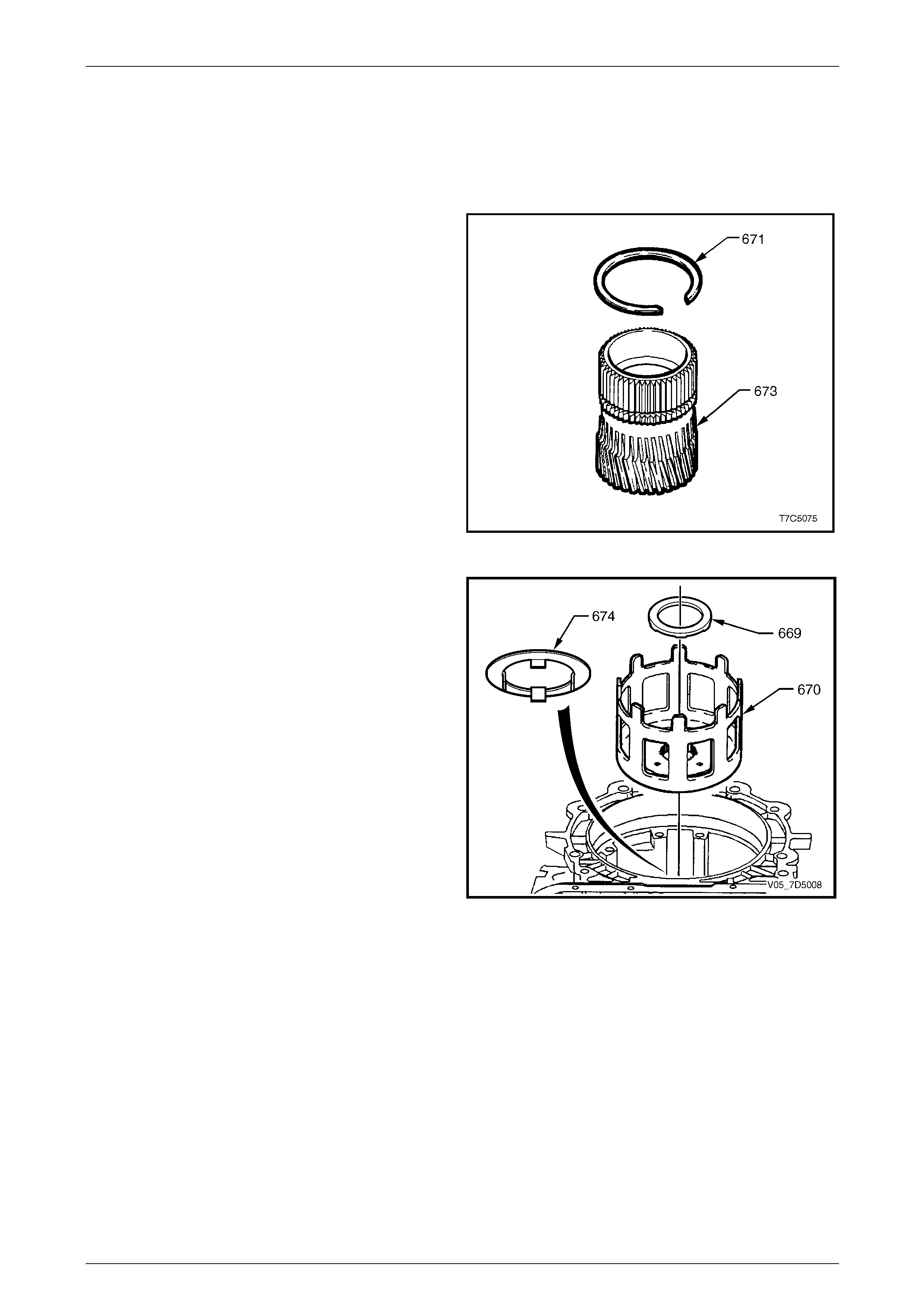
1 Inspect the reaction sun gear (673) for damage to the
bush, spline or teeth, loose or weak retaining ring. Do
not remove the snap ring (671) except for
replacement.
Figure 7D5 – 58
2 Inspect the reaction sun shell (670) for damage or
wear to tangs.
3 Inspect the thrust bearing (669) and thrust
washer (674) for wear or damage.
Figure 7D5 – 59
7D5 Automatic Transmission – 4L65E – Unit Repair Page 7D5–42
15–DEC–2005 Page 7D5–42
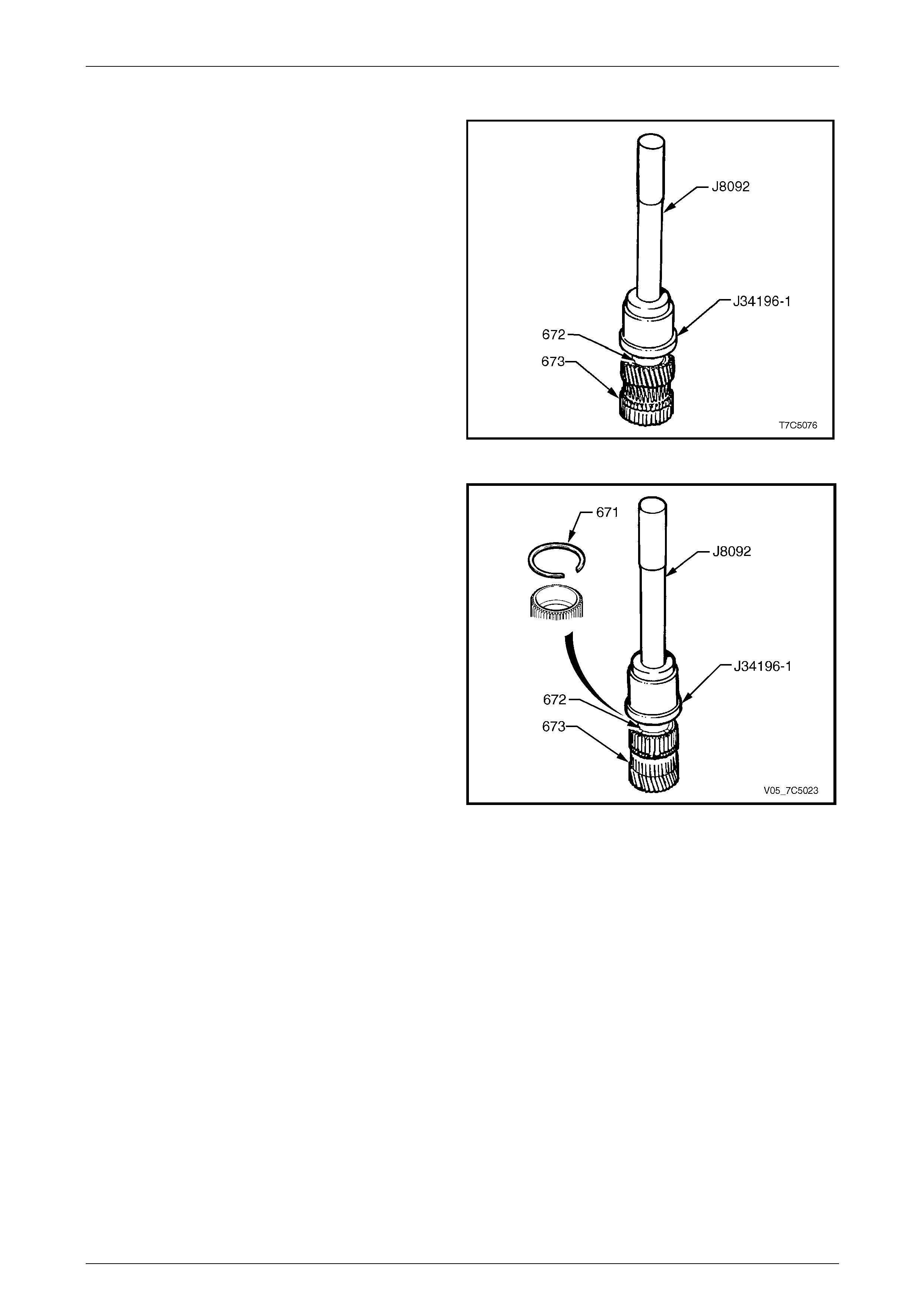
Sun Gear Bush – Replace
1 If the sun gear bush (672) requires replacement, use
the bush remover, Tool No. J34196-1 ( part of kit, T ool
No.J34196-B) and driver handle, Tool No. J8092, to
press the bush from the gear (673).
Figure 7D5 – 60
2 Install a replacement bush (672) using the same tools
used for removal but press the bush in from the other
side of the sun gear (673), as shown.
3 If required, install a new retaining ring (671) to the sun
gear.
Figure 7D5 – 61
7D5 Automatic Transmission – 4L65E – Unit Repair Page 7D5–43
15–DEC–2005 Page 7D5–43
3.9 Input Internal Gear and Output Shaft
LT Section No. — 04–200
Inspect
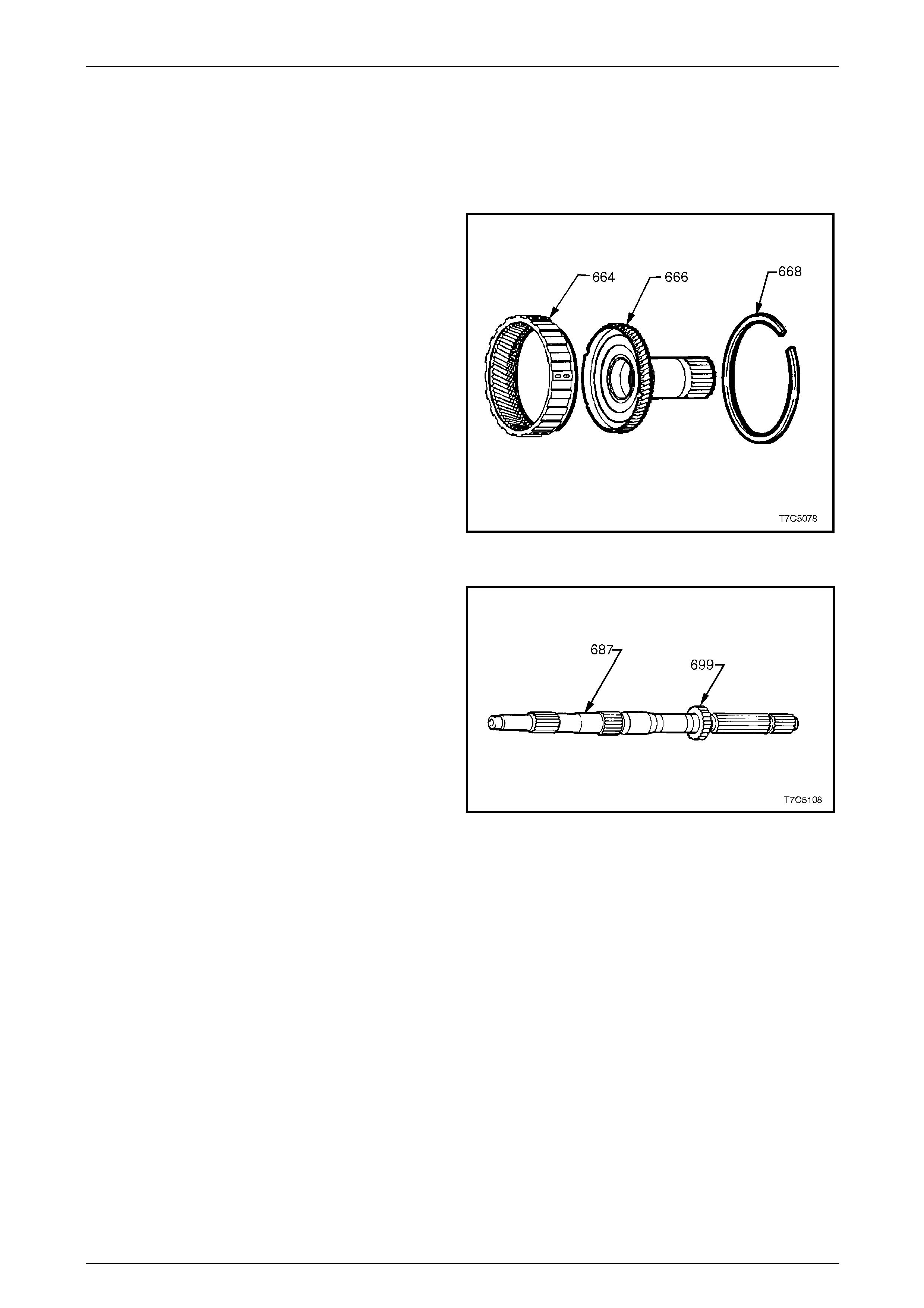
1 Remove the retaining ring (668) from the input internal
gear (664).
2 Remove the reaction carrier shaft (666) from the input
internal gear and inspect the shaft for the following:
• damaged or worn bushes,
• cracks,
• damaged spline or gear teeth and
• undercutting around shaft from interferenc e wit h
sun gear.
3 Inspect the input internal gear (664) for cracked or
damaged splines or gear teeth.
4 Inspect the carrier to reaction shaft thrust bearing (not
shown) for wear or damage.
5 If all parts are serviceable, reassemble the reactio n
carrier shaft (666) into the input internal gear (664)
and install the retaining ring (668). Figure 7D5 – 62
6 Inspect the transmission output shaft (687) for the
following:
• blocked or restricted lube p assages,
• damage to splines or ring groove,
• burrs or damage to bearing journals,
• burrs or damage to extension housing seal
surface (polish with crocus cloth if necessary),
• tooth damage to transmission output shaft
sensor rotor (699).
Figure 7D5 – 63
7D5 Automatic Transmission – 4L65E – Unit Repair Page 7D5–44
15–DEC–2005 Page 7D5–44
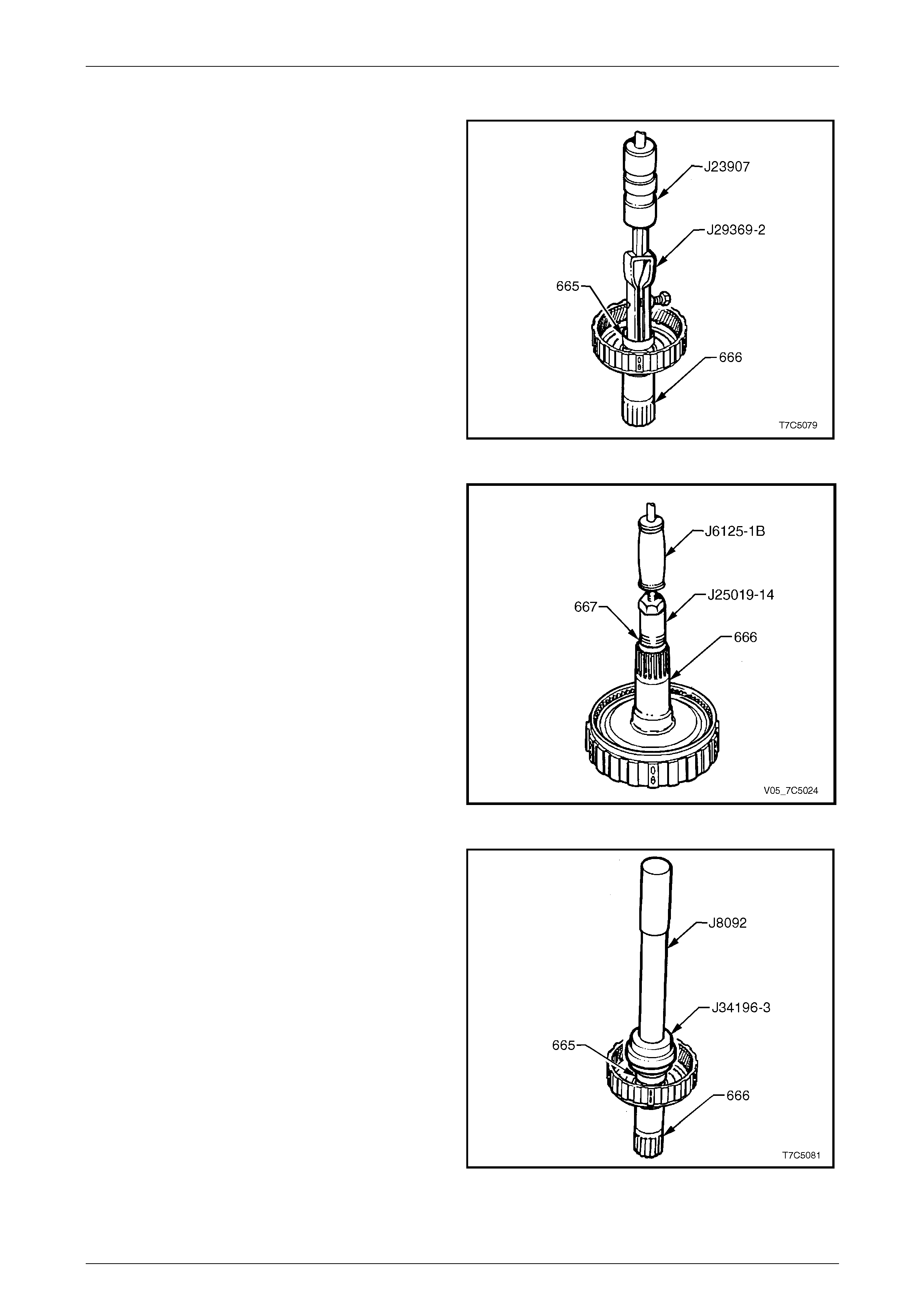
Reaction Carrier Shaft Bushes – Replace
1 Using the universal bush remover, T ool No. J29369-2
and slide hammer, Tool No. J239 07, or equivalent,
remove the front bush (665) from the reaction carrier
gear shaft (666).
Figure 7D5 – 64
2 Remove the rear bush (667) from the reaction carrier
gear shaft (666) using the bush puller, Tool No.
J25019-14 and slide hammer, Tool No. J6125-1B, or
equivalent.
Figure 7D5 – 65
3 Install the front bush (665), using bush installer, Tool
No. J34196-3 (part of kit Tool No. 34196-B) and driver
handle, Tool No. J8092.
Figure 7D5 – 66
7D5 Automatic Transmission – 4L65E – Unit Repair Page 7D5–45
15–DEC–2005 Page 7D5–45
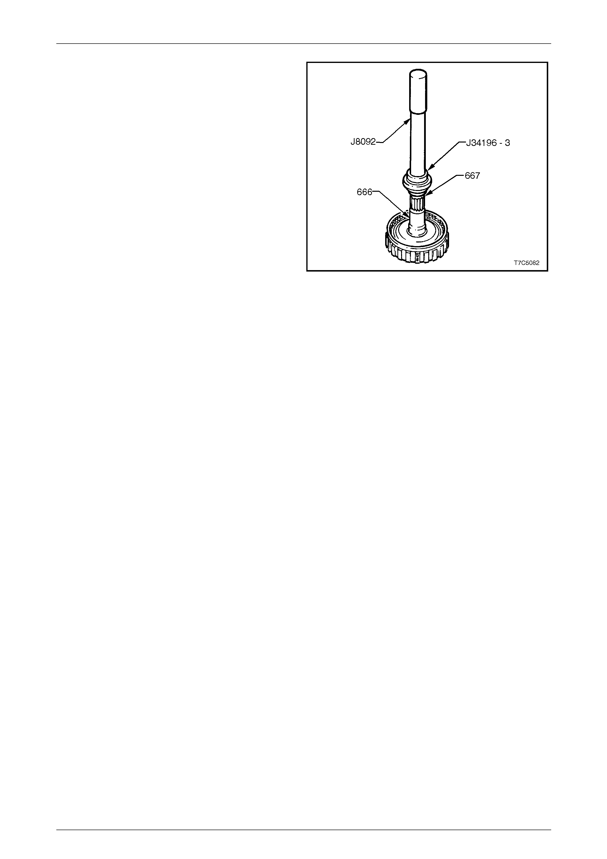
4 Install the rear bush (667), using bus h installer, Tool
No. J34196-3 (part of kit Tool No. 34196-B) and driver
handle, Tool No. J8092.
Figure 7D5 – 67
7D5 Automatic Transmission – 4L65E – Unit Repair Page 7D5–46
15–DEC–2005 Page 7D5–46
3.10 Transmission Output Speed Sensor Ring
LT Section No. — 04–200
Replace
NOTE
Normally this operation is not necessary and
should only be carried out, if inspection of the
speed sensor ring (699) reveals tooth damage
has occurred. Once removed, the ring must be
replaced and not re-used.
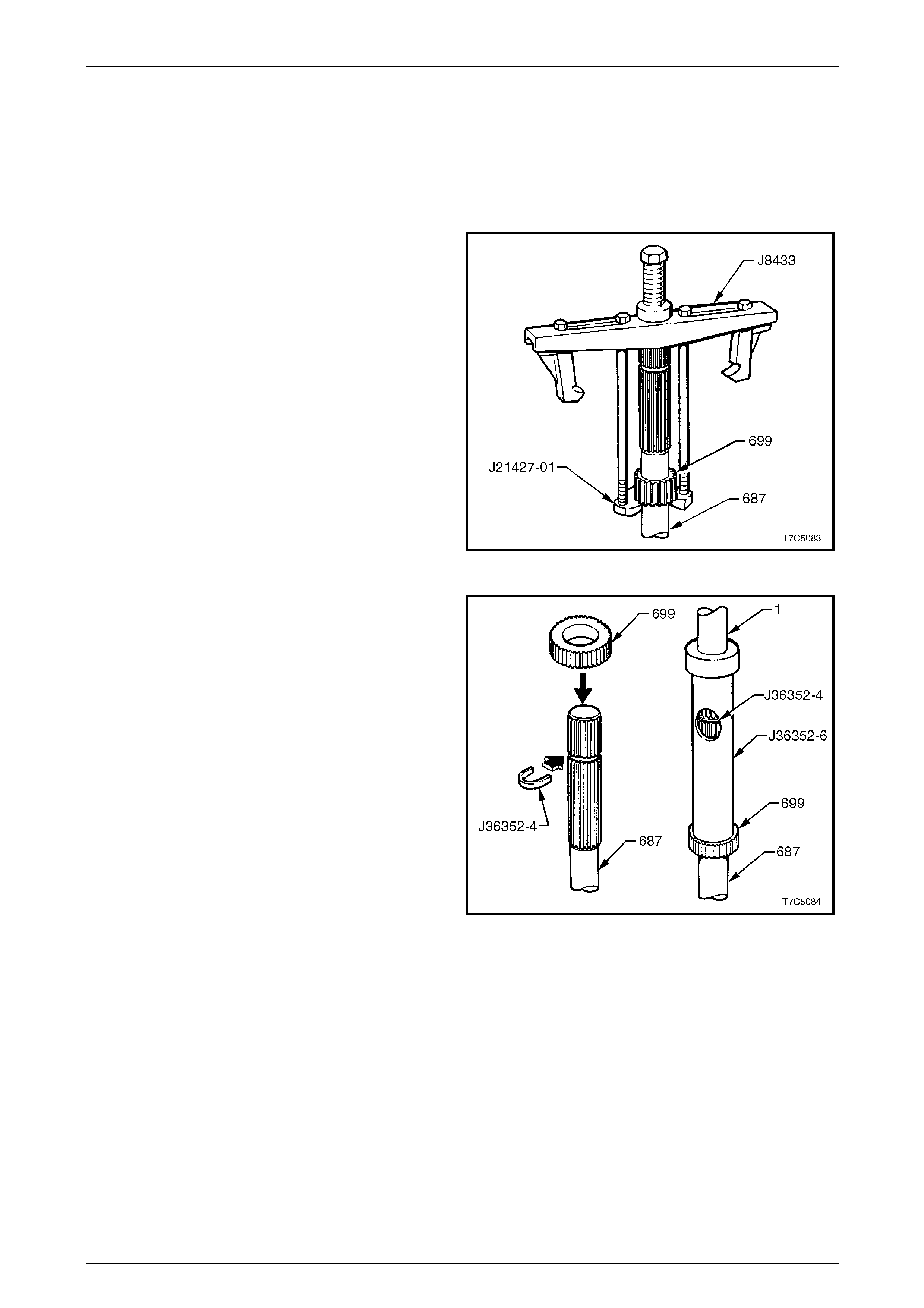
1 Using Tool Nos J8433 and J21427-01, remove the
speed sensor ring (699) from the output shaft (687).
Figure 7D5 – 68
2 Place a new speed sensor ring (699) over the
transmission output shaft (687).
3 Insert the C-washer, Tool No. J36352-4, into the
groove on the transmission output shaft (687).
4 Place Tool No. J36352-6 over the output shaft and
press the sensor ring onto the output shaft until the
tube contacts the C-washer, in the window.
Figure 7D5 – 69
7D5 Automatic Transmission – 4L65E – Unit Repair Page 7D5–47
15–DEC–2005 Page 7D5–47
3.11 Input Carrier and Sun Gear
LT Section No. — 04–200
Inspect
1 Inspect the carrier assembly (662) for pini on gear
wear, proper pinion staking and free turning of pinions.
2 Check for excessive wear of pinion washer by
measuring the pinion end play.
Pinion gear end play
specification........................................... 0.20 – 0.60 mm
NOTE
The input carrier assembly is serviced as a
complete assembly and must be replaced if
components are worn or defective.
Figure 7D5 – 70
3 Check the carrier assembly captive thrust be aring as
follows:
a Place a suitable bush (or socket) on the bearing
race (do not contact the pinion gears) and turn
the bush with the palm of your hand.
b Any imperfections will be felt through the bush.
Figure 7D5 – 71
7D5 Automatic Transmission – 4L65E – Unit Repair Page 7D5–48
15–DEC–2005 Page 7D5–48
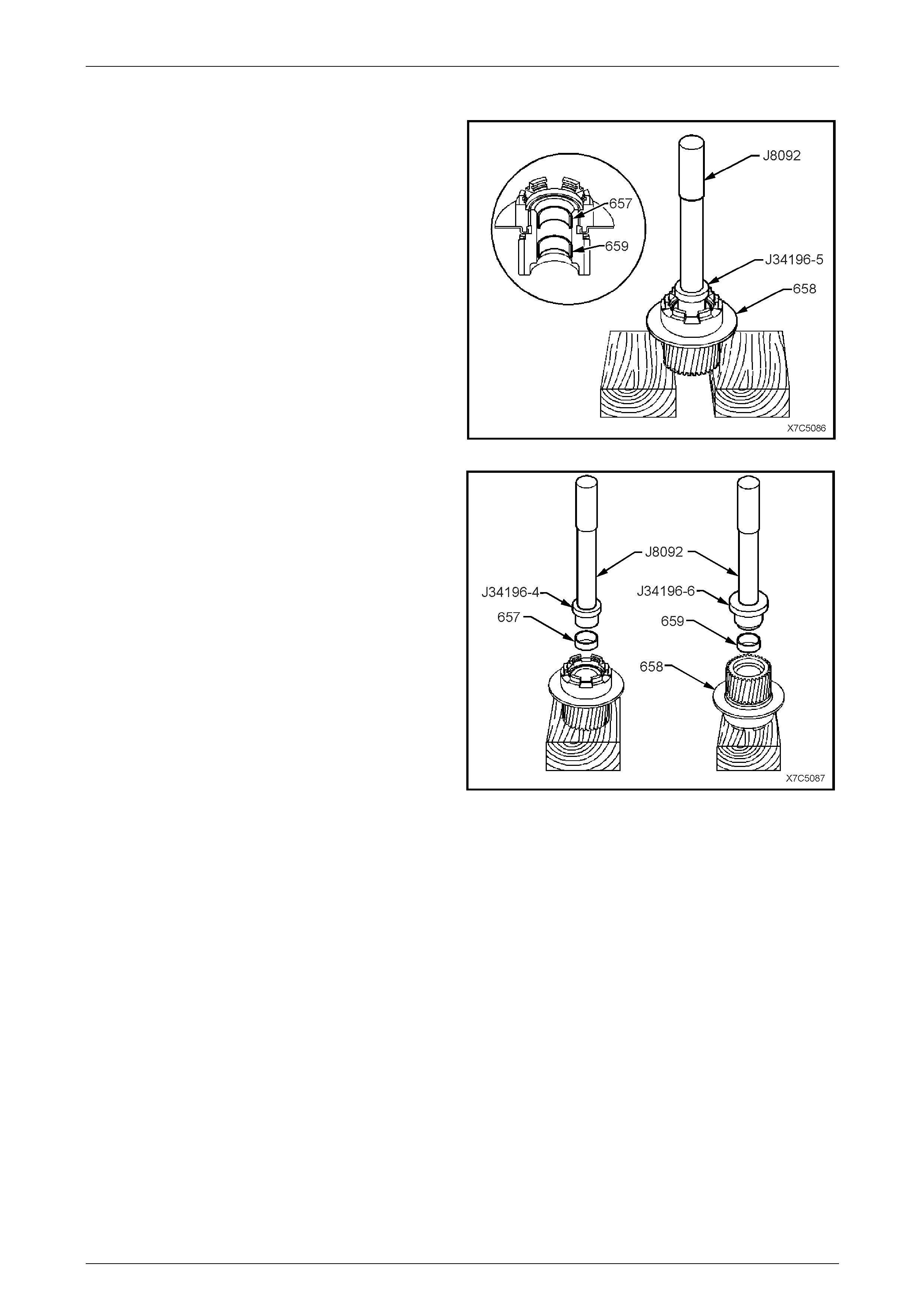
Input Sun Gear Bushes – Replace
1 Using the bush remover, T ool No. J34196-5, (part of
kit, Tool No. J34196-B) and driver handle, Tool No.
J8092, press both sun gear bushes (657 and 659)
from the gear (658).
Figure 7D5 – 72
2 Press the front sun gear bush (657) into the
gear (658), using Tool No. J34196-4 (part of kit, Tool
No. J34196-B) and driver han dle, Tool No. J8092.
3 Press the rear sun gear bush (659) into the g ear,
using Tool J34196- 6 (part of kit, T ool No. J34196-B)
and driver handle, Tool No. J809 2.
Figure 7D5 – 73

7D5 Automatic Transmission – 4L65E – Unit Repair Page 7D5–49
15–DEC–2005 Page 7D5–49
3.12 Input Clutch Housing Assembly
LT Section No. — 04–200
Exploded View
Figure 7D5 – 74
7D5 Automatic Transmission – 4L65E – Unit Repair Page 7D5–50
15–DEC–2005 Page 7D5–50
Legend
600 Spring Assembly, 3-4 Clutch Boost - 5 places
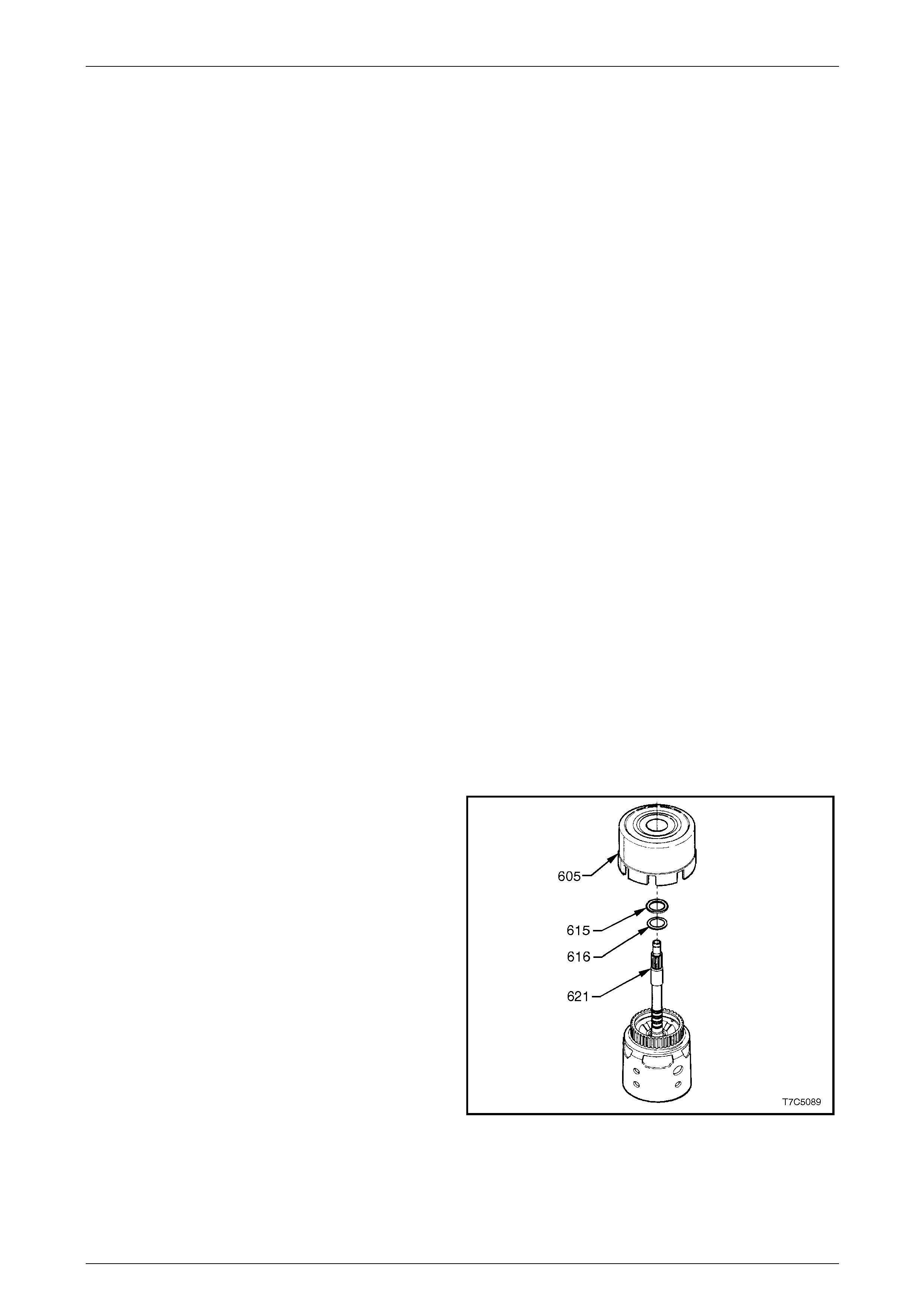
615 Bearing Assembly, Stator Shaft – Selective Washer
616 Washer, Thrust Selective
617 Retainer & Ball Assy., Check Valve
618 Seal, O-Ring, Turbine Shaft
619 Ring, Oil Seal (Solid)
620 Retainer & Checkball Assembly
621 Input Housing and Shaft Assembly.
622 Seal, O-Ring Input to Forward Clutch Housing
623 Piston, 3rd and 4th Clutch
625 Ring, 3rd & 4th Clutch (Apply)
626 Spring Assembly, 3rd and 4th Clutch
627 Retainer & Ball Assembly, Forward Clutch Housing
628 Housing, Forward Clutch
630 Piston, Forward Clutch
632 Piston, Overrun Clutch
633 Ball, Overrun Clutch
634 Spring Assembly, Overrun Clutch
635 Snap Ring, Overrun Clutch Spring Retainer
636 Seal, Input Housing to Output Shaft
637 Bearing Assembly , Input Sun Gear
638 Snap Ring, Overrun Clutch Hub Retaining
639 Hub, Overrun Clutch
640 Forward Sprag Clutch Inner Race & Input Clutch Assembly
642 Forward Sprag Assembly
643 Retainer Ring, Sprag Assembly
644 Race, Forward Clutch (Outer)
645a Plate Assy., Overrun Clutch (Steel)
645b Plate Assy., Overrun Clutch (Composition)
646 Plate, Forward Clutch (Apply)
648 Plate, Forward Clutch (Waved)
649a Plate, Forward Clutch (Steel)
649b Plate Assy., Forward Clutch (Composition)
650 Plate, Forward Clutch Backing (Selective)
651 Ring, Forward Clutch Backing Plate Retainer
653 Plate, 3rd & 4th Clutch Apply (Stepped)
654a Plate Assy., 3rd & 4th Clutch (Composition)
654b Plate Assy., 3rd & 4th Clutch (Steel)
655 Plate, 3rd & 4th Clutch Backing (Selective)
656 Ring, 3rd & 4th Clutch Backing Plate Retainer
657 Bush, Input Sun Gear, Front
659 Bush, Input Sun Gear, Rear
688 Plug, Cup
698 Plug, Orifice Cup
Disassemble
Disassemble the component s of the input clutch housing assembly as follows:
1 3 – 4 Clutch,
2 Forward Clutch Assembly,
3 Overrun Clutch Assembly and
4 3 – 4 Clutch Assembly.
3 – 4 Clutch
1 Remove the reverse input clutch housing and drum
assembly (605) from the input housi ng and shaft
assembly (621).
2 Remove the thrust bearing (615) and sel ecti v e thrust
washer (616).
Figure 7D5 – 75
7D5 Automatic Transmission – 4L65E – Unit Repair Page 7D5–51
15–DEC–2005 Page 7D5–51
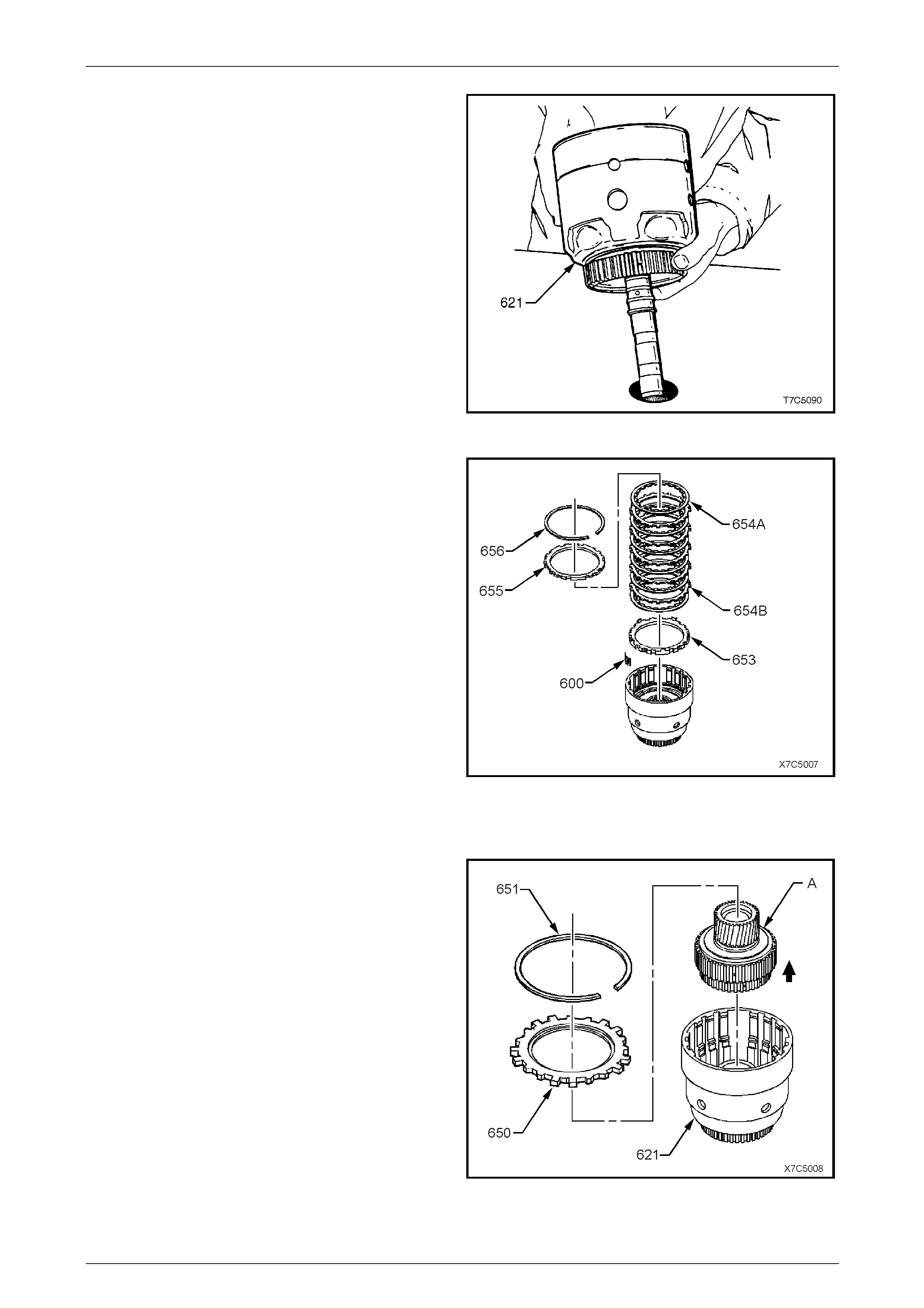
3 Place the input clutch housing and drum
assembly (621) on a work bench with the input shaft
protruding through a hol e in the workbench.
Figure 7D5 – 76
4 Remove the 3-4 clutch plate retaining ring (656) and
backing plate (655).
5 Remove the 3-4 clutch plates (654B and 654B).
6 Remove the 3-4 clutch boost spring assembly (600),
five places.
7 Remove the 3-4 clutch apply stepped plate (653).
Figure 7D5 – 77
Forward Clutch Assembly
1 Remove the forward clutch backing plate reta ining
ring (651) and backing pl ate (650).
2 Lift the forward clutch sprag and input sun gear
assembly (A) from the input shaft and housing
assembly (621).
Figure 7D5 – 78

7D5 Automatic Transmission – 4L65E – Unit Repair Page 7D5–52
15–DEC–2005 Page 7D5–52
3 Remove the forward clutch plates (649A and 649B).
4 Remove the forward clutch wave plate (64 8).
5 Remove the forward clutch apply plate (646).
6 Remove the input sun gear bearing assembly (637).
7 Remove the input housing to output sh aft lip
seal (636).
8 Remove the overrun clutch plates (645A and 645B).
Figure 7D5 – 79
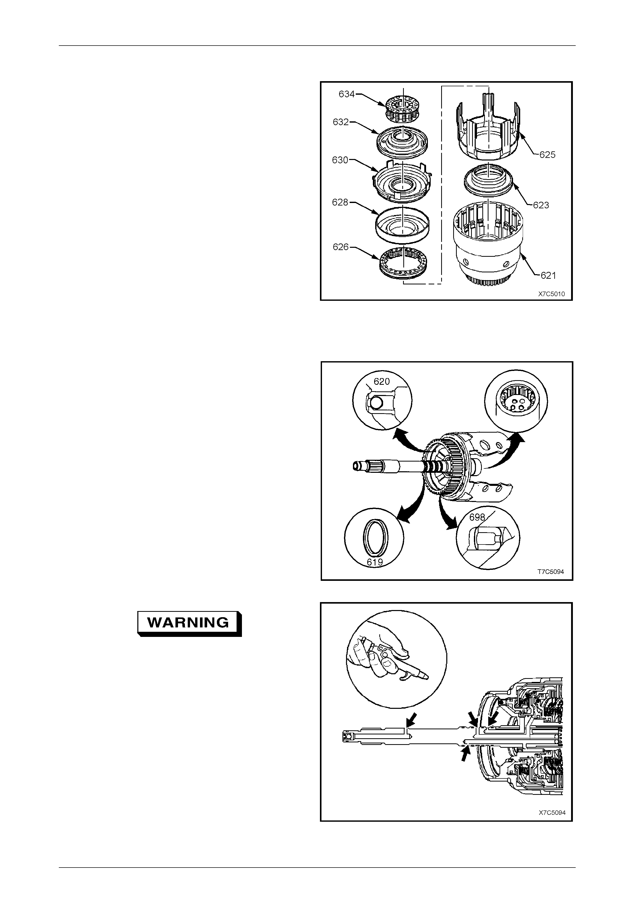
Overrun Clutch Assembl y
1 Place the input housing and shaft assembly (621) in a
suitable press.
2 Install part of Tool Nos J23327-1 and J25018-A
underneath, as shown.
Do not over-compress the springs or over-
expand the retaining ring.
3 Compress the overrun clutch spring assembly (not
visible) in press and remove the overrun clutch
retaining ring (635), using suitable snap ring pliers (1).
4 Return the input housing and shaft assembly to the
workbench.
Figure 7D5 – 80
7D5 Automatic Transmission – 4L65E – Unit Repair Page 7D5–53
15–DEC–2005 Page 7D5–53
3 – 4 Clutch Assembly
1 Remove the overrun clutch spring assembly (634).
2 Remove the forward clutch piston assembl y (630),
together with the overrun clutch piston (6 32).
3 Separate the two pistons and remove all seals.
NOTE
Separate assembly by impacting the input
housing assembly on a wooden block.
4 Remove the forward clutch housing (628).
5 Remove the 3-4 clutch spring assembly (626).
6 Remove the 3-4 clutch appl y ring (625) and
piston (623) with seals.
7 Discard all removed seals.
Figure 7D5 – 81
Inspect
1 Inspect the input housing and shaft assembly for
porosity, wear or damage.
2 Check if the orifice cup plug (698) is not missing.
3 Check for cracks at all lube holes.
4 Check if the turbine shaft four sealing rings (619)
rotate freely in their grooves and if they are not
damaged and free from burrs.
5 Inspect the check ball and retainer (620). Check if the
ball moves freely and if the retainer is not lo ose in the
housing. Leak test the check ball, with solvent.
Figure 7D5 – 82
When using compressed air wear safety
equipment to avoid personal injury.
6 Blow through all input shaft passages with
compressed air. The three turbine shaft seal ing balls
must not be loose or leaking.
Figure 7D5 – 83
7D5 Automatic Transmission – 4L65E – Unit Repair Page 7D5–54
15–DEC–2005 Page 7D5–54
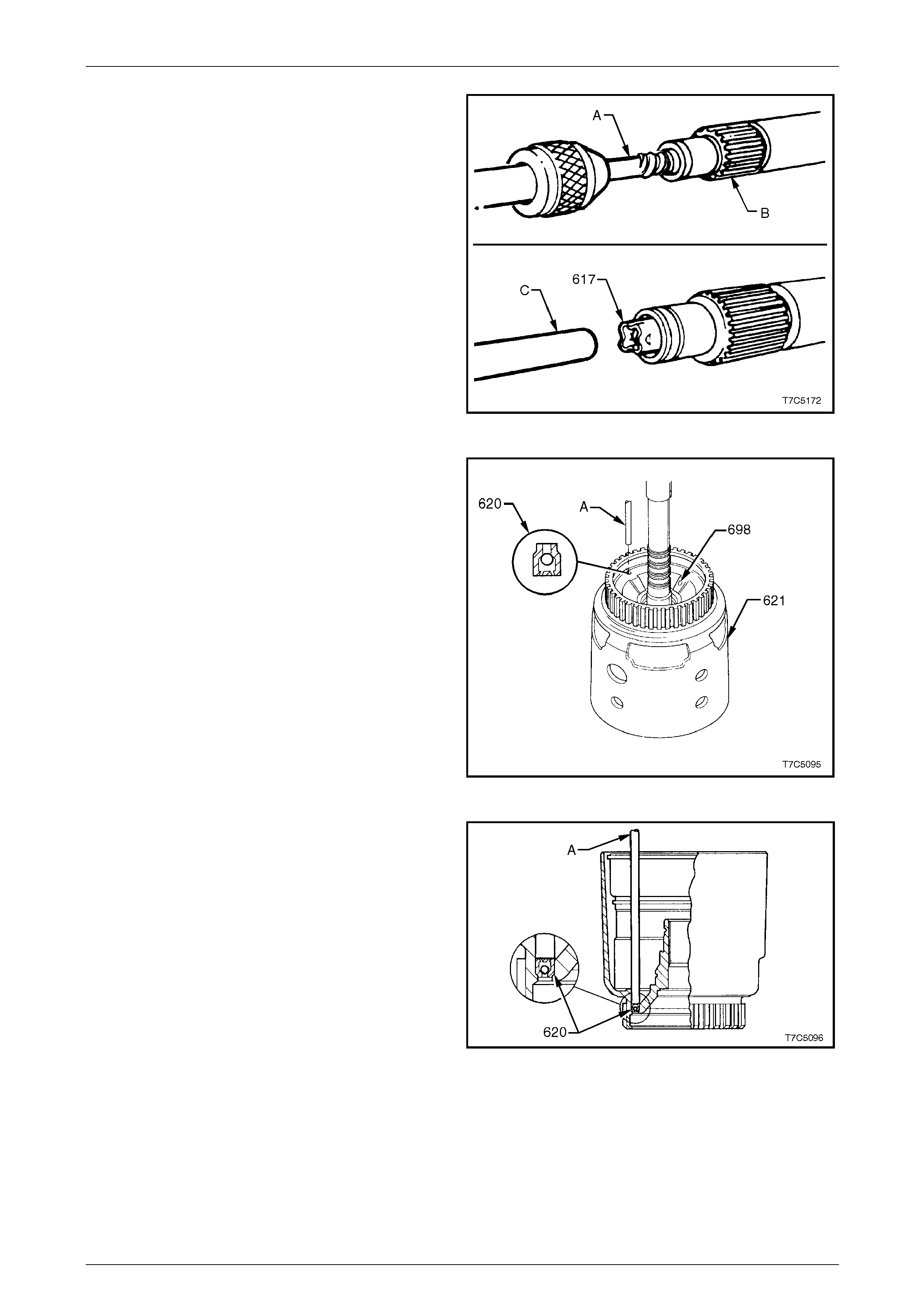
7 If required, replace the turbine shaft retainer and
check the ball assembly (617) as follows:
a Straighten the retainer tangs and remove the
ball.
b Use a suitable screw extractor (A) to remove the
retainer from the turbine shaft (B).
c Install a new check ball and retain er
assembly (617), using a 9.5 mm rod (C), until the
retainer is 3.0 mm below the end of the input
shaft.
d Ensure the check ball moves freely.
NOTE
The end of the turbine shaft (B) may vary,
depending on t he engine application.
Figure 7D5 – 84
8 If necessary, replace the input shaft housing check
ball assembly, as follows:
a Tap out the retainer and bal l assembly (620),
using a 5.7 mm (1/4 inch) rod (A).
Figure 7D5 – 85
b Install new check ball assembly (620) with a
5.7 mm rod (A) until the shoulder is seated in the
housing from the input shaft side, as shown.
Figure 7D5 – 86
9 Inspect the 3-4 clutch piston (623) for porosity or damage, refer to Figure 7D5 – 74.
10 Inspect the 3-4 clutch apply ring (625) for be nt tangs.
11 Inspect the 3-4 clutch spring assembly (626) for distortion or damage.
12 Inspect each of the 3-4 clutch five spring ass embli es (600) for damage or distortion.
13 Inspect the 3-4 clutch plates for damaged tangs, delamin ation and/or excessive wear.

7D5 Automatic Transmission – 4L65E – Unit Repair Page 7D5–55
15–DEC–2005 Page 7D5–55
NOTE
The green/black appearance of the 3-4 clutch
plates is normal. T herefore, do not assume these
plates are burned because of colour.
14 Inspect the forward clutch housing (628) for:
• correct check ball (627) operation,
• damage, distortion or cracks and
• burrs in seal areas.
Figure 7D5 – 87
15 Inspect the forward clutch piston (630) for:
• porosity or damage,
• ring groove damage a nd
• apply leg damage.
NOTE
As the inner and outer piston seals are bonded
to the forward clutch piston, if any seal damage
is found, the piston assembly must be replaced.
Figure 7D5 – 88
7D5 Automatic Transmission – 4L65E – Unit Repair Page 7D5–56
15–DEC–2005 Page 7D5–56
16 Inspect the overrun clutch piston (632) for:
• porosity or damage,
• ring groove damage,
• seal damage and
• check ball (633) operation (overrun).
NOTE
As the inner and outer piston seals are now
bonded to the overrun clutch piston, if any seal
damage is found, then the piston assemb ly must
be replaced.
17 Inspect the overrun spring assembl y (634) for damage
or distortion, refer to Figure 7D5 – 74.
18 Inspect the overrun clutch plates (645 a/b), forward
clutch plates (649a/b) and 3-4 clutch plates (654a/b).
Check the composition plates for damaged tangs,
delamination or excessive wear. Check the steel
plates for damaged tangs, wear or heat damage.
Figure 7D5 – 89
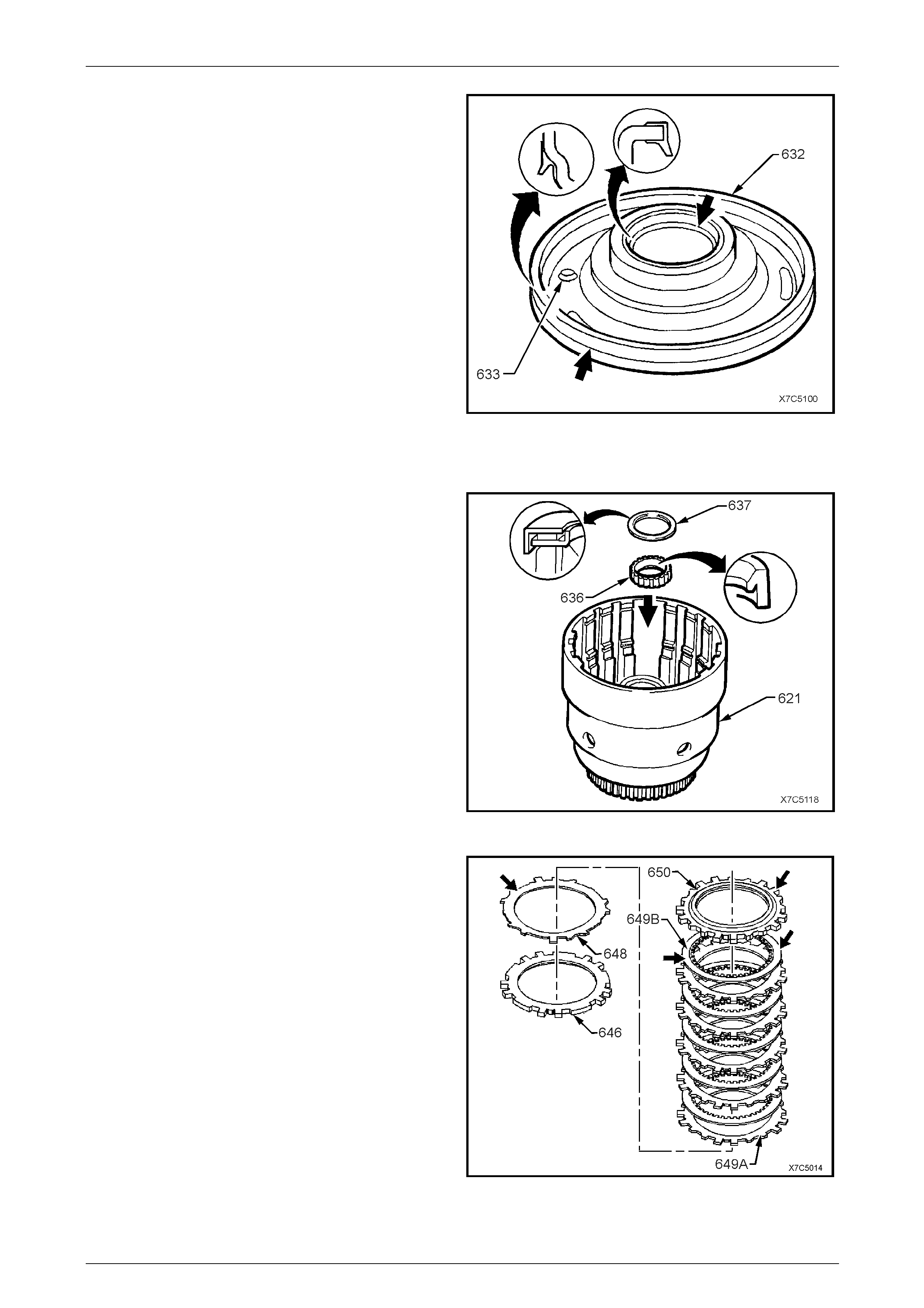
19 Inspect the input sun gear bearin g assembly (637) and
the input housing to output shaft seal (636) for wear,
damage or distortion.
Figure 7D5 – 90
20 Inspect the forward clutch waved plate (648), apply
plate (646), steel plates (649A), compositio n
plates (649B) and selective backing p late (650) for:
• flatness,
• delamination of the compositio n plates (649B),
• heat damage and/or excessive wear and
• burrs, nicks and other surface finish damage.
Figure 7D5 – 91
7D5 Automatic Transmission – 4L65E – Unit Repair Page 7D5–57
15–DEC–2005 Page 7D5–57
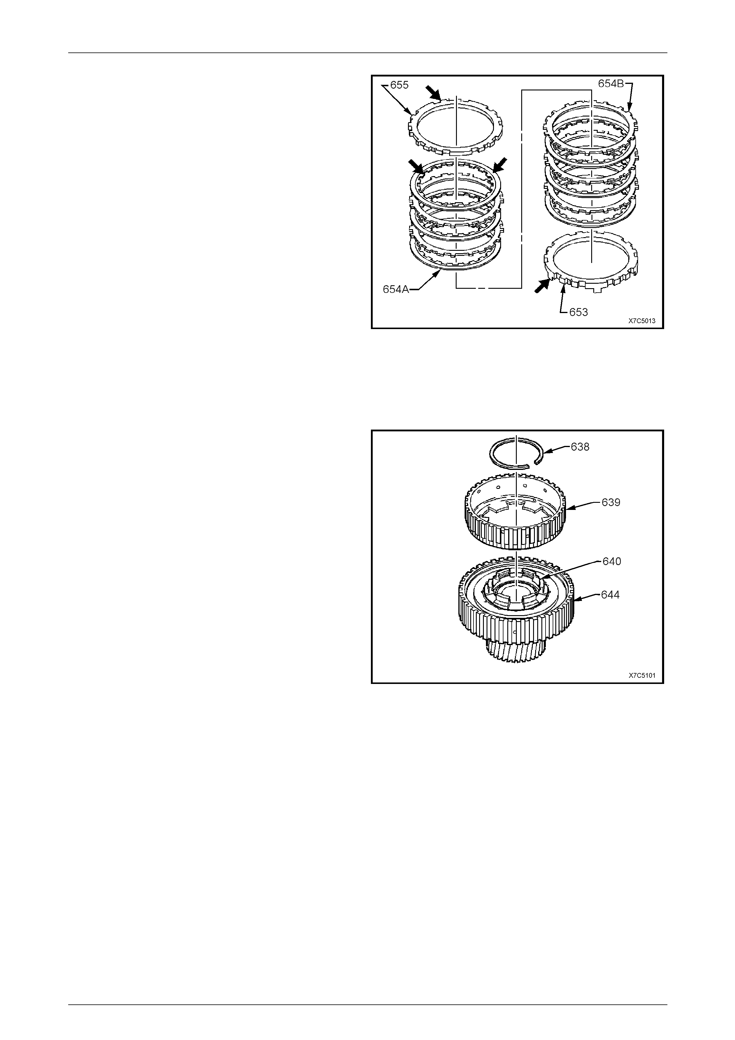
21 Inspect the 3-4 clutch apply plate (653), com position
plates (654A), steel plates (654B) and selective
backing plate (655), for:
• flatness,
• delamination of the compositio n plates (654A),
• heat damage and/or excessive wear and
• burrs, nicks and other surface finish damage.
Figure 7D5 – 92
Forward Clutch Sprag Assembly
Disassemble
1 Remove the overrun clutch hub retaining snap
ring (638) and clutch hub (639).
2 Remove the forward clutch outer race (644).
3 Remove the forward sprag clutch inner race and sun
gear assembly (640) from the forward clutch sprag
assembly (644).
Figure 7D5 – 93
7D5 Automatic Transmission – 4L65E – Unit Repair Page 7D5–58
15–DEC–2005 Page 7D5–58
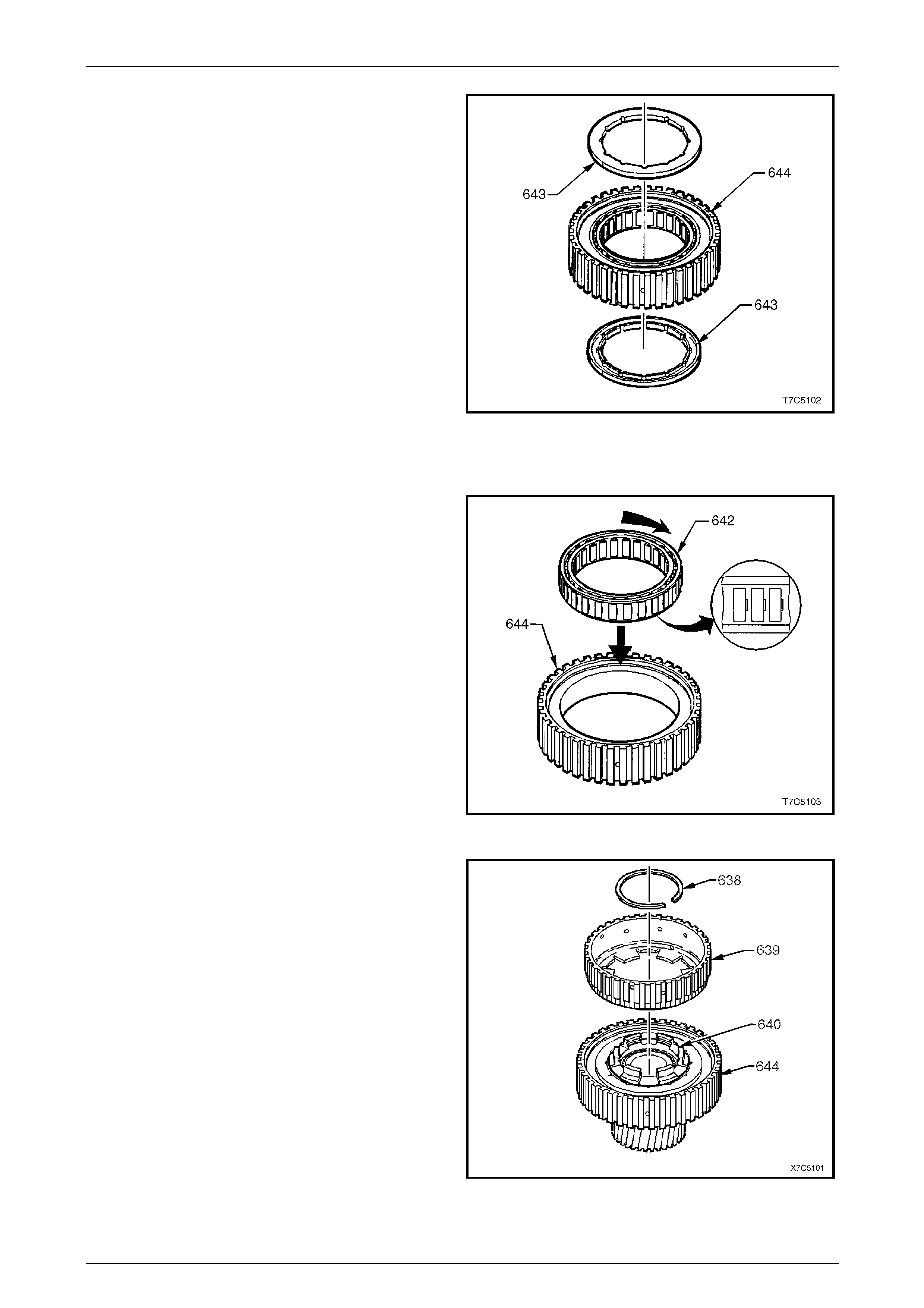
4 Remove the sprag assembly retainer rings (643).
5 Remove the forward sprag assembl y from the forward
clutch outer race (644).
Figure 7D5 – 94
Inspect
1 Inspect the forward clutch sprag assembly (642) for:
• wear or damage,
• weak or broken springs and
• damaged or missing retaining caps.
2 Inspect the forward clutch outer race (644) for:
• spline damage,
• surface finish damage and
• plugged lubricat ion holes.
Figure 7D5 – 95
3 Inspect the overrun clutch hub (639) for:
• spline damage,
• plugged lubricat ion holes,
• damaged tangs and
• cracks.
4 Inspect the forward sprag clutch inner race and input
sun gear assembly (640) for:
• spline damage,
• ring groove damage,
• surface finish damage and
• loose retainer.
Figure 7D5 – 96
7D5 Automatic Transmission – 4L65E – Unit Repair Page 7D5–59
15–DEC–2005 Page 7D5–59
Reassemble
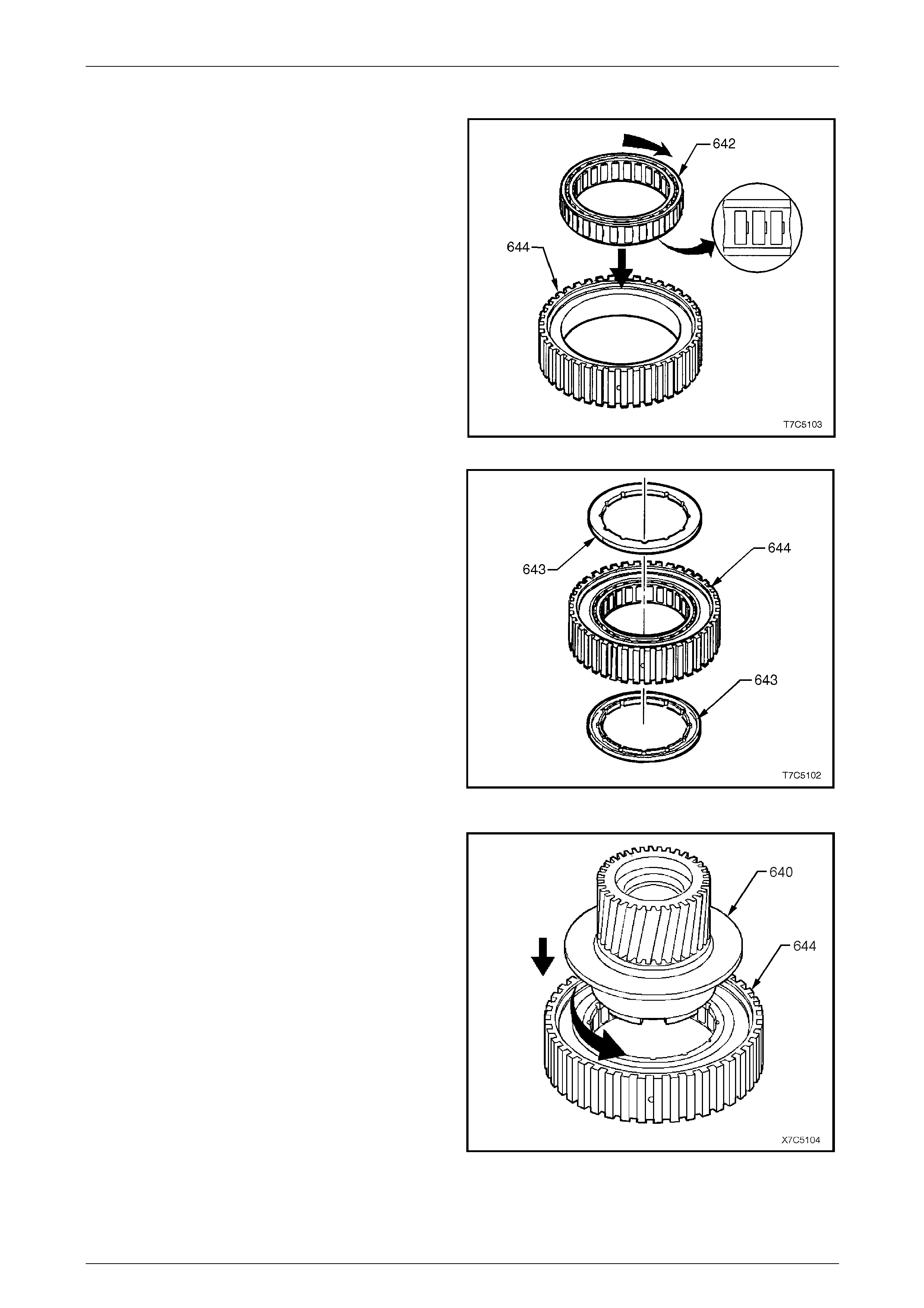
1 Reinstall the forward sprag assembly (642) into the
forward clutch outer race (644), notches in sprag cage
pointing in the direction shown.
Figure 7D5 – 97
2 Reinstall a sprag retainin g ring (643) to each side of
the forward clutch outer race (644) with the retaining
ring recesses facing outward.
Figure 7D5 – 98
3 Reinstall the forward sprag clutch inner race and input
sun gear assembly (640) into the sprag retai nin g ring
and the outer race (644), as follows:
a Hold the outer race in right hand, supporting the
forward sprag assembly with yo ur fingers at the
recessed side of the outer race.
b Insert the retaining ring and the forward sprag
clutch inner race and input sun gear assemb ly
from the opposite side of the outer race by
pushing in and turning anti-clockwise (curved
arrow).
4 Turn the assembly over and reinsta ll the remaining
sprag assembly outer retaining ring, with the recess
facing inward toward the forward sprag assembly.
Figure 7D5 – 99
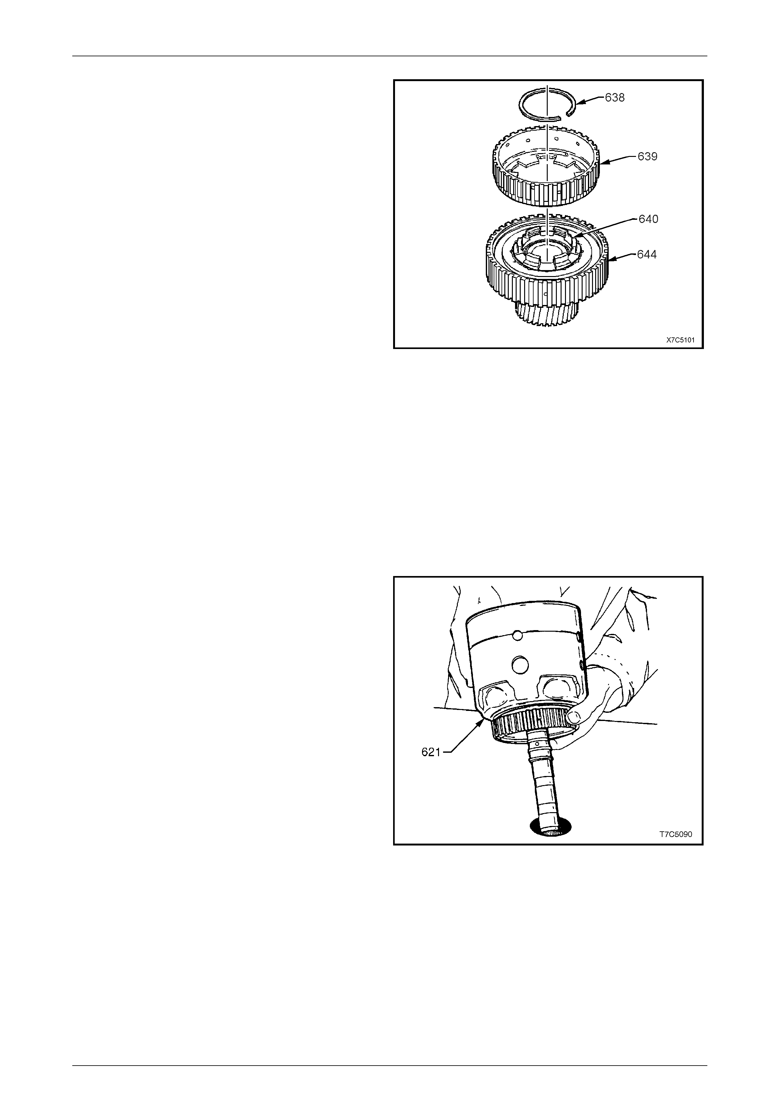
7D5 Automatic Transmission – 4L65E – Unit Repair Page 7D5–60
15–DEC–2005 Page 7D5–60
5 Reinstall the overrun clutch h ub (639) onto the forward
sprag clutch inner race and input sun gear
assembly (640).
6 Reinstall the overrun clutch h ub retaining snap
ring (638) into the groove in the forward sprag clutch
inner race and input sun gear assemb ly.
7 Test the assembly for correct operation as follows:
a Hold the forward clutch outer race (64 4) in th e
left hand and grasp the overru n clutch hub with
the right hand. Attempt to rotate the hub in both
directions.
b If the overrun clutch hub rotates when turned
clockwise and locks up when attempting to turn it
counter-clockwise, the sprag has been
assembled correctly.
c If however, the assembly operates backwards,
the sprag is assembled incorr ectly. Dismantle
and re-assemble correctly, as required. Figure 7D5 – 100
Reassemble
Reassemble the components of the input clutch housing assembly as follows:
1 3-4 Clutch Assembly
2 Overrun Clutch Assembly
3 Forward Clutch Assembly
4 3-4 Clutch
3-4 Clutch Assembly
1 Place the input housing and shaft assembly (621) on a
workbench with the input shaft protruding throug h a
hole in the workbench.
Figure 7D5 – 101
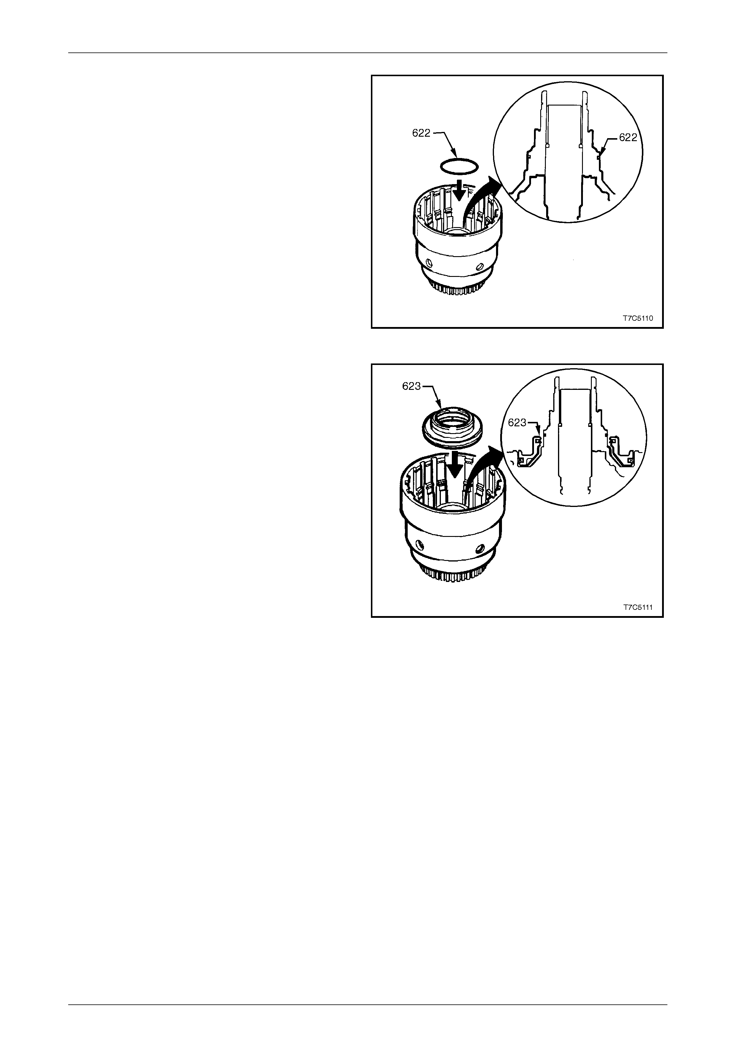
7D5 Automatic Transmission – 4L65E – Unit Repair Page 7D5–61
15–DEC–2005 Page 7D5–61
2 Lubricate a new O-ring (622) with petroleum jelly and
install it on the input housing.
Figure 7D5 – 102
3 Coat the 3-4 clutch piston new inner and outer lip
seals with petroleum jelly.
4 Reinstall the 3-4 clutch piston (623) in the input
housing as shown, taking care not to damage the
seals.
Figure 7D5 – 103
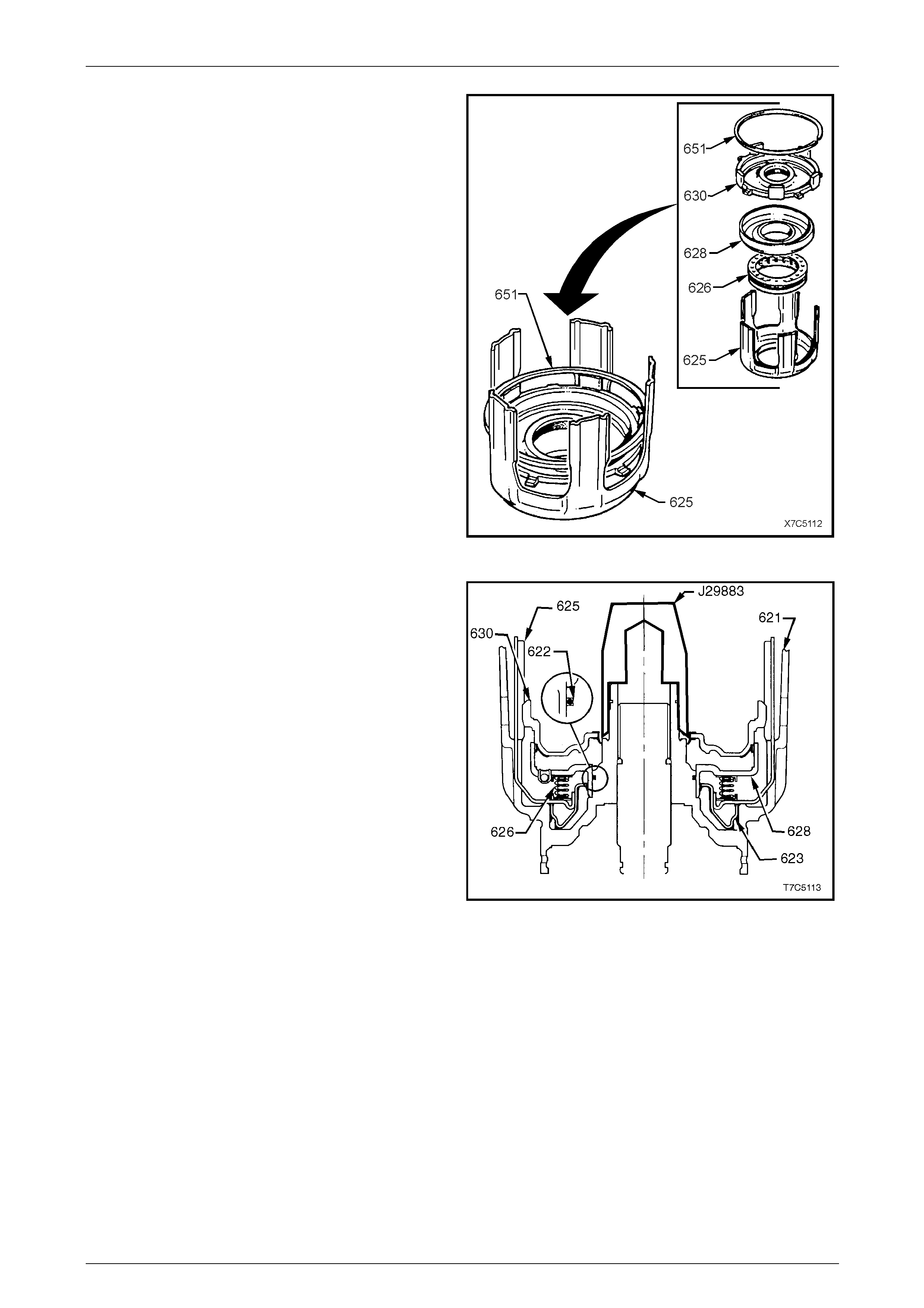
7D5 Automatic Transmission – 4L65E – Unit Repair Page 7D5–62
15–DEC–2005 Page 7D5–62
5 Locate the 3-4 clutch spring assembl y (626) onto the
five legged 3-4 clutch apply ring (625).
6 Coat the piston inner and oute r bonded seals with
petroleum jelly and install the forward clutch
piston (630) into the for ward clutch housing (628)
taking care not to damage the outer seal.
7 Reinstall the forward clutch assembly onto the 3-4
clutch spring assembly, locating the forward clutch
piston smaller apply legs between the 3-4 clutch apply
ring legs, as shown.
8 Use the forward clutch backing plate retaining
ring (651) to hold these parts in place during
reinstallation.
Figure 7D5 – 104
9 Fit Tool No. J29883 on the input housing and shaft
assembly (621), as shown and coat with petroleum
jelly.
10 Reinstall the 3-4 clutch apply ring (625) and forward
clutch assembly into the input housing and shaft
assembly as follows:
a Hold assembly by apply ring legs and carefully
lower into the input housing and shaft assembly.
b Do not let the forward clutch piston (630)
separate from the forward clutch housing (628).
c Seat the assembly by pushing down firmly onto
the forward clutch piston. Ensure the forward
clutch housing is seated over the O-ring (622).
NOTE
It may be necessary to slightly rock the assembly
to overcome cocking.
11 Remove Tool No. J298 83 and the temporarily installed
retaining ring (Step 8).
Figure 7D5 – 105
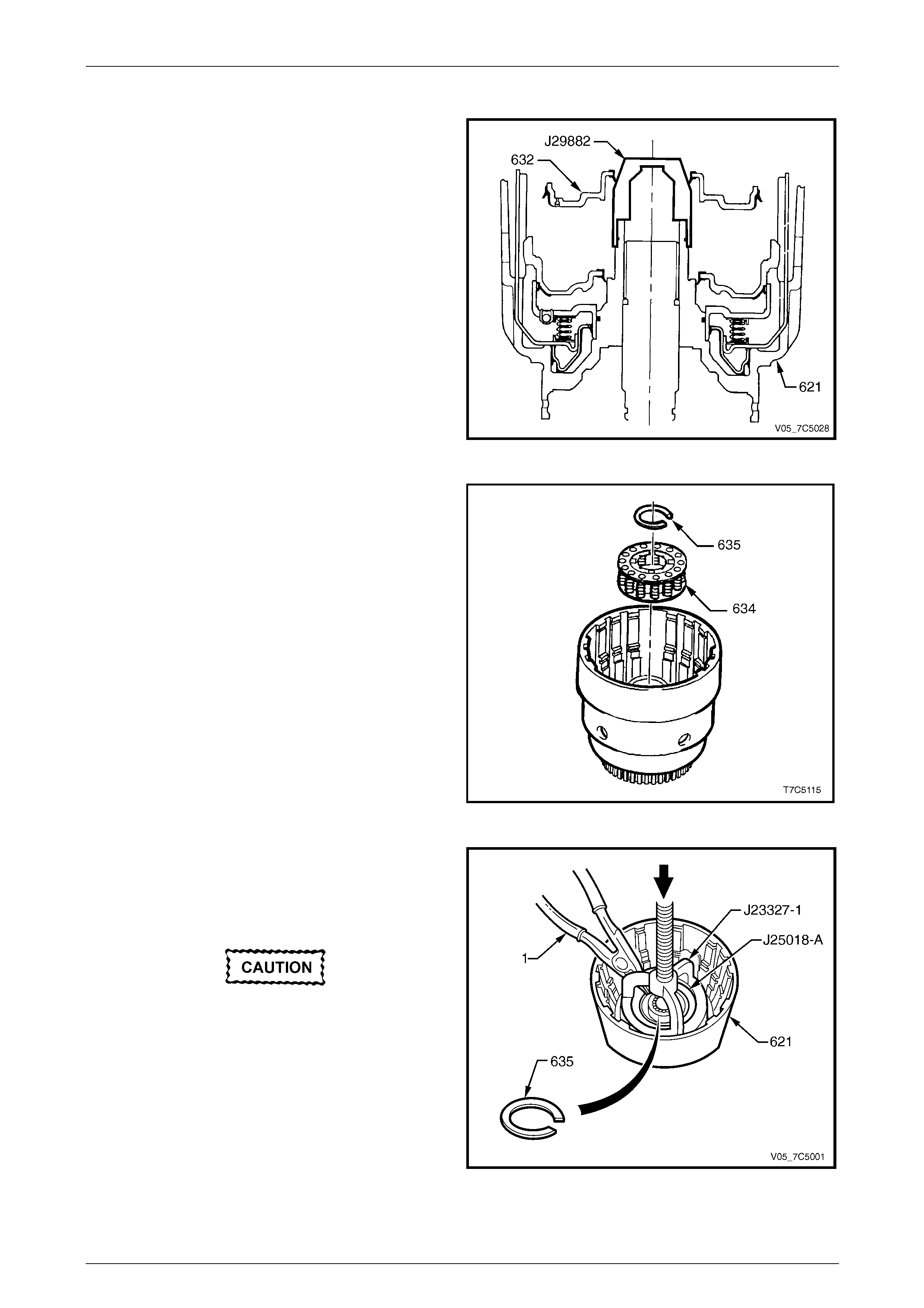
7D5 Automatic Transmission – 4L65E – Unit Repair Page 7D5–63
15–DEC–2005 Page 7D5–63
Overrun Clutch Assembl y
1 Fit Tool No. J29882 on the input housing and shaft
assembly (621), as shown and coat with petroleum
jelly.
NOTE
To ease the installation of the outer bonde d seal,
coat a straightened paper clip or similar with
petroleum jelly and work around the piston
circumference.
2 Lubricate the piston inner and outer bonded seals with
petroleum jelly and i nstall the overrun clutch
piston (632) with the hub facing up wards, as sho wn.
NOTE
If all components are correctly seated, the piston
hub locates approximately three mm below the
snap ring groove in the input housing hub.
3 Remove Tool No. J29882. Figure 7D5 – 106
4 Reinstall the overrun clutch spring assembly (634)
onto the overrun clutch piston.
Figure 7D5 – 107
5 Install part of Tool Nos J23327-1 and J25018-A, as
shown.
6 Place the input housing and shaft assembly (621) in a
suitable press.
Do not over-compress the springs or over-
expand the retaining ring.
7 Compress the overrun clutch spring assembly and
install a new clutch retaining ring (635), using suitable
snap ring pliers (1).
8 Remove Tool Nos J23327-1 and J25018-A.
Figure 7D5 – 108
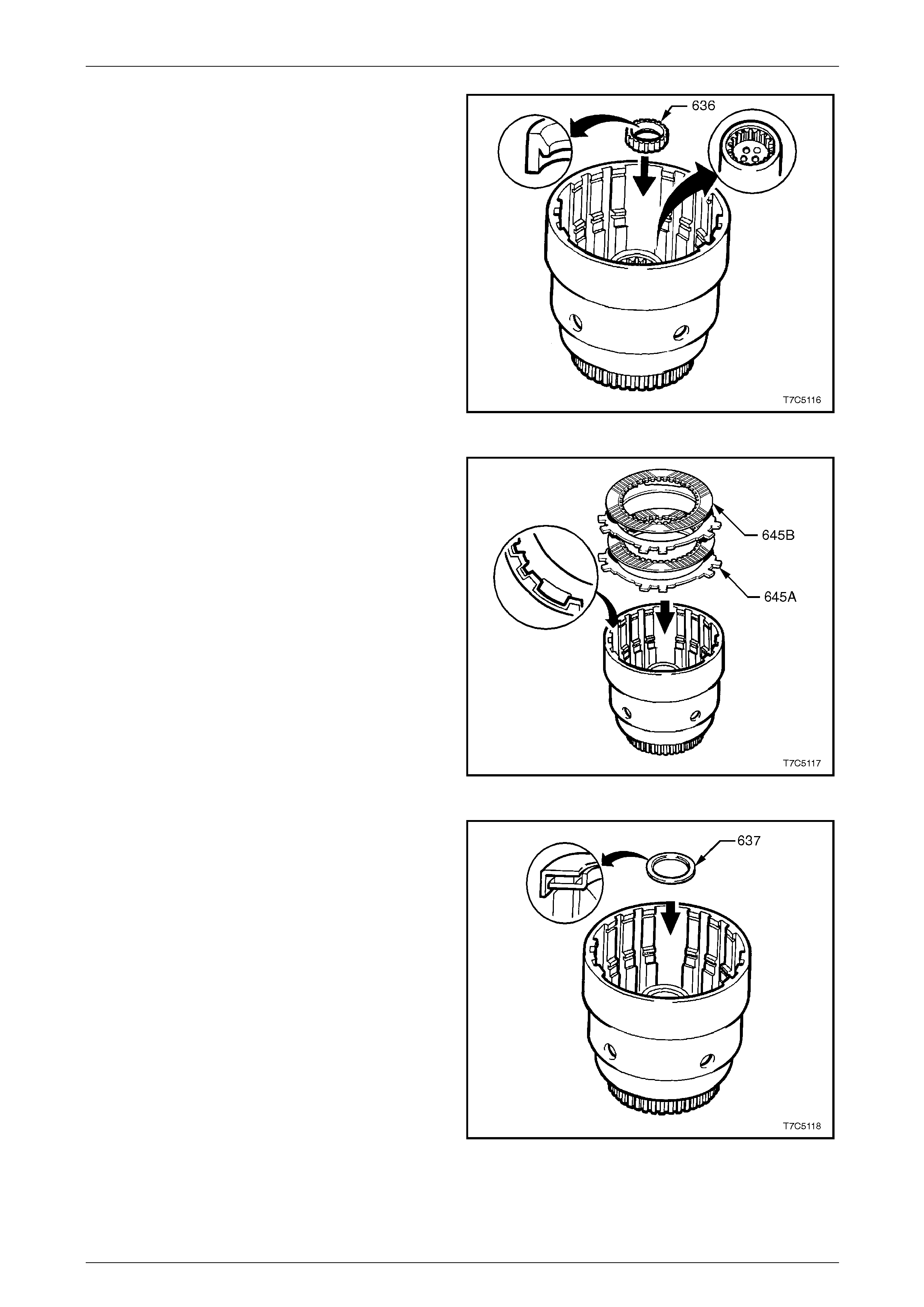
7D5 Automatic Transmission – 4L65E – Unit Repair Page 7D5–64
15–DEC–2005 Page 7D5–64
9 Install a new output shaft seal (636) into the input
housing, noting the seal lip orientation.
Figure 7D5 – 109
10 Pre-lubricate the overrun clutc h composition
plates (645B) with automatic transmission fluid.
11 Align the steel plates with the wide notch, as shown
and reinstall the plates into the input housing in the
following order:
a steel plate (645A) first,
b composition plate (645B),
c second steel plate and
d second composition plate.
NOTE
This clutch pack is the smallest set in the
transmission.
Figure 7D5 – 110
12 Reinstall the input sun gear thrust bearing
assembly (637) onto the input clutch hub with inside
race facing input housing hub, as shown. Retain thrust
bearing in plac e with petroleum jelly.
Figure 7D5 – 111
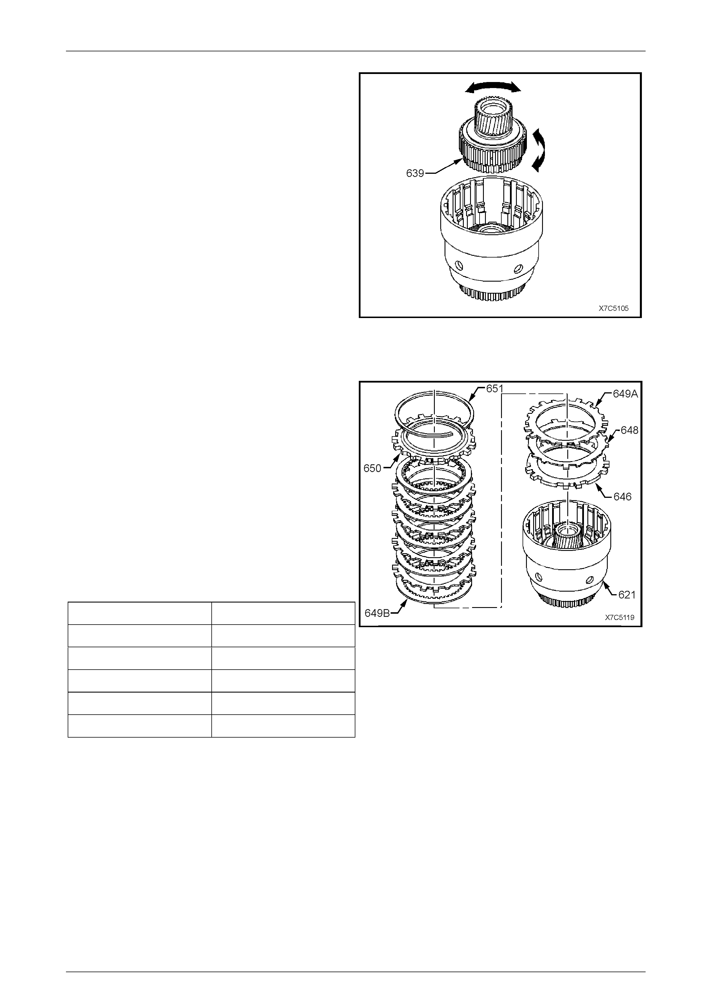
7D5 Automatic Transmission – 4L65E – Unit Repair Page 7D5–65
15–DEC–2005 Page 7D5–65
13 Using a fine bladed screwdriver or similar, line up the
inner tangs of the two composition plates.
14 Reinstall the for ward clutch sp rag assembly into the
input clutch housing, locating the overrun clutch
hub (639) into the overrun clutch plates.
Figure 7D5 – 112
Forward Clutch Assembly
1 Reinstall the forward clutch ap ply plate (646) into the
input clutch housing (621), indexing as shown.
2 Reinstall the waved steel forward clutch plate (648)
into the input clutch housing, indexing as before.
3 Reinstall the remaining forward clutch plates into the
input housing, starting with a steel plate (649A), then a
composition plate (649B), etc.
NOTE
The clearance between the backing plate (650)
and the retaining ring (651) is established on
initial build by the manufacturer.
4 If required, replace the selective backi ng plate (650)
using an equivalent plate, refer to following table.
Plate Thickness (mm) Identification
6.97 – 7.07 A
6.38 – 6.48 B
5.79 – 5.89 C
5.20 – 5.30 D
4.61 – 4.71 E
NOTE
The identification letters are stamped on the
backing plate.
5 Reinstall the forward clutch selective backing plate
and the retaining ring (65 1).
Figure 7D5 – 113
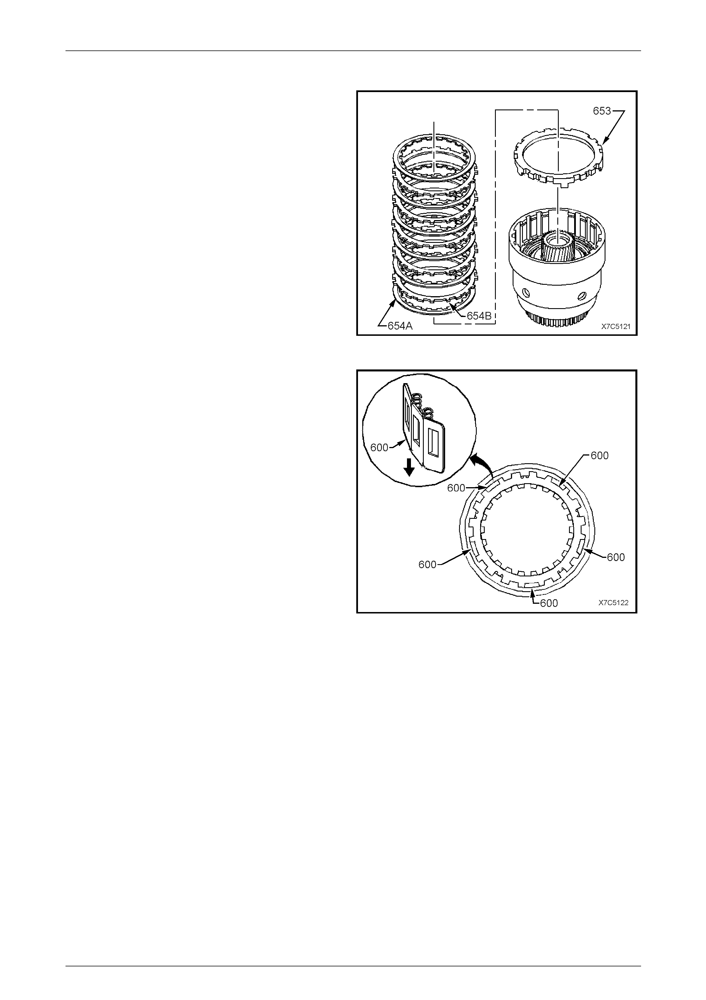
7D5 Automatic Transmission – 4L65E – Unit Repair Page 7D5–66
15–DEC–2005 Page 7D5–66
3-4 Clutch
1 Reinstall the 3-4 clutch apply plate (653), with its
protruding lugs facing inward, as shown.
2 Reinstall the 3-4 clutch plates, starting with a
composition plate (654A), then a steel plate (654B),
etc.
NOTE
When installing the 3-4 clutch plates note the
following:
• The first steel plate has the same spline
configuration as the apply plate.
• The number of plates is seven composition
and six steel.
• Install the steel plates with the wider lug
openings in the wide gap of the input hous in g
to allow space for the five spring boost
assemblies.
Figure 7D5 – 114
3 Reinstall the five spring boost assemb lies (600),
exposed spring ends uppermost and equally spaced in
the locations shown.
Figure 7D5 – 115
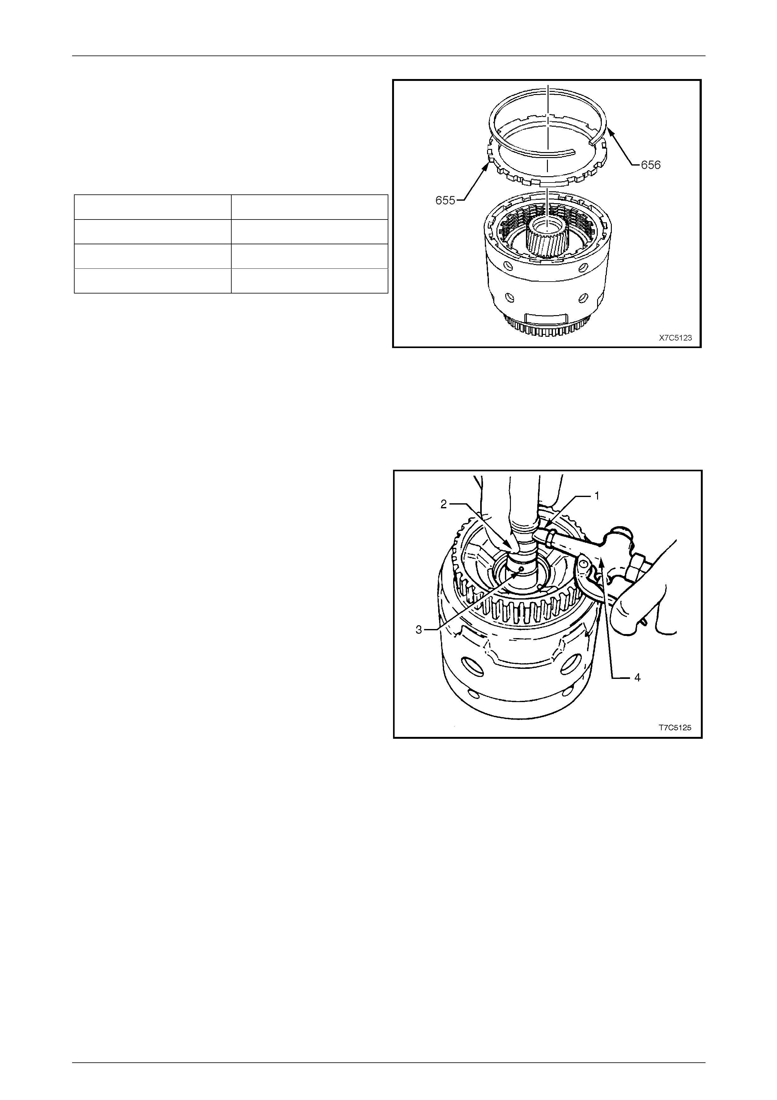
7D5 Automatic Transmission – 4L65E – Unit Repair Page 7D5–67
15–DEC–2005 Page 7D5–67
NOTE
The clearance between the backing plate (655)
and the retaining ring (656) is established on
initial build by the manufacturer.
4 If required, replace the selective backi ng plate (655)
using an equivalent plate, refer to following table.
Plate Thickness (mm) Identification
5.88 – 5.68 A
4.99 – 4.76 B
4.10 – 3.90 C
NOTE
The identification letters are stamped on the
backing plate.
5 Reinstall the 3-4 clutch selecti v e backing plate (655),
chamfered side up (if applicable) and wide tangs over
the spring boost assemblies. Reinstall the retaining
ring (656).
Figure 7D5 – 116
Input Clutch Housing Air Checks
NOTE
When performing the overrun clutch test:
• Unless the forward clutch apply hole is
blocked , air will leak past the forward clutch
piston lip seals an d exit via the forward clutch
feed hole in the input shaft.
• Lube passage (3) is shown to assist with
correct orifice identification.
1 Check the overrun clutch using a rubber tipped air
nozzle (4) to apply air pressure to the overrun clutch
passage (1) while blocking th e forward clutch apply
hole (2). The overrun clutch should apply.
2 Check the forward clutch by applying air pressure to
the forward clutch apply hole (2). The forward clutch
should apply.
Figure 7D5 – 117
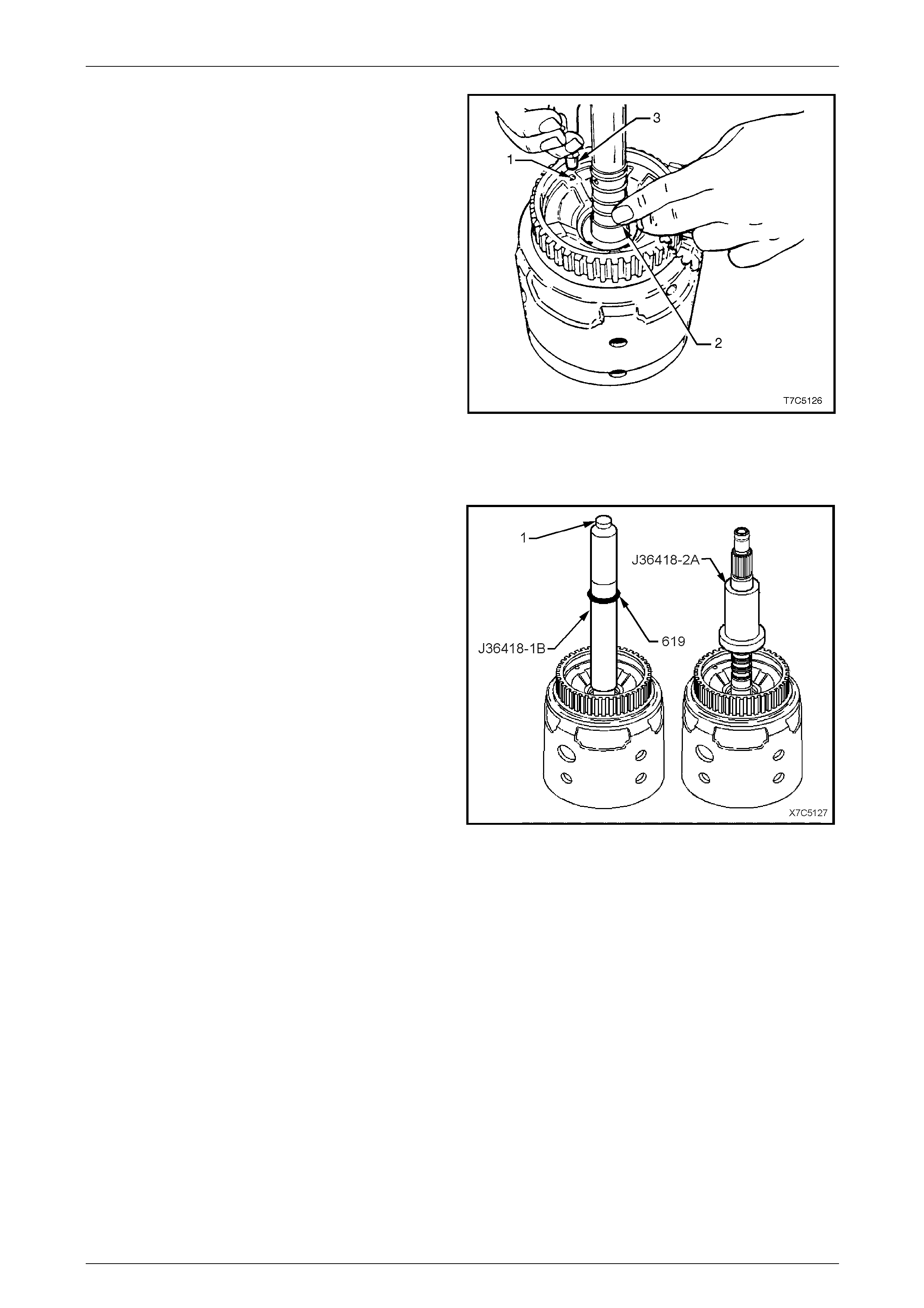
7D5 Automatic Transmission – 4L65E – Unit Repair Page 7D5–68
15–DEC–2005 Page 7D5–68
3 Check the 3-4 clutch by applying air pressure (3) to
the 3-4 clutch ball and retain er assembly (1), while
blocking the 3-4 feed hole (2) in the turbine shaft. The
3-4 clutch should apply.
Figure 7D5 – 118
Reinstall Turbine Shaft Sealing Rings
NOTE
Tool Nos J36418-1B and J36418-2A are part of
kit Tool No. J36418-B.
1 Install Tool No. J36418-1B over the input shaft.
2 Slide four new input shaft oil seal rings (61 9),
lubricated with petroleum jelly, over Tool No.
J36418-1B and install as follows:
a Use the knurled screw (1) to adjust the inner end
of the tool so the innermost seal groove in the
input shaft is exposed.
b Slide the first seal ring down until it slips off the
end of the tool and is installed in the input shaft
groove.
c Turn the knurled crew in a clockwise direction
until the second groove in the input shaft is
exposed. Repeat Step b to install the second
seal ring.
d Repeat the above Steps until all sealing rings are
installed.
3 Remove Tool No. J36418-1B and install Tool No.
J36418-2A over all the seal rings to re-size th em.
Leave the tool in place until the transmission is
reassembled.
Figure 7D5 – 119
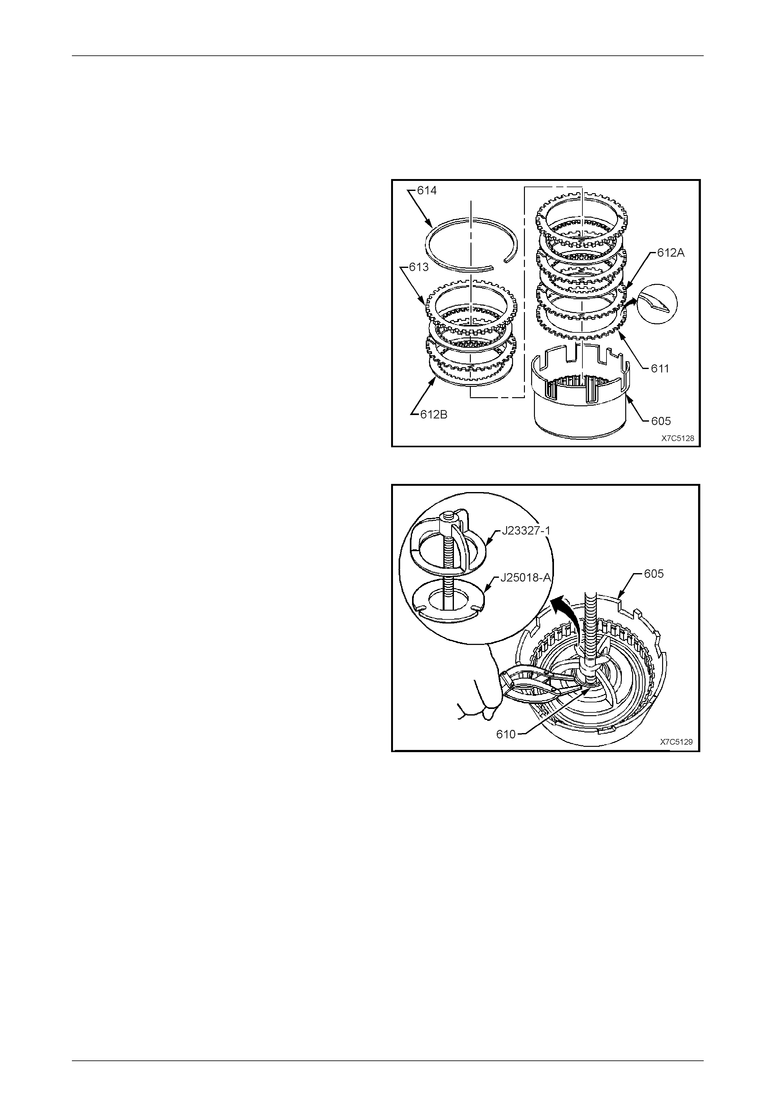
7D5 Automatic Transmission – 4L65E – Unit Repair Page 7D5–69
15–DEC–2005 Page 7D5–69
3.13 Reverse Input Clutch Assembly
LT Section No. — 04–200
Disassemble
1 Remove the backing plate retaining ring (614) from the
housing and drum assemb ly (605).
2 Remove the backing plate (613) and the clutch
plates (612A and 612B) including the Belleville
plate (611).
Figure 7D5 – 120
3 Install Tool No. J23327-1 with T ool No. J25018-A
underneath the housing (605) and compress the
reverse input clutch spring assembly.
4 Remove spring assembly retaining ring (610).
5 Remove the tools.
Figure 7D5 – 121
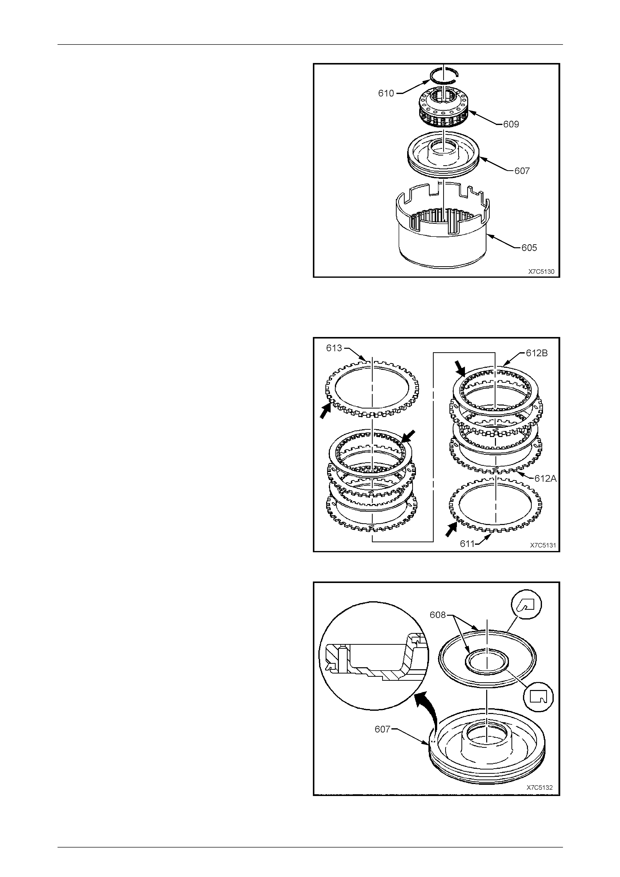
7D5 Automatic Transmission – 4L65E – Unit Repair Page 7D5–70
15–DEC–2005 Page 7D5–70
6 Remove the spring assembly (609).
7 Remove the piston (607) and discard piston seals.
Figure 7D5 – 122
Inspect
1 Inspect the selective backing plate (613) for dama ge,
burrs or distortion.
2 Inspect the clutch plates as follows:
a Check the composition plates (612B) for tang
damage, delamination or wear.
b Check the steel plates (612A) for tang dam age,
wear or heat damage.
3 Check the Belleville plate (61 1) for heat damage or
tang wear.
4 Inspect the spring assembly for distortion or damage.
Figure 7D5 – 123
5 Inspect the reverse input clutch piston (607) for:
• damage or porosity
• ring groove damage.
6 Remove both piston seals (608) and discard.
Figure 7D5 – 124
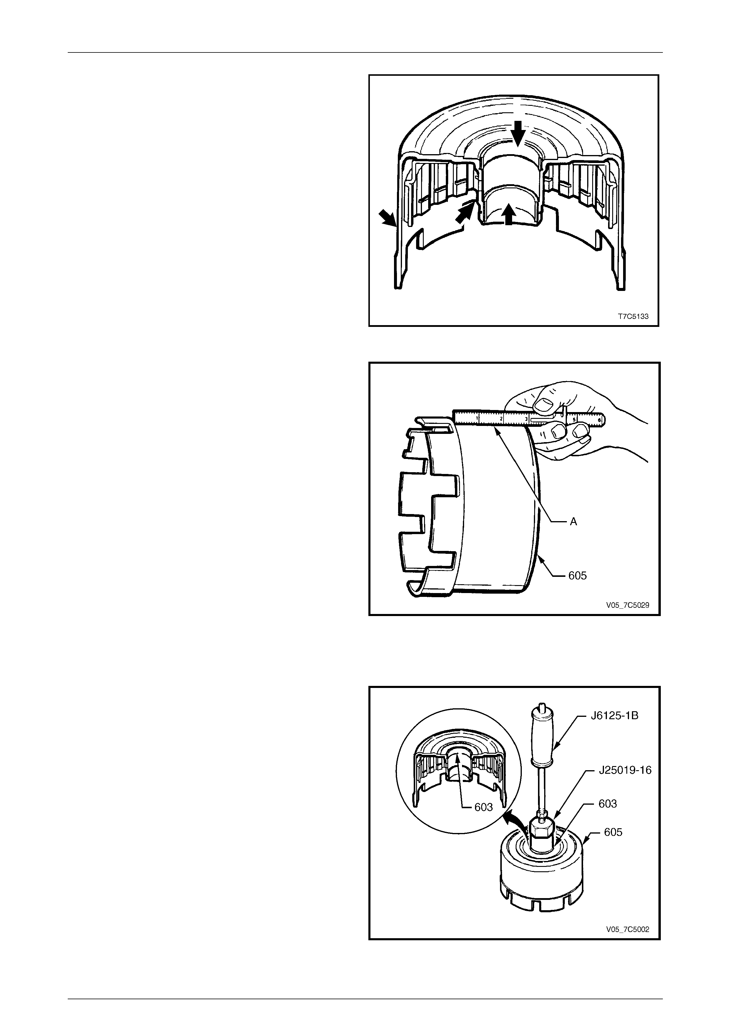
7D5 Automatic Transmission – 4L65E – Unit Repair Page 7D5–71
15–DEC–2005 Page 7D5–71
7 Inspect the housing and drum assembly (605) for:
a damaged or worn bushes,
b surface damage to hub or outer housing,
c leaking weld,
Figure 7D5 – 125
d outer housing dishing at p oint A.
8 If the bushes require replacement, refer to Reverse
Input Clutch Housing Bushes – Replace in this
Section.
Figure 7D5 – 126
Reverse Input Clutch Housing Bushes – Replace
1 Using bush remover, Tool No. J2501 9-16 and slide
hammer, Tool No. J6125-1B, remove the front
bush (603) from the reverse input clutch
housing (605).
Figure 7D5 – 127
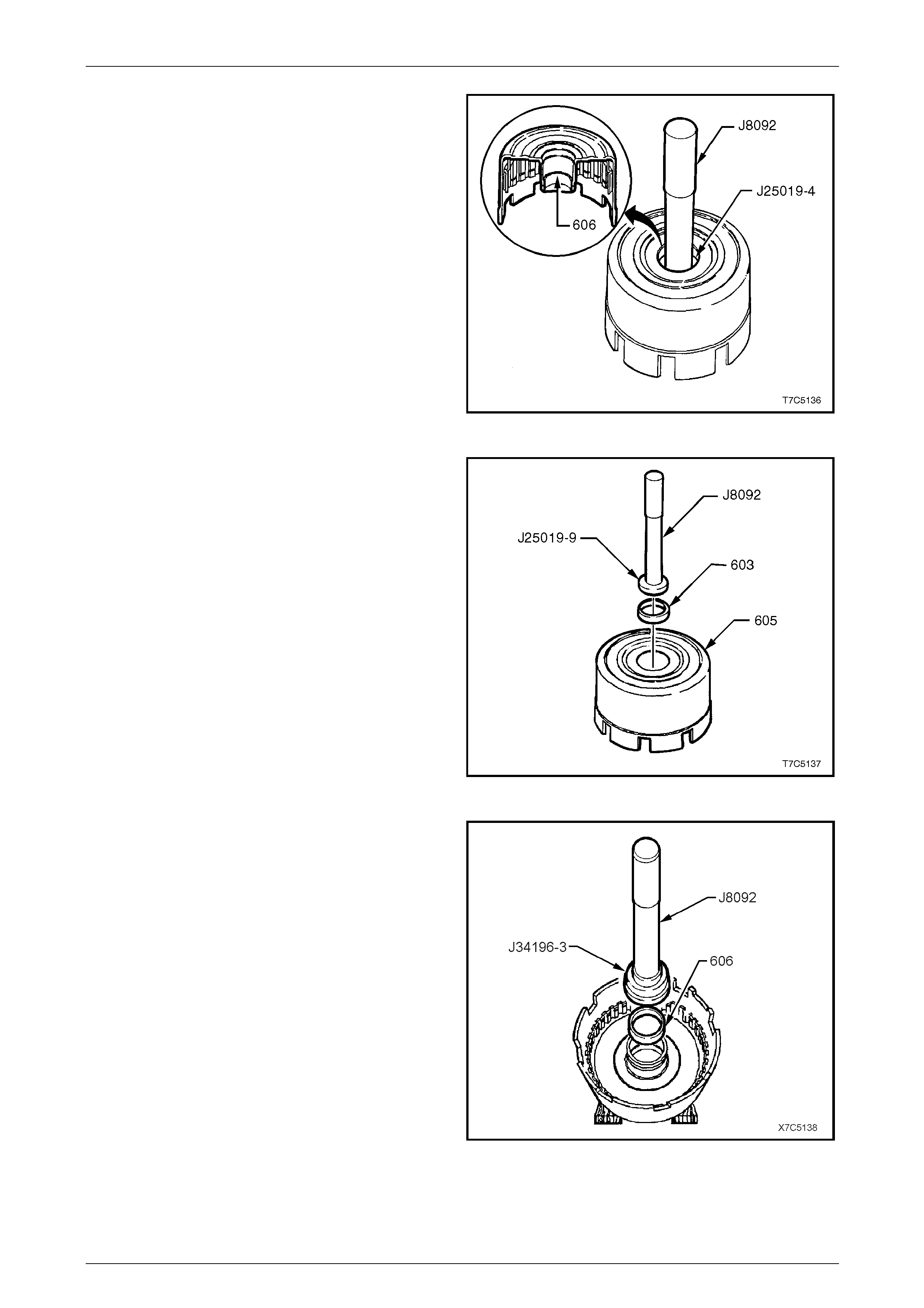
7D5 Automatic Transmission – 4L65E – Unit Repair Page 7D5–72
15–DEC–2005 Page 7D5–72
2 Turn the reverse input clutch housing over and use the
bush remover, Tool No. J25019-4 an d driver handle,
Tool No. J8092, to remove the rear bush (606) from
the reverse input clutch housing.
Figure 7D5 – 128
3 Press a new front bush (603) into the reverse input
clutch housing (605), using in staller Tool No. J25019-9
and driver handle, Tool No. J809 2.
Figure 7D5 – 129
4 Support the reverse input clutch housing on suitable
pieces of wood and install a new rear bush (606),
using installer T ool No. J34196-3 (part of kit J34196-B)
and driver handle, Tool No. J809 2.
Figure 7D5 – 130
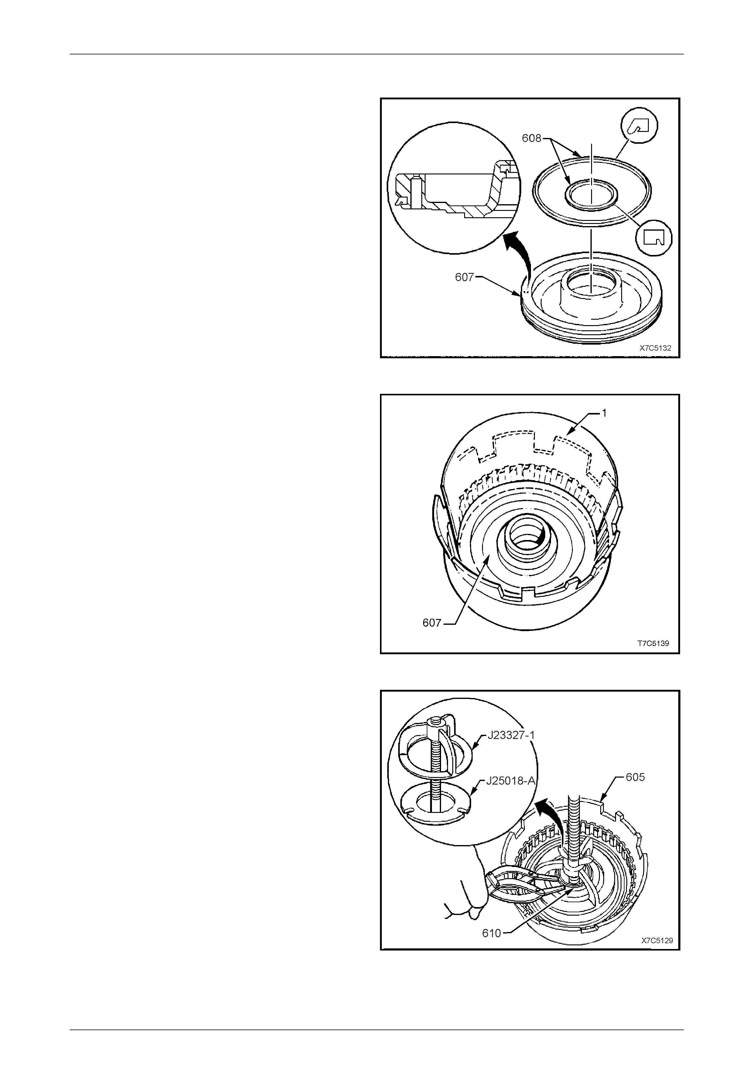
7D5 Automatic Transmission – 4L65E – Unit Repair Page 7D5–73
15–DEC–2005 Page 7D5–73
Reassemble
1 Lubricate new seals (608) with transmission fluid and
install them on piston (607) with lips facing in the
directions shown.
Figure 7D5 – 131
2 Position a strip (1) of thin plastic material
(approximately 0.01 mm thick) around one half of the
hub and coat with petroleum jelly.
3 Coat the piston seals with petroleum jell y and, with
seal lips facing down, reinstall the piston (607) by
tilting it down on the side opposite the plastic strip.
4 Gently work the piston down against the plastic strip
and into the hub, then remove the plastic strip.
5 Reinstall the spring assembly with larger opening
facing the piston.
Figure 7D5 – 132
6 Install Tool Nos J25018-A and J23327-1, compress
the spring assembly and reinstall the reta ining
ring (610).
7 Remove the tools.
Figure 7D5 – 133
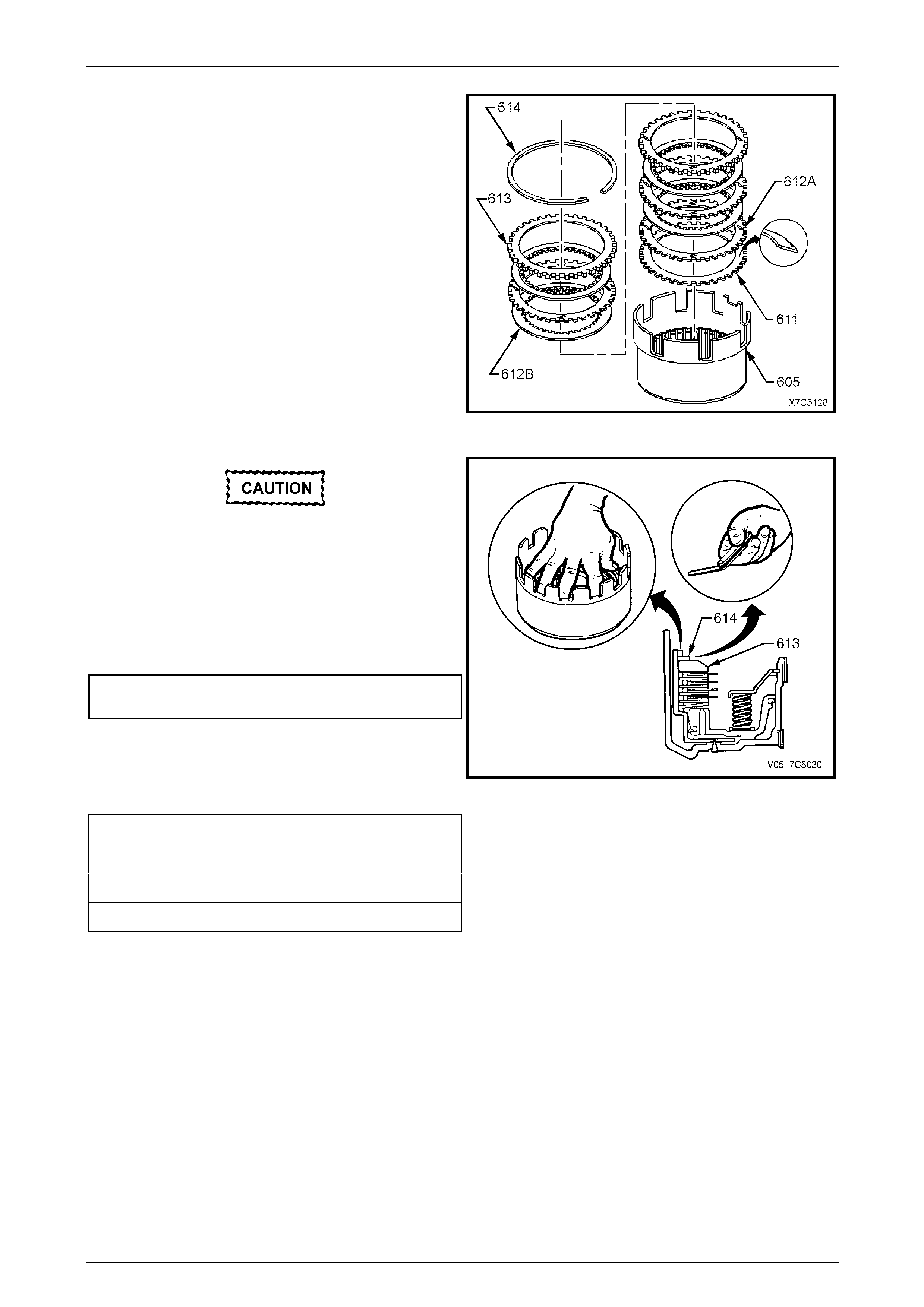
7D5 Automatic Transmission – 4L65E – Unit Repair Page 7D5–74
15–DEC–2005 Page 7D5–74
8 Reinstall the Belleville clutch plate (611), concave side
down, as shown.
9 Reinstall the remaining clutch plates, starting with a
steel plate (612A), then a composition plate (612B),
etc.
10 Reinstall the selectiv e backing plate (613), chamfered
side up and reinstall the retaining ring (614).
Figure 7D5 – 134
Excessive pressure will distort the Belleville
plate.
11 Apply an evenly distribute d medi um load,
(approximately 10 kg) to the backing plate (613) as
shown.
12 Measure the gap between the selective backing plate
and the retaining ring (614) with a feeler gauge.
Reverse input clutch backing plate
clearance specification........................... 1.02 – 1.95 mm
13 If the clearance is incorrect, select a suitabl e selective
backing plate from the table below and replace the
original backing plate.
Reverse input clutch selective backing plate specifications:
Plate Thickness (mm) Identification
7.25 – 7.41 2
6.52 – 6.68 3
5.79 – 5.95 4
NOTE
The identification numbers are stamped on the
backing plate.
Figure 7D5 – 135

7D5 Automatic Transmission – 4L65E – Unit Repair Page 7D5–75
15–DEC–2005 Page 7D5–75
Reverse Input Clutch Air Check
Prior to conducting this test, note the
following:
• Even though air pressure will be lost
through the bleed hole in the piston
during this process, a ssemble the re verse
input clutch completely.
• If tested with only the piston and return
spring assembly secured with a retaining
ring, the piston may over-stroke and
dislodge the snap ring and/or the piston
seals. In either case, there is a safety risk
that must be avoided.
1 Mount the reverse input clutch housing
assembly (605) and thrust washer (601), onto the
inverted oil pump assembly (4), as shown.
2 Apply air pressure in bursts to the oil pum p housing
passage (#4) and observe the movement of the clutch
piston and the clutch pack.
3 If the clutch does not apply, the air pressure may be
too low. Therefore, increase the air pressure before
condemning the clutch piston assembly. Figure 7D5 – 136
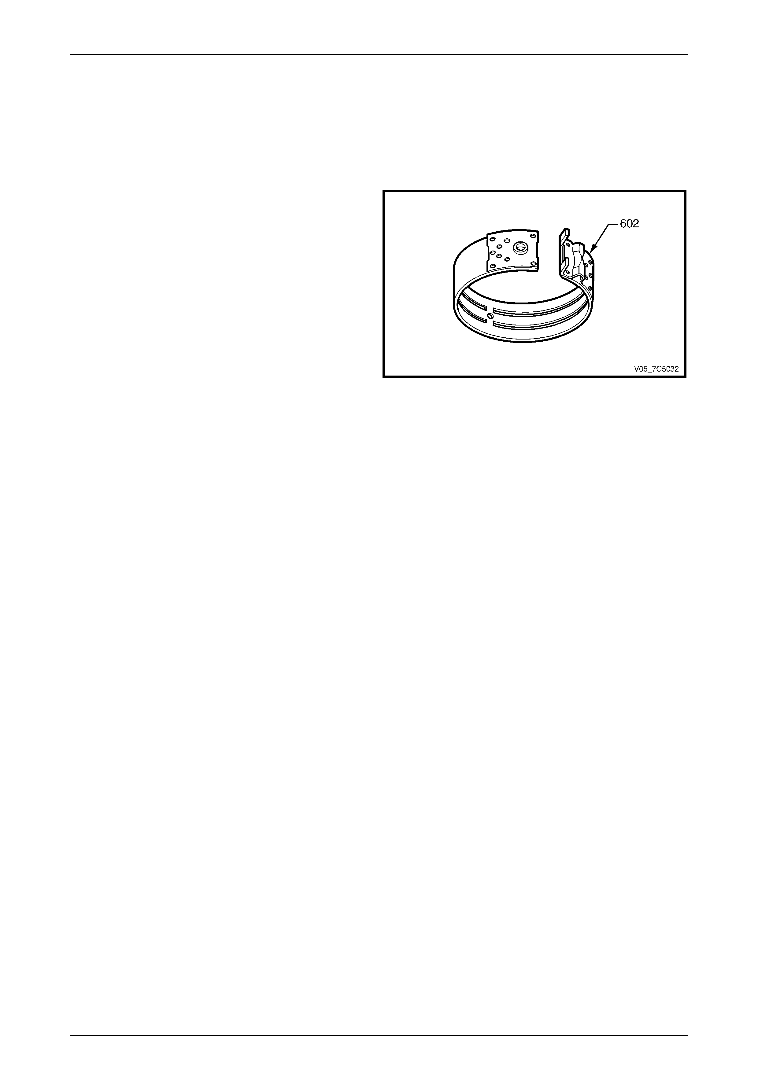
7D5 Automatic Transmission – 4L65E – Unit Repair Page 7D5–76
15–DEC–2005 Page 7D5–76
3.14 2-4 Band
LT Section No. — 04–200
Inspect
Inspect the 2-4 band assembly (602) for damage,
delamination or excessive wear.
Figure 7D5 – 137
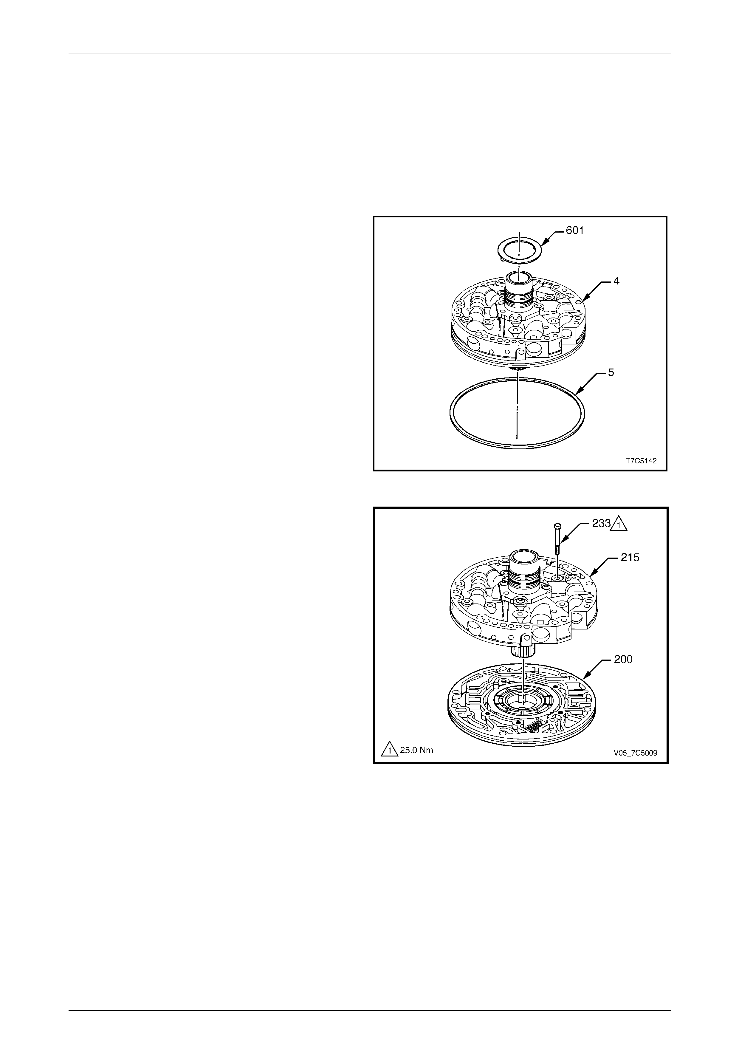
7D5 Automatic Transmission – 4L65E – Unit Repair Page 7D5–77
15–DEC–2005 Page 7D5–77
3.15 Oil Pump Assembly
LT Section No. — 04–200
Disassemble
Oil Pump Assembly
1 Position the oil pump assembly (4) with the stator shaft
protruding through a hol e in the workbench.
2 Remove the thrust washer (601), from the reverse
input clutch housing and the O-ring sea (5) f r om the
pump body.
Figure 7D5 – 138
3 Remove the bolt (233), five places, attaching the pump
cover (215) to the pump body (200).
4 Separate the pump cover from the pump body.
Figure 7D5 – 139
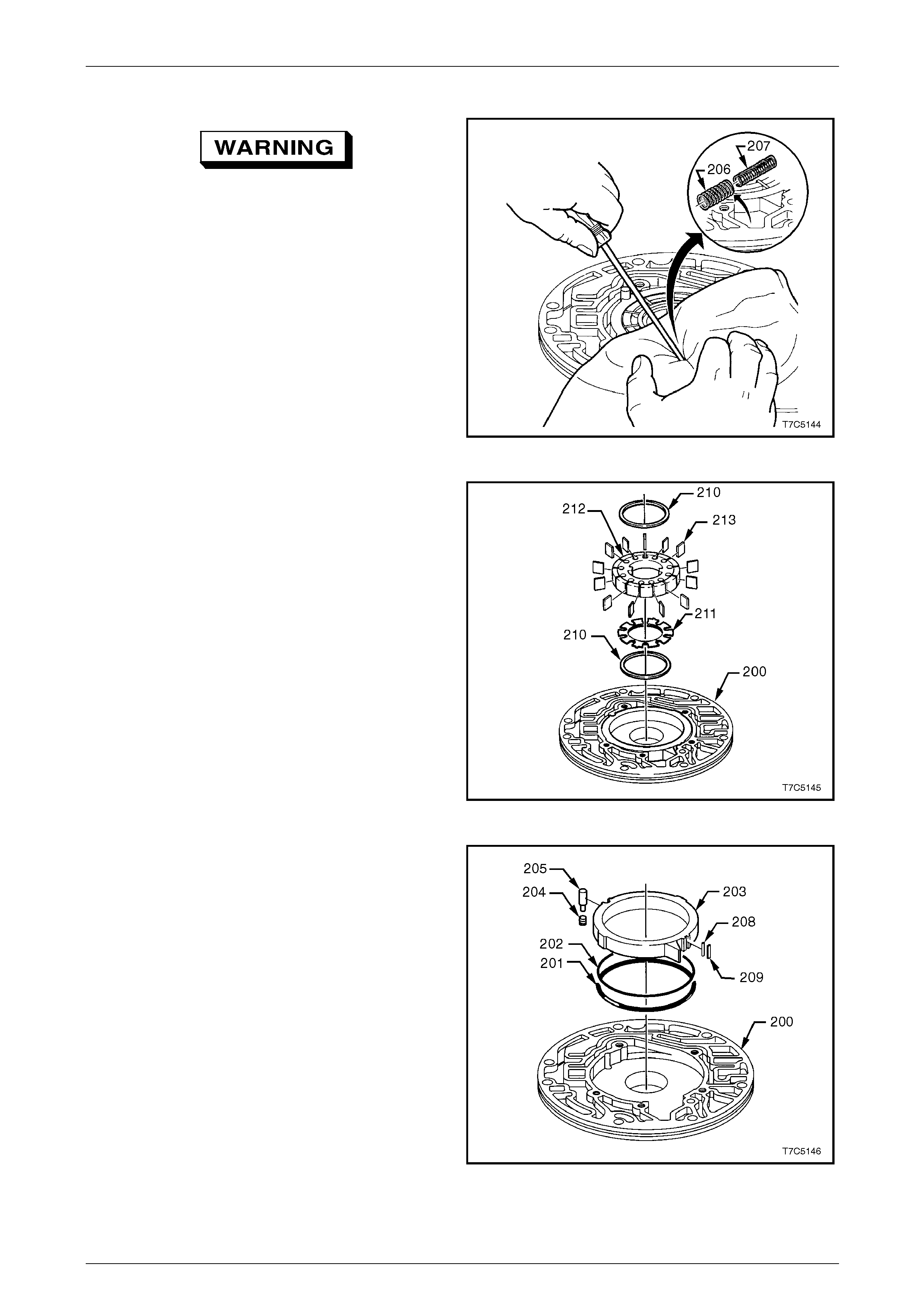
7D5 Automatic Transmission – 4L65E – Unit Repair Page 7D5–78
15–DEC–2005 Page 7D5–78
Oil Pump Body
To prevent possible injury, place a rag over
the springs before removal, as they are u nder
high load.
1 Compress the pump slide springs (206 and 207) with a
suitable lever or long nose pliers and remove the
springs.
Figure 7D5 – 140
NOTE
Note the position of the wear marks o n the pump
vanes to assist with the reinstallation.
2 Remove following components from the pump cavity in
the body (200):
a upper pump vane guide ring (210),
b thirteen pump vanes (213), note wear mark
patterns for reassembly,
c pump rotor (212),
d rotor guide (211),
e lower pump vane guide ring (210),
Figure 7D5 – 141
f slide (203),
g slide seal (209),
h seal support (208),
i pivot slide pin (205) and spring (204) and
j slide seal ring (201) and back up seal (202).
Figure 7D5 – 142
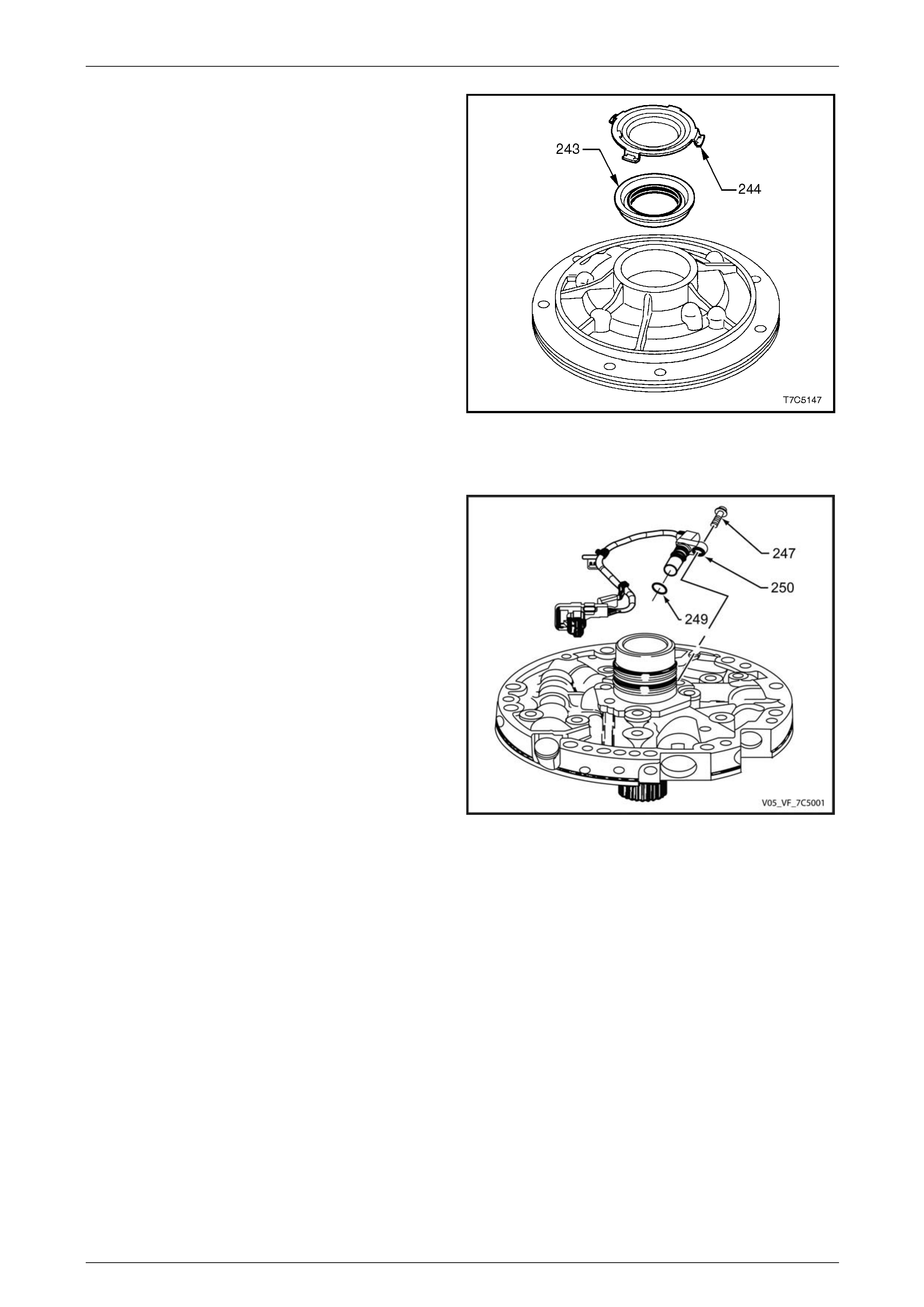
7D5 Automatic Transmission – 4L65E – Unit Repair Page 7D5–79
15–DEC–2005 Page 7D5–79
3 Use a screwdriver to prise out the front helix seal
retainer (244) and oil seal assembly (243) from the
pump body.
Figure 7D5 – 143
Input Speed Sensor
1 Remove the input speed sensor (ISS) retaining bolt
(247).
2 Remove the ISS retaining clips and ISS assembly
(250).
Figure 7D5 – 144
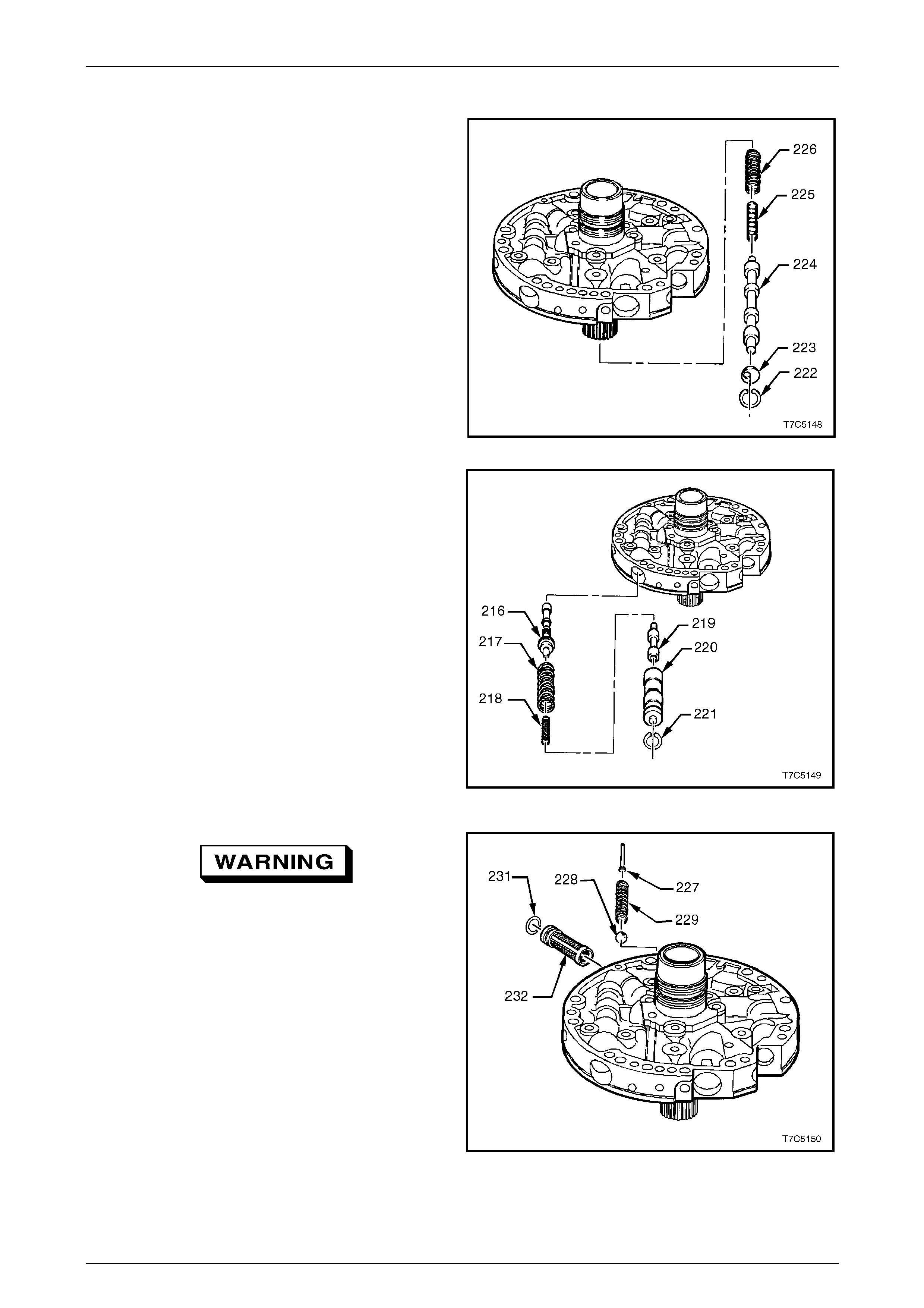
7D5 Automatic Transmission – 4L65E – Unit Repair Page 7D5–80
15–DEC–2005 Page 7D5–80
Oil Pump Cover
1 Compress the converter clutch apply stop valve (223)
with a screwdriver and use circlip pliers to remove the
circlip (222).
2 Slowly release spring force and remove the stop valve,
the converter clutch apply valve (224) and the two
converter clutch valve springs (225 and 226). Lay out
the components for inspection.
Figure 7D5 – 145
3 Using a screwdriver, push in the reverse boost valve
sleeve (220) against spring force and remove the
circlip (221) with suitable circlip pliers.
4 Slowly release spring force and remove the reverse
boost valve sleeve, the reverse boost valve (219), the
pressure regulator isolator spring (2 18), the pressure
regulator spring (217) and the pressure re gulator
valve (216). Lay out all components for insp ection.
Figure 7D5 – 146
To prevent possible injury, place a rag over
the assembly before remo ving the pin, as the
spring is under very high load.
5 Prise the pressure release pin (227) from the pump
cover and remove the spring (229) and ball (228).
6 Using long nose pliers, pull the filter screen (232) and
O-ring seal (231) from the pump cover.
Figure 7D5 – 147
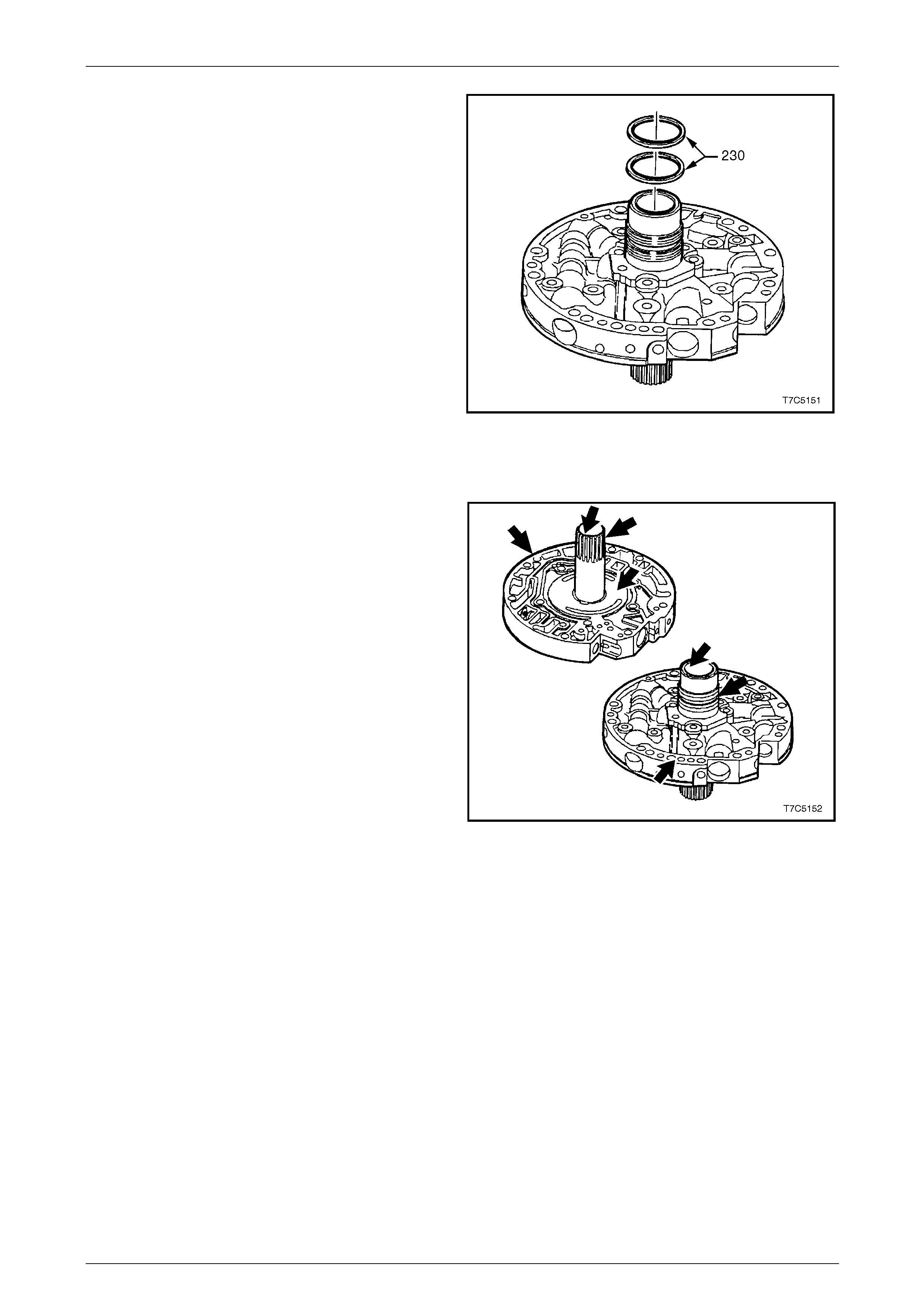
7D5 Automatic Transmission – 4L65E – Unit Repair Page 7D5–81
15–DEC–2005 Page 7D5–81
7 Carefully cut the two stator shaft seals (230) and
discard.
8 Wash all components with solvent and air dry. Do not
dry with a cloth.
Figure 7D5 – 148
Inspect
1 Inspect the pump cover (215) and body (200) for:
• worn or damaged bushes,
• porosity,
• scored or irregular mating faces,
• foreign material,
• cross channel leaks and
• ring groove damage.
2 Inspect the valve trains for chips, burrs, distortion,
blocked passages and free m oveme nt of components
in bores. Remove burrs with lappi ng compound, as
required.
3 Inspect pressure relief components for dama ge or
distortion. Figure 7D5 – 149
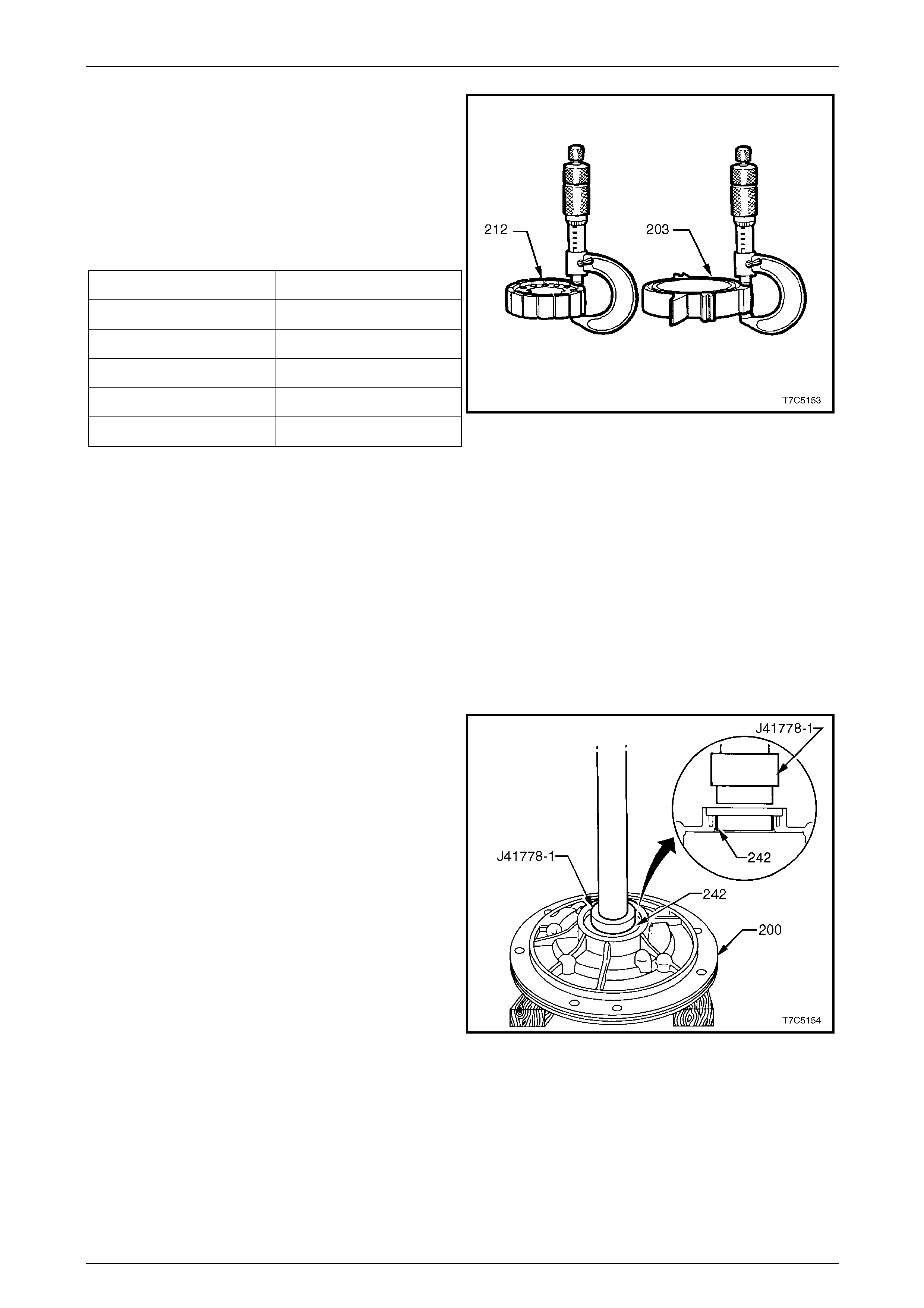
7D5 Automatic Transmission – 4L65E – Unit Repair Page 7D5–82
15–DEC–2005 Page 7D5–82
4 Inspect the pump rotor and slide for cracks.
5 If inspection indicates the pump rotor (212) or
slide (203) require replac ement, measure the
components over undamaged surfaces and select
replacement parts from the same size group in the
following table.
Lightly hone both sides of replacement rotor or slide to
remove any nicks or burrs.
Oil pump rotor and slide selec t ion table:
Thickness (mm) Identification
17.948 – 17.961 1
17.961 – 17.974 2
17.974 – 17.987 3
17.987 – 18.000 4
18.000 – 18.013 5
NOTE
While there are no identification numbers
stamped on the oil pum p rotor and sl ide, the size
grading is used in manufacture to achi eve a best
match rotor and slide to the oil pump body.
Therefore, if inspection shows excessive wear
and/or damage to these components, the
complete oil pump body assembly must be
replaced.
Figure 7D5 – 150
Oil Pump Bushes – Replace
Pump Body Bush
1 Remove the pump cavity body bush (242), using a
bench press and Tool No. J4177 8-1.
Figure 7D5 – 151
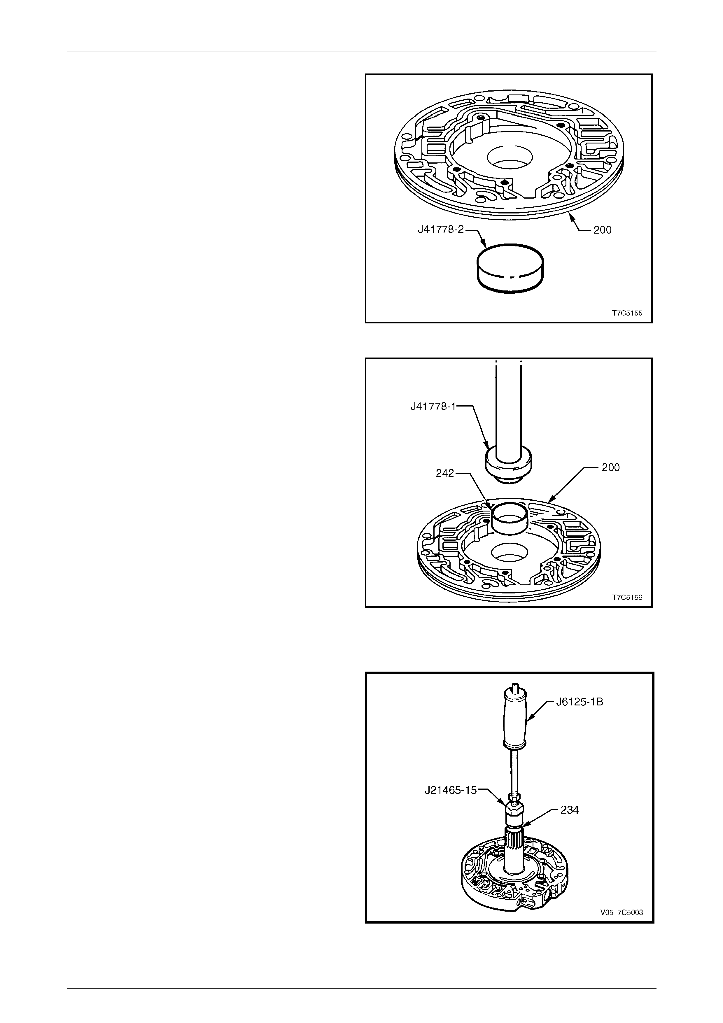
7D5 Automatic Transmission – 4L65E – Unit Repair Page 7D5–83
15–DEC–2005 Page 7D5–83
2 Before installing a new bush place the stop pl ate, T ool
No. J41778-2, under the cavit y of the pum p
body (200).
Figure 7D5 – 152
3 Position both components under a bench press.
4 Install a new bush (242) into the cavity of the pump
body (200), using Tool No. J41778-1.
NOTE
Having the stop plate under the cavity of the
pump body, effectively limits how far the new
bush can be installed.
Figure 7D5 – 153
Pump Cover Bushes
1 Using bush remover, Tool No. J2146 5-15 and slide
hammer, Tool No. J6125-1B, remove the stat or shaft
front bush (234).
Figure 7D5 – 154
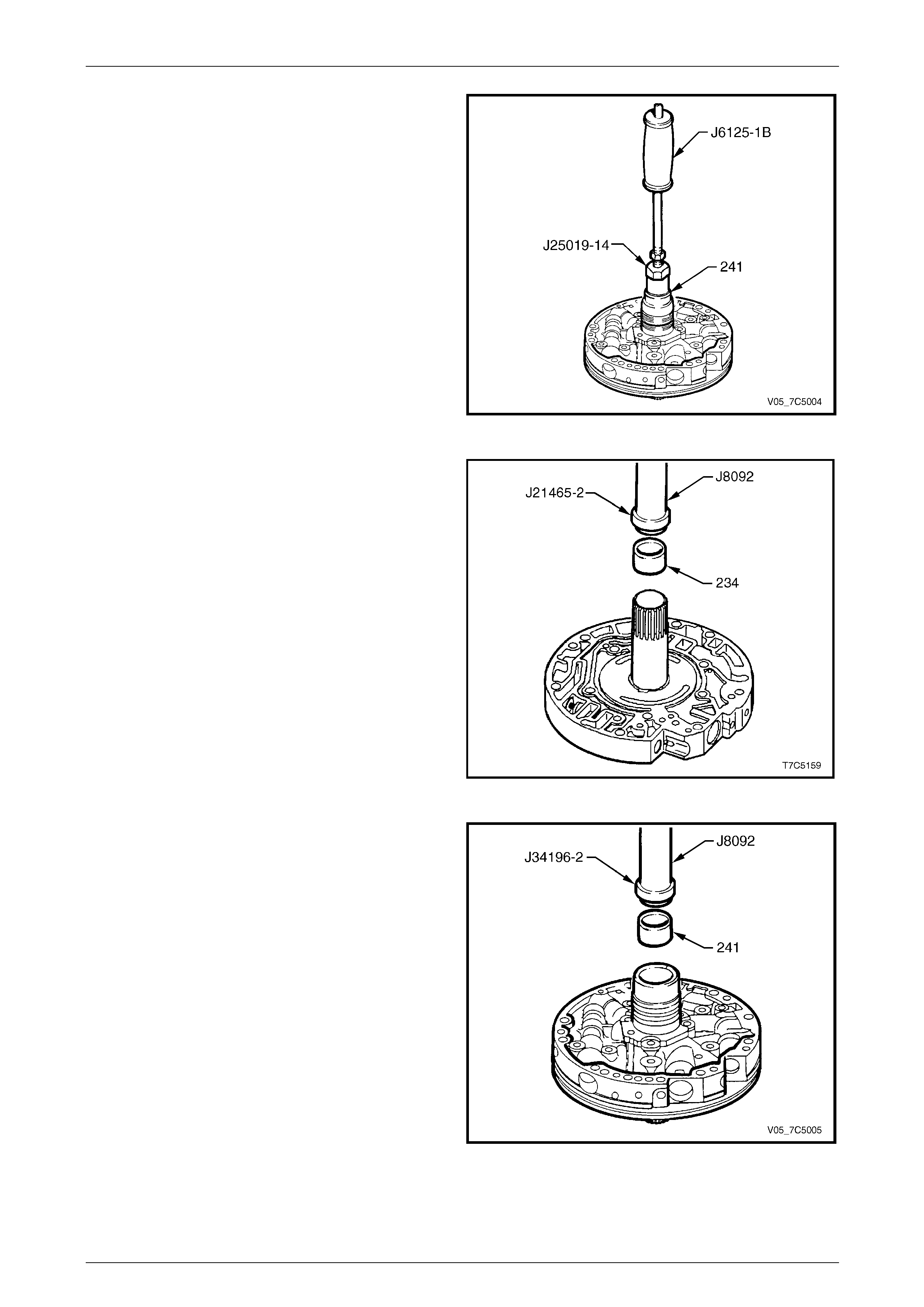
7D5 Automatic Transmission – 4L65E – Unit Repair Page 7D5–84
15–DEC–2005 Page 7D5–84
2 Using bush remover, Tool No. J2501 9-14 and slide
hammer, Tool No. J6125-1B, remove the stat or shaft
rear bush (241) from the pump cover.
Figure 7D5 – 155
3 Install a new stator shaft front bush (234), using
installer Tool No. J21465-2 an d driver h andle, Tool
No. J8092.
Figure 7D5 – 156
4 Install a new stator shaft rear bush (241), using
installer Tool No. J34196-2 an d driver h andle, Tool
No. J8092.
NOTE
Tool No. J34196-2 is part of kit Tool No.
J34196B.
Figure 7D5 – 157
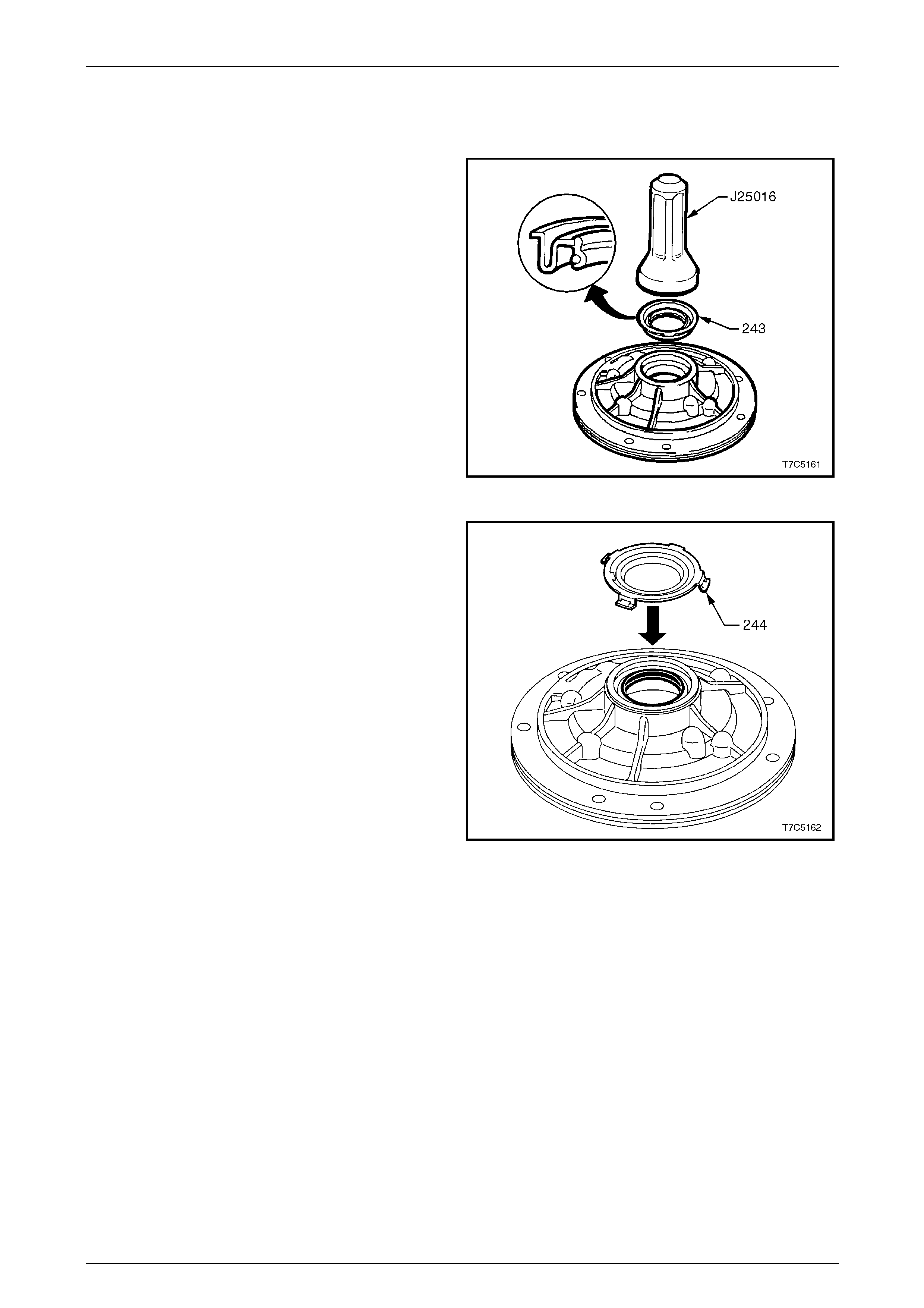
7D5 Automatic Transmission – 4L65E – Unit Repair Page 7D5–85
15–DEC–2005 Page 7D5–85
Reassemble
Oil Pump Body
1 Install a new oil seal (243), using the seal installer,
Tool No. J25016.
Figure 7D5 – 158
2 Install the front helix retainer (244).
Figure 7D5 – 159
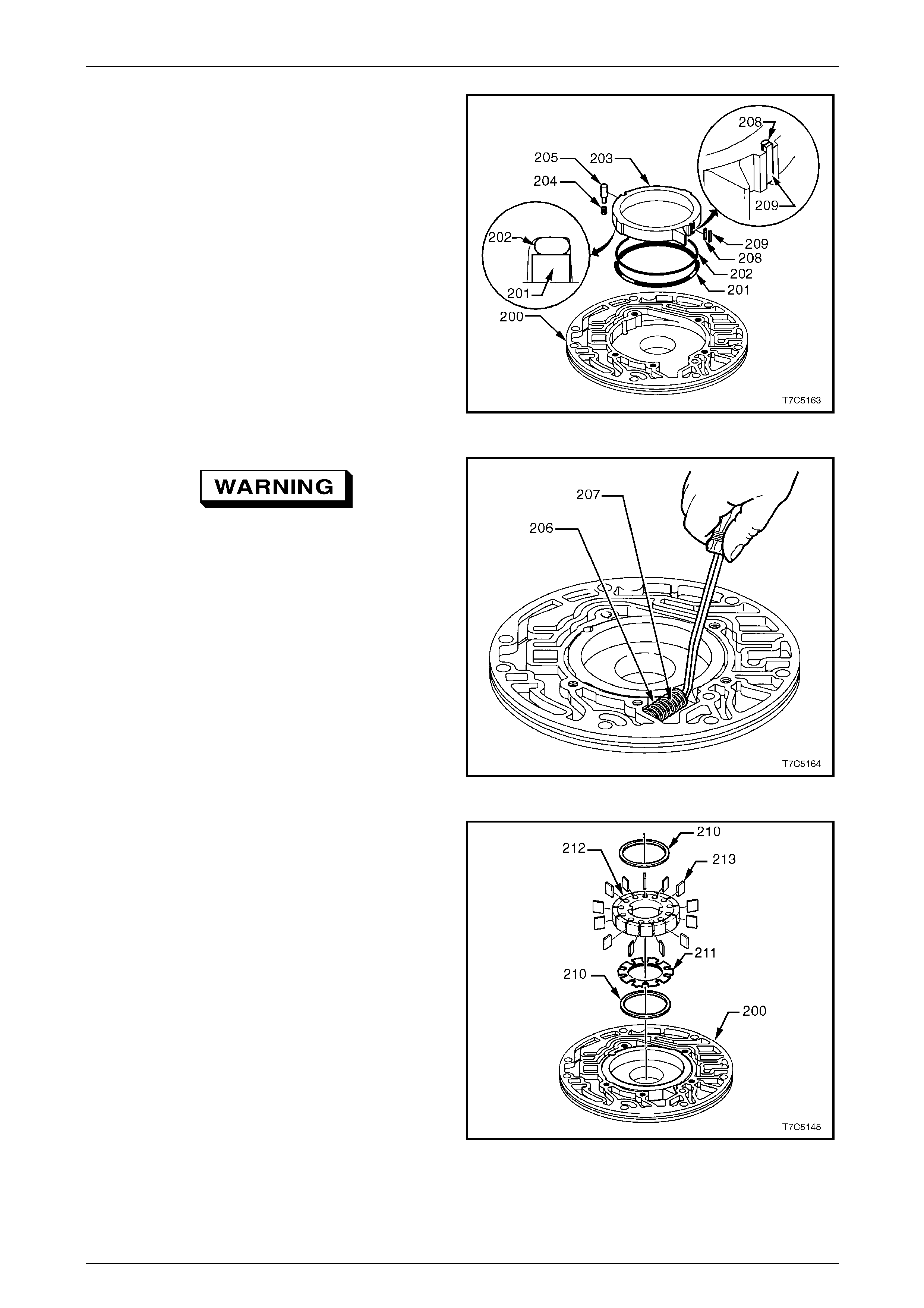
7D5 Automatic Transmission – 4L65E – Unit Repair Page 7D5–86
15–DEC–2005 Page 7D5–86
3 Install a new slide seal back-u p O-ring (20 2) and the
support ring (201) into the groove on the rear side of
the slide (203), retaining both with petroleum jelly.
4 Reinstall the slide into th e pump body (200), aligning
the notch with the pivot pin hole.
5 Reinstall the slide seal support (208) together with the
slide seal (209) into notch in p ump sli de.
6 Install the pivot spring (204) and pin (205).
Figure 7D5 – 160
To prevent possible injury, wear eye
protection when compressing both springs,
as their tension is very high.
7 Carefully compress the slide springs (206 and 207)
with long nose pliers, then use a wide bladed
screwdriver (or a piece of hacksaw blade) against the
slide flange to assist and reinstall the springs in the
pump body.
Figure 7D5 – 161
8 Reinstall the lower pump vane guide ring (210) into the
pump body (200).
9 Locate the rotor guide (211) onto the rotor (212) an d
retain with petroleum jelly.
10 Reinstall the rotor, with the rotor guide facing the
pump body.
11 Reinstall the pump vanes (213), with the wear marks
in the same position as noted on dis assemb ly.
12 Reinstall the upper pump va ne guide ring (210).
Figure 7D5 – 162
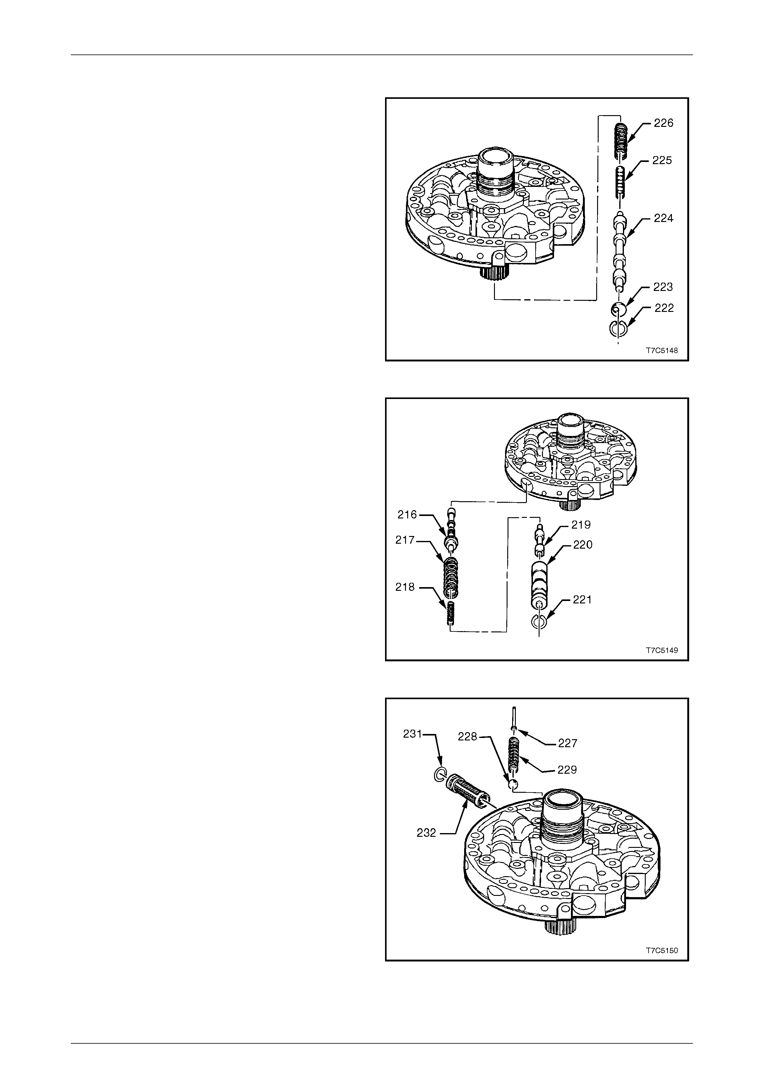
7D5 Automatic Transmission – 4L65E – Unit Repair Page 7D5–87
15–DEC–2005 Page 7D5–87
Oil Pump Cover
1 Reinstall the inner (225) an d outer (226) springs onto
the stem of the converter clutch apply valve (224) and
reinstall as an assembly into the valve bore of the
pump cover.
2 Reinstall the stop valve (223) and while compressing
the springs, reinstall the circlip (222) in the converter
clutch valve bore, ensuring the circlip is correctly
seated in groove.
Figure 7D5 – 163
3 Reinstall the pressure regul ator valve (216), pressure
regulator isolator spring (218) and pressure regulator
spring (217) into the pressure regulator valve bore of
the pump cover.
4 Reinstall the reverse boost valve (219) into the reverse
boost valve sleeve (220), and reinstall the assembly
into the pressure regulator valve bore, aligned as
shown.
5 While compressing the valve train against the
pressure regulator spring forces, install the
circlip (221), ensuring it is correctly seated in groove.
Figure 7D5 – 164
6 Reinstall the pressure relief b all (2 28), spring (229)
and pin (227) in the pump cover.
7 Reinstall the filter screen (232) with a new seal (231)
in the pump cover.
Figure 7D5 – 165
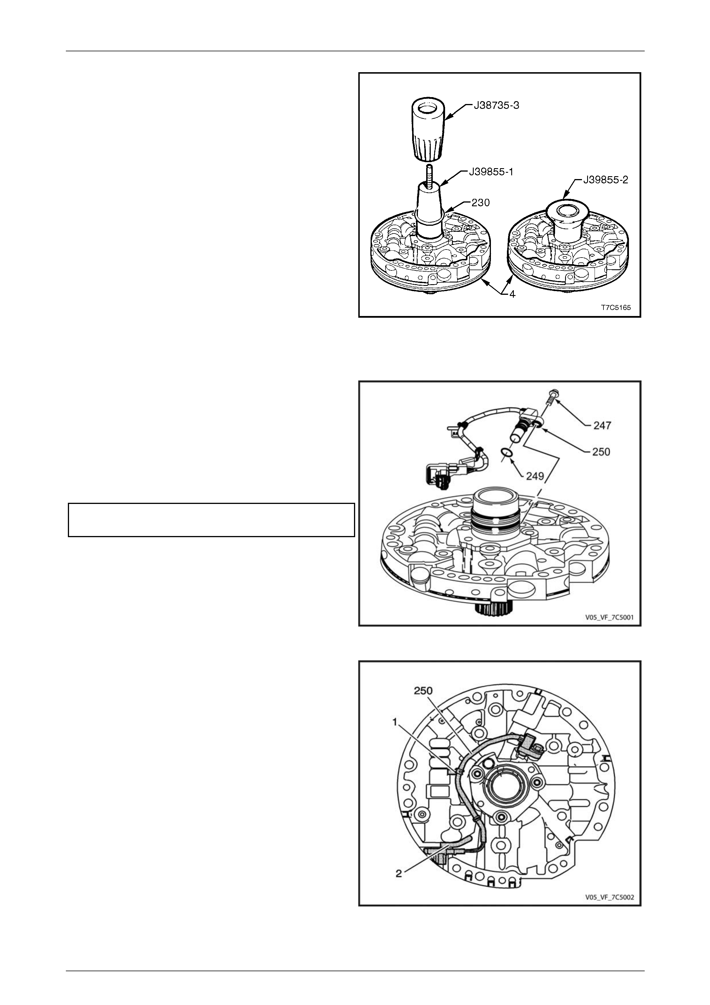
7D5 Automatic Transmission – 4L65E – Unit Repair Page 7D5–88
15–DEC–2005 Page 7D5–88
8 Expand two new solid stator shaft oil seals (230) over
Tool No. J39855-1 and install them using Tool No.
J38735-3.
9 Once both seals are installed, compress to size by
fitting sizing tool, Tool No. J39855-2, using petroleum
jelly to assist, as required. Leave sizing tool installed
until the oil pump assembl y is reinstalled into the
transmission.
Figure 7D5 – 166
Input Speed Sensor
1 Remove the input speed sensor (ISS) O-ring (249).
2 Lubircate NEW O-ring (249) with transmission fluid
and position in ISS O-ring groove.
3 Insert ISS (250) into oil pump ISS bore and fully seal.
4 Align ISS bolt insert with oil pump mounting bolt ho le.
5 Insert bolt (247). Tighten bolt to specified torque.
Input speed sensor attaching bolt
torque specification...................................9.0 – 11.0 Nm
Figure 7D5 – 167
6 Route the ISS assembly (250) wire harness as shown.
7 Install harness bracket (1) and (2) in the locations
shown. Ensure wire harness does not cover pump
mounting holes and lays flat a gainst the pump
housing.
Figure 7D5 – 168
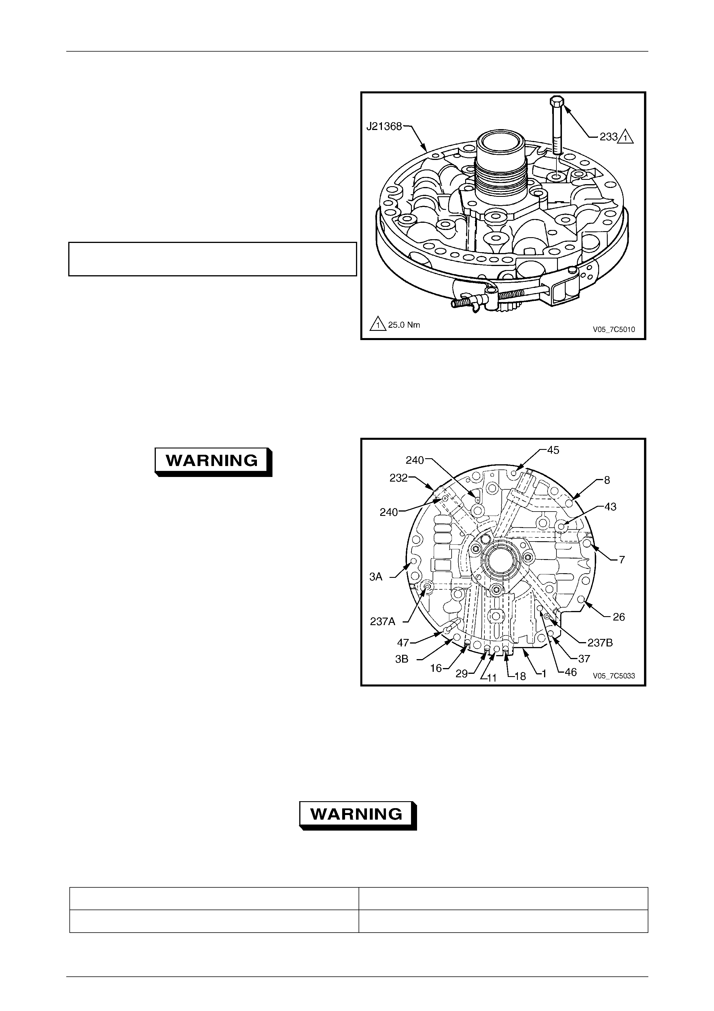
7D5 Automatic Transmission – 4L65E – Unit Repair Page 7D5–89
15–DEC–2005 Page 7D5–89
Oil Pump Assembly
1 Place the stator shaft through a hole in the workbench.
2 Install the pump cover assembly on the pump body
assembly and reinstall the attaching bolts (233), five
places, finger tight.
3 To align the pump cover with the pum p body, fit the
alignment band tool, Tool No. J2136 8, as shown and
secure finger tight.
4 Tighten the pump cover to pump body attaching bolts
to the correct torque specification.
Pump cover to pump body attaching
bolt torque specification.....................................25.0 Nm
5 Remove the pump assembly alignment band tool.
Figure 7D5 – 169
Oil Pump Air Checks
Introduction
To prevent possible injury, wear eye
protection when performing any of the
following air check procedures.
Air check the oil pump (1) as indicated in the following table
to ensure all passages are open a nd all cup plugs are
correctly installed, refer to Air Checks Table.
NOTE
To check for a restriction, instead of a blocked
passage, perform the tests with a piston type oil
can filled with transmission fluid, rather than
using compressed air.
Figure 7D5 – 170
Air Checks Table
The numbers within the following table represent the orifice identification for the passages of the oil pump. To vie w the
location of these orifices on the oil pump, refer to Figure 7D5 – 170.
When checking for air out through the filter
screen, take care as the air pressure may
blow the filter screen out of the oil pump.
Blow Air In Orifice: Check For Air Out:
18 Forward Clutch Feed The second hole down inside the stator shaft bore.

7D5 Automatic Transmission – 4L65E – Unit Repair Page 7D5–90
15–DEC–2005 Page 7D5–90
Blow Air In Orifice: Check For Air Out:
11 Torque Signal Block hole (47) with a finger. Inject short blasts of
compressed air into hole (11). The Boost valve will click
with each blast of air.
29 3 - 4 Clutch The first hole do wn inside the stator shaft bore.
16 Reverse Input Clutch The reverse input feed hole between the two oil seals on
the outside of the pump hub. The air seats the reverse
check ball, shown as (237A).
3 (B) Line Pressure (to Valve Body) Line Pressure hole (3A) an d through the filter screen (232).
47 Void This drilling terminates in a cavity in the pump body.
3 (A) Line Pressure (to Pressure Tap Point) Line pressure hole (3B) and through the filter screen (232).
45 Vent The vent cavity.
8 From Oil Cooler From the lube cavity in the top of the stator support shaft.
43 Torque Converter Clutch Release Insert an Allen key through the hol e in the converter clutch
valve and push on the valve against spring force. Air will
then come out of the lower hole inside the stator support.
7 To Oil Cooler Through the filter screen (232)
48 Torque Converter Clutch Regulated Apply Through the hole normall y filled by the converter clutch
solenoid.
37 Overrun Clutch The third hole down inside the stator support shaft. Air
pressure will also seat the check valve, sho wn as (237B).
46 Seal Drain Back Between the stator shaft and the oil pump body seal.
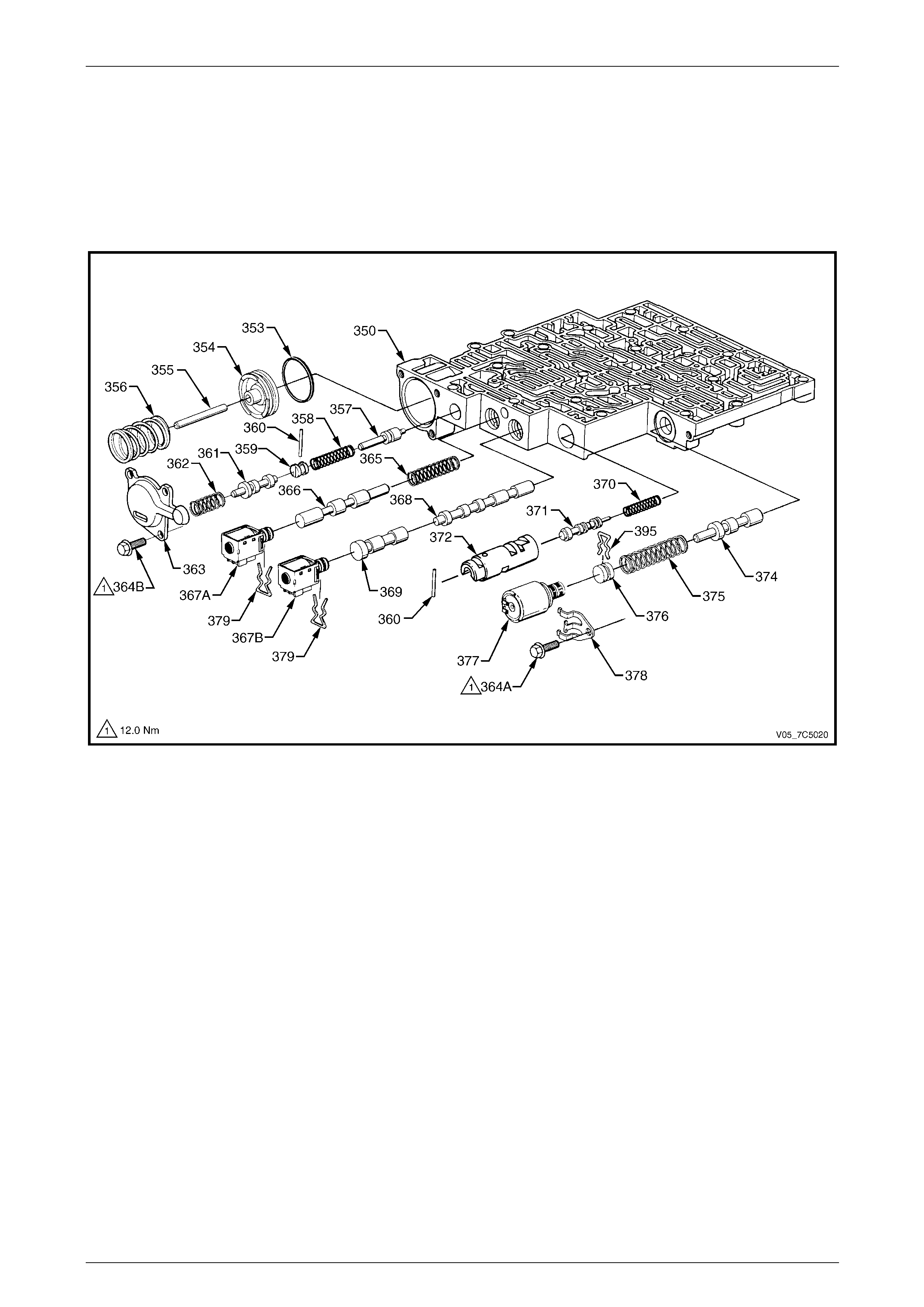
7D5 Automatic Transmission – 4L65E – Unit Repair Page 7D5–91
15–DEC–2005 Page 7D5–91
3.16 Control Valve Body
LT Section No. — 04–200
Exploded Views
View A
Figure 7D5 – 171
Legend
350 Valve Assembly, Control Body
353 Seal, Forward Accumulator
354 Piston, Forward Accumulator
355 Pin, Forward Accumulator
356 Spring, Forward Accumulator
357 Valve, Forward Abuse
358 Spring, Forward Abuse Valve
359 Plug, Bore
360 Pin, Coiled Spring
361 Valve, Low Overrun
362 Spring, Low Overrun Valve
363 Cover, Forward Accumulator
364A Bolt, Pressure Control Solenoid Retainer
364B Bolt, Forward Accumulator Cover
365 Spring, 1 - 2 Shift Valve
366 Valve, 1 - 2 Shift
367A 1 - 2 Shift Solenoid (A)
367B 2 - 3 Shift Solenoid (B)
368 Valve, 2 - 3 Shift
369 Valve, 2 - 3 Shuttle
370 Spring, 1 - 2 Accumulator Valve
371 Valve, 1 - 2 Accumulator
372 Sleeve, 1 - 2 Accumulator
374 Valve, Actuator Feed Limit
375 Spring, Actuator Feed Limit Valve
376 Plug, Bore
377 Pressure Control Solenoid (PCS)
378 Retainer, Pressure Control Solenoid
379 Retainer, Shift Solenoid
395 Retainer, Bore Plug and Solenoid
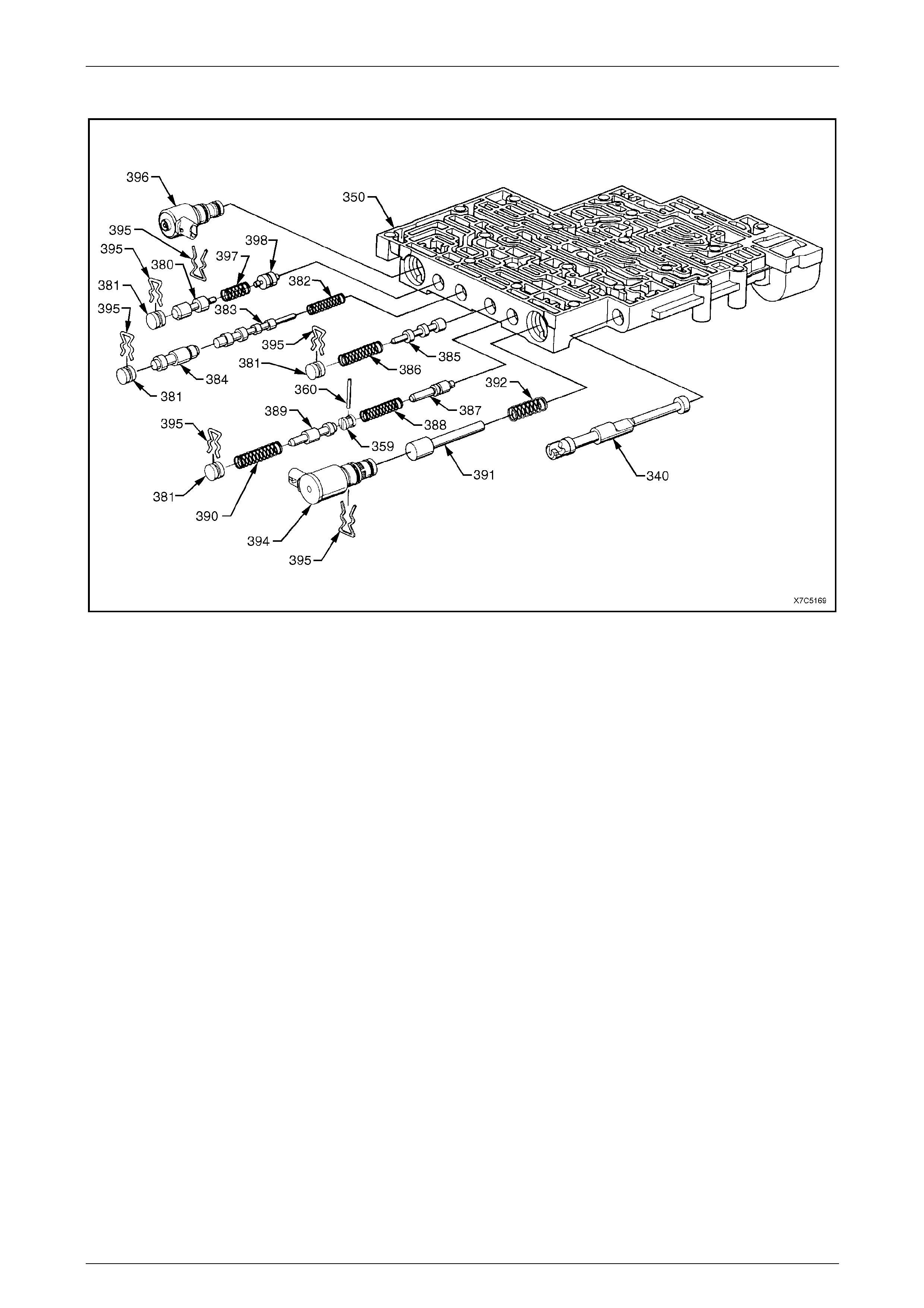
7D5 Automatic Transmission – 4L65E – Unit Repair Page 7D5–92
15–DEC–2005 Page 7D5–92
View B
Figure 7D5 – 172
Legend
340 Valve, Manual
350 Valve Assembly, Control Body
359 Plug, Bore
360 Pin, Coiled Spring
380 Valve, Regulator Apply
381 Plug, Bore
382 Spring, 4 - 3 Sequence Valve
383 Valve, 4 - 3 Sequence
384 Valve, 3 - 4 Relay
385 Valve, 3 - 4 Shift
386 Spring, 3 - 4 Shift Valve
387 Valve, Reverse Abuse
388 Spring, Reverse Abuse Valve
389 Valve, 3 - 2 Downshift
390 Spring, 3 - 2 Downshift Valve
391 Valve, 3 -2 Control
392 Spring, 3 -2 Control Valve
394 3 - 2 Control Solenoid
395 Retainer, Bore Plug and Solenoid
396 Torque Converter Clutch PWM Solenoid
397 Spring, Regulator Supply
398 Valve, Isolator

7D5 Automatic Transmission – 4L65E – Unit Repair Page 7D5–93
15–DEC–2005 Page 7D5–93
Disassemble
Some valve trains are under pressure from
spring force. To prevent possible inju ry, place
a rag over the bores while removing roll pins
and retainer clips.
Valves, springs and bushes must be laid out
in the exact order of removal, to ensure
correct orientation w hen reassembling.
NOTE
The suggested disassembly sequence is not
mandatory. The Exploded Views in this Section,
identify the various components and show their
location in the control valve body.
1 Remove the pressure control solenoid retaining bolt (364A), the retainer (378) and the soleno id (377), refer to
Figure 7D5 – 171.
2 While supporting the bore plug (376), remove the retaining clip (395), the bore plug, the actuator feed limit valve
spring (375) and valve (374).
3 Remove the 2-3 shift solenoid retaining clip (379), the solenoid (367B). Then remove the valve train consisting of
the 2-3 shuttle valve (369) and 2-3 shift valve (368).
4 Remove the 1-2 shift solenoid retaining clip (379), the solenoid (367A), the 1-2 shift valve (366) and spring (365).
5 Remove the 1-2 accumulator roll pin (360), the 1-2 accumulator sleeve (3 72), valve (371) and spring (370).
6 Remove the forward accumulator cover retaining bolt (364B), three places, and the cover (363).
7 Remove the forward accumulator spring (356), piston (354) and pin (355). Remove the sealing ring (353) from the
piston and discard it.
8 Remove the low overrun valve spring (362) and valve (361).
9 While supporting the bore plug (359) with a suitable probe, remove the rol l pin (3 60), the bore plug, the forward
abuse valve spring (358) and valve (357).
10 Turn the control valve body (350) aroun d and remove the manual valve (340), refer to Figure 7D5 – 17 2 .
11 While supporting the 3-2 control solenoid (394), remove the retaining clip (395) and the solenoid.
12 Remove the 3-2 control valve (391) and spring (392).
13 Hold the 3-2 downshift bore plug (381) and remove the retaining clip (395); then remove the 3-2 downshift valve
spring (390) and valve (389).
14 While supporting the reverse abuse bore plu g (359) with a suitable probe, remove the roll pin (3 60) and plug; then
remove the reverse abuse valve sprin g (388) and valve (387).
15 Support the 3-4 shift valve bo r e plug (381) and remove the retaining clip (395); then remove the 3-4 shift valve
spring (386) and valve (385).
16 Support the 3-4 relay valve bore plug (381) and remove the retaining clip (395); then remove the 3-4 relay
valve (384), the 4-3 sequence valve (383) and spring (382).
17 Support the regulator apply valve bore plug (381) and remove the retaining clip (395), then remove the regulator
apply valve (380), spring (397) and isolator valve (398).
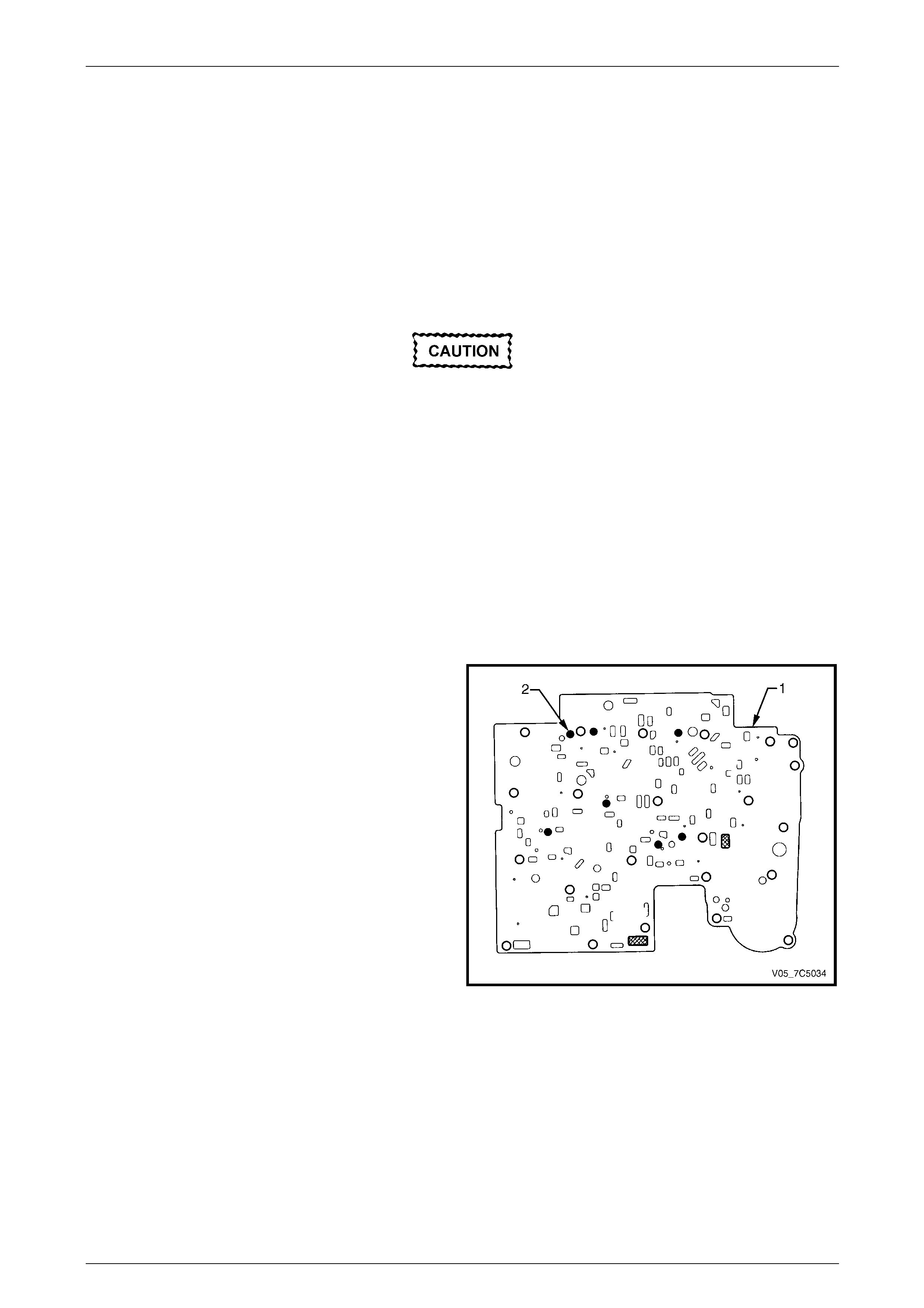
7D5 Automatic Transmission – 4L65E – Unit Repair Page 7D5–94
15–DEC–2005 Page 7D5–94
NOTE
The torque converter clutch PWM solenoid (396)
is removed prior to the TCC solenoid, during the
removal of the control valve body from the
transmission.
Clean and Inspect
Control Valve Body
1 Clean all valves, springs, bushes an d the control valve body in clea n solvent and dry with compressed air.
Too much lapping of a valve will create
excessive clearances, increasing the risk of
valve malfunction.
2 If it is necessary to clean a valve, micro fine lapp ing compound with a 900 grit or finer may be used. T he use of a
honing stone, fine sandpaper or crocus cloth is not recommended for servicing stuck valves. All valve lands have
sharply machined corners, necessary for keeping the bore clean. If these corners are rounded, foreign material c an
wedge between the valve and its bore, causing the valve to stick.
3 Inspect all valves, plugs and sleeve for scoring, scratches or nicks, replace as required.
4 Inspect all springs for damaged or distorte d coils, replace as required.
5 Inspect valve body casting for porosity, cracks, damaged machined surfaces, blocked or partially blocked passages
and scored or damaged v alve train bores, replace as requir ed.
Spacer Plate Evaluation
During inspection of the spacer plate (1), it is acceptable for
some check ball peening to be evident at the seven
locations (2), as shown.
Perform the two following procedures to establish the
serviceability of the spacer plate.
Figure 7D5 – 173
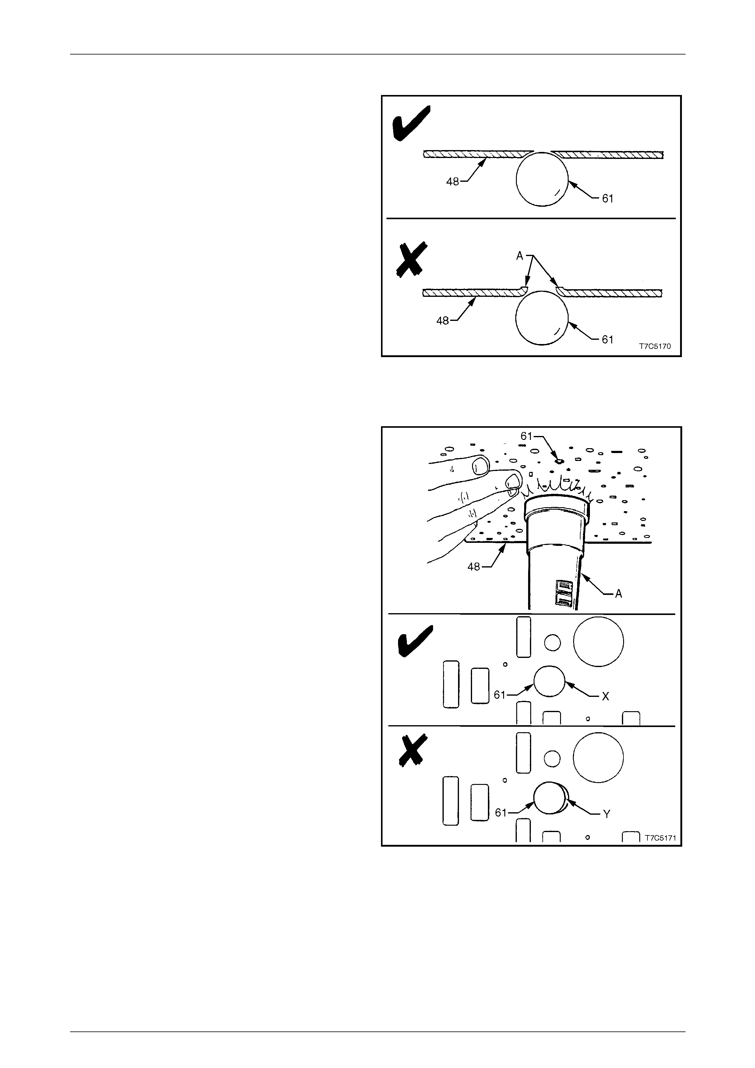
7D5 Automatic Transmission – 4L65E – Unit Repair Page 7D5–95
15–DEC–2005 Page 7D5–95
Procedure 1
The spacer plate (48) must be inspected thoroughly for
raised material on the opposite side of all check ball (61)
locations. If the material on the opposite side is raised (A),
the peening is considere d to be too severe and the spacer
plate must be replaced.
Figure 7D5 – 174
Procedure 2
To verify if a check ball location has peened evenly and the
check ball is seating correctly, proceed as follows:
a place the check ball (61) at its location on the spacer
plate (48).
b Use a torch (A) to shine a beam of light on the
opposite side and check for light between the spacer
plate and the check ball.
c No light should be visible, as indicated at (X). If it is, as
indicated by (Y), the spacer plate must be replaced.
d Perform this check for all check ball locations on the
spacer plate.
Figure 7D5 – 175
Reassemble
Reassembly of the control valve body is the reverse of the disassembly procedure, noting the following:
1 Note the orientation of all valves, sleeves and solenoids bef ore reinstalling in the control valve body, refer to
Exploded Views in this Section.

7D5 Automatic Transmission – 4L65E – Unit Repair Page 7D5–96
15–DEC–2005 Page 7D5–96
2 When reinstalling eac h of the bore plug retainer clips, ensure they are installed from the side of the valve body
mating with the transmission case (machined side). Failing to do so would cause damage to the wiring harness on
reinstallation. Also, correct installation of the fluid filter would not be p ossib le, preventing fitment of the oil pan.
3 Tighten the bolt attaching the pressure control solenoid reta iner to the correct torque specification.
Pressure control solenoid retainer
attaching bolt torque specification......................12.0 Nm
4 Tighten the three bolts attaching the forward accumulator co ver to the correct torque specification.
Forward accumulator cover attaching
bolt torque specification.....................................12.0 Nm
5 The torque converter clutch PWM solenoid (396) is reinstalled after the T CC solenoid has been attached to the
control valve body, during the reinstallatio n o f the control valve body to the transmission case. refer to
Section 7D4 Automatic Transmission – 4L65E – On-vehicle Servicing .
6 To prevent contamination, store the assembl ed control valve body in a clean plastic bag until it is reinstalled to the
transmission.
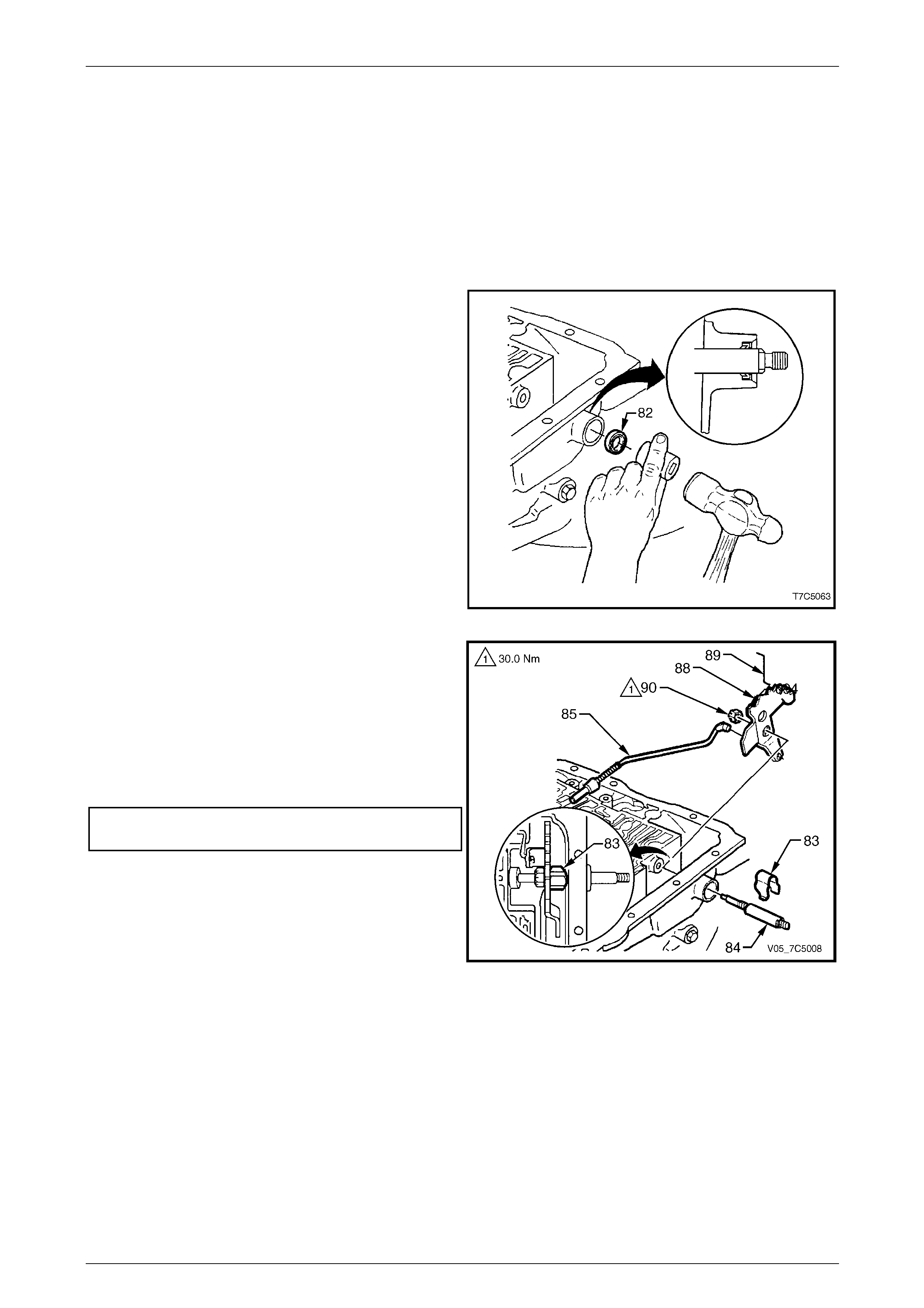
7D5 Automatic Transmission – 4L65E – Unit Repair Page 7D5–97
15–DEC–2005 Page 7D5–97
4 Transmission Reassembly
4.1 Manual Shaft, Inner Linkage and Seal
LT Section No. — 04–190
Reinstall
1 Using a suitable socket, install a new manual shaft
seal (82) into the transmission case. Lubrica t e the seal
lips with a small amount of clean transmissio n fluid.
Figure 7D5 – 176
2 Reinstall the parking pawl actuator (85) to the inner
detent lever (88).
3 Remove any burrs from the manual shaft (84),
lubricate it with clean transmission fluid and carefully
install into the transmission case, locatin g the inner
detent lever over the flats on the shaft.
4 Install the manual shaft nut (90) and tighten to the
correct torque specification.
Manual shaft to inner detent lever
attaching nut torque specification.......................30.0 Nm
5 Install the retainer clip (83) over the manual shaft.
Figure 7D5 – 177
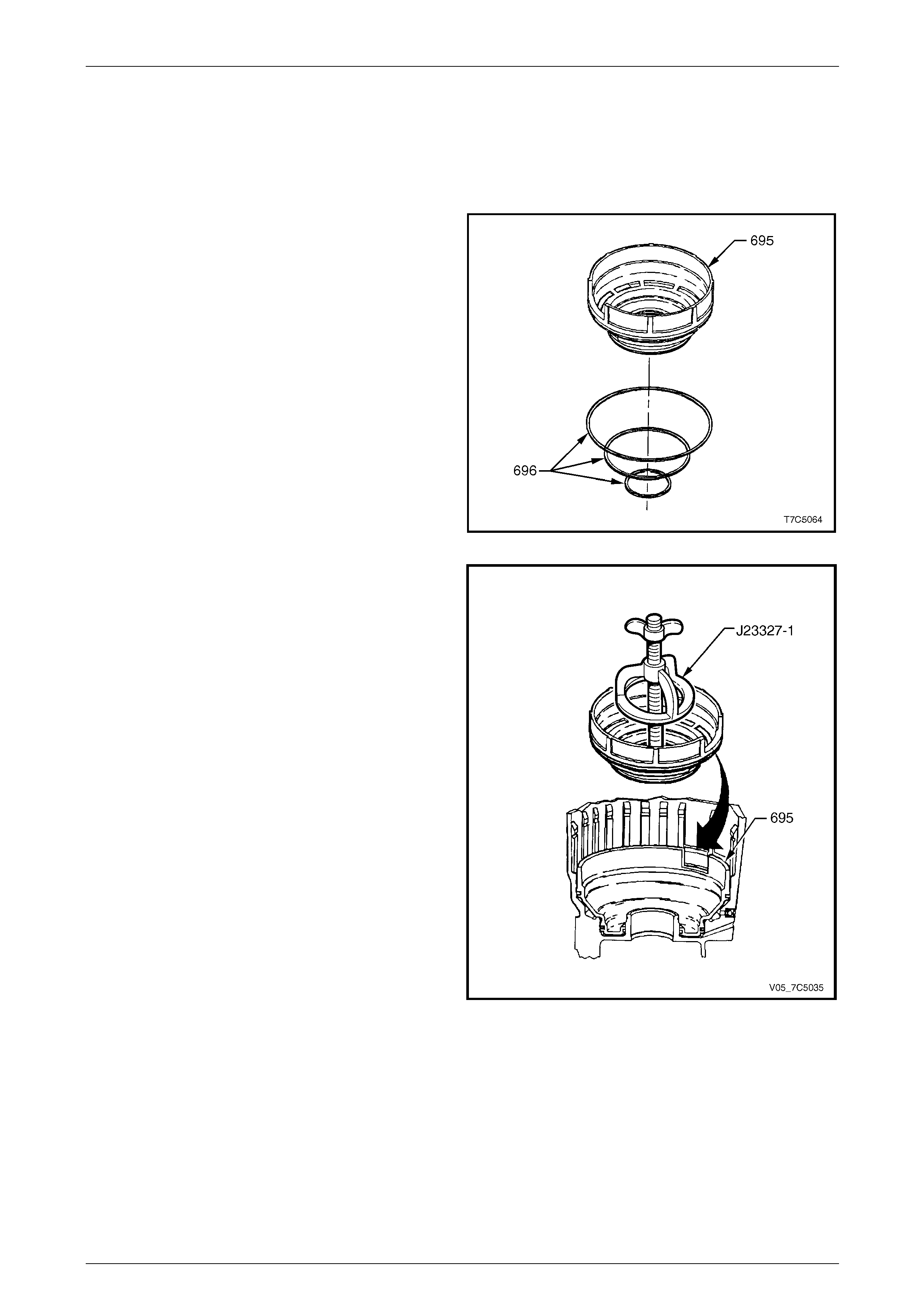
7D5 Automatic Transmission – 4L65E – Unit Repair Page 7D5–98
15–DEC–2005 Page 7D5–98
4.2 Low and Reverse Clutch Piston
LT Section No. — 04–200
Reinstall
1 Lubricate new squar e section seals (696) with clean
transmission fluid (or petroleum jelly) and install on the
low and reverse clutch piston (695).
Figure 7D5 – 178
2 Reinstall the piston (695) in the transmission case,
aligning it with the notch in bottom of case, as
indicated. Use Tool No. J23327-1 to ensur e the piston
is installed square to its bore.
Figure 7D5 – 179
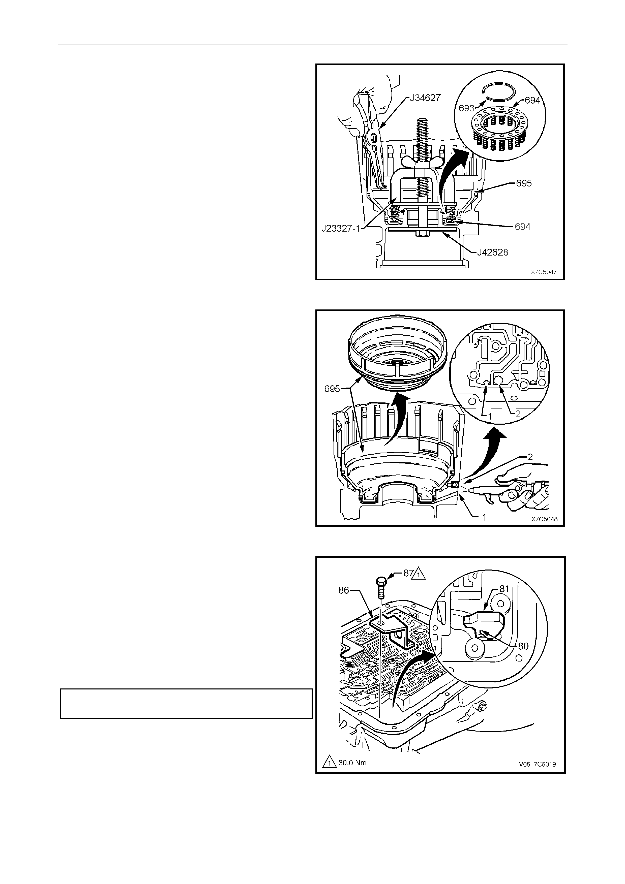
7D5 Automatic Transmission – 4L65E – Unit Repair Page 7D5–99
15–DEC–2005 Page 7D5–99
3 Locate the spring assembly (694) on the piston (695)
with its flat side facing outward, as shown.
4 Install Tool Nos J23327-1 and J42628, then compress
the spring assembly below the groove in case.
NOTE
Make sure the lower plate, Tool No. J42628,
indexes correctly in the recess at the end of the
transmission case.
5 Reinstall the retaining ring (693) using snap ring pliers,
Tool No. J34627.
6 Remove the special tools.
Figure 7D5 – 180
7 Check the operation of the low and reverse piston as
follows:
a Apply low pressure air to either the low feed
passage (1) or the reverse feed passage (2), as
shown.
b As air is supplied, the low and reverse piston
should be seen moving when viewed in the
parking pawl area of the transmission case.
c Air leaks should also be listened for, durin g this
check.
NOTE
The spring assembly and retainer ring are not
shown, to clearly show the air passage
arrangements.
Figure 7D5 – 181
8 If previously removed, locate the parking pawl (81)
and the return spring (80) in t he transmission case.
9 Reinstall the parking pawl pivot shaft (not shown).
Check for free movement of components.
10 Coat the parking pawl shaft plug, (not shown), with
Loctite® 242 sealant or equivalent and reinstall the
plug with a hammer and punch.
11 Reinstall the parking pawl bracket (86) and bolt (87),
tighten bolt to the correct torque specification.
Parking pawl bracket attaching bolt
torque specification............................................30.0 Nm
Figure 7D5 – 182
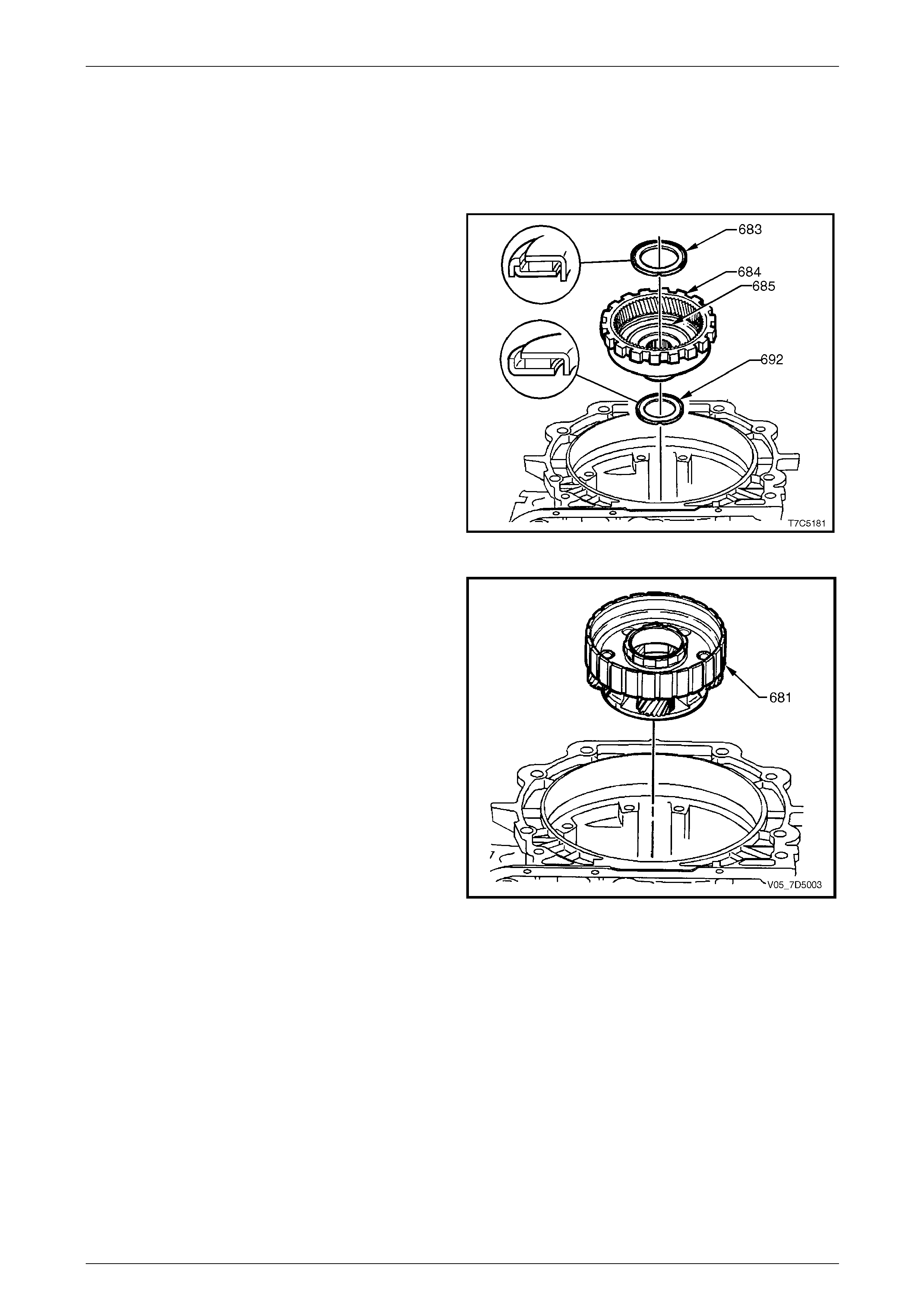
7D5 Automatic Transmission – 4L65E – Unit Repair Page 7D5–100
15–DEC–2005 Page 7D5–100
4.3 Reaction Planetary Gear Set
LT Section No. — 04–200
Reinstall
1 Reinstall the reaction gear support to case
bearing (692) onto the transmission case hub, as
shown, with outside bearing race towards the case
hub. Retain with petroleum jell y.
2 Reinstall the reaction internal gear (684) and support
assembly (685) into the bearing (69 2) an d
transmission case hub.
3 Reinstall the reaction carrier to supp ort thrust
bearing (683) on support, with outer beari ng race
facing support.
Figure 7D5 – 183
4 Reinstall the reaction carrier a ssembly (681) onto the
thrust bearing.
Figure 7D5 – 184
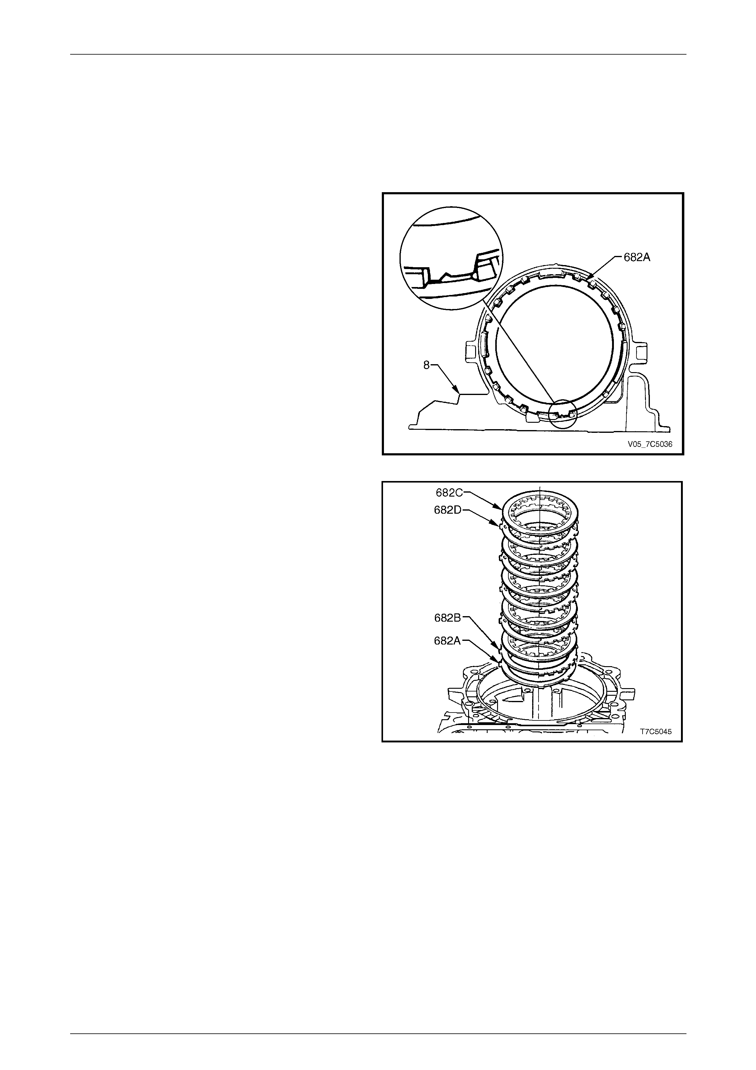
7D5 Automatic Transmission – 4L65E – Unit Repair Page 7D5–101
15–DEC–2005 Page 7D5–101
4.4 Low and Reverse Clutch Plates and
Support Assembly
LT Section No. — 04–200
Reinstall
1 Reassemble the low and reverse clutch assembly by
starting with the waved plate (682A), indexing in the
transmission case (8) as shown.
Figure 7D5 – 185
2 Reinstall the selectiv e pl ate (682B), selected during
component inspection proc edures, indexing it the
same way as the waved plate (682A).
3 Soak the composition plat es (682C) in new
transmission fluid.
4 Reinstall the remaining clutch plates, starting with a
composition plate, then a steel plate (682D), etc. Index
the steel plates the same way as the wave and
selective plates.
Figure 7D5 – 186
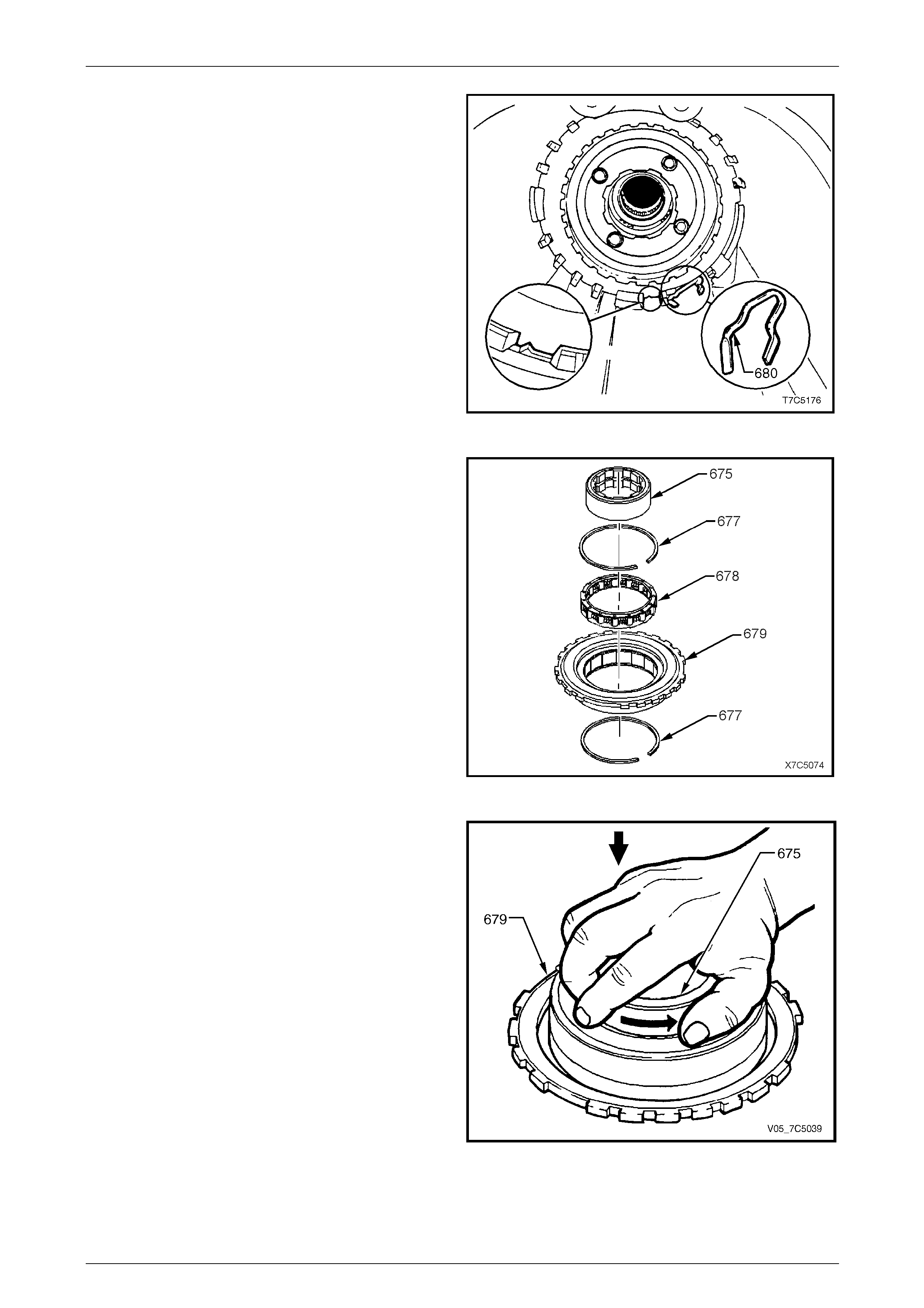
7D5 Automatic Transmission – 4L65E – Unit Repair Page 7D5–102
15–DEC–2005 Page 7D5–102
5 Apply petroleum jelly to the flat portion of the clutch
support retainer spring (680) and insert it into the
curved area in the transmission case, as sho wn.
Figure 7D5 – 187
6 Reinstall the low and reverse roller clutch
assembly (678) into the cam and support
assembly (679).
7 Reinstall both retaining rings (677), removed during
roller clutch disassembly.
Figure 7D5 – 188
8 Reinstall the roller clutch inner race (675) in the
support assembly (679) by pushing and turning in the
direction shown.
9 Test for correct operation, the roller clutch inner race
must free-wheel in the direction indicated by the arrow.
Figure 7D5 – 189
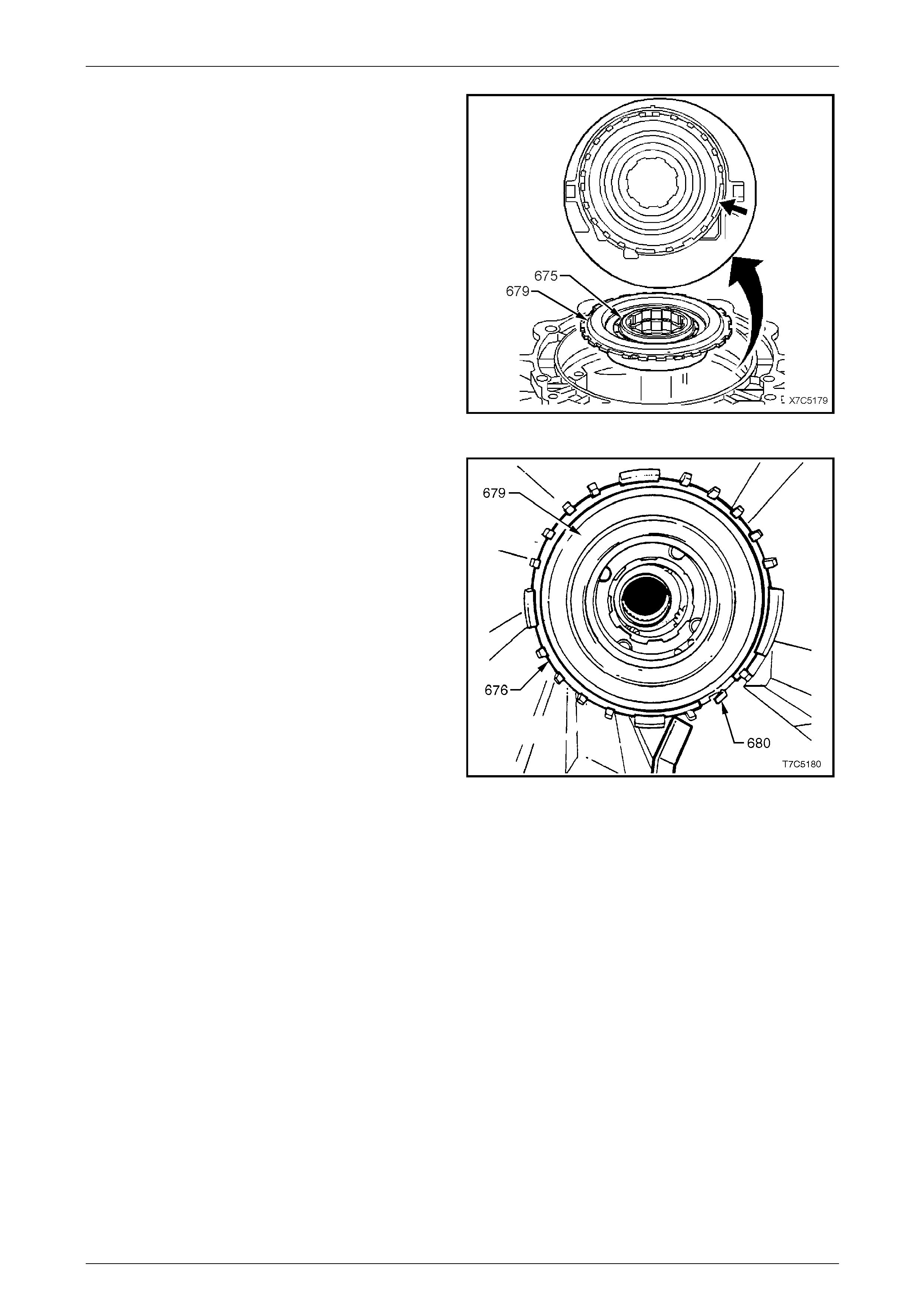
7D5 Automatic Transmission – 4L65E – Unit Repair Page 7D5–103
15–DEC–2005 Page 7D5–103
10 Pull the low and reverse roller clutch inner race (675)
up from its normally seated position, to enable a grip
on the support assembly (679). Slightly tilt the support
assembly while aligning the wide notch on the support
with a matching wide lug on the case.
11 Push the support assembly into the case until it is
squarely seated. Then, while turning the roller clutch
inner race in a clockwise (free) directio n, push it down
until the internal splines line up with those on the
reaction carrier.
Figure 7D5 – 190
12 Reinstall the supp ort retaining ring (676) as follows:
a Align one end against the low and reverse clutch
support retainer spring (680).
b With a screwdriver, work the remainder into the
groove. Make sure the retaining ring is fully
seated in the groove.
Figure 7D5 – 191
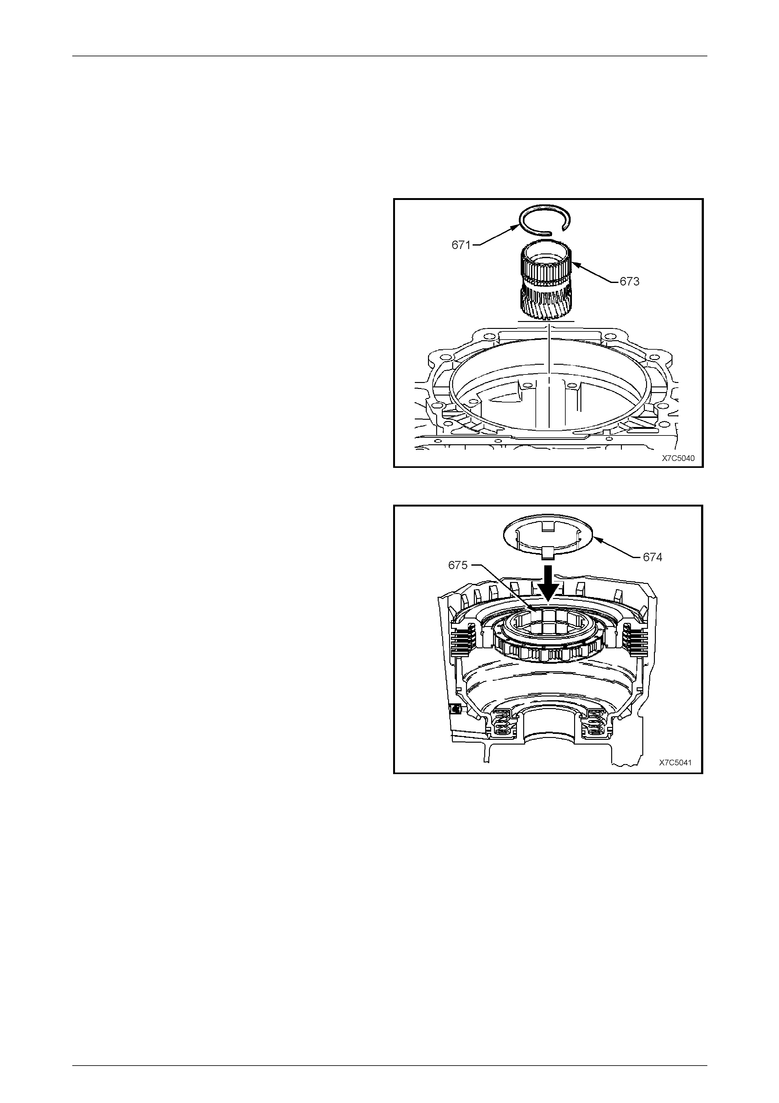
7D5 Automatic Transmission – 4L65E – Unit Repair Page 7D5–104
15–DEC–2005 Page 7D5–104
4.5 Reaction Gear, Input Gear and Output
Shaft
LT Section No. — 04–200
Reinstall
1 If required, install a new retaining ring (671) onto the
reaction sun gear (673).
2 Reinstall the reaction sun gear, with helical gear facing
down, into the reaction carrier in transmission case,
meshing the teeth with the pinion gears.
Figure 7D5 – 192
3 Reinstall the thrust washer (674) ensuring its lugs are
facing downward and locate it in the inner ra ce of the
low and reverse roller clutch (675).
Figure 7D5 – 193
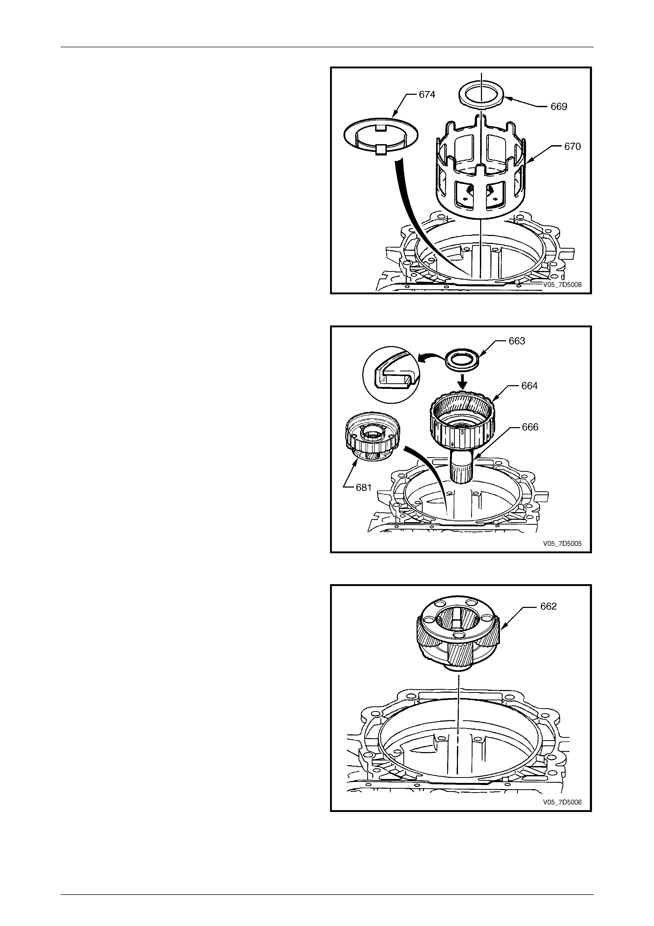
7D5 Automatic Transmission – 4L65E – Unit Repair Page 7D5–105
15–DEC–2005 Page 7D5–105
4 Reinstall the thrust bearing (669) onto the reaction sun
shell (670) and secure with petroleum jelly. The six
retention tabs on bearing locate in holes in reaction
sun shell.
5 Reinstall the reaction sun shell on the thrust
washer (674) and locate it over the reaction sun gear.
Figure 7D5 – 194
6 Reinstall the thrust bearing (663) onto the input
internal gear (664) and reaction carrier shaft assembly
with outer race against reaction carrier shaft (666).
Turn and press until the splines on the reaction carrier
shaft are aligned with the splines on the rea c tion
carrier assembly (681).
Figure 7D5 – 195
7 Reinstall the input carrier ass embl y (662), rotating
back and forth, to index with the teeth of the inp ut
internal gear.
Figure 7D5 – 196

7D5 Automatic Transmission – 4L65E – Unit Repair Page 7D5–106
15–DEC–2005 Page 7D5–106
8 While supporting the input carrier assemb ly, reinstall
the output shaft into the input carrier and attach the
support bracket (1), used during disassembly.
Figure 7D5 – 197
Do not over-expand the retaining ring during
installation.
NOTE
Using snap ring pliers, Tool No. J34627, will
assist in preventing retaining ring over-
expansion, as they have been designed for this
specific task.
9 Reinstall the retaining ring (661) in its groove on the
output shaft. If the ring was previously over-expanded,
use a new ring.
Figure 7D5 – 198
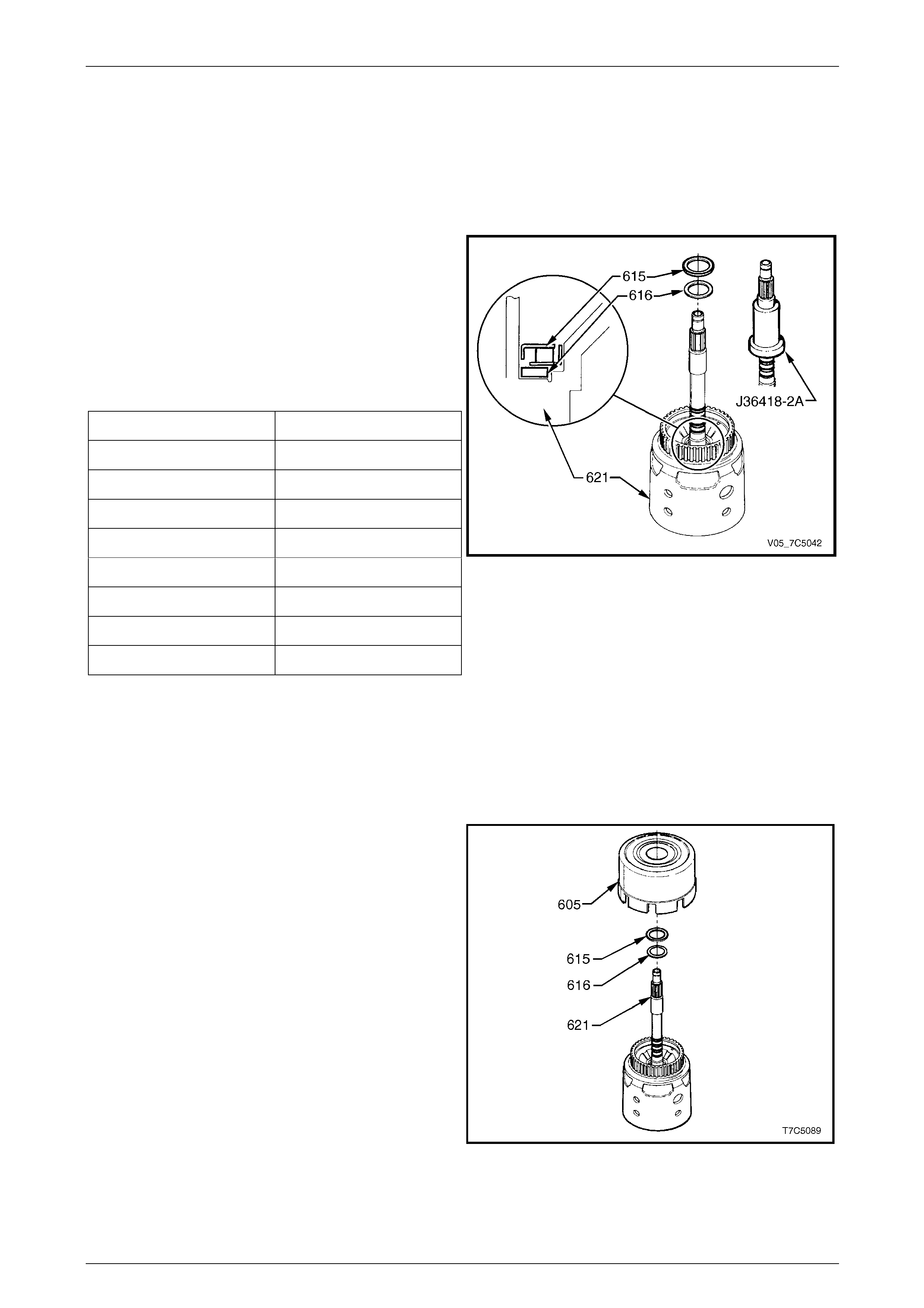
7D5 Automatic Transmission – 4L65E – Unit Repair Page 7D5–107
15–DEC–2005 Page 7D5–107
4.6 Reverse Input Clutch, Input Clutch and
Input Gear Set
LT Section No. — 04–200
Reinstall
1 Remove the seal rings resizer, Tool No. J36418-2A,
from the input shaft and reinstall the sel ective thrust
washer (616) on input housing and shaft
assembly (621).
2 If the end play measured in 2. 7 Transmission End
Play Check, is not to specification, replace the original
selective thrust washer with a new one, selec t ed from
the table below.
Selective thrust washer specifications:
Washer Thickness (mm) Identification
1.87 – 1.97 67
2.04 – 2.14 68
2.21 – 2.31 69
2.38 – 2.48 70
2.55 – 2.65 71
2.72 – 2.82 72
2.89 – 2.99 73
3.06 – 3.16 74
NOTE
The identification number is stamped on the
washer.
3 Reinstall the bearing assembly (615) on the selective
thrust washer with the inner race facing the selective
washer.
Figure 7D5 – 199
4 Reinstall the reverse input clutch assembly (605) onto
the input housing and shaft a ssembly (621), aligning
the reverse input clutch plate tangs with the input
housing hub. Ensure all clutch plates are engaged.
Figure 7D5 – 200
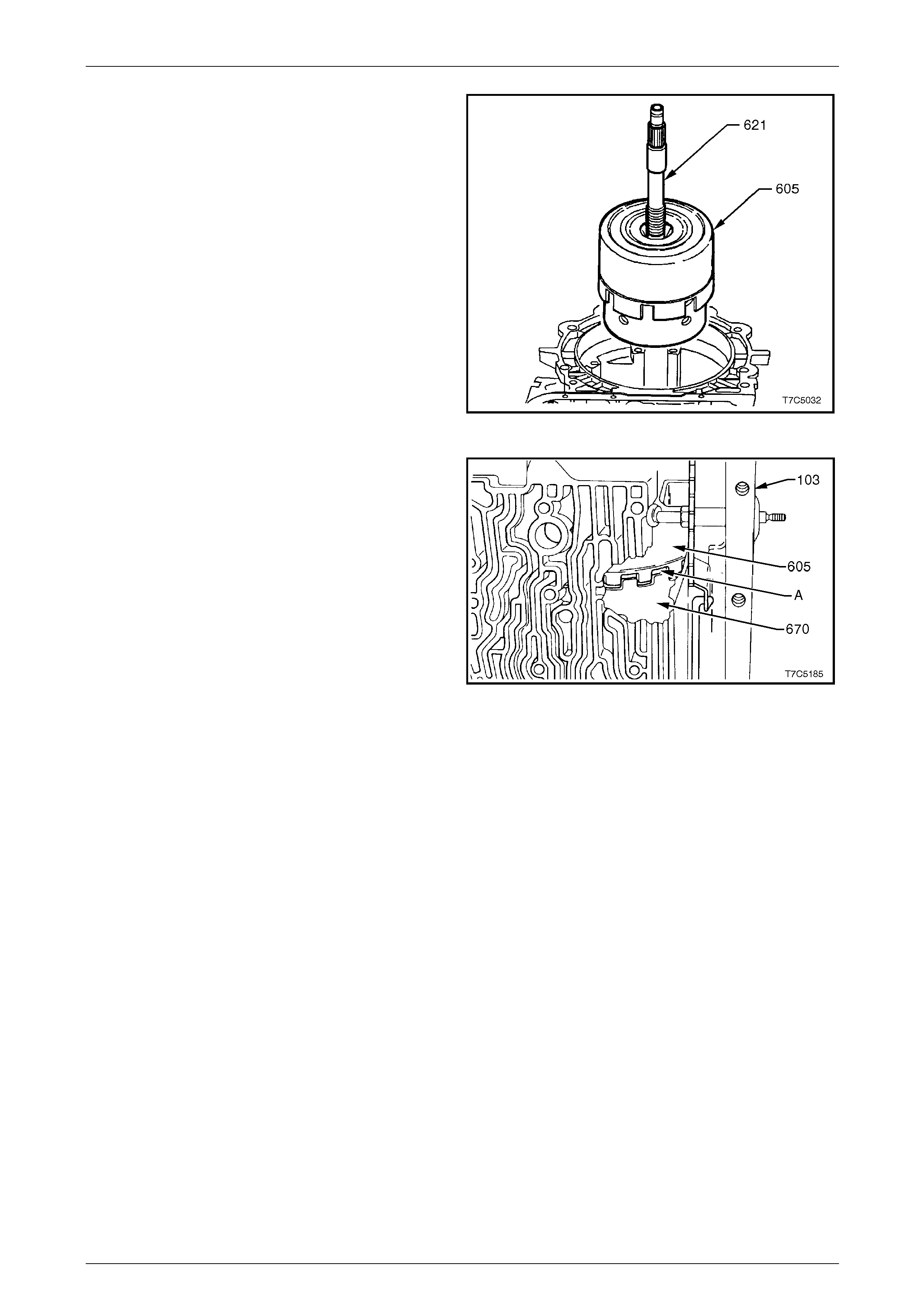
7D5 Automatic Transmission – 4L65E – Unit Repair Page 7D5–108
15–DEC–2005 Page 7D5–108
5 Reinstall the reverse input clutch (605) and input
housing and shaft (621) assemblies into the
transmission case:
a Locate the 3-4 clutch plate tangs over the input
internal gear.
b Ensure all clutch plates are fully engaged.
c When correctly installed, the reverse input clutch
housing is located just below the oil pump case
machined land in the transmission case.
Figure 7D5 – 201
d There is a normal clearance (A) of appro xim ately
3.8 mm between the reverse inp ut clutch (60 5)
and the reaction sun gear shell (670), as shown.
Figure 7D5 – 202
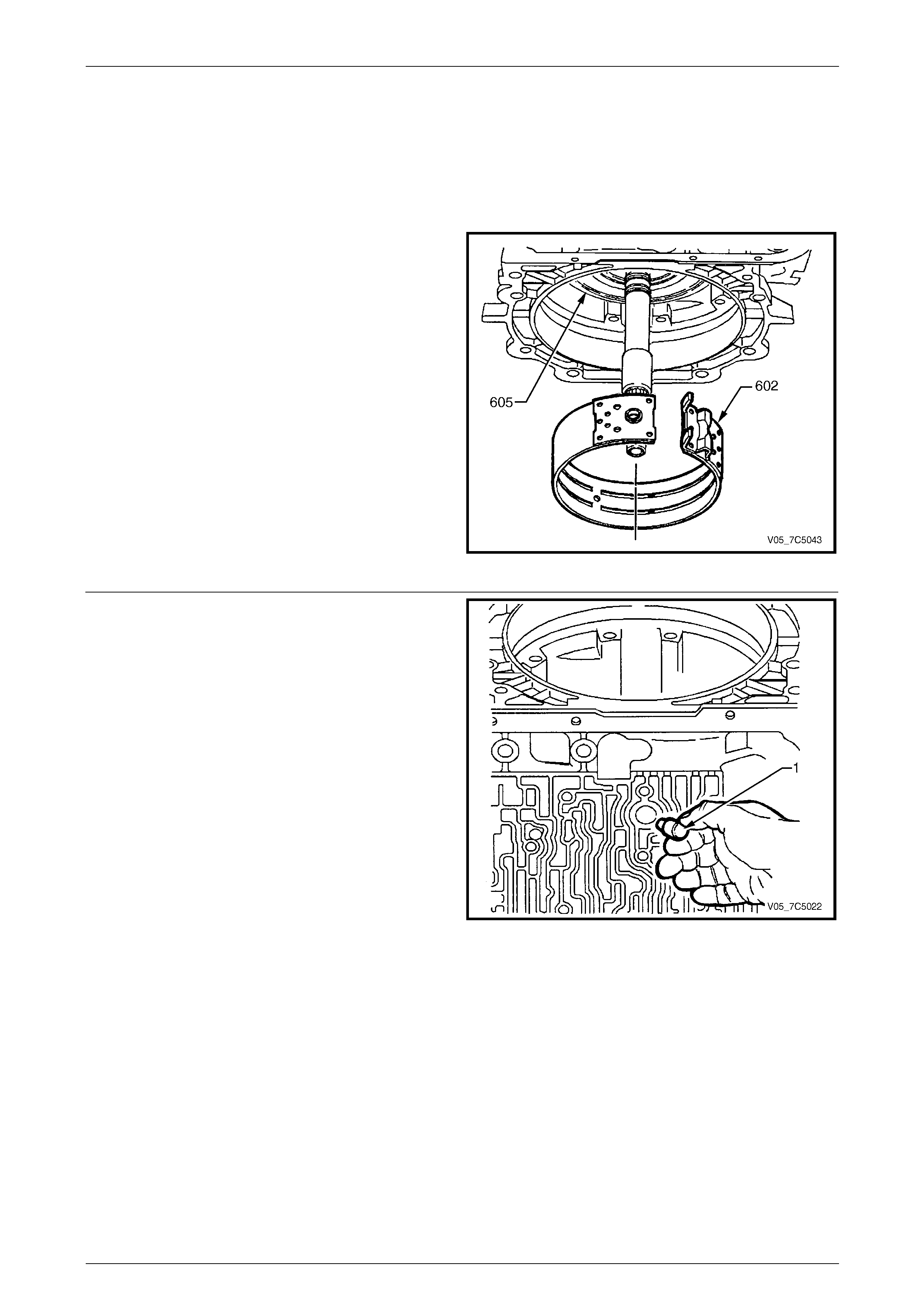
7D5 Automatic Transmission – 4L65E – Unit Repair Page 7D5–109
15–DEC–2005 Page 7D5–109
4.7 2-4 Band Assembly
LT Section No. — 04–200
Reinstall
1 Inspect the 2-4 band assembly (602) for dam age or
wear. Only replace the band if the material is scored,
flaking or heavily worn.
NOTE
The 2-4 band material is now grey/black in
colour.
2 Rotate the transmission through 90° as shown, with
the case channels in the uppermost positio n.
3 Using both hands, squeeze th e 2-4 band into a circle
and work it into place around the reverse input clutch
housing (605).
NOTE
With the transmission in this position, the weight
of the reverse input and input clutch assembly
will be such that adequate clearance will be
provided for reinstallation of the band. Figure 7D5 – 203
4 After reinstalling the 2-4 band assembly into the
transmission case, align the anchor pin end of the
band with the hole in case.
5 Reinstall the 2-4 band anchor pin (1) into the
transmission case, as indicated. Ensure the pin
engages the 2-4 band assembly.
Figure 7D5 – 204
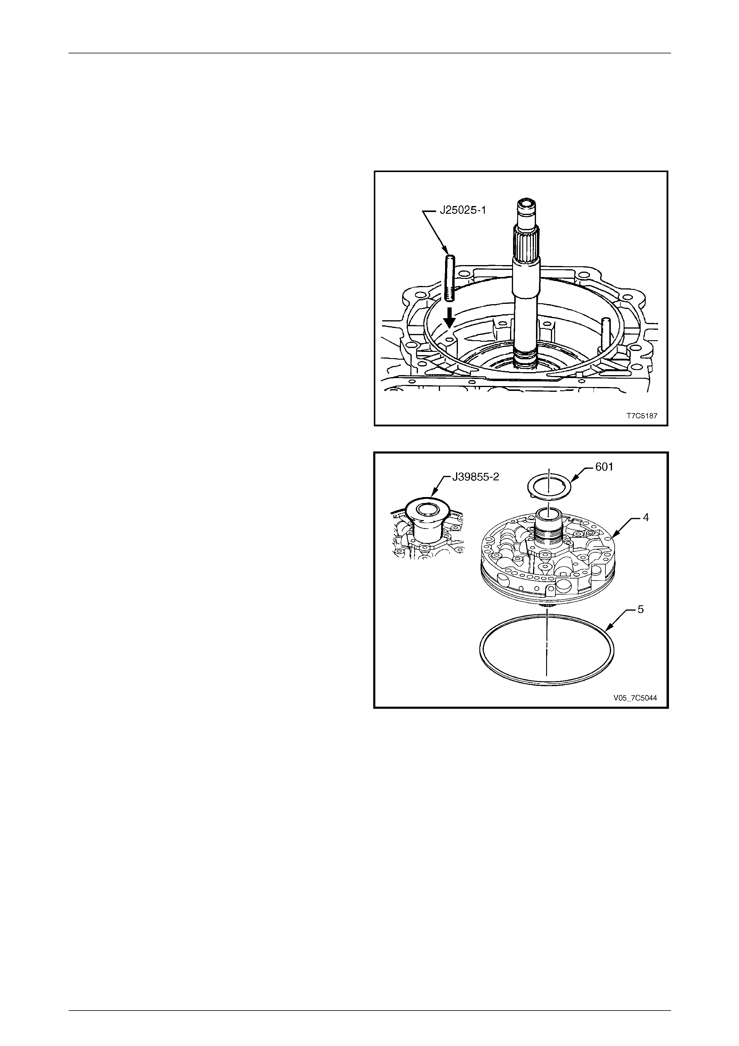
7D5 Automatic Transmission – 4L65E – Unit Repair Page 7D5–110
15–DEC–2005 Page 7D5–110
4.8 Oil Pump
LT Section No. — 04–200
Reinstall
1 Install two alignment pins, Tool No. J25025-1 (part of
kit Tool No. J25025-B), into the transmission case, as
shown.
Figure 7D5 – 205
2 Remove the stator shaft oil seal sizing tool, Tool No.
J39855-2.
3 Reinstall the thrust washer (601) on the oil pump (4),
retain with petroleum jelly.
4 Lubricate a new square section seal (5) with petroleum
jelly and install it in the pump body groov e.
NOTE
When correctly installed and not t wisted, the seal
colour strip is visible around the pump body.
Figure 7D5 – 206
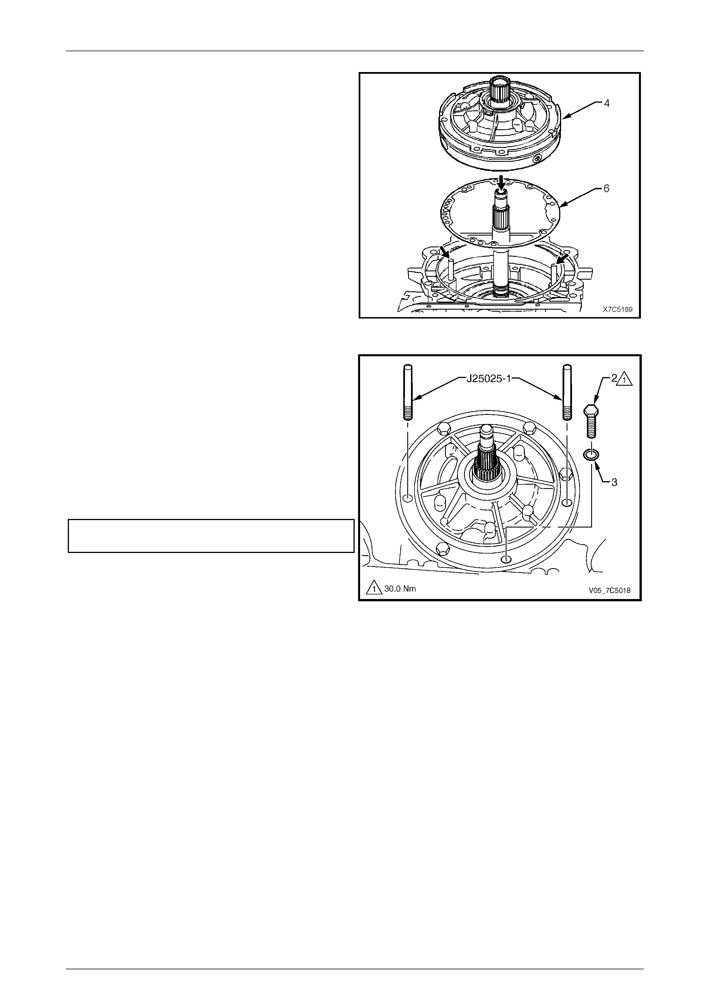
7D5 Automatic Transmission – 4L65E – Unit Repair Page 7D5–111
15–DEC–2005 Page 7D5–111
5 Fit a new oil pump gasket (6) to the transmission cas e,
align the bolt holes and locate over the two alignment
pins (arrows), retain it with petroleum jelly.
Figure 7D5 – 207
6 Prime the oil pump with new transmission fluid and
reinstall the assembly into the transmission case, over
the alignment pins, Tool No.J25025-1 (part of kit Tool
No. J25025-B).
7 Remove the two alignment pins and reinstall the
bolt (2), complete with new sealing washer (3), seven
places.
8 Progressively tighten the bolts in an alternating pattern
to draw the pump body fully i nto the transmi ssion
case. Tighten the bolts to the correct torque
specification.
Oil pump to transmission case attaching
bolt torque specification.....................................30.0 Nm
Figure 7D5 – 208
9 After removing the output shaft support bracket, turn the input shaft by hand. If unable to do so, the transmission is
incorrectly assembled (possible thrust washer dislodgment), dismantle and rectify as required.
10 Measure the transmission en d pla y, refer to 2.7 Tr ansmission End Play Check.
11 If the transmission end play is not to specific ation, replace the selective thrust washer (616) between the input
housing and shaft assembly (621) and the stator shaft bearing assembly (615), refer to 4.6 Reverse Input Clutch,
Input Clutch and Input Gear Set.
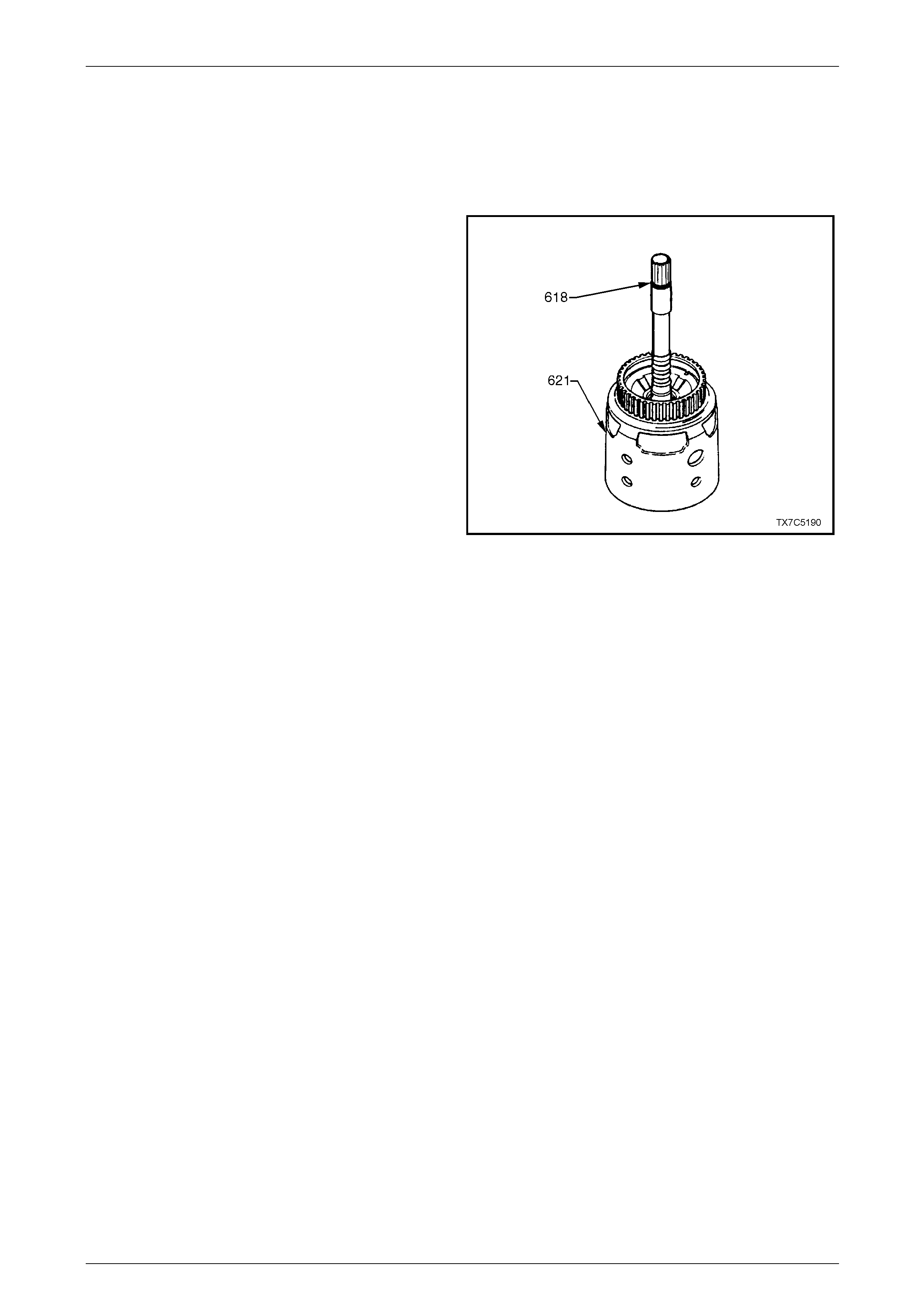
7D5 Automatic Transmission – 4L65E – Unit Repair Page 7D5–112
15–DEC–2005 Page 7D5–112
NOTE
If end play is to specification, the o utput shaft can
be turned in both forward and reverse directions.
The effort required to turn the output shaft in the
reverse direction however, will be greater than in
the forward direction.
12 Install a new O-ring seal (618) into the groove at the
end of the shaft of the input housing and shaft
assembly (621).
Figure 7D5 – 209
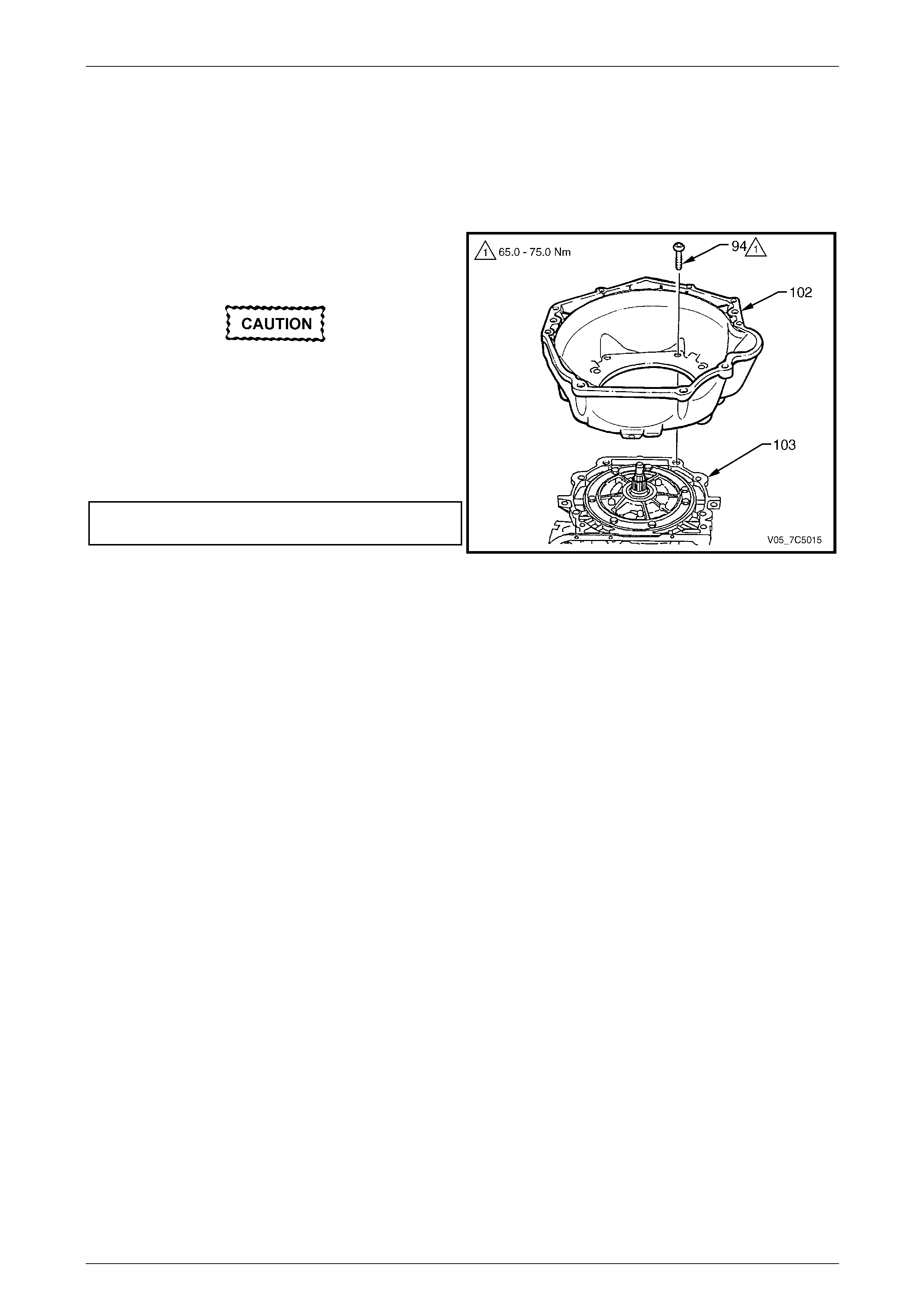
7D5 Automatic Transmission – 4L65E – Unit Repair Page 7D5–113
15–DEC–2005 Page 7D5–113
4.9 Torque Converter Housing
LT Section No. — 04–200
Reinstall
1 Reinstall the torque converter housing (102) and the
attaching bolt (94), eight places, to the transmission
case (103).
Do not use a standard # 50 Torx® bit, as the
bolt design is such that only the Torx Plus®
bit is capable of applying the correct torque
without bolt damage.
2 Tighten the bolts attaching the housing to the correct
torque specification, using Torx Plus® bit, Tool No.
J41510 or commercial equivalent.
Torque converter housing attaching
bolt torque specification...........................65.0 - 75.0 Nm
Figure 7D5 – 210

7D5 Automatic Transmission – 4L65E – Unit Repair Page 7D5–114
15–DEC–2005 Page 7D5–114
4.10 Control Valve Body and Wiring Harness
LT Section No. —
Reinstall
For the reinstallation procedure of the cont rol valve body and wiring harness , refer to Section 7D4 Automatic
Transmission – 4L65E – On-vehicle Servicing.

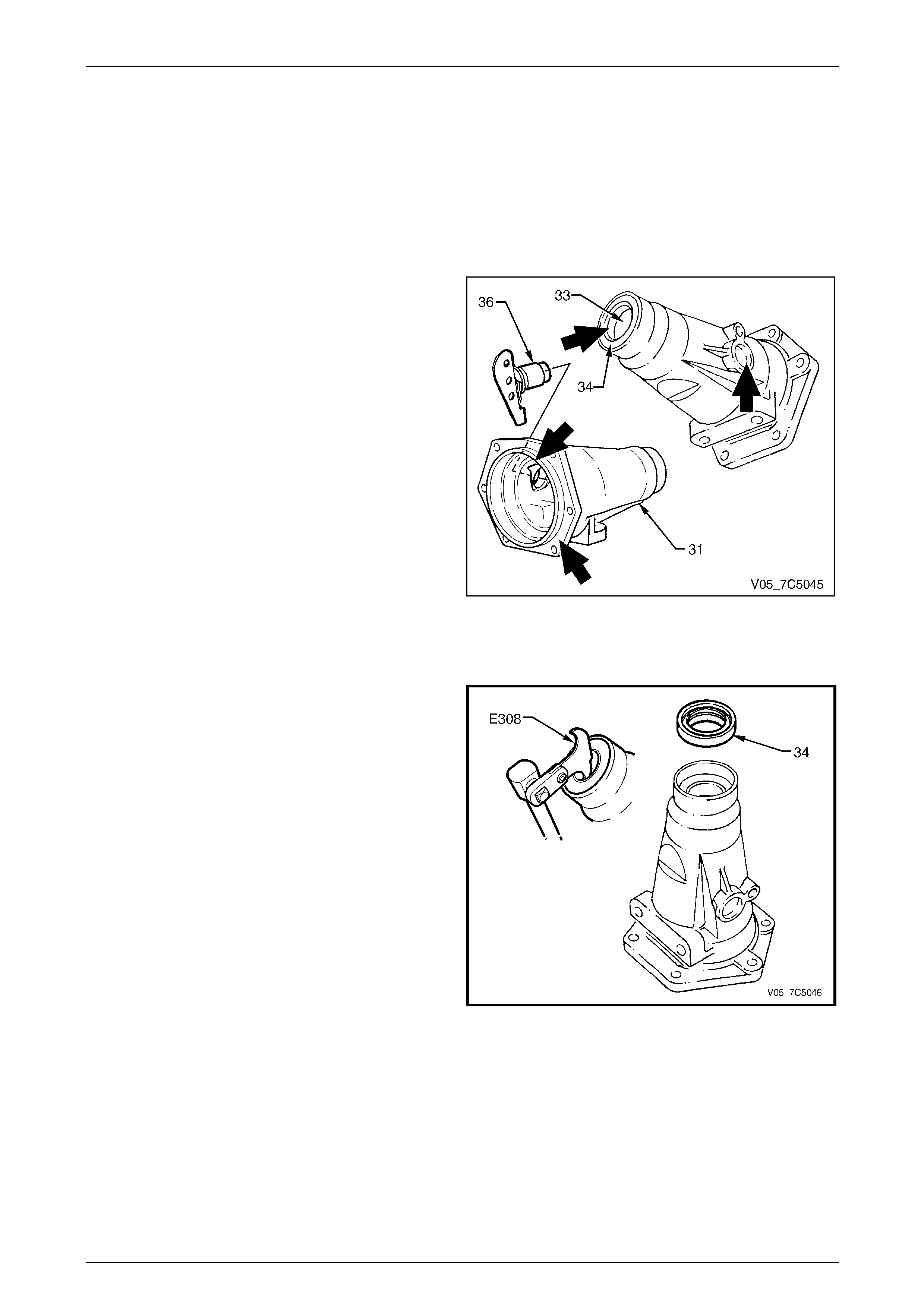
7D5 Automatic Transmission – 4L65E – Unit Repair Page 7D5–116
15–DEC–2005 Page 7D5–116
4.12 Extension Housing and Speed Sensor
LT Section No. — 04–200
For service procedures of the adaptor housing and speed sensor fitted to AWD vehicles, refer to Section 7F Transfer
Case and Adaptor Housing.
Inspect
1 Inspect all machined surfaces of the extension
housing (31) for nicks or burrs, repair as required with
a fine cut file.
2 Check the extension housing oil seal (34) for wear
and/or damage.
3 Check the extension housing bush (33) for wear.
4 Inspect the speed sensor (36) for damage, replace as
required.
Figure 7D5 – 211
Extension Housing Bush – Replace
1 If not previously carried out, remove the extension
housing oil seal (34), usin g a removing tool such as
Tool No. E308, or commercial equivalent.
Figure 7D5 – 212
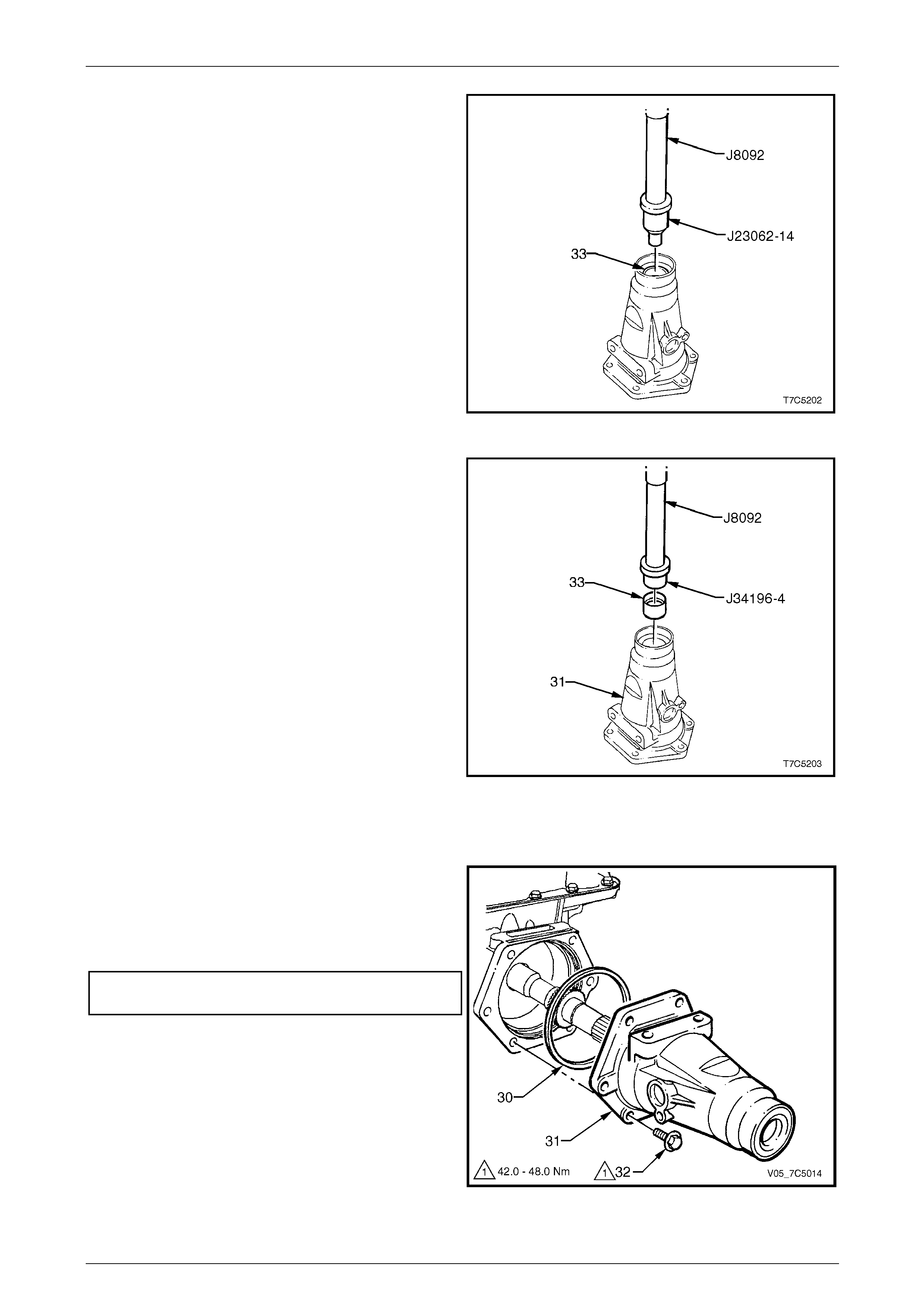
7D5 Automatic Transmission – 4L65E – Unit Repair Page 7D5–117
15–DEC–2005 Page 7D5–117
2 Using the bush remover, T ool No. J23062-14 and
driver handle, Tool No. J8092, press the bush (33) out
of the extension housin g and discard.
Figure 7D5 – 213
3 Lubricate the outside of a n ew bush (33) with
transmission fluid to reduce the risk of material
pick-up.
4 Install the new bush into the extension housing (31)
using the installer Tool No. J34196-4 (part of kit Tool
No. J34196-B) and driver han dle Tool No. J8092.
Figure 7D5 – 214
Reinstall
1 Install a new seal (30) to the extension housing (31)
and reinstall the housin g to the rear of the
transmission case.
2 Reinstall the attaching bolt (32), six places, and tighten
to the correct torque specification.
Extension housing attaching
bolt torque specification.....................................45.0 Nm
Figure 7D5 – 215
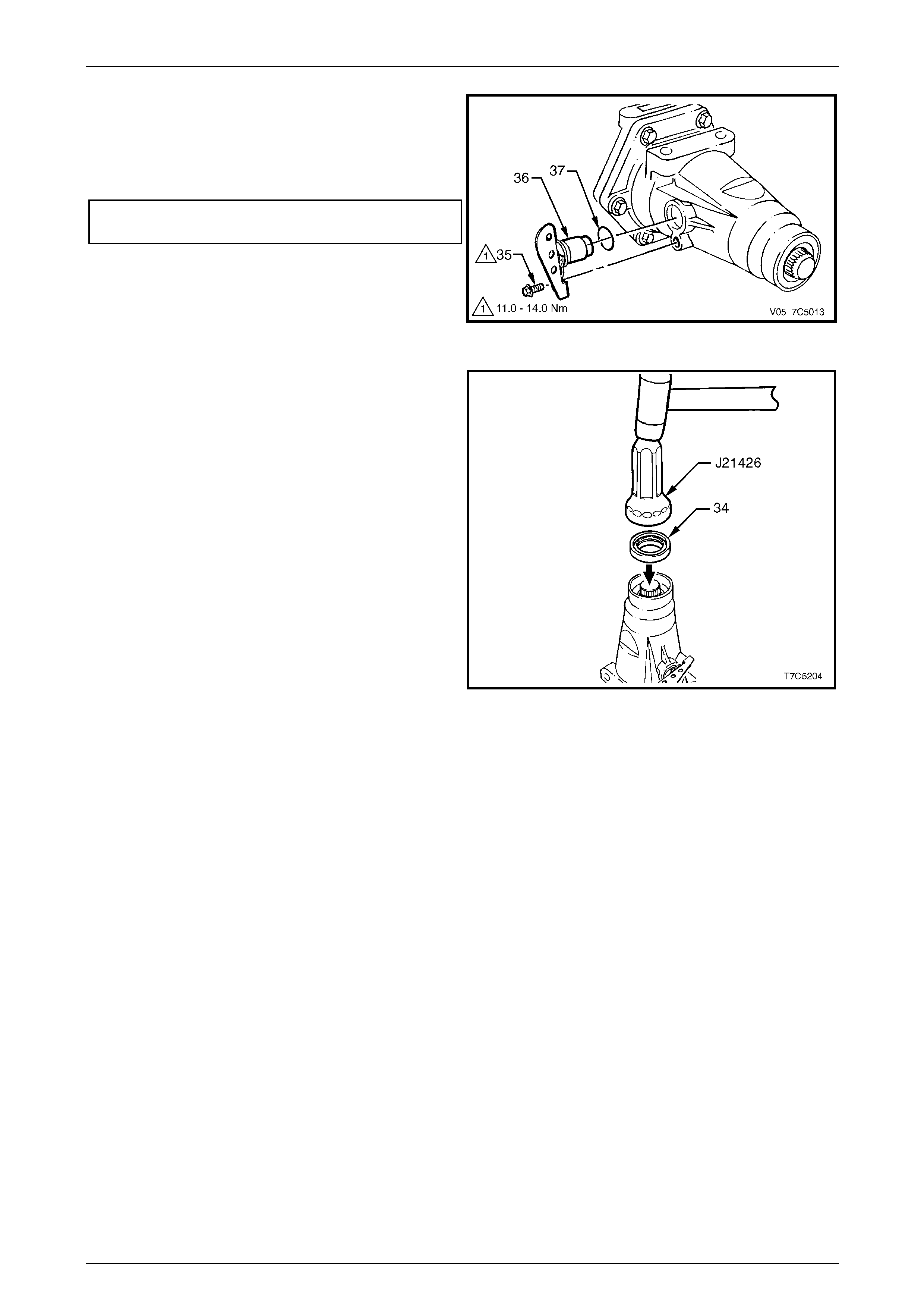
7D5 Automatic Transmission – 4L65E – Unit Repair Page 7D5–118
15–DEC–2005 Page 7D5–118
3 Lubricate a new O-ring (37) with petro leum jelly and
install on speed sensor (36).
4 Reinstall the speed sensor to the extension housing,
tighten the attaching bolt to the correct torque
specification.
Speed sensor attaching bolt
torque specification............................................12.0 Nm
Figure 7D5 – 216
5 Using the seal installer T ool No. J21426 and a soft
faced hammer, tap a new oil seal (34) in the extension
housing.
Figure 7D5 – 217
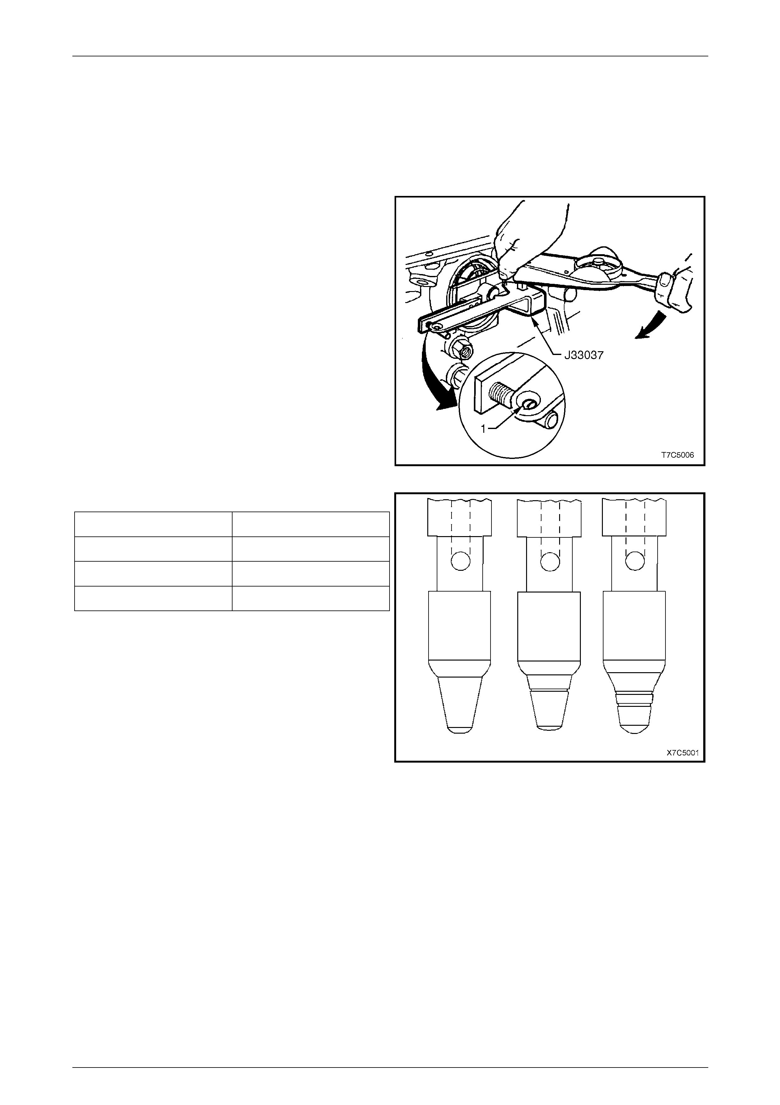
7D5 Automatic Transmission – 4L65E – Unit Repair Page 7D5–119
15–DEC–2005 Page 7D5–119
4.13 2-4 Servo Assembly
LT Section No. — 04–200
Servo Pin Length – Check
1 Install the pin, tapered end firs t, into the transmission.
2 Install Tool No. J33037 as shown, and refit the servo
cover retaining ring to secure the tool.
3 Apply 11 Nm torque to the tool arm.
• If a white line appears in the gauge e yelet (1),
the pin length is correct.
• If the white line does not appear in the gauge
eyelet, a replacement pin must be selected from
the following table.
4 Remove Tool No. J33037 and the second apply piston
pin from the transmission case.
Figure 7D5 – 218
Servo pin selection table:
Pin Length (mm) Identification
65.82 – 66.12 1 Groove
67.23 – 67.53 2 Grooves
68.64 – 68.94 No Groove
Figure 7D5 – 219
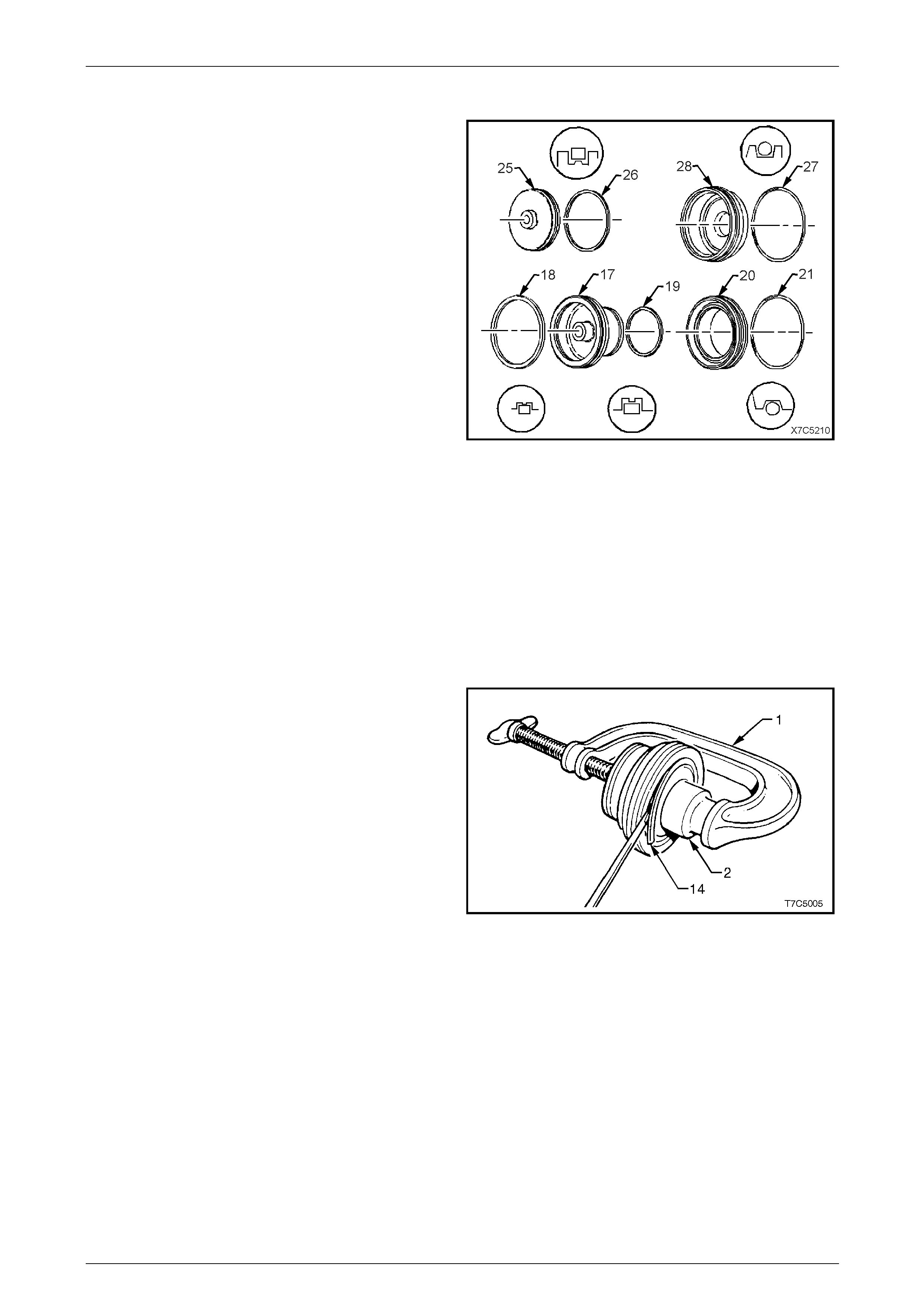
7D5 Automatic Transmission – 4L65E – Unit Repair Page 7D5–120
15–DEC–2005 Page 7D5–120
Reassemble
1 Install new seals to the 2-4 servo pistons components
as follows:
a Fit the square section outer seal (26) to the
fourth apply piston (25).
b Fit the round section O-ring seal (27) to the 2-4
servo cover (28).
c Fit the square section outer seal (18) and in ner
seal (19) to the second apply piston (17).
d Fit the round section O-ring seal (21) to the
servo piston inner housing (20).
Figure 7D5 – 220
2 Reinstall the cushion spri ngs (16 and 105) into the well
of the second apply piston (17), refer to
Figure 7D5 – 222.
NOTE
There is no inner cushion springs (105) in
automatic transmission fitted to a GEN III V8
engine
3 Reinstall the retainer (15) on top of the cushion
spring (16).
4 Use a G-clamp (1) and a suitable sized socket (2) to
compress the spring(s) under the second apply piston
assembly.
5 Reinstall the retaining ring (14), ensure it is fully
installed into the piston groove.
6 Remove the tools to release the spring tension.
Figure 7D5 – 221
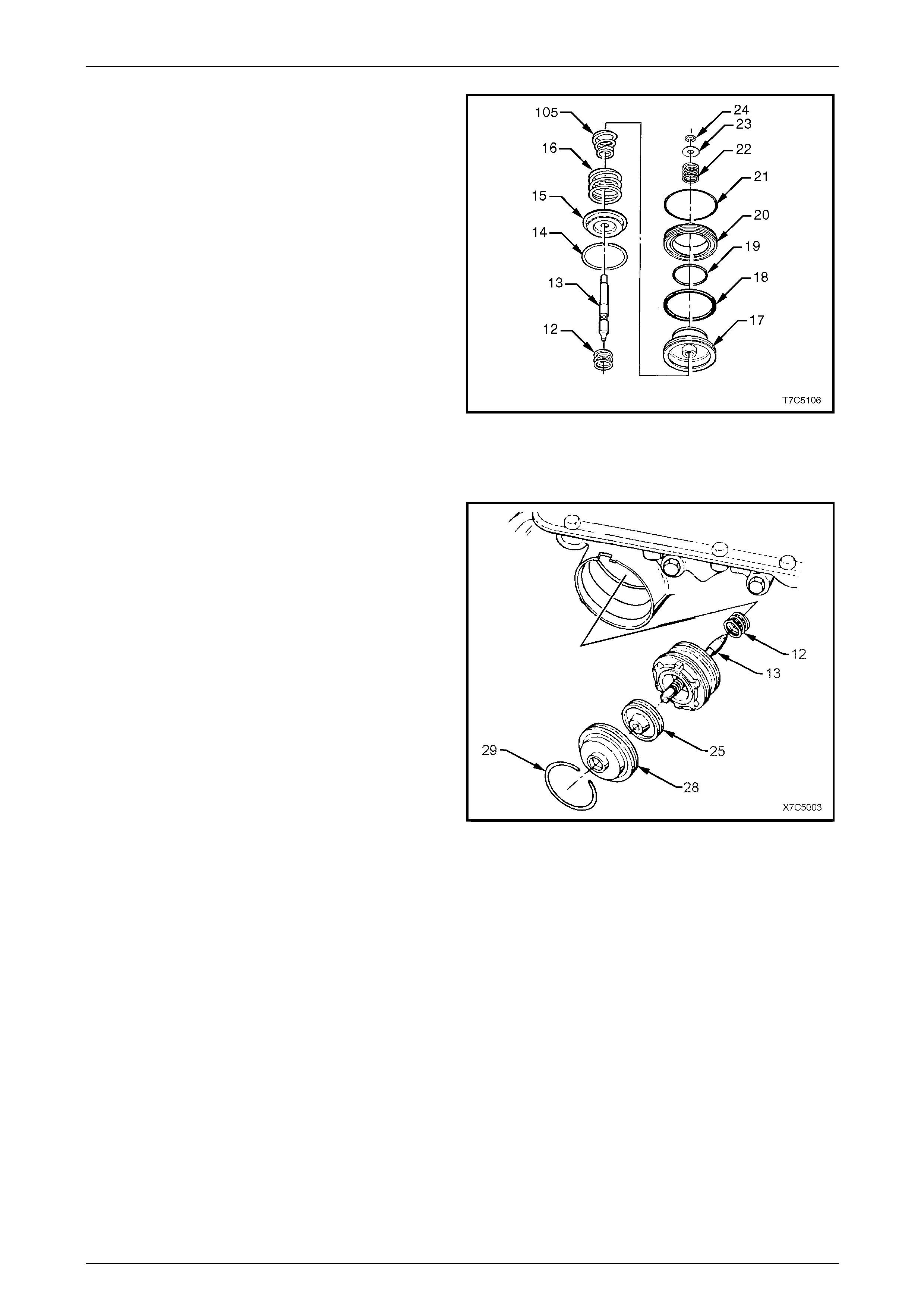
7D5 Automatic Transmission – 4L65E – Unit Repair Page 7D5–121
15–DEC–2005 Page 7D5–121
7 Reinstall the C-clip retainer (2 4) to the second apply
piston pin (13) and test to ensure the pin do es not
bind.
8 Reinstall the servo apply pin spring (22) and
washer (23), securing with the C-clip (24).
9 Apply petroleum jell y to the inner and outer sealing
rings (18 and 19) and install them to the seco nd apply
piston (17).
10 Apply petroleum jelly to a new O-ring seal (21) and
install it on the servo piston inner housin g (20),
ensuring it is correctly seated in the groove.
11 Reinstall the inner housing over the inner sealing ring
of the second apply piston.
Figure 7D5 – 222
Reinstall
1 Reinstall the fourth apply piston assemb ly (25) into the
servo cover (28), with the piston boss facing the cover.
2 Reinstall the servo return spring (12), the servo apply
pin and second apply p iston assembly (13) into the
servo bore in the transmission case.
3 Reinstall the fourth apply piston and o uter co ver over
the servo pin.
4 Using a hammer handle, press the servo cover in, until
the retaining ring groove in the case is visibl e.
5 Reinstall retaining ring (29), ensuring it is correctly
seated in the groove.
Figure 7D5 – 223
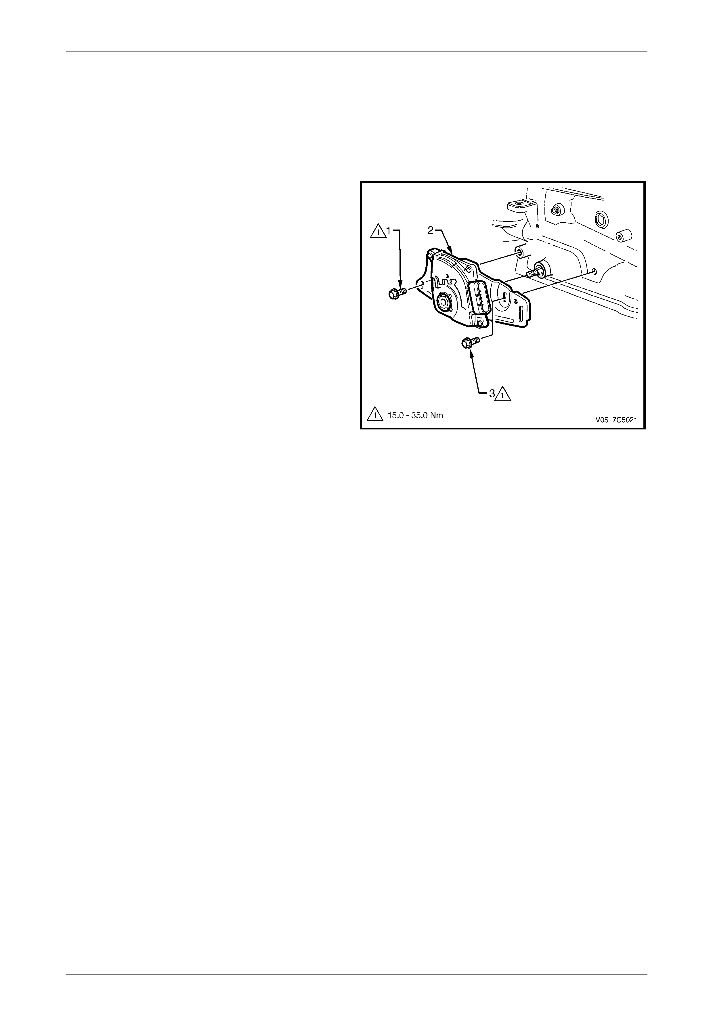
7D5 Automatic Transmission – 4L65E – Unit Repair Page 7D5–122
15–DEC–2005 Page 7D5–122
4.14 Neutral Start & Back-Up Lamp Switch
Assembly
LT Section No. — 04–170
Reinstall
Reinstall the neutral start and back-up lamp switch (2) but
do not fully tighten the attaching screws (1 and 3).
NOTE
The manual shaft linkage and attaching nut
reinstallation and adjustment of the neutral start
and back-up lamp s witch is carried out when the
transmission is reinstalled to the vehicle. Refer to
Section 7D4 Automatic Transmission – 4L65E –
On-vehicle Servicing.
Figure 7D5 – 224
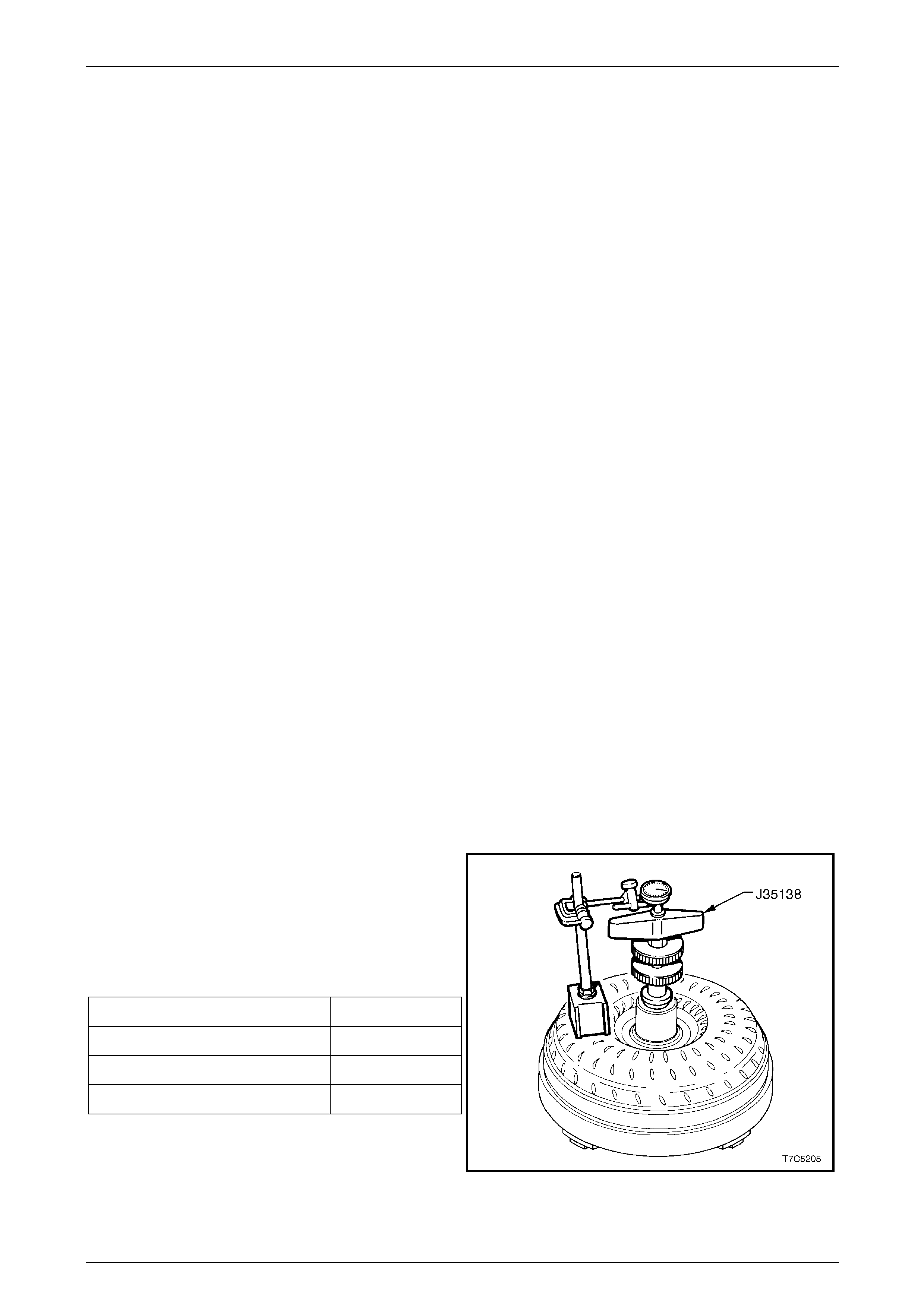
7D5 Automatic Transmission – 4L65E – Unit Repair Page 7D5–123
15–DEC–2005 Page 7D5–123
4.15 Torque Converter
LT Section No. — 04–200
Inspect
1 The torque converter is serviced as an assembly and should be replaced if any of the following conditions exist:
NOTE
For detailed information regarding cooler flushing
procedures, refer to Section 7D4 Automatic
Transmission – 4L65E – On-vehicle Servicing.
• metal particles found when flushing the cooler or converter pipes, converter flushing is not recommended,
• oil pump damaged,
• leaking converter welds,
• converter pilot broken, damaged or poor fit in crankshaft,
• converter hub scored or damage d,
• internal damage to stator,
• transmission fluid contaminat ed with coolant, or
• excess end play.
2 The torque converter should not be replaced if the following conditions exist:
• The transmission fluid has an odour an d/or discolouration, but there is no evidence of metallic or cl utch plate
material in the fluid. If these conditions apply carry out the following, refer to Section 7D4 Automatic
Transmission – 4L65E – On-vehicle Servicing:
a Drain as much fluid as possibl e from the torque converter.
b Replace the oil filter and pan gasket.
c Fill transmission with the correct fluid, to the recommended level.
• Any converter bolt hole threads are dam aged or stripped, install thread inserts to repair.
End Play Check
Determine the torque converter end play using Tool
No. J35138, in conjunction with an accurate dial indicator
and a magnetic stand.
Set the dial indicator to zero, move the handle up and d own
and take the end play reading from the dial indicator needle
fluctuation.
Torque converter end play specification:
Torque Converter Diameter End Play
V6 engine – 258 mm 0.1 – 0.5 mm
GEN III V8 engine – 300 mm 0.1 – 0.5 mm
GEN IV V8 engine – 300 mm 0.1 – 0.5 mm
If the end play is not within specification, replace the torque
converter.
Figure 7D5 – 225
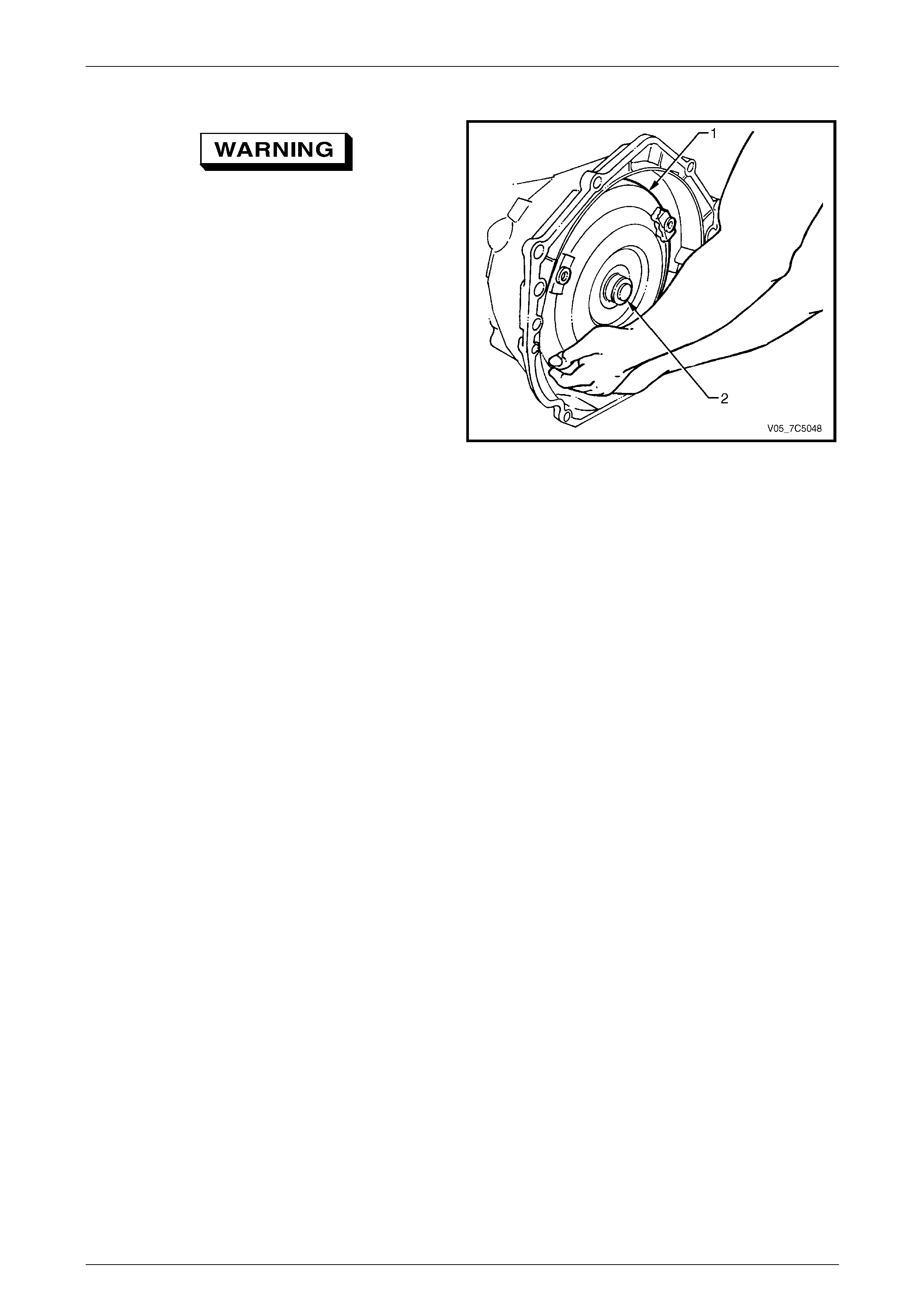
7D5 Automatic Transmission – 4L65E – Unit Repair Page 7D5–124
15–DEC–2005 Page 7D5–124
Reinstall
Take care when handling the torque
converter as it is a heavy assembly and
personal injury may result if lifted incorrectly.
1 Reinstall the torque converter (1) to the input shaft (2),
with the transmission in horizontal pos ition.
2 Install a restraining plate across the torque converter
housing to prevent it from being dislodged
accidentally, prior to reinstallat ion of the transmission.
Figure 7D5 – 226
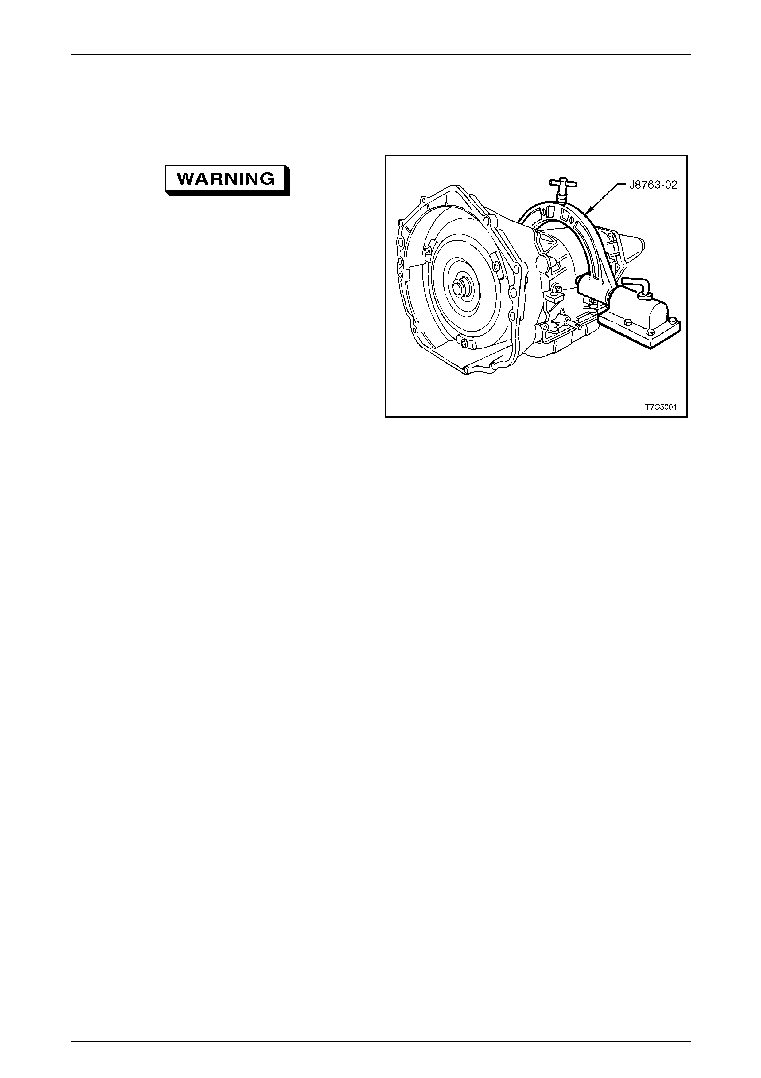
7D5 Automatic Transmission – 4L65E – Unit Repair Page 7D5–125
15–DEC–2005 Page 7D5–125
4.16 Transmission Fixture Removal
LT Section No. — 04–200
Take care when lifting or handling the
transmission as it is a heavy assembly and
personal injury may result if lifted incorrectly.
Use appropriate lifting gear.
1 Remove the transmission and hol ding fixture, Tool
No. J8763-02, from the base, Tool No. J3289-20.
2 Loosen the clamp screws and remove the holding
fixture bracket from the transmission.
3 Plug all openings such as the oil cooler fittings and
output shaft to prevent the ingress of foreign material,
prior to installation to the vehicle.
Figure 7D5 – 227
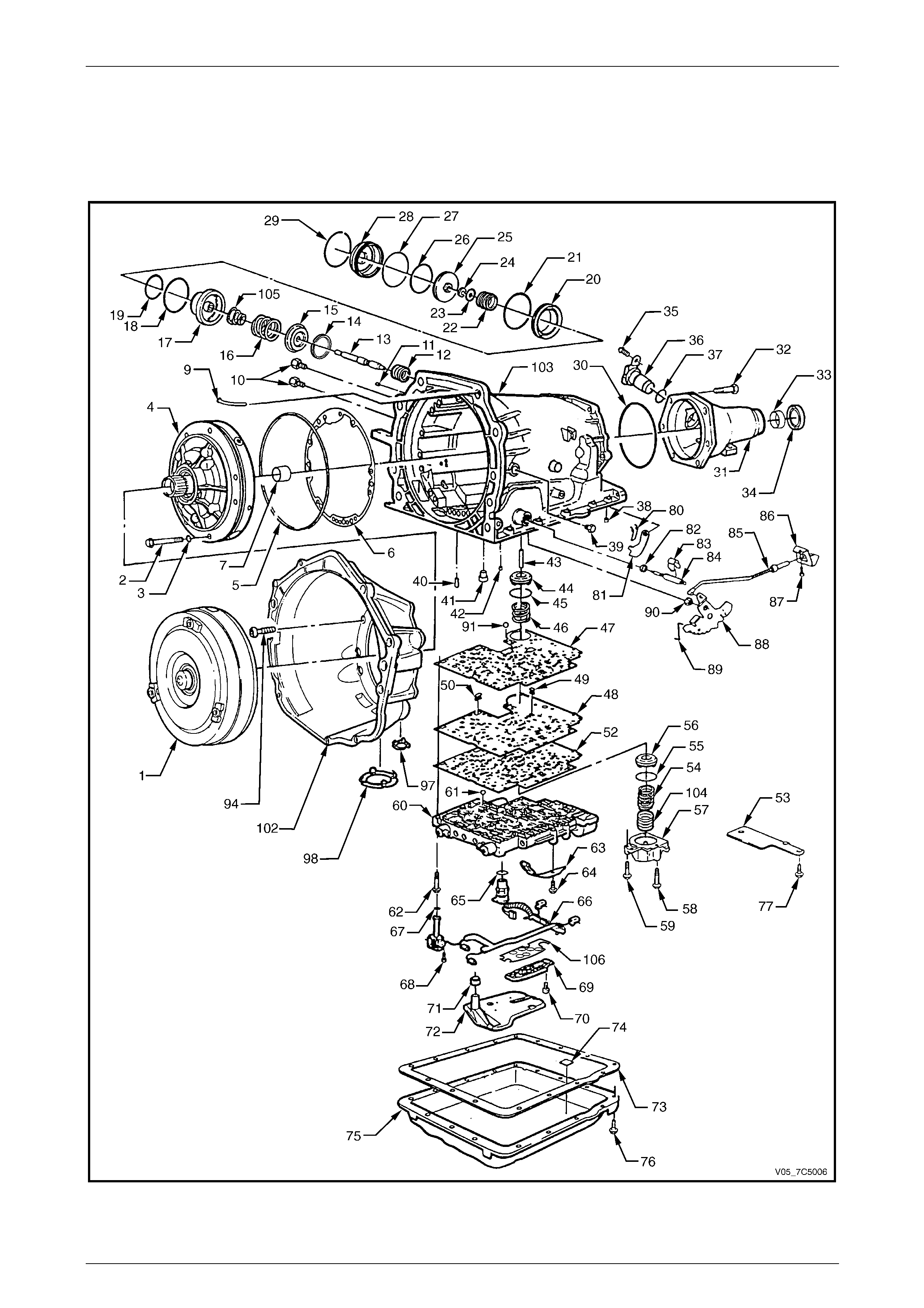
7D5 Automatic Transmission – 4L65E – Unit Repair Page 7D5–126
15–DEC–2005 Page 7D5–126
5 Transmission Diagrams
5.1 Transmission Case and External Parts
Figure 7D5 – 228

7D5 Automatic Transmission – 4L65E – Unit Repair Page 7D5–127
15–DEC–2005 Page 7D5–127
Legend
1 Torque Converter Assembly
2 Bolt, Oil Pump to Case
3 O-ring, Oil Pump to Case Bolt
4 Pump Assembly, Oil
5 Seal, Oil (Oil Pump to Case)
6 Gasket, Oil Pump Cover to Case
7 Bush, Case
9 Vent Assembly, Transmission
10 Quick Connect Fittings, Oil Cooler Pipe
11 Plug, Case Servo
12 Spring, Servo Return
13 Pin, 2nd Apply Piston
14 Ring, Retainer (2nd Apply Piston)
15 Retainer, Servo Cushion Spring (Outer)
16 Spring, Servo Cushion (Outer)
17 Piston, 2nd Apply
18 Ring, Oil Seal (2nd Apply Piston - Outer)
19 Ring, Oil Seal (2nd Apply Piston - Inner)
20 Housing, Servo Piston (Inner)
21 Seal O-ring
22 Spring, Servo Apply Pin
23 Washer, Servo Apply Pin
24 Ring, Retainer (Apply Pin)
25 Piston 4th Apply
26 Ring, Oil Seal (4th Apply Piston - Outer)
27 Seal, O-ring (2-4 Servo Cover)
28 Cover, 2-4 Servo
29 Ring, Servo Cover Retaining
30 Seal, Case Extension to Case
31 Extension, Case
32 Bolt, Case Extension to Case
33 Bush, Case Extension
34 Seal Assembly, Case Extension Oil
35 Bolt, Speed Sensor Retaining
36 Sensor, Vehicle Speed
37 Seal, O-ring (Vehicle Speed Sensor)
38 Plug, Transmission Case (Accumulator Bleed)
39 Plug, Line Pressure
40 Retainer and Ball Assembly, 3rd Accumulator
41 Pin, Band Anchor
42 Retainer and Ball Assembly, (Double Orifice)
43 Pin, Accumulator Piston
44 Piston, 3-4 Accumulator
45 Ring, Oil Seal (3-4 Accumulator Piston)
46 Spring, 3-4 Accumulator (V6 Engines Only)
47 Gasket, Spacer Plate to Case
48 Plate, Valve Body Spacer
49 Screen, Shift Solenoids
50 Screen, Pressure Control Solenoid
52 Gasket, Spacer Plate to Valve Body
53 Plate, Spacer Plate Support
54 Spring, 1-2 Accumulator (Outer)
55 Ring, Oil Seal (1-2 Accumulator)
56 Piston, 1-2 Accumulator
57 Cover and Pin Assembly, 1-2 Accumulator
58 Bolt, Accumulator Cover
59 Bolt, Accumulator Cover
60 Valve Assembly, Control Body
61 Checkball
62 Bolt, Valve Body
63 Spring Assembly, Manual Detent
64 Bolt, Manual Detent Spring
65 O-ring Seal, Wiring Harness Pass-Through Connector
66 Solenoid Assembly Harness, Wiring
67 Seal, O-ring, (Solenoid)
68 Bolt, Hex Washer Head (Solenoid)
69 Switch Assembly, Transmission Fluid Pressure Manual
Valve Position
70 Bolt, Pressure Switch Assembly
71 Seal, Filter
72 Filter Assembly, Transmission Oil
73 Gasket, Transmission Oil Pan
74 Magnet, Chip Collector
75 Pan, Transmission Oil
76 Screw, Transmission Oil Pan
77 Bolt, Spacer Plate Support
80 Spring, Parking Brake Pawl
81 Pawl, Parking Brake
82 Seal, Manual Shaft
83 Retainer, Manual Shaft
84 Shaft, Manual
85 Actuator Assembly, Parking Lock
86 Bracket, Parking Lock
87 Bolt, Parking Lock Bracket
88 Lever, Inside Detent
89 Link, Manual Valve
90 Nut, Hex Head
91 Number 10 Checkball
94 Bolt, Converter Housing to Case
97 Plug, Converter Housing Access Hole
98 Plate, Converter Bolt Inspection
102 Housing, Torque Converter
103 Case, Transmission Main
104 Spring, 1-2 Accumulator (Inner)
105 Spring, Servo Cushion (Inner) (V6 Engine Only)
106 Shield, Transmission Fluid Pressure Switch Assembly,
Manual Valve Position
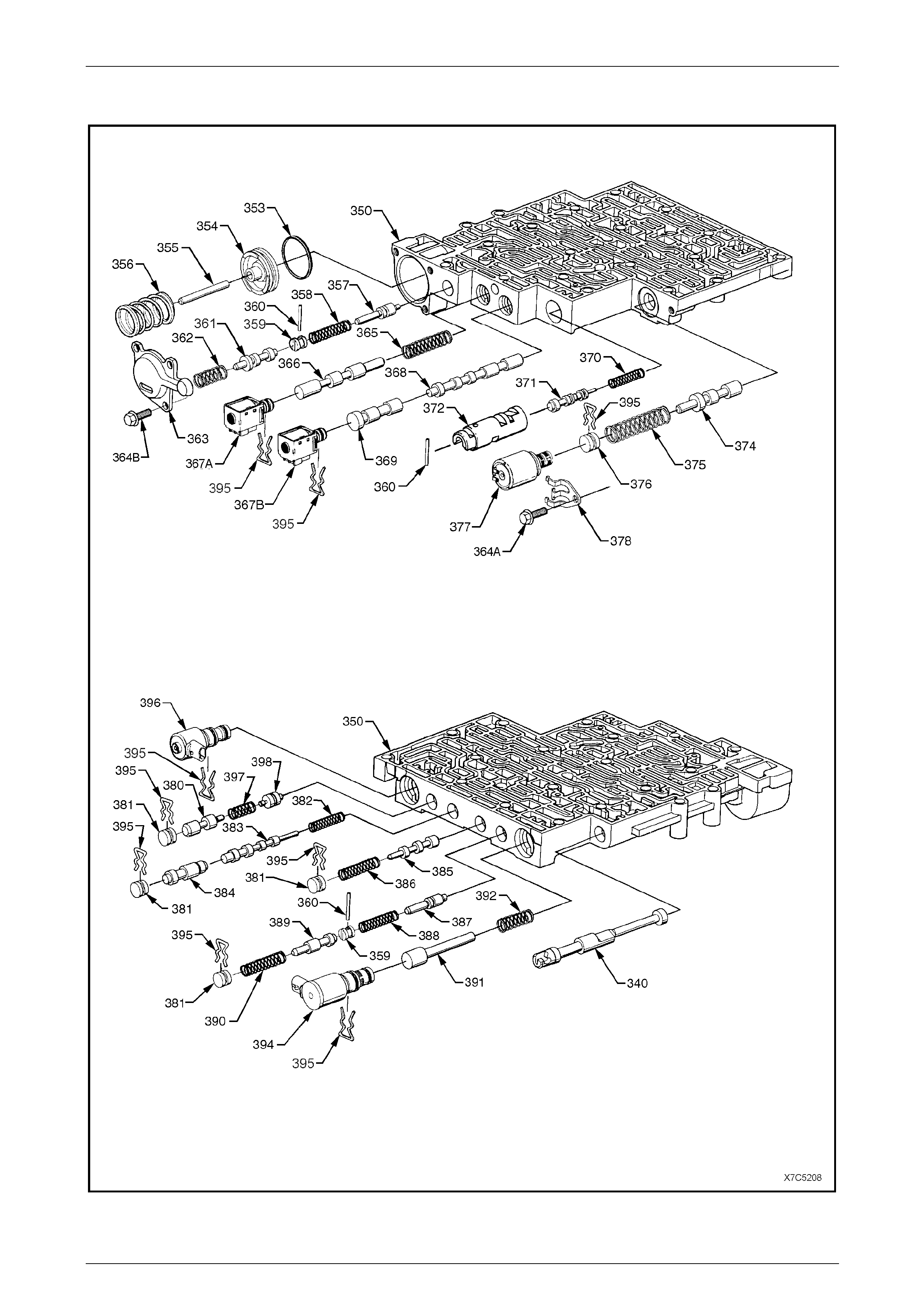
7D5 Automatic Transmission – 4L65E – Unit Repair Page 7D5–128
15–DEC–2005 Page 7D5–128
5.2 Control Valve Body Assembly
Figure 7D5 – 229

7D5 Automatic Transmission – 4L65E – Unit Repair Page 7D5–129
15–DEC–2005 Page 7D5–129
Legend
340 Valve, Manual
350 Valve Assembly, Control Body
353 Seal, Forward Accumulator
354 Piston, Forward Accumulator
355 Pin, Forward Accumulator
356 Spring, Forward Accumulator
357 Valve, Forward Abuse
358 Spring, Forward Abuse Valve
359 Plug, Bore
360 Pin, Coiled Spring
361 Valve, Low Overrun
362 Spring, Low Overrun Valve
363 Cover, Forward Accumulator
364A Bolt, Pressure Control Solenoid Retainer
364B Bolt, Forward Accumulator Cover
365 Spring, 1 - 2 Shift Valve
366 Valve, 1 - 2 Shift
367A 1 - 2 Shift Solenoid (A)
367B 2 - 3 Shift Solenoid (B)
368 Valve, 2 - 3 Shift
369 Valve, 2 - 3 Shuttle
370 Spring, 1 - 2 Accumulator Valve
371 Valve, 1 - 2 Accumulator
372 Sleeve, 1 - 2 Accumulator
374 Valve, Actuator Feed Limit
375 Spring, Actuator Feed Limit Valve
376 Plug, Bore
377 Pressure Control Solenoid
378 Retainer, Pressure Control Solenoid
380 Valve, Regulator Apply
381 Plug, Bore
382 Spring, 4 - 3 Sequence Valve
383 Valve, 4 - 3 Sequence
384 Valve, 3 - 4 Relay
385 Valve, 3 - 4 Shift
386 Spring, 3 - 4 Shift Valve
387 Valve, Reverse Abuse
388 Spring, Reverse Abuse Valve
389 Valve, 3 - 2 Downshift
390 Spring, 3 - 2 Downshift Valve
391 Valve, 3 -2 Control
392 Spring, 3 -2 Control Valve
394 3 - 2 Control Solenoid
395 Retainer, Bore Plug and Solenoid
396 TCC PWM Solenoid Valve
397 Spring, Regulator Supply
398 Valve, Isolator
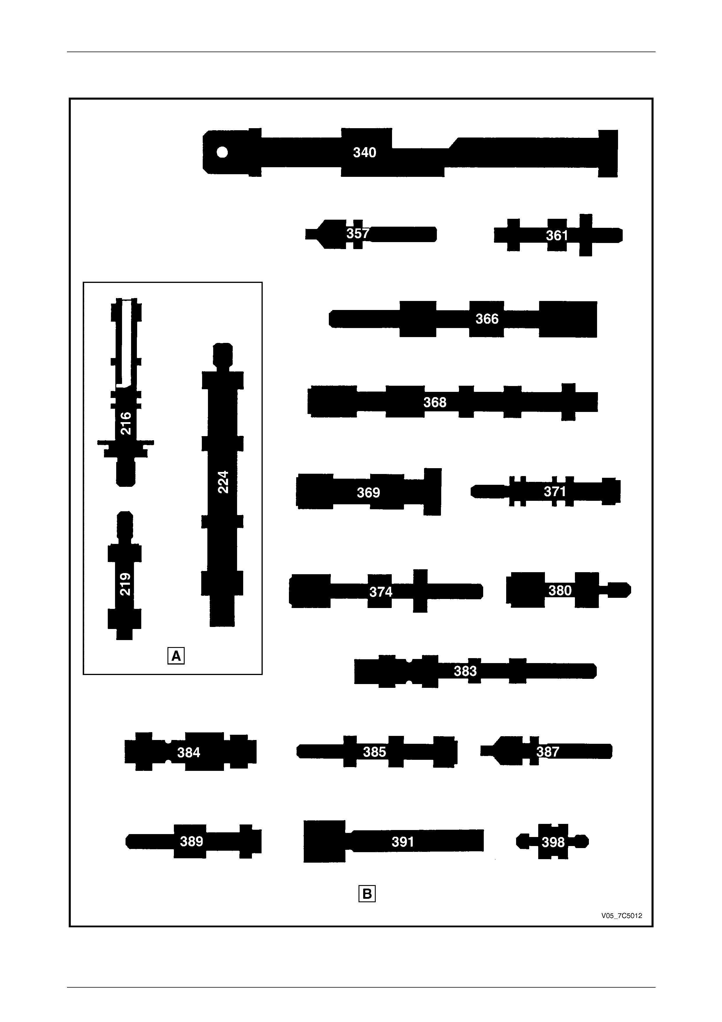
7D5 Automatic Transmission – 4L65E – Unit Repair Page 7D5–130
15–DEC–2005 Page 7D5–130
5.3 Control Valve Identification
Figure 7D5 – 230

7D5 Automatic Transmission – 4L65E – Unit Repair Page 7D5–131
15–DEC–2005 Page 7D5–131
Legend
Valves in the Oil Pump
216 Valve, Pressure Regulator
219 Valve, Reverse Boost
224 Valve, Converter Clutch
Valves in the Control Valve Body
340 Valve, Manual
357 Valve, Forward Abuse
361 Valve, Low Overrun
366 Valve, 1 - 2 Shift
368 Valve, 2 - 3 Shift
369 Valve, 2 - 3 Shuttle
371 Valve, 1 - 2 Accumulator
374 Valve, Actuator Feed Limit
380 Valve, Regulator Apply
383 Valve, 4 - 3 Sequence
384 Valve, 3 - 4 Relay
385 Valve, 3 - 4 Shift
387 Valve, Reverse Abuse
389 Valve, 3 -2 Downshift
391 Valve, 3 -2 Control
398 Valve, Isolator
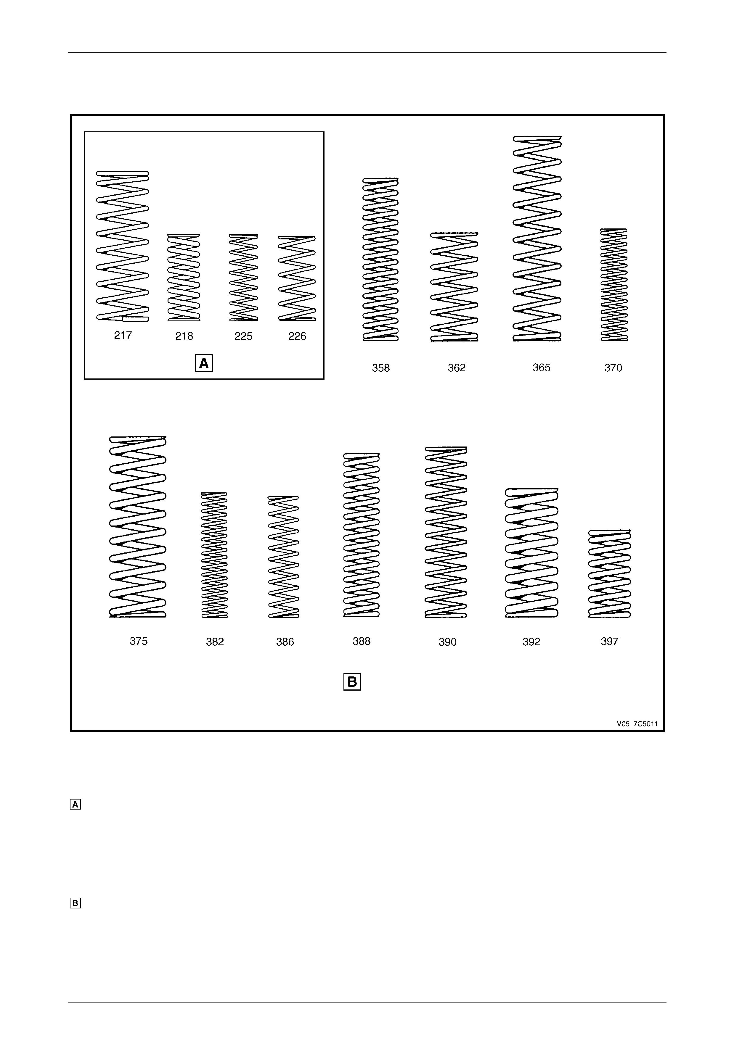
7D5 Automatic Transmission – 4L65E – Unit Repair Page 7D5–132
15–DEC–2005 Page 7D5–132
5.4 Control Valve Spring Identification
Figure 7D5 – 231
Legend
Springs in the Oil Pump
217 Spring, Pressure Regulator Valve
218 Spring, Reverse Isolator
225 Spring, Converter Clutch Valve (Inner)
226 Spring, Converter Clutch Valve (Outer)
Springs in the Control Valve Body
358 Spring, Forward Abuse Valve
362 Spring, Low Overrun Valve
365 Spring, 1 – 2 Shift Valve
370 Spring, 1 – 2 Accumulator Valve
375 Spring, Actuator Feed Limit Valve
382 Spring, 4 – 3 Sequence Valve
386 Spring, 3 – 4 Shift Valve
388 Spring, Reverse Abuse Valve
390 Spring, 3 – 2 Downshift Valve
392 Spring, 3 – 2 Control Valve
397 Spring, Regulator Apply Valve
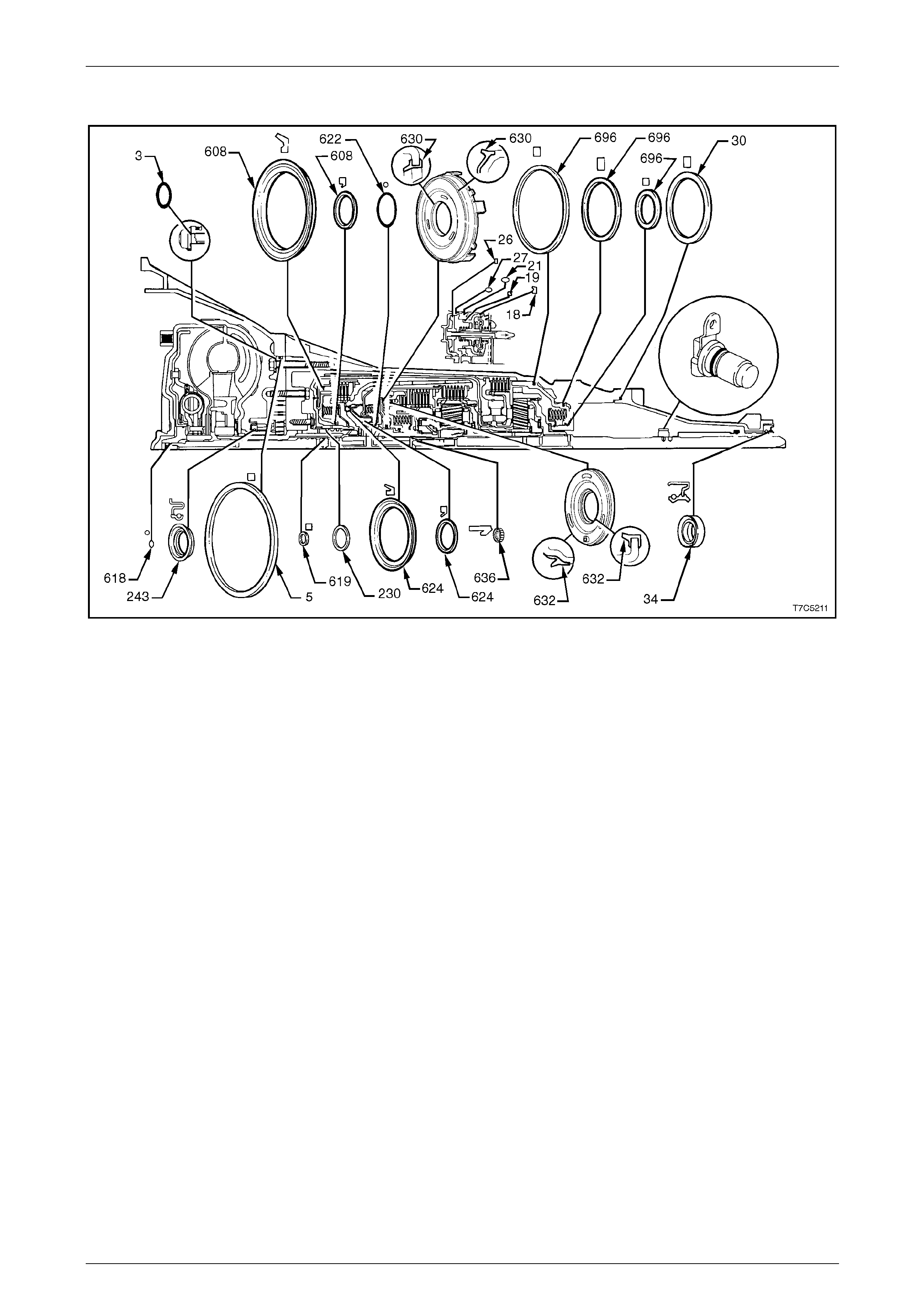
7D5 Automatic Transmission – 4L65E – Unit Repair Page 7D5–133
15–DEC–2005 Page 7D5–133
5.5 Seal Location and Orientation
Figure 7D5 – 232
Legend
3 O-ring, Pump to Case Bolt
5 Seal, Oil (Pump to Case)
18 Ring, Oil Seal (2nd Apply Piston - Outer)
19 Ring, Oil Seal (2nd Apply Piston - Inner)
21 Seal, O-ring
26 Ring, Oil Seal (4th Apply Piston - Outer)
27 Seal, O-ring (2-4 Servo Cover)
30 Seal, Extension housing to Case
34 Seal, Extension housing
37 Seal, O-ring (Vehicle Speed Sensor)
230 Ring, Oil Seal (Stator Shaft)
243 Seal Assembly, Oil
608 Seals, Reverse Input Clutch
618 Seal, O-ring (Turbine Shaft)
619 Ring, Oil Seal (Solid)
622 Seal, O-ring (Input to Forward Housing)
624 Seals, 3rd and 4th Clutch (Service Replacement)
630 Piston, Forward Clutch
632 Piston, Overrun Clutch
636 Seal, Input Housing to Output Shaft
696 Seals, (Low and Reverse Clutch Piston)
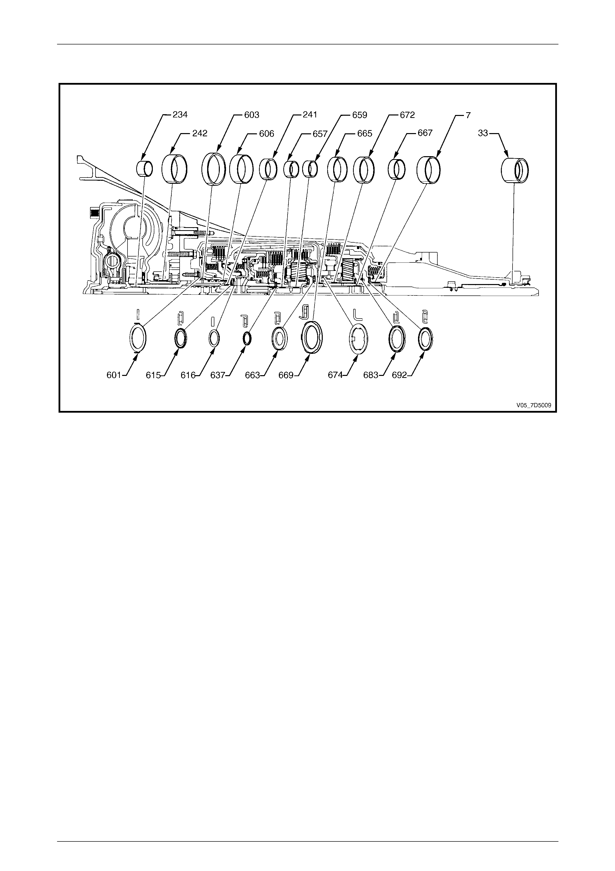
7D5 Automatic Transmission – 4L65E – Unit Repair Page 7D5–134
15–DEC–2005 Page 7D5–134
5.6 Bush/Bearing Location and Orientation
Figure 7D5 – 233
Legend
7 Bush, Case
33 Bush, Extension housing
234 Bush, Stator Shaft (Front)
241 Bush, Stator Shaft (Rear)
242 Bush, Oil pump Body
601 Washer, Thrust (Pump to Drum)
603 Bush, Reverse Input Clutch (Front)
606 Bush, Reverse Input Clutch (Rear)
615 Bearing Assembly, Stator Shaft Selective Washer
616 Washer, Thrust (Selective)
637 Bearing Assembly, Input Sun Gear
657 Bush, Input Sun Gear (Front)
659 Bush, Input Sun Gear (Rear)
663 Bearing Assembly, Thrust (Input carrier to Reaction Shaft
665 Bush, Reaction Carrier Shaft (Front)
667 Bush, Reaction Carrier Shaft (Rear)
669 Bearing, Thrust (Reaction Shaft/Shell)
672 Bush, Reaction Gear
674 Washer, Thrust (Race/Reaction Shell)
683 Bearing Assembly, (Reaction Carrier/Support)
692 Bearing, Reaction Gear Support to Case


7D5 Automatic Transmission – 4L65E – Unit Repair Page 7D5–136
15–DEC–2005 Page 7D5–136
7 Torque Wrench Specifications
For a complete listing of all torque wrench s pecifications for the 4L65E hydra-matic automatic transmission, refer to
Section 7D1 Automatic Transmission – 4L65E – General Information.
