
4/5L40-E
HYDRA-MATIC
2
CONTENTS
INTRODUCTION..................................................................................... 3
HOW TO USE THIS BOOK ...................................................................... 4
UNDERSTANDING THE GRAPHICS ....................................................... 6
TRANSMISSION CUTAWAY VIEW (FOLDOUT) ....................................... 8
GENERAL DESCRIPTION ....................................................................... 9
PRINCIPLES OF OPERATION ............................................................... 9A
MAJOR MECHANICAL COMPONENTS (FOLDOUT) ...................... 10
RANGE REFERENCE CHART ......................................................... 11
TORQUE CONVERTER .................................................................. 12
APPLY COMPONENTS ................................................................. 15
PLANETARY GEAR SETS ............................................................. 29
HYDRAULIC CONTROL COMPONENTS........................................ 32
ELECTRICAL COMPONENTS ........................................................ 45
POWER FLOW ...................................................................................... 53
COMPLETE HYDRAULIC CIRCUITS ..................................................... 85
LUBRICATION POINTS....................................................................... 112
BUSHING AND BEARING LOCATIONS............................................... 113
SEAL LOCATIONS.............................................................................. 114
ILLUSTRATED PARTS LIST ................................................................ 115
BASIC SPECIFICATIONS .................................................................... 136
PRODUCT DESIGNATION SYSTEM ................................................... 138
GLOSSARY ........................................................................................ 140
ABBREVIATIONS ............................................................................... 142
INDEX................................................................................................ 143

PREFACE
All information contained in this book is based on the latest data available
at the time of publication approv al. T he right is reserved to mak e product or
publication changes, at any time, without notice.
No part of any GM Powertrain publication may be reproduced, stored
in any retrieval system or transmitted in any form or by any means,
including but not limited to electronic, mechanical, photocopying,
recording or otherwise, without the prior written permission of
Powertrain Group of General Motors Corporation. This includes all
text, illustrations, tables and charts.
© COPYRIGHT 2001 POWERTRAIN GROUP
General Motors Corporation
ALL RIGHTS RESERVED
The Hydra-matic 4/5L40-E Technician’s Guide is intended for automotive
technicians that are familiar with the operation of an automatic transaxle or
transmission. Technicians or other persons not having automatic transaxle
or transmission know-how may find this publication somewhat technically
complex if additional instruction is not provided. Since the intent of this
book is to explain the fundamental mechanical, hydraulic and electrical
operating principles, technical terms used herein are specific to the
transmission industry. However, words commonly associated with the
specific transaxle or transmission function have been defined in a Glossary
rather than within the text of this book.
The Hydra-matic 4/5L40-E Technician’s Guide is also intended to assist
technicians during the service, diagnosis and repair of this transmission.
However, this book is not intended to be a substitute for other General
Motors service publications that are normally used on the job. Since there
is a wide range of repair procedures and technical specifications specific to
certain vehicles and transmission models, the proper service publication
must be referred to when servicing the Hydra-matic 4/5L40-E transmission.
1

The Hydra-matic 4/5L40-E Technician’s Guide is
another Po wertrain publication from the Technician’s
Guide series of books. The purpose of this
publication, as is the case with other Technician’s
Guides, is to provide complete information on the
theoretical operating characteristics of this
transmission. Operational theories of the mechanical,
hydraulic and electrical components are presented in
a sequential and functional order to better explain
their operation as part of the system.
In the first section of this book entitled “Principles
of Operation”, detailed explanations of the major
components and their functions are presented. In
every situation possible, text describes component
operation during the apply and release cyc le as well
as situations where it has no effect at all. The
descriptive text is then supported by numerous
graphic illustrations to further emphasize the
operational theories presented.
The second major section entitled “Power Flow”,
blends the information presented in the “Principles of
Operation” section into the complete transmission
assembly. The transfer of torque from the engine
through the transmission is graphically displayed on a
full page while a narrative description is provided on
a facing half page. The opposite side of the half page
contains the narrati ve description of the hydraulic fluid
as it applies components or shifts valv es in the system.
Facing this partial page is a hydraulic schematic that
shows the position of valves, ball check valves, etc.,
as they function in a specific gear rang e.
The third major section of this book displays the
“Complete Hydraulic Circuit” for specific gear
ranges. Fold-out pages containing fluid flow
schematics and two dimensional illustra tions of major
components graphically display hydraulic circuits.
This information is extremely useful when tracing
fluid circuits for learning or diagnosis purposes.
The “Appendix” section of this book provides
additional transmission information regarding
lubrication circuits, seal locations, illustrated parts
lists and more. Although this information is available
in current model year Service Manuals, its inclusion
provides for a quick reference guide that is useful to
the technician.
Production of the Hydra-matic 4/5L40-E T ec hnician’s
Guide was made possible through the combined
ef forts of many staf f areas within the General Motors
Powertrain Division. As a result, the Hydra-matic
4/5L40-E Technician’s Guide was written to provide
the user with the most current, concise and usable
information available regarding this product.
3
INTRODUCTION

specific fluid circuits that enable the mechanical
components to operate. The mechanical power
flow is graphically displayed on a full size page
and is followed b y a half page of descripti ve te xt.
The opposite side of the half page contains the
narrative description of the hydraulic fluid as it
applies components or moves valves in the system.
Facing this partial page is a hydr aulic schematic
which shows the position of valves, ball check
valves, etc., as they function in a specific gear
range. Also, located at the bottom of each half
page is a reference to the Complete Hydraulic
Circuit section that follows.
•The Complete Hydraulic Circuits section
(beginning on page 85) details the entire hydraulic
system. T his is accomplished by using a fold-out
circuit schematic with a facing page two
dimensional fold-out drawing of each component.
The circuit schematics and component drawings
display only the fluid passages for that specific
operating range.
•Finally , the Appendix section contains a schematic
of the lubrication flow through the transmission,
disassembled view parts lists and transmission
specifications. This information has been included
to provide the user with convenient reference
information published in the appropriate vehicle
Service Manuals. Since component parts lists
and specifications may change over time, this
information should be verified with Service
Manual information.
First time users of this book may find the pa ge layout
a little unusual or perhaps confusing. Ho we ver, with
a minimal amount of exposure to this format its
usefulness becomes more obvious. If you are
unfamiliar with this publication, the following
guidelines are helpful in understanding the functional
intent for the various page layouts:
•Read the following section, “Understanding the
Graphics” to know how the graphic illustrations
are used, particularly as they relate to the
mechanical power flow and hydraulic controls
(see Understanding the Graphics page 6).
•Unfold the cutaway illustration of the Hydra-
matic 4/5L40-E (page 8) and refer to it as you
progress through each major section. This
cutaway pro vides a quick reference of component
location inside the transmission assembly and
their relationship to other components.
•The Principles of Operation section (beginning on
page 9A) presents information regarding the major
apply components and hydraulic control
components used in this transmission. This section
describes “how” specific components work and
interfaces with the sections that follow.
•The Power Flow section (beginning on page 53)
presents the mechanical and hydraulic functions
corresponding to specific gear ranges. This
section b uilds on the information presented in the
Principles of Operation section by showing
4
HOW TO USE THIS BOOK
DIRECT
CLUTCH
ASSEMBLY
(405–414)
COAST
CLUTCH
ASSEMBLY
(437–446)
TRANSMISSION
FLUID
PAN
(62)
CONVERTER
PUMP
ASSEMBLY
STATOR
ROLLER
CLUTCH
ASSEMBLY
CONVERTER
STATOR
ASSEMBLY
TORQUE
CONVERTER
ASSEMBLY
(1)
TORQUE
CONVERTER
HOUSING/PUMP
ASSEMBLY
(3)
FORWARD
CLUTCH
ASSEMBLY
(435–451)
INPUT
SUN GEAR
SHAFT
(457)
FORWARD
SPRAG
CLUTCH
ASSEMBLY
(461)
OVERDRIVE
CLUTCH
ASSEMBLY
(480–487)
INTERMEDIATE
CLUTCH
ASSEMBLY
(488–497)
INTERMEDIATE
SPRAG
CLUTCH
ASSEMBLY
(473)
TCC PWM
SOLENOID
VALVE
(352)
TRANSMISSION
FLUID
FILTER
(59)
LOW /REVERSE
CLUTCH
ASSEMBLY
(510–517)
REVERSE
CLUTCH
ASSEMBLY
(404–420)
LOW SPRAG
CLUTCH
ASSEMBLY
(503)
SECOND
COAST
CLUTCH
ASSEMBLY
(528–535)
SECOND
CLUTCH
ASSEMBLY
(520–527)
OUTPUT
SHAFT
(562)
FORWARD/COAST
CLUTCH HOUSING
SHAFT
(433)
MANUAL
VALVE
(377)
CONTROL
VALVE BODY/
ACCUMULATOR
ASSEMBLY
(47)
PRESSURE
PLATE
ASSEMBLY
PLANETARY
CARRIER
ASSEMBLY
(553)
SECOND
SPRAG
CLUTCH
ASSEMBLY
(547)
REAR
INTERNAL
GEAR
(560)
FRONT
INTERNAL
GEAR
(550)
TRANSMISSION
MANUAL SHIFT
SHAFT SWITCH
ASSEMBLY
(602)
PARK PAWL
ACTUATOR
ASSEMBLY
(613)
CONVERTER
TURBINE
ASSEMBLY
5
Figure 1
➤ ➤
➤➤
➤
➤
➤
TORQUE CONVERTER HOUSING (227)
(Fluid Pump Cover Side)
➤
➤
➤
➤
➤➤➤
➤
➤
➤ ➤
➤
➤
TOP CHANNEL PLATE (301)
(Case Side)
FRONT
➤
TOP CHANNEL PLATE (301)
(Bottom Channel Plate Side)
FRONT
➤
BOTTOM CHANNEL PLATE (304)
(Top Channel Plate Side)
FRONT
➤
REAR CONTROL VALVE BODY (310)
(Bottom Channel Plate Side)
FRONT
➤
CASE (24)
(Top Channel Plate Side)
FRONT
➤
CASE (24)
(Fluid Pump Cover Side)
SPACER PLATE (307)
(Bottom Channel Plate Side)
FRONT
➤
FRONT CONTROL VALVE BODY (311)
(Bottom Channel Plate Side)
FRONT
➤
BOTTOM CHANNEL PLATE (304)
(Control Valve Body Side)
FRONT
➤
NOTE:
– INDICATES BOLT HOLES
– NON FUNCTIONAL HOLES HAVE BEEN
REMOVED FROM COMPONENT DRAWINGS
TO SIMPLIFY TRACING FLUID FLOW.
– DUAL PURPOSE PASSAGES HAVE
CHANNEL PLATE SIDE NUMBERS LISTED FIRST
– EXHAUST FLUID NOT SHOWN
– PASSAGES MARKED WITH ARE USED FOR
THE 5L40-E ONLY
FLUID PUMP COVER (202)
(Case Side)
FLUID PUMP COVER (202)
(Torque Converter Housing Side)
➤
➤
➤
➤
➤
➤
➤ ➤
➤
➤
➤➤
➤
➤
➤
7
➤
25
➤
27
➤
3
➤
20
➤
16
➤
2
➤
10
➤
9
➤
24
➤
15
➤
11
➤
22
➤
29
➤
28
➤
23
➤
18
➤
17
➤
14
➤
8
➤
4
➤
5
➤
26
➤
13
➤
19
➤
21
➤
6
➤
12
(40)
➤
21
(203)
➤
16
(203)
➤➤
(232)
➤➤
(229)
➤➤
(231)
➤➤
(213)
➤
(233)
➤
TRANSMISSION
VENT
ASSEMBLY
➤➤
32
(203)
➤
37
(203)
➤➤
2/21
(214)
➤➤
(36)
➤
FILTER
(312)
➤
FILTER
(308)
➤
#12
#2
#3
#5
#6
#7
(Spring)
#8
#10 #9
#4
#1
#11
X-2
X-4
X-5
X-1
X-3
33
32
38
38
38
30
30
24
37
37
37
40
40
12
16
15
15
23 52
24
24
23
28
47
41
42
43
27
28
28
27
27
25
25
26
22
22
15
13
18 19
19
19
19
19
19
19
21
17
17
22
23
23
48
48
48
48
48
48
48
48
48
15
13
36
36
36
36
39
35
35
34
10
10 11
10
10
10
20
20
48
44
44
45
43 42
52
52
52
48
48
77
2
2
2
2
2
2
2
12a
16a
15d/16 15c/16
15b
23c
24a 24b
24c
25b
25c 25d
25e
26b
26a
32a
30a
33a
35a
39a
36a
36b
36c
36d
38a 39b
39c/41
40c/41
36e
36f
35b
35c 35d
37c
37d
37b
37a
40b
40a
38d 38b
38c
38e
40d
34a
33e
33c
33d
33b
30b
30c 30d
25a
23b
23a
20a
28c
27c/46
27b
28b
28a
27a
47b
47a
20b
20d
20c
13a
15a
19e
19h
19g
19i
19j
19f
13b15e
17a
17b
17c/18
15f/18
19b/21
19c/21
19d/21
19a
22a
22b
22c
22d
22f
21a
21b/31
21c/31
22g/23
14a/23
22e
48
48
48
48
48
48
48
48
52
52
52
52
52
52
52
52
48
48
2g
7a
7b 2a/54a
2b
42b
43a
42a
43b
44c
44d 44b
44a
44e
43c/45
44f/45
48a 48b
2c/54c
54d
2d/54e
2e 2m/54g
2f
10i
10h
10f
10e
10d
10a 10c
11b
11a/10b
10g
2h
54f
54b
12
2
23
24
48
48
48
48
48
48
48
48
52
52
52
52
52
52
52
23
36
36
36
20
27
28
46
47
47
19
16
15
13
10
10
10
11
54
2
54
37
37
37
39
38
40
42
43
40
27
7
48
48
48
52
52
52
52
52
52
52
24
25
25
25
2525
26
26
15 19 19
19
19
31
21
20 20
15 17
17
14
13
14
54
22
22
28
28
22
22
32
42 43
44
44
48
48
48
48
48
48
44
44
38
39
38
33
33
30
35
40
35
35
36
35
34
30
30
30
33
2
2
10
10 10
10
27
2
216
24
15
18
7
32
52
52
52
52 52
52
52
52
52
52
52
52
52 52
52
52
52
52
30 34
35
41
12 21 37
8
9
2
16
24
7
32
12 21
37
12
21
21
24
848
7
9
9
52
52
2
16
5
16
37
32
32
52
1
52
52
52
48
37
1
2
51
51
52
12
12
24
24
52
2
2
4
4
4
4
5
66
8
8
7
7
7
5
9
48
48
48
48
48
48
48
48
53
53
48
52
2
3
3
3
2
1
16
21
21
16
32
37
32
51
50
50
51 52
52
52
52
52
52
48
48
48
48
52
48
48
12
12
24
24
2
2
3
2
4
4
4
5
6
53
53
8
8
7
7
7
48
16
16
21 32
37
➤➤
1
➤➤
31
➤➤
30
(233)
➤➤
32
38
30
24 12
16
13
15
15
13
18
19
19
19
21
21
22
16 48
48
48
48
48
48
48
48
36
35
35
34
2
2
7
2
10
10
10
10
41
42
43
43
42
48 48
20
28
27
37
27
28
28
27
20
48
52
52
32
32
32
38
24
12 16
16
18
28
28
28
27
27
48 48
43 42
42
43
48
30
48
48
48 48
48
48
48
48
48
48
48
48
35
36
37
34
2
7
2
10
13
13
15
19
41
41
19
19
15
22
21
21
20
20
21
21
13
10
10
10
2
48
48 48
52
52
52
52
52
52
12
32
37 21
24
2
16
18
48
48
48
48
48
30
48
48
48
48
48
48
15
35
41
34
7
52
52
52
52
52
52
OVERDR CL FD 2
ACCUMULATOR
INTERMED CL
ACCUMULATOR
EX
SECOND CL
ACCUM
ACCUMULATOR
LINE
LINE
LINE
EXEXEX
DIRECT CL
4
2
5
DIRECT
CLUTCH
ACCUMULATOR
OVERDRIVE
CLUTCH
ACCUMULATOR
INTERMEDIATE
CLUTCH
ACCUMULATOR
SECOND
CLUTCH
ACCUMULATOR
3
LINE
LINE
LINE (from Pump)
LINE
FILTERED FEED LIMIT
THROTTLE SIGNAL
EX
2345 OR REVERSE
TCC SIGNAL
REGULATED APPLY
REGULATED APPLY
EX
EX
FEED LIMIT VALVE
LINE
EX
EX
EX
EX
FEED LIMIT
FEED LIMIT
EX EX
SECOND COAST CLUTCH
23 REGULATED
OVERDRIVE CL FD 1
INTERMEDIATE CLUTCH
2345
INTERMEDIATE CLUTCH
2345
345
FEED LIMIT
EX
EX
EX
EX
2-3 SIGNAL
23 REGULATED
123 BRAKING
123
EX
EX
EX
123
COAST CLUTCH
COAST CLUTCH FEED
OVERDRIVE CL FD 2
45
FEED LIMIT
LINE
FEED LIMIT
32
MEMORY
MEMORY
MEMORY
MEMORY PILOT
32 SAFETY MODE
EX
EX
FDL
D432
2345
D432
SECOND CL
23 REGULATED
123 REGULATED
SECOND CL
123 REGULATED
LOW AND REV CL
EX
EX
EX
FEED LIMIT
FEED LIMIT
FDL
1-2 SIGNAL
2-3 SIGNAL
EX
EX
RPND432
MANUAL VALVE
LINE
D432
REV
REVERSE
EX
32
LINELINE
LINE SAFETY MODE
4-5 SIGNAL
24
28
PRESSURE
CONTROL
SOLENOID
VALVE
1-2 SHIFT
SOLENOID
VALVE
N/C
(A)
OFF
2-3 SHIFT
SOLENOID
VALVE
N/C
(B)
OFF
4-5 SHIFT
SOLENOID
VALVE
N/C
(C)
OFF
TCC PWM
SOLENOID
VALVE
N/C
1-2 SHIFT VALVE
7
11
10
9
FILTER
(312)
TCC REGULATOR VALVE
1-2 SHIFT CONTROL VALVE
29
8
FEED LIMIT
FEED LIMIT FEED LIMIT
FEED LIMITFEED LIMIT
2-3 SHIFT VALVE CNTRL
CNTRL
LINE SM
LINE SM
LINE SAFETY MODE
SAFETY MODE
DECREASE
CONVERTER FEED
THROTTLE SIGNAL
LINE
EX
REVERSE CLUTCH
PRESS REG VALVEBOOST VALVE
4-5 SHIFT VLV
2c
2b
2a
1
3
PRESSURES
INTAKE & DECREASE (SUCTION)
CONVERTER & LUBE
MAINLINE
REGULATED LINE
SOLENOID SIGNAL
ACCUMULATOR
FEED LIMIT
THROTTLE SIGNAL
NOTE:
PASSAGES AND
COMPONENTS
MARKED WITH
ARE USED FOR
THE 5L40-E ONLY
GASKET (309)
GASKET (305)
GASKET (303)
BOTTOM CHANNEL PLATE (304)
TOP CHANNEL PLATE (301)
CASE (24)
REAR CONTROL VALVE BODY (310)
SPACER PLATE (307)
GASKET (309)
GASKET (305)
GASKET (303)
BOTTOM CHANNEL PLATE (304)
TOP CHANNEL PLATE (301)
CASE (24)
FRONT CONTROL VALVE BODY (311)
SPACER PLATE (307)
FLUID
PUMP
COVER
(202)
CONVERTER
HOUSING
(224)
ACCUMULATOR HOUSING (317) ACCUMULATOR HOUSING (323) ACCUMULATOR HOUSING (328) ACCUMULATOR HOUSING (333)
LUBE
LUBE
LUBE
LUBE
TO COOLER
LUBE
TO COOLER
APPLY
APPLY
APPLY
RELEASE
DECREASE
DECREASE
LINE
OVERDRIVE CLUTCH FEED 1
OVERDRIVE CL FD 1OVERDRIVE CLUTCH FEED 1
OVERDRIVE CLUTCH FEED 1 OVERDRIVE CLUTCH FEED 1
OVERDRIVE CLUTCH
2345 2345
2345
2345
2345
2345
2345 OR REVERSE
RLO
LOW AND REV CL OR RLO
LOW AND REV CL OR RLO
SECOND COAST CLUTCH
SECOND CLUTCH
SECOND COAST CLUTCH
SUCTION SUCTION
LINE
LINE
LINE LINE
LINE
LINE
LINE LINE LINE
TCC SIGNAL
CONVERTER FEED
CONVERTER FEED
RELEASE
TO COOLER
REGULATED APPLYREGULATED APPLY
LINE
EX
CONVERTER FEED
REVERSE CLUTCH
REVERSE CLUTCH
THROTTLE SIGNAL
LINE
EX
FILTERED FEED LIMIT
THROTTLE SIGNAL
THROTTLE SIGNAL
THROTTLE SIGNAL
EX
2345 OR REVERSE
2345 OR REVERSE
2345 OR REVERSE
TCC SIGNAL
TCC SIGNAL
TCC SIGNAL
REGULATED APPLY
REGULATED APPLY
REGULATED APPLY
EX
EX
FEED LIMIT VALVE
LINE
EX
EX
EX
EX
FEED LIMIT
FEED LIMIT FEED LIMIT
FEED LIMIT
FEED LIMIT
FEED LIMIT
FEED LIMIT
FEED LIMIT FEED LIMIT
FEED LIMIT
2-3 SHIFT VALVE CNTRL
EX
EX
EX
EX
EX
EX
EX EX
SECOND COAST CLUTCH
23 REGULATED
23 REGULATED
OVERDRIVE CLUTCH FEED 1
INTERMEDIATE CLUTCH
2345
2345
2345
2345
INTERMEDIATE CLUTCH
2345
345
FEED LIMIT
EX
EX
EX
EX
2-3 SIGNAL
LOW PRESSURE
123 REGULATED
123 REGULATED
EX
CNTRL
LINE SAFETY MODE
123 BRAKING
123
EX
EX
EX
123
123
123
123
123
123
123
123123
COAST CLUTCH
COAST CLUTCH FEED
OVERDRIVE CLUTCH FEED 2
45
FEED LIMIT
SAFETY MODE
LINE
FEED LIMIT
32
MEMORY
MEMORY
MEMORY
MEMORY PILOT
MEMORY PILOT
32 SAFETY MODE
LINE SAFETY MODE
EX
EX
LINE SAFETY MODE
CNTRL 3-4 SHIFT
2-3 SIGNAL
123123 D432D432
DIRECT CLUTCH
DIRECT CLUTCH
4545
1-2 SIGNAL
EX
EX
EX
1-2 SHIFT VALVE
FDL
FDL
FDL
FDL
FDL
FDL
D432
2345 2345
D432
SECOND CLUTCH
23 REGULATED
23 REGULATED23 REGULATED
123 REGULATED
LOW AND REVERSE CLUTCH
LOW AND REVERSE CL
SECOND CLUTCH
123 REGULATED
EX
EX
EX
FD LIMIT
FEED LIMIT
FDL
1-2 SIGNAL
2-3 SIGNAL
EX
EX
TCC SIGNAL
TCC SIGNAL
TCC SIGNAL
RLO
EX
REV
RPND432
MANUAL VALVE
LINE
D432
D432 D432
D432
D432
D432
D432 D432
D432
D432D432
D432
REV
REVERSE
EX
3232
LINE
EX
EX
LINE
CASE (24)
OVERDRIVE CLUTCH FEED 2
OVERDRIVE CL FD 2
OVERDRIVE CLUTCH FEED 2
ACCUMULATOR
DIRECT CLUTCH
ACCUM
INTERMEDIATE CLUTCH
INTERMEDIATE CLUTCH
INTERMEDIATE CLUTCH
ACCUMULATOR
EX
SECOND CLUTCH
SECOND CLUTCH
ACCUM
ACCUM
LINELINE
FORWARD CLUTCH
FORWARD CLUTCH FORWARD CLUTCH
ACCUMULATOR
LINE
LINELINE
LINE
OVERDRIVE CLUTCH
INTERMEDIATE CL
COAST CLUTCH
REVERSE LOCKOUT
COAST CLUTCH
REVERSE CLUTCH
REVERSE CLUTCH
REVERSE CLUTCH
4-5 SIGNAL
EXEXEX
LINE SAFETY MODE
LINE SAFETY MODE
REVERSE LOCKOUT
REVERSE LOCKOUT REVERSE LOCKOUT
COAST CLUTCH
REVERSE LOCKOUT REVERSE LOCKOUT
REVERSE LOCKOUT
REVERSE LOCKOUT
REVERSE LOCKOUT
REVERSE LOCKOUT
REVERSE CLUTCH
REVERSE CLUTCH
LOW AND REV CL OR RLO
FORWARD CLUTCH
FORWARD CLUTCH
FORWARD CLUTCH
COAST CLUTCH
FORWARD CLUTCH
FORWARD CLUTCH
FORWARD CLUTCH
2345
2345 OR REVERSE
123 REGULATED
123 REGULATED
123 REGULATED 123 REGULATED
123 REGULATED
123 REGULATED
123 REGULATED
123 BRAKING
123 BRAKING
123 BRAKING
123 BRAKING
1-2 SIGNAL1-2 SIGNAL
1-2 SIGNAL1-2 SIGNAL1-2 SIGNAL
1-2 SIGNAL 1-2 SIGNAL 1-2 SIGNAL
2-3 SIGNAL2-3 SIGNAL2-3 SIGNAL
2-3 SIGNAL 2-3 SIGNAL
2-3 SIGNAL2-3 SIGNAL2-3 SIGNAL
2-3 SIGNAL
SECOND CLUTCH
SECOND CLUTCH
COAST CLUTCHCOAST CLUTCHCOAST CLUTCH
COAST CLUTCH
COAST CLUTCH
COAST CLUTCH
COAST CLUTCH
COAST CLUTCH
23 REGULATED
345
345
345
345 345 345
345
345
345
345
345
345
345
345
DIRECT CLUTCH
DIRECT CLUTCH
DIRECT CLUTCH
DIRECT CL
DIRECT CLUTCH
DIRECT CLUTCH
DIRECT CLUTCH
DIRECT CLUTCH
45
45
45
4545
45
OVERDRIVE CLUTCH
OVERDRIVE CL FD 1
OVERDRIVE CLUTCH FEED 2OVERDRIVE CLUTCH FEED 2
OVERDRIVE CL FD 2
OVERDRIVE CLUTCH FEED 2 OVERDRIVE CL FD 2
3232
32 32 32
323232
32 SAFETY MODE
32 SAFETY MODE 32 SAFETY MODE 32 SAFETY MODE
32 SAFETY MODE32 SAFETY MODE
32 SM 32 SM
FDL
PRESSURE
CONTROL
SOLENOID
VALVE
1-2 SHIFT
SOLENOID
VALVE
N/C
(A)
OFF
2-3 SHIFT
SOLENOID
VALVE
N/C
(B)
OFF
4-5 SHIFT
SOLENOID
VALVE
N/C
(C)
OFF
TCC PWM
SOLENOID
VALVE
N/C
PRESS REG VALVEBOOST VALVE
CONVERTER FDL
AIR
BLEED
(233)
AIR
BLEED
(233)
AIR
BLEED
(203)
AIR
BLEED
(203)
AIR
BLEED
(203)
AIR
BLEED
(203)
7
4
2
1
5
6
11
10
9
12
18
FILTER
(308)
FILTER
(312)
TCC REGULATOR VALVE
TCC
CONTROL
VALVE
TCC
ENABLE
VALVE
REVERSE
LOCKOUT
VALVE
1-2 SHIFT CONTROL VALVE
FLUID
PAN
(62)
FLUID FILTER
ASSEMBLY
(59)
FLUID
PRESSURE
TEST PLUG
(40)
TORQUE
CONVERTER
ASSEMBLY
(1)
DIRECT
CLUTCH
ACCUMULATOR
OVERDRIVE
CLUTCH
ACCUMULATOR
INTERMEDIATE
CLUTCH
ACCUMULATOR
SECOND
CLUTCH
ACCUMULATOR
COOLER
PRESSURE
RELIEF
BALL
VALVE
21 2
10d
2a
2b
42b
43a
37d
39b
40b
37c
40d
11b
10a
24a
10c
11a 10b
54b
54d
2c
54a
54c
27c 46
7a
24b
20a
13a
37b
38a
7b
47a
47b
27b
28c
12a
23a
36e
36f
23b
23c
15a
24c
26b
36a
38c
38d
36b
25a
15
2m 54g
54f
#8
18
15f
15e
17c
17b
17a
27a
44a
44e
44d
44b
25c
30a
33a
25e
19e
35c
19h
19f
10f
10h
10g
22a
35b
#7
13b
32a
26a
10i
22f
22e
43b
22b
34a
48b
39a
22c
X-1
22
22e
21a
42a
19a
20b
19b
#2
23 22g
14a
2f
2h
19g
19i
19
j
DIRECT
AND REVERSE
CLUTCH
ASSEMBLY
(400–420)
FORWARD
AND COAST
CLUTCH
ASSEMBLY
(430–451)
OVERDRIVE
AND
INTERMEDIATE
CLUTCH
ASSEMBLY
(480–497)
CENTER
SUPPORT
ASSEMBLY
(510–535)
3
2d54e
2e
30c
30d
35d
26
37a
13
#1
15c
15b
16
15d 16
15
X-2
16a
X-4 X-5
38
14
X-3
19
#6
19d
19
21
19c 21
15
#5
21b 31
21c 31
17
21
#4
20d
20c
16
25b
19
25d
20
36 46
28a
44c
28b
30b
21
#11
33e
33d
23
24
35a
#9
33c
33b
22
36d
36c
25
#12
41 40c
39c
43 13
28
40a
#10
45
45
45
44f
44
48
43c
#3
38b
38e
27
48a
29
8
10e
2310
32 SM/FDL
30
31
FLUID PUMP
SCREEN
ASSEMBLY
(213)
(214)
4-5 SHIFT VLV
1
POWER FROM
TORQUE
CONVERTER
(1)
REAR
INTERNAL
GEAR
(560)
HELD
NO POWER
TRANSMITTED
TO
DIFFERENTIAL
ASSEMBLY
TORQUE
CONVERTER
ASSEMBLY
(1)
REVERSE CLUTCH
HOUSING ASSEMBLY
(401)
FORWARD AND COAST
CLUTCH HOUSING
ASSEMBLY
(433)
REAR
INTERNAL
GEAR
(560)
HELD
TORQUE
CONVERTER
HOUSING/PUMP
ASSEMBLY
(3)
PARK
PAWL
(612)
ENGAGED
PARK
PAWL
ACTUATOR
ASSEMBLY
(613)
➤
➤
➤
PARK
(Engine Running)
FOLDOUT ➤ 87
Figure 83
Figure 82
86
PARK
(Engine Running)
(Engine Running)
With the selector lever in the Park (P)
position, line pressure from the oil
pump is directed to the following:
Pressure Regulator Valve(218): Reg-
ulates pump output (line pressure)
according to the transmission
requirements. When pump
output exceeds the demand
of line pressure, fluid from
the pressure regulator
PARK
COMPONENTS ( )
(36) TRANSMISSION FLUID LEVEL HOLE PLUG
(40) TRANSMISSION FLUID PRESSURE TEST PLUG
(203 CHECK VALVE RETAINER AND BALL ASSEMBLY
(213) TRANSMISSION FLUID PUMP SCREEN ASSEMBLY
(214) BRASS ORIFICE INSERT
(230) TRANSMISSION VENT ASSEMBLY
(232) ORIFICE SLEEVE
(233) ORIFICE CUP PLUG
(306) CONTROL VALVE BODY BALL CHECK VALVE
(#1, 2, 3, 4, 5, 6, 7, 8, 9, 10, 11, 12
(308) TCC PWM SOLENOID VALVE FILTER ASSEMBLY
(312) PRESSURE CONTROL SOLENOID VALVE
FILTER ASSEMBLY
86B
HOW TO USE THIS BOOK
PARK
Figure 52
56
(Engine Running)
COMPLETE HYDRAULIC CIRCUIT
PAGE 86
With the selector lever in the Park (P)
position, line pressure from the oil
pump is directed to the following:
Pressure Regulator Valve(218): Reg-
ulates pump output (line pressure)
according to the transmission
requirements. When pump
output exceeds the demand
of line pressure, fluid from
the pressure regulator
PARK
HYDRA-MATIC 5L40-E
8
Figure 6
Figure 53
57
PARK
(Engine Running)
(Engine Running)
56B
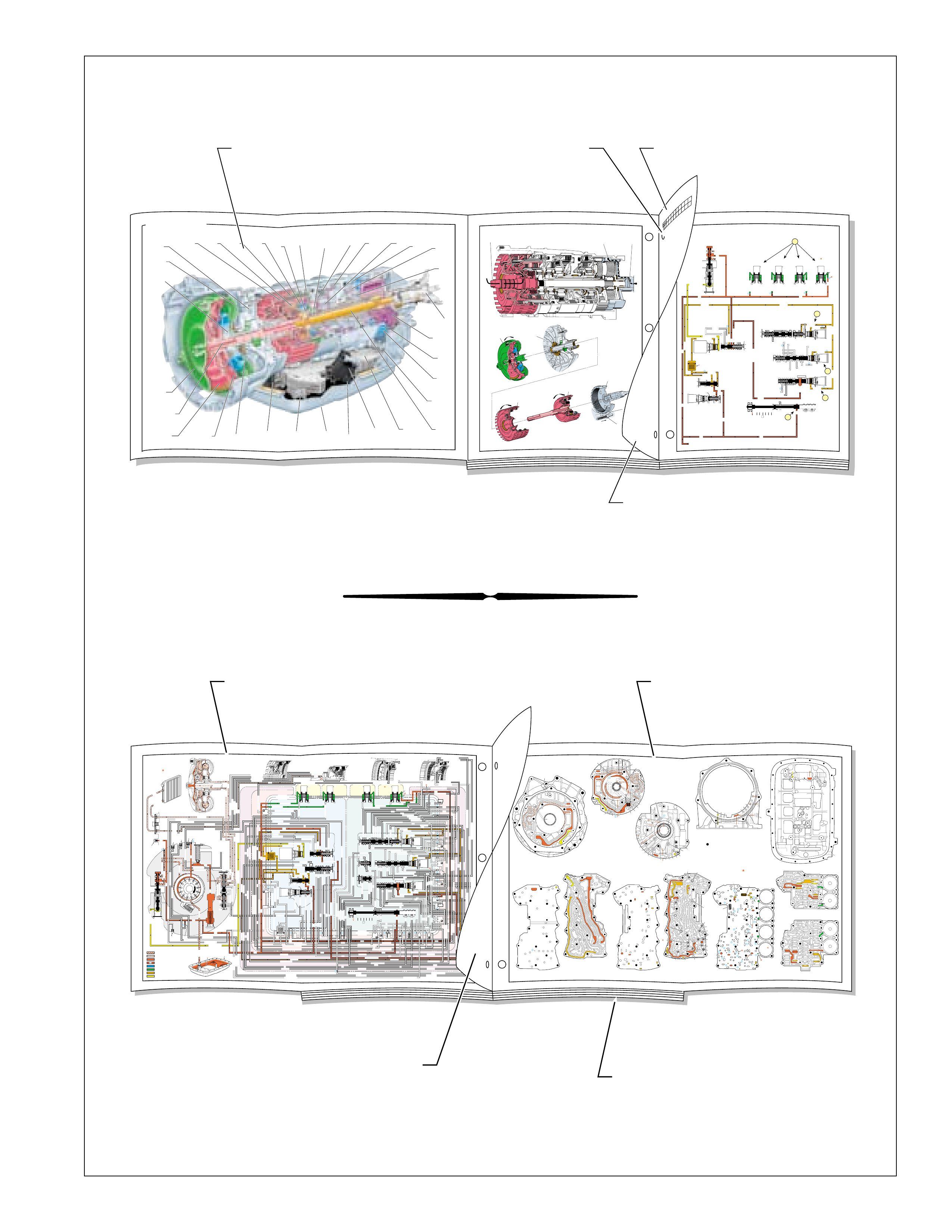
FLUID FLOW SCHEMATIC —
(FOLDOUT) FLUID FLOW THROUGH
COMPONENTS (FOLDOUT)
COMPLETE ILLUSTRATED
PARTS LIST
HALF PAGE TEXT AND LEGEND
➤
➤
➤
➤
RANGE REFERENCE CHARTLARGE CUTAWAY VIEW
OF TRANSMISSION
(FOLDOUT)
HALF PAGE TEXT FOR EASY
REFERENCE TO BOTH PAGES
PAGE NUMBER —
FOR REFERENCE TO
FLUID FLOW SCHEMATIC
➤
➤
➤
➤
CASE
ASSEMBLY
(24)
CONTROL
VALVE BODY AND
ACCUMULATOR
ASSEMBLY
(47)
TORQUE
CONVERTER
ASSEMBLY
(1)
TORQUE
CONVERTER
HOUSING
(227)
FLUID PUMP
COVER
ASSEMBLY
(202)
GASKET
(46)
GASKET
(60)
FLUID
FILTER
(59)
FLUID
PAN
(62)
UNDERSTANDING THE GRAPHICS
6
The flow of transmission fluid starts in the bottom
pan and is drawn through the f ilter , case assembly and
into the oil pump assembly. This is a basic concept of
fluid flow that can be understood by reviewing the
illustrations provided in Figure 2. Ho we v er, fluid may
pass between the control valve body, spacer plate,
case and other components many times before reaching
a valve or applying a clutch. For this reason, the
graphics are designed to show the e xact location where
fluid passes through a component and into other
passages for specific g ear range operation.
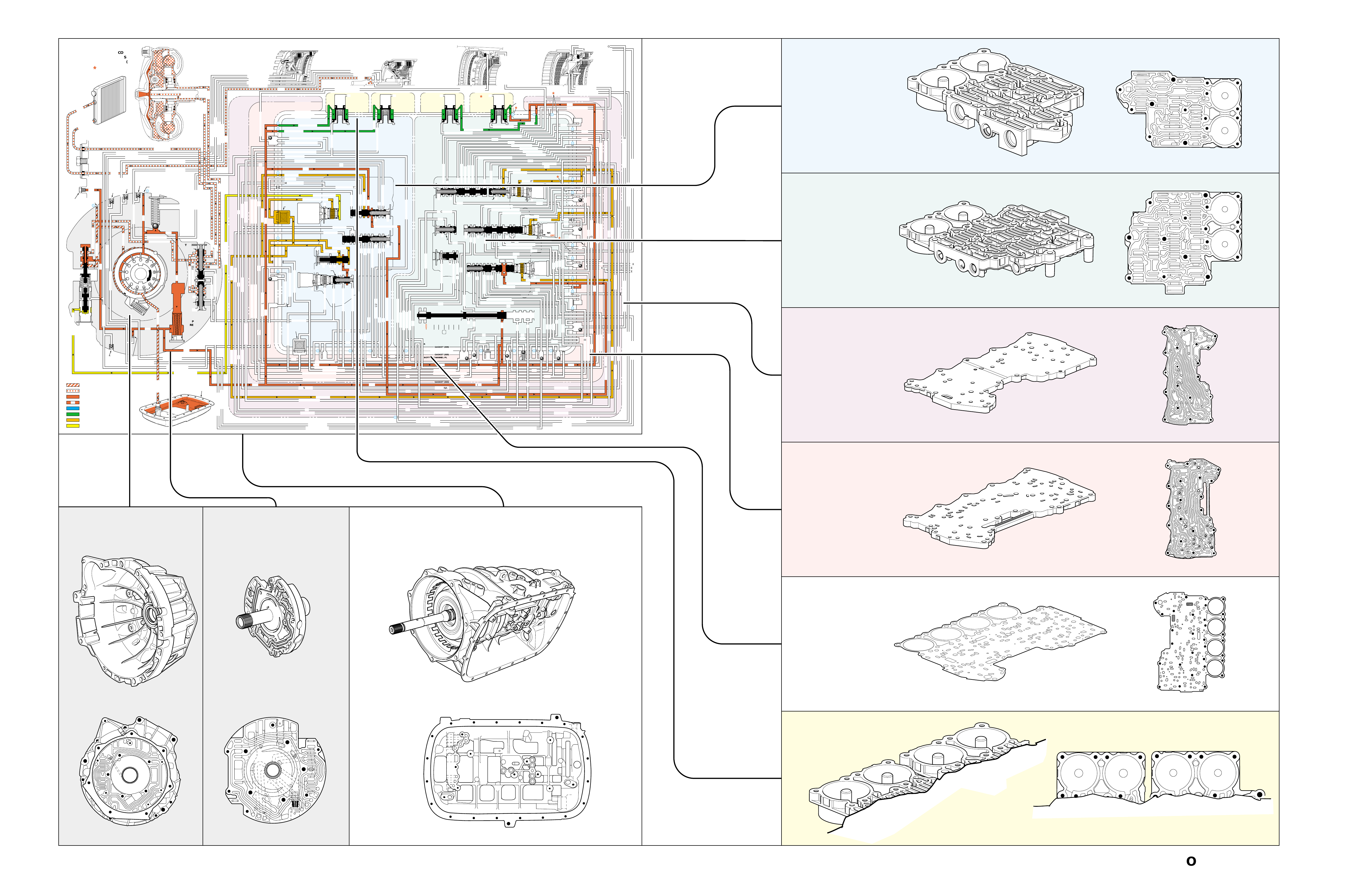
To provide a better understanding of fluid flow in
the Hydra-matic 4/5L40-E transmission, the
components in v olved with hydraulic contr ol and fluid
flow are illustrated in three major formats. Figure 3
provides an example of these formats which are:
•A three dimensional line drawing of the component
for easier part identification.
•A two dimensional line drawing of the component
to indicate fluid passages and orifices.
•A graphic schematic representation that displays
valves, ball check valves, orifices and so forth,
required for the proper function of the transmission
in a specific gear range. In the schematic drawings,
fluid circuits are represented by straight lines and
orifices are represented by indentations in a circuit.
All circuits are labeled and color coded to provide
reference points between the schematic drawing
and the two dimensional line drawing of the
components.
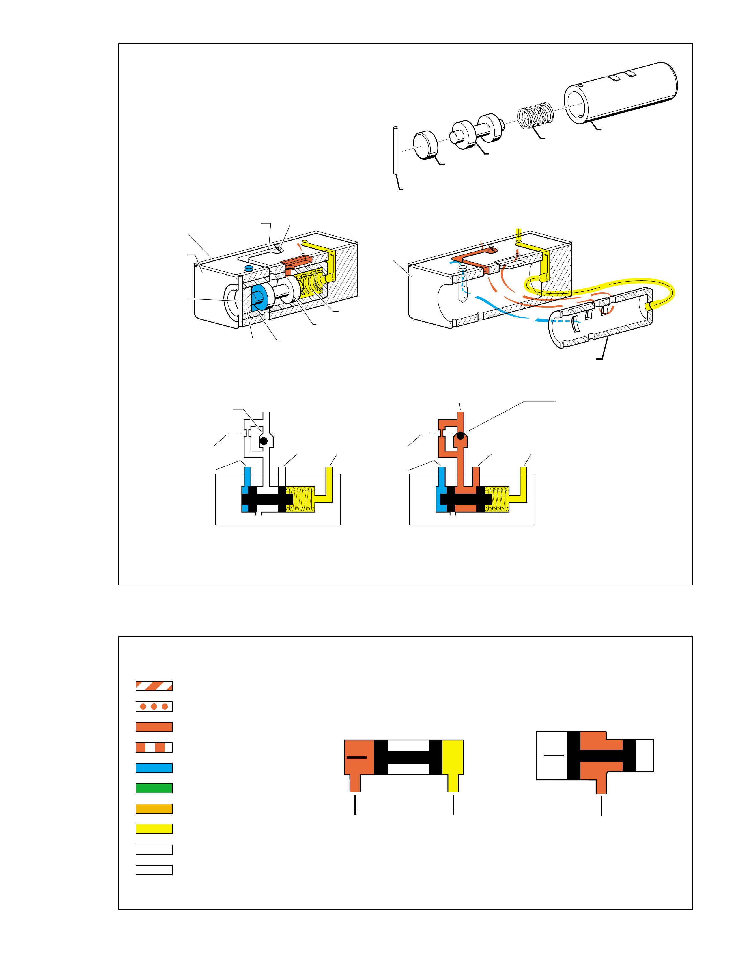
•Figure 4 (page 7B) provides an illustration of a
typical valve, bushing and valve train components.
A brief description of valve operation is also
provided to support the illustration.
•Figure 5 (page 7B) provides a color coded chart
that references different fluid pressures used to
operate the hydraulic control systems. A brief
description of how fluid pressures affect valve
operation is also provided.
Figure 2
PRESSURES
INTAKE & DECREASE (SUCTION)
CONVERTER & LUBE
MAINLINE
REGULATED LINE
SOLENOID SIGNAL
ACCUMULATOR
FEED LIMIT
THROTTLE SIGNAL
NOTE:
PASSAGES AND
COMPONENTS
MARKED WITH
ARE USED FOR
THE 5L40-E ONLY
;
;
;
;;
;;
;;
;
;
;
;;;
;;;
;;;
;
;
;;;
;;;
;;;
;;;
;;;
;;;
;;;
;;;
;;;
;
;
;
GASKET (309)
GASKET (305)
GASKET (303)
BOTTOM CHANNEL PLATE (304)
TOP CHANNEL PLATE (301)
CASE (24)
REAR CONTROL VALVE BODY (310)
SPACER PLATE (307)
GASKET (309)
GASKET (305)
GASKET (303)
BOTTOM CHANNEL PLATE (304)
TOP CHANNEL PLATE (301)
CASE (24)
FRONT CONTROL VALVE BODY (311)
SPACER PLATE (307)
FLUID
PUMP
COVER
(202)
CONVERTER
HOUSING
(224)
ACCUMULATOR HOUSING (317) ACCUMULATOR HOUSING (323) ACCUMULATOR HOUSING (328) ACCUMULATOR HOUSING (333)
LUBE
LUBE
LUBE
LUBE
TO COOLER
LUBE
TO COOLER
APPLY
APPLY
APPLY
RELEASE
DECREASE
DECREASE
LINE
OVERDRIVE CLUTCH FEED 1
OVERDRIVE CL FD 1OVERDRIVE CLUTCH FEED 1
OVERDRIVE CLUTCH FEED 1 OVERDRIVE CLUTCH FEED 1
OVERDRIVE CLUTCH
2345 2345
2345
2345
2345
2345
2345 OR REVERSE
RLO
LOW AND REV CL OR RLO
LOW AND REV CL OR RLO
SECOND COAST CLUTCH
SECOND CLUTCH
SECOND COAST CLUTCH
SUCTION SUCTION
LINE
LINE
LINE LINE
LINE
LINE
LINE LINE LINE
TCC SIGNAL
CONVERTER FEED
CONVERTER FEED
RELEASE
TO COOLER
REGULATED APPLYREGULATED APPLY
LINE
EX
CONVERTER FEED
REVERSE CLUTCH
REVERSE CLUTCH
THROTTLE SIGNAL
LINE
EX
FILTERED FEED LIMIT
THROTTLE SIGNAL
THROTTLE SIGNAL
THROTTLE SIGNAL
EX
2345 OR REVERSE
2345 OR REVERSE
2345 OR REVERSE
TCC SIGNAL
TCC SIGNAL
TCC SIGNAL
REGULATED APPLY
REGULATED APPLY
REGULATED APPLY
EX
EX
FEED LIMIT VALVE
LINE
EX
EX
EX
EX
FEED LIMIT
FEED LIMIT FEED LIMIT
FEED LIMIT
FEED LIMIT
FEED LIMIT
FEED LIMIT
FEED LIMIT FEED LIMIT
FEED LIMIT
2-3 SHIFT VALVE CNTRL
EX
EX
EX
EX
EX
EX
EX EX
SECOND COAST CLUTCH
23 REGULATED
23 REGULATED
OVERDRIVE CLUTCH FEED 1
INTERMEDIATE CLUTCH
2345
2345
2345
2345
INTERMEDIATE CLUTCH
2345
345
FEED LIMIT
EX
EX
EX
EX
2-3 SIGNAL
LOW PRESSURE
123 REGULATED
123 REGULATED
EX
CNTRL
LINE SAFETY MODE
123 BRAKING
123
EX
EX
EX
123
123
123
123
123
123
123
123123
COAST CLUTCH
COAST CLUTCH FEED
OVERDRIVE CLUTCH FEED 2
45
FEED LIMIT
SAFETY MODE
LINE
FEED LIMIT
32
MEMORY
MEMORY
MEMORY
MEMORY PILOT
MEMORY PILOT
32 SAFETY MODE
LINE SAFETY MODE
EX
EX
LINE SAFETY MODE
CNTRL 3-4 SHIFT
2-3 SIGNAL
123123 D432D432
DIRECT CLUTCH
DIRECT CLUTCH
4545
1-2 SIGNAL
EX
EX
EX
1-2 SHIFT VALVE
FDL
FDL
FDL
FDL
FDL
FDL
D432
2345 2345
D432
SECOND CLUTCH
23 REGULATED
23 REGULATED23 REGULATED
123 REGULATED
LOW AND REVERSE CLUTCH
LOW AND REVERSE CL
SECOND CLUTCH
123 REGULATED
EX
EX
EX
FD LIMIT
FEED LIMIT
FDL
1-2 SIGNAL
2-3 SIGNAL
EX
EX
TCC SIGNAL
TCC SIGNAL
TCC SIGNAL
RLO
EX
REV
RPND432
MANUAL VALVE
LINE
D432
D432 D432
D432
D432
D432
D432 D432
D432
D432D432
D432
REV
REVERSE
EX
3232
LINE
EX
EX
LINE
CASE (24)
OVERDRIVE CLUTCH FEED 2
OVERDRIVE CL FD 2
OVERDRIVE CLUTCH FEED 2
ACCUMULATOR
DIRECT CLUTCH
ACCUM
INTERMEDIATE CLUTCH
INTERMEDIATE CLUTCH
INTERMEDIATE CLUTCH
ACCUMULATOR
EX
SECOND CLUTCH
SECOND CLUTCH
ACCUM
ACCUM
LINELINE
FORWARD CLUTCH
FORWARD CLUTCH FORWARD CLUTCH
ACCUMULATOR
LINE
LINELINE
LINE
OVERDRIVE CLUTCH
INTERMEDIATE CL
COAST CLUTCH
REVERSE LOCKOUT
COAST CLUTCH
REVERSE CLUTCH
REVERSE CLUTCH
REVERSE CLUTCH
4-5 SIGNAL
EXEXEX
LINE SAFETY MODE
LINE SAFETY MODE
REVERSE LOCKOUT
REVERSE LOCKOUT REVERSE LOCKOUT
COAST CLUTCH
REVERSE LOCKOUT REVERSE LOCKOUT
REVERSE LOCKOUT
REVERSE LOCKOUT
REVERSE LOCKOUT
REVERSE LOCKOUT
REVERSE CLUTCH
REVERSE CLUTCH
LOW AND REV CL OR RLO
FORWARD CLUTCH
FORWARD CLUTCH
FORWARD CLUTCH
COAST CLUTCH
FORWARD CLUTCH
FORWARD CLUTCH
FORWARD CLUTCH
2345
2345 OR REVERSE
123 REGULATED
123 REGULATED
123 REGULATED 123 REGULATED
123 REGULATED
123 REGULATED
123 REGULATED
123 BRAKING
123 BRAKING
123 BRAKING
123 BRAKING
1-2 SIGNAL1-2 SIGNAL
1-2 SIGNAL1-2 SIGNAL1-2 SIGNAL
1-2 SIGNAL 1-2 SIGNAL 1-2 SIGNAL
2-3 SIGNAL2-3 SIGNAL2-3 SIGNAL
2-3 SIGNAL 2-3 SIGNAL
2-3 SIGNAL2-3 SIGNAL2-3 SIGNAL
2-3 SIGNAL
SECOND CLUTCH
SECOND CLUTCH
COAST CLUTCHCOAST CLUTCHCOAST CLUTCH
COAST CLUTCH
COAST CLUTCH
COAST CLUTCH
COAST CLUTCH
COAST CLUTCH
23 REGULATED
345
345
345
345 345 345
345
345
345
345
345
345
345
345
DIRECT CLUTCH
DIRECT CLUTCH
DIRECT CLUTCH
DIRECT CL
DIRECT CLUTCH
DIRECT CLUTCH
DIRECT CLUTCH
DIRECT CLUTCH
45
45
45
4545
45
OVERDRIVE CLUTCH
OVERDRIVE CL FD 1
OVERDRIVE CLUTCH FEED 2OVERDRIVE CLUTCH FEED 2
OVERDRIVE CL FD 2
OVERDRIVE CLUTCH FEED 2 OVERDRIVE CL FD 2
3232
32 32 32
323232
32 SAFETY MODE
32 SAFETY MODE 32 SAFETY MODE 32 SAFETY MODE
32 SAFETY MODE32 SAFETY MODE
32 SM 32 SM
FDL
PRESSURE
CONTROL
SOLENOID
VALVE
1-2 SHIFT
SOLENOID
VALVE
N/C
(A)
OFF
2-3 SHIFT
SOLENOID
VALVE
N/C
(B)
OFF
4-5 SHIFT
SOLENOID
VALVE
N/C
(C)
OFF
TCC PWM
SOLENOID
VALVE
N/C
PRESS REG VAL VEBOOST VAL VE
CONVERTER FDL
AIR
BLEED
(233)
AIR
BLEED
(233)
AIR
BLEED
(203)
AIR
BLEED
(203)
AIR
BLEED
(203)
AIR
BLEED
(203)
7
4
2
1
5
6
11
10
9
12
18
FILTER
(308)
FILTER
(312)
TCC REGULATOR VALVE
TCC
CONTROL
VALVE
TCC
ENABLE
VALVE
REVERSE
LOCKOUT
VALVE
1-2 SHIFT CONTROL VALVE
FLUID
PAN
(62)
FLUID FILTER
ASSEMBLY
(59)
FLUID
PRESSURE
TEST PLUG
(40)
TORQUE
CONVERTER
ASSEMBLY
(1)
DIRECT
CLUTCH
ACCUMULATOR
OVERDRIVE
CLUTCH
ACCUMULATOR
INTERMEDIATE
CLUTCH
ACCUMULATOR
SECOND
CLUTCH
ACCUMULATOR
COOLER
PRESSURE
RELIEF
BALL
VALVE
21 2
10d
2a
2b
42b
43a
37d
39b
40b
37c
40d
11b
10a
24a
10c
11a 10b
54b
54d
2c
54a
54c
27c 46
7a
24b
20a
13a
37b
38a
7b
47a
47b
27b
28c
12a
23a
36e
36f
23b
23c
15a
24c
26b
36a
38c
38d
36b
25a
15
2m 54g
54f
#8
18
15f
15e
17c
17b
17a
27a
44a
44e
44d
44b
25c
30a
33a
25e
19e
35c
19h
19f
10f
10h
10g
22a
35b
#7
13b
32a
26a
10i
22f
22e
43b
22b
34a
48b
39a
22c
X-1
22
22e
21a
42a
19a
20b
19b
#2
23 22g
14a
2f
2h
19g
19i
19
j
DIRECT
AND REVERSE
CLUTCH
ASSEMBLY
(400—420)
FORWARD
AND COAST
CLUTCH
ASSEMBLY
(430—451)
OVERDRIVE
AND
INTERMEDIATE
CLUTCH
ASSEMBLY
(480—497)
CENTER
SUPPORT
ASSEMBLY
(510—535)
3
2d54e
2e
30c
30d
35d
26
37a
13
#1
15c
15b
16
15d 16
15
X-2
16a
X-4 X-5
38
14
X-3
19
#6
19d
19
21
19c 21
15
#5
21b 31
21c 31
17
21
#4
20d
20c
16
25b
19
25d
20
36 46
28a
44c
28b
30b
21
#11
33e
33d
23
24
35a
#9
33c
33b
22
36d
36c
25
#12
41 40c
39c
43 13
28
40a
#10
45
45
45
44f
44
48
43c
#3
38b
38e
27
48a
29
8
10e
2310
32 SM/FDL
30
31
FLUID PUMP
SCREEN
ASSEMBLY
(213)
(214)
4-5 SHIFT VLV
UNDERSTANDING THE GRAPHICS
Figure 3
FOLDOUT ➤ 7AFOLDOUT ➤ 7
➤
➤
➤
➤
➤
➤
➤
➤
➤
➤
➤
➤
➤
➤
➤
➤
➤
➤
FRONT CONTROL
VALVE BODY
ASSEMBLY
(311)
BOTTOM CHANNEL PLATE SIDE
TWO DIMENSIONALTHREE DIMENSIONAL
TOP
CHANNEL PLATE
(301)
BOTTOM CHANNEL PLATE SIDE
BOTTOM CHANNEL PLATE SIDE
SPACER
PLATE
(307)
TWO DIMENSIONALTHREE DIMENSIONAL
TWO DIMENSIONALTHREE DIMENSIONAL
TWO DIMENSIONALTHREE DIMENSIONAL
TWO DIMENSIONALTHREE DIMENSIONAL
TWO DIMENSIONALTHREE DIMENSIONAL
BOTTOM CHANNEL PLATE SIDE
CONTROL VALVE BODY SIDE
ACCUMULATORS
BOTTOM
CHANNEL
PLATE
(304)
REAR CONTROL
VALVE BODY
(310)
CONTROL VALVE BODY SIDE
FLUID PUMP
COVER
ASSEMBLY
(202)
TORQUE CONVERTER
HOUSING
(227)
CASE
ASSEMBLY
(24)
FLUID PUMP COVER SIDE CONVERTER HOUSING SIDE TOP CHANNEL PLATE SIDE
THREE DIMENSIONALTHREE DIMENSIONAL THREE DIMENSIONAL
TWO DIMENSIONAL TWO DIMENSIONAL TWO DIMENSIONAL
GRAPHIC
SCHEMATIC
REPRESENTATION
7B
UNDERSTANDING THE GRAPHICS
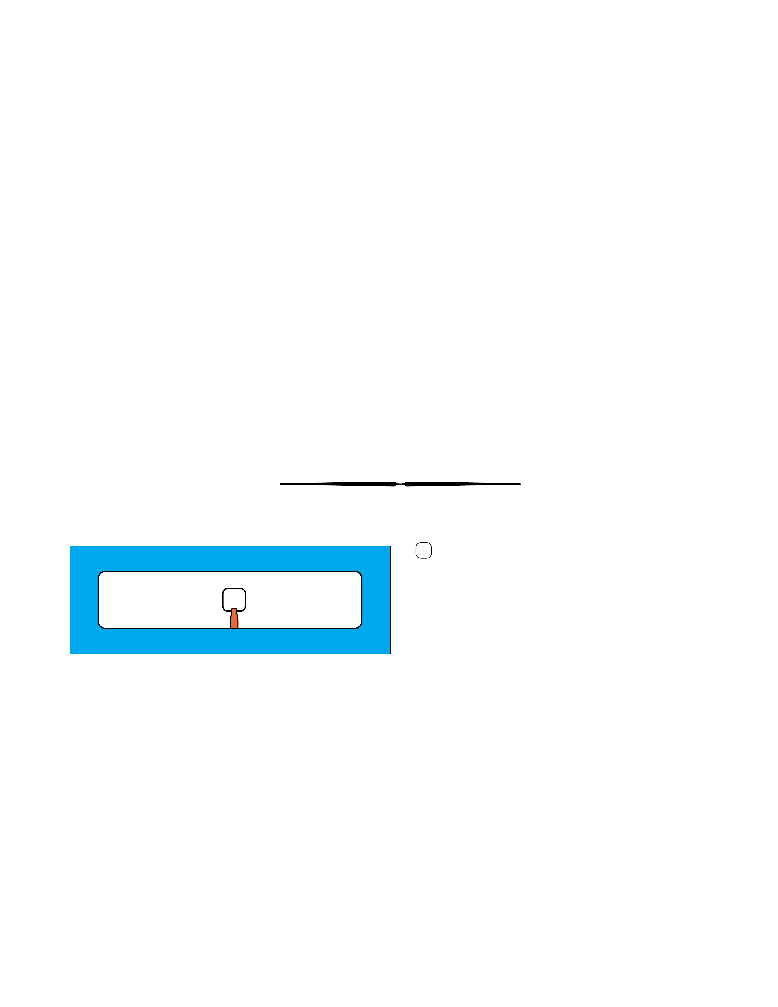
TYPICAL BUSHING AND VALVE
Figure 4
Figure 5
➤
➤
➤
➤
➤
➤
➤
➤
➤
➤
➤
➤
➤
SPRING
RETAINING
PIN
BORE
PLUG
VALVE
BUSHING
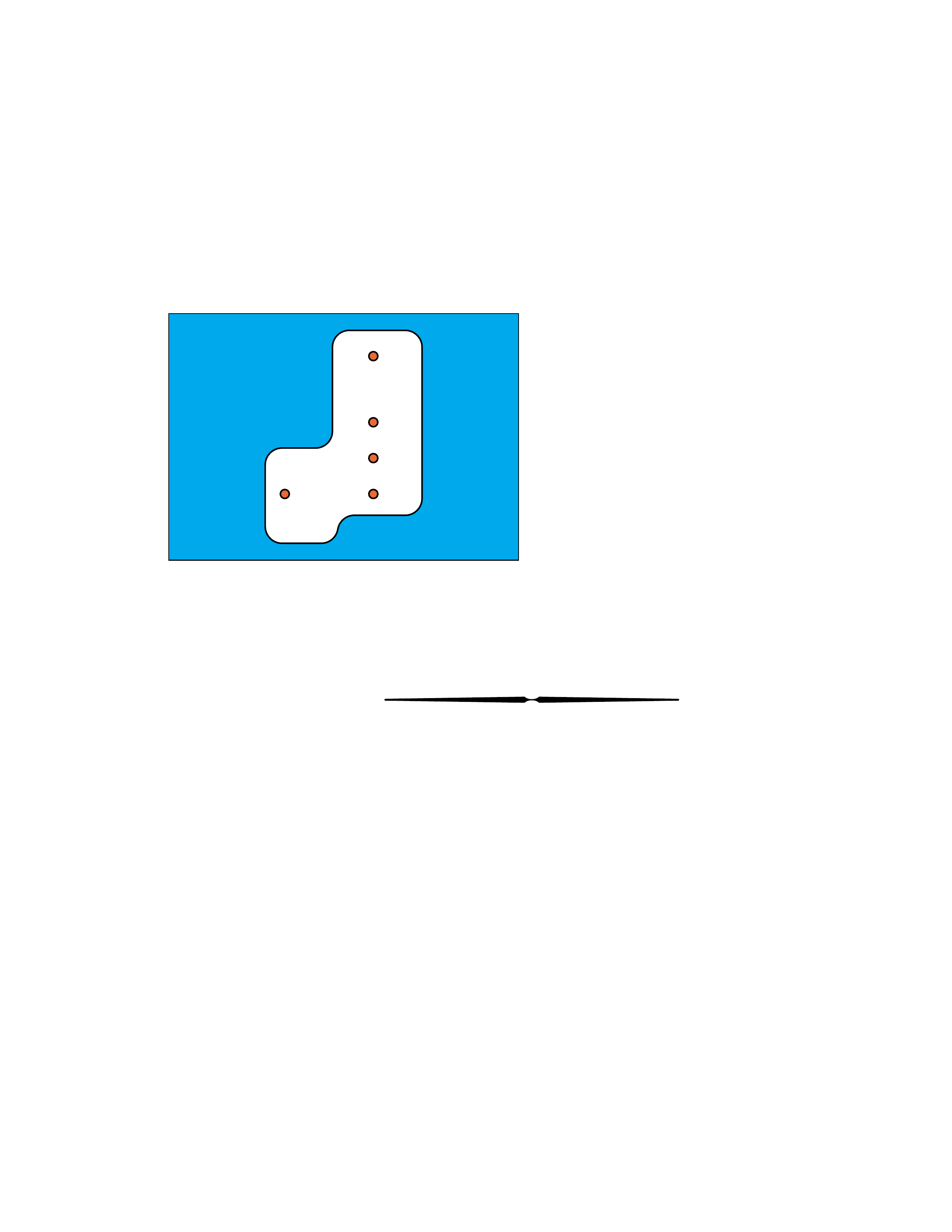
EXHAUST FROM THE
APPLY COMPONENT
UNSEATS THE
BALL CHECK VALVE,
THEREFORE CREATING
A QUICK RELEASE.
TO APPLY
COMPONENT APPLY FLUID SEATS
THE BALL CHECK VALVE
FORCING FLUID THROUGH
AN ORIFICE IN THE SPACER
PLATE, WHICH CREATES
A SLOWER APPLY.
WITH SIGNAL FLUID PRESSURE
GREATER THAN SPRING AND
SPRING ASSIST FLUID PRESSURE
THE VALVE MOVES OVER.
WITH SIGNAL FLUID PRESSURE
EQUAL TO OR LESS THAN
SPRING AND SPRING ASSIST
FLUID PRESSURE THE VALVE
REMAINS IN CLOSED POSITION.
BUSHING
➤
VALVE
BODY
SPACER
PLATE
RESTRICTING
ORIFICE
BALL
CHECK
VALVE
RETAINING
PIN
BORE
PLUG
SPRING
VALVE
BUSHING
VALVE
BODY
➤
➤
➤
➤
➤
➤
➤
➤➤
➤
➤
➤➤
➤
➤
➤
SPACER
PLATE
SIGNAL
FLUID
APPLY
FLUID
SPRING
ASSIST
FLUID
EX
➤
➤
➤
➤
➤
➤
➤
➤
➤
➤
➤
➤
➤
➤
➤
➤
➤
SPACER
PLATE
SIGNAL
FLUID
APPLY
FLUID
SPRING
ASSIST
FLUID
EX
➤
➤
➤
➤
➤
➤
➤
NOTE: NOT ALL VALVES ARE
USED WITH A BUSHING
FLUID PRESSURES
INTAKE & INCREASE (SUCTION)
CONVERTER & LUBE
MAINLINE
REGULATED LINE
SOLENOID SIGNAL
ACCUMULATOR
FEED LIMIT
THROTTLE SIGNAL
EXHAUST
DIRECTION OF FLOW
➤➤➤
➤
➤
AB
➤
➤
➤
➤
AB
➤
WITH EQUAL SURFACE AREAS
ON EACH END OF THE VALVE,
BUT FLUID PRESSURE "A"
BEING GREATER THAN FLUID
PRESSURE "B", THE VALVE
WILL MOVE TO THE RIGHT.
WITH THE SAME FLUID PRESSURE
ACTING ON BOTH SURFACE "A"
AND SURFACE "B" THE VALVE
WILL MOVE TO THE LEFT. THIS
IS DUE TO THE LARGER SURFACE
AREA OF "A" THAN "B".
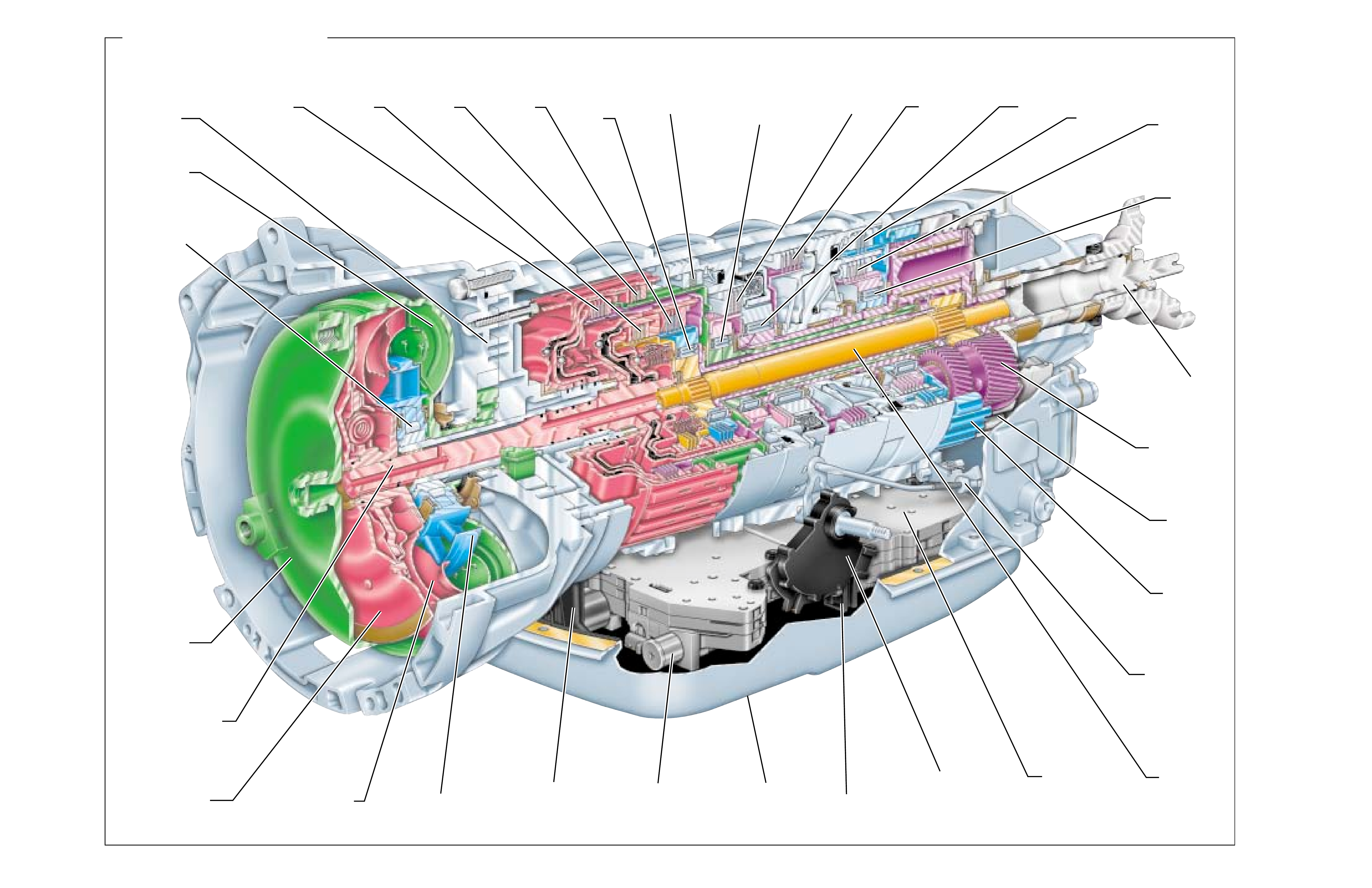
Figure 6
HYDRA-MATIC 5L40-E
DIRECT
CLUTCH
ASSEMBLY
(405–414)
COAST
CLUTCH
ASSEMBLY
(437–446)
TRANSMISSION
FLUID
PAN
(62)
CONVERTER
PUMP
ASSEMBLY
STATOR
ROLLER
CLUTCH
ASSEMBLY
CONVERTER
STATOR
ASSEMBLY
TORQUE
CONVERTER
ASSEMBLY
(1)
TORQUE
CONVERTER
HOUSING/PUMP
ASSEMBLY
(3)
FORWARD
CLUTCH
ASSEMBLY
(435–451)
INPUT
SUN GEAR
SHAFT
(457)
FORWARD
SPRAG
CLUTCH
ASSEMBLY
(461)
OVERDRIVE
CLUTCH
ASSEMBLY
(480–487)
INTERMEDIATE
CLUTCH
ASSEMBLY
(488–497)
INTERMEDIATE
SPRAG
CLUTCH
ASSEMBLY
(473)
TCC PWM
SOLENOID
VALVE
(352)
TRANSMISSION
FLUID
FILTER
(59)
LOW /REVERSE
CLUTCH
ASSEMBLY
(510–517)
REVERSE
CLUTCH
ASSEMBLY
(404–420)
LOW SPRAG
CLUTCH
ASSEMBLY
(503)
SECOND
COAST
CLUTCH
ASSEMBLY
(528–535)
SECOND
CLUTCH
ASSEMBLY
(520–527)
OUTPUT
SHAFT
(562)
FORWARD/COAST
CLUTCH HOUSING
SHAFT
(433)
MANUAL
VALVE
(377)
CONTROL
VALVE BODY/
ACCUMULATOR
ASSEMBLY
(47)
PRESSURE
PLATE
ASSEMBLY
PLANETARY
CARRIER
ASSEMBLY
(553)
SECOND
SPRAG
CLUTCH
ASSEMBLY
(547)
REAR
INTERNAL
GEAR
(560)
FRONT
INTERNAL
GEAR
(550)
TRANSMISSION
MANUAL SHIFT
SHAFT SWITCH
ASSEMBLY
(602)
PARK PAWL
ACTUATOR
ASSEMBLY
(613)
CONVERTER
TURBINE
ASSEMBLY
8
8A
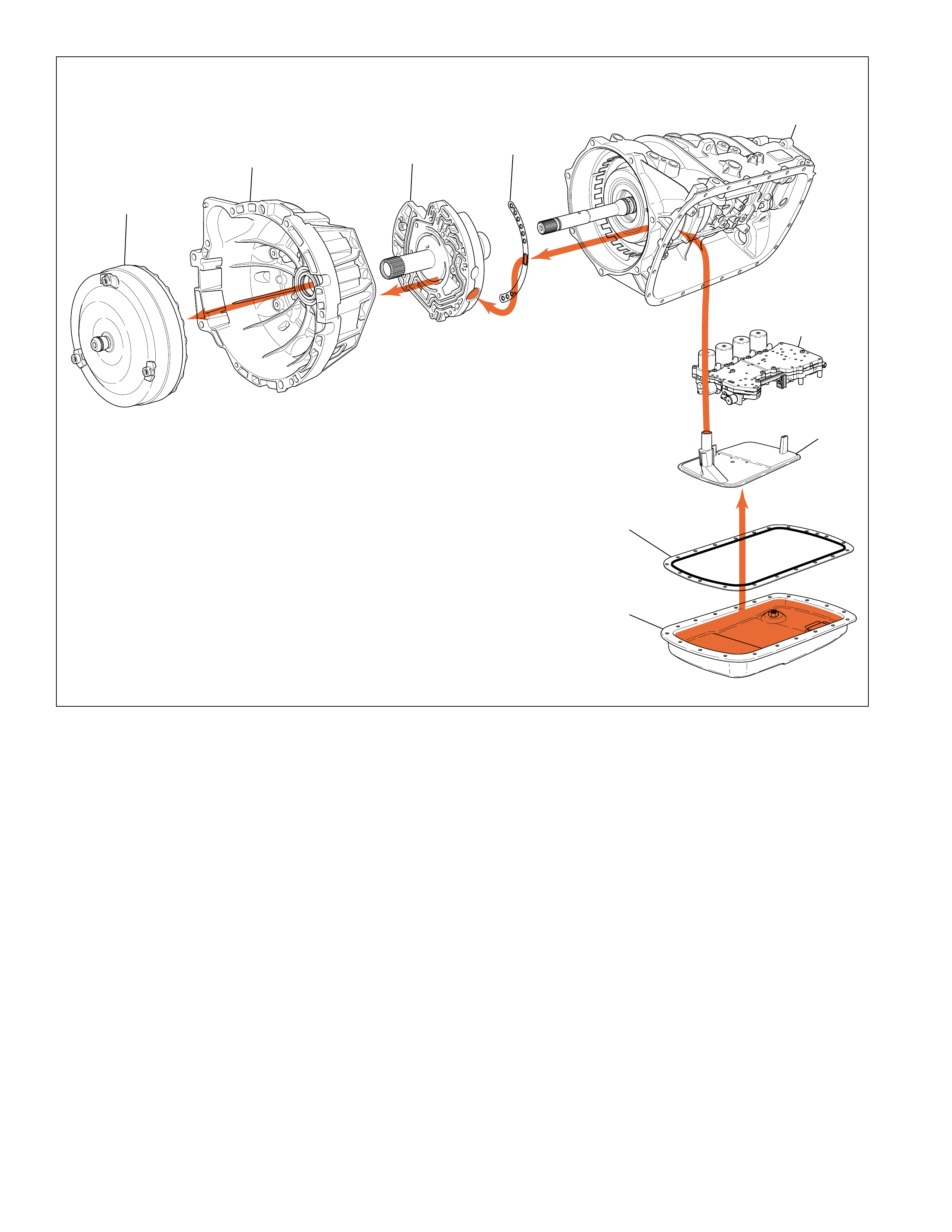
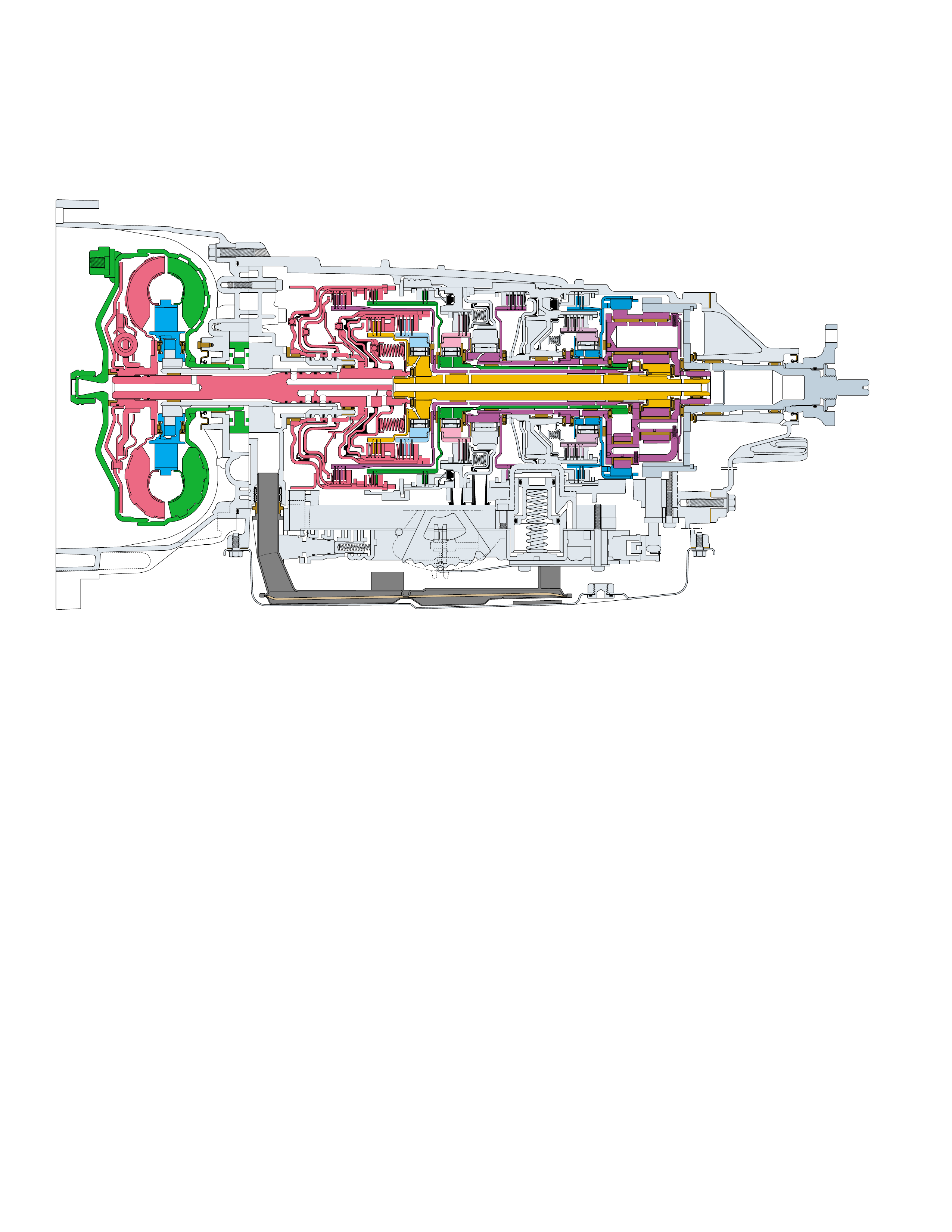
Figure 7
A cross sectional line drawing is typically the standard
method for illustrating either an individual mechanical
component or a complete transmission assembly.
However, unless a person is familiar with all the
individual components of the transmission,
distinguishing components may be diff icult in this type
of drawing. For this reason, a three dimensional
perspectiv e illustration (sho wn on page 8) is the primary
drawing used thr oughout this book.
The purpose for this type of illustration is to provide a
more detailed graphic representation of each component
and to show their relationship to other components
within the transmission assembly. It is also useful for
HYDRA-MATIC 4/5L40-E
CROSS SECTIONAL DRAWING
understanding the cross sectional line drawing by
comparing the same components from the three
dimensional perspective illustration. In this regard it
becomes an excellent teaching instrument.
Additionally, all the illustrations contained in this book
use a color scheme that is consistent throughout this
book. In other words, regardless of the type of
illustration or drawing , all components hav e an assigned
color and that color is used whenever that component
is illustrated. This consistenc y not only helps to provide
for easy component identification but it also enhances
the graphic and color continuity between sections.
The 4/5L40-E was designed to be a four or five speed
transmission. The same case and components are used
for both applications with the exclusion of the second
clutch and the second sprag clutch, and the use of a
smaller ravigneaux planetary carrier assembly in the
four speed version. This book will describe the five
speed model, however, the parts list will show the
differences in components between the four and five
speed. The function and operation of all components
and systems is the same for both the four and five speed
models, except that the four speed model uses third as
second gear , four th as third gear and fifth as fourth gear.
The Hydra-matic 5L40-E is a fully automatic, five speed,
rear wheel drive, electronically controlled transmission.
It consists primarily of a four-element torque conver ter,
one planetary gear set, friction and mechanical clutches
and a hydraulic pressurization and control system.
The four-element torque converter contains a pump, a
turbine, a pressure plate splined to the turbine, and a
stator assembly. The torque converter acts as a fluid
coupling to smoothly transmit power from the engine
to the transmission. It also hydraulically provides
additional torque multiplication when required. The
pressure plate, when applied, provides a mechanical
“direct dri v e” coupling of the engine to the transmission.
The planetary gear set provides the five forward gear
ratios and rev erse. Changing gear ratios is fully automatic
and is accomplished through the use of a Transmission
Control Module (TCM). The TCM recei ves and monitors
v arious electronic sensor inputs and uses this information
to shift the transmission at the optimum time.
The TCM commands shift solenoids, within the
transmission, on and off to control shift timing. The
TCM controls shift feel through the pressure control
solenoid. The TCM also contr ols the apply and release
of the torque converter clutch which allows the engine
to deliver the maximum fuel efficiency without
sacrificing vehicle performance.
The hydraulic system primarily consists of a vane type
pump, two control valve bodies, two channel plates,
converter housing and case. The pump maintains the
working pressures needed to stroke the clutch pistons
that apply or release the friction components. These
friction components (when applied or released) support
the automatic shifting qualities of the transmission.
The friction components used in this transmission consist
of nine multiple disc clutches. The multiple disc clutches
combine with four mechanical sprag clutches, to deliv er
six different gear ratios through the gear set. The gear
set then transfers torque through the output shaft.
D –Overdrive range should be used for all normal
driving conditions for maximum efficiency and fuel
economy. Overdrive range allows the transmission to
operate in each of the five forward gear ratios. Down-
shifts to a lower gear, or higher gear ratio are available
for safe passing by depressing the accelerator or by
manually selecting a low er gear with the shift selector.
4–Manual Fourth can be used for conditions where it
may be desirable to use only four gear ratios. These
conditions include towing a trailer and driving on hilly
terrain as described above. This range is also helpful
for engine braking when descending slight grades. Up-
shifts and downshifts are the same as in Overdrive
range for first, second, third and fourth gears except
that the transmission will not shift into f ifth gear . Manual
Fourth can be selected at any vehicle speed but will
downshift into fourth gear only if vehicle speed is low
enough not to o verrev the engine (calibr atable in TCM).
3–Manual Third ad ds more performance for congested
traffic and hilly terrain. It has the same starting ratio
(fir st gear) as Manual Fourth but pre v ents the transmis-
sion from shifting above Third gear. Thus, Manual
Third can be used to retain third gear for acceleration
and engine braking as desired. Manual Third can be
selected at any vehicle speed but will downshift into
third gear only if vehicle speed is low enough not to
over rev the engine (calibratable in TCM).
Figure 8
EXPLANATION OF GEAR RANGES
FOLDOUT ➤ 9
GENERAL DESCRIPTION
P R N D 4 3 2
The transmission can be operated in any one of the
seven different positions shown on the shift quadrant
(Figure 8).
P–Park position enables the engine to be started while
preventing the vehicle from rolling either forward or
backward. For safety reasons, the vehicle’s parking
brake should be used in addition to the transmission
“Park” position. Since the output shaft is mechanically
locked to the case through the parking pawl and rear
internal gear, P ark position should not be selected until
the vehicle has come to a complete stop.
R–Reverse enables the vehicle to be operated in a
rearward direction.
N–Neutral position enables the engine to start and
operate without driving the vehicle. If necessary, this
position should be selected to restart the engine while
the vehicle is moving.
PRINCIPLES OF OPERATION
An automatic transmission is the mechanical
component of a vehicle that transfers power
(torque) from the engine to the wheels. It
accomplishes this task by providing a number of
forward gear ratios that automatically change as
the speed of the vehicle increases. The reason
for changing forward gear ratios is to provide
the performance and economy expected from
vehicles man ufactured today. On the performance
end, a gear ratio that develops a lot of torque
(through torque multiplication) is required in
order to initially start a vehicle moving. Once
the vehicle is in motion, less torque is required
in order to maintain the v ehicle at a certain speed.
When the vehicle has reached a desired speed,
economy becomes the important factor and the
transmission will shift into o verdriv e. At this point
output speed is greater than input speed, and,
input torque is greater than output torque.
Another important function of the automatic
transmission is to allow the engine to be started
2–
Manual Second adds more performance for
congested traffic and hill y terrain. It has the same
starting ratio (first gear) as Manual Third but pre-
vents the transmission from shifting above second
gear. Thus, Manual Second can be used to retain
second gear for acceleration and engine braking
as desired. Manual Second can be selected a t any
vehicle speed but will downshift into second gear
only if vehicle speed is low enough not to overrev
the engine (calibratable in TCM).
Some vehicles are equipped with a Driver Shift
Control (DSC) version of the selector system
(Figure 9). This configuration allows the driver
DRIVER SHIFT CONTROL GEAR RANGES
+
-
P
R
N
DM/S
Figure 9
and run without transferring torque to the wheels.
This situation occurs whenever Park (P) or
Neutral (N) range has been selected. Also,
operating the vehicle in a rearward direction is
possible whenever Reverse (R) range has been
selected (accomplished by the gear sets).
The variety of gear ranges in an automatic
transmission are made possible through the
interaction of numerous mechanically,
hydraulically and electronically controlled
components inside the transmission. At the
appropriate time and sequence, these components
are either applied or released and operate the
gear set at a gear ratio consistent with the driver’s
needs. The following pages describe the
theoretical operation of the mechanical, hydraulic
and electrical components found in the Hydra-
matic 4/5L40-E transmission. When an
understanding of these operating principles has
been attained, diagnosis of these transmission
systems is made easier.
9A
When the vehicle speed slows down to a speed
low enough not to o verre v the engine (calibratable
in TCM), the transmission will automatically shift
into first gear. This is particularly beneficial for
maintaining maximum engine braking when de-
scending steep grades.
to manually shift between Park (P), Reverse (R),
Neutral (N) and Drive (D).
D–In the Drive position, the transmission will
automatically upshift from first to fifth, and
downshift from fifth to first, according to the
Economy shift pattern programmed in the TCM.
M/S –In the M/S position, the transmission will
either automatically upshift from f irst to f ifth, and
downshift from fifth to first, according to the
Performance shift pattern programmed in the TCM
or , the driver ma y activate the manual function by
tapping the selector lever towards “+” or “-” to
cause an upshift or downshift. The transmission
will shift up or down depending on the request
that is made by tapping the selector. The TCM
will upshift automatically when maximum engine
speed is achieved and will protect from any
downshift which may overrev the engine.
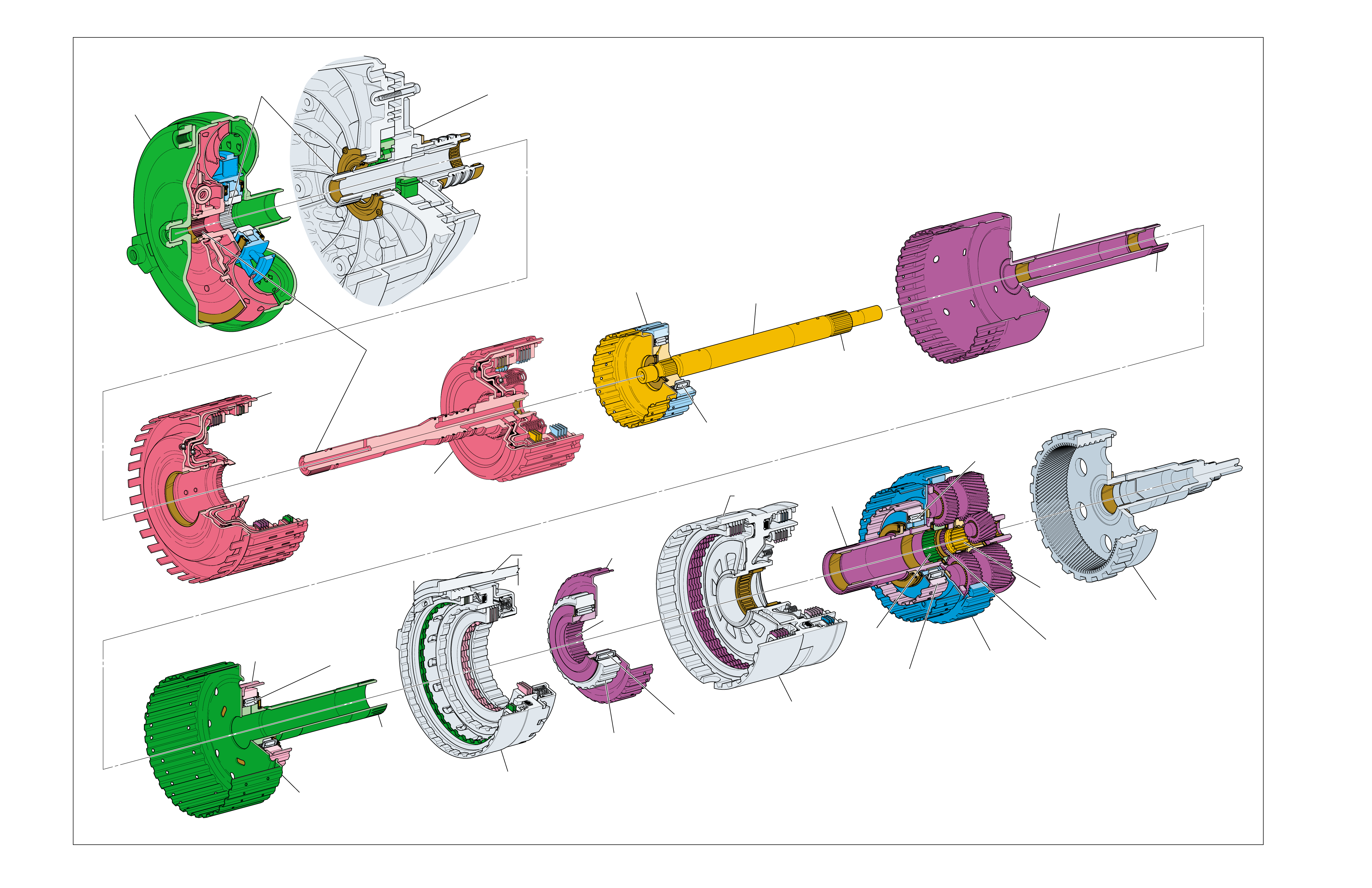
MAJOR MECHANICAL COMPONENTS
SPLINED
TOGETHER
SPLINED T O THE
FRONT INPUT
SUN GEAR
IN THE
PLANETARY
CARRIER
ASSEMBLY
SPLINED T O
PLANETARY
CARRIER
ASSEMBLY
SPLINED T O
PLANETARY
CARRIER
ASSEMBLY
SPLINED T O THE
REAR INPUT
SUN GEAR
IN THE
PLANETARY
CARRIER
ASSEMBLY
REAR
INPUT
SUN
GEAR
SPLINED T O
DIRECT
CLUTCH
INPUT
AND HUB
ASSEMBLY
(466)
SPLINED T O
TRANSMISSION
CASE (24)
FRONT
INPUT
SUN
GEAR
SPLINED
TOGETHER
TORQUE
CONVERTER
ASSEMBLY
(1)
TORQUE CONVERTER
HOUSING/PUMP
ASSEMBLY
(3)
DIRECT AND
REVERSE
CLUTCH
ASSEMBLY
(400-420)
INPUT SHAFT/
FORWARD
AND COAST
CLUTCH
ASSEMBLY
(430-451)
INPUT SUN GEAR
SHAFT
ASSEMBLY
(457)
FORWARD
CLUTCH SPRAG
OUTER RACE
(459)
FORWARD
CLUTCH SPRAG
ASSEMBLY
(461)
DIRECT CLUTCH
INPUT AND
HUB
ASSEMBLY
(466)
OVERDRIVE AND
REVERSE CLUTCH
HUB ASSEMBLY
(470)
INTERMEDIATE
CLUTCH SPRAG
OUTER RACE
(474)
INTERMEDIATE
CLUTCH SPRAG
ASSEMBLY
(473)
TRANSMISSION
CASE
(24)
OVERDRIVE AND
INTERMEDIATE
CLUTCH
ASSEMBLY
(480-497)
LOW
CLUTCH SPRAG
OUTER RACE
(504)
LOW
CLUTCH SPRAG
ASSEMBLY
(503)
LOW
CLUTCH SPRAG
INNER RACE
(505)
CENTER
SUPPORT
ASSEMBLY
(510-535)
SECOND
CLUTCH SPRAG
INNER RACE
(549)
SECOND
CLUTCH SPRAG
OUTER RACE
(545)
SECOND
CLUTCH SPRAG
ASSEMBLY
(547)
PLANETARY
CARRIER
ASSEMBLY
(540-554)
REAR
INTERNAL GEAR
OUTPUT SHAFT
ASSEMBLY
(560-563)
10 Figure 10

RANGE REFERENCE CHART
Figure 11
HYDRA-MATIC 4L40-E - GEAR RATIOS
FIRST 2.82 FOURTH 0.70
SECOND 1.54 REVERSE 2.38
THIRD 1.00
LD = LOCKED IN DRIVE @ THE SOLENOID'S STATE FOLLOWS A SHIFT PATTERN WHICH DEPENDS UPON VEHICLE
ON = SOLENOID ENERGIZED SPEED AND THROTTLE POSITION. IT DOES NOT DEPEND UPON THE SELECTED GEAR.
OFF = SOLENOID DE-ENERGIZED *ENGINE BRAKING IS ELECTRONICALLY CONTROLLED BY THE TCM, AND IS AVAILABLE AS
CALIBRATED FOR EACH MODEL AND APPLICATION.
ENGINE 1-2 SHIFT 2-3 SHIFT 4-5 SHIFT TCC DIRECT COAST REVERSE FORWARD FORWARD OVER- INTERM. INTER- LOW LOW AND SECOND SECOND SECOND
RANGE GEAR BRAKING RATIO SOLENOID SOLENOID SOLENOID SOLENOID CLUTCH CLUTCH CLUTCH CLUTCH CLUTCH DRIVE CLUTCH MEDIATE CLUTCH REVERSE CLUTCH CLUTCH COAST
VALVE VALVE VALVE VALVE SPRAG CLUTCH SPRAG CLUTCH SPRAG CLUTCH SPRAG CLUTCH
1
*
NO 3.42 OFF ON OFF OFF APPLIED APPLIED LD LD
1 YES 3.42 OFF ON ON OFF APPLIED APPLIED LD LD APPLIED
2
*
NO 2.21 ON ON OFF ON/OFF
@
APPLIED APPLIED LD APPLIED LD
D432
2 YES 2.21 ON ON ON ON/OFF
@
APPLIED APPLIED LD APPLIED LD APPLIED
3
*
NO 1.60 ON OFF OFF ON/OFF
@
APPLIED APPLIED LD LD APPLIED APPLIED
3 YES 1.60 ON OFF ON ON/OFF
@
APPLIED APPLIED LD APPLIED LD APPLIED APPLIED
4 YES 1.00 OFF OFF ON ON/OFF
@
APPLIED APPLIED APPLIED LD APPLIED APPLIED
5 YES 0.75 OFF OFF OFF ON/OFF
@
APPLIED APPLIED APPLIED APPLIED APPLIED
NEUTRAL
———ON/OFF ON/OFF ON/OFF
REVERSE
R YES 3.03 ON/OFF ON/OFF ON/OFF OFF APPLIED APPLIED
PARK
———ON/OFF ON/OFF ON/OFF
@@@
@@@
@@@
HYDRA-MATIC 5L40-E - GEAR RATIOS
FIRST 3.42 FOURTH 1.00
SECOND 2.21 FIFTH 0.75
THIRD 1.60 REVERSE 3.03
11
10A
COLOR LEGEND
MAJOR MECHANICAL COMPONENTS
The foldout graphic on page 10 contains a disassembled drawing
of the major components used in the Hydra-matic 4/5L40-E
transmission. This drawing, along with the cross sectional
illustrations on page 8 and 8A, show the major mechanical
components and their relationship to each other as a complete
assembly. Therefore, color has been used throughout this book
to help identify parts that are splined together, rotating at engine
speed, held stationary, and so forth. Color differentiation is
particularly helpful when using the Power Flow section for
understanding the transmission operation.
The color legend below provides the “general” guidelines that
were followed in assigning specific colors to the major
components. However, due to the complexity of this
transmission, some colors (such as grey) were used for artistic
purposes rather than based on the specific function or location
of that component.
Components held stationary in the case or splined to
the case. Examples: the Fluid Pump Cover
Assembly (202), the Overdrive Clutch Housing
(493), and the Center Support (518). Also includes
the Clutch Sprag assemblies.
Components that rotate at engine speed. Examples:
the Torque Converter Assembly (1), the Fluid Pump
Rotor (223), and the Fluid Pump Vanes (222).
Components that rotate at turbine speed. Examples:
the Converter Turbine, the Forward Clutch and Input
Housing Assembly (433), and the Reverse Clutch
and Input Housing Assembly (401).
Components such as the Stator in the Torque
Converter Clutch Assembly (1).
Components such as the Input Sun Gear Shaft
Assembly (457).
Components such as the Forward Clutch Sprag Outer
Race (459).
Components such as the Direct Clutch Input and
Hub Assembly (466), and the Input and Reaction
Carrier Assembly (553).
Components such as the Overdrive and Reverse
Clutch Hub Assembly (470).
Components such as the Intermediate Clutch Sprag
Outer Race (474).
Components such as the Second Clutch Sprag Outer
Race (545).
Components such as the Second Clutch Sprag Inner
Race (549).
Components that rotate at transmission output speed.
Examples: the Output Shaft Assembly (562) and the
Input and Reaction Carrier Assembly (553).
Accumulators, Servos and Bands.
All bearings and bushings.
All seals
10B
COLOR LEGEND
APPLY COMPONENTS
The Range Reference Chart on page 11, provides another
valuable source of information for explaining the overall function
of the Hydra-matic 4/5L40-E transmission. This chart highlights
the major apply components that function in a selected gear
range, and the specific gear operation within that gear range.
Included as part of this chart is the same color reference to each
major component that was previously discussed. If a component
is active in a specific gear range, a word describing its activity
will be listed in the column below that component. The row
where the activity occurs corresponds to the appropriate
transmission range and gear operation. An abbreviated version
of this chart can also be found at the top of the half page of text
located in the Power Flow section. This provides for a quick
reference when reviewing the mechanical power flow information
contained in that section.
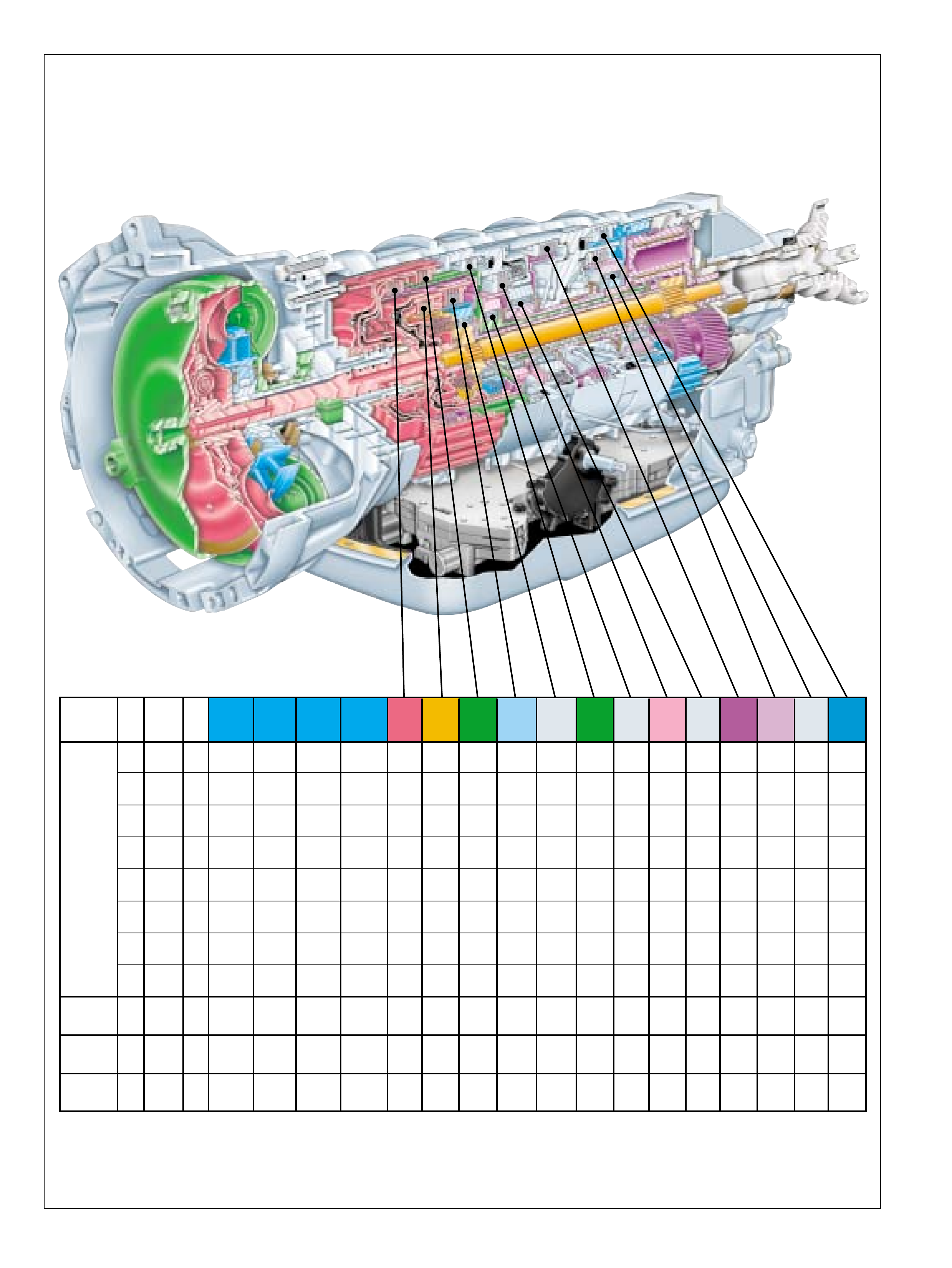
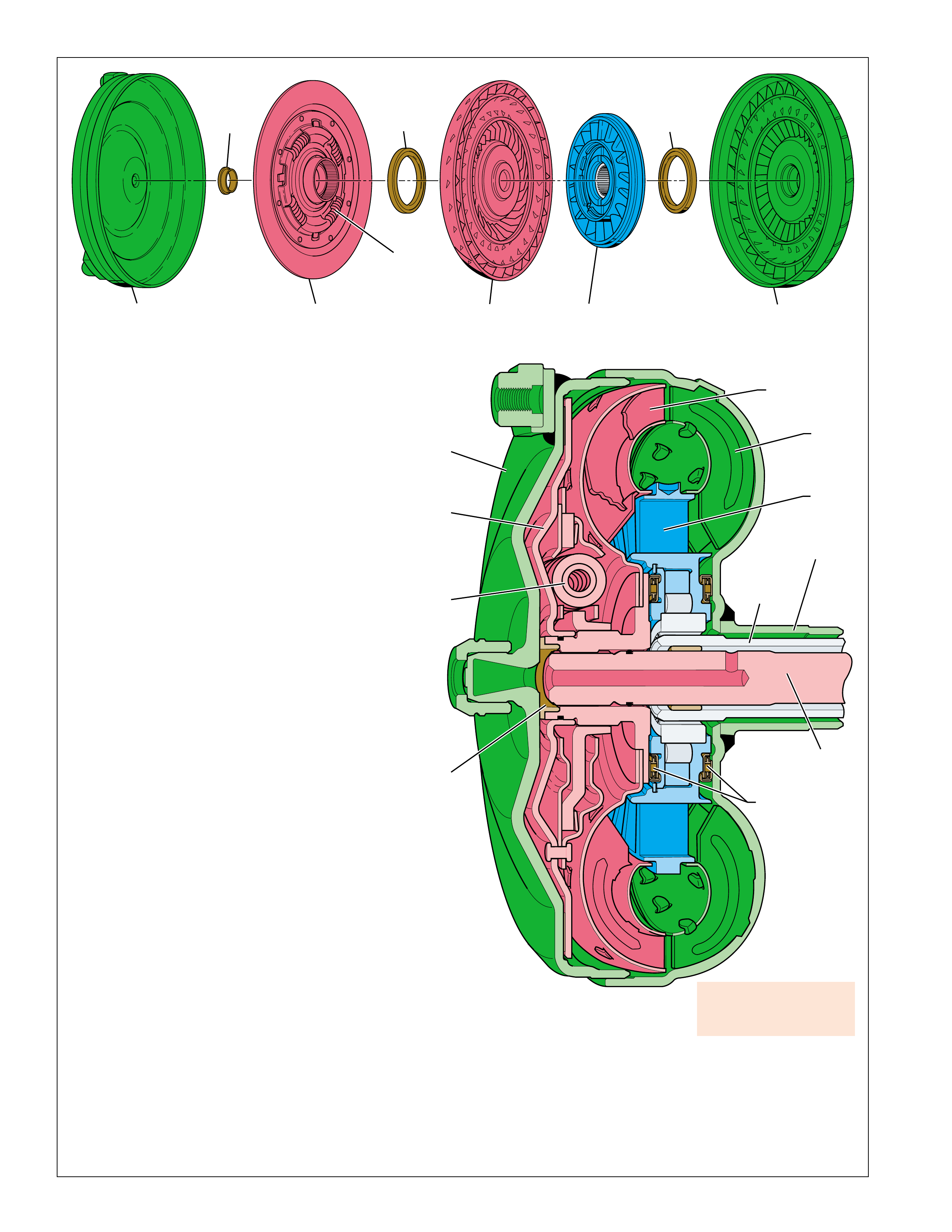
B
C
A
F
H
D
FORWARD
CLUTCH
AND INPUT
HOUSING
ASSEMBLY
(433)
(TURBINE
SHAFT)
STATOR
SHAFT
(202)
CONVERTER
HUB
E
G
CONVERTER HOUSING
COVER ASSEMBLY
(A)
PRESSURE PLATE
ASSEMBLY
(C)
DAMPER
ASSEMBLY
(D)
TURBINE
ASSEMBLY
(F)
STATOR
ASSEMBLY
(G)
CONVERTER PUMP
ASSEMBLY
(H)
THRUST
BEARING
ASSEMBLY
(E)
THRUST
BEARING
ASSEMBLY
(E )
TURBINE
THRUST
SPACER
(B)
TORQUE CONVERTER
Figure 12
TORQUE CONVERTER:
The torque converter (1) is the primary component for
transmittal of power between the engine and the
transmission. It is bolted to the engine flywheel (also known
as the flexplate) so that it will rotate at engine speed.
Some of the major functions of the torque converter are:
•to provide for a smooth conversion of torque from the
engine to the mechanical components of the transmission.
•to multiply torque from the engine that enables the
vehicle to achieve additional performance when required.
•to mechanically operate the transmission fluid pump (3)
through the converter hub.
•to provide a mechanical link, or direct drive, from the
engine to the transmission through the use of a torque
converter clutch (TCC).
The torque converter assembly is made up of the following
five main sub-assemblies:
•a converter housing cover assembly (A) which is welded
to the converter pump assembly (H).
•a converter pump assembly (H) which is the driving
member.
•a turbine assembly (F) which is the driven or output
member.
•a stator assembly (G) which is the reaction member
located between the converter pump and turbine
assemblies.
•a pressure plate assembly (C) splined to the turbine
assembly to enable direct mechanical drive when
appropriate.
CONVERTER PUMP ASSEMBLY AND TURBINE
ASSEMBLY
When the engine is running the converter pump assembly
acts as a centrifugal pump by picking up fluid at its center
and discharging it at its rim between the blades (see Figure
13). The force of this fluid then hits the turbine blades
and causes the turbine to rotate. As the engine and
converter pump increase in RPM, so does the turbine.
PRESSURE PLATE, DAMPER AND
CONVERTER HOUSING ASSEMBLIES
The pressure plate is splined to the turbine hub and applies
(engages) with the converter cover to provide a mechanical
coupling of the engine to the transmission. When the
pressure plate assembly is applied, the amount of slippage
that occurs through a fluid coupling is reduced (but not
necessarily eliminated), thereby providing a more efficient
transfer of engine torque to the drive wheels.
Torque converter failure
could cause loss of drive
and or loss of power.
To reduce torsional shock during the apply of the pressure plate to the
converter cover, a spring loaded damper assembly (D) is used. The
pressure plate is attached to the pivoting mechanism of the damper
assembly which allows the pressure plate to rotate independently of
the damper assembly up to approximately 45 degrees. During
engagement, the springs in the damper assembly cushion the pressure
plate engagement and also reduce irregular torque pulses from the
engine or road surface.
12
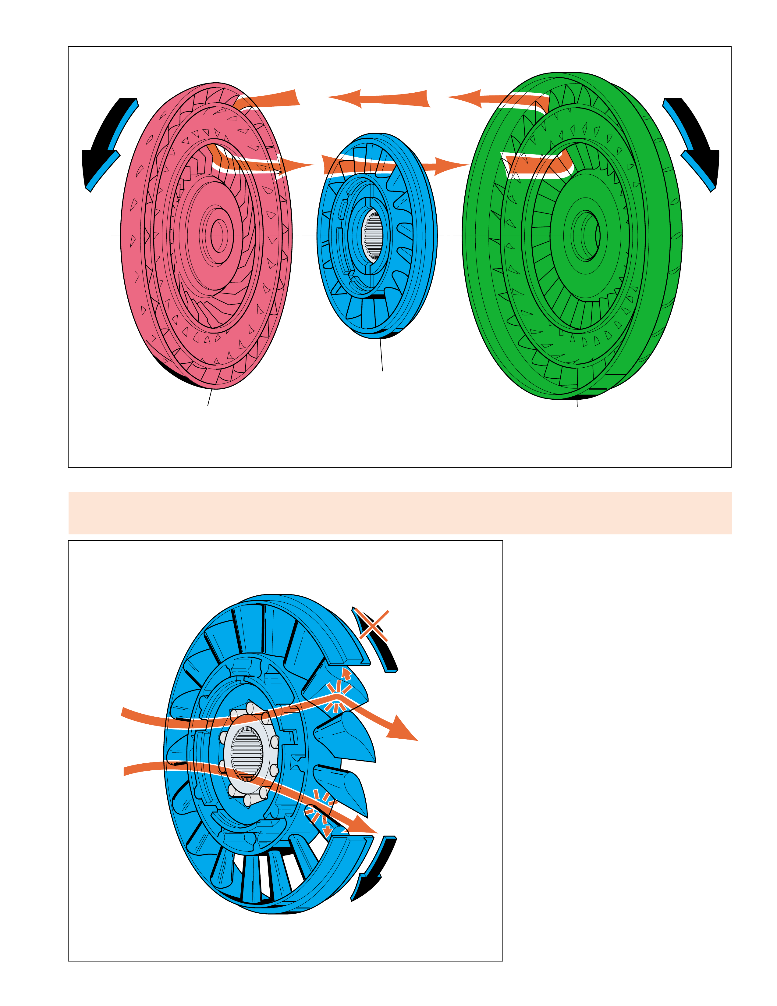
STATOR
STATOR ROTATES
FREELY
STATOR HELD
FLUID FLOW REDIRECTED
CONVERTER AT
COUPLING SPEED
FLUID FLOW
FROM TURBINE
CONVERTER
MULTIPLYING
FLUID FLOW
TURBINE
ASSEMBLY
(F)
CONVERTER PUMP
ASSEMBLY
(H)
STATOR
ASSEMBLY
(G)
TORQUE CONVERTER
Figure 14
Figure 13
STATOR ASSEMBLY
The stator assembly is located between the
pump assembly and turbine assembly, and is
mounted on a one-way roller clutch. This one-
way roller clutch allows the stator to rotate in
one direction and prevents (holds) the stator
from rotating in the other direction. The
function of the stator is to redirect fluid
returning from the turbine in order to assist the
engine in turning the converter pump assembly.
At low vehicle speeds, when greater torque is
needed, fluid from the turbine hits the front
side of the stator blades (the converter is
multiplying torque). At this time, the one-way
roller clutch prevents the stator from rotating
in the same direction as the fluid flow, thereby
redirecting fluid to assist the engine in turning
the converter pump. In this mode, fluid leaving
the converter pump has more force to turn the
turbine assembly and multiply engine torque.
As vehicle speed increases and less torque is
required, centrifugal force acting on the fluid
changes the direction of the fluid leaving the
turbine such that it hits the back side of the
stator blades (converter at coupling speed).
When this occurs, the roller clutch overruns
and allows the stator to rotate freely. Fluid is
no longer being redirected to the converter
pump and engine torque is not being multiplied.
Stator roller clutch failure
•roller clutch freewheels in both directions can
cause poor acceleration at low speed. •roller clutch locks up in both directions can
cause poor acceleration at high speed. •Overheated fluid.
13
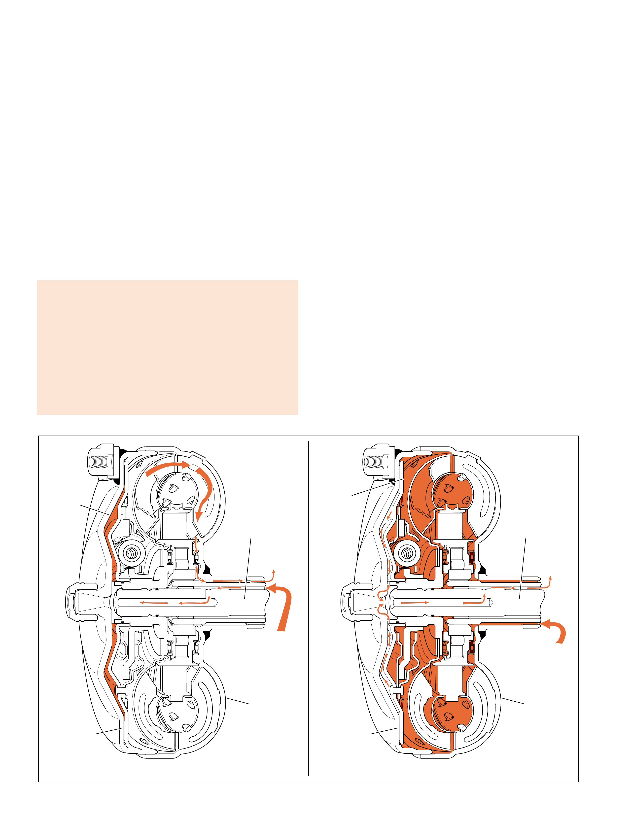
TORQUE CONVERTER
Figure 15
APPLY
When the TCM determines that the vehicle is at the
proper speed for the torque converter clutch to apply
it sends a signal to the TCC PWM solenoid valve.
The TCC PWM solenoid valve then regulates line
fluid from the pump into the re gulated apply passage.
The regulated apply fluid then feeds the apply fluid
passage and applies the torque converter. The apply
passage is located between the converter hub and the
stator shaft. T he fluid flo ws between the shafts, then
passes into the torque converter on the apply side of
the pressure plate assembly. Release fluid is then
routed out of the torque converter between the turbine
shaft and the stator shaft.
Apply fluid pressure forces the pressure plate against
the torque converter cover to provide a mechanical
link between the engine and the turbine.
The TCC apply may occur in second, third, fourth
and fifth gear (depending on the shift pattern), and
should not apply until the transmission fluid and
engine coolant temperatures hav e reached a minim um
value (calibratable in TCM).
For mor e information on TCC apply and release, see
Overdrive Range – Fifth Gear TCC Released and
Applied, pages 72–75.
RELEASE
When the torque converter clutch is released, fluid is
fed into the torque converter by the pump into the
release fluid passage. The release fluid passage is
located between the stator shaft (202) and the turbine
shaft (433). Fluid tra vels between the shafts and enter s
the release side of the pressure plate at the end of the
turbine shaft. The pressure plate is forced away from
the converter cover and allows the torque converter
turbine to rotate at speeds other than engine speed.
The release fluid then flows between the friction
element on the pressure plate and the con v erter co ver
to enter the apply side of the torque converter. The
fluid then exits the torque con v erter through the apply
passage, which is located between the torque
converter clutch hub and the stator shaft (202), and
enters the pump.
TCC APPLYTCC RELEASE
RELEASE
FLUID
APPLY
FLUID
➤
➤
➤
➤
➤
➤
RELEASE
FLUID
PRESSURE
PLATE
TORQUE
CONVERTER
ASSEMBLY
(1)
FORWARD
CLUTCH
AND INPUT
HOUSING
ASSEMBLY
(433)
(TURBINE
SHAFT)
APPLY
FLUID
RELEASE
FLUID
➤
➤
APPLY
FLUID
➤
➤
➤
➤
PRESSURE
PLATE
TORQUE
CONVERTER
ASSEMBLY
(1)
FORWARD
CLUTCH
AND INPUT
HOUSING
ASSEMBLY
(433)
(TURBINE
SHAFT)
No TCC apply can be caused by:
•Electrical connectors, wiring harness or solenoid damaged
•Converter clutch valves stuck or assembled backwards
•Pump to case gasket mispositioned
•Solenoid O-ring seal cut or damaged
•Turbine shaft O-ring seal cut or damaged
•Control valve body TCC signal valve stuck
•Solenoid screen blocked
•TCC solenoid valve internal damage
•Turbine speed sensor internal damage
14
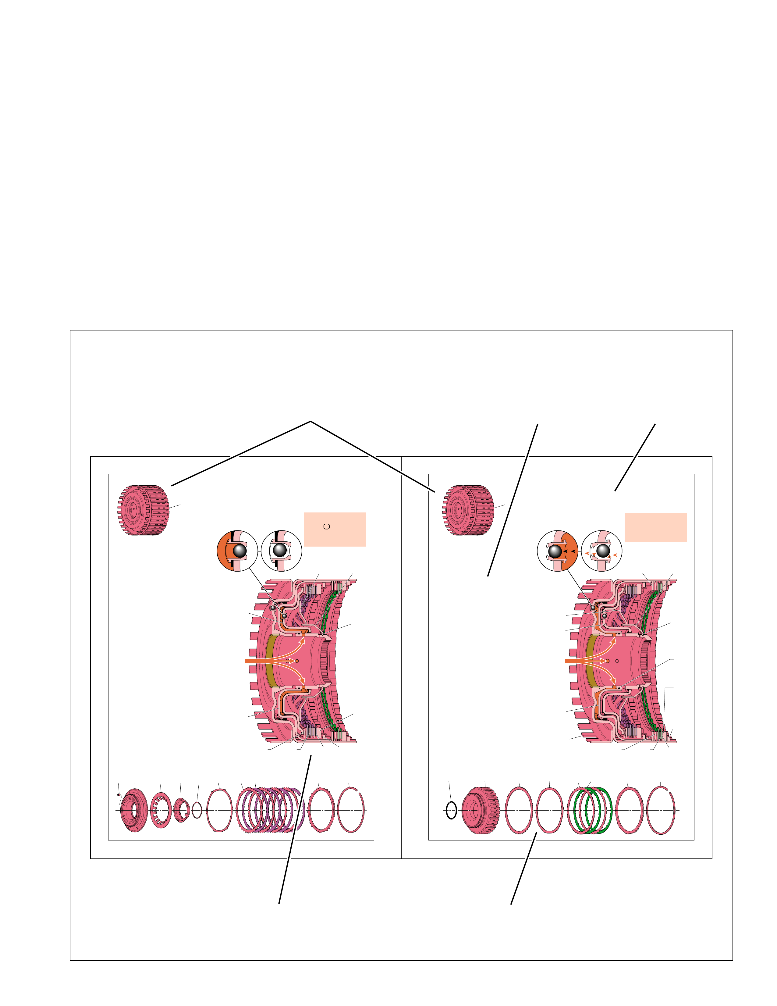
During the exhaust of reverse clutch fluid, the reverse clutch housin
check valve (403), located in the reverse clutch housing (401), u
Centrifugal force, resulting from the rotation of the reverse clutch ho
forces residual reverse fluid to the outside of the housing and past the un
ball check valve. If this fluid did not completely exhaust from behin
piston, there could be a partial apply, or drag, of the reverse clutch pla
A plugged reverse clutch apply
passage, damaged clutch
plates, clutch spring or piston
seals can cause no reverse/
slips in reverse.
REVERSE
CLUTCH
:
The reverse clutch assembly is located in
reverse clutch housing assembly (401).
external teeth on the reverse clutch plates (
are splined to the reverse clutch housing whil
internal teeth on the reverse clutch plate assem
(418) are splined to the overdrive and rev
clutch hub (470). The reverse clutch is app
only when the transmission is in reverse gea
provide a reverse gear ratio.
REVERSE CLUTCH APPLY:
To apply the reverse clutch, reverse clutch flu
fed through the fluid pump cover (202) and be
the reverse clutch piston (404). Reverse cl
fluid pressure forces the piston against the d
clutch piston (406) and the direct and rev
clutch spring (407). As fluid pressure increa
the piston compresses the clutch plates tog
until they are held against the reverse cl
backing plate (419). Also included in the asse
is a reverse clutch spacer plate (415), and a re
clutch apply (waved) plate (416) that helps cu
the apply of the reverse clutch.
When fully applied, the reverse clutch plates
and reverse clutch plate assemblies (418) are l
together, thereby holding the reverse clutch hou
(401) and the overdrive and reverse clutch hub
together. This forces the overdrive and rev
clutch hub to rotate at the same speed as the for
clutch and input housing assembly (433).
REVERSE CLUTCH RELEASE:
To release the reverse clutch, reverse clutch
exhausts through the reverse clutch fluid cir
allowing pressure at the reverse clutch piston (
to decrease. In the absence of fluid pressure, sp
force from the direct and reverse clutch sp
(407) moves the reverse clutch piston away
the clutch pack. This disengages the reverse c
plates (417) and reverse clutch plate assem
(418) from the backing plate (419).
During the exhaust of direct clutch fluid, the direct clutch housing ball
valve (405), located in the direct clutch piston (406), unseats. Cent
force, resulting from the rotation of the reverse clutch housing, forces re
direct clutch fluid to the outside of the housing and past the unseate
check valve. If this fluid did not completely exhaust from behind the p
there could be a partial apply, or drag, of the direct clutch plates.
If inoperative the direct
clutch can cause no fourth
gear in D range or Manual
Fourth range; degraded
shifts from third to fourth
and from fourth to third.
DIRECT
CLUTCH
:
The direct clutch assembly is located in the re
clutch piston (404), which is splined to the re
clutch housing assembly (401). The external
on the direct clutch plates (411) are splined t
reverse clutch piston while the internal teet
the direct clutch plate assemblies (412) are sp
to the direct clutch hub (466). The direct clut
applied when the transmission is in Fourth
Fifth gears.
DIRECT CLUTCH APPLY:
To apply the direct clutch for Fourth and F
gears, direct clutch fluid is fed through the f
pump cover (202) and into the inner hub of
reverse clutch housing assembly (401). Feed h
in the inner hub allow direct clutch fluid to e
the housing between the reverse clutch piston (
and the direct clutch piston (406). Direct c
fluid pressure moves the piston to compress
direct and reverse clutch spring (407). As f
pressure increases, the piston compresses the c
plates until they are held against the direct c
backing plate (413). Also included in the asse
is a direct clutch apply (waved) plate (410
helps cushion the apply of the direct clutch.
When fully applied, the direct clutch plates (
direct clutch plate assemblies (412) and d
clutch apply plate (410) are locked toge
thereby holding the reverse clutch housing
direct clutch hub (466) together. This forces
direct clutch hub to rotate at the same speed
input/forward clutch housing assembly (433).
DIRECT CLUTCH RELEASE:
To release the direct clutch, direct clutch
exhausts from the piston, through the inner hu
the reverse clutch housing and into the fluid p
cover (202). In the absence of fluid pressure, sp
force from the direct and reverse clutch spring (
moves the direct clutch piston away from the c
plates. This disengages the direct clutch plates (
direct clutch plate assemblies (412) and direct
apply plate (410) from the direct clutch bac
plate (413) and disconnects the reverse cl
housing from the direct clutch hub (466).
Figure 17
16
APPLY COMPONENTS
Figure 18
17
APPLY COMPONENTS
APPLY COMPONENTS
REVERSE
CLUTCH
HOUSING
ASSEMBLY
(401)
REVERSE
CLUTCH
PISTON
(404)
REVERSE
CLUTCH
APPLY
FLUID
REVERSE
CLUTCH
SPACER
PLATE
(415)
REVERSE
CLUTCH
APPLY
PLATE
(416)
REVERSE
CLUTCH
PLATE
ASSEMBLY
(OUTER SPLINE)
(417)
REVERSE
CLUTCH
PLATE
ASSEMBLY
(INNER SPLINE)
(418)
REVERSE
CLUTCH
PISTON
INNER
SEAL
(402)
REVERSE
CLUTCH
BACKING
PLATE
(419)
REVERSE
CLUTCH
BACKING
PLATE
RETAINER
RING
(SELECTIVE)
(420)
REVERSE CLUTCH HOUSING
BALL CHECK VALVE
(403)
APPLIED RELEASED
404
402 415 416 417 418 419 420
DIRECT
CLUTCH
PISTON
(406)
DIRECT AND
REVERSE
CLUTCH
SPRING
(407)
DIRECT AND
REVERSE
CLUTCH
SPRING
RETAINER
RING
(409)
DIRECT AND
REVERSE
CLUTCH SPRING
RETAINER
(408)
REVERSE
CLUTCH
HOUSING
ASSEMBLY
(401)
410
405 406 407 408 409 411 412 413 414
REVERSE
CLUTCH
HOUSING
ASSEMBLY
(401)
DIRECT
CLUTCH
APPLY
FLUID
DIRECT CLUTCH PISTON
BALL CHECK VALVE
(405)
DIRECT
CLUTCH
PISTON
(406)
REVERSE
CLUTCH
PISTON
(404)
DIRECT AND
REVERSE
CLUTCH
SPRING
(407)
DIRECT AND
REVERSE
CLUTCH
SPRING
RETAINER
RING
(409)
DIRECT AND
REVERSE
CLUTCH SPRING
RETAINER
(408)
DIRECT
CLUTCH
APPLY PLATE
(WAVED)
(410)
DIRECT
CLUTCH
PLATE
ASSEMBLY
(INNER SPLINE)
(412)
DIRECT
CLUTCH
PLATE
ASSEMBLY
(OUTER SPLINE)
(411)
DIRECT
CLUTCH
BACKING
PLATE
(413)
DIRECT CLUTCH
BACKING PLATE
RETAINER RING
(SELECTIVE)
(414)
APPLIED RELEASED
➤
➤
➤
➤
➤➤
FUNCTIONAL
DESCRIPTION
➤
BRIEF
DESCRIPTION
➤
CUTAWAY
VIEW
➤
DISASSEMBLED
VIEW
➤
MATING
OR
RELATED
COMPONENTS
➤
➤
Figure 16
The Apply Components section is designed to explain
the function of the hydraulic and mechanical holding
devices used in the Hydra-matic 4/5L40-E
transmission. Some of these apply components, such
as clutches, are hydraulically “applied” and “released”
in order to provide automatic gear range shifting.
Other components, such as a sprag clutch, often react
to a hydraulically “applied” component by
mechanically “holding” or “releasing” another member
of the transmission. This interaction between the
hydraulically and mechanically applied components
is then explained in detail and supported with a graphic
illustration. In addition, this section shows the routing
of fluid pressure to the individual components and
their internal functions when it applies or releases.
The sequence in which the components in this section
have been discussed coincides with their physical
arrangement inside the transmission. This order
closely parallels the disassembly sequence used in
the Hydra-matic 4/5L40-E Unit Repair Section
located in Section 7 of the appropriate Service
Manual. It also correlates with the components sho wn
on the Range Reference Charts that are used
throughout the Power Flow section of this book.
The correlation of information between the sections
of this book helps the user more clearly understand
the hydraulic and mechanical operating principles
for this transmission.
15
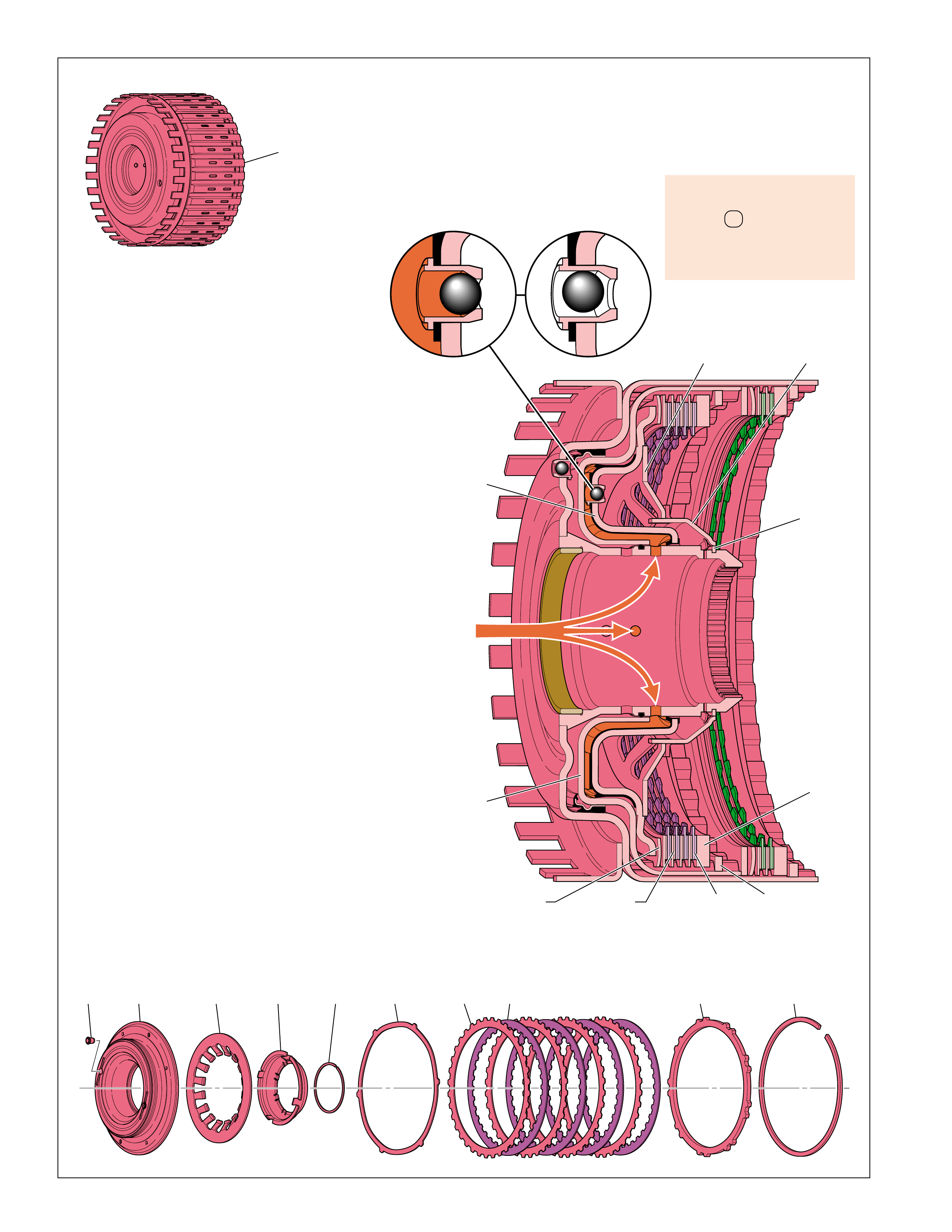
410
405 406 407 408 409 411 412 413 414
REVERSE
CLUTCH
HOUSING
ASSEMBLY
(401)
DIRECT
CLUTCH
APPLY
FLUID
DIRECT CLUTCH PISTON
BALL CHECK VALVE
(405)
DIRECT
CLUTCH
PISTON
(406)
REVERSE
CLUTCH
PISTON
(404)
DIRECT AND
REVERSE
CLUTCH
SPRING
(407)
DIRECT AND
REVERSE
CLUTCH
SPRING
RETAINER
RING
(409)
DIRECT AND
REVERSE
CLUTCH SPRING
RETAINER
(408)
DIRECT
CLUTCH
APPLY PLATE
(WAVED)
(410)
DIRECT
CLUTCH
PLATE
ASSEMBLY
(INNER SPLINE)
(412)
DIRECT
CLUTCH
PLATE
ASSEMBLY
(OUTER SPLINE)
(411)
DIRECT
CLUTCH
BACKING
PLATE
(413)
DIRECT CLUTCH
BACKING PLATE
RETAINER RING
(SELECTIVE)
(414)
APPLIED RELEASED
➤
➤
➤
➤
➤➤
APPLY COMPONENTS
Figure 17
During the exhaust of direct clutch fluid, the direct clutch housing ball check
valve (405), located in the direct clutch piston (406), unseats. Centrifugal
force, resulting from the rotation of the reverse clutch housing, forces residual
direct clutch fluid to the outside of the housing and past the unseated ball
check valve. If this fluid did not completely exhaust from behind the piston,
there could be a partial apply, or drag, of the direct clutch plates.
If inoperative the direct
clutch can cause no fourth
gear in D range or Manual
Fourth range; degraded
shifts from third to fourth
and from fourth to third.
DIRECT CLUTCH:
The direct clutch assembly is located in the reverse
clutch piston (404), which is splined to the reverse
clutch housing assembly (401). The external teeth
on the direct clutch plates (411) are splined to the
reverse clutch piston while the internal teeth on
the direct clutch plate assemblies (412) are splined
to the direct clutch hub (466). The direct clutch is
applied when the transmission is in Fourth and
Fifth gears.
DIRECT CLUTCH APPLY:
To apply the direct clutch for Fourth and Fifth
gears, direct clutch fluid is fed through the fluid
pump cover (202) and into the inner hub of the
reverse clutch housing assembly (401). Feed holes
in the inner hub allow direct clutch fluid to enter
the housing between the reverse clutch piston (404)
and the direct clutch piston (406). Direct clutch
fluid pressure moves the piston to compress the
direct and reverse clutch spring (407). As fluid
pressure increases, the piston compresses the clutch
plates until they are held against the direct clutch
backing plate (413). Also included in the assembly
is a direct clutch apply (waved) plate (410) that
helps cushion the apply of the direct clutch.
When fully applied, the direct clutch plates (411),
direct clutch plate assemblies (412) and direct
clutch apply plate (410) are locked together,
thereby holding the reverse clutch housing and
direct clutch hub (466) together. This forces the
direct clutch hub to rotate at the same speed as the
input/forward clutch housing assembly (433).
DIRECT CLUTCH RELEASE:
To release the direct clutch, direct clutch fluid
exhausts from the piston, through the inner hub of
the reverse clutch housing and into the fluid pump
cover (202). In the absence of fluid pressure, spring
force from the direct and reverse clutch spring (407)
moves the direct clutch piston away from the clutch
plates. This disengages the direct clutch plates (411),
direct clutch plate assemblies (412) and direct clutch
apply plate (410) from the direct clutch backing
plate (413) and disconnects the reverse clutch
housing from the direct clutch hub (466).
16
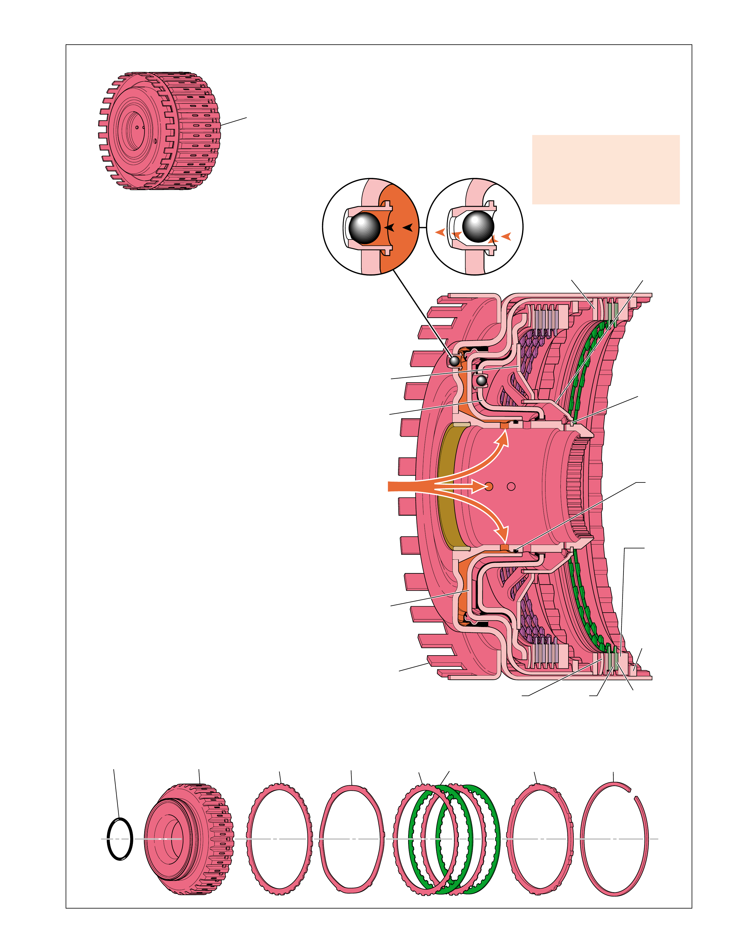
REVERSE
CLUTCH
HOUSING
ASSEMBLY
(401)
REVERSE
CLUTCH
PISTON
(404)
REVERSE
CLUTCH
APPLY
FLUID
REVERSE
CLUTCH
SPACER
PLATE
(415)
REVERSE
CLUTCH
APPLY
PLATE
(416)
REVERSE
CLUTCH
PLATE
ASSEMBLY
(OUTER SPLINE)
(417)
REVERSE
CLUTCH
PLATE
ASSEMBLY
(INNER SPLINE)
(418)
REVERSE
CLUTCH
PISTON
INNER
SEAL
(402)
REVERSE
CLUTCH
BACKING
PLATE
(419)
REVERSE
CLUTCH
BACKING
PLATE
RETAINER
RING
(SELECTIVE)
(420)
REVERSE CLUTCH HOUSING
BALL CHECK VALVE
(403)
APPLIED RELEASED
404
402 415 416 417 418 419 420
DIRECT
CLUTCH
PISTON
(406)
DIRECT AND
REVERSE
CLUTCH
SPRING
(407)
DIRECT AND
REVERSE
CLUTCH
SPRING
RETAINER
RING
(409)
DIRECT AND
REVERSE
CLUTCH SPRING
RETAINER
(408)
REVERSE
CLUTCH
HOUSING
ASSEMBLY
(401)
Figure 18
APPLY COMPONENTS
REVERSE CLUTCH:
The reverse clutch assembly is located in the
reverse clutch housing assembly (401). The
external teeth on the reverse clutch plates (417)
are splined to the reverse clutch housing while the
internal teeth on the reverse clutch plate assemblies
(418) are splined to the overdrive and reverse
clutch hub (470). The reverse clutch is applied
only when the transmission is in reverse gear to
provide a reverse gear ratio.
REVERSE CLUTCH APPLY:
To apply the reverse clutch, reverse clutch fluid is
fed through the fluid pump cover (202) and behind
the reverse clutch piston (404). Reverse clutch
fluid pressure forces the piston against the direct
clutch piston (406) and the direct and reverse
clutch spring (407). As fluid pressure increases,
the piston compresses the clutch plates together
until they are held against the reverse clutch
backing plate (419). Also included in the assembly
is a reverse clutch spacer plate (415), and a reverse
clutch apply (waved) plate (416) that helps cushion
the apply of the reverse clutch.
When fully applied, the reverse clutch plates (417)
and reverse clutch plate assemblies (418) are locked
together, thereby holding the reverse clutch housing
(401) and the overdrive and reverse clutch hub (470)
together. This forces the overdrive and reverse
clutch hub to rotate at the same speed as the forward
clutch and input housing assembly (433).
REVERSE CLUTCH RELEASE:
To release the reverse clutch, reverse clutch fluid
exhausts through the reverse clutch fluid circuit,
allowing pressure at the reverse clutch piston (404)
to decrease. In the absence of fluid pressure, spring
force from the direct and reverse clutch spring
(407) moves the reverse clutch piston away from
the clutch pack. This disengages the reverse clutch
plates (417) and reverse clutch plate assemblies
(418) from the backing plate (419).
During the exhaust of reverse clutch fluid, the reverse clutch housing ball
check valve (403), located in the reverse clutch housing (401), unseats.
Centrifugal force, resulting from the rotation of the reverse clutch housing,
forces residual reverse fluid to the outside of the housing and past the unseated
ball check valve. If this fluid did not completely exhaust from behind the
piston, there could be a partial apply, or drag, of the reverse clutch plates.
A plugged reverse c lutch apply
passage, damaged clutch
plates, clutch spring or piston
seals can cause no reverse/
slips in reverse.
17
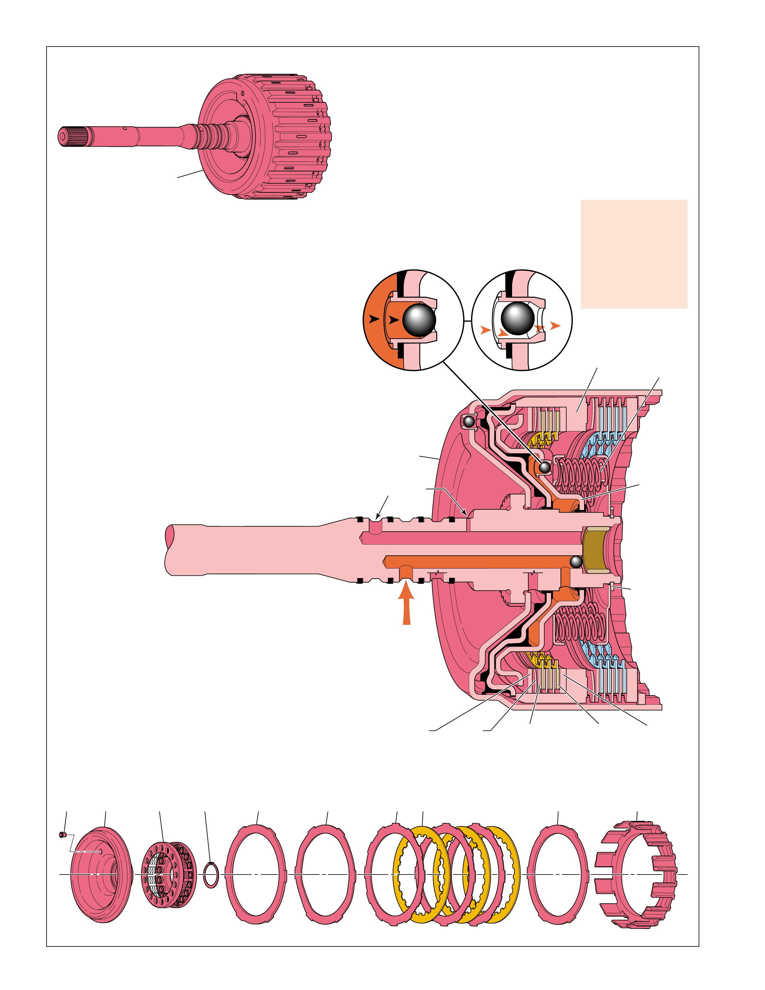
FORWARD CLUTCH
HOUSING ASSEMBLY
(433)
COAST CLUTCH PISTON
BALL CHECK VALVE
(437)
APPLIED RELEASED
FORWARD
CLUTCH
HOUSING
ASSEMBLY
(433) COAST
CLUTCH
PISTON
ASSEMBLY
(438)
COAST
CLUTCH
APPLY
FLUID
COAST
CLUTCH
APPLY
PLATE
(442)
FORWARD
AND COAST
CLUTCH
SPRING
(439)
COAST
CLUTCH
PLATE
ASSEMBLY
(OUTER SPLINE)
(443)
COAST
CLUTCH
PLATE
ASSEMBLY
(INNER SPLINE)
(444)
COAST
CLUTCH
BACKING
PLATE
(445)
COAST
CLUTCH
HOUSING
(446)
FORWARD
AND COAST
CLUTCH
SPRING
RETAINER
RING
(440)
437 438 441440439 442 443 444 445 446
COAST
CLUTCH
SPACER
PLATE
(SELECTIVE)
(441)
LUBE
PASSAGE
APPLY COMPONENTS
Figure 19
COAST CLUTCH:
The coast clutch assembly is located in the coast clutch
housing (446), which is splined to the forward clutch housing
assembly (433). The external teeth on the coast clutch plates
(443) are splined to the coast clutch housing while the
internal teeth on the coast clutch plate assemblies (444) are
splined to the input sun gear shaft assembly (457). The
coast clutch is applied when the transmission is in all forward
gear ranges, except Fifth gear, to transfer engine coast torque
to the input and reaction planetary gear set.
COAST CLUTCH APPLY:
To apply the coast clutch, coast clutch fluid is fed through the
fluid pump cover (202), through the turbine shaft to the inner
hub of the forward clutch housing assembly (433). Feed holes in
the inner hub allow coast clutch fluid to enter the housing between
the forward clutch piston (436) and the coast clutch piston (438).
Coast clutch fluid pressure moves the piston to compress the
forward and coast clutch spring (439). As fluid pressure increases,
the piston compresses the clutch plates until they are held against
the coast clutch backing plate (445). Also included in the
assembly is a coast clutch spacer plate (441) and a coast clutch
apply (waved) plate (442)
that helps cushion
the apply of the
coast clutch.
When fully applied,
the coast clutch
plates (443), coast
clutch plate assemblies (444), coast clutch spacer plate (441)
and coast clutch apply plate (442) are locked together, thereby
holding the forward clutch housing and the input sun gear shaft
assembly (457) together. This forces the input sun gear shaft
assembly to rotate at the same speed as the input/forward clutch
housing assembly (433).
COAST CLUTCH RELEASE:
To release the coast clutch, coast clutch fluid exhausts from the
piston, through the inner hub of the forward clutch housing and
into the fluid pump cover (202). In the absence of fluid pressure,
spring force from the forward and coast clutch spring (439)
moves the coast clutch piston away from the clutch plates. This
disengages the coast clutch plates (443), coast clutch plate
assemblies (444), coast clutch spacer plate (441) and coast clutch
If inoperative the
coast clutch can
cause no engine
braking in first,
second, third and
fourth (all ranges),
and degraded shifts
from fourth to fifth.
apply plate (442) from the coast clutch backing plate (445) and
disconnects the forward clutch housing from the input sun gear
shaft assembly (457).
During the exhaust of coast clutch fluid, the coast clutch piston
ball check valve (437), located in the coast clutch piston (438),
unseats. Centrifugal force, resulting from the rotation of the
forward/coast clutch housing, forces residual coast clutch fluid to
the outside of the housing and past the unseated ball check valve.
If this fluid did not completely exhaust from behind the piston,
there could be a partial apply, or drag, of the coast clutch plates.
18
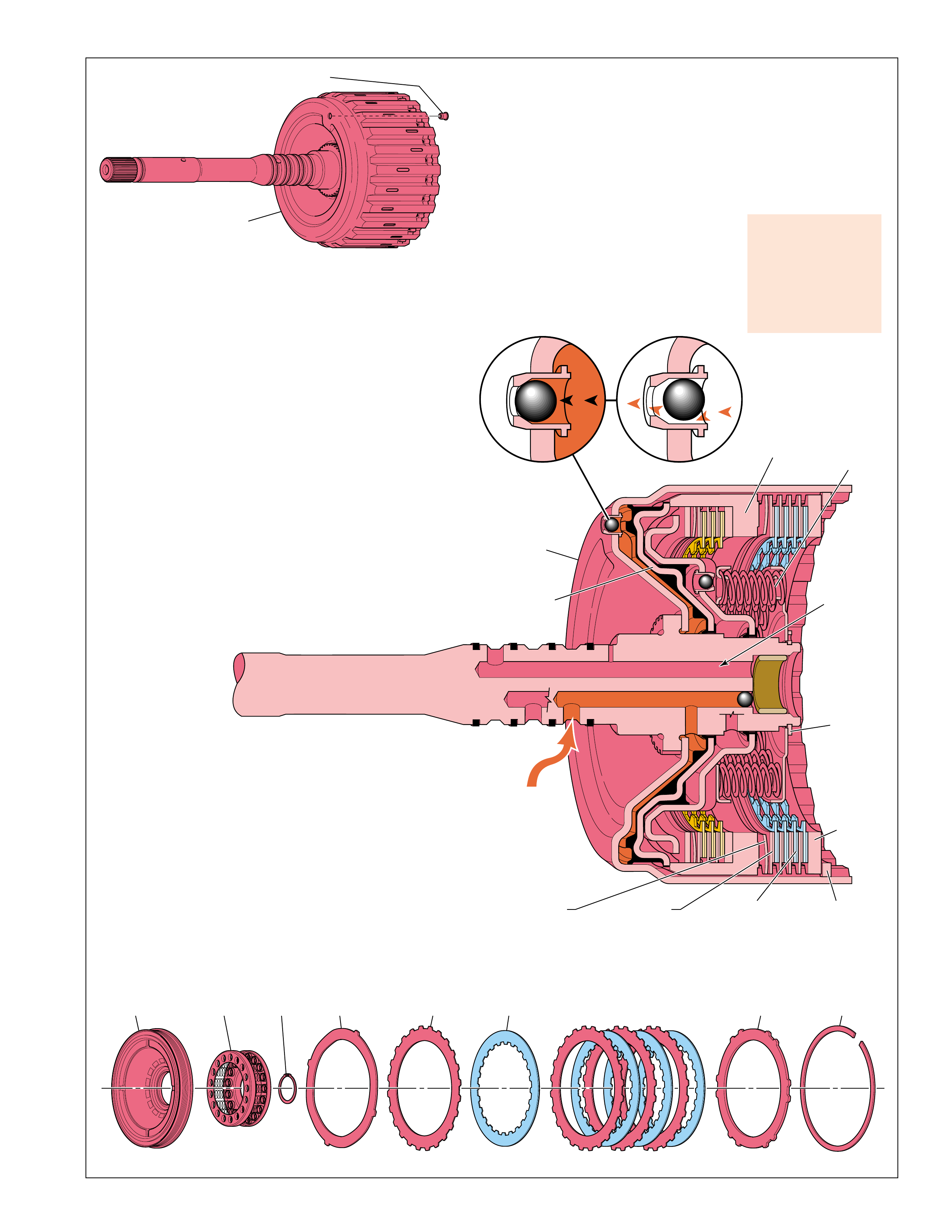
436
439 440 447 448 449 450 451
FORWARD CLUTCH HOUSING
BALL CHECK VALVE
(434)
FORWARD CLUTCH
HOUSING ASSEMBLY
(433)
FORWARD
CLUTCH
APPLY
FLUID
FORWARD
CLUTCH
HOUSING
ASSEMBLY
(433)
FORWARD
CLUTCH
PISTON
ASSEMBLY
(436)
FORWARD
CLUTCH
APPLY
PLATE
(447)
FORWARD
AND COAST
CLUTCH
SPRING
(439)
FORWARD
CLUTCH
PLATE
ASSEMBLY
(INNER SPLINE)
(448)
FORWARD
CLUTCH
PLATE
ASSEMBLY
(INNER SPLINE)
(449)
FORWARD
CLUTCH
BACKING
PLATE
(450)
COAST
CLUTCH
HOUSING
(446)
FORWARD
AND COAST
CLUTCH
SPRING
RETAINER
RING
(440)
FORWARD
CLUTCH
BACKING PLATE
RETAINER RING
(SELECTIVE)
(451)
FORWARD CLUTCH HOUSING
BALL CHECK VALVE
(434)
APPLIED RELEASED
LUBE
PASSAGE
Figure 20
APPLY COMPONENTS
FORWARD CLUTCH:
The forward clutch assembly is located in the forward clutch
housing assembly (433). The external teeth on the forward
clutch plates (448) are splined to the forward clutch housing
while the internal teeth on the forward clutch plate
assemblies (449) are splined to the forward clutch sprag
outer race (459). The forward clutch is applied in all forward
gear ranges to transfer engine torque to the input and reaction
planetary gear set.
FORWARD CLUTCH APPLY:
To apply the forward clutch, forward clutch fluid is fed through
the turbine shaft to the inner hub of the forward clutch housing.
Feed holes in the inner hub allow fluid to enter the housing
behind the forward clutch piston assembly (436). Forward clutch
fluid pressure moves the piston and compresses the forward and
coast clutch spring (439). As fluid pressure increases, the piston
moves the coast clutch housing (446) and compresses the clutch
plates until they are held against the forward clutch backing
plate (450). Also included in the clutch pack is a forward clutch
apply (waved) plate (447) that helps control the apply rate of the
forward clutch.
When fully applied,
the forward clutch
plates (448) and
forward clutch plate
assemblies (449)
are locked together,
thereby holding the
forward clutch housing
assembly and the forward clutch sprag outer race (459) together.
This forces the forward clutch sprag outer race to rotate at the
same speed as the forward clutch housing assembly.
FORWARD CLUTCH RELEASE:
To release the forward clutch, forward clutch fluid exhausts
from the piston, through the inner hub of the forward clutch
housing assembly and into the turbine shaft. In the absence of
fluid pressure, spring force from the forward and coast clutch
spring (439) moves the forward clutch piston assembly away
from the clutch plates. This disengages the forward clutch plates
(448), forward clutch plate assemblies (449) and forward clutch
apply (waved) plate (447) from the forward clutch backing plate
(450) and disconnects the forward clutch housing assembly from
the forward clutch sprag outer race (459).
During the exhaust of forward clutch fluid, the forward clutch
housing ball check valve, located in the forward clutch housing
assembly (434), unseats. Centrifugal force, resulting from the
rotation of the forward clutch housing assembly, forces residual
forward clutch fluid to the outside of the housing and past the
unseated ball check valve. If this fluid did not completely exhaust
from behind the piston, there could be a partial apply, or drag,
of the forward clutch plates.
If inoperative the
forward clutch can
cause forward
motion in Neutral,
loss of drive, and
harsh shifts from
D to R.
19
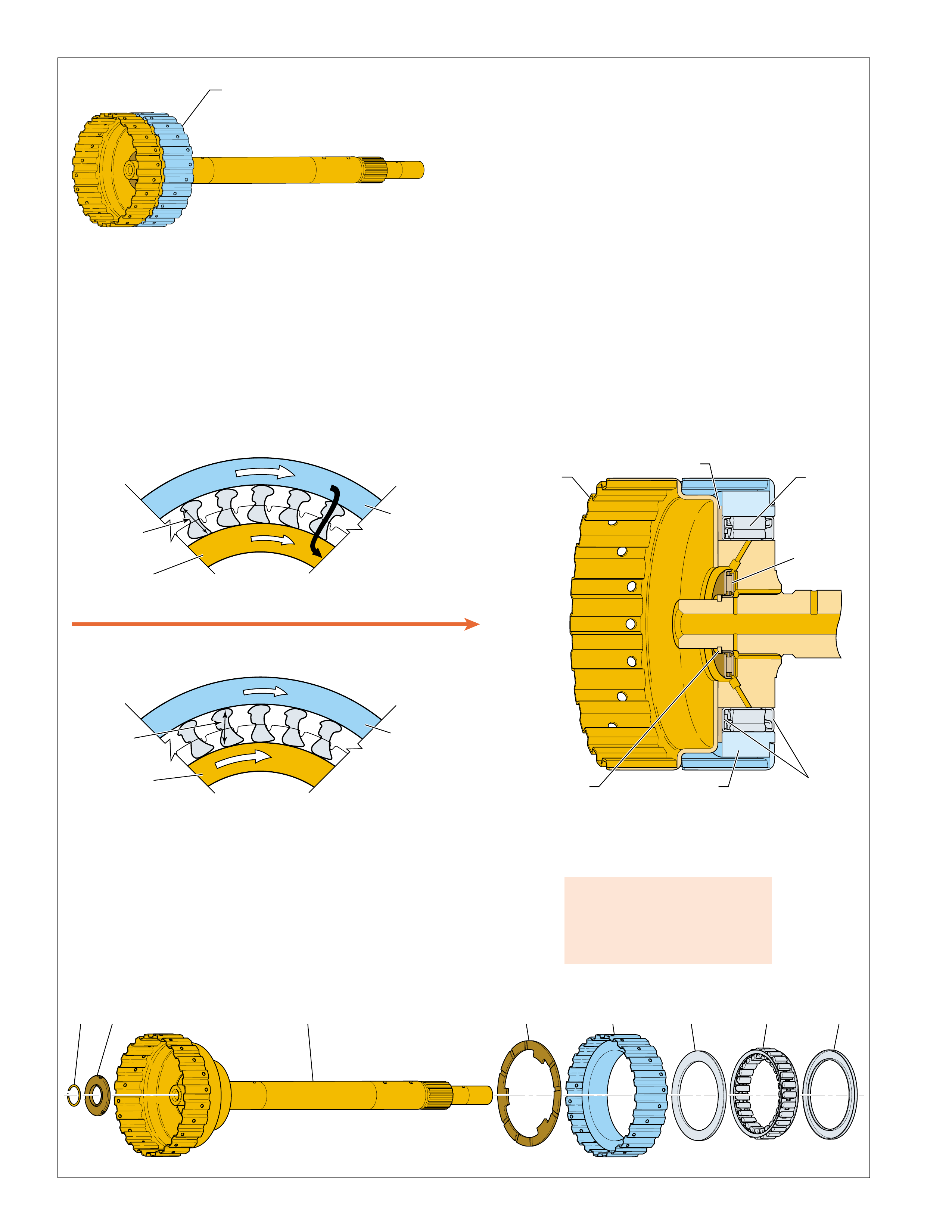
457 458 459 460 461 460455 456
FORWARD
CLUTCH SPRAG
ASSEMBLY
(455-459)
FORWARD
CLUTCH
SPRAG
ASSEMBLY
(461)
FORWARD
CLUTCH
ROLLER
INNER
BEARING
(456)
FORWARD
CLUTCH ROLLER
OUTER RACE WASHER
(458)
FORWARD
CLUTCH
SPRAG
OUTER RACE
(459)
FORWARD
CLUTCH ROLLER
INNER RACE
THRUST RING
(455)
FORWARD
CLUTCH SPRAG
ASSEMBLY
RETAINER RING
(460)
INPUT
SUN GEAR
SHAFT
ASSEMBLY
(457)
CLUTCH SPRAG RELEASED
INNER RACE OVERRUNNING THE OUTER RACE
INNER
RACE
(457)
DRIVING
F
R
E
E
(B) OUTER
RACE
(459)
CLUTCH SPRAG HOLDING
OUTER RACE DRIVING THE INNER RACE
INNER
RACE
(457)
H
E
L
D
(A) OUTER
RACE
(459)
DRIVING
SPRAG IS VIEWED FROM THIS DIRECTION
APPLY COMPONENTS
Figure 21
FORWARD CLUTCH SPRAG ASSEMBLY:
The forward clutch sprag assembly (461) is located between the
forward clutch sprag outer race (459) and the input sun gear
shaft assembly (457) (inner race). The input sun gear shaft
assembly is splined to the input sun gear in the input and reaction
carrier (553) while the forward clutch sprag outer race is splined
to the forward clutch plates. The clutch sprag is a type of one-
way clutch that transfers engine torque from the forward clutch
to the input sun gear during acceleration in First, Second, Third
and Fourth gears in all ranges.
A damaged forward clutch sprag
assembly can cause loss of
drive, no first gear in overdrive
and manual ranges.
FORWARD CLUTCH SPRAG HOLDING:
When the forward clutch is applied, engine torque is transferred
to the forward clutch sprag outer race (459). The rotation of the
forward clutch sprag outer race pivots the sprags toward their
long diagonals. The length of the long diagonal (distance A) is
greater than the distance between the outer race and inner race
(457). This causes the sprags to “lock” between the inner and
outer races and transfer engine torque from the forward clutch
sprag outer race to the input sun gear shaft assembly (457).
FORWARD CLUTCH SPRAG RELEASED:
The clutch sprag releases when the sprags pivot toward their
short diagonals. The length of the short diagonals (B) is less
than the distance between the inner and outer sprag races. This
occurs when power flow drives the input sun gear shaft assembly
(457) faster than the forward clutch drives the forward clutch
sprag outer race (459). During acceleration the clutch sprag is
overrun only in Fifth gear.
COAST CLUTCH APPLIED:
The coast clutch is applied in first, second, third and fourth gear
in all forward ranges. It holds the coast clutch housing (446)
and the input sun gear shaft assembly (457) together. These
components are then forced to rotate at the same speed as the
forward clutch housing assembly (433). This prevents the input
sun gear shaft assembly (457) from being driven faster than the
forward clutch sprag outer race (459) and, also allows engine
braking to occur in first, second, third or fourth gear if the
proper braking clutch is applied (refer to the range reference
chart on page 11), specific per customer application.
20
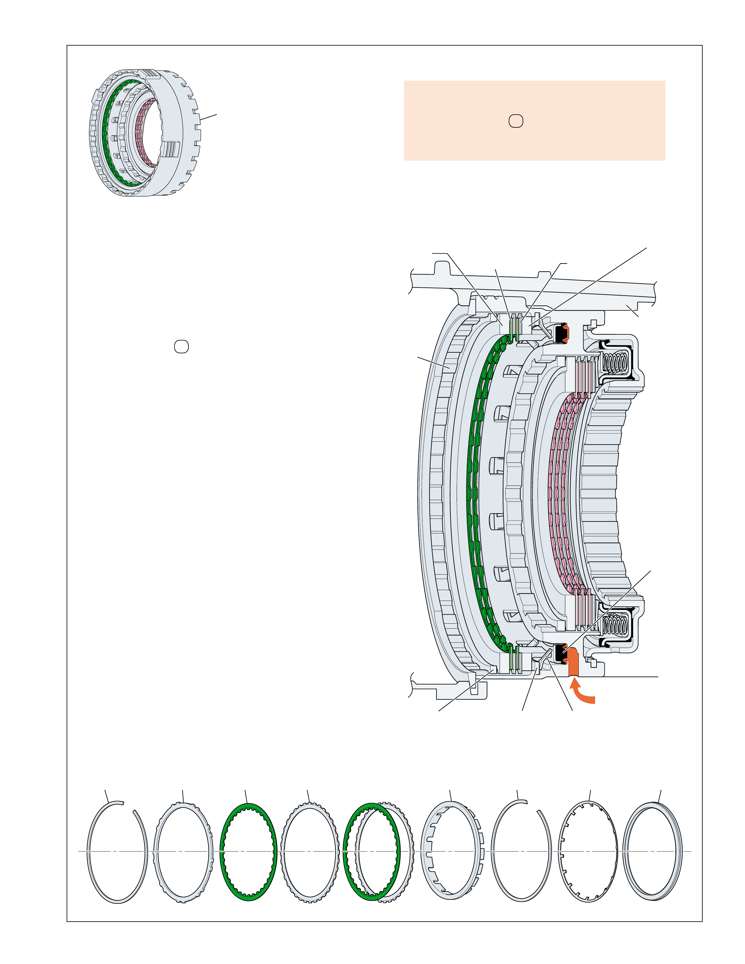
OVERDRIVE AND
INTERMEDIATE
CLUTCH
ASSEMBLY
(480-497)
OVERDRIVE
CLUTCH
SPRING
(486)
OVERDRIVE CLUTCH
BACKING PLATE
RETAINER RING
(SELECTIVE)
(480)
OVERDRIVE
CLUTCH
BACKING
PLATE
(481)
OVERDRIVE
CLUTCH
PLATE
ASSEMBLY
(INNER SPLINE)
(482)
OVERDRIVE
CLUTCH
SPRING
RETAINER RING
(485)
OVERDRIVE
CLUTCH
PISTON
ASSEMBLY
(487)
OVERDRIVE
CLUTCH
PLATE
ASSEMBLY
(OUTER SPLINE)
(483)
OVERDRIVE
CLUTCH
HOUSING
(493)
TRANSMISSION
CASE
(24)
OVERDRIVE
CLUTCH
SPACER
(484)
OVERDRIVE
CLUTCH FLUID
483 484 485 486 487482481480
Figure 22
APPLY COMPONENTS
OVERDRIVE CLUTCH:
The overdrive clutch assembly is located in the overdrive
clutch housing (493). The overdrive clutch housing is splined
to the transmission case (24). The external teeth on the
overdrive clutch plates (483) are splined to the overdrive
clutch housing while the internal teeth on the overdrive clutch
plate assemblies (482) are splined to the overdrive and reverse
clutch hub assembly (470). The overdrive clutch is applied
only when the transmission is in Overdrive range Fifth gear,
or in Third gear in D , manual fourth and manual third
ranges when engine braking is commanded ON.
OVERDRIVE CLUTCH APPLY:
To apply the overdrive clutch, overdrive clutch fluid is fed
through the transmission case (24) into the overdrive clutch
housing (493). A feed hole in the overdrive clutch housing
allows fluid to enter the housing behind the overdrive clutch
piston assembly (487). Overdrive clutch fluid pressure
moves the piston to compress the overdrive clutch spring
(486). As fluid pressure increases, the overdrive clutch
spacer plate (484) compresses the overdrive clutch plates
together until they are held against the overdrive clutch
backing plate (481).
When fully applied, the overdrive spacer (484), the overdrive
clutch plates (483) and the overdrive clutch plate assemblies
(482) are locked together, thereby holding the overdrive
clutch housing (493) and the overdrive and reverse clutch
hub assembly (470) together. This holds the overdrive and
reverse clutch hub assembly stationary to the transmission
case (24).
OVERDRIVE CLUTCH RELEASE:
To release the overdrive clutch, overdrive clutch fluid
exhausts through the overdrive clutch housing and into the
transmission case, allowing pressure at the overdrive clutch
piston (487) to decrease. In the absence of fluid pressure,
spring force from the overdrive clutch spring (486) moves
the overdrive clutch piston (487) away from the clutch
pack. This disengages the overdrive clutch plates (483) and
the overdrive clutch plate assemblies (482) from the backing
plate (481), thereby allowing the overdrive and reverse
clutch hub assembly to rotate freely.
If inoperative the overdrive clutch can cause:
•No engine braking in third gear
•No fifth gear - D
•Degraded shifts from fourth to fifth and from
fifth to fourth.
21
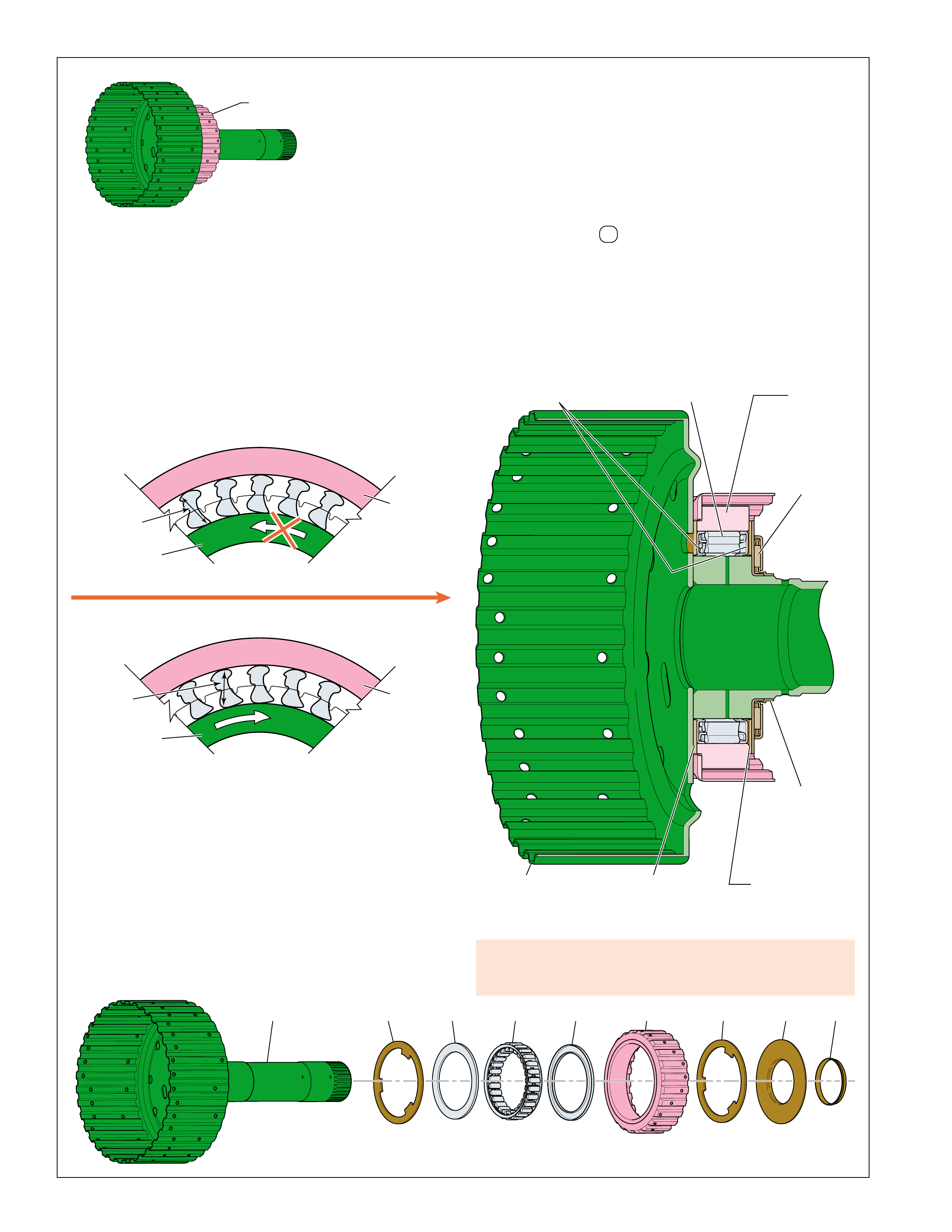
OVERDRIVE
AND REVERSE
CLUTCH HUB
ASSEMBLY (470)
INTERMEDIATE
CLUTCH SPRAG
RETAINER RING
(472)
INTERMEDIATE
CLUTCH SPRAG
ASSEMBLY
(473)
INTERMEDIATE
CLUTCH SPRAG
OUTER RACE
(474)
INTERMEDIATE
CLUTCH SPRAG
THR UST W ASHER
(471)
INTERMEDIATE
CLUTCH SPRAG
THRUST BEARING
ASSEMBLY
(476)
INTERMEDIATE
CLUTCH SPRAG
THRUST BEARING
ASSEMBLY
RETAINER
(477)
INTERMEDIATE
CLUTCH SPRAG
THR UST W ASHER
(475)
INTERMEDIATE
CLUTCH SPRAG
ASSEMBLY
(470-477)
470 471 472 472 474 475 476 477473
CLUTCH SPRAG RELEASED
INNER RACE OVERRUNNING THE OUTER RACE
INNER
RACE
(470)
F
R
E
E
(B) OUTER
RACE
(474)
H
E
L
D
CLUTCH SPRAG HOLDING
OUTER RACE HOLDING THE INNER RACE
INNER
RACE
(470)
H
E
L
D
(A) OUTER
RACE
(474)
H
E
L
D
SPRAG IS VIEWED FROM THIS DIRECTION
APPLY COMPONENTS
Figure 23
INTERMEDIATE CLUTCH SPRAG:
The intermediate clutch sprag assembly (473) is located between
the intermediate clutch sprag outer race (474) and the overdrive
and reverse clutch hub assembly (470) (inner race). The overdrive
and reverse clutch hub assembly is splined to the overdrive and
reverse sun gear in the input and reaction carrier (553) while the
intermediate clutch plate assemblies are splined to the intermediate
clutch sprag outer race (474). The intermediate clutch sprag is a
type of one-way clutch that, when effective, prevents the overdrive
and reverse clutch hub assembly from rotating in the direction
opposite of engine rotation. The clutch sprag is holding, and
effective, when the transmission is in Third Gear.
A damaged intermediate clutch sprag can cause no third gear
or, no torque in third gear, in overdrive range, manual fourth,
or manual third.
INTERMEDIATE CLUTCH SPRAG HOLDING:
In Third gear, power flow attempts to drive the overdrive and
reverse clutch hub assembly in the direction opposite of engine
rotation and pivots the sprags toward their long diagonals. The
long diagonal (A) of the sprag is greater than the distance between
the inner race and the outer race, causing the sprags to “lock”
against the intermediate clutch sprag outer race (474). However,
in Third gear the intermediate clutch is applied and the outer race
is held stationary to the transmission case (24). Therefore, the
sprag assembly, being “locked” between the outer race and
overdrive and reverse clutch hub assembly (inner race), holds the
overdrive and reverse clutch hub assembly (470) and the overdrive
and reverse sun gear (553) stationary to obtain a Third gear ratio
through the transmission gear set.
INTERMEDIATE CLUTCH SPRAG RELEASED:
The intermediate clutch sprag releases when the sprags pivot
toward their short diagonals. The short diagonal (B) is smaller
than the distance between the inner race and outer race and the
outer race overruns the sprags. This action occurs in Fourth and
Fifth gears when the intermediate clutch is applied and power
flow drives the overdrive and reverse clutch hub assembly in the
direction of engine rotation.
Depending on model and application, the inner race may also
overrun the intermediate clutch sprag during coast conditions
(throttle released) in D , manual fourth and manual third ranges
– Third Gear when vehicle speed is greater than engine speed
(refer to the Range Reference Chart on page 11). This causes
the transmission gear set to be driven by the vehicle drive shaft,
and not the engine, which drives the overdrive and reverse
clutch hub assembly in the direction of engine rotation,
overrunning the sprags.
22
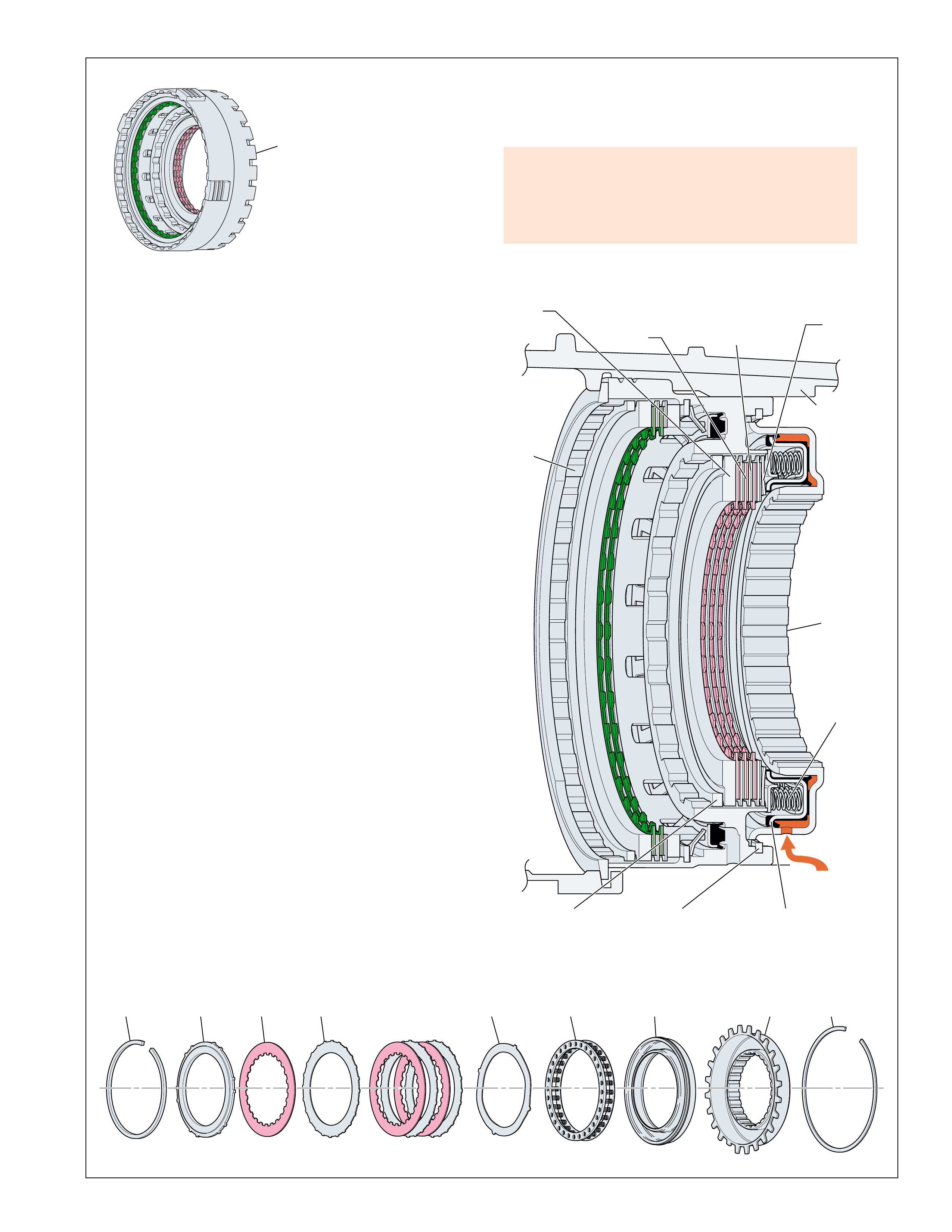
OVERDRIVE AND
INTERMEDIATE
CLUTCH
ASSEMBLY
(480-497)
488 489
490
491
492 494
495
496
497
INTERMEDIATE
CLUTCH
HOUSING
RETAINER RING
(497)
INTERMEDIATE
CLUTCH
APPLY
PLATE
(492)
INTERMEDIATE
CLUTCH
BACKING PLATE
RETAINER RING
(SELECTIVE)
(488)
INTERMEDIATE
CLUTCH
BACKING PLATE
(489)
INTERMEDIATE
CLUTCH
PISTON
ASSEMBLY
(495)
INTERMEDIATE
CLUTCH
SPRING
(494)
INTERMEDIATE
CLUTCH
PLATE
ASSEMBLY
(INNER SPLINE)
(490)
INTERMEDIATE
CLUTCH
HOUSING
(496)
TRANSMISSION
CASE
(24)
INTERMEDIATE
CLUTCH
PLATE
ASSEMBLY
(OUTER SPLINE)
(491)
INTERMEDIATE
CLUTCH FLUID
OVERDRIVE
CLUTCH
HOUSING
(493)
Figure 24
APPLY COMPONENTS
INTERMEDIATE CLUTCH:
The intermediate clutch assembly is located between the
intermediate clutch housing (496) and the overdrive clutch
housing (493). The overdrive clutch housing is splined to
the transmission case (24). The external teeth on the
intermediate clutch plates (491) are splined to the overdrive
clutch housing (493) while the internal teeth on the
intermediate clutch plate assemblies (490) are splined to
the intermediate clutch sprag outer race (474). The
intermediate clutch is applied when the transmission is in
Third, Fourth, and Fifth gears.
INTERMEDIATE CLUTCH APPLY:
To apply the intermediate clutch, intermediate clutch apply
fluid is fed from the transmission case (24) into the
intermediate clutch housing (496). A feed hole in the
intermediate clutch housing allows fluid to enter the housing
behind the intermediate clutch piston assembly (495).
Intermediate clutch fluid pressure moves the piston to
compress the intermediate clutch spring (494). As fluid
pressure increases, the piston compresses the intermediate
clutch plates until they are held against the intermediate clutch
backing plate (489). Also included in the intermediate clutch
pack is an intermediate clutch apply (waved) plate (492) that
helps control the apply rate of the intermediate clutch.
When fully applied, the intermediate clutch plates (491)
and intermediate clutch plate assemblies (490) are locked
together, thereby holding the intermediate clutch sprag outer
race (474) stationary to the transmission case. This allows
the intermediate clutch sprag (473) to become effective and
hold when the overdrive and reverse clutch hub assembly
(470) attempts to rotate in the direction opposite of engine
rotation. Remember that the inner race of the intermediate
clutch sprag is part of the overdrive and reverse clutch hub
assembly (470).
INTERMEDIATE CLUTCH RELEASE:
To release the intermediate clutch, intermediate clutch fluid
exhausts from the piston, through the intermediate clutch
housing and into the transmission case. In the absence of
fluid pressure, spring force from the intermediate clutch
spring (494) moves the piston away from the clutch plates.
This disengages the intermediate clutch plates (491) and
intermediate clutch plate assemblies (490) from the
intermediate clutch backing plate (489) and disconnects the
If inoperative the intermediate clutch can cause:
•No third gear in overdrive range, manual fourth or
manual third
•Degraded shifts from second to third and from third
to second
intermediate clutch sprag outer race from the overdrive clutch housing/
transmission case. Therefore, the intermediate clutch sprag is no
longer effective – the outer race will rotate with the overdrive and
reverse clutch hub assembly when the sprags engage.
23
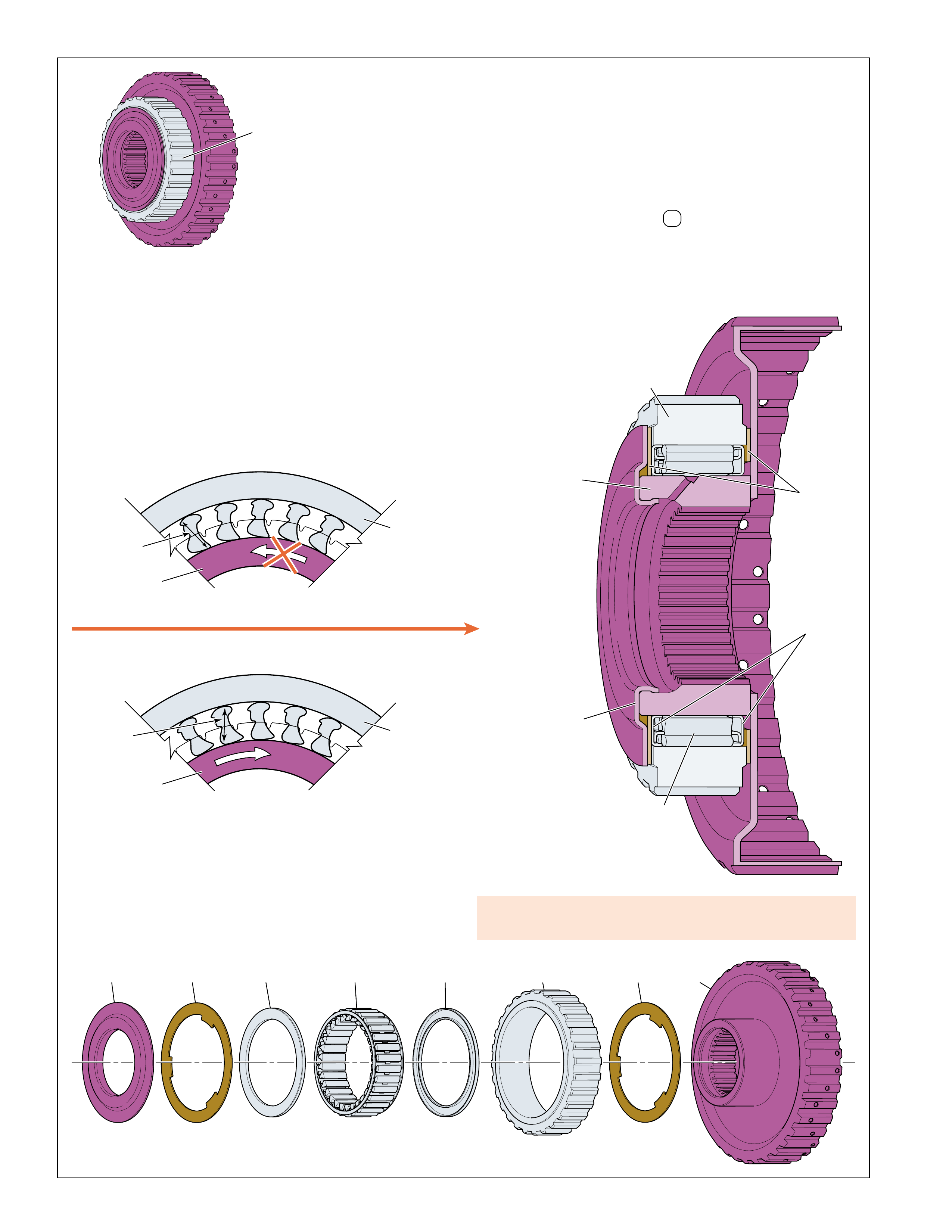
CLUTCH SPRAG HOLDING
OUTER RACE HOLDING THE INNER RACE
INNER
RACE
(505)
H
E
L
D
H
E
L
D
(A) OUTER
RACE
(504)
LOW
CLUTCH
SPRAG
ASSEMBLY
(500-505)
500 501 502 502 504 501 505503
LOW
CLUTCH
SPRAG
OUTER RACE
(504)
LOW
CLUTCH
SPRAG
INNER RACE
(505)
LOW
CLUTCH
SPRAG
ASSEMBLY
RETAINER
RING
(502)
LOW
CLUTCH
SPRAG
ASSEMBLY
(503)
LOW
CLUTCH
ROLLER
RETAINER
(500)
LOW
CLUTCH
ROLLER
THRUST
WASHER
(501)
CLUTCH SPRAG RELEASED
INNER RACE OVERRUNNING THE OUTER RACE
INNER
RACE
(505)
F
R
E
E
(B) OUTER
RACE
(504)
H
E
L
D
SPRAG IS VIEWED FROM THIS DIRECTION
APPLY COMPONENTS
Figure 25
LOW CLUTCH SPRAG:
The low clutch sprag assembly (503) is located between the low
clutch sprag outer race (504) and the low clutch sprag inner race
(505). The low clutch sprag outer race is splined to the
transmission case (24) through the intermediate clutch housing
assembly (496) and the overdrive clutch housing (493). The low
clutch sprag inner race is splined to the input and reaction carrier
(553). The low clutch sprag assembly is a type of one-way
clutch that prevents the input and reaction carrier from rotating
in the direction opposite of engine rotation. The low clutch sprag
is holding, and effective, when the vehicle is in First Gear.
A damaged low clutch sprag can cause loss of drive/no first
gear in overdrive range and all manual ranges.
LOW CLUTCH SPRAG HOLDING:
In First gear, power flow attempts to drive the input and reaction
carrier in the direction opposite of engine rotation and pivots the
sprags toward their long diagonals. The long diagonal (A) of
the sprag is greater than the distance between the inner race and
the outer race, causing the sprags to “lock” between the inner
and outer races. This action holds the input and reaction carrier
stationary to the transmission case (24) to obtain a First gear
ratio through the transmission gear set.
LOW CLUTCH SPRAG RELEASED:
The low clutch sprag releases when the sprags pivot toward their
short diagonals. The length of the short diagonals (B) is less than
the distance between the inner race and the outer race. This
causes the inner race to overrun the sprags. This action occurs in
Second, Third, Fourth and Fifth gears when power flow drives
the input and reaction carrier in the direction of engine rotation.
Depending on model and application, the input and reaction
carrier may also overrun the low clutch sprag during coast
conditions (throttle released) in D , manual fourth, manual third
and manual second ranges – First Gear when vehicle speed is
greater than engine speed. This causes the transmission gear set
to be driven by the vehicle drive shaft, and not the engine,
which drives the input and reaction carrier in the direction of
engine rotation, overrunning the sprags.
24
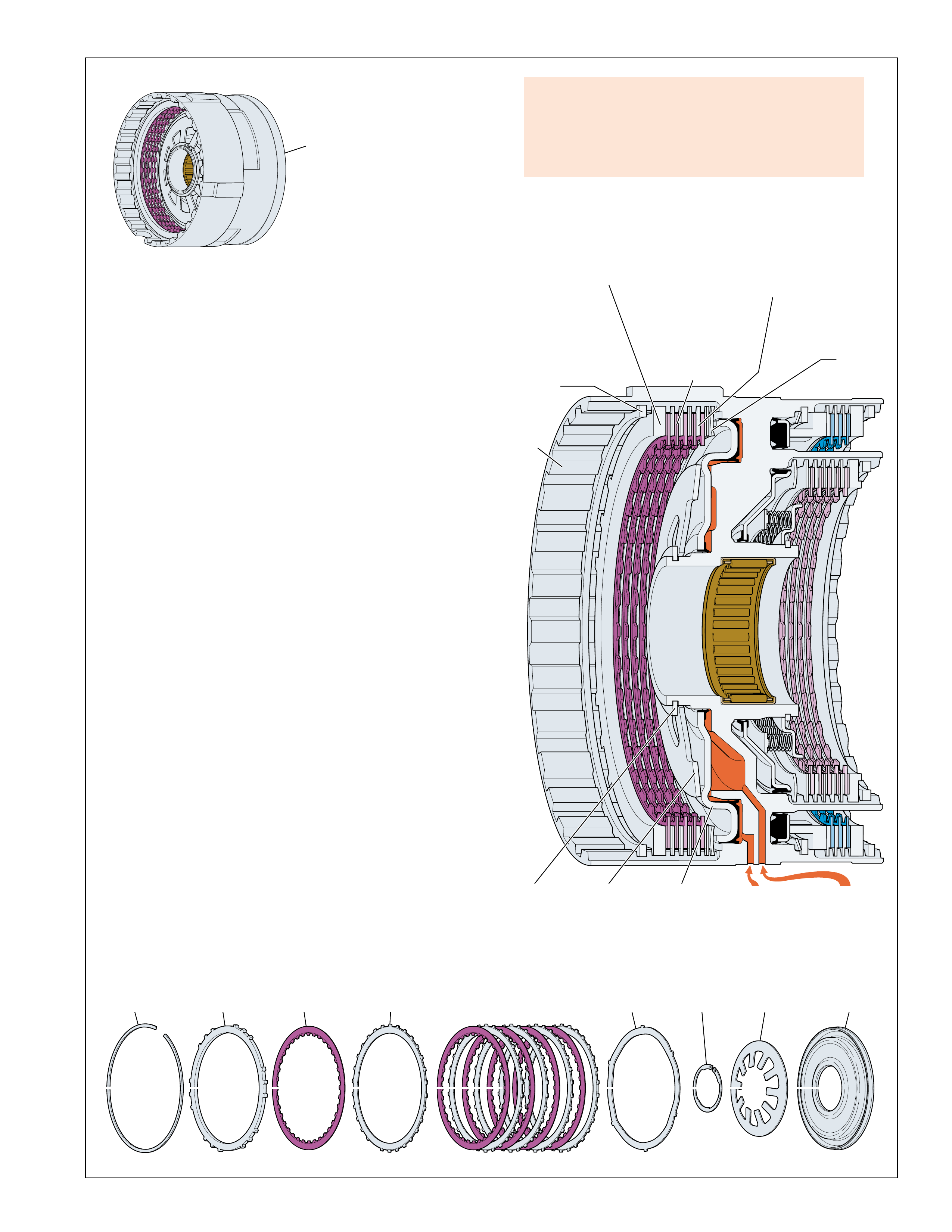
CENTER
SUPPORT
ASSEMBLY
(510-535)
510 511 516512 513 517515514
LOW AND
REVERSE
CLUTCH
PLATE
RETAINER
RING
(SELECTIVE)
(510)
LOW AND
REVERSE
CLUTCH
BACKING
PLATE
(511)
REVERSE
LOCKOUT
FLUID
LOW AND
REVERSE
CLUTCH
OR RLO
FLUID
LOW AND
REVERSE
CLUTCH
PLATE
ASSEMBLY
(INNER SPLINE)
(512)
LOW AND
REVERSE
CLUTCH
SPRING
RETAINER
RING
(515)
LOW AND
REVERSE
CLUTCH
SPRING
(516)
LOW AND
REVERSE
CLUTCH
PISTON
(517)
CENTER
SUPPORT
(518)
LOW AND
REVERSE
CLUTCH
PLATE
ASSEMBLY
(OUTER SPLINE)
(513) LOW AND
REVERSE
CLUTCH
APPLY
PLATE
(514)
Figure 26
APPLY COMPONENTS
LOW AND REVERSE CLUTCH:
The low and reverse clutch assembly is located in the center
support (518). The center support is splined to the transmission
case (24). The external teeth on the low and reverse clutch
plates (513) are splined to the center support (518) while the
internal teeth on the low and reverse clutch plate assemblies
(512) are splined to the low clutch sprag inner race (505). The
low and reverse clutch is applied when the transmission is in
First gear in all forward ranges when engine braking is
commanded ON, and in Reverse.
LOW AND REVERSE CLUTCH APPLY:
To apply the low and reverse clutch, low and reverse clutch or
reverse lockout (RLO) apply fluid is fed from the transmission
case (24) into the center support (518). A feed hole in the center
support allows fluid to enter behind the low and reverse clutch
piston assembly (517). Low and reverse clutch or reverse lockout
(RLO) fluid pressure moves the piston to compress the low and
reverse clutch spring (516). As fluid pressure increases, the
piston compresses the low and reverse clutch plates until they
are held against the low and reverse clutch backing plate (511).
Also included in the clutch pack is a low and reverse clutch
apply (waved) plate (514) that helps control the apply rate of the
low and reverse clutch.
When fully applied, the low and reverse clutch plates (513) and
low and reverse clutch plate assemblies (512) are locked together,
thereby holding the low clutch sprag inner race (505) stationary
to the transmission case (24). The low clutch sprag inner race
(505) is splined to the input and reaction carrier (553), causing
the input and reaction carrier to be held stationary also.
LOW AND REVERSE CLUTCH RELEASE:
To release the low and reverse clutch, low and reverse clutch or
reverse lockout (RLO) fluid exhausts from the piston, through
the center support and into the transmission case. In the absence
of fluid pressure, spring force from the low and reverse clutch
spring (516) moves the piston away from the clutch plates. This
disengages the low and reverse clutch plates (513) and low and
reverse clutch plate assemblies (512) from the low and reverse
clutch backing plate (511) and disconnects the low clutch sprag
inner race from the center support/transmission case. Therefore,
the low clutch sprag inner race (505) and the input and reaction
carrier (553) are free to rotate in the direction of engine rotation.
If inoperative the low and reverse clutch can cause:
•No first gear engine braking in overdrive range,
manual fourth, manual third, manual second, or
manual first
•No reverse/slips in reverse
25
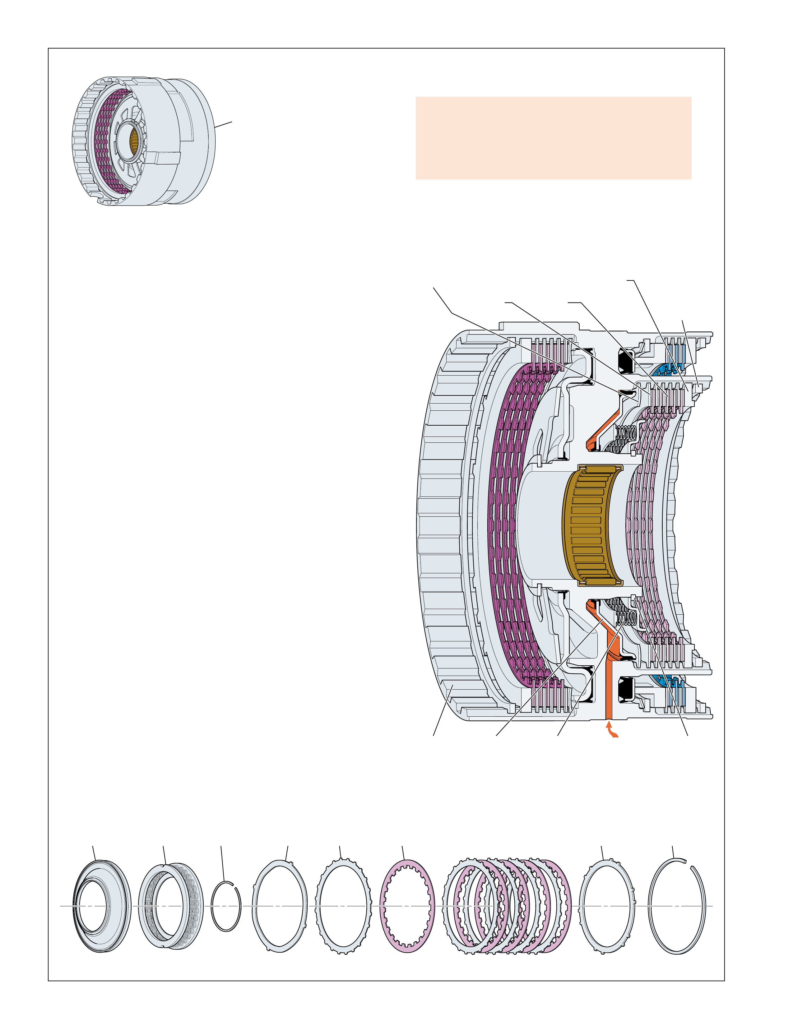
CENTER
SUPPORT
ASSEMBLY
(510-535)
520 522 525 527526524521 523
SECOND
CLUTCH
APPLY
PLATE
(523)
SECOND
CLUTCH
PLATE
ASSEMBLY
(OUTER
SPLINE)
(524)
SECOND
CLUTCH
FLUID
SECOND
CLUTCH
PLATE
ASSEMBLY
(INNER
SPLINE)
(525)
SECOND
CLUTCH
PISTON
(520)
SECOND
CLUTCH
SPRING
(521)
SECOND
CLUTCH
SPRING
RETAINER
RING
(522)
CENTER
SUPPORT
(518)
SECOND
CLUTCH
BACKING
PLATE
(526)
SECOND
CLUTCH
BACKING
PLATE
RETAINER
RING
(SELECTIVE)
(527)
APPLY COMPONENTS
SECOND CLUTCH:
The second clutch assembly is located in the center support
(518). The center support is splined to the transmission case
(24). The external teeth on the second clutch plates (524) are
splined to the center support (518) while the internal teeth on
the second clutch plate assemblies (525) are splined to the second
clutch sprag outer race (545). The second clutch is applied
when the transmission is in Second, Third, Fourth or Fifth gears.
SECOND CLUTCH APPLY:
To apply the second clutch, second clutch apply fluid is fed from
the transmission case (24) into the center support (518). A feed
hole in the center support allows fluid to enter behind the second
clutch piston (520). Second clutch fluid pressure moves the
piston to compress the second clutch spring (521) to cushion the
apply. As fluid pressure increases, the piston compresses the
second clutch plates until they are held against the second clutch
backing plate (526). Also included in the clutch pack is a second
clutch apply (waved) plate (523) that, in addition to the second
clutch spring, helps control the apply rate of the second clutch.
When fully applied, the second clutch plates (524) and second
clutch plate assemblies (525) are locked together, thereby holding
the second clutch sprag outer race (545) stationary to the
transmission case (24). This allows the second clutch sprag
assembly (547) to become effective and hold when the second
clutch sprag inner race (549) attempts to rotate in the direction
opposite of engine rotation.
SECOND CLUTCH RELEASE:
To release the second clutch, second clutch fluid exhausts from
the piston, through the center support and into the transmission
case. In the absence of fluid pressure, spring force from the
second clutch spring (521) moves the piston away from the
clutch plates. This disengages the second clutch plates (524)
and second clutch plate assemblies (525) from the second clutch
backing plate (526) and disconnects the second clutch sprag
outer race (545) from the second clutch sprag inner race (549).
Therefore, the second clutch sprag is no longer effective – the
inner race is free to rotate.
If inoperative the second clutch can cause:
•No second gear in overdrive range, manual fourth,
manual third, or manual second
•Degraded shifts from first to second and from
second to first
Figure 27
26
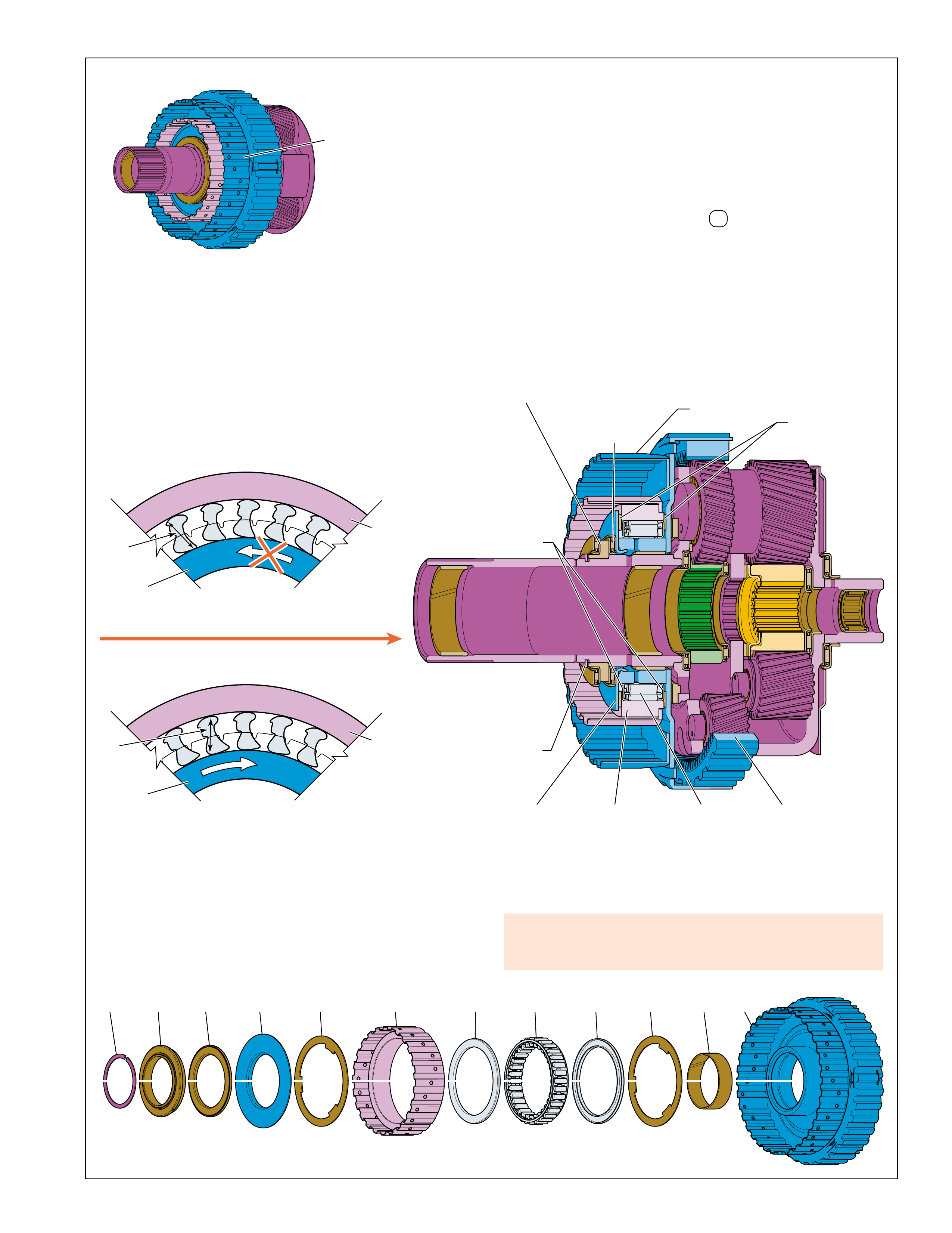
CLUTCH SPRAG HOLDING
OUTER RACE HOLDING THE INNER RACE
INNER
RACE
(549)
(A) OUTER
RACE
(545)
H
E
L
D
H
E
L
D
540 542 544541 543 545 547 544546 546 548 549
SECOND
CLUTCH
SPRAG
ASSEMBLY
(540-549)
INPUT AND
REACTION
CARRIER
OUTER
RING
(540)
INPUT AND
REACTION
BEARING
ASSEMBLY
(541)
SECOND
CLUTCH
ROLLER
INNER
RACE
BEARING
ASSEMBLY
(542)
SECOND
CLUTCH
SPRAG
OUTER
RACE
(545)
SECOND
CLUTCH
SPRAG
INNER
RACE
(549)
SECOND
CLUTCH
SPRAG
ASSEMBLY
RETAINER
(546)
SECOND
CLUTCH
SPRAG
ASSEMBLY
(547)
REACTION
INTERNAL
GEAR
(550)
SECOND
CLUTCH
SPRAG
RETAINER
(543)
SECOND
CLUTCH
ROLLER
OUTER
RACE
WASHER
(544)
CLUTCH SPRAG RELEASED
INNER RACE OVERRUNNING THE OUTER RACE
INNER
RACE
(549)
(B) OUTER
RACE
(545)
F
R
E
E
H
E
L
D
SPRAG IS VIEWED FROM THIS DIRECTION
APPLY COMPONENTS
SECOND CLUTCH SPRAG:
The second clutch sprag assembly (547) is located between the
second clutch sprag outer race (545) and the second clutch sprag
inner race (549). The second clutch sprag outer race is splined to
the second clutch plate assemblies (525). The second clutch sprag
inner race is splined to the reaction internal gear (550). The second
clutch sprag assembly is a type of one-way clutch that prevents the
reaction internal gear (550) from rotating in the direction opposite
of engine rotation and affects the output gear ratio of the input and
reaction carrier (553). The second clutch sprag is holding, and
effective, when the vehicle is in Second Gear.
A damaged second clutch sprag can cause no second gear in
overdrive range, manual fourth, manual third and manual
second.
SECOND CLUTCH SPRAG HOLDING:
In Second gear, power flow attempts to drive the reaction internal
gear (550) in the direction opposite of engine rotation and pivots
the sprags toward their long diagonals. The long diagonal (A) of
the sprag is greater than the distance between the inner race and the
outer race, causing the sprags to “lock” between the inner and outer
races. Because the second clutch is also applied, this action holds
the reaction internal gear (550) stationary to the transmission case
(24) to obtain a Second gear ratio through the transmission gear set.
SECOND CLUTCH SPRAG RELEASED:
The second clutch sprag releases when the sprags pivot toward
their short diagonals. The length of the short diagonals (B) is
less than the distance between the inner race and the outer race.
This causes the inner race to overrun the sprags. This action
occurs in Third, Fourth and Fifth gears when power flow drives
the reaction internal gear (550) in the direction of engine rotation.
Depending on model and application, the reaction internal gear
(550) may also overrun the second clutch sprag during coast
conditions (throttle released) in D , manual fourth, manual
third, and manual second ranges – Second Gear when vehicle
speed is greater than engine speed (refer to the Range Reference
Chart on page 11). This causes the transmission gear set to be
driven by the vehicle drive shaft, and not the engine, which
drives the reaction internal gear in the direction of engine rotation,
overrunning the sprags.
Figure 28 27
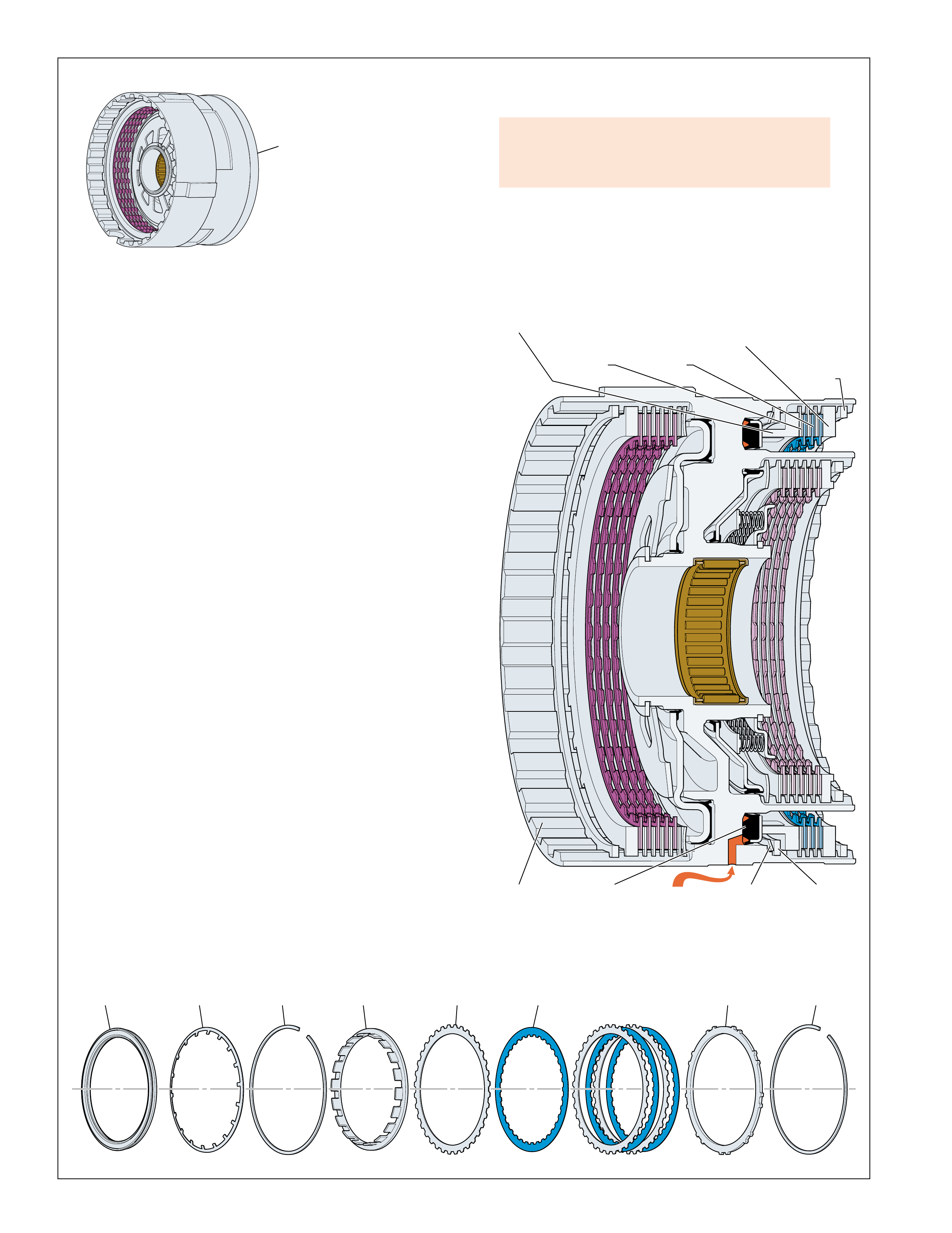
CENTER
SUPPORT
ASSEMBLY
(510-535)
SECOND
COAST
CLUTCH
SPACER
(531)
SECOND
COAST
CLUTCH
PLATE
ASSEMBLY
(OUTER
SPLINE)
(532)
SECOND
COAST
CLUTCH
FLUID
SECOND
COAST
CLUTCH
PLATE
ASSEMBLY
(INNER
SPLINE)
(533)
SECOND
COAST
CLUTCH
PISTON
(528)
SECOND
COAST
CLUTCH
SPRING
(529)
SECOND
COAST
CLUTCH
SPRING
RETAINER
RING
(530)
CENTER
SUPPORT
(518)
SECOND
COAST
CLUTCH
BACKING
PLATE
(534)
SECOND
COAST
CLUTCH
BACKING
PLATE
RETAINER
RING
(SELECTIVE)
(535)
528 529 531 533 534 535530 532
APPLY COMPONENTS
SECOND COAST CLUTCH:
The second coast clutch assembly is located in the center support
(518). The center support is splined to the transmission case
(24). The external teeth on the second coast clutch plates (532)
are splined to the center support (518) while the internal teeth
on the second coast clutch plate assemblies (533) are splined to
the second clutch sprag inner race (549). The second coast
clutch is applied when the transmission is in Second gear in all
forward ranges when engine braking is commanded ON.
SECOND COAST CLUTCH APPLY:
To apply the second coast clutch, second coast clutch apply fluid
is fed from the transmission case (24) into the center support
(518). A feed hole in the center support allows fluid to enter
behind the second coast clutch piston assembly (528). Second
coast clutch fluid pressure moves the piston to compress the
second coast clutch spring (529) to cushion the apply. As fluid
pressure increases, the piston compresses the second coast clutch
plates until they are held against the second coast clutch backing
plate (534). Also included in the clutch pack is a second coast
clutch spacer (531).
When fully applied, the second coast clutch plates (532) and
second coast clutch plate assemblies (533) are locked together,
thereby holding the second clutch sprag inner race (549)
stationary to the transmission case (24). This allows the second
clutch sprag assembly (547) to become effective and hold when
the second clutch sprag inner race (549) attempts to rotate.
SECOND COAST CLUTCH RELEASE:
To release the second coast clutch, second coast clutch fluid
exhausts from the piston, through the center support and into the
transmission case. In the absence of fluid pressure, spring force
from the second coast clutch spring (529) moves the piston
away from the clutch plates. This disengages the second coast
clutch plates (532) and second coast clutch plate assemblies
(533) from the second coast clutch backing plate (534) and
disconnects from the second clutch sprag inner race (549).
Therefore, the second clutch sprag is no longer effective – the
inner race is free to rotate.
If inoperative the second coast clutch can cause:
•No second gear engine braking in overdrive range,
manual fourth, manual third, or manual second
Figure 29
28
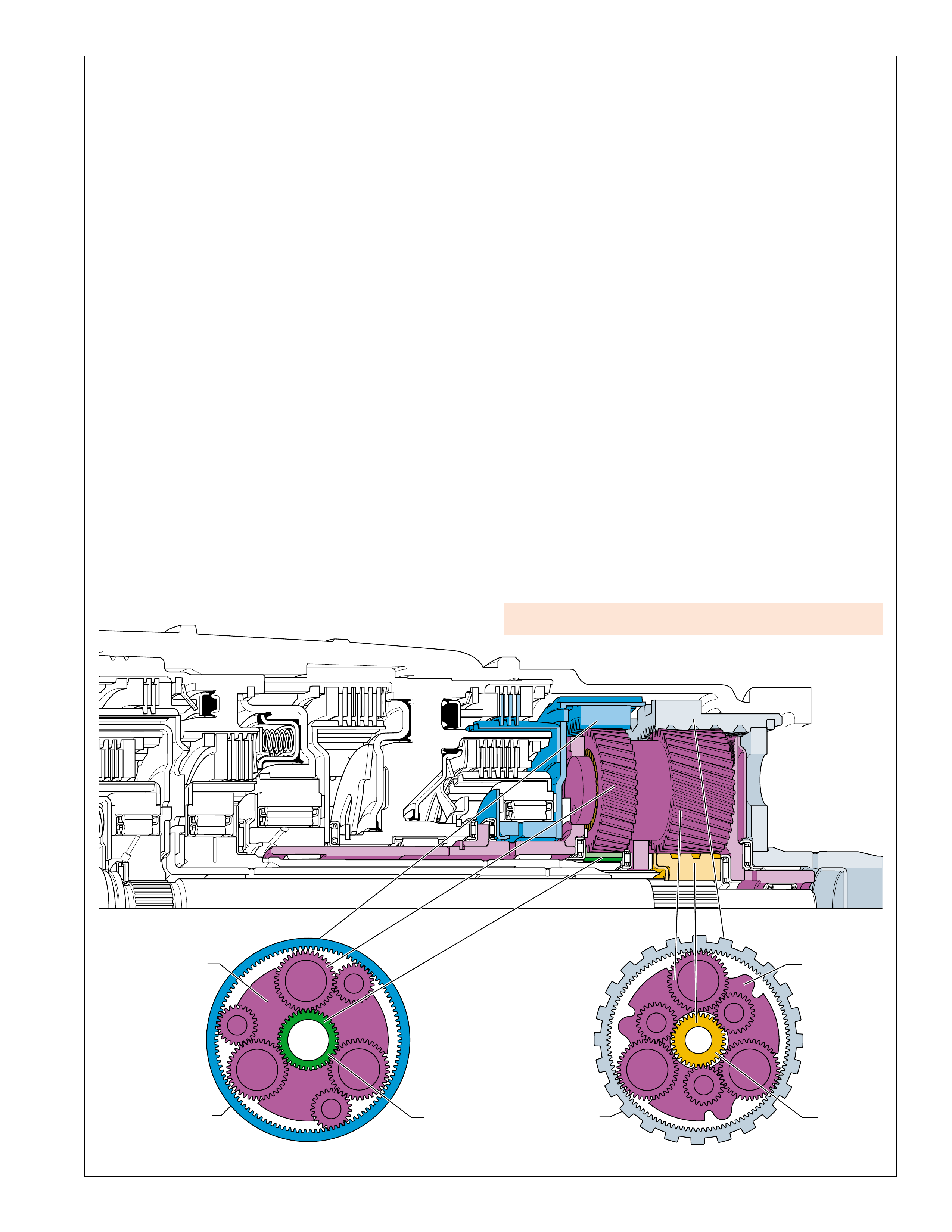
REAR
INPUR
SUN
GEAR
INPUT AND
REACTION
CARRIER
(553)
REAR
INTERNAL
GEAR
(560)
INPUT AND
REACTION
CARRIER
(553)
FRONT
INPUT
SUN
GEAR
REACTION
INTERNAL
GEAR
(550)
PLANETARY GEAR SETS
PLANETARY GEAR SETS
Planetary gear sets are commonly used in automatic transmissions
as the primary method of multiplying the torque, or twisting force,
of the engine (reduction). Planetary gear sets are also used to reverse
the direction of rotation, function as a coupling for direct drive, and
provide an overdrive gear ratio.
Planetary gear sets are so named because of their physical arrangement.
All planetary gear sets contain at least three main components:
•a sun gear at the center of the gear set,
•a carrier assembly with planet pinion gears that rotate around
the sun gear and,
•an internal (ring) gear that encompasses the entire gear set.
The gears are designed such that several gear teeth are always in
contact, or mesh, at the same time. This design distributes the
energy forces over several gear teeth for greater strength and
eliminates potential clash that is a common occurrence in manual
transmissions when gear teeth go in and out of mesh. Another
benefit of planetary gear sets is that shafts are generally used for
input and output components and can be arranged on the same axis,
thus providing a very compact unit.
The Hydra-matic 4/5L40-E transmission uses one planetary gear
set, the Ravigneaux gear set. Figures 30, 31 and 32 show this gear
set and it's respective components. These figures also graphically
explain how the planetary gear set is used to achieve each of the
transmission's five forward gear ratios and Reverse.
Ravigneaux Planetary Gear Set
The Ravigneaux planetary gear set is unique in that it resembles a
combination of two gear sets. This gear set consists of three sets of
pinion gears (one long and two short) in one planetary carrier (553),
two sun gears – front input and rear input, and two internal gears –
reaction (550) and rear (560). The front input sun gear is in constant
mesh with the long pinion gears. The rear input sun gear is in
constant mesh with the rear short pinion gears. The long pinion
gears are in constant mesh with both the front and the rear short
pinion gears, and the rear internal gear (560). The front short pinion
gears are in constant mesh with the reaction internal gear (550) in
addition to the long pinion gears. Also, the output shaft (562) is
splined to the rear internal gear (560) which acts as a part of the
Ravigneaux planetary gear set.
Torque
When engine torque is transferred through a gear set the output
torque from the gear set can either increase, decrease, or remain the
same. The output torque achieved depends on:
•which member of the gear set provides the input torque,
•which member of the gear set (if any) is held stationary, and,
•which member of the gear set provides the output torque.
If output torque is greater than input torque the gear set is operating
in reduction (First, Second, Third and Reverse gears). If output
torque is less than input torque, then the gear set is operating in
overdrive (Fifth gear). When output torque equals input torque the
gear set is operating in direct drive (Fourth gear) and all gear set
components are rotating at the same speed.
Torque vs. Speed
One transmission operating condition directly affected by input and
output torque through a gear set is the relationship of torque with
output speed. As the transmission shifts from First to Second to
Third to Fourth to Fifth gear, the overall output torque to the wheels
decreases as the speed of the vehicle increases (when input speed
and input torque are held constant). Higher output torque is needed
at low vehicle speed (First, Second and Third gears) to provide the
power to move the vehicle from a standstill. However, once the
vehicle is moving and the speed of the vehicle increases (Fourth
and Fifth gears), less output torque is required to maintain that
speed. This provides for a more efficient operation of the powertrain.
Figure 30
Gear set failure can cause noise and loss of drive.
29
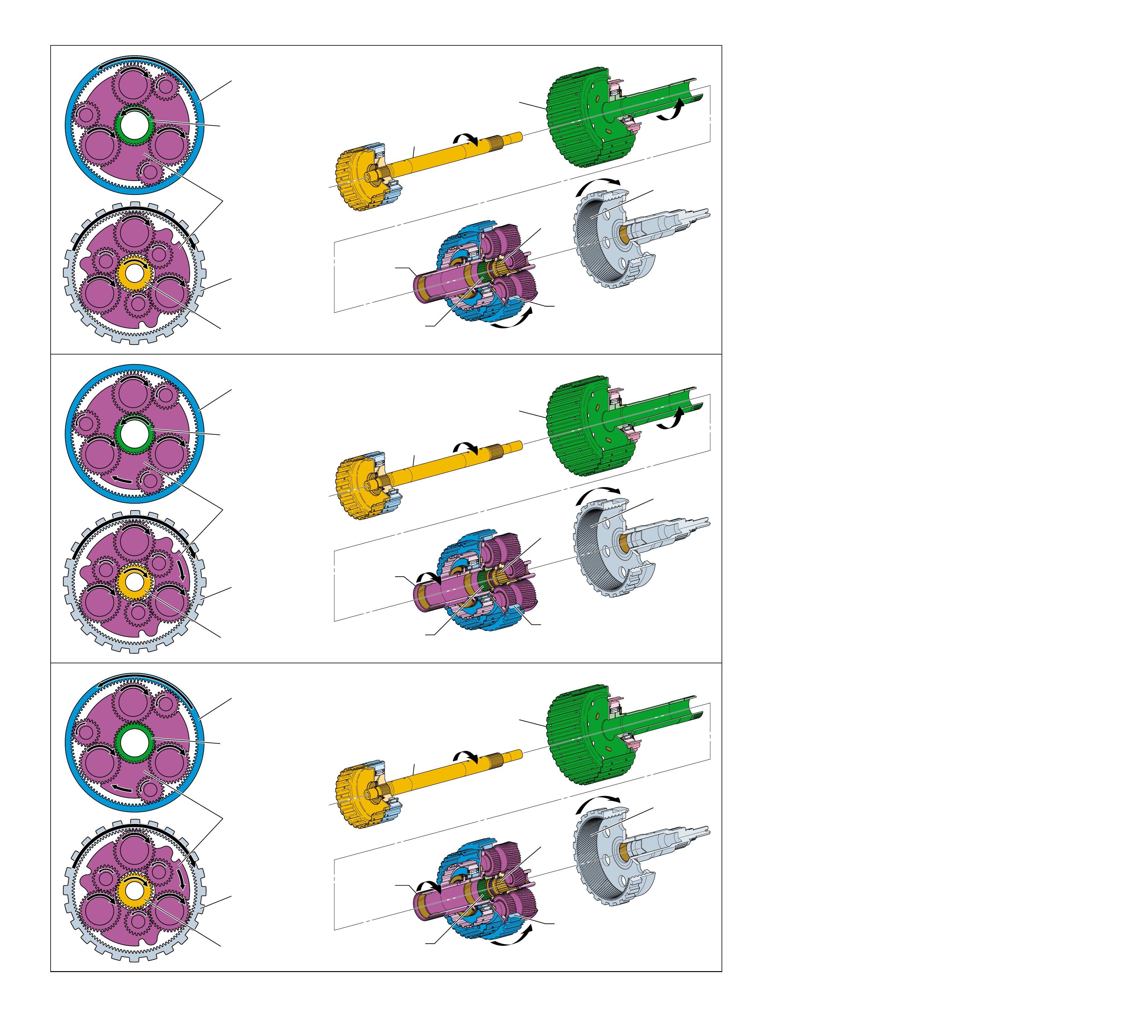
REDUCTION
FIRST GEAR
REDUCTION
SECOND GEAR
REDUCTION
THIRD GEAR
INPUT AND
REACTION
CARRIER
(553)
DRIVEN
REACTION
INTERNAL
GEAR
(550)
HELD
FRONT INPUT
SUN GEAR
DRIVEN
REAR INPUT
SUN GEAR
DRIVING
REAR
INTERNAL
GEAR
(560)
DRIVEN
INPUT
SUN GEAR
SHAFT
ASSEMBLY
(457)
DRIVING
OVERDRIVE AND
REVERSE CLUTCH
HUB ASSEMBLY
(470)
DRIVEN
FRONT INPUT
SUN GEAR
DRIVEN
REAR INPUT
SUN GEAR
DRIVING
INPUT AND
REACTION
CARRIER
(553)
DRIVEN
REAR
INTERNAL GEAR
(560)
DRIVEN
REACTION
INTERNAL GEAR
(550)
HELD
INPUT
SUN GEAR
SHAFT
ASSEMBLY
(457)
DRIVING
OVERDRIVE AND
REVERSE CLUTCH
HUB ASSEMBLY
(470)
DRIVEN
FRONT INPUT
SUN GEAR
DRIVEN
REAR INPUT
SUN GEAR
DRIVING
INPUT AND
REACTION
CARRIER
(553)
HELD
REAR
INTERNAL GEAR
(560)
DRIVEN
REACTION
INTERNAL GEAR
(550)
DRIVEN
INPUT AND
REACTION
CARRIER
(553)
HELD
REACTION
INTERNAL
GEAR
(550)
DRIVEN
FRONT INPUT
SUN GEAR
DRIVEN
REAR INPUT
SUN GEAR
DRIVING
REAR
INTERNAL
GEAR
(560)
DRIVEN
INPUT AND
REACTION
CARRIER
(553)
DRIVEN
INPUT
SUN GEAR
SHAFT
ASSEMBLY
(457)
DRIVING
OVERDRIVE AND
REVERSE CLUTCH
HUB ASSEMBLY
(470)
HELD
FRONT INPUT
SUN GEAR
HELD
REAR INPUT
SUN GEAR
DRIVING
INPUT AND
REACTION
CARRIER
(553)
DRIVEN
REAR
INTERNAL GEAR
(560)
DRIVEN
REACTION
INTERNAL GEAR
(550)
DRIVEN
REACTION
INTERNAL
GEAR
(550)
DRIVEN
FRONT INPUT
SUN GEAR
HELD
REAR INPUT
SUN GEAR
DRIVING
REAR
INTERNAL
GEAR
(560)
DRIVEN
PLANETARY GEAR SETS
Figure 31
30 30A
PLANETARY GEAR SETS
REDUCTION
Increasing the output torque is known as operating in reduction
because there is a decrease in the speed of the output member
proportional to the increase in output torque. Therefore, with a
constant input speed, the output torque increases when the
transmission is in a lower gear, or higher gear ratio. Reduction
occurs in First, Second, Third and Reverse gears through the
Ravigneaux gear set.
FIRST GEAR
In First gear, torque input to the Ravigneaux gear set is provided
by the rear input sun gear in the direction of engine rotation.
The rear input sun gear drives the rear short pinion gears in the
direction opposite of engine rotation. The rear short pinion
gears then drive the long pinion gears in the direction of engine
rotation. The long pinion gears drive the front short pinion
gears which in turn drive the reaction internal gear (550) in the
direction opposite of engine rotation. The front short pinion
gears also attempt to drive the input and reaction carrier (553) in
the direction opposite of engine rotation but, the low clutch
sprag prevents this from occurring and the carrier is held
stationary. This action forces the long pinion gears to drive the
rear internal gear (560) and output shaft assembly in an reduction
gear ratio of approximately 3.42:1.
SECOND GEAR
In Second gear, the torque input to the Ravigneaux gear set is
provided by the rear input sun gear in the direction of engine
rotation. The rear input sun gear drives the rear short pinion
gears in the direction opposite of engine rotation. The rear short
pinion gears then drive the long pinion gears in the direction of
engine rotation. The long pinion gears drive the front short
pinion gears, and the front short pinion gears then attempt to
drive the reaction internal gear (550) in the direction opposite of
engine rotation but, because the second clutch is applied, the
second clutch sprag prevents this from occurring and the rear
internal gear is held stationary. The front short pinion gears are
forced to walk around the stationary reaction internal gear and
drive the input and reaction carrier (553) in the direction of
engine rotation. This action forces the long pinion gears to
drive the rear internal gear (560) and output shaft assembly in a
reduction gear ratio of approximately 2.21:1.
THIRD GEAR
In Third gear, the torque input to the Ravigneaux gear set is
provided by the rear input sun gear in the direction of engine
rotation. The rear input sun gear drives the rear short pinion
gears in the direction opposite of engine rotation. The rear
short pinion gears then drive the long pinion gears in the direction
of engine rotation. The long pinion gears drive the front short
pinion gears, and the front short pinion gears then attempt to
drive the front input sun gear in the direction opposite of engine
rotation. However, the intermediate clutch is applied, holding
the front input sun gear stationary and forcing the long pinion
gears to walk around the stationary front input sun gear, driving
the input and reaction carrier (553) in the direction of engine
rotation. This action forces the long pinion gears to drive the
rear internal gear (560) and output shaft assembly in a reduction
gear ratio of approximately 1.60:1.
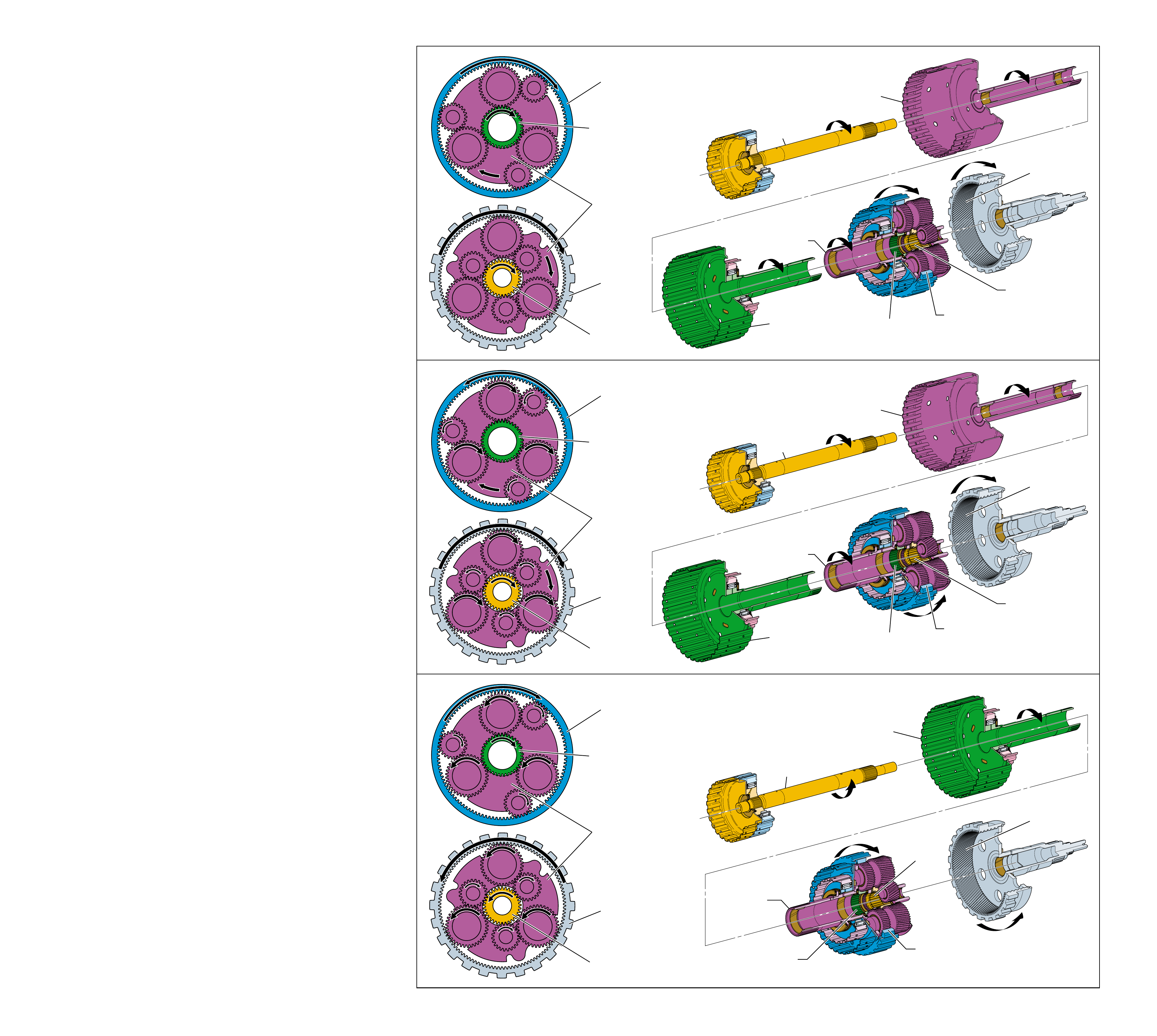
DIRECT DRIVE
FOURTH GEAR
OVERDRIVE
FIFTH GEAR
REVERSE
DIRECT CLUTCH
INPUT AND HUB
ASSEMBLY
(466)
DRIVING
INPUT AND
REACTION
CARRIER
(553)
DRIVING
REACTION
INTERNAL
GEAR
(550)
DRIVEN
FRONT INPUT
SUN GEAR
HELD
REAR INPUT
SUN GEAR
DRIVEN
REAR
INTERNAL
GEAR
(560)
DRIVEN
INPUT AND
REACTION
CARRIER
(553)
DRIVING
REACTION
INTERNAL
GEAR
(550)
DRIVEN
FRONT INPUT
SUN GEAR
DRIVEN
REAR INPUT
SUN GEAR
DRIVING
REAR
INTERNAL
GEAR
(560)
DRIVEN
INPUT SUN GEAR
SHAFT ASSEMBLY
(457)
DRIVING
OVERDRIVE AND
REVERSE CLUTCH
HUB ASSEMBLY
(470)
DRIVEN
FRONT INPUT
SUN GEAR
DRIVEN
REAR INPUT
SUN GEAR
DRIVING
INPUT AND REACTION
CARRIER
(553)
DRIVING
REAR
INTERNAL GEAR
(560)
DRIVEN
REACTION
INTERNAL GEAR
(550)
DRIVEN
DIRECT CLUTCH
INPUT AND HUB
ASSEMBLY
(466)
DRIVING
INPUT SUN GEAR
SHAFT ASSEMBLY
(457)
DRIVEN
OVERDRIVE AND
REVERSE CLUTCH
HUB ASSEMBLY
(470)
HELD
FRONT INPUT
SUN GEAR
HELD
REAR INPUT
SUN GEAR
DRIVEN
INPUT AND REACTION
CARRIER
(553)
DRIVING
REAR
INTERNAL GEAR
(560)
DRIVEN
REACTION
INTERNAL GEAR
(550)
DRIVEN
INPUT AND
REACTION
CARRIER
(553)
HELD
REACTION
INTERNAL
GEAR
(550)
DRIVEN
FRONT INPUT
SUN GEAR
DRIVING
REAR INPUT
SUN GEAR
DRIVEN
REAR
INTERNAL
GEAR
(560)
DRIVEN
INPUT
SUN GEAR
SHAFT
ASSEMBLY
(457)
DRIVEN
OVERDRIVE AND
REVERSE CLUTCH
HUB ASSEMBLY
(470)
DRIVING
FRONT INPUT
SUN GEAR
DRIVING
REAR INPUT
SUN GEAR
DRIVEN
INPUT AND
REACTION
CARRIER
(553)
HELD
REAR
INTERNAL GEAR
(560)
DRIVEN
REACTION
INTERNAL GEAR
(550)
DRIVEN
Figure 32
PLANETARY GEAR SETS
3130B
PLANETARY GEAR SETS
DIRECT DRIVE
Direct drive through a planetary gear set is obtained when any
two members of the gear set rotate in the same direction at the
same speed. This forces the third member of the gear set to
rotate at the same speed. Therefore, in direct drive the output
speed of the transmission is the same as the input speed from the
converter turbine. Output speed will equal engine speed when
the torque converter clutch is applied (see Torque Converter –
pages 12-14).
FOURTH GEAR
Direct drive occurs in Fourth gear when input torque to the
Ravigneaux gear set is provided by both the rear input sun gear
and the direct clutch input and hub assembly (466). The direct
clutch input and hub assembly (466) is splined directly to the
input and reaction carrier (553) and drives the carrier in the
direction of engine rotation at input speed. The rear input sun
gear attempts to drive the long pinion gears in the direction of
engine rotation at input speed through the rear short pinion
gears but, because the carrier is rotating at the same speed, the
long pinion gears are prevented from rotating on their pins and
they force the rear internal gear (560) to rotate at the same
speed. Therefore, the Ravigneaux carrier (553) and the output
shaft assembly (562) are driven at the same speed for a direct
drive 1:1 gear ratio.
OVERDRIVE
Operating the transmission in Overdrive allows the output speed
of the transmission to be greater than the input speed from the
engine. This mode of operation allows the vehicle to maintain a
given road speed with reduced engine speed for increased fuel
economy.
FIFTH GEAR
Overdrive is achieved through the Ravigneaux gear set and only
occurs in Overdrive Range – Fifth Gear. The overdrive clutch
holds the overdrive and reverse clutch hub (470) and the front
input sun gear stationary to the transmission case. Therefore,
when input torque drives the input and reaction carrier (553) in
the direction of engine rotation, the long pinion gears walk in
the direction of engine rotation around the stationary front input
sun gear. These pinion gears then drive the rear internal gear
(560) in the direction of engine rotation in an overdrive gear
ratio of approximately 0.75:1.
REVERSE
The Ravigneaux planetary gear set reverses the direction of power
flow rotation when the reverse clutch and the low and reverse
clutch are applied. Input torque to the Ravigneaux gear set is
provided through the reverse clutch to the front input sun gear in
the direction of engine rotation, while the input and reaction
carrier (553) is held stationary by the low and reverse clutch.
The front input sun gear drives the long pinion gears in the
direction opposite of engine rotation. With the input and reaction
carrier (553) held, the long pinion gears drive the rear internal
gear (560) and output shaft (562) assembly in the direction
opposite of engine rotation (reverse), in a reduction gear ratio of
approximately 3.03:1.
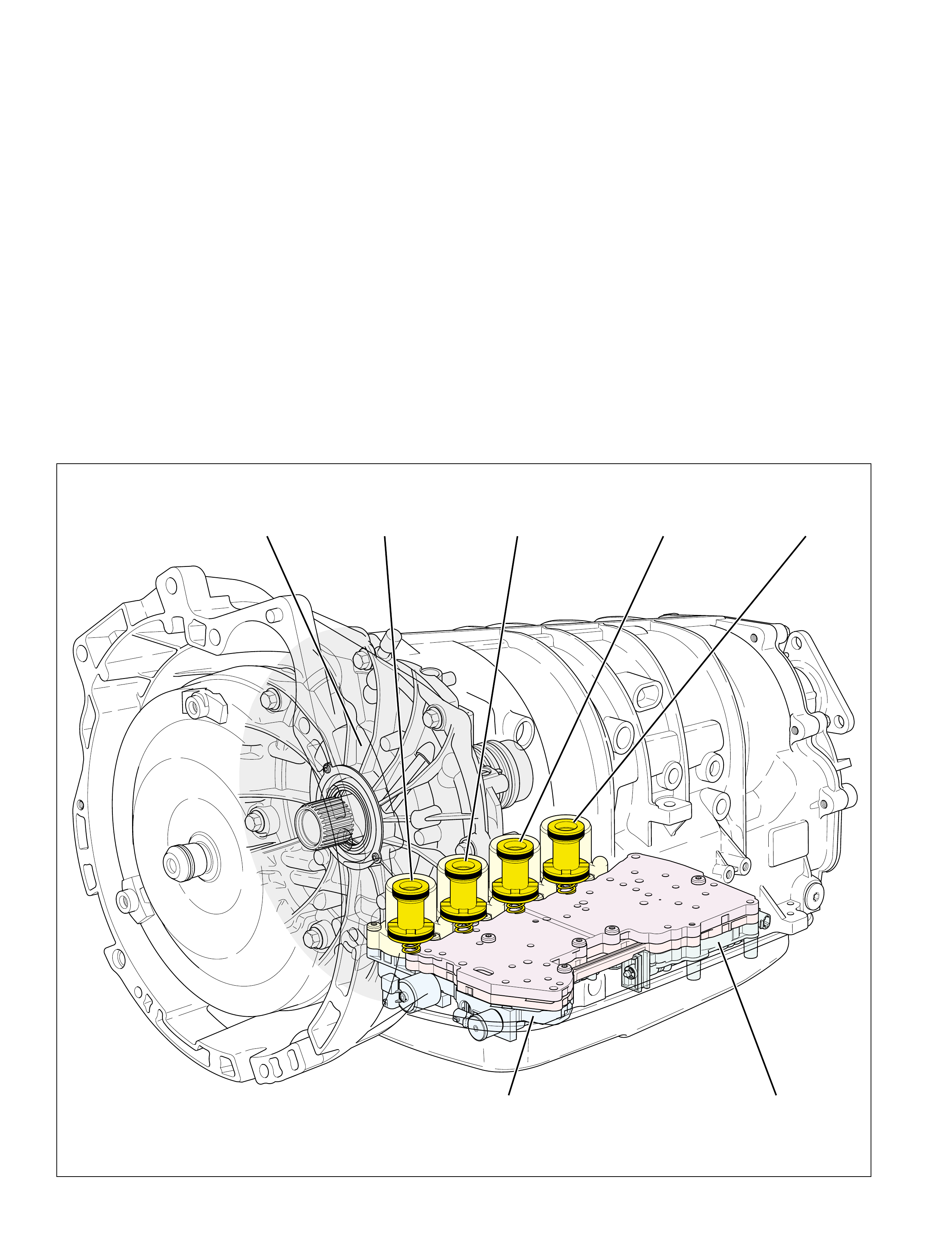
HYDRAULIC CONTROL COMPONENTS
32
FRONT
CONTROL
VALVE BODY
(311)
REAR
CONTROL
VALVE BODY
(310)
FLUID PUMP
ASSEMBLY
(200-241)
SECOND
CLUTCH
ACCUMULATOR
DIRECT
CLUTCH
ACCUMULATOR
OVERDRIVE
CLUTCH
ACCUMULATOR
INTERMEDIATE
CLUTCH
ACCUMULATOR
The previous sections of this book were used to
describe some of the mechanical component
operations of the Hydra-matic 4/5L40-E. In the
Hydraulic Control Components section a detailed
Figure 33
description of individual components used in the
hydraulic system will be presented. These hydraulic
control components apply and release the clutch packs
to provide automatic shifting of the transmission.

HYDRAULIC CONTROL COMPONENTS
33
DECREASE
DECREASE
SUCTION
LINE
LINE
EX
LINE
AIR
BLEED
(233)
FLUID
PAN
(62)
FLUID FILTER
ASSEMBLY
(59)
PRESSURE
RELIEF
BALL
VALVE
FLUID
PUMP
ASSEMBLY
FLUID
PUMP
SCREEN
ASSEMBLY
(213)
ROTOR
GUIDE
(224)
VANE
(222)
ROTOR
(223)
VANE
RING
(225)
VANE
RING
(221)
TORQUE
CONVERTER
HOUSING
(227)
PUMP
COVER
ASSEMBLY
(202)
SLIDE
PIN
ASSEMBLY
(231)
SLIDE
SEAL
(218)
SLIDE
SPRING
(219)
SLIDE
SEAL
SUPPORT
(217)
SLIDE
RING
(220)
SLIDE
O-RING
SEAL
(242)
SLIDE
(216)
ROTOR
(223)
VANE
RING
(221)
SLIDE
(216)
31 30
FLUID PUMP ASSEMBLY
Figure 34
FLUID PUMP ASSEMBLY
The fluid pump assembly contains a variable displacement, vane
type pump, located in the torque converter housing (227). When
the engine is cranking, the torque converter pump hub, which is
keyed to the fluid pump rotor (223), turns the rotor at cranking
speed. As the fluid pump rotor and the fluid pump vanes (222)
begin to rotate, the volume of fluid between the vanes is at its
maximum, creating a vacuum at the pump intake port. The
vacuum allows atmospheric pressure, acting on the fluid in the
bottom pan, to prime the pump quickly and pressurize the
hydraulic system when the engine is running.
Fluid from the transmission bottom pan (62) is drawn through
the fluid filter assembly (59) and into the fluid pump intake
(suction) fluid circuit. This fluid is then forced to rotate around
the fluid pump slide (216) to the pump outlet port where the
clearance between the fluid pump slide and the fluid pump rotor
decreases. Decreasing the volume pressurizes the fluid and
forces the fluid into the line pressure fluid circuit. This fluid is
directed to the pressure regulator valve and becomes the main
supply of fluid to the various components and hydraulic circuits
in the transmission.
The events described above occur when the pump is operating
at maximum output. Since most normal driving conditions do
not require maximum output, the pressure regulator valve will
move far enough against spring force to allow excess line pressure
fluid to enter the decrease fluid circuit. Decrease pressure is
applied to the backside of the fluid pump slide, and moves the
slide against pump slide spring (219) pressure to lower the
output of the pump. The result is a control of the pump's
delivery rate of fluid to the hydraulic system.
Pump Related Diagnostic Tips
•Transmission Overheating
•Loss of drive
•High or low line pressure
•Slipping clutch or harsh apply
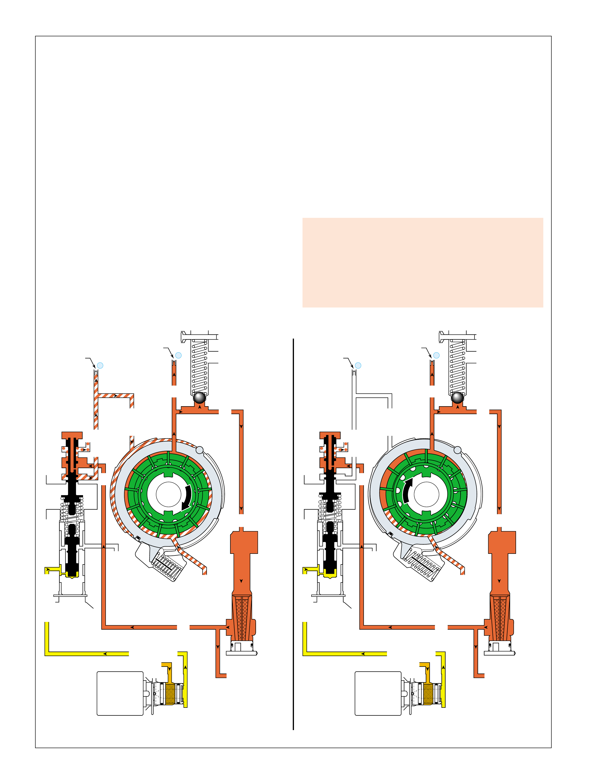
HYDRAULIC CONTROL COMPONENTS
34
MAXIMUM PUMP OUTPUTMINIMUM PUMP OUTPUT
DECREASE
DECREASE
LINE
LINE (To Manual Valve)
LINE
CONVERTER FEED
REVERSE CLUTCH
THROTTLE SIGNAL
LINE
EX
LINE
LINE
PRESS REG VALVEBOOST VALVE
FLUID
PUMP
SCREEN
ASSEMBLY
(213)
FILTERED FEED LIMIT
THROTTLE SIGNAL
EX
PRESSURE
CONTROL
SOLENOID
VALVE
AIR
BLEED
(233)
AIR
BLEED
(233)
DECREASE
DECREASE
LINE
LINE (To Manual Valve)
LINE
CONVERTER FEED
REVERSE CLUTCH
THROTTLE SIGNAL
LINE
EX
LINE
LINE
PRESS REG VALVEBOOST VALVE
FLUID
PUMP
SCREEN
ASSEMBLY
(213)
FILTERED FEED LIMIT
THROTTLE SIGNAL
EX
PRESSURE
CONTROL
SOLENOID
VALVE
AIR
BLEED
(233)
AIR
BLEED
(233)
FLUID
PUMP
ASSEMBLY
SUCTION
EX
PRESSURE
RELIEF
BALL
VALVE
SUCTION
EX
PRESSURE
RELIEF
BALL
VALVE
➤➤
FLUID
PUMP
ASSEMBLY
➤➤
31
30
31
30
Figure 35
PRESSURE REGULATION
The main components that control line pressure are the pressure
control solenoid valve and the pressure regulator valve. The
fluid pressure required to apply the clutches varies in relation to
throttle position and engine torque. At the pressure regulator
valve, line pressure is regulated in response to the following:
-
throttle signal fluid pressure routed from the pressure control
(PC) solenoid valve (this fluid pressure is proportional to
engine torque – see page 51). Throttle signal fluid pressure
moves the line boost valve (207) against the line boost valve
spring (208) which acts against the pressure regulator valve.
- pressure regulator valve spring force.
- line pressure acting on the end of the pressure regulator
valve.
- reverse clutch fluid pressure acting on the line boost valve
in Reverse.
The pressure regulator valve routes line pressure into both the
converter feed and the decrease fluid circuits. Converter feed
fluid is routed through the TCC control valve to the torque
converter apply and release, and the cooler fluid circuits.
Decrease fluid pressure moves the fluid pump slide against the
force of the pump slide spring (219).
Pressure Regulator Related
Diagnostic Tips
A stuck or damaged pressure regulator valve could cause:
•High or low line pressure
•Slipping clutches or harsh apply
•Transmission overheating
•Low or no cooler/lube flow
Pressure Regulation
The PC solenoid valve regulates throttle signal fluid pressure as
a function of engine torque (minimum signal pressure at low
torque, maximum signal pressure at high torque). Line pressure,
acting on the end of the pressure regulator valve, moves the
valve against spring force and throttle signal fluid pressure to a
point where line pressure enters both the converter feed and the
decrease fluid circuits. Decrease fluid pressure moves the pump
slide (216) against spring force and toward the center of the
pump cavity, causing the slide to partially cover the pump intake
port and increase the concentricity between the pump slide and
the rotor which, as a consequence, decreases the pump output
capacity. Decrease pressure and the position of the pump slide
constantly varies depending on driving conditions and the amount
of fluid pressure and volume needed to operate the transmission.
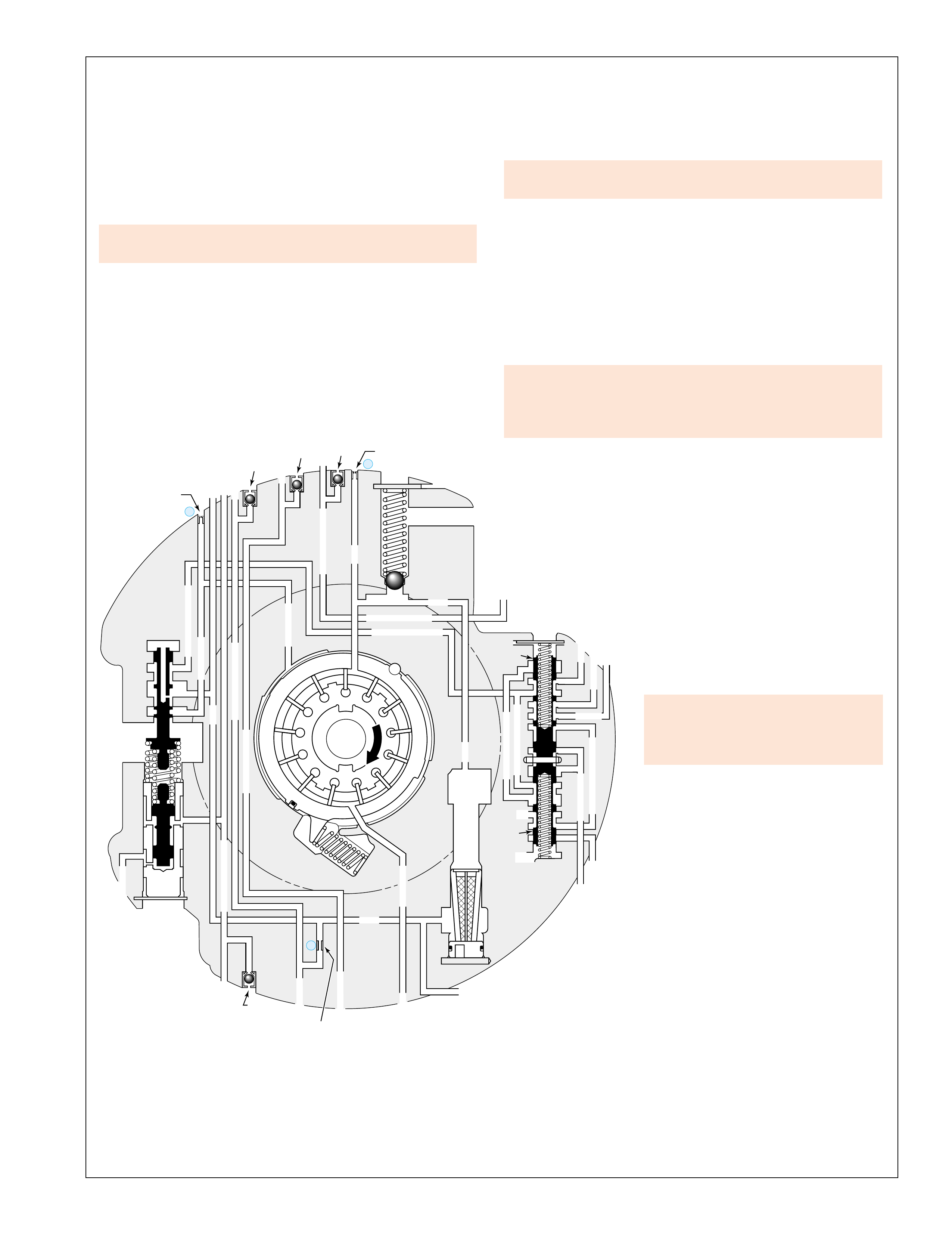
HYDRAULIC CONTROL COMPONENTS
35
FLUID
PUMP
ASSEMBLY
FLUID
PUMP
COVER
(202)
CONVERTER
HOUSING
(224)
APPLY
DECREASE
DECREASE
SUCTIONSUCTION
LINE
LINE
TCC SIGNAL
CONVERTER FEED
CONVERTER FEED
RELEASE
TO COOLER
REGULATED APPLYREGULATED APPLY
LINE
EX
CONVERTER FEED
REVERSE CLUTCH REVERSE CLUTCHREVERSE CL
THROTTLE SIGNAL
LINE LINE
EX
LINE
EX
EX
LINE
FORWARD CL
COAST CLUTCH
FORWARD CLUTCH FORWARD CLUTCH
COAST CLUTCH
COAST CLUTCH
DIRECT CLUTCH
DIRECT CLUTCH
DIRECT CLUTCH
PRESS REG VALVEBOOST VALVE
CONVERTER FDL
AIR
BLEED
(233)
AIR
BLEED
(203)
AIR
BLEED
(203)
AIR
BLEED
(203)
AIR
BLEED
(203) (214)
1
31
30
TCC
ENABLE
VALVE
TCC
CONTROL
VALVE
PRESSURE
RELIEF
BALL
VALVE
FLUID PUMP
SCREEN
ASSEMBLY
(213)
21 2
AIR
BLEED
(233)
Figure 36
VALVES LOCATED IN THE FLUID PUMP COVER ASSEMBLY
Check Valve Retainer and Ball Assemblies (203)
These four assemblies are located in the reverse clutch, forward
clutch, direct clutch and coast clutch fluid circuits. When the
clutch releases the ball unseats and allows air into the circuit to
displace the exhausting fluid.
Pressure Relief Ball Valve (239)
The pressure relief ball valve and spring (238) prevent line pressure
from exceeding approximately 2240 to 2520 kPa (320 to 360 psi).
Above this pressure, line fluid pressure moves the ball against
spring force and exhausts until line pressure decreases sufficiently.
•A pressure relief ball not seated or damaged could cause
high or low fluid pressure.
Torque Converter Clutch (TCC) Control Valve (235)
Controlled by the TCC PWM solenoid valve state and TCC
signal fluid pressure, it directs converter feed fluid pressure to
the release side of the converter clutch and into the cooler fluid
circuit. The TCC control valve also directs regulated apply
fluid to the apply side of the converter clutch. The valve is held
in the release position (as shown) by spring force when the TCC
PWM solenoid valve is OFF. With the TCC PWM solenoid
valve ON, TCC signal fluid pressure increases and moves the
valve into the apply position against spring force.
If stuck, missing or binding, the TCC control valve or
spring may cause:
•Incorrect TCC apply or release
•Inadequate lubrication
Torque Converter Clutch (TCC)
Enable Valve (237):
When the TCC is released, converter feed
fluid passes through the valve and enters
the converter feed limit fluid circuit to
go on stand by at the TCC control valve.
If for any reason the TCC control valve
is stuck ON when the TCC is commanded
OFF, converter feed limit pressure will
enter the release side of the converter
preventing overheating of the TCC.
When the TCC applies, TCC signal fluid
moves the valve against spring force and
allows regulated apply pressure to be
directed to the TCC control valve and
then to the apply side of the TCC.
•If stuck, missing or binding, the
TCC enable valve or spring may
cause incorrect TCC apply or
release.
PRESSURE REGULATOR VALVE TRAIN (204-210)
Pressure Regulator Valve (210)
Regulates line pressure in relation to vehicle operating conditions
(see page 34 on Pressure Regulation). The pressure regulator
valve is biased by throttle signal fluid pressure, pressure regulator
spring (209) force, line pressure routed to the end of the valve,
and reverse clutch fluid pressure acting on the line boost valve
in Reverse. Line pressure is routed through the valve and into
both the converter feed and decrease fluid circuits.
•A stuck pressure regulator valve could cause high or low
fluid pressure.
Line Boost Valve (207)
Throttle signal fluid pressure moves the line boost valve against
the line boost valve spring (208). The line boost valve spring
then transfers the force from throttle signal fluid pressure to the
pressure regulator valve. Therefore, line pressure increases as
throttle position and engine torque increase. Also, reverse clutch
fluid pressure acting on the line boost valve increases the operating
range of line pressure when the transmission is in Reverse.
Brass Orifice Insert (214)
The brass orifice insert is located in the fluid pump cover (202).
It is a restriction, between the line and forward clutch fluid
circuits, that provides a constant feed to the forward clutch in
order to reduce garage shift response time.
Orifice Cup Plugs (233)
Orifice cup plugs are located in the fluid pump cover (202).
They allow air to escape from the fluid circuits and prevent
pressure oscillations.

HYDRAULIC CONTROL COMPONENTS
36
VALVES LOCATED IN THE FRONT CONTROL VALVE BODY
Pressure Control (PC) Solenoid Valve Assembly (357):
Controlled by the TCM, it provides controlled throttle signal fluid
pressure to the line boost valve (207). (See the Electrical
Components Section for additional information.)
•A leaking/damaged o-ring or bad electrical connection can
cause high or low line pressure.
Feed Limit Valve (353):
The PC solenoid valve and the shift solenoid valves can not support
more than a given fluid pressure. In order not to overload these
solenoids, the feed limit valve regulates line fluid pressure into
feed limit fluid pressure given by the solenoid design. Force from
the feed limit valve spring (354) and orificed feed limit fluid
pressure acting on the end of the valve regulate line pressure as it
passes through the valve and enters the feed limit circuit. Feed
limit pressures will normally equal line pressure when line pressure
is below the calibrated limiting values.
•If stuck in the exhaust position, the feed limit valve or
spring could cause 5th gear only and low line pressure.
TCC REGULATOR VALVE TRAIN (347-352)
Torque Converter Clutch Pulse Width Modulated (TCC PWM)
Solenoid Valve Assembly (352):
Voltage supply is through the ignition switch while the TCM
provides the ground to energize the solenoid. The solenoid regulates
2345 or reverse fluid into TCC signal fluid pressure (according to
TCC PWM duty cycle) that is routed to the TCC control valve
(235), the TCC enable valve (237), the reverse lockout (RLO)
valve (385), and to the TCC regulator apply valve (348). (See the
Electrical Components Section for additional information.)
•Stuck on, exhaust plugged, would cause no TCC release in
2nd, 3rd, 4th or fifth gear, and no reverse.
•Stuck off, leaking o-ring, no voltage, would cause no TCC/
slip or soft apply.
Torque Converter Clutch (TCC) Regulator Apply Valve (348):
It is controlled by TCC signal fluid pressure on one side of the
valve and spring force from the TCC regulator apply valve spring
(347) and orificed regulated apply pressure at the other end. When
the TCC PWM solenoid valve assembly is energized and TCC
signal fluid pressure is present, it regulates line fluid pressure into
the regulated apply fluid passage.
•Stuck in the release position would cause no TCC/slip or
soft apply.
•Stuck in the maximum pressure position would cause harsh
TCC apply.
3-4 SHIFT VALVE TRAIN (343-346)
3-4 Shift Valve (345):
Responds to 2-3 signal fluid pressure acting on the 3-4 shift control
valve, 1-2 signal fluid pressure and force from the 3-4 shift valve
spring (344). Depending on the transmission gear range operation
and the shift solenoid valve states, the valve directs D432 fluid
into the 123 fluid circuit to apply the coast clutch, or it directs 345
fluid into the direct clutch and the 45 fluid circuits to apply the
direct and overdrive clutches. When in the released position, the
valve opens 123 fluid to an exhaust.
•3-4 shift valve stuck in the applied position could cause no 4th
or slips in 4th gear, and no 5th or slips in 5th gear.
•3-4 shift valve stuck in the released position could cause no
engine braking in 1st, 2nd and 3rd gear.
3-4 Shift Control Valve (346):
Responds to 2-3 signal fluid pressure and force from the 3-4 shift
valve spring (344). Depending on the transmission gear range
operation and the 2-3 shift solenoid valve state, the valve allows
D432 fluid to be directed into the 123 fluid circuit to apply the
coast clutch. When in the released position, the valve allows 123
clutch fluid to exhaust.
•3-4 shift control valve stuck in the applied position could
cause no 4th or slips in 4th gear, and no 5th or slips in 5th gear.
•3-4 shift control valve stuck in the released position could
cause no engine braking in 1st gear.
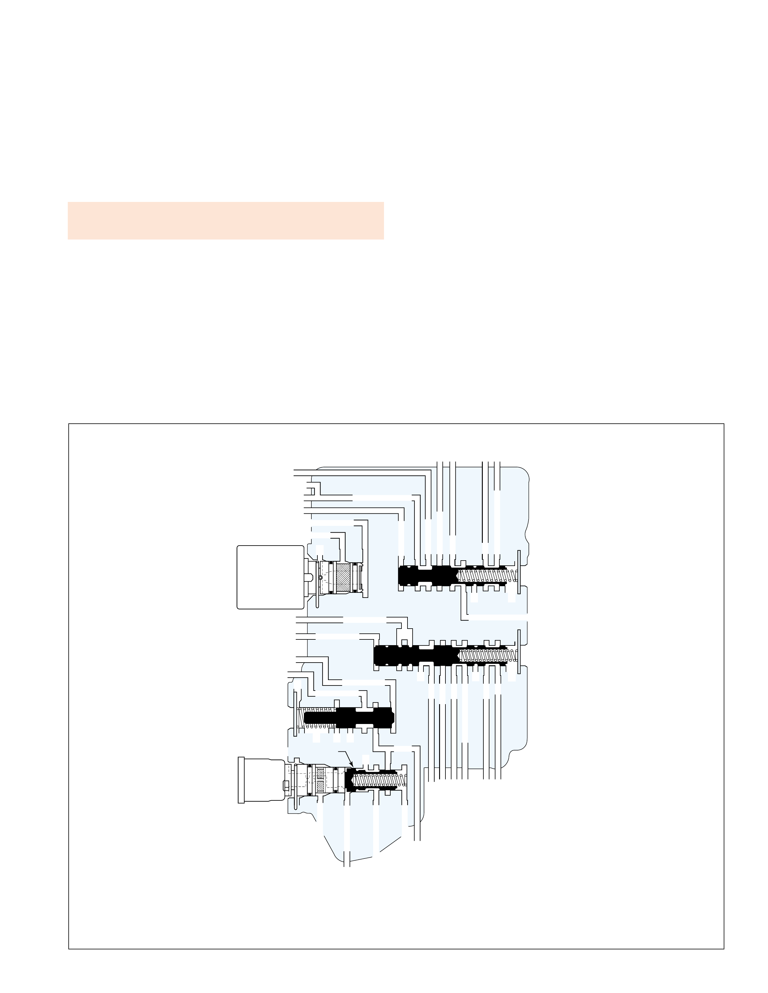
HYDRAULIC CONTROL COMPONENTS
37
LINE
FILTERED FEED LIMIT
THROTTLE SIGNAL
EX
2345 OR REVERSE
TCC SIGNAL
REGULATED APPLY
REGULATED APPLY
EX
EX
FEED LIMIT VALVE
LINE
EX
EX
EX
EX
FEED LIMIT
FEED LIMIT
SAFETY MODE
LINE
FEED LIMIT
32
MEMORY
MEMORY
MEMORY
MEMORY PILOT
MEMORY PILOT
32 SAFETY MODE
LINE SAFETY MODE
EX
EX
CNTRL 3-4 SHIFT
2-3 SIGNAL
123123 D432D432
DIRECT CLUTCH
4545
1-2 SIGNAL
EX
EX
EX
345
345
345
345
PRESSURE
CONTROL
SOLENOID
VALVE
TCC PWM
SOLENOID
VALVE
N/C
TCC REGULATOR VALVE
FRONT
CONTROL
VALVE BODY
Figure 37
VALVES LOCATED IN THE FRONT CONTROL VALVE BODY
Safety Mode Valve (341):
Responds to memory pilot (1-2 signal) fluid pressure and force
from the safety mode valve spring (342). Under normal
transmission operation, when the first 1-2 shift occurs, the valve is
shifted to the applied position by memory pilot fluid. If there is no
TCM signal to the shift solenoid valves, the transmission will
operate in fifth gear. When the engine is switched off, the valve
shifts to the released position and directs (when the engine is
restarted) line pressure into the line safety mode fluid circuit
allowing the transmission to operate in fourth gear.
•If stuck in the applied position, the transmission could be
limited to fifth gear only in Safety Mode.

HYDRAULIC CONTROL COMPONENTS
38
Reverse Lockout (RLO) Valve (385):
Responds to TCC signal fluid pressure and force from the reverse
lockout valve spring (386). In reverse gear the valve directs
reverse fluid into the reverse lockout (RLO) fluid circuit to apply
the reverse clutch and the low and reverse clutch. When the TCC
PWM solenoid valve provides TCC signal fluid pressure, the RLO
valve is applied to block reverse fluid from entering the reverse
lockout fluid circuit, thereby preventing reverse clutch or low and
reverse clutch apply while the vehicle is moving forward at a
speed greater than a value calibratable in the TCM, even if the
manual valve is in reverse position.
•Reverse lockout valve stuck in the applied position could
cause no reverse gear.
•Reverse lockout valve stuck in the released position could
allow the reverse clutch and the low and reverse clutch to
apply, if reverse gear is selected while the vehicle is moving
forward at any speed, causing transmission damage.
Low Pressure Control Valve (383):
In first, second and third gear coast conditions, when engine braking
is desired, 123 braking fluid pressure is regulated through the
valve into the 123 regulated fluid circuit by orificed 123 regulated
fluid pressure and force from the low pressure control valve spring
(382). Depending on the transmission gear and the shift solenoid
valve operating states, 123 regulated fluid is directed to provide
engine braking through a controlled apply of the low and reverse
clutch, the second coast clutch or the overdrive clutch.
•A missing, stuck or incorrectly assembled low pressure
control valve could cause harsh or no engine braking in 1st,
2nd, or third gear.
1-2 SHIFT VALVE TRAIN (343, 349-351, 366-368, 387-388)
1-2 Shift Solenoid (SS) Valve Assembly (368):
The 1-2 SS valve assembly is a normally closed, 3-port, ON/OFF
type solenoid controlled by the TCM. When energized (ON) in
Second and Third Gear, the 1-2 SS valve assembly fluid inlet port
opens allowing feed limit fluid to pressurize the 1-2 signal fluid
circuit. 1-2 signal fluid pressure acts on the 1-2 shift control valve
and the 3-4 shift valve to control the shift valve positioning for the
appropriate gear range. 1-2 signal (memory pilot) fluid pressure
also acts on the safety mode valve to provide safe transmission
operation if there is no TCM signal to the shift solenoid valves.
When de-energized (OFF), the solenoid inlet port is closed and 1-
2 signal fluid is exhausted through the solenoid exhaust port. (See
the Electrical Components Section for more detail.)
•1-2 SS valve stuck off or leaking could cause a 1st, 4th and
5th gear only condition.
•1-2 SS valve stuck on could cause 2nd and 3rd gears only.
1-2 Shift Control Valve (366):
Responds to 1-2 signal fluid pressure, 2-3 signal fluid pressure, and
force from the 1-2 shift control valve spring (367). Depending on
the transmission gear range operation, 1-2 shift solenoid valve and
2-3 shift solenoid valve operating states, the valve directs feed limit
fluid into the FDL fluid circuit in order to apply the 1-2 shift valve.
When released, the valve opens FDL fluid to exhaust.
•1-2 shift control valve stuck in the applied position could
cause 1st gear only.
•1-2 shift control valve stuck in the released position could
cause no 1st gear.
1-2 Shift Valve (387):
Responds to FDL fluid pressure and force from the 1-2 shift valve
spring (388). Depending on the transmission gear range operation,
1-2 shift solenoid valve and 2-3 shift solenoid valve operating
states, the valve directs 123 regulated fluid into the low and reverse
clutch fluid circuit in order to provide engine braking. When
released, the valve directs D432 fluid into the 2345 fluid circuit
and the second clutch fluid circuit.
•1-2 shift valve stuck in the applied position could cause no
2nd, 3rd, 4th or 5th gear.
•1-2 shift valve stuck in the released position could cause no
1st gear.
2-3 SHIFT VALVE TRAIN (349-351, 369-372)
2-3 Shift Solenoid (SS) Valve Assembly (369):
The 2-3 SS valve assembly is a normally closed, 3-port, ON/OFF
type solenoid controlled by the TCM. When energized (ON) in
First and Second Gear, the 2-3 SS valve assembly fluid inlet port
opens allowing feed limit fluid to pressurize the 2-3 signal fluid
circuit. 2-3 signal fluid pressure acts on the 2-3 shift control
valve, the 1-2 shift control valve, and the 3-4 shift control valve to
control the shift valve positioning for the appropriate gear range.
When de-energized (OFF), the solenoid inlet port is closed and 2-
3 signal fluid is exhausted through the solenoid exhaust port. (See
the Electrical Components Section for more detail.)
•2-3 SS valve stuck off or leaking could cause no 1st or
2nd gear.
•2-3 SS valve stuck on could cause 1st and 2nd gears only.
2-3 Shift Control Valve (370) and 2-3 Shift Valve (371):
The 2-3 shift valve train responds to 2-3 signal fluid pressure and
force from the 2-3 shift valve spring (372). Depending on the
transmission gear range operation and the 2-3 shift solenoid valve
state, the valve train controls the routing and exhausting of various
fluids to obtain the appropriate gear range as determined by the
TCM or gear selector lever.
•2-3 shift valve stuck in the applied position could cause 1st
or 2nd gear only.
•2-3 shift valve stuck in the released position could cause no
3rd, 4th or 5th gears.
VALVES LOCATED IN THE REAR CONTROL VALVE BODY
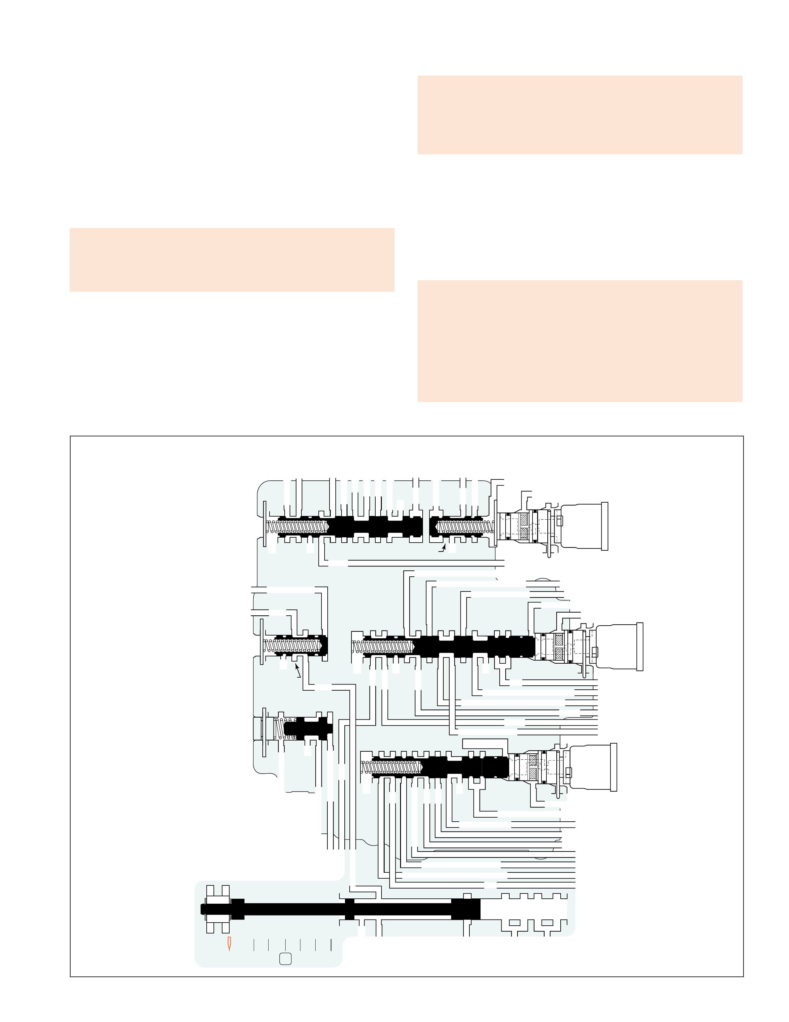
HYDRAULIC CONTROL COMPONENTS
39
VALVES LOCATED IN THE REAR CONTROL VALVE BODY
Figure 38
2345
2345
2-3 SHIFT VALVE CNTRL
EX
SECOND COAST CLUTCH
23 REGULATED
23 REGULATED
OVERDRIVE CLUTCH FEED 1
INTERMEDIATE CLUTCH
2345
INTERMEDIATE CLUTCH
2345
345
FEED LIMIT
EX
EX
EX
EX
2-3 SIGNAL
LOW PRESSURE
123 REGULATED
123 REGULATED EX
4-5 SHIFT VLV CNTRL
LINE SAFETY MODE
123 BRAKING
123
EX
EX
EX
123
123
123
COAST CLUTCH
COAST CLUTCH FEED
OVERDRIVE CLUTCH FEED 2
45
FEED LIMIT
1-2 SHIFT VALVE
FDL
D432
2345 2345
D432
SECOND CL
23 REG
123 REG
LOW AND REV CL
SECOND CL
123 REG
EX
EX
EX
FD LIMIT
FEED LIMIT
FDL
1-2 SIGNAL
2-3 SIGNAL
EX
EX
TCC SIGNAL
RLO
EX
REV
RPND432
MANUAL VALVE
LINE
D432
REV
REVERSE
EX
32
4-5 SIGNAL
123 BRAKING
345
45
1-2 SHIFT
SOLENOID
VALVE
N/C
(A)
2-3 SHIFT
SOLENOID
VALVE
N/C
(B)
4-5 SHIFT
SOLENOID
VALVE
N/C
(C)
REVERSE
LOCKOUT
VALVE
1-2 SHIFT CONTROL VALVE
REAR
CONTROL
VALVE BODY
4-5 SHIFT VALVE TRAIN (349-351, 373-376)
4-5 Shift Solenoid (SS) Valve Assembly (376):
The 4-5 SS valve assembly is a normally closed, 3-port, ON/OFF
type solenoid controlled by the TCM. When energized (ON) in
Fourth Gear, the 4-5 SS valve assembly fluid inlet port opens
allowing feed limit fluid to pressurize the 4-5 signal fluid circuit.
4-5 signal fluid pressure acts on the 4-5 shift control valve to help
control the 4-5 shift valve positioning for the appropriate gear
range. When de-energized (OFF), the solenoid inlet port is closed
and 4-5 signal fluid is exhausted through the solenoid exhaust
port. (See the Electrical Components Section for more detail.)
•4-5 SS valve stuck off or leaking could cause no 4th gear
and no engine braking in 1st, 2nd or 3rd gears.
•4-5 SS valve stuck on could cause no 5th gear.
4-5 Shift Control Valve (375) and 4-5 Shift Valve (374):
The 4-5 shift valve train responds to 4-5 signal fluid pressure and
force from the 4-5 shift valve spring (373). Depending on the
transmission gear range operation and the 4-5 shift solenoid valve
state, the valve train controls the routing and exhausting of various
fluids to obtain the appropriate gear range as determined by the
TCM or gear selector lever.
•4-5 shift valve stuck in the applied position could cause no
5th gear.
•4-5 shift valve stuck in the released position could cause no
4th gear and no engine braking in 1st, 2nd or 3rd gears.
Manual Valve (377):
The manual valve is fed by line pressure from the fluid pump assembly
and is mechanically linked to the gear selector lever. When a gear
range is selected, the manual valve directs line pressure into the
various circuits by opening and closing feed passages. The circuits
that are fed by the manual valve are: Reverse, D432, and 32.
Stuck, misaligned or damaged, the manual valve and linkage
could cause:
•No Park
•No reverse or slips in reverse
•Drives in Neutral
•No Drive
•No gear selections
•Shift indicator indicates wrong gear selection
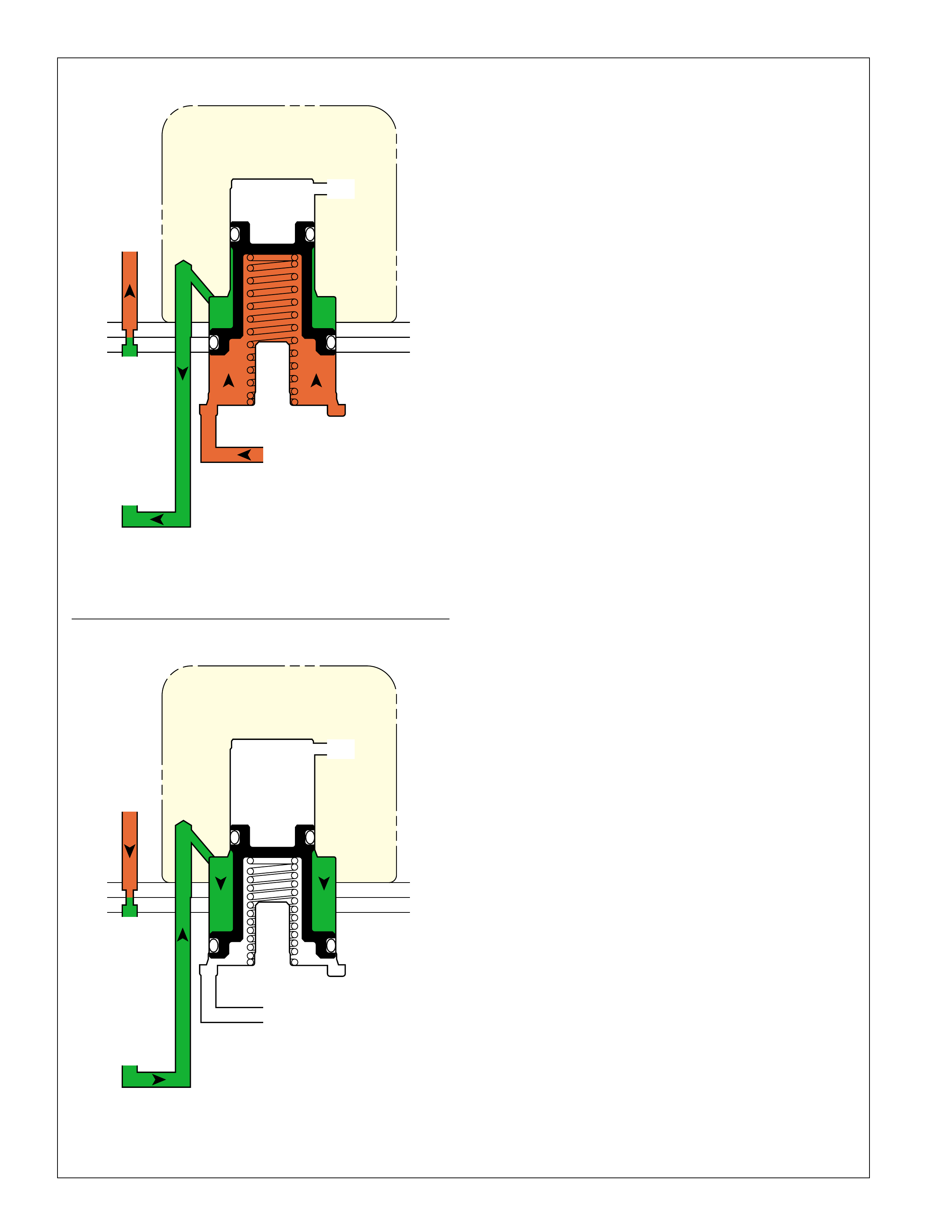
HYDRAULIC CONTROL COMPONENTS
40 Figure 39
DOWNSHIFT CONTROL
• CLUTCH RELEASED
• ACCUMULATOR
READY FOR UPSHIFT
ACCUMULATOR LINE
EX
CLUTCH APPLY
CLUTCH
ACCUMULATOR
UPSHIFT CONTROL
• CLUTCH APPLIED
• ACCUMULATOR ABSORBS
EXCESS APPLY PRESSURE
ACCUMULATOR LINE
EX
CLUTCH APPLY
CLUTCH
ACCUMULATOR
ACCUMULATORS
In the Hydra-matic 4/5L40-E, accumulators are used to control
shift feel for the apply of the second clutch (2nd), the intermediate
clutch (3rd), the direct clutch (4th), and the overdrive clutch (5th).
All four of these accumulators function identically.
An accumulator is a fluid pressure operated component that
absorbs a certain amount of clutch apply fluid pressure to cushion
the clutch engagement.
Clutch apply fluid pressure, directed to an accumulator piston
and helped by a spring force, opposes an accumulator fluid
pressure to create an action similar to a shock absorber.
Upshift Control:
During the clutch apply, clutch apply fluid pressure moves the
clutch piston against the clutch piston spring and clutch plates.
After the clearance between the clutch plates is taken up by the
clutch piston travel and the clutch plates begin to hold, fluid
pressure in the circuit builds up rapidly. This clutch apply fluid
pressure is also directed to an accumulator assembly. As clutch
apply fluid pressure increases, the accumulator piston moves to an
intermediate position determined by the equilibrium between
accumulator fluid pressure and clutch apply fluid pressure, assisted
by the accumulator spring force. The movement of the accumulator
piston delays the pressure buildup in the circuit and allows for a
more gradual clutch apply. Without an accumulator in the circuit,
this rapid buildup of clutch apply fluid pressure would cause the
clutch to grab very quickly and create a harsh shift.
The force of the accumulator fluid pressure controls the rate at
which the clutch is applied. Because accumulator fluid pressure
is supplied by line fluid pressure, it is affected by engine throttle
position. At minimum or light throttle, engine torque is at a
minimum and the clutch requires less apply force. At heavy
throttle, the engine develops a large amount of torque which
requires a greater apply pressure to hold the clutch. To
accommodate these various conditions, the pressure regulator
valve (210) regulates line fluid pressure, and therefore accumulator
fluid pressure, in order to control shift feel in the transmission. At
greater throttle positions, accumulator fluid pressure increases,
thereby creating less cushion for the clutch apply fluid during an
upshift. Remember that throttle signal fluid acting on the pressure
regulator valve (210) is regulated according to engine torque by
the pressure control (PC) solenoid valve (357).
Downshift Control:
During a downshift, the clutch apply fluid pressure is exhausted
from the accumulator assembly by the shift valve. Accumulator
fluid pressure, supplied by orificed line fluid pressure from the
fluid pump, fills the accumulator with fluid and returns the
piston to its initial position in preparation for another upshift.
Orificing line fluid pressure helps control the rate at which
accumulator fluid pressure fills the accumulator and the rate at
which clutch apply fluid exhausts. If clutch apply fluid exhausts
too quickly, pressure could build up in the clutch apply circuit.
This would cause the clutch to release too slowly and possibly
“drag” and damage the clutch.
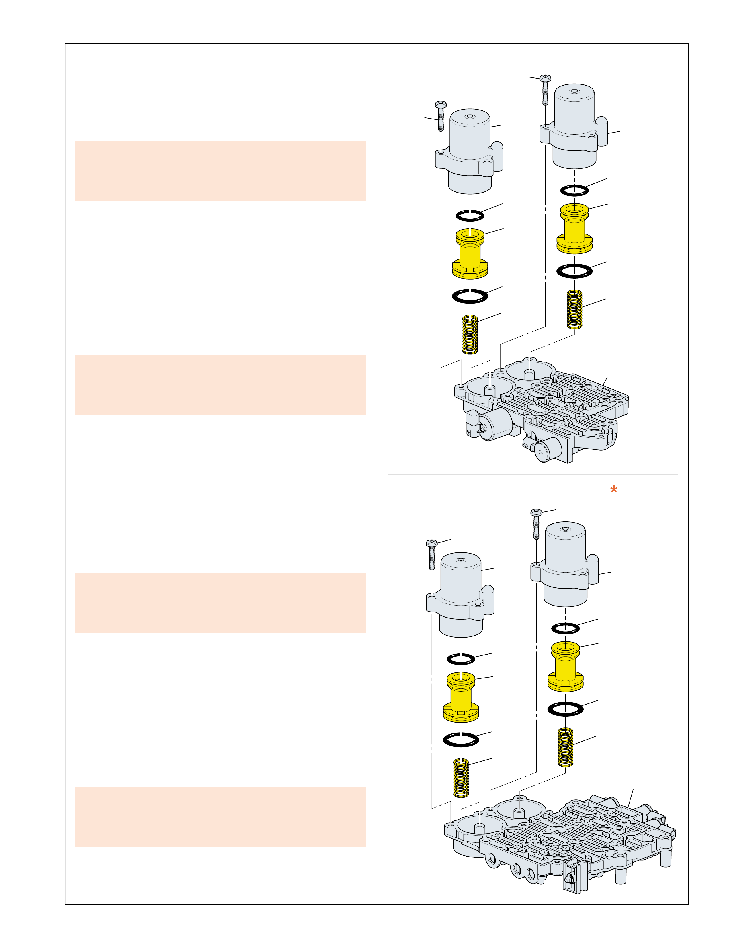
HYDRAULIC CONTROL COMPONENTS
41
310
318
333
332
331
330
329
318
328
327
326
325
324
311
318 317
316
315
314
313
318
323
322
321
320
319
DIRECT
CLUTCH
ACCUMULATOR
ASSEMBLY
OVERDRIVE
CLUTCH
ACCUMULATOR
ASSEMBLY
FRONT
CONTROL
VALVE
BODY
INTERMEDIATE
CLUTCH
ACCUMULATOR
ASSEMBLY
SECOND
CLUTCH
ACCUMULATOR
ASSEMBLY
REAR
CONTROL
VALVE
BODY
Figure 40
DIRECT CLUTCH ACCUMULATOR ASSEMBLY:
The direct clutch accumulator assembly is located in an
accumulator housing bolted to the front control valve body and
consists of the direct clutch accumulator piston (315) and the
direct clutch accumulator piston spring (313). The direct clutch
accumulator assembly is the primary component for controlling
the shift feel of a 3-4 shift.
•
A leak at the accumulator piston seal or porosity in the
accumulator housing could cause slipping during a 3-4 shift.
•A stuck accumulator piston would cause harsh 3-4 shifts.
OVERDRIVE CLUTCH ACCUMULATOR ASSEMBLY:
The overdrive clutch accumulator assembly is located in an
accumulator housing bolted to the front control valve body and
consists of the overdrive clutch accumulator piston (321) and
the overdrive clutch accumulator piston spring (319). The
overdrive clutch accumulator assembly is the primary component
for controlling the shift feel of a 4-5 shift.
•
A leak at the accumulator piston seal or porosity in the
accumulator housing could cause slipping during a 4-5 shift.
•A stuck accumulator piston would cause harsh 4-5 shifts.
INTERMEDIATE CLUTCH ACCUMULATOR ASSEMBLY:
The intermediate clutch accumulator assembly is located in an
accumulator housing bolted to the rear control valve body and
consists of the intermediate clutch accumulator piston (326) and
the intermediate clutch accumulator piston spring (324). The
intermediate clutch accumulator assembly is the primary
component for controlling the shift feel of a 2-3 shift.
•
A leak at the accumulator piston seal or porosity in the
accumulator housing could cause slipping during a 2-3 shift.
•A stuck accumulator piston would cause harsh 2-3 shifts.
SECOND CLUTCH ACCUMULATOR ASSEMBLY *:
The second clutch accumulator assembly is located in an
accumulator housing bolted to the rear control valve body and
consists of the second clutch accumulator piston (331) and the
second clutch accumulator piston spring (329). The second
clutch accumulator assembly is the primary component for
controlling the shift feel of a 1-2 shift.
•
A leak at the accumulator piston seal or porosity in the
accumulator housing could cause slipping during a 1-2 shift.
•A stuck accumulator piston would cause harsh 1-2 shifts.
*Note: The second clutch accumulator assembly is used for
the 5L40-E only.

HYDRAULIC CONTROL COMPONENTS
42
Ball Check Valves Related Diagnostic Tips
Understanding the design principle of each
ball check valve will help in the diagnosis of
hydraulic related conditions. For example:
•A harsh shift complaint could be caused by a stuck or
missing ball check valve.
•
Slow reverse or disengagement could be caused by a
stuck #1 ball check valve.
•No engine compression braking in manual first could
be caused by a missing or stuck #8 ball check valve.
BALL CHECK VALVES LOCATION AND FUNCTION
#8 LOW AND REVERSE CLUTCH OR RLO:
Located in the bottom channel plate, it allows either low and
reverse clutch fluid (in a First gear coast condition) or reverse
lockout (RLO) fluid (in Reverse) to enter the low and reverse
clutch or RLO fluid circuit while blocking the other fluid circuit.
Low and reverse clutch or RLO fluid is used to apply the low
and reverse clutch.
#9 23 REGULATED/OVERDRIVE CLUTCH FEED 1:
Located in the bottom channel plate, it seats to force 23 regulated
fluid through orifice 22 before entering the overdrive clutch
feed 1 circuit. This helps control the apply rate of the overdrive
clutch in a Third gear coast condition. When the overdrive
clutch releases, exhausting 23 regulated fluid unseats, and flows
past, the #9 ball check valve. This allows for a faster exhaust of
23 regulated fluid and a quick release of the overdrive clutch.
#10 32 SAFETY MODE/FDL:
Located in the bottom channel plate, it allows either 32 safety
mode fluid (in Safety Mode operation only) or FDL fluid (in
First gear) to enter the 32 safety mode or FDL fluid circuit while
blocking the other fluid circuit.
#11 23 REGULATED/SECOND COAST CLUTCH
(Used Only On 5L40-E Models):
Located in the bottom channel plate, it seats to force 23 regulated
fluid through orifice 23 before entering the second coast clutch
circuit. This helps control the apply rate of the second coast
clutch in a Second gear coast condition. When the second
coast clutch releases, exhausting 23 regulated fluid unseats,
and flows past, the #11 ball check valve. This allows for a
faster exhaust of 23 regulated fluid and a quick release of the
second coast clutch.
#12 OVERDRIVE CLUTCH FEED:
Located in the bottom channel plate, it allows either overdrive
clutch feed 1 fluid (in a Third gear coast condition) or overdrive
clutch feed 2 fluid (in Fifth gear) to enter the overdrive clutch
fluid circuit while blocking the other fluid circuit. Overdrive
clutch fluid is used to apply the overdrive clutch.
#1 REVERSE CLUTCH:
Located in the bottom channel plate, it seats to force reverse
lockout fluid through orifice 13 on the spacer plate and into the
reverse clutch fluid circuit. This helps control the apply rate of
the reverse clutch. When the reverse clutch releases, exhausting
reverse clutch fluid unseats, and flows past, the #1 ball check
valve and into the reverse lockout fluid circuit. This allows for
a faster exhaust of reverse clutch fluid and a quick release of the
reverse clutch.
#2 REVERSE/2345:
Located in the bottom channel plate, it allows either reverse
fluid (in Reverse) or 2345 fluid (in Second, Third, Fourth and
Fifth) to enter the 2345 or reverse fluid circuit while blocking
the other fluid circuit.
#3 45:
Located in the bottom channel plate, it seats to force 45 fluid
through orifice 27 to help control the apply rate of the overdrive
clutch. When the clutch releases, exhausting 45 fluid unseats,
and flows past, the #3 ball check valve. This allows for a
faster exhaust of 45 fluid and a quick release of the overdrive
clutch assembly.
#4 123:
Located in the bottom channel plate, it seats to force 123 fluid
through orifice 16 to help control the apply rate of the coast
clutch. When the coast clutch releases, exhausting 123 fluid
unseats, and flows past, the #4 ball check valve. This allows
for a faster exhaust of 123 fluid and a quick release of the
coast clutch.
#5 COAST CLUTCH:
Located in the bottom channel plate, it seats to force forward
clutch fluid through orifice 17 before entering the coast clutch
feed circuit. This helps control the apply rate of the coast
clutch. When the coast clutch releases, exhausting coast clutch
feed fluid unseats, and flows past, the #5 ball check valve. This
allows for a faster exhaust of coast clutch feed fluid and a quick
release of the coast clutch.
#6 D432/FORWARD CLUTCH:
Located in the bottom channel plate, it seats to force D432 fluid
through orifice 15 before entering the forward clutch circuit.
This helps control the apply rate of the forward clutch. When
the forward clutch releases, exhausting D432 feed fluid unseats,
and flows past, the #6 ball check valve. This allows for a faster
exhaust of D432 fluid and a quick release of the forward clutch.
#7 FORWARD CLUTCH/COAST CLUTCH:
Located in the bottom channel plate, it is seated by a calibrated
spring and provides extra D432 fluid flow into the forward clutch
and coast clutch circuits to reduce garage shift response time.
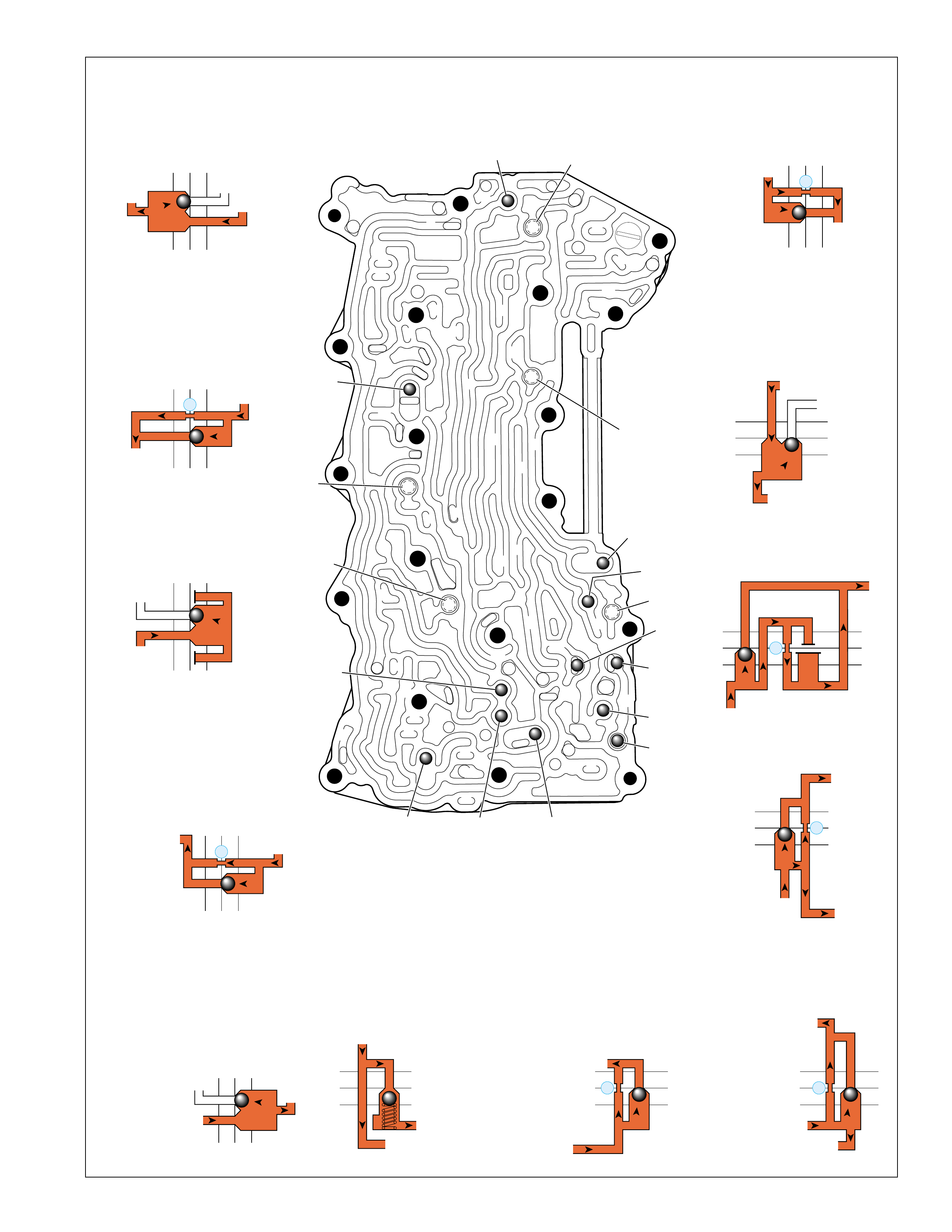
HYDRAULIC CONTROL COMPONENTS
43
BOTTOM CHANNEL PLATE (304)
(Control Valve Body Side)
FRONT
➤
#12
#2
#3
#5
#6
#7
(Spring)
#8
#10 #9
#4
#1
#11
X-2
X-4
X-5
X-1
X-3
33
32
38
38
38
30
30
24
37
37
37
40
40
12
16
15
15
23
23
28
47
41
42
43
27
28
28
27
27
25
25
26
22
22
15
13
18 19
19
19
19
19
19
19
21
17
17
22
23
23
48
48
48
48
48
48
48
48
15
13
36
36
36
36
39
35
35
34
10
10 11
10
10
10
20
20
48
44
44
45
43 42
52
48
48
77
2
2
2
2
2
2
2
REVERSE LOCKOUT
REVERSE CLUTCH
13
#1
15c 16
15d 16
2345
2345 OR REVERSE
REVERSE
#2
23 22g
14a
45
45
38c
38d
X-5
38
#3
38b
38e
27
123
123
123
#4
20d
20c
16
COAST CLUTCH FEED
FORWARD CLUTCH
FORWARD CLUTCH
#5
21b 31
21c 31
17
D432
FORWARD CLUTCH
#6
19d 21
19c 21
15
D432
D432 FORWARD CLUTCH
#7
19a
19b
21
23 REGULATED
#11
33e
33d
23
23 REGULATED
#8
18
15f
17c
REVERSE LOCKOUT
LOW AND REVERSE CL
LOW AND REV CL OR RLO
23 REGULATED
#9
33c
33b
1
23 REGULATED
FDL32 SAFETY MODE
#10
45
45
45
44f
43c
OVERDRIVE CLUTCH
OVERDRIVE CL FEED 1
OVERDRIVE CL FEED 2
41 40c
39c
#12
Figure 41
BALL CHECK VALVES LOCATION AND FUNCTION

HYDRAULIC CONTROL COMPONENTS
44
NOTES
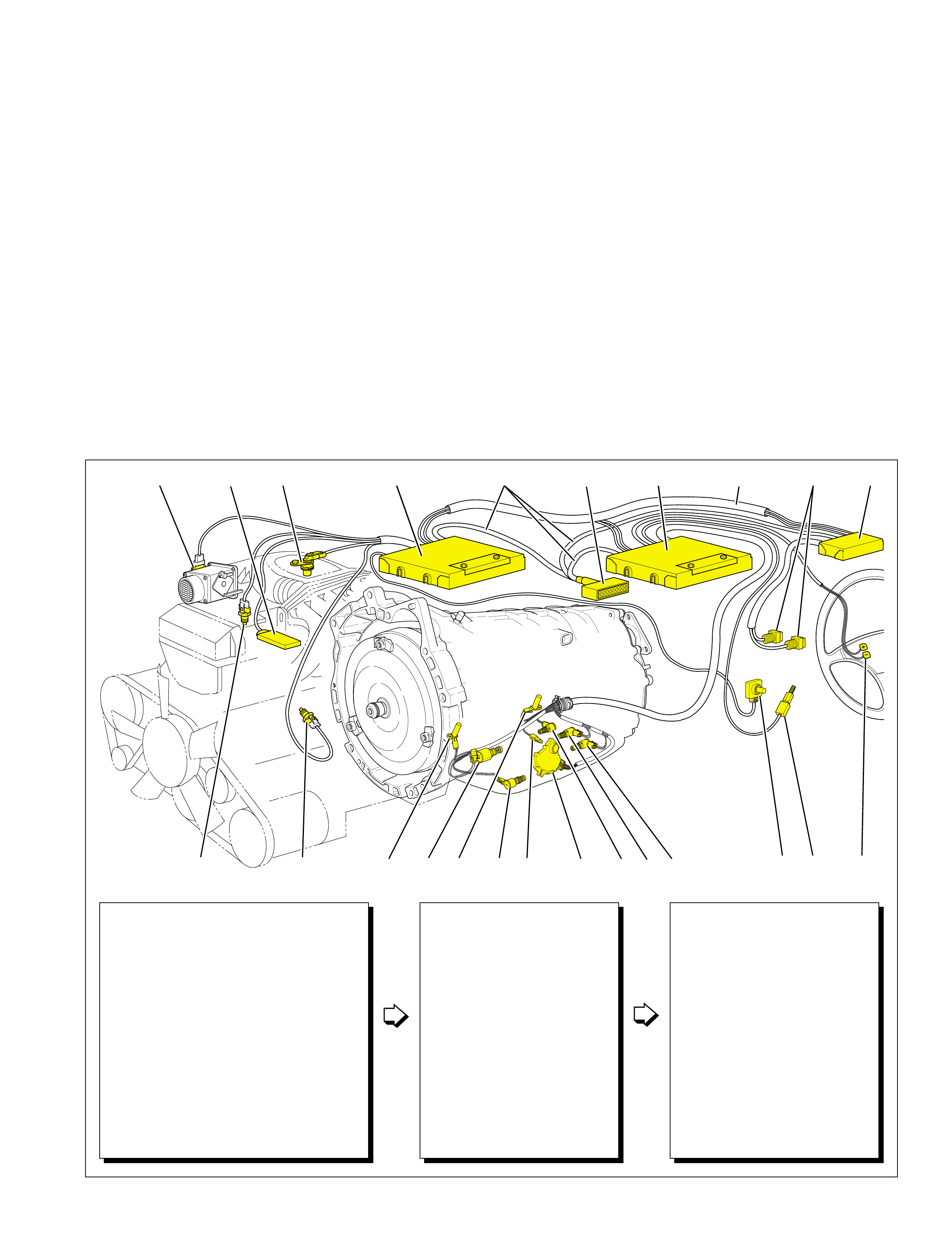
45
ELECTRICAL COMPONENTS
ED 25
1IF 43G KJL
H
AC MDLC CAN BUSTCMTCMECM SERIAL DATA BCM
B
INPUTS
INFORMATION SENSORS
A. THROTTLE POSITION (TP) SENSOR
B. MANIFOLD ABSOLUTE PRESSURE (MAP) SENSOR
C. ENGINE SPEED SENSOR
D. MANIFOLD AIR TEMPERATURE (MAT) SENSOR
E. ENGINE COOLANT TEMPERATURE (ECT) SENSOR
F. TRANSMISSION INPUT SPEED SENSOR (A/T ISS)
G. TRANSMISSION OUTPUT SPEED SENSOR (A/T OSS)
H. TRANSMISSION FLUID TEMPERATURE (TFT) SENSOR
I. TRANSMISSION MANUAL SHIFT
SHAFT SWITCH ASSEMBLY
J. ACCELERATOR PEDAL POSITION (APP) SENSOR
K. TCC BRAKE SWITCH
L. DRIVER SHIFT CONTROL (DSC) SWITCHES
M. OPERATING MODE SELECTION SWITCHES
ELECTRONIC CONTROLLERS
TRANSMISSION CONTROL
MODULE (TCM) OR
POWERTRAIN CONTROL
MODULE (PCM) (SEE NOTE ABOVE)
ENGINE CONTROL MODULE (ECM)
BODY CONTROL MODULE (BCM)
ELECTRONIC BRAKE AND TRACTION
CONTROL MODULE (EBTCM)
(NOT SHOWN)
DIAGNOSTIC LINK CONNECTOR
(DLC)
OUTPUTS
ELECTRONICALLY CONTROLLED
TRANSMISSION COMPONENTS
1. PRESSURE CONTROL (PC)
SOLENOID V ALVE
2. TORQUE CONVERTER CLUTCH
PULSE WIDTH MODULATION
(TCC PWM) SOLENOID
3. 1-2 SHIFT SOLENOID (SS) VALVE
4. 2-3 SHIFT SOLENOID (SS) VALVE
5. 4-5 SHIFT SOLENOID (SS) VALVE
Figure 42
“Safety Mode” operating state of the solenoids forces
the transmission to operate in Fifth gear regardless of
other vehicle oper ating conditions when the gear selector
is in a forward drive range. Also, in “Safety Mode” the
PC solenoid valve is turned off which increases line
pressure to a maximum and the TCC PWM solenoid
valve cannot apply the TCC. This allows the vehicle to
be operated safely, despite the disabled electronic
controls, until the condition can be corrected.
Another feature of the Hydra-matic 4/5L40-E is the
electronic control of engine braking. In Ov erdriv e Range,
Manual Fourth, Manual Third, and Manual Second, engine
braking in first, second and third gear can be obtained if
desired by activation of the 4-5 shift solenoid valve.
Note: Some models utilize a Powertr ain Contr ol Module
(PCM) instead of a TCM. The PCM functions similar
to the TCM b ut does incorpor ate some differ ent contr ols.
However, throughout this publication only the TCM is
referenced for simplicity. Refer to the appropriate
General Motors Service Manual for a description of
PCM controls.
The Hydra-matic 4/5L40-E transmission incorporates
electronic controls that utilize the transmission control
module (TCM) (see Note below) to control shift points
(through shift solenoid valves), torque converter clutch
(TCC) apply and release [through the torque converter
clutch pulse width modulated (TCC PWM) solenoid] and
line pressure [through the pressure control (PC) solenoid
valve]. Electrical signals from various sensors provide
information to the TCM about vehicle speed, throttle
position, engine coolant temperature, transmission fluid
temperature, gear range selector position, engine speed,
con v erter turbine speed, engine load braking and operating
mode. The TCM uses this information to determine the
precise moment to upshift or downshift, apply or release
the TCC and what fluid pressure is needed to apply the
clutches. This type of control provides consistent and
precise shift points and shift quality based on the operating
conditions of the vehicle .
If for any reason the entire electronic control system of
the transmission becomes disabled, all three of the shift
solenoid valves will be de-energized (turned OFF). This
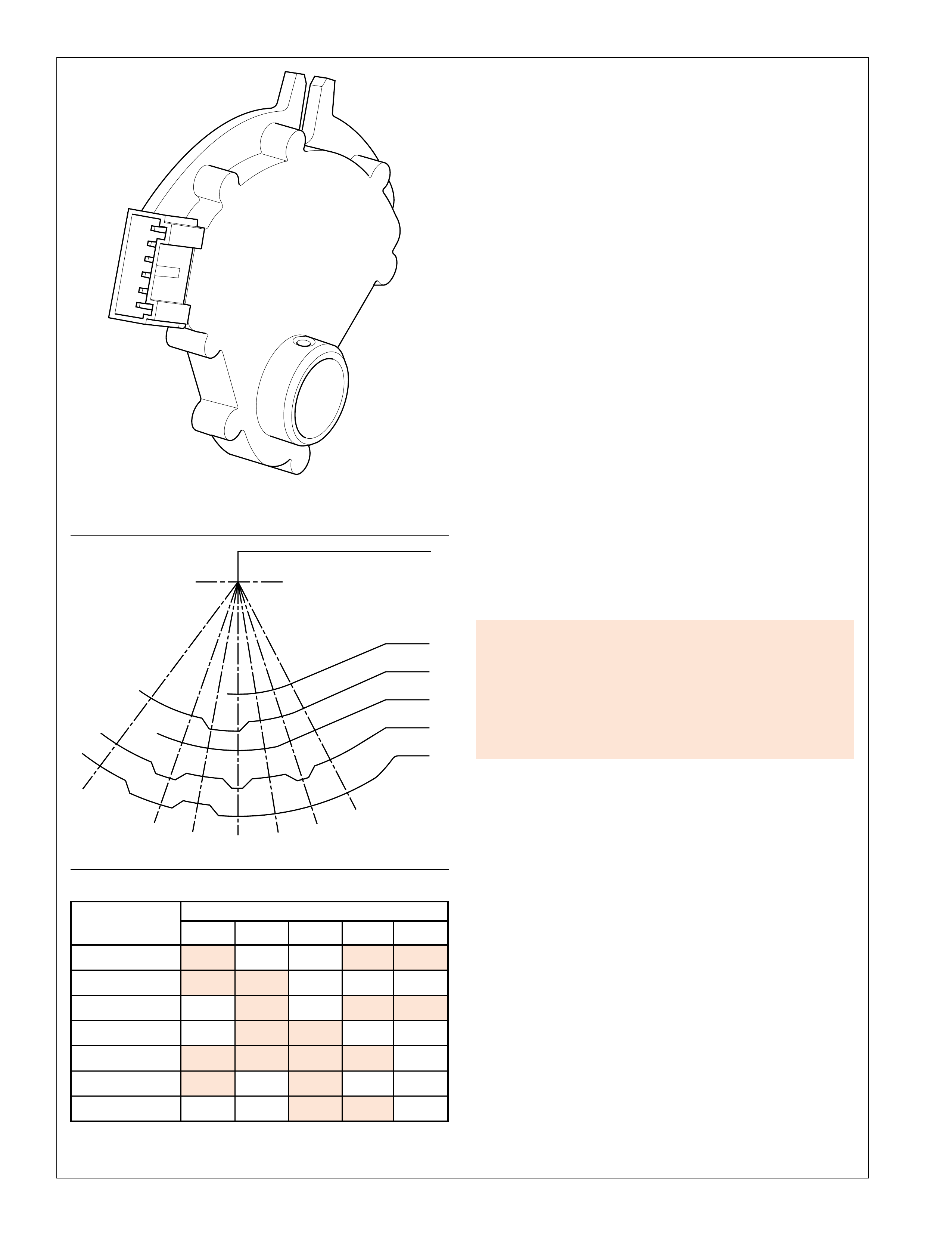
46
ELECTRICAL COMPONENTS
TRANSMISSION MANUAL SHIFT
SHAFT SWITCH ASSEMBLY
(602)
N
P
B
A
C
+
D
N
R
P
432
C
+
A
B
P
N
Figure 43
RANGE CIRCUIT
INDICATOR A B C P P/N
Park 1 0 0 1 1
Reverse 1 1 0 0 0
Neutral 0 1 0 1 1
Overdrive 0 1 1 0 0
Manual Fourth 1 1 1 1 0
Manual Third 1 0 1 0 0
Manual Second 0 0 1 1 0
1 = Closed (Resistance <50 ohms)
0 = Open (Resistance >50k ohms)
TRANSMISSION MANUAL SHIFT SHAFT
SWITCH ASSEMBLY (602):
The transmission manual shift shaft switch assembly (602) is a
sliding contact switch attached to the manual shift shaft inside
the transmission case. The five inputs to the TCM from the
transmission manual shift shaft switch assembly indicate which
position is selected by the transmission selector lever. This
information is used for engine controls as well as determining
the transmission shift patterns. The state of each input is available
for display on the scan tool. The five input parameters
represented are Mode A, Mode B, Mode C, Mode P (Parity) and
Mode N (P/N Start).
If the TCM detects an improper signal from the transmission
manual shift shaft switch assembly, a DTC will be activated.
The DTC strategy may be different depending on the
customer/application (refer to the appropriate Service
Information).
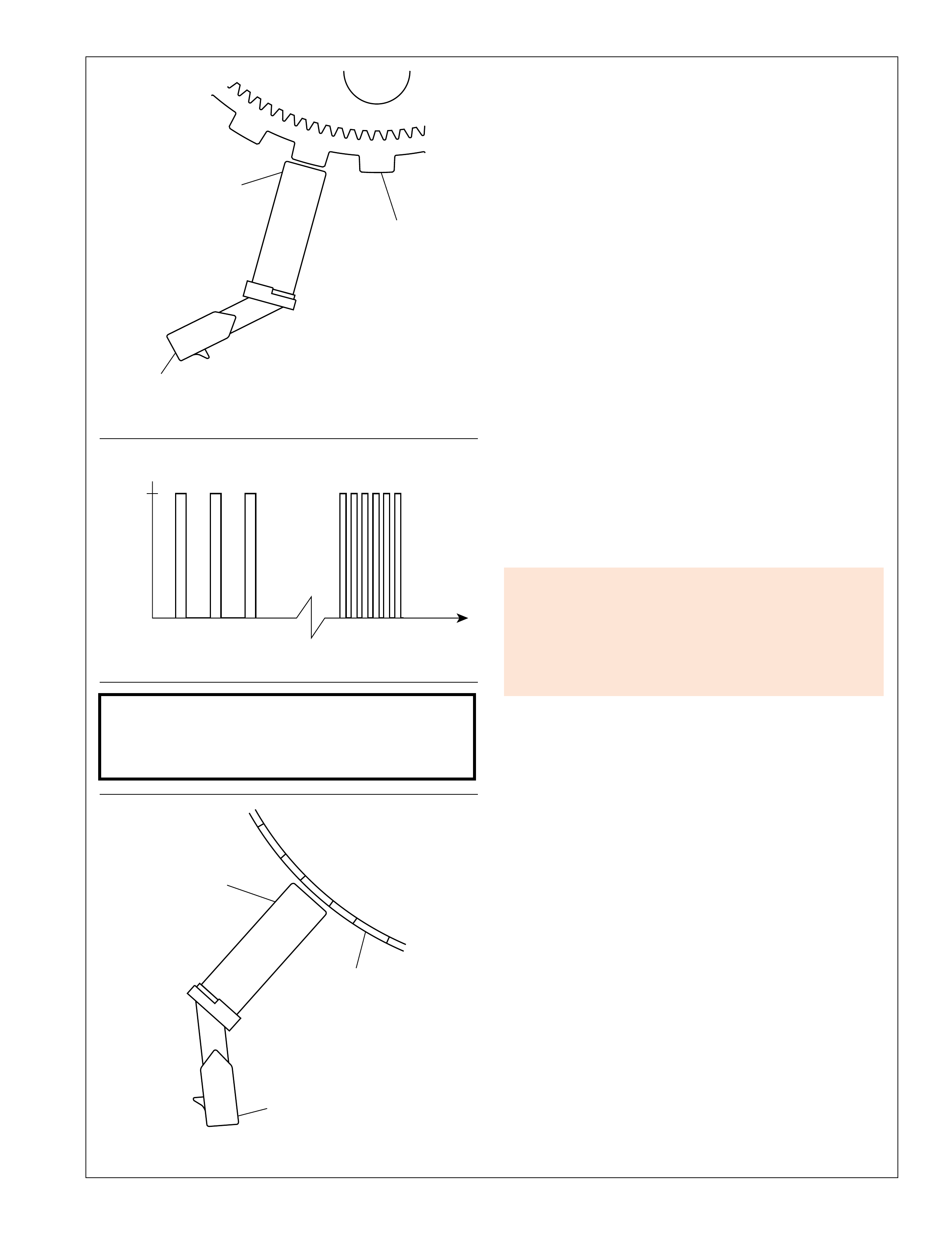
47
ELECTRICAL COMPONENTS
FIGURE A: CONDITIONED SIGNAL
OUTPUT VOLTS
LOW SPEED
5.0 HIGH SPEED
TIME
OUTPUT SPEED SENSOR
INPUT SPEED SENSOR
MAGNETIC
PICKUP
REVERSE
CLUTCH
INPUT
HOUSING
ASSEMBLY
(401)
ELECTRICAL
CONNECTOR
REAR
INTERNAL
GEAR
(560)
ELECTRICAL
CONNECTOR
MAGNETIC
PICKUP
Figure 44
Automatic Transmission Output (Shaft) Speed
(A/T OSS) Sensor (42):
The A/T OSS sensor is a variable reluctance magnetic pickup
located in the rear of the transmission case. This sensor is
mounted in the case opposite the rear internal gear (560). The
rear internal gear is splined to the output shaft assembly (562).
The sensor consists of a permanent magnet surrounded by a coil
of wire. As the output shaft and rear internal gear rotate, an
alternating current (AC) is induced in the coil by the “teeth” on
the rear internal gear as they pass by the magnetic pickup.
Therefore, whenever the vehicle is moving, the A/T OSS sensor
produces an AC voltage signal proportional to vehicle speed.
At the TCM, the AC signal is electronically conditioned to a 5
volt square wave form (see Figure A). The square wave form
can then be interpreted as transmission output speed by the
TCM through the frequency of square waves in a given time
frame. The square waves can be thought of as a representation
of the rear internal gear teeth. Therefore, the more teeth (or
waves) that pass by the magnetic pickup in a given time frame,
the faster the vehicle is moving. The square wave form is
compared to a fixed clock signal within the TCM to determine
transmission output speed.
TRANSMISSION SPEED SENSORS
Sensor resistance should measure between 325 and 485
ohms at 20°C (68°F). Output voltage will vary from a
minimum of 0.5 V peak to peak at 100 RPM, to 600 V
peak to peak at 8500 RPM.
Automatic Transmission Input (Shaft) Speed
(A/T ISS) Sensor (44):
The A/T ISS sensor operates identically to the A/T OSS sensor
except that it uses the stamped teeth on the reverse clutch input
housing assembly (401) as the rotor (reluctor). Remember that
the reverse clutch input housing assembly is driven at converter
turbine speed. The A/T ISS sensor square wave form is also
compared to a fixed clock signal within the TCM to determine
actual converter turbine speed. The TCM uses transmission
input and output speeds to help determine line pressure,
transmission shift patterns, TCC apply pressure, gear ratios, and
TCC slippage for diagnostic purposes.
If the TCM detects an improper signal from the transmission
input or output speed sensors, a DTC will be activated.
The DTC strategy may be different depending on the
customer/application (refer to the appropriate Service
Information).
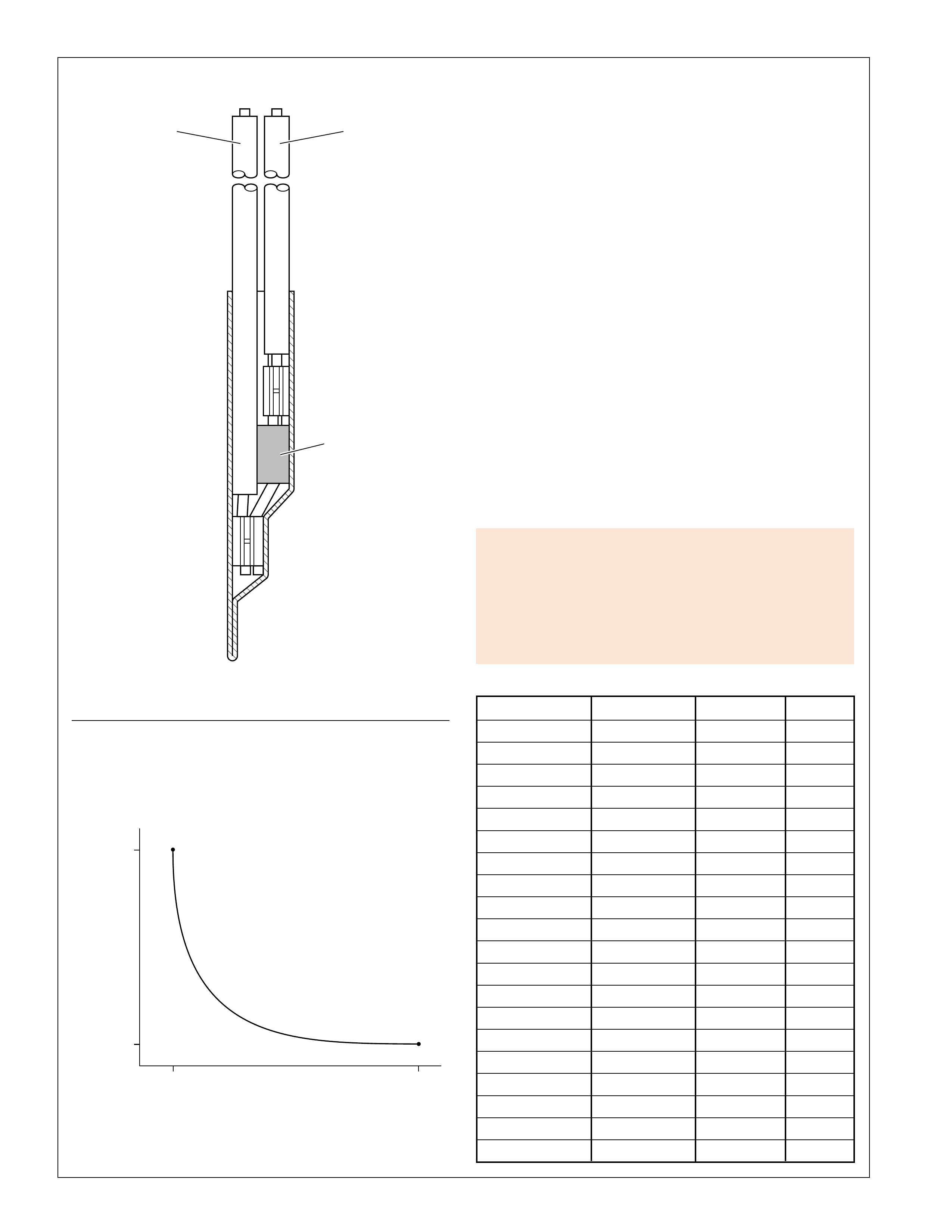
48
ELECTRICAL COMPONENTS
TRANSMISSION FLUID TEMPERATURE SENSOR
TFT SENSOR RESISTANCE VS. TEMPERATURE
133
-10 110
TEMPERATURE ( C)
TFT SENSOR RESISTANCE (OHMS)
16,000
RESISTOR
(THERMISTOR)
WIREWIRE
Automatic Transmission Fluid Temperature (TFT) Sensor:
The TFT sensor is part of the transmission wiring harness
assembly (55). The TFT sensor is a resistor, or thermistor,
which changes value based on temperature (see chart). The
sensor has a negative-temperature coefficient. This means that
as the temperature increases, the resistance decreases, and as the
temperature decreases the resistance increases. The TCM
supplies a 5-volt reference signal to the sensor and measures the
voltage drop in the circuit. When the transmission fluid is cold
the sensor resistance is high and the TCM detects high signal
voltage. As the fluid temperature warms to a normal operating
temperature, the resistance becomes less and the signal voltage
decreases. The TCM uses this information to maintain shift
quality and torque converter clutch apply quality over operating
temperature range.
If transmission fluid temperatures become excessively high
[above approximately 140°C (284°F) (calibratable in the TCM)],
the TCM will disable ECCC function and command lock up
mode. Applying the TCC serves to reduce transmission fluid
temperatures created by the fluid coupling in the torque converter
with the TCC released.
Above approximately 149°C (300°F) (calibratable in the TCM),
the TCM will set a transmission fluid temperature code. This
causes the TCM to use a fixed value of 135°C (275°F)
(calibratable in the TCM) as the transmission fluid temperature
input signal.
Figure 45
If the TCM detects an improper signal from the transmission
fluid temperature sensor, a DTC will be activated.
The DTC strategy may be different depending on the
customer/application (refer to the appropriate Service
Information).
Temperature Resistance R% (+/-) +/-°C
-40 100000 10.5 1.51
-30 51400 9.69 1.52
-20 27610 9.02 1.49
-10 15450 8.35 1.49
0 8972 7.74 1.43
10 5391 7.16 1.42
20 3342 6.64 1.42
30 2132 6.19 1.41
40 1397 5.73 1.39
50 938 5.32 1.38
60 645 4.92 1.35
70 453 4.55 1.30
80 324 4.19 1.27
90 237 3.89 1.25
100 176 3.59 1.22
110 132 3.25 1.16
120 101 2.96 1.13
130 79 2.66 1.07
140 62 2.58 1.09
150 49 2.83 1.26
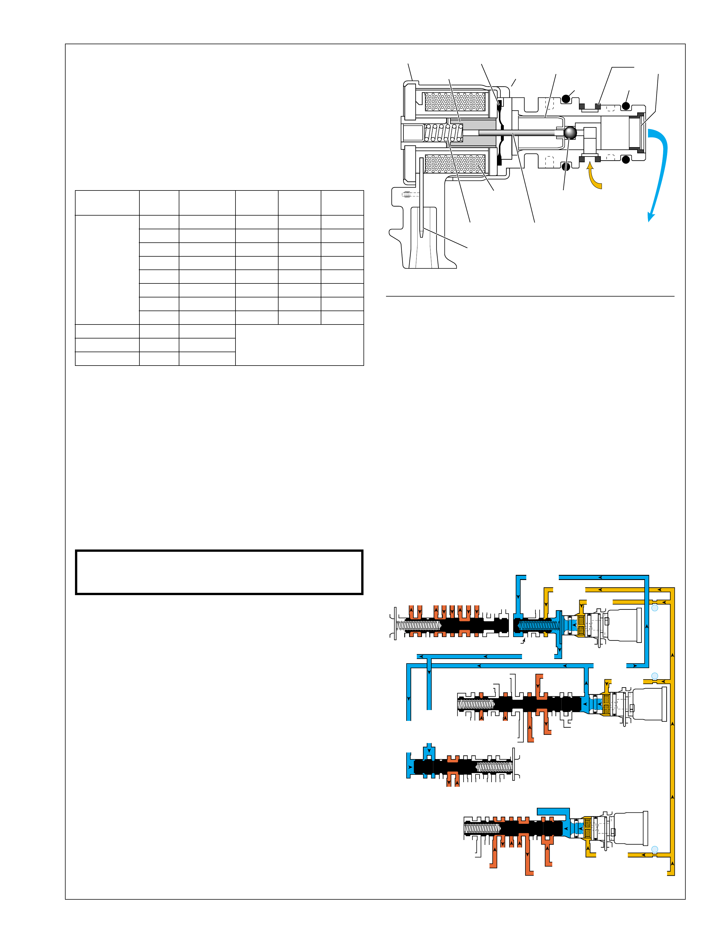
49
ELECTRICAL COMPONENTS
➤
➤➤
➤
➤
➤➤
➤
➤
➤
➤
1-2, 2-3 OR 4-5 SHIFT SOLENOID VALVE
HOUSING
COIL
ASSEMBLY
PLUNGER
METERING
BALL
FLUID
SCREEN
EXHAUSTEXHAUST
SEAT
FEED
LIMIT
FLUID
SOLENOID
SIGNAL
FLUID
CONNECTOR
SPRING
ARMATURE
DIAPHRAGM
O-RINGO-RING
➤
➤
➤
2-3 SHIFT VALVE CNTRL
EX
SECOND COAST CLUTCH
23 REGULATED
23 REG
OVERDRIVE CL FD 1
INTERMEDIATE CLUTCH
2345
INTERMEDIATE CL
2345
345
FEED LIMIT
EX
EX
EX
EX
2-3 SIGNAL
4-5 SHIFT VLV CNTRL
LINE SAFETY MODE
123 BRAKING
123
EX
EX
EX
123
COAST CL
COAST CL FD
OVERDRIVE CL FD 2
45
FEED LIMIT
FEED LIMIT
1-2 SHIFT VALVE
FDL
D432
D432
SECOND CL
2345
23 REG
123 REG
LOW AND REV CL
SECOND CL
123 REG
EX
EX
EX
FD LIMIT
FEED LIMIT
FDL
1-2 SIGNAL
EX
EX
4-5 SIGNAL
2-3 SIGNAL
CNTRL 3-4 SHIFT
2-3 SIGNAL
123
D432
DIRECT CL
45
1-2 SIGNAL
1-2 SIGNAL
EX
EX
EX
345
345
1-2 SHIFT
SOLENOID
VALVE
N/C
(A)
ON
2-3 SHIFT
SOLENOID
VALVE
N/C
(B)
ON
4-5 SHIFT
SOLENOID
VALVE
N/C
(C)
ON
11
10
9
1-2 SHIFT CONTROL VALVE
SECOND GEAR COAST
Figure 46
SHIFT SOLENOID VALVES
The Hydra-matic 4/5L40-E uses three electromagnetic shift
solenoid valves (1-2, 2-3 and 4-5) to control upshifts and
downshifts in all forward gear ranges. The shift solenoid valves
are all identical, normally closed, 3-port, ON/OFF type solenoids
controlled by the TCM. These shift solenoid valves work together
in a combination of ON and OFF sequences to control the
various shift valves. The TCM uses numerous inputs (as shown
in Figure 42) to determine which solenoid state combination the
transmission should be in. The following table shows the
solenoid state combination required for each gear range:
RANGE GEAR ENGINE 1-2 SS 2-3 SS 4-5 SS
BRAKING VALVE VALVE VALVE
1 NO OFF ON OFF
1 YES OFF ON ON
2 NO ON ON OFF
D432 2 YES ON ON ON
3 NO ON OFF OFF
3 YES ON OFF ON
4 YES OFF OFF ON
5 YES OFF OFF OFF
Neutral ––
Reverse R YES ON/OFF
Park ––
When the TCM provides a path to ground for the electrical
circuit to energize (turn ON) the solenoid, current flows through
the coil assembly in the solenoid and creates a magnetic field.
The magnetic field moves the plunger to the left (with respect to
the illustration) and feed limit fluid seats the metering ball against
the exhaust seat, thereby blocking the exhaust passage and
creating signal fluid pressure.
The shift solenoid valves are de-energized (turned OFF) when
the TCM opens the path to ground for the solenoid’s electrical
circuit. With the solenoid OFF, solenoid spring force moves the
metering ball and plunger away from the exhaust seat. This
blocks feed limit fluid from entering the signal fluid circuit and
allows any existing signal fluid pressure to flow past the metering
ball and exhaust out of the solenoid as shown in the illustration.
Shift solenoid valve resistance should measure between 15
and 17 ohms when measured at 20
°
C (68
°
F). The resistance
should measure approximately 24 ohms at 150
°
C (302
°
F).
1-2 Shift Solenoid (SS) Valve (368):
Feed limit fluid feeds the 1-2 signal fluid circuit at the 1-2 shift
control valve (366). When the 1-2 SS valve is energized (ON),
feed limit fluid is allowed to pass through the solenoid, thereby
creating 1-2 signal fluid pressure (see Second Gear Coast example
below). 1-2 signal fluid pressure acts together with spring force
on the 1-2 shift control valve (366) to keep it in the downshifted
position when 2-3 signal fluid pressure is present. 1-2 signal
fluid pressure also acts on the 3-4 shift valve (345) and the
safety mode valve (341).
When the 1-2 SS valve is de-energized (OFF), feed limit fluid is
blocked from feeding the 1-2 signal fluid circuit, and any existing
1-2 signal fluid pressure exhausts through the solenoid.
2-3 Shift Solenoid (SS) Valve (369):
The 2-3 SS valve functions similar to the 1-2 SS valve in that the
TCM controls the path to ground for the electrical circuit to turn
the solenoid ON or OFF. Feed limit fluid feeds the 2-3 signal
fluid circuit at the 2-3 shift control valve (370). When the 2-3
SS valve is energized (ON), feed limit fluid is allowed to pass
through the solenoid, thereby creating 2-3 signal fluid pressure
(see Second Gear Coast example below). 2-3 signal fluid pressure
acts on the 2-3 shift control valve (370) and the 2-3 shift valve
(371) (against spring force) to move it into the upshifted position.
2-3 signal fluid pressure also acts on the 1-2 shift control valve
(366) and the 3-4 shift control valve (346).
When the 2-3 SS valve is de-energized (OFF), feed limit fluid is
blocked from feeding the 2-3 signal fluid circuit, and any existing
2-3 signal fluid pressure exhausts through the solenoid.
4-5 Shift Solenoid (SS) Valve (376):
The 4-5 SS valve functions similar to the 1-2 SS valve and the
2-3 SS valve in that the TCM controls the path to ground for the
electrical circuit to turn the solenoid ON or OFF. Feed limit
fluid feeds the 4-5 signal fluid circuit at the 4-5 shift control
valve (375). When the 4-5 SS valve is energized (ON), feed
limit fluid is allowed to pass through the solenoid, thereby
creating 4-5 signal fluid pressure (see Second Gear Coast example
below). 4-5 signal fluid pressure acts on the 4-5 shift control
valve (375) and the 4-5 shift valve (374) (against spring force)
to move it into the upshifted position.
When the 4-5 SS valve is de-energized (OFF), feed limit fluid is
blocked from feeding the 4-5 signal fluid circuit, and any existing
4-5 signal fluid exhausts through the solenoid.

50
ELECTRICAL COMPONENTS
;;
;
;
;
;
;;
;;
;;
;;;
;;;
;;;
;;;
;
;
;;;
;;;
;;;
;;;
;;;
;;;
;;;
;;;
;;;
;;;
;;
;;
;;
APPLY
RELEASE
TORQUE
CONVERTER
ASSEMBLY
(1)
APPLY
APPLY
TCC SIGNAL
CONVERTER FEED
CONVERTER FEED
RELEASE
TO COOLER
REGULATED APPLY
REGULATED APPLY
EX
EX
CONVERTER FDL
TCC
ENABLE
VALVE
TCC
CONTROL
VALVE
2345 OR REVERSE
TCC SIGNAL
REGULATED APPLY
REGULATED APPLY
EX
EX
LINE
TCC PWM
SOLENOID
VALVE
N/C
6
TCC REGULATOR VALVE
TCC PWM SOLENOID VALVE
➤
➤➤➤➤
➤
➤
➤
➤➤➤➤
➤
➤
➤
➤
➤
➤
➤
➤➤
➤
HOUSING
COIL
ASSEMBLY
STAINLESS STEEL
SHIM METERING
BALL
EXHAUST
EXHAUST
SEAT
2345 OR
REVERSE
FLUID
TCC
SIGNAL
FLUID
CONNECTOR
INLET
SEAT
ARMATURE
DIAPHRAGM
O-RINGINTERNAL
O-RING
Figure 47
T orque Converter Clutch Pulse Width Modulation (TCC PWM)
Solenoid Valve (352):
The TCC PWM solenoid valve is a normally closed, pulse
width modulated (PWM) solenoid used to control the apply and
release of the converter clutch. The TCM operates the solenoid
with a negative duty cycle, at a fixed frequency of 32 Hz, to
control the rate of TCC apply/release. The solenoid’s ability to
“ramp” the TCC apply and release pressures results in a smoother
TCC operation.
When vehicle operating conditions are appropriate to apply the
TCC, the TCM increases the duty cycle to allow the TCC PWM
solenoid valve to command TCC signal fluid pressure at a level
sufficient to move the TCC enable valve and the TCC control
valve to the apply position. Release pressure is directed to
exhaust, and regulated apply fluid is directed to the apply side of
the converter pressure plate/damper assembly. The TCM then
increases the duty cycle to control a slippage of 20–80 RPM
between the pressure plate/damper assembly and the converter
cover. This provides for improved filtration of engine vibrations
and allows the TCC to apply at low engine speeds in 2nd, 3rd,
4th and 5th gear. At high speed, lock up mode is set by activating
the TCC PWM solenoid valve at maximum duty cycle.
Release of the TCC is achieved by decreasing the duty cycle to
a level low enough to allow spring force to move the TCC
enable valve and the TCC control valve to the release position.
Apply fluid is directed to exhaust and converter feed fluid is
directed into the release circuit to the release side of the pressure
plate/damper assembly.
There are also some operating conditions that may prevent or
enable TCC apply under various conditions (engine temperature,
transmission temperature, brake switch activation) depending
on vehicle application.
TCC PWM solenoid valve resistance should measure
between 10.0 and 11.5 ohms when measured at 20°C
(68°F). The resistance should measure approximately 16
ohms at 150°C (300°F).
T orque Converter Clutch Pulse Width Modulation (TCC PWM)
Solenoid Valve Operation:
The TCC PWM solenoid valve is the electronic control component
of the TCC apply and release system. The other components are
all hydraulic control or regulating valves. The illustration below
shows all the valves and the TCC PWM solenoid valve that
make up the TCC control system. (For more information on
system operation see pages 74–75 in the Power Flow section).
If the TCM detects that the TCC system is stuck ON or
stuck OFF, a DTC will be activated.
The DTC strategy may be different depending on the
customer/application (refer to the appropriate Service
Information).
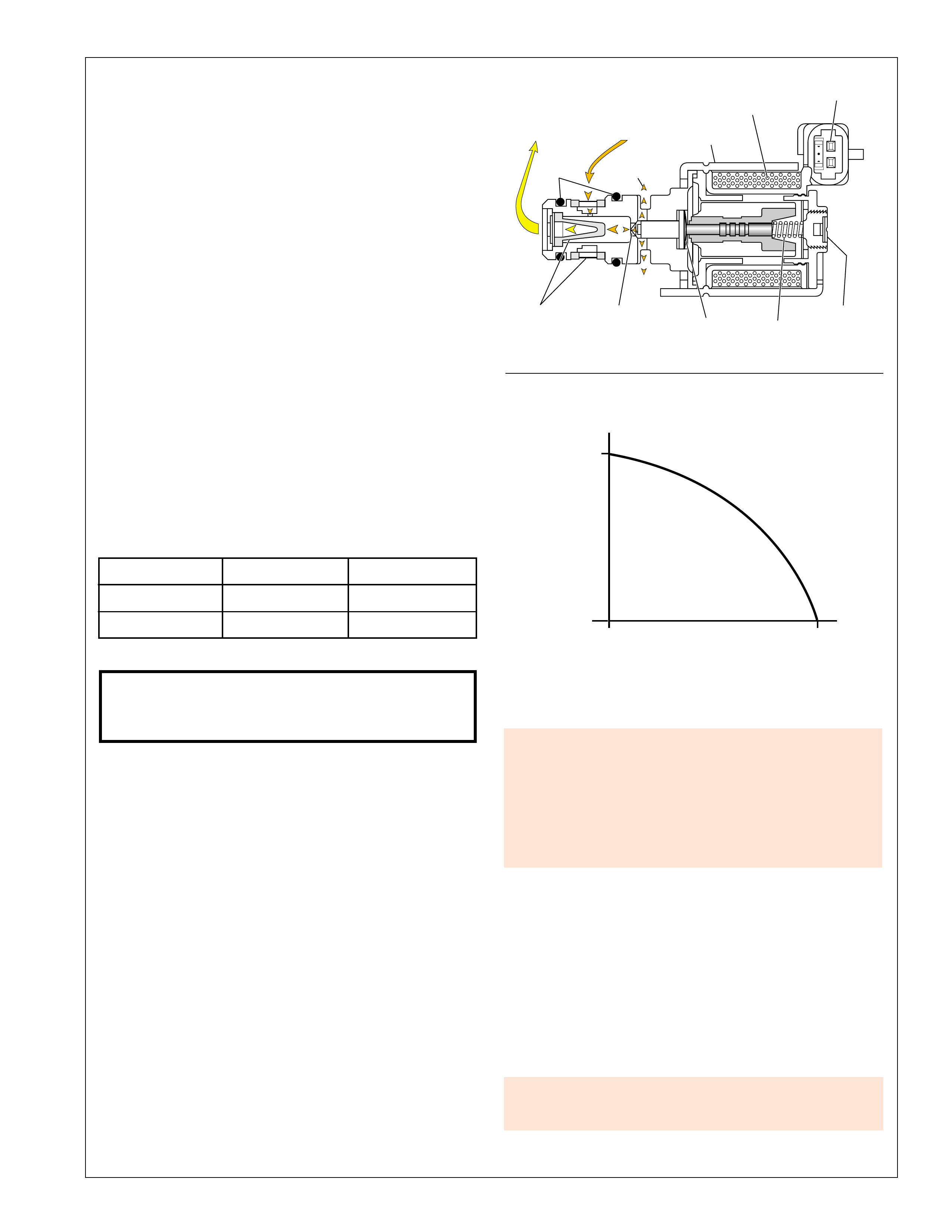
51
ELECTRICAL COMPONENTS
PRESSURE CONTROL SOLENOID VALVE
175
(Nom)
50
(Nom) 0 1.1
LINE PRESSURE
CURRENT (AMPS)
EXHAUST
VARIABLE
RESTRICTION CALIBRATION
SCREW
CONNECTOR
DIAPHRAGM
COIL
ASSEMBLY
O-RING
SPRING
HOUSING
FLUID
SCREENS
PRESSURE
SUPPLY
(FILTERED
FEED LIMIT)
PRESSURE
CONTROL
(THROTTLE
SIGNAL)
Figure 48
Pressure Control (PC) Solenoid Valve (357):
The pressure control (PC) solenoid valve is a precision electronic
pressure regulator that controls transmission line pressure based
on current flow through its coil windings. As current flow is
increased, the magnetic field produced by the coil moves the
solenoid’s plunger further away from the exhaust port. Opening
the exhaust port decreases the output fluid pressure regulated by
the PC solenoid valve, which ultimately decreases line pressure.
The TCM controls the PC solenoid valve based on various
inputs including throttle position, transmission fluid temperature
and gear state.
Duty Cycle, Frequency and Current Flow:
A “duty cycle” may be defined as the percentage of time current
is flowing through a solenoid coil during each cycle. The number
of cycles that occur within a specified amount of time, usually
measured in seconds, is called “frequency”. Typically, the
operation of an electronically controlled pulse width modulated
solenoid is explained in terms of duty cycle and frequency.
The TCM controls the PC solenoid valve on a positive duty
cycle at a fixed frequency of 292.5 Hz (cycles per second). A
higher duty cycle provides a greater current flow through the
solenoid. The high (positive) side of the PC solenoid valve
electrical circuit at the TCM controls the PC solenoid valve
operation. The TCM provides a ground path for the circuit,
monitors average current and continuously varies the PC solenoid
valve duty cycle to maintain the correct average current flowing
through the PC solenoid valve.
Duty Cycle Current Line Pressure
Minimum 0.1 Amps Maximum
Maximum 1.1 Amps Minimum
Pressure control solenoid valve resistance should measure
between 3.5 and 4.6 ohms when measured at 20°C (68°F),
and approximately 6 ohms at 150°C (302°F).
The duty cycle and current flow to the PC solenoid valve are
mainly affected by throttle position (engine torque) and they are
inversely proportional to throttle angle (engine torque). In other
words, as the throttle angle (engine torque) increases, the duty
cycle is decreased by the TCM which decreases current flow to
the PC solenoid valve. Current flow to the PC solenoid valve
creates a magnetic field that moves the solenoid armature against
spring force.
Transmission Adapt Function:
Programming within the TCM also allows for automatic
adjustments in shift pressure that are based on the changing
characteristics of the transmission components. As the apply
components within the transmission wear, shift time (the time
required to apply a clutch) increases. In order to compensate for
this wear, the TCM adjusts trim pressure by controlling the PC
solenoid valve in order to maintain the originally calibrated shift
timing. The automatic adjusting process is referred to as
“adaptive learning” and it is used to assure consistent shift feel
plus increase transmission durability. The TCM monitors the
A/T ISS and the A/T OSS during commanded shifts to determine
if a shift is occurring too fast (harsh) or too slow (soft) and
adjusts the PC solenoid valve signal to maintain a set shift feel.
Transmission adapts must be reset whenever the transmission
is overhauled or replaced (see appropriate service manual).
If the TCM detects a pressure control solenoid valve
electrical malfunction, a DTC will be activated.
The DTC strategy may be different depending on the
customer/application (refer to the appropriate Service
Information).

52
ELECTRICAL COMPONENTS
TCC Brake Switch: This switch causes the TCM to command
TCC release. When the brake pedal is depressed, the TCM opens
the path to ground for the TCC electrical circuit which releases the
torque converter clutch.
Driver Shift Control (DSC) Switches: These switches are located
either on the steering wheel or on a secondary gate within the
console shift lever mechanism. The TCM uses the switch inputs
to provide manual shift control to the driver. When a switch is
depressed, the TCM opens a path to ground causing the transmission
to shift up or down.
Operating Mode Selection Switches: Depending on the customer/
application, vehicles may be equipped with switches allowing the
driver to select various automatic operating modes (Economy,
Performance, Winter), or manual mode (Driver Shift Control) to
allow manual shifting by bumping the selector lever up and down.
Diagnostic Link Connector (DLC): The DLC is a multi-terminal
connector that is located under the vehicle dashboard. The DLC is
connected by serial data wires to the various control modules
located throughout the vehicle. The DLC can be used to diagnose
conditions in the vehicle's electrical system, TCM or PCM, and
various transmission components. Refer to the appropriate Service
Manual for specific electrical diagnosis information.
Controller Area Network (CAN) Bus: The CAN bus consists of
two wires that connect the various vehicle control modules together,
allowing them to exchange information about vehicle conditions.
Note: These are typical inputs to the controllers. The
combination and usage of these inputs may vary depending on
model and application.
COMPONENTS EXTERNAL TO THE TRANSMISSION
Throttle Position (TP) Sensor: The ECM monitors the variable
voltage signal from the TP sensor to calculate throttle position
(angle). These input signals are then transmitted over the CAN
bus to the TCM, in addition to other vehicle and transmission
sensor inputs, in order to determine the appropriate line pressure,
shift pattern and TCC apply and release for the transmission. In
general, with greater throttle angle, upshift speeds and line pressure
both increase.
Engine Speed Sensor: Monitored by the ECM through the ignition
module, information from this sensor is transmitted over the CAN
bus to the TCM and used to help determine shift patterns and TCC
apply and release.
Manifold Absolute Pressure (MAP) Sensor: The MAP sensor
measures changes relative to intake manifold pressure which results
from changes in engine load and speed. These changes are
converted to a voltage output which is monitored by the ECM and
transmitted over the CAN bus to the TCM in order to adjust line
pressure and shift timing.
Engine Coolant Temperature (ECT) Sensor: The ECM monitors
the variable resistance signal from this sensor to determine engine
coolant temperature. When the engine is cold, resistance is high,
and when the engine is hot, resistance through the sensor is low.
The ECM then transmits this information over the CAN bus to the
TCM where it is used to prevent the TCC from applying when
engine temperature is below approximately 20°C (68°F) (calibratable).
Manifold Air Temperature (MAT) Sensor: The ECM monitors
the variable resistance signal from the MAT sensor to determine
manifold air temperature. When the air is cold, resistance is high,
and when the air is hot, resistance through the sensor is low. The
ECM then transmits this information over the CAN bus to the TCM
where it is used to prevent the TCC from applying when manifold
air temperature is below approximately 20°C (68°F) (calibratable).
Accelerator Pedal Position (APP) Sensor: The APP sensor is
monitored by the ECM in order to determine accelerator pedal
position. The ECM uses this signal to open and close the throttle
in response to the driver's commands. It also signals the TCM
when the accelerator pedal is fully depressed, allowing forced
downshifts and maximum performance.

1
POWER FROM
TORQUE
CONVERTER
(1)
REAR
INTERNAL
GEAR
(560)
HELD
NO POWER
TRANSMITTED
TO
DIFFERENTIAL
ASSEMBLY
TORQUE
CONVERTER
ASSEMBLY
(1)
REVERSE CLUTCH
HOUSING ASSEMBLY
(401)
FORWARD AND COAST
CLUTCH HOUSING
ASSEMBLY
(433)
REAR
INTERNAL
GEAR
(560)
HELD
TORQUE
CONVERTER
HOUSING/PUMP
ASSEMBLY
(3)
PARK
PAWL
(612)
ENGAGED
PARK
PAWL
ACTUATOR
ASSEMBLY
(613)
➤
➤
➤
OVERDR CL FD 2
ACCUMULATOR
INTERMED CL
ACCUMULATOR
EX
SECOND CL
ACCUM
ACCUMULATOR
LINE
LINE
LINE
EXEXEX
DIRECT CL
4
2
5
DIRECT
CLUTCH
ACCUMULATOR
OVERDRIVE
CLUTCH
ACCUMULATOR
INTERMEDIATE
CLUTCH
ACCUMULATOR
SECOND
CLUTCH
ACCUMULATOR
3
LINE
LINE
LINE (from Pump)
LINE
FILTERED FEED LIMIT
THROTTLE SIGNAL
EX
2345 OR REVERSE
TCC SIGNAL
REGULATED APPLY
REGULATED APPLY
EX
EX
FEED LIMIT VALVE
LINE
EX
EX
EX
EX
FEED LIMIT
FEED LIMIT
EX EX
SECOND COAST CLUTCH
23 REGULATED
OVERDRIVE CL FD 1
INTERMEDIATE CLUTCH
2345
INTERMEDIATE CLUTCH
2345
345
FEED LIMIT
EX
EX
EX
EX
2-3 SIGNAL
23 REGULATED
123 BRAKING
123
EX
EX
EX
123
COAST CLUTCH
COAST CLUTCH FEED
OVERDRIVE CL FD 2
45
FEED LIMIT
LINE
FEED LIMIT
32
MEMORY
MEMORY
MEMORY
MEMORY PILOT
32 SAFETY MODE
EX
EX
FDL
D432
2345
D432
SECOND CL
23 REGULATED
123 REGULATED
SECOND CL
123 REGULATED
LOW AND REV CL
EX
EX
EX
FEED LIMIT
FEED LIMIT
FDL
1-2 SIGNAL
2-3 SIGNAL
EX
EX
RPND432
MANUAL VALVE
LINE
D432
REV
REVERSE
EX
32
LINELINE
LINE SAFETY MODE
4-5 SIGNAL
24
28
PRESSURE
CONTROL
SOLENOID
VALVE
1-2 SHIFT
SOLENOID
VALVE
N/C
(A)
OFF
2-3 SHIFT
SOLENOID
VALVE
N/C
(B)
OFF
4-5 SHIFT
SOLENOID
VALVE
N/C
(C)
OFF
TCC PWM
SOLENOID
VALVE
N/C
1-2 SHIFT VALVE
7
11
10
9
FILTER
(312)
TCC REGULATOR VALVE
1-2 SHIFT CONTROL VALVE
29
8
FEED LIMIT
FEED LIMIT FEED LIMIT
FEED LIMITFEED LIMIT
2-3 SHIFT VALVE CNTRL
CNTRL
LINE SM
LINE SM
LINE SAFETY MODE
SAFETY MODE
DECREASE
CONVERTER FEED
THROTTLE SIGNAL
LINE
EX
REVERSE CLUTCH
PRESS REG VALVEBOOST VALVE
4-5 SHIFT VLV
2c
2b
2a
1
3
POWER FLOW
(Engine Running)
Figure 53
57
PARK
PARK
Figure 52
56
(Engine Running)
COMPLETE HYDRAULIC CIRCUIT
PAGE 86
With the selector lever in the Park (P)
position, line pressure from the oil
pump is directed to the following:
Pressure Regulator Valve(218): Reg-
ulates pump output (line pressure)
according to the transmission
requirements. When pump
output exceeds the demand
of line pressure, fluid from
the pressure regulator
PARK
(Engine Running)
56B
This section of the book describes how torque from
the engine is transferred through the Hydra-matic
4/5L40-E transmission allo wing the v ehicle to mov e
either in a forward or reverse direction. The
information that f ollows details the specific mec hanical
operation, electrical, hydraulic and apply components
that are required to achieve a gear operating range.
The full size, left hand pages throughout this section
contain drawings of the mechanical components used
in a specific range and gear. Facing this full page is a
half page insert containing a color coded range
reference chart at the top. This chart is one of the key
items used to understand the mechanical operation of
the transmission in each range and gear. The text
below this chart provides a detailed explanation of
what is occurring mechanically in that range and gear.
The full size, right hand pages contain a simplified
version of the Complete Hydraulic Circuit that is
involved f or that range and gear. Facing this full page
is a half page insert containing text and a detailed
explanation of what is occur ring hydraulically in that
range and gear. A page number located at the bottom
of the half page of text provides a ready reference to
the complete Hydraulic Circuits section of this book
if more detailed information is desired.
It is the intent of this section to provide an overall
simplified explanation of the mechanical, hydraulic
and electrical operation of the Hydra-matic 4/5L40-E
transmission. If the operating principle of a clutch, or
valve is unclear, refer to the previous sections of this
book for individual component descriptions.
Figure 49 53
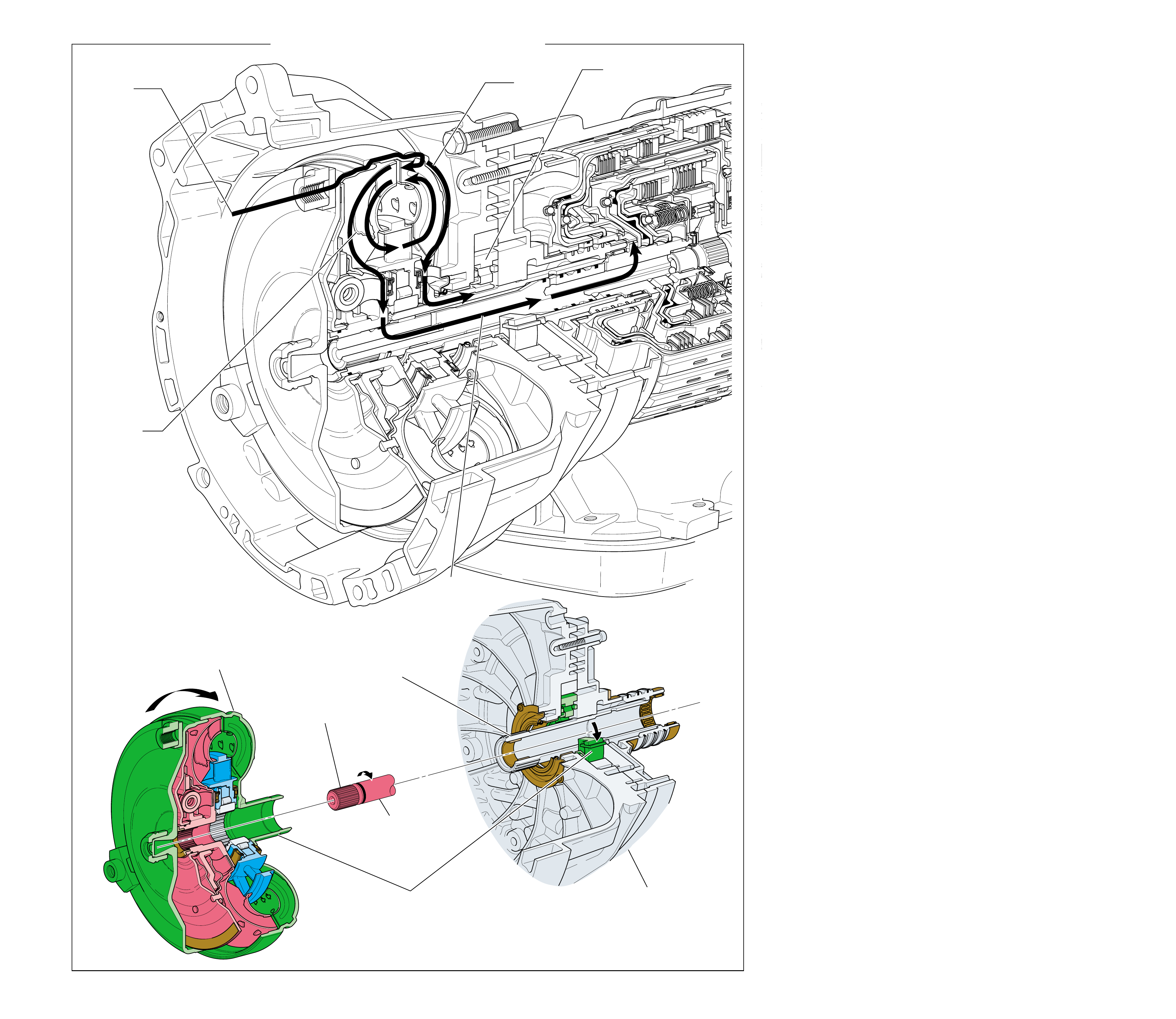
Figure 50
FORWARD CLUTCH
AND INPUT HOUSING
ASSEMBLY (433)
(TURBINE SHAFT)
SPLINED TO
TORQUE CONVERTER
STATOR ASSEMBLY
TORQUE CONVERTER
ASSEMBLY
(1)
KEYED TO
FLUID PUMP
ROTOR
SPLINED TO
TORQUE CONVERTER
TURBINE ASSEMBLY
MECHANICAL POWERFLOW FROM THE TORQUE CONVERTER
TO THE TURBINE SHAFT
(Engine Running)
1
POWER FROM
THE ENGINE
3
FLUID COUPLING
DRIVES THE TURBINE
2
POWER TO
DRIVE FLUID PUMP
2a
FLUID PUMP
ROTOR (223)
DRIVEN
4
TURBINE
SHAFT DRIVEN
TORQUE CONVERTER
HOUSING/PUMP ASSEMBLY
(3)
54
MECHANICAL POWERFLOW FROM
THE TORQUE CONVERTER TO
THE TURBINE SHAFT
(Engine Running)
54A
The mechanical power flow in the Hydra-matic 4/5L40-E
transmission begins at the point of connection between the
torque con verter and the engine flywheel. When the engine is
running, the torque con ver ter co ver (pump) is forced to rotate
at engine speed. As the torque converter rotates it multiplies
engine torque and transmits it to the turbine shaft (433). The
turbine shaft provides the primary link to the mechanical
operation of the transmission.
The Hydra-matic 4/5L40-E automatic transmission requires a
constant supply of pressurized fluid to cool and lubricate all
of the components throughout the unit. It also requires a
holding force to be applied to the clutches during the various
gear range operations. The torque converter housing/pump
assembly (3) and the control valve body accumulator assembly
(47) provide for the pressurization and distribution of fluid
throughout the transmission.
1 Power from the Engine
Torque from the engine is transferred to the transmission through
the engine flywheel which is bolted to the engine crankshaft.
2 Power to Drive the Fluid Pump
The fluid pump rotor (223) is keyed to the torque converter hub.
Therefore, the fluid pump rotor also rotates at engine speed.
3 Fluid Coupling Drives the Turbine
Transmission fluid inside the torque converter (1) creates a fluid
coupling which in turn drives the torque converter turbine.
4 Turbine Shaft Driven
As the torque converter turbine rotates, the turbine shaft (433),
which is splined to the torque converter turbine, is also forced to
rotate at turbine speed.
NOTE: To minimize the amount of repetitive text, the
remaining mechanical power flow descriptions will begin
with the turbine shaft (433). The transfer of torque from the
engine through the torque converter to the turbine shaft is
identical in all gear ranges except when the torque converter
clutch is applied (see pages 74A and 74B for complete
explanation of torque con verter apply.
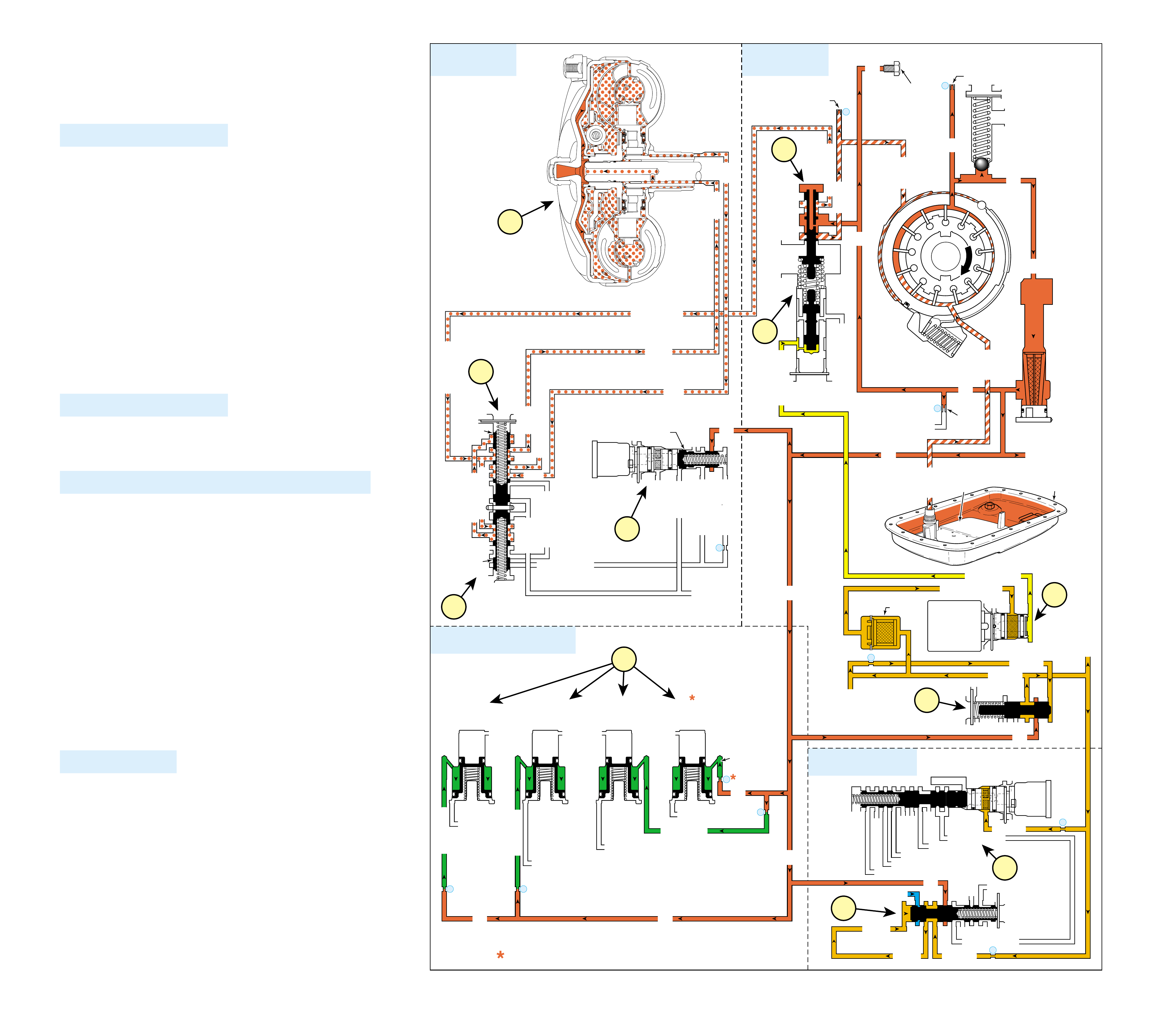
HYDRAULIC POWERFLOW – COMMON
FUNCTIONS FOR ALL RANGES
(Engine Running)
When the gear selector lever is in the Park (P) position and the
engine is running, fluid is drawn into the oil pump and line
pressure is directed to the pressure regulator valv e.
1 PRESSURE REGULATION
1a Pressure Regulator Valve:
Regulates pump output (line pressure) in response to throttle
signal fluid pressure acting on the line boost valve, spring
force, and line pressure acting on the end of the valve. Line
pressure is directed to the manual valve, the TCC regulator
valve, feed limit valve, and the safety mode valve. Line
pressure also feeds the converter feed circuit through the
pressure regulator valve, and the accumulator fluid circuits.
1b Feed Limit Valve:
Line pressure is routed through the valve and into the feed
limit fluid circuit. The valve limits feed limit fluid pressure
to a maximum pressure. Feed limit fluid is routed to the
pressure control solenoid valve, the safety mode valve, the
1-2 control valve, and also feeds the 1-2 signal, the 2-3
signal, and the 4-5 signal fluid circuits.
1c Pressure Control (PC) Solenoid Valve:
Controlled by the TCM, the PC solenoid valve regulates
filtered feed limit fluid pressure into the throttle signal
fluid circuit.
2 SHIFT ACCUMULATION
2a Direct, Overdrive, Intermediate, and Second Clutch
Accumulator Assemblies:
Accumulator fluid is routed to each of the accumulator
assemblies in preparation for upshifts and downshifts.
3 TORQUE CONVERTER (RELEASED POSITION ONLY)
3a Pressure Regulator Valve:
Line pressure is routed through the pressure regulator valve
and into the converter feed fluid circuit. Converter feed fluid is
routed to the TCC control valve and to the TCC enable valve.
3b TCC Regulator Valve:
Spring force holds the valve in the release position, thereby
blocking line pressure from entering the regulated apply
fluid circuit.
3c TCC Enable Valve:
Converter feed fluid is routed through the TCC enable valve
and into the converter FDL circuit. Converter FDL fluid is
routed to the TCC control valve.
3d TCC Control Valve:
Spring force holds the valve in the release position allowing
converter feed fluid to enter the release circuit.
3e Torque Converter:
Release fluid pressure is routed to the torque converter to keep
the TCC released. Fluid leaves the converter in the apply fluid
circuit and returns to the cooler through the TCC control valve.
4 SAFETY MODE
4a Safety Mode Valve:
When the first 1-2 shift occurs, the safety mode valve shifts
from the released position to the applied position and remains
there until the engine is switched OFF. If safety mode
occurs (no TCM signal to the shift solenoid valves), the
transmission will shift to safety (fifth) gear. If the engine is
then switched OFF and ON, still with no TCM signal, the
safety mode valve will return to, and remain in, the released
position. Line pressure fluid will pass through the safety
mode valve into the line safety mode fluid circuit. Line
safety mode fluid is routed to the 4-5 shift valve train.
4b 4-5 Shift Valve and 4-5 Shift Control Valve:
Line safety mode fluid forces the 4-5 shift valve to downshift
to the fourth gear position allowing (after the engine has
been switched OFF) a fourth gear start (instead of fifth) in
the event of safety mode.
54B
2
SHIFT ACCUMULATION
COMMON HYDRAULIC FUNCTIONS FOR ALL RANGES
1
PRESSURE
REGULATION
3
TORQUE
CONVERTER
NOTE: PASSAGES AND COMPONENTS MARKED
WITH ARE USED FOR THE 5L40-E ONLY
4
SAFETY MODE
APPLY
RELEASE
TORQUE
CONVERTER
ASSEMBLY
(1)
APPLY
APPLY
TCC SIGNAL
TCC SIGNAL
CONVERTER FEED
CONVERTER FEED
CONVERTER FEED
RELEASE
RELEASE
TO COOLER
REGULATED APPLY
REGULATED APPLY
EX
EX
CONVERTER FDL
TCC
CONTROL
VALVE
TCC
ENABLE
VALVE
LINE LINE
FILTERED FEED LIMIT
THROTTLE SIGNAL
EX
FEED LIMIT VALVE
LINE
EX
EX
EX
EX
FEED LIMIT
FEED LIMIT
FEED LIMIT
PRESSURE
CONTROL
SOLENOID
VALVE
7
FILTER
(312)
2345 OR REVERSE
TCC SIGNAL
REGULATED APPLY
REGULATED APPLY
EX
EX
LINE
TCC PWM
SOLENOID
VALVE
N/C
6
TCC REGULATOR VALVE
DECREASE
DECREASE
LINE
LINE
FORWARD CLUTCH
LINE LINE (to manual valve)
LINE
EX
CONVERTER FEED
REVERSE CLUTCH
THROTTLE SIGNAL
LINE
EX
LINE
LINE
PRESS REG VALVEBOOST VALVE
AIR
BLEED
(233)
AIR
BLEED
(233)
1
FLUID
PRESSURE
TEST PLUG
(40)
PRESSURE
RELIEF
BALL
VALVE
30
31
FLUID PUMP
SCREEN
ASSEMBLY
(213)
FLUID
PUMP
ASSEMBLY
(214)
SUCTION
SUCTION
FLUID
PAN
(62)
FLUID FILTER
ASSEMBLY
(59)
INTERMEDIATE CLUTCH
ACCUMULATOR
EX
SECOND CLUTCH
ACCUMULATOR
EX
2
INTERMEDIATE
CLUTCH
ACCUMULATOR
SECOND
CLUTCH
ACCUMULATOR
3
LINE
OVERDRIVE CLUTCH FEED 2
ACCUMULATOR
ACCUMULATOR
EXEX
DIRECT CLUTCH
4 5
DIRECT
CLUTCH
ACCUMULATOR
OVERDRIVE
CLUTCH
ACCUMULATOR
LINELINE
LINE
32
MEMORY
MEMORY
MEMORY PILOT 32 SAFETY MODE
LINE SAFETY MODE
EX
EX
FEED LIMIT
8
LINE SAFETY MODE
123 BRAKING
123
EX
EX
EX
123
COAST CLUTCH
COAST CLUTCH FEED
OVERDRIVE CLUTCH FEED 2
45
FEED LIMIT
4-5 SIGNAL
4-5 SHIFT
SOLENOID
VALVE
N/C
(C)
OFF
11
FEED LIMIT (to 1-2 and 2-3 SS valves)
4-5 SHIFT VLV CNTRL
SAFETY MODE
1a
3a
3b
3c
3d
3e
2a
1c
4b
1b
4a
Figure 51 55
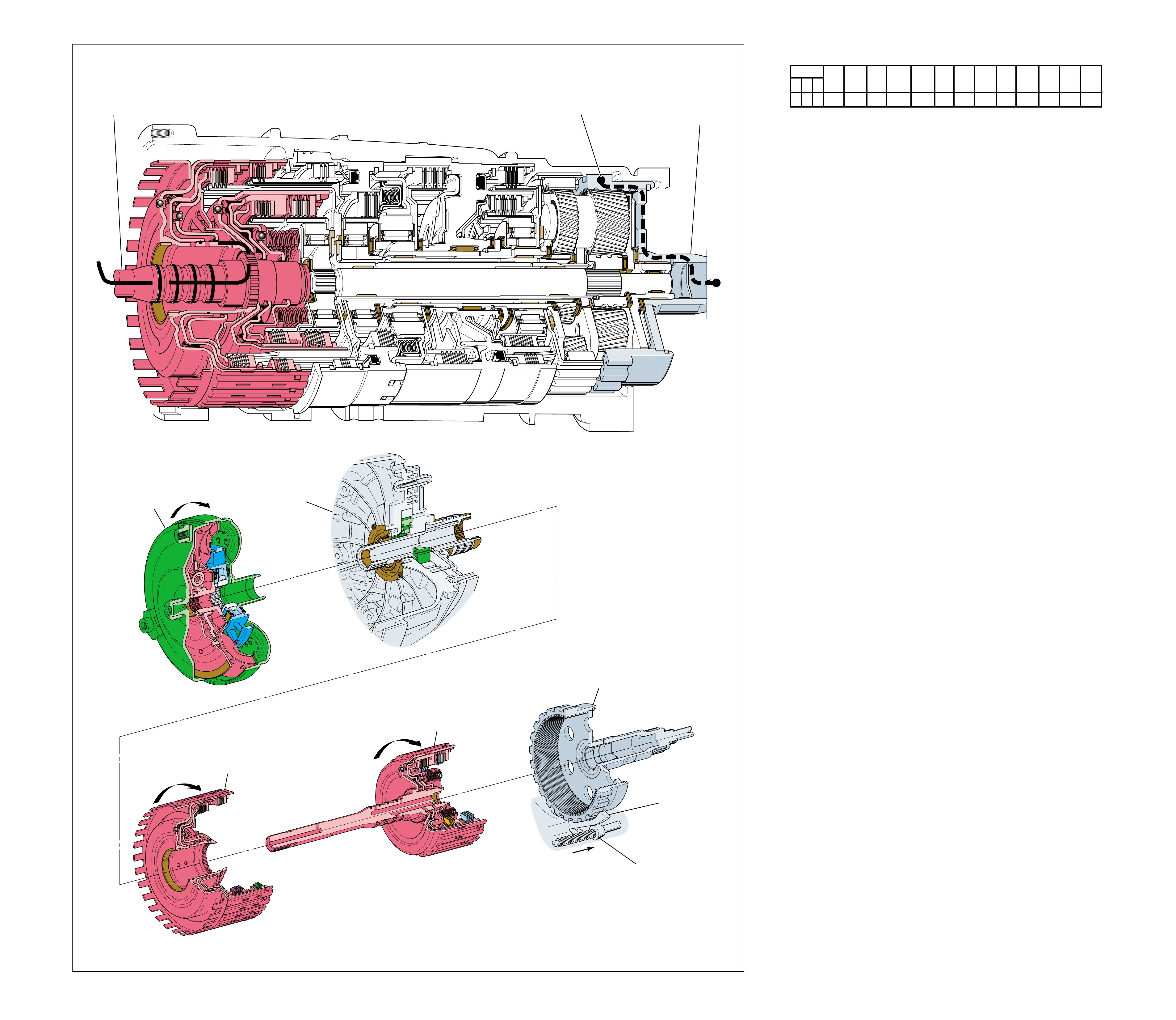
Figure 52
PARK
(Engine Running)
1
POWER FROM
TORQUE
CONVERTER
(1)
REAR
INTERNAL
GEAR
(560)
HELD
2
NO POWER
TRANSMITTED
TO
DIFFERENTIAL
ASSEMBLY
TORQUE
CONVERTER
ASSEMBLY
(1)
REVERSE CLUTCH
HOUSING ASSEMBLY
(401)
FORWARD AND COAST
CLUTCH HOUSING
ASSEMBLY
(433)
REAR
INTERNAL
GEAR
(560)
HELD
TORQUE
CONVERTER
HOUSING/PUMP
ASSEMBLY
(3)
PARK
PAWL
(612)
ENGAGED
PARK
PAWL
ACTUATOR
ASSEMBLY
(613)
➤
➤
➤
PARK
(Engine Running)
•The manual shift shaft (606) and the manual valve (377) are
in the Park position. The parking pawl actuator assembly
(613) engages the parking pawl (612) with the lugs on the
rear internal gear (560).
•The rear internal gear is held stationary by the parking pawl.
•The output shaft (562), which is splined to the rear internal
gear is also held stationary preventing the vehicle from
moving.
1 Power from Torque Converter
The input shaft forward and coast clutch assembly (433)
and the reverse clutch housing assembly (401) are driven by
the turbine shaft, which is splined to the converter turbine.
2 Power Flow Terminated
The input shaft forward and coast clutch assembly rotates
freely without any clutches applied or sprag clutches holding
and power flow is terminated.
Note: The vehicle should be completely stopped before selecting
Park range or internal damage to the transmission could occur.
Also, the manual linkage must be adjusted properly so the
indicator quadrants in the vehicle correspond with the manual
shaft detent lever (600) in the transmission. If not adjusted
properly, an internal leak between fluid passages at the manual
valve may cause a clutch to slip or cause the transmission to not
hold in park.
Refer to the appropriate General Motors Service Manual for the
proper manual linkage adjustment procedures.
SOLENOID FORWARD OVER- INTERM. INTER- LOW LOW AND SECOND SECOND
DIRECT REVERSE COAST FORWARD SPRAG DRIVE SPRAG MEDIATE SPRAG REVERSE SECOND SPRAG COAST
1-2 2-3 4-5 CLUTCH CLUTCH CLUTCH CLUTCH CLUTCH CLUTCH CLUTCH CLUTCH CLUTCH CLUTCH CLUTCH CLUTCH CLUTCH
OFF OFF OFF
LD = LOCKED IN DRIVE
56A
56
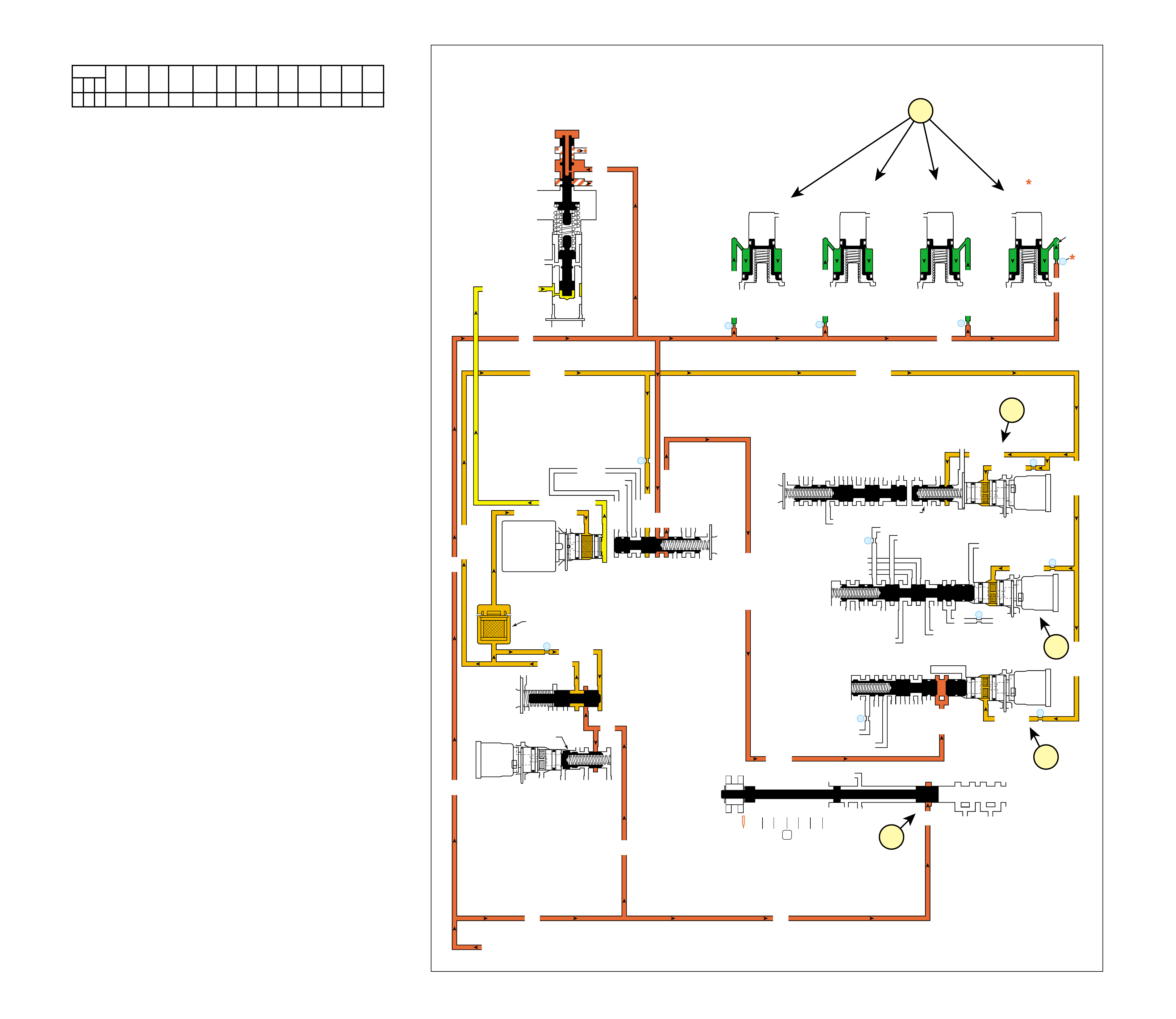
PARK
(Engine Running)
COMPLETE HYDRAULIC CIRCUIT
Page 86
Figure 53
FLUID PRESSURE DIRECTED IN PREPARATION FOR A SHIFT
1 Manual Valve:
Mechanically controlled by the gear selector lever, the manual
valve is in the Park (P) position and prevents line pressure
from the pressure regulator valve from entering the reverse,
D432 and 32 fluid circuits.
2a 1-2 Shift Solenoid (SS) Valve and
1-2 Shift Control Valve:
Feed limit fluid from the feed limit valve is routed to the
1-2 SS valve and to the 1-2 shift control valve in
preparation for a shift.
2b 2-3 Shift Solenoid (SS) Valve:
Feed limit fluid from the feed limit valve is routed to the
2-3 SS valve in preparation for a shift.
2c 4-5 Shift Solenoid (SS) Valve:
Feed limit fluid from the feed limit valve is routed to the 4-5
SS valve in preparation for a shift.
Note: Refer to Shift Solenoid Valves on page 49 for a description
of solenoid and shift valve operation.
3 Direct Clutch, Overdrive Clutch, Intermediate Clutch,
and Second Clutch Accumulators:
Line fluid fills the accumulator circuits and accumulator
assemblies in preparation for an upshift.
SOLENOID FORWARD OVER- INTERM. INTER- LOW LOW AND SECOND SECOND
DIRECT REVERSE COAST FORWARD SPRAG DRIVE SPRAG MEDIATE SPRAG REVERSE SECOND SPRAG COAST
1-2 2-3 4-5 CLUTCH CLUTCH CLUTCH CLUTCH CLUTCH CLUTCH CLUTCH CLUTCH CLUTCH CLUTCH CLUTCH CLUTCH CLUTCH
OFF OFF OFF
LD = LOCKED IN DRIVE
PARK
(Engine Running)
OVERDR CL FD 2
ACCUMULATOR
INTERMED CL
ACCUMULATOR
EX
SECOND CL
ACCUM
ACCUMULATOR
LINE
LINE
LINE
EXEXEX
DIRECT CL
4
2
5
DIRECT
CLUTCH
ACCUMULATOR
OVERDRIVE
CLUTCH
ACCUMULATOR
INTERMEDIATE
CLUTCH
ACCUMULATOR
SECOND
CLUTCH
ACCUMULATOR
3
LINE
LINE
LINE (from Pump)
LINE
FILTERED FEED LIMIT
THROTTLE SIGNAL
EX
2345 OR REVERSE
TCC SIGNAL
REGULATED APPLY
REGULATED APPLY
EX
EX
FEED LIMIT VALVE
LINE
EX
EX
EX
EX
FEED LIMIT
FEED LIMIT
EX EX
SECOND COAST CLUTCH
23 REGULATED
OVERDRIVE CL FD 1
INTERMEDIATE CLUTCH
2345
INTERMEDIATE CLUTCH
2345
345
FEED LIMIT
EX
EX
EX
EX
2-3 SIGNAL
23 REGULATED
123 BRAKING
123
EX
EX
EX
123
COAST CLUTCH
COAST CLUTCH FEED
OVERDRIVE CL FD 2
45
FEED LIMIT
LINE
FEED LIMIT
32
MEMORY
MEMORY
MEMORY
MEMORY PILOT
32 SAFETY MODE
EX
EX
FDL
D432
2345
D432
SECOND CL
23 REGULATED
123 REGULATED
SECOND CL
123 REGULATED
LOW AND REV CL
EX
EX
EX
FEED LIMIT
FEED LIMIT
FDL
1-2 SIGNAL
2-3 SIGNAL
EX
EX
RPND432
MANUAL VALVE
LINE
D432
REV
REVERSE
EX
32
LINELINE
LINE SAFETY MODE
4-5 SIGNAL
24
28
PRESSURE
CONTROL
SOLENOID
VALVE
1-2 SHIFT
SOLENOID
VALVE
N/C
(A)
OFF
2-3 SHIFT
SOLENOID
VALVE
N/C
(B)
OFF
4-5 SHIFT
SOLENOID
VALVE
N/C
(C)
OFF
TCC PWM
SOLENOID
VALVE
N/C
1-2 SHIFT VALVE
7
11
10
9
FILTER
(312)
TCC REGULATOR VALVE
1-2 SHIFT CONTROL VALVE
29
8
FEED LIMIT
FEED LIMIT FEED LIMIT
FEED LIMITFEED LIMIT
2-3 SHIFT VALVE CNTRL
CNTRL
LINE SM
LINE SM
LINE SAFETY MODE
SAFETY MODE
DECREASE
CONVERTER FEED
THROTTLE SIGNAL
LINE
EX
REVERSE CLUTCH
PRESS REG VALVEBOOST VALVE
4-5 SHIFT VLV
2c
2b
2a
1
3
56B 57
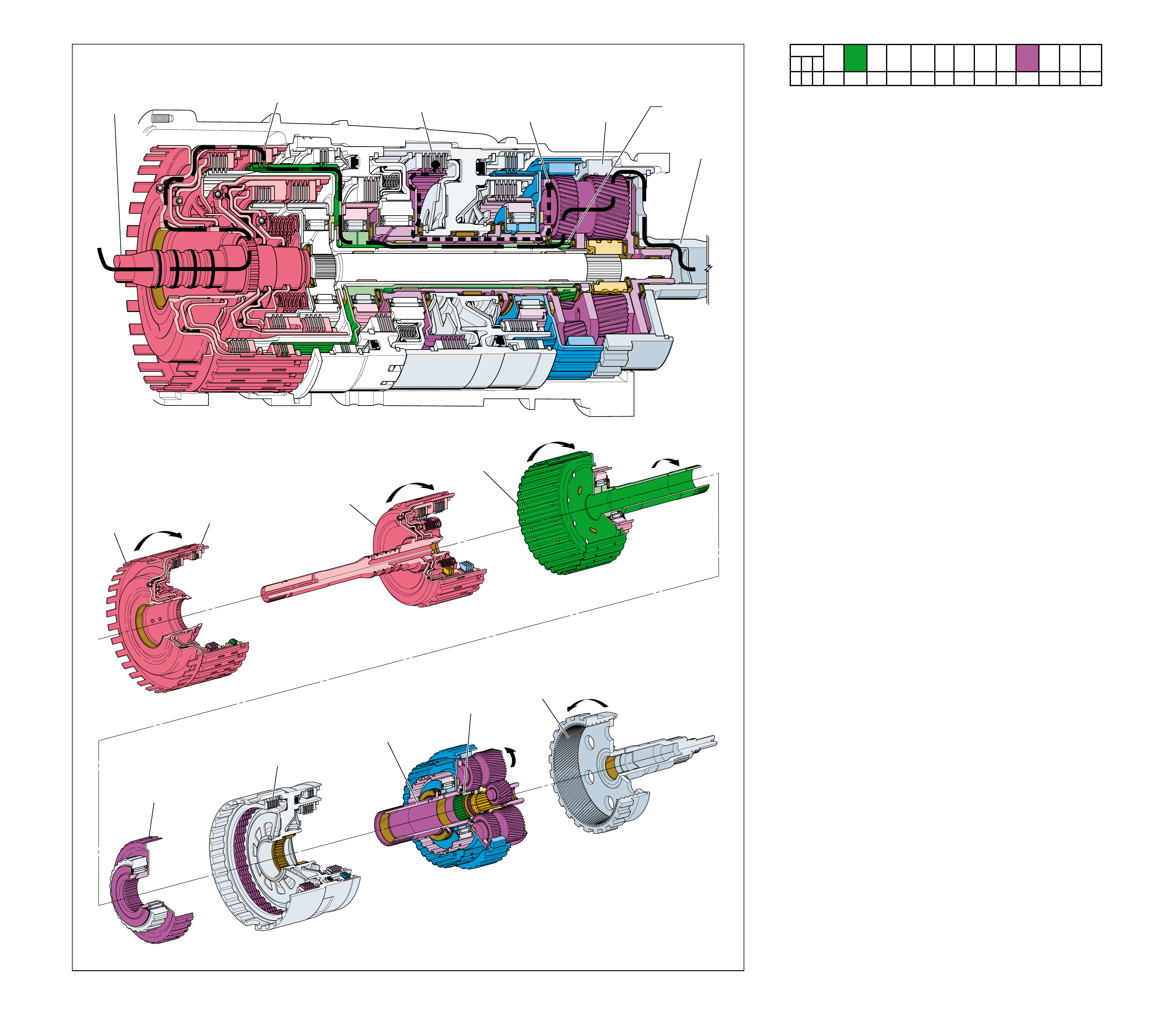
Figure 54
REVERSE
➤
➤
➤
➤
➤
➤
➤
➤➤➤
➤➤
➤
➤
➤
➤
6
REAR
INTERNAL
GEAR
(560)
DRIVEN
3
FRONT
INPUT SUN
GEAR
DRIVING
5
INPUT AND
REACTION
CARRIER
(553)
HELD
2
REVERSE
CLUTCH
APPLIED
4
LOW AND
REVERSE
CLUTCH
APPLIED
REVERSE
CLUTCH
HOUSING
ASSEMBLY
(401)
REVERSE
CLUTCH
APPLIED
LOW AND
REVERSE
CLUTCH
APPLIED
LOW CLUTCH
SPRAG
ASSEMBLY
INPUT AND
REACTION
CARRIER
(553)
HELD
FRONT
INPUT SUN
GEAR
DRIVING
OVERDRIVE AND
REVERSE CLUTCH
HUB ASSEMBLY
(470)
FOWARD AND
COAST CLUTCH
HOUSING
ASSEMBLY
(433)
REAR
INTERNAL
GEAR
(560)
DRIVEN
1
POWER FROM
TORQUE
CONVERTER
(1)
POWER TO
DIFFERENTIAL
ASSEMBLY
58
REVERSE
58A
In Reverse (R), torque from the engine is multiplied through the
torque converter and transmission gear set to the vehicle’s drive
shaft and rear axle. The planetary gear set operates in reduction
and also reverses the direction of input torque for a reverse gear
ratio of approximately 3.03:1.
•The manual shift shaft (606) and the manual valve (377) are
in the Reverse position.
1 Power from Torque Converter
The input shaft forward and coast clutch assembly (433) is
driven by the converter turbine.
2 Reverse Clutch Applied
The reverse clutch plates (415-419) are applied and allow
the overdrive and reverse clutch hub assembly (470), to
drive the front input sun gear.
3 Front Input Sun Gear Driving
Engine torque is transferred from the reverse clutch housing,
through the front input sun gear and to the long pinion
gears. The long pinion gears are in mesh with and drive the
rear internal gear (560).
4 Low and Reverse Clutch Applied
The low and reverse clutch is applied and holds the low
clutch sprag inner race which is splined to the input and
reaction carrier.
5 Input and Reaction Carrier Assembly Held
With the low and reverse clutch holding the input and reaction
carrier assembly, the reaction long pinion gears drive the
rear internal gear (560) in a reverse direction.
6 Rear Internal Gear Driven
The rear internal gear (560) is splined to the output shaft
assembly (562), thus the output shaft is also driven in a
reverse direction.
When the throttle is released in Reverse, power from the
vehicle (output shaft) drives through the reverse clutch to the
input shaft faster than engine speed is driving the input shaft.
The engine then works as a brake, slowing the transmission
down to input speed. This is referred to as engine braking.
SOLENOID FORWARD OVER- INTERM. INTER- LOW LOW AND SECOND SECOND
DIRECT REVERSE COAST FORWARD SPRAG DRIVE SPRAG MEDIATE SPRAG REVERSE SECOND SPRAG COAST
1-2 2-3 4-5 CLUTCH CLUTCH CLUTCH CLUTCH CLUTCH CLUTCH CLUTCH CLUTCH CLUTCH CLUTCH CLUTCH CLUTCH CLUTCH
OFF OFF OFF APPLIED APPLIED
LD = LOCKED IN DRIVE
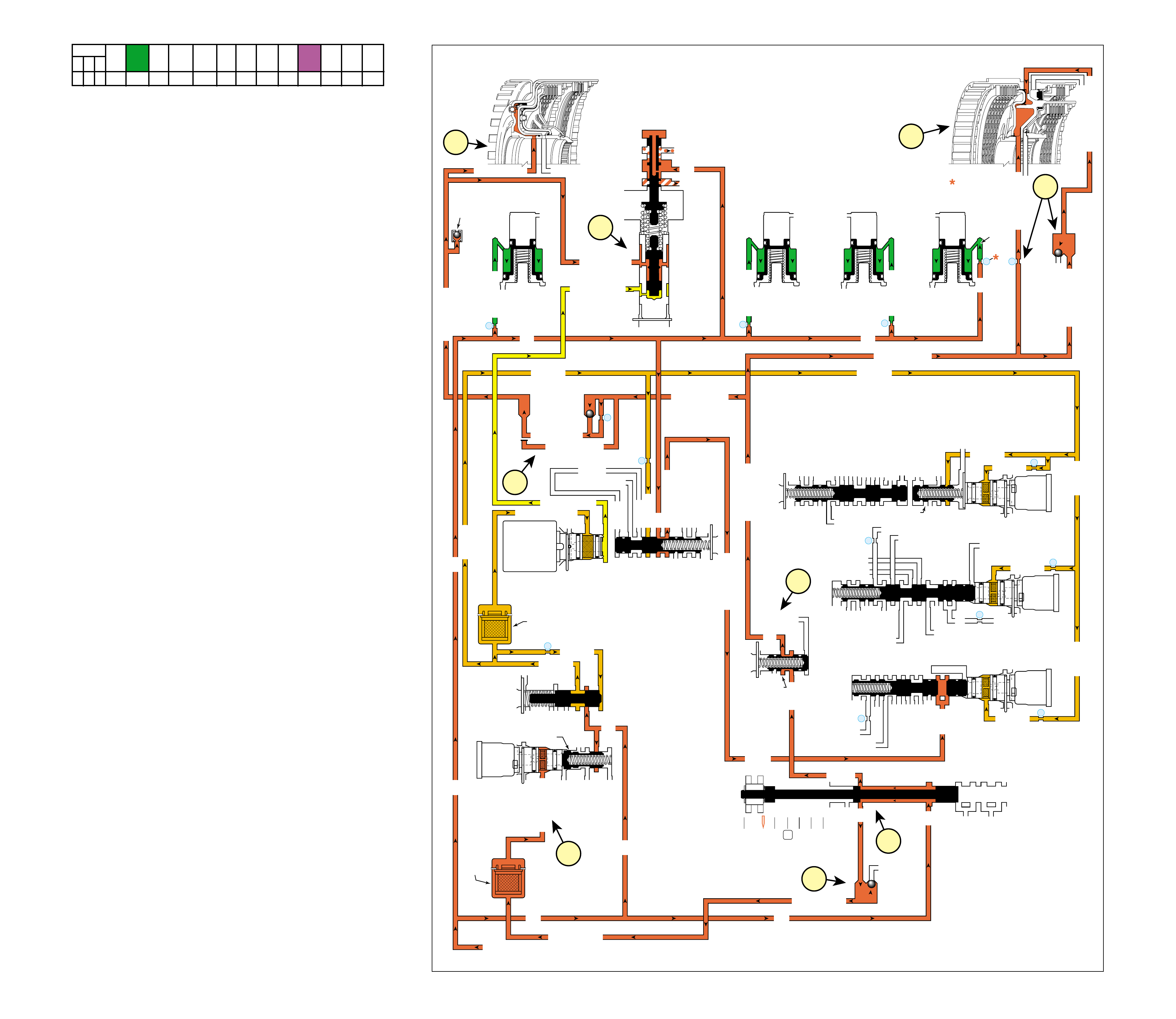
REVERSE
58B
COMPLETE HYDRAULIC CIRCUIT
Page 88
Figure 55
When the gear selector lever is moved to the Reverse (R)
position (from the Park position) the following changes occur
in the transmission’s hydraulic and electrical systems.
1 PRESSURE REGULATION
1a Manual Valve:
With the manual valve in the reverse position, line pressure
is directed into the reverse fluid circuit.
1b Reverse Lockout Valve:
Reverse fluid is routed through the reverse lockout valve
into the reverse lockout fluid circuit.
1c Pressure Regulator and Line Boost Valves:
Reverse clutch fluid at the line boost valve boosts line
pressure for the additional torque requirements in Reverse.
Throttle signal fluid pressure from the pressure control (PC)
solenoid acting on the line boost valve also helps determine
line pressure in Reverse depending on throttle position and
other TCM input signals.
2 LOW AND REVERSE CLUTCH APPLIES
2a #8 Ball Check Valve and Orifice #12:
Located in the bottom channel plate, reverse lockout fluid
seats the #8 ball check valve against the low and reverse
clutch fluid passage and directs fluid into the low and reverse
clutch or reverse lockout fluid passage. Reverse lockout
fluid pressure is also orificed, through orifice #12, to provide
a controlled apply of the low and reverse clutch.
2b Low and Reverse Clutch:
Low and reverse clutch or reverse lockout fluid pressure
enters the outer area of the low and reverse clutch piston
and moves the piston against spring force to apply the low
and reverse clutch plates. In addition, reverse lockout fluid
pressure is orificed into the inner area of the low and reverse
clutch piston and provides additional force to apply the low
and reverse clutch plates.
3 REVERSE CLUTCH APPLIES
3a #1 Ball Check Valve:
Located in the bottom channel plate, reverse lockout fluid
seats the #1 ball check valve and is forced through orifice
#13 in the control valve body spacer plate into the reverse
clutch fluid passage.
Note: Remember that the function of an orifice is to control the
flow rate of fluid and rate of apply or release of a clutch.
3b Reverse Clutch:
Reverse clutch fluid enters the reverse clutch housing and acts
on the reverse clutch piston to apply the reverse clutch plates.
4 FLUID PRESSURE DIRECTED IN PREPARATION
FOR TCC APPLY
4a #2 Ball Check Valve:
Located in the bottom channel plate, reverse fluid seats the
#2 ball check valve against the 2345 fluid passage and directs
fluid into the 2345 or reverse fluid passage.
4b Torque Converter Clutch Pulse Width Modulation
(TCC PWM) Solenoid Valve:
The TCC PWM solenoid valve remains de-energized (OFF).
2345 or reverse fluid is prevented from entering the TCC
signal fluid circuit. Under normal circumstances the TCC
PWM solenoid valve is not energized. In the event the TCC
PWM solenoid valve is energized (when engaging Reverse
while driving in Forward above a certain speed), TCC signal
fluid will shift the reverse lockout valve to block reverse
fluid from entering the reverse lockout circuit and the reverse
clutch and the low and reverse clutch will release to prevent
damage to the transmission.
SOLENOID FORWARD OVER- INTERM. INTER- LOW LOW AND SECOND SECOND
DIRECT REVERSE COAST FORWARD SPRAG DRIVE SPRAG MEDIATE SPRAG REVERSE SECOND SPRAG COAST
1-2 2-3 4-5 CLUTCH CLUTCH CLUTCH CLUTCH CLUTCH CLUTCH CLUTCH CLUTCH CLUTCH CLUTCH CLUTCH CLUTCH CLUTCH
OFF OFF OFF APPLIED APPLIED
LD = LOCKED IN DRIVE
REVERSE
LOW AND REV CL OR RLO
SECOND COAST CL
SECOND CLUTCH
REVERSE CLUTCH
OVERDR CL FD 2
ACCUMULATOR
INTERMED CL
ACCUMULATOR
EX
SECOND CL
ACCUM
ACCUMULATOR
LINE
LINE
LINE
REVERSE LOCKOUT
EXEXEX
DIRECT CL
DIRECT CLUTCH
4
2
5
DIRECT
CLUTCH
ACCUMULATOR
OVERDRIVE
CLUTCH
ACCUMULATOR
INTERMEDIATE
CLUTCH
ACCUMULATOR
SECOND
CLUTCH
ACCUMULATOR
DIRECT
AND REVERSE
CLUTCH
ASSEMBLY
(400—420)
CENTER
SUPPORT
ASSEMBLY
(510—535)
3
2345
2345 OR REVERSE
LINE
LINE
LINE (from Pump)
LINE
FILTERED FEED LIMIT
THROTTLE SIGNAL
EX
2345 OR REVERSE
TCC SIGNAL
REGULATED APPLY
REGULATED APPLY
EX
EX
FEED LIMIT VALVE
LINE
EX
EX
EX
EX
FEED LIMIT
FEED LIMIT
EX EX
SECOND COAST CLUTCH
23 REGULATED
OVERDRIVE CL FD 1
INTERMEDIATE CLUTCH
2345
INTERMEDIATE CLUTCH
2345
345
FEED LIMIT
EX
EX
EX
EX
2-3 SIGNAL
23 REGULATED
123 BRAKING
123
EX
EX
EX
123
COAST CLUTCH
COAST CLUTCH FEED
OVERDRIVE CL FD 2
45
FEED LIMIT
LINE
FEED LIMIT
32
MEMORY
MEMORY
MEMORY
MEMORY PILOT
32 SAFETY MODE
EX
EX
FDL
D432
2345
D432
SECOND CL
23 REGULATED
123 REGULATED
SECOND CL
123 REGULATED
LOW AND REV CL
EX
EX
EX
FEED LIMIT
FEED LIMIT
FDL
1-2 SIGNAL
2-3 SIGNAL
EX
EX
RPND432
MANUAL VALVE
LINE
D432
REV
REVERSE
EX
32
LINELINE
LINE SAFETY MODE
4-5 SIGNAL
24
28
2345 OR REVERSE
PRESSURE
CONTROL
SOLENOID
VALVE
1-2 SHIFT
SOLENOID
VALVE
N/C
(A)
OFF
2-3 SHIFT
SOLENOID
VALVE
N/C
(B)
OFF
4-5 SHIFT
SOLENOID
VALVE
N/C
(C)
OFF
TCC PWM
SOLENOID
VALVE
N/C
1-2 SHIFT VALVE
7
11
10
9
FILTER
(308)
FILTER
(312)
TCC REGULATOR VALVE
1-2 SHIFT CONTROL VALVE
#2
29
8
REVERSE CLUTCH
AIR
BLEED
(203)
FEED LIMIT
FEED LIMIT FEED LIMIT
FEED LIMITFEED LIMIT
2-3 SHIFT VALVE CNTRL
CNTRL
LINE SM
LINE SM
LINE SAFETY MODE
SAFETY MODE
TCC SIGNAL
RLO
EX
REVERSE
REVERSE
LOCKOUT
VALVE
REVERSE CLUTCH
REVERSE LOCKOUT
REVERSE LOCKOUT
REVERSE LOCKOUT
13
#1X-2
REVERSE LOCKOUT
REVERSE LOCKOUT
12
LOW AND REVERSE CL
#8
DECREASE
CONVERTER FEED
THROTTLE SIGNAL
LINE
EX
REVERSE CLUTCH
PRESS REG VALVEBOOST VALVE
4-5 SHIFT VLV
4b
3a
1c
1b
1a
3b
4a
2b
2a
59

NEUTRAL
(Engine Running)
1
POWER FROM
TORQUE
CONVERTER
(1)
TORQUE
CONVERTER
ASSEMBLY
(1)
REVERSE
CLUTCH
HOUSING
ASSEMBLY
(401)
FORWARD AND
COAST CLUTCH
HOUSING
ASSEMBLY
(433)
REAR
INTERNAL
GEAR
(560)
TORQUE
CONVERTER
HOUSING/PUMP
ASSEMBLY
(3)
PARK
PAWL
(612)
DISENGAGED
PARK
PAWL
ACTUATOR
ASSEMBLY
(613)
➤
➤
➤
2
NO POWER
TRANSMITTED
TO
DIFFERENTIAL
ASSEMBLY
Figure 56
60
NEUTRAL
(Engine Running)
60A
When the gear selector lever is placed in the Neutral (N) position,
mechanical power flow is identical to Park (P) range, except
that the park lock actuator assembly (613) is disengaged. The
park pawl spring (611) releases the park pawl (612) from the
lugs on the rear internal gear (560). With the park pawl
disengaged, the output shaft is free to rotate allowing the vehicle
to roll.
•The manual shift shaft (606) and the manual valve (377) are
in the Neutral position.
1 Power from Torque Converter
The input shaft forward and coast clutch housing assembly
is splined to and driven by the converter turbine.
2 Powerflow Terminated
Without any clutches applied, or sprag clutches holding, the
input shaft forward and coast clutch housing assembly rotates
freely and power flow is terminated.
Neutral range may be selected for starting the engine when
the vehicle is standing still or moving down the road.
SOLENOID FORWARD OVER- INTERM. INTER- LOW LOW AND SECOND SECOND
DIRECT REVERSE COAST FORWARD SPRAG DRIVE SPRAG MEDIATE SPRAG REVERSE SECOND SPRAG COAST
1-2 2-3 4-5 CLUTCH CLUTCH CLUTCH CLUTCH CLUTCH CLUTCH CLUTCH CLUTCH CLUTCH CLUTCH CLUTCH CLUTCH CLUTCH
OFF OFF OFF
LD = LOCKED IN DRIVE
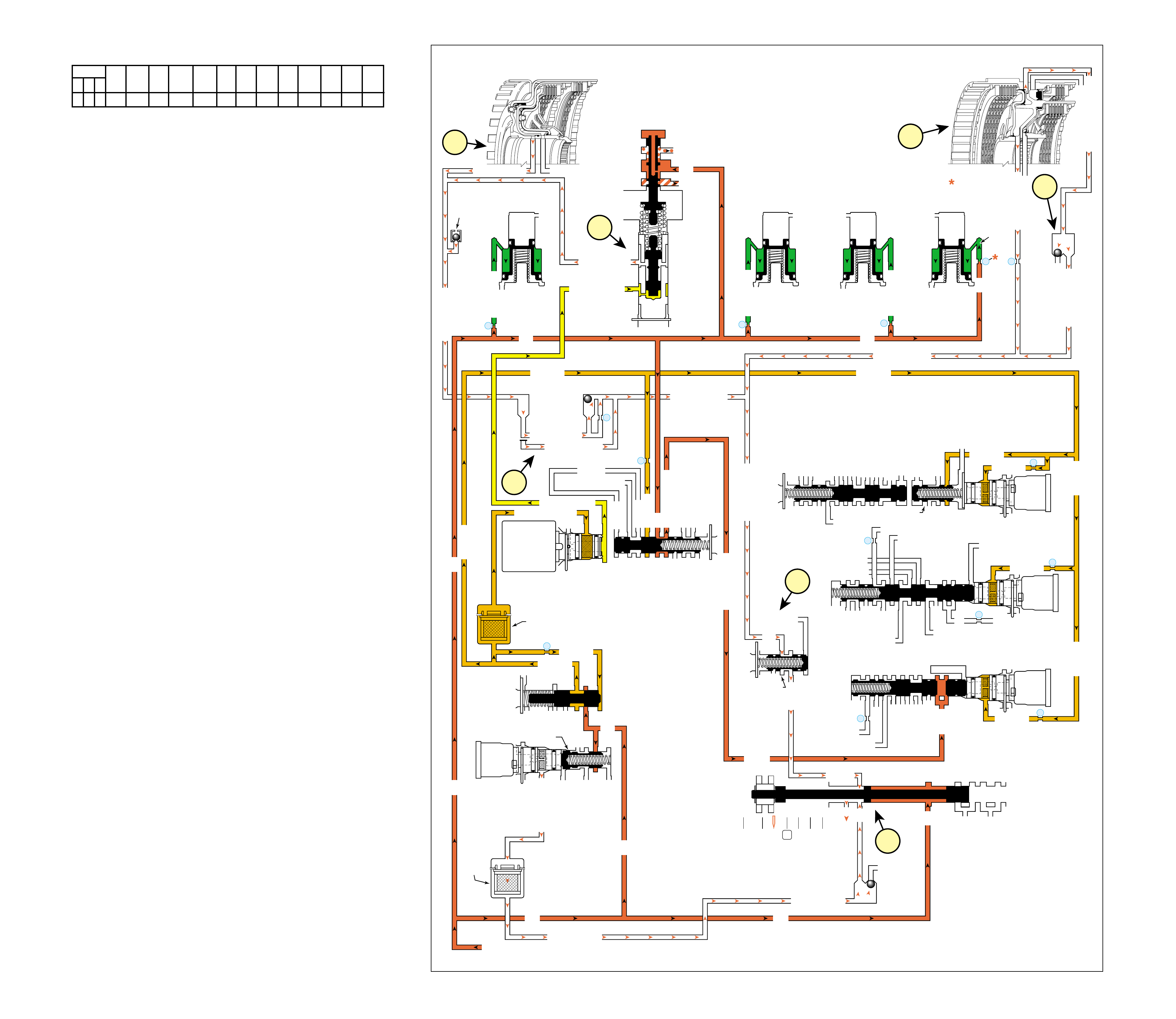
NEUTRAL
(Engine Running)
COMPLETE HYDRAULIC CIRCUIT
Page 90
Figure 57
When the gear selector lever is moved to the Neutral (N)
position, the hydraulic and electrical system operation is
identical to Park (P) range. However, if Neutral is selected
after the vehicle was operating in Reverse (R), the following
changes would occur in the hydraulic system:
1 REVERSE CLUTCH RELEASES
1a Manual Valve:
The manual valve is moved to the Neutral position and
blocks line pressure from entering the reverse fluid circuit.
The reverse fluid circuit is opened to an exhaust at the
manual valve.
1b Reverse Clutch:
Reverse clutch fluid exhausts from the reverse clutch to the
#1 ball check valve allowing the reverse clutch to release.
1c #1 Ball Check Valve:
Reverse clutch fluid unseats the #1 ball check valve and
enters the reverse lockout fluid circuit. Reverse lockout
fluid then flows to the reverse lockout valve where it enters
the reverse fluid circuit.
1d Reverse Lockout Valve:
Reverse lockout fluid passes through the reverse lockout
valve and into the reverse fluid circuit and on to the manual
valve where it exhausts.
1e Line Boost Valve:
Reverse clutch fluid exhausts from the line boost valve,
allowing line pressure to return to the normal operating
range as in Park, Neutral and Overdrive gear ranges.
2 LOW AND REVERSE CLUTCH RELEASES
2a Low and Reverse Clutch:
Low and reverse clutch or reverse lockout fluid exhausts
from the outer area of the low and reverse clutch piston to
the #8 ball check valve. Reverse lockout fluid also exhausts
from the inner area of the low and reverse clutch piston
through orifice #12. The exhaust of these fluids allows the
low and reverse clutch to release.
2b #8 Ball Check Valve:
Low and reverse clutch or reverse lockout fluid seats the #8
ball check valve against the low and reverse clutch fluid
circuit and enters the reverse lockout fluid circuit where it
exhausts along with reverse clutch fluid past the manual valve.
Note: Allowing fluid to bypass an orifice when exhausting
ensur es a quick r elease of the c lutch. This pr events the friction
material from “dragging” and creating excess fluid
temperatur es or damag ing the clutc h.
Note: In Park, Reverse and Neutral the shift solenoid valves
are shown de-energized. This is the normal operating state
when the vehicle is stationary or at low vehicle speeds. However ,
the TCM will change the shift solenoid valve states depending
on vehicle speed. For example, if Neutral range is selected
when the vehicle is operating in Second gear, the shift solenoid
valves will r emain in a Second gear sta te . But with the manual
valve in Neutral, line pressure is b locked, D432 fluid exhausts
and the transmission will shift into Neutr al.
SOLENOID FORWARD OVER- INTERM. INTER- LOW LOW AND SECOND SECOND
DIRECT REVERSE COAST FORWARD SPRAG DRIVE SPRAG MEDIATE SPRAG REVERSE SECOND SPRAG COAST
1-2 2-3 4-5 CLUTCH CLUTCH CLUTCH CLUTCH CLUTCH CLUTCH CLUTCH CLUTCH CLUTCH CLUTCH CLUTCH CLUTCH CLUTCH
OFF OFF OFF
LD = LOCKED IN DRIVE
NEUTRAL
(Engine Running)
LOW AND REV CL OR RLO
SECOND COAST CL
SECOND CLUTCH
REVERSE CLUTCH
OVERDR CL FD 2
ACCUMULATOR
INTERMED CL
ACCUMULATOR
EX
SECOND CL
ACCUM
ACCUMULATOR
LINE
LINE
LINE
REVERSE LOCKOUT
EXEXEX
DIRECT CL
DIRECT CLUTCH
4
2
5
DIRECT
CLUTCH
ACCUMULATOR
OVERDRIVE
CLUTCH
ACCUMULATOR
INTERMEDIATE
CLUTCH
ACCUMULATOR
SECOND
CLUTCH
ACCUMULATOR
DIRECT
AND REVERSE
CLUTCH
ASSEMBLY
(400—420)
CENTER
SUPPORT
ASSEMBLY
(510—535)
3
2345
2345 OR REVERSE
LINE
LINE
LINE (from Pump)
LINE
FILTERED FEED LIMIT
THROTTLE SIGNAL
EX
2345 OR REVERSE
TCC SIGNAL
REGULATED APPLY
REGULATED APPLY
EX
EX
FEED LIMIT VALVE
LINE
EX
EX
EX
EX
FEED LIMIT
FEED LIMIT
EX EX
SECOND COAST CLUTCH
23 REGULATED
OVERDRIVE CL FD 1
INTERMEDIATE CLUTCH
2345
INTERMEDIATE CLUTCH
2345
345
FEED LIMIT
EX
EX
EX
EX
2-3 SIGNAL
23 REGULATED
123 BRAKING
123
EX
EX
EX
123
COAST CLUTCH
COAST CLUTCH FEED
OVERDRIVE CL FD 2
45
FEED LIMIT
LINE
FEED LIMIT
32
MEMORY
MEMORY
MEMORY
MEMORY PILOT
32 SAFETY MODE
EX
EX
FDL
D432
2345
D432
SECOND CL
23 REGULATED
123 REGULATED
SECOND CL
123 REGULATED
LOW AND REV CL
EX
EX
EX
FEED LIMIT
FEED LIMIT
FDL
1-2 SIGNAL
2-3 SIGNAL
EX
EX
RPND432
MANUAL VALVE
LINE
D432
REV
REVERSE
EX
32
LINELINE
LINE SAFETY MODE
4-5 SIGNAL
24
28
2345 OR REVERSE
PRESSURE
CONTROL
SOLENOID
VALVE
1-2 SHIFT
SOLENOID
VALVE
N/C
(A)
OFF
2-3 SHIFT
SOLENOID
VALVE
N/C
(B)
OFF
4-5 SHIFT
SOLENOID
VALVE
N/C
(C)
OFF
TCC PWM
SOLENOID
VALVE
N/C
1-2 SHIFT VALVE
7
11
10
9
FILTER
(308)
FILTER
(312)
TCC REGULATOR VALVE
1-2 SHIFT CONTROL VALVE
#2
29
8
REVERSE CLUTCH
AIR
BLEED
(203)
FEED LIMIT
FEED LIMIT FEED LIMIT
FEED LIMITFEED LIMIT
2-3 SHIFT VALVE CNTRL
CNTRL
LINE SM
LINE SM
LINE SAFETY MODE
SAFETY MODE
TCC SIGNAL
RLO
EX
REVERSE
REVERSE
LOCKOUT
VALVE
REVERSE CLUTCH
REVERSE LOCKOUT
REVERSE LOCKOUT
REVERSE LOCKOUT
13
#1X-2
REVERSE LOCKOUT
REVERSE LOCKOUT
12
LOW AND REVERSE CL
#8
DECREASE
CONVERTER FEED
THROTTLE SIGNAL
LINE
EX
REVERSE CLUTCH
PRESS REG VALVEBOOST VALVE
4-5 SHIFT VLV
1c
1e
1d
1a
1b 2a
2b
60B 61

Figure 58
OVERDRIVE RANGE – FIRST GEAR
(before the first 1-2 shift has occurred)
➤
➤➤
➤
➤➤➤➤
➤
➤
➤
➤
➤
➤
➤➤
1
POWER FROM
TORQUE
CONVERTER
(1)
4
REAR
INPUT SUN
GEAR
DRIVING
POWER TO
DIFFERENTIAL
ASSEMBLY
LOW AND
REVERSE
CLUTCH
APPLIED
8
REAR
INTERNAL
GEAR
(560)
DRIVEN
5
LONG
PLANETARY
PINION
GEAR
DRIVING
REAR
INTERNAL
GEAR
(560)
DRIVEN
6a
INPUT AND
REACTION
CARRIER
(553)
HELD
INPUT AND
REACTION
CARRIER
(553)
HELD
4a
REAR SHORT
PINION GEAR
DRIVING
REAR SHORT
PINION GEAR
DRIVING
REAR
INPUT
SUN GEAR
DRIVING
LONG
PLANETARY
PINION
GEAR
DRIVING
2a
COAST
CLUTCH
APPLIED
COAST
CLUTCH
APPLIED
REVERSE
CLUTCH
HOUSING
ASSEMBLY
(401)
2
FORWARD
CLUTCH
APPLIED
FORWARD
CLUTCH
APPLIED
3
FORWARD
CLUTCH
SPRAG
(461)
HOLDING
FORWARD
CLUTCH
SPRAG
(461)
HOLDING
6
LOW
CLUTCH
SPRAG
(503)
HOLDING
7
LOW AND
REVERSE
CLUTCH
APPLIED
LOW
CLUTCH
SPRAG
(503)
HOLDING
In Overdrive Range D – First Gear, torque from the engine is
multiplied through the torque converter and transmission gear set
to the vehicle’s drive shaft. The planetary gears operate in reduction
to achieve a First gear starting ratio of approximately 3.42:1.
•The manual shift shaft (606) and the manual valve (377) are
in the Overdrive D position.
1 Power from Torque Converter
The input shaft forward and coast clutch housing assembly
(433) is splined to and driven by the converter turbine.
2 Forward and Coast Clutches Applied
The forward clutch, which is located within the input shaft
forward and coast clutch housing assembly (433), is applied
and holds the forward clutch sprag outer race (459). The
coast clutch is also located in the input shaft forward and
coast clutch housing assembly (433) and is also applied.
3 Forward Clutch Sprag Holding
The forward clutch sprag (461) holds and power is
transmitted to the input sun gear shaft assembly (457).
4 Rear Input Sun Gear Driving
The input sun gear shaft assembly (457) is splined to the
rear input sun gear. The rear input sun gear drives the rear
short planetary pinions.
5 Long Planetary Pinion Gears Driving
The rear short planetary pinions drive the long planetary
pinions. The long pinions are in mesh with the front input
sun gear, the front short pinions and the rear internal gear.
6 Low Clutch Sprag Holding
The power transferred to the input and reaction carrier (553)
by the long planetary pinions attempts to rotate the carrier but,
the carrier is held stationary by the low clutch sprag (503).
7 Low and Reverse Clutch Applied
The low and reverse clutch, which is located within the
center support (518), is applied and holds the low clutch
sprag inner race (505). This assists the low clutch sprag in
holding the input and reaction carrier (553) stationary.
8 Rear Internal Gear Driven
With the input and reaction carrier (553) held, the long
pinions drive the rear internal gear (560) to achieve the first
gear starting ratio of approximately 3.42:1
•When the throttle is released in Overdrive Range – First Gear
before the first 1-2 shift has occurred, power from the vehicle
wheels attempts to drive the transmission components faster
than engine torque is driving them. Because the low and
reverse clutch is applied and holds the input and reaction carrier
assembly stationary, the low clutch sprag (503) is prevented
from overrunning and engine braking slows the vehicle.
As vehicle speed increases, less torque multiplication is needed
for maximum efficiency. Therefore, it is desirable to shift the
transmission to a lower gear ratio, or Second gear.
Note: the above description of mechanical power flow occurs
before the first 1-2 shift has occurred.
OVERDRIVE RANGE – FIRST GEAR
(before the first 1-2 shift has occurred)
62A
SOLENOID FORWARD OVER- INTERM. INTER- LOW LOW AND SECOND SECOND
DIRECT REVERSE COAST FORWARD SPRAG DRIVE SPRAG MEDIATE SPRAG REVERSE SECOND SPRAG COAST
1-2 2-3 4-5 CLUTCH CLUTCH CLUTCH CLUTCH CLUTCH CLUTCH CLUTCH CLUTCH CLUTCH CLUTCH CLUTCH CLUTCH CLUTCH
OFF ON OFF APPLIED APPLIED LD LD APPLIED
LD = LOCKED IN DRIVE
62
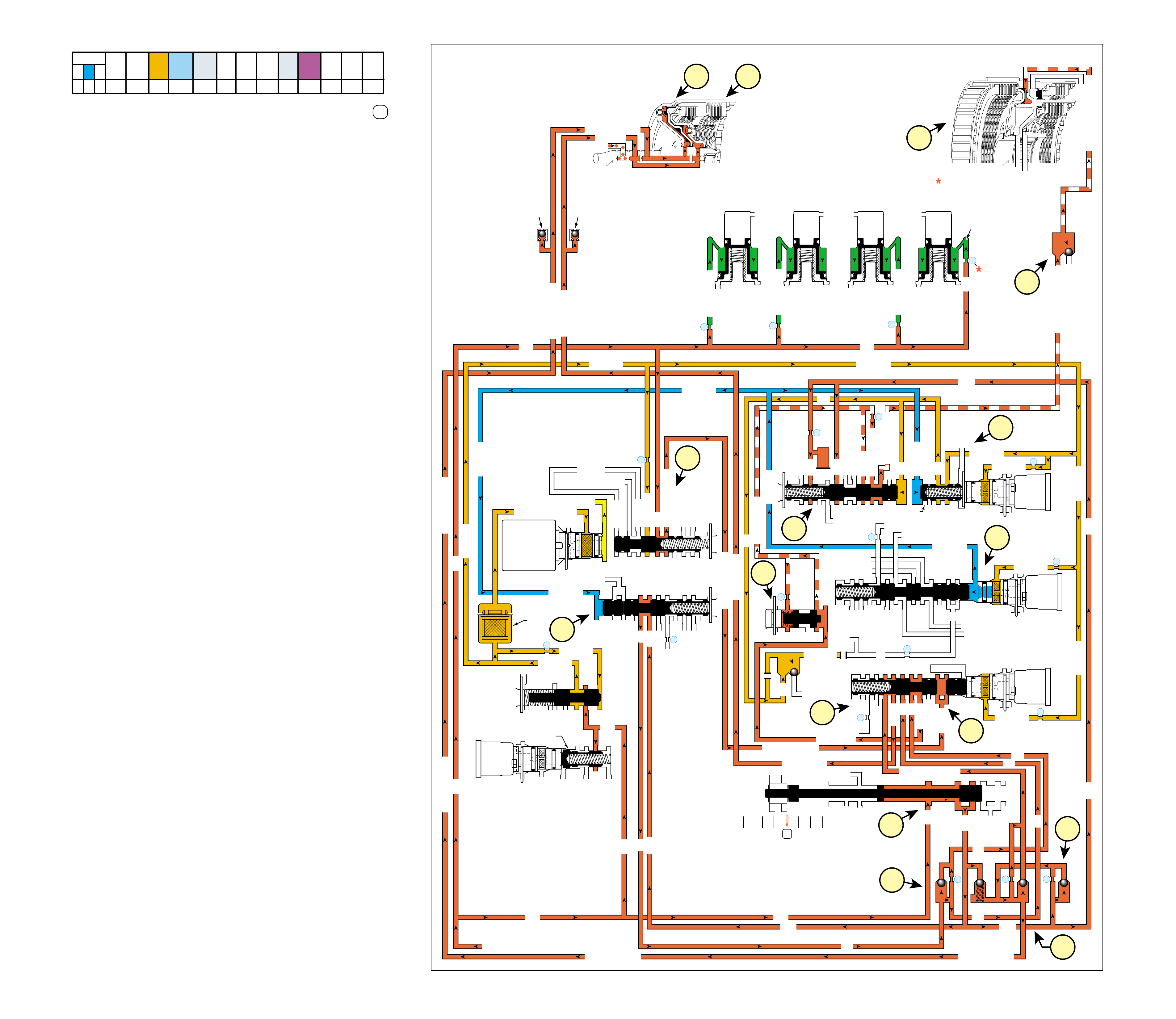
OVERDRIVE RANGE – FIRST GEAR
(before the first 1-2 shift has occurred)
COMPLETE HYDRAULIC CIRCUIT
Page 92 Figure 59
When the gear selector lever is moved to the Overdrive Range D
position from the Neutral (N) position, before the first 1-2 shift has
occurred, the following changes occur to shift the transmission into
Overdri ve Range – First Gear.
1 MANUAL VALVE
In the Overdrive position the manual valve routes line pressure into the
D432 fluid circuit. D432 fluid is routed to the 1-2 shift valve and to
the 3-4 shift valve.
2 FORWARD CLUTCH APPLIES
2a #6 and #7 Ball Check Valves:
D432 fluid seats the #6 ball check valve and passes through
orifice #15 into the forward clutch fluid circuit. D432 fluid also
passes by the spring loaded #7 ball check valve to feed the forward
clutch circuit as necessary to help control forward clutch apply.
2b Forward Clutch Assembly:
Forward clutch fluid is routed to the forward clutch piston to
apply the forward clutch plates.
3 COAST CLUTCH APPLIES
3a #5 Ball Check Valve:
Forward clutch fluid seats the #5 ball check valve and passes
through orifice #17 into the coast clutch feed circuit. This orifice
helps to control coast clutch apply.
3b Safety Mode Valve
Before the first 1-2 shift has occurred, the safety mode valve
(341) remains in the released position, allowing line fluid pressure
to enter the line safety mode fluid circuit.
3c 4-5 Shift Valve:
Line safety mode fluid applies the 4-5 shift valve (374) against 4-
5 shift valve spring (373) force. This allows coast clutch feed
fluid to enter the coast clutch fluid circuit.
3d Coast Clutch Assembly:
Coast clutch fluid is routed to the coast clutch piston to apply the
coast clutch plates.
4 LOW AND REVERSE CLUTCH APPLIES
4a 2-3 Shift Solenoid (SS) Valve:
The 2-3 SS valve is energized, allowing feed limit fluid to enter
the 2-3 signal fluid circuit. 2-3 signal fluid overcomes spring
force and applies the 2-3 shift valve (371).
4b 3-4 Shift Control Valve and 3-4 Shift Valve:
2-3 signal fluid is routed to the 3-4 shift control valve (346) and
applies the valve against spring force. This allows D432 fluid to
enter the 123 fluid circuit.
4c #4 Ball Check Valve:
123 fluid seats the #4 ball check valve and passes through orifice
#16. This orifice helps to control low and reverse clutch apply.
4d 4-5 Shift Valve:
Orificed 123 fluid is routed to the 4-5 shift valve (374) where it
passes into the 123 braking fluid circuit.
4e Low Pressure Control Valve:
123 braking fluid is routed to the low pressure control valve (383).
This valve regulates 123 braking fluid into the 123 regulated fluid
circuit against spring force and orificed 123 regulated fluid pressure.
4f 1-2 Shift Control Valve and 1-2 Shift Valve:
2-3 signal fluid is also routed to the 1-2 shift control valve (366)
and applies the valve against spring force. This allows feed limit
fluid to enter the FDL fluid circuit. FDL fluid is routed to the 1-2
shift valve (387) and applies the valve against spring force. 123
regulated fluid is routed through orifice #20 to the 1-2 shift valve
where it passes into the low and reverse clutch fluid circuit.
4g #8 Ball Check Valve:
Low and reverse clutch fluid seats the #8 ball check valve against
the reverse lockout fluid passage and enters the low and reverse
clutch or reverse lockout fluid passage.
4h Low and Reverse Clutch:
Low and reverse clutch or reverse lockout fluid pressure enters the
outer area of the low and reverse clutch piston and moves the piston
against spring force to apply the low and reverse clutch plates.
5 FLUID PRESSURE DIRECTED IN PREPARATION
FOR A SHIFT TO SECOND GEAR
5a 1-2 Shift Valve:
D432 fluid is routed to the 1-2 shift valve (387) where it is
blocked by the valve in preparation for an upshift to second gear.
SOLENOID FORWARD OVER- INTERM. INTER- LOW LOW AND SECOND SECOND
DIRECT REVERSE COAST FORWARD SPRAG DRIVE SPRAG MEDIATE SPRAG REVERSE SECOND SPRAG COAST
1-2 2-3 4-5 CLUTCH CLUTCH CLUTCH CLUTCH CLUTCH CLUTCH CLUTCH CLUTCH CLUTCH CLUTCH CLUTCH CLUTCH CLUTCH
OFF ON OFF APPLIED APPLIED LD LD APPLIED
LD = LOCKED IN DRIVE
OVERDRIVE RANGE – FIRST GEAR
(before the first 1-2 shift has occurred)
LUBE
OVERDRIVE CL FD 2
ACCUMULATOR
INTERMEDIATE CL
ACCUMULATOR
EX
SECOND CLUTCH
ACCUM
ACCUMULATOR
LINE
LINE
LINE
COAST CL
EXEXEX
DIRECT CL
4
2
5
DIRECT
CLUTCH
ACCUMULATOR
OVERDRIVE
CLUTCH
ACCUMULATOR
INTERMEDIATE
CLUTCH
ACCUMULATOR
SECOND
CLUTCH
ACCUMULATOR
FORWARD
AND COAST
CLUTCH
ASSEMBLY
(430–451)
3
LINE
LINE
LINE (from Pump)
LINE
FILTERED FEED LIMIT
THROTTLE SIGNAL
EX
2345 OR REVERSE
TCC SIGNAL
REGULATED APPLY
REGULATED APPLY
EX
EX
FEED LIMIT VALVE
LINE
EX
EX
EX
EX
FEED LIMIT
FEED LIMIT
EX
SECOND COAST CLUTCH
23 REGULATED
OVERDRIVE CL FD 1
INTERMEDIATE CLUTCH
2345
INTERMEDIATE CLUTCH
2345
345
FEED LIMIT
EX
EX
EX
EX
2-3 SIGNAL
23 REGULATED
LINE SM
LINE SAFETY MODE
123 BRK
123
EX
EX
EX
123
123
123123
123
123
CST CL
COAST CLUTCH
COAST CLUTCH COAST CLUTCH FEED
OVERDRIVE CL FD 2
45
FEED LIMIT
LINE
FEED LIMIT
32
MEMORY
MEMORY
MEMORY
MEMORY PILOT
32 SAFETY MODE
EX
EX
2-3 SIGNAL
123123 D432D432
DIRECT CLUTCH
45
1-2 SIGNAL
EX
EX
EX
FDL
D432
2345
D432
D432
D432D432
D432D432
SECOND CL
23 REGULATED
SECOND CL
123 REGULATED
LOW AND REV CL
EX
EX
EX
FEED LIMIT
FEED LIMIT
FDL
1-2 SIGNAL
2-3 SIGNAL
EX
EX
RPND432
MANUAL VALVE
LINE
D432
REV
REVERSE
EX
32
LINELINE
LINE SAFETY MODE
LINE SAFETY MODE
4-5 SIGNAL
24
28
345
345
PRESSURE
CONTROL
SOLENOID
VALVE
1-2 SHIFT
SOLENOID
VALVE
N/C
(A)
OFF
2-3 SHIFT
SOLENOID
VALVE
N/C
(B)
ON
4-5 SHIFT
SOLENOID
VALVE
N/C
(C)
OFF
TCC PWM
SOLENOID
VALVE
N/C
CNTRL
7
11
10
9
FILTER
(312)
TCC REGULATOR VALVE
1-2 SHIFT CONTROL VALVE
#7
26
#6
15
#5
17
#4 16
EX
EX
29
8
COAST CLUTCH
AIR
BLEED
(203)
FORWARD CLUTCH
FORWARD CLUTCH
FORWARD CLUTCHFORWARD CLUTCH
FORWARD CLUTCH FORWARD CLUTCH
AIR
BLEED
(203)
14
X-3
FEED LIMIT
FEED LIMIT FEED LIMIT
FEED LIMITFEED LIMIT
123
3-4 SHIFT
CNTRL
2-3 SIGNAL
2-3 SIGNAL
2-3 SIGNAL
2-3 SHIFT VALVE CNTRL
FDL
FDL
FDL
#10
32 SM/FDL
32 SM
SAFETY MODE
1-2 SHIFT VALVE
4-5 SHIFT VLV
123 BRAKING
123 REG
LOW PRESSURE
EX
123 REGULATED
19
20
LOW AND REV CL OR RLO
SECOND COAST CL
SECOND CLUTCH
REVERSE LOCKOUT
CENTER
SUPPORT
ASSEMBLY
(510–535)
REVERSE LOCKOUT
LOW AND REVERSE CL
#8
3d
3c
4a
2a
4e
3a
4f
3b
2b
5a
4g
4b
4d
4h
1
4c
62B 63
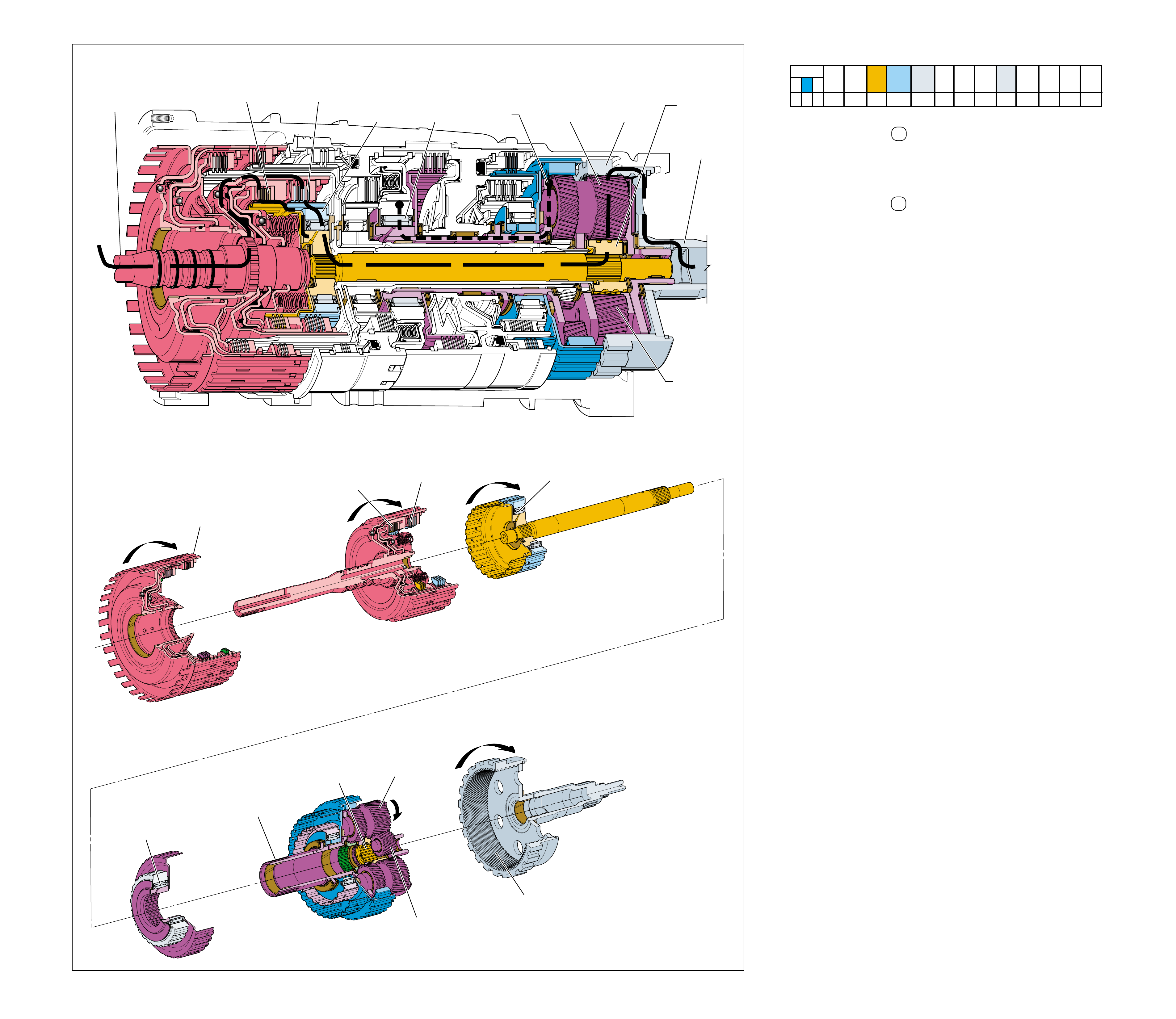
OVERDRIVE RANGE – FIRST GEAR
(after the first 1-2 shift has occurred)
➤
➤➤
➤
➤➤➤➤
➤
➤
➤
➤
➤
➤
➤➤
7
REAR
INTERNAL
GEAR
(560)
DRIVEN
5
LONG
PLANETARY
PINION
GEAR
DRIVING
REAR
INTERNAL
GEAR
(560)
DRIVEN
6a
INPUT AND
REACTION
CARRIER
(553)
HELD
INPUT AND
REACTION
CARRIER
(553)
HELD
4a
REAR SHORT
PINION GEAR
DRIVING
REAR SHORT
PINION GEAR
DRIVING
REAR
INPUT
SUN GEAR
DRIVING
LONG
PLANETARY
PINION
GEAR
DRIVING
2a
COAST
CLUTCH
APPLIED
COAST
CLUTCH
APPLIED
REVERSE
CLUTCH
HOUSING
ASSEMBLY
(401)
2
FORWARD
CLUTCH
APPLIED
FORWARD
CLUTCH
APPLIED
3
FORWARD
CLUTCH
SPRAG
(461)
HOLDING
FORWARD
CLUTCH
SPRAG
(461)
HOLDING
6
LOW
CLUTCH
SPRAG
(503)
HOLDING
LOW
CLUTCH
SPRAG
(503)
HOLDING
1
POWER FROM
TORQUE
CONVERTER
(1)
4
REAR
INPUT SUN
GEAR
DRIVING
POWER TO
DIFFERENTIAL
ASSEMBLY
Figure 60
In Overdrive Range D – First Gear, torque from the engine is
multiplied through the torque converter and transmission gear set
to the vehicle’s drive shaft. The planetary gears operate in reduction
to achieve a First gear starting ratio of approximately 3.42:1.
•The manual shift shaft (606) and the manual valve (377) are
in the Overdrive D position.
1 Power from Torque Converter
The input shaft forward and coast clutch housing assembly
(433) is splined to and driven by the converter turbine.
2 Forward and Coast Clutches Applied
The forward clutch, which is located within the input shaft
forward and coast clutch housing assembly (433), is applied
and holds the forward clutch sprag outer race (459). The
coast clutch is also located in the input shaft forward and
coast clutch housing assembly (433) and is also applied.
3 Forward Clutch Sprag Holding
The forward clutch sprag (461) holds and power is
transmitted to the input sun gear shaft assembly (457).
4 Rear Input Sun Gear Driving
The input sun gear shaft assembly (457) is splined to the
rear input sun gear. The rear input sun gear drives the rear
short planetary pinions.
5 Long Planetary Pinion Gears Driving
The rear short planetary pinions drive the long planetary
pinions. The long pinions are in mesh with the front input
sun gear, the front short pinions and the rear internal gear.
6 Low Clutch Sprag Holding
The power transferred to the input and reaction carrier (553)
by the long planetary pinions attempts to rotate the carrier but,
the carrier is held stationary by the low clutch sprag (503).
7 Rear Internal Gear Driven
With the input and reaction carrier (553) held, the long
pinions drive the rear internal gear (560) to achieve the first
gear starting ratio of approximately 3.42:1
•When the throttle is released in Overdrive Range – First
Gear, power from the vehicle wheels drives the transmission
components faster than engine torque is driving them. This
causes the low clutch sprag (503) to overrun and allows the
vehicle to coast freely without engine braking.
•In order to achieve engine braking, the low and reverse clutch
can be applied to hold the input and reaction carrier assembly.
See Manual Second – First Gear (page 82A) for a description
of power flow during coast conditions.
As vehicle speed increases, less torque multiplication is needed
for maximum efficiency. Therefore, it is desirable to shift the
transmission to a lower gear ratio, or Second gear.
Note: the above description of mechanical power flow occurs
after the first 1-2 shift has occurred.
OVERDRIVE RANGE – FIRST GEAR
(after the first 1-2 shift has occurred)
64A
SOLENOID FORWARD OVER- INTERM. INTER- LOW LOW AND SECOND SECOND
DIRECT REVERSE COAST FORWARD SPRAG DRIVE SPRAG MEDIATE SPRAG REVERSE SECOND SPRAG COAST
1-2 2-3 4-5 CLUTCH CLUTCH CLUTCH CLUTCH CLUTCH CLUTCH CLUTCH CLUTCH CLUTCH CLUTCH CLUTCH CLUTCH CLUTCH
OFF ON OFF APPLIED APPLIED LD LD
LD = LOCKED IN DRIVE
64
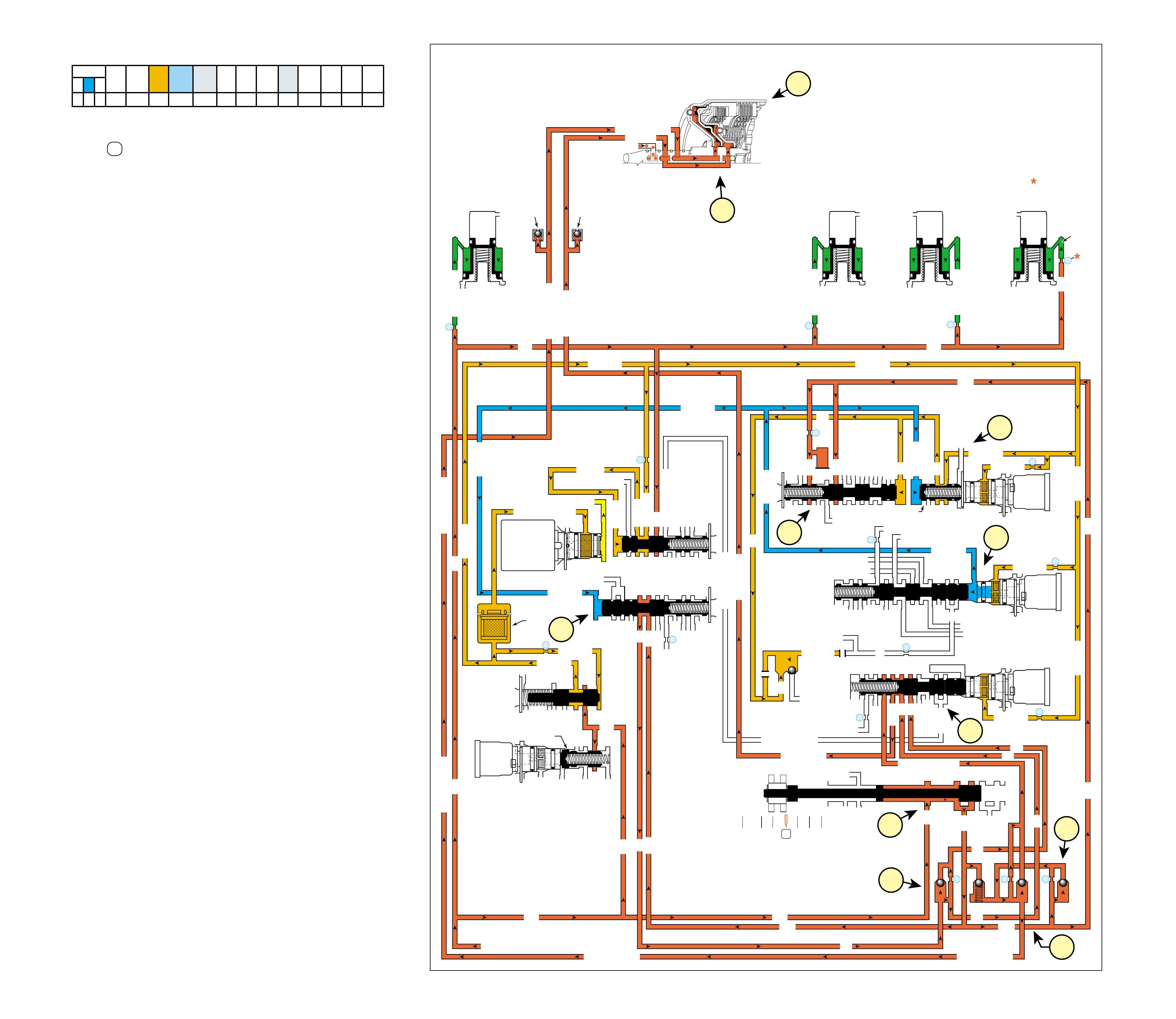
64B
OVERDRIVE RANGE – FIRST GEAR
(after the first 1-2 shift has occurred)
COMPLETE HYDRAULIC CIRCUIT
Page 92
When the gear selector lever is moved to the Overdrive
Range D position from the Neutral (N) position, after the
first 1-2 shift has occurred, the following changes occur to
shift the transmission into Overdr iv e Range – First Gear.
1 MANUAL VALVE
In the Overdrive position the manual valve routes line pressure
into the D432 fluid circuit. D432 fluid is routed to the 1-2 shift
valve and to the 3-4 shift valve.
2 FORWARD CLUTCH APPLIES
2a #6 and #7 Ball Check Valves:
D432 fluid seats the #6 ball check valve and passes through
orifice #15 into the forward clutch fluid circuit. D432 fluid
also passes by the spring loaded #7 ball check valve to feed
the forward clutch circuit as necessary to help control forward
clutch apply.
2b #5 Ball Check Valve:
Forward clutch fluid seats the #5 ball check valve and passes
through orifice #17 into the coast clutch feed circuit.
2c Forward Clutch Assembly:
Forward clutch fluid is routed to the forward clutch piston
to apply the forward clutch plates.
3 COAST CLUTCH APPLIES
3a 2-3 Shift Solenoid (SS) Valve:
The 2-3 SS valve is energized, allowing feed limit fluid to
enter the 2-3 signal fluid circuit. 2-3 signal fluid overcomes
2-3 shift valve spring (372) force and moves the 2-3 shift
valve (371) to the applied position.
3b 1-2 Shift Control Valve and 1-2 Shift Valve:
2-3 signal fluid is routed to the 1-2 shift control valve (366)
and moves the valve against 1-2 shift control valve spring
(367) force to the applied position. This allows feed limit
fluid to enter the FDL fluid circuit. FDL fluid is routed to
the 1-2 shift valve (387) and moves the valve against 1-2
shift valve spring (388) force to the applied position to
block D432 fluid at the valve.
3c 3-4 Shift Control Valve and 3-4 Shift Valve:
2-3 signal fluid is also routed to the 3-4 shift control valve
(346) and moves the valve against 3-4 shift valve spring
(344) force to the applied position. This allows D432 fluid
to enter the 123 fluid circuit at the 3-4 shift valve (345).
3d #4 Ball Check Valve:
123 fluid seats the #4 ball check valve and passes through
orifice #16. This orifice helps to control coast clutch apply.
3e 4-5 Shift Valve:
Orificed 123 fluid is routed to the 4-5 shift valve (374)
where it passes into the coast clutch fluid circuit.
3f Coast Clutch Assembly:
Coast clutch fluid is routed to the coast clutch piston to
apply the coast clutch plates.
4 FLUID PRESSURE DIRECTED IN PREPARATION
FOR A SHIFT TO SECOND GEAR
4a 1-2 Shift Valve:
D432 fluid is routed to the 1-2 shift valve (387) where it
is blocked by the valve in preparation for an upshift to
second gear.
SOLENOID FORWARD OVER- INTERM. INTER- LOW LOW AND SECOND SECOND
DIRECT REVERSE COAST FORWARD SPRAG DRIVE SPRAG MEDIATE SPRAG REVERSE SECOND SPRAG COAST
1-2 2-3 4-5 CLUTCH CLUTCH CLUTCH CLUTCH CLUTCH CLUTCH CLUTCH CLUTCH CLUTCH CLUTCH CLUTCH CLUTCH CLUTCH
OFF ON OFF APPLIED APPLIED LD LD
LD = LOCKED IN DRIVE
Figure 61
OVERDRIVE RANGE – FIRST GEAR
(after the first 1-2 shift has occurred)
LUBE
OVERDRIVE CL FD 2
ACCUMULATOR
INTERMEDIATE CL
ACCUMULATOR
EX
SECOND CLUTCH
ACCUM
ACCUMULATOR
LINE
LINE
LINE
COAST CL
EXEXEX
DIRECT CL
4
2
5
DIRECT
CLUTCH
ACCUMULATOR
OVERDRIVE
CLUTCH
ACCUMULATOR
INTERMEDIATE
CLUTCH
ACCUMULATOR
SECOND
CLUTCH
ACCUMULATOR
FORWARD
AND COAST
CLUTCH
ASSEMBLY
(430–451)
3
LINE
LINE
LINE (from Pump)
LINE
FILTERED FEED LIMIT
THROTTLE SIGNAL
EX
2345 OR REVERSE
TCC SIGNAL
REGULATED APPLY
REGULATED APPLY
EX
EX
FEED LIMIT VALVE
LINE
EX
EX
EX
EX
FEED LIMIT
FEED LIMIT
EX
SECOND COAST CLUTCH
23 REGULATED
OVERDRIVE CL FD 1
INTERMEDIATE CLUTCH
2345
INTERMEDIATE CLUTCH
2345
345
FEED LIMIT
EX
EX
EX
EX
2-3 SIGNAL
23 REGULATED
LINE SM
LINE SAFETY MODE
123 BRK
123
EX
EX
EX
123
123
123123
123
123
CST CL
COAST CLUTCH
COAST CLUTCH COAST CLUTCH FEED
OVERDRIVE CL FD 2
45
FEED LIMIT
LINE
FEED LIMIT
32
MEMORY
MEMORY
MEMORY
MEMORY PILOT
32 SAFETY MODE
EX
EX
2-3 SIGNAL
123123 D432D432
DIRECT CLUTCH
45
1-2 SIGNAL
EX
EX
EX
FDL
D432
2345
D432
D432
D432D432
D432D432
SECOND CL
23 REGULATED
123 REGULATED
SECOND CL
123 REGULATED
LOW AND REV CL
EX
EX
EX
FEED LIMIT
FEED LIMIT
FDL
1-2 SIGNAL
2-3 SIGNAL
EX
EX
RPND432
MANUAL VALVE
LINE
D432
REV
REVERSE
EX
32
LINELINE
LINE SAFETY MODE
LINE SAFETY MODE
4-5 SIGNAL
24
28
345
345
PRESSURE
CONTROL
SOLENOID
VALVE
1-2 SHIFT
SOLENOID
VALVE
N/C
(A)
OFF
2-3 SHIFT
SOLENOID
VALVE
N/C
(B)
ON
4-5 SHIFT
SOLENOID
VALVE
N/C
(C)
OFF
TCC PWM
SOLENOID
VALVE
N/C
CNTRL
7
11
10
9
FILTER
(312)
TCC REGULATOR VALVE
1-2 SHIFT CONTROL VALVE
#7
26
#6
15
#5
17
#4 16
EX
EX
29
8
COAST CLUTCH
AIR
BLEED
(203)
FORWARD CLUTCH
FORWARD CLUTCH
FORWARD CLUTCHFORWARD CLUTCH
FORWARD CLUTCH FORWARD CLUTCH
AIR
BLEED
(203)
14
X-3
FEED LIMIT
FEED LIMIT FEED LIMIT
FEED LIMITFEED LIMIT
123
3-4 SHIFT
4-5 SHIFT VLV CNTRL
2-3 SIGNAL
2-3 SIGNAL
2-3 SIGNAL
2-3 SHIFT VALVE CNTRL
FDL
FDL
FDL
#10
32 SM/FDL
32 SM
1-2 SHIFT VALVE
SAFETY MODE
3f
3e
3a
2a
2b
3b
2c
4a
3c
1
3d
65
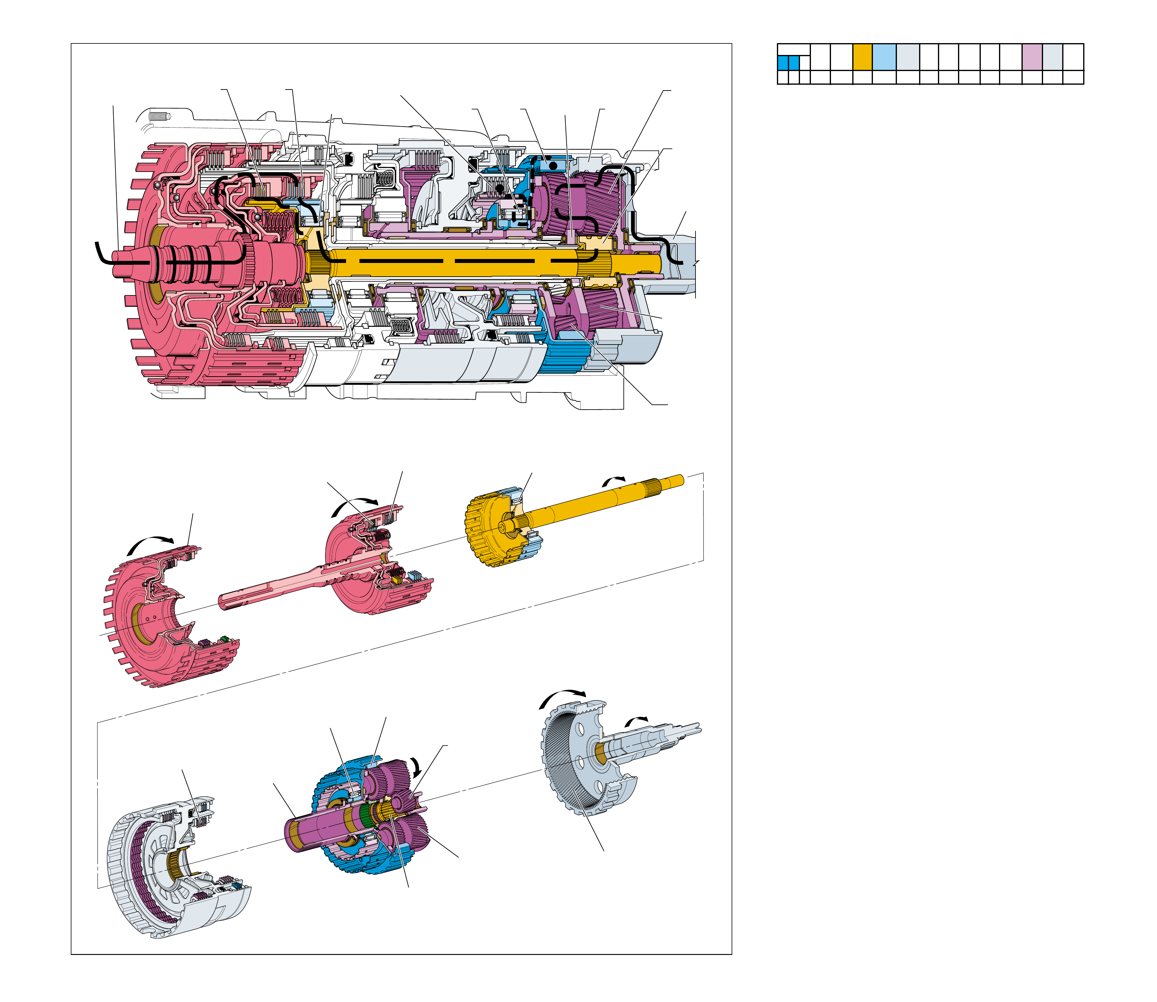
Figure 62
OVERDRIVE RANGE – SECOND GEAR
1
POWER FROM
TORQUE
CONVERTER
(1)
➤
➤
➤
➤
➤
➤
➤
➤
➤
➤➤
➤
➤
➤
➤
➤
➤
POWER TO
DIFFERENTIAL
ASSEMBLY
7a
REACTION
INTERNAL
GEAR
(550)
HELD
7
SECOND
CLUTCH
SPRAG
(547)
HOLDING 4
REAR INPUT
SUN GEAR
DRIVING
5
LONG
PINION GEAR
DRIVING
9
REAR
INTERNAL
GEAR
(560)
DRIVEN
8
INPUT AND
REACTION
CARRIER
(553)
DRIVEN
8a
FRONT SHORT
PINION
GEAR
DRIVING
4a
REAR SHORT
PINION
GEAR
DRIVING
2a
COAST
CLUTCH
APPLIED
2
FORWARD
CLUTCH
APPLIED
COAST
CLUTCH
APPLIED
REVERSE
CLUTCH
HOUSING
ASSEMBLY
(401)
FORWARD
CLUTCH
APPLIED
3
FORWARD
CLUTCH
SPRAG
(461)
HOLDING
FORWARD
CLUTCH
SPRAG
(461)
HOLDING
6
SECOND
CLUTCH
APPLIED
REACTION
INTERNAL
GEAR
(550)
HELD
SECOND
CLUTCH
SPRAG
(547)
HOLDING
REAR
INPUT
SUN GEAR
DRIVING
LONG
PINION
GEAR
DRIVING
REAR
INTERNAL
GEAR
(560)
DRIVEN
INPUT AND
REACTION
CARRIER
(553)
DRIVEN
REAR SHORT
PINION GEAR
DRIVING
SECOND
CLUTCH
APPLIED
OVERDRIVE RANGE – SECOND GEAR
66A
As vehicle speed increases, input signals from the transmission
speed sensors (input and output), throttle position (To) sensor,
and other vehicle sensors are sent to the transmission control
module (TCM). The TCM processes this information to
determine the precise moment to shift the transmission. In
Second gear, the planetary gear set continues to operate in
reduction at a gear ratio of approximately 2.21:1.
1 Power from Torque Converter
The input shaft forward and coast clutch housing assembly
(433) is splined to and driven by the converter turbine.
2 Forward and Coast Clutches Applied
The forward clutch, which is located within the input shaft
forward and coast clutch housing assembly (433), is applied
and holds the forward clutch sprag outer race (459). The
coast clutch is also located in the input shaft forward and
coast clutch housing assembly (433) and is also applied.
3 Forward Clutch Sprag Holding
The forward clutch sprag (461) holds and power is
transmitted to the input sun gear shaft assembly (457).
4 Rear Input Sun Gear Driving
The input sun gear shaft assembly (457) is splined to the
rear input sun gear. The rear input sun gear drives the rear
short planetary pinions.
5 Long Planetary Pinion Gears Driving
The rear short planetary pinions drive the long planetary
pinions. The long pinions are in mesh with the front input
sun gear, the front short pinions and the rear internal gear.
6 Second Clutch Applied
The second clutch, which is located within the center support
(518), is applied and holds the second clutch sprag outer
race (545).
7 Second Clutch Sprag Holding
The power transferred to the front short pinions by the long
planetary pinions attempts to rotate the reaction internal
gear (550) but, the reaction internal gear is held stationary
by the second clutch sprag (547).
8 Input and Reaction Carrier Driven
The front short pinions are driven around the stationary
reaction internal gear (550), driving the input and reaction
carrier (553).
9 Rear Internal Gear Driven
The long pinions drive the rear internal gear (560) to achieve
the second gear ratio of approximately 2.21:1
•When the throttle is released in Overdrive Range – Second
Gear, power from the vehicle wheels drives the transmission
components faster than engine torque is driving them. This
causes the second clutch sprag (547) to overrun and allows
the vehicle to coast freely without engine braking.
•In order to achieve engine braking, the second coast clutch
can be applied to hold the reaction internal gear. See Manual
Second – Second Gear (page 80A) for a description of power
flow during coast conditions.
As vehicle speed increases, less torque multiplication is needed
to move the vehicle efficiently. Therefore, it is desirable to shift
the transmission to a lower gear ratio, or Third gear.
SOLENOID FORWARD OVER- INTERM. INTER- LOW LOW AND SECOND SECOND
DIRECT REVERSE COAST FORWARD SPRAG DRIVE SPRAG MEDIATE SPRAG REVERSE SECOND SPRAG COAST
1-2 2-3 4-5 CLUTCH CLUTCH CLUTCH CLUTCH CLUTCH CLUTCH CLUTCH CLUTCH CLUTCH CLUTCH CLUTCH CLUTCH CLUTCH
ON ON OFF APPLIED APPLIED LD APPLIED LD
LD = LOCKED IN DRIVE
66
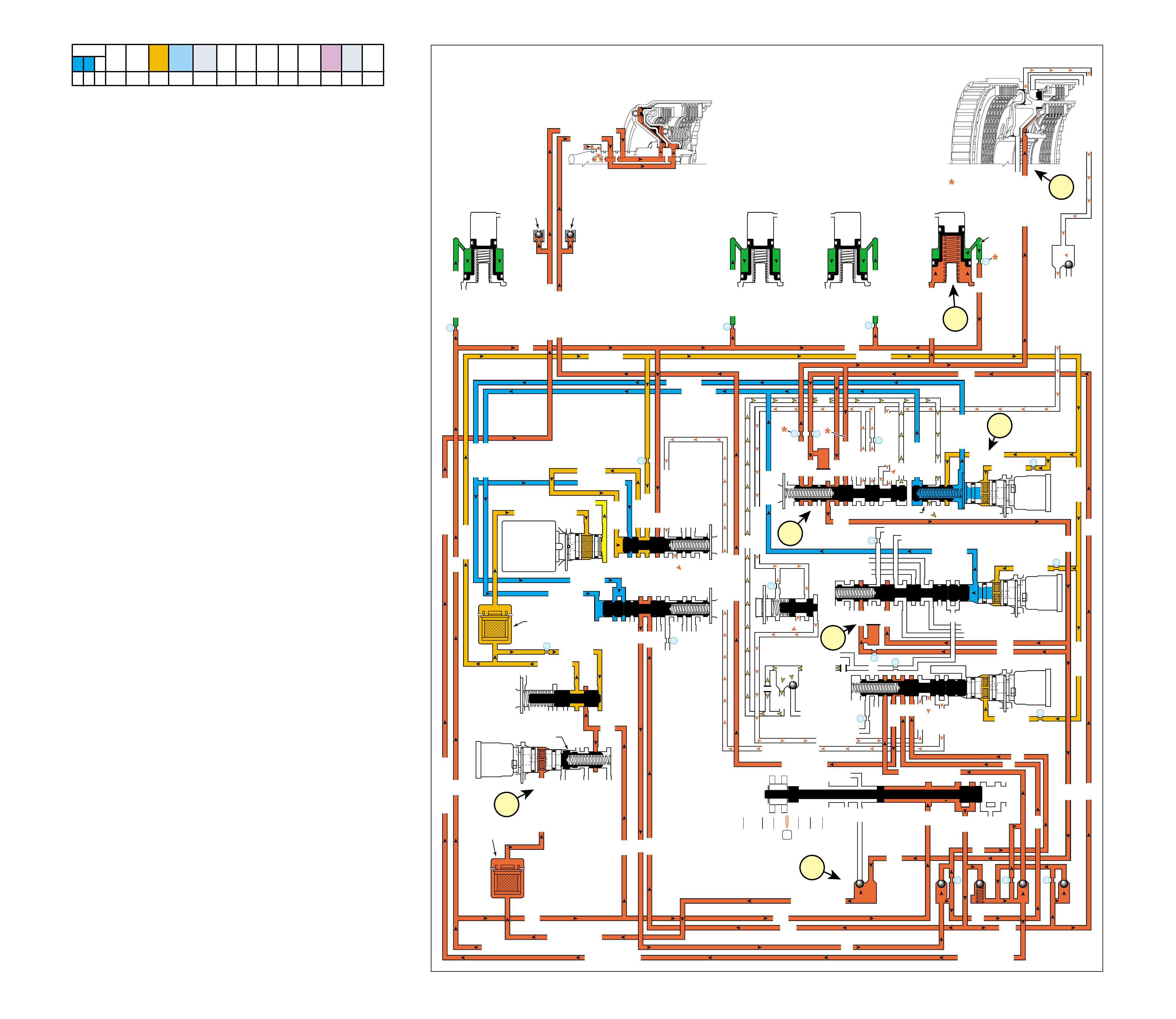
As vehicle speed increases, the transmission control module
(TCM) receives input signals from both the input and output
speed sensors, the throttle position (To) sensor and other vehicle
sensors to determine the precise moment to energize or “turn
ON” the 1-2 shift solenoid (SS) valve.
1 SECOND CLUTCH APPLIES
1a 1-2 Shift Solenoid (SS) Valve:
The 1-2 SS valve is energized, allowing feed limit fluid to
enter the 1-2 signal fluid circuit. 1-2 signal fluid, together
with 1-2 shift control valve spring (367) force, overcomes
2-3 signal fluid pressure and moves the 1-2 shift control
valve (366) to the released position. This blocks feed limit
fluid from entering the FDL fluid circuit.
1b 1-2 Shift Valve:
FDL fluid is exhausted from the 1-2 shift valve (387) and
1-2 shift valve spring (388) force moves the valve to the
released position to allow D432 fluid to enter the second
clutch and 2345 fluid circuits.
1c Second Clutch:
Second clutch fluid is directed to the second clutch piston to
apply the second clutch plates and achieve Second gear.
2 SHIFT ACCUMULATION
2a Second Clutch Accumulator:
Second clutch fluid is also sent to the second clutch
accumulator assembly. Second clutch fluid, together with
accumulator spring force, moves the second clutch
accumulator piston against accumulator fluid pressure to
cushion the apply of the second clutch.
3 FLUID PRESSURE DIRECTED IN PREPARATION
FOR A SHIFT TO THIRD GEAR
3a 2-3 Shift Valve:
2345 fluid is routed to the 2-3 shift valve (371) where it is
blocked by the valve in preparation for an upshift to third gear.
4 TORQUE CONVERTER CLUTCH RELEASED
4a #2 Ball Check valve:
2345 fluid seats the ball check valve against the reverse
passage and enters the 2345 or reverse fluid circuit.
4b TCC PWM Solenoid Valve:
2345 or reverse fluid is directed through the TCC PWM
solenoid valve filter to the TCC PWM solenoid valve.
However, depending on the shift pattern, the TCM keeps
the pulse width modulated (PWM) solenoid de-energized
blocking filtered 2345 or reverse fluid from entering the
TCC signal fluid circuit, thereby keeping the torque converter
clutch released.
66B
OVERDRIVE RANGE – SECOND GEAR
COMPLETE HYDRAULIC CIRCUIT
Page 94
Figure 63
SOLENOID FORWARD OVER- INTERM. INTER- LOW LOW AND SECOND SECOND
DIRECT REVERSE COAST FORWARD SPRAG DRIVE SPRAG MEDIATE SPRAG REVERSE SECOND SPRAG COAST
1-2 2-3 4-5 CLUTCH CLUTCH CLUTCH CLUTCH CLUTCH CLUTCH CLUTCH CLUTCH CLUTCH CLUTCH CLUTCH CLUTCH CLUTCH
ON ON OFF APPLIED APPLIED LD APPLIED LD
LD = LOCKED IN DRIVE
OVERDRIVE RANGE – SECOND GEAR
LUBE
LOW AND REV CL OR RLO
SECOND COAST CL
SECOND CLUTCH
OVERDRIVE CL FD 2
ACCUMULATOR
INTERMEDIATE CL
ACCUMULATOR
EX
SECOND CLUTCH
ACCUM
ACCUMULATOR
LINE
LINE
LINE
COAST CL
REVERSE LOCKOUT
EXEXEX
DIRECT CL
4
2
5
DIRECT
CLUTCH
ACCUMULATOR
OVERDRIVE
CLUTCH
ACCUMULATOR
INTERMEDIATE
CLUTCH
ACCUMULATOR
SECOND
CLUTCH
ACCUMULATOR
FORWARD
AND COAST
CLUTCH
ASSEMBLY
(430—451)
CENTER
SUPPORT
ASSEMBLY
(510—535)
3
21
2345
2345
2345
2345
2345 OR REVERSE
LINE
LINE
LINE (from Pump)
LINE
FILTERED FEED LIMIT
THROTTLE SIGNAL
EX
2345 OR REVERSE
TCC SIGNAL
REGULATED APPLY
REGULATED APPLY
EX
EX
FEED LIMIT VALVE
LINE
EX
EX
EX
EX
FEED LIMIT
FEED LIMIT
EX
SECOND COAST CLUTCH
23 REGULATED
OVERDRIVE CL FD 1
INTERMEDIATE CLUTCH
2345
INTERMEDIATE CLUTCH
2345
345
FEED LIMIT
EX
EX
EX
EX
2-3 SIGNAL
23 REGULATED
LINE SM
LINE SAFETY MODE
123 BRK
123
EX
EX
EX
123
123
123123
123
123
CST CL
COAST CLUTCH
COAST CLUTCH COAST CLUTCH FEED
OVERDRIVE CL FD 2
45
FEED LIMIT
SAFETY MODE
LINE
FEED LIMIT
32
MEMORY
MEMORY
MEMORY
MEMORY PILOT
32 SAFETY MODE
EX
EX
2-3 SIGNAL
123123 D432D432
DIRECT CLUTCH
45
1-2 SIGNAL
1-2 SIGNAL
1-2 SIGNAL
EX
EX
EX
FDL
D432
2345
D432
D432
D432D432
D432D432
SECOND CL
23 REGULATED
123 REG
SECOND CL
123 REG
EX
EX
EX
FEED LIMIT
FEED LIMIT
FDL
1-2 SIGNAL
2-3 SIGNAL
EX
EX
RPND432
MANUAL VALVE
LINE
D432
REV
REVERSE
EX
32
LINELINE
LINE SAFETY MODE
LINE SAFETY MODE
4-5 SIGNAL
24
28
2345
2345 OR REVERSE
345
345
PRESSURE
CONTROL
SOLENOID
VALVE
1-2 SHIFT
SOLENOID
VALVE
N/C
(A)
ON
2-3 SHIFT
SOLENOID
VALVE
N/C
(B)
ON
4-5 SHIFT
SOLENOID
VALVE
N/C
(C)
OFF
TCC PWM
SOLENOID
VALVE
N/C
1-2 SHIFT VALVE
CNTRL
7
11
10
9
18
FILTER
(308)
FILTER
(312)
TCC REGULATOR VALVE
1-2 SHIFT CONTROL VALVE
#7
X-1
#2
26
#6
15
#5
17
#4 16
EX
29
8
COAST CLUTCH
AIR
BLEED
(203)
FORWARD CLUTCH
FORWARD CLUTCH
FORWARD CLUTCHFORWARD CLUTCH
FORWARD CLUTCH FORWARD CLUTCH
AIR
BLEED
(203)
14
X-3
FEED LIMIT
FEED LIMIT FEED LIMIT
FEED LIMITFEED LIMIT
123
3-4 SHIFT
4-5 SHIFT VLV CNTRL
2-3 SIGNAL
2-3 SIGNAL
2-3 SIGNAL
2-3 SHIFT VALVE CNTRL
FDL
FDL
EX
FDL
#10
32 SM/FDL
32 SM
123 BRAKING
EX
123 REGULATED
19
20
LOW AND REV CL
REVERSE LOCKOUT
LOW AND REVERSE CL
#8
LOW PRESSURE
1c
2a
1a
3a
1b
4b
4a
67
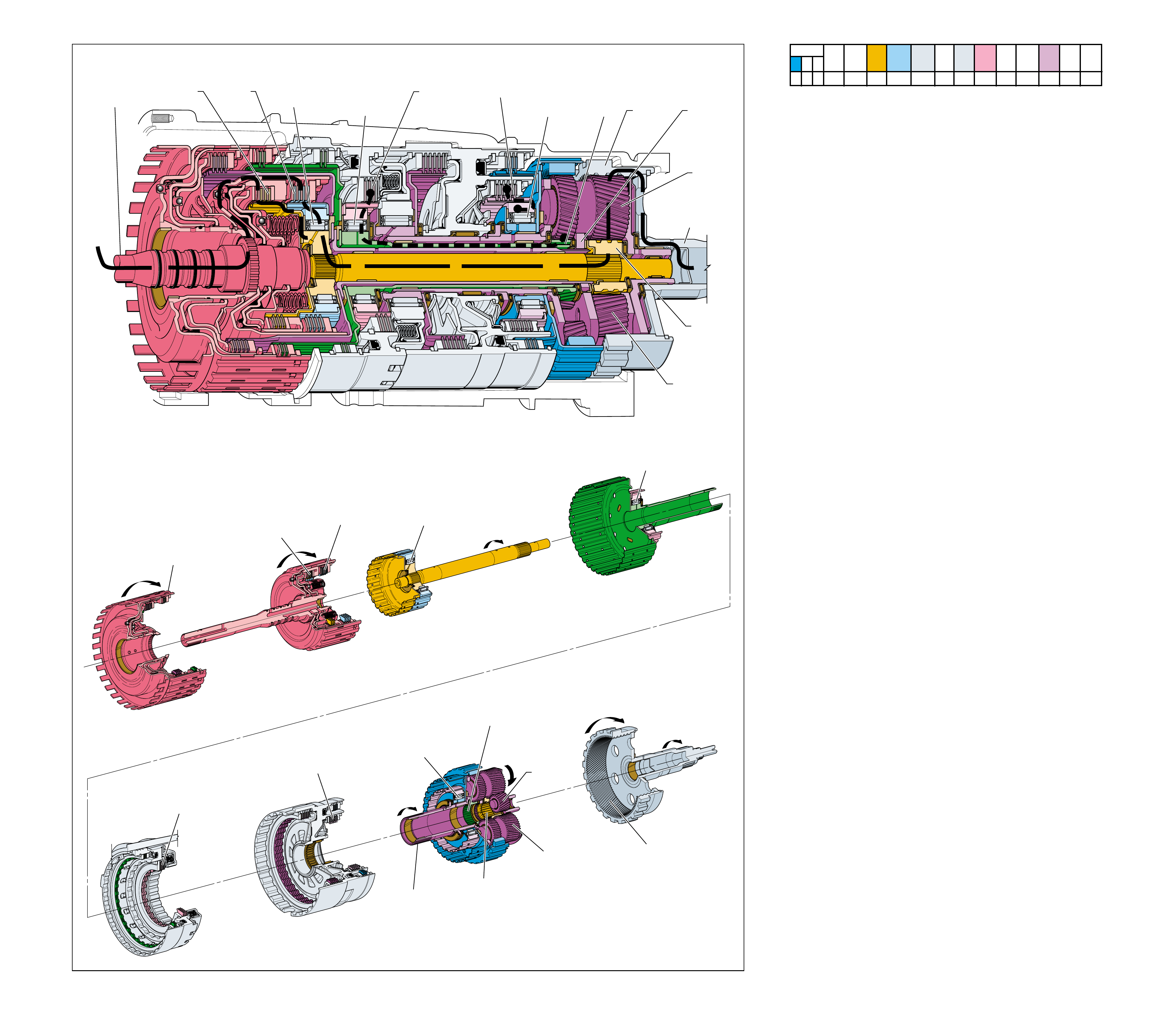
Figure 64
OVERDRIVE RANGE – THIRD GEAR
➤
➤
➤
➤➤
➤
➤
➤➤➤➤
➤
➤
➤
➤
➤
1
POWER FROM
TORQUE
CONVERTER
(1)
10
SECOND
CLUTCH
SPRAG
(547)
OVERRUNNING
9
SECOND
CLUTCH
APPLIED
4
REAR
INPUT
SUN GEAR
DRIVING
7a
FRONT
INPUT
SUN
GEAR
HELD
8
INPUT AND
REACTION
CARRIER
(553)
DRIVEN
11
REAR
INTERNAL
GEAR
(560)
DRIVEN
11a
LONG
PINION
GEAR
DRIVING
5
REAR SHORT
PINION
GEAR
DRIVING
2a
COAST
CLUTCH
APPLIED
2
FORWARD
CLUTCH
APPLIED
3
FORWARD
CLUTCH SPRAG
(461)
HOLDING
6
INTERMEDIATE
CLUTCH
APPLIED
7
INTERMEDIATE
CLUTCH
SPRAG
(473)
HOLDING
SECOND
CLUTCH
SPRAG
(547)
OVERRUNNING
INPUT AND
REACTION
CARRIER
(553)
DRIVEN
SECOND
CLUTCH
APPLIED
REAR INPUT
SUN GEAR
DRIVING
FRONT INPUT
SUN GEAR
HELD
REAR
INTERNAL
GEAR
(560)
DRIVEN
LONG
PINION
GEAR
DRIVING
REAR
SHORT
PINION
GEAR
DRIVING
COAST
CLUTCH
APPLIED
REVERSE
CLUTCH
HOUSING
ASSEMBLY
(401)
FORWARD
CLUTCH
APPLIED
FORWARD
CLUTCH
SPRAG
(461)
HOLDING
INTERMEDIATE
CLUTCH
APPLIED
INTERMEDIATE
CLUTCH SPRAG
(473)
HOLDING
POWER TO
DIFFERENTIAL
ASSEMBLY
OVERDRIVE RANGE – THIRD GEAR
68A
As vehicle speed continues to increase, input signals from the
transmission speed sensors (input and output), throttle position
(To) sensor, and other vehicle sensors are sent to the TCM. The
TCM uses this information to determine the precise moment to
shift the transmission into Third gear. In Third gear, the planetary
gear set continues to operate in reduction at a gear ratio of
approximately 1.60:1.
1 Power from Torque Converter
The input shaft forward and coast clutch housing assembly
(433) is splined to and driven by the converter turbine.
2 Forward and Coast Clutches Applied
The forward clutch, which is located within the input shaft
forward and coast clutch housing assembly (433), is applied
and holds the forward clutch sprag outer race (459). The
coast clutch is also located in the input shaft forward and
coast clutch housing assembly (433) and is also applied.
3 Forward Clutch Sprag Holding
The forward clutch sprag (461) holds and power is
transmitted to the input sun gear shaft assembly (457).
4 Rear Input Sun Gear Driving
The input sun gear shaft assembly (457) is splined to the
rear input sun gear. The rear input sun gear drives the rear
short planetary pinions.
5 Long Planetary Pinion Gears Driving
The rear short planetary pinions drive the long planetary
pinions. The long pinions are in mesh with the front input
sun gear, the front short pinions and the rear internal gear.
6 Intermediate Clutch Applied
The intermediate clutch, which is located within the overdrive
and intermediate clutch assembly (15), is applied and holds
the intermediate clutch sprag outer race (474).
7 Intermediate Clutch Sprag Holding
The power transferred to the front short pinions by the long
planetary pinions attempts to drive the front input sun gear
but, the front input sun gear is held stationary by the
intermediate clutch sprag (473).
8 Input and Reaction Carrier Driven
The long planetary pinions are forced to walk around the
stationary front input sun gear, driving the input and reaction
carrier (553).
9 Second Clutch Applied
The second clutch, which is located within the center support
(518), is applied and holds the second clutch sprag outer
race (545).
10 Second Clutch Sprag Overrunning
The power transferred to the front short pinions by the long
planetary pinions drives the reaction internal gear (550) in
the opposite direction of the input and reaction carrier (553)
and the second clutch sprag (547) overruns.
11 Rear Internal Gear Driven
The long pinions drive the rear internal gear (560) to achieve
the second gear ratio of approximately 1.60:1
•When the throttle is released in Overdrive Range – Third
Gear, power from the vehicle wheels drives the transmission
components faster than engine torque is driving them. This
causes the intermediate clutch sprag (473) to overrun and
allows the vehicle to coast freely without engine braking.
•In order to achieve engine braking, the overdrive clutch can
be applied to hold the front input sun gear. See Manual
Third – Third Gear (page 78A) for a description of power
flow during coast conditions.
As vehicle speed increases, less torque multiplication is required
to move the vehicle efficiently. Therefore, it is desirable to shift
the transmission to a lower gear ratio, or Fourth gear.
SOLENOID FORWARD OVER- INTERM. INTER- LOW LOW AND SECOND SECOND
DIRECT REVERSE COAST FORWARD SPRAG DRIVE SPRAG MEDIATE SPRAG REVERSE SECOND SPRAG COAST
1-2 2-3 4-5 CLUTCH CLUTCH CLUTCH CLUTCH CLUTCH CLUTCH CLUTCH CLUTCH CLUTCH CLUTCH CLUTCH CLUTCH CLUTCH
ON OFF OFF APPLIED APPLIED LD LD APPLIED APPLIED
LD = LOCKED IN DRIVE
68
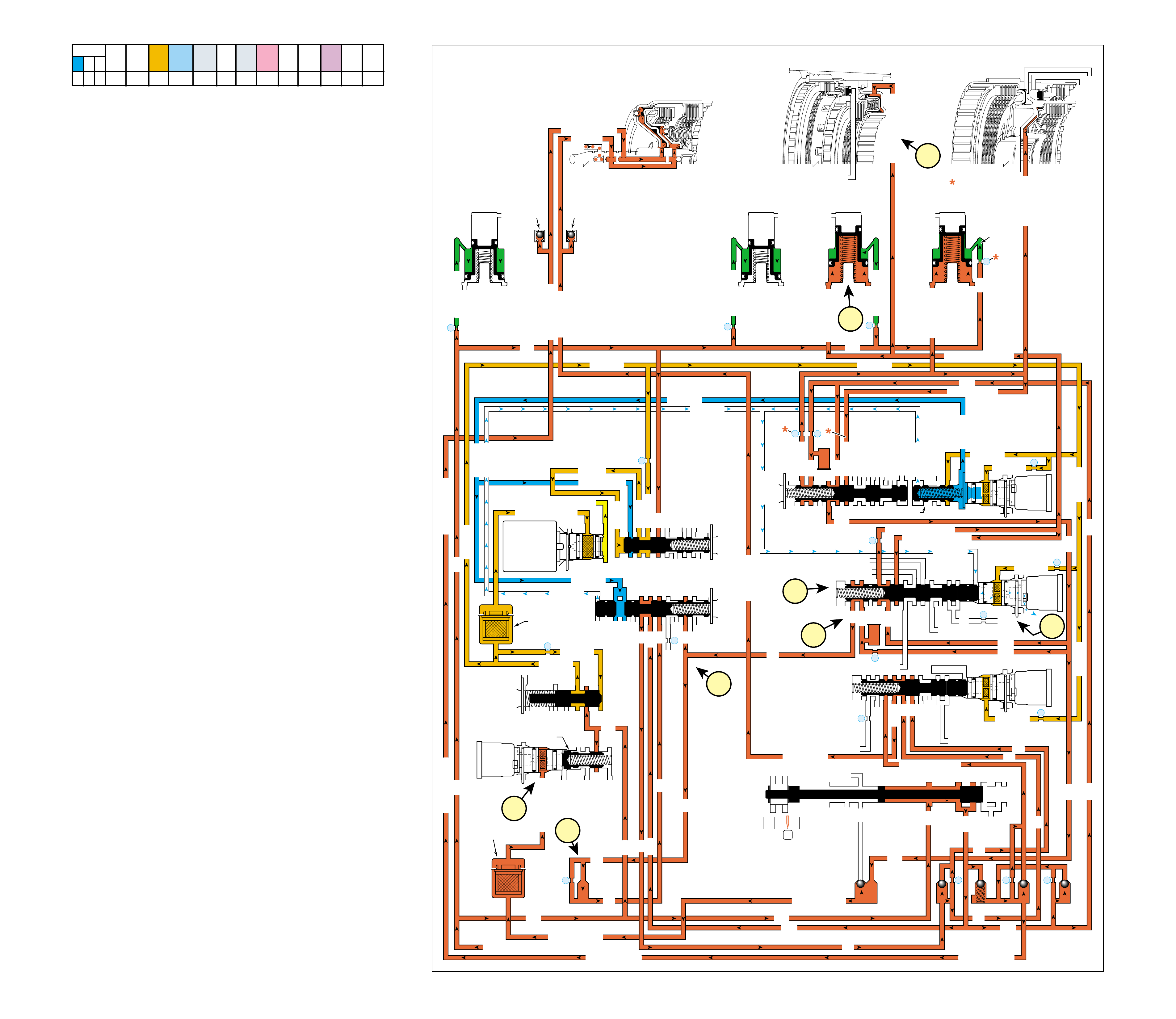
68B
OVERDRIVE RANGE – THIRD GEAR
Figure 65
COMPLETE HYDRAULIC CIRCUIT
Page 96
As vehicle speed increases, the TCM receives input signals
from both speed sensors, the To sensor and other vehicle sensors
to determine the precise moment to de-energize or “turn OFF”
the 2-3 shift solenoid (SS) valve. The 2-3 solenoid is OFF when
the TCM removes the path to ground for that electrical circuit.
This allows 2-3 signal fluid to exhaust at the 2-3 SS valve.
1 INTERMEDIATE CLUTCH APPLIES
1a 2-3 Shift Solenoid (SS) Valve:
The 2-3 SS valve is de-energized, blocking feed limit fluid
from entering the 2-3 signal fluid circuit. 2-3 signal fluid
pressure exhausts through the 2-3 SS valve and 2-3 shift
valve spring (372) force moves the 2-3 shift valve (371) to
the released position.
1b 2-3 Shift Valve:
2345 fluid is routed through the 2-3 shift valve and enters
the intermediate clutch circuit.
1c Intermediate Clutch:
Intermediate clutch fluid is directed to the intermediate clutch
piston to apply the intermediate clutch plates and achieve
Third gear.
2 SHIFT ACCUMULATION
2a Intermediate Clutch Accumulator:
Intermediate clutch fluid is also sent to the intermediate
clutch accumulator assembly. Intermediate clutch fluid,
together with accumulator spring force, moves the
intermediate clutch accumulator piston against accumulator
fluid pressure to cushion the apply of the intermediate clutch.
3 TORQUE CONVERTER CLUTCH RELEASED
3a TCC PWM Solenoid Valve:
Filtered 2345 or reverse fluid is still available at the TCC
PWM solenoid valve. However, depending on the shift
pattern, the TCM keeps the pulse width modulated (PWM)
solenoid de-energized blocking filtered 2345 or reverse fluid
from entering the TCC signal fluid circuit, thereby keeping
the torque converter clutch released.
4 FLUID PRESSURE DIRECTED IN PREPARATION
FOR A SHIFT TO FOURTH GEAR
4a 2-3 Shift Valve:
2345 fluid is routed through the 2-3 shift valve (371) into
the 345 fluid circuit.
4b X-4 Ball Check Valve:
345 fluid is routed through the X-4 ball check valve pocket.
In some transmission models there is a ball check valve
present which would force 345 fluid through orifice #25.
4c 3-4 Shift Valve:
345 fluid is routed to the 3-4 shift valve (345) where it is
blocked by the valve in preparation for an upshift to fourth gear.
SOLENOID FORWARD OVER- INTERM. INTER- LOW LOW AND SECOND SECOND
DIRECT REVERSE COAST FORWARD SPRAG DRIVE SPRAG MEDIATE SPRAG REVERSE SECOND SPRAG COAST
1-2 2-3 4-5 CLUTCH CLUTCH CLUTCH CLUTCH CLUTCH CLUTCH CLUTCH CLUTCH CLUTCH CLUTCH CLUTCH CLUTCH CLUTCH
ON OFF OFF APPLIED APPLIED LD LD APPLIED APPLIED
LD = LOCKED IN DRIVE
OVERDRIVE RANGE – THIRD GEAR
LUBE
LOW AND REV CL OR RLO
SECOND COAST CL
SECOND CLUTCH
OVERDRIVE CL FD 2
ACCUMULATOR
INTERMEDIATE CL
INTERMEDIATE CLUTCH
INTERMEDIATE CLUTCH
ACCUMULATOR
EX
SECOND CLUTCH
ACCUM
ACCUMULATOR
LINE
LINE
LINE
OVERDRIVE CLUTCH
COAST CL
REVERSE LOCKOUT
EXEXEX
SECOND CLUTCH
DIRECT CL
4
2
5
DIRECT
CLUTCH
ACCUMULATOR
OVERDRIVE
CLUTCH
ACCUMULATOR
INTERMEDIATE
CLUTCH
ACCUMULATOR
SECOND
CLUTCH
ACCUMULATOR
FORWARD
AND COAST
CLUTCH
ASSEMBLY
(430—451)
OVERDRIVE
AND
INTERMEDIATE
CLUTCH
ASSEMBLY
(480—497)
CENTER
SUPPORT
ASSEMBLY
(510—535)
3
21
2345
2345
2345
2345
2345 OR REVERSE
LINE
LINE
LINE (from Pump)
LINE
FILTERED FEED LIMIT
THROTTLE SIGNAL
EX
2345 OR REVERSE
TCC SIGNAL
REGULATED APPLY
REGULATED APPLY
EX
EX
FEED LIMIT VALVE
LINE
EX
EX
EX
EX
FEED LIMIT
FEED LIMIT
EX EX
SECOND COAST CLUTCH
23 REGULATED
OVERDRIVE CL FD 1
INTERMEDIATE CLUTCH
2345
INTERMEDIATE CLUTCH
2345
345
345
FEED LIMIT
EX
EX
EX
EX
2-3 SIGNAL
23 REGULATED
LINE SAFETY MODE
123 BRAKING
123
EX
EX
EX
123
123
123
123
123
123
CST CL
COAST CLUTCH
COAST CLUTCH COAST CLUTCH FEED
OVERDRIVE CL FD 2
45
FEED LIMIT
SAFETY MODE
LINE
FEED LIMIT
32
MEMORY
MEMORY
MEMORY
MEMORY PILOT
32 SAFETY MODE
EX
EX
2-3 SIGNAL
123123 D432D432
DIRECT CLUTCH
45
1-2 SIGNAL
1-2 SIGNAL
1-2 SIGNAL
EX
EX
EX
FDL
D432
2345
D432
D432
D432D432
D432D432
SECOND CL
23 REGULATED
123 REGULATED
SECOND CL
123 REGULATED
LOW AND REV CL
EX
EX
EX
FEED LIMIT
FEED LIMIT
FDL
1-2 SIGNAL
2-3 SIGNAL
EX
EX
RPND432
MANUAL VALVE
LINE
D432
REV
REVERSE
EX
32
LINELINE
LINE SAFETY MODE
4-5 SIGNAL
24
28
2345
2345 OR REVERSE
345
345
345
345
345
345
PRESSURE
CONTROL
SOLENOID
VALVE
1-2 SHIFT
SOLENOID
VALVE
N/C
(A)
ON
2-3 SHIFT
SOLENOID
VALVE
N/C
(B)
OFF
4-5 SHIFT
SOLENOID
VALVE
N/C
(C)
OFF
TCC PWM
SOLENOID
VALVE
N/C
1-2 SHIFT VALVE
2-3 SHIFT VALVE CNTRL
CNTRL
7
11
10
9
18
FILTER
(308)
FILTER
(312)
TCC REGULATOR VALVE
1-2 SHIFT CONTROL VALVE
#7
X-1
#2
26
X-4 #6
15
#5
17
#4 16
25
29
8
COAST CLUTCH
AIR
BLEED
(203)
FORWARD CLUTCH
FORWARD CLUTCH
FORWARD CLUTCHFORWARD CLUTCH
FORWARD CLUTCH FORWARD CLUTCH
AIR
BLEED
(203)
14
X-3
FEED LIMIT
FEED LIMIT FEED LIMIT
FEED LIMITFEED LIMIT
123
3-4 SHIFT
4-5 SHIFT VLV CNTRL
2-3 SIGNAL
2-3 SIGNAL
2-3 SIGNAL
1c
2a
3a
1a
4b
1b
4a
4c
69
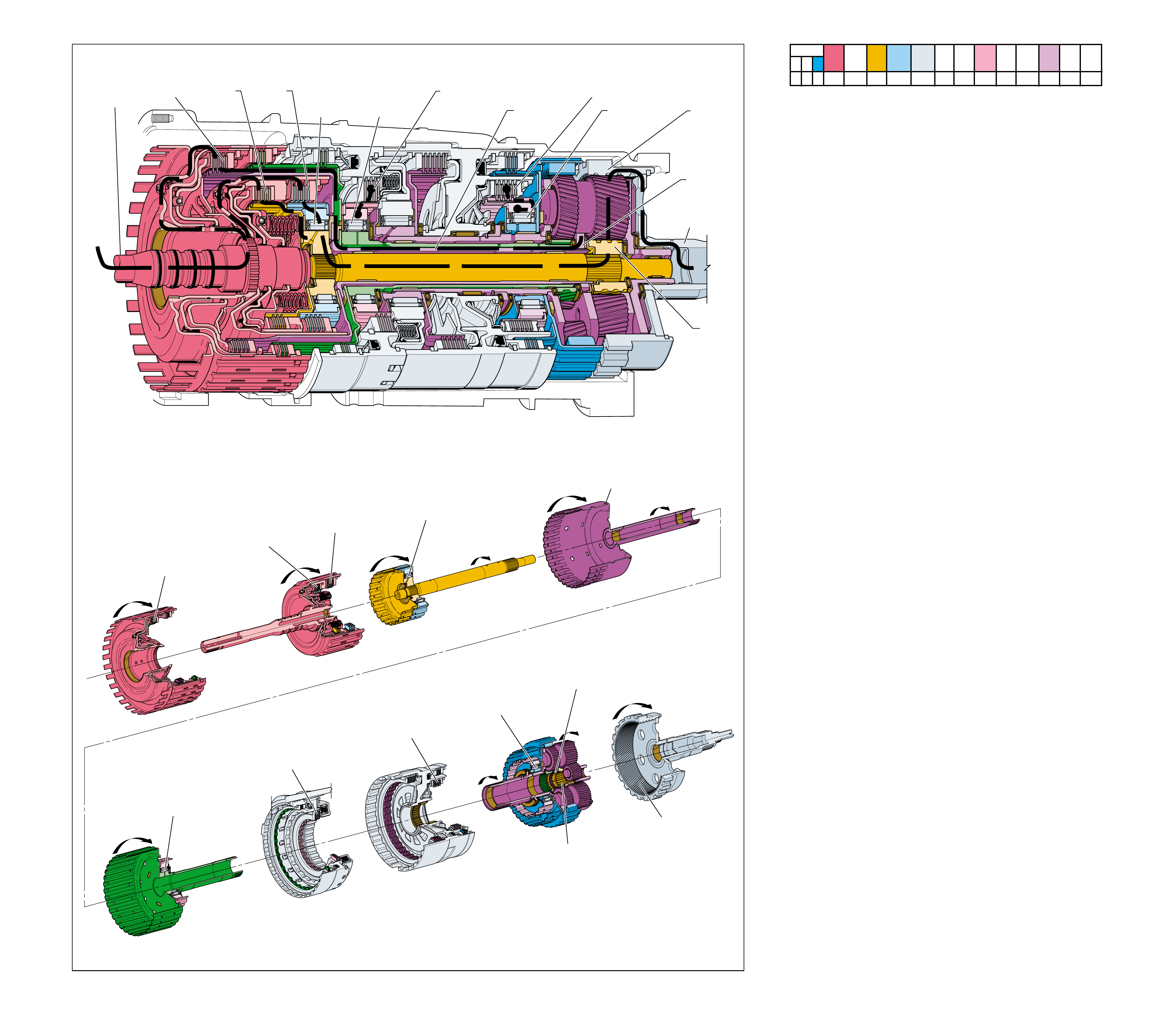
OVERDRIVE RANGE – FOURTH GEAR
➤
➤
➤
➤➤
➤
➤
➤➤➤➤
➤
➤
➤
➤
➤
➤
➤
➤
➤
➤
➤
➤➤➤
➤
12
SECOND
CLUTCH
SPRAG
(547)
OVERRUNNING
11
SECOND
CLUTCH
APPLIED
6
DIRECT CLUTCH
INPUT AND HUB
ASSEMBLY
(466)
DRIVING
4
REAR
INPUT
SUN
GEAR
DRIVING
8
REAR
INTERNAL
GEAR
(560)
DRIVEN
7
INPUT AND
REACTION
CARRIER
(553)
DRIVING
5
DIRECT
CLUTCH
APPLIED
2a
COAST
CLUTCH
APPLIED
2
FORWARD
CLUTCH
APPLIED
3
FORWARD
CLUTCH
SPRAG
(461)
HOLDING
9
INTERMEDIATE
CLUTCH
APPLIED
10
INTERMEDIATE
CLUTCH
SPRAG
(473)
OVERRUNNING
SECOND
CLUTCH
SPRAG
(547)
OVERRUNNING
SECOND
CLUTCH
APPLIED
REAR
INPUT
SUN
GEAR
DRIVING
REAR
INTERNAL
GEAR
(560)
DRIVEN
INPUT AND
REACTION
CARRIER
(553)
DRIVING
DIRECT
CLUTCH
APPLIED
COAST
CLUTCH
APPLIED
FORWARD
CLUTCH
APPLIED
FORWARD
CLUTCH
SPRAG
(461)
HOLDING
DIRECT CLUTCH
INPUT AND HUB
ASSEMBLY
(466)
DRIVING
INTERMEDIATE
CLUTCH
APPLIED
INTERMEDIATE
CLUTCH
SPRAG
(473)
OVERRUNNING
1
POWER FROM
TORQUE
CONVERTER
(1)
POWER TO
DIFFERENTIAL
ASSEMBLY
Figure 66
OVERDRIVE RANGE – FOURTH GEAR
As vehicle speed increases further, input signals from both
transmission speed sensors (input and output), throttle position
(To) sensor, and other vehicle sensors are sent to the TCM. The
TCM uses this information to determine the precise moment to
shift the transmission into Fourth Gear. In Fourth gear, the
planetary gear set rotates as a unit, providing a 1:1 direct drive
gear ratio between the converter turbine and output shaft.
1 Power from Torque Converter
The input shaft forward and coast clutch housing assembly
(433) is splined to and driven by the converter turbine.
2 Forward and Coast Clutches Applied
The forward clutch, which is located within the input shaft
forward and coast clutch housing assembly (433), is applied
and holds the forward clutch sprag outer race (459). The
coast clutch is also located in the input shaft forward and
coast clutch housing assembly (433) and is also applied.
3 Forward Clutch Sprag Holding
The forward clutch sprag (461) holds and power is
transmitted to the input sun gear shaft assembly (457).
4 Rear Input Sun Gear Driving
The input sun gear shaft assembly (457) is splined to the
rear input sun gear. The rear input sun gear attempts to drive
the long planetary pinion gears through the rear short
planetary pinions.
5 Direct Clutch Applied
The direct clutch, which is located within the reverse clutch
housing assembly (401), is applied and engine torque is
transferred to the direct clutch input and hub assembly (466).
6 Direct Clutch Input and Hub Assembly Driving
The direct clutch input and hub assembly (466) is splined to
and drives the input and reaction carrier (553).
7 Input and Reaction Carrier Driving
With the rear input sun gear and the input and reaction
carrier both turning at converter turbine speed, the carrier
pinion gears are locked together as an assembly and drive
the rear internal gear (560).
8 Rear Internal Gear Driven
The input and reaction carrier (553) drives the rear internal
gear (560) at converter turbine speed to obtain a 1:1 direct
drive gear ratio through the transmission gear set.
9 Intermediate Clutch Applied
The intermediate clutch, which is located within the overdrive
and intermediate clutch assembly (15), is applied and holds
the intermediate clutch sprag outer race (474).
10 Intermediate Clutch Sprag Overrunning
With the input and reaction carrier (553) locked together
and driving as a unit, the intermediate clutch sprag (473) is
overrunning.
11 Second Clutch Applied
The second clutch, which is located within the center support
(518), is applied and holds the second clutch sprag outer
race (545).
12 Second Clutch Sprag Overrunning
With the input and reaction carrier (553) locked together and
driving as a unit, the second clutch sprag (547) is overrunning.
•When the throttle is released in Overdrive Range – Fourth
Gear, the vehicle is allowed to coast brake. Because none of
the sprag clutches are used in driving the vehicle during
acceleration, there are no elements to overrun to allow the
vehicle to coast freely in fourth gear. Therefore, engine
compression slows the vehicle when the throttle is released.
Refer to Manual Fourth – Fourth Gear (page 76A) a for
description of power flow during coast conditions.
As vehicle speed increases, less torque multiplication is required
to operate the engine efficiently. Therefore, it is desirable to
shift to an overdrive gear ratio, or Fifth gear.
70A
SOLENOID FORWARD OVER- INTERM. INTER- LOW LOW AND SECOND SECOND
DIRECT REVERSE COAST FORWARD SPRAG DRIVE SPRAG MEDIATE SPRAG REVERSE SECOND SPRAG COAST
1-2 2-3 4-5 CLUTCH CLUTCH CLUTCH CLUTCH CLUTCH CLUTCH CLUTCH CLUTCH CLUTCH CLUTCH CLUTCH CLUTCH CLUTCH
OFF OFF ON APPLIED APPLIED APPLIED LD APPLIED APPLIED
LD = LOCKED IN DRIVE
70
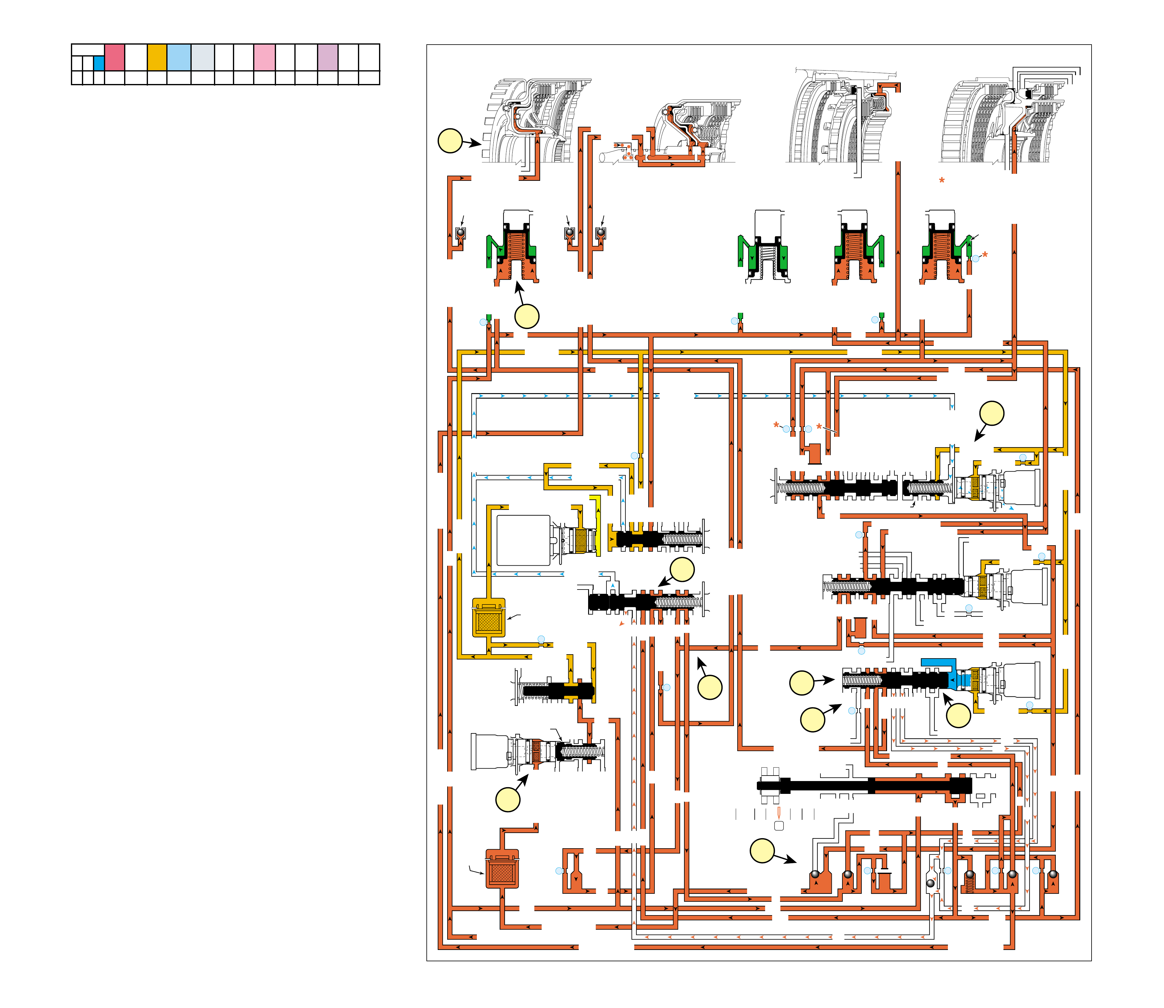
70B
OVERDRIVE RANGE – FOURTH GEAR
COMPLETE HYDRAULIC CIRCUIT
Page 98
Figure 67
As vehicle speed increases, the TCM receives input signals
from both speed sensors, the To sensor and other vehicle sensors
to determine the precise moment to de-energize or “turn OFF”
the 1-2 shift solenoid (SS) valve, and to energize or “turn ON”
the 4-5 SS valve.
1 DIRECT CLUTCH APPLIED
1a 1-2 Shift Solenoid (SS) Valve:
The 1-2 SS valve is de-energized, blocking feed limit fluid
from entering the 1-2 signal fluid circuit and 1-2 signal fluid
pressure exhausts through the 1-2 SS valve.
1b 3-4 Shift Valve:
When 1-2 signal fluid pressure exhausts from the 3-4 shift
valve (345), the 3-4 shift valve spring (344) moves the
valve to the released position. 345 fluid from the 2-3 shift
valve flows through the 3-4 shift valve and enters the direct
clutch circuit.
1c Direct Clutch:
Direct clutch fluid is routed to the direct clutch piston to
apply the direct clutch plates and obtain Fourth gear.
2 3-4 SHIFT ACCUMULATION
2a Direct Clutch Accumulator:
Direct clutch fluid is also sent to the direct clutch accumulator
assembly. Direct clutch fluid, together with accumulator
spring force, moves the direct clutch accumulator piston
against accumulator fluid pressure to cushion the apply of
the direct clutch.
3 COAST CLUTCH FEED
3a 4-5 Shift Solenoid (SS) Valve:
The 4-5 SS valve is energized, allowing feed limit fluid to
enter the 4-5 signal fluid circuit. 4-5 signal fluid overcomes
4-5 shift valve spring (373) force and moves the 4-5 shift
control valve (375) and the 4-5 shift valve (374) to the
applied position.
3b 4-5 Shift Valve:
In first through third gears, the coast clutch has been fed by
123 fluid. In fourth gear the 4-5 shift valve (374) is applied
in preparation for a shift to fifth gear. This causes the coast
clutch fluid circuit to be supplied by coast clutch feed fluid,
and 123 fluid to exhaust.
4 TORQUE CONVERTER CLUTCH RELEASED
4a TCC PWM Solenoid Valve:
Filtered 2345 or reverse fluid is still available at the TCC
PWM solenoid valve. However, depending on the shift
pattern, the TCM keeps the pulse width modulated (PWM)
solenoid de-energized blocking filtered 2345 or reverse fluid
from entering the TCC signal fluid circuit, thereby keeping
the torque converter clutch released.
5 FLUID PRESSURE DIRECTED IN PREPARATION
FOR A SHIFT TO FIFTH GEAR
5a 3-4 Shift Valve:
345 fluid is routed through the 3-4 shift valve (345) into the
45 fluid circuit.
5b #3 Ball Check Valve:
45 fluid seats the #3 ball check valve and passes through
orifice #27. This orifice helps to control overdrive clutch
apply in fifth gear.
5c 4-5 Shift Valve:
45 fluid is routed to the 4-5 shift valve (374) where it is
blocked by the valve in preparation for an upshift to fifth gear.
SOLENOID FORWARD OVER- INTERM. INTER- LOW LOW AND SECOND SECOND
DIRECT REVERSE COAST FORWARD SPRAG DRIVE SPRAG MEDIATE SPRAG REVERSE SECOND SPRAG COAST
1-2 2-3 4-5 CLUTCH CLUTCH CLUTCH CLUTCH CLUTCH CLUTCH CLUTCH CLUTCH CLUTCH CLUTCH CLUTCH CLUTCH CLUTCH
OFF OFF ON APPLIED APPLIED APPLIED LD APPLIED APPLIED
LD = LOCKED IN DRIVE
OVERDRIVE RANGE – FOURTH GEAR
LUBE
LOW AND REV CL OR RLO
SECOND COAST CL
SECOND CLUTCH
REVERSE CLUTCH
OVERDR CL FD 2
ACCUMULATOR
INTERMED CL
INTERMEDIATE CLUTCH
INTERMEDIATE CLUTCH
ACCUMULATOR
EX
SECOND CL
ACCUM
ACCUMULATOR
LINE
LINE
LINE
OVERDRIVE CLUTCH
COAST CL
REVERSE LOCKOUT
EXEXEX
SECOND CLUTCH
DIRECT CL
DIRECT CLUTCH
4
2
5
DIRECT
CLUTCH
ACCUMULATOR
OVERDRIVE
CLUTCH
ACCUMULATOR
INTERMEDIATE
CLUTCH
ACCUMULATOR
SECOND
CLUTCH
ACCUMULATOR
DIRECT
AND REVERSE
CLUTCH
ASSEMBLY
(400—420)
FORWARD
AND COAST
CLUTCH
ASSEMBLY
(430—451)
OVERDRIVE
AND
INTERMEDIATE
CLUTCH
ASSEMBLY
(480—497)
CENTER
SUPPORT
ASSEMBLY
(510—535)
3
21
2345
2345
2345
2345
2345 OR REVERSE
LINE
LINE
LINE (from Pump)
LINE
FILTERED FEED LIMIT
THROTTLE SIGNAL
EX
2345 OR REVERSE
TCC SIGNAL
REGULATED APPLY
REGULATED APPLY
EX
EX
FEED LIMIT VALVE
LINE
EX
EX
EX
EX
FEED LIMIT
FEED LIMIT
EX EX
SECOND COAST CLUTCH
23 REGULATED
OVERDRIVE CL FD 1
INTERMEDIATE CLUTCH
2345
INTERMEDIATE CLUTCH
2345
345
345
FEED LIMIT
EX
EX
EX
EX
2-3 SIGNAL
23 REGULATED
LINE SAFETY MODE
123 BRAKING
123
EX
EX
EX
123
CST CL
COAST CLUTCH
COAST CLUTCH COAST CLUTCH FEED
OVERDRIVE CL FD 2
45
FEED LIMIT
SAFETY MODE
LINE
FEED LIMIT
32
MEMORY
MEMORY
MEMORY
MEMORY PILOT
32 SAFETY MODE
EX
EX
2-3 SIGNAL
123
D432D432
DIRECT CLUTCH
DIRECT CLUTCH
4545
1-2 SIGNAL
EX
EX
EX
FDL
D432
2345
D432
D432
D432D432
D432D432
SECOND CL
23 REGULATED
123 REGULATED
SECOND CL
123 REGULATED
LOW AND REV CL
EX
EX
EX
FEED LIMIT
FEED LIMIT
FDL
1-2 SIGNAL
2-3 SIGNAL
EX
EX
RPND432
MANUAL VALVE
LINE
D432
REV
REVERSE
EX
32
LINELINE
LINE SAFETY MODE
4-5 SIGNAL
24
28
2345
2345 OR REVERSE
345
345
345
345
345
345
45
45
45
45
45
PRESSURE
CONTROL
SOLENOID
VALVE
1-2 SHIFT
SOLENOID
VALVE
N/C
(A)
OFF
2-3 SHIFT
SOLENOID
VALVE
N/C
(B)
OFF
4-5 SHIFT
SOLENOID
VALVE
N/C
(C)
ON
TCC PWM
SOLENOID
VALVE
N/C
1-2 SHIFT VALVE
7
11
10
9
18
FILTER
(308)
FILTER
(312)
TCC REGULATOR VALVE
1-2 SHIFT CONTROL VALVE
#7
X-1
#2
26
X-4 X-5 #6
15
#5
17
25 #3 27
29
8
COAST CLUTCH
AIR
BLEED
(203)
DIRECT CLUTCH
DIRECT CL
AIR
BLEED
(203)
FORWARD CLUTCH
FORWARD CLUTCH
FORWARD CLUTCHFORWARD CLUTCH
FORWARD CLUTCH FORWARD CLUTCH
AIR
BLEED
(203)
14
X-3
FEED LIMIT
FEED LIMIT FEED LIMIT
FEED LIMITFEED LIMIT
4-5 SHIFT VLV CNTRL
2-3 SHIFT VALVE CNTRL
CNTRL 3-4 SHIFT
1-2 SIGNAL
1-2 SIGNAL
123
123123
123
123
123
#4 16
123
3a
1a
5a
2a
1c
1b
4a
5b
3b
5a
71
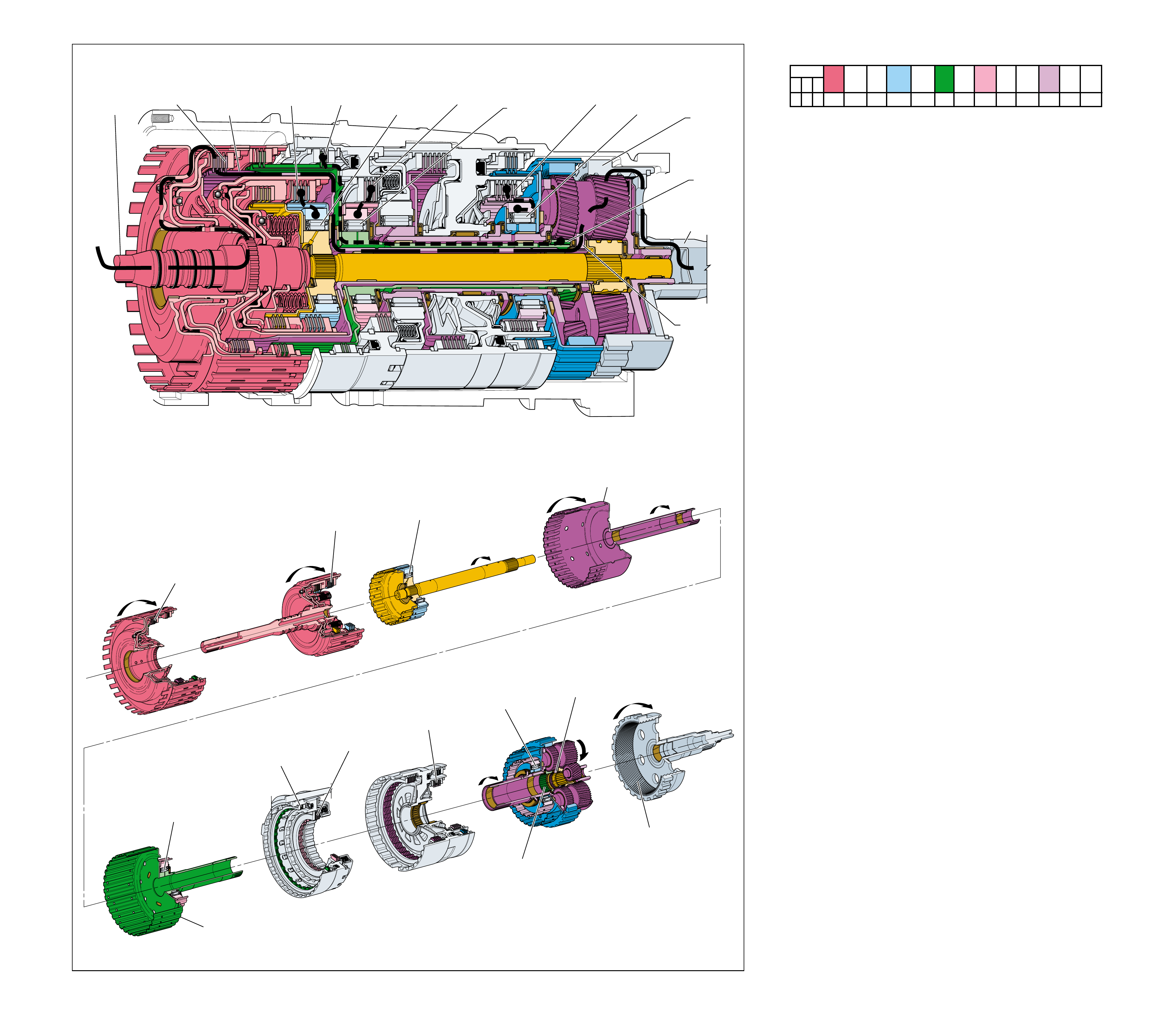
OVERDRIVE RANGE – FIFTH GEAR
(Torque Converter Clutch Released)
➤
➤
➤
➤
➤
➤
➤
➤
➤
➤
➤
➤➤➤
➤
5
FRONT
INPUT
SUN GEAR
HELD
12
SECOND
CLUTCH
APPLIED
13
SECOND
CLUTCH
SPRAG (547)
OVERRUNNING
7
REAR
INTERNAL
GEAR
(560)
DRIVEN
6
INPUT AND
REACTION
CARRIER
(553)
DRIVING
2
DIRECT
CLUTCH
APPLIED
3
DIRECT CLUTCH
INPUT AND HUB
ASSEMBLY (466)
DRIVING
8
FORWARD
CLUTCH
APPLIED
9
FORWARD
CLUTCH
SPRAG (461)
OVERRUNNING
4
OVERDRIVE
CLUTCH
APPLIED
10
INTERMEDIATE
CLUTCH
APPLIED
11
INTERMEDIATE
CLUTCH
SPRAG (473)
INEFFECTIVE
SECOND
CLUTCH
SPRAG
(547)
OVERRUNNING
FRONT INPUT
SUN GEAR
HELD
SECOND
CLUTCH
APPLIED
REAR
INTERNAL
GEAR
(560)
DRIVEN
INPUT AND
REACTION
CARRIER
(553)
DRIVING
DIRECT
CLUTCH
APPLIED
FORWARD
CLUTCH
APPLIED
DIRECT CLUTCH
INPUT AND HUB
ASSEMBLY
(466)
DRIVING
FORWARD
CLUTCH SPRAG
ASSEMBLY
(461)
OVERRUNNING
INTERMEDIATE
CLUTCH
APPLIED
OVERDRIVE
CLUTCH
APPLIED
OVERDRIVE AND
REVERSE CLUTCH
HUB ASSEMBLY
(470)
HELD
INTERMEDIATE
CLUTCH
SPRAG
(473)
INEFFECTIVE
1
POWER FROM
TORQUE
CONVERTER
(1)
POWER TO
DIFFERENTIAL
ASSEMBLY
Figure 68
OVERDRIVE RANGE – FIFTH GEAR
(Torque Converter Clutch Released)
72A
To maximize engine performance and fuel economy, a Fifth
gear (Overdrive) is used to achieve an approximate ratio of
0.75:1 through the transmission gear set to the vehicle drive
shaft. This allows the vehicle to maintain a given road speed
with less engine output speed.
1 Power from Torque Converter
The input shaft forward and coast clutch housing assembly
(433) is splined to and driven by the converter turbine.
2 Direct Clutch Applied
The direct clutch, which is located within the reverse clutch
housing assembly (401), is applied and engine torque is
transferred to the direct clutch input and hub assembly (466).
3 Direct Clutch Input and Hub Assembly Driving
The direct clutch input and hub assembly (466) is splined to
and drives the input and reaction carrier (553).
4 Overdrive Clutch Applied
The overdrive clutch, which is located within the overdrive
clutch housing (493), is applied and holds the overdrive and
reverse clutch hub assembly (470) stationary.
5 Front Input Sun Gear Held
The overdrive and reverse clutch hub assembly (470) is
splined to the front input sun gear and holds it stationary.
6 Input and Reaction Carrier Driving
With the front input sun gear held, and the input and reaction
carrier being driven by the direct clutch input and hub
assembly (466), the long planetary pinion gears are forced to
walk in the direction of engine rotation around the stationary
front input sun gear and drive the rear internal gear (560).
7 Rear Internal Gear Driven
The input and reaction carrier long pinion gears drive the
rear internal gear (560) faster than converter turbine speed
to obtain a 0.75:1 overdrive drive gear ratio through the
transmission gear set.
8 Forward Clutch Applied
The forward clutch is applied and holds the forward clutch
sprag outer race (459).
9 Forward Clutch Sprag Overrunning
The input sun gear shaft assembly is splined to and driven
by the rear input sun gear, causing the forward clutch sprag
(461) to overrun.
10 Intermediate Clutch Applied
The intermediate clutch is applied and holds the intermediate
clutch sprag outer race (474) stationary.
11 Intermediate Clutch Sprag Ineffective
With the intermediate clutch sprag outer race (474) and the
overdrive and reverse clutch hub assembly (470) both held,
the intermediate clutch sprag (473) has no effect in fifth gear.
12 Second Clutch Applied
The second clutch is applied and holds the second clutch
sprag outer race (545) stationary.
13 Second Clutch Sprag Overrunning
The power transferred to the front short pinions by the long
planetary pinions drives the reaction internal gear (550)
causing the second clutch sprag (547) to overrun.
When the throttle is released in Overdrive Range – Fifth Gear,
the vehicle is allowed to coast brake. Because none of the sprag
clutches are used in driving the vehicle during acceleration,
there are no elements to overrun to allow the vehicle to coast
freely in Fifth gear. Therefore, engine compression slows the
vehicle when the throttle is released until the transmission
downshifts into Overdrive Range – Fourth Gear.
However, due to the gear ratio in Overdrive, engine compression
braking is not as noticeable by the driver as it is in the Manual
gear ranges.
SOLENOID FORWARD OVER- INTERM. INTER- LOW LOW AND SECOND SECOND
DIRECT REVERSE COAST FORWARD SPRAG DRIVE SPRAG MEDIATE SPRAG REVERSE SECOND SPRAG COAST
1-2 2-3 4-5 CLUTCH CLUTCH CLUTCH CLUTCH CLUTCH CLUTCH CLUTCH CLUTCH CLUTCH CLUTCH CLUTCH CLUTCH CLUTCH
OFF OFF OFF APPLIED APPLIED APPLIED APPLIED APPLIED
LD = LOCKED IN DRIVE
72
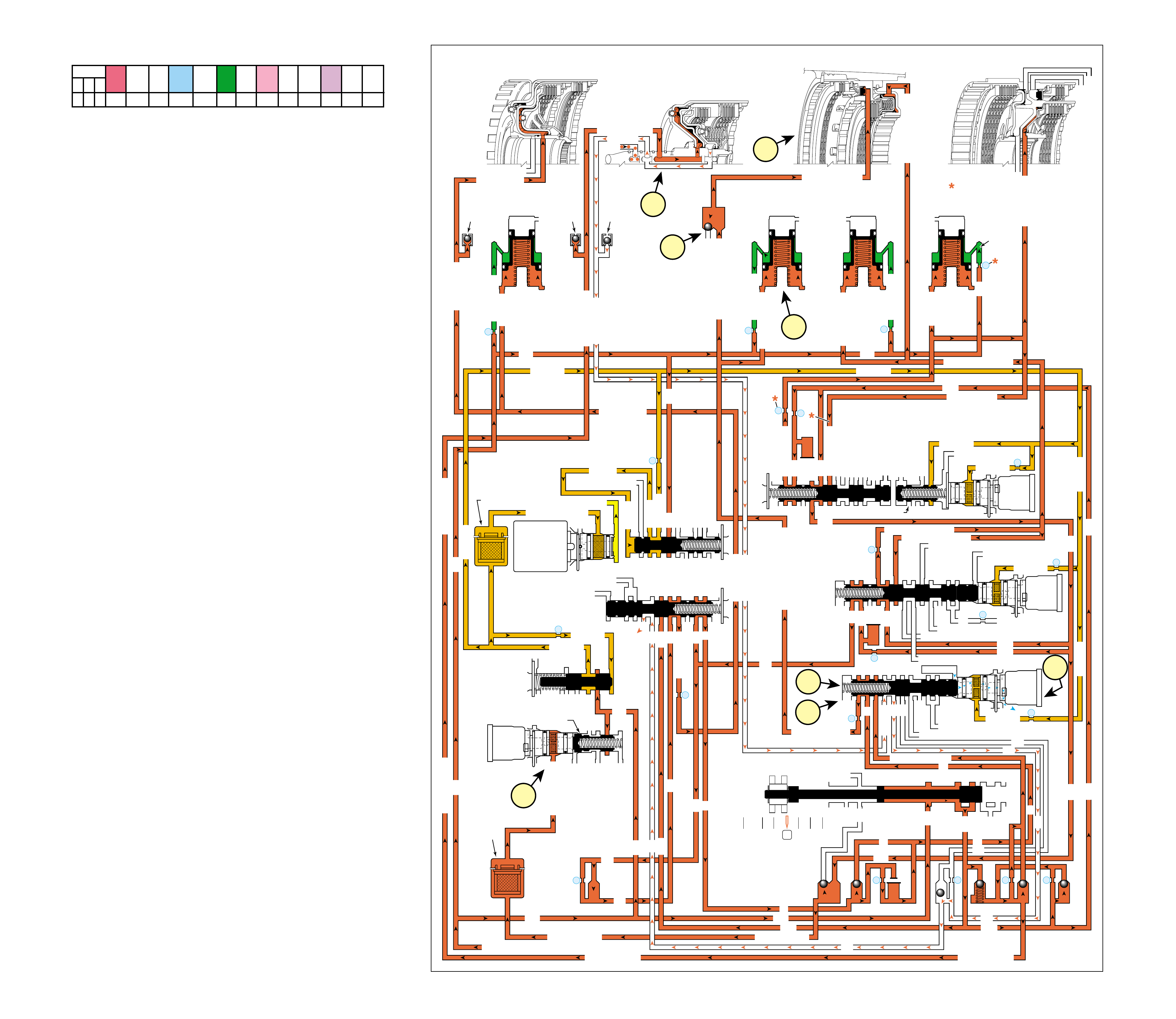
Figure 69
OVERDRIVE RANGE – FIFTH GEAR
(Torque Converter Clutch Released)
72B
SOLENOID FORWARD OVER- INTERM. INTER- LOW LOW AND SECOND SECOND
DIRECT REVERSE COAST FORWARD SPRAG DRIVE SPRAG MEDIATE SPRAG REVERSE SECOND SPRAG COAST
1-2 2-3 4-5 CLUTCH CLUTCH CLUTCH CLUTCH CLUTCH CLUTCH CLUTCH CLUTCH CLUTCH CLUTCH CLUTCH CLUTCH CLUTCH
OFF OFF OFF APPLIED APPLIED APPLIED APPLIED APPLIED
LD = LOCKED IN DRIVE
COMPLETE HYDRAULIC CIRCUIT
Page 100
OVERDRIVE RANGE – FIFTH GEAR
(Torque Converter Clutch Released)
LUBE
LOW AND REV CL OR RLO
SECOND COAST CL
SECOND CLUTCH
REVERSE CLUTCH
OVERDRIVE CL FD 2
ACCUMULATOR
INTERMEDIATE CL
INTERMEDIATE CLUTCH
INTERMEDIATE CLUTCH
ACCUMULATOR
EX
SECOND CL
ACCUM
ACCUMULATOR
LINE
LINE
LINE
OVERDRIVE CLUTCH
COAST CL
REVERSE LOCKOUT
EX
LINE
EXEX
SECOND CLUTCH
DIRECT CL
DIRECT CLUTCH
4
2
5
DIRECT
CLUTCH
ACCUMULATOR
OVERDRIVE
CLUTCH
ACCUMULATOR
INTERMEDIATE
CLUTCH
ACCUMULATOR
SECOND
CLUTCH
ACCUMULATOR
DIRECT
AND REVERSE
CLUTCH
ASSEMBLY
(400—420)
FORWARD
AND COAST
CLUTCH
ASSEMBLY
(430—451)
OVERDRIVE
AND
INTERMEDIATE
CLUTCH
ASSEMBLY
(480—497)
CENTER
SUPPORT
ASSEMBLY
(510—535)
3
21
OVERDRIVE CLUTCH FEED 1
OVERDRIVE CLUTCH FEED 2
#12
2345
2345
2345
2345
2345 OR REVERSE
LINE
LINE
LINE (from Pump)
LINE
FILTERED FEED LIMIT
THROTTLE SIGNAL
EX
2345 OR REVERSE
TCC SIGNAL
REGULATED APPLY
REGULATED APPLY
EX
EX
FEED LIMIT VALVE
LINE
EX
EX
EX
EX
FEED LIMIT
FEED LIMIT
EX EX
SECOND COAST CLUTCH
23 REGULATED
23 REGULATED
OVERDRIVE CLUTCH FEED 1
INTERMEDIATE CLUTCH
2345
INTERMEDIATE CLUTCH
2345
345
345
FEED LIMIT
EX
EX
EX
EX
2-3 SIGNAL
LINE SAFETY MODE
123 BRAKING
123
EX
EX
EX
123
123
123123
123
123
COAST CL
COAST CLUTCH
COAST CLUTCH FEED
OVERDRIVE CL FD 2
45
FEED LIMIT
SAFETY MODE
LINE
FEED LIMIT
32
MEMORY
MEMORY
MEMORY
MEMORY PILOT
32 SAFETY MODE
EX
EX
2-3 SIGNAL
123123 D432D432
DIRECT CLUTCH
DIRECT CLUTCH
4545
1-2 SIGNAL
EX
EX
EX
FDL
D432
2345
D432
D432
D432D432
D432D432
SECOND CLUTCH
23 REGULATED
123 REGULATED
SECOND CLUTCH
123 REGULATED
LOW AND REVERSE CL
EX
EX
EX
FEED LIMIT
FEED LIMIT
FDL
1-2 SIGNAL
2-3 SIGNAL
EX
EX
RPND432
MANUAL VALVE
LINE
D432
REV
REVERSE
EX
32
LINELINE
LINE SAFETY MODE
4-5 SIGNAL
24
28
2345
2345 OR REVERSE
345
345
345
345
345
345
45
45
45
45
45
OVERDRIVE CLUTCH FEED 2
PRESSURE
CONTROL
SOLENOID
VALVE
1-2 SHIFT
SOLENOID
VALVE
N/C
(A)
OFF
2-3 SHIFT
SOLENOID
VALVE
N/C
(B)
OFF
4-5 SHIFT
SOLENOID
VALVE
N/C
(C)
OFF
TCC PWM
SOLENOID
VALVE
N/C
1-2 SHIFT VALVE
2-3 SHIFT VALVE CNTRL
CNTRL 3-4 SHIFT
4-5 SHIFT VLV CNTRL
7
11
10
9
18
FILTER
(308)
FILTER
(312)
TCC REGULATOR VALVE
1-2 SHIFT CONTROL VALVE
#7
X-1
#2
26
X-4 X-5 #6
15
#5
17
#4 16
25 #3 27
29
8
COAST CLUTCH
AIR
BLEED
(203)
DIRECT CLUTCH
DIRECT CLUTCH
AIR
BLEED
(203)
FORWARD CLUTCH
FORWARD CLUTCH
FORWARD CLUTCHFORWARD CLUTCH
FORWARD CLUTCH FORWARD CLUTCH
AIR
BLEED
(203)
14
X-3
FEED LIMIT
FEED LIMIT FEED LIMIT
FEED LIMITFEED LIMIT
123
1c
1d
3a
2a
3b
1b
1a
4a
Overdrive Range – Fifth Gear is used to maximize engine
efficiency and fuel economy under most normal driving
conditions. In order to shift the transmission into Fifth gear, the
TCM receives input signals from both speed sensors, the To
sensor and other vehicle sensors to determine the precise moment
to de-energize or “turn OFF” the 4-5 shift solenoid (SS) valve.
1 OVERDRIVE CLUTCH APPLIED
1a 4-5 Shift Solenoid (SS) Valve:
The 4-5 SS valve is de-energized, blocking feed limit fluid
from entering the 4-5 signal fluid circuit. 4-5 signal fluid
pressure exhausts through the 4-5 SS valve and 4-5 shift
valve spring (373) force moves the 4-5 shift valve (374) and
the 4-5 shift control valve (375) to the released position.
1b 4-5 Shift Valve:
45 fluid is routed through the 4-5 shift valve and enters the
overdrive clutch feed 2 fluid circuit through orifice #28.
1c #12 Ball Check Valve:
Overdrive clutch feed 2 fluid seats the #12 ball check valve
against the overdrive clutch feed 1 passage and enters the
overdrive clutch fluid circuit.
1d Overdrive Clutch:
Overdrive clutch fluid is then directed to the overdrive
clutch piston to apply the overdrive clutch plates and achieve
Fifth gear.
2 4-5 SHIFT ACCUMULATION
2a Overdrive Clutch Accumulator:
Overdrive clutch fluid is also sent to the overdrive clutch
accumulator assembly. Overdrive clutch fluid, together with
accumulator spring force, moves the overdrive clutch
accumulator piston against accumulator fluid pressure to
cushion the apply of the overdrive clutch.
3 COAST CLUTCH RELEASES
3a Coast Clutch:
When the 4-5 shift valve is shifted to the released position,
coast clutch feed fluid is blocked and coast clutch fluid
exhausts through the valve allowing the coast clutch to release.
3b 4-5 Shift Valve:
Coast clutch fluid passes through the 4-5 shift valve and into
the 123 circuit and on to the 3-4 shift valve where it exhausts.
4 TORQUE CONVERTER CLUTCH RELEASED
4a TCC PWM Solenoid Valve:
Filtered 2345 or reverse fluid is still available at the TCC
PWM solenoid valve. However, depending on the shift
pattern, the TCM keeps the pulse width modulated (PWM)
solenoid de-energized blocking filtered 2345 or reverse fluid
from entering the TCC signal fluid circuit, thereby keeping
the torque converter clutch released.
73
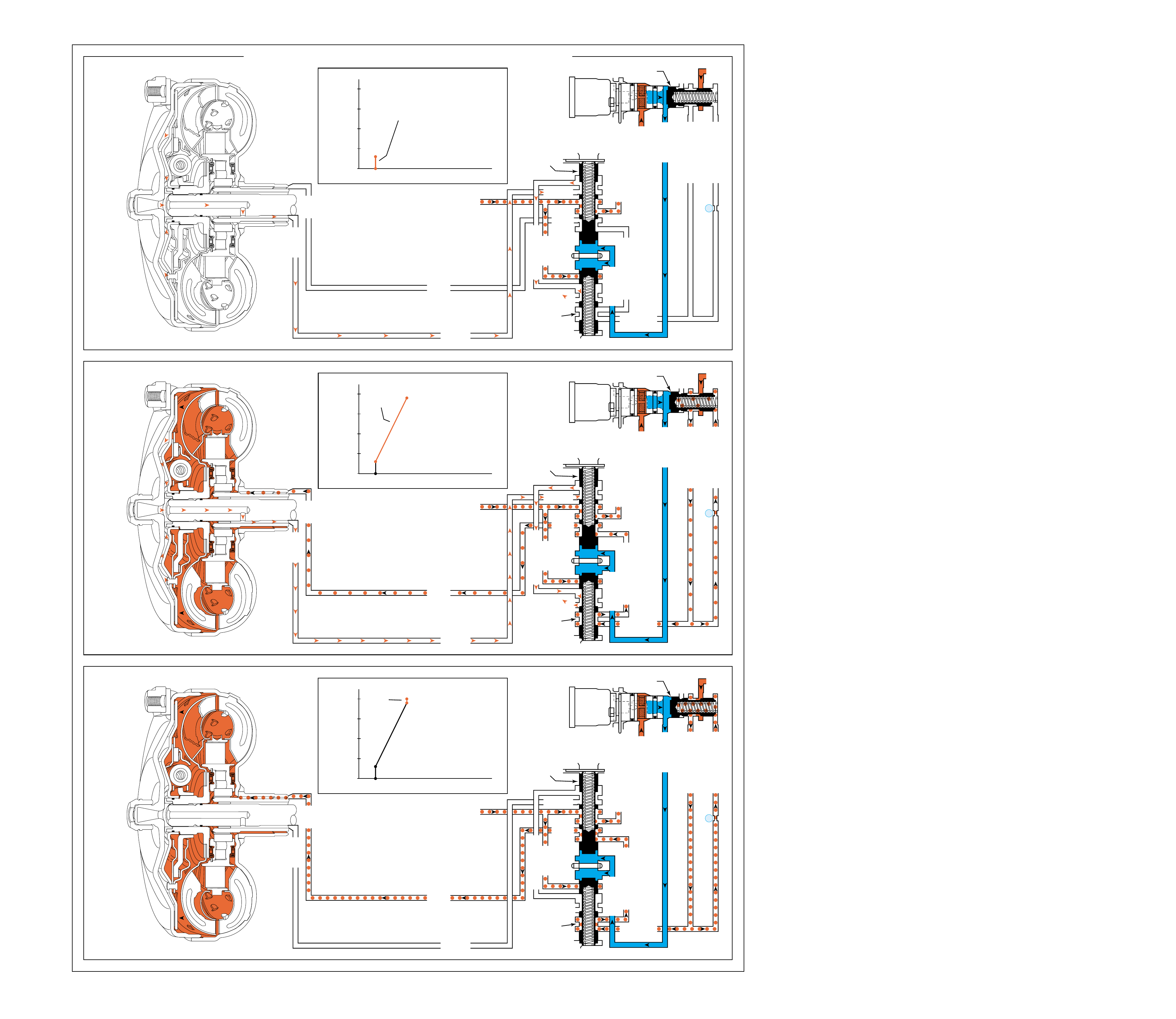
OVERDRIVE RANGE – FIFTH GEAR
(Torque Converter Clutch from Released to Applied)
STAGE 1
(S - A)
STAGE 2
(A - B)
STAGE 3
(B - C)
APPLY
RELEASE
TORQUE
CONVERTER
ASSEMBLY
(1)
APPLY
APPLY
TCC SIGNAL
CONV FD
CONVERTER FEED RELEASE
TO COOLER
REGULATED APPLY
REG APPLY
EX
EX
CONVERTER FDL
TCC
CONTROL
VALVE
TCC
ENABLE
VALVE
2345 OR REVERSE
TCC SIGNAL
REGULATED APPLY
REGULATED APPLY
EX
EX
LINE
TCC PWM
SOLENOID
VALVE
N/C
6
TCC REGULATOR VALVE
RELEASE
APPLY
RELEASE
TORQUE
CONVERTER
ASSEMBLY
(1)
APPLY
APPLY
TCC SIGNAL
CONV FD
CONVERTER FEED RELEASE
TO COOLER
REGULATED APPLY
REG APPLY
EX
EX
CONVERTER FDL
TCC
CONTROL
VALVE
TCC
ENABLE
VALVE
2345 OR REVERSE
TCC SIGNAL
REGULATED APPLY
REGULATED APPLY
EX
EX
LINE
TCC PWM
SOLENOID
VALVE
N/C
6
TCC REGULATOR VALVE
RELEASE
TCC APPLY AND RELEASE
STAGE
1
A
S
TCC
APPLY
FLUID
PRESSURE
TIME
➤
100%
➤
0
25
50
75
PERCENT DUTY CYCLE
➤
TCC APPLY AND RELEASE
STAGE
2
A
S
B
➤
TCC
APPLY
FLUID
PRESSURE TIME
➤
100%
➤
0
25
50
75
PERCENT DUTY CYCLE
TCC APPLY AND RELEASE
STAGE
3
A
S
B
C
➤
TCC
APPLY
FLUID
PRESSURE TIME
➤
100%
➤
0
25
50
75
PERCENT DUTY CYCLE
Figure 70
OVERDRIVE RANGE – FIFTH GEAR
(Torque Converter Clutch from Released to Applied)
74A
COMPLETE HYDRAULIC CIRCUIT
Page 102
When the Transmission Control Module (TCM) determines that
the engine and transmission are operating properly to engage
the Torque Converter Clutch (TCC), the TCM energizes the
TCC PWM solenoid valve. The following events occur in order
to apply the torque converter clutch:
OFF At this time the Torque Converter Clutch is
considered to be disengaged (OFF).
TCM decision to apply TCC (see page 50, in the Electrical
Components section, for more information).
Stage 1 The TCM pulses the TCC PWM solenoid valve to
approximately 15% duty cycle from point S to point A. 2345
or Reverse fluid at the TCC PWM solenoid valve is “pulsed”
into the TCC Signal fluid circuit. The TCC Signal fluid
pressure at point A is strong enough to move the TCC Control,
and TCC Enable valves against spring force. The TCC
Control valve moves and allows Release fluid to begin to
exhaust from the torque converter and enter the Converter
FDL fluid circuit. The TCC Enable valve moves and allows
Release/Converter FDL fluid to exhaust into the sump. This
stage is designed to move the TCC Control and TCC Enable
valves from the released position toward the applied position;
there is not enough pressure to apply the TCC.
Stage 2 The TCC PWM solenoid valve duty cycle is ramped
up from point A to point B. TCC Signal fluid pressure is
now strong enough to move the TCC Regulator valve against
spring force. Line pressure from the pump enters the
Regulated Apply circuit at the TCC Regulator valve.
Regulated Apply fluid is routed through the TCC Enable
valve and through the TCC Control valve into the Apply
circuit. The pressure value in the Regulated Apply circuit is
precisely controlled to maintain a small amount of slippage
(20 to 80 RPM) between the engine and the turbine, reducing
driveline torsional disturbances.
Stage 3 Now the Regulated Apply pressure is increased.
This is caused by the TCC PWM solenoid valve duty cycle
being increased from point B to point C, to maximum duty
cycle. This extra pressure ensures that the apply force on the
TCC pressure plate is not at the slip threshold, but in the
condition of full lock up.
74
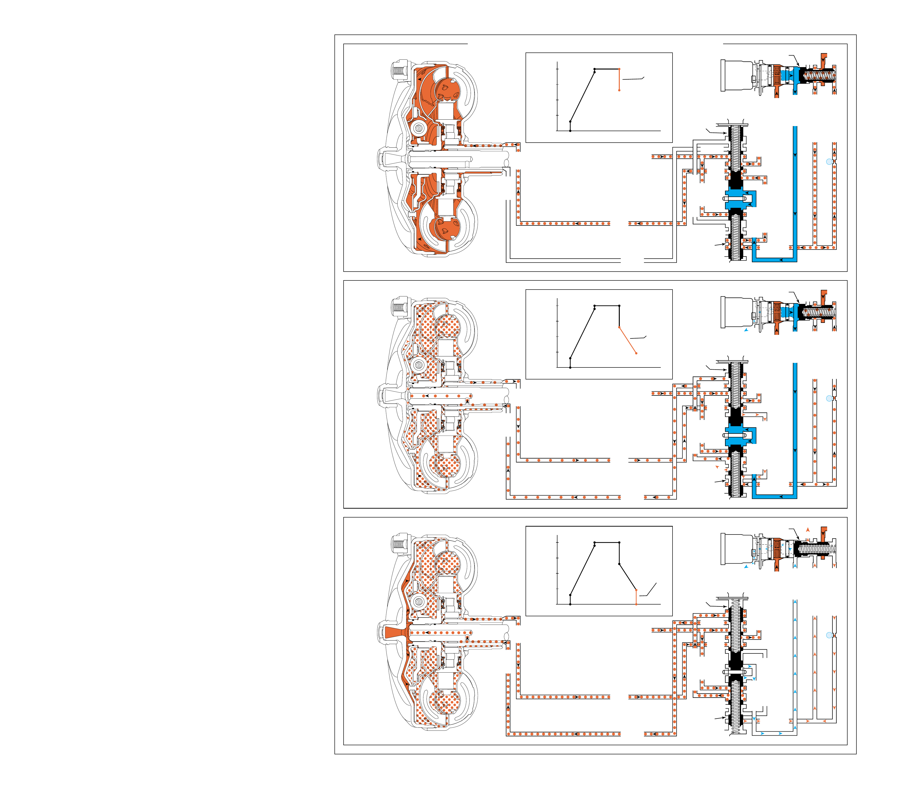
OVERDRIVE RANGE – FIFTH GEAR
(Torque Converter Clutch from Applied to Released)
Figure 71
OVERDRIVE RANGE – FIFTH GEAR
(Torque Converter Clutch from Applied to Released)
STAGE 4
(D - E)
STAGE 5
(E - F)
STAGE 6
(F - G)
APPLY
RELEASE
TORQUE
CONVERTER
ASSEMBLY
(1)
APPLY
APPLY
TCC SIGNAL
CONV FD
CONVERTER FEED RELEASE
TO COOLER
REGULATED APPLY
REG APPLY
EX
EX
CONVERTER FDL
TCC
CONTROL
VALVE
TCC
ENABLE
VALVE
2345 OR REVERSE
TCC SIGNAL
REGULATED APPLY
REGULATED APPLY
EX
EX
LINE
TCC PWM
SOLENOID
VALVE
N/C
6
TCC REGULATOR VALVE
RELEASE
APPLY
RELEASE
TORQUE
CONVERTER
ASSEMBLY
(1)
APPLY
APPLY
TCC SIGNAL
CONV FD
CONVERTER FEED RELEASE
TO COOLER
REGULATED APPLY
REG APPLY
EX
EX
CONVERTER FDL
TCC
CONTROL
VALVE
TCC
ENABLE
VALVE
2345 OR REVERSE
TCC SIGNAL
REGULATED APPLY
REGULATED APPLY
EX
EX
LINE
TCC PWM
SOLENOID
VALVE
N/C
6
TCC REGULATOR VALVE
RELEASE
TCC APPLY AND RELEASE
STAGE
4
A
S
B
CD
E
➤
TCC
APPLY
FLUID
PRESSURE TIME
➤
100%
➤
0
25
50
75
PERCENT DUTY CYCLE
TCC APPLY AND RELEASE
A
S
B
CD
E
F
STAGE
5
➤
TCC
APPLY
FLUID
PRESSURE TIME
➤
100%
➤
0
25
50
75
PERCENT DUTY CYCLE
TCC APPLY AND RELEASE
A
S
B
CD
E
F
G
STAGE
6
➤
TCC
APPLY
FLUID
PRESSURE TIME
➤
100%
➤
0
25
50
75
PERCENT DUTY CYCLE
74B
COMPLETE HYDRAULIC CIRCUIT
Page 102
When the TCC pressure plate is applied, it is held against the
torque converter cover. Since it is splined to the converter
turbine hub, it provides a mechanical coupling (direct drive) of
the engine to the transmission gear sets. This mechanical
coupling eliminates the small amount of slippage that occurs in
the fluid coupling of a torque converter, resulting in a more
efficient transfer of engine torque through the transmission and
to the drive wheels.
ON At this time the Torque Converter Clutch is
considered to be engaged (ON).
TCM decision to release TCC (see page 50, in the Electrical
Components section, for more information).
Stage 4 During this stage, the apply pressure from the TCC
Regulator valve is decreased by the TCC PWM solenoid
valve duty cycle dropping from point D to point E. Spring
force pushes the valve back and reduces the Regulated Apply
pressure. This reduces the apply force on the TCC pressure
plate to the slip threshold. This gets the TCC pressure plate
ready for a smooth release.
Stage 5 The TCC PWM solenoid valve duty cycle is ramped
down from point E to point F through this stage. This action
allows the Regulated Apply pressure to start at the slip
threshold, and decrease to near “0” pressure over a very short
time to point F. The Regulated Apply pressure value from
the TCC Regulator valve at this duty cycle (point F) should
fully release the TCC pressure plate. Slip speed should be at
the maximum value.
Stage 6 The TCM pulses the TCC PWM solenoid valve to
a value of “0”. Now the TCC Control and TCC Enable
valves return to their released positions (away from the spring).
Release fluid is now directed back to the torque converter.
This stage is designed to move the TCC Control and TCC
Enable valves to the released position.
OFF At this time the Torque Converter Clutch is
considered to be disengaged (OFF).
(Some TCM calibrations may allow stages 4 - 6 to happen very
rapidly in almost a straight line down from point D to point G.)
75

Figure 72
MANUAL FOURTH – FOURTH GEAR
(from Overdrive Range – Fifth Gear)
➤
➤
➤
➤
➤
➤➤
➤
➤➤➤
➤
➤
➤
➤
➤
➤
➤
➤
➤
➤
➤
➤
➤
➤
SECOND
CLUTCH
SPRAG
(547)
OVERRUNNING
SECOND
CLUTCH
APPLIED
DIRECT CLUTCH
INPUT AND HUB
ASSEMBLY
(466)
DRIVING
REAR
INPUT
SUN
GEAR
DRIVING
REAR
INTERNAL
GEAR
(560)
DRIVEN
INPUT AND
REACTION
CARRIER
(553)
DRIVING
4
DIRECT
CLUTCH
APPLIED
2a
COAST
CLUTCH
APPLIED
2
FORWARD
CLUTCH
APPLIED
3
FORWARD
CLUTCH
SPRAG (461)
INEFFECTIVE
INTERMEDIATE
CLUTCH
APPLIED
INTERMEDIATE
CLUTCH
SPRAG
(473)
OVERRUNNING
SECOND
CLUTCH
SPRAG
(547)
OVERRUNNING
SECOND
CLUTCH
APPLIED
REAR
INPUT
SUN
GEAR
DRIVING
REAR
INTERNAL
GEAR
(560)
DRIVEN
INPUT AND
REACTION
CARRIER
(553)
DRIVING
DIRECT
CLUTCH
APPLIED
COAST
CLUTCH
APPLIED
FORWARD
CLUTCH
APPLIED
FORWARD
CLUTCH
SPRAG
(461)
INEFFECTIVE
DIRECT CLUTCH
INPUT AND HUB
ASSEMBLY
(466)
DRIVING
INTERMEDIATE
CLUTCH
APPLIED
INTERMEDIATE
CLUTCH
SPRAG
(473)
OVERRUNNING
5
POWER TO
TORQUE
CONVERTER
(1)
FOR ENGINE
BRAKING
1
POWER FROM
DIFFERENTIAL
ASSEMBLY
MANUAL FOURTH – FOURTH GEAR
(from Overdrive Range – Fifth Gear)
76A
SOLENOID FORWARD OVER- INTERM. INTER- LOW LOW AND SECOND SECOND
DIRECT REVERSE COAST FORWARD SPRAG DRIVE SPRAG MEDIATE SPRAG REVERSE SECOND SPRAG COAST
1-2 2-3 4-5 CLUTCH CLUTCH CLUTCH CLUTCH CLUTCH CLUTCH CLUTCH CLUTCH CLUTCH CLUTCH CLUTCH CLUTCH CLUTCH
OFF OFF ON APPLIED APPLIED APPLIED LD APPLIED APPLIED
LD = LOCKED IN DRIVE
Manual Fourth – Fourth Gear (4) is available to the driver when
vehicle operating conditions make it desirable to use only four
gear ratios. These conditions include city driving [where speeds
are generally below 72 km/h (45 mph)], towing a trailer, or
driving in hilly terrain. Manual Fourth also provides for engine
compression braking when descending slight grades and can be
used to retain Fourth gear when ascending slight grades for
additional engine performance. Manual Fourth is also referred
to as Drive Range because it has a 1:1 direct drive gear ratio
available through the transmission gear set.
In Manual Fourth, the transmission can upshift and downshift
between First, Second, Third and Fourth gears in the same
manner as Overdrive Range. However, the transmission is
prevented from shifting into Fifth gear while operating in this
gear selector position. If the transmission is in Overdrive Range
– Fifth Gear when Manual Fourth is selected, the transmission
will not shift into Fourth gear until vehicle speed is low enough
not to overrev the engine (calibratable in the TCM).
Note: Transfer of engine torque during acceleration is identical
to Overdrive Range – Fourth Gear (refer to page 70A). The
power flow in Figure 72 and the following text describes
conditions during deceleration (zero or minimum throttle
conditions) and how engine compression braking is achieved.
Vehicle speed provides the torque input to the transmission
through the drive shaft and transmission output shaft assembly
(562). This is shown by the direction of the power flow arrows
in the drawing at the top of Figure 72. Notice that this flow is
identical to Overdrive Range – Fourth Gear except that the
arrows are in the opposite direction.
1 Power From the Differential Assembly
Power flow is transferred back through the transmission
from the output shaft to the input shaft forward and coast
clutch housing assembly (433). Each of the component’s
function and rotation direction is the same as during
acceleration (compare Figures 66 and 72).
2 Forward and Coast Clutches Applied
The forward clutch, which is located within the input shaft
forward and coast clutch housing assembly (433), is applied
and holds the forward clutch sprag outer race (459). The
coast clutch is also located in the input shaft forward and
coast clutch housing assembly (433) and is also applied.
3 Forward Clutch Sprag Ineffective
With the forward and coast clutches both applied, the forward
clutch sprag (461) has no effect in Manual Fourth.
4 Direct Clutch Applied
The direct clutch is applied and input torque from the input
and reaction carrier (553) is transferred through the direct
clutch input and hub assembly (466) to the reverse clutch
housing assembly (401).
5 Engine Compression Braking
The reverse clutch housing assembly (401) is splined to the
input shaft forward and coast clutch housing assembly (433),
creating a mechanical link between the output shaft and
torque converter turbine. This creates a 1:1 direct drive gear
ratio and allows engine compression to slow the vehicle
when the throttle is released.
In Manual Fourth range, First, Second and Third gears operate
the same as in Overdrive Range.
76
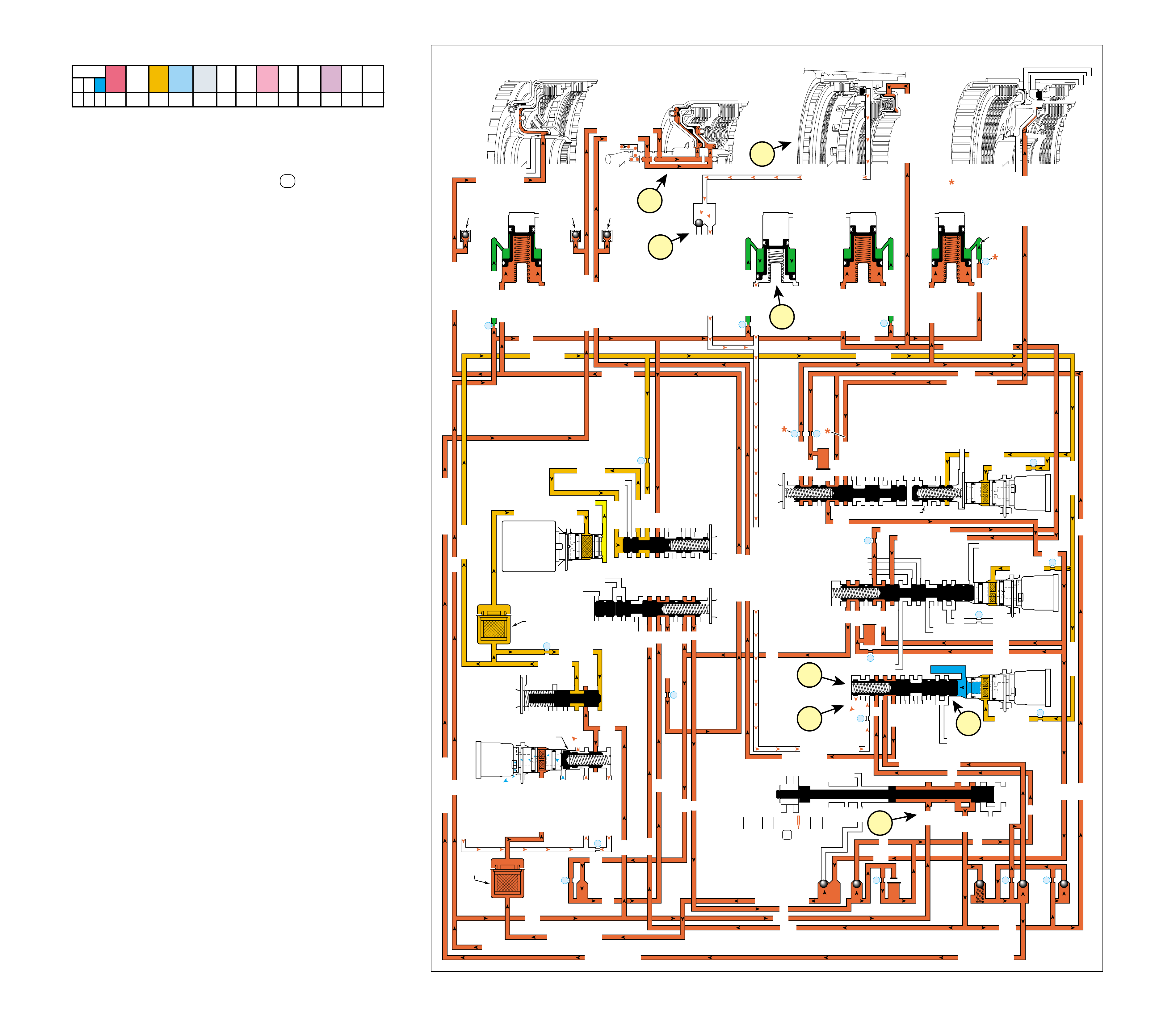
Manual Fourth – Fourth Gear (Drive Range) may be selected at
any time while the vehicle is being operated in a forward gear
range. However, TCM control prevents the transmission from
shifting into Fifth gear. When the gear selector lever is moved
to Drive Range (4) from Overdrive Range D , the manual valve
also moves. Changes to the hydraulic and electrical systems are
as follows:
1 OVERDRIVE CLUTCH RELEASES
1a Manual Valve:
The manual valve moves only to activate the transmission
manual shift shaft switch assembly. The transmission manual
shift shaft switch assembly signals the TCM that the
transmission is in Manual Fourth Range. There is no
hydraulic difference between Overdrive Range and Manual
Fourth Range at the manual valve.
1b 4-5 Shift Solenoid (SS) Valve:
The 4-5 SS valve is energized, allowing feed limit fluid to
enter the 4-5 signal fluid circuit. 4-5 signal fluid overcomes
4-5 shift valve spring (373) force and moves the 4-5 shift
control valve (375) and the 4-5 shift valve (374) to the
applied position.
1c 4-5 Shift Valve:
4-5 fluid is blocked at the 4-5 shift valve (374) allowing
overdrive clutch feed 2 fluid to exhaust.
1d Overdrive Clutch Assembly:
Overdrive clutch fluid exhausts from the overdrive clutch
piston, allowing the overdrive clutch plates to disengage.
1e #12 Ball Check Valve:
Overdrive clutch fluid seats the #12 ball check valve
against the overdrive clutch feed 1 passage and enters the
overdrive clutch feed 2 fluid circuit where it exhausts at
the 4-5 shift valve.
2 SHIFT ACCUMULATION
2a Overdrive Clutch Accumulator:
Overdrive clutch fluid also exhausts from the overdrive clutch
accumulator assembly. Accumulator fluid moves the
overdrive clutch accumulator piston against accumulator
spring force in preparation for another application of the
overdrive clutch.
3 COAST CLUTCH APPLIES
3a 4-5 Shift Valve:
Coast clutch feed fluid passes through the 4-5 shift valve
(374) and into the coast clutch circuit.
3b Coast Clutch:
Coast clutch fluid is routed to the coast clutch piston to
apply the coast clutch plates.
In Manual Fourth – Fourth Gear, the TCC will not release if
Manual Fourth was selected while the vehicle was operating in
Overdrive Range – Fifth Gear with the TCC applied. Under
normal operating conditions, the converter clutch operates the
same way in Manual Fourth – Fourth Gear as in Overdrive
Range – Fourth Gear. Refer to pages 74A and 74B for
descriptions of TCC release and apply.
Figure 73
76B
COMPLETE HYDRAULIC CIRCUIT
Page 104
MANUAL FOURTH – FOURTH GEAR
(from Overdrive Range – Fifth Gear)
SOLENOID FORWARD OVER- INTERM. INTER- LOW LOW AND SECOND SECOND
DIRECT REVERSE COAST FORWARD SPRAG DRIVE SPRAG MEDIATE SPRAG REVERSE SECOND SPRAG COAST
1-2 2-3 4-5 CLUTCH CLUTCH CLUTCH CLUTCH CLUTCH CLUTCH CLUTCH CLUTCH CLUTCH CLUTCH CLUTCH CLUTCH CLUTCH
OFF OFF ON APPLIED APPLIED APPLIED LD APPLIED APPLIED
LD = LOCKED IN DRIVE
MANUAL FOURTH – FOURTH GEAR
(from Overdrive Range – Fifth Gear)
LUBE
LOW AND REV CL OR RLO
SECOND COAST CL
SECOND CLUTCH
REVERSE CLUTCH
OVERDR CL FD 2
ACCUMULATOR
INTERMED CL
INTERMEDIATE CLUTCH
INTERMEDIATE CLUTCH
ACCUMULATOR
EX
SECOND CL
ACCUM
ACCUMULATOR
LINE
LINE
LINE
OVERDRIVE CLUTCH
COAST CL
REVERSE LOCKOUT
EXEXEX
SECOND CLUTCH
DIRECT CL
DIRECT CLUTCH
4
2
5
DIRECT
CLUTCH
ACCUMULATOR
OVERDRIVE
CLUTCH
ACCUMULATOR
INTERMEDIATE
CLUTCH
ACCUMULATOR
SECOND
CLUTCH
ACCUMULATOR
DIRECT
AND REVERSE
CLUTCH
ASSEMBLY
(400—420)
FORWARD
AND COAST
CLUTCH
ASSEMBLY
(430—451)
OVERDRIVE
AND
INTERMEDIATE
CLUTCH
ASSEMBLY
(480—497)
CENTER
SUPPORT
ASSEMBLY
(510—535)
3
21
OVERDRIVE CLUTCH FEED 1
OVERDRIVE CLUTCH FEED 2
#12
2345
2345
2345
2345
2345 OR REVERSE
LINE
LINE
LINE (from Pump)
LINE
FILTERED FEED LIMIT
THROTTLE SIGNAL
EX
2345 OR REVERSE
TCC SIGNAL
REGULATED APPLY
REGULATED APPLY (from TCC Enable Valve
REGULATED APPLY
EX
EX
FEED LIMIT VALVE
LINE
EX
EX
EX
EX
FEED LIMIT
FEED LIMIT
EX EX
SECOND COAST CLUTCH
23 REGULATED
OVERDRIVE CL FD 1
INTERMEDIATE CLUTCH
2345
INTERMEDIATE CLUTCH
2345
345
345
FEED LIMIT
EX
EX
EX
EX
2-3 SIGNAL
23 REGULATED
LINE SAFETY MODE
123 BRAKING
123
EX
EX
EX
123
CST CL
COAST CLUTCH
COAST CLUTCH COAST CLUTCH FEED
OVERDRIVE CL FD 2
45
FEED LIMIT
SAFETY MODE
LINE
FEED LIMIT
32
MEMORY
MEMORY
MEMORY
MEMORY PILOT
32 SAFETY MODE
EX
EX
2-3 SIGNAL
123
D432D432
DIRECT CLUTCH
DIRECT CLUTCH
4545
1-2 SIGNAL
EX
EX
EX
FDL
D432
2345
D432
D432
D432D432
D432D432
SECOND CL
23 REGULATED
123 REGULATED
SECOND CL
123 REGULATED
LOW AND REV CL
EX
EX
EX
FEED LIMIT
FEED LIMIT
FDL
1-2 SIGNAL
2-3 SIGNAL
EX
EX
RPND432
MANUAL VALVE
LINE
D432
REV
REVERSE
EX
32
LINELINE
LINE SAFETY MODE
4-5 SIGNAL
24
28
2345
2345 OR REVERSE
345
345
345
345
345
345
45
45
45
45
45
OVERDRIVE CLUTCH FEED 2
PRESSURE
CONTROL
SOLENOID
VALVE
1-2 SHIFT
SOLENOID
VALVE
N/C
(A)
OFF
2-3 SHIFT
SOLENOID
VALVE
N/C
(B)
OFF
4-5 SHIFT
SOLENOID
VALVE
N/C
(C)
ON
TCC PWM
SOLENOID
VALVE
N/C
1-2 SHIFT VALVE
7
11
10
9
18
FILTER
(308)
FILTER
(312)
TCC REGULATOR VALVE
1-2 SHIFT CONTROL VALVE
#7
X-1
#2
26
X-4 X-5 #6
15
#5
17
25 #3 27
29
8
COAST CLUTCH
AIR
BLEED
(203)
DIRECT CLUTCH
DIRECT CL
AIR
BLEED
(203)
FORWARD CLUTCH
FORWARD CLUTCH
FORWARD CLUTCHFORWARD CLUTCH
FORWARD CLUTCH FORWARD CLUTCH
AIR
BLEED
(203)
14
X-3
FEED LIMIT
FEED LIMIT FEED LIMIT
FEED LIMITFEED LIMIT
4-5 SHIFT VLV CNTRL
2-3 SHIFT VALVE CNTRL
CNTRL 3-4 SHIFT
6
1e
2a
3b
1d
1c
3a
1b
1a
77

Figure 74
MANUAL THIRD – THIRD GEAR
(from Manual Fourth – Fourth Gear)
➤
➤
➤
➤
➤➤➤➤
➤
➤
➤
➤
➤
➤
➤➤
5
POWER TO
TORQUE
CONVERTER
(1)
FOR ENGINE
BRAKING
1
POWER FROM
DIFFERENTIAL
ASSEMBLY
SECOND
CLUTCH
SPRAG
(547)
OVERRUNNING
SECOND
CLUTCH
APPLIED
REAR
INPUT
SUN GEAR
DRIVING
3
FRONT
INPUT
SUN
GEAR
HELD
INPUT AND
REACTION
CARRIER
(553)
DRIVEN
REAR
INTERNAL
GEAR
(560)
DRIVEN
LONG
PINION
GEAR
DRIVING
REAR SHORT
PINION
GEAR
DRIVING
4a
COAST
CLUTCH
APPLIED
4
FORWARD
CLUTCH
APPLIED
FORWARD
CLUTCH SPRAG
(461)
INEFFECTIVE
2
OVERDRIVE
CLUTCH
APPLIED
INTERMEDIATE
CLUTCH
APPLIED
INTERMEDIATE
CLUTCH
SPRAG
(473)
INEFFECTIVE
SECOND
CLUTCH
SPRAG
(547)
OVERRUNNING
INPUT AND
REACTION
CARRIER
(553)
DRIVEN
SECOND
CLUTCH
APPLIED
REAR INPUT
SUN GEAR
DRIVING
FRONT INPUT
SUN GEAR
HELD
REAR
INTERNAL
GEAR
(560)
DRIVEN
LONG
PINION
GEAR
DRIVING
REAR
SHORT
PINION
GEAR
DRIVING
COAST
CLUTCH
APPLIED
REVERSE
CLUTCH
HOUSING
ASSEMBLY
(401)
FORWARD
CLUTCH
APPLIED
FORWARD
CLUTCH
SPRAG
(461)
INEFFECTIVE
INTERMEDIATE
CLUTCH
APPLIED
INTERMEDIATE
CLUTCH SPRAG
(473)
INEFFECTIVE
OVERDRIVE
CLUTCH
APPLIED
MANUAL THIRD – THIRD GEAR
(from Manual Fourth – Fourth Gear)
78A
Manual Third – Third Gear (3) is available to the driver when
vehicle operating conditions make it desirable to use only three
gear ratios. These conditions include descending a steep grade
when engine compression braking is needed, or to retain third gear
when ascending a steep grade for additional engine performance.
In Manual Third, the transmission can upshift and downshift
between First, Second and Third gears in the same manner as
Overdrive Range but is prevented from shifting into Fourth or
Fifth gear while operating in this gear selector position. If the
transmission is in Fourth or Fifth Gear when Manual Third is
selected, the transmission will not shift into Third gear until
vehicle speed is low enough not to overrev the engine
(calibratable in the TCM).
Note: Transfer of engine torque during acceleration is identical
to Overdrive Range – Third Gear (refer to page 68A) to obtain
an approximate gear ratio reduction of 1.60:1 through the
transmission gear set. The power flow in Figure 74 and the
following text describes conditions during deceleration (zero or
minimum throttle conditions) and how engine compression
braking is achieved.
Vehicle speed provides the torque input to the transmission
through the drive shaft and transmission output shaft assembly
(562). This is shown by the direction of the power flow arrows
in the drawing at the top of Figure 74. Notice that this flow is
identical to Overdrive Range – Third Gear except that the arrows
are in the opposite direction.
1 Power From the Differential Assembly
Power flow is transferred back through the transmission
from the output shaft to the input shaft forward and coast
clutch housing assembly (433). Each of the component’s
function and rotation direction is the same as during
acceleration (compare Figures 64 and 74).
2 Overdrive Clutch Applied
The overdrive clutch, which is located within the overdrive
clutch housing (493), is applied and holds the overdrive and
reverse clutch hub assembly (470) stationary.
3 Front Input Sun Gear Held
The overdrive and reverse clutch hub assembly (470) is
splined to the front input sun gear and holds it stationary.
4 Forward and Coast Clutches Applied
The forward clutch, which is located within the input shaft
forward and coast clutch housing assembly (433), is applied
and holds the forward clutch sprag outer race (459). The
coast clutch is also located in the input shaft forward and
coast clutch housing assembly (433) and is also applied. Input
torque from the rear input sun gear of the input and reaction
carrier (553) is transferred through the coast clutch to the
input shaft forward and coast clutch housing assembly (433).
5 Engine Compression Braking
With the overdrive clutch applied, power flow is
mechanically connected between the output shaft and torque
converter turbine. This allows engine compression to slow
the vehicle when the throttle is released.
In Manual Third range, First and Second gears operate the same
as in Overdrive Range.
SOLENOID FORWARD OVER- INTERM. INTER- LOW LOW AND SECOND SECOND
DIRECT REVERSE COAST FORWARD SPRAG DRIVE SPRAG MEDIATE SPRAG REVERSE SECOND SPRAG COAST
1-2 2-3 4-5 CLUTCH CLUTCH CLUTCH CLUTCH CLUTCH CLUTCH CLUTCH CLUTCH CLUTCH CLUTCH CLUTCH CLUTCH CLUTCH
ON OFF ON APPLIED APPLIED LD APPLIED LD APPLIED APPLIED
LD = LOCKED IN DRIVE
78
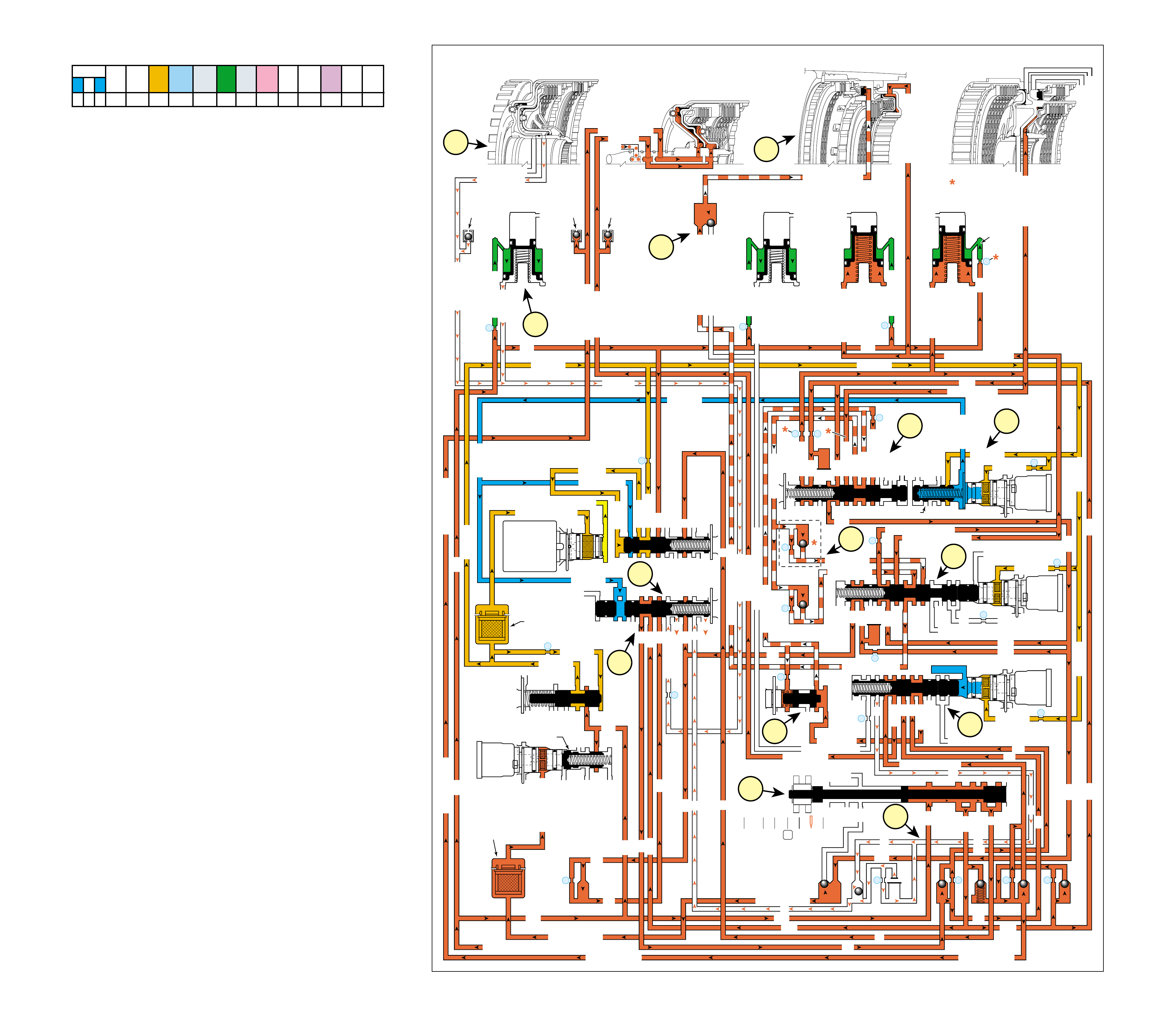
78B
MANUAL THIRD – THIRD GEAR
(from Manual Fourth – Fourth Gear)
COMPLETE HYDRAULIC CIRCUIT
Page 106 Figure 75
Manual Third – Third Gear may be selected at any time while the
vehicle is being operated in a forward gear range. However, TCM
control prevents the transmission from shifting above Third gear.
When the gear selector lever is moved to Manual Third range (3)
from Manual Fourth – Fourth Gear, the manual valve also moves.
Changes to the hydraulic and electrical systems are as follows:
1 OVERDRIVE CLUTCH APPLIES
1a Manual Valve:
Line pressure enters the 32 fluid circuit at the manual valve.
32 fluid is routed to the safety mode valve.
1b 1-2 Shift Solenoid (SS) Valve:
The 1-2 SS valve is energized, allowing feed limit fluid to
enter the 1-2 signal fluid circuit. 1-2 signal fluid is routed to
the safety mode valve and to the 3-4 shift valve.
1c 3-4 Shift Valve:
1-2 signal fluid overcomes 3-4 shift valve spring force and
moves the 3-4 shift valve to the applied position. This
allows D432 fluid to enter the 123 fluid circuit, and allows
direct clutch and 45 fluids to exhaust.
1d #4 Ball Check Valve:
123 fluid seats the #4 ball check valve and passes through
orifice #16 on the way to the 4-5 shift valve.
1e 4-5 Shift Valve:
123 fluid passes through the 4-5 shift valve (333) into the
123 braking fluid circuit.
1f Low Pressure Control Valve:
123 braking fluid is regulated into the 123 regulated fluid
circuit through the low pressure control valve (383).
1g 1-2 shift Valve:
123 regulated fluid passes through the 1-2 shift valve into
the 23 regulated fluid circuit.
1h #9 and #11 Ball Check Valves:
23 regulated fluid seats the #9 and the #11 ball check valves
and is forced through orifices #22 and #23.
1i 2-3 Shift Valve:
23 regulated fluid passes through the 2-3 shift valve into the
overdrive clutch feed 1 fluid circuit.
1j #12 Ball Check Valve:
Overdrive clutch feed 1 fluid seats the #12 ball check valve
against the overdrive clutch feed 2 passage and enters the
overdrive clutch fluid circuit.
1k Overdrive Clutch:
Overdrive clutch fluid is then directed to the overdrive clutch
piston to apply the overdrive clutch plates.
2 DIRECT CLUTCH RELEASES
2a Direct Clutch:
Direct clutch fluid is exhausts from the direct clutch piston
to release the direct clutch plates.
2b 3-4 Shift Valve:
Direct clutch fluid flows through orifice #26 to the 3-4 shift
valve where it exhausts.
3 SHIFT ACCUMULATION
3a Direct Clutch Accumulator:
Direct clutch fluid also exhausts from the direct clutch
accumulator assembly. Accumulator fluid moves the direct
clutch accumulator piston against accumulator spring force
in preparation for another application of the direct clutch.
In Manual Third – Third Gear, the TCC will not release if Manual
Third was selected while the vehicle was operating in Overdrive
Range – Fifth Gear with the TCC applied. Under normal operating
conditions, the converter clutch operates the same way in Manual
Third – Third Gear as in Overdrive Range – Third Gear. Refer to
pages 74A and 74B for descriptions of TCC release and apply.
SOLENOID FORWARD OVER- INTERM. INTER- LOW LOW AND SECOND SECOND
DIRECT REVERSE COAST FORWARD SPRAG DRIVE SPRAG MEDIATE SPRAG REVERSE SECOND SPRAG COAST
1-2 2-3 4-5 CLUTCH CLUTCH CLUTCH CLUTCH CLUTCH CLUTCH CLUTCH CLUTCH CLUTCH CLUTCH CLUTCH CLUTCH CLUTCH
ON OFF ON APPLIED APPLIED LD APPLIED LD APPLIED APPLIED
LD = LOCKED IN DRIVE
MANUAL THIRD – THIRD GEAR
(from Manual Fourth – Fourth Gear)
LUBE
LOW AND REV CL OR RLO
SECOND COAST CL
SECOND CLUTCH
REVERSE CLUTCH
OVERDRIVE CL FD 2
ACCUMULATOR
INTERMEDIATE CL
INTERMEDIATE CLUTCH
INTERMEDIATE CLUTCH
ACCUMULATOR
EX
SECOND CLUTCH
ACCUM
ACCUMULATOR
LINE
LINE
LINE
OVERDRIVE CLUTCH
COAST CL
REVERSE LOCKOUT
EXEXEX
SECOND CLUTCH
DIRECT CL
DIRECT CLUTCH
4
2
5
DIRECT
CLUTCH
ACCUMULATOR
OVERDRIVE
CLUTCH
ACCUMULATOR
INTERMEDIATE
CLUTCH
ACCUMULATOR
SECOND
CLUTCH
ACCUMULATOR
DIRECT
AND REVERSE
CLUTCH
ASSEMBLY
(400—420)
FORWARD
AND COAST
CLUTCH
ASSEMBLY
(430—451)
OVERDRIVE
AND
INTERMEDIATE
CLUTCH
ASSEMBLY
(480—497)
CENTER
SUPPORT
ASSEMBLY
(510—535)
3
21
OVERDRIVE CLUTCH FEED 1
OVERDRIVE CLUTCH FEED 1
OVERDRIVE CLUTCH FEED 2
#12
2345
2345
2345
2345
2345 OR REVERSE
LINE
LINE
LINE (from Pump)
LINE
FILTERED FEED LIMIT
THROTTLE SIGNAL
EX
2345 OR REVERSE
TCC SIGNAL
REGULATED APPLY
REGULATED APPLY
EX
EX
FEED LIMIT VALVE
LINE
EX
EX
EX
EX
FEED LIMIT
FEED LIMIT
EX EX
SECOND COAST CLUTCH
23 REGULATED
OVERDRIVE CL FD 1
INTERMEDIATE CLUTCH
2345
INTERMEDIATE CLUTCH
2345
345
345
FEED LIMIT
EX
EX
EX
EX
2-3 SIGNAL
23 REGULATED
LINE SAFETY MODE
123 BRAKING
123 BRK
123
EX
EX
EX
123
123
123
123
123
123
CST CL
COAST CLUTCH
COAST CLUTCH COAST CLUTCH FEED
OVERDRIVE CL FD 2
45
FEED LIMIT
SAFETY MODE
LINE
FEED LIMIT
32
32
MEMORY
MEMORY
MEMORY
MEMORY PILOT
32 SAFETY MODE
EX
EX
2-3 SIGNAL
123123 D432D432
DIRECT CLUTCH
DIRECT CLUTCH
4545
1-2 SIGNAL
1-2 SIGNAL
1-2 SIGNAL
EX
EX
EX
FDL
D432
2345
D432
D432
D432D432
D432D432
SECOND CL
23 REG
23 REGULATED
123 REG
SECOND CL
123 REGULATED
LOW AND REV CL
EX
EX
EX
FEED LIMIT
FEED LIMIT
FDL
1-2 SIGNAL
2-3 SIGNAL
EX
EX
RPND432
MANUAL VALVE
LINE
D432
REV
REVERSE
EX
32
32
32
LINELINE
LINE SAFETY MODE
4-5 SIGNAL
24
28
2345
2345 OR REVERSE
345
345
345
345
345
345
45
45
45
45
45
OVERDRIVE CLUTCH FEED 2
PRESSURE
CONTROL
SOLENOID
VALVE
1-2 SHIFT
SOLENOID
VALVE
N/C
(A)
ON
2-3 SHIFT
SOLENOID
VALVE
N/C
(B)
OFF
4-5 SHIFT
SOLENOID
VALVE
N/C
(C)
ON
TCC PWM
SOLENOID
VALVE
N/C
1-2 SHIFT VALVE
2-3 SHIFT VALVE CNTRL
CNTRL
7
11
10
9
18
FILTER
(308)
FILTER
(312)
TCC REGULATOR VALVE
1-2 SHIFT CONTROL VALVE
#7
X-1
#2
26
X-4 X-5 #6
15
#5
17
#4 16
25 #3 27
29
8
COAST CLUTCH
AIR
BLEED
(203)
DIRECT CLUTCH
DIRECT CL
AIR
BLEED
(203)
FORWARD CLUTCH
FORWARD CLUTCH
FORWARD CLUTCHFORWARD CLUTCH
FORWARD CLUTCH FORWARD CLUTCH
AIR
BLEED
(203)
14
X-3
FEED LIMIT
FEED LIMIT FEED LIMIT
FEED LIMITFEED LIMIT
123
4-5 SHIFT VLV CNTRL
3-4 SHIFT
LOW PRESSURE
EX
123 REGULATED
19
20
#9
22
#11
23
1j
1k
3a
1c
1f
1d
1a
2a
1h
2b
1b
1g
1i
1e
79
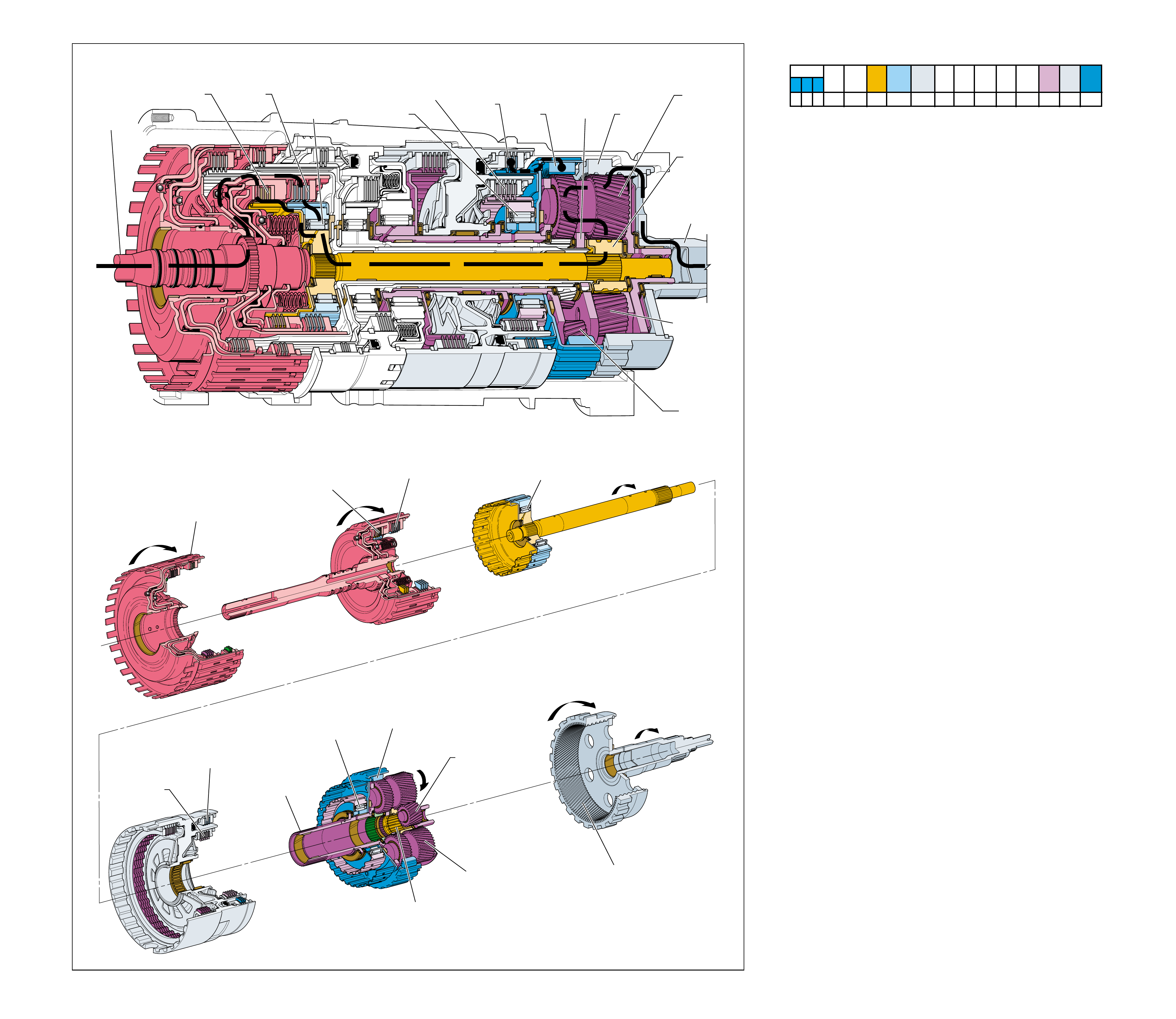
MANUAL SECOND – SECOND GEAR
(from Manual Third – Third Gear)
➤
➤
➤
➤
➤
➤
➤
➤
➤
➤
➤
➤
➤
➤
➤
➤
➤
5
POWER TO
TORQUE
CONVERTER
(1)
FOR ENGINE
BRAKING
1
POWER FROM
DIFFERENTIAL
ASSEMBLY
3
REACTION
INTERNAL
GEAR
(550)
HELD
SECOND
CLUTCH
SPRAG
(547)
INEFFECTIVE
REAR INPUT
SUN GEAR
DRIVING
LONG
PINION GEAR
DRIVING
REAR
INTERNAL
GEAR
(560)
DRIVEN
INPUT AND
REACTION
CARRIER
(553)
DRIVEN
FRONT SHORT
PINION
GEAR
DRIVING
REAR SHORT
PINION
GEAR
DRIVING
4a
COAST
CLUTCH
APPLIED
4
FORWARD
CLUTCH
APPLIED
COAST
CLUTCH
APPLIED
REVERSE
CLUTCH
HOUSING
ASSEMBLY
(401)
FORWARD
CLUTCH
APPLIED
FORWARD
CLUTCH
SPRAG
(461)
INEFFECTIVE
FORWARD
CLUTCH
SPRAG
(461)
INEFFECTIVE
SECOND
CLUTCH
APPLIED
2
SECOND
COAST
CLUTCH
APPLIED
REACTION
INTERNAL
GEAR
(550)
HELD
SECOND
CLUTCH
SPRAG
(547)
INEFFECTIVE
REAR
INPUT
SUN GEAR
DRIVING
LONG
PINION
GEAR
DRIVING
REAR
INTERNAL
GEAR
(560)
DRIVEN
INPUT AND
REACTION
CARRIER
(553)
DRIVEN
REAR SHORT
PINION GEAR
DRIVING
SECOND
CLUTCH
APPLIED
SECOND
COAST
CLUTCH
APPLIED
Figure 76 80A
MANUAL SECOND – SECOND GEAR
(from Manual Third – Third Gear)
Manual Second (2) gear range is available to the driver when
vehicle operating conditions require maximum engine
compression braking for slowing the vehicle, or maximum engine
torque transfer to the wheels. These conditions include
descending a steep grade when maximum engine compression
braking is needed, to retain second gear when ascending a steep
grade, or pulling a heavy load for maximum engine power.
In Manual Second, the transmission can upshift and downshift
between First and Second gear in the same manner as Overdrive
Range but is prevented from shifting into Third, Fourth or Fifth
gear while operating in this gear selector position. If the
transmission is in any other forward gear range when Manual
Second is selected, the transmission will not shift into Second
gear until vehicle speed is low enough not to overrev the engine
(calibratable in the TCM). Above this speed, the transmission
will first shift into Third gear until vehicle speed slows sufficiently.
Note: Transfer of engine torque during acceleration is identical to
Overdrive Range – Second Gear (refer to page 66A) to obtain an
approximate gear ratio reduction of 2.21:1 through the transmission
gear set. The power flow in Figure 76 and the following text
describes conditions during deceleration (zero or minimum throttle)
and how engine compression braking is achieved.
Vehicle speed provides the torque input to the transmission
through the drive shaft and transmission output shaft assembly
(562). This is shown by the direction of the power flow arrows
in the drawing at the top of Figure 76. Notice that this flow is
identical to Overdrive Range – Second Gear except that the
arrows are in the opposite direction.
1 Power From the Differential Assembly
Power flow is transferred back through the transmission
from the output shaft to the input shaft forward and coast
clutch housing assembly (433). Each of the component’s
function and rotation direction is the same as during
acceleration (compare Figures 62 and 76).
2 Second Coast Clutch Applied
The second coast clutch, which is located within the center
support (518), is applied and holds the second clutch sprag
inner race (549) stationary.
3 Reaction Internal Gear Held
The second clutch sprag inner race (549) is splined to the
reaction internal gear (550) and holds it stationary.
4 Forward and Coast Clutches Applied
The forward clutch, which is located within the input shaft
forward and coast clutch housing assembly (433), is applied
and holds the forward clutch sprag outer race (459). The
coast clutch is also located in the input shaft forward and
coast clutch housing assembly (433) and is also applied. Input
torque from the rear input sun gear of the input and reaction
carrier (553) is transferred through the coast clutch to the
input shaft forward and coast clutch housing assembly (433).
5 Engine Compression Braking
With the second coast clutch applied, power flow is
mechanically connected between the output shaft and torque
converter turbine. This allows engine compression to slow
the vehicle when the throttle is released.
In Manual Second range, First gear operates the same as in
Overdrive Range.
SOLENOID FORWARD OVER- INTERM. INTER- LOW LOW AND SECOND SECOND
DIRECT REVERSE COAST FORWARD SPRAG DRIVE SPRAG MEDIATE SPRAG REVERSE SECOND SPRAG COAST
1-2 2-3 4-5 CLUTCH CLUTCH CLUTCH CLUTCH CLUTCH CLUTCH CLUTCH CLUTCH CLUTCH CLUTCH CLUTCH CLUTCH CLUTCH
ON ON ON APPLIED APPLIED LD APPLIED LD APPLIED
LD = LOCKED IN DRIVE
80
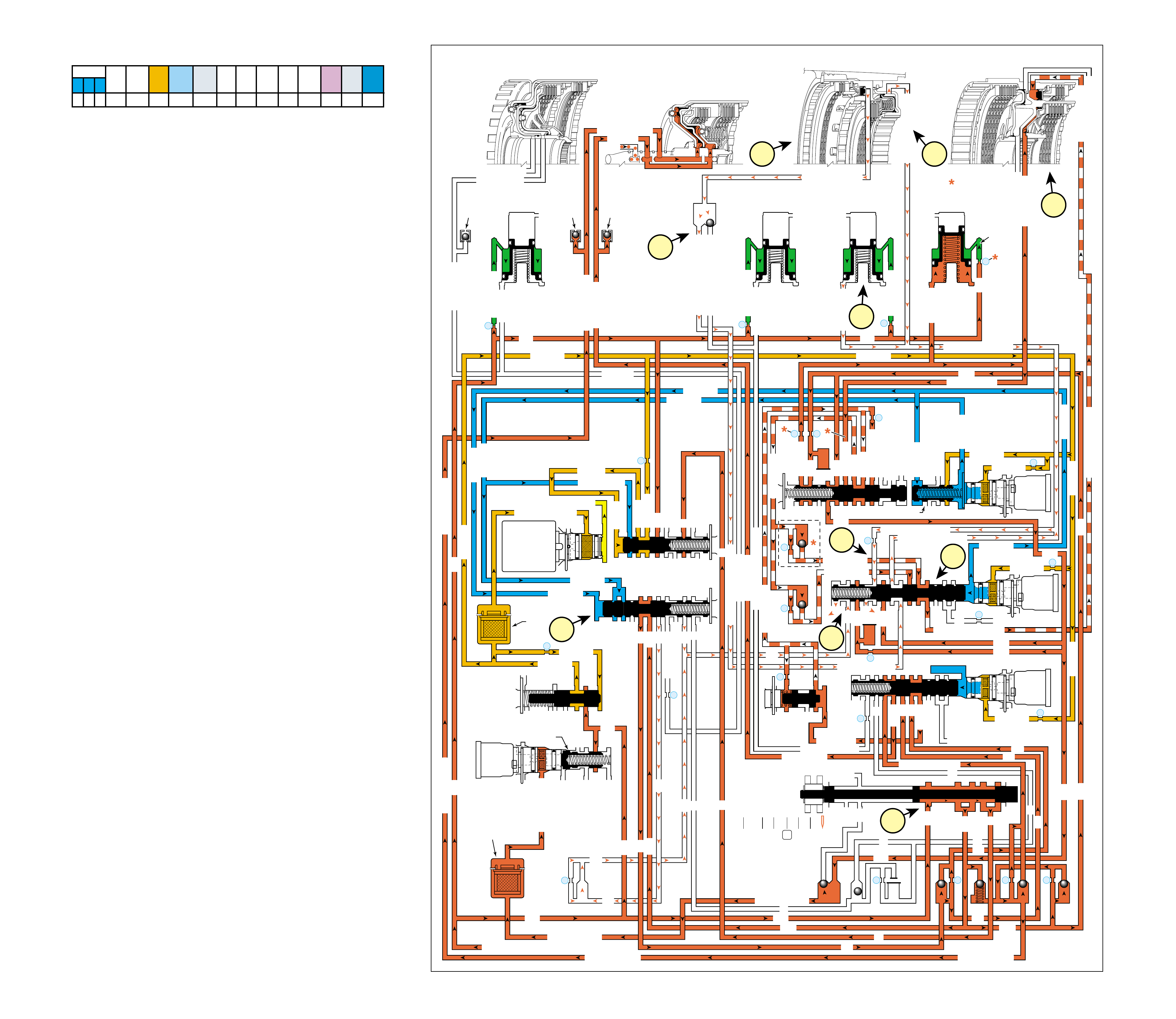
80B
MANUAL SECOND – SECOND GEAR
(from Manual Third – Third Gear)
Figure 77
COMPLETE HYDRAULIC CIRCUIT
Page 108
Manual Second – Second Gear may be selected at any time
while the vehicle is being operated in a forward gear range.
However, TCM control prevents the transmission from upshifting
above Second gear. When the gear selector lever is moved to
Manual Second (2) from Manual Third – Third Gear, the manual
valve also moves. Changes to the hydraulic and electrical systems
are as follows:
1 SECOND COAST CLUTCH APPLIED
1a Manual Valve:
The volume of line pressure entering the 32 fluid circuit at the
manual valve is increased to accommodate the added torque
requirements for engine braking or increased engine load.
1b 2-3 Shift Solenoid (SS) Valve:
The 2-3 SS valve is energized, allowing feed limit fluid to
enter the 2-3 signal fluid circuit. 2-3 signal fluid overcomes
2-3 shift valve spring (372) force and moves the 2-3 shift
valve (371) to the applied position. This allows 23 regulated
fluid to enter the second coast clutch fluid circuit and also
opens the overdrive clutch feed 1, intermediate clutch and
345 fluid circuits to exhaust.
1c 3-4 Shift Control Valve:
2-3 signal fluid is also routed to the 3-4 shift control valve
(346) and moves the valve against 1-2 signal fluid pressure
to keep the 3-4 shift valve (345) in the applied position.
1d Second Coast Clutch:
Second coast clutch fluid is directed to the second coast
clutch piston to apply the second coast clutch plates.
Note: Figure 77 is shown in Second gear with the 2-3 SS valve
energized. However, if vehicle operating conditions are such
that the TCM signals a Third, Fourth or Fifth gear state, the 2-3
solenoid will be de-energized. Thus a downshift will not occur
until the vehicle speed is low enough not to overrev the engine
(calibratable in the TCM).
2 OVERDRIVE CLUTCH RELEASES
2a Overdrive Clutch Assembly:
Overdrive clutch fluid exhausts from the overdrive clutch
piston, allowing the overdrive clutch plates to disengage.
2b #12 Ball Check Valve:
Overdrive clutch fluid seats the #12 ball check valve
against the overdrive clutch feed 2 passage and enters the
overdrive clutch feed 1 fluid circuit.
2c 2-3 Shift Valve:
Exhausting overdrive
clutch feed 2 fluid is routed through
the 2-3 shift valve into the intermediate clutch fluid circuit.
3 INTERMEDIATE CLUTCH RELEASES
3a Intermediate Clutch Assembly:
Intermediate clutch fluid exhausts from the intermediate clutch
piston, allowing the intermediate clutch plates to disengage.
3b 2-3 Shift Valve:
I
ntermediate clutch fluid is routed through orifice #24 to the
2-3 shift valve where it exhausts.
4 SHIFT ACCUMULATION
4a Intermediate Clutch Accumulator:
Intermediate clutch fluid also exhausts from the intermediate
clutch accumulator assembly. Accumulator fluid moves the
intermediate clutch accumulator piston against accumulator
spring force in preparation for another application of the
intermediate clutch.
If the converter clutch was applied when Manual Second was
selected it will release during downshifting. Under normal operating
conditions the converter clutch will not re-apply in Second gear.
SOLENOID FORWARD OVER- INTERM. INTER- LOW LOW AND SECOND SECOND
DIRECT REVERSE COAST FORWARD SPRAG DRIVE SPRAG MEDIATE SPRAG REVERSE SECOND SPRAG COAST
1-2 2-3 4-5 CLUTCH CLUTCH CLUTCH CLUTCH CLUTCH CLUTCH CLUTCH CLUTCH CLUTCH CLUTCH CLUTCH CLUTCH CLUTCH
ON ON ON APPLIED APPLIED LD APPLIED LD APPLIED
LD = LOCKED IN DRIVE
MANUAL SECOND – SECOND GEAR
(from Manual Third – Third Gear)
LUBE
LOW AND REV CL OR RLO
SECOND COAST CL
SECOND COAST CLUTCH
SECOND CLUTCH
REVERSE CLUTCH
OVERDR CL FD 2
ACCUMULATOR
INTERMED CL
INTERMEDIATE CLUTCH
INTERMEDIATE CLUTCH
ACCUMULATOR
EX
SECOND CL
ACCUM
ACCUMULATOR
LINE
LINE
LINE
OVERDRIVE CLUTCH
COAST CL
REVERSE LOCKOUT
EXEXEX
SECOND CLUTCH
DIRECT CL
DIRECT CLUTCH
4
2
5
DIRECT
CLUTCH
ACCUMULATOR
OVERDRIVE
CLUTCH
ACCUMULATOR
INTERMEDIATE
CLUTCH
ACCUMULATOR
SECOND
CLUTCH
ACCUMULATOR
DIRECT
AND REVERSE
CLUTCH
ASSEMBLY
(400—420)
FORWARD
AND COAST
CLUTCH
ASSEMBLY
(430—451)
OVERDRIVE
AND
INTERMEDIATE
CLUTCH
ASSEMBLY
(480—497)
CENTER
SUPPORT
ASSEMBLY
(510—535)
3
21
OVERDRIVE CLUTCH FEED 1
OVERDRIVE CLUTCH FEED 1
OVERDRIVE CLUTCH FEED 2
#12
2345
2345
2345
2345
2345 OR REVERSE
LINE
LINE
LINE (from Pump)
LINE
FILTERED FEED LIMIT
THROTTLE SIGNAL
EX
2345 OR REVERSE
TCC SIGNAL
REGULATED APPLY
REGULATED APPLY
EX
EX
FEED LIMIT VALVE
LINE
EX
EX
EX
EX
FEED LIMIT
FEED LIMIT
EX EX
SECOND COAST CLUTCH
23 REGULATED
OVERDRIVE CL FD 1
INTERMEDIATE CLUTCH
2345
INTERMEDIATE CLUTCH
2345
345
345
FEED LIMIT
EX
EX
EX
EX
2-3 SIGNAL
23 REGULATED
LINE SAFETY MODE
123 BRAKING
123 BRK
123
EX
EX
EX
123
123
123123
123
123
CST CL
COAST CLUTCH
COAST CLUTCH COAST CLUTCH FEED
OVERDRIVE CL FD 2
45
FEED LIMIT
SAFETY MODE
LINE
FEED LIMIT
32
32
MEMORY
MEMORY
MEMORY
MEMORY PILOT
32 SAFETY MODE
EX
EX
2-3 SIGNAL
2-3 SIGNAL
2-3 SIGNAL
123123 D432D432
DIRECT CLUTCH
DIRECT CLUTCH
4545
1-2 SIGNAL
1-2 SIGNAL
1-2 SIGNAL
EX
EX
EX
FDL
D432
2345
D432
D432
D432D432
D432D432
SECOND CL
23 REG
23 REGULATED
123 REG
SECOND CL
123 REGULATED
LOW AND REV CL
EX
EX
EX
FEED LIMIT
FEED LIMIT
FDL
1-2 SIGNAL
2-3 SIGNAL
2-3 SIGNAL
EX
EX
RPND432
MANUAL VALVE
LINE
D432
REV
REVERSE
EX
32
32
32
LINELINE
LINE SAFETY MODE
4-5 SIGNAL
24
28
2345
2345 OR REVERSE
345
345
345
345
345
345
45
45
45
45
45
OVERDRIVE CLUTCH FEED 2
PRESSURE
CONTROL
SOLENOID
VALVE
1-2 SHIFT
SOLENOID
VALVE
N/C
(A)
ON
2-3 SHIFT
SOLENOID
VALVE
N/C
(B)
ON
4-5 SHIFT
SOLENOID
VALVE
N/C
(C)
ON
TCC PWM
SOLENOID
VALVE
N/C
1-2 SHIFT VALVE
7
11
10
9
18
FILTER
(308)
FILTER
(312)
TCC REGULATOR VALVE
1-2 SHIFT CONTROL VALVE
#7
X-1
#2
26
X-4 X-5 #6
15
#5
17
#4 16
25 #3 27
29
8
COAST CLUTCH
AIR
BLEED
(203)
DIRECT CLUTCH
DIRECT CL
AIR
BLEED
(203)
FORWARD CLUTCH
FORWARD CLUTCH
FORWARD CLUTCHFORWARD CLUTCH
FORWARD CLUTCH FORWARD CLUTCH
AIR
BLEED
(203)
14
X-3
FEED LIMIT
FEED LIMIT FEED LIMIT
FEED LIMITFEED LIMIT
123
4-5 SHIFT VLV CNTRL
3-4 SHIFT
LOW PRESSURE
EX
123 REGULATED
19
20
#9
22
#11
23
CNTRL
2-3 SHIFT VALVE CNTRL
2b
1c
4a
1d
2a 3a
3b
1a
2c
1b
81
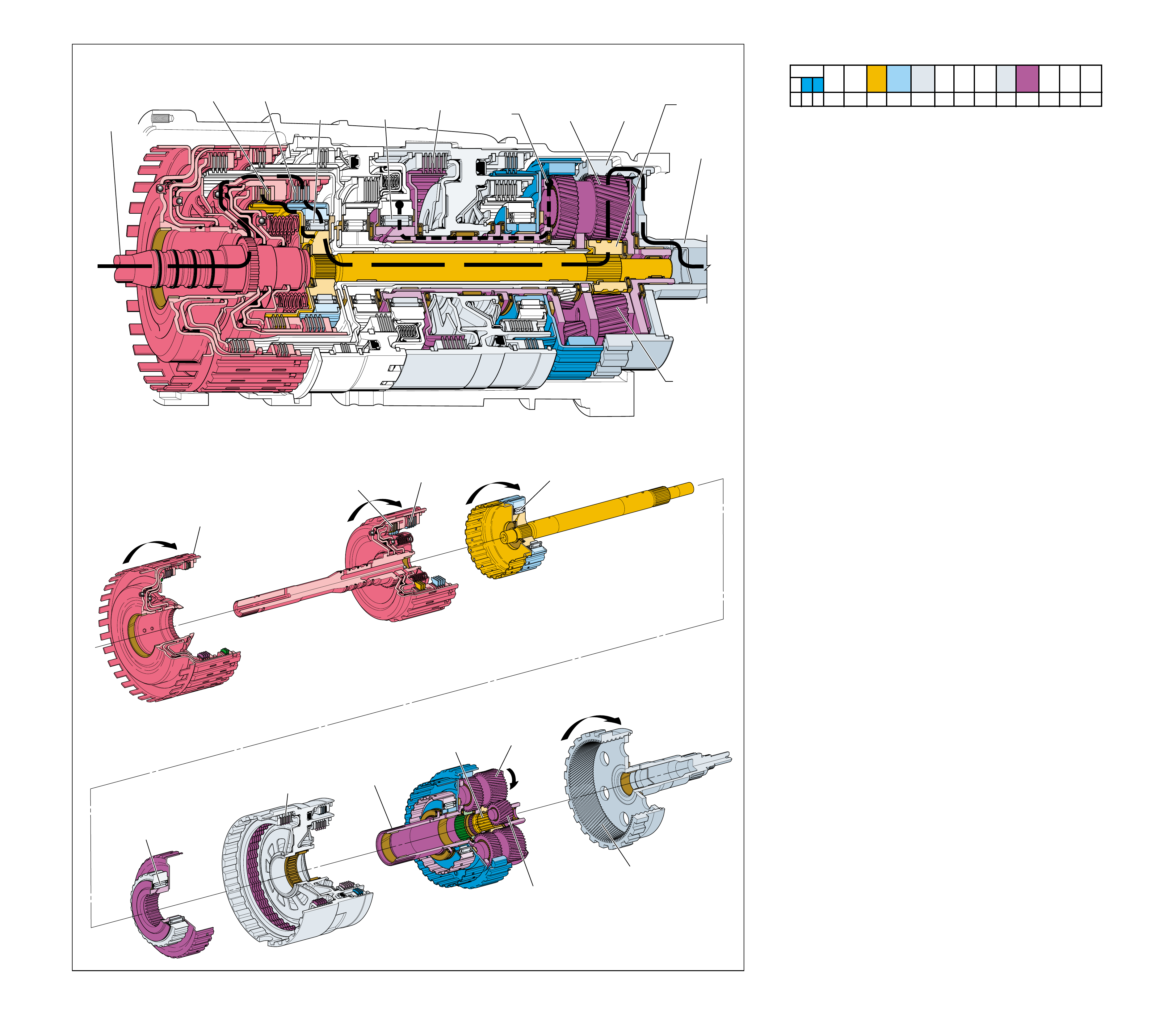
Figure 78
MANUAL SECOND – FIRST GEAR
(from Manual Second – Second Gear)
➤
➤
➤
➤
➤
➤
➤
➤
➤
➤
➤
➤
➤
➤
➤
➤
5
POWER TO
TORQUE
CONVERTER
(1)
FOR ENGINE
BRAKING
REAR
INPUT SUN
GEAR
DRIVING
1
POWER FROM
DIFFERENTIAL
ASSEMBLY
LOW AND
REVERSE
CLUTCH
APPLIED
REAR
INTERNAL
GEAR
(560)
DRIVEN
LONG
PLANETARY
PINION
GEAR
DRIVING
REAR
INTERNAL
GEAR
(560)
DRIVEN
3
INPUT AND
REACTION
CARRIER
(553)
HELD
INPUT AND
REACTION
CARRIER
(553)
HELD
REAR SHORT
PINION GEAR
DRIVING
REAR SHORT
PINION GEAR
DRIVING
REAR
INPUT
SUN GEAR
DRIVING
LONG
PLANETARY
PINION
GEAR
DRIVING
4a
COAST
CLUTCH
APPLIED
COAST
CLUTCH
APPLIED
REVERSE
CLUTCH
HOUSING
ASSEMBLY
(401)
4
FORWARD
CLUTCH
APPLIED
FORWARD
CLUTCH
APPLIED
FORWARD
CLUTCH
SPRAG
(461)
INEFFECTIVE
FORWARD
CLUTCH
SPRAG
(461)
INEFFECTIVE
LOW
CLUTCH
SPRAG
(503)
INEFFECTIVE
2
LOW AND
REVERSE
CLUTCH
APPLIED
LOW
CLUTCH
SPRAG
(503)
INEFFECTIVE
MANUAL SECOND – FIRST GEAR
(from Manual Second – Second Gear)
82A
Manual Second – First Gear is commanded by the TCM when
vehicle speed is low enough not to overrev the engine
(calibratable in the TCM). Manual Second – First Gear is
commanded in order to achieve maximum engine compression
braking for slowing the vehicle.
Note: Transfer of engine torque during acceleration is identical to
Overdrive Range – First Gear (refer to page 64A) to obtain an
approximate gear ratio reduction of 3.42:1 through the transmission
gear set. The power flow in Figure 78 and the following text
describes conditions during deceleration (zero or minimum throttle)
and how engine compression braking is achieved.
Vehicle speed provides the torque input to the transmission
through the drive shaft and transmission output shaft assembly
(562). This is shown by the direction of the power flow arrows
in the drawing at the top of Figure 78. Notice that this flow is
identical to Overdrive Range – First Gear except that the arrows
are in the opposite direction.
1 Power From the Differential Assembly
Power flow is transferred back through the transmission
from the output shaft to the input shaft forward and coast
clutch housing assembly (433). Each of the component’s
function and rotation direction is the same as during
acceleration (compare Figures 60 and 78).
2 Low and Reverse Clutch Applied
The low and reverse clutch, which is located within the
center support (518), is applied and holds the low clutch
sprag inner race (505) stationary.
3 Input and Reaction Carrier Held
The low clutch sprag inner race (505) is splined to the input
and reaction carrier (553) and holds it stationary.
4 Forward and Coast Clutches Applied
The forward clutch, which is located within the input shaft
forward and coast clutch housing assembly (433), is applied
and holds the forward clutch sprag outer race (459). The
coast clutch is also located in the input shaft forward and
coast clutch housing assembly (433) and is also applied. Input
torque from the rear input sun gear of the input and reaction
carrier (553) is transferred through the coast clutch to the
input shaft forward and coast clutch housing assembly (433).
5 Engine Compression Braking
With the low and reverse clutch applied, power flow is
mechanically connected between the output shaft and torque
converter turbine. This allows engine compression to slow
the vehicle when the throttle is released.
SOLENOID FORWARD OVER- INTERM. INTER- LOW LOW AND SECOND SECOND
DIRECT REVERSE COAST FORWARD SPRAG DRIVE SPRAG MEDIATE SPRAG REVERSE SECOND SPRAG COAST
1-2 2-3 4-5 CLUTCH CLUTCH CLUTCH CLUTCH CLUTCH CLUTCH CLUTCH CLUTCH CLUTCH CLUTCH CLUTCH CLUTCH CLUTCH
OFF ON ON APPLIED APPLIED LD LD APPLIED
LD = LOCKED IN DRIVE
82
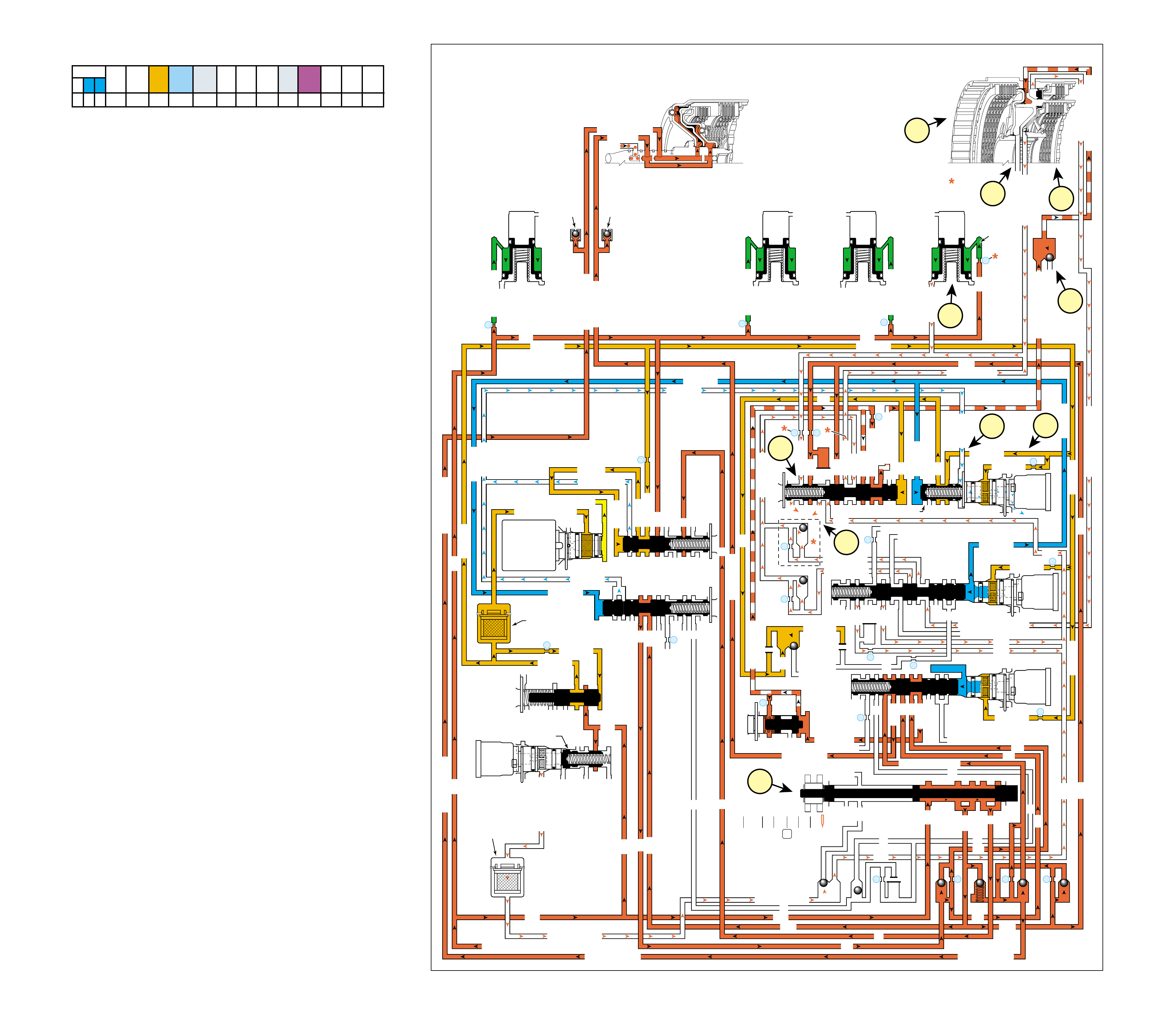
82B Figure 79
MANUAL SECOND – FIRST GEAR
(from Manual Second – Second Gear)
COMPLETE HYDRAULIC CIRCUIT
Page 110
Manual Second – First Gear is commanded by the TCM, when
vehicle speed is low enough not to overrev the engine (calibratable
in the TCM), in order to achieve maximum engine braking.
Changes to the hydraulic and electrical systems are as follows:
1 MANUAL VALVE
Manual Second – First Gear is commanded by the TCM
only, there is no movement of the manual valve.
2 LOW AND REVERSE CLUTCH APPLIED
2a 1-2 Shift Solenoid (SS) Valve:
The 1-2 SS valve is de-energized, blocking feed limit fluid
from entering the 1-2 signal fluid circuit and 1-2 signal fluid
pressure exhausts through the 1-2 SS valve.
2b 1-2 Shift Control Valve:
With 1-2 signal fluid exhausted, 2-3 signal fluid is able to
move the 1-2 shift control valve (366) against 1-2 shift
control valve spring (367) force to the applied position.
This allows feed limit fluid to enter the FDL fluid circuit.
2c 1-2 Shift Valve:
FDL fluid is routed to the 1-2 shift valve (387) and moves
the valve against 1-2 shift valve spring (388) force to the
applied position. This allows 123 regulated fluid to enter
the low and reverse clutch fluid circuit.
2d #8 Ball Check Valve:
Low and reverse clutch fluid seats the #8 ball check valve
against the reverse lockout fluid passage and enters the low
and reverse clutch or reverse lockout fluid passage.
2e Low and Reverse Clutch:
Low and reverse clutch or reverse lockout fluid pressure
enters the outer area of the low and reverse clutch piston
and moves the piston against spring force to apply the low
and reverse clutch plates.
3 SECOND CLUTCH AND
SECOND COAST CLUTCH RELEASE
3a Second Clutch Assembly:
Second clutch fluid exhausts from the second clutch piston,
allowing the second clutch plates to disengage.
3b Second Coast Clutch Assembly:
Second coast clutch fluid exhausts from the second coast
clutch piston, allowing the second coast clutch plates to
disengage.
3c 1-2 Shift Valve:
Second coast clutch fluid is routed through the 2-3 shift
valve to the 1-2 shift valve where it enters the second clutch
fluid circuit. Second clutch fluid is routed through orifice
#21 to the 1-2 shift valve where it exhausts.
4 SHIFT ACCUMULATION
4a Second Clutch Accumulator:
Second clutch fluid also exhausts from the second clutch
accumulator assembly. Accumulator fluid moves the second
clutch accumulator piston against accumulator spring force
in preparation for another application of the second clutch.
MANUAL SECOND – FIRST GEAR
(from Manual Second – Second Gear)
LUBE
LOW AND REV CL OR RLO
SECOND COAST CL
SECOND COAST CLUTCH
SECOND CLUTCH
OVERDR CL FD 2
ACCUMULATOR
INTERMED CL
ACCUMULATOR
EX
SECOND CL
ACCUM
ACCUMULATOR
LINE
LINE
LINE
COAST CL
REVERSE LOCKOUT
EXEXEX
SECOND CLUTCH
DIRECT CL
4
2
5
DIRECT
CLUTCH
ACCUMULATOR
OVERDRIVE
CLUTCH
ACCUMULATOR
INTERMEDIATE
CLUTCH
ACCUMULATOR
SECOND
CLUTCH
ACCUMULATOR
FORWARD
AND COAST
CLUTCH
ASSEMBLY
(430–451)
CENTER
SUPPORT
ASSEMBLY
(510–535)
3
21
2345
2345
2345
2345
2345 OR REVERSE
LINE
LINE
LINE (from Pump)
LINE
FILTERED FEED LIMIT
THROTTLE SIGNAL
EX
2345 OR REVERSE
TCC SIGNAL
REGULATED APPLY
REGULATED APPLY
EX
EX
FEED LIMIT VALVE
LINE
EX
EX
EX
EX
FEED LIMIT
FEED LIMIT
EX
SECOND COAST CLUTCH
23 REGULATED
OVERDRIVE CL FD 1
INTERMEDIATE CLUTCH
2345
INTERMEDIATE CLUTCH
2345
345
FEED LIMIT
EX
EX
EX
EX
2-3 SIGNAL
23 REGULATED
LINE SAFETY MODE
123 BRAKING
123 BRK
123
EX
EX
EX
123
123
123123
123
123
CST CL
COAST CLUTCH
COAST CLUTCH COAST CLUTCH FEED
OVERDRIVE CL FD 2
45
FEED LIMIT
SAFETY MODE
LINE
FEED LIMIT
32
32
MEMORY
MEMORY
MEMORY
MEMORY PILOT
32 SAFETY MODE
EX
EX
2-3 SIGNAL
2-3 SIGNAL
2-3 SIGNAL
123123 D432D432
DIRECT CLUTCH
4545
1-2 SIGNAL
1-2 SIGNAL
1-2 SIGNAL
EX
EX
EX
FDL
D432
2345
D432
D432
D432D432
D432D432
SECOND CL
23 REG
23 REGULATED
123 REG
SECOND CL
123 REGULATED
LOW AND REV CL
EX
EX
EX
FEED LIMIT
FEED LIMIT
FDL
1-2 SIGNAL
2-3 SIGNAL
2-3 SIGNAL
EX
EX
RPND432
MANUAL VALVE
LINE
D432
REV
REVERSE
EX
32
32
32
LINELINE
LINE SAFETY MODE
4-5 SIGNAL
24
28
2345
2345 OR REVERSE
345
345
45
45
45
45
45
PRESSURE
CONTROL
SOLENOID
VALVE
1-2 SHIFT
SOLENOID
VALVE
N/C
(A)
OFF
2-3 SHIFT
SOLENOID
VALVE
N/C
(B)
ON
4-5 SHIFT
SOLENOID
VALVE
N/C
(C)
ON
TCC PWM
SOLENOID
VALVE
N/C
7
11
10
9
18
FILTER
(308)
FILTER
(312)
TCC REGULATOR VALVE
1-2 SHIFT CONTROL VALVE
#7
X-1
#2
26
X-5 #6
15
#5
17
#4 16
#3 27
29
8
COAST CLUTCH
AIR
BLEED
(203)
FORWARD CLUTCH
FORWARD CLUTCH
FORWARD CLUTCHFORWARD CLUTCH
FORWARD CLUTCH FORWARD CLUTCH
AIR
BLEED
(203)
14
X-3
FEED LIMIT
FEED LIMIT FEED LIMIT
FEED LIMITFEED LIMIT
123
3-4 SHIFT
LOW PRESSURE
EX
123 REGULATED
19
20
#9
22
#11
23
CNTRL
2-3 SHIFT VALVE CNTRL
1-2 SHIFT VALVE
4-5 SHIFT VLV CNTRL
REVERSE LOCKOUT
LOW AND REVERSE CL
#8
FDL
FDL
EXEX
FDL
#10
32 SM/FDL
32 SM
2b
2c
4a 2d
2e
3a 3b
3c
1
2a
SOLENOID FORWARD OVER- INTERM. INTER- LOW LOW AND SECOND SECOND
DIRECT REVERSE COAST FORWARD SPRAG DRIVE SPRAG MEDIATE SPRAG REVERSE SECOND SPRAG COAST
1-2 2-3 4-5 CLUTCH CLUTCH CLUTCH CLUTCH CLUTCH CLUTCH CLUTCH CLUTCH CLUTCH CLUTCH CLUTCH CLUTCH CLUTCH
OFF ON ON APPLIED APPLIED LD LD APPLIED
LD = LOCKED IN DRIVE
83
OPERATING CONDITIONS
RANGE REFERENCE CHART
LD = LOCKED IN DRIVE @ THE SOLENOID'S STATE FOLLOWS A SHIFT PATTERN WHICH DEPENDS UPON VEHICLE
ON = SOLENOID ENERGIZED SPEED AND THROTTLE POSITION. IT DOES NOT DEPEND UPON THE SELECTED GEAR.
OFF = SOLENOID DE-ENERGIZED *ENGINE BRAKING IS ELECTRONICALLY CONTROLLED BY THE TCM, AND IS AVAILABLE AS
CALIBRATED FOR EACH MODEL AND APPLICATION.
†REVERSE LOCK OUT IS A CONDITION THAT OCCURS WHEN TCC APPLY IS COMMANDED BY
THE TCM. TCC SIGNAL FLUID FROM THE TCC PWM SOLENOID VALVE APPLIES THE REVERSE
LOCKOUT VALVE TO PREVENT REVERSE CLUTCH OR LOW AND REVERSE CLUTCH APPLY
EVEN IF THE MANUAL VALVE IS IN REVERSE POSITION.
NOTE: DESCRIPTIONS ABOVE EXPLAIN COMPONENT FUNCTION DURING ACCELERATION.
EXPECTED OPERATING CONDITION IF COMPONENT IN COLUMN NUMBER IS INOPERATIVE:
COLUMN # CONDITION
1 NO 4TH OR FIFTH GEARS.
2 NO ENGINE BRAKING IN OVERDRIVE RANGE – FIRST, SECOND, THIRD AND FOURTH GEARS;
OR IN MANUAL FOURTH, MANUAL THIRD AND MANUAL SECOND RANGES.
3 NO REVERSE.
4 NO FORWARD.
5 NO FORWARD.
6 NO FIFTH GEAR OR,
NO ENGINE BRAKING IN THIRD GEAR – ALL FORWARD RANGES.
7 NO THIRD GEAR.
8 NO THIRD, FOURTH, OR FIFTH GEARS.
9 NO FIRST GEAR.
10 NO REVERSE, NO ENGINE BRAKING IN MANUAL FIRST.
11 NO SECOND, THIRD, FOURTH, OR FIFTH GEARS.
12 NO SECOND GEAR.
13 NO ENGINE BRAKING IN SECOND GEAR – ALL FORWARD RANGES.
Figure 80
123 4 5 678910111213
ENGINE 1-2 SHIFT 2-3 SHIFT 4-5 SHIFT TCC DIRECT COAST REVERSE FORWARD FORWARD OVER- INTERM. INTER- LOW LOW AND SECOND SECOND SECOND
RANGE GEAR BRAKING RATIO SOLENOID SOLENOID SOLENOID SOLENOID CLUTCH CLUTCH CLUTCH CLUTCH CLUTCH DRIVE CLUTCH MEDIATE CLUTCH REVERSE CLUTCH CLUTCH COAST
VALVE VALVE VALVE VALVE SPRAG CLUTCH SPRAG CLUTCH SPRAG CLUTCH SPRAG CLUTCH
1
*
NO 3.42 OFF ON OFF OFF APPLIED APPLIED LD LD
1 YES 3.42 OFF ON ON OFF APPLIED APPLIED LD LD APPLIED
2
*
NO 2.21 ON ON OFF ON/OFF
@
APPLIED APPLIED LD APPLIED LD
D432
2 YES 2.21 ON ON ON ON/OFF
@
APPLIED APPLIED LD APPLIED LD APPLIED
3
*
NO 1.60 ON OFF OFF ON/OFF
@
APPLIED APPLIED LD LD APPLIED APPLIED
3 YES 1.60 ON OFF ON ON/OFF
@
APPLIED APPLIED LD APPLIED LD APPLIED APPLIED
4 YES 1.00 OFF OFF ON ON/OFF
@
APPLIED APPLIED APPLIED LD APPLIED APPLIED
5 YES 0.75 OFF OFF OFF ON/OFF
@
APPLIED APPLIED APPLIED APPLIED APPLIED
NEUTRAL
———ON/OFF ON/OFF ON/OFF
REVERSE
R YES 3.03 ON/OFF ON/OFF ON/OFF OFF APPLIED APPLIED
†
REVERSE
LOCK OUT
ON/OFF ON/OFF ON/OFF ON
PARK
———ON/OFF ON/OFF ON/OFF
@@@
@@@
@@@
@@@
84
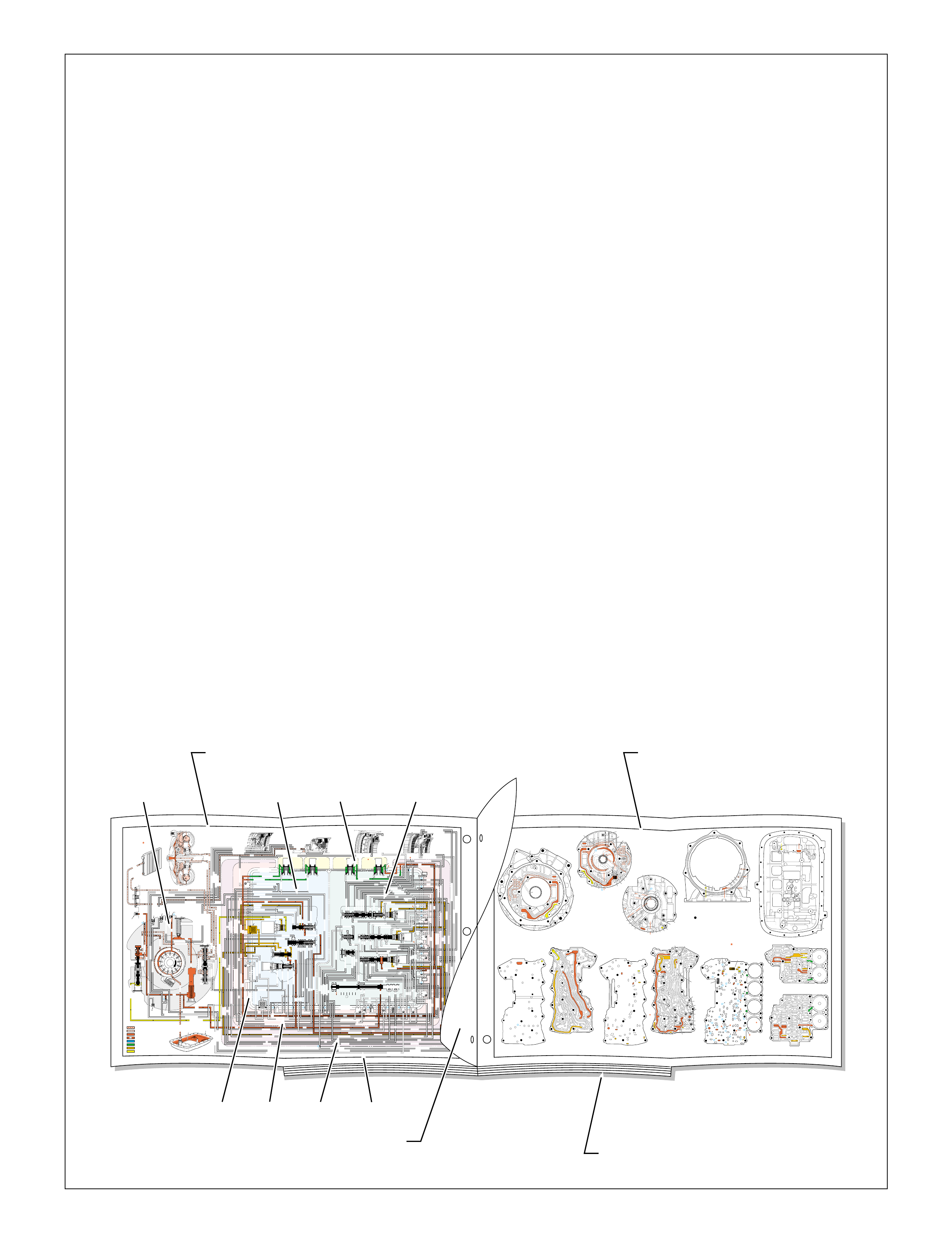
Figure 81
➤ ➤
➤➤
➤
➤
➤
TORQUE CONVERTER HOUSING (227)
(Fluid Pump Cover Side)
➤
➤
➤
➤
➤➤➤
➤
➤
➤ ➤
➤
➤
TOP CHANNEL PLATE (301)
(Case Side)
FRONT
➤
TOP CHANNEL PLATE (301)
(Bottom Channel Plate Side)
FRONT
➤
BOTTOM CHANNEL PLATE (304)
(Top Channel Plate Side)
FRONT
➤
REAR CONTROL VALVE BODY (310)
(Bottom Channel Plate Side)
FRONT
➤
CASE (24)
(Top Channel Plate Side)
FRONT
➤
CASE (24)
(Fluid Pump Cover Side)
SPACER PLATE (307)
(Bottom Channel Plate Side)
FRONT
➤
FRONT CONTROL VALVE BODY (311)
(Bottom Channel Plate Side)
FRONT
➤
BOTTOM CHANNEL PLATE (304)
(Control Valve Body Side)
FRONT
➤
NOTE:
–INDICATES BOLT HOLES
–NON FUNCTIONAL HOLES HAVE BEEN
REMOVED FROM COMPONENT DRAWINGS
TO SIMPLIFY TRACING FLUID FLOW.
–DUAL PURPOSE PASSAGES HAVE
CHANNEL PLATE SIDE NUMBERS LISTED FIRST
–EXHAUST FLUID NOT SHOWN
–PASSAGES MARKED WITH ARE USED FOR
THE 5L40-E ONLY
FLUID PUMP COVER (202)
(Case Side)
FLUID PUMP COVER (202)
(Torque Converter Housing Side)
➤
➤
➤
➤
➤
➤
➤ ➤
➤
➤
➤➤
➤
➤
➤
7
➤
25
➤
27
➤
3
➤
20
➤
16
➤
2
➤
10
➤
9
➤
24
➤
15
➤
11
➤
22
➤
29
➤
28
➤
23
➤
18
➤
17
➤
14
➤
8
➤
4
➤
5
➤
26
➤
13
➤
19
➤
21
➤
6
➤
12
(40)
➤
21
(203)
➤
16
(203)
➤➤
(232)
➤➤
(229)
➤➤
(231)
➤➤
(213)
➤
(233)
➤
TRANSMISSION
VENT
ASSEMBLY
➤➤
32
(203)
➤
37
(203)
➤➤
2/21
(214)
➤➤
(36)
➤
FILTER
(312)
➤
FILTER
(308)
➤
#12
#2
#3
#5
#6
#7
(Spring)
#8
#10 #9
#4
#1
#11
X-2
X-4
X-5
X-1
X-3
33
32
38
38
38
30
30
24
37
37
37
40
40
12
16
15
15
23 52
24
24
23
28
47
41
42
43
27
28
28
27
27
25
25
26
22
22
15
13
18 19
19
19
19
19
19
19
21
17
17
22
23
23
48
48
48
48
48
48
48
48
48
15
13
36
36
36
36
39
35
35
34
10
10 11
10
10
10
20
20
48
44
44
45
43 42
52
52
52
48
48
77
2
2
2
2
2
2
2
12a
16a
15d/16 15c/16
15b
23c
24a 24b
24c
25b
25c 25d
25e
26b
26a
32a
30a
33a
35a
39a
36a
36b
36c
36d
38a 39b
39c/41
40c/41
36e
36f
35b
35c 35d
37c
37d
37b
37a
40b
40a
38d 38b
38c
38e
40d
34a
33e
33c
33d
33b
30b
30c 30d
25a
23b
23a
20a
28c
27c/46
27b
28b
28a
27a
47b
47a
20b
20d
20c
13a
15a
19e
19h
19g
19i
19j
19f
13b15e
17a
17b
17c/18
15f/18
19b/21
19c/21
19d/21
19a
22a
22b
22c
22d
22f
21a
21b/31
21c/31
22g/23
14a/23
22e
48
48
48
48
48
48
48
48
52
52
52
52
52
52
52
52
48
48
2g
7a
7b 2a/54a
2b
42b
43a
42a
43b
44c
44d 44b
44a
44e
43c/45
44f/45
48a 48b
2c/54c
54d
2d/54e
2e 2m/54g
2f
10i
10h
10f
10e
10d
10a 10c
11b
11a/10b
10g
2h
54f
54b
12
2
23
24
48
48
48
48
48
48
48
48
52
52
52
52
52
52
52
23
36
36
36
20
27
28
46
47
47
19
16
15
13
10
10
10
11
54
2
54
37
37
37
39
38
40
42
43
40
27
7
48
48
48
52
52
52
52
52
52
52
24
25
25
25
2525
26
26
15 19 19
19
19
31
21
20 20
15 17
17
14
13
14
54
22
22
28
28
22
22
32
42 43
44
44
48
48
48
48
48
48
44
44
38
39
38
33
33
30
35
40
35
35
36
35
34
30
30
30
33
2
2
10
10 10
10
27
2
216
24
15
18
7
32
52
52
52
52 52
52
52
52
52
52
52
52
52 52
52
52
52
52
30 34
35
41
12 21 37
8
9
2
16
24
7
32
12 21
37
12
21
21
24
848
7
9
9
52
52
2
16
5
16
37
32
32
52
1
52
52
52
48
37
1
2
51
51
52
12
12
24
24
52
2
2
4
4
4
4
5
66
8
8
7
7
7
5
9
48
48
48
48
48
48
48
48
53
53
48
52
2
3
3
3
2
1
16
21
21
16
32
37
32
51
50
50
51 52
52
52
52
52
52
48
48
48
48
52
48
48
12
12
24
24
2
2
3
2
4
4
4
5
6
53
53
8
8
7
7
7
48
16
16
21 32
37
➤➤
1
➤➤
31
➤➤
30
(233)
➤➤
32
38
30
24 12
16
13
15
15
13
18
19
19
19
21
21
22
16 48
48
48
48
48
48
48
48
36
35
35
34
2
2
7
2
10
10
10
10
41
42
43
43
42
48 48
20
28
27
37
27
28
28
27
20
48
52
52
32
32
32
38
24
12 16
16
18
28
28
28
27
27
48 48
43 42
42
43
48
30
48
48
48 48
48
48
48
48
48
48
48
48
35
36
37
34
2
7
2
10
13
13
15
19
41
41
19
19
15
22
21
21
20
20
21
21
13
10
10
10
2
48
48 48
52
52
52
52
52
52
12
32
37 21
24
2
16
18
48
48
48
48
48
30
48
48
48
48
48
48
15
35
41
34
7
52
52
52
52
52
52
PRESSURES
INTAKE & DECREASE (SUCTION)
CONVERTER & LUBE
MAINLINE
REGULATED LINE
SOLENOID SIGNAL
ACCUMULATOR
FEED LIMIT
THROTTLE SIGNAL
NOTE:
PASSAGES AND
COMPONENTS
MARKED WITH
ARE USED FOR
THE 5L40-E ONLY
GASKET (309)
GASKET (305)
GASKET (303)
BOTTOM CHANNEL PLATE (304)
TOP CHANNEL PLATE (301)
CASE (24)
REAR CONTROL VALVE BODY (310)
SPACER PLATE (307)
GASKET (309)
GASKET (305)
GASKET (303)
BOTTOM CHANNEL PLATE (304)
TOP CHANNEL PLATE (301)
CASE (24)
FRONT CONTROL VALVE BODY (311)
SPACER PLATE (307)
FLUID
PUMP
COVER
(202)
CONVERTER
HOUSING
(224)
ACCUMULATOR HOUSING (317) ACCUMULATOR HOUSING (323) ACCUMULATOR HOUSING (328) ACCUMULATOR HOUSING (333)
LUBE
LUBE
LUBE
LUBE
TO COOLER
LUBE
TO COOLER
APPLY
APPLY
APPLY
RELEASE
DECREASE
DECREASE
LINE
OVERDRIVE CLUTCH FEED 1
OVERDRIVE CL FD 1OVERDRIVE CLUTCH FEED 1
OVERDRIVE CLUTCH FEED 1 OVERDRIVE CLUTCH FEED 1
OVERDRIVE CLUTCH
2345 2345
2345
2345
2345
2345
2345 OR REVERSE
RLO
LOW AND REV CL OR RLO
LOW AND REV CL OR RLO
SECOND COAST CLUTCH
SECOND CLUTCH
SECOND COAST CLUTCH
SUCTION SUCTION
LINE
LINE
LINE LINE
LINE
LINE
LINE LINE LINE
TCC SIGNAL
CONVERTER FEED
CONVERTER FEED
RELEASE
TO COOLER
REGULATED APPLYREGULATED APPLY
LINE
EX
CONVERTER FEED
REVERSE CLUTCH
REVERSE CLUTCH
THROTTLE SIGNAL
LINE
EX
FILTERED FEED LIMIT
THROTTLE SIGNAL
THROTTLE SIGNAL
THROTTLE SIGNAL
EX
2345 OR REVERSE
2345 OR REVERSE
2345 OR REVERSE
TCC SIGNAL
TCC SIGNAL
TCC SIGNAL
REGULATED APPLY
REGULATED APPLY
REGULATED APPLY
EX
EX
FEED LIMIT VALVE
LINE
EX
EX
EX
EX
FEED LIMIT
FEED LIMIT FEED LIMIT
FEED LIMIT
FEED LIMIT
FEED LIMIT
FEED LIMIT
FEED LIMIT FEED LIMIT
FEED LIMIT
2-3 SHIFT VALVE CNTRL
EX
EX
EX
EX
EX
EX
EX EX
SECOND COAST CLUTCH
23 REGULATED
23 REGULATED
OVERDRIVE CLUTCH FEED 1
INTERMEDIATE CLUTCH
2345
2345
2345
2345
INTERMEDIATE CLUTCH
2345
345
FEED LIMIT
EX
EX
EX
EX
2-3 SIGNAL
LOW PRESSURE
123 REGULATED
123 REGULATED
EX
CNTRL
LINE SAFETY MODE
123 BRAKING
123
EX
EX
EX
123
123
123
123
123
123
123
123123
COAST CLUTCH
COAST CLUTCH FEED
OVERDRIVE CLUTCH FEED 2
45
FEED LIMIT
SAFETY MODE
LINE
FEED LIMIT
32
MEMORY
MEMORY
MEMORY
MEMORY PILOT
MEMORY PILOT
32 SAFETY MODE
LINE SAFETY MODE
EX
EX
LINE SAFETY MODE
CNTRL 3-4 SHIFT
2-3 SIGNAL
123123 D432D432
DIRECT CLUTCH
DIRECT CLUTCH
4545
1-2 SIGNAL
EX
EX
EX
1-2 SHIFT VALVE
FDL
FDL
FDL
FDL
FDL
FDL
D432
2345 2345
D432
SECOND CLUTCH
23 REGULATED
23 REGULATED23 REGULATED
123 REGULATED
LOW AND REVERSE CLUTCH
LOW AND REVERSE CL
SECOND CLUTCH
123 REGULATED
EX
EX
EX
FD LIMIT
FEED LIMIT
FDL
1-2 SIGNAL
2-3 SIGNAL
EX
EX
TCC SIGNAL
TCC SIGNAL
TCC SIGNAL
RLO
EX
REV
RPND432
MANUAL VALVE
LINE
D432
D432 D432
D432
D432
D432
D432 D432
D432
D432D432
D432
REV
REVERSE
EX
3232
LINE
EX
EX
LINE
CASE (24)
OVERDRIVE CLUTCH FEED 2
OVERDRIVE CL FD 2
OVERDRIVE CLUTCH FEED 2
ACCUMULATOR
DIRECT CLUTCH
ACCUM
INTERMEDIATE CLUTCH
INTERMEDIATE CLUTCH
INTERMEDIATE CLUTCH
ACCUMULATOR
EX
SECOND CLUTCH
SECOND CLUTCH
ACCUM
ACCUM
LINELINE
FORWARD CLUTCH
FORWARD CLUTCH FORWARD CLUTCH
ACCUMULATOR
LINE
LINELINE
LINE
OVERDRIVE CLUTCH
INTERMEDIATE CL
COAST CLUTCH
REVERSE LOCKOUT
COAST CLUTCH
REVERSE CLUTCH
REVERSE CLUTCH
REVERSE CLUTCH
4-5 SIGNAL
EXEXEX
LINE SAFETY MODE
LINE SAFETY MODE
REVERSE LOCKOUT
REVERSE LOCKOUT REVERSE LOCKOUT
COAST CLUTCH
REVERSE LOCKOUT REVERSE LOCKOUT
REVERSE LOCKOUT
REVERSE LOCKOUT
REVERSE LOCKOUT
REVERSE LOCKOUT
REVERSE CLUTCH
REVERSE CLUTCH
LOW AND REV CL OR RLO
FORWARD CLUTCH
FORWARD CLUTCH
FORWARD CLUTCH
COAST CLUTCH
FORWARD CLUTCH
FORWARD CLUTCH
FORWARD CLUTCH
2345
2345 OR REVERSE
123 REGULATED
123 REGULATED
123 REGULATED 123 REGULATED
123 REGULATED
123 REGULATED
123 REGULATED
123 BRAKING
123 BRAKING
123 BRAKING
123 BRAKING
1-2 SIGNAL1-2 SIGNAL
1-2 SIGNAL1-2 SIGNAL1-2 SIGNAL
1-2 SIGNAL 1-2 SIGNAL 1-2 SIGNAL
2-3 SIGNAL2-3 SIGNAL2-3 SIGNAL
2-3 SIGNAL 2-3 SIGNAL
2-3 SIGNAL2-3 SIGNAL2-3 SIGNAL
2-3 SIGNAL
SECOND CLUTCH
SECOND CLUTCH
COAST CLUTCHCOAST CLUTCHCOAST CLUTCH
COAST CLUTCH
COAST CLUTCH
COAST CLUTCH
COAST CLUTCH
COAST CLUTCH
23 REGULATED
345
345
345
345 345 345
345
345
345
345
345
345
345
345
DIRECT CLUTCH
DIRECT CLUTCH
DIRECT CLUTCH
DIRECT CL
DIRECT CLUTCH
DIRECT CLUTCH
DIRECT CLUTCH
DIRECT CLUTCH
45
45
45
4545
45
OVERDRIVE CLUTCH
OVERDRIVE CL FD 1
OVERDRIVE CLUTCH FEED 2OVERDRIVE CLUTCH FEED 2
OVERDRIVE CL FD 2
OVERDRIVE CLUTCH FEED 2 OVERDRIVE CL FD 2
3232
32 32 32
323232
32 SAFETY MODE
32 SAFETY MODE 32 SAFETY MODE 32 SAFETY MODE
32 SAFETY MODE32 SAFETY MODE
32 SM 32 SM
FDL
PRESSURE
CONTROL
SOLENOID
VALVE
1-2 SHIFT
SOLENOID
VALVE
N/C
(A)
OFF
2-3 SHIFT
SOLENOID
VALVE
N/C
(B)
OFF
4-5 SHIFT
SOLENOID
VALVE
N/C
(C)
OFF
TCC PWM
SOLENOID
VALVE
N/C
PRESS REG VALVEBOOST VALVE
CONVERTER FDL
AIR
BLEED
(233)
AIR
BLEED
(233)
AIR
BLEED
(203)
AIR
BLEED
(203)
AIR
BLEED
(203)
AIR
BLEED
(203)
7
4
2
1
5
6
11
10
9
12
18
FILTER
(308)
FILTER
(312)
TCC REGULATOR VALVE
TCC
CONTROL
VALVE
TCC
ENABLE
VALVE
REVERSE
LOCKOUT
VALVE
1-2 SHIFT CONTROL VALVE
FLUID
PAN
(62)
FLUID FILTER
ASSEMBLY
(59)
FLUID
PRESSURE
TEST PLUG
(40)
TORQUE
CONVERTER
ASSEMBLY
(1)
DIRECT
CLUTCH
ACCUMULATOR
OVERDRIVE
CLUTCH
ACCUMULATOR
INTERMEDIATE
CLUTCH
ACCUMULATOR
SECOND
CLUTCH
ACCUMULATOR
COOLER
PRESSURE
RELIEF
BALL
VALVE
21 2
10d
2a
2b
42b
43a
37d
39b
40b
37c
40d
11b
10a
24a
10c
11a 10b
54b
54d
2c
54a
54c
27c 46
7a
24b
20a
13a
37b
38a
7b
47a
47b
27b
28c
12a
23a
36e
36f
23b
23c
15a
24c
26b
36a
38c
38d
36b
25a
15
2m 54g
54f
#8
18
15f
15e
17c
17b
17a
27a
44a
44e
44d
44b
25c
30a
33a
25e
19e
35c
19h
19f
10f
10h
10g
22a
35b
#7
13b
32a
26a
10i
22f
22e
43b
22b
34a
48b
39a
22c
X-1
22
22e
21a
42a
19a
20b
19b
#2
23 22g
14a
2f
2h
19g
19i
19
j
DIRECT
AND REVERSE
CLUTCH
ASSEMBLY
(400–420)
FORWARD
AND COAST
CLUTCH
ASSEMBLY
(430–451)
OVERDRIVE
AND
INTERMEDIATE
CLUTCH
ASSEMBLY
(480–497)
CENTER
SUPPORT
ASSEMBLY
(510–535)
3
2d54e
2e
30c
30d
35d
26
37a
13
#1
15c
15b
16
15d 16
15
X-2
16a
X-4 X-5
38
14
X-3
19
#6
19d
19
21
19c 21
15
#5
21b 31
21c 31
17
21
#4
20d
20c
16
25b
19
25d
20
36 46
28a
44c
28b
30b
21
#11
33e
33d
23
24
35a
#9
33c
33b
22
36d
36c
25
#12
41 40c
39c
43 13
28
40a
#10
45
45
45
44f
44
48
43c
#3
38b
38e
27
48a
29
8
10e
2310
32 SM/FDL
30
31
FLUID PUMP
SCREEN
ASSEMBLY
(213)
(214)
4-5 SHIFT VLV
PARK
(Engine Running)
FOLDOUT ➤ 87
Figure 83
Figure 82
86
PARK
(Engine Running)
(Engine Running)
With the selector lever in the Park (P)
position, line pressure from the oil
pump is directed to the following:
Pressure Regulator Valve(218): Reg-
ulates pump output (line pressure)
according to the transmission
requirements. When pump
output exceeds the demand
of line pressure, fluid from
the pressure regulator
PARK
COMPONENTS ( )
(36) TRANSMISSION FLUID LEVEL HOLE PLUG
(40) TRANSMISSION FLUID PRESSURE TEST PLUG
(203 CHECK VALVE RETAINER AND BALL ASSEMBLY
(213) TRANSMISSION FLUID PUMP SCREEN ASSEMBLY
(214) BRASS ORIFICE INSERT
(230) TRANSMISSION VENT ASSEMBLY
(232) ORIFICE SLEEVE
(233) ORIFICE CUP PLUG
(306) CONTROL VALVE BODY BALL CHECK VALVE
(#1, 2, 3, 4, 5, 6, 7, 8, 9, 10, 11, 12
(308) TCC PWM SOLENOID VALVE FILTER ASSEMBLY
(312) PRESSURE CONTROL SOLENOID VALVE
FILTER ASSEMBLY
86B
FLUID FLOW SCHEMATIC —
(FOLDOUT) FLUID FLOW THROUGH
COMPONENTS (FOLDOUT)
COMPLETE ILLUSTRATED
PARTS LIST
HALF PAGE TEXT AND LEGEND
➤
➤
➤
➤
A
➤
B
➤
C
➤
G
➤
H
➤
D
➤
E
➤
F
➤
COMPLETE HYDRAULIC CIRCUITS
components such as the pump, control valve
bodies, channel plates and case to assist the user
when following the hydraulic circuits as they
pass between them. T he half page of information
facing this foldout lists possible conditions and
component diagnostic tips. Always refer to the
appropriate vehic le platform service manual when
diagnosing specific concerns.
The right side foldout shows a two-dimensional
line drawing of the fluid passages within each
component. The active fluid passages for each
gear range are appropriately colored to correspond
with the hydraulic schematic used for that range.
The half page of information facing this foldout
identifies the various fluid circuits with numbers
that correspond to the circuit numbers used on
the foldout page.
For a more complete understanding of the
dif ferent hydraulic systems used in a specif ic gear
range, refer to the Hydraulic Control Components
section and/or Power Flow section.
PASSAGE AIS LOCATED IN THE FLUID PUMP BODY (LIGHT GREY AREA)
PASSAGE BIS LOCATED IN THE FRONT CONTROL VALVE BODY (LIGHT BLUE AREA)
PASSAGE CIS LOCATED IN THE REAR CONTROL VALVE BODY (LIGHT GREEN AREA)
PASSAGE DIS LOCATED ON THE SPACER PLATE (DASHED LINE)
PASSAGE EIS LOCATED IN THE BOTTOM CHANNEL PLATE (LIGHT RED AREA)
PASSAGE FIS LOCATED IN THE TOP CHANNEL PLATE (LIGHT PURPLE AREA)
PASSAGE GIS LOCATED IN THE ACCUMULATOR HOUSING (LIGHT YELLOW AREA)
PASSAGE HIS LOCATED IN THE CASE (WHITE AREA)
The hydraulic circuitry of the Hydra-matic
4/5L40-E transmission is better understood when
fluid flow can be related to the specific
components in which the fluid travels. In the
Power Flow section, a simplified hydraulic
schematic was given to show what hydraulically
occurs in a specific gear range. The purpose was
to isolate the hydraulics used in each gear range
in order to provide the user with a basic
understanding of the hydraulic system.
In contrast, this section shows a complete
hydraulic schematic with fluid passages active in
the appropriate component for each gear range.
This is accomplished using tw o opposing foldout
pages that are separated by a half page of
supporting information.
The left side foldout contains the complete color
coded hydraulic circuit used in that gear range
along with the relative location of valves, ball
check valves and orifices within specific
components. A broken line is also used to separ ate
FOLDOUT ➤ 85

PARK
(Engine Running)
PRESSURES
INTAKE & DECREASE (SUCTION)
CONVERTER & LUBE
MAINLINE
REGULATED LINE
SOLENOID SIGNAL
ACCUMULATOR
FEED LIMIT
THROTTLE SIGNAL
NOTE:
PASSAGES AND
COMPONENTS
MARKED WITH
ARE USED FOR
THE 5L40-E ONLY
GASKET (309)
GASKET (305)
GASKET (303)
BOTTOM CHANNEL PLATE (304)
TOP CHANNEL PLATE (301)
CASE (24)
REAR CONTROL VALVE BODY (310)
SPACER PLATE (307)
GASKET (309)
GASKET (305)
GASKET (303)
BOTTOM CHANNEL PLATE (304)
TOP CHANNEL PLATE (301)
CASE (24)
FRONT CONTROL VALVE BODY (311)
SPACER PLATE (307)
FLUID
PUMP
COVER
(202)
CONVERTER
HOUSING
(224)
ACCUMULATOR HOUSING (317) ACCUMULATOR HOUSING (323) ACCUMULATOR HOUSING (328) ACCUMULATOR HOUSING (333)
LUBE
LUBE
LUBE
LUBE
TO COOLER
LUBE
TO COOLER
APPLY
APPLY
APPLY
RELEASE
DECREASE
DECREASE
LINE
OVERDRIVE CLUTCH FEED 1
OVERDRIVE CL FD 1OVERDRIVE CLUTCH FEED 1
OVERDRIVE CLUTCH FEED 1 OVERDRIVE CLUTCH FEED 1
OVERDRIVE CLUTCH
2345 2345
2345
2345
2345
2345
2345 OR REVERSE
RLO
LOW AND REV CL OR RLO
LOW AND REV CL OR RLO
SECOND COAST CLUTCH
SECOND CLUTCH
SECOND COAST CLUTCH
SUCTION SUCTION
LINE
LINE
LINE LINE
LINE
LINE
LINE LINE LINE
TCC SIGNAL
CONVERTER FEED
CONVERTER FEED
RELEASE
TO COOLER
REGULATED APPLYREGULATED APPLY
LINE
EX
CONVERTER FEED
REVERSE CLUTCH
REVERSE CLUTCH
THROTTLE SIGNAL
LINE
EX
FILTERED FEED LIMIT
THROTTLE SIGNAL
THROTTLE SIGNAL
THROTTLE SIGNAL
EX
2345 OR REVERSE
2345 OR REVERSE
2345 OR REVERSE
TCC SIGNAL
TCC SIGNAL
TCC SIGNAL
REGULATED APPLY
REGULATED APPLY
REGULATED APPLY
EX
EX
FEED LIMIT VALVE
LINE
EX
EX
EX
EX
FEED LIMIT
FEED LIMIT FEED LIMIT
FEED LIMIT
FEED LIMIT
FEED LIMIT
FEED LIMIT
FEED LIMIT FEED LIMIT
FEED LIMIT
2-3 SHIFT VALVE CNTRL
EX
EX
EX
EX
EX
EX
EX EX
SECOND COAST CLUTCH
23 REGULATED
23 REGULATED
OVERDRIVE CLUTCH FEED 1
INTERMEDIATE CLUTCH
2345
2345
2345
2345
INTERMEDIATE CLUTCH
2345
345
FEED LIMIT
EX
EX
EX
EX
2-3 SIGNAL
LOW PRESSURE
123 REGULATED
123 REGULATED
EX
CNTRL
LINE SAFETY MODE
123 BRAKING
123
EX
EX
EX
123
123
123
123
123
123
123
123123
COAST CLUTCH
COAST CLUTCH FEED
OVERDRIVE CLUTCH FEED 2
45
FEED LIMIT
SAFETY MODE
LINE
FEED LIMIT
32
MEMORY
MEMORY
MEMORY
MEMORY PILOT
MEMORY PILOT
32 SAFETY MODE
LINE SAFETY MODE
EX
EX
LINE SAFETY MODE
CNTRL 3-4 SHIFT
2-3 SIGNAL
123123 D432D432
DIRECT CLUTCH
DIRECT CLUTCH
4545
1-2 SIGNAL
EX
EX
EX
1-2 SHIFT VALVE
FDL
FDL
FDL
FDL
FDL
FDL
D432
2345 2345
D432
SECOND CLUTCH
23 REGULATED
23 REGULATED23 REGULATED
123 REGULATED
LOW AND REVERSE CLUTCH
LOW AND REVERSE CL
SECOND CLUTCH
123 REGULATED
EX
EX
EX
FD LIMIT
FEED LIMIT
FDL
1-2 SIGNAL
2-3 SIGNAL
EX
EX
TCC SIGNAL
TCC SIGNAL
TCC SIGNAL
RLO
EX
REV
RPND432
MANUAL VALVE
LINE
D432
D432 D432
D432
D432
D432
D432 D432
D432
D432D432
D432
REV
REVERSE
EX
3232
LINE
EX
EX
LINE
CASE (24)
OVERDRIVE CLUTCH FEED 2
OVERDRIVE CL FD 2
OVERDRIVE CLUTCH FEED 2
ACCUMULATOR
DIRECT CLUTCH
ACCUM
INTERMEDIATE CLUTCH
INTERMEDIATE CLUTCH
INTERMEDIATE CLUTCH
ACCUMULATOR
EX
SECOND CLUTCH
SECOND CLUTCH
ACCUM
ACCUM
LINELINE
FORWARD CLUTCH
FORWARD CLUTCH FORWARD CLUTCH
ACCUMULATOR
LINE
LINELINE
LINE
OVERDRIVE CLUTCH
INTERMEDIATE CL
COAST CLUTCH
REVERSE LOCKOUT
COAST CLUTCH
REVERSE CLUTCH
REVERSE CLUTCH
REVERSE CLUTCH
4-5 SIGNAL
EXEXEX
LINE SAFETY MODE
LINE SAFETY MODE
REVERSE LOCKOUT
REVERSE LOCKOUT REVERSE LOCKOUT
COAST CLUTCH
REVERSE LOCKOUT REVERSE LOCKOUT
REVERSE LOCKOUT
REVERSE LOCKOUT
REVERSE LOCKOUT
REVERSE LOCKOUT
REVERSE CLUTCH
REVERSE CLUTCH
LOW AND REV CL OR RLO
FORWARD CLUTCH
FORWARD CLUTCH
FORWARD CLUTCH
COAST CLUTCH
FORWARD CLUTCH
FORWARD CLUTCH
FORWARD CLUTCH
2345
2345 OR REVERSE
123 REGULATED
123 REGULATED
123 REGULATED 123 REGULATED
123 REGULATED
123 REGULATED
123 REGULATED
123 BRAKING
123 BRAKING
123 BRAKING
123 BRAKING
1-2 SIGNAL1-2 SIGNAL
1-2 SIGNAL1-2 SIGNAL1-2 SIGNAL
1-2 SIGNAL 1-2 SIGNAL 1-2 SIGNAL
2-3 SIGNAL2-3 SIGNAL2-3 SIGNAL
2-3 SIGNAL 2-3 SIGNAL
2-3 SIGNAL2-3 SIGNAL2-3 SIGNAL
2-3 SIGNAL
SECOND CLUTCH
SECOND CLUTCH
COAST CLUTCHCOAST CLUTCHCOAST CLUTCH
COAST CLUTCH
COAST CLUTCH
COAST CLUTCH
COAST CLUTCH
COAST CLUTCH
23 REGULATED
345
345
345
345 345 345
345
345
345
345
345
345
345
345
DIRECT CLUTCH
DIRECT CLUTCH
DIRECT CLUTCH
DIRECT CL
DIRECT CLUTCH
DIRECT CLUTCH
DIRECT CLUTCH
DIRECT CLUTCH
45
45
45
4545
45
OVERDRIVE CLUTCH
OVERDRIVE CL FD 1
OVERDRIVE CLUTCH FEED 2OVERDRIVE CLUTCH FEED 2
OVERDRIVE CL FD 2
OVERDRIVE CLUTCH FEED 2 OVERDRIVE CL FD 2
3232
32 32 32
323232
32 SAFETY MODE
32 SAFETY MODE 32 SAFETY MODE 32 SAFETY MODE
32 SAFETY MODE32 SAFETY MODE
32 SM 32 SM
FDL
PRESSURE
CONTROL
SOLENOID
VALVE
1-2 SHIFT
SOLENOID
VALVE
N/C
(A)
OFF
2-3 SHIFT
SOLENOID
VALVE
N/C
(B)
OFF
4-5 SHIFT
SOLENOID
VALVE
N/C
(C)
OFF
TCC PWM
SOLENOID
VALVE
N/C
PRESS REG VALVEBOOST VALVE
CONVERTER FDL
4-5 SHIFT VLV
AIR
BLEED
(233)
AIR
BLEED
(233)
AIR
BLEED
(203)
AIR
BLEED
(203)
AIR
BLEED
(203)
AIR
BLEED
(203)
7
4
2
1
5
6
11
10
9
12
18
FILTER
(308)
FILTER
(312)
TCC REGULATOR VALVE
TCC
CONTROL
VALVE
TCC
ENABLE
VALVE
REVERSE
LOCKOUT
VALVE
1-2 SHIFT CONTROL VALVE
FLUID
PAN
(62)
FLUID FILTER
ASSEMBLY
(59)
FLUID
PRESSURE
TEST PLUG
(40)
TORQUE
CONVERTER
ASSEMBLY
(1)
DIRECT
CLUTCH
ACCUMULATOR
OVERDRIVE
CLUTCH
ACCUMULATOR
INTERMEDIATE
CLUTCH
ACCUMULATOR
SECOND
CLUTCH
ACCUMULATOR
COOLER
PRESSURE
RELIEF
BALL
VALVE
21 2
10d
2a
2b
42b
43a
37d
39b
40b
37c
40d
11b
10a
24a
10c
11a 10b
54b
54d
2c
54a
54c
27c 46
7a
24b
20a
13a
37b
38a
7b
47a
47b
27b
28c
12a
23a
36e
36f
23b
23c
15a
24c
26b
36a
38c
38d
36b
25a
15
2m 54g
54f
#8
18
15f
15e
17c
17b
17a
27a
44a
44e
44d
44b
25c
30a
33a
25e
19e
35c
19h
19f
10f
10h
10g
22a
35b
#7
13b
32a
26a
10i
22f
22d
43b
22b
34a
48b
39a
22c
X-1
22
22e
21a
42a
19a
20b
19b
#2
23 22g
14a
2f
2h
19g
19i
19
j
DIRECT
AND REVERSE
CLUTCH
ASSEMBLY
(400–420)
FORWARD
AND COAST
CLUTCH
ASSEMBLY
(430–451)
OVERDRIVE
AND
INTERMEDIATE
CLUTCH
ASSEMBLY
(480–497)
CENTER
SUPPORT
ASSEMBLY
(510–535)
3
2d54e
2e
30c
30d
35d
26
37a
13
#1
15c
15b
16
15d 16
15
X-2
16a
X-4 X-5
38
14
X-3
19
#6
19d
19
21
19c 21
15
#5
21b 31
21c 31
17
21
#4
20d
20c
16
25b
19
25d
20
36 46
28a
44c
28b
30b
21
#11
33e
33d
23
2435a
#9
33c
33b
22
36d
36c
25
#12
41 40c
39c
43 13
2840a
#10
45
45
45
44f
44
48
43c
#3
38b
38e
27
48a29
8
10e
2310
32 SM/FDL
30
31
FLUID PUMP
SCREEN
ASSEMBLY
(213)
(214)
Figure 8286

86A
PARK
(Engine Running)
The following conditions and component problems could happen
in any gear range, and are only some of the possibilities
recommended to diagnose hydraulic problems. Always refer to
the appropriate vehicle platform service manual when diagnosing
specific concerns.
HIGH LINE PRESSURE
• Pressure Regulator Valve (210), or
Line Boost Valve (207)
–Stuck, damaged
• Pump Slide (216)
–Stuck
• Pressure Control Solenoid Valve (357)
–Loose connector
–Valve has failed Off
LOW LINE PRESSURE
• Pressure Regulator Valve (210), Line Boost Valve (207),
or Pressure Regulator Valve Spring (209)
–Stuck, damaged, broken
• Fluid Pump Cover (202)
–Cross channel leak, converter housing to cover or cover to
case
• Fluid Pump Cover Gasket (46)
–Damaged
• Pump Valve Bores
–Excessive valve clearance due to wear
• Front Control Valve Body (340)
–Cross channel leaks
–Cross valve land leaks
• Rear Control Valve Body (365)
–Cross channel leaks
–Cross valve land leaks
• Gasket/Spacer Plate
–Damaged
–Missing
• Pressure Control Solenoid Valve (357)
–Valve is stuck On
–Broken clip causes leakage
• Pressure Control Solenoid Valve Filter (312)
–Clogged or restricted
• Feed Limit Valve (353), Spring (354) or Retainer (343)
–Stuck, damaged, broken
SOLENOID FORWARD OVER- INTERM. INTER- LOW LOW AND SECOND SECOND
DIRECT REVERSE COAST FORWARD SPRAG DRIVE SPRAG MEDIATE SPRAG REVERSE SECOND SPRAG COAST
1-2 2-3 4-5 CLUTCH CLUTCH CLUTCH CLUTCH CLUTCH CLUTCH CLUTCH CLUTCH CLUTCH CLUTCH CLUTCH CLUTCH CLUTCH
OFF OFF OFF
LD = LOCKED IN DRIVE

86B
PASSAGES
1 SUCTION
2 LINE
3 DECREASE
4 CONVERTER FEED
5 RELEASE
6 APPLY
7 REGULATED APPLY
8 TO COOLER
9 LUBE
10 FEED LIMIT
11 FILTERED FEED LIMIT
12 THROTTLE SIGNAL
13 LINE SAFETY MODE
14 REVERSE
15 REVERSE LOCK OUT (RLO)
16 REVERSE CLUTCH
17 LOW AND REVERSE CLUTCH
18 LOW AND REVERSE CLUTCH OR RLO
19 D432
20 123
21 FORWARD CLUTCH
22 2345
23 2345 OR REVERSE
24 TCC SIGNAL
25 123 REGULATED
26 123 BRAKING
27 1-2 SIGNAL
28 2-3 SIGNAL
29 4-5 SIGNAL
30 SECOND CLUTCH
31 COAST CLUTCH FEED
32 COAST CLUTCH
33 23 REGULATED
34 SECOND COAST CLUTCH
35 INTERMEDIATE CLUTCH
36 345
37 DIRECT CLUTCH
38 45
39 OVERDRIVE CLUTCH FEED 1
40 OVERDRIVE CLUTCH FEED 2
41 OVERDRIVE CLUTCH
42 32
43 32 SAFETY MODE
44 FDL
45 32 SAFETY MODE/FDL
46 MEMORY PILOT
47 MEMORY
48 EXHAUST
49 OIL RESERVOIR
50 TORQUE CONVERTER SEAL DRAINBACK
51 VENT
52 VOID
53 CONVERTER FDL
54 ACCUMULATOR
COMPONENTS ( )
(36) TRANSMISSION FLUID LEVEL HOLE PLUG
(40) TRANSMISSION FLUID PRESSURE TEST PLUG
(203) CHECK VALVE RETAINER AND BALL ASSEMBLY
(213) TRANSMISSION FLUID PUMP SCREEN ASSEMBLY
(214) BRASS ORIFICE INSERT
(232) ORIFICE SLEEVE
(233) ORIFICE CUP PLUG
(306) CONTROL VALVE BODY BALL CHECK VALVE
(#1, 2, 3, 4, 5, 6, 7, 8, 9, 10, 11, 12)
(308) TCC PWM SOLENOID VALVE FILTER ASSEMBLY
(312) PRESSURE CONTROL SOLENOID VALVE
FILTER ASSEMBLY
PARK
(Engine Running)
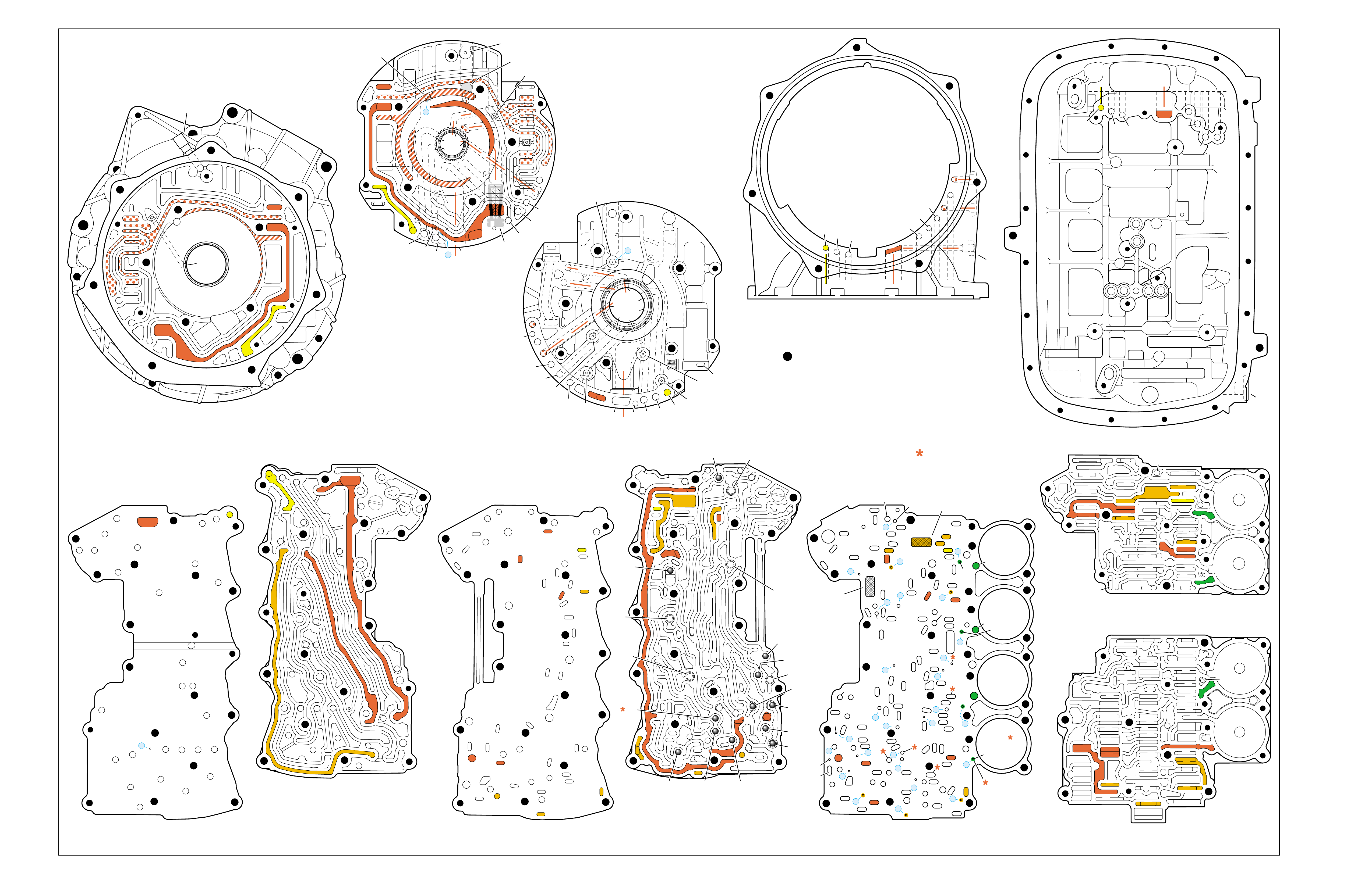
PARK
(Engine Running)
➤ ➤
➤➤
➤
➤
➤
TORQUE CONVERTER HOUSING (227)
(Fluid Pump Cover Side)
➤
➤
➤
➤
➤➤➤
➤
➤
➤ ➤
➤
➤
TOP CHANNEL PLATE (301)
(Case Side)
FRONT
➤
TOP CHANNEL PLATE (301)
(Bottom Channel Plate Side)
FRONT
➤
BOTTOM CHANNEL PLATE (304)
(Top Channel Plate Side)
FRONT
➤
REAR CONTROL VALVE BODY (310)
(Bottom Channel Plate Side)
FRONT
➤
CASE (24)
(Top Channel Plate Side)
FRONT
➤
CASE (24)
(Fluid Pump Cover Side)
SPACER PLATE (307)
(Bottom Channel Plate Side)
FRONT
➤
FRONT CONTROL VALVE BODY (311)
(Bottom Channel Plate Side)
FRONT
➤
BOTTOM CHANNEL PLATE (304)
(Control Valve Body Side)
FRONT
➤
NOTE:
–INDICATES BOLT HOLES
–NON FUNCTIONAL HOLES HAVE BEEN
REMOVED FROM COMPONENT DRAWINGS
TO SIMPLIFY TRACING FLUID FLOW.
–DUAL PURPOSE PASSAGES HAVE
CHANNEL PLATE SIDE NUMBERS LISTED FIRST
–EXHAUST FLUID NOT SHOWN
–PASSAGES MARKED WITH ARE USED FOR
THE 5L40-E ONLY
FLUID PUMP COVER (202)
(Case Side)
FLUID PUMP COVER (202)
(Torque Converter Housing Side)
➤
➤
➤
➤
➤
➤
➤ ➤
➤
➤
➤➤
➤
➤
➤
7
➤
25
➤
27
➤
3
➤
20
➤
16
➤
2
➤
10
➤
9
➤
24
➤
15
➤
11
➤
22
➤
29
➤
28
➤
23
➤
18
➤
17
➤
14
➤
8
➤
4
➤
5
➤
26
➤
13
➤
19
➤
21
➤
6
➤
12
(40)
➤
21
(203)
➤
16
(203)
➤➤
(232)
➤➤
(229)
➤➤
(231)
➤➤
(213)
➤
(233)
➤
TRANSMISSION
VENT
ASSEMBLY
➤➤
32
(203)
➤
37
(203)
➤➤
2/21
(214)
➤➤
(36)
➤
FILTER
(312)
➤
FILTER
(308)
➤
#12
#2
#3
#5
#6
#7
(Spring)
#8
#10 #9
#4
#1
#11
X-2
X-4
X-5
X-1
X-3
33
32
38
38
38
30
30
24
37
37
37
40
40
12
16
15
15
23 52
24
24
23
28
47
41
42
43
27
28
28
27
27
25
25
26
22
22
15
13
18 19
19
19
19
19
19
19
21
17
17
22
23
23
48
48
48
48
48
48
48
48
48
15
13
36
36
36
36
39
35
35
34
10
10 11
10
10
10
20
20
48
44
44
45
43 42
52
52
52
48
48
77
2
2
2
2
2
2
2
12a
16a
15d/16 15c/16
15b
23c
24a 24b
24c
25b
25c 25d
25e
26b
26a
32a
30a
33a
35a
39a
36a
36b
36c
36d
38a 39b
39c/41
40c/41
36e
36f
35b
35c 35d
37c
37d
37b
37a
40b
40a
38d 38b
38c
38e
40d
34a
33e
33c
33d
33b
30b
30c 30d
25a
23b
23a
20a
28c
27c/46
27b
28b
28a
27a
47b
47a
20b
20d
20c
13a
15a
19e
19h
19g
19i
19j
19f
13b 15e
17a
17b
17c/18
15f/18
19b/21
19c/21
19d/21
19a
22a
22b
22c
22d
22f
21a
21b/31
21c/31
22g/23
14a/23
22e
48
48
48
48
48
48
48
48
52
52
52
52
52
52
52
52
48
48
2g
7a
7b 2a/54a
2b
42b
43a
42a
43b
44c
44d 44b
44a
44e
43c/45
44f/45
48a 48b
2c/54c
54d
2d/54e
2e 2m/54g
2f
10i
10h
10f
10e
10d
10a 10c
11b
11a/10b
10g
2h
54f
54b
12
2
23
24
48
48
48
48
48
48
48
48
52
52
52
52
52
52
52
23
36
36
36
20
27
28
46
47
47
19
16
15
13
10
10
10
11
54
2
54
37
37
37
39
38
40
42
43
40
27
7
48
48
48
52
52
52
52
52
52
52
24
25
25
25
2525
26
26
15 19 19
19
19
31
21
20 20
15 17
17
14
13
14
54
22
22
28
28
22
22
32
42 43
44
44
48
48
48
48
48
48
44
44
38
39
38
33
33
30
35
40
35
35
36
35
34
30
30
30
33
2
2
10
10 10
10
27
2
216
24
15
18
7
32
52
52
52
52 52
52
52
52
52
52
52
52
52 52
52
52
52
52
30 34
35
41
12 21 37
8
9
2
16
24
7
32
12 21
37
12
21
21
24
848
7
9
9
52
52
2
16
5
16
37
32
32
52
1
52
52
52
48
37
1
2
51
51
52
12
12
24
24
52
2
2
4
4
4
4
5
66
8
8
7
7
7
5
9
48
48
48
48
48
48
48
48
53
53
48
52
2
3
3
3
2
1
16
21
21
16
32
37
32
51
50
50
51 52
52
52
52
52
52
48
48
48
48
52
48
48
12
12
24
24
2
2
3
2
4
4
4
5
6
53
53
8
8
7
7
7
48
16
16
21 32
37
➤➤
1
➤➤
31
➤➤
30
(233)
➤➤
32
38
30
24 12
16
13
15
15
13
18
19
19
19
21
21
22
16 48
48
48
48
48
48
48
48
36
35
35
34
2
2
7
2
10
10
10
10
41
42
43
43
42
48 48
20
28
27
37
27
28
28
27
20
48
52
52
32
32
32
38
24
12 16
16
18
28
28
28
27
27
48 48
43 42
42
43
48
30
48
48
48 48
48
48
48
48
48
48
48
48
35
36
37
34
2
7
2
10
13
13
15
19
41
41
19
19
15
22
21
21
20
20
21
21
13
10
10
10
2
48
48 48
52
52
52
52
52
52
12
32
37 21
24
2
16
18
48
48
48
48
48
30
48
48
48
48
48
48
15
35
41
34
7
52
52
52
52
52
52
Figure 83 FOLDOUT ➤ 87
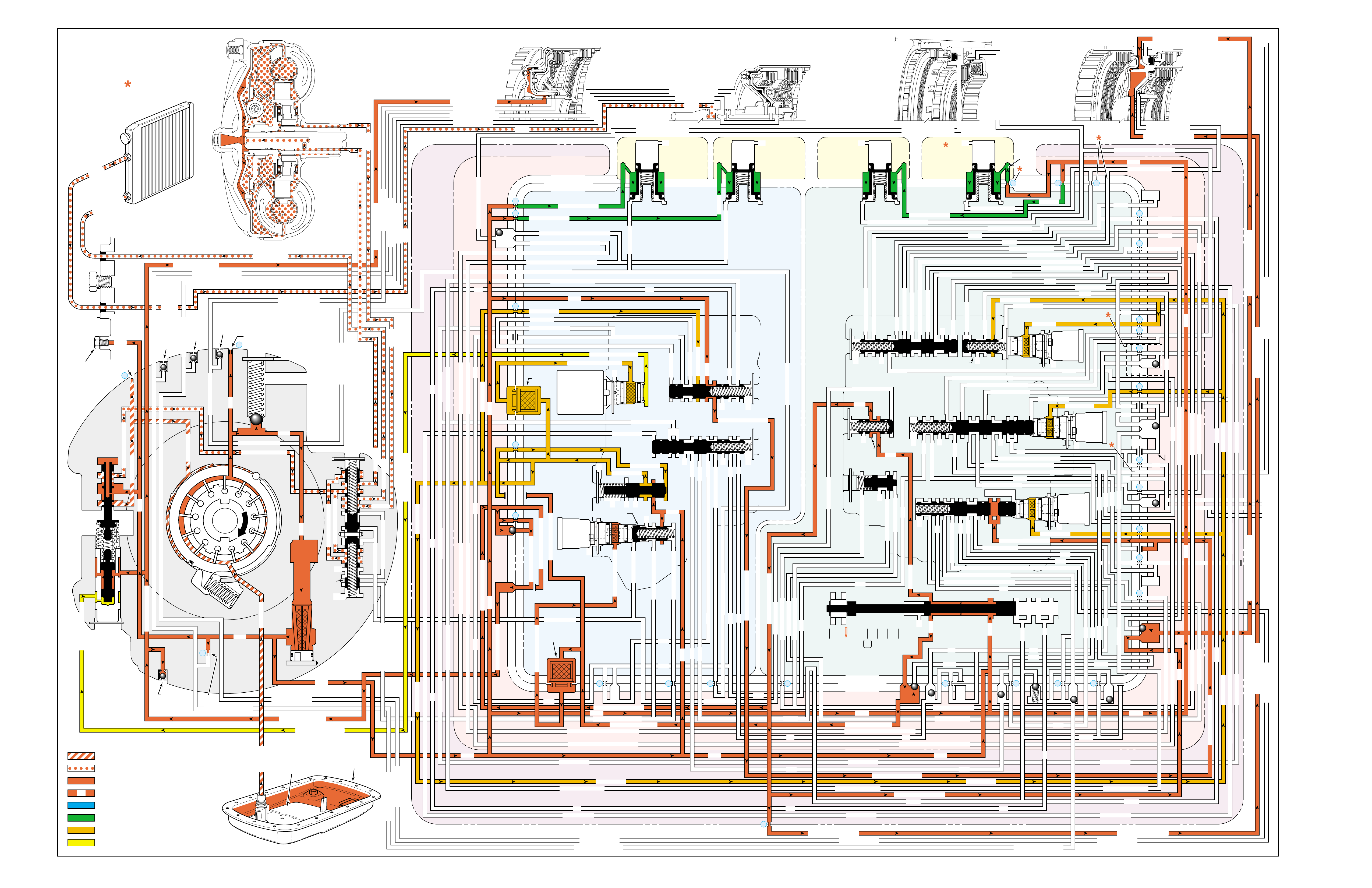
Figure 84
REVERSE
PRESSURES
INTAKE & DECREASE (SUCTION)
CONVERTER & LUBE
MAINLINE
REGULATED LINE
SOLENOID SIGNAL
ACCUMULATOR
FEED LIMIT
THROTTLE SIGNAL
NOTE:
PASSAGES AND
COMPONENTS
MARKED WITH
ARE USED FOR
THE 5L40-E ONLY
GASKET (309)
GASKET (305)
GASKET (303)
BOTTOM CHANNEL PLATE (304)
TOP CHANNEL PLATE (301)
CASE (24)
REAR CONTROL VALVE BODY (310)
SPACER PLATE (307)
GASKET (309)
GASKET (305)
GASKET (303)
BOTTOM CHANNEL PLATE (304)
TOP CHANNEL PLATE (301)
CASE (24)
FRONT CONTROL VALVE BODY (311)
SPACER PLATE (307)
FLUID
PUMP
COVER
(202)
CONVERTER
HOUSING
(224)
ACCUMULATOR HOUSING (317) ACCUMULATOR HOUSING (323) ACCUMULATOR HOUSING (328) ACCUMULATOR HOUSING (333)
LUBE
LUBE
LUBE
LUBE
TO COOLER
LUBE
TO COOLER
APPLY
APPLY
APPLY
RELEASE
DECREASE
DECREASE
LINE
OVERDRIVE CLUTCH FEED 1
OVERDRIVE CL FD 1OVERDRIVE CLUTCH FEED 1
OVERDRIVE CLUTCH FEED 1 OVERDRIVE CLUTCH FEED 1
OVERDRIVE CLUTCH
2345 2345
2345
2345
2345
2345
2345 OR REVERSE
RLO
LOW AND REV CL OR RLO
LOW AND REV CL OR RLO
SECOND COAST CLUTCH
SECOND CLUTCH
SECOND COAST CLUTCH
SUCTION SUCTION
LINE
LINE
LINE LINE
LINE
LINE
LINE LINE LINE
TCC SIGNAL
CONVERTER FEED
CONVERTER FEED
RELEASE
TO COOLER
REGULATED APPLYREGULATED APPLY
LINE
EX
CONVERTER FEED
REVERSE CLUTCH
REVERSE CLUTCH
THROTTLE SIGNAL
LINE
EX
FILTERED FEED LIMIT
THROTTLE SIGNAL
THROTTLE SIGNAL
THROTTLE SIGNAL
EX
2345 OR REVERSE
2345 OR REVERSE
2345 OR REVERSE
TCC SIGNAL
TCC SIGNAL
TCC SIGNAL
REGULATED APPLY
REGULATED APPLY
REGULATED APPLY
EX
EX
FEED LIMIT VALVE
LINE
EX
EX
EX
EX
FEED LIMIT
FEED LIMIT FEED LIMIT
FEED LIMIT
FEED LIMIT
FEED LIMIT
FEED LIMIT
FEED LIMIT FEED LIMIT
FEED LIMIT
2-3 SHIFT VALVE CNTRL
EX
EX
EX
EX
EX
EX
EX EX
SECOND COAST CLUTCH
23 REGULATED
23 REGULATED
OVERDRIVE CLUTCH FEED 1
INTERMEDIATE CLUTCH
2345
2345
2345
2345
INTERMEDIATE CLUTCH
2345
345
FEED LIMIT
EX
EX
EX
EX
2-3 SIGNAL
LOW PRESSURE
123 REGULATED
123 REGULATED
EX
CNTRL
LINE SAFETY MODE
123 BRAKING
123
EX
EX
EX
123
123
123
123
123
123
123
123123
COAST CLUTCH
COAST CLUTCH FEED
OVERDRIVE CLUTCH FEED 2
45
FEED LIMIT
SAFETY MODE
LINE
FEED LIMIT
32
MEMORY
MEMORY
MEMORY
MEMORY PILOT
MEMORY PILOT
32 SAFETY MODE
LINE SAFETY MODE
EX
EX
LINE SAFETY MODE
CNTRL 3-4 SHIFT
2-3 SIGNAL
123123 D432D432
DIRECT CLUTCH
DIRECT CLUTCH
4545
1-2 SIGNAL
EX
EX
EX
1-2 SHIFT VALVE
FDL
FDL
FDL
FDL
FDL
FDL
D432
2345 2345
D432
SECOND CLUTCH
23 REGULATED
23 REGULATED23 REGULATED
123 REGULATED
LOW AND REVERSE CLUTCH
LOW AND REVERSE CL
SECOND CLUTCH
123 REGULATED
EX
EX
EX
FD LIMIT
FEED LIMIT
FDL
1-2 SIGNAL
2-3 SIGNAL
EX
EX
TCC SIGNAL
TCC SIGNAL
TCC SIGNAL
RLO
EX
REV
RPND432
MANUAL VALVE
LINE
D432
D432 D432
D432
D432
D432
D432 D432
D432
D432D432
D432
REV
REVERSE
EX
3232
LINE
EX
EX
LINE
CASE (24)
OVERDRIVE CLUTCH FEED 2
OVERDRIVE CL FD 2
OVERDRIVE CLUTCH FEED 2
ACCUMULATOR
DIRECT CLUTCH
ACCUM
INTERMEDIATE CLUTCH
INTERMEDIATE CLUTCH
INTERMEDIATE CLUTCH
ACCUMULATOR
EX
SECOND CLUTCH
SECOND CLUTCH
ACCUM
ACCUM
LINELINE
FORWARD CLUTCH
FORWARD CLUTCH FORWARD CLUTCH
ACCUMULATOR
LINE
LINELINE
LINE
OVERDRIVE CLUTCH
INTERMEDIATE CL
COAST CLUTCH
REVERSE LOCKOUT
COAST CLUTCH
REVERSE CLUTCH
REVERSE CLUTCH
REVERSE CLUTCH
4-5 SIGNAL
EXEXEX
LINE SAFETY MODE
LINE SAFETY MODE
REVERSE LOCKOUT
REVERSE LOCKOUT REVERSE LOCKOUT
COAST CLUTCH
REVERSE LOCKOUT REVERSE LOCKOUT
REVERSE LOCKOUT
REVERSE LOCKOUT
REVERSE LOCKOUT
REVERSE LOCKOUT
REVERSE CLUTCH
REVERSE CLUTCH
LOW AND REV CL OR RLO
FORWARD CLUTCH
FORWARD CLUTCH
FORWARD CLUTCH
COAST CLUTCH
FORWARD CLUTCH
FORWARD CLUTCH
FORWARD CLUTCH
2345
2345 OR REVERSE
123 REGULATED
123 REGULATED
123 REGULATED 123 REGULATED
123 REGULATED
123 REGULATED
123 REGULATED
123 BRAKING
123 BRAKING
123 BRAKING
123 BRAKING
1-2 SIGNAL1-2 SIGNAL
1-2 SIGNAL1-2 SIGNAL1-2 SIGNAL
1-2 SIGNAL 1-2 SIGNAL 1-2 SIGNAL
2-3 SIGNAL2-3 SIGNAL2-3 SIGNAL
2-3 SIGNAL 2-3 SIGNAL
2-3 SIGNAL2-3 SIGNAL2-3 SIGNAL
2-3 SIGNAL
SECOND CLUTCH
SECOND CLUTCH
COAST CLUTCHCOAST CLUTCHCOAST CLUTCH
COAST CLUTCH
COAST CLUTCH
COAST CLUTCH
COAST CLUTCH
COAST CLUTCH
23 REGULATED
345
345
345
345 345 345
345
345
345
345
345
345
345
345
DIRECT CLUTCH
DIRECT CLUTCH
DIRECT CLUTCH
DIRECT CL
DIRECT CLUTCH
DIRECT CLUTCH
DIRECT CLUTCH
DIRECT CLUTCH
45
45
45
4545
45
OVERDRIVE CLUTCH
OVERDRIVE CL FD 1
OVERDRIVE CLUTCH FEED 2OVERDRIVE CLUTCH FEED 2
OVERDRIVE CL FD 2
OVERDRIVE CLUTCH FEED 2 OVERDRIVE CL FD 2
3232
32 32 32
323232
32 SAFETY MODE
32 SAFETY MODE 32 SAFETY MODE 32 SAFETY MODE
32 SAFETY MODE32 SAFETY MODE
32 SM 32 SM
FDL
PRESSURE
CONTROL
SOLENOID
VALVE
1-2 SHIFT
SOLENOID
VALVE
N/C
(A)
OFF
2-3 SHIFT
SOLENOID
VALVE
N/C
(B)
OFF
4-5 SHIFT
SOLENOID
VALVE
N/C
(C)
OFF
TCC PWM
SOLENOID
VALVE
N/C
PRESS REG VALVEBOOST VALVE
CONVERTER FDL
4-5 SHIFT VLV
AIR
BLEED
(233)
AIR
BLEED
(233)
AIR
BLEED
(203)
AIR
BLEED
(203)
AIR
BLEED
(203)
AIR
BLEED
(203)
7
4
2
1
5
6
11
10
9
12
18
FILTER
(308)
FILTER
(312)
TCC REGULATOR VALVE
TCC
CONTROL
VALVE
TCC
ENABLE
VALVE
REVERSE
LOCKOUT
VALVE
1-2 SHIFT CONTROL VALVE
FLUID
PAN
(62)
FLUID FILTER
ASSEMBLY
(59)
FLUID
PRESSURE
TEST PLUG
(40)
TORQUE
CONVERTER
ASSEMBLY
(1)
DIRECT
CLUTCH
ACCUMULATOR
OVERDRIVE
CLUTCH
ACCUMULATOR
INTERMEDIATE
CLUTCH
ACCUMULATOR
SECOND
CLUTCH
ACCUMULATOR
COOLER
PRESSURE
RELIEF
BALL
VALVE
21 2
10d
2a
2b
42b
43a
37d
39b
40b
37c
40d
11b
10a
24a
10c
11a 10b
54b
54d
2c
54a
54c
27c 46
7a
24b
20a
13a
37b
38a
7b
47a
47b
27b
28c
12a
23a
36e
36f
23b
23c
15a
24c
26b
36a
38c
38d
36b
25a
15
2m 54g
54f
#8
18
15f
15e
17c
17b
17a
27a
44a
44e
44d
44b
25c
30a
33a
25e
19e
35c
19h
19f
10f
10h
10g
22a
35b
#7
13b
32a
26a
10i
22f
22d
43b
22b
34a
48b
39a
22c
X-1
22
22e
21a
42a
19a
20b
19b
#2
23 22g
14a
2f
2h
19g
19i
19
j
DIRECT
AND REVERSE
CLUTCH
ASSEMBLY
(400–420)
FORWARD
AND COAST
CLUTCH
ASSEMBLY
(430–451)
OVERDRIVE
AND
INTERMEDIATE
CLUTCH
ASSEMBLY
(480–497)
CENTER
SUPPORT
ASSEMBLY
(510–535)
3
2d54e
2e
30c
30d
35d
26
37a
13
#1
15c
15b
16
15d 16
15
X-2
16a
X-4 X-5
38
14
X-3
19
#6
19d
19
21
19c 21
15
#5
21b 31
21c 31
17
21
#4
20d
20c
16
25b
19
25d
20
36 46
28a
44c
28b
30b
21
#11
33e
33d
23
2435a
#9
33c
33b
22
36d
36c
25
#12
41 40c
39c
43 13
2840a
#10
45
45
45
44f
44
48
43c
#3
38b
38e
27
48a29
8
10e
2310
32 SM/FDL
30
31
FLUID PUMP
SCREEN
ASSEMBLY
(213)
(214)
88

88A
REVERSE
NO REVERSE OR SLIPS IN REVERSE
•Center Support (518)
–Broken
–Leaking at case
•Fluid Passage Sleeve (38)
–Leaking
•Low and Reverse Clutch Piston (517)
–Leaking
–Jammed or cracked
•Reverse Lockout Valve
–Stuck
•#2 Ball Check Valve
–Stuck
–Missing
•#8 Ball Check Valve
–Stuck
–Missing
•Reverse Clutch Piston (404)
–Leaking
–Jammed or cracked
•Reverse Clutch Housing Ball Check Valve (403)
–Leaking
•Reverse Clutch Housing Seal Ring (200)
–Leaking
•TCC PWM Solenoid Valve (352)
–Stuck On
SOLENOID FORWARD OVER- INTERM. INTER- LOW LOW AND SECOND SECOND
DIRECT REVERSE COAST FORWARD SPRAG DRIVE SPRAG MEDIATE SPRAG REVERSE SECOND SPRAG COAST
1-2 2-3 4-5 CLUTCH CLUTCH CLUTCH CLUTCH CLUTCH CLUTCH CLUTCH CLUTCH CLUTCH CLUTCH CLUTCH CLUTCH CLUTCH
OFF OFF OFF APPLIED APPLIED
LD = LOCKED IN DRIVE

88B
PASSAGES
1 SUCTION
2 LINE
3 DECREASE
4 CONVERTER FEED
5 RELEASE
6 APPLY
7 REGULATED APPLY
8 TO COOLER
9 LUBE
10 FEED LIMIT
11 FILTERED FEED LIMIT
12 THROTTLE SIGNAL
13 LINE SAFETY MODE
14 REVERSE
15 REVERSE LOCK OUT (RLO)
16 REVERSE CLUTCH
17 LOW AND REVERSE CLUTCH
18 LOW AND REVERSE CLUTCH OR RLO
19 D432
20 123
21 FORWARD CLUTCH
22 2345
23 2345 OR REVERSE
24 TCC SIGNAL
25 123 REGULATED
26 123 BRAKING
27 1-2 SIGNAL
28 2-3 SIGNAL
29 4-5 SIGNAL
30 SECOND CLUTCH
31 COAST CLUTCH FEED
32 COAST CLUTCH
33 23 REGULATED
34 SECOND COAST CLUTCH
35 INTERMEDIATE CLUTCH
36 345
37 DIRECT CLUTCH
38 45
39 OVERDRIVE CLUTCH FEED 1
40 OVERDRIVE CLUTCH FEED 2
41 OVERDRIVE CLUTCH
42 32
43 32 SAFETY MODE
44 FDL
45 32 SAFETY MODE/FDL
46 MEMORY PILOT
47 MEMORY
48 EXHAUST
49 OIL RESERVOIR
50 TORQUE CONVERTER SEAL DRAINBACK
51 VENT
52 VOID
53 CONVERTER FDL
54 ACCUMULATOR
COMPONENTS ( )
(36) TRANSMISSION FLUID LEVEL HOLE PLUG
(40) TRANSMISSION FLUID PRESSURE TEST PLUG
(203) CHECK VALVE RETAINER AND BALL ASSEMBLY
(213) TRANSMISSION FLUID PUMP SCREEN ASSEMBLY
(214) BRASS ORIFICE INSERT
(232) ORIFICE SLEEVE
(233) ORIFICE CUP PLUG
(306) CONTROL VALVE BODY BALL CHECK VALVE
(#1, 2, 3, 4, 5, 6, 7, 8, 9, 10, 11, 12)
(308) TCC PWM SOLENOID VALVE FILTER ASSEMBLY
(312) PRESSURE CONTROL SOLENOID VALVE
FILTER ASSEMBLY
REVERSE
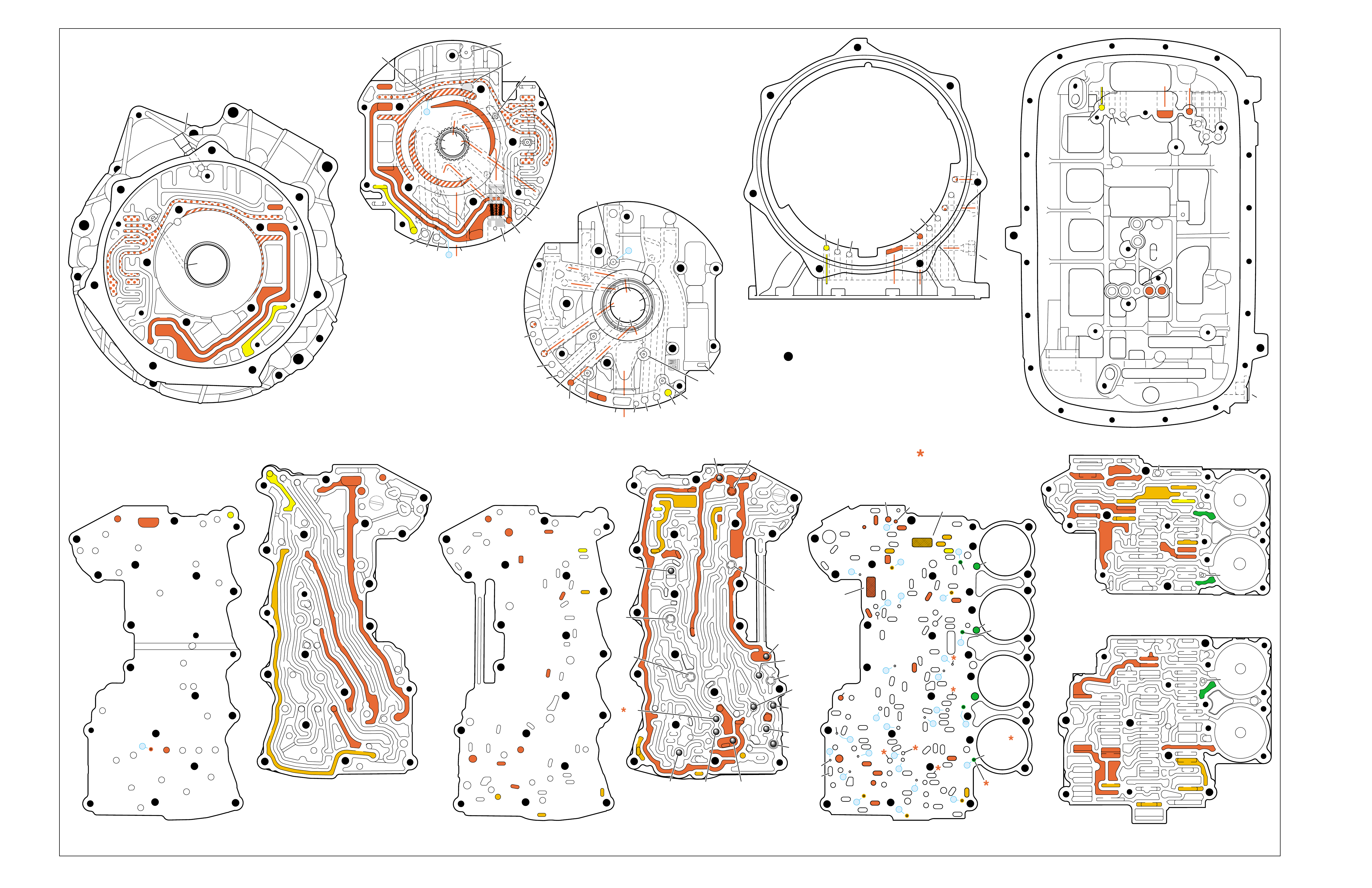
Figure 85
REVERSE
➤➤
➤
➤➤
➤
➤ ➤
➤➤
➤
➤
➤
TORQUE CONVERTER HOUSING (227)
(Fluid Pump Cover Side)
➤
➤
➤
➤
➤➤➤
➤➤
➤
➤
➤
➤ ➤
➤
➤
TOP CHANNEL PLATE (301)
(Case Side)
FRONT
➤
TOP CHANNEL PLATE (301)
(Bottom Channel Plate Side)
FRONT
➤
BOTTOM CHANNEL PLATE (304)
(Top Channel Plate Side)
FRONT
➤
REAR CONTROL VALVE BODY (310)
(Bottom Channel Plate Side)
FRONT
➤
CASE (24)
(Top Channel Plate Side)
FRONT
➤
CASE (24)
(Fluid Pump Cover Side)
SPACER PLATE (307)
(Bottom Channel Plate Side)
FRONT
➤
FRONT CONTROL VALVE BODY (311)
(Bottom Channel Plate Side)
FRONT
➤
BOTTOM CHANNEL PLATE (304)
(Control Valve Body Side)
FRONT
➤
NOTE:
–INDICATES BOLT HOLES
–NON FUNCTIONAL HOLES HAVE BEEN
REMOVED FROM COMPONENT DRAWINGS
TO SIMPLIFY TRACING FLUID FLOW.
–DUAL PURPOSE PASSAGES HAVE
CHANNEL PLATE SIDE NUMBERS LISTED FIRST
–EXHAUST FLUID NOT SHOWN
–PASSAGES MARKED WITH ARE USED FOR
THE 5L40-E ONLY
FLUID PUMP COVER (202)
(Case Side)
FLUID PUMP COVER (202)
(Torque Converter Housing Side)
➤
➤
➤
➤
➤
➤
➤ ➤
➤
➤
➤➤
➤
➤
➤
7
➤
25
➤
27
➤
3
➤
20
➤
16
➤
2
➤
10
➤
9
➤
24
➤
15
➤
11
➤
22
➤
29
➤
28
➤
23
➤
18
➤
17
➤
14
➤
8
➤
4
➤
5
➤
26
➤
13
➤
19
➤
21
➤
6
➤
12
(40)
➤
21
(203)
➤
16
(203)
➤➤
(232)
➤➤
(229)
➤➤
(231)
➤➤
(213)
➤
(233)
➤
TRANSMISSION
VENT
ASSEMBLY
➤➤
32
(203)
➤
37
(203)
➤➤
2/21
(214)
➤➤
(36)
➤
FILTER
(312)
➤
FILTER
(308)
➤
#12
#2
#3
#5
#6
#7
(Spring)
#8
#10 #9
#4
#1
#11
X-2
X-4
X-5
X-1
X-3
12a
16a
15d/16 15c/16
15b
23c
24a 24b
24c
25b
25c 25d
25e
26b
26a
32a
30a
33a
35a
39a
36a
36b
36c
36d
38a 39b
39c/41
40c/41
36e
36f
35b
35c 35d
37c
37d
37b
37a
40b
40a
38d 38b
38c
38e
40d
34a
33e
33c
33d
33b
30b
30c 30d
25a
23b
23a
20a
28c
27c/46
27b
28b
28a
27a
47b
47a
20b
20d
20c
13a
15a
19e
19h
19g
19i
19j
19f
13b 15e
17a
17b
17c/18
15f/18
19b/21
19c/21
19d/21
19a
22a
22b
22c
22d
22f
21a
21b/31
21c/31
22g/23
14a/23
22e
48
48
48
48
48
48
48
48
52
52
52
52
52
52
52
52
48
48
2g
7a
7b 2a/54a
2b
42b
43a
42a
43b
44c
44d 44b
44a
44e
43c/45
44f/45
48a 48b
2c/54c
54d
2d/54e
2e 2m/54g
2f
10i
10h
10f
10e
10d
10a 10c
11b
11a/10b
10g
2h
54f
54b
12
2
23
24
48
48
48
48
48
48
48
48
52
52
52
52
52
52
52
23
36
36
36
20
27
28
46
47
47
19
16
15
13
10
10
10
11
54
2
54
37
37
37
39
38
40
42
43
40
27
7
48
48
48
52
52
52
52
52
52
52
24
25
25
25
2525
26
26
15 19 19
19
19
31
21
20 20
15 17
17
14
13
14
54
22
22
28
28
22
22
32
42 43
44
44
48
48
48
48
48
48
44
44
38
39
38
33
33
30
35
40
35
35
36
35
34
30
30
30
33
2
2
10
10 10
10
27
2
216
24
15
18
7
32
52
52
52
52 52
52
52
52
52
52
52
52
52 52
52
52
52
52
30 34
35
41
12 21 37
8
9
2
16
24
7
32
12 21
37
12
21
21
24
848
7
9
9
52
52
2
16
5
16
37
32
32
52
1
52
52
52
48
37
1
2
51
51
52
12
12
24
24
52
2
2
4
4
4
4
5
66
8
8
7
7
7
5
9
48
48
48
48
48
48
48
48
53
53
48
52
2
3
3
3
2
1
16
21
21
16
32
37
32
51
50
50
51 52
52
52
52
52
52
48
48
48
48
52
48
48
12
12
24
24
2
2
3
2
4
4
4
5
6
53
53
8
8
7
7
7
48
16
16
21 32
37
➤➤
1
➤➤
31
➤➤
30
(233)
➤➤
33
32
38
38
38
30
30
24
37
37
37
40
40
12
16
15
15
23 52
24
24
23
28
47
41
42
43
27
28
28
27
27
25
25
26
22
22
15
13
18 19
19
19
19
19
19
19
21
17
17
22
23
23
48
48
48
48
48
48
48
48
48
15
13
36
36
36
36
39
35
35
34
10
10 11
10
10
10
20
20
48
44
44
45
43 42
52
48
48
77
2
2
2
2
2
2
2
52
52
32
38
30
24 12
16
13
15
15
13
18
19
19
19
21
21
22
16 48
48
48
48
48
48
48
48
36
35
35
34
2
2
7
2
10
10
10
10
41
42
43
43
42
48 48
20
28
27
37
27
28
28
27
20
48
52
52
32
32
32
38
24
12 16
16
18
28
28
28
27
27
48 48
43 42
42
43
48
30
48
48
48 48
48
48
48
48
48
48
48
48
35
36
37
34
2
7
2
10
13
13
15
19
41
41
19
19
15
22
21
21
20
20
21
21
13
10
10
10
2
48
48 48
52
52
52
52
52
52
12
32
37 21
24
2
16
18
48
48
48
48
48
30
48
48
48
48
48
48
15
35
41
34
7
52
52
52
52
52
52
FOLDOUT ➤ 89
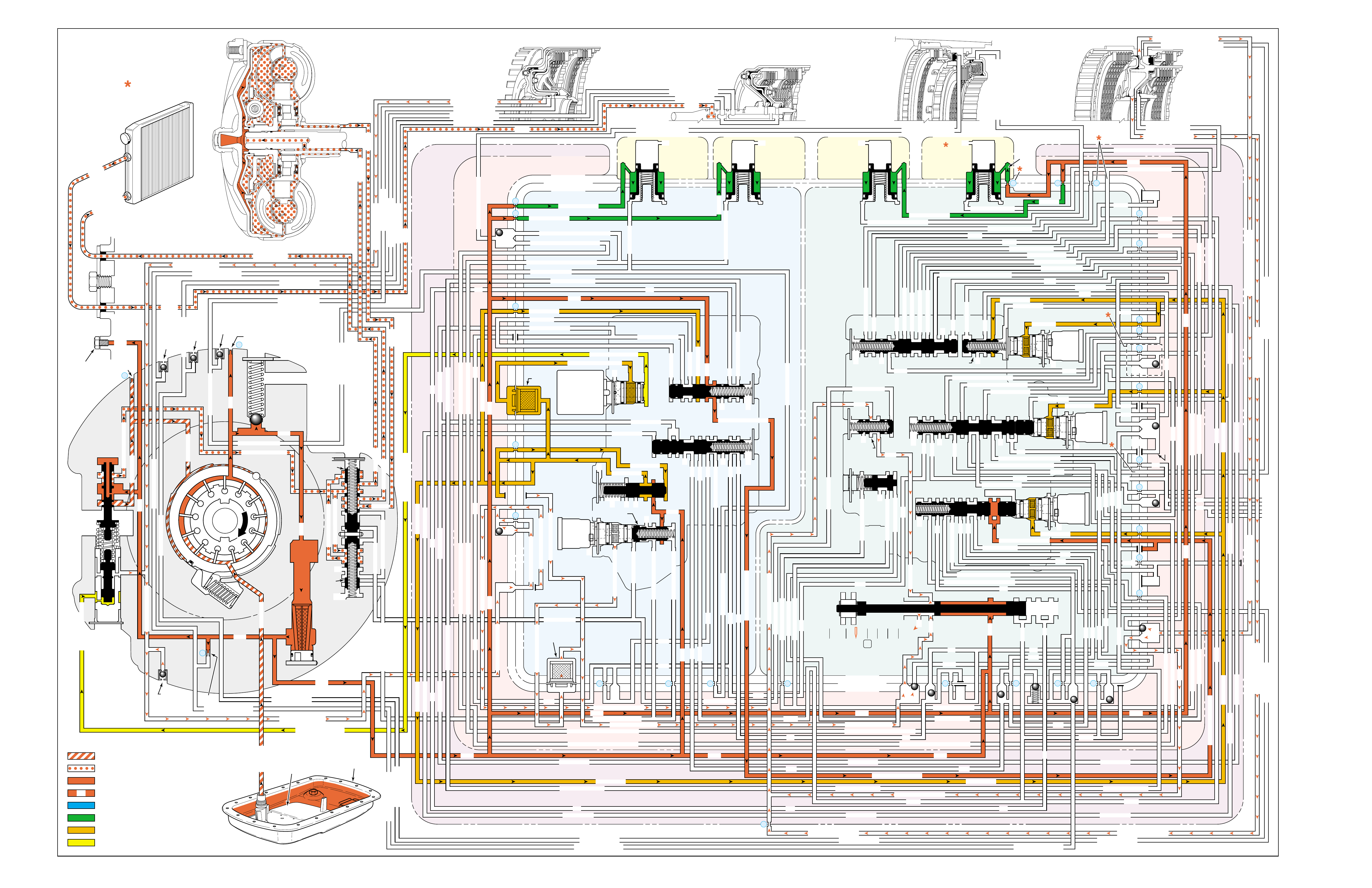
Figure 86
NEUTRAL
(Engine Running)
PRESSURES
INTAKE & DECREASE (SUCTION)
CONVERTER & LUBE
MAINLINE
REGULATED LINE
SOLENOID SIGNAL
ACCUMULATOR
FEED LIMIT
THROTTLE SIGNAL
NOTE:
PASSAGES AND
COMPONENTS
MARKED WITH
ARE USED FOR
THE 5L40-E ONLY
GASKET (309)
GASKET (305)
GASKET (303)
BOTTOM CHANNEL PLATE (304)
TOP CHANNEL PLATE (301)
CASE (24)
REAR CONTROL VALVE BODY (310)
SPACER PLATE (307)
GASKET (309)
GASKET (305)
GASKET (303)
BOTTOM CHANNEL PLATE (304)
TOP CHANNEL PLATE (301)
CASE (24)
FRONT CONTROL VALVE BODY (311)
SPACER PLATE (307)
FLUID
PUMP
COVER
(202)
CONVERTER
HOUSING
(224)
ACCUMULATOR HOUSING (317) ACCUMULATOR HOUSING (323) ACCUMULATOR HOUSING (328) ACCUMULATOR HOUSING (333)
LUBE
LUBE
LUBE
LUBE
TO COOLER
LUBE
TO COOLER
APPLY
APPLY
APPLY
RELEASE
DECREASE
DECREASE
LINE
OVERDRIVE CLUTCH FEED 1
OVERDRIVE CL FD 1OVERDRIVE CLUTCH FEED 1
OVERDRIVE CLUTCH FEED 1 OVERDRIVE CLUTCH FEED 1
OVERDRIVE CLUTCH
2345 2345
2345
2345
2345
2345
2345 OR REVERSE
RLO
LOW AND REV CL OR RLO
LOW AND REV CL OR RLO
SECOND COAST CLUTCH
SECOND CLUTCH
SECOND COAST CLUTCH
SUCTION SUCTION
LINE
LINE
LINE LINE
LINE
LINE
LINE LINE LINE
TCC SIGNAL
CONVERTER FEED
CONVERTER FEED
RELEASE
TO COOLER
REGULATED APPLYREGULATED APPLY
LINE
EX
CONVERTER FEED
REVERSE CLUTCH
REVERSE CLUTCH
THROTTLE SIGNAL
LINE
EX
FILTERED FEED LIMIT
THROTTLE SIGNAL
THROTTLE SIGNAL
THROTTLE SIGNAL
EX
2345 OR REVERSE
2345 OR REVERSE
2345 OR REVERSE
TCC SIGNAL
TCC SIGNAL
TCC SIGNAL
REGULATED APPLY
REGULATED APPLY
REGULATED APPLY
EX
EX
FEED LIMIT VALVE
LINE
EX
EX
EX
EX
FEED LIMIT
FEED LIMIT FEED LIMIT
FEED LIMIT
FEED LIMIT
FEED LIMIT
FEED LIMIT
FEED LIMIT FEED LIMIT
FEED LIMIT
2-3 SHIFT VALVE CNTRL
EX
EX
EX
EX
EX
EX
EX EX
SECOND COAST CLUTCH
23 REGULATED
23 REGULATED
OVERDRIVE CLUTCH FEED 1
INTERMEDIATE CLUTCH
2345
2345
2345
2345
INTERMEDIATE CLUTCH
2345
345
FEED LIMIT
EX
EX
EX
EX
2-3 SIGNAL
LOW PRESSURE
123 REGULATED
123 REGULATED
EX
CNTRL
LINE SAFETY MODE
123 BRAKING
123
EX
EX
EX
123
123
123
123
123
123
123
123123
COAST CLUTCH
COAST CLUTCH FEED
OVERDRIVE CLUTCH FEED 2
45
FEED LIMIT
SAFETY MODE
LINE
FEED LIMIT
32
MEMORY
MEMORY
MEMORY
MEMORY PILOT
MEMORY PILOT
32 SAFETY MODE
LINE SAFETY MODE
EX
EX
LINE SAFETY MODE
CNTRL 3-4 SHIFT
2-3 SIGNAL
123123 D432D432
DIRECT CLUTCH
DIRECT CLUTCH
4545
1-2 SIGNAL
EX
EX
EX
1-2 SHIFT VALVE
FDL
FDL
FDL
FDL
FDL
FDL
D432
2345 2345
D432
SECOND CLUTCH
23 REGULATED
23 REGULATED23 REGULATED
123 REGULATED
LOW AND REVERSE CLUTCH
LOW AND REVERSE CL
SECOND CLUTCH
123 REGULATED
EX
EX
EX
FD LIMIT
FEED LIMIT
FDL
1-2 SIGNAL
2-3 SIGNAL
EX
EX
TCC SIGNAL
TCC SIGNAL
TCC SIGNAL
RLO
EX
REV
RPND432
MANUAL VALVE
LINE
D432
D432 D432
D432
D432
D432
D432 D432
D432
D432D432
D432
REV
REVERSE
EX
3232
LINE
EX
EX
LINE
CASE (24)
OVERDRIVE CLUTCH FEED 2
OVERDRIVE CL FD 2
OVERDRIVE CLUTCH FEED 2
ACCUMULATOR
DIRECT CLUTCH
ACCUM
INTERMEDIATE CLUTCH
INTERMEDIATE CLUTCH
INTERMEDIATE CLUTCH
ACCUMULATOR
EX
SECOND CLUTCH
SECOND CLUTCH
ACCUM
ACCUM
LINELINE
FORWARD CLUTCH
FORWARD CLUTCH FORWARD CLUTCH
ACCUMULATOR
LINE
LINELINE
LINE
OVERDRIVE CLUTCH
INTERMEDIATE CL
COAST CLUTCH
REVERSE LOCKOUT
COAST CLUTCH
REVERSE CLUTCH
REVERSE CLUTCH
REVERSE CLUTCH
4-5 SIGNAL
EXEXEX
LINE SAFETY MODE
LINE SAFETY MODE
REVERSE LOCKOUT
REVERSE LOCKOUT REVERSE LOCKOUT
COAST CLUTCH
REVERSE LOCKOUT REVERSE LOCKOUT
REVERSE LOCKOUT
REVERSE LOCKOUT
REVERSE LOCKOUT
REVERSE LOCKOUT
REVERSE CLUTCH
REVERSE CLUTCH
LOW AND REV CL OR RLO
FORWARD CLUTCH
FORWARD CLUTCH
FORWARD CLUTCH
COAST CLUTCH
FORWARD CLUTCH
FORWARD CLUTCH
FORWARD CLUTCH
2345
2345 OR REVERSE
123 REGULATED
123 REGULATED
123 REGULATED 123 REGULATED
123 REGULATED
123 REGULATED
123 REGULATED
123 BRAKING
123 BRAKING
123 BRAKING
123 BRAKING
1-2 SIGNAL1-2 SIGNAL
1-2 SIGNAL1-2 SIGNAL1-2 SIGNAL
1-2 SIGNAL 1-2 SIGNAL 1-2 SIGNAL
2-3 SIGNAL2-3 SIGNAL2-3 SIGNAL
2-3 SIGNAL 2-3 SIGNAL
2-3 SIGNAL2-3 SIGNAL2-3 SIGNAL
2-3 SIGNAL
SECOND CLUTCH
SECOND CLUTCH
COAST CLUTCHCOAST CLUTCHCOAST CLUTCH
COAST CLUTCH
COAST CLUTCH
COAST CLUTCH
COAST CLUTCH
COAST CLUTCH
23 REGULATED
345
345
345
345 345 345
345
345
345
345
345
345
345
345
DIRECT CLUTCH
DIRECT CLUTCH
DIRECT CLUTCH
DIRECT CL
DIRECT CLUTCH
DIRECT CLUTCH
DIRECT CLUTCH
DIRECT CLUTCH
45
45
45
4545
45
OVERDRIVE CLUTCH
OVERDRIVE CL FD 1
OVERDRIVE CLUTCH FEED 2OVERDRIVE CLUTCH FEED 2
OVERDRIVE CL FD 2
OVERDRIVE CLUTCH FEED 2 OVERDRIVE CL FD 2
3232
32 32 32
323232
32 SAFETY MODE
32 SAFETY MODE 32 SAFETY MODE 32 SAFETY MODE
32 SAFETY MODE32 SAFETY MODE
32 SM 32 SM
FDL
PRESSURE
CONTROL
SOLENOID
VALVE
1-2 SHIFT
SOLENOID
VALVE
N/C
(A)
OFF
2-3 SHIFT
SOLENOID
VALVE
N/C
(B)
OFF
4-5 SHIFT
SOLENOID
VALVE
N/C
(C)
OFF
TCC PWM
SOLENOID
VALVE
N/C
PRESS REG VALVEBOOST VALVE
CONVERTER FDL
4-5 SHIFT VLV
AIR
BLEED
(233)
AIR
BLEED
(233)
AIR
BLEED
(203)
AIR
BLEED
(203)
AIR
BLEED
(203)
AIR
BLEED
(203)
7
4
2
1
5
6
11
10
9
12
18
FILTER
(308)
FILTER
(312)
TCC REGULATOR VALVE
TCC
CONTROL
VALVE
TCC
ENABLE
VALVE
REVERSE
LOCKOUT
VALVE
1-2 SHIFT CONTROL VALVE
FLUID
PAN
(62)
FLUID FILTER
ASSEMBLY
(59)
FLUID
PRESSURE
TEST PLUG
(40)
TORQUE
CONVERTER
ASSEMBLY
(1)
DIRECT
CLUTCH
ACCUMULATOR
OVERDRIVE
CLUTCH
ACCUMULATOR
INTERMEDIATE
CLUTCH
ACCUMULATOR
SECOND
CLUTCH
ACCUMULATOR
COOLER
PRESSURE
RELIEF
BALL
VALVE
21 2
10d
2a
2b
42b
43a
37d
39b
40b
37c
40d
11b
10a
24a
10c
11a 10b
54b
54d
2c
54a
54c
27c 46
7a
24b
20a
13a
37b
38a
7b
47a
47b
27b
28c
12a
23a
36e
36f
23b
23c
15a
24c
26b
36a
38c
38d
36b
25a
15
2m 54g
54f
#8
18
15f
15e
17c
17b
17a
27a
44a
44e
44d
44b
25c
30a
33a
25e
19e
35c
19h
19f
10f
10h
10g
22a
35b
#7
13b
32a
26a
10i
22f
22d
43b
22b
34a
48b
39a
22c
X-1
22
22e
21a
42a
19a
20b
19b
#2
23 22g
14a
2f
2h
19g
19i
19
j
DIRECT
AND REVERSE
CLUTCH
ASSEMBLY
(400–420)
FORWARD
AND COAST
CLUTCH
ASSEMBLY
(430–451)
OVERDRIVE
AND
INTERMEDIATE
CLUTCH
ASSEMBLY
(480–497)
CENTER
SUPPORT
ASSEMBLY
(510–535)
3
2d54e
2e
30c
30d
35d
26
37a
13
#1
15c
15b
16
15d 16
15
X-2
16a
X-4 X-5
38
14
X-3
19
#6
19d
19
21
19c 21
15
#5
21b 31
21c 31
17
21
#4
20d
20c
16
25b
19
25d
20
36 46
28a
44c
28b
30b
21
#11
33e
33d
23
2435a
#9
33c
33b
22
36d
36c
25
#12
41 40c
39c
43 13
2840a
#10
45
45
45
44f
44
48
43c
#3
38b
38e
27
48a29
8
10e
2310
32 SM/FDL
30
31
FLUID PUMP
SCREEN
ASSEMBLY
(213)
(214)
90

90A
NEUTRAL
(Engine Running)
FORWARD MOTION IN NEUTRAL
•Manual Valve (377)
–Mis-positioned
•Forward Clutch Piston (436)
–Jammed
•Coast Clutch Piston (438)
–Jammed
•Forward Clutch Input Housing (433)
–Passage plugged
SOLENOID FORWARD OVER- INTERM. INTER- LOW LOW AND SECOND SECOND
DIRECT REVERSE COAST FORWARD SPRAG DRIVE SPRAG MEDIATE SPRAG REVERSE SECOND SPRAG COAST
1-2 2-3 4-5 CLUTCH CLUTCH CLUTCH CLUTCH CLUTCH CLUTCH CLUTCH CLUTCH CLUTCH CLUTCH CLUTCH CLUTCH CLUTCH
OFF OFF OFF
LD = LOCKED IN DRIVE

90B
PASSAGES
1 SUCTION
2 LINE
3 DECREASE
4 CONVERTER FEED
5 RELEASE
6 APPLY
7 REGULATED APPLY
8 TO COOLER
9 LUBE
10 FEED LIMIT
11 FILTERED FEED LIMIT
12 THROTTLE SIGNAL
13 LINE SAFETY MODE
14 REVERSE
15 REVERSE LOCK OUT (RLO)
16 REVERSE CLUTCH
17 LOW AND REVERSE CLUTCH
18 LOW AND REVERSE CLUTCH OR RLO
19 D432
20 123
21 FORWARD CLUTCH
22 2345
23 2345 OR REVERSE
24 TCC SIGNAL
25 123 REGULATED
26 123 BRAKING
27 1-2 SIGNAL
28 2-3 SIGNAL
29 4-5 SIGNAL
30 SECOND CLUTCH
31 COAST CLUTCH FEED
32 COAST CLUTCH
33 23 REGULATED
34 SECOND COAST CLUTCH
35 INTERMEDIATE CLUTCH
36 345
37 DIRECT CLUTCH
38 45
39 OVERDRIVE CLUTCH FEED 1
40 OVERDRIVE CLUTCH FEED 2
41 OVERDRIVE CLUTCH
42 32
43 32 SAFETY MODE
44 FDL
45 32 SAFETY MODE/FDL
46 MEMORY PILOT
47 MEMORY
48 EXHAUST
49 OIL RESERVOIR
50 TORQUE CONVERTER SEAL DRAINBACK
51 VENT
52 VOID
53 CONVERTER FDL
54 ACCUMULATOR
COMPONENTS ( )
(36) TRANSMISSION FLUID LEVEL HOLE PLUG
(40) TRANSMISSION FLUID PRESSURE TEST PLUG
(203) CHECK VALVE RETAINER AND BALL ASSEMBLY
(213) TRANSMISSION FLUID PUMP SCREEN ASSEMBLY
(214) BRASS ORIFICE INSERT
(232) ORIFICE SLEEVE
(233) ORIFICE CUP PLUG
(306) CONTROL VALVE BODY BALL CHECK VALVE
(#1, 2, 3, 4, 5, 6, 7, 8, 9, 10, 11, 12)
(308) TCC PWM SOLENOID VALVE FILTER ASSEMBLY
(312) PRESSURE CONTROL SOLENOID VALVE
FILTER ASSEMBLY
NEUTRAL
(Engine Running)
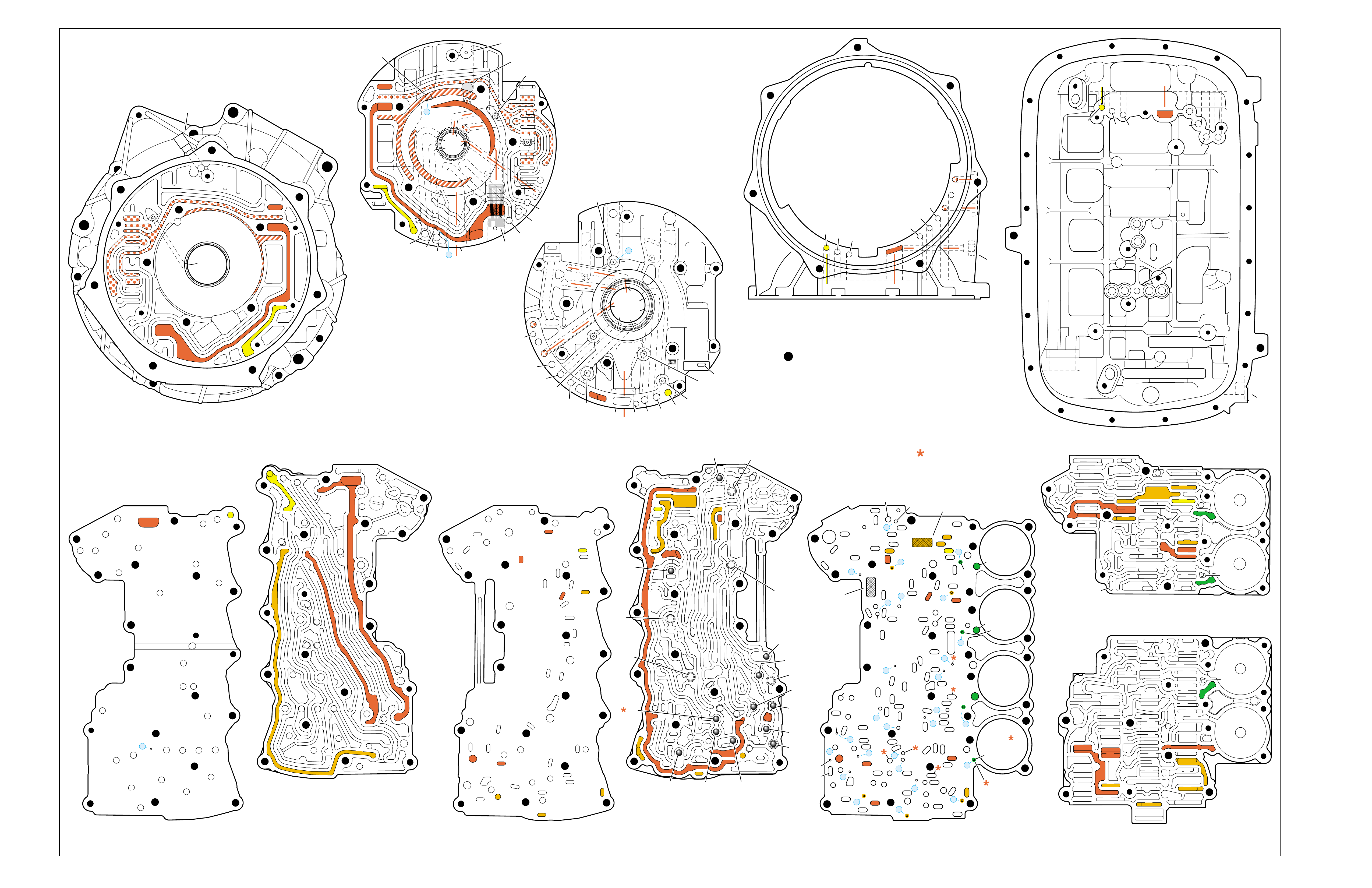
Figure 87
NEUTRAL
(Engine Running)
➤ ➤
➤➤
➤
➤
➤
TORQUE CONVERTER HOUSING (227)
(Fluid Pump Cover Side)
➤
➤
➤
➤
➤➤➤
➤
➤
➤ ➤
➤
➤
TOP CHANNEL PLATE (301)
(Case Side)
FRONT
➤
TOP CHANNEL PLATE (301)
(Bottom Channel Plate Side)
FRONT
➤
BOTTOM CHANNEL PLATE (304)
(Top Channel Plate Side)
FRONT
➤
REAR CONTROL VALVE BODY (310)
(Bottom Channel Plate Side)
FRONT
➤
CASE (24)
(Top Channel Plate Side)
FRONT
➤
CASE (24)
(Fluid Pump Cover Side)
SPACER PLATE (307)
(Bottom Channel Plate Side)
FRONT
➤
FRONT CONTROL VALVE BODY (311)
(Bottom Channel Plate Side)
FRONT
➤
BOTTOM CHANNEL PLATE (304)
(Control Valve Body Side)
FRONT
➤
NOTE:
–INDICATES BOLT HOLES
–NON FUNCTIONAL HOLES HAVE BEEN
REMOVED FROM COMPONENT DRAWINGS
TO SIMPLIFY TRACING FLUID FLOW.
–DUAL PURPOSE PASSAGES HAVE
CHANNEL PLATE SIDE NUMBERS LISTED FIRST
–EXHAUST FLUID NOT SHOWN
–PASSAGES MARKED WITH ARE USED FOR
THE 5L40-E ONLY
FLUID PUMP COVER (202)
(Case Side)
FLUID PUMP COVER (202)
(Torque Converter Housing Side)
➤
➤
➤
➤
➤
➤
➤ ➤
➤
➤
➤➤
➤
➤
➤
7
➤
25
➤
27
➤
3
➤
20
➤
16
➤
2
➤
10
➤
9
➤
24
➤
15
➤
11
➤
22
➤
29
➤
28
➤
23
➤
18
➤
17
➤
14
➤
8
➤
4
➤
5
➤
26
➤
13
➤
19
➤
21
➤
6
➤
12
(40)
➤
21
(203)
➤
16
(203)
➤➤
(232)
➤➤
(229)
➤➤
(231)
➤➤
(213)
➤
(233)
➤
TRANSMISSION
VENT
ASSEMBLY
➤➤
32
(203)
➤
37
(203)
➤➤
2/21
(214)
➤➤
(36)
➤
FILTER
(312)
➤
FILTER
(308)
➤
#12
#2
#3
#5
#6
#7
(Spring)
#8
#10 #9
#4
#1
#11
X-2
X-4
X-5
X-1
X-3
12
2
23
24
48
48
48
48
48
48
48
48
52
52
52
52
52
52
52
23
36
36
36
20
27
28
46
47
47
19
16
15
13
10
10
10
11
54
2
54
37
37
37
39
38
40
42
43
40
27
7
48
48
48
52
52
52
52
52
52
52
24
25
25
25
2525
26
26
15 19 19
19
19
31
21
20 20
15 17
17
14
13
14
54
22
22
28
28
22
22
32
42 43
44
44
48
48
48
48
48
48
44
44
38
39
38
33
33
30
35
40
35
35
36
35
34
30
30
30
33
2
2
10
10 10
10
27
2
216
24
15
18
7
32
52
52
52
52 52
52
52
52
52
52
52
52
52 52
52
52
52
52
30 34
35
41
12 21 37
8
9
2
16
24
7
32
12 21
37
12
21
21
24
848
7
9
9
52
52
2
16
5
16
37
32
32
52
1
52
52
52
48
37
1
2
51
51
52
12
12
24
24
52
2
2
4
4
4
4
5
66
8
8
7
7
7
5
9
48
48
48
48
48
48
48
48
53
53
48
52
2
3
3
3
2
1
16
21
21
16
32
37
32
51
50
50
51 52
52
52
52
52
52
48
48
48
48
52
48
48
12
12
24
24
2
2
3
2
4
4
4
5
6
53
53
8
8
7
7
7
48
16
16
21 32
37
➤➤
1
➤➤
31
➤➤
30
(233)
➤➤
33
32
38
38
38
30
30
24
37
37
37
40
40
12
16
15
15
23 52
24
24
23
28
47
41
42
43
27
28
28
27
27
25
25
26
22
22
15
13
18 19
19
19
19
19
19
19
21
17
17
22
23
23
48
48
48
48
48
48
48
48
48
15
13
36
36
36
36
39
35
35
34
10
10 11
10
10
10
20
20
48
44
44
45
43 42
52
48
48
77
2
2
2
2
2
2
2
52
52
12a
16a
15d/16 15c/16
15b
23c
24a 24b
24c
25b
25c 25d
25e
26b
26a
32a
30a
33a
35a
39a
36a
36b
36c
36d
38a 39b
39c/41
40c/41
36e
36f
35b
35c 35d
37c
37d
37b
37a
40b
40a
38d 38b
38c
38e
40d
34a
33e
33c
33d
33b
30b
30c 30d
25a
23b
23a
20a
28c
27c/46
27b
28b
28a
27a
47b
47a
20b
20d
20c
13a
15a
19e
19h
19g
19i
19j
19f
13b 15e
17a
17b
17c/18
15f/18
19b/21
19c/21
19d/21
19a
22a
22b
22c
22d
22f
21a
21b/31
21c/31
22g/23
14a/23
22e
48
48
48
48
48
48
48
52
52
52
52
52
52
52
52
48
48
2g
7a
7b 2a/54a
2b
42b
43a
42a
43b
44c
44d 44b
44a
44e
43c/45
44f/45
48a 48b
2c/54c
54d
2d/54e
2e 2m/54g
2f
10i
10h
10f
10e
10d
10a 10c
11b
11a/10b
10g
2h
54f
54b
48
32
38
30
24 12
16
13
15
15
13
18
19
19
19
21
21
22
16 48
48
48
48
48
48
48
48
36
35
35
34
2
2
7
2
10
10
10
10
41
42
43
43
42
48 48
20
28
27
37
27
28
28
27
20
48
52
52
32
32
32
38
24
12 16
16
18
28
28
28
27
27
48 48
43 42
42
43
48
30
48
48
48 48
48
48
48
48
48
48
48
48
35
36
37
34
2
7
2
10
13
13
15
19
41
41
19
19
15
22
21
21
20
20
21
21
13
10
10
10
2
48
48 48
52
52
52
52
52
52
12
32
37 21
24
2
16
18
48
48
48
48
48
30
48
48
48
48
48
48
15
35
41
34
7
52
52
52
52
52
52
FOLDOUT ➤ 91
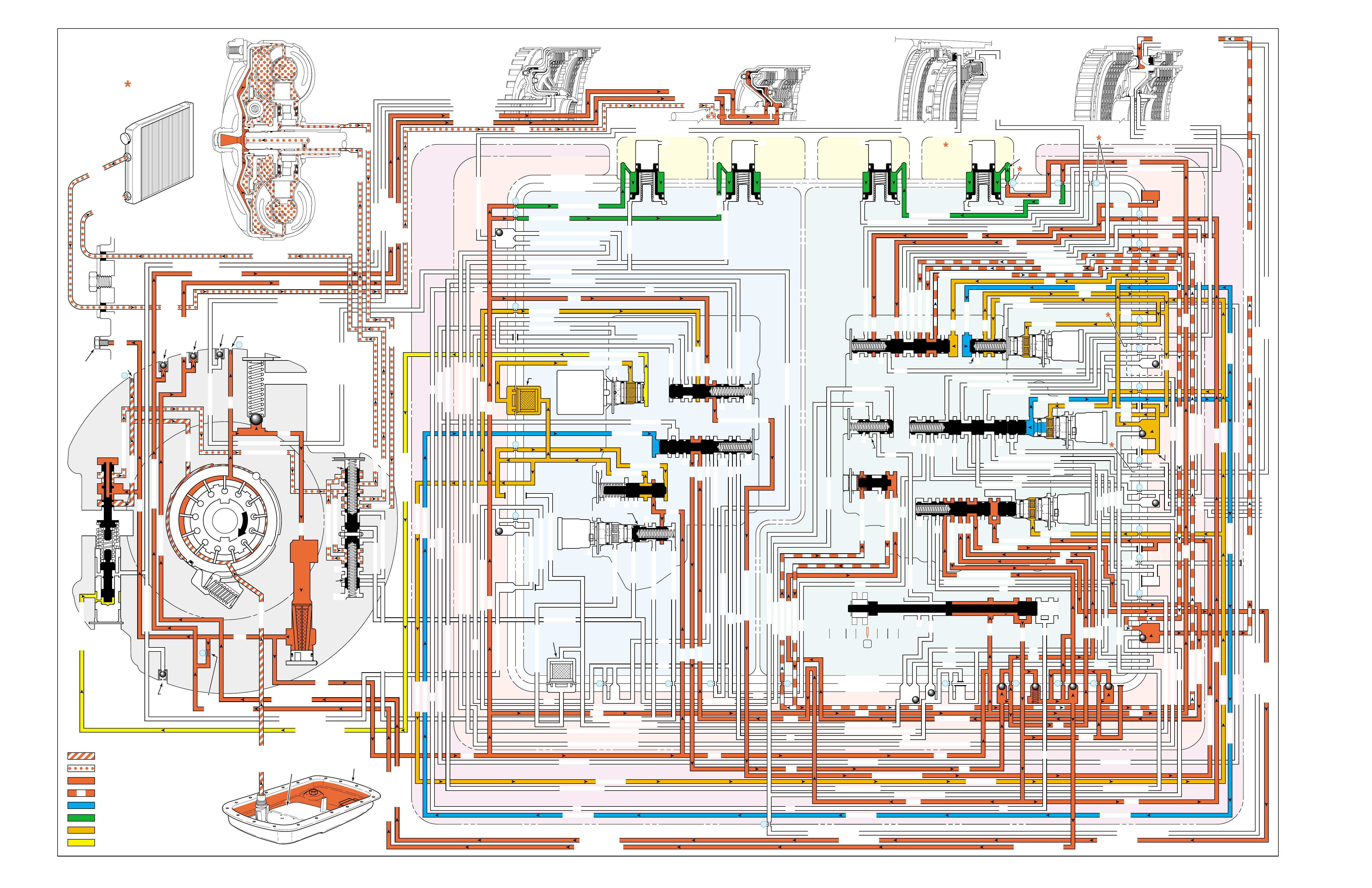
Figure 88
OVERDRIVE RANGE – FIRST GEAR
PRESSURES
INTAKE & DECREASE (SUCTION)
CONVERTER & LUBE
MAINLINE
REGULATED LINE
SOLENOID SIGNAL
ACCUMULATOR
FEED LIMIT
THROTTLE SIGNAL
NOTE:
PASSAGES AND
COMPONENTS
MARKED WITH
ARE USED FOR
THE 5L40-E ONLY
GASKET (309)
GASKET (305)
GASKET (303)
BOTTOM CHANNEL PLATE (304)
TOP CHANNEL PLATE (301)
CASE (24)
REAR CONTROL VALVE BODY (310)
SPACER PLATE (307)
GASKET (309)
GASKET (305)
GASKET (303)
BOTTOM CHANNEL PLATE (304)
TOP CHANNEL PLATE (301)
CASE (24)
FRONT CONTROL VALVE BODY (311)
SPACER PLATE (307)
FLUID
PUMP
COVER
(202)
CONVERTER
HOUSING
(224)
ACCUMULATOR HOUSING (317) ACCUMULATOR HOUSING (323) ACCUMULATOR HOUSING (328) ACCUMULATOR HOUSING (333)
LUBE
LUBE
LUBE
LUBE
TO COOLER
LUBE
TO COOLER
APPLY
APPLY
APPLY
RELEASE
DECREASE
DECREASE
LINE
OVERDRIVE CLUTCH FEED 1
OVERDRIVE CL FD 1OVERDRIVE CLUTCH FEED 1
OVERDRIVE CLUTCH FEED 1 OVERDRIVE CLUTCH FEED 1
OVERDRIVE CLUTCH
2345 2345
2345
2345
2345
2345
2345 OR REVERSE
RLO
LOW AND REV CL OR RLO
LOW AND REV CL OR RLO
SECOND COAST CLUTCH
SECOND CLUTCH
SECOND COAST CLUTCH
SUCTION SUCTION
LINE
LINE
LINE LINE
LINE
LINE
LINE LINE LINE
TCC SIGNAL
CONVERTER FEED
CONVERTER FEED
RELEASE
TO COOLER
REGULATED APPLYREGULATED APPLY
LINE
EX
CONVERTER FEED
REVERSE CLUTCH
REVERSE CLUTCH
THROTTLE SIGNAL
LINE
EX
FILTERED FEED LIMIT
THROTTLE SIGNAL
THROTTLE SIGNAL
THROTTLE SIGNAL
EX
2345 OR REVERSE
2345 OR REVERSE
2345 OR REVERSE
TCC SIGNAL
TCC SIGNAL
TCC SIGNAL
REGULATED APPLY
REGULATED APPLY
REGULATED APPLY
EX
EX
FEED LIMIT VALVE
LINE
EX
EX
EX
EX
FEED LIMIT
FEED LIMIT FEED LIMIT
FEED LIMIT
FEED LIMIT
FEED LIMIT
FEED LIMIT
FEED LIMIT FEED LIMIT
FEED LIMIT
2-3 SHIFT VALVE CNTRL
EX
EX
EX
EX
EX
EX
EX EX
SECOND COAST CLUTCH
23 REGULATED
23 REGULATED
OVERDRIVE CLUTCH FEED 1
INTERMEDIATE CLUTCH
2345
2345
2345
2345
INTERMEDIATE CLUTCH
2345
345
FEED LIMIT
EX
EX
EX
EX
2-3 SIGNAL
123 REGULATED
123 REGULATED
EX
CNTRL
LINE SAFETY MODE
123 BRAKING
123
EX
EX
EX
123
123
123
123
123
123
123
123123
COAST CLUTCH
COAST CLUTCH FEED
OVERDRIVE CLUTCH FEED 2
45
FEED LIMIT
SAFETY MODE
LINE
FEED LIMIT
32
MEMORY
MEMORY
MEMORY
MEMORY PILOT
MEMORY PILOT
32 SAFETY MODE
LINE SAFETY MODE
EX
EX
LINE SAFETY MODE
CNTRL 3-4 SHIFT
2-3 SIGNAL
123123 D432D432
DIRECT CLUTCH
DIRECT CLUTCH
4545
1-2 SIGNAL
EX
EX
EX
1-2 SHIFT VALVE
FDL
FDL
FDL
FDL
FDL
FDL
D432
2345 2345
D432
SECOND CLUTCH
23 REGULATED
23 REGULATED23 REGULATED
123 REGULATED
LOW AND REVERSE CLUTCH
LOW AND REVERSE CL
SECOND CLUTCH
123 REGULATED
EX
EX
EX
FD LIMIT
FEED LIMIT
FDL
1-2 SIGNAL
2-3 SIGNAL
EX
EX
TCC SIGNAL
TCC SIGNAL
TCC SIGNAL
RLO
EX
REV
RPND432
MANUAL VALVE
LINE
D432
D432 D432
D432
D432
D432
D432 D432
D432
D432D432
D432
REV
REVERSE
EX
3232
LINE
EX
EX
LINE
CASE (24)
OVERDRIVE CLUTCH FEED 2
OVERDRIVE CL FD 2
OVERDRIVE CLUTCH FEED 2
ACCUMULATOR
DIRECT CLUTCH
ACCUM
INTERMEDIATE CLUTCH
INTERMEDIATE CLUTCH
INTERMEDIATE CLUTCH
ACCUMULATOR
EX
SECOND CLUTCH
SECOND CLUTCH
ACCUM
ACCUM
LINELINE
FORWARD CLUTCH
FORWARD CLUTCH FORWARD CLUTCH
ACCUMULATOR
LINE
LINELINE
LINE
OVERDRIVE CLUTCH
INTERMEDIATE CL
COAST CLUTCH
REVERSE LOCKOUT
COAST CLUTCH
REVERSE CLUTCH
REVERSE CLUTCH
REVERSE CLUTCH
4-5 SIGNAL
EXEXEX
LINE SAFETY MODE
LINE SAFETY MODE
REVERSE LOCKOUT
REVERSE LOCKOUT REVERSE LOCKOUT
COAST CLUTCH
REVERSE LOCKOUT REVERSE LOCKOUT
REVERSE LOCKOUT
REVERSE LOCKOUT
REVERSE LOCKOUT
REVERSE LOCKOUT
REVERSE CLUTCH
REVERSE CLUTCH
LOW AND REV CL OR RLO
FORWARD CLUTCH
FORWARD CLUTCH
FORWARD CLUTCH
COAST CLUTCH
FORWARD CLUTCH
FORWARD CLUTCH
FORWARD CLUTCH
2345
2345 OR REVERSE
123 REGULATED
123 REGULATED
123 REGULATED 123 REGULATED
123 REGULATED
123 REGULATED
123 REGULATED
123 BRAKING
123 BRAKING
123 BRAKING
123 BRAKING
1-2 SIGNAL1-2 SIGNAL
1-2 SIGNAL1-2 SIGNAL1-2 SIGNAL
1-2 SIGNAL 1-2 SIGNAL 1-2 SIGNAL
2-3 SIGNAL2-3 SIGNAL2-3 SIGNAL
2-3 SIGNAL 2-3 SIGNAL
2-3 SIGNAL2-3 SIGNAL2-3 SIGNAL
2-3 SIGNAL
SECOND CLUTCH
SECOND CLUTCH
COAST CLUTCHCOAST CLUTCHCOAST CLUTCH
COAST CLUTCH
COAST CLUTCH
COAST CLUTCH
COAST CLUTCH
COAST CLUTCH
23 REGULATED
345
345
345
345 345 345
345
345
345
345
345
345
345
345
DIRECT CLUTCH
DIRECT CLUTCH
DIRECT CLUTCH
DIRECT CL
DIRECT CLUTCH
DIRECT CLUTCH
DIRECT CLUTCH
DIRECT CLUTCH
45
45
45
4545
45
OVERDRIVE CLUTCH
OVERDRIVE CL FD 1
OVERDRIVE CLUTCH FEED 2OVERDRIVE CLUTCH FEED 2
OVERDRIVE CL FD 2
OVERDRIVE CLUTCH FEED 2 OVERDRIVE CL FD 2
3232
32 32 32
323232
32 SAFETY MODE
32 SAFETY MODE 32 SAFETY MODE 32 SAFETY MODE
32 SAFETY MODE32 SAFETY MODE
32 SM 32 SM
FDL
PRESSURE
CONTROL
SOLENOID
VALVE
1-2 SHIFT
SOLENOID
VALVE
N/C
(A)
OFF
2-3 SHIFT
SOLENOID
VALVE
N/C
(B)
ON
4-5 SHIFT
SOLENOID
VALVE
N/C
(C)
OFF
TCC PWM
SOLENOID
VALVE
N/C
PRESS REG VALVEBOOST VALVE
CONVERTER FDL
4-5 SHIFT VLV
LOW PRESSURE
AIR
BLEED
(233)
AIR
BLEED
(233)
AIR
BLEED
(203)
AIR
BLEED
(203)
AIR
BLEED
(203)
AIR
BLEED
(203)
7
4
2
1
5
6
11
10
9
12
18
FILTER
(308)
FILTER
(312)
TCC REGULATOR VALVE
TCC
CONTROL
VALVE
TCC
ENABLE
VALVE
REVERSE
LOCKOUT
VALVE
1-2 SHIFT CONTROL VALVE
FLUID
PAN
(62)
FLUID FILTER
ASSEMBLY
(59)
FLUID
PRESSURE
TEST PLUG
(40)
TORQUE
CONVERTER
ASSEMBLY
(1)
DIRECT
CLUTCH
ACCUMULATOR
OVERDRIVE
CLUTCH
ACCUMULATOR
INTERMEDIATE
CLUTCH
ACCUMULATOR
SECOND
CLUTCH
ACCUMULATOR
COOLER
PRESSURE
RELIEF
BALL
VALVE
21 2
10d
2a
2b
42b
43a
37d
39b
40b
37c
40d
11b
10a
24a
10c
11a 10b
54b
54d
2c
54a
54c
27c 46
7a
24b
20a
13a
37b
38a
7b
47a
47b
27b
28c
12a
23a
36e
36f
23b
23c
15a
24c
26b
36a
38c
38d
36b
25a
15
2m 54g
54f
#8
18
15f
15e
17c
17b
17a
27a
44a
44e
44d
44b
25c
30a
33a
25e
19e
35c
19h
19f
10f
10h
10g
22a
35b
#7
13b
32a
26a
10i
22f
22d
43b
22b
34a
48b
39a
22c
X-1
22
22e
21a
42a
19a
20b
19b
#2
23 22g
14a
2f
2h
19g
19i
19
j
DIRECT
AND REVERSE
CLUTCH
ASSEMBLY
(400–420)
FORWARD
AND COAST
CLUTCH
ASSEMBLY
(430–451)
OVERDRIVE
AND
INTERMEDIATE
CLUTCH
ASSEMBLY
(480–497)
CENTER
SUPPORT
ASSEMBLY
(510–535)
3
2d54e
2e
30c
30d
35d
26
37a
13
#1
15c
15b
16
15d 16
15
X-2
16a
X-4 X-5
38
14
X-3
19
#6
19d
19
21
19c 21
15
#5
21b 31
21c 31
17
21
#4
20d
20c
16
25b
19
25d
20
36 46
28a
44c
28b
30b
21
#11
33e
33d
23
2435a
#9
33c
33b
22
36d
36c
25
#12
41 40c
39c
43 13
2840a
#10
45
45
45
44f
44
48
43c
#3
38b
38e
27
48a29
8
10e
2310
32 SM/FDL
30
31
FLUID PUMP
SCREEN
ASSEMBLY
(213)
(214)
92

92A
OVERDRIVE RANGE – FIRST GEAR
LOSS OF DRIVE
•Fluid Pump (202)
–Seized
•Forward Clutch Piston (436)
–Jammed or cracked
–Leaking
•Forward Clutch Input Housing (433)
–Passage plugged
•Forward Clutch Housing Ball Check Valve (434)
–Leaking
•Forward Clutch Sprag (461)
–Not Holding
•Input Shaft Fluid Seal (432)
–Leaking
FIRST, FOURTH AND FIFTH GEAR ONLY
•1-2 Shift Solenoid Valve (368)
–Stuck Off
–Loose connector
–No voltage
–Leaking
•1-2 Shift Valve (387)
–Stuck
•1-2 Shift Control Valve (366)
–Stuck
THIRD, FOURTH AND FIFTH GEAR ONLY
•2-3 Shift Solenoid Valve (369)
–Stuck Off
–Loose connector
–No voltage
–Leaking
•2-3 Shift Valve (371)
–Stuck
•2-3 Shift Control Valve (370)
–Stuck
FIRST, SECOND, THIRD AND FIFTH GEAR ONLY
•4-5 Shift Solenoid Valve (376)
–Stuck Off
–Loose connector
–No voltage
–Leaking
•4-5 Shift Valve (374)
–Stuck
•4-5 Shift Control Valve (375)
–Stuck
SOLENOID FORWARD OVER- INTERM. INTER- LOW LOW AND SECOND SECOND
DIRECT REVERSE COAST FORWARD SPRAG DRIVE SPRAG MEDIATE SPRAG REVERSE SECOND SPRAG COAST
1-2 2-3 4-5 CLUTCH CLUTCH CLUTCH CLUTCH CLUTCH CLUTCH CLUTCH CLUTCH CLUTCH CLUTCH CLUTCH CLUTCH CLUTCH
OFF ON OFF APPLIED APPLIED LD LD
*
APPLIED
LD = LOCKED IN DRIVE
*
APPLIED BEFORE THE FIRST 1-2 SHIFT HAS OCCURRED

92B
PASSAGES
1 SUCTION
2 LINE
3 DECREASE
4 CONVERTER FEED
5 RELEASE
6 APPLY
7 REGULATED APPLY
8 TO COOLER
9 LUBE
10 FEED LIMIT
11 FILTERED FEED LIMIT
12 THROTTLE SIGNAL
13 LINE SAFETY MODE
14 REVERSE
15 REVERSE LOCK OUT (RLO)
16 REVERSE CLUTCH
17 LOW AND REVERSE CLUTCH
18 LOW AND REVERSE CLUTCH OR RLO
19 D432
20 123
21 FORWARD CLUTCH
22 2345
23 2345 OR REVERSE
24 TCC SIGNAL
25 123 REGULATED
26 123 BRAKING
27 1-2 SIGNAL
28 2-3 SIGNAL
29 4-5 SIGNAL
30 SECOND CLUTCH
31 COAST CLUTCH FEED
32 COAST CLUTCH
33 23 REGULATED
34 SECOND COAST CLUTCH
35 INTERMEDIATE CLUTCH
36 345
37 DIRECT CLUTCH
38 45
39 OVERDRIVE CLUTCH FEED 1
40 OVERDRIVE CLUTCH FEED 2
41 OVERDRIVE CLUTCH
42 32
43 32 SAFETY MODE
44 FDL
45 32 SAFETY MODE/FDL
46 MEMORY PILOT
47 MEMORY
48 EXHAUST
49 OIL RESERVOIR
50 TORQUE CONVERTER SEAL DRAINBACK
51 VENT
52 VOID
53 CONVERTER FDL
54 ACCUMULATOR
COMPONENTS ( )
(36) TRANSMISSION FLUID LEVEL HOLE PLUG
(40) TRANSMISSION FLUID PRESSURE TEST PLUG
(203) CHECK VALVE RETAINER AND BALL ASSEMBLY
(213) TRANSMISSION FLUID PUMP SCREEN ASSEMBLY
(214) BRASS ORIFICE INSERT
(232) ORIFICE SLEEVE
(233) ORIFICE CUP PLUG
(306) CONTROL VALVE BODY BALL CHECK VALVE
(#1, 2, 3, 4, 5, 6, 7, 8, 9, 10, 11, 12)
(308) TCC PWM SOLENOID VALVE FILTER ASSEMBLY
(312) PRESSURE CONTROL SOLENOID VALVE
FILTER ASSEMBLY
OVERDRIVE RANGE – FIRST GEAR
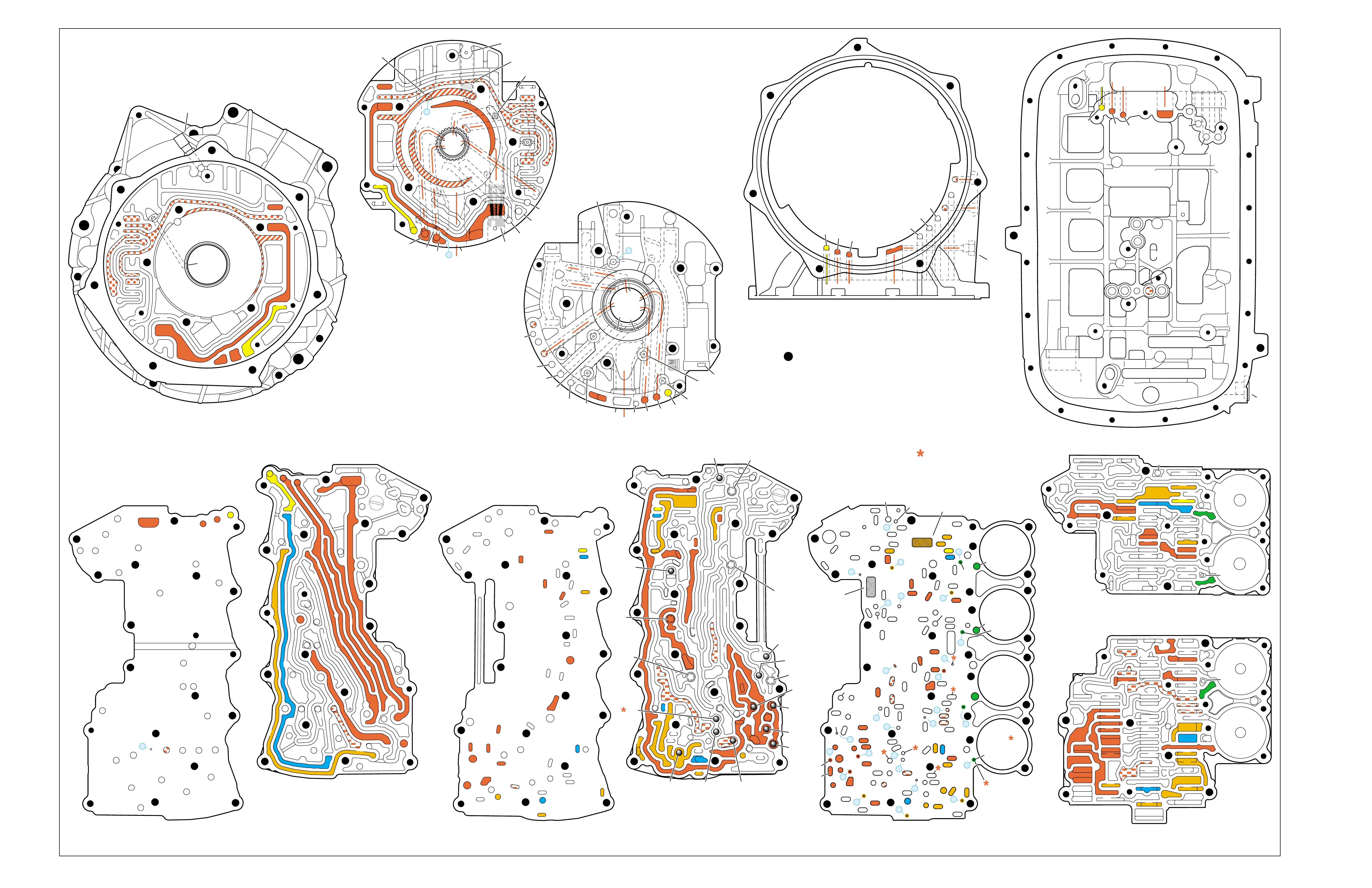
Figure 89
OVERDRIVE RANGE – FIRST GEAR
➤
➤➤
➤
➤➤
➤
➤
➤
➤➤
➤
➤➤
➤
➤
➤
➤
➤ ➤
➤➤
➤
➤
➤
TORQUE CONVERTER HOUSING (227)
(Fluid Pump Cover Side)
➤
➤
➤
➤
➤➤➤
➤
➤
➤ ➤
➤
➤
TOP CHANNEL PLATE (301)
(Case Side)
FRONT
➤
TOP CHANNEL PLATE (301)
(Bottom Channel Plate Side)
FRONT
➤
BOTTOM CHANNEL PLATE (304)
(Top Channel Plate Side)
FRONT
➤
REAR CONTROL VALVE BODY (310)
(Bottom Channel Plate Side)
FRONT
➤
CASE (24)
(Top Channel Plate Side)
FRONT
➤
CASE (24)
(Fluid Pump Cover Side)
SPACER PLATE (307)
(Bottom Channel Plate Side)
FRONT
➤
FRONT CONTROL VALVE BODY (311)
(Bottom Channel Plate Side)
FRONT
➤
BOTTOM CHANNEL PLATE (304)
(Control Valve Body Side)
FRONT
➤
NOTE:
–INDICATES BOLT HOLES
–NON FUNCTIONAL HOLES HAVE BEEN
REMOVED FROM COMPONENT DRAWINGS
TO SIMPLIFY TRACING FLUID FLOW.
–DUAL PURPOSE PASSAGES HAVE
CHANNEL PLATE SIDE NUMBERS LISTED FIRST
–EXHAUST FLUID NOT SHOWN
–PASSAGES MARKED WITH ARE USED FOR
THE 5L40-E ONLY
FLUID PUMP COVER (202)
(Case Side)
FLUID PUMP COVER (202)
(Torque Converter Housing Side)
➤
➤
➤
➤
➤
➤
➤ ➤
➤
➤
➤➤
➤
➤
➤
7
➤
25
➤
27
➤
3
➤
20
➤
16
➤
2
➤
10
➤
9
➤
24
➤
15
➤
11
➤
22
➤
29
➤
28
➤
23
➤
18
➤
17
➤
14
➤
8
➤
4
➤
5
➤
26
➤
13
➤
19
➤
21
➤
6
➤
12
(40)
➤
21
(203)
➤
16
(203)
➤➤
(232)
➤➤
(229)
➤➤
(231)
➤➤
(213)
➤
(233)
➤
TRANSMISSION
VENT
ASSEMBLY
➤➤
32
(203)
➤
37
(203)
➤➤
2/21
(214)
➤➤
(36)
➤
FILTER
(312)
➤
FILTER
(308)
➤
#12
#2
#3
#5
#6
#7
(Spring)
#8
#10 #9
#4
#1
#11
X-2
X-4
X-5
X-1
X-3
12
2
23
24
48
48
48
48
48
48
48
48
52
52
52
52
52
52
52
23
36
36
36
20
27
28
46
47
47
19
16
15
13
10
10
10
11
54
2
54
37
37
37
39
38
40
42
43
40
27
7
48
48
48
52
52
52
52
52
52
52
24
25
25
25
2525
26
26
15 19 19
19
19
31
21
20 20
15 17
17
14
13
14
54
22
22
28
28
22
22
32
42 43
44
44
48
48
48
48
48
48
44
44
38
39
38
33
33
30
35
40
35
35
36
35
34
30
30
30
33
2
2
10
10 10
10
27
2
216
24
15
18
7
32
52
52
52
52 52
52
52
52
52
52
52
52
52 52
52
52
52
52
30 34
35
41
12 21 37
8
9
2
16
24
7
32
12 21
37
12
21
21
24
848
7
9
9
52
52
2
16
5
16
37
32
32
52
1
52
52
52
48
37
1
2
51
51
52
12
12
24
24
52
2
2
4
4
4
4
5
66
8
8
7
7
7
5
9
48
48
48
48
48
48
48
48
53
53
48
52
2
3
3
3
2
1
16
21
21
16
32
37
32
51
50
50
51 52
52
52
52
52
52
48
48
48
48
52
48
48
12
12
24
24
2
2
3
2
4
4
4
5
6
53
53
8
8
7
7
7
48
16
16
21 32
37
➤➤
1
➤➤
31
➤➤
30
(233)
➤➤
33
32
38
38
38
30
30
24
37
37
37
40
40
12
16
15
15
23 52
24
24
23
28
47
41
42
43
27
28
28
27
27
25
25
26
22
22
15
13
18 19
19
19
19
19
19
19
21
17
17
22
23
23
48
48
48
48
48
48
48
48
48
15
13
36
36
36
36
39
35
35
34
10
10 11
10
10
10
20
20
48
44
44
45
43 42
52
48
48
77
2
2
2
2
2
2
2
52
52
12a
16a
15d/16 15c/16
15b
23c
24a 24b
24c
25b
25c 25d
25e
26b
26a
32a
30a
33a
35a
39a
36a
36b
36c
36d
38a 39b
39c/41
40c/41
36e
36f
35b
35c 35d
37c
37d
37b
37a
40b
40a
38d 38b
38c
38e
40d
34a
33e
33c
33d
33b
30b
30c 30d
25a
23b
23a
20a
28c
27c/46
27b
28b
28a
27a
47b
47a
20b
20d
20c
13a
15a
19e
19h
19g
19i
19j
19f
13b 15e
17a
17b
17c/18
15f/18
19b/21
19c/21
19d/21
19a
22a
22b
22c
22d
22f
21a
21b/31
21c/31
22g/23
14a/23
22e
48
48
48
48
48
48
48
52
52
52
52
52
52
52
52
48
48
2g
7a
7b 2a/54a
2b
42b
43a
42a
43b
44c
44d 44b
44a
44e
43c/45
44f/45
48a 48b
2c/54c
54d
2d/54e
2e 2m/54g
2f
10i
10h
10f
10e
10d
10a 10c
11b
11a/10b
10g
2h
54f
54b
48
32
38
30
24 12
16
13
15
15
13
18
19
19
19
21
21
22
16 48
48
48
48
48
48
48
48
36
35
35
34
2
2
7
2
10
10
10
10
41
42
43
43
42
48 48
20
28
27
37
27
28
28
27
20
48
52
52
32
32
32
38
24
12 16
16
18
28
28
28
27
27
48 48
43 42
42
43
48
30
48
48
48 48
48
48
48
48
48
48
48
48
35
36
37
34
2
7
2
10
13
13
15
19
41
41
19
19
15
22
21
21
20
20
21
21
13
10
10
10
2
48
48 48
52
52
52
52
52
52
12
32
37 21
24
2
16
18
48
48
48
48
48
30
48
48
48
48
48
48
15
35
41
34
7
52
52
52
52
52
52
FOLDOUT ➤ 93
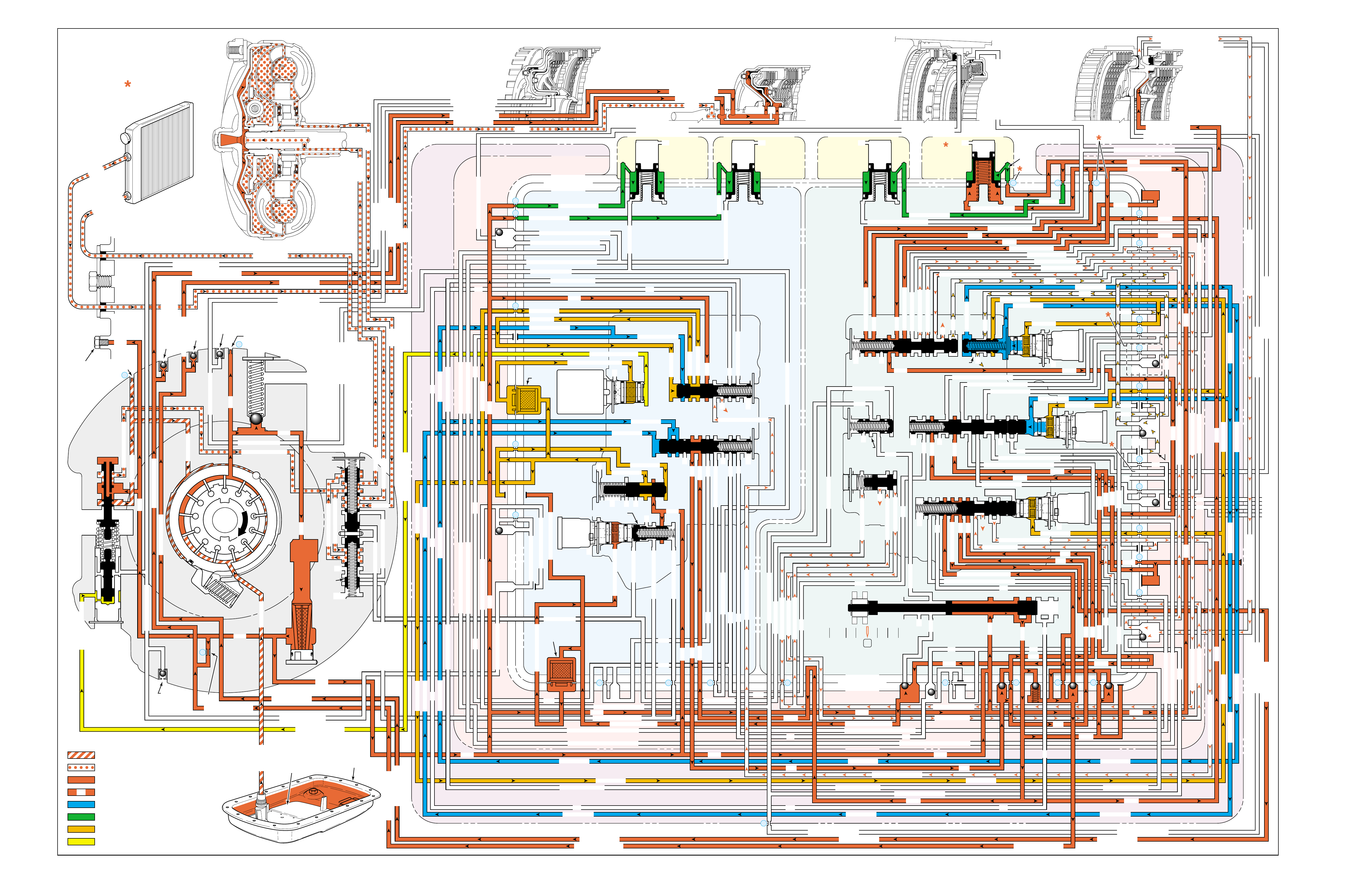
Figure 90
OVERDRIVE RANGE – SECOND GEAR
PRESSURES
INTAKE & DECREASE (SUCTION)
CONVERTER & LUBE
MAINLINE
REGULATED LINE
SOLENOID SIGNAL
ACCUMULATOR
FEED LIMIT
THROTTLE SIGNAL
NOTE:
PASSAGES AND
COMPONENTS
MARKED WITH
ARE USED FOR
THE 5L40-E ONLY
GASKET (309)
GASKET (305)
GASKET (303)
BOTTOM CHANNEL PLATE (304)
TOP CHANNEL PLATE (301)
CASE (24)
REAR CONTROL VALVE BODY (310)
SPACER PLATE (307)
GASKET (309)
GASKET (305)
GASKET (303)
BOTTOM CHANNEL PLATE (304)
TOP CHANNEL PLATE (301)
CASE (24)
FRONT CONTROL VALVE BODY (311)
SPACER PLATE (307)
FLUID
PUMP
COVER
(202)
CONVERTER
HOUSING
(224)
ACCUMULATOR HOUSING (317) ACCUMULATOR HOUSING (323) ACCUMULATOR HOUSING (328) ACCUMULATOR HOUSING (333)
LUBE
LUBE
LUBE
LUBE
TO COOLER
LUBE
TO COOLER
APPLY
APPLY
APPLY
RELEASE
DECREASE
DECREASE
LINE
OVERDRIVE CLUTCH FEED 1
OVERDRIVE CL FD 1OVERDRIVE CLUTCH FEED 1
OVERDRIVE CLUTCH FEED 1 OVERDRIVE CLUTCH FEED 1
OVERDRIVE CLUTCH
2345 2345
2345
2345
2345
2345
2345 OR REVERSE
RLO
LOW AND REV CL OR RLO
LOW AND REV CL OR RLO
SECOND COAST CLUTCH
SECOND CLUTCH
SECOND COAST CLUTCH
SUCTION SUCTION
LINE
LINE
LINE LINE
LINE
LINE
LINE LINE LINE
TCC SIGNAL
CONVERTER FEED
CONVERTER FEED
RELEASE
TO COOLER
REGULATED APPLYREGULATED APPLY
LINE
EX
CONVERTER FEED
REVERSE CLUTCH
REVERSE CLUTCH
THROTTLE SIGNAL
LINE
EX
FILTERED FEED LIMIT
THROTTLE SIGNAL
THROTTLE SIGNAL
THROTTLE SIGNAL
EX
2345 OR REVERSE
2345 OR REVERSE
2345 OR REVERSE
TCC SIGNAL
TCC SIGNAL
TCC SIGNAL
REGULATED APPLY
REGULATED APPLY
REGULATED APPLY
EX
EX
FEED LIMIT VALVE
LINE
EX
EX
EX
EX
FEED LIMIT
FEED LIMIT FEED LIMIT
FEED LIMIT
FEED LIMIT
FEED LIMIT
FEED LIMIT
FEED LIMIT FEED LIMIT
FEED LIMIT
2-3 SHIFT VALVE CNTRL
EX
EX
EX
EX
EX
EX
EX EX
SECOND COAST CLUTCH
23 REGULATED
23 REGULATED
OVERDRIVE CLUTCH FEED 1
INTERMEDIATE CLUTCH
2345
2345
2345
2345
INTERMEDIATE CLUTCH
2345
345
FEED LIMIT
EX
EX
EX
EX
2-3 SIGNAL
LOW PRESSURE
123 REGULATED
123 REGULATED
EX
4-5 SHIFT VLV CNTRL
LINE SAFETY MODE
123 BRAKING
123
EX
EX
EX
123
123
123
123
123
123
123
123123
COAST CLUTCH
COAST CLUTCH FEED
OVERDRIVE CLUTCH FEED 2
45
FEED LIMIT
SAFETY MODE
LINE
FEED LIMIT
32
MEMORY
MEMORY
MEMORY
MEMORY PILOT
MEMORY PILOT
32 SAFETY MODE
LINE SAFETY MODE
EX
EX
LINE SAFETY MODE
CNTRL 3-4 SHIFT
2-3 SIGNAL
123123 D432D432
DIRECT CLUTCH
DIRECT CLUTCH
4545
1-2 SIGNAL
EX
EX
EX
FDL
FDL
FDL
FDL
FDL
FDL
D432
2345 2345
D432
SECOND CLUTCH
23 REGULATED
23 REGULATED23 REGULATED
123 REGULATED
LOW AND REVERSE CLUTCH
LOW AND REVERSE CL
SECOND CLUTCH
123 REGULATED
EX
EX
EX
FD LIMIT
FEED LIMIT
FDL
1-2 SIGNAL
2-3 SIGNAL
EX
EX
TCC SIGNAL
TCC SIGNAL
TCC SIGNAL
RLO
EX
REV
RPND432
MANUAL VALVE
LINE
D432
D432 D432
D432
D432
D432
D432 D432
D432
D432D432
D432
REV
REVERSE
EX
3232
LINE
EX
EX
LINE
CASE (24)
OVERDRIVE CLUTCH FEED 2
OVERDRIVE CL FD 2
OVERDRIVE CLUTCH FEED 2
ACCUMULATOR
DIRECT CLUTCH
ACCUM
INTERMEDIATE CLUTCH
INTERMEDIATE CLUTCH
INTERMEDIATE CLUTCH
ACCUMULATOR
EX
SECOND CLUTCH
SECOND CLUTCH
ACCUM
ACCUM
LINELINE
FORWARD CLUTCH
FORWARD CLUTCH FORWARD CLUTCH
ACCUMULATOR
LINE
LINELINE
LINE
OVERDRIVE CLUTCH
INTERMEDIATE CL
COAST CLUTCH
REVERSE LOCKOUT
COAST CLUTCH
REVERSE CLUTCH
REVERSE CLUTCH
REVERSE CLUTCH
4-5 SIGNAL
EXEXEX
LINE SAFETY MODE
LINE SAFETY MODE
REVERSE LOCKOUT
REVERSE LOCKOUT REVERSE LOCKOUT
COAST CLUTCH
REVERSE LOCKOUT REVERSE LOCKOUT
REVERSE LOCKOUT
REVERSE LOCKOUT
REVERSE LOCKOUT
REVERSE LOCKOUT
REVERSE CLUTCH
REVERSE CLUTCH
LOW AND REV CL OR RLO
FORWARD CLUTCH
FORWARD CLUTCH
FORWARD CLUTCH
COAST CLUTCH
FORWARD CLUTCH
FORWARD CLUTCH
FORWARD CLUTCH
2345
2345 OR REVERSE
123 REGULATED
123 REGULATED
123 REGULATED 123 REGULATED
123 REGULATED
123 REGULATED
123 REGULATED
123 BRAKING
123 BRAKING
123 BRAKING
123 BRAKING
1-2 SIGNAL1-2 SIGNAL
1-2 SIGNAL1-2 SIGNAL1-2 SIGNAL
1-2 SIGNAL 1-2 SIGNAL 1-2 SIGNAL
2-3 SIGNAL2-3 SIGNAL2-3 SIGNAL
2-3 SIGNAL 2-3 SIGNAL
2-3 SIGNAL2-3 SIGNAL2-3 SIGNAL
2-3 SIGNAL
SECOND CLUTCH
SECOND CLUTCH
COAST CLUTCHCOAST CLUTCHCOAST CLUTCH
COAST CLUTCH
COAST CLUTCH
COAST CLUTCH
COAST CLUTCH
COAST CLUTCH
23 REGULATED
345
345
345
345 345 345
345
345
345
345
345
345
345
345
DIRECT CLUTCH
DIRECT CLUTCH
DIRECT CLUTCH
DIRECT CL
DIRECT CLUTCH
DIRECT CLUTCH
DIRECT CLUTCH
DIRECT CLUTCH
45
45
45
4545
45
OVERDRIVE CLUTCH
OVERDRIVE CL FD 1
OVERDRIVE CLUTCH FEED 2OVERDRIVE CLUTCH FEED 2
OVERDRIVE CL FD 2
OVERDRIVE CLUTCH FEED 2 OVERDRIVE CL FD 2
3232
32 32 32
323232
32 SAFETY MODE
32 SAFETY MODE 32 SAFETY MODE 32 SAFETY MODE
32 SAFETY MODE32 SAFETY MODE
32 SM 32 SM
FDL
PRESSURE
CONTROL
SOLENOID
VALVE
1-2 SHIFT
SOLENOID
VALVE
N/C
(A)
ON
2-3 SHIFT
SOLENOID
VALVE
N/C
(B)
ON
4-5 SHIFT
SOLENOID
VALVE
N/C
(C)
OFF
TCC PWM
SOLENOID
VALVE
N/C
PRESS REG VALVEBOOST VALVE
CONVERTER FDL
1-2 SHIFT VALVE
AIR
BLEED
(233)
AIR
BLEED
(233)
AIR
BLEED
(203)
AIR
BLEED
(203)
AIR
BLEED
(203)
AIR
BLEED
(203)
7
4
2
1
5
6
11
10
9
12
18
FILTER
(308)
FILTER
(312)
TCC REGULATOR VALVE
TCC
CONTROL
VALVE
TCC
ENABLE
VALVE
REVERSE
LOCKOUT
VALVE
1-2 SHIFT CONTROL VALVE
FLUID
PAN
(62)
FLUID FILTER
ASSEMBLY
(59)
FLUID
PRESSURE
TEST PLUG
(40)
TORQUE
CONVERTER
ASSEMBLY
(1)
DIRECT
CLUTCH
ACCUMULATOR
OVERDRIVE
CLUTCH
ACCUMULATOR
INTERMEDIATE
CLUTCH
ACCUMULATOR
SECOND
CLUTCH
ACCUMULATOR
COOLER
PRESSURE
RELIEF
BALL
VALVE
21 2
10d
2a
2b
42b
43a
37d
39b
40b
37c
40d
11b
10a
24a
10c
11a 10b
54b
54d
2c
54a
54c
27c 46
7a
24b
20a
13a
37b
38a
7b
47a
47b
27b
28c
12a
23a
36e
36f
23b
23c
15a
24c
26b
36a
38c
38d
36b
25a
15
2m 54g
54f
#8
18
15f
15e
17c
17b
17a
27a
44a
44e
44d
44b
25c
30a
33a
25e
19e
35c
19h
19f
10f
10h
10g
22a
35b
#7
13b
32a
26a
10i
22f
22d
43b
22b
34a
48b
39a
22c
X-1
22
22e
21a
42a
19a
20b
19b
#2
23 22g
14a
2f
2h
19g
19i
19
j
DIRECT
AND REVERSE
CLUTCH
ASSEMBLY
(400–420)
FORWARD
AND COAST
CLUTCH
ASSEMBLY
(430–451)
OVERDRIVE
AND
INTERMEDIATE
CLUTCH
ASSEMBLY
(480–497)
CENTER
SUPPORT
ASSEMBLY
(510–535)
3
2d54e
2e
30c
30d
35d
26
37a
13
#1
15c
15b
16
15d 16
15
X-2
16a
X-4 X-5
38
14
X-3
19
#6
19d
19
21
19c 21
15
#5
21b 31
21c 31
17
21
#4
20d
20c
16
25b
19
25d
20
36 46
28a
44c
28b
30b
21
#11
33e
33d
23
2435a
#9
33c
33b
22
36d
36c
25
#12
41 40c
39c
43 13
2840a
#10
45
45
45
44f
44
48
43c
#3
38b
38e
27
48a29
8
10e
2310
32 SM/FDL
30
31
FLUID PUMP
SCREEN
ASSEMBLY
(213)
(214)
94

94A
OVERDRIVE RANGE – SECOND GEAR
NO SECOND GEAR
•Center Support (518)
–Cracked
–Feed hole blocked
•Fluid Passage Sleeve (38)
–Leaking
•Second Clutch Piston (520)
–Cracked or jammed
–Leaking seals
•Second Clutch Sprag (547)
–Not holding
•1-2 Shift Solenoid Valve (368)
–Stuck Off
–Leaking
–No voltage supply
•1-2 Shift Valve (387)
–Stuck
•1-2 Shift Control Valve (366)
–Stuck
•Second Clutch Accumulator
–Leaking
SOLENOID FORWARD OVER- INTERM. INTER- LOW LOW AND SECOND SECOND
DIRECT REVERSE COAST FORWARD SPRAG DRIVE SPRAG MEDIATE SPRAG REVERSE SECOND SPRAG COAST
1-2 2-3 4-5 CLUTCH CLUTCH CLUTCH CLUTCH CLUTCH CLUTCH CLUTCH CLUTCH CLUTCH CLUTCH CLUTCH CLUTCH CLUTCH
ON ON OFF APPLIED APPLIED LD APPLIED LD
LD = LOCKED IN DRIVE

94B
PASSAGES
1 SUCTION
2 LINE
3 DECREASE
4 CONVERTER FEED
5 RELEASE
6 APPLY
7 REGULATED APPLY
8 TO COOLER
9 LUBE
10 FEED LIMIT
11 FILTERED FEED LIMIT
12 THROTTLE SIGNAL
13 LINE SAFETY MODE
14 REVERSE
15 REVERSE LOCK OUT (RLO)
16 REVERSE CLUTCH
17 LOW AND REVERSE CLUTCH
18 LOW AND REVERSE CLUTCH OR RLO
19 D432
20 123
21 FORWARD CLUTCH
22 2345
23 2345 OR REVERSE
24 TCC SIGNAL
25 123 REGULATED
26 123 BRAKING
27 1-2 SIGNAL
28 2-3 SIGNAL
29 4-5 SIGNAL
30 SECOND CLUTCH
31 COAST CLUTCH FEED
32 COAST CLUTCH
33 23 REGULATED
34 SECOND COAST CLUTCH
35 INTERMEDIATE CLUTCH
36 345
37 DIRECT CLUTCH
38 45
39 OVERDRIVE CLUTCH FEED 1
40 OVERDRIVE CLUTCH FEED 2
41 OVERDRIVE CLUTCH
42 32
43 32 SAFETY MODE
44 FDL
45 32 SAFETY MODE/FDL
46 MEMORY PILOT
47 MEMORY
48 EXHAUST
49 OIL RESERVOIR
50 TORQUE CONVERTER SEAL DRAINBACK
51 VENT
52 VOID
53 CONVERTER FDL
54 ACCUMULATOR
COMPONENTS ( )
(36) TRANSMISSION FLUID LEVEL HOLE PLUG
(40) TRANSMISSION FLUID PRESSURE TEST PLUG
(203) CHECK VALVE RETAINER AND BALL ASSEMBLY
(213) TRANSMISSION FLUID PUMP SCREEN ASSEMBLY
(214) BRASS ORIFICE INSERT
(232) ORIFICE SLEEVE
(233) ORIFICE CUP PLUG
(306) CONTROL VALVE BODY BALL CHECK VALVE
(#1, 2, 3, 4, 5, 6, 7, 8, 9, 10, 11, 12)
(308) TCC PWM SOLENOID VALVE FILTER ASSEMBLY
(312) PRESSURE CONTROL SOLENOID VALVE
FILTER ASSEMBLY
OVERDRIVE RANGE – SECOND GEAR

Figure 91
OVERDRIVE RANGE – SECOND GEAR
➤
➤➤
➤
➤➤
➤
➤
➤
➤➤
➤
➤➤
➤
➤
➤
➤
➤ ➤
➤➤
➤
➤
➤
TORQUE CONVERTER HOUSING (227)
(Fluid Pump Cover Side)
➤
➤
➤
➤
➤➤➤
➤
➤
➤ ➤
➤
➤
TOP CHANNEL PLATE (301)
(Case Side)
FRONT
➤
TOP CHANNEL PLATE (301)
(Bottom Channel Plate Side)
FRONT
➤
BOTTOM CHANNEL PLATE (304)
(Top Channel Plate Side)
FRONT
➤
REAR CONTROL VALVE BODY (310)
(Bottom Channel Plate Side)
FRONT
➤
CASE (24)
(Top Channel Plate Side)
FRONT
➤
CASE (24)
(Fluid Pump Cover Side)
SPACER PLATE (307)
(Bottom Channel Plate Side)
FRONT
➤
FRONT CONTROL VALVE BODY (311)
(Bottom Channel Plate Side)
FRONT
➤
BOTTOM CHANNEL PLATE (304)
(Control Valve Body Side)
FRONT
➤
NOTE:
–INDICATES BOLT HOLES
–NON FUNCTIONAL HOLES HAVE BEEN
REMOVED FROM COMPONENT DRAWINGS
TO SIMPLIFY TRACING FLUID FLOW.
–DUAL PURPOSE PASSAGES HAVE
CHANNEL PLATE SIDE NUMBERS LISTED FIRST
–EXHAUST FLUID NOT SHOWN
–PASSAGES MARKED WITH ARE USED FOR
THE 5L40-E ONLY
FLUID PUMP COVER (202)
(Case Side)
FLUID PUMP COVER (202)
(Torque Converter Housing Side)
➤
➤
➤
➤
➤
➤
➤ ➤
➤
➤
➤➤
➤
➤
➤
7
➤
25
➤
27
➤
3
➤
20
➤
16
➤
2
➤
10
➤
9
➤
24
➤
15
➤
11
➤
22
➤
29
➤
28
➤
23
➤
18
➤
17
➤
14
➤
8
➤
4
➤
5
➤
26
➤
13
➤
19
➤
21
➤
6
➤
12
(40)
➤
21
(203)
➤
16
(203)
➤➤
(232)
➤➤
(229)
➤➤
(231)
➤➤
(213)
➤
(233)
➤
TRANSMISSION
VENT
ASSEMBLY
➤➤
32
(203)
➤
37
(203)
➤➤
2/21
(214)
➤➤
(36)
➤
FILTER
(312)
➤
FILTER
(308)
➤
#12
#2
#3
#5
#6
#7
(Spring)
#8
#10 #9
#4
#1
#11
X-2
X-4
X-5
X-1
X-3
12
2
23
24
48
48
48
48
48
48
48
48
52
52
52
52
52
52
52
23
36
36
36
20
27
28
46
47
47
19
16
15
13
10
10
10
11
54
2
54
37
37
37
39
38
40
42
43
40
27
7
48
48
48
52
52
52
52
52
52
52
24
25
25
25
2525
26
26
15 19 19
19
19
31
21
20 20
15 17
17
14
13
14
54
22
22
28
28
22
22
32
42 43
44
44
48
48
48
48
48
48
44
44
38
39
38
33
33
30
35
40
35
35
36
35
34
30
30
30
33
2
2
10
10 10
10
27
2
216
24
15
18
7
32
52
52
52
52 52
52
52
52
52
52
52
52
52 52
52
52
52
52
30 34
35
41
12 21 37
8
9
2
16
24
7
32
12 21
37
12
21
21
24
848
7
9
9
52
52
2
16
5
16
37
32
32
52
1
52
52
52
48
37
1
2
51
51
52
12
12
24
24
52
2
2
4
4
4
4
5
66
8
8
7
7
7
5
9
48
48
48
48
48
48
48
48
53
53
48
52
2
3
3
3
2
1
16
21
21
16
32
37
32
51
50
50
51 52
52
52
52
52
52
48
48
48
48
52
48
48
12
12
24
24
2
2
3
2
4
4
4
5
6
53
53
8
8
7
7
7
48
16
16
21 32
37
➤➤
1
➤➤
31
➤➤
30
(233)
➤➤
33
32
38
38
38
30
30
24
37
37
37
40
40
12
16
15
15
23 52
24
24
23
28
47
41
42
43
27
28
28
27
27
25
25
26
22
22
15
13
18 19
19
19
19
19
19
19
21
17
17
22
23
23
48
48
48
48
48
48
48
48
48
15
13
36
36
36
36
39
35
35
34
10
10 11
10
10
10
20
20
48
44
44
45
43 42
52
48
48
77
2
2
2
2
2
2
2
52
52
12a
16a
15d/16 15c/16
15b
23c
24a 24b
24c
25b
25c 25d
25e
26b
26a
32a
30a
33a
35a
39a
36a
36b
36c
36d
38a 39b
39c/41
40c/41
36e
36f
35b
35c 35d
37c
37d
37b
37a
40b
40a
38d 38b
38c
38e
40d
34a
33e
33c
33d
33b
30b
30c 30d
25a
23b
23a
20a
28c
27c/46
27b
28b
28a
27a
47b
47a
20b
20d
20c
13a
15a
19e
19h
19g
19i
19j
19f
13b 15e
17a
17b
17c/18
15f/18
19b/21
19c/21
19d/21
19a
22a
22b
22c
22d
22f
21a
21b/31
21c/31
22g/23
14a/23
22e
48
48
48
48
48
48
48
52
52
52
52
52
52
52
52
48
48
2g
7a
7b 2a/54a
2b
42b
43a
42a
43b
44c
44d 44b
44a
44e
43c/45
44f/45
48a 48b
2c/54c
54d
2d/54e
2e 2m/54g
2f
10i
10h
10f
10e
10d
10a 10c
11b
11a/10b
10g
2h
54f
54b
48
32
38
30
24 12
16
13
15
15
13
18
19
19
19
21
21
22
16 48
48
48
48
48
48
48
48
36
35
35
34
2
2
7
2
10
10
10
10
41
42
43
43
42
48 48
20
28
27
37
27
28
28
27
20
48
52
52
32
32
32
38
24
12 16
16
18
28
28
28
27
27
48 48
43 42
42
43
48
30
48
48
48 48
48
48
48
48
48
48
48
48
35
36
37
34
2
7
2
10
13
13
15
19
41
41
19
19
15
22
21
21
20
20
21
21
13
10
10
10
2
48
48 48
52
52
52
52
52
52
12
32
37 21
24
2
16
18
48
48
48
48
48
30
48
48
48
48
48
48
15
35
41
34
7
52
52
52
52
52
52
FOLDOUT ➤ 95
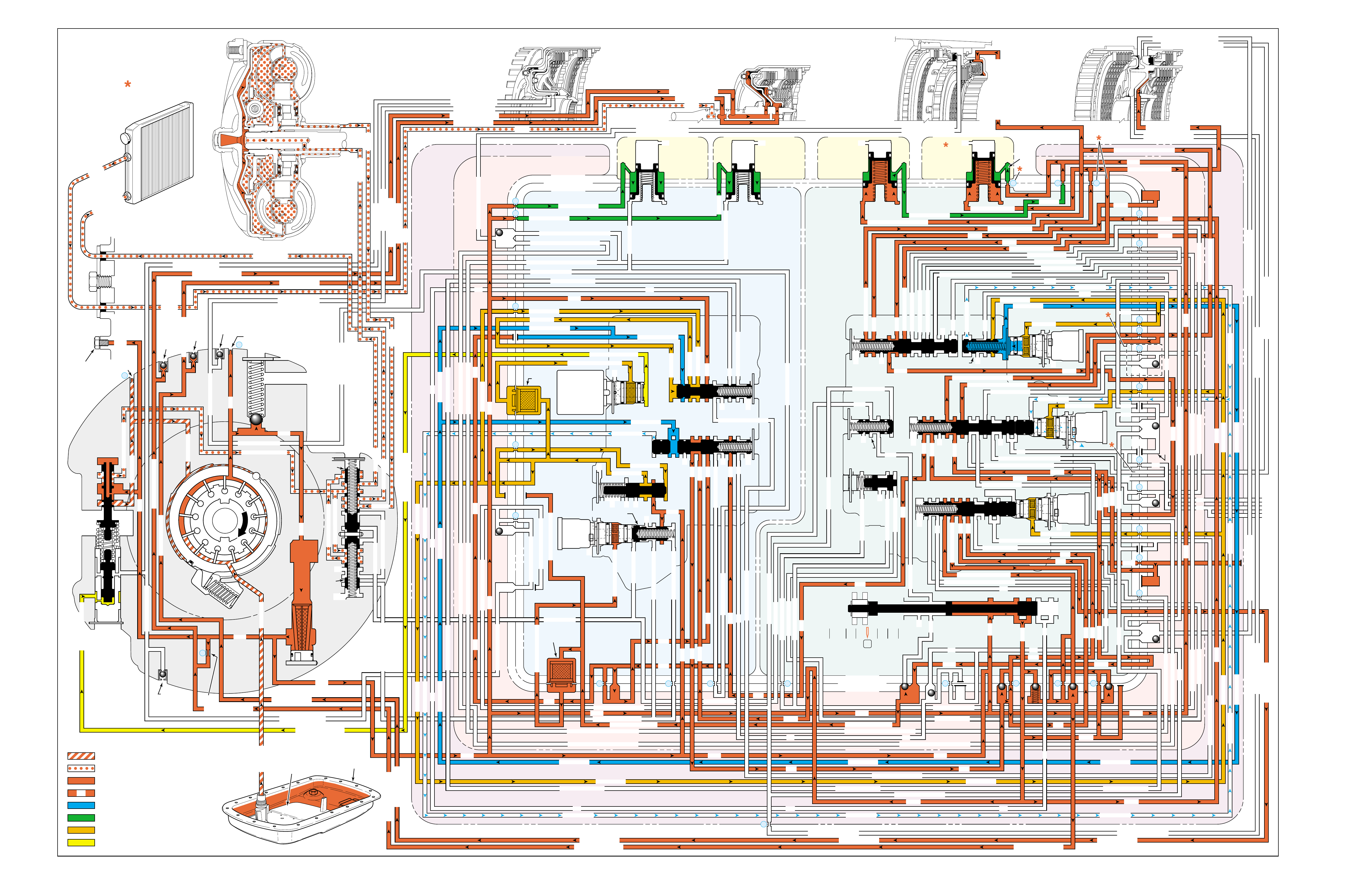
Figure 92
OVERDRIVE RANGE – THIRD GEAR
PRESSURES
INTAKE & DECREASE (SUCTION)
CONVERTER & LUBE
MAINLINE
REGULATED LINE
SOLENOID SIGNAL
ACCUMULATOR
FEED LIMIT
THROTTLE SIGNAL
NOTE:
PASSAGES AND
COMPONENTS
MARKED WITH
ARE USED FOR
THE 5L40-E ONLY
GASKET (309)
GASKET (305)
GASKET (303)
BOTTOM CHANNEL PLATE (304)
TOP CHANNEL PLATE (301)
CASE (24)
REAR CONTROL VALVE BODY (310)
SPACER PLATE (307)
GASKET (309)
GASKET (305)
GASKET (303)
BOTTOM CHANNEL PLATE (304)
TOP CHANNEL PLATE (301)
CASE (24)
FRONT CONTROL VALVE BODY (311)
SPACER PLATE (307)
FLUID
PUMP
COVER
(202)
CONVERTER
HOUSING
(224)
ACCUMULATOR HOUSING (317) ACCUMULATOR HOUSING (323) ACCUMULATOR HOUSING (328) ACCUMULATOR HOUSING (333)
LUBE
LUBE
LUBE
LUBE
TO COOLER
LUBE
TO COOLER
APPLY
APPLY
APPLY
RELEASE
DECREASE
DECREASE
LINE
OVERDRIVE CLUTCH FEED 1
OVERDRIVE CL FD 1OVERDRIVE CLUTCH FEED 1
OVERDRIVE CLUTCH FEED 1 OVERDRIVE CLUTCH FEED 1
OVERDRIVE CLUTCH
2345 2345
2345
2345
2345
2345
2345 OR REVERSE
RLO
LOW AND REV CL OR RLO
LOW AND REV CL OR RLO
SECOND COAST CLUTCH
SECOND CLUTCH
SECOND COAST CLUTCH
SUCTION SUCTION
LINE
LINE
LINE LINE
LINE
LINE
LINE LINE LINE
TCC SIGNAL
CONVERTER FEED
CONVERTER FEED
RELEASE
TO COOLER
REGULATED APPLYREGULATED APPLY
LINE
EX
CONVERTER FEED
REVERSE CLUTCH
REVERSE CLUTCH
THROTTLE SIGNAL
LINE
EX
FILTERED FEED LIMIT
THROTTLE SIGNAL
THROTTLE SIGNAL
THROTTLE SIGNAL
EX
2345 OR REVERSE
2345 OR REVERSE
2345 OR REVERSE
TCC SIGNAL
TCC SIGNAL
TCC SIGNAL
REGULATED APPLY
REGULATED APPLY
REGULATED APPLY
EX
EX
FEED LIMIT VALVE
LINE
EX
EX
EX
EX
FEED LIMIT
FEED LIMIT FEED LIMIT
FEED LIMIT
FEED LIMIT
FEED LIMIT
FEED LIMIT
FEED LIMIT FEED LIMIT
FEED LIMIT
EX
EX
EX
EX
EX
EX
EX EX
SECOND COAST CLUTCH
23 REGULATED
23 REGULATED
OVERDRIVE CLUTCH FEED 1
INTERMEDIATE CLUTCH
2345
2345
2345
2345
INTERMEDIATE CLUTCH
2345
345
FEED LIMIT
EX
EX
EX
EX
2-3 SIGNAL
LOW PRESSURE
123 REGULATED
123 REGULATED
EX
4-5 SHIFT VLV CNTRL
LINE SAFETY MODE
123 BRAKING
123
EX
EX
EX
123
123
123
123
123
123
123
123123
COAST CLUTCH
COAST CLUTCH FEED
OVERDRIVE CLUTCH FEED 2
45
FEED LIMIT
SAFETY MODE
LINE
FEED LIMIT
32
MEMORY
MEMORY
MEMORY
MEMORY PILOT
MEMORY PILOT
32 SAFETY MODE
LINE SAFETY MODE
EX
EX
LINE SAFETY MODE
3-4 SHIFT
2-3 SIGNAL
123123 D432D432
DIRECT CLUTCH
DIRECT CLUTCH
4545
1-2 SIGNAL
EX
EX
EX
FDL
FDL
FDL
FDL
FDL
FDL
D432
2345 2345
D432
SECOND CLUTCH
23 REGULATED
23 REGULATED23 REGULATED
123 REGULATED
LOW AND REVERSE CLUTCH
LOW AND REVERSE CL
SECOND CLUTCH
123 REGULATED
EX
EX
EX
FD LIMIT
FEED LIMIT
FDL
1-2 SIGNAL
2-3 SIGNAL
EX
EX
TCC SIGNAL
TCC SIGNAL
TCC SIGNAL
RLO
EX
REV
RPND432
MANUAL VALVE
LINE
D432
D432 D432
D432
D432
D432
D432 D432
D432
D432D432
D432
REV
REVERSE
EX
3232
LINE
EX
EX
LINE
CASE (24)
OVERDRIVE CLUTCH FEED 2
OVERDRIVE CL FD 2
OVERDRIVE CLUTCH FEED 2
ACCUMULATOR
DIRECT CLUTCH
ACCUM
INTERMEDIATE CLUTCH
INTERMEDIATE CLUTCH
INTERMEDIATE CLUTCH
ACCUMULATOR
EX
SECOND CLUTCH
SECOND CLUTCH
ACCUM
ACCUM
LINELINE
FORWARD CLUTCH
FORWARD CLUTCH FORWARD CLUTCH
ACCUMULATOR
LINE
LINELINE
LINE
OVERDRIVE CLUTCH
INTERMEDIATE CL
COAST CLUTCH
REVERSE LOCKOUT
COAST CLUTCH
REVERSE CLUTCH
REVERSE CLUTCH
REVERSE CLUTCH
4-5 SIGNAL
EXEXEX
LINE SAFETY MODE
LINE SAFETY MODE
REVERSE LOCKOUT
REVERSE LOCKOUT REVERSE LOCKOUT
COAST CLUTCH
REVERSE LOCKOUT REVERSE LOCKOUT
REVERSE LOCKOUT
REVERSE LOCKOUT
REVERSE LOCKOUT
REVERSE LOCKOUT
REVERSE CLUTCH
REVERSE CLUTCH
LOW AND REV CL OR RLO
FORWARD CLUTCH
FORWARD CLUTCH
FORWARD CLUTCH
COAST CLUTCH
FORWARD CLUTCH
FORWARD CLUTCH
FORWARD CLUTCH
2345
2345 OR REVERSE
123 REGULATED
123 REGULATED
123 REGULATED 123 REGULATED
123 REGULATED
123 REGULATED
123 REGULATED
123 BRAKING
123 BRAKING
123 BRAKING
123 BRAKING
1-2 SIGNAL1-2 SIGNAL
1-2 SIGNAL1-2 SIGNAL1-2 SIGNAL
1-2 SIGNAL 1-2 SIGNAL 1-2 SIGNAL
2-3 SIGNAL2-3 SIGNAL2-3 SIGNAL
2-3 SIGNAL 2-3 SIGNAL
2-3 SIGNAL2-3 SIGNAL2-3 SIGNAL
2-3 SIGNAL
SECOND CLUTCH
SECOND CLUTCH
COAST CLUTCHCOAST CLUTCHCOAST CLUTCH
COAST CLUTCH
COAST CLUTCH
COAST CLUTCH
COAST CLUTCH
COAST CLUTCH
23 REGULATED
345
345
345
345 345 345
345
345
345
345
345
345
345
345
DIRECT CLUTCH
DIRECT CLUTCH
DIRECT CLUTCH
DIRECT CL
DIRECT CLUTCH
DIRECT CLUTCH
DIRECT CLUTCH
DIRECT CLUTCH
45
45
45
4545
45
OVERDRIVE CLUTCH
OVERDRIVE CL FD 1
OVERDRIVE CLUTCH FEED 2OVERDRIVE CLUTCH FEED 2
OVERDRIVE CL FD 2
OVERDRIVE CLUTCH FEED 2 OVERDRIVE CL FD 2
3232
32 32 32
323232
32 SAFETY MODE
32 SAFETY MODE 32 SAFETY MODE 32 SAFETY MODE
32 SAFETY MODE32 SAFETY MODE
32 SM 32 SM
FDL
PRESSURE
CONTROL
SOLENOID
VALVE
1-2 SHIFT
SOLENOID
VALVE
N/C
(A)
ON
2-3 SHIFT
SOLENOID
VALVE
N/C
(B)
OFF
4-5 SHIFT
SOLENOID
VALVE
N/C
(C)
OFF
TCC PWM
SOLENOID
VALVE
N/C
PRESS REG VALVEBOOST VALVE
CONVERTER FDL
1-2 SHIFT VALVE
2-3 SHIFT VALVE CNTRL
CNTRL
AIR
BLEED
(233)
AIR
BLEED
(233)
AIR
BLEED
(203)
AIR
BLEED
(203)
AIR
BLEED
(203)
AIR
BLEED
(203)
7
4
2
1
5
6
11
10
9
12
18
FILTER
(308)
FILTER
(312)
TCC REGULATOR VALVE
TCC
CONTROL
VALVE
TCC
ENABLE
VALVE
REVERSE
LOCKOUT
VALVE
1-2 SHIFT CONTROL VALVE
FLUID
PAN
(62)
FLUID FILTER
ASSEMBLY
(59)
FLUID
PRESSURE
TEST PLUG
(40)
TORQUE
CONVERTER
ASSEMBLY
(1)
DIRECT
CLUTCH
ACCUMULATOR
OVERDRIVE
CLUTCH
ACCUMULATOR
INTERMEDIATE
CLUTCH
ACCUMULATOR
SECOND
CLUTCH
ACCUMULATOR
COOLER
PRESSURE
RELIEF
BALL
VALVE
21 2
10d
2a
2b
42b
43a
37d
39b
40b
37c
40d
11b
10a
24a
10c
11a 10b
54b
54d
2c
54a
54c
27c 46
7a
24b
20a
13a
37b
38a
7b
47a
47b
27b
28c
12a
23a
36e
36f
23b
23c
15a
24c
26b
36a
38c
38d
36b
25a
15
2m 54g
54f
#8
18
15f
15e
17c
17b
17a
27a
44a
44e
44d
44b
25c
30a
33a
25e
19e
35c
19h
19f
10f
10h
10g
22a
35b
#7
13b
32a
26a
10i
22f
22d
43b
22b
34a
48b
39a
22c
X-1
22
22e
21a
42a
19a
20b
19b
#2
23 22g
14a
2f
2h
19g
19i
19
j
DIRECT
AND REVERSE
CLUTCH
ASSEMBLY
(400–420)
FORWARD
AND COAST
CLUTCH
ASSEMBLY
(430–451)
OVERDRIVE
AND
INTERMEDIATE
CLUTCH
ASSEMBLY
(480–497)
CENTER
SUPPORT
ASSEMBLY
(510–535)
3
2d54e
2e
30c
30d
35d
26
37a
13
#1
15c
15b
16
15d 16
15
X-2
16a
X-4 X-5
38
14
X-3
19
#6
19d
19
21
19c 21
15
#5
21b 31
21c 31
17
21
#4
20d
20c
16
25b
19
25d
20
36 46
28a
44c
28b
30b
21
#11
33e
33d
23
2435a
#9
33c
33b
22
36d
36c
25
#12
41 40c
39c
43 13
2840a
#10
45
45
45
44f
44
48
43c
#3
38b
38e
27
48a29
8
10e
2310
32 SM/FDL
30
31
FLUID PUMP
SCREEN
ASSEMBLY
(213)
(214)
96

96A
OVERDRIVE RANGE – THIRD GEAR
NO THIRD GEAR
•Overdrive Clutch Housing (493)
–Cracked
–Feed hole blocked
•Fluid Passage Sleeve (39)
–Leaking
•Intermediate Clutch Piston (495)
–Leaking
–Cracked or jammed
•2-3 Shift Solenoid Valve (369)
–Stuck On
•2-3 Shift Valve (371)
–Stuck
•2-3 Shift Control Valve (370)
–Stuck
•Intermediate Clutch Accumulator
–Leaking
•Intermediate Clutch Sprag (473)
–Not holding
SOLENOID FORWARD OVER- INTERM. INTER- LOW LOW AND SECOND SECOND
DIRECT REVERSE COAST FORWARD SPRAG DRIVE SPRAG MEDIATE SPRAG REVERSE SECOND SPRAG COAST
1-2 2-3 4-5 CLUTCH CLUTCH CLUTCH CLUTCH CLUTCH CLUTCH CLUTCH CLUTCH CLUTCH CLUTCH CLUTCH CLUTCH CLUTCH
ON OFF OFF APPLIED APPLIED LD LD APPLIED APPLIED
LD = LOCKED IN DRIVE

96B
PASSAGES
1 SUCTION
2 LINE
3 DECREASE
4 CONVERTER FEED
5 RELEASE
6 APPLY
7 REGULATED APPLY
8 TO COOLER
9 LUBE
10 FEED LIMIT
11 FILTERED FEED LIMIT
12 THROTTLE SIGNAL
13 LINE SAFETY MODE
14 REVERSE
15 REVERSE LOCK OUT (RLO)
16 REVERSE CLUTCH
17 LOW AND REVERSE CLUTCH
18 LOW AND REVERSE CLUTCH OR RLO
19 D432
20 123
21 FORWARD CLUTCH
22 2345
23 2345 OR REVERSE
24 TCC SIGNAL
25 123 REGULATED
26 123 BRAKING
27 1-2 SIGNAL
28 2-3 SIGNAL
29 4-5 SIGNAL
30 SECOND CLUTCH
31 COAST CLUTCH FEED
32 COAST CLUTCH
33 23 REGULATED
34 SECOND COAST CLUTCH
35 INTERMEDIATE CLUTCH
36 345
37 DIRECT CLUTCH
38 45
39 OVERDRIVE CLUTCH FEED 1
40 OVERDRIVE CLUTCH FEED 2
41 OVERDRIVE CLUTCH
42 32
43 32 SAFETY MODE
44 FDL
45 32 SAFETY MODE/FDL
46 MEMORY PILOT
47 MEMORY
48 EXHAUST
49 OIL RESERVOIR
50 TORQUE CONVERTER SEAL DRAINBACK
51 VENT
52 VOID
53 CONVERTER FDL
54 ACCUMULATOR
COMPONENTS ( )
(36) TRANSMISSION FLUID LEVEL HOLE PLUG
(40) TRANSMISSION FLUID PRESSURE TEST PLUG
(203) CHECK VALVE RETAINER AND BALL ASSEMBLY
(213) TRANSMISSION FLUID PUMP SCREEN ASSEMBLY
(214) BRASS ORIFICE INSERT
(232) ORIFICE SLEEVE
(233) ORIFICE CUP PLUG
(306) CONTROL VALVE BODY BALL CHECK VALVE
(#1, 2, 3, 4, 5, 6, 7, 8, 9, 10, 11, 12)
(308) TCC PWM SOLENOID VALVE FILTER ASSEMBLY
(312) PRESSURE CONTROL SOLENOID VALVE
FILTER ASSEMBLY
OVERDRIVE RANGE – THIRD GEAR
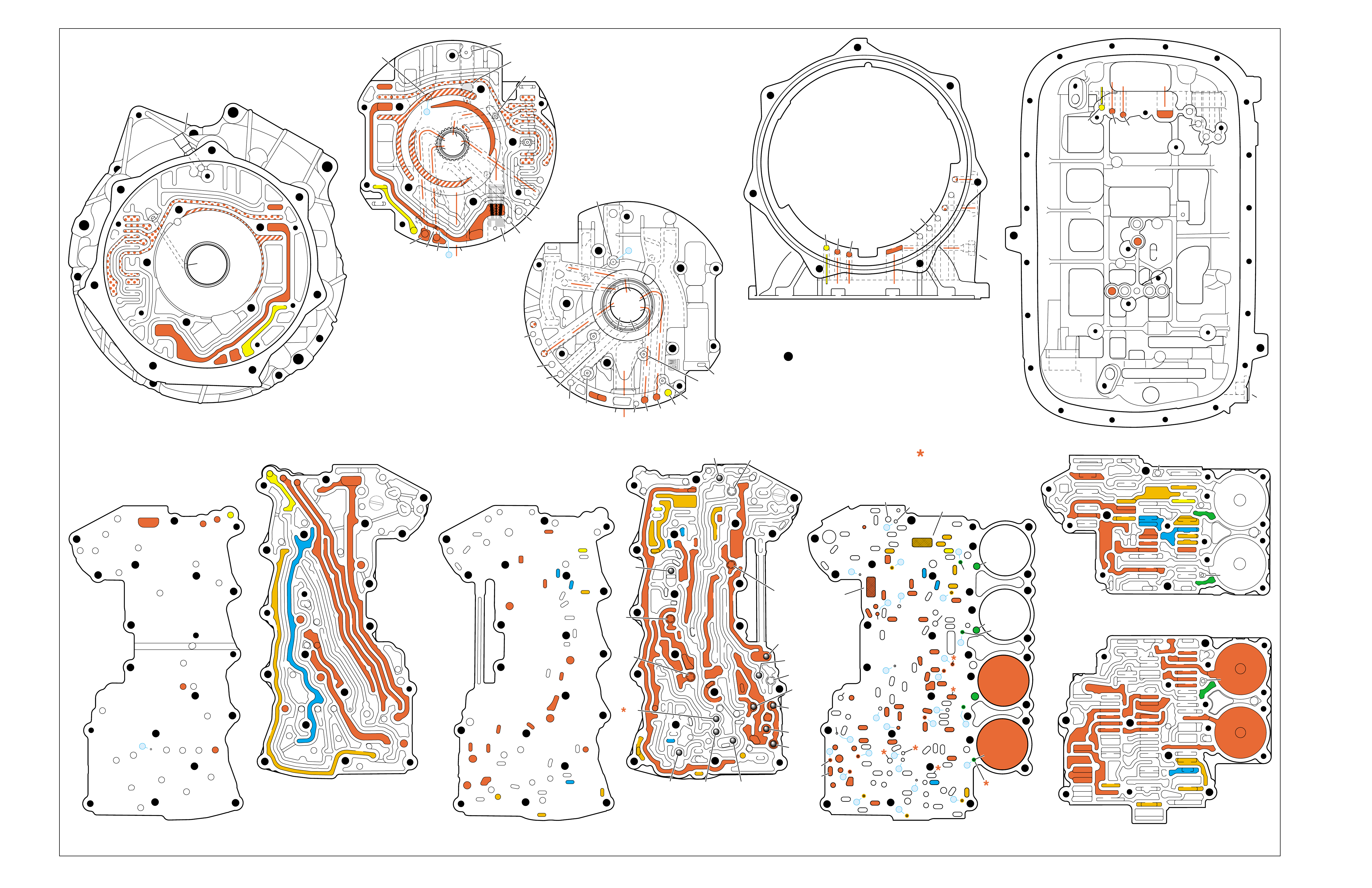
Figure 93
OVERDRIVE RANGE – THIRD GEAR
➤
➤➤
➤
➤➤
➤
➤
➤
➤➤
➤
➤➤
➤
➤
➤
➤
➤ ➤
➤➤
➤
➤
➤
TORQUE CONVERTER HOUSING (227)
(Fluid Pump Cover Side)
➤
➤
➤
➤
➤➤➤
➤
➤
➤ ➤
➤
➤
TOP CHANNEL PLATE (301)
(Case Side)
FRONT
➤
TOP CHANNEL PLATE (301)
(Bottom Channel Plate Side)
FRONT
➤
BOTTOM CHANNEL PLATE (304)
(Top Channel Plate Side)
FRONT
➤
REAR CONTROL VALVE BODY (310)
(Bottom Channel Plate Side)
FRONT
➤
CASE (24)
(Top Channel Plate Side)
FRONT
➤
CASE (24)
(Fluid Pump Cover Side)
SPACER PLATE (307)
(Bottom Channel Plate Side)
FRONT
➤
FRONT CONTROL VALVE BODY (311)
(Bottom Channel Plate Side)
FRONT
➤
BOTTOM CHANNEL PLATE (304)
(Control Valve Body Side)
FRONT
➤
NOTE:
–INDICATES BOLT HOLES
–NON FUNCTIONAL HOLES HAVE BEEN
REMOVED FROM COMPONENT DRAWINGS
TO SIMPLIFY TRACING FLUID FLOW.
–DUAL PURPOSE PASSAGES HAVE
CHANNEL PLATE SIDE NUMBERS LISTED FIRST
–EXHAUST FLUID NOT SHOWN
–PASSAGES MARKED WITH ARE USED FOR
THE 5L40-E ONLY
FLUID PUMP COVER (202)
(Case Side)
FLUID PUMP COVER (202)
(Torque Converter Housing Side)
➤
➤
➤
➤
➤
➤
➤ ➤
➤
➤
➤➤
➤
➤
➤
7
➤
25
➤
27
➤
3
➤
20
➤
16
➤
2
➤
10
➤
9
➤
24
➤
15
➤
11
➤
22
➤
29
➤
28
➤
23
➤
18
➤
17
➤
14
➤
8
➤
4
➤
5
➤
26
➤
13
➤
19
➤
21
➤
6
➤
12
(40)
➤
21
(203)
➤
16
(203)
➤➤
(232)
➤➤
(229)
➤➤
(231)
➤➤
(213)
➤
(233)
➤
TRANSMISSION
VENT
ASSEMBLY
➤➤
32
(203)
➤
37
(203)
➤➤
2/21
(214)
➤➤
(36)
➤
FILTER
(312)
➤
FILTER
(308)
➤
#12
#2
#3
#5
#6
#7
(Spring)
#8
#10 #9
#4
#1
#11
X-2
X-4
X-5
X-1
X-3
12
2
23
24
48
48
48
48
48
48
48
48
52
52
52
52
52
52
52
23
36
36
36
20
27
28
46
47
47
19
16
15
13
10
10
10
11
54
2
54
37
37
37
39
38
40
42
43
40
27
7
48
48
48
52
52
52
52
52
52
52
24
25
25
25
2525
26
26
15 19 19
19
19
31
21
20 20
15 17
17
14
13
14
54
22
22
28
28
22
22
32
42 43
44
44
48
48
48
48
48
48
44
44
38
39
38
33
33
30
35
40
35
35
36
35
34
30
30
30
33
2
2
10
10 10
10
27
2
216
24
15
18
7
32
52
52
52
52 52
52
52
52
52
52
52
52
52 52
52
52
52
52
30 34
35
41
12 21 37
8
9
2
16
24
7
32
12 21
37
12
21
21
24
848
7
9
9
52
52
2
16
5
16
37
32
32
52
1
52
52
52
48
37
1
2
51
51
52
12
12
24
24
52
2
2
4
4
4
4
5
66
8
8
7
7
7
5
9
48
48
48
48
48
48
48
48
53
53
48
52
2
3
3
3
2
1
16
21
21
16
32
37
32
51
50
50
51 52
52
52
52
52
52
48
48
48
48
52
48
48
12
12
24
24
2
2
3
2
4
4
4
5
6
53
53
8
8
7
7
7
48
16
16
21 32
37
➤➤
1
➤➤
31
➤➤
30
(233)
➤➤
33
32
38
38
38
30
30
24
37
37
37
40
40
12
16
15
15
23 52
24
24
23
28
47
41
42
43
27
28
28
27
27
25
25
26
22
22
15
13
18 19
19
19
19
19
19
19
21
17
17
22
23
23
48
48
48
48
48
48
48
48
48
15
13
36
36
36
36
39
35
35
34
10
10 11
10
10
10
20
20
48
44
44
45
43 42
52
48
48
77
2
2
2
2
2
2
2
52
52
12a
16a
15d/16 15c/16
15b
23c
24a 24b
24c
25b
25c 25d
25e
26b
26a
32a
30a
33a
35a
39a
36a
36b
36c
36d
38a 39b
39c/41
40c/41
36e
36f
35b
35c 35d
37c
37d
37b
37a
40b
40a
38d 38b
38c
38e
40d
34a
33e
33c
33d
33b
30b
30c 30d
25a
23b
23a
20a
28c
27c/46
27b
28b
28a
27a
47b
47a
20b
20d
20c
13a
15a
19e
19h
19g
19i
19j
19f
13b 15e
17a
17b
17c/18
15f/18
19b/21
19c/21
19d/21
19a
22a
22b
22c
22d
22f
21a
21b/31
21c/31
22g/23
14a/23
22e
48
48
48
48
48
48
48
52
52
52
52
52
52
52
52
48
48
2g
7a
7b 2a/54a
2b
42b
43a
42a
43b
44c
44d 44b
44a
44e
43c/45
44f/45
48a 48b
2c/54c
54d
2d/54e
2e 2m/54g
2f
10i
10h
10f
10e
10d
10a 10c
11b
11a/10b
10g
2h
54f
54b
48
32
38
30
24 12
16
13
15
15
13
18
19
19
19
21
21
22
16 48
48
48
48
48
48
48
48
36
35
35
34
2
2
7
2
10
10
10
10
41
42
43
43
42
48 48
20
28
27
37
27
28
28
27
20
48
52
52
32
32
32
38
24
12 16
16
18
28
28
28
27
27
48 48
43 42
42
43
48
30
48
48
48 48
48
48
48
48
48
48
48
48
35
36
37
34
2
7
2
10
13
13
15
19
41
41
19
19
15
22
21
21
20
20
21
21
13
10
10
10
2
48
48 48
52
52
52
52
52
52
12
32
37 21
24
2
16
18
48
48
48
48
48
30
48
48
48
48
48
48
15
35
41
34
7
52
52
52
52
52
52
FOLDOUT ➤ 97
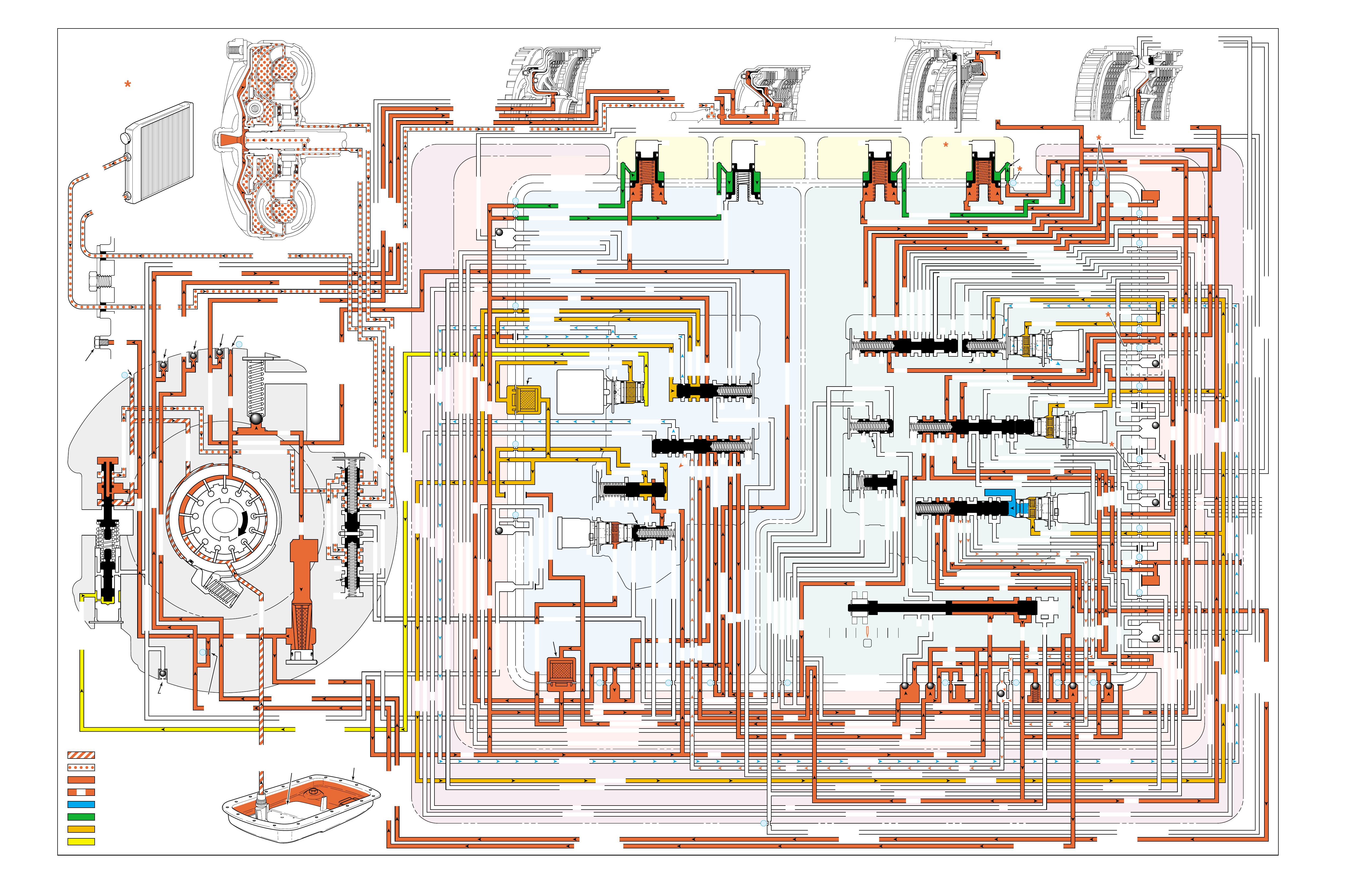
Figure 94
OVERDRIVE RANGE – FOURTH GEAR
PRESSURES
INTAKE & DECREASE (SUCTION)
CONVERTER & LUBE
MAINLINE
REGULATED LINE
SOLENOID SIGNAL
ACCUMULATOR
FEED LIMIT
THROTTLE SIGNAL
NOTE:
PASSAGES AND
COMPONENTS
MARKED WITH
ARE USED FOR
THE 5L40-E ONLY
GASKET (309)
GASKET (305)
GASKET (303)
BOTTOM CHANNEL PLATE (304)
TOP CHANNEL PLATE (301)
CASE (24)
REAR CONTROL VALVE BODY (310)
SPACER PLATE (307)
GASKET (309)
GASKET (305)
GASKET (303)
BOTTOM CHANNEL PLATE (304)
TOP CHANNEL PLATE (301)
CASE (24)
FRONT CONTROL VALVE BODY (311)
SPACER PLATE (307)
FLUID
PUMP
COVER
(202)
CONVERTER
HOUSING
(224)
ACCUMULATOR HOUSING (317) ACCUMULATOR HOUSING (323) ACCUMULATOR HOUSING (328) ACCUMULATOR HOUSING (333)
LUBE
LUBE
LUBE
LUBE
TO COOLER
LUBE
TO COOLER
APPLY
APPLY
APPLY
RELEASE
DECREASE
DECREASE
LINE
OVERDRIVE CLUTCH FEED 1
OVERDRIVE CL FD 1OVERDRIVE CLUTCH FEED 1
OVERDRIVE CLUTCH FEED 1 OVERDRIVE CLUTCH FEED 1
OVERDRIVE CLUTCH
2345 2345
2345
2345
2345
2345
2345 OR REVERSE
RLO
LOW AND REV CL OR RLO
LOW AND REV CL OR RLO
SECOND COAST CLUTCH
SECOND CLUTCH
SECOND COAST CLUTCH
SUCTION SUCTION
LINE
LINE
LINE LINE
LINE
LINE
LINE LINE LINE
TCC SIGNAL
CONVERTER FEED
CONVERTER FEED
RELEASE
TO COOLER
REGULATED APPLYREGULATED APPLY
LINE
EX
CONVERTER FEED
REVERSE CLUTCH
REVERSE CLUTCH
THROTTLE SIGNAL
LINE
EX
FILTERED FEED LIMIT
THROTTLE SIGNAL
THROTTLE SIGNAL
THROTTLE SIGNAL
EX
2345 OR REVERSE
2345 OR REVERSE
2345 OR REVERSE
TCC SIGNAL
TCC SIGNAL
TCC SIGNAL
REGULATED APPLY
REGULATED APPLY
REGULATED APPLY
EX
EX
FEED LIMIT VALVE
LINE
EX
EX
EX
EX
FEED LIMIT
FEED LIMIT FEED LIMIT
FEED LIMIT
FEED LIMIT
FEED LIMIT
FEED LIMIT
FEED LIMIT FEED LIMIT
FEED LIMIT
EX
EX
EX
EX
EX
EX
EX EX
SECOND COAST CLUTCH
23 REGULATED
23 REGULATED
OVERDRIVE CLUTCH FEED 1
INTERMEDIATE CLUTCH
2345
2345
2345
2345
INTERMEDIATE CLUTCH
2345
345
FEED LIMIT
EX
EX
EX
EX
2-3 SIGNAL
LOW PRESSURE
123 REGULATED
123 REGULATED
EX
4-5 SHIFT VLV CNTRL
LINE SAFETY MODE
123 BRAKING
123
EX
EX
EX
123
123
123
123
123
123
123
123123
COAST CLUTCH
COAST CLUTCH FEED
OVERDRIVE CLUTCH FEED 2
45
FEED LIMIT
SAFETY MODE
LINE
FEED LIMIT
32
MEMORY
MEMORY
MEMORY
MEMORY PILOT
MEMORY PILOT
32 SAFETY MODE
LINE SAFETY MODE
EX
EX
LINE SAFETY MODE
2-3 SIGNAL
123123 D432D432
DIRECT CLUTCH
DIRECT CLUTCH
4545
1-2 SIGNAL
EX
EX
EX
FDL
FDL
FDL
FDL
FDL
FDL
D432
2345 2345
D432
SECOND CLUTCH
23 REGULATED
23 REGULATED23 REGULATED
123 REGULATED
LOW AND REVERSE CLUTCH
LOW AND REVERSE CL
SECOND CLUTCH
123 REGULATED
EX
EX
EX
FD LIMIT
FEED LIMIT
FDL
1-2 SIGNAL
2-3 SIGNAL
EX
EX
TCC SIGNAL
TCC SIGNAL
TCC SIGNAL
RLO
EX
REV
RPND432
MANUAL VALVE
LINE
D432
D432 D432
D432
D432
D432
D432 D432
D432
D432D432
D432
REV
REVERSE
EX
3232
LINE
EX
EX
LINE
CASE (24)
OVERDRIVE CLUTCH FEED 2
OVERDRIVE CL FD 2
OVERDRIVE CLUTCH FEED 2
ACCUMULATOR
DIRECT CLUTCH
ACCUM
INTERMEDIATE CLUTCH
INTERMEDIATE CLUTCH
INTERMEDIATE CLUTCH
ACCUMULATOR
EX
SECOND CLUTCH
SECOND CLUTCH
ACCUM
ACCUM
LINELINE
FORWARD CLUTCH
FORWARD CLUTCH FORWARD CLUTCH
ACCUMULATOR
LINE
LINELINE
LINE
OVERDRIVE CLUTCH
INTERMEDIATE CL
COAST CLUTCH
REVERSE LOCKOUT
COAST CLUTCH
REVERSE CLUTCH
REVERSE CLUTCH
REVERSE CLUTCH
4-5 SIGNAL
EXEXEX
LINE SAFETY MODE
LINE SAFETY MODE
REVERSE LOCKOUT
REVERSE LOCKOUT REVERSE LOCKOUT
COAST CLUTCH
REVERSE LOCKOUT REVERSE LOCKOUT
REVERSE LOCKOUT
REVERSE LOCKOUT
REVERSE LOCKOUT
REVERSE LOCKOUT
REVERSE CLUTCH
REVERSE CLUTCH
LOW AND REV CL OR RLO
FORWARD CLUTCH
FORWARD CLUTCH
FORWARD CLUTCH
COAST CLUTCH
FORWARD CLUTCH
FORWARD CLUTCH
FORWARD CLUTCH
2345
2345 OR REVERSE
123 REGULATED
123 REGULATED
123 REGULATED 123 REGULATED
123 REGULATED
123 REGULATED
123 REGULATED
123 BRAKING
123 BRAKING
123 BRAKING
123 BRAKING
1-2 SIGNAL1-2 SIGNAL
1-2 SIGNAL1-2 SIGNAL1-2 SIGNAL
1-2 SIGNAL 1-2 SIGNAL 1-2 SIGNAL
2-3 SIGNAL2-3 SIGNAL2-3 SIGNAL
2-3 SIGNAL 2-3 SIGNAL
2-3 SIGNAL2-3 SIGNAL2-3 SIGNAL
2-3 SIGNAL
SECOND CLUTCH
SECOND CLUTCH
COAST CLUTCHCOAST CLUTCHCOAST CLUTCH
COAST CLUTCH
COAST CLUTCH
COAST CLUTCH
COAST CLUTCH
COAST CLUTCH
23 REGULATED
345
345
345
345 345 345
345
345
345
345
345
345
345
345
DIRECT CLUTCH
DIRECT CLUTCH
DIRECT CLUTCH
DIRECT CL
DIRECT CLUTCH
DIRECT CLUTCH
DIRECT CLUTCH
DIRECT CLUTCH
45
45
45
4545
45
OVERDRIVE CLUTCH
OVERDRIVE CL FD 1
OVERDRIVE CLUTCH FEED 2OVERDRIVE CLUTCH FEED 2
OVERDRIVE CL FD 2
OVERDRIVE CLUTCH FEED 2 OVERDRIVE CL FD 2
3232
32 32 32
323232
32 SAFETY MODE
32 SAFETY MODE 32 SAFETY MODE 32 SAFETY MODE
32 SAFETY MODE32 SAFETY MODE
32 SM 32 SM
FDL
PRESSURE
CONTROL
SOLENOID
VALVE
1-2 SHIFT
SOLENOID
VALVE
N/C
(A)
OFF
2-3 SHIFT
SOLENOID
VALVE
N/C
(B)
OFF
4-5 SHIFT
SOLENOID
VALVE
N/C
(C)
ON
TCC PWM
SOLENOID
VALVE
N/C
PRESS REG VALVEBOOST VALVE
CONVERTER FDL
1-2 SHIFT VALVE
2-3 SHIFT VALVE CNTRL
CNTRL 3-4 SHIFT
AIR
BLEED
(233)
AIR
BLEED
(233)
AIR
BLEED
(203)
AIR
BLEED
(203)
AIR
BLEED
(203)
AIR
BLEED
(203)
7
4
2
1
5
6
11
10
9
12
18
FILTER
(308)
FILTER
(312)
TCC REGULATOR VALVE
TCC
CONTROL
VALVE
TCC
ENABLE
VALVE
REVERSE
LOCKOUT
VALVE
1-2 SHIFT CONTROL VALVE
FLUID
PAN
(62)
FLUID FILTER
ASSEMBLY
(59)
FLUID
PRESSURE
TEST PLUG
(40)
TORQUE
CONVERTER
ASSEMBLY
(1)
DIRECT
CLUTCH
ACCUMULATOR
OVERDRIVE
CLUTCH
ACCUMULATOR
INTERMEDIATE
CLUTCH
ACCUMULATOR
SECOND
CLUTCH
ACCUMULATOR
COOLER
PRESSURE
RELIEF
BALL
VALVE
21 2
10d
2a
2b
42b
43a
37d
39b
40b
37c
40d
11b
10a
24a
10c
11a 10b
54b
54d
2c
54a
54c
27c 46
7a
24b
20a
13a
37b
38a
7b
47a
47b
27b
28c
12a
23a
36e
36f
23b
23c
15a
24c
26b
36a
38c
38d
36b
25a
15
2m 54g
54f
#8
18
15f
15e
17c
17b
17a
27a
44a
44e
44d
44b
25c
30a
33a
25e
19e
35c
19h
19f
10f
10h
10g
22a
35b
#7
13b
32a
26a
10i
22f
22d
43b
22b
34a
48b
39a
22c
X-1
22
22e
21a
42a
19a
20b
19b
#2
23 22g
14a
2f
2h
19g
19i
19
j
DIRECT
AND REVERSE
CLUTCH
ASSEMBLY
(400–420)
FORWARD
AND COAST
CLUTCH
ASSEMBLY
(430–451)
OVERDRIVE
AND
INTERMEDIATE
CLUTCH
ASSEMBLY
(480–497)
CENTER
SUPPORT
ASSEMBLY
(510–535)
3
2d54e
2e
30c
30d
35d
26
37a
13
#1
15c
15b
16
15d 16
15
X-2
16a
X-4 X-5
38
14
X-3
19
#6
19d
19
21
19c 21
15
#5
21b 31
21c 31
17
21
#4
20d
20c
16
25b
19
25d
20
36 46
28a
44c
28b
30b
21
#11
33e
33d
23
2435a
#9
33c
33b
22
36d
36c
25
#12
41 40c
39c
43 13
2840a
#10
45
45
45
44f
44
48
43c
#3
38b
38e
27
48a29
8
10e
2310
32 SM/FDL
30
31
FLUID PUMP
SCREEN
ASSEMBLY
(213)
(214)
98

98A
OVERDRIVE RANGE – FOURTH GEAR
NO FOURTH GEAR
•Direct Clutch Piston (406)
–Leaking
–Cracked or jammed
•Direct Clutch Housing Ball Check Valve (405)
–Leaking
•Direct Clutch Accumulator
–Leaking
•1-2 Shift Solenoid Valve (368)
–Stuck On
•3-4 Shift Valve (345)
–Stuck
•Reverse Clutch Housing Seal Ring (200)
–Leaking
SOLENOID FORWARD OVER- INTERM. INTER- LOW LOW AND SECOND SECOND
DIRECT REVERSE COAST FORWARD SPRAG DRIVE SPRAG MEDIATE SPRAG REVERSE SECOND SPRAG COAST
1-2 2-3 4-5 CLUTCH CLUTCH CLUTCH CLUTCH CLUTCH CLUTCH CLUTCH CLUTCH CLUTCH CLUTCH CLUTCH CLUTCH CLUTCH
OFF OFF ON APPLIED APPLIED APPLIED LD APPLIED APPLIED
LD = LOCKED IN DRIVE

98B
PASSAGES
1 SUCTION
2 LINE
3 DECREASE
4 CONVERTER FEED
5 RELEASE
6 APPLY
7 REGULATED APPLY
8 TO COOLER
9 LUBE
10 FEED LIMIT
11 FILTERED FEED LIMIT
12 THROTTLE SIGNAL
13 LINE SAFETY MODE
14 REVERSE
15 REVERSE LOCK OUT (RLO)
16 REVERSE CLUTCH
17 LOW AND REVERSE CLUTCH
18 LOW AND REVERSE CLUTCH OR RLO
19 D432
20 123
21 FORWARD CLUTCH
22 2345
23 2345 OR REVERSE
24 TCC SIGNAL
25 123 REGULATED
26 123 BRAKING
27 1-2 SIGNAL
28 2-3 SIGNAL
29 4-5 SIGNAL
30 SECOND CLUTCH
31 COAST CLUTCH FEED
32 COAST CLUTCH
33 23 REGULATED
34 SECOND COAST CLUTCH
35 INTERMEDIATE CLUTCH
36 345
37 DIRECT CLUTCH
38 45
39 OVERDRIVE CLUTCH FEED 1
40 OVERDRIVE CLUTCH FEED 2
41 OVERDRIVE CLUTCH
42 32
43 32 SAFETY MODE
44 FDL
45 32 SAFETY MODE/FDL
46 MEMORY PILOT
47 MEMORY
48 EXHAUST
49 OIL RESERVOIR
50 TORQUE CONVERTER SEAL DRAINBACK
51 VENT
52 VOID
53 CONVERTER FDL
54 ACCUMULATOR
COMPONENTS ( )
(36) TRANSMISSION FLUID LEVEL HOLE PLUG
(40) TRANSMISSION FLUID PRESSURE TEST PLUG
(203) CHECK VALVE RETAINER AND BALL ASSEMBLY
(213) TRANSMISSION FLUID PUMP SCREEN ASSEMBLY
(214) BRASS ORIFICE INSERT
(232) ORIFICE SLEEVE
(233) ORIFICE CUP PLUG
(306) CONTROL VALVE BODY BALL CHECK VALVE
(#1, 2, 3, 4, 5, 6, 7, 8, 9, 10, 11, 12)
(308) TCC PWM SOLENOID VALVE FILTER ASSEMBLY
(312) PRESSURE CONTROL SOLENOID VALVE
FILTER ASSEMBLY
OVERDRIVE RANGE – FOURTH GEAR

Figure 95
OVERDRIVE RANGE – FOURTH GEAR
➤➤
➤
➤ ➤
➤
➤
➤➤
➤
➤➤
➤
➤
➤
➤➤
➤
➤➤
➤
➤
➤
➤
➤ ➤
➤➤
➤
➤
➤
TORQUE CONVERTER HOUSING (227)
(Fluid Pump Cover Side)
➤
➤
➤
➤
➤➤➤
➤➤
➤
➤
➤
➤ ➤
➤
➤
TOP CHANNEL PLATE (301)
(Case Side)
FRONT
➤
TOP CHANNEL PLATE (301)
(Bottom Channel Plate Side)
FRONT
➤
BOTTOM CHANNEL PLATE (304)
(Top Channel Plate Side)
FRONT
➤
REAR CONTROL VALVE BODY (310)
(Bottom Channel Plate Side)
FRONT
➤
CASE (24)
(Top Channel Plate Side)
FRONT
➤
CASE (24)
(Fluid Pump Cover Side)
SPACER PLATE (307)
(Bottom Channel Plate Side)
FRONT
➤
FRONT CONTROL VALVE BODY (311)
(Bottom Channel Plate Side)
FRONT
➤
BOTTOM CHANNEL PLATE (304)
(Control Valve Body Side)
FRONT
➤
NOTE:
–INDICATES BOLT HOLES
–NON FUNCTIONAL HOLES HAVE BEEN
REMOVED FROM COMPONENT DRAWINGS
TO SIMPLIFY TRACING FLUID FLOW.
–DUAL PURPOSE PASSAGES HAVE
CHANNEL PLATE SIDE NUMBERS LISTED FIRST
–EXHAUST FLUID NOT SHOWN
–PASSAGES MARKED WITH ARE USED FOR
THE 5L40-E ONLY
FLUID PUMP COVER (202)
(Case Side)
FLUID PUMP COVER (202)
(Torque Converter Housing Side)
➤
➤
➤
➤
➤
➤
➤ ➤
➤
➤
➤➤
➤
➤
➤
7
➤
25
➤
27
➤
3
➤
20
➤
16
➤
2
➤
10
➤
9
➤
24
➤
15
➤
11
➤
22
➤
29
➤
28
➤
23
➤
18
➤
17
➤
14
➤
8
➤
4
➤
5
➤
26
➤
13
➤
19
➤
21
➤
6
➤
12
(40)
➤
21
(203)
➤
16
(203)
➤➤
(232)
➤➤
(229)
➤➤
(231)
➤➤
(213)
➤
(233)
➤
TRANSMISSION
VENT
ASSEMBLY
➤➤
32
(203)
➤
37
(203)
➤➤
2/21
(214)
➤➤
(36)
➤
FILTER
(312)
➤
FILTER
(308)
➤
#12
#2
#3
#5
#6
#7
(Spring)
#8
#10 #9
#4
#1
#11
X-2
X-4
X-5
X-1
X-3
12
2
23
24
48
48
48
48
48
48
48
48
52
52
52
52
52
52
52
23
36
36
36
20
27
28
46
47
47
19
16
15
13
10
10
10
11
54
2
54
37
37
37
39
38
40
42
43
40
27
7
48
48
48
52
52
52
52
52
52
52
24
25
25
25
2525
26
26
15 19 19
19
19
31
21
20 20
15 17
17
14
13
14
54
22
22
28
28
22
22
32
42 43
44
44
48
48
48
48
48
48
44
44
38
39
38
33
33
30
35
40
35
35
36
35
34
30
30
30
33
2
2
10
10 10
10
27
2
216
24
15
18
7
32
52
52
52
52 52
52
52
52
52
52
52
52
52 52
52
52
52
52
30 34
35
41
12 21 37
8
9
2
16
24
7
32
12 21
37
12
21
21
24
848
7
9
9
52
52
2
16
5
16
37
32
32
52
1
52
52
52
48
37
1
2
51
51
52
12
12
24
24
52
2
2
4
4
4
4
5
66
8
8
7
7
7
5
9
48
48
48
48
48
48
48
48
53
53
48
52
2
3
3
3
2
1
16
21
21
16
32
37
32
51
50
50
51 52
52
52
52
52
52
48
48
48
48
52
48
48
12
12
24
24
2
2
3
2
4
4
4
5
6
53
53
8
8
7
7
7
48
16
16
21 32
37
➤➤
1
➤➤
31
➤➤
30
(233)
➤➤
33
32
38
38
38
30
30
24
37
37
37
40
40
12
16
15
15
23 52
24
24
23
28
47
41
42
43
27
28
28
27
27
25
25
26
22
22
15
13
18 19
19
19
19
19
19
19
21
17
17
22
23
23
48
48
48
48
48
48
48
48
48
15
13
36
36
36
36
39
35
35
34
10
10 11
10
10
10
20
20
48
44
44
45
43 42
52
48
48
77
2
2
2
2
2
2
2
52
52
12a
16a
15d/16 15c/16
15b
23c
24a 24b
24c
25b
25c 25d
25e
26b
26a
32a
30a
33a
35a
39a
36a
36b
36c
36d
38a 39b
39c/41
40c/41
36e
36f
35b
35c 35d
37c
37d
37b
37a
40b
40a
38d 38b
38c
38e
40d
34a
33e
33c
33d
33b
30b
30c 30d
25a
23b
23a
20a
28c
27c/46
27b
28b
28a
27a
47b
47a
20b
20d
20c
13a
15a
19e
19h
19g
19i
19j
19f
13b 15e
17a
17b
17c/18
15f/18
19b/21
19c/21
19d/21
19a
22a
22b
22c
22d
22f
21a
21b/31
21c/31
22g/23
14a/23
22e
48
48
48
48
48
48
48
52
52
52
52
52
52
52
52
48
48
2g
7a
7b 2a/54a
2b
42b
43a
42a
43b
44c
44d 44b
44a
44e
43c/45
44f/45
48a 48b
2c/54c
54d
2d/54e
2e 2m/54g
2f
10i
10h
10f
10e
10d
10a 10c
11b
11a/10b
10g
2h
54f
54b
48
32
38
30
24 12
16
13
15
15
13
18
19
19
19
21
21
22
16 48
48
48
48
48
48
48
48
36
35
35
34
2
2
7
2
10
10
10
10
41
42
43
43
42
48 48
20
28
27
37
27
28
28
27
20
48
52
52
32
32
32
38
24
12 16
16
18
28
28
28
27
27
48 48
43 42
42
43
48
30
48
48
48 48
48
48
48
48
48
48
48
48
35
36
37
34
2
7
2
10
13
13
15
19
41
41
19
19
15
22
21
21
20
20
21
21
13
10
10
10
2
48
48 48
52
52
52
52
52
52
12
32
37 21
24
2
16
18
48
48
48
48
48
30
48
48
48
48
48
48
15
35
41
34
7
52
52
52
52
52
52
FOLDOUT ➤ 99
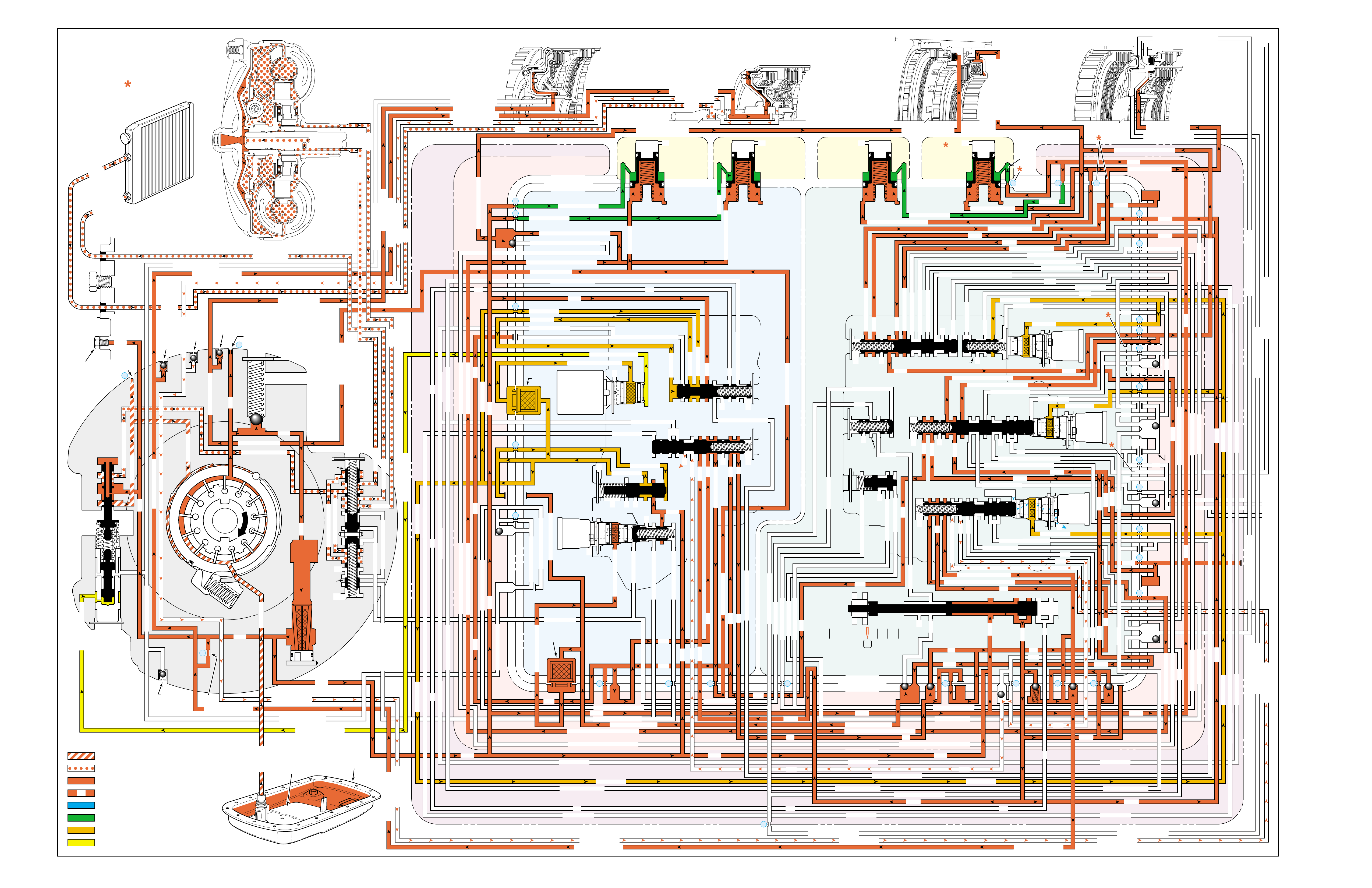
Figure 96
OVERDRIVE RANGE – FIFTH GEAR
(Torque Converter Clutch Released)
PRESSURES
INTAKE & DECREASE (SUCTION)
CONVERTER & LUBE
MAINLINE
REGULATED LINE
SOLENOID SIGNAL
ACCUMULATOR
FEED LIMIT
THROTTLE SIGNAL
NOTE:
PASSAGES AND
COMPONENTS
MARKED WITH
ARE USED FOR
THE 5L40-E ONLY
GASKET (309)
GASKET (305)
GASKET (303)
BOTTOM CHANNEL PLATE (304)
TOP CHANNEL PLATE (301)
CASE (24)
REAR CONTROL VALVE BODY (310)
SPACER PLATE (307)
GASKET (309)
GASKET (305)
GASKET (303)
BOTTOM CHANNEL PLATE (304)
TOP CHANNEL PLATE (301)
CASE (24)
FRONT CONTROL VALVE BODY (311)
SPACER PLATE (307)
FLUID
PUMP
COVER
(202)
CONVERTER
HOUSING
(224)
ACCUMULATOR HOUSING (317) ACCUMULATOR HOUSING (323) ACCUMULATOR HOUSING (328) ACCUMULATOR HOUSING (333)
LUBE
LUBE
LUBE
LUBE
TO COOLER
LUBE
TO COOLER
APPLY
APPLY
APPLY
RELEASE
DECREASE
DECREASE
LINE
OVERDRIVE CLUTCH FEED 1
OVERDRIVE CL FD 1OVERDRIVE CLUTCH FEED 1
OVERDRIVE CLUTCH FEED 1 OVERDRIVE CLUTCH FEED 1
OVERDRIVE CLUTCH
2345 2345
2345
2345
2345
2345
2345 OR REVERSE
RLO
LOW AND REV CL OR RLO
LOW AND REV CL OR RLO
SECOND COAST CLUTCH
SECOND CLUTCH
SECOND COAST CLUTCH
SUCTION SUCTION
LINE
LINE
LINE LINE
LINE
LINE
LINE LINE LINE
TCC SIGNAL
CONVERTER FEED
CONVERTER FEED
RELEASE
TO COOLER
REGULATED APPLYREGULATED APPLY
LINE
EX
CONVERTER FEED
REVERSE CLUTCH
REVERSE CLUTCH
THROTTLE SIGNAL
LINE
EX
FILTERED FEED LIMIT
THROTTLE SIGNAL
THROTTLE SIGNAL
THROTTLE SIGNAL
EX
2345 OR REVERSE
2345 OR REVERSE
2345 OR REVERSE
TCC SIGNAL
TCC SIGNAL
TCC SIGNAL
REGULATED APPLY
REGULATED APPLY
REGULATED APPLY
EX
EX
FEED LIMIT VALVE
LINE
EX
EX
EX
EX
FEED LIMIT
FEED LIMIT FEED LIMIT
FEED LIMIT
FEED LIMIT
FEED LIMIT
FEED LIMIT
FEED LIMIT FEED LIMIT
FEED LIMIT
EX
EX
EX
EX
EX
EX
EX EX
SECOND COAST CLUTCH
23 REGULATED
23 REGULATED
OVERDRIVE CLUTCH FEED 1
INTERMEDIATE CLUTCH
2345
2345
2345
2345
INTERMEDIATE CLUTCH
2345
345
FEED LIMIT
EX
EX
EX
EX
2-3 SIGNAL
LOW PRESSURE
123 REGULATED
123 REGULATED
EX
LINE SAFETY MODE
123 BRAKING
123
EX
EX
EX
123
123
123
123
123
123
123
123123
COAST CLUTCH
COAST CLUTCH FEED
OVERDRIVE CLUTCH FEED 2
45
FEED LIMIT
SAFETY MODE
LINE
FEED LIMIT
32
MEMORY
MEMORY
MEMORY
MEMORY PILOT
MEMORY PILOT
32 SAFETY MODE
LINE SAFETY MODE
EX
EX
LINE SAFETY MODE
2-3 SIGNAL
123123 D432D432
DIRECT CLUTCH
DIRECT CLUTCH
4545
1-2 SIGNAL
EX
EX
EX
FDL
FDL
FDL
FDL
FDL
FDL
D432
2345 2345
D432
SECOND CLUTCH
23 REGULATED
23 REGULATED23 REGULATED
123 REGULATED
LOW AND REVERSE CLUTCH
LOW AND REVERSE CL
SECOND CLUTCH
123 REGULATED
EX
EX
EX
FD LIMIT
FEED LIMIT
FDL
1-2 SIGNAL
2-3 SIGNAL
EX
EX
TCC SIGNAL
TCC SIGNAL
TCC SIGNAL
RLO
EX
REV
RPND432
MANUAL VALVE
LINE
D432
D432 D432
D432
D432
D432
D432 D432
D432
D432D432
D432
REV
REVERSE
EX
3232
LINE
EX
EX
LINE
CASE (24)
OVERDRIVE CLUTCH FEED 2
OVERDRIVE CL FD 2
OVERDRIVE CLUTCH FEED 2
ACCUMULATOR
DIRECT CLUTCH
ACCUM
INTERMEDIATE CLUTCH
INTERMEDIATE CLUTCH
INTERMEDIATE CLUTCH
ACCUMULATOR
EX
SECOND CLUTCH
SECOND CLUTCH
ACCUM
ACCUM
LINELINE
FORWARD CLUTCH
FORWARD CLUTCH FORWARD CLUTCH
ACCUMULATOR
LINE
LINELINE
LINE
OVERDRIVE CLUTCH
INTERMEDIATE CL
COAST CLUTCH
REVERSE LOCKOUT
COAST CLUTCH
REVERSE CLUTCH
REVERSE CLUTCH
REVERSE CLUTCH
4-5 SIGNAL
EXEXEX
LINE SAFETY MODE
LINE SAFETY MODE
REVERSE LOCKOUT
REVERSE LOCKOUT REVERSE LOCKOUT
COAST CLUTCH
REVERSE LOCKOUT REVERSE LOCKOUT
REVERSE LOCKOUT
REVERSE LOCKOUT
REVERSE LOCKOUT
REVERSE LOCKOUT
REVERSE CLUTCH
REVERSE CLUTCH
LOW AND REV CL OR RLO
FORWARD CLUTCH
FORWARD CLUTCH
FORWARD CLUTCH
COAST CLUTCH
FORWARD CLUTCH
FORWARD CLUTCH
FORWARD CLUTCH
2345
2345 OR REVERSE
123 REGULATED
123 REGULATED
123 REGULATED 123 REGULATED
123 REGULATED
123 REGULATED
123 REGULATED
123 BRAKING
123 BRAKING
123 BRAKING
123 BRAKING
1-2 SIGNAL1-2 SIGNAL
1-2 SIGNAL1-2 SIGNAL1-2 SIGNAL
1-2 SIGNAL 1-2 SIGNAL 1-2 SIGNAL
2-3 SIGNAL2-3 SIGNAL2-3 SIGNAL
2-3 SIGNAL 2-3 SIGNAL
2-3 SIGNAL2-3 SIGNAL2-3 SIGNAL
2-3 SIGNAL
SECOND CLUTCH
SECOND CLUTCH
COAST CLUTCHCOAST CLUTCHCOAST CLUTCH
COAST CLUTCH
COAST CLUTCH
COAST CLUTCH
COAST CLUTCH
COAST CLUTCH
23 REGULATED
345
345
345
345 345 345
345
345
345
345
345
345
345
345
DIRECT CLUTCH
DIRECT CLUTCH
DIRECT CLUTCH
DIRECT CL
DIRECT CLUTCH
DIRECT CLUTCH
DIRECT CLUTCH
DIRECT CLUTCH
45
45
45
4545
45
OVERDRIVE CLUTCH
OVERDRIVE CL FD 1
OVERDRIVE CLUTCH FEED 2OVERDRIVE CLUTCH FEED 2
OVERDRIVE CL FD 2
OVERDRIVE CLUTCH FEED 2 OVERDRIVE CL FD 2
3232
32 32 32
323232
32 SAFETY MODE
32 SAFETY MODE 32 SAFETY MODE 32 SAFETY MODE
32 SAFETY MODE32 SAFETY MODE
32 SM 32 SM
FDL
PRESSURE
CONTROL
SOLENOID
VALVE
1-2 SHIFT
SOLENOID
VALVE
N/C
(A)
OFF
2-3 SHIFT
SOLENOID
VALVE
N/C
(B)
OFF
4-5 SHIFT
SOLENOID
VALVE
N/C
(C)
OFF
TCC PWM
SOLENOID
VALVE
N/C
PRESS REG VALVEBOOST VALVE
CONVERTER FDL
1-2 SHIFT VALVE
2-3 SHIFT VALVE CNTRL
CNTRL 3-4 SHIFT
4-5 SHIFT VLV CNTRL
AIR
BLEED
(233)
AIR
BLEED
(233)
AIR
BLEED
(203)
AIR
BLEED
(203)
AIR
BLEED
(203)
AIR
BLEED
(203)
7
4
2
1
5
6
11
10
9
12
18
FILTER
(308)
FILTER
(312)
TCC REGULATOR VALVE
TCC
CONTROL
VALVE
TCC
ENABLE
VALVE
REVERSE
LOCKOUT
VALVE
1-2 SHIFT CONTROL VALVE
FLUID
PAN
(62)
FLUID FILTER
ASSEMBLY
(59)
FLUID
PRESSURE
TEST PLUG
(40)
TORQUE
CONVERTER
ASSEMBLY
(1)
DIRECT
CLUTCH
ACCUMULATOR
OVERDRIVE
CLUTCH
ACCUMULATOR
INTERMEDIATE
CLUTCH
ACCUMULATOR
SECOND
CLUTCH
ACCUMULATOR
COOLER
PRESSURE
RELIEF
BALL
VALVE
21 2
10d
2a
2b
42b
43a
37d
39b
40b
37c
40d
11b
10a
24a
10c
11a 10b
54b
54d
2c
54a
54c
27c 46
7a
24b
20a
13a
37b
38a
7b
47a
47b
27b
28c
12a
23a
36e
36f
23b
23c
15a
24c
26b
36a
38c
38d
36b
25a
15
2m 54g
54f
#8
18
15f
15e
17c
17b
17a
27a
44a
44e
44d
44b
25c
30a
33a
25e
19e
35c
19h
19f
10f
10h
10g
22a
35b
#7
13b
32a
26a
10i
22f
22d
43b
22b
34a
48b
39a
22c
X-1
22
22e
21a
42a
19a
20b
19b
#2
23 22g
14a
2f
2h
19g
19i
19
j
DIRECT
AND REVERSE
CLUTCH
ASSEMBLY
(400–420)
FORWARD
AND COAST
CLUTCH
ASSEMBLY
(430–451)
OVERDRIVE
AND
INTERMEDIATE
CLUTCH
ASSEMBLY
(480–497)
CENTER
SUPPORT
ASSEMBLY
(510–535)
3
2d54e
2e
30c
30d
35d
26
37a
13
#1
15c
15b
16
15d 16
15
X-2
16a
X-4 X-5
38
14
X-3
19
#6
19d
19
21
19c 21
15
#5
21b 31
21c 31
17
21
#4
20d
20c
16
25b
19
25d
20
36 46
28a
44c
28b
30b
21
#11
33e
33d
23
2435a
#9
33c
33b
22
36d
36c
25
#12
41 40c
39c
43 13
2840a
#10
45
45
45
44f
44
48
43c
#3
38b
38e
27
48a29
8
10e
2310
32 SM/FDL
30
31
FLUID PUMP
SCREEN
ASSEMBLY
(213)
(214)
100

100A
OVERDRIVE RANGE – FIFTH GEAR
(Torque Converter Clutch Released)
NO FIFTH GEAR
•Overdrive Clutch Piston (487)
–Leaking
–Cracked or jammed
•#12 Ball Check Valve
–Stuck
–Missing
•4-5 Shift Solenoid Valve (376)
–Stuck On
•4-5 Shift Valve (374)
–Stuck
•4-5 Shift Control Valve (375)
–Stuck
•Overdrive Accumulator
–Leaking
•Fluid Passage Sleeve (39)
–Leaking
SOLENOID FORWARD OVER- INTERM. INTER- LOW LOW AND SECOND SECOND
DIRECT REVERSE COAST FORWARD SPRAG DRIVE SPRAG MEDIATE SPRAG REVERSE SECOND SPRAG COAST
1-2 2-3 4-5 CLUTCH CLUTCH CLUTCH CLUTCH CLUTCH CLUTCH CLUTCH CLUTCH CLUTCH CLUTCH CLUTCH CLUTCH CLUTCH
OFF OFF OFF APPLIED APPLIED APPLIED APPLIED APPLIED
LD = LOCKED IN DRIVE

100B
PASSAGES
1 SUCTION
2 LINE
3 DECREASE
4 CONVERTER FEED
5 RELEASE
6 APPLY
7 REGULATED APPLY
8 TO COOLER
9 LUBE
10 FEED LIMIT
11 FILTERED FEED LIMIT
12 THROTTLE SIGNAL
13 LINE SAFETY MODE
14 REVERSE
15 REVERSE LOCK OUT (RLO)
16 REVERSE CLUTCH
17 LOW AND REVERSE CLUTCH
18 LOW AND REVERSE CLUTCH OR RLO
19 D432
20 123
21 FORWARD CLUTCH
22 2345
23 2345 OR REVERSE
24 TCC SIGNAL
25 123 REGULATED
26 123 BRAKING
27 1-2 SIGNAL
28 2-3 SIGNAL
29 4-5 SIGNAL
30 SECOND CLUTCH
31 COAST CLUTCH FEED
32 COAST CLUTCH
33 23 REGULATED
34 SECOND COAST CLUTCH
35 INTERMEDIATE CLUTCH
36 345
37 DIRECT CLUTCH
38 45
39 OVERDRIVE CLUTCH FEED 1
40 OVERDRIVE CLUTCH FEED 2
41 OVERDRIVE CLUTCH
42 32
43 32 SAFETY MODE
44 FDL
45 32 SAFETY MODE/FDL
46 MEMORY PILOT
47 MEMORY
48 EXHAUST
49 OIL RESERVOIR
50 TORQUE CONVERTER SEAL DRAINBACK
51 VENT
52 VOID
53 CONVERTER FDL
54 ACCUMULATOR
COMPONENTS ( )
(36) TRANSMISSION FLUID LEVEL HOLE PLUG
(40) TRANSMISSION FLUID PRESSURE TEST PLUG
(203) CHECK VALVE RETAINER AND BALL ASSEMBLY
(213) TRANSMISSION FLUID PUMP SCREEN ASSEMBLY
(214) BRASS ORIFICE INSERT
(232) ORIFICE SLEEVE
(233) ORIFICE CUP PLUG
(306) CONTROL VALVE BODY BALL CHECK VALVE
(#1, 2, 3, 4, 5, 6, 7, 8, 9, 10, 11, 12)
(308) TCC PWM SOLENOID VALVE FILTER ASSEMBLY
(312) PRESSURE CONTROL SOLENOID VALVE
FILTER ASSEMBLY
OVERDRIVE RANGE – FIFTH GEAR
(Torque Converter Clutch Released)
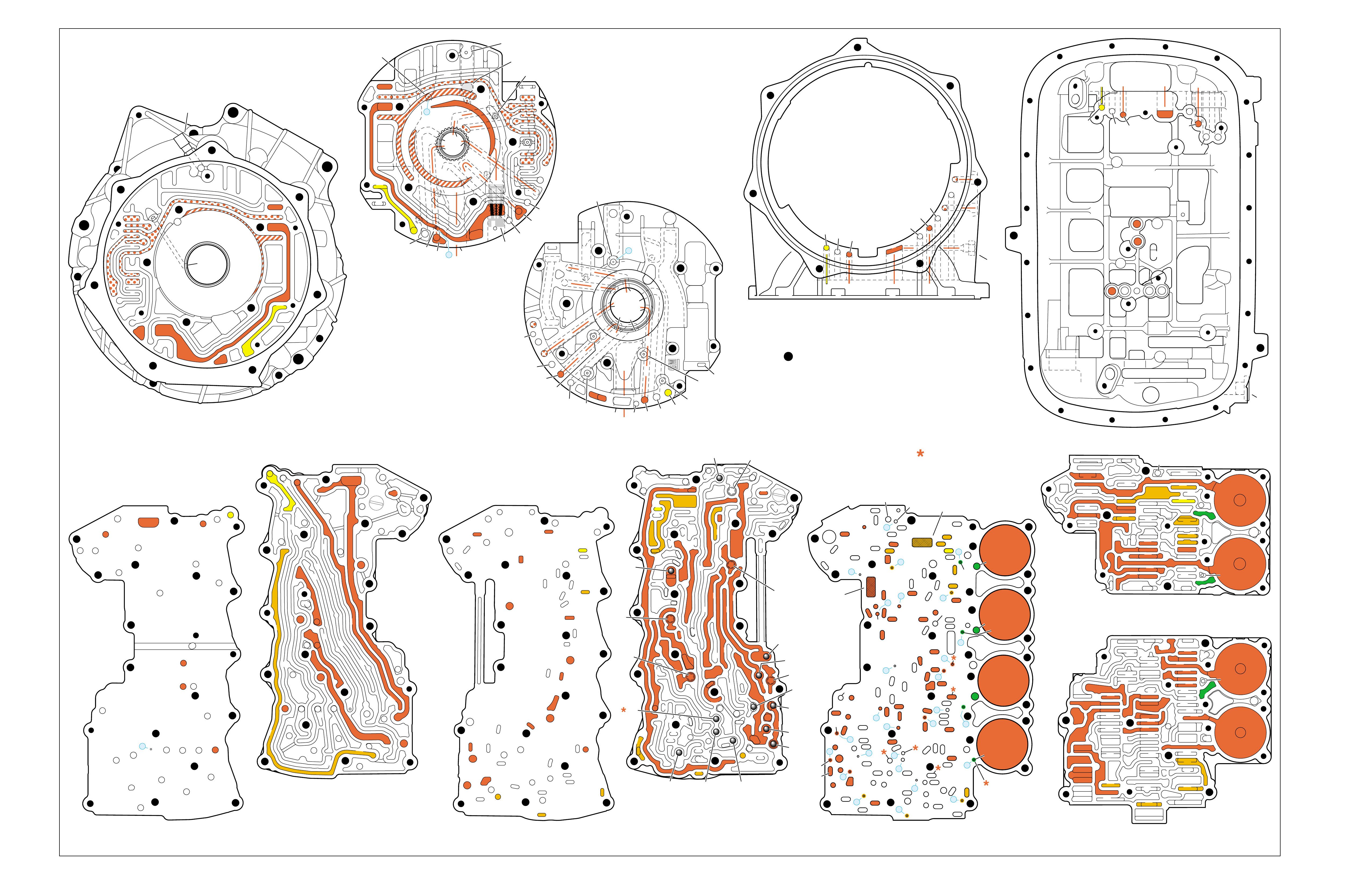
Figure 97
OVERDRIVE RANGE – FIFTH GEAR
(Torque Converter Clutch Released)
➤➤
➤
➤ ➤
➤
➤
➤➤
➤
➤➤
➤
➤
➤
➤ ➤
➤➤
➤
➤
➤
TORQUE CONVERTER HOUSING (227)
(Fluid Pump Cover Side)
➤
➤
➤
➤
➤➤➤
➤➤
➤
➤
➤
➤ ➤
➤
➤
TOP CHANNEL PLATE (301)
(Case Side)
FRONT
➤
TOP CHANNEL PLATE (301)
(Bottom Channel Plate Side)
FRONT
➤
BOTTOM CHANNEL PLATE (304)
(Top Channel Plate Side)
FRONT
➤
REAR CONTROL VALVE BODY (310)
(Bottom Channel Plate Side)
FRONT
➤
CASE (24)
(Top Channel Plate Side)
FRONT
➤
CASE (24)
(Fluid Pump Cover Side)
SPACER PLATE (307)
(Bottom Channel Plate Side)
FRONT
➤
FRONT CONTROL VALVE BODY (311)
(Bottom Channel Plate Side)
FRONT
➤
BOTTOM CHANNEL PLATE (304)
(Control Valve Body Side)
FRONT
➤
NOTE:
–INDICATES BOLT HOLES
–NON FUNCTIONAL HOLES HAVE BEEN
REMOVED FROM COMPONENT DRAWINGS
TO SIMPLIFY TRACING FLUID FLOW.
–DUAL PURPOSE PASSAGES HAVE
CHANNEL PLATE SIDE NUMBERS LISTED FIRST
–EXHAUST FLUID NOT SHOWN
–PASSAGES MARKED WITH ARE USED FOR
THE 5L40-E ONLY
FLUID PUMP COVER (202)
(Case Side)
FLUID PUMP COVER (202)
(Torque Converter Housing Side)
➤
➤
➤
➤
➤
➤
➤ ➤
➤
➤
➤➤
➤
➤
➤
7
➤
25
➤
27
➤
3
➤
20
➤
16
➤
2
➤
10
➤
9
➤
24
➤
15
➤
11
➤
22
➤
29
➤
28
➤
23
➤
18
➤
17
➤
14
➤
8
➤
4
➤
5
➤
26
➤
13
➤
19
➤
21
➤
6
➤
12
(40)
➤
21
(203)
➤
16
(203)
➤➤
(232)
➤➤
(229)
➤➤
(231)
➤➤
(213)
➤
(233)
➤
TRANSMISSION
VENT
ASSEMBLY
➤➤
32
(203)
➤
37
(203)
➤➤
2/21
(214)
➤➤
(36)
➤
FILTER
(312)
➤
FILTER
(308)
➤
#12
#2
#3
#5
#6
#7
(Spring)
#8
#10 #9
#4
#1
#11
X-2
X-4
X-5
X-1
X-3
12
2
23
24
48
48
48
48
48
48
48
48
52
52
52
52
52
52
52
23
36
36
36
20
27
28
46
47
47
19
16
15
13
10
10
10
11
54
2
54
37
37
37
39
38
40
42
43
40
27
7
48
48
48
52
52
52
52
52
52
52
24
25
25
25
2525
26
26
15 19 19
19
19
31
21
20 20
15 17
17
14
13
14
54
22
22
28
28
22
22
32
42 43
44
44
48
48
48
48
48
48
44
44
38
39
38
33
33
30
35
40
35
35
36
35
34
30
30
30
33
2
2
10
10 10
10
27
2
216
24
15
18
7
32
52
52
52
52 52
52
52
52
52
52
52
52
52 52
52
52
52
52
30 34
35
41
12 21 37
8
9
2
16
24
7
32
12 21
37
12
21
21
24
848
7
9
9
52
52
2
16
5
16
37
32
32
52
1
52
52
52
48
37
1
2
51
51
52
12
12
24
24
52
2
2
4
4
4
4
5
66
8
8
7
7
7
5
9
48
48
48
48
48
48
48
48
53
53
48
52
2
3
3
3
2
1
16
21
21
16
32
37
32
51
50
50
51 52
52
52
52
52
52
48
48
48
48
52
48
48
12
12
24
24
2
2
3
2
4
4
4
5
6
53
53
8
8
7
7
7
48
16
16
21 32
37
➤➤
1
➤➤
31
➤➤
30
(233)
➤➤
33
32
38
38
38
30
30
24
37
37
37
40
40
12
16
15
15
23 52
24
24
23
28
47
41
42
43
27
28
28
27
27
25
25
26
22
22
15
13
18 19
19
19
19
19
19
19
21
17
17
22
23
23
48
48
48
48
48
48
48
48
48
15
13
36
36
36
36
39
35
35
34
10
10 11
10
10
10
20
20
48
44
44
45
43 42
52
48
48
77
2
2
2
2
2
2
2
52
52
12a
16a
15d/16 15c/16
15b
23c
24a 24b
24c
25b
25c 25d
25e
26b
26a
32a
30a
33a
35a
39a
36a
36b
36c
36d
38a 39b
39c/41
40c/41
36e
36f
35b
35c 35d
37c
37d
37b
37a
40b
40a
38d 38b
38c
38e
40d
34a
33e
33c
33d
33b
30b
30c 30d
25a
23b
23a
20a
28c
27c/46
27b
28b
28a
27a
47b
47a
20b
20d
20c
13a
15a
19e
19h
19g
19i
19j
19f
13b 15e
17a
17b
17c/18
15f/18
19b/21
19c/21
19d/21
19a
22a
22b
22c
22d
22f
21a
21b/31
21c/31
22g/23
14a/23
22e
48
48
48
48
48
48
48
52
52
52
52
52
52
52
52
48
48
2g
7a
7b 2a/54a
2b
42b
43a
42a
43b
44c
44d 44b
44a
44e
43c/45
44f/45
48a 48b
2c/54c
54d
2d/54e
2e 2m/54g
2f
10i
10h
10f
10e
10d
10a 10c
11b
11a/10b
10g
2h
54f
54b
48
32
38
30
24 12
16
13
15
15
13
18
19
19
19
21
21
22
16 48
48
48
48
48
48
48
48
36
35
35
34
2
2
7
2
10
10
10
10
41
42
43
43
42
48 48
20
28
27
37
27
28
28
27
20
48
52
52
32
32
32
38
24
12 16
16
18
28
28
28
27
27
48 48
43 42
42
43
48
30
48
48
48 48
48
48
48
48
48
48
48
48
35
36
37
34
2
7
2
10
13
13
15
19
41
41
19
19
15
22
21
21
20
20
21
21
13
10
10
10
2
48
48 48
52
52
52
52
52
52
12
32
37 21
24
2
16
18
48
48
48
48
48
30
48
48
48
48
48
48
15
35
41
34
7
52
52
52
52
52
52
FOLDOUT ➤ 101
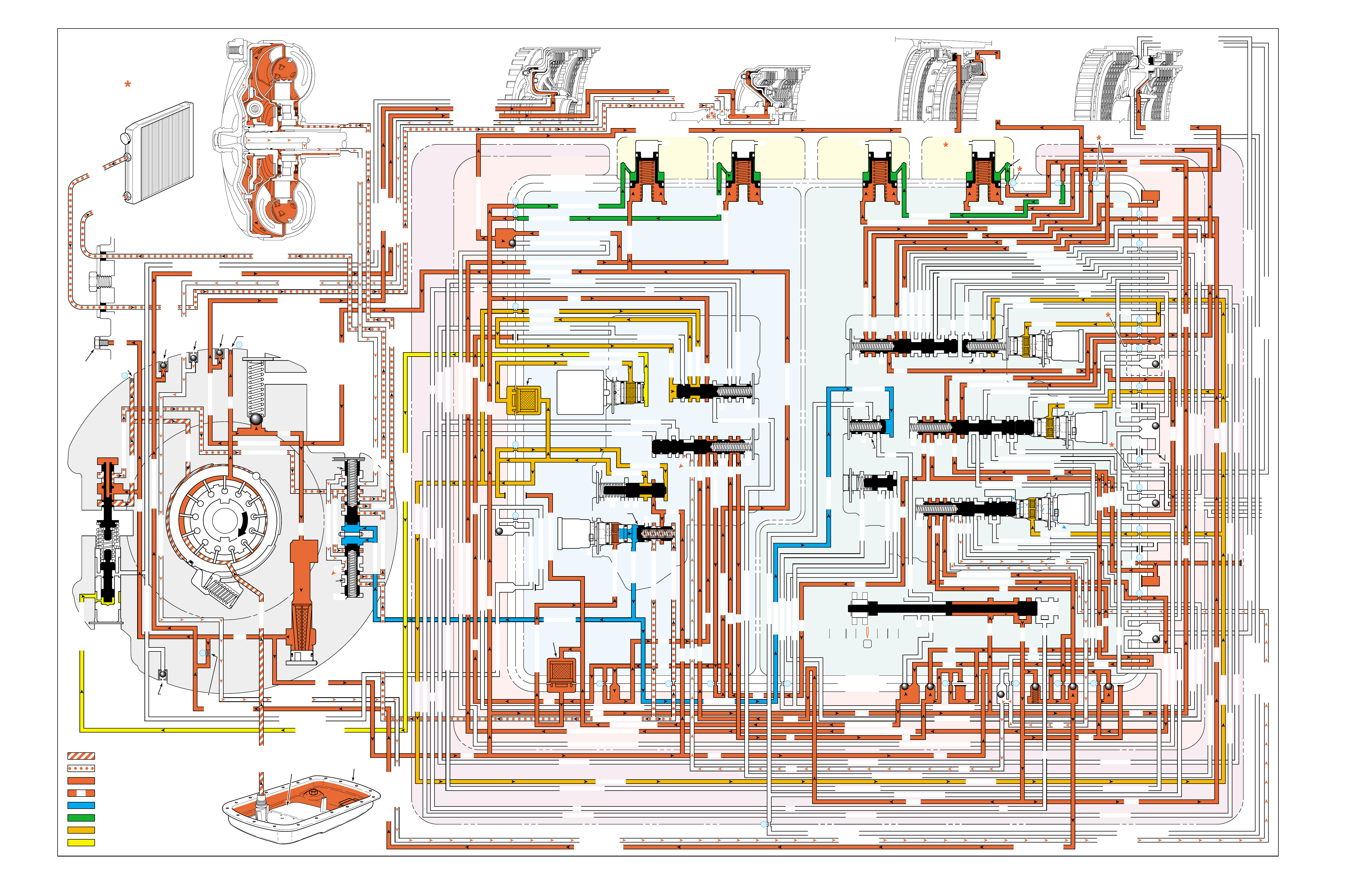
Figure 98
OVERDRIVE RANGE – FIFTH GEAR
(Torque Converter Clutch Applied)
PRESSURES
INTAKE & DECREASE (SUCTION)
CONVERTER & LUBE
MAINLINE
REGULATED LINE
SOLENOID SIGNAL
ACCUMULATOR
FEED LIMIT
THROTTLE SIGNAL
NOTE:
PASSAGES AND
COMPONENTS
MARKED WITH
ARE USED FOR
THE 5L40-E ONLY
GASKET (309)
GASKET (305)
GASKET (303)
BOTTOM CHANNEL PLATE (304)
TOP CHANNEL PLATE (301)
CASE (24)
REAR CONTROL VALVE BODY (310)
SPACER PLATE (307)
GASKET (309)
GASKET (305)
GASKET (303)
BOTTOM CHANNEL PLATE (304)
TOP CHANNEL PLATE (301)
CASE (24)
FRONT CONTROL VALVE BODY (311)
SPACER PLATE (307)
FLUID
PUMP
COVER
(202)
CONVERTER
HOUSING
(224)
ACCUMULATOR HOUSING (317) ACCUMULATOR HOUSING (323) ACCUMULATOR HOUSING (328) ACCUMULATOR HOUSING (333)
LUBE
LUBE
LUBE
LUBE
TO COOLER
LUBE
TO COOLER
APPLY
APPLY
APPLY
RELEASE
DECREASE
DECREASE
LINE
OVERDRIVE CLUTCH FEED 1
OVERDRIVE CL FD 1OVERDRIVE CLUTCH FEED 1
OVERDRIVE CLUTCH FEED 1 OVERDRIVE CLUTCH FEED 1
OVERDRIVE CLUTCH
2345 2345
2345
2345
2345
2345
2345 OR REVERSE
RLO
LOW AND REV CL OR RLO
LOW AND REV CL OR RLO
SECOND COAST CLUTCH
SECOND CLUTCH
SECOND COAST CLUTCH
SUCTION SUCTION
LINE
LINE
LINE LINE
LINE
LINE
LINE LINE LINE
TCC SIGNAL
CONVERTER FEED
CONVERTER FEED
RELEASE
TO COOLER
REGULATED APPLYREGULATED APPLY
LINE
EX
CONVERTER FEED
REVERSE CLUTCH
REVERSE CLUTCH
THROTTLE SIGNAL
LINE
EX
FILTERED FEED LIMIT
THROTTLE SIGNAL
THROTTLE SIGNAL
THROTTLE SIGNAL
EX
2345 OR REVERSE
2345 OR REVERSE
2345 OR REVERSE
TCC SIGNAL
TCC SIGNAL
TCC SIGNAL
REGULATED APPLY
REGULATED APPLY
REGULATED APPLY
EX
EX
FEED LIMIT VALVE
LINE
EX
EX
EX
EX
FEED LIMIT
FEED LIMIT FEED LIMIT
FEED LIMIT
FEED LIMIT
FEED LIMIT
FEED LIMIT
FEED LIMIT FEED LIMIT
FEED LIMIT
EX
EX
EX
EX
EX
EX
EX EX
SECOND COAST CLUTCH
23 REGULATED
23 REGULATED
OVERDRIVE CLUTCH FEED 1
INTERMEDIATE CLUTCH
2345
2345
2345
2345
INTERMEDIATE CLUTCH
2345
345
FEED LIMIT
EX
EX
EX
EX
2-3 SIGNAL
LOW PRESSURE
123 REGULATED
123 REGULATED
EX
LINE SAFETY MODE
123 BRAKING
123
EX
EX
EX
123
123
123
123
123
123
123
123123
COAST CLUTCH
COAST CLUTCH FEED
OVERDRIVE CLUTCH FEED 2
45
FEED LIMIT
SAFETY MODE
LINE
FEED LIMIT
32
MEMORY
MEMORY
MEMORY
MEMORY PILOT
MEMORY PILOT
32 SAFETY MODE
LINE SAFETY MODE
EX
EX
LINE SAFETY MODE
2-3 SIGNAL
123123 D432D432
DIRECT CLUTCH
DIRECT CLUTCH
4545
1-2 SIGNAL
EX
EX
EX
FDL
FDL
FDL
FDL
FDL
FDL
D432
2345 2345
D432
SECOND CLUTCH
23 REGULATED
23 REGULATED23 REGULATED
123 REGULATED
LOW AND REVERSE CLUTCH
LOW AND REVERSE CL
SECOND CLUTCH
123 REGULATED
EX
EX
EX
FD LIMIT
FEED LIMIT
FDL
1-2 SIGNAL
2-3 SIGNAL
EX
EX
TCC SIGNAL
TCC SIGNAL
TCC SIGNAL
RLO
EX
REV
RPND432
MANUAL VALVE
LINE
D432
D432 D432
D432
D432
D432
D432 D432
D432
D432D432
D432
REV
REVERSE
EX
3232
LINE
EX
EX
LINE
CASE (24)
OVERDRIVE CLUTCH FEED 2
OVERDRIVE CL FD 2
OVERDRIVE CLUTCH FEED 2
ACCUMULATOR
DIRECT CLUTCH
ACCUM
INTERMEDIATE CLUTCH
INTERMEDIATE CLUTCH
INTERMEDIATE CLUTCH
ACCUMULATOR
EX
SECOND CLUTCH
SECOND CLUTCH
ACCUM
ACCUM
LINELINE
FORWARD CLUTCH
FORWARD CLUTCH FORWARD CLUTCH
ACCUMULATOR
LINE
LINELINE
LINE
OVERDRIVE CLUTCH
INTERMEDIATE CL
COAST CLUTCH
REVERSE LOCKOUT
COAST CLUTCH
REVERSE CLUTCH
REVERSE CLUTCH
REVERSE CLUTCH
4-5 SIGNAL
EXEXEX
LINE SAFETY MODE
LINE SAFETY MODE
REVERSE LOCKOUT
REVERSE LOCKOUT REVERSE LOCKOUT
COAST CLUTCH
REVERSE LOCKOUT REVERSE LOCKOUT
REVERSE LOCKOUT
REVERSE LOCKOUT
REVERSE LOCKOUT
REVERSE LOCKOUT
REVERSE CLUTCH
REVERSE CLUTCH
LOW AND REV CL OR RLO
FORWARD CLUTCH
FORWARD CLUTCH
FORWARD CLUTCH
COAST CLUTCH
FORWARD CLUTCH
FORWARD CLUTCH
FORWARD CLUTCH
2345
2345 OR REVERSE
123 REGULATED
123 REGULATED
123 REGULATED 123 REGULATED
123 REGULATED
123 REGULATED
123 REGULATED
123 BRAKING
123 BRAKING
123 BRAKING
123 BRAKING
1-2 SIGNAL1-2 SIGNAL
1-2 SIGNAL1-2 SIGNAL1-2 SIGNAL
1-2 SIGNAL 1-2 SIGNAL 1-2 SIGNAL
2-3 SIGNAL2-3 SIGNAL2-3 SIGNAL
2-3 SIGNAL 2-3 SIGNAL
2-3 SIGNAL2-3 SIGNAL2-3 SIGNAL
2-3 SIGNAL
SECOND CLUTCH
SECOND CLUTCH
COAST CLUTCHCOAST CLUTCHCOAST CLUTCH
COAST CLUTCH
COAST CLUTCH
COAST CLUTCH
COAST CLUTCH
COAST CLUTCH
23 REGULATED
345
345
345
345 345 345
345
345
345
345
345
345
345
345
DIRECT CLUTCH
DIRECT CLUTCH
DIRECT CLUTCH
DIRECT CL
DIRECT CLUTCH
DIRECT CLUTCH
DIRECT CLUTCH
DIRECT CLUTCH
45
45
45
4545
45
OVERDRIVE CLUTCH
OVERDRIVE CL FD 1
OVERDRIVE CLUTCH FEED 2OVERDRIVE CLUTCH FEED 2
OVERDRIVE CL FD 2
OVERDRIVE CLUTCH FEED 2 OVERDRIVE CL FD 2
3232
32 32 32
323232
32 SAFETY MODE
32 SAFETY MODE 32 SAFETY MODE 32 SAFETY MODE
32 SAFETY MODE32 SAFETY MODE
32 SM 32 SM
FDL
PRESSURE
CONTROL
SOLENOID
VALVE
1-2 SHIFT
SOLENOID
VALVE
N/C
(A)
OFF
2-3 SHIFT
SOLENOID
VALVE
N/C
(B)
OFF
4-5 SHIFT
SOLENOID
VALVE
N/C
(C)
OFF
TCC PWM
SOLENOID
VALVE
N/C
PRESS REG VALVEBOOST VALVE
CONVERTER FDL
1-2 SHIFT VALVE
2-3 SHIFT VALVE CNTRL
CNTRL 3-4 SHIFT
4-5 SHIFT VLV CNTRL
AIR
BLEED
(233)
AIR
BLEED
(233)
AIR
BLEED
(203)
AIR
BLEED
(203)
AIR
BLEED
(203)
AIR
BLEED
(203)
7
4
2
1
5
6
11
10
9
12
18
FILTER
(308)
FILTER
(312)
TCC REGULATOR VALVE
TCC
CONTROL
VALVE
TCC
ENABLE
VALVE
REVERSE
LOCKOUT
VALVE
1-2 SHIFT CONTROL VALVE
FLUID
PAN
(62)
FLUID FILTER
ASSEMBLY
(59)
FLUID
PRESSURE
TEST PLUG
(40)
TORQUE
CONVERTER
ASSEMBLY
(1)
DIRECT
CLUTCH
ACCUMULATOR
OVERDRIVE
CLUTCH
ACCUMULATOR
INTERMEDIATE
CLUTCH
ACCUMULATOR
SECOND
CLUTCH
ACCUMULATOR
COOLER
PRESSURE
RELIEF
BALL
VALVE
21 2
10d
2a
2b
42b
43a
37d
39b
40b
37c
40d
11b
10a
24a
10c
11a 10b
54b
54d
2c
54a
54c
27c 46
7a
24b
20a
13a
37b
38a
7b
47a
47b
27b
28c
12a
23a
36e
36f
23b
23c
15a
24c
26b
36a
38c
38d
36b
25a
15
2m 54g
54f
#8
18
15f
15e
17c
17b
17a
27a
44a
44e
44d
44b
25c
30a
33a
25e
19e
35c
19h
19f
10f
10h
10g
22a
35b
#7
13b
32a
26a
10i
22f
22d
43b
22b
34a
48b
39a
22c
X-1
22
22e
21a
42a
19a
20b
19b
#2
23 22g
14a
2f
2h
19g
19i
19
j
DIRECT
AND REVERSE
CLUTCH
ASSEMBLY
(400–420)
FORWARD
AND COAST
CLUTCH
ASSEMBLY
(430–451)
OVERDRIVE
AND
INTERMEDIATE
CLUTCH
ASSEMBLY
(480–497)
CENTER
SUPPORT
ASSEMBLY
(510–535)
3
2d54e
2e
30c
30d
35d
26
37a
13
#1
15c
15b
16
15d 16
15
X-2
16a
X-4 X-5
38
14
X-3
19
#6
19d
19
21
19c 21
15
#5
21b 31
21c 31
17
21
#4
20d
20c
16
25b
19
25d
20
36 46
28a
44c
28b
30b
21
#11
33e
33d
23
2435a
#9
33c
33b
22
36d
36c
25
#12
41 40c
39c
43 13
2840a
#10
45
45
45
44f
44
48
43c
#3
38b
38e
27
48a29
8
10e
2310
32 SM/FDL
30
31
FLUID PUMP
SCREEN
ASSEMBLY
(213)
(214)
102

102A
NO TCC APPLY
•TCC PWM Solenoid Valve (352)
–Stuck Off
–Leaking
–No voltage to the solenoid
–Poor connection
•TCC Regulator Apply Valve (348)
–Stuck
•Input Shaft Fluid Seal (432)
–Leaking
•TCC Control Valve (235)
–Stuck in Off position
•TCC Enable Valve (237)
–Stuck in Off position
•#2 Ball Check Valve
–Stuck
–Missing
TCC STUCK ON
•TCC PWM Solenoid Valve (352)
–Stuck On
•TCC Regulator Apply Valve (348)
–Stuck
The torque converter clutch (TCC) applies during Fifth gear operation
when the transmission control module (TCM) receives the
appropriate input signals to energize (turn ON) the Torque Converter
Clutch Pulse Width Modulated (TCC PWM) solenoid valve.
OVERDRIVE RANGE – FIFTH GEAR
(Torque Converter Clutch Applied)
SOLENOID FORWARD OVER- INTERM. INTER- LOW LOW AND SECOND SECOND
DIRECT REVERSE COAST FORWARD SPRAG DRIVE SPRAG MEDIATE SPRAG REVERSE SECOND SPRAG COAST
1-2 2-3 4-5 CLUTCH CLUTCH CLUTCH CLUTCH CLUTCH CLUTCH CLUTCH CLUTCH CLUTCH CLUTCH CLUTCH CLUTCH CLUTCH
OFF OFF OFF APPLIED APPLIED APPLIED APPLIED APPLIED
LD = LOCKED IN DRIVE

102B
PASSAGES
1 SUCTION
2 LINE
3 DECREASE
4 CONVERTER FEED
5 RELEASE
6 APPLY
7 REGULATED APPLY
8 TO COOLER
9 LUBE
10 FEED LIMIT
11 FILTERED FEED LIMIT
12 THROTTLE SIGNAL
13 LINE SAFETY MODE
14 REVERSE
15 REVERSE LOCK OUT (RLO)
16 REVERSE CLUTCH
17 LOW AND REVERSE CLUTCH
18 LOW AND REVERSE CLUTCH OR RLO
19 D432
20 123
21 FORWARD CLUTCH
22 2345
23 2345 OR REVERSE
24 TCC SIGNAL
25 123 REGULATED
26 123 BRAKING
27 1-2 SIGNAL
28 2-3 SIGNAL
29 4-5 SIGNAL
30 SECOND CLUTCH
31 COAST CLUTCH FEED
32 COAST CLUTCH
33 23 REGULATED
34 SECOND COAST CLUTCH
35 INTERMEDIATE CLUTCH
36 345
37 DIRECT CLUTCH
38 45
39 OVERDRIVE CLUTCH FEED 1
40 OVERDRIVE CLUTCH FEED 2
41 OVERDRIVE CLUTCH
42 32
43 32 SAFETY MODE
44 FDL
45 32 SAFETY MODE/FDL
46 MEMORY PILOT
47 MEMORY
48 EXHAUST
49 OIL RESERVOIR
50 TORQUE CONVERTER SEAL DRAINBACK
51 VENT
52 VOID
53 CONVERTER FDL
54 ACCUMULATOR
COMPONENTS ( )
(36) TRANSMISSION FLUID LEVEL HOLE PLUG
(40) TRANSMISSION FLUID PRESSURE TEST PLUG
(203) CHECK VALVE RETAINER AND BALL ASSEMBLY
(213) TRANSMISSION FLUID PUMP SCREEN ASSEMBLY
(214) BRASS ORIFICE INSERT
(232) ORIFICE SLEEVE
(233) ORIFICE CUP PLUG
(306) CONTROL VALVE BODY BALL CHECK VALVE
(#1, 2, 3, 4, 5, 6, 7, 8, 9, 10, 11, 12)
(308) TCC PWM SOLENOID VALVE FILTER ASSEMBLY
(312) PRESSURE CONTROL SOLENOID VALVE
FILTER ASSEMBLY
OVERDRIVE RANGE – FIFTH GEAR
(Torque Converter Clutch Applied)
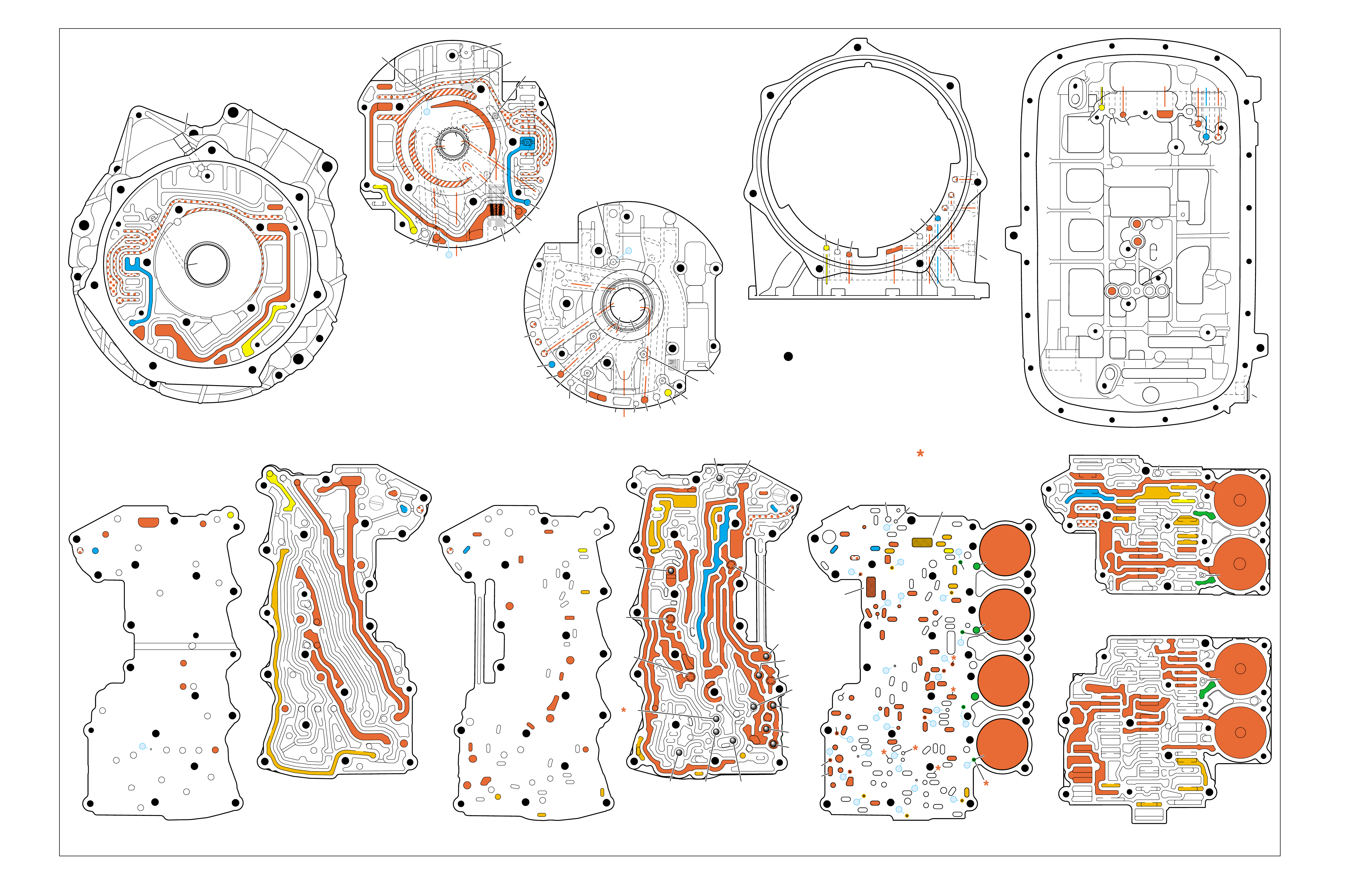
Figure 99
OVERDRIVE RANGE – FIFTH GEAR
(Torque Converter Clutch Applied)
➤➤
➤
➤
➤➤
➤
➤
➤
➤ ➤
➤➤
➤
➤➤
➤ ➤
➤
➤➤
➤➤
➤
➤
➤
➤ ➤
➤➤
TORQUE CONVERTER HOUSING (227)
(Fluid Pump Cover Side)
➤
➤
➤
➤
➤➤➤
➤➤
➤
➤
➤
➤➤
➤ ➤➤
➤ ➤
➤
➤
TOP CHANNEL PLATE (301)
(Case Side)
FRONT
➤
TOP CHANNEL PLATE (301)
(Bottom Channel Plate Side)
FRONT
➤
BOTTOM CHANNEL PLATE (304)
(Top Channel Plate Side)
FRONT
➤
REAR CONTROL VALVE BODY (310)
(Bottom Channel Plate Side)
FRONT
➤
CASE (24)
(Top Channel Plate Side)
FRONT
➤
CASE (24)
(Fluid Pump Cover Side)
SPACER PLATE (307)
(Bottom Channel Plate Side)
FRONT
➤
FRONT CONTROL VALVE BODY (311)
(Bottom Channel Plate Side)
FRONT
➤
BOTTOM CHANNEL PLATE (304)
(Control Valve Body Side)
FRONT
➤
NOTE:
–INDICATES BOLT HOLES
–NON FUNCTIONAL HOLES HAVE BEEN
REMOVED FROM COMPONENT DRAWINGS
TO SIMPLIFY TRACING FLUID FLOW.
–DUAL PURPOSE PASSAGES HAVE
CHANNEL PLATE SIDE NUMBERS LISTED FIRST
–EXHAUST FLUID NOT SHOWN
–PASSAGES MARKED WITH ARE USED FOR
THE 5L40-E ONLY
FLUID PUMP COVER (202)
(Case Side)
FLUID PUMP COVER (202)
(Torque Converter Housing Side)
➤
➤
➤
7
➤
25
➤
27
➤
3
➤
20
➤
16
➤
2
➤
10
➤
9
➤
24
➤
15
➤
11
➤
22
➤
29
➤
28
➤
23
➤
18
➤
17
➤
14
➤
8
➤
4
➤
5
➤
26
➤
13
➤
19
➤
21
➤
6
➤
12
(40)
➤
21
(203)
➤
16
(203)
➤➤
(232)
➤➤
(229)
➤➤
(231)
➤➤
(213)
➤
(233)
➤
TRANSMISSION
VENT
ASSEMBLY
➤➤
32
(203)
➤
37
(203)
➤➤
2/21
(214)
➤➤
(36)
➤
FILTER
(312)
➤
FILTER
(308)
➤
#12
#2
#3
#5
#6
#7
(Spring)
#8
#10 #9
#4
#1
#11
X-2
X-4
X-5
X-1
X-3
12
2
23
24
48
48
48
48
48
48
48
48
52
52
52
52
52
52
52
23
36
36
36
20
27
28
46
47
47
19
16
15
13
10
10
10
11
54
2
54
37
37
37
39
38
40
42
43
40
27
7
48
48
48
52
52
52
52
52
52
52
24
25
25
25
2525
26
26
15 19 19
19
19
31
21
20 20
15 17
17
14
13
14
54
22
22
28
28
22
22
32
42 43
44
44
48
48
48
48
48
48
44
44
38
39
38
33
33
30
35
40
35
35
36
35
34
30
30
30
33
2
2
10
10 10
10
27
2
216
24
15
18
7
32
52
52
52
52 52
52
52
52
52
52
52
52
52 52
52
52
52
52
30 34
35
41
12 21 37
8
9
2
16
24
7
32
12 21
37
12
21
21
24
848
7
9
9
52
52
2
16
5
16
37
32
32
52
1
52
52
52
48
37
1
2
51
51
52
12
12
24
24
52
2
2
4
4
4
4
5
66
8
8
7
7
7
5
9
48
48
48
48
48
48
48
48
53
53
48
52
2
3
3
3
2
1
16
21
21
16
32
37
32
51
50
50
51 52
52
52
52
52
52
48
48
48
48
52
48
48
12
12
24
24
2
2
3
2
4
4
4
5
6
53
53
8
8
7
7
7
48
16
16
21 32
37
➤➤
1
➤➤
31
➤➤
30
(233)
➤➤
33
32
38
38
38
30
30
24
37
37
37
40
40
12
16
15
15
23 52
24
24
23
28
47
41
42
43
27
28
28
27
27
25
25
26
22
22
15
13
18 19
19
19
19
19
19
19
21
17
17
22
23
23
48
48
48
48
48
48
48
48
48
15
13
36
36
36
36
39
35
35
34
10
10 11
10
10
10
20
20
48
44
44
45
43 42
52
48
48
77
2
2
2
2
2
2
2
52
52
12a
16a
15d/16 15c/16
15b
23c
24a 24b
24c
25b
25c 25d
25e
26b
26a
32a
30a
33a
35a
39a
36a
36b
36c
36d
38a 39b
39c/41
40c/41
36e
36f
35b
35c 35d
37c
37d
37b
37a
40b
40a
38d 38b
38c
38e
40d
34a
33e
33c
33d
33b
30b
30c 30d
25a
23b
23a
20a
28c
27c/46
27b
28b
28a
27a
47b
47a
20b
20d
20c
13a
15a
19e
19h
19g
19i
19j
19f
13b 15e
17a
17b
17c/18
15f/18
19b/21
19c/21
19d/21
19a
22a
22b
22c
22d
22f
21a
21b/31
21c/31
22g/23
14a/23
22e
48
48
48
48
48
48
48
52
52
52
52
52
52
52
52
48
48
2g
7a
7b 2a/54a
2b
42b
43a
42a
43b
44c
44d 44b
44a
44e
43c/45
44f/45
48a 48b
2c/54c
54d
2d/54e
2e 2m/54g
2f
10i
10h
10f
10e
10d
10a 10c
11b
11a/10b
10g
2h
54f
54b
48
32
38
30
24 12
16
13
15
15
13
18
19
19
19
21
21
22
16 48
48
48
48
48
48
48
48
36
35
35
34
2
2
7
2
10
10
10
10
41
42
43
43
42
48 48
20
28
27
37
27
28
28
27
20
48
52
52
32
32
32
38
24
12 16
16
18
28
28
28
27
27
48 48
43 42
42
43
48
30
48
48
48 48
48
48
48
48
48
48
48
48
35
36
37
34
2
7
2
10
13
13
15
19
41
41
19
19
15
22
21
21
20
20
21
21
13
10
10
10
2
48
48 48
52
52
52
52
52
52
12
32
37 21
24
2
16
18
48
48
48
48
48
30
48
48
48
48
48
48
15
35
41
34
7
52
52
52
52
52
52
FOLDOUT ➤ 103
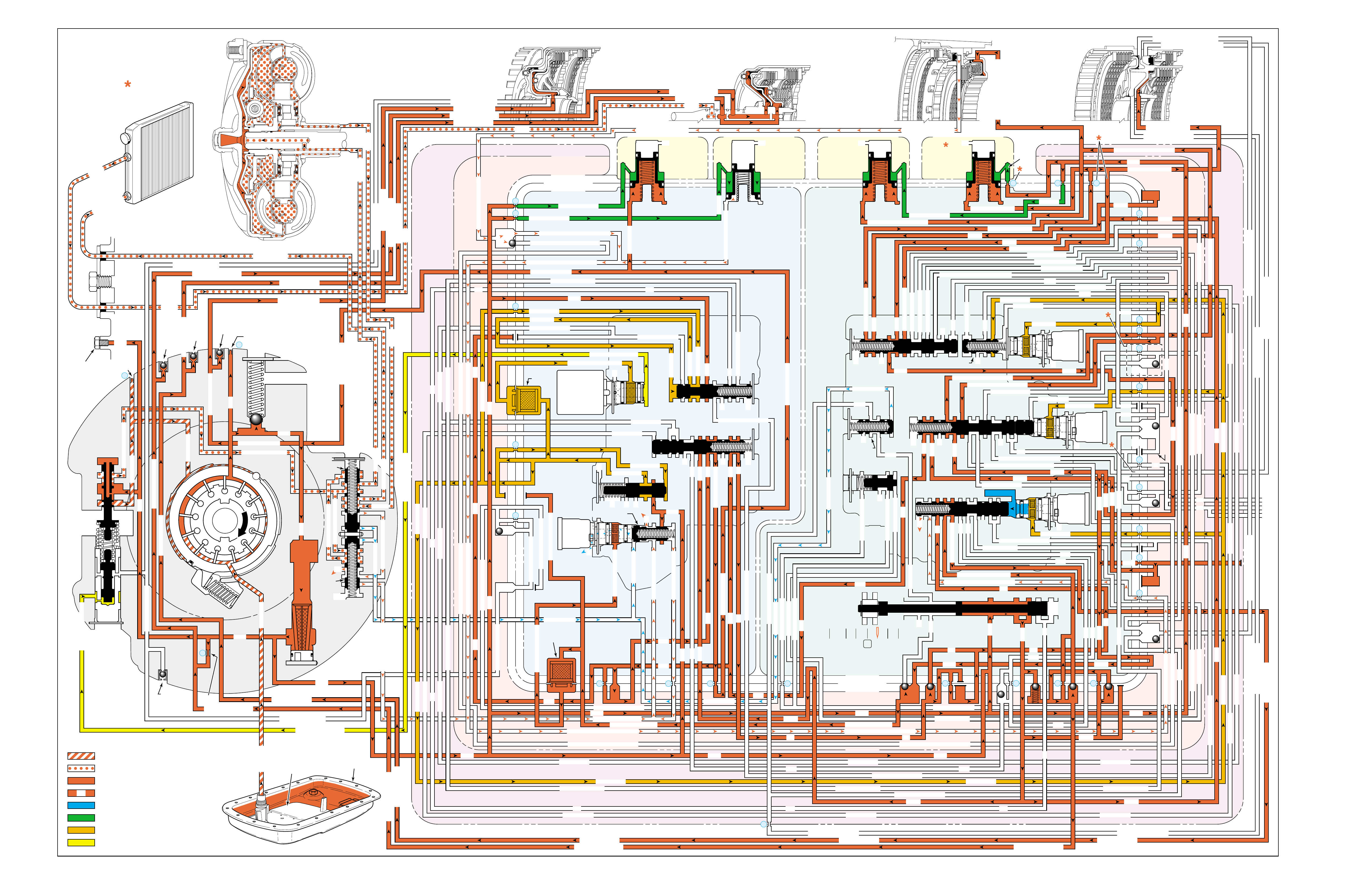
Figure 100
MANUAL FOURTH – FOURTH GEAR
(from Overdrive Range – Fifth Gear)
PRESSURES
INTAKE & DECREASE (SUCTION)
CONVERTER & LUBE
MAINLINE
REGULATED LINE
SOLENOID SIGNAL
ACCUMULATOR
FEED LIMIT
THROTTLE SIGNAL
NOTE:
PASSAGES AND
COMPONENTS
MARKED WITH
ARE USED FOR
THE 5L40-E ONLY
GASKET (309)
GASKET (305)
GASKET (303)
BOTTOM CHANNEL PLATE (304)
TOP CHANNEL PLATE (301)
CASE (24)
REAR CONTROL VALVE BODY (310)
SPACER PLATE (307)
GASKET (309)
GASKET (305)
GASKET (303)
BOTTOM CHANNEL PLATE (304)
TOP CHANNEL PLATE (301)
CASE (24)
FRONT CONTROL VALVE BODY (311)
SPACER PLATE (307)
FLUID
PUMP
COVER
(202)
CONVERTER
HOUSING
(224)
ACCUMULATOR HOUSING (317) ACCUMULATOR HOUSING (323) ACCUMULATOR HOUSING (328) ACCUMULATOR HOUSING (333)
LUBE
LUBE
LUBE
LUBE
TO COOLER
LUBE
TO COOLER
APPLY
APPLY
APPLY
RELEASE
DECREASE
DECREASE
LINE
OVERDRIVE CLUTCH FEED 1
OVERDRIVE CL FD 1OVERDRIVE CLUTCH FEED 1
OVERDRIVE CLUTCH FEED 1 OVERDRIVE CLUTCH FEED 1
OVERDRIVE CLUTCH
2345 2345
2345
2345
2345
2345
2345 OR REVERSE
RLO
LOW AND REV CL OR RLO
LOW AND REV CL OR RLO
SECOND COAST CLUTCH
SECOND CLUTCH
SECOND COAST CLUTCH
SUCTION SUCTION
LINE
LINE
LINE LINE
LINE
LINE
LINE LINE LINE
TCC SIGNAL
CONVERTER FEED
CONVERTER FEED
RELEASE
TO COOLER
REGULATED APPLYREGULATED APPLY
LINE
EX
CONVERTER FEED
REVERSE CLUTCH
REVERSE CLUTCH
THROTTLE SIGNAL
LINE
EX
FILTERED FEED LIMIT
THROTTLE SIGNAL
THROTTLE SIGNAL
THROTTLE SIGNAL
EX
2345 OR REVERSE
2345 OR REVERSE
2345 OR REVERSE
TCC SIGNAL
TCC SIGNAL
TCC SIGNAL
REGULATED APPLY
REGULATED APPLY
REGULATED APPLY
EX
EX
FEED LIMIT VALVE
LINE
EX
EX
EX
EX
FEED LIMIT
FEED LIMIT FEED LIMIT
FEED LIMIT
FEED LIMIT
FEED LIMIT
FEED LIMIT
FEED LIMIT FEED LIMIT
FEED LIMIT
EX
EX
EX
EX
EX
EX
EX EX
SECOND COAST CLUTCH
23 REGULATED
23 REGULATED
OVERDRIVE CLUTCH FEED 1
INTERMEDIATE CLUTCH
2345
2345
2345
2345
INTERMEDIATE CLUTCH
2345
345
FEED LIMIT
EX
EX
EX
EX
2-3 SIGNAL
LOW PRESSURE
123 REGULATED
123 REGULATED
EX
4-5 SHIFT VLV CNTRL
LINE SAFETY MODE
123 BRAKING
123
EX
EX
EX
123
123
123
123
123
123
123
123123
COAST CLUTCH
COAST CLUTCH FEED
OVERDRIVE CLUTCH FEED 2
45
FEED LIMIT
SAFETY MODE
LINE
FEED LIMIT
32
MEMORY
MEMORY
MEMORY
MEMORY PILOT
MEMORY PILOT
32 SAFETY MODE
LINE SAFETY MODE
EX
EX
LINE SAFETY MODE
2-3 SIGNAL
123123 D432D432
DIRECT CLUTCH
DIRECT CLUTCH
4545
1-2 SIGNAL
EX
EX
EX
FDL
FDL
FDL
FDL
FDL
FDL
D432
2345 2345
D432
SECOND CLUTCH
23 REGULATED
23 REGULATED23 REGULATED
123 REGULATED
LOW AND REVERSE CLUTCH
LOW AND REVERSE CL
SECOND CLUTCH
123 REGULATED
EX
EX
EX
FD LIMIT
FEED LIMIT
FDL
1-2 SIGNAL
2-3 SIGNAL
EX
EX
TCC SIGNAL
TCC SIGNAL
TCC SIGNAL
RLO
EX
REV
RPND432
MANUAL VALVE
LINE
D432
D432 D432
D432
D432
D432
D432 D432
D432
D432D432
D432
REV
REVERSE
EX
3232
LINE
EX
EX
LINE
CASE (24)
OVERDRIVE CLUTCH FEED 2
OVERDRIVE CL FD 2
OVERDRIVE CLUTCH FEED 2
ACCUMULATOR
DIRECT CLUTCH
ACCUM
INTERMEDIATE CLUTCH
INTERMEDIATE CLUTCH
INTERMEDIATE CLUTCH
ACCUMULATOR
EX
SECOND CLUTCH
SECOND CLUTCH
ACCUM
ACCUM
LINELINE
FORWARD CLUTCH
FORWARD CLUTCH FORWARD CLUTCH
ACCUMULATOR
LINE
LINELINE
LINE
OVERDRIVE CLUTCH
INTERMEDIATE CL
COAST CLUTCH
REVERSE LOCKOUT
COAST CLUTCH
REVERSE CLUTCH
REVERSE CLUTCH
REVERSE CLUTCH
4-5 SIGNAL
EXEXEX
LINE SAFETY MODE
LINE SAFETY MODE
REVERSE LOCKOUT
REVERSE LOCKOUT REVERSE LOCKOUT
COAST CLUTCH
REVERSE LOCKOUT REVERSE LOCKOUT
REVERSE LOCKOUT
REVERSE LOCKOUT
REVERSE LOCKOUT
REVERSE LOCKOUT
REVERSE CLUTCH
REVERSE CLUTCH
LOW AND REV CL OR RLO
FORWARD CLUTCH
FORWARD CLUTCH
FORWARD CLUTCH
COAST CLUTCH
FORWARD CLUTCH
FORWARD CLUTCH
FORWARD CLUTCH
2345
2345 OR REVERSE
123 REGULATED
123 REGULATED
123 REGULATED 123 REGULATED
123 REGULATED
123 REGULATED
123 REGULATED
123 BRAKING
123 BRAKING
123 BRAKING
123 BRAKING
1-2 SIGNAL1-2 SIGNAL
1-2 SIGNAL1-2 SIGNAL1-2 SIGNAL
1-2 SIGNAL 1-2 SIGNAL 1-2 SIGNAL
2-3 SIGNAL2-3 SIGNAL2-3 SIGNAL
2-3 SIGNAL 2-3 SIGNAL
2-3 SIGNAL2-3 SIGNAL2-3 SIGNAL
2-3 SIGNAL
SECOND CLUTCH
SECOND CLUTCH
COAST CLUTCHCOAST CLUTCHCOAST CLUTCH
COAST CLUTCH
COAST CLUTCH
COAST CLUTCH
COAST CLUTCH
COAST CLUTCH
23 REGULATED
345
345
345
345 345 345
345
345
345
345
345
345
345
345
DIRECT CLUTCH
DIRECT CLUTCH
DIRECT CLUTCH
DIRECT CL
DIRECT CLUTCH
DIRECT CLUTCH
DIRECT CLUTCH
DIRECT CLUTCH
45
45
45
4545
45
OVERDRIVE CLUTCH
OVERDRIVE CL FD 1
OVERDRIVE CLUTCH FEED 2OVERDRIVE CLUTCH FEED 2
OVERDRIVE CL FD 2
OVERDRIVE CLUTCH FEED 2 OVERDRIVE CL FD 2
3232
32 32 32
323232
32 SAFETY MODE
32 SAFETY MODE 32 SAFETY MODE 32 SAFETY MODE
32 SAFETY MODE32 SAFETY MODE
32 SM 32 SM
FDL
PRESSURE
CONTROL
SOLENOID
VALVE
1-2 SHIFT
SOLENOID
VALVE
N/C
(A)
OFF
2-3 SHIFT
SOLENOID
VALVE
N/C
(B)
OFF
4-5 SHIFT
SOLENOID
VALVE
N/C
(C)
ON
TCC PWM
SOLENOID
VALVE
N/C
PRESS REG VALVEBOOST VALVE
CONVERTER FDL
1-2 SHIFT VALVE
2-3 SHIFT VALVE CNTRL
CNTRL 3-4 SHIFT
AIR
BLEED
(233)
AIR
BLEED
(233)
AIR
BLEED
(203)
AIR
BLEED
(203)
AIR
BLEED
(203)
AIR
BLEED
(203)
7
4
2
1
5
6
11
10
9
12
18
FILTER
(308)
FILTER
(312)
TCC REGULATOR VALVE
TCC
CONTROL
VALVE
TCC
ENABLE
VALVE
REVERSE
LOCKOUT
VALVE
1-2 SHIFT CONTROL VALVE
FLUID
PAN
(62)
FLUID FILTER
ASSEMBLY
(59)
FLUID
PRESSURE
TEST PLUG
(40)
TORQUE
CONVERTER
ASSEMBLY
(1)
DIRECT
CLUTCH
ACCUMULATOR
OVERDRIVE
CLUTCH
ACCUMULATOR
INTERMEDIATE
CLUTCH
ACCUMULATOR
SECOND
CLUTCH
ACCUMULATOR
COOLER
PRESSURE
RELIEF
BALL
VALVE
21 2
10d
2a
2b
42b
43a
37d
39b
40b
37c
40d
11b
10a
24a
10c
11a 10b
54b
54d
2c
54a
54c
27c 46
7a
24b
20a
13a
37b
38a
7b
47a
47b
27b
28c
12a
23a
36e
36f
23b
23c
15a
24c
26b
36a
38c
38d
36b
25a
15
2m 54g
54f
#8
18
15f
15e
17c
17b
17a
27a
44a
44e
44d
44b
25c
30a
33a
25e
19e
35c
19h
19f
10f
10h
10g
22a
35b
#7
13b
32a
26a
10i
22f
22d
43b
22b
34a
48b
39a
22c
X-1
22
22e
21a
42a
19a
20b
19b
#2
23 22g
14a
2f
2h
19g
19i
19
j
DIRECT
AND REVERSE
CLUTCH
ASSEMBLY
(400–420)
FORWARD
AND COAST
CLUTCH
ASSEMBLY
(430–451)
OVERDRIVE
AND
INTERMEDIATE
CLUTCH
ASSEMBLY
(480–497)
CENTER
SUPPORT
ASSEMBLY
(510–535)
3
2d54e
2e
30c
30d
35d
26
37a
13
#1
15c
15b
16
15d 16
15
X-2
16a
X-4 X-5
38
14
X-3
19
#6
19d
19
21
19c 21
15
#5
21b 31
21c 31
17
21
#4
20d
20c
16
25b
19
25d
20
36 46
28a
44c
28b
30b
21
#11
33e
33d
23
2435a
#9
33c
33b
22
36d
36c
25
#12
41 40c
39c
43 13
2840a
#10
45
45
45
44f
44
48
43c
#3
38b
38e
27
48a29
8
10e
2310
32 SM/FDL
30
31
FLUID PUMP
SCREEN
ASSEMBLY
(213)
(214)
104

MANUAL FOURTH – FOURTH GEAR
(from Overdrive Range – Fifth Gear)
104A
NO FOURTH GEAR
•4-5 Shift Solenoid Valve (376)
–Stuck Off
–Leaking
–No voltage to the solenoid
•4-5 Shift Valve (374)
–Stuck
•4-5 Shift Control Valve (375)
–Stuck
•Coast Clutch Piston (438)
–Leaking
–Cracked or jammed
•Coast Clutch Piston Ball Check Valve (437)
–Leaking
•Input Shaft Fluid Seal Ring (432)
–Leaking
A manual 5-4 downshift can be accomplished by moving the gear
selector lever into the Manual Fourth position (4) when the
transmission is operating in Overdrive Range – Fifth Gear D .
SOLENOID FORWARD OVER- INTERM. INTER- LOW LOW AND SECOND SECOND
DIRECT REVERSE COAST FORWARD SPRAG DRIVE SPRAG MEDIATE SPRAG REVERSE SECOND SPRAG COAST
1-2 2-3 4-5 CLUTCH CLUTCH CLUTCH CLUTCH CLUTCH CLUTCH CLUTCH CLUTCH CLUTCH CLUTCH CLUTCH CLUTCH CLUTCH
OFF OFF ON APPLIED APPLIED APPLIED LD APPLIED APPLIED
LD = LOCKED IN DRIVE

104B
PASSAGES
1 SUCTION
2 LINE
3 DECREASE
4 CONVERTER FEED
5 RELEASE
6 APPLY
7 REGULATED APPLY
8 TO COOLER
9 LUBE
10 FEED LIMIT
11 FILTERED FEED LIMIT
12 THROTTLE SIGNAL
13 LINE SAFETY MODE
14 REVERSE
15 REVERSE LOCK OUT (RLO)
16 REVERSE CLUTCH
17 LOW AND REVERSE CLUTCH
18 LOW AND REVERSE CLUTCH OR RLO
19 D432
20 123
21 FORWARD CLUTCH
22 2345
23 2345 OR REVERSE
24 TCC SIGNAL
25 123 REGULATED
26 123 BRAKING
27 1-2 SIGNAL
28 2-3 SIGNAL
29 4-5 SIGNAL
30 SECOND CLUTCH
31 COAST CLUTCH FEED
32 COAST CLUTCH
33 23 REGULATED
34 SECOND COAST CLUTCH
35 INTERMEDIATE CLUTCH
36 345
37 DIRECT CLUTCH
38 45
39 OVERDRIVE CLUTCH FEED 1
40 OVERDRIVE CLUTCH FEED 2
41 OVERDRIVE CLUTCH
42 32
43 32 SAFETY MODE
44 FDL
45 32 SAFETY MODE/FDL
46 MEMORY PILOT
47 MEMORY
48 EXHAUST
49 OIL RESERVOIR
50 TORQUE CONVERTER SEAL DRAINBACK
51 VENT
52 VOID
53 CONVERTER FDL
54 ACCUMULATOR
COMPONENTS ( )
(36) TRANSMISSION FLUID LEVEL HOLE PLUG
(40) TRANSMISSION FLUID PRESSURE TEST PLUG
(203) CHECK VALVE RETAINER AND BALL ASSEMBLY
(213) TRANSMISSION FLUID PUMP SCREEN ASSEMBLY
(214) BRASS ORIFICE INSERT
(232) ORIFICE SLEEVE
(233) ORIFICE CUP PLUG
(306) CONTROL VALVE BODY BALL CHECK VALVE
(#1, 2, 3, 4, 5, 6, 7, 8, 9, 10, 11, 12)
(308) TCC PWM SOLENOID VALVE FILTER ASSEMBLY
(312) PRESSURE CONTROL SOLENOID VALVE
FILTER ASSEMBLY
MANUAL FOURTH – FOURTH GEAR
(from Overdrive Range – Fifth Gear)
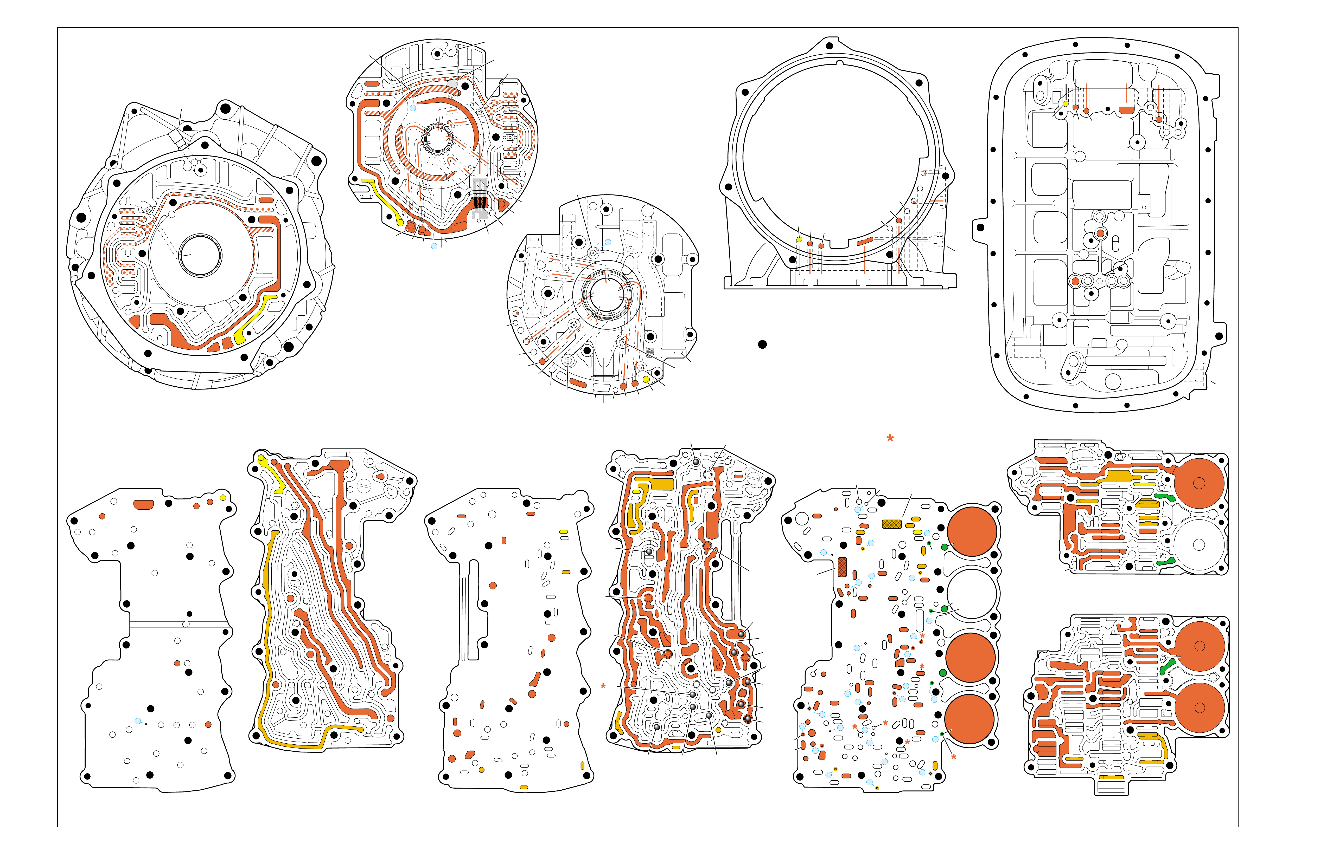
Figure 101
MANUAL FOURTH – FOURTH GEAR
(from Overdrive Range – Fifth Gear)
➤➤
➤
➤ ➤
➤
➤
➤➤
➤
➤➤
➤
➤
➤
➤➤
➤
➤➤
➤
➤
➤
➤
➤ ➤
➤➤
➤
➤
➤
TORQUE CONVERTER HOUSING (227)
(Fluid Pump Cover Side)
➤
➤
➤
➤
➤➤➤
➤➤
➤
➤
➤
➤ ➤
➤
➤
TOP CHANNEL PLATE (301)
(Case Side)
FRONT
➤
TOP CHANNEL PLATE (301)
(Bottom Channel Plate Side)
FRONT
➤
BOTTOM CHANNEL PLATE (304)
(Top Channel Plate Side)
FRONT
➤
REAR CONTROL VALVE BODY (310)
(Bottom Channel Plate Side)
FRONT
➤
CASE (24)
(Top Channel Plate Side)
FRONT
➤
CASE (24)
(Fluid Pump Cover Side)
SPACER PLATE (307)
(Bottom Channel Plate Side)
FRONT
➤
FRONT CONTROL VALVE BODY (311)
(Bottom Channel Plate Side)
FRONT
➤
BOTTOM CHANNEL PLATE (304)
(Control Valve Body Side)
FRONT
➤
NOTE:
–INDICATES BOLT HOLES
–NON FUNCTIONAL HOLES HAVE BEEN
REMOVED FROM COMPONENT DRAWINGS
TO SIMPLIFY TRACING FLUID FLOW.
–DUAL PURPOSE PASSAGES HAVE
CHANNEL PLATE SIDE NUMBERS LISTED FIRST
–EXHAUST FLUID NOT SHOWN
–PASSAGES MARKED WITH ARE USED FOR
THE 5L40-E ONLY
FLUID PUMP COVER (202)
(Case Side)
FLUID PUMP COVER (202)
(Torque Converter Housing Side)
➤
➤
➤
➤
➤
➤
➤ ➤
➤
➤
➤➤
➤
➤
➤
7
➤
25
➤
27
➤
3
➤
20
➤
16
➤
2
➤
10
➤
9
➤
24
➤
15
➤
11
➤
22
➤
29
➤
28
➤
23
➤
18
➤
17
➤
14
➤
8
➤
4
➤
5
➤
26
➤
13
➤
19
➤
21
➤
6
➤
12
(40)
➤
21
(203)
➤
16
(203)
➤➤
(232)
➤➤
(229)
➤➤
(231)
➤➤
(213)
➤
(233)
➤
TRANSMISSION
VENT
ASSEMBLY
➤➤
32
(203)
➤
37
(203)
➤➤
2/21
(214)
➤➤
(36)
➤
FILTER
(312)
➤
FILTER
(308)
➤
#12
#2
#3
#5
#6
#7
(Spring)
#8
#10 #9
#4
#1
#11
X-2
X-4
X-5
X-1
X-3
12
2
23
24
48
48
48
48
48
48
48
48
52
52
52
52
52
52
52
23
36
36
36
20
27
28
46
47
47
19
16
15
13
10
10
10
11
54
2
54
37
37
37
39
38
40
42
43
40
27
7
48
48
48
52
52
52
52
52
52
52
24
25
25
25
2525
26
26
15 19 19
19
19
31
21
20 20
15 17
17
14
13
14
54
22
22
28
28
22
22
32
42 43
44
44
48
48
48
48
48
48
44
44
38
39
38
33
33
30
35
40
35
35
36
35
34
30
30
30
33
2
2
10
10 10
10
27
2
216
24
15
18
7
32
52
52
52
52 52
52
52
52
52
52
52
52
52 52
52
52
52
52
30 34
35
41
12 21 37
8
9
2
16
24
7
32
12 21
37
12
21
21
24
848
7
9
9
52
52
2
16
5
16
37
32
32
52
1
52
52
52
48
37
1
2
51
51
52
12
12
24
24
52
2
2
4
4
4
4
5
66
8
8
7
7
7
5
9
48
48
48
48
48
48
48
48
53
53
48
52
2
3
3
3
2
1
16
21
21
16
32
37
32
51
50
50
51 52
52
52
52
52
52
48
48
48
48
52
48
48
12
12
24
24
2
2
3
2
4
4
4
5
6
53
53
8
8
7
7
7
48
16
16
21 32
37
➤➤
1
➤➤
31
➤➤
30
(233)
➤➤
33
32
38
38
38
30
30
24
37
37
37
40
40
12
16
15
15
23 52
24
24
23
28
47
41
42
43
27
28
28
27
27
25
25
26
22
22
15
13
18 19
19
19
19
19
19
19
21
17
17
22
23
23
48
48
48
48
48
48
48
48
48
15
13
36
36
36
36
39
35
35
34
10
10 11
10
10
10
20
20
48
44
44
45
43 42
52
48
48
77
2
2
2
2
2
2
2
52
52
12a
16a
15d/16 15c/16
15b
23c
24a 24b
24c
25b
25c 25d
25e
26b
26a
32a
30a
33a
35a
39a
36a
36b
36c
36d
38a 39b
39c/41
40c/41
36e
36f
35b
35c 35d
37c
37d
37b
37a
40b
40a
38d 38b
38c
38e
40d
34a
33e
33c
33d
33b
30b
30c 30d
25a
23b
23a
20a
28c
27c/46
27b
28b
28a
27a
47b
47a
20b
20d
20c
13a
15a
19e
19h
19g
19i
19j
19f
13b 15e
17a
17b
17c/18
15f/18
19b/21
19c/21
19d/21
19a
22a
22b
22c
22d
22f
21a
21b/31
21c/31
22g/23
14a/23
22e
48
48
48
48
48
48
48
52
52
52
52
52
52
52
52
48
48
2g
7a
7b 2a/54a
2b
42b
43a
42a
43b
44c
44d 44b
44a
44e
43c/45
44f/45
48a 48b
2c/54c
54d
2d/54e
2e 2m/54g
2f
10i
10h
10f
10e
10d
10a 10c
11b
11a/10b
10g
2h
54f
54b
48
32
38
30
24 12
16
13
15
15
13
18
19
19
19
21
21
22
16 48
48
48
48
48
48
48
48
36
35
35
34
2
2
7
2
10
10
10
10
41
42
43
43
42
48 48
20
28
27
37
27
28
28
27
20
48
52
52
32
32
32
38
24
12 16
16
18
28
28
28
27
27
48 48
43 42
42
43
48
30
48
48
48 48
48
48
48
48
48
48
48
48
35
36
37
34
2
7
2
10
13
13
15
19
41
41
19
19
15
22
21
21
20
20
21
21
13
10
10
10
2
48
48 48
52
52
52
52
52
52
12
32
37 21
24
2
16
18
48
48
48
48
48
30
48
48
48
48
48
48
15
35
41
34
7
52
52
52
52
52
52
FOLDOUT ➤ 105
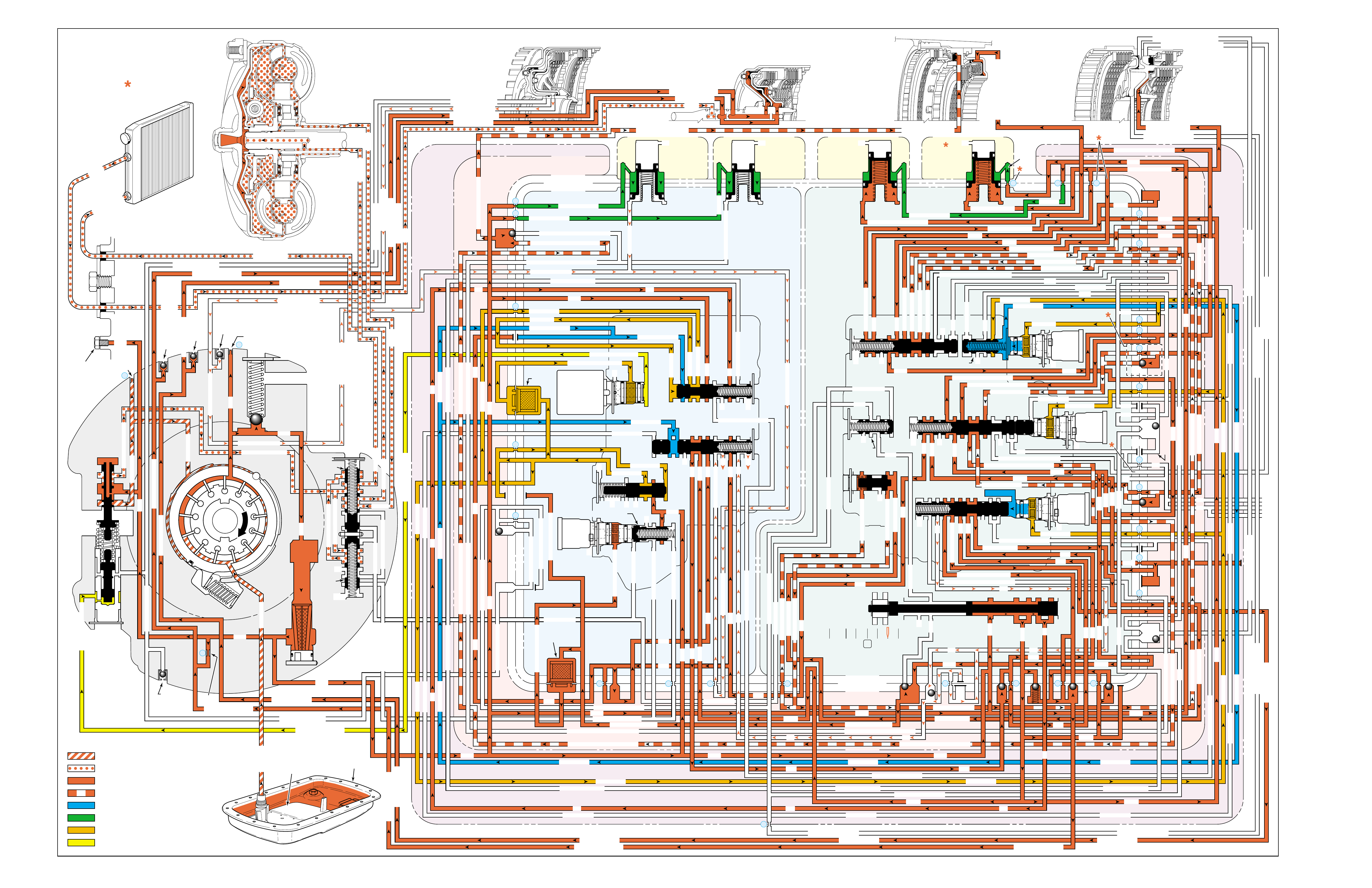
Figure 102
MANUAL THIRD – THIRD GEAR
(from Manual Fourth – Fourth Gear)
PRESSURES
INTAKE & DECREASE (SUCTION)
CONVERTER & LUBE
MAINLINE
REGULATED LINE
SOLENOID SIGNAL
ACCUMULATOR
FEED LIMIT
THROTTLE SIGNAL
NOTE:
PASSAGES AND
COMPONENTS
MARKED WITH
ARE USED FOR
THE 5L40-E ONLY
GASKET (309)
GASKET (305)
GASKET (303)
BOTTOM CHANNEL PLATE (304)
TOP CHANNEL PLATE (301)
CASE (24)
REAR CONTROL VALVE BODY (310)
SPACER PLATE (307)
GASKET (309)
GASKET (305)
GASKET (303)
BOTTOM CHANNEL PLATE (304)
TOP CHANNEL PLATE (301)
CASE (24)
FRONT CONTROL VALVE BODY (311)
SPACER PLATE (307)
FLUID
PUMP
COVER
(202)
CONVERTER
HOUSING
(224)
ACCUMULATOR HOUSING (317) ACCUMULATOR HOUSING (323) ACCUMULATOR HOUSING (328) ACCUMULATOR HOUSING (333)
LUBE
LUBE
LUBE
LUBE
TO COOLER
LUBE
TO COOLER
APPLY
APPLY
APPLY
RELEASE
DECREASE
DECREASE
LINE
OVERDRIVE CLUTCH FEED 1
OVERDRIVE CL FD 1OVERDRIVE CLUTCH FEED 1
OVERDRIVE CLUTCH FEED 1 OVERDRIVE CLUTCH FEED 1
OVERDRIVE CLUTCH
2345 2345
2345
2345
2345
2345
2345 OR REVERSE
RLO
LOW AND REV CL OR RLO
LOW AND REV CL OR RLO
SECOND COAST CLUTCH
SECOND CLUTCH
SECOND COAST CLUTCH
SUCTION SUCTION
LINE
LINE
LINE LINE
LINE
LINE
LINE LINE LINE
TCC SIGNAL
CONVERTER FEED
CONVERTER FEED
RELEASE
TO COOLER
REGULATED APPLYREGULATED APPLY
LINE
EX
CONVERTER FEED
REVERSE CLUTCH
REVERSE CLUTCH
THROTTLE SIGNAL
LINE
EX
FILTERED FEED LIMIT
THROTTLE SIGNAL
THROTTLE SIGNAL
THROTTLE SIGNAL
EX
2345 OR REVERSE
2345 OR REVERSE
2345 OR REVERSE
TCC SIGNAL
TCC SIGNAL
TCC SIGNAL
REGULATED APPLY
REGULATED APPLY
REGULATED APPLY
EX
EX
FEED LIMIT VALVE
LINE
EX
EX
EX
EX
FEED LIMIT
FEED LIMIT FEED LIMIT
FEED LIMIT
FEED LIMIT
FEED LIMIT
FEED LIMIT
FEED LIMIT FEED LIMIT
FEED LIMIT
EX
EX
EX
EX
EX
EX
EX EX
SECOND COAST CLUTCH
23 REGULATED
23 REGULATED
OVERDRIVE CLUTCH FEED 1
INTERMEDIATE CLUTCH
2345
2345
2345
2345
INTERMEDIATE CLUTCH
2345
345
FEED LIMIT
EX
EX
EX
EX
2-3 SIGNAL
LOW PRESSURE
123 REGULATED
123 REGULATED
EX
LINE SAFETY MODE
123 BRAKING
123
EX
EX
EX
123
123
123
123
123
123
123
123123
COAST CLUTCH
COAST CLUTCH FEED
OVERDRIVE CLUTCH FEED 2
45
FEED LIMIT
SAFETY MODE
LINE
FEED LIMIT
32
MEMORY
MEMORY
MEMORY
MEMORY PILOT
MEMORY PILOT
32 SAFETY MODE
LINE SAFETY MODE
EX
EX
LINE SAFETY MODE
3-4 SHIFT
2-3 SIGNAL
123123 D432D432
DIRECT CLUTCH
DIRECT CLUTCH
4545
1-2 SIGNAL
EX
EX
EX
FDL
FDL
FDL
FDL
FDL
FDL
D432
2345 2345
D432
SECOND CLUTCH
23 REGULATED
23 REGULATED23 REGULATED
123 REGULATED
LOW AND REVERSE CLUTCH
LOW AND REVERSE CL
SECOND CLUTCH
123 REGULATED
EX
EX
EX
FD LIMIT
FEED LIMIT
FDL
1-2 SIGNAL
2-3 SIGNAL
EX
EX
TCC SIGNAL
TCC SIGNAL
TCC SIGNAL
RLO
EX
REV
RPND432
MANUAL VALVE
LINE
D432
D432 D432
D432
D432
D432
D432 D432
D432
D432D432
D432
REV
REVERSE
EX
3232
LINE
EX
EX
LINE
CASE (24)
OVERDRIVE CLUTCH FEED 2
OVERDRIVE CL FD 2
OVERDRIVE CLUTCH FEED 2
ACCUMULATOR
DIRECT CLUTCH
ACCUM
INTERMEDIATE CLUTCH
INTERMEDIATE CLUTCH
INTERMEDIATE CLUTCH
ACCUMULATOR
EX
SECOND CLUTCH
SECOND CLUTCH
ACCUM
ACCUM
LINELINE
FORWARD CLUTCH
FORWARD CLUTCH FORWARD CLUTCH
ACCUMULATOR
LINE
LINELINE
LINE
OVERDRIVE CLUTCH
INTERMEDIATE CL
COAST CLUTCH
REVERSE LOCKOUT
COAST CLUTCH
REVERSE CLUTCH
REVERSE CLUTCH
REVERSE CLUTCH
4-5 SIGNAL
EXEXEX
LINE SAFETY MODE
LINE SAFETY MODE
REVERSE LOCKOUT
REVERSE LOCKOUT REVERSE LOCKOUT
COAST CLUTCH
REVERSE LOCKOUT REVERSE LOCKOUT
REVERSE LOCKOUT
REVERSE LOCKOUT
REVERSE LOCKOUT
REVERSE LOCKOUT
REVERSE CLUTCH
REVERSE CLUTCH
LOW AND REV CL OR RLO
FORWARD CLUTCH
FORWARD CLUTCH
FORWARD CLUTCH
COAST CLUTCH
FORWARD CLUTCH
FORWARD CLUTCH
FORWARD CLUTCH
2345
2345 OR REVERSE
123 REGULATED
123 REGULATED
123 REGULATED 123 REGULATED
123 REGULATED
123 REGULATED
123 REGULATED
123 BRAKING
123 BRAKING
123 BRAKING
123 BRAKING
1-2 SIGNAL1-2 SIGNAL
1-2 SIGNAL1-2 SIGNAL1-2 SIGNAL
1-2 SIGNAL 1-2 SIGNAL 1-2 SIGNAL
2-3 SIGNAL2-3 SIGNAL2-3 SIGNAL
2-3 SIGNAL 2-3 SIGNAL
2-3 SIGNAL2-3 SIGNAL2-3 SIGNAL
2-3 SIGNAL
SECOND CLUTCH
SECOND CLUTCH
COAST CLUTCHCOAST CLUTCHCOAST CLUTCH
COAST CLUTCH
COAST CLUTCH
COAST CLUTCH
COAST CLUTCH
COAST CLUTCH
23 REGULATED
345
345
345
345 345 345
345
345
345
345
345
345
345
345
DIRECT CLUTCH
DIRECT CLUTCH
DIRECT CLUTCH
DIRECT CL
DIRECT CLUTCH
DIRECT CLUTCH
DIRECT CLUTCH
DIRECT CLUTCH
45
45
45
4545
45
OVERDRIVE CLUTCH
OVERDRIVE CL FD 1
OVERDRIVE CLUTCH FEED 2OVERDRIVE CLUTCH FEED 2
OVERDRIVE CL FD 2
OVERDRIVE CLUTCH FEED 2 OVERDRIVE CL FD 2
3232
32 32 32
323232
32 SAFETY MODE
32 SAFETY MODE 32 SAFETY MODE 32 SAFETY MODE
32 SAFETY MODE32 SAFETY MODE
32 SM 32 SM
FDL
PRESSURE
CONTROL
SOLENOID
VALVE
1-2 SHIFT
SOLENOID
VALVE
N/C
(A)
ON
2-3 SHIFT
SOLENOID
VALVE
N/C
(B)
OFF
4-5 SHIFT
SOLENOID
VALVE
N/C
(C)
ON
TCC PWM
SOLENOID
VALVE
N/C
PRESS REG VALVEBOOST VALVE
CONVERTER FDL
1-2 SHIFT VALVE
2-3 SHIFT VALVE CNTRL
CNTRL
4-5 SHIFT VLV CNTRL
AIR
BLEED
(233)
AIR
BLEED
(233)
AIR
BLEED
(203)
AIR
BLEED
(203)
AIR
BLEED
(203)
AIR
BLEED
(203)
7
4
2
1
5
6
11
10
9
12
18
FILTER
(308)
FILTER
(312)
TCC REGULATOR VALVE
TCC
CONTROL
VALVE
TCC
ENABLE
VALVE
REVERSE
LOCKOUT
VALVE
1-2 SHIFT CONTROL VALVE
FLUID
PAN
(62)
FLUID FILTER
ASSEMBLY
(59)
FLUID
PRESSURE
TEST PLUG
(40)
TORQUE
CONVERTER
ASSEMBLY
(1)
DIRECT
CLUTCH
ACCUMULATOR
OVERDRIVE
CLUTCH
ACCUMULATOR
INTERMEDIATE
CLUTCH
ACCUMULATOR
SECOND
CLUTCH
ACCUMULATOR
COOLER
PRESSURE
RELIEF
BALL
VALVE
21 2
10d
2a
2b
42b
43a
37d
39b
40b
37c
40d
11b
10a
24a
10c
11a 10b
54b
54d
2c
54a
54c
27c 46
7a
24b
20a
13a
37b
38a
7b
47a
47b
27b
28c
12a
23a
36e
36f
23b
23c
15a
24c
26b
36a
38c
38d
36b
25a
15
2m 54g
54f
#8
18
15f
15e
17c
17b
17a
27a
44a
44e
44d
44b
25c
30a
33a
25e
19e
35c
19h
19f
10f
10h
10g
22a
35b
#7
13b
32a
26a
10i
22f
22d
43b
22b
34a
48b
39a
22c
X-1
22
22e
21a
42a
19a
20b
19b
#2
23 22g
14a
2f
2h
19g
19i
19
j
DIRECT
AND REVERSE
CLUTCH
ASSEMBLY
(400–420)
FORWARD
AND COAST
CLUTCH
ASSEMBLY
(430–451)
OVERDRIVE
AND
INTERMEDIATE
CLUTCH
ASSEMBLY
(480–497)
CENTER
SUPPORT
ASSEMBLY
(510–535)
3
2d54e
2e
30c
30d
35d
26
37a
13
#1
15c
15b
16
15d 16
15
X-2
16a
X-4 X-5
38
14
X-3
19
#6
19d
19
21
19c 21
15
#5
21b 31
21c 31
17
21
#4
20d
20c
16
25b
19
25d
20
36 46
28a
44c
28b
30b
21
#11
33e
33d
23
2435a
#9
33c
33b
22
36d
36c
25
#12
41 40c
39c
43 13
2840a
#10
45
45
45
44f
44
48
43c
#3
38b
38e
27
48a29
8
10e
2310
32 SM/FDL
30
31
FLUID PUMP
SCREEN
ASSEMBLY
(213)
(214)
106

MANUAL THIRD – THIRD GEAR
(from Manual Fourth – Fourth Gear)
106A
NO THIRD GEAR
•1-2 Shift Solenoid Valve (368)
–Stuck Off
–Leaking
–No voltage to solenoid
•3-4 Shift Valve (345)
–Stuck
NO ENGINE BRAKING
•4-5 Shift Solenoid Valve (376)
–Leaking
–No voltage to solenoid
•Low Pressure Control Valve (383)
–Stuck
•#12 Ball Check Valve
–Stuck
–Missing
•Fluid Passage Sleeve (39)
–Leaking
•Overdrive Clutch Piston (487)
–Leaking
–Cracked or jammed
A manual 4-3 downshift can be accomplished by moving the gear
selector lever into the Manual Third (3) position when the
transmission is operating in Fourth gear. This causes the
transmission to shift into Third gear and prevents the transmission
from upshifting to either Fourth or Fifth gears.
SOLENOID FORWARD OVER- INTERM. INTER- LOW LOW AND SECOND SECOND
DIRECT REVERSE COAST FORWARD SPRAG DRIVE SPRAG MEDIATE SPRAG REVERSE SECOND SPRAG COAST
1-2 2-3 4-5 CLUTCH CLUTCH CLUTCH CLUTCH CLUTCH CLUTCH CLUTCH CLUTCH CLUTCH CLUTCH CLUTCH CLUTCH CLUTCH
ON OFF ON APPLIED APPLIED LD APPLIED LD APPLIED APPLIED
LD = LOCKED IN DRIVE

106B
PASSAGES
1 SUCTION
2 LINE
3 DECREASE
4 CONVERTER FEED
5 RELEASE
6 APPLY
7 REGULATED APPLY
8 TO COOLER
9 LUBE
10 FEED LIMIT
11 FILTERED FEED LIMIT
12 THROTTLE SIGNAL
13 LINE SAFETY MODE
14 REVERSE
15 REVERSE LOCK OUT (RLO)
16 REVERSE CLUTCH
17 LOW AND REVERSE CLUTCH
18 LOW AND REVERSE CLUTCH OR RLO
19 D432
20 123
21 FORWARD CLUTCH
22 2345
23 2345 OR REVERSE
24 TCC SIGNAL
25 123 REGULATED
26 123 BRAKING
27 1-2 SIGNAL
28 2-3 SIGNAL
29 4-5 SIGNAL
30 SECOND CLUTCH
31 COAST CLUTCH FEED
32 COAST CLUTCH
33 23 REGULATED
34 SECOND COAST CLUTCH
35 INTERMEDIATE CLUTCH
36 345
37 DIRECT CLUTCH
38 45
39 OVERDRIVE CLUTCH FEED 1
40 OVERDRIVE CLUTCH FEED 2
41 OVERDRIVE CLUTCH
42 32
43 32 SAFETY MODE
44 FDL
45 32 SAFETY MODE/FDL
46 MEMORY PILOT
47 MEMORY
48 EXHAUST
49 OIL RESERVOIR
50 TORQUE CONVERTER SEAL DRAINBACK
51 VENT
52 VOID
53 CONVERTER FDL
54 ACCUMULATOR
COMPONENTS ( )
(36) TRANSMISSION FLUID LEVEL HOLE PLUG
(40) TRANSMISSION FLUID PRESSURE TEST PLUG
(203) CHECK VALVE RETAINER AND BALL ASSEMBLY
(213) TRANSMISSION FLUID PUMP SCREEN ASSEMBLY
(214) BRASS ORIFICE INSERT
(232) ORIFICE SLEEVE
(233) ORIFICE CUP PLUG
(306) CONTROL VALVE BODY BALL CHECK VALVE
(#1, 2, 3, 4, 5, 6, 7, 8, 9, 10, 11, 12)
(308) TCC PWM SOLENOID VALVE FILTER ASSEMBLY
(312) PRESSURE CONTROL SOLENOID VALVE
FILTER ASSEMBLY
MANUAL THIRD – THIRD GEAR
(from Manual Fourth – Fourth Gear)
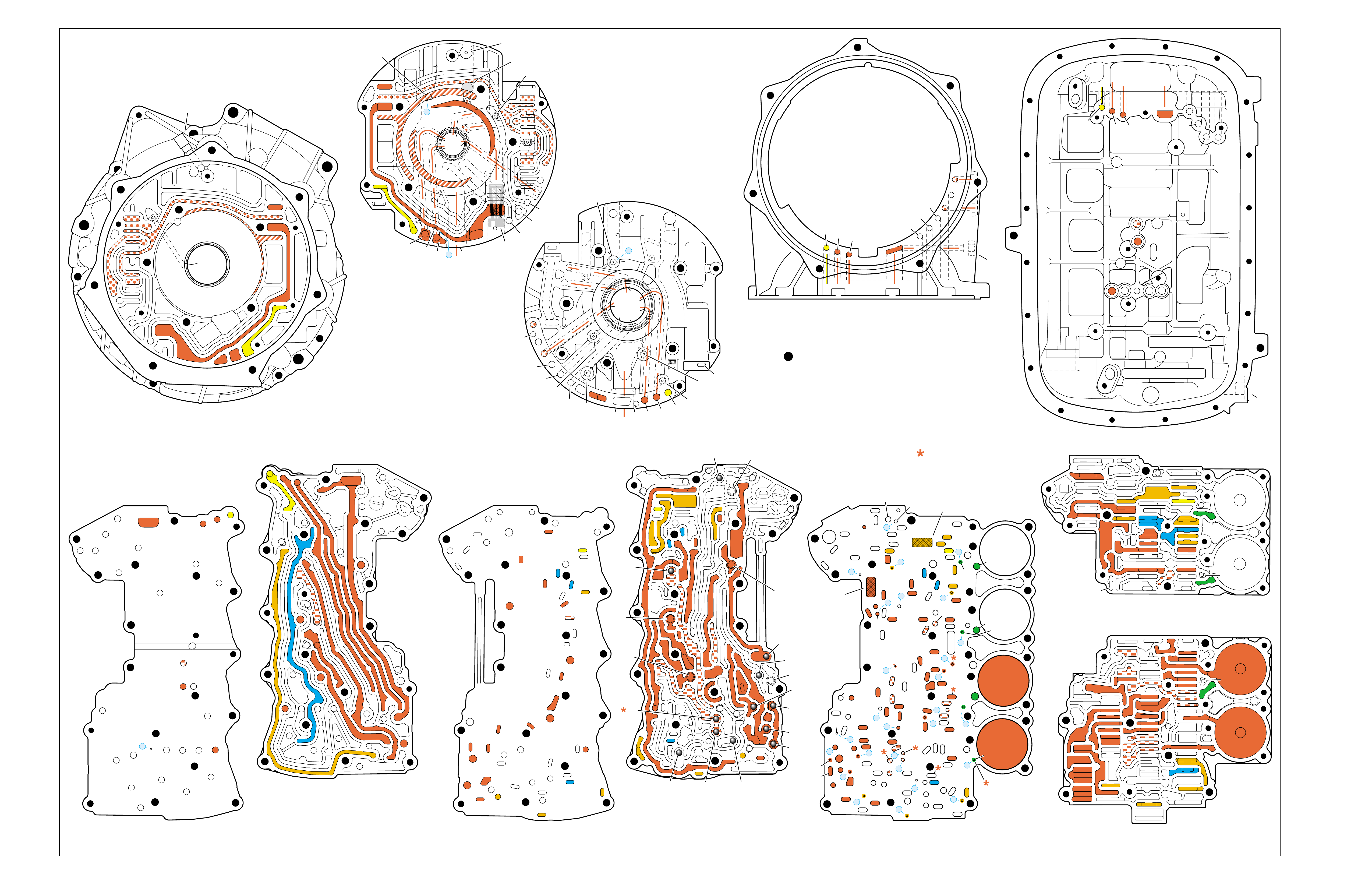
Figure 103
MANUAL THIRD – THIRD GEAR
(from Manual Fourth – Fourth Gear)
➤
➤➤
➤
➤➤
➤
➤
➤
➤➤
➤
➤➤
➤
➤
➤
➤
➤ ➤
➤➤
➤
➤
➤
TORQUE CONVERTER HOUSING (227)
(Fluid Pump Cover Side)
➤
➤
➤
➤
➤➤➤
➤
➤
➤ ➤
➤
➤
TOP CHANNEL PLATE (301)
(Case Side)
FRONT
➤
TOP CHANNEL PLATE (301)
(Bottom Channel Plate Side)
FRONT
➤
BOTTOM CHANNEL PLATE (304)
(Top Channel Plate Side)
FRONT
➤
REAR CONTROL VALVE BODY (310)
(Bottom Channel Plate Side)
FRONT
➤
CASE (24)
(Top Channel Plate Side)
FRONT
➤
CASE (24)
(Fluid Pump Cover Side)
SPACER PLATE (307)
(Bottom Channel Plate Side)
FRONT
➤
FRONT CONTROL VALVE BODY (311)
(Bottom Channel Plate Side)
FRONT
➤
BOTTOM CHANNEL PLATE (304)
(Control Valve Body Side)
FRONT
➤
NOTE:
–INDICATES BOLT HOLES
–NON FUNCTIONAL HOLES HAVE BEEN
REMOVED FROM COMPONENT DRAWINGS
TO SIMPLIFY TRACING FLUID FLOW.
–DUAL PURPOSE PASSAGES HAVE
CHANNEL PLATE SIDE NUMBERS LISTED FIRST
–EXHAUST FLUID NOT SHOWN
–PASSAGES MARKED WITH ARE USED FOR
THE 5L40-E ONLY
FLUID PUMP COVER (202)
(Case Side)
FLUID PUMP COVER (202)
(Torque Converter Housing Side)
➤
➤
➤
➤
➤
➤
➤ ➤
➤
➤
➤➤
➤
➤
➤
7
➤
25
➤
27
➤
3
➤
20
➤
16
➤
2
➤
10
➤
9
➤
24
➤
15
➤
11
➤
22
➤
29
➤
28
➤
23
➤
18
➤
17
➤
14
➤
8
➤
4
➤
5
➤
26
➤
13
➤
19
➤
21
➤
6
➤
12
(40)
➤
21
(203)
➤
16
(203)
➤➤
(232)
➤➤
(229)
➤➤
(231)
➤➤
(213)
➤
(233)
➤
TRANSMISSION
VENT
ASSEMBLY
➤➤
32
(203)
➤
37
(203)
➤➤
2/21
(214)
➤➤
(36)
➤
FILTER
(312)
➤
FILTER
(308)
➤
#12
#2
#3
#5
#6
#7
(Spring)
#8
#10 #9
#4
#1
#11
X-2
X-4
X-5
X-1
X-3
12
2
23
24
48
48
48
48
48
48
48
48
52
52
52
52
52
52
52
23
36
36
36
20
27
28
46
47
47
19
16
15
13
10
10
10
11
54
2
54
37
37
37
39
38
40
42
43
40
27
7
48
48
48
52
52
52
52
52
52
52
24
25
25
25
2525
26
26
15 19 19
19
19
31
21
20 20
15 17
17
14
13
14
54
22
22
28
28
22
22
32
42 43
44
44
48
48
48
48
48
48
44
44
38
39
38
33
33
30
35
40
35
35
36
35
34
30
30
30
33
2
2
10
10 10
10
27
2
216
24
15
18
7
32
52
52
52
52 52
52
52
52
52
52
52
52
52 52
52
52
52
52
30 34
35
41
12 21 37
8
9
2
16
24
7
32
12 21
37
12
21
21
24
848
7
9
9
52
52
2
16
5
16
37
32
32
52
1
52
52
52
48
37
1
2
51
51
52
12
12
24
24
52
2
2
4
4
4
4
5
66
8
8
7
7
7
5
9
48
48
48
48
48
48
48
48
53
53
48
52
2
3
3
3
2
1
16
21
21
16
32
37
32
51
50
50
51 52
52
52
52
52
52
48
48
48
48
52
48
48
12
12
24
24
2
2
3
2
4
4
4
5
6
53
53
8
8
7
7
7
48
16
16
21 32
37
➤➤
1
➤➤
31
➤➤
30
(233)
➤➤
33
32
38
38
38
30
30
24
37
37
37
40
40
12
16
15
15
23 52
24
24
23
28
47
41
42
43
27
28
28
27
27
25
25
26
22
22
15
13
18 19
19
19
19
19
19
19
21
17
17
22
23
23
48
48
48
48
48
48
48
48
48
15
13
36
36
36
36
39
35
35
34
10
10 11
10
10
10
20
20
48
44
44
45
43 42
52
48
48
77
2
2
2
2
2
2
2
52
52
12a
16a
15d/16 15c/16
15b
23c
24a 24b
24c
25b
25c 25d
25e
26b
26a
32a
30a
33a
35a
39a
36a
36b
36c
36d
38a 39b
39c/41
40c/41
36e
36f
35b
35c 35d
37c
37d
37b
37a
40b
40a
38d 38b
38c
38e
40d
34a
33e
33c
33d
33b
30b
30c 30d
25a
23b
23a
20a
28c
27c/46
27b
28b
28a
27a
47b
47a
20b
20d
20c
13a
15a
19e
19h
19g
19i
19j
19f
13b 15e
17a
17b
17c/18
15f/18
19b/21
19c/21
19d/21
19a
22a
22b
22c
22d
22f
21a
21b/31
21c/31
22g/23
14a/23
22e
48
48
48
48
48
48
48
52
52
52
52
52
52
52
52
48
48
2g
7a
7b 2a/54a
2b
42b
43a
42a
43b
44c
44d 44b
44a
44e
43c/45
44f/45
48a 48b
2c/54c
54d
2d/54e
2e 2m/54g
2f
10i
10h
10f
10e
10d
10a 10c
11b
11a/10b
10g
2h
54f
54b
48
32
38
30
24 12
16
13
15
15
13
18
19
19
19
21
21
22
16 48
48
48
48
48
48
48
48
36
35
35
34
2
2
7
2
10
10
10
10
41
42
43
43
42
48 48
20
28
27
37
27
28
28
27
20
48
52
52
32
32
32
38
24
12 16
16
18
28
28
28
27
27
48 48
43 42
42
43
48
30
48
48
48 48
48
48
48
48
48
48
48
48
35
36
37
34
2
7
2
10
13
13
15
19
41
41
19
19
15
22
21
21
20
20
21
21
13
10
10
10
2
48
48 48
52
52
52
52
52
52
12
32
37 21
24
2
16
18
48
48
48
48
48
30
48
48
48
48
48
48
15
35
41
34
7
52
52
52
52
52
52
FOLDOUT ➤ 107
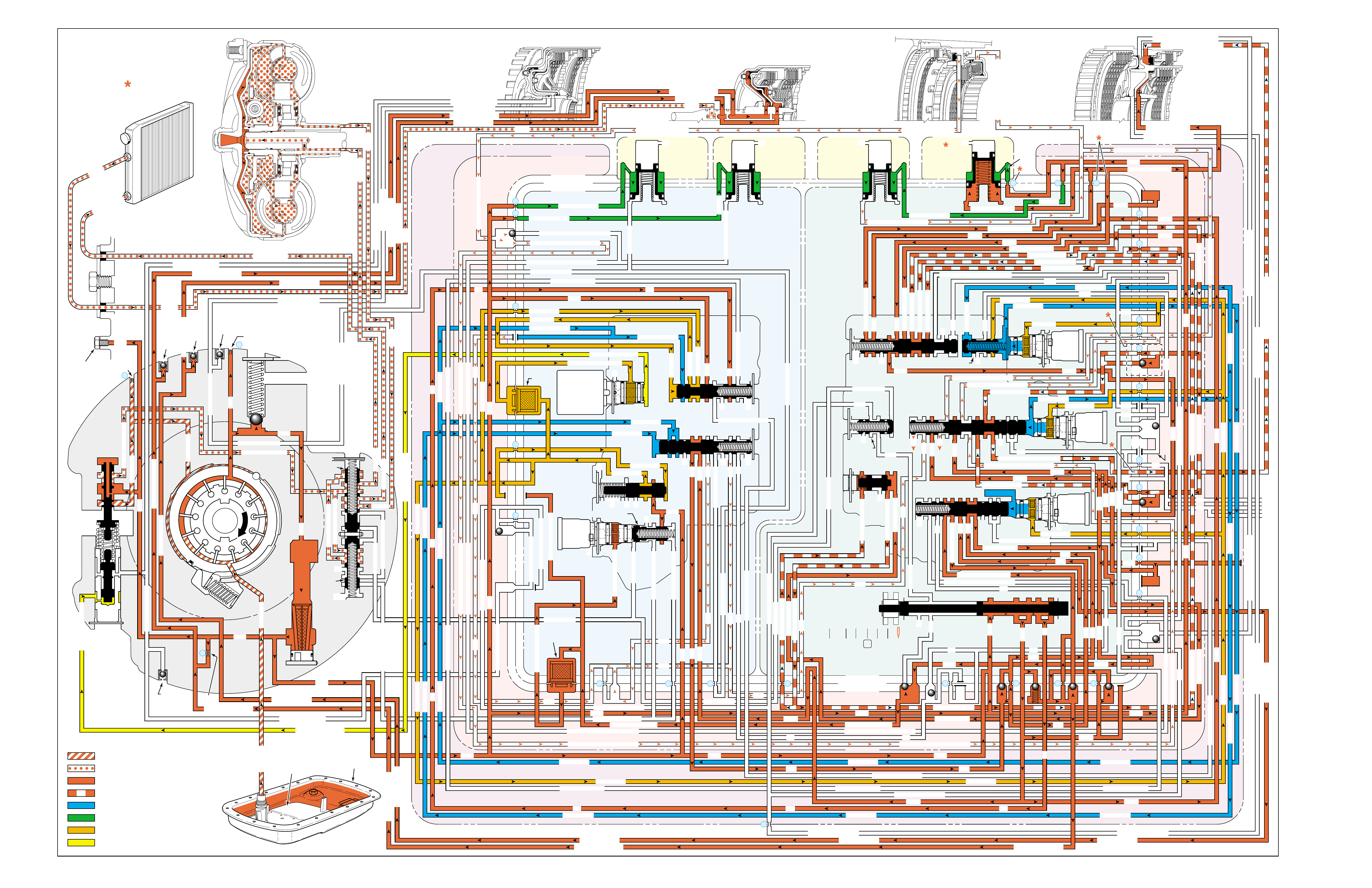
Figure 104
MANUAL SECOND – SECOND GEAR
(from Manual Third – Third Gear)
PRESSURES
INTAKE & DECREASE (SUCTION)
CONVERTER & LUBE
MAINLINE
REGULATED LINE
SOLENOID SIGNAL
ACCUMULATOR
FEED LIMIT
THROTTLE SIGNAL
NOTE:
PASSAGES AND
COMPONENTS
MARKED WITH
ARE USED FOR
THE 5L40-E ONLY
GASKET (309)
GASKET (305)
GASKET (303)
BOTTOM CHANNEL PLATE (304)
TOP CHANNEL PLATE (301)
CASE (24)
REAR CONTROL VALVE BODY (310)
SPACER PLATE (307)
GASKET (309)
GASKET (305)
GASKET (303)
BOTTOM CHANNEL PLATE (304)
TOP CHANNEL PLATE (301)
CASE (24)
FRONT CONTROL VALVE BODY (311)
SPACER PLATE (307)
FLUID
PUMP
COVER
(202)
CONVERTER
HOUSING
(224)
ACCUMULATOR HOUSING (317) ACCUMULATOR HOUSING (323) ACCUMULATOR HOUSING (328) ACCUMULATOR HOUSING (333)
LUBE
LUBE
LUBE
LUBE
TO COOLER
LUBE
TO COOLER
APPLY
APPLY
APPLY
RELEASE
DECREASE
DECREASE
LINE
OVERDRIVE CLUTCH FEED 1
OVERDRIVE CL FD 1OVERDRIVE CLUTCH FEED 1
OVERDRIVE CLUTCH FEED 1 OVERDRIVE CLUTCH FEED 1
OVERDRIVE CLUTCH
2345 2345
2345
2345
2345
2345
2345 OR REVERSE
RLO
LOW AND REV CL OR RLO
LOW AND REV CL OR RLO
SECOND COAST CLUTCH
SECOND CLUTCH
SECOND COAST CLUTCH
SUCTION SUCTION
LINE
LINE
LINE LINE
LINE
LINE
LINE LINE LINE
TCC SIGNAL
CONVERTER FEED
CONVERTER FEED
RELEASE
TO COOLER
REGULATED APPLYREGULATED APPLY
LINE
EX
CONVERTER FEED
REVERSE CLUTCH
REVERSE CLUTCH
THROTTLE SIGNAL
LINE
EX
FILTERED FEED LIMIT
THROTTLE SIGNAL
THROTTLE SIGNAL
THROTTLE SIGNAL
EX
2345 OR REVERSE
2345 OR REVERSE
2345 OR REVERSE
TCC SIGNAL
TCC SIGNAL
TCC SIGNAL
REGULATED APPLY
REGULATED APPLY
REGULATED APPLY
EX
EX
FEED LIMIT VALVE
LINE
EX
EX
EX
EX
FEED LIMIT
FEED LIMIT FEED LIMIT
FEED LIMIT
FEED LIMIT
FEED LIMIT
FEED LIMIT
FEED LIMIT FEED LIMIT
FEED LIMIT
2-3 SHIFT VALVE CNTRL
EX
EX
EX
EX
EX
EX
EX EX
SECOND COAST CLUTCH
23 REGULATED
23 REGULATED
OVERDRIVE CLUTCH FEED 1
INTERMEDIATE CLUTCH
2345
2345
2345
2345
INTERMEDIATE CLUTCH
2345
345
FEED LIMIT
EX
EX
EX
EX
2-3 SIGNAL
123 REGULATED
123 REGULATED
EX
LINE SAFETY MODE
123 BRAKING
123
EX
EX
EX
123
123
123
123
123
123
123
123123
COAST CLUTCH
COAST CLUTCH FEED
OVERDRIVE CLUTCH FEED 2
45
FEED LIMIT
SAFETY MODE
LINE
FEED LIMIT
32
MEMORY
MEMORY
MEMORY
MEMORY PILOT
MEMORY PILOT
32 SAFETY MODE
LINE SAFETY MODE
EX
EX
LINE SAFETY MODE
CNTRL 3-4 SHIFT
2-3 SIGNAL
123123 D432D432
DIRECT CLUTCH
DIRECT CLUTCH
4545
1-2 SIGNAL
EX
EX
EX
FDL
FDL
FDL
FDL
FDL
FDL
D432
2345 2345
D432
SECOND CLUTCH
23 REGULATED
23 REGULATED23 REGULATED
123 REGULATED
LOW AND REVERSE CLUTCH
LOW AND REVERSE CL
SECOND CLUTCH
123 REGULATED
EX
EX
EX
FD LIMIT
FEED LIMIT
FDL
1-2 SIGNAL
2-3 SIGNAL
EX
EX
TCC SIGNAL
TCC SIGNAL
TCC SIGNAL
RLO
EX
REV
RPND432
MANUAL VALVE
LINE
D432
D432 D432
D432
D432
D432
D432 D432
D432
D432D432
D432
REV
REVERSE
EX
3232
LINE
EX
EX
LINE
CASE (24)
OVERDRIVE CLUTCH FEED 2
OVERDRIVE CL FD 2
OVERDRIVE CLUTCH FEED 2
ACCUMULATOR
DIRECT CLUTCH
ACCUM
INTERMEDIATE CLUTCH
INTERMEDIATE CLUTCH
INTERMEDIATE CLUTCH
ACCUMULATOR
EX
SECOND CLUTCH
SECOND CLUTCH
ACCUM
ACCUM
LINELINE
FORWARD CLUTCH
FORWARD CLUTCH FORWARD CLUTCH
ACCUMULATOR
LINE
LINELINE
LINE
OVERDRIVE CLUTCH
INTERMEDIATE CL
COAST CLUTCH
REVERSE LOCKOUT
COAST CLUTCH
REVERSE CLUTCH
REVERSE CLUTCH
REVERSE CLUTCH
4-5 SIGNAL
EXEXEX
LINE SAFETY MODE
LINE SAFETY MODE
REVERSE LOCKOUT
REVERSE LOCKOUT REVERSE LOCKOUT
COAST CLUTCH
REVERSE LOCKOUT REVERSE LOCKOUT
REVERSE LOCKOUT
REVERSE LOCKOUT
REVERSE LOCKOUT
REVERSE LOCKOUT
REVERSE CLUTCH
REVERSE CLUTCH
LOW AND REV CL OR RLO
FORWARD CLUTCH
FORWARD CLUTCH
FORWARD CLUTCH
COAST CLUTCH
FORWARD CLUTCH
FORWARD CLUTCH
FORWARD CLUTCH
2345
2345 OR REVERSE
123 REGULATED
123 REGULATED
123 REGULATED 123 REGULATED
123 REGULATED
123 REGULATED
123 REGULATED
123 BRAKING
123 BRAKING
123 BRAKING
123 BRAKING
1-2 SIGNAL1-2 SIGNAL
1-2 SIGNAL1-2 SIGNAL1-2 SIGNAL
1-2 SIGNAL 1-2 SIGNAL 1-2 SIGNAL
2-3 SIGNAL2-3 SIGNAL2-3 SIGNAL
2-3 SIGNAL 2-3 SIGNAL
2-3 SIGNAL2-3 SIGNAL2-3 SIGNAL
2-3 SIGNAL
SECOND CLUTCH
SECOND CLUTCH
COAST CLUTCHCOAST CLUTCHCOAST CLUTCH
COAST CLUTCH
COAST CLUTCH
COAST CLUTCH
COAST CLUTCH
COAST CLUTCH
23 REGULATED
345
345
345
345 345 345
345
345
345
345
345
345
345
345
DIRECT CLUTCH
DIRECT CLUTCH
DIRECT CLUTCH
DIRECT CL
DIRECT CLUTCH
DIRECT CLUTCH
DIRECT CLUTCH
DIRECT CLUTCH
45
45
45
4545
45
OVERDRIVE CLUTCH
OVERDRIVE CL FD 1
OVERDRIVE CLUTCH FEED 2OVERDRIVE CLUTCH FEED 2
OVERDRIVE CL FD 2
OVERDRIVE CLUTCH FEED 2 OVERDRIVE CL FD 2
3232
32 32 32
323232
32 SAFETY MODE
32 SAFETY MODE 32 SAFETY MODE 32 SAFETY MODE
32 SAFETY MODE32 SAFETY MODE
32 SM 32 SM
FDL
PRESSURE
CONTROL
SOLENOID
VALVE
1-2 SHIFT
SOLENOID
VALVE
N/C
(A)
ON
2-3 SHIFT
SOLENOID
VALVE
N/C
(B)
ON
4-5 SHIFT
SOLENOID
VALVE
N/C
(C)
ON
TCC PWM
SOLENOID
VALVE
N/C
PRESS REG VALVEBOOST VALVE
CONVERTER FDL
1-2 SHIFT VALVE
4-5 SHIFT VLV CNTRL
LOW PRESSURE
AIR
BLEED
(233)
AIR
BLEED
(233)
AIR
BLEED
(203)
AIR
BLEED
(203)
AIR
BLEED
(203)
AIR
BLEED
(203)
7
4
2
1
5
6
11
10
9
12
18
FILTER
(308)
FILTER
(312)
TCC REGULATOR VALVE
TCC
CONTROL
VALVE
TCC
ENABLE
VALVE
REVERSE
LOCKOUT
VALVE
1-2 SHIFT CONTROL VALVE
FLUID
PAN
(62)
FLUID FILTER
ASSEMBLY
(59)
FLUID
PRESSURE
TEST PLUG
(40)
TORQUE
CONVERTER
ASSEMBLY
(1)
DIRECT
CLUTCH
ACCUMULATOR
OVERDRIVE
CLUTCH
ACCUMULATOR
INTERMEDIATE
CLUTCH
ACCUMULATOR
SECOND
CLUTCH
ACCUMULATOR
COOLER
PRESSURE
RELIEF
BALL
VALVE
21 2
10d
2a
2b
42b
43a
37d
39b
40b
37c
40d
11b
10a
24a
10c
11a 10b
54b
54d
2c
54a
54c
27c 46
7a
24b
20a
13a
37b
38a
7b
47a
47b
27b
28c
12a
23a
36e
36f
23b
23c
15a
24c
26b
36a
38c
38d
36b
25a
15
2m 54g
54f
#8
18
15f
15e
17c
17b
17a
27a
44a
44e
44d
44b
25c
30a
33a
25e
19e
35c
19h
19f
10f
10h
10g
22a
35b
#7
13b
32a
26a
10i
22f
22d
43b
22b
34a
48b
39a
22c
X-1
22
22e
21a
42a
19a
20b
19b
#2
23 22g
14a
2f
2h
19g
19i
19
j
DIRECT
AND REVERSE
CLUTCH
ASSEMBLY
(400–420)
FORWARD
AND COAST
CLUTCH
ASSEMBLY
(430–451)
OVERDRIVE
AND
INTERMEDIATE
CLUTCH
ASSEMBLY
(480–497)
CENTER
SUPPORT
ASSEMBLY
(510–535)
3
2d54e
2e
30c
30d
35d
26
37a
13
#1
15c
15b
16
15d 16
15
X-2
16a
X-4 X-5
38
14
X-3
19
#6
19d
19
21
19c 21
15
#5
21b 31
21c 31
17
21
#4
20d
20c
16
25b
19
25d
20
36 46
28a
44c
28b
30b
21
#11
33e
33d
23
2435a
#9
33c
33b
22
36d
36c
25
#12
41 40c
39c
43 13
2840a
#10
45
45
45
44f
44
48
43c
#3
38b
38e
27
48a29
8
10e
2310
32 SM/FDL
30
31
FLUID PUMP
SCREEN
ASSEMBLY
(213)
(214)
108

108A
NO SECOND GEAR
•2-3 Shift Solenoid Valve (369)
–Stuck Off
–Leaking
–No voltage to solenoid
•2-3 Shift Valve (371)
–Stuck
•2-3 Shift Control Valve (370)
–Stuck
NO ENGINE BRAKING
•Center Support (518)
–Cracked
–Feed hole blocked
•Fluid Passage Sleeve (38)
–Leaking
•Second Coast Clutch Piston (528)
–Cracked or jammed
–Leaking seals
•4-5 Shift Solenoid Valve (376)
–Leaking
–No voltage to solenoid
•Low Pressure Control Valve (383)
–Stuck
A manual 3-2 downshift can be accomplished by moving the gear
selector lever into the Manual Second (2) position when the
transmission is operating in Third gear. This causes the
transmission to shift into Second gear and prevents the
transmission from upshifting to Third, Fourth or Fifth gears.
MANUAL SECOND – SECOND GEAR
(from Manual Third – Third Gear)
SOLENOID FORWARD OVER- INTERM. INTER- LOW LOW AND SECOND SECOND
DIRECT REVERSE COAST FORWARD SPRAG DRIVE SPRAG MEDIATE SPRAG REVERSE SECOND SPRAG COAST
1-2 2-3 4-5 CLUTCH CLUTCH CLUTCH CLUTCH CLUTCH CLUTCH CLUTCH CLUTCH CLUTCH CLUTCH CLUTCH CLUTCH CLUTCH
ON ON ON APPLIED APPLIED LD APPLIED LD APPLIED
LD = LOCKED IN DRIVE

108B
PASSAGES
1 SUCTION
2 LINE
3 DECREASE
4 CONVERTER FEED
5 RELEASE
6 APPLY
7 REGULATED APPLY
8 TO COOLER
9 LUBE
10 FEED LIMIT
11 FILTERED FEED LIMIT
12 THROTTLE SIGNAL
13 LINE SAFETY MODE
14 REVERSE
15 REVERSE LOCK OUT (RLO)
16 REVERSE CLUTCH
17 LOW AND REVERSE CLUTCH
18 LOW AND REVERSE CLUTCH OR RLO
19 D432
20 123
21 FORWARD CLUTCH
22 2345
23 2345 OR REVERSE
24 TCC SIGNAL
25 123 REGULATED
26 123 BRAKING
27 1-2 SIGNAL
28 2-3 SIGNAL
29 4-5 SIGNAL
30 SECOND CLUTCH
31 COAST CLUTCH FEED
32 COAST CLUTCH
33 23 REGULATED
34 SECOND COAST CLUTCH
35 INTERMEDIATE CLUTCH
36 345
37 DIRECT CLUTCH
38 45
39 OVERDRIVE CLUTCH FEED 1
40 OVERDRIVE CLUTCH FEED 2
41 OVERDRIVE CLUTCH
42 32
43 32 SAFETY MODE
44 FDL
45 32 SAFETY MODE/FDL
46 MEMORY PILOT
47 MEMORY
48 EXHAUST
49 OIL RESERVOIR
50 TORQUE CONVERTER SEAL DRAINBACK
51 VENT
52 VOID
53 CONVERTER FDL
54 ACCUMULATOR
COMPONENTS ( )
(36) TRANSMISSION FLUID LEVEL HOLE PLUG
(40) TRANSMISSION FLUID PRESSURE TEST PLUG
(203) CHECK VALVE RETAINER AND BALL ASSEMBLY
(213) TRANSMISSION FLUID PUMP SCREEN ASSEMBLY
(214) BRASS ORIFICE INSERT
(232) ORIFICE SLEEVE
(233) ORIFICE CUP PLUG
(306) CONTROL VALVE BODY BALL CHECK VALVE
(#1, 2, 3, 4, 5, 6, 7, 8, 9, 10, 11, 12)
(308) TCC PWM SOLENOID VALVE FILTER ASSEMBLY
(312) PRESSURE CONTROL SOLENOID VALVE
FILTER ASSEMBLY
MANUAL SECOND – SECOND GEAR
(from Manual Third – Third Gear)
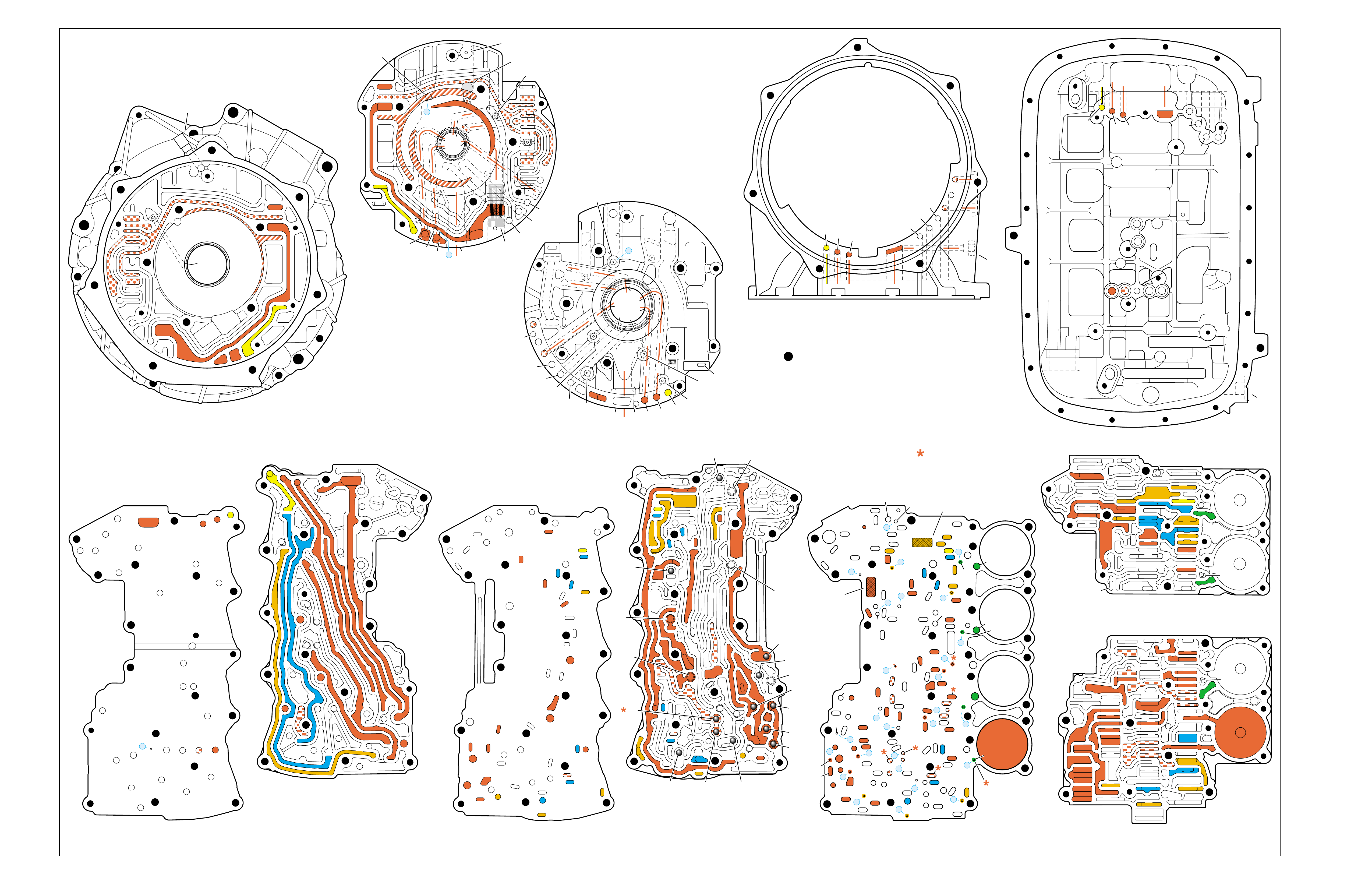
Figure 105
MANUAL SECOND – SECOND GEAR
(from Manual Third – Third Gear)
➤
➤➤
➤
➤➤
➤
➤
➤
➤➤
➤
➤➤
➤
➤
➤
➤
➤ ➤
➤➤
➤
➤
➤
TORQUE CONVERTER HOUSING (227)
(Fluid Pump Cover Side)
➤
➤
➤
➤
➤➤➤
➤
➤
➤ ➤
➤
➤
TOP CHANNEL PLATE (301)
(Case Side)
FRONT
➤
TOP CHANNEL PLATE (301)
(Bottom Channel Plate Side)
FRONT
➤
BOTTOM CHANNEL PLATE (304)
(Top Channel Plate Side)
FRONT
➤
REAR CONTROL VALVE BODY (310)
(Bottom Channel Plate Side)
FRONT
➤
CASE (24)
(Top Channel Plate Side)
FRONT
➤
CASE (24)
(Fluid Pump Cover Side)
SPACER PLATE (307)
(Bottom Channel Plate Side)
FRONT
➤
FRONT CONTROL VALVE BODY (311)
(Bottom Channel Plate Side)
FRONT
➤
BOTTOM CHANNEL PLATE (304)
(Control Valve Body Side)
FRONT
➤
NOTE:
–INDICATES BOLT HOLES
–NON FUNCTIONAL HOLES HAVE BEEN
REMOVED FROM COMPONENT DRAWINGS
TO SIMPLIFY TRACING FLUID FLOW.
–DUAL PURPOSE PASSAGES HAVE
CHANNEL PLATE SIDE NUMBERS LISTED FIRST
–EXHAUST FLUID NOT SHOWN
–PASSAGES MARKED WITH ARE USED FOR
THE 5L40-E ONLY
FLUID PUMP COVER (202)
(Case Side)
FLUID PUMP COVER (202)
(Torque Converter Housing Side)
➤
➤
➤
➤
➤
➤
➤ ➤
➤
➤
➤➤
➤
➤
➤
7
➤
25
➤
27
➤
3
➤
20
➤
16
➤
2
➤
10
➤
9
➤
24
➤
15
➤
11
➤
22
➤
29
➤
28
➤
23
➤
18
➤
17
➤
14
➤
8
➤
4
➤
5
➤
26
➤
13
➤
19
➤
21
➤
6
➤
12
(40)
➤
21
(203)
➤
16
(203)
➤➤
(232)
➤➤
(229)
➤➤
(231)
➤➤
(213)
➤
(233)
➤
TRANSMISSION
VENT
ASSEMBLY
➤➤
32
(203)
➤
37
(203)
➤➤
2/21
(214)
➤➤
(36)
➤
FILTER
(312)
➤
FILTER
(308)
➤
#12
#2
#3
#5
#6
#7
(Spring)
#8
#10 #9
#4
#1
#11
X-2
X-4
X-5
X-1
X-3
12
2
23
24
48
48
48
48
48
48
48
48
52
52
52
52
52
52
52
23
36
36
36
20
27
28
46
47
47
19
16
15
13
10
10
10
11
54
2
54
37
37
37
39
38
40
42
43
40
27
7
48
48
48
52
52
52
52
52
52
52
24
25
25
25
2525
26
26
15 19 19
19
19
31
21
20 20
15 17
17
14
13
14
54
22
22
28
28
22
22
32
42 43
44
44
48
48
48
48
48
48
44
44
38
39
38
33
33
30
35
40
35
35
36
35
34
30
30
30
33
2
2
10
10 10
10
27
2
216
24
15
18
7
32
52
52
52
52 52
52
52
52
52
52
52
52
52 52
52
52
52
52
30 34
35
41
12 21 37
8
9
2
16
24
7
32
12 21
37
12
21
21
24
848
7
9
9
52
52
2
16
5
16
37
32
32
52
1
52
52
52
48
37
1
2
51
51
52
12
12
24
24
52
2
2
4
4
4
4
5
66
8
8
7
7
7
5
9
48
48
48
48
48
48
48
48
53
53
48
52
2
3
3
3
2
1
16
21
21
16
32
37
32
51
50
50
51 52
52
52
52
52
52
48
48
48
48
52
48
48
12
12
24
24
2
2
3
2
4
4
4
5
6
53
53
8
8
7
7
7
48
16
16
21 32
37
➤➤
1
➤➤
31
➤➤
30
(233)
➤➤
33
32
38
38
38
30
30
24
37
37
37
40
40
12
16
15
15
23 52
24
24
23
28
47
41
42
43
27
28
28
27
27
25
25
26
22
22
15
13
18 19
19
19
19
19
19
19
21
17
17
22
23
23
48
48
48
48
48
48
48
48
48
15
13
36
36
36
36
39
35
35
34
10
10 11
10
10
10
20
20
48
44
44
45
43 42
52
48
48
77
2
2
2
2
2
2
2
52
52
12a
16a
15d/16 15c/16
15b
23c
24a 24b
24c
25b
25c 25d
25e
26b
26a
32a
30a
33a
35a
39a
36a
36b
36c
36d
38a 39b
39c/41
40c/41
36e
36f
35b
35c 35d
37c
37d
37b
37a
40b
40a
38d 38b
38c
38e
40d
34a
33e
33c
33d
33b
30b
30c 30d
25a
23b
23a
20a
28c
27c/46
27b
28b
28a
27a
47b
47a
20b
20d
20c
13a
15a
19e
19h
19g
19i
19j
19f
13b 15e
17a
17b
17c/18
15f/18
19b/21
19c/21
19d/21
19a
22a
22b
22c
22d
22f
21a
21b/31
21c/31
22g/23
14a/23
22e
48
48
48
48
48
48
48
52
52
52
52
52
52
52
52
48
48
2g
7a
7b 2a/54a
2b
42b
43a
42a
43b
44c
44d 44b
44a
44e
43c/45
44f/45
48a 48b
2c/54c
54d
2d/54e
2e 2m/54g
2f
10i
10h
10f
10e
10d
10a 10c
11b
11a/10b
10g
2h
54f
54b
48
32
38
30
24 12
16
13
15
15
13
18
19
19
19
21
21
22
16 48
48
48
48
48
48
48
48
36
35
35
34
2
2
7
2
10
10
10
10
41
42
43
43
42
48 48
20
28
27
37
27
28
28
27
20
48
52
52
32
32
32
38
24
12 16
16
18
28
28
28
27
27
48 48
43 42
42
43
48
30
48
48
48 48
48
48
48
48
48
48
48
48
35
36
37
34
2
7
2
10
13
13
15
19
41
41
19
19
15
22
21
21
20
20
21
21
13
10
10
10
2
48
48 48
52
52
52
52
52
52
12
32
37 21
24
2
16
18
48
48
48
48
48
30
48
48
48
48
48
48
15
35
41
34
7
52
52
52
52
52
52
FOLDOUT ➤ 109
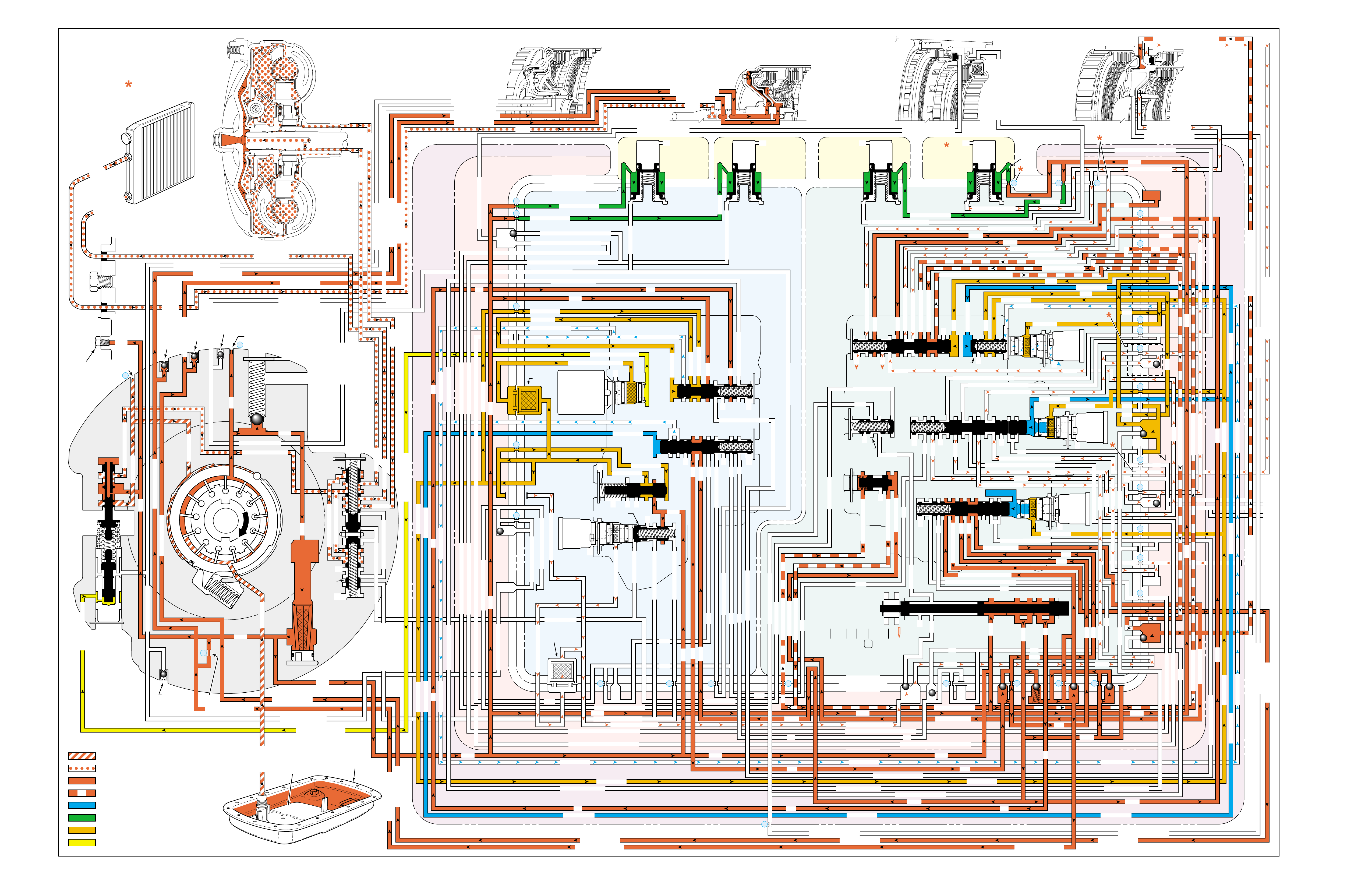
Figure 106
MANUAL SECOND – FIRST GEAR
(from Manual Second – Second Gear)
PRESSURES
INTAKE & DECREASE (SUCTION)
CONVERTER & LUBE
MAINLINE
REGULATED LINE
SOLENOID SIGNAL
ACCUMULATOR
FEED LIMIT
THROTTLE SIGNAL
NOTE:
PASSAGES AND
COMPONENTS
MARKED WITH
ARE USED FOR
THE 5L40-E ONLY
GASKET (309)
GASKET (305)
GASKET (303)
BOTTOM CHANNEL PLATE (304)
TOP CHANNEL PLATE (301)
CASE (24)
REAR CONTROL VALVE BODY (310)
SPACER PLATE (307)
GASKET (309)
GASKET (305)
GASKET (303)
BOTTOM CHANNEL PLATE (304)
TOP CHANNEL PLATE (301)
CASE (24)
FRONT CONTROL VALVE BODY (311)
SPACER PLATE (307)
FLUID
PUMP
COVER
(202)
CONVERTER
HOUSING
(224)
ACCUMULATOR HOUSING (317) ACCUMULATOR HOUSING (323) ACCUMULATOR HOUSING (328) ACCUMULATOR HOUSING (333)
LUBE
LUBE
LUBE
LUBE
TO COOLER
LUBE
TO COOLER
APPLY
APPLY
APPLY
RELEASE
DECREASE
DECREASE
LINE
OVERDRIVE CLUTCH FEED 1
OVERDRIVE CL FD 1OVERDRIVE CLUTCH FEED 1
OVERDRIVE CLUTCH FEED 1 OVERDRIVE CLUTCH FEED 1
OVERDRIVE CLUTCH
2345 2345
2345
2345
2345
2345
2345 OR REVERSE
RLO
LOW AND REV CL OR RLO
LOW AND REV CL OR RLO
SECOND COAST CLUTCH
SECOND CLUTCH
SECOND COAST CLUTCH
SUCTION SUCTION
LINE
LINE
LINE LINE
LINE
LINE
LINE LINE LINE
TCC SIGNAL
CONVERTER FEED
CONVERTER FEED
RELEASE
TO COOLER
REGULATED APPLYREGULATED APPLY
LINE
EX
CONVERTER FEED
REVERSE CLUTCH
REVERSE CLUTCH
THROTTLE SIGNAL
LINE
EX
FILTERED FEED LIMIT
THROTTLE SIGNAL
THROTTLE SIGNAL
THROTTLE SIGNAL
EX
2345 OR REVERSE
2345 OR REVERSE
2345 OR REVERSE
TCC SIGNAL
TCC SIGNAL
TCC SIGNAL
REGULATED APPLY
REGULATED APPLY
REGULATED APPLY
EX
EX
FEED LIMIT VALVE
LINE
EX
EX
EX
EX
FEED LIMIT
FEED LIMIT FEED LIMIT
FEED LIMIT
FEED LIMIT
FEED LIMIT
FEED LIMIT
FEED LIMIT FEED LIMIT
FEED LIMIT
2-3 SHIFT VALVE CNTRL
EX
EX
EX
EX
EX
EX
EX EX
SECOND COAST CLUTCH
23 REGULATED
23 REGULATED
OVERDRIVE CLUTCH FEED 1
INTERMEDIATE CLUTCH
2345
2345
2345
2345
INTERMEDIATE CLUTCH
2345
345
FEED LIMIT
EX
EX
EX
EX
2-3 SIGNAL
123 REGULATED
123 REGULATED
EX
LINE SAFETY MODE
123 BRAKING
123
EX
EX
EX
123
123
123
123
123
123
123
123123
COAST CLUTCH
COAST CLUTCH FEED
OVERDRIVE CLUTCH FEED 2
45
FEED LIMIT
SAFETY MODE
LINE
FEED LIMIT
32
MEMORY
MEMORY
MEMORY
MEMORY PILOT
MEMORY PILOT
32 SAFETY MODE
LINE SAFETY MODE
EX
EX
LINE SAFETY MODE
CNTRL 3-4 SHIFT
2-3 SIGNAL
123123 D432D432
DIRECT CLUTCH
DIRECT CLUTCH
4545
1-2 SIGNAL
EX
EX
EX
FDL
FDL
FDL
FDL
FDL
FDL
D432
2345 2345
D432
SECOND CLUTCH
23 REGULATED
23 REGULATED23 REGULATED
123 REGULATED
LOW AND REVERSE CLUTCH
LOW AND REVERSE CL
SECOND CLUTCH
123 REGULATED
EX
EX
EX
FD LIMIT
FEED LIMIT
FDL
1-2 SIGNAL
2-3 SIGNAL
EX
EX
TCC SIGNAL
TCC SIGNAL
TCC SIGNAL
RLO
EX
REV
RPND432
MANUAL VALVE
LINE
D432
D432 D432
D432
D432
D432
D432 D432
D432
D432D432
D432
REV
REVERSE
EX
3232
LINE
EX
EX
LINE
CASE (24)
OVERDRIVE CLUTCH FEED 2
OVERDRIVE CL FD 2
OVERDRIVE CLUTCH FEED 2
ACCUMULATOR
DIRECT CLUTCH
ACCUM
INTERMEDIATE CLUTCH
INTERMEDIATE CLUTCH
INTERMEDIATE CLUTCH
ACCUMULATOR
EX
SECOND CLUTCH
SECOND CLUTCH
ACCUM
ACCUM
LINELINE
FORWARD CLUTCH
FORWARD CLUTCH FORWARD CLUTCH
ACCUMULATOR
LINE
LINELINE
LINE
OVERDRIVE CLUTCH
INTERMEDIATE CL
COAST CLUTCH
REVERSE LOCKOUT
COAST CLUTCH
REVERSE CLUTCH
REVERSE CLUTCH
REVERSE CLUTCH
4-5 SIGNAL
EXEXEX
LINE SAFETY MODE
LINE SAFETY MODE
REVERSE LOCKOUT
REVERSE LOCKOUT REVERSE LOCKOUT
COAST CLUTCH
REVERSE LOCKOUT REVERSE LOCKOUT
REVERSE LOCKOUT
REVERSE LOCKOUT
REVERSE LOCKOUT
REVERSE LOCKOUT
REVERSE CLUTCH
REVERSE CLUTCH
LOW AND REV CL OR RLO
FORWARD CLUTCH
FORWARD CLUTCH
FORWARD CLUTCH
COAST CLUTCH
FORWARD CLUTCH
FORWARD CLUTCH
FORWARD CLUTCH
2345
2345 OR REVERSE
123 REGULATED
123 REGULATED
123 REGULATED 123 REGULATED
123 REGULATED
123 REGULATED
123 REGULATED
123 BRAKING
123 BRAKING
123 BRAKING
123 BRAKING
1-2 SIGNAL1-2 SIGNAL
1-2 SIGNAL1-2 SIGNAL1-2 SIGNAL
1-2 SIGNAL 1-2 SIGNAL 1-2 SIGNAL
2-3 SIGNAL2-3 SIGNAL2-3 SIGNAL
2-3 SIGNAL 2-3 SIGNAL
2-3 SIGNAL2-3 SIGNAL2-3 SIGNAL
2-3 SIGNAL
SECOND CLUTCH
SECOND CLUTCH
COAST CLUTCHCOAST CLUTCHCOAST CLUTCH
COAST CLUTCH
COAST CLUTCH
COAST CLUTCH
COAST CLUTCH
COAST CLUTCH
23 REGULATED
345
345
345
345 345 345
345
345
345
345
345
345
345
345
DIRECT CLUTCH
DIRECT CLUTCH
DIRECT CLUTCH
DIRECT CL
DIRECT CLUTCH
DIRECT CLUTCH
DIRECT CLUTCH
DIRECT CLUTCH
45
45
45
4545
45
OVERDRIVE CLUTCH
OVERDRIVE CL FD 1
OVERDRIVE CLUTCH FEED 2OVERDRIVE CLUTCH FEED 2
OVERDRIVE CL FD 2
OVERDRIVE CLUTCH FEED 2 OVERDRIVE CL FD 2
3232
32 32 32
323232
32 SAFETY MODE
32 SAFETY MODE 32 SAFETY MODE 32 SAFETY MODE
32 SAFETY MODE32 SAFETY MODE
32 SM 32 SM
FDL
PRESSURE
CONTROL
SOLENOID
VALVE
1-2 SHIFT
SOLENOID
VALVE
N/C
(A)
OFF
2-3 SHIFT
SOLENOID
VALVE
N/C
(B)
ON
4-5 SHIFT
SOLENOID
VALVE
N/C
(C)
ON
TCC PWM
SOLENOID
VALVE
N/C
PRESS REG VALVEBOOST VALVE
CONVERTER FDL
4-5 SHIFT VLV CNTRL
LOW PRESSURE
1-2 SHIFT VALVE
AIR
BLEED
(233)
AIR
BLEED
(233)
AIR
BLEED
(203)
AIR
BLEED
(203)
AIR
BLEED
(203)
AIR
BLEED
(203)
7
4
2
1
5
6
11
10
9
12
18
FILTER
(308)
FILTER
(312)
TCC REGULATOR VALVE
TCC
CONTROL
VALVE
TCC
ENABLE
VALVE
REVERSE
LOCKOUT
VALVE
1-2 SHIFT CONTROL VALVE
FLUID
PAN
(62)
FLUID FILTER
ASSEMBLY
(59)
FLUID
PRESSURE
TEST PLUG
(40)
TORQUE
CONVERTER
ASSEMBLY
(1)
DIRECT
CLUTCH
ACCUMULATOR
OVERDRIVE
CLUTCH
ACCUMULATOR
INTERMEDIATE
CLUTCH
ACCUMULATOR
SECOND
CLUTCH
ACCUMULATOR
COOLER
PRESSURE
RELIEF
BALL
VALVE
21 2
10d
2a
2b
42b
43a
37d
39b
40b
37c
40d
11b
10a
24a
10c
11a 10b
54b
54d
2c
54a
54c
27c 46
7a
24b
20a
13a
37b
38a
7b
47a
47b
27b
28c
12a
23a
36e
36f
23b
23c
15a
24c
26b
36a
38c
38d
36b
25a
15
2m 54g
54f
#8
18
15f
15e
17c
17b
17a
27a
44a
44e
44d
44b
25c
30a
33a
25e
19e
35c
19h
19f
10f
10h
10g
22a
35b
#7
13b
32a
26a
10i
22f
22d
43b
22b
34a
48b
39a
22c
X-1
22
22e
21a
42a
19a
20b
19b
#2
23 22g
14a
2f
2h
19g
19i
19
j
DIRECT
AND REVERSE
CLUTCH
ASSEMBLY
(400–420)
FORWARD
AND COAST
CLUTCH
ASSEMBLY
(430–451)
OVERDRIVE
AND
INTERMEDIATE
CLUTCH
ASSEMBLY
(480–497)
CENTER
SUPPORT
ASSEMBLY
(510–535)
3
2d54e
2e
30c
30d
35d
26
37a
13
#1
15c
15b
16
15d 16
15
X-2
16a
X-4 X-5
38
14
X-3
19
#6
19d
19
21
19c 21
15
#5
21b 31
21c 31
17
21
#4
20d
20c
16
25b
19
25d
20
36 46
28a
44c
28b
30b
21
#11
33e
33d
23
2435a
#9
33c
33b
22
36d
36c
25
#12
41 40c
39c
43 13
2840a
#10
45
45
45
44f
44
48
43c
#3
38b
38e
27
48a29
8
10e
2310
32 SM/FDL
30
31
FLUID PUMP
SCREEN
ASSEMBLY
(213)
(214)
110

110A
NO FIRST GEAR
•1-2 Shift Solenoid Valve (368)
–Stuck On
•1-2 Shift Control Valve (366)
–Stuck
•1-2 Shift Valve (387)
–Stuck
NO ENGINE BRAKING
•#8 Ball Check Valve (518)
–Stuck
–Missing
•Fluid Passage Sleeve (38)
–Leaking
•Low and Reverse Clutch Piston (517)
–Leaking
–Jammed or cracked
•Center Support (518)
–Broken
–Leaking
•4-5 Shift Solenoid Valve (376)
–Leaking
–No voltage to solenoid
•Low Pressure Control Valve (383)
–Stuck
In Manual Second range, a 2-1 downshift can be commanded by
the TCM, if the vehicle speed is low enough not to overrev the
engine (calibratable in the TCM). Manual Second – First Gear is
commanded in order to achieve maximum engine compression
braking for slowing the vehicle.
MANUAL SECOND – FIRST GEAR
(from Manual Second – Second Gear)
SOLENOID FORWARD OVER- INTERM. INTER- LOW LOW AND SECOND SECOND
DIRECT REVERSE COAST FORWARD SPRAG DRIVE SPRAG MEDIATE SPRAG REVERSE SECOND SPRAG COAST
1-2 2-3 4-5 CLUTCH CLUTCH CLUTCH CLUTCH CLUTCH CLUTCH CLUTCH CLUTCH CLUTCH CLUTCH CLUTCH CLUTCH CLUTCH
OFF ON ON APPLIED APPLIED LD LD APPLIED
LD = LOCKED IN DRIVE

110B
PASSAGES
1 SUCTION
2 LINE
3 DECREASE
4 CONVERTER FEED
5 RELEASE
6 APPLY
7 REGULATED APPLY
8 TO COOLER
9 LUBE
10 FEED LIMIT
11 FILTERED FEED LIMIT
12 THROTTLE SIGNAL
13 LINE SAFETY MODE
14 REVERSE
15 REVERSE LOCK OUT (RLO)
16 REVERSE CLUTCH
17 LOW AND REVERSE CLUTCH
18 LOW AND REVERSE CLUTCH OR RLO
19 D432
20 123
21 FORWARD CLUTCH
22 2345
23 2345 OR REVERSE
24 TCC SIGNAL
25 123 REGULATED
26 123 BRAKING
27 1-2 SIGNAL
28 2-3 SIGNAL
29 4-5 SIGNAL
30 SECOND CLUTCH
31 COAST CLUTCH FEED
32 COAST CLUTCH
33 23 REGULATED
34 SECOND COAST CLUTCH
35 INTERMEDIATE CLUTCH
36 345
37 DIRECT CLUTCH
38 45
39 OVERDRIVE CLUTCH FEED 1
40 OVERDRIVE CLUTCH FEED 2
41 OVERDRIVE CLUTCH
42 32
43 32 SAFETY MODE
44 FDL
45 32 SAFETY MODE/FDL
46 MEMORY PILOT
47 MEMORY
48 EXHAUST
49 OIL RESERVOIR
50 TORQUE CONVERTER SEAL DRAINBACK
51 VENT
52 VOID
53 CONVERTER FDL
54 ACCUMULATOR
COMPONENTS ( )
(36) TRANSMISSION FLUID LEVEL HOLE PLUG
(40) TRANSMISSION FLUID PRESSURE TEST PLUG
(203) CHECK VALVE RETAINER AND BALL ASSEMBLY
(213) TRANSMISSION FLUID PUMP SCREEN ASSEMBLY
(214) BRASS ORIFICE INSERT
(232) ORIFICE SLEEVE
(233) ORIFICE CUP PLUG
(306) CONTROL VALVE BODY BALL CHECK VALVE
(#1, 2, 3, 4, 5, 6, 7, 8, 9, 10, 11, 12)
(308) TCC PWM SOLENOID VALVE FILTER ASSEMBLY
(312) PRESSURE CONTROL SOLENOID VALVE
FILTER ASSEMBLY
MANUAL SECOND – FIRST GEAR
(from Manual Second – Second Gear)

Figure 107
MANUAL SECOND – FIRST GEAR
(from Manual Second – Second Gear)
➤
➤➤
➤
➤➤
➤
➤
➤
➤➤
➤
➤➤
➤
➤
➤
➤
➤ ➤
➤➤
➤
➤
➤
TORQUE CONVERTER HOUSING (227)
(Fluid Pump Cover Side)
➤
➤
➤
➤
➤➤➤
➤
➤
➤ ➤
➤
➤
TOP CHANNEL PLATE (301)
(Case Side)
FRONT
➤
TOP CHANNEL PLATE (301)
(Bottom Channel Plate Side)
FRONT
➤
BOTTOM CHANNEL PLATE (304)
(Top Channel Plate Side)
FRONT
➤
REAR CONTROL VALVE BODY (310)
(Bottom Channel Plate Side)
FRONT
➤
CASE (24)
(Top Channel Plate Side)
FRONT
➤
CASE (24)
(Fluid Pump Cover Side)
SPACER PLATE (307)
(Bottom Channel Plate Side)
FRONT
➤
FRONT CONTROL VALVE BODY (311)
(Bottom Channel Plate Side)
FRONT
➤
BOTTOM CHANNEL PLATE (304)
(Control Valve Body Side)
FRONT
➤
NOTE:
–INDICATES BOLT HOLES
–NON FUNCTIONAL HOLES HAVE BEEN
REMOVED FROM COMPONENT DRAWINGS
TO SIMPLIFY TRACING FLUID FLOW.
–DUAL PURPOSE PASSAGES HAVE
CHANNEL PLATE SIDE NUMBERS LISTED FIRST
–EXHAUST FLUID NOT SHOWN
–PASSAGES MARKED WITH ARE USED FOR
THE 5L40-E ONLY
FLUID PUMP COVER (202)
(Case Side)
FLUID PUMP COVER (202)
(Torque Converter Housing Side)
➤
➤
➤
➤
➤
➤
➤ ➤
➤
➤
➤➤
➤
➤
➤
7
➤
25
➤
27
➤
3
➤
20
➤
16
➤
2
➤
10
➤
9
➤
24
➤
15
➤
11
➤
22
➤
29
➤
28
➤
23
➤
18
➤
17
➤
14
➤
8
➤
4
➤
5
➤
26
➤
13
➤
19
➤
21
➤
6
➤
12
(40)
➤
21
(203)
➤
16
(203)
➤➤
(232)
➤➤
(229)
➤➤
(231)
➤➤
(213)
➤
(233)
➤
TRANSMISSION
VENT
ASSEMBLY
➤➤
32
(203)
➤
37
(203)
➤➤
2/21
(214)
➤➤
(36)
➤
FILTER
(312)
➤
FILTER
(308)
➤
#12
#2
#3
#5
#6
#7
(Spring)
#8
#10 #9
#4
#1
#11
X-2
X-4
X-5
X-1
X-3
12
2
23
24
48
48
48
48
48
48
48
48
52
52
52
52
52
52
52
23
36
36
36
20
27
28
46
47
47
19
16
15
13
10
10
10
11
54
2
54
37
37
37
39
38
40
42
43
40
27
7
48
48
48
52
52
52
52
52
52
52
24
25
25
25
2525
26
26
15 19 19
19
19
31
21
20 20
15 17
17
14
13
14
54
22
22
28
28
22
22
32
42 43
44
44
48
48
48
48
48
48
44
44
38
39
38
33
33
30
35
40
35
35
36
35
34
30
30
30
33
2
2
10
10 10
10
27
2
216
24
15
18
7
32
52
52
52
52 52
52
52
52
52
52
52
52
52 52
52
52
52
52
30 34
35
41
12 21 37
8
9
2
16
24
7
32
12 21
37
12
21
21
24
848
7
9
9
52
52
2
16
5
16
37
32
32
52
1
52
52
52
48
37
1
2
51
51
52
12
12
24
24
52
2
2
4
4
4
4
5
66
8
8
7
7
7
5
9
48
48
48
48
48
48
48
48
53
53
48
52
2
3
3
3
2
1
16
21
21
16
32
37
32
51
50
50
51 52
52
52
52
52
52
48
48
48
48
52
48
48
12
12
24
24
2
2
3
2
4
4
4
5
6
53
53
8
8
7
7
7
48
16
16
21 32
37
➤➤
1
➤➤
31
➤➤
30
(233)
➤➤
33
32
38
38
38
30
30
24
37
37
37
40
40
12
16
15
15
23 52
24
24
23
28
47
41
42
43
27
28
28
27
27
25
25
26
22
22
15
13
18 19
19
19
19
19
19
19
21
17
17
22
23
23
48
48
48
48
48
48
48
48
48
15
13
36
36
36
36
39
35
35
34
10
10 11
10
10
10
20
20
48
44
44
45
43 42
52
48
48
77
2
2
2
2
2
2
2
52
52
12a
16a
15d/16 15c/16
15b
23c
24a 24b
24c
25b
25c 25d
25e
26b
26a
32a
30a
33a
35a
39a
36a
36b
36c
36d
38a 39b
39c/41
40c/41
36e
36f
35b
35c 35d
37c
37d
37b
37a
40b
40a
38d 38b
38c
38e
40d
34a
33e
33c
33d
33b
30b
30c 30d
25a
23b
23a
20a
28c
27c/46
27b
28b
28a
27a
47b
47a
20b
20d
20c
13a
15a
19e
19h
19g
19i
19j
19f
13b 15e
17a
17b
17c/18
15f/18
19b/21
19c/21
19d/21
19a
22a
22b
22c
22d
22f
21a
21b/31
21c/31
22g/23
14a/23
22e
48
48
48
48
48
48
48
52
52
52
52
52
52
52
52
48
48
2g
7a
7b 2a/54a
2b
42b
43a
42a
43b
44c
44d 44b
44a
44e
43c/45
44f/45
48a 48b
2c/54c
54d
2d/54e
2e 2m/54g
2f
10i
10h
10f
10e
10d
10a 10c
11b
11a/10b
10g
2h
54f
54b
48
32
38
30
24 12
16
13
15
15
13
18
19
19
19
21
21
22
16 48
48
48
48
48
48
48
48
36
35
35
34
2
2
7
2
10
10
10
10
41
42
43
43
42
48 48
20
28
27
37
27
28
28
27
20
48
52
52
32
32
32
38
24
12 16
16
18
28
28
28
27
27
48 48
43 42
42
43
48
30
48
48
48 48
48
48
48
48
48
48
48
48
35
36
37
34
2
7
2
10
13
13
15
19
41
41
19
19
15
22
21
21
20
20
21
21
13
10
10
10
2
48
48 48
52
52
52
52
52
52
12
32
37 21
24
2
16
18
48
48
48
48
48
30
48
48
48
48
48
48
15
35
41
34
7
52
52
52
52
52
52
FOLDOUT ➤ 111
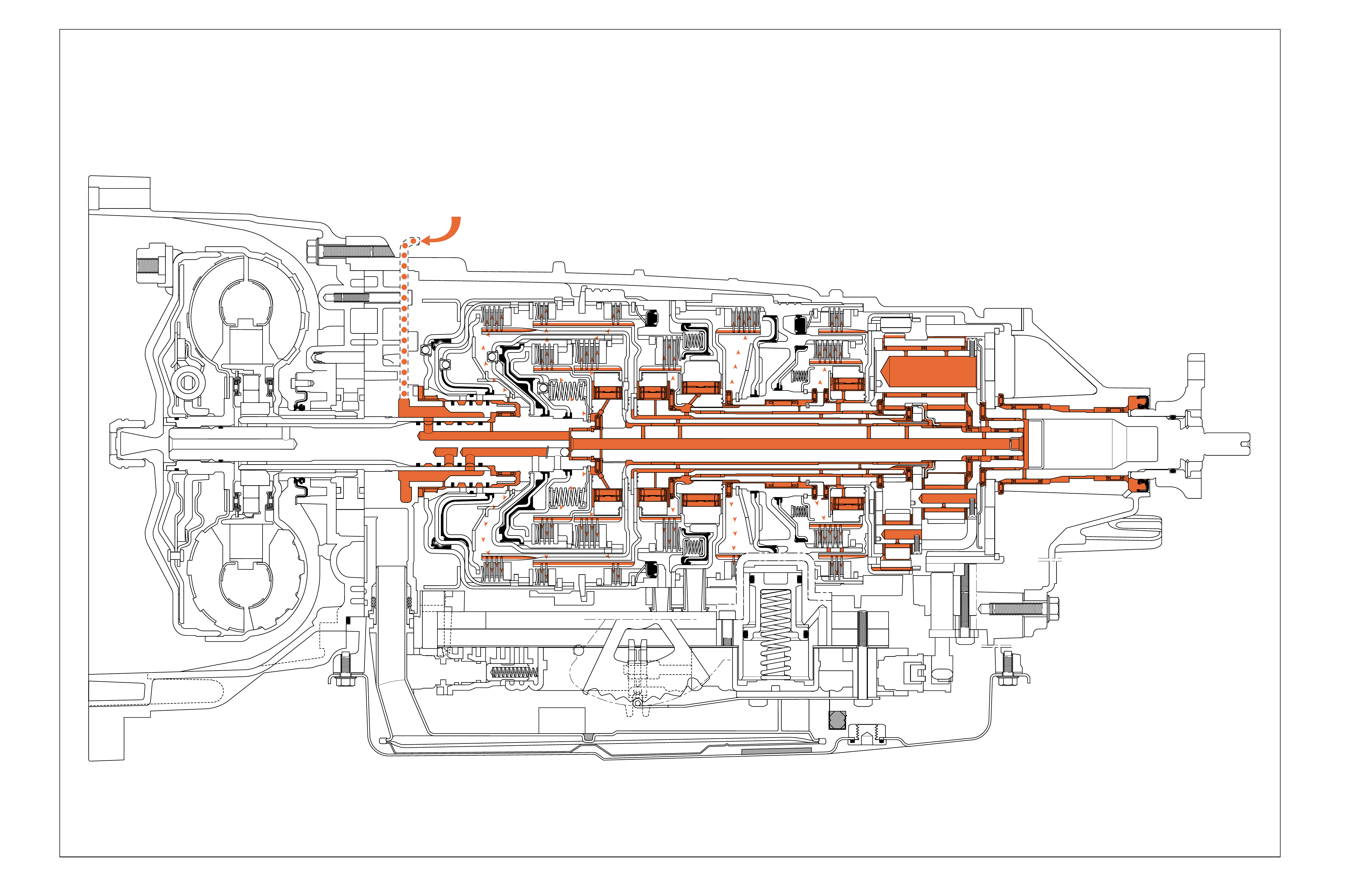
LUBRICATION POINTS
LUBE FLUID
FROM COOLER
Figure 108
COOLER CIRCUIT:
•Line pressure from the fluid pump assembly is
directed to the pressure regulator valve (210)
located in the fluid pump cover assembly (202).
•Line pressure passes through the pressure regulator
valv e (210) and enters the converter feed passage.
•Converter feed fluid is routed to the TCC control
valv e (235) where it passes through the valv e into
the release circuit.
Note: In TCC apply mode, converter feed fluid is
r outed directly from the TCC control valve (235) into
the cooler circuit and does not enter the torque converter.
COOLER AND LUBRICATION CIRCUITS
•Release fluid passes through the fluid pump cover
assembly (202) and flows between the stator shaft
and the turbine shaft (433).
•
Release fluid enters a passage in the turbine shaft
(433) and flows to the release side of the torque
con v er ter clutch pr essure plate, passes ar ound the
pressure plate and enters the apply side of the plate.
•Apply fluid from the torque converter assembly
(1) is then routed back to the TCC control valve
(235) where it passes through the valve and enters
the cooler circuit.
•
The cooler passage is routed through the fluid pump
cover assembly (202), into the case (24) and is sent
to the transmission cooler located inside the radiator.
LUBRICATION CIRCUITS:
•Fluid leaving the transmission cooler
enters the lube circuit at the case (24)
and is routed to the fluid pump cover
assembly (202).
•Lube passes through the fluid pump
co ver assembly (202) and enter s the
input shaft (433).
•Lube then passes through the input
shaft (433) and flows throughout the
transmission.
112
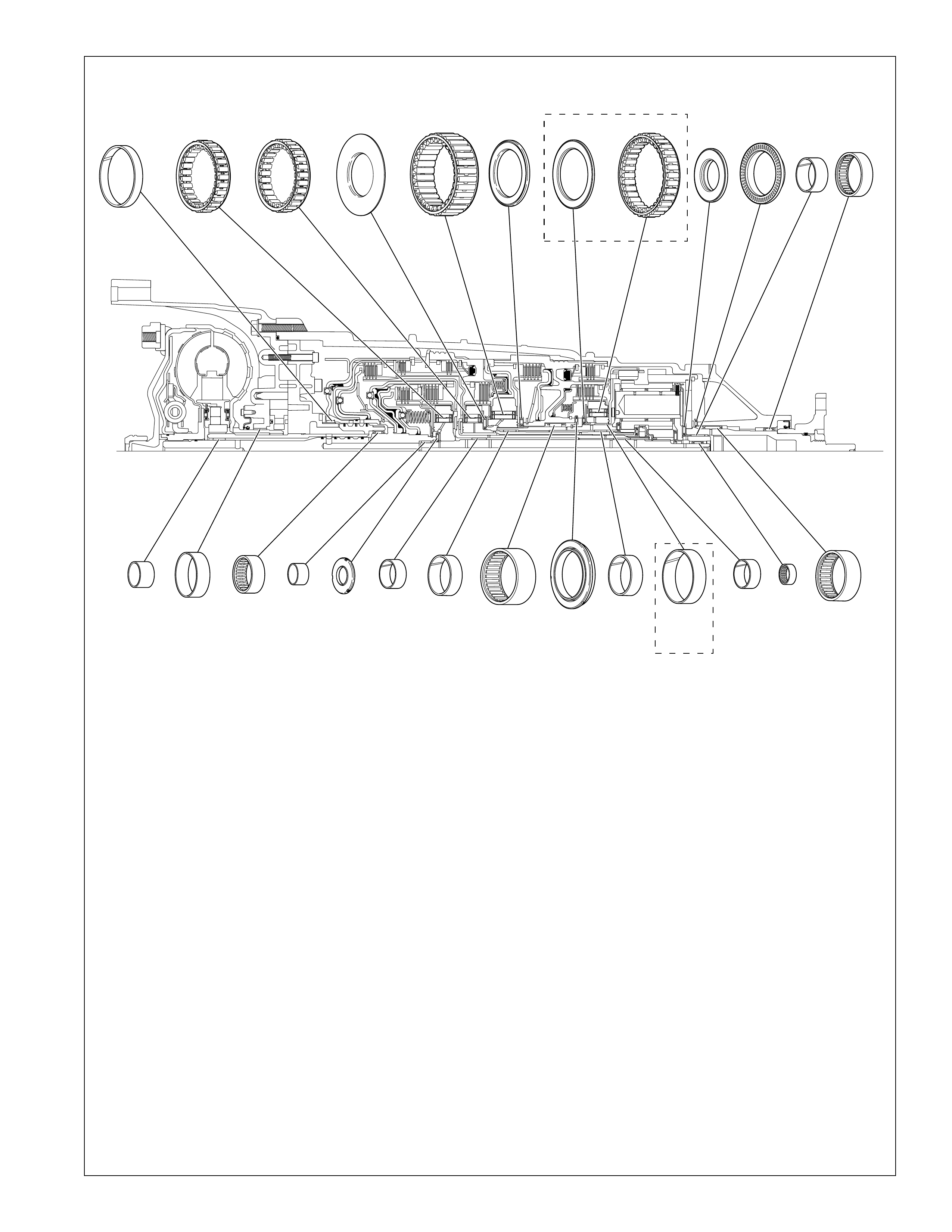
113
17 LOW CLUTCH ROLLER THRUST BEARING
20 INPUT AND REACTION CARRIER THRUST BEARING
23 INPUT AND REACTION CARRIER THRUST BEARING
26 OUTPUT SHAFT BEARING
28 OUTPUT SHAFT BEARING
201 INPUT SHAFT BEARING ASSEMBLY
215 TURBINE SHAFT BUSHING
226 TORQUE CONVERTER BUSHING
400 REVERSE CLUTCH HOUSING BUSHING
435 FORWARD CLUTCH BUSHING
456 FORWARD CLUTCH ROLLER INNER BEARING
461 FORWARD CLUTCH SPRAG ASSEMBLY
465 INPUT AND REACTION CARRIER BUSHING ASSEMBLY
bushbrngloc
Bushing and Bearing Locations
Figure 109
473 INTERMEDIATE CLUTCH SPRAG ASSEMBLY
476 INTERMEDIATE CLUTCH ROLLER THRUST BEARING
ASSEMBLY
503 LOW CLUTCH SPRAG ASSEMBLY
519 INPUT AND REACTION BEARING ASSEMBLY
541 INPUT AND REACTION BEARING ASSEMBLY
542 2ND CLUTCH ROLLER INNER RACE BEARING
ASSEMBLY
547 2ND CLUTCH SPRAG ASSEMBLY
548 INPUT AND REACTION CARRIER BUSHING
552 REACTION CARRIER BUSHING
554 INPUT AND REACTION BEARING ASSEMBLY
561 INPUT AND REACTION CARRIER BUSHING
400 461 473 503 542 547
561
17 20 23 28
476
456
435 465 465
519 541 548
552 552 554 26
201
215 226
5L40-E
ONLY
5L40-E
ONLY
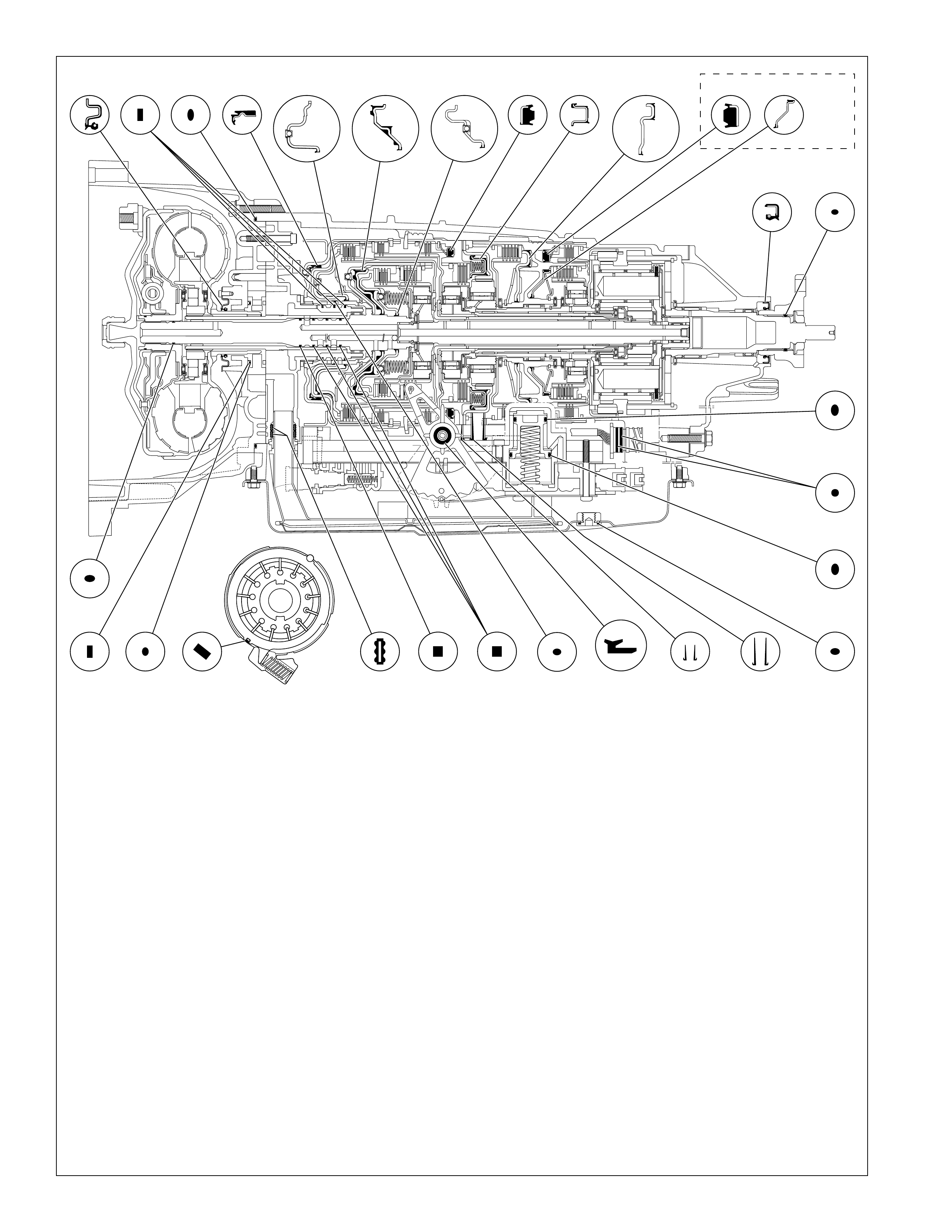
114
402 REVERSE CLUTCH PISTON INNER SEAL
404 REVERSE CLUTCH PISTON
406 DIRECT CLUTCH PISTON ASSEMBLY
430 INPUT SHAFT (O-RING) SEAL
431 INPUT SHAFT FLUID SEAL RING
432 INPUT SHAFT FLUID SEAL RING
436 FORWARD CLUTCH PISTON ASSEMBLY
438 COAST CLUTCH PISTON ASSEMBLY
487 OVERDRIVE CLUTCH PISTON ASSEMBLY
495 INTERMEDIATE CLUTCH PISTON ASSEMBLY
517 LOW AND REVERSE CLUTCH PISTON
520 2ND CLUTCH PISTON
528 2ND COAST CLUTCH PISTON ASSEMBLY
605 MANUAL SHIFT SHAFT SEAL
4 TORQUE CONVERTER HOUSING FLUID SEAL ASSEMBLY
29 TRANSMISSION PROP SHAFT FLANGE SEAL
32 TRANSMISSION PROP SHAFT FLANGE (O-RING) SEAL
38 CENTER SUPPORT FLUID PASSAGE SLEEVE
39 OVERDRIVE CLUTCH FLUID PASSAGE SLEEVE
56 A/TRANSMISSION WIRING HARNESS (O-RING) SEAL (2)
57 TRANSMISSION FILTER SEAL (2)
64 A/TRANS FLUID PAN DRAIN PLUG SEAL
200 REVERSE CLUTCH HOUSING FLUID SEAL RING
218 A/TRANS FLUID PUMP SLIDE SEAL
220 A/TRANS FLUID PUMP SLIDE RING
229 TORQUE CONVERTER HOUSING SEAL
242 A/TRANS FLUID PUMP SLIDE O-RING SEAL
314 CLUTCH ACCUMULATOR PISTON FLUID
SEAL RING
316 CLUTCH ACCUMULATOR PISTON FLUID
SEAL RING sealloc
Seal Locations
Figure 110
316
314
643839
218
56
430
229
43157 432 402
438
220 242
200 404 406 436 487 495 5174 528 520
29 32
5L40-E
ONLY
605

115
ILLUSTRATED PARTS LIST
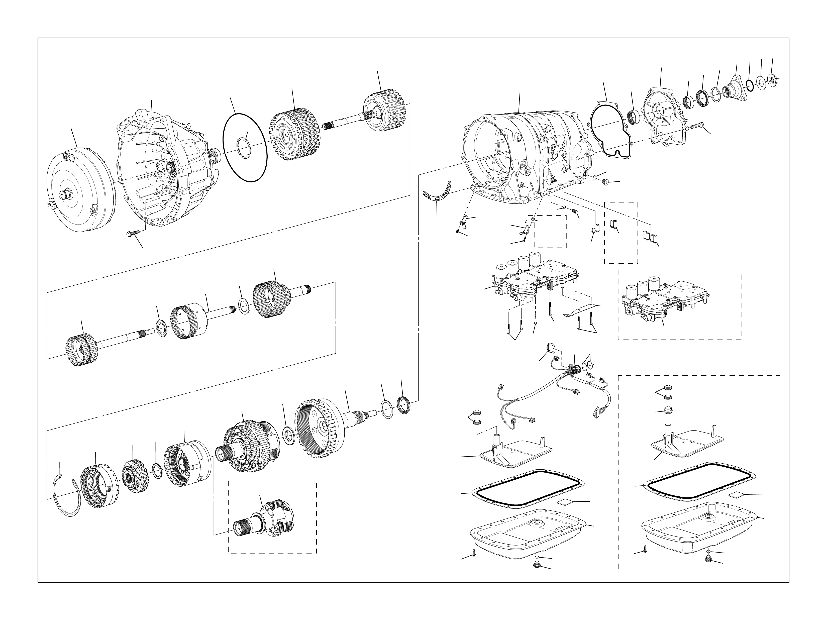
116
assmpart_explode
Case and Associated Parts
Figure 111
1
2
34
5
6
7
8910 11
12
14 15 16 17 18
19
19
20 21 22 23
24 25 26
27 28 29 31
30 32 33 34
35
36
37
38
38
39
40
43
42 41
44
45
46
47
47
49 50 51
52
53
54
55 56
57
5L40-E
ONLY
4L40-E
ONLY
4L40-E
ONLY
59 59
60 61
62
64
63
65
5L40-E
SOME
MODELS
60 61
62
64
63
65
5757
58
66
4L40-E
ONLY

117
Case and Associated Parts Legend
1 TORQUE CONVERTER ASSEMBLY
2 TORQUE CONVERTER HOUSING TO MAIN CASE BOLT
3 TORQUE CONVERTER HOUSING ASSEMBLY
4 TORQUE CONVERTER HOUSING FLUID SEAL ASSEMBLY
5 REVERSE CLUTCH HOUSING THRUST WASHER
(SELECTIVE)
6 DIRECT AND REVERSE CLUTCH ASSEMBLY
7 FORWARD AND COAST (W/CLUTCH ASSEMBLY)
8 INPUT SUN GEAR (W/FORWARD CLUTCH ROLLER
INNER RACE) SHAFT
9 DIRECT CLUTCH HUB THRUST WASHER
10 DIRECT CLUTCH (W/INPUT AND REACTION CARRIER IN)
HUB
11 INPUT AND REACTION CARRIER INNER SHAFT
THRUST WASHER
12 INTERMEDIATE CLUTCH SPRAG ASSEMBLY
14 INTERMEDIATE AND OVERDRIVE CLUTCH HOUSING
RETAINER RING (SELECTIVE)
15 OVERDRIVE CLUTCH HOUSING
16 LOW CLUTCH SPRAG
17 LOW CLUTCH ROLLER THRUST BEARING
18 CENTER SUPPORT
19 INPUT AND REACTION CARRIER
20 INPUT AND REACTION CARRIER THRUST BEARING
21 OUTPUT SHAFT ASSEMBLY (W/REAR INTERNAL GEAR)
22 INPUT AND REACTION CARRIER WASHER (SELECTIVE)
23 INPUT AND REACTION CARRIER THRUST BEARING
24 A/TRANSMISSION CASE
25 A/T CASE EXTENSION GASKET
26 OUTPUT SHAFT BEARING
27 TRANSMISSION CASE EXTENSION
28 OUTPUT SHAFT BEARING
29 TRANSMISSION PROP SHAFT FLANGE SEAL
30 OUTPUT SHAFT ASSEMBLY RETAINER
31 TRANSMISSION PROP SHAFT FLANGE
32 TRANSMISSION PROP SHAFT FLANGE (O-RING) SEAL
33 TRANSMISSION PROP SHAFT THRUST WASHER
34 PROP SHAFT FLANGE NUT
35 A/T CASE EXTENSION BOLT
36 TRANSMISSION LEVEL HOLE PLUG
37 TRANSMISSION FLUID LEVEL HOLE PLUG O-RING
38 CENTER SUPPORT FLUID PASSAGE SLEEVE
39 OVERDRIVE CLUTCH FLUID PASSAGE SLEEVE
40 TRANSMISSION PRESSURE TEST PLUG
41 OUTPUT SPEED SENSOR SPACER
42 OUTPUT SPEED SENSOR
43 OUTPUT SPEED SENSOR BOLT
44 INPUT SPEED SENSOR
45 INPUT SPEED SENSOR BOLT
46 TRANSMISSION FLUID PUMP COVER GASKET
47 CONTROL VALVE BODY AND ACCUMULATOR ASSEMBLY
49 CONTROL VALVE BODY BOLT
50 CONTROL VALVE BODY BOLT
51 CONTROL VALVE BODY BOLT
52 MANUAL SHAFT DETENT ASSEMBLY
53 CONTROL VALVE BODY BOLT
54 WIRING HARNESS CLIP
55 A/TRANSMISSION WIRING HARNESS
56 A/TRANSMISSION WIRING HARNESS (O-RING) SEAL (2)
57 TRANSMISSION FILTER SEAL (2)
58 TRANSMISSION FILTER SPACER
59 A/TRANSMISSION FLUID FILTER
60 A/TRANS FLUID PAN GASKET
61 A/TRANS FLUID PAN MAGNET
62 A/TRANS FLUID PAN ASSEMBLY
63 A/TRANS FLUID PAN DRAIN PLUG
64 A/TRANS FLUID PAN DRAIN PLUG SEAL
65 A/TRANS FLUID PAN BOLT
66 TRANSMISSION PRESSURE TEST PLUG O-RING SEAL
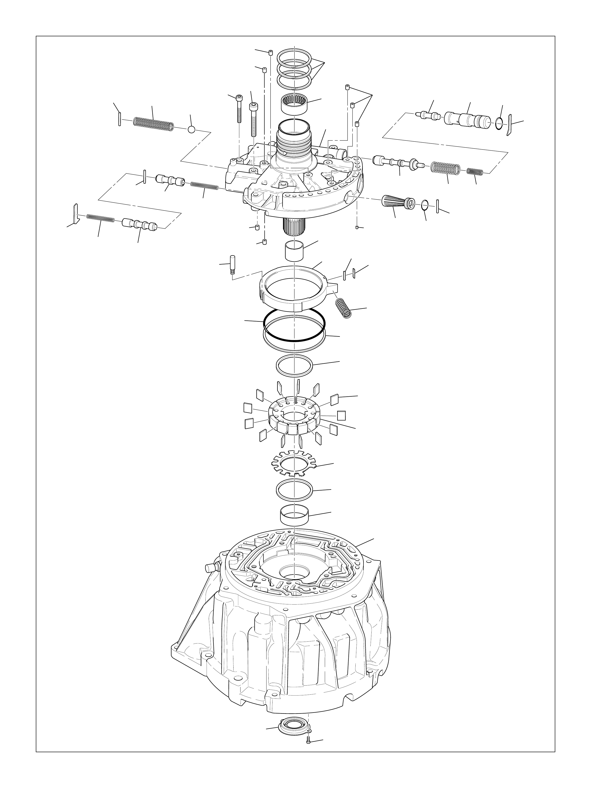
118
234
234
211 238 239
240 241
203
203
233
204
231
242
200
201
202
215
207 206 205
204
208
209
210
213 212 211
217 218
216
219
220
225
221
222
223
224
226
227
214
232
233
235
236 237
229 228
conv_hous_expl
Fluid Pump Assembly
Figure 112

119
200 REVERSE CLUTCH HOUSING FLUID SEAL RING
201 INPUT SHAFT BEARING ASSEMBLY
202 A/TRANS FLUID PUMP COVER ASSEMBLY
203 CHECK VALVE RETAINER AND BALL ASSEMBLY
204 VALVE BUSHING/SPRING RETAINER
205 LINE BOOST VALVE BUSHING SEAL
206 LINE BOOST VALVE BUSHING
207 LINE BOOST VALVE
208 LINE BOOST VALVE SPRING
209 PRESSURE REGULATOR VALVE SPRING
210 PRESSURE REGULATOR VALVE
211 A/TRANS FLUID PUMP RETAINER PIN
212 A/TRANS FLUID PUMP COVER SEAL
213 A/TRANS FLUID PUMP SCREEN ASSEMBLY
214 BRASS ORIFICE INSERT
215 TURBINE SHAFT BUSHING
216 A/TRANS FLUID PUMP SLIDE (SELECTIVE)
217 A/TRANS FLUID PUMP SLIDE SEAL SUPPORT
218 A/TRANS FLUID PUMP SLIDE SEAL
219 A/TRANS FLUID PUMP SLIDE SPRING
220 A/TRANS FLUID PUMP SLIDE RING
221 A/TRANS FLUID PUMP VANE RING
Fluid Pump Assembly Legend
222 A/TRANS FLUID PUMP VANE
223 A/TRANS FLUID PUMP ROTOR (SELECTIVE)
224 A/TRANS FLUID PUMP ROTOR GUIDE
225 A/TRANS FLUID PUMP VANE RING
226 TORQUE CONVERTER BUSHING
227 TORQUE CONVERTER HOUSING
228 TORQUE CONVERTER HOUSING SEAL BOLT
229 TORQUE CONVERTER HOUSING SEAL
231 A/TRANS FLUID PUMP SLIDE PIN ASSEMBLY
232 ORIFICE SLEEVE
233 ORIFICE CUP PLUG
234 TCC CONTROL VALVE SPRING
235 TCC CONTROL VALVE
236 A/TRANS FLUID PUMP RETAINER PIN
237 TCC ENABLE VALVE
238 PRESSURE RELIEF BALL VALVE SPRING
239 PRESSURE RELIEF BALL VALVE
240 A/TRANS FLUID PUMP BOLT
241 A/TRANS FLUID PUMP BOLT
242 A/TRANS FLUID PUMP SLIDE O-RING SEAL
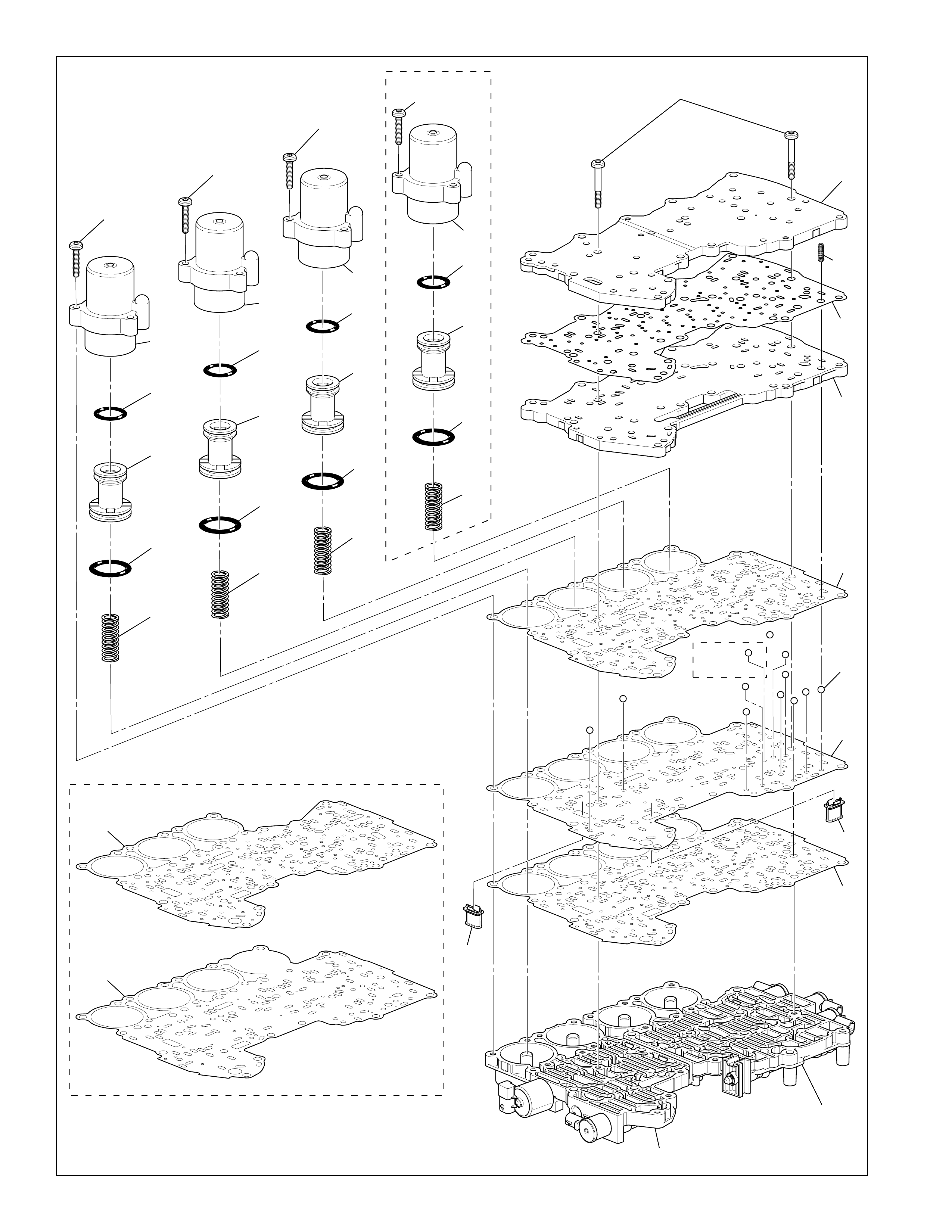
120
vb_explode
Control Valve Body and Accumulator Assembly
Figure 113
318
318
318
318
317
316
315
314
313
323
322
321
320
319
328
327
326
325
324
333
332
331
330
329
300
301
302
303
304
305
306
308
307
309
310
311
312
5L40-E
ONLY
4L40-E
ONLY
5L40-E
ONLY
305
307

121
Control Valve Body and Accumulator Assembly Legend
300 CONTROL VALVE BODY BOLT
301 CONTROL VALVE T OP CHANNEL PLATE
302 CONTROL VALVE CHANNEL PLATE BALL CHECK SPRING
303 CONTROL VALVE CHANNEL PLATE GASKET
304 CONTROL VALVE BOTTOM CHANNEL PLATE
305 CONTROL VALVE BODY GASKET
306 CONTROL VALVE BODY BALL CHECK VALVE
307 CONTROL VALVE BODY SPACER PLATE
308 TCC PWM SOLENOID VALVE FILTER ASSEMBLY
309 CONTROL VALVE BODY SPACER PLATE GASKET
310 CONTROL VALVE REAR BODY
311 CONTROL VALVE FRONT BODY
312 PRESSURE CONTROL SOLENOID VALVE FILTER
ASSEMBLY
313 DIRECT CLUTCH ACCUMULATOR PISTON SPRING
314 DIRECT CLUTCH ACCUMULATOR PISTON FLUID
SEAL RING
315 DIRECT CLUTCH ACCUMULATOR PISTON
316 DIRECT CLUTCH ACCUMULATOR PISTON FLUID
SEAL RING
317 DIRECT CLUTCH ACCUMULATOR HOUSING
318 ACCUMULATOR HOUSING BOLT
319 OVERDRIVE CLUTCH ACCUMULATOR PISTON SPRING
320 OVERDRIVE CLUTCH ACCUMULATOR PISTON FLUID
SEAL RING
321 OVERDRIVE CLUTCH ACCUMULATOR PISTON
322 OVERDRIVE CLUTCH ACCUMULATOR PISTON FLUID
SEAL RING
323 OVERDRIVE CLUTCH ACCUMULATOR HOUSING
324 INTERMEDIATE CLUTCH ACCUMULATOR PISTON
SPRING
325 INTERMEDIATE CLUTCH ACCUMULATOR PISTON
FLUID RING
326 INTERMEDIATE CLUTCH ACCUMULATOR PISTON
327 INTERMEDIATE CLUTCH ACCUMULATOR PISTON FLUID
SEAL RING
328 INTERMEDIATE CLUTCH ACCUMULATOR HOUSING
329 2ND CLUTCH ACCUMULATOR PISTON SPRING
330 2ND CLUTCH ACCUMULATOR PISTON RING
331 2ND CLUTCH ACCUMULATOR PISTON
332 2ND CLUTCH ACCUMULATOR PISTON RING
333 2ND CLUTCH ACCUMULATOR HOUSING
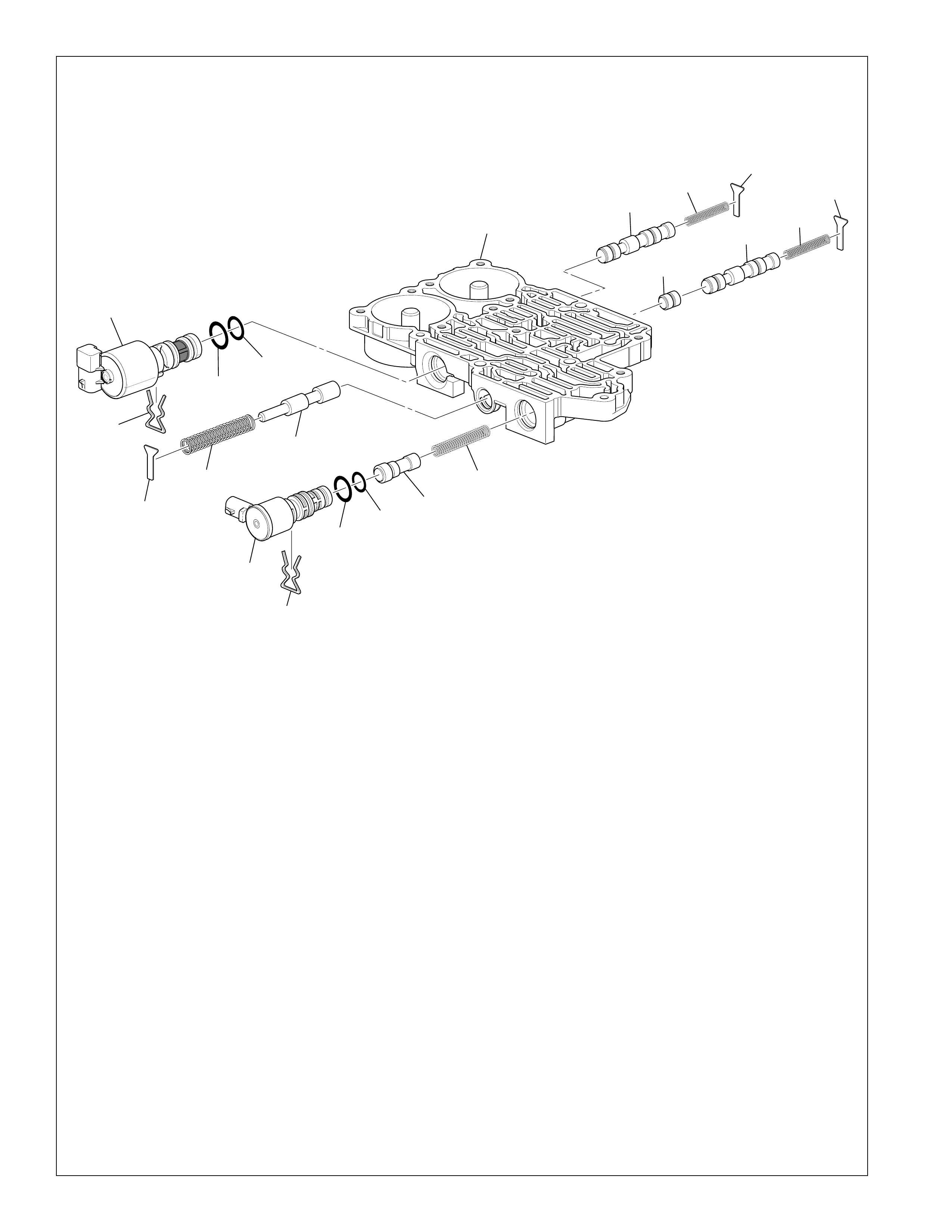
122
vb2_disassembly
Front Control Valve Body
Figure 114
357
351
356 355
343
354
353
352
351
350 349 348
347
340 341 342 343
346
345 344
343
340 CONTROL VALVE FRONT BODY
341 SAFETY MODE VALVE
342 SAFETY MODE VALVE SPRING
343 VALVE SPRING RETAINER
344 3-4 SHIFT VALVE SPRING
345 3-4 SHIFT VALVE
346 3-4 SHIFT CONTROL VALVE
347 TCC REGULATOR APPLY VALVE SPRING
348 TCC REGULATOR APPLY VALVE
349 SOLENOID VALVE (O-RING) SEAL
350 SOLENOID VALVE (O-RING) SEAL
351 SOLENOID VALVE RETAINER
352 TCC PWM SOLENOID VALVE
353 FEED LIMIT VALVE
354 FEED LIMIT VALVE SPRING
355 PRESSURE CONTROL SOLENOID (O-RING) SEAL
356 PRESSURE CONTROL SOLENOID (O-RING) SEAL
357 PRESSURE CONTROL SOLENOID ASSEMBLY
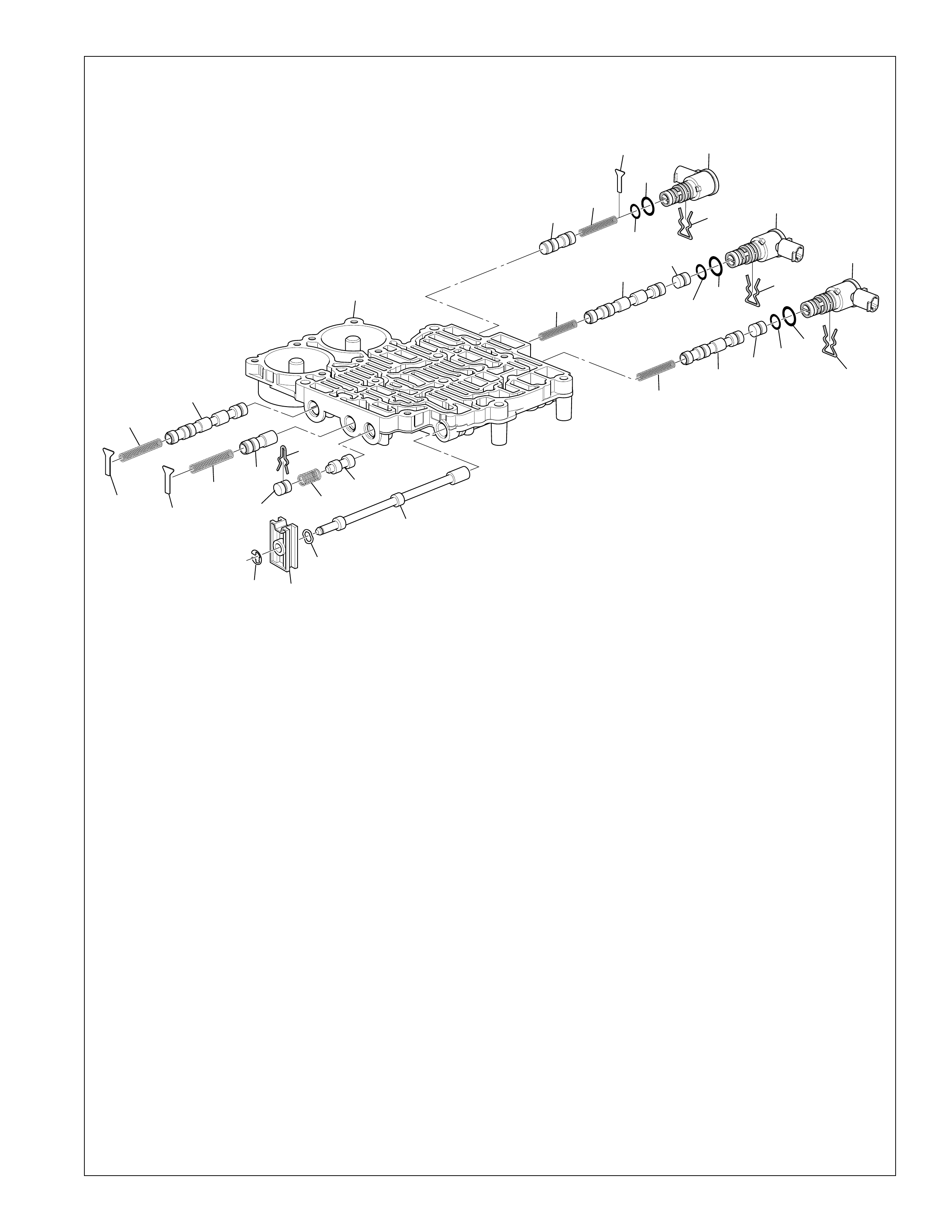
123
vb1_disassembly
Rear Control Valve Body
Figure 115
343
388
387
343
386 385
384
381 382 383
377
378
379
380
373 374 375 349
349
350
351
376
369
351
350
370
371
372
368
351
350
349
343
367
366
365
343 VALVE SPRING RETAINER
349 SOLENOID VALVE (O-RING) SEAL
350 SOLENOID VALVE (O-RING) SEAL
351 SOLENOID VALVE RETAINER
365 CONTROL VALVE REAR BODY
366 1-2 SHIFT CONTROL VALVE
367 1-2 SHIFT CONTROL VALVE SPRING
368 1-2 SHIFT SOLENOID VALVE ASSEMBLY
369 2-3 SHIFT SOLENOID VALVE ASSEMBLY
370 2-3 SHIFT CONTROL VALVE
371 2-3 SHIFT VALVE
372 2-3 SHIFT VALVE SPRING
373 4-5 SHIFT VALVE SPRING
374 4-5 SHIFT VALVE
375 4-5 SHIFT CONTROL VALVE
376 4-5 SHIFT SOLENOID VALVE ASSEMBLY
377 MANU AL VALVE
378 MANU AL VALVE LINK W ASHER (W AVED)
379 MANU AL VALVE LINK
380 MANUAL VALVE LINK RETAINER
381 LOW PRESSURE CONTROL VALVE BORE PLUG
382 LOW PRESSURE CONTROL VALVE SPRING
383 LOW PRESSURE CONTROL VALVE
384 LOW PRESSURE CONTROL VALVE BORE RETAINER
385 REVERSE LOCKOUT VALVE
386 REVERSE LOCKOUT VALVE SPRING
387 1-2 SHIFT VALVE
388 1-2 SHIFT VALVE SPRING
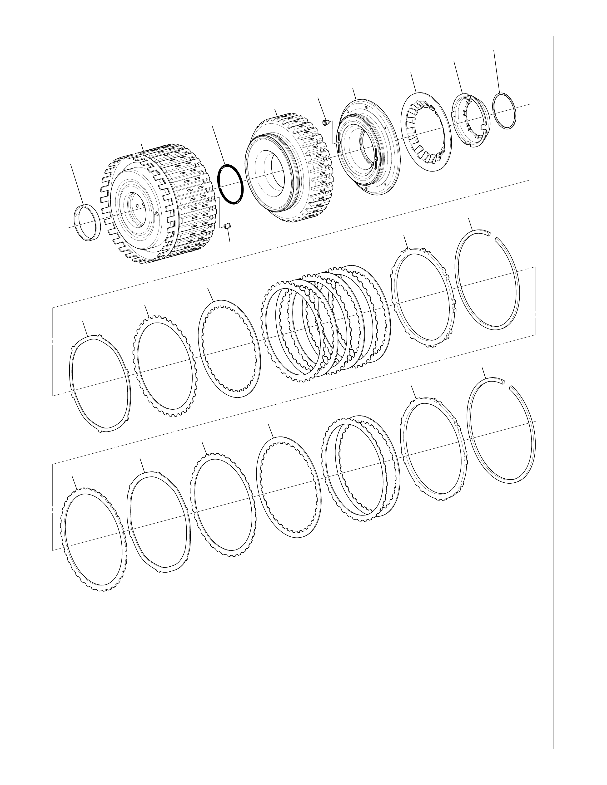
124
Partlist_A
Direct and Reverse Clutch Assembly
Figure 116
403
400
401
402
404 405 406
407 408 409
410
411
412
413
414
415
416
417
418
419
420
400 REVERSE CLUTCH HOUSING BUSHING
401 REVERSE CLUTCH (W/INPUT HOUSING ASSEMBLY)
402 REVERSE CLUTCH PISTON INNER SEAL
403 REVERSE CLUTCH HOUSING BALL CHECK VALVE
404 REVERSE CLUTCH PISTON
405 DIRECT CLUTCH HOUSING BALL CHECK VALVE
406 DIRECT CLUTCH PISTON ASSEMBLY
407 DIRECT AND REVERSE CLUTCH SPRING
408 DIRECT AND REVERSE CLUTCH SPRING RETAINER
409
DIRECT AND REVERSE CLUTCH SPRING RETAINER RING
410 DIRECT CLUTCH APPLY PLATE
411 DIRECT CLUTCH PLATE ASSEMBLY (OUTER SPLINE)
412 DIRECT CLUTCH PLATE ASSEMBLY (INNER SPLINE)
413 DIRECT CLUTCH BACKING PLATE
414 DIRECT CLUTCH BACKING PLATE RETAINER RING
(SELECTIVE)
415 REVERSE CLUTCH SPACER
416 REVERSE CLUTCH APPLY PLATE
417 REVERSE CLUTCH PLATE ASSEMBLY (OUTER SPLINE)
418 REVERSE CLUTCH PLATE ASSEMBLY (INNER SPLINE)
419 REVERSE CLUTCH BACKING PLATE
420 REVERSE CLUTCH BACKING PLATE RETAINER RING
(SELECTIVE)
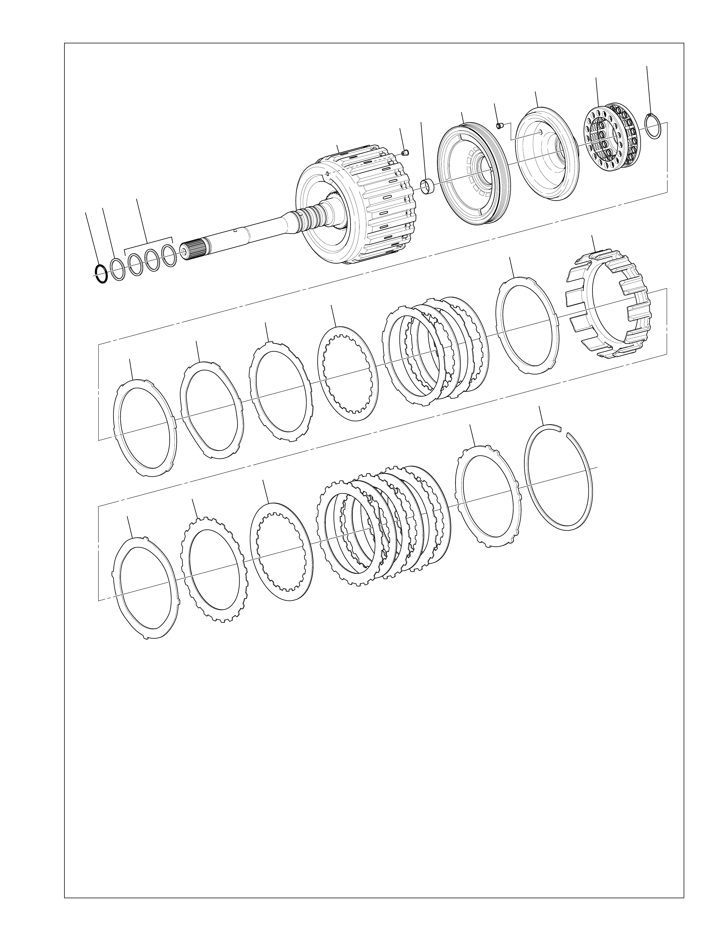
125
Forward and Coast Clutch Assembly
430 431 432
433
434 435 436 437 438 439 440
441
442
443
444
445
446
447
448
449
450
451
430 INPUT SHAFT (O-RING) SEAL
431 INPUT SHAFT FLUID SEAL RING
432 INPUT SHAFT FLUID SEAL RING
433 FORWARD CLUTCH (W/INPUT HOUSING ASSEMBLY)
434 FORWARD CLUTCH HOUSING BALL CHECK VALVE
ASSEMBLY
435 FORWARD CLUTCH BUSHING
436 FORWARD CLUTCH PISTON ASSEMBLY
437 COAST CLUTCH PISTON BALL CHECK VALVE
ASSEMBLY
438 COAST CLUTCH PISTON ASSEMBLY
439 FORWARD AND COAST CLUTCH SPRING
Figure 117
Partlist_B
440 FORWARD AND COAST CLUTCH SPRING
RETAINER RING
441 COAST CLUTCH SPACER PLATE (SELECTIVE)
442 COAST CLUTCH APPLY PLATE
443 COAST CLUTCH PLATE ASSEMBLY (OUTER SPLINE)
444 COAST CLUTCH PLATE ASSEMBLY (INNER SPLINE)
445 COAST CLUTCH BACKING PLATE
446 COAST CLUTCH HOUSING
447 FORWARD CLUTCH APPLY PLATE
448 FORWARD CLUTCH PLATE ASSEMBLY (OUTER SPLINE)
449 FORWARD CLUTCH PLATE ASSEMBLY (INNER SPLINE)
450 FORWARD CLUTCH BACKING PLATE
451 FORWARD CLUTCH BACKING PLATE
RETAINER RING (SELECTIVE)
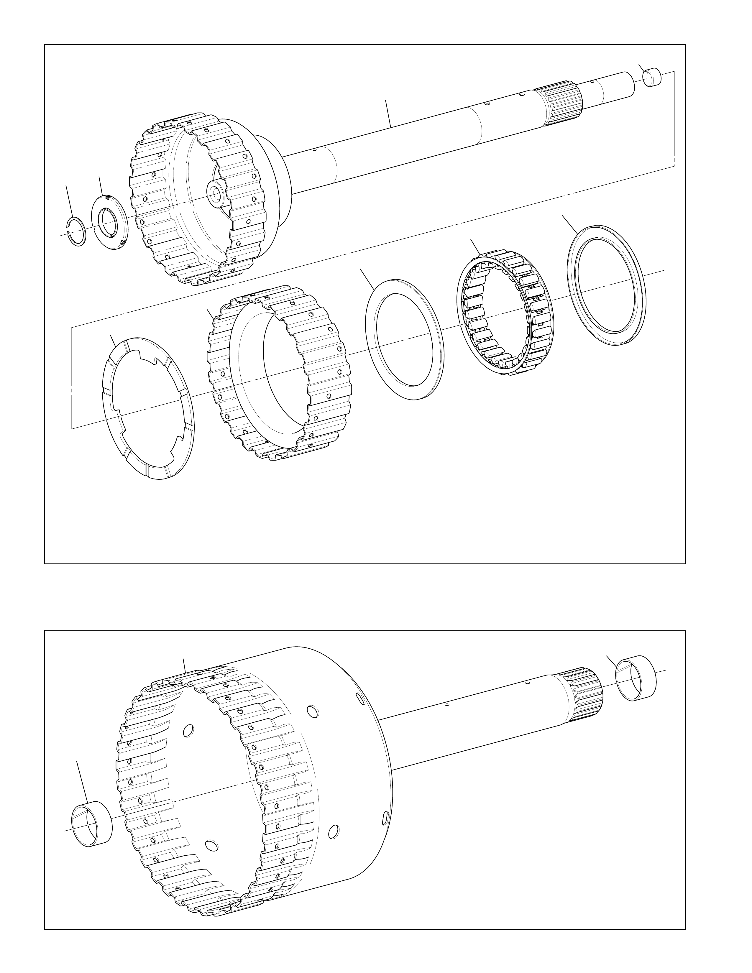
126
455 456
457
462
458
459
460
461
460
Direct Clutch Drum and Shaft Assembly
465
466 465
465 INPUT AND REACTION CARRIER BUSHING ASSEMBLY
466 DIRECT CLUTCH (W/INPUT AND HUB ASSEMBLY)
Partlist_D
Figure 119
Input Sun Gear Shaft and Forward Sprag Clutch Assembly
455 FORWARD CLUTCH ROLLER INNER RACE THRUST RING
456 FORWARD CLUTCH ROLLER INNER BEARING
457 INPUT SUN GEAR SHAFT ASSEMBLY
458 FORWARD CLUTCH ROLLER OUTER RACE WASHER
459 FORWARD CLUTCH SPRAG OUTER RACE
460 FORWARD CLUTCH SPRAG ASSEMBLY RETAINER
RINGS
461 FORWARD CLUTCH SPRAG ASSEMBLY
462 ORIFICED CUP PLUG (LUBE) Partlist_C
Figure 118
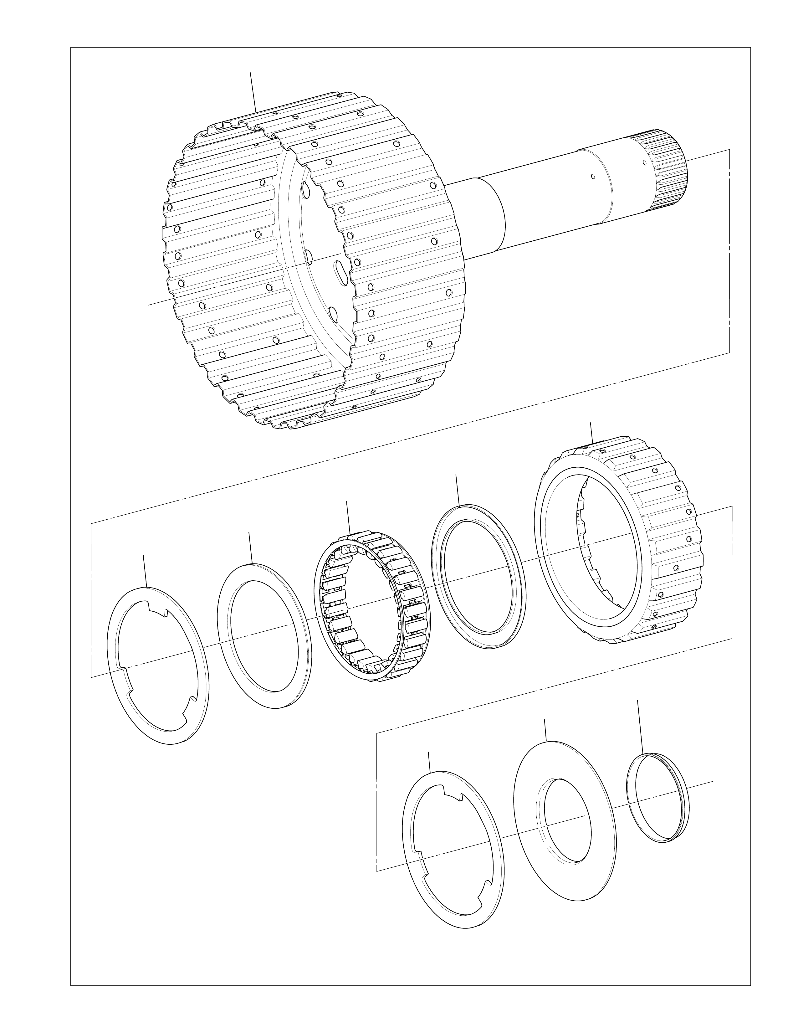
127
Intermediate Sprag Clutch Assembly
470
471
472
473
472
474
475
476 477
Partlist_E
Figure 120
470 OVERDRIVE AND REVERSE CLUTCH (W/HUB
ASSEMBLY)
471 INTERMEDIATE CLUTCH ROLLER THRUST WASHER
472 INTERMEDIATE CLUTCH SPRAG ASSEMBLY
RETAINER RINGS
473 INTERMEDIATE CLUTCH SPRAG ASSEMBLY
474 INTERMEDIATE CLUTCH SPRAG OUTER RACE
475 INTERMEDIATE CLUTCH ROLLER THRUST WASHER
476 INTERMEDIATE CLUTCH ROLLER THRUST BEARING
ASSEMBLY
477 INTERMEDIATE CLUTCH ROLLER THRUST BEARING
ASSEMBLY RETAINER
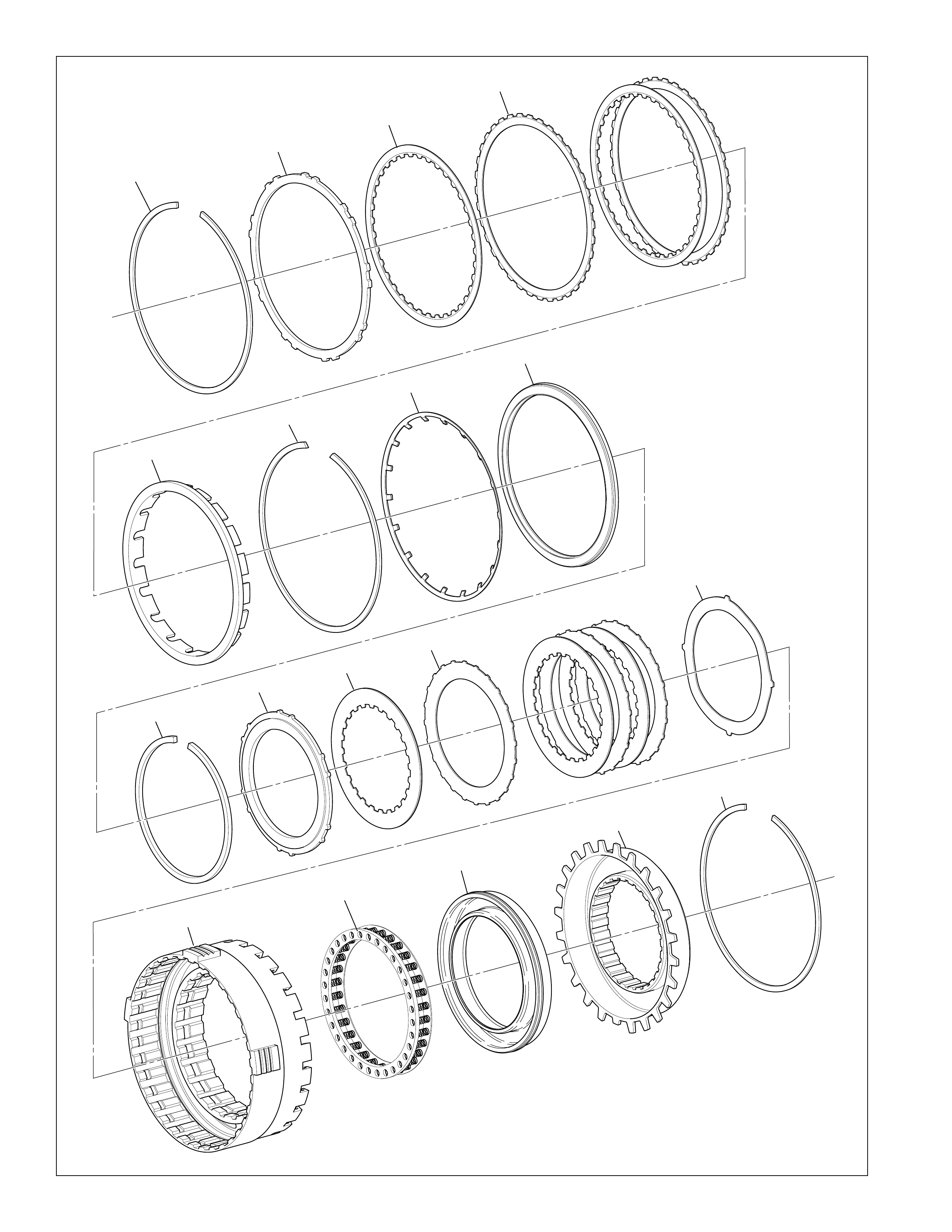
128
Overdrive and Intermediate Clutch Assembly
480
481
482
483
484
485
486
487
488
489 490
491
492
493
494
495
496
497
Partlist_F
Figure 121

129
500 501 502
502
504
501
505
503
Low Clutch Sprag Assembly
500 LOW CLUTCH ROLLER RETAINER
501 LOW CLUTCH ROLLER THRUST WASHER
502 LOW CLUTCH SPRAG ASSEMBLY RETAINER RINGS Partlist_G
Figure 122
503 LOW CLUTCH SPRAG ASSEMBLY
504 LOW CLUTCH SPRAG OUTER RACE
505 LOW CLUTCH SPRAG INNER RACE
Overdrive and Intermediate Clutch Assembly Legend
480 OVERDRIVE CLUTCH BACKING PLATE
RETAINER RING (SELECTIVE)
481 OVERDRIVE CLUTCH BACKING PLATE
482 OVERDRIVE CLUTCH PLATE ASSEMBLY
(INNER SPLINE)
483 OVERDRIVE CLUTCH PLATE ASSEMBLY
(OUTER SPLINE)
484 OVERDRIVE CLUTCH SPACER
485 OVERDRIVE CLUTCH SPRING RETAINER RING
486 OVERDRIVE CLUTCH SPRING
487 OVERDRIVE CLUTCH PISTON ASSEMBLY
488 INTERMEDIATE CLUTCH BACKING PLATE
RETAINER RING (SELECTIVE)
489 INTERMEDIATE CLUTCH BACKING PLATE
490 INTERMEDIATE CLUTCH PLATE ASSEMBLY
(INNER SPLINE)
491 INTERMEDIATE CLUTCH PLATE ASSEMBLY
(OUTER SPLINE)
492 INTERMEDIATE CLUTCH APPLY PLATE
493 OVERDRIVE CLUTCH HOUSING
494 INTERMEDIATE CLUTCH SPRING
495 INTERMEDIATE CLUTCH PISTON ASSEMBLY
496 INTERMEDIATE CLUTCH (W/HOUSING ASSEMBLY)
497 INTERMEDIATE CLUTCH HOUSING RETAINER RING
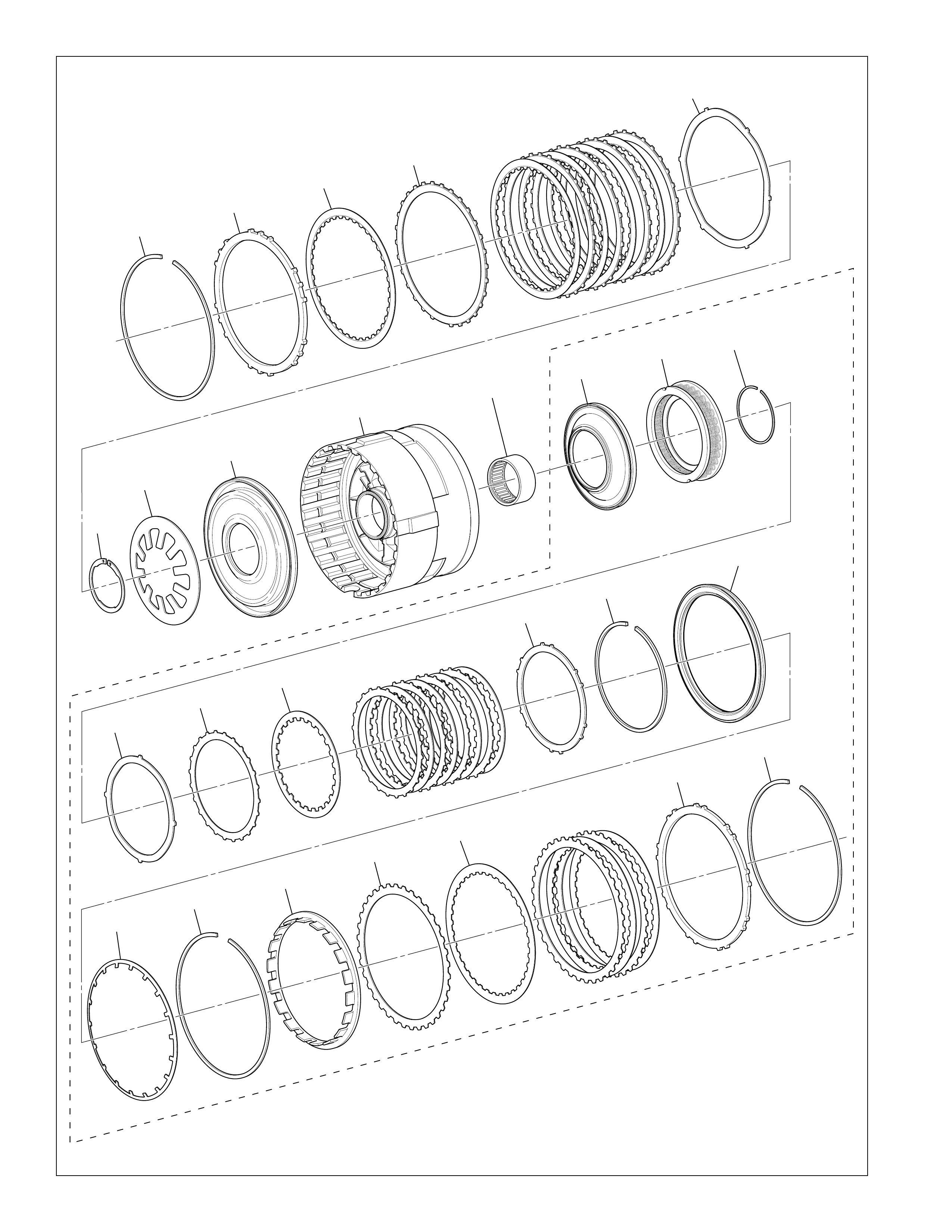
130
Center Support Assembly
Partlist_H
Figure 123
510
511
512
513
514
515
516
517
518 519 520
521 522
523
524 525
526
527
528
529
530 531
532
533
534
535
5L40-E
ONLY

131
Center Support Assembly Legend
510 LOW AND REVERSE CLUTCH PLATE
RETAINER RING (SELECTIVE)
511 LOW AND REVERSE CLUTCH BACKING PLATE
512 LOW AND REVERSE CLUTCH PLATE ASSEMBLY
(INNER SPLINE)
513 LOW AND REVERSE CLUTCH PLATE ASSEMBLY
(OUTER SPLINE)
514 LOW AND REVERSE CLUTCH APPLY PLATE
515 LOW AND REVERSE CLUTCH SPRING RETAINER RING
516 LOW AND REVERSE CLUTCH SPRING
517 LOW AND REVERSE CLUTCH PISTON
518 CENTER SUPPORT
519 INPUT AND REACTION BEARING ASSEMBLY
520 2ND CLUTCH PISTON
521 2ND CLUTCH SPRING
522 2ND CLUTCH SPRING RETAINER RING
523 2ND CLUTCH APPLY PLATE
524 2ND CLUTCH PLATE ASSEMBLY (OUTER SPLINE)
525 2ND CLUTCH PLATE ASSEMBLY (INNER SPLINE)
526 2ND CLUTCH BACKING PLATE
527 2ND CLUTCH BACKING PLATE
RETAINER RING (SELECTIVE)
528 2ND COAST CLUTCH PISTON ASSEMBLY
529 2ND COAST CLUTCH SPRING
530 2ND COAST CLUTCH SPRING RETAINER RING
531 2ND COAST CLUTCH SPACER
532 2ND COAST CLUTCH PLATE ASSEMBLY (OUTER SPLINE)
533 2ND COAST CLUTCH PLATE ASSEMBLY (INNER SPLINE)
534 2ND COAST CLUTCH BACKING PLATE
535 2ND COAST CLUTCH PLATE (BACKING PLATE)
RETAINER RING (SELECTIVE)
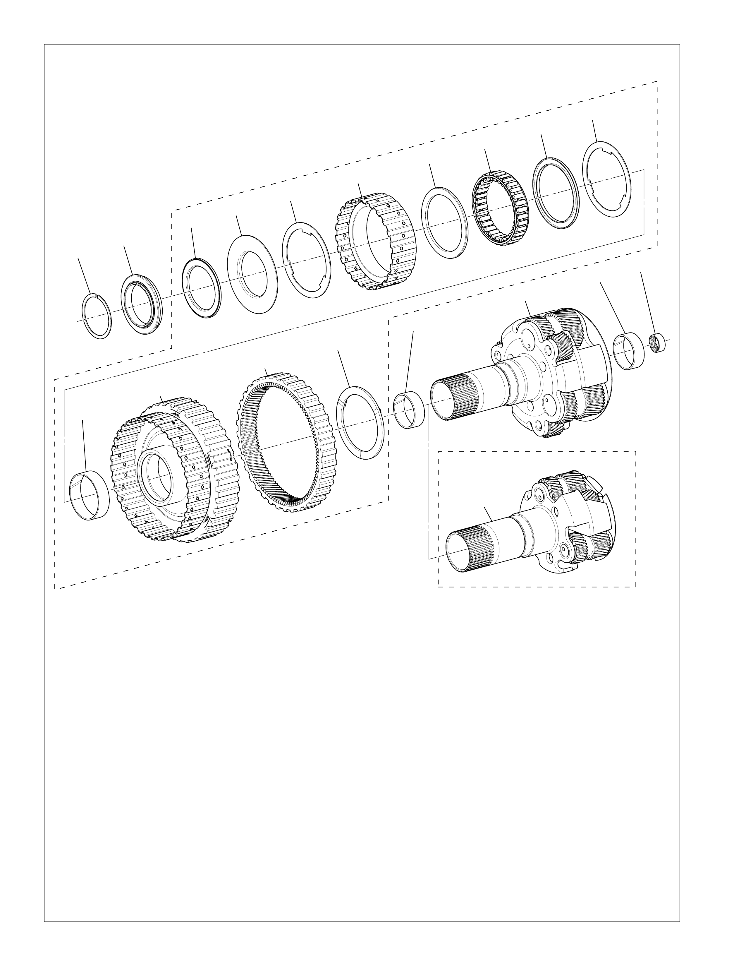
132
Planetary Carrier Assembly
540 INPUT AND REACTION CARRIER OUTER RING
541 INPUT AND REACTION BEARING ASSEMBLY
542 2ND CLUTCH ROLLER INNER RACE BEARING
ASSEMBLY
543 2ND CLUTCH SPRAG RETAINER
544 2ND CLUTCH ROLLER OUTER RACE WASHER
545 2ND CLUTCH SPRAG OUTER RACE
546 2ND CLUTCH SPRAG ASSEMBLY RETAINER
547 2ND CLUTCH SPRAG ASSEMBLY
548 INPUT AND REACTION CARRIER BUSHING
549 2ND CLUTCH SPRAG INNER (W/RACE)
550 REACTION INTERNAL GEAR
551 REACTION INTERNAL GEAR FLANGE WASHER
552 REACTION CARRIER BUSHING (2)
553 INPUT AND REACTION CARRIER
554 INPUT AND REACTION BEARING ASSEMBLY
Partlist_J
Figure 124
540 541
542 543 544
548
549
550
551
552
552
553
553
554
545
546
546 544
547
5L40-E
ONLY
4L40-E
ONLY
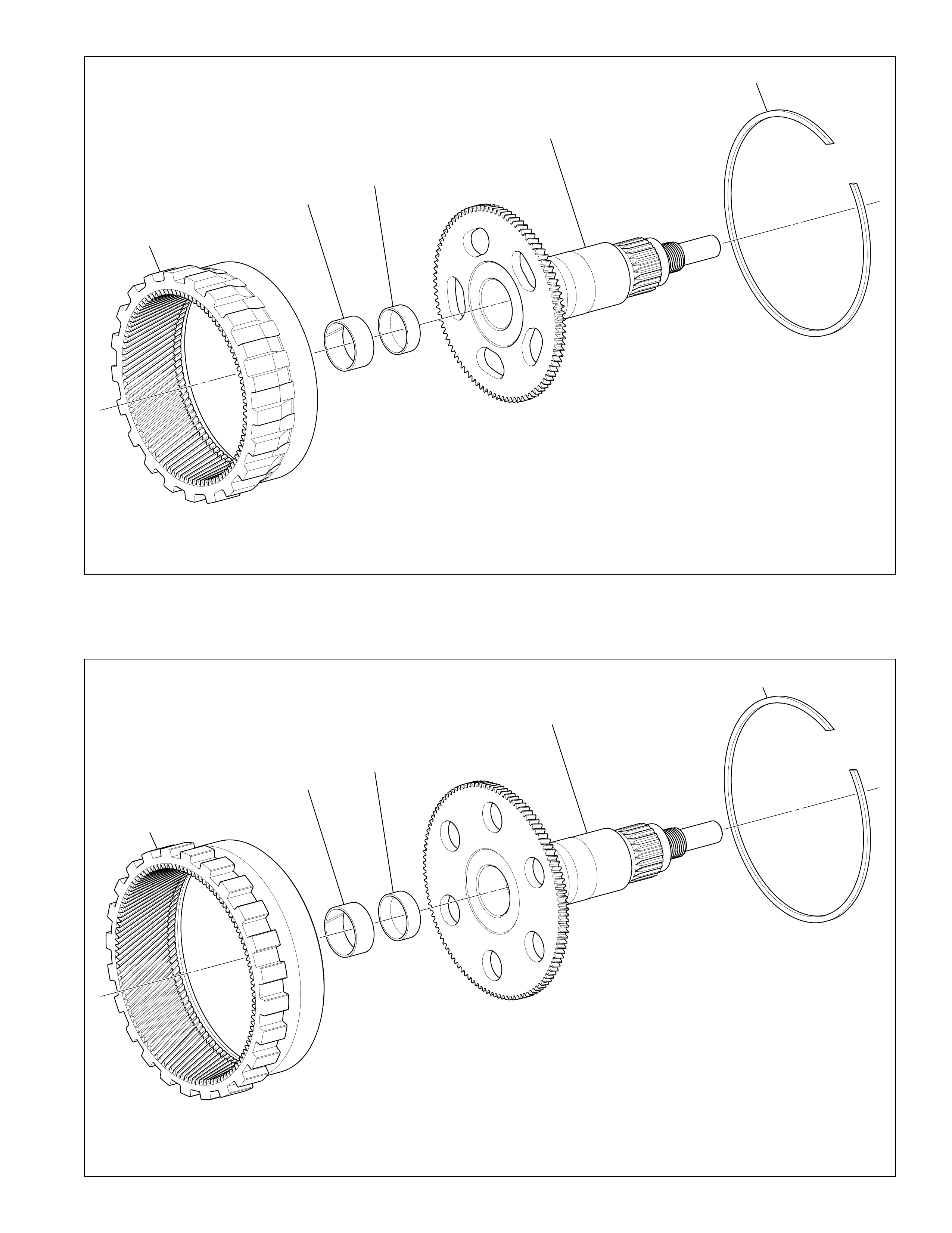
133
560
561 564
562
563
560
561 564
562
563
Figure 126
Rear Internal Gear Output Shaft Assembly (4L40-E)
Rear Internal Gear Output Shaft Assembly (5L40-E)
Partlist_K4L40-E
Partlist_K
560 REAR INTERNAL GEAR
561 INPUT AND REACTION CARRIER BUSHING
Figure 125
560 REAR INTERNAL GEAR
561 INPUT AND REACTION CARRIER BUSHING
562 OUTPUT SHAFT ASSEMBLY
563 REAR INTERNAL RETAINER RING
564 CUP PLUG
562 OUTPUT SHAFT ASSEMBLY
563 REAR INTERNAL RETAINER RING
564 CUP PLUG
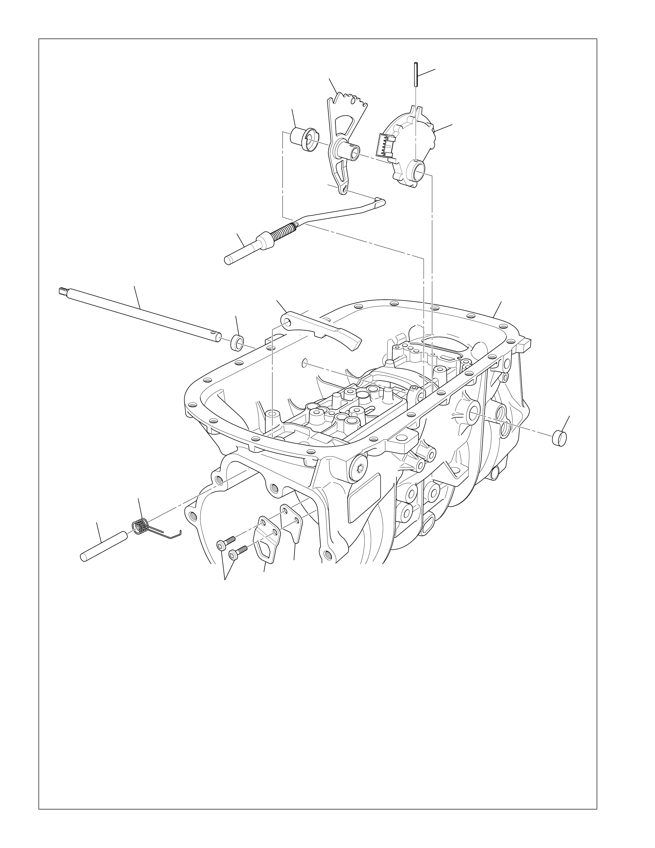
134
Park Pawl Assembly A
600
615
601
602
613
604
612
611
610
609 608 607
614
605
606
600 MANUAL SHAFT DETENT LEVER
601 MANUAL SHAFT DETENT LEVER PIN
602 TRANSMISSION MANUAL SHIFT SHAFT SWITCH
ASSEMBLY
604 TRANSMISSION CASE ASSEMBLY
605 MANUAL SHIFT SHAFT SEAL
606 MANUAL SHIFT SHAFT
607 PARK PAWL ACTUATOR BRACKET
608 PARK PAWL ACTUATOR BRACKET
609 PARK PAWL ACTUATOR BRACKET BOLT
610 PARK PAWL SHAFT
611 PARK PAWL SPRING
612 PARK PAWL
613 PARK PAWL ACTUATOR ASSEMBLY
614 CUP PLUG
615 TRANSMISSION MANUAL SHIFT SHAFT ASSEMBLY
SPACER
shift_assmA
Figure 127
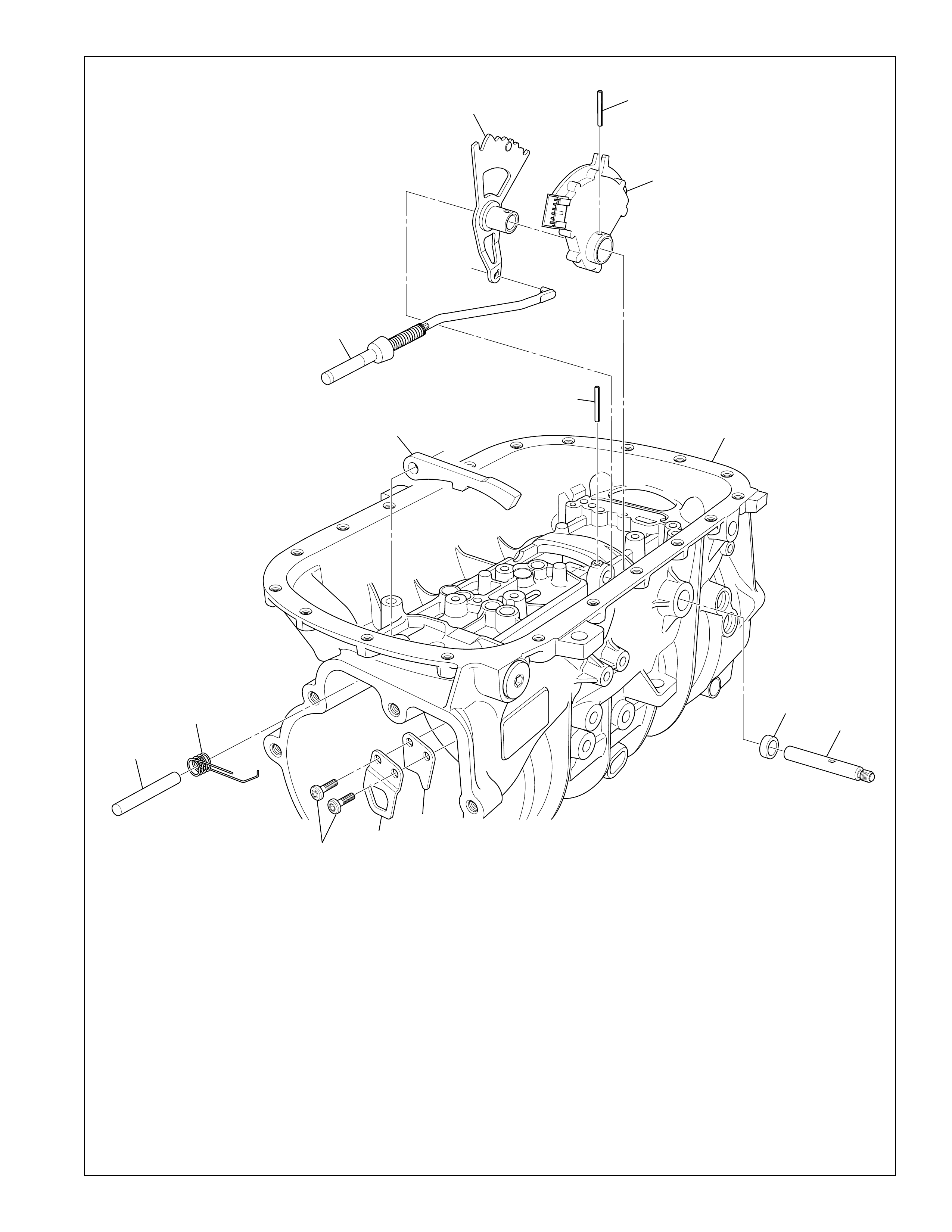
135
Park Pawl Assembly B
600 601
602
613
603
604
612
611
610
609 608 607
605 606
600 MANUAL SHAFT DETENT LEVER
601 MANUAL SHAFT DETENT LEVER PIN
602 TRANSMISSION MANUAL SHIFT SHAFT SWITCH
ASSEMBLY
603 MANUAL SHAFT DETENT LEVER PIN
604 TRANSMISSION CASE ASSEMBLY
605 MANUAL SHIFT SHAFT SEAL
606 MANUAL SHIFT SHAFT
607 PARK PAWL ACTUATOR BRACKET
608 PARK PAWL ACTUATOR BRACKET
609 PARK PAWL ACTUATOR BRACKET BOLT
610 PARK PAWL SHAFT
611 PARK PAWL SPRING
612 PARK PAWL
613 PARK PAWL ACTUATOR ASSEMBLY
shift_assmB
Figure 128
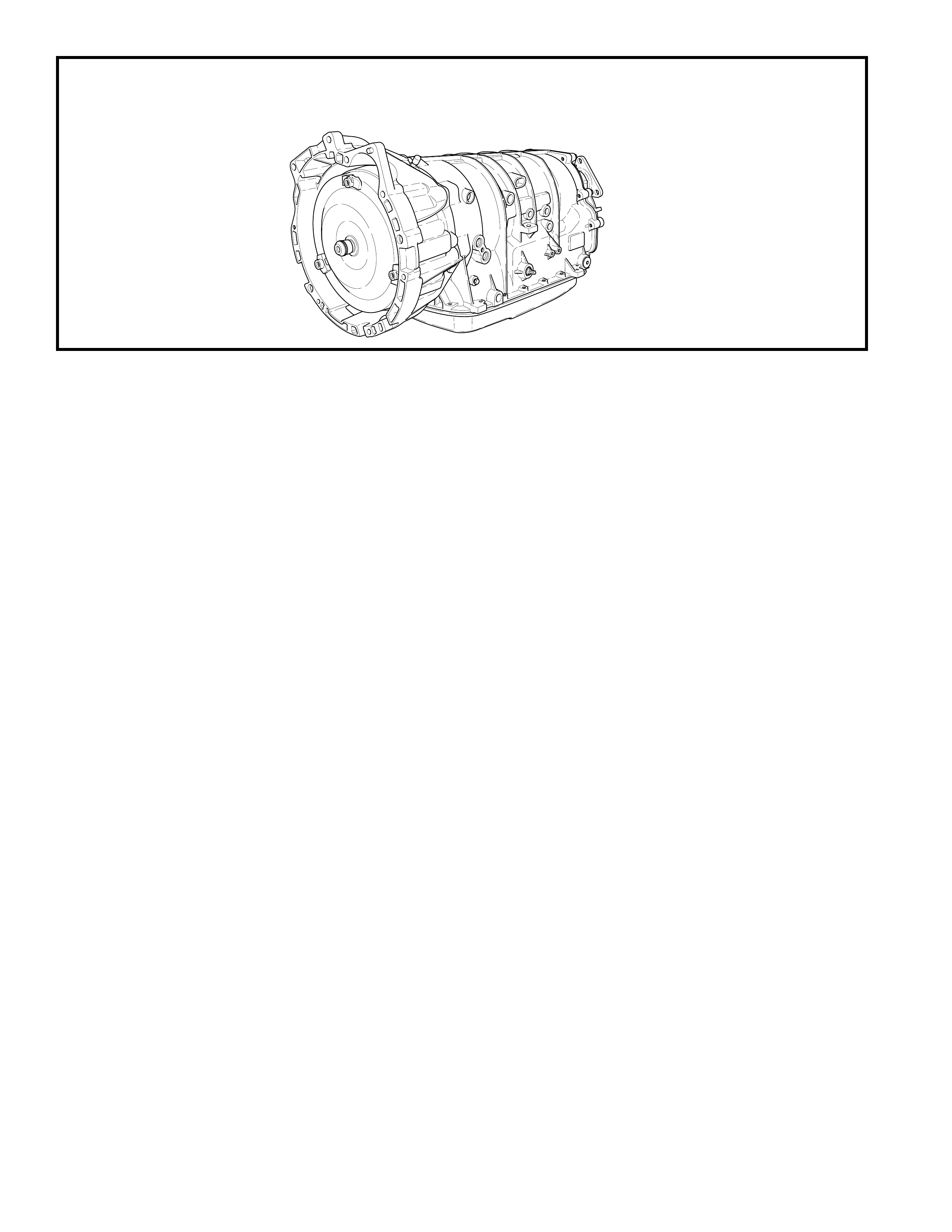
136
BASIC SPECIFICATIONS
HYDRA-MATIC 4L40-E TRANSMISSION
HYDRA-MATIC 4L40-E
(FOUR-SPEED)
Produced at: Strasbourg,
France
Transmission Drive
Rear Wheel Driv e
All Wheel Drive
Transmission Type
4L40-E = 4: Four Speed
L: Longitudinal Mount
40: Product Series
E: Electronically Controlled
Automatic Overdrive with a Torque Converter Clutch Assembly.
Current Engine Range
1.9 L Gasoline
Control Systems
Shift Pattern –(3) Two-way on/off solenoids
Shift Quality –Pressure Control Solenoid
Torque Converter Clutch –Pulse Width Modulated
solenoid control
Gear Ratios
1st 2.82
2nd 1.54
3rd 1.00
4th 0.70
Rev 2.38
Maximum Engine Torque
180 N•m (133 lb ft)
Maximum Gearbox Torque
430 N•m (317 lb ft)
Maximum Shift Speed
Output: 8,500 RPM
Shift: 6,500 RPM
Maximum Gross Vehicle Weight
3,500 kg (7,716 lb)
Transmission Fluid Type
Dexron® III
Transmission Fluid Capacity (Approximate)
245 mm Converter (Dry): 8.5 L (9.0 qt)
Transmission W eight
245 mm Converter (Dry): 66.5 kg (146.6 lb)
(Wet): 74.0 kg (163.1 lb)
Converter Sizes Available
245 mm
Converter Bolt Circle Diameters
For 245 mm Converter – 228.0 mm to 247.7 mm
Converter Stall Torque Ratio Range
For 245 mm Converter – 1.60 to 2.70
Converter “K” Factor Range
For 245 mm Converter – 122 to 260
Not all “K” Factors are applicable across the range of Con ver ter Stall Torque Ratios.
Transmission Packaging Information*
Overall Length
723.0 mm with 245 mm Converter
(2 Wheel Drive)
*All dimensions shown are nominal.
Driver Shift Control Only
Pressur e Taps Available
Line Pressure
Information may vary with application. All inf ormation, illustrations
and specifications contained in this book ar e based on the latest product
information available at the time of publication. The right is reserved to
make changes at any time without notice.
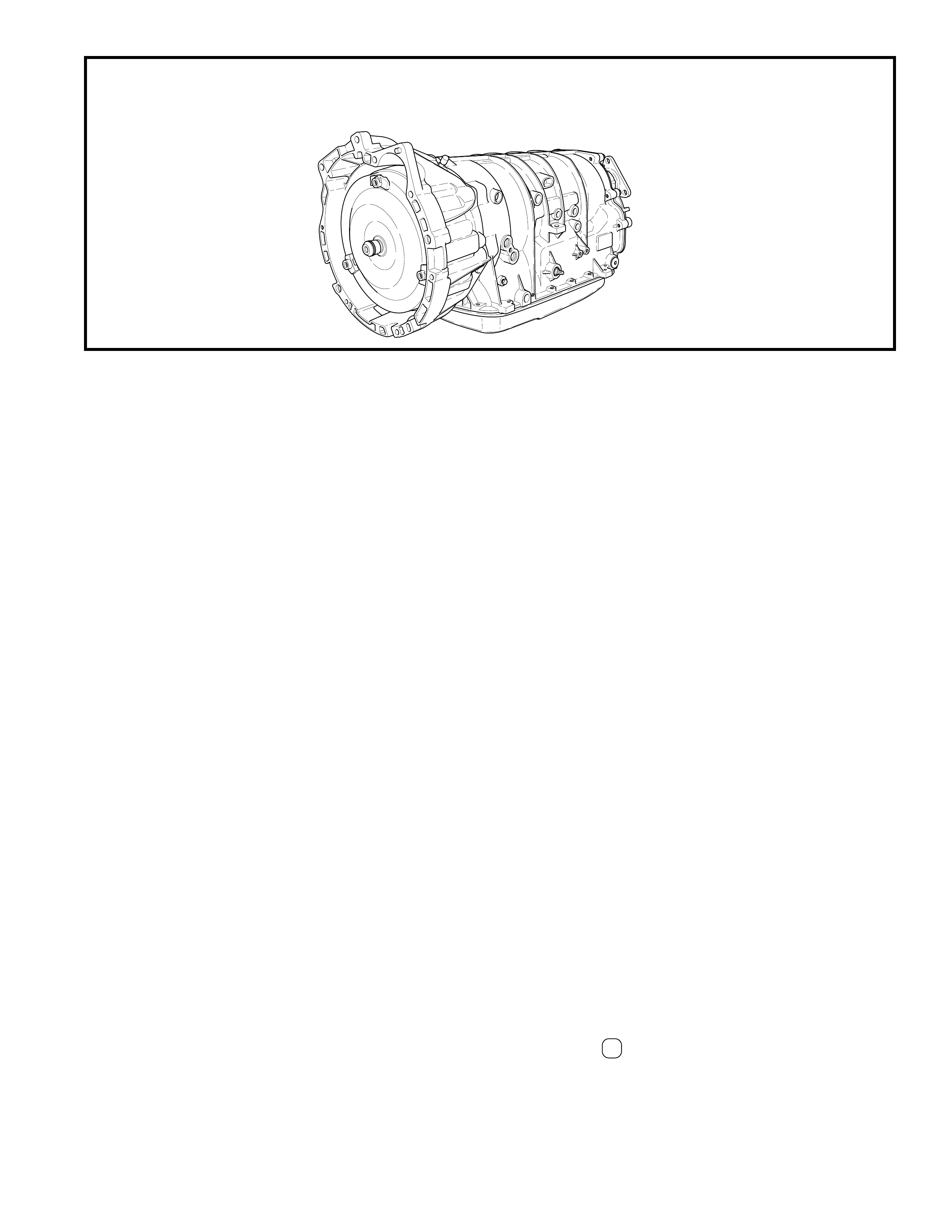
137
BASIC SPECIFICATIONS
HYDRA-MATIC 5L40-E TRANSMISSION
HYDRA-MATIC 5L40-E
(FIVE-SPEED)
Produced at: Strasbourg,
France
Transmission Drive
Rear Wheel Dri ve
All Wheel Driv e
Tr ansmission Type
5L40-E = 5: Five Speed
L: Longitudinal Mount
40: Product Series
E: Electronically Controlled
Automatic Overdrive with a Torque Converter Clutch Assembly.
Current Engine Range
2.2 L to 3.2 L Gasoline
2.0 L to 3.0 L Diesel
Control Systems
Shift Pattern –(3) Two-way on/off solenoids
Shift Quality –Pressure Control Solenoid
Torque Converter Clutch –Pulse Width Modulated
solenoid control
Gear Ratios
1st 3.42
2nd 2.21
3rd 1.60
4th 1.00
5th 0.75
Rev 3.03
Maximum Engine Torque
390 N•m (288 lb ft)
Maximum Gearbox Torque
670 N•m (494 lb ft)
Maximum Shift Speed
Output: 8,500 RPM
Shift: 6,500 RPM
Maximum Gross Vehicle Weight
3,500 kg (7,716 lb)
Transmission Fluid Type
Dexron® III
Tr ansmission Fluid Capacity (Approximate)
245 mm Converter (Dry): 8.5 L (9.0 qt)
Tr ansmission Weight
245 mm Converter (Dry): 73.0 kg (161.0 lb)
(Wet): 80.5 kg (177.5 lb)
Converter Sizes Available
245 mm
245 mm Hybrid Converter (Option for applications
above approximately 280 N•m (207 lb ft)
258 mm Converter (Option for applications above
approximately 350 N•m (258 lb ft)
Converter Bolt Circle Diameters
For 245 mm Converter – 228.0 mm to 247.7 mm
For 245 mm Hybrid Conv erter – 234.0 mm (Reference)
For 258 mm Converter – 234.0 mm (Reference)
Converter Stall Torque Ratio Range
For 245 mm Converter – 1.60 to 2.70
For 245 mm Hybrid Converter – 2.0 (Reference)
For 258 mm Converter – 1.60 to 2.10
Converter “K” Factor Range
For 245 mm Converter – 122 to 260
For 245 mm Hybrid Converter – 140 (Reference)
For 258 mm Converter – 106 to 164
Not all “K” Factors are applicable across the range of Con v erter Stall Torque Ratios.
Transmission Packaging Information*
Overall Length
711.0 to 723.0 mm with 245 mm Converter
(2 Wheel Drive)
728.0 mm with 258 mm Converter
(2 Wheel Drive)
*All dimensions shown are nominal.
Seven Position Quadrant or Driver Shift Control
(P, R, N, D , 4, 3, 2)
Pr essure Taps Available
Line Pressure
Information may vary with application. All inf ormation, illustrations
and specifications contained in this book ar e based on the latest product
information av ailable at the time of publication. The right is reserved to
make changes at any time without notice.

138
HYDRA-MATIC 4L40-E
HYDRA-MATIC PRODUCT DESIGNATION SYSTEM
The product designation system used for all Hydra-matic
transaxles and transmissions consists of a series of numbers
and letters that correspond with the special features incorporated
in that product line. The first character is a number that
designates the number of forward gear ranges available in that
unit. For example: 4 = four forward gear ranges.
The second character is a letter that designates how the unit is
mounted in the vehicle. When the letter “T” is used, it
designates that the unit is transversely mounted and is used
primarily for front wheel drive vehicles. The letter “L”
designates that it is longitudinally mounted in the vehicle and
it is used primarily for rear wheel drive vehicles. T he letter
“M” designates that the unit is a manual transaxle or
transmission but not specific to a front or rear wheel drive
vehicle application.
The third and fourth characters consists of a set of numbers,
(i.e. “40”), that designate the transaxle or transmission “Series”
number . This number signifies the relative torque capacity of
the unit.
The fifth character designates the major features incorporated
into this unit. For example , the letter “E” designa tes that the
unit has electronic controls.
By using this method of classification, the HYDRA-MATIC
4L40-E is a 4-speed, longitudinally mounted, 40 series unit,
with electronic controls.
HYDRA-MATIC 4 L 40 E
Number of Type: Series: Major Features:
Speeds: T - Transverse Based on E - Electronic Controls
3 L - Longitudinal Relative A - All Wheel Drive
4 M - Manual Torque HD - Heavy Duty
5 Capacity
V (CVT)

139
HYDRA-MATIC 5L40-E
HYDRA-MATIC PRODUCT DESIGNATION SYSTEM
The product designation system used for all Hydra-matic
transaxles and transmissions consists of a series of numbers
and letters that correspond with the special features incorporated
in that product line. The first character is a number that
designates the number of forward gear ranges available in that
unit. For example: 5 = five forward gear ranges.
The second character is a letter that designates how the unit is
mounted in the vehicle. When the letter “T” is used, it
designates that the unit is transversely mounted and is used
primarily for front wheel drive vehicles. The letter “L”
designates that it is longitudinally mounted in the vehicle and
it is used primarily for rear wheel drive vehicles. The letter
“M” designates that the unit is a manual transaxle or
transmission but not specific to a front or rear wheel drive
vehicle application.
The third and fourth characters consists of a set of numbers,
(i.e. “40”), that designate the transaxle or transmission “Series”
number . This number signifies the relative torque capacity of
the unit.
The fifth character designates the major features incorporated
into this unit. For example , the letter “E” designates that the
unit has electronic controls.
By using this method of classification, the HYDRA-MATIC
5L40-E is a 5-speed, longitudinally mounted, 40 series unit,
with electronic controls.
HYDRA-MATIC 5 L 40 E
Number of Type: Series: Major Features:
Speeds: T - Transverse Based on E - Electronic Controls
3 L - Longitudinal Relative A - All Wheel Drive
4 M - Manual Torque HD - Heavy Duty
5 Capacity
V (CVT)

140
GLOSSARY OF TECHNICAL TERMS
Accumulator: A component of the transmission that
absorbs hydraulic pressure during the apply of clutch
or band. Accumulators are designed to control the
quality of a shift from one gear range to another.
Adaptive Learning: Programming within the TCM
that automatically adjusts hydraulic pressures in order
to compensate for changes in the transmission (i.e.
component wear).
Applied: An apply component that is holding another
component to which it is splined or assembled with.
Also referred to as “engaged”.
A pply Components:
Hydraulically operated clutc hes,
serv os, bands, and mechanical one-w ay roller or sprag
clutches that drive or hold members of a planetary
gear set.
Apply Plate: A steel clutch plate in a clutch pack
located next to the (apply) piston.
Backing Plate: A steel plate in a clutch pack that is
usually the last plate in that clutch assembly (farthest
from the clutch piston).
Ball Check Valve: A spherical hydraulicall y controlled
component (usually made of steel) that either seals or
opens fluid circuits. It is also referred to as a check
valve or checkball.
Band: An apply component that consists of a flexible
strip of steel and friction material that wraps around a
drum. When applied, it tightens around the drum and
prevents the drum from rotating.
Brake Switch: An electrical device that provides
signals to the Transmission Control Module (TCM)
based on the position of the brake pedal. The TCM
uses this information to apply or release the torque
converter clutch (TCC).
Centrifugal Force: A force that is imparted on an
object (due to rotation) that increases as that object
moves further away from a center/point of rotation.
Clutch Pack:
An assembly of components generally
consisting of clutch plates, an apply plate and a
backing plate.
Clutch Plate: A hydraulically activated component
that has two basic designs: (1) all steel, or (2) a steel
core with friction material bonded to one or two sides
of the plate.
Component: Any physical part of the transmission.
Control Valve Body: A machined metal casting that
contains valv e tr ains and other hydraulically contr olled
components that shift the transmission.
Coupling Speed: The speed at which a vehicle is
traveling and no longer requires torque multiplication
through the torque converter. At this point the stator
free wheels to allow fluid leaving the turbine to flow
directly to the pump. (See torque converter)
De-energize(d): To interrupt the electrical current that
flows to an electronically controlled device making it
electrically inoperable.
Direct Drive: A condition in a gear set where the
input speed and input torque equals the output speed
and torque. The g ear ratio through the gear set is 1:1.
Downshift: A change in a gear ratio where input
speed and torque increases.
Driver Shift Control: A selector system variant which
is configured to be shifted only manually, and allo ws for
engine braking in first, second, third and fourth gears.
Duty Cycle: In reference to an electronically controlled
solenoid, it is the amount of time (expressed as a
percentage) that current flo ws through the solenoid coil.
Engine Control Module (ECM): An electronic de vice
that manages the electrical system of the engine.
Energize(d): To supply a current to an electronically
controlled device enabling it to perform its designed
function.
Engine Compression Braking: A condition where
compression from the engine is used with the
transmission to decrease vehicle speed. Braking
(slowing of the vehicle) occurs w hen a lo wer g ear ratio
is manually selected by moving the gear selector lever.
Exhaust: The release of f luid pressure from a hydraulic
circuit. (The words exhausts and exhausting are also
used and have the same intended meaning.)
Fluid: Generally considered a liquid or gas. In this
publication fluid refers primarily to “transmission fluid”.
Fluid Pressure:
A pressure (in this textbook usually
transmission fluid) that is consistent throughout its circuit.
Force: A measurable ef fort that is ex erted on an object
(component).
Freewheeling: A condition where po wer is lost through
a dri ving or holding de vice (i.e. roller or sprag clutches).
Friction Material: A heat and wear resistant fibrous
material bonded to clutch plates and bands.
Gear: A round, toothed device that is used for
transmitting torque through other components.
Gear Range: A specific speed to torque ratio at
which the transmission is operating (i.e. 1st gear,
2nd gear etc.).

141
GLOSSARY OF TECHNICAL TERMS
Gear Ratio: Re volutions of an input gear as compared
to the revolutions of an output gear. It can also be
e xpressed as the number of teeth on a gear as compared
to the number of teeth on a gear that it is in mesh with.
Hydraulic Circuit: A fluid passage which often
includes the mechanical components in that circuit
designed to perform a specific function.
Input: A starting point f or torque, re volutions or ener gy
into another component of the transmission.
Internal Gear: The outermost member of a gear set
that has gear teeth in constant mesh with planetary
pinion gears of the gear set.
Internal Leak: Loss of fluid pressure in a hydraulic
circuit.
Land (Valve Land): The larger diameters of a spool
valve that contact the valve bore or bushing.
Line Pressure: The main fluid pressure in a hydraulic
system created by the pump and pressure regulator
valve.
Manual Valve: A spool valve that distributes fluid to
various hydraulic circuits and is mechanically linked
to the gear selector lever.
Orifice: A restricting device (usually a hole in the
spacer plate) for controlling pressure build up into
another circuit.
Overdrive: An operating condition in the gear set
allowing output speed to be higher than input speed
and output torque to be lower than input torque.
Overrunning: The function of a one-way mechanical
clutch that allows the clutc h to free wheel during certain
operating conditions of the transmission.
Pinion Gear: A small toothed gear that meshes with a
larger gear.
Planet Pinion Gears: Pinion gears (housed in a carrier)
that are in constant mesh with a circumferential internal
gear and centralized sun gear.
Planetary Gear Set: An assembly of gears that consists
of an internal gear, planet pinion gears with a carrier,
and a sun gear.
Powertrain Control Module (PCM): An electronic
device that manages most of the electrical systems
throughout the vehicle.
Pressure: A measurable force that is exerted on an
area and expressed as kilopascals (kPa) or pounds per
square inch (psi).
Pulse W idth Modulated (PWM): An electr onic signal
that continuously cycles the ON and OFF time of a
device (such as a solenoid) while varying the amount
of ON time.
Race (Inner or Outer): A highly polished steel surface
that contacts bearings or sprag or roller elements.
Reduction (Gear Reduction):
An operating condition
in the gear set allowing output speed to be lower
than input speed and output torque to be higher than
input torque.
Residual Fluid Pressure: Excess pressure contained
within an area after the supply pressure has been
terminated.
Roller Clutch: A mechanical clutch (holding device)
consisting of roller bearings assembled between inner
and outer races.
Safety Mode: A condition whereby a component (i.e.
engine or transmission) will partially function even if
its electrical system is disabled.
Servo: A spring loaded device consisting of a piston
in a bore that is operated (stroked) by hydraulic pressure
to apply or release a band.
Solenoid Valve: An electronic device used to control
transmission shift patterns or regula te fluid pressure.
Spool Valve: A cylindrical hydraulic control device
having a variety of land and valley diameters, used to
control fluid flow.
Sprag Clutch: A mechanical clutch (holding device)
consisting of figure eight like elements assembled
between inner and outer races.
Throttle Position: The travel of the throttle plate that
is expressed in percenta ges and measured by the throttle
position (TP) sensor.
Torque: A measurable twisting force expressed in
terms of Newton-meters (N•m), pounds feet (lbs ft) or
pounds inches (lbs in).
Torque Converter: A component of an automatic
transmission, (attached to the engine flywheel) that
transfers torque from the engine to the transmission
through a fluid coupling.
Transmission Control Module (TCM): An electronic
device that manages the electrical system of the
transmission.
Variable Capacity Pump: The device that provides
fluid for operating the hydraulic circuits in the
transmission. The amount of fluid supplied varies
depending on vehicle operating conditions.

142
ABBREVIATIONS
AC - Alternating Curr ent
A/C - Air Conditioning
ACC or ACCUM - Accumulator
AFL - Actuator Feed Limit
ALDL - Assembly Line Diagnostic Link
AMP - Amperage
ASM - Assembly
AT - Automatic Transmission
°C - Degrees Celsius
CC - Converter Clutch
CL - Clutch
CONT - Control
CONV - Converter
DC - Direct Current
D.C. - Duty Cycle
DLC - Diagnostic Link Connector
DRAC - Digital Ratio Adaptor Converter
DSC - Driver Shift Control
DTC - Diagnostic Trouble Code
D2 - Drive 2 (circuit)
D3 - Drive 3 (circuit)
D4 - Drive 4 (circuit)
D432 - Drive 432 (circuit)
ECM - Engine Control Module
ECT - Engine Coolant Temperature
EX - Exhaust
°F - Degrees Fahrenheit
FD - Feed
FWD - Forward
Hz - Hertz
ISS - Input Speed Sensor
KM/H - Kilometers per Hour
kPa - KiloPascals
MAP - Manifold Absolute Pressure
MPH - Miles per Hour
N - Neutral
NC - Normally Closed
N.m - Newton Meters
NO - Normally Open
ORF - Orificed
ORUN - Overrun
OSS - Output Speed Sensor
P - Park
PCM - Powertrain Control Module
PC - Pressure Control (solenoid)
PR - Park Reverse (circuit)
PRESS REG - Pressure Regulator
PSI - Pounds per Square Inch
PWM - Pulse Width Modulated
R - Reverse
REV - Reverse
RPM - Revolutions per Minute
SEL - Selective
SIG - Signal
SOL - Solenoid
SS - Shift Solenoid
TCC - Torque Converter Clutch
TCM - Transmission Control Module
TFP - Transmission Fluid Pressure
TFT - Transmission Fluid Temperature
TP - Throttle Position (sensor)
TRANS - Transmission or Transaxle
V - Volts
VSS - Vehicle Speed Sensor
2WD - 2 Wheel Drive
4WD - 4 Wheel Drive

143
A
Abbreviations ........................................................................... 142
Accumulators......................................................................... 40-41
direct clutch accumulator ................................................ 41
overdrive clutch accumulator.......................................... 41
intermediate clutch accumulator ..................................... 41
second clutch accumulator .............................................. 41
Apply Components................................................................ 15-28
direct clutch ..................................................................... 16
reverse clutch .................................................................. 17
coast clutch...................................................................... 18
forward clutch ................................................................. 19
forward clutch sprag ....................................................... 20
overdrive clutch............................................................... 21
intermediate clutch sprag ................................................ 22
intermediate clutch .......................................................... 23
low clutch sprag .............................................................. 24
low and reverse clutch .................................................... 25
second clutch................................................................... 26
second clutch sprag ......................................................... 27
second coast clutch ......................................................... 28
B
Ball Check Valves Location and Function ........................... 42-43
Basic Specifications .......................................................... 136-137
Bushing and Bearing Locations ............................................... 113
C
Case and Associated Parts................................................. 116-117
Center Support Assembly.................................................. 130-131
Coast Clutch ............................................................................... 18
Color Legend ....................................................................... 10A-B
Complete Hydraulic Circuits............................................... 85-112
park............................................................................. 86-87
reverse ........................................................................ 88-89
neutral......................................................................... 90-91
overdrive range – first gear........................................ 92-93
overdrive range – second gear ................................... 94-95
overdrive range – third gear....................................... 96-97
overdrive range – fourth gear .................................... 98-99
overdrive range – fifth gear (TCC released).......... 100-101
overdrive range – fifth gear (TCC applied) ........... 102-103
manual fourth – fourth gear ................................... 104-105
manual third – third gear........................................106-107
manual second – second gear ................................ 108-109
manual second – first gear ..................................... 110-111
lubrication points .......................................................... 112
Contents, Table of ........................................................................ 2
Control Valve Body and Accumulator Assembly ............ 120-121
Cross Sectional Views............................................................ 8-8A
INDEX
D
Direct Clutch .............................................................................. 16
Direct Clutch Accumulator ........................................................ 41
Direct Clutch Drum and Shaft Assembly ................................ 126
Direct and Reverse Clutch Assembly ...................................... 124
Direct Drive ..............................................................................30B
Driver Shift Control Gear Ranges............................................. 9A
E
Electrical Components .......................................................... 45-52
component locations ....................................................... 45
safety mode ..................................................................... 45
transmission manual shift shaft switch assembly ........... 46
transmission output speed sensor.................................... 47
transmission input speed sensor...................................... 47
transmission fluid temperature sensor ............................ 48
shift solenoid valves........................................................ 49
TCC PWM solenoid valve .............................................. 50
pressure control solenoid valve....................................... 51
components external to the transmission ........................ 52
Explanation of Gear Ranges................................................... 9-9A
F
Feed Limit Valve........................................................................ 36
Fluid Pump Assembly ................................................. 33, 118-119
First Gear (overdrive)................................................ 62-65, 92-93
Forward Clutch........................................................................... 19
Forward Clutch Sprag ................................................................ 20
Forward and Coast Clutch Assembly....................................... 125
Front Control Valve Body........................................................ 122
G
General Description...................................................................... 9
Glossary Of Technical Terms ........................................... 140-141
H
How To Use This Book ............................................................ 4-5
Hydra-matic Product Designation System ........................ 138-139
Hydraulic Control Components ............................................ 32-44
location of major components......................................... 32
fluid pump assembly ....................................................... 33
pressure regulation .......................................................... 34
valves located in the fluid pump cover assembly ........... 35
valves located in the front control valve body .......... 36-37
valves located in the rear control valve body ............ 38-39
accumulators .............................................................. 40-41
ball check valves location and function..................... 42-43

144
INDEX
I
Illustrated Parts List .......................................................... 115-135
case and associated parts........................................ 116-117
fluid pump assembly .............................................. 118-119
control valve body and accumulator assembly...... 120-121
front control valve body................................................ 122
rear control valve body ................................................. 123
direct and reverse clutch assembly ............................... 124
forward and coast clutch assembly ............................... 125
input sun gear shaft and forward sprag clutch assembly .
126
direct clutch drum and shaft assembly ......................... 126
intermediate sprag clutch assembly .............................. 127
overdrive and intermediate clutch assembly.......... 128-129
low clutch sprag assembly ............................................ 129
center support assembly ......................................... 130-131
planetary carrier assembly ............................................ 132
rear internal gear output shaft assembly ....................... 133
park pawl assembly................................................ 134-135
Input Speed Sensor..................................................................... 47
Input Sun Gear Shaft and Forward Sprag Clutch Assembly ... 126
Intermediate Clutch .................................................................... 23
Intermediate Clutch Accumulator .............................................. 41
Intermediate Clutch Sprag.......................................................... 22
Intermediate Sprag Clutch Assembly....................................... 127
Introduction .................................................................................. 3
L
Line Boost Valve........................................................................ 35
Low and Reverse Clutch ............................................................ 25
Low Clutch Sprag....................................................................... 24
Low Clutch Sprag Assembly ................................................... 129
Low Pressure Control Valve ...................................................... 38
Lubrication Points .................................................................... 112
M
Major Mechanical Components ................................................. 10
Manual Fourth – Fourth Gear ............................... 76-77, 104-105
Manual Second – First Gear.................................. 82-83, 110-111
Manual Second – Second Gear ............................. 80-81, 108-109
Manual Third – Third Gear ................................... 76-79, 106-107
Manual Valve ............................................................................. 39
N
Neutral .................................................................... 60-61, 90-91
O
Operating Conditions - Range Reference Chart ........................ 84
Output Speed Sensor .................................................................. 47
Overdrive ..................................................................................30B
Overdrive and Intermediate Clutch Assembly.................. 128-129
Overdrive Clutch ........................................................................ 21
Overdrive Clutch Accumulator .................................................. 41
Overdrive Range – First Gear ................................... 62-65, 92-93
Overdrive Range – Fifth Gear............................................... 72-73
Overdrive Range – Fifth Gear (TCC Applied) ... 74B-75, 102-103
Overdrive Range – Fifth Gear (TCC Released)..74-74A, 100-101
Overdrive Range – Fourth Gear ................................ 70-71, 98-99
Overdrive Range – Second Gear............................... 66-67, 94-95
Overdrive Range – Third Gear.................................. 68-69, 96-97
P
Park............................................................................ 56-57, 86-87
Park Pawl Assembly.......................................................... 134-135
Planetary Carrier Assembly ..................................................... 132
Planetary Gear Sets ............................................................... 29-31
description ....................................................................... 29
reduction....................................................................... 30A
direct drive ....................................................................30B
overdrive .......................................................................30B
reverse direction of rotation ..........................................30B
Power Flow............................................................................ 53-84
mechanical powerflow from TCC .......................... 54-54A
common hydraulic functions................................... 54B-55
park............................................................................. 56-57
reverse ........................................................................ 58-59
neutral......................................................................... 60-61
overdrive range – first gear........................................ 62-65
overdrive range – second gear ................................... 66-67
overdrive range – third gear....................................... 68-69
overdrive range – fourth gear .................................... 70-71
overdrive range – fifth gear ....................................... 72-73
overdrive fifth, TCC released to applied ................ 74-74A
overdrive fifth, TCC applied to released ................ 74B-75
manual fourth – fourth gear ....................................... 76-77
manual third – third gear............................................ 78-79
manual second – second gear .................................... 80-81
manual second – first gear ......................................... 82-83
Preface ....................................................................................... 1
Pressure Control Solenoid Valve ......................................... 36, 51
Pressure Regulation .................................................................... 34
Pressure Regulator Valve ........................................................... 35
Pressure Relief Ball Valve ......................................................... 35
Principles of Operation......................................................... 9A-52
major mechanical components........................................ 10
color legend.............................................................. 10A-B
range reference chart....................................................... 11
torque converter ......................................................... 12-14
apply components ...................................................... 15-28
planetary gear sets...................................................... 29-31
hydraulic control components.................................... 32-44
electrical components................................................. 45-52

145
INDEX
R
Range Reference Charts ....................................................... 11, 84
Ravigneaux Planetary Gear Set.................................................. 29
Rear Control Valve Body ......................................................... 123
Rear Internal Gear Output Shaft Assembly ............................. 133
Reduction................................................................................. 30A
Reverse ............................................................30B, 58-59, 88-89
Reverse Clutch ........................................................................... 17
Reverse Lockout Valve .............................................................. 38
S
Safety Mode ............................................................................... 45
Safety Mode Valve..................................................................... 37
Seal Locations .......................................................................... 114
Second Clutch............................................................................. 26
Second Clutch Accumulator....................................................... 41
Second Clutch Sprag .................................................................. 27
Second Coast Clutch .................................................................. 28
Second Gear (overdrive) ........................................... 66-67, 94-95
Shift Solenoid Valve (1-2) ......................................................... 38
Shift Solenoid Valve (2-3) ......................................................... 38
Shift Solenoid Valve (4-5) ......................................................... 39
Shift Solenoid Valves................................................................. 49
Shift Control Valve (1-2) ........................................................... 38
Shift Control Valve (2-3) ........................................................... 38
Shift Control Valve (3-4) ........................................................... 36
Shift Control Valve (4-5) ........................................................... 39
Shift Valve (1-2)......................................................................... 38
Shift Valve (2-3)......................................................................... 38
Shift Valve (3-4)......................................................................... 36
Shift Valve (4-5)......................................................................... 39
Speed Sensors............................................................................. 47
Stator Assembly ......................................................................... 13
T
Table of Contents ......................................................................... 2
TCC PWM Solenoid Valve.................................................. 36, 50
Torque Converter Clutch Control Valve.................................... 35
Torque Converter Clutch Enable Valve..................................... 35
Torque Converter Clutch Regulator Apply Valve ..................... 36
Transmission Manual Shift Shaft Switch Assembly ................. 46
Third Gear (overdrive) .............................................. 68-69, 96-97
Torque Converter Clutch....................................................... 12-14
converter pump and turbine ............................................ 12
pressure plate................................................................... 12
stator assembly ................................................................ 13
torque converter apply and release ................................. 14
Torque Converter Clutch Applied.................14, 74B-75, 102-103
Torque Converter Clutch Released .............................. 14, 74-74A
Transmission Fluid Temperature Sensor ................................... 48
Transmission Adapt Function .................................................... 51
U
Understanding The Graphics.................................................. 6-8A
V
Valves Located In The Front Control Valve Body............... 36-37
pressure control solenoid valve....................................... 36
feed limit valve ............................................................... 36
TCC PWM solenoid valve .............................................. 36
TCC regulator apply valve.............................................. 36
3-4 shift valve ................................................................. 36
3-4 shift control valve ..................................................... 36
safety mode valve ........................................................... 37
Valves Located In The Rear Control Valve Body ................ 38-39
reverse lockout valve ...................................................... 38
low pressure control valve .............................................. 38
1-2 shift solenoid valve ................................................... 38
1-2 shift control valve ..................................................... 38
1-2 shift valve ................................................................. 38
2-3 shift solenoid valve ................................................... 38
2-3 shift control valve ..................................................... 38
2-3 shift valve ................................................................. 38
4-5 shift solenoid valve ................................................... 39
4-5 shift control valve ..................................................... 39
4-5 shift valve ................................................................. 39
manual valve ................................................................... 39
Valves Located In The Fluid Pump Cover Assembly ............... 35
pressure regulator valve .................................................. 35
line boost valve ............................................................... 35
pressure relief ball valve ................................................. 35
torque converter clutch control valve ............................. 35
torque converter clutch enable valve .............................. 35
check valve retainer and ball assemblies ........................ 35
orifice cup plugs.............................................................. 35

146
NOTES