
VZ L.P.G. Conversion Kit Page 8A2–1
Page 8A2–1
Section 8A2
VZ L.P.G. Conversion Kit
Section 1 Passenger Compartment........................................................................................................8A2-2
Section 2 Manifold Modification............................................................................................................8A2-17
Section 3 Engine Compartment............................................................................................................8A2-21
Owner’s Handbook.................................................................................................................................8A2-41
Techline
Techline
Techline
Techline
Techline
FD1349
09MA05
COPYRIGHT
Reproduction in whole or part
prohibited without written approval
HOLDEN LTD
Division of HOLDEN Ltd ACN 006 893 232
FITTING INSTRUCTIONS FOR
VZ L.P.G. CONVERSION KIT
FITTING INSTRUCTIONS:
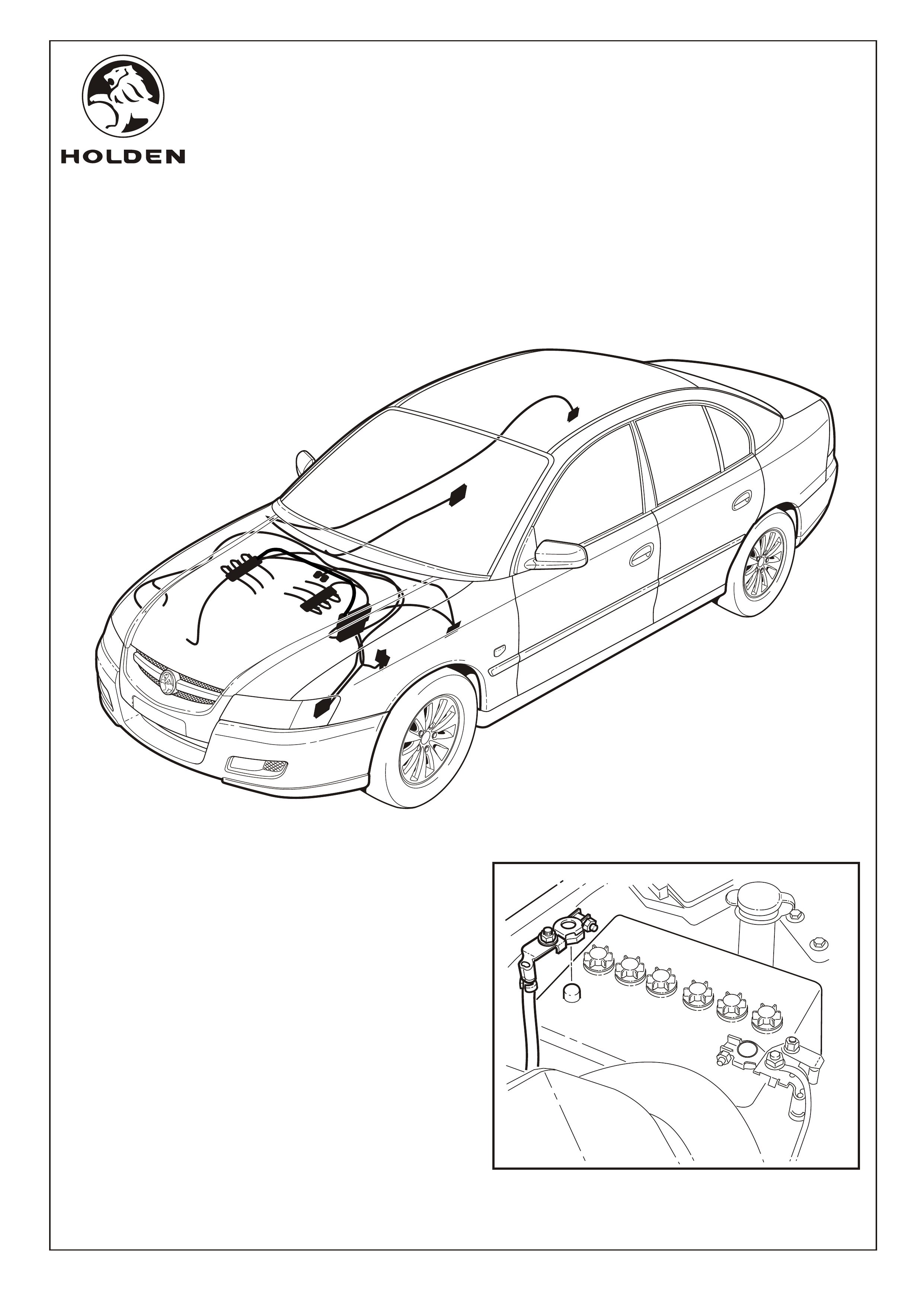
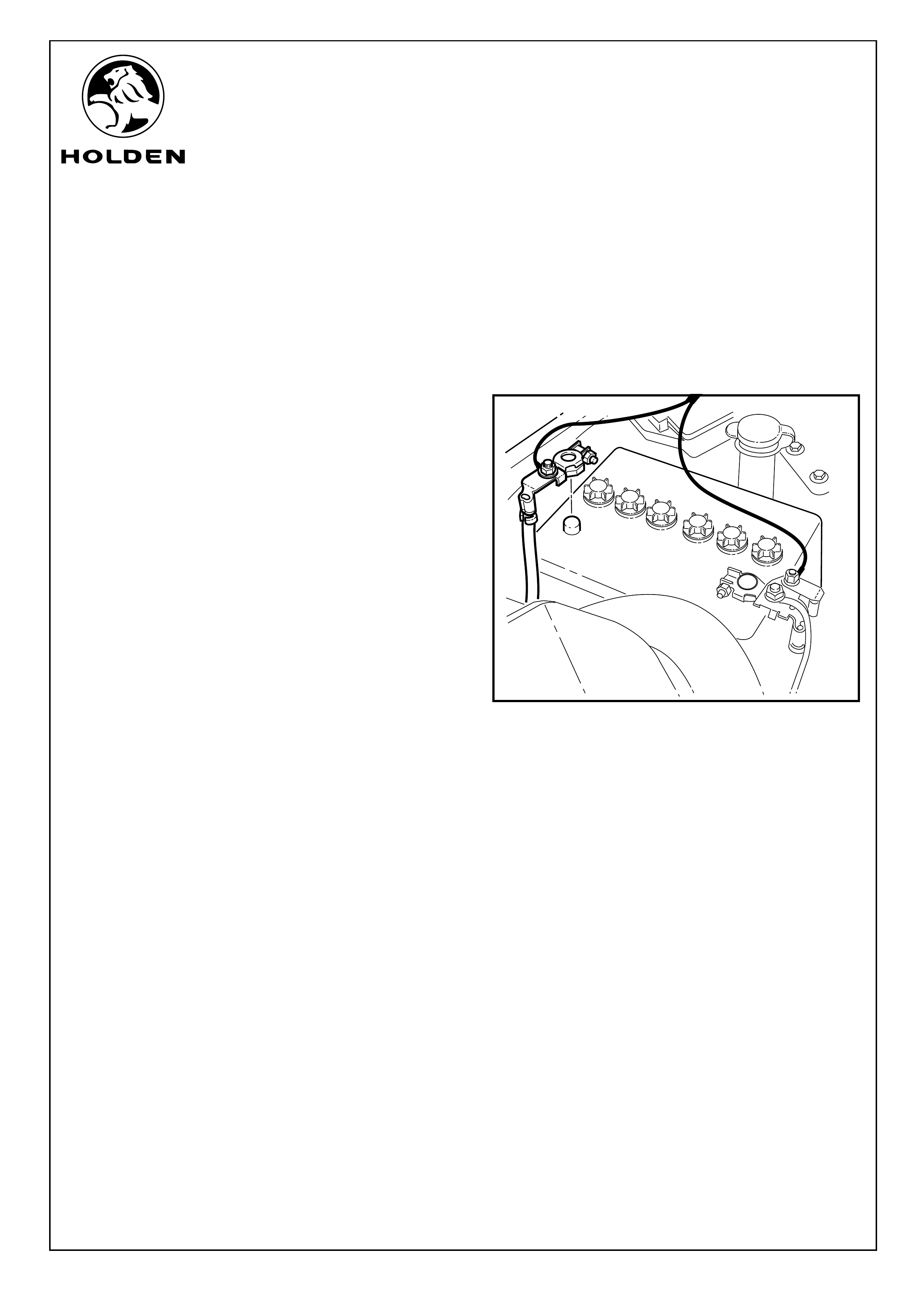
1. Disconnect the vehicle battery. Refer to Figure 1.
IMPORTANT: Disconnecting the vehicle battery may
impact or damage electrical systems in the vehicle -
Body Control Module, Entertainment System, Electric
Sunroof, etc unless correct instructions are followed.
Please contact your Holden Retailer for further
information.
NOTE: To reinstate the audio system, the security code will
be required.
SECTION 1
PASSENGER COMPARTMENT
Page 1 of 15
FIGURE 1
FD1349
09MA05
COPYRIGHT
Reproduction in whole or part
prohibited without written approval
HOLDEN LTD
Division of HOLDEN Ltd ACN 006 893 232
FITTING INSTRUCTIONS FOR
VZ L.P.G. CONVERSION KIT
FITTING INSTRUCTIONS: - continued...
Refer to Figure 4 for the following:
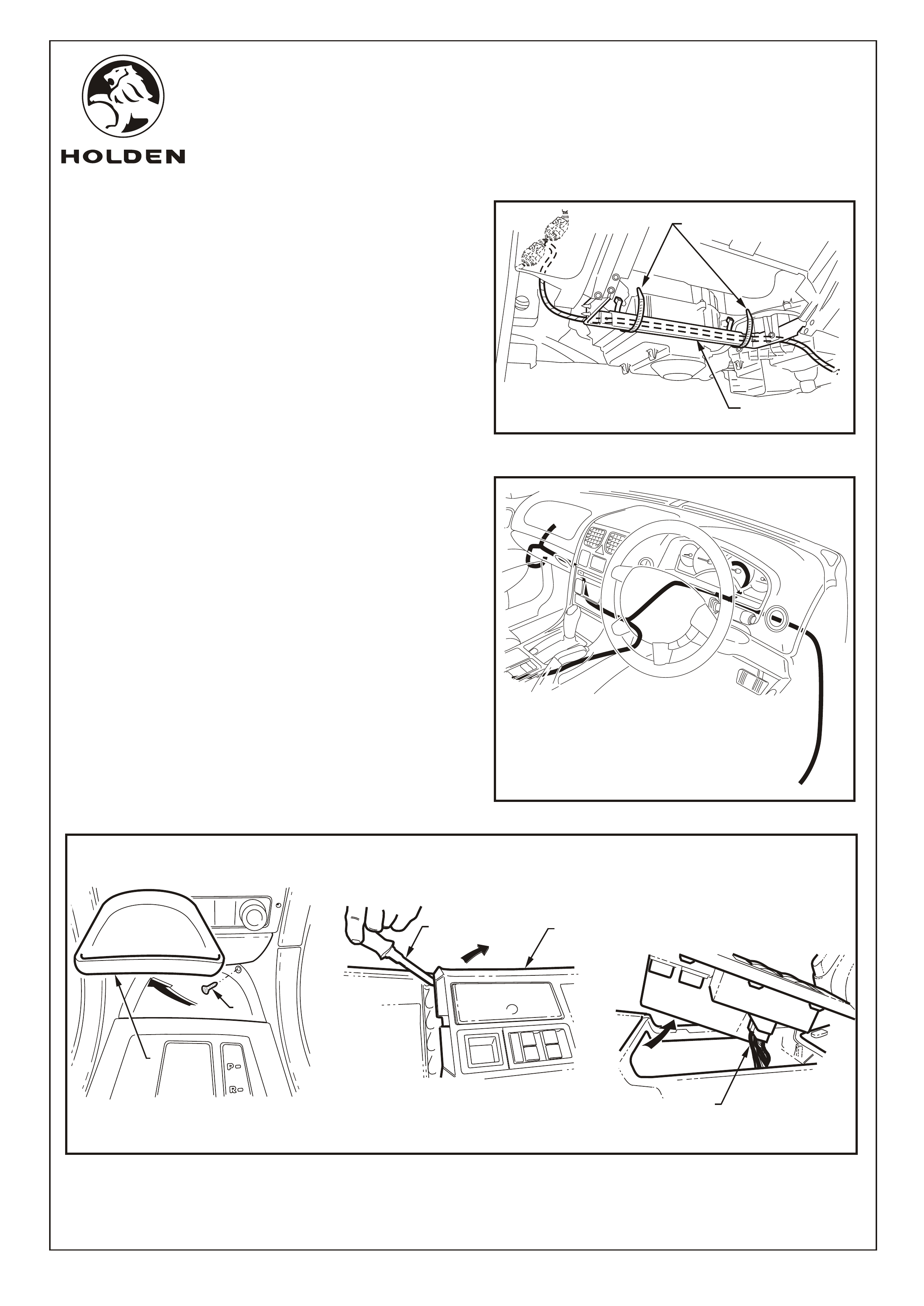
5. Remove the left-hand side instrument panel lower trim
plate assembly as follows:
a. Grasp the instrument panel lower trim plate
assembly (1) and carefully pull downward to
disengage the retaining clips (2) (3 places).
b. Lower the plate assembly slightly and if fitted
remove the foot well lamp (3) by rotating the socket
and removing from the plate assembly.
c. Remove the plate assembly.
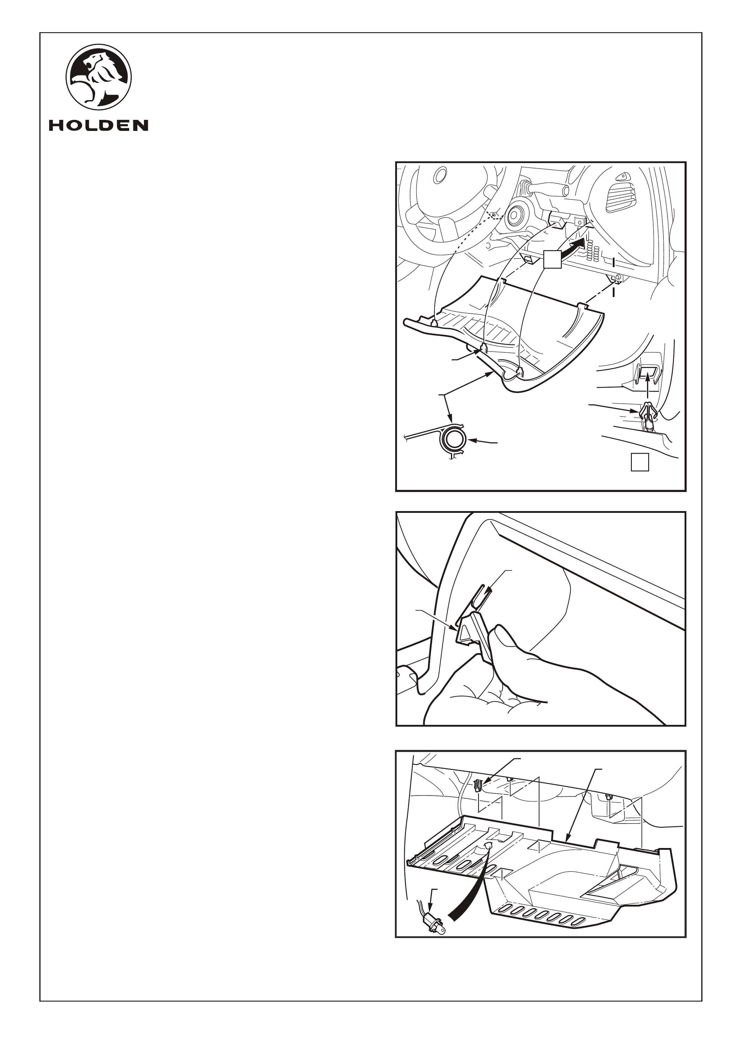
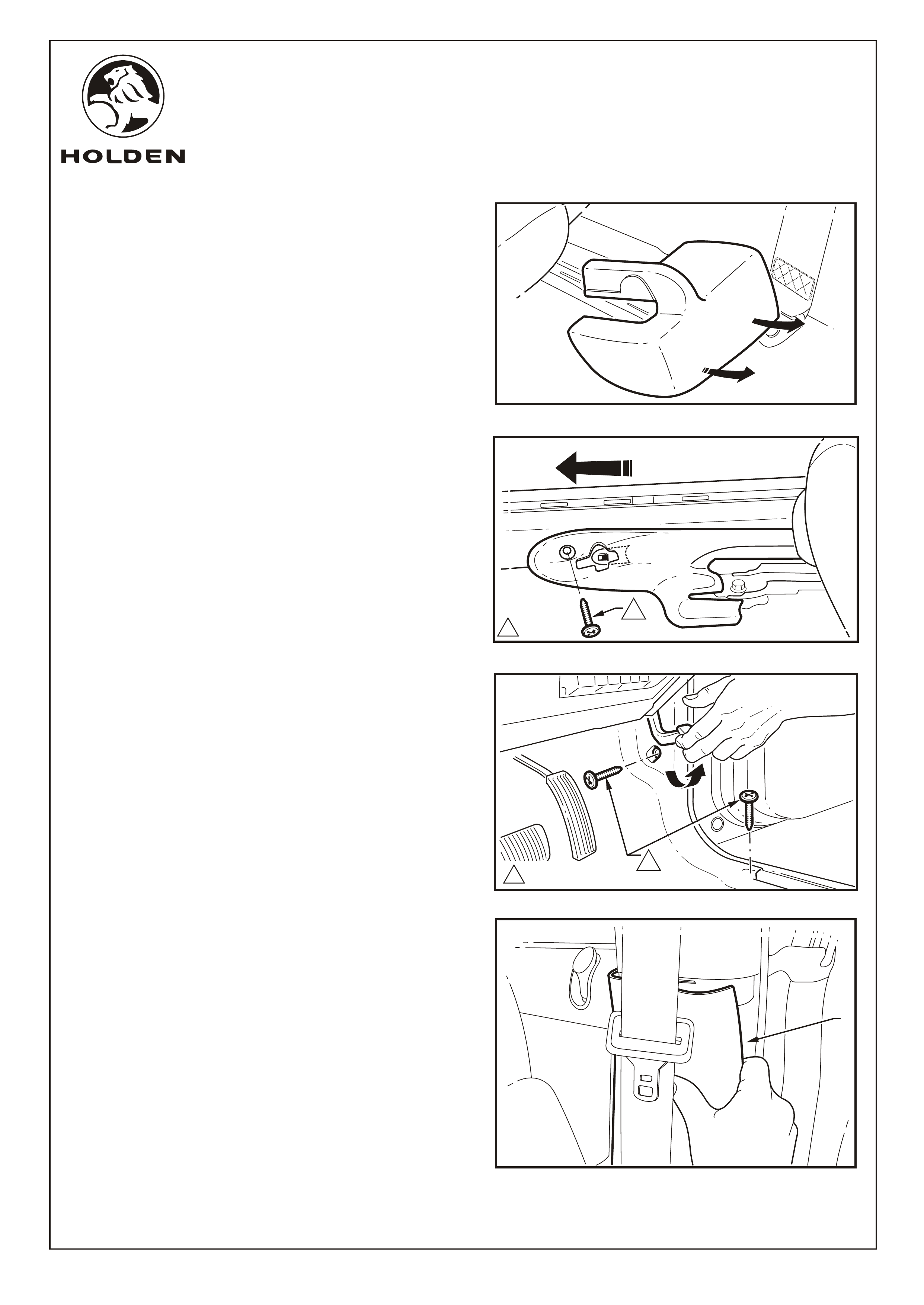
Refer to Figure 2 for the following:
2. Remove the lower instrument trim panel (1) assembly
as follows:
a. Adjust the steering wheel to upper-most position.
b. Grasp the top edge of the lower instrument trim
panel assembly and pull outwards to disengage the
three retaining clips (2).
c. Swing the panel assembly open.
d. Holding each side of the panel assembly pull
rearwards to disengage it from the instrument panel
lower trim panel retainer (3) (2 places).
Refer to Figure 3 for the following:
3. Open the glovebox and remove the two travel limiting
lugs (1). This is done by carefully raising the rubber tabs
on the limiting lugs and pulling them rearwards. Once
pulled rearwards, gently pull the rubber tabs towards the
center of the glovebox. To release the glovebox, pull
glovebox towards the rear of the vehicle.
NOTE: Care must be taken not to break the tongues (2)
off during travel limiting lug removal.
4. Refit travel limiting lugs and place glovebox to one side.
FIGURE 2
LOWER
TRIM
PANEL
A-A
A
A
A
A
RETAINING
CLIP
RETAINING
CLIP
(3 PLACES)
LOWER TRIM
PANEL
RETAINER
(2 PLACES)
FIGURE 3
1
2
FIGURE 12
3
1
2
FIGURE 4
Page 2 of 15
FD1349
09MA05
COPYRIGHT
Reproduction in whole or part
prohibited without written approval
HOLDEN LTD
Division of HOLDEN Ltd ACN 006 893 232
FITTING INSTRUCTIONS FOR
VZ L.P.G. CONVERSION KIT
FITTING INSTRUCTIONS: - continued...
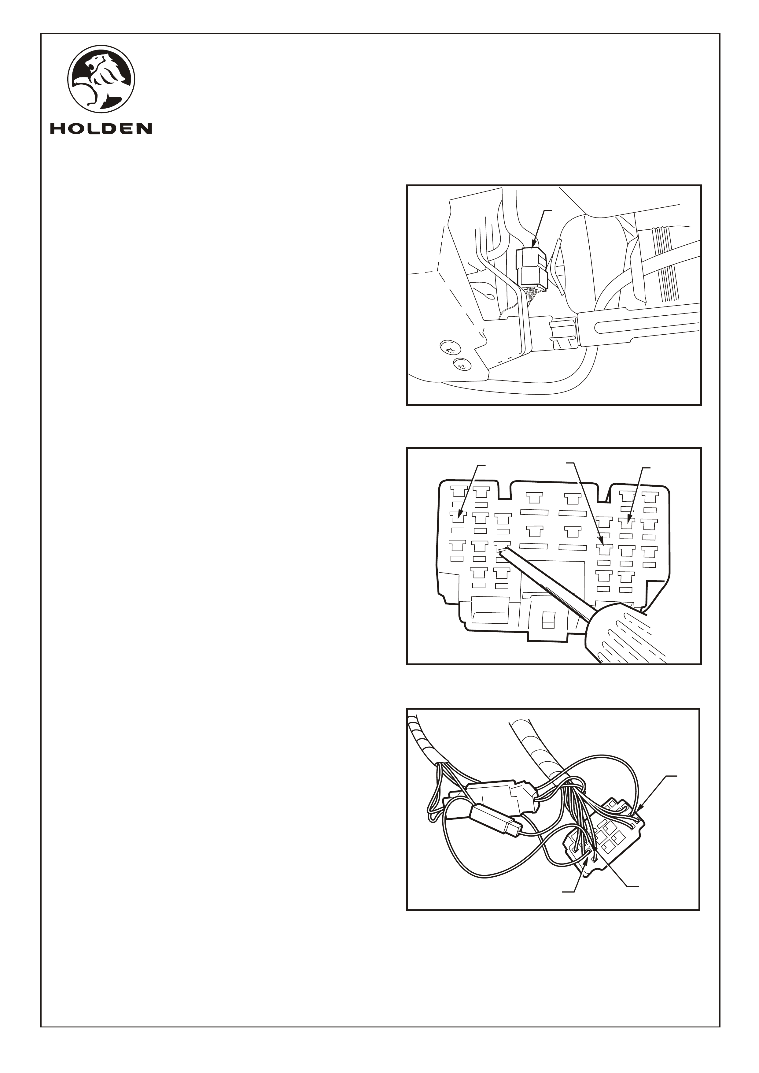
6. Press the release lever of the X206 connector (1) to
separate the connectors. Refer to Figure 5.
IMPORTANT: As the two wires in pin 11 and 17 are the
same colour it is critical that each wire is back out and
the new connections completed before backing out the
second wire.
Refer to Figure 6 for the following:
7. To connect the L.P.G. harness into the female X206
harness connector:
a. Identify Pins 8, 11 and 17 on the inner face of the
connector.
b. The brown and blue wire in pin 8 is connected to
the brown wire in the single connector block of
the LPG harness. Fit the brown fly wire
originating from the LPG harness single
connector into the pin 8 position of the X206
connector.
c. The purple wire in pin 11 is connected to the pink
coloured wire in the LPG harness twin connector
block and the pink and blue fly wire is inserted
into the pin 11 position.
d. The purple wire in pin 17 is connected to the
yellow coloured wire in the LPG harness twin
connector block and the yellow and blue fly wire
is inserted into the pin 17 position.
NOTE: When the terminals are in the connector
block properly they will lock into position and not
come back out. A small pull on the wires is a good
check for positive locks. Ensure all terminals are
completely covered by the connector block.
8. To back out the pin terminals:
a. Use a small jewellers screwdriver to push
between the terminal and the plastic terminal
lock to release the first of the terminals next to the
body harness connector lock. Refer to Figure 5.
NOTE: When the terminal lock is released the
terminal will slide out without significant force.
b. Gently remove the terminal and connect as
indicated in step 7. Refer to Figure 7.
9. Reconnect the body harness connector and refit the
connector to it's fixing point.
FIGURE 5
1
Page 3 of 15
17
11
FIGURE 6
FIGURE 7
PIN 17
PIN 8
PIN 11
8
FD1349
09MA05
COPYRIGHT
Reproduction in whole or part
prohibited without written approval
HOLDEN LTD
Division of HOLDEN Ltd ACN 006 893 232
FITTING INSTRUCTIONS FOR
VZ L.P.G. CONVERSION KIT
FIGURE 8
A
11.0 - 3.0 Nm
A
11
2
VIEW
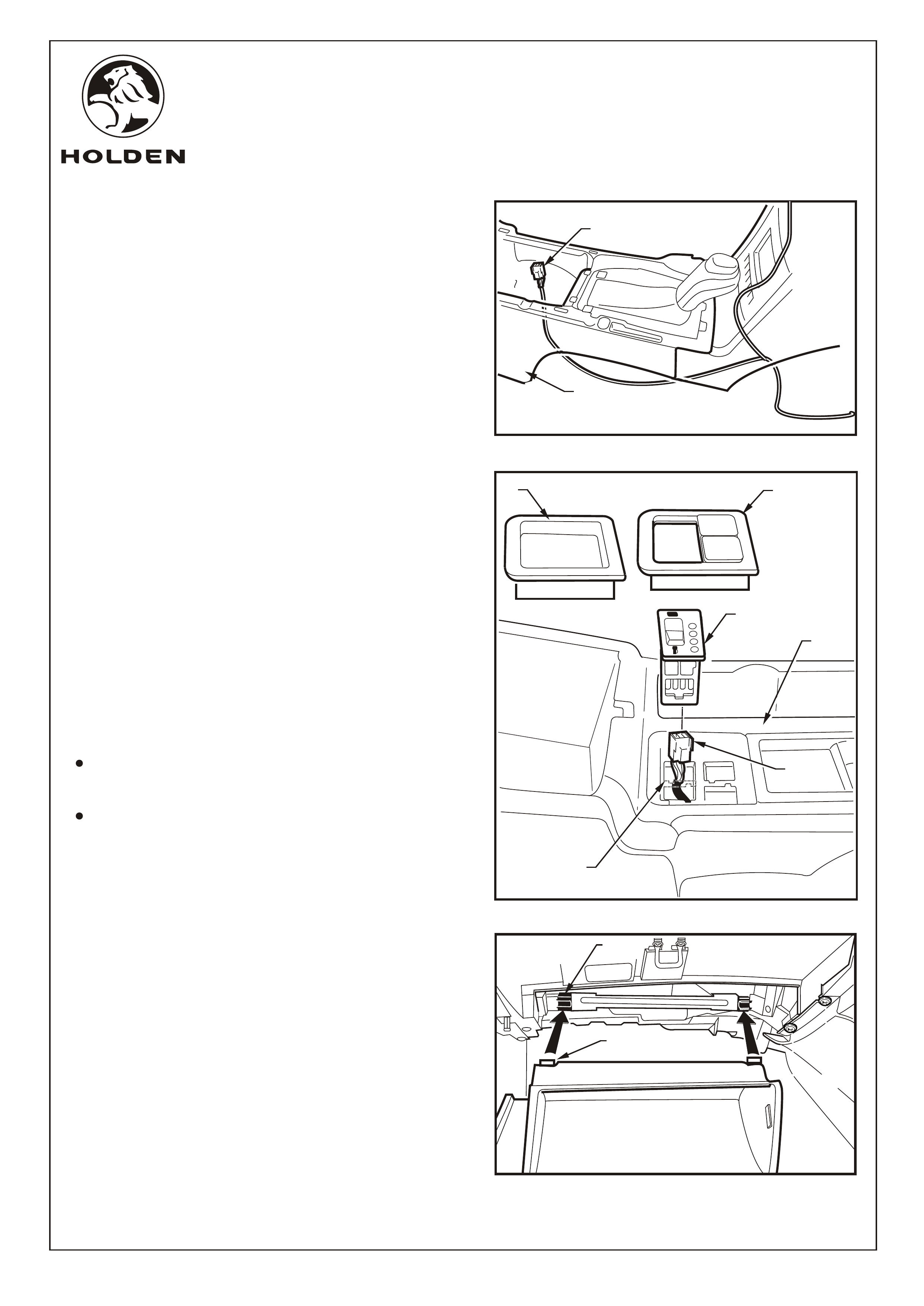
FITTING INSTRUCTIONS: Continued...
10. Remove the passenger side front floor console
extension side trim by removing the two screws (1) (2
places) attaching the console extension side trim (2) to
the instrument panel and allow to swing down. Refer to
Figure 8.
11. Remove the screws (2 places) retaining the drivers
side lower centre floor console extension trim (1) and
allow to rest on the floor. Refer to Figure 9.
12. Feed the harness across the back support rail of the
glovebox and through the cavity forward of the floor
mounted centre console.
FIGURE 9
1
Page 4 of 15
FD1349
09MA05
COPYRIGHT
Reproduction in whole or part
prohibited without written approval
HOLDEN LTD
Division of HOLDEN Ltd ACN 006 893 232
FITTING INSTRUCTIONS FOR
VZ L.P.G. CONVERSION KIT
1
2
FITTING INSTRUCTIONS: Continued...
13. Run the L.P.G. harness across the back of the glovebox
support rail (1) and fix in place with two cable ties (2).
Refer to Figure 10.
14. Pass the harness through the cavity forward of the floor
mounted centre console. Refer to Figure 11.
15. Remove the front compartment cover (1) to allow
access to the console cover assembly retaining screw
(2) and remove the screw. Raise the armrest; starting at
the rear of the console cover assembly (3), use a trim
removal tool (4) to lever up and release the console
cover. Disconnect the window operating switch
harness and remove the cover assembly. Refer to
Figure 12.
NOTE: If sat nav is fitted remove remote control
cradle.
FIGURE 12
4
3
FIGURE 11
FIGURE 10
1
2
5
Page 5 of 15
FD1349
09MA05
COPYRIGHT
Reproduction in whole or part
prohibited without written approval
HOLDEN LTD
Division of HOLDEN Ltd ACN 006 893 232
FITTING INSTRUCTIONS FOR
VZ L.P.G. CONVERSION KIT
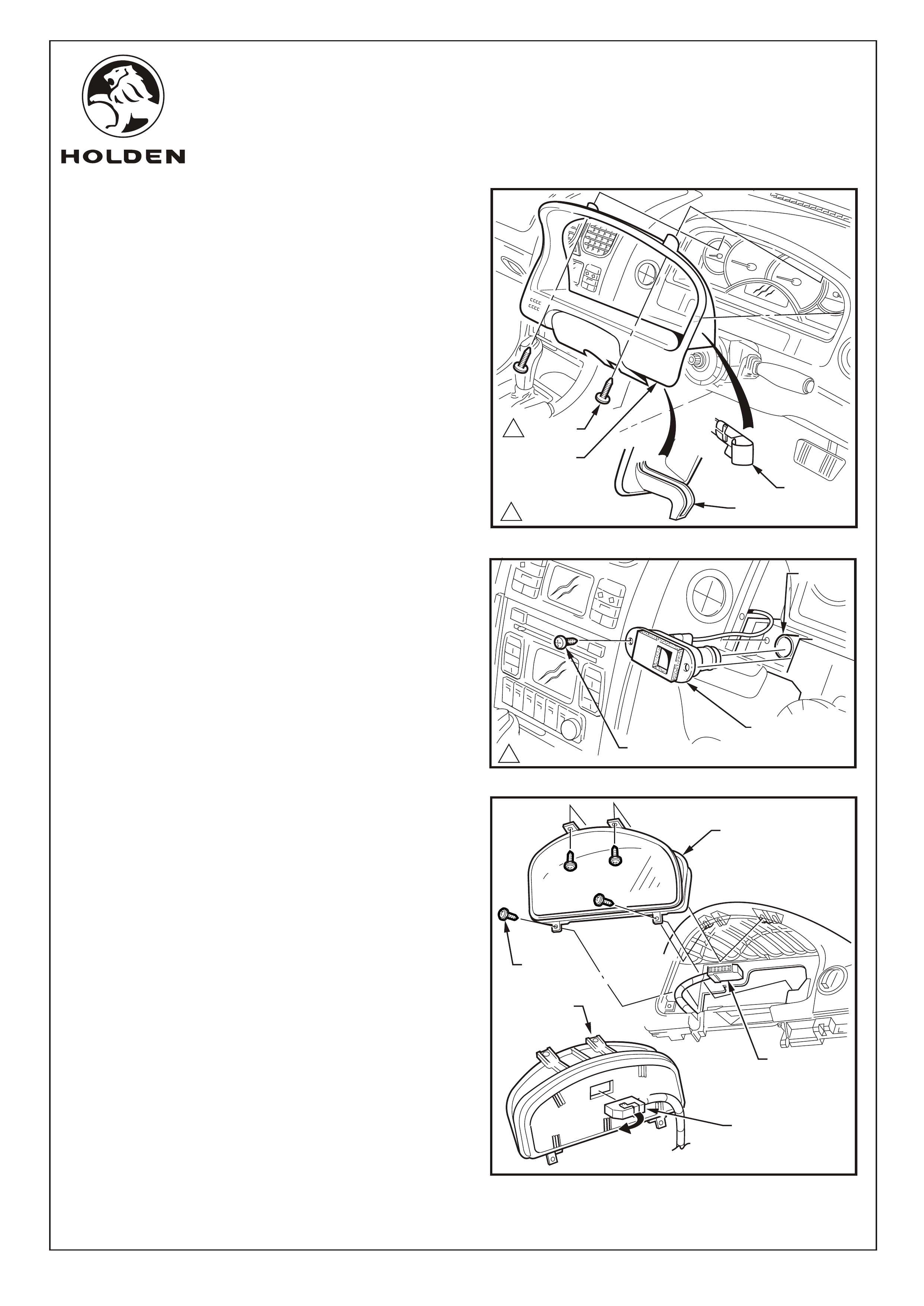
FITTING INSTRUCTIONS: Continued...
Refer to Figure 13 for the following:
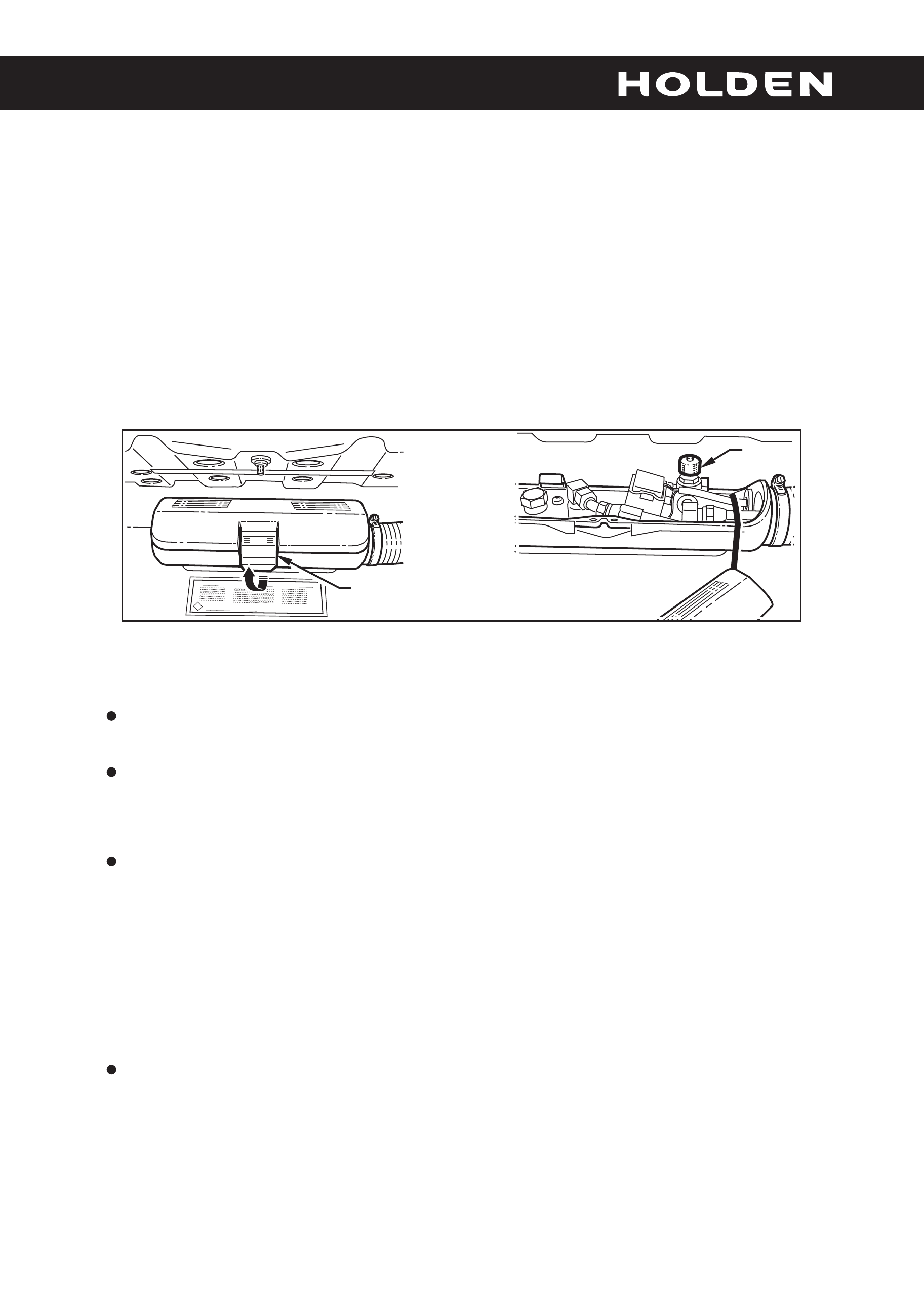
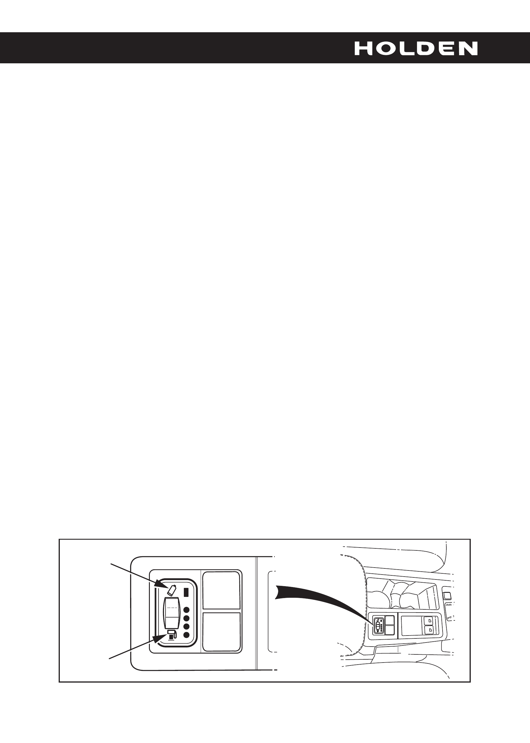
16. Feed the L.P.G. switch/Gauge harness connector (1)
into the rear switch cavity of the console. Shown with
console cover removed for clarity.
17. Remove the console switch blanking plate or rubber
liner (1) from the rear right corner of the centre console
cover (2). Cut the front to back switch cross bar (3) off in
the rear switch position. Fit the replacement cover (4)
into the console. Fit the L.P.G. control switch (5) into the
rear switch position. Connect the switch to the L.P.G
harness connector (6). Fit the switch blank if required
Refer to Figure 14.
18. Continue running the harness across the drivers side
dashboard to the side of the vehicle.
NOTE:
Ensure wire is routed clear of the steering column
mechanisms.
Ensure wire is retained correctly and can not loop
down into foot well.
19. Refit the floor mounted centre consol extension trims.
20. Refit the glovebox, align the pivots (1) (2 places) on
the back of the glovebox with the receiving lugs (2) (2
places) in the glovebox cavity; push home and close
the glovebox. Refer to Figure 15.
FIGURE 13
1
2
FIGURE 14
FIGURE 15
1
2
Page 6 of 15
1
2
6
3
5
4
FD1349
09MA05
COPYRIGHT
Reproduction in whole or part
prohibited without written approval
HOLDEN LTD
Division of HOLDEN Ltd ACN 006 893 232
FITTING INSTRUCTIONS FOR
VZ L.P.G. CONVERSION KIT
3
SCREWS
(4 PLACES)
INSTRUMENT
CLUSTER
FITTING INSTRUCTIONS: Continued...
Refer to Figure 16 for the following:
21. Remove the instrument cluster trim panel assembly
as follows:
NOTE: The steering wheel is not shown for clarity, the
cluster trim can be removed with the steering wheel
installed.
a. Release the steering column adjustment lever and
move the steering column to its lowest position.
b. Remove the two screws attaching the instrument
cluster trim assembly to the instrument panel.
c. Depress the top of the trim assembly slightly and tilt
the top of the trim assembly out of the instrument
panel pad, disengaging the retaining clips (3
places) each side.
d. Unhook each lug from the instrument panel pad.
e. Remove the trim assembly.
in-car air
temperature sensor
Refer to Figure 18 for the following:
23. Remove the instrument cluster as follows:
a. Remove the four screws attaching the instrument
cluster to the instrument panel.
b. Roll the top of the instrument cluster from its
cavity.
c. Using a fine flat blade screwdriver, open the
wiring connector locking tab on the back of the
cluster.
d. Remove the cluster assembly.
NOTE: When reinstalling the instrument cluster,
tighten the screws in the sequence indicated.
Refer to Figure 18.
22. Remove the screw attaching the
to the instrument panel. Extract
the sensor assembly from the cavity and disconnect
the air tube. Refer to Figure 17.
11.0 - 3.0 Nm
.
.
.
..
.
.
.
.
.
.
.
.
.
.
.
.
.
.
.
.
.
.
.
.
.
.
.
.
.
.
.
..
.
.
.
.
.
.
.
.
.
.
.
.
.
.
.
.
.
.
.
.
IN-CAR
TEMPERATURE
SENSOR
FIGURE 17
SCREW
FIGURE 16
11.0 - 3.0 Nm
1SCREWS
CLIPS
(3 PLACES
EACH SIDE)
LUG
INSTRUMENT
CLUSTER
TRIM ASSEMBLY
2
4
1
INSTRUMENT
CLUSTER
WIRING
CONNECTOR
WIRING
CONNECTOR
FIGURE 18
AIR TUBE
Page 7 of 15
FD1349
09MA05
COPYRIGHT
Reproduction in whole or part
prohibited without written approval
HOLDEN LTD
Division of HOLDEN Ltd ACN 006 893 232
FITTING INSTRUCTIONS FOR
VZ L.P.G. CONVERSION KIT
FIGURE 19
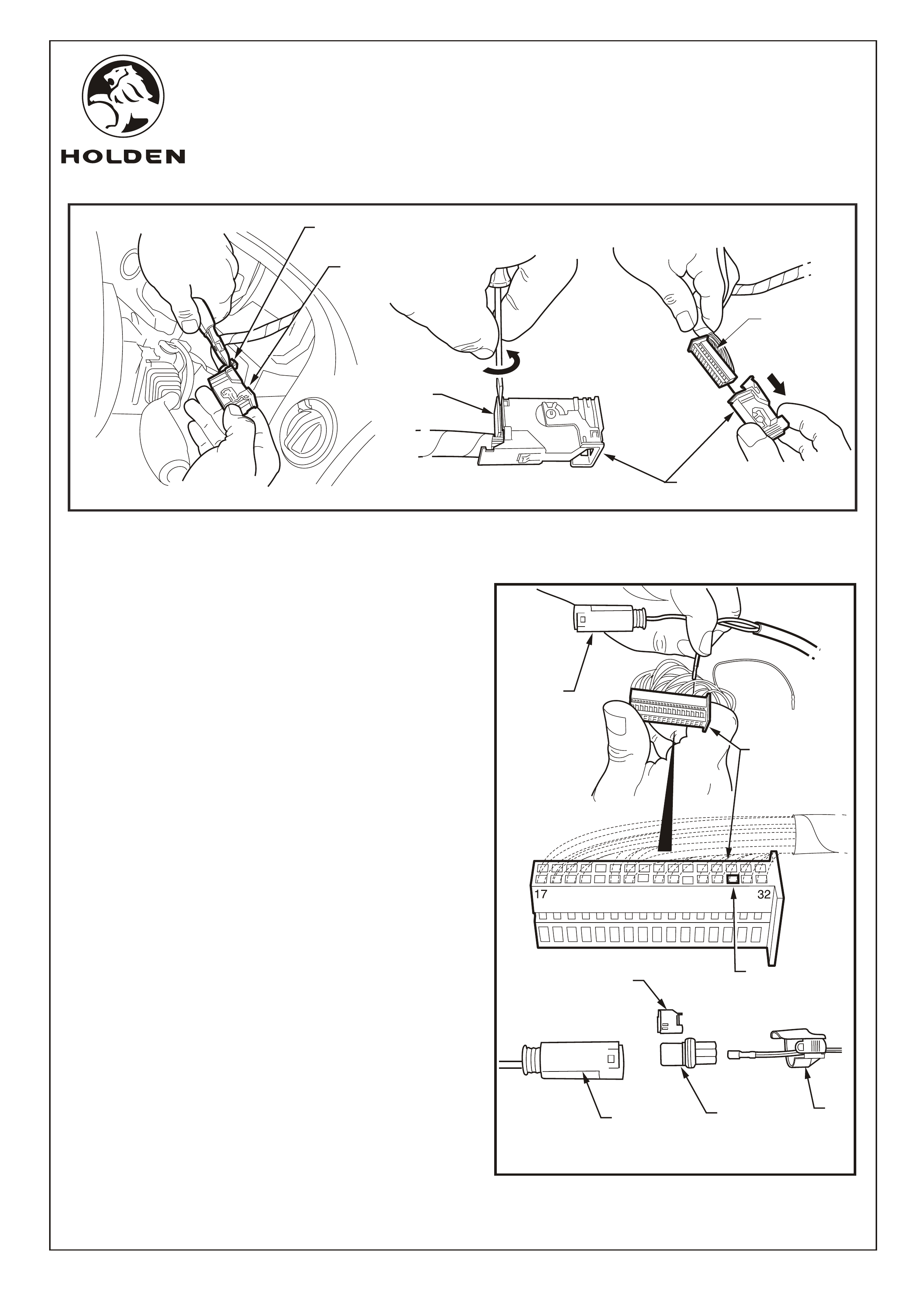
FITTING INSTRUCTIONS: Continued...
Refer to Figure 19 for the following:
24. Cut the cable tie securing the instrument cluster
connector housing to the wiring harness
25. Place a small flat blade screwdriver between the front
edge of the connector housing and the inner connector
(1). Twist as shown to release the housing and withdraw
from the inner connector.
26. Route the section of the harness with exposed wires
and female connector through from the end of the
dashboard to the instrument cluster connection.
27. Identify pin 30 (2),use a small jewellers screw driver and
back out pin 30. The pin numbering sequence is on the
inner connector (stamped on the side of the connector
body). Insert the L.P.G. terminal into pin 30.
Refer to Figure 20 for the following:
28 Slide the outer connector shield (3) over the wire that
was back out. Slide the terminal into the connector
inner (4) and slide the terminal lock (5) into position.
Connect to the female connector (6) on the LPG
harness.
NOTE: Make certain the terminal aligns with the
terminal in the other connector.
Ensure the wires are securely fitted then reassemble
the inner connector to the housing connector and
secure with a cable tie.
29. Reconnect the instrument cluster connector and
reinstall the instrument cluster.
INSTRUMENT CLUSTER
WIRING CONNECTOR
CUT CABLE TIE
CONNECTOR
HOUSING
INNER
CONNECTOR
INNER
CONNECTOR
TWIST TO
RELEASE
2
FIGURE 20
Page 8 of 15
1
3
4
5
6
6
FD1349
09MA05
COPYRIGHT
Reproduction in whole or part
prohibited without written approval
HOLDEN LTD
Division of HOLDEN Ltd ACN 006 893 232
FITTING INSTRUCTIONS FOR
VZ L.P.G. CONVERSION KIT
FIGURE 23
FIGURE 21
FIGURE 22
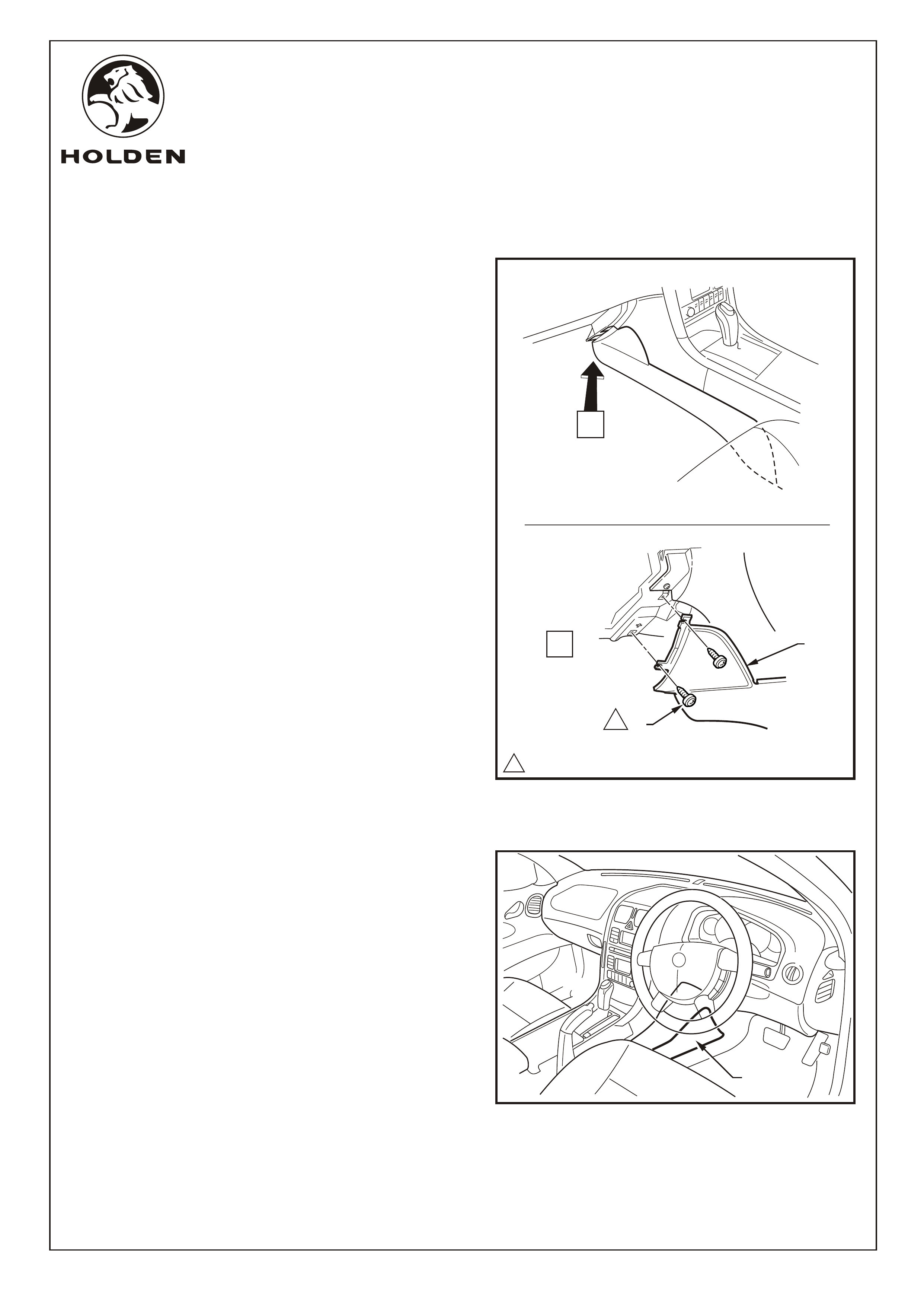
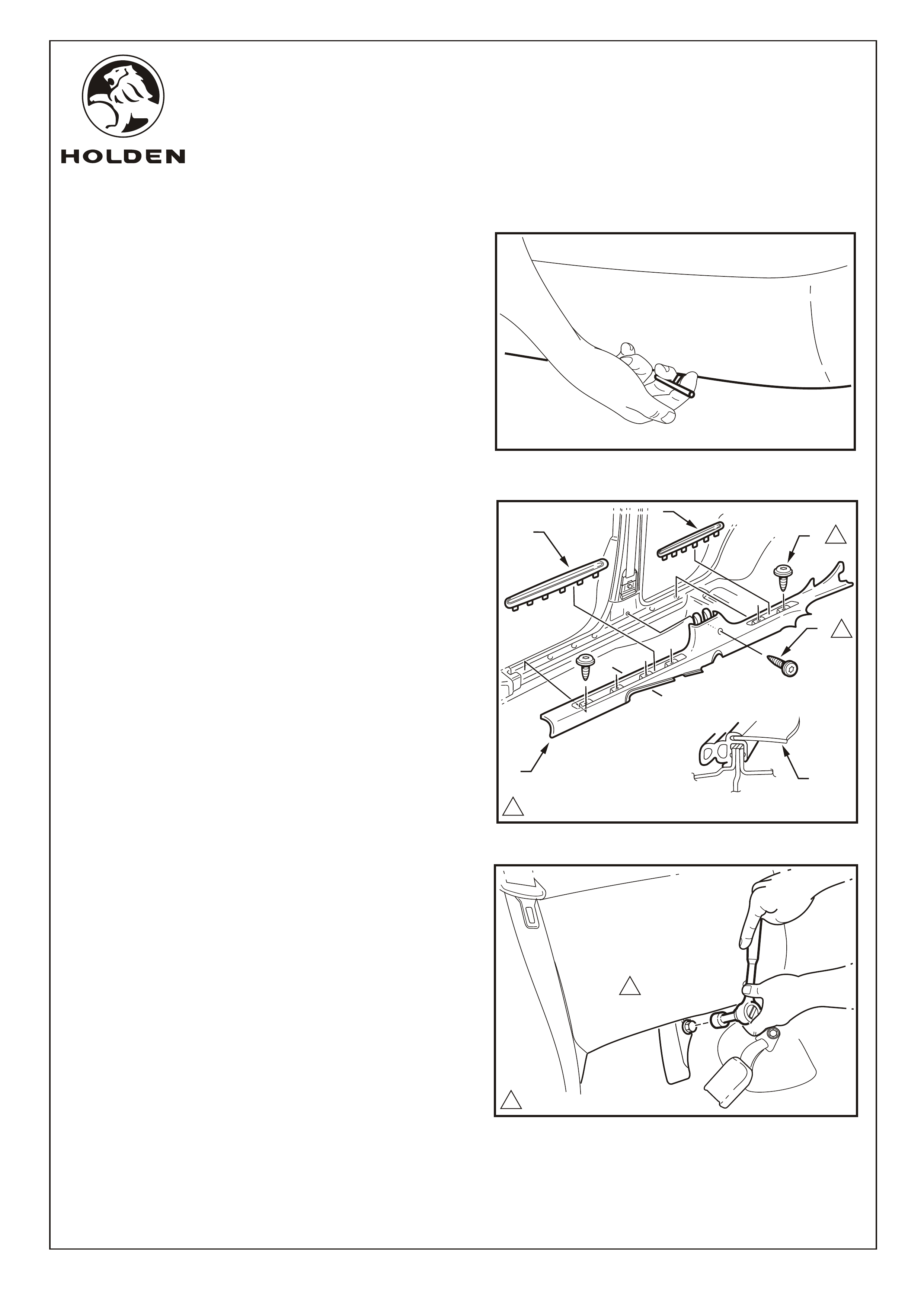
FITTING INSTRUCTIONS: - continued...
30. Unclip the rear section of the front seat rail cover (both
sides) by pushing down on the join between the front
and rear covers and pull the rear cover back and up to
remove. Refer to Figure 21.
31. Remove screw from behind fuel release lever (drivers
side only). Slide the front section of the front seat rail
cover out towards the front of the vehicle. Repeat on
passenger side front seat rail cover. Refer to Figure 22.
Refer to Figure 23 for the following:
32. Remove the screws (2 places) holding the front side
kick panel in position and pull back on the front side kick
plate to release the two clips. Remove the side kick
panel. Repeat on other side of the vehicle.
NOTE: The bonnet release handle will need to be pulled
back to expose the screw head of one of the screws on
the drivers side.
33. Pull off the drivers lower “B” pillar trim panel (1).
Refer to Figure 24.
1
FIGURE 24
Page 9 of 15
11.0 - 3.0 Nm
1
11.0 - 3.0 Nm
1
FD1349
09MA05
COPYRIGHT
Reproduction in whole or part
prohibited without written approval
HOLDEN LTD
Division of HOLDEN Ltd ACN 006 893 232
FITTING INSTRUCTIONS FOR
VZ L.P.G. CONVERSION KIT
FIGURE 26
1.0 - 3.0 Nm
1
1
1
1
A-A
A
A
2
4
3
2
1
FITTING INSTRUCTIONS: - continued...
34. Remove the rear seat base by pulling on the toggles
under the seat and removing. Refer to
Figure 25.
Refer to Figure 26 for the following:
35. Carefully lever the front and rear side sill trim plates (1)
from the side sill trim (2), starting at the front of each
plate and moving rearwards, revealing the attaching
screws.
CAUTION: Take care not to break the sill trim plates.
36. Remove the Torx head screws (3) (4 places in front door
opening, 2 places rear door opening) from the side sill
trim.
37. Remove the screw (4) from the side sill trim to the centre
pillar.
38. Remove the side sill trim.
(Ste ) SEDAN ONLY
39. Use a socket to remove the bolt securing the rear
drivers side seat back. Push up on the seat back to
release and remove from the vehicle. Refer to
Figure 27.
ps 39 - 44
FIGURE 25
FIGURE 27
Page 10 of 15
1.0 - 3.0 Nm
1
1
FD1349
09MA05
COPYRIGHT
Reproduction in whole or part
prohibited without written approval
HOLDEN LTD
Division of HOLDEN Ltd ACN 006 893 232
FITTING INSTRUCTIONS FOR
VZ L.P.G. CONVERSION KIT
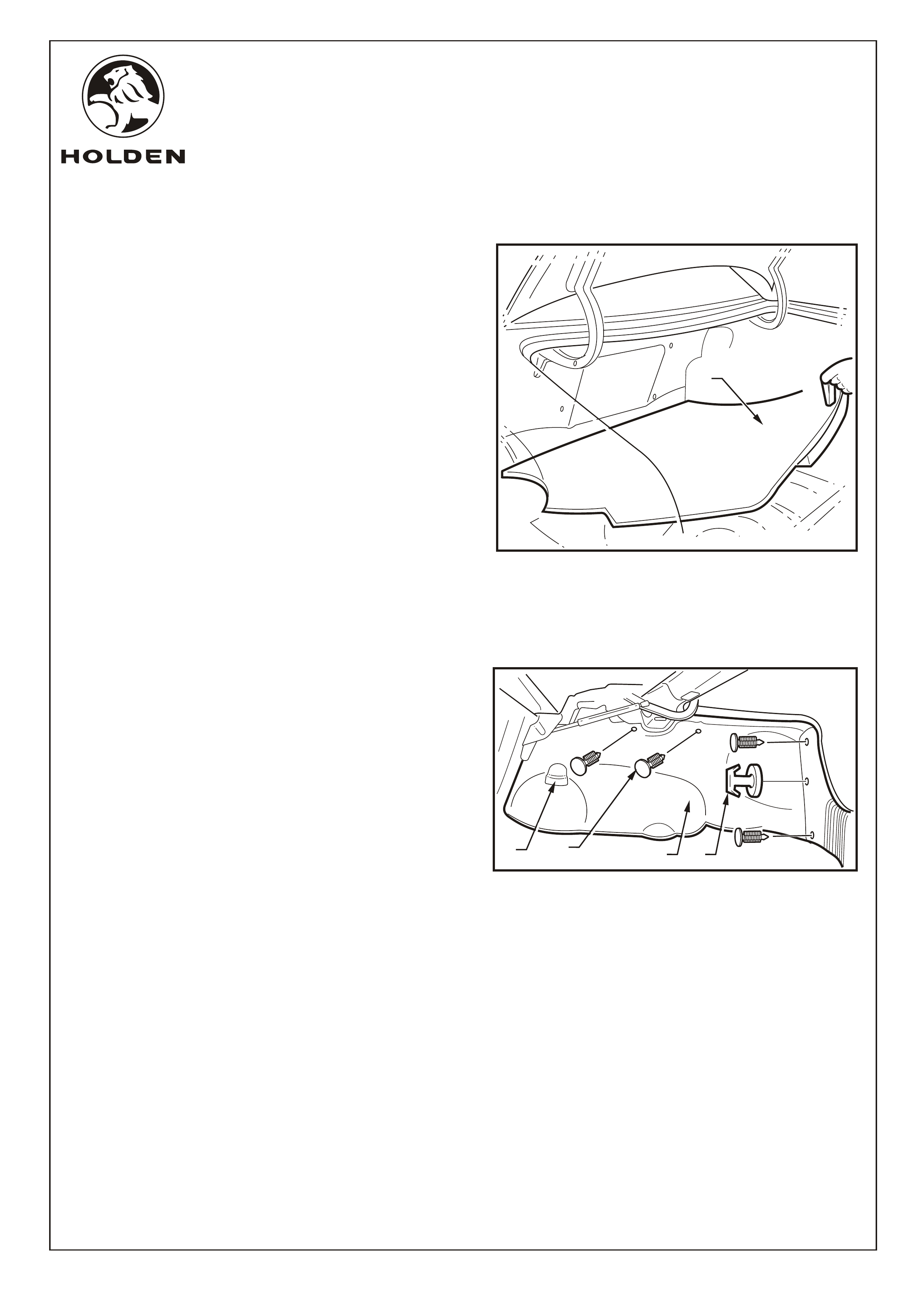
FITTING INSTRUCTIONS: - continued...
40. Remove the rear compartment floor carpet assembly
(1) from the vehicle. Refer to Figure 28.
Refer to Figure 29 for the following:
41. Carefully prise off the drivers side rear shock absorber
cover (1).
42. Using a trim removing tool, carefully remove the retainer
(2) away from the drivers side quarter inner rear side
carpet (3).
43. Unhook the carpet flap from the rear compartment lid
hinge bracket.
44. Carefully remove the drivers side rear quarter inner
carpet.
45. Disconnect the rear boot net (if fitted) and unscrew and
remove the drivers side boot net fixing (4).
FIGURE 28
1
COPYRIGHT
FIGURE 29
123 4
Page 11 of 15
FD1349
09MA05
COPYRIGHT
Reproduction in whole or part
prohibited without written approval
HOLDEN LTD
Division of HOLDEN Ltd ACN 006 893 232
FITTING INSTRUCTIONS FOR
VZ L.P.G. CONVERSION KIT
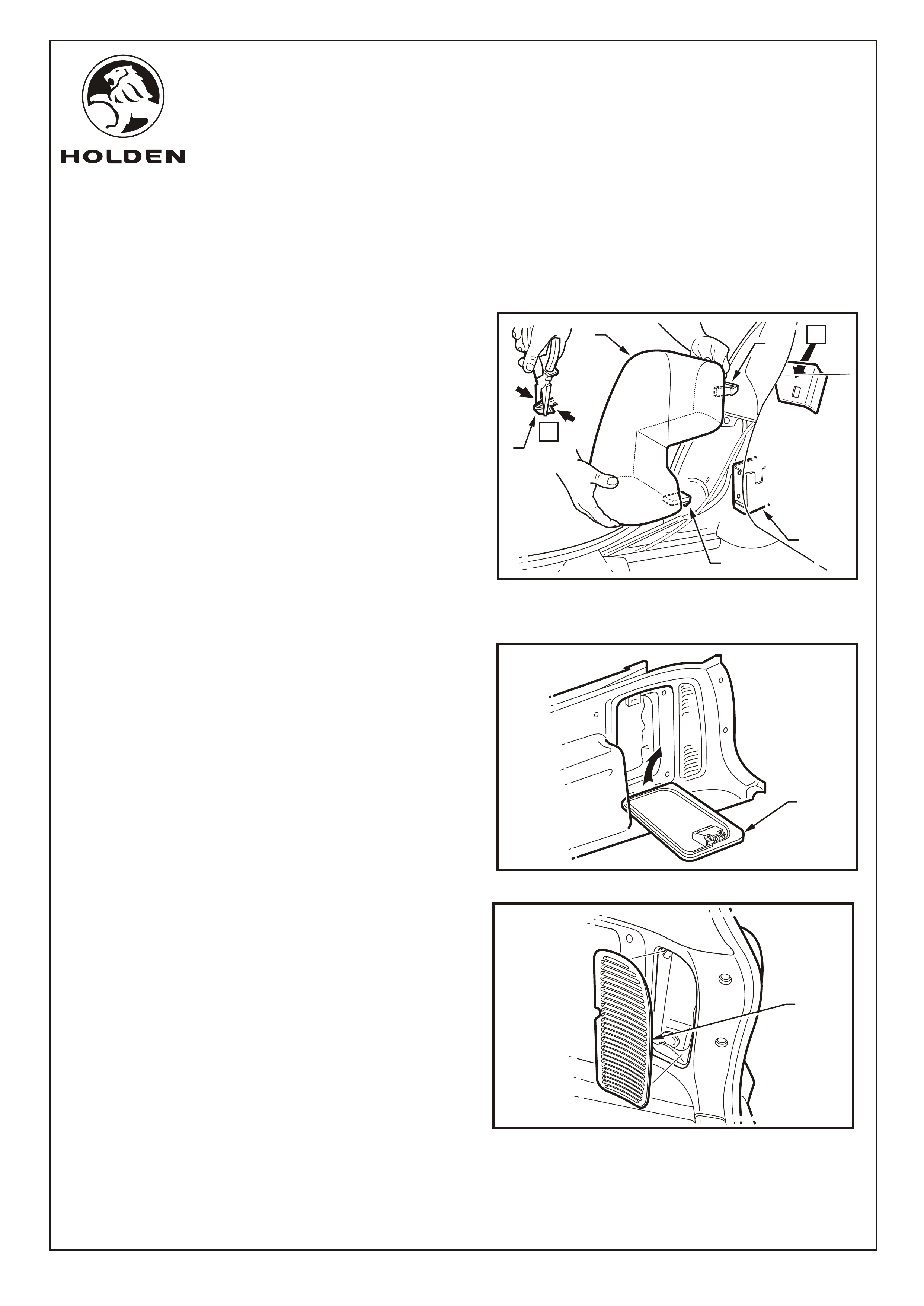
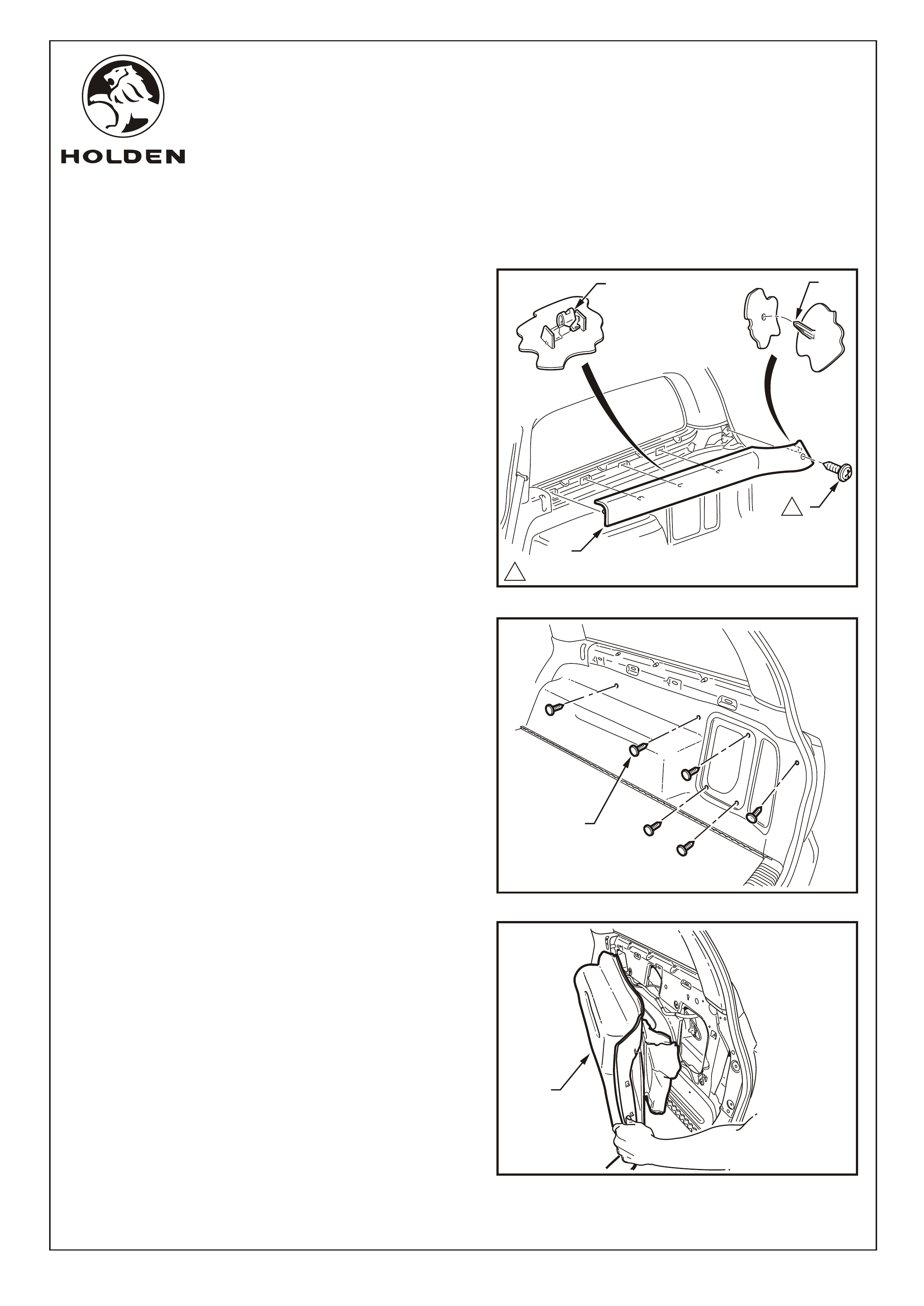
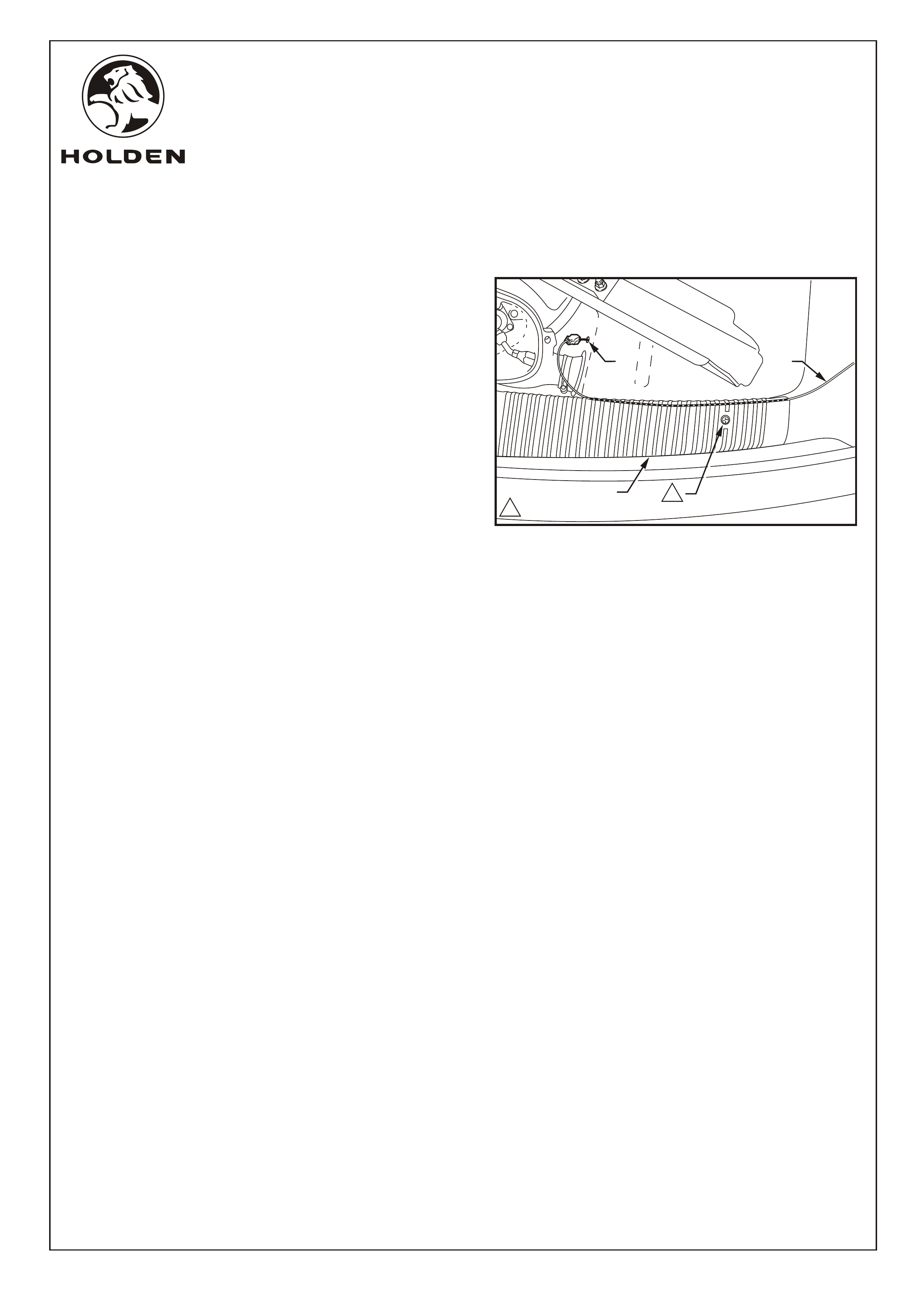
FITTING INSTRUCTIONS: - continued...
48. Open the door (1) on drivers side of wagon boot trim
Refer to Figure 31.
49. Lever the centre of the rear edge of the vent (1) away
from trim panel on the drivers side. Refer to Figure 32.
(Ste WAGON ONLY
Refer to Figure 30 for the following:
46. Using pliers, squeeze the tangs of the rear drivers side
seat upper bolster retaining clip (1) together and pull the
rear bolster assembly (2) towards the front of the
vehicle.
47. To disengage, lift the lower retainer retaining tang (3) up
and pull the bolster forward, out of the seat-back
retaining bracket (4) towards the front of the vehicle.
ps 45 - 52)
FIGURE 31
1
FIGURE 30
A
A
2
1
1
4
3
FIGURE 32
1
Page 12 of 15
FD1349
09MA05
COPYRIGHT
Reproduction in whole or part
prohibited without written approval
HOLDEN LTD
Division of HOLDEN Ltd ACN 006 893 232
FITTING INSTRUCTIONS FOR
VZ L.P.G. CONVERSION KIT
FITTING INSTRUCTIONS: - continued...
Refer to Figure 33 for the following:
50. Remove the screw (1) retaining the upper trim on the
drivers side (2).
51. Pull the rear edge of the upper trim away from the body
side panel and working forwards, disengage the
garnish clips (3) (4 places). Ensure that the garnish clips
are retained on the upper trim.
NOTE: When removing the upper trim ensure that care
is taken not to damage the locating pin (4).
52. Use a trim removal tool to remove the retainers (1) (7
places) on the quarter inner trim panel assembly. Refer
to Figure 34.
53. Remove the driver side boot quarter trim panel
assembly (1) by raising the edge of the rear
compartment floor carpet and lifting it forward over the
rear seat back striker. Refer to Figure 35.
1.0 - 3.0 Nm
1
34
1
1
2
FIGURE 33
FIGURE 34
1
COPYRIGHT
FIGURE 35
1
Page 13 of 15
FD1349
09MA05
COPYRIGHT
Reproduction in whole or part
prohibited without written approval
HOLDEN LTD
Division of HOLDEN Ltd ACN 006 893 232
FITTING INSTRUCTIONS FOR
VZ L.P.G. CONVERSION KIT
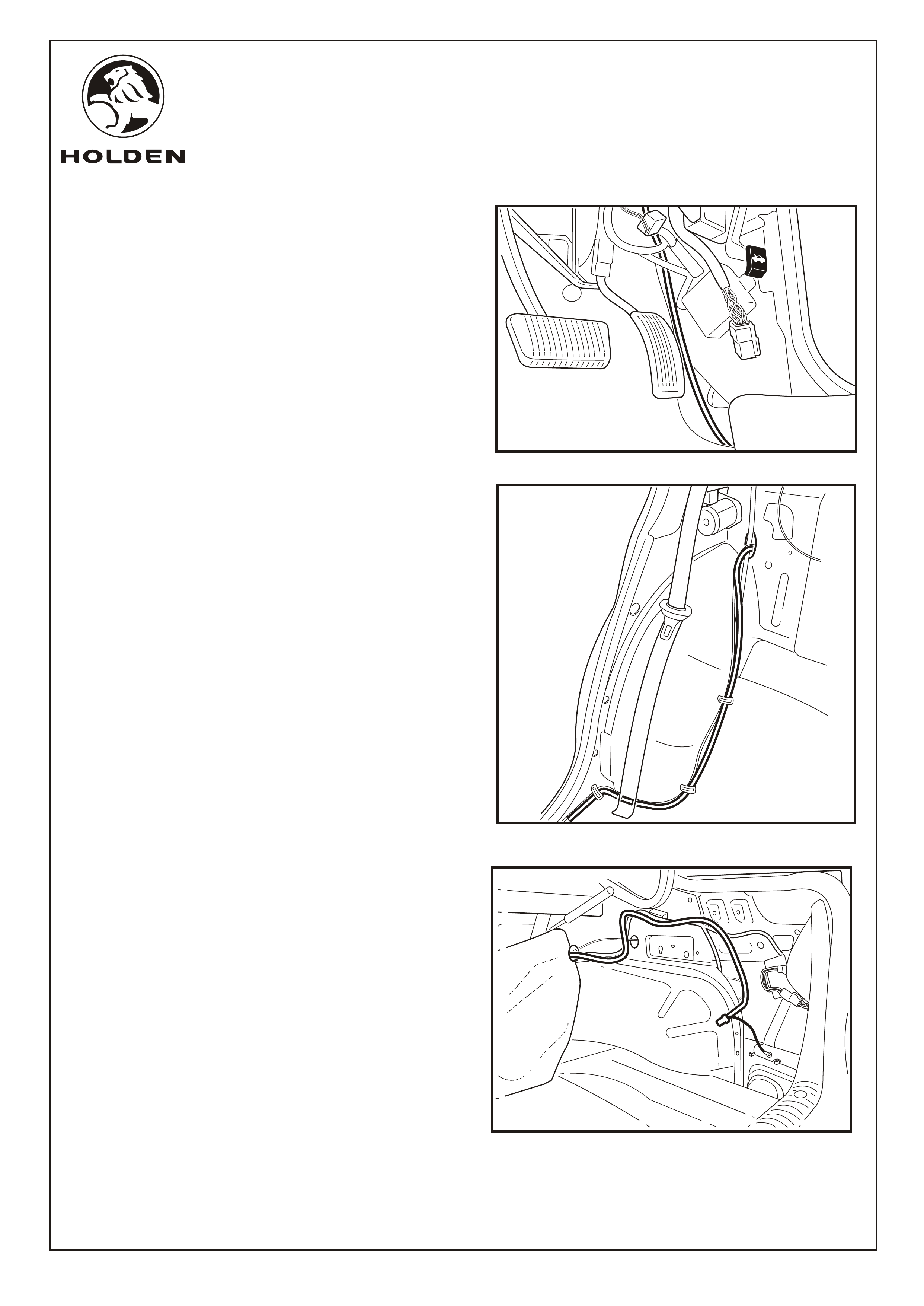
FITTING INSTRUCTIONS: - continued...
54. Run the power outlet harness from the fuse panel,
down the side of the vehicle behind the bonnet release
cable. Refer to Figure 36.
55. Run the power outlet harness along the drivers side
inner sill. Apply cable ties at vehicle body mounted
cable tie positions.
s 56 -57
56. Run along
.
(Step ) SEDAN ONLY
the wheel arch, through the hole in the rear
seat back panel Refer to Figure 37.
57. Run the power outlet harness along the vehicle body
harness. Cable tie power outlet harness at the same
positions as body harness fixing points. Refer to
Figure 38.
FIGURE 36
FIGURE 37
FIGURE 38
Page 14 of 15
FD1349
09MA05
COPYRIGHT
Reproduction in whole or part
prohibited without written approval
HOLDEN LTD
Division of HOLDEN Ltd ACN 006 893 232
FITTING INSTRUCTIONS FOR
VZ L.P.G. CONVERSION KIT
FITTING INSTRUCTIONS: - continued...
(Step ) WAGON ONLY
Refer to Figure 39 for the following:
58. Run the LPG harness (1) out from the rear drivers side,
side panel across the rear tailgate sill trim (2)and into
the spare wheel well.
59. Drill a 25mm hole (3) by the side of the 70mm cylinder
outlet hole. Deburr the hole and paint any unpainted
metal with a high zinc corrosion prevention primmer.
60. Pass the cylinder electrical connector into the spare
wheel well and fit the grommet.
61. Connect the LPG harness and the Cylinder harness
together.
s 58- 61
Page 15 of 15
FIGURE 39
2
31
1.0 - 3.0 Nm
1
1
FITTING INSTRUCTIONS FOR
VZ COMMODORE
LPG GAS INJECTION KIT
FD1349
09MA05
COPYRIGHT
Reproduction in whole or part
prohibited without written approval
HOLDEN LTD
Division of HOLDEN Ltd ACN 006 893 232
Page 1 of 4
SECTION 2
MANIFOLD MODIFICATION
FITTING INSTRUCTIONS FOR
VZ COMMODORE
LPG GAS INJECTION KIT
FD1349
09MA05
COPYRIGHT
Reproduction in whole or part
prohibited without written approval
HOLDEN LTD
Division of HOLDEN Ltd ACN 006 893 232
FIGURE 1
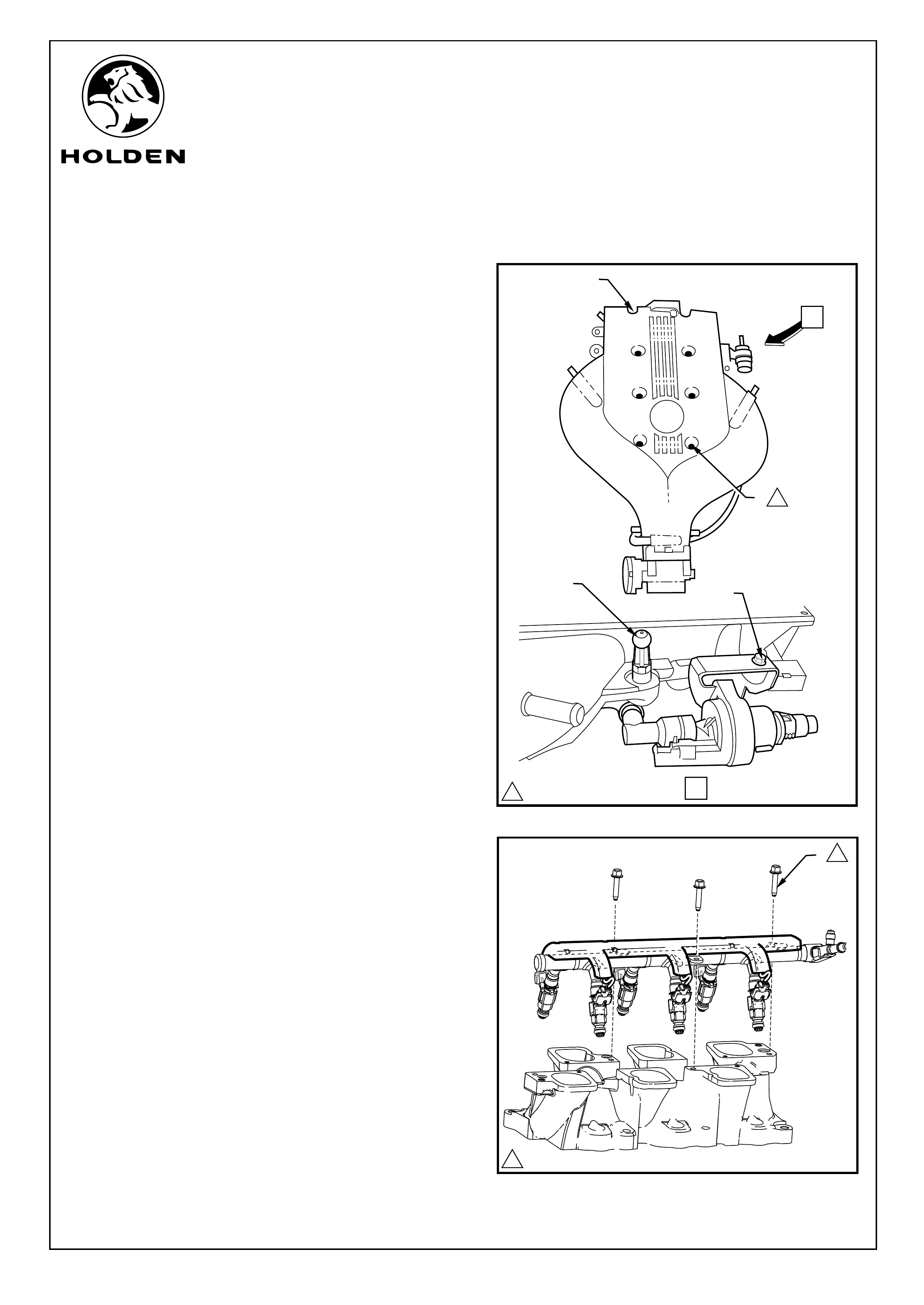
FITTING INSTRUCTIONS:
NOTE: Place the lower inlet manifold on a clean soft surface
to protect the machined faces from scratches.
Refer to Figure 1 for the following:
1. Remove the two remaining bolts (1) holding the upper
and lower intake manifolds together and separate.
2. Remove the bolt (2) securing the Emission Canister
Purge Valve Solenoid to the upper intake manifold.
3. Remove the two engine cover retaining lugs (3) from
either side of the upper intake manifold.
4. Remove the three bolts (1) (3 places) retaining the petrol
injector assembly to the lower intake manifold and
remove the petrol injector assembly. Refer to Figure 2.
Page 2 of 4
A
VIEW A
1
1
32
1
FIGURE 2
125 N.m
1
1
115 N.m
FITTING INSTRUCTIONS FOR
VZ COMMODORE
LPG GAS INJECTION KIT
FD1349
09MA05
COPYRIGHT
Reproduction in whole or part
prohibited without written approval
HOLDEN LTD
Division of HOLDEN Ltd ACN 006 893 232
FITTING INSTRUCTIONS: - continued...
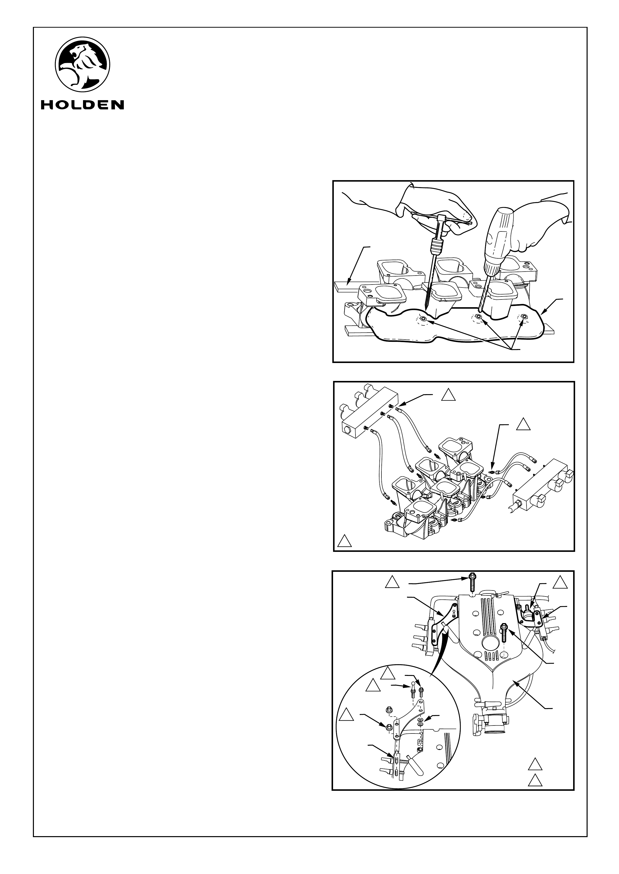
Refer to Figure 3 for the following:
5. Place the lower intake manifold into the drilling jig base
(1).
6. Position the drill guide on the manifold, drill and tap the
first three gas injector holes (2). Rotate the manifold and
repeat on the other side.
Refer to Figure 4 for the following:
7. Place some Loctite 577 on the threads of the manifold
gas injection ports (1) and screw into the taped gas
injector hole (1). Tighten. Repeat for all six locations.
8. Connect the gas injector hoses to the six intake manifold
injector ports (2).
9. Connect the injector hose unions to the gas manifolds
and tighten to the specified toque.
10. Refit the petrol injection assembly and tighten the bolts
to the specified toque.
Refer to Figure 5 for the following:
11. Refit the upper intake manifold gaskets.
12. Refit the upper intake manifold to the lower intake
manifold and refit the two bolts (1) that hold the two
manifolds together. Tighten to the specified toque.
13. Fit the two gas injector manifold brackets (2) to the
upper intake manifold (3) with the bolts (4) provided on
the two back holes of the brackets and the two engine
cover retaining lugs (5) with two packer washers (6)
under the mounting brackets in the front position.
Tighten to the specified toque.
NOTE: The Emission Canister Purge Valve Solenoid (7)
is reattached to the LHS rear mounting bolt.
14. Put the gas manifold studs (8) through the holes in the
mounting brackets secure with nuts (9) supplied.
Tighten to the specified toque.
Page 3 of 4
1
2
1
2
2
1
3
FIGURE 3
FIGURE 4
FIGURE 5
1
5
3
2
1
1
1
115 N.m
4
2
125 N.m
25 N.m
6
7
8
2
2
2
9
FITTING INSTRUCTIONS FOR
VZ COMMODORE
LPG GAS INJECTION KIT
FD1349
09MA05
COPYRIGHT
Reproduction in whole or part
prohibited without written approval
HOLDEN LTD
Division of HOLDEN Ltd ACN 006 893 232
FITTING INSTRUCTIONS: - continued...
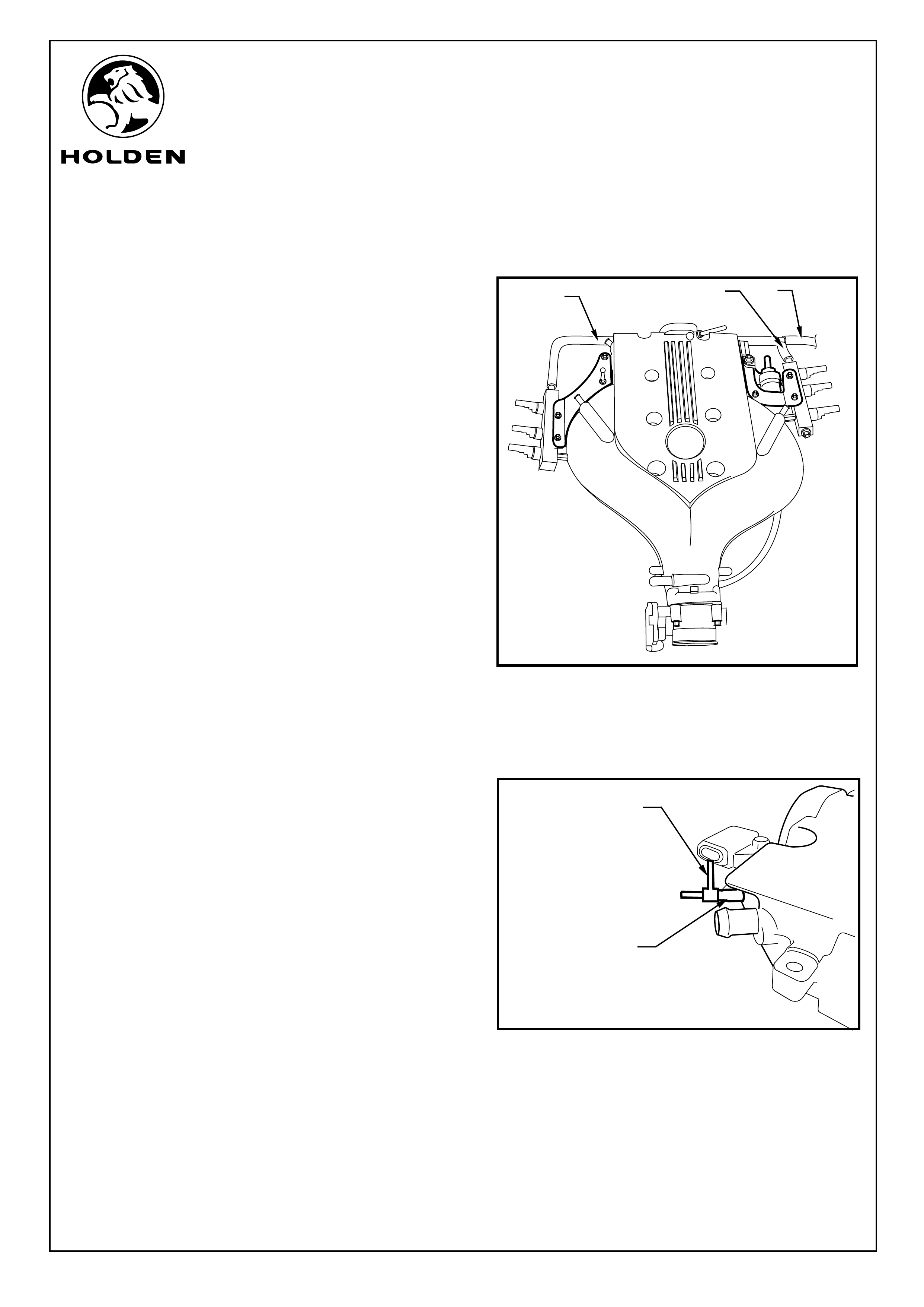
Refer to Figure 6 for the following:
15. Fit the two gas injector manifolds supply hoses. The
short hose (1) to the left injector manifold and the L
shape hose to the right (2) injector manifold.
16. Connect the two supply hoses to the third hose (3) that
will connect to the supply filter with the tee provided. Use
the clips supplied to clamp all connections.
NOTE: The injector manifolds supply hose is routed
over the top of the petrol manifold.
17. Fit the hose Tee (1) to the upper intake manifold
ventilation vacuum hose outlet (2). Refer to Figure 7.
18. Refit assembly back on vehicle.
1
2
FIGURE 6
213
FIGURE 7
Page 4 of 4
FITTING INSTRUCTIONS FOR
VZ COMMODORE
LPG GAS INJECTION KIT
FD1349
21MR05
COPYRIGHT
Reproduction in whole or part
prohibited without written approval
HOLDEN LTD
Division of HOLDEN Ltd ACN 006 893 232
Page 1 of 15
SECTION 3
ENGINE COMPARTMENT
1
FITTING INSTRUCTIONS FOR
VZ COMMODORE
LPG GAS INJECTION KIT
FD1349
21MR05
COPYRIGHT
Reproduction in whole or part
prohibited without written approval
HOLDEN LTD
Division of HOLDEN Ltd ACN 006 893 232
1
2
FIGURE 2
FITTING INSTRUCTIONS:
1. Turn the ignition to the "OFF" position.
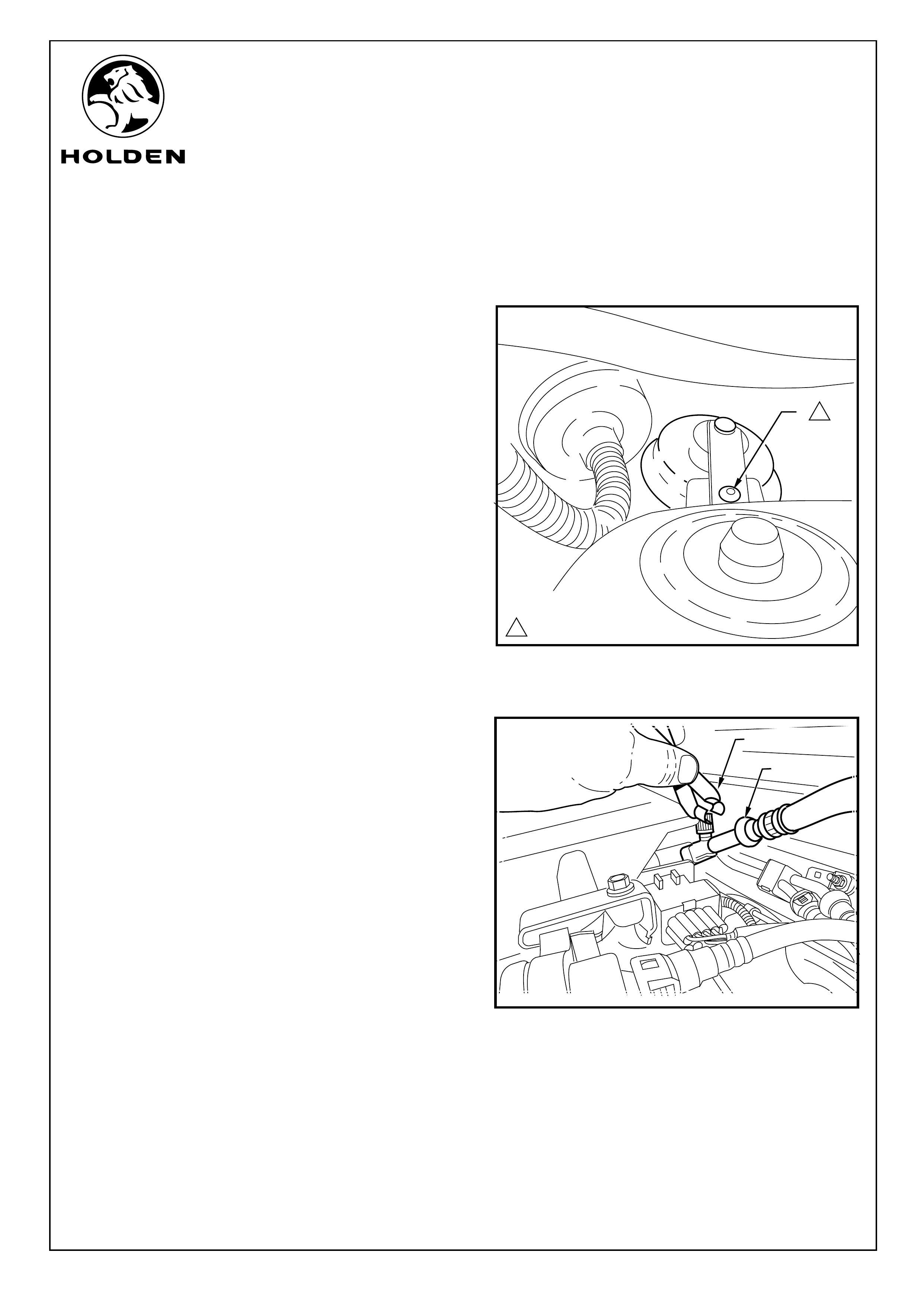
Refer to Figure 1 for the following:
3. For ease of access to the grommet on the fire wall.
Disconnect the vehicle security siren. Use a Torx 30 bit
(1) to remove the siren.
4. Remove the grommet from the firewall.
NOTE: If the vehicle is a wagon, disconnect the rear
window wash tube at the join in the engine bay and pull
through into vehicle cabin.
Refer to Figure 2 for the following:
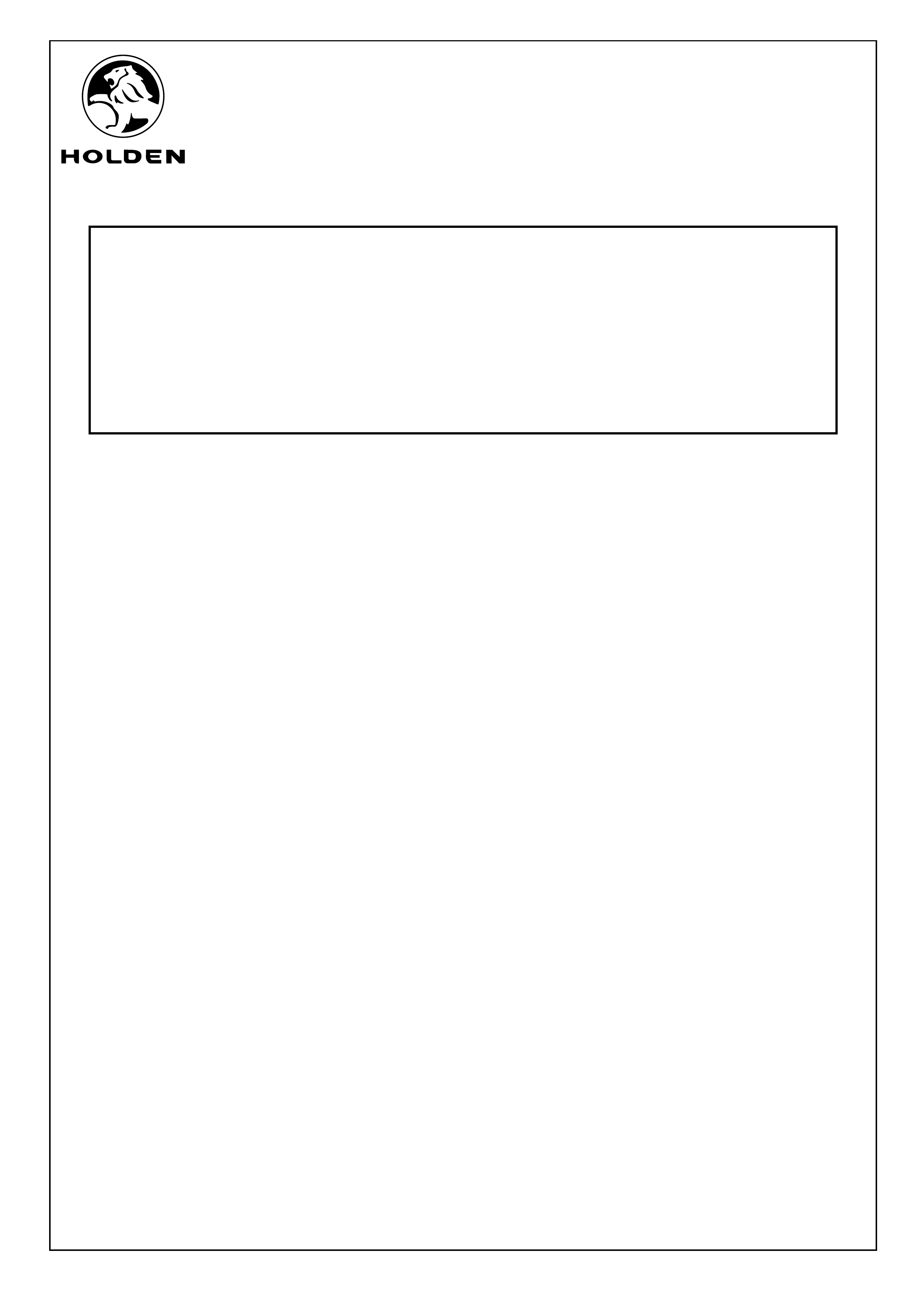
5. Wrap a workshop cloth around the lower intake manifold
supply line pressure release the thumbscrew. Gradually
open the thumbscrew to release the fuel pressure. Close
the thumbscrew once the pressure has been released.
CAUTION: The workshop cloth will be highly
flammable and must be disposed of where the cloth
or the vapours cannot come into contact with a
naked flame.
6. Place the release tool (1) around the fuel pipe (2) and
push into the quick release fitting. Pull the join apart and
catch any remaining fuel with a workshop cloth.
NOTE: Cover the ends of the pipes to prevent dirt from
entering the lines.
2. Remove the left and right engine covers.
Page 2 of 15
FIGURE 1
115 N.m
1
FITTING INSTRUCTIONS FOR
VZ COMMODORE
LPG GAS INJECTION KIT
FD1349
21MR05
COPYRIGHT
Reproduction in whole or part
prohibited without written approval
HOLDEN LTD
Division of HOLDEN Ltd ACN 006 893 232
FITTING INSTRUCTIONS: - continued...
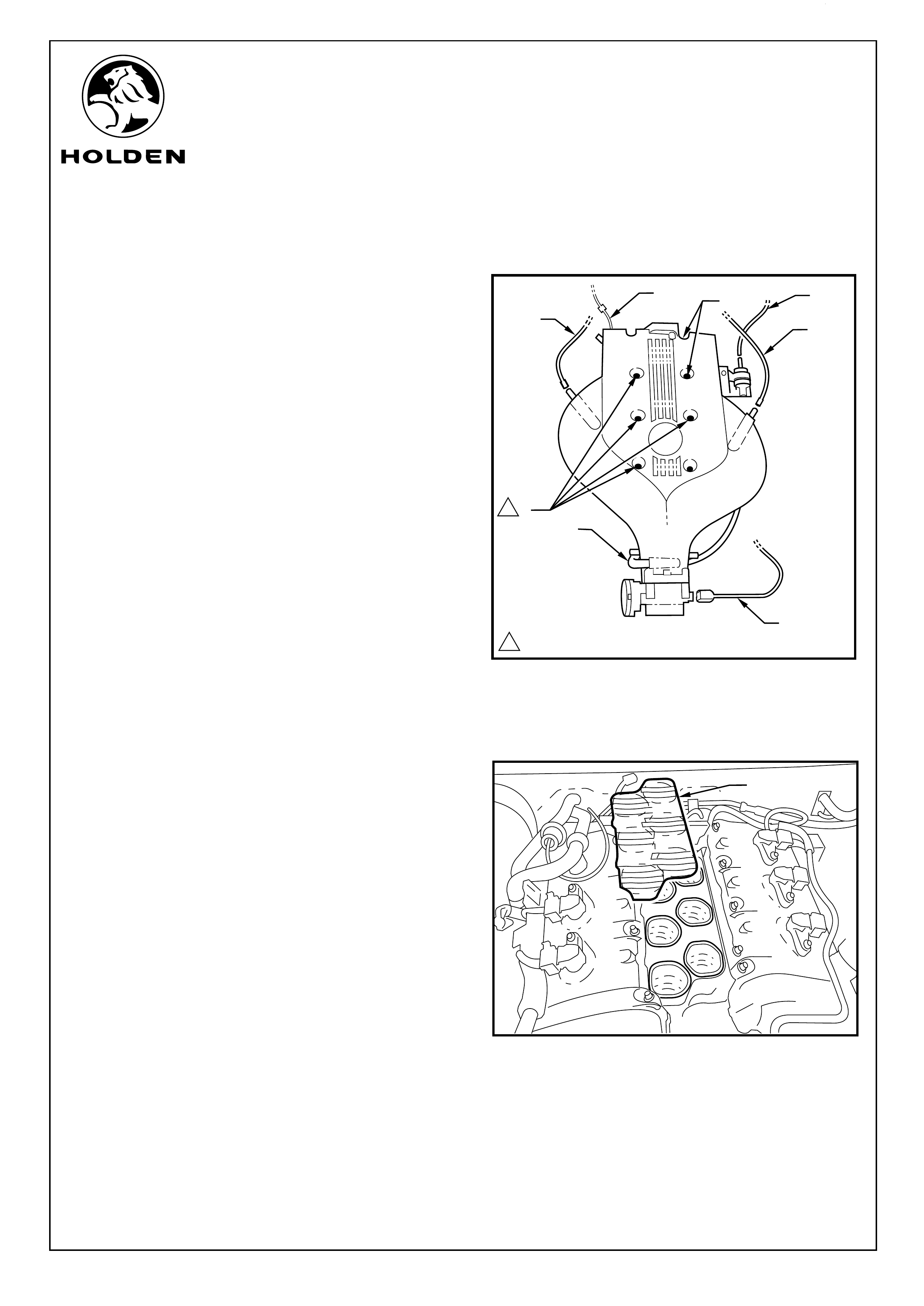
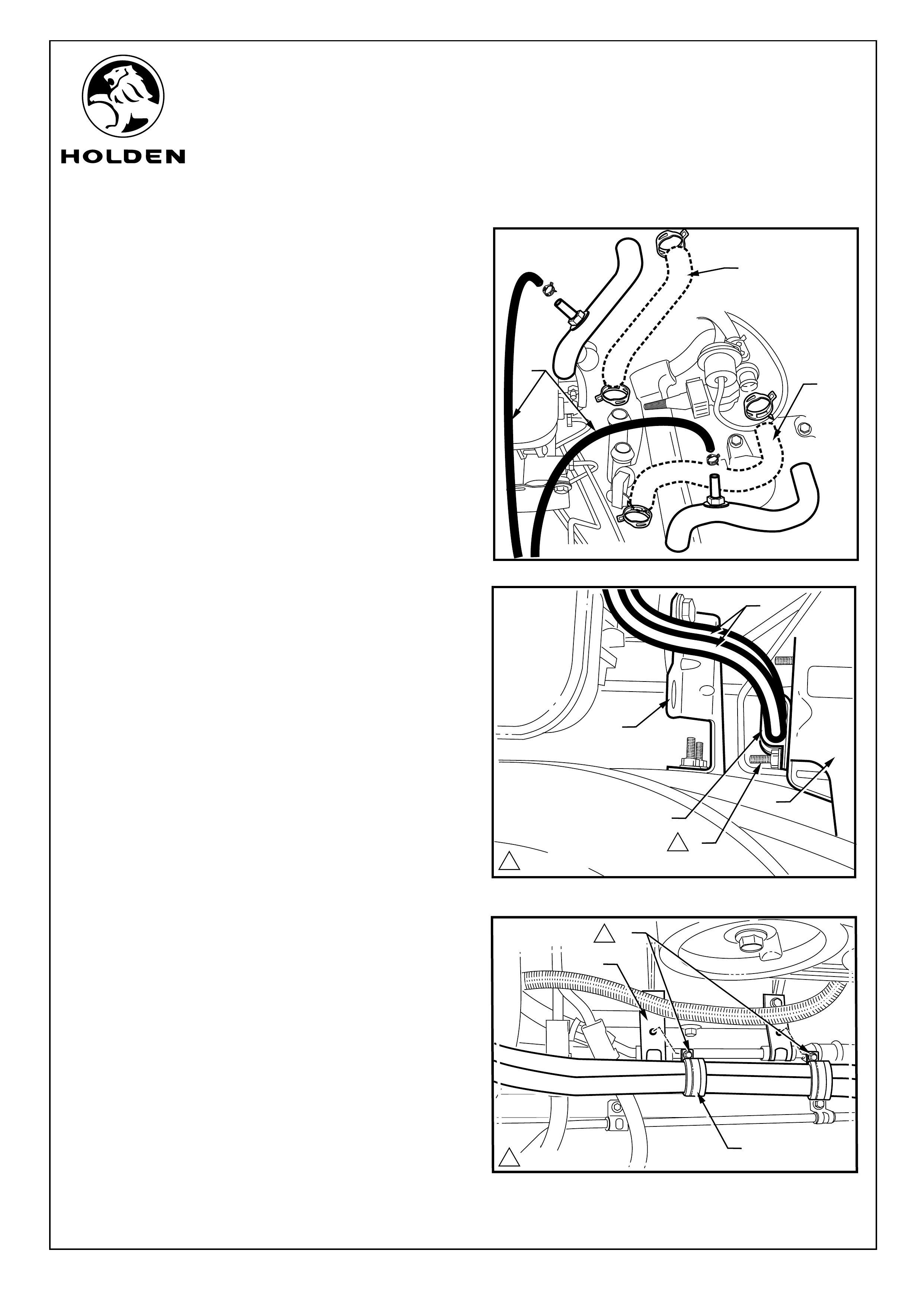
Refer to Figure 3 for the following:
7. Disconnect the engine breather (1) hose from both sides
of the intake manifold and from the rear of the RHS
rocker cover. Remove the hose.
8. Disconnect the vehicle ventilation system vacuum hose
(2).
9. Disconnect the throttle body wiring connector (3).
10. Disconnect Emission Canister Purge Valve Solenoids
vacuum hose (4) from the upper intake manifold behind
the throttle body.
11. Disconnect the Emission Canister Purge Valve
Solenoid electrical connector and vacuum hose (5).
12. Use a socket to remove the six bolts (6) of the eight
manifold bolts that hold both the upper and lower inlet
manifolds to the engine block, (back LHS, front RHS and
the four centre bolts) fixing the upper and lower
manifolds to the engine. Remove the intake manifolds
from the vehicle.
NOTE: The back RHS and the front LHS bolts are not
removed, these two bolts keep the upper and lower
manifolds together.
13. Cover the engine inlet ports (1) with the workshop
blanking plate or clean workshop cloth. Refer to
Figure 4.
Page 3 of 15
FIGURE 3
FIGURE 4
1
1
1
2
3
4
5
6
6
1
112 - 18 N.m
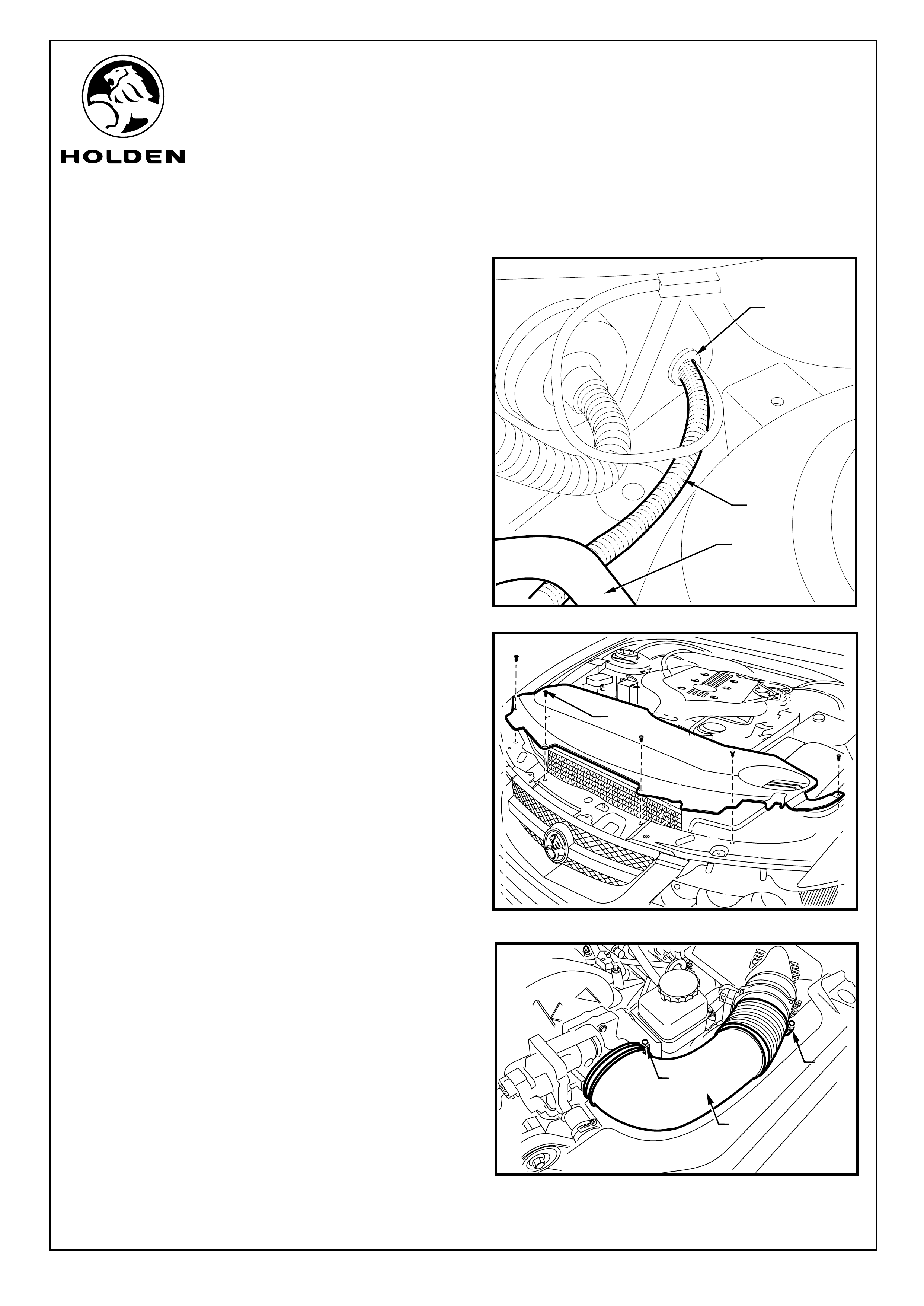
FIGURE 7
1
1
2
FIGURE 6
FIGURE 5
6
9
10
1
FITTING INSTRUCTIONS FOR
VZ COMMODORE
LPG GAS INJECTION KIT
FD1349
21MR05
COPYRIGHT
Reproduction in whole or part
prohibited without written approval
HOLDEN LTD
Division of HOLDEN Ltd ACN 006 893 232
Page 4 of 15
FITTING INSTRUCTIONS: - continued...
Refer to Figure 5 for the following:
14. Identify the part of the injection system harness (1) that
runs through the vehicle and feed it under the AC
supply pipe (2) through the grommet hole (3) into the
vehicle cabin until the grommet is in place and push the
grommet into position.
NOTE: On wagons cut off the end of the grommet
nipple.
15. On wagons pass the window washer back through into
the engine compartment and reconnect it.
16. From under the bonnet, remove the scrivets (1) (5
places) securing the upper radiator shroud and remove
the shroud. Refer to Figure 6.
Refer to figue 7 for the following:
17. Disconnect the airflow sensor from the intake air duct.
18. Loosen the clamps (1) (2 places) retaining the air ducts
between the throttle body and the air cleaner. Remove
the air ducts from the vehicle.
19. Unscrew and remove the top of the air cleaner box.
Remove the air cleaner element.
20. Use a 30 Torx bit to remove the three bolts (2 in the air
cleaner box and 1 outside) attaching the air cleaner
base to the vehicle. Remove the air cleaner base.
3
1
2
1
4
FITTING INSTRUCTIONS FOR
VZ COMMODORE
LPG GAS INJECTION KIT
FD1349
21MR05
COPYRIGHT
Reproduction in whole or part
prohibited without written approval
HOLDEN LTD
Division of HOLDEN Ltd ACN 006 893 232
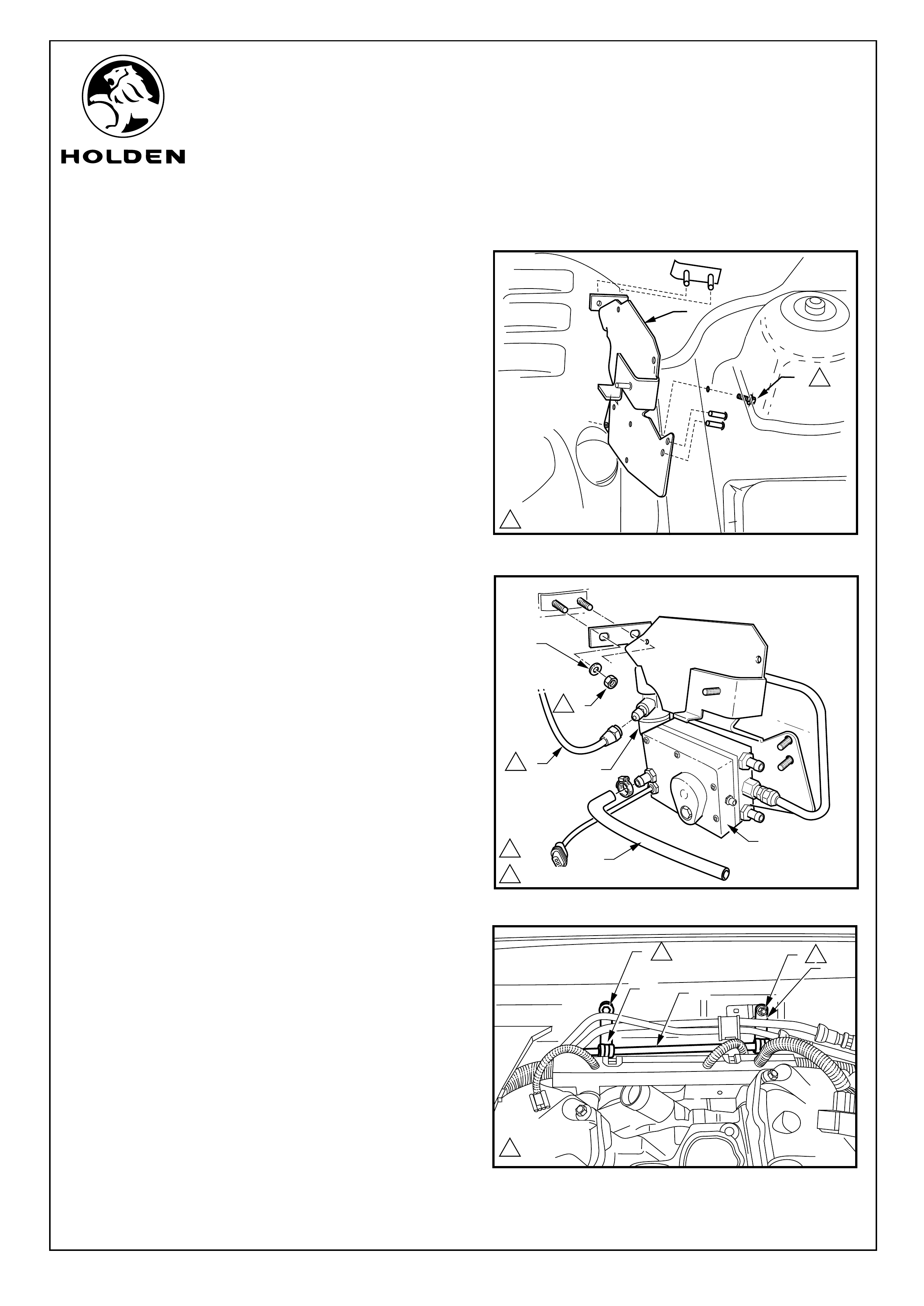
FITTING INSTRUCTIONS: - continued...
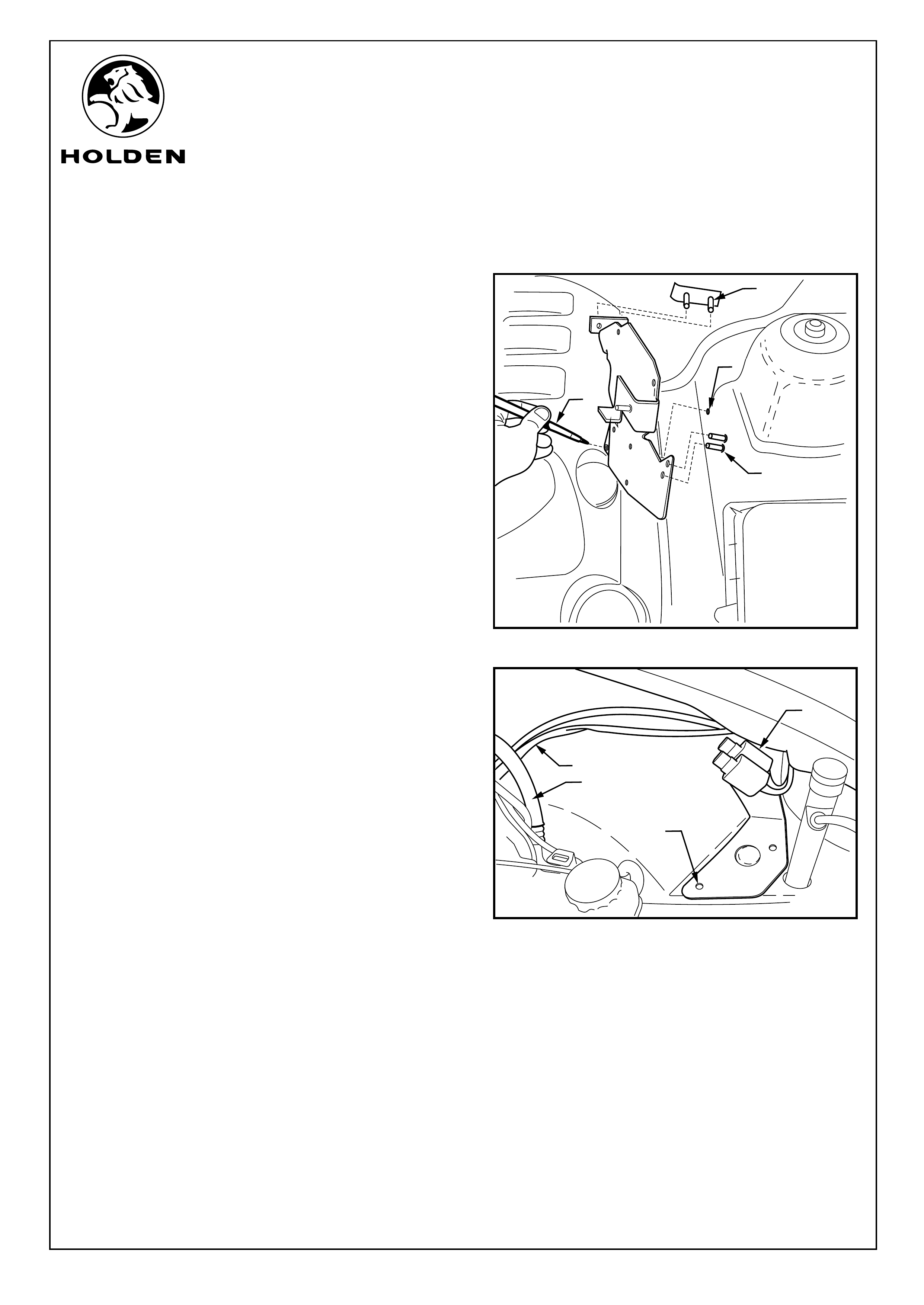
Refer to Figure 8 for the following:
NOTE: The ECU Mounting Bracket is mounted using the
two studs on the passenger side firewall (1) and the two
studs on the wheel arch (2).
21. Place the ECU mounting bracket onto the studs and
use a marker pen (3) to mark the position of the fifth
hole position (4). Remove the ECU mounting bracket
and use a 90-degree drill with a 7mm drill bit to drill out
the hole.
22. Paint the edges of the hole with a high Zinc content
corrosion resistant paint and allow to dry.
Refer to Figure 9 for the following:
23. Pass the ECU emulator harnesses (1) under the AC
supply line (2) and run along the LHS inner wheel arch
fit the emulator boxes to the bracket.
NOTE: The emulator boxes with the four pin (3)
connections will be fitted nearest the inner wheel arch.
24. Use the nut and bolt provided to fit the emulators to the
emulator-mounting bracket. Place the bracket into
position aligning the holes with the air cleaner base
fixing holes (4).
1
2
4
3
1
2
3
FIGURE 9
FIGURE 8
Page 5 of 15
FITTING INSTRUCTIONS FOR
VZ COMMODORE
LPG GAS INJECTION KIT
FD1349
21MR05
COPYRIGHT
Reproduction in whole or part
prohibited without written approval
HOLDEN LTD
Division of HOLDEN Ltd ACN 006 893 232
FITTING INSTRUCTIONS: - continued...
Refer to figure 10 for the following:
Refer to figure 11 for the following:
Refer to figure 12 for the following:
25. Remove the front heater hose (1) from between the
engine supply line and the heater control valve and
discard.
26. Remove the back heater hose (2) and discard.
27. Fit the replacement hoses and clips supplied.
28. Fit the two converter supply lines (3) to the two heater
hoses.
29. Run the two converter hoses down between the ABS
mounting bracket (1) and the Master brake cylinder
support bracket (2). Fit the hose clip (3) around the two
converter supply hoses (4) and fit to the stud (5) on the
rear face of the ABS bracket, use the nut provided to
secure the clip. Tighten to specified torque.
30. Run the two converter hoses down and across the front
cross member. On the LHS of the vehicle, fit the hose
clip around the two converter supply hoses and use the
nut provided to secure them to the stud in the wheel
arch under the air cleaner box.
31. Drill out the two power steering support brackets holes
(1) attached to the front cross member to 7mm.
32. Use two clips (2) and their fastenings to fix the converter
supply lines to the power steering support brackets on
the front cross member.
FIGURE 10
FIGURE 12
TRANS/LOCK
TRANS/LOCK
1
2
3
Page 6 of 15
FIGURE 11
1
2
3
1
2
4
5
1
13.0 - 4.0 N.m
13.0 - 4.0 N.m
13
1
110 - 12 N.m
1
2
1
2
FITTING INSTRUCTIONS FOR
VZ COMMODORE
LPG GAS INJECTION KIT
FD1349
21MR05
COPYRIGHT
Reproduction in whole or part
prohibited without written approval
HOLDEN LTD
Division of HOLDEN Ltd ACN 006 893 232
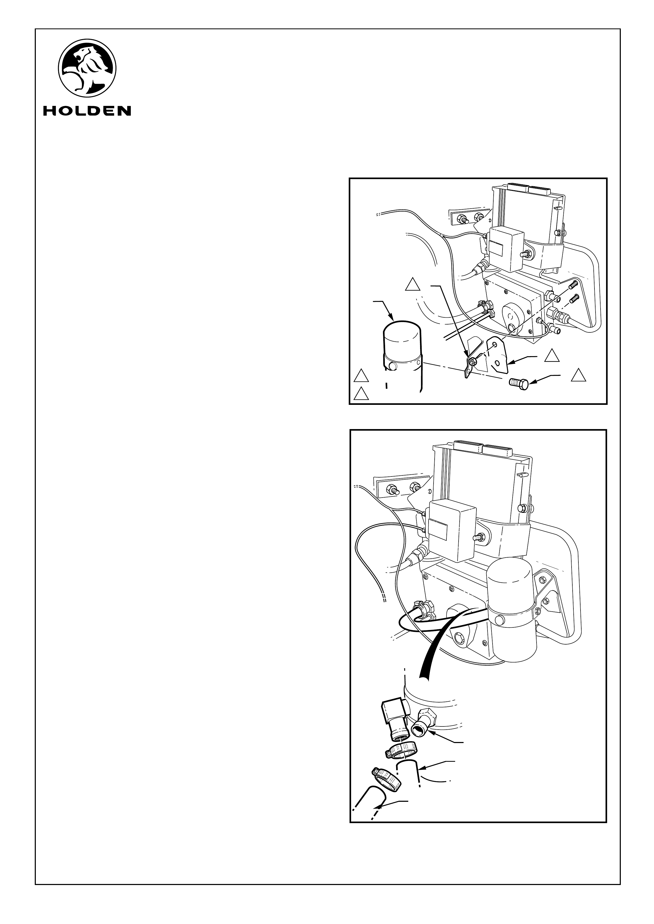
FITTING INSTRUCTIONS: - continued...
33. Refit the ECU mounting bracket (1). Fit the bolt (2)
through from the wheel arch and tighten to specified
toque. Refer to Figure13.
Refer to figure 14 for the following:
34. Fit two nuts (1) and washers (2) supplied to the two studs
on the firewall and tighten to the specified torque.
NOTE: Do not fit the two nuts and washers to the studs
on the wheel arch at this time.
35. Connect the high-pressure supply pipe (3) to the gas
lock valve (4) mounted to the rear of the ECU Mounting
bracket and tighten to specified torque.
36. Fit the piece of gas supply hose 300mm long (5) to the
converter (6) outlet and secure with a hose clamp.
37. Remove the nut (1) and bolt (2) on the two pipe support
brackets on the firewall. Fit two clips (3) to the gas high-
pressure supply pipe (4) and secure to the firewall with
the nut and bolt from the pipe support brackets. Tighten
to specified torque. Refer to Figure 15.
1
2
34
3
1
2
FIGURE 13
FIGURE 15
FIGURE 14
Page 7 of 15
2
1
34
5
6
1
2
10 - 12 N.m
14 - 5 N.m
12 - 18 N.m
1
14 - 5 N.m
11.0 - 3.0 N.m
FITTING INSTRUCTIONS FOR
VZ COMMODORE
LPG GAS INJECTION KIT
FD1349
21MR05
COPYRIGHT
Reproduction in whole or part
prohibited without written approval
HOLDEN LTD
Division of HOLDEN Ltd ACN 006 893 232
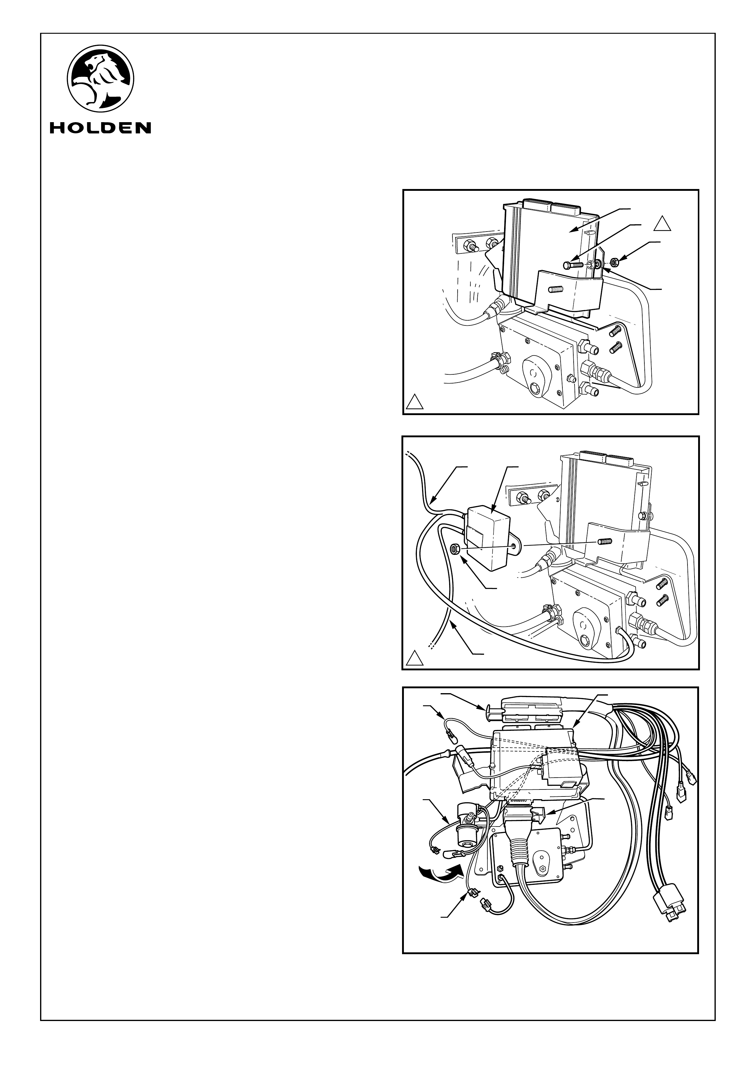
FITTING INSTRUCTIONS: - continued...
38. Fit the ECU module (1) into the ECU mounting bracket.
Fix the ECU in position with the nuts, (2) bolts (3) and
washers (4) supplied. Refer to Figure 16.
NOTE: Fit a washer between the ECU module and the
ECU mounting bracket.
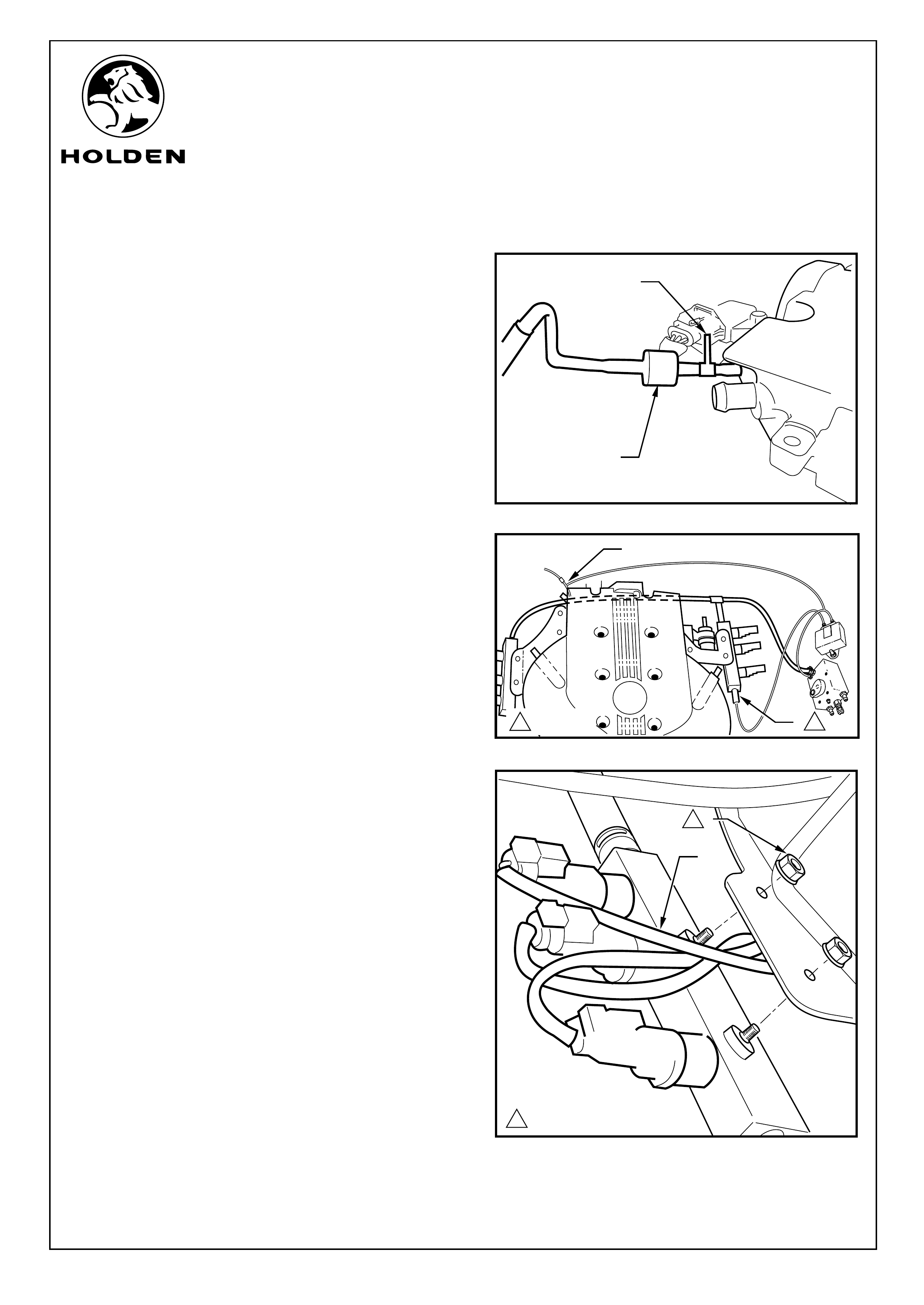
Refer to Figure 17 for the following:
39. Fit the MAP sensor box (1) to the stud on the ECU
mounting bracket using the nut (2) supplied. Tighten to
specified toque.
40. Connect the forked end of the vacuum pipe (3) to the
top connection on the MAP sensor and the sensor on
the converter.
41. Connect gas pressure supply sensor hose (4) to the
lower connection of the MAP sensor.
Refer to Figure 18 for the following:
42. Open the locks on the two main harness ECU (1)
connectors and connect them to the ECU (2), close the
connector locks.
43. Pass the four wire harness connector (3), the twin
harness connector (4) and the three wire harness
connector (5) around the back of the ECU bracket.
44. Connect the four wire harness connector into the MAP
sensor harness.
45. Connect the two-way wiring harness connector into the
gas lock valve connector.
46. Connect the three-way wiring harness connector into
the converter.
FIGURE 16
FIGURE 17
FIGURE 18
1
2
3
4
1
3
4
Page 8 of 15
1
1
2
3
4
5
2
FITTING INSTRUCTIONS FOR
VZ COMMODORE
LPG GAS INJECTION KIT
FD1349
21MR05
COPYRIGHT
Reproduction in whole or part
prohibited without written approval
HOLDEN LTD
Division of HOLDEN Ltd ACN 006 893 232
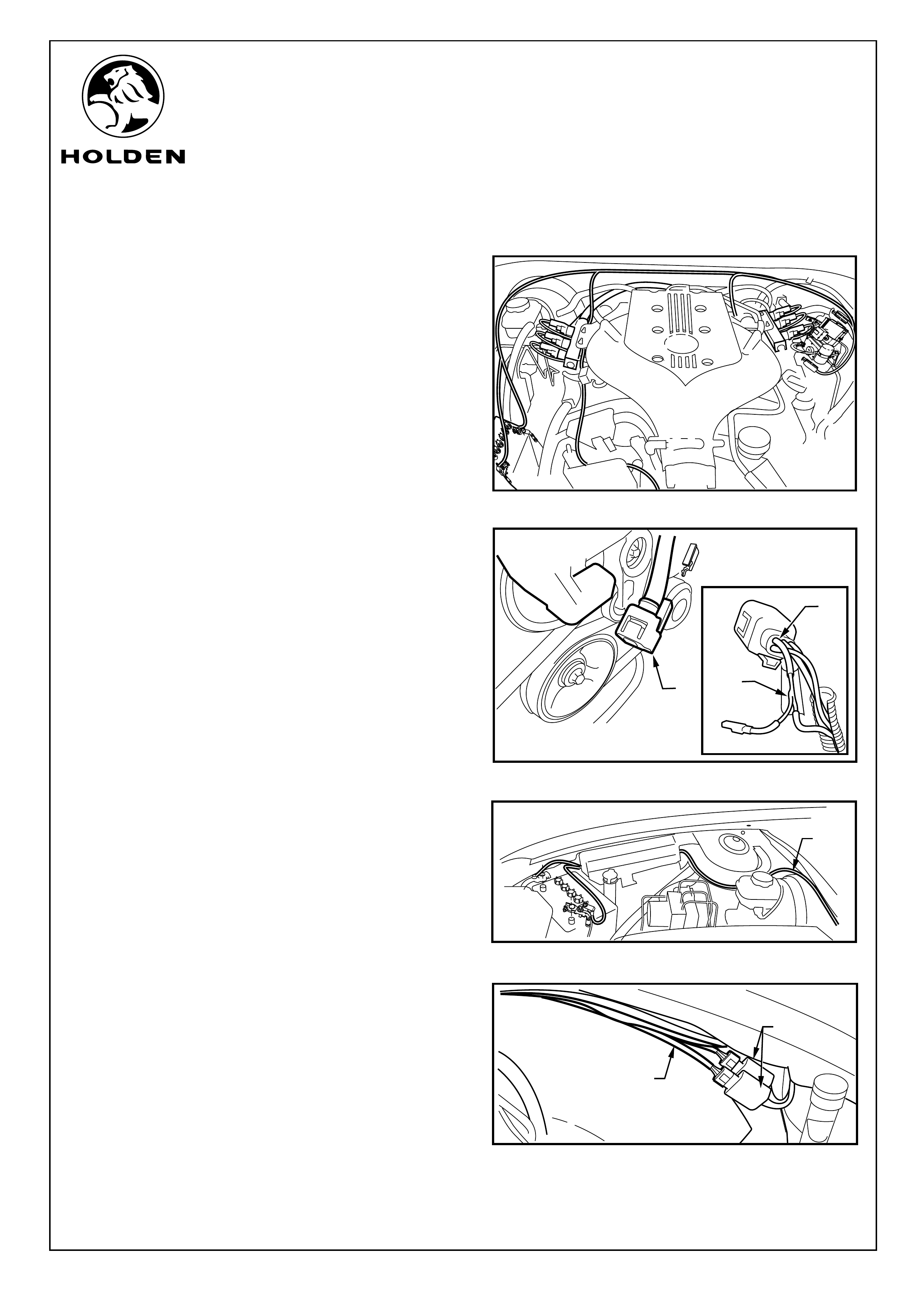
FITTING INSTRUCTIONS: - continued...
Refer to Figure 19 for the following:
47. The two fuel injector harnesses and the battery
harness are pass around the back of the ECU to the
vehicle body harness on the firewall of the vehicle. Run
the short injector harness across to the LHS of the
engine and the long injector harness across to the RHS
of the engine.
48. Continue to run the throttle sensing wire to the front of
the engine to the throttle sensing connector.
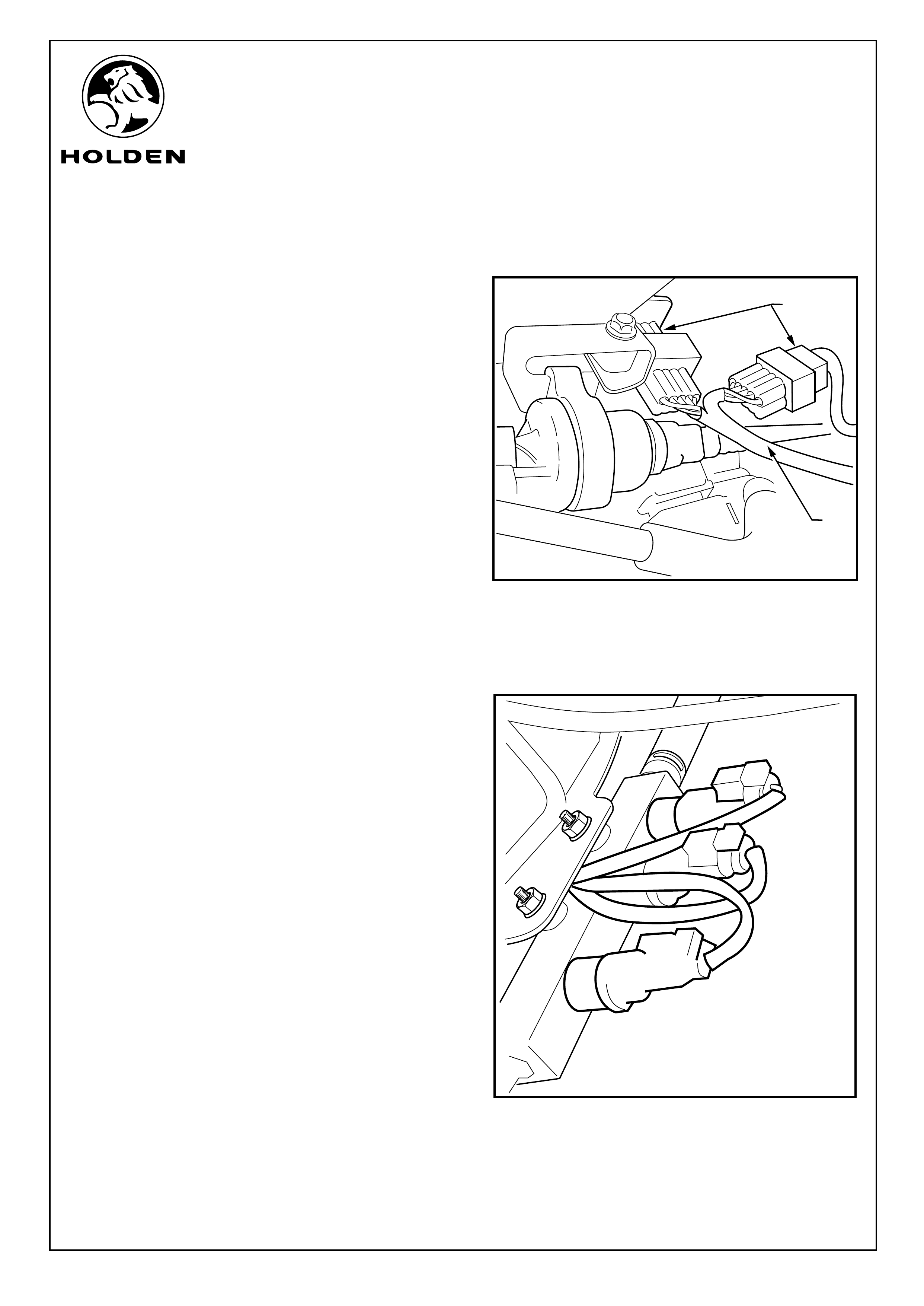
Refer to Figure 20 for the following:
49. Release the outer connector sheath of the throttle
sensor connector and remove the locking clip. Back out
pin 1, (2) the wire is green in colour. Solder splice the
signal pickup wire (3) to the backed out wire and seal join
with shrink wrap.
50 Refit the backed out terminal. Connect the throttle
sensor harness to the throttle positioning sensor.
51. Join the gas harness throttle sensing wire to the new
connection.
52. Run the battery harness (1) across to the other side of
the vehicle, along the underside of the wiring conduit to
the battery. Refer to Figure 21.
NOTE: Do not connect to the battery at this time.
53. Connect the emulator patch harness (1) into the two
emulators (2) and run along the LHS of the vehicle,
across the vehicle harness to the connectors for the
petrol injection manifold on the LHS of the engine.
Cable tie as required. Refer to Figure 22.
FIGURE 19
1
2
FIGURE 20
FIGURE 21
FIGURE 22
1
1
Page 9 of 15
2
3
1
1
2
FITTING INSTRUCTIONS FOR
VZ COMMODORE
LPG GAS INJECTION KIT
FD1349
21MR05
COPYRIGHT
Reproduction in whole or part
prohibited without written approval
HOLDEN LTD
Division of HOLDEN Ltd ACN 006 893 232
FITTING INSTRUCTIONS: - continued...
Refer to Figure 23 for the following:
54. Fit the gas filter support bracket (1) onto the two studs
used to mount the ECU bracket and use the nut (2)
provided to secure the bracket.
55. Using the nut (3) supplied fit the filter (4) to the filter
support bracket and tighten.
56. Connect the gas supply hose from the converter to the
filter (1) and secure with a hose clamp supplied. Refer to
Figure 24.
57. Remove the blanking plate or clean workshop cloth from
the engine inlet ports, refit the intake gasket.
58. Take the modified intake assembly with the gas injection
system fitted and refit to the vehicle.
59. Refit the remaining six engine intake bolts and tighten to
specified toque.
60. Connect the gas Filter to the injector manifold supply
hose (2) to the filter connector (3) and secure with the
clamps supplied. Refer to Figure 24.
61. Reconnect the petrol fuel line to the petrol injector
manifold.
FIGURE 23
FIGURE 24
Page 10 of 15
1
3
2
1
2
3
4
110 - 12 N.m
2.5 N.m
1
1
FITTING INSTRUCTIONS FOR
VZ COMMODORE
LPG GAS INJECTION KIT
FD1349
21MR05
COPYRIGHT
Reproduction in whole or part
prohibited without written approval
HOLDEN LTD
Division of HOLDEN Ltd ACN 006 893 232
FITTING INSTRUCTIONS: - continued...
62. Fit the ventilation vacuum hose (1) to the Tee (2) on the
upper intake manifold. Refer to Figure 25.
Refer to Figure 26 for the following;
63. Connect the top vacuum hose from the mapping
sensor to the Tee (1) on the back of the upper intake
manifold.
64. Connect the lower hose on the mapping sensor to the
front LHS gas manifold (2) and tighten to specified
torque.
65. Remove two nuts (1) holding the gas injector manifolds
to their mounting brackets and pass the injector
harness (2) between the bracket and the manifold.
Refit the manifolds to their brackets and tighten. Refer
to Figure 27.
FIGURE 27
1
2
Page 11 of 15
FIGURE 25
FIGURE 26
2
1
1
2
11.0 - 3.0 N.m
14 - 5 N.m
FITTING INSTRUCTIONS FOR
VZ COMMODORE
LPG GAS INJECTION KIT
FD1349
21MR05
COPYRIGHT
Reproduction in whole or part
prohibited without written approval
HOLDEN LTD
Division of HOLDEN Ltd ACN 006 893 232
FITTING INSTRUCTIONS: - continued...
Refer to Figure 28 for the following:
66. Connect the emulator patch harness (1) between the
engine petrol injectors and the vehicle injector
connector (2).
67. Fit all harnesses into the clips running across the
vehicle firewall.
Refer to Figure 29 for the following:
68. Pull back the black outer sheath of each of the gas
injector leads and read the injector number written on
the wire. Connect the lead to the corresponding
injector.
69. Connect the gas supply hose on the inlet manifold
assembly to the gas filter and secure with the clamp
supplied.
FIGURE 28
FIGURE 29
1
2
Page 12 of 15
FITTING INSTRUCTIONS FOR
VZ COMMODORE
LPG GAS INJECTION KIT
FD1349
21MR05
COPYRIGHT
Reproduction in whole or part
prohibited without written approval
HOLDEN LTD
Division of HOLDEN Ltd ACN 006 893 232
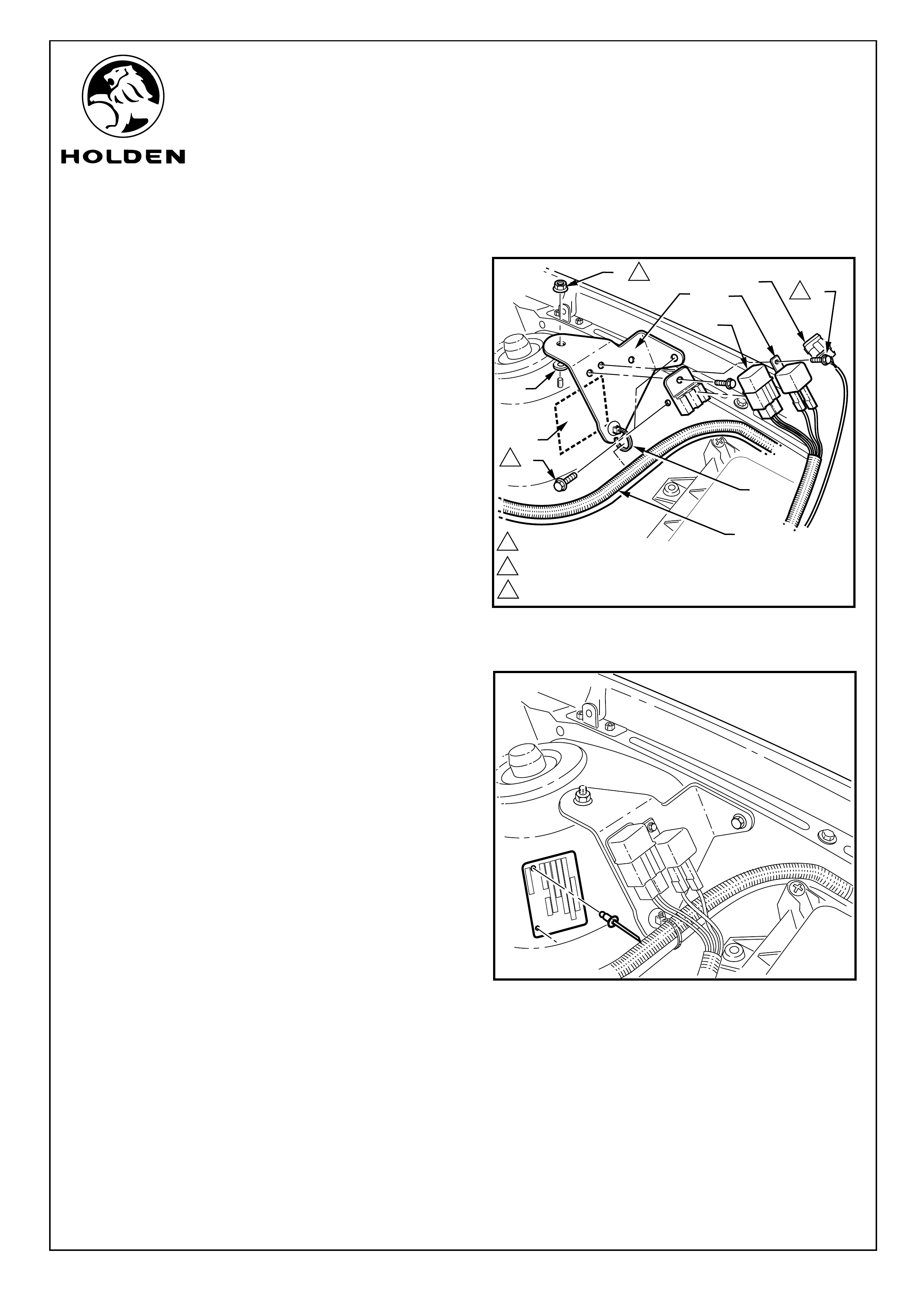
FITTING INSTRUCTIONS: - continued...
70. Remove the ID plate (1) from the LHS wheel arch.
71. Use the nuts and bolts (2) provided to mount the fuse (3)
and relay (4) to the relay-mounting bracket (5).
72. Place a washer (6) on the front stud on the wheel arch,
fit the rely mounting bracket over the stud, place a
second washer and the nut supplied (7). Fit the bolt (8)
supplied through the bracket into the captive nut on the
inner wing. Tighten to specified toque.
73. Clip a mounting tie (9) to the bottom of the relay-
mounting bracket and clip the emulator harnesses (10)
in.
74. Clip the system diagnostic connector into the hole
along side the relay.
75. Drill and rivet the identity plate to the wheel arch.
FIGURE 30
FIGURE 31
XXXXXXX
XXX
XXXXXXX
XXX
XXXXXX
XX
XX
XX
Page 13 of 15
11.0 - 3.0 N.m
210 - 12 N.m
34 - 5 N.m
1
2
3
3
52
6
9
10
1
4
7
8
11
FITTING INSTRUCTIONS FOR
VZ COMMODORE
LPG GAS INJECTION KIT
FD1349
21MR05
COPYRIGHT
Reproduction in whole or part
prohibited without written approval
HOLDEN LTD
Division of HOLDEN Ltd ACN 006 893 232
FITTING INSTRUCTIONS: - continued...
76. Connect the throttle positioning sensor wire.
77. Refit the air cleaner box, filter and ducting.
78. Fill the vehicle with gas and use a soapy liquid to check
for gas leaks on all joins up to the gas lock valve.
79. Connect the harness to the battery. Refer to Figure 32.
80. Start vehicle on petrol only mode. When satisfied that
the vehicle is running correctly on petrol switch to gas.
Run the vehicle until the temperature gauge is shows at
least ¼ of the normal operating temperature and the
gas indicator light on the gas fuel level indicator is
green, these conditions must be met before the gas
check can be carried out. Check all joins forward of the
gas lock valve for gas leaks using a soapy liquid.
IMPORTANT: The vehicle must not be left
unattended whilst the vehicle is warning up.
Monitor the vehicle for signs of leaks.
81. Check coolant levels
82. Refit all parts removed in reverse order.
83. Select petrol only mode and purge gas system of gas.
84. Place owners manual in the vehicle glovebox.
FIGURE 32
Page 14 of 15

FITTING INSTRUCTIONS FOR
VZ COMMODORE
LPG GAS INJECTION KIT
FD1349
21MR05
COPYRIGHT
Reproduction in whole or part
prohibited without written approval
HOLDEN LTD
Division of HOLDEN Ltd ACN 006 893 232
PARTS LIST
PART NUMBER DESCRIPTION QUANTITY
11090684 SCREW: M8 x 1.25 x 25 8
11095803 NUT - CONELOCK - REINF TO LPG 2
92054459 CLAMP - SPARE WHEEL MOUNTING
92055707 CLAMP - HOSE TO BODY 4
92055708 CONVOLUTED TUBE - LPG HEATER HOSE 6
92055714 HEAT SHIELD-LPG SUPPLY PI 1
92055723 LABEL-LPG 1
92055723 LABEL-LPG
92055724 LABEL-LPG INSTRUCTION
92055726 BRKT-LPG CYL ATTACH-RH ST 1
92055727 BRKT-LPG CYL ATTACH-LH ST 1
92055728 REINF-LPG CYL ATTACH RHS 1
92055729 REINF-LPG CYL ATTACH-LHS 1
92055730 TANK ASSEMBLY-LPG WAGON VT/VX 1
92055731 REMOTE FILLER ASM-LPG CYL 1
92055732 HOSE ASM-LPG TANK FILLER 1
92055733 HOSE ASM-LPG CYL FILLER 1
92055736 VENT TUBE-LPG CYL TO JOIN 1
92055737 VENT TUBE-LPG FILLER TO J 1
92055738 FLOOR FLANGE-VENT TUBE AT 1
92055739 VENT TUBE-JOIN TO FLOOR F 1
92055741 SPRING-REAR 2
92055742 BRACKET ASM-SPARE WHL MTG 1
92055743 REINFORCEMENT ASM-SPARE WHEEL 1
92056796 SUPPORT-HEAT SHEILD-FRONT 1
92056797 SUPPORT-HEAT SHEILD-REAR 1
92056801 JOINER - VENT TUBE 1
92057565 FITTING-5/16 SAE STRAIGHT 2
92057566 P CLAMP - LPG SUPPLY 2
92058200 GROMMET - VENT HOSE 1
92058201 POCKET FLANGE - FUEL 1
92058202 WASHER - FILLER VALVE 1
92058203 NUT - FILLER VALVE 1
92075623 REINFORCEMENT-LPG TANK MTG-RHF 1
92075624 REINFORCEMENT-LPG TANK MTG-RHR 1
92075625 REINFORCEMENT-LPG TANK MTG-LHF 1
92075626 REINFORCEMENT-LPG TANK MTG-LHR 1
92076266 ISOLATOR-DUAL COMPRESS-LP TANK 4
92076267 REINFORCEMENT-S/WHL MTG-FRT 1
92076268 REINFORCEMENT-S/WHL MTG-FRT 1
92076269 SPACER PLATE-S/WHL MTG-LHS 1
92076272 CRUSH TUBE-S/WHL BRKT MTG-LHS 1
92076273 CRUSH TUBE-S/WHL MTG BRKT-FRT 1
92076274 CRUSH TUBE-LPG TANK MTG-RHF BO 1
92076275 CRUSH TUBE-LPG TANK MTG-RHR 63 1
92076276 CRUSH TUBE-LPG TANK MTG-LHF 71 1
92076277 CRUSH TUBE-LPG TANK MTG-LHRý74 1
92076279 REMOTE FILLER ASM-LPG TANK 1
92076280 PIPE ASM-CONN LPG TANK REM FLR 1
92077227 CAP-FUEL FILLER 1
92091859 REGO LABEL ASM-LPG 2
92138020 SCREW 4
92138212 TIE-CABLE. 14
92138551 SCREW-POCKET FLANGE (M6x2 2
92141576 CLAMP - Main pipe to underbody 9
92145288 PIPE-REAR ASSEMBLY 1
92145289 PIPE-MID ASSEMBLY 1
70G-990201 NUTSERT - M6x1 1
92055716NK COVER-SPARE WHEEL - ANTHRACITE
92055760NK CARPET & INSULATOR ASM-CARGO
H213000201 STRAP-REMOTE BOOT RELEASE 1
Page 15 of 15
WAGON PARTS KIT

FITTING INSTRUCTIONS FOR
VZ COMMODORE
LPG GAS INJECTION KIT
FD1349
21MR05
COPYRIGHT
Reproduction in whole or part
prohibited without written approval
HOLDEN LTD
Division of HOLDEN Ltd ACN 006 893 232
PART NUMBER DESCRIPTION QUANTITY
SP1543 / 92138003 CLAMP-VALVE BOX VENT TUBE 4
SP1618 CLAMP - HOSE 25mm-38mm 3
SP2754 / 92138040 CLAMP-FILLER HOSE VENT TU 2
SP3945 / 92138241 BOLT-M10x1.5x26 HEX HEAD 2
SP4163 / 92138381 RIVET 25
06M-052001 INJECTOR RAIL ASM. 1
BRC INJECTOR MOD MAX 6
GAS PIPE, 5x10 0.61
SLEEVE, REFLECTOTHERM, 32MM 330
CLAMP, CLICK, 10-11 DIA 2
RAIL, INJECTOR VZ, 2
NUT FOR 4X10 RUBBER PIPE 2
JOINT FOR 4X10 RUBBER PIPE 2
BUMPER-BRKT PUM 4
HOSE, P1 sensor. 1
12H-052001 WIRING HARNESS VZ LPG 1
ASSY, WIRING HARNESS VZ
06M-052002 CONVERTER LPG ASM 1
BRC LPG GENIUS REDUCER 1
Flare union 1
BRC, LPG Solenoid Valve mod. 1
Flare union 1
ELBOW / CONVERTOR 1
BRC DOUBLE FJ1 FILTER 1
NIPPLE, 1/4 NPT X 5/16 FLARE 2
PIPE, SERVICE, L/OFF TO REG 1
VACUUM HOSE, 5MM 112
BKT, CONVERTOR MOUNTING 1
BKT, FILTER FJ1 DOUBLE 1
TEE 1
M6 x 12 SET SCREW, HEX HD 5
6mm Spring Washer Zn 5
M6 FLANGED NUT - Zn plated 1
HOSE, Vapour LPG 90 deg 1
CLAMP, CLICK, 17-18 DIA 2
SLEEVE, Heat Shield 15
06M-052003 INJECTOR HOSE ASM 1
BRC, Nut 4 x 10 Rubber pipe 12
BRC, Joint 4 x 10 rubber pipe 12
BRC, Clamp Click 10-11 12
BRC, Gas hose pipe 5 x 10 1.26m
06M-052004 HOSE ASM - MAP Sensor 1
4mm Vacuum hose 108
BRC, Nut 4 x 10 Rubber pipe 2
BRC, Joint 4 x 10 rubber pipe 2
4mm Tee - plastic 2
06M-052005 HOSE ASM - INJECTOR FEED 1
BRC, Gas pipe 12 x 19 "E67" 0.87
Tee 1
BRC, Clamp Click 17-189 6
Corrugated tube, 16mm 15
06M-052006 STANDOFF, SERVICE LINE, FRONT 1
74A-052001 CLAMP, INSULATED, 6MM 4
12G-052001 SWITCH BEZEL (with laser cut hole) (92111638) 1
06K-052001 HEATER HOSE 3/8 2.2 metres 2
06K-052002 HOSE HEATER OUTLET (Mod 92155841) 1
WAGON PARTS KIT Continued...
PARTS LIST

FITTING INSTRUCTIONS FOR
VZ COMMODORE
LPG GAS INJECTION KIT
FD1349
21MR05
COPYRIGHT
Reproduction in whole or part
prohibited without written approval
HOLDEN LTD
Division of HOLDEN Ltd ACN 006 893 232
PART NUMBER DESCRIPTION QUANTITY
06K-052003 1
74A-052002 CLAMP - MOO (Coolant hose to regulator) 2
06K-052004 FRONT SERVICE LINE (Modified 92145290) 1
06M-052007 BKT, INJECTOR RAIL RH BANK 1
06M-052008 BKT, INJECTOR RAIL LH BANK 1
06M-052009 BKT, EMMULATORS, VZ 1
12H-052002 BKT, FUSE, RELAY VZ 1
12H-052003 BKT, WIRING INJECTOR 1
06M-052010 M6 NOZZLE FOR MANIFOLD 6
92111636 SWITCH BLANK, VY LPG 1
73A-052001 M6 x 25 HT 8.8 Hex head Set Screw -Zn plated 2
71A-052001 6MM FLAT WASHER ZINC 2
70B-052001 M8 NUT - Zn plated 4
71A-052002 8MM SPRING WASHER, ZINC 4
92138351 M6 x 16 HT 8.8 Hex head Set screw - Zn plated 4
08A-052001 TANK ASSEMBLY-LPG SEDAN V (Mod 92055725) 1
12F-052002 BRC 6 Cyl ECU 1
12F-052003 BRC SWITCH WITH BUZZER 1
12F-052004 BRC P1-MAP 1
74A-052003 CLAMP, CLICK, 17-18 DIA 8
HOSE HEATER VALVE (Mod 92157583)
PARTS LIST
PART NUMBER DESCRIPTION QUANTITY
11090684 SCREW: M8 x 1.25 x 25 8
11095803 NUT-CONELOCK-REINF TO LPG 2
92055707 CLAMP - HOSE to BODY 4
92055708 Convoluted tube - LPG heater hose 6
92055714 HEAT SHIELD-LPG SUPPLY PI 1
92055723 LABEL-LPG 1
92055726 BRKT-LPG CYL ATTACH-RH ST 1
92055727 BRKT-LPG CYL ATTACH-LH ST 1
92055728 REINF-LPG CYL ATTACH RHS 1
92055729 REINF-LPG CYL ATTACH-LHS 1
92055731 REMOTE FILLER ASM-LPG CYL 1
92055733 HOSE ASM-LPG CYL FILLER 1
92055736 VENT TUBE-LPG CYL TO JOIN 1
92055737 VENT TUBE-LPG FILLER TO J 1
92055738 FLOOR FLANGE-VENT TUBE AT 1
92055739 VENT TUBE-JOIN TO FLOOR F 1
92055741 SPRING-REAR 2
92056801 JOINER - VENT TUBE 1
92057565 FITTING-5/16 SAE STRAIGHT 2
92057566 P CLAMP - LPG SUPPLY 2
92058200 GROMMET - VENT HOSE 1
92058201 POCKET FLANGE - FUEL 1
92058202 WASHER - FILLER VALVE 1
92058203 NUT - FILLER VALVE 1
92077227 CAP-FUEL FILLER 1
0G-990201 NUTSERT-M6x1 1
92091859 REGO LABEL ASM-LPG 2
SP1618 CLAMP - HOSE 25mm-38mm 3
H213000201 STRAP-REMOTE BOOT RELEASE 1
92138020 SCREW 4
SP2754 / 92138040 CLAMP-FILLER HOSE VENT TU 2
92138212 TIE-CABLE. 1
SEDAN PARTS KIT
PARTS LIST
WAGON PARTS KIT Continued...

FITTING INSTRUCTIONS FOR
VZ COMMODORE
LPG GAS INJECTION KIT
FD1349
21MR05
COPYRIGHT
Reproduction in whole or part
prohibited without written approval
HOLDEN LTD
Division of HOLDEN Ltd ACN 006 893 232
PART NUMBER DESCRIPTION QUANTITY
11090684 SCREW: M8 x 1.25 x 25 8
11095803 NUT-CONELOCK-REINF TO LPG 2
92055707 CLAMP - HOSE to BODY 4
92055708 Convoluted tube - LPG heater hose 6
92055714 HEAT SHIELD-LPG SUPPLY PI 1
92055723 LABEL-LPG 1
92055726 BRKT-LPG CYL ATTACH-RH ST 1
92055727 BRKT-LPG CYL ATTACH-LH ST 1
92055728 REINF-LPG CYL ATTACH RHS 1
92055729 REINF-LPG CYL ATTACH-LHS 1
92055731 REMOTE FILLER ASM-LPG CYL 1
92055733 HOSE ASM-LPG CYL FILLER 1
92055736 VENT TUBE-LPG CYL TO JOIN 1
92055737 VENT TUBE-LPG FILLER TO J 1
92055738 FLOOR FLANGE-VENT TUBE AT 1
92055739 VENT TUBE-JOIN TO FLOOR F 1
92055741 SPRING-REAR 2
92056801 JOINER - VENT TUBE 1
92057565 FITTING-5/16 SAE STRAIGHT 2
92057566 P CLAMP - LPG SUPPLY 2
92058200 GROMMET - VENT HOSE 1
92058201 POCKET FLANGE - FUEL 1
92058202 WASHER - FILLER VALVE 1
92058203 NUT - FILLER VALVE 1
92077227 CAP-FUEL FILLER 1
0G-990201 NUTSERT-M6x1 1
92091859 REGO LABEL ASM-LPG 2
SP1618 CLAMP - HOSE 25mm-38mm 3
H213000201 STRAP-REMOTE BOOT RELEASE 1
92138020 SCREW 4
SP2754 / 92138040 CLAMP-FILLER HOSE VENT TU 2
92138212 TIE-CABLE. 14
SP4163 / 92138381 RIVET 25
92138551 SCREW-POCKET FLANGE (M6x2 2
92145288 PIPE-REAR ASSEMBLY 1
92145289 PIPE-MID ASSEMBLY 1
SP3945 / 92138241 BOLT-M10x1.5x26 HEX HEAD 2
SP1543 / 92138003 CLAMP-VALVE BOX VENT TUBE 4
92141576 CLAMP - Main pipe to underbody 9
M6 x 12 SET SCREW, HEX HD
M6 FLANGED NUT - Zn plated 11
8MM FLAT WASHER, ZINC
06M-052001 INJECTOR RAIL ASM. 1
BRC INJECTOR MOD MAX 6
GAS PIPE, 5x10 0.61
SLEEVE, REFLECTOTHERM, 32MM 330
CLAMP, CLICK, 10-11 DIA 2
RAIL, INJECTOR VZ, 2
NUT FOR 4X10 RUBBER PIPE 2
JOINT FOR 4X10 RUBBER PIPE 2
BUMPER-BRKT PUM 4
HOSE, P1 sensor. 1
12H-052001 WIRING HARNESS VZ LPG 1
ASSY, WIRING HARNESS VZ
SEDAN PARTS KIT Continued...
PARTS LIST

FITTING INSTRUCTIONS FOR
VZ COMMODORE
LPG GAS INJECTION KIT
FD1349
21MR05
COPYRIGHT
Reproduction in whole or part
prohibited without written approval
HOLDEN LTD
Division of HOLDEN Ltd ACN 006 893 232
PART NUMBER DESCRIPTION QUANTITY
06M-052002 CONVERTER LPG ASM 1
BRC LPG GENIUS REDUCER 1
Flare union 1
BRC, LPG Solenoid Valve mod. 1
Flare union 1
ELBOW / CONVERTOR 1
BRC DOUBLE FJ1 FILTER 1
NIPPLE, 1/4 NPT X 5/16 FLARE 2
PIPE, SERVICE, L/OFF TO REG 1
VACUUM HOSE, 5MM 112
BKT, CONVERTOR MOUNTING 1
BKT, FILTER FJ1 DOUBLE 1
TEE 1
M6 x 12 SET SCREW, HEX HD 5
6mm Spring Washer Zn 5
M6 FLANGED NUT - Zn plated 1
HOSE, Vapour LPG 90 deg 1
CLAMP, CLICK, 17-18 DIA 2
SLEEVE, Heat Shield 15
06M-052003 INJECTOR HOSE ASM 1
BRC, Nut 4 x 10 Rubber pipe 12
BRC, Joint 4 x 10 rubber pipe 12
BRC, Clamp Click 10-11 12
BRC, Gas hose pipe 5 x 10 1.26m
06M-052004 HOSE ASM - MAP Sensor 1
4mm Vacuum hose 108
BRC, Nut 4 x 10 Rubber pipe 2
BRC, Joint 4 x 10 rubber pipe 2
4mm Tee - plastic 2
06M-052005 HOSE ASM - INJECTOR FEED 1
BRC, Gas pipe 12 x 19 "E67" 0.87
Tee 1
BRC, Clamp Click 17-189 6
Corrugated tube, 16mm 15
06M-052006 STANDOFF, SERVICE LINE, FRONT 1
74A-052001 CLAMP, INSULATED, 6MM 4
12
06K-052004 FRONT SERVICE LINE (Modified 92145290) 1
06M-052007 BKT, INJECTOR RAIL RH BANK 1
06M-052008 BKT, INJECTOR RAIL LH BANK 1
06M-052009 BKT, EMMULATORS, VZ 1
12H-052002 BKT, FUSE, RELAY VZ 1
12H-052003 BKT, WIRING INJECTOR 1
06M-052010 M6 NOZZLE FOR MANIFOLD 6
92111636 SWITCH BLANK, VY LPG 1
73A-052001 M6 x 25 HT 8.8 Hex head Set Screw -Zn plated 2
71A-052001 6MM FLAT WASHER ZINC 2
70B-052001 M8 NUT - Zn plated 4
71A-052002 8MM SPRING WASHER, ZINC 4
G-052001 SWITCH BEZEL (with laser cut hole) (92111638) 1
06K-052001 HEATER HOSE 3/8 2.2 metres 2
06K-052002 HOSE HEATER OUTLET (Mod 92155841) 1
06K-052003 HOSE HEATER VALVE (Mod 92157583) 1
74A-052002 CLAMP - MOO (Coolant hose to regulator) 2
PARTS LIST
SEDAN PARTS KIT Continued...
FITTING INSTRUCTIONS FOR
VZ COMMODORE
LPG GAS INJECTION KIT
FD1349
21MR05
COPYRIGHT
Reproduction in whole or part
prohibited without written approval
HOLDEN LTD
Division of HOLDEN Ltd ACN 006 893 232
PART NUMBER DESCRIPTION QUANTITY
92138351 M6 x 16 HT 8.8 Hex head Set screw - Zn plated 4
08A-052001 TANK ASSEMBLY-LPG SEDAN V (Mod 92055725) 1
12F-052002 BRC 6 Cyl ECU 1
12F-052003 BRC SWITCH WITH BUZZER 1
12F-052004 BRC P1-MAP 1
74A-052003 CLAMP, CLICK, 17-18 DIA 8
PARTS LIST
SEDAN PARTS KIT Continued...

CCOPYRIGHT HOLDEN 2004
Reproduction in whole or part prohibited
without written approval of Holden LTD
Dual Fuel
Owner's Handbook
05SP05
FD1379

Table of Content
Emergency Procedures 1
Preface 2
Vehicle Operation 3
Fuel Indication 4
Refuelling 5
Vehicle Storage 5
Vehicle Trip Computer 5
Using Vehicle Boot (sedan only) 5
Towing Capacities 5
Radio Operation 5
Service and Maintenance 6
Service Coupons 7
Warranty Information 12
Content 1
Page 1 of 14
Emergency Procedures
LPG has an odour that enables any leaks in the vehicle LPG system to be
detected, should this odour be detected in or around the vehicle or in the event of
an accident, fire, or other abnormal circumstance:
1. Turn the vehicle ignition OFF.
2. Turn the manual service valve on LPG cylinder to OFF (turning in a
clockwise direction) See diagram below.
3. Contact nearest authorised IMPCO LPG repairer or Holden dealer for
advice.
WARNINGS:
LPG is heavier than air and if not dispersed tends to collect in low-lying
areas.
Accident or Fire
Call the emergency fire services to the scene and keep people away from
the vehicle.
Whilst Filling
Ensure that there is no gas leakage. If a leak is detected whilst filling the
vehicle stop filling the vehicle, notify the filling station operator of a potential
problem with the pump. If the odour still persists when disconnected, Carry
out the Emergency Procedures steps I and 2. Select petrol operation with
the fuel selector switch and take the vehicle to nearest authorised LPG
repairer for advice. NOTE: If frost is present do not touch the area until the
frost has dissipated.
Suspected Gas Leak
Carry out the Emergency Procedures steps I through 3. Once the steps have
been followed and the odour is no longer present, select petrol operation
with the fuel selector switch and take vehicle to nearest authorised LPG
repairer for advice.
APA
APAAPA
PULL TO OPENPULL TO OPEN
WNINAR G SAFETY INSTRUCTIONS CL
NER
TSIGY
ID ETN
M NU AC UR D I AU TR L AA F T E N SA I
1
2

Preface
Congratulations on purchasing a Holden 'Dual Fuel' vehicle. Not only will you
appreciate the savings in fuel costs, but as importantly you will reap the benefit of
a fully integrated LPG engine management system. Your Holden Dual Fuel
system will maximise your Holden vehicles performance in both fuel modes
whilst minimise exhaust emissions, retaining vehicle reliability and performance.
It is Important to understand that the engine in your 'Dual Fuel' Holden vehicle will
always start on petrol and if LPG is selected on the dual fuel control switch the
vehicle will automatically transfer over to LPG when the engine has warmed up
sufficiently.
The Holden Dual Fuel System has been designed to comply with the relevant
Australian Standard AS/NZS 1425:2003.
It is recommended to advise your insurance company that your new vehicle
operates on both petrol and LPG as failure to do so may invalidate your
insurance policy. Your vehicle is required to display the LPG decal on both the
front and rear numberplates.
The information contained in this manual is designed to cover the Holden Dual
Fuel System. Information provided was accurate at the time this manual was
approved for printing. Holden Ltd., reserves the right subject to all applicable
laws and regulations to change specifications at any time without incurring any
liability what so ever.
Page 2 of 14
VEHICLE OPERATION
New Engine Run-In Procedure
It is recommended that the engine of your vehicle be run in on petrol for 1000km
before running the vehicle on LPG.
Starting the Engine
There are no special requirements for starting your Dual Fuel engine with either
fuel selected, always follow starting directions as indicated in the vehicle
Owner's Handbook.
Changing Fuels and Starting
The fuel selector switch is located on the centre floor mounted console. Fuel
selection may be done at any time by simply changing the switch to the desired
fuel.
Fuel Selector Switch
The switch has two positions and a fuel operation indicator lamp, which will
change colour to indicate which fuel mode the vehicle is currently running on.
The lamp colours are as follows:
Red Petrol operation
Amber Transition state, currently transferring to selected fuel
Green LPG operation
PETROL OPERATION:
When the switch is in the 'Petrol' position, the engine will operate on
unleaded petrol. The engine will start on petrol, and if switched from LPG, will
automatically make the transition to petrol operation.
LPG OPERATION:
When the switch is in the 'LPG' position, the engine will operate on LPG
fuel. The engine will start and run on petrol until required conditions are reached,
at which time the system will automatically transfer to LPG operation.
Page 3 of 14
LPG
PETROL
BRC

FUEL INDICATION
Petrol Fuel Level Indication
The fuel gauge on the instrument panel will show petrol tank contents.
LPG Fuel Level Indication
The 4 lights in the change over switch indicate fuel level:
4 lights illuminated full
3 lights illuminated ¾ full
2 lights illuminated ½ full
1 light illuminated ¼ full
1 light flashing LPG reserve
1 light flashing and beeper sounding Out of LPG and the system has changed
back to petrol operation. To stop the
system beeping, change fuel selection
switch to petrol.
A few quick beeps indicates system has changed back to
petrol, under high load conditions, and
will return back to LPG automatically
when ready.
Petrol Usage
Holden recommends: the petrol tank of your vehicle should always have at
least a ¼ of a tank of petrol.
When the engine is started with LPG selected, the engine will start and run on
petrol until required conditions are reached, at which time the system will
automatically begin the change to LPG operation.
IMPORTANT:
If the vehicle runs out of petrol it will not start, eliminating the ability to
changeover to LPG operation.
Operating the vehicle with 'NO' petrol in the fuel tank may cause
damage to the petrol fuel pump.
Page 4 of 14

REFUELLING
Sedan vehicles are fitted with a 94 litre cylinder with a working capacity of 75 litre
and the Wagon is fitted with a 75 litre doughnut tank with a working capacity of 60
litres.
LPG or petrol may be added, regardless of the fuel selected.
NOTE: Observe the filling instructions and warnings displayed at the filling
station.
Petrol Refuelling
Refuel the vehicle in the normal manner. Refer to the vehicle operator's manual.
LPG Refuelling
Switch off the engine.
Remove the LPG filler cap.
Connect LPG filler nozzle and fully squeeze and hold trigger.
Release the trigger when it shuts off. The AFL (Automatic Fill Limiter) shuts
off the LPG flow when your vehicle's LPG cylinder is 80% full: this is to allow
for liquid expansion.
Disconnect the LPG filler nozzle.
Screw the LPG filler cap back on.
VEHICLE STORAGE
If the vehicle is to be stored for a prolonged period, turn off the Service Valve,
located on the LPG cylinder.
VEHICLE TRIP COMPUTER
The Distance to empty and Average speed/fuel modes are not available on dual
fuel vehicles. Refer to Standard Petrol Owner's Handbook for additional
information.
USING VEHICLE BOOT (SEDAN ONLY)
Please take care when placing heavy or sharp items in the vehicle boot as these
may cause damage to the LPG tank or vent pipes. Please see your
dealer if you notice damage to these items.
TOWING CAPACITIES
The maximum towing capacity of both sedan and wagon is 1600kg.
RADIO OPERATION
Vehicles fitted with Dual Fuel may show reduced radio reception at times.
Page 5 of 14

SERVICE AND MAINTENANCE
Scheduled Maintenance
All service and repair work must be performed by a properly trained specialist. If
the repair work involves opening the high-pressure LPG lines or associated
components to the atmosphere, this should also be carried out by an authorised
LPG technician and the work must be carried out to Australian Standard
AS/NZS1425:2003.
The following coupons cover additional service requirements for Holden dual
fuel vehicles.
State / Territory Regulations
Different states/territories may have additional service requirements. The
additional work should be carried out and noted on the service coupons.
LPG Cylinder
The LPG cylinder must be removed and pressure tested by an authorised LPG
cylinder test centre once every 10 years from the original test date stamped on a
plate attached to the cylinder.
Convertor
Check the 6 screws on the converter body are at the correct torque in accordance
with the service schedule coupons.
a. Use a dynamometric spanner to check the torque of the 6 screws and
tighten to 9 Nm if required.
LPG
Page 6 of 14

LPG Service Coupons
3,000km or 3 months service
High-pressure leak check including the following:
Converter screw torque settings (9 Nm follow on torque)
Converter and lock-off
All service line connections
Filler valve
LPG cylinder connections
Fuel selector operation
All mounting points for tightness
Date: ___ / ___ / ___ Kms ________________
Servicing Dealer:
_______________________
15,000km or 12 months service
High-pressure leak check including the following:
Converter and lock-off
All service line connections
Filler valve
LPG cylinder connections
Fuel selector operation
Replace LPG vapour filters
Date: ___ / ___ / ___ Kms ________________
Servicing Dealer:
_______________________
Page 7 of 14

LPG Service Coupons
30,000km or 24 months service
High-pressure leak check including the following:
All service line connections
Filler valve
LPG cylinder connections
Fuel selector operation
Replace LPG vapour filters
Date: ___ / ___ / ___ Kms ________________
Servicing Dealer:
_______________________
45,000km or 36 months service
High-pressure leak check including the following:
Converter and lock-off
All service line connections
Filler valve
LPG cylinder connections
Fuel selector operation
Replace LPG vapour filters
Date: ___ / ___ / ___ Kms ________________
Servicing Dealer:
_______________________
Converter screw torque settings (9 Nm follow on torque)
Page 8 of 14

LPG Service Coupons
60,000km or 48 months service
High-pressure leak check including the following:
All service line connections
Filler valve
LPG cylinder connections
Fuel selector operation
Replace LPG vapour filters
Date: ___ / ___ / ___ Kms ________________
Servicing Dealer:
_______________________
75,000km or 60 months service
High-pressure leak check including the following:
Converter and lock-off
All service line connections
Filler valve
LPG cylinder connections
Fuel selector operation
Replace LPG vapour filters
Date: ___ / ___ / ___ Kms ________________
Servicing Dealer:
_______________________
Page 9 of 14

LPG Service Coupons
90,000km or 72 months service
High-pressure leak check including the following:
All service line connections
Filler valve
LPG cylinder connections
Fuel selector operation
Replace LPG vapour filters
Date: ___ / ___ / ___ Kms ________________
Servicing Dealer:
_______________________
105,000km or 84 months service
High-pressure leak check including the following:
Converter and lock-off
All service line connections
Filler valve
LPG cylinder connections
Fuel selector operation
Replace LPG vapour filters
Date: ___ / ___ / ___ Kms ________________
Servicing Dealer:
_______________________
Page 10 of 14

LPG Service Coupons
120,000km or 96 months service
High-pressure leak check including the following:
All service line connections
Filler valve
LPG cylinder connections
Fuel selector operation
Replace LPG vapour filters
Inspect LPG front liquid filter
Date: ___ / ___ / ___ Kms ________________
Servicing Dealer:
_______________________
135,000km or 108 months service
High-pressure leak check including the following:
Converter and lock-off
All service line connections
Filler valve
LPG cylinder connections
Fuel selector operation
Replace LPG vapour filters
Date: ___ / ___ / ___ Kms ________________
Servicing Dealer:
_______________________
Page 11 of 14

LPG Service Coupons
150,000km or 120 months service
High-pressure leak check including the following:
Converter and lock-off
All service line connections
Filler valve
LPG cylinder connections
Fuel selector operation
Replace LPG vapour filters
Date: ___ / ___ / ___ Kms ________________
Servicing Dealer:
_______________________
Warranty
New Vehicle Warranty Period. The LPG system is 3 years / 100,000 kms,
whichever comes first.
Page 12 of 14


Refer to your Holden Dealer for further information.
Holden Ltd
ABN 84 006 983 232
241 Salmon Street Port Melbourne
Victoria 3207 Australia
Subsidiary of General Motors Corp
All correspondence to:
PO Box 1714 Melbourne
Victoria 3001 Australia
Telephone (03) 9647 1111
Facsimile (03) 9647 2550
Please note that all information, illustrations and specifications in this Handbook are based
on the latest production information available at the time of printing.
Holden reserves the right to make any changes at any time without notice and without incurring any obligation.
Fault Tree
Holden VZ Commodore Sequent 6 Cylinder
#S
y
m
p
toms Com
p
onents Faults .# Tests Results Action
1 Engine will not start Injector Harness Open circuit on
injector power line
1 Disconnect injector harness
from LPG harness and OEM
harness. Measure for
continuitiy between pin 1 on
the Petrol ECU connector
and pin 1 on Injector
connector
No continuity Replace injector
harness.
Continuit
y
N
o fault
LPG ECU Injector switches failed 2 Replace with known good
uni
t
Engine starts Replace unit
Engine does not start Replace main
harness
2 Engine runs in Petrol
onl
y
5A Fuse Blown 1 Check fuse continuity No continutity Replace fuse
Switch has no
illumination and no
b
ee
p
Continuity No fault
LPG ECU Switch drivers failed 2 Replace with known good
uni
t
Normal system
o
p
eration
Replace unit
No change in symptoms Replace main
harness
3 Engine runs in LPG
only
Switch has no
illumination and no
b
ee
p
Disconnected 1 Check connection on back of
switch
Not connected properly Connect and retest
Connected
p
ro
p
erl
y
Re
p
lace unit
LPG ECU Faulty switch circuitry 2 Install known good LPG
ECU
Symptom resolved Replace LPG ECU
Symptom persists Replace LPG
Main Harness
4 Engine stalls or
switches back to
Petrol. LPG is
selected. Fuel
indicator illuminates
RED.
Tank Contents empty 1 Inspect gauge at tank Showing empty Fill with LPG and
test again
N
ot showin
g
em
p
t
y
N
o fault
050801 Fault Tree.xls Page 1

Fault Tree
Holden VZ Commodore Sequent 6 Cylinder
#S
y
m
p
toms Com
p
onents Faults .# Tests Results Action
Tank Manual Valve Closed 2 Turn valve counter-
clockwise to o
p
en
Does not open or fuel
does not flow
Replace manifold
on tank
O
p
ens
N
o fault
Fuel Sending Unit Physically stuck 3 Remove fuel sending unit.
Actuate unit with
magnetically susceptible
metal.
Gauge does not follow
movement
Replace unit
Delivering an incorrect
resistance.
4 Actuate unit with
magnetically susceptible
metal and measure resistance
with ohm meter
Does not indicates E
when resistance is 0 and
smoothly transitions to
90 ohms at F
Replace unit
Indicates E when
resistance is 0 and
smoothly transitions to
90 ohms at F
No fault
15A Fuse Blown 5 Check fuse continuit
y
N
o continutit
y
Re
p
lace fuse
Continuit
y
N
o fault
Rear L/O L/O does not operate 6 Manually apply power across
L/O
L/O Fails to open Replace L/O
Front L/O L/O Opens Check for
b
locka
g
e
7 Manually apply power across
L/O and pass air through
valve
Air does not pass
through easily
Replace L/O
Air passes through
easil
y
No fault
Power Rela
y
Fails to actuate Manuall
y
actuate rela
y
Fails to actuate Re
p
lace unit
Actuates normall
y
N
o fault
LPG ECU Actuator driver failure 2 Replace with known good
uni
t
System functions
normall
y
Replace defective
uni
t
Service Line Blocked 8 Disconnect at tank and front
L/O and blow air through
line.
Air does not pass easily Clear obstruction
or replace
Air
p
asses easil
y
N
o fault
050801 Fault Tree.xls Page 2

Fault Tree
Holden VZ Commodore Sequent 6 Cylinder
#S
y
m
p
toms Com
p
onents Faults .# Tests Results Action
Low pressure fuel
filte
r
Blocked 9 Check service interval for
fuel filters
Service interval expired Replace filters
10 Disconnect vapor line to and
from filter manifold and pass
air throu
g
h.
Air does not pass easily Replace filters
Air
p
asses easil
y
N
o fault
Low pressure fuel
line
Blocked 11 Disconnect at fuel filter and
near fuel rail and pass air
through low pressure fuel
line
Air does not pass easily Clear obstruction
or replace
Air passes easily Check far line for
b
locka
g
e
12 Re-connect fuel line at near
fuel rail and disconnect at far
fuel rail and pass air through
low pressure fuel line
Air does not pass easily Clear obstruction
or replace
Air
p
asses easil
y
N
o fault
Fuel Rail Blockage 13 Disconnect fuel rail from
s
y
stem and visuall
y
ins
p
ect
Visual evidence of
b
locka
g
e
Clear obstruction
or re
p
lace
No visual evidence of
b
locka
g
es
No fault
Fuel Regulator Blockage 14 Remove inlet and outlet
fittings on regulator and
apply pass pressurized air
throu
g
h re
g
ulator.
Air does not pass
through with significant
flow
Replace unit
Air passes through
easil
y
No fault
5 Rough idle on
LPG,Normal idle on
Petrol
Injector Fault Failed closed 1 Engine idle worsens Injector not
faulted
Engine idle does not
change
Replace injector.
While idling, individually
disconnect each LPG injector
connector, listen for change
in idle, then re-connect.
050801 Fault Tree.xls Page 3

Fault Tree
Holden VZ Commodore Sequent 6 Cylinder
#S
y
m
p
toms Com
p
onents Faults .# Tests Results Action
Fuel Filter Blockage 2 Check service interval for
fuel filters
Service interval expired Replace filters
Disconnect vapor line to and
from filter manifold and pass
air through.
Air does not pass easily Replace filters
Air
p
asses easil
y
N
o fault
Fuel Rail Blockage 3 Disconnect fuel rail from
s
y
stem and visuall
y
ins
p
ect
Visual evidence of
b
locka
g
e
Clear obstruction
or re
p
lace
No visual evidence of
b
locka
g
es
No fault
6 Rough idle on LPG,
N
ormal idle on Petrol
Post injector nozzle
hose
Leakage 1 Engine idle does not
chan
g
e
Check / Replace
in
j
ector hose
Engine idle worsens Hose not faulted
7 Rough idle on LPG,
Normal idle on Petrol
Petrol injector Faulty 1 Perform petrol injector
diagnostic procedure
Harness Bad connection 2 Engine idle does not
change
Faulty circuit.
Check harness
and/or LPG ECU.
En
g
ine idle worsens
N
o fault
LPG EC
U
Failed circuit 3
N
o
p
otential
N
o fault
Voltage > 1VDC Replace ECU
While idling, individually
disconnect each Petrol
injector connector, listen for
change in idle, then re-
connect.
With ignition switch on, but
engine stopped, measure
voltage across pins (54-
26, 53-25, 52-24, 51-23, B3-
C3, B4-C4)
While idling, individually
disconnect each LPG injector
connector, listen for change
in idle, then re-connect.
050801 Fault Tree.xls Page 4

Fault Tree
Holden VZ Commodore Sequent 6 Cylinder
#S
y
m
p
toms Com
p
onents Faults .# Tests Results Action
8 Sufficient fuel in LPG
tank, Switch LED
flashes to indicate
empty
Fuel Sending Unit Failed low impedance 1 Resistance changes
with position from 0 to
100 Ohms.
Unit OK.
Resistance does not
change
Replace sending
unit.
Harness Short across sending
unit pins
Measure harness pins at
Sequent ECU for short
Resistance low Replace harness
Resistance per sending
unit
Replace ECU
9 Low fuel in LPG tank,
Fuel switch LED array
lit to indicate full
Fuel Sending Unit Failed high impedance Resistance changes
with position from 0 to
100 Ohms.
Unit OK.
Resistance does not
change
Replace sending
unit.
Harness Open circuit across
sending unit pins
Measure harness pins at
Sequent ECU for short
Resistance high Replace harness
Resistance per sending
unit
Replace ECU
10 Indication on gauge
LED array does not
change with fuel
usa
g
e.
Fuel sending unit Resistance changes
with position from 0 to
100 Ohms.
Unit OK.
Resistance does not
chan
g
e
Replace sending
unit.
Harness Fixed resistance across
harness pins
Measure harness pins at
Sequent ECU for short
Resistance high not
equal to sending unit
Replace harness
Disconnect sending unit.
Measure resistance while
changing position of sending
unit with a ferrite
Failed stuck
Disconnect sending unit.
Measure resistance while
changing position of sending
unit with a ferrite
Disconnect sending unit.
Measure resistance while
changing position of sending
unit with a ferrite
050801 Fault Tree.xls Page 5
Fault Tree
Holden VZ Commodore Sequent 6 Cylinder
#S
y
m
p
toms Com
p
onents Faults .# Tests Results Action
Resistance per sending
unit
Replace ECU
11 Vehicle operates only
in LPG
Fuel selector switch Switch stuck 1 Actuate switch to Petrol
p
osition.
Will not actuate Replace unit.
Actuates Check harness
Check ECU
Re
p
lace unit.
12 Fuel mode indicator
illuminates LPG when
switch is in Petrol
p
osition.
Fuel selector switch Switch stuck Check switch connection. Faulty connection. Re connect and re-
test
Good connection.
N
o fault
Harness Short in wirin
g
Check harness continuit
y
N
o continuit
y
Re
p
lace harness
Continuit
y
Re
p
lace ECU
13 Vehicle operates only
in Petrol
Fuel selector switch Switch stuck 1 Actuate switch to Petrol
p
osition.
Will not actuate Replace unit.
Actuates Check harness
Check ECU
Re
p
lace unit.
14 LED fails to luminate
showing incorrect level
indication
Fuel level
indicators
Faulty fuel level
indicator
At first key on, examine fuel
level LEDs for 2 seconds
All lamps flash on once,
go out, and illuminate
to level pattern.
Check sending
unit
Check harness
Check ECU.
Any LED fails to flash
once before pattern
illuminatio
n
Check harness
Check ECU.
Re
p
lace unit.
15 No RED illumiation
during Petrol operation
Fuel mode indicator Faulty fuel mode
indicator
Select Petrol mode. Key on
and examine indicator (no
RPM
)
No illumination Replace unit.
Oran
g
e illuminatio
n
Check harness
Check ECU.
Green illumination Check harness
050801 Fault Tree.xls Page 6
Fault Tree
Holden VZ Commodore Sequent 6 Cylinder
#S
y
m
p
toms Com
p
onents Faults .# Tests Results Action
Check ECU.
16 No GREEN
illumiation during LPG
o
p
eration
Fuel mode indicator Faulty fuel mode
indicator
Select LPG mode. Start
engine and wait for LPG
o
p
eration
No illumination Replace unit.
Oran
g
e illuminatio
n
Check harness
Check ECU.
Re
p
lace unit.
Red illumination Check harness
Check ECU.
Re
p
lace unit.
17 No Orange
illumination during
changeover
Fuel mode indicator Faulty fuel mode
indicator
Select LPG mode. Start
engine and observe indicator
during transfer from Petrol to
LPG operation
No illumination Replace unit.
Green illumination Check harness
Check ECU.
Re
p
lace unit.
Red illumination Check harness
Check ECU.
Re
p
lace unit.
18 Fuel mode indicator is
not illuminated
5A Fuse Fuel mode indicator is
not illuminated
Check 5A fuse Blown Replace unit.
Fuel level indicators
are not illuminated
Active Check harness
(Battery
connection
)
Vehicle starts and runs
in Petrol onl
y
Check switch
module
Check ECU.
19 Vehicle starts and runs
on Petrol
15A Fuse Vehicle starts and runs
on Petrol
Check 15A fuse Blown Replace unit.
Vehicle starts but stalls
when switching to
LPG o
p
eratio
n
Active Check harness.
050801 Fault Tree.xls Page 7
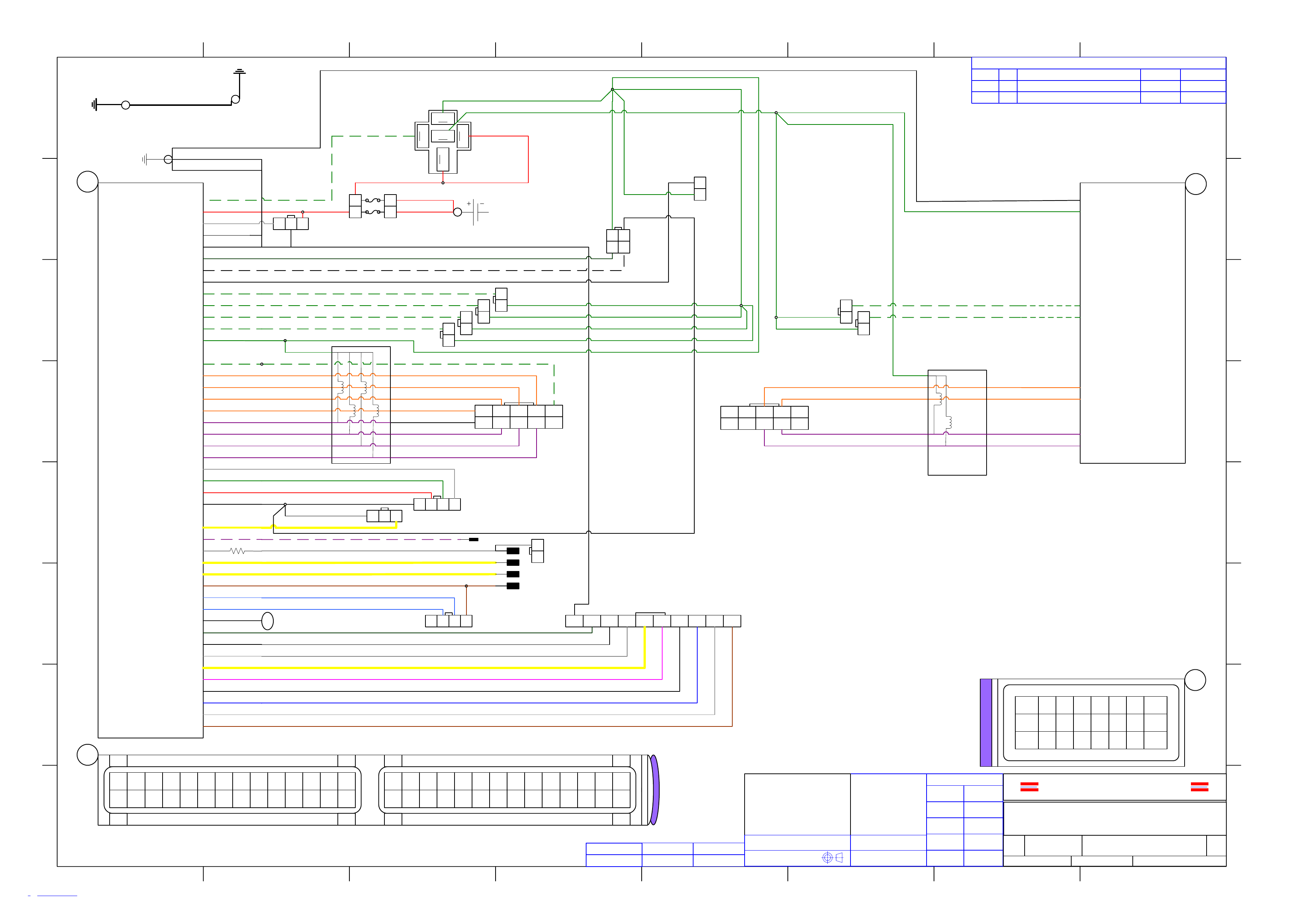
H
G
F
E
D
C
B
A
87654321
H
G
F
E
D
C
B
A
87654321
UNLESS OTHERWISE SPECIFIED
DIMENSIONS ARE IN MM
DECIMAL TOLERANCE .X ± 0.1
.XX ± 0.01
.XXX ±
0.005
ANGULAR TOLERANCE ± 0.2º
FILLET & CORNER RADII 0.03
COPYRIGHT © IMPCO TECHNOLOGIES PTY. LTD.,
ALL RIGHTS RESERVED. NO PART OF THIS
DRAWING TO BE REPRODUCED OR
MANUFACTURED WITHOUT THE CONSENT OF
IMPCO TECHNOLOGIES PTY. LTD.
DATE
21/01/05
DRAWN
TS
DATECHECKED
DATEASS. Q.A.
DATEQ.A.
DATEMFG ENG
APPROVALS
MATERIALMASS KG.
THIRD ANGLE PROJECTION
PART NUMBER USED ONNEXT ASSY
IMPCO® Technologies Pty Ltd
2004 Holden VZ Commodore
Harness Diagram
SIZE FSCM NO DWG NO REV
A3 WIRING COMMODORE V6 COLOR
1.R1.VSD 1
SCALE DNS SHEET 1 OF 2
FINISH
REVISIONS
ZONE REV DESCRIPTION DATE APPROVED
N/A AInitial Drawing 25 MAY 05 TSTANDKE
BV(+) - 27
InjG 1 - 18
InjG 2 - 20
InjG 3 - 21
InjG 4 - 22
TACHO Signal - 39
TPS Signal - 36
5A
87
87
30
85
86
Power Relay Control - 46
Battery Ground - 19
Serial - 9 1 2 3
2 1
4 3
Rear L/O Control - 16
10A
1 2
1 2
1 2
1 2
Fuel Gauge - 7
Front L/O Control - 17
1 2
Rear L/O
& Sender
Front L/O
1 2
1 2
A3 - InjG 5
A4 - InjG 6
10 9 8 7 6
5 4 3 2 1
InjP 1 - 23
InjP 2 - 24
InjP 3 - 25
InjP 4 - 26
InjP 4 ECU - 54
InjP 3 ECU - 53
InjP 2 ECU - 52
InjP 1 ECU - 51
10 98 7 6
5 4 3 2 1
C4 -InjP 6
C3 -InjP 5
B3 - InjP 5 ECU
B4 - InjP 6 ECU
A7 - BV(+)
A8 - Battery Ground
BV(+) From Relay - 28
P1/MAP Supply +V - 2
P1 Signal - 3
MAP Signal - 32
Sensor Return -31
Reg Temp Signal - 4
1 2 3 4
1 2 3
O2/1 Signal - 5
Switch - 47
Switch - 13
Switch - 41
Switch - 48
Switch - 15
Switch - 43
Switch - 42
Switch - 14
Switch - 44
12345678910
GREEN
RED
WHITE
BLACK
GREEN / WHITE
BLACK / GREEN
WHITE / BLACK
BLACK / GREEN
GREEN / WHITE
GREEN / WHITE
GREEN / WHITE
GREEN / WHITE
ORANGE
ORANGE
ORANGE
ORANGE
PURPLE
PURPLE
PURPLE
PURPLE
WHITE
GREEN
RED
BLACK
YELLOW
PURPLE / WHITE
GREY
YELLOW
DK GREEN
PURPLE
GREY
YELLOW
PINK
RED
DK BLUE
WHITE
BROWN
GREEN
BLACK
WHITE / GREEN
WHITE / GREEN
ORANGE
ORANGE
PURPLE
PURPLE
RED
RED
RED
GREEN
GREEN
GREEN
GREEN
GREEN
GREEN
GREEN
GREEN
GREEN
GREEN
Emulator Inj 1..4 Power - 55 GREEN / WHITE GREEN / WHITE
GREEN
GREEN / WHITE
BLACK
ORANGE
ORANGE
ORANGE
ORANGE
PURPLE
PURPLE
PURPLE
PURPLE
BLACK
Battery Ground - 56 BLACK
GREEN
GREEN
ORANGE
ORANGE
PURPLE
PURPLE
RED
12345678910 11 12 13 14
29 30 31 32 33 34 35 36 37 38 39 40 41 42
15 16 17 18 19 20 21 22 23 24 25 26 27 28
43 44 45 46 47 48 49 50 51 52 53 54 55 56
114
29 42
15
43 56
28
B1 B2 B3 B4
A1 A2 A3 A4 A5 A6 A7 A8
B5 B6 B7 B8
C1 C2 C3 C4 C5 C6 C7 C8
A
B
C
A
B
C
18
18234567
234567
J1A
J1A
J1B
J1B
SERIAL COM
POWER RELAY
GAS INJECTORS 1..4 GAS INJECTORS 5..6
INJECTOR EMULATOR 5..6
INJECTOR EMULATOR 1..4
P1 / MAP SIGNAL
REGULATOR TEMPERATURE
SWITCH & LPG FUEL DISPLAY
RED
Shield - 37 METAL
+12V Ke y Contact - 50 BROWN
O2/1 Emulation - 8 LT BLUE
O2/2 Emulation - 35 LT BLUE
O2/2 Signal - 6 YELLOW
1 2
1 2 3 4
Ground onto
ECU Mounting
Bolt
Ground onto
engine earth
N/A BRevised Ground Circuits for Radio RF 16 Aug 05 PNOLEN
R=10k
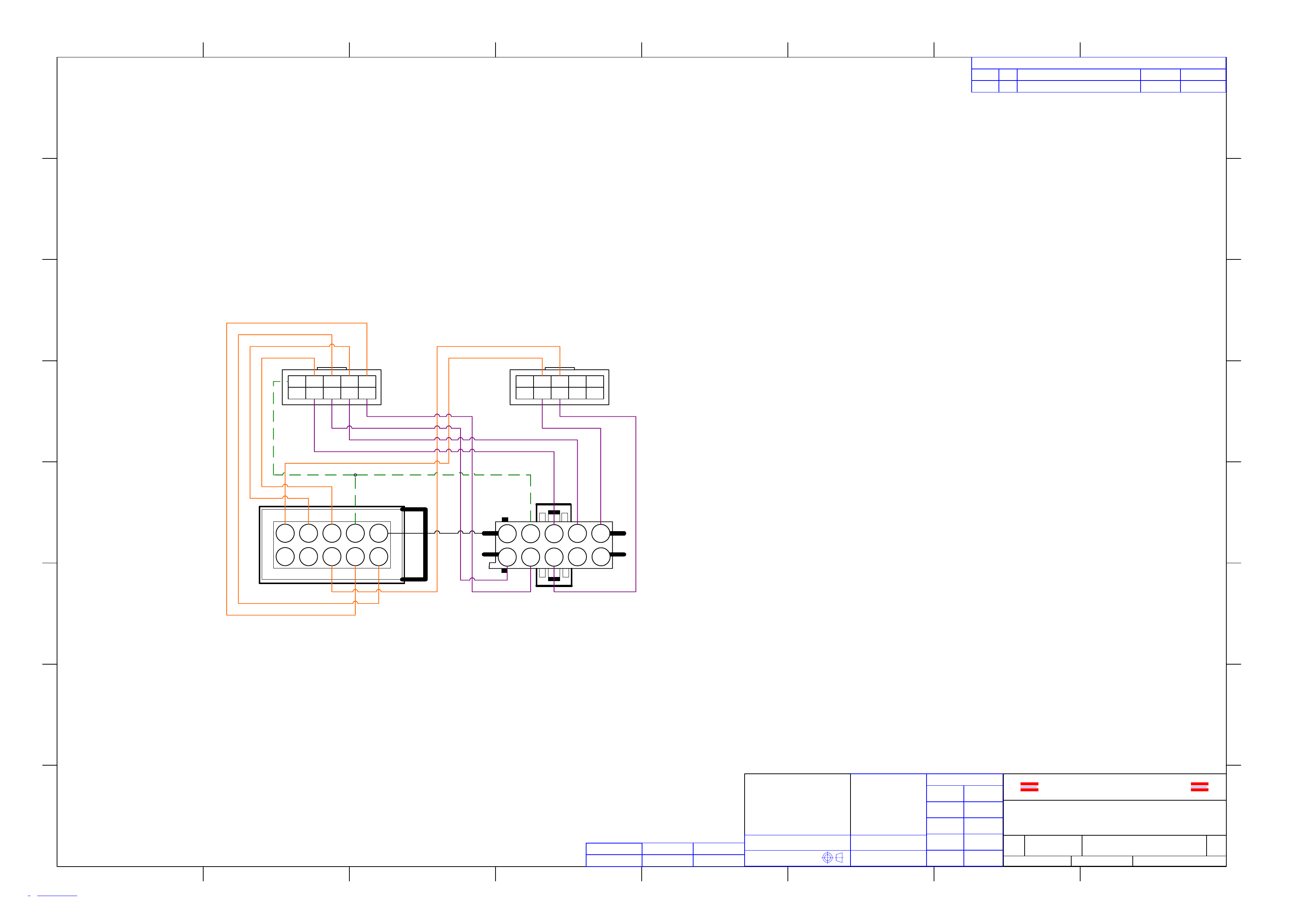
H
G
F
E
D
C
B
A
87654321
H
G
F
E
D
C
B
A
87654321
UNLESS OTHERWISE SPECIFIED
DIMENSIONS ARE IN MM
DECIMAL TOLERANCE .X ± 0.1
.XX ± 0.01
.XXX ±
0.005
ANGULAR TOLERANCE ± 0.2º
FILLET & CORNER RADII 0.03
COPYRIGHT © IMPCO TECHNOLOGIES PTY. LTD.,
ALL RIGHTS RESERVED. NO PART OF THIS
DRAWING TO BE REPRODUCED OR
MANUFACTURED WITHOUT THE CONSENT OF
IMPCO TECHNOLOGIES PTY. LTD.
DATE
21/01/05
DRAWN
TS
DATECHECKED
DATEASS. Q.A.
DATEQ.A.
DATEMFG ENG
APPROVALS
MATERIALMASS KG.
THIRD ANGLE PROJECTION
PART NUMBER USED ONNEXT ASSY
IMPCO® Technologies Pty Ltd
2004 Holden VZ Commodore
Harness Diagram
SIZE FSCM NO DWG NO REV
A3 WIRING COMMODORE V6 COLOR
2.R0.VSD 0
SCALE DNS SHEET 2 OF 2
FINISH
REVISIONS
ZONE REV DESCRIPTION DATE APPROVED
N/A AInitial Drawing 25 MAY 05 TSTANDKE
109876
54321
109876
54321
54321
10 9 8 7 6
1234 5
678910
Emulator 1..4
Connector Emulator 5..6
Connector
WHITE
GREEN / WHITE
VIOLET (1)
VIOLET (3)
VIOLET (5)
VIOLET (6)
VIOLET (4)
VIOLET (2)
GREEN / WHITE
ORANGE (6)
ORANGE (2)
ORANGE (4)
ORANGE (1)
ORANGE (3)
ORANGE (5)