
Exhaust System Page 8B–1
Page 8B–1
Section 8B
Exhaust System
MY06 Supplement
ATTENTION
Before performing any service operation or other procedure described in this Section, refer to 00 Warnings,
Cautions and Notes for correct workshop practices with regard to safety and/or property dama.
1 General Information ...............................................................................................................................3
1.1 Emission Reductions ............................................................................................................................................ 3
1.2 Catalytic Converter................................................................................................................................................ 4
Service Notes......................................................................................................................................................... 5
Euro 3 Emission Standards .................................................................................................................................. 5
1.3 Exhaust System Configurations........................................................................................................................... 6
Alloytec Engine...................................................................................................................................................... 6
Sedan and Wagon.............................................................................................................................................. 6
Utility .................................................................................................................................................................. 7
Regular & Crew Cab – Except AWD.................................................................................................................. 8
AWD Regular & Crew Cab................................................................................................................................. 9
AWD Wagon .................................................................................................................................................... 10
GEN lV V8 Engine ................................................................................................................................................ 11
Sedan............................................................................................................................................................... 11
Utility Regular & Crew Cab............................................................................................................................... 12
2 Service Operations – Alloytec.............................................................................................................13
2.1 Service Notes....................................................................................................................................................... 13
Catalytic Converter.............................................................................................................................................. 13
Oxygen Sensors................................................................................................................................................... 13
2.2 Exhaust System................................................................................................................................................... 14
2.3 Complete Exhaust System Assembly................................................................................................................ 15
Remove................................................................................................................................................................. 15
Reinstall................................................................................................................................................................ 17
2.4 Rear Exhaust Assembly...................................................................................................................................... 18
Remove................................................................................................................................................................. 18
Reinstall................................................................................................................................................................ 18
2.5 Intermediate Exhaust Assembly......................................................................................................................... 19
Remove................................................................................................................................................................. 19
Reinstall................................................................................................................................................................ 19
2.6 Front Exhaust Assembly..................................................................................................................................... 20
Remove................................................................................................................................................................. 20
Reinstall................................................................................................................................................................ 21
2.7 Tightening Sequence........................................................................................................................................... 23
3 Service Operations – GEN lV V8.........................................................................................................25
3.1 Service Notes....................................................................................................................................................... 25
Catalytic Converter.............................................................................................................................................. 25
Oxygen Sensors................................................................................................................................................... 25
3.2 Exhaust System................................................................................................................................................... 26
3.3 Complete Exhaust System Assembly................................................................................................................ 27
Remove................................................................................................................................................................. 27
Reinstall................................................................................................................................................................ 29
Techline

Exhaust System Page 8B–2
Page 8B–2
3.4 Rear Exhaust Assembly...................................................................................................................................... 30
Remove................................................................................................................................................................. 30
Reinstall................................................................................................................................................................ 30
3.5 Intermediate Exhaust Assembly......................................................................................................................... 31
Remove................................................................................................................................................................. 31
Reinstall................................................................................................................................................................ 31
3.6 Front Exhaust Assembly..................................................................................................................................... 32
Remove................................................................................................................................................................. 32
Reinstall................................................................................................................................................................ 33
3.7 Tightening Sequence........................................................................................................................................... 35
4 Service Operations – Heat Shields.....................................................................................................37
4.1 Rear Heat Shield .................................................................................................................................................. 38
Remove................................................................................................................................................................. 38
Reinstall................................................................................................................................................................ 38
4.2 Intermediate Heat Shield..................................................................................................................................... 39
Remove................................................................................................................................................................. 39
Reinstall................................................................................................................................................................ 39
4.3 Front Heat Shield – Underbody Mounted........................................................................................................... 40
Remove................................................................................................................................................................. 40
Reinstall................................................................................................................................................................ 40
4.4 Front On-Pipe Heat Shield – Pre-catalytic Converter ....................................................................................... 41
Remove................................................................................................................................................................. 41
Reinstall................................................................................................................................................................ 41
4.5 Front On-Pipe Heat Shield – Post-catalytic Converter ..................................................................................... 42
Remove................................................................................................................................................................. 42
Reinstall................................................................................................................................................................ 42
5 Exhaust System Diagnosis .................................................................................................................43
6 Specifications.......................................................................................................................................44
7 Torque Wrench Specifications............................................................................................................45
8 Special Tools ........................................................................................................................................46

Exhaust System Page 8B–3
Page 8B–3
1 General Information
The following section is an MY06 supplement to the current MY05 8B Exh aust System section. For procedures regarding
MY05 Exhaust System, refer to MY05 Section 8B Exhaust System.
For MY06 vehicles, many different exhaust s ystem configurations are ava ilable depending on engine, body type and
model specification. All feature close-coupled catalytic converters to improve warm-up response and reduce emissions,
and either single or dual pipe configurations; or a combination of both.
1.1 Emission Reductions
Through developments in various vehicle emission reduction systems, significant reductions in emissions have bee n
achieved. The developments have been primarily concern ed with refinements in engine calibratio n and the optimisation
of exhaust system catalytic converter configurations.
Exhaust System Page 8B–4
Page 8B–4
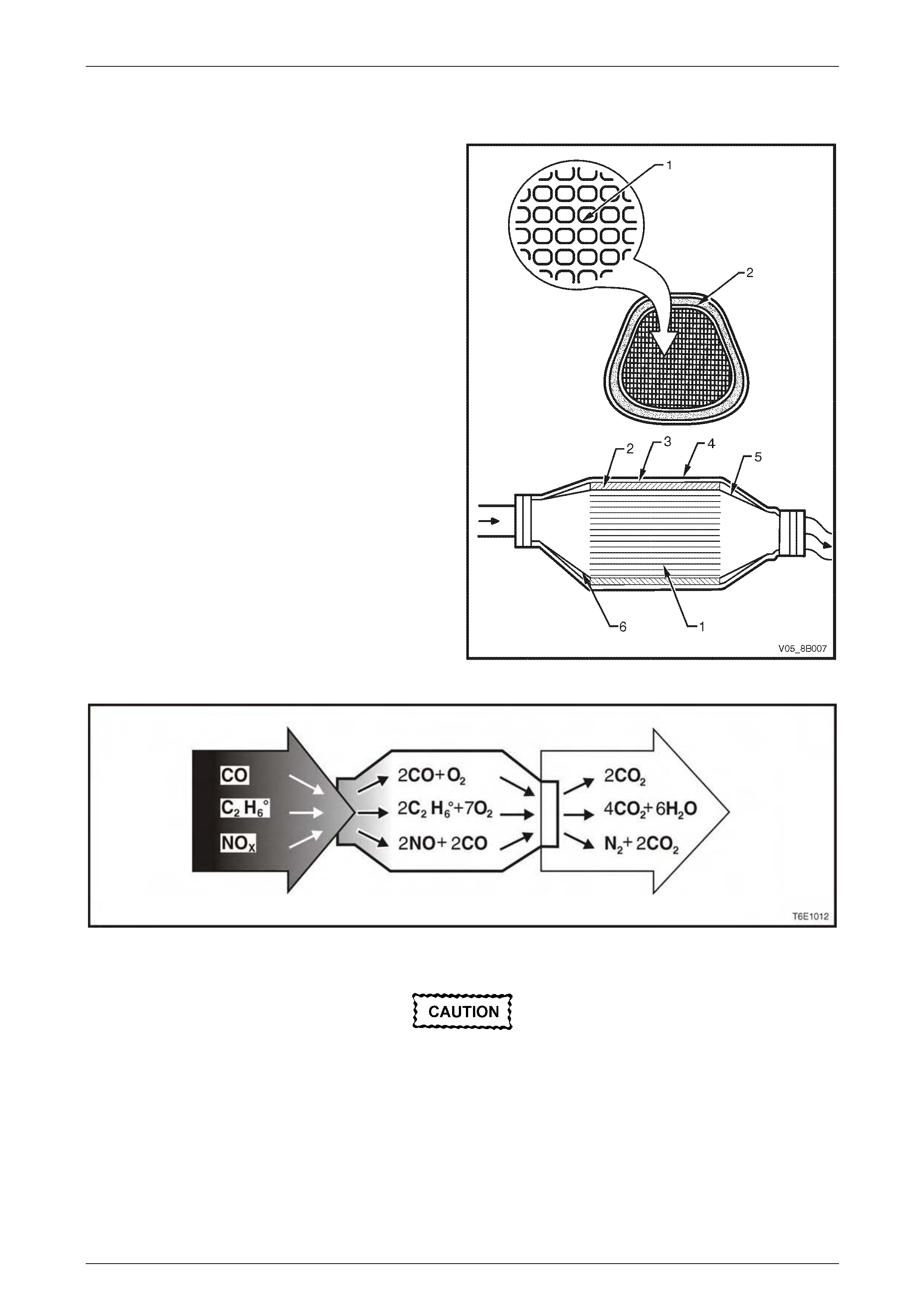
1.2 Catalytic Converter
The catalytic converter is similar to a muffler in appearance
however, within the outer stainless steel shell (4), there is a
ceramic monolith (1) which is hon eycombed in the direction
of exhaust flow, as shown. The ceramic monolith is
surrounded by a mat (2), which has the primary function of
holding the monolith firmly in place. This prevents any
contact between the monolith and the inner shell (3) and
also insulates the inner shell. Inner cones (5 and 6) at each
end of the converter direct the exhaust gases into the
ceramic monolith to prevent fouling and erosion of the mat.
Surfaces of the ceramic monolith that are exposed to
exhaust gases are coated with a catalytic material. This
material contains platinum an d / or palla dium and rhodium,
which act to facilitate the chemical reactions necessary to
oxidise carbon monoxide and hydrocarbons into harmless
carbon dioxide.
The catalytic converter is a substanc e that accelerates a
chemical reaction without itself being changed. Engine
exhaust gases contain carbon monoxide (CO),
hydrocarbons (HC) and oxide s of nitrogen (NOx). When the
exhaust gases flow through the monolith, reactions with the
catalytic converter occur. CO and HC are converted by
oxidation with oxygen (O2) in the exhaust gases to produce
carbon dioxide (CO2) and water vapour (H2O). NOx is
converted by reduction with CO to produce nitrog en (N2)
and CO2.
The converter is called a three- way type because it
simultaneously converts three components of exhaust gas
(CO, HC and NOx) to harmless natural gases, refer to
Figure 8B – 2.
Figure 8B – 1
Figure 8B – 2
Catalytic converter can be damaged or
rendered ineffective, if:
• fuel containing MMF (Methyl-
cyclopentadiesyl Manganese) is used
• engine misfires and unburnt fuel reaches
the converter
• the engine burns excessive amount of oil
• the exhaust temperature at the converter
is too high (exceeds 950°C).

Exhaust System Page 8B–5
Page 8B–5
The catalytic material is very sensitive to the effects of a rich or lean fuel mixture, which may cause the temperature of
the converter to rise rapidly. The catalytic converter normally operates at approximately 500°C to 850°C.
The catalytic converter is also sensitive to the use of leaded petrol. Using leaded fuel can cause deposits to form in the
converter, which restrict exhaust flow and prevent the catalyst from working. This will result in an increase in exhaust
backpressure and converter t emperature.
NOTE
The use of unleaded petrol results in black
tailpipe deposits rather than the grey colour that
some people may associate with an acceptable
combustion condition. This black colour resulting
from the use of unleaded fuel does not
necessarily indicate a state of poor engine tune.
For V6 engines refer to Section 6C1-1 Engine
Management – V6 – General Information, for
GEN lV V8 engines refer to Section 6C4-1
Powertrain Management – GEN lV V8 – General
Information for more information regarding this
topic.
Service Notes
1 Vehicles fitted with catalytic converters should not be operated with leaded petrol. Lead will contaminate the
ceramic monolith
2 Do not drop the catalytic converter as it will damage the ceramic monolith.
3 Replace the catalytic converter if it is damaged.
4 Do not allow water, oil or fuel to enter the converter, as the ceramic monolit h will be contaminated.
5 Do not use engine and/or fuel additives unless approved by General Motors. Many additives contain ph osphorous
that will contaminate the ceramic monolith.
6 The vehicle must not be started by pushing or towing, as unburned fuel could reach the catalytic converter and
destroy the ceramic monolith. Always use jumper leads to start a vehicle that has a flat or defective battery.
7 When carrying out a compression test, for V6 engines use Tech 2 to ensure the output control Engine
Compression Test is set to enable, refer to Section 6A1 Engine Mechanical – V6. For GEN lV V8 engines remove
the Engine Control Relay R4 from the engine compartment fuse and relay panel assembly, refer to
Section 6A4 Engine Mechanical – GEN lV V8. This prevents fuel injection and ignition d uring engine cranking.
8 Do not drive the vehicle with the engine misfiring or with any of the spark plug leads d isconnected, as the catalytic
converter will overheat.
9 Do not coast downhill with the engine misfiri ng or with any of the spark plug leads disconnected.
10 The catalytic converter is serviceable as part of the front exhaust assembly only. Refer to the service operations in
this section for details of front exhaust pipe assembly rem oval and reinstallation.
Euro 3 Emission Standards
The Euro 3 emissions standard is a Europ ean standard which aims at setting vehicle emissions targets to encourage
vehicle manufacturers to reduce harmful vehi cle emissions such as Carbon Monoxide (CO), Hydrocarbons (HC) and the
various oxides of Nitrogen (NOx).
Exhaust System Page 8B–6
Page 8B–6
1.3 Exhaust System Configurations
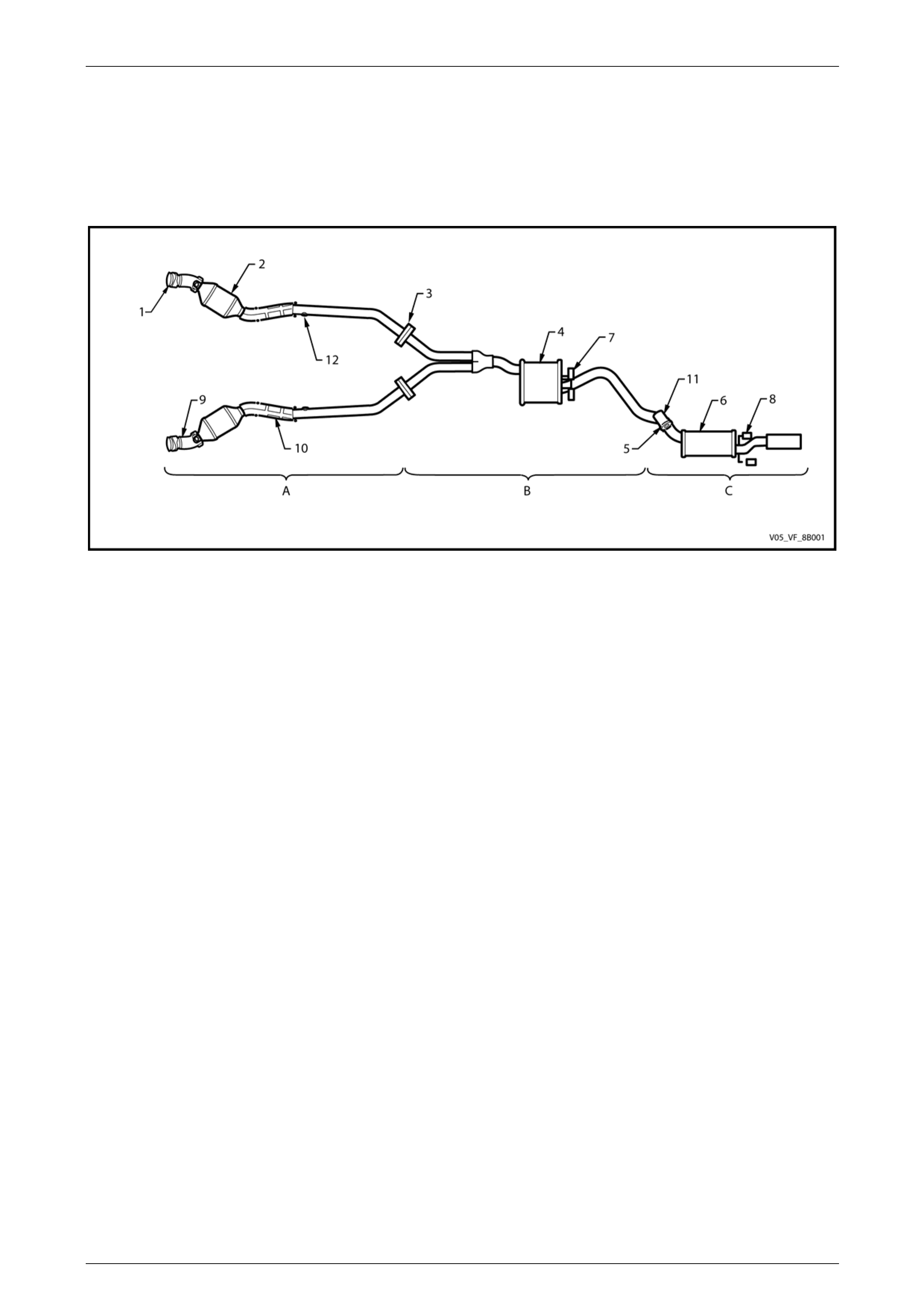
Alloytec Engine
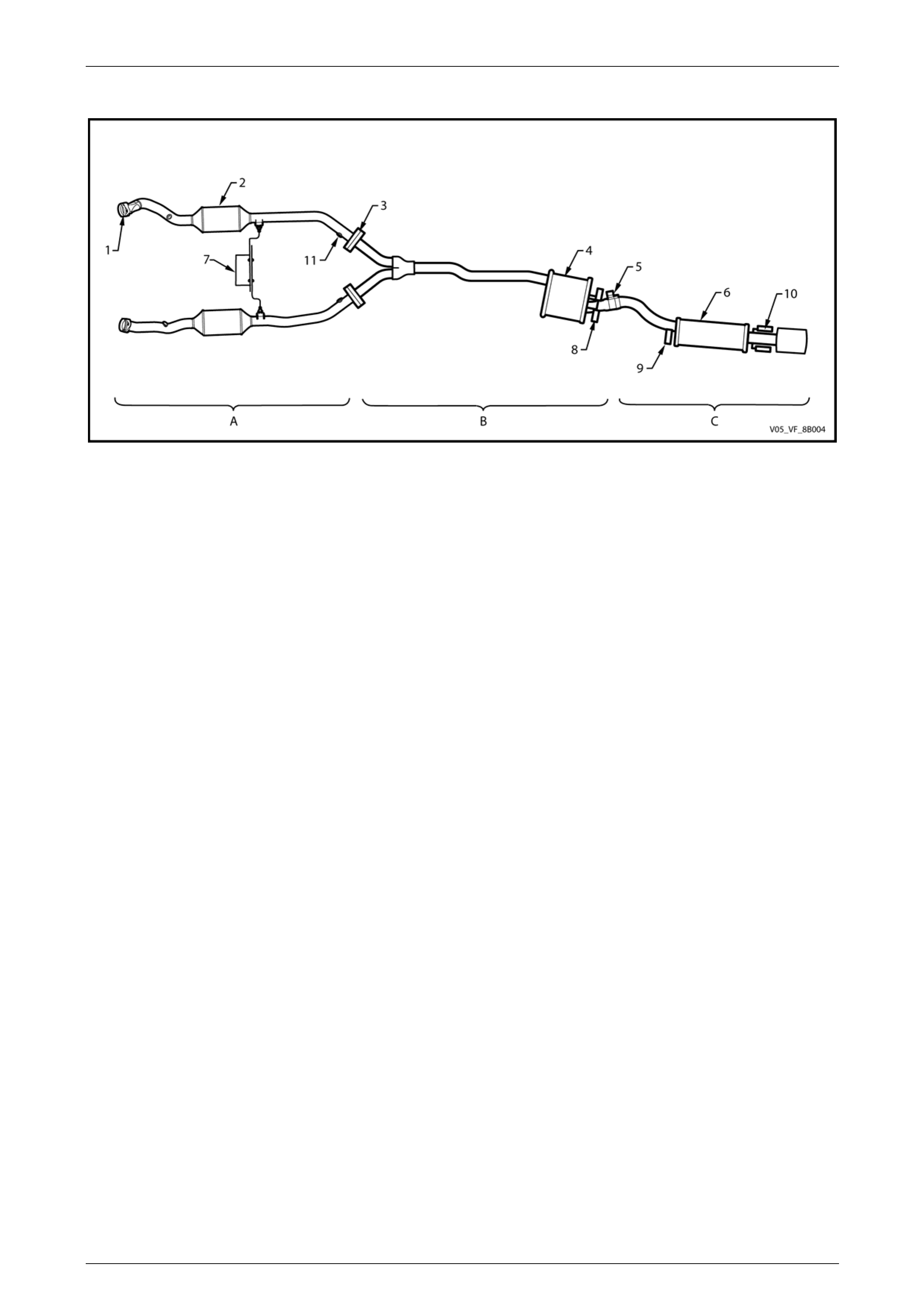
Sedan and Wagon
Figure 8B – 3
Legend
A Front Exhaust Assembly
B Intermediate Exhaust Assembly
C Rear Exhaust Assembly
1 Manifold to Front Pipe Flange Joint
2 Catalytic Converter
3 Front to Intermediate Pipe Flange Joint
4 Intermediate Muffler
5 Intermediate to Rear Pipe Slip Joint
6 Rear Muffler
7 Intermediate Muffler Support Pegs and Rubbers
8 Rear Muffler Support Pegs and Rubbers
9 Pre-catalytic Converter Heat Shields and Oxygen Sensor Mounting Boss
10 Post-catalytic Converter Heat Shields
11 Tuned Vibration Absorber
12 Rear Oxygen Sensor Mounting Boss
Exhaust System Page 8B–7
Page 8B–7
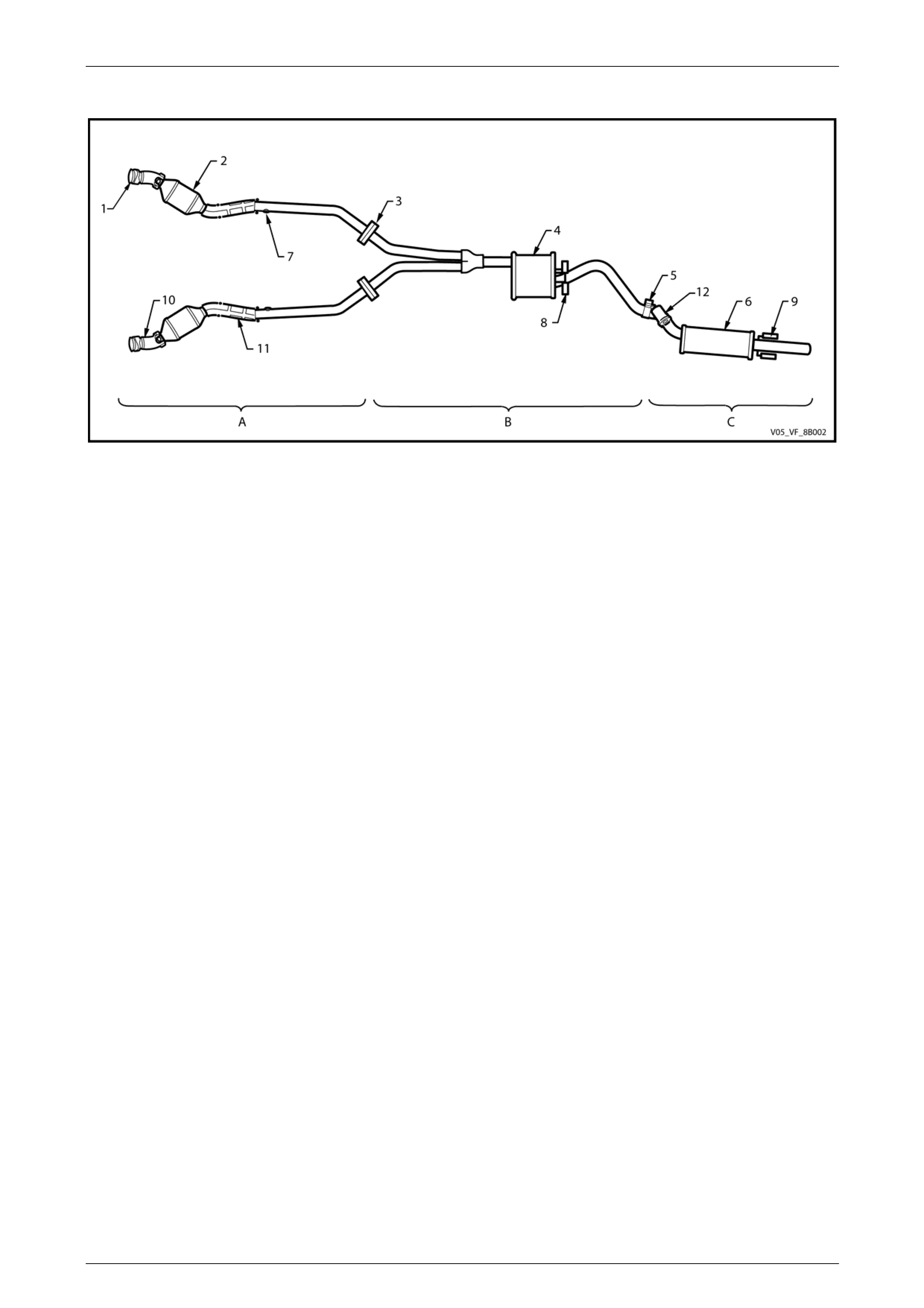
Utility
Figure 8B – 4
Legend
A Front Exhaust Assembly
B Intermediate Exhaust Assembly
C Rear Exhaust Assembly
1 Manifold to Front Pipe Flange Joint
2 Catalytic Converter
3 Front to Intermediate Pipe Flange Joint
4 Intermediate Muffler
5 Intermediate to Rear Pipe Slip Joint
6 Rear Muffler
7 Rear Oxygen Sensor Mounting Boss
8 Intermediate Muffler Support Pegs and Rubbers
9 Rear Muffler Support Pegs and Rubbers
10 Pre-catalytic Converter Heat Shields and Oxygen Sensor Mounting Boss
11 Post-catalytic Converter Heat Shields
12 Tuned Vibration Absorber
Exhaust System Page 8B–8
Page 8B–8
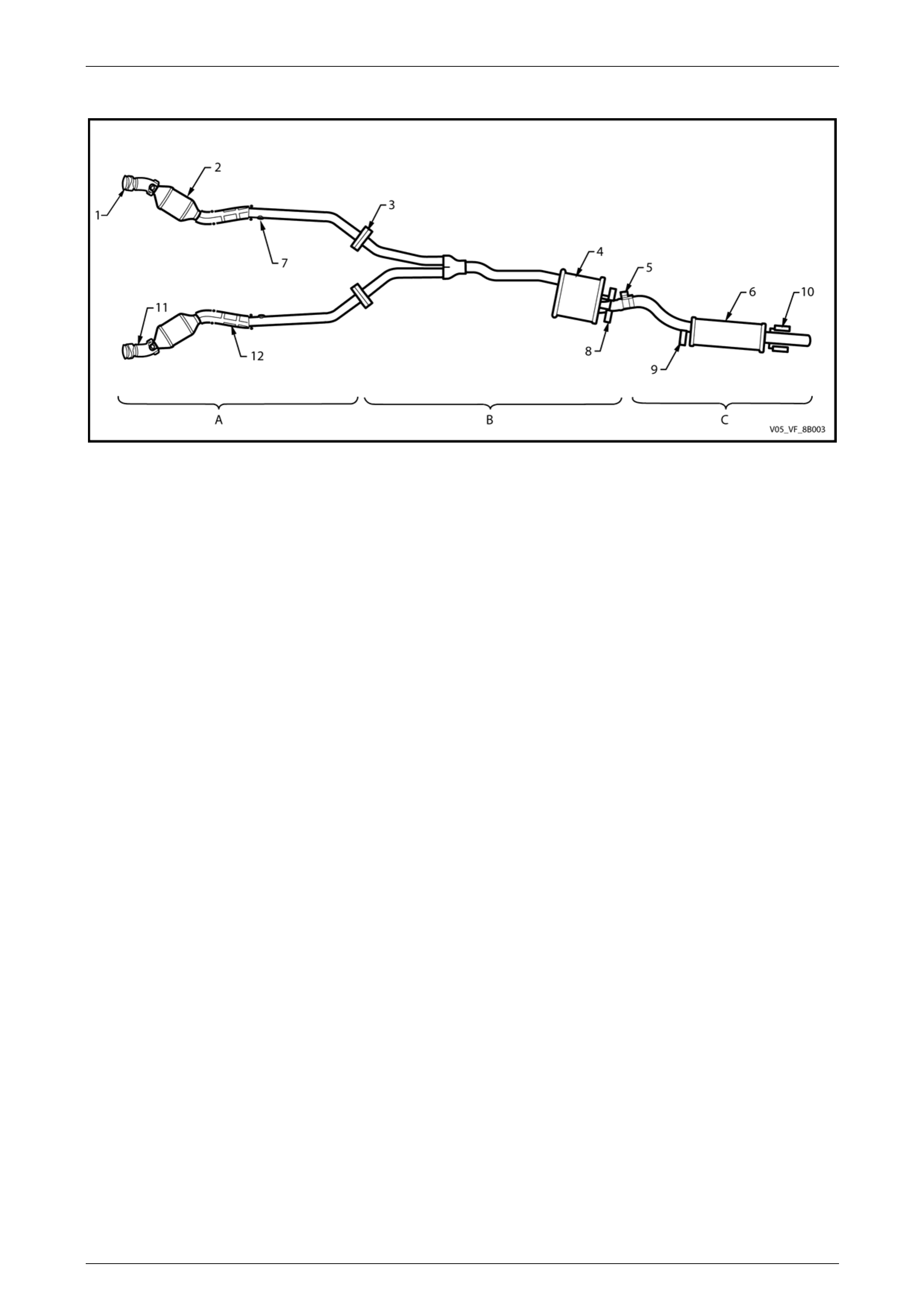
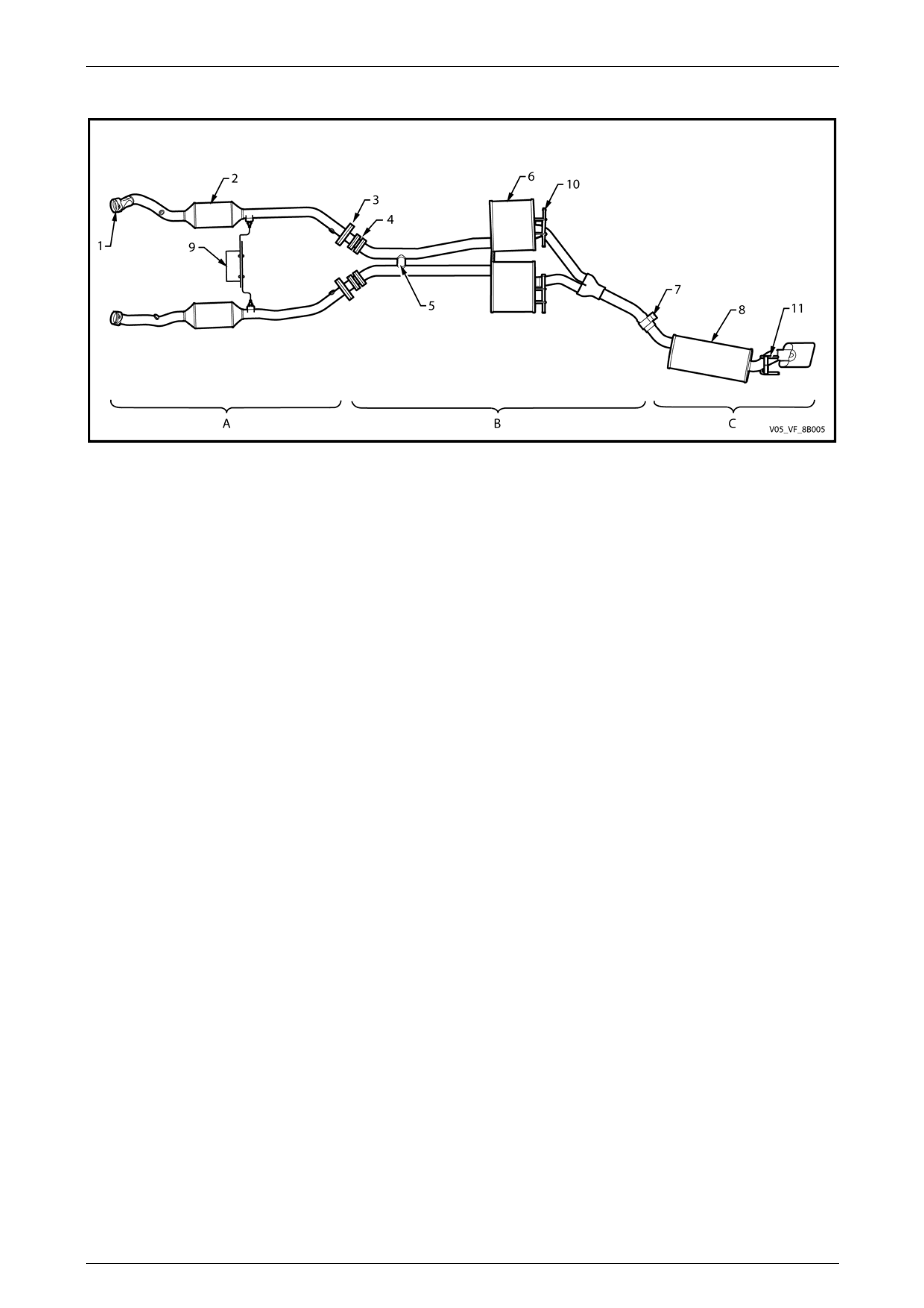
Regular & Crew Cab – Except AWD
Figure 8B – 5
Legend
A Front Exhaust Assembly
B Intermediate Exhaust Assembly
C Rear Exhaust Assembly
1 Manifold to Front Pipe Flange Joint
2 Catalytic Converter
3 Front to Intermediate Pipe Flange Joint
4 Intermediate Muffler
5 Intermediate to Rear Pipe Slip Joint
6 Rear Muffler
7 Rear Oxygen Sensor Mounting Boss
8 Intermediate Muffler Support Pegs and Rubbers
9 Rear Muffler Front Support Peg and Rubber
10 Rear Muffler Rear Support Pegs and Rubbers
11 Pre-catalytic Converter Heat Shields and Oxygen Sensor
Mounting Boss
12 Post-catalytic Converter Heat Shields
Exhaust System Page 8B–9
Page 8B–9
AWD Regular & Crew Cab
Figure 8B – 6
Legend
A Front Exhaust Assembly
B Intermediate Exhaust Assembly
C Rear Exhaust Assembly
1 Manifold to Front Pipe Flange Joint
2 Catalytic Converter
3 Front to Intermediate Pipe Flange Joint
4 Intermediate Muffler
5 Intermediate to Rear Pipe Slip Joint
6 Rear Muffler
7 Cross Brace and Transmission Mount
8 Intermediate Muffler Support Pegs and Rubbers
9 Rear Muffler Front Support Peg and Rubber
10 Rear Muffler Rear Support Pegs and Rubbers
11 Rear Oxygen Sensor Mounting Boss
Exhaust System Page 8B–10
Page 8B–10
AWD Wagon
Figure 8B – 7
Legend
A Front Exhaust Assembly
B Intermediate Exhaust Assembly
C Rear Exhaust Assembly
1 Manifold to Front Pipe Flange Joint
2 Catalytic Converter
3 Front to Intermediate Pipe Flange Joint
4 Flexible Section
5 Balance Pipe
6 Intermediate Muffler
7 Intermediate to Rear Pipe Slip Joint
8 Rear Muffler
9 Cross Brace and Transmission Mount
10 Intermediate Muffler Support Pegs and Rubbers
11 Rear Muffler Support Pegs and Rubbers
Exhaust System Page 8B–11
Page 8B–11
GEN lV V8 Engine
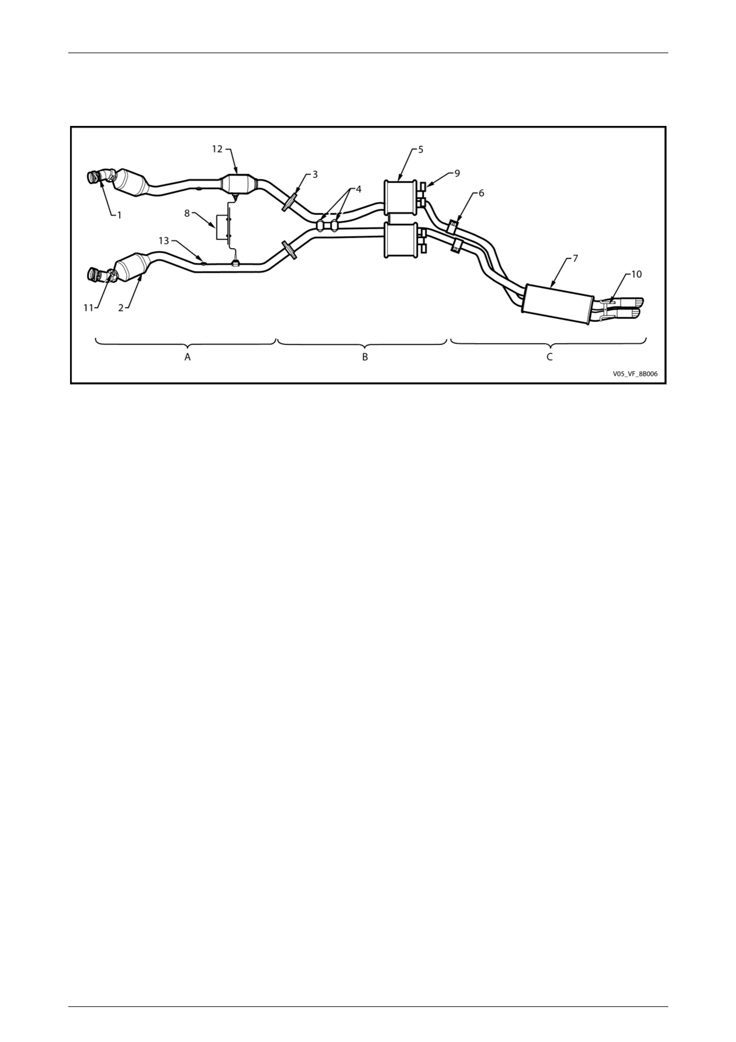
Sedan
Figure 8B – 8
Legend
A Front Exhaust Assembly
B Intermediate Exhaust Assembly
C Rear Exhaust Assembly
1 Manifold to Front Pipe Flange Joint
2 Catalytic Converter
3 Front to Intermediate Pipe Flange Joint
4 Balance Pipe
5 Intermediate Muffler
6 Intermediate to Rear Pipe Slip Joint
7 Rear Muffler
8 Cross Brace and Transmission Mount
9 Intermediate Muffler Support Pegs and Rubbers
10 Rear Muffler Support Pegs and Rubbers
11 Pre-catalytic Converter Heat Shields and Oxygen Sensor Mounting Boss
12 Resonator
13 Rear Oxygen Sensor Mounting Boss
Exhaust System Page 8B–12
Page 8B–12
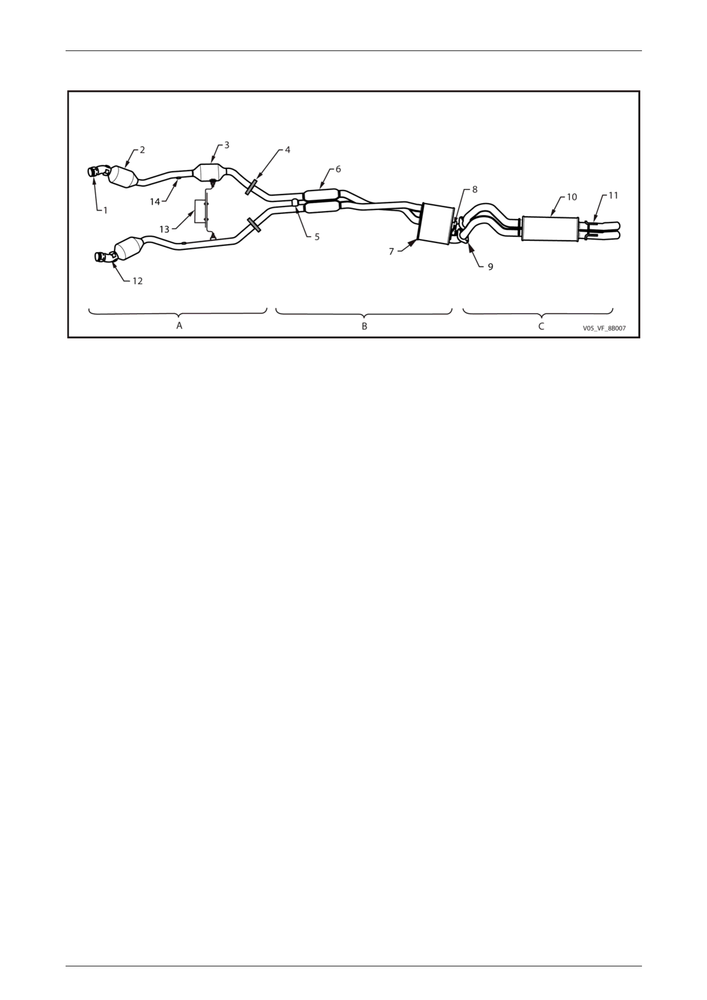
Utility Regular & Cre w Cab
Figure 8B – 9
Legend
A Front Exhaust Assembly
B Intermediate Exhaust Assembly
C Rear Exhaust Assembly
1 Manifold to Front Pipe Flange Joint
2 Catalytic Converter
3 Resonator
4 Front to Intermediate Pipe Flange Joint
5 Balance Pipe
6 Resonator
7 Intermediate Muffler
8 Intermediate Muffler Support Pegs and Rubbers
9 Intermediate to Rear Pipe Slip Joint
10 Rear Muffler
11 Rear Muffler Rear Support Pegs and Rubbers
12 Pre-catalytic Converter Heat Shields and Oxygen Sensor Mounting Boss
13 Cross Brace and Transmission Mount
14 Rear Oxygen Sensor Mounting Boss
Exhaust System Page 8B–13
Page 8B–13
2 Service Operations – Alloytec
2.1 Service Notes
Care must be taken to install each component in the correct relationship with the other components. Ensure the correct
assembly, reinstallation, tighteni ng sequence, tightening torque and clearances are observed.
The incorrect assembly of exhaust system
components can frequently be the cause of
rattles and booms due to incorrect alignment
or clearance of body or suspension parts.
Ensure the correct tightening sequence is
observed upon reinstallation of exhaust
system components.
NOTE
Service operations on exhaust system
components must be carried out with all parts at
ambient temperatures to ensure that correct
clearances are maintai ned.
Catalytic Converter
Catalytic converters are serviced as part of the complete front exhaust pipe assembly only .
NOTE
If removing or replacing the c atalytic converter as
part of a complete front pipe assembly, always
check the flange gaskets for damag e and replace
if required.
Oxygen Sensors
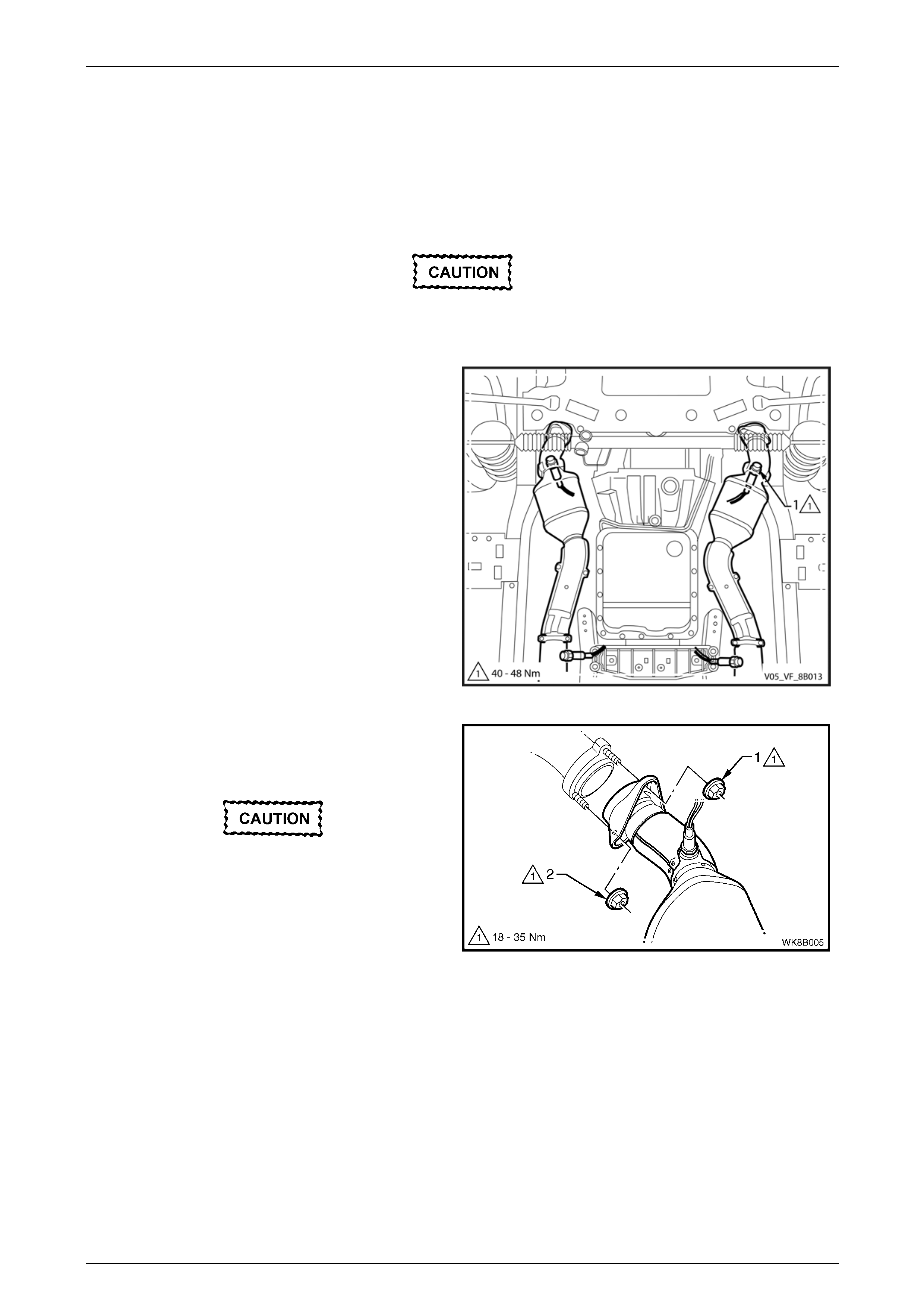
When removing the front exhaust pipes, it is necessary to
disconnect the wiring harness connector from each oxygen
sensor (1). For oxygen sensor replacement, refer to
Section 6C1-3 Engine Management – V6 –Service
Operations.
NOTE
Where it is necessary to remove oxygen
sensors from the exhaust pipe assembly, tag
each oxygen sensor to aid correct replacement.
Figure 8B – 10
Exhaust System Page 8B–14
Page 8B–14
2.2 Exhaust System
The following service operations shou ld be referred to when conducting work on Alloytec exhaust systems.
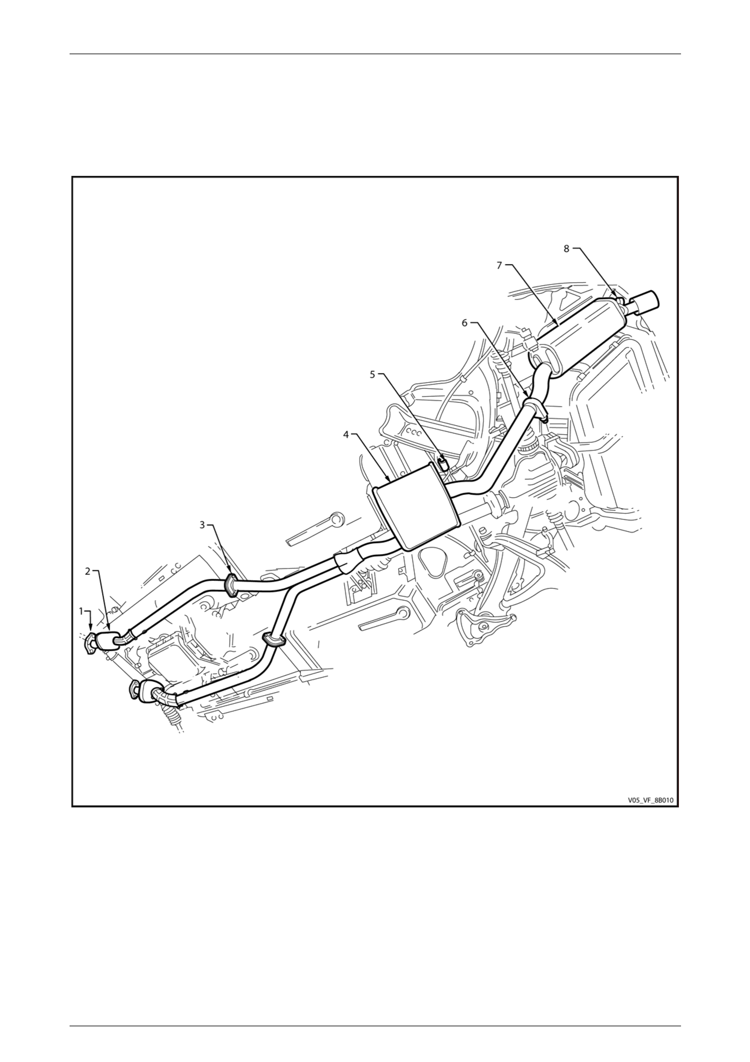
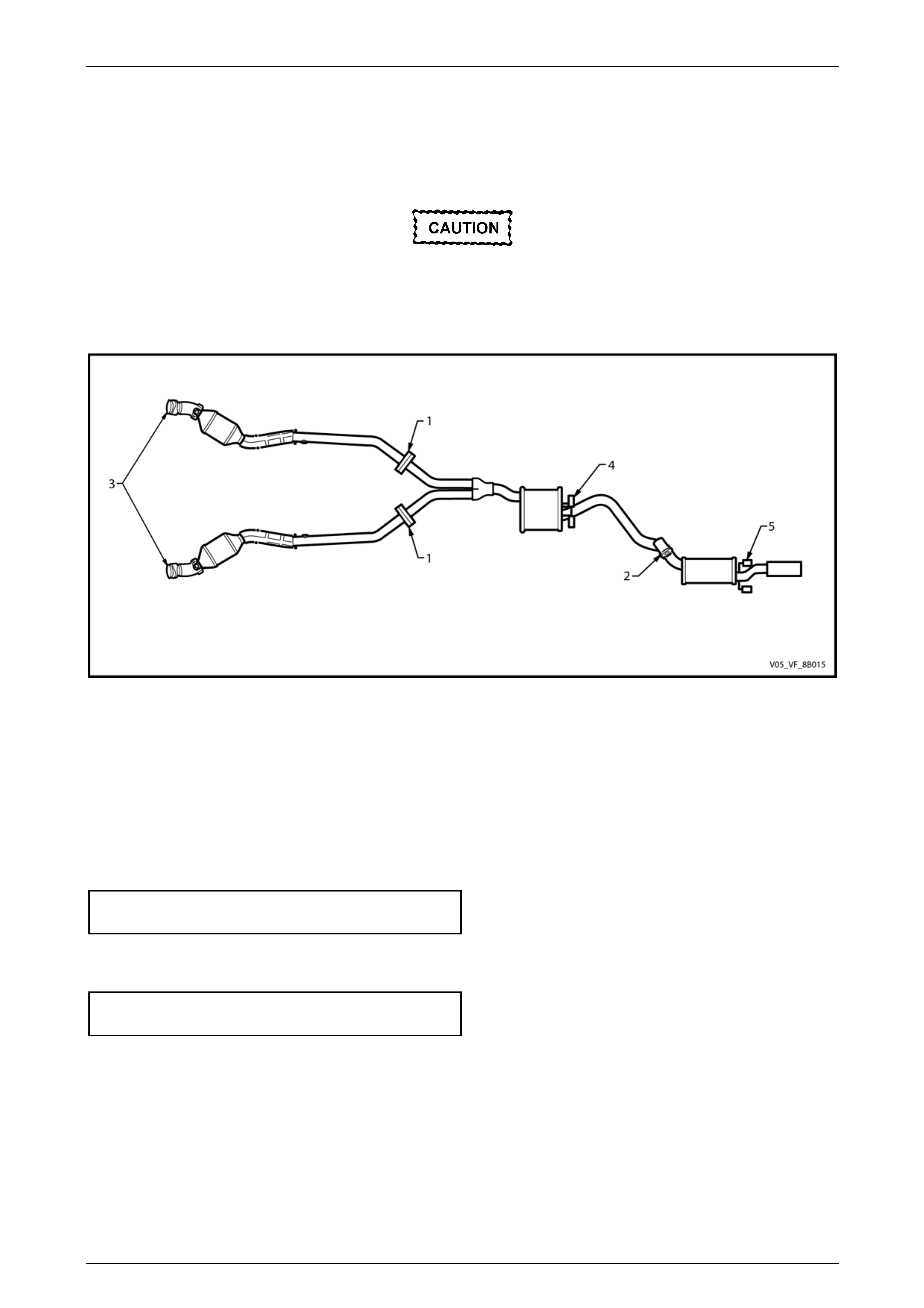
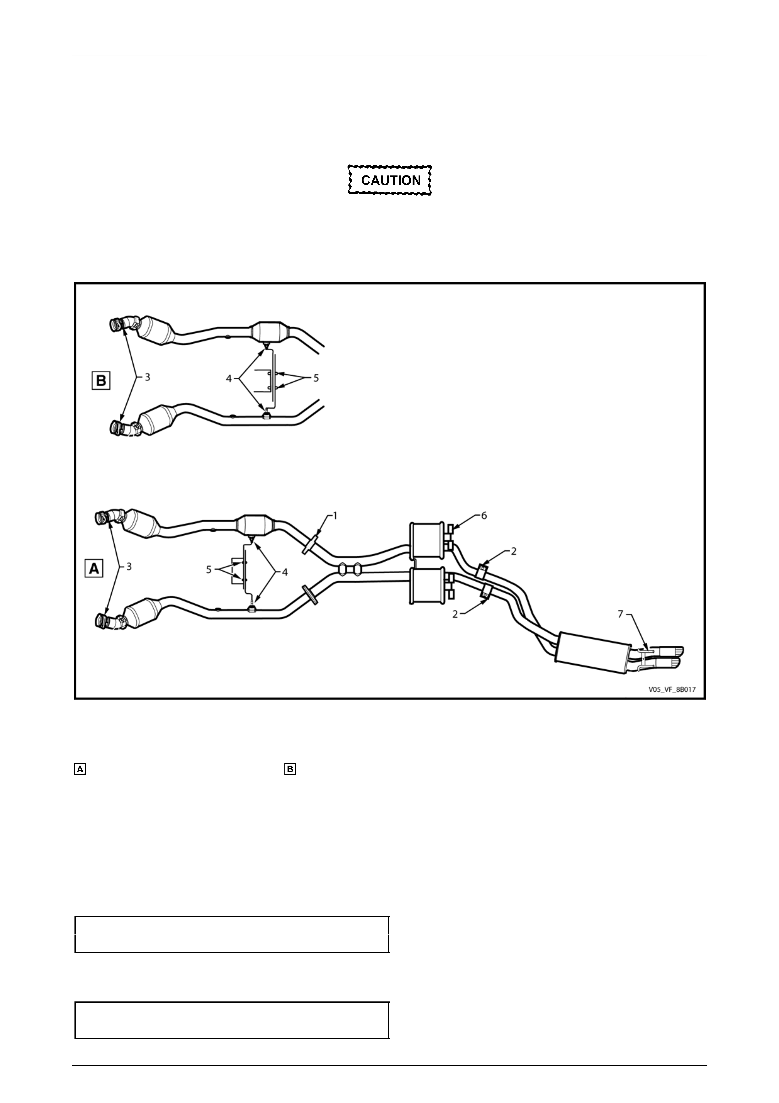
Figure 8B – 11 illustrates a typical exhaust system fitted to vehicles with an Alloytec engine, for other configurations refer
to 1.3 Exhaust System Configuratio ns.
Figure 8B – 11
Legend
1 Manifold to Front Pipe Flange Joint
2 Catalytic Converter
3 Front pipe to Intermediate Pipe Flange Joint
4 Intermediate Muffler
5 Intermediate Muffler Support Rubbers
6 Intermediate to Rear Pipe Slip Joint and U-clamp
7 Rear Muffler
8 Rear Muffler Support Rubbers
Exhaust System Page 8B–15
Page 8B–15
2.3 Complete Exhaust System Assembly
LT Section No. — 03–750
Remove
Ensure the exhaust assembly is properly
supported to avoid damage and undue stress
on the system.
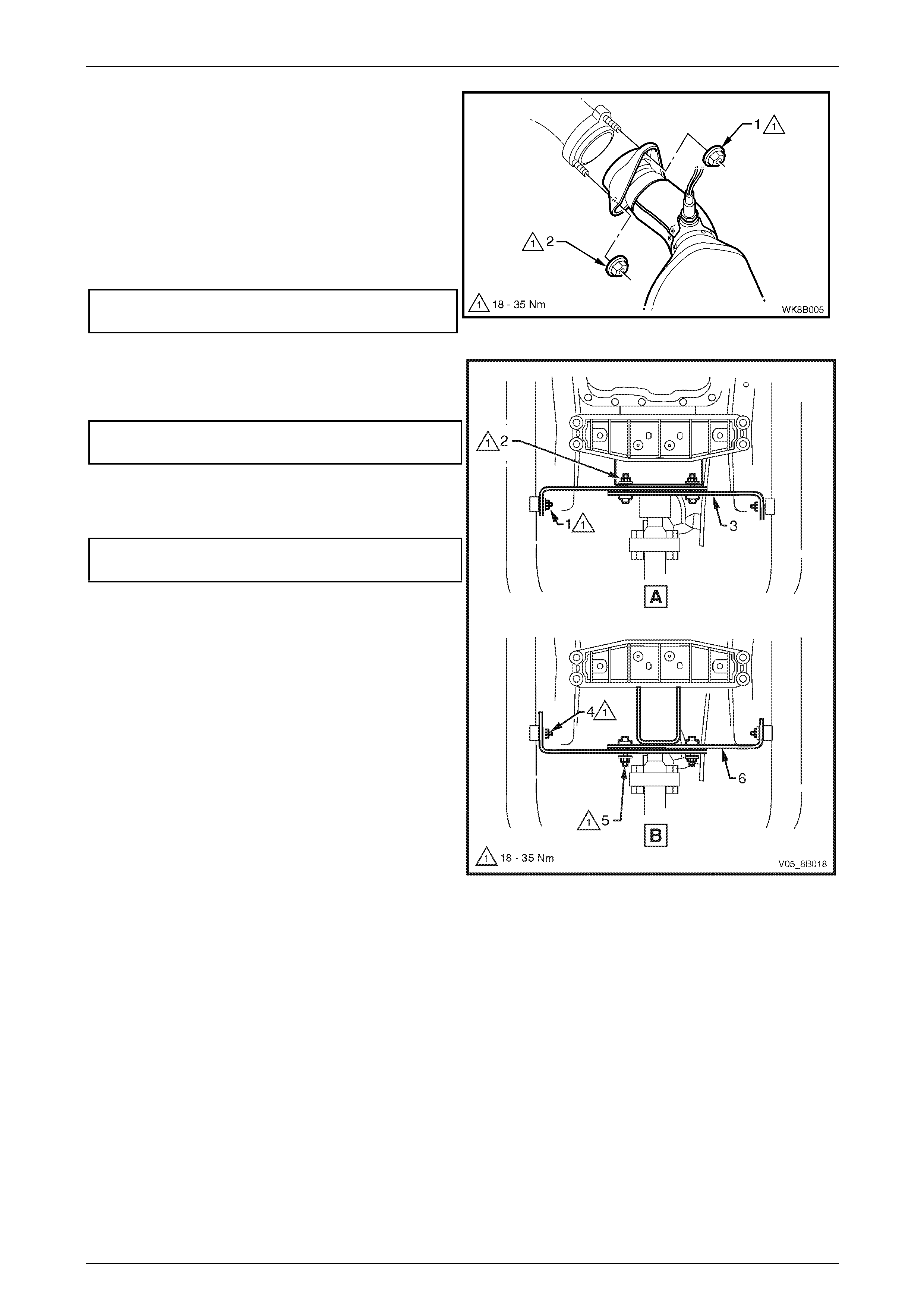
1 Disconnect the wiring harness connector from each
oxygen sensor (1).
NOTE
Automatic transmission shown, manual
transmission similar.
Figure 8B – 12
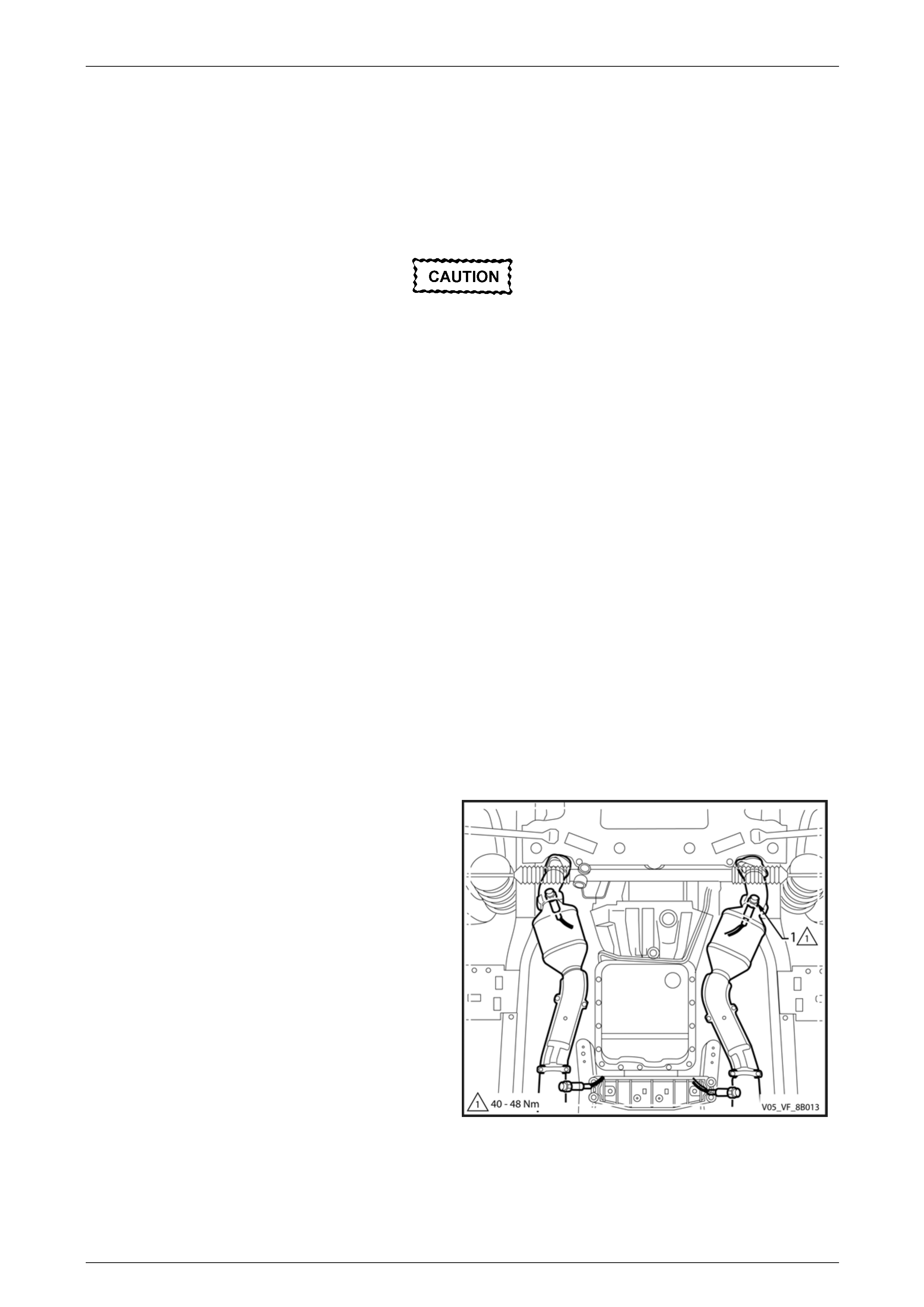
2 Support the exhaust system.
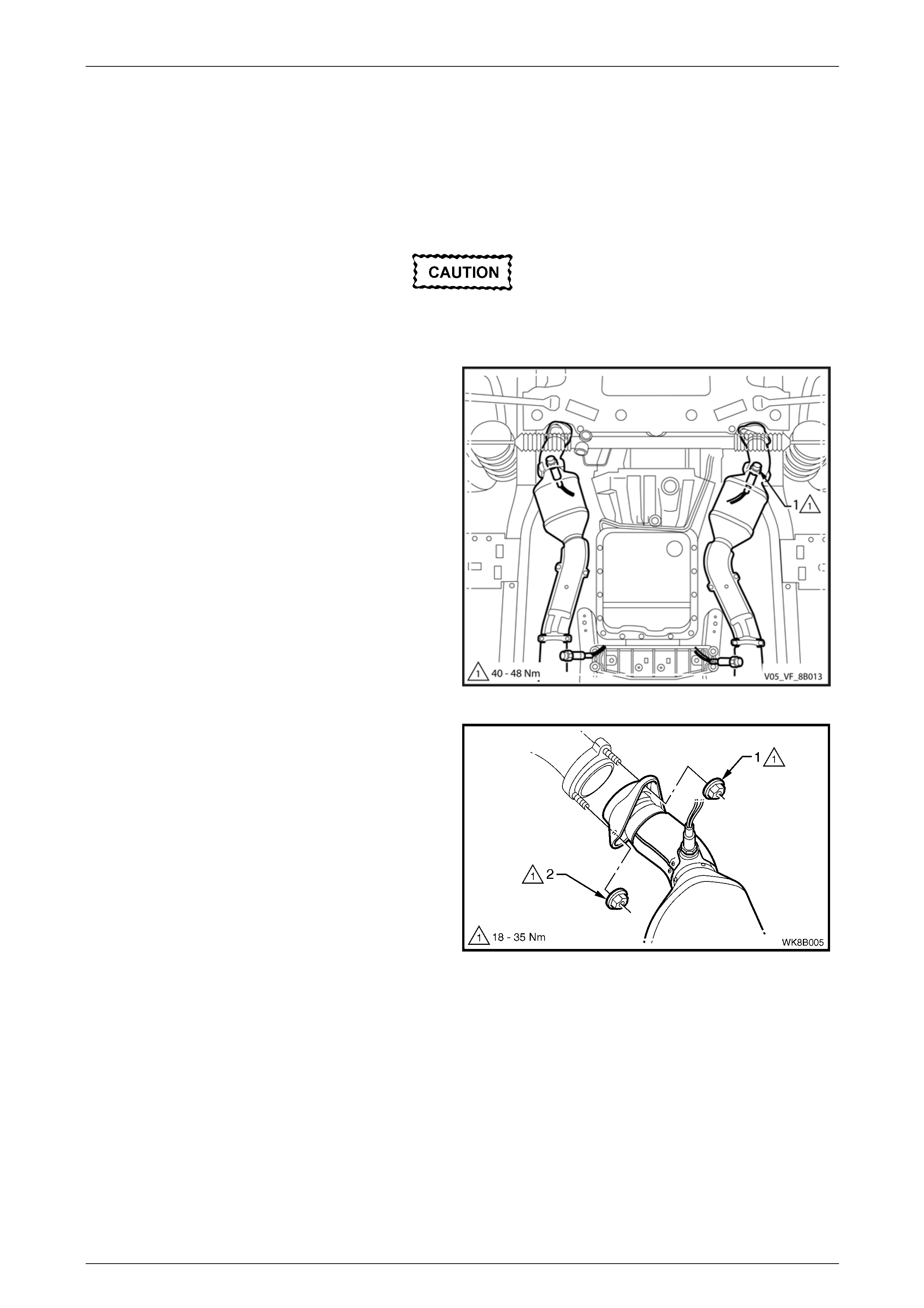
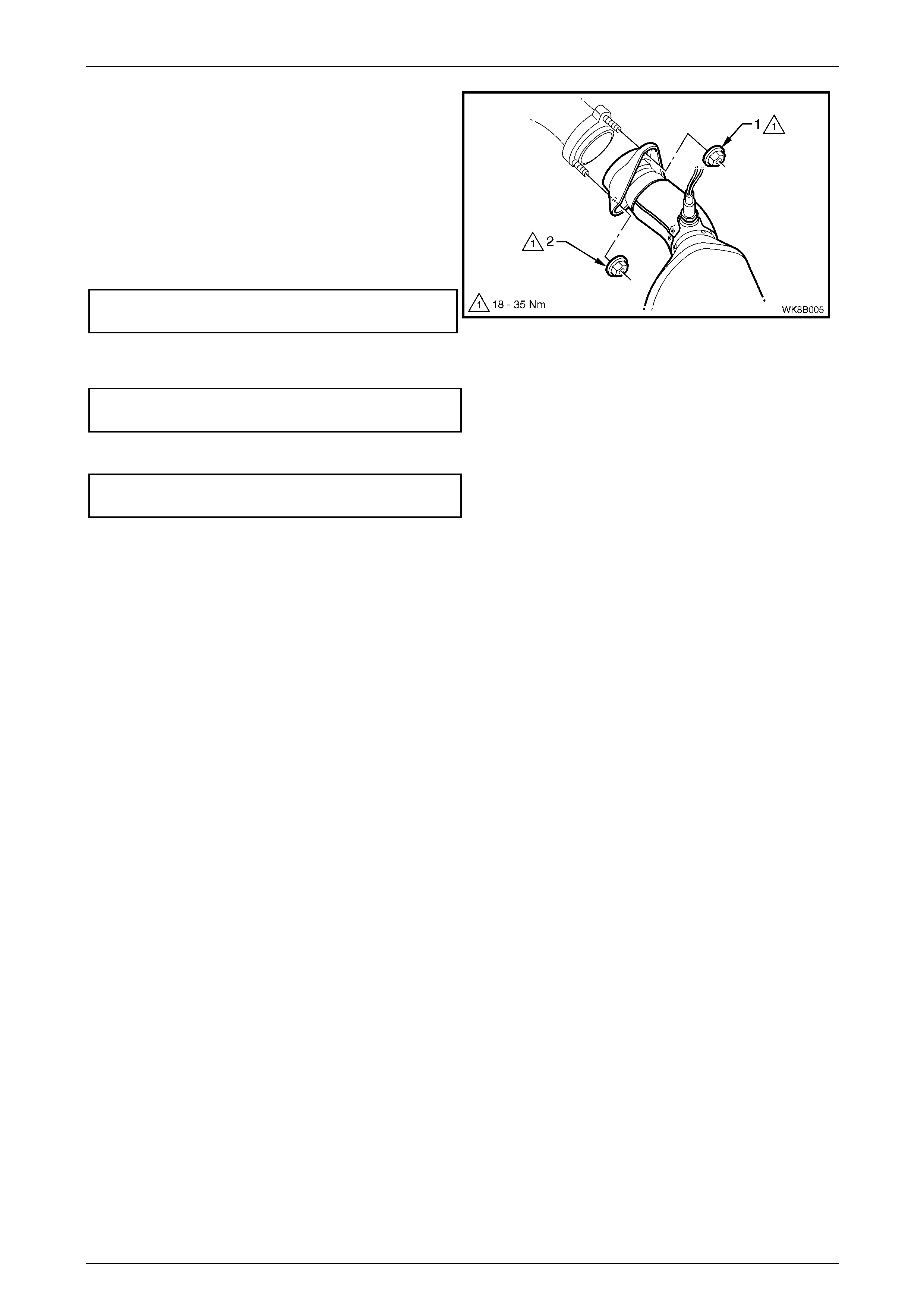
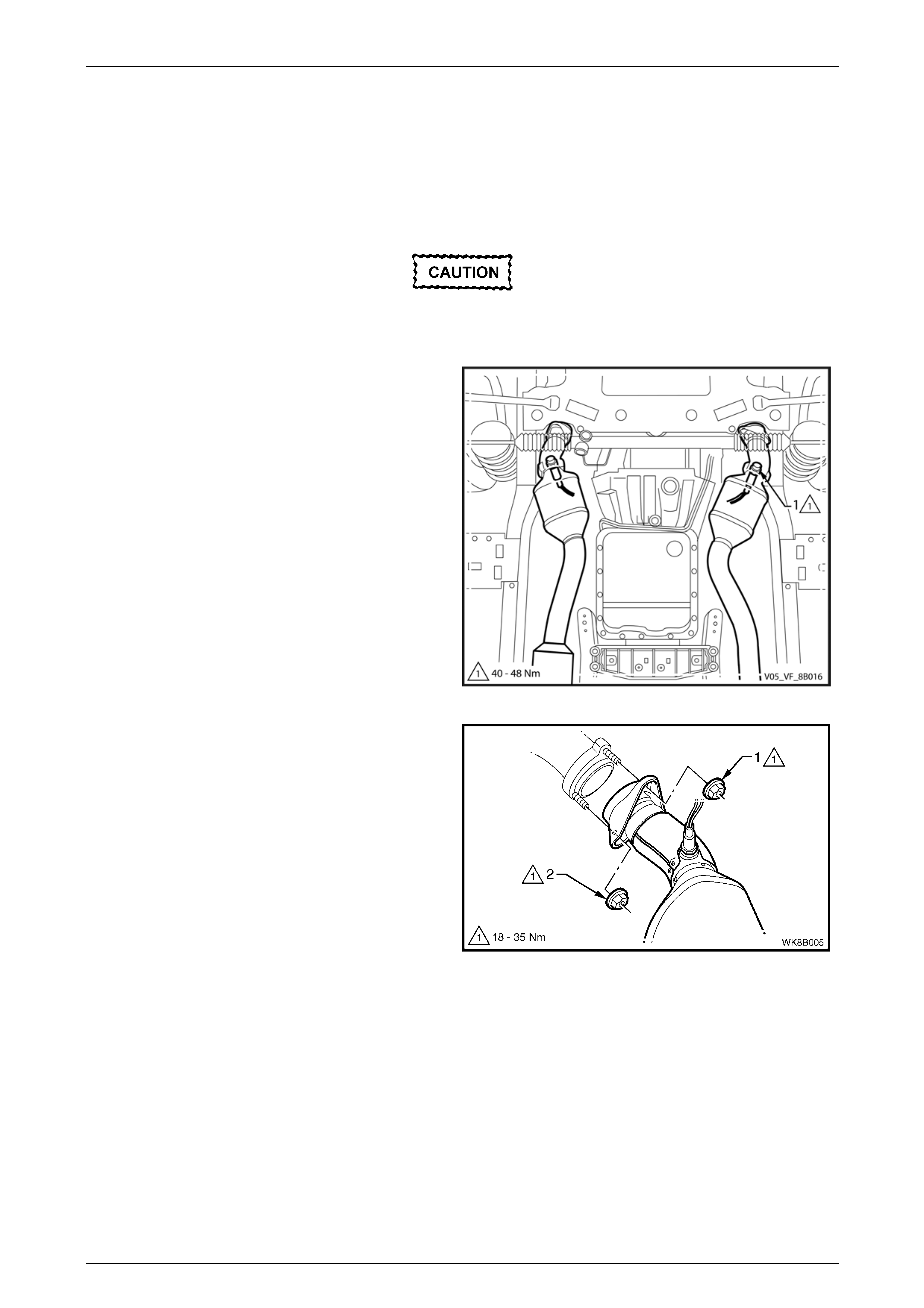
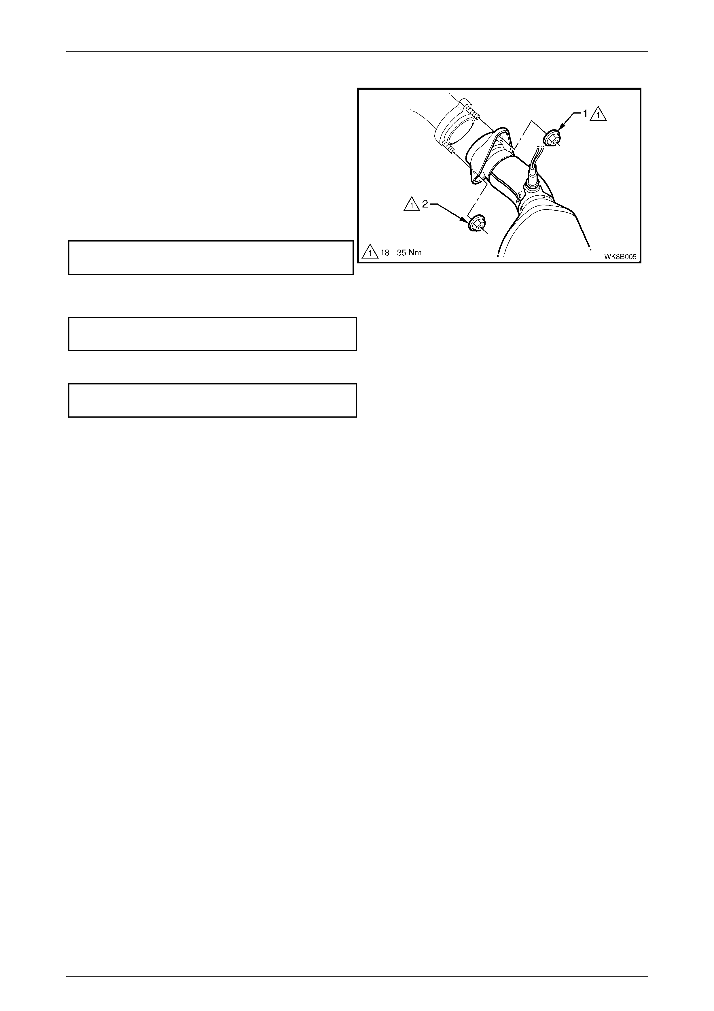
3 Remove the upper (1) and then lower (2) attaching
nuts from the manifold to front pipe flange joint studs
on both sides.
Figure 8B – 13

Exhaust System Page 8B–16
Page 8B–16
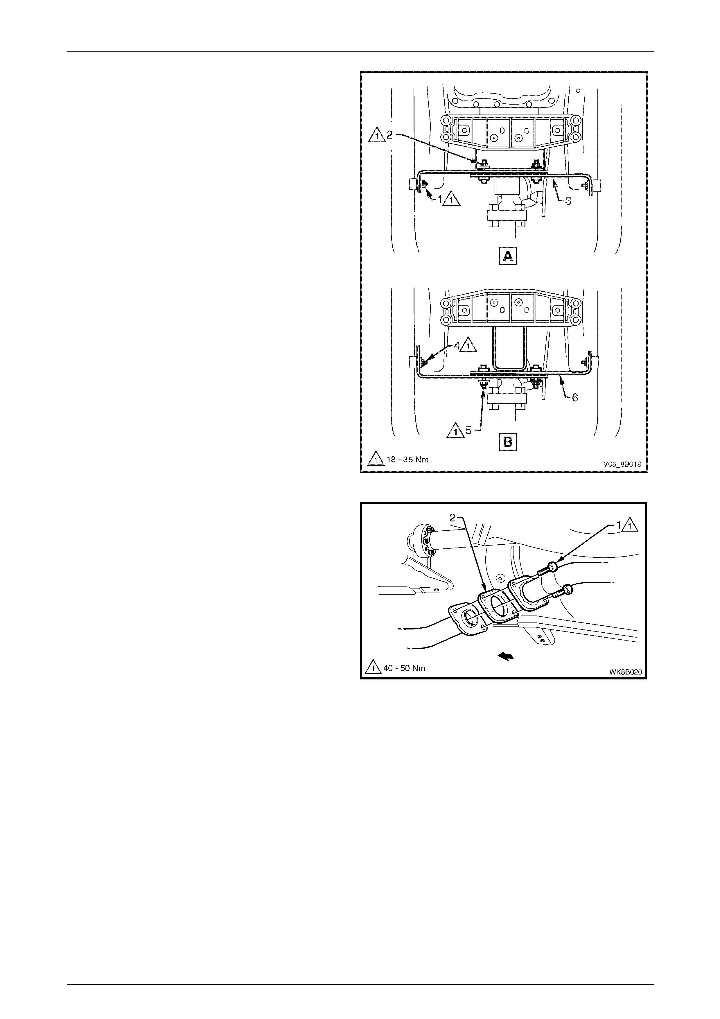
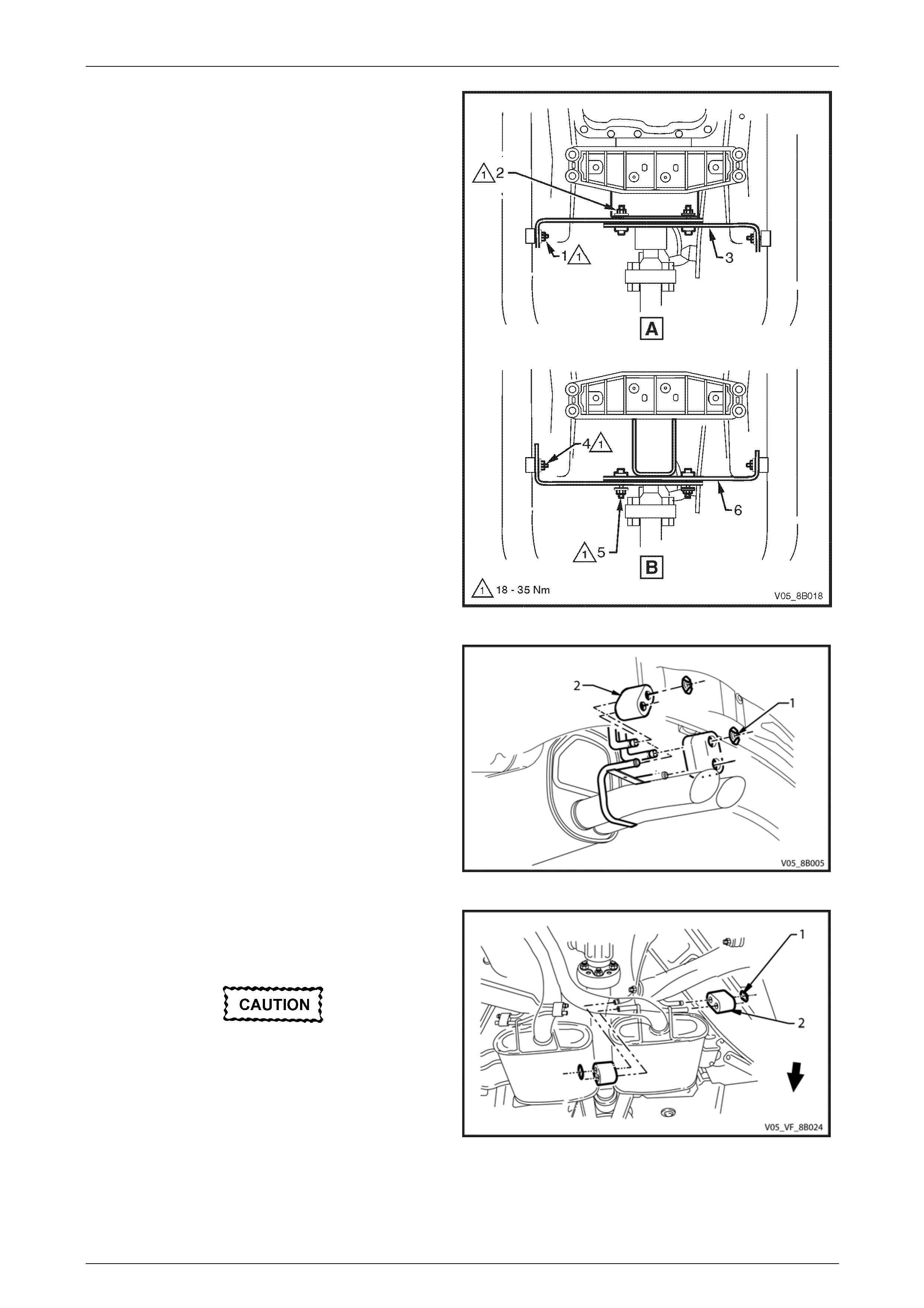
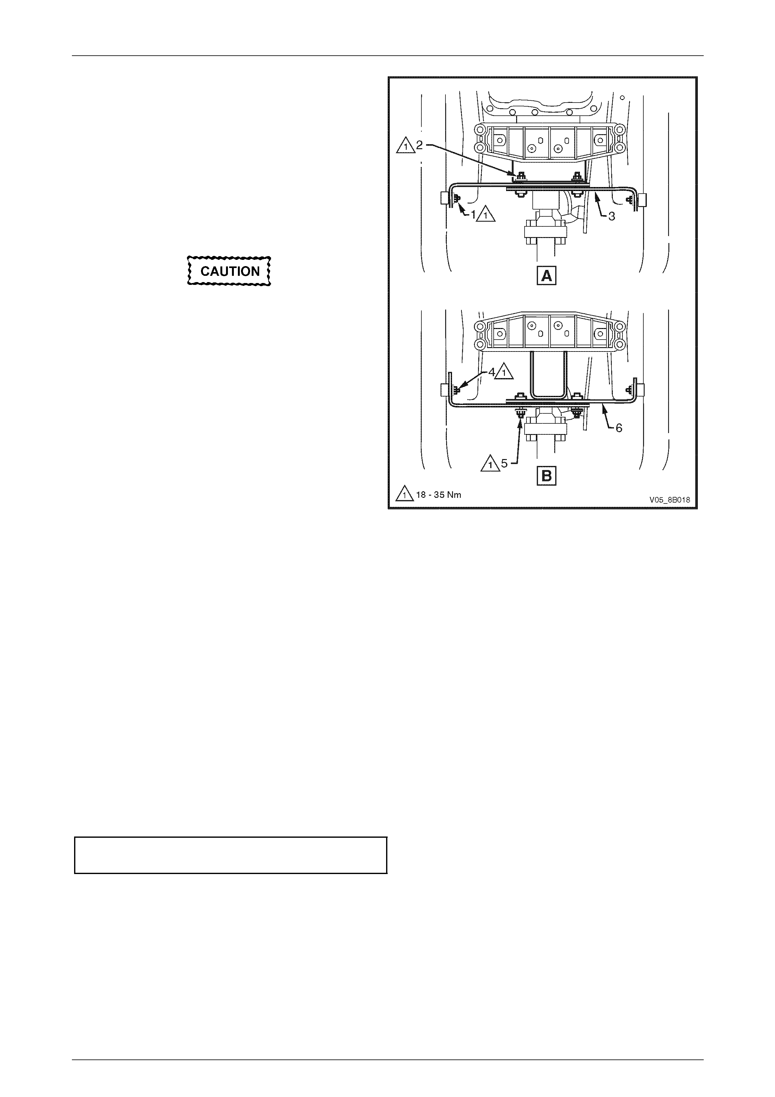
4 Where fitted, remove the cross brace and
transmission mount nuts as follows:
a For the automatic transmission (View A),
remove the cross brace and transmission mount
nuts (1 and 2) and remove the cross brace and
transmission mount (3).
b For the manual transmission (View B), remove
the cross brace and transmission mo unt
nuts (4 and 5) and remove the cross brace and
transmission mount (6).
Figure 8B – 14
5 Disconnect the rear muffler from the underbody
hangers by removing the retainer clips (1) and re ar
muffler support rubbers (2).
Figure 8B – 15
6 Disconnect the intermediate exhaust assembly from
the underbody hangers by removin g the retain er clips
(1) and the intermediate exhaust support rubbers (2).
Take care not to damage the oxygen
sensors.
7 Carefully lower and remove the exhaust assembly
from the vehicle.
Figure 8B – 16

Exhaust System Page 8B–17
Page 8B–17
Reinstall
Reinstallation of the complete exhaust system is the reverse of the removal procedure, noting the following:
1 Support the exhaust system at all times.
2 Clean the threads of the manifold to front pipe flange joint studs and nuts with a suita ble cleaning solvent.
3 Apply a high temperature anti-seize compound to the manifold to front pipe flange joint studs, then align the flange
over the studs.
4 Hand tighten the upper attaching nut (1) and then the l ower attaching nut (2) to the studs on both sides, refer to
Figure 8B – 17.
5 Where fitted, install the cross brace and transmission mount (3 or 6) depending on transmission t ype, hand tig hten
the attaching nuts, refer to Figure 8B – 18.
6 Tighten the manifold to front pipe flange joi nt studs
upper attaching nut (1) and then lower attaching
nut (2) so that approximately equal amounts of stud
thread are showing.
7 Tighten the upper and then the lower attaching nuts to
the correct torque specification.
Manifold to front pipe flange joint stud
attaching nut torque specification............18.0 – 35.0 Nm
Figure 8B – 17
8 Where fitted, tighten the cross brace to front exhaust
pipe nuts (1 automatic transmission) or nuts (4 manual
transmission), to the correct torque specification.
Cross brace to front exhaust pipe
attaching nut torque specification............18.0 – 35.0 Nm
9 Tighten the cross brace bracket attaching nuts (2
automatic transmission) or nuts (5 manual
transmission), to the correct torque specification.
Cross brace bracket attaching
nut torque specification...........................18.0 – 35.0 Nm
10 Ensure that all support rubbers are under load.
11 Ensure the exhaust is clear of all other components
and chassis. If it is not clear, loosen off all fasteners
and perform the tightening sequence procedure,
2.7 Tightening Sequence.
12 Connect the wiring harness connector for each oxygen
sensor.
Figure 8B – 18
Exhaust System Page 8B–18
Page 8B–18
2.4 Rear Exhaust Assembly
LT Section No. — 03–750
Remove
Ensure the exhaust assembly is properly
supported to avoid damage and undue stress
on the system.
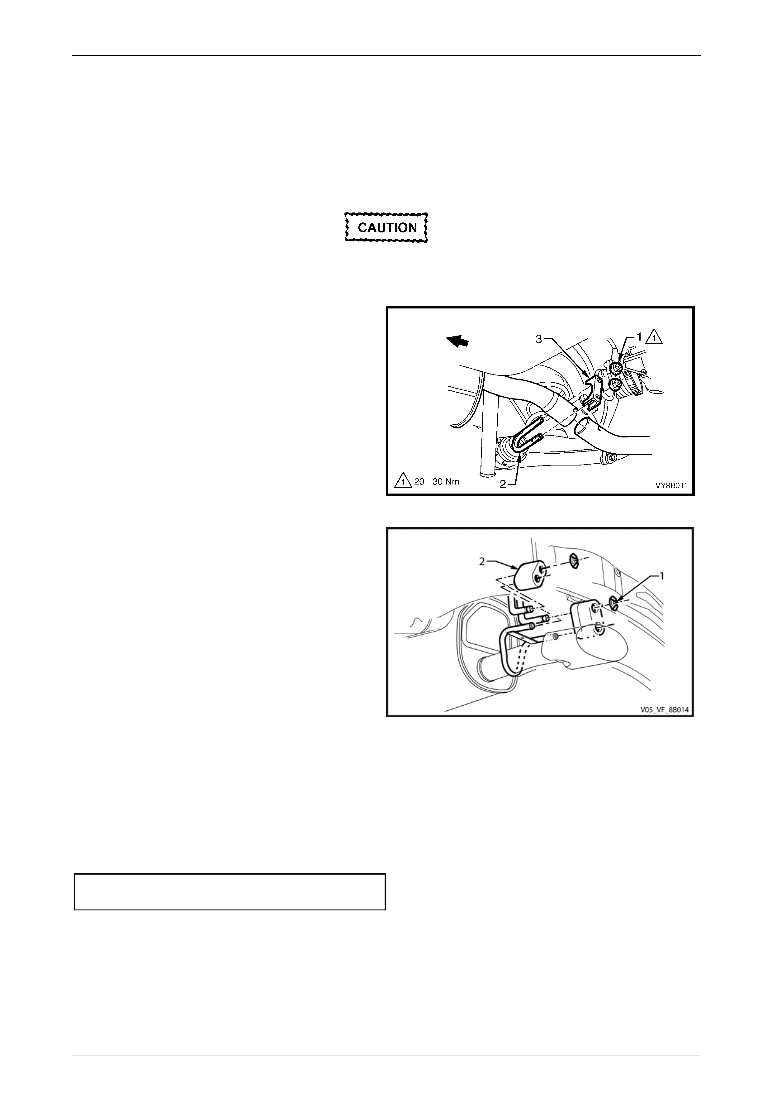
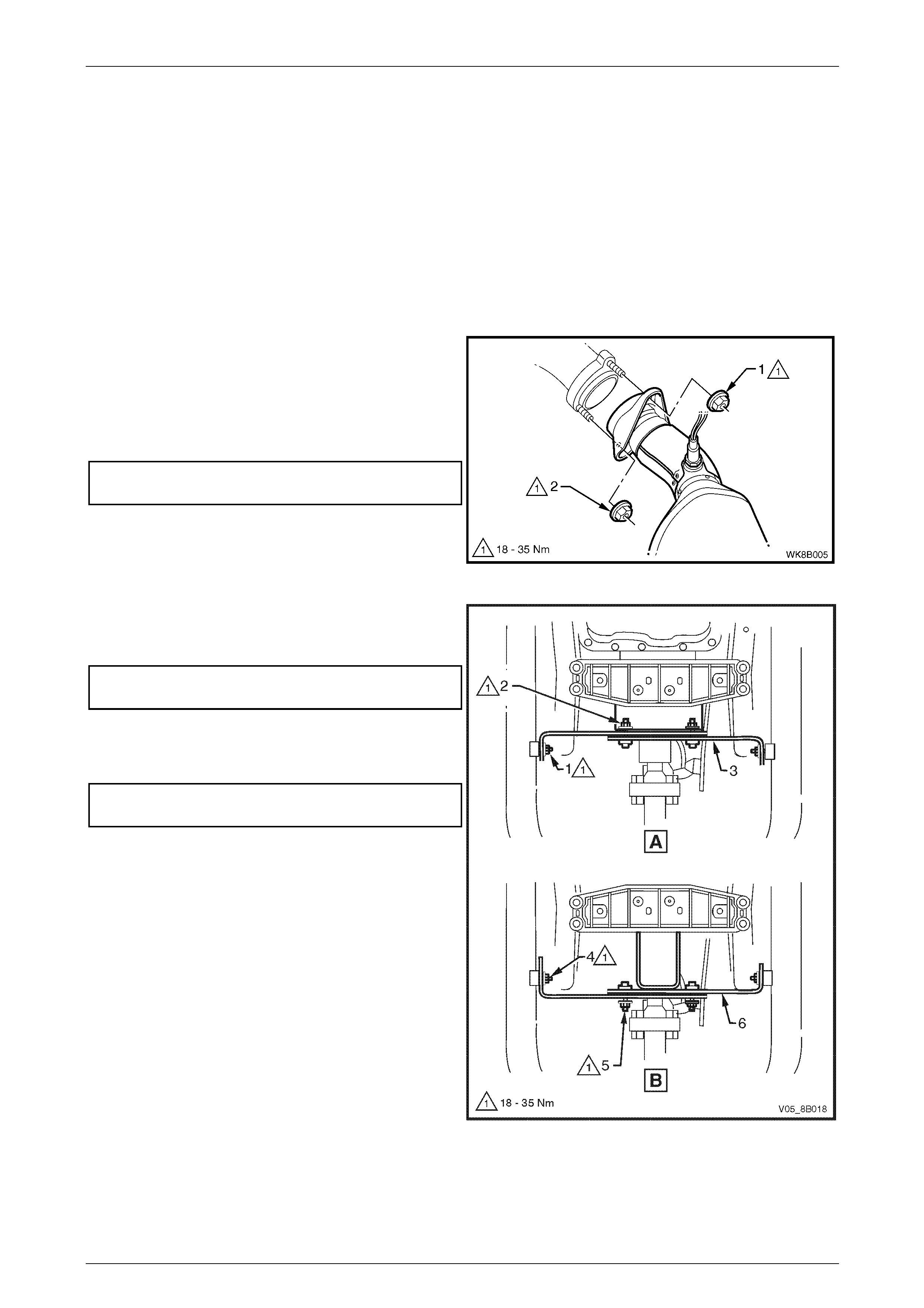
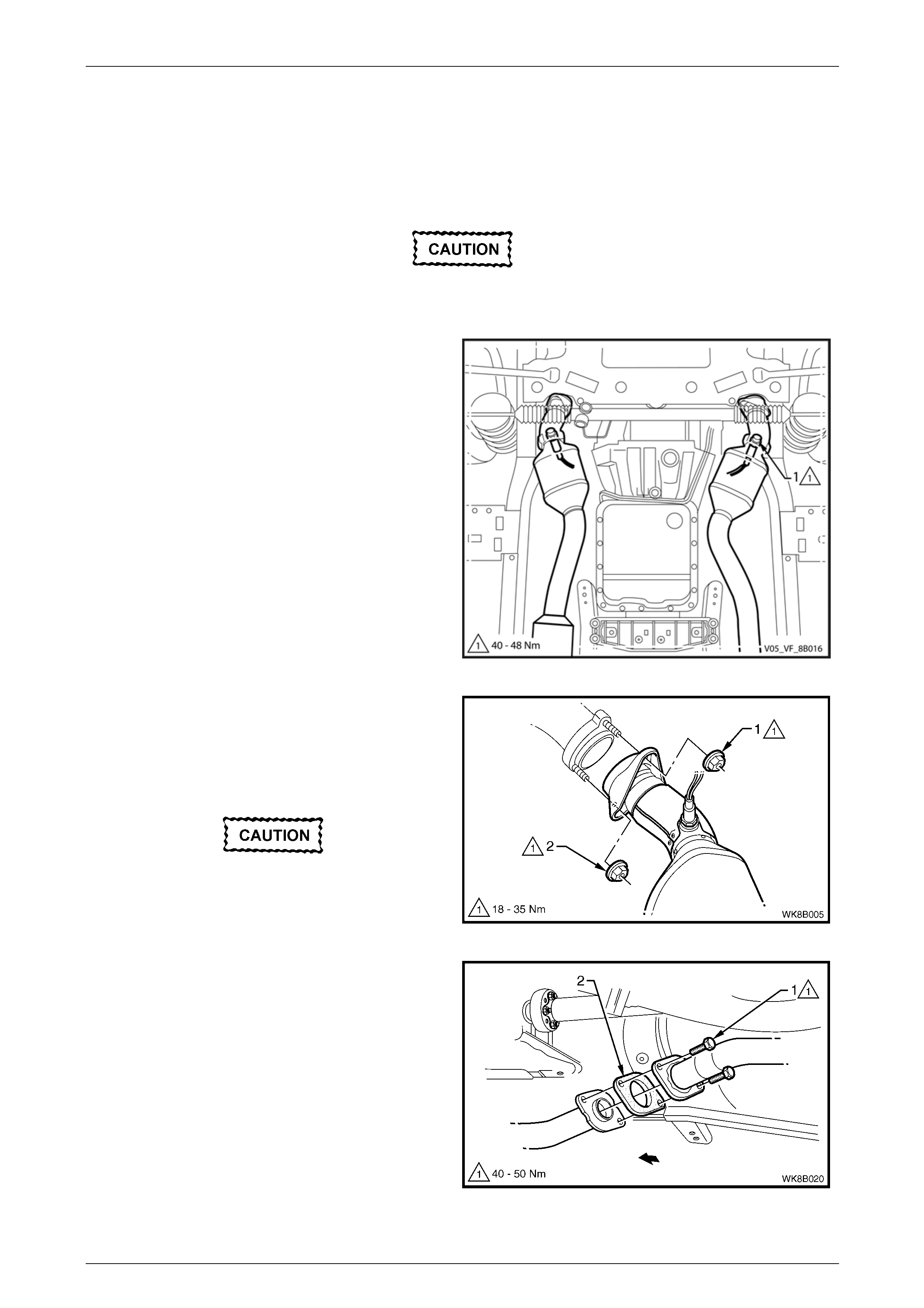
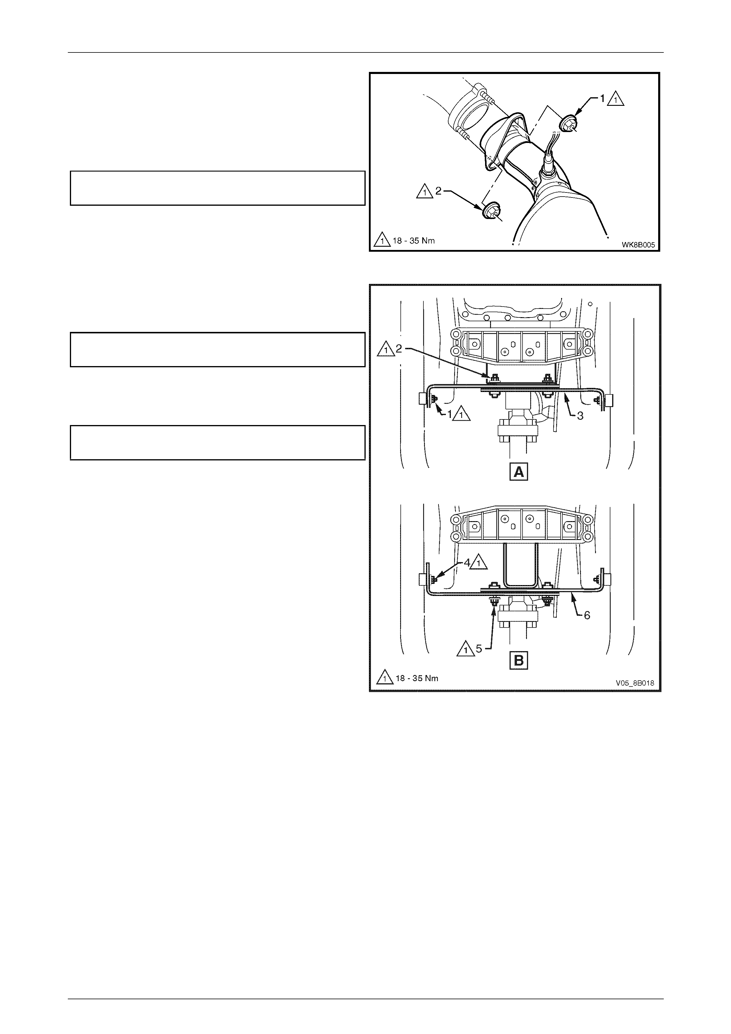
1 Remove the two retaining nuts (1), the slip joint
U-bolt (2) and clamp (3) from the intermediate to rear
pipe slip joint.
Figure 8B – 19
2 Remove the underbody support hanger reta iner
clips (1) and the rear muffler support rubbers (2) from
the underbody hangers.
3 Carefully slide the rear e xhaust pipe out of the
intermediate exhaust pipe end slip j oint a nd remove
the rear exhaust assembly.
Figure 8B – 20
Reinstall
Reinstallation of the rear exhaust assemb ly is the reverse of the removal procedure, n oti ng the following:
1 Ensure the rear exhaust pipe slides unobstructed into the intermediate exhaust pipe slip joint, and the ali gnment
key is positioned in the slip joint channel.
2 Tighten the slip joint U-clamp attaching nuts to the correct torque specification.
Slip joint U-clamp attaching nut
torque specification.................................20.0 – 30.0 Nm
3 Ensure that all support rubbers are under load.
4 Ensure the exhaust is clear of all other components and chassis. If the exhaust is not clear, loosen off all fasteners
and perform the tightening sequence procedure, 2.7 Tightening Sequence.
Exhaust System Page 8B–19
Page 8B–19
2.5 Intermediate Exhaust Assembly
LT Section No. — 03–750
Remove
Ensure the exhaust assembly is properly
supported to avoid damage and undue stress
on the system.
1 Remove the rear exhaust assembly, refer to 2.4 Rear Exhaust Assembly
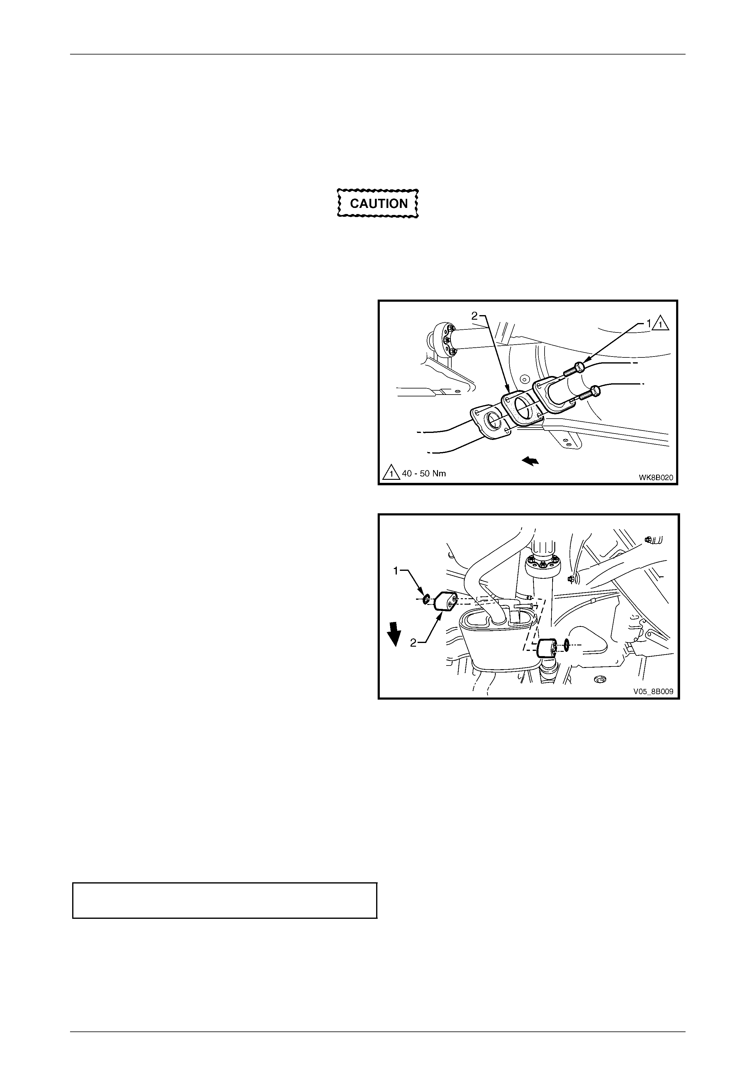
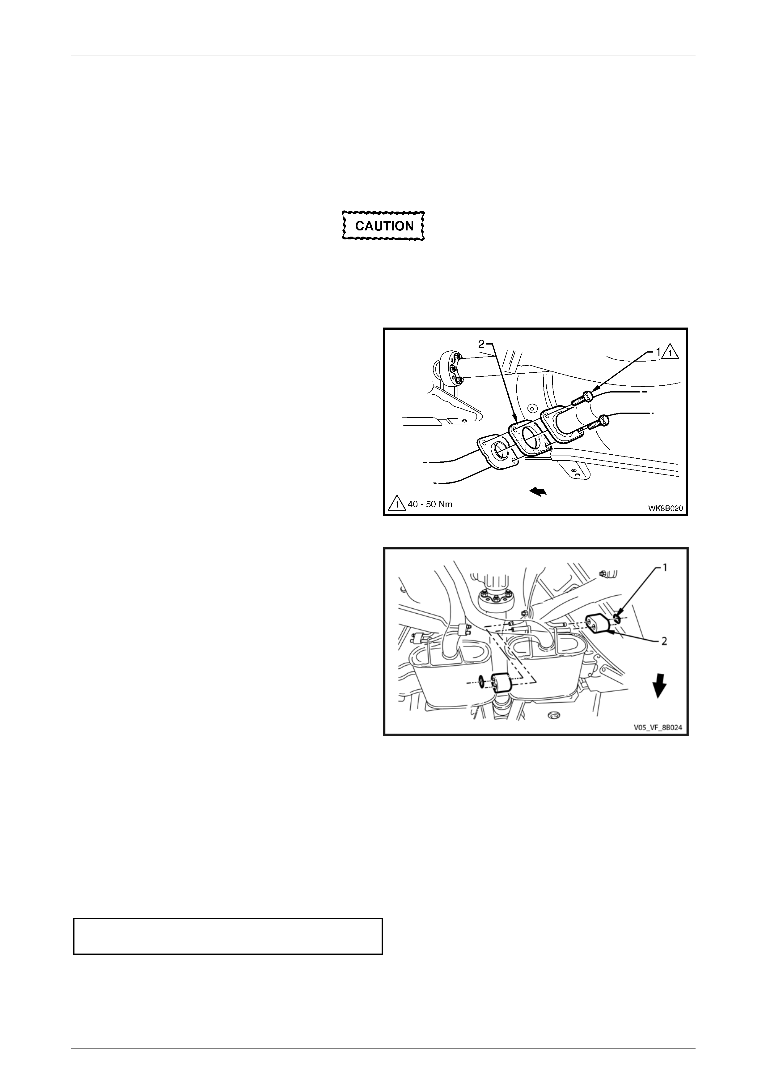
2 Support the intermediate exhaust assembly and
remove the two attaching bolts (1) from each of the
front to intermediate pipe flange joints.
3 Separate the intermediate exhaust assembly from the
front exhaust assembly and remove the gasket (2)
from between each of the two front to intermediate
pipe flange joints.
Figure 8B – 21
4 Disconnect the intermediate exhaust assembly from
the underbody hangers by removin g retain er clips (1)
and the intermediate exhaust supp ort rubbers (2) and
remove the intermediate exhaust assembly.
Figure 8B – 22
Reinstall
Reinstallation of the intermediate exhaust assembly is the reverse of the removal procedure, noting the following:
1 Support the exhaust system at all times.
2 Clean the threads of all attaching bolts and flan ges with a suitable cleaning solvent.
3 Always check the condition of the front pipe to intermediate pipe flange jo int gaskets, replace if required.
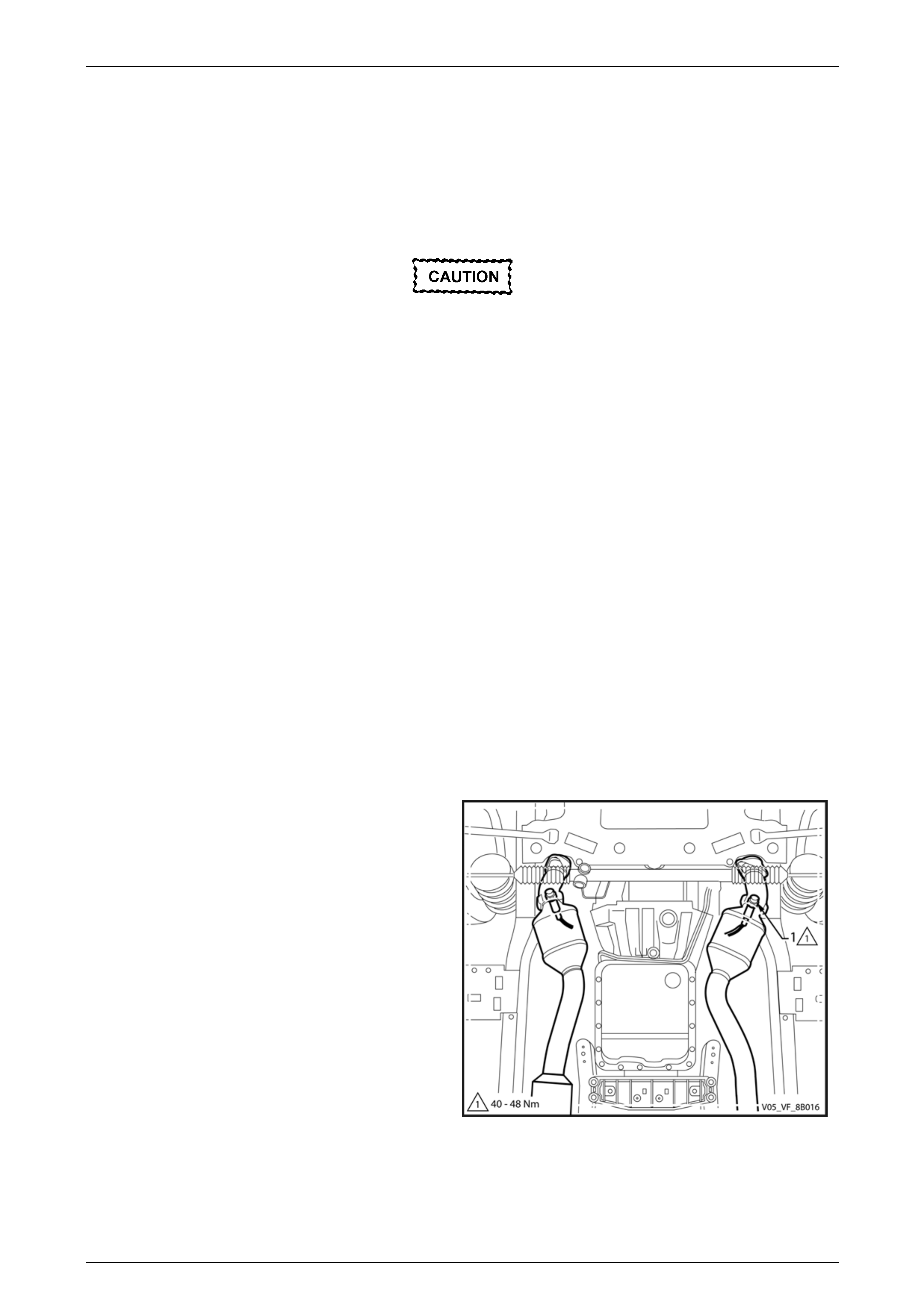
4 Tighten the front pipe to intermedi ate pipe flange joints attaching bolts to the correct torque specification, refer to
Figure 8B – 21.
Front pipe to intermediate pip e flang e
joint attaching bolt torque specification...40.0 – 50.0 Nm
5 Ensure the rear exhaust pipe slides unobstructed into the intermediate exhaust pipe slip joint, and the ali gnment
key is positioned in the slip joint channel.
6 Ensure that all support rubbers are under load.
7 Ensure the exhaust is clear of all other components and chassis. If the exhaust is not clear, loosen off all fasteners
and perform the tightening sequence procedure, 2.7 Tightening Sequence.
Exhaust System Page 8B–20
Page 8B–20
2.6 Front Exhaust Assembly
LT Section No. — 03–750
Remove
Ensure the exhaust assembly is properly
supported to avoid damage and undue stress
on the system.
1 Disconnect the wiring harness connector from each
oxygen sensor (1).
NOTE
Automatic transmission shown, manual
transmission similar.
Figure 8B – 23
2 Remove the upper (1) and then lower (2) attaching
nuts from the manifold to front pipe flange joint studs
on both sides.
Take care not to damage the oxygen
sensors.
Figure 8B – 24
Exhaust System Page 8B–21
Page 8B–21
3 Where fitted, remove the cross brace and
transmission mount nuts as follows:
a For the automatic transmission (View A),
remove the cross brace and transmission mount
nuts (1 and 2) and remove the cross brace and
transmission mount (3).
b For the manual transmission (View B), remove
the cross brace and transmission mo unt
nuts (4 and 5) and remove the cross brace and
transmission mount (6).
Figure 8B – 25
4 Support the intermediate exhaust assembly and
remove the two attaching bolts (1) from each of the
front to intermediate pipe flange joints.
5 Separate the intermediate exhaust assembly from the
front exhaust assembly and remove the gasket (2)
from between each of the front to intermediate pipe
flange joints.
6 Carefully lower and remove the front exhaust
assembly from the vehicle.
Figure 8B – 26
Reinstall
Reinstallation of the front exhaust assembly is the reverse of the removal procedure, noting the following:
1 Support the exhaust system at all times.
2 Clean the threads of the attaching bolts, nut s, studs and flanges with a suitable cleaning solvent.
3 Always check the condition of the front pipe to intermediate pipe flange joint gaskets upon reinstallation and
replace if required.
4 Apply a high temperature anti-seize compound to the manifold to front pipe flange joint studs, then align the flange
over the studs.
5 Where fitted, install the cross brace and transmission mount (3) and hand tighten the attaching nuts, refer to
Figure 8B – 28.
Exhaust System Page 8B–22
Page 8B–22
6 Hand tighten the upper attaching nut (1) to the stud
on both sides.
7 Hand tighten the lower attaching nut (2) to the stud on
both sides.
8 Tighten the upper and then the lower attaching nuts
so that approximately equal amounts of stud thread
are showing.
9 Tighten the upper and then the lower attaching nuts
to the correct torque specification.
Manifold to front pipe flange joint stud
attaching nut torque specification............18.0 – 35.0 Nm Figure 8B – 27
10 Where fitted, tighten the cross brace to front exhaust
pipe nuts (1 automatic transmission) or nuts (4 manual
transmission), to the correct torque specification.
Cross brace to front exhaust pipe
attaching nut torque specification............18.0 – 35.0 Nm
11 Tighten the cross brace bracket attaching nuts (2
automatic transmission) or nuts (5 manual
transmission), to the correct torque specification.
Cross brace bracket attaching
nut torque specification...........................18.0 – 35.0 Nm
12 Ensure that all support rubbers are under load.
13 Ensure the exhaust is clear of all other components
and chassis. If the exhaust is not clear, loosen off all
fasteners and perform the tightening sequence
procedure, 2.7 Tightening Sequence.
14 Connect the wiring harness connector for each oxygen
sensor.
Figure 8B – 28
Exhaust System Page 8B–23
Page 8B–23
2.7 Tightening Sequence
LT Section No. — 03–750
Ensure the exhaust assembly is properly
supported to avoid damage and undue stress
on the system.
This procedure is only to be performed if the exhaust system positioning is not to specification.
Figure 8B – 29
Refer to Figure 8B – 29 for the following.
NOTE
Ensure that all fasteners mentioned in the
following steps 1 to 3 are loos e b efore con ducting
this procedure.
1 Tighten each of the front pipe to intermed iate pipe flange joint attaching bolts (1) to the correct torque specification.
Front pipe to intermediate pip e flang e
joint attaching bolt torque specification...40.0 – 50.0 Nm
2 Check the rear exhaust pipe align ing key is fully seated within the intermediate to rear pipe slip joint channel.
Position the U-clamp (2) along the slip joint and tighten the pair of attaching nuts to the correct torque specification.
Slip joint U-clamp attaching nut
torque specification.................................20.0 – 30.0 Nm
3 Tighten the manifold to front pipe flange joint (3) studs nuts as follows:
Exhaust System Page 8B–24
Page 8B–24
a Hand tighten the upper attaching nut (1) to the
stud on both sides, refer to Figure 8B – 30.
b Hand tighten the lower attaching nut (2) to the
stud on both sides.
c Tighten the upper and then the lower attaching
nuts so that approximately equal amounts of
stud thread are showing.
d Tighten the upper and then the lower attaching
nuts to the correct torque specification.
Manifold to front pipe flange joint stud
attaching nut torque specification............18.0 – 35.0 Nm Figure 8B – 30
4 Where fitted, tighten the cross brace to front exhaust pipe nuts to the correct torque specification.
Cross brace to front exhaust pipe
attaching nut torque specification............18.0 – 35.0 Nm
5 Tighten the cross brace bracket attaching nuts to the correct torque specification.
Cross brace bracket attaching
nut torque specification...........................18.0 – 35.0 Nm
6 Ensure that all support rubbers (4 and 5) are under load. If this is not achieved, loosen the respective joints in the
reverse order to steps 1 to 3. Load the under body hangers, re-tighten and check in the sequence d escribed from
steps 1 to 6.
NOTE
The exhaust system should be self-aligning and
not require further adjustment, provided Step 6 is
achieved.
Exhaust System Page 8B–25
Page 8B–25
3 Service Operations – GEN lV V8
3.1 Service Notes
Care must be taken to install each component in the correct relationship with the other components. Ensure the correct
assembly, reinstallation, tighteni ng sequence, tightening torque and clearances are observed.
The incorrect assembly of exhaust system
components can frequently be the cause of
rattles and booms due to incorrect alignment
or clearance of body or suspension parts.
Ensure the correct tightening sequence is
observed upon reinstallation of exhaust
system components.
NOTE
Service operations on exhaust system
components must be carried out with all parts at
ambient temperatures to ensure that correct
clearances are maintai ned.
Catalytic Converter
Catalytic converters are serviced as part of the complete front exhaust pipe assembly only .
NOTE
If removing or replacing the c atalytic converter as
part of a complete front pipe assembly, always
check the flange gaskets for damag e and replace
if required.
Oxygen Sensors
When removing the front exhaust pipes, it is necessary to
disconnect the wiring harness connector from each oxygen
sensor (1). For oxygen sensor replacement, refer to
Section 6C4-3 Powertrain Management – GEN lV V8 –
Service Operations.
NOTE
Where it is necessary to remove oxygen
sensors from the exhaust pipe assembly, tag
each oxygen sensor to aid correct replacement.
Figure 8B – 31
Exhaust System Page 8B–26
Page 8B–26
3.2 Exhaust System
The following service operations shou ld be referred to when conducting work on GEN lV V8 exhaust systems.
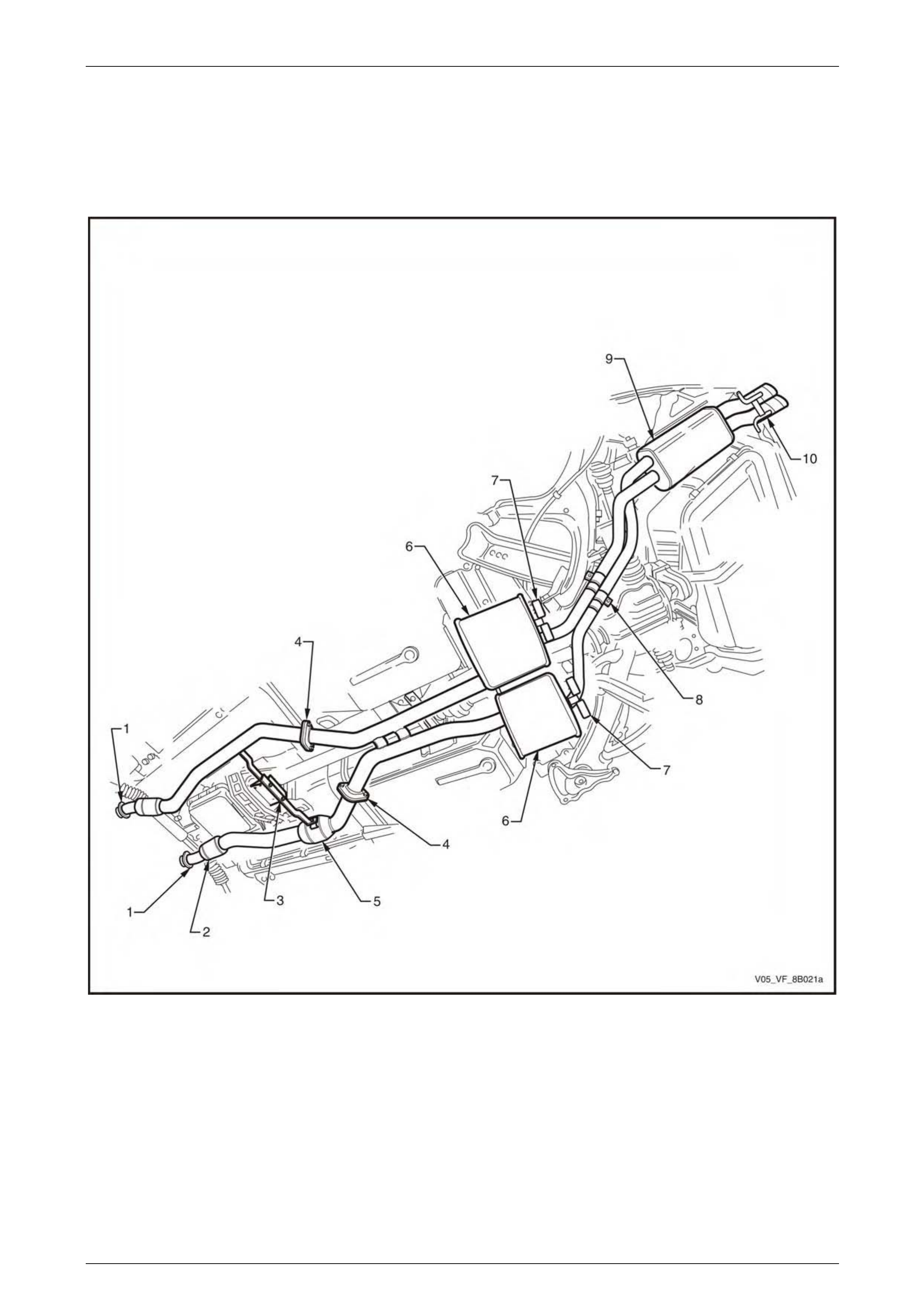
Figure 8B – 32 illustrates a typical exhaust system fitted to vehicles with an GEN lV V8 engine, except Coupe, for other
configurations refer to 1.3 Exhaust System Configurations.
Figure 8B – 32
Legend
1 Manifold to Front Pipe Flange Joint
2 Catalytic Converter
3 Cross Brace and Transmission Mount
4 Front to Intermediate Pipe Flange Join
5 Resonator
6 Intermediate Muffler
7 Intermediate Muffler Support Rubbers
8 Intermediate to Rear Pipe Slip Joint and Ring Clamp
9 Rear Muffler
10 Rear Muffler Support Rubbers
Exhaust System Page 8B–27
Page 8B–27
3.3 Complete Exhaust System Assembly
LT Section No. — 03–750
Remove
Ensure the exhaust assembly is properly
supported to avoid damage and undue stress
on the system.
1 Disconnect the wiring harness connector from each
oxygen sensor (1).
NOTE
Automatic transmission shown, manual
transmission similar.
Figure 8B – 33
2 Support the exhaust system.
3 Remove the upper (1) and then lower (2) attaching
nuts from the manifold to front pipe flange joint studs
on both sides.
Figure 8B – 34
Exhaust System Page 8B–28
Page 8B–28
4 Remove the cross brace and transmission m ount nuts
as follows:
a For the automatic transmission (view A),
remove the cross brace and transmission mount
nuts (1 and 2) and remove the cross brace and
transmission mount (3).
b For the manual transmission (view B), remove
the cross brace and transmission mo unt
nuts (4 and 5) and remove the cross brace and
transmission mount (6).
Figure 8B – 35
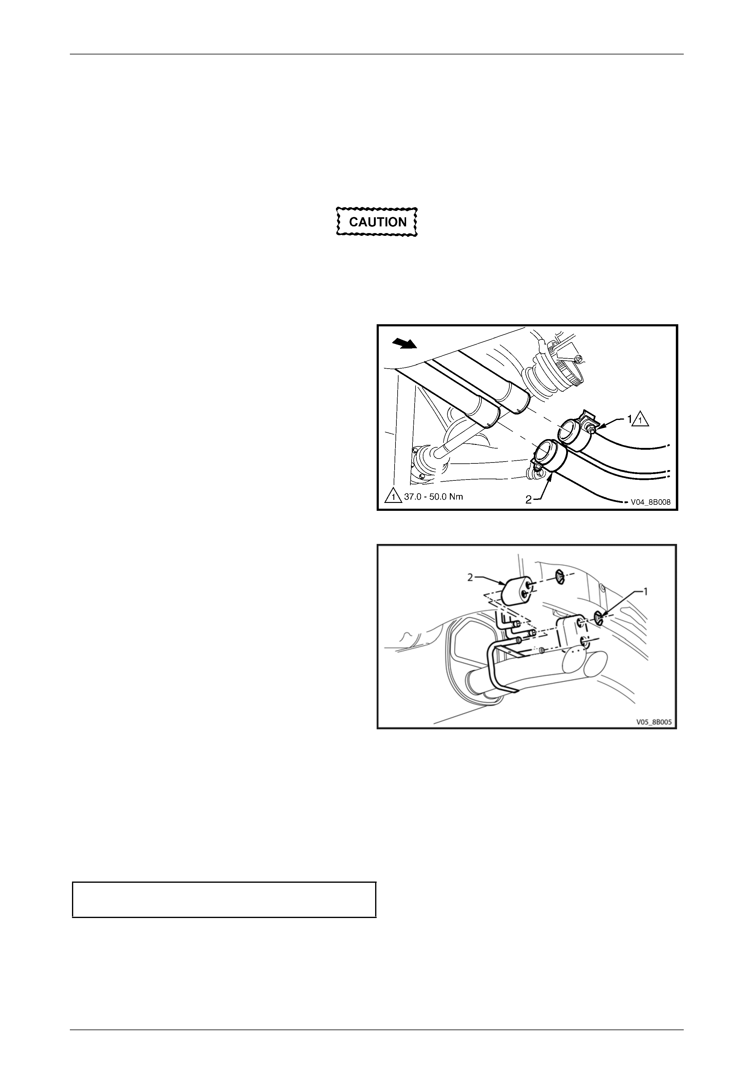
5 Disconnect the rear muffler from the underbody
hangers by removing the retainer clips (1) and re ar
muffler support rubbers (2).
Figure 8B – 36
6 Disconnect the intermediate exhaust from the
underbody hangers by remov ing the retainer clips (1)
and the intermediate muffler support rubb ers (2).
Take care not to damage the oxygen
sensors.
7 Carefully lower and remove the exhaust assembly
from the vehicle.
Figure 8B – 37
Exhaust System Page 8B–29
Page 8B–29
Reinstall
Reinstallation of the complete exhaust system is the reverse of the removal procedure, noting the following:
1 Support the exhaust system at all times.
2 Clean the threads of the manifold to front pipe flange joint studs and nuts with a suita ble cleaning solvent.
3 Apply a high temperature anti-seize compound to the manifold to front pipe flange joint studs, then align the flange
over the studs.
4 Hand tighten the upper attaching nut (1) then the lower attaching nut (2) to the studs on both sides, refer to
Figure 8B – 38.
5 Install the cross brace and transmission mount (3 or 6) depend ing on transmission type, hand tighten the attaching
nuts, refer to Figure 8B – 39.
6 Tighten the manifold to front pipe flange joi nt studs
upper attaching nut (1) and then lower attaching
nut (2) so that approximately equal amounts of stud
thread are showing.
7 Tighten the upper and then the lower attaching nuts to
the correct torque specification.
Manifold to front pipe flange joint stud
attaching nut torque specification............18.0 – 35.0 Nm
Figure 8B – 38
8 Tighten the cross brace to front exhaust pipe nuts
(1 automatic transmission) or nuts (4 manual
transmission), to the correct torque specification.
Cross brace to front exhaust pipe
attaching nut torque specification............18.0 – 35.0 Nm
9 Tighten the cross brace bracket attaching nuts (2
automatic transmission) or nuts (5 manual
transmission), to the correct torque specification.
Cross brace bracket attaching
nut torque specification...........................18.0 – 35.0 Nm
10 Ensure that all support rubbers are under load.
11 Ensure the exhaust is clear of all other components
and chassis. If the exhaust is not clear, loosen off all
fasteners and perform the tightening sequence
procedure, 3.7 Tightening Sequence.
12 Connect the wiring harness connector for each oxygen
sensor.
Figure 8B – 39
Exhaust System Page 8B–30
Page 8B–30
3.4 Rear Exhaust Assembly
LT Section No. — 03–750
Remove
Ensure the exhaust assembly is properly
supported to avoid damage and undue stress
on the system.
1 Remove the intermediate to rear pip e slip j oint U-clamp or ring clamps as follows:
a Loosen the attaching n ut (1) for each of the two
intermediate to rear pipe slip joint ring
clamps (2).
Figure 8B – 40
2 Support the rear exhaust assembly and then remove
the underbody hanger retainer clips (1) and the rear
muffler support rubbers (2) from the underbod y
hangers.
3 Support the intermediate exhaust assembly and slide
the rear exhaust assembly out of the intermediate
exhaust pipe/s end slip joint/s.
4 Remove the rear exhaust assembly.
Figure 8B – 41
Reinstall
Reinstallation of the rear exhaust assemb ly is the reverse of the removal procedure, n oti ng the following:
1 Ensure the rear exhaust pipe/s slides unobstructed into the intermediate exhaust pipe/s slip joint/s, and the
alignment key/s is positioned in the sli p joi nt/s chann el/s.
2 Tighten each slip joint ring clamp attaching nut to the correct torque specification.
Slip joint ring clamp attaching nut
torque specification.................................37.0 – 50.0 Nm
3 Ensure that all support rubbers are under load.
4 Ensure the exhaust is clear of all other components and chassis. If the exhaust is not clear, loosen off all fasteners
and perform the tightening sequence procedure, 3.7 Tightening Sequence.
Exhaust System Page 8B–31
Page 8B–31
3.5 Intermediate Exhaust Assembly
LT Section No. — 03–750
Remove
Ensure the exhaust assembly is properly
supported to avoid damage and undue stress
on the system.
1 Remove the rear exhaust assembly, refer to 3.4 Rear Exhaust Assembly.
2 Support the intermediate exhaust assembly and
remove the two attaching bolts (1) from each of the
two front to intermediate pipe flange joints.
3 Separate the intermediate exhaust assembly from the
front exhaust assembly and remove the gasket (2)
from between each of the two front to intermediate
pipe flange joints.
Figure 8B – 42
4 Remove the retainer clips (1) and intermediate muffler
support rubbers (2) from the underbody hangers of
the intermediate mufflers and remove the
intermediate exhaust assembly.
Figure 8B – 43
Reinstall
Reinstallation of the intermediate exhaust assembly is the reverse of the removal procedure, noting the following:
1 Support the exhaust system at all times.
2 Clean the threads of all attaching bolts and flan ges with a suitable cleaning solvent.
3 Always check condition of flange gaskets up on reinstallation and replace if required.
4 Tighten the front pipe to intermedi ate pipe flange joint attaching bolts to the correct torque specification.
Front pipe to intermediate pip e flang e
joint attaching bolt torque specification...40.0 – 50.0 Nm
5 Ensure that all support rubbers are under load.
6 Ensure the exhaust is clear of all other components and chassis. If the exhaust is not clear, loosen off all fasteners
and perform the tightening sequence procedure, 3.7 Tightening Sequence.
Exhaust System Page 8B–32
Page 8B–32
3.6 Front Exhaust Assembly
LT Section No. — 03–750
Remove
Ensure the exhaust assembly is properly
supported to avoid damage and undue stress
on the system.
1 Disconnect the wiring harness connector from each
oxygen sensor (1).
NOTE
Automatic transmission shown, manual
transmission similar.
Figure 8B – 44
2 Support the front exhaust assembly and the
intermediate exhaust assembly.
3 Remove the upper (1) and then lower (2) attaching
nuts from the manifold to front pipe flange joint studs
on both sides.
Take care not to damage the oxygen
sensors.
Figure 8B – 45
4 Remove the two attaching bolts (1) from each front to
intermediate pipe flange joint.
5 Separate the intermediate exhaust assembly from the
front exhaust assembly and remove the gasket (2)
from between each of the two front to intermediate
pipe flange joints.
Figure 8B – 46
Exhaust System Page 8B–33
Page 8B–33
6 Remove the cross brace and transmission m ount nuts
as follows:
a For the automatic transmission (View A),
remove the cross brace and transmission mount
nuts (1 and 2) and remove the cross brace and
transmission mount (3).
b For the manual transmission (View B), remove
the cross brace and transmission mo unt
nuts (4 and 5) and remove the cross brace and
transmission mount (6).
Take care not to damage the oxygen
sensors.
7 Carefully lower and remove the front exhaust
assembly from the vehicle.
Figure 8B – 47
Reinstall
Reinstallation of the front exhaust assembly is the reverse of the removal procedure, noting the following:
1 Support the exhaust system at all times.
2 Clean the threads of the attaching bolts, nut s, studs and flanges with a suitable cleaning solvent.
3 Always check condition of flange gaskets up on reinstallation and replace if required.
4 Apply a high temperature anti-seize compound to the manifold to front pipe flange joint studs, then align the flange
over the studs.
5 Hand tighten the front to intermediate pipe flange joi nt attachin g bolts.
6 Hand tighten the manifold to front pipe flange joint studs upper attaching nut and then the lower attaching nut on
both sides.
7 Install the cross brace and transmission mount depending on transmission type and hand tighten the attaching
nuts.
8 Tighten the front pipe to intermedi ate pipe flange joint attaching bolts to the correct torque specification.
Front pipe to intermediate pip e flang e
joint attaching bolt torque specification...40.0 – 50.0 Nm
Exhaust System Page 8B–34
Page 8B–34
9 Tighten the manifold to front pipe flange joi nt studs
upper attaching nut (1) and then lower attaching
nut (2) so that approximately equal amounts of stud
thread are showing.
10 Tighten the upper and then the lower attaching nuts to
the correct torque specification.
Manifold to front pipe flange joint stud
attaching nut torque specification............18.0 – 35.0 Nm
Figure 8B –48
11 Tighten the cross brace to front exhaust pipe nuts (1
automatic transmission) or nuts (4 manual
transmission), to the correct torque specification.
Cross brace to front exhaust pipe
attaching nut torque specification............18.0 – 35.0 Nm
12 Tighten the cross brace bracket attaching nuts (2
automatic transmission) or nuts (5 manual
transmission), to the correct torque specification.
Cross brace bracket attaching
nut torque specification...........................18.0 – 35.0 Nm
13 Ensure that all support rubbers are under load.
14 Ensure the exhaust is clear of all other components
and chassis. If the exhaust is not clear, loosen off all
fasteners and perform the tightening sequence
procedure, 3.7 Tightening Sequence.
15 Connect the wiring harness connector to each oxygen
sensor.
Figure 8B – 49
Exhaust System Page 8B–35
Page 8B–35
3.7 Tightening Sequence
LT Section No. — 03–750
Ensure the exhaust assembly is properly
supported to avoid damage and undue stress
on the system.
This procedure is only to be performed if the exhaust system positioning is not to specification.
Figure 8B – 50
Legend
Automatic Transmission Manual Transmission
Refer Figure 8B – 50 for the follo wing:
NOTE
Ensure that all fasteners mentioned in the
following steps 1 to 8 are loose before conducting
this procedure.
1 Tighten each of the front pipe to intermed iate pipe flange joint attaching bolts (1) to the correct torque specification.
Front pipe to intermediate pip e flang e
joint attaching bolt torque specification...40.0 – 50.0 Nm
2 Position each ring clamp (2) over each of the two intermediate to rear pipe slip joints and tighten each attaching nut
to the correct torque specification.
Slip joint ring clamp attaching nut
torque specification.................................37.0 – 50.0 Nm
Exhaust System Page 8B–36
Page 8B–36
3 Tighten the manifold to front pipe flange joint (3) studs nuts as follows:
a Hand tighten the upper attaching nut (1) to the
stud on both sides, refer to Figure 8B – 51.
b Hand tighten the lower attaching nut (2) to the
stud on both sides.
c Tighten the upper and then the lower attaching
nuts so that approximately equal amounts of
stud thread are showing.
d Tighten the upper and then the lower attaching
nuts to the correct torque specification.
Manifold to front pipe flange joint stud
attaching nut torque specification............18.0 – 35.0 Nm Figure 8B – 51
4 Tighten the cross brace to front exhaust pipe nuts (4) to the correct torque specification.
Cross brace to front exhaust pipe
attaching nut torque specification............18.0 – 35.0 Nm
5 Tighten the cross brace bracket attaching nuts (5) to the correct torque specification.
Cross brace bracket attaching
nut torque specification...........................18.0 – 35.0 Nm
6 Ensure that all support rubbers (6 and 7) are under load. If this is not achieved, loosen the respective joints in the
reverse order to steps 1 to 6. Load the under body hangers, re-tighten and check in the sequence d escribed from
steps 1 to 6.
NOTE
The exhaust system should be self-aligning and
not require further adjustment, provided Step 6 is
achieved.
Exhaust System Page 8B–37
Page 8B–37
4 Service Operations – Heat
Shields
To avoid the possibility of personal injury by
burns, allow the exhau st system to co ol down
before attempting this operation.
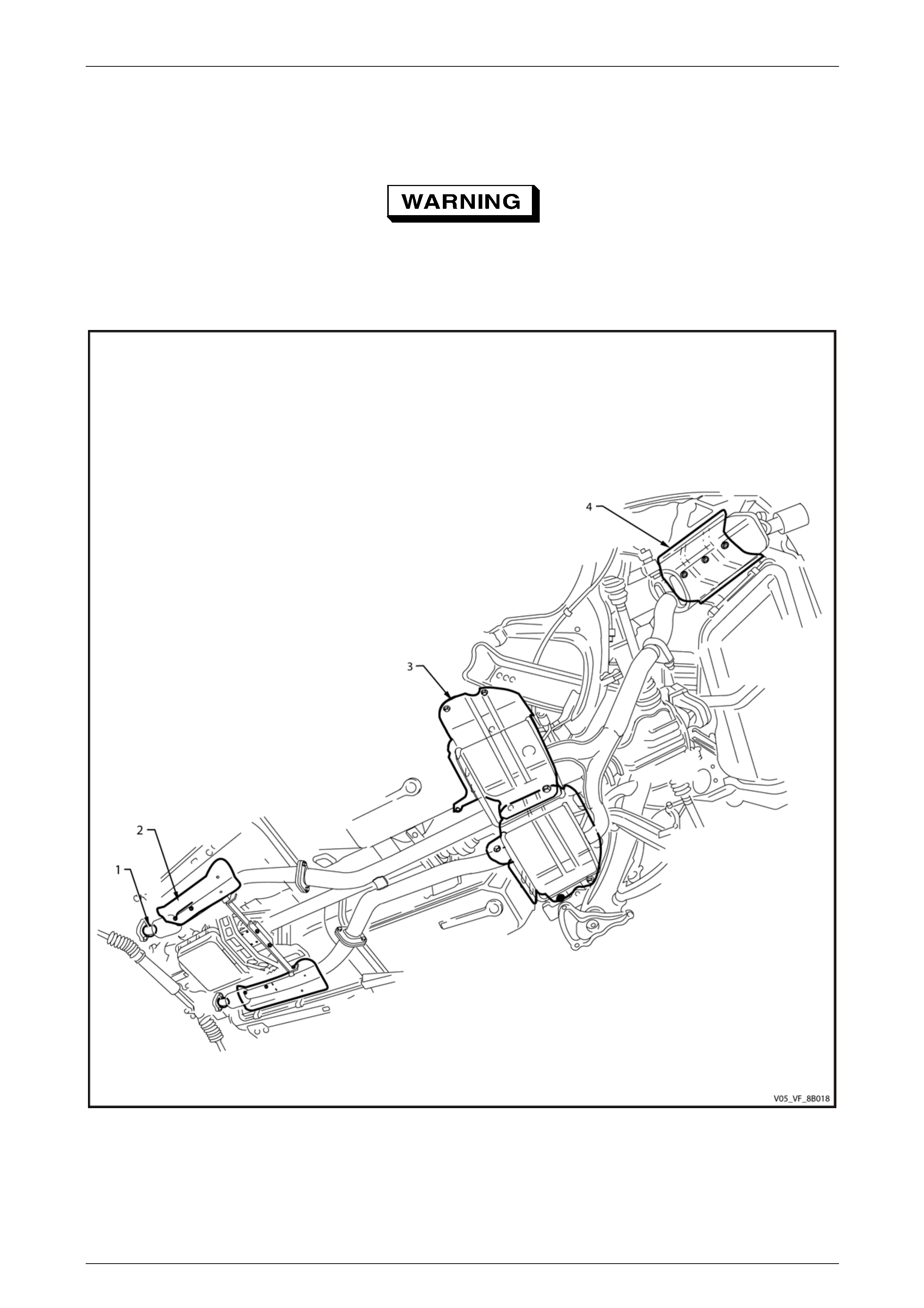
Figure 8B – 52 provides a t ypical refere nce to the location of heat shields.
Figure 8B – 52
Legend
1 Pre Catalytic Converter On-pipe Heat Shield
2 Front Foil Heat Shield 3 Intermediate Heat Shields
4 Rear Heat Shield
Exhaust System Page 8B–38
Page 8B–38
4.1 Rear Heat Shield
Remove
1 If required, remove the rear exhaust assembl y, refer to:
• 2.4 Rear Exhaust Assembly for Alloytec.
• 3.4 Rear Exhaust Assembly for GEN IV V8, except Coupe.
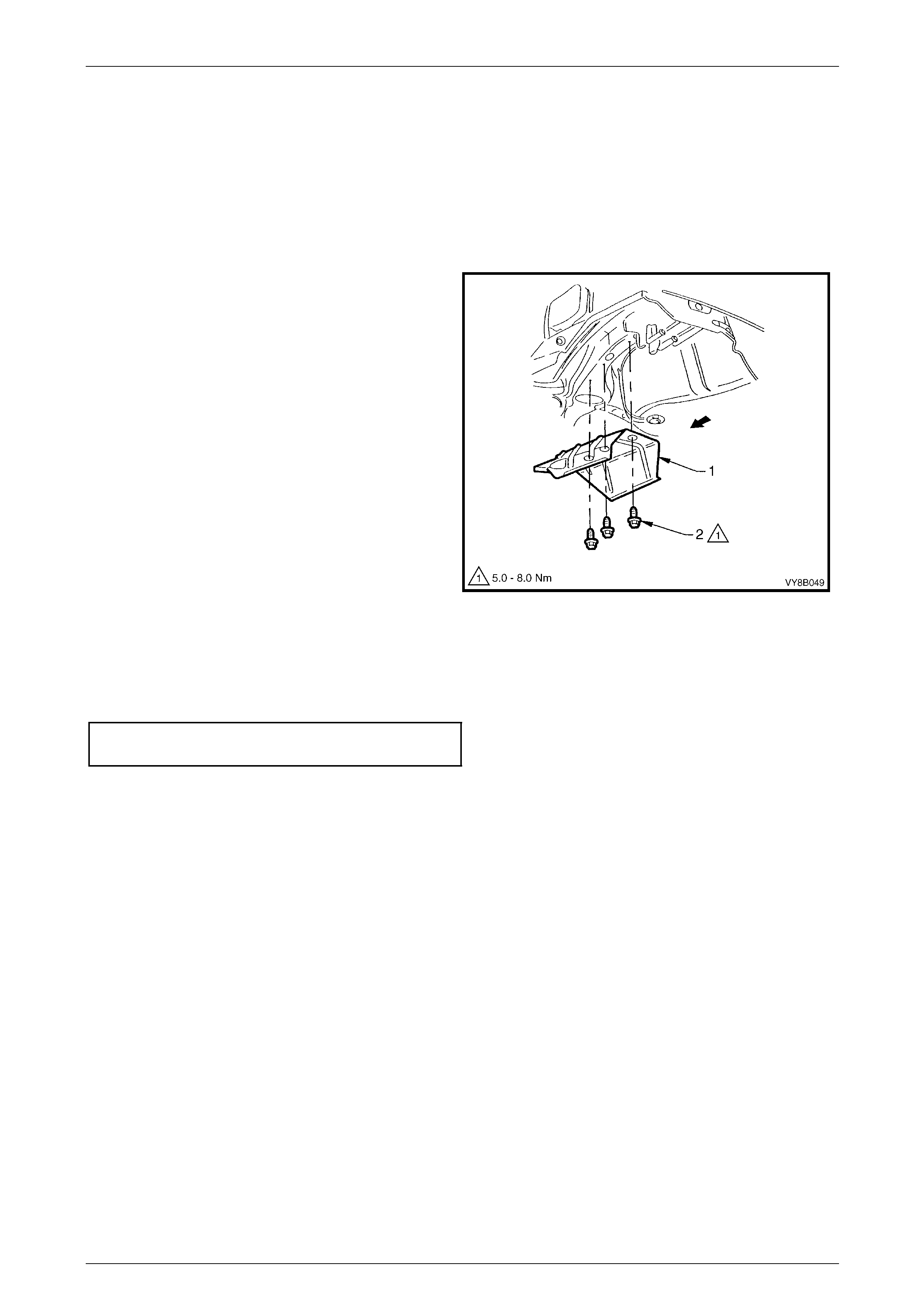
2 Remove the three screws (2) attaching the rear he at
shield (1) and remove the shield.
Figure 8B – 53
Reinstall
Reinstallation of the rear heat shield is the reverse of the removal procedure. Tighten the screws to the correct torque
specification.
Rear heat shield attaching
screw torque specification...........................5.0 – 8.0 Nm
Exhaust System Page 8B–39
Page 8B–39
4.2 Intermediate Heat Shield
Remove
1 If required, remove the intermediate exhaust assembl y, refer to the follo wing:
• 2.5 Intermediate Exhaust Assembly for Alloytec.
• 3.5 Intermediate Exhaust Assembly for GEN IV V8, except Coupe.
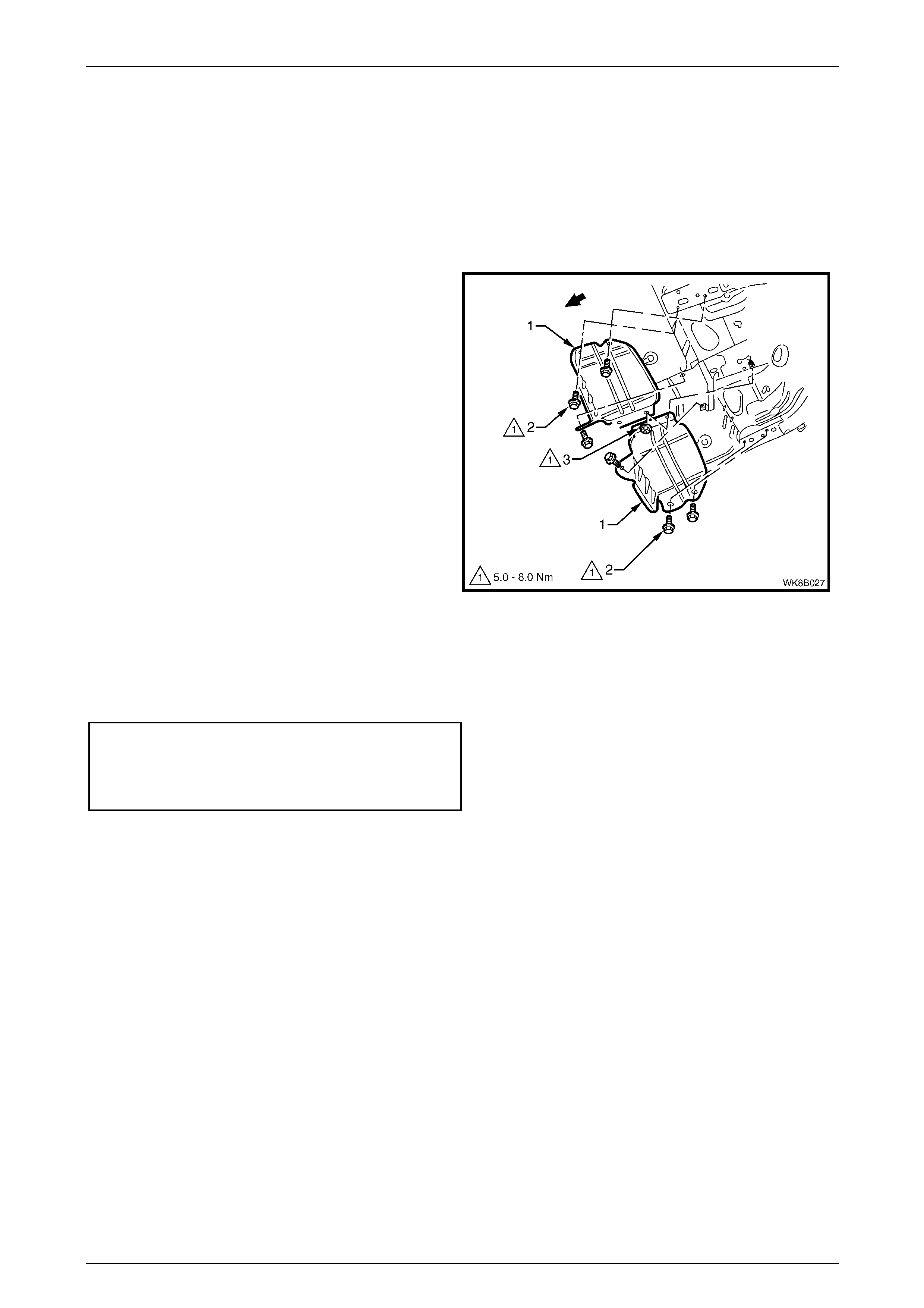
2 Remove the screws (2) and nut (3) attaching the
intermediate heat shield (1) and remov e the shield.
3 Repeat for the adjacent shield as required.
Figure 8B – 54
Reinstall
Reinstallation of the intermediate heat shield is the reverse of the removal procedure. T ighten the screws and nut to the
correct torque specification.
Intermediate heat shield attaching
screw torque specification...........................5.0 – 8.0 Nm
Intermediate heat shield attaching
nut torque specification...............................5.0 – 8.0 Nm
Exhaust System Page 8B–40
Page 8B–40
4.3 Front Heat Shield – Underbody Mounted
Remove
1 If required, remove the rear exhaust assembl y, refer to:
• 2.4 Rear Exhaust Assembly for Alloytec.
• 3.4 Rear Exhaust Assembly for GEN lV V8, except Coupe.
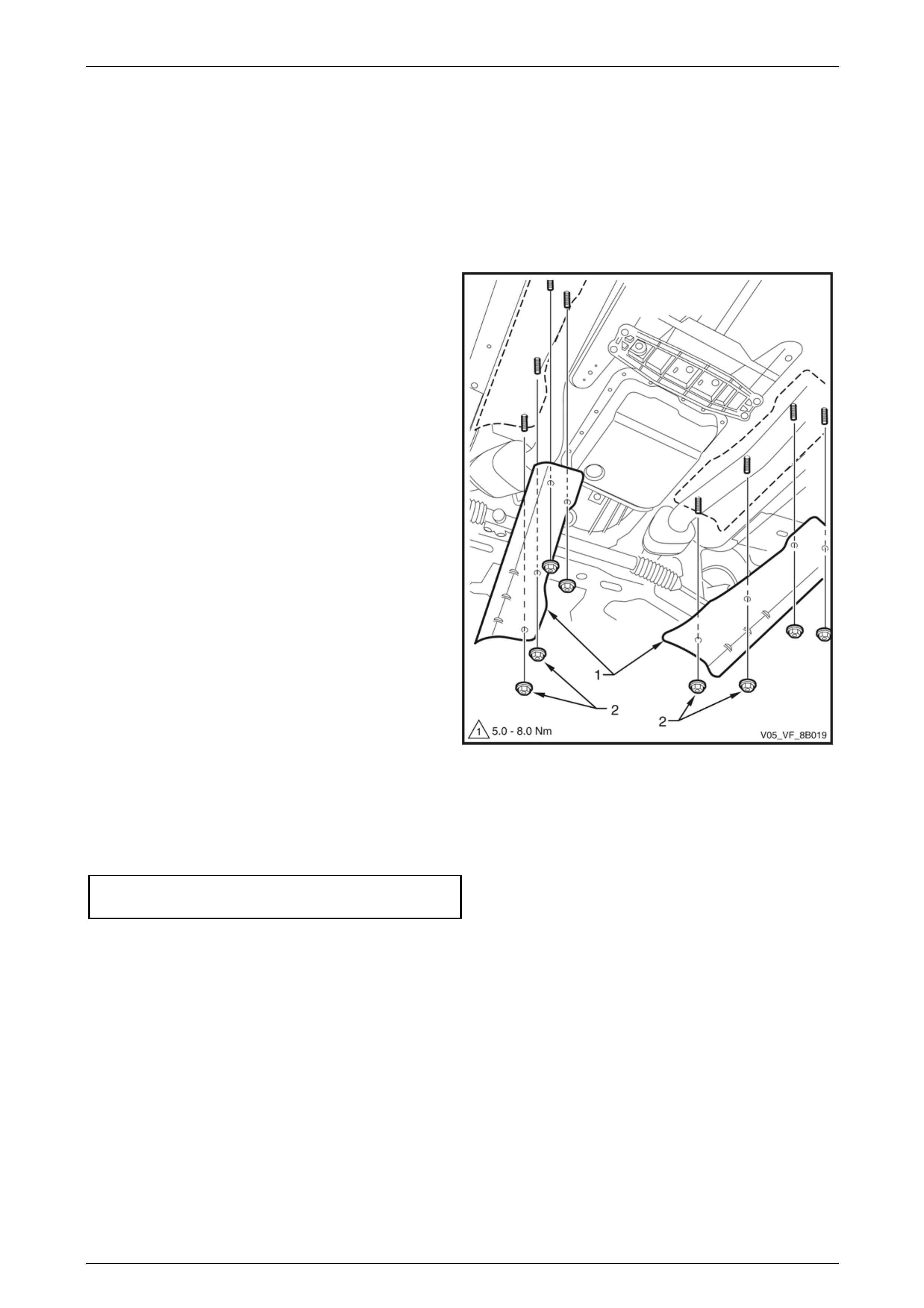
2 Remove the nuts (2) attaching the front heat
shield (1) and remove the shield.
Figure 8B – 55
Reinstall
Reinstallation of the front heat shield is the reverse of the removal procedure. Tighten the nuts to the correct torque
specification.
Front heat shield attaching nut
torque specification.....................................5.0 – 8.0 Nm
Exhaust System Page 8B–41
Page 8B–41
4.4 Front On-Pipe Heat Shield – Pre-catalytic
Converter
Remove
1 If required, remove the rear exhaust assembl y, refer to:
• 2.4 Rear Exhaust Assembly for Alloytec.
• 3.4 Rear Exhaust Assembly for GEN IV V8, except Coupe.
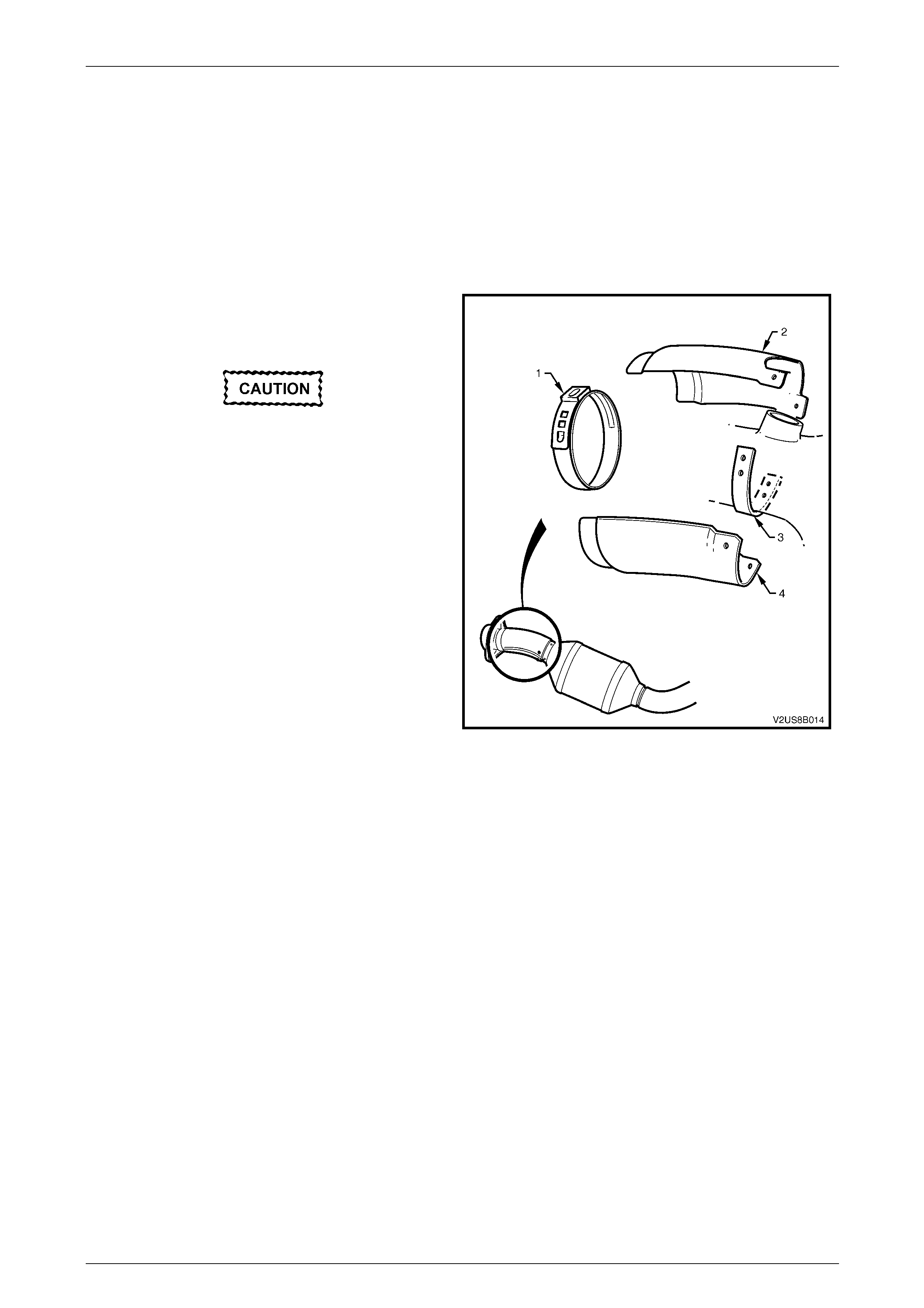
2 Use Keystone clamp pliers, Tool No. J22610 , to cut
through the ear (1) of the ear-type clam p and remove
and dispose of clamp.
Do not use excessive force when drilling
out heat shield rivets. Excessive force
may result in the drill being pushed into
and piercing the exhaust pipe underneath.
3 Drill out each of the four rivets securing the upper and
lower facing on-pipe heat shiel ds (2 and 4) to the
welded-on exhaust pipe bracket (3).
Figure 8B – 56
Reinstall
Reinstallation of the on-pipe heat shields is the reverse of the removal procedure, noting the follo wing:
1 Rivet the upper and lower on-pipe heat shields onto the front exhaust pipe bracket.
2 Install a new ear-type clamp by hand and fasten using Keystone clamp pliers, Tool No. J22610.
Exhaust System Page 8B–42
Page 8B–42
4.5 Front On-Pipe Heat Shield – Post-
catalytic Converter
Remove
1 If required, remove the front exhaust assembly, refer to:
• 2.6 Front Exhaust for Alloytec.
• 3.6 Front Exhaust for GEN IV V8, except Coupe.
The lower heat shield and clamps will drop
away from exhaust when all attaching nuts
are removed.
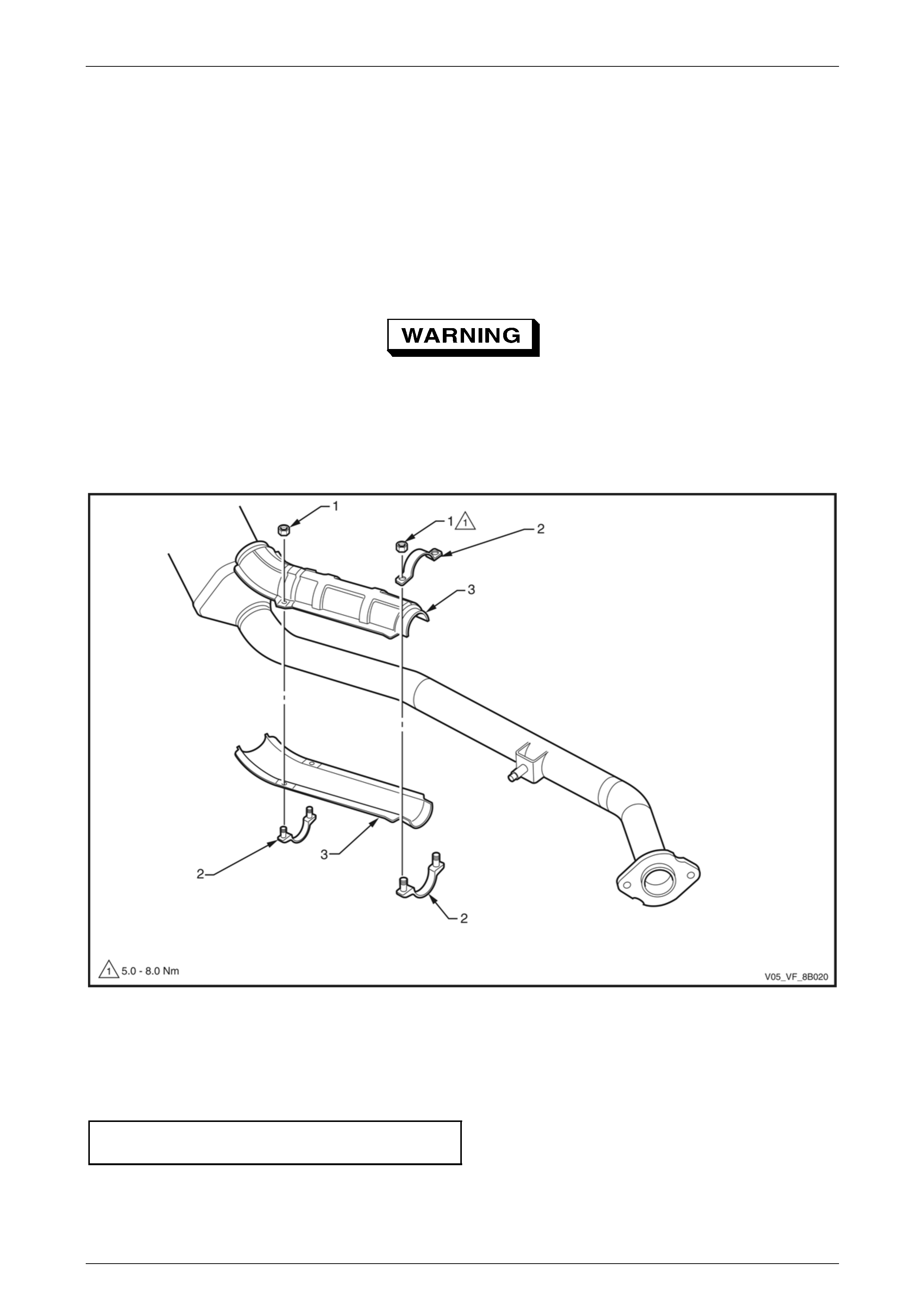
2 Supporting the lower heat shield, remove the attaching nuts (1) and clamps (2), refer to Figure 8B –.57.
3 Remove the lower and upper heat shield (3).
Figure 8B –57
Reinstall
Reinstallation of the on-pipe heat shield is the reverse of the removal procedure. T ighten the nuts to the correct torque
specification.
Front on-pipe heat shield attaching
nut torque specification...............................5.0 – 8.0 Nm

Exhaust System Page 8B–43
Page 8B–43
5 Exhaust System Diagnosis
CONDITION PROBABLE CAUSE CORRECTION
Leaks at pipe joints. Tighten U-bolt nuts, ring clamps
and joint bolts to the correct
torque specification.
Damaged or incorrectly installed
converter sealing ring/gaskets. Replace sealing ring/gasket as
required.
Leaking exhaust gases
Burned or rusted out exhaust pipe or
muffler/s. Replace component as required.
Leaks at manifold or pipe connections.
Tighten clamps at leaking
connections to the correct torque
specification. Replace gasket as
required.
Burned or blown out pipe or muffler/s. Replace pipe/muffler assembly
as required.
Exhaust manifold/s cracked or broken. Replace manifold.
Exhaust noises
Leak between manifold/s an d cylinder
head/s.
Tighten manifold to cylinder head
studs to the correct torque
specification.
Clogged catalytic converter (may
result from serious engine
malfunction). Replace catalytic converter.
Loss of engine power, hesitation,
surging, poor fuel economy,
stalling or hard starting Crushed pipe work. Replace pipe work.
Dislodged tubes and/or baffles in
muffler. Replace muffler.
Internal rattling in muffler Catalytic converter monolith has
crumbled and pieces blo wn into
muffler.
Replace catalytic converter
assembly and affected muffler.
Damaged, worn, missing or incorrectly
installed support rubbers. Check and replace as required.
Damaged mounting hangers or pegs. Service / replace hangers or
pegs as required.
Check clearances and adjust
joint alignment as required.
Incorrect alignment. Tighten all fasteners accordin g to
tightening sequence and to the
correct torque specification s.
Damaged or incorrect exhaust system
components. Replace damaged or incorrec t
components as required.
Damaged or dislodged tuned vibration
absorber. (Where fitted) Replace rear exhaust assembly.
Rattling or knocking exhaust
system
Damaged flexible pipe section.
(Where fitted) Replace rear exhaust assembly.

Exhaust System Page 8B–44
Page 8B–44
6 Specifications
Material
Engine Pipes .............................................................................................. 409 stainless steel
Intermediate Muffler.................................................................................... 409 stainless steel
Rear Muffler................................................................................................ 409 stainless steel
Catalytic Converter
Make.....................................................................................................................AC Australia
Type............................................................................................................three-way monolith
Outer Steel Shell......................................................................................... 409 stainless steel
Monolith Material .......................................................................................Extruded Cordierite
Cells/cm2..............................................................................................................................62

Exhaust System Page 8B–45
Page 8B–45
7 Torque Wrench Specifications
Manifold to Front Pipe Flange Joint Stud Attaching Nut............18.0 – 35.0 Nm
Cross Brace to Front Exhaust Pipe Nut.....................................18.0 – 35.0 Nm
Cross Brace Bracket Attaching Nut...........................................18.0 – 35.0 Nm
Slip Joint U-clamp Attaching Nut...............................................20.0 – 30.0 Nm
Front Pipe to Intermediate Pipe Flange Jo int Attaching
Bolt, Except Coupe....................................................................40.0 – 50.0 Nm
Intermediate to Rear Exhaust Flange Joint Attaching Bolt ........20.0 – 30.0 Nm
Slip Joint Ring Clamp Nut..........................................................37.0 – 50.0 Nm
Front Pipe to intermediate Pipe Flange Joint Attaching
Bolt, Coupe................................................................................34.0 – 46.0 Nm
Front Pipe to Intermediate Pipe Flange Jo int Attaching
Nut, Coupe................................................................................34.0 – 46.0 Nm
Displacement Joint Attaching Bolt.............................................40.0 – 50.0 Nm
Rear Heat Shield Attaching Screw................................................5.0 – 8.0 Nm
Intermediate Heat Shield Attaching Screw....................................5.0 – 8.0 Nm
Intermediate Heat Shield Attaching Nut ........................................5.0 – 8.0 Nm
Front Heat Shield Attaching Nut....................................................5.0 – 8.0 Nm
Front On-pipe Heat Shield Attaching Nut ......................................5.0 – 8.0 Nm

Exhaust System Page 8B–46
Page 8B–46
8 Special Tools
Tool Number Illustration Description Tool Classification
J22610
Keystone Clamp Pliers
Used to tighten ear-type clamps.
Essential