
Vehicle Diagnostics 0D – 1
0D – 1
Section 0D
Vehicle Diagnostics
ATTENTION
Before performing any Service Operation or other procedure described in this Section, refer to Section 00
Warnings, Cautions and Notes for correct workshop practices with regard to safety and/or property damage.
1 General Description ...............................................................................................................................2
1.1 General Information............................................................................................................................................... 2
1.2 A Tiered Approach to Diagnostics....................................................................................................................... 4
Step 1 Diagnostic System Check – Vehicle..................................................................................................... 4
Step 2 Diagnostic System Check – System..................................................................................................... 4
Step 3 Diagnostic Trouble Code (DTC) Tables................................................................................................ 4
Multiple DTCs Fault Condition............................................................................................................................ 4
Symptom Diagnostics ........................................................................................................................................... 4
2 Diagnostic Skills Required....................................................................................................................5
2.1 Basic Knowledge Required................................................................................................................................... 5
2.2 Basic Diagnostic Tools Required......................................................................................................................... 6
2.3 Diagnostic Precautions......................................................................................................................................... 7
2.4 Preliminary Checks................................................................................................................................................ 8
3 Vehicle Diagnostics ...............................................................................................................................9
3.1 Diagnostic System Check – Vehicle..................................................................................................................... 9
Purpose of Test...................................................................................................................................................... 9
Test Description..................................................................................................................................................... 9
Diagnostic System Check – Vehicle................................................................................................................... 10
4 Diagnostic Trouble Code List – Vehicle.............................................................................................13
Introduction.......................................................................................................................................................... 13
DTC List – Vehicle................................................................................................................................................ 13
Glossary of Abbreviations .................................................................................................................................. 64
Vehicle Diagnostics 0D – 2
0D – 2
1 General Description
1.1 General Information
There are a number of reasons for including this Section in the MY 2005 range of vehicles:
1 There are now three means of serial data communication available between the various electronic control modules
in the vehicle range;
• Universal Asynchronous Receive and Transmit (UART) protocol.
• Class II.
• General Motors Local Area Network (GM LAN) for the Alloytec range of V6 engines.
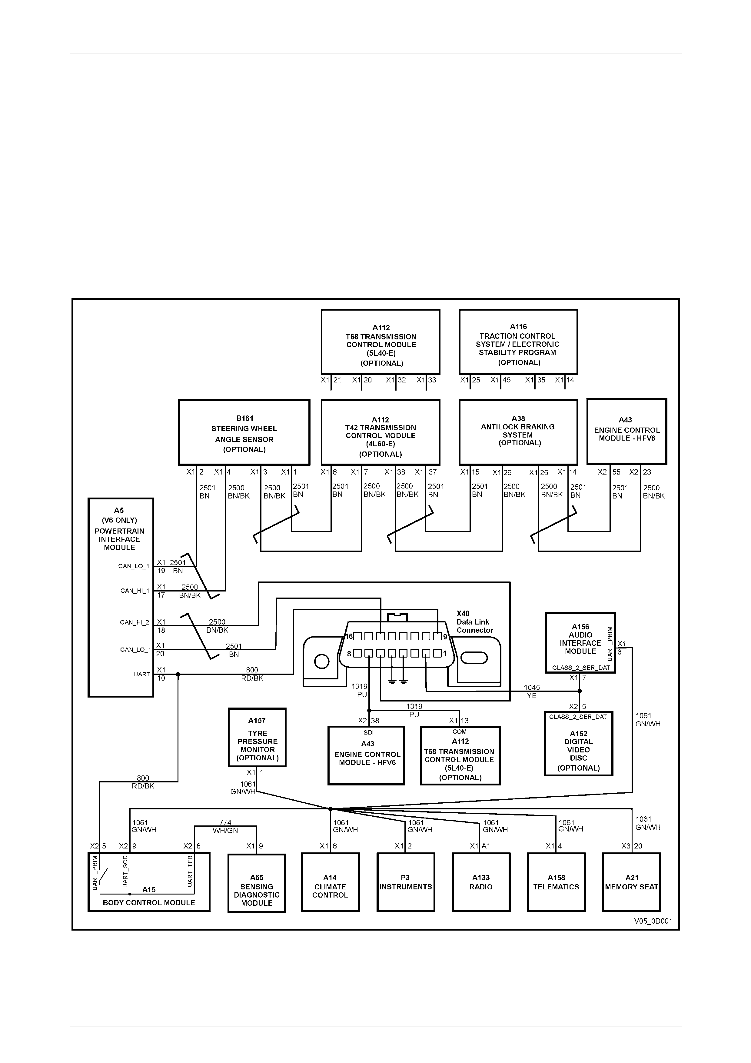
2 Alloytec engines have separate engine and transmissi on co ntrol modules, depen ding on engine and transmission
configuration.
Figure 0D – 1 – V6 Serial Data Communications
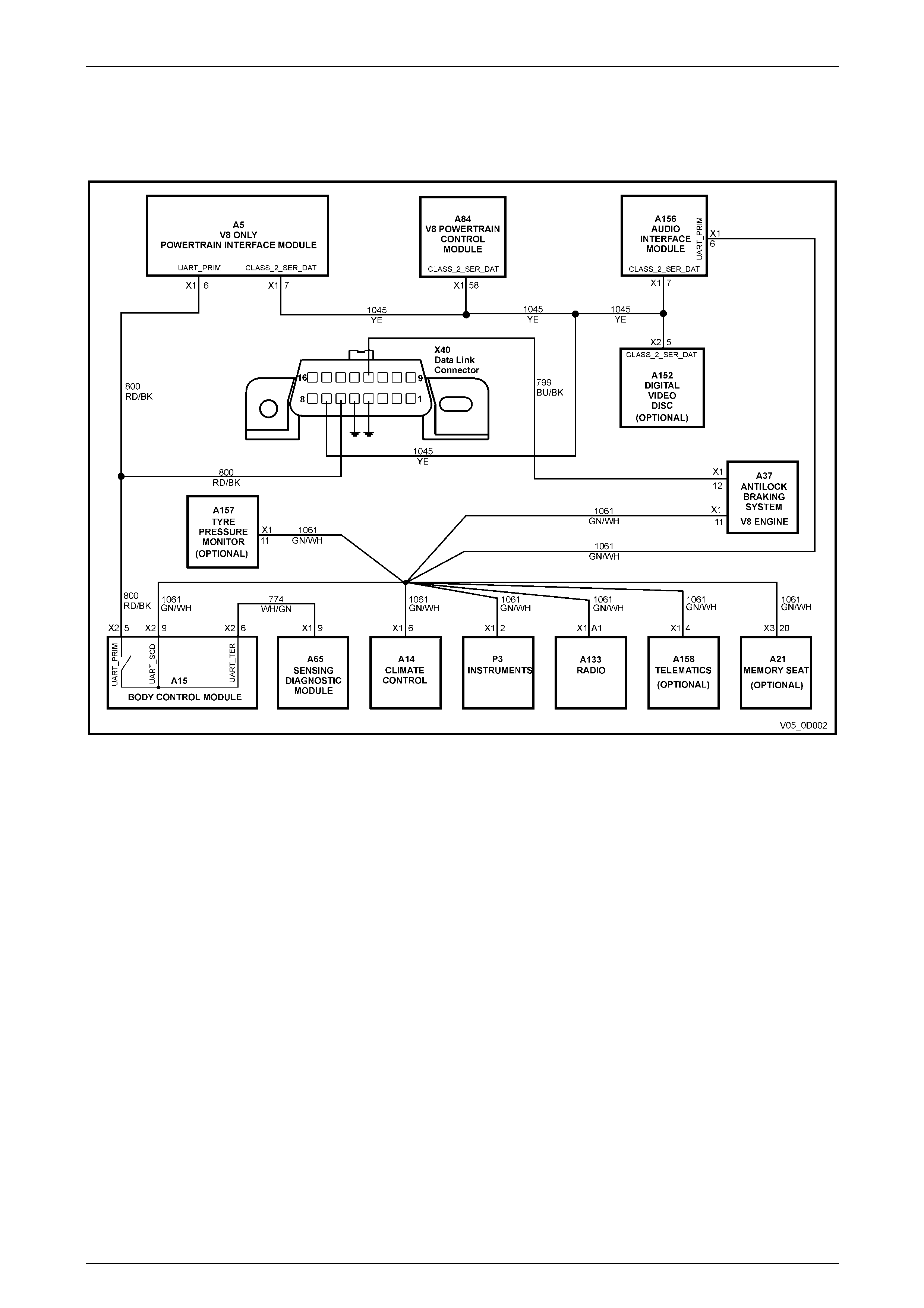
3 A Powertrain Interface Module (PIM) is also required as the hard ware and serial communications interfac e for both
the V6 and GEN III V8 engines. The PIM acts as a transparent bi-directional translation device that allows data to
flow between modules with GM LAN protocol and modules with UART protocol, as shown in Figures 0D-1 and
0D-2.
Vehicle Diagnostics 0D – 3
0D – 3
4 With the communication necessary between the engine and transmission modules, there are instances where the
engine control module (ECM) could set a diagnostic trouble code (DTC) that would also be detected by the
transmission control module (TCM).
Therefore, to ensure that the most efficient and effective diagnostic process is followed, a ‘tiered approach’ to the
diagnostic process for electric al systems within the vehicle is now more important than ever.
Figure 0A – 2 – GEN III V8 Serial Data Communications
As shown in the previous two circuit diagrams, the Body Control Module (BCM) remains as the ‘Bus Master’ that
periodically polls (or surveys) each of the following devices on the serial data bus (including the BCM itself), requesting
status data:
• V6 Engine Control Module (ECM) and Transmission Control Module (TCM), via the Powertrain Interface Module
(PIM).
• GEN III V8 Powertrain Control Module (PCM) and Audio Interface Module (AIM) if fitted, via the Powertrain
Interface Module (PIM).
• Antilock Braking System / Traction Control System (ABS / TCS) module (GEN III V8 Engine) or Antilock Braking
System / Traction Control System (ABS / TCS) module, via the PIM (V6 Engines).
• Electronic Stability Program (ESP) and the Steering Angle Sensor (SAS), via the PIM (V6 Engines).
• Instrument cluster (INS).
• Telematics Control Module.
• Supplemental Restraint System (SRS) Sensing Diagnostic Module (SDM).
• Audio System Head Unit (AHU).
• Premium Sound Amplifier (PSA)
• Occupant Climate Control (OCC) Module.
• Memory Seat and Mirror Module (MSM)
• Body Control Module (BCM)
• Tech 2 diagnostic scan tool.
From this list it will be apparent that only those modules fitted to a specific vehicle, will be polled.
The BCM polls each device for a status report every 300 milliseconds, with the exception of the ECM, TCM, and the
AHU, which are polled every 150 millisecon ds.

Vehicle Diagnostics 0D – 4
0D – 4
1.2 A Tiered Approach to Diagnostics
Resulting from the increased compl exity and communication s systems utilised in MY 2005 range of vehicles, this three
stage approach to the diagnostic process must be un dertaken in the specified manner, if misdiagnosis and the
unnecessary replacement of soun d components is to be avoided.
Step 1 Diagnostic System Check – Vehicle
All vehicle diagnostic procedures are organised in a logical structure that begins with the Diagnostic S ys tem Check –
Vehicle, detailed in this Section. The Diagnostic System Check – Vehicle must always be referred to first, as you will be
directed through the logical steps nec essary to diagnose any ve hicle electrical fault condition.
When working through the Di agnostic System Check – Vehicle, you will be directed to a specific system or diagnostic
system check (e.g. automatic transmission, BCM, etc). Activating the hyperlink provided will then take you to the system
check required.
Step 2 Diagnostic System Check – System
By working through this specific system diagnostic system check, you will be directed to either a Diagnostic Trouble
Code (DTC) table or to other sections within the service information to assist in the solutio n of a vehicl e related problem.
This referral may be to the Symptoms section included for all systems or to intermittent electrical circuit problems.
Through the process of completing the i ndividual system diagnostic system check, you will be directed to the Diagnostic
Trouble Code (DTC) Tables, assuming that there is a DTC currently stored.
Step 3 Diagnostic Trouble Code (DTC) Tables
All diagnostic tables are developed with the following assumptions:
• The vehicle functioned correctly at the time of assembly,
• There are no multiple faults, and
• The problem currently exists.
An understanding of and the correct use of the diagnostic tables is essential if the diagnostic time is to be minimised
and/or to prevent poor diagnosis.
Multiple DTCs Fault Condition
In any given electronic system, some fault conditions trigger multiple component DTCs even if the fault cond ition exists
only in a single component. If there are multiple DTCs stored, the Technician must view and record all DTCs logged.
The relationship between the logged DTCs can then be reviewed to determine the so urce of the fault condition. Always
begin the diagnostic process by compl eting the Diagnostic Table for the fault condition that may trigger other DTCs to
set.
The following fault conditions ma y trigger multiple DTCs:
• A system voltage that is too low may cause incorrect system management operation or a component to
malfunction.
• A system voltage that is too high may damage the system control module and/or other sensitive electronic
components.
• A fault condition in the system control module Read Only Memory (ROM) or Random Access Memory (RAM).
• A fault condition in the system control module internal circuitry or programming.
• An improperly connected sen sor or component wiring harness connector.
• An electrical fault condition in shared system electrical circuits may trigger DTCs for components or sensors that
are connected to the same faulty circuit (e.g. an open in one of the GMLAN circuits). Test the electrical circuit of the
appropriate sensor or components to isolate the fault condition. Each Section contains detailed electrical circuits
relating to that system.
If there are no obvious faults to begin a multiple set DTC fault condition, always start with the lowest number, then work
progressively through each.
Symptom Diagnostics
Should all of the following conditions exist, refer to the Symptom Tables, that may be provided in the particular system:
• An system fault condition exists,
• There is no Current Diagnostic Trouble Code presently stored in the control module, and
• All the Tech 2 data parameters for that system, are within the normal operating range.

Vehicle Diagnostics 0D – 5
0D – 5
2 Diagnostic Skills Required
2.1 Basic Knowledge Required
A lack of basic understanding regarding
electronics, electrical wiring circuits and use
of electrical circuit testing tools when
performing any diagnostic procedure, could
result in incorrect diagnostic results or
damage to system components.
Understanding of the following is required to perform any of the dia gn ostic procedures detailed in this Service
Information:
• Basic electronics,
• Electrical wiring circuits,
• Electrical circuits testing, and
• Correct use of basic system diagnostic tools.
Refer to Section 12P Wiring Diagrams and to 2.2 Basic Dia gnostic Tools Required, as required.
In addition, a complete under standing of the affected vehicle system is essential to prevent misdiagnosis and component
damage. Refer to 1 General Information in any specific Section.

Vehicle Diagnostics 0D – 6
0D – 6
2.2 Basic Diagnostic Tools Required
Use of incorrect electrical circuit diagnostic
tools when performing any diagnostic
procedures could result in incorrect
diagnostic results or damage to system
components.
The following electrical circuit testing tools are required to perform the diagnostic procedu r es detailed in this Section.
• Tech 2, refer to Section 0C Tech 2.
• Unpowered test lamp, refer to Section 12P Wiring D iagrams.
• Digital multimeter with a minimum 10 Megohm impedance, refer to Section 12P W iring Diagrams.

Vehicle Diagnostics 0D – 7
0D – 7
2.3 Diagnostic Precautions
The following precautions must be observed when performing all diagn osti c procedures. Otherwise, incorrect diagnostic
results or damage to system components will occur:
1 Disconnection of the battery affects certain vehicle electronic systems.
Refer to Section 00 Warnings, Cautio ns and Notes before disconnecting the battery.
2 Disconnect the battery negative lead when performing the following procedures:
• Disconnecting the electronic c ontrol module wiring harness conn ector/s or
• Charging the battery.
3 Disconnect the battery terminal ground lea d and the electronic control module wiring harness conn ector before
attempting any electric arc welding on the vehicle.
4 Do not start the engine if the battery terminal is not properly secured to the battery.
5 Do not disconnect or reconnect any of the following while the ignition is switched on or when the engine is running:
• Any electronic control module or system component el ectrical wiring connector, or
• Battery terminal leads.
6 Ensure that the correct procedure for disconnecting and co n necting system electrical wiring harness connectors is
always followed. For information on the correct procedure for disconnecting and connecting specific wiring
connectors, refer to Section 12P Wiring Harness, Connectors.
7 Ensure that all wiring harness connectors are fitted correctly and secure.
8 When steam or pressure cleanin g vehicle components, such as engines, transmissions, etc., do not direct the
cleaning nozzle at any system electrical wiring harness connectors or compon ents.
9 Do not clear any DTCs unless instructed.
10 The fault must be present when usi ng the Diagnostic Trouble Code (DTC) Diagnostic Tables. Otherwise,
misdiagnosis or replacement of good parts may occur.
11 Do not touch any electronic control mo dule connector pins or soldered compon ents on the circuit board. This is
required to avoid the possibility of electrostati c discharge damage. Refer to Handling ESD Sensitive Parts,
4 Safety and Service Guidelines, in Section 00 Warnings, Cautions and Notes.
12 Use only the test equipment specified in the diagnostic tables, as other test equipment may give incorrect results or
damage good components.
13 Electronic control modules are designed to withstand normal curre nt draws associated with vehicle oper ation.
However, the following fault conditions or incorrect test procedure may overload internal control module circuits and
irreparably damage the control module:
• A short to voltage fault condition in any of the control module low reference circuits may cause i ntern al and/or
sensor damage. Therefore, any short to voltage fault condition in the control module low reference circuits
must be rectified before replacing a fau lty component.
• A short to ground fault condition in any of the control module 5 volts reference circuits may cause internal
control module and/or sensor damage. Therefore, any short to ground fault condition i n the control module 5
volt reference circuits must be rectified before replacing a faulty component.
• When using a test light to test an electrical circuit, do not use any of the control module low reference circuits
or 5 volts reference circuits as a reference point. Otherwise, excessive current draw from the test light may
damage the control module.
14 Disregard DTCs that set while performing the following diagnostic Steps:
• Using the Tech 2 output control function, or
• Disconnecting a control modu le system sensor connector then switching the ignition ON.
15 After completing the required diagnostics an d service operations, road test the vehicle to ensure correct system
operation.

Vehicle Diagnostics 0D – 8
0D – 8
2.4 Preliminary Checks
The Preliminary Checks is a set of visual and physical checks or inspections that may quickly identify a control module
system fault condition:
1 Refer to relevant Service Techlines for information regarding the fault condition.
2 Ensure that the battery is fully charged.
3 Inspect the battery connections for corrosion or a loose terminal.
4 Ensure that all relevant control module system related fuses are serviceable.
5 Inspect for incorrect aftermarket theft deterrent devices, lights or mobile phone i nstall atio n.
6 Ensure that there is no speaker magnet positi oned too close to any electronic module that contains relays.
7 Inspect the system wiring harness for proper connections, pinches or cuts.
8 Ensure that all control module related electrical wiring connectors are fitted correctl y.
9 Inspect the control module ground conn ections for corrosion, loose terminal or incorr ect position.
10 Ensure that the resistance between the control module housing and the b attery ground cable is less than 0.5 ohms.
11 Check that the control module and its mounting bracket is secure.
12 Check all control module relat ed components for correct installation.
13 Check the control module and related wiring harness routing to ensure that no rubbing or cutting of the wiring
harness by sharp body compo nents can occur.

Vehicle Diagnostics 0D – 9
0D – 9
3 Vehicle Diagnostics
3.1 Diagnostic System Check – Vehicle
Purpose of Test
When a vehicle system test is carried out, the following ‘Diagnostic System Check – Vehicle’ must be completed, using
Tech 2. This must always be the first stage in any diagnostic process before proceeding with a vehicle system specific,
diagnostic system check. Failure to complete this process, may lead to an incorrect or incompl ete dia gn osis of the
system fault or faults present in the vehicle.
When a vehicle system develops a fault, the source of the fault may not necessarily be located within the confines of the
system displaying a DTC. Accordingly, the follo wing ‘Diagnostic System Check – Vehicle’ table is provided to ensure that
any faults outside of a vehicle system that cause it to display a DTC, are id entified prior to any system specific diagnosis
being carried out.
When working through the Di agnostic System Check – Vehicle, once a referral is made, then that must be foll owed
through to its conclusion. It is not necessary to work through the complete Diagnostic Syst em Check – Vehicle table
before addressing the sec on d tiered level in the diagnostics strategy.
The order of control modules listed in this Diagnostic System Check is intent ional.
Test Description
The numbers below refer to the step numbers on the diagnostic table:
1 This step ensures that the battery, the vehicle primary power, and ground systems are functioning c orre ctly.
2 This test ensures that Tech 2 is being p owered up.
3 This step ensures that all mandatory Mo dules/ECU’s are present. Lack of communication with a mandator y
Module/ECU may be due to a particular malfunction of a serial data circuit.
4 Lack of communication may be due to a parti cular malfunction of a serial data circuit. You must be aware of the
vehicle options to determine if Tech 2 should be able to communicate with a Module/ECU or not.
5 This test step determines if the engine will crank.
6 This test step determines if the engine will start and idle.
7 This test step determines if any DTCs are present.
8/23 These steps ensure that DTCs are diagn osed in a specific order. With each step being linked to a unique
Diagnostic System Check, this appro ach provides quick access to the appropri ate Section.
NOTE
Not all the systems listed in this procedure are
fitted to all vehicles.
24 For specific symptoms complaints you shoul d refer to the associated system symptom diagnostics.

Vehicle Diagnostics 0D – 10
0D – 10
Diagnostic System Check – Vehicle
Step Action Yes No
1 Have the Preliminary Ch ecks been completed?
Go to Step 2.
Go to 2.4
Preliminary Checks,
in this Section.
2 Install Tech 2.
Does Tech 2 power up? Go to Step 3.
Go to Tech 2 Does
Not Power Up in OC
Tech 2.
3 1 Ignition ON, engine OFF.
2 From the Tech 2 Main Menu select:
Diagnostics / 2005 / VZ and WL Series / Vehicle / Module /
ECU Presence Check, then follow the on-screen instructions.
NOTE
If more than one of the four mandatory Module/ECUs
(BCM, PIM, ECM/PCM, Instrument) are displayed as ‘No
Communication’, diagnose them in this priority order.
Does Tech 2 display a ny mandatory ECU as No Communication?
Go to Diagnostic
System Check for
the Mandatory
Module/ECU in the
following order:
BCM
PIM
ECM (V6) /
PCM (GEN III V8)
Instrument. Go to Step 4.
4 Does Tech 2 communicate with all of the expected vehicle
Modules/ECUs?
Go to Step 5.
Go to Steps 8 to 23
inclusive, in this
table and select the
Diagnostic System
Check for the
affected
Module/ECU.
5 Attempt to start the engine.
Does the engine crank?
Go to Step 6.
Go to Diagnostic
System Check in
Section 6C1-2 V6
Diagnostics or
Section 6C3-2 GEN
III V8 Diagnostics.
6 Attempt to start the engine.
Does the engine start and idle?
Go to Step 7.
Go to Diagnostic
System Check in
Section 6C1-2 V6
Diagnostics or
Section 6C3-2 GEN
III V8 Diagnostics.
7 Use the appropriate Tech 2 selections to obtain DTCs for each of the
control modules.
Does Tech 2 display an y DTCs? Go to Step 8. Go to Step 24.
8 Does Tech 2 display a ny BCM DTCs? Go to Diagnostics,
in Section 12J BCM. Go to Step 9.

Vehicle Diagnostics 0D – 11
0D – 11
Step Action Yes No
9 Does Tech 2 display any PIM DTCs? Go to PIM
Diagnostic System
Check, in Section
6E1 V6 PIM or
Section 6E3 GEN III
V8 PIM. Go to Step 10.
10 Does Tech 2 display a ny Engine DTCs? Go to Diagnostic
System Check, in
Section 6C1-2 – V6
Diagnostics or
Section 6C3-2 –
GEN III V8
Diagnostics. Go to Step 11.
For the V6 engine
and 4L60-E
transmission, go to
Diagnostic System
Check, in Section
7C2 – Electrical
Diagnosis.
For the 5L40-E
transmission, go to
Diagnostic System
Check, in Section
7E2 – 5L40-E
Electrical Diagnosis.
11 Does Tech 2 display a ny Transmission DTCs?
For the GEN III V8
engine and 4L60-E
or 4L65-E
transmission, go to
Diagnostic System
Check, in Section
6C3-2 GEN III V8
Diagnostics Go to Step 12.
12 Does Tech 2 display any ABS / ABS-TCS / ABS-TCS ESP DTCs? Go to
ABS-TCS/ESP
Diagnostic System
Check, in Section
5B General
Information. Go to Step 13
13 Does Tech 2 display any Instrument DTCs? Go to Diagnostics,
in Section 12C
Instrumentation. Go to Step 14
14 Does Tech 2 display any Telematics Module DTCs? Go to Diagnostics,
in Section 12K
Telematics. Go to Step 15

Vehicle Diagnostics 0D – 12
0D – 12
Step Action Yes No
15 Does Tech 2 display any SRS SDM DTCs? Go to Diagnostics,
in Section 12M
Occupant Protection
System. Go to Step 16
16 Does Tech 2 display any Audio System DTCs? Go to Diagnostics,
in Section 12D
Entertainment
System. Go to Step 17
17 Does Tech 2 display any Premium Sound Amplifier (PSA) DTCs? Go to Diagnostics,
in Section 12D
Entertainment
System. Go to Step 18
18 Does Tech 2 display any Occupant Climate Control DTCs? Go to Diagnostics,
in Section 2E
Occupant Climate
Control. Go to Step 19
19 Does Tech 2 display an y Mem ory Seat and Mirror Module (MSM)
DTCs? Go to Diagnostics,
in Section 1A7 Seat
Assemblies. Go to Step 20
20 Does Tech 2 display any Multi Function Display (MFD) DTCs? Go to Diagnostics,
in Section 12I Multi
Function Display. Go to Step 21
21 Does Tech 2 display any Audio Interface Module (AIM) DTCs? Go to Diagnostics,
in Section 12D
Entertainment
System. Go to Step 22
22 Does Tech 2 display a ny DVD DTCs? Go to Diagnostics,
in Section 12D
Entertainment
System. Go to Step 23
23 Does Tech 2 display a ny Auxiliary Gauge DTCs? Go to Diagnostics,
in Section 12I Multi
Function Display. Go to Step 24
24 Is the customer’s concern with a specific system symptom? Go to Symptoms
for the affected
system. System OK

Vehicle Diagnostics 0D – 13
0D – 13
4 Diagnostic Trouble Code List –
Vehicle
Introduction
This master DTC list includes all applicable DTCs in numeric and alphanumeric order with descriptors. There will be
times when working through a diagnostic table, that you will be required to check for additi onal Diagnostic Trouble C od es
(DTCs). This list is intended to be used to identify those additional DT C/s and to provide a link to the appropriate
Diagnostic System Check table.
NOTES
• There are instances where the same
numerical DTC number is set by different
modules. Where this occurs, the DTCs are
listed in the same module order as listed in
the Diagnostic System Check – Vehicle.
• There are also multiple DTC listings that are
set by the same module. In these instances,
Tech 2 will identify the individual condition for
that item.
• Yet again, there are a number of DTCs with
the same descriptors that relate to different
vehicle systems; e.g. engines, transmissions
and braking system. Therefore, for this DTC
list to be of any value, you must be aware of
the vehicle equipment level and specification,
before activating the appropriate hyperlink.
Where a DTC has a letter prefix, it provides an indication of the system within the vehicle, that ‘owns’ that device. For
example:
B Body
C Chassis
P Powertrain
U Serial Communication
DTC List – Vehicle
DTC DTC Descriptor Module That
Sets the DTC Diagnostic Table Location
1 Output Overload BCM Go to 3 Diagnostics, in Section
12J Body Control Module
1 No Serial Data From BCM Telematics Go to 4 Diagnostics in Section
12K Telematics.
1 DSP Failure Premium Sound
Amplifier Go to 3 Diagnostics in Section
12D Entertainment System.
1 Front Vertical Up Switch Stuck Memory Seat and
Mirror Module
(MSM) Go to 4 Diagnostics, in Section
1A7 Seat Assemblies.
1 No Class 2 Serial Data from DVD Audio Interface
Module Go to 3 Diagnostics in Section
12D Entertainment System.

Vehicle Diagnostics 0D – 14
0D – 14
DTC DTC Descriptor Module That
Sets the DTC Diagnostic Table Location
2 Slip Ring Communic ation Error BCM Go to 3 Diagnostics, in Section
12J Body Control Module
2 No Serial Data From Instrument Telematics Go to 4 Diagnostics in Section
12K Telematics.
2 EEPROM Error Premium Sound
Amplifier Go to 3 Diagnostics in Section
12D Entertainment System.
2 Front Vertical Down Switch Stuck Memory Seat and
Mirror Module
(MSM) Go to 4 Diagnostics, in Section
1A7 Seat Assemblies.
2 DVD Not Initialised Audio Interface
Module Go to Diagnostic System Check,
in Section 12D Audio System
3 Fuel Type Mismatch Instrument Go to 2 Diagnostics in Section
12C Instrumentation.
3 No Serial Data From Sensing Diag nostic Module Telematics Go to 4 Diagnostics in Section
12K Telematics.
3 No Serial Data Premium Sound
Amplifier Go to 3 Diagnostics in Section
12D Entertainment System.
3 Rear Vertical Up Switch Stuck Memory Seat and
Mirror Module
(MSM) Go to 4 Diagnostics, in Section
1A7 Seat Assemblies.
3 No Serial Data From BCM Audio Interface
Module Go to 3 Diagnostics in Section
12D Entertainment System.
4 Auto Transmission Mismatch Instrument Go to 2 Diagnostics in Section
12C Instrumentation.
4 No Serial Data From Audio System Telematics Go to 4 Diagnostics in Section
12K Telematics.
4 Rear Vertical Down Switch Stuck Memory Seat and
Mirror Module
(MSM) Go to 4 Diagnostics, in Section
1A7 Seat Assemblies.
4 No Serial Data From Audio System Audio Interface
Module Go to 3 Diagnostics in Section
12D Entertainment System.
5 Tail Lamp Bulb Failure BCM Go to 3 Diagnostics, in Section
12J Body Control Module
5 Fuel Invalid Flag Set Instrument Go to 2 Diagnostics in Section
12C Instrumentation.
5 No Serial Data Telematics Go to 4 Diagnostics in Section
12K Telematics.
5 Horizontal Forward Switch Stuck Memory Seat and
Mirror Module
(MSM) Go to 4 Diagnostics, in Section
1A7 Seat Assemblies.
5 Loss of Accessory Power Supply Audio Interface
Module Go to 3 Diagnostics in Section
12D Entertainment System.
6 Stop Lamp Bulb Failure BCM Go to 3 Diagnostics, in Section
12J Body Control Module
6 No TPM Poll Response Detect ed For 10 Seconds Instrument Go to 2 Diagnostics in Section
12C Instrumentation.
6 Horizontal Back Switch Stuck Memory Seat and
Mirror Module
(MSM) Go to 4 Diagnostics, in Section
1A7 Seat Assemblies.

Vehicle Diagnostics 0D – 15
0D – 15
DTC DTC Descriptor Module That
Sets the DTC Diagnostic Table Location
7 No Serial Data From PCM BCM Go to 3 Diagnostics, in Section
12J Body Control Module
7 No ESP Poll Response Detected For 10 Seconds Instrument Go to Diagnostic System Check,
in Section 12C Instrumentation
7 Recline Up Switch Stuck Memory Seat and
Mirror Module
(MSM) Go to 4 Diagnostics, in Section
1A7 Seat Assemblies.
7 No Class 2 Serial Data Audio Interface
Module Go to 3 Diagnostics in Section
12D Entertainment System.
8 No ABS Poll Response Detected For 10 Seconds Instrument Go to 2 Diagnostics in Section
12C Instrumentation.
8 SIM Mismatch Telematics Go to 4 Diagnostics in Section
12K Telematics.
8 Recline Down Switch Stuck Memory Seat and
Mirror Module
(MSM) Go to 4 Diagnostics, in Section
1A7 Seat Assemblies.
8 Wrong Security Code (System Locked) Audio Interface
Module Go to 3 Diagnostics in Section
12D Entertainment System.
9 No BCM Broadcast Detected For 10 Second s Instrument Go to 2 Diagnostics in Section
12C Instrumentation.
9 Vehicle Battery Voltage Too High Telematics Go to 4 Diagnostics in Section
12K Telematics.
9 Memory Button 1 Stuck Memory Seat and
Mirror Module
(MSM) Go to 4 Diagnostics, in Section
1A7 Seat Assemblies.
10 No OCC Poll Response Detected For 10 Seconds Instrument Go to 2 Diagnostics in Section
12C Instrumentation.
10 Vehicle Battery Voltage Too Low Telematics Go to 4 Diagnostics in Section
12K Telematics.
10 Fascia Button Jammed Audio Head Unit Go to 3 Diagnostics in Section
12D Entertainment System.
10 Memory Button 2 Stuck Memory Seat and
Mirror Module
(MSM) Go to 4 Diagnostics, in Section
1A7 Seat Assemblies.
10 No CAN Communication From OOC Multi-function
Display Go to 2 Diagnostics in Section 12I
Multi-Function Display.
11 No PCM / ECM Poll Response Detected For 10
Seconds Instrument Go to 2 Diagnostics in Section
12C Instrumentation.
11 RAM Error Telematics Go to 4 Diagnostics in Section
12K Telematics.
11 Steering Wheel Remote Button Jammed Audio Head Unit Go to 3 Diagnostics in Section
12D Entertainment System.
11 Memory Button 3 Stuck Memory Seat and
Mirror Module
(MSM) Go to 4 Diagnostics, in Section
1A7 Seat Assemblies.
11 Class 2 Hardware Failure Audio Interface
Module Go to 3 Diagnostics in Section
12D Entertainment System.

Vehicle Diagnostics 0D – 16
0D – 16
DTC DTC Descriptor Module That
Sets the DTC Diagnostic Table Location
12 No SDM Poll Response Detected For 10 Seconds Instrument Go to 2 Diagnostics in Section
12C Instrumentation.
12 EEPROM Error Telematics Go to 4 Diagnostics in Section
12K Telematics.
12 Mirror Dip Button Stuck Memory Seat and
Mirror Module
(MSM) Go to 4 Diagnostics, in Section
1A7 Seat Assemblies.
12 EEPROM Mirror Checksum Error Audio Interface
Module Go to 3 Diagnostics in Section
12D Entertainment System.
13 No Instrument Poll from BCM Detected for 10
Seconds Instrument Go to 2 Diagnostics in Section
12C Instrumentation.
13 Backup Battery Timer Expired Telematics Go to 4 Diagnostics in Section
12K Telematics.
13 Ambient Temperature Sensor Voltage Too High OCC – ECU Go to Chart A – Diagnostic Circuit
Check, in Section 2E Occupant
Climate Control Diagnosis.
13 No Serial Data Memory Seat and
Mirror Module
(MSM) Go to 4 Diagnostics, in Section
1A7 Seat Assemblies.
13 EEPROM Checksum Error Audio Interface
Module Go to 3 Diagnostics in Section
12D Entertainment System.
14 No Serial Communic ations D etected F or 10
Seconds Instrument Go to 2 Diagnostics in Section
12C Instrumentation.
14 Backup Battery Voltage Too High Telematics Go to 4 Diagnostics in Section
12K Telematics.
14 Ambient Temperature Sensor Voltage Too Low OCC – ECU Go to Chart A – Diagnostic Circuit
Check, in Section 2E Occupant
Climate Control Diagnosis.
14 No Exterior Mirror Communication Memory Seat and
Mirror Module
(MSM) Go to 4 Diagnostics, in Section
1A7 Seat Assemblies.
15 No Radio Poll Response D etected F or 10 Seconds Instrument Go to 2 Diagnostics in Section
12C Instrumentation.
15 Backup Battery Voltage Too Low Telematics Go to 4 Diagnostics in Section
12K Telematics.
15 In-Car Temperature Sensor V oltage Too High OCC – ECU Go to Chart A – Diagnostic Circuit
Check, in Section 2E Occupant
Climate Control Diagnosis.
15 No Serial Data From Audio System Multi-function
Display Go to 2 Diagnostics in Section 12I
Multi-Function Display.
16 Loss of PCM Poll Response Data Or Fuel Level
Data At 0 Or 255 For More Than 10 Seconds Instrument Go to 2 Diagnostics in Section
12C Instrumentation.
16 Backup Battery Not Detected Telematics Go to 4 Diagnostics in Section
12K Telematics.
16 In-Car Temperature Sensor V oltage Too Low OCC – ECU Go to Chart A – Diagnostic Circuit
Check, in Section 2E Occupant
Climate Control Diagnosis.
17 Not Okay To Start Received From PCM BCM Go to 3 Diagnostics, in Section
12J Body Control Module
17 Microphone Not Detected Telematics Go to 4 Diagnostics in Section
12K Telematics.
17 Driver Airbag Circuit Short to Battery SDM Go to 2 Diagnostics in Section
12M Occupant Protection System.
17 Evaporative Temperatur e Sensor Voltage Too High OCC – ECU Go to Chart A – Diagnostic Circuit
Check, in Section 2E Occupant
Climate Control Diagnosis.

Vehicle Diagnostics 0D – 17
0D – 17
DTC DTC Descriptor Module That
Sets the DTC Diagnostic Table Location
18 Auxiliary (Secondary and Tertiary) Serial Data Bus
Fault BCM Go to 3 Diagnostics, in Section
12J Body Control Module
18 Passenger Seat Voltage Below Normal Operating
Range Or Open Circuit Detected Or Drive Circuit
Fault Detected Instrument Go to 2 Diagnostics in Section
12C Instrumentation.
18 Microphone Circuit Voltage Too Low Telematics Go to 4 Diagnostics in Section
12K Telematics.
18 Driver Airbag Circuit Short to Ground SDM Go to 2 Diagnostics in Section
12M Occupant Protection System.
18 Evaporative Temperatur e Sensor Voltage T oo Low OCC – ECU Go to Chart A – Diagnostic Circuit
Check, in Section 2E Occupant
Climate Control Diagnosis.
19 EEPROM Error BCM Go to 3 Diagnostics, in Section
12J Body Control Module
19 Incorrect SDM Module Poll Response Detected Instrument Go to 2 Diagnostics in Section
12C Instrumentation.
19 Microphone Circuit Voltage Too High Telematics Go to 4 Diagnostics in Section
12K Telematics.
19 Driver Airbag Circuit Capacitance Too High SDM Go to 2 Diagnostics in Section
12M Occupant Protection System.
19 Sun Load Sensor Error OCC – ECU Go to Chart A – Diagnostic Circuit
Check, in Section 2E Occupant
Climate Control Diagnosis.
19 ECU Malfunction Memory Seat and
Mirror Module
(MSM) Go to 4 Diagnostics, in Section
1A7 Seat Assemblies.
20 RAM Erro BCM Go to 3 Diagnostics, in Section
12J Body Control Module
20 Driver Airbag Circuit Capacitance Too Low SDM Go to 2 Diagnostics in Section
12M Occupant Protection System.
20 Front Vertical Position Sensor F ault Memory Seat and
Mirror Module
(MSM) Go to 4 Diagnostics, in Section
1A7 Seat Assemblies.
21 Battery Voltage Too Low BCM Go to 3 Diagnostics, in Section
12J Body Control Module
21 Right Front Wheel Speed Sensor Incorrect Signal. ABS-TCS
Go to Section 5B ABS / TCS /
ESP – General Information, for
the specific system identification
and reference to the correct
diagnosis.
21 Trip Switch Voltage Bel ow Normal Operating Range
100 ms Instrument Go to 2 Diagnostics in Section
12C Instrumentation.
21 Speaker Circuit Voltage Too Low Telematics Go to 4 Diagnostics in Section
12K Telematics.
21 Driver Airbag Circuit Resistance Too High SDM Go to 2 Diagnostics in Section
12M Occupant Protection System.
21 CD Mechanism Error (CD Changer Models Only) Audio Head Unit Go to 3 Diagnostics in Section
12D Entertainment System.
21 Rear Vertical Position Sensor Fault Memory Seat and
Mirror Module
(MSM) Go to 4 Diagnostics, in Section
1A7 Seat Assemblies.

Vehicle Diagnostics 0D – 18
0D – 18
DTC DTC Descriptor Module That
Sets the DTC Diagnostic Table Location
22 Battery Voltage Too High BCM Go to 3 Diagnostics, in Section
12J Body Control Module
22 Trip Switch Button or Buttons Pressed For At Least
One Minute Instrument Go to 2 Diagnostics in Section
12C Instrumentation.
22 Speaker Circuit Voltage Too High Telematics Go to 4 Diagnostics in Section
12K Telematics.
22 Driver Airbag Circuit Resistance Too Low SDM Go to 2 Diagnostics in Section
12M Occupant Protection System.
22 CD Play Error (CD Changer Models Only) Audio Head Unit Go to 3 Diagnostics in Section
12D Entertainment System.
22 Horizontal Position Sensor Fault Memory Seat and
Mirror Module
(MSM) Go to 4 Diagnostics, in Section
1A7 Seat Assemblies.
23 Door Lock / Unlock Circuit Overload BCM Go to 3 Diagnostics, in Section
12J Body Control Module
23 Right Front Wheel Spee d Sensor Short Circuit or
Open Circuit. ABS-TCS
Go to Section 5B ABS / TCS /
ESP – General Information, for
the specific system identification
and reference to the correct
diagnosis.
23 Recline Position Sensor Fault Memory Seat and
Mirror Module
(MSM) Go to 4 Diagnostics, in Section
1A7 Seat Assemblies.
24 Remote Key Rolling Code Error BCM Go to 3 Diagnostics, in Section
12J Body Control Module
24 Incorrect EEPROM Checksum Calculated After a
Battery Reset Instrument Go to 2 Diagnostics in Section
12C Instrumentation.
24 CD Loading Error (Single CD Models Only) Audio Hea d Unit Go to 3 Diagnostics in Section
12D Entertainment System.
24 System Voltage Out of Range Memory Seat and
Mirror Module
(MSM) Go to 4 Diagnostics, in Section
1A7 Seat Assemblies.
24 EEPROM Error Multi-function
Display Go to 2 Diagnostics in Section 12I
Multi-Function Display.
25 Engine Start Without Slip Ring Communic atio ns BCM Go to 3 Diagnostics, in Section
12J Body Control Module
25 Left Front Wheel Speed Sensor Incorrect Signal. ABS-TCS
Go to Section 5B ABS / TCS /
ESP – General Information, for
the specific system identification
and reference to the correct
diagnosis.
25 Incorrect ROM Checksum Calculated After a Battery
Reset Instrument Go to 2 Diagnostics in Section
12C Instrumentation.
25 CD Defect (Single CD Models Only) Audio Head Unit Go to 3 Diagnostics in Section
12D Entertainment System.
26 No Serial Data From ABS/ETC BCM Go to 3 Diagnostics, in Section
12J Body Control Module
26 CD General Error (Single CD Models Only) Audio Head Unit Go to 3 Diagnostics in Section
12D Entertainment System.

Vehicle Diagnostics 0D – 19
0D – 19
DTC DTC Descriptor Module That
Sets the DTC Diagnostic Table Location
27 No Serial Data From Instrument BCM Go to 3 Diagnostics, in Section
12J Body Control Module
27 Left Front Wheel Speed Sensor Short Circuit or
Open Circuit. ABS-TCS
Go to Section 5B ABS / TCS /
ESP – General Information, for
the specific system identification
and reference to the correct
diagnosis.
28 Antenna Drive Circuit Overload BCM Go to 3 Diagnostics, in Section
12J Body Control Module
28 Wheel Speed Frequency Error ABS-T CS
Go to Section 5B ABS / TCS /
ESP – General Information, for
the specific system identification
and reference to the correct
diagnosis.
29 Stop Lamp or Park Lamp Fuse Failure BCM Go to 3 Diagnostics, in Section
12J Body Control Module
30 Keypad Circuit Voltage Too High Telematics Go to 4 Diagnostics in Section
12K Telematics.
30 Internal Bus Failure Audio Head Unit Go to 3 Diagnostics in Section
12D Entertainment System.
31 Right Rear Wheel Speed Sensor Incorrect Signal. ABS-TCS
Go to Section 5B ABS / TCS /
ESP – General Information, for
the specific system identification
and reference to the correct
diagnosis.
33 Right Rear Wheel Spee d Sensor Short Circuit or
Open Circuit. ABS-TCS
Go to Section 5B ABS / TCS /
ESP – General Information, for
the specific system identification
and reference to the correct
diagnosis.
33 Passenger Airbag Circuit Short to Battery SDM Go to 2 Diagnostics in Section
12M Occupant Protection System.
33 Single Communication Bus F ailure Audio Head Unit Go to 3 Diagnostics in Section
12D Entertainment System.
34 Passenger Airbag Circuit Short to Ground SDM Go to 2 Diagnostics in Section
12M Occupant Protection System.
34 Multi Communication Bus Failure Audio Head Unit Go to 3 Diagnostics in Section
12D Entertainment System.
35 Left Rear Wheel Speed Sensor Incorrect Signal. ABS-TCS
Go to Section 5B ABS / TCS /
ESP – General Information, for
the specific system identification
and reference to the correct
diagnosis.
35 Passenger Airbag Circuit Capacita nce Too High SDM Go to 2 Diagnostics in Section
12M Occupant Protection System.
35 Fascia Communication Bus Failure Audio Head Unit Go to 3 Diagnostics in Section
12D Entertainment System.
35 No Serial Data from PCM OCC – ECU Go to Chart A – Diagnostic Circuit
Check, in Section 2E Occupant
Climate Control Diagnosis.

Vehicle Diagnostics 0D – 20
0D – 20
DTC DTC Descriptor Module That
Sets the DTC Diagnostic Table Location
36 Passenger Airbag Circuit Capacita nce Too Low SDM Go to 2 Diagnostics in Section
12M Occupant Protection System.
36 DSP Failure Audio Head Unit Go to 3 Diagnostics in Section
12D Entertainment System.
36 No Serial Data from BCM OCC – ECU Go to Chart A – Diagnostic Circuit
Check, in Section 2E Occupant
Climate Control Diagnosis.
37 Left Rear Wheel Speed Sensor Short Circuit or
Open Circuit. ABS-TCS
Go to Section 5B ABS / TCS /
ESP – General Information, for
the specific system identification
and reference to the correct
diagnosis.
37 Passenger Airbag Circuit Resistance Too High SDM Go to 2 Diagnostics in Section
12M Occupant Protection System.
37 ROM Checksum Error OCC – ECU Go to Chart A – Diagnostic Circuit
Check, in Section 2E Occupant
Climate Control Diagnosis.
38 Passenger Airbag Circuit Resistance Too Low SDM Go to 2 Diagnostics in Section
12M Occupant Protection System.
38 EEPROM Checksum Error OCC – ECU Go to Chart A – Diagnostic Circuit
Check, in Section 2E Occupant
Climate Control Diagnosis.
39 Telephone Number Error Telematics Go to Diagnostic System Check,
in 12K Telematics
39 RAM Error OCC – ECU Go to Chart A – Diagnostic Circuit
Check, in Section 2E Occupant
Climate Control Diagnosis.
40 Vehicle Identification Number Mismatch Telematics Go to 4 Diagnostics in Section
12K Telematics.
40 No BCM Serial Data Audio Head Unit Go to 3 Diagnostics in Section
12D Entertainment System.
40 Air Mix Door Motor Driver Error OCC – ECU Go to Chart A – Diagnostic Circuit
Check, in Section 2E Occupant
Climate Control Diagnosis.
41 Right Front Hydraulic Modulator Inlet Solenoid Valve
Fault ABS-TCS
Go to Section 5B ABS / TCS /
ESP – General Information, for
the specific system identification
and reference to the correct
diagnosis.
41 No Class 2 Serial Data Audio Head Unit Go to 3 Diagnostics in Section
12D Entertainment System.
41 Solenoid Driver Error OCC – ECU Go to Chart A – Diagnostic Circuit
Check, in Section 2E Occupant
Climate Control Diagnosis.
42 Right Front Hydraulic Modulator Outlet Solenoid
Valve Fault ABS-TCS
Go to Section 5B ABS / TCS /
ESP – General Information, for
the specific system identification
and reference to the correct
diagnosis.
42 Fuel Pump Circuit Voltage Too Low Telematics Go to 4 Diagnostics in Section
12K Telematics.
43 Fuel Pump Circuit Voltage Too High Telematics Go to 4 Diagnostics in Section
12K Telematics.
43 Driver’s Air Mix Door Motor Feedback Circuit
Voltage Too Low OCC – ECU Go to Chart A – Diagnostic Circuit
Check, in Section 2E Occupant
Climate Control Diagnosis.

Vehicle Diagnostics 0D – 21
0D – 21
DTC DTC Descriptor Module That
Sets the DTC Diagnostic Table Location
44 Driver’s Air Mix Door Motor Feedback Circuit
Voltage Too High OCC – ECU Go to Chart A – Diagnostic Circuit
Check, in Section 2E Occupant
Climate Control Diagnosis.
45 Left Front Hydraulic Modulator Inlet Solenoid Valve
Fault ABS-TCS
Go to Section 5B ABS / TCS /
ESP – General Information, for
the specific system identification
and reference to the correct
diagnosis.
45 End Call / Information Button Stuck Telematics Go to 4 Diagnostics in Section
12K Telematics.
45 Passenger’s Air Mix Door Motor Feedback Circuit
Voltage Too Low OCC – ECU Go to Chart A – Diagnostic Circuit
Check, in Section 2E Occupant
Climate Control Diagnosis.
46 Left Front Hydraulic Modulator Outlet Solenoid
Valve Fault ABS-TCS
Go to Section 5B ABS / TCS /
ESP – General Information, for
the specific system identification
and reference to the correct
diagnosis.
46 Holden Assist Button Stuck Telematics Go to 4 Diagnostics in Section
12K Telematics.
46 Passenger’s Air Mix Door Motor Feedback Circuit
Voltage Too High OCC – ECU Go to Chart A – Diagnostic Circuit
Check, in Section 2E Occupant
Climate Control Diagnosis.
47 Emergency Button Stuck Telematics Go to 4 Diagnostics in Section
12K Telematics.
47 Driver Airmix Min. Calibration Error OCC – ECU Go to Chart A – Diagnostic Circuit
Check, in Section 2E Occupant
Climate Control Diagnosis.
48 Driver Airmix Max. Calibratio n Error OCC – ECU Go to Chart A – Diagnostic Circuit
Check, in Section 2E Occupant
Climate Control Diagnosis.
49 Left Hand Pretensioner Circuit Short to Battery SDM Go to 2 Diagnostics in Section
12M Occupant Protection System.
49 Pass Airmix Min. Calibration Error OCC – ECU Go to Chart A – Diagnostic Circuit
Check, in Section 2E Occupant
Climate Control Diagnosis.
50 Left Hand Pretensioner Circuit Short to Ground SDM Go to 2 Diagnostics in Section
12M Occupant Protection System.
50 Pass Airmix Max. Calibration Error OCC – ECU Go to Chart A – Diagnostic Circuit
Check, in Section 2E Occupant
Climate Control Diagnosis.
51 Left Hand Pretensioner Circuit Capacitance Too
High SDM Go to 2 Diagnostics in Section
12M Occupant Protection System.
52 Left Hand Pretensioner Circuit Capacitance Too
Low SDM Go to 2 Diagnostics in Section
12M Occupant Protection System.
53 Left Hand Pretensioner Circuit Resistance Too High SDM Go to 2 Diagnostics in Section
12M Occupant Protection System.
54 Left Hand Pretensioner Circuit Resistance Too Low SDM Go to 2 Diagnostics in Section
12M Occupant Protection System.

Vehicle Diagnostics 0D – 22
0D – 22
DTC DTC Descriptor Module That
Sets the DTC Diagnostic Table Location
55 Rear Axle Hydraulic M odulator Inlet Solenoid Valve
Fault ABS-TCS
Go to Section 5B ABS / TCS /
ESP – General Information, for
the specific system identification
and reference to the correct
diagnosis.
56 Rear Axle Hydraulic Modulator Outlet Solenoid
Valve Fault ABS-TCS
Go to Section 5B ABS / TCS /
ESP – General Information, for
the specific system identification
and reference to the correct
diagnosis.
61 Pump Motor or Relay Fault ABS-TCS
Go to Section 5B ABS / TCS /
ESP – General Information, for
the specific system identification
and reference to the correct
diagnosis.
63 Valve Solenoid Relay Fault ABS-TCS
Go to Section 5B ABS / TCS /
ESP – General Information, for
the specific system identification
and reference to the correct
diagnosis.
65 Right Hand Pretensioner Circuit Short to Battery SDM Go to 2 Diagnostics in Section
12M Occupant Protection System.
66 Right Hand Pretensioner Circuit Short to Ground SDM Go to 2 Diagnostics in Section
12M Occupant Protection System.
67 Brake Switch Circuit Fault ABS-TCS
Go to Section 5B ABS / TCS /
ESP – General Information, for
the specific system identification
and reference to the correct
diagnosis.
67 Right Hand Pretension er Circuit Capacitance Too
High SDM Go to 2 Diagnostics in Section
12M Occupant Protection System.
68 Right Hand Pretension er Circuit Capacitance Too
Low SDM Go to 2 Diagnostics in Section
12M Occupant Protection System.
69 Right Hand Pretension er Circuit Resistance Too
High SDM Go to 2 Diagnostics in Section
12M Occupant Protection System.
70 Right Hand Pretension er Circuit Resistance Too
Low SDM Go to 2 Diagnostics in Section
12M Occupant Protection System.
71 Electronic Control Unit Internal Fault ABS-TCS
Go to Section 5B ABS / TCS /
ESP – General Information, for
the specific system identification
and reference to the correct
diagnosis.
81 Left Hand Side Airbag Circuit Short to Battery SDM Go to 2 Diagnostics in Section
12M Occupant Protection System.
82 Left Hand Side Airbag Circuit Short to Ground SDM Go to 2 Diagnostics in Section
12M Occupant Protection System.
83 Left Hand Side Airbag Circuit Cap acitance Too High SDM Go to 2 Diagnostics in Section
12M Occupant Protection System.

Vehicle Diagnostics 0D – 23
0D – 23
DTC DTC Descriptor Module That
Sets the DTC Diagnostic Table Location
84 Left Hand Side Airbag Circuit Cap acitance Too Low SDM Go to 2 Diagnostics in Section
12M Occupant Protection System.
85 Battery Voltage Too Low ABS-TCS
Go to Section 5B ABS / TCS /
ESP – General Information, for
the specific system identification
and reference to the correct
diagnosis.
85 Left Hand Side Airbag Circuit Resista nce Too High SDM Go to 2 Diagnostics in Section
12M Occupant Protection System.
86 Left Hand Side Airbag Circuit Resista nce Too Low SDM Go to 2 Diagnostics in Section
12M Occupant Protection System.
97 Right Hand Side Airbag Circuit Short to Battery SDM Go to 2 Diagnostics in Section
12M Occupant Protection System.
98 Right Hand Side Airbag Circuit Short to Ground SDM Go to 2 Diagnostics in Section
12M Occupant Protection System.
99 Right Hand Side Airbag Circu it Capacitance Too
High SDM Go to 2 Diagnostics in Section
12M Occupant Protection System.
100 Right Hand Side Airbag Circui t Capacitance Too
Low SDM Go to 2 Diagnostics in Section
12M Occupant Protection System.
101 Right Hand Side Airbag Circuit Resistance Too High SDM Go to 2 Diagnostics in Section
12M Occupant Protection System.
102 Right Hand Side Airbag Circuit Resistance Too Low SDM Go to 2 Diagnostics in Section
12M Occupant Protection System.
129 Left Peripheral Acceleration Sensor Line Fa ult SDM Go to 2 Diagnostics in Section
12M Occupant Protection System.
130 Right Peripheral Acceleration Sensor Line Fault SDM Go to 2 Diagnostics in Section
12M Occupant Protection System.
131 Left Peripheral Acceleration Sensor Communication
Fault SDM Go to 2 Diagnostics in Section
12M Occupant Protection System.
132 Right Peripheral Acceleratio n Sensor
Communication Fault SDM Go to 2 Diagnostics in Section
12M Occupant Protection System.
133 Left Peripheral Acceleration Sensor Identification
Fault SDM Go to 2 Diagnostics in Section
12M Occupant Protection System.
134 Right Peripheral Acceleratio n Sensor Identification
Fault SDM Go to 2 Diagnostics in Section
12M Occupant Protection System.
135 Left Peripheral Acceleration Sensor Hardware Fault SDM Go to 2 Diagnostics in Section
12M Occupant Protection System.
136 Right Peripheral Acceleratio n Sensor Hardware
Fault SDM Go to 2 Diagnostics in Section
12M Occupant Protection System.
161 Configuration Mismatch: Too Little or Too Many
Loops in OPS SDM Go to 2 Diagnostics in Section
12M Occupant Protection System.
163 SDM Internal Fault SDM Go to 2 Diagnostics in Section
12M Occupant Protection System.

Vehicle Diagnostics 0D – 24
0D – 24
DTC DTC Descriptor Module That
Sets the DTC Diagnostic Table Location
247 Driver Airbag Circuit Power Stage Error SDM Go to 2 Diagnostics in Section
12M Occupant Protection System.
247 Passenger Airbag Circuit Power Stage Error SDM Go to 2 Diagnostics in Section
12M Occupant Protection System.
247 Right Hand Pretensioner Circuit Power Stage Error SDM Go to 2 Diagnostics in Section
12M Occupant Protection System.
247 Left Hand Side Airbag Circuit Po wer Stage Error SDM Go to 2 Diagnostics in Section
12M Occupant Protection System.
247 Right Hand Side Airbag Circuit Po wer Stage Error SDM Go to 2 Diagnostics in Section
12M Occupant Protection System.
B1000,
B1009,
B1013,
or B1014
PIM Internal Fault PIM – V6 Go to Diagnostic System Check,
in Section 6E1 Powertrain
Interface Module – V6
B1000 DVD Player Malfunction DVD Player Go to 3 Diagnostics in Section
12D Entertainment System.
B273A Hill Descent Control Switch Signal Malfunction PIM – V6 Go to Diagnostic System Check,
in Section 6E1 Powertrain
Interface Module – V6
B0575 or
B0576 Fuel Level Information PIM – GEN III V8 Go to Diagnostic System Check,
in Section 6E3 Powertrain
Interface Module – GEN III V8
B0976 F r ont Parking Aid Circuit Malfunction PIM – GEN III V8 Go to Diagnostic System Check,
in Section 6E3 Powertrain
Interface Module – GEN III V8
B0980 Active Select Switch Signal Malfunction PIM – V6 Go to Diagnostic System Check,
in Section 6E1 Powertrain
Interface Module – V6
B1019 Transmission Control Module Configuration
Mismatch PIM – V6 Go to Diagnostic System Check,
in Section 6E1 Powertrain
Interface Module – V6
B1019 Configuration Mismatch PIM – GEN III V8 Go to Diagnostic System Check,
in Section 6E3 Powertrain
Interface Module – GEN III V8
B2745 Traction Control Switch Signal Malfunction PIM – V6 Go to Diagnostic System Check,
in Section 6E1 Powertrain
Interface Module – V6
B3027 Starter Enable Circuit Range Performance PIM – GEN III V8 Go to Diagnostic System Check,
in Section 6E3 Powertrain
Interface Module – GEN III V8
B3657 Power Mode Switch Signal Malfunction PIM – V6 Go to Diagnostic System Check,
in Section 6E1 Powertrain
Interface Module – V6
B3924 Wrong Environment Identifier Received from Body
Control Module PIM – V6 Go to Diagnostic System Check,
in Section 6E1 Powertrain
Interface Module – V6

Vehicle Diagnostics 0D – 25
0D – 25
DTC DTC Descriptor Module That
Sets the DTC Diagnostic Table Location
C0035 Front Left Wheel Speed Sensor Malfunction ABS-TCS or ABS-
TCS / ESP – ECM
Go to Section 5B ABS / TCS /
ESP – General Information, for
the specific system identification
and reference to the correct
diagnosis.
C0035 Front Left Wheel Speed Sensor Circuit Open Or
High Voltage ABS-TCS or ABS-
TCS / ESP – ECM
Go to Section 5B ABS / TCS /
ESP – General Information, for
the specific system identification
and reference to the correct
diagnosis.
C0035 Front Left Wheel Speed Sensor Erratic Signal ABS-TCS or ABS-
TCS / ESP – ECM
Go to Section 5B ABS / TCS /
ESP – General Information, for
the specific system identification
and reference to the correct
diagnosis.
C0035 Front Left Wheel Speed Sensor Dropout ABS-TCS or ABS-
TCS / ESP – ECM
Go to Section 5B ABS / TCS /
ESP – General Information, for
the specific system identification
and reference to the correct
diagnosis.
C0035 Front Left Wheel Speed Sensor Actuator Slipping ABS-TCS or ABS-
TCS / ESP – ECM
Go to Section 5B ABS / TCS /
ESP – General Information, for
the specific system identification
and reference to the correct
diagnosis.
C0040 Front Right Wheel Speed Sens or Malfunction ABS-TCS or ABS-
TCS / ESP – ECM
Go to Section 5B ABS / TCS /
ESP – General Information, for
the specific system identification
and reference to the correct
diagnosis.
C0040 Front Right Wheel Speed Sen sor Circuit Open Or
High Voltage ABS-TCS or ABS-
TCS / ESP – ECM
Go to Section 5B ABS / TCS /
ESP – General Information, for
the specific system identification
and reference to the correct
diagnosis.
C0040 Front Right Wheel Speed Sen sor Erratic Signal ABS-TCS or ABS-
TCS / ESP – ECM
Go to Section 5B ABS / TCS /
ESP – General Information, for
the specific system identification
and reference to the correct
diagnosis.
C0040 Front Right Wheel Speed Sen sor Dropout ABS-TCS or ABS-
TCS / ESP – ECM
Go to Section 5B ABS / TCS /
ESP – General Information, for
the specific system identification
and reference to the correct
diagnosis.
C0040 Front Right Wheel Speed Sen sor Actuator Slipping ABS-TCS or ABS-
TCS / ESP – ECM
Go to Section 5B ABS / TCS /
ESP – General Information, for
the specific system identification
and reference to the correct
diagnosis.

Vehicle Diagnostics 0D – 26
0D – 26
DTC DTC Descriptor Module That
Sets the DTC Diagnostic Table Location
C0045 Rear Left Wheel Speed Sensor Malfuncti on ABS-TCS or ABS-
TCS / ESP – ECM
Go to Section 5B ABS / TCS /
ESP – General Information, for
the specific system identification
and reference to the correct
diagnosis.
C0045 Rear Left Wheel Speed Sens or Circuit Open Or
High Voltage ABS-TCS or ABS-
TCS / ESP – ECM
Go to Section 5B ABS / TCS /
ESP – General Information, for
the specific system identification
and reference to the correct
diagnosis.
C0045 Rear Left Wheel Speed Sensor Erratic Sign al ABS-TCS or ABS-
TCS / ESP – ECM
Go to Section 5B ABS / TCS /
ESP – General Information, for
the specific system identification
and reference to the correct
diagnosis.
C0045 Rear Left Wheel Speed Sensor Drop out ABS-TCS or ABS-
TCS / ESP – ECM
Go to Section 5B ABS / TCS /
ESP – General Information, for
the specific system identification
and reference to the correct
diagnosis.
C0045 Rear Left Wheel Speed Sensor Actuator Sli pping ABS-TCS or ABS-
TCS / ESP – ECM
Go to Section 5B ABS / TCS /
ESP – General Information, for
the specific system identification
and reference to the correct
diagnosis.
C0050 Rear Right Wheel Speed Sen sor Malfunction ABS-TCS or ABS-
TCS / ESP – ECM
Go to Section 5B ABS / TCS /
ESP – General Information, for
the specific system identification
and reference to the correct
diagnosis.
C0050 Rear Right Wheel Spee d Sensor Circuit Open Or
High Voltage ABS-TCS or ABS-
TCS / ESP – ECM
Go to Section 5B ABS / TCS /
ESP – General Information, for
the specific system identification
and reference to the correct
diagnosis.
C0050 Rear Right Wheel Speed Sen sor Erratic Signal ABS-TCS or ABS-
TCS / ESP – ECM
Go to Section 5B ABS / TCS /
ESP – General Information, for
the specific system identification
and reference to the correct
diagnosis.
C0050 Rear Right Wheel Speed Sen sor Dropout ABS-TCS or ABS-
TCS / ESP – ECM
Go to Section 5B ABS / TCS /
ESP – General Information, for
the specific system identification
and reference to the correct
diagnosis.
C0050 Rear Right Wheel Speed Sen sor Actuator Slipping ABS-TCS or ABS-
TCS / ESP – ECM
Go to Section 5B ABS / TCS /
ESP – General Information, for
the specific system identification
and reference to the correct
diagnosis.

Vehicle Diagnostics 0D – 27
0D – 27
DTC DTC Descriptor Module That
Sets the DTC Diagnostic Table Location
C0060 Front Left Outlet Valve Driver Circuit Malfun ction ABS-TCS or ABS-
TCS / ESP – ECM
Go to Section 5B ABS / TCS /
ESP – General Information, for
the specific system identification
and reference to the correct
diagnosis.
C0060 Front Left Outlet Valve Feedback Circuit Invalid
Signal ABS-TCS or ABS-
TCS / ESP – ECM
Go to Section 5B ABS / TCS /
ESP – General Information, for
the specific system identification
and reference to the correct
diagnosis.
C0065 Front Left Inlet Valve Driver Circuit Malfunction ABS-TCS or ABS-
TCS / ESP – ECM
Go to Section 5B ABS / TCS /
ESP – General Information, for
the specific system identification
and reference to the correct
diagnosis.
C0065 Front Left Inlet Valve Feedback Circuit Invalid Signal ABS-TCS or ABS-
TCS / ESP – ECM
Go to Section 5B ABS / TCS /
ESP – General Information, for
the specific system identification
and reference to the correct
diagnosis.
C0065 Front Left Inlet Valve Circuit Malfunction ABS-TCS or ABS-
TCS / ESP – ECM
Go to Section 5B ABS / TCS /
ESP – General Information, for
the specific system identification
and reference to the correct
diagnosis.
C0070 Front Right Outlet Valve Driver Circuit Malfunction ABS-TCS or ABS-
TCS / ESP – ECM
Go to Section 5B ABS / TCS /
ESP – General Information, for
the specific system identification
and reference to the correct
diagnosis.
C0070 Front Right Outlet Valve Feedback Circ uit Invalid
Signal ABS-TCS or ABS-
TCS / ESP – ECM
Go to Section 5B ABS / TCS /
ESP – General Information, for
the specific system identification
and reference to the correct
diagnosis.
C0075 Front Right Inlet Valve Driver Circuit Malfunc tion ABS-TCS or ABS-
TCS / ESP – ECM
Go to Section 5B ABS / TCS /
ESP – General Information, for
the specific system identification
and reference to the correct
diagnosis.
C0075 Front Right Inlet Valve Feedback Circuit Invalid
Signal ABS-TCS or ABS-
TCS / ESP – ECM
Go to Section 5B ABS / TCS /
ESP – General Information, for
the specific system identification
and reference to the correct
diagnosis.
C0075 Front Right Inlet Valve Circuit Malfunction ABS-TCS or ABS-
TCS / ESP – ECM
Go to Section 5B ABS / TCS /
ESP – General Information, for
the specific system identification
and reference to the correct
diagnosis.

Vehicle Diagnostics 0D – 28
0D – 28
DTC DTC Descriptor Module That
Sets the DTC Diagnostic Table Location
C0080 Rear Left Outlet Valve Driver Circuit Malfunction ABS-TCS / ESP –
ECM
Go to Section 5B ABS / TCS /
ESP – General Information, for
the specific system identification
and reference to the correct
diagnosis.
C0080 Rear Left Outlet Valve Feedback Circuit Invali d
Signal ABS-TCS or ABS-
TCS / ESP – ECM
Go to Section 5B ABS / TCS /
ESP – General Information, for
the specific system identification
and reference to the correct
diagnosis.
C0085 Rear Left Inlet Valve Driver Circuit Malfunction ABS-TCS or ABS-
TCS / ESP – ECM
Go to Section 5B ABS / TCS /
ESP – General Information, for
the specific system identification
and reference to the correct
diagnosis.
C0085 Rear Left Inlet Valve Feedback Circuit Invalid Signal ABS-TCS or ABS-
TCS / ESP – ECM
Go to Section 5B ABS / TCS /
ESP – General Information, for
the specific system identification
and reference to the correct
diagnosis.
C0085 Rear Left Inlet Valve Circuit Malfunction ABS-TCS or ABS-
TCS / ESP – ECM
Go to Section 5B ABS / TCS /
ESP – General Information, for
the specific system identification
and reference to the correct
diagnosis.
C0090 Rear Axle Outlet Valve Driver Circuit Malfun c tion ABS-TCS or ABS-
TCS / ESP – ECM
Go to Section 5B ABS / TCS /
ESP – General Information, for
the specific system identification
and reference to the correct
diagnosis.
C0090 Rear Right Outlet Valve Driver Circuit Malfunction ABS-TCS or ABS-
TCS / ESP – ECM
Go to Section 5B ABS / TCS /
ESP – General Information, for
the specific system identification
and reference to the correct
diagnosis.
C0090 Rear Axle Outlet Valve Feedback Circuit Invalid
Signal ABS-TCS or ABS-
TCS / ESP – ECM
Go to Section 5B ABS / TCS /
ESP – General Information, for
the specific system identification
and reference to the correct
diagnosis.
C0090 Rear Right Outlet Valve Feedback Circ uit Invalid
Signal ABS-TCS or ABS-
TCS / ESP – ECM
Go to Section 5B ABS / TCS /
ESP – General Information, for
the specific system identification
and reference to the correct
diagnosis.

Vehicle Diagnostics 0D – 29
0D – 29
DTC DTC Descriptor Module That
Sets the DTC Diagnostic Table Location
C0095 Rear Axle Inlet Valve Driver Circuit Malfunction ABS-T CS or ABS-
TCS / ESP – ECM
Go to Section 5B ABS / TCS /
ESP – General Information, for
the specific system identification
and reference to the correct
diagnosis.
C0095 Rear Right Inlet Valve Driver Circuit Malfunction ABS-TCS or ABS-
TCS / ESP – ECM
Go to Section 5B ABS / TCS /
ESP – General Information, for
the specific system identification
and reference to the correct
diagnosis.
C0095 Rear Axle Inlet Valve Feed back Circuit Invalid
Signal ABS-TCS or ABS-
TCS / ESP – ECM
Go to Section 5B ABS / TCS /
ESP – General Information, for
the specific system identification
and reference to the correct
diagnosis.
C0095 Rear Right Inlet Valve Feedba ck Circuit Invalid
Signal ABS-TCS or ABS-
TCS / ESP – ECM
Go to Section 5B ABS / TCS /
ESP – General Information, for
the specific system identification
and reference to the correct
diagnosis.
C0095 Rear Axle Inlet Valve Circuit Malfunction ABS-TCS or ABS-
TCS / ESP – ECM
Go to Section 5B ABS / TCS /
ESP – General Information, for
the specific system identification
and reference to the correct
diagnosis.
C0095 Rear Right Inlet Valve Circuit Malfunction ABS-TCS or ABS-
TCS / ESP – ECM
Go to Section 5B ABS / TCS /
ESP – General Information, for
the specific system identification
and reference to the correct
diagnosis.
C0110 Return Pump Circuit Low Voltage ABS-TCS or ABS-
TCS / ESP – ECM
Go to Section 5B ABS / TCS /
ESP – General Information, for
the specific system identification
and reference to the correct
diagnosis.
C0110 Return Pump Circuit High Voltage ABS-TCS or ABS-
TCS / ESP – ECM
Go to Section 5B ABS / TCS /
ESP – General Information, for
the specific system identification
and reference to the correct
diagnosis.
C0110 ECU Failure / Replace ECU (Electronic Control Unit) ABS-TCS or ABS-
TCS / ESP – ECM
Go to Section 5B ABS / TCS /
ESP – General Information, for
the specific system identification
and reference to the correct
diagnosis.

Vehicle Diagnostics 0D – 30
0D – 30
DTC DTC Descriptor Module That
Sets the DTC Diagnostic Table Location
C0121 Valve Relay Circuit Short To Battery ABS-TCS or ABS-
TCS / ESP – ECM
Go to Section 5B ABS / TCS /
ESP – General Information, for
the specific system identification
and reference to the correct
diagnosis.
C0121 Valve Relay Circuit Short To Ground ABS-TCS or ABS-
TCS / ESP – ECM
Go to Section 5B ABS / TCS /
ESP – General Information, for
the specific system identification
and reference to the correct
diagnosis.
C0121 Valve Relay Circuit Low Voltage ABS-TCS or ABS-
TCS / ESP – ECM
Go to Section 5B ABS / TCS /
ESP – General Information, for
the specific system identification
and reference to the correct
diagnosis.
C0121 Valve Relay Invalid Signal ABS-TCS or ABS-
TCS / ESP – ECM
Go to Section 5B ABS / TCS /
ESP – General Information, for
the specific system identification
and reference to the correct
diagnosis.
C0121 Valve Relay Maximum Number Of Activations
Exceeded ABS-TCS or ABS-
TCS / ESP – ECM
Go to Section 5B ABS / TCS /
ESP – General Information, for
the specific system identification
and reference to the correct
diagnosis.
C0121 Valve Relay Actuator Stuck ABS-TCS or ABS-
TCS / ESP – ECM
Go to Section 5B ABS / TCS /
ESP – General Information, for
the specific system identification
and reference to the correct
diagnosis.
C0131 Brake Fluid Pressure Sensor Circuit Malfunction ABS-TCS or ABS-
TCS / ESP – ECM
Go to Section 5B ABS / TCS /
ESP – General Information, for
the specific system identification
and reference to the correct
diagnosis.
C0131 Brake Fluid Pressure Sensor Invalid Signal ABS-TCS or ABS-
TCS / ESP – ECM
Go to Section 5B ABS / TCS /
ESP – General Information, for
the specific system identification
and reference to the correct
diagnosis.
C0131 Brake Fluid Pressure Sensor Offset
Range/Performance ABS-TCS or ABS-
TCS / ESP – ECM
Go to Section 5B ABS / TCS /
ESP – General Information, for
the specific system identification
and reference to the correct
diagnosis.
C0131 ECU Failure / Replace ECU (Electronic Control Unit) ABS-TCS or ABS-
TCS / ESP – ECM
Go to Section 5B ABS / TCS /
ESP – General Information, for
the specific system identification
and reference to the correct
diagnosis.

Vehicle Diagnostics 0D – 31
0D – 31
DTC DTC Descriptor Module That
Sets the DTC Diagnostic Table Location
C0141 Front Left/Front Right TC/ESP Priming Valve Circuit
Malfunction ABS-TCS or ABS-
TCS / ESP – ECM
Go to Section 5B ABS / TCS /
ESP – General Information, for
the specific system identification
and reference to the correct
diagnosis.
C0141 Front Left/Front Right TC/ESP Priming Valve Invalid
Signal ABS-TCS or ABS-
TCS / ESP – ECM
Go to Section 5B ABS / TCS /
ESP – General Information, for
the specific system identification
and reference to the correct
diagnosis.
C0146 Front Left/Front Right TC/ESP Switch Over Valve
Circuit Malfunction ABS-TCS or ABS-
TCS / ESP – ECM
Go to Section 5B ABS / TCS /
ESP – General Information, for
the specific system identification
and reference to the correct
diagnosis.
C0146 Front Left/Front Right TC/ESP Switch Over Valve
Invalid Signal ABS-TCS or ABS-
TCS / ESP – ECM
Go to Section 5B ABS / TCS /
ESP – General Information, for
the specific system identification
and reference to the correct
diagnosis.
C0146 ECU Failure / Replace ECU (Electronic Control Unit) ABS-TCS or ABS-
TCS / ESP – ECM
Go to Section 5B ABS / TCS /
ESP – General Information, for
the specific system identification
and reference to the correct
diagnosis.
C0151 Rear Left/Rear Right TC/ESP Priming Valve Circuit
Malfunction ABS-TCS or ABS-
TCS / ESP – ECM
Go to Section 5B ABS / TCS /
ESP – General Information, for
the specific system identification
and reference to the correct
diagnosis.
C0151 Rear Left/Rear Right TC/ESP Priming Valve Invalid
Signal ABS-TCS or ABS-
TCS / ESP – ECM
Go to Section 5B ABS / TCS /
ESP – General Information, for
the specific system identification
and reference to the correct
diagnosis.
C0156 Left/Rear Right TC/ESP Switch Over Valve Circuit
Malfunction ABS-TCS or ABS-
TCS / ESP – ECM
Go to Section 5B ABS / TCS /
ESP – General Information, for
the specific system identification
and reference to the correct
diagnosis.
C0156 Rear Left/Rear Right TC/ESP Switch Over Valve
Invalid Signal ABS-TCS or ABS-
TCS / ESP – ECM
Go to Section 5B ABS / TCS /
ESP – General Information, for
the specific system identification
and reference to the correct
diagnosis.
C0156 ECU Failure / Replace ECU (Electronic Control Unit) ABS-TCS or ABS-
TCS / ESP – ECM
Go to Section 5B ABS / TCS /
ESP – General Information, for
the specific system identification
and reference to the correct
diagnosis.

Vehicle Diagnostics 0D – 32
0D – 32
DTC DTC Descriptor Module That
Sets the DTC Diagnostic Table Location
C0161 Brake Switch Circuit Malfunction ABS-TCS or ABS-
TCS / ESP – ECM
Go to Section 5B ABS / TCS /
ESP – General Information, for
the specific system identification
and reference to the correct
diagnosis.
C0161 Brake Switch Circuit Malfunction ABS-TCS or ABS-
TCS / ESP – ECM
Go to Section 5B ABS / TCS /
ESP – General Information, for
the specific system identification
and reference to the correct
diagnosis.
C0186 Replace Lateral Acceleration Sensor ABS-TCS or ABS-
TCS / ESP – ECM
Go to Section 5B ABS / TCS /
ESP – General Information, for
the specific system identification
and reference to the correct
diagnosis.
C0186 Lateral Acceleration Sensor Erratic Signal ABS-TCS or ABS-
TCS / ESP – ECM
Go to Section 5B ABS / TCS /
ESP – General Information, for
the specific system identification
and reference to the correct
diagnosis.
C0186 Lateral Acceleration Sensor Invalid Signal ABS-TCS or ABS-
TCS / ESP – ECM
Go to Section 5B ABS / TCS /
ESP – General Information, for
the specific system identification
and reference to the correct
diagnosis.
C0186 Lateral Acceleration Sensor Offset
Range/Performance ABS-TCS or ABS-
TCS / ESP – ECM
Go to Section 5B ABS / TCS /
ESP – General Information, for
the specific system identification
and reference to the correct
diagnosis.
C0186 Lateral Acceleration Sensor Circuit
Range/Performance ABS-TCS or ABS-
TCS / ESP – ECM
Go to Section 5B ABS / TCS /
ESP – General Information, for
the specific system identification
and reference to the correct
diagnosis.
C0186 Lateral Acceleration Sensor Initialization Error ABS-TCS or ABS-
TCS / ESP – ECM
Go to Section 5B ABS / TCS /
ESP – General Information, for
the specific system identification
and reference to the correct
diagnosis.

Vehicle Diagnostics 0D – 33
0D – 33
DTC DTC Descriptor Module That
Sets the DTC Diagnostic Table Location
C0196 Replace Yaw Rate Sensor ABS-TCS or ABS-
TCS / ESP – ECM
Go to Section 5B ABS / TCS /
ESP – General Information, for
the specific system identification
and reference to the correct
diagnosis.
C0196 Replace Yaw Rate Sensor ABS-TCS or ABS-
TCS / ESP – ECM
Go to Section 5B ABS / TCS /
ESP – General Information, for
the specific system identification
and reference to the correct
diagnosis.
C0196 Yaw Rate Sensor Erratic Signal ABS-TCS or ABS-
TCS / ESP – ECM
Go to Section 5B ABS / TCS /
ESP – General Information, for
the specific system identification
and reference to the correct
diagnosis.
C0196 Yaw Rate Sensor Invalid Signal ABS-TCS or ABS-
TCS / ESP – ECM
Go to Section 5B ABS / TCS /
ESP – General Information, for
the specific system identification
and reference to the correct
diagnosis.
C0196 Yaw Rate Sensor Offset Range/Performance ABS-TCS or ABS-
TCS / ESP – ECM
Go to Section 5B ABS / TCS /
ESP – General Information, for
the specific system identification
and reference to the correct
diagnosis.
C0196 Yaw Rate Sensor Circuit Range/Performance ABS-TCS or ABS-
TCS / ESP – ECM
Go to Section 5B ABS / TCS /
ESP – General Information, for
the specific system identification
and reference to the correct
diagnosis.
C0245 Wheel Speed Sensor Signals Range/Performance ABS-TCS or ABS-
TCS / ESP – ECM
Go to Section 5B ABS / TCS /
ESP – General Information, for
the specific system identification
and reference to the correct
diagnosis.
C0252 ECU Failure / Replace ECU (Electronic Control Unit) ABS-TCS or ABS-
TCS / ESP – ECM
Go to Section 5B ABS / TCS /
ESP – General Information, for
the specific system identification
and reference to the correct
diagnosis.
C0253 ECU Failure / Replace ECU (Electronic Control Unit) ABS-TCS or ABS-
TCS / ESP – ECM
Go to Section 5B ABS / TCS /
ESP – General Information, for
the specific system identification
and reference to the correct
diagnosis.

Vehicle Diagnostics 0D – 34
0D – 34
DTC DTC Descriptor Module That
Sets the DTC Diagnostic Table Location
C0460 Replace Steering Angle Se nsor ABS-TCS / ESP –
ECM
Go to Section 5B ABS / TCS /
ESP – General Information, for
the specific system identification
and reference to the correct
diagnosis.
C0460 Steering Angle Sensor Offset Range/Performance ABS-TCS / ESP –
ECM
Go to Section 5B ABS / TCS /
ESP – General Information, for
the specific system identification
and reference to the correct
diagnosis.
C0460 Steering Angle Sensor Circuit Range/Performance ABS-TCS / ESP –
ECM
Go to Section 5B ABS / TCS /
ESP – General Information, for
the specific system identification
and reference to the correct
diagnosis.
C0460 Steering Angle Sensor Not Calibrated ABS-TCS / ESP –
ECM
Go to Section 5B ABS / TCS /
ESP – General Information, for
the specific system identification
and reference to the correct
diagnosis.
C0550 ECU Failure / Replace ECU (Electronic Control Unit) ABS-TCS or ABS-
TCS / ESP – ECM
Go to Section 5B ABS / TCS /
ESP – General Information, for
the specific system identification
and reference to the correct
diagnosis.
C0551 Electronic Control Unit (ECU) Not Programm ed ABS-TCS or ABS-
TCS / ESP – ECM
Go to Section 5B ABS / TCS /
ESP – General Information, for
the specific system identification
and reference to the correct
diagnosis.
C0558 Tyre Pressure Sensors IDs Not Learned TPMS – ECU Go to Diagnostic System Check –
Tyre Pressure Monitoring Syst em ,
in Section 10 Wheels and Tyres
C0569 System Configuration Wrong ABS-TCS or ABS-
TCS / ESP – ECM
Go to Section 5B ABS / TCS /
ESP – General Information, for
the specific system identification
and reference to the correct
diagnosis.
C0750 Front Left Pressure Sensor Circuit
Range/Performance TPMS – ECU Go to Diagnostic System Check –
Tyre Pressure Monitoring Syst em ,
in Section 10 Wheels and Tyres
C0750 Front Left Pressure Sensor Battery Low Voltage TPMS – ECU Go to Diagnostic System Check –
Tyre Pressure Monitoring Syst em ,
in Section 10 Wheels and Tyres
C0755 Front Right Pressure Sensor Circuit Range/
Performance TPMS – ECU Go to Diagnostic System Check –
Tyre Pressure Monitoring Syst em ,
in Section 10 Wheels and Tyres
C0755 Front Right Pressure Sensor Battery Lo w Voltage TPMS – ECU Go to Diagnostic System Check –
Tyre Pressure Monitoring Syst em ,
in Section 10 Wheels and Tyres

Vehicle Diagnostics 0D – 35
0D – 35
DTC DTC Descriptor Module That
Sets the DTC Diagnostic Table Location
C0760 Rear Left Pressure Sensor Circuit
Range/Performance TPMS – ECU Go to Diagnostic System Check –
Tyre Pressure Monitoring Syst em ,
in Section 10 Wheels and Tyres
C0760 Rear Right Pressure Sensor Battery Low Voltage TPMS – ECU Go to Diagnostic System Check –
Tyre Pressure Monitoring Syst em ,
in Section 10 Wheels and Tyres
C0765 Rear Right Pressure Sensor Circuit Ra nge/
Performance TPMS – ECU Go to Diagnostic System Check –
Tyre Pressure Monitoring Syst em ,
in Section 10 Wheels and Tyres
C0765 Rear Left Pressure Sensor Battery Low Voltage TPMS – ECU Go to Diagnostic System Check –
Tyre Pressure Monitoring Syst em ,
in Section 10 Wheels and Tyres
C0800 Power Supply Circuit Low Voltage ABS-TCS or ABS-
TCS / ESP – ECM
Go to 5B ABS/ TCS/ ESP –
General Information, for the
specific system identification and
reference to the correct diagnosis.
C0800 Power Supply Circuit High Voltage ABS-TCS or ABS-
TCS / ESP – ECM
Go to Section 5B ABS / TCS /
ESP – General Information, for
the specific system identification
and reference to the correct
diagnosis.
C0800 Power Supply Circuit Temporary High Voltage ABS-TCS or ABS-
TCS / ESP – ECM
Go to Section 5B ABS / TCS /
ESP – General Information, for
the specific system identification
and reference to the correct
diagnosis.
P0008 Engine Position System Performance – Bank 1 ECM – V6 Go to Diagnostic System Check,
in Section 6C1-2 – V6 –
Diagnostics
P0009 Engine Position system Performance – Bank 2 ECM – V6 Go to Diagnostic System Check,
in Section 6C1-2 – V6 –
Diagnostics
P0010 Intake Camshaft Position Control Solenoid Circuit
Malfunction – Bank 1 ECM – V6 Go to Diagnostic System Check,
in Section 6C1-2 – V6 –
Diagnostics
P0011 Intake Camshaft Position Performance – Bank 1 ECM – V6 Go to Diagnostic System Check,
in Section 6C1-2 – V6 –
Diagnostics
P0013 Exhaust Camshaft Position Control Sole noid Circuit
Malfunction – Bank 1 ECM – V6 Go to Diagnostic System Check,
in Section 6C1-2 – V6 –
Diagnostics
P0014 Exhaust Camshaft Position Performance – Bank 1 ECM – V6 Go to Diagnostic System Check,
in Section 6C1-2 – V6 –
Diagnostics
P0016 Crankshaft/Intake Camshaft Position not Plausible –
Bank 1 ECM – V6 Go to Diagnostic System Check,
in Section 6C1-2 – V6 –
Diagnostics
P0017 Crankshaft/Exhaust Camshaft Position not Plausible
– Bank 1 ECM – V6 Go to Diagnostic System Check,
in Section 6C1-2 – V6 –
Diagnostics
P0018 Crankshaft/Intake Camshaft Position not Plausible –
Bank 2 ECM – V6 Go to Diagnostic System Check,
in Section 6C1-2 – V6 –
Diagnostics

Vehicle Diagnostics 0D – 36
0D – 36
DTC DTC Descriptor Module That
Sets the DTC Diagnostic Table Location
P0019 Crankshaft/Exhaust Camshaft Position not Plausible
– Bank 2 ECM – V6 Go to Diagnostic System Check,
in Section 6C1-2 – V6 –
Diagnostics
P0020 Intake Camshaft Position Control Solenoid Circuit
Malfunction – Bank 2 ECM – V6 Go to Diagnostic System Check,
in Section 6C1-2 – V6 –
Diagnostics
P0021 Intake Camshaft Position Performance – Bank 2 ECM – V6 Go to Diagnostic System Check,
in Section 6C1-2 – V6 –
Diagnostics
P0023 Exhaust Camshaft Position Control Sole noid Circuit
Malfunction – Bank 2 ECM – V6 Go to Diagnostic System Check,
in Section 6C1-2 – V6 –
Diagnostics
P0024 Exhaust Camshaft Position Performance – Bank 2 ECM – V6 Go to Diagnostic System Check,
in Section 6C1-2 – V6 –
Diagnostics
P0030 O2 Sensor 1 Heater Circuit Malfunction – Bank 1 ECM – V6 Go to Diagnostic System Check,
in Section 6C1-2 – V6 –
Diagnostics
P0031 O2 Sensor 1 Heater Circuit Low Voltage – Bank 1 ECM – V6 Go to Diagnostic System Check,
in Section 6C1-2 – V6 –
Diagnostics
P0032 O2 Sensor 1 Heater Circuit High Voltage – Bank 1 ECM – V6 Go to Diagnostic System Check,
in Section 6C1-2 – V6 –
Diagnostics
P0036 O2 Sensor 2 Heater Circuit Malfunction – Bank 1 ECM – V6 Go to Diagnostic System Check,
in Section 6C1-2 – V6 –
Diagnostics
P0037 O2 Sensor 2 Heater Circuit Low Voltage – Bank 1 ECM – V6 Go to Diagnostic System Check,
in Section 6C1-2 – V6 –
Diagnostics
P0038 O2 Sensor 2 Heater Circuit High Voltage – Bank 1 ECM – V6 Go to Diagnostic System Check,
in Section 6C1-2 – V6 –
Diagnostics
P0040 O2 Sensor 1 Signals Not Plausible – Bank 1 /
Bank 2 ECM – V6 Go to Diagnostic System Check,
in Section 6C1-2 – V6 –
Diagnostics
P0041 O2 Sensor 2 Wire Connector Swapped – Bank 1 /
Bank 2 ECM – V6 Go to Diagnostic System Check,
in Section 6C1-2 – V6 –
Diagnostics
P0050 O2 Sensor 1 Heater Circuit Malfunction Bank 2 ECM – V6 Go to Diagnostic System Check,
in Section 6C1-2 – V6 –
Diagnostics
P0051 O2 Sensor 1 Heater Circuit Low Voltage Bank 2 ECM – V6 Go to Diagnostic System Check,
in Section 6C1-2 – V6 –
Diagnostics
P0052 O2 Sensor 1 Heater Circuit High Voltage Bank 2 ECM – V6 Go to Diagnostic System Check,
in Section 6C1-2 – V6 –
Diagnostics
P0053 O2 Sensor 1 Heater Resistance Performance
Bank 1 ECM – V6 Go to Diagnostic System Check,
in Section 6C1-2 – V6 –
Diagnostics
P0056 O2 Sensor 2 Heater Control Circuit Bank 1 ECM – V6 Go to Diagnostic System Check,
in Section 6C1-2 – V6 –
Diagnostics
P0057 O2 Sensor 2 Heater Control Circuit Low Voltage
Bank 1 ECM – V6 Go to Diagnostic System Check,
in Section 6C1-2 – V6 –
Diagnostics

Vehicle Diagnostics 0D – 37
0D – 37
DTC DTC Descriptor Module That
Sets the DTC Diagnostic Table Location
P0058 O2 Sensor 2 Heater Control Circuit High Voltage
Bank 1 ECM – V6 Go to Diagnostic System Check,
in Section 6C1-2 – V6 –
Diagnostics
P0059 O2 Sensor 1 Heater Resistance
Range/Performance Bank 2 ECM – V6 Go to Diagnostic System Check,
in Section 6C1-2 – V6 –
Diagnostics
P0068 Throttle Body Airflow Performance PCM
Go to Diagnostic System Check,
in Section 6C3-2 Po wertrain
Management GEN III V8 –
Diagnostics
P0101 Mass Air F low Sensor Circuit Range/Performance ECM – V6 Go to Diagnostic System Check,
in Section 6C1-2 – V6 –
Diagnostics
P0101 Mass Air F low System Performance PCM
Go to Diagnostic System Check,
in Section 6C3-2 Po wertrain
Management GEN III V8 –
Diagnostics
P0102 Mass Air F low Sensor Voltage Low ECM – V6 Go to Diagnostic System Check,
in Section 6C1-2 – V6 –
Diagnostics
P0102 Mass Air F low Sensor Circuit Low Frequency PCM
Go to Diagnostic System Check,
in Section 6C3-2 Po wertrain
Management GEN III V8 –
Diagnostics
P0103 Mass Air F low Sensor Voltage High ECM – V6 Go to Diagnostic System Check,
in Section 6C1-2 – V6 –
Diagnostics
P0103 Mass Air F low Sensor Circuit High Frequenc y PCM
Go to Diagnostic System Check,
in Section 6C3-2 Po wertrain
Management GEN III V8 –
Diagnostics
P0106 Manifold Absolute Pressure Sensor Circuit Range /
Performance PCM
Go to Diagnostic System Check,
in Section 6C3-2 Po wertrain
Management GEN III V8 –
Diagnostics
P0107 Manifold Absolute Pressure Sensor Circuit Low
Voltage PCM
Go to Diagnostic System Check,
in Section 6C3-2 Po wertrain
Management GEN III V8 –
Diagnostics
P0108 Manifold Absolute Pressure Sensor Circuit High
Voltage PCM
Go to Diagnostic System Check,
in Section 6C3-2 Po wertrain
Management GEN III V8 –
Diagnostics
P0112 Intake Air Temperature Circuit Low Voltage PCM
Go to Diagnostic System Check,
in Section 6C3-2 Po wertrain
Management GEN III V8 –
Diagnostics
P0112 Intake Air Temperature Sensor Circuit Low Voltage ECM – V6 Go to Diagnostic System Check,
in Section 6C1-2 – V6 –
Diagnostics
P0113 Intake Air Temperature Sensor Circuit High Voltage ECM – V6 Go to Diagnostic System Check,
in Section 6C1-2 – V6 –
Diagnostics
P0113 Intake Air Temperature Circuit High Volta ge PCM
Go to Diagnostic System Check,
in Section 6C3-2 Po wertrain
Management GEN III V8 –
Diagnostics

Vehicle Diagnostics 0D – 38
0D – 38
DTC DTC Descriptor Module That
Sets the DTC Diagnostic Table Location
P0115 GMLAN Engine Coolant Temperatur e Fault (No
Valid GM LAN Signal) T CM – 5L40-E
Go to Diagnostic System Check –
Automatic Transmission (5L40-E),
in Section 7E2 Electrical
Diagnosis
P0116 Engine Coolant Temperature Sensor Range /
Performance PCM
Go to Diagnostic System Check,
in Section 6C3-2 Po wertrain
Management GEN III V8 –
Diagnostics
P0117 Engine Coolant Temperature Sensor Circuit Low
Voltage ECM – V6 Go to Diagnostic System Check,
in Section 6C1-2 – V6 –
Diagnostics
P0117 Engine Coolant Temperature Sensor Low Voltage PCM
Go to Diagnostic System Check,
in Section 6C3-2 Po wertrain
Management GEN III V8 –
Diagnostics
P0118 Engine Coolant Temperature Sensor Circuit High
Voltage ECM – V6 Go to Diagnostic System Check,
in Section 6C1-2 – V6 –
Diagnostics
P0118 Engine Coolant Temperature Sensor High Voltage PCM
Go to Diagnostic System Check,
in Section 6C3-2 Po wertrain
Management GEN III V8 –
Diagnostics
P0120 Throttle Position Signal (No Valid GM LAN Sign al) TCM – 5L40-E
Go to Diagnostic System Check –
Automatic Transmission (5L40-E),
in Section 7E2 Electrical
Diagnosis
P0120 Throttle Position Sensor 1 Circuit Range /
Performance PCM
Go to Diagnostic System Check,
in Section 6C3-2 Po wertrain
Management GEN III V8 –
Diagnostics
P0121 Throttle Position Sensor Circuit Insufficient Activity PCM
Go to Diagnostic System Check,
in Section 6C3-2 Po wertrain
Management GEN III V8 –
Diagnostics
P0121 Throttle Position Sensor 1 Circuit Performance ECM – V6 Go to Diagnostic System Check,
in Section 6C1-2 – V6 –
Diagnostics
P0122 Throttle Position Circuit Low Voltage PCM
Go to Diagnostic System Check,
in Section 6C3-2 Po wertrain
Management GEN III V8 –
Diagnostics
P0122 Throttle Position Sensor 1 Circuit Low Voltage ECM – V6 Go to Diagnostic System Check,
in Section 6C1-2 – V6 –
Diagnostics
P0123 Throttle Position Circuit High Voltage PCM
Go to Diagnostic System Check,
in Section 6C3-2 Po wertrain
Management GEN III V8 –
Diagnostics
P0123 Throttle Position Sensor 1 Circuit High Volta ge ECM – V6 Go to Diagnostic System Check,
in Section 6C1-2 – V6 –
Diagnostics
P0125 Insufficient Engine Coolant Temperature For Closed
Loop Fuel Control ECM – V6 Go to Diagnostic System Check,
in Section 6C1-2 – V6 –
Diagnostics
P0125 Engine Coolant Temperature Sensor Excessive
Time to Closed Loop Fuel Control PCM
Go to Diagnostic System Check,
in Section 6C3-2 Po wertrain
Management GEN III V8 –
Diagnostics

Vehicle Diagnostics 0D – 39
0D – 39
DTC DTC Descriptor Module That
Sets the DTC Diagnostic Table Location
P0130 O2 Sensor 1 Circuit Malfunction Bank 1 ECM – V6 Go to Diagnostic System Check,
in Section 6C1-2 – V6 –
Diagnostics
P0131 O2 Sensor 1 Circuit Low Voltage Bank 1 ECM – V6 Go to Diagnostic System Check,
in Section 6C1-2 – V6 –
Diagnostics
P0131 O2 Sensor Circuit Low Voltage (Bank 1, Sensor 1) PCM
Go to Diagnostic System Check,
in Section 6C3-2 Po wertrain
Management GEN III V8 –
Diagnostics
P0132 O2 Sensor Circuit High Voltage (Bank 1, Sensor 1) PCM
Go to Diagnostic System Check,
in Section 6C3-2 Po wertrain
Management GEN III V8 –
Diagnostics
P0132 O2 Sensor 1 Circuit High Voltage Bank 1 ECM – V6 Go to Diagnostic System Check,
in Section 6C1-2 – V6 –
Diagnostics
P0134 O2 Sensor Circuit No Activity Detected (Bank 1,
Sensor 1) PCM
Go to Diagnostic System Check,
in Section 6C3-2 Po wertrain
Management GEN III V8 –
Diagnostics
P0135 O2 Sensor 1 Heater Performance Bank 1 ECM – V6 Go to Diagnostic System Check,
in Section 6C1-2 – V6 –
Diagnostics
P0135 O2 Sensor Heater Circuit (Bank 1, Sensor 1) PCM
Go to Diagnostic System Check,
in Section 6C3-2 Po wertrain
Management GEN III V8 –
Diagnostics
P0137 O2 Sensor 2 Circuit Low Voltage Bank 1 ECM – V6 Go to Diagnostic System Check,
in Section 6C1-2 – V6 –
Diagnostics
P0138 O2 Sensor 2 Circuit High Voltage Bank 1 ECM – V6 Go to Diagnostic System Check,
in Section 6C1-2 – V6 –
Diagnostics
P0140 O2 Sensor 2 C ircuit Insufficie nt Activity Bank 1 ECM – V6 Go to Diagnostic System Check,
in Section 6C1-2 – V6 –
Diagnostics
P0141 O2 Sensor 2 Heater Performance Bank 1 ECM – V6 Go to Diagnostic System Check,
in Section 6C1-2 – V6 –
Diagnostics
P0150 O2 Sensor 1 Circuit Malfunction Bank 2 ECM – V6 Go to Diagnostic System Check,
in Section 6C1-2 – V6 –
Diagnostics
P0151 O2 Sensor 1 Circuit Low Voltage Bank 2 ECM – V6 Go to Diagnostic System Check,
in Section 6C1-2 – V6 –
Diagnostics
P0151 O2 Sensor Circuit Low Voltage (Bank 2, Sensor 1) PCM
Go to Diagnostic System Check,
in Section 6C3-2 Po wertrain
Management GEN III V8 –
Diagnostics
P0152 O2 Sensor 1 Circuit High Voltage Bank 2 ECM – V6 Go to Diagnostic System Check,
in Section 6C1-2 – V6 –
Diagnostics
P0152 O2 Sensor Circuit High Voltage (Bank 2, Sensor 1) PCM
Go to Diagnostic System Check,
in Section 6C3-2 Po wertrain
Management GEN III V8 –
Diagnostics

Vehicle Diagnostics 0D – 40
0D – 40
DTC DTC Descriptor Module That
Sets the DTC Diagnostic Table Location
P0154 O2 Sensor Circuit No Activity Detected (Bank 2,
Sensor 1) PCM
Go to Diagnostic System Check,
in Section 6C3-2 Po wertrain
Management GEN III V8 –
Diagnostics
P0155 O2 Sensor 1 Heater Performance Bank 2 ECM – V6 Go to Diagnostic System Check,
in Section 6C1-2 – V6 –
Diagnostics
P0155 O2 Sensor Heater Circuit (Bank 2, Sensor 1) PCM
Go to Diagnostic System Check,
in Section 6C3-2 Po wertrain
Management GEN III V8 –
Diagnostics
P0157 O2 Sensor 2 Circuit Low Voltage Bank 2 ECM – V6 Go to Diagnostic System Check,
in Section 6C1-2 – V6 –
Diagnostics
P0158 O2 Sensor 2 C ircuit Insufficie nt Activity Bank 2 ECM – V6 Go to Diagnostic System Check,
in Section 6C1-2 – V6 –
Diagnostics
P0160 O2 Sensor 2 Circuit High Voltage Bank 2 ECM – V6 Go to Diagnostic System Check,
in Section 6C1-2 – V6 –
Diagnostics
P0161 O2 Sensor 2 Heater Performance Bank 2 ECM – V6 Go to Diagnostic System Check,
in Section 6C1-2 – V6 –
Diagnostics
P0171 F uel System Lean Bank 1 PCM
Go to Diagnostic System Check,
in Section 6C3-2 Po wertrain
Management GEN III V8 –
Diagnostics
P0172 F uel System Rich Bank 1 PCM
Go to Diagnostic System Check,
in Section 6C3-2 Po wertrain
Management GEN III V8 –
Diagnostics
P0174 F uel System Lean Bank 2 PCM
Go to Diagnostic System Check,
in Section 6C3-2 Po wertrain
Management GEN III V8 –
Diagnostics
P0175 F uel System Rich Bank 2 PCM
Go to Diagnostic System Check,
in Section 6C3-2 Po wertrain
Management GEN III V8 –
Diagnostics
P0196 Engine Oil Temperature Sensor Range/Performanc e ECM – V6 Go to Diagnostic System Check,
in Section 6C1-2 – V6 –
Diagnostics
P0197 Engine Oil Temperature Voltage Low ECM – V6 Go to Diagnostic System Check,
in Section 6C1-2 – V6 –
Diagnostics
P0198 Engine Oil Temperature Voltage High ECM – V6 Go to Diagnostic System Check,
in Section 6C1-2 – V6 –
Diagnostics
P0200 Injector Circuit Malfunction PCM
Go to Diagnostic System Check,
in Section 6C3-2 Po wertrain
Management GEN III V8 –
Diagnostics

Vehicle Diagnostics 0D – 41
0D – 41
DTC DTC Descriptor Module That
Sets the DTC Diagnostic Table Location
P0201 Injector 1 Control Circuit Malfunction ECM – V6 Go to Diagnostic System Check,
in Section 6C1-2 – V6 –
Diagnostics
P0202 Injector 2 Control Circuit Malfunction ECM – V6 Go to Diagnostic System Check,
in Section 6C1-2 – V6 –
Diagnostics
P0203 Injector 3 Control Circuit Malfunction ECM – V6 Go to Diagnostic System Check,
in Section 6C1-2 – V6 –
Diagnostics
P0204 Injector 4 Control Circuit Malfunction ECM – V6 Go to Diagnostic System Check,
in Section 6C1-2 – V6 –
Diagnostics
P0205 Injector 5 Control Circuit Malfunction ECM – V6 Go to Diagnostic System Check,
in Section 6C1-2 – V6 –
Diagnostics
P0206 Injector 6 Control Circuit Malfunction ECM – V6 Go to Diagnostic System Check,
in Section 6C1-2 – V6 –
Diagnostics
P0218 Transmission Fluid Over T emperature TCM – 5L40-E
Go to Diagnostic System Check –
Automatic Transmission (5L40-E),
in Section 7E2 Electrical
Diagnosis
P0218 Transmission Fluid Over T emperature TCM – 4L60-E
Go to Diagnostic System Check,
in Automatic Transmission –
4L60E – Section 7C2 Electrical
Diagnosis (V6 Engine)
P0218 Transmission Fluid Over-temperature PCM – 4L60-E or
4L65-E
Go to Diagnostic System Check,
in Section 6C3-2 Po wertrain
Management GEN III V8 –
Diagnostics
P0219 Engine Over Speed Condition ECM – V6 Go to Diagnostic System Check,
in Section 6C1-2 – V6 –
Diagnostics
P0220 Throttle Position Sensor 2 Circuit Range /
Performance PCM
Go to Diagnostic System Check,
in Section 6C3-2 Po wertrain
Management GEN III V8 –
Diagnostics
P0221 Throttle Position Sensor 2 Circuit Performance ECM – V6 Go to Diagnostic System Check,
in Section 6C1-2 – V6 –
Diagnostics
P0222 Throttle Position Sensor 2 Circuit Low Voltage ECM – V6 Go to Diagnostic System Check,
in Section 6C1-2 – V6 –
Diagnostics
P0223 Throttle Position Sensor 2 Circuit High Volta ge ECM – V6 Go to Diagnostic System Check,
in Section 6C1-2 – V6 –
Diagnostics
P0230 F uel Pump Control Circuit PCM
Go to Diagnostic System Check,
in Section 6C3-2 Po wertrain
Management GEN III V8 –
Diagnostics
P0261 Injector 1 Control Circuit Low Voltage ECM – V6 Go to Diagnost ic System Check,
in Section 6C1-2 – V6 –
Diagnostics
P0262 Injector 1 Control Circuit High Voltage ECM – V6 Go to Diagnostic System Check,
in Section 6C1-2 – V6 –
Diagnostics

Vehicle Diagnostics 0D – 42
0D – 42
DTC DTC Descriptor Module That
Sets the DTC Diagnostic Table Location
P0264 Injector 2 Control Circuit Low Voltage ECM – V6 Go to Diagnostic System Check,
in Section 6C1-2 – V6 –
Diagnostics
P0265 Injector 2 Control Circuit High Voltage ECM – V6 Go to Diagnostic System Check,
in Section 6C1-2 – V6 –
Diagnostics
P0267 Injector 3 Control Circuit Low Voltage ECM – V6 Go to Diagnost ic System Check,
in Section 6C1-2 – V6 –
Diagnostics
P0268 Injector 3 Control Circuit High Voltage ECM – V6 Go to Diagnostic System Check,
in Section 6C1-2 – V6 –
Diagnostics
P0270 Injector 4 Control Circuit Low Voltage ECM – V6 Go to Diagnost ic System Check,
in Section 6C1-2 – V6 –
Diagnostics
P0271 Injector 4 Control Circuit High Voltage ECM – V6 Go to Diagnostic System Check,
in Section 6C1-2 – V6 –
Diagnostics
P0273 Injector 5 Control Circuit Low Voltage ECM – V6 Go to Diagnost ic System Check,
in Section 6C1-2 – V6 –
Diagnostics
P0274 Injector 5 Control Circuit High Voltage ECM – V6 Go to Diagnostic System Check,
in Section 6C1-2 – V6 –
Diagnostics
P0276 Injector 6 Control Circuit Low Voltage ECM – V6 Go to Diagnost ic System Check,
in Section 6C1-2 – V6 –
Diagnostics
P0277 Injector 6 Control Circuit High Voltage ECM – V6 Go to Diagnostic System Check,
in Section 6C1-2 – V6 –
Diagnostics
P0324 Knock Sensor Module Performance ECM – V6 Go to Diagnostic System Check,
in Section 6C1-2 – V6 –
Diagnostics
P0325 Knock Sensor System PCM
Go to Diagnostic System Check,
in Section 6C3-2 Po wertrain
Management GEN III V8 –
Diagnostics
P0327 Knock Sensor Circuit Low Frequenc y Bank 1 ECM – V6 Go to Diagnostic System Check,
in Section 6C1-2 – V6 –
Diagnostics
P0327 Knock Sensor Circuit Front Sensor PCM
Go to Diagnostic System Check,
in Section 6C3-2 Po wertrain
Management GEN III V8 –
Diagnostics
P0328 Knock Sensor Circuit High Frequenc y Bank 1 ECM – V6 Go to Diagnost ic System Check,
in Section 6C1-2 – V6 –
Diagnostics
P0332 Knock Sensor Circuit Low Frequenc y Bank 2 ECM – V6 Go to Diagnostic System Check,
in Section 6C1-2 – V6 –
Diagnostics
P0332 Knock Sensor Circuit Rear Sensor PCM
Go to Diagnostic System Check,
in Section 6C3-2 Po wertrain
Management GEN III V8 –
Diagnostics

Vehicle Diagnostics 0D – 43
0D – 43
DTC DTC Descriptor Module That
Sets the DTC Diagnostic Table Location
P0333 Knock Sensor Circuit High Frequenc y Bank 2 ECM – V6 Go to Diagnost ic System Check,
in Section 6C1-2 – V6 –
Diagnostics
P0335 Crankshaft Position Sensor Circuit Malfunction ECM – V6 Go to Diagnostic System Check,
in Section 6C1-2 – V6 –
Diagnostics
P0335 Crankshaft Position Sensor Circuit PCM
Go to Diagnostic System Check,
in Section 6C3-2 Po wertrain
Management GEN III V8 –
Diagnostics
P0336 Crankshaft Position Sensor Signal Performance ECM – V6 Go to Diagnostic System Check,
in Section 6C1-2 – V6 –
Diagnostics
P0336 Crankshaft Position Sensor Circuit Performance PCM
Go to Diagnostic System Check,
in Section 6C3-2 Po wertrain
Management GEN III V8 –
Diagnostics
P0337 Crankshaft Position Sensor Circuit Low Dut y Cycle ECM – V6 Go to Diagnostic System Check,
in Section 6C1-2 – V6 –
Diagnostics
P0338 Crankshaft Position Sensor Circuit High Dut y Cycle ECM – V6 Go to Diagnostic System Check,
in Section 6C1-2 – V6 –
Diagnostics
P0341 Intake Camshaft Position Sensor Performance Bank
1 ECM – V6 Go to Diagnostic System Check,
in Section 6C1-2 – V6 –
Diagnostics
P0341 Camshaft Position Sensor Circuit Performance PCM
Go to Diagnostic System Check,
in Section 6C3-2 Po wertrain
Management GEN III V8 –
Diagnostics
P0342 Intake Camshaft Position Sensor Low Voltage Bank
1 ECM – V6 Go to Diagnostic System Check,
in Section 6C1-2 – V6 –
Diagnostics
P0342 Camshaft Position Sensor Circuit Low Voltage PCM
Go to Diagnostic System Check,
in Section 6C3-2 Po wertrain
Management GEN III V8 –
Diagnostics
P0343 Intake Camshaft Position Sensor High Voltage
Bank 1 ECM – V6 Go to Diagnostic System Check,
in Section 6C1-2 – V6 –
Diagnostics
P0343 Camshaft Position Sensor Circuit High Voltage PCM
Go to Diagnostic System Check,
in Section 6C3-2 Po wertrain
Management GEN III V8 –
Diagnostics
P0346 Intake Camshaft Position Sensor Performance
Bank 2 ECM – V6 Go to Diagnostic System Check,
in Section 6C1-2 – V6 –
Diagnostics
P0347 Intake Camshaft Position Sensor Low Voltage
Bank 2 ECM – V6 Go to Diagnostic System Check,
in Section 6C1-2 – V6 –
Diagnostics
P0348 Intake Camshaft Position Sensor High Voltage
Bank 2 ECM – V6 Go to Diagnostic System Check,
in Section 6C1-2 – V6 –
Diagnostics

Vehicle Diagnostics 0D – 44
0D – 44
DTC DTC Descriptor Module That
Sets the DTC Diagnostic Table Location
P0351 Ignition Coil Cylinder 1 Circuit Malfunction ECM – V6 Go to Diagnostic System Check,
in Section 6C1-2 – V6 –
Diagnostics
P0351 Ignition 1 Control Circuit PCM
Go to Diagnostic System Check,
in Section 6C3-2 Po wertrain
Management GEN III V8 –
Diagnostics
P0352 Ignition Coil Cylinder 2 Circuit Malfunction ECM – V6 Go to Diagnostic System Check,
in Section 6C1-2 – V6 –
Diagnostics
P0352 Ignition 2 Control Circuit PCM
Go to Diagnostic System Check,
in Section 6C3-2 Po wertrain
Management GEN III V8 –
Diagnostics
P0353 Ignition Coil Cylinder 3 Circuit Malfunction ECM – V6 Go to Diagnostic System Check,
in Section 6C1-2 – V6 –
Diagnostics
P0353 Ignition 3 Control Circuit PCM
Go to Diagnostic System Check,
in Section 6C3-2 Po wertrain
Management GEN III V8 –
Diagnostics
P0354 Ignition Coil Cylinder 4 Circuit Malfunction ECM – V6 Go to Diagnostic System Check,
in Section 6C1-2 – V6 –
Diagnostics
P0354 Ignition 4 Control Circuit PCM
Go to Diagnostic System Check,
in Section 6C3-2 Po wertrain
Management GEN III V8 –
Diagnostics
P0355 Ignition Coil Cylinder 5 Circuit Malfunction ECM – V6 Go to Diagnostic System Check,
in Section 6C1-2 – V6 –
Diagnostics
P0355 Ignition 5 Control Circuit PCM
Go to Diagnostic System Check,
in Section 6C3-2 Po wertrain
Management GEN III V8 –
Diagnostics
P0356 Ignition Coil Cylinder 6 Circuit Malfunction ECM – V6 Go to Diagnostic System Check,
in Section 6C1-2 – V6 –
Diagnostics
P0356 Ignition 6 Control Circuit PCM
Go to Diagnostic System Check,
in Section 6C3-2 Po wertrain
Management GEN III V8 –
Diagnostics
P0357 Ignition 7 Control Circuit PCM
Go to Diagnostic System Check,
in Section 6C3-2 Po wertrain
Management GEN III V8 –
Diagnostics
P0358 Ignition 8 Control Circuit PCM
Go to Diagnostic System Check,
in Section 6C3-2 Po wertrain
Management GEN III V8 –
Diagnostics
P0366 Exhaust Camshaft Position Sensor Perform ance
Bank 1 ECM – V6 Go to Diagnostic System Check,
in Section 6C1-2 – V6 –
Diagnostics
P0367 Exhaust Camshaft Position Sensor Low Voltage
Bank 1 ECM – V6 Go to Diagnostic System Check,
in Section 6C1-2 – V6 –
Diagnostics

Vehicle Diagnostics 0D – 45
0D – 45
DTC DTC Descriptor Module That
Sets the DTC Diagnostic Table Location
P0368 Exhaust Camshaft Position Sensor High Voltage
Bank 1 ECM – V6 Go to Diagnostic System Check,
in Section 6C1-2 – V6 –
Diagnostics
P0391 Exhaust Camshaft Position Sensor
Range/Performance Bank 2 ECM – V6 Go to Diagnostic System Check,
in Section 6C1-2 – V6 –
Diagnostics
P0392 Exhaust Camshaft Position Sensor Low Voltage
Bank 2 ECM – V6 Go to Diagnostic System Check,
in Section 6C1-2 – V6 –
Diagnostics
P0393 Exhaust Camshaft Position Sensor High Voltage
Bank 2 ECM – V6 Go to Diagnostic System Check,
in Section 6C1-2 – V6 –
Diagnostics
P0423 CAN Interface Gateway, Invalid Signals From PIM ECM – V6 Go to Diagnostic System Check,
in Section 6C1-2 – V6 –
Diagnostics
P0443 Evaporative Emission Control System Purge
Solenoid Circuit Malfunction ECM – V6 Go to Diagnostic System Check,
in Section 6C1-2 – V6 –
Diagnostics
P0443 Evaporative Emission Contro l System Purge Control
Circuit PCM
Go to Diagnostic System Check,
in Section 6C3-2 Po wertrain
Management GEN III V8 –
Diagnostics
P0458 Evaporative Emission Control System Purge
Solenoid Circuit Low Voltage ECM – V6 Go to Diagnostic System Check,
in Section 6C1-2 – V6 –
Diagnostics
P0459 Evaporative Emission Control System Purge
Solenoid Circuit High Voltage ECM – V6 Go to Diagnostic System Check,
in Section 6C1-2 – V6 –
Diagnostics
P0461 F uel Level Sensor Range / Performance PCM
Go to Diagnostic System Check,
in Section 6C3-2 Po wertrain
Management GEN III V8 –
Diagnostics
P0462 F uel Level Sensor Low Voltage PCM
Go to Diagnostic System Check,
in Section 6C3-2 Po wertrain
Management GEN III V8 –
Diagnostics
P0463 F uel Level Sensor High Voltage PCM
Go to Diagnostic System Check,
in Section 6C3-2 Po wertrain
Management GEN III V8 –
Diagnostics
P0480 Cooling Fan Relay 1 C ircuit Malfunction ECM – V6 Go to Diagnostic System Check,
in Section 6C1-2 – V6 –
Diagnostics
P0481 Cooling Fan Relay 2 a nd 3 Circuit Malfunction ECM – V6 Go to Diagnostic System Check,
in Section 6C1-2 – V6 –
Diagnostics
P0481 Cooling Fan High Speed Relay Circuit PCM
Go to Diagnostic System Check,
in Section 6C3-2 Po wertrain
Management GEN III V8 –
Diagnostics
P0500 Vehicle Speed Sensor Circuit Malfunction ECM – V6 Go to Diagnostic System Check,
in Section 6C1-2 – V6 –
Diagnostics
P0500 Vehicle Speed Sensor Circuit PCM
Go to Diagnostic System Check,
in Section 6C3-2 Po wertrain
Management GEN III V8 –
Diagnostics

Vehicle Diagnostics 0D – 46
0D – 46
DTC DTC Descriptor Module That
Sets the DTC Diagnostic Table Location
P0502 Vehicle Speed Sensor Low Input PCM
Go to Diagnostic System Check,
in Section 6C3-2 Po wertrain
Management GEN III V8 –
Diagnostics
P0503 Output Speed Sensor Circuit No Signal PCM
Go to Diagnostic System Check,
in Section 6C3-2 Po wertrain
Management GEN III V8 –
Diagnostics
P0504 Brake Switch Circuit Malfunction ECM – V6 Go to Diagnostic System Check,
in Section 6C1-2 – V6 –
Diagnostics
P0506 Idle Speed Control RPM Too Low ECM – V6 Go to Diagnostic System Check,
in Section 6C1-2 – V6 –
Diagnostics
P0506 Idle Speed Control RPM Too Low PCM
Go to Diagnostic System Check,
in Section 6C3-2 Po wertrain
Management GEN III V8 –
Diagnostics
P0507 Idle Speed Control RPM too High ECM – V6 Go to Diagnostic System Check,
in Section 6C1-2 – V6 –
Diagnostics
P0507 Idle Speed Control RPM Too High PCM
Go to Diagnostic System Check,
in Section 6C3-2 Po wertrain
Management GEN III V8 –
Diagnostics
P0513 Immobiliser Transponder Response Distorted ECM – V6 Go to Diagnostic System Check,
in Section 6C1-2 – V6 –
Diagnostics
P0521 Oil Pressure Sensor Performance ECM – V6 Go to Diagnostic System Check,
in Section 6C1-2 – V6 –
Diagnostics
P0522 Oil Pressure Sensor Voltage Low ECM – V6 Go to Diagnostic System Check,
in Section 6C1-2 – V6 –
Diagnostics
P0522 Engine Oil Pressure Sensor Low Voltage PCM
Go to Diagnostic System Check,
in Section 6C3-2 Po wertrain
Management GEN III V8 –
Diagnostics
P0523 Oil Pressure Sensor Voltage High ECM – V6 Go to Diagnostic System Check,
in Section 6C1-2 – V6 –
Diagnostics
P0523 Engine Oil Pressure Sensor High Voltage PCM
Go to Diagnostic System Check,
in Section 6C3-2 Po wertrain
Management GEN III V8 –
Diagnostics
P0530 A/C Refrigerant Pressure Sensor Circuit PCM
Go to Diagnostic System Check,
in Section 6C3-2 Po wertrain
Management GEN III V8 –
Diagnostics
P0532 A/C Pressure Sensor Voltage Low ECM – V6 Go to Diagnost ic System Check,
in Section 6C1-2 – V6 –
Diagnostics
P0533 A/C Pressure Sensor Voltage High ECM – V6 Go to Diagnostic System Check,
in Section 6C1-2 – V6 –
Diagnostics

Vehicle Diagnostics 0D – 47
0D – 47
DTC DTC Descriptor Module That
Sets the DTC Diagnostic Table Location
P0560 System Voltage Malfunction ECM – V6 Go to Diagnostic System Check,
in Section 6C1-2 – V6 –
Diagnostics
P0562 System Voltage Low Voltage ECM – V6 Go to Diagnostic System Check,
in Section 6C1-2 – V6 –
Diagnostics
P0562 System Voltage Low PCM
Go to Diagnostic System Check,
in Section 6C3-2 Po wertrain
Management GEN III V8 –
Diagnostics
P0562 System Voltage Low TCM – 5L40-E
Go to Diagnostic System Check –
Automatic Transmission (5L40-E),
in Section 7E2 Electrical
Diagnosis
P0562 System Voltage Low TCM – 4L60-E
Go to Diagnostic System Check,
in Automatic Transmission –
4L60E – Section 7C2 Electrical
Diagnosis.
P0562 System Voltage Low PCM – 4L60-E or
4L65-E
Go to Diagnostic System Check,
in Section 6C3-2 Po wertrain
Management GEN III V8 –
Diagnostics
P0563 System Voltage High ECM – V6 Go to Diagnostic System Check,
in Section 6C1-2 – V6 –
Diagnostics
P0563 System Voltage High PCM
Go to Diagnostic System Check,
in Section 6C3-2 Po wertrain
Management GEN III V8 –
Diagnostics
P0563 System Voltage High TCM – 5L40-E
Go to Diagnostic System Check –
Automatic Transmission (5L40-E),
in Section 7E2 Electrical
Diagnosis
P0563 System Voltage High TCM – 4L60-E
Go to Diagnostic System Check,
in Automatic Transmission –
4L60E – Section 7C2 Electrical
Diagnosis.
P0563 System Voltage High PCM – 4L60-E or
4L65-E
Go to Diagnostic System Check,
in Section 6C3-2 Po wertrain
Management GEN III V8 –
Diagnostics
P0565 Cruise Control On Signal Malfunction PIM – V6 Go to Diagnost ic System Check,
in Section 6E1 Powertrain
Interface Module – V6
P0567 Cruise Control Resume Signal Malfunctio n PIM – V6 Go to Diagnostic System Check,
in Section 6E1 Powertrain
Interface Module – V6
P0567 Cruise Control Resume Signal Malfunctio n PCM
Go to Diagnostic System Check,
in Section 6C3-2 Po wertrain
Management GEN III V8 –
Diagnostics
P0568 Cruise Control Set Signal Malfunction PIM – V6 Go to Diagnost ic System Check,
in Section 6E1 Powertrain
Interface Module – V6
P0568 Cruise Control Set Signal Malfunction PCM
Go to Diagnostic System Check,
in Section 6C3-2 Po wertrain
Management GEN III V8 –
Diagnostics

Vehicle Diagnostics 0D – 48
0D – 48
DTC DTC Descriptor Module That
Sets the DTC Diagnostic Table Location
P0571 Cruise Control Brake Switch Circuit PCM
Go to Diagnostic System Check,
in Section 6C3-2 Po wertrain
Management GEN III V8 –
Diagnostics
P0572 Brake Switch ‘Stuck Off’ TCM – 5L40-E
Go to Diagnostic System Check –
Automatic Transmission (5L40-E),
in Section 7E2 Electrical
Diagnosis
P0573 Brake Switch ‘Stuck On’ TCM – 5L40-E
Go to Diagnostic System Check –
Automatic Transmission (5L40-E),
in Section 7E2 Electrical
Diagnosis
P0601 Replace Electronic Control Unit (ECU) ECM – V6 Go to Diagnostic System Check,
in Section 6C1-2 – V6 –
Diagnostics
P0601 Powertrain Control Module Memory PCM
Go to Diagnostic System Check,
in Section 6C3-2 Po wertrain
Management GEN III V8 –
Diagnostics
P0601 TCM ROM Test TCM – 5L40-E
Go to Diagnostic System Check –
Automatic Transmission (5L40-E),
in Section 7E2 Electrical
Diagnosis
P0601 Transmission Control Module (TCM) Read Only
Memory (ROM) TCM – 4L60-E
Go to Diagnostic System Check
Automatic Transmission – 4L60E,
in Section 7C2 Electrical
Diagnosis or
Section 7D2 Automatic
Transmission – 4L65E – Electrical
Diagnosis
P0602 Program Electronic Control Unit (ECU) ECM – V6 Go to Diagnost ic System Check,
in Section 6C1-2 – V6 –
Diagnostics
P0602 Powertrain Control Module Not Programmed PCM
Go to Diagnostic System Check,
in Section 6C3-2 Po wertrain
Management GEN III V8 –
Diagnostics
P0602 No Start Calibration TCM – 5L40-E
Go to Diagnostic System Check –
Automatic Transmission (5L40-E),
in Section 7E2 Electrical
Diagnosis
P0602 Transmission Control Module (TCM) Not
Programmed TCM – 4L60-E
Go to Diagnostic System Check,
in Automatic Transmission –
4L60E Section 7C2 Electrical
Diagnosis
P0603 Power–up Copy of NVM to RAM TCM – 5L40-E
Go to Diagnostic System Check –
Automatic Transmission (5L40-E),
in Section 7E2 Electrical
Diagnosis
P0603 Transmission Control Module (TCM) Long Term
Memory Reset TCM – 4L60-E
Go to Diagnostic System Check,
in Automatic Transmission –
4L60E Section 7C2 Electrical
Diagnosis

Vehicle Diagnostics 0D – 49
0D – 49
DTC DTC Descriptor Module That
Sets the DTC Diagnostic Table Location
P0604 Replace Electronic Control Unit (ECU) ECM – V6 Go to Diagnostic System Check,
in Section 6C1-2 – V6 –
Diagnostics
P0604 Internal Control Module Random Access Memory
(RAM) Error PCM
Go to Diagnostic System Check,
in Section 6C3-2 Po wertrain
Management GEN III V8 –
Diagnostics
P0604 RAM Test TCM – 5L40-E
Go to Diagnostic System Check –
Automatic Transmission (5L40-E),
in Section 7E2 Electrical
Diagnosis
P0604 Transmission Control Module (TCM) Random
Access Memory (RAM) TCM – 4L60-E
Go to Diagnostic System Check,
in Automatic Transmission –
4L60E Section 7C2 Electrical
Diagnosis
P0606 Replace Electronic Control Unit (ECU) ECM – V6 Go to Diagnostic System Check,
in Section 6C1-2 – V6 –
Diagnostics
P0608 Vehicle Speed Output Circuit PCM
Go to Diagnostic System Check,
in Section 6C3-2 Po wertrain
Management GEN III V8 –
Diagnostics
P0615 Starter Relay Circuit Malfunction ECM – V6 Go to Diagnostic S ystem Check,
in Section 6C1-2 – V6 –
Diagnostics
P0616 Starter Relay Circuit Low Voltage ECM – V6 Go to Diagnostic S ystem Check,
in Section 6C1-2 – V6 –
Diagnostics
P0617 Starter Relay Circuit High Voltage ECM – V6 Go to Diagnostic System Check,
in Section 6C1-2 – V6 –
Diagnostics
P0625 Alternator F Terminal Low Voltage ECM – V6 Go to Diagnostic System Check,
in Section 6C1-2 – V6 –
Diagnostics
P0626 Alternator F Terminal High Voltage ECM – V6 Go to Diagnostic System Check,
in Section 6C1-2 – V6 –
Diagnostics
P0627 F uel Pump Relay Circuit Malfunction ECM – V6 Go to Diagnostic System Check,
in Section 6C1-2 – V6 –
Diagnostics
P0628 F uel Pump Relay Voltage Low ECM – V6 Go to Diagnostic System Check,
in Section 6C1-2 – V6 –
Diagnostics
P0629 F uel Pump Relay Voltage High ECM – V6 Go to Diagnostic System Check,
in Section 6C1-2 – V6 –
Diagnostics
P0633 Immobiliser Security Key and Security Code Not
Programmed ECM – V6 Go to Diagnostic System Check,
in Section 6C1-2 – V6 –
Diagnostics
P0633 Immobiliser Function not Programmed PIM – V6 Go to Diagnost ic System Check,
in Section 6E1 Powertrain
Interface Module – V6
P0638 Commanded versus Actual Throttle Position
Correlation ECM – V6 Go to Diagnostic System Check,
in Section 6C1-2 – V6 –
Diagnostics

Vehicle Diagnostics 0D – 50
0D – 50
DTC DTC Descriptor Module That
Sets the DTC Diagnostic Table Location
P0641 5V Reference Circuit 1 Malfunction PCM
Go to Diagnostic System Check,
in Section 6C3-2 Po wertrain
Management GEN III V8 –
Diagnostics
P0645 A/C Relay Circuit Malfunction ECM – V6 Go to Diagnostic System Check,
in Section 6C1-2 – V6 –
Diagnostics
P0645 A/C Relay Circuit Malfunction PCM
Go to Diagnostic System Check,
in Section 6C3-2 Po wertrain
Management GEN III V8 –
Diagnostics
P0646 A/C Relay Voltage Low ECM – V6 Go to Diagnostic System Check,
in Section 6C1-2 – V6 –
Diagnostics
P0647 A/C Relay Voltage High ECM – V6 Go to Diagnostic System Check,
in Section 6C1-2 – V6 –
Diagnostics
P0651 5V Reference Circuit 2 Malfunction PCM
Go to Diagnostic System Check,
in Section 6C3-2 Po wertrain
Management GEN III V8 –
Diagnostics
P0654 Engine Speed Output Circuit PCM
Go to Diagnostic System Check,
in Section 6C3-2 Po wertrain
Management GEN III V8 –
Diagnostics
P0685 Engine Control Relay Circ uit Malfunction ECM – V6 Go to Diagnostic System Check,
in Section 6C1-2 – V6 –
Diagnostics
P0686 Engine Control Relay Circ uit Low Voltage ECM – V6 Go to Diagnostic System Check,
in Section 6C1-2 – V6 –
Diagnostics
P0687 Engine Control Relay Circ uit High Voltage ECM – V6 Go to Diagnostic System Check,
in Section 6C1-2 – V6 –
Diagnostics
P0691 Cooling Fan Relay 1 C ircuit Low Voltage ECM – V6 Go to Diagnostic System Check,
in Section 6C1-2 – V6 –
Diagnostics
P0692 Cooling Fan Relay 1 C ircuit High Voltage ECM – V6 Go to Diagnostic System Check,
in Section 6C1-2 – V6 –
Diagnostics
P0693 Cooling Fan Relay 2 and 3 Circuit Low Voltage ECM – V6 Go to Diagnostic System Check,
in Section 6C1-2 – V6 –
Diagnostics
P0694 Cooling Fan Relay 2 and 3 Circuit High Volta ge ECM – V6 Go to Diagnostic System Check,
in Section 6C1-2 – V6 –
Diagnostics
P0700 Malfunction Indicator (MI) Request from
Transmission Control Module ECM – V6 Go to Diagnostic System Check,
in Section 6C1-2 – V6 –
Diagnostics
P0704 Clutch Switch Input Circuit Malfunction ECM – V6 Go to Diagnostic System Check,
in Section 6C1-2 – V6 –
Diagnostics
P0705 Transmission Range Sensor Circuit Range /
Performance PCM – 4L60-E or
4L65-E
Go to Diagnostic System Check,
in Section 6C3-2 Po wertrain
Management GEN III V8 –
Diagnostics
P0706 T ransmission Range Sensor Circuit PCM – 4L60-E or
4L65-E
Go to Diagnostic System Check,
in Section 6C3-2 Po wertrain
Management GEN III V8 –
Diagnostics

Vehicle Diagnostics 0D – 51
0D – 51
DTC DTC Descriptor Module That
Sets the DTC Diagnostic Table Location
P0711 Transmission Fluid Temperature Sensor Cir cuit –
Performance Test TCM – 5L40-E
Go to Diagnostic System Check –
Automatic Transmission (5L40-E),
in Section 7E2 Electrical
Diagnosis
P0711 Transmission Fluid Temperature (TFT) Sensor
Performance TCM – 4L60-E
Go to Diagnostic System Check,
in Automatic Transmission –
4L60E Section 7C2 Electrical
Diagnosis
P0711 Transmission Fluid Temperature Sensor Cir cuit
Range / Performance PCM – 4L60-E or
4L65-E
Go to Diagnostic System Check,
in Section 6C3-2 Po wertrain
Management GEN III V8 –
Diagnostics
P0712 Transmission Fluid Temperature Sensor Cir cuit –
Low Input (High Temp) TCM – 5L40-E
Go to Diagnostic System Check –
Automatic Transmission (5L40-E),
in Section 7E2 Electrical
Diagnosis
P0712 Transmission Fluid Temperature (TFT) Sensor
Circuit Low Voltage TCM – 4L60-E
Go to Diagnostic System Check,
in Automatic Transmission –
4L60E Section 7C2 Electrical
Diagnosis
P0712 Transmission Fluid Temperature Sensor Cir cuit Low
Input PCM – 4L60-E or
4L65-E
Go to Diagnostic System Check,
in Section 6C3-2 Po wertrain
Management GEN III V8 –
Diagnostics
P0713 Transmission Fluid Temperature Sensor Cir cuit –
High Input (Low Temp) TCM – 5L40-E
Go to Diagnostic System Check –
Automatic Transmission (5L40-E),
in Section 7E2 Electrical
Diagnosis
P0713 Transmission Fluid Temperature (TFT) Sensor
Circuit High Voltage TCM – 4L60-E
Go to Diagnostic System Check,
in Automatic Transmission –
4L60E Section 7C2 Electrical
Diagnosis
P0713 Transmission Fluid Temperature Sensor Cir cuit High
Input PCM – 4L60-E or
4L65-E
Go to Diagnostic System Check,
in Section 6C3-2 Po wertrain
Management GEN III V8 –
Diagnostics
P0716 Transmission Input Speed Sensor – Performance
Signal Drop T CM – 5L40-E
Go to Diagnostic System Check –
Automatic Transmission (5L40-E),
in Section 7E2 Electrical
Diagnosis
P0717 Transmission Input Speed Sensor – Low Input, No
Activity TCM – 5L40-E
Go to Diagnostic System Check –
Automatic Transmission (5L40-E),
in Section 7E2 Electrical
Diagnosis
P0719 Brake Switch Circuit Low PCM
Go to Diagnostic System Check,
in Section 6C3-2 Po wertrain
Management GEN III V8 –
Diagnostics
P0719 Brake Switch Circuit High Voltage TCM – 4L60-E
Go to Diagnostic System Check,
in Automatic Transmission –
4L60E Section 7C2 Electrical
Diagnosis
P0722 Transmission Output Speed Sensor – Low Input TCM – 5L40-E
Go to Diagnostic System Check –
Automatic Transmission (5L40-E),
in Section 7E2 Electrical
Diagnosis
P0722 Output Speed Sensor Circuit Low Voltage TCM – 4L60-E
Go to Diagnostic System Check,
in Automatic Transmission –
4L60E Section 7C2 Electrical
Diagnosis

Vehicle Diagnostics 0D – 52
0D – 52
DTC DTC Descriptor Module That
Sets the DTC Diagnostic Table Location
P0723 Transmission Output Speed Sensor – Intermittent TCM – 5L40-E
Go to Diagnostic System Check –
Automatic Transmission (5L40-E),
in Section 7E2 Electrical
Diagnosis
P0723 Output Speed Sensor Circuit Intermittent TCM – 4L60-E
Go to Diagnostic System Check,
in Automatic Transmission –
4L60E Section 7C2 Electrical
Diagnosis
P0724 Brake Switch Circuit High PCM
Go to Diagnostic System Check,
in Section 6C3-2 Po wertrain
Management GEN III V8 –
Diagnostics
P0724 Brake Switch Circuit Low Voltage TCM – 4L60-E
Go to Diagnostic System Check,
in Automatic Transmission –
4L60E Section 7C2 Electrical
Diagnosis
P0727 Engine Speed Sensor Circuit – No Valid GMLAN
Signal TCM – 5L40-E
Go to Diagnostic System Check –
Automatic Transmission (5L40-E),
in Section 7E2 Electrical
Diagnosis
P0740 Torque Converter Clutch (TCC) Enable Solenoid
Circuit Fault PCM – 4L60-E or
4L65-E
Go to Diagnostic System Check,
in Section 6C3-2 Po wertrain
Management GEN III V8 –
Diagnostics
P0741 TCC System Stuck OFF T CM – 5L40-E
Go to Diagnostic System Check –
Automatic Transmission (5L40-E),
in Section 7E2 Electrical
Diagnosis
P0741 Torque Converter Clutch (TCC) System - Stuck Off TCM – 4L60-E
Go to Diagnostic System Check,
in Automatic Transmission –
4L60E Section 7C2 Electrical
Diagnosis
P0741 Torque Converter Clutch (TCC) Stuck Off PCM – 4L60-E or
4L65-E
Go to Diagnostic System Check,
in Section 6C3-2 Po wertrain
Management GEN III V8 –
Diagnostics
P0742 TCC System Stuck ON TCM – 5L40-E
Go to Diagnostic System Check –
Automatic Transmission (5L40-E),
in Section 7E2 Electrical
Diagnosis
P0742 Torque Converter Clutch (TCC) System – Stuck On TCM – 4L60-E
Go to Diagnostic System Check,
in Automatic Transmission –
4L60E Section 7C2 Electrical
Diagnosis
P0742 Torque Converter Clutch (TCC) Stuck On PCM – 4L60-E or
4L65-E
Go to Diagnostic System Check,
in Section 6C3-2 Po wertrain
Management GEN III V8 –
Diagnostics
P0748 Pressure Control Solenoid Circuit Fault TCM – 5L40-E
Go to Diagnostic System Check –
Automatic Transmission (5L40-E),
in Section 7E2 Electrical
Diagnosis
P0748 Pressure Control Solenoid Ele ctrical PCM – 4L60-E or
4L65-E
Go to Diagnostic System Check,
in Section 6C3-2 Po wertrain
Management GEN III V8 –
Diagnostics

Vehicle Diagnostics 0D – 53
0D – 53
DTC DTC Descriptor Module That
Sets the DTC Diagnostic Table Location
P0751 1–2 Shift Solenoid Stuck On TCM – 5L40-E
Go to Diagnostic System Check –
Automatic Transmission (5L40-E),
in Section 7E2 Electrical
Diagnosis
P0751 1-2 Shift Solenoid (SS) Valve Performance – No
First or Fourth Gear TCM – 4L60-E
Go to Diagnostic System Check,
in Automatic Transmission –
4L60E Section 7C2 Electrical
Diagnosis
P0751 1-2 Shift Solenoid A Performance or Stuck Off PCM – 4L60-E or
4L65-E
Go to Diagnostic System Check,
in Section 6C3-2 Po wertrain
Management GEN III V8 –
Diagnostics
P0752 1–2 Shift Solenoid Stuck Off TCM – 5L40-E
Go to Diagnostic System Check –
Automatic Transmission (5L40-E),
in Section 7E2 Electrical
Diagnosis
P0752 1-2 Shift Solenoid (SS) Valve Performance - No
Second or Third Gear TCM – 4L60-E
Go to Diagnostic System Check,
in Automatic Transmission –
4L60E Section 7C2 Electrical
Diagnosis
P0752 1-2 Shift Solenoid A Performance or Stuck On PCM – 4L60-E or
4L65-E
Go to Diagnostic System Check,
in Section 6C3-2 Po wertrain
Management GEN III V8 –
Diagnostics
P0753 1-2 Shift Solenoid A Electrical PCM – 4L60-E or
4L65-E
Go to Diagnostic System Check,
in Section 6C3-2 Po wertrain
Management GEN III V8 –
Diagnostics
P0756 2–3 Shift Solenoid Stuck Off TCM – 5L40-E
Go to Diagnostic System Check –
Automatic Transmission (5L40-E),
in Section 7E2 Electrical
Diagnosis
P0756 2-3 Shift Solenoid (SS) Valve Performance – No
First or Second Gear TCM – 4L60-E
Go to Diagnostic System Check,
in Automatic Transmission –
4L60E Section 7C2 Electrical
Diagnosis
P0756 2-3 Shift Solenoid B Performance or Stuck Off PCM – 4L60-E or
4L65-E
Go to Diagnostic System Check,
in Section 6C3-2 Po wertrain
Management GEN III V8 –
Diagnostics
P0757 2–3 Shift Solenoid Stuck On TCM – 5L40-E
Go to Diagnostic System Check –
Automatic Transmission (5L40-E),
in Section 7E2 Electrical
Diagnosis
P0757 2-3 Shift Solenoid (SS) Valve Performance – No
Third or Fourth Gear TCM – 4L60-E
Go to Diagnostic System Check,
in Automatic Transmission –
4L60E Section 7C2 Electrical
Diagnosis
P0757 2-3 Shift Solenoid B Performance or Stuck On PCM – 4L60-E or
4L65-E
Go to Diagnostic System Check,
in Section 6C3-2 Po wertrain
Management GEN III V8 –
Diagnostics
P0758 2-3 Shift Solenoid B Electrical PCM – 4L60-E or
4L65-E
Go to Diagnostic System Check,
in Section 6C3-2 Po wertrain
Management GEN III V8 –
Diagnostics

Vehicle Diagnostics 0D – 54
0D – 54
DTC DTC Descriptor Module That
Sets the DTC Diagnostic Table Location
P0761 4–5 Shift Solenoid Stuck Off TCM – 5L40-E
Go to Diagnostic System Check –
Automatic Transmission (5L40-E),
in Section 7E2 Electrical
Diagnosis
P0762 4–5 Shift Solenoid Stuck On TCM – 5L40-E
Go to Diagnostic System Check –
Automatic Transmission (5L40-E),
in Section 7E2 Electrical
Diagnosis
P0785 3-2 Downshift Control Solenoid Circuit Fault PCM – 4L60-E or
4L65-E
Go to Diagnostic System Check,
in Section 6C3-2 Po wertrain
Management GEN III V8 –
Diagnostics
P0787 3-2 Shift Solenoid (SS) Control Circuit Low Voltage TCM – 4L60-E
Go to Diagnostic System Check,
in Automatic Transmission –
4L60E Section 7C2 Electrical
Diagnosis
P0788 3-2 Shift Solenoid (SS) Control Circuit High Voltage TCM – 4L60-E
Go to Diagnostic System Check,
in Automatic Transmission –
4L60E Section 7C2 Electrical
Diagnosis
P0801 Reverse Inhibit Solenoid Circuit F ault – Manual
Transmission PCM
Go to Diagnostic System Check,
in Section 6C3-2 Po wertrain
Management GEN III V8 –
Diagnostics
P0815 Transmission Upshift Switch Circuit Stuck On TCM – 5L40-E
Go to Diagnostic System Check –
Automatic Transmission (5L40-E),
in Section 7E2 Electrical
Diagnosis
P0816 Transmission Downshift S witch Circuit Stuck On TCM – 5L40-E
Go to Diagnostic System Check –
Automatic Transmission (5L40-E),
in Section 7E2 Electrical
Diagnosis
P0826 Tap Circuit Reads An Invalid Voltag e Range TCM – 5L40-E
Go to Diagnostic System Check –
Automatic Transmission (5L40-E),
in Section 7E2 Electrical
Diagnosis
P0850 Park/Neutral Signal Circuit Incorrect Signal ECM – V6 Go to Diagnostic System Check,
in Section 6C1-2 – V6 –
Diagnostics
P0864 Invalid Signal from T r ansmission Control Module ECM – V6 Go to Diagnostic System Check,
in Section 6C1-2 – V6 –
Diagnostics
P0894 Transmission Compone nt Slipping PCM – 4L60-E or
4L65-E
Go to Diagnostic System Check,
in Section 6C3-2 Po wertrain
Management GEN III V8 –
Diagnostics
P0894 Transmission Component Slipping TCM – 4L60-E
Go to Diagnostic System Check,
in Automatic Transmission –
4L60E Section 7C2 Electrical
Diagnosis
P0961 Line Pressure Control (PC) Solenoid System
Performance TCM – 4L60-E
Go to Diagnostic System Check,
in Automatic Transmission –
4L60E Section 7C2 Electrical
Diagnosis

Vehicle Diagnostics 0D – 55
0D – 55
DTC DTC Descriptor Module That
Sets the DTC Diagnostic Table Location
P0973 1–2 Shift Solenoid Electrical Fault (Open or Short to
Ground) TCM – 5L40-E
Go to Diagnostic System Check –
Automatic Transmission (5L40-E),
in Section 7E2 Electrical
Diagnosis
P0973 1-2 Shift Solenoid (SS) Control Circuit Low Voltage TCM – 4L60-E
Go to Diagnostic System Check,
in Automatic Transmission –
4L60E Section 7C2 Electrical
Diagnosis
P0974 1–2 Shift Solenoid Electrical Fault (Short to Voltage) TCM – 5L40-E
Go to Diagnostic System Check –
Automatic Transmission (5L40-E),
in Section 7E2 Electrical
Diagnosis
P0974 1-2 Shift Solenoid (SS) Control Circuit High Voltage TCM – 4L60-E
Go to Diagnostic System Check,
in Automatic Transmission –
4L60E Section 7C2 Electrical
Diagnosis
P0976 2–3 Shift Solenoid Electrical Fault (Open or Short to
Ground) TCM – 5L40-E
Go to Diagnostic System Check –
Automatic Transmission (5L40-E),
in Section 7E2 Electrical
Diagnosis
P0976 2-3 Shift Solenoid (SS) Control Circuit Low Voltage TCM – 4L60-E
Go to Diagnostic System Check,
in Automatic Transmission –
4L60E Section 7C2 Electrical
Diagnosis
P0977 2–3 Shift Solenoid Electrical Fault (Short to Voltage) TCM – 5L40-E
Go to Diagnostic System Check –
Automatic Transmission (5L40-E),
in Section 7E2 Electrical
Diagnosis
P0977 2-3 Shift Solenoid (SS) Control Circuit High Voltage TCM – 4L60-E
Go to Diagnostic System Check,
in Automatic Transmission –
4L60E Section 7C2 Electrical
Diagnosis
P0979 4–5 Shift Solenoid Electrical Fault (Open or Short to
Ground) TCM – 5L40-E
Go to Diagnostic System Check –
Automatic Transmission (5L40-E),
in Section 7E2 Electrical
Diagnosis
P0980 4–5 Shift Solenoid Electrical Fault (Short to Voltage) TCM – 5L40-E
Go to Diagnostic System Check –
Automatic Transmission (5L40-E),
in Section 7E2 Electrical
Diagnosis
P1106 Manifold Absolute Pressure Circuit Intermittent High PCM
Go to Diagnostic System Check,
in Section 6C3-2 Po wertrain
Management GEN III V8 –
Diagnostics
P1107 Manifold Absolute Pressure Circuit Intermittent Low PCM
Go to Diagnostic System Check,
in Section 6C3-2 Po wertrain
Management GEN III V8 –
Diagnostics
P1011 Intake Camshaft Actuator Park Position Bank 1 ECM – V6 Go to Diagnostic System Check,
in Section 6C1-2 – V6 –
Diagnostics
P1012 Exhaust Camshaft Actuator Park Position Bank 1 ECM – V6 Go to Diagnostic System Check,
in Section 6C1-2 – V6 –
Diagnostics
P1013 Intake Camshaft Actuator Park Position Bank 2 ECM – V6 Go to Diagnostic System Check,
in Section 6C1-2 – V6 –
Diagnostics
P1014 Exhaust Camshaft Actuator Park Position Bank 2 ECM – V6 Go to Diagnostic System Check,
in Section 6C1-2 – V6 –
Diagnostics

Vehicle Diagnostics 0D – 56
0D – 56
DTC DTC Descriptor Module That
Sets the DTC Diagnostic Table Location
P1111 Intake Air Temperature Circuit Intermittent High PCM
Go to Diagnostic System Check,
in Section 6C3-2 Po wertrain
Management GEN III V8 –
Diagnostics
P1112 Intake Air Temperature Circuit Intermittent Low PCM
Go to Diagnostic System Check,
in Section 6C3-2 Po wertrain
Management GEN III V8 –
Diagnostics
P1114 Engine Coolant Temperature Circuit Intermittent
Low PCM
Go to Diagnostic System Check,
in Section 6C3-2 Po wertrain
Management GEN III V8 –
Diagnostics
P1115 Engine Coolant Temperature Circuit Intermittent
High PCM
Go to Diagnostic System Check,
in Section 6C3-2 Po wertrain
Management GEN III V8 –
Diagnostics
P1121 Throttle Position Sensor Circuit Intermittent High PCM
Go to Diagnostic System Check,
in Section 6C3-2 Po wertrain
Management GEN III V8 –
Diagnostics
P1122 Throttle Position Sensor Circuit Intermittent Low PCM
Go to Diagnostic System Check,
in Section 6C3-2 Po wertrain
Management GEN III V8 –
Diagnostics
P1125 Accelerator Pedal Position System PCM
Go to Diagnostic System Check,
in Section 6C3-2 Po wertrain
Management GEN III V8 –
Diagnostics
P1258 Engine Coolant Over Temperature Fuel D isabled PCM
Go to Diagnostic System Check,
in Section 6C3-2 Po wertrain
Management GEN III V8 –
Diagnostics
P1258 Engine Coolant Over Temperature - Protecti on
Mode Active ECM – V6 Go to Diagnostic System Check,
in Section 6C1-2 – V6 –
Diagnostics
P1516 Throttle Actuator Control Module Throttle Actuator
Position Performance PCM
Go to Diagnostic System Check,
in Section 6C3-2 Po wertrain
Management GEN III V8 –
Diagnostics
P1539 A/C Clutch Status Circuit High Voltage PCM
Go to Diagnostic System Check,
in Section 6C3-2 Po wertrain
Management GEN III V8 –
Diagnostics
P1551 Throttle Control Lower Position not Reached during
Learning Mode ECM – V6 Go to Diagnostic S ystem Check,
in Section 6C1-2 – V6 –
Diagnostics
P1554 Cruise Control Cancel Circuit Malfunction PIM – GEN III V8 Go to Diagnostic System Check,
in Section 6E3 Powertrain
Interface Module – GEN III V8
P1572 Traction Control Active Too Long PCM
Go to Diagnostic System Check,
in Section 6C3-2 Po wertrain
Management GEN III V8 –
Diagnostics
P1574 Brake Switch Circuit Malfunction PCM
Go to Diagnostic System Check,
in Section 6C3-2 Po wertrain
Management GEN III V8 –
Diagnostics

Vehicle Diagnostics 0D – 57
0D – 57
DTC DTC Descriptor Module That
Sets the DTC Diagnostic Table Location
P1575 Extended Travel Brake Switch Circuit Malfunction PCM
Go to Diagnostic System Check,
in Section 6C3-2 Po wertrain
Management GEN III V8 –
Diagnostics
P1585 Cruise Control Enable Circuit Malfunction PIM – GEN III V8 Go to Diagnostic System Check,
in Section 6E3 Powertrain
Interface Module – GEN III V8
P1611 W r ong Security Code Entered PIM – V6 Go to Diagnostic System Check,
in Section 6E1 Powertrain
Interface Module – V6
P1621 Power Down Copy of RAM to NVM TCM – 5L40-E
Go to Diagnostic System Check –
Automatic Transmission (5L40-E),
in Section 7E2 Electrical
Diagnosis
P1621 Transmission Control Module (TCM) Long Term
Memory Performance TCM – 4L60-E
Go to Diagnostic System Check,
in Automatic Transmission –
4L60E Section 7C2 Electrical
Diagnosis
P1626 Immobiliser Fuel Enable Signal Lost ECM – V6 Go to Diagnostic System Check,
in Section 6C1-2 – V6 –
Diagnostics
P1626 Theft Deterrent System Fuel Enable Circuit (VTD
Input Not Received) PCM
Go to Diagnostic System Check,
in Section 6C3-2 Po wertrain
Management GEN III V8 –
Diagnostics
P1629 Immobiliser Fuel Enable Signal not Receive d ECM – V6 Go to Diagnostic S ystem Check,
in Section 6C1-2 – V6 –
Diagnostics
P1630 Theft Deterrent Powertrain Control Module In Learn
Mode PCM
Go to Diagnostic System Check,
in Section 6C3-2 Po wertrain
Management GEN III V8 –
Diagnostics
P1631 Theft Deterrent Password Incorrect PCM
Go to Diagnostic System Check,
in Section 6C3-2 Po wertrain
Management GEN III V8 –
Diagnostics
P1632 Immobiliser Transponder Response Distorted ECM – V6 Go to Diagnostic System Check,
in Section 6C1-2 – V6 –
Diagnostics
P1637 Alternator L Terminal Circuit Malfunction PCM
Go to Diagnostic System Check,
in Section 6C3-2 Po wertrain
Management GEN III V8 –
Diagnostics
P1648 Immobiliser Security Code Wrong ECM – V6 Go to Diagnostic System Check,
in Section 6C1-2 – V6 –
Diagnostics
P1668 Alternator L Terminal Circuit Malfunction ECM – V6 Go to Diagnostic System Check,
in Section 6C1-2 – V6 –
Diagnostics
P1677 Immobiliser Function Switched Off ECM – V6 Go to Diagnostic System Check,
in Section 6C1-2 – V6 –
Diagnostics
P1678 Immobiliser Wrong VID From BCM ECM – V6 Go to Diagnostic System Check,
in Section 6C1-2 – V6 –
Diagnostics
P1678 Engine Control Module I dentification Failed PIM – V6 Go to Diagnostic System Check,
in Section 6E1 Powertrain
Interface Module – V6

Vehicle Diagnostics 0D – 58
0D – 58
DTC DTC Descriptor Module That
Sets the DTC Diagnostic Table Location
P1679 Immobiliser Wrong VID From PIM ECM – V6 Go to Diagnostic System Check,
in Section 6C1-2 – V6 –
Diagnostics
P1793 Wheel Speed Sensor Signal – No Valid GMLAN
Signal TCM – 5L40-E
Go to Diagnostic System Check –
Automatic Transmission (5L40-E),
in Section 7E2 Electrical
Diagnosis
P1810 Transmission Fluid Pressure (TFP) Position Switch
Circuit PCM – 4L60-E or
4L65-E
Go to Diagnostic System Check,
in Section 6C3-2 Po wertrain
Management GEN III V8 –
Diagnostics
P1810 Transmission Fluid Pressure (TFP) Position Switch
Circuit TCM – 4L60-E
Go to Diagnostic System Check,
in Automatic Transmission –
4L60E Section 7C2 Electrical
Diagnosis
P1815 IMS Start In Wrong Rang e TCM – 5L40-E
Go to Diagnostic System Check –
Automatic Transmission (5L40-E),
in Section 7E2 Electrical
Diagnosis
P1815 Transmission Fluid Pressure (TFP) Position Switch
– Start in Wrong Range TCM – 4L60-E
Go to Diagnostic System Check,
in Automatic Transmission –
4L60E Section 7C2 Electrical
Diagnosis
P1816 Transmission Fluid Pressure (TFP) Position Switch
Indicates Park/Neutral (P/N) with Drive Ratio TCM – 4L60-E
Go to Diagnostic System Check,
in Automatic Transmission –
4L60E Section 7C2 Electrical
Diagnosis
P1820 IMS Circuit A Low TCM – 5L40-E
Go to Diagnostic System Check –
Automatic Transmission (5L40-E),
in Section 7E2 Electrical
Diagnosis
P1822 IMS Circuit B High TCM – 5L40-E
Go to Diagnostic System Check –
Automatic Transmission (5L40-E),
in Section 7E2 Electrical
Diagnosis
P1823 IMS Circuit P Low TCM – 5L40-E
Go to Diagnostic System Check –
Automatic Transmission (5L40-E),
in Section 7E2 Electrical
Diagnosis
P1825 IMS Illegal Range TCM – 5L40-E
Go to Diagnostic System Check –
Automatic Transmission (5L40-E),
in Section 7E2 Electrical
Diagnosis
P1826 IMS Circuit C High TCM – 5L40-E
Go to Diagnostic System Check –
Automatic Transmission (5L40-E),
in Section 7E2 Electrical
Diagnosis
P1831 High Side Driver 1 Short T o Ground TCM – 5L40-E
Go to Diagnostic System Check –
Automatic Transmission (5L40-E),
in Section 7E2 Electrical
Diagnosis
P1832 High Side Driver 1 Short to Voltage TCM – 5L40-E
Go to Diagnostic System Check –
Automatic Transmission (5L40-E),
in Section 7E2 Electrical
Diagnosis
P1833 High Side Driver 2 Short T o Ground TCM – 5L40-E
Go to Diagnostic System Check –
Automatic Transmission (5L40-E),
in Section 7E2 Electrical
Diagnosis

Vehicle Diagnostics 0D – 59
0D – 59
DTC DTC Descriptor Module That
Sets the DTC Diagnostic Table Location
P1834 High Side Driver 2 Short to Voltage TCM – 5L40-E
Go to Diagnostic System Check –
Automatic Transmission (5L40-E),
in Section 7E2 Electrical
Diagnosis
P1845 Engine Torque Reduction Mal f unction ECM – V6 Go to Diagnostic System Check,
in Section 6C1-2 – V6 –
Diagnostics
P2088 Intake Camshaft Position Control Solenoid Circuit
Low Voltage Bank 1 ECM – V6 Go to Diagnostic System Check,
in Section 6C1-2 – V6 –
Diagnostics
P2089 Intake Camshaft Position Control Solenoid Circuit
High Voltage Bank 1 ECM – V6 Go to Diagnostic System Check,
in Section 6C1-2 – V6 –
Diagnostics
P2090 Exhaust Camshaft Position Control Sole noid Circuit
Low Voltage Bank 1 ECM – V6 Go to Diagnostic System Check,
in Section 6C1-2 – V6 –
Diagnostics
P2091 Exhaust Camshaft Position Control Sole noid Circuit
High Voltage Bank 1 ECM – V6 Go to Diagnostic System Check,
in Section 6C1-2 – V6 –
Diagnostics
P2092 Intake Camshaft Position Control Solenoid Circuit
Low Voltage Bank 2 ECM – V6 Go to Diagnostic System Check,
in Section 6C1-2 – V6 –
Diagnostics
P2093 Intake Camshaft Position Control Solenoid High
Voltage Bank 2 ECM – V6 Go to Diagnostic System Check,
in Section 6C1-2 – V6 –
Diagnostics
P2094 Exhaust Camshaft Position Control Sole noid Low
Voltage Bank 2 ECM – V6 Go to Diagnostic System Check,
in Section 6C1-2 – V6 –
Diagnostics
P2095 Exhaust Camshaft Position Control Sole noid Circuit
High Voltage Bank 2 ECM – V6 Go to Diagnostic System Check,
in Section 6C1-2 – V6 –
Diagnostics
P2100 Throttle Control Motor Malfunction ECM – V6 Go to Diagnostic System Check,
in Section 6C1-2 – V6 –
Diagnostics
P2101 Throttle Control Position Range/Performance ECM – V6 Go to Diagnostic System Check,
in Section 6C1-2 – V6 –
Diagnostics
P2101 Throttle Actuator Control Position Performance PCM
Go to Diagnostic System Check,
in Section 6C3-2 Po wertrain
Management GEN III V8 –
Diagnostics
P2105 Throttle Control Forced Engine Shutdo wn ECM – V6 Go to Diagnostic System Check,
in Section 6C1-2 – V6 –
Diagnostics
P2107 Throttle Control Malfunction ECM – V6 Go to Diagnostic System Check,
in Section 6C1-2 – V6 –
Diagnostics
P2108 Electronic Throttle Control Malfunction PCM
Go to Diagnostic System Check,
in Section 6C3-2 Po wertrain
Management GEN III V8 –
Diagnostics
P2119 Closed Throttle Position Range/Performance ECM – V6 Go to Diagnostic System Check,
in Section 6C1-2 – V6 –
Diagnostics
P2119 Closed Throttle Position Range / Performanc e PCM
Go to Diagnostic System Check,
in Section 6C3-2 Po wertrain
Management GEN III V8 –
Diagnostics

Vehicle Diagnostics 0D – 60
0D – 60
DTC DTC Descriptor Module That
Sets the DTC Diagnostic Table Location
P2120 Accelerator Pedal Position Sensor 1 Range /
Performance PCM
Go to Diagnostic System Check,
in Section 6C3-2 Po wertrain
Management GEN III V8 –
Diagnostics
P2122 Accelerator Pedal Position Sensor 1 Voltage Low ECM – V6 Go to Diagnostic System Check,
in Section 6C1-2 – V6 –
Diagnostics
P2123 Accelerator Pedal Position Sensor 1 Voltage High ECM – V6 Go to Diagnostic System Check,
in Section 6C1-2 – V6 –
Diagnostics
P2125 Accelerator Pedal Position Sensor 2 Range /
Performance PCM
Go to Diagnostic System Check,
in Section 6C3-2 Po wertrain
Management GEN III V8 –
Diagnostics
P2127 Accelerator Pedal Position Sensor 2 Voltage Low ECM – V6 Go to Diagnostic System Check,
in Section 6C1-2 – V6 –
Diagnostics
P2128 Accelerator Pedal Position Sensor 2 Voltage High ECM – V6 Go to Diagnostic System Check,
in Section 6C1-2 – V6 –
Diagnostics
P2135 Throttle Position Sensor 1-2 Correlation PCM
Go to Diagnostic System Check,
in Section 6C3-2 Po wertrain
Management GEN III V8 –
Diagnostics
P2138 Accelerator Pedal Position Sensor 1-2 Correlation ECM – V6 Go to Diagnostic System Check,
in Section 6C1-2 – V6 –
Diagnostics
P2176 Throttle Control Lower Position not Learned ECM – V6 Go to Diagnostic System Check,
in Section 6C1-2 – V6 –
Diagnostics
P2227 Barometric Pressure Sensor Range/Performance ECM – V6 Go to Diagnostic System Check,
in Section 6C1-2 – V6 –
Diagnostics
P2228 Barometric Pressure Sensor Voltage Low ECM – V6 Go to Diagnostic System Check,
in Section 6C1-2 – V6 –
Diagnostics
P2229 Barometric Pressure Sensor Voltage High ECM – V6 Go to Diagnostic System Check,
in Section 6C1-2 – V6 –
Diagnostics
P2231 O2 Sensor 1 Signal Circuit Shorted to Heater Circuit
Bank 1 ECM – V6 Go to Diagnostic System Check,
in Section 6C1-2 – V6 –
Diagnostics
P2232 O2 Sensor 2 Signal Circuit Shorted to Heater Circuit
Bank 1 ECM – V6 Go to Diagnostic System Check,
in Section 6C1-2 – V6 –
Diagnostics
P2234 O2 Sensor 1 Signal Circuit Shorted to Heater Circuit
Bank 2 ECM – V6 Go to Diagnostic System Check,
in Section 6C1-2 – V6 –
Diagnostics
P2235 O2 Sensor 2 Signal Circuit Shorted to Heater Circuit
Bank 2 ECM – V6 Go to Diagnostic System Check,
in Section 6C1-2 – V6 –
Diagnostics
P2237 O2 Sensor 1 Pumping Current Control Circuit Bank
1 ECM – V6 Go to Diagnostic System Check,
in Section 6C1-2 – V6 –
Diagnostics
P2238 O2 Sensor 1 Pumping Current Control Circuit Bank
1 ECM – V6 Go to Diagnostic System Check,
in Section 6C1-2 – V6 –
Diagnostics
P2239 O2 Sensor 1 Pumping Current Control Circuit Bank
1 ECM – V6 Go to Diagnostic System Check,
in Section 6C1-2 – V6 –
Diagnostics

Vehicle Diagnostics 0D – 61
0D – 61
DTC DTC Descriptor Module That
Sets the DTC Diagnostic Table Location
P2240 O2 Sensor 1 Pumping Current Control Circuit Bank
2 ECM – V6 Go to Diagnostic System Check,
in Section 6C1-2 – V6 –
Diagnostics
P2241 O2 Sensor 1 Pumping Current Control Circuit Bank
2 ECM – V6 Go to Diagnostic System Check,
in Section 6C1-2 – V6 –
Diagnostics
P2242 O2 Sensor 1 Pumping Current Control Circuit Bank
2 ECM – V6 Go to Diagnostic System Check,
in Section 6C1-2 – V6 –
Diagnostics
P2243 O2 Sensor 1 Signal Circuit Bank 1 ECM – V6 Go to Diagnostic System Check,
in Section 6C1-2 – V6 –
Diagnostics
P2247 O2 Sensor 1 Signal Circuit Open Bank 2 ECM – V6 Go to Diagnostic System Check,
in Section 6C1-2 – V6 –
Diagnostics
P2251 O2 Sensor 1 Low Reference Circuit Open Bank 1 ECM – V6 Go to Diagnostic System Check,
in Section 6C1-2 – V6 –
Diagnostics
P2254 O2 Sensor 1 Low Reference Circuit Open Bank 2 ECM – V6 Go to Diagnostic System Check,
in Section 6C1-2 – V6 –
Diagnostics
P2270 O2 Sensor 2 Stuck Lean Bank 1 ECM – V6 Go to Diagnostic System Check,
in Section 6C1-2 – V6 –
Diagnostics
P2271 O2 Sensor 2 Stuck Rich Bank 1 ECM – V6 Go to Diagnostic System Check,
in Section 6C1-2 – V6 –
Diagnostics
P2272 O2 Sensor 2 Stuck Lean Bank 2 ECM – V6 Go to Diagnostic System Check,
in Section 6C1-2 – V6 –
Diagnostics
P2273 O2 Sensor 2 Stuck Rich Bank 2 ECM – V6 Go to Diagnostic System Check,
in Section 6C1-2 – V6 –
Diagnostics
P2297 O2 Sensor 1 Performance During Fuel Cut-o ff Bank
1 (LSU in air) ECM – V6 Go to Diagnostic System Check,
in Section 6C1-2 – V6 –
Diagnostics
P2298 O2 Sensor 1 Performance During Fuel Cut-o ff Bank
2 (LSU in air) ECM – V6 Go to Diagnostic System Check,
in Section 6C1-2 – V6 –
Diagnostics
P2300 Ignition Coil Cylinder 1 Circuit Low Voltage ECM – V6 Go to Diagnostic System Check,
in Section 6C1-2 – V6 –
Diagnostics
P2301 Ignition Coil Cylinder 1 Circuit High V oltage ECM – V6 Go to Diagnostic S ystem Check,
in Section 6C1-2 – V6 –
Diagnostics
P2303 Ignition Coil Cylinder 2 Circuit Low Voltage ECM – V6 Go to Diagnostic System Check,
in Section 6C1-2 – V6 –
Diagnostics
P2304 Ignition Coil Cylinder 2 Circuit High V oltage ECM – V6 Go to Diagnostic S ystem Check,
in Section 6C1-2 – V6 –
Diagnostics
P2306 Ignition Coil Cylinder 3 Circuit Low Voltage ECM – V6 Go to Diagnostic System Check,
in Section 6C1-2 – V6 –
Diagnostics
P2307 Ignition Coil Cylinder 3 Circuit High V oltage ECM – V6 Go to Diagnostic S ystem Check,
in Section 6C1-2 – V6 –
Diagnostics
P2309 Ignition Coil Cylinder 4 Circuit Low Voltage ECM – V6 Go to Diagnostic System Check,
in Section 6C1-2 – V6 –
Diagnostics

Vehicle Diagnostics 0D – 62
0D – 62
DTC DTC Descriptor Module That
Sets the DTC Diagnostic Table Location
P2310 Ignition Coil Cylinder 4 Circuit High V oltage ECM – V6 Go to Diagnostic S ystem Check,
in Section 6C1-2 – V6 –
Diagnostics
P2312 Ignition Coil Cylinder 5 Circuit Low Voltage ECM – V6 Go to Diagnostic System Check,
in Section 6C1-2 – V6 –
Diagnostics
P2313 Ignition Coil Cylinder 5 Circuit High V oltage ECM – V6 Go to Diagnostic S ystem Check,
in Section 6C1-2 – V6 –
Diagnostics
P2315 Ignition Coil Cylinder 6 Circuit Low Voltage ECM – V6 Go to Diagnostic System Check,
in Section 6C1-2 – V6 –
Diagnostics
P2316 Ignition Coil Cylinder 6 Circuit High V oltage ECM – V6 Go to Diagnostic S ystem Check,
in Section 6C1-2 – V6 –
Diagnostics
P2500 Alternator L Terminal Low Voltage ECM – V6 Go to Diagnostic System Check,
in Section 6C1-2 – V6 –
Diagnostics
P2501 Alternator L Terminal High Voltage ECM – V6 Go to Diagnostic System Check,
in Section 6C1-2 – V6 –
Diagnostics
P2544 Torque Reduction Signal Circ uit – CAN TCM – 5L40-E
Go to Diagnostic System Check –
Automatic Transmission (5L40-E),
in Section 7E2 Electrical
Diagnosis
P2610 Control Module Ignition Off Timer Performance PCM
Go to Diagnostic System Check,
in Section 6C3-2 Po wertrain
Management GEN III V8 –
Diagnostics
P2626 O2 Sensor Pumping Current Trim Circuit Bank 1
Sensor 1 ECM – V6 Go to Diagnostic System Check,
in Section 6C1-2 – V6 –
Diagnostics
P2629 O2 Sensor Pumping Current Trim Circuit Bank 2
Sensor 1 ECM – V6 Go to Diagnostic System Check,
in Section 6C1-2 – V6 –
Diagnostics
P2637 Engine Torque Signal Circuit – No Valid GMLAN
Signal TCM – 5L40-E
Go to Diagnostic System Check –
Automatic Transmission (5L40-E),
in Section 7E2 Electrical
Diagnosis
P2761 Torque Converter Clutch (T CC) Solenoi d Circuit
Fault PCM – 4L60-E or
4L65-E
Go to Diagnostic System Check,
in Section 6C3-2 Po wertrain
Management GEN III V8 –
Diagnostics
P2763 TCC PWM Solenoid Fault – Short to Voltage TCM – 5L40-E
Go to Diagnostic System Check –
Automatic Transmission (5L40-E),
in Section 7E2 Electrical
Diagnosis
P2764 TCC PWM Solenoid Fault – Open or Short to
Ground TCM – 5L40-E
Go to Diagnostic System Check –
Automatic Transmission (5L40-E),
in Section 7E2 Electrical
Diagnosis
P2764 Torque Converter Clutch (TCC) Pressure
Control (PC) Solenoid Control Circuit Low Voltage TCM – 4L60-E
Go to Diagnostic System Check,
in Automatic Transmission –
4L60E Section 7C2 Electrical
Diagnosis
P2769 Torque Converter Clutch (TCC) Enable Solenoid
Control Circuit Low Voltage TCM – 4L60-E
Go to Diagnostic System Check,
in Automatic Transmission –
4L60E Section 7C2 Electrical
Diagnosis
P2770 Torque Converter Clutch (TCC) Enable Solenoid
Control Circuit High Voltage TCM – 4L60-E
Go to Diagnostic System Check,
in Automatic Transmission –
4L60E Section 7C2 Electrical
Diagnosis

Vehicle Diagnostics 0D – 63
0D – 63
DTC DTC Descriptor Module That
Sets the DTC Diagnostic Table Location
U0001 Controller Area Network Bus Communication ECM – V6 Go to Diagnostic System Check,
in Section 6C1-2 – V6 –
Diagnostics
U0100 GMLAN Bus Error Between Engine ECM and TCM TCM – 5L40-E
Go to Diagnostic System Check –
Automatic Transmission (5L40-E),
in Section 7E2 Electrical
Diagnosis
U0101 Lost Controller Area Network Communication with
TCM ECM – V6 Go to Diagnostic System Check,
in Section 6C1-2 – V6 –
Diagnostics
U0107 Throttle Actuator Control Serial Commu nication
Malfunction PCM
Go to Diagnostic System Check,
in Section 6C3-2 Po wertrain
Management GEN III V8 –
Diagnostics
U0121 Controller Area Network PIM Timeout ECM – V6 Go to Diagnostic System Check,
in Section 6C1-2 – V6 –
Diagnostics
U0155 Controller Area Network PIM Timeout ECM – V6 Go to Diagnostic System Check,
in Section 6C1-2 – V6 –
Diagnostics
U0402 Invalid Signal From TCM ECM – V6 Go to Diagnostic System Check,
in Section 6C1-2 – V6 –
Diagnostics
U0415 Controller Area Network Invalid Signal From TCS ECM – V6 Go to Diagnostic System Check,
in Section 6C1-2 – V6 –
Diagnostics
U0423 Controller Area Network Interface Gateway, Invalid
Signals from PIM ECM – V6 Go to Diagnost ic S ystem Check,
in Section 6C1-2 – V6 –
Diagnostics
U1000 No Class 2 Serial Data PIM – GEN III V8 Go to Diagnostic System Check,
in Section 6E3 Powertrain
Interface Module – GEN III V8
U1001 No Serial Data From PCM PIM – GEN III V8 Go to Diagnostic System Check,
in Section 6E3 Powertrain
Interface Module – GEN III V8
U1002 No Oil Pressure Information PIM – GEN III V8 Go to Diagnostic System Check,
in Section 6E3 Powertrain
Interface Module – GEN III V8
U1064 Serial Communications Error TPMS – ECU Go to Diagnostic System Check –
Tyre Pressure Monitoring Syst em ,
in Section 10 Wheels and Tyres
U1064 No Serial Data From BCM PIM – GEN III V8 Go to Diagnostic System Check,
in Section 6E3 Powertrain
Interface Module – GEN III V8
U1128 No Audio Interface Module Se rial Data DVD Player Go to 3 Diagnostics in Section
12D Audio System.

Vehicle Diagnostics 0D – 64
0D – 64
DTC DTC Descriptor Module That
Sets the DTC Diagnostic Table Location
U1300 Class 2 Serial Data Circuit Voltage L ow DVD Pla yer Go to 3 Diagnostics in Section
12D Audio System.
U1301 Class 2 Serial Data Circuit Voltage High DVD Player Go to 3 Diagnostics in Section
12D Audio System.
U1304 Lost Communications With UART System PIM – V6 Go to Diagnostic S ystem Check,
in Section 6E1 Powertrain
Interface Module – V6
U2100 No Communication With CAN Bus (High Speed) PIM – V6 Go to Diagnostic System Check,
in Section 6E1 Powertrain
Interface Module – V6
U2105 CAN Bus No Communication With Engine C ontrol
Module PIM – V6 Go to Diagnostic System Check,
in Section 6E1 Powertrain
Interface Module – V6
U2106 CAN Bus No Communication With Transmission
Control Module PIM – V6 Go to Diagnostic System Check,
in Section 6E1 Powertrain
Interface Module – V6
U2108 CAN Bus No Communication With ABS-TCS
Electronic Control Unit PIM – V6 Go to Diagnostic System Check,
in Section 6E1 Powertrain
Interface Module – V6
Glossary of Abbreviations
The following list in alphabetical order, is intended to clarify common abbreviations used for electronic control devices
used in MY 2005 VX/WL series vehicles.
ABS Antilock Braking System
BCM Body Control Module
DVD Digital Video Disc
ECM Engine Control Modul e
ECU Electronic Control Unit
ESP Electronic Stability Program
MFD Multi Function Displa y
MSM Memory Seat and Mirror Module
OCC Occupant Climate Control
PCM Powertrain Control Module
PIM Powertrain Interface Module
SDM Sensing Diagnostic Module
TCM Transmission Control Module
TCS Traction Control System
TPMS Tyre Pressure Monitor System