
Vehicle Diagnostics Page 0D – 1
Page 0D – 1
Section 0D
Vehicle Diagnostics
ATTENTION
Before performing any Service Operation or other procedure described in this Section, refer to 00 Warnings,
Cautions and Notes for correct workshop practices with regard to safety and/or property damage.
1 General Description ...............................................................................................................................2
1.1 General Information............................................................................................................................................... 2
1.2 The Diagnostic Strategy........................................................................................................................................ 6
Step 1 Diagnostic System Check – Vehicle..................................................................................................... 6
Step 2 Diagnostic System Check – System..................................................................................................... 6
Step 3 Diagnostic Trouble Code (DTC) Tables................................................................................................ 6
Multiple DTCs Fault Condition............................................................................................................................ 6
Symptom Diagnostics ........................................................................................................................................... 7
2 Diagnostic Skills Required....................................................................................................................8
2.1 Basic Knowledge Required................................................................................................................................... 8
2.2 Basic Diagnostic Tools Required......................................................................................................................... 9
2.3 Diagnostic Precautions....................................................................................................................................... 10
2.4 Preliminary Checks.............................................................................................................................................. 11
3 Vehicle Diagnostics .............................................................................................................................12
3.1 Diagnostic System Check – Vehicle................................................................................................................... 12
Purpose of Test.................................................................................................................................................... 12
Test Description................................................................................................................................................... 12
Diagnostic System Check – Vehicle................................................................................................................... 13
3.2 DTC Symptom Description.................................................................................................................................. 16
DTC Symptom Categories................................................................................................................................... 16
DTC Symptom Sub-types.................................................................................................................................... 16
Example........................................................................................................................................................... 16
4 Diagnostic Trouble Code List – Vehicle.............................................................................................19
Introduction.......................................................................................................................................................... 19
DTC List – Vehicle................................................................................................................................................ 19
Glossary of Abbreviations .................................................................................................................................. 59

Vehicle Diagnostics Page 0D – 2
Page 0D – 2
1 General Description
1.1 General Information
There are a number of reasons for including this Section in the MY 2005 Service Information:
1 There are now three means of serial data communication available between the various electronic control modules
in the vehicle range;
• Universal Asynchronous Receive and Transmit (UART) protocol.
• Class II.
• General Motors Local Area Network (GMLAN) for HFV6 V6 and GEN IV V8 engines.
Vehicle Diagnostics Page 0D – 3
Page 0D – 3
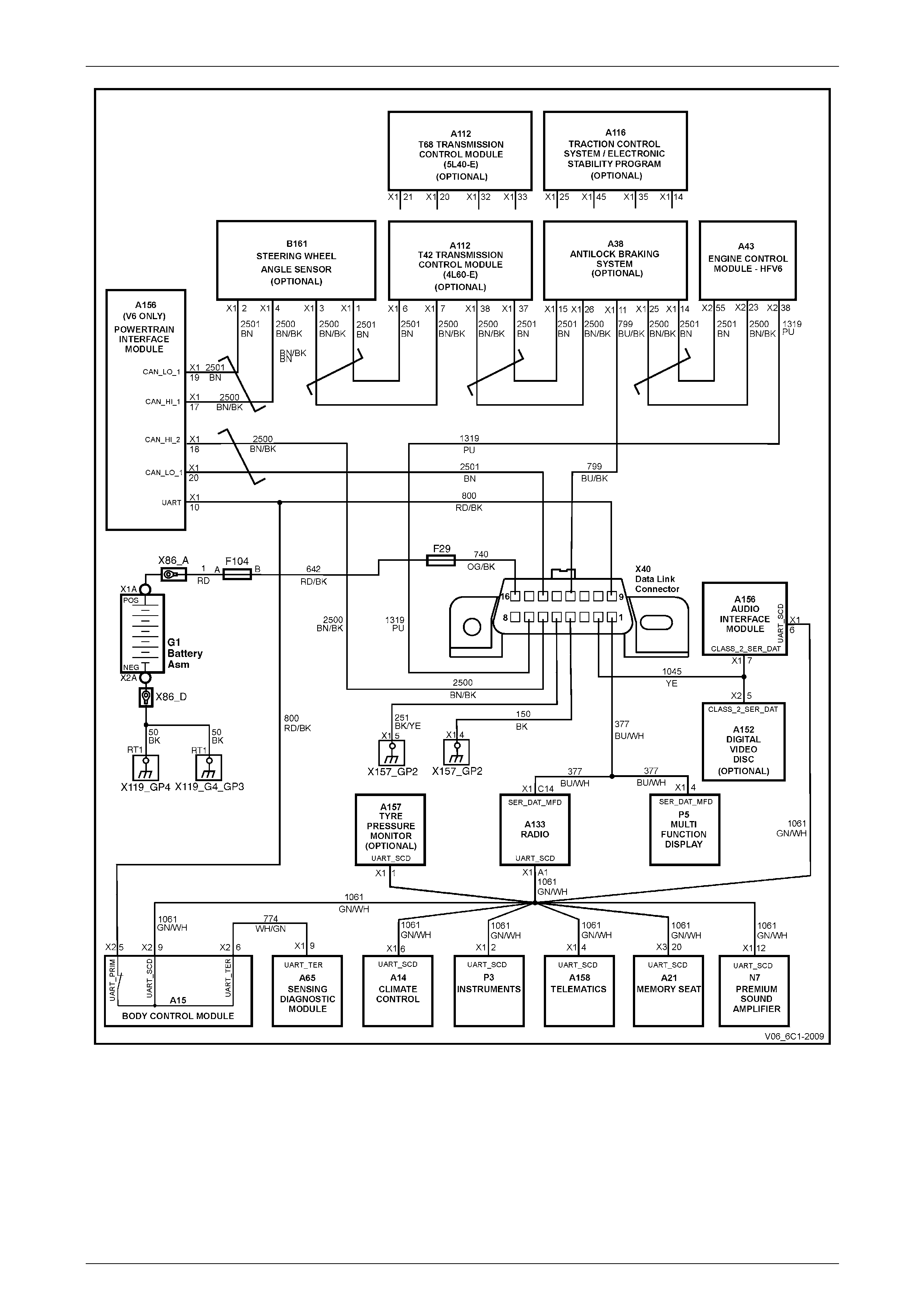
Figure 0D – 1 – V6 Serial Data Communications
2 A Powertrain Interface Module (PIM) is required as the hardware and serial communications interface for both the
V6 and GEN IV V8 engines. With V6 engines, the GMLAN PIM acts as a transparent bi-d irectional translation
device that allows data to flow between modules with GMLAN protocol and modules with UART protocol (see
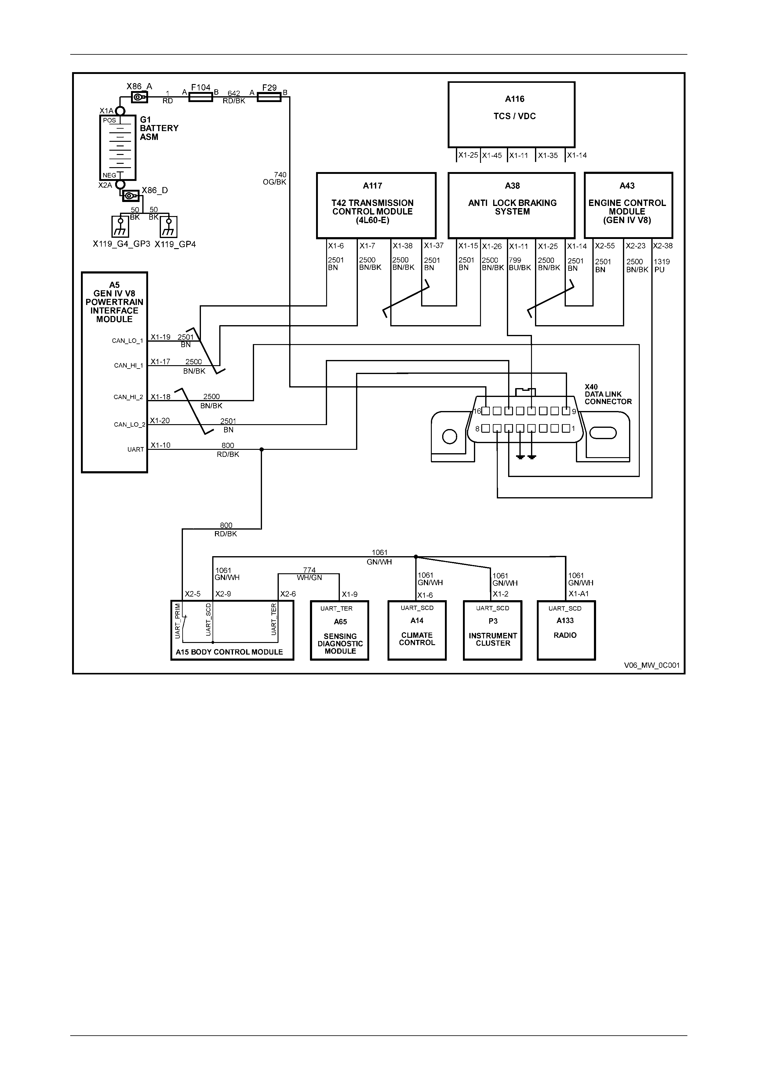
Figure 0D-1). With GEN IV V8 engines, the GMLAN PIM also acts as a transparent bi-directional translation device
that allows data to flo w bet ween mod ules with GMLAN protocol and modules with UART protocol (see Figure 0D-2)
3 With the communication necessary between the V6 engine and transmissi on modules, there are instances where
the engine control module (ECM) could set a diagnostic trouble code (DTC) that would also be detected by the
transmission control module (TCM). Therefore, to ensure that the most efficient and effective diagnostic process is
followed, a structured approach to the diagno stic process for electrical systems within the vehicle is most important.
Vehicle Diagnostics Page 0D – 4
Page 0D – 4
Figure 0A – 2 – GEN IV V8 Serial Data Communications
The Body Control Module (BCM) is the UART ‘Bus Master’ that periodically polls (or surveys) each of the following
devices on the serial data bus every 300 milliseconds (incl uding the BCM itself), requesting status data. Exceptions are
the PIM and the Audio Head Unit (AHU), which are polled every 150 milliseconds:
• V6 Engine Control Module (ECM) and Transmission Control Modu le (TCM), via the GMLAN PIM.
• GEN IV V8 Engine Control Module (ECM) and AWD ABS / TCS, via the GMLAN PIM.
• V6 ABS/TC/ESP via the GMLAN PIM.
• GEN IV V8 RWD ABS/TCS via the GMLAN PIM.
• Instrument cluster (INS).
• Occupant Climate Control (OCC) Module.
• Audio System Head Unit (AHU).
• Supplemental Restraint System (SRS) Sensing Diagnostic Module (SDM).
• Body Control Module (BCM)
• Tech 2 diagnostic scan tool.

Vehicle Diagnostics Page 0D – 5
Page 0D – 5
While there are other modules and devices connected to the serial data bus, they only monitor the bus for applicable
data that affects their functionality. These devices are:
• Telematics Control Module.
• Audio Interface Module (AIM).
• Digital Video Disc (DVD).
• Premium Sound Amplifier (PSA).
• Memory Seat and Mirror Module (MSM).
• Multi Function Display (MFD) via the AHU.
• Tyre Pressure Monitor.

Vehicle Diagnostics Page 0D – 6
Page 0D – 6
1.2 The Diagnostic Strategy
Resulting from the increased compl exity and communication s systems utilised in MY 2005 range of vehicles, this three
staged approach to the diagnostic process must be undertaken in the specified ma nner, if misdiagnosis and the
unnecessary replacement of soun d components is to be avoided.
Step 1 Diagnostic System Check – Vehicle
All vehicle diagnostic procedures are organised in a logical structure that begins with the Diagnostic S ys tem Check –
Vehicle, detailed in this Section. The Diagnostic System Check – Vehicle must always be referred to first, as you will be
directed through the logical steps nec essary to diagnose any ve hicle electrical fault condition.
When working through the Di agnostic System Check – Vehicle, you will be directed to a specific system or diagnostic
system check (e.g. automatic transmission, BCM, etc). Activating the hyperlink provided will then take you to the system
check required.
Step 2 Diagnostic System Check – System
By working through this specific system diagnostic system check, you will be directed to either a Diagnostic Trouble
Code (DTC) table or to other sections within the service information to assist in the solutio n of a vehicl e related problem.
This referral may be to the Symptoms section included for all systems or to intermittent electrical circuit problems.
Through the process of completing the i ndividual system diagnostic system check, you will be directed to the Diagnostic
Trouble Code (DTC) Tables, assuming that there is a DTC currently stored.
Step 3 Diagnostic Trouble Code (DTC) Tables
All diagnostic tables are developed with the following assumptions:
• The vehicle functioned correctly at the time of assembly,
• There are no multiple faults, and
• The problem currently exists.
An understanding of and the correct use of the diagnostic tables is essential if the diagnostic time is to be minimised
and/or to prevent poor diagnosis.
Multiple DTCs Fault Condition
In any given electronic system, some fault conditions trigger multiple component DTCs even if the fault cond ition exists
only in a single component. If there are multiple DTCs stored, the Technician must view and record all DTCs logged.
The relationship between the logged DTCs can then be reviewed to determine the so urce of the fault condition. Always
begin the diagnostic process by compl eting the Diagnostic Table for the fault condition that may trigger other DTCs to
set.
The following fault conditions ma y trigger multiple DTCs:
• A system voltage that is too low may cause incorrect system management operation or a component to
malfunction.
• A system voltage that is too high may damage the system control module and/or other sensitive electronic
components.
• A fault condition in the system control module Read Only Memory (ROM) or Random Access Memory (RAM).
• A fault condition in the system control module internal circuitry or programming.
• An improperly connected sen sor or component wiring harness connector.
• An electrical fault condition in shared system electrical circuits may trigger DTCs for components or sensors that
are connected to the same faulty circuit (e.g. an open in one of the GMLAN circuits). Test the electrical circuit of the
appropriate sensor or components to isolate the fault condition. Each Section contains detailed electrical circuits
relating to that system.
If there are no obvious faults to begin a multiple set DTC fault condition, always start with the lowest number, then work
progressively through each.

Vehicle Diagnostics Page 0D – 7
Page 0D – 7
Symptom Diagnostics
Should all of the following conditions exist, refer to the Symptom Tables, that may be provided for a particular system:
• A system fault condition exists,
• There is no Current Diagnostic Trouble Code presently stored in the control module, and
• All the Tech 2 data parameters for that system, are within the normal operating range.

Vehicle Diagnostics Page 0D – 8
Page 0D – 8
2 Diagnostic Skills Required
2.1 Basic Knowledge Required
A lack of basic understanding regarding
electronics, electrical wiring circuits and use
of electrical circuit testing tools when
performing any diagnostic procedure, could
result in incorrect diagnostic results or
damage to system components.
Understanding of the following is required to perform any of the dia gn ostic procedures detailed in this Service
Information:
• Basic electronics,
• Electrical wiring circuits,
• Electrical circuits testing, and
• Correct use of basic system diagnostic tools.
Refer to Section 12P Wiring Diagrams and to 2.2 Basic Diagnostic Tools Required, as required.
In addition, a complete under standing of the affected vehicle system is essential to prevent misdiagnosis and component
damage. Refer to 1.1 General Information in any specific Section.

Vehicle Diagnostics Page 0D – 9
Page 0D – 9
2.2 Basic Diagnostic Tools Required
Use of incorrect electrical circuit diagnostic
tools when performing any diagnostic
procedures could result in incorrect
diagnostic results or damage to system
components.
The following electrical circuit testing tools are required to perform the diagnostic procedu r es detailed in this Section.
• Tech 2, refer to Section 0C Tech 2.
• Unpowered test lamp, refer to Section 12P Wiring Diagrams.
• Digital multimeter with a minimum 10 Megohm impedance, refer to Section 12P Wiring Diagrams.

Vehicle Diagnostics Page 0D – 10
Page 0D – 10
2.3 Diagnostic Precautions
The following precautions must be observed when performing all diagn osti c procedures. Otherwise, incorrect diagnostic
results or damage to system components will occur:
1 Disconnection of the battery affects certain vehicle electronic systems. Refer to Section 00 Warnings, Cautions and Notes
before disconnecting the batter y.
2 Disconnect the battery negative lead when performing the following procedures:
• Disconnecting the electronic c ontrol module wiring harness conn ector/s or
• Charging the battery.
3 Disconnect the battery terminal ground lea d and the electronic control module wiring harness conn ector before
attempting any electric arc welding on the vehicle.
4 Do not start the engine if the battery terminal is not properly secured to the battery.
5 Do not disconnect or reconnect any of the following while the ignition is switched on or when the engine is running:
• Any electronic control module or system component el ectrical wiring connector, or
• Battery terminal leads.
6 Ensure that the correct procedure for disconnecting and co n necting system electrical wiring harness connectors is
always followed. For information on the correct procedure for disconnecting and connecting specific wiring
connectors, refer to Section 12P Wiring Harness, Connectors.
7 Ensure that all wiring harness connectors are fitted correctly and secure.
8 When steam or pressure cleanin g vehicle components, such as engines, transmissions, etc., do not direct the
cleaning nozzle at any system electrical wiring harness connectors or compon ents.
9 Do not clear any DTCs unless instructed.
10 The fault must be present when usi ng the Diagnostic Trouble Code (DTC) Diagnostic Tables. Otherwise,
misdiagnosis or replacement of good parts may occur.
11 Do not touch any electronic control mo dule connector pins or soldered compon ents on the circuit board. This is
required to avoid the possib ility of electrostatic discharge damage. Refer to Hand ling ESD Sensitive Parts, 4 Safety
and Service Guidelines, in Section 00 Warni ngs, Cautions and Notes.
12 Use only the test equipment specified in the diagnostic tables, as other test equipment may give incorrect results or
damage good components.
13 Electronic control modules are designed to withstand normal curre nt draws associated with vehicle oper ation.
However, the following fault conditions or incorrect test procedure may overload internal control module circuits and
irreparably damage the control module:
• A short to voltage fault condition in any of the control module low reference circuits may cause i ntern al and/or
sensor damage. Therefore, any short to voltage fault condition in the control module low reference circuits
must be rectified before replacing a fau lty component.
• A short to ground fault condition in any of the control module 5 volts reference circuits may cause internal
control module and/or sensor damage. Therefore, any short to ground fault condition i n the control module 5
volt reference circuits must be rectified before replacing a faulty component.
• When using a test light to test an electrical circuit, do not use any of the control module low reference circuits
or 5 volts reference circuits as a reference point. Otherwise, excessive current draw from the test light may
damage the control module.
14 Disregard DTCs that set while performing the following diagnostic Steps:
• Using the Tech 2 output control function, or
• Disconnecting a control modu le system sensor connector then switching the ignition ON.
15 After completing the required diagnostics an d service operations, road test the vehicle to ensure correct system
operation.

Vehicle Diagnostics Page 0D – 11
Page 0D – 11
2.4 Preliminary Checks
The Preliminary Checks is a set of visual and physical checks or inspections that may quickly identify a control module
system fault condition:
1 Refer to relevant Service Techlines for information regarding the fault condition.
2 Ensure that the battery is fully charged.
3 Inspect the battery connections for corrosion or a loose terminal.
4 Ensure that all relevant control module system related fuses are serviceable.
5 Inspect for incorrect aftermarket theft deterrent devices, lights or mobile phone i nstallation.
6 Ensure that there is no speaker magnet positi oned too close to any electronic module that contains relays.
7 Inspect the system wiring harness for proper connections, pinches or cuts.
8 Ensure that all control module related electrical wiring connectors are fitted correctl y.
9 Inspect the control module ground conn ections for corrosion, loose terminal or incorr ect position.
10 Ensure that the resistance between the control module housing and the b attery ground cable is less than 0.5 ohms.
11 Check that the control module and its mounting bracket is secure.
12 Check all control module relat ed components for correct installation.
13 Check the control module and related wiring harness routing to ensure that no rubbing or cutting of the wiring
harness by sharp body compo nents can occur.

Vehicle Diagnostics Page 0D – 12
Page 0D – 12
3 Vehicle Diagnostics
3.1 Diagnostic System Check – Vehicle
Purpose of Test
When a vehicle system test is carried out, the following ‘Diagnostic System Check – Vehicle’ has to be completed, using
Tech 2. This must always be the first stage in any diagnostic process before proceeding with a vehicle s ystem specific,
diagnostic system check. Failure to complete this process, may lead to an incorrect or incompl ete dia gn osis of the
system fault or faults present in the vehicle.
When a vehicle system develops a fault, the source of the fault may not necessarily be located within the confines of the
system displaying a DTC. Accordingly, the follo wing ‘Diagnostic System Check – Vehicle’ table is provided to ensure that
any faults outside of a vehicle system that cause it to display a DTC, are id entified prior to any system specific diagnosis
being carried out.
When working through the Di agnostic System Check – Vehicle, once a referral is made, then that must be foll owed
through to its conclusion. It is not necessary to work through the complete Diagnostic Syst em Check – Vehicle table
before addressing the sec ond level in the diagnostics strategy.
The order the control modules are listed in this Diagnostic System Check, is intentio nal.
Test Description
The numbers below refer to the step numbers on the diagnostic table:
1 This step ensures that the battery, the vehicle primary power, and ground systems are functioning c orre ctly.
2 This test ensures that Tech 2 is being p owered up.
3 This step ensures that all mandatory Mo dules/ECU’s are present. Lack of communication with a mandator y
Module/ECU may be due to a particular malfunction of a serial data circuit.
4 Lack of communication may be due to a parti cular malfunction of a serial data circuit. You must be aware of the
vehicle options to determine if Tech 2 should be able to communicate with a Module/ECU or not.
5 This test step determines if the engine will crank.
6 This test step determines if the engine will start and idle.
7 This test step determines if any DTCs are present.
8/24 These steps ensure that DTCs are diagn osed in a specific order. With each step being linked to a unique
Diagnostic System Check, this appro ach provides quick access to the appropri ate Section.
NOTE
Not all the systems listed in this procedure are
fitted to all vehicles.
25 For specific symptoms complaints you shoul d refer to the associated system symptom diagnostics.

Vehicle Diagnostics Page 0D – 13
Page 0D – 13
Diagnostic System Check – Vehicle
Step Action Yes No
1 Have the Preliminary Ch ecks been completed?
Go to Step 2.
Go to
2.4 Preliminary
Checks, in this
Section.
2 Install Tech 2.
Does Tech 2 power up? Go to Step 3.
Go to Tech 2 Does
Not Power Up in OC
Tech 2.
3 1 Ignition ON, engine OFF.
2 From the Tech 2 Main Menu select:
Diagnostics / 2005 / VZ and WL Series / Vehicle / Module /
ECU Presence Check, then follow the on-screen instructions.
Does Tech 2 display a ny mandatory ECU as No Communication?
NOTE
If more than one of the four mandatory Module/ECUs
(BCM, PIM, ECM, Instrument) are displayed as ‘No
Communication’, diagnose them in the listed priority order.
Go to Diagnostic
System Check for
the Mandatory
Module/ECU in the
following order:
BCM
PIM
ECM (V6) /
ECM (GEN IV V8)
Instrument. Go to Step 4.
4 Does Tech 2 communicate with all of the expected vehicle
Modules/ECUs?
Go to Step 5.
Go to Steps 8 to 24
inclusive, in this
table and select the
Diagnostic System
Check for the
affected
Module/ECU.
5 Attempt to start the engine.
Does the engine crank?
Go to Step 6.
Go to Diagnostic
System Check in
6C1-2 V6
Diagnostics or
6C4-2 GEN IV V8
Diagnostics.
6 Attempt to start the engine.
Does the engine start and idle?
Go to Step 7.
Go to Diagnostic
System Check in
6C1-2 V6
Diagnostics or
6C4-2 GEN IV V8
Diagnostics.
7 Use the appropriate Tech 2 selections to obtain DTCs for each of the
control modules.
Does Tech 2 display a ny DTCs? Go to Step 8. Go to Step 25.
8 Does Tech 2 display a ny BCM DTCs? Go to Diagnostics,
in 12J BCM. Go to Step 9.
9 Does Tech 2 display any Instrument DTCs? Go to Diagnostics,
in 12C
Instrumentation. Go to Step 10
10 Does Tech 2 display any PIM DTCs? Go to PIM
Diagnostic System
Check, in 6E1 V6
PIM or 6E3 GEN IV
V8 PIM. Go to Step 11.
11 Does Tech 2 display a ny Engine DTCs? Go to Diagnostic
System Check, in
6C1-2 – V6
Diagnostics or
6C4-2 – GEN IV V8
Diagnostics. Go to Step 12.

Vehicle Diagnostics Page 0D – 14
Page 0D – 14
Step Action Yes No
12 Does Tech 2 display any ABS, ABS-TCS, ABS-TCS ESP DTCs? Go to 5B General
Information for
referral to the
correct Diagnostic
System Check. Go to Step 13
For the V6 engine
and 4L60-E
transmission, go to
Diagnostic System
Check, in 7C2 –
Electrical Diagnosis.
For the 5L40-E
transmission, go to
Diagnostic System
Check, in 7E2 –
5L40-E Electrical
Diagnosis.
13 Does Tech 2 display a ny Transmission DTCs?
For the GEN IV V8
engine and 4L60-E
or 4L65-E
transmission, go to
Diagnostic System
Check, in 6C4-2
GEN IV V8
Diagnostics Go to Step 14.
14 Does Tech 2 display a ny SRS SDM DTCs? Go to Diagnostics,
in 12M Occupant
Protection System. Go to Step 15
15 Does Tech 2 display any Occupant Climate Control DTCs? Go to Diagnostics,
in 2E Occupant
Climate Control. Go to Step 16
16 Does Tech 2 display a ny Telematics Module DT Cs? Go to Diagnostics,
in 12K Telematics. Go to Step 17
17 Does Tech 2 display any Audio System DTCs? Go to Diagnostics,
in 12D
Entertainment
System. Go to Step 18
18 Does Tech 2 display a ny Tyre Pressure Monitoring System (TPMS)
DTCs? Go to 4.4 Diagnostic
Trouble Code List,
in 10 Wheels and
Tyres Go to Step 19
19 Does Tech 2 display any Multi Function Display (MFD) DT Cs? Go to Diagnostics,
in 12I Multi Function
Display. Go to Step 20
20 Does Tech 2 display a ny Memory Seat and Mirror Module (MSM)
DTCs? Go to Diagnostics,
in 1A7 Seat
Assemblies. Go to Step 21
21 Does Tech 2 display any Premium Sound Amplifier (PSA) DTCs? Go to Diagnostics,
in 12D
Entertainment
System. Go to Step 22
22 Does Tech 2 display any Audio Interface Module (AIM) DTCs? Go to Diagnostics,
in 12D
Entertainment
System. Go to Step 23
23 Does Tech 2 display a ny DVD DTCs? Go to Diagnostics,
in 12D
Entertainment
System. Go to Step 24

Vehicle Diagnostics Page 0D – 15
Page 0D – 15
Step Action Yes No
24 Does Tech 2 display a ny Auxiliary Gauge DTCs? Go to Diagnostics,
in 12I Multi Function
Display. Go to Step 25
25 Is the customer’s concern with a specific system symptom? Go to Symptoms for
the affected system. System OK

Vehicle Diagnostics Page 0D – 16
Page 0D – 16
3.2 DTC Symptom Description
A DTC symptom code is a 2-digit number which adds a dditional detail to a DTC. The DTC symptom provides additi onal
information without requiring a large increase in the number of new DTCs.
DTC Symptom Categories
The DTC symptom code is made up of 2 alphanumeric digits. The first digit following the DTC indicates the DTC
symptom category. There are 16 possible categories available in the range of 0 throug h the letter F . Currently there are
8 categories in use, 0 through 7. These 8 categories together with their de f initions are given below.
Category
Number Category Name Category Description
0 General Electrical Failures This category includes standard wiring failure modes, direct current
quantities related by Ohm's Law and quantities related to amplitude,
frequency or rate of change, and wave shape.
1 Additional General Electrical
Failures This category includes the overflo w from the previous category.
2 FM/PWM (Frequency/Puls e
Width Modulated) Failures
This category includes faults related to frequency modulated and pulse width
modulated inputs and outputs of the electronic control module (ECU). This
category also includes faults where position is determined by counts.
3 ECU Internal Failures This category includes faults related to memory, software, and internal
electrical circuitry; requiring ECU replacement.
4 ECU Programming F ailures This category includes faults related to operational software, calibrations,
and options, remedied by programming the ECU.
5 Algorithm Based Failures This category includes faults based on com paring two or more input
parameters for plausibility or comparing a single paramet er to itself with
respect to time.
6 Mechanical Failures This category includes faults detected b y inappropriate motion in response to
an ECU controlled output.
7 Bus Signal/Message Failures This category includes faults related to bus hardware and signal integrity.
This category is also used when the ph ysical input for a signal is located in
one ECU and another ECU diagnoses th e circuit.
8-F Reserved by Document Not in use at this time.
DTC Symptom Sub-types
The second digit of the DT C symptom code is the subtype of the DTC symptom. These subtypes and t heir categories,
together with their definitions, are give n in the following table, except for DTC symptom ‘00’, which is a special case. If
‘00’ is displayed, only the base DTC code nu mber and its description apply. Information regarding the fault will be
provided in the code setting criteria.
Example
The DTC symptoms associated with each DTC provide more information about the fault that caused that DTC. An
example of a DTC displa yed can be C0050 05, where the ‘C0050’ is the DTC, and ‘05’ after the space represents the
DTC symptom. While this DTC indicates that the fault is in the Right Rear W heel Speed Sensor, the DTC symptom ‘05’
indicates the circuit is shorted to battery or open. Another possible symptom for this code is C0050 0F, where ‘C0050’ is
the DTC for the Right Rear Wheel Spee d Sensor, and ‘0F’ indicates that the sensor signal is erratic.
DTC Symptom DTC Symptom Description
00 No Additional Information
01 Short to Battery
02 Short to Ground
03 Voltage Below Threshold
04 Open Circuit

Vehicle Diagnostics Page 0D – 17
Page 0D – 17
DTC Symptom DTC Symptom Description
05 Short to Battery or Open
06 Short to Ground or Open
07 Voltage Above Threshold
08 Signal Invalid
09 Rate of Change Above Threshold
0A Rate of Change Belo w Thres hold
0B Current Above Threshold
0C Current Below Threshold
0D Resistance Above Threshold
0E Resistance Below Threshold
0F Erratic
10 Reserved
11 Above Maximum Threshold
12 Below Minimum Threshold
13 Voltage Low/High Temperature
14 Voltage High/Low Temperatur e
15 Signal Rising Time Failur e
16 Signal Falling Time Failure
17 Signal Shape/Waveform Failure
18 Signal Amplitude Less Than Minimum
19 Signal Amplitude Greater Than Maximum
1A Bias Level Out of Range
1F Intermittent
21 Incorrect Period
22 Low Time Less Than Minimum
23 Low Time Greater Than Maximum
24 High Time Less Than Minimu m
25 High Time Greater Than Maximum
26 Frequency Too Low
27 Frequency Too High
28 Incorrect Frequency
29 Too Few Pulses
2A Too Many Pulses
2B Missing Reference
2C Reference Compare Error
31 General Checksum Failure
32 General Memory Failure
33 Special Memory Failure

Vehicle Diagnostics Page 0D – 18
Page 0D – 18
DTC Symptom DTC Symptom Description
34 RAM Failure
35 ROM Failure
36 EEPROM Failure
37 Watchdog/Safety Processor Failure
38 Supervision Software Failure
39 Internal Electronic Failure
41 Operational Software/Calibration Data Set Not Programmed
42 Calibration Data Set Not Programmed
43 EEPROM Error
44 Security Access Not Activated
45 Variant Not Programmed
46 Vehicle Configuration Not Programmed
47 VIN Not Programmed
48 Theft/Security Data Not Programmed
49 RAM Error
4A Checksum Error
4B Calibration Not Learned
51 Calculation Failure
52 Compare Failure
53 Temperature Low
54 Temperature High
55 Expected Number of Transitions/Events Not Reached
56 Allowable Number of Transitions/Events Exceeded
57 Expected Reaction After Event Did Not Occur
58 Incorrect Reaction After Event
59 Circuit/Component Protection Time-Out
61 Actuator Stuck
62 Actuator Stuck Open
63 Actuator Stuck Closed
64 Actuator Slipping
65 Emergency Position Not Reachable
71 Invalid Serial Data Received (Signal Validity Bit Indicates F ailure)
72 Alive Counter Incorrect/Not Updated
73 Parity Error
74 Value of Signal Protection Calculation Incorrect
75 Signal Above Allowable Range
76 Signal Below Allowable Ra nge
7F Erratic

Vehicle Diagnostics Page 0D – 19
Page 0D – 19
4 Diagnostic Trouble Code List –
Vehicle
Introduction
This master DTC list includes all applicable DTCs in numeric and alphanumeric order with descriptors. There will be
times when working through a diagnostic table, that you will be required to check for additi onal Diagnostic Trouble C od es
(DTCs). This list is intended to be used to identify those additional DT Cs and to provide a link to the appropriate
Diagnostic System Check table.
NOTES
• There are instances where the same
numerical DTC number is set by different
modules. Where this occurs, the DTCs are
listed in the same module order as listed in
the Diagnostic System Check – Vehicle.
• There are also multiple DTC listings of the
same number, that are set by the same
module. In these instances, the symptom
code is also listed. Tech 2 will identify both
the DTC, the individual symptom code and a
description for that item.
• Yet again, there are a number of DTCs with
the same descriptors that relate to different
vehicle systems; e.g. engines, transmissions
and braking system. Therefore, for this DTC
list to be of any value, you must be aware of
the vehicle equipment level and specification,
before activating the appropriate hyperlink.
Where a DTC has a letter prefix, it provides an indication of the system within the vehicle, that ‘owns’ that device. For
example:
B Body
C Chassis
P Powertrain
U Serial Communication
DTC List – Vehicle
DTC Symptom
Code DTC Descriptor Module That
Sets the DTC Diagnostic Table Location
1 — Output Overload BCM Go to 12J Body Control Module
1 — No Serial Data From BCM Telematics Go to 12K Telematics.
1 —
Replace Electronic Control Unit
(ECU) TPMS – ECU Go to 10 Wheels and Tyres
1 — DSP Failure Premium Sound
Amplifier Go to 12D Entertainment
System.
1 — Front Vertical Up S witch Stuck Memory Seat and
Mirror Module
(MSM) Go to 1A7 Seat Assemblies.
1 — No Class 2 Serial Dat a from DVD Audio Interface
Module Go to 12D Entertainment
System.
2 — Slip Ring Communication Error BCM Go to 12J Body Control Module
2 — No Serial Data From Instrument Telematics Go to 12K Telematics.
2
Replace Electronic Control Unit
(ECU) – RAM Failure TPMS – ECU Go to 10 Wheels and Tyres
2 — EEPROM Error Premium Sound
Amplifier Go to 12D Entertainment
System.

Vehicle Diagnostics Page 0D – 20
Page 0D – 20
DTC Symptom
Code DTC Descriptor Module That
Sets the DTC Diagnostic Table Location
2 — Front Vertical Down Switch Stuck Memory Seat and
Mirror Module —
(MSM) Go to 1A7 Seat Assemblies.
2 — DVD Not Initialised Audio Interface
Module Go to 12D Audio S ystem
3 — Fuel Type Mismatch Instrument Go to 12C Instrumentation.
3 — No Serial Data From Sensin g
Diagnostic Module Telematics Go to 12K Telematics.
3 —
Replace Electronic Control Unit
(ECU)- EEPROM Error TPMS – ECU Go to 10 Wheels and Tyres
3 — No Serial Data Premium Sound
Amplifier Go to 12D Entertainment
System.
3 — Rear Vertical Up Switch Stuck Memory Seat and
Mirror Module
(MSM) Go to 1A7 Seat Assemblies.
3 — No Serial Data From BCM Audio Interface
Module Go to 12D Entertainment
System.
4 — Auto Transmission Mismatch Instrument Go to 12C Instrumentation.
4 — No Serial Data From Audio System Telematics Go to 12K Telematics.
4 — Tyre Pressure Sensors IDs Not
Learned TPMS – ECU Go to 10 Wheels and Tyres
4 — Rear Vertical Do wn Switch Stuck Memory Seat and
Mirror Module
(MSM) Go to 1A7 Seat Assemblies.
4 — No Serial Data From Audio S ystem Audio Interface
Module Go to 12D Entertainment
System.
5 — Tail Lamp Bulb Failure BCM Go to 12J Body Control Module
5 — Fuel Invalid Flag Set Instrument Go to 12C Instrumentation.
5 — No Serial Data Telematics Go to 12K Telematics.
5 — Serial Communications Error TPMS – ECU Go to 10 Wheels and Tyres
5 — Horizontal Forward S witch Stuck Memory Seat and
Mirror Module
(MSM) Go to 1A7 Seat Assemblies.
5 — Loss of Accessory Power Supply Audio Interface
Module Go to 12D Entertainment
System.
6 — Stop Lamp Bulb Failure BCM Go to 12J Body Control Module
6 — No TPM Poll Response Detected For
10 Seconds Instrument Go to 12C Instrumentation.
6 — Program Electronic Control Unit
(ECU) TPMS – ECU Go to 10 Wheels and Tyres
6 — Horizontal Back Switch Stuck Memory Seat and
Mirror Module
(MSM) Go to 1A7 Seat Assemblies.
7 — No Serial Data From ECM BCM Go to 12J Body Control Module
7 — No ESP Poll Response Detected For
10 Seconds Instrument Go to 12C Instrumentation
7 — Supply Voltage Too High TPMS – ECU Go to 10 Wheels and Tyres
7 — Recline Up Switch Stuck Memory Seat and
Mirror Module
(MSM) Go to 1A7 Seat Assemblies.

Vehicle Diagnostics Page 0D – 21
Page 0D – 21
DTC Symptom
Code DTC Descriptor Module That
Sets the DTC Diagnostic Table Location
7 — No Class 2 Serial Dat a Audio Interface
Module Go to 12D Entertainment
System.
8 — No ABS Poll Response Detected For
10 Seconds Instrument Go to 12C Instrumentation.
8 — SIM Mismatch Telematics Go to 12K Telematics.
8 — Supply Voltage Too Low TPMS – ECU Go to 10 Wheels and Tyres
8 — Recline Down Switch Stuck Memory Seat and
Mirror Module
(MSM) Go to 1A7 Seat Assemblies.
8 — Wrong Security Code (System
Locked) Audio Interface
Module Go to 12D Entertainment
System.
9 — No BCM Broadcast Detected For 10
Seconds Instrument Go to 12C Instrumentation.
9 — Vehicle Battery Voltage Too High Telematics Go to 12K Telematics.
9 — Front Left Pressure Sensor Circuit
Range/Performance TPMS – ECU Go to 10 Wheels and Tyres
9 — Memory Button 1 Stuck Memory Seat and
Mirror Module
(MSM) Go to 1A7 Seat Assemblies.
10 — No OCC Poll Response Detected For
10 Seconds Instrument Go to 12C Instrumentation.
10 — Vehicle Battery Voltage Too L ow Telematics Go to 12K Telematics.
10 — Front Right Pressure Sensor Circuit
Range/ Performance TPMS – ECU Go to 10 Wheels and Tyres
10 — Fascia Button Jammed Audio Head Unit Go to 12D Entertainment
System.
10 — Memory Button 2 Stuck Memory Seat and
Mirror Module
(MSM) Go to 1A7 Seat Assemblies.
10 — No CAN Communication From OOC Multi-function
Display Go to 12I Multi-Function Display.
11 — No ECM Poll Response Detected For
10 Seconds Instrument Go to 12C Instrumentation.
11 — RAM Error Telematics Go to 12K Telematics.
11 — Rear Right Pressure Sensor Circuit
Range/Performance TPMS – ECU Go to 10 Wheels and Tyres
11 — Steering Wheel Remote Button
Jammed Audio Head Unit Go to 12D Entertainment
System.
11 — Memory Button 3 Stuck Memory Seat and
Mirror Module
(MSM) Go to 1A7 Seat Assemblies.
11 — Class 2 Hardware Failure Audio Interface
Module Go to 12D Entertainment
System.
12 — No SDM Poll Response Detected For
10 Seconds Instrument Go to 12C Instrumentation.
12 — EEPROM Error Telematics Go to 12K Telematics.
12 —
Rear Left Pressure Sensor Circuit
Range/Performance TPMS – ECU Go to 10 Wheels and Tyres
12 — Mirror Dip Button Stuck Memory Seat and
Mirror Module
(MSM) Go to 1A7 Seat Assemblies.
12 — EEPROM Mirror Checksum Error Audio Interface
Module Go to 12D Entertainment
System.

Vehicle Diagnostics Page 0D – 22
Page 0D – 22
DTC Symptom
Code DTC Descriptor Module That
Sets the DTC Diagnostic Table Location
13 — No Instrument Poll from BCM
Detected for 10 Seconds Instrument Go to 12C Instrumentation.
13 — Backup Battery Timer Expired Telematics Go to 12K Telematics.
13 —
Front Left Pressure Sensor Battery
Low Voltage TPMS – ECU Go to 10 Wheels and Tyres
13 — Ambient Temperature Sensor Voltage
Too High OCC – ECU Go to 2E Occupant Climate
Control Diagnosis.
13 — No Serial Data Memory Seat and
Mirror Module
(MSM) Go to 1A7 Seat Assemblies.
13 — EEPROM Checksum Error Audio Interface
Module Go to 12D Entertainment
System.
14 — No Serial Communications Detected
For 10 Seconds Instrument Go to 12C Instrumentation.
14 — Backup Battery Voltage Too High Telematics Go to 12K Telematics.
14 —
Front Right Pressure Sensor Battery
Low Voltage TPMS – ECU Go to 10 Wheels and Tyres
14 — Ambient Temperature Sensor Voltage
Too Low OCC – ECU Go to 2E Occupant Climate
Control Diagnosis.
14 — No Exterior Mirror Communication Memory Seat and
Mirror Module
(MSM) Go to 1A7 Seat Assemblies.
15 — No Radio Poll Response Detected
For 10 Seconds Instrument Go to 12C Instrumentation.
15 — Backup Battery Voltage Too Low Telematics Go to 12K Telematics.
15 —
Rear Left Pressure Sensor Battery
Low Voltage TPMS – ECU Go to 10 Wheels and Tyres
15 — In-Car Temperature Sensor Voltage
Too High OCC – ECU Go to 2E Occupant Climate
Control Diagnosis.
15 — No Serial Data From Audio System Multi-function
Display Go to 12I Multi-Function Display.
16 — Loss of ECM Poll Response Data Or
Fuel Level Data At 0 Or 255 For More
Than 10 Seconds Instrument Go to 12C Instrumentation.
16 — Backup Battery Not Detected Telematics Go to 12K Telematics.
16 —
Rear Right Pressure Sensor Battery
Low Voltage TPMS – ECU Go to 10 Wheels and Tyres
16 — In-Car Temperature Sensor Voltage
Too Low OCC – ECU Go to 2E Occupant Climate
Control Diagnosis.
17 — Not Okay To Start Received From
ECM BCM Go to 12J Body Control Module
17 — Microphone Not Detected Telematics Go to 12K Telematics.
17 — Driver Airbag Circuit Short to Battery SDM Go to 12M Occupant Protection
System.
17 — Evaporative Temperature Sensor
Voltage Too High OCC – ECU Go to 2E Occupant Climate
Control Diagnosis.
18 — Auxiliary (Secondary and Tertiary)
Serial Data Bus Fault BCM Go to 12J Body Control Module
18 —
Passenger Seat Voltage Below
Normal Operating Range Or Open
Circuit Detected Or Drive Circuit Fault
Detected
Instrument Go to 12C Instrumentation.
18 — Microphone Circuit Voltage Too Low Telematics Go to 12K Telematics.

Vehicle Diagnostics Page 0D – 23
Page 0D – 23
DTC Symptom
Code DTC Descriptor Module That
Sets the DTC Diagnostic Table Location
18 — Driver Airbag Circuit Short to Ground SDM Go to 12M Occupant Protection
System.
18 — Evaporative Temperature Sensor
Voltage Too Low OCC – ECU Go to 2E Occupant Climate
Control Diagnosis.
19 — EEPROM Error BCM Go to 12J Body Control Module
19 — Incorrect SDM Module Poll Response
Detected Instrument Go to 12C Instrumentation.
19 — Microphone Circuit Voltage Too High Telematics Go to 12K Telematics.
19 — Driver Airbag Circuit Capacitance Too
High SDM Go to 12M Occupant Protection
System.
19 — Sun Load Sensor Error OCC – ECU Go to 2E Occupant Climate
Control Diagnosis.
19 — ECU Malfunction Memory Seat and
Mirror Module
(MSM) Go to 1A7 Seat Assemblies.
20 — RAM Erro BCM Go to 12J Body Control Module
20 — Driver Airbag Circuit Capacitance Too
Low SDM Go to 12M Occupant Protection
System.
20 — Front Vertical Position Sensor F ault Memory Seat and
Mirror Module
(MSM) Go to 1A7 Seat Assemblies.
21 — Battery Voltage Too Low BCM Go to 12J Body Control Module
21 — Right Front Wheel Speed Sens or
Incorrect Signal. ABS-TCS Go to 5B ABS / TCS / ESP –
General Information.
21 — Trip Switch Voltage Below Normal
Operating Range 100 ms Instrument Go to 12C Instrumentation.
21 — Speaker Circuit Voltage Too Low Telematics Go to 12K Telematics.
21 — Driver Airbag Circuit Resistance Too
High SDM Go to 12M Occupant Protection
System.
21 — CD Mechanism Error (CD Changer
Models Only) Audio Head Unit Go to 12D Entertainment
System.
21 — Rear Vertical Position Sensor Fault Memory Seat and
Mirror Module
(MSM) Go to 1A7 Seat Assemblies.
22 — Battery Voltage Too High BCM Go to 12J Body Control Module
22 — Trip Switch Button or Buttons Pressed
For At Least One Minute Instrument Go to 12C Instrumentation.
22 — Speaker Circuit Voltage Too High Telematics Go to 12K Telematics.
22 — Driver Airbag Circuit Resistance Too
Low SDM Go to 12M Occupant Protection
System.
22 — CD Play Error (CD Changer Models
Only) Audio Head Unit Go to 12D Entertainment
System.
22 — Horizontal Position Sensor F ault Memory Seat and
Mirror Module
(MSM) Go to 1A7 Seat Assemblies.
23 — Door Lock / Unlock Circuit Overload BCM Go to 12J Body Control Module
23 — Right Front Wheel Speed Sens or
Short Circuit or Open Circuit. ABS-TCS Go to 5B ABS / TCS / ESP –
General Information.

Vehicle Diagnostics Page 0D – 24
Page 0D – 24
DTC Symptom
Code DTC Descriptor Module That
Sets the DTC Diagnostic Table Location
23 — Recline Position Sensor Fault Memory Seat and
Mirror Module
(MSM) Go to 1A7 Seat Assemblies.
24 — Remote Key Rolling Code Error BCM Go to 12J Body Control Module
24 — Incorrect EEPROM Checksum
Calculated After a Battery Reset Instrument Go to 12C Instrumentation.
24 — CD Loading Error (Single CD Models
Only) Audio Head Unit Go to 12D Entertainment
System.
24 — System Voltage Out of Range Memory Seat and
Mirror Module
(MSM) Go to 1A7 Seat Assemblies.
24 — EEPROM Error Multi-function
Display Go to 12I Multi-Function Display.
25 — Engine Start Without Slip Ring
Communications BCM Go to 12J Body Control Module
25 — Left Front Wheel Speed Sensor
Incorrect Signal. ABS-TCS Go to 5B ABS / TCS / ESP –
General Information.
25 — Incorrect ROM Checksum Calculated
After a Battery Reset Instrument Go to 12C Instrumentation.
25 — CD Defect (Single CD Models Only) Audio Head Unit Go to 12D Entertainment
System.
26 — No Serial Data From ABS/ETC BCM Go to 12J Body Control Module
26 — CD General Error (Single CD Models
Only) Audio Head Unit Go to 12D Entertainment
System.
27 — No Serial Data From Instrument BCM Go to 12J Body Control Module
27 — Left Front Wheel Speed Sensor Short
Circuit or Open Circuit. ABS-TCS Go to 5B ABS / TCS / ESP –
General Information.
28 — Antenna Drive Circuit Overload BCM Go to 12J Body Control Module
28 — Wheel Speed Frequency Error ABS-TCS Go to 5B ABS / TCS / ESP –
General Information.
29 — Stop Lamp or Park Lamp Fuse
Failure BCM Go to 12J Body Control Module
30 — Keypad Circuit Voltage Too High Telematics Go to 12K Telematics.
30 — Internal Bus Failure Audio Head Unit Go to 12D Entertainment
System.
31 — Right Rear Wheel Speed Sen sor
Incorrect Signal. ABS-TCS Go to 5B ABS / TCS / ESP –
General Information.
33 — Right Rear Wheel Speed Sen sor
Short Circuit or Open Circuit. ABS-TCS Go to 5B ABS/ TCS/ ESP –
General Information.
33 — Passenger Airbag Circuit Short to
Battery SDM Go to 12M Occupant Protection
System.
33 — Single Communication Bus Failur e Audio Head Unit Go to 12D Entertainment
System.
34 — Passenger Airbag Circuit Short to
Ground SDM Go to 12M Occupant Protection
System.
34 — Multi Communication Bus Failure Audio Head Unit Go to 12D Entertainment
System.
35 — Left Rear Wheel Speed Sensor
Incorrect Signal. ABS-TCS Go to 5B ABS / TCS / ESP –
General Information.

Vehicle Diagnostics Page 0D – 25
Page 0D – 25
DTC Symptom
Code DTC Descriptor Module That
Sets the DTC Diagnostic Table Location
35 — Passenger Airbag Circuit Capacitance
Too High SDM Go to 12M Occupant Protection
System.
35 — Fascia Communication Bus Failure Audio Head Unit Go to 12D Entertainment
System.
35 — No Serial Data from ECM OCC – ECU Go to 2E Occupant Climate
Control Diagnosis.
36 — Passenger Airbag Circuit Capacitance
Too Low SDM Go to 12M Occupant Protection
System.
36 — DSP Failure Audio Head Unit Go to 12D Entertainment
System.
36 — No Serial Data from BCM OCC – ECU Go to 2E Occupant Climate
Control Diagnosis.
37 — Left Rear Wheel Speed Sensor Short
Circuit or Open Circuit. ABS-TCS Go to 5B ABS / TCS / ESP –
General Information.
37 — Passenger Airbag Circuit Resistance
Too High SDM Go to 12M Occupant Protection
System.
37 — ROM Checksum Error OCC – ECU Go to 2E Occupant Climate
Control Diagnosis.
38 — Passenger Airbag Circuit Resistance
Too Low SDM Go to 12M Occupant Protection
System.
38 — EEPROM Checksum Error OCC – ECU Go to 2E Occupant Climate
Control Diagnosis.
39 — Telephone Number Error Telematics Go to 12K Telematics
39 — RAM Error OCC – ECU Go to 2E Occupant Climate
Control Diagnosis.
40 — Vehicle Identification Number
Mismatch Telematics Go to 12K Telematics.
40 — No BCM Serial Data Audio Head Unit Go to 12D Entertainment
System.
40 — Air Mix Door Motor Driver Error OCC – ECU Go to 2E Occupant Climate
Control Diagnosis.
41 — Right Front Hydraulic Modulator Inlet
Solenoid Valve Fault ABS-TCS Go to 5B ABS / TCS / ESP –
General Information.
41 — No Class 2 Serial Data Audi o Head Unit Go to 12D Entertainment
System.
41 — Solenoid Driver Error OCC – ECU Go to 2E Occupant Climate
Control Diagnosis.
42 — Right Front Hydraulic Modulator
Outlet Solenoid Valve Fault ABS-TCS Go to 5B ABS / TCS / ESP –
General Information.
42 — Fuel Pump Circuit Voltage Too Low Telematics Go to 12K Telematics.
43 — Fuel Pump Circuit Voltage Too High Telematics Go to 12K Telematics.
43 — Driver’s Air Mix Door Motor Feedback
Circuit Voltage T oo Low OCC – ECU Go to 2E Occupant Climate
Control Diagnosis.
44 — Driver’s Air Mix Door Motor Feedback
Circuit Voltage T oo High OCC – ECU Go to 2E Occupant Climate
Control Diagnosis.
45 — Left Front Hydraulic Modulator Inlet
Solenoid Valve Fault ABS-TCS Go to 5B ABS / TCS / ESP –
General Information.
45 — End Call / Information Button Stuck Telematics Go to 12K Telematics.

Vehicle Diagnostics Page 0D – 26
Page 0D – 26
DTC Symptom
Code DTC Descriptor Module That
Sets the DTC Diagnostic Table Location
45 — Passenger’s Air Mix Door Motor
Feedback Circuit Voltage Too Low OCC – ECU Go to 2E Occupant Climate
Control Diagnosis.
46 — Left Front Hydraulic Modulator Outlet
Solenoid Valve Fault ABS-TCS Go to 5B ABS / TCS / ESP –
General Information.
46 — Holden Assist Button Stuck Telematics Go to 12K Telematics.
46 — Passenger’s Air Mix Door Motor
Feedback Circuit Voltage Too High OCC – ECU Go to 2E Occupant Climate
Control Diagnosis.
47 — Emergency Button Stuck Telematics Go to 12K Telematics.
47 — Driver Airmix Min. Calibratio n Error OCC – ECU Go to 2E Occupant Climate
Control Diagnosis.
48 — Driver Airmix Max. Calibration Error OCC – ECU Go to 2E Occupant Climate
Control Diagnosis.
49 — Left Hand Pretensioner Circuit Short
to Battery SDM Go to 12M Occupant Protection
System.
49 — Pass Airmix Min. Calibration Error OCC – ECU Go to 2E Occupant Climate
Control Diagnosis.
50 — Left Hand Pretensioner Circuit Short
to Ground SDM Go to 12M Occupant Protection
System.
50 — Pass Airmix Max. Calibration Error OCC – ECU Go to 2E Occupant Climate
Control Diagnosis.
51 — Left Hand Pretensioner Circuit
Capacitance Too High SDM Go to 12M Occupant Protection
System.
52 — Left Hand Pretensioner Circuit
Capacitance Too Low SDM Go to 12M Occupant Protection
System.
53 — Left Hand Pretensioner Circuit
Resistance Too High SDM Go to 12M Occupant Protection
System.
54 — Left Hand Pretensioner Circuit
Resistance Too Low SDM Go to 12M Occupant Protection
System.
55 — Rear Axle Hydraulic Modulator Inlet
Solenoid Valve Fault ABS-TCS Go to 5B ABS / TCS / ESP –
General Information.
56 — Rear Axle Hydraulic Modulator Outlet
Solenoid Valve Fault ABS-TCS Go to 5B ABS / TCS / ESP –
General Information.
61 — Pump Motor or Relay Fault ABS-TCS Go to 5B ABS / TCS / ESP –
General Information.
63 — Valve Solenoid Relay Fault ABS-TCS Go to 5B ABS / TCS / ESP –
General Information.
65 — Right Hand Pretensioner Circuit Short
to Battery SDM Go to 12M Occupant Protection
System.
66 — Right Hand Pretensioner Circuit Short
to Ground SDM Go to 12M Occupant Protection
System.
67 — Brake Switch Circuit Fault ABS-TCS Go to 5B ABS / TCS / ESP –
General Information.
67 — Right Hand Pretensioner Circuit
Capacitance Too High SDM Go to 12M Occupant Protection
System.
68 — Right Hand Pretensioner Circuit
Capacitance Too Low SDM Go to 12M Occupant Protection
System.
69 — Right Hand Pretensioner Circuit
Resistance Too High SDM Go to 12M Occupant Protection
System.

Vehicle Diagnostics Page 0D – 27
Page 0D – 27
DTC Symptom
Code DTC Descriptor Module That
Sets the DTC Diagnostic Table Location
70 — Right Hand Pretensioner Circuit
Resistance Too Low SDM Go to 12M Occupant Protection
System.
71 — Electronic Control Unit Internal Fault ABS-TCS Go to 5B ABS / TCS / ESP –
General Information.
81 — Left Hand Side Airbag Circuit Short to
Battery SDM Go to 12M Occupant Protection
System.
82 — Left Hand Side Airbag Circuit Short to
Ground SDM Go to 12M Occupant Protection
System.
83 — Left Hand Side Airbag Circuit
Capacitance Too High SDM Go to 12M Occupant Protection
System.
84 — Left Hand Side Airbag Circuit
Capacitance Too Low SDM Go to 12M Occupant Protection
System.
85 — Battery Voltage Too Low ABS-TCS Go to 5B ABS / TCS / ESP –
General Information.
85 — Left Hand Side Airbag Circuit
Resistance Too High SDM Go to 12M Occupant Protection
System.
86 — Left Hand Side Airbag Circuit
Resistance Too Low SDM Go to 12M Occupant Protection
System.
97 — Right Hand Side Airbag Circuit Short
to Battery SDM Go to 12M Occupant Protection
System.
98 — Right Hand Side Airbag Circuit Short
to Ground SDM Go to 12M Occupant Protection
System.
99 — Right Hand Side Airbag Circuit
Capacitance Too High SDM Go to 12M Occupant Protection
System.
100 — Right Hand Side Airbag Circuit
Capacitance Too Low SDM Go to 12M Occupant Protection
System.
101 — Right Hand Side Airbag Circuit
Resistance Too High SDM Go to 12M Occupant Protection
System.
102 — Right Hand Side Airbag Circuit
Resistance Too Low SDM Go to 12M Occupant Protection
System.
129 — Left Peripheral Acceleration Sensor
Line Fault SDM Go to 12M Occupant Protection
System.
130 — Right Peripheral Acceleration Sensor
Line Fault SDM Go to 12M Occupant Protection
System.
131 — Left Peripheral Acceleration Sensor
Communication Fault SDM Go to 12M Occupant Protection
System.
132 — Right Peripheral Acceleration Sensor
Communication Fault SDM Go to 12M Occupant Protection
System.
133 — Left Peripheral Acceleration Sensor
Identification Fault SDM Go to 12M Occupant Protection
System.
134 — Right Peripheral Acceleration Sensor
Identification Fault SDM Go to 12M Occupant Protection
System.
135 — Left Peripheral Acceleration Sensor
Hardware Fault SDM Go to 12M Occupant Protection
System.
136 — Right Peripheral Acceleration Sensor
Hardware Fault SDM Go to 12M Occupant Protection
System.
161 — Configuration Mismatch: Too Little or
Too Many Loops in OPS SDM Go to 12M Occupant Protection
System.

Vehicle Diagnostics Page 0D – 28
Page 0D – 28
DTC Symptom
Code DTC Descriptor Module That
Sets the DTC Diagnostic Table Location
163 — SDM Internal Fault SDM Go to 12M Occupant Protection
System.
247 — Driver Airbag Circuit Power Stage
Error SDM Go to 12M Occupant Protection
System.
247 — Passenger Airbag Circuit Power
Stage Error SDM Go to 12M Occupa nt Protection
System.
247 — Right Hand Pretensioner Circuit
Power Stage Error SDM Go to 12M Occupant Protection
System.
247 — Left Hand Side Airbag Circuit Power
Stage Error SDM Go to 12M Occupa nt Protection
System.
247 — Right Hand Side Airbag Circuit Power
Stage Error SDM Go to 12M Occupa nt Protection
System.
B0980 — Power Mode Switch Signal
Malfunction PIM – V6 Go to 6E1 Powertrain Interface
Module – V6
B1000,
B1009,
B1013,
or
B1014
— PIM Internal Fault PIM – V6 Go to 6E1 Powertrain Interface
Module – V6
B1000,
B1009,
B1013,
or
B1014
— PIM Internal Fault PIM – GEN IV V8 Go to 6E4 Powertrain Interface
Module – GEN IV V8
B1000 — DVD Player Malfunction DVD Player Go to 12D Entertainment
System.
B273A — Hill Descent Control Switch Signal
Malfunction PIM – V6 Go to 6E1 Powertrain Interface
Module – V6
B0575
or
B0576 — Fuel Level Information PIM – GEN IV V8 Go to 6E4 Powertrain Interface
Module – GEN IV V8
B0976 — Front Parking Aid Circuit Malfunctio n PIM – GEN IV V8 Go to 6E4 Powertrain Interface
Module – GEN IV V8
B1019 — Transmission Control Module
Configuration Mismatch PIM – V6 Go to 6E1 Powertrain Interface
Module – V6
B1019 — Transmission Control Module
Configuration Mismatch PIM – GEN IV V8 Go to 6E4 Powertrain Interface
Module – GEN IV V8
B2745 — Traction Control / Electronic Stability
Program Switch Signal Malfunction PIM – V6 Go to 6E1 Powertrain Interface
Module – V6
B2745 — Traction Control / Electronic Stability
Program Switch Signal Malfunction PIM – GEN IV V8 Go to 6E4 Powertrain Interface
Module – GEN IV V8
B3027 — Starter Enable Circuit Range
Performance PIM – GEN IV V8 Go to 6E4 Powertrain Interface
Module – GEN IV V8
B3657 — Power Mode Switch Signal
Malfunction PIM – V6 Go to 6E1 Powertrain Interface
Module – V6
B3924 — Wrong Environment Identifier
Received from Body Control Module PIM – V6 Go to 6E1 Powertrain Interface
Module – V6
B3924 — Wrong Environment Identifier
Received from Body Control Module PIM – GEN IV V8 Go to 6E4 Powertrain Interface
Module – GEN IV V8

Vehicle Diagnostics Page 0D – 29
Page 0D – 29
DTC Symptom
Code DTC Descriptor Module That
Sets the DTC Diagnostic Table Location
C0035 00 Front Left Wheel Speed Sensor
Malfunction ABS-TCS or ABS-
TCS / ESP – ECM Go to 5B ABS / TCS / ESP –
General Information.
C0035 05 Front Left Wheel Speed Sensor
Circuit Open Or High Voltage ABS-TCS or ABS-
TCS / ESP – ECM Go to 5B ABS / TCS / ESP –
General Information.
C0035 0F Front Left Wheel Speed Sensor
Erratic Signal ABS-TCS or ABS-
TCS / ESP – ECM Go to 5B ABS / TCS / ESP –
General Information.
C0035 28 Front Left Wheel Speed Sensor
Dropout ABS-TCS or ABS-
TCS / ESP – ECM Go to 5B ABS / TCS / ESP –
General Information.
C0035 64 Front Left Wheel Speed Sensor
Actuator Slipping ABS-TCS or ABS-
TCS / ESP – ECM Go to 5B ABS / TCS / ESP –
General Information.
C0040 00 Front Right Wheel Speed Sen s or
Malfunction ABS-TCS or ABS-
TCS / ESP – ECM Go to 5B ABS / TCS / ESP –
General Information.
C0040 05 Front Right Wheel Speed Sen s or
Circuit Open Or High Voltage ABS-TCS or ABS-
TCS / ESP – ECM Go to 5B ABS / TCS / ESP –
General Information.
C0040 0F Front Right Wheel Speed Sens or
Erratic Signal ABS-TCS or ABS-
TCS / ESP – ECM Go to 5B ABS / TCS / ESP –
General Information.
C0040 28 Front Right Wheel Speed Sen s or
Dropout ABS-TCS or ABS-
TCS / ESP – ECM Go to 5B ABS / TCS / ESP –
General Information.
C0040 64 Front Right Wheel Speed Sen s or
Actuator Slipping ABS-TCS or ABS-
TCS / ESP – ECM Go to 5B ABS / TCS / ESP –
General Information.
C0045 00 Rear Left Wheel Speed Sensor
Malfunction ABS-TCS or ABS-
TCS / ESP – ECM Go to 5B ABS / TCS / ESP –
General Information.
C0045 05 Rear Left Wheel Speed Sensor
Circuit Open Or High Voltage ABS-TCS or ABS-
TCS / ESP – ECM Go to 5B ABS / TCS / ESP –
General Information.
C0045 0F Rear Left Wheel Speed Sensor
Erratic Signal ABS-TCS or ABS-
TCS / ESP – ECM Go to 5B ABS / TCS / ESP –
General Information.
C0045 28 Rear Left Wheel Speed Sensor
Dropout ABS-TCS or ABS-
TCS / ESP – ECM Go to 5B ABS / TCS / ESP –
General Information.
C0045 64 Rear Left Wheel Speed Sensor
Actuator Slipping ABS-TCS or ABS-
TCS / ESP – ECM Go to 5B ABS / TCS / ESP –
General Information.
C0050 00 Rear Right Wheel Speed Sensor
Malfunction ABS-TCS or ABS-
TCS / ESP – ECM Go to 5B ABS / TCS / ESP –
General Information.
C0050 05 Rear Right Wheel Speed Sensor
Circuit Open Or High Voltage ABS-TCS or ABS-
TCS / ESP – ECM Go to 5B ABS / TCS / ESP –
General Information.
C0050 0F Rear Right Wheel Speed Sen sor
Erratic Signal ABS-TCS or ABS-
TCS / ESP – ECM Go to 5B ABS / TCS / ESP –
General Information.
C0050 28 Rear Right Wheel Speed Sensor
Dropout ABS-TCS or ABS-
TCS / ESP – ECM Go to 5B ABS / TCS / ESP –
General Information.
C0050 64 Rear Right Wheel Speed Sensor
Actuator Slipping ABS-TCS or ABS-
TCS / ESP – ECM Go to 5B ABS / TCS / ESP –
General Information.
C0060 00 Front Left Outlet Valve Driver Circuit
Malfunction ABS-TCS or ABS-
TCS / ESP – ECM Go to 5B ABS / TCS / ESP –
General Information.
C0060 08 Front Left Outlet Valve Feedback
Circuit Invalid Signal ABS-TCS or ABS-
TCS / ESP – ECM Go to 5B ABS / TCS / ESP –
General Information.
C0065 00 Front Left Inlet Valve Driver Circuit
Malfunction ABS-TCS or ABS-
TCS / ESP – ECM Go to 5B ABS / TCS / ESP –
General Information.
C0065 08 Front Left Inlet Valve Feedback
Circuit Invalid Signal ABS-TCS or ABS-
TCS / ESP – ECM Go to 5B ABS / TCS / ESP –
General Information.

Vehicle Diagnostics Page 0D – 30
Page 0D – 30
DTC Symptom
Code DTC Descriptor Module That
Sets the DTC Diagnostic Table Location
C0065 57 Front Left Inlet Valve Circuit
Malfunction (Expected Reaction After
Event Did Not Occur)
ABS-TCS or ABS-
TCS / ESP – ECM Go to 5B ABS / TCS / ESP –
General Information.
C0070 00 Front Right Outlet Valve Driver Circuit
Malfunction ABS-TCS or ABS-
TCS / ESP – ECM Go to 5B ABS / TCS / ESP –
General Information.
C0070 08 Front Right Outlet Valve Feedback
Circuit Invalid Signal ABS-TCS or ABS-
TCS / ESP – ECM Go to 5B ABS / TCS / ESP –
General Information.
C0075 00 Front Right Inlet Valve Driver Circuit
Malfunction ABS-TCS or ABS-
TCS / ESP – ECM Go to 5B ABS / TCS / ESP –
General Information.
C0075 08 Front Right Inlet Valve Feedback
Circuit Invalid Signal ABS-TCS or ABS-
TCS / ESP – ECM Go to 5B ABS / TCS / ESP –
General Information.
C0075 57 Front Right Inlet Valve Circuit
Malfunction (Expected Reaction After
Event Did Not Occur)
ABS-TCS or ABS-
TCS / ESP – ECM Go to 5B ABS / TCS / ESP –
General Information.
C0080 00 Rear Left Outlet Valve Driver Circuit
Malfunction ABS-TCS or ABS-
TCS / ESP – ECM Go to 5B ABS / TCS / ESP –
General Information.
C0080 08 Rear Left Outlet Valve Feedback
Circuit Invalid Signal ABS-TCS or ABS-
TCS / ESP – ECM Go to 5B ABS / TCS / ESP –
General Information.
C0085 00 Rear Left Inlet Valve Driver Circuit
Malfunction ABS-TCS or ABS-
TCS / ESP – ECM Go to 5B ABS / TCS / ESP –
General Information.
C0085 08 Rear Left Inlet Valve Feedback Circuit
Invalid Signal ABS-TCS or ABS-
TCS / ESP – ECM Go to 5B ABS / TCS / ESP –
General Information.
C0085 57 Rear Left Inlet Valve Circuit
Malfunction (Expected Reaction After
Event Did Not Occur)
ABS-TCS or ABS-
TCS / ESP – ECM Go to 5B ABS / TCS / ESP –
General Information.
C0090 00 Rear Right Outlet Valve Driver Circuit
Malfunction ABS-TCS or ABS-
TCS / ESP – ECM Go to 5B ABS / TCS / ESP –
General Information.
C0090 08 Rear Right Outlet Valve Feedback
Circuit Invalid Signal ABS-TCS or ABS-
TCS / ESP – ECM Go to 5B ABS / TCS / ESP –
General Information.
C0090 00 Rear Axle Outlet Valve Driver Circuit
Malfunction ABS Go to 5B ABS / TCS / ESP –
General Information.
C0090 08 Rear Axle Outlet Valve Feedback
Circuit Invalid Signal ABS Go to 5B ABS / TCS / ESP –
General Information.
C0095 00 Rear Right Inlet Valve Driver Circuit
Malfunction ABS-TCS / ESP –
ECM Go to 5B ABS / TCS / ESP –
General Information.
C0095 08 Rear Right Inlet Valve Feedback
Circuit Invalid Signal ABS-TCS / ESP –
ECM Go to 5B ABS / TCS / ESP –
General Information.
C0095 57 Rear Right Inlet Valve Circuit
Malfunction (Expected Reaction After
Event Did Not Occur)
ABS-TCS / ESP –
ECM Go to 5B ABS / TCS / ESP –
General Information.
C0095 00 Rear Axle Inlet Valve Driver Circuit
Malfunction ABS Go to 5B ABS / TCS / ESP –
General Information.
C0095 08 Rear Axle Inlet Valve Feedback
Circuit Invalid Signal ABS Go to 5B ABS / TCS / ESP –
General Information.
C0095 57 Rear Axle Inlet Valve Circuit
Malfunction (Expected Reaction After
Event Did Not Occur) ABS Go to 5B ABS / TCS / ESP –
General Information.
C0110 03 Return Pump Circuit Low Voltage ABS-TCS or ABS-
TCS / ESP – ECM Go to 5B ABS / TCS / ESP –
General Information.
C0110 07 Return Pump Circuit High Voltage ABS-TCS or ABS-
TCS / ESP – ECM Go to 5B ABS / TCS / ESP –
General Information.

Vehicle Diagnostics Page 0D – 31
Page 0D – 31
DTC Symptom
Code DTC Descriptor Module That
Sets the DTC Diagnostic Table Location
C0110 16 ECU Failure / Replace ECU
(Electronic Control Unit) ABS-TCS or ABS-
TCS / ESP – ECM Go to 5B ABS / TCS / ESP –
General Information.
C0121 01 Valve Relay Circuit Short To Battery ABS-TCS or ABS-
TCS / ESP – ECM Go to 5B ABS / TCS / ESP –
General Information.
C0121 02 Valve Relay Circuit Short To Ground ABS-TCS or ABS-
TCS / ESP – ECM Go to 5B ABS / TCS / ESP –
General Information.
C0121 03 Valve Relay Cir cuit Low Voltage ABS-TCS or ABS-
TCS / ESP – ECM Go to 5B ABS / TCS / ESP –
General Information.
C0121 08 Valve Relay Invalid Signal ABS-TCS or ABS-
TCS / ESP – ECM Go to 5B ABS / TCS / ESP –
General Information.
C0121 56 Valve Relay Maximum Numb er Of
Activations Exceeded ABS-TCS or ABS-
TCS / ESP – ECM Go to 5B ABS / TCS / ESP –
General Information.
C0121 61 Valve Relay Actuator Stuck ABS-TCS or ABS-
TCS / ESP – ECM Go to 5B ABS / TCS / ESP –
General Information.
C0131 00 Brake Fluid Pressure Sensor Circuit
Malfunction ABS-TCS or ABS-
TCS / ESP – ECM Go to 5B ABS / TCS / ESP –
General Information.
C0131 08 Brake Fluid Pressure Sensor Invalid
Signal ABS-TCS or ABS-
TCS / ESP – ECM Go to 5B ABS / TCS / ESP –
General Information.
C0131 11 Brake Fluid Pressure Sensor Offset
Range/Performance ABS-TCS or ABS-
TCS / ESP – ECM Go to 5B ABS / TCS / ESP –
General Information.
C0131 57 ECU Failure / Replace ECU
(Electronic Control Unit) ABS-TCS or ABS-
TCS / ESP – ECM Go to 5B ABS / TCS / ESP –
General Information.
C0141 00 Front Left/Front Right TC/ESP
Priming Valve Circuit Malfunction ABS-TCS or ABS-
TCS / ESP – ECM Go to 5B ABS / TCS / ESP –
General Information.
C0141 08 Front Left/Front Right TC/ESP
Priming Valve Invalid Sig nal ABS-TCS or ABS-
TCS / ESP – ECM Go to 5B ABS / TCS / ESP –
General Information.
C0146 00 Front Left/Front Right TC/ESP Switch
Over Valve Circuit Malfunction ABS-TCS or ABS-
TCS / ESP – ECM Go to 5B ABS / TCS / ESP –
General Information.
C0146 08 Front Left/Front Right TC/ESP Switch
Over Valve Invalid Signal ABS-TCS or ABS-
TCS / ESP – ECM Go to 5B ABS / TCS / ESP –
General Information.
C0146 57 ECU Failure / Replace ECU
(Electronic Control Unit) ABS-TCS or ABS-
TCS / ESP – ECM Go to 5B ABS / TCS / ESP –
General Information.
C0151 00 Rear Left/Rear Right TC/ESP Priming
Valve Circuit Malfunction ABS-TCS or ABS-
TCS / ESP – ECM Go to 5B ABS / TCS / ESP –
General Information.
C0151 08 Rear Left/Rear Right TC/ESP Priming
Valve Invalid Signal ABS-TCS or ABS-
TCS / ESP – ECM Go to 5B ABS / TCS / ESP –
General Information.
C0156 00 Left/Rear Right TC/ESP Switch Over
Valve Circuit Malfunction ABS-TCS or ABS-
TCS / ESP – ECM Go to 5B ABS / TCS / ESP –
General Information.
C0156 08 Rear Left/Rear Right TC/ESP Switch
Over Valve Invalid Signal ABS-TCS or ABS-
TCS / ESP – ECM Go to 5B ABS / TCS / ESP –
General Information.
C0156 57 ECU Failure / Replace ECU
(Electronic Control Unit) ABS-TCS or ABS-
TCS / ESP – ECM Go to 5B ABS / TCS / ESP –
General Information.
C0161 04 Brake Switch Circuit Malfunction ABS-TCS or ABS-
TCS / ESP – ECM Go to 5B ABS / TCS / ESP –
General Information.
C0161 58 Brake Switch Circuit Malfunction ABS-TCS or ABS-
TCS / ESP – ECM Go to 5B ABS / TCS / ESP –
General Information.
C0186 00 Replace Lateral Acceleration Sensor ABS-TCS or ABS-
TCS / ESP – ECM Go to 5B ABS / TCS / ESP –
General Information.

Vehicle Diagnostics Page 0D – 32
Page 0D – 32
DTC Symptom
Code DTC Descriptor Module That
Sets the DTC Diagnostic Table Location
C0186 07 Lateral Acceleration Sensor Erratic
Signal ABS-TCS or ABS-
TCS / ESP – ECM Go to 5B ABS / TCS / ESP –
General Information.
C0186 08 Lateral Acceleration Sensor Invalid
Signal ABS-TCS or ABS-
TCS / ESP – ECM Go to 5B ABS / TCS / ESP –
General Information.
C0186 11 Lateral Acceleration Sensor Offset
Range/Performance ABS-TCS or ABS-
TCS / ESP – ECM Go to 5B ABS / TCS / ESP –
General Information.
C0186 12 Lateral Acceleration Sensor Circuit
Range/Performance ABS-TCS or ABS-
TCS / ESP – ECM Go to 5B ABS / TCS / ESP –
General Information.
C0186 57 Lateral Acceleration Sensor
Initialization Error ABS-TCS or ABS-
TCS / ESP – ECM Go to 5B ABS / TCS / ESP –
General Information.
C0191 00 Longitudinal Acceleration Sensor
Circuit Malfunction ABS-TCS / ESP –
ECM Go to 5B ABS / TCS / ESP –
General Information.
C0191 28 Longitudinal Acceleration Sensor
Power Supply Voltage
Range/Performance
ABS-TCS / ESP –
ECM Go to 5B ABS / TCS / ESP –
General Information.
C0192 00 Longitudinal Acceleration Sensor
Invalid Signal ABS-T CS / ESP –
ECM Go to 5B ABS / TCS / ESP –
General Information.
C0196 00 Replace Yaw Rate Sensor ABS-TCS or ABS-
TCS / ESP – ECM Go to 5B ABS / TCS / ESP –
General Information.
C0196 03 Replace Yaw Rate Sensor ABS-TCS or ABS-
TCS / ESP – ECM Go to 5B ABS / TCS / ESP –
General Information.
C0196 07 Yaw Rate Sensor Erratic Signal ABS-TCS or ABS-
TCS / ESP – ECM Go to 5B ABS / TCS / ESP –
General Information.
C0196 08 Yaw Rate Sensor Invalid Signal ABS-TCS or ABS-
TCS / ESP – ECM Go to 5B ABS / TCS / ESP –
General Information.
C0196 11 Yaw Rate Sensor Offset
Range/Performance ABS-TCS or ABS-
TCS / ESP – ECM Go to 5B ABS / TCS / ESP –
General Information.
C0196 12 Yaw Rate Sensor Circuit
Range/Performance ABS-TCS or ABS-
TCS / ESP – ECM Go to 5B ABS / TCS / ESP –
General Information.
C0245 00 Wheel Speed Sensor Signals
Range/Performance ABS-TCS or ABS-
TCS / ESP – ECM Go to 5B ABS / TCS / ESP –
General Information.
C0252 00 ECU Failure / Replace ECU
(Electronic Control Unit) ABS-TCS or ABS-
TCS / ESP – ECM Go to 5B ABS / TCS / ESP –
General Information.
C0253 00 ECU Failure / Replace ECU
(Electronic Control Unit) ABS-TCS or ABS-
TCS / ESP – ECM Go to 5B ABS / TCS / ESP –
General Information.
C0460 00 Replace Steering Angle Sensor ABS-TCS / ESP –
ECM Go to 5B ABS / TCS / ESP –
General Information.
C0460 11 Steering Angle Sensor Offset
Range/Performance ABS-TCS / ESP –
ECM Go to 5B ABS / TCS / ESP –
General Information.
C0460 12 Steering Angle Sensor Circuit
Range/Performance ABS-TCS / ESP –
ECM Go to 5B ABS / TCS / ESP –
General Information.
C0460 42 Steering Angle Sensor Not Calibr ated ABS-TCS / ESP –
ECM Go to 5B ABS / TCS / ESP –
General Information.
C0550 00 ECU Failure / Replace ECU
(Electronic Control Unit) ABS-TCS or ABS-
TCS / ESP – ECM Go to 5B ABS / TCS / ESP –
General Information.
C0550 31 ECU Failure / Replace ECU
(Electronic Control Unit) – General
Checksum Error
ABS-TCS / ESP –
ECM Go to 5B ABS / TCS / ESP –
General Information.

Vehicle Diagnostics Page 0D – 33
Page 0D – 33
DTC Symptom
Code DTC Descriptor Module That
Sets the DTC Diagnostic Table Location
C0550 32 ECU Failure / Replace ECU
(Electronic Control Unit) – General
Memory Error
ABS-TCS / ESP –
ECM Go to 5B ABS / TCS / ESP –
General Information.
C0550 33 ECU Failure / Replace ECU
(Electronic Control Unit) – Special
Memory Error
ABS-TCS / ESP –
ECM Go to 5B ABS / TCS / ESP –
General Information.
C0550 34 ECU Failure / Replace ECU
(Electronic Control Unit) – RAM Error ABS-TCS / ESP –
ECM Go to 5B ABS / TCS / ESP –
General Information.
C0550 35 ECU Failure / Replace ECU
(Electronic Control Unit) – ROM Error ABS-TCS / ESP –
ECM Go to 5B ABS / TCS / ESP –
General Information.
C0550 36 ECU Failure / Replace ECU
(Electronic Control Unit) – EEPROM
Error
ABS-TCS / ESP –
ECM Go to 5B ABS / TCS / ESP –
General Information.
C0550 37
ECU Failure / Replace ECU
(Electronic Control Unit) –
Watchdog/Safety Micro-Controller
Error
ABS-TCS / ESP –
ECM Go to 5B ABS / TCS / ESP –
General Information.
C0550 38 ECU Failure / Replace ECU
(Electronic Control Unit) –
Supervision Software Failure
ABS-TCS / ESP –
ECM Go to 5B ABS / TCS / ESP –
General Information.
C0550 55
ECU Failure / Replace ECU
(Electronic Control Unit) Expected
Number of Events Not Reached
(Algorithm SW)
ABS-TCS / ESP –
ECM Go to 5B ABS / TCS / ESP –
General Information.
C0550 57
ECU Failure / Replace ECU
(Electronic Control Unit) Expected
Reaction After Event Did Not Occur
(Algorithm SW)
ABS-TCS / ESP –
ECM Go to 5B ABS / TCS / ESP –
General Information.
C0551 45 Electronic Control Unit (ECU) Not
Programmed ABS-TCS or ABS-
TCS / ESP – ECM Go to 5B ABS / TCS / ESP –
General Information.
C0569 00 System Configuration Wrong ABS-TCS or ABS-
TCS / ESP – ECM Go to 5B ABS / TCS / ESP –
General Information.
C0800 03 Power Supply Circuit Low Voltage ABS-TCS or ABS-
TCS / ESP – ECM Go to 5B ABS / TCS / ESP –
General Information.
C0800 07 Power Supply Circuit High Vo ltage ABS-TCS or ABS-
TCS / ESP – ECM Go to 5B ABS / TCS / ESP –
General Information.
C0800 0F Power Supply Circuit Temporary High
Voltage ABS-TCS or ABS-
TCS / ESP – ECM Go to 5B ABS / TCS / ESP –
General Information.
C0895 08 Yaw Rate Sensor Power Supply
Voltage Range/Performance ABS-TCS / ESP –
ECM Go to 5B ABS / TCS / ESP –
General Information.
P0008 —
Engine Position System Performanc e
– (Bank 1) ECM – V6 Go to 6C1-2 – V6 – Diagnostics.
P0009 —
Engine Position system Performance
– (Bank 2) ECM – V6 Go to 6C1-2 – V6 – Diagnostics.
P0010 —
Intake Camshaft Position Control
Solenoid Circuit Malfunction (Bank 1) ECM – V6 Go to 6C1-2 – V6 – Diagnostics.
P0011 —
Intake Camshaft Position Range/
Performance (Bank 1) ECM – V6 Go to 6C1-2 – V6 – Diagnostics.
P0013 —
Exhaust Camshaft Position Control
Solenoid Circuit Malfunction (Bank 1) ECM – V6 Go to 6C1-2 – V6 – Diagnostics.
P0014 —
Exhaust Camshaft Position Range/
Performance (Bank 1) ECM – V6 Go to 6C1-2 – V6 – Diagnostics.
P0016 —
Crankshaft / Intake Camshaft Position
not Plausible (Bank 1) ECM – V6 Go to 6C1-2 – V6 – Diagnostics.
P0016 —
Crankshaft / Camshaft Position
Correlation Bank 1 Sensor A ECM – V8 Go to 6C4-2 Engine
Management GEN IV V8 –
Diagnostics

Vehicle Diagnostics Page 0D – 34
Page 0D – 34
DTC Symptom
Code DTC Descriptor Module That
Sets the DTC Diagnostic Table Location
P0017 —
Crankshaft / Exhaust Camshaft
Position not Plausible (Bank 1) ECM – V6 Go to 6C1-2 – V6 – Diagnostics.
P0018 —
Crankshaft / Intake Camshaft Position
not Plausible (Bank 2) ECM – V6 Go to 6C1-2 – V6 – Diagnostics.
P0019 —
Crankshaft / Exhaust Camshaft
Position not Plausible (Bank 2) ECM – V6 Go to 6C1-2 – V6 – Diagnostics.
P0020 —
Intake Camshaft Position Control
Solenoid Circuit Malfunction (Bank 2) ECM – V6 Go to 6C1-2 – V6 – Diagnostics.
P0021 —
Intake Camshaft Position System
Performance (Bank 2) ECM – V6 Go to 6C1-2 – V6 – Diagnostics.
P0023 —
Exhaust Camshaft Position Control
Solenoid Circuit Malfunction (Bank 2) ECM – V6 Go to 6C1-2 – V6 – Diagnostics.
P0024 —
Exhaust Camshaft Position Range/
Performance (Bank 2) ECM – V6 Go to 6C1-2 – V6 – Diagnostics.
P0030 —
O2 Sensor Heater Circuit Malfunction
(Bank 1 Sensor 1) ECM – V6 Go to 6C1-2 – V6 – Diagnostics.
P0030 —
O2 Sensor Heater Circuit Range/
Performance (Bank 1 Sensor 1) ECM – V8 Go to 6C4-2 Engine
Management GEN IV V8 –
Diagnostics
P0031 —
O2 Sensor Heater Circuit Low
Voltage Sensor (Bank 1 Sens or 1) ECM – V6 Go to 6C1-2 – V6 – Diagnostics.
P0032 —
O2 Sensor Heater Circuit High
Voltage (Bank 1 Sensor 1) ECM – V6 Go to 6C1-2 – V6 – Diagnostics.
P0036 —
O2 Sensor Heater Circuit Malfunction
(Bank 1 Sensor 2) ECM – V6 Go to 6C1-2 – V6 – Diagnostics.
P0036 —
O2 Sensor Heater Circuit Range/
Performance (Bank 1 Sensor 2) ECM – V8 Go to 6C4-2 Engine
Management GEN IV V8 –
Diagnostics
P0037 —
O2 Sensor Heater Circuit Low
Voltage (Bank 1 Sensor 2 ECM – V6 Go to 6C1-2 – V6 – Diagnostics.
P0038 —
O2 Sensor 2 Heater Circuit High
Voltage (Bank 1 Sensor 2) ECM – V6 Go to 6C1-2 – V6 – Diagnostics.
P0040 —
O2 Sensor Signals Not Plausible
(Bank 1 Sensor 1 and Bank 2
Sensor1) ECM – V6 Go to 6C1-2 – V6 – Diagnostics.
P0041 —
O2 Sensor Signals Not Plausible
(Bank 1 Sensor 2 and Bank 2 Sensor
2) ECM – V6 Go to 6C1-2 – V6 – Diagnostics.
P0050 —
O2 Sensor Heater Circuit Malfunction
(Bank 2 Sensor 1) ECM – V6 Go to 6C1-2 – V6 – Diagnostics.
P0050 —
O2 Sensor Heater Circuit Range/
Performance (Bank 2 Sensor 1) ECM – V8 Go to 6C4-2 Engine
Management GEN IV V8 –
Diagnostics
P0051 —
O2 Sensor Heater Circuit Low
Voltage (Bank 2 Sensor 1) ECM – V6 Go to 6C1-2 – V6 – Diagnostics.
P0052 —
O2 Sensor 1 Heater Circuit High
Voltage (Bank 2 Sensor 1) ECM – V6 Go to 6C1-2 – V6 – Diagnostics.
P0053 —
O2 Sensor 1 Heater Resistance
Range/ Performance (Bank 1 Sensor
1) ECM – V6 Go to 6C1-2 – V6 – Diagnostics.
P0053 —
O2 Sensor Heater Circuit Malfunction
(Bank 1 Sensor 1) ECM – V8 Go to 6C4-2 Engine
Management GEN IV V8 –
Diagnostics
P0054 —
O2 Sensor Heater Circuit Malfunction
(Bank 1 Sensor 2) ECM – V8 Go to 6C4-2 Engine
Management GEN IV V8 –
Diagnostics
P0056 —
O2 Sensor Heater Circuit Malfunction
(Bank 2 Sensor 2) ECM – V6 Go to 6C1-2 – V6 – Diagnostics.
P0056 —
O2 Sensor Heater Circuit Range/
Performance (Bank 2 Sensor 2) ECM – V8 Go to 6C4-2 Engine
Management GEN IV V8 –
Diagnostics

Vehicle Diagnostics Page 0D – 35
Page 0D – 35
DTC Symptom
Code DTC Descriptor Module That
Sets the DTC Diagnostic Table Location
P0057 —
O2 Sensor Heater Circuit Low
Voltage (Bank 2 Sensor 2) ECM – V6 Go to 6C1-2 – V6 – Diagnostics.
P0058 —
O2 Sensor Heater Circuit High
Voltage (Bank 2 Sensor 2) ECM – V6 Go to 6C1-2 – V6 – Diagnostics.
P0059 —
O2 Sensor Heater Resistance Range/
Performance (Bank 2 Sensor 1) ECM – V6 Go to 6C1-2 – V6 – Diagnostics.
P0059 —
O2 Sensor Heater Circuit Malfunction
(Bank 2 Sensor 1) ECM – V8 Go to 6C4-2 Engine
Management GEN IV V8 –
Diagnostics
P0060 —
O2 Sensor Heater Circuit Malfunction
(Bank 2 Sensor 2) ECM – V8 Go to 6C4-2 Engine
Management GEN IV V8 –
Diagnostics
P0068 —
Throttle Position Sensor (TPS)
Monitoring Fault ECM – V8 Go to 6C4-2 Engine
Management GEN IV V8 –
Diagnostics
P0101 —
Mass Air Flow Sensor Circuit Range/
Performance ECM – V6 Go to 6C1-2 – V6 – Diagnostics.
P0101 —
Mass or Volume Air Flow Sensor
Circuit Range/Performance ECM – V8 Go to 6C4-2 Engine
Management GEN IV V8 –
Diagnostics
P0102 — Mass Air Flow Sensor Voltage Low ECM – V6 Go to 6C1-2 – V6 – Diagn ostics.
P0102 —
Mass or Volume Air Flow Sensor
Circuit Low Input ECM – V8 Go to 6C4-2 Engine
Management GEN IV V8 –
Diagnostics
P0103 — Mass Air Flow Sensor Voltage High ECM – V6 Go to 6C1-2 – V6 – Diagnosti cs.
P0103 —
Mass or Volume Air Flow Sensor
Circuit High Input ECM – V8 Go to 6C4-2 Engine
Management GEN IV V8 –
Diagnostics
P0106 —
Manifold Absolute Pressure Sensor
Circuit Range/Performance ECM – V8 Go to 6C4-2 Engine
Management GEN IV V8 –
Diagnostics
P0107 —
Manifold Absolute Pressure Sensor
Circuit Low Voltage ECM – V8 Go to 6C4-2 Engine
Management GEN IV V8 –
Diagnostics
P0108 —
Manifold Absolute Pressure Sensor
Circuit High Voltage ECM – V8 Go to 6C4-2 Engine
Management GEN IV V8 –
Diagnostics
P0112 —
Intake Air Temperature Sensor Circuit
Low Voltage ECM – V6 Go to 6C1-2 – V6 – Diagnostics.
P0112 —
Intake Air Temperature Sensor Circuit
Low Input ECM – V8 Go to 6C4-2 Engine
Management GEN IV V8 –
Diagnostics
P0113 —
Intake Air Temperature Sensor Circuit
High Voltage ECM – V6 Go to 6C1-2 – V6 – Diagnostics.
P0113 —
Intake Air Temperature Sensor Circuit
High Input ECM – V8 Go to 6C4-2 Engine
Management GEN IV V8 –
Diagnostics
P0115 —
GMLAN Engine Coolant Temperatur e
Fault (No Valid GM LAN Signal) TCM – 5L40-E Go to 7E2 Electrical Diagnosis –
5L40-E
P0116 —
Engine Coolant Temperature Sensor
Circuit Range/Performance ECM – V6 Go to Diagnostic System Check,
in 6C1-2 – V6 – Diagnostics
P0116 —
Engine Coolant Temperature Sensor
Circuit Range/Performance ECM – V8 Go to 6C4-2 Engine
Management GEN IV V8 –
Diagnostics
P0117 —
Engine Coolant Temperature Sensor
Circuit Low Voltage ECM – V6 Go to 6C1-2 – V6 – Diagnostics.
P0117 —
Engine Coolant Temperature Circuit
Low Input ECM – V8 Go to 6C4-2 Engine
Management GEN IV V8 –
Diagnostics
P0118 —
Engine Coolant Temperature Sensor
Circuit High Voltage ECM – V6 Go to 6C1-2 – V6 – Diagnostics.

Vehicle Diagnostics Page 0D – 36
Page 0D – 36
DTC Symptom
Code DTC Descriptor Module That
Sets the DTC Diagnostic Table Location
P0118 —
Engine Coolant Temperature Circuit
High Input ECM – V8 Go to 6C4-2 Engine
Management GEN IV V8 –
Diagnostics
P0120 —
Throttle Position Signal (No Valid GM
LAN Signal) TCM – 5L40-E Go to 7E2 Electrical Diagnosis –
5L40-E
P0120 —
Throttle Position Sensor 1 Circuit
Malfunction ECM – V8 Go to 6C4-2 Engine
Management GEN IV V8 –
Diagnostics
P0121 —
Throttle Position Sensor 1 Circuit
Range/Performance ECM – V6 Go to 6C1-2 – V6 – Diagnostics.
P0121 — Throttle Position Sensor (TPS) Stuck ECM – V8 Go to 6C4-2 Engine
Management GEN IV V8 –
Diagnostics
P0122 —
Throttle Position Sensor 1 Circuit Low
Voltage ECM – V6 Go to 6C1-2 – V6 – Diagnostics.
P0122 —
Throttle Position Sensor 1 Circuit Low
Input ECM – V8 Go to 6C4-2 Engine
Management GEN IV V8 –
Diagnostics
P0123 —
Throttle Position Sensor 1 Circuit
High Voltage ECM – V6 Go to 6C1-2 – V6 – Diagnostics.
P0123 —
Throttle Position Sensor 1 Circuit
High Input ECM – V8 Go to 6C4-2 Engine
Management GEN IV V8 –
Diagnostics
P0125 —
Insufficient Engine Coolant
Temperature For Closed Loop Fuel
Control ECM – V6 Go to 6C1-2 – V6 – Diagnostics.
P0128 —
Engine Coolant Temperature Below
Thermostat Regulating T emperature ECM – V8 Go to 6C4-2 Engine
Management GEN IV V8 –
Diagnostics
P0130 —
O2 Sensor Circuit Malfunction (Bank
1 Sensor 1) ECM – V6 Go to 6C1-2 – V6 – Dia gnostics.
P0131 —
O2 Sensor Circuit Low Voltage (Bank
1 Sensor 1) ECM – V6 Go to 6C1-2 – V6 – Dia gnostics.
P0131 —
O2 Sensor Circuit Low Voltage (Bank
1 Sensor 1) ECM – V8 Go to 6C4-2 Engine
Management GEN IV V8 –
Diagnostics
P0132 —
O2 Sensor Circuit High Voltage (Bank
1 Sensor 1) ECM – V6 Go to 6C1-2 – V6 – Diagnostics.
P0132 —
O2 Sensor Circuit High Voltage (Bank
1 Sensor 1) ECM – V8 Go to 6C4-2 Engine
Management GEN IV V8 –
Diagnostics
P0133 —
O2 Sensor Circuit Slow Response
(Bank 1 Sensor 1) ECM – V6 Go to 6C1-2 – V6 – Diagnostics.
P0133 —
O2 Sensor Circuit Slow Response
(Bank 1 Sensor 1) ECM – V8 Go to 6C4-2 Engine
Management GEN IV V8 –
Diagnostics
P0134 —
O2 Sensor Circuit No Activity
Detected (Bank 1 Sensor 1) ECM – V8 Go to 6C4-2 E ngine
Management GEN IV V8 –
Diagnostics
P0135 —
O2 Sensor Heater Circuit Range/
Performance (Bank 1 Sensor 1) ECM – V6 Go to 6C1-2 – V6 – Diagnostics.
P0135 —
O2 Sensor Heater Circuit Malfunction
(Bank 1 Sensor 1) ECM – V8 Go to 6C4-2 Engine
Management GEN IV V8 –
Diagnostics
P0136 —
O2 Sensor Circuit
Range/Performance (Bank 1 Sensor
2) ECM – V8 Go to 6C4-2 E ngine
Management GEN IV V8 –
Diagnostics
P0137 —
O2 Sensor Circuit Low Voltage (Bank
1 Sensor 2) ECM – V6 Go to Diagnostic S ystem Check,
in 6C1-2 – V6 – Diagnostics
P0137 —
O2 Sensor Circuit Low Voltage (Bank
1 Sensor 2) ECM – V8 Go to 6C4-2 Engine
Management GEN IV V8 –
Diagnostics

Vehicle Diagnostics Page 0D – 37
Page 0D – 37
DTC Symptom
Code DTC Descriptor Module That
Sets the DTC Diagnostic Table Location
P0138 —
O2 Sensor Circuit High Voltage
(Bank 1 Sensor 2) ECM – V6 Go to 6C1-2 – V6 – Diagnostics.
P0138 —
O2 Sensor Circuit High Voltage (Bank
1 Sensor 2) ECM – V8 Go to 6C4-2 Engine
Management GEN IV V8 –
Diagnostics
P0139 —
O2 Sensor Slow Response (Bank 1
Sensor 2) ECM – V6 Go to 6C1-2 – V6 – Diagnostics.
P0140 —
O2 Sensor Circuit No Activity
Detected (Bank 1 Sensor 2) ECM – V6 Go to 6C1-2 – V6 – Diagnostics.
P0140 —
O2 Sensor Circuit No Activity
Detected (Bank 1 Sensor 2) ECM – V8 Go to 6C4-2 E ngine
Management GEN IV V8 –
Diagnostics
P0141 —
O2 Sensor Heater Circuit Range/
Performance (Bank 1 Sensor 2) ECM – V6 Go to 6C1-2 – V6 – Diagnostics.
P0141 —
O2 Sensor Heater Circuit Malfunction
(Bank 1 Sensor 2) ECM – V8 Go to 6C4-2 Engine
Management GEN IV V8 –
Diagnostics
P0150 —
O2 Sensor Circuit Malfunction (Bank
2 Sensor 2) ECM – V6 Go to 6C1-2 – V6 – Dia gnostics.
P0151 —
O2 Sensor Circuit Low Voltage (Bank
2 Sensor 1) ECM – V6 Go to 6C1-2 – V6 – Dia gnostics.
P0151 —
O2 Sensor Circuit Low Voltage (Bank
2 Sensor 1) ECM – V8 Go to 6C4-2 Engine
Management GEN IV V8 –
Diagnostics
P0152 —
O2 Sensor Circuit High Voltage (Bank
2 Sensor 1) ECM – V6 Go to 6C1-2 – V6 – Diagnostics.
P0152 —
O2 Sensor Circuit High Voltage (Bank
2 Sensor 1) ECM – V8 Go to 6C4-2 Engine
Management GEN IV V8 –
Diagnostics
P0153 —
O2 Sensor Circuit Slow Response
(Bank 2 Sensor 1) ECM – V6 Go to 6C1-2 – V6 – Diagnostics.
P0153 —
O2 Sensor Circuit Slow Response
(Bank 2 Sensor 1) ECM – V8 Go to 6C4-2 Engine
Management GEN IV V8 –
Diagnostics
P0154 —
O2 Sensor Circuit No Activity
Detected (Bank 2 Sensor 1) ECM – V8 Go to 6C4-2 E ngine
Management GEN IV V8 –
Diagnostics
P0155 —
O2 Sensor Heater Circuit Range/
Performance (Bank 2 Sensor 1) ECM – V6 Go to 6C1-2 – V6 – Diagnostics.
P0155 —
O2 Sensor Heater Circuit Malfunction
(Bank 2 Sensor 1) ECM – V8 Go to 6C4-2 Engine
Management GEN IV V8 –
Diagnostics
P0156 —
O2 Sensor Circuit
Range/Performance (Bank 2 Sensor
2) ECM – V8 Go to 6C4-2 E ngine
Management GEN IV V8 –
Diagnostics
P0157 —
O2 Sensor Circuit Low Voltage (Bank
2 Sensor 2) ECM – V6 Go to 6C1-2 – V6 – Dia gnostics.
P0157 —
O2 Sensor Circuit Low Voltage (Bank
2 Sensor 2) ECM – V8 Go to 6C4-2 Engine
Management GEN IV V8 –
Diagnostics
P0158 —
O2 Sensor Circuit High Voltage (Bank
2 Sensor 2) ECM – V6 Go to 6C1-2 – V6 – Diagnostics.
P0158 —
O2 Sensor Circuit High Voltage (Bank
2 Sensor 2) ECM – V8 Go to 6C4-2 Engine
Management GEN IV V8 –
Diagnostics
P0159 —
O2 Sensor Slow Response (Bank 1
Sensor 2) ECM – V6 Go to 6C1-2 – V6 – Diagnostics.
P0160 —
O2 Sensor Circuit No Activity
Detected (Bank 2 Sensor 2) ECM – V6 Go to 6C1-2 – V6 – Diagnostics.
P0160 —
O2 Sensor Circuit No Activity
Detected (Bank 2 Sensor 2) ECM – V8 Go to 6C4-2 E ngine
Management GEN IV V8 –
Diagnostics

Vehicle Diagnostics Page 0D – 38
Page 0D – 38
DTC Symptom
Code DTC Descriptor Module That
Sets the DTC Diagnostic Table Location
P0161 —
O2 Sensor Heater Circuit Range/
Performance (Bank 2 Sensor 2) ECM – V6 Go to 6C1-2 – V6 – Diagnostics.
P0161 —
O2 Sensor Heater Circuit Malfunction
(Bank 2 Sensor 2) ECM – V8 Go to 6C4-2 Engine
Management GEN IV V8 –
Diagnostics
P0171 — Fuel Trim System Too Lean Bank 1 ECM – V8 Go to 6C4-2 Engine
Management GEN IV V8 –
Diagnostics
P0172 — Fuel Trim System Too Rich Bank 1 ECM – V8 Go to 6C4-2 Engi ne
Management GEN IV V8 –
Diagnostics
P0174 — Fuel Trim System Too Lean Bank 2 ECM – V8 Go to 6C4-2 Engine
Management GEN IV V8 –
Diagnostics
P0175 — Fuel Trim System Too Rich Bank 2 ECM – V8 Go to 6C4-2 Engi ne
Management GEN IV V8 –
Diagnostics
P0196 —
Engine Oil Temperature Sensor
Range/Performance ECM – V6 Go to 6C1-2 – V6 – Diagnostics.
P0197 — Engine Oil Temperature Voltage Low ECM – V6 Go to 6C1-2 – V6 – Diagnostics.
P0198 — Engine Oil Temperature Voltage High ECM – V6 Go to 6C1-2 – V6 – Diagnostics.
P0201 — Injector 1 Control Circuit Malfunction ECM – V6 Go to 6C1-2 – V6 – Diagnostics.
P0201 —
Cylinder 1 – Injector Circuit
Malfunction ECM – V8 Go to 6C4-2 Engine
Management GEN IV V8 –
Diagnostics
P0202 — Injector 2 Control Circuit Malfunction ECM – V6 Go to 6C1-2 – V6 – Diagnostics.
P0202 —
Cylinder 2 – Injector Circuit
Malfunction ECM – V8 Go to 6C4-2 Engine
Management GEN IV V8 –
Diagnostics
P0203 — Injector 3 Control Circuit Malfunction ECM – V6 Go to 6C1-2 – V6 – Diagnostics.
P0203 —
Cylinder 3 – Injector Circuit
Malfunction ECM – V8 Go to 6C4-2 Engine
Management GEN IV V8 –
Diagnostics
P0204 — Injector 4 Control Circuit Malfunction ECM – V6 Go to 6C1-2 – V6 – Diagnostics.
P0204 —
Cylinder 4 – Injector Circuit
Malfunction ECM – V8 Go to 6C4-2 Engine
Management GEN IV V8 –
Diagnostics
P0205 — Injector 5 Control Circuit Malfunction ECM – V6 Go to 6C1-2 – V6 – Diagnostics
P0205 —
Cylinder 5 – Injector Circuit
Malfunction ECM – V8 Go to 6C4-2 Engine
Management GEN IV V8 –
Diagnostics
P0206 — Injector 6 Control Circuit Malfunction ECM – V6 Go to 6C1-2 – V6 – Diagnostics.
P0206 —
Cylinder 6 – Injector Circuit
Malfunction ECM – V8 Go to 6C4-2 Engine
Management GEN IV V8 –
Diagnostics
P0207 —
Cylinder 7 – Injector Circuit
Malfunction ECM – V8 Go to 6C4-2 Engine
Management GEN IV V8 –
Diagnostics
P0208 —
Cylinder 8 – Injector Circuit
Malfunction ECM – V8 Go to 6C4-2 Engine
Management GEN IV V8 –
Diagnostics
P0218 — Transmission Fluid Over Temperature TCM – 5L40-E Go to 7E2 Electrical Diagnosis –
5L40-E
P0218 — Transmission Fluid Over Temperature TCM – 4L60-E Go to 7C2 Electrical Diagnosis
4L60E (V6 Engine)

Vehicle Diagnostics Page 0D – 39
Page 0D – 39
DTC Symptom
Code DTC Descriptor Module That
Sets the DTC Diagnostic Table Location
P0218 — Transmission Fluid Over-Temperature
ECM – V8
4L60-E or 4L65-E
Go to 6C4-2 Engine
Management GEN IV V8 –
Diagnostics
P0218 — Transmission Fluid Over-Temperature TCM – 4L60-E Go to 7C2 Electrical Diagnosis
4L60E (V6 Engine)
P0220 —
Throttle Position Sensor 2 Circuit
Malfunction ECM – V8 Go to 6C4-2 Engine
Management GEN IV V8 –
Diagnostics
P0221 —
Throttle Position Sensor 2 Circuit
Range/Performance ECM – V6 Go to 6C1-2 – V6 – Diagnostics.
P0222 —
Throttle Position Sensor 2 Circuit Low
Voltage ECM – V6 Go to 6C1-2 – V6 – Diagnostics.
P0222 —
Throttle Position Sensor 2 Circuit Low
Input ECM – V8 Go to 6C4-2 Engine
Management GEN IV V8 –
Diagnostics
P0223 —
Throttle Position Sensor 2 Circuit
High Voltage ECM – V6 Go to 6C1-2 – V6 – Diagnostics.
P0223 —
Throttle Position Sensor 2 Circuit
High Voltage ECM – V8 Go to 6C4-2 Engine
Management GEN IV V8 –
Diagnostics
P0230 —
Fuel Pump Primary Circuit
Malfunction ECM – V8 Go to 6C4-2 Engine
Management GEN IV V8 –
Diagnostics
P0261 — Injector 1 Control Circuit Low Voltage ECM – V6 Go to 6C1-2 – V6 – Diagnostics.
P0262 — Injector 1 Control Circuit High Voltage ECM – V6 Go to 6C1-2 – V6 – Diagnostics.
P0264 — Injector 2 Control Circuit Low Voltage ECM – V6 Go to 6C1-2 – V6 – Diagnostics.
P0265 — Injector 2 Control Circuit High Voltage ECM – V6 Go to 6C1-2 – V6 – Diagnostics.
P0267 — Injector 3 Control Circuit Low Voltage ECM – V6 Go to 6C1-2 – V6 – Diagnostics.
P0268 — Injector 3 Control Circuit High Voltage ECM – V6 Go to 6C1-2 – V6 – Diagnostics.
P0270 — Injector 4 Control Circuit Low Voltage ECM – V6 Go to 6C1-2 – V6 – Diagnostics.
P0271 — Injector 4 Control Circuit High Voltage ECM – V6 Go to 6C1-2 – V6 – Diagnostics.
P0273 — Injector 5 Control Circuit Low Voltage ECM – V6 Go to 6C1-2 – V6 – Diagnostics.
P0274 — Injector 5 Control Circuit High Voltage ECM – V6 Go to 6C1-2 – V6 – Diagnostics.
P0276 — Injector 6 Control Circuit Low Voltage ECM – V6 Go to 6C1-2 – V6 – Diagnostics.
P0277 — Injector 6 Control Circuit High Voltage ECM – V6 Go to 6C1-2 – V6 – Diagnostics.
P0300 — Engine Misfire Detected ECM – V6 Go to 6C1-2 – V6 – Diagnostics.
P0300 —
Random/Multiple Cylinder Misfire
Detected ECM – V8 Go to 6C4-2 Engine
Management GEN IV V8 –
Diagnostics
P0301 — Cylinder 1 Misfire Detected ECM – V6 Go to 6C1-2 – V6 – Diagnostics.
P0301 — Cylinder 1 Misfire Detected ECM – V8 Go to 6C4-2 Engine
Management GEN IV V8 –
Diagnostics
P0302 — Cylinder 2 Misfire Detected ECM – V6 Go to 6C1-2 – V6 – Diagnostics.
P0302 — Cylinder 2 Misfire Detected ECM – V8 Go to 6C4-2 Engine
Management GEN IV V8 –
Diagnostics
P0303 — Cylinder 3 Misfire Detected ECM – V6 Go to 6C1-2 – V6 – Diagnostics.
P0303 — Cylinder 3 Misfire Detected ECM – V8 Go to 6C4-2 Engine
Management GEN IV V8 –
Diagnostics

Vehicle Diagnostics Page 0D – 40
Page 0D – 40
DTC Symptom
Code DTC Descriptor Module That
Sets the DTC Diagnostic Table Location
P0304 — Cylinder 4 Misfire Detected ECM – V6 Go to 6C1-2 – V6 – Diagnostics.
P0304 — Cylinder 4 Misfire Detected ECM – V8 Go to 6C4-2 Engine
Management GEN IV V8 –
Diagnostics
P0305 — Cylinder 5 Misfire Detected ECM – V6 Go to 6C1-2 – V6 – Diagnostics.
P0305 — Cylinder 5 Misfire Detected ECM – V8 Go to 6C4-2 Engine
Management GEN IV V8 –
Diagnostics
P0306 — Cylinder 6 Misfire Detected ECM – V6 Go to 6C1-2 – V6 – Diagnostics.
P0306 — Cylinder 6 Misfire Detected ECM – V8 Go to 6C4-2 Engine
Management GEN IV V8 –
Diagnostics
P0307 — Cylinder 7 Misfire Detected ECM – V8 Go to 6C4-2 Engine
Management GEN IV V8 –
Diagnostics
P0308 — Cylinder 8 Misfire Detected ECM – V8 Go to 6C4-2 Engine
Management GEN IV V8 –
Diagnostics
P0315 —
Crankshaft Position System Variation
Not Learned ECM – V8 Go to 6C4-2 Engine
Management GEN IV V8 –
Diagnostics
P0324 — Knock Sensor Module Performance ECM – V6 Go to 6C1-2 – V6 – Diagnostics.
P0324 — Knock Sensor Module Performance ECM – V8 Go to 6C4-2 Engine
Management GEN IV V8 –
Diagnostics
P0325 — Knock Sensor Circuit Malfunction ECM – V8 Go to 6C4-2 Engine
Management GEN IV V8 –
Diagnostics
P0326 — Knock Sensor Range/Performance ECM – V8 Go to 6C4-2 Engi ne
Management GEN IV V8 –
Diagnostics
P0327 —
Knock Sensor Circuit Low Frequency
(Bank 1) ECM – V6 Go to 6C1-2 – V6 – Dia gnostics.
P0327 —
Knock Sensor 1 Circuit Low Input
(Bank 1 or Single Sensor) ECM – V8 Go to 6C4-2 Engine
Management GEN IV V8 –
Diagnostics
P0328 —
Knock Sensor Circuit High Frequency
(Bank 1) ECM – V6 Go to 6C1-2 – V6 – Dia gnostics.
P0328 —
Knock Sensor Circuit High Frequency
(Bank 1) ECM – V8 Go to 6C4-2 Engine
Management GEN IV V8 –
Diagnostics
P0330 —
Knock Sensor 2 Circuit Malfunction
(Bank 2) ECM – V8 Go to 6C4-2 Engine
Management GEN IV V8 –
Diagnostics
P0332 —
Knock Sensor Circuit Low Frequency
(Bank 2) ECM – V6 Go to 6C1-2 – V6 – Dia gnostics.
P0332 —
Knock Sensor 2 Circuit Low Input
(Bank 2) ECM – V8 Go to 6C4-2 Engine
Management GEN IV V8 –
Diagnostics
P0333 —
Knock Sensor Circuit High Frequency
(Bank 2) ECM – V6 Go to 6C1-2 – V6 – Dia gnostics.
P0333 —
Knock Sensor Circuit High Frequency
Bank 2 ECM – V8 Go to 6C4-2 Engine
Management GEN IV V8 –
Diagnostics
P0335 —
Crankshaft Position Sensor Circuit
Malfunction ECM – V6 Go to 6C1-2 – V6 – Diagnostics.
P0335 — Crankshaft Sensor Incorrect Signal ECM – V8 Go to 6C4-2 Engine
Management GEN IV V8 –
Diagnostics

Vehicle Diagnostics Page 0D – 41
Page 0D – 41
DTC Symptom
Code DTC Descriptor Module That
Sets the DTC Diagnostic Table Location
P0336 —
Crankshaft Position Sensor Signal
Range/Performance ECM – V6 Go to 6C1-2 – V6 – Diagnostics.
P0336 —
Crankshaft Sensor Circuit Range/
Performance ECM – V8 Go to 6C4-2 Engine
Management GEN IV V8 –
Diagnostics
P0337 —
Crankshaft Position Sensor Circuit
Low Duty Cycle ECM – V6 Go to 6C1-2 – V6 – Dia gnostics.
P0338 —
Crankshaft Position Sensor Circuit
High Duty Cycle ECM – V6 Go to 6C1-2 – V6 – Diagnosti cs.
P0340 —
Camshaft Position Sensor Circuit
Malfunction ECM – V8 Go to 6C4-2 Engine
Management GEN IV V8 –
Diagnostics
P0341 —
Intake Camshaft Position Sensor
Range/Performance (Bank 1) ECM – V6 Go to 6C1-2 – V6 – Diagnostics.
P0341 —
Camshaft Position Sensor Circuit
Range/Performance ECM – V8 Go to 6C4-2 Engine
Management GEN IV V8 –
Diagnostics
P0342 —
Intake Camshaft Position Sensor Low
Voltage Bank 1 ECM – V6 Go to Diagnostic System Check,
in 6C1-2 – V6 – Diagnostics
P0342 —
Camshaft Position Sensor Circuit Low
Voltage ECM – V8 Go to 6C4-2 Engine
Management GEN IV V8 –
Diagnostics
P0343 —
Intake Camshaft Position Sensor High
Voltage Bank 1 ECM – V6 Go to 6C1-2 – V6 – Diagnostics.
P0343 —
Camshaft Position Sensor Circuit
High Voltage ECM – V8 Go to 6C4-2 Engine
Management GEN IV V8 –
Diagnostics
P0346 —
Intake Camshaft Position Sensor
Performance Bank 2 ECM – V6 Go to 6C1-2 – V6 – Diagnostics.
P0347 —
Intake Camshaft Position Sensor Low
Voltage Bank 2 ECM – V6 Go to 6C1-2 – V6 – Diagnostics.
P0348 —
Intake Camshaft Position Sensor High
Voltage Bank 2 ECM – V6 Go to 6C1-2 – V6 – Diagnostics.
P0351 —
Ignition Coil Cylinder 1 Circuit
Malfunction ECM – V6 Go to 6C1-2 – V6 – Diagnostics.
P0351 —
Ignition Coil Cylinder 1 Circuit
Malfunction ECM – V8 Go to 6C4-2 Engine
Management GEN IV V8 –
Diagnostics
P0352 —
Ignition Coil Cylinder 2 Circuit
Malfunction ECM – V6 Go to 6C1-2 – V6 – Diagnostics.
P0352 —
Ignition Coil Cylinder 2 Circuit
Malfunction ECM – V8 Go to 6C4-2 Engine
Management GEN IV V8 –
Diagnostics
P0353 —
Ignition Coil Cylinder 3 Circuit
Malfunction ECM – V6 Go to 6C1-2 – V6 – Diagnostics.
P0353 —
Ignition Coil Cylinder 3 Circuit
Malfunction ECM – V8 Go to 6C4-2 Engine
Management GEN IV V8 –
Diagnostics
P0354 —
Ignition Coil Cylinder 4 Circuit
Malfunction ECM – V6 Go to 6C1-2 – V6 – Diagnostics.
P0354 —
Ignition Coil Cylinder 4 Circuit
Malfunction ECM – V8 Go to 6C4-2 Engine
Management GEN IV V8 –
Diagnostics
P0355 —
Ignition Coil Cylinder 5 Circuit
Malfunction ECM – V6 Go to 6C1-2 – V6 – Diagnostics.
P0355 —
Ignition Coil Cylinder 5 Circuit
Malfunction ECM – V8 Go to 6C4-2 Engine
Management GEN IV V8 –
Diagnostics
P0356 —
Ignition Coil Cylinder 6 Circuit
Malfunction ECM – V6 Go to 6C1-2 – V6 – Diagnostics.

Vehicle Diagnostics Page 0D – 42
Page 0D – 42
DTC Symptom
Code DTC Descriptor Module That
Sets the DTC Diagnostic Table Location
P0356 —
Ignition Coil Cylinder 6 Circuit
Malfunction ECM – V8 Go to 6C4-2 Engine
Management GEN IV V8 –
Diagnostics
P0357 —
Ignition Coil Cylinder 7 Circuit
Malfunction ECM – V8 Go to 6C4-2 Engine
Management GEN IV V8 –
Diagnostics
P0358 —
Ignition Coil Cylinder 8 Circuit
Malfunction ECM – V8 Go to 6C4-2 Engine
Management GEN IV V8 –
Diagnostics
P0366 —
Exhaust Camshaft Position Sensor
Performance Bank 1 ECM – V6 Go to 6C1-2 – V6 – Diagnostics.
P0367 —
Exhaust Camshaft Position Sensor
Low Voltage Bank 1 ECM – V6 Go to 6C1-2 – V6 – Diagnostics.
P0368 —
Exhaust Camshaft Position Sensor
High Voltage Bank 1 ECM – V6 Go to 6C1-2 – V6 – Diagnostics.
P0391 —
Exhaust Camshaft Position Sensor
Range/Performance Bank 2 ECM – V6 Go to 6C1-2 – V6 – Diagnostics.
P0392 —
Exhaust Camshaft Position Sensor
Low Voltage Bank 2 ECM – V6 Go to 6C1-2 – V6 – Diagnostics.
P0393 —
Exhaust Camshaft Position Sensor
High Voltage Bank 2 ECM – V6 Go to 6C1-2 – V6 – Diagnostics.
P0420 —
Catalyst System Efficiency Below
Threshold (Bank 1) ECM – V8 Go to 6C4-2 Engi ne
Management GEN IV V8 –
Diagnostics
P0423 —
CAN Interface Gateway, Invalid
Signals From PIM ECM – V6 Go to 6C1-2 – V6 – Diagnostics.
P0430 —
Catalyst System Efficiency Below
Threshold (Bank 2 ECM – V8 Go to 6C4-2 Engi ne
Management GEN IV V8 –
Diagnostics
P0442 —
Evaporative Emission Contro l System
Small Leak Detected ECM – V8 Go to 6C4-2 Engine
Management GEN IV V8 –
Diagnostics
P0443 —
Evaporative Emission Contro l System
Purge Solenoid Circuit Malfunction ECM – V6 Go to 6C1-2 – V6 – Diagnostics.
P0443 —
Evaporative Emission Contro l System
Purge Control Valve Circuit
Malfunction ECM – V8 Go to 6C4-2 Engine
Management GEN IV V8 –
Diagnostics
P0446 —
Evaporative Emission Contro l System
Vent Control Circuit Malfunction ECM – V8 Go to 6C4-2 Engine
Management GEN IV V8 –
Diagnostics
P0449 —
Evaporative Emission Contro l System
Vent Valve/Solenoid Circuit
Malfunction ECM – V8 Go to 6C4-2 Engine
Management GEN IV V8 –
Diagnostics
P0451 —
Evaporative Emission Contro l System
Pressure Sensor Range/Performance ECM – V8 Go to 6C4-2 Engine
Management GEN IV V8 –
Diagnostics
P0452 —
Evaporative Emission Contro l System
Pressure Sensor Circuit Low Input ECM – V8 Go to 6C4-2 Engine
Management GEN IV V8 –
Diagnostics
P0453 —
Evaporative Emission Contro l System
Pressure Sensor Circuit High Input ECM – V8 Go to 6C4-2 Engine
Management GEN IV V8 –
Diagnostics
P0454 —
Evaporative Emission Contro l System
Pressure Sensor Intermittent ECM – V8 Go to 6C4-2 Engine
Management GEN IV V8 –
Diagnostics
P0455 —
Evaporative Emission Contro l System
Gross Leak Detected ECM – V8 Go to 6C4-2 Engine
Management GEN IV V8 –
Diagnostics
P0458 —
Evaporative Emission Contro l System
Purge Solenoid Circuit Low Voltage ECM – V6 Go to 6C1-2 – V6 – Diagnostics.
P0459 —
Evaporative Emission Contro l System
Purge Solenoid Circuit High Voltage ECM – V6 Go to 6C1-2 – V6 – Diagnostics.

Vehicle Diagnostics Page 0D – 43
Page 0D – 43
DTC Symptom
Code DTC Descriptor Module That
Sets the DTC Diagnostic Table Location
P0461 —
Fuel Level Sensor Circuit Range /
Performance ECM – V8 Go to 6C4-2 Engine
Management GEN IV V8 –
Diagnostics
P0462 — Fuel Level Sensor Circuit Low Input ECM – V8 Go to 6C4-2 Engine
Management GEN IV V8 –
Diagnostics
P0463 — Fuel Level Sensor Circuit High Input ECM – V8 Go to 6C4-2 Engi ne
Management GEN IV V8 –
Diagnostics
P0464 — Fuel Level Sensor Circuit Intermittent ECM – V8 Go to 6C4-2 Engine
Management GEN IV V8 –
Diagnostics
P0480 —
Cooling Fan Relay 1 Circuit
Malfunction ECM – V6 Go to 6C1-2 – V6 – Diagnostics.
P0480 — Fan Control 1 Circuit Malfunction ECM – V8 Go to 6C4-2 Engine
Management GEN IV V8 –
Diagnostics
P0481 —
Cooling Fan Relay 2 and 3 Circuit
Malfunction ECM – V6 Go to 6C1-2 – V6 – Diagnostics.
P0481 — Fan Control 2 Circuit Malfunction ECM – V8 Go to 6C4-2 Engine
Management GEN IV V8 –
Diagnostics
P0496 —
Evaporative Emission Contro l System
Incorrect Purge Flow ECM – V8 Go to 6C4-2 Engine
Management GEN IV V8 –
Diagnostics
P0500 —
Vehicle Speed Sensor Circuit
Malfunction ECM – V6 Go to 6C1-2 – V6 – Diagnostics.
P0502 —
Vehicle Speed Output Circuit No
Signal ECM – V8 Go to 6C4-2 Engine
Management GEN IV V8 –
Diagnostics
P0503 —
Vehicle Speed Sensor Intermit t ent/
Erratic/High ECM – V8 Go to 6C4-2 Engine
Management GEN IV V8 –
Diagnostics
P0504 — Brake Switch Circuit Malfunction ECM – V6 Go to 6C1-2 – V6 – Diagnostics.
P0506 — Idle Speed Control RPM Too Lo w ECM – V6 Go to 6C1-2 – V6 – Diagnostics.
P0506 —
Idle Control System RPM Lower Than
Expected ECM – V8 Go to 6C4-2 Engine
Management GEN IV V8 –
Diagnostics
P0507 — Idle Speed Control RPM too High ECM – V6 Go to 6C1-2 – V6 – Diagnostics.
P0507 —
Idle Control System RPM Higher
Than Expected ECM – V8 Go to 6C4-2 E ngine
Management GEN IV V8 –
Diagnostics
P0513 —
Immobiliser Transponder Response
Distorted ECM – V6 Go to 6C1-2 – V6 – Diagnostics.
P0513 — Wrong Transponder Key ECM – V8 Go to 6C4-2 Engine
Management GEN IV V8 –
Diagnostics
P0521 — Oil Pressure Sensor Performance ECM – V6 Go to 6C1-2 – V6 – Diagnostics.
P0522 — Oil Pressure Sensor Voltage Low ECM – V6 Go to 6C1-2 – V6 – Diagnostics.
P0522 —
Engine Oil Pressure Sensor Low
Input ECM – V8 Go to 6C4-2 Engine
Management GEN IV V8 –
Diagnostics
P0523 — Oil Pressure Sensor Voltage High ECM – V6 Go to 6C1-2 – V6 – Diagnostics.
P0523 —
Engine Oil Pressure Sensor High
Input ECM – V8 Go to 6C4-2 Engine
Management GEN IV V8 –
Diagnostics
P0532 — A/C Pressure Sensor Voltage Low ECM – V6 Go to 6C1-2 – V6 – Diagnostics.

Vehicle Diagnostics Page 0D – 44
Page 0D – 44
DTC Symptom
Code DTC Descriptor Module That
Sets the DTC Diagnostic Table Location
P0532 —
A/C Refrigerant Pressure Sensor
Circuit Low Input ECM – V8 Go to 6C4-2 Engine
Management GEN IV V8 –
Diagnostics
P0533 — A/C Pressure Sensor Voltage High ECM – V6 Go to 6C1-2 – V6 – Diagnostics.
P0533 —
A/C Refrigerant Pressure Sensor
Circuit High Input ECM – V8 Go to 6C4-2 Engine
Management GEN IV V8 –
Diagnostics
P0560 — System Voltage Malfunction ECM – V6 Go to 6C1-2 – V6 – Diagnostics.
P0562 — System Voltage Low Voltage ECM – V6 Go to 6C1-2 – V6 – Diagnostics.
P0562 — System Voltage Low Input ECM – V8 Go to 6C4-2 Engine
Management GEN IV V8 –
Diagnostics
P0562 — System Voltage Low TCM – 5L40-E Go to 7E2 Elec trical Diagnosis –
5L40-E.
P0562 — System Voltage Low TCM – 4L60-E Go to 7C2 Electrical Dia gnosis –
4L60E
P0562 — System Voltage Low ECM – V8
4L60-E or 4L65-E
Go to 6C4-2 Engine
Management GEN IV V8 –
Diagnostics
P0563 — System Voltage High ECM – V6 Go to 6C1-2 – V6 – Diagnostics.
P0563 — System Voltage High Input ECM – V8 Go to 6C4-2 Engine
Management GEN IV V8 –
Diagnostics
P0563 — System Voltage High TCM – 5L40-E Go to 7E2 Electrical Diagnosis –
5L40-E
P0563 — System Voltage High TCM – 4L60-E Go to 7C2 Electrical Diagnosis –
4L60E
P0563 — System Voltage High ECM – V8
4L60-E or 4L65-E
Go to 6C4-2 Engine
Management GEN IV V8 –
Diagnostics
P0564 — Cruise Control Switch Malfunction ECM – V8 Go to 6C4-2 Engine
Management GEN IV V8 –
Diagnostics
P0565 — Cruise Control On Signal Malfunction PIM – V6 Go to 6E1 Powertrain Interface
Module – V6
P0565 — Cruise Control On Signal Malfunction PIM – GEN IV V8 Go to 6C4-2 Engine
Management GEN IV V8 –
Diagnostics
P0567 —
Cruise Control ‘Resume’ Sign al
Malfunction PIM – V6 Go to Diagnostic System Check,
in 6E1 Powertrain Interface
Module – V6
P0567 —
Cruise Control ‘Resume’ Sign al
Malfunction PIM – GEN IV V8 Go to 6C4-2 Engine
Management GEN IV V8 –
Diagnostics
P0567 —
Cruise Control ‘Resume’ Sign al
Malfunction ECM – V8 Go to 6C4-2 Engine
Management GEN IV V8 –
Diagnostics
P0568 —
Cruise Control ‘Set’ Signal
Malfunction PIM – V6 Go to 6E1 Powertrain Interface
Module – V6
P0568 —
Cruise Control ‘Set’ Signal
Malfunction PIM – GEN IV V8 Go to 6C4-2 Engine
Management GEN IV V8 –
Diagnostics

Vehicle Diagnostics Page 0D – 45
Page 0D – 45
DTC Symptom
Code DTC Descriptor Module That
Sets the DTC Diagnostic Table Location
P0568 —
Cruise Control ‘Set’ Signal
Malfunction ECM – V8 Go to 6C4-2 Engine
Management GEN IV V8 –
Diagnostics
P0572 — Brake Switch ‘Stuck Off’ TCM – 5L40-E Go to 7E2 Electrical Diagnosis –
5L40-E
P0572 —
Cruise Control/Brake Switch ‘A’
Circuit Low ECM – V8 Go to 6C4-2 Engine
Management GEN IV V8 –
Diagnostics
P0573 — Brake Switch ‘Stuck On’ TCM – 5L40-E Go to 7E2 Electrical Diagnosis –
5L40-E
P0573 —
Cruise Control/Brake Switch ‘A’
Circuit High ECM – V8 Go to 6C4-2 Engine
Management GEN IV V8 –
Diagnostics
P0575 —
Cruise Control ‘Enable’ Circuit
Malfunction ECM – V8 Go to 6C4-2 Engine
Management GEN IV V8 –
Diagnostics
P0601 —
Replace Electronic Control Unit
(ECU) ECM – V6 Go to 6C1-2 – V6 – Diagnostics.
P0601 —
Re-program or Replace Electronic
Control Unit (ECU) ECM – V8 Go to 6C4-2 Engine
Management GEN IV V8 –
Diagnostics
P0601 — TCM ROM Test TCM – 5L40-E Go to 7E2 Electrical Diagnosis –
5L40-E
P0601 —
Transmission Control Module (TCM)
Read Only Memory (ROM) TCM – 4L60-E Go to 7C2 Electrical Dia gnosis –
4L60E
P0602 —
Program Electronic Control Unit
(ECU) ECM – V6 Go to 6C1-2 – V6 – Diagnostics.
P0602 — Control Unit Programming Error ECM – V8 Go to 6C4-2 Engine
Management GEN IV V8 –
Diagnostics
P0602 — No Start Calibration TCM – 5L40-E Go to 7E2 Electrical Dia gnosis –
5L40-E
P0602 —
Transmission Control Module (TCM)
Not Programmed TCM – 4L60-E Go to 7C2 Electrical Diagnosis –
4L60E
P0603 — EEPROM Checksum Failure ECM – V8 Go to 6C4-2 Engine
Management GEN IV V8 –
Diagnostics
P0603 — Power–up Copy of NVM to RAM TCM – 5L40-E Go to 7E2 Electrical Diagnosis –
5L40-E
P0603 —
Transmission Control Module (TCM)
Long Term Memory Reset TCM – 4L60-E Go to 7C2 Elec trical Diagnosis –
4L60E
P0604 —
Replace Electronic Control Unit
(ECU) ECM – V6 Go to 6C1-2 – V6 – Diagnostics.
P0604 —
Electronic Control Unit (ECU) Fault –
Random Access Memory (RAM) ECM – V8 Go to 6C4-2 Engine
Management GEN IV V8 –
Diagnostics
P0604 — RAM Test TCM – 5L40-E Go to 7E2 Electrical Diagnosis –
5L40-E
P0604 —
Transmission Control Module (TCM)
Random Access Memory (RAM) TCM – 4L60-E Go to 7C2 Electrical Diagnosis –
4L60E
P0606 —
Replace Electronic Control Unit
(ECU) ECM – V6 Go to 6C1-2 – V6 – Diagnostics.
Vehicle Diagnostics Page 0D – 46
Page 0D – 46
DTC Symptom
Code DTC Descriptor Module That
Sets the DTC Diagnostic Table Location
P0606 —
Electronic Control Unit (ECU) -
Malfunction ECM – V8 Go to 6C4-2 Engine
Management GEN IV V8 –
Diagnostics
P0607 —
Electronic Control Unit (ECU) -
Malfunction ECM – V8 Go to 6C4-2 Engine
Management GEN IV V8 –
Diagnostics
P0608 —
Vehicle Speed Output Circuit
Malfunction ECM – V8 Go to 6C4-2 Engine
Management GEN IV V8 –
Diagnostics
P060D — Accelerator Pedal Position Sensor
Circuit 1 and 2 Shorted ECM – V8 Go to 6C4-2 Engine
Management GEN IV V8 –
Diagnostics
P060E — T hrottle Position SensorCircuit 1 and
2 Shorted ECM – V8 Go to 6C4-2 Engine
Management GEN IV V8 –
Diagnostics
P0615 — Starter Relay Circuit Malfunction ECM – V6 Go to 6C1-2 – V6 – Diagnostics.
P0615 — Starter Relay Circuit Malfunction ECM – V8 Go to 6C4-2 Engine
Management GEN IV V8 –
Diagnostics
P0616 — Starter Relay Circuit Low Voltage ECM – V6 Go to 6C1-2 – V6 – Diagnostics.
P0617 — Starter Relay Circuit High Voltage ECM – V6 Go to 6C1-2 – V6 – Diagnostics.
P0621 —
Generator Lamp ‘L’ Control Circuit
Malfunction ECM – V8 Go to 6C4-2 Engine
Management GEN IV V8 –
Diagnostics
P0622 —
Generator Field ‘F’ Control Ci rcuit
Malfunction ECM – V8 Go to 6C4-2 Engine
Management GEN IV V8 –
Diagnostics
P0625 — Alternator F Terminal Low Voltage ECM – V6 Go to 6C1-2 – V6 – Diagnostics.
P0626 — Alternator F Terminal High Voltage ECM – V6 Go to 6C1-2 – V6 – Diagnostics.
P0627 — Fuel Pump Relay Circuit Malfunction ECM – V6 Go to 6C1-2 – V6 – Dia gnostics.
P0628 — Fuel Pump Relay Voltage Low ECM – V6 Go to 6C1-2 – V6 – Diagnostics.
P0629 — Fuel Pump Relay Voltage High ECM – V6 Go to 6C1-2 – V6 – Diagnostics.
P062F — Internal Control Module EPROM Error ECM – V8 Go to 6C4-2 Engine
Management GEN IV V8 –
Diagnostics
P0633 —
Immobiliser Security Key and Security
Code Not Programmed ECM – V6 Go to 6C1-2 – V6 – Diagnostics.
P0633 —
Immobiliser Function not
Programmed PIM – V6 Go to 6E1 Powertrain Interface
Module – V6
P0633 —
Immobiliser Function not
Programmed ECM – V8 Go to 6C4-2 Engine
Management GEN IV V8 –
Diagnostics
P0638 —
Commanded versus Actual Throttle
Position Correlation ECM – V6 Go to 6C1-2 – V6 – Diagnostics.
P0641 — 5V Reference Circuit 1 Malfunction ECM – V8 Go to 6C4-2 Engine
Management GEN IV V8 –
Diagnostics
P0645 — A/C Relay Circuit Malfunction ECM – V6 Go to 6C1-2 – V6 – Diagnostics.

Vehicle Diagnostics Page 0D – 47
Page 0D – 47
DTC Symptom
Code DTC Descriptor Module That
Sets the DTC Diagnostic Table Location
P0645 — A/C Clutch Relay Control Circuit ECM – V8 Go to 6C4-2 Engine
Management GEN IV V8 –
Diagnostics
P0646 — A/C Relay Voltage Low ECM – V6 Go to 6C1-2 – V6 – Diagn ostics.
P0647 — A/C Relay Voltage High ECM – V6 Go to 6C1-2 – V6 – Diagnostics.
P0650 —
Malfunction Indicator (MI) Circuit
Malfunction ECM – V8 Go to 6C4-2 Engine
Management GEN IV V8 –
Diagnostics
P0651 — 5V Reference Circuit 2 Malfunction ECM – V8 Go to 6C4-2 Engine
Management GEN IV V8 –
Diagnostics
P0654 —
Engine Speed Output Circuit
Malfunction ECM – V8 Go to 6C4-2 Engine
Management GEN IV V8 –
Diagnostics
P0685 —
Engine Control Relay Circuit
Malfunction ECM – V6 Go to 6C1-2 – V6 – Diagnostics.
P0685 — Main Relay Malfunction ECM – V8 Go to 6C4-2 Engine
Management GEN IV V8 –
Diagnostics
P0686 —
Engine Control Relay Circuit Low
Voltage ECM – V6 Go to 6C1-2 – V6 – Diagnostics.
P0687 —
Engine Control Relay Circuit High
Voltage ECM – V6 Go to 6C1-2 – V6 – Diagnostics.
P0689 — Main Relay Output Voltage Low ECM – V8 Go to 6C4-2 Engine
Management GEN IV V8 –
Diagnostics
P0690 — Main Relay Output Voltage High ECM – V8 Go to 6C4-2 Engine
Management GEN IV V8 –
Diagnostics
P0691 —
Cooling Fan Relay 1 Circuit Low
Voltage ECM – V6 Go to 6C1-2 – V6 – Diagnostics.
P0692 —
Cooling Fan Relay 1 Circuit High
Voltage ECM – V6 Go to 6C1-2 – V6 – Diagnostics.
P0693 —
Cooling Fan Relay 2 and 3 Circuit
Low Voltage ECM – V6 Go to 6C1-2 – V6 – Diagnostics.
P0694 —
Cooling Fan Relay 2 and 3 Circuit
High Voltage ECM – V6 Go to 6C1-2 – V6 – Diagnostics.
P0700 —
Malfunction Indicator (MI) Request
from Transmission Control Module ECM – V6 Go to 6C1-2 – V6 – Diagnostics.
P0700 —
Malfunction Indicator (MI) Request
from Transmission Control Module
(TCM) Range/Perform ECM – V8 Go to 6C4-2 Engine
Management GEN IV V8 –
Diagnostics
P0703 —
Torque Converter/Brake Switch ‘B’
Circuit Malfunction ECM – V8 Go to 6C4-2 Engine
Management GEN IV V8 –
Diagnostics
P0704 —
Clutch Switch Input Circuit
Malfunction ECM – V6 Go to 6C1-2 – V6 – Diagnostics.
P0705 —
Transmission Range Sensor Circuit
Range / Performance ECM – V8
4L60-E or 4L65-E
Go to 6C4-2 Engine
Management GEN IV V8 –
Diagnostics
P0706 — Tr ansmission Range Sensor Circuit ECM – V8
4L60-E or 4L65-E
Go to 6C4-2 Engine
Management GEN IV V8 –
Diagnostics
P0711 —
Transmission Fluid Temperat ure
Sensor Circuit – Performance Test TCM – 5L40-E Go to 7E2 Electrical Diagnosis –
5L40-E

Vehicle Diagnostics Page 0D – 48
Page 0D – 48
DTC Symptom
Code DTC Descriptor Module That
Sets the DTC Diagnostic Table Location
P0711 —
Transmission Fluid
Temperature (TFT) Sensor
Performance TCM – 4L60-E Go to 7C2 Elec trical Diagnosis –
4L60E
P0711 —
Transmission Fluid Temperat ure
Sensor Circuit Range / Performance ECM – V8
4L60-E or 4L65-E
Go to 6C4-2 Engine
Management GEN IV V8 –
Diagnostics
P0712 —
Transmission Fluid Temperat ure
Sensor Circuit – Low Input (High
Temp) TCM – 5L40-E Go to 7E2 Electrical Diagnosis –
5L40-E
P0712 —
Transmission Fluid
Temperature (TFT) Sensor Circuit
Low Voltage TCM – 4L60-E Go to 7C2 Electrical Diagnosis –
4L60E
P0712 —
Transmission Fluid Temperat ure
Sensor Circuit Low Input ECM – V8
4L60-E or 4L65-E
Go to 6C4-2 Engine
Management GEN IV V8 –
Diagnostics
P0712 —
Transmission Fluid Temperat ure
Sensor Circuit Low Input ECM – V8 Go to 6C4-2 Engine
Management GEN IV V8 –
Diagnostics
P0713 —
Transmission Fluid Temperat ure
Sensor Circuit – High Input (Low
Temp) TCM – 5L40-E Go to 7E2 Electrical Diagnosis –
5L40-E
P0713 —
Transmission Fluid
Temperature (TFT) Sensor Circuit
High Voltage TCM – 4L60-E Go to 7E2 Electrical Diagnosis –
5L40-E
P0713 —
Transmission Fluid Temperat ure
Sensor Circuit High Input ECM – V8
4L60-E or 4L65-E
Go to 6C4-2 Engine
Management GEN IV V8 –
Diagnostics
P0713 —
Transmission Fluid Temperat ure
Sensor Circuit Low Input ECM – V8 Go to 6C4-2 Engine
Management GEN IV V8 –
Diagnostics
P0716 —
Transmission Input Speed Sensor –
Performance Signal Drop T CM – 5L40-E Go to 7E2 Electrical Diagnosis –
5L40-E
P0716 — Input Speed Sensor – Performance TCM – 4L60-E Go to 7C2 Electrical Diagnosis –
4L60E
P0717 —
Transmission Input Speed Sensor –
Low Input, No Activity TCM – 5L40-E Go to 7E2 Electrical Diagnosis –
5L40-E
P0717 —
Input Speed Sensor Circuit Low
Voltage TCM – 4L60-E Go to 7C2 Electrical Diagnosis –
4L60E
P0719 —
Torque Converter/Brake Switch ‘B’
Circuit Low ECM – V8 Go to 6C4-2 Engine
Management GEN IV V8 –
Diagnostics
P0719 — Brake Switch Circuit High Voltage TCM – 4L60-E Go to 7C2 Electrical Diagnosis –
4L60E
P0722 —
Transmission Output Speed Sensor –
Low Input TCM – 5L40-E Go to 7E2 Electrical Diagn osis –
5L40-E
P0722 —
Output Speed Sensor Circuit Low
Voltage TCM – 4L60-E Go to 7C2 Electrical Diagnosis –
4L60E
P0723 —
Transmission Output Speed Sensor –
Intermittent TCM – 5L40-E Go to 7E2 Electrical Dia gnosis –
5L40-E
P0723 —
Output Speed Sensor Circuit
Intermittent TCM – 4L60-E Go to 7C2 Electrical Dia gnosis –
4L60E
P0724 —
Torque Converter/Brake Switch ‘B’
Circuit High ECM – V8 Go to 6C4-2 Engine
Management GEN IV V8 –
Diagnostics
P0724 —
Brake Switch Circuit Low Voltage
(Stuck Off) TCM – 4L60-E Go to 7C2 Electrical Dia gnosis –
4L60E
P0727 —
Engine Speed Sensor Circuit – No
Valid GMLAN Signal TCM – 5L40-E Go to 7E2 Electrical Diagnosis –
5L40-E
P0740 —
Torque Converter Clutch (TCC)
Enable Solenoid Circuit Fault ECM – V8
4L60-E or 4L65-E
Go to 6C4-2 Engine
Management GEN IV V8 –
Diagnostics

Vehicle Diagnostics Page 0D – 49
Page 0D – 49
DTC Symptom
Code DTC Descriptor Module That
Sets the DTC Diagnostic Table Location
P0741 — TCC System Stuck OFF TCM – 5L40-E Go to 7E2 Electrical Diagnosis –
5L40-E
P0741 —
Torque Converter Clutch (TCC)
System – Stuck Off TCM – 4L60-E Go to 7C2 Electrical Dia gnosis –
4L60E
P0741 —
Torque Converter Clutch (TCC) Stuck
Off ECM – V8
4L60-E or 4L65-E
Go to 6C4-2 Engine
Management GEN IV V8 –
Diagnostics
P0742 — TCC System Stuck ON TCM – 5L40-E Go to 7E2 Electrical Diagnosis –
5L40-E
P0742 —
Torque Converter Clutch (TCC)
System – Stuck On TCM – 4L60-E Go to 7C2 Electrical Diagn osis –
4L60E
P0742 —
Torque Converter Clutch (TCC) Stuck
On ECM – V8
4L60-E or 4L65-E
Go to 6C4-2 Engine
Management GEN IV V8 –
Diagnostics
P0748 —
Pressure Control Solenoid Circuit
Fault TCM – 5L40-E Go to 7E2 Electrical Dia gnosis –
5L40-E
P0748 — Pressure Control Solenoid Electrical ECM – V8
4L60-E or 4L65-E
Go to 6C4-2 Engine
Management GEN IV V8 –
Diagnostics
P0751 — 1–2 Shift Solenoid Stuck On TCM – 5L40-E Go to 7E2 Electrical Diagnosis –
5L40-E
P0751 —
1-2 Shift Solenoid (SS) Valve
Performance – No First or Fourth
Gear TCM – 4L60-E Go to 7C2 Electrical Dia gnosis –
4L60E
P0751 —
1-2 Shift Solenoid A Performance or
Stuck Off ECM – V8
4L60-E or 4L65-E
Go to 6C4-2 Engine
Management GEN IV V8 –
Diagnostics
P0752 — 1–2 Shift Solenoid Stuck Off TCM – 5L40-E Go to 7E2 Electrical Diagnosis –
5L40-E
P0752 —
1-2 Shift Solenoid (SS) Valve
Performance - No Second or Third
Gear TCM – 4L60-E Go to 7C2 Electrical Dia gnosis –
4L60E
P0752 —
1-2 Shift Solenoid A Performance or
Stuck On ECM – V8
4L60-E or 4L65-E
Go to 6C4-2 Engine
Management GEN IV V8 –
Diagnostics
P0753 — 1-2 Shift Solenoid A Electrical ECM – V8
4L60-E or 4L65-E
Go to 6C4-2 Engine
Management GEN IV V8 –
Diagnostics
P0756 — 2–3 Shift Solenoid Stuck Off TCM – 5L40-E Go to 7E2 Electrical Diagnosis –
5L40-E
P0756 —
2-3 Shift Solenoid (SS) Valve
Performance – No First or Second
Gear TCM – 4L60-E Go to 7C2 Electrical Dia gnosis –
4L60E
P0756 —
2-3 Shift Solenoid B Performance or
Stuck Off ECM – V8
4L60-E or 4L65-E
Go to 6C4-2 Engine
Management GEN IV V8 –
Diagnostics
P0757 — 2–3 Shift Solenoid Stuck On TCM – 5L40-E Go to 7E2 Electrical Diagnosis –
5L40-E
P0757 —
2-3 Shift Solenoid (SS) Valve
Performance – No Third or Fourth
Gear TCM – 4L60-E Go to 7C2 Electrical Dia gnosis –
4L60E
P0757 —
2-3 Shift Solenoid B Performance or
Stuck On ECM – V8
4L60-E or 4L65-E
Go to 6C4-2 Engine
Management GEN IV V8 –
Diagnostics
P0758 — 2-3 Shift Solenoid B Electrical ECM – V8
4L60-E or 4L65-E
Go to 6C4-2 Engine
Management GEN IV V8 –
Diagnostics
P0761 — 4–5 Shift Solenoid Stuck Off TCM – 5L40-E Go to 7E2 Electrical Diagnosis –
5L40-E
P0762 — 4–5 Shift Solenoid Stuck On TCM – 5L40-E Go to 7E2 Electrical Diagnosis –
5L40-E

Vehicle Diagnostics Page 0D – 50
Page 0D – 50
DTC Symptom
Code DTC Descriptor Module That
Sets the DTC Diagnostic Table Location
P0785 —
3-2 Downshift Control Solenoid Circuit
Fault ECM – V8
4L60-E or 4L65-E
Go to 6C4-2 Engine
Management GEN IV V8 –
Diagnostics
P0787 —
3-2 Shift Solenoid (SS) Control Circuit
Low Voltage TCM – 4L60-E Go to 7C2 Electrical Diagnosis –
4L60E
P0788 —
3-2 Shift Solenoid (SS) Control Circuit
High Voltage TCM – 4L60-E Go to 7C2 Electrical Diagnosis –
4L60E
P0801 —
Reverse Inhibit Solenoid Circuit Fault
– Manual Transmission ECM – V8 Go to 6C4-2 Engine
Management GEN IV V8 –
Diagnostics
P0815 —
Transmission Upshift Switch Circuit
Stuck On TCM – 5L40-E Go to 7E2 Electrical Diagnosis –
5L40-E
P0816 —
Transmission Downshift Switch
Circuit Stuck On TCM – 5L40-E Go to 7E2 Electrical Diagnosis –
5L40-E
P0826 —
Active Select Switch Signal
Malfunction PIM – V6 Go to 6E1 Powertrain Interface
Module – V6
P0826 —
Tap Circuit Reads An Invalid Voltage
Range TCM – 5L40-E Go to 7E2 Electrical Dia gnosis –
5L40-E
P0831 —
Clutch Pedal Switch ‘A’ Circuit Low
Voltage ECM – V8 Go to 6C4-2 Engine
Management GEN IV V8 –
Diagnostics
P0833 —
Clutch Pedal Switch ‘B’ Circuit
Malfunction ECM – V8 Go to 6C4-2 Engine
Management GEN IV V8 –
Diagnostics
P0850 —
Park/Neutral Signal Circuit Incorrect
Signal ECM – V6 Go to 6C1-2 – V6 – Diagnostics.
P0851 — Park/Neutral Switch Malfunction ECM – V8 Go to 6C4-2 Engine
Management GEN IV V8 –
Diagnostics
P0852 — Park/Neutral Switch Voltage High ECM – V8 Go to 6C4-2 Engine
Management GEN IV V8 –
Diagnostics
P0856 —
Traction Control Deliver ed Torque
Signal Circuit Malfunction ECM – V8 Go to 6C4-2 Engine
Management GEN IV V8 –
Diagnostics
P0864 —
Invalid Signal from Transmission
Control Module ECM – V6 Go to 6C1-2 – V6 – Diagnostics.
P0894 — Transmission Component Slipping ECM – V8
4L60-E or 4L65-E
Go to 6C4-2 Engine
Management GEN IV V8 –
Diagnostics
P0894 — Transmission Component Slipping TCM – 4L60-E Go to 7C2 Electrical Diagnosis –
4L60E
P0961 —
Line Pressure Control (PC) Solenoid
System Performance TCM – 4L60-E Go to 7C2 Electrical Diagnosis –
4L60E
P0973 —
1–2 Shift Solenoid Electrical Fault
(Open or Short to Ground) TCM – 5L40-E Go to 7E2 Electrical Diagnosis –
5L40-E
P0973 —
1-2 Shift Solenoid (SS) Control Circuit
Low Voltage TCM – 4L60-E Go to 7C2 Electrical Diagnosis –
4L60E
P0974 —
1–2 Shift Solenoid Electrical Fault
(Short to Voltage) TCM – 5L40-E Go to 7E2 Electrical Diagnosis –
5L40-E
P0974 —
1-2 Shift Solenoid (SS) Control Circuit
High Voltage TCM – 4L60-E Go to 7C2 Electrical Diagnosis –
4L60E
P0976 —
2–3 Shift Solenoid Electrical Fault
(Open or Short to Ground) TCM – 5L40-E Go to 7E2 Electrical Diagnosis –
5L40-E
P0976 —
2-3 Shift Solenoid (SS) Control Circuit
Low Voltage TCM – 4L60-E Go to 7C2 Electrical Diagnosis –
4L60E
P0977 —
2–3 Shift Solenoid Electrical Fault
(Short to Voltage) TCM – 5L40-E Go to 7E2 Electrical Diagnosis –
5L40-E
P0977 —
2-3 Shift Solenoid (SS) Control Circuit
High Voltage TCM – 4L60-E Go to 7C2 Electrical Diagnosis –
4L60E
P0979 —
4–5 Shift Solenoid Electrical Fault
(Open or Short to Ground) TCM – 5L40-E Go to 7E2 Electrical Diagnosis –
5L40-E

Vehicle Diagnostics Page 0D – 51
Page 0D – 51
DTC Symptom
Code DTC Descriptor Module That
Sets the DTC Diagnostic Table Location
P0980 —
4–5 Shift Solenoid Electrical Fault
(Short to Voltage) TCM – 5L40-E Go to 7E2 Electrical Diagnosis –
5L40-E
P1011 —
Intake Camshaft Actuator Park
Position (Bank 1) ECM – V6 Go to 6C1-2 – V6 – Diagnostics.
P1012 —
Exhaust Camshaft Actuator Park
Position (Bank 1) ECM – V6 Go to 6C1-2 – V6 – Diagnostics.
P1013 —
Intake Camshaft Actuator Park
Position (Bank 2) ECM – V6 Go to 6C1-2 – V6 – Diagnostics.
P1014 —
Exhaust Camshaft Actuator Park
Position (Bank 2) ECM – V6 Go to 6C1-2 – V6 – Diagnostics.
P1101 — Mass Air Flow System Performance ECM – V8 Go to 6C4-2 Engine
Management GEN IV V8 –
Diagnostics
P1111 —
Intake Air Temperature Circuit
Intermittent High ECM – V8 Go to 6C4-2 Engine
Management GEN IV V8 –
Diagnostics
P1112 —
Intake Air Temperature Circuit
Intermittent Low ECM – V8 Go to 6C4-2 Engine
Management GEN IV V8 –
Diagnostics
P1114 —
Engine Coolant Temperature Circuit
Intermittent Low ECM – V8 Go to 6C4-2 Engine
Management GEN IV V8 –
Diagnostics
P1115 —
Engine Coolant Temperature Circuit
Intermittent High ECM – V8 Go to 6C4-2 Engine
Management GEN IV V8 –
Diagnostics
P1133 —
O2 Sensor – Too Few Rich/Lean and
Lean/Rich Switches (Bank 1 Sensor
1) ECM – V8 Go to 6C4-2 E ngine
Management GEN IV V8 –
Diagnostics
P1134 —
O2 Sensor – Transition Switch Time
Ratio (Bank 1 Sensor 1) ECM – V8 Go to 6C4-2 Engine
Management GEN IV V8 –
Diagnostics
P1153 —
O2 Sensor – Too Few Rich/Lean and
Lean/Rich Switches (Bank 2 Sensor
1) ECM – V8 Go to 6C4-2 E ngine
Management GEN IV V8 –
Diagnostics
P1154 —
O2 Sensor – Transition Switch Time
Ratio (Bank 2 Sensor 1) ECM – V8 Go to 6C4-2 Engine
Management GEN IV V8 –
Diagnostics
P1258 —
Engine Coolant Over Temperature -
Protection Mode Active ECM – V6 Go to 6C1-2 – V6 – Diagnostics.
P1258 — Engine Protective Mode Active ECM – V8 Go to 6C4-2 Engine
Management GEN IV V8 –
Diagnostics
P1380 —
ABS Rough Road/Misfire Diagnostic
Prevented ECM – V8 Go to 6C4-2 Engine
Management GEN IV V8 –
Diagnostics
P1381 —
ABS Rough Road/Misfire Diagnostic
Communication ECM – V8 Go to 6C4-2 Engine
Management GEN IV V8 –
Diagnostics
P1516 —
Throttle Control Position Range/
Performance ECM – V8 Go to 6C4-2 Engine
Management GEN IV V8 –
Diagnostics
P1545 — A/C Clutch Relay Control Circuit ECM – V8 Go to 6C4-2 Engine
Management GEN IV V8 –
Diagnostics
P1551 —
Throttle Control Lower Position Not
Reached During Learning Mode ECM – V6 Go to 6C1-2 – V6 – Diagnostics.
P1554 —
Cruise Control Cancel Circuit
Malfunction PIM – GEN IV V8 Go to 6C4-2 Engine
Management GEN IV V8 –
Diagnostics
P1574 — Brake Light Switch Circuit Malfunction ECM – V8 Go to 6C4-2 E ngine
Management GEN IV V8 –
Diagnostics

Vehicle Diagnostics Page 0D – 52
Page 0D – 52
DTC Symptom
Code DTC Descriptor Module That
Sets the DTC Diagnostic Table Location
P1575 —
Cruise Control/Brake Switch ‘A’
Circuit Malfunction ECM – V8 Go to 6C4-2 Engine
Management GEN IV V8 –
Diagnostics
P1611 — Wrong Security Code Entered PIM – V6 Go to Powertrain Interface
Module – V6
P1611 — Wrong Security Code Entered PIM – GEN IV V8 Go to 6C4-2 Engine
Management GEN IV V8 –
Diagnostics
P1617 — Oil Level Sensor Circuit Malfunction ECM – V8 Go to 6C4-2 Engine
Management GEN IV V8 –
Diagnostics
P1621 — EEPROM Checksum Failure ECM – V8 Go to 6C4-2 Engine
Management GEN IV V8 –
Diagnostics
P1621 — Power Down Copy of RAM to NVM TCM – 5L40-E Go to 7E2 Electrical Diagnosis –
5L40-E
P1621 —
Transmission Control Module (TCM)
Long Term Memory Performance TCM – 4L60-E Go to 7C2 Electrical Diagnosis –
4L60E
P1626 — Immobiliser Fuel Enable Signal Lost ECM – V6 Go to 6C1-2 – V6 – Diagnostics.
P1629 —
Immobiliser Fuel Enable Signal not
Received ECM – V6 Go to 6C1-2 – V6 – Diagnostics.
P1629 —
Immobiliser Fuel Enable Signal not
Received ECM – V8 Go to 6C4-2 Engine
Management GEN IV V8 –
Diagnostics
P1630 —
Theft Deterrent Powertrain Control
Module In Learn Mode ECM – V8 Go to 6C4-2 Engine
Management GEN IV V8 –
Diagnostics
P1630 —
Theft Deterrent Powertrain Control
Module In Learn Mode ECM – V8 Go to 6C4-2 Engine
Management GEN IV V8 –
Diagnostics
P1631 — Theft Deterrent Password Incorrect ECM – V8 Go to 6C4-2 Engine
Management GEN IV V8 –
Diagnostics
P1632 —
Immobiliser Fuel Disable Signal
Received ECM – V6 Go to 6C1-2 – V6 – Diagnostics.
P1632 —
Immobiliser Fuel Disable Signal
Received ECM – V8 Go to 6C4-2 Engine
Management GEN IV V8 –
Diagnostics
P1637 —
Alternator L Terminal Circuit
Malfunction ECM – V8 Go to 6C4-2 Engine
Management GEN IV V8 –
Diagnostics
P1648 — Immobiliser Security Code Wrong ECM – V6 Go to 6C1-2 – V6 – Diagnostics.
P1648 — Wrong Security Code Entered ECM – V8 Go to 6C4-2 Engine
Management GEN IV V8 –
Diagnostics
P1668 —
Alternator L Terminal Circuit
Malfunction ECM – V6 Go to 6C1-2 – V6 – Diagnostics.
P1677 — Immobiliser Function Not Enabled ECM – V6 Go to 6C1-2 – V6 – Diagnosti cs.
P1677 — Immobiliser Function Not Enabled ECM – V8 Go to 6C4-2 Engine
Management GEN IV V8 –
Diagnostics
P1678 —
ECM (Engine Control Module )
Identification Failed ECM – V6 Go to 6C1-2 – V6 – Diagnostics.
P1678 —
ECM (Engine Control Module )
Identification Failed ECM – V8 Go to Diagnostic System Check,
P1678 —
Engine Control Modul e Identification
Failed PIM – V6 Go to 6E1 Powertrain Interface
Module – V6
P1678 —
Engine Control Modul e Identification
Failed PIM – GEN IV V8 Go to 6C4-2 Engine
Management GEN IV V8 –
Diagnostics

Vehicle Diagnostics Page 0D – 53
Page 0D – 53
DTC Symptom
Code DTC Descriptor Module That
Sets the DTC Diagnostic Table Location
P1679 —
Immobiliser Environment Identification
Failed ECM – V6 Go to 6C1-2 – V6 – Diagnostics.
P1679 —
Immobiliser Environment Identification
Failed ECM – V8 Go to 6C4-2 Engine
Management GEN IV V8 –
Diagnostics
P1680 —
Accelerator Pedal Position Sensor
Circuit Malfunction ECM – V8 Go to 6C4-2 Engine
Management GEN IV V8 –
Diagnostics
P1681 —
Electronic Control Unit (ECU)
Malfunction ECM – V8 Go to 6C4-2 Engine
Management GEN IV V8 –
Diagnostics
P1682 —
Electronic Throttle Control Voltage not
Plausible with Switched System
Voltage (Ignition ON) ECM – V8 Go to 6C4-2 Engine
Management GEN IV V8 –
Diagnostics
P1689 —
Traction Control Deliver ed Torque
Signal Output Circuit Malfunction ECM – V8 Go to 6C4-2 Engine
Management GEN IV V8 –
Diagnostics
P1793 —
Wheel Speed Sensor Signal – No
Valid GMLAN Signal TCM – 5L40-E Go to 7E2 Electrical Diagnosis –
5L40-E
P1810 —
Transmission Fluid Pressure (TFP)
Position Switch Circuit ECM – V8
4L60-E or 4L65-E
Go to 6C4-2 Engine
Management GEN IV V8 –
Diagnostics
P1810 —
Transmission Fluid Pressure (TFP)
Position Switch Circuit TCM – 4L60-E Go to 7C2 Electrical Diagnosis –
4L60E
P1815 — IMS Start In Wrong Range TCM – 5L40-E Go to 7E2 Electrical Diagnosis –
5L40-E
P1815 —
Transmission Fluid Pressure (TFP)
Position Switch – Start in Wrong
Range TCM – 4L60-E Go to 7C2 Electrical Dia gnosis –
4L60E
P1816 —
Transmission Fluid Pressure (TFP)
Position Switch Indicates
Park/Neutral (P/N) with Drive Ratio T CM – 4L60-E Go to 7C2 Electrical Diagnosis –
4L60E
P1818 —
Transmission Fluid Pressure (TFP)
Position Switch Indicates Drive
Without Drive Ratio TCM – 4L60-E Go to 7C2 Electrical Diagnosis –
4L60E
P1820 — IMS Circuit A Low TCM – 5L40-E Go to 7E2 Electrical Diagn osis –
5L40-E
P1822 — IMS Circuit B High TCM – 5L40-E Go to 7E2 Electrical Diagnosis –
5L40-E
P1823 — IMS Circuit P Low TCM – 5L40-E Go to 7E2 Electrical Diagn osis –
5L40-E
P1825 — IMS Illegal Range T CM – 5L40-E Go to 7E2 Electrical Diagnosis –
5L40-E
P1826 — IMS Circuit C High TCM – 5L40-E Go to 7E2 Electrical Diagnosis –
5L40-E
P1831 — High Side Driver 1 Short To Ground TCM – 5L40-E Go to 7E2 Electrical Diagnosis –
5L40-E
P1832 — High Side Driver 1 Short to Voltage TCM – 5L40-E Go to 7E2 Electrical Diagnosis –
5L40-E
P1833 — High Side Driver 2 Short To Ground TCM – 5L40-E Go to 7E2 Electrical Diagnosis –
5L40-E
P1834 — High Side Driver 2 Short to Voltage TCM – 5L40-E Go to 7E2 Electrical Diagnosis –
5L40-E
P1845 — Engine Torque Reduction Malfunction ECM – V6 Go to 6C1-2 – V6 – Diagnostics.
P2088 —
Intake Camshaft Position Control
Solenoid Circuit Low Voltage Bank 1 ECM – V6 Go to 6C1-2 – V6 – Diagnostics.
P2089 —
Intake Camshaft Position Control
Solenoid Circuit High Voltage Bank 1 ECM – V6 Go to 6C1-2 – V6 – Diagnosti cs.
P2090 —
Exhaust Camshaft Position Control
Solenoid Circuit Low Voltage Bank 1 ECM – V6 Go to 6C1-2 – V6 – Diagnostics.

Vehicle Diagnostics Page 0D – 54
Page 0D – 54
DTC Symptom
Code DTC Descriptor Module That
Sets the DTC Diagnostic Table Location
P2091 —
Exhaust Camshaft Position Control
Solenoid Circuit High Voltage Bank 1 ECM – V6 Go to 6C1-2 – V6 – Diagnosti cs.
P2092 —
Intake Camshaft Position Control
Solenoid Circuit Low Voltage Bank 2 ECM – V6 Go to 6C1-2 – V6 – Diagnostics.
P2093 —
Intake Camshaft Position Control
Solenoid High Voltage Bank 2 ECM – V6 Go to 6C1-2 – V6 – Dia gnostics.
P2094 —
Exhaust Camshaft Position Control
Solenoid Low Voltage Bank 2 ECM – V6 Go to 6C1-2 – V6 – Diagnostics.
P2095 —
Exhaust Camshaft Position Control
Solenoid Circuit High Voltage Bank 2 ECM – V6 Go to 6C1-2 – V6 – Diagnosti cs.
P2096 —
Post Catalyst O2 Sensor Fuel Trim
Below Lower Limit (Bank 1) ECM – V6 Go to 6C1-2 – V6 – Diagnostics.
P2097 —
Post Catalyst O2 Sensor Fuel Trim
Above Upper Limit (Bank 1) ECM – V6 Go to 6C1-2 – V6 – Diagnostics.
P2098 —
Post Catalyst O2 Sensor Fuel Trim
Below Lower Limit (Bank 2) ECM – V6 Go to 6C1-2 – V6 – Diagnostics.
P2099 —
Post Catalyst O2 Sensor Fuel Trim
Above Upper Limit (Bank 2) ECM – V6 Go to 6C1-2 – V6 – Diagnostics.
P2100 — Throttle Control Motor Malfunction ECM – V6 Go to 6C1-2 – V6 – Diagnostics.
P2101 —
Throttle Control Position
Range/Performance ECM – V6 Go to 6C1-2 – V6 – Diagnostics.
P2101 —
Throttle Actuator Control Return
Performance ECM – V8 Go to 6C4-2 Engine
Management GEN IV V8 –
Diagnostics
P2105 —
Throttle Control Forced Engine
Shutdown ECM – V6 Go to 6C1-2 – V6 – Diagnostics.
P2107 — Throttle Control Malfunction ECM – V6 Go to 6C1-2 – V6 – Diagnosti cs.
P2119 —
Closed Throttle Position Range/
Performance ECM – V6 Go to 6C1-2 – V6 – Diagnostics.
P2119 —
Throttle Actuator Control Closed
Adaption Malfunction ECM – V8 Go to 6C4-2 Engine
Management GEN IV V8 –
Diagnostics
P2120 —
Accelerator Pedal Position Sensor 1
Malfunction ECM – V8 Go to 6C4-2 Engine
Management GEN IV V8 –
Diagnostics
P2122 —
Accelerator Pedal Position Sensor 1
Voltage Low ECM – V6 Go to 6C1-2 – V6 – Diagnostics.
P2122 —
Accelerator Pedal Position Sensor 1
Voltage Low Input ECM – V8 Go to 6C4-2 Engine
Management GEN IV V8 –
Diagnostics
P2123 —
Accelerator Pedal Position Sensor 1
Voltage High ECM – V6 Go to 6C1-2 – V6 – Diagnostics.
P2123 —
Accelerator Pedal Position Sensor 1
Voltage High Input ECM – V8 Go to 6C4-2 Engine
Management GEN IV V8 –
Diagnostics
P2125 —
Accelerator Pedal Position Sensor 2
Malfunction ECM – V8 Go to 6C4-2 Engine
Management GEN IV V8 –
Diagnostics
P2127 —
Accelerator Pedal Position Sensor 2
Voltage Low Input ECM – V6 Go to 6C1-2 – V6 – Diagnostics.
P2127 —
Accelerator Pedal Position Sensor 2
Voltage High Input ECM – V8 Go to 6C4-2 Engine
Management GEN IV V8 –
Diagnostics
P2128 —
Accelerator Pedal Position Sensor 2
Voltage High ECM – V6 Go to 6C1-2 – V6 – Diagnostics.
P2135 —
Throttle Position Sensor 1-2
Correlation ECM – V8 Go to 6C4-2 Engine
Management GEN IV V8 –
Diagnostics
P2138 —
Accelerator Pedal Position Sensor 1-2
Correlation ECM – V6 Go to 6C1-2 – V6 – Dia gnostics.

Vehicle Diagnostics Page 0D – 55
Page 0D – 55
DTC Symptom
Code DTC Descriptor Module That
Sets the DTC Diagnostic Table Location
P2138 —
Accelerator Pedal Position Sensor 1-2
Correlation ECM – V8 Go to 6C4-2 Engine
Management GEN IV V8 –
Diagnostics
P2172 — Throttle Actuator High Air Flow ECM – V8 Go to 6C4-2 Engine
Management GEN IV V8 –
Diagnostics
P2176 —
Throttle Control Lower Position not
Learned ECM – V6 Go to 6C1-2 – V6 – Diagn ostics.
P2176 —
Throttle Control Lower Position not
Learned ECM – V8 Go to 6C4-2 Engine
Management GEN IV V8 –
Diagnostics
P2177 —
Fuel Trim Lean During Cruis ing /
Acceleration (Bank 1) ECM – V6 Go to 6C1-2 – V6 – Diagn ostics.
P2178 —
Fuel Trim Rich During Cruising/
Acceleration (Bank 1) ECM – V6 Go to 6C1-2 – V6 – Diagn ostics.
P2179 —
Fuel Trim Lean During Cruising/
Acceleration (Bank 2) ECM – V6 Go to 6C1-2 – V6 – Diagn ostics.
P2180 —
Fuel Trim Rich During Cruising/
Acceleration (Bank 2) ECM – V6 Go to 6C1-2 – V6 – Diagn ostics.
P2187 —
Fuel Trim Lean During Idlin g/
Deceleration (Bank 1) ECM – V6 Go to 6C1-2 – V6 – Diagnostics.
P2188 —
Fuel Trim Rich During Idling/
Deceleration (Bank 1) ECM – V6 Go to 6C1-2 – V6 – Diagnostics.
P2189 —
Fuel Trim Lean During
Idling/Deceleration (Bank 2) ECM – V6 Go to 6C1-2 – V6 – Diagnostics.
P2190 —
Fuel Trim Rich During Idling/
Deceleration (Bank 2) ECM – V6 Go to 6C1-2 – V6 – Diagnostics.
P2195 —
B1S1 O2 Sensor - System Too Lean
(Bank 1 Sensor 1) ECM – V6 Go to 6C1-2 – V6 – Diagnostics.
P2196 —
B1S1 O2 Sensor - System Too Rich
(Bank 1 Sensor 1) ECM – V6 Go to 6C1-2 – V6 – Diagnostics.
P2197 —
B2S1 O2 Sensor - System Too Lean
(Bank 2 Sensor 1) ECM – V6 Go to 6C1-2 – V6 – Diagnostics.
P2198 —
B2S1 O2 Sensor - System Too Rich
(Bank 2 Sensor 1) ECM – V6 Go to 6C1-2 – V6 – Diagnostics.
P2227 —
Barometric Pressure Sensor Range/
Performance ECM – V6 Go to 6C1-2 – V6 – Diagnostics.
P2228 —
Barometric Pressure Sensor Voltage
Low ECM – V6 Go to 6C1-2 – V6 – Diagnostics.
P2229 —
Barometric Pressure Sensor Voltage
High ECM – V6 Go to 6C1-2 – V6 – Diagn ostics.
P2231 —
O2 Sensor Signal Short to Heater
Circuit (Bank 1 Sensor 1) ECM – V6 Go to 6C1-2 – V6 – Diagnostics.
P2232 —
O2 Sensor Signal Short to Heater
Circuit (Bank 1 Sensor 2) ECM – V6 Go to 6C1-2 – V6 – Diagnostics.
P2234 —
O2 Sensor Signal Short to Heater
Circuit (Bank 2 Sensor 1) ECM – V6 Go to 6C1-2 – V6 – Diagnostics.
P2235 —
O2 Sensor Signal Short to Heater
Circuit (Bank 2 Sensor 2) ECM – V6 Go to 6C1-2 – V6 – Diagnostics.
P2237 —
O2 Sensor Pump Current Circuit
Malfunction (Bank 1 Sensor 1) ECM – V6 Go to 6C1-2 – V6 – Diagnostics.
P2238 —
O2 Sensor Pump Current Circuit Low
Voltage (Bank 1 Sensor 1) ECM – V6 Go to 6C1-2 – V6 – Diagnostics.
P2239 —
O2 Sensor Pump Current Circuit High
Voltage (Bank 1 Sensor 1) ECM – V6 Go to 6C1-2 – V6 – Diagnostics.
P2240 —
O2 Sensor Pump Current Control
Malfunction (Bank 2 Sensor 1) ECM – V6 Go to 6C1-2 – V6 – Diagnostics.
P2241 —
O2 Sensor Pump Current Circuit Low
Voltage (Bank 2 Sensor 1) ECM – V6 Go to 6C1-2 – V6 – Diagnostics.
P2242 —
O2 Sensor Pump Current Circuit High
Voltage (Bank 2 Sensor 1) ECM – V6 Go to 6C1-2 – V6 – Diagnostics.

Vehicle Diagnostics Page 0D – 56
Page 0D – 56
DTC Symptom
Code DTC Descriptor Module That
Sets the DTC Diagnostic Table Location
P2243 —
O2 Sensor Voltage Signal Circ uit
Malfunction (Bank 1 Sensor 1) ECM – V6 Go to 6C1-2 – V6 – Diagnostics.
P2247 —
O2 Sensor Voltage Signal Circ uit
Open (Bank 2 Sensor 1) ECM – V6 Go to 6C1-2 – V6 – Diagnostics.
P2251 —
O2 Sensor Ground Circuit Malfunction
(Bank 1 Sensor 1) ECM – V6 Go to 6C1-2 – V6 – Diagnostics.
P2254 —
O2 Sensor Ground Circuit Malfunction
(Bank 2 Sensor 1) ECM – V6 Go to 6C1-2 – V6 – Diagnostics.
P2270 —
O2 Sensor Lean / Rich Switch Signal
Malfunction (Bank 1 Sensor 2) ECM – V6 Go to 6C1-2 – V6 – Diagnostics.
P2271 —
O2 Sensor Rich / Lean Switch Signal
Malfunction (Bank 1 Sensor 2) ECM – V6 Go to 6C1-2 – V6 – Diagnostics.
P2272 —
O2 Sensor Lean / Rich Switch Signal
Malfunction (Bank 2 Sensor 2) ECM – V6 Go to 6C1-2 – V6 – Diagnostics.
P2273 —
O2 Sensor Rich / Lean Switch Signal
Malfunction (Bank 2 Sensor 2) ECM – V6 Go to 6C1-2 – V6 – Diagnostics.
P2297 —
O2 Sensor Range / Performance
During Deceleration Fuel Cut-off
(Bank 1 Sensor 1) ECM – V6 Go to 6C1-2 – V6 – Diagnostics.
P2298 —
O2 Sensor Range / Performance
During Deceleration Fuel Cut-off
(Bank 2 Sensor 1) ECM – V6 Go to 6C1-2 – V6 – Diagnostics.
P2300 —
Ignition Coil Cylinder 1 Circuit Low
Voltage ECM – V6 Go to 6C1-2 – V6 – Diagnostics.
P2301 —
Ignition Coil Cylinder 1 Circuit High
Voltage ECM – V6 Go to 6C1-2 – V6 – Diagnostics.
P2303 —
Ignition Coil Cylinder 2 Circuit Low
Voltage ECM – V6 Go to 6C1-2 – V6 – Diagnostics.
P2304 —
Ignition Coil Cylinder 2 Circuit High
Voltage ECM – V6 Go to 6C1-2 – V6 – Diagnostics.
P2306 —
Ignition Coil Cylinder 3 Circuit Low
Voltage ECM – V6 Go to 6C1-2 – V6 – Diagnostics.
P2307 —
Ignition Coil Cylinder 3 Circuit High
Voltage ECM – V6 Go to 6C1-2 – V6 – Diagnostics.
P2309 —
Ignition Coil Cylinder 4 Circuit Low
Voltage ECM – V6 Go to 6C1-2 – V6 – Diagnostics.
P2310 —
Ignition Coil Cylinder 4 Circuit High
Voltage ECM – V6 Go to 6C1-2 – V6 – Diagnostics.
P2312 —
Ignition Coil Cylinder 5 Circuit Low
Voltage ECM – V6 Go to 6C1-2 – V6 – Diagnostics.
P2313 —
Ignition Coil Cylinder 5 Circuit High
Voltage ECM – V6 Go to 6C1-2 – V6 – Diagnostics.
P2315 —
Ignition Coil Cylinder 6 Circuit Low
Voltage ECM – V6 Go to 6C1-2 – V6 – Diagnostics.
P2316 —
Ignition Coil Cylinder 6 Circuit High
Voltage ECM – V6 Go to 6C1-2 – V6 – Diagnostics.
P2500 — Alternator L Terminal Low Voltage ECM – V6 Go to 6C1-2 – V6 – Diagnostics.
P2501 — Alternator L Terminal High Voltage ECM – V6 Go to 6C1-2 – V6 – Diagnostics.
P2544 —
Torque Reduction Signal Circuit –
CAN TCM – 5L40-E Go to 7E2 Electrical Dia gnosis –
5L40-E
P2544 —
Engine Torque Reduction Request
Malfunction ECM – V8 Go to 6C4-2 Engine
Management GEN IV V8 –
Diagnostics
P2610 —
Control Module Ignition Off Timer
Performance ECM – V8 Go to 6C4-2 Engine
Management GEN IV V8 –
Diagnostics
P2626 —
O2 Sensor Pump Current Trim Circuit
Malfunction (Bank 1 Sensor 1) ECM – V6 Go to 6C1-2 – V6 – Diagnostics.
P2627 —
O2 Sensor Pump Current Trim Circuit
Low Voltage (Bank 1 Sensor 1) ECM – V6 Go to 6C1-2 – V6 – Dia gnostics.

Vehicle Diagnostics Page 0D – 57
Page 0D – 57
DTC Symptom
Code DTC Descriptor Module That
Sets the DTC Diagnostic Table Location
P2628 —
O2 Sensor Pump Current Trim Circuit
High Voltage (Bank 1 Sensor 1) ECM – V6 Go to 6C1-2 – V6 – Diagnostics.
P2629 —
O2 Sensor Pump Current Trim Circuit
Malfunction (Bank 2 Sensor 1) ECM – V6 Go to 6C1-2 – V6 – Diagnostics.
P2630 —
O2 Sensor Pump Current Trim Circuit
Low Voltage (Bank 2 Sensor 1) ECM – V6 Go to 6C1-2 – V6 – Dia gnostics.
P2631 —
O2 Sensor Pump Current Trim Circuit
High Voltage (Bank 2 Sensor 1) ECM – V6 Go to 6C1-2 – V6 – Diagnostics.
P2637 —
Engine Torque Signal Circuit – No
Valid GMLAN Signal TCM – 5L40-E Go to 7E2 Electrical Diagnosis –
5L40-E
P2761 —
Torque Converter Clutch (TCC)
Solenoid Circuit F ault ECM – V8
4L60-E or 4L65-E
Go to 6C4-2 Engine
Management GEN IV V8 –
Diagnostics
P2763 —
TCC PWM Solenoid Fault – Short to
Voltage TCM – 5L40-E Go to 7E2 Electrical Diagnosis –
5L40-E
P2763 —
Torque Converter Clutch (TCC)
Pressure Control (PC) Solenoid
Control Circuit High Voltage TCM – 4L60-E Go to 7C2 Electrical Dia gnosis –
4L60E
P2764 —
TCC PWM Solenoid Fault – Open or
Short to Ground T CM – 5L40-E Go to 7E2 Electrical Diagnosis –
5L40-E
P2764 —
Torque Converter Clutch (TCC)
Pressure Control (PC) Solenoid
Control Circuit Low Voltage TCM – 4L60-E Go to 7C2 Electrical Dia gnosis –
4L60E
P2769 —
Torque Converter Clutch (TCC)
Enable Solenoid Control Circuit Low
Voltage TCM – 4L60-E Go to 7C2 Electrical Diagnosis –
4L60E
P2770 —
Torque Converter Clutch (TCC)
Enable Solenoid Control Circuit High
Voltage TCM – 4L60-E Go to 7C2 Electrical Diagnosis –
4L60E
P2A01 — O2 Sensor Circuit
Range/Performance (Bank 1 Sensor
2) ECM – V8 Go to 6C4-2 E ngine
Management GEN IV V8 –
Diagnostics
P2A04 — O2 Sensor Circuit
Range/Performance (Bank 2 Sensor
2) ECM – V8 Go to 6C4-2 E ngine
Management GEN IV V8 –
Diagnostics
U0001 — No Communication With CAN-Bus
(High Speed) ECM – V6 Go to Diagnostic System Check,
in 6C1-2 – V6 – Diagnostics
U0002 — CAN-Bus (High Speed) Range/
Performance ECM – V8 Go to 6C4-2 Engine
Management GEN IV V8 –
Diagnostics
U0073 — CAN-Bus Node – No Communication ECM – V8 Go to 6C4-2 Engi ne
Management GEN IV V8 –
Diagnostics
U0100 — GMLAN Bus Error Between Engine
ECM and TCM TCM – 5L40-E Go to 7E2 Electrical Dia gnosis –
5L40-E
U0100 — CAN-Bus No Communication with
ECM (Engine Control Module ) ECM – V8 Go to 6C4-2 Engi ne
Management GEN IV V8 –
Diagnostics
U0101 — CAN-BUS No Communication With
TCM (Transmission Control Module) ECM – V6 Go to 6C1-2 – V6 – Diagnostics.
U0101 — CAN-Bus No Communication With
TCM (Transmission Control Module) ECM – V8 Go to 6C4-2 Engine
Management GEN IV V8 –
Diagnostics
U0121 — CAN-Bus No Communication with
ABS/TC/ESP ECM – V6 Go to 6C1-2 – V6 – Diagnostics.
U0121 — CAN-Bus No Communication with
ABS/TC/ESP ECM – V8 Go to 6C4-2 Engine
Management GEN IV V8 –
Diagnostics
U0155 — CAN-Bus No Communication With
Gateway ECM – V6 Go to 6C1-2 – V6 – Diagnostics.
U0415 — CAN-Bus Invalid Data ABS / TC /
ESP ECM – V6 Go to 6C1-2 – V6 – Diagn ostics.

Vehicle Diagnostics Page 0D – 58
Page 0D – 58
DTC Symptom
Code DTC Descriptor Module That
Sets the DTC Diagnostic Table Location
U0423 — CAN-Bus Invalid Data From Gateway ECM – V6 Go to 6C1-2 – V6 – Diagnostics.
U1000 — No Class 2 Serial Data PIM – GEN IV V8 Go to 6C4-2 Engine
Management GEN IV V8 –
Diagnostics
U1001 — No Serial Data From ECM PIM – GEN IV V8 Go to 6C4-2 Engine
Management GEN IV V8 –
Diagnostics
U1002 — No Oil Pressure Information PIM – GEN IV V8 Go to 6C4-2 Engine
Management GEN IV V8 –
Diagnostics
U1064 — Serial Communications Error TPMS – ECU Go to Diagnostic S ystem Check
– Tyre Pressure Monitoring
System, in 10 Wheels and Tyres
U1064 — No Serial Data From BCM PIM – GEN IV V8 Go to 6C4-2 Engine
Management GEN IV V8 –
Diagnostics
U1128 — No Audio Interface Module Serial
Data DVD Player Go to 3 Diagnostics in 12D
Audio System.
U1300 — Class 2 Serial Data Circuit Voltage
Low DVD Player Go to 3 Diagnostics in 12D
Audio System.
U1301 — Class 2 Serial Data Circuit Voltage
High DVD Player Go to 3 Diagnostics in 12D
Audio System.
U1304 — Lost Communications With UART
System PIM – V6 Go to 6E1 Powertrain Interface
Module – V6
U1304 — Lost Communications With UART
System PIM – GEN IV V8 Go to 6C4-2 Engine
Management GEN IV V8 –
Diagnostics
U2100 — CAN Bus No Communication With
Engine Control Module PIM – V6 Go to 6E1 Powertrain Interface
Module – V6
U2100 — No Communication With CAN Bus
(High Speed) PIM – GEN IV V8 Go to 6C4-2 Engine
Management GEN IV V8 –
Diagnostics
U2100 00 CAN Bus Off – Cannot Transmit
Generic Failure ABS-TCS / ESP Go to 5B ABS / TCS / ESP –
General Information.
U2105 — CAN Bus No Communication With
Engine Control Module PIM – V6 Go to 6E1 Powertrain Interface
Module – V6
U2105 — CAN Bus No Communication With
ECM (Engine Control Module ) PIM – GEN IV V8 Go to 6C4-2 Engine
Management GEN IV V8 –
Diagnostics
U2105 00 CAN Bus No Communication With
ECM (Engine Control Module ) ABS-TCS / ESP Go to 5B ABS / TCS / ESP –
General Information.
U2105 71 Invalid Signal From ECM ABS-T CS / ESP Go to 5B ABS / TCS / ESP –
General Information.
U2106 — CAN Bus No Communication With
TCM (Transmission Control Module) ECM – V8 Go to 6C4-2 Engine
Management GEN IV V8 –
Diagnostics
U2106 — CAN Bus No Communication With
Transmission Control Module PIM – V6 Go to 6E1 Powertrain Interface
Module – V6
U2106 — CAN Bus No Communication With
TCM (Transmission Control Module) PIM – GEN IV V8 Go to 6C4-2 Engine
Management GEN IV V8 –
Diagnostics
U2106 00 CAN Bus No Communication With
TCM (Transmission Control Module) ABS-TCS / ESP Go to 5B ABS / TCS / ESP –
General Information.
U2106 71 Invalid Signal From T CM
(Transmission Control Module) ABS-TCS / ESP Go to 5B ABS / TCS / ESP –
General Information.
U2107 — Lost Communication with Body
Control Module PIM – V6 Go to 6E1 Powertrain Interface
Module – V6
U2107 — Lost Communication with Body
Control Module PIM – GEN IV V8 Go to 6C4-2 Engine
Management GEN IV V8 –
Diagnostics

Vehicle Diagnostics Page 0D – 59
Page 0D – 59
DTC Symptom
Code DTC Descriptor Module That
Sets the DTC Diagnostic Table Location
U2107 00 CAN Bus No Communication With
BCM (Body Control Module) ABS-TCS / ESP Go to 5B ABS / TCS / ESP –
General Information
U2107 71 Invalid Signal From BCM (Bod y
Control Module) ABS-TCS / ESP Go to 5B ABS / TCS / ESP –
General Information
U2108 — CAN Bus No Communication With
ABS-TCS Electronic Control Unit PIM – V6 Go to 6E1 Powertrain Interface
Module – V6
U2108 — CAN Bus No Communication With
ABS-TCS Electronic Control Unit PIM – GEN IV V8 Go to 6C4-2 Engine
Management GEN IV V8 –
Diagnostics
U2143 00 CAN Bus No Communication With
SAS (Steering Angle Sensor) ABS-TCS / ESP Go to 5B ABS / T CS / ESP –
General Information
U2143 71 CAN Bus Invalid Data from SAS
(Steering Angle Sensor) ABS-TCS / ESP Go to 5B ABS / T CS / ESP –
General Information
U2143 74 SAS (Steering Angle Sensor)
Checksum Error Replace ABS-TCS / ESP Go to 5B ABS / T CS / ESP –
General Information
Glossary of Abbreviations
The following list in alphabetical order, is intended to clarify common abbreviations used for electronic control devices
used in MY2006 VZ/WL series vehicles.
ABS Antilock Braking System
BCM Body Control Module
DVD Digital Video Disc
ECM Engine Control Module
ECU Electronic Control Unit
ESP Electronic Stability Program
MFD Multi Function Display
MSM Memory Seat and Mirror Module
OCC Occupant Climate Control
PIM Powertrain Interface Module
SDM Sensing Diagnostic Module
TCM Transmission Control Module
TCS Traction Control System
TPMS Tyre Pressure Monitor System