
Hood and Rear Compartment Lid Page 1A4–1
Page 1A4–1
Section 1A4
Hood and Rear Compartment Lid
ATTENTION
Before performing any service operation or other procedure described in this Section, refer to Section 00
Warnings, Cautions and Notes for correct workshop practices with regard to safety and/or property damage.
1 General Information ...............................................................................................................................3
2 Service Operations — Hood..................................................................................................................4
2.1 Hood Primary Latch Striker Assembly................................................................................................................. 4
Remove................................................................................................................................................................... 4
Reinstall.................................................................................................................................................................. 4
Adjust...................................................................................................................................................................... 5
2.2 Hood Primary Latch Spring................................................................................................................................... 6
Remove................................................................................................................................................................... 6
Reinstall.................................................................................................................................................................. 6
2.3 Hood Primary Latch Release Cable Assembly.................................................................................................... 7
Remove................................................................................................................................................................... 7
Reinstall.................................................................................................................................................................. 8
2.4 Hood Secondary Lock Lever Assembly............................................................................................................... 9
Remove................................................................................................................................................................... 9
Reinstall.................................................................................................................................................................. 9
2.5 Hood Secondary Latch Assembly...................................................................................................................... 10
Remove................................................................................................................................................................. 10
Reinstall................................................................................................................................................................ 10
2.6 Hood Insulator...................................................................................................................................................... 11
Remove................................................................................................................................................................. 11
Reinstall................................................................................................................................................................ 11
2.7 Hood Strut Assembly .......................................................................................................................................... 12
Remove................................................................................................................................................................. 12
Reinstall................................................................................................................................................................ 12
2.8 Hood and Hinge Assemblies............................................................................................................................... 13
Remove................................................................................................................................................................. 13
Reinstall................................................................................................................................................................ 14
Adjust.................................................................................................................................................................... 15
Fender Alignment............................................................................................................................................. 15
Hood Alignment................................................................................................................................................ 15
Techline

Hood and Rear Compartment Lid Page 1A4–2
Page 1A4–2
3 Service Operations — Rear Compartment Lid..................................................................................17
3.1 Rear Compartment Lid Safety Triangle.............................................................................................................. 17
Remove................................................................................................................................................................. 17
Reinstall................................................................................................................................................................ 17
3.2 Rear Compartment Lid Carpet............................................................................................................................ 18
Remove................................................................................................................................................................. 18
Reinstall................................................................................................................................................................ 18
3.3 Rear Compartment Lid Moulding Assembly...................................................................................................... 19
Replace................................................................................................................................................................. 19
3.4 Rear Spoiler Assembly........................................................................................................................................ 20
Remove................................................................................................................................................................. 20
Reinstall................................................................................................................................................................ 20
3.5 Rear Compartment Lid Latch Assembly............................................................................................................ 23
Remove................................................................................................................................................................. 23
Reinstall................................................................................................................................................................ 23
3.6 Rear Compartment Lid Actuator Assembly ....................................................................................................... 24
Remove................................................................................................................................................................. 24
Reinstall................................................................................................................................................................ 24
3.7 Rear Compartment Lid Release Cable Assembly............................................................................................. 25
Remove................................................................................................................................................................. 25
Reinstall................................................................................................................................................................ 26
3.8 Rear Compartment Lid Assembly ...................................................................................................................... 27
Remove................................................................................................................................................................. 27
Reinstall................................................................................................................................................................ 28
Adjust.................................................................................................................................................................... 29
3.9 Rear Compartment Lid Strut Assembly............................................................................................................. 30
Remove................................................................................................................................................................. 30
Reinstall................................................................................................................................................................ 30
3.10 Rear Compartment Lid Hinge Assembly ........................................................................................................... 31
Remove................................................................................................................................................................. 31
Reinstall................................................................................................................................................................ 31
3.11 Rear Compartment Lid Striker Assembly.......................................................................................................... 32
Remove................................................................................................................................................................. 32
Reinstall................................................................................................................................................................ 32
3.12 Rear Compartment Lid Weatherstrip ................................................................................................................. 33
Remove................................................................................................................................................................. 33
Reinstall................................................................................................................................................................ 33
4 Torque Wrench Specifications............................................................................................................34
4.1 Hood...................................................................................................................................................................... 34
4.2 Rear Compartment Lid........................................................................................................................................ 35

Hood and Rear Compartment Lid Page 1A4–3
Page 1A4–3
1 General Information
This Section describes the service procedures for the hood assembly and rear compartment lid assembly.
The hood assembly incorporates the radiator grille and is supported by gas-struts when in the open pos ition. The hood
release mechanism uses a cable and lever arrangement located on the driver’s side, below the instrument panel.
The rear compartment lid latch assembly is operated by an actuator, controlled by a release switch located in the
instrument panel compartment, or by a button on the igniti on key. A rear compartment lid release cable is fitted to provide
entry to the rear compartment if a power failure occurs. A handle that operates the release is accessible from behind the
rear seat centre.
Hood and Rear Compartment Lid Page 1A4–4
Page 1A4–4
2 Service Operations — Hood
2.1 Hood Primary Latch Striker Assembly
LT Section No. — 12–050
Remove
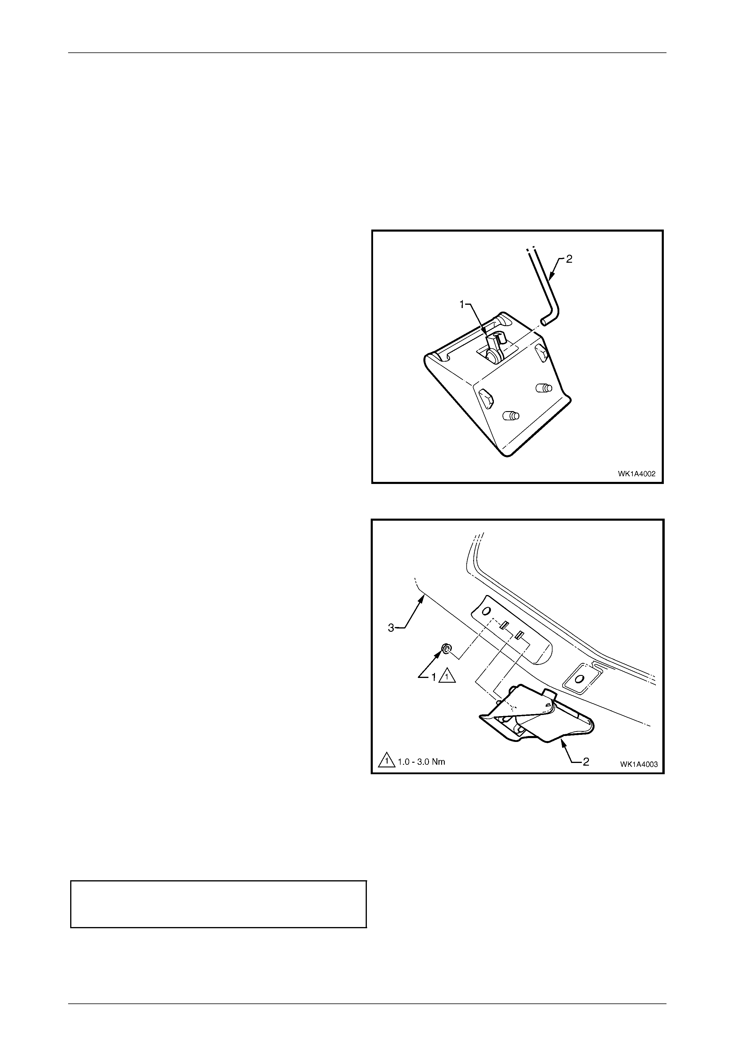
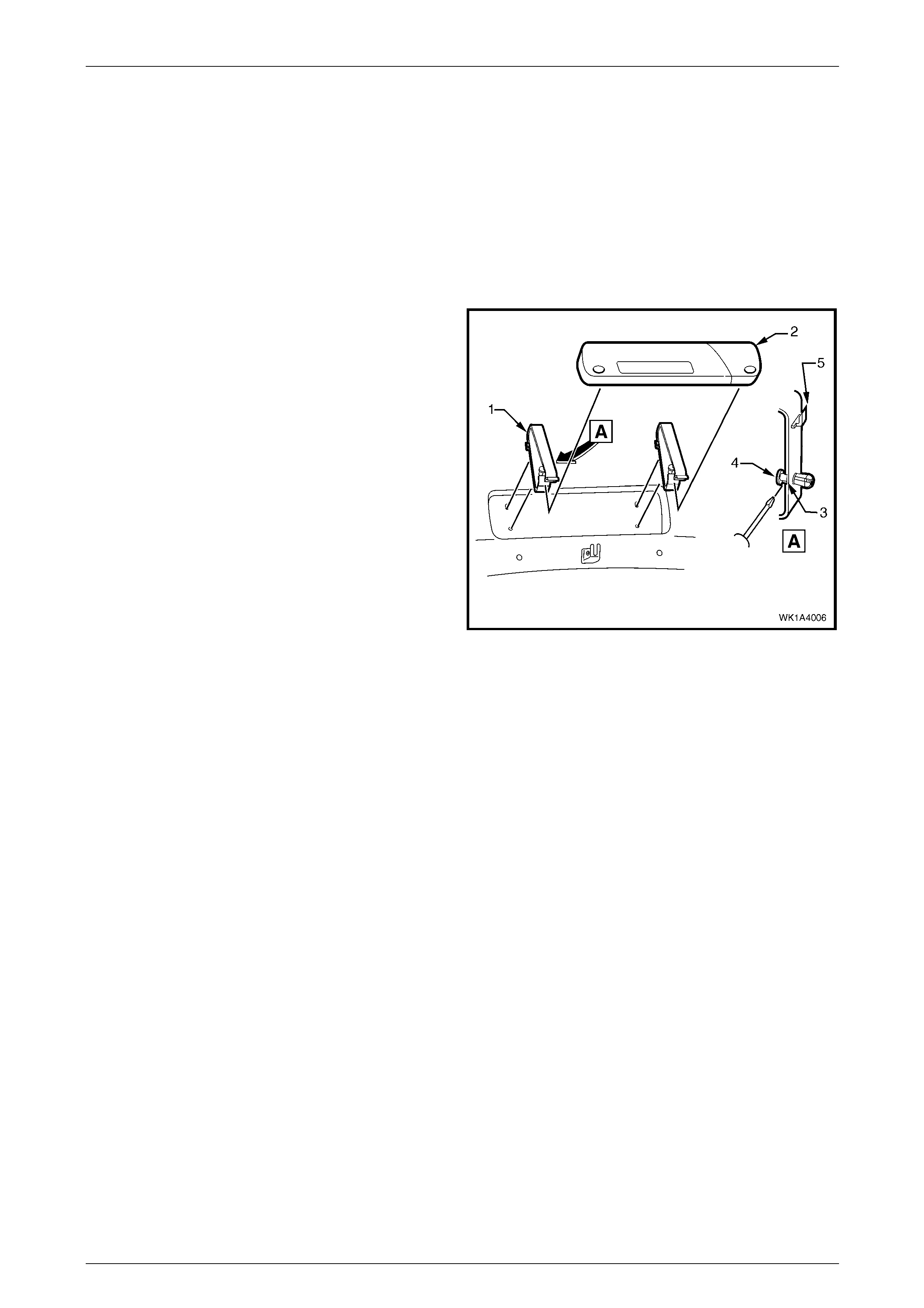
1 Raise the hood.
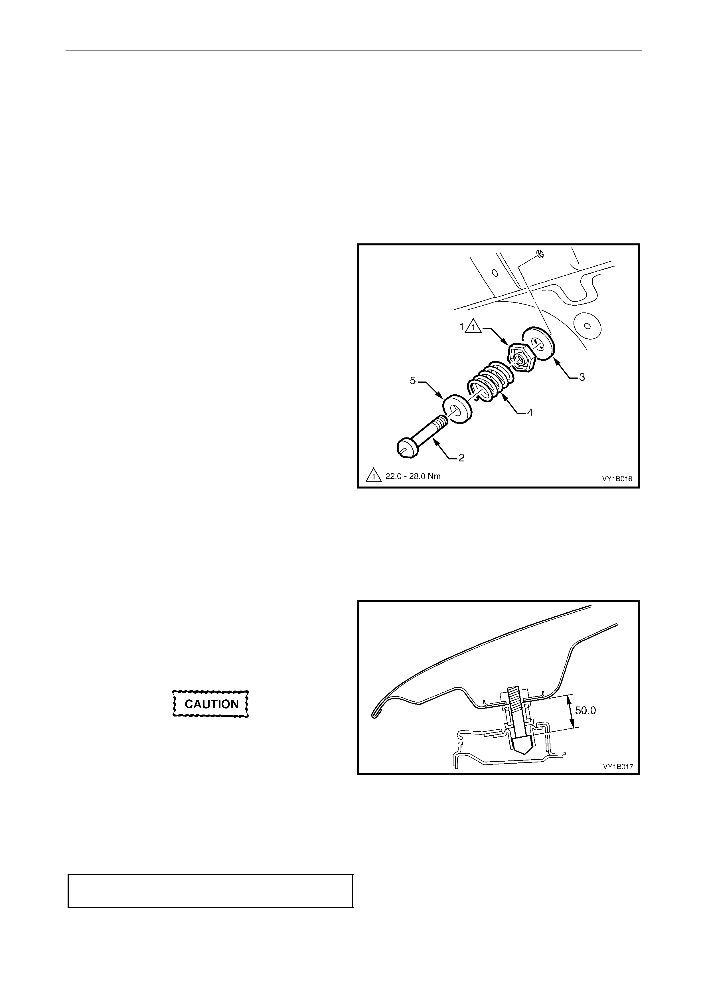
2 Loosen the hood primary latch striker nut (1).
3 Using a flat-bladed screwdrive r , unscrew the hood
primary latch striker bolt (2) and remove the assembly.
4 If required, remove the washer (3), nut, hood pop-up
spring (4) and hood pop-up s prin g retain er (5).
Figure 1A4 – 1
Reinstall
Reinstallation of the hood primary latch striker assembly is the reverse of the removal procedur e, noting the following:
1 Reassemble the hood primary latch striker assembly components as required.
2 Install the hood primary latch striker assemb ly to the
hood and tighten the hood primary latch striker bolt to
achieve a nominal length of 50 mm.
3 Apply a lubricant (for example, NLGI No. 1 lithium
grease or equivalent) to the end of the strike r bolt.
Do not push the hood closed as damage to
the panel surface may occur. If it does not
close on the first attempt, try again from a
slightly greater height.
Figure 1A4 – 2
4 Close the hood by dropping it from a height of about 300 mm.
5 If required, adjust the usable length of the striker bolt, refer to Adjust in this Section.
6 Tighten the hood primary latch striker nut to the correct torque specification.
Hood primary latch striker nut
torque specification.................................22.0 – 28.0 Nm

Hood and Rear Compartment Lid Page 1A4–5
Page 1A4–5
Adjust
1 Check the difference in height between the front of the hood and the fenders, refer to Figure 1A4 – 18.
2 To adjust the usable length of the hood primary latch striker bolt:
a Open the hood.
b Loosen and hold the hood primary latch striker nut while rotating the hood primary latch striker bolt with a flat-
bladed screwdriver.
c If required, set the hood adjust bumper to align the hood height, refer to 2.8 Hood and Hinge Assemblies.
3 Tighten the striker nut to the correct torque specification, ref er to reinstall in this Section.
Hood and Rear Compartment Lid Page 1A4–6
Page 1A4–6
2.2 Hood Primary Latch Spring
LT Section No. — 12–050
Remove
1 Raise the hood.
2 Remove the radiator upper shroud, refer to Section 6B1 Engine Cooling – V6 or
Section 6B3 Engine Cooling – GEN III V8.
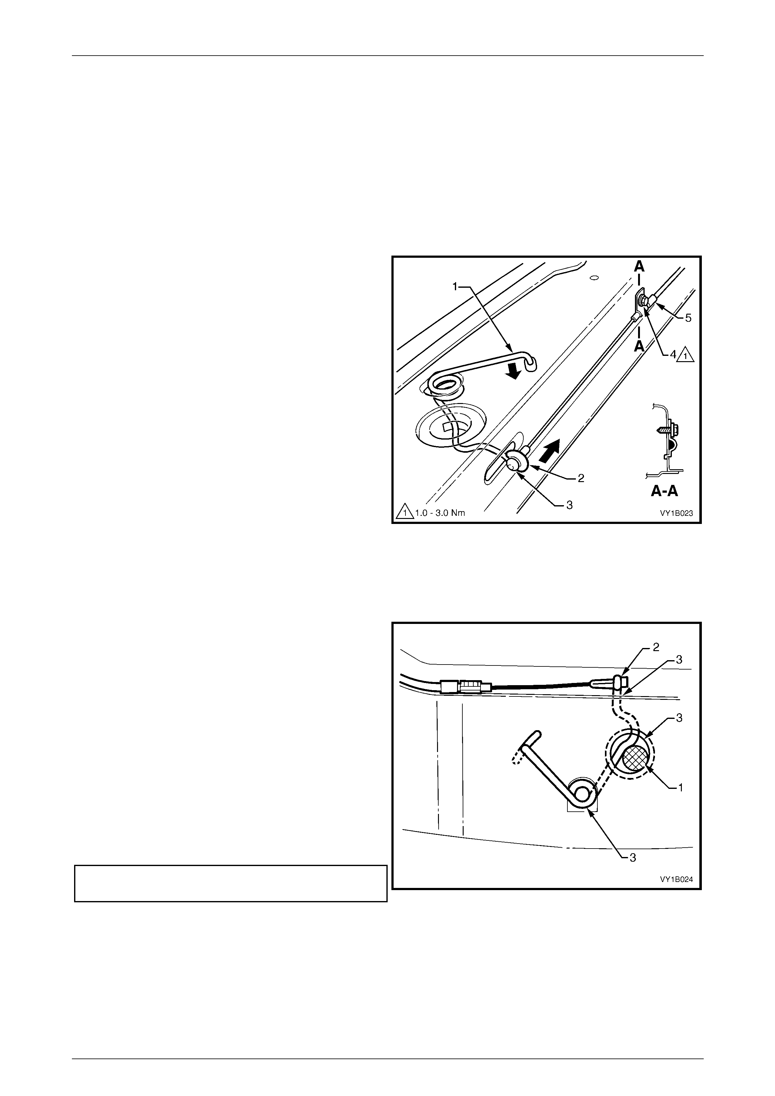
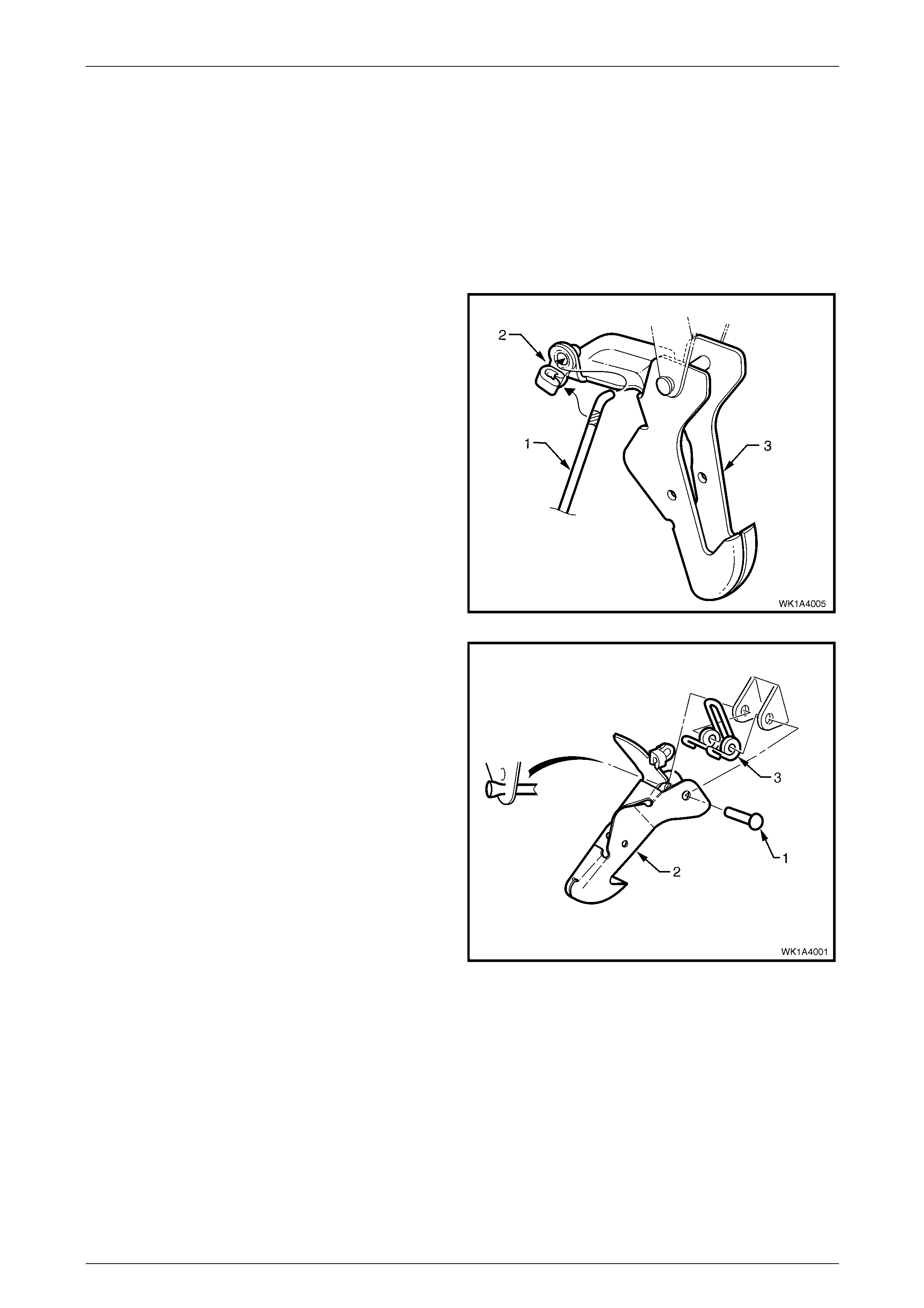
3 Using a pair of pliers, grasp th e hood primary latch
spring at point (1) and carefully dis en gage it from the
front panel in the direction shown.
4 Slide the cable end of the hood primary latch
spring (2) to the open position in the direction shown
to clear the latch hole.
5 Unhook the hood primary latch release cable
assembly (3) from the latch spring.
6 Grasp the end of the latch spring at point (1), rotate to
vertical and manipulate the section of the spri ng in the
front panel out through the spring co il hole.
Figure 1A4 – 3
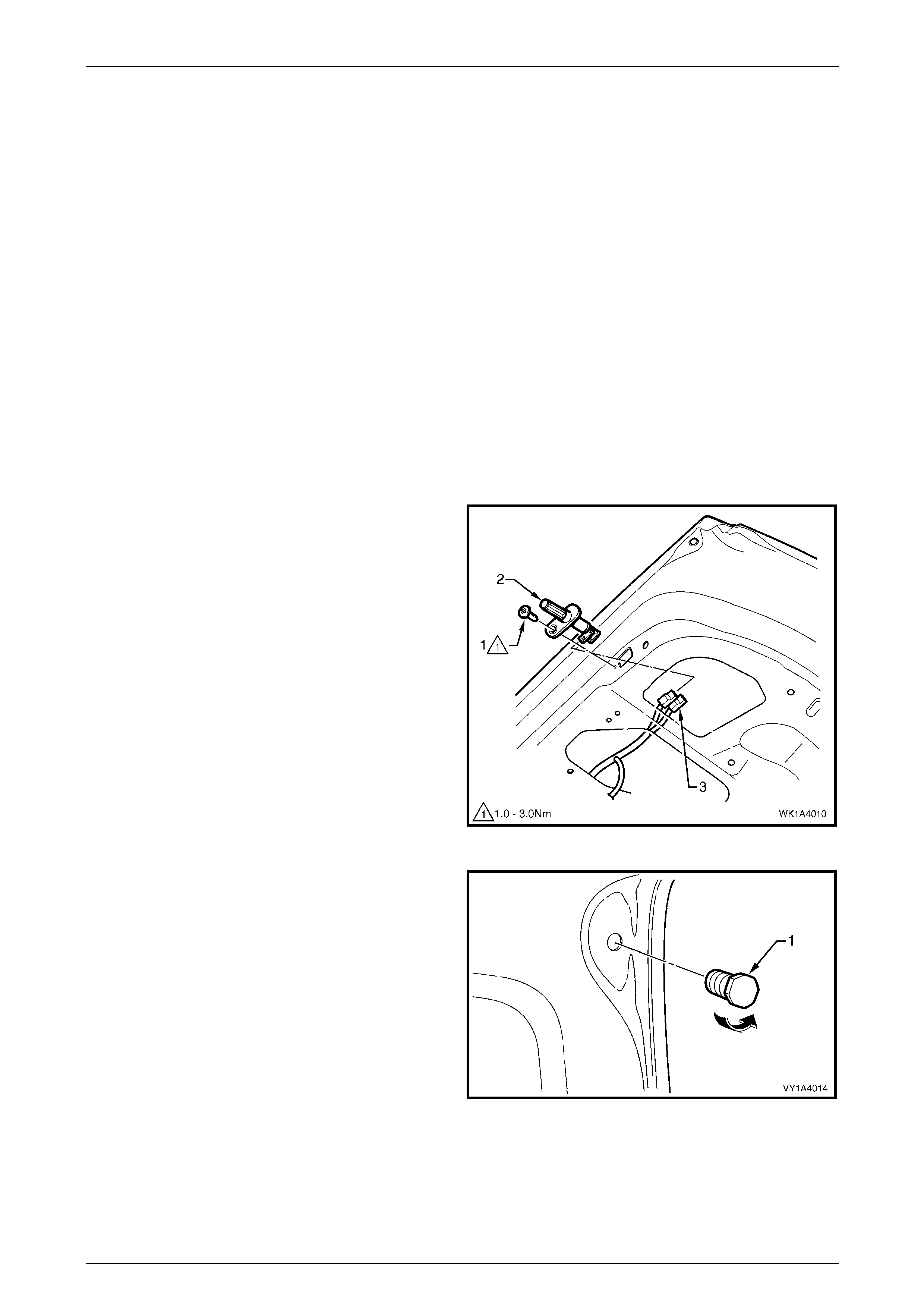
Reinstall
Reinstallation of the hood primary latch spring is the reverse of the removal procedure, noting the following:
1 Check the hood primary latch release cable
adjustment by inserting a 16 mm pin (1) between the
spring and the latch hole and check there is no
clearance between the inner cable ferrule and the
spring (2).
2 If required, loosen the hood primary latch release
cable retainer screw (4, refer to Figure 1A4 – 3) and
adjust the latch release cable.
NOTE
Ensure the outer cable ferrule (5, refer to Figure
1A4 – 3) is positioned before the retainer.
3 Tighten the retainer screw to the correct torque
specification.
Hood primary latch release cable
retainer screw torque specification..............1.0 – 3.0 Nm Figure 1A4 – 4
4 Remove the 16 mm pin and check the hood primary latch spring for correct operation.
5 Apply NLGI No. 1 lithium grease or equivalent to the following locations, refer to points (3) in Figure 1A4 – 4:
• spring slot,
• latch hole to a depth of the spring slot, and
• spring coils.
Hood and Rear Compartment Lid Page 1A4–7
Page 1A4–7
2.3 Hood Primary Latch Release Cable
Assembly
LT Section No. — 12–050
Remove
1 If required:
a Remove the radiator upper shroud, refer to Section 6B1 Engine Cooling – V6 or
Section 6B3 Engine Cooling – GEN III V8.
b Remove the right-hand instrument panel o uter cover, refer to Section 1A3 Instrument Panel and Console.
c Detach the wiring harness former from the right-ha nd strut tower,
refer to Section 12O Fuses, Relays and Wiring Harnesses.
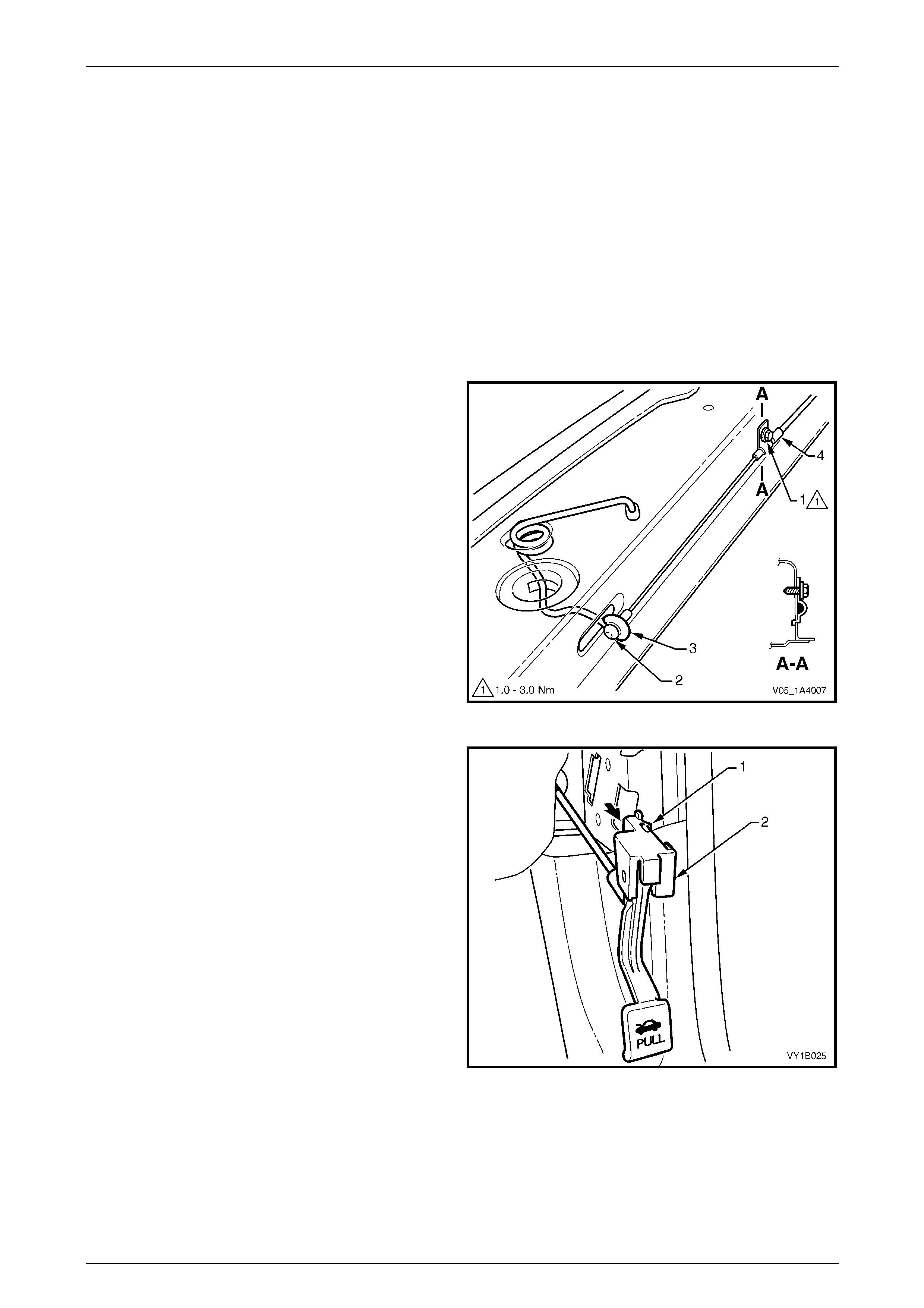
2 Remove the hood primary latch release cable retainer
screw (1) from the outer cable ferrule (4).
3 Unhook the hood primary latch release cable
assembly (2) from the hood primary latch spr ing (3).
Figure 1A4 – 5
4 From inside the vehicle, using a fine flat-bl aded
screwdriver, lever the retaining tabs (1) top and bottom
on the hood release lever ass embly (2) and slide the
hood release lever assembl y rearward.
Figure 1A4 – 6
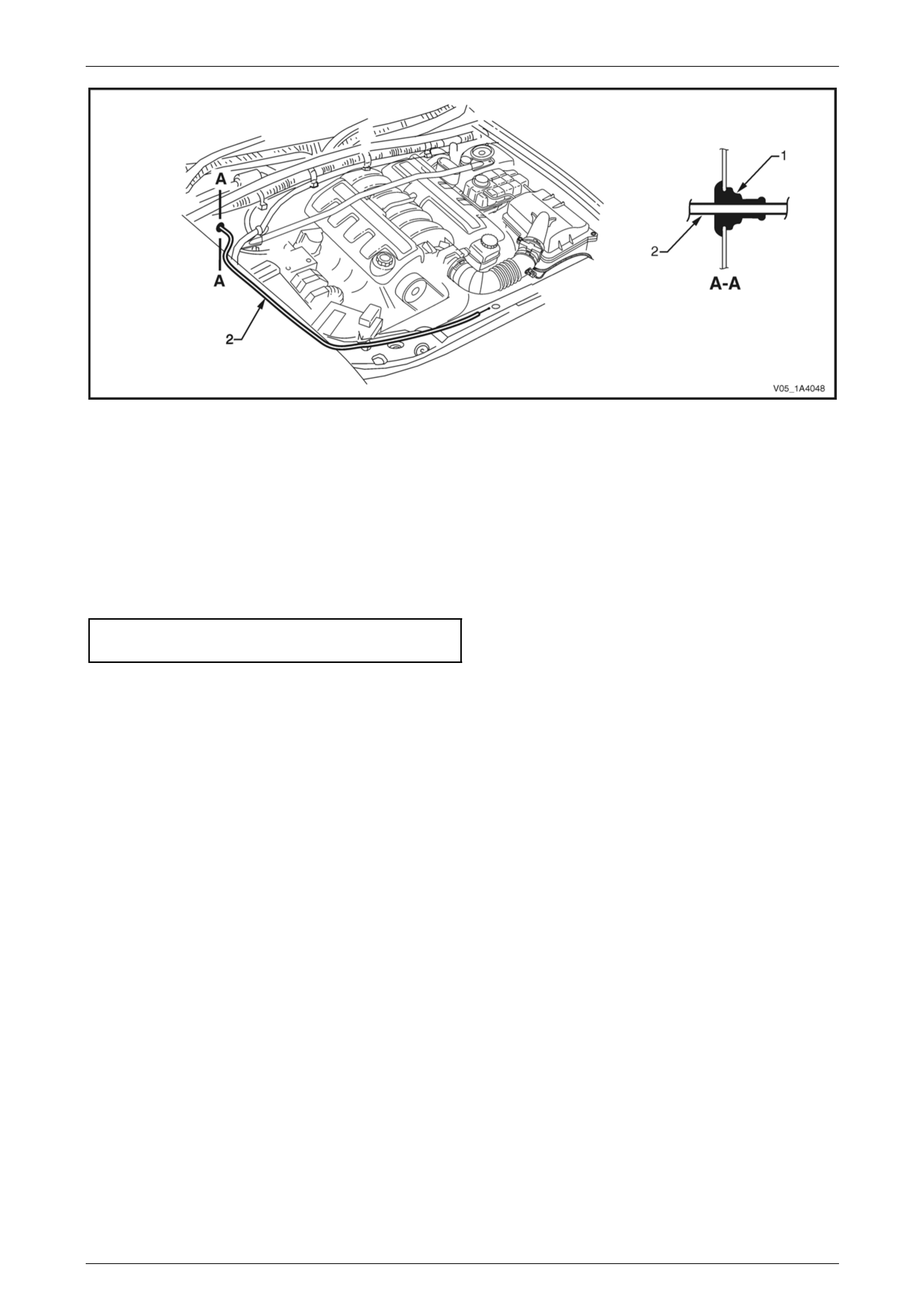
5 From within the engine compartment, push the gromm et (1) through the dash panel, refer to Figure 1A4 – 7.
6 Withdraw the cable assembly (2) from behind the fuse and relay box, across the dash panel and into the passenger
compartment.
Hood and Rear Compartment Lid Page 1A4–8
Page 1A4–8
Figure 1A4 – 7
Reinstall
Reinstallation of the hood primary latch release cable assembly is the reverse of the removal procedure, noting the
following:
1 Ensure the outer cable ferrule (4, F igure 1A4 – 5) is positioned before the retainer.
2 Ensure the cable assembly is correctl y rout ed and there are no sharp bends in the cabl e.
3 Tighten the hood primary latch release cable retainer screw to the correct torque specification.
Hood primary latch release cable
retainer screw torque specification..............1.0 – 3.0 Nm
4 Check the cable adjustment, refer to 2.2 Hood Primary Latch Spring.
5 Attach a spring scale to the lower edge of the release lever. The effort required to release the hood should not
exceed 40 N.
Hood and Rear Compartment Lid Page 1A4–9
Page 1A4–9
2.4 Hood Secondary Lock Lever Assembly
LT Section No. — 12–050
Remove
1 Raise the hood.
2 Remove the radiator grille, refer to Section 1C Radi ator Grille.
3 Unclip the retainer (1) from the rod (2).
4 Remove the rod from the hood secondary lock lever
assembly.
Figure 1A4 – 8
5 Remove the nut (1), two places, attaching the hood
secondary lock lever assem bly (2) to the hood (3) and
remove the hood secondar y lock lever assembly.
Figure 1A4 – 9
Reinstall
Reinstallation of the hood secondary lock lever assembly is the reverse of the removal procedure. Tighten the nuts to the
correct torque specification.
Hood secondary lock lever
assembly attaching nut
torque specification.....................................1.0 – 3.0 Nm
Hood and Rear Compartment Lid Page 1A4–10
Page 1A4–10
2.5 Hood Secondary Latch Assembly
LT Section No. — 12–050
Remove
NOTE
Replace the secondar y latch rivet when removing
the hood secondary latch assembly.
1 Raise the hood.
2 Unclip the rod (1) from the retainer (2) attaching it to
the hood secondary latch assembly (3).
3 Remove the rod from the latch assembly.
Figure 1A4 – 10
4 Carefully cut the end of the secondar y latch ri vet (1)
securing the hood secondary latch (2) and hood
secondary latch spring (3) to the ho od.
NOTE
Take care not to damage the paintwork.
5 Using a pin punch, extract the rivet to remove the latch
and latch spring.
Figure 1A4 – 11
Reinstall
Reinstallation of the hood secondary latch assembly is the reverse of the removal procedure, noting the following:
1 Lubricate the new secondar y latch rivet with NLGI No. 1 lithium grease or equivalent.
2 While holding t he hood secondary latch and hood secondary latch spring in position on the hood, insert the ne w
secondary latch rivet. Ensure the latch spring is correctly oriented, refer to Figure 1A 4 – 11.
3 Crimp the end of the rivet to secure it in place.
4 Place the rod into position and attach it with the retainer.
5 Test the operation of the hood secondary latch assembly.
Hood and Rear Compartment Lid Page 1A4–11
Page 1A4–11
2.6 Hood Insulator
LT Section No. — 12–050
Remove
NOTE
The hood insulator retainers may require
replacement when performing this operation.
1 Raise the hood.
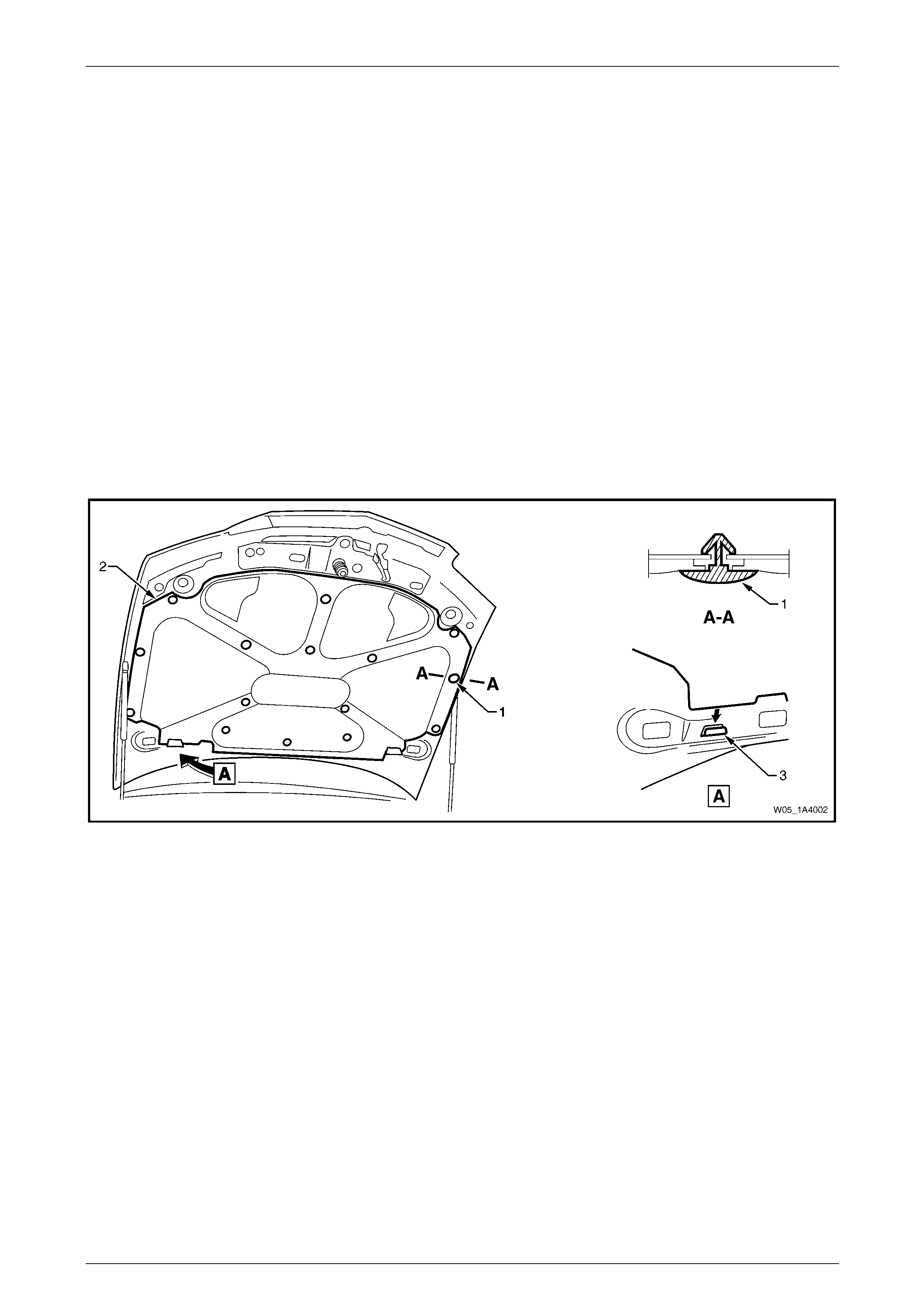
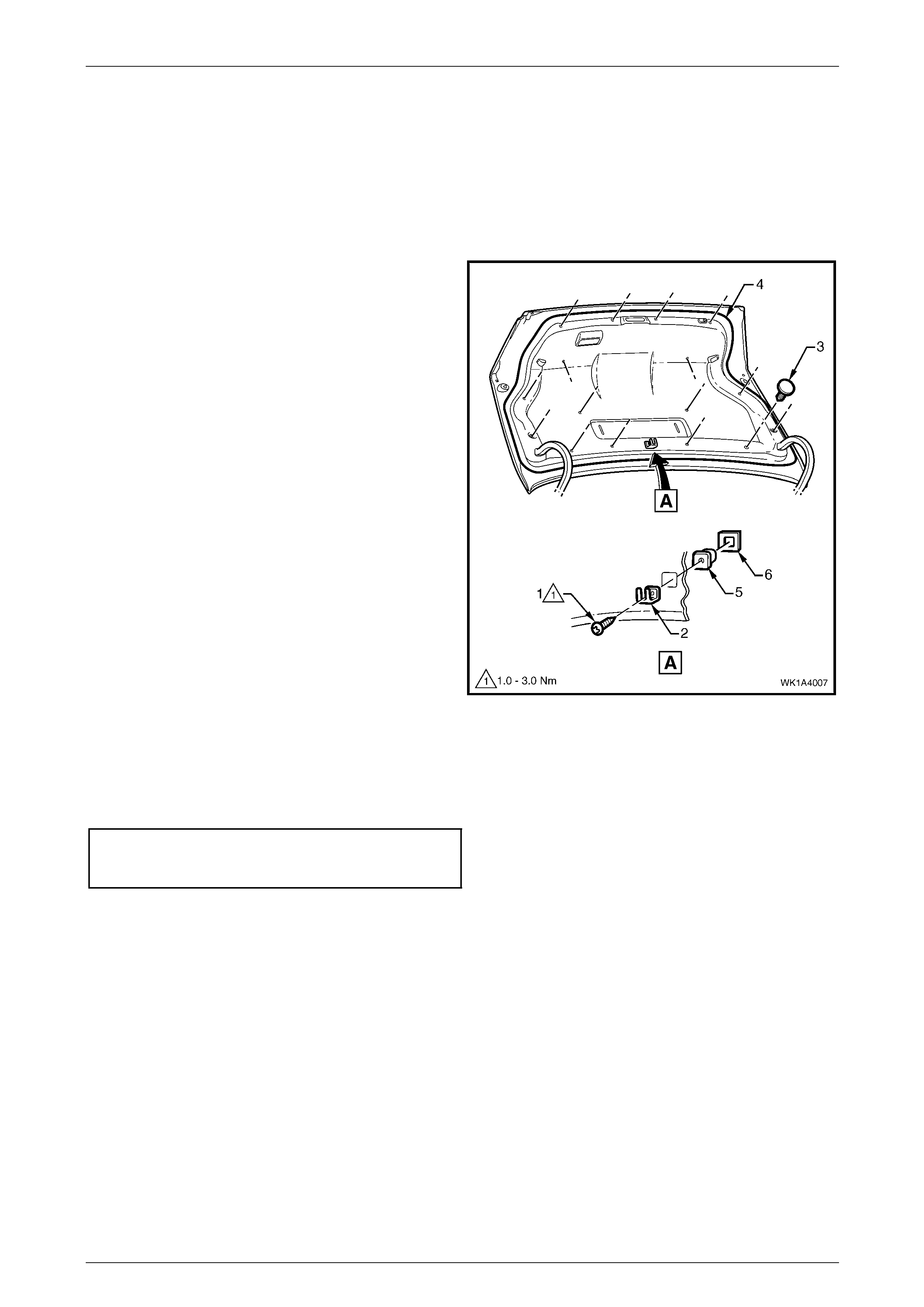
2 Beginning at the rear of the hood and working toward the front, remove the hood insulator retainer (1), 13 places,
attaching the hood insulator (2) to the hood, refer to Figure 1A4 – 12.
NOTE
Take care not to crush or damage the hood
insulator.
3 Slide the insulator from the tabs (3) in the hood inn er pa nel and remove the insulator.
Figure 1A4 – 12
Reinstall
Reinstallation of the hood insulator is the reverse of the removal procedure.
Hood and Rear Compartment Lid Page 1A4–12
Page 1A4–12
2.7 Hood Strut Assembly
LT Section No. — 12–050
Remove
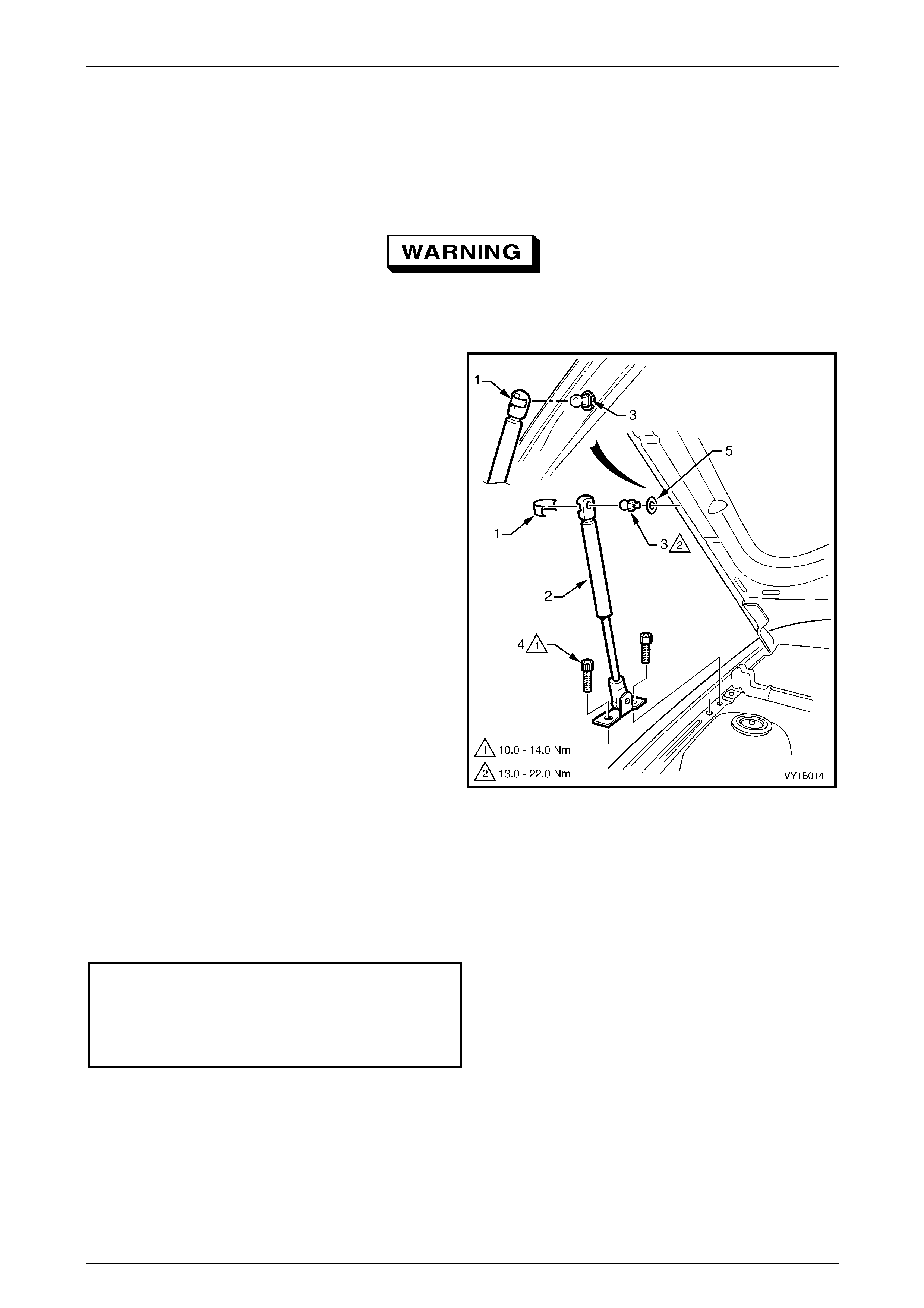
The hood struts contain pressurised gas. Do
not subject them to extreme heat, p ressure or
physical damage.
1 With the aid of an assistant, use a fine flat-bladed
screwdriver to remove the retainer (1) securing the
hood strut assembly (2) to the hood strut ball stud (3).
NOTE
The retainer can spring off the hood strut
assembly and be easily lost.
2 Remove the Torx-head screws (4), two places,
attaching the strut assembly to the fender.
3 Disconnect the strut assembly from the hood and
remove.
4 If required, unscrew the hood strut ball stud and
washer (5) from the hood.
Figure 1A4 – 13
Reinstall
Reinstallation of the hood strut assembly is the reverse of the removal procedure, noting the follo wing:
1 Apply a small amount of NLGI No. 1 lithium grease or equivalent to the inside of the strut ball cup.
2 Tighten the fasteners to the correct torque specification.
Hood strut ball stud
torque specification.................................13.0 – 22.0 Nm
Hood strut assembly
to fender attaching screw
torque specification.................................10.0 – 14.0 Nm
3 Check for correct operation of the hood strut assembly.
Hood and Rear Compartment Lid Page 1A4–13
Page 1A4–13
2.8 Hood and Hinge Assemblies
LT Section No. — 12–425
Remove
1 If required, remove the following components:
a hood primary latch striker assembl y, refer to 2.1 Hood Primary Latch Striker Assembly;
b hood secondary latch assembly, refer to 2.5 Hood Secondary Latch Assembly;
c hood insulator, refer to 2.6 Hood Insulator; and
d radiator grille, refer to Section 1C Radiator Grille
2 Raise and support the hood.
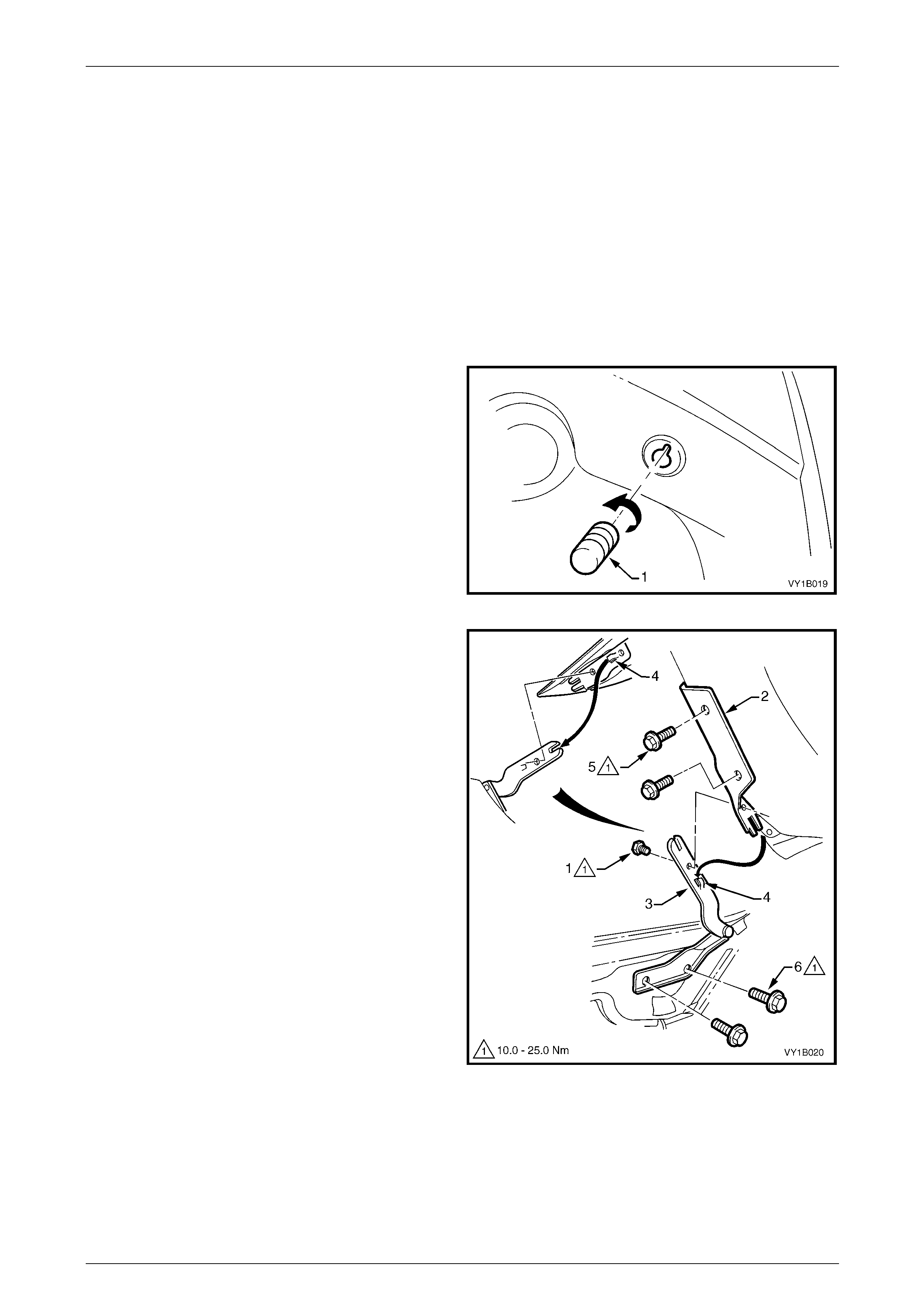
3 If required, unscrew and remove the hood adjust
bumper (1) from the centre and on each side of the
hood.
4 Disconnect the hood strut assemblies from the hood,
refer to 2.7 Hood Strut Assembly.
NOTE
The lower end of the hood strut assembly does
not need to be removed.
Figure 1A4 – 14
5 To remove the hood:
NOTE
Alignment of the hood is not required if the
following method is used to remove the hood.
a If the hood will be reinstalled:
(1) With the aid of an assistant, remove the
screw (1) attaching the upper hinge
section (2) and lower hinge section (3)
from each hood and hinge assembly.
(2) With the aid of an assistant, slide the hood
out of the locating tabs (4) and remove the
hood.
NOTE
Alignment of the hood may be required if the
following method is used to remove the hood.
b If a new hood will be installed:
(1) With the aid of an assistant, remove the
two screws (5) attaching the upper hinge
section to the hood from each hood and
hinge assembly.
Figure 1A4 – 15
(2) With the aid of an assistant, remove the hood.
6 If required, remove the lower hinge section:
a Remove the screw (1) attaching the upper hinge section (2) and lower hinge section (3).
b Remove the plenum cover assembly, refer to Section 12N Wipers, Washers and Horn.
c Remove the two screws (6) attaching the lower hinge section to the body and remove the lower section.
Hood and Rear Compartment Lid Page 1A4–14
Page 1A4–14
Reinstall
Reinstallation of the hood and hinge assemblies is the reverse of the removal procedure, noting the following:
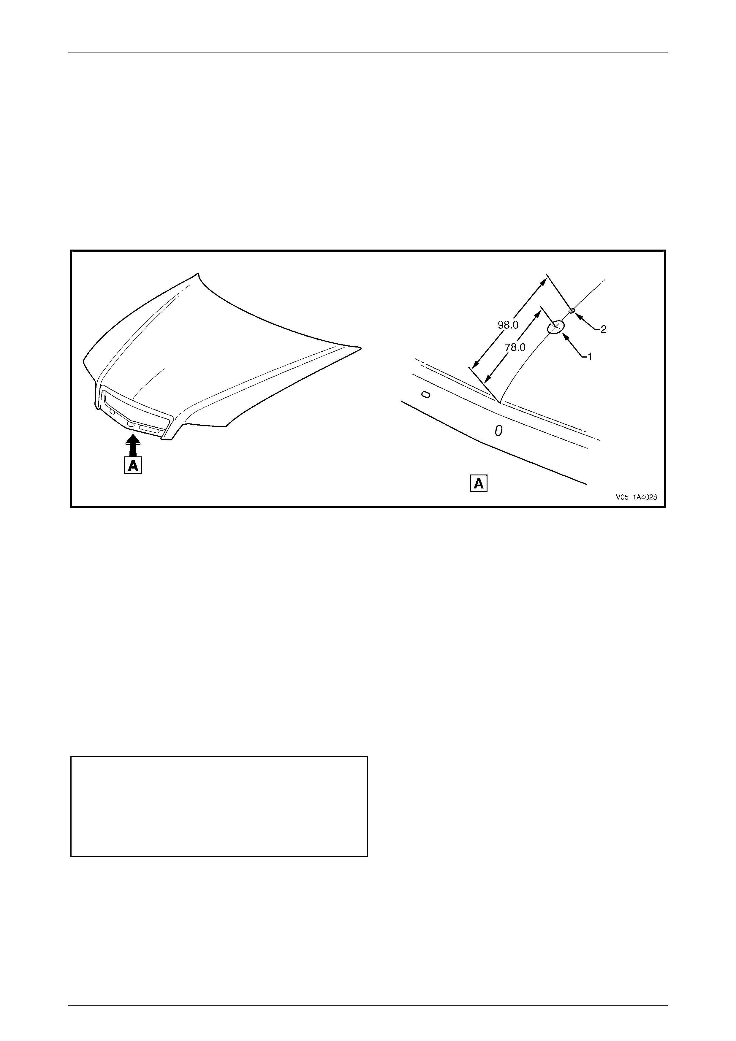
1 If required, before refinishing the hood panel drill a hole to accommodate the hood emblem, refer to
Figure 1A4 – 16:
a Measure along the hood centre-line and mar k the centre point of each hole.
b Drill a 3 mm pilot hole at each position.
c Enlarge the hole (1) to a diameter of 14 mm in two stages.
d Enlarge the hole (2) to a diameter of 4.5 mm.
e Remove any burrs as required.
Figure 1A4 – 16
2 If the lower hinge sections were removed from the body:
a Reinstall the lower hinge sections and, if possible, align them with any existing marks. Otherwise, install the
lower hinge sections with the screws centrally in their holes.
b Temporarily tighten the screws.
3 If the upper hinge sections were removed from the hood:
a With the aid of an assistant, reinstall the upper hinge sections to the hood and, if possible, align them with
any existing marks. Otherwise, install the upper hinge sections with the screws centrally in their holes.
b Temporarily tighten the screws.
4 If the screw attaching the upper hinge section and lower hinge section were removed:
a With the aid of an assistant, slide the hood (and upper hing e sections) onto the lower hinge sections,
ensuring the upper hinge sections and lo wer hinge sections are correctly seated together.
b Tighten the screws to the correct torque specification.
Upper hood hinge section attaching
screw torque specification.......................10.0 – 25.0 Nm
Lower hood hinge section attaching
screw torque specification.......................10.0 – 25.0 Nm
Hood hinge scre w
torque specification.................................10.0 – 25.0 Nm
5 Install the hood adjust bumpers to their original position or half-way along the thread, refer to Figure 1A4 – 14.
6 Install or reconnect the hood strut assemblies, refer to 2.7 Hood Strut Assembly.
7 If required, adjust the hood, refer to Adjust in this Section.
8 If removed, reinstall the plenum cover assembly, refer to Section 12N Wipers, Washers and Horn.
Hood and Rear Compartment Lid Page 1A4–15
Page 1A4–15
Adjust
Correct alignment of the hood is critical to its operation and to the aesthetics of the vehicle. If the fenders are not
correctly positioned, the hood can not be aligned correctly.
Depending upon the repa irs performed, it may be advantageous to perform a measurement check between the fenders
before adjusting the hood.
Fender Alignment
1 Check the distance between the front doors and fen ders are correct. If not correct, rectify before proceeding, refer
to Section 1B Sheetmetal.
Paint damage may occur. Use care and, if
required, touch up any paint damage.
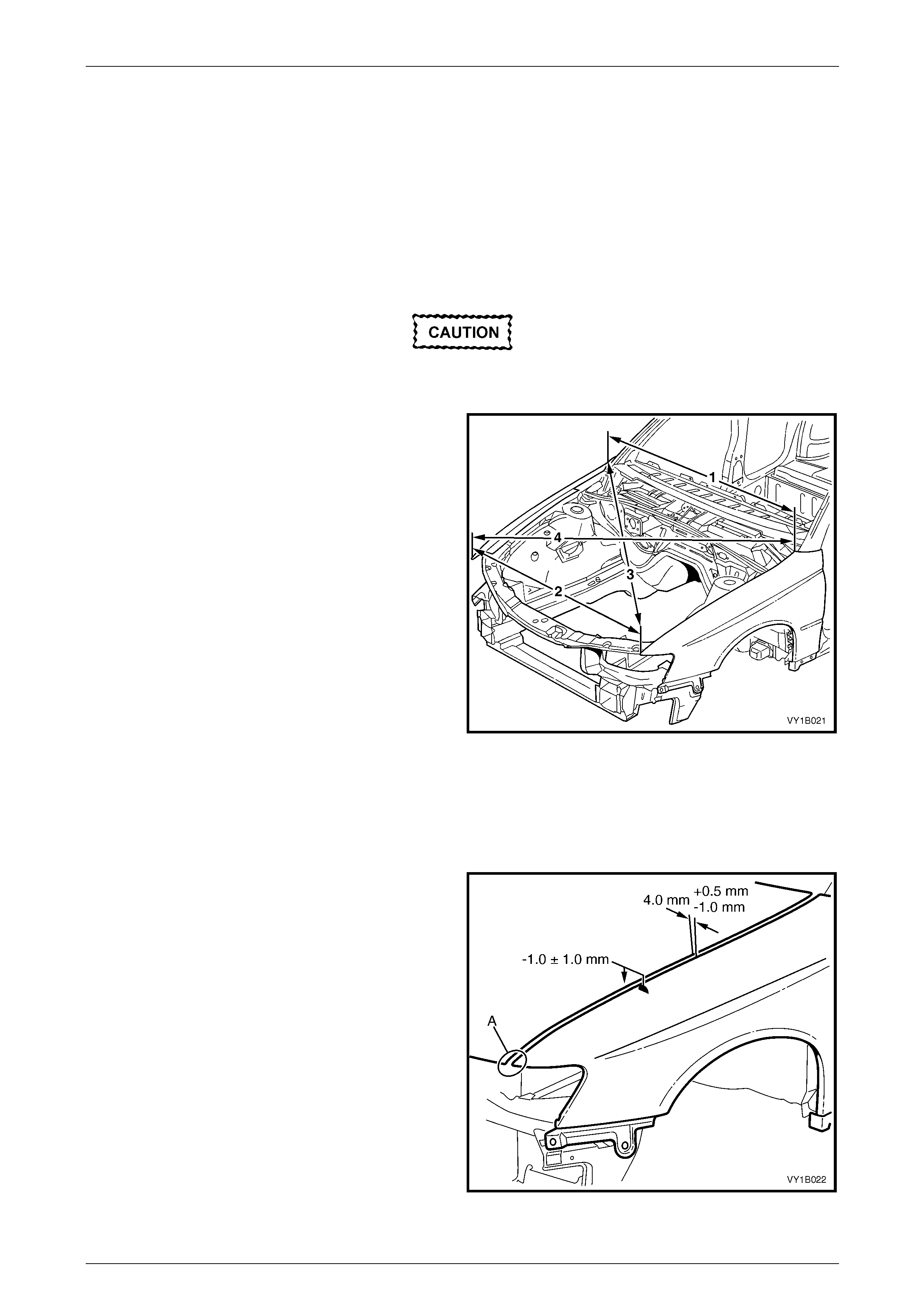
2 Measure the distance between the rear of each
fender (1). This distance should be the width of the
rear of the hood plus 8.0 mm. If not, adjust the
fenders, refer to Section 1B Sheetmetal.
3 Measure the distance between the front of each
fender (2). This should be the width of the front of the
hood plus 8.0 mm. If not, adjust the fenders, refer to
Section 1B Sheetmetal.
4 Measure the distance between a suitable point at the
rear of the left-hand fender and front of the right-hand
fender (3). Note the length.
5 Measure the distance between the opposite fender
points (4). This measurement must be within 1.5 mm
of result (3).
6 If the measurements are correct, align the hood as
follows. If not, adjust the fenders, refer to
Section 1B Sheetmetal.
Figure 1A4 – 17
Hood Alignment
1 If fitted, remove the hood primary latch striker assembly, refer to 2.1 Hood Primary Latch Striker Assembl y.
2 Carefully close the hood, ensuring each side does not contact the fenders.
3 Check the alignment of the hood for:
• Length:
Compare to the front edge of the fenders; they
should be equal at point A.
• Width of gap:
Compare the gap bet ween the hoo d and the side
of each fender; the gap must be 4.0 mm
(+0.5 mm / –1.0 mm).
• Consistency of gap:
Compare the gap bet ween the hoo d and each
fender at the front, middle and rear; the gap
should be even.
• Height:
Compare the height of the hood with the fenders
at each corner; the hood height must be –1 mm
(±1.0 mm).
Figure 1A4 – 18
Hood and Rear Compartment Lid Page 1A4–16
Page 1A4–16
4 Open the hood and, if required:
• Loosen the screws attaching the hood to both upper hinge sections for fore and aft adjustment, refer to
Figure 1A4 – 15.
• Loosen the scre ws attaching both lower hinge sections to the body for rear height adjustment. If required, this
also provides fore and aft adjustment, refer to Figure 1A4 – 15.
• Turn the hood adjust bumper clockwise to lower the front of the hood or anticlockwise to raise the front of the
hood, refer to Figure 1A4 – 14.
NOTE
Do not make all adjustments at once. Perform
one adjustment, then carefully close the hood;
check its position and make further adjustments
until the correct alignment is a c hieved.
5 Install the hood primary latch striker assemb ly, refer to 2.1 Hood Primary Latch Striker Assembly.
6 Lower the hood while watching the alignment of the hood primary latch striker assembly and the latch hole.
7 Check the hood primary latch striker bolt do es not foul the latch hole and the hood alignment does not alter. If
required, adjust the hood primary latch striker bolt position.
Do not push the hood closed as damage to
the panel surface may occur. If it does not
close on the first attempt, try again from a
slightly greater height.
8 Close the hood by dropping it from a height of approximately 300 mm.
9 Check the height difference between the front of the hood and both fenders:
a If required, adjust the usable length of the hood primary latch striker bolt by loosening the hood primary latch
striker nut and rotating the hood primary latch striker bolt with a flat-bladed screwdriver, refer to
Figure 1A4 – 1.
b If required, adjust the hood adjust bumpers, refer to Figure 1A4 – 14.
10 Tighten the screws and nuts to the correct torque specification.
Upper hinge section attaching
screw torque specification.......................10.0 – 25.0 Nm
Lower hinge section attaching
screw torque specification.......................10.0 – 25.0 Nm
Hood primary latch striker nut
torque specification.................................22.0 – 28.0 Nm
11 Recheck the alignment of the hood.
Hood and Rear Compartment Lid Page 1A4–17
Page 1A4–17
3 Service Operations — Rear
Compartment Lid
3.1 Rear Compartment Lid Safety Triangle
LT Section No. — 14–480
Remove
1 Unfasten the safety triangle retainers (1) and remove
the safety triangle (2).
2 Insert a fine flat-bladed screwdriver in the slot (3)
under the pin head (4) and prise the pin out.
3 Withdraw the lower portion of the safety triangle
retainer, then pull it down and out to release the upper
tab (5).
Figure 1A4 – 19
Reinstall
Reinstallation of the rear com partment lid safety triangle is the reverse of the removal procedure.
Hood and Rear Compartment Lid Page 1A4–18
Page 1A4–18
3.2 Rear Compartment Lid Carpet
LT Section No. — 14–480
Remove
1 If required, remove the safety triangle, refer to 3.1 Rear Compartment Lid Safety Triangl e.
2 Remove the screw (1) attaching the spare wheel
stowage cover hook (2) and remove the hook .
3 Using a suitable trim clip removal tool, remove the
retainer (3), 16 places, attaching the rear compartment
lid carpet (4).
4 Remove the carpet from the rear compartment lid.
5 If required, prise the nut (5) and washer (6) from the
rear compartment lid with a fine flat-bladed
screwdriver.
Figure 1A4 – 20
Reinstall
Reinstallation of the rear com partment lid carpet is the reverse of the removal procedure. Tighten the spare wheel
stowage cover hook screw to the correct torque specification.
Spare wheel stowage cover
hook attaching screw
torque specification.....................................1.0 – 3.0 Nm

Hood and Rear Compartment Lid Page 1A4–20
Page 1A4–20
3.4 Rear Spoiler Assembly
LT Section No. — 10–350
Remove
1 If required, remove the rear compartment lid carpet, refer to 3.2 Rear Compartment Lid Carpet.
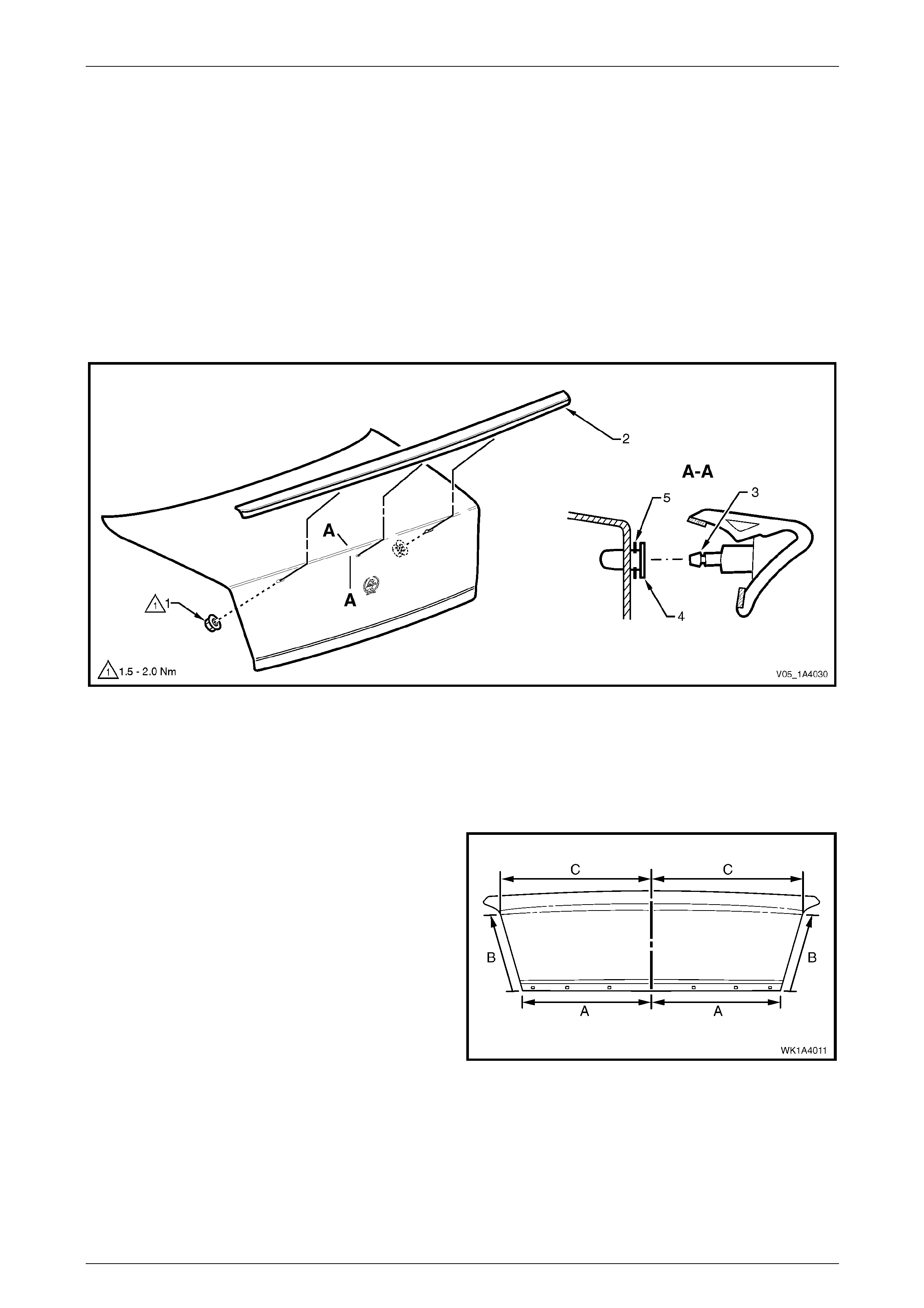
2 Locate the holes from inside the rear compar tment lid and remove the two nuts (1) attaching the rear spoiler
assembly (2) to the rear compartment lid, refer to Figure 1A4 – 21.
3 Carefully lift the spoiler from the rear compartment lid, unclipping the centre lug (3) from the retainer (4).
4 If required, carefully prise the retainer and seal (5) from the rear compartment lid.
Figure 1A4 – 21
Reinstall
Reinstallation of the rear spoiler assembly is the reverse of the removal procedure, noting the following:
1 If the rear compartment lid has not been replaced, proceed to step 16.
2 Measure along the lo wer edge of the rear
compartment lid (A) and mark the centre point.
3 Measure up each side of the rear compartment lid
equally (B, approximately 300.0 mm) and mark a
point.
4 Measure across the upper are a of the rear
compartment lid (C) from points (B) and mark the
centre point.
5 Draw a vertical centre-line bet wee n the two centre
points.
Figure 1A4 – 22
Hood and Rear Compartment Lid Page 1A4–21
Page 1A4–21
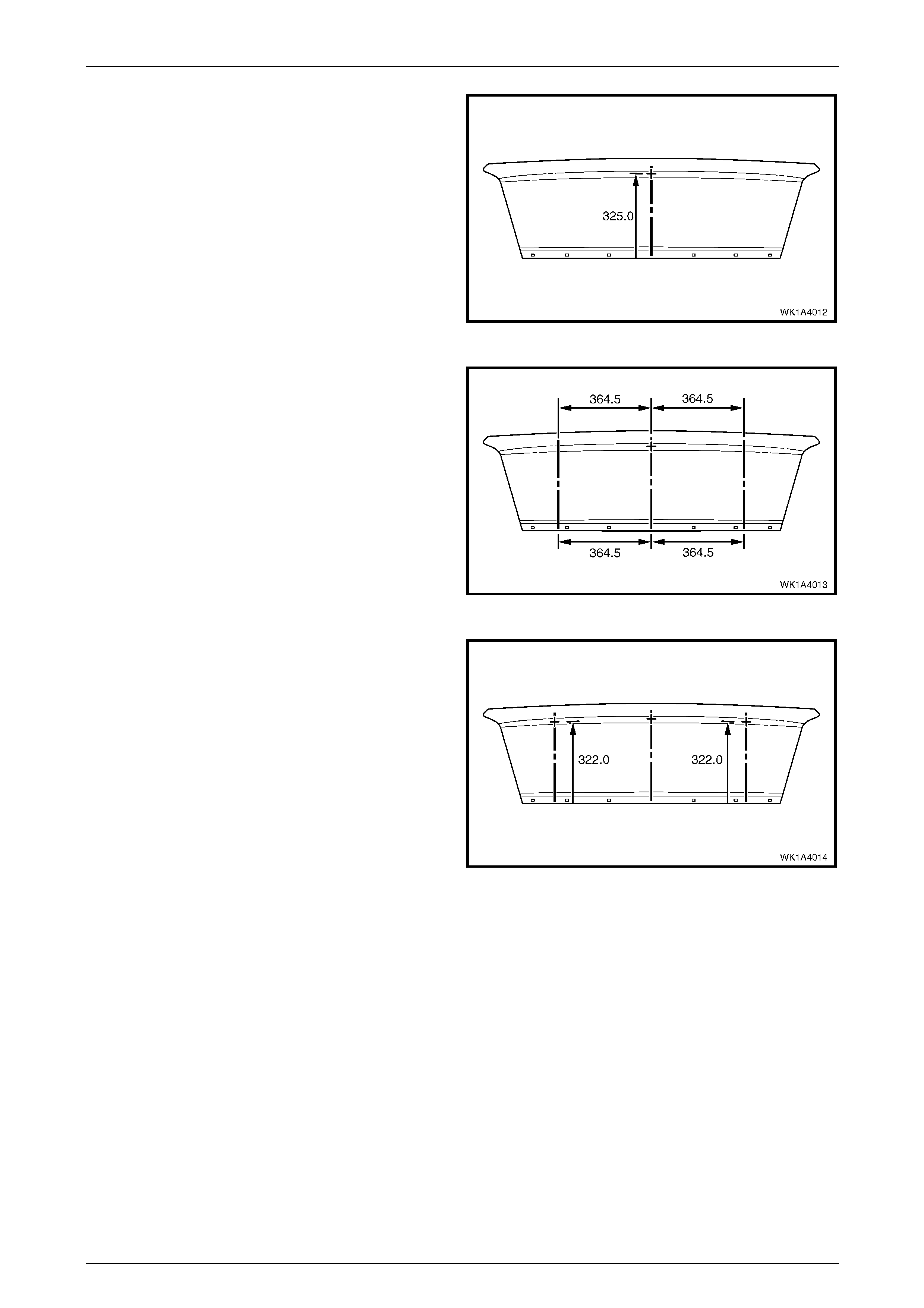
6 Measure up 325.0 mm from the lo wer edge al ong the
centre-line and mark the centre point of the middle
hole.
Figure 1A4 – 23
7 Measure 364.5 mm from the centre-line at th e lower
edge and upper area, and mark each po int. Repeat for
the opposite side.
8 Draw a vertical line between the marks.
Figure 1A4 – 24
9 Measure up from the lo wer edge along each vertical
line 322.0 mm and mark the centre point of each outer
hole.
10 Sit the rear spoiler in position and ensure the attaching
studs align with each centre point.
11 Drill a 3.0 mm pilot hole at each centre point.
Figure 1A4 – 25
Hood and Rear Compartment Lid Page 1A4–22
Page 1A4–22
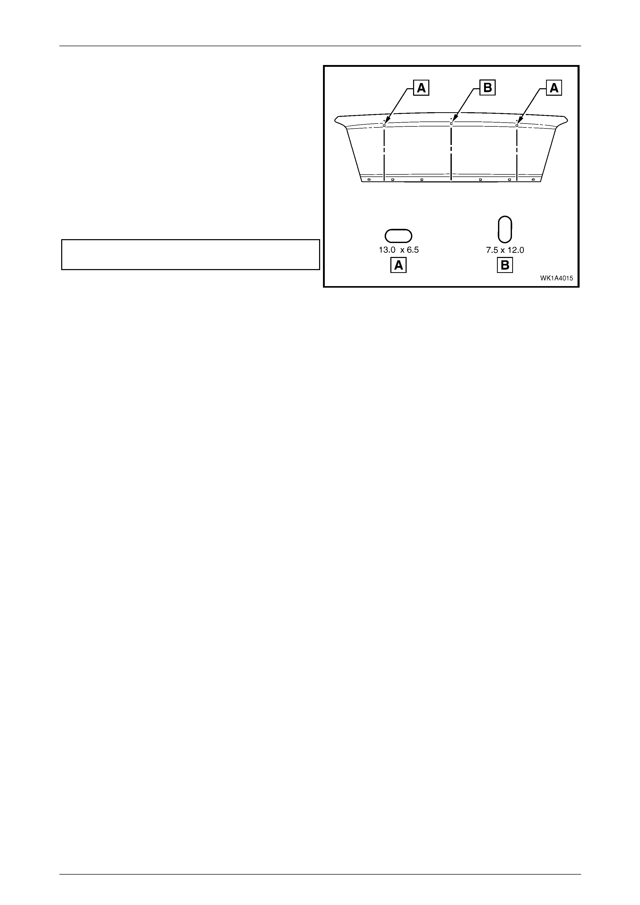
12 Carefully enlarge the outer holes to a horizontal slot
13.0 mm x 6.5 mm.
13 Carefully enlarge the in ner hole to a vertical slot
7.5 mm x 12.0 mm.
14 Remove any burrs and drilling swarf from within the
rear compartment lid cavity.
15 Refinish the panel as requir ed .
16 Fit the retainer (4) securely, ensuring the seal (5) is
correctly installed, refer to Figure 1A4 – 21.
17 Tighten the rear compartment lid spoiler attaching nuts
to the specified torque.
Rear compartment lid spoiler
attaching nut torque specification................1.5 – 2.0 Nm
Figure 1A4 – 26
Hood and Rear Compartment Lid Page 1A4–23
Page 1A4–23
3.5 Rear Compartment Lid Latch Assembly
LT Section No. — 12–680
Remove
1 If required, remove the rear compartment lid carpet, refer to 3.2 Rear Compartment Lid Carpet.
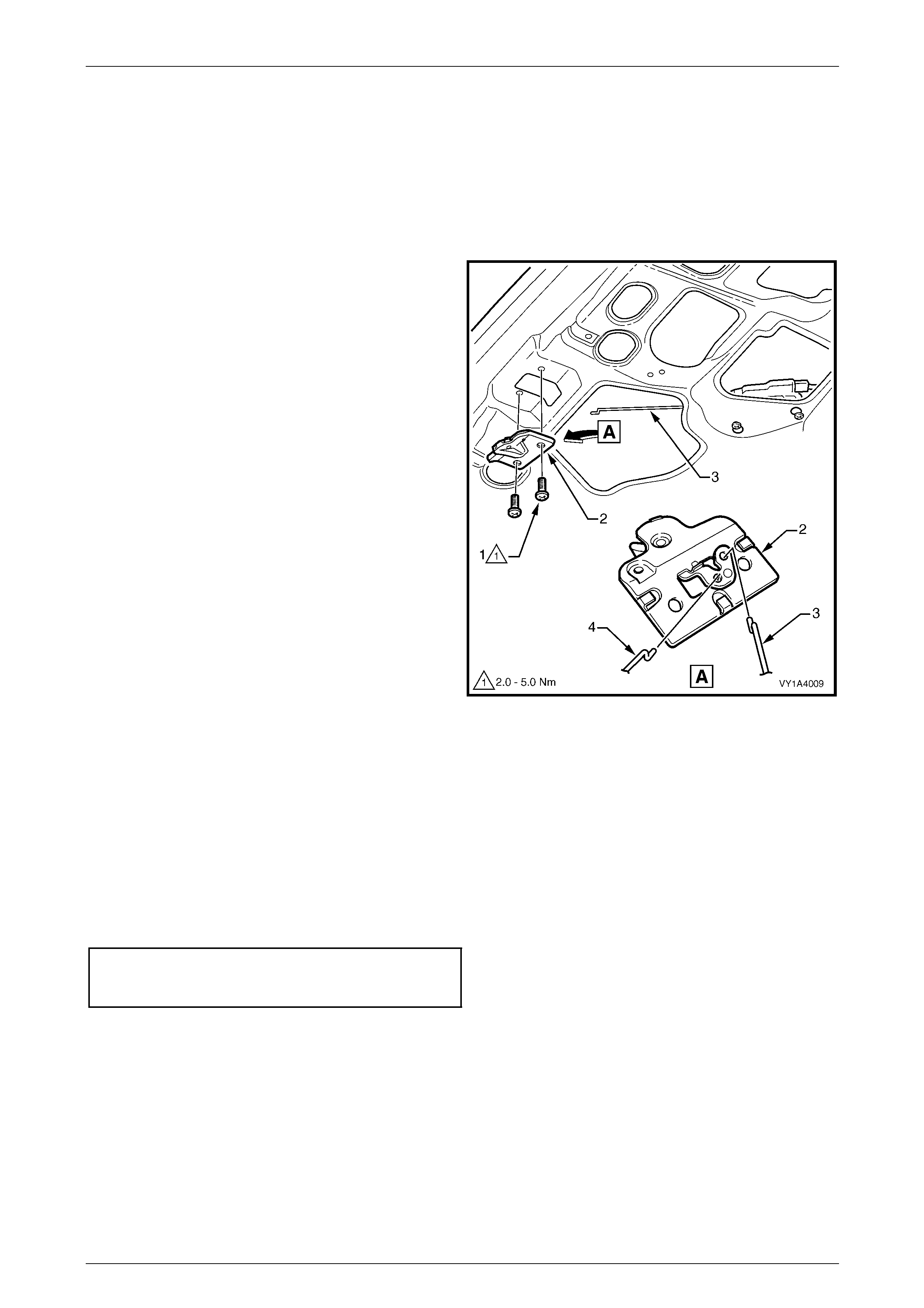
2 Remove the two screws (1) attaching the rea r
compartment lid latch assembly (2) to the rear
compartment lid.
3 Withdraw the latch assembly from the inner rear
compartment lid panel far enough to e nable
disconnection of the actuator rod (3) and rear
compartment lid release cable (4).
4 Remove the latch assembl y.
Figure 1A4 – 27
Reinstall
Reinstallation of the rear com partment lid latch assembly is the reverse of the removal procedure, noting the following:
1 Lubricate the rear compartment lid latch assembly with NLGI No. 1 lithium grease or equivalent.
2 Before closing the rear compartment lid, close the rear compartment lid latch and check the operation of the rear
compartment lid latch assembly using the rear compartment lid release switch and rear compartment lid release
cable assembly. If the operation is satisfactory, close the rear compartmen t lid and recheck the operation. If
required, adjust the rear compartment lid striker assemb ly, refer to 3.11 Rear Compartment Lid Striker Assembly.
3 Tighten the screws to the correct torque specification.
Rear compartment lid latch
assembly attaching screw
torque specification.....................................2.0 – 5.0 Nm
Hood and Rear Compartment Lid Page 1A4–24
Page 1A4–24
3.6 Rear Compartment Lid Actuator
Assembly
LT Section No. — 12–680
NOTE
The rear compartment lid actuator assembly is
controlled by the bod y control module (BCM ). For
diagnosis, refer to Section 12J Body Control
Module.
Remove
1 If required, remove the rear compartment lid carpet, refer to 3.2 Rear Compartment Lid Carpet.
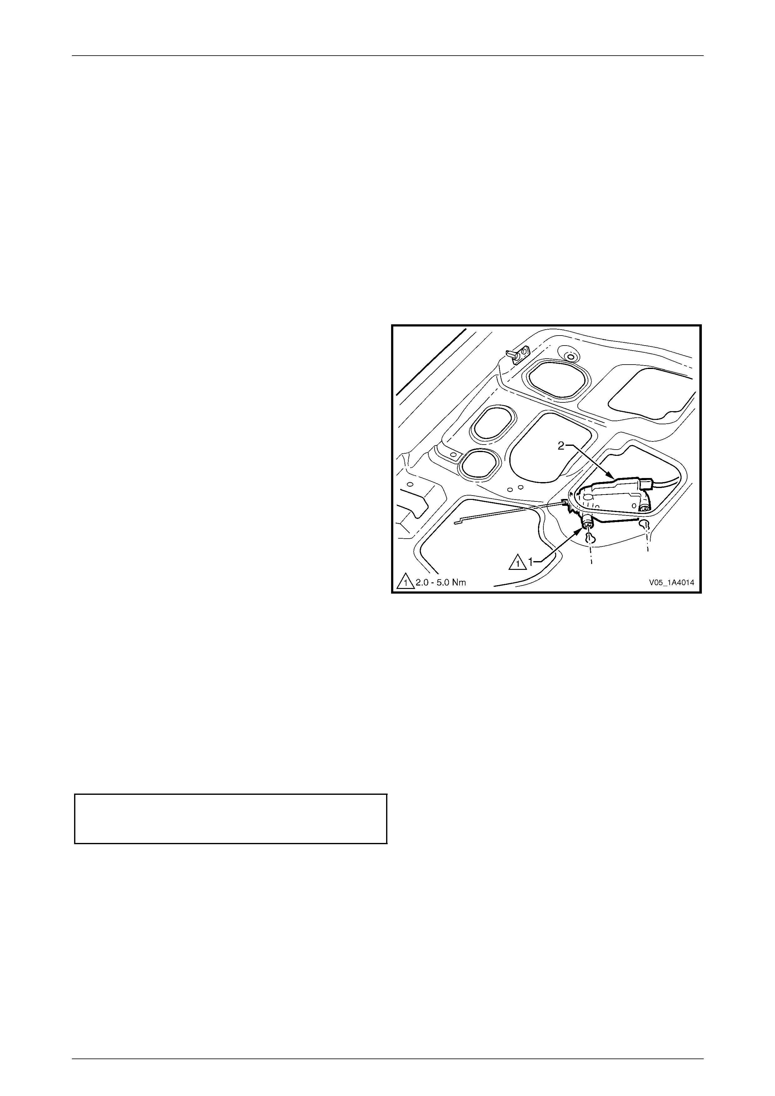
2 Loosen the scre w (1), two places, attaching the rear
compartment lid actuator assembly (2) to the rear
compartment lid.
3 If required, disconnect the connecting ro d from the
rear compartment lid latch assembly.
4 Withdraw the actuator assembly from the keyhole slots
in the inner rear compartment lid p anel.
5 Remove the actuator assembly from the inne r rear
compartment lid panel cavity far enough to enable the
wiring harness connector (3) to be disc onnected.
6 Remove the actuator assembly.
Figure 1A4 – 28
Reinstall
Reinstallation of the rear com partment lid actuator assembly is the reverse of the removal procedure, not ing the
following:
1 Before closing the rear compartment lid, close the rear compartment lid latch and check the operation of the rear
compartment lid latch assembl y using the rear compartment lid release switch. If the operation is satisfactory, close
the rear compartment lid and recheck the operation. If required, adjust the rear compartment lid striker assembly,
refer to 3.11 Rear Compartment Lid Striker Assembly.
2 Tighten the screws to the correct torque specification.
Rear compartment lid actuator
assembly attaching screw
torque specification.....................................2.0 – 5.0 Nm
Hood and Rear Compartment Lid Page 1A4–25
Page 1A4–25
3.7 Rear Compartment Lid Release Cable
Assembly
LT Section No. — 12–680
Remove
1 If required:
a Remove the rear compartment lid carpet, refer to 3.2 Rear Compartment Lid Carpet.
b Remove the rear compartment lid latch assembly, refer to 3.5 Rear Compartment Lid Latch Assembly.
c Remove the right-hand rear seat backrest, refer to Section 1A7 Seat Assemblies.
d Partially remove the rear window trim panel assembly, refer to Section 1A8 Headlining and Interior Trim.
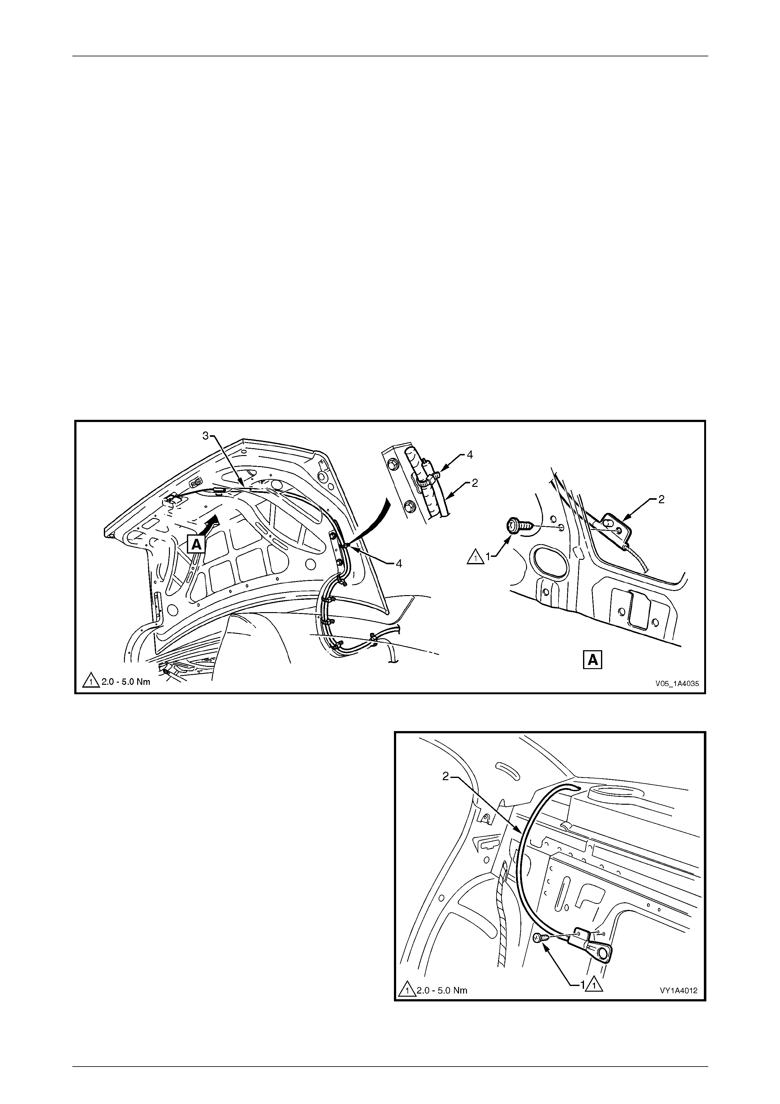
2 Remove the screw (1) attaching the rear compartment lid rele ase cable assembly (2) to the rear compartment lid,
refer to Figure 1A4 – 29.
3 Remove the straps (4) attaching the cable assembl y to the rear comp artme nt lid actuator assembly wiring harness.
4 Withdraw the cable assembly from the rear compartment lid cavity and lay it on the rear compartment floor.
Figure 1A4 – 29
5 From within the right-hand rear passenger
compartment, remove the screw (1) attaching the rear
compartment lid release cable assembl y (2).
6 Carefully feed the cab le assembly into the passenger
compartment and remove.
Figure 1A4 – 30

Hood and Rear Compartment Lid Page 1A4–26
Page 1A4–26
Reinstall
Reinstallation of the rear com partment lid release cable assembly is the reverse of the removal procedure, noting the
following:
1 Before closing the rear compartment lid, close the rear compartment lid latch and check the operation of the rear
compartment lid latch assembly using the rear compartment lid release switch and rear compartment lid release
cable assembly. If the operation is satisfactory, close the rear compartmen t lid and recheck the operation. If
required, adjust the rear compartment lid latch striker assembly,
refer to 3.11 Rear Compartment Lid Striker Assembly.
2 Tighten the screws to the correct torque specification.
Rear compartment lid release
cable assembly attaching screw
torque specification.....................................2.0 – 5.0 Nm
Hood and Rear Compartment Lid Page 1A4–27
Page 1A4–27
3.8 Rear Compartment Lid Assembly
LT Section No. — 12–680
Remove
1 If required, remove the following components:
a rear compartment lid safety triangle, refer to 3.1 Rear Compartment Lid Safety Triangle;
b rear compartment lid carpet, refer to 3.2 Rear Compartment Lid Carpet;
c rear compartment lid moulding assembly, refer to Section 1A9 Exterior Ornamentation
d rear spoiler assembly, if fitted, refer to 3.4 Rear Spoiler Assembly;
e rear compartment lid latch assembly, refer to 3.5 Rear Compartment Lid Latch Assembly;
f rear compartment lid actuator assembly, refer to 3.6 Rear Compartment Lid Actuator Assembly;
g rear compartment lid release cable assembly from the rear compartment lid only,
refer to 3.7 Rear Compartment Lid Release Cable Assembly; and
h badges and emblems, refer to Section 1A9 Exterior Ornamentation.
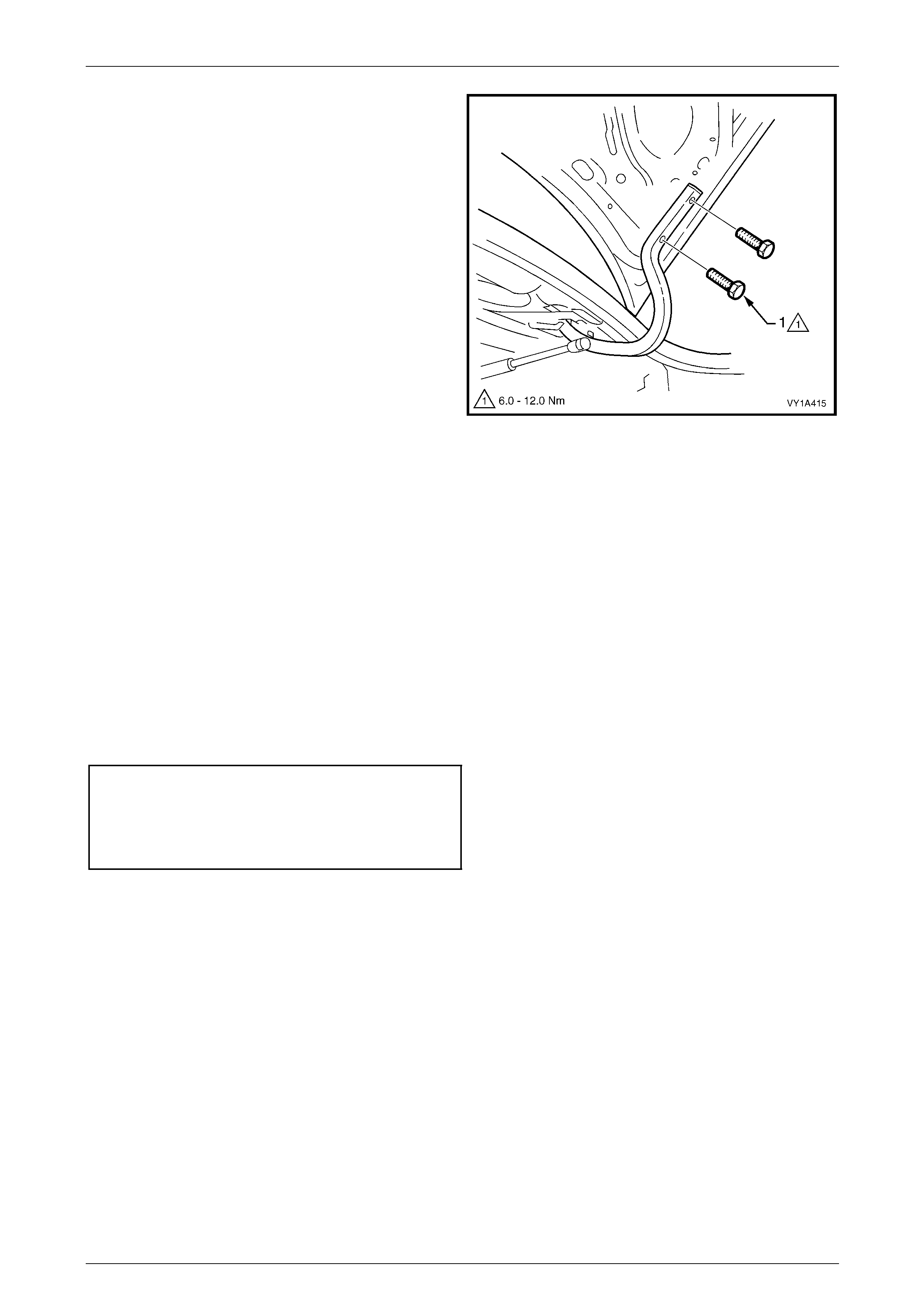
2 Remove the screw (1) attaching the rear compartment
courtesy lamp switch assembly (2) to the rear
compartment lid.
3 Withdraw the rear compartment courtesy lamp switch
assembly and disconnect the wiring connectors (3).
4 Remove the body wiring harness assembly from the
rear compartment lid only, refer to
Section 12O Fuses, Relays and Wiring Harnesses.
Figure 1A4 – 31
5 Unscrew the rear compartment lid bumper (1) from
each side of the rear compartment lid.
Figure 1A4 – 32
Hood and Rear Compartment Lid Page 1A4–28
Page 1A4–28
6 Mark the position of the rear compartment lid
screws (1) on the hinges to aid installation.
7 Remove the two screws from each side attaching the
rear compartment lid to the hinges.
8 With the aid of an assistant, carefully lift the rear
compartment lid from the vehicle.
Figure 1A4 – 33
Reinstall
Reinstallation of the rear com partment lid is the reverse of the removal procedure, noting the following:
1 With the aid of an assistant, lift the rear compartment lid into position.
2 Align the rear compartment lid with the screw holes in the hinges and i nstall the four attaching screws; do not
tighten.
3 Align the screw heads with the marks previously made and temporarily tighten the screws. If no marks exist, align
the screws centrally in their holes.
4 Install the rear compartment lid bumper each side, ensuring they are set fully in.
5 Carefully close the rear comp artment lid, ensuring it does not contact the surrounding panels.
6 If required, adjust the position of the rear compartment lid, refer to Adjust in this Section.
7 Tighten the screws to the correct torque specification.
Rear compartment lid assembly
attaching screw torque specification.........6.0 – 12.0 Nm
Rear compartment courtesy
lamp switch assembly attaching
screw torque specification...........................1.0 – 3.0 Nm
NOTE
Ensure the body wiring harness
assembly is correctly routed and attached
within the rear compartment lid, refer to
Section 12O Fuses, Relays and Wiring
Harnesses.
Hood and Rear Compartment Lid Page 1A4–29
Page 1A4–29
Adjust
Correct alignment of the rear compartment lid is critical to it s operation and to the aesthetics of the vehicle. The following
components allow adjustment of the rear compartment lid:
• rear compartment lid bumper (providing vertical adjustment at the rear of the rear compartment lid),
• rear compartment lid to hinge screws and rear compartment lid hinge to body screws (providing forward, rearward
and skew adjustment of the rear compartment lid), and
• rear compartment lid striker assembly (providing vertical and sideways adjustment of the rear compartment lid).
If alignment is required, adjust the rear compartment lid assembly in the following order:
1 If fitted, remove the rear compartment lid striker assembly, refer to 3.11 Rear Compartment Lid Striker Assembly.
2 Ensure the rear compartment lid weatherstrip assembly is installed and the rear compartment lid bump ers are fitted
and set fully in.
3 Carefully close the rear comp artment lid, ensuring each side does not contact the vehicle .
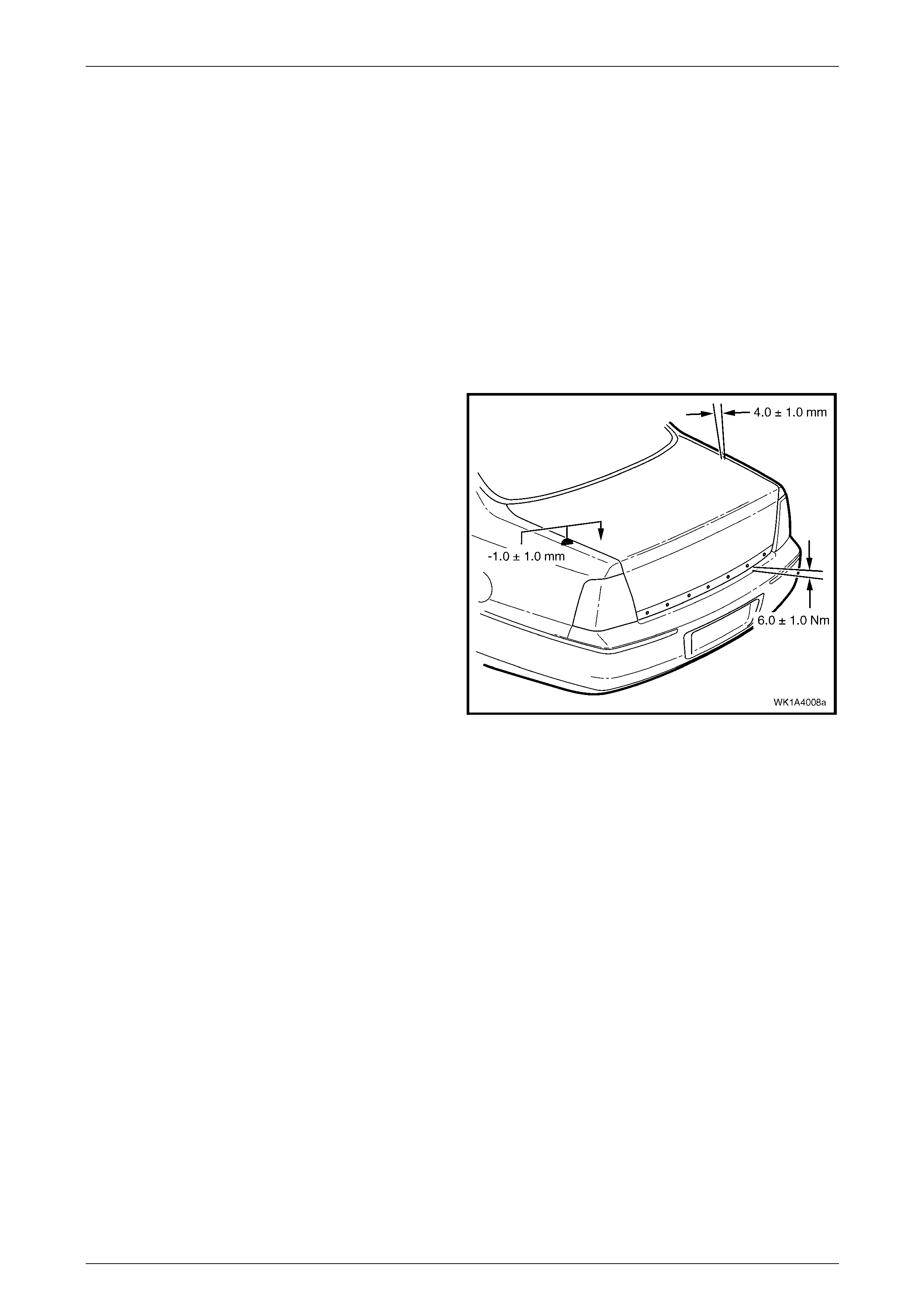
4 Check the alignment of the rear compartment lid for:
• length,
(Compare to the tail lamps: they should be
equal.)
• width of gap, and
(Compare the gap between the rear
compartment lid and the quarter panel on each
side: the gap must be 4.0 mm ±1.0 mm.
• consistency of gap.
(Compare the width of gap between the rear
compartment lid and the quarter panel at the
front, middle and rear on each side: the gap
should be even.)
5 Open the rear compartment lid and, if required, loosen
the screws attaching the rear compartment lid to the
hinge assembly for fore, aft and skew adjustment.
Figure 1A4 – 34
NOTE
Do not make all adjustments at once. Perform
one adjustment, then carefully close the hood;
check its position and make further adjustments
until the correct alignment is a c hieved.
NOTE
If further adjustment is required, loosen the
screws attaching the rear compartment lid hinge
to the body and adjust the position of the hinge,
refer to 3.10 Rear Compartment Lid Hinge
Assembly.
6 Install the rear compartment lid striker assembly, refer to 3.11 Rear Com partment Lid Striker Assembly.
7 Close the rear compartment lid (ensur ing the rear compartment lid striker assembly does not pull the rear
compartment lid to one side, changing the panel gaps). If the panel gaps change, reposition the rear compartment
lid striker assembly.
8 Check the height difference between the rear compartment lid and the quarter panel each side; the specification
is –1.0 mm ±1.0 mm, refer to Figure 1A4 – 34. Check the rear compartment lid to rear bumper fascia assembly gap
specification is 6.0 mm ±1.0 mm.
9 If required, open the rear compartment lid and adj ust the re ar compartme nt lid striker assembly and/or bumper,
and recheck.
10 Tighten the screws to the correct torque specification, refer to Reinstall in this Section.
Hood and Rear Compartment Lid Page 1A4–30
Page 1A4–30
3.9 Rear Compartment Lid Strut Assembly
LT Section No. — 12–680
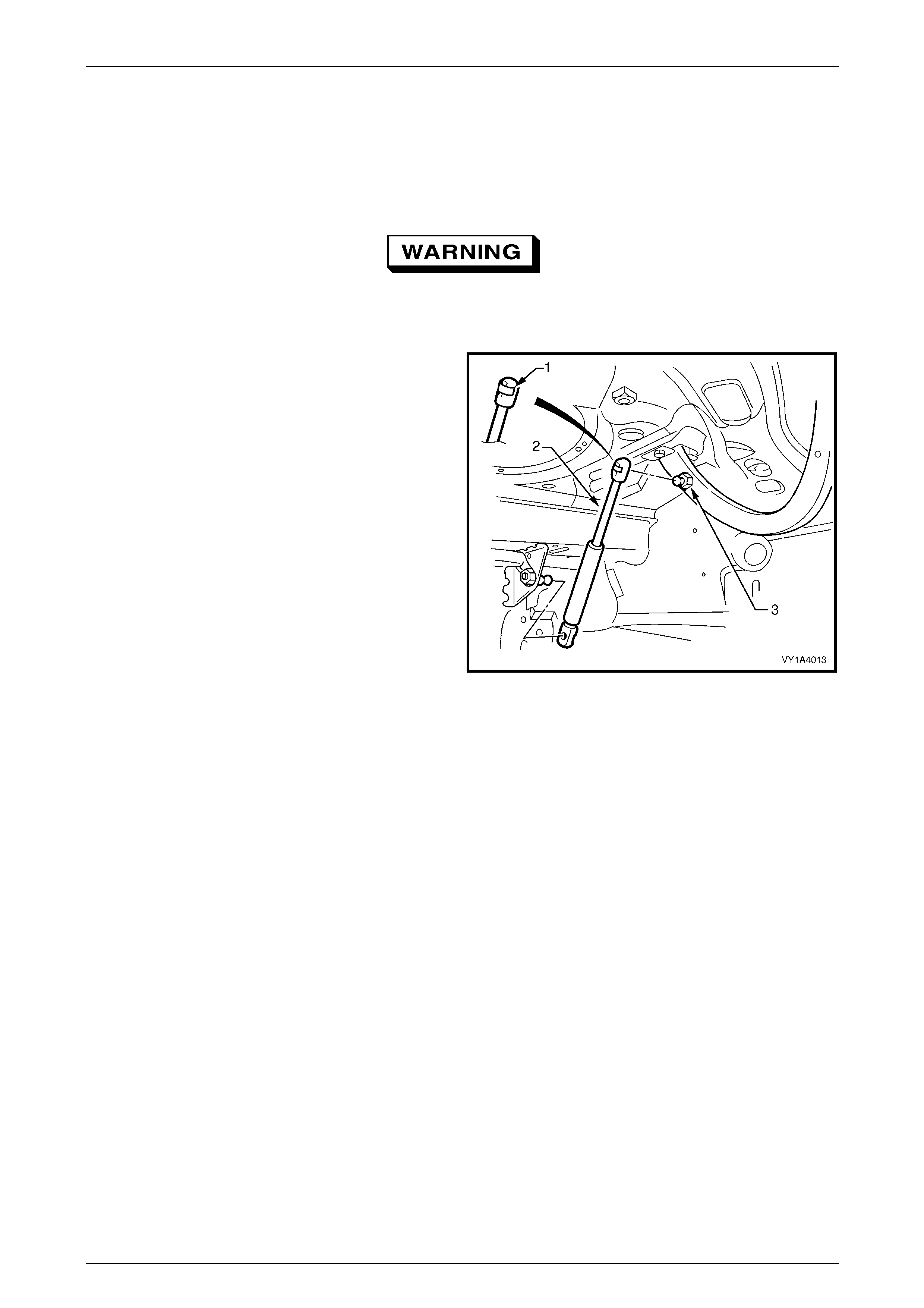
Remove
The hood struts contain pressurised gas. Do
not subject them to extreme heat, p ressure or
physical damage.
1 Support the rear compartment lid securel y.
2 Using a fine flat-bladed screwdriver, prise the
retainer (1) from the rear compartment lid strut end (2).
NOTE
The retainer can spring off the hood strut
assembly and be easily lost.
3 Pull the strut assembly from the strut ball stud (3).
4 Repeat for the opposite end, if required.
Figure 1A4 – 35
Reinstall
NOTE
If a rear compartment lid strut assembly is
replaced, ensure the correct type is specified as
vehicles with a rear spoiler require stronger units.
Reinstallation of the rear com partment lid strut assembly is the reverse of the removal procedure, noting the following:
1 Apply a small amount of NLGI No. 1 lithium grease or equivalent to the inside of the strut ball cup.
2 Install the retainer onto the rear compartment lid strut end, if removed.
3 Align the rear compartment lid strut with the strut ball stud and push into place.
4 If required, repeat for the opposite end.
Hood and Rear Compartment Lid Page 1A4–31
Page 1A4–31
3.10 Rear Compartment Lid Hinge Assembly
LT Section No. — 12–660
Remove
1 If required:
a Partially remove the rear window panel trim assembly, refer to Section 1A8 Headlining and Interior Trim.
b Remove the rear compartment lid strut assembly from the hinge assembly,
refer to 3.9 Rear Compartment Lid Strut Assembly.
c Remove the rear compartment lid, refer to 3.8 Rear Compartment Lid Assembly.
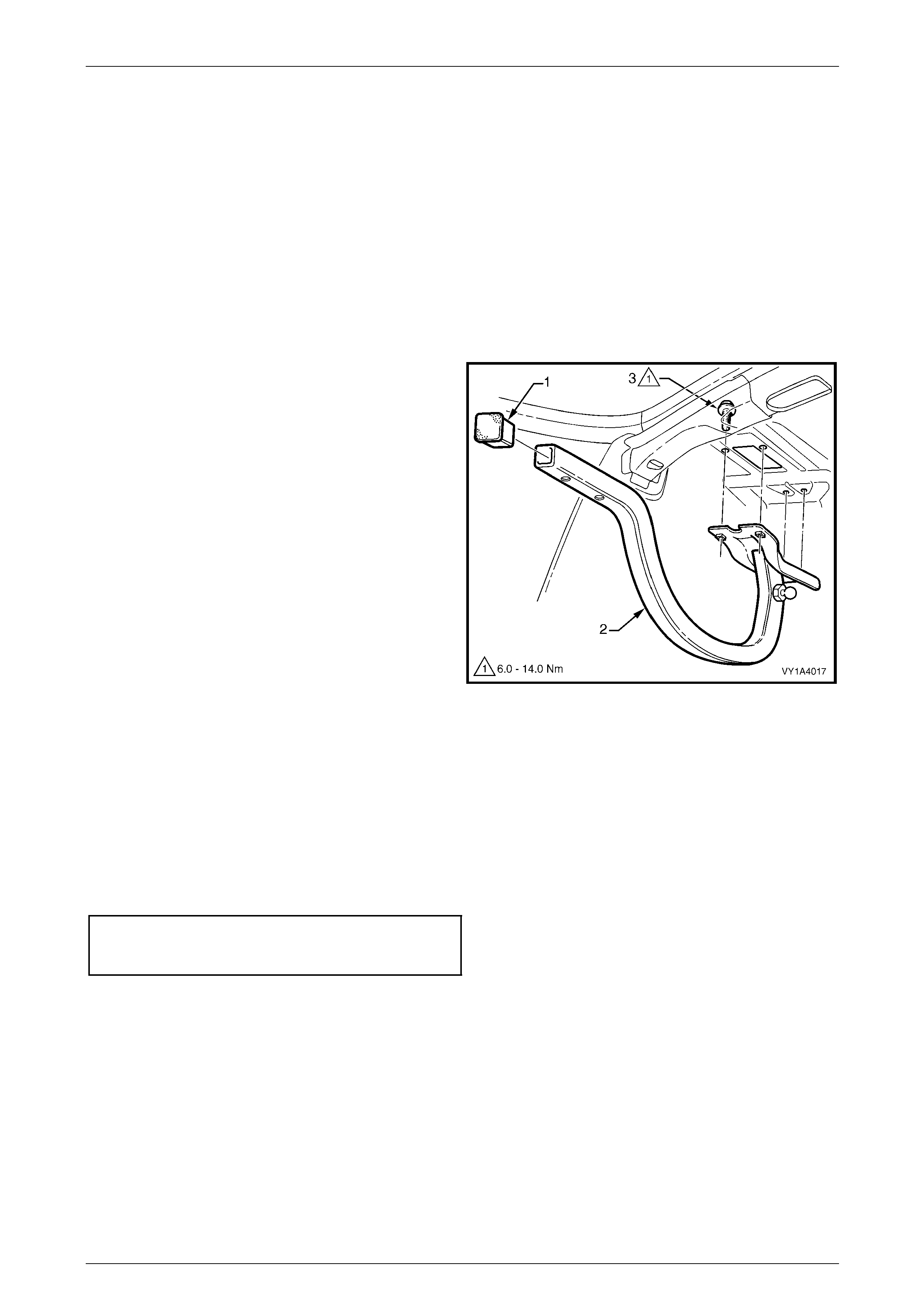
2 If required, prise the rear compartment lid hinge
cap (1) from the end of the rear compartment lid hinge
assembly (2).
3 Remove the sound deadener sheet from ab ove the
hinge screws.
4 With the aid of an assistant, hold the rear
compartment lid hinge assembly.
5 From within the passenger compartment remove the
screw (3), four places, attaching the rear compartment
lid hinge assembly to the vehicle.
6 Remove the rear compartment lid hin ge assembly.
Figure 1A4 – 36
Reinstall
Reinstallation of the rear com partment lid hinge assembly is the reverse of the removal pr ocedure, noting the following:
1 With the aid of an assistant, lift the rear compartment lid hinge assembly into position.
2 Install the screws, aligning them with the old marks or centrall y in their holes.
3 Install and align the rear compartment lid, refer to 3.8 Rear Compartment Lid Assembly.
4 Tighten the screws to the correct torque specification.
Rear compartment lid hing e
assembly attaching screw
torque specification...................................6.0 – 14.0 Nm
Hood and Rear Compartment Lid Page 1A4–32
Page 1A4–32
3.11 Rear Compartment Lid Striker Assembly
LT Section No. — 12–680
Remove
1 If required, remove the rear end trim panel, refer to Section 1A8 Headlining and Interior T r im.
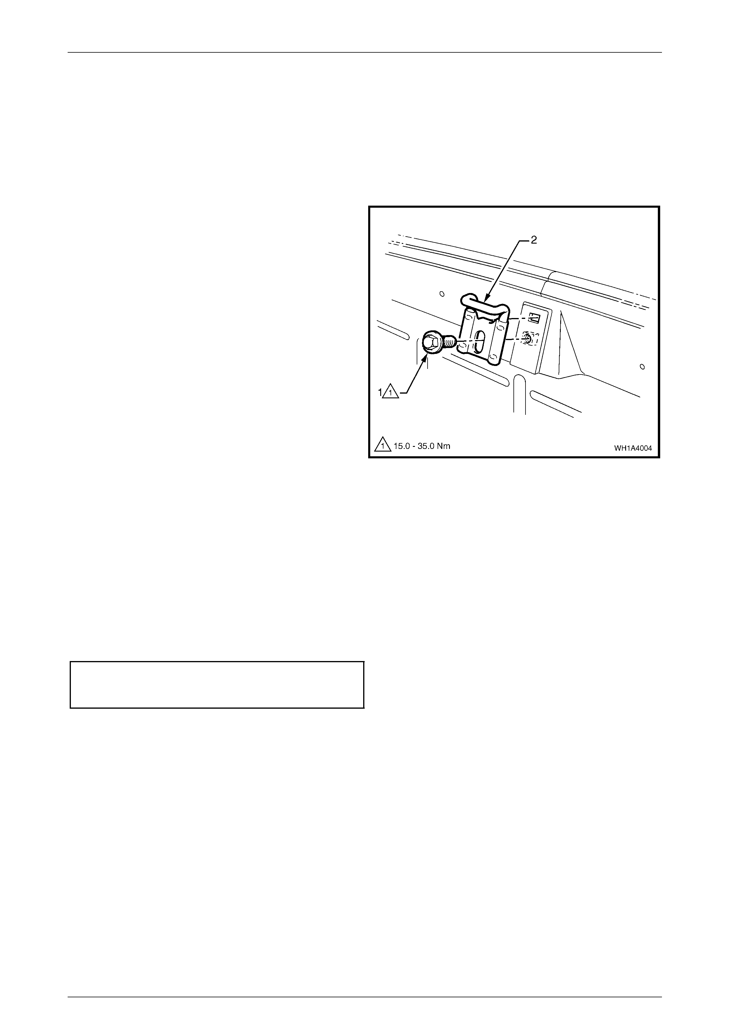
2 Mark the position of the rear compartment lid striker
assembly with a pencil.
3 Remove the screw (1) attaching the rear compartment
lid striker assembly (2) to the vehicle and remove the
striker assembly.
Figure 1A4 – 37
Reinstall
Reinstallation of the rear com partment lid striker assembly is the reverse of the removal procedure. Tighten the screw to
the correct torque specification.
NOTE
If required, adjust the position of the striker to
obtain the correct rear compartment lid
alignment, refer to 3.8 Rear Compartment Lid
Assembly.
Rear compartment lid striker
assembly attaching screw
torque specification.................................15.0 – 35.0 Nm
Hood and Rear Compartment Lid Page 1A4–33
Page 1A4–33
3.12 Rear Compartment Lid Weatherstrip
LT Section No. — 11–600
Remove
1 If required, remove the rear end trim panel, refer to Section 1A8 Headlining and Interior T r im.
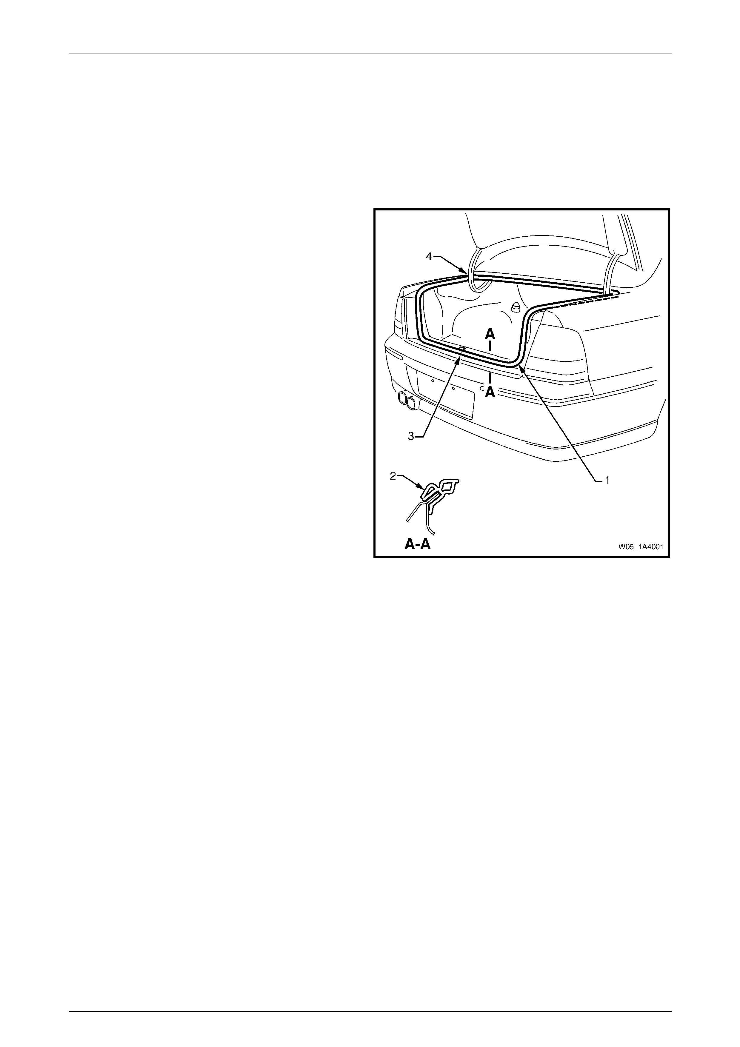
2 Grasp the rear compartment lid weatherstrip (1) and
carefully pull it from the body flange. Start at one poi nt
and continue along its length.
3 Remove the rear compartment lid weatherstrip from
the vehicle, over the rear compartment lid.
Figure 1A4 – 38
Reinstall
Reinstallation of the rear com partment lid weatherstrip is the reverse of the removal procedure, noting the following:
1 Lay the rear compartment lid weatherstrip on the floor, ensuring the L-shaped lip (2) faces the inside, refer to
Figure 1A4 – 38.
2 Locate the rear compartment lid weatherstrip join (3) and align it with the rear compartment lid striker assembl y.
3 Fit the rear compartment lid weatherstrip over the rear compartment lid and push onto the body flange, beginnin g
at the join.
NOTE
Allow the rear compartment lid weatherstrip to
crowd in each corner (4) to avoid short-cutting the
corners.

Hood and Rear Compartment Lid Page 1A4–34
Page 1A4–34
4 Torque Wrench Specifications
4.1 Hood
Hood Primary Latch Striker Nut.................................................22.0 – 28.0 Nm
Hood Primary Latch Release Cable Retainer Screw.....................1.0 – 3.0 Nm
Hood Secondary Lock Lever Attaching Nut...................................1.0 – 3.0 Nm
Hood Strut Ball Stud..................................................................13.0 – 22.0 Nm
Hood Strut Assembly to Fender Attaching Screw......................10.0 – 14.0 Nm
Upper Hood Hinge Section Attaching Screw ............................10.0 – 25.0 Nm
Lower Hood Hinge Section Attaching Screw.............................10.0 – 25.0 Nm
Hood Hinge Screw ....................................................................10.0 – 25.0 Nm
Hood Primary Latch Striker Nut.................................................22.0 – 28.0 Nm

Hood and Rear Compartment Lid Page 1A4–35
Page 1A4–35
4.2 Rear Compartment Lid
Spare Wheel Stowage Cover Hook Attaching Screw....................1.0 – 3.0 Nm
Rear Compartment Lid Spoiler Attaching Nut................................1.5 – 2.0 Nm
Rear Compartment Lid Latch
Assembly Attaching Screw............................................................2.0 – 5.0 Nm
Rear Compartment Lid Actuator
Assembly Attaching Screw............................................................2.0 – 5.0 Nm
Rear Compartment Lid Release
Cable Assembly Attaching Screw..................................................2.0 – 5.0 Nm
Rear Compartment Lid Assembly Attaching Screw.....................6.0 – 12.0 Nm
Rear Compartment Courtesy Lamp
Switch Assembly Attaching Screw ................................................1.0 – 3.0 Nm
Rear Compartment Lid Hinge
Assembly Attaching Screw..........................................................6.0 – 14.0 Nm
Rear Compartment Lid Striker
Assembly Attaching Screw........................................................15.0 – 35.0 Nm