
Sheetmetal Page 1B–1
Page 1B–1
Section 1B
Sheetmetal
ATTENTION
Before performing any service operation or other procedure described in this Section, refer to Section 00
Warnings, Cautions and Notes for correct workshop practices with regard to safety and/or property damage.
1 General Information ...............................................................................................................................2
2 Service Notes..........................................................................................................................................3
2.1 Body Structure Replacement Part Refinishing ................................................................................................... 3
2.2 Anti-corrosive Treatment ...................................................................................................................................... 4
3 Body Structure Replacement Parts......................................................................................................5
Underbody.............................................................................................................................................................. 6
Upperbody Structure – Excluding Roof............................................................................................................... 8
Roof Structure........................................................................................................................................................ 9
Body Assembly.................................................................................................................................................... 10
4 Service Operations...............................................................................................................................12
4.1 Front Fender......................................................................................................................................................... 12
Remove................................................................................................................................................................. 12
Reinstall................................................................................................................................................................ 14
4.2 Battery Tray Assembly........................................................................................................................................ 15
Remove................................................................................................................................................................. 15
Reinstall................................................................................................................................................................ 15
4.3 Front Side Rail Brace........................................................................................................................................... 16
Remove................................................................................................................................................................. 16
Reinstall................................................................................................................................................................ 16
5 Torque Wrench Specifications............................................................................................................17

Sheetmetal Page 1B–2
Page 1B–2
1 General Information
This Section contains an illus t rated listing of the service d sheetmetal components that form the vehicle’s body structure.
This listing is provided for information o nly and is to be used as a guide. For the latest configurations refer to the current
spare parts information.

Sheetmetal Page 1B–3
Page 1B–3
2 Service Notes
2.1 Body Structure Replacement Part
Refinishing
The vehicle body structure is designed to meet or exceed many regulations, including crash performance and occupant
protection, etc. When replacing or repairin g a part or sub-assembly, care must be taken to ensure the corr ect alignment
and strength of the unit as a whole is mainta ined.
In some instances, replacing a part or sub-assembl y with a new one, rather than repairing the damage d part, can more
effectively and economically repair major damage to the body structure.
Spot welding is used extensiv ely for joining panels or assemblies, however special adhesives are playing an ever-
increasing role in the joini ng of body structure components, either on their own or together with spot welds. Where
repairs are performed, it is imperative the correct adhesives are used. Effective rust proofing techniques, as outlined in
the following paragraphs, must also be obse rved.
It is for these reasons that only qualified persons with suitable training and qualifications should perform the repair or
replacement of body structure compon ents. Further information can be found in the MY 2005 W L Service Manual
Supplement, Body Structure Repair.

Sheetmetal Page 1B–4
Page 1B–4
2.2 Anti-corrosive Treatment
Pre-coated and galvanised steel is used ext ensively for various body struc t ure components for increased corrosion
protection. Body panels such as the engin e hoo d, door and rear compartment lid outer panels are pre-coated on th e
inner surface of the metal to improve corrosion protection. Other body structure members have complete doubl e-sided
galvanised protection.
In addition, a rust preventative material is sprayed after paint application to areas such as the interior surfaces of doors,
etc. This rust preventative material must be replaced whenever a panel repair or replacem ent procedure disturbs its
application.
Rust preventative compounds used for repairs should be light bodied materials designe d to penetrate between metal-to-
metal surfaces such as pinch weld flanges and integral panel attaching poi nts.
All bare metal surfaces must be treated with metal conditioner and primed. T hese operations need to be carried o ut prior
to the application of sealers, waxes and sound deadeners. Attaching points of new replacement panels should be
resealed. The hemming flanges of replacement doors and the rear compartment lid will require re-sealing.
Open joins that require bridging of the sealer to close a gap should be sealed with a heavy-b odied caulking materi al.
When colour applicatio n is required to restore repaired areas to original appear ance, conventional refinishing
preparation, undercoat build-u p and colour application techniques should be emplo ye d.
When deadeners are disturbed during damage repair, or a panel h as been replaced, the deadener material must b e
replaced with an equivalent material. The location and pattern for replacement material can be determined by observin g
the original deadener application outlines.
Further information can be found in the MY 200 5 WL Service Manual Supplement, Body Structure Rep air.

Sheetmetal Page 1B–5
Page 1B–5
3 Body Structure Replacement
Parts
The following illustration and table describe the body structure assemblies and pa nels that are available for service
replacement.
The purpose of this information is to provid e the repairer with a better understanding of av ailable replacement sections.
For further information regarding the body structure, refer to the MY2005 WL Service Man ual Supplement, Body
Structure Repair.
NOTE
Always refer to an authorised dea ler for the latest
configurations.
Sheetmetal Page 1B–6
Page 1B–6
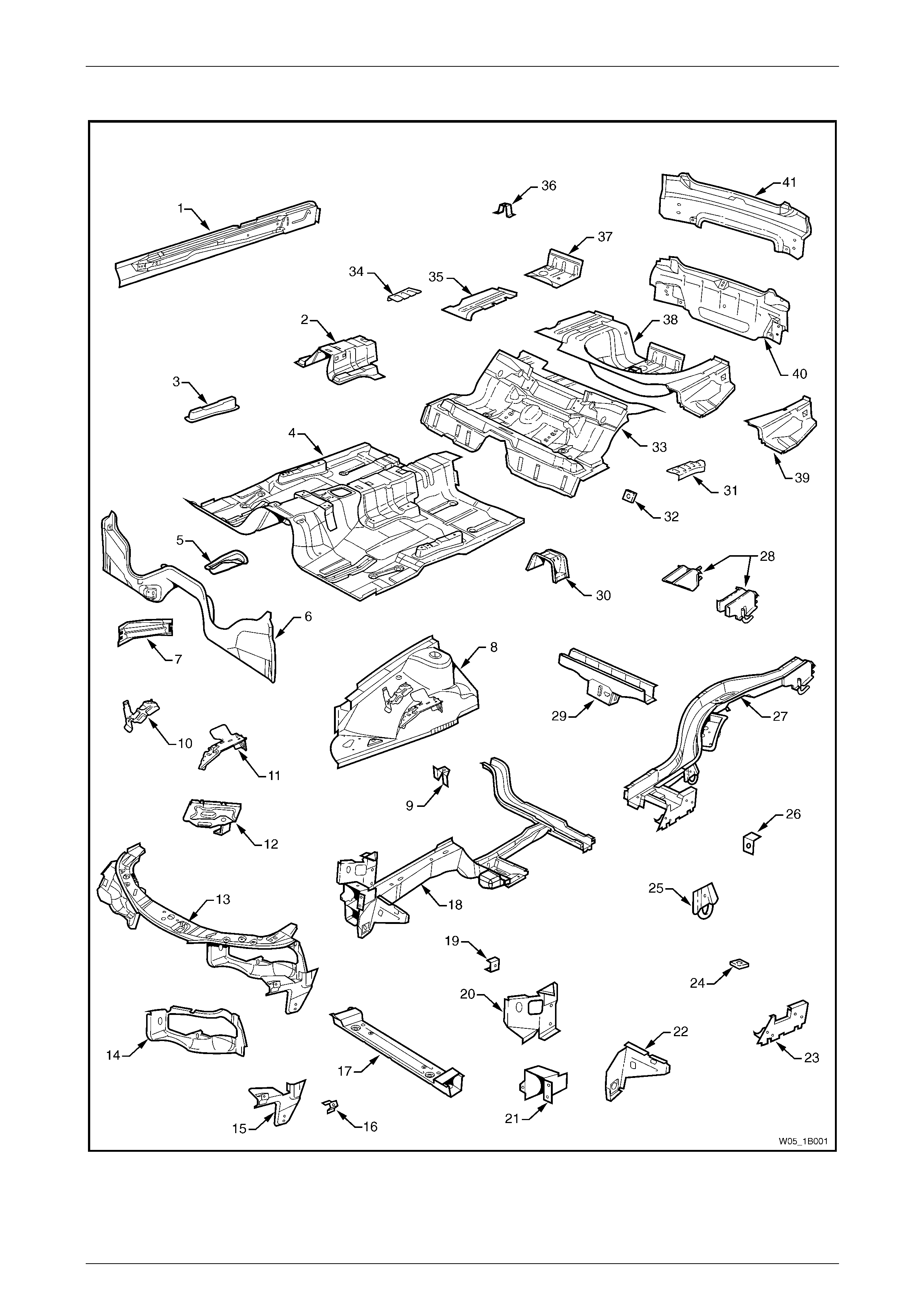
Underbody
Figure 1B – 1

Sheetmetal Page 1B–7
Page 1B–7
Legend
1 Inner Rocker Panel Assembly, RH / LH
2 Seat Inner Bracket Assembly
3 Seat Outer Bracket Assembly, RH / LH
4 Front Floor Panel Assembly
5 Transmission Support Bracket, RH / LH
6 Front Floor Panel Extension
7 Front Side Rail Brace, RH / LH
8 Front Wheelhouse Panel Assembly, RH / LH
9 Horn Bracket Assembly, LH only
10 Relay Housing Bracket, RH only
11 ABS Modulator Bracket Assembly, RH only
12 Battery Tray Assembly, RH only
13 Front End Panel Assembly
14 Headlamp Panel, LH / RH
15 Headlamp & Front Fascia Mount Bracket, LH / RH
16 Fender Front Lower Bracket, LH / RH
17 Radiator Lower Support Assembly
18 Front Side Rail Assembly, LH / RH
19 Radiator Side Mounting Bracket, LH / RH
20 Front Wheelhouse Bracket Assembly, LH / RH
21 Front Bumper Impact Bar Bracket, LH / RH
22 Front Wheelhouse Panel Bracket, LH / RH
23 Rear Floor Panel Outer Extension , LH / RH
24 Rear Suspension Support Mount Plate, LH / RH
25 Rear Tie Down Assembly, LH / RH
26 Rear Brake Hose Bracket, LH / RH
27 Rear Side Rail Assembly, LH / RH
28 Rear Bumper Impact Bar Brace Assembly, LH / RH
29 Crossmember Assembly No. 2
30 Propeller Shaft Hanger Assembly
31 Rear Floor Panel Reinforcement, LH
32 Rear Seat Belt Anchor Plate Assembly, 3 places
33 Rear Floor Panel Assembly
34 Rear Floor Panel Reinforcement, RH
35 Rear Compartment Floor Panel Outer Extension, RH
36 Spare Wheel Anchor Plate Assembly
37 Fuel Tank Support Reinforcement Assembly
38 Rear Compartment Floor Panel Assembly
39 Rear Compartment Floor Panel Outer Extension, LH
40 Rear End Panel Assembly
41 Rear End Lower Panel
Sheetmetal Page 1B–8
Page 1B–8
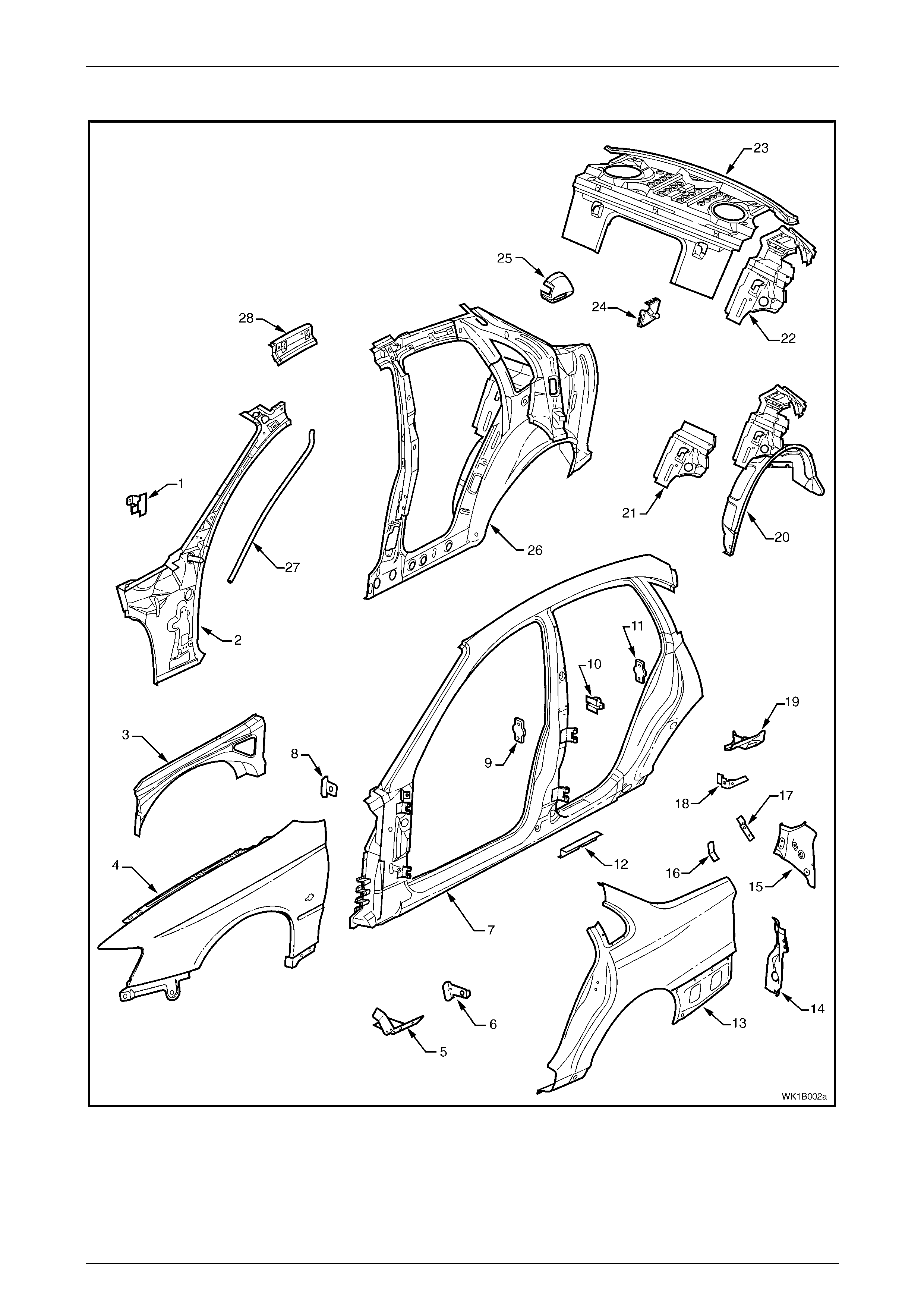
Upperbody Structure – Excluding Roof
Figure 1B – 2
Sheetmetal Page 1B–9
Page 1B–9
Legend
1 Hinge Pillar Trim Panel Bracket, LH / RH
2 Hinge Pillar Inner Panel Assembly, LH / RH
3 Front Wheelhouse Panel Upper Side Rail, LH / RH
4 Front Fender, LH / RH
5 Fender Lower Rear Bracket, LH / RH
6 Fender Rear Bracket, LH / RH
7 Door Opening Frame Assembly, LH / RH
8 Fender Upper Rear Bracket, LH / RH
9 Front Door Striker Anchor Plate, LH / RH
10 Rear Door Check Link Bracket, LH / RH
11 Rear Door Striker Anchor Plate, LH / RH
12 Underbody Jacking Locator, LH / RH
13 Rear Quarter Panel, LH / RH
14 Quarter Panel Lower Extension, LH / RH
15 Tail Lamp Housing, LH / RH
16 Wiring Harness Bracket, LH / RH
17 Tail Lamp Connector Bracket, LH / RH
18 Rear Compartment Trim Attach Bracket, LH / RH
19 Quarter Panel Upper Extension, LH / RH
20 Rear Wheelhouse Inner Panel Assembly, LH / RH
21 Rear Seat Back Panel Extension, LH / RH
22 Rear Seat Back Panel Extension Assembly, LH / RH
23 Rear Window Panel Assembly
24 Rear Compartment Lid Strut Bracket Assembly, LH / RH
25 Fuel Filler Pipe Housing, RH only
26 Quarter Panel Inner Assembly, LH / RH
27 Sunroof Front Drain Tube, LH / RH #
28 Quarter Panel Inner Extension, LH / RH
# Vehicles with on-line sunroof assembly
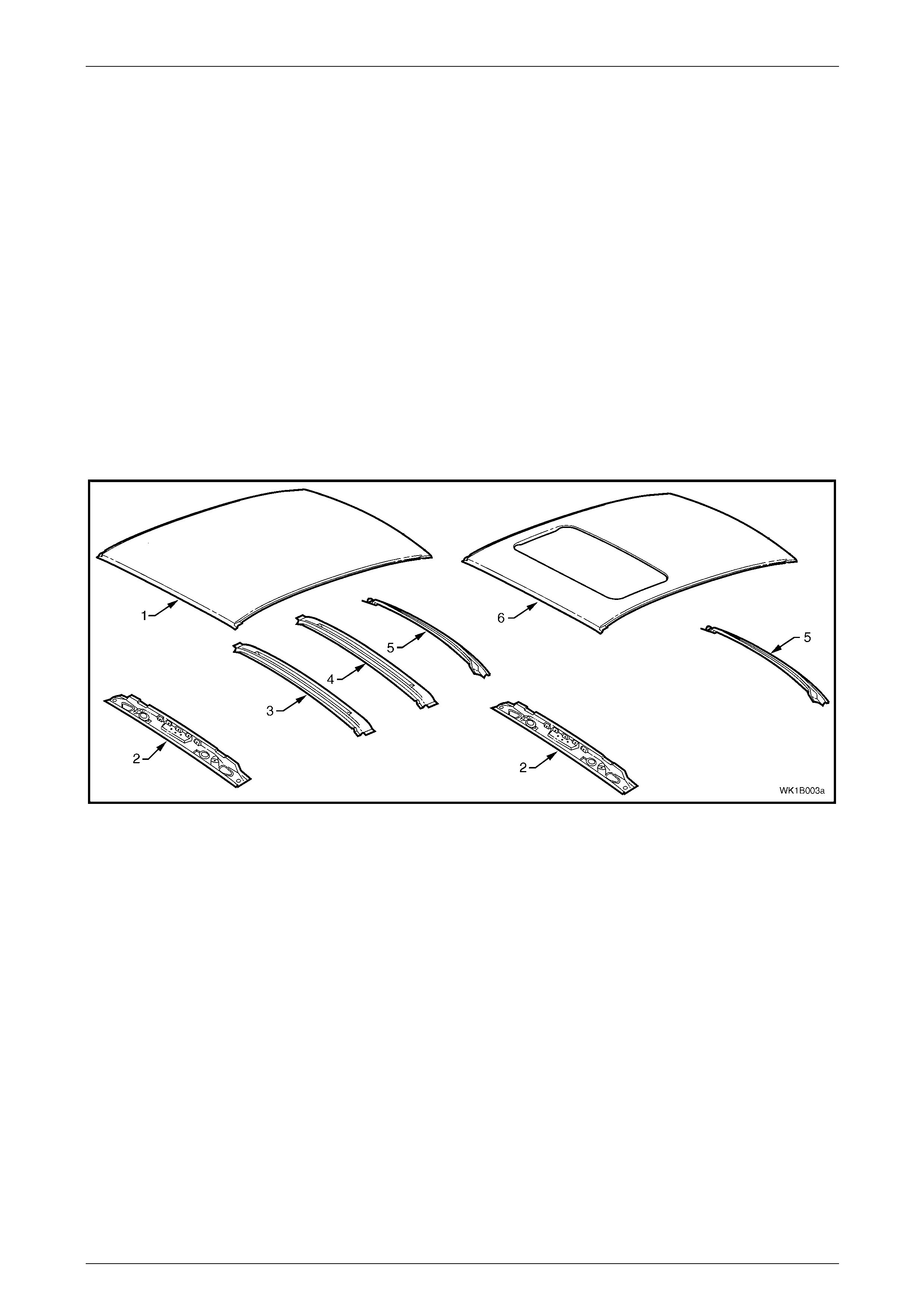
Roof Structure
Figure 1B – 3
Legend
1 Roof Panel
2 Roof Front Header Panel
3 Roof Bow Panel
4 Roof Bow Panel No. 2
5 Roof Rear Panel
6 Roof Panel Assembly #
# Vehicles with on-line sunroof assembly
Sheetmetal Page 1B–10
Page 1B–10
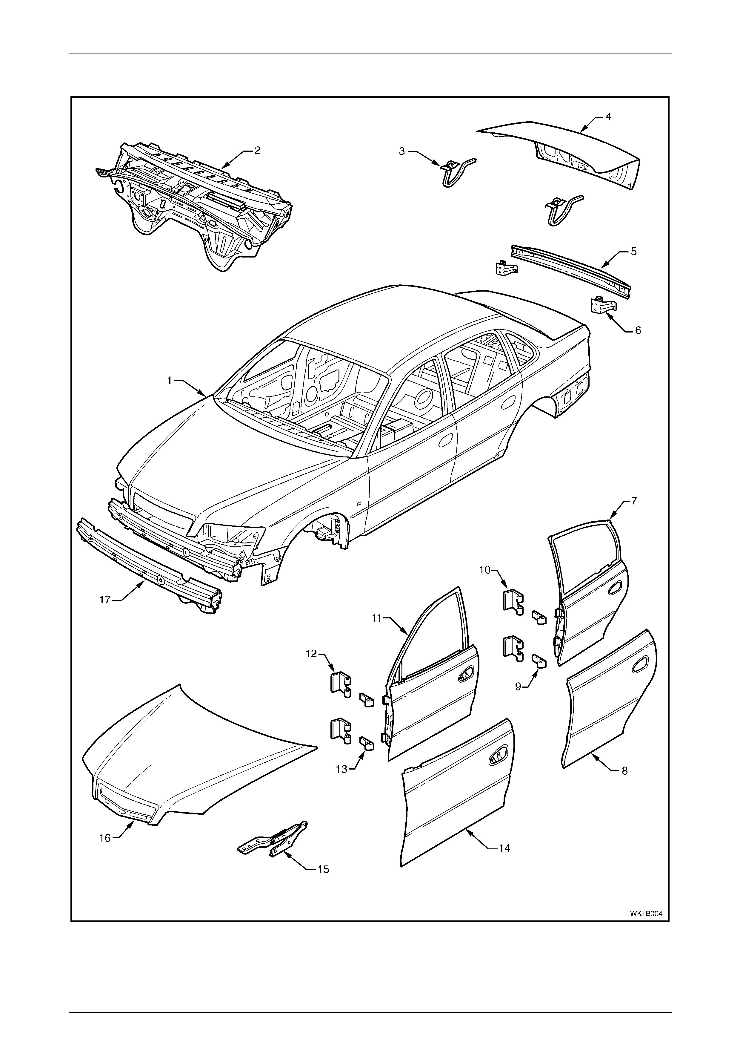
Body Assembly
Figure 1B – 4

Sheetmetal Page 1B–11
Page 1B–11
Legend
1 Body Assembly
2 Dash Panel Assembly
3 Rear Compartment Lid Hinge Assembly
4 Rear Compartment Lid Assembly
5 Rear Bumper Impact Bar
6 Rear Bumper Impact Bar Bracket Assembly
7 Rear Door Assembly, LH / RH
8 Rear Door Outer Panel, LH / RH
9 Rear Door Hinge (door side), LH / RH
10 Rear Door Hinge (body side), LH / RH
11 Front Door Assembly, LH / RH
12 Front Door Hinge (body side), LH / RH
13 Front Door Hinge (door side), LH / RH
14 Front Door Outer Panel, LH / RH
15 Hood Hinge Assembly, LH / RH
16 Hood Assembly
17 Front Bumper Impact Bar Assembly
Sheetmetal Page 1B–12
Page 1B–12
4 Service Operations
4.1 Front Fender
LT Section – 12-425
Remove
1 Remove the following components:
a Front bumper fascia assembly, refer to Section 1D Bumper Bars.
b Rocker panel moulding, refer to Section 1A9 Exteri or Ornamentation.
c Front wheelhouse liner, refer to Section 1A1 Body.
d The fender name plate and the fender section of the body side mould in g, refer to
Section 1A9 Exterior Ornamentation.
e Where fitted, the radio antenna assembly, refer to Section 12D Entertai nment System.
f Hood strut assembly to fender screws, refer to Section 1A4 Hood and Rear Compartment Lid.
g Front side turn signal lamp assembly, refer to Section 12B Lighting System.
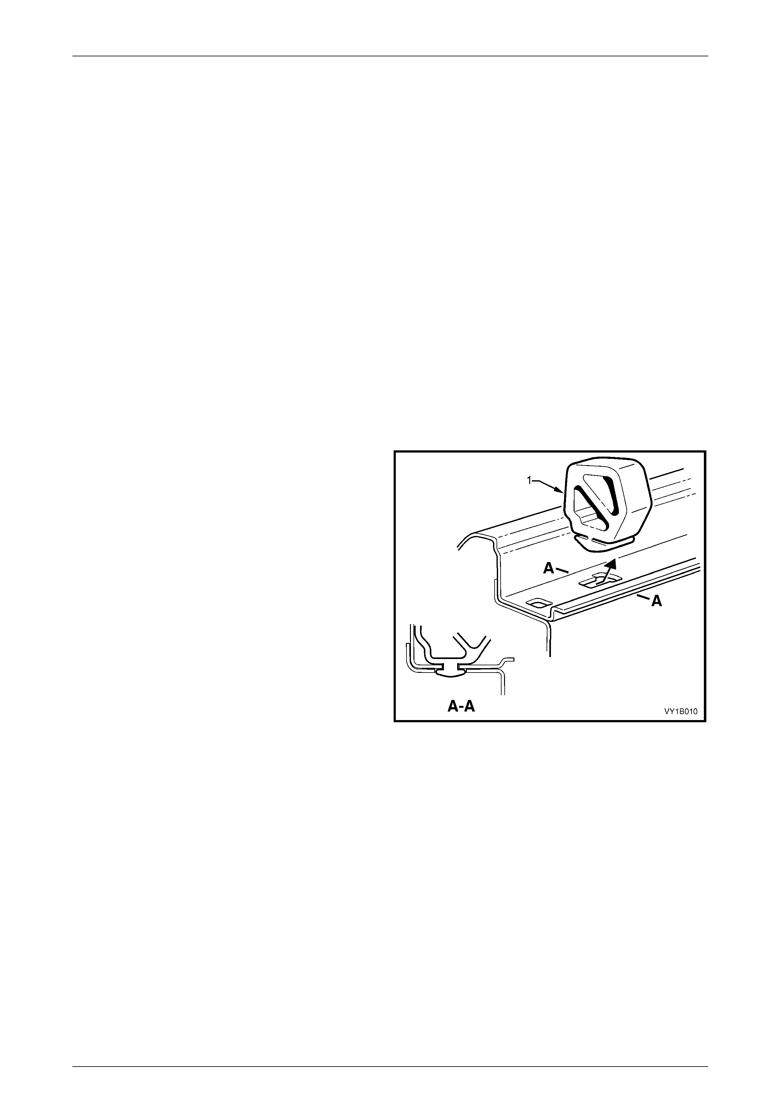
2 While tilting the hood side bu m per (1) forward slightly,
carefully slide it rear ward to disengage it from the
inner edge of the fender.
Figure 1B – 5
Sheetmetal Page 1B–13
Page 1B–13
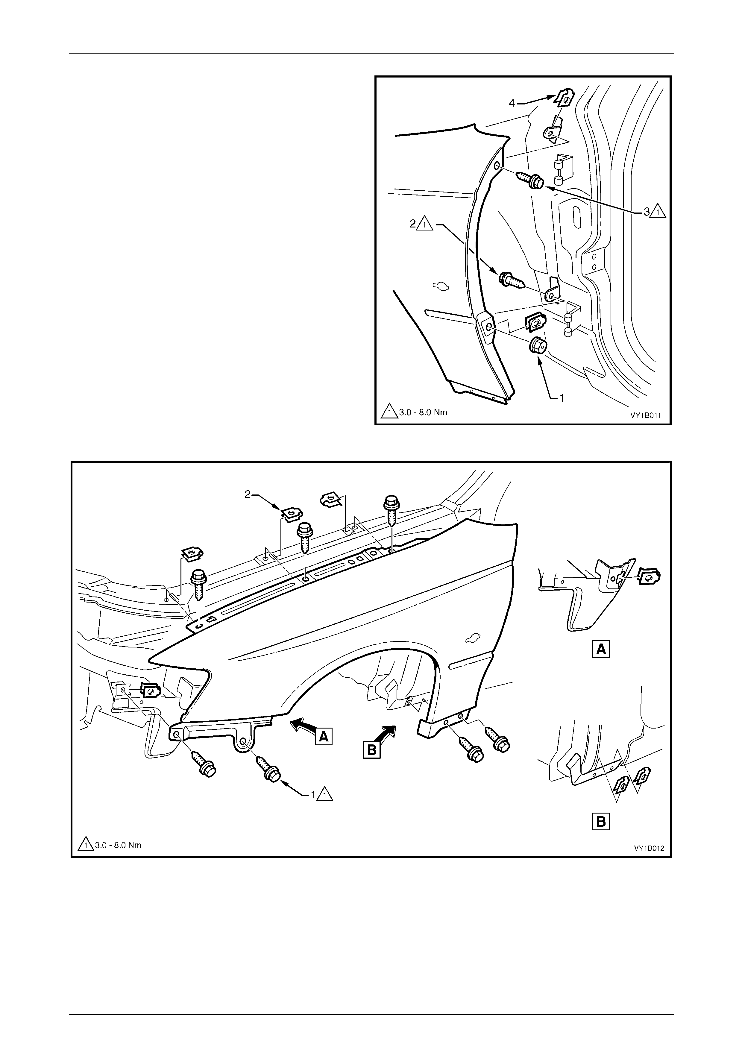
3 From the rear of the fender, remove the nut (1).
4 From behind the fender, remove the screw (2)
attaching the rear of the fender.
5 Remove the screw (3) attaching the rear of the fender
to the vehicle.
6 Remove the seven screws (1) attaching the fender to
the vehicle, refer to Figure 1B – 7.
7 Remove the fender.
Figure 1B – 6
Figure 1B – 7
Sheetmetal Page 1B–14
Page 1B–14
Reinstall
1 Install the J-nuts as required, refer to Figure 1B – 6 (4, t wo places) and in F igure 1B – 7 (2, six places).
NOTE
Replace any nuts that are worn or damaged.
2 Install the fender in position a nd start all screws.
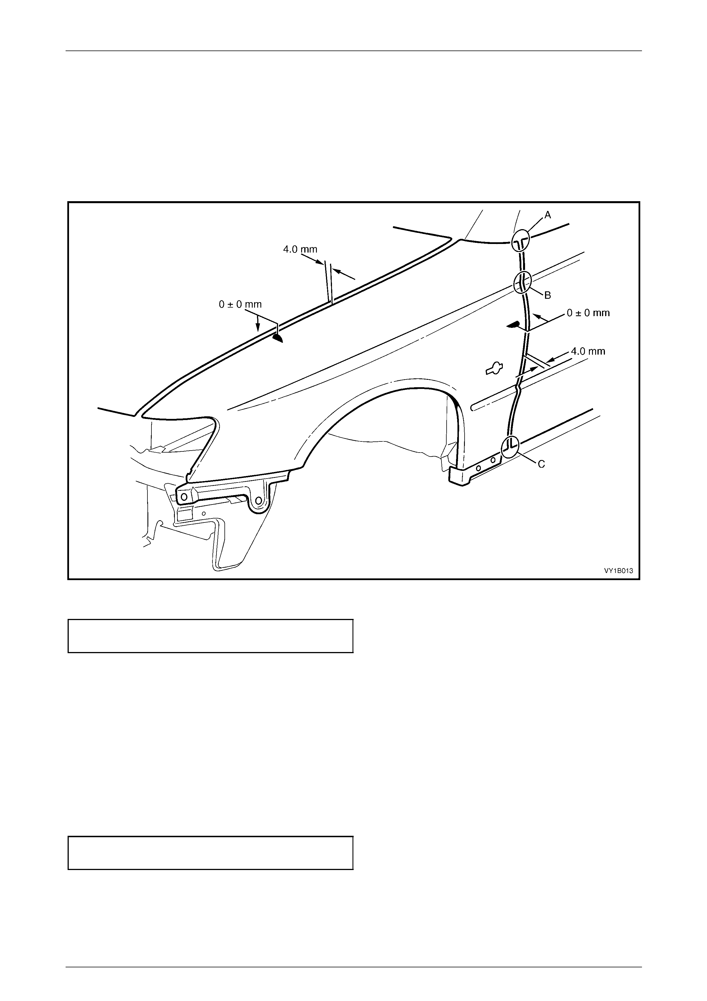
3 Carefully close the door and align the rear of the fender to the door panel surface and bod y lines at points A, B & C,
refer to Figure 1B – 8.
Figure 1B – 8
4 Tighten the lower rear screw from behind the fender to the correct torque specification, refer to Figure 1B – 6.
Front fender attaching screw
torque specification.....................................3.0 – 8.0 Nm
5 Open the door and tighten the upper rear screw to the correct torque specification.
6 Recheck alignment and also check for an even gap of 4.0 mm to the front door, refer to Figure 1B – 8.
7 If the gap is not to specification, carefully bend the rear fender brackets.
8 Carefully close the hood and adjust the posit ion of the fender to provide a n even g ap of 4.0 mm.
9 Open the hood and tighten the three upper fender scre ws to the correct torque specification, refer to Figure 1B – 7.
10 Recheck alignment and readjust as required. NOTE
Also check the upper fender surface aligns t o the
engine hood surface. If not adjust the hood, refer
to Section 1A4 Hood and Rear Compartment Lid.
11 Tighten all of the remaining s c rews to the correct torque specification.
Front fender attaching screw
torque specification.....................................3.0 – 8.0 Nm
12 Following paint ing, install the plastic nut onto the rear lower fender screw and install other removed components as
required.
Sheetmetal Page 1B–15
Page 1B–15
4.2 Battery Tray Assembly
LT Section – 02-200
Remove
1 Remove the battery, refer to Section 12A Battery.
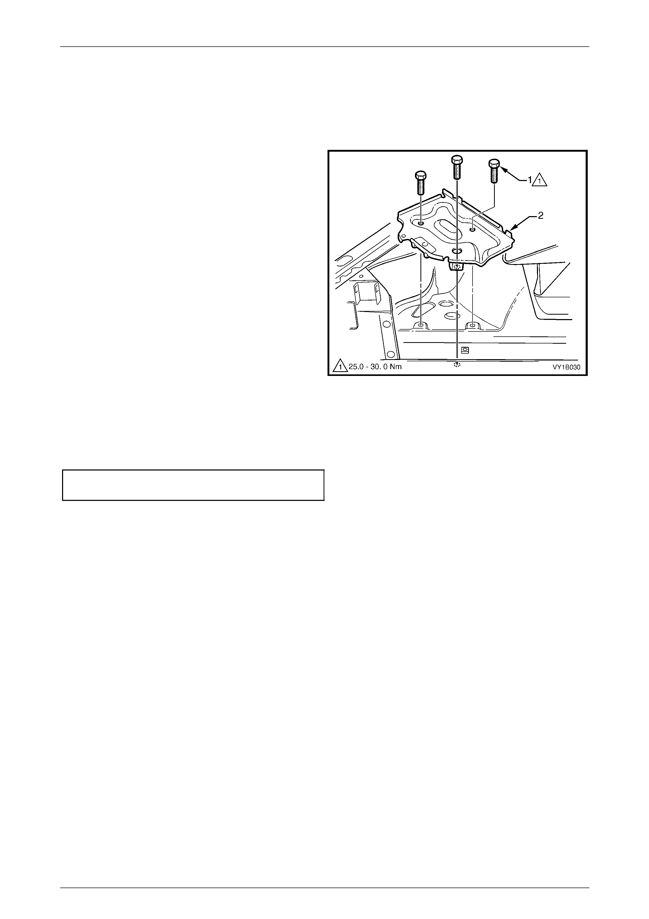
2 Remove the three screws (1) attaching the battery tray
assembly (2) to the front wheelhouse and rail.
Figure 1B – 9
Reinstall
Reinstallation of the batter y tray assembly is the reverse of the removal procedure. Tighten the screws to the correct
torque specification.
Battery tray assembly attaching
screw torque specification.......................25.0 – 30.0 Nm
Sheetmetal Page 1B–16
Page 1B–16
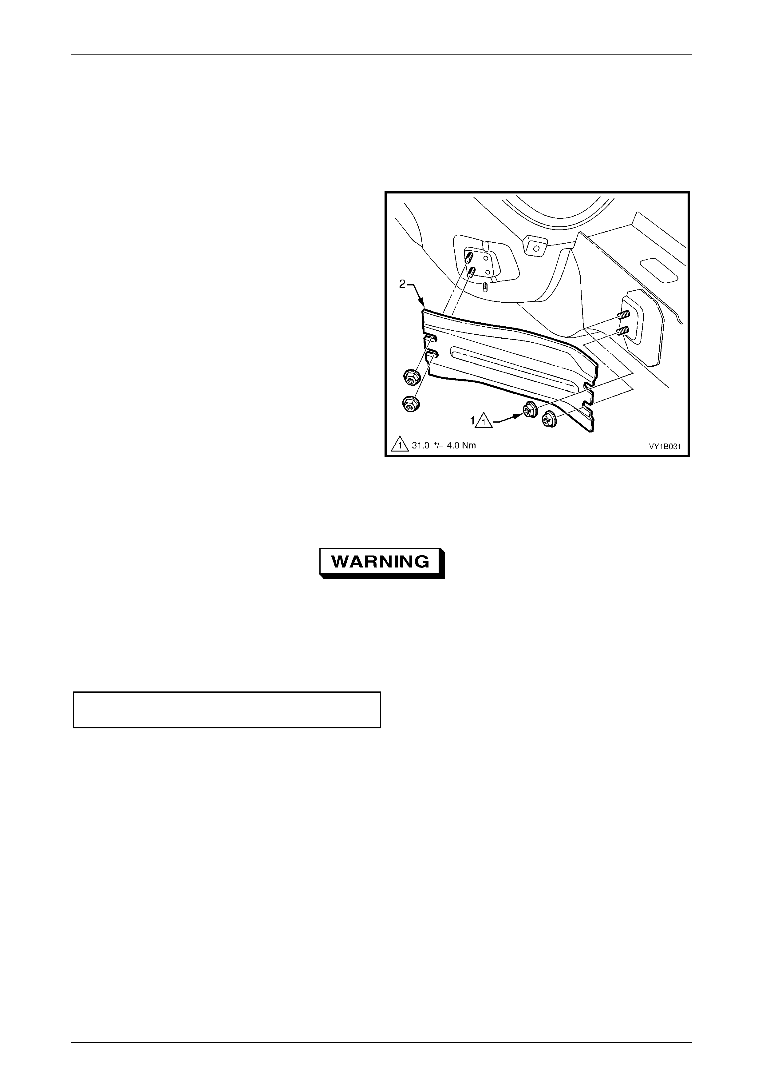
4.3 Front Side Rail Brace
LT Section – 12-425
Remove
1 Loosen the two rear nuts and remove the two front
nuts (1) attaching the front side rail brace (2).
2 Remove the brace from the vehicle.
Figure 1B – 10
Reinstall
As the braces serve as a critical structural
component of the body structure, correct
fitment and torque are crucial.
1 Reinstall the brace ens uring it is correctly orientated.
2 Tighten the nuts to the correct torque specification.
Front side rail brace upper attaching
nut torque specification.............................31.0 ± 4.0 Nm

Sheetmetal Page 1B–17
Page 1B–17
5 Torque Wrench Specifications
Front Fender Attaching Screw.......................................................3.0 – 8.0 Nm
Battery Tray Assembly Attaching Screw....................................25.0 – 30.0 Nm
Front Side Rail Brace Attaching Nut............................................31.0 ± 4.0 Nm