
Bumper Bars Page 1D–1
Page 1D–1
Section 1D
Bumper Bars
ATTENTION
Before performing any service operation or other procedure described in this Section, refer to Section 00
Warnings, Cautions and Notes for correct workshop practices with regard to safety and/or property damage.
1 General Information ...............................................................................................................................3
2 Paint Systems.........................................................................................................................................4
2.1 General ................................................................................................................................................................... 4
2.2 Park Assist ............................................................................................................................................................. 5
2.3 Recommended Materials....................................................................................................................................... 6
2.4 Refinishing of Replacement Parts........................................................................................................................ 7
Priming ................................................................................................................................................................... 7
Paint – 2K Systems................................................................................................................................................ 7
Paint – Cobra Basecoat, Metallic, Pearl or Solid Colour System....................................................................... 8
2.5 Repairing Colour Coat........................................................................................................................................... 9
2.6 Hardener Precautions.......................................................................................................................................... 10
3 Service Operations...............................................................................................................................11
3.1 Service Notes....................................................................................................................................................... 11
Speed Nuts........................................................................................................................................................... 11
Razor Blade Retainers......................................................................................................................................... 11
3.2 Front Bumper Fascia Assembly......................................................................................................................... 12
Remove................................................................................................................................................................. 12
Disassemble......................................................................................................................................................... 14
Front Bumper Fascia Moulding ........................................................................................................................ 14
Front Fog and Cornering Lamp Assembly........................................................................................................ 14
Lower Radiator Grille........................................................................................................................................ 15
Dual Park Assist Front Components ................................................................................................................ 16
Reinstall................................................................................................................................................................ 21
3.3 Front Fascia Support........................................................................................................................................... 22
Remove................................................................................................................................................................. 22
Reinstall................................................................................................................................................................ 22
3.4 Front Bumper Guide Assembly.......................................................................................................................... 23
Remove................................................................................................................................................................. 23
Reinstall................................................................................................................................................................ 23
3.5 Front Bumper Impact Bar Assembly.................................................................................................................. 24
Remove................................................................................................................................................................. 24
Reinstall................................................................................................................................................................ 24

Bumper Bars Page 1D–2
Page 1D–2
3.6 Rear Bumper Fascia Assembly .......................................................................................................................... 25
Remove................................................................................................................................................................. 25
Disassemble......................................................................................................................................................... 27
Rear Bumper Fascia Moulding......................................................................................................................... 27
Licence Plate Lamp Assembly ......................................................................................................................... 28
Rear Park Assist and Licence Plate Lamp Wiring Harness.............................................................................. 28
Licence Plate Lamp Carrier, Level 5 Vehicles.................................................................................................. 29
Licence Plate Surround, Level 4 Vehicles........................................................................................................ 30
Towbar Opening Cover.................................................................................................................................... 30
Rear Bumper Fascia Anchor Plate Assembly .................................................................................................. 31
Rear Bumper Fascia Mounting Bracket Assembly, Level 5 Vehicles............................................................... 31
Rear or Dual Park Assist Rear Components.................................................................................................... 31
Reinstall................................................................................................................................................................ 36
3.7 Rear Bumper Fascia Guide Assembly............................................................................................................... 37
Remove................................................................................................................................................................. 37
Reinstall................................................................................................................................................................ 37
3.8 Rear Bumper Fascia Centre Support................................................................................................................. 38
Remove................................................................................................................................................................. 38
Reinstall................................................................................................................................................................ 38
3.9 Rear Bumper Impact Bar..................................................................................................................................... 39
Remove................................................................................................................................................................. 39
Reinstall................................................................................................................................................................ 39
4 Torque Wrench Specifications............................................................................................................40

Bumper Bars Page 1D–3
Page 1D–3
1 General Information
The bumper fascia assemblies fitted are constructed from polypropylene resin. Two styles of bumper fascias are
available, with Model Level 5 vehicles having deeper, sportier looking fascias. Front fog lamps that incorporate cornering
signal lamps are instal led on all vehicles.
NOTE
For Model Level designations refer to
Section 0A General Information.
The rear bumper fascia assemblies incl ude four rear sensor assemblies and a wiring harness for Rear Park Assist
(RPA), or for Level 5 vehicles; Dual Park Assist (DPA), which also includes four front sensor assemblies and a wiring
harness within the front bumper fascia assembly.
NOTE
If the vehicle is fitted with RPA or DPA, a new
front or rear bumper fascia service part will
require modification prior to painting and
installation. For further information on RPA, refer
to Section 12F1 Rear Park Assist or for DPA,
refer to Section 12F2 Dual Park Assist.
Two fascia supports are installed behi nd the front bumper fascia. These supports are attached to the steel front bumper
impact bar assembly which is attached directly to the front side rails. Both the supports and impact bar assembly act as a
mount and support for the bumper fascia assembl y and are critical in the dispersion of crash energy. Hence, they play an
integral role in the operation of the vehicle’s safety systems.
A steel rear bumper impact bar is also installed behind the rear bumper fascia.
Repair of the fascia supports should be limited to replacement. Repair of the impact bar assemblies should also be
limited to replacement, as straightening and / or heating can weaken the impact bar assembly resulting in incorrect
occupant protection system operation.

Bumper Bars Page 1D–4
Page 1D–4
2 Paint Systems
2.1 General
The paint system for the bumper fascia assemblies and other painted plastic components is relatively straightforward
providing the correct materials are used. Normal refinish lacquers will not adhere to plastic components unless the
correct primers and/or additives are used.
NOTE
Thorough cleanin g and the use of approv ed paint
and additives or their equivalent is required.
Incorrect materials and methods may damage the
plastic or lead to premature paint failure.
The following service recommendatio ns are compiled to guide repairers on the correct materials and methods to be
employed when refinishing bumper fascias and preparing new parts for service installation. If another paint bran d is
chosen, refer to the manufacturer’s latest technic al data for the appropriate materials and procedures req uired.

Bumper Bars Page 1D–5
Page 1D–5
2.2 Park Assist
The rear bumper fascia assemblies contain four sensor assemblies for both Rear Park Assist (RPA) and Dual Park
Assist (DPA). The exposed end of the sensor assemb ly is painted the vehicle's body colour and must not have any
further paint applied.
On Level 5 vehicles, the front fascia assembly also inc orporates four sensor assemblies for the Dual Park Assist (DPA).
As with the rear sensors, the exposed surface of the sensor assembly is painted the vehicle's body colour.
New sensor assemblies are supplied pre-painted in the vehicle's body colour and must not have any further paint
applied.
If repainting a fascia assembly, the sensors
and rings MUST be removed. Paint must not
be applied to any part of a sensor, including
the exposed coloured surface. Paint film
applied to the exp osed surface will render the
sensor inoperable as the paint film restricts
the sensor’s ultra-sonic signal. If a sensor is
damaged, it must be replaced.
Replacement housings are supplied unpainted. As they are partially expos ed when installed, they will require painting
using the same procedures for painting the bumper fascia, described below.
NOTE
It is preferable to paint the housings and bumper
fascia separately to avoid adhesion problems.
Assemble the housings onto the bumper fascia
once the paint has cured, refer to
3.6 Rear Bumper Fascia Assembly – Park Assist
Rear Sensor Components or
3.2 Front Bumper Fascia Assembly – Park Assist
Front Sensor Components.
For further information on rear park assist, refer to Section 12F1 Rear Park Assist.
For further information on dual park assist, refer to Section 12F2 Dual Park Assist.

Bumper Bars Page 1D–6
Page 1D–6
2.3 Recommended Materials
Front and rear bumper fascias are made from high impact strength Polypropylene (PP) resin.
It is essential that only approved materials, paints, etc. or their equivalent are employed when paint repair operations are
performed and when preparing new parts for installation to the vehicles.
The approved materials are:
• PPG Bodykleen 920-30509
• PPG Plastpak Universal Anti Static Cleaner 920-39237
• PPG Plastpak Universal Primer 499-38571
• PPG Plastpak Flexible Additive for Two Component Products 499-35484
• PPG Cobra Basecoat - Colour 534 Line
• PPG 2K Clearcoat 455-30900
• PPG 2K Acrylic Enamel Solid Colour 426 Lin e
• PPG 2K MS Hardener Normal 980-35239
• PPG 2K Thinner 920-49424
NOTE
Always refer to the paint manufacturer’s latest
product information.

Bumper Bars Page 1D–7
Page 1D–7
2.4 Refinishing of Replacement Parts
Replacement parts will requir e priming and coating with approved topcoat colour before installation to the vehicle.
1 Order part and paint materials.
2 Read all safety data material relative to the paint system chosen from the paint manufacturer and
2.6 Hardener Precautions, includ ed in this Section.
3 Obtain the required respiration and safety equipment recommended by the paint manufacturer, in this publication
or required by regulations.
4 Wash the unpainted bumper fascia all over with a made-up solution of 9 parts fresh water to 1 part PPG Bodykleen
920-39237. Apply with a clea n, non-metallic pad (recommended Scotchbrite** 448) to scuff the surface.
5 Rinse with fresh cold water.
6 Use a clean cloth saturated with PPG Plastpak Universal Anti-static Cle aner 920-39237. Wash the entire part
allowing contact for a minimum 15 seconds.
7 Dry thoroughly usin g a separate, clean, dry cloth.
8 Repeat Steps 5 and 6 anothe r three times. Use a separate, clean dry cloth each time.
NOTE
If a static charge has built up on the bumper
surface (after completing all cleaning operations)
dampen the surface with Plastpak Universal Anti
Static Cleaner and allow to evaporate dry. This
will impart full anti-static properties to the bumper
fascia.
Priming
1 Fit an air-supplied respirator.
2 Apply one light double coat (approximately 3 – 8 m D.F.B. uniformly wet) of PPG Plastpak Universal Prim er 499-
38571 to the bumper surface intended for topcoat. Recommended air pressure range is 320 – 420 kPa.
3 Allow to air dry 15 – 20 minutes at 20°C. DO NOT SAND.
** Scotchbrite is a trademark of 3M Co.
Paint – 2K Systems
1 To the matched colour, add Flexible Additive then Hardener and Thinner in the following ratios:
• 246 line colour - 5 parts by volume
• Flexible Additive 499-35484 - 1 part by volume
• 2K MS Hardener 980-35239 - 3 parts by volume
• 2K Thinner 920-49424 - 10 – 20% b y volume
2 Stir thoroughly and strain.
3 Fit an air-supplied respirator.
4 Using a 1.4 – 1.8 mm fluid nozzle on a sta ndard spray gun, apply one medium wet coat.
5 Apply a further one or two coats to achieve coverage (correct film thickness is 40 – 50 microns) allowing a 3 – 5
minute flash-off time bet ween coats.
6 If low baking, this can be done immediately after the last coat, but do not allow more than 5 minutes flash-off. Bake
at 60°C for 40 minutes.
7 If air drying, allow 16 hours.

Bumper Bars Page 1D–8
Page 1D–8
Paint – Cobra Basecoat, Metallic, Pearl or Solid Colour System
1 Thin the matched basecoat colour with Cobra Basebu ilder, 920 line at a 1:1 mix ratio and stir thoroughly.
2 Strain material.
3 Fit an air supplied respirator.
4 Using a 1.4 – 1.6 mm gravit y feed spra y gu n, apply one medium, wet even coat. Allow to flash-off for five minutes
before applying the next coat.
5 Apply one or two further coats to achieve a uniform and even coverage with 5 minutes flash-off between coats.
6 Allow 10 – 20 minutes dryi ng
7 Mix the 2K Clearcoat with Flexible Additive, then Hardener and Thinner in the following ratios:
• 2K Clearcoat 455-30900 - 5 parts b y volume
• Flexible Additive 499-35484 - 1 part by volume
• 2K MS Hardener 980-35239 - 3 parts by volume
• PPG 2K Thinner 920-49424 - 20% by volume
8 Stir thoroughly and strain.
9 Using a 1.4 – 1.8 fluid nozzle spray gun set up, apply one medium wet coat.
10 Apply a further one or two wet coats after a 3 – 5 minutes flash-off between coats.
11 If low baking, this can be done immediately after the last coat, but do not allow more than 5 minutes flash-off. Bake
at 60°C for 40 minutes.
12 If air drying, allow 16 hours.

Bumper Bars Page 1D–9
Page 1D–9
2.5 Repairing Colour Coat
Sanding and repainting may rectify superficial damage to the paint film an d/or plastic surfaces. Parts having deep
gouges in the plastic surface should be replaced as repair methods using filling materials and thinning d own of the plastic
section may reduce overall impact strength.
For shallow paint damage, follow the procedure listed un der, Colour Finishing of Replacement Parts, in this Section,
using P800 paper to sand down imperfections and using a Scotchbrite 448 pad or P1200 paper, scuff and key existing
paintwork.
Basecoat and Clearcoat can be spot repaired by blending away the basecoat colour and spraying the complete bumper
with Clearcoat. Solid colours are best sprayed as complete panels. If the damage extends through the paintwork to the
plastic surface, this must be primed with Plastpak Universal Primer after the correct cleaning procedure.
NOTE
Drying of all products may be accelerated by
heat. But to avoid distortion, unsupported
bumpers should not be heated in an oven or by
lamp above 60°C.

Bumper Bars Page 1D–10
Page 1D–10
2.6 Hardener Precautions
The following instructions relate to the safe handling of all paints containing PPG 2K MS Hardener, which contains not
more than 0.3% isocyanate monomer.
This product is for automotive and industrial
use only. It requires professional equipment
and experience for safe handling. It is not for
use by the general public.
Read and understand the instructions and warnings contained in Material Safety Data sheets and on the label of the can
containing the base product before opening. Follow all directions an d warnings carefully, otherwise do not use this
product. Warnings and precautions o n the la bel also apply to the mixture of hardener and base.
Inhalation of vapour, spray mist and dust from sanding is h armful and may cause lung irritation and allergic respiratory
reaction. The vapour also irritates the skin and eyes.
When mixed with the appropriate base, appl y in a spray booth fitted with an effective exhaust system. Comply with local
legislation applicable to spray painting of motor vehicles. Wear a pos itive pressure air supplied full face respirator
(complying with any relevant Standards) and gloves while sp raying and during all subsequent use. The spray booth area
should be isolated from other peo ple while spraying is in progress and until all spra y mist has been effectively evacuated.
If affected by inhalation of vapour or spray mist, move to a location with plenty of fresh air.
If breathing difficulty persists or occurs later, consult a doctor and have the label information ava ilable. In the case of eye
contact, flush immediately with plenty of water for 15 minutes and ca ll a doctor.
In case of skin contact, remove contaminated clothing and wash skin thoroughly with soap and water. Immerse
contaminated clothing in water for 24 hours and do not re-use until it has been laundered.
In case of spillage, absorb the liquid o nto dry sand or earth. Remove the spillage from the work area and cover with
water for 24 hours before disposal. Treat the empty hardene r cans in the same manner.
Bumper Bars Page 1D–11
Page 1D–11
3 Service Operations
3.1 Service Notes
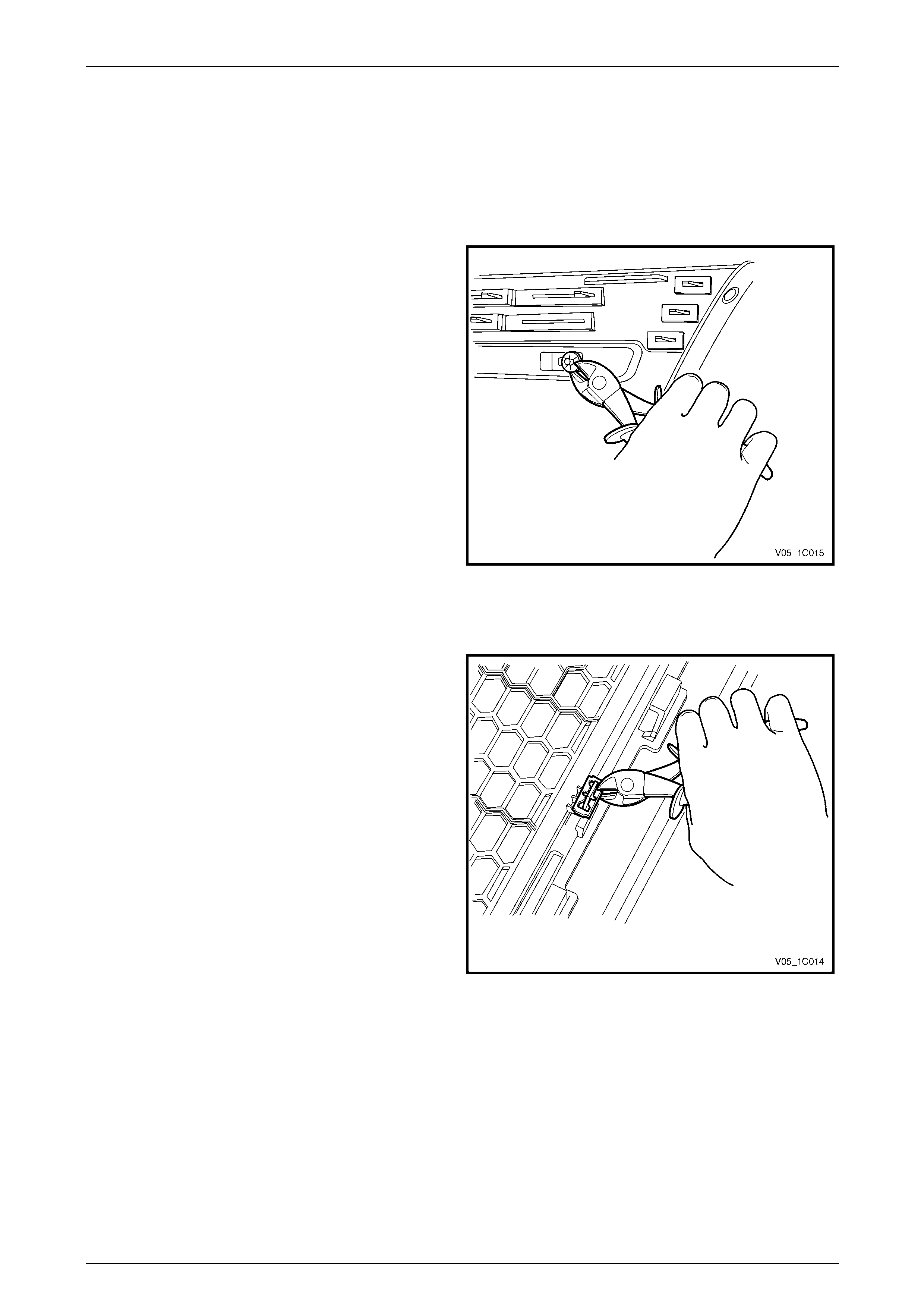
Speed Nuts
1 Prise the edge of the speed nut away from the
surface, giving enough clearance to allow access with
side cutters.
2 With the side cutters, cut the speed nut and bend it
away from the mounting lug and remov e.
3 Replace the speed nut as required.
Figure 1D – 1
Razor Blade Retainers
1 Prise the edge of the razor blade retai ner away from
the surface, giving enough clearance to allow access
with side cutters.
2 With the side cutters, cut the razor blade retainer and
bend it from the mounting lug and remov e.
3 Replace the razor blade retainer as required.
Figure 1D – 2
Bumper Bars Page 1D–12
Page 1D–12
3.2 Front Bumper Fascia Assembly
LT Section No. — 07–500
Remove
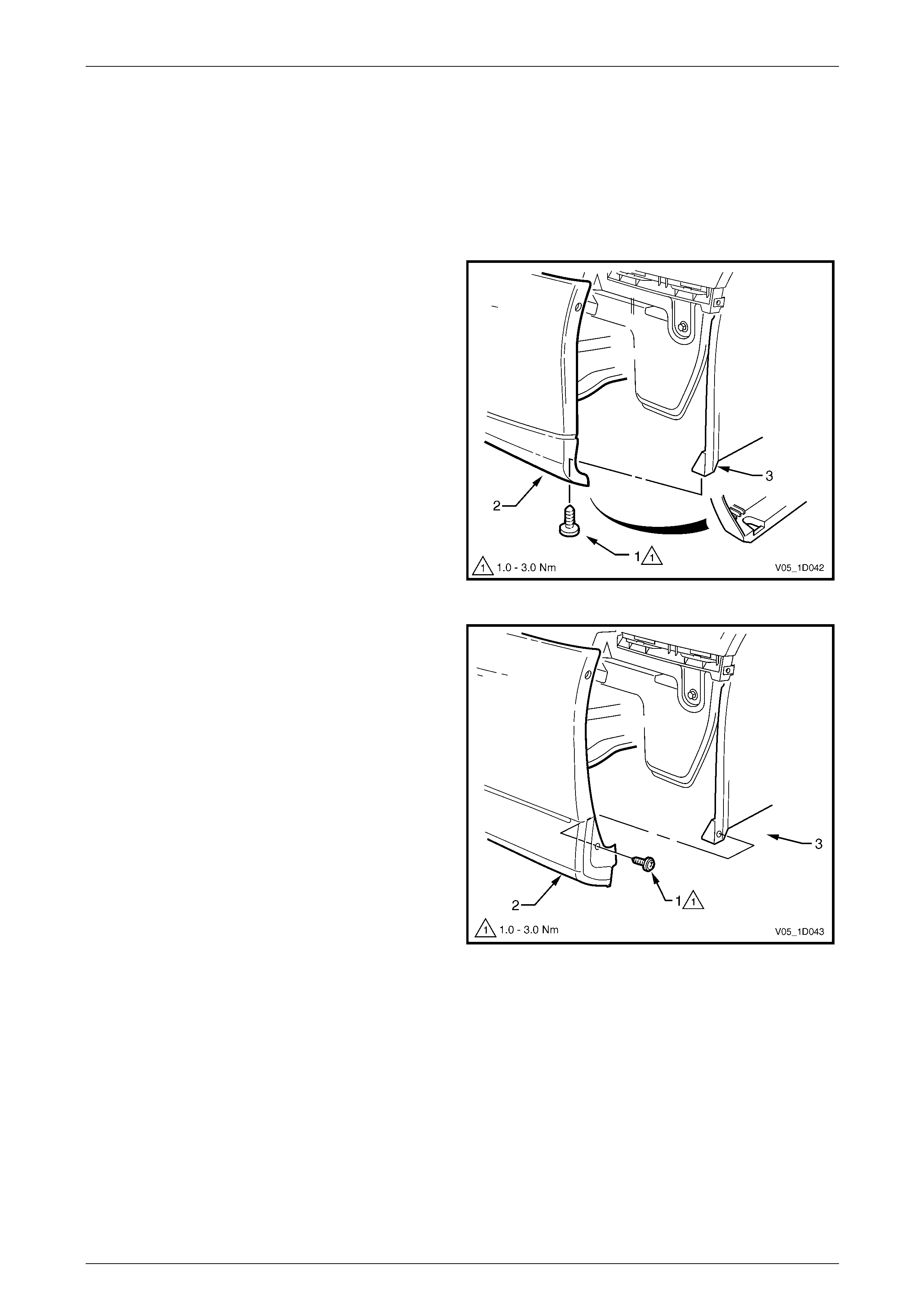
1 Depending of vehicle Lev el, perform Steps a or b as required:
a For Level 4 vehicles, remove screw (1) attaching
the front bumper fascia assembly (2) to the
wheelhouse liner (3). Repeat for each si de.
Figure 1D – 3
b For Level 5 vehicles, remove the screw (1)
attaching the front bumper fascia assembly ( 2) to
the front wheelhouse liner (3). Repeat for each
side.
Figure 1D – 4
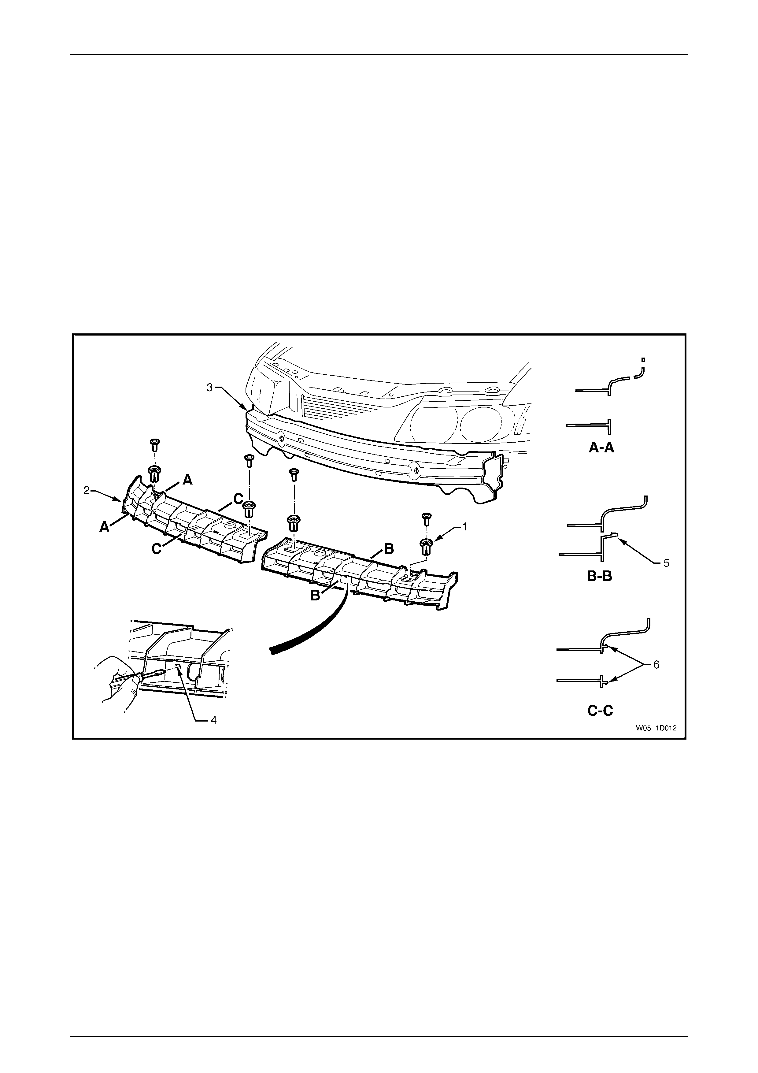
2 Referring to Figure 1D – 5, from each side of the vehicle:
a Remove the screw (1) attaching the front bumper assembly (3) to the fascia gui de assembly (2).
b Carefully unclip the fascia assembly from the guide assembly by graspin g the upper end of the fascia and
pulling away from the vehicle.

Bumper Bars Page 1D–13
Page 1D–13
Figure 1D – 5
3 Disconnect the front fog lamp wiring connector (1), one plac e each side of the vehicle, refer to Figure 1D – 6.
4 Prise the centre pin and remove the retain er (2), two places, attaching the fascia assembly (3) to the front fascia
support (4).
Figure 1D – 6
5 With the aid of an assistant remove the fascia assembly and store in a safe plac e.
Bumper Bars Page 1D–14
Page 1D–14
Disassemble
Front Bumper Fascia Moulding
Remove
1 From the rear of the front bumper fascia (1), remove the speed nut (2), six places, securing the front bumper fascia
moulding (3) to the bumper fascia, refer to Figure 1D – 7. For the removal procedure of the spee d nut, refer to
3.1 Service Notes.
2 Withdraw the moulding from the recess in the front of the bumper fascia.
Figure 1D – 7
Reinstall
1 Fit the moulding into the bumper fascia, locating the lugs in their respective holes, refer to Figure 1D – 7.
2 Fit a speed nut to the rear of each lug securely.
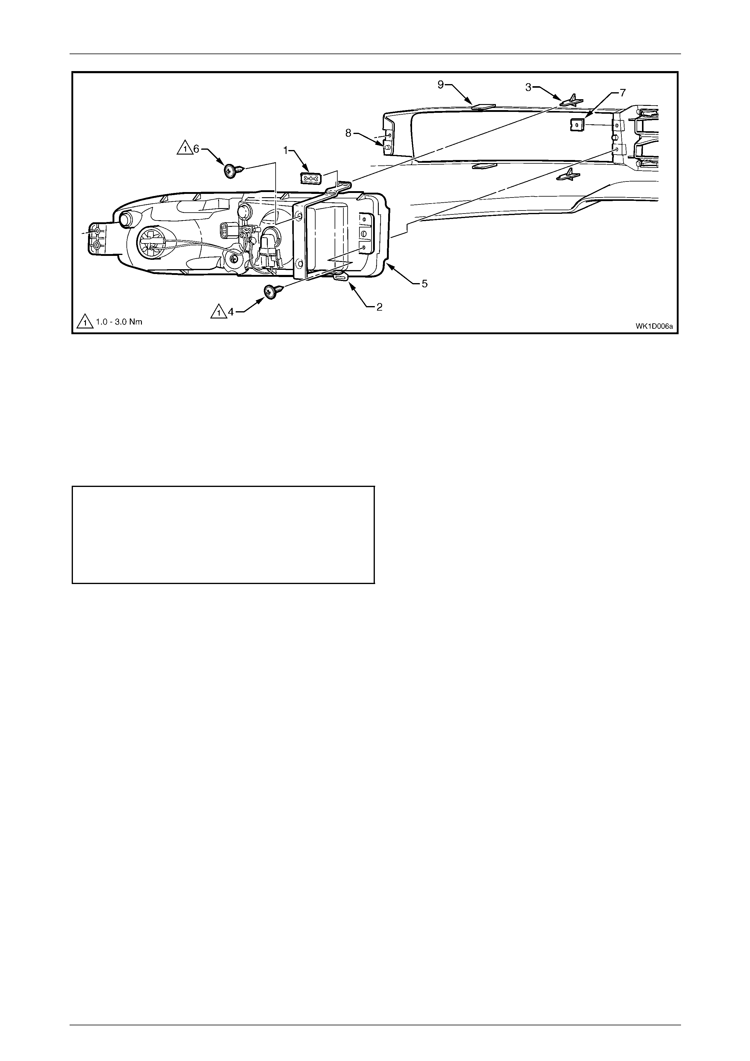
Front Fog and Cornering Lamp Asse mbly
Remove
1 From the rear of the fascia, remove the razor blade retainer (1), two places, securing the metal bracket (2) to the
attachment lugs (3), refer to Figure 1D – 8. For the removal procedure of the razor blade retainers, refer to
3.1 Service Notes.
2 Remove the screw (4), three places, attaching the front fog and cornering l amp assembly (5) to the bumper fascia.
3 Withdraw the lamp and bracket assembly from the rear of the bumper fascia.
4 If required, remove the screw (6), two places, attaching the metal bracket to the lamp assembly.
NOTE
For further service of the front fog and
cornering lamp assembly, refer to
Section 12B Lighting System.
5 If required, remove the J-nut (7), three places.
Bumper Bars Page 1D–15
Page 1D–15
Figure 1D – 8
Reinstall
Reinstallation of the front fog and cor nering lamp assembly is the reverse of the removal procedure, noting the following:
1 Locate the lamp housing onto the two guide pins (8), between the two support lugs (9) and locate the bracket on
the two attachment lugs (3), refer to Figure 1D – 8.
2 Tighten the screws to the correct torque specification.
Front fog and cornering lamp
metal bracket attaching screw
torque specification.....................................1.0 – 3.0 Nm
Front fog and cornering lamp
assembly attaching screw
torque specification.....................................1.0 – 3.0 Nm
NOTE
Following installation of the bumper fascia
assembly, aim the front fog lamps, refer to
Section 12B Lighting System.
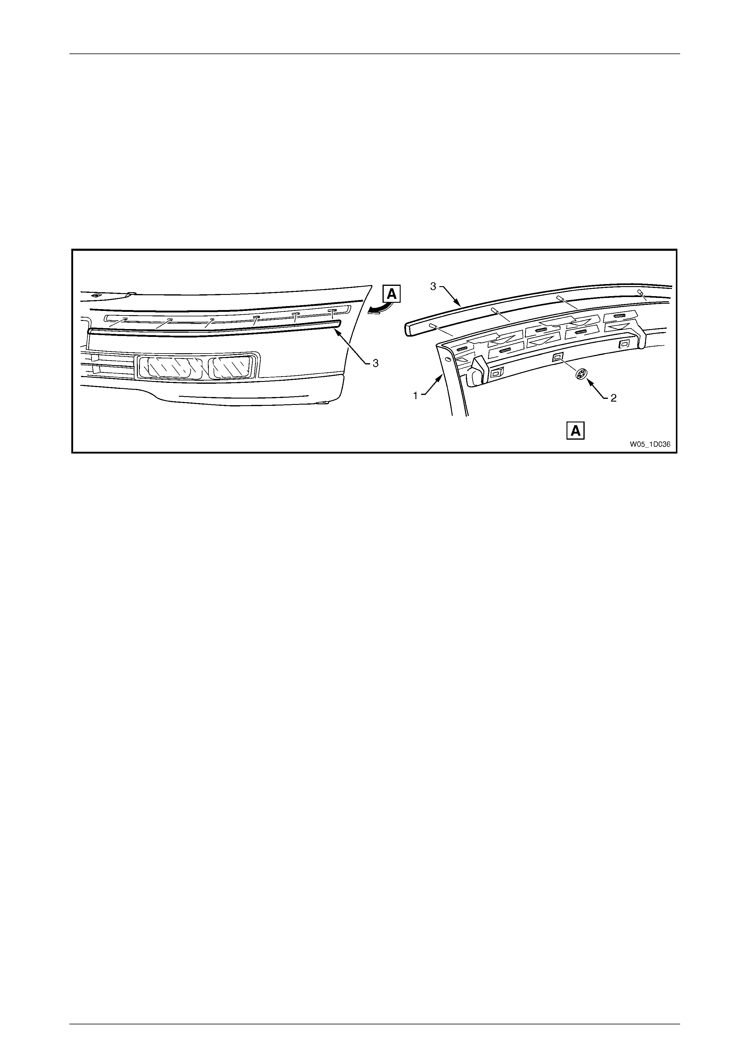
Lower Radiator Grille
Remove
1 Remove both front fog and cornering lam p a ssemblies, refer to Front Fog and Cornering Lamp Assembly.
2 Remove the screw (1), four places, attaching the lower radiator grille (2) to the bumper fascia, refer to
Figure 1D – 9.
3 Remove the razor blade retainer (3), three places, securing the lower grille to the bumper fascia. For the removal
procedure of the razor blade retain ers refer to 3.1 Service Notes.
4 Unclip the retainer (4), 10 places, securing the lower grille to the bumper fascia.
5 Remove the lower radiator grille.
6 If required, remove the J-nut (5), two places each side.
Bumper Bars Page 1D–16
Page 1D–16
Figure 1D – 9
Reinstall
Reinstallation of the lower radiator grille is the reverse of the removal pro cedure, noting the following:
1 Locate the lower radiator grille onto the guid e post (6), refer to F igure 1D – 9.
2 Tighten the screws to the correct torque specification.
Lower radiator grille attaching screw
torque specification.....................................1.0 – 3.0 Nm
Dual Park Assist Front Components
Four sensor assemblies and their associated wiring are fitted to the front bumper fascia assembly on Level 5 vehicles as
part of the Dual Park Assist (DPA), refer to Figure 1D – 10.
Each front object sensor assembly (1) is fitted into a front object sensor housing (2) which is attached to the fascia
assembly by ultra-sonic welding. Holes in th e fascia expose the sensor and housing faces. Five retaining clips (3) secure
the object sensor wiring harness assembly (4) to the fascia assembly, which is routed across to the right-hand side.
Figure 1D – 10
Bumper Bars Page 1D–17
Page 1D–17
• The fascia assembly and sensors must be
correctly aligned if the system is to
operate correctly. Sensors may be
damaged if dropped or subjected to
temperatures abo ve 80°C.
• If repainting a fascia assembly, the
sensors and rings MUST be removed.
Paint must not be applied to any part of a
sensor, including the exposed coloured
surface. Paint film applied to the exposed
surface will render the sensor inoperable
as the paint film restricts the sensor’s
ultra-sonic signal. If a sensor is damaged,
it must be replaced.
• Replacement housings are supplied
unpainted. As they are partially exposed
when installed, they will require
painting using the same procedures for
painting the bumper fascia, refer to
2 Paint Systems.
NOTE
It is preferable to paint the housings and bumper
fascia separately to avoid adhesion problems.
Assemble the housings onto the bumper fascia
once the paint has cured.
Replacement bumper fascias are sup pli ed without holes and must be modified by following the procedures in
New Fascia Modification.
For further information on dual park assist, refer to Section 12F2 Dual Park Assist.
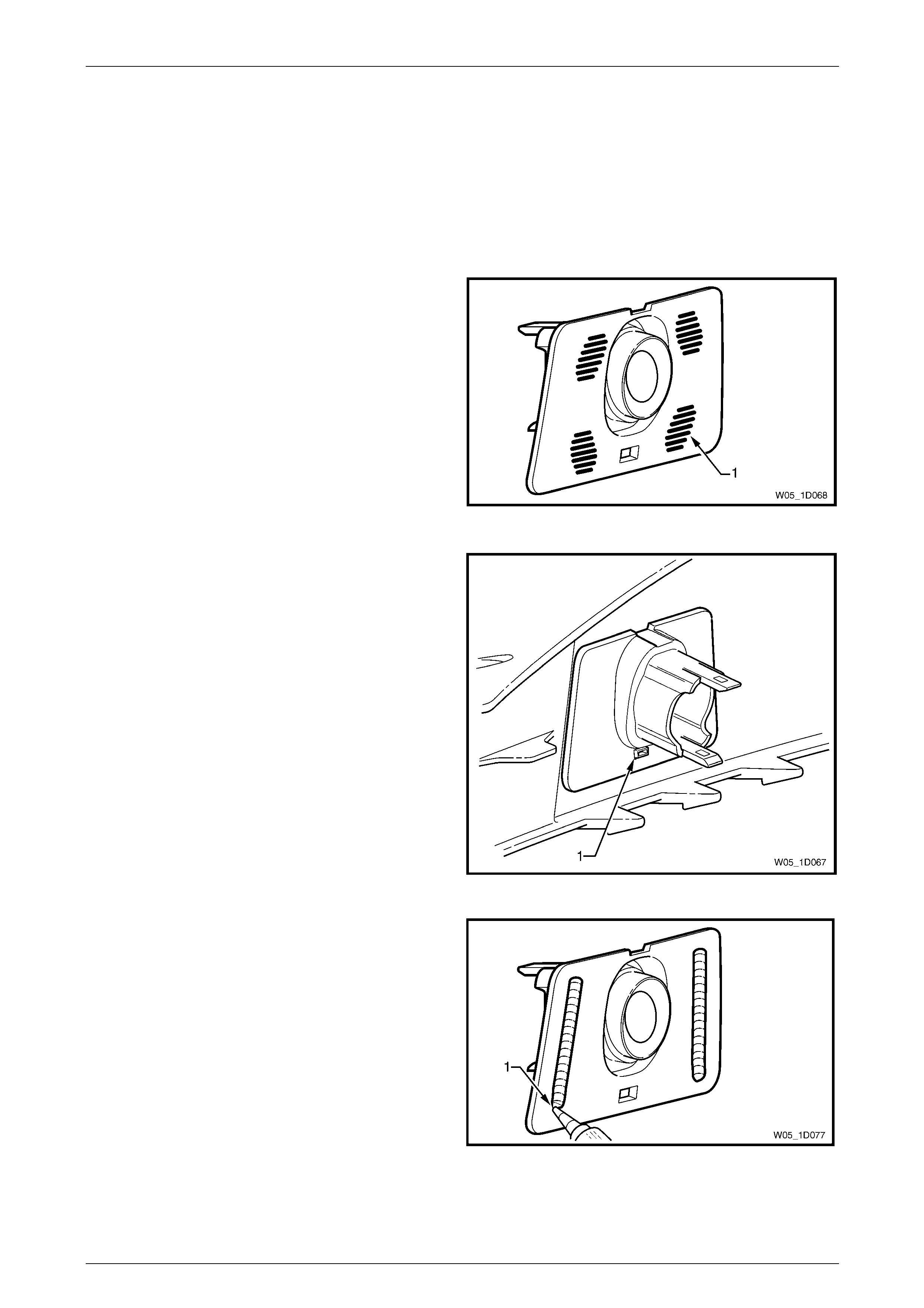
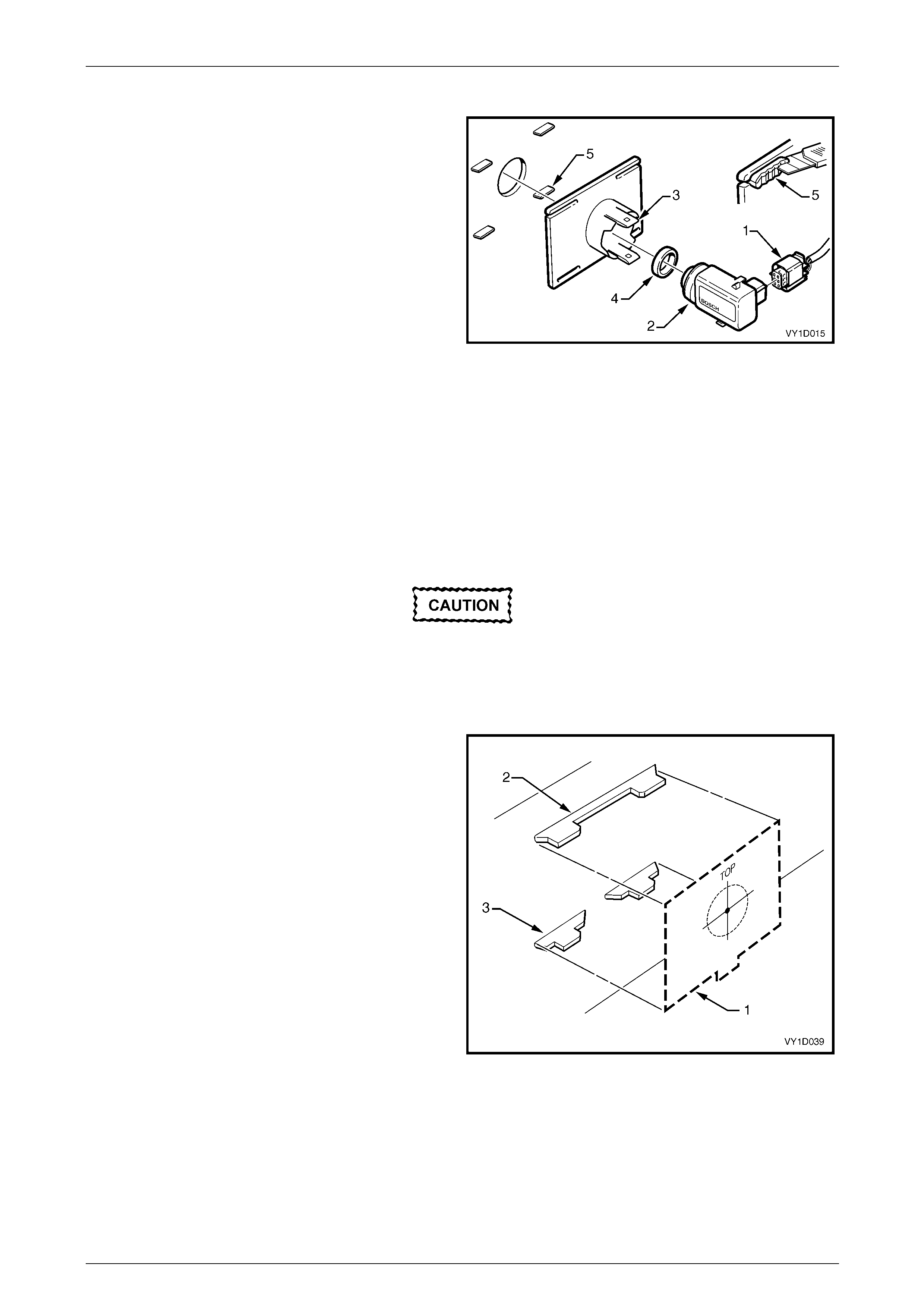
Remove
1 Remove the wiring connector (1) from the front object
sensor assembly (2).
2 Using a fine blade screwdriver, lever the upper and
lower tabs (3) of the front object sensor housing and
slide the sensor from the hous ing.
3 If required, remove the front object sensor ring (4)
from the sensor.
4 If required, remove the housing from the bumper
fascia by prising and cutting between the housing and
bumper fascia.
5 Remove the wiring harness from the bumper fascia by
prising the retaining clips from the bumper fascia with
a fine flat blade screwdriver. Figure 1D – 11
Bumper Bars Page 1D–18
Page 1D–18
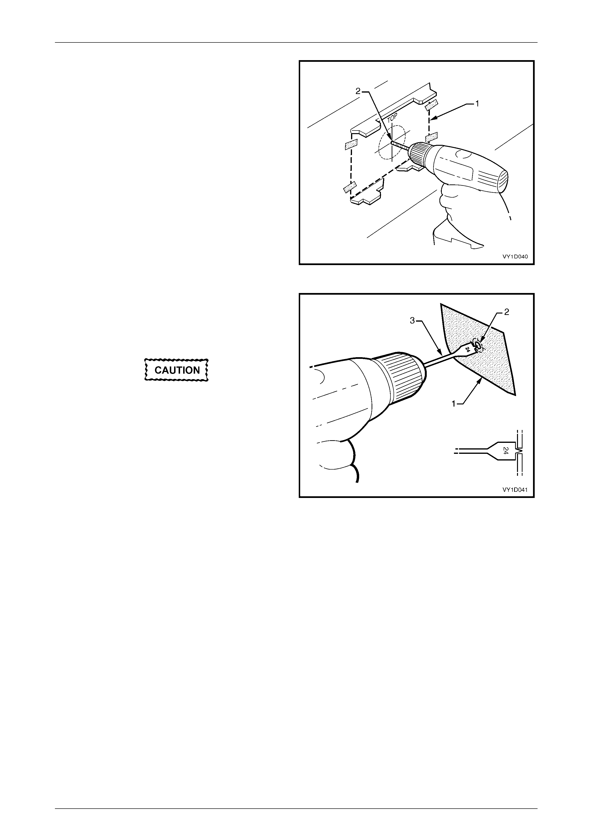
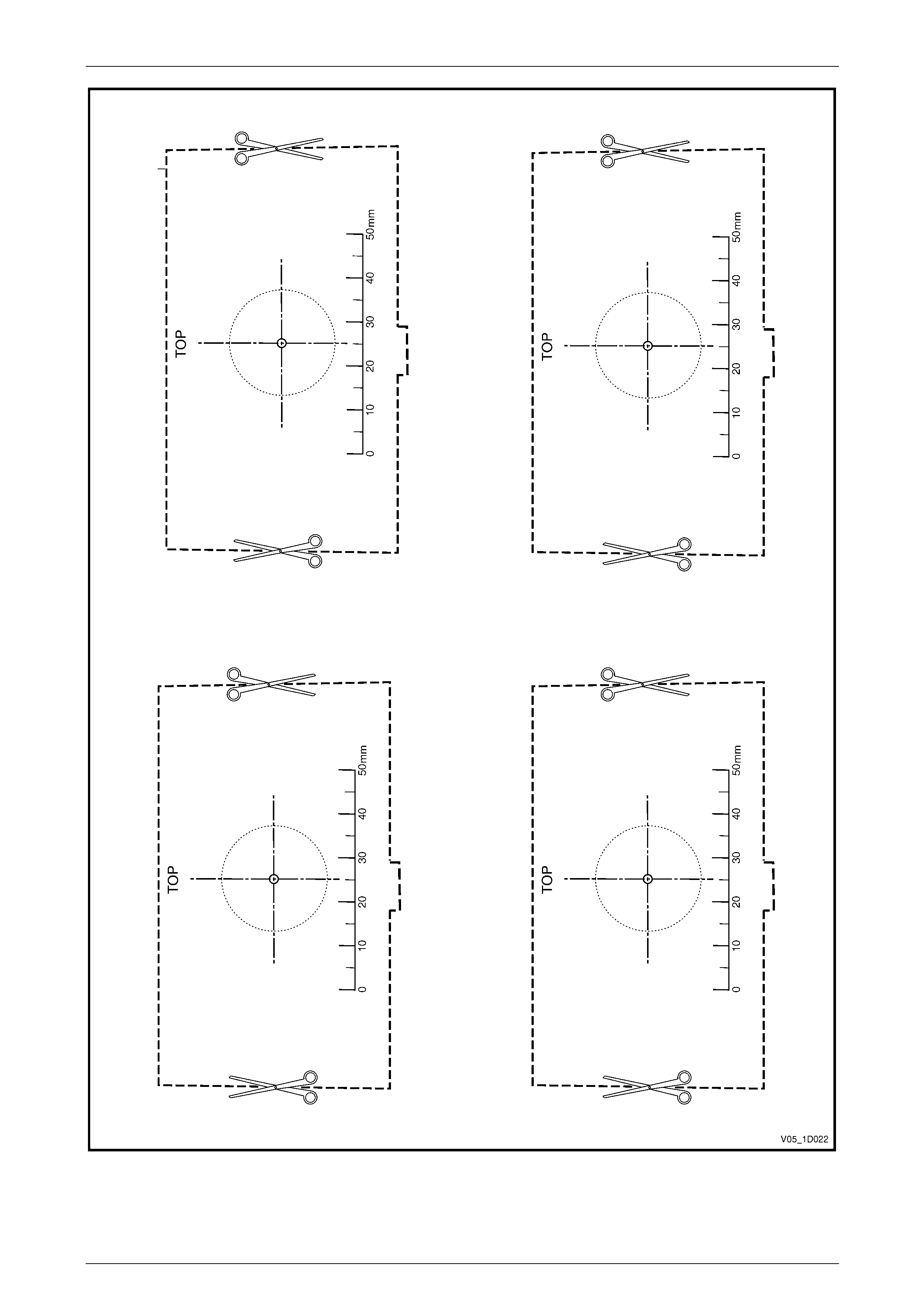
New Fascia Modification
1 Print and cut-out the templates shown in Figure 1D – 15.
When printing, always check the scale on the
template to ensure it has printed the correct
size.
2 Tape the template (1) to the inside of the bu m per
fascia, aligning the cut-out over the locating l ug (2)
and the lower edge of fascia rib (3).
NOTE
Ensure the correct template is used and the
arrow is pointing to the centre of the fascia.
Figure 1D – 12
3 From the inside of the bumper fascia, drill a 2 mm
diameter pilot hole at the template (1) centre point (2).
Figure 1D – 13
4 Place masking tape (1) on the outside surface of the
bumper fascia in the area to be drilled.
5 From the outside of the bumper fascia, enlarge the
pilot hole (2) to 28 mm using a wood spade drill bit (3).
• Only use a wood spade drill bit as a
normal drill bit or hole saw may damage
the fascia.
• Ensure the spade drill bit remains square
with the fascia.
• Use a slow drill speed to avoid damaging
the fascia.
6 Debur the edges of the hole if necessary.
7 As required, paint the bumper fascia an d sensor
housings prior to reassembly, refer to
2 Paint Systems. Figure 1D – 14
Bumper Bars Page 1D–19
Page 1D–19
Figure 1D – 15
Bumper Bars Page 1D–20
Page 1D–20
Reinstall
NOTE
• It is advisable to paint the bumper fascia and
housings prior to attachment to the bumper
fascia, refer to 2 Paint Systems.
• Avoid overspray on the rear of the fascia and
mask the attachment area on the sensor
housings.
1 Using a file, remove the ribs (1) from the face of the
sensor housings.
2 Using 80-grit sand paper roug hen the face of the
housing and the surface area of the fascia where
housing is to be attached.
3 Clean away any dust from both the housin g and fascia
surface.
Figure 1D – 16
4 Test fit the housing onto its locating tab (1), ensur ing it
is seated against the fascia surface and protrudes
through the hole so that it is level or just below the
bumper fascia outer surface.
5 Remove the housing and apply Lord Chemlok 459X
primer to both the sensor hou sing mounting surface
and the bumper fascia mounting surface area.
6 Allow the primer to dry for 30 minutes.
Figure 1D – 17
7 Apply a bead of Lord Fusor #143 adhesive (1) to the
mounting surface each side of the housing and install
the housing to the fascia.
NOTE
Ensure the housing is correctly seated and
protrudes through the hole so it is level or just
below the bumper fascia outer surface.
8 Secure the housing to the bumper fascia with tape or
similar, allowing 20 minutes for the adhesive to cure.
9 Repeat for the remaining housings as required.
Figure 1D – 18
10 Once the adhesive has completely cured, fit the rin g onto the end of each sensor and insert the sensors into their
housings firmly, ensuring the tabs are locked into the sensor.
Bumper Bars Page 1D–21
Page 1D–21
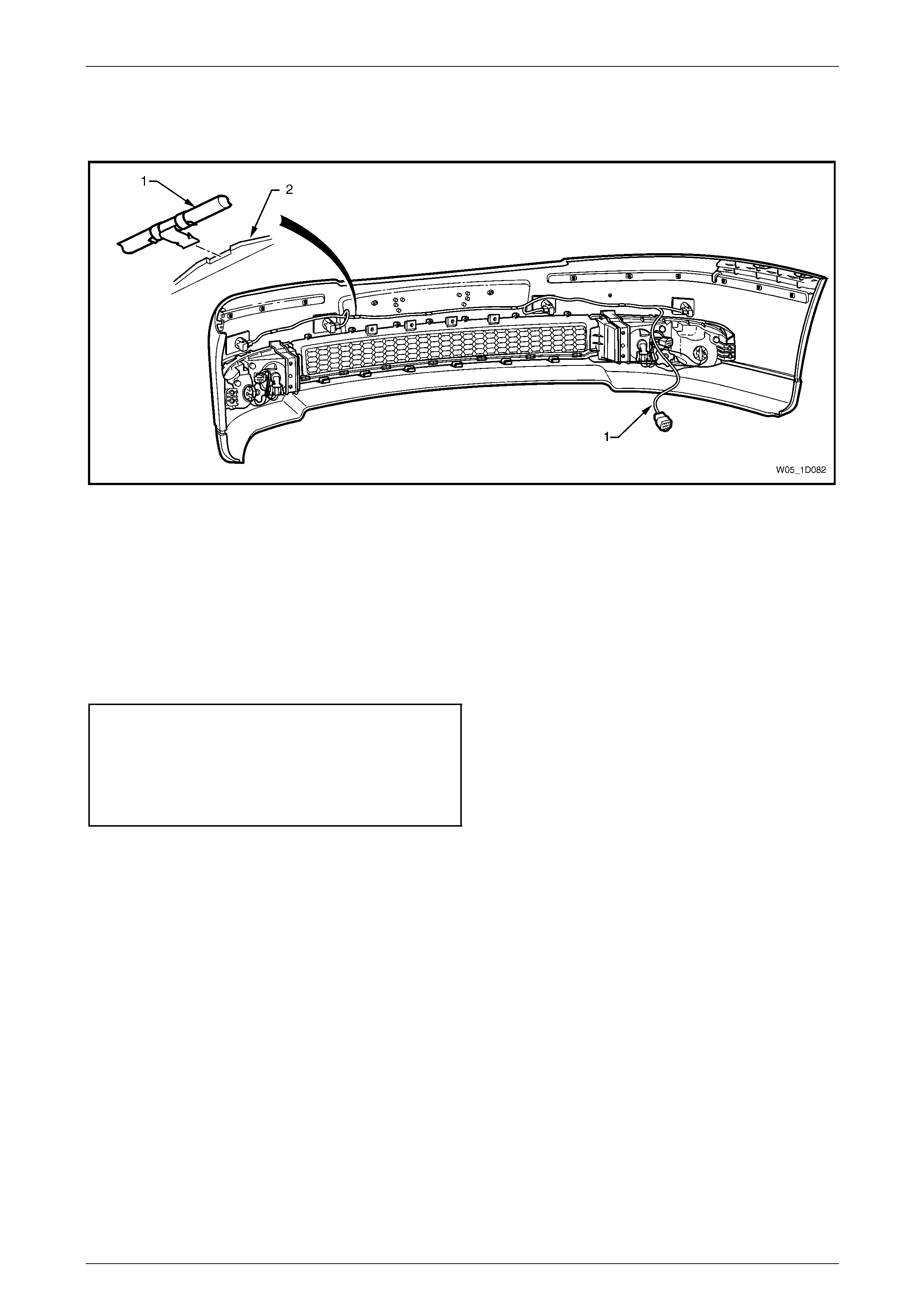
11 Route the wiring harness (1) to the right-hand side of the bumper fascia and connect the wiring harness connectors
to each sensor, refer to Figure 1D – 19.
12 Attach the harness to the upper side of the bumper fascia rib (2), aligning the clips at the notches.
Figure 1D – 19
Reinstall
Reinstallation of the front bumper fascia assembly is the reverse of the removal procedure, noting the following:
1 As required, refinish the bumper fascia, refer to 2 Paint Systems.
2 To avoid damaging the bump er fascia an d / or vehicle, fit the fascia assembly onto the vehicle with the aid of an
assistant.
3 Tighten the screws to the correct torque specification.
Front bumper fascia assembly to front
wheelhouse liner screw torque
specification................................................1.0 – 3.0 Nm
Front bumper fascia assembly to front
bumper fascia guide assembl y screw
torque specification.....................................1.0 – 3.0 Nm
4 Test the dual park assist for correct operation, refer to Section 12F2 Dual Park Assist.
Bumper Bars Page 1D–22
Page 1D–22
3.3 Front Fascia Support
LT Section No. — 07–500
Remove
1 Remove the front bumper fascia assembly, refer to 3.2 Front Bumper Fascia Assembly.
2 Prise the centre pin and remove the two retainers (1), securing the front fascia sup port (2) to the front bumper
impact bar (3), refer to Figure 1D – 20.
3 Insert a flat blade screwdriver into the opening (4) in the fascia support and depress the tab (5). Whilst depressing
the tab, slightly rotate the bottom of the fascia support upwards to release the remaining two retaining clips (6).
4 Remove the fascia support.
5 Repeat for the opposite side as required.
Figure 1D – 20
Reinstall
1 Align the front fascia support (2) against the front bumper impact bar (3) and clip the two retainers (1) into place,
refer to Figure 1D – 20.
2 Insert pins into retainers and ensure the fascia support is secure.
3 Repeat for the opposite side as required.
Bumper Bars Page 1D–23
Page 1D–23
3.4 Front Bumper Guide Assembly
LT Section No. — 07–500
Remove
1 Remove the front bumper fascia assembly, refer to
3.2 Front Bumper Fascia Assembly.
NOTE
It is possible to remove one side of the bumper
fascia and carefully move it out to gain access to
the guide assembly.
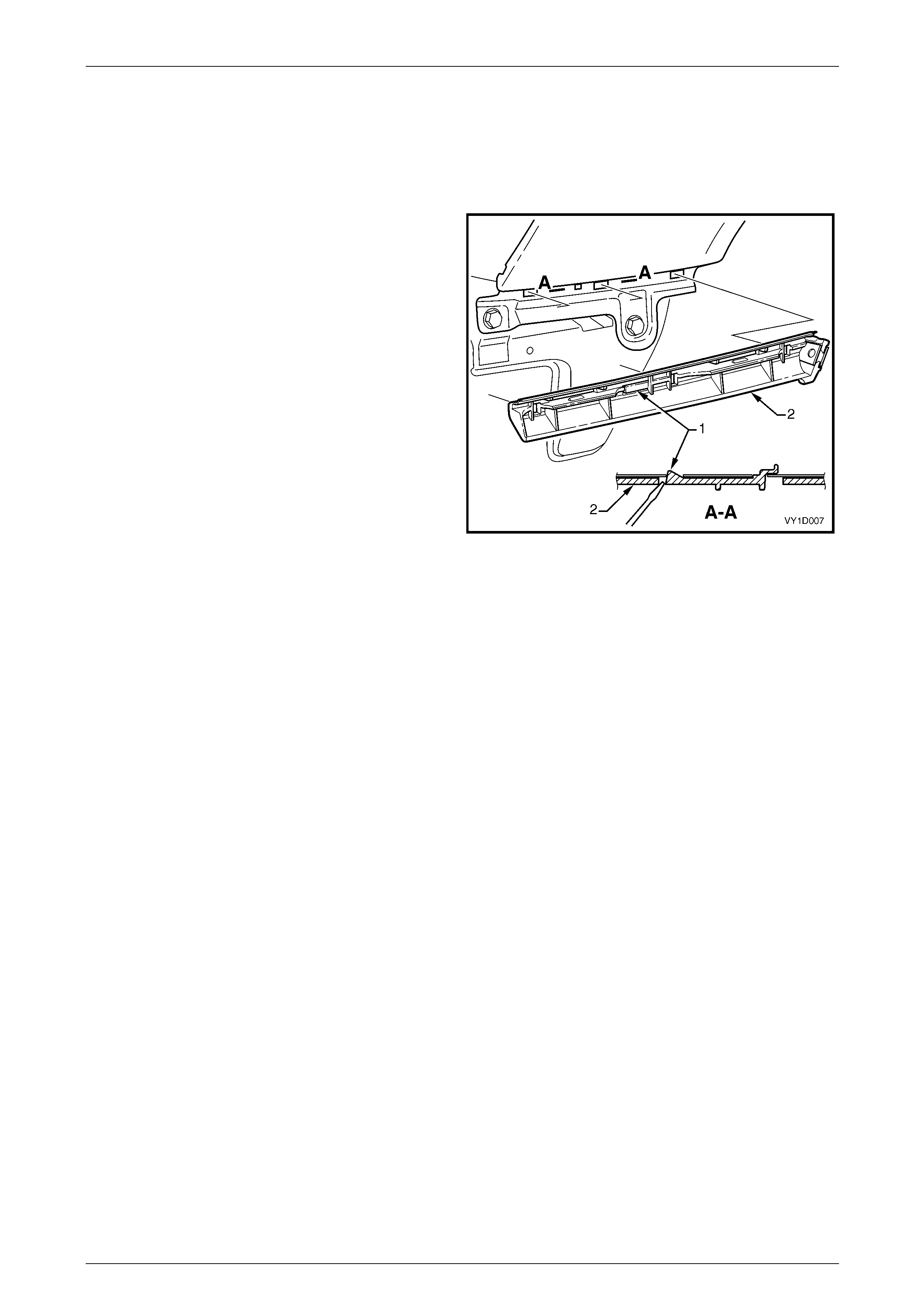
2 Using a fine flat-blade screwdriver, lever and hold the
tab (1) outwards.
3 Slide the guide assembly (2) forward and out to detach
it from the fender.
Figure 1D – 21
Reinstall
1 Align the guide assembly with the slots in the fender and while pushing in slightly, slide the guide rearwards until it
clicks into place.
2 Reinstall the bumper fascia as required, refer to 3.2 Front Bumper Fascia Assembly.
Bumper Bars Page 1D–24
Page 1D–24
3.5 Front Bumper Impact Bar Assembly
LT Section No. — 07–500
Remove
1 Remove the front bumper fascia assembly, refer to
3.2 Front Bumper Fascia Assembly.
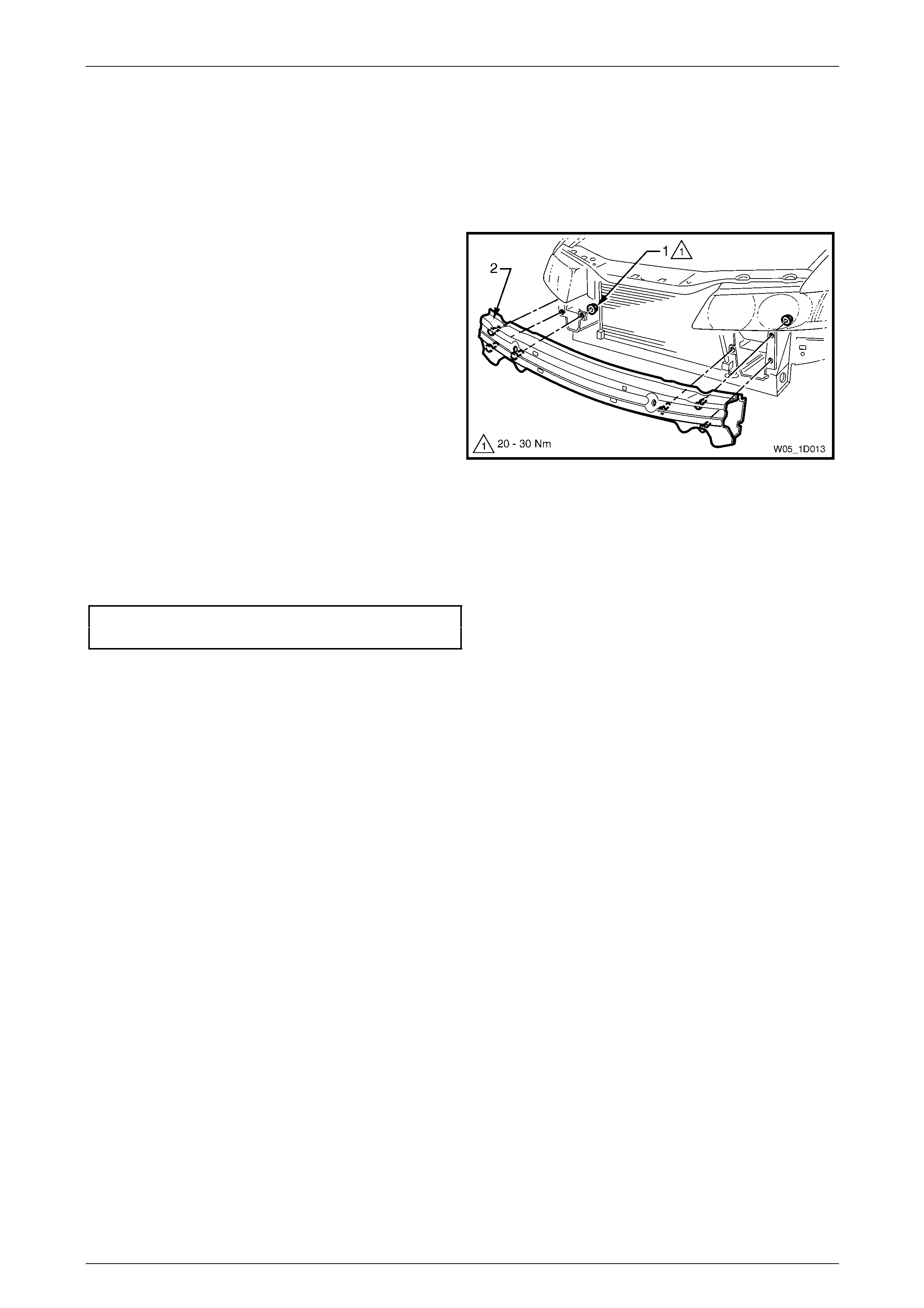
2 Remove the nut (1), three places each side, attaching
the front impact bar assembly (2) to the vehicle.
3 Remove the bar assembly.
Figure 1D – 22
Reinstall
1 Fit the bar assembly in position and attach each nut. Do n ot tighten.
2 Ensure the bar assembly is correctl y pos itioned centrally and tighten the nuts to the correct torque specification.
Front bumper impact bar assembly
attaching nut torque specification............20.0 – 30.0 Nm
3 Reinstall the front bumper fas c ia assembly, refer to 3.2 Front Bumper Fascia Assembly.

Bumper Bars Page 1D–25
Page 1D–25
3.6 Rear Bumper Fascia Assembly
LT Section No. — 07–525
Remove
1 Remove the following components:
a Rear end trim panel, refer to Section 1A8 Headlining and Interior Trim.
b Quarter inner rear side carpet, refer to Section 1A8 Headlining and Interior Trim.
2 Depending on vehicl e Level, perform Steps a or b as required:
a For Level 4 vehicles, remove the screw (1), two
places, attaching the rear bumper fascia
assembly (2) to the rear wheelhouse liner (3).
Figure 1D – 23
b For Level 5 vehicles, remove the screw (1),
attaching the rear bumper fas c ia assembly (2) to
the rear wheelhouse liner (3).
Figure 1D – 24
3 Referring to Figure 1D – 25, from each side of the vehicle:
a Remove the two screws (1) attaching the rear bumper fascia assembly (3) to the liner and rear bum per fascia
guide assembly (2).
b Carefully unclip the fascia assembly from the guide assembly by graspin g the upper end of the fascia and
pulling away from the vehicle. For Level 4 vehicles disconnect the liner lug (4) from the bumper fascia
assembly.
Bumper Bars Page 1D–26
Page 1D–26
Figure 1D – 25
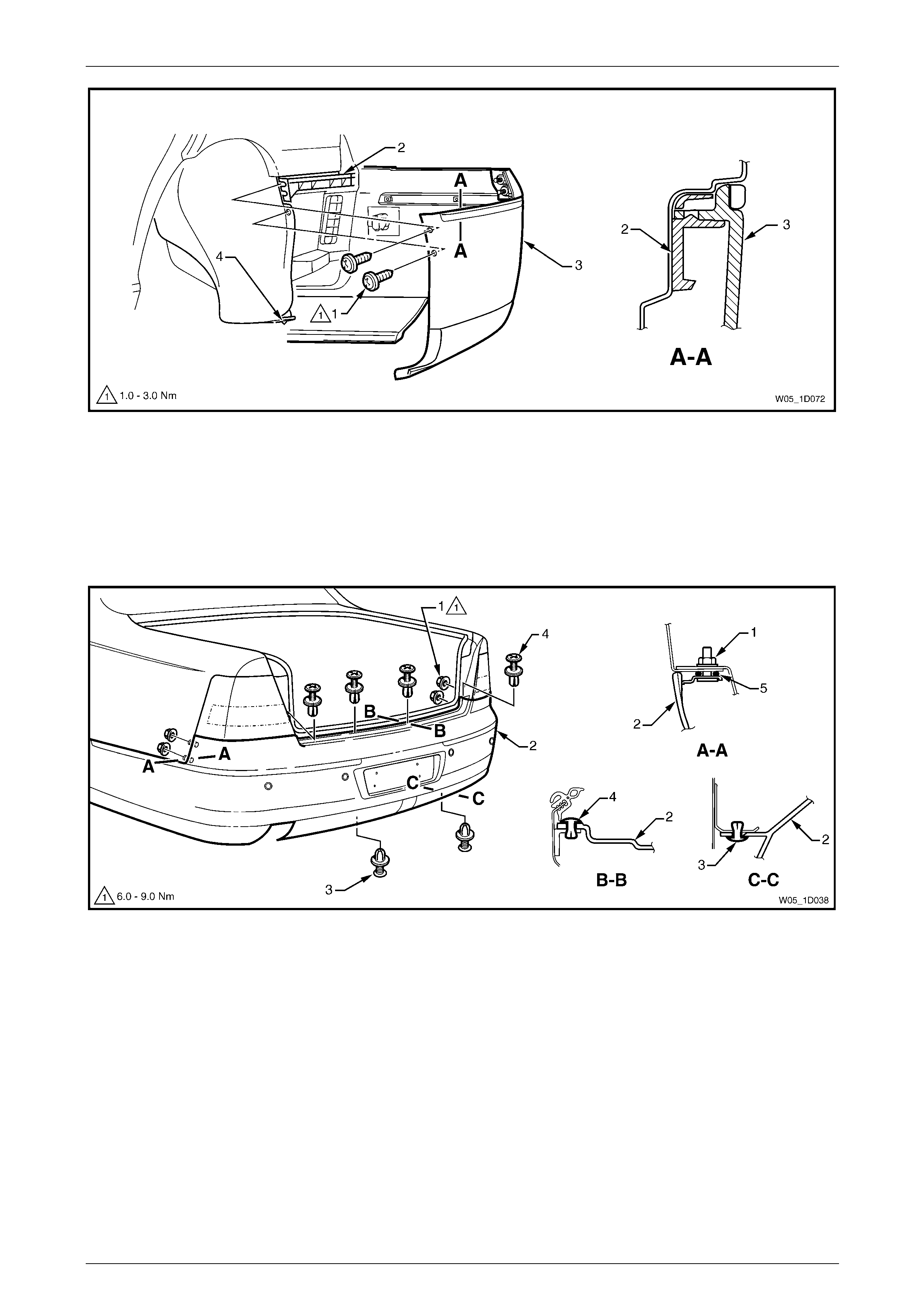
4 Remove the two nuts (1), each side, attaching the rear b umper fascia assembly (2) to the vehicle, refer to
Figure 1D – 26.
5 Remove the two retainers (3) from belo w the fascia assembl y.
6 Remove the centre section of the rear compa r tment lid weatherstrip to allow access to the four upper retainers (4).
7 Remove the four upper retainers attaching the fascia assembly to the rear bumper fascia centre support assembly.
Figure 1D – 26
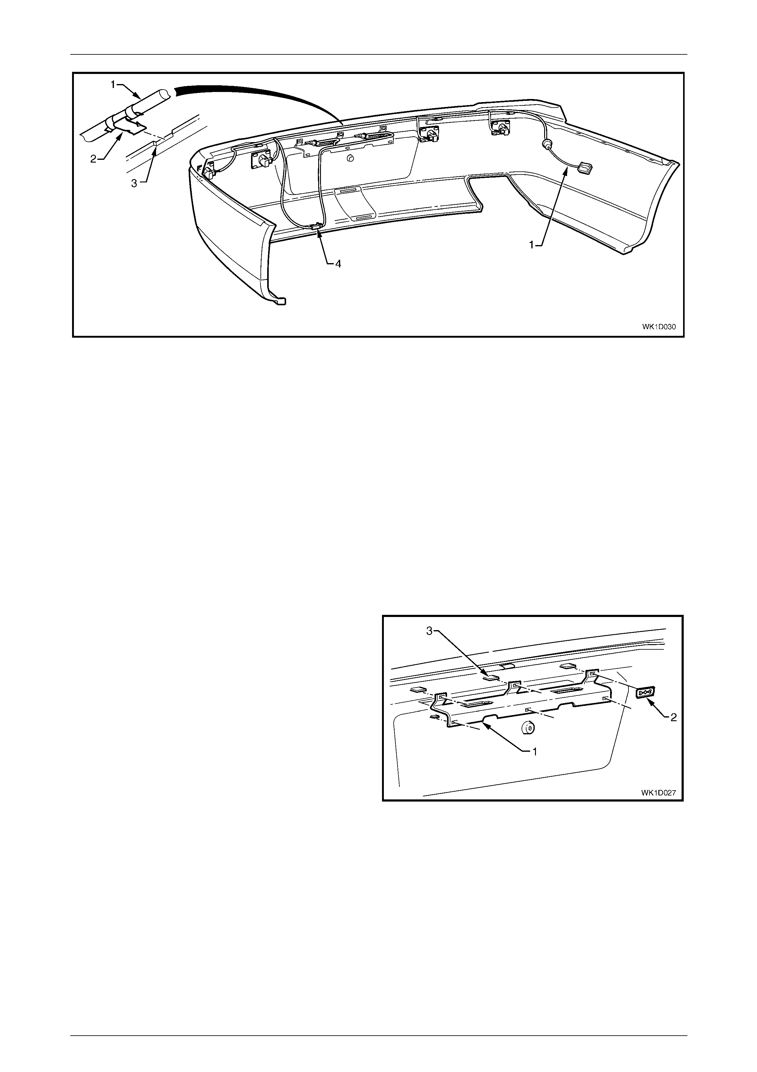
8 Disconnect the Rear Park Assist (RPA) and license plate lamp wiring harness connector from within the left-hand
side of the rear compartment.
Bumper Bars Page 1D–27
Page 1D–27
9 With the aid of an assistant, withdraw the fascia
assembly and push the wiring harness and grommet
(1) through the side panel.
10 Remove the fascia assembly ensuring the seals (5)
remain with the fascia assembly, refer to
Figure 1D – 26.
Figure 1D – 27
Disassemble
Rear Bumper Fascia Moulding
Remove
1 From the rear of the bumper fascia (1), remove the
speed nut (2), six places, securing the rear bumper
fascia moulding (3) to the bumper fascia. For the
removal procedure of the speed nut refer to
3.1 Service Notes.
2 Withdraw the moulding from the recess in the bumper
fascia.
Reinstall
1 Align and insert the corner lug of the moulding into the
rear fascia. Working from the centre lug, insert each
lug into the rear fascia.
2 Fit a speed nut to the rear of each lug securely.
Figure 1D – 28
Bumper Bars Page 1D–28
Page 1D–28
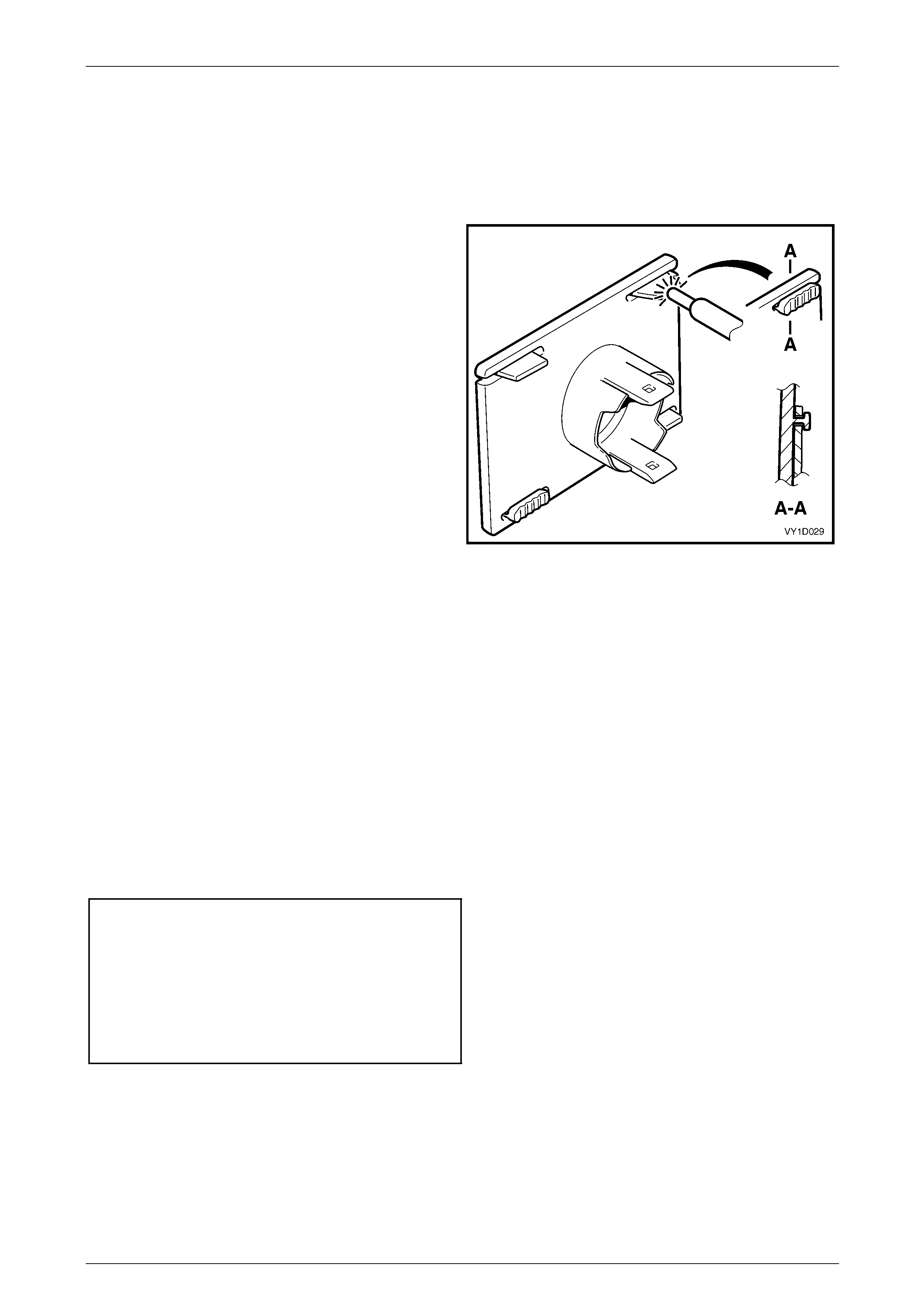
Licence Plate Lamp Assembly
Remove
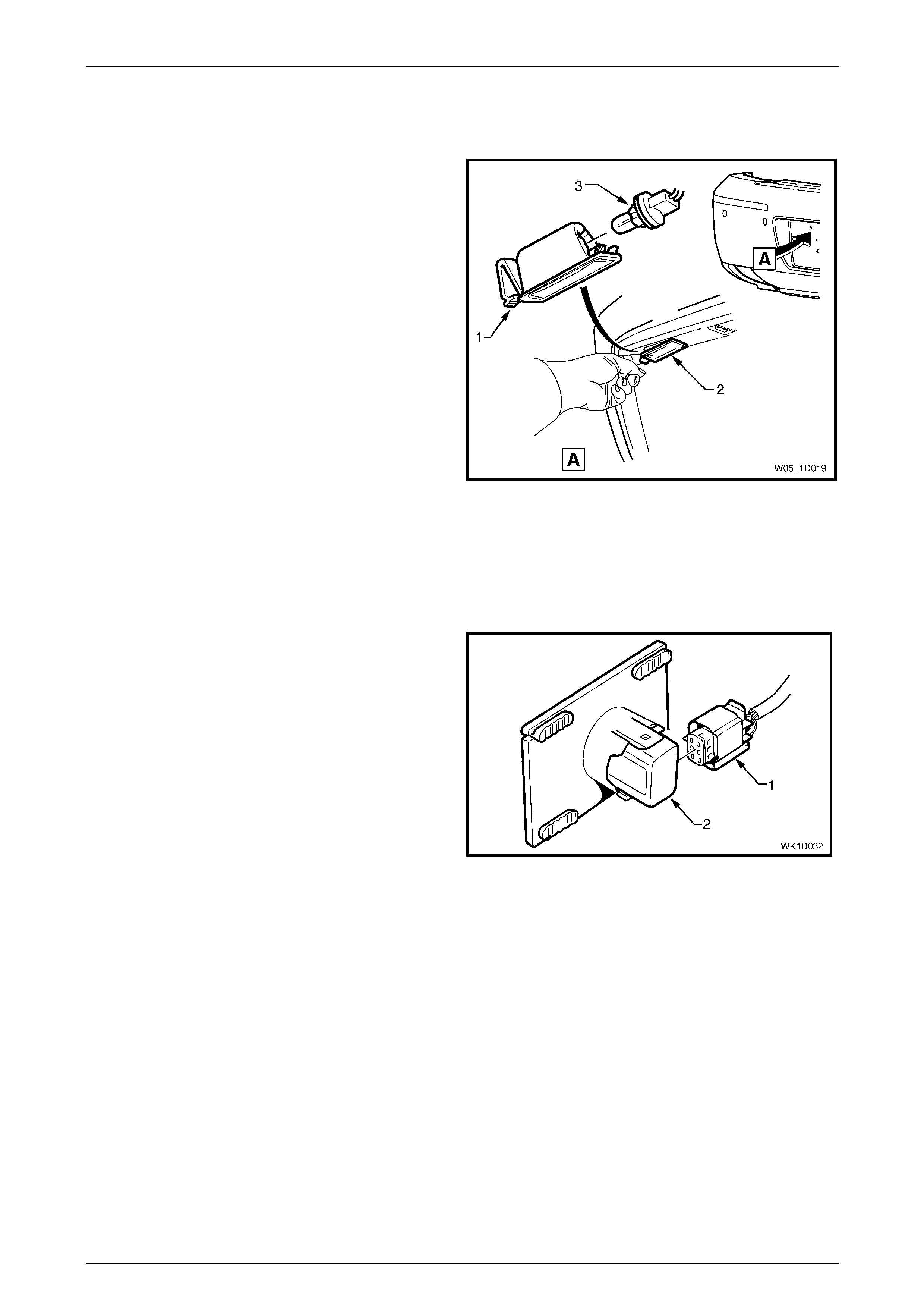
1 Push the locking tang (1) located at the end of the
lamp housing (2) towards the lens. Pivot the housing
down and remove it from the aperture. Repeat for the
opposite side as required.
2 Remove the bulb socket (3) from the lamp housing.
Reinstall
Reinstallation of the licence plate lamp assembly is the
reverse of the removal procedure.
Figure 1D – 29
Rear Park Assist and Licence Plate Lamp Wiring Harness
Remove
1 Remove both licence plate lamp assemblies, refer to Licence Plate Lamp Assembly.
2 Remove the wiring harness connector (1) from the
rear object sensor assembly (2), four places.
3 Unclip the licence plate lamp harness co nnector (4)
from the bumper fascia, refer to Figure 1D – 31.
4 Remove the wiring harness by prisin g the three
retaining clips (2) from the bumper
fascia (3) with a fine flat blade screwdriver.
Figure 1D – 30
Bumper Bars Page 1D–29
Page 1D–29
Figure 1D – 31
Reinstall
1 Route the wiring harness (1) to the left-hand side of the vehicle, refer to Figure 1D – 31.
2 Attach the licence plate lamp harness connector (4) to the bumper fascia.
3 Attach the harness, three places, to the upper side of the bumper fascia rib , aligning each clip (2) at the
notch (3).
4 Attach the wiring harness connector (1), four places, to the rear object sensor assembl y (2), refer to
Figure 1D – 30.
5 Reinstall the licence p late lamp assemblies, refer to Licence Plate Lamp Assembly.
Licence Plate Lamp Carrier, Level 5 Vehicles
Remove
1 Removing the razor blade reta iner (2), six places,
securing the license plate lamp carrier (1) to the
bumper fascia. For the removal procedure of the razor
blade retainer refer to 3.1 Service Notes.
2 Remove the carrier.
Reinstall
1 Position the licence plate lamp carrier onto the lug (3),
six places, ensuring it is seated against the fascia
surface and the lugs correctly protrude thro ugh the
holes.
2 Fit a razor blade retaining clip (2), six places, to the
rear of each lug securely. Figure 1D – 32
Bumper Bars Page 1D–30
Page 1D–30
Licence Plate Surround, Level 4 Vehicles
Remove
1 From the rear of the bumper fascia, remove the speed
nut (1), 11 places, securing the licence plate surround
(2) to the bumper fascia (3). For the removal
procedure of the speed nut refer to 3.1 Service Notes.
2 Withdraw the licence plate surround from the bumper
fascia.
Reinstall
1 Fit the license plate surround into the bumper fascia
cavity, locating the lugs in their respective holes.
2 Fit a speed nut to the rear of each lug securely.
Figure 1D – 33
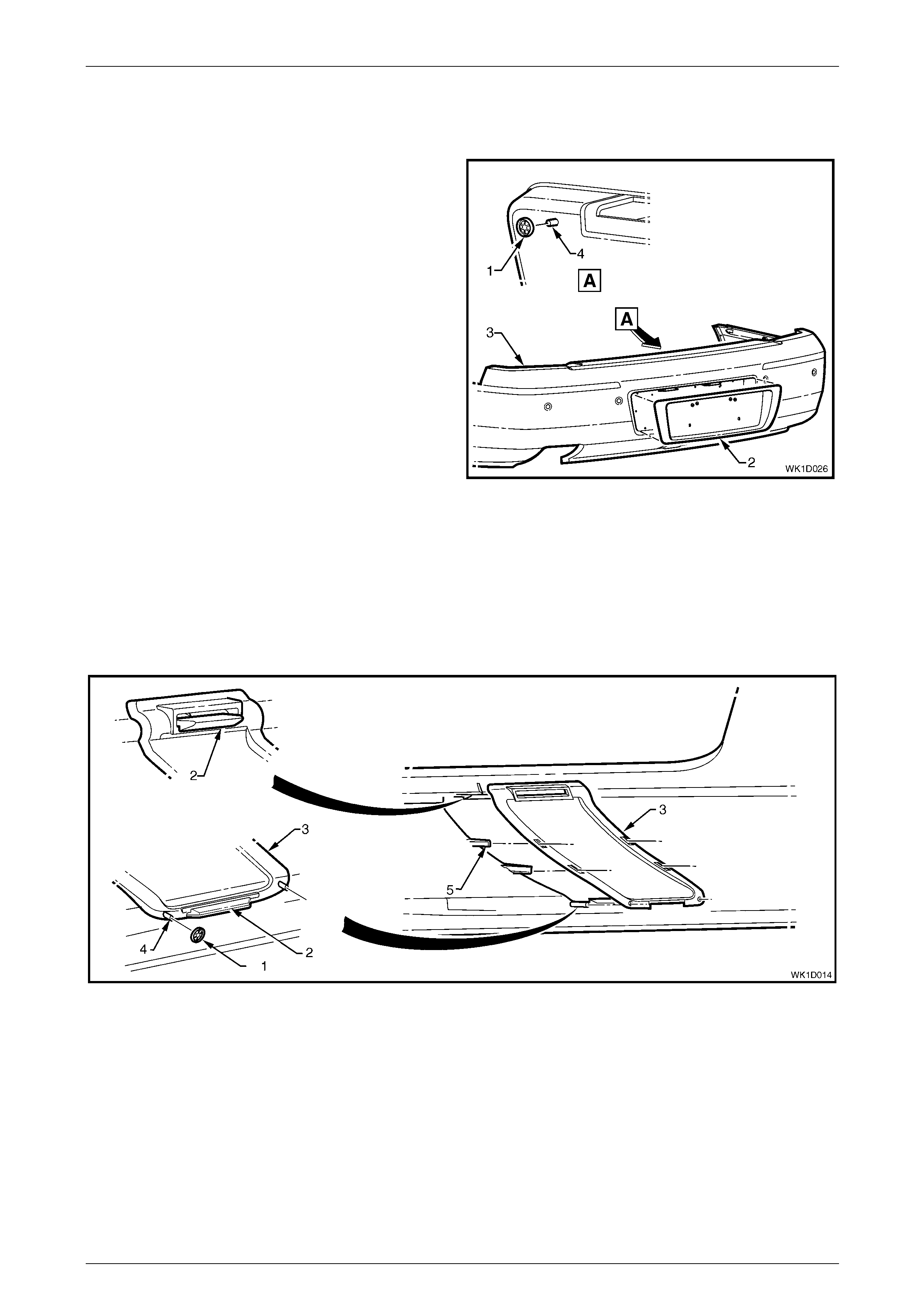
Towbar Opening Cover
Remove
1 From the rear of the bumper fascia, remove the speed nut (1), two places, securing the towbar opening cover (3) to
the bumper fascia. For the removal procedure of the speed nut, refer to 3.1 Service Notes.
2 Depress the retaining tab (2), two places, and remove the c over.
Figure 1D – 34
Reinstall
1 Clip the towbar opening cover in place, taking care to align the cover with the bum per fascia guides (4 and 5).
Ensure the retaining tab (2), two places, are seated correctly. Refer to Figure 1D – 34.
2 Fit a speed nut to the rear of each lug securely.
Bumper Bars Page 1D–31
Page 1D–31
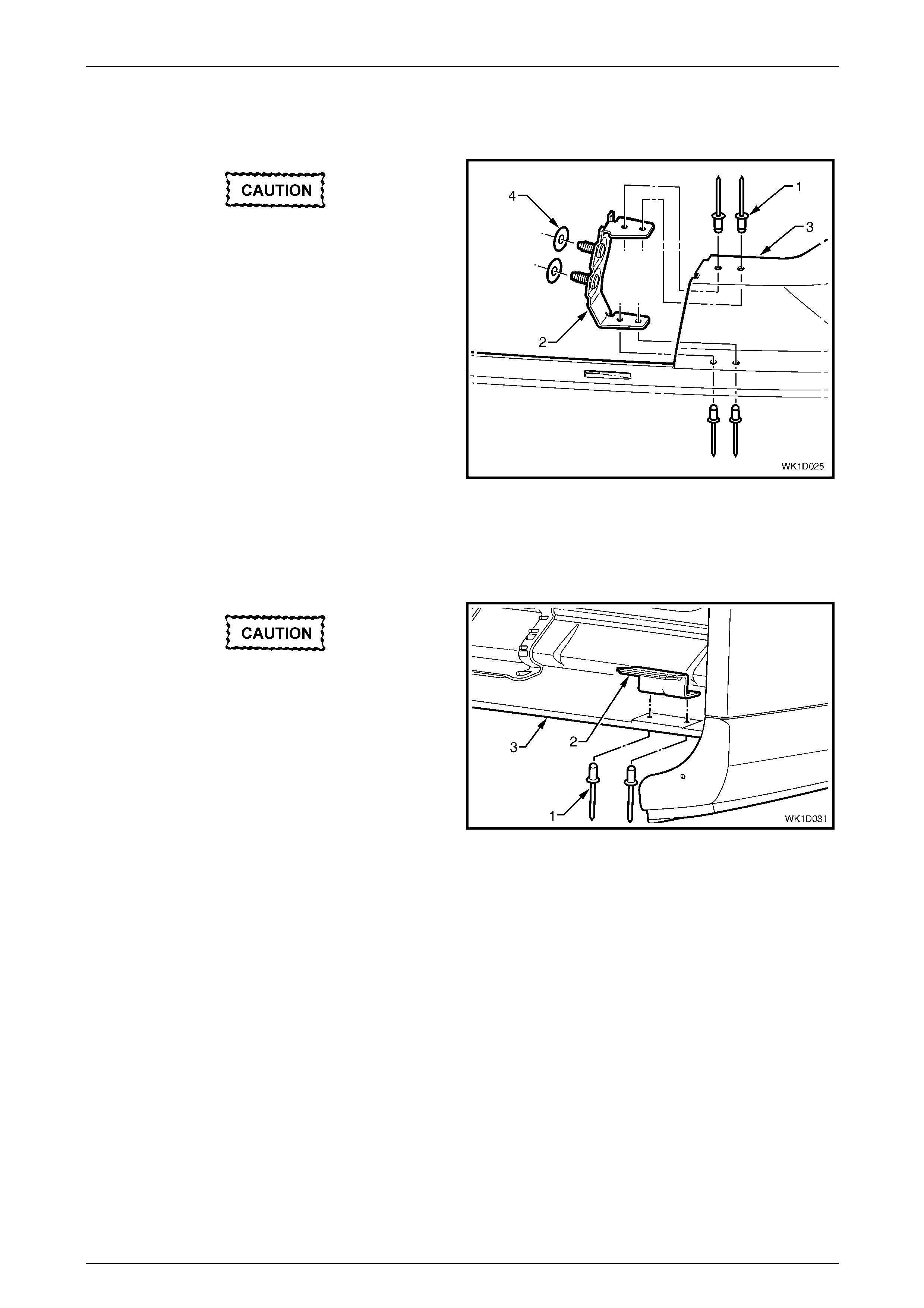
Rear Bumper Fascia Anchor Plate Assembly
Remove
If reusing the fascia assembly, take care not
to enlarge the rivet holes.
1 Using a 3mm drill-bit, remove the four rivets (1)
attaching the anchor plate assembly (2) to the fascia
assembly (3).
2 Remove the anchor plate assembl y and if required the
two seals (4).
Reinstall
Reinstallation of the rear bum per fascia anchor plate
assembly is the reverse of the removal procedure.
Figure 1D – 35
Rear Bumper Fascia Mounting Bracket Assembly, Level 5 Vehicles
Remove
If reusing the fascia assembly, take care not
to enlarge the rivet holes.
1 Using a 3mm drill-bit, remove the two rivets (1)
attaching the fascia mounting bracket assem bl y (2) to
the fascia assembly (3).
2 Remove the fascia mounting bracket assembl y.
Reinstall
Reinstallation of the rear bum per fascia mounting bracket
assembly is the reverse of the removal procedure. Figure 1D – 36
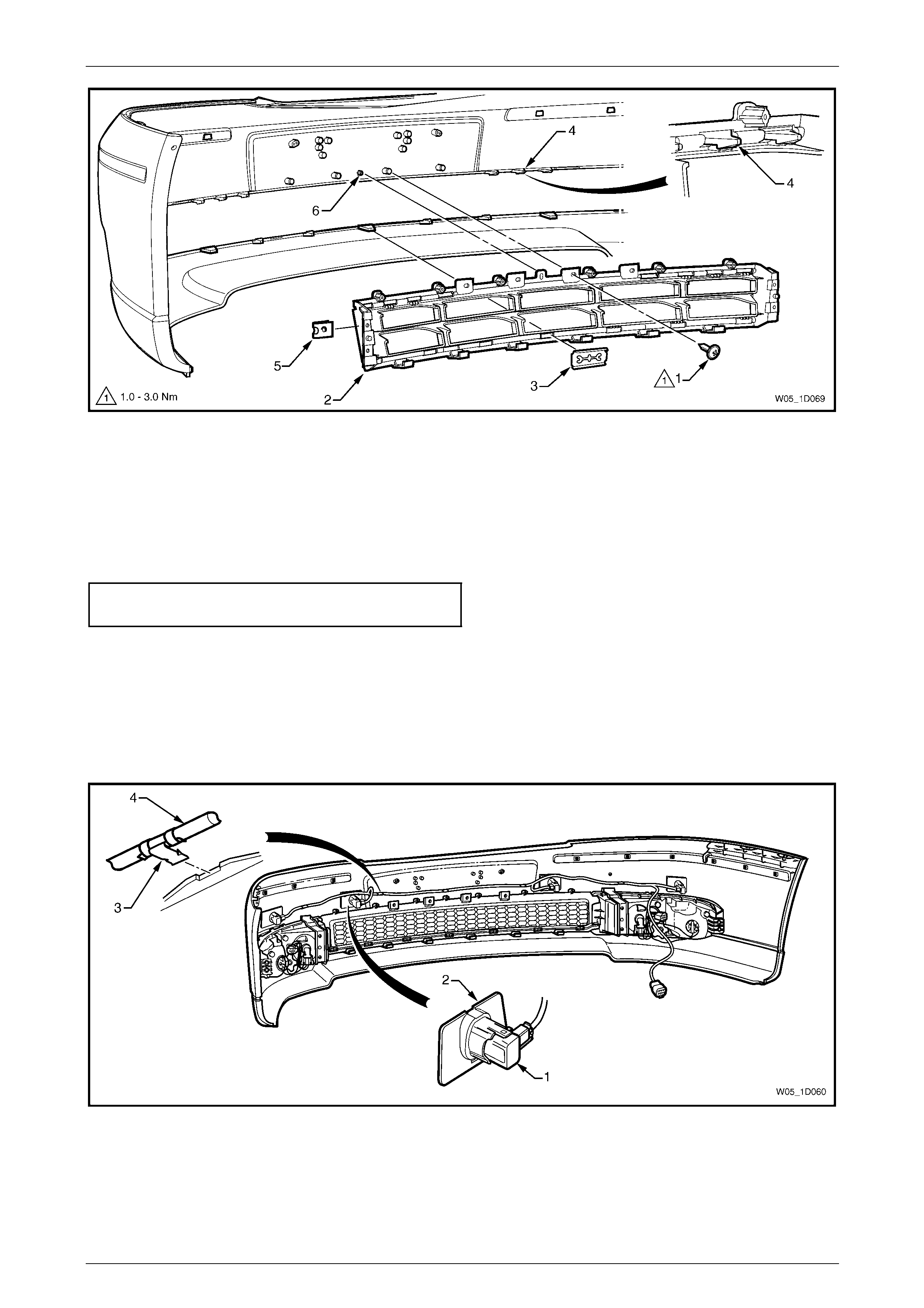
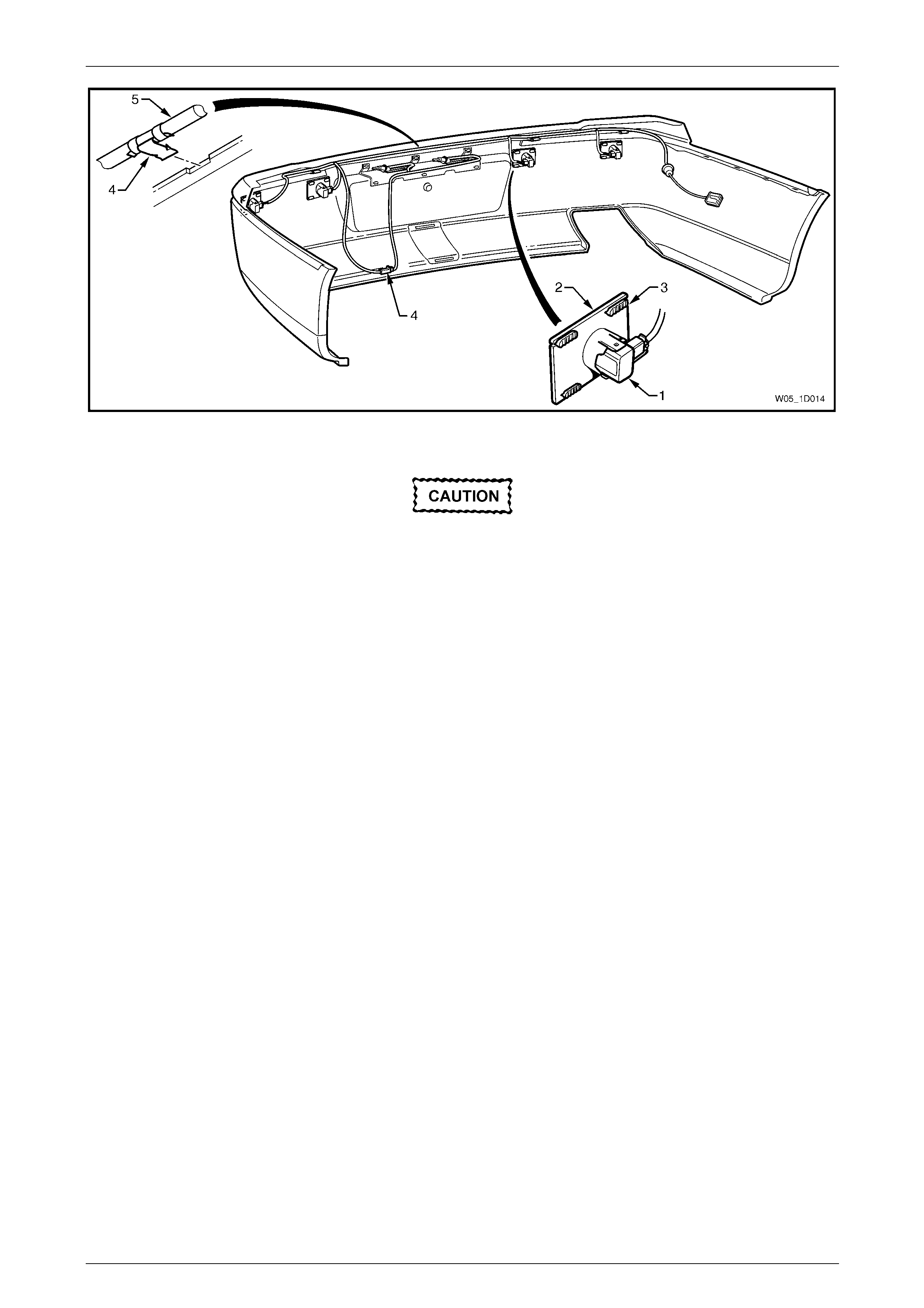
Rear or Dual Park Assist Rear Components
Four sensor assemblies and their associated wiring are fitted to the rear bumper fascia as sembly as part of the Rear
Park Assist (RPA) or Dual Park Assist (DPA), refer to Figure 1D – 37.
Each rear object sensor assembly (1) is fitted into a rear object sensor housing (2) which is attached to the fascia
assembly with four heat-stakes (3). Holes in the fascia expose the sensor and housing faces. Four retaining clips (4)
secure the rear object sensor wiring har ness assembly (5) to the fascia assembly which is routed across to the left-hand
side.
Bumper Bars Page 1D–32
Page 1D–32
Figure 1D – 37
• The fascia assembly and sensors must be
correctly aligned if the system is to
operate correctly. Sensors may be
damaged if dropped or subjected to
temperatures abo ve 80°C.
• If repainting a fascia assembly, the
sensors and rings MUST be removed.
Paint must not be applied to any part of a
sensor, including the exposed coloured
surface. Paint film applied to the exposed
surface will render the sensor inoperable
as the paint film restricts the sensor’s
ultra-sonic signal. If a sensor is damaged,
it must be replaced.
• Replacement housings are supplied
unpainted. As they are partially exposed
when installed, they will require
painting using the same procedures for
painting the bumper fascia, refer to
2 Paint Systems.
NOTE
It is preferable to paint the housings and bumper
fascia separately to avoid adhesion problems.
Assemble the housings onto the bumper fascia
once the paint has cured.
Replacement bumper fascias are sup pli ed without holes and must be modified by following the procedures in
New Fascia Modification.
For further information on rear park assist, refer to Section 12F1 Rear Park Assist.
Bumper Bars Page 1D–33
Page 1D–33
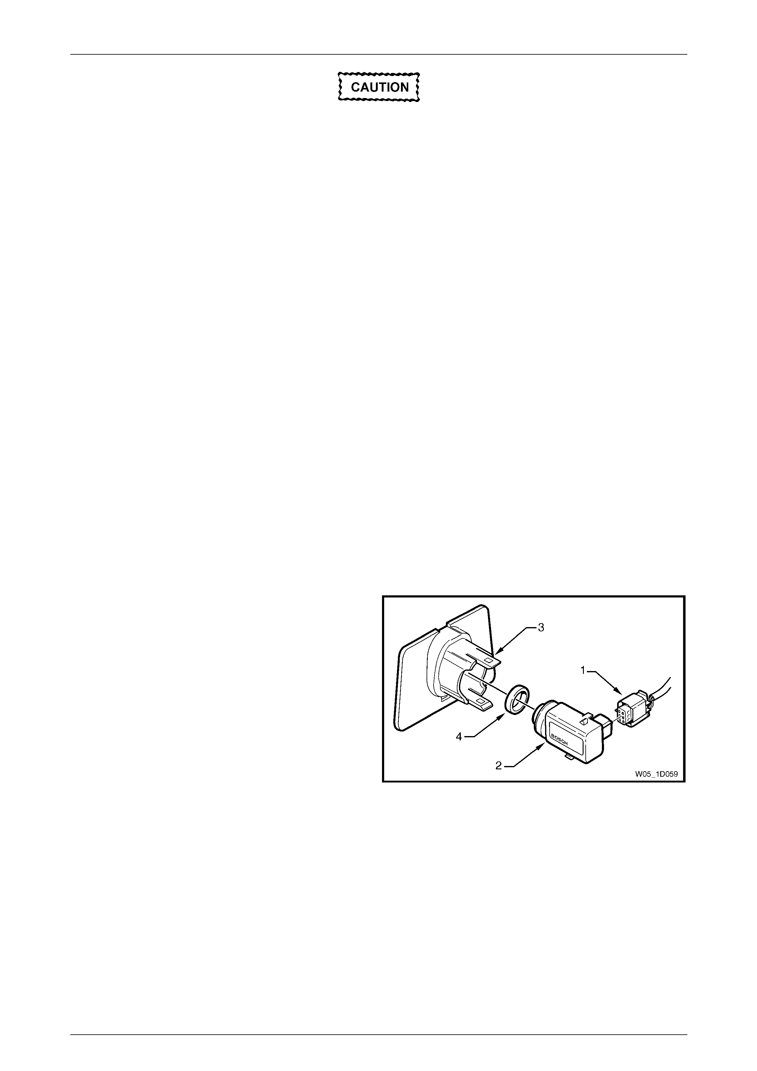
Remove
1 Remove the wiring connector (1) from the rear object
sensor assembly (2).
2 Using a flat blade screwdriver, lever the upper and
lower tabs (3) of the rear object sensor housing and
slide the sensor from the hous ing.
3 If required, remove the rear object sensor ring (4) from
the sensor.
4 Remove the housing from the bumper fascia by cutting
the heat-stakes (5).
NOTE
If the housing is to be reinstalled on the same
bumper fascia, only cut the minimum amount of
material to enable removal, ensuring enough
remains to reattach the housing.
5 Remove the wiring harness from the bumper fascia by
prising the four retaining clips from the bump er fascia
with a fine flat blade screwdriver.
Figure 1D – 38
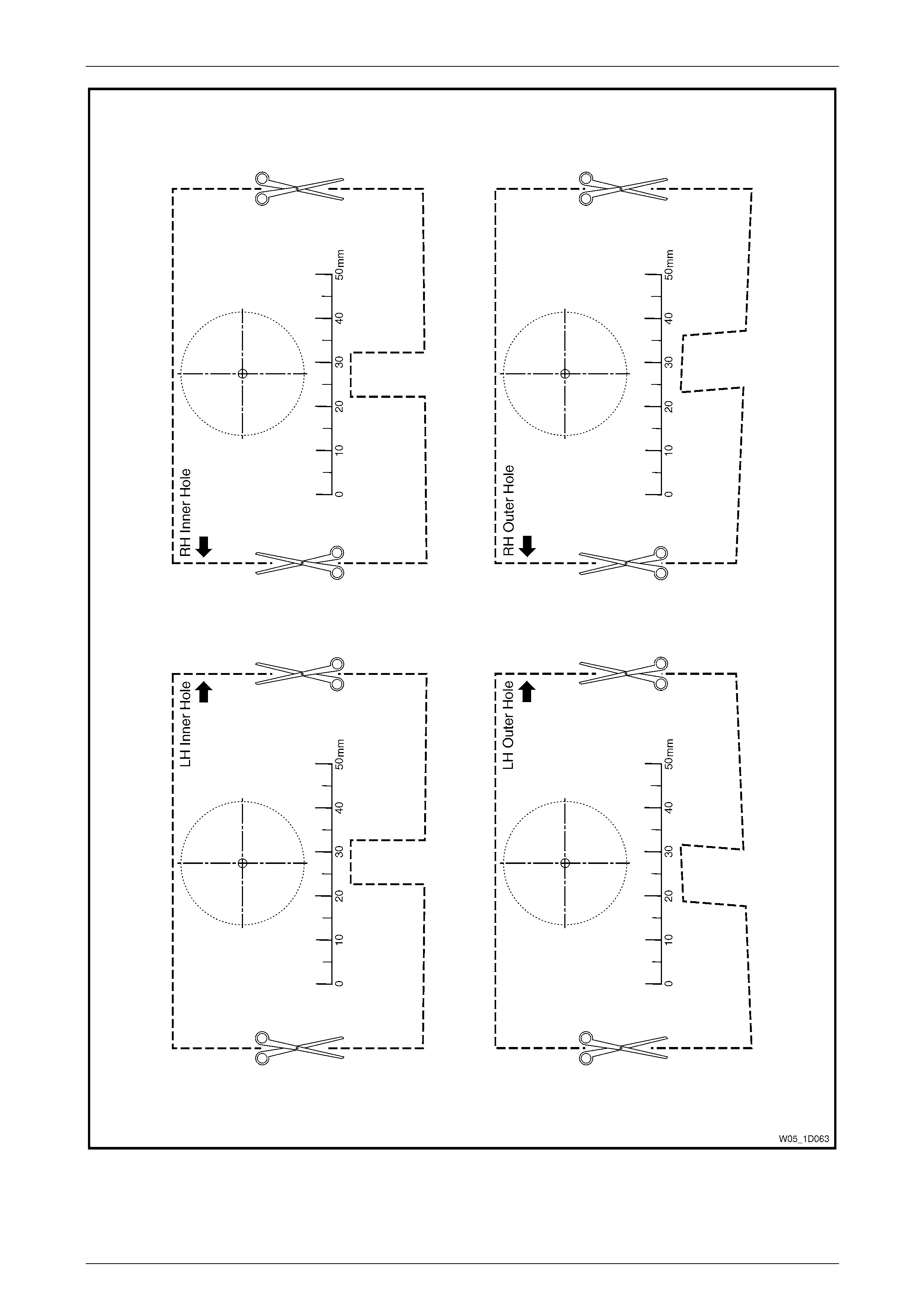
New Fascia Modification
1 Print and cut-out the templates shown in Figure 1D – 42.
When printing, in the printer dialog box
ensure the Shrink Oversize Pages To Paper
Size box is not ticked. Always check the scale
on the template to ensure it has printed the
correct size.
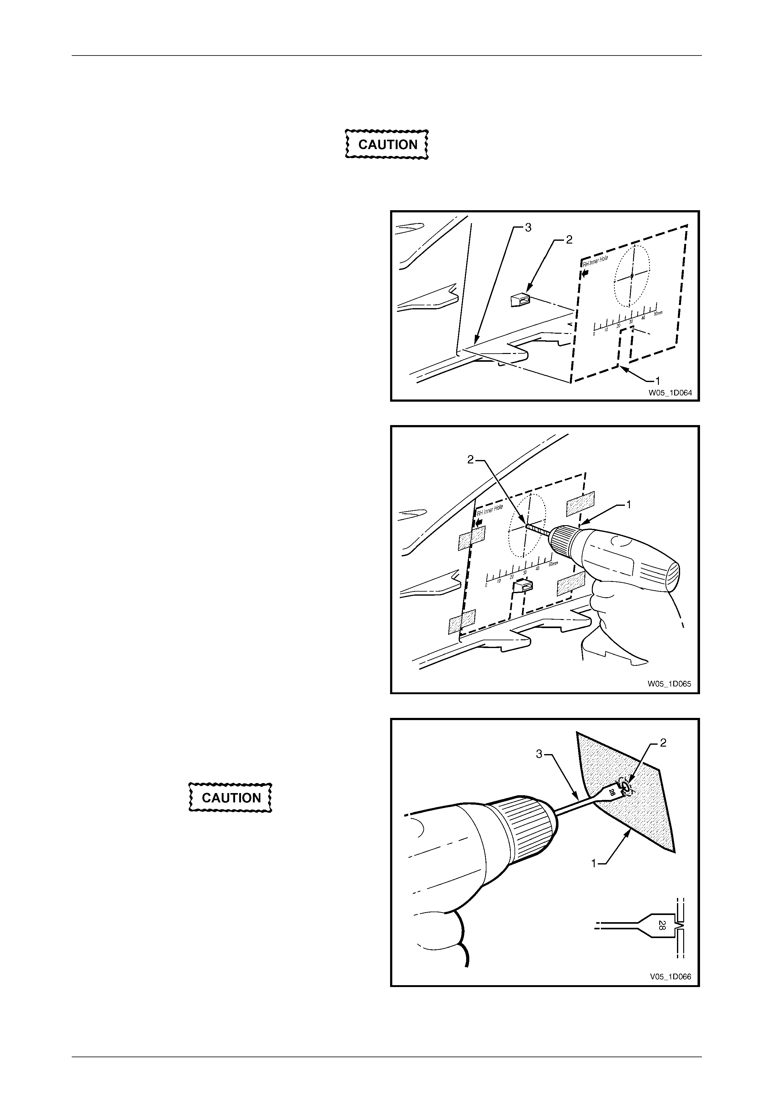
2 Tape the template (1) to the inside of the rear bumper
fascia, aligning the edges between the upper (2) and
lower (3) heat stakes.
Figure 1D – 39
Bumper Bars Page 1D–34
Page 1D–34
3 From the inside of the fascia, drill a 2 mm diameter
pilot hole at the template (1) centre point (2).
Figure 1D – 40
4 Place masking tape (1) on the outside surface of the
fascia in the area to be drilled.
5 From the outside of the fascia, enlarge the pi lot hole
(2) to 24 mm using a wood spade drill bit (3).
• Only use a wood spade drill bit as a
normal drill bit or hole saw may damage
the rear fascia.
• Ensure the spade drill bit remains square
with the rear fascia.
• Use a slow drill speed to avoid damaging
the rear fascia.
6 Debur the edges of the hole if necessary.
7 As required, paint the bumper fascia an d sensor
housings prior to reassembly, refer to
2 Paint Systems. Figure 1D – 41
Bumper Bars Page 1D–35
Page 1D–35
Figure 1D – 42
Bumper Bars Page 1D–36
Page 1D–36
Reinstall
NOTE
It is advisable to paint the bumper fascia and
housings separately prior to attachment to the
bumper fascia, refer to 2 Paint Systems.
1 Position the housing onto the four stakes, en suring it is
seated against the fascia surface and correctly
protrudes through the hole.
2 Using a soldering iron, melt the end of the heat-stakes.
Hold the housing in position until the plastic has
cooled.
NOTE
Do not over-melt the material and ensure the
housing is fixed securely.
NOTE
If the housing is being reinstalled onto the same
bumper fascia, ensure there is enough material
to provide secure attachment. If required, cut a
thin piece of bumper material from an
inconspicuous place an d use as a filler, melting it
into the heat-stake. Figure 1D – 43
3 Fit the ring onto the end of the sensor, refer to F igure 1D – 38.
4 Insert the sensor into the housing firmly, ensuring the tabs are locked into the sensor.
5 Repeat as required.
6 Following installation of the bumper fascia assembly, test the rear park assist for correct operation,
refer to Section 12F1 Rear Park Assist.
Reinstall
Reinstallation of the rear bum per fascia assembly is the reverse of the removal procedure, noting the foll owing:
1 Refinish the bumper fascia, refer to 2 Paint Systems.
2 To avoid damaging the bump er fascia an d/or vehicle, fit the fascia assembly onto the vehicle with the aid of an
assistant.
3 Tighten the fasteners to the correct torque specification.
Rear bumper fascia assembly to
rear wheelhouse liner attaching
screw torque specification...........................1.0 – 3.0 Nm
Rear bumper fascia assembly to
rear bumper fascia guide assembly
attaching screw torque specification...........1.0 – 3.0 Nm
Rear bumper fascia assembly
attaching nut torque specification................6.0 – 9.0 Nm
4 Test the rear park assist for correct operation, refer to Section 12F1 Rear Park Assist .
Bumper Bars Page 1D–37
Page 1D–37
3.7 Rear Bumper Fascia Guide Assembly
LT Section No. — 07–525
Remove
1 Remove the rear bumper fascia, refer to 3.6 Rear Bumper Fascia Assem bly
NOTE
It may be possible to remove one side of the
bumper fascia and carefully move it out far
enough to gain access to the guide assembly.
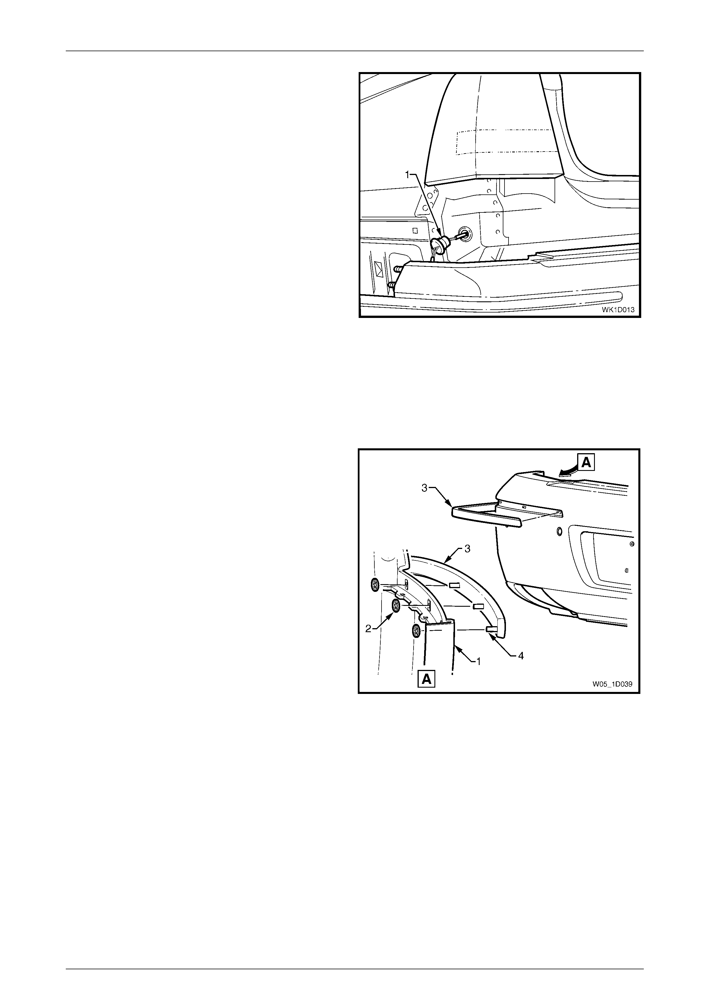
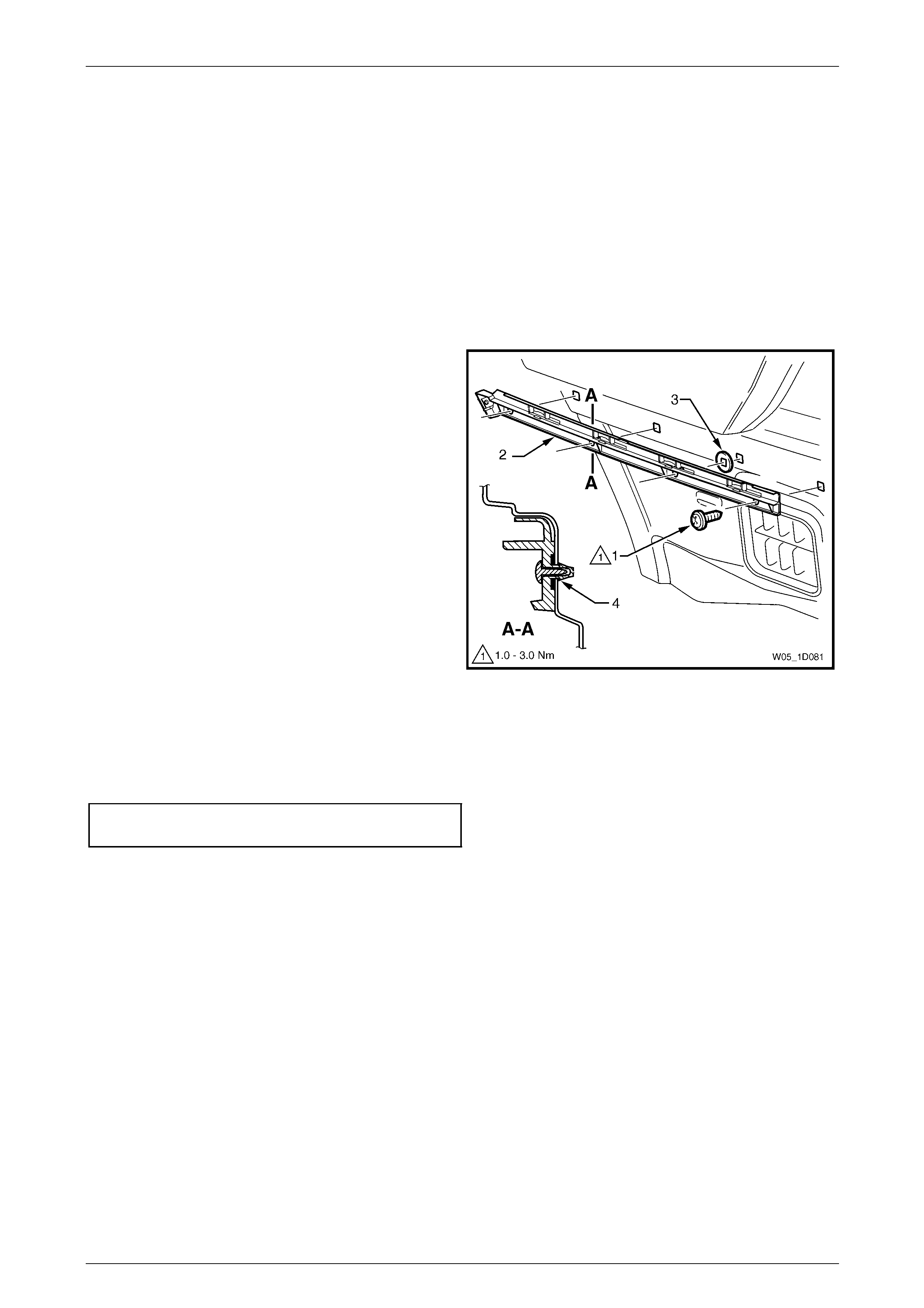
2 Remove the screw (1), four places, attaching the guide
assembly (2).
3 Prise the guide assembly out to detach it from the
vehicle.
NOTE
If required, remove the quarter inner rear side
carpet and using a fine flat-blade screwdriver,
depress the guide rail retaining tabs (4), four
places. Refer to Section 1A8 Headlining and
Interior Trim for the rear side carpet removal
procedure.
Ensure the seal (3), four places, is removed with
the guide assembly.
Figure 1D – 44
Reinstall
Reinstallation of the rear bum per fascia guide assembly is the reverse of the removal procedure. T ighten the screws to
the correct torque specification.
Rear bumper fascia guide assembly
attaching screw torque specification...........1.0 – 3.0 Nm
Bumper Bars Page 1D–38
Page 1D–38
3.8 Rear Bumper Fascia Centre Support
LT Section No. — 07–525
Remove
1 Remove the rear bumper fascia assembly, refer to 3.6 Rear Bumper Fascia Assembly.
2 Remove the tail lamp assembly, refer to Section 12B Lighting System.
NOTE
It is only necessar y to remove the tail lam p on the
side the rear bumper fascia support is being
removed.
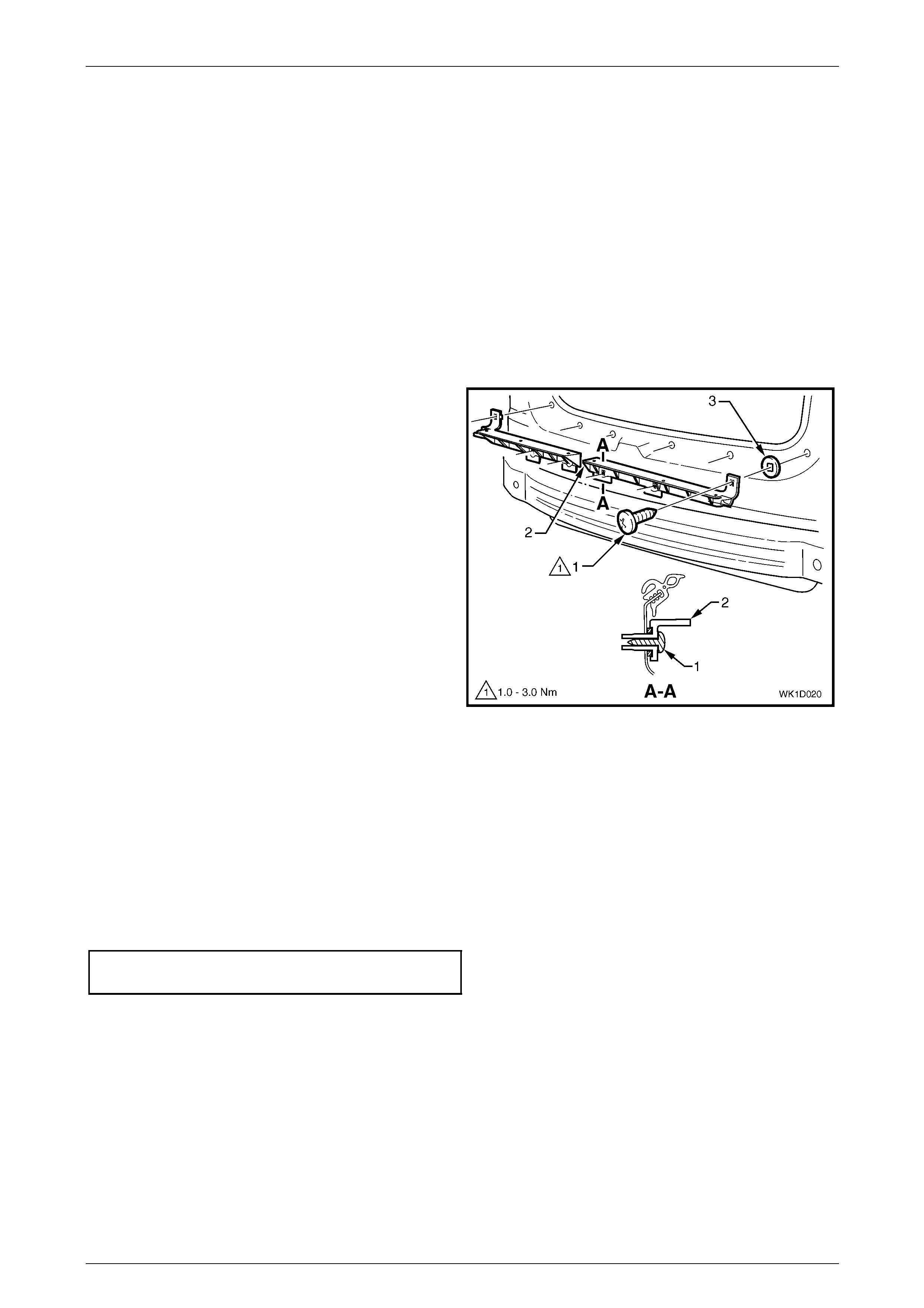
3 Remove the screw (1), three places, attaching the rear
bumper fascia centre support (2) to the vehic le.
4 Prise the support from the vehicle. Repeat for the
opposite side as required.
NOTE
Ensure the seal (3), three places, is removed
with the centre support.
Figure 1D – 45
Reinstall
Reinstallation of the rear bum per fascia centre support is the reverse of the removal procedure. Tighten the screws to the
correct torque specification.
NOTE
Ensure the seals are correctly fitted to the
support prior to installation. T ighten the screws to
the correct torque specification.
Rear bumper fascia centre support
attaching screw torque specification...........1.0 – 3.0 Nm
Bumper Bars Page 1D–39
Page 1D–39
3.9 Rear Bumper Impact Bar
LT Section No. — 07–525
Remove
1 Remove the rear bumper fascia assembly, refer to
3.6 Rear Bumper Fascia Assembly.
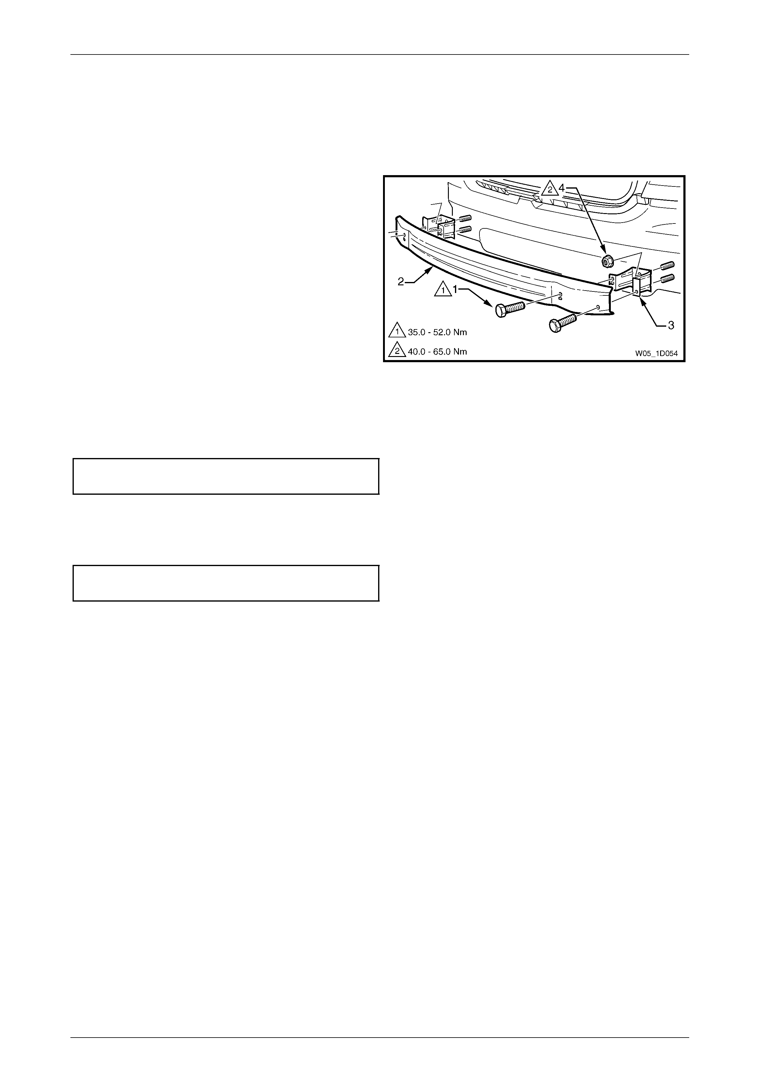
2 Remove the screws (1), two places each side,
attaching the rear bumper im pact bar (2) to the rear
bumper impact bar bracket assembly (3).
3 Remove the bar.
4 If required, remove the nut (4), two places, attaching
the bracket assembly to the vehicle and remove the
bracket.
Figure 1D – 46
Reinstall
1 Fit the bracket assemblies in position and attach the nuts. Tighten the screws to the correct torque specification.
Rear bumper impact bar bracket assembly
attaching nut torque specification............40.0 – 65.0 Nm
2 Fit the bar to the bracket assemblies and fit each screw. Do not tighten.
3 When all screws are installed, check the bar is centralised and tighten the screws to the correct torque
specification.
Rear bumper impact bar attaching
screw torque specification.......................35.0 – 52.0 Nm
4 Refit the rear bumper fascia, refer to 3.6 Rear Bumper Fascia Assembly.

Bumper Bars Page 1D–40
Page 1D–40
4 Torque Wrench Specifications
Front Fog And Cornering Lamp Metal Bracket Attaching Screw...1.0 – 3.0 Nm
Front Fog And Cornering Lamp Assembly Attaching Screw..........1.0 – 3.0 Nm
Lower Radiator Grille Attaching Screw..........................................1.0 – 3.0 Nm
Front Bumper Fascia Assembly To Front Wheelhouse
Liner Screw ..................................................................................1.0 – 3.0 Nm
Front Bumper Fascia Assembly To Front Bumper Fasci a Guide
Assembly Screw ...........................................................................1.0 – 3.0 Nm
Front Bumper Impact Bar Assembly Attaching Nut ..................20.0 – 30.0 Nm
Rear Bumper Fascia Assembl y To Rear Wheelhouse Liner
Attaching Screw ...........................................................................1.0 – 3.0 Nm
Rear Bumper Fascia Assembl y To Rear Bu mper F ascia Guide
Assembly Attaching Screw ........................................................... 1.0 – 3.0 Nm
Rear Bumper Fascia Assembly Attaching Nut ..............................6.0 – 9.0 Nm
Rear Bumper Fascia Guide Assembly Attaching Screw ...............1.0 – 3.0 Nm
Rear Bumper Fascia Centre Support Attaching Screw .................1.0 – 3.0 Nm
Rear Bumper Impact Bar Bracket Assembly Attaching Nut ......40.0 – 65.0 Nm
Rear Bumper Impact Bar Attaching Screw ...............................35.0 – 52.0 Nm