
Exterior Ornamentation Page 1A9–1
Page 1A9–1
Section 1A9
Exterior Ornamentation
ATTENTION
Before performing any service operation or other procedure described in this Section, refer to 00 Warnings,
Cautions and Notes for correct w o rkshop practices with regard to safety and/or property damage.
1 General Information...............................................................................................................................2
1.1 Pictorial Index ........................................................................................................................................................ 2
Statesman............................................................................................................................................................... 3
Caprice.................................................................................................................................................................... 5
2 Service Operations.................................................................................................................................7
2.1 Hood Emblem......................................................................................................................................................... 7
Remove................................................................................................................................................................... 7
Reinstall.................................................................................................................................................................. 7
2.2 Lower Fender Name Plate..................................................................................................................................... 8
Remove................................................................................................................................................................... 8
Reinstall.................................................................................................................................................................. 8
2.3 Fender Name Plate................................................................................................................................................. 9
Remove................................................................................................................................................................... 9
Reinstall.................................................................................................................................................................. 9
2.4 Rear Compartment Lid Emblem ......................................................................................................................... 10
Remove................................................................................................................................................................. 10
Reinstall................................................................................................................................................................ 10
2.5 Rear Compartment Lid Moulding Assembly...................................................................................................... 11
Remove................................................................................................................................................................. 11
Reinstall................................................................................................................................................................ 12
2.6 Roof Joint Moulding............................................................................................................................................ 13
Remove................................................................................................................................................................. 13
Reinstall................................................................................................................................................................ 13
2.7 Door Opening Moulding...................................................................................................................................... 14
Remove................................................................................................................................................................. 14
Reinstall................................................................................................................................................................ 14
2.8 Body Side Mouldings .......................................................................................................................................... 15
Remove................................................................................................................................................................. 15
Reinstall................................................................................................................................................................ 15
2.9 Rocker Panel Moulding Assembly...................................................................................................................... 17
Remove................................................................................................................................................................. 17
Reinstall................................................................................................................................................................ 18
2.10 Centre Pillar Upper Finisher Assembly.............................................................................................................. 19
Remove................................................................................................................................................................. 19
Reinstall................................................................................................................................................................ 19
3 Torque Wrench Specifications ...........................................................................................................20
Exterior Ornamentation Page 1A9–2
Page 1A9–2
1 General Information
This Section describes the service procedures for the external ornamentation components such as emblems, name
plates, mouldings and finishers.
NOTE
MY2006 Vehicles fitted with a V6 engine do not
have any engine related exterior badging.
V6 Alloytec 190 badges in this section are for
MY2005 vehicles only.
Many of the components are affixed to the
vehicle with double-sided tape or urethane
adhesive. It is imperative the correct
materials, as specified in this Section, are
used when reassembling these parts. Use of
materials other than those specified may lead
to premature failure.
To aid in identification and service procedure location, refer to the pictorial index diagrams on the following pages.
1.1 Pictorial Index
The following diagrams provide a quick reference to the correct service procedures for exterior ornamentation
components.
Simply locate the component in the correct figure below and using the reference chart, go to the appropriate service
procedure.
Model Refer To Model Refer To
Statesman Figure 1A9 – 1 Caprice Figure 1A9 – 2
Exterior Ornamentation Page 1A9–3
Page 1A9–3
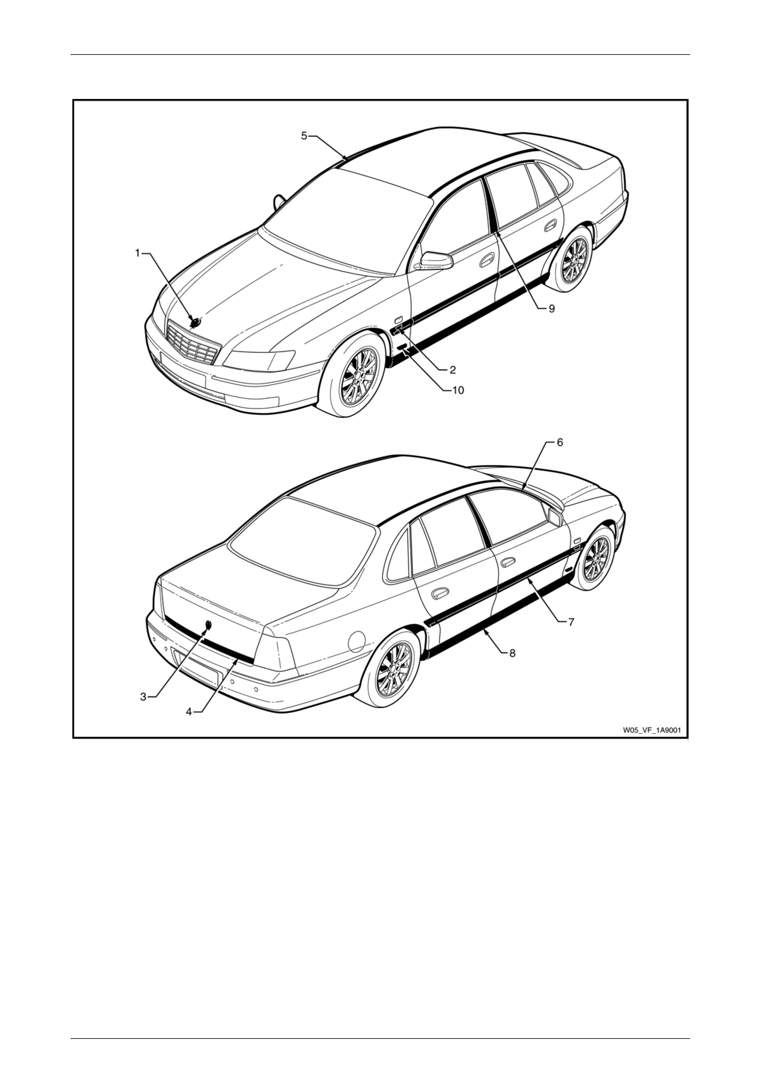
Statesman
Figure 1A9 – 1

Exterior Ornamentation Page 1A9–4
Page 1A9–4
Reference Chart: Statesman
Item Description Refer to
1 Hood Emblem: Holden 2.1 Hood Emblem
2 Fender Name Plate: Alloytec190, V8 2.3 Fender Name Plate
3 Rear Compartment Lid Emblem: Holden 2.4 Rear Compartment Lid Emblem
4 Rear Compartment Lid Moulding Assembly:
Statesman 2.5 Rear Compartment Lid Moulding Assembly
5 Roof Joint Moulding 2.6 Roof Joint Moulding
6 Door Opening Moulding 2.7 Door Opening Moulding
7 Body Side Moulding 2.8 Body Side Mouldings
8 Rocker Panel Moulding Assembly 2.9 Rocker Panel Moulding Assembly
9 Centre Pillar Upper Finisher Assembly 2.10 Centre Pillar Upper Finisher Assembly
10 Lower Fender Name Plate: V8 6.0 Litre 2.2 Lower Fender Name Plate
Exterior Ornamentation Page 1A9–5
Page 1A9–5
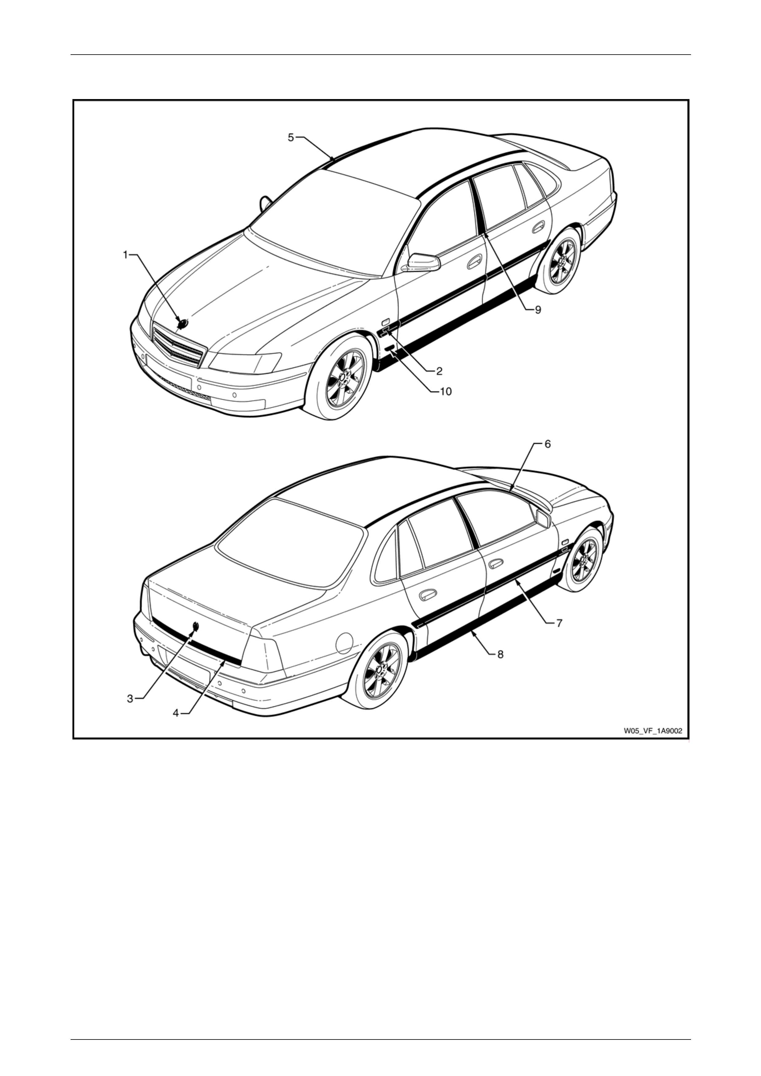
Caprice
Figure 1A9 – 2

Exterior Ornamentation Page 1A9–6
Page 1A9–6
Reference Chart: Caprice
Item Description Refer to
1 Hood Emblem: Holden 2.1 Hood Emblem
2 Fender Name Plate: Alloytec190, V8 2.3 Fender Name Plate
3 Rear Compartment Lid Emblem: Holden 2.4 Rear Compartment Lid Emblem
4 Rear Compartment Lid Moulding Assembly: Caprice 2.5 Rear Compartment Lid Moulding Assembly
5 Roof Joint Moulding 2.6 Roof Joint Moulding
6 Door Opening Moulding 2.7 Door Opening Moulding
7 Body Side Moulding 2.8 Body Side Mouldings
8 Rocker Panel Moulding Assembly 2.9 Rocker Panel Moulding Assembly
9 Centre Pillar Upper Finisher Assembly 2.10 Centre Pillar Upper Finisher Assembly
10 Lower Fender Name Plate: V8 6.0 Litre 2.2 Lower Fender Name Plate
Exterior Ornamentation Page 1A9–7
Page 1A9–7
2 Service Operations
2.1 Hood Emblem
LT Section No. — 10–150
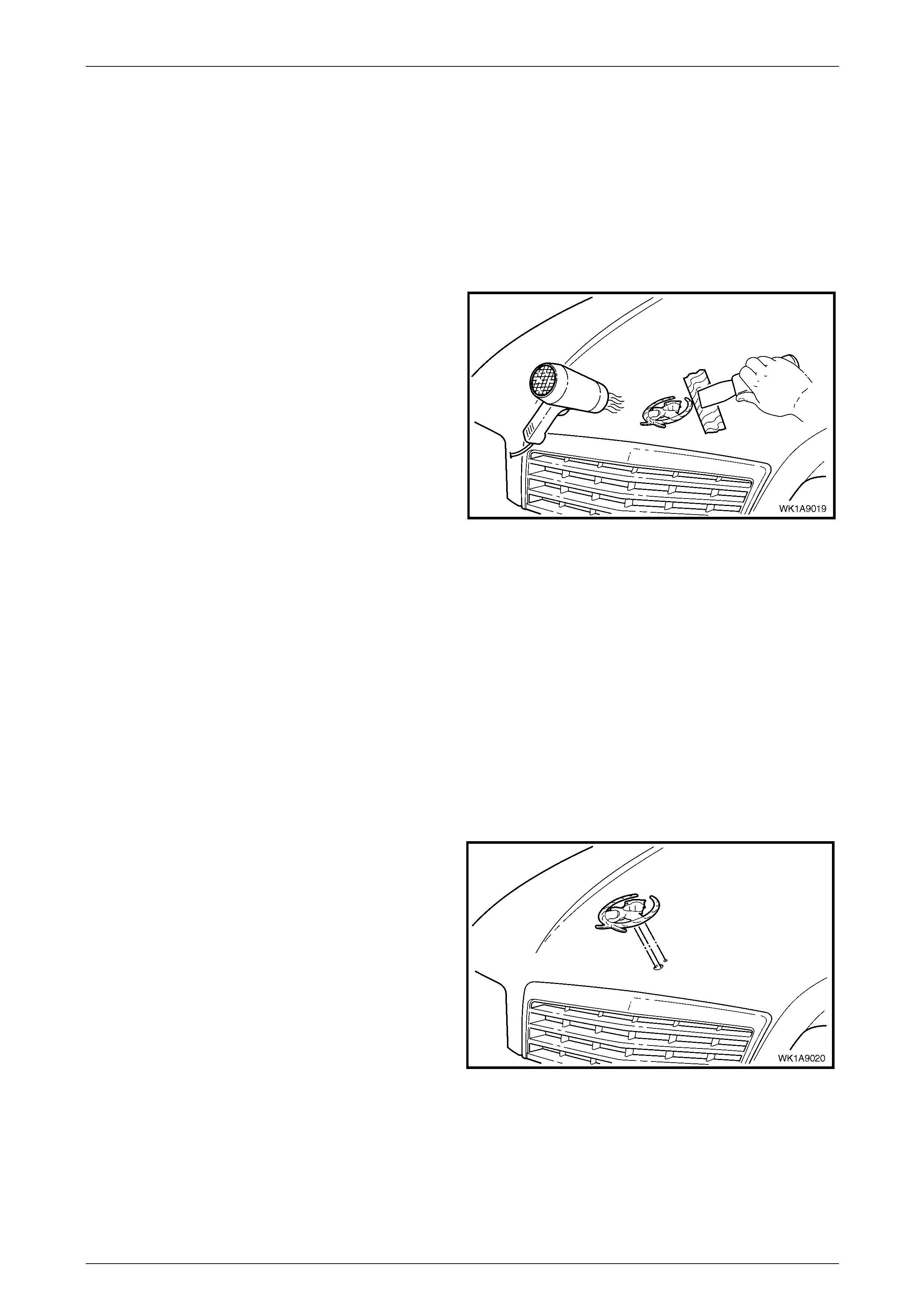
Remove
1 Protect the paint and bodywork with tape or a clean
rag.
2 To assist removal, warm the emblem with a heat-lamp
or heat-gun to soften the adhesive.
NOTE
The emblem has three locating lugs that must
not be cut if the emblem is to be reused.
3 Using a knife or paint scraper, carefully remove the
emblem assembly from the hood, cutting the double-
sided tape.
4 As required remove any remaining double-sided tape
from the emblem and/or hood and clean the surfaces
with Prepsol or equivalent. Figure 1A9 – 3
Reinstall
NOTE
If the hood has been replaced, the new part will
require drilling with emblem holes, refer to
Section 1A4 Hood and Rear Compartment Lid.
1 If reusing the emblem, apply new polyethylene double-sided tape such as 3M 4428 or equivalent to the back of the
name plate. Trim back the tape slightly away from the edge of the emblem.
2 Clean the surface of the hood with Prepsol or equivalent.
3 Remove the backing paper from the double-sided tape.
4 Align the emblem. Locate the lugs with their
corresponding holes at the centre line of the hood.
5 Affix the emblem and press firmly over the entire
emblem for at least 10 seconds to ensure sound
adhesion.
Figure 1A9 – 4
Exterior Ornamentation Page 1A9–8
Page 1A9–8
2.2 Lower Fender Name Plate
LT Section No. — 10–150
Remove
1 Protect the paint and bodywork with tape or a clean
rag.
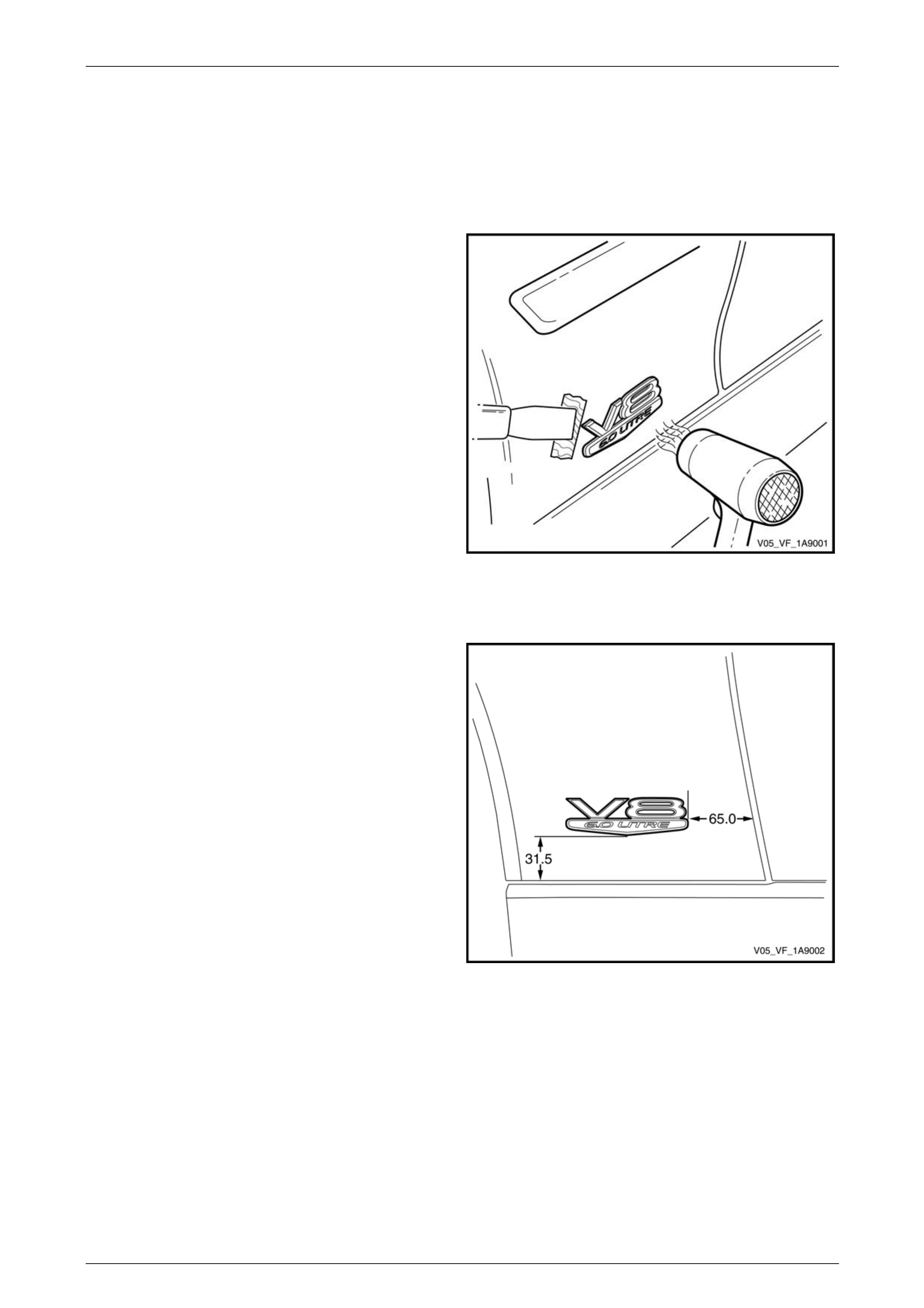
2 To assist removal, warm the name plate with a heat-
lamp or heat-gun to soften the adhesive.
3 Using a paint scraper or similar, carefully prise the
name plate from the lower fender.
4 As required remove any remaining double-sided tape
from the name plate and/or lower fender and clean the
surfaces with Prepsol or equivalent.
Figure 1A9 – 5
Reinstall
1 If reusing the name plate, apply new polyethylene
double-sided tape such as 3M 4428 or equivalent to
the back of the name plate. Trim back the tape slightly
away from the edge of the name plate.
2 Clean the surface with Prepsol or equivalent.
3 Remove the backing paper from the double-sided
tape.
4 Apply the name plate in the position shown. Ensure it
is positioned parallel to the style line.
5 Press firmly over the entire name plate for at least 10
seconds to ensure sound adhesion.
Figure 1A9 – 6
Exterior Ornamentation Page 1A9–9
Page 1A9–9
2.3 Fender Name Plate
LT Section No. — 10–150
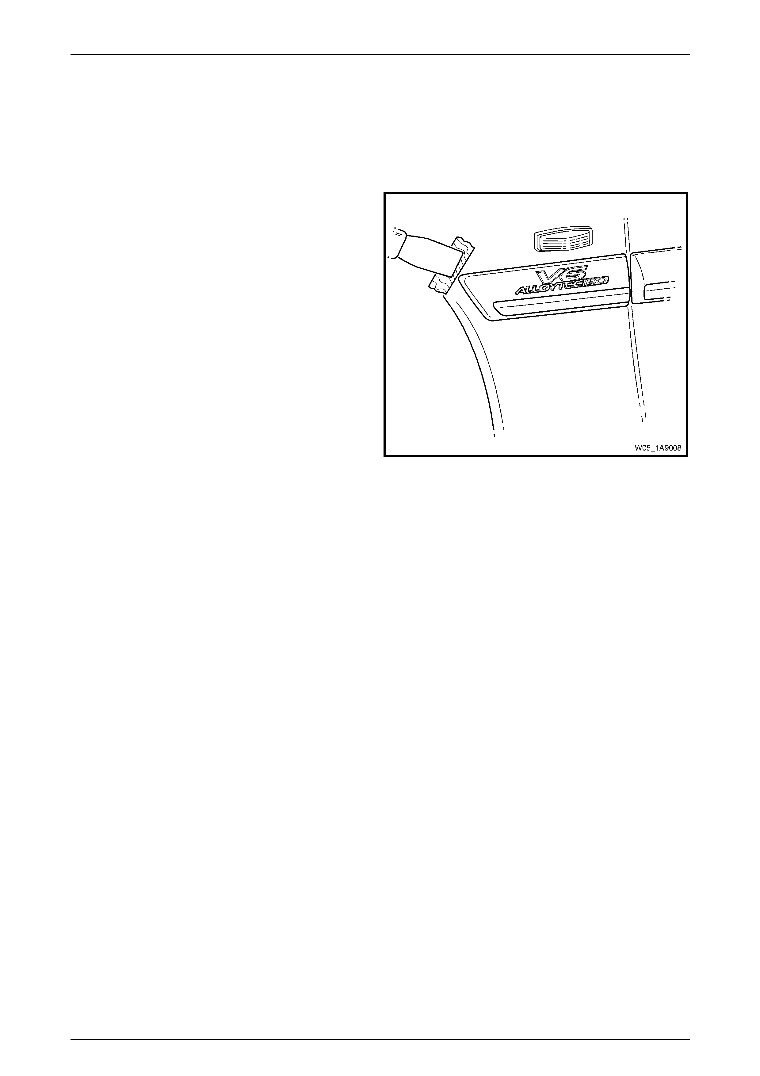
Remove
1 Protect the paint and body side moulding with tape or
a clean rag.
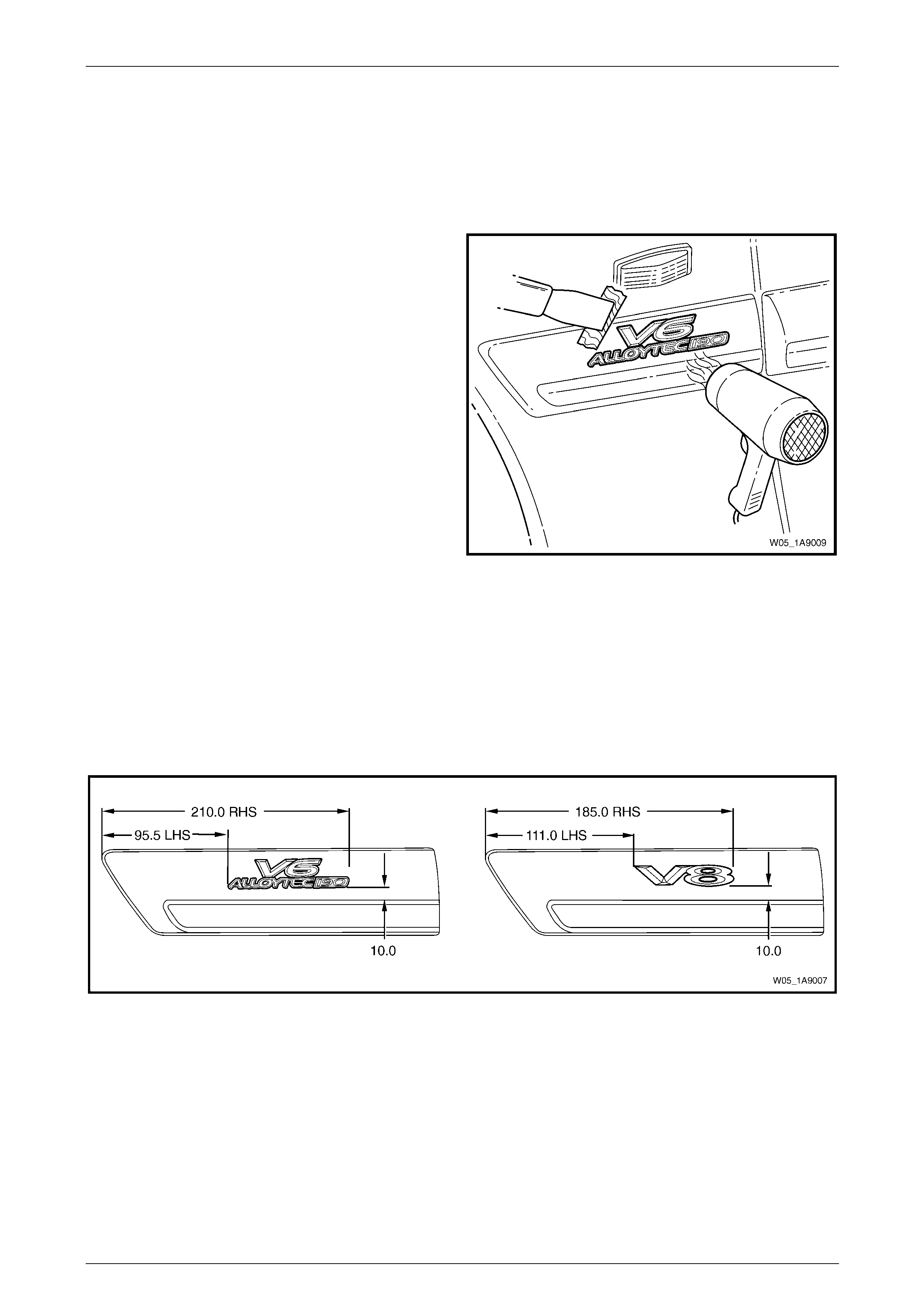
2 To assist removal, warm the name plate with a heat-
lamp or heat-gun to soften the adhesive.
3 Using a paint scraper or similar, carefully prise the
name plate from the body side moulding.
4 As required remove any remaining double-sided tape
from the name plate and/or body side moulding and
clean the surfaces with Prepsol or equivalent.
Figure 1A9 – 7
Reinstall
1 If reusing the name plate, apply new polyethylene double-sided tape such as 3M 4428 or equivalent to the back of
the name plate. Trim back the tape slightly away from the edge of the name plate.
2 Clean the body side moulding surface with Prepsol or equivalent.
3 Remove the backing paper from the double-sided tape.
4 Apply the name plate in the position shown, refer to Figure 1A9 – 8. Ensure it is positioned parallel to the moulding.
Figure 1A9 – 8
5 Press firmly over the entire name plate for at least 10 seconds to ensure sound adhesion.
Exterior Ornamentation Page 1A9–10
Page 1A9–10
2.4 Rear Compartment Lid Emblem
LT Section No. — 10–150
Remove
1 Protect the paint and bodywork with tape or a clean
rag.
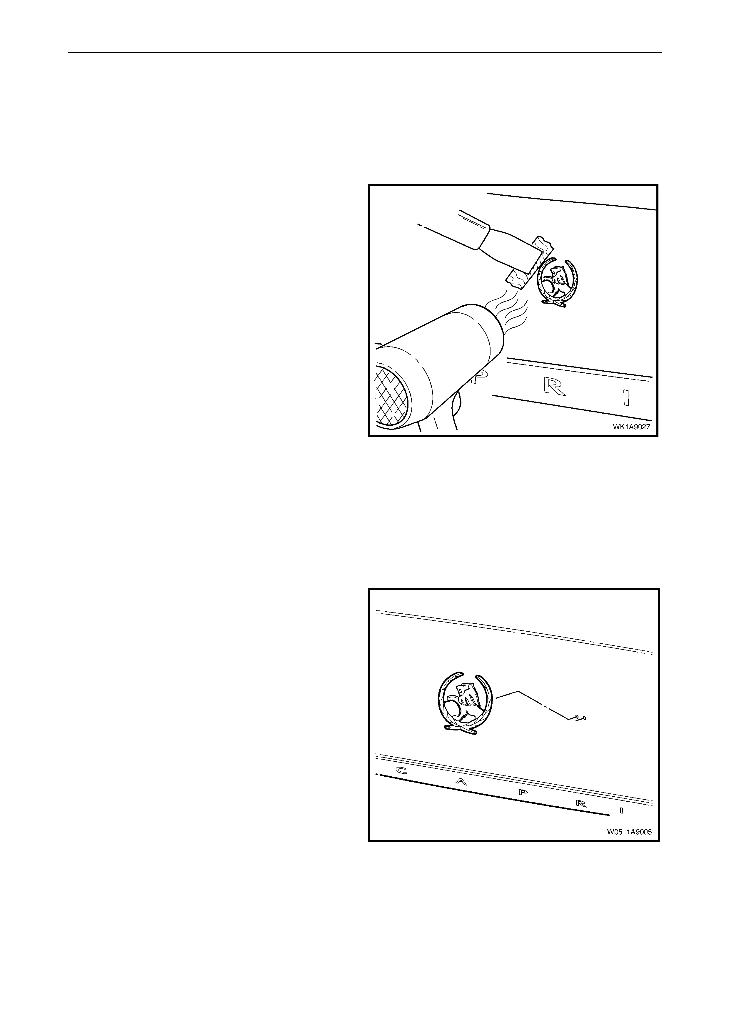
2 To assist removal, warm the emblem with a heat-lamp
or heat-gun to soften the adhesive.
NOTE
The emblem has two locating lugs that must not
be cut if the emblem is to be reused.
3 Using a paint scraper or similar, carefully prise the
emblem from the rear compartment lid.
4 As required, remove any remaining double-sided tape
from the emblem and/or rear compartment lid and
clean the surfaces with Prepsol or equivalent.
Figure 1A9 – 9
Reinstall
1 If reusing the emblem, apply new polyethylene double-sided tape such as 3M 4428 or equivalent to the back of the
emblem. Trim back the tape slightly away from the edge of the emblem.
2 Clean the panel surface with Prepsol or equivalent.
3 Remove the backing paper from the double-sided tape.
4 Apply the emblem in the position shown, ensuring the
locating pins are correctly orientated with the locating
holes in the panel surface.
5 Press firmly over the entire emblem for at least 10
seconds to ensure sound adhesion.
Figure 1A9 – 10
Exterior Ornamentation Page 1A9–11
Page 1A9–11
2.5 Rear Compartment Lid Moulding
Assembly
LT Section No. — 10–150
Remove
1 Raise the rear compartment lid.
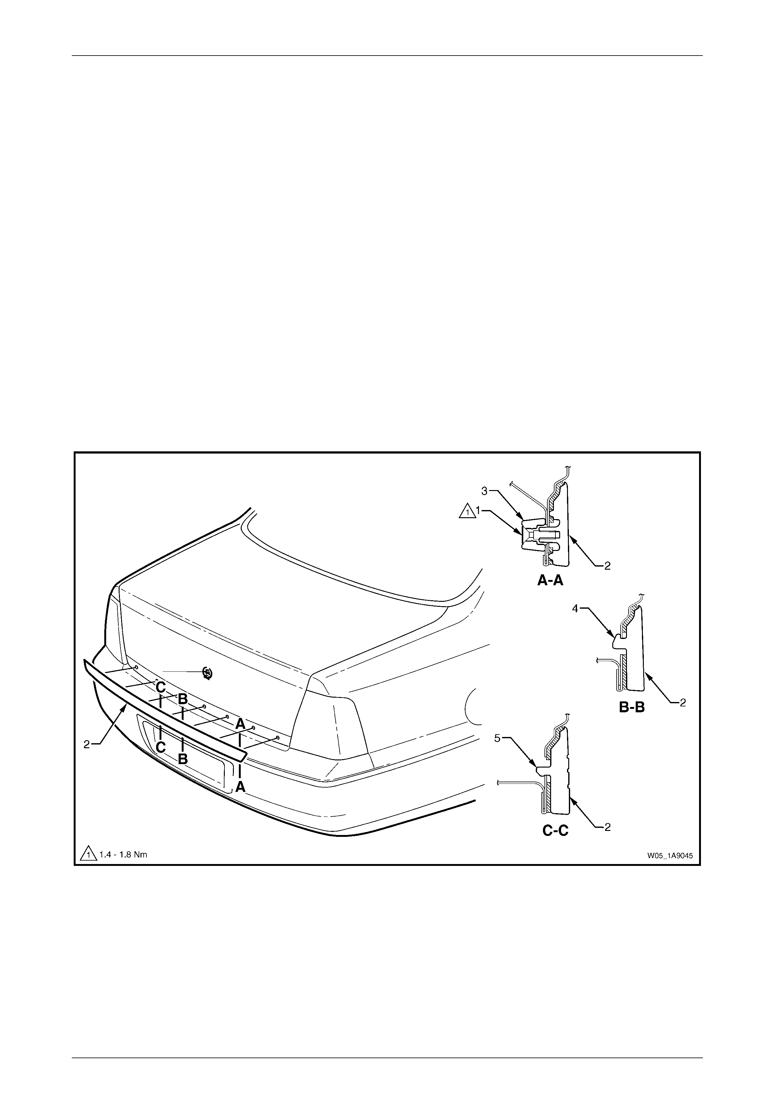
2 Remove the screw (1), two places, attaching the rear compartment lid moulding assembly (2), refer to
Figure 1A9 – 11.
3 Remove the spacers (3) that were separating the screws from the rear compartment lid sheet metal.
NOTE
Be careful not to damage the five retaining tabs
on the rear compartment lid moulding assembly if
the assembly is to be reused.
4 Beginning at each end and working towards the centre release the four outer tabs (4) by carefully manoeuvring
them down and out of the holes.
5 Release the centre tab (5) by carefully lifting and pulling the moulding assembly from the rear compartment lid.
Figure 1A9 – 11

Exterior Ornamentation Page 1A9–12
Page 1A9–12
Reinstall
Reinstallation of the rear compartment lid moulding assembly is the reverse of the removal procedure, noting the
following:
1 Align the tabs with their corresponding holes on the rear compartment lid.
2 Tighten the screws to the correct torque specification.
Rear compartment lid moulding assembly
attaching screw torque specification ...........1.4 – 1.8 Nm
Exterior Ornamentation Page 1A9–13
Page 1A9–13
2.6 Roof Joint Moulding
LT Section No. — 10–150
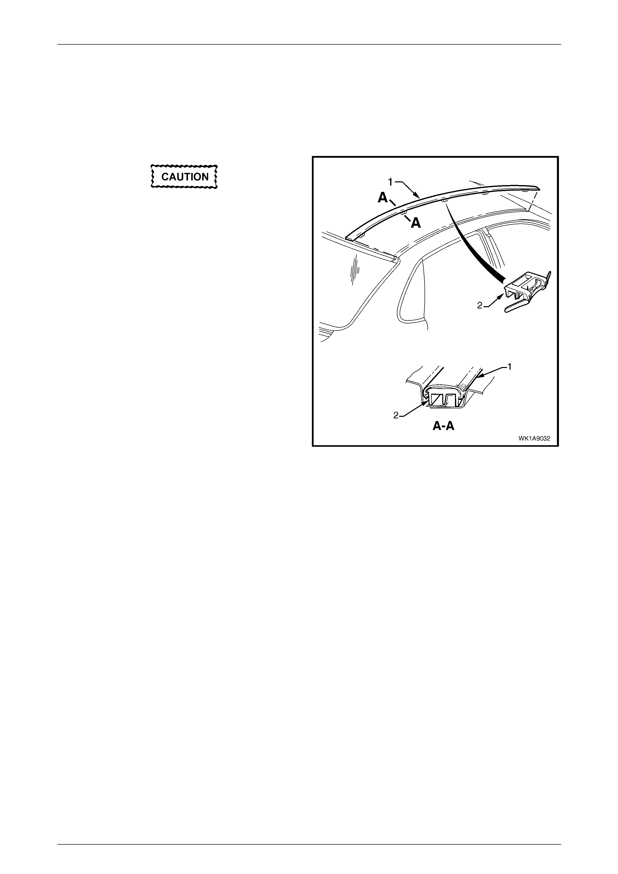
Remove
Take care as the retaining clips can easily
break. Protect the paintwork with a clean rag.
1 Beginning at the front of the vehicle, use a screwdriver
to carefully prise the roof joint moulding (1) from the
roof channel, disengaging the retaining clips (2), five
places and remove.
Figure 1A9 – 12
Reinstall
1 As required, seat the five retainers onto the roof joint moulding, spacing them evenly.
2 Seat the roof joint moulding in the roof channel and beginning at the rear, clip it in place.
3 At the front, ensure the moulding is installed under the windshield moulding cover.
Exterior Ornamentation Page 1A9–14
Page 1A9–14
2.7 Door Opening Moulding
LT Section No. — 10–150
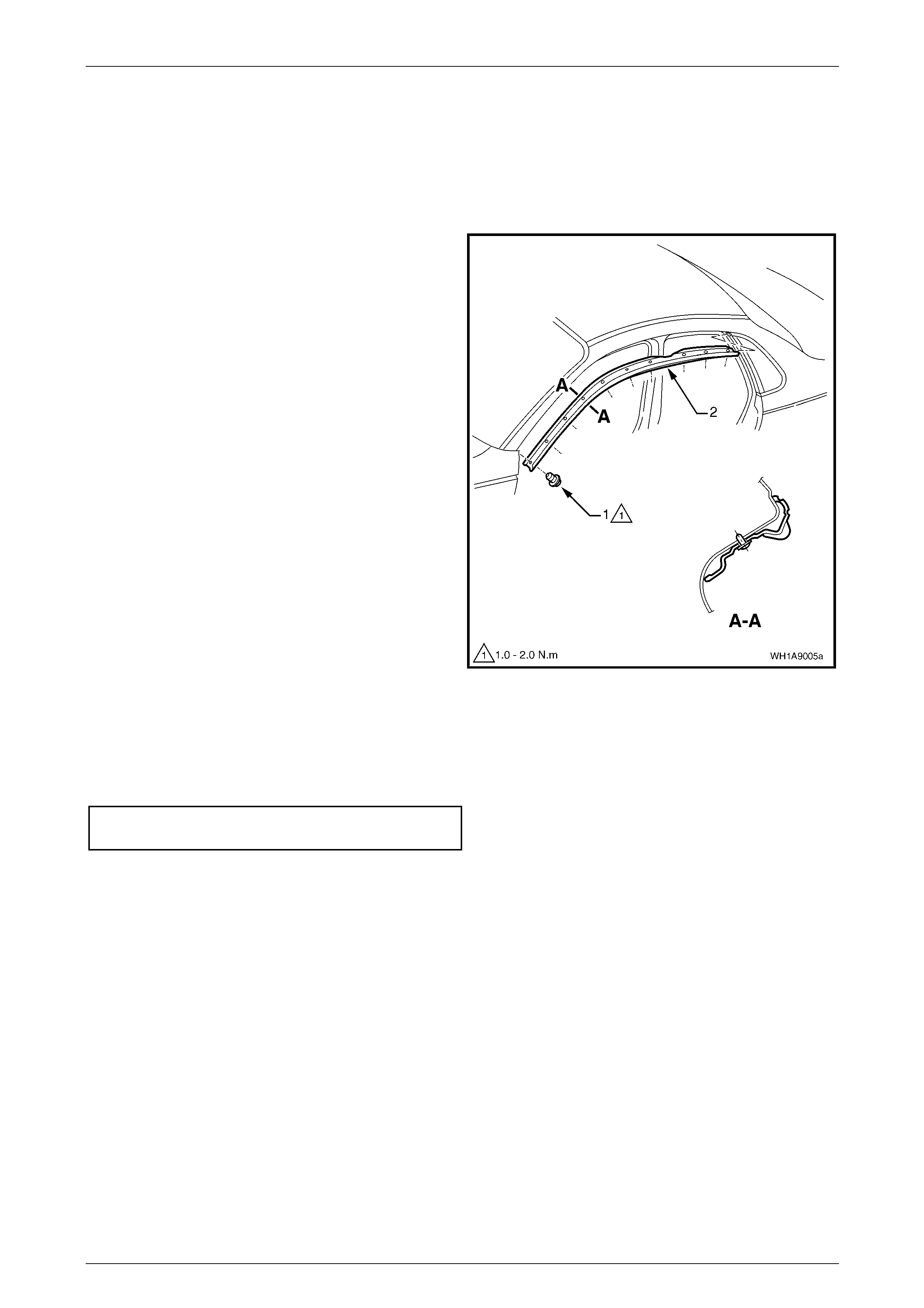
Remove
1 Open the front and rear doors on the relevant side of
the vehicle.
2 Beginning at each end and working towards the
middle, remove the screw (1), 10 places, attaching the
door opening moulding (2) to the vehicle.
3 Carefully remove the moulding.
Figure 1A9 – 13
Reinstall
Reinstallation of the door opening moulding is the reverse of the removal procedure. Tighten the screws to the correct
torque specification.
Door opening moulding attaching
screw torque specification...........................1.0 – 2.0 Nm
NOTE
The screws are encapsulated with a wax sealer. It
is recommended the screws be replaced once
removed, however if this is impractical, apply a
small amount of sealer to the end of the thread.
Exterior Ornamentation Page 1A9–15
Page 1A9–15
2.8 Body Side Mouldings
LT Section No. — 10–150
Remove
1 Protect the paint and bodywork with tape or a clean
rag.
2 Using a paint scraper or similar, begin at one end and
carefully prise the moulding from the panel, cutting
through the double-sided tape and urethane adhesive.
NOTE
As an alternative, carefully use a length of piano
wire to cut the adhesive in a similar way to
removing a windshield. If required, refer to
Section 1A6 Stationary Windows.
3 As required, remove any remaining double-sided tape
and adhesive from the moulding and/or panel.
Figure 1A9 – 14
Reinstall
1 Clean the surfaces with Prepsol or equivalent.
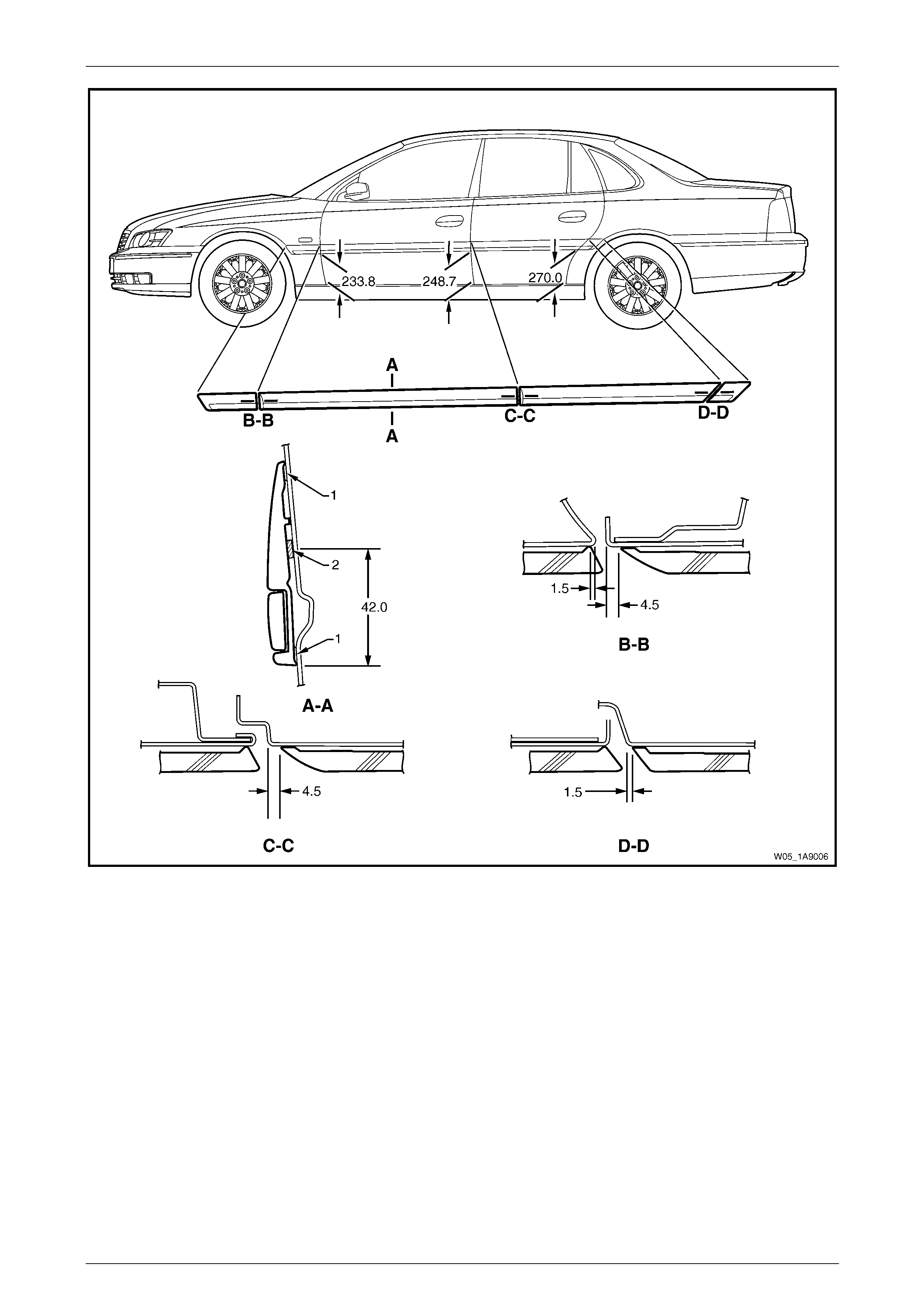
2 Place a mark on the rear edge of the fender and/or door panels at the three points shown as required. Measure in a
straight line from the lower edge of each panel, refer to Figure 1A9 – 15.
3 If a complete moulding set is to be fitted, or as required, apply a length of masking tape along the side of the
vehicle, aligning the top edge of the tape with the marks. Begin by affixing the tape at the rear of the rear door, hold
it taut and away from the vehicle, and affix it to each panel. Ensure it is straight and then smooth it down along its
length.
4 If reusing the moulding, apply new acrylic double-sided tape (1) such as 3M 5344 or equivalent along the back of
the moulding.
5 Apply a 3.0mm diameter bead of urethane adhesive such as Expandite Betaseal 554.02, Sikaflex Drive or
equivalent over the entire length of moulding (2).
NOTE
Refer to any further directions supplied with the
urethane adhesive.
6 Affix the moulding to the vehicle in the correct positions, aligning the lower edge with the masking tape (if fitted)
and:
• For the fender moulding begin at the rear edge of the fender, aligning to the dimension at Section B–B.
• For the front door moulding begin at the front edge of the front door, aligning to the dimension at Section
B–B.
• For the rear door moulding begin at the front edge of the rear door, aligning to the dimension at Section C–C.
• For the rear quarter panel moulding begin at the rear quarter panel edge closest to the rear door aligning to
the dimension at Section D–D.
7 Press firmly over the length of the moulding(s) at the double-sided tape for 10 seconds to ensure sound adhesion.
Exterior Ornamentation Page 1A9–16
Page 1A9–16
Figure 1A9 – 15
Exterior Ornamentation Page 1A9–17
Page 1A9–17
2.9 Rocker Panel Moulding Assembly
LT Section No. — 10–150
Remove
1 On the relevant side remove the rear road wheel, refer
to Section 10 Wheels and Tyres.
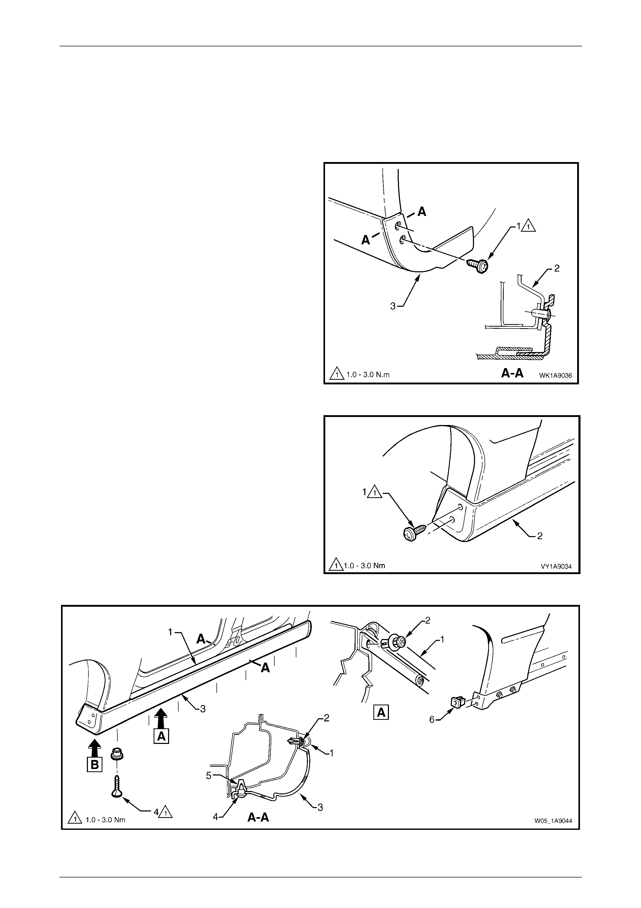
2 Remove the screw (1), two places, attaching the rear
rocker panel moulding (3) and wheelhouse liner (2).
NOTE
If required, the rear rocker panel moulding can
be removed at this stage by sliding it rearward
from the front rocker panel moulding.
Figure 1A9 – 16
3 Remove the screw (1), two places, attaching the front
rocker panel moulding (2) to the fender and liner.
4 Lift up the rocker panel weatherstrip (1) to gain access
and remove the retainer (2), nine places, attaching the
front rocker panel moulding (3), refer to
Figure 1A9 – 18.
5 Remove the screw (4), seven places, from the
retainer (5) under the moulding.
6 Remove the moulding.
7 If required, prise the nut (6), two places, from the
fender.
Figure 1A9 – 17
Figure 1A9 – 18
Exterior Ornamentation Page 1A9–18
Page 1A9–18
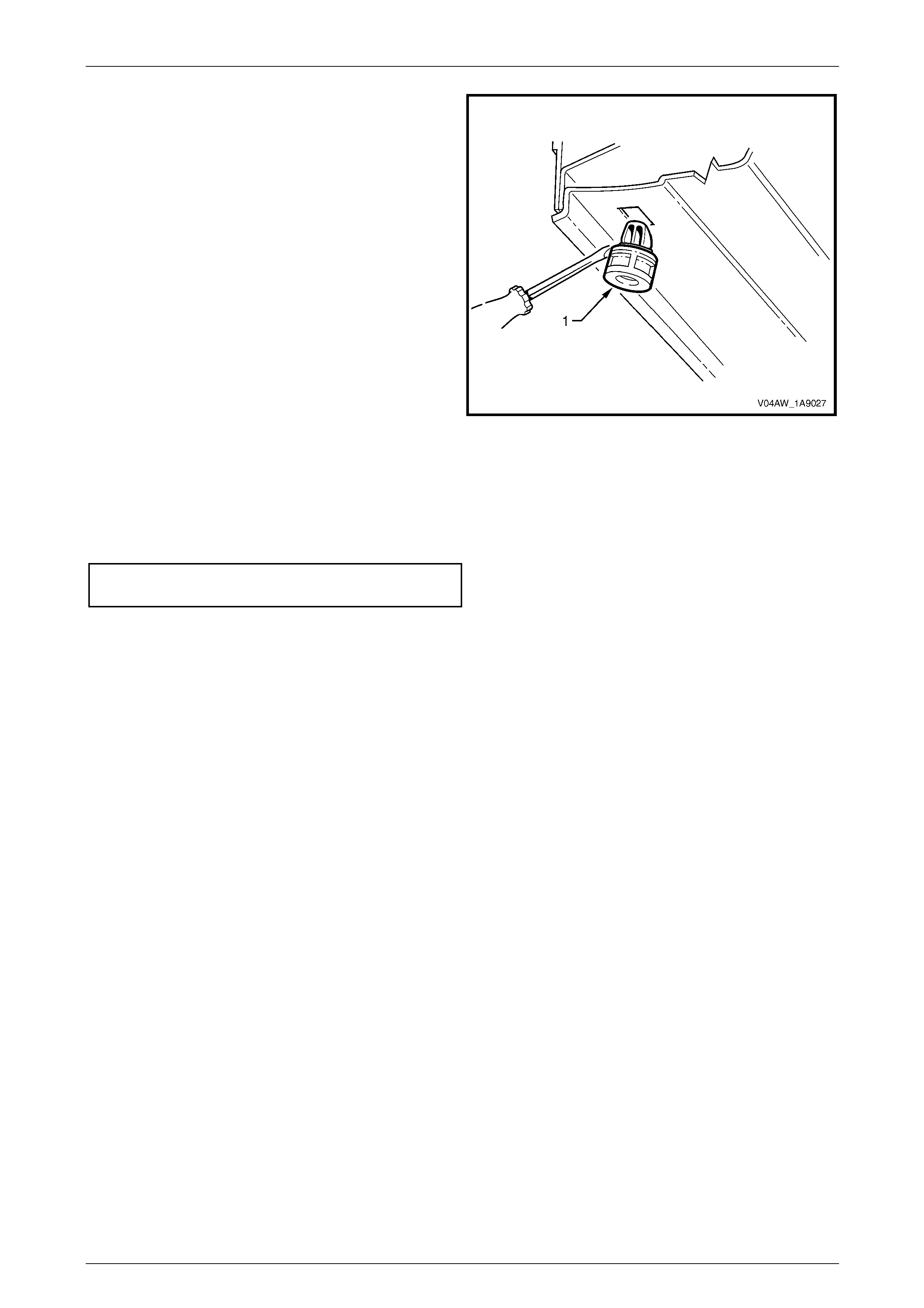
8 If required, remove the retainer (1), seven places, by
gently levering out from the body, taking care not to
damage the paint work.
Figure 1A9 – 19
Reinstall
Reinstallation of the rocker panel moulding assembly is the reverse of the removal procedure, noting the following:
1 Tighten the screws to the correct torque specification.
Rocker panel moulding attaching
screw torque specification...........................1.0 – 3.0 Nm
2 Ensure the weatherstrip is seated correctly.
Exterior Ornamentation Page 1A9–19
Page 1A9–19
2.10 Centre Pillar Upper Finisher Assembly
LT Section No. — 10–250
Remove
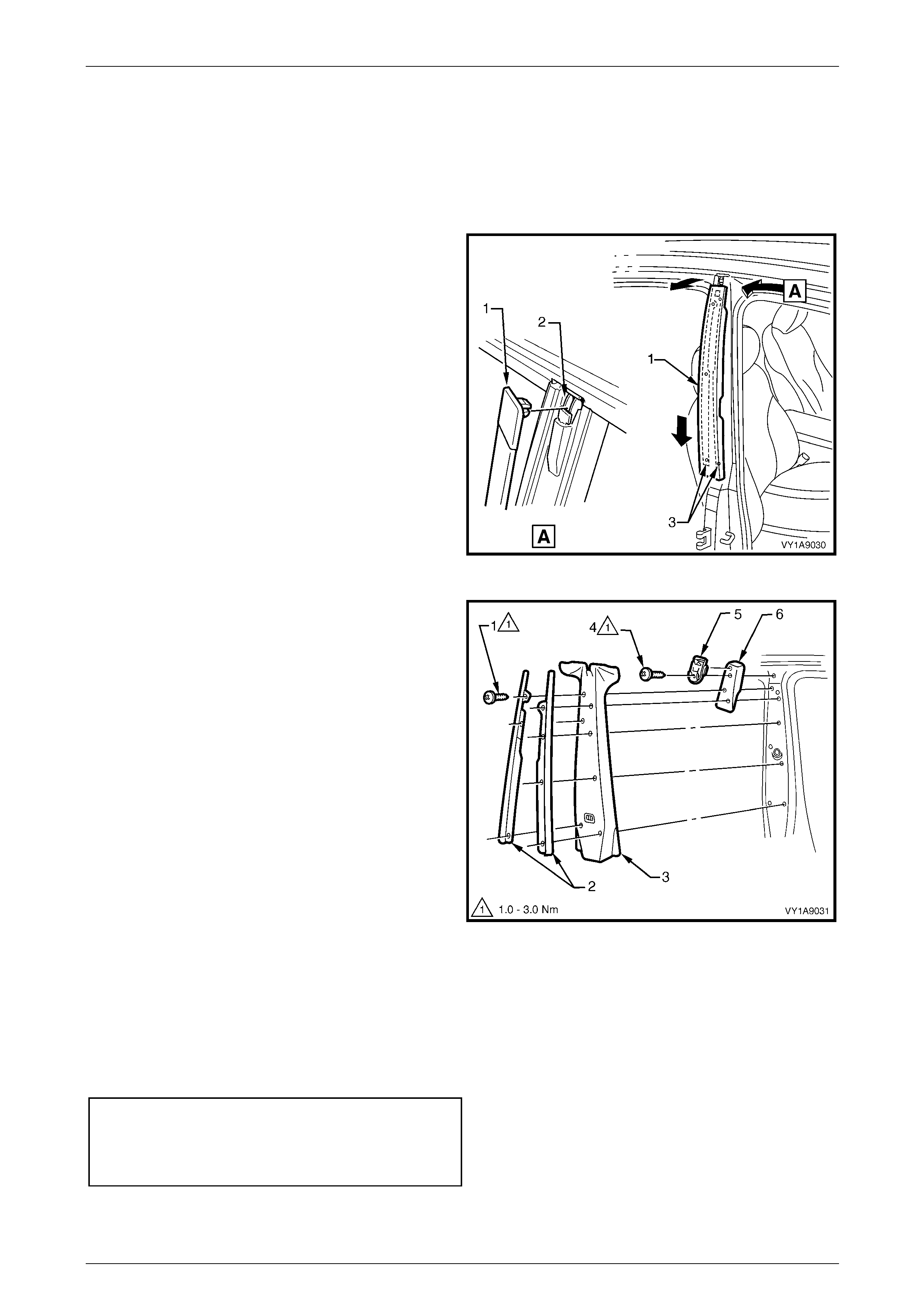
1 Open the front and rear doors on the relevant side of
the vehicle.
2 Gently prise the top of the centre pillar upper finisher
(1) out to disengage it from the centre pillar upper
finisher retainer (2).
3 Holding the top of finisher out, slide it down the centre
pillar outer sealing strips (3) until it rests on rear door
hinge.
4 Manoeuvre the finisher from the sealing strips and
remove.
Figure 1A9 – 20
5 Remove the screw (1), seven places, securing the
centre pillar sealing strips (2) to the pillar and remove
the strips.
6 Partially remove the door opening moulding, refer to
2.7 Door Opening Moulding.
7 Remove centre pillar upper trim panel (3) by pulling
away from the pillar.
8 Remove the screw (4) attaching the centre pillar upper
finisher retainer (5) and centre pillar upper trim mount
plate (6) to the pillar and remove.
Figure 1A9 – 21
Reinstall
Reinstallation of the centre pillar upper finisher assembly is the reverse of the removal procedure, noting the following:
1 Ensure the centre pillar upper trim panel is seated correctly under the door opening weatherstrips.
2 Ensure the screws are tightened to the correct torque specification.
Centre pillar upper finisher retainer
attaching screw torque specification ...........1.0 – 3.0 Nm
Centre pillar sealing strip attaching
screw torque specification...........................1.0 – 3.0 Nm

Exterior Ornamentation Page 1A9–20
Page 1A9–20
3 Torque Wrench Specifications
Rear Compartment Lid Moulding Assembly
Attaching Screw...........................................................................1.4 – 1.8 Nm
Door Opening Moulding Attaching Screw....................................1.0 – 2.0 Nm
Rocker Panel Skirt Attaching Screw............................................ 1.0 – 3.0 Nm
Centre Pillar Upper Finisher Retainer Attaching Screw...............1.0 – 3.0 Nm
Centre Pillar Sealing Strip Attaching Screw.................................1.0 – 3.0 Nm