
Battery Page 12A–1
Section 12A
Battery
ATTENTION
Before performing any service operation or other procedure described in this Section, refer to Section 00
Warnings, Cautions and Notes for correct workshop practices with regard to safety and/or property damage.
1 General Information ...............................................................................................................................2
1.1 Battery Terminals and Cables............................................................................................................................... 2
1.2 Battery Ratings ...................................................................................................................................................... 3
Reserve Capacity................................................................................................................................................... 3
Cold Cranking Amps ............................................................................................................................................. 3
Ratings.................................................................................................................................................................... 3
2 Safety Precautions.................................................................................................................................4
3 Diagnosis ................................................................................................................................................5
3.1 Diagnostic Procedures.......................................................................................................................................... 5
Introduction............................................................................................................................................................ 5
Test Description..................................................................................................................................................... 5
Diagnostic Table Notes ......................................................................................................................................... 5
Diagnostic Table.................................................................................................................................................... 6
3.2 Battery Inspection.................................................................................................................................................. 7
3.3 Hydrometer Test .................................................................................................................................................... 9
3.4 Load Test.............................................................................................................................................................. 10
High Rate Discharge Load Test.......................................................................................................................... 10
Alternate Load Test ............................................................................................................................................. 11
3.5 Battery Current Draw Test................................................................................................................................... 12
Test Preparation................................................................................................................................................... 12
Test Procedure..................................................................................................................................................... 13
Fault Diagnosis.................................................................................................................................................... 14
Restore ................................................................................................................................................................. 14
4 Service Operations...............................................................................................................................15
4.1 Battery .................................................................................................................................................................. 15
Remove................................................................................................................................................................. 15
Reinstall................................................................................................................................................................ 15
4.2 Battery Charge..................................................................................................................................................... 17
Safety Precautions............................................................................................................................................... 17
Battery Charge Procedure .................................................................................................................................. 17
4.3 Emergency Jump Starting Procedure................................................................................................................ 19
Safety Precautions............................................................................................................................................... 19
Jump Starting Procedure.................................................................................................................................... 19
4.4 Dry Charged Batteries......................................................................................................................................... 21
Storage ................................................................................................................................................................. 21
Activation ............................................................................................................................................................. 21
Post Activation Tests .......................................................................................................................................... 21
5 Specifications.......................................................................................................................................22
6 Torque Wrench Specifications............................................................................................................23
7 Special Tools ........................................................................................................................................24
Page 12A–1
Battery Page 12A–2
1 General Information
The vehicle is fitted with a 12 V battery located in the front right-hand c orn er of the engine compartment. The battery
provides:
• power for cranking the engine,
• power for a limited time when the electrical load exceeds the generator output,
• power for the accessories when the engi ne is not running, and
• a voltage stabilising load for the electric al system.
1.1 Battery Terminals and Cables
The cables attached to the battery posts provide power and ground connections for the vehicle electrical system. These
battery cables attach to the battery posts via nut-tightened terminals. The battery is held in position by a hold-down
bracket and a hold-do wn bolt. Refer to Figure 12A – 1.
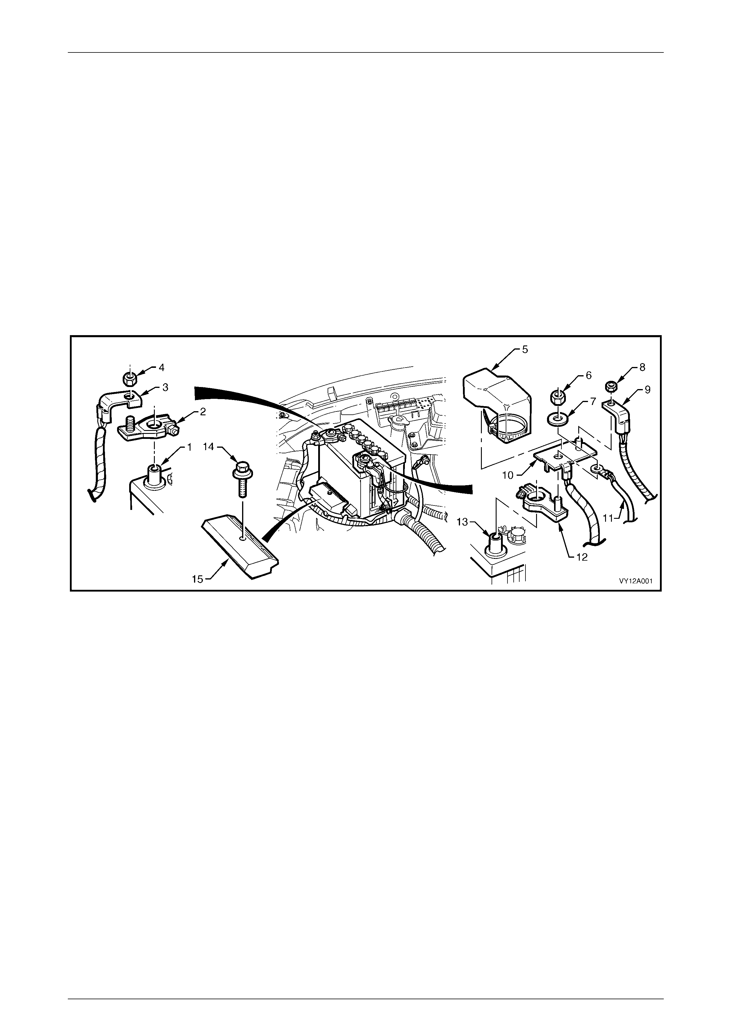
Figure 12A – 1
Legend
1 Battery Negative Post
2 Battery Negative Terminal
3 Battery Ground Cable Connection
4 Battery Terminal Nut
5 Positive Connection Cover and Tie
6 Battery Terminal Nut
7 Battery Terminal Washer
8 Main Fuse Box Supply Terminal Nut
9 Main Fuse Box Supply
10 Battery Positive Cable Assembly
11 Generator Voltage Sensing Wire
12 Positive Battery Terminal
13 Positive Battery Post
14 Battery Hold Down Bolt
15 Battery Hold Down Bracket
Page 12A–2

Battery Page 12A–3
1.2 Battery Ratings
There are two battery ratings to consid er when replacing a battery, reserve capacity (RC) and cold cranking amps (CCA).
Ensure the replacement battery meets or exceeds these rating specifications.
Reserve Capacity
The RC of a battery is the amount of time (measured in minutes) the vehicle will travel at night with minimum electrical
load and no generator input.
This time is measured as the time taken for the battery voltage to reduce to 10.5 V from the following init ial conditions:
• a fully charged battery at 25°C, and
• discharged at a constant current of 25 A.
Cold Cranking Amps
The CCA rating indicates the ability of the battery to maintain enough voltage for ignition requirements while supplying
engine cranking current for long enough to start the engine under severely cold conditions.
The rating is the minimum amperage mai ntained when the engine is cranked for 30 seconds. The battery must maintain
at least 7.2 V at 18°C.
Ratings
A specification label on the top of the battery displays important information about the battery. This inclu des the battery
ratings and the original equipm ent part number.
All vehicles are fitted with a low maintenanc e, 85 minute RC and 430 CCA battery.
Page 12A–3

Battery Page 12A–4
2 Safety Precautions
Battery fluid contains sulphuric acid, which
can cause serious injury. Do not allow liquid
from the battery to contact eyes or skin. If
contact occurs, flush the area immediately
with runnin g water and contact a physician.
Lead acid batteries produce explosive gases.
Keep sparks, flames and lighted cigarettes
away from the battery, especially when the
battery is being charged. Failure to follow this
warning could result in a battery explosion.
Metal objects that touch a battery terminal
can produce sparks that can cause serious
burns. When working near a battery, take
extra care with metal objects including tools
and items of jewellery, especially rings and
metal watchbands.
Do not allow liquid from the battery to contact
clothing or painted surfaces. If contact
occurs, flush the area immediately with
running water.
When working with or near the battery, always:
• Wear safety glasses and work gloves.
• Remove items of jewellery such as rings and metal watchbands.
• Ensure the ignition is switched off when connecting or disconnecting battery cables, battery charging equipment or
battery jumper cables. Failing to do so can damage the veh icle electronic components.
• Disconnect the negative battery cable before disconnecting the positive cable from the battery. Inversely, connect
the positive battery cable to the battery before connecting the negative cable. This reduces the possibility of
shorting the battery to ground while working near the positive connections.
For vehicles fitted with Telematics, refer to Section 12K Telematics before performing an y service work on the battery.
Page 12A–4

Battery Page 12A–5
3 Diagnosis
3.1 Diagnostic Procedures
Introduction
This test is used to aid in diagnosing faults with the vehicle where the battery seems to be at fault.
With the increased use of electronic sens ors and computer control, the battery is much more than just a component us ed
to start a car. Low battery voltage can:
• affect the operation of the vehicle control m odules and cause driveability problems, and
• cause the control modules to set diagnostic trouble codes (DTCs).
For example if a control module senses low battery voltage, it may increase fuel injector timing to increase engine rpm to
increase the generator output.
Therefore consider the state of charge of the battery any time a customer c omplains of a driveability related pro blem.
For vehicles fitted with Telematics, refer to Section 12K Telematics before performing an y service work on the battery.
Test Description
The following numbers refer to the step numbers in the diagnostic table:
1 Checks the operator understands the safety precautions for working with batteries.
2 Checks if the vehicle is fitted with a battery of the correct specification.
3 Checks if the battery appears serviceable by performing the battery inspection procedure.
4 Checks if the battery loses charge over an extended period. If so the likely problem is excess current draw while
the vehicle is in battery saver mode.
5 Checks the state of charge of the battery.
6 Checks if the battery is capable of delivering the required load by performing the load test procedure.
Diagnostic Table Notes
1 For all wiring harness fault diagnosis, refer to Section 12P Wiring Diagrams.
2 For wiring harness repairs, refer to Section 12P Wiring Diagrams.
3 Refer to Section 12O Fuses, Relays and Wiring Harnesses for harness routeing.
Page 12A–5

Battery Page 12A–6
Diagnostic Table
Step Action Yes No
1 Have you read and understood the safety precautions for working with
batteries? Go to Step 2
Refer to
2 Safety
Precautions
2 Check the battery fitted is the correct specification recommended for
the vehicle? Refer to 5 Specifications.
Is the battery the correct specification? Go to Step 3
Replace the battery
with the correct
specification
3 Perform the battery inspection, refer to 3.2 Battery Inspection.
Does the battery appear serviceable? Go to Step 4
Replace the
battery, refer to
4.1 Battery
4 Does the customer complain the battery loses charge if the engine is
not started for an extended period? Preform the battery
current draw test,
refer to
3.5 Battery
Current Draw Test Go to Step 5
5 Perform the hydrometer test, refer to 3.3 Hydrometer Test.
Is the battery fully charged? Go to Step 6
Fully charge the
battery, refer to
4.2 Battery Charge
6 Load test the battery, refer to 3.4 Load Test.
Does the battery pass the load test?
Battery Serviceable.
Refer to:
6D1–1 Charging
System – V6 or
6D3-1 Charging
System – GEN III
V8 to diagnose
further electrical
faults with the
vehicle.
Replace the battery,
refer to
4.1 Battery
When all diagno sis and repairs are completed, check th e system for correct operation.
Page 12A–6
Battery Page 12A–7
3.2 Battery Inspection
LT Section No. — 02–200
1 Read and obey the safety precautions for working with batteries, refer to 2 Safety Precautions.
2 Check the battery terminals and around the batter y area for corrosion deposits. Remove any deposits as follows:
a Scrub the area with a stiff brush.
b Treat the area with a solution of warm water and baking soda or ammonia.
c Rinse with clean water.
3 Check the battery posts, if they are loose, burned, pitted or damaged in any way replace the battery. Refer to
4.1 Battery.
4 Check the battery case, if it is cracked or damaged replace the battery. Refer to 4.1 Battery.
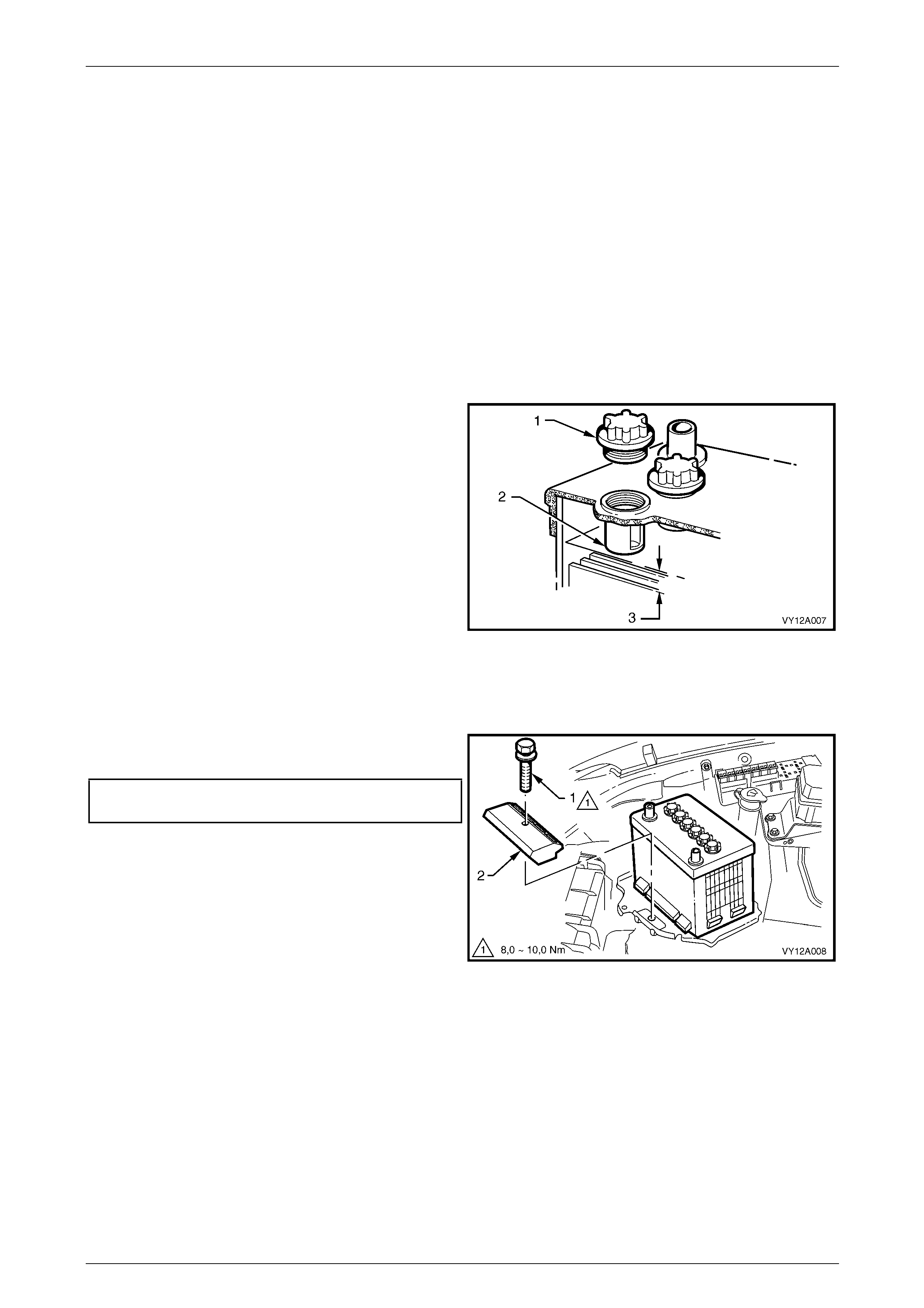
5 Remove each filler cap (1) an d check the electrolyte
level is at the bottom of the filler-neck tube (2).
6 If the level is low, carefully add distilled water to the
cell until the level reaches the bottom of the filler- neck
tube.
NOTE
Do not overfill the cells, but maintain the level at
least 20 mm above the separator plates (3).
7 If the electrolyte usage seems excessive, ch eck the
battery case is not faulty.
NOTE
Normal electrolyte usage is less than 30 ml per
10,000 kilometres (or slightly more for long,
continuous running or in high temperatures).
Figure 12A – 2
8 Ensure the battery hold-down bolt (1) and bracket (2)
firmly secure the battery.
Battery hold-down bolt
torque specification...................................8.0 – 10.0 Nm
9 Check the cable insulation for damage or wear along
the cable. Replace the cable a s required.
10 Check the cables do not have broken or frayed
strands and are secure in the terminals. Repair as
required.
Figure 12A – 3
Page 12A–7
Battery Page 12A–8
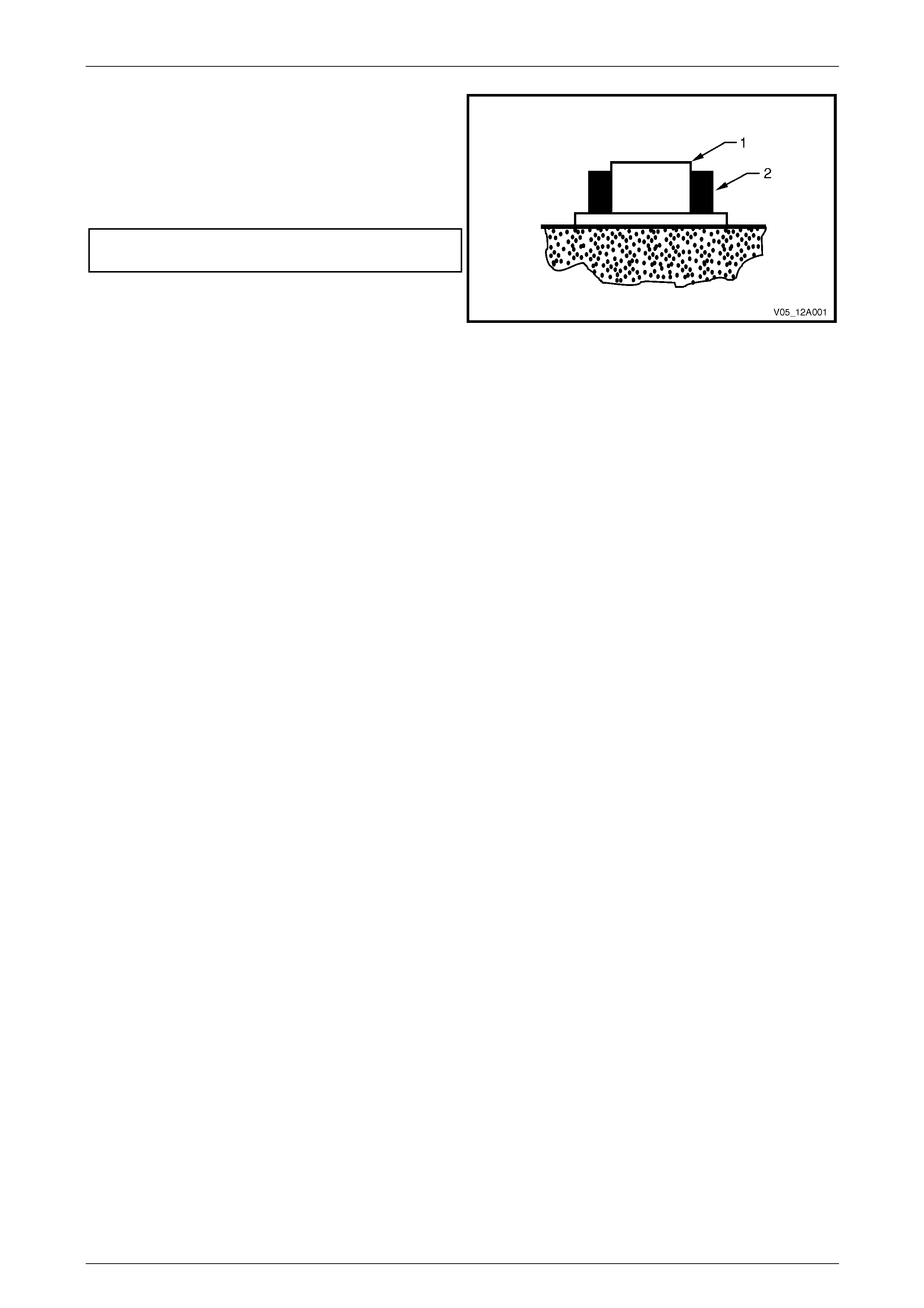
11 Ensure the terminal clamp (2) sits below the top of the
battery post (1).
12 Check the terminal clamps are attached to the battery
posts securely. Replace the terminals as require d.
13 Tighten the terminal clamp nut s to the correct torque
specification.
Battery terminal nut
torque specification.....................................2.0 – 5.0 Nm
14 Smear the battery posts and terminals with petroleum
jelly to resist corrosion.
Figure 12A – 4
Page 12A–8
Battery Page 12A–9
3.3 Hydrometer Test
As a lead-acid battery discharges, sulphur elements in the electrolyte mov e from the electrolyte solution into the lead
battery plates. This removes the sulphuric acid from the electrolyte and changes it to water. Therefore the concentration
of sulphuric acid in the electrolyte indicates the state of charge.
The concentration of sulphuric acid can be measured using a hydrometer. The state of charge is measured in terms of
specific gravity; the lo wer the specific gravity reading, the lower the state of charge.
NOTE
If distilled water has been added to the battery,
do not use the hydrometer until the battery has
been charged for at least 30 minutes.
1 Read and obey the safety precautions for working with batteries, refer to 2 Safety Precautions.
2 Remove the battery filler caps.
3 Force the air out of the hydrometer bulb.
4 Hold the hydrometer verticall y in the cell with the pick-up tube submerged.
5 Draw in sufficient liquid to lift the hydrometer float freely when the bulb is fully released.
6 Still holding the hydrometer verticall y, recor d the rea din g.
7 Put the electrolyte back into the cell.
8 Repeat steps 3 to 7 for each cell.
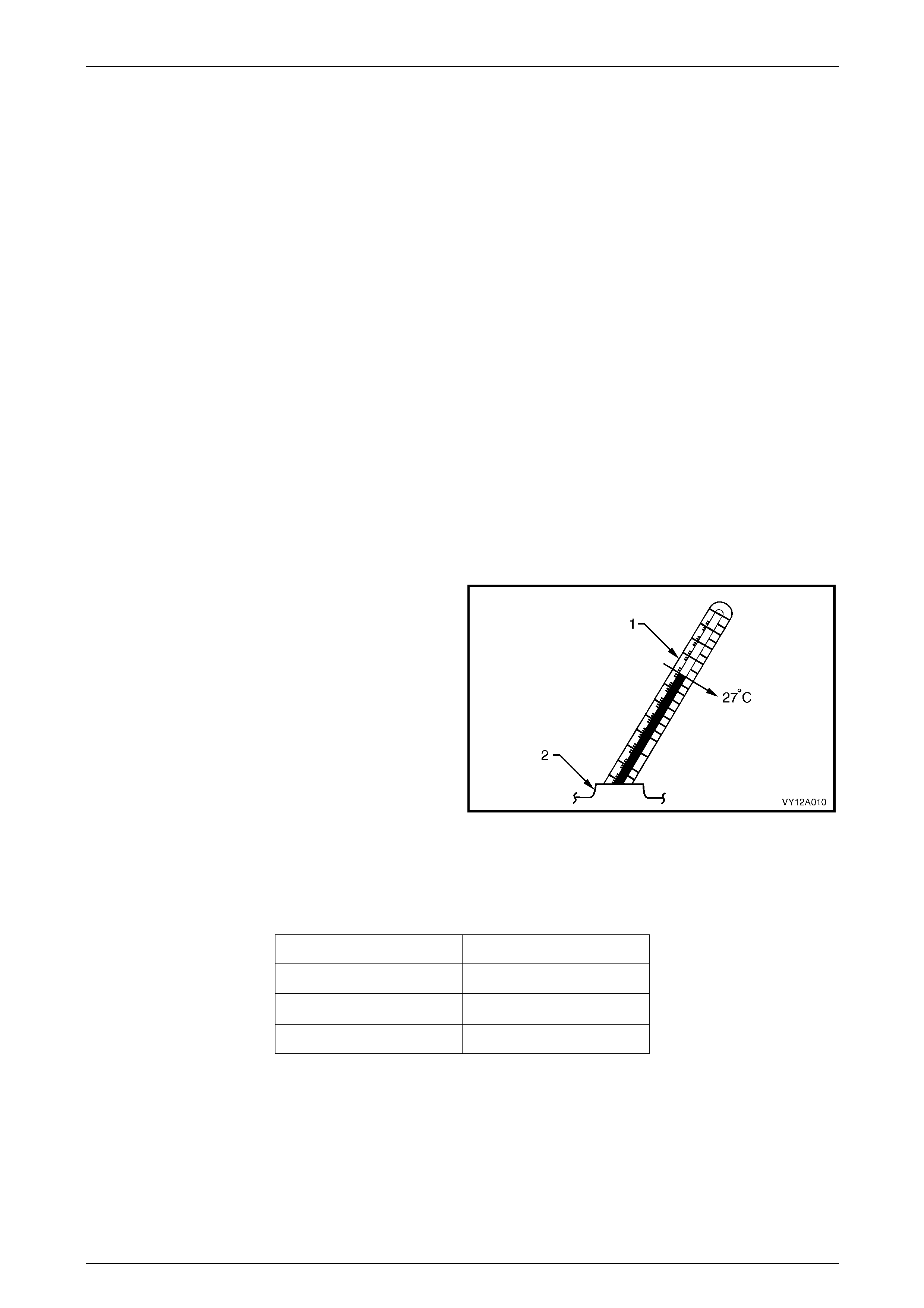
9 Determine the temperature of the battery by
temporarily placing a thermometer (1) into one of the
cells (2).
10 Install the battery filler caps.
11 Calculate the temperature-compensated readings: add
0.004 for every 5°C above 27°C or subtract 0.004 for
every 5°C below 27°C.
12 Determine the state of charge of the battery using the
temperature-compensated readings and the table
below.
NOTE
The specific gravity of a charged battery should
not vary more than 0.025 between cells. Larger
variations indicate defective c ells and the battery
must be replaced, refer to 4.1 Battery.
Figure 12A – 5
Battery Condition Specific Gravity Reading
Fully charged 1.240 to 1.260
Requires charging < 1.190
Fully discharged 1.110 to 1.130
Page 12A–9

Battery Page 12A–10
3.4 Load Test
Load testing the battery with a high rate discharge (HR D) tes t er simulates using the starter motor and checks if the
battery is in serviceable condition. The battery must be at least 65% charged before commencing this test.
NOTE
For vehicles fitted with Telematics, refer to
Section 12K Telematics before performing any
service work on the battery.
NOTE
HRD testers are available with either fixed or
variable loads. The operating procedures may
vary from brand to brand, therefore follow the
manufacturer’s instructions.
High Rate Discharge Load Test
1 Read and obey the safety precautions for working with batteries, refer to 2 Safety Precautions.
2 Ensure the state of the battery is at least 65% charge d. Refe r to 3.3 Hydrometer Test.
3 Refer to Section 00 Warnings, Cautions and Notes before disconnecting the battery.
4 Disconnect the battery negative terminal.
5 Disconnect the battery positive terminal.
6 Connect the HRD tester to the battery terminals ensuring correct polarity.
7 Set the tester switches to suit the battery size.
Fixed load tester:
a Apply the load for approximately 10 seconds to remove any surface charge.
b Wait 15 seconds for the battery to recover.
Variable load tester:
a Apply a 300 A load for approximately 15 seco nds to remove any surface charge.
b Wait 15 seconds for the battery to recover.
8 If possible, set the selector to 50% of rapid discharge current (or three times the 20 hour d ischarge rate).
9 Apply the load test for 10 seconds and record the battery voltage. If one cell is faulty it will gas excessively or
overheat. This indicates a faulty battery.
10 Recharge the battery if the voltage is at or below the minimum voltage specified by the HRD manufacturer (or
9.6 V).
11 Replace the battery if the voltage is below the minimum voltage specified by the HRD manufacturer (or below 9.6 V
after the battery is charged and the test is repeated). Refer to 4.1 Batter y.
12 Connect the battery positive terminal.
13 Connect the battery negative terminal.
Page 12A–10
Battery Page 12A–11
Alternate Load Test
If HRD test equipment is not available, test the battery as follows:
1 Read and obey the safety precautions for working with batteries, refer to 2 Safety Precautions.
2 Ensure the state of the battery is at least 65% charge d. Refe r to 3.3 Hydrometer Test.
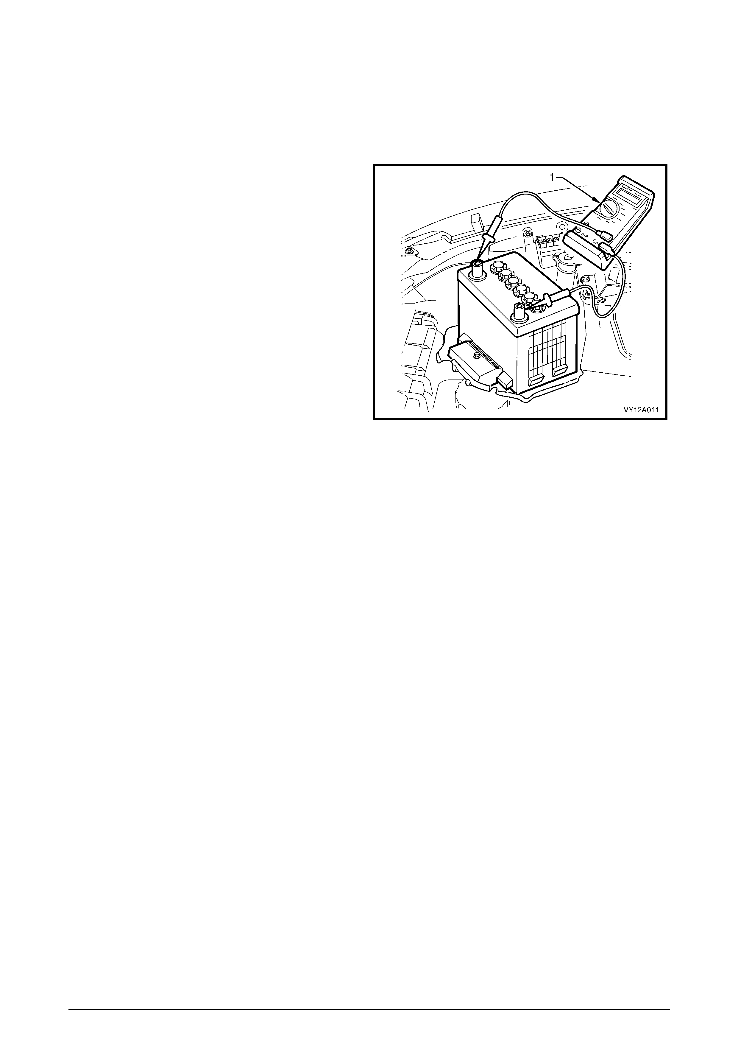
3 Connect a voltmeter (1) between the battery terminals.
4 Turn the headlights on to high-beam for 10 seconds to
remove any surface charge from the battery.
5 Remove fuses F34 and F35 from the engine
compartment fuse and relay housing. T his prevents
vehicle ignition and fuel i njection while cranking the
engine.
6 Crank the engine and read the voltmeter. At
temperatures above 5°C, the voltage of a fully charged
battery should not fall below 9.6 V.
NOTE
If the battery and engine tem peratures are belo w
5°C, the voltage may fall to 9 V.
NOTE
Try to avoid activating the starter motor
continuously for more than 30 seconds. If
activating the starter motor for 30 seconds, allow
the starter motor to cool for 3 minutes.
7 Replace the battery if a cell gasses excessiv ely or
overheats or if the voltage falls away quickly.
Figure 12A – 6
Page 12A–11

Battery Page 12A–12
3.5 Battery Current Draw Test
The following test determines if excess curre nt is bein g dra wn from the battery whilst the vehicle is in Battery Saver
Mode. Excess current draw will cause the battery to go flat if the vehicle is not started for an extended period.
With the ignition turned off, current is continued to be drawn from the battery for modules such as the BCM, PIM and
PCM. To minimise the current the drawn from the battery while the ignition is off, the BCM will switch to Battery Saver
Mode after a preset period. This peri od has a factory default of 65 minutes; however it can be set between 3 to
180 minutes using Tech 2. The delay period commences once the ignition is switched off.
When the BCM switches to Battery Saver Mode, it de-energises the interior illumination relay which suppli es power to the
interior dome lamps, ignition lock lamp, instrument pane l compartment lamp and rear compartment lamps. It also
de-energises the power window relay, and disables the BCM inputs that are normally not required when the ignition is
off.
Test Preparation
1 Read and obey the safety precautions for working with batteries, refer to 2 Safety Precautions.
2 If the battery is flat, temporarily install a good battery for the duration of the test.
3 Ensure the vehicle starts and the access ories operate normally.
4 Ensure the theft deterrent system operates normally. Refer to Section 12J Body Control Module.
5 Use Tech 2 to set the BCM Battery Saver Shut Down Time to 3 minutes. Refer to Section 12J Body Control
Module.
6 For vehicles fitted with Telematics, enable the Service mode. Refer to Section 12K Telematics. The Telematics will
switch to Stand-by mode 2 minutes after the ignition is switched off and a door has been closed.
7 Open all the side windo ws for access purposes.
8 Turn the windscreen wiper intermittent setting to maximum dwell.
9 Switch the ignition off.
10 Cover the ambient light sensor, which is mounted in the top centre of the instrument panel to simulate dark
conditions.
11 Check that all interior illumination is off, including any compartment lighting.
12 Ensure the rear compartment lid is closed.
13 Deactivate the hood switch where fitted, to simulate the hood being closed. Use masking tape to retain the hood
switch in the depressed position.
14 Open the instrument panel compartment. When the BCM switches to Battery Saver mode, the instrument panel
compartment lamp will switch off.
15 Close all doors.
16 Lock the doors and activate the theft deterrent system to arm the vehicle.
17 If the multimeter contains fuses, check they are serviceable.
18 Wait for the BCM to switch to Battery Saver mode, by observing when the instrument panel compartmen t lamp
switches off. Once the lamp is off proceed to Test Procedure in this Section.
Page 12A–12
Battery Page 12A–13
Test Procedure
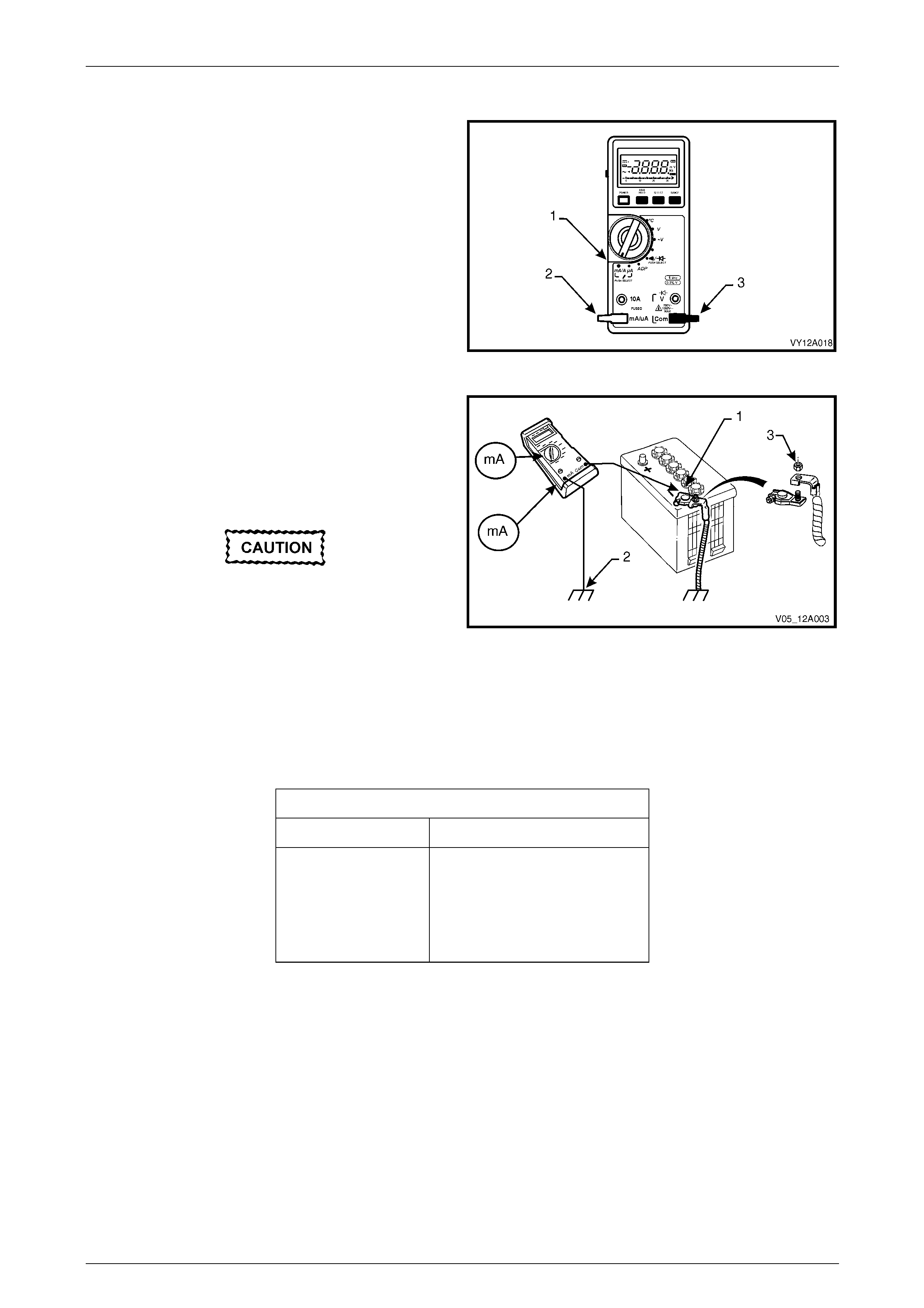
1 Switch the multimeter to the mA current range (1).
2 Connect the positive test lead (2) to the fused mA
terminal of the multimeter.
3 Connect the negative test (3) lead to the common
terminal of the multimeter.
4 Connect large alligator clips to the ends of both test
leads.
Figure 12A – 7
5 Connect the negative test lead clip to the threads of
the battery negative terminal clamp (1).
6 Connect the positive lead’s clip to the thread s of a
convenient engine bolt (2). Refer to Section 12O
Fuses, Relays and Wiring Harnesses for bolt
locations.
Do not turn on the ignition switch while this
test is in progress. It will blow the
multimeter’s low current fuse.
7 Check the multimeter connections are secure.
8 Disconnect the vehicle’s main electrica l earth by
removing the battery negative terminal cable retaining
nut (3) and separating the cable from the battery
clamp.
Figure 12A – 8
9 Read the vehicle’s battery saver current on the multimeter. The multimeter reading should be within the values
listed in the following table:
Current Draw
Without Telematics 16 – 30 mA (fluctuating)
With Telematics Initially: (Stand-by mode)
66 – 99 mA (fluctuating)
After 15 minutes: (Sleep mode)
18.5 – 51.5 mA (fluctuating)
10 If the multimeter reading is higher than specified, refer to Fault Diagn osis in this Section, otherwise restore the
vehicle to its prior condition, refer to Restore in this Section.
Page 12A–13

Battery Page 12A–14
Fault Diagnosis
Do not open any doors during this inspection.
If the doors must be opened, reinstall the
battery terminal to the battery clamp to
protect the multimeter's fuse from blowing.
Alternatively, use the higher (10 A) fuse rated
terminal on the multimeter until the source of
the higher current draw has been found.
1 Visually inspect the vehicle for illuminated lamps and components activated by energised relays.
2 Lower the rear seat fold-down tray to check the rear compartment lamp is not illuminated.
3 If the cause of the excessive current draw is not apparent, remove one fuse (or circuit breaker) at a time to
determine the circuit group that is drawing excess current. Refer to Section 12O Fuses, Relays and Wiring
Harnesses for fuse grouping location.
4 When the circuit group is determined, install the fuse / circuit breaker and identify the specif ic circuit within this
group that is drawing the excess current. Disconnect the wiring harness connectors in this circuit group one at a
time. Refer to Section 12P Wiring Diagrams.
5 When the cause is disconnected, the multimeter reading should drop to the correct reading as outlined in Step 9 of
the Test Procedure in this Section.
6 If required, remove the components in this circuit one at a time to determin e the cause of the excessive standing
current. Refer to Section 12P Wiring Diagrams.
7 Repair the fault, refer to Section 12O Fuses, Relays and Wiring Harnesses.
8 Ensure any fuses, circuit breakers and connectors that have been removed are secure.
Restore
1 Reconnect the electrical earth cable to the battery terminal and tighten the nut to the correct torque specification.
Battery terminal nut
torque specification.....................................2.0 – 5.0 Nm
2 Disconnect the multimeter connections.
3 Remove the tape retaining the hood switch.
4 Use Tech 2 to set the BCM Battery Saver Shut Down Time to 65 minutes. Refer to Section 12J Body Control
Module.
5 For vehicles fitted with Telematics, disable the Service mode. Refer to Section 12K Telematics.
Page 12A–14
Battery Page 12A–15
4 Service Operations
4.1 Battery
LT Section No. — 02–200
Remove
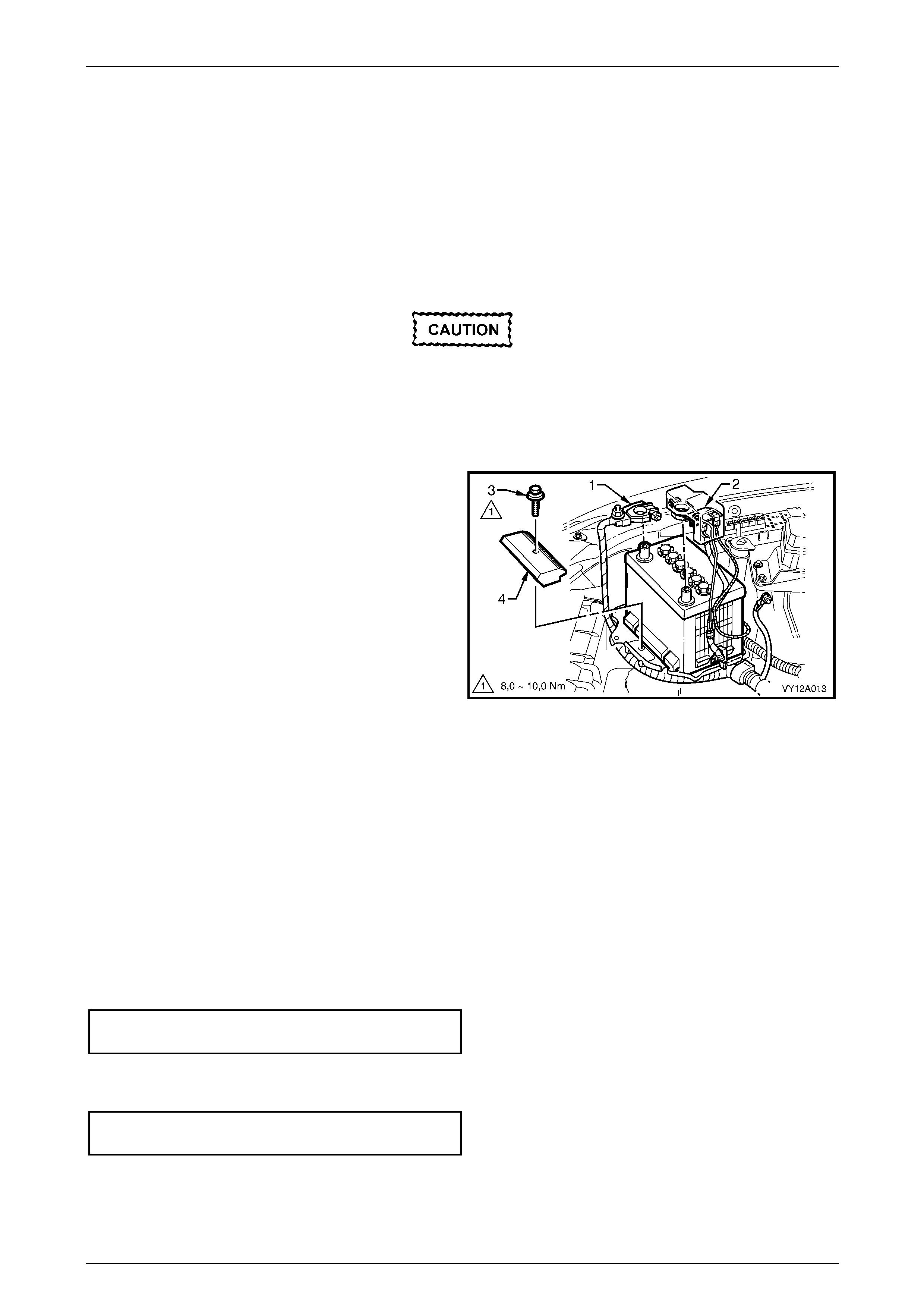
Disconnection of the battery affects certain
vehicle electronic systems. Refer to
Section 00 Warnings, Cautions and Notes
before disconnecting the battery.
1 Read and obey the safety precautions for working with batteries, refer to 2 Safety Precautions.
2 Disconnect the negative battery terminal (1).
3 Disconnect the positive battery terminal (2).
4 Remove the battery hold-down bolt (3) and the battery
hold-down bracket (4).
5 Lift the battery out of the engine compartment.
Figure 12A – 9
Reinstall
NOTE
Before installing a used battery perform steps 1
to 10 of the battery inspection, refer to
3.2 Battery Inspection.
1 Ensure the battery tray, cables and terminals are clean a nd free from corrosion and moisture.
2 Ensure that no foreign objects such as loose nuts or stones are located in the battery tray.
3 Place the battery onto the battery tray and ensure the battery sits level.
4 Install the battery hold down bracket and tighten the bolt to the specified torque.
Battery hold-down bolt
torque specification...................................8.0 – 10.0 Nm
5 Install the positive terminal onto the positive battery post. Ensure the terminal sits below the top of the post and
tighten the terminal nut to the correct specification.
Battery terminal nut
torque specification.....................................2.0 – 5.0 Nm
6 Install the negative terminal onto the negative battery post. Ensure the terminal sits below the top of the post and
tighten the terminal nut to the correct specification.
Page 12A–15

Battery Page 12A–16
Battery terminal nut
torque specification.....................................2.0 – 5.0 Nm
7 Smear the battery posts and cable terminals wit h petro leum jelly to inhibit corrosion.
Page 12A–16

Battery Page 12A–17
4.2 Battery Charge
LT Section No. — 02–200
Safety Precautions
Read and obey the general safety precautions for working with batteries, refer to 2 Safety Precautions.
The battery releases an explo s ive hydrogen and oxygen gas mixture during charging. Ensure there are no naked flames
or sparks near the battery.
Flat batteries can be safely boost-charg ed, however avoid excessive charging current if the battery is more than half
charged. Slow charging is best.
Fast charging can substantially boost a battery, but slow charging is required to fully charge the battery.
Do not use a fast charger:
• for starting the vehicle,
• if the specific gravity readings are not uniform between battery cells, refer to 3.3 Hydrometer Test,
• if the specific gravity readings are above 1.2 0, refer to 3.3 Hydrometer Test,
• if the electrolyte is discoloured with brown sediment, and
• if any of the above three conditions develop after beginning a fast charge.
Battery Charge Procedure
Disconnection of the battery affects
certain vehicle electronic systems. Refer to
Section 00 Warnings, Cautions and Notes
before disconnecting the battery.
NOTE
For vehicles fitted with Telematics, refer to
Section 12K Telematics before performing any
service work on the battery.
1 Perform steps 1 to 10 of the battery inspection, refer to 3.2 Battery Inspection.
2 Remove the battery from the vehicle. Refer to 4.1 Battery.
3 If required remove the battery filler caps. Let the caps rest loosely o n top of the filler tub es.
Always ensure the connections are to the
correct polarity and follow the man ufacturer’s
recommendations for battery charging.
4 Connect the battery to the battery charger.
5 Set the charging current using the following table as a gu ide.
Page 12A–17

Battery Page 12A–18
NOTE
Charging a battery at higher current rates can
significantly reduce the life of the battery.
Charge Rate Initial Current Maximum Time
Required
Slow charge 4 A 24 hours
Fast charge 35 A 2 hours
6 After a few minutes, check the colour and specific gravity of the electrolyte. Refer to 3.3 Hydrometer Test.
7 Monitor the electrolyte temperature while the battery is charging. If the electrolyte temperat ure reaches 55°C:
a switch the charging current off,
b allow the battery to cool,
c reduce the charging current, and
d restart charging the battery.
NOTE
For the best results, charge the battery with the
electrolyte and plates at room temperature. An
extremely cold battery may not appear to accept
current for several hours after starting the battery
charger. If the battery does not appear to accept
charge after several hours replace the battery.
8 For slow charging check the voltage and specific gravity each hour or more regularly for fast charging. Stop the
charging when there is no change i n voltage or electrolyte specific gravity over three checks.
9 If the battery was fast charged connect the battery to a slow-charger for a few hours to bring the battery to the fully
charged condition. Ensure the last few hours of charge do not exceed 1 A.
10 Tighten the filler caps. Ensure they are secur e.
11 Install the battery in the vehicle. Refer to 4.1 Battery.
Page 12A–18

Battery Page 12A–19
4.3 Emergency Jump Starting Procedure
Safety Precautions
• Read and obey the general safety precautions for working with batteries, refer to 2 Safety Precautions.
• Do not allow the vehicles to touch each other during the jump starting procedure.
• Ensure the assisting vehicle b attery has the same voltage rating and connects negative to ground. If this is not the
case, serious injury and damage to electrical equ ipment can result.
• Do not push or tow the vehicle to start it. Damage can result when unburnt fuel reaches the catalytic converter and
ignites.
• Do not start the vehicle using a fast charger.
• When using jumper leads, treat both the boo ster battery and the discharged battery with care.
• Do not allow sparks, flame or smoking near the battery.
• Ensure that metal tools or jumper cables do not simultaneously contact the batter y positi ve terminal and any other
metal part of the vehicle.
Jump Starting Procedure
NOTE
For vehicles fitted with Telematics, refer to
Section 12K Telematics before performing any
service work on the battery.
1 Position the assisting vehicle so the batteries of both vehicles are close together, refer to F igure 12A – 10.
2 Apply the park brake on both vehicles.
3 Ensure that P (park) is selected for automatic transmission and N (neutral) is selected for manual transmissions.
4 Turn off the ignition, lights and all other electri cal loads.
5 Check the battery filler caps on both batteries are tight.
6 Place a wet cloth over the battery filler caps o f each battery.
7 Attach one end of the red jumper cable to the positiv e terminal of the booster battery.
8 Attach the other end of the same cable to the positive terminal of the d ischarged battery.
9 Attach one end of the black jumper cable to the negative terminal of the booster battery.
10 Attach the other end to a solid stationary, me tallic point o n the en gine of the disabled vehicle.
NOTE
Do not connect this end directly to the negative
post of the discharged battery.
Page 12A–19
Battery Page 12A–20
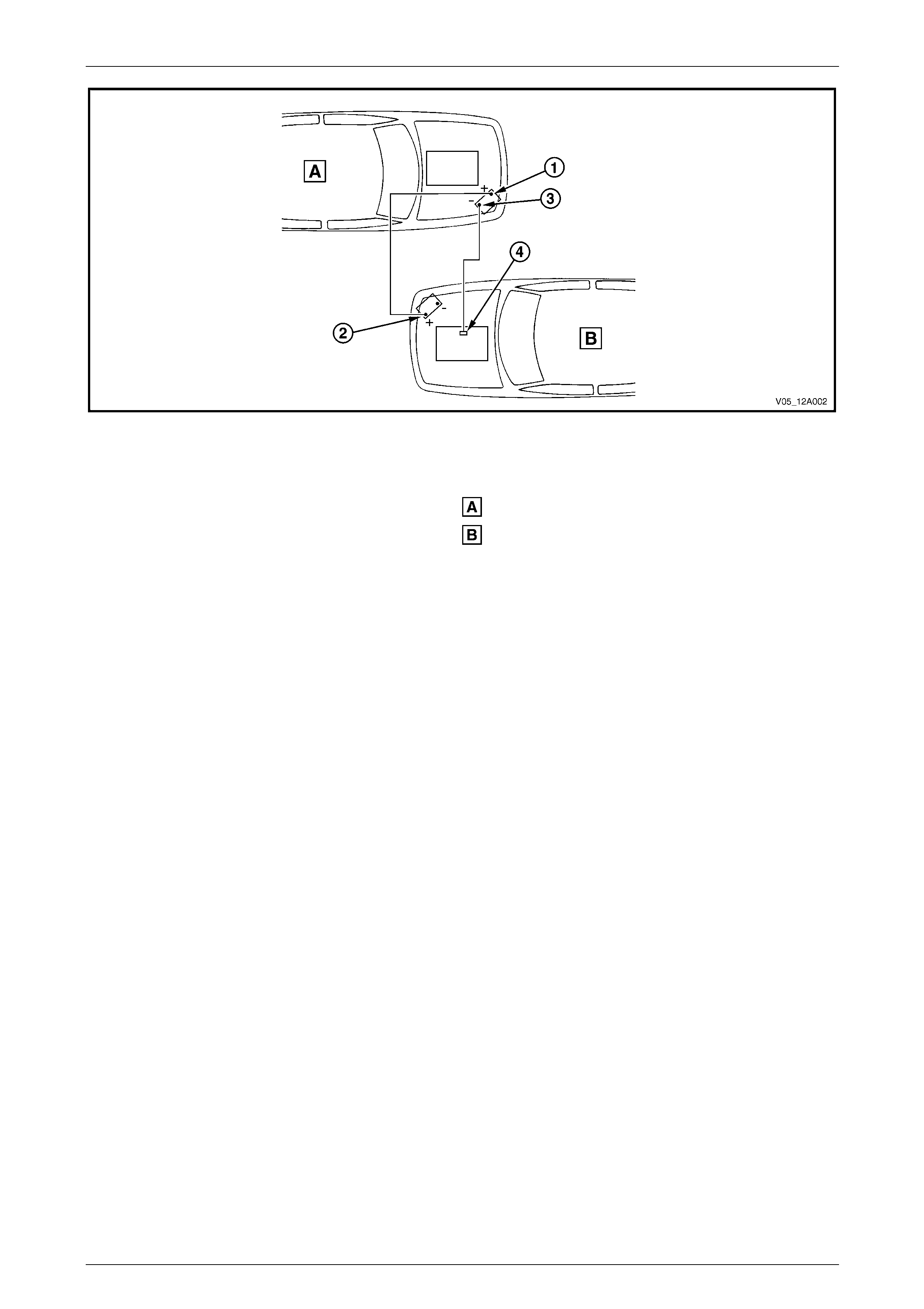
Figure 12A – 10
Legend
Order of hook-up:
1 Booster vehicle, positive terminal
2 Disabled vehicle, positive terminal
3 Booster vehicle, negative terminal
4 Disabled vehicle, engine ground point
Booster vehicle
Disabled vehicle
11 Ensure the jumper cables are not on or n ear drive pulleys, cooling fans or other points that will move when the
engine is started.
12 Start the engine in the booster vehicle and run the engine at a moderate speed for a few minutes.
13 Start the engine in the disabled vehic le.
NOTE
If the engine in the d isable d vehicl e does not start
within 30 seconds, stop cranking the engine and
fix the cause. Refer to 3 Diagnosis.
14 When the engine starts, allow both engin es to idle for approximately sev en minutes. This allows the voltage l evels
in both vehicles to balance.
15 Leave the vehicles runnin g and remove the jumper cables in the reverse sequence to attaching them. When
removing each clamp, take care to ensure that it does not touch any other metal.
16 Discard the wet cloths covering the battery filler caps of both batteries.
Page 12A–20

Battery Page 12A–21
4.4 Dry Charged Batteries
Storage
Dry charged batteries are fully charged when manufactured and contain no electrolyte until activated. The dr y charged
battery is completely sealed and can be stored indefinitely with no servicing until activated.
Activation
1 Remove the battery filler caps.
2 Add 1.265 specific gravity ele c trolyte to each cell to the correct level.
3 Wait several minutes.
4 Check the electrolyte level and add more electrolyte (not water) as required. After a dry charged battery is
activated, it becomes a wet battery.
Post Activation Tests
Although a dry charged battery can be put into service immediately after activation, the following tests are recommended:
1 Check the voltage of the battery after adding the electrolyte.
2 If the reading is less than 10 V, replace the battery.
3 Check the specific gravity of the electrolyte in each cell, refer to 3.3 Hydrometer Test.
4 If any reading shows more than a 0.030 drop from the initial electrolyte reading, slow-charge the battery before
use. Refer to 4.2 Battery Charge.
5 Check the cells for violent gassing. If violent gassing is detected evenly across all cells, slow-charge the battery
before use. If violent gassing is not even across all cells, replace the battery.
Page 12A–21

Battery Page 12A–22
5 Specifications
Rated Voltage................................................................................................................... 12 V
Cold Cranking Amps........................................................................................430 A minimum
Reserve Capacity ....................................................................................85 minutes minimum
20 Hour Discharge...................................................................................55 A / hour minimum
5 Second Voltage @ 25° C....................................................................150 A 10.4 + / – 0.2 V
.................................................................................................................400 A 8.4 + / – 0.2 V
Number of Plates (per cell)...................................................................................................11
NOTE
Specified ratings when tested in accordance with
Australian Standard AS 2149-1990
Page 12A–22

Battery Page 12A–23
6 Torque Wrench Specifications
Battery Hold-Down Bolt...............................................................8.0 – 10.0 Nm
Battery Terminal Nut .....................................................................2.0 – 5.0 Nm
Page 12A–23
Battery Page 12A–24
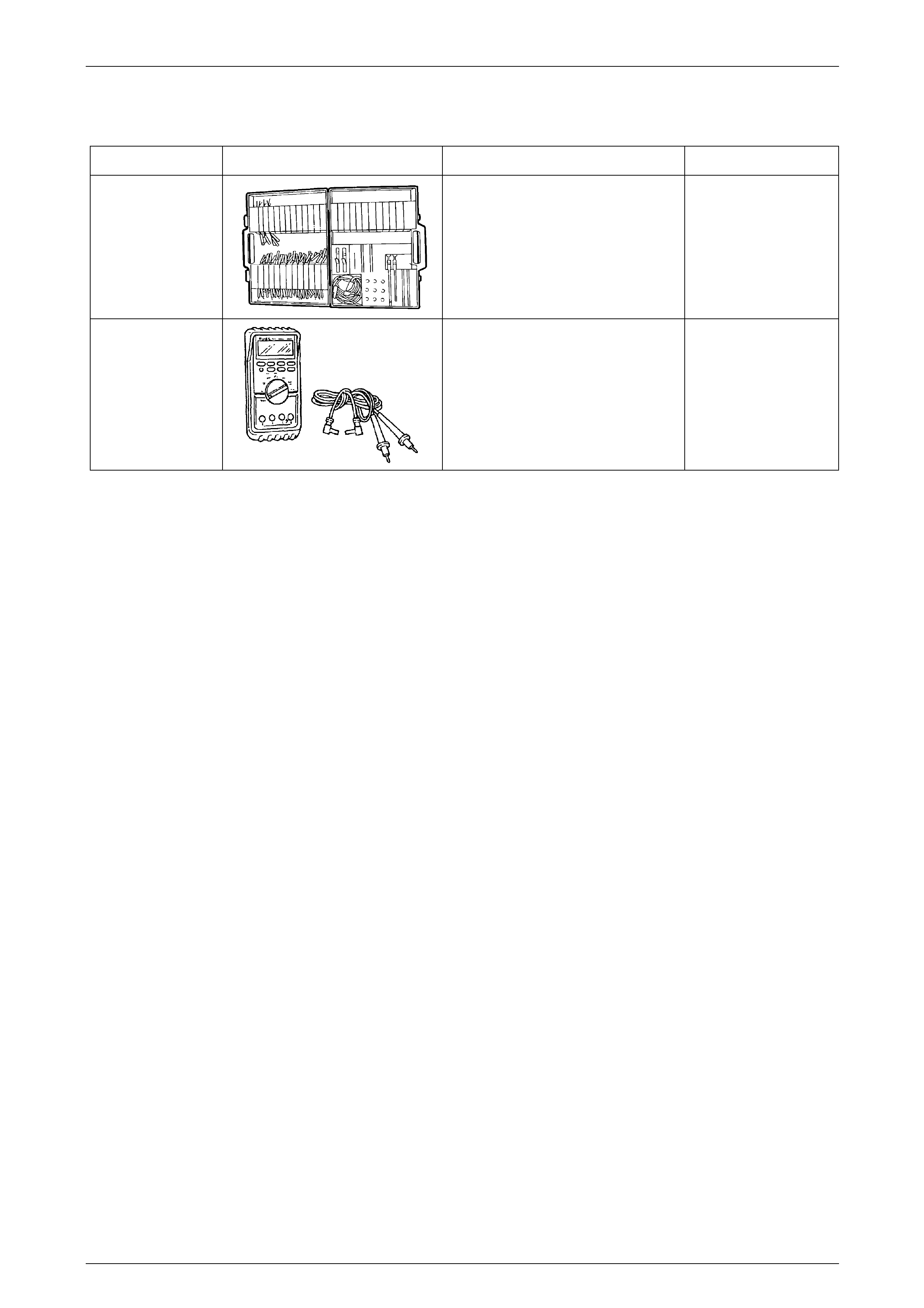
7 Special Tools
Tool Number Illustration Description Tool Classification
KM609
Connector Test Adaptor Kit
Used when carrying out electric al
diagnostic circuit checks.
Previously released.
Desirable
J39200
Digital Multimeter
Must have at least 10 MΩ input
impedance and be capable of reading
frequencies.
Previously released.
Available
Page 12A–24