
Instrumentation Page 12C – 1
Page 12C – 1
Section 12C
Instrumentation
ATTENTION
Before performing any service operation or other procedure described in this Section, refer to Section 00
Warnings, Cautions and Notes for correct w orkshop practices wi th regard to safety and/or property damage.
1 General Information...............................................................................................................................8
1.1 General Description............................................................................................................................................... 8
Instrument Cluster................................................................................................................................................. 9
Instrument Cluster Warning Indicators................................................................................................................ 9
LED Warning Indicator Table ............................................................................................................................. 9
MFD Information Messages ............................................................................................................................. 10
MFD Animated Graphics.................................................................................................................................. 10
Warning Indicator Symbols............................................................................................................................... 10
1.2 Instrument Cluster Illumination.......................................................................................................................... 11
Chimes.................................................................................................................................................................. 11
1.3 Instrument Cluster Operation............................................................................................................................. 12
Ignition ON – Welcome Sequence Holden......................................................................................................... 12
1.4 Ignition On System Check .................................................................................................................................. 13
Ignition OFF.......................................................................................................................................................... 13
1.5 Alarms................................................................................................................................................................... 14
Vehicle Immobilisation by ECM or PCM ............................................................................................................ 14
1.6 Trip Computer...................................................................................................................................................... 15
Operation.............................................................................................................................................................. 15
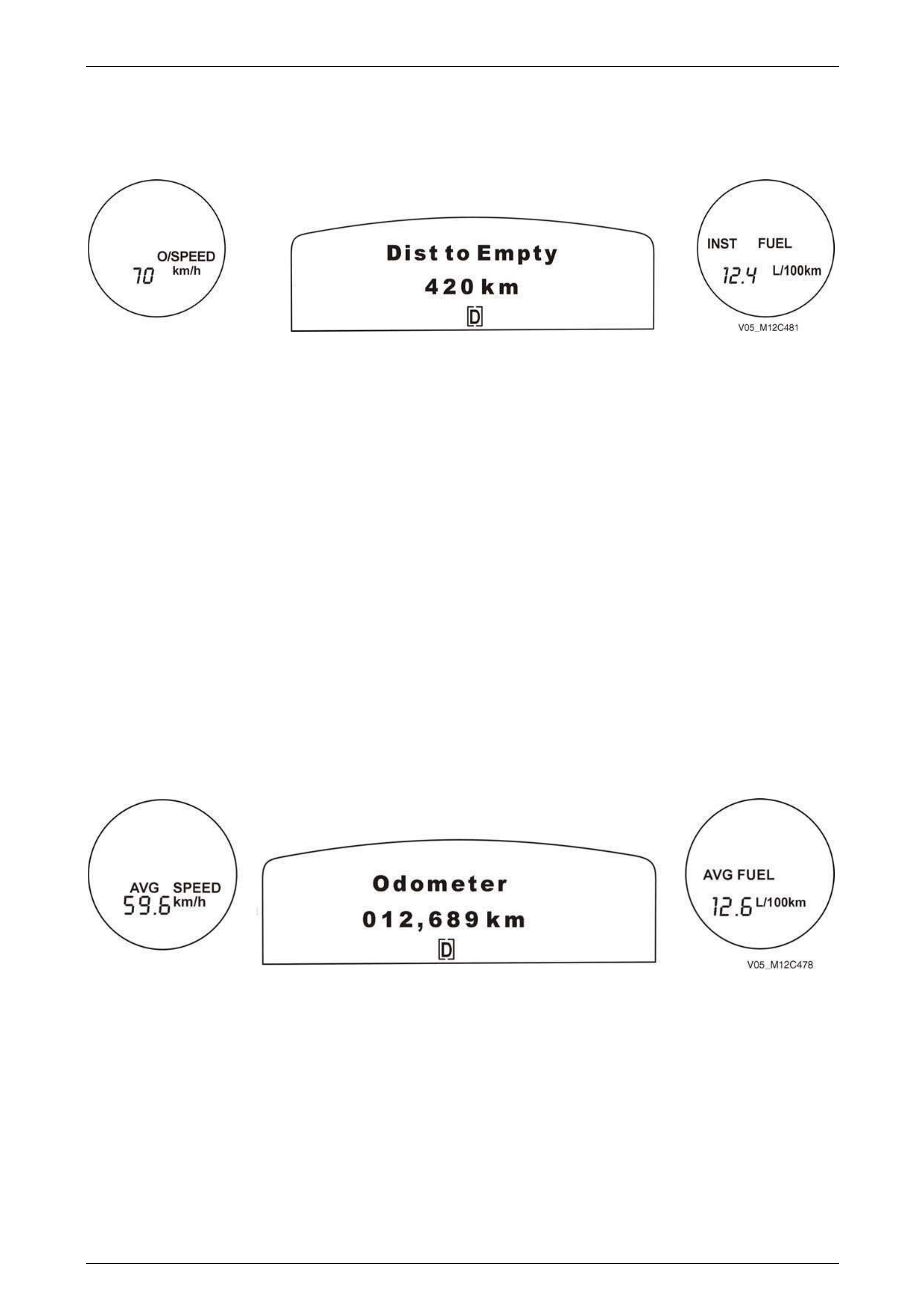
Overspeed / Distance to Empty / Instantaneous Fuel....................................................................................... 16
Overspeed........................................................................................................................................................ 16
Mandatory Overspeed...................................................................................................................................... 17
Preset Overspeed ............................................................................................................................................ 17
Distance to Empty............................................................................................................................................ 18
Instantaneous Fuel........................................................................................................................................... 18
Average Speed / Odometer / Average Fuel........................................................................................................ 18
Average Speed................................................................................................................................................. 18
Odometer ......................................................................................................................................................... 18
Average Fuel.................................................................................................................................................... 18
Trip Time / Trip Distance / Fuel Used................................................................................................................. 19
Trip Time.......................................................................................................................................................... 19
Trip Distance.................................................................................................................................................... 19
Fuel Used......................................................................................................................................................... 19
Time to Arrival / Distance to Arrival / Remaining Fuel...................................................................................... 19
Time to Arrival.................................................................................................................................................. 20
Distance to Arrival............................................................................................................................................ 20
Remaining Fuel................................................................................................................................................ 20
Trip Time A/B / Trip Distance A/B / Fuel Used A/B............................................................................................ 20
Police Mode.......................................................................................................................................................... 21
Stop Watch........................................................................................................................................................... 21
1.7 Multi-function Display ......................................................................................................................................... 22
Constant Icons..................................................................................................................................................... 22
Cruise Control .................................................................................................................................................. 22
Power Mode (Automatic Transmission Only) ................................................................................................... 24
PRND321 (Automatic Transmission) – Normal Shift Mode.............................................................................. 25
“54321” (5 Speed Transmission) – Active Select Mode.................................................................................... 25
Traction Control or Electronic Stability Program............................................................................................... 26
Techline
Techline
Techline
Techline
Techline
Techline
Techline
Techline
Techline
Techline
Techline

Instrumentation Page 12C – 2
Page 12C – 2
Radio Settings.................................................................................................................................................. 27
Compact Disc (CD) .......................................................................................................................................... 30
Audio Settings.................................................................................................................................................. 32
Animated Warnings ............................................................................................................................................. 34
Engine Warning Messages............................................................................................................................... 35
Rear Lamp Failure Warning Messages............................................................................................................ 37
Vehicle Performance Warning Messages......................................................................................................... 38
Fuel Warning Messages................................................................................................................................... 39
System Fault Warning Message....................................................................................................................... 39
Rest Reminder Warning................................................................................................................................... 40
Seat Belt Warning ............................................................................................................................................ 40
Trapping Speed................................................................................................................................................ 41
Trap Speed Reset............................................................................................................................................ 41
Service Items........................................................................................................................................................ 41
Service Due...................................................................................................................................................... 42
Fuel Sender Error............................................................................................................................................. 43
Programming The Instrument Cluster ............................................................................................................... 44
Fuel Calibration Programming.......................................................................................................................... 44
1.8 Customisation Mode............................................................................................................................................ 45
Entering Customisation Mode (Options Menu)................................................................................................. 45
Stop Watch........................................................................................................................................................... 49
Rest Reminder...................................................................................................................................................... 49
Radio MFD Messages.......................................................................................................................................... 50
Confirmation Beeps............................................................................................................................................. 50
Factory Default Settings...................................................................................................................................... 62
1.9 Police Mode.......................................................................................................................................................... 63
2 Tech 2 Information ...............................................................................................................................64
System Identification........................................................................................................................................... 64
Body Menu............................................................................................................................................................ 64
Normal Mode.................................................................................................................................................... 64
Diagnostic Trouble Codes................................................................................................................................ 64
Data Display..................................................................................................................................................... 64
Snapshot.......................................................................................................................................................... 64
Miscellaneous Tests......................................................................................................................................... 64
Program ........................................................................................................................................................... 64
2.1 Normal Mode........................................................................................................................................................ 65
Normal Mode Data List........................................................................................................................................ 65
2.2 Diagnostic Trouble Codes .................................................................................................................................. 66
2.3 Data Display ......................................................................................................................................................... 67
Instruments .......................................................................................................................................................... 67
Inputs.................................................................................................................................................................... 68
Trip Computer...................................................................................................................................................... 69
Configuration ....................................................................................................................................................... 70
System Identification........................................................................................................................................... 71
2.4 Snapshot .............................................................................................................................................................. 72
2.5 Miscellaneous Tests............................................................................................................................................ 73
Warnings .............................................................................................................................................................. 73
Chime.................................................................................................................................................................... 73
2.6 Gauge Control Tests............................................................................................................................................ 74
Speedometer........................................................................................................................................................ 74
Tachometer........................................................................................................................................................... 74
Temperature Gauge............................................................................................................................................. 74
Fuel Gauge ........................................................................................................................................................... 74
2.7 Input Overrides .................................................................................................................................................... 75
2.8 Illumination........................................................................................................................................................... 76
MFD / LCD............................................................................................................................................................. 76
Pointers ................................................................................................................................................................ 76
Dials...................................................................................................................................................................... 76

Instrumentation Page 12C – 3
Page 12C – 3
2.9 Self Test – All Functions On ............................................................................................................................... 77
Test Display...................................................................................................................................................... 77
2.10 MFD Test............................................................................................................................................................... 78
LCD Tests............................................................................................................................................................. 78
Test Display...................................................................................................................................................... 78
2.11 Program................................................................................................................................................................ 79
Fuel Gauge Calibration........................................................................................................................................ 79
Configuration ....................................................................................................................................................... 79
Odometer.............................................................................................................................................................. 79
Speedometer calibration..................................................................................................................................... 79
Reset Service Interval.......................................................................................................................................... 79
Reset Trip Computer Settings ............................................................................................................................ 79
3 Wiring Diagrams and Connectors......................................................................................................80
3.1 Wiring Diagrams – V6.......................................................................................................................................... 80
3.2 Wiring Diagrams – V8.......................................................................................................................................... 83
3.3 Connector Chart – V6 .......................................................................................................................................... 86
3.4 Connector Chart – V8 .......................................................................................................................................... 88
3.5 Instrument Cluster Inputs................................................................................................................................... 90
P3 Connector Pin Locations............................................................................................................................... 90
S237 Connector Pin Locations........................................................................................................................... 91
4 Diagnostics...........................................................................................................................................92
4.1 Diagnostic System Check................................................................................................................................... 92
Circuit Description............................................................................................................................................... 92
Test Description................................................................................................................................................... 93
Diagnostic Aids.................................................................................................................................................... 93
Diagnostic System Check Diagnostic Table...................................................................................................... 93
4.2 Instrument Cluster Self Diagnostics.................................................................................................................. 95
Self Diagnostic Mode Operation......................................................................................................................... 95
Full Test ......................................................................................................................................................... 100
5 Diagnostic Trouble Codes.................................................................................................................101
General Information........................................................................................................................................... 101
5.1 Diagnostic Trouble Code List........................................................................................................................... 101
5.2 DTC 6 – No Serial Data from TPMS .................................................................................................................. 103
Circuit Description............................................................................................................................................. 103
5.3 DTC 7 – No Serial Data from ABS / TCS / ESP – V6 ........................................................................................ 104
Circuit Description............................................................................................................................................. 104
Test Description................................................................................................................................................. 104
Diagnostic Table Notes ..................................................................................................................................... 104
DTC 7 Diagnostic Table..................................................................................................................................... 104
5.4 DTC 8 – No Serial Data from ABS / TCS – V8 .................................................................................................. 106
Circuit Description............................................................................................................................................. 106
Test Description................................................................................................................................................. 106
Diagnostic Table Notes ..................................................................................................................................... 106
DTC 8 Diagnostic Table..................................................................................................................................... 106
5.5 DTC 9 – No Serial Data from BCM.................................................................................................................... 108
Circuit Description............................................................................................................................................. 108
Test Description................................................................................................................................................. 108
Diagnostic Table Notes ..................................................................................................................................... 108
DTC 9 Diagnostic Table..................................................................................................................................... 108
5.6 DTC 10 – No Serial Data from OCC .................................................................................................................. 110
Circuit Description............................................................................................................................................. 110
Test Description................................................................................................................................................. 110
Diagnostic Table Notes ..................................................................................................................................... 110
DTC 10 Diagnostic Table................................................................................................................................... 110

Instrumentation Page 12C – 4
Page 12C – 4
5.7 DTC 11 – No Serial Data from ECM – V6.......................................................................................................... 112
Circuit Description............................................................................................................................................. 112
Test Description................................................................................................................................................. 112
Diagnostic Table Notes ..................................................................................................................................... 112
DTC 11 Diagnostic Table................................................................................................................................... 112
5.8 DTC 11 – No Serial Data from PCM – V8.......................................................................................................... 114
Circuit Description............................................................................................................................................. 114
Test Description................................................................................................................................................. 114
Diagnostic Table Notes ..................................................................................................................................... 114
DTC 11 Diagnostic Table................................................................................................................................... 114
5.9 DTC 12 – No Serial Data from SDM .................................................................................................................. 116
Circuit Description............................................................................................................................................. 116
Test Description................................................................................................................................................. 116
Diagnostic Table Notes ..................................................................................................................................... 116
DTC 12 Diagnostic Table................................................................................................................................... 116
5.10 DTC 13 – No Instrument Poll from BCM........................................................................................................... 118
Circuit Description............................................................................................................................................. 118
Test Description................................................................................................................................................. 118
Diagnostic Table Notes ..................................................................................................................................... 118
DTC 13 Diagnostic Table................................................................................................................................... 118
5.11 DTC 14 – No Serial Communication Data ........................................................................................................ 120
Circuit Description............................................................................................................................................. 120
Module Data Bus Allocations for V6 and V8.................................................................................................... 120
Test Description................................................................................................................................................. 120
Diagnostic Table Notes ..................................................................................................................................... 120
DTC 14 Diagnostic Table................................................................................................................................... 121
5.12 DTC 15 – No Serial Data from Audio System................................................................................................... 122
Circuit Description............................................................................................................................................. 122
Test Description................................................................................................................................................. 122
Diagnostic Table Notes ..................................................................................................................................... 122
DTC 15 Diagnostic Table................................................................................................................................... 122
5.13 DTC 16 – Fuel Level System ............................................................................................................................. 124
Circuit Description............................................................................................................................................. 124
Test Description................................................................................................................................................. 124
Diagnostic Table Notes ..................................................................................................................................... 124
DTC 16 Diagnostic Table................................................................................................................................... 124
5.14 DTC 19 – Incorrect SDM Detected .................................................................................................................... 126
Circuit Description............................................................................................................................................. 126
Test Description................................................................................................................................................. 126
Diagnostic Table Notes ..................................................................................................................................... 126
DTC 19 Diagnostic Table................................................................................................................................... 126
5.15 DTC 21 or 22 – Trip Sw itch Faulty.................................................................................................................... 127
Circuit Description............................................................................................................................................. 127
Test Description................................................................................................................................................. 127
Diagnostic Table Notes ..................................................................................................................................... 127
DTC 21 or 22 Diagnostic Table ......................................................................................................................... 127
5.16 DTC 24 – EEPROM Checksum Failure ............................................................................................................. 129
Circuit Description............................................................................................................................................. 129
Test Description................................................................................................................................................. 129
Diagnostic Table Notes ..................................................................................................................................... 129
DTC 24 Diagnostic Table................................................................................................................................... 129
6 Diagnostics For Non DTC Faults......................................................................................................130
Diagnosis For Hard-wired Input Signals.......................................................................................................... 130
Diagnosis For Serial Data Input Signals.......................................................................................................... 130
6.1 Front Fog Lamp Indicator Not Working........................................................................................................... 131
Circuit Description............................................................................................................................................. 131
Test Description................................................................................................................................................. 131

Instrumentation Page 12C – 5
Page 12C – 5
Diagnostic Table Notes ..................................................................................................................................... 131
Front Fog Lamp Indicator Not Working Diagnostic Table.............................................................................. 131
6.2 Turn Signal Indicator......................................................................................................................................... 132
Circuit Description............................................................................................................................................. 132
Test Description................................................................................................................................................. 132
Diagnostic Table Notes ..................................................................................................................................... 132
Turn Signal Indicator Diagnostic Table ........................................................................................................... 133
6.3 High Beam Indicator.......................................................................................................................................... 134
Circuit Description............................................................................................................................................. 134
Test Description................................................................................................................................................. 134
Diagnostic Table Notes ..................................................................................................................................... 134
High Beam Indicator Diagnostic Table ............................................................................................................ 134
6.4 Security Status Indicator................................................................................................................................... 135
6.5 ABS OFF Warning Indicator – V6 ..................................................................................................................... 136
Circuit Description............................................................................................................................................. 136
Test Description................................................................................................................................................. 136
Diagnostic Table Notes ..................................................................................................................................... 136
ABS OFF Warning Indicator – V6 Diagnostic Table........................................................................................ 136
6.6 ABS OFF Warning Indicator – V8 ..................................................................................................................... 137
ABS OFF Warning Lamp Operation ................................................................................................................. 137
Circuit Description............................................................................................................................................. 137
Test Description................................................................................................................................................. 137
Diagnostic Table Notes ..................................................................................................................................... 137
ABS OFF Warning Indicator – V8 Diagnostic Table........................................................................................ 137
6.7 Cruise Control – V6............................................................................................................................................ 138
Circuit Description............................................................................................................................................. 138
Test Description................................................................................................................................................. 138
Diagnostic Table Notes ..................................................................................................................................... 138
Cruise Control – V6 Diagnostic Table.............................................................................................................. 138
6.8 Cruise Control – V8............................................................................................................................................ 140
Circuit Description............................................................................................................................................. 140
Test Description................................................................................................................................................. 140
Diagnostic Table Notes ..................................................................................................................................... 140
Cruise Control (V8) Diagnostic Table............................................................................................................... 140
6.9 Low Traction Control Display – V6................................................................................................................... 142
Circuit Description............................................................................................................................................. 142
Test Description................................................................................................................................................. 142
Diagnostic Table Notes ..................................................................................................................................... 142
Low Traction Control Display – V6 No ESP Diagnostic Table....................................................................... 142
Low Traction Control Display – V6 With ESP Diagnostic Table.................................................................... 142
6.10 Low Traction Control Display – V8................................................................................................................... 143
Circuit Operation................................................................................................................................................ 143
Test Description................................................................................................................................................. 143
Diagnostic Table Notes ..................................................................................................................................... 143
Low Traction Control Display – V8 Diagnostic Table..................................................................................... 143
6.11 Alternator Warning – V6.................................................................................................................................... 144
Operation............................................................................................................................................................ 144
Circuit Description............................................................................................................................................. 144
Test Description................................................................................................................................................. 144
Diagnostic Table Notes ..................................................................................................................................... 144
Alternator Warning – V6 Diagnostic Table....................................................................................................... 144
6.12 Alternator Warning – V8.................................................................................................................................... 145
Operation............................................................................................................................................................ 145
Circuit Description............................................................................................................................................. 145
Test Description................................................................................................................................................. 145
Diagnostic Table Notes ..................................................................................................................................... 145
Alternator Warning – V8 Diagnostic Table....................................................................................................... 145

Instrumentation Page 12C – 6
Page 12C – 6
6.13 Trip Computer Switch........................................................................................................................................ 146
Operation............................................................................................................................................................ 146
Circuit Description............................................................................................................................................. 146
Test Description................................................................................................................................................. 146
Diagnostic Table Notes ..................................................................................................................................... 146
Trip Computer Switch Diagnostic Table.......................................................................................................... 146
6.14 Instrument Illumination..................................................................................................................................... 148
Operation............................................................................................................................................................ 148
Circuit Description............................................................................................................................................. 148
Test Description................................................................................................................................................. 148
Diagnostic Table Notes ..................................................................................................................................... 148
Instrument Illumination Diagnostic Table........................................................................................................ 148
6.15 Brake Fail / Park Brake Warning....................................................................................................................... 150
Brake Fail / Park Brake Warning....................................................................................................................... 150
Operation ....................................................................................................................................................... 150
Circuit Description.......................................................................................................................................... 150
Brake Fluid Warning.......................................................................................................................................... 150
Operation ....................................................................................................................................................... 150
Circuit Description.......................................................................................................................................... 150
Test Description................................................................................................................................................. 150
Diagnostic Table Notes ..................................................................................................................................... 150
Brake Fail / Park Brake Warning Diagnostic Table......................................................................................... 151
6.16 Speedometer Diagnosis.................................................................................................................................... 152
Circuit Description – V6 .................................................................................................................................... 152
Circuit Description – V8 .................................................................................................................................... 152
Test Description................................................................................................................................................. 152
Diagnostic Table Notes ..................................................................................................................................... 152
Speedometer Diagnostic Table......................................................................................................................... 152
6.17 Tachometer Diagnosis ...................................................................................................................................... 154
Circuit Description – V6 .................................................................................................................................... 154
Circuit Description – V8 .................................................................................................................................... 154
Test Description................................................................................................................................................. 154
Diagnostic Table Notes ..................................................................................................................................... 154
Tachometer Diagnostic Table........................................................................................................................... 154
6.18 Coolant Temperature Gauge Diagnostic ......................................................................................................... 156
Circuit Description – V6 .................................................................................................................................... 156
Circuit Description – V8 .................................................................................................................................... 156
Test Description................................................................................................................................................. 156
Diagnostic Table Notes ..................................................................................................................................... 156
Coolant Temperature Gauge Diagnostic Table............................................................................................... 156
6.19 Fuel Level Gauge Diagnosis............................................................................................................................. 157
Circuit Description – V6 .................................................................................................................................... 157
Circuit Description – V8 .................................................................................................................................... 157
Test Description................................................................................................................................................. 157
Diagnostic Table Notes ..................................................................................................................................... 157
Fuel Level Gauge Diagnostic Table.................................................................................................................. 157
6.20 Serial Data Communication .............................................................................................................................. 158
General Information........................................................................................................................................... 158
7 Service Operations.............................................................................................................................159
7.1 Instrument Cluster Removal And Reinstallation............................................................................................. 159
Trim Removal and Reinstallation ..................................................................................................................... 159
Instrument Removal and Reinstallation........................................................................................................... 159
Sensor Removal and Reinstallation................................................................................................................. 159
Trip Computer Sw itch Removal and Reinstallation........................................................................................ 159
Trip Computer Switch Testing.......................................................................................................................... 159

Instrumentation Page 12C – 7
Page 12C – 7
7.2 Programming...................................................................................................................................................... 160
Tech 2 Instrument Cluster Configuration. ....................................................................................................... 160
Programming.................................................................................................................................................. 160
Police Speedo Calibration.............................................................................................................................. 160
Fuel Gauge Calibration................................................................................................................................... 160
Configuration.................................................................................................................................................. 160
Odometer Reset............................................................................................................................................. 160
Speedometer Calibration................................................................................................................................ 160
Reset Service Interval.................................................................................................................................... 160
Reset Trip Computer Settings........................................................................................................................ 160
Fuel Calibration Settings ................................................................................................................................ 161
Fuel Gauge Calibration...................................................................................................................................... 161
Fuel Calibration Details..................................................................................................................................... 161
Configuration.................................................................................................................................................. 161
Country........................................................................................................................................................... 161
Engine Type................................................................................................................................................... 162
Speedometer Pulses...................................................................................................................................... 162
Vehicle Speed PPK Values............................................................................................................................ 162
V8 4-speed Auto............................................................................................................................................. 162
V6 5-speed Auto............................................................................................................................................. 163
SRS Configuration.......................................................................................................................................... 163
Transmission Type......................................................................................................................................... 163
Police Mode.................................................................................................................................................... 163
Seat Belt Warning .......................................................................................................................................... 164
Program Settings............................................................................................................................................ 164
4 and 5 Speed Automatic Transmission.......................................................................................................... 164
Transmission Programming............................................................................................................................ 164
Odometer ....................................................................................................................................................... 164
Speedometer Calibration .................................................................................................................................. 165
Reset Service Interval........................................................................................................................................ 165
Reset Trip Computer Settings .......................................................................................................................... 165
8 Special Tools ......................................................................................................................................166

Instrumentation Page 12C – 8
Page 12C – 8
1 General Information
This document contains information on the operation, diagnosis, self testing and programming of the instrument clusters.
Should it be necessary to electric weld on a
vehicle, removal of the instrument cluster is
mandatory. Failure to do so will result in
damage to the instrument gauge circuitry.
NOTE
If the battery is disconnected, the following
accumulative values are reset:
• Trip time
• Trip distance
• Fuel used
• Average fuel
• Average speed
• Stop watch (if enabled and displaying a non
zero figure)
1.1 General Description
A trip computer is standard equipment on all vehicles; refer to the following for an explanation of trip computer functions
refer to 1.6 Trip Computer.
The instrument clusters fitted to all vehicles have a multi function display (MFD), which displays messages from various
vehicle systems including the engine, transmission, ABS and entertainment system. The MFD supplements the warning
indicators by displaying a more precise message; all clusters feature a number of warning indicators of different colours
that are illuminated by LED’s. For further information, refer to 1.3 Instrument Cluster Operation.
Communication protocol between the instrument cluster and the BCM is via the secondary UART bus.
On all vehicles, the clock is incorporated into the multi-function display situated above the radio mounting location.
Instrument cluster illumination is by light emitting diodes (LED’s) within the instrument cluster. The LED’s are not
serviceable and should any of them fail the instrument cluster needs to be replaced.
NOTE
• A difference of ±2 km/h may be noticed when
comparing the analogue speedometer with
the digital MFD reading, this is normal and
within design specifications.
• Only left-hand drive vehicles have the
instrument cluster’s door ajar indicator
activated.
Instrumentation Page 12C – 9
Page 12C – 9
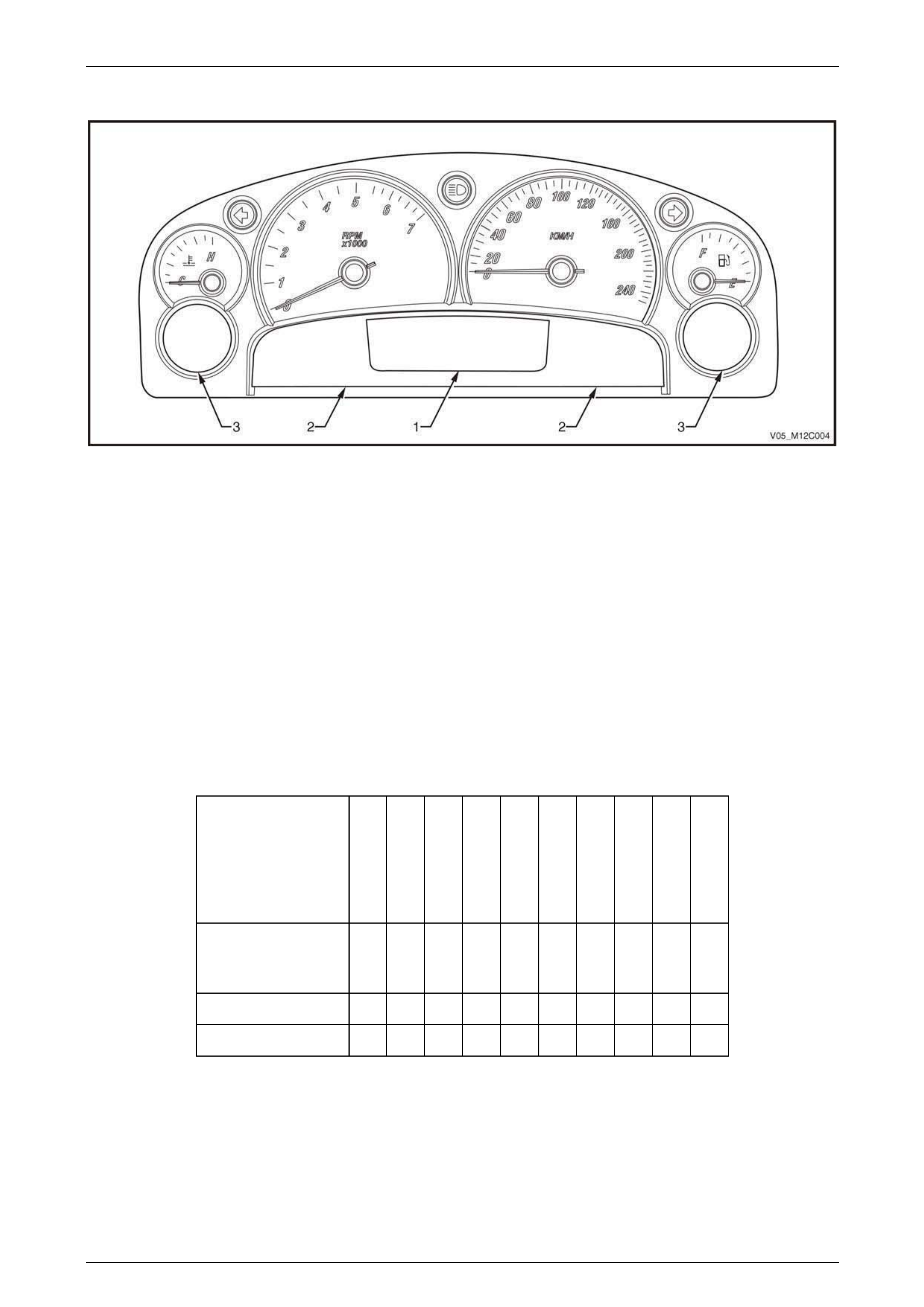
Instrument Cluster
Figure 12C – 1
Legend
1 Multi-function Display 2 Warning Indicators 3 Trip Computer Display
NOTE
• When installing a new instrument cluster, the
original odometer reading, together with other
important parameters, must be transferred
into the replacement instrument cluster.
• The instrument cluster is not a serviceable
item if there is any internal fault the instrument
cluster must be replaced.
Instrument Cluster Warning Indicators
LED Warning Indicator Table
Warning
Indicator
ABS
Alternator
Brake
(Park/Fail)
Front Fog
High Beam
Left Turn Arrow
Right Turn
Arrow
Seatbelt
Security
SRS
Colour
Amber
Red
Red
Green
Blue
Green
Green
Red
Red
Red
LVL4 WL X X X X X X X X X X
LVL5 WL X X X X X X X X X X
Instrumentation Page 12C – 10
Page 12C – 10
MFD Information Messages
MDF Information
Messages
Cruise
Active
Cruise
On
Over
speed
Power
Shift
PRNDL
Traction
Off
LVL4 WL X X X X X X
LVL5 WL X X X X X X
MFD Animated Graphics
MFD Graphics
ABS
Airbag / SRS
Alternator
Audio
Check
Powertrain
High Temp
Low
Coolant
Low Fuel
Low Oil
Pressure
Low
Traction
Overspeed
Park / Brake
Fail
Rear Lamp
Fail
Traction Off
LVL4 WL X X X X X X X X X X X X X X
LVL5 WL X X X X X X X X X X X X X X
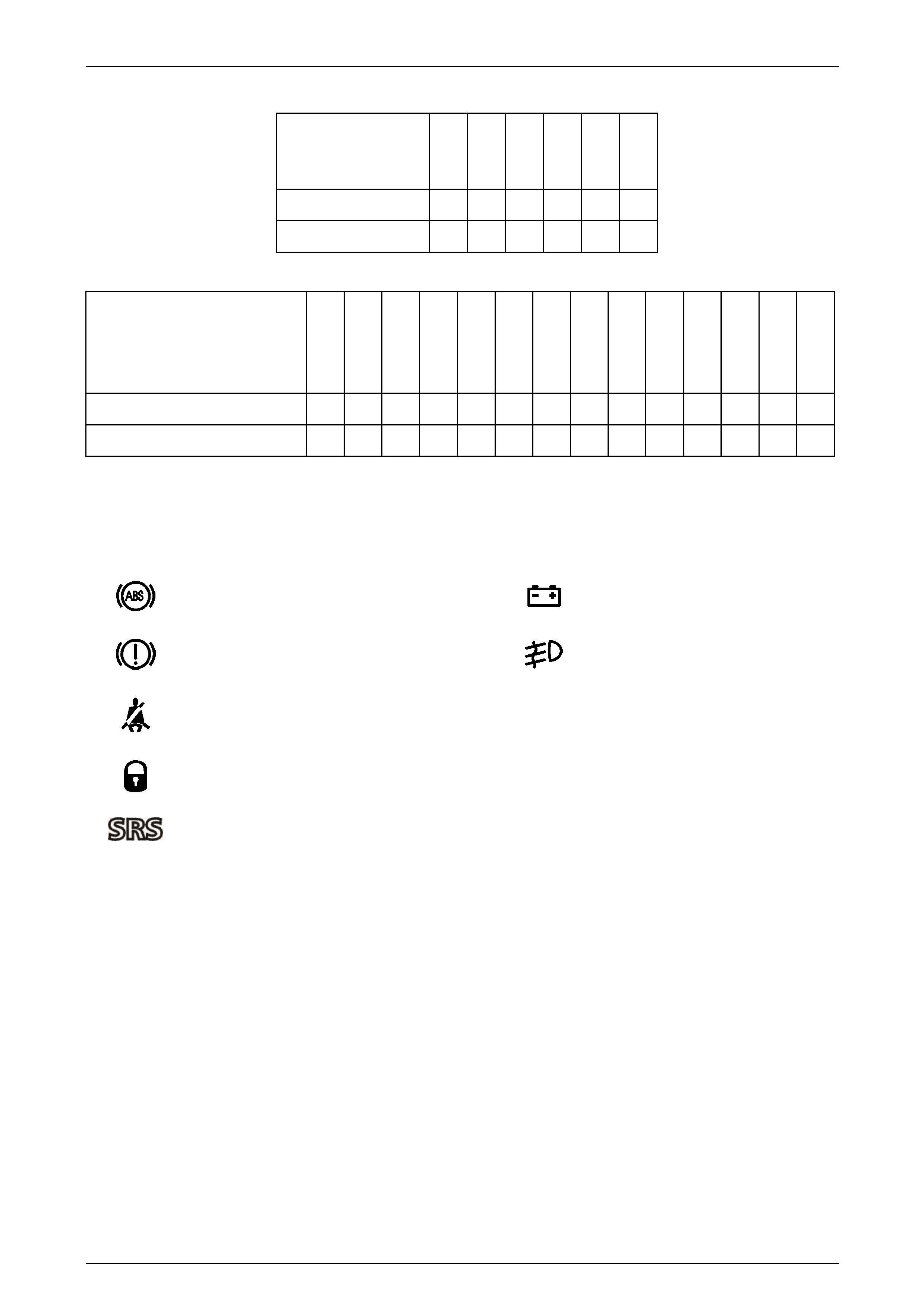
Warning Indicator Symbols
The following warning indicators are located beneath the temperature gauge on the left-hand side of the instrument
cluster and beneath the fuel gauge on the right-hand side of the instrument cluster. LED’s illuminate the indicators.
Left-hand Side Right-hand Side
ABS Off (Amber) Alternator Fail (Red)
Brake (Red) – (Park Brake On or Brake Fail)
Front Fog Lamps On (Green)
Seat Belt (Red)
Security System On (Red)
SRS Fault (Red)
NOTE
The Alternator fail warning indicator will
extinguish 6 seconds after the ignition is switched
on with the engine not running.

Instrumentation Page 12C – 11
Page 12C – 11
1.2 Instrument Cluster Illumination
The headlamp switch incorporates a variable intensity instrument cluster illumination control (slider), and a four-position
switch for off, parking, headlamps on and auto headlamps on switch mode. In auto headlamps on mode, the instrument
cluster illumination is dependant upon whether the lights are on or off.
With the headlamp switch in the OFF position, the MFD illumination (or the trip computer windows if fitted) are set to
maximum backlighting. In any of the other positions, the MFD illumination (or trip computer windows) are controlled by
the illumination slider on the headlight switch.
The slider on the headlamp switch controls the dial, pointer and MFD illumination. Moving the slider varies an input
voltage to the body control module (BCM), which in turn sends an illumination level signal to the instrument cluster via the
serial data communications bus. The instrument cluster interprets the illumination level signal and controls the instrument
clusters illumination level accordingly, refer to Section 12J body control module.
Chimes
An audible warning chime is incorporated in the instrument cluster. This feature is used to emphasise the warning
conditions with the tone and repetition rate of the chime being variable for the warning messages.
Instrumentation Page 12C – 12
Page 12C – 12
1.3 Instrument Cluster Operation
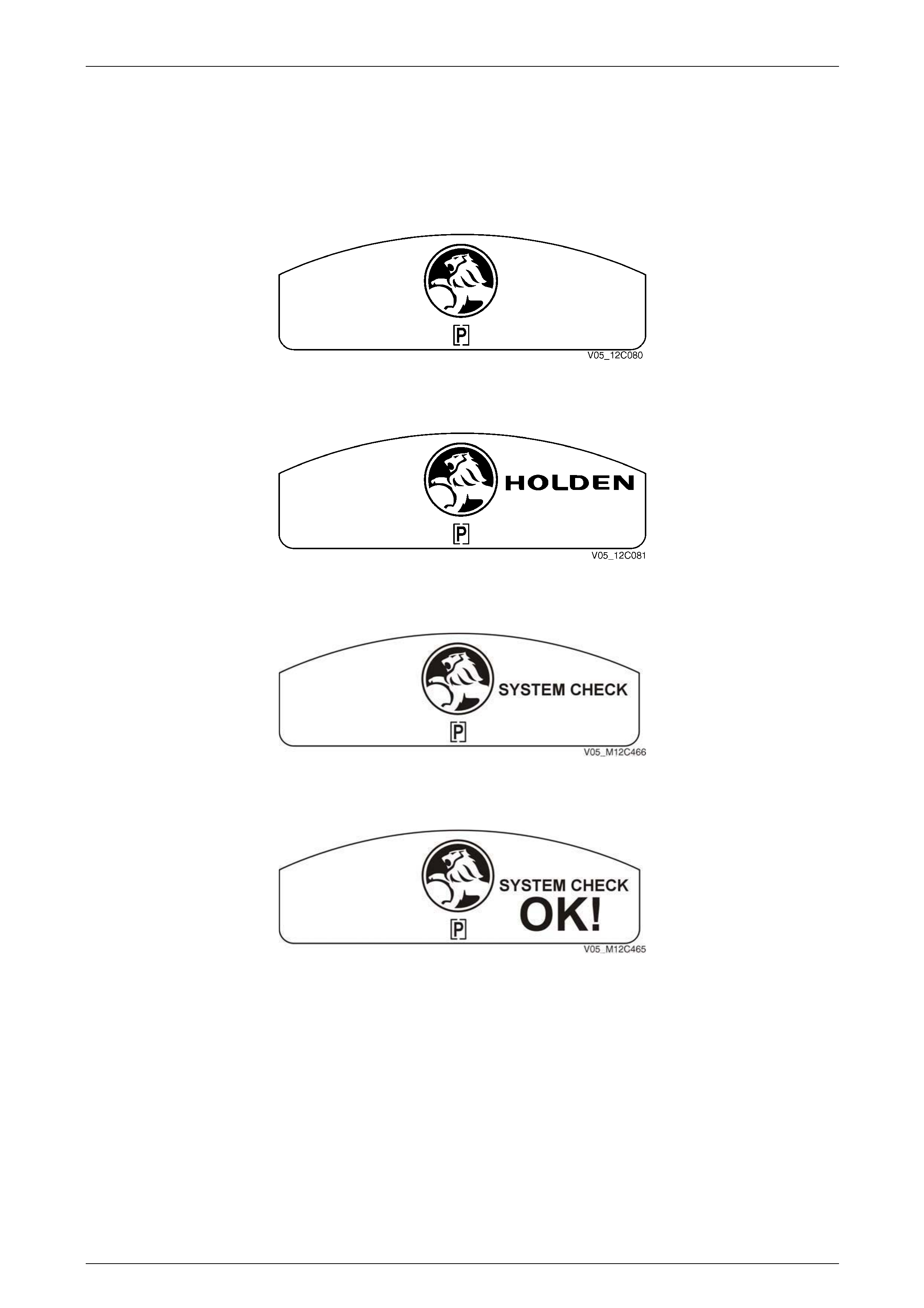
Ignition ON – Welcome Sequence Holden
When the ignition switch is turned to the ON position, a vehicle system check is performed and the status is displayed on
the MFD. The system check displays the following if there are no warnings or service reminders active.
Figure 12C – 2
After 0.5 second.
Figure 12C – 3
After 1.0 second.
Figure 12C – 4
After 2.0 seconds.
Figure 12C – 5
NOTE
If the driver invokes the Options Menu, eg, MODE
is held while ignition is keyed on, the System
Check will be carried out in the background and
not displayed.
Instrumentation Page 12C – 13
Page 12C – 13
1.4 Ignition On System Check
During the System Check the PRNDL icon or any other icon that can be turned on or off, or is on by default from the last
ignition cycle, will be displayed at the System Check start up.
If the System Check detects a warning or alarm, the MFD displays it immediately. If a warning or alarm is displayed and
then acknowledged by the driver (depending on the fault message) by pressing the MODE button, the Welcome
Sequence is bypassed and the MFD defaults to the last screen that was displayed prior to the last ignition key off.
If a service reminder is active, it will be displayed for 10 seconds before the Welcome Sequence. If no service reminder is
active, the Welcome Sequence continues. If more than one service reminder is active, they will be displayed for a total of
10 seconds. When the service reminders are displayed, pressing the trip computer switch MODE button allows scrolling
through the service reminders.
Pressing the trip computer switch MODE button at any stage throughout the System Check will display the trip computer
screen. The System Check will continue operating in the background.
To operate the MODE selection button correctly it is important to only press it momentarily to advance to the next option
screen.
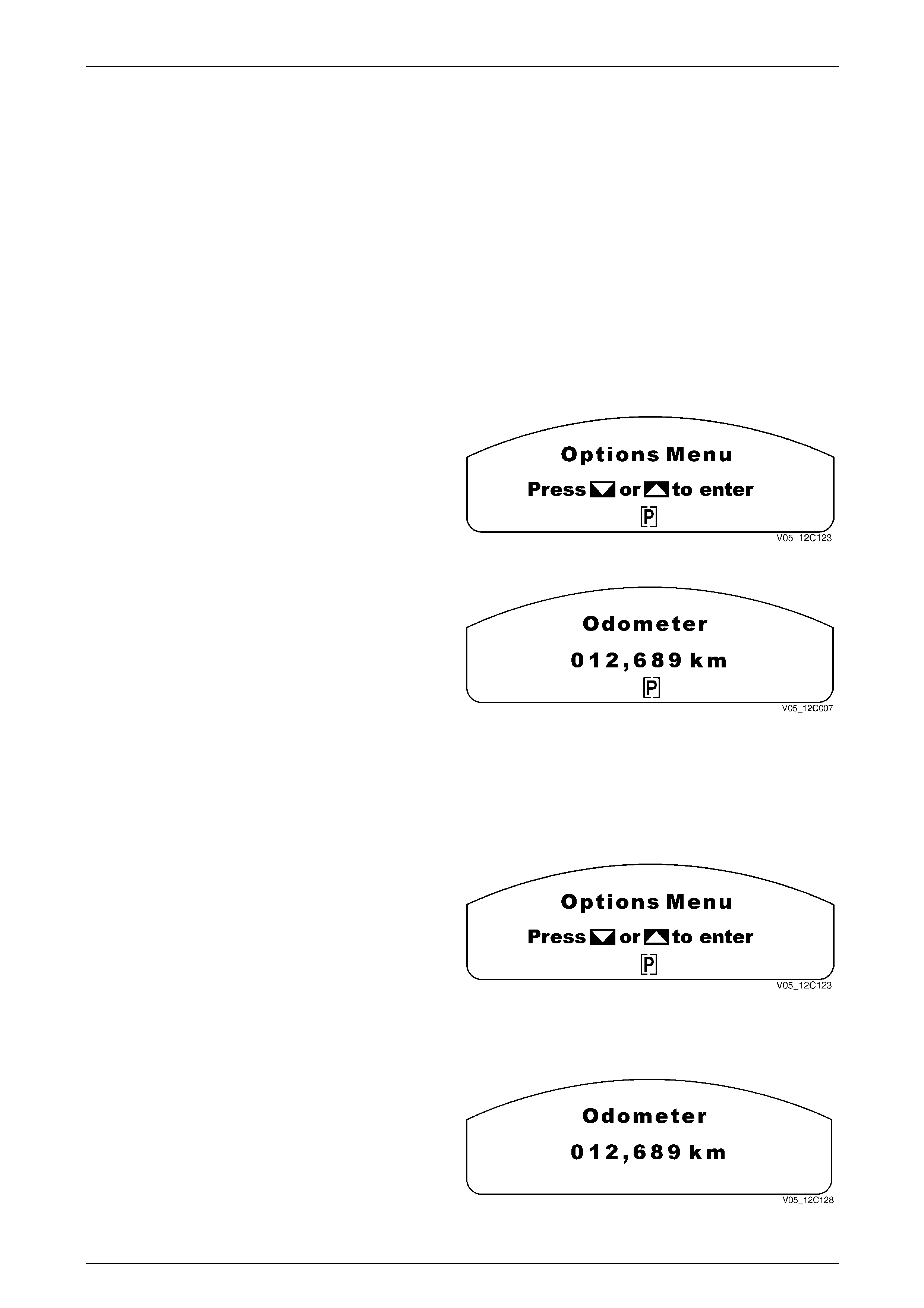
When the System Check is completed, the Options Menu is
displayed for 3 seconds if the vehicle speed is below
10 km/h, refer to 1.8 Customisation Mode for further details
on the Options Menu.
If the MODE button is pressed or the screen times-out
(3 seconds), the Options Menu disappears and reverts to
the last screen displayed on the last key off for that priority
key. Figure 12C – 6
To display the odometer screen, tap the MODE button until
the screen is displayed.
Figure 12C – 7
NOTE
• If the driver invokes the options menu, eg,
mode is held while ignition is keyed on, the
system check will be carried out in the
background and not displayed.
If the system check picks up a fault it displays it immediately,
refer to 1.7 Multi-function Display, If a fault is displayed and
then erased by the driver (depending on the fault message)
by pressing the MODE button, Figure 12C – 8 is displayed,
which skips the welcome message.
Figure 12C – 8
Ignition OFF
When the ignition switch is turned to the OFF position, the
odometer is displayed in the MFD unless any service
reminders are active. Active service reminders are shown for
10 seconds before displaying the odometer screen.
Figure 12C – 9
Instrumentation Page 12C – 14
Page 12C – 14
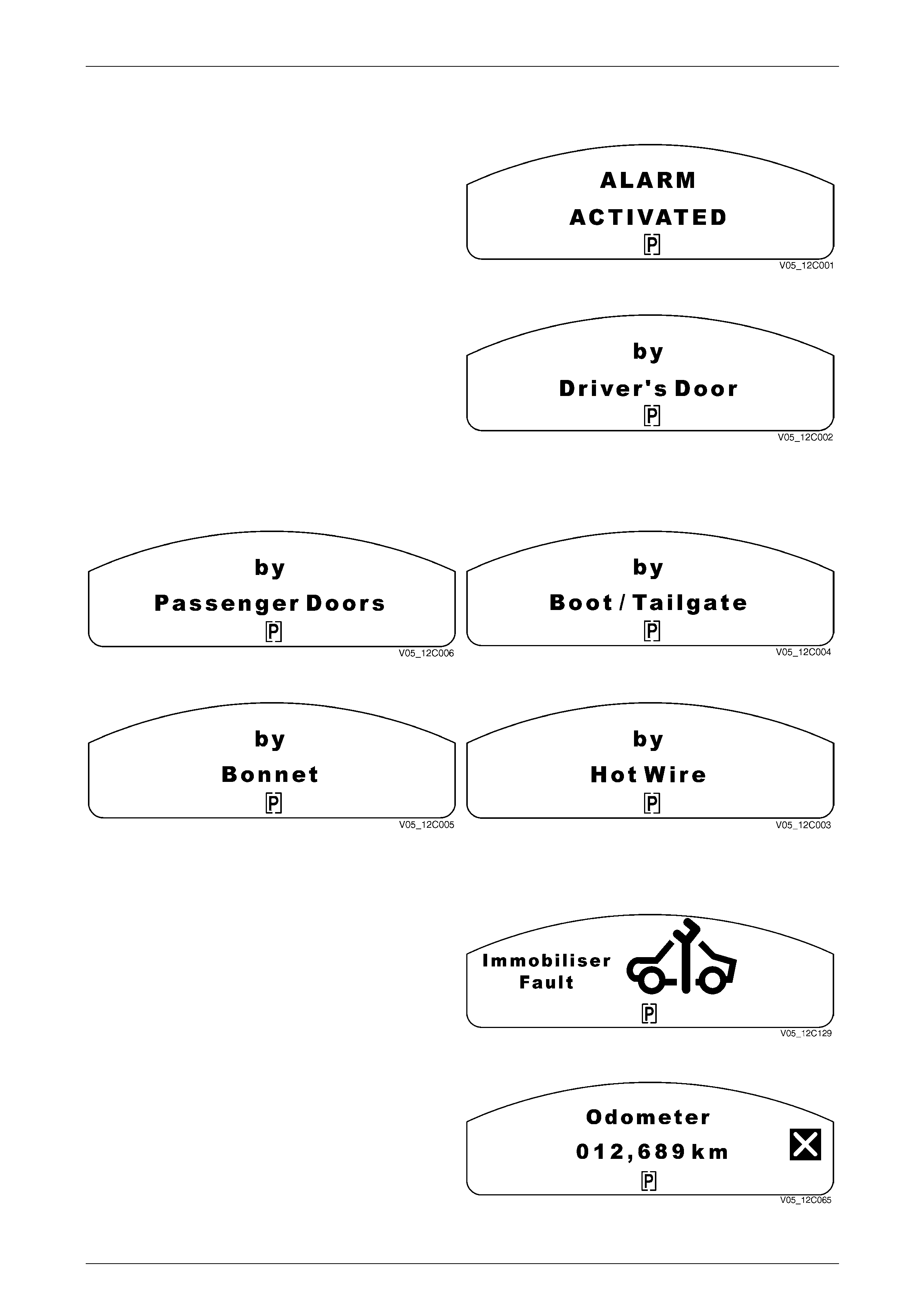
1.5 Alarms
The following screens are displayed if an alarm has been
activated and are displayed as soon as the cluster has
received the alarm, even prior to or during a System Check.
The Alarm Activated screen is displayed first for 1 second,
followed by the trigger point screens.
Figure 12C – 10
The display flashes between the Alarm Activated screen and
the area of activation. If there are two or more areas of
activation, the MFD scrolls through the list of activated areas
until the MODE button is pressed. The MFD then proceeds
on to the next screen in the welcome sequence.
Figure 12C – 11
If there has been an unauthorised entry(s) and an MFD warning remains active, the following messages will continue to
alternate until the MODE button is pressed on the trip computer switch or the ignition cycled from off to on.
Figure 12C – 12 Figure 12C – 13
Figure 12C – 14 Figure 12C – 15
Vehicle Immobilisation by ECM or PCM
If an immobiliser fault is detected, the cluster will flash the
Immobiliser Fault screen on the MFD at a 2 Hz duty cycle
(BCM controlled) and the following MFD message is to be
displayed until the mode button is pressed then is displayed
as a CROSS on the RHS of the MFD and is shown in all
screens.
Figure 12C – 16
This screen occurs only in V6 engine vehicles.
Figure 12C – 17
Instrumentation Page 12C – 15
Page 12C – 15
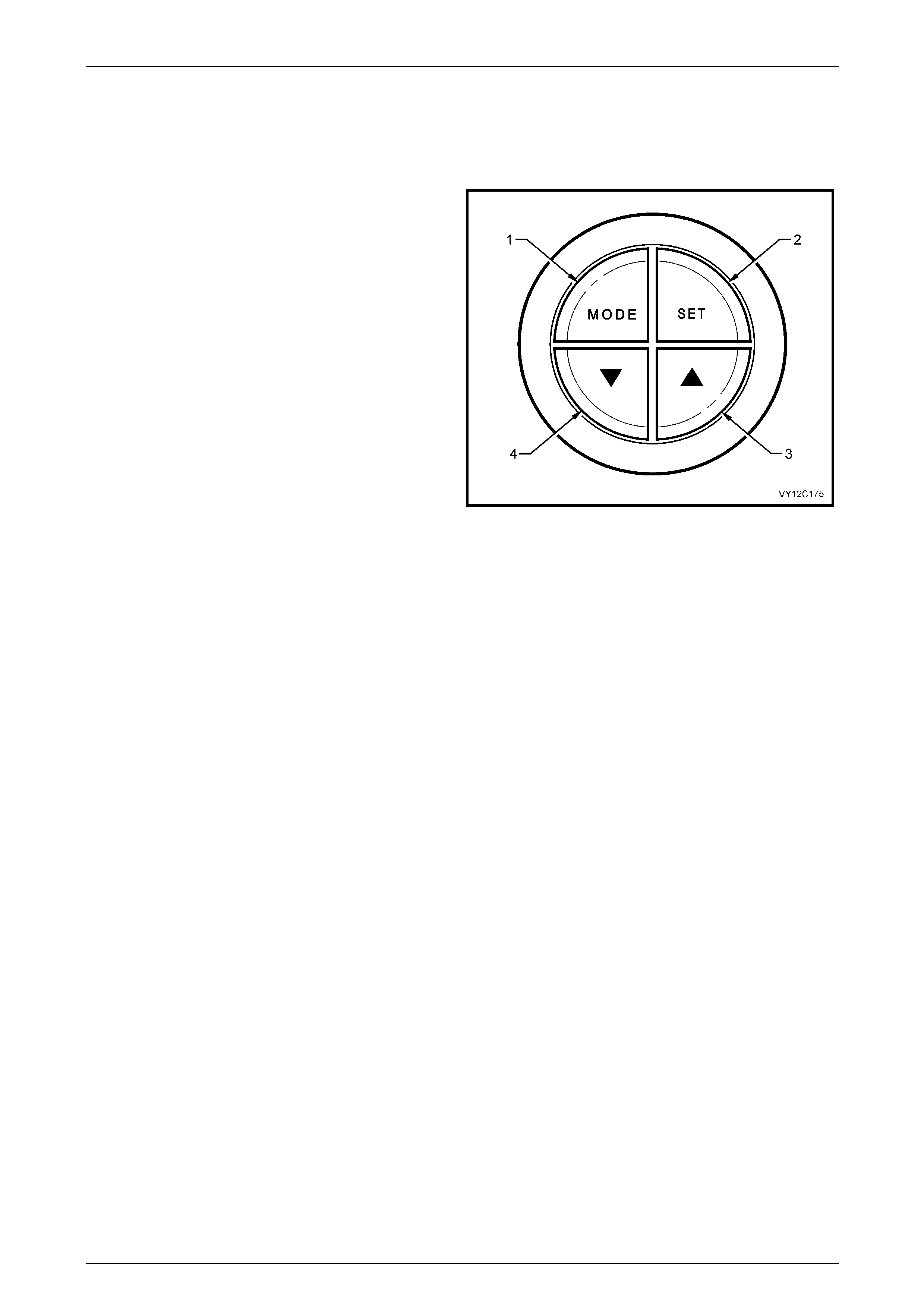
1.6 Trip Computer
Operation
The buttons for the trip computer are located to the left of
the instrument cluster. The four buttons in the switch
assembly are MODE (1), SET (2), UP (3) and DOWN (4).
The trip computer screens are displayed on the MFD, and
the two-side Trip Computer Displays, The MFD is located in
the centre of the instrument cluster below the gauges, and
the two side Trip Computer Displays are located beneath the
temperature gauge on the left, and the fuel gauge on the
right.
To scroll between the functions (three sets of displays),
press the MODE button for less than 2 seconds. The speed
related details are provided in the left Trip Computer
Display, the distance related details are provided in the
MFD, and the fuel related details are provided in the right
Trip Computer Display.
Figure 12C – 18
When the ignition is turned on, the MFD initially displays the start up sequence, and then displays the same trip computer
functions as when the ignition was last turned off as long as the same priority key is used.
The trip computer functions can be reset when the Average Speed or Trip Time details are displayed in the left trip
computer display to reset the trip computer functions, press the SET button. This will reset all functions, with the
exception of Distance to Empty, Overspeed Warning, Odometer, Time to Arrival, Distance to Arrival, Remaining Fuel and
Instantaneous Fuel.
Personal customisation of the trip computer is also possible refer to 1.8 Customisation Mode.
The Distance to Arrival function must be enabled in Customisation Mode before the Time to Arrival / Distance to Arrival /
Remaining Fuel screens can be accessed using the MODE button.
These screens are not available if Trip A and B function is enabled. However, they can be accessed from the Trip B
screens by pressing and holding the MODE button for more than 2 seconds.
NOTE
Cycle through the alarm and warning displays if
active before accessing the trip computer
functions.
Instrumentation Page 12C – 16
Page 12C – 16
Overspeed / Distance to Empty / Instantaneous Fuel
If the MODE button is pressed, the normal Overspeed or Preset Overspeed screens will be displayed, depending on the
previous overspeed selection.
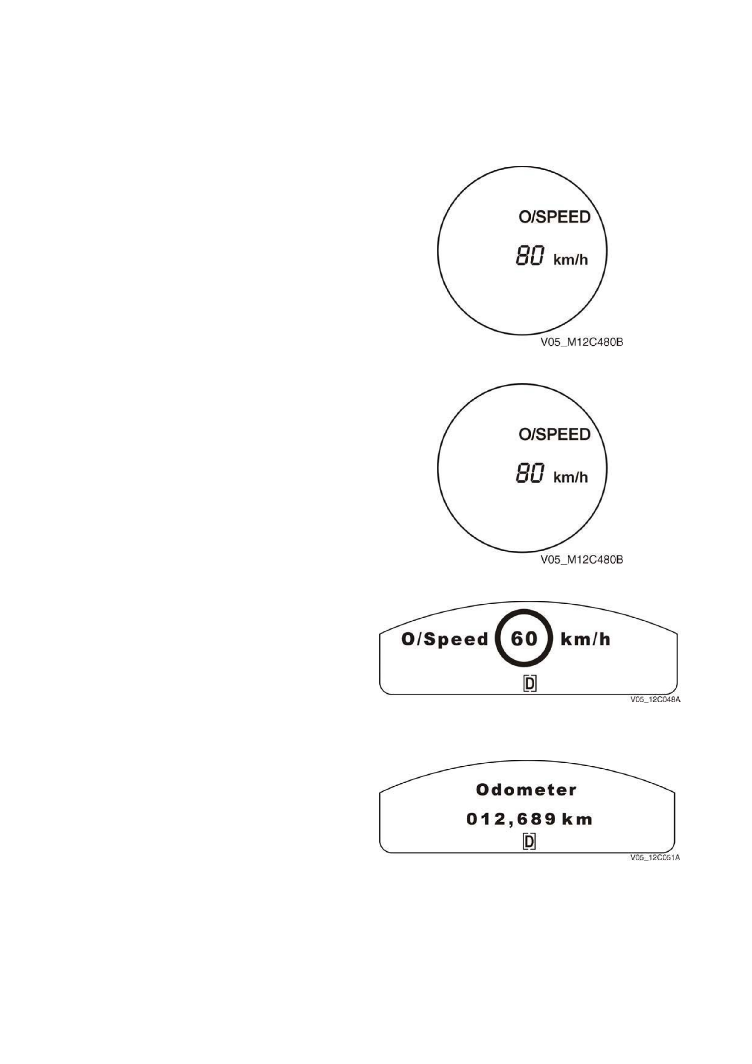
Overspeed
Overspeed On / Off
To turn the Overspeed function on, press and hold the trip
computer switch SET button for at least 2 seconds, and the
Overspeed screen appears.
To turn the Overspeed function off, press and hold the SET
button for at least 2 seconds while the Overspeed screen is
displayed.
Figure 12C – 19
Overspeed Adjustment
To adjust the overspeed value, tap the UP or DOWN
buttons on the trip computer switch until the screen displays
the desired speed. The new overspeed value is now locked
in. The overspeed value is variable between 20 km/h and
200 km/h, and increments or decrements by 5 km/h for each
press of the corresponding button.
Figure 12C – 20
Overspeed Trigger
The Overspeed screen alerts the driver a predetermined
speed has been reached. If the overspeed warning is
triggered, the overspeed figure in a circle flashes for
10 seconds, or until the speed is dropped if overspeed is
maintained for less than 10 seconds.
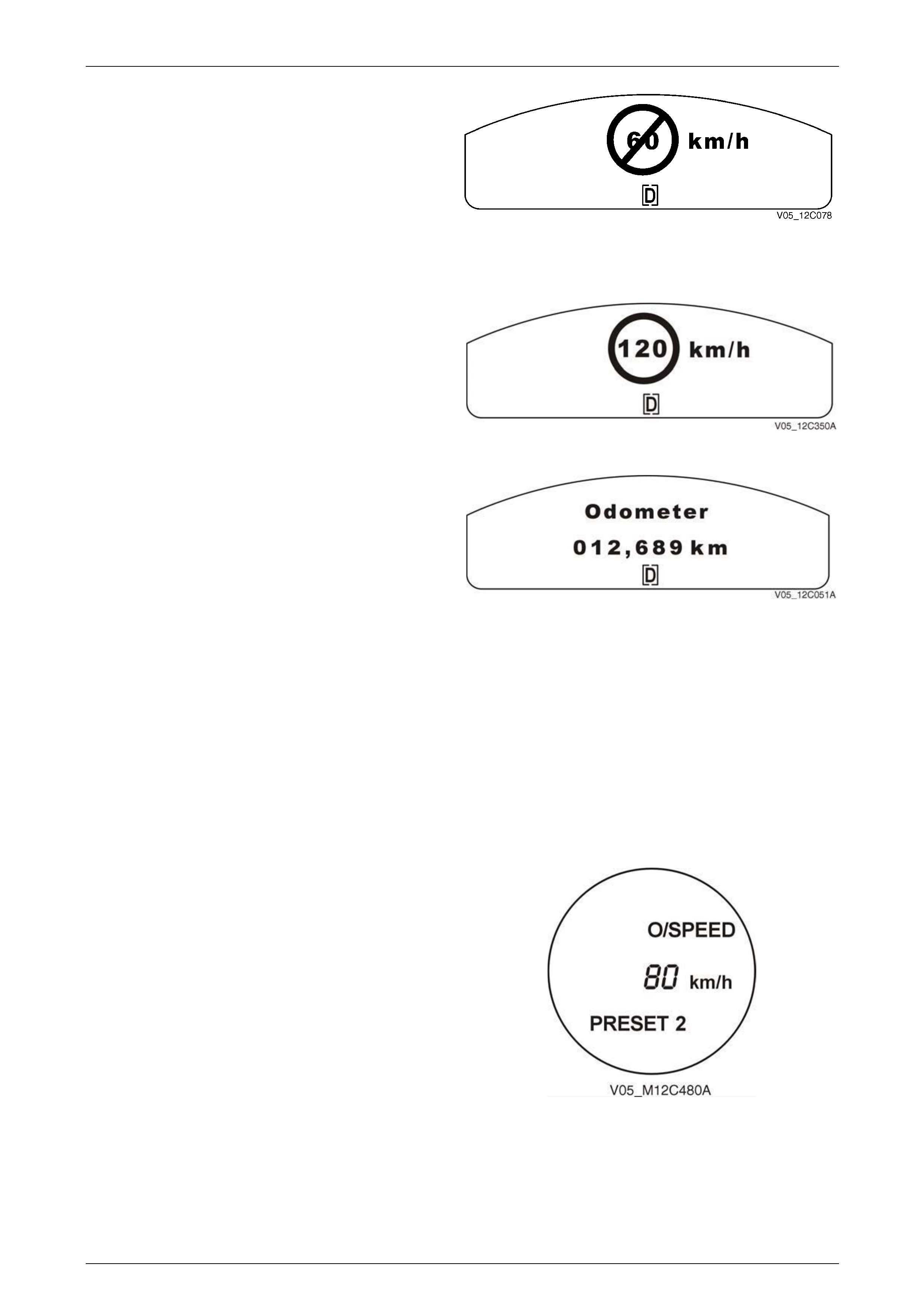
If the vehicle speed is more than 15 km/h above the set
overspeed value, the display, the overspeed wording and
the overspeed value all flash.
Figure 12C – 21
If the overspeed is maintained for longer than 10 seconds
but it is not more than 15 km/h over the set overspeed
value, the overspeed warning drops back to the O/SPEED
constant icon. The display reverts to the previously
displayed trip computer screen.
If the overspeed is maintained for longer than 10 seconds
and is more than 15 km/h over the set overspeed value, the
overspeed warning drops back to the O/SPEED constant
icon and continues to flash. Figure 12C – 22
NOTE
To scroll to a speed rapidly, press and hold the
UP or DOWN button.
Instrumentation Page 12C – 17
Page 12C – 17
Underspeed
When the vehicle drops below the overspeed setting, the
Underspeed screen is displayed and a chime sounds if the
driver has enabled the underspeed chime in Customisation
Mode, refer to 1.8 Customisation Mode If no underspeed
chime has been set, the screen turns off with no chime or
visual underspeed indication. Figure 12C – 23
Mandatory Overspeed
Tech 2 sets the Mandatory Overspeed value. If the vehicle
travels above this speed, the Mandatory Overspeed screen
is displayed for 10 seconds, or until the speed is dropped. If
overspeed is maintained for less than 10 seconds. The
overspeed value in the circle flashes.
Figure 12C – 24
If the overspeed is maintained for more than 10 seconds but
not by more than 15 km/h over the mandatory overspeed
value, the overspeed warning drops back to the constant
O/SPEED icon. The display reverts to the previously
displayed trip computer screen.
If the overspeed is maintained, and is more than 15 km/h
over the mandatory overspeed value, the constant
O/SPEED icon flashes. Figure 12C – 25
NOTE
If a mandatory overspeed is set, there is no under
speed chime or display. The underspeed function
is turned off when a mandatory overspeed is set.
Preset Overspeed
There are four preset overspeed values, which are 60, 80, 100 and 110 km/h. These are called PRESET 1 to PRESET 4
respectively. To enter the Preset Overspeed function, press the trip computer switch MODE button for more than
2 seconds while the Overspeed screen is displayed. PRESET 1 screen will be displayed. Press the trip computer switch
UP or DOWN buttons to move between the Preset Overspeed screens.
Preset Overspeed Adjustment
NOTE
The vehicle must be stationary to change the
overspeed presets.
To alter the preset, ensure the speed to be changed is
showing, eg, PRESET 2 80 km/h, and then briefly press the
trip computer switch SET button. When the screen display
starts flashing, uses the UP or DOWN button to adjust the
setting. When the preset overspeed value is correct, briefly
press the SET button.
Each preset can be changed in this way and the presets are
automatically arranged in ascending order.
One or more presets can be assigned to ‘OFF’ by reducing
the reset to 0 (OFF). This reduces the number of presets
available. To reset and OFF’ preset, use the UP button to
increase the speed for this preset when the car is stationary.
Figure 12C – 26
Instrumentation Page 12C – 18
Page 12C – 18
Distance to Empty
Distance to empty is an estimate of how far current fuel will last. It is based on previous fuel usage and is frequently
updated. Therefore, as conditions become suited to more economical driving the Distance to empty may actually
increase, for example changing from city to highway driving.
Figure 12C – 27
Instantaneous Fuel
This screen shows instantaneous fuel usage in litres per 100 km when driving. When the vehicle speed drops below
10 km/h the usage is shown in litres per hour.
Average Speed / Odometer / Average Fuel
To reset the Average Speed and Average Fuel displays, press the SET button for less than 2 seconds while this set of
functions is displayed. Note that this also resets the Trip Time / Trip Distance / Fuel Used set of displays. However, to
reset the Average Speed and Average Fuel functions only, hold the SET button down for 8 seconds while this set of
functions is displayed.
Average Speed
This screen shows the average speed (while the engine is running) since the trip computer was last reset.
Odometer
The odometer records kilometres travelled since the vehicle was built.
Average Fuel
Shows average fuel used since the trip computer was reset. After resetting, some large numbers may initially be shown,
due to the short distance travelled and the high fuel used when accelerating.
Figure 12C – 28
If the Trip A and B function has been selected in Customisation Mode, the Average Speed and Average Fuel displays
indicate Trip A.
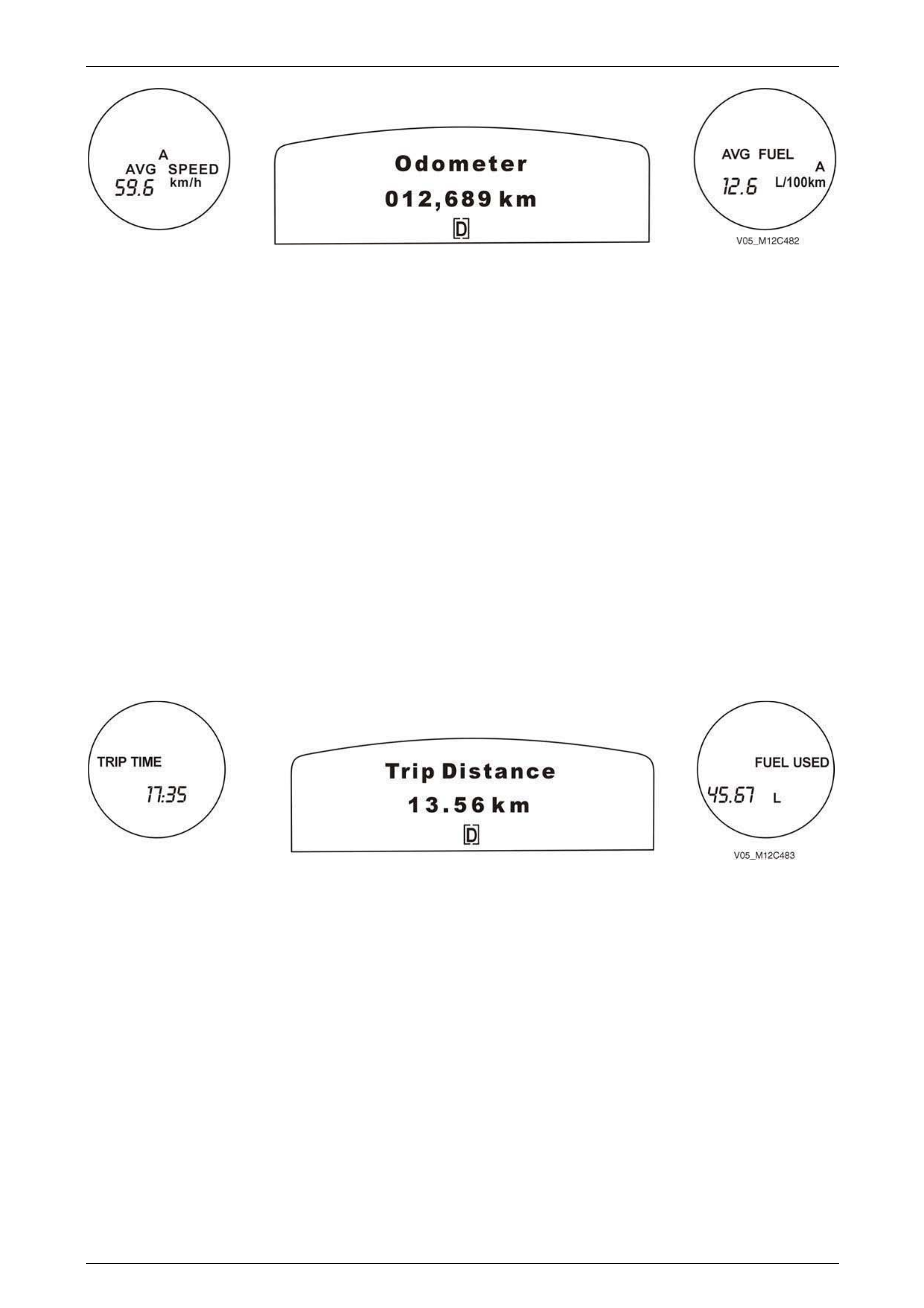
Instrumentation Page 12C – 19
Page 12C – 19
Figure 12C – 29
Press the trip computer MODE button to advance to the next set of screens.
• If Trip A and B is enabled, the Trip Time A / Trip Distance A / Fuel Used A screens will be displayed, or
• If Trip A and B is not enabled, the Trip Time / Trip Distance / Fuel Used screens will be displayed.
Trip Time / Trip Distance / Fuel Used
To reset the Trip Distance to zero, press the SET button for less than 2 seconds while these functions are displayed.
Note that this also resets the Average Speed and Average Fuel set of displays. However, to reset the Trip Time / Trip
Distance / Fuel Used functions only, hold the SET button down for 8 seconds while these functions are displayed.
Trip Time
Shows the engine running time in hours and minutes since the trip computer was reset. If this exceeds 99 hours and
59 minutes, the trip time is displayed in hours only.
Trip Distance
Shows the kilometres travelled from the start of a particular trip.
Fuel Used
Shows the total litres of fuel consumed since the trip computer was reset.
Figure 12C – 30
• Press the trip computer MODE button to advance to the next set of screens.
• If Trip A and B is enabled, the Trip Time B / Trip Distance B / Fuel Used B screens will be displayed, or
• If Trip A and B is not enabled and the Distance to Arrival function is enabled in Customisation Mode, then the Time
to Arrival / Distance to Arrival / Remaining Fuel screens will be displayed, or
• If neither the Trip A and B function nor the Distance to Arrival function is enabled, then the normal Overspeed or
Preset Overspeed screens will be displayed, depending on the previous overspeed selection.
Time to Arrival / Distance to Arrival / Remaining Fuel
The Time to Arrival / Distance to Arrival / Remaining Fuel screens can be enabled in Customisation Mode as a set. They
cannot be individually activated. Additionally, the Trip A and B function can be enabled from this set of screens by
pressing and holding the MODE button for more than 2 seconds.
To reset the Distance to Arrival to a value set in Customisation Mode, press the SET button for less than 2 seconds while
this set of screens is displayed.
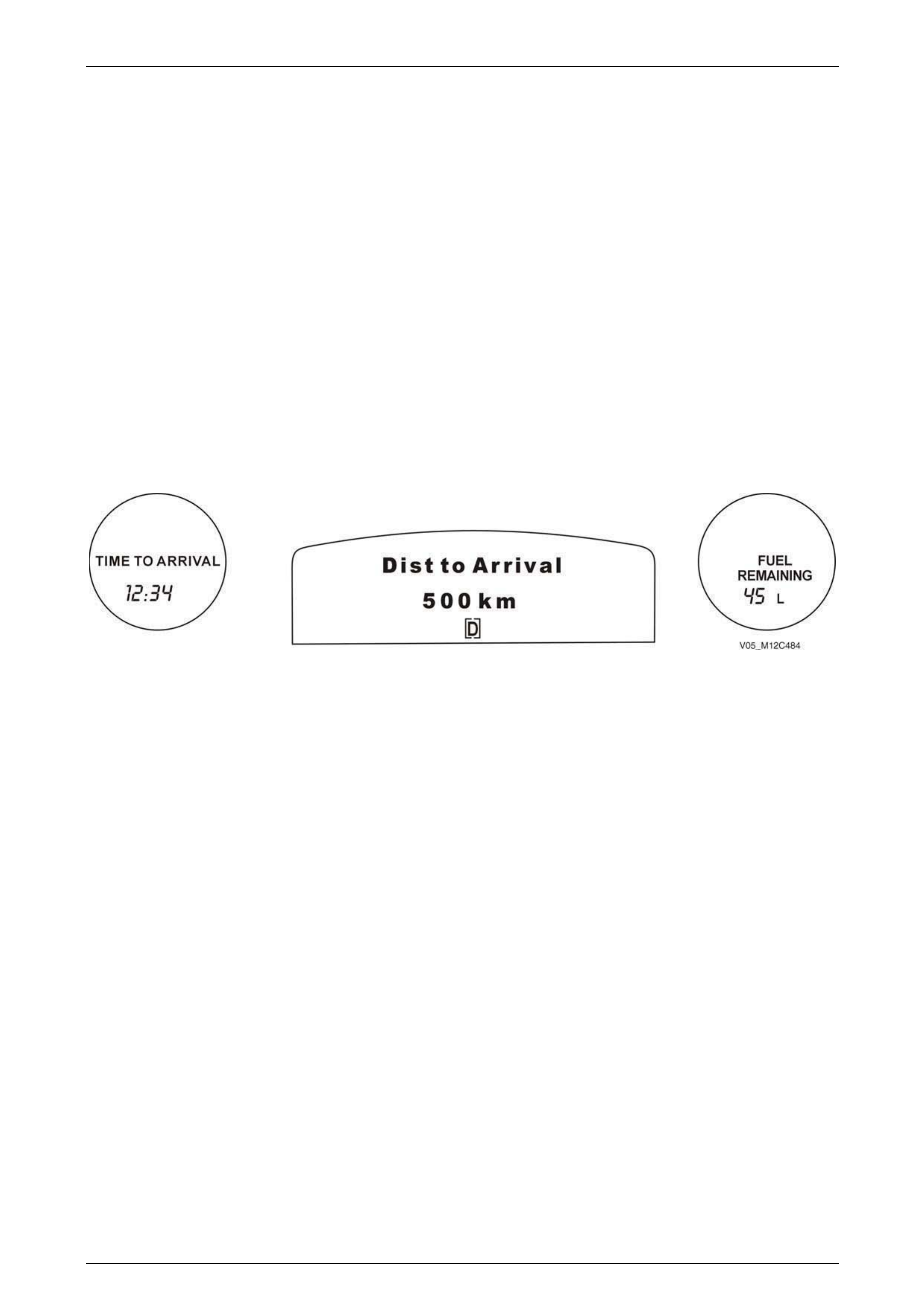
Instrumentation Page 12C – 20
Page 12C – 20
Time to Arrival
Shows trip time to arrival in hours and minutes, based on Distance to Arrival. The Time to Arrival value is displayed as
follows:
• In 1 minute increments if the Time to Arrival is less than 10 minutes.
• In 5 minute increments if the Time to Arrival is more than 10 minutes, but less than 2 hours.
• In 10 minute increments if the Time to Arrival is more than 2 hours, but less than 99 hours and 59 minutes.
• In 1-hour increments if the Time to Arrival is more than 99 hours and 59 minutes.
Distance to Arrival
At the start of a trip, estimate the distance to arrival from maps or road signs. Tap the UP or DOWN buttons until the
display shows the estimated trip distance. When the vehicle is driven the trip computer will constantly update the time to
arrival, based on changing driving speeds.
The UP or DOWN buttons can be used to adjust the distance (kilometres) any time this screen is displayed.
Remaining Fuel
Displays the amount of fuel left in the fuel tank in litres, rounded to the nearest 5 litres. In a low fuel situation, LO will be
displayed in the right trip computer display when the fuel level is down to approximately 8 litres left in the tank.
Figure 12C – 31
Press the trip computer MODE button to advance to the next set of screens:
• Press the MODE button for less than 2 seconds and either the normal Overspeed or Preset Overspeed screens will
be displayed, depending on the previous overspeed selection.
• Press the MODE button for more than 2 seconds, the Trip A and B function will be enabled and the Trip Time B /
Trip Distance B / Fuel Used B screens will be displayed.
Trip Time A/B / Trip Distance A/B / Fuel Used A/B
The Trip A and B function is enabled in Customisation Mode. Normally if this function is enabled, the Distance to Arrival
function is disabled. However, the Distance to Arrival function can be accessed from the Trip B windows by pressing and
holding the MODE button for more than 2 seconds.
When the Trip A and B function has been enabled, the T r ip A windows are normally displayed on the instrument cluster.
Two different sets of trip screens are now counting, the original set of trip screens (labelled A while B is turned on) and a
new set of trip screens, labelled B. This is useful on a long trip, as Trip B can be reset at the beginning of the journey and
then locked away (by pressing the MODE button for more than 2 seconds when Trip B is shown). Time to Arrival /
Distance to Arrival / Remaining Fuel will again be shown on the screen, but Trip B will still be counting away in the
background and the original trip screen can be used for short distances during the journey. Trip B can be viewed at any
time by pressing the MODE button for more than 2 seconds when Distance to Arrival is shown.
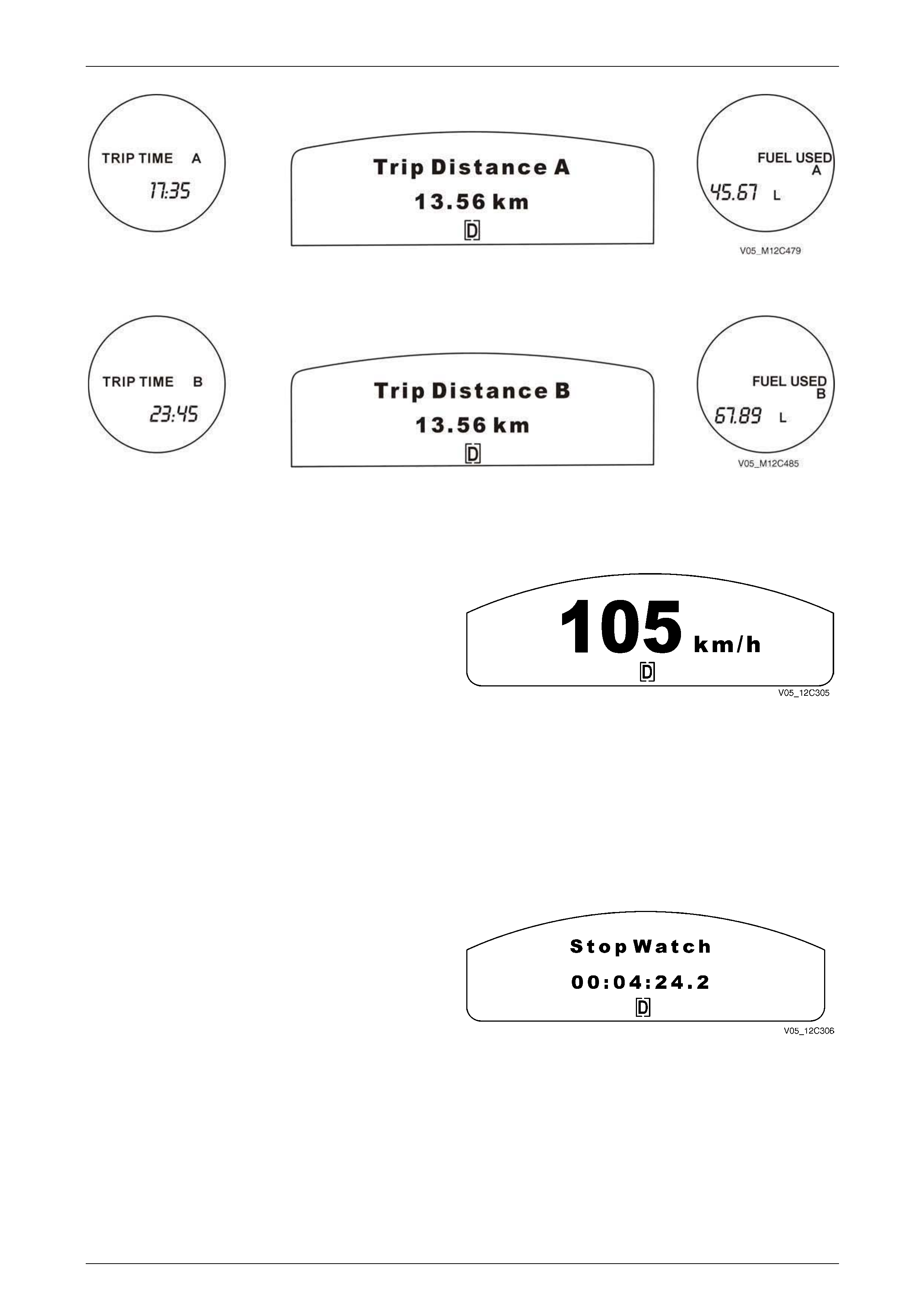
Instrumentation Page 12C – 21
Page 12C – 21
Figure 12C – 32
To advance to the Trip B windows, press the MODE button for less than 2 seconds.
Figure 12C – 33
Press the trip computer MODE button to advance to the next set of screens.
Police Mode
Only Tech 2 can enable police Mode. If the Police Mode is
enabled, the digital speedometer is the MFD default display
at ignition on, and the side LCD’s display no information,
refer to.1.9 Police Mode.
NOTE
The Police Mode is not applicable on Omega vehicles.
Figure 12C – 34
1 Press the MODE button to advance to the next screen.
2 If Police Mode has been enabled by Tech 2, then the true speed digital speedometer will be displayed, or
3 If Police Mode has not been enabled and the Stop Watch function is enabled in Customisation Mode, then the Stop
Watch screen will be displayed, or
4 If neither the Police Mode nor the Stop Watch function are enabled, then the next screen displayed will be the
Average Speed / Odometer / Average Fuel screen, or the Average Speed A / Odometer / Average Fuel A screen.
Stop Watch
The Stop Watch screen is enabled in Customisation Mode
refer to 1.8 Customisation Mode.
Pressing the SET button on the trip computer switch starts
and stops the stopwatch. Pressing and holding the MODE
button for more than 3 seconds resets the stopwatch with a
confirming beep.
Figure 12C – 35
1 Press the MODE button to advance to the next screen.
2 If the Stop Watch function is enabled in Customisation Mode, then the Stop Watch screen will be displayed, or
3 If the Stop Watch function is not enabled, then the next screen displayed will be the Average Speed / Odometer /
Average Fuel screen, or the Average Speed A / Odometer / Average Fuel A screen.
Press the MODE button to advance to either the Average Speed / Odometer / Average Fuel screen, or the Average
Speed A / Odometer / Average Fuel A screen.
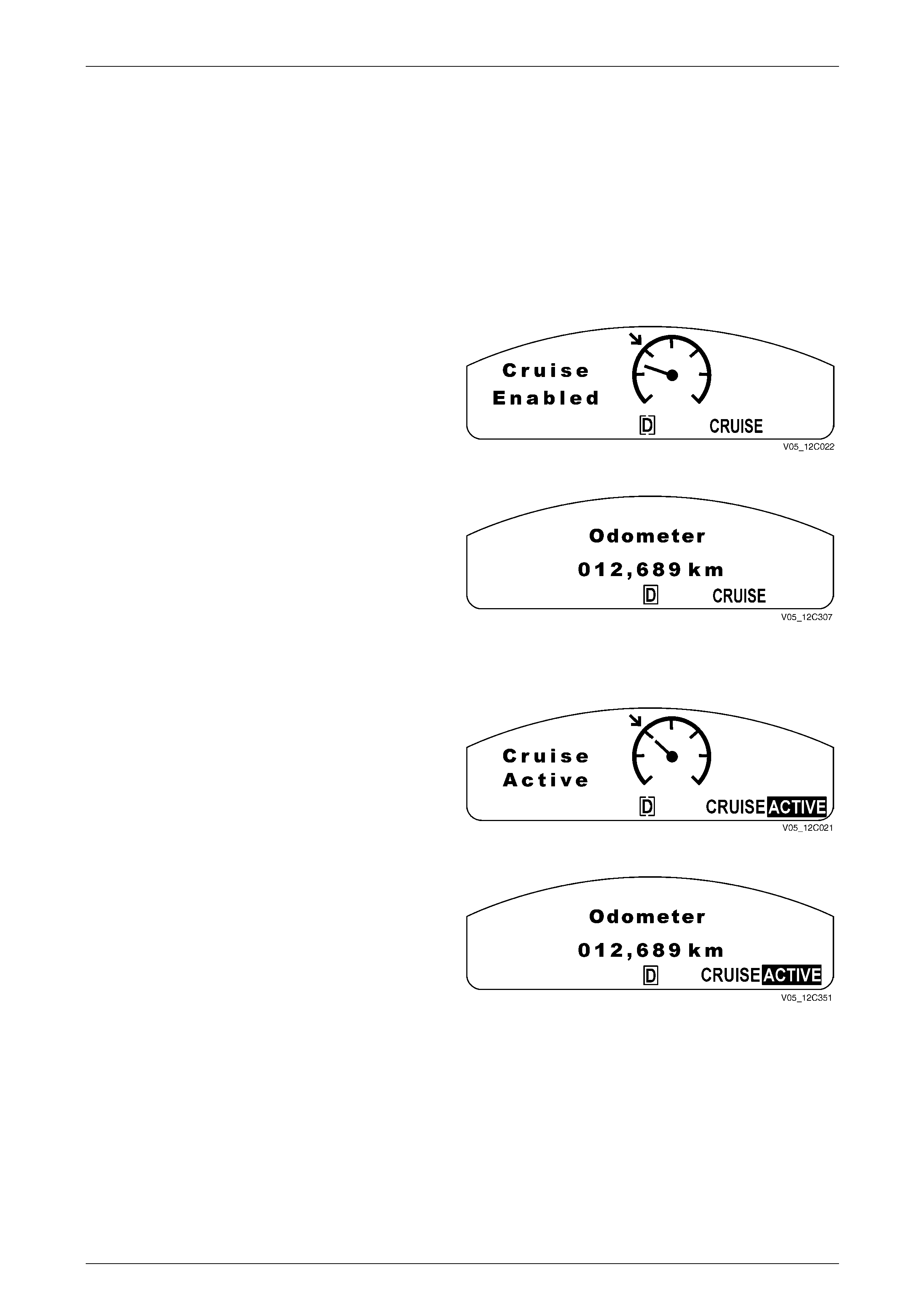
Instrumentation Page 12C – 22
Page 12C – 22
1.7 Multi-function Display
The following details the functions available in the MFD on both single-window and triple-window instrument clusters.
Constant Icons
The display of Warnings has priority over the display of animated icons.
Cruise Control
Cruise Enabled
1 When the instrument cluster receives the Cruise ON
signal from the ECM (V6) or the TAC (V8), the
CRUISE icon illuminates and the Cruise Enabled
animation is displayed for 2 seconds.
2 The animation is shown initially with the set arrow
flashing.
Figure 12C – 36
After 2 seconds, the animated display extinguishes and the
CRUISE icon remains. The display reverts to the previously
displayed trip computer screen.
Figure 12C – 37
Cruise Active
When the cruise control is activated via the cruise control
switch assembly, the highlighted ACTIVE icon illuminates
and the Cruise Active animation is displayed for 2 seconds.
The animation is shown initially with speedometer needle
moving toward the set arrow.
Figure 12C – 38
After 2 seconds the animated display extinguishes, the
CRUISE icon, and the highlighted ACTIVE icon remain, the
display reverts to the previously displayed trip computer
screen.
Figure 12C – 39
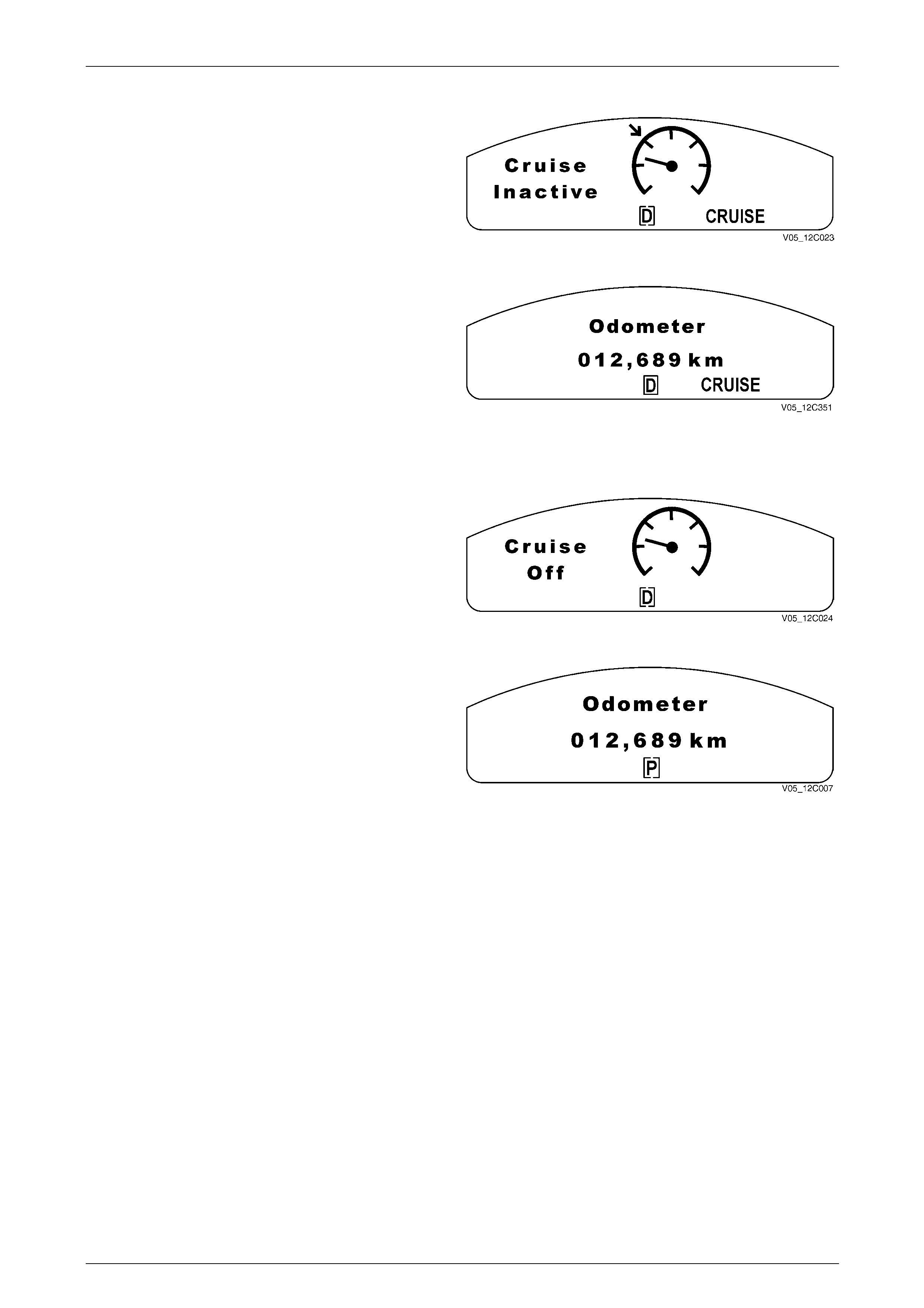
Instrumentation Page 12C – 23
Page 12C – 23
Cruise Inactive
When the cruise control is deactivated via the cruise control
switch assembly, brake, or clutch pedal the highlighted
ACTIVE icon extinguishes immediately and the Cruise
Inactive animation is displayed for 2 seconds.
Figure 12C – 40
After 2 seconds, the animated display extinguishes and the
CRUISE icon remains. The display reverts to the previously
displayed trip computer screen.
Figure 12C – 41
Cruise Off
When Cruise Power is disabled, the CRUISE icon
extinguishes immediately and the Cruise Off animation is
displayed for 2 seconds.
Figure 12C – 42
After 2 seconds, the animated display extinguishes, and the
display reverts to the previously displayed trip computer
screen.
Figure 12C – 43
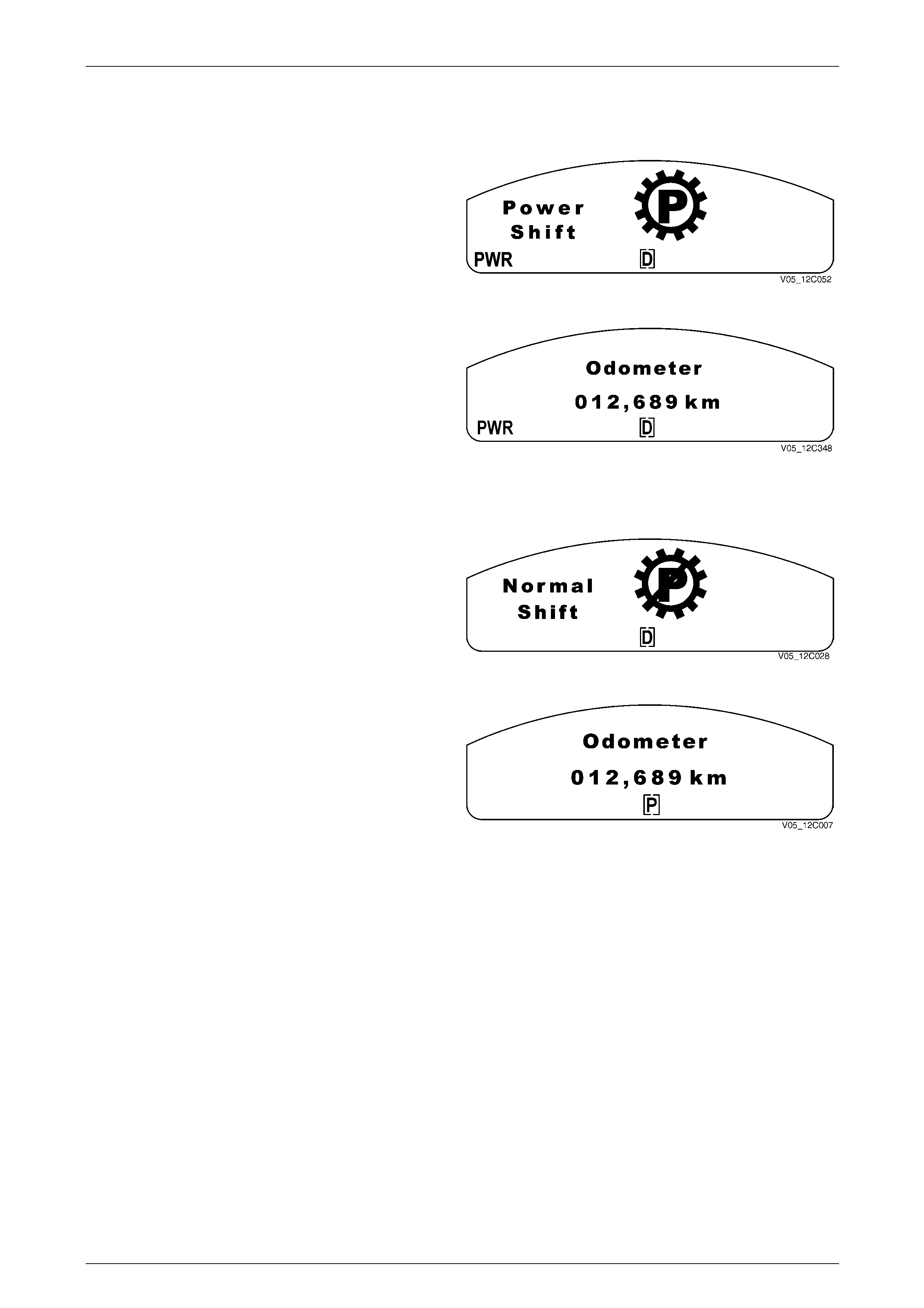
Instrumentation Page 12C – 24
Page 12C – 24
Power Mode (Automatic Transmission Only)
Power Mode On
When the transmission is placed in Power Mode, the PWR
icon illuminates and the Power Shift animation is displayed
for 2 seconds.
Figure 12C – 44
After 2 seconds, the animated display extinguishes and the
PWR icon remains. The display reverts to the previously
displayed trip computer screen.
Figure 12C – 45
Normal Mode On (Power Mode Off)
When the transmission is changed from Power Mode to
Normal Mode, the PWR icon extinguishes immediately and
the Normal Shift animation is displayed for 2 seconds.
Figure 12C – 46
After 2 seconds, the animated display extinguishes and the
display reverts to the previously displayed trip computer
screen.
Figure 12C – 47
NOTE
If Power Mode is on and the cruise control has
been activated, the Power Mode is turned off by
the ECM (V6) or the PCM (V8), as there is no
Power Mode while the cruise control is active.
When this occurs, the display does not show the
Normal Shift display but instead turns off the
PWR icon. When cruise control is deselected, the
PWR icon illuminates for 3 seconds after the
cruise control has been deselected. This prevents
the PWR icon cycling if the cruise control is
deselected momentarily.
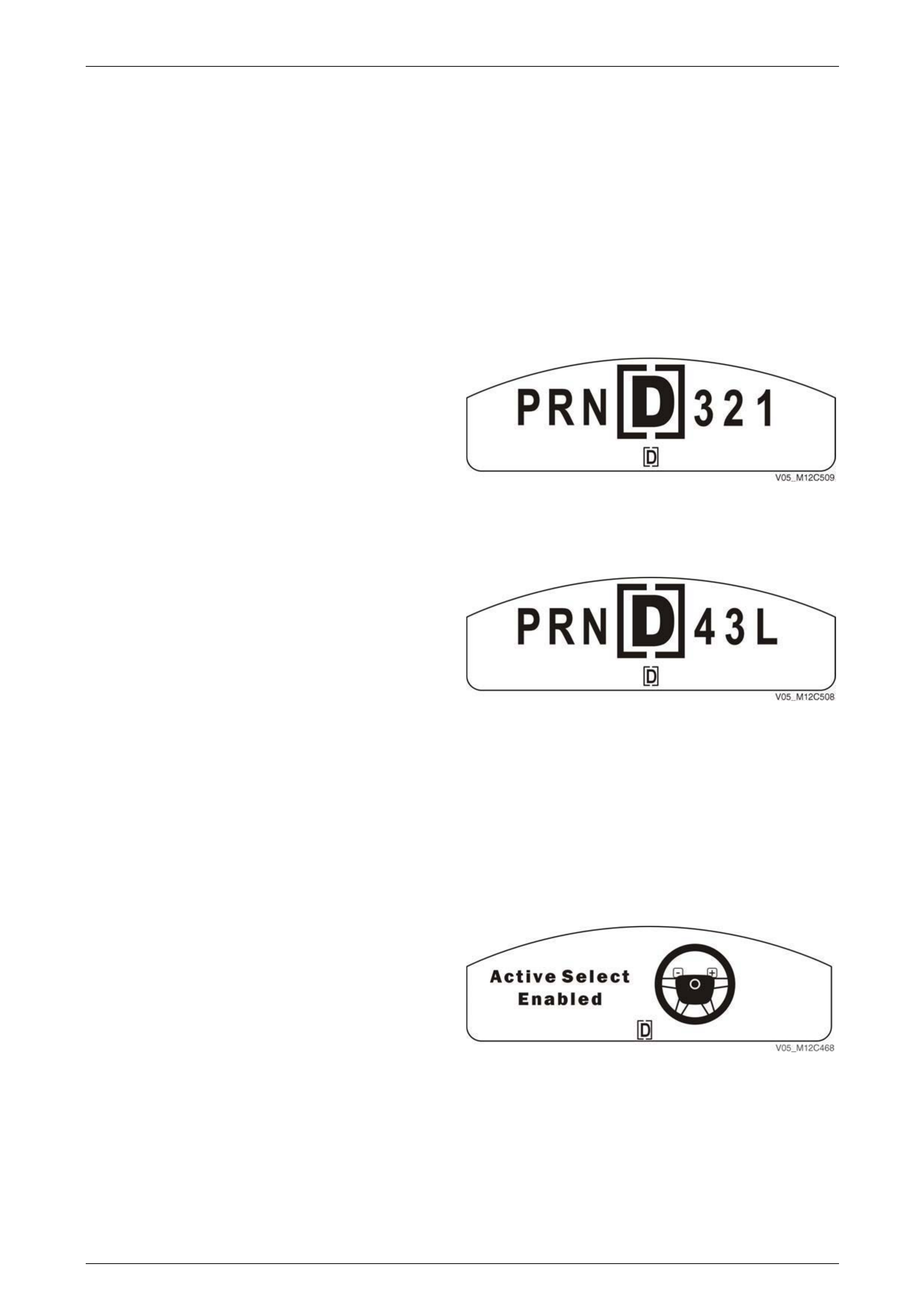
Instrumentation Page 12C – 25
Page 12C – 25
PRND321 (Automatic Transmission) – Normal Shift Mode
When the position of the automatic transmission gear selector is changed, a large icon is displayed on the MFD in
conjunction with the PRND321 constant icon at the bottom of the MFD.
NOTE
• PRNDL is NOT displayed on manual vehicles.
• The 4 Speed Automatic Transmission has
Normal Shift Mode only.
• The 5 Speed Automatic Transmission has
Normal Shift Mode and Active Select Mode.
Four Speed Automatic Transmission
The gear icon remains for 2 seconds after it is selected.
While the transmission selector is moving, the constant
icons reflect the selector movement through the gears.
NOTE
• If any warning is active, the large display
symbol is not shown and only the bracketed
constant icon at the bottom changes when
the automatic transmission selector is
moved. Figure 12C – 48
Five Speed Automatic T ransmission
The gear icon remains for 2 seconds after it is selected.
While the transmission selector is moving, the constant
icons reflect the selector movement through the gears.
NOTE
• If any warning is active, the large display
symbol is not shown and only the bracketed
constant icon at the bottom changes when
the automatic transmission selector is
moved. Figure 12C – 49
“54321” (5 Speed Transmission) – Active Select Mode
The steering wheel is fitted with two gearshift paddles that enable manual selection of the automatic transmission gears.
• The (+) paddle located on the right side of the steering wheel is used to shift up the gears (1,2,3…etc.).
• The (–) paddle on the left side of the steering wheel is used to shift down the gears (5,4,3…etc.).
The active select button (A/S) that either engages or disengages the paddles is located at the bottom of the PRN43L
indicator at the right hand side gearshift lever.
When Active Select Mode is enabled, the MFD will display
an animated icon for 2 seconds, which then minimises to a
small icon in the right side of the MFD display.
Figure 12C – 50
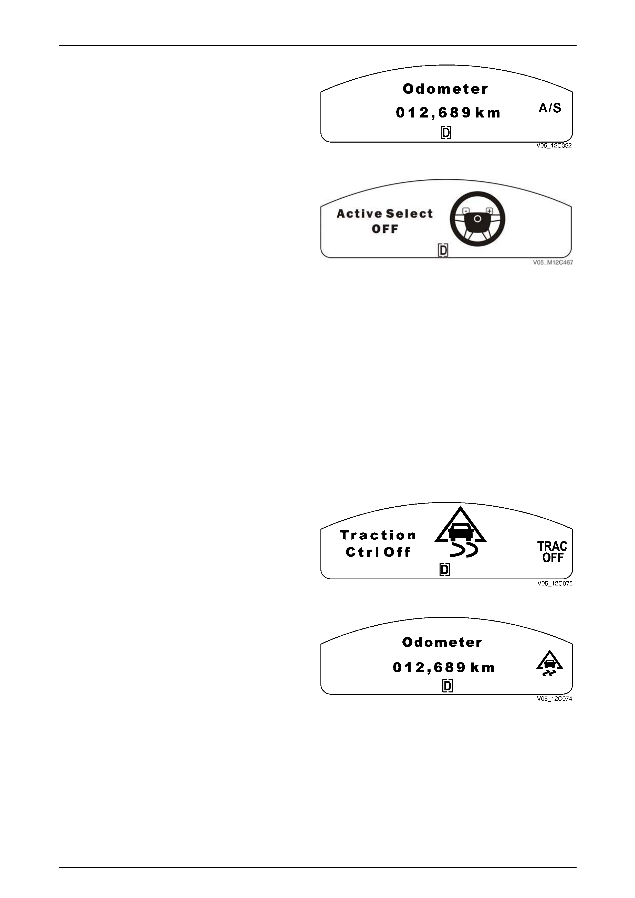
Instrumentation Page 12C – 26
Page 12C – 26
The A/S message will be present on the MFD for the
duration of time the transmission is in Active Select Mode.
Figure 12C – 51
When Active Select Mode is deselected, the MFD will
display the animated icon for 2 seconds before returning the
MFD to the normal operating screen.
The automatic transmission then reverts to Normal Shift
Mode.
Figure 12C – 52
Traction Control or Electronic Stability Program
Traction Control Description
The traction control system (TCS) helps prevent the driving wheels from spinning irrespective of the road conditions and
tyre grip. Once one driving wheel commences to spin, the TCS system reduces the power from the engine and applies
the brake to the spinning wheel, as necessary.
Electronic Control Description (if fitted)
The electronic stability program (ESP) is an advanced feature that works in conjunction with the vehicle’s anti-lock
braking system (ABS), Traction Control System (TCS) and electronic brake assist system (EBA). The ESP system
assists in maintaining the vehicle’s stability by providing intervention when the vehicle’s grip level is exceeded (such as a
sudden lane change, slippery or unexpected road conditions). Refer to Section 5B ABS/TCS/ESP for further information.
Traction Control Off
When the traction control is turned off (by depressing the
button below the PRNDL indicator next to the gearshift
lever) or a fault occurs, the TRAC OFF icon illuminates
immediately and the Traction Control Off animation is
displayed for 2 seconds.
Figure 12C – 53
After 2 seconds, the animated display extinguishes and the
TRAC OFF / ESP OFF icon remains. The display reverts to
the previously displayed trip computer screen.
Figure 12C – 54
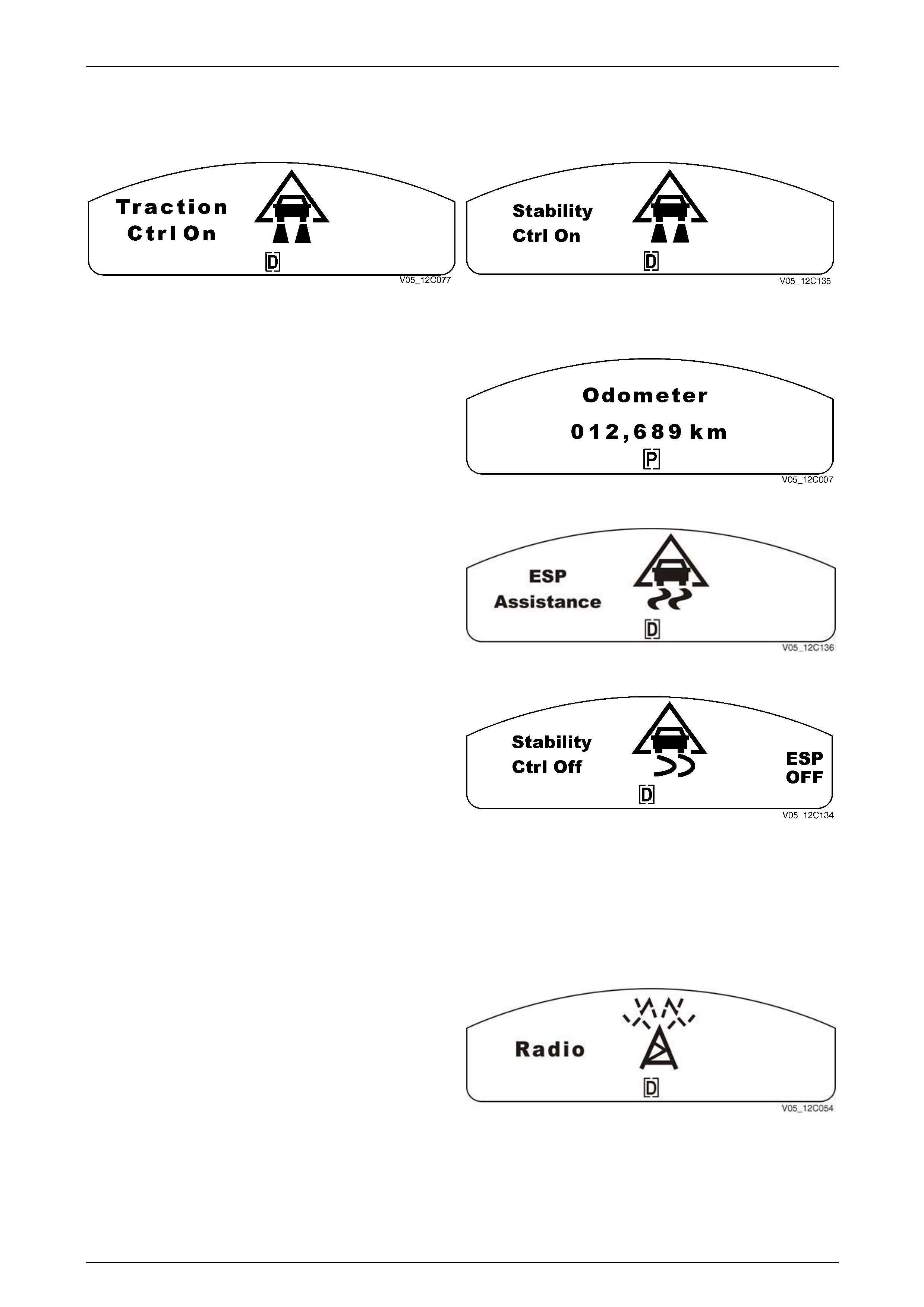
Instrumentation Page 12C – 27
Page 12C – 27
Traction Control or ESP On
When the traction control or the electronic stability program is turned on, the TRAC OFF icon extinguishes immediately
and the Traction Control On or Stability Control On animation is displayed for 2 seconds.
Figure 12C – 55
This display is for the Traction Control function.
Figure 12C – 56
This display is for the Electronic Stability Program.
After 2 seconds, the animated display extinguishes, and the
display reverts to the previously displayed trip computer
screen.
Figure 12C – 57
If Fitted the ESP animation is displayed while driving it
indicates that ESP has sensed a low stability event is
occurring and the ESP is assisting the vehicle to maintain
stability.
Figure 12C – 58
If the Stability Ctrl Off animation illuminates while driving,
without the ESP being turned off by the driver, it indicates
that the ESP system is no longer functioning.
Figure 12C – 59
Radio Settings
The radio information is displayed in the warning icon location on the left-hand side of the MFD. If a warning is active, the
radio information will be overridden, as all warning messages have priority.
Radio On
This display appears when the radio is first switched on and
with no alerts or warnings set.
Figure 12C – 60
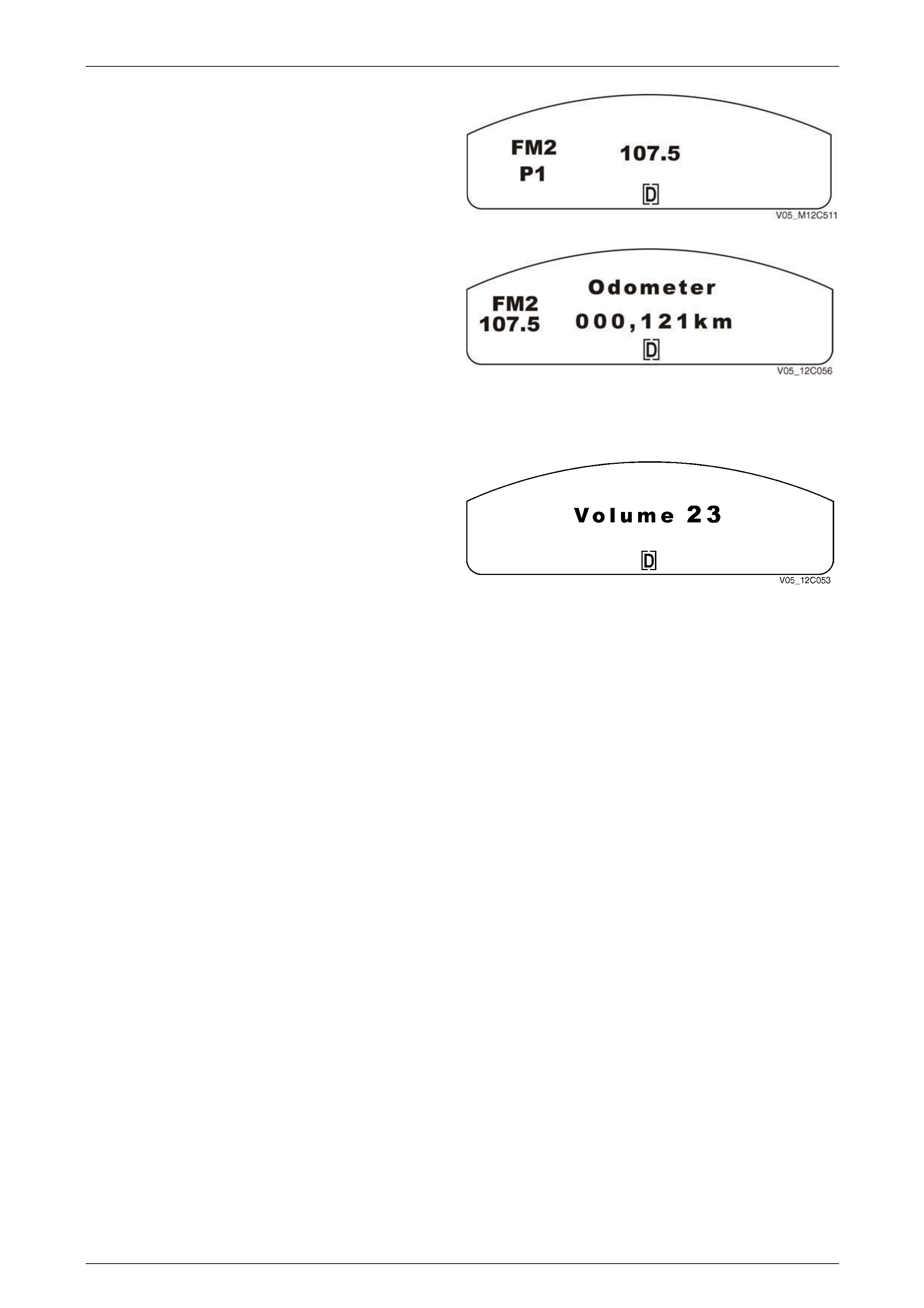
Instrumentation Page 12C – 28
Page 12C – 28
When the radio source or the radio bands are selected, the
display will be shown for 2 seconds.
Figure 12C – 61
If the radio is on when the ignition is turned on, the MFD
displays trip computer information and the radio information
is shown on the left-hand side of the MFD in the small
constant icon location.
Figure 12C – 62
Volume
This display is shown if the radio volume is adjusted up or
down.
The volume indication shown is a number corresponding to
the value sent to the instrument cluster by the radio.
Figure 12C – 63
NOTE
• At ignition key on, the instrument cluster
detects the presence of the original equipment
radio by a message response from the radio
via the serial data communication bus. If the
vehicle has, no radio fitted or the driver has
fitted a different radio, the radio information on
the display is not shown. Additionally the
Diagnostic Trouble Code (DTC) associated
with the radio may be permanently set.
• If the trip computer MODE button is pressed,
the main MFD radio message is cancelled
and the trip computer function is returned.
The radio information display on the left hand
side of the MFD remains.
When the radio bands are being selected, the following main displays are shown in sequence for 2 seconds.
Once a band has been selected, the display reverts to the secondary small icon of the station band and frequency with
the odometer display.
If a preset station is being selected or scrolled through, the MFD will display the station frequency and preset number it is
stored in, The display will be shown for 2 seconds once it has been selected and then revert to the small icon on the right
of the MFD.
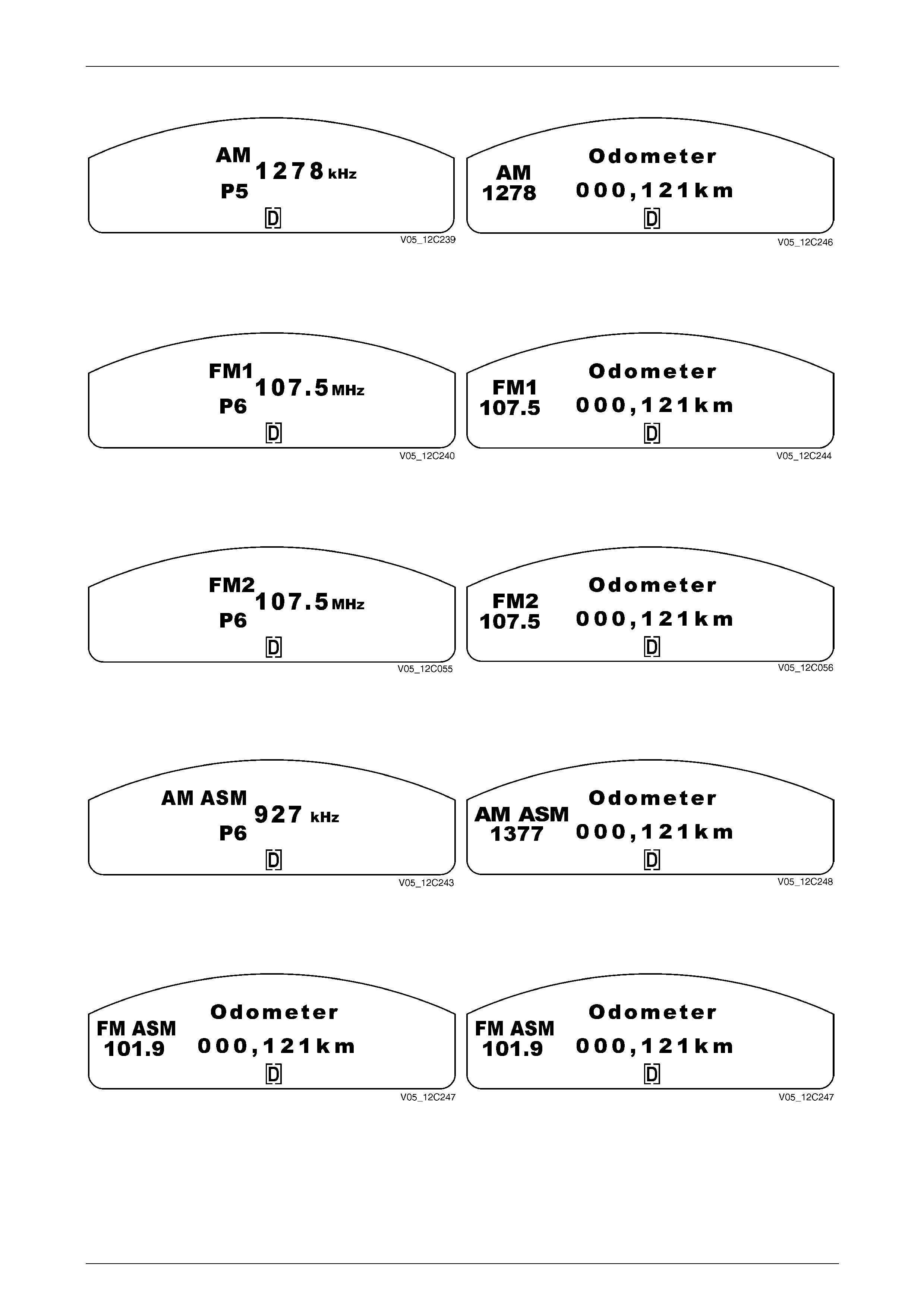
Instrumentation Page 12C – 29
Page 12C – 29
For the AM band:
Figure 12C – 64 Figure 12C – 65
For the FM 1 band:
Figure 12C – 66 Figure 12C – 67
For the FM 2 band:
Figure 12C – 68 Figure 12C – 69
For the AM ASM band:
Figure 12C – 70 Figure 12C – 71
For the FM ASM band:
Figure 12C – 72 Figure 12C – 73
When the radio is tuning or seeking a frequency, the MFD will display the radio band and the frequency scrolling. If the
radio comes across a preset station while scrolling through the frequency during a tune or seek, this preset number will
be displayed in the preset location on the display.
Once the frequency has stopped scrolling and the driver has stored or started listening to the station, the frequency of the
radio station will be displayed for 2 seconds and then revert back to the small icon on the right of the MFD.
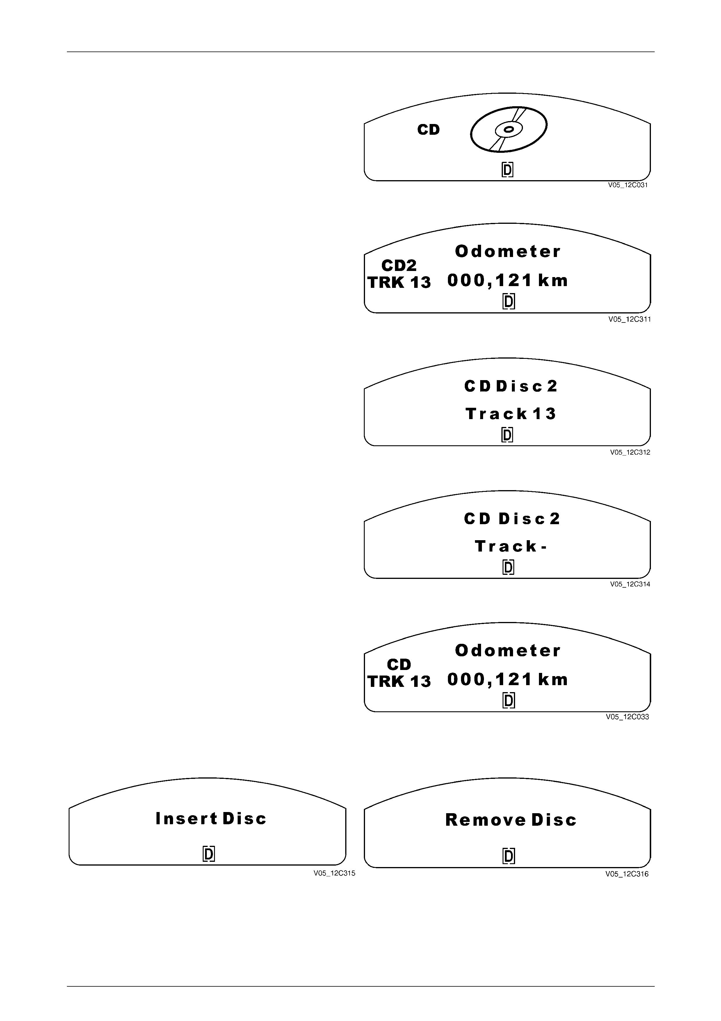
Instrumentation Page 12C – 30
Page 12C – 30
Compact Disc (CD)
When the CD source is selected, this display is shown for
2 seconds.
Figure 12C – 74
Once the CD source has been selected, the display reverts
to a small icon. The small icon displays the current CD
number and the track number.
Figure 12C – 75
When the driver or the radio head unit changes tracks or
discs, the MFD displays the disc and track information.
Once the change is completed, the display remains for
2 seconds.
Figure 12C – 76
If the CD changer is changing discs, it shows this display for
the disc and track numbers and then drops back with the
same information in the small icon location.
Figure 12C – 77
After 2 seconds, the display will revert to a small display.
Figure 12C – 78
When the driver is informed on when to remove or insert a CD, the following is displayed on the MFD when necessary.
Figure 12C – 79 Figure 12C – 80
This display remains until a disc is inserted or removed, or the driver presses the MODE button to go to the last trip
computer function. When this occurs there are no small message icons. This is also implemented for Load Disc, Eject
Disc and Please Wait.
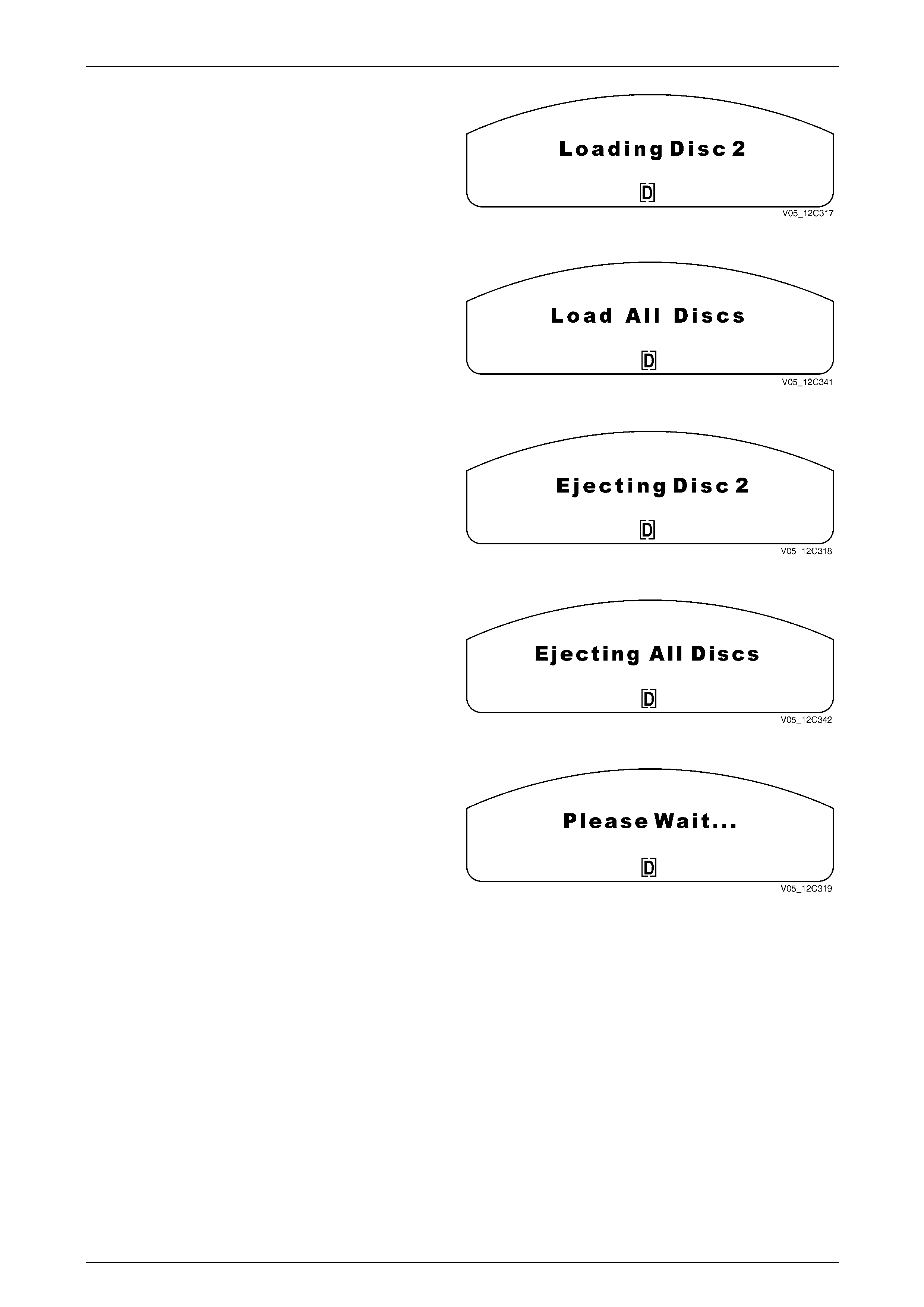
Instrumentation Page 12C – 31
Page 12C – 31
The MFD presents this message when the single slot CD
changer is loading a disc number when inserting a disc, or
when the CD changer is changing a disc. This message is
displayed while the CD is loading. The message remains
until the next insert or remove disc message or the track
disc message is displayed. If the driver presses the MODE
button, the message is cancelled and the MFD goes to the
last trip computer function.
Figure 12C – 81
If the driver has selected Load All Discs, the following
display is presented for 2 seconds unless the driver presses
the MODE button and the display reverts to the last trip
computer function.
Figure 12C – 82
If the driver has elected to eject a single CD, the display
shows the number of the CD being ejected. The display
remains until the CD is ejected or the driver presses the
MODE button to revert to the last trip computer function.
Figure 12C – 83
If the driver has elected to eject all the discs in the CD
changer, the display shows this message. The display
remains until the CDs are ejected or the driver presses the
MODE button to revert to the last trip computer function.
Figure 12C – 84
If the CD changer is performing a function and the driver
should wait before selecting the next operation, a Please
Wait display appears.
Figure 12C – 85
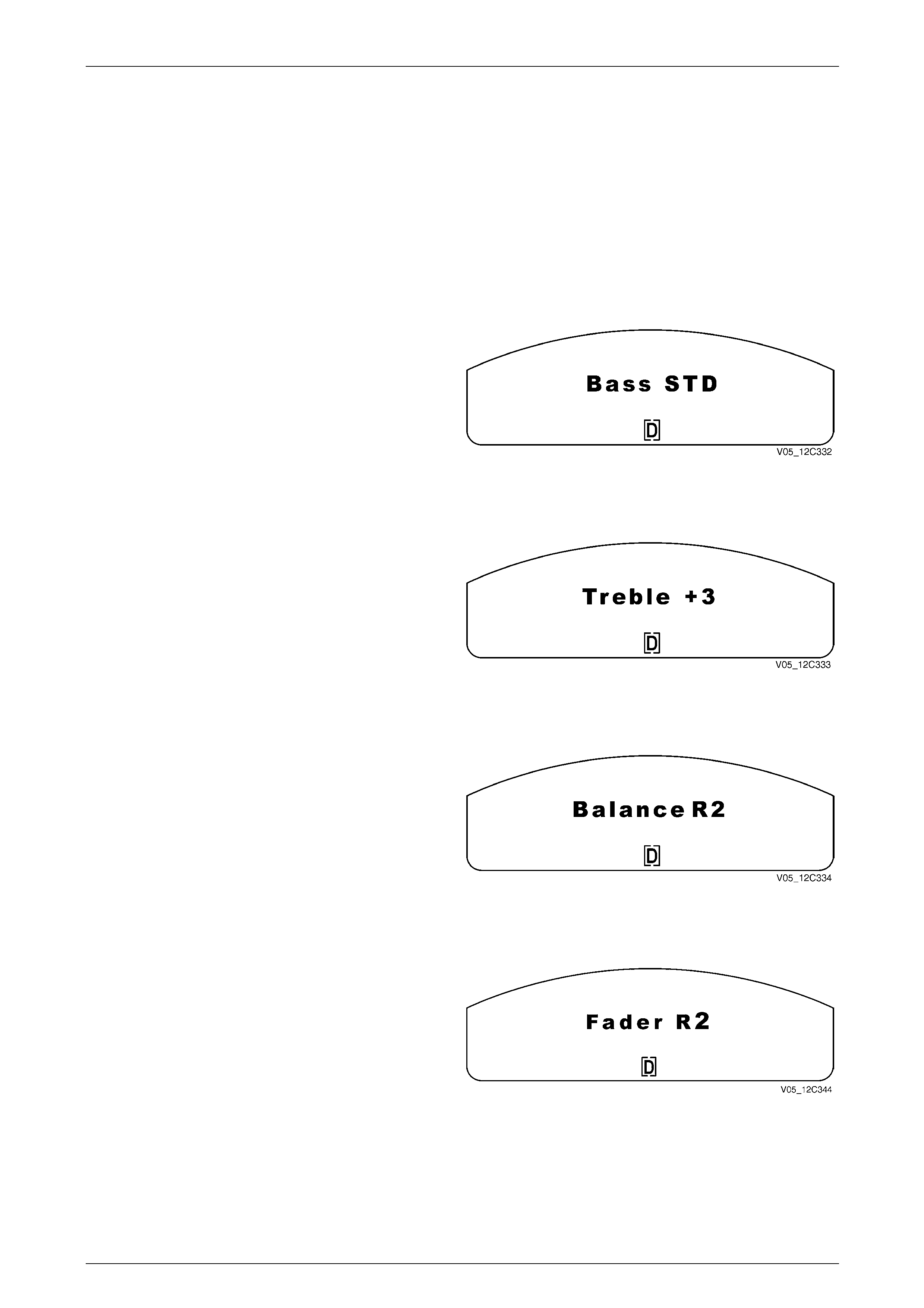
Instrumentation Page 12C – 32
Page 12C – 32
Audio Settings
When the audio settings are selected, the MFD shows the current entertainment system settings. The driver can scroll
through these parameters from the entertainment system. Once the final adjustment has been made, the display is
shown for 2 seconds before reverting to the original trip computer function.
NOTE
If the entertainment system fitted does not include
a particular function, the screen for that function
will not be displayed.
Bass Settings
The range of Bass adjustment is from –6 to +6 with STD (0)
being the standard setting.
NOTE
On models fitted with a pre-programmed
equalizer function, the bass function is replaced
by the boost function when the equaliser is
operating. Figure 12C – 86
Treble Settings
The range of Treble adjustment is from –6 to +6 with
STD (0) being the standard setting.
NOTE
On models fitted with a pre-programmed
equalizer function, the treble function is replaced
by the boost function when the equaliser is
operating. Figure 12C – 87
Balance Settings
The Balance adjustment shifts the sound between the left
and right speakers.
The range of adjustment for Balance is from L6 to R6 with
STD (0) being the standard setting.
Figure 12C – 88
Fader Settings
The Fader adjustment shifts the sound between the front
and rear speaker.
The range of adjustment for Fader is from F6 to R6 with
STD (0) being the standard setting.
Figure 12C – 89
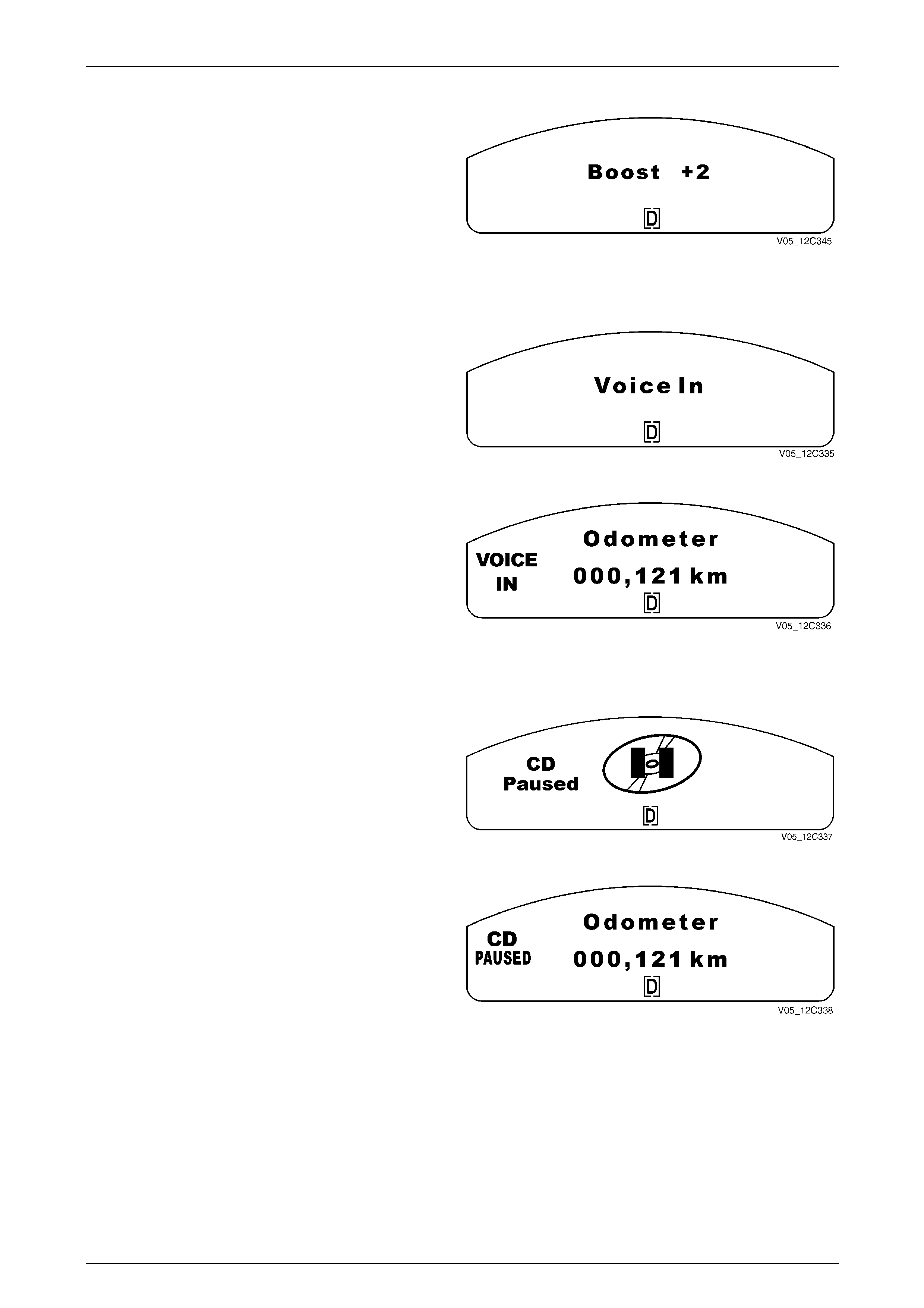
Instrumentation Page 12C – 33
Page 12C – 33
Boost Settings
On models fitted with a pre-programmed equalizer function,
the sound level can be boosted or cut to highlight the
frequency responses found in various types of music.
The range of Boost adjustment, is from –2 to +2 with
STD (0) being the standard setting.
Figure 12C – 90
Phone Display
When the audio system head unit detects a phone is
connected and is in use, the MFD shows the message Voice
In.
Refer to Section 12G Cellular Phone for more details as to
how the telephone connects into the vehicle.
Figure 12C – 91
After 2 seconds the MFD, display reverts to a small wording
in the icon location on the left.
The MFD shows the status or if a source change has
occurred, it then drops back to the small icon location.
Figure 12C – 92
Pause Display
When the audio system head unit source is paused in CD
mode the MFD shows CD Paused.
Figure 12C – 93
After 2 seconds, the display reverts to small wording in the
icon location on the left.
When the Pause function is switched off, the small icon on
the MFD extinguishes.
Figure 12C – 94

Instrumentation Page 12C – 34
Page 12C – 34
Animated Warnings
There are effectively three warning levels. The Level 0 Warning instantly overrides all displays, both warning and
otherwise. This warning can only be cleared by removing the condition, i.e. removing the redline condition.
All current Level 1 Warnings will be displayed after the System Check has been completed and before any current
Level 2 Warnings. If a Level 2 Warning is being displayed and there are new Level 1 and Level 2 Warnings, the new
Level 1 Warning/s are displayed before the Level 2 Warnings. All current warnings are displayed in a cycle until the driver
acknowledges each by pressing the trip computer switch MODE button.
Level 1 Warnings Level 2 Warnings
High Temperature
Brake (See Note 1)
Low Oil Pressure (See Note 1)
Check Powertrain (See Note 1)
SRS (See Note 1)
Alternator
Seat Belt
Low / Very Low Petrol
Low Tyre Pressure (WL-LVL5 only)
Very Low Tyre Pressure (WL-LVL5 only)
Reduced Performance Mode
Limp Home Mode
Immobiliser Fault
Low Traction (See Note 1)
ESP Active (See Note 1)
Park Lamp Fail
Stop Lamp Fail
Stop Lamp Fuse Fail
ABS (See Note 1)
Traction Control Off (See Note 1)
ESP Failed (See Note 1)
Rest Reminder
No Communication
Fuel Sender Error
Cruise Enabled
Active Select
NOTE 1
• The current state of the above listed warning
messages will be ignored when the ignition is
switched on for the System Check
(5 seconds), and then once again when the
engine cranks and starts (running). This is to
enable the Tech 2 diagnostics to be carried
out on modules that have sent their warning
messages to the instrument cluster without
the engine running. A chime accompanies all
of the above-listed warnings.
• If more than one warning occurs and reverts
to a small icon on the right of the MFD, the
warnings cycle for 1 second each until the
warning condition is cleared.
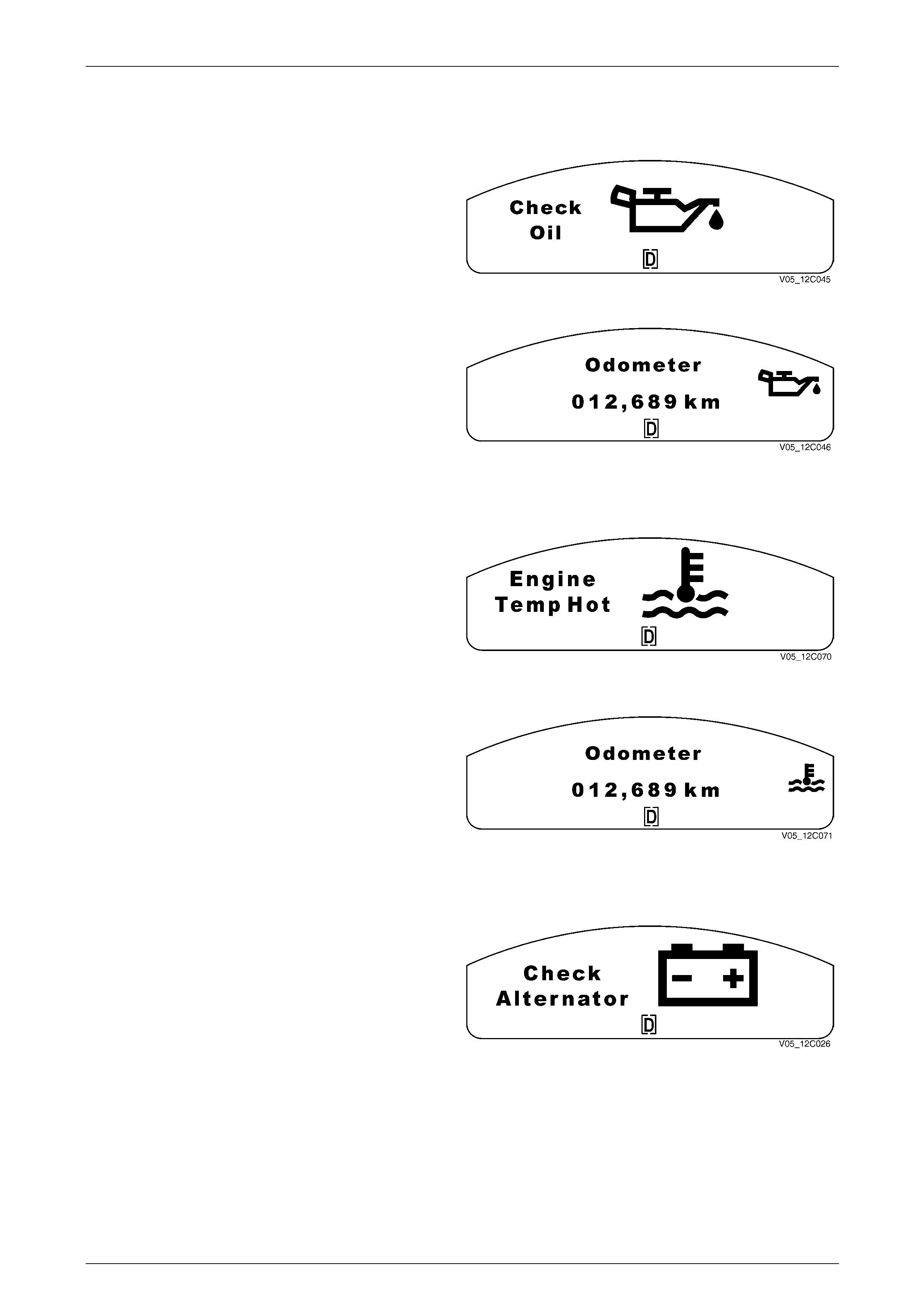
Instrumentation Page 12C – 35
Page 12C – 35
Engine Warning Messages
Low Oil Pressure
The Check Oil (low oil pressure) warning is active when the
low oil pressure bit in the ECM (V6) or PCM (V8) poll
response is active and the engine speed has equalled or
exceeded 150 r.p.m for at least 5 seconds.
A large oil can with droplets flowing from the spout is shown
on the MFD.
Figure 12C – 95
When the MODE button on the trip computer switch is
pressed, the animated symbol reverts to a small oilcan icon
on the right of the MFD.
The small icon remains illuminated until the problem is
rectified.
Figure 12C – 96
Over Temperature
The Over Temperature warning is active when the engine
temperature value in the ECM (V6) or PCM (V8) poll
response equals or exceeds the over-temperature value set
in the instrument cluster.
A large thermometer over flowing water is shown on the
MFD.
A chime sounds with this warning.
The icon remains until the problem is rectified. Figure 12C – 97
When the MODE button on the trip computer switch is
pressed, the animated symbol reverts to a small over
temperature icon on the right of the MFD.
The small icon remains illuminated until the problem is
rectified.
Figure 12C – 98
Alternator
The Alternator warning (Check Alternator) is active when the
Alternator input to the instrument cluster is active and the
engine speed has equalled or exceeded 150 r.p.m for at
least 5 seconds.
A fault in the Alternator system illuminates the battery
warning indicator and the animated icon on the MFD if the
engine is running.
A chime sounds with this warning.
The MFD icon is displayed until the MODE button on the trip
computer switch is pressed. The MFD then reverts to the
previously displayed trip computer screen.
The Alternator fail warning light will extinguish 6 seconds
after the ignition is turned on with the engine not running.
Figure 12C – 99
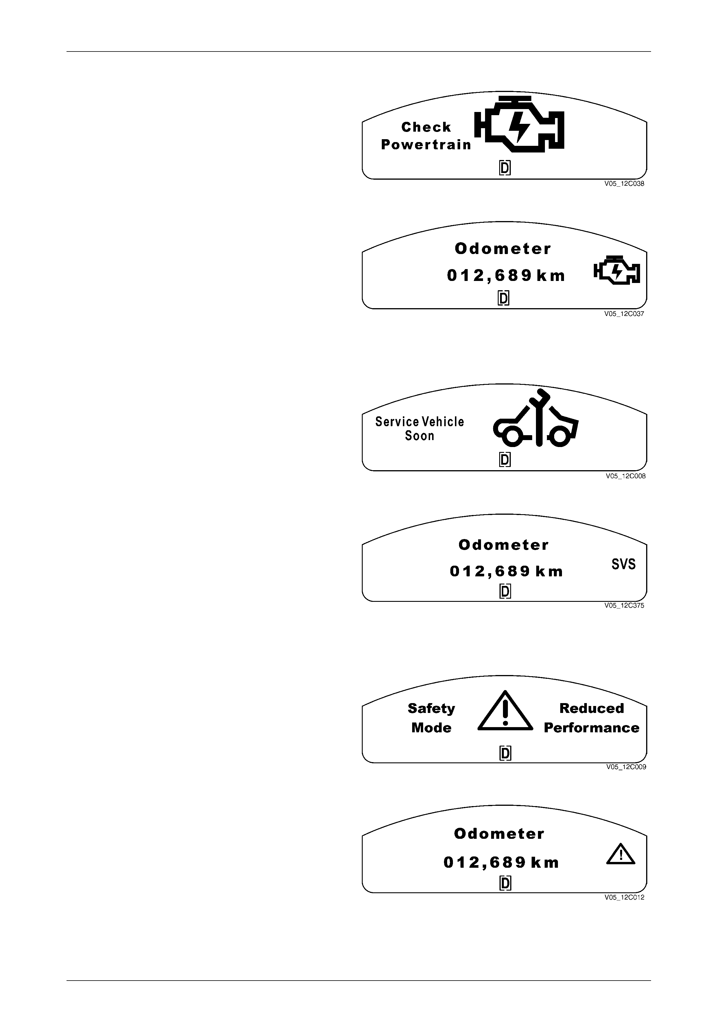
Instrumentation Page 12C – 36
Page 12C – 36
Check Powertrain – Emissions Related Fault
When a fault in the powertrain is detected, the Check
Powertrain warning message is displayed in the MFD as
shown.
A chime sounds with this warning.
The large animated Check Powertrain icon is displayed on
the MFD. The lightning bolt in the centre of the icon flashes
until the MODE button on the trip computer switch is
pressed. Figure 12C – 100
When the MODE button on the trip computer switch is
pressed, the display reverts to a small icon on the right of
the MFD.
The icon remains until the problem is rectified.
Figure 12C – 101
Service Vehicle Soon – Non Emissions Related Fault
The Service Vehicle Soon message is displayed if the ECM
(V6) or the PCM (V8) has detected an engine fault. It
appears as a large warning symbol.
A chime sounds with this warning.
Figure 12C – 102
When the MODE button on the trip computer switch is
pressed, the display reverts to the letters “SVS” on the right-
hand side of the MFD.
The “SVS” reminder remains on the MFD until the problem
is rectified.
Figure 12C – 103
Safety Mode Reduced Performance
The Electronic Throttle Control (ET C-V6) or Throttle
Actuator Control (TAC-V8) feature is implemented on all
models. If the ECM (V6)or the PCM (V8) detects a fault
within the powertrain, it may limit the throttle control normally
available to the driver, effectively placing the vehicle in
Safety Mode that results in reduced power being supplied by
the engine to the transmission.
Figure 12C – 104
When the MODE button on the trip computer switch is
pressed, the display reverts to a safety symbol on the right
of the MFD.
The safety symbol remains on the MFD until the problem is
rectified.
Figure 12C – 105
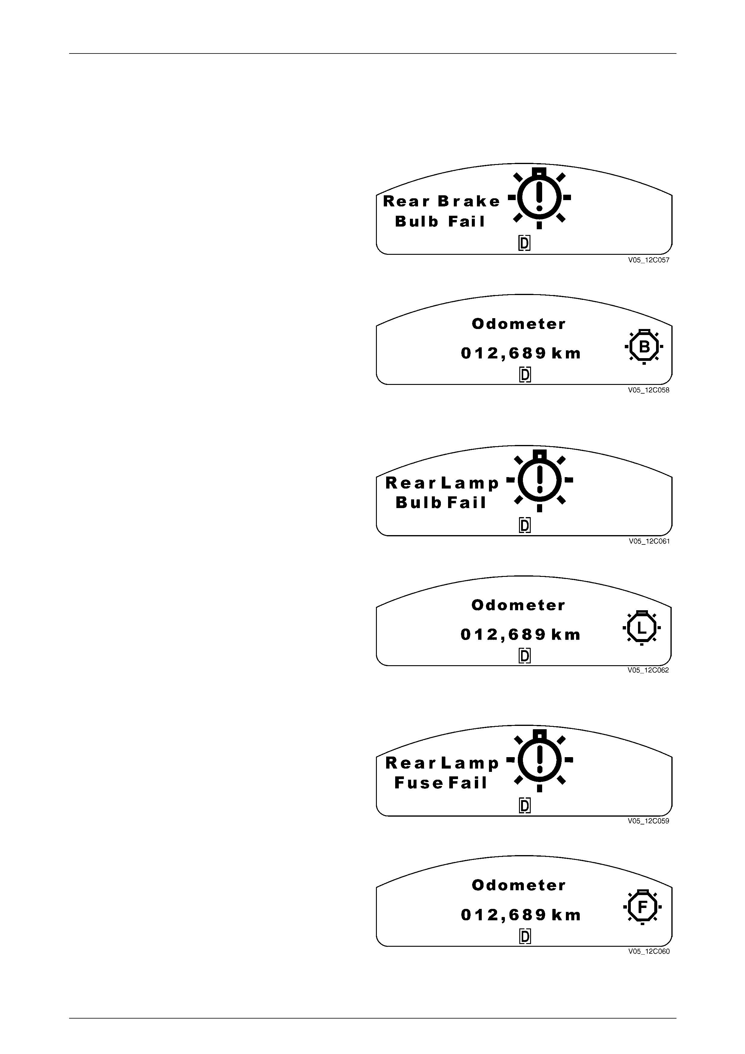
Instrumentation Page 12C – 37
Page 12C – 37
Rear Lamp Failure Warning Messages
NOTE
This feature is active only in WL level 4 vehicles.
Rear Brake Bulb Failure
The stop lamp circuits are monitored by the BCM. The Rear
Brake Bulb Fail warning is active when the rear brake bulb
failure bit in the BCM broadcast message is set.
A large bulb with a flashing exclamation mark is shown on
the MFD.
This warning indicates that a fault has been detected in the
rear brake lamps or the high-mount brake lamp. Figure 12C – 106
When the MODE button on the trip computer switch is
pressed, the animated symbol reverts to a small bulb failure
icon on the right of the MFD.
The small icon remains illuminated until the problem is
rectified.
Figure 12C – 107
Rear Lamp Bulb Failure
The rear park lamp circuits are monitored by the BCM. The
Rear Lamp Bulb Fail warning is active when the rear lamp
failure bit in the BCM broadcast message is set.
A large bulb with a flashing exclamation mark is shown on
the MFD.
This warning indicates that a fault has been detected in the
rear park lamps or the licence plate lamps. Figure 12C – 108
When the MODE button on the trip computer switch is
pressed, the animated symbol reverts to a small bulb failure
icon on the right of the MFD.
The small icon remains illuminated until the problem is
rectified.
Figure 12C – 109
Rear Lamp Fuse Failure
The rear brake lamp fuse circuit is monitored by the BCM.
The Rear Lamp Fuse Fail warning is active when the rear
lamp fuse failure bit in the BCM broadcast message is set.
A large bulb with a flashing exclamation mark is shown on
the MFD.
This warning indicates that a fault has been detected in the
stop lamps fuse or the park lamps fuse. Figure 12C – 110
When the MODE button on the trip computer switch is
pressed, the animated symbol reverts to a small fuse failure
icon on the right of the MFD.
The small icon remains illuminated until the problem is
rectified.
Figure 12C – 111
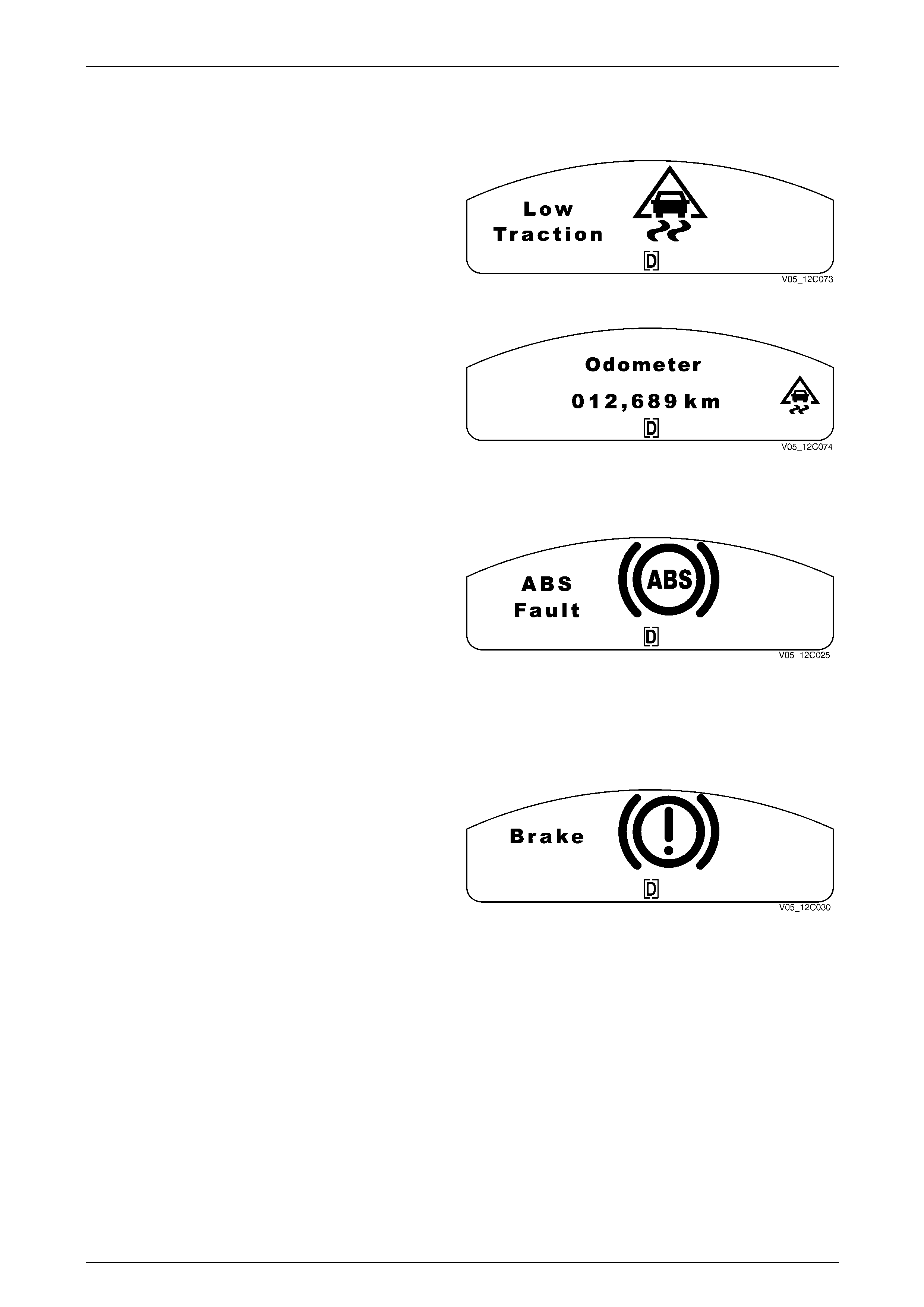
Instrumentation Page 12C – 38
Page 12C – 38
Vehicle Performance Warning Messages
Low Traction
When a low traction event occurs, the MFD shows the Low
Traction animated symbol and the fixed text warning.
A chime does not accompany the Low Traction warning.
Figure 12C – 112
When the MODE button on the trip computer switch is
pressed, the animated symbol reverts to a small low traction
icon on the right of the MFD.
The small icon remains illuminated as long as the low
traction situation exists.
Figure 12C – 113
ABS Fault
The ABS fault-warning LED is illuminated while the ABS
animated icon is displayed on the MFD.
A chime sounds with this warning.
The ABS text in the centre of the icon flashes until the
MODE button on the trip computer switch is pressed. The
MFD then reverts to the previously displayed trip computer
screen.
The ABS warning indicator illuminates as soon as the ABS
fault is detected and remains illuminated until the problem is
rectified.
Figure 12C – 114
Brake Fail / Park Brake Warning
When the instrument cluster receives a brake fail warning
signal, the vehicle speed is greater than 8 km/h the brake
warning indicator illuminates, and the MFD displays an
animated icon, a chime sounds with this warning. The
exclamation mark in the centre of the icon flashes until the
MODE button on the trip computer switch is pressed the
MFD then reverts to the previously displayed trip computer
screen.
The Brake Fail indicator illuminates as soon as the warning
is detected and remains illuminated until the problem is
rectified.
NOTE
A fault occurring in the Electronic or Hydraulic
Brake Distribution System also uses this warning
message.
Figure 12C – 115

Instrumentation Page 12C – 39
Page 12C – 39
Fuel Warning Messages
Low Fuel (Petrol)
The Low Fuel (petrol) warning is active when the estimated
current fuel level is equal to or less than the low fuel warning
level but greater than the very low fuel warning level. The
large animated low fuel icon is displayed on the MFD.
A chime sounds with this warning.
Figure 12C – 116
When the MODE button on the trip computer switch is
pressed, the distance to empty display is shown for
10 seconds before reverting to the original trip computer
display with a small low fuel icon on the right of the MFD.
The small icon remains until the fuel tank is filled above the
low level.
Figure 12C – 117
Very Low Fuel
The Very Low Fuel (petrol) warning is active when the
estimated current fuel level is equal to or less than the very
low fuel warning level. The large animated very low fuel icon
is displayed on the MFD.
A chime sounds with this warning.
Figure 12C – 118
When the MODE button on the trip computer switch is
pressed, the Distance to Empty display is shown for
10 seconds before reverting to the original trip computer
display with a small flashing very low fuel icon on the right of
the MFD.
The small icon remains flashing until the fuel tank is filled
above the very low level.
Figure 12C – 119
System Fault Warning Message
SRS Airbag and Pretension ers
For vehicles fitted with airbags, the SRS Airbag Fault
warning illuminates the SRS warning lamp indicator and
displays an icon on the MFD when an OPS fault has been
detected.
The MFD icon flashes and the words are stationary until the
MODE button on the trip computer switch is pressed.
A chime sounds with this warning.
The SRS indicator illuminates as soon as the warning is
activated and remains illuminated until the problem is
rectified.
Figure 12C – 120
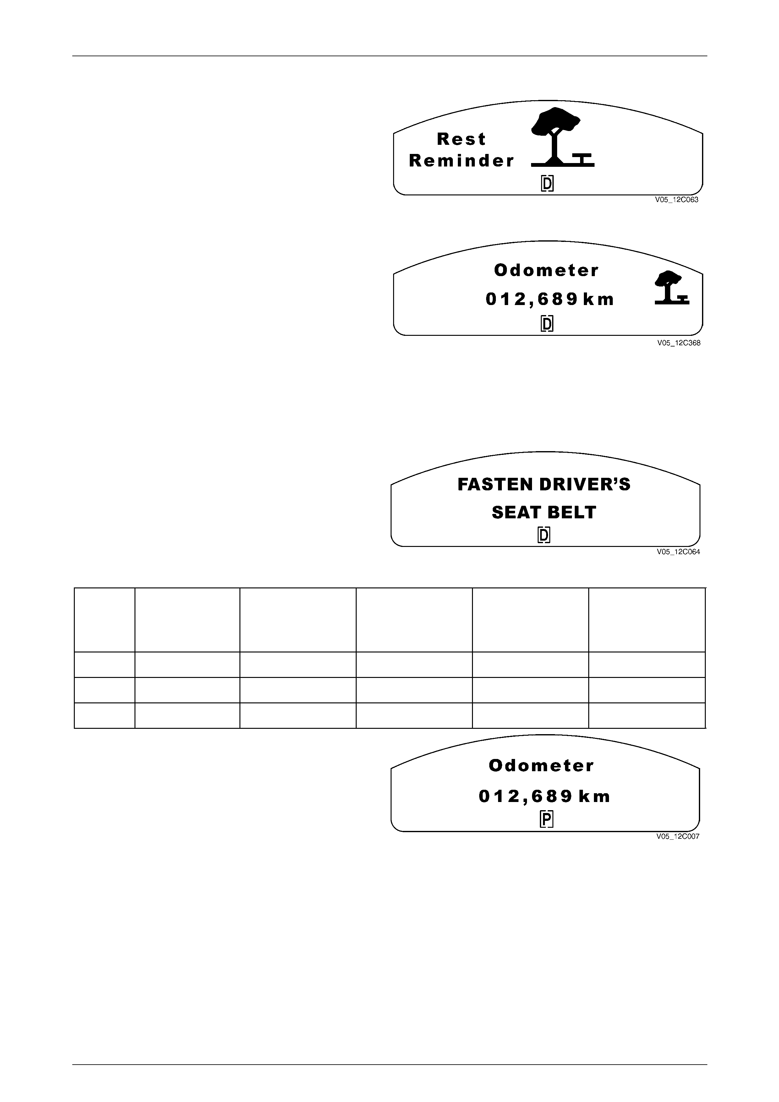
Instrumentation Page 12C – 40
Page 12C – 40
Rest Reminder Warning
This feature alerts the driver that they may have been
travelling for too long without having a rest.
Once the ignition has been switched on, the instrument
cluster’s Rest Reminder timer will start, and after two hours
of continuous driving, the trip computer automatically
switches over to the trip time on the trip computer window
and the centre MFD displays the Rest Reminder message.
Figure 12C – 121
For low series clusters, the display shown in
Figure 12C – 122 is the only rest reminder message shown.
The Rest Reminder message can only be cancelled by
taking a break for more than 10 minutes with the ignition
turned off.
The Rest Reminder warning will be repeated every two
hours of driving. Figure 12C – 122
Seat Belt Warning
MFD Seat Belt Warning
If the seat belt has not been buckled and after various
periods of time have elapsed and a speed greater than 25
km/h has been reached, then the Seat Belt warning
indicator, the MFD display and the chimes will operate
according to the sequence described in the following table.
Figure 12C – 123
Ignition
On
Time 1
IGN On + 60 sec’s
or 500 metres
Time 2
Time 1 + 90 sec’s
Time 3
Time 2 + 60 sec’s
Speed
Speed. 25 km/h
Symbol Solid Solid Flash Flash Flash
Chime None Chime 1 None Chime 2
MFD None None None Message
The seat belt warning message on the MFD is removed by
the pressing the MODE button.
The chime and the Seat Belt warning indicator will remain
active until the relevant periods of time have elapsed.
Figure 12C – 124
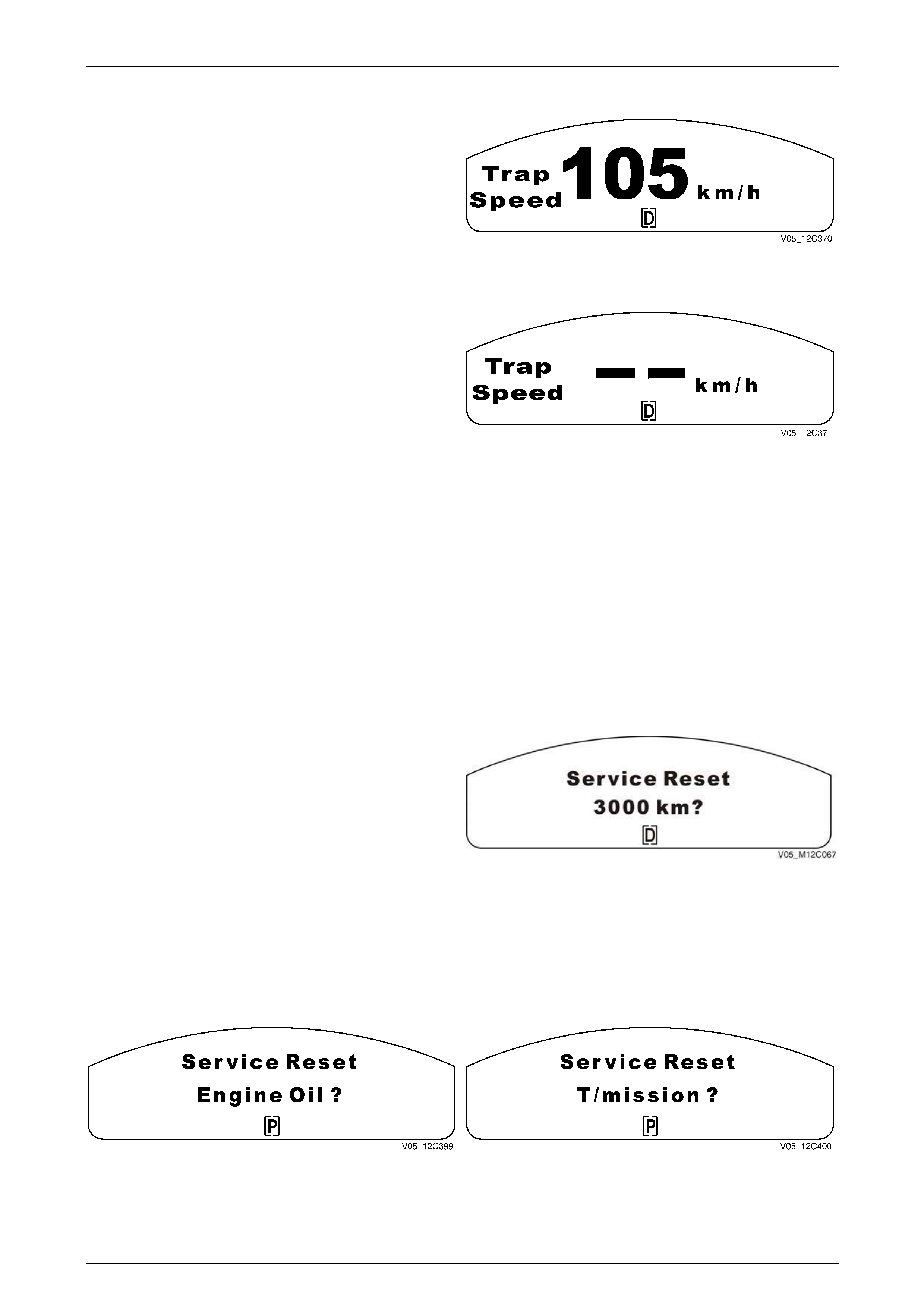
Instrumentation Page 12C – 41
Page 12C – 41
Trapping Speed
The Trap Speed screen enables the driver to capture the
speed at which the vehicle is travelling. The MFD must be
operating in Digital Speedo mode.
To use the Trap Speed function, press the SET button on
the trip computer switch. The current speed is stored and
displayed for 5 seconds with a confirming beep.
Figure 12C – 125
Trap Speed Reset
After 5 seconds, the display reverts to the current speed on
the Digital Speedometer display. Pressing the UP or DOWN
buttons toggles between the current speed and the stored
speed. Trapping another speed or pressing and holding the
trip computer switch SET button for more than 3 seconds
resets the trap speed.
Resetting is confirmed by a beep. Figure 12C – 126
NOTE
When trap speed is reset, it reverts to the current
speed on the Digital Speedo display. The trap
speed is stored in memory even if the vehicle
ignition is turned off. The trap speed remains
stored unless trapping another speed or resetting
the trapped speed erases it.
Service Items
All Service items, including Service Due, Service Oil, Service Transmission Oil, Service Error and Fuel Sender Errors are
displayed at both the beginning and end of an ignition cycle. The service error message for serial communications is only
displayed when the communications BUS is faulty and not at the beginning or end of ignition cycles.
Reset Service Period
The service reminder can be reset at ignition on.
To enter the reset function, press and hold both the UP and
DOWN buttons together on the trip computer switch while
turning the ignition on.
NOTE
The UP and DOWN buttons must be held for 2
seconds after the ignition switch is turned on. Figure 12C – 127
Reset Oil Display / Reset Transmission Display
Press the SET button on the trip computer switch to reset the particular service item. The display will then revert to the
start up sequence.
If more than one service item is to be displayed, the next service item will be shown and the same procedure will apply to
reset it.
Figure 12C – 128 Figure 12C – 129
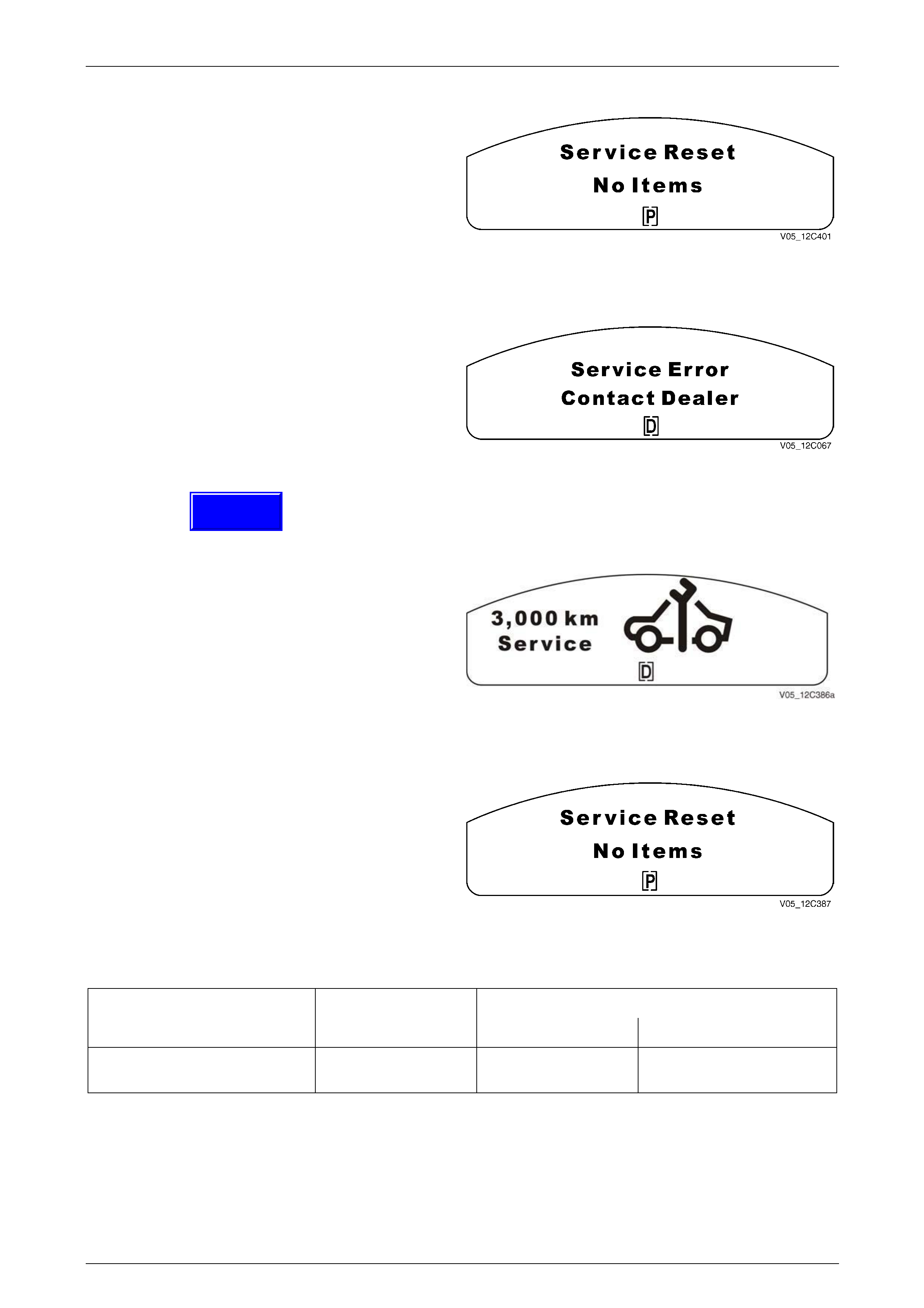
Instrumentation Page 12C – 42
Page 12C – 42
Reset Oil Display
When all service items have been reset, the display will be
as above; the No Items message will be displayed. Then the
display will revert to the start up sequence.
Figure 12C – 130
Service Error
If the “Service Error Contact Dealer” animation illuminates
while driving, a fault in the instrument cluster or the
communication data bus is indicated.
Figure 12C – 131
Service Due
Service Period Display
A service reminder is displayed when the ignition is switched
on or off until the trip computer is reset. The service
reminder is displayed for a total of 10 seconds.
To reset the displayed service reminder, press and hold the
SET button for 3 seconds. A confirmation beep sounds upon
reset.
NOTE
When resetting the service reminders, the PCM poll
responses are cleared and the odometer readings for the
last changes are recorded. Tech 2 can access these.
Figure 12C – 132
When the service reminder is reset, the MFD shows the
Service Reset No Items screen.
After 2 seconds, the MFD advances to the System Check.
Figure 12C – 133
First Inspection Od ometer Warning Messages
Sedan First Inspection Due Regular Inspections Du e
V6 V8
WL series vehicles 3,000 km 15,000 km or
12 months 10000 km or
6 months
Techline
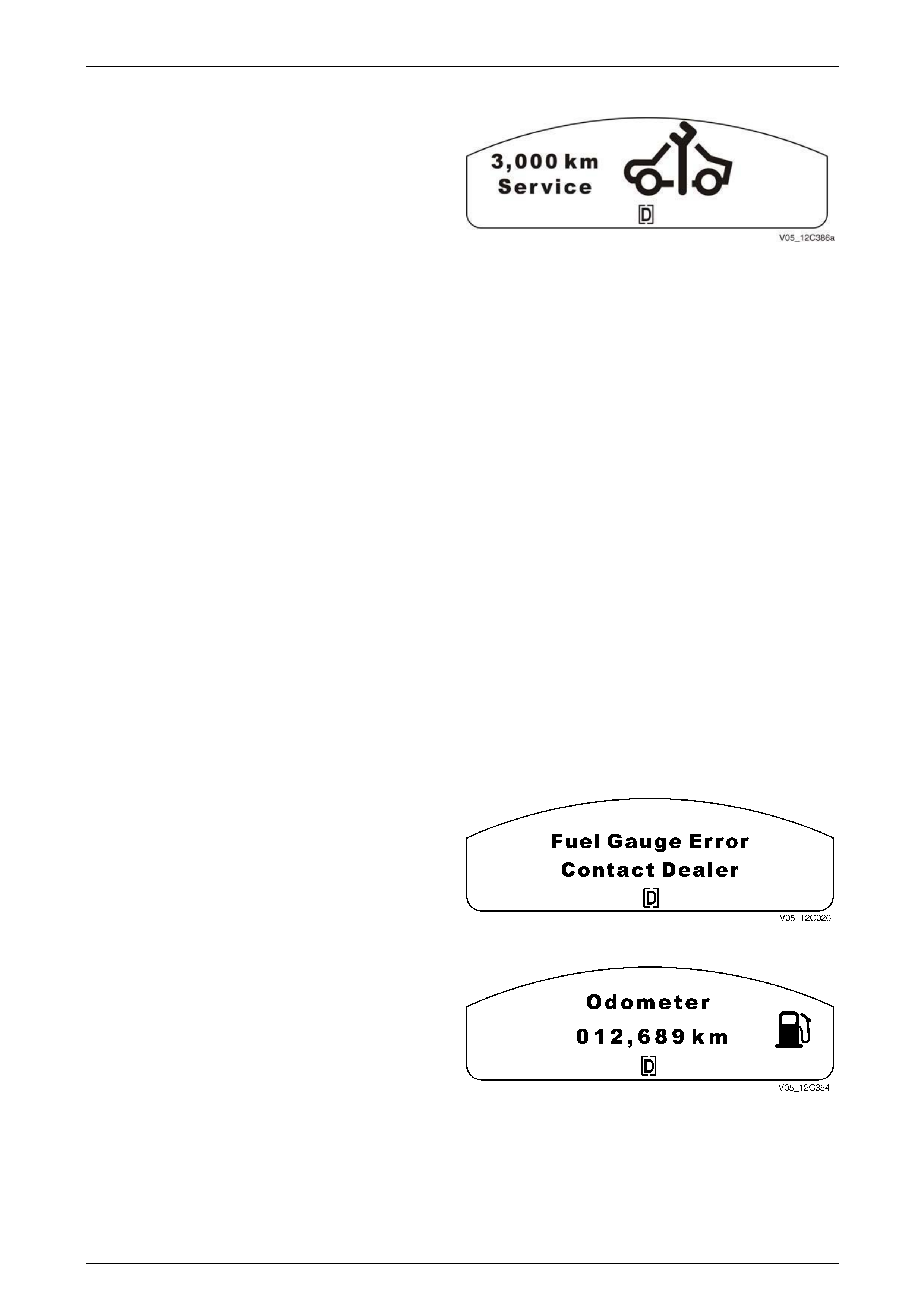
Instrumentation Page 12C – 43
Page 12C – 43
Prior to Service Due
Service Due is determined from the odometer reading. The
MFD shows a reminder 1000 km before a service is due.
The service interval becoming due is displayed on the MFD,
and the spanner in the icon flashes. This service reminder is
displayed for up to 10 seconds whenever the ignition is
switched on or off until the service reminder is reset.
Figure 12C – 134
Service Due
When a service is due, the whole icon flashes. This service reminder is displayed for up to 10 seconds whenever the
ignition is switched on or off until the service reminder is reset.
Service Overdue
When a service is overdue by less than 5000 km, the MFD shows a flashing icon for up to 10 seconds whenever the
ignition is switched on or off until the service reminder is reset.
Service Well Overdue
When a service is overdue by more than 5000 km, the MFD shows a flashing icon for up to 10 seconds whenever the
ignition is switched on or off until the service reminder is reset. This event is permanently logged in the instrument cluster
memory (EEPROM) in case of future warranty disputes.
NOTE
When a Service Due reminder is reset, the ECM
(V6) or the PCM (V8) poll responses are cleared
and the odometer readings for the last changes
are recorded. Tech 2 can access these. The next
Service Due reminder will appear 1000 km before
the next scheduled service period.
Fuel Sender Error
Fuel (Petrol) Sender Error
The Fuel Gauge Error screen is displayed if a fault has been
detected with the fuel sender. This means that the fuel
gauge pointer returns to the minimum reading and the MFD
will display the corresponding message and the low Fuel
warning chime then sounds.
Figure 12C – 135
When the MODE button on the trip computer switch is
pressed, the original trip computer screen is displayed with a
small fuel icon on the right of the MFD.
After each ignition cycle, the MFD screen in Figure 12C – 136
will be display ed. After the correct time period or button press,
the fuel gauge error warning comes on again. If this problem
has been rectified or gone away during ignition off, then on the
next ignition cycle there is no w arning, it has been reset.
Use Tech 2 diagnostics to check the appropriate Diagnostic
Trouble Code. The display resets when the problem has
been rectified.
Figure 12C – 136

Instrumentation Page 12C – 44
Page 12C – 44
Programming The Instrument Cluster
When a new instrument cluster is fitted at a General Motors
Retailer, the Program Cluster screen indicates that it must
be programmed to suit the vehicle type and country of
destination.
When the instrument cluster is first powered up, the MFD
shows the message, Program with Tech 2.
No trip computer functions or selections are available when
the ignition is on.
NOTE
If a warning is active on the MFD, it will be
shown until the trip computer switch MODE
button is pressed. When the MODE button is
pressed, the display reverts to having the small
warning icon on the right of the MFD. The
Program with Tech 2 message remains
displayed.
Figure 12C – 137/VY12C389
At ignition off, the MFD shows the Odometer screen and the
Not Programmed message indicates that the instrument
cluster requires programming.
NOTE
If a vehicle alarm is activated, the corresponding
warning message will be displayed. When the
MODE button is pressed, the warning icon will
revert to the small size, but the ‘Program cluster
with Tech 2’ will remain in the MFD.
For further details on programming the instrument cluster,
refer to 7.2 Programming.
Figure 12C – 138
Fuel Calibration Programming
If the cluster does not have a valid code file programmed (i.e. the Index Value and Code Version are both equal to zero),
then fuel gauge readings and the trip computer calculations cannot take place.
Once a valid fuel code file has been entered into the
instrument cluster via Tech 2 the message is removed.
Refer to, 7.2 Programming.
Figure 12C – 139

Instrumentation Page 12C – 45
Page 12C – 45
1.8 Customisation Mode
Customisation Mode enables the driver to turn on or off functions and adjust features. Only features that are fitted to the
vehicle are displayed. If the vehicle is moving at more than 10 km/h while in Customisation Mode, the screen reverts to
the previous trip computer function.
In Customisation Mode, there are help menus to assist drivers to understand the feature they are adjusting. If a
Customisation Menu item is selected and the screen item is not changed for more than 5 seconds, a help screen will then
be displayed to inform the driver how to operate the displayed feature.
To access the options menu turn the ignition key on while pressing the MODE button on the trip computer.
To scroll through the customisation items, press the MODE button on the trip computer switch.
1 Press the trip computer switch MODE button to scroll through to the exit screen, or
2 Drive the vehicle at more than 10 km/h, or
3 Switch the ignition to the OFF position.
NOTE
Customisation Mode is not displayed if an alarm
warning has been activated or a warning symbol
on the instrument cluster has been triggered.
If a warning goes off once the customisation been has been entered, the warning will be displayed to the driver until the
MODE button has been pressed to clear it. It will then disappear until Customisation Mode is exited. Once a normal MFD
screen is being displayed, the warning observed previously will be displayed as an icon on the right side of the MFD.
NOTE
Not all the following customisation items are
available on all Vehicles.
Entering Customisation Mode (Options Menu)
Customisation Mode is accessed via the Options Menu,
which can be displayed when the vehicle is stationary or
moving slowly.
• If the vehicle is stationary, turn the ignition key on
while pressing the MODE button on the trip computer
switch. (If the MODE button is pressed a second time,
the Options Menu disappears and the display reverts
to the previous trip computer function).
• If the vehicle has been started, the System Check
completed and the vehicle speed is less than 10 km/h,
then the Options Menu is displayed for 3 seconds. (If
the vehicle is driven at more than 10 km/h, the Options
Menu disappears and the display reverts to the
previous trip computer function).
With the Options Menu displayed, press the trip computer
UP or DOWN button to enter Customisation Mode.
Figure 12C – 140
When the Customisation Mode is entered, the following
displays show how to reach the Help screens.
Press the MODE button to advance to the next Help screen.
Figure 12C – 141
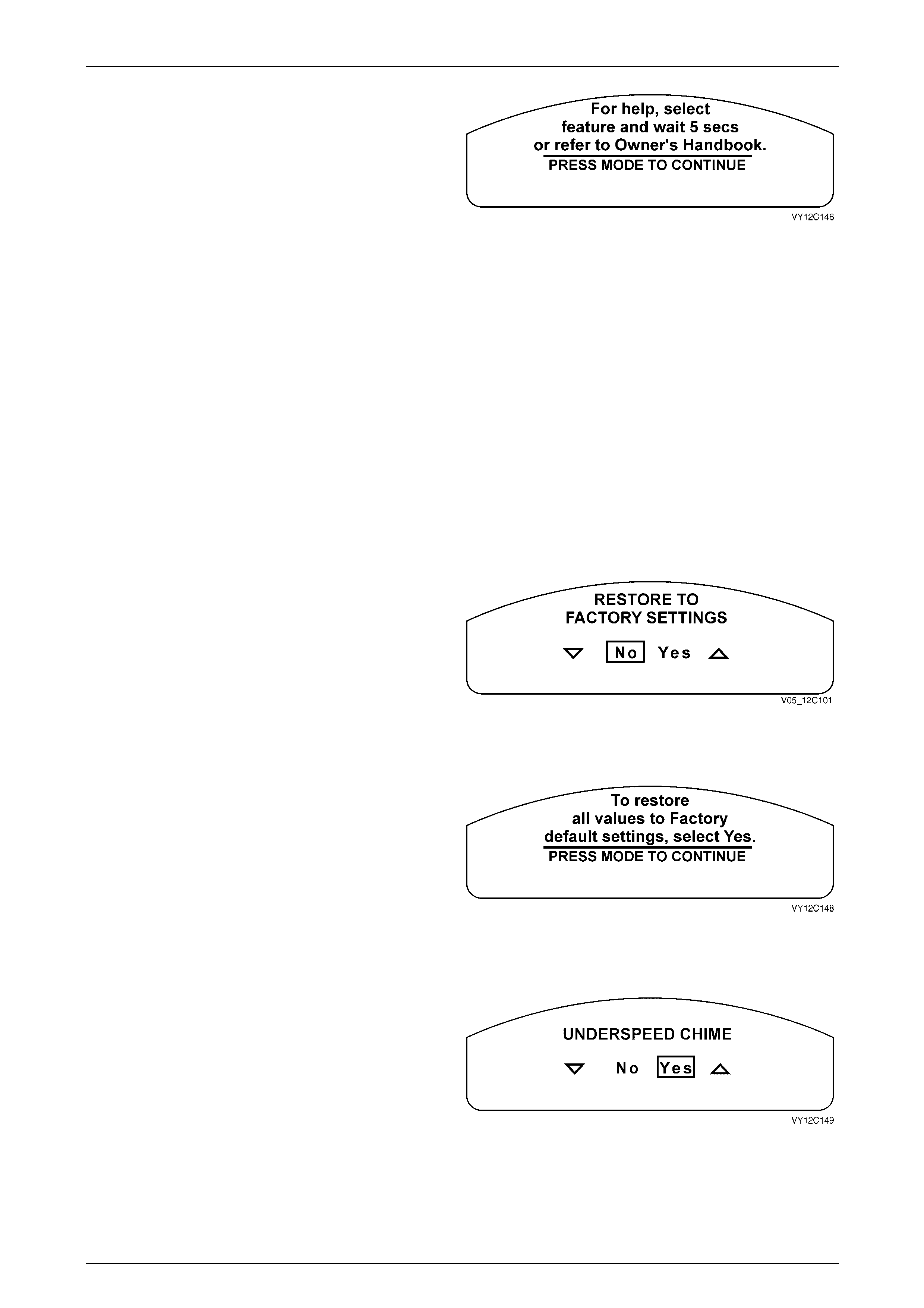
Instrumentation Page 12C – 46
Page 12C – 46
Press the MODE button to advance to the Restore to
Factory Setting screen.
Figure 12C – 142
NOTE
• If the message is too big for one screen, a
second (or third) screen with more information
appears once the MODE button is pressed,
until the menu item is shown.
• Within the Options Menu there are no fixed
icons displayed around the outside of the
main dot matrix area. If an icon is activated
while in the Options Menu, that icon is
displayed for 2 seconds and then disappears.
Once the Options Menu is exited or the
vehicle speed is greater than 10 km/h when
the Options Menu is locked out, the icons
reappear.
Restore to Factory Settings
The Restore to Factory Settings screen is the first item on
the Options Menu.
NOTE
This function restores the instrument cluster, the
entertainment system and the body control
module to the factory default settings, Refer to
Factory Default Settings.
Use the trip computer switch UP or DOWN button to select
Yes or No.
Figure 12C – 143
Press the MODE button to continue. If Yes is selected as
the option, a 2 second delay allows the following parameters
to be updated before the next screen is displayed.
Figure 12C – 144
Underspeed Chime
When an Overspeed condition has occurred and the vehicle
reduces speed, the Underspeed chime alerts the driver
when the vehicle speed drops back below the set
Overspeed value.
Use the trip computer switch UP or DOWN button to select
Yes or No.
Press the MODE button to continue. If Yes is selected as
the option, the Underspeed chime is activated. Figure 12C – 145
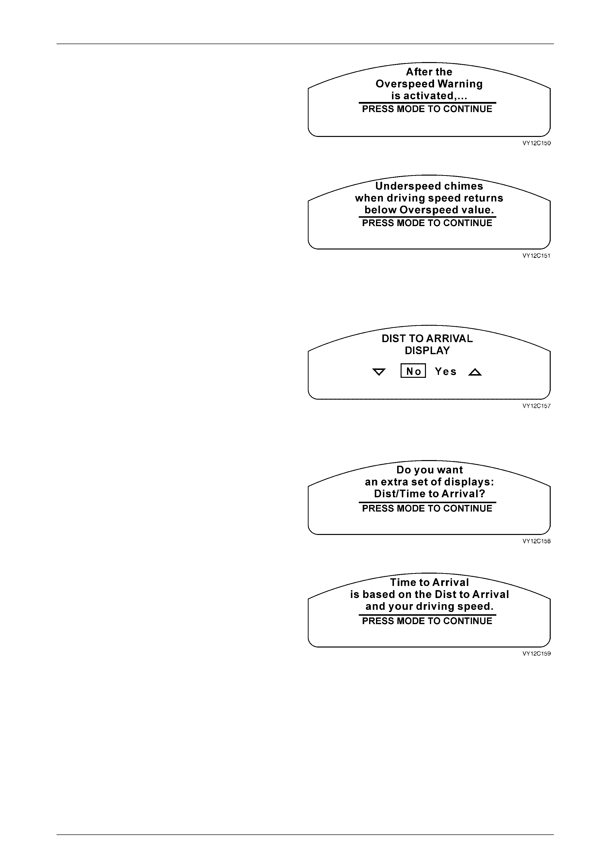
Instrumentation Page 12C – 47
Page 12C – 47
If no selection is made at the Underspeed Chime screen
within 5 seconds, this Help screen message appears.
Press the MODE button to advance to the next Help screen.
Figure 12C – 146
Press the MODE button to return to the Underspeed Chime
screen.
NOTE
• This mode is not available when the cluster
has had Mandatory Overspeed turned on.
• The Underspeed chime is set to Yes if the
Restore to Factory Settings option has been
selected. Figure 12C – 147
Distance to Arrival Display
Use the trip computer switch UP or DOWN button to select
Yes or No.
Press the MODE button to continue. If Yes is selected as
the option, the Distance to Arrival Default screen is
displayed.
NOTE
The Distance to Arrival Display is set to Yes if
the Restore to Factory Settings option has been
selected.
Figure 12C – 148
If no selection is made at the Distance to Arrival Display
screen within 5 seconds, this Help screen message
appears.
Press the MODE button to advance to the next Help screen.
Figure 12C – 149
Press the MODE button to return to the Distance to Arrival
Display screen.
Figure 12C – 150
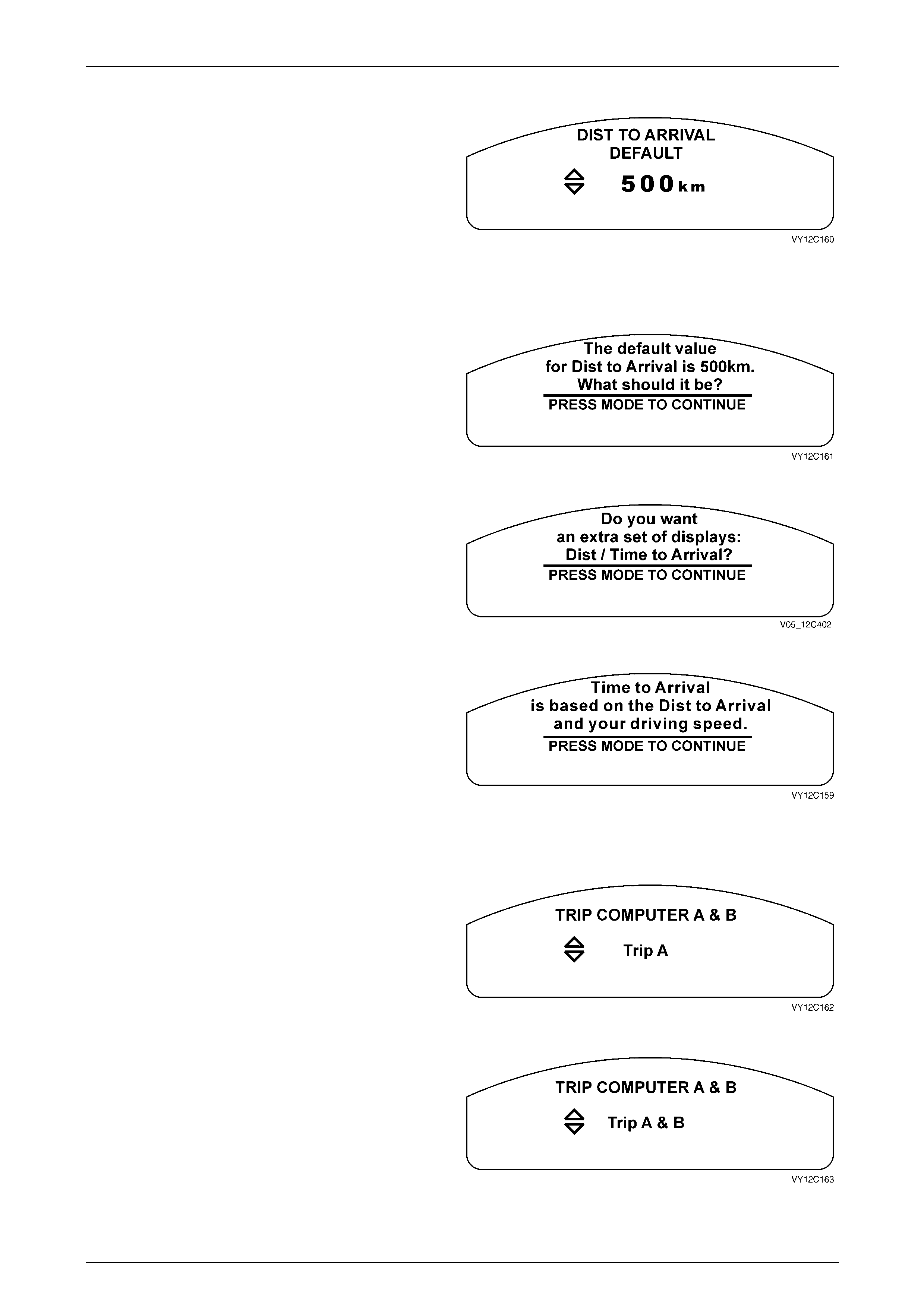
Instrumentation Page 12C – 48
Page 12C – 48
Distance to Arrival Default
Use the trip computer switch UP or DOWN button to adjust
the Distance to Arrival value. Note that changing this value
changes the displayed Distance to Arrival figure.
The default value for Distance to Arrival is 500 km.
Press the MODE button to continue.
NOTE
The Distance to Arrival Default is set to 500 km if
the Restore to Factory Settings option has been
selected.
Figure 12C – 151
If no selection is made at the Distance to Arrival Default
screen within 5 seconds, this Help screen message
appears.
Figure 12C – 152
If no selection is made at the Distance to Arrival Default
screen within 5 seconds, this Help screen message
appears.
Figure 12C – 153
Press the MODE button to return to the Distance to Arrival
Display screen.
Figure 12C – 154
Trip Computer A and B
Two trip computers can be used to record the details of
separate trips.
Use the trip computer switch DOWN button to select Trip A
only, or press the MODE button to continue.
NOTE
Trip A is enabled if the Restore to Factory
Settings option has been selected. Figure 12C – 155
Use the trip computer switch UP button to select Trip A and
Trip B, or press the MODE button to continue.
Figure 12C – 156
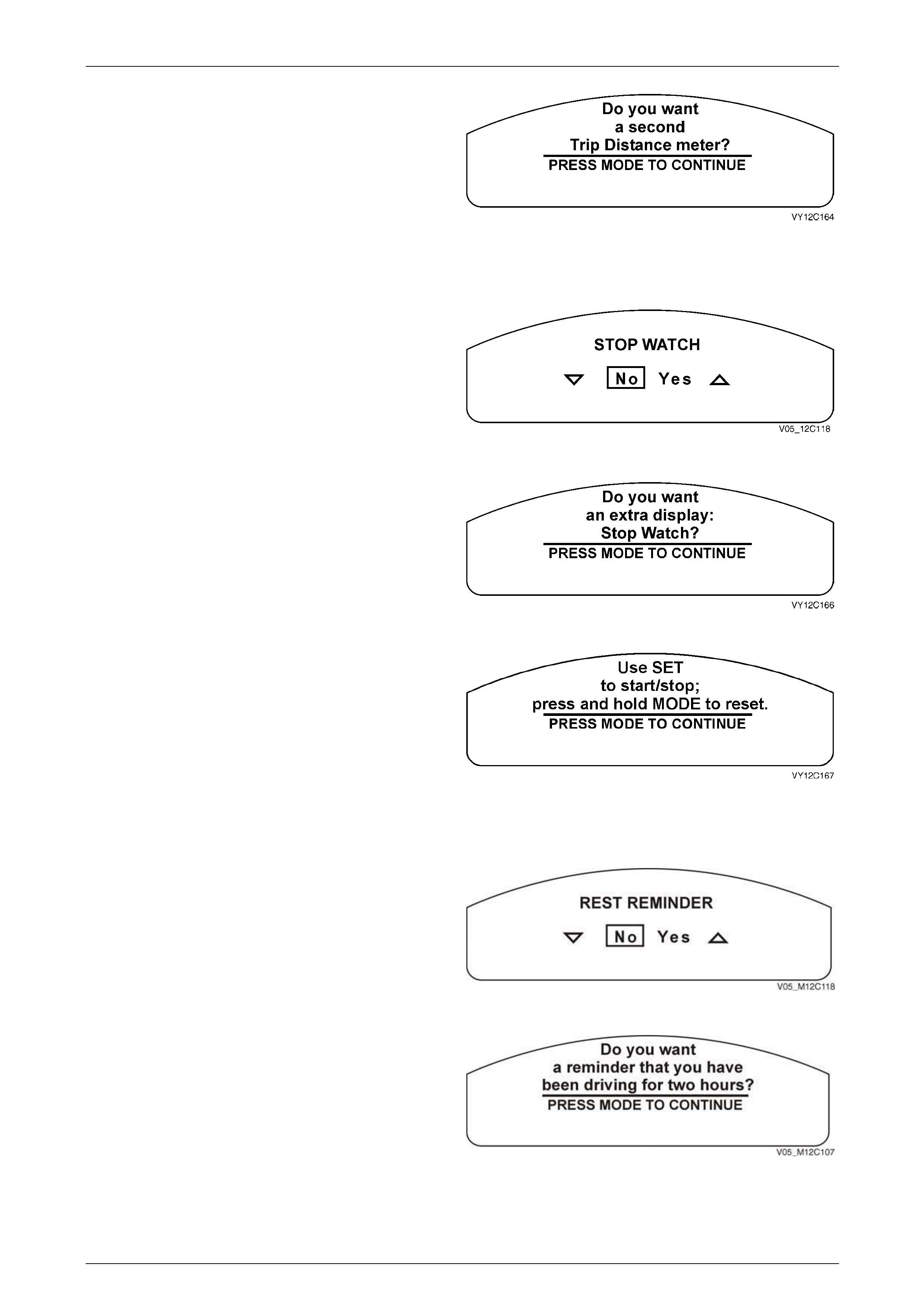
Instrumentation Page 12C – 49
Page 12C – 49
If no selection is made at the Trip Computer A and B screen
within 5 seconds, this Help screen message appears.
Press the MODE button to return to the Trip Computer A
and B screen.
Figure 12C – 157
Stop Watch
Use the trip computer switch UP or DOWN button to select
Yes or No.
Press the MODE button to continue. If Yes is selected as
the option, the Stop Watch screen is enabled.
NOTE
The Stop Watch is set to Yes if the Restore to
Factory Settings option has been selected. Figure 12C – 158
If no selection is made at the Stop Watch screen within
5 seconds, this Help screen message appears.
Press the MODE button to advance to the next Help screen.
Figure 12C – 159
Press the MODE button to return to the Stop Watch screen.
Figure 12C – 160
Rest Reminder
Use the trip computer switch UP or DOWN button to select
Yes or No.
Press the MODE button to continue. If Yes is selected as
the option, the Rest Reminder screen is enabled.
Figure 12C – 161
Press the MODE button to return to the Rest Reminder
screen.
Figure 12C – 162
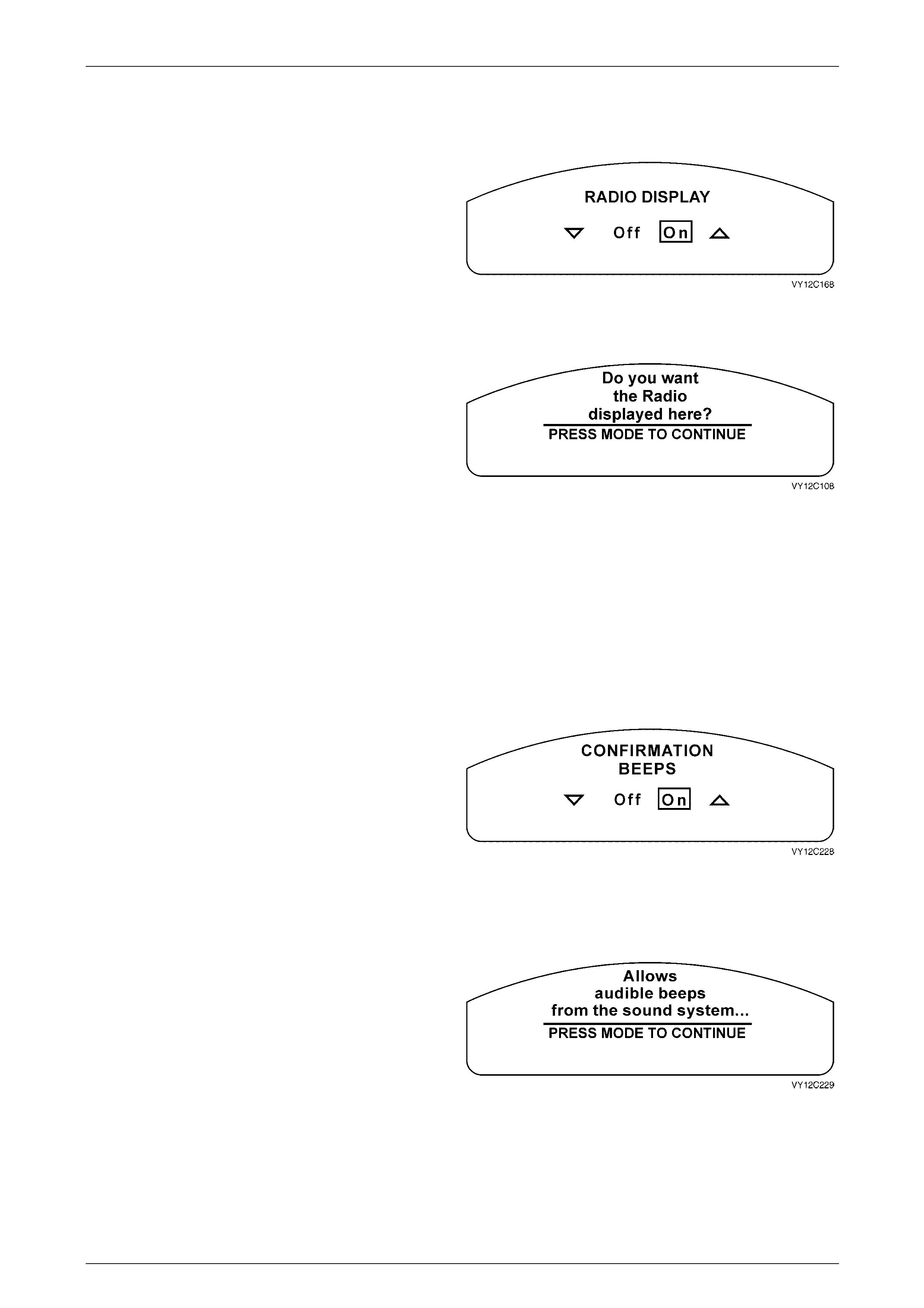
Instrumentation Page 12C – 50
Page 12C – 50
Radio MFD Messages
Radio Display
The entertainment system parameters can be displayed on
the instrument cluster MFD.
Use the trip computer switch UP or DOWN button to select
On or Off.
Press the MODE button to continue.
NOTE
The Radio Display is set to On if the Restore to
Factory Settings option has been selected. Figure 12C – 163
If no selection is made at the Radio Display screen within
5 seconds, this Help screen message appears.
Press the MODE button to return to the Radio Display
screen.
Figure 12C – 164
Confirmation Beeps
NOTE
The Confirmation Beeps screen displayed will
depend on the level of the audio system fitted to
the vehicle.
Confirmation Beeps – Radio Only
Confirmation beeps can be set to confirm that various
functions of the entertainment system have been completed.
For example storing a radio station.
Use the trip computer switch UP or DOWN button to set to
On or Off.
Press the MODE button to continue.
NOTE
The Confirmation Beeps are set to On if the
Restore to Factory Settings option has been
selected.
Figure 12C – 165
If no selection is made at the Confirmation Beeps screen
within 5 seconds, this Help screen message appears.
Press the MODE button to advance to the next Help screen.
Figure 12C – 166
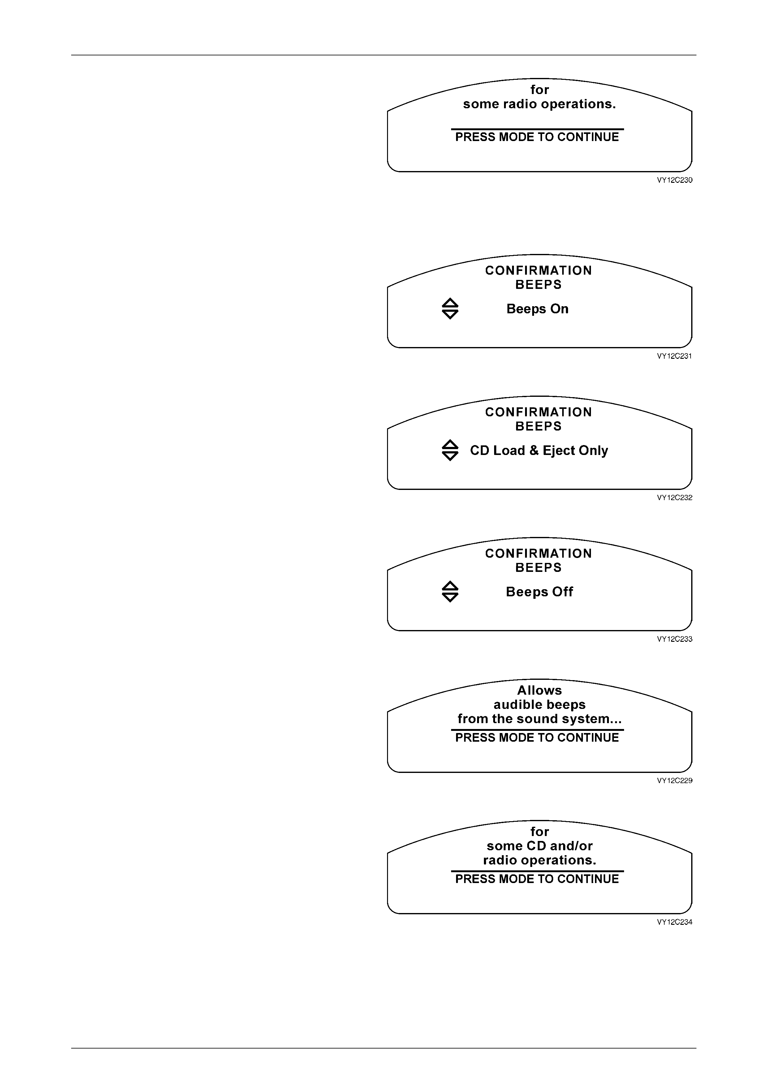
Instrumentation Page 12C – 51
Page 12C – 51
Press the MODE button to return to the Confirmation Beeps
screen.
Figure 12C – 167
Confirmation Beeps – Radio and CD
Confirmation beeps can be set to confirm that various
functions of the entertainment system have been completed.
For example storing a radio station or loading a CD. The
Confirmation Beeps screen displayed indicates the current
setting.
The confirmation beeps can be set to On, CD Load and
Eject Only or Off.
Figure 12C – 168
Use the trip computer switch UP or DOWN buttons to scroll
through the selection.
Press the MODE button to continue.
Figure 12C – 169
NOTE
The Confirmation Beeps is set to On if the Restore to
Factory Settings option has been selected.
Figure 12C – 170
If no selection is made at the Confirmation Beeps screen
within 5 seconds, this Help screen message appears.
Press the MODE button to advance to the next Help screen.
Figure 12C – 171
Press the MODE button to return to the Confirmation Beeps
screen.
Figure 12C – 172
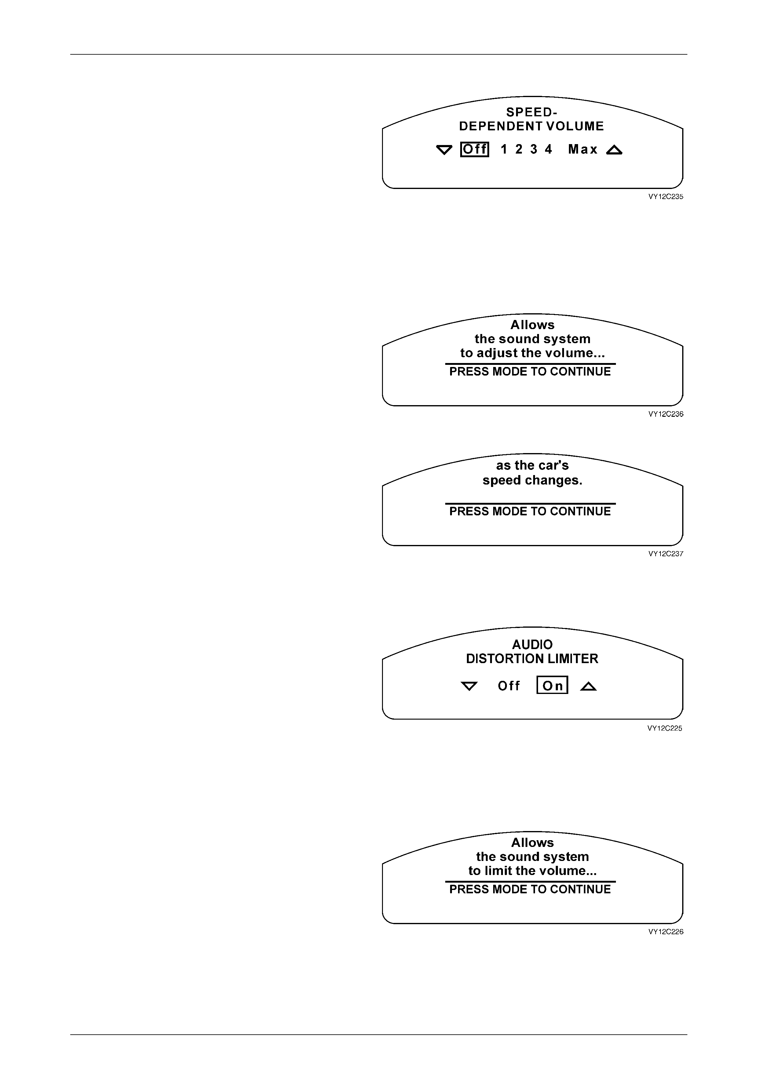
Instrumentation Page 12C – 52
Page 12C – 52
Speed Dependent Volume
The entertainment system volume can be set to vary
automatically with the speed of the vehicle to compensate
for additional background noise produced inside the vehicle.
The speed dependent volume can be selected between Off /
1 / 2 / 3 / 4 / Max.
Use the trip computer switch UP or DOWN button to scroll
through the selection.
Press the MODE button to continue.
NOTE
The Speed Dependent Volume is set to 2 if the
Restore to Factory Settings option has been
selected.
Figure 12C – 173
If no selection is made at the Speed Dependent Volume
screen within 5 seconds, this Help screen message
appears.
Press the MODE button to advance to the next Help screen.
Figure 12C – 174
Press the MODE button to return to the Speed Dependent
Volume screen.
Figure 12C – 175
Audio Distortion Limiter
The entertainment system incorporates a dynamic distortion
limiting function to monitor the audio output and reduce the
audio level if distortion is detected. The audio distortion
limiter can be enabled or disabled.
Use the trip computer switch UP or DOWN button to select
On or Off.
Press the MODE button to continue.
NOTE
The Audio Distortion Limiter is set to On if the
Restore to Factory Settings option has been
selected.
Figure 12C – 176
If no selection is made at the Audio Distortion Limiter screen
within 5 seconds, this Help screen message appears.
Press the MODE button to advance to the next Help screen.
Figure 12C – 177
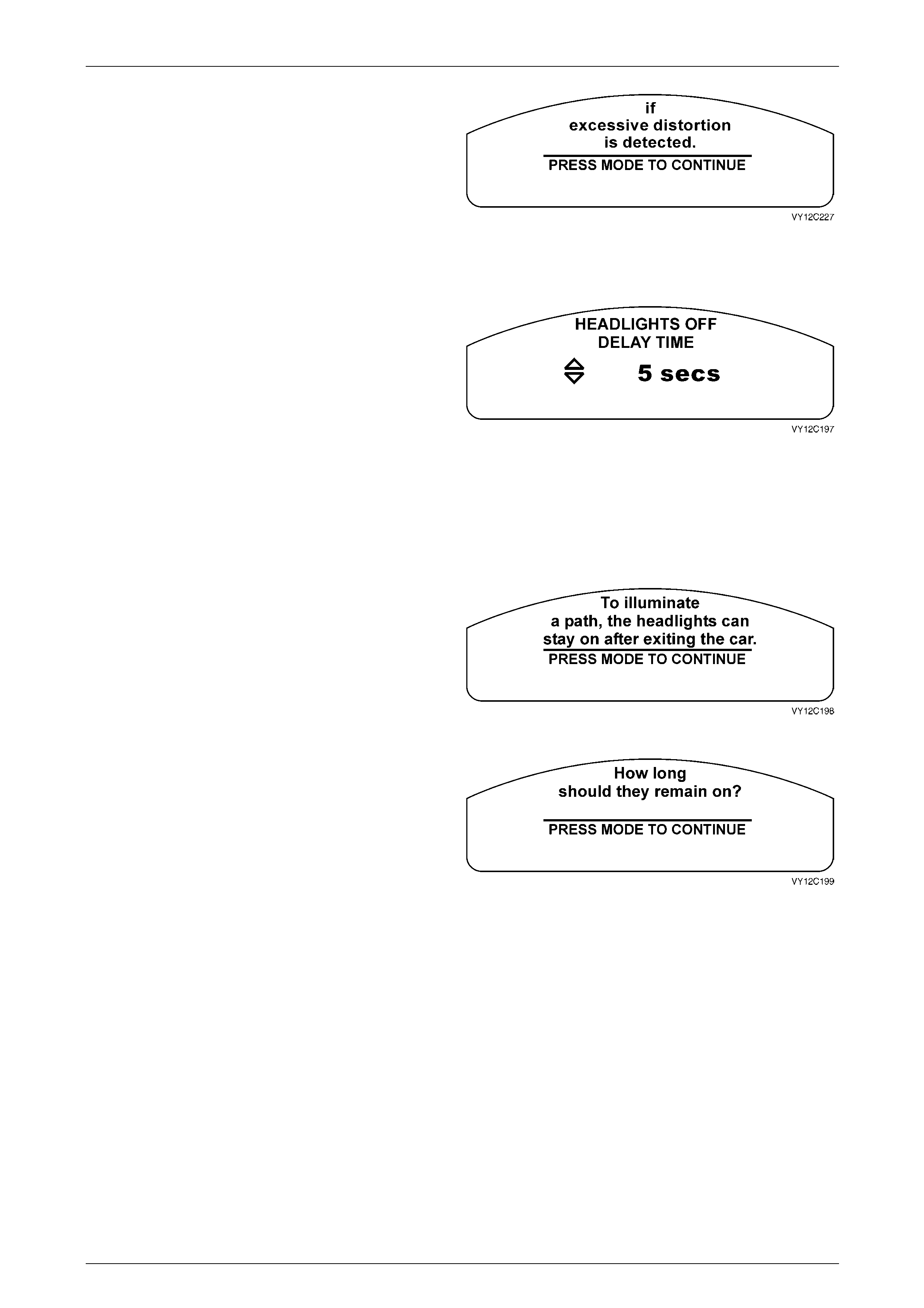
Instrumentation Page 12C – 53
Page 12C – 53
Press the MODE button to return to the Audio Distortion
Limiter screen.
Figure 12C – 178
Headlamp Off Delay
The Headlamp Off Delay is a count down timer that
automatically controls the on time of the headlights after the
vehicle has been exited and locked; it is adjustable between
zero and 180 seconds.
Use the trip computer switch UP or DOWN button to
increase or decrease the set value. Pressing the button
once will change the value by 1 second. Press and hold the
button to change the value at a faster rate.
Press the MODE button to continue.
NOTE
The Headlamp Off Delay is set to 1 second if the
Restore to Factory Settings option has been
selected.
Figure 12C – 179
If no selection is made at the Headlights Off Delay screen
within 5 seconds, this Help screen message appears.
Press the MODE button to advance to the next Help screen.
Figure 12C – 180
Press the MODE button to return to the Headlights Off Delay
Time screen.
Figure 12C – 181
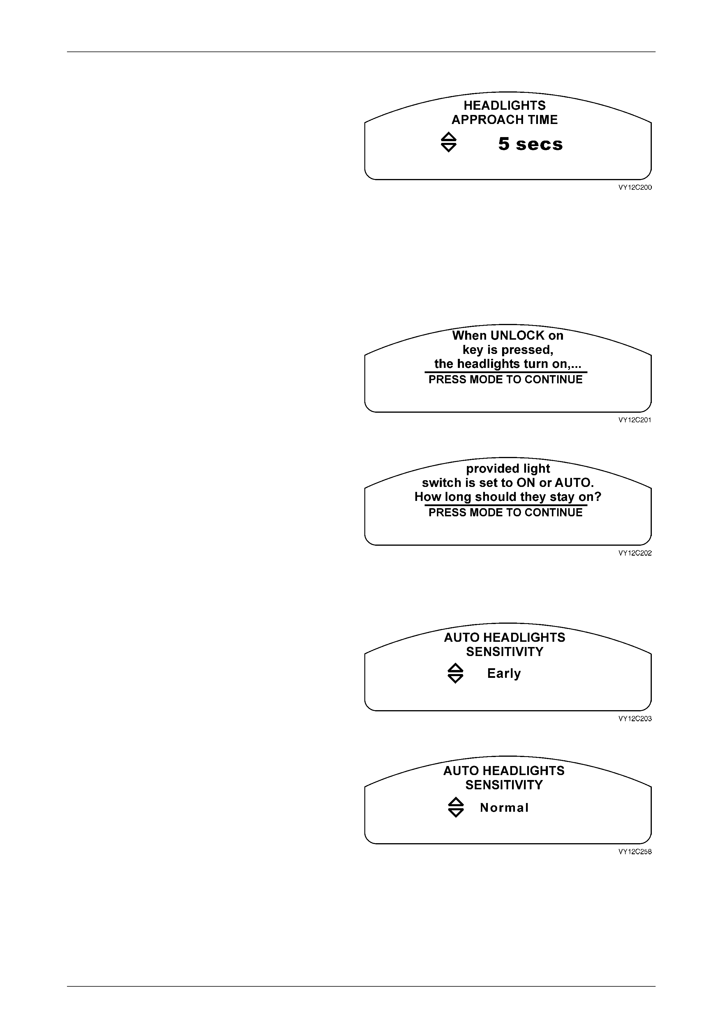
Instrumentation Page 12C – 54
Page 12C – 54
Approach Illumination
The headlamps can be requested to provide illumination
when approaching the vehicle at night. When set, activating
the remote UNLOCK button activates this feature. The
approach illumination delay is adjustable between zero and
90 seconds.
Use the trip computer switch UP or DOWN button to
increase or decrease the set value of the delay. Pressing
the button once will change the value by 1 second. Press
and hold the button to change the value at a faster rate.
Press the MODE button to continue.
NOTE
The Headlights Approach Time is set to 30
seconds if the Restore to Factory Settings option
has been selected.
Figure 12C – 182
If no selection is made at the Headlights Approach Time
screen within 5 seconds, this Help screen message
appears.
Press the MODE button to advance to the next Help screen.
Figure 12C – 183
Press the MODE button to return to the Headlights
Approach Time screen.
Figure 12C – 184
Automatic Headlamp Sensitivity
The headlamps can be set to come on automatically when
lighting conditions deteriorate. The headlamp sensitivity can
be set to Early, Normal or Late.
Use the trip computer switch UP or DOWN button to scroll
through the selection.
Figure 12C – 185
Press the MODE button to continue.
Figure 12C – 186
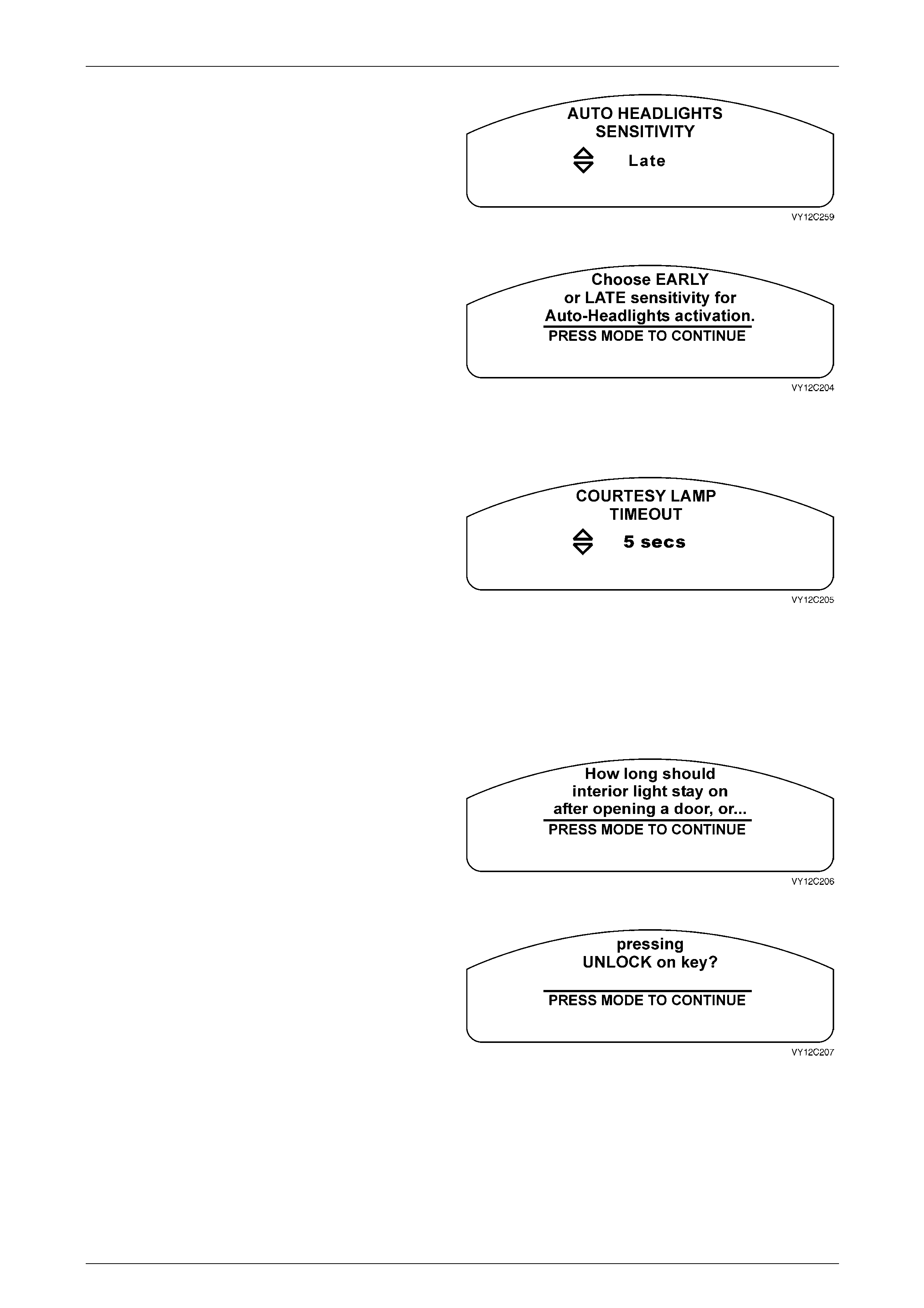
Instrumentation Page 12C – 55
Page 12C – 55
NOTE
The Automatic Headlights Sensitivity is set to
Normal if the Restore to Factory Settings option
has been selected.
Figure 12C – 187
If no selection is made at the Auto Headlights Sensitivity
screen within 5 seconds, this Help screen message
appears.
Press the MODE button to return to the Auto Headlights
Sensitivity screen.
Figure 12C – 188
Interior Courtesy Lamp Timeout
The length of time that the interior courtesy lamp remains
illuminated after opening a door prior to exiting it or
unlocking the vehicle remotely prior to entering it is
adjustable between zero and 255 seconds.
Use the trip computer switch UP or DOWN buttons to
increase or decrease the set value. Pressing the button
once will change the value by 1 second. Press and hold the
button to change the value at a faster rate.
Press the MODE button to continue.
NOTE
The Interior Courtesy Lamp Timeout is set to 30
seconds if the Restore to Factory Settings option
has been selected.
Figure 12C – 189
If no selection is made at the Courtesy Lamp Timeout
screen within 5 seconds, this Help screen message
appears.
Press the MODE button to advance to the next Help screen.
Figure 12C – 190
Press the MODE button to return to the Courtesy Lamp
Timeout screen.
Figure 12C – 191
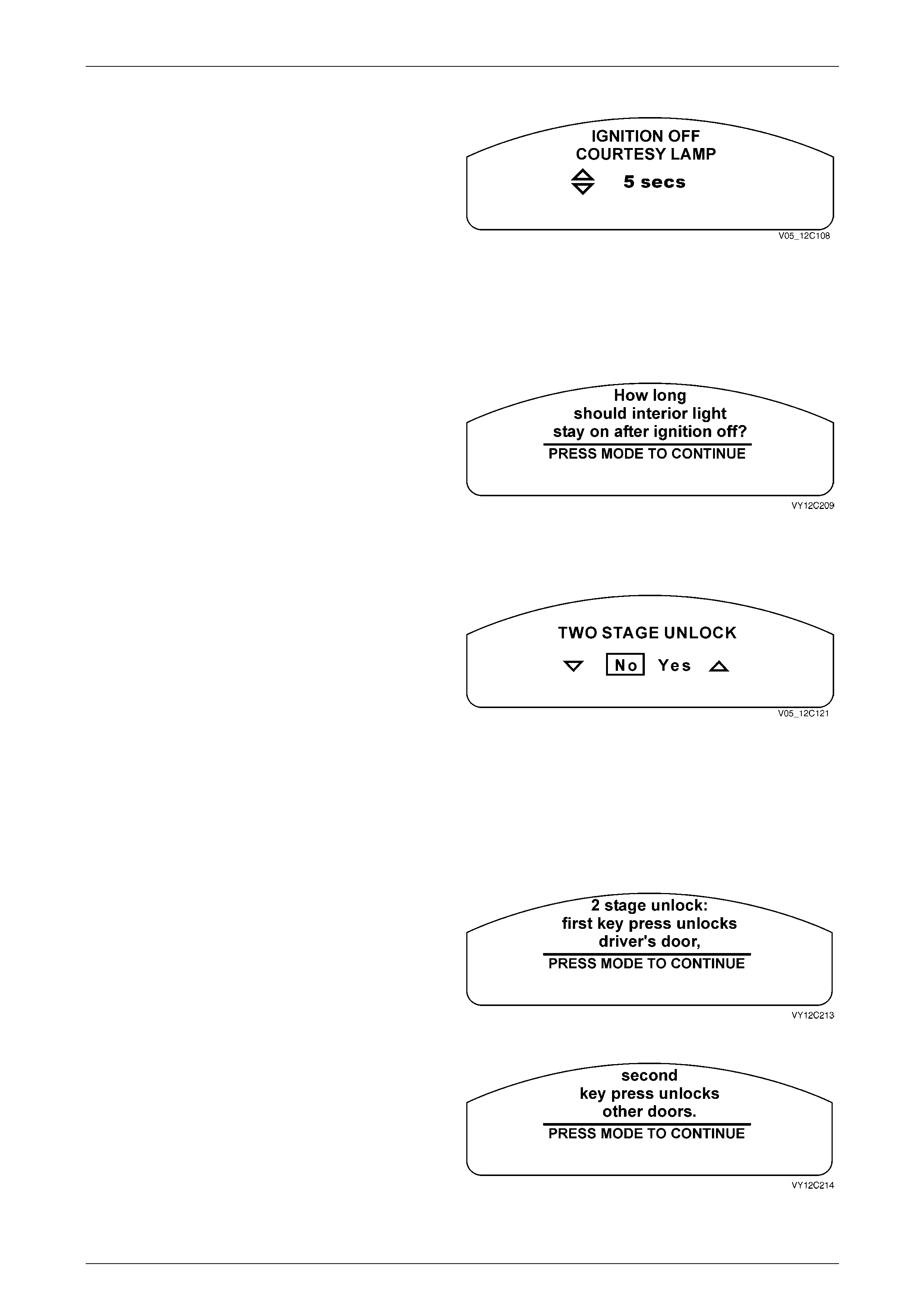
Instrumentation Page 12C – 56
Page 12C – 56
Ignition Off Courtesy Lamp Timeout
The length of time that the interior courtesy lamp remains
illuminated after the ignition is turned off is adjustable
between zero and 255 seconds.
Use the trip computer switch UP or DOWN button to
increase or decrease the set value. Pressing the button
once will change the value by 1 second. Press and hold the
button to change the value at a faster rate.
Press the MODE button to continue.
NOTE
The Ignition Off Courtesy Lamp Timeout is set to
30 seconds if the Restore to Factory Settings
option has been selected.
Figure 12C – 192
If no selection is made at the Ignition Off Courtesy Lamp
screen within 5 seconds, this Help screen message
appears.
Press the MODE button to return to the Ignition Off Courtesy
Lamp screen.
Figure 12C – 193
Two Stage Unlock
The vehicle can be set to either Two Stage Unlock, or
Unlock All Doors. With two stage unlock, the first press of
the UNLOCK button on the remote coded key unlocks the
drivers door only. Pressing the button, a second time
unlocks the remaining doors. With Unlock ALL Doors, the
first press of the remote UNLOCK button will release all door
locks.
Use the trip computer switch UP or DOWN button to select
Yes or No.
Press the MODE button to continue.
NOTE
The Two Stage Unlock is set to Yes if the
Restore to Factory Settings option has been
selected.
Figure 12C – 194
If no selection is made at the Two Stage Unlock screen
within 5 seconds, this Help screen message appears.
Press the MODE button to advance to the next Help screen.
Figure 12C – 195
Press the MODE button to return to the Two Stage Unlock
screen.
Figure 12C – 196
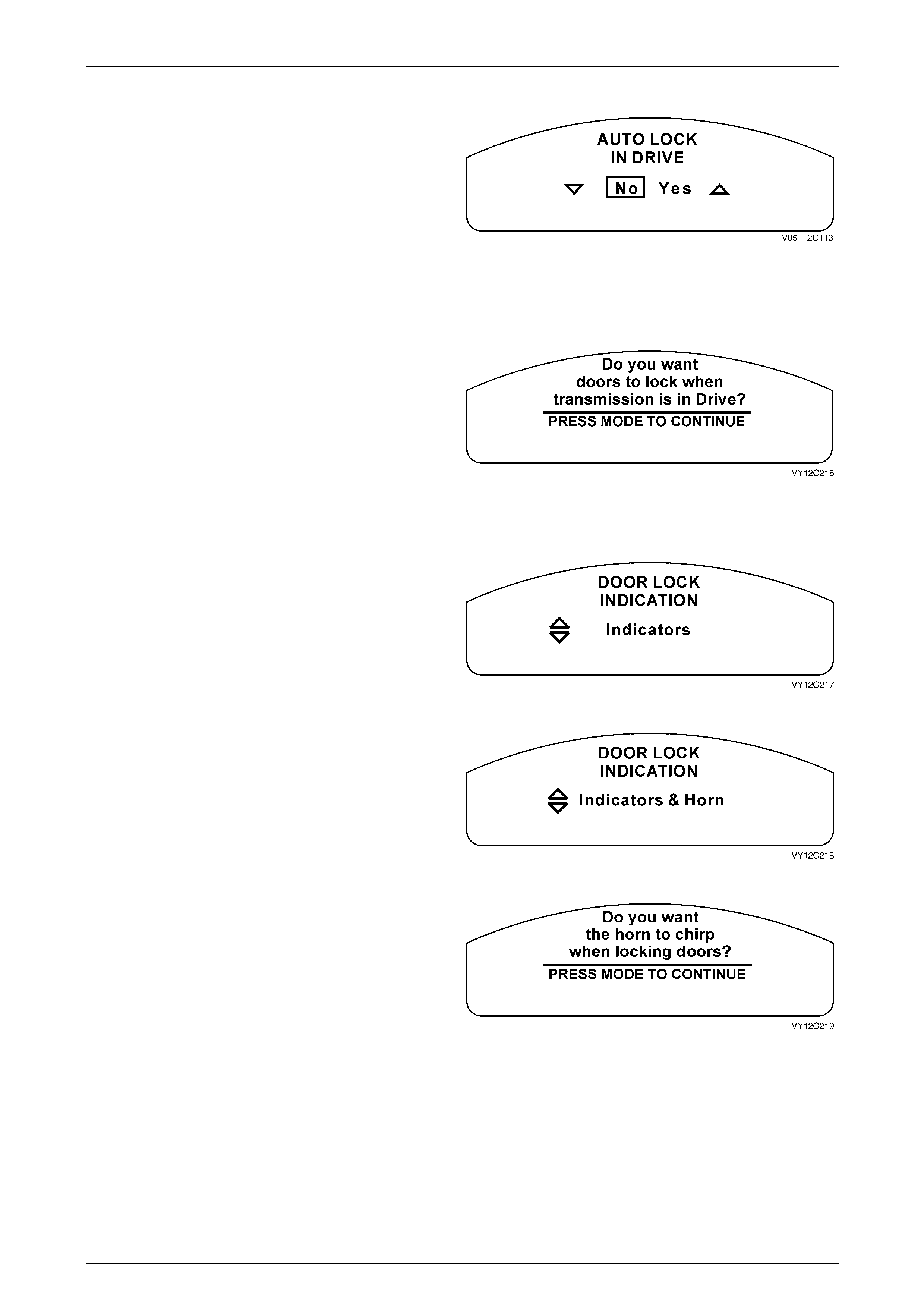
Instrumentation Page 12C – 57
Page 12C – 57
Auto Lock In Drive
The doors can be automatically locked when the
transmission is shifted out of the Park position. This function
is only available on vehicles fitted with an automatic
transmission.
Use the trip computer switch UP or DOWN button to select
Yes or No.
Press the MODE button to continue.
NOTE
The Auto Lock In Drive is set to No if the Restore
to Factory Settings option has been selected.
Figure 12C – 197
If no selection is made at the Auto Lock In Drive screen
within 5 seconds, this Help screen message appears.
Press the MODE button to return to the Auto Lock In Drive
screen.
Figure 12C – 198
Door Lock Indication
The door lock indication can be selected between the turn
indicators flashing or accompanied by the sounding of the
horn. The selected function also operates when unlocking
the vehicle.
Use the trip computer switch UP button to enable the turn
indicators and horn, or the DOWN button to enable the turn
indicators only.
Press the MODE button to continue. Figure 12C – 199
NOTE
The Door Lock Indication is set to Indicators if
the Restore to Factory Settings option has been
selected.
Figure 12C – 200
If no selection is made at the Door Lock Indication screen
within 5 seconds, this Help screen message appears.
Press the MODE button to return to the Door Lock Indication
screen.
Figure 12C – 201
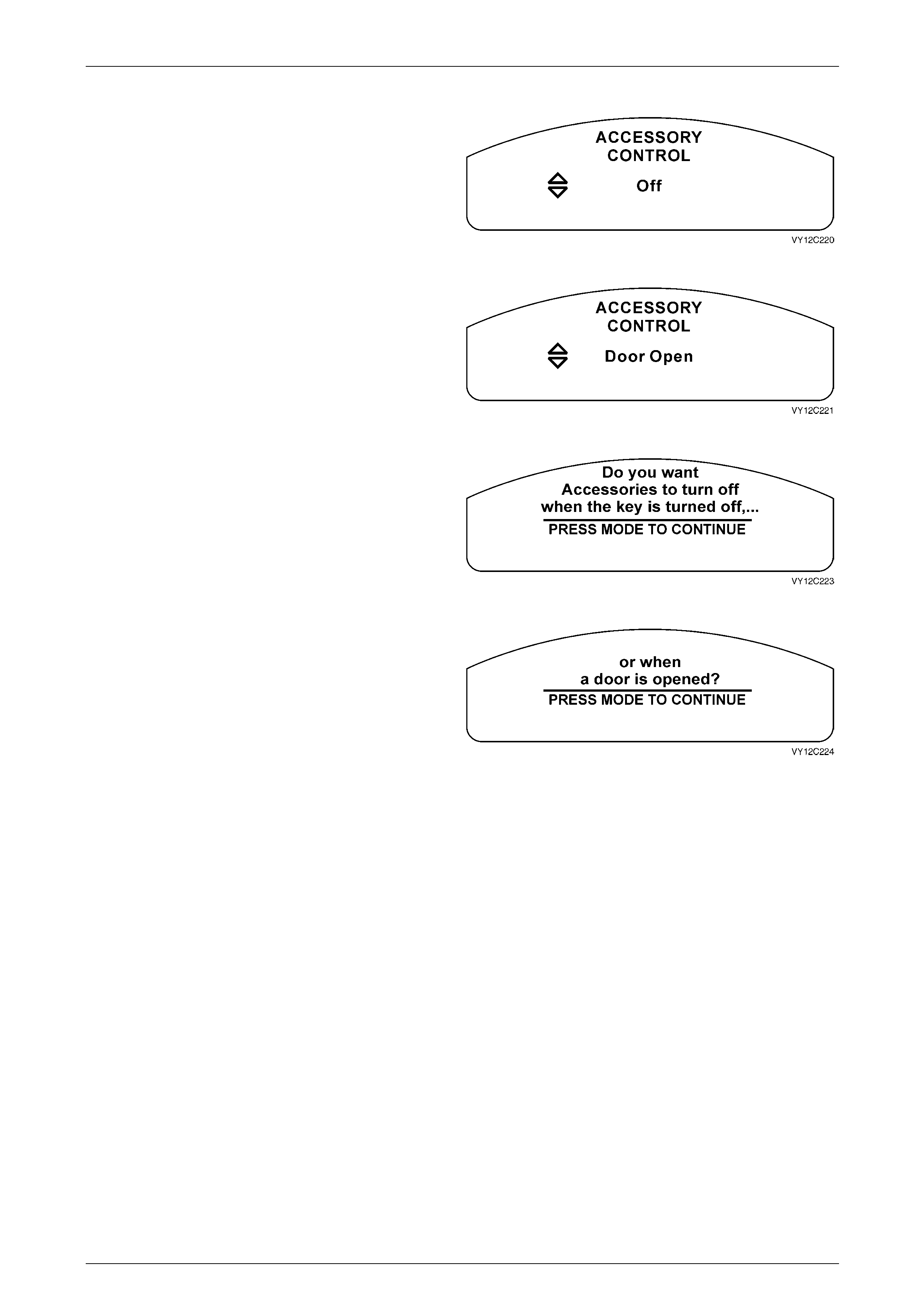
Instrumentation Page 12C – 58
Page 12C – 58
Accessory Control
The accessories within the vehicle can be turned off at
either ignition off or when a door is opened.
Use the trip computer switch UP or DOWN button to scroll
through the selection.
Press the MODE button to continue.
Figure 12C – 202
NOTE
The Radio and Accessories Timeout period is
set to Door Open if the Restore to Factory
Settings option has been selected.
Figure 12C – 203
If no selection is made at the Accessory Control screen
within 5 seconds, this Help screen message appears.
Press the MODE button to advance to the next Help screen.
Figure 12C – 204
Press the MODE button to return to the Accessory Control
screen.
Figure 12C – 205
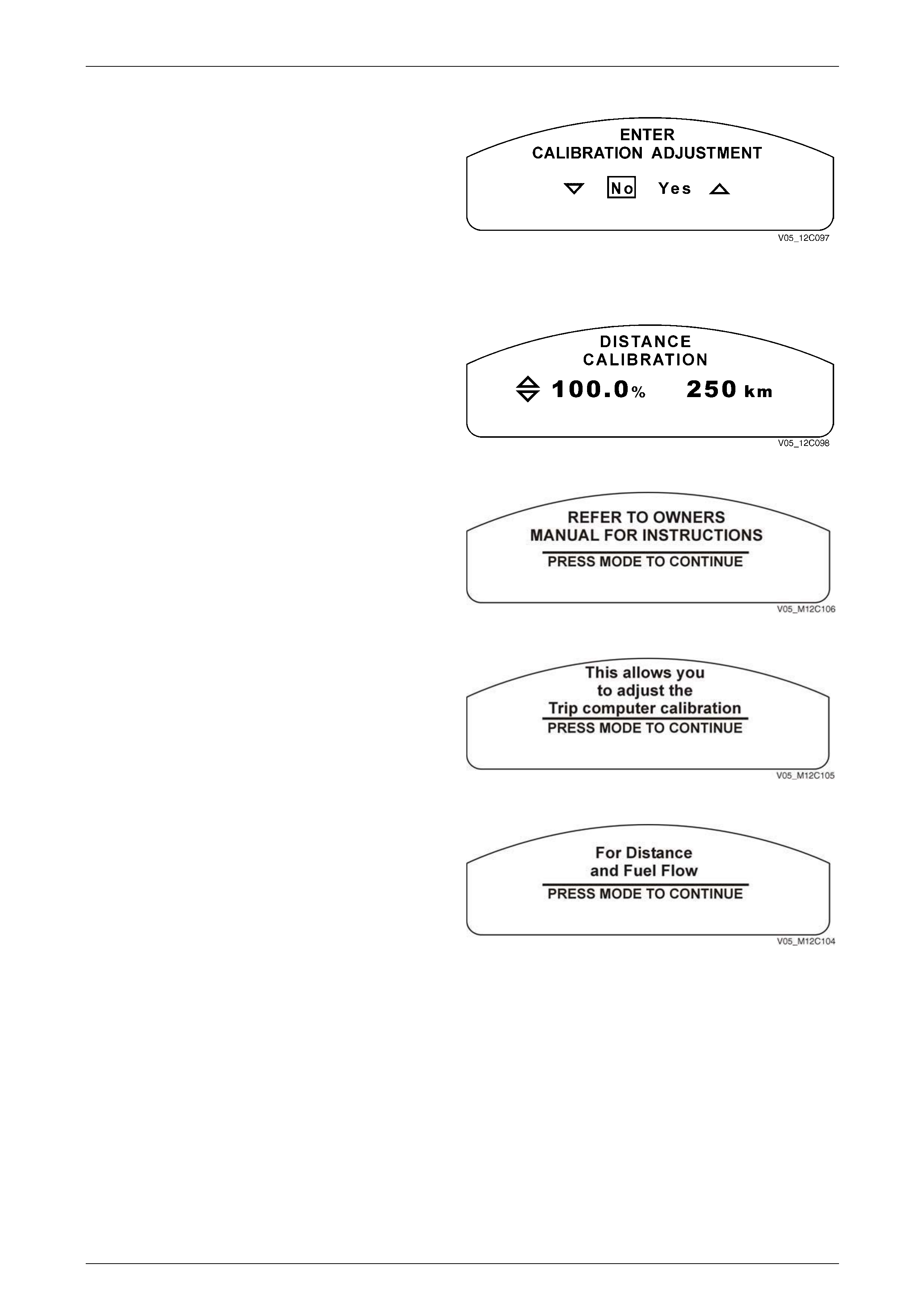
Instrumentation Page 12C – 59
Page 12C – 59
Calibration Adjustment
The trip computer can be calibrated for more accurate
distance and fuel flow readings.
Use the trip computer switch UP or DOWN button to select
Yes or No.
Press the MODE button to continue.
If No is selected, Customisation Mode advances to the Exit
Options Menu.
If Yes is selected, the next screen displayed is the Distance
Calibration screen.
Figure 12C – 206
If the Distance Calibration screen is not required, press the
MODE button to advance to the Fuel Calibration screen.
To check the distance calibration figures, align the front
wheels of the vehicle with a highway kilometre shield post
before entering Customisation Mode.
Press the MODE button to display the Trip Distance screen.
Reset the Trip Distance by pressing the SET button for less
than 2 seconds.
Drive to another shield post, between 10 km and 500 km,
and stop with the front wheels aligned with the shield post.
Note the real distance between the shield posts and the
distance on the Trip Distance display. If these distances are
different, enter Customisation Mode / Calibration Adjustment
/ Distance Calibration and use the UP and DOWN buttons to
adjust the distance displayed to the real distance between
the shield posts.
NOTE
The default distance calibration figure is 100%.
The maximum figure is 120%, while the minimum
figure is 80%.
NOTE
Further information for this adjustment can be
found in the owners manual.
Figure 12C –
207
Figure 12C –
208
Figure 12C –
209
Figure 12C – 210
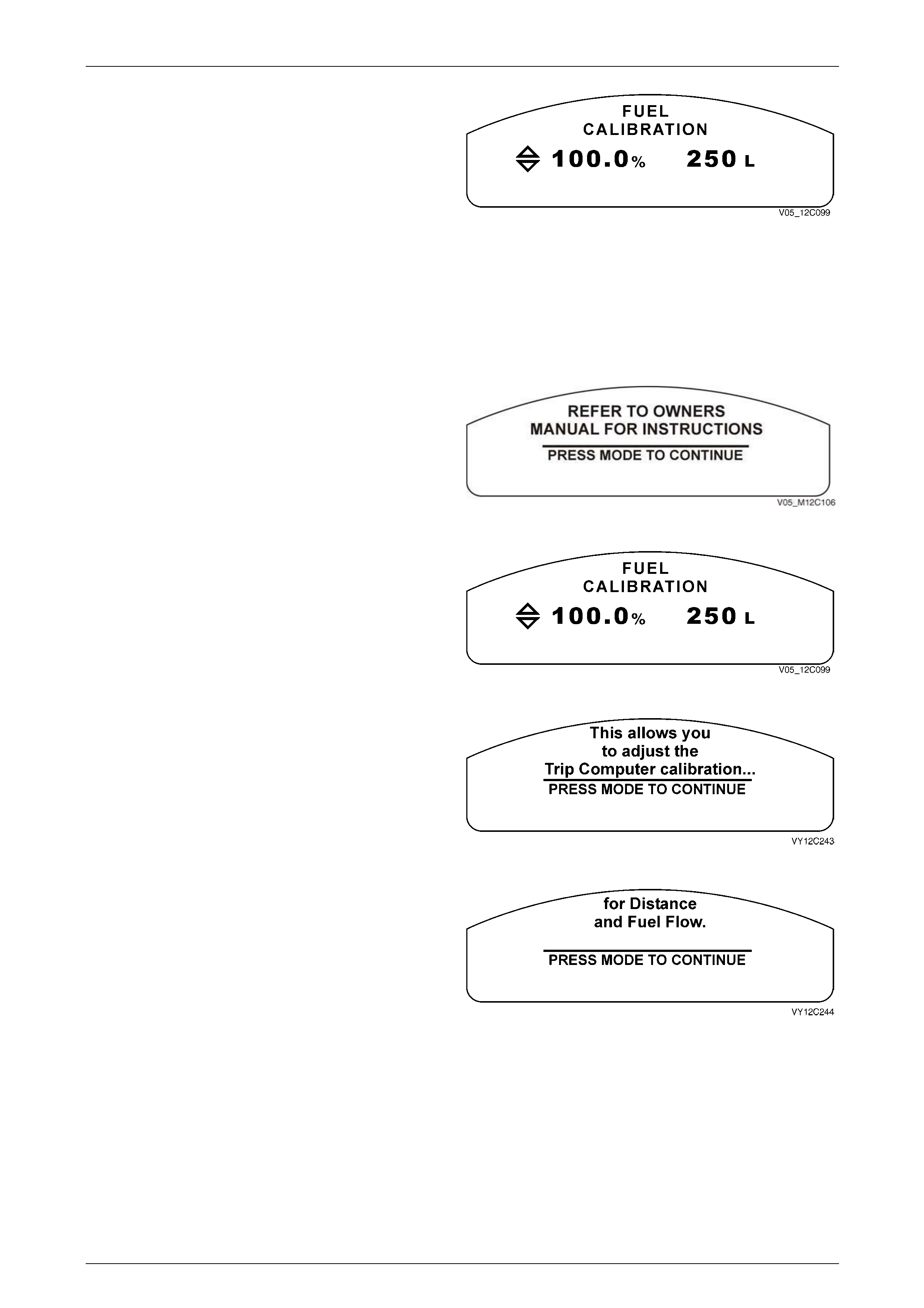
Instrumentation Page 12C – 60
Page 12C – 60
Press the MODE button to advance to the Fuel Calibration
screen.
If the Fuel Calibration screen is not required, press the
MODE button to advance to the Exit Options Menu.
To check the fuel calibration figures, press the MODE button
to display the Fuel Used screen before entering
Customisation Mode. Reset the Fuel Used by pressing the
SET button for less than 2 seconds.
For at least five consecutive fuel fills, record the total litres
added (but no more than 500 litres) according to the service
station fuel meters. Note the real fuel used and the reading
on the Fuel Used display. If these are different, enter
Customisation Mode / Calibration Adjustment / Distance
Calibration / Fuel Calibration and use the UP and DOWN
buttons to adjust the litres displayed to the real figure.
Figure 12C – 211
NOTE
Further information for this adjustment can be
found in the owner’s manual.
Figure 12C – 212
The default fuel calibration figure is 100%. The maximum
figure is 120%, while the minimum figure is 80%.
Press the MODE button to advance to the Exit Options
Menu screen.
Figure 12C – 213
If no selection is made at the Enter Calibration Adjustment
screen within 5 seconds, this Help screen message
appears.
Press the MODE button to advance to the next Help screen.
Figure 12C – 214
Press the MODE button to return to the Enter Calibration
Adjustment screen.
Figure 12C – 215
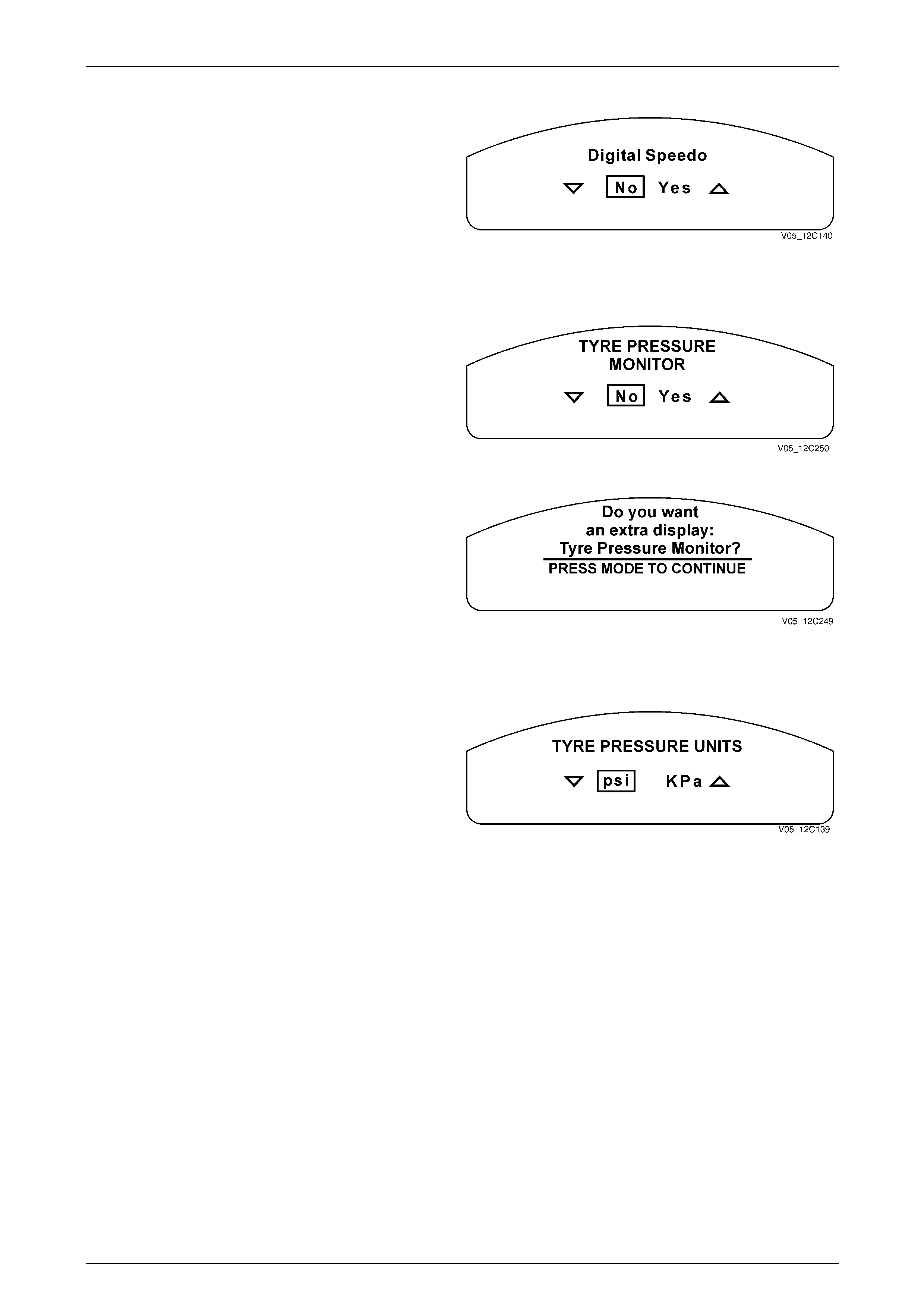
Instrumentation Page 12C – 61
Page 12C – 61
Digital Speedo
Use the trip computer switch UP or DOWN buttons to select
the Digital Speedometer option.
If no selection is made at the Digital Speedo screen within
5 seconds, a Help screen appears.
Press the MODE button to exit the options menu
Figure 12C – 216
Tyre Pressure Monitor
Use the trip computer switch MODE button to select the
Tyre Pressure Monitor option.
Figure 12C – 217
If no selection is made at the Tyre Pressure Monitor screen
within 5 seconds, this Help screen message appears.
Press the MODE button to advance to the next Help screen.
Figure 12C – 218
Tyre Pressure Units
Use the trip computer switch UP or DOWN button to select
the tyre pressure units (psi) or (KPa).
Press the MODE button to exit the options menu.
Figure 12C – 219
Instrumentation Page 12C – 62
Page 12C – 62
Factory Default Settings
Cluster Parameters BCM Parameters Audio System Parameters
• Underspeed Chime set to No
• Distance to Go Display set to yes
(only low spec vehicles)
• Distance to Go Default set to
500 km (only low spec vehicles)
• Distance to Arrival Display set to
No
• Distance to Arrival Default set to
500 km
• Trip Computer A and B set to
Trip A
• Stop Watch set to No
• Radio Display set to on
• Rest reminder set to No
• Digital speedometer set to Yes
• Restore BCM Factory Settings
set to No
• Headlamp Off Delay set to
1 second
• Approach Illumination set to
30 seconds
• Automatic Headlamp Sensitivity
set to Normal
• Interior Courtesy Lamp Timeout
set to 30 seconds
• Interior Courtesy Lamp
Timeout – Ignition Off set to
30 seconds
• Intermittent Wiper Speed set to
on (only low spec vehicles)
• Two Stage Unlock set to Yes
• Auto Lock in Drive set to No
• Door Lock Indication set to
Indicators
• Radio and Accessories Timeout
set to Door Open
• Bass set to STD (0)
• Treble set to STD (0)
• Balance set to STD (0)
• Fader set to STD (0)
• Loudness set to on
• Equaliser set to on
• CD Random set to off
• CD Repeat set to off
• Local / Distance set to
Distance
• Display Mode set to Time
• Audio Distortion Limiter set
to on
• Confirmation Beeps set to
on
• Speed Dependent Volume
set to 2
If no selection is made at the Restore to Factory Settings
screen within 5 seconds, this Help screen message
appears.
Press the MODE button to return to the Restore to Factory
Settings screen.
Figure 12C – 220\

Instrumentation Page 12C – 63
Page 12C – 63
1.9 Police Mode
Tech 2 enables the Police Mode.
If the Police Mode is enabled, the digital speedometer is the
MFD default display at ignition on.
NOTE
• In Police mode, the overspeed screen is
disabled and not shown on a single window
cluster. For a triple-window cluster, the
overspeed side LCD display is blank. Figure 12C – 221

Instrumentation Page 12C – 64
Page 12C – 64
2 Tech 2 Information
A prerequisite of this diagnostic information is for the user to be familiar with the correct use of Tech 2. The following
pages describe only the major Tech 2 screen displays and provide a brief explanation of their function for diagnosing the
instruments. If additional information is required on the operation of Tech 2, reference should be made to either 0C
Tech 2 or the Tech 2 User’s Guide.
1 Connect Tech 2 to the DLC.
2 Turn the ignition on and press the power button (PWR) on the Tech 2.
3 The Tech 2 will perform a series of self-diagnosing power on self-tests (POST). Once this has been completed
successfully, the Tech 2 Start-up screen will be displayed. Press the Enter key to continue.
The following will then be displayed:
System Identification
Turn the ignition on (as requested) and press Confirm soft key to continue.
The System Identification screen will be displayed detailing the following:
Identifier Code Version
Part number Code Index
Production Date VAP Process Number
Software Version TIS Hardware Key Serial Number
Instrument Type TAG Number
Fuel Calibration Country
Press the Confirm soft key to confirm these details and the Body Menu will be displayed.
Body Menu
This menu provides the Tech 2 user with access to the various functions used to diagnose faults in the instrument cluster
and its related components.
Normal Mode
The instrument normal mode data list is used to view serial data being sent to and from the instrument cluster, refer to
2.1 Normal Mode.
Diagnostic Trouble Codes
In this mode the Diagnostic Trouble Codes can be read and cleared, refer to 2.2 Diagnostic Trouble Codes.
Data Display
In this test mode, Tech 2 displays the status of inputs and outputs of the instrument cluster including the hardwired
inputs, refer to 2.3 Data Display.
Snapshot
In this test mode, the Tech 2 captures data before and after a selected snapshot triggering condition, which may or may
not set a DTC, refer to 2.4 Snapshot.
Miscellaneous Tests
In this test mode, the Tech 2 can test and diagnose faults in the instrument cluster. Warning Indicators and instrument
gauges can be tested in this mode, refer to 2.5 Miscellaneous Tests.
Program
In this mode the following instruments and options can be programmed, fuel gauge, configuration, odometer,
speedometer calibration, reset service interval and reset trip computer settings can be modified, refer to
7.2 Programming.

Instrumentation Page 12C – 65
Page 12C – 65
2.1 Normal Mode
NOTE
If Tech 2 gives the warning Address Error –
Processor Halt, check the software version
loaded into Tech 2 it may require an upgrade.
The Normal Mode data list is used to view serial data being sent to and from the instrument cluster.
On Tech 2 select:
Body / Instrument / Normal Mode.
Normal Mode Data List
Tech 2 Parameter Units Displayed Typical Data Value
Engine Oil Life Reset No / Yes Varies
Transmission Fluid Life No / Yes Varies
SRS Configuration 4 Loop SRS / 6 Loop SRS Varies
Cruise Control Engaged No / Yes Varies
Radio Status Request No / Yes Varies
MFD Message Requested No / Yes Varies
MFD Message Received No / Yes Varies
TPMSS Learn Mode Request Active / Inactive Varies

Instrumentation Page 12C – 66
Page 12C – 66
2.2 Diagnostic Trouble Codes
This function is used to read and clear set DTCs.
On Tech 2 select:
Body / Instrument / Read DTC Information.
Tech 2 Parameter Units Displayed Typical Data Value
Read DTC Information No / Yes Listed DTCs
Clear DTC Information No / Yes Listed DTCs

Instrumentation Page 12C – 67
Page 12C – 67
2.3 Data Display
The Data Display function allows the status of the instrument cluster to be monitored.
On Tech 2 select:
Body / Instrument / Data Display / Instrument.
The Data Display Menu provides access to the serial data lists for:
• The instrument cluster.
• Inputs.
• The trip computer switch.
• System warning details.
• Configuration.
• System Identification.
The list can be scrolled through using the Up and Down arrow keys, Make the required selection from the data display
screen.
Instruments
Tech 2 Parameter Units Displayed Typical Data Value
Battery Voltage Volts 12.0 V
Ignition Switch Off / Acc / On / Start Varies
Park Lamp Switch Input Off / On Varies
Trip Computer Switch Voltage Volts 5.0 V
Trip Switch Status Not In Use / In Use Varies
Vehicle Speed km/h Varies
Engine Speed RPM Varies
Low Fuel Warning Off / On Varies
Very Low Fuel Warning Off / On Varies
Check Powertrain Warning Off / On Varies
Service Vehicle Soon Off / On Varies
High Coolant Temperature Off / On Varies
Low Oil Pressure Warning Off / On Varies
Seat Belt Telltale Off / On Varies
Seat Belt Warning Off / On Varies
SRS Airbag Telltale Off / On Varies
SRS Airbag Warning Off / On Varies
Park Brake and Brake Fail Telltale Off / On Varies
Park Brake and Brake Fail
Warning Off / On Varies
Alternator Telltale Off / On Varies
Alternator Warning Off / On Varies
Low Traction Warning Off / On Varies
Rear Park Lamp Bulb Fail Off / On Varies

Instrumentation Page 12C – 68
Page 12C – 68
Tech 2 Parameter Units Displayed Typical Data Value
Stop Lamp Bulb Fail Off / On Varies
Stop Lamp Fuse Fail Off / On Varies
ABS Telltale Off / On Varies
ABS Warning Off / On Varies
Rest Reminder Off / On Varies
Over Speed Warning Off / On Varies
Cruise Control Enabled Off / On Varies
Traction Control Off / On Varies
Instrument Illumination 0 / 100% Varies
Pointer Illumination Led 0 / 100% Varies
MFD / LCD Illumination Led 0 / 100% Varies
Drivers Seat Belt Unbuckled / Buckled Varies
ESP (Electronic Stability) Failed / Active Varies
Limp Home Mode Inactive / Active Varies
Reduced Performance Off / On Varies
Apply Brake Before Cruise No / Yes Varies
Immobiliser Failed Off / On Varies
Shift Mode Normal / Active Select Varies
Active Select Off / On Varies
Service Due Reminder Off / On Varies
Fuel Level 0 / 100% Varies
Displayed Fuel Level 0 / 100% Varies
Key Priority 1 / 2 Varies
Inputs
The Data Display Inputs function allows the status of the instrument cluster inputs to be monitored.
On Tech 2 select:
Body / Instrument / Data Display / Inputs.
Tech 2 Parameter Units Displayed Typical Data Value
Battery Voltage Volts 12.0 V
Ignition Switch Off / Acc / On / Start Varies
Park Lamp Switch input Off / On Varies
Drivers Seat Belt Unbuckled / Buckled Varies
Low Traction No / Yes Varies
Cruise Control Enabled Off / On Varies
Cruise Control Active I Off / On Varies
ABS Off No / Yes Varies
Check Powertrain Warning Off / On Varies
Service Vehicle Soon Off / On Varies

Instrumentation Page 12C – 69
Page 12C – 69
Tech 2 Parameter Units Displayed Typical Data Value
Alternator Off / On Varies
Low Oil Pressure No / Yes Varies
Rear Park Lamp Bulb Failure Off / On Varies
Stop Lamp Fuse Failure Off / On Varies
Stop Lamp Bulb Failure Off / On Varies
CD Paused Off / On Varies
Mute Active Off / On Varies
Alarm Triggered Off / On Varies
TC / ESP (Traction Control) Off / On Varies
SRS Airbag Off / On Varies
ESP Active (Electronic Stability) No / Yes Varies
ESP Park Brake Active Off / On Varies
ESP Failed (Electronic Stability) No / Yes Varies
Active Select Enabled Off / On Varies
Immobiliser Failed Off / On Varies
Trip Computer Switch Voltage Volts 5.01 V
Trip Switch Status Not In Use / In Use Varies
Transmission Type Manual / Auto Selectable
Vehicle Speed km/h Varies
Engine Speed RPM Varies
Trip Computer
The Data Display Trip Computer function allows the status of the trip computer inputs to be monitored.
On Tech 2 select:
Body / Instrument / Data Display / Trip Computer.
Tech 2 Parameter Units Displayed Typical Data Value
Odometer km Varies
Average Speed km/h Varies
Remaining Fuel Litres Varies
Distance To Arrival km Varies
Time To Arrival Day (s) Varies
Time To Arrival h:m:s Varies
Average Fuel Consumption L / 100km Varies
Instantaneous Fuel Consumption L / 100km Varies
Instantaneous Fuel Consumption L / hour Varies
Stop Watch Day (s) Varies
Stop Watch h:m:s Varies
Distance To Empty km Varies
Trip A Distance km Varies

Instrumentation Page 12C – 70
Page 12C – 70
Tech 2 Parameter Units Displayed Typical Data Value
Trip A Time Day (s) Varies
Trip A Time h:m:s Varies
Fuel Used A Litres Varies
Trip B Distance km Varies
Trip B Time Day (s) Varies
Trip B Time h:m:s Varies
Fuel Used B Litres Varies
Overspeed km / h Varies
Preset 1 Overspeed km / h Varies
Preset 2 Overspeed km / h Varies
Preset 3 Overspeed km / h Varies
Preset 4 Overspeed km / h Varies
Trip Distance Mode A / B Varies
Current Overspeed Preset 1, 2 ,3 or 4 Varies
Overspeed Mode Preset Varies
Current Trip Mode Vehicle Speed Varies
Overspeed Off / On Varies
Configuration
The Data Display Configuration function allows the status of the instrument cluster configuration to be monitored.
On Tech 2 select:
Body / Instrument / Data Display / Configuration.
Tech 2 Parameter Units Displayed Typical Data Value
Speedometer Pulses Pulses Varies
Transmission Type Manual / Auto Varies
Police Mode Disabled / Enabled Varies
SRS Configuration 4 Loop SRS / 6 Loop SRS Varies
First / Next Service km Varies
Service Interval km Varies
Country Location Varies

Instrumentation Page 12C – 71
Page 12C – 71
System Identification
The Data Display System Identification function allows the status of the instrument cluster identification codes to be
monitored.
On Tech 2 select:
Body / Instrument / Data Display / System Identification.
Tech 2 Parameter Units Displayed Typical Data Value
Identifier 1001 Varies
Part Number 92121925 Varies
Production Date Date 220404
Software Version Level 002400
Instrument Type Level Varies
Fuel Calibration 92166016 Varies
Code Version Code 1
Code Index Code 14
VAP Process Number Number 99
TIS Hardware Key Serial Serial Number 0
TAG Number Number 270208
Country Location Varies

Instrumentation Page 12C – 72
Page 12C – 72
2.4 Snapshot
The Tech 2 can be used to record system information that is occurring at a particular moment in time, and this is called a
snapshot. For more details, refer to Section 0C Tech 2.
On Tech 2 select:
Body / Instrument / Snapshot.
The Snapshot Menu provides access to the serial data lists for:
• The instrument cluster.
• The trip computer switch.
Scroll through the Data Display screen using the Up and Down arrow keys. Make the required selection.
NOTE
The snapshot data list is the same as
the instrument cluster data list, refer to
2.3 Data Display.

Instrumentation Page 12C – 73
Page 12C – 73
2.5 Miscellaneous Tests
Miscellaneous Tests allows for the testing of various components of the instrument cluster, such as instrument and
warning indicators, switches and instrument gauges.
1 On Tech 2 select:
Body / Instrument / Miscellaneous Tests.
2 Scroll through the Miscellaneous Tests using the Tech 2 Up and Down arrows.
3 To select the required test function, press the Enter key.
Warnings
Tech 2 can be used to test the following warning functions.
On Tech 2 select:
Body / Instrument / Miscellaneous Tests / Warnings.
Tech 2 Parameter Units Displayed Typical Data Value
Park Brake And Brake Fail Telltale Off / On Varies
Alternator Telltale Off / On Varies
SRS Airbag Fault Off / On Varies
Seat Belt Telltale Off / On Varies
ABS Fault Off / On Varies
Low Traction Off / On Varies
Rear Lamp Bulb Fail Off / On Varies
Rear Brake Bulb Fail Off / On Varies
Rear Lamp Fuse Fail Off / On Varies
Chime
On Tech 2 select:
Body / Instrument / Miscellaneous Tests / Chime.
Pressing the soft keys commands the chime on and off.

Instrumentation Page 12C – 74
Page 12C – 74
2.6 Gauge Control Tests
The Gauge Control Test function provides a means of testing the speedometer, tachometer, engine coolant temperature
gauge and fuel gauge by forcing known values into each gauge to verify their correct operation.
On Tech 2 select:
Body / Instrument / Miscellaneous Tests / Gauge Control Tests.
Tech 2 Parameter Units Displayed Typical Data Value
Speedometer km / h 20 km / h Steps
Tachometer RPM 500 RPM Steps
Temperature Gauge C / H 50% Steps
Fuel Gauge E / F 50% Steps
Speedometer
Commanded vehicle speed can be adjusted up or down in 20 km/h steps from 0 km/h to the maximum value displayed
on the speedometer. Ensure that the speedometer is accurate according to the following table.
On Tech 2 select:
Body / Instrument / Miscellaneous Tests / Gauge Control Tests / Speedometer.
Commanded
Vehicle Speed Speedo
Error Acceptable Readings on
Speedometer
60 km/h –0 / +2 km/h 60 – 62 km/h
100 km/h –0 / +2 km/h 100 – 102 km/h
160 km/h –0 / +3 km/h 160 – 163 km/h
NOTE
In Police Mode the allowable speedometer, error
is ±1 km/h at all speeds.
Tachometer
Commanded engine speed can be adjusted up and down in 500 r.p.m steps with a maximum value of 7000 r.p.m. Ensure
that the tachometer is accurate to ±50 r.p.m between 500 r.p.m and 6500 r.p.m.
On Tech 2 select:
Body / Instrument / Miscellaneous Tests / Gauge Control Tests / Tachometer.
Temperature Gauge
Commanded engine temperature can be adjusted up and down in three steps, these being Cold, Mid and Hot.
On Tech 2 select:
Body / Instrument / Miscellaneous Tests / Gauge Control Tests / Temperature Gauge.
Fuel Gauge
Commanded fuel tank level can be adjusted up and down in three steps, these being Empty, Half and Full.
On Tech 2 select:
Body / Instrument / Miscellaneous Tests / Gauge Control Tests / Fuel Gauge.

Instrumentation Page 12C – 75
Page 12C – 75
2.7 Input Overrides
The following instrument cluster warnings can be commanded on or off using Tech 2.
On Tech 2 select:
Body / Instrument / Miscellaneous Tests / Input overrides.
Tech 2 Parameter Units Displayed Typical Data Value
Vehicle Speed km / h Varies
Engine Speed RPM Varies
Instrument Illumination Down / Up 20% Steps
Park Lamps On Down / Up 50% Steps
Drivers Seat Belt Down / Up 50% Steps
Check Oil Off / On Varies
Shift Mode Off / On Varies
Service Vehicle Soon Off / On Varies
Check Powertrain Off / On Varies
Check Alternator Off / On Varies
Immobiliser Failed Off / On Varies
Apply Brake Before Cruise Off / On Varies
Reduce Performance Off / On Varies
SRS Airbag Off / On Varies
Mute Off / On Varies
CD Paused Off / On Varies
ESP Assistance Off / On Varies
ESP Failed (Electronic Stability
Program) Off / On Varies
Cruise Control Enabled Off / On Varies
Cruise Control Active Off / On Varies

Instrumentation Page 12C – 76
Page 12C – 76
2.8 Illumination
The illumination function provides a means of testing the illumination level of the MFD, LCD's, as well as the instrument
cluster pointers and dials. The illumination level can be adjusted in increments of 20%, from 0% to 100%.
On Tech 2 select:
Body / Instrument / Miscellaneous Tests / Illumination.
Tech 2 Parameter Units Displayed Typical Data Value
MFD / LCD Down / Up 20% Steps
Pointers Down / Up 20% Steps
Dials Down / Up 20% Steps
MFD / LCD
Use the Up and Down arrow keys to scroll through the Miscellaneous Tests list and highlight Illumination.
Use the Up and Down soft keys on the Tech 2 to increase and decrease the illumination level and verify that the MFD /
LCD illumination level changes accordingly.
Pointers
Use the Up and Down soft keys on the Tech 2 to increase and decrease the illumination level and verify that the
illumination level of the pointers changes accordingly.
Dials
Use the Up and Down soft keys on the Tech 2 to increase and decrease the illumination level and verify that the
illumination level of the dials changes accordingly.

Instrumentation Page 12C – 77
Page 12C – 77
2.9 Self Test – All Functions On
The Self Test function provides a means of testing the correct operation of the instrument cluster.
On Tech 2 select:
Body / Instrument / Miscellaneous Tests / Self Test.
1 Once the test function has been highlighted and selected, the Tech 2 will display the current serial data at the top of
the screen and three soft keys at the bottom of the screen.
2 Use the on and off soft keys on Tech 2 to enable and disable the self test.
When activated, the following occurs for approximately 5 seconds:
• The temperature gauge and the fuel gauge are set to the half-way mark (50%).
• The tachometer is set to 3000 r.p.m.
• The speedometer is set to 100 km/h.
• The chime is activated at 1 kHz.
• The indicators that are driven either by the internal microprocessor or from the serial data line are illuminated.
These are SRS, ABS, Security, Brake Park/Fail, Alternator Fail and Seat Belt. All segments of the MFD and
the side LCD’s (triple-window cluster only) are illuminated, refer to Figure 12C – 222.
3 Press the Quit soft key or the Exit key to exit the test and return to the previous screen.
Figure 12C – 222
Test Display
1 Press the ON soft key on the Tech 2 to enable the
self-test. When activated, the MFD display is as
shown.
2 Press the Quit soft key or the Exit key to exit the test
and return to the previous screen.
Figure 12C – 223

Instrumentation Page 12C – 78
Page 12C – 78
2.10 MFD Test
The MFD Test function provides a means of commanding all segments within the MFD display to be shown.
On Tech 2 select:
Body / Instrument / Miscellaneous Tests / MFD Test.
1 Once the test function has been highlighted and selected, the Tech 2 will display the current serial data at the top of
the screen and three soft keys at the bottom of the screen.
2 Use the On and Off soft keys on Tech 2 to enable and disable the MFD test.
3 Press the Quit soft key or the Exit key to exit the test and return to the previous screen.
The MFD display will be the same as for self test, refer to 2.9 Self Test – All Functions On.
LCD Tests
The LCD Tests function provides a means of testing the correct operation of the side LCD's (triple-window cluster only)
by using the Tech 2 to force known values into the LCD displays in type two, three and four, instrument clusters.
On Tech 2 select:
Body / Instrument / Miscellaneous Tests / LCD Tests.
Test Display
1 Using Tech 2 select the LCD test. When activated, the
LCD displays should be as shown in Figure 12C – 224.
2 Press the Quit soft key or the Exit key to exit the test
and return to the previous screen.
Figure 12C – 224

Instrumentation Page 12C – 79
Page 12C – 79
2.11 Program
Fuel Gauge Calibration
This function is used to program the fuel gauge to the fuel tank and sender unit type.
On Tech 2 select:
Body / Instrument / Miscellaneous Tests / Program.
Tech 2 Parameter Units Displayed Typical Data Value
Code Index Code 14
Code Version Version 1
Fuel Calibration Number 92166016
Configuration
On Tech 2 select:
Body / Instrument / Miscellaneous Tests / Configuration.
To view the instrument cluster configuration, refer to 2.3 Data Display
Odometer
This function is for changing the odometer reading back to zero, providing the vehicle has travelled no more than 100 km
also TIS approval must be obtained to perform this function.
On Tech 2 select:
Body / Instrument / Miscellaneous Tests / Odometer
and follow the instructions on Tech 2.
Speedometer calibration
This function is used to change the speedometer accuracy, this function is only enabled when police mode has been
selected.
On Tech 2 select:
Body / Instrument / Miscellaneous Tests / Speedometer Calibration
and follow the instructions on Tech 2.
Reset Service Interval
This function is used to reset the scheduled service interval of the vehicle.
On Tech 2 select:
Body / Instrument / Miscellaneous Tests / Reset Service Interval
and follow the instructions on Tech 2.
Reset Trip Computer Settings
This function is used to reset to zero all stored values in the trip computer memory.
On Tech 2 select:
Body / Instrument / Miscellaneous Tests / Reset Trip Computer Settings
and follow the instructions on Tech 2.
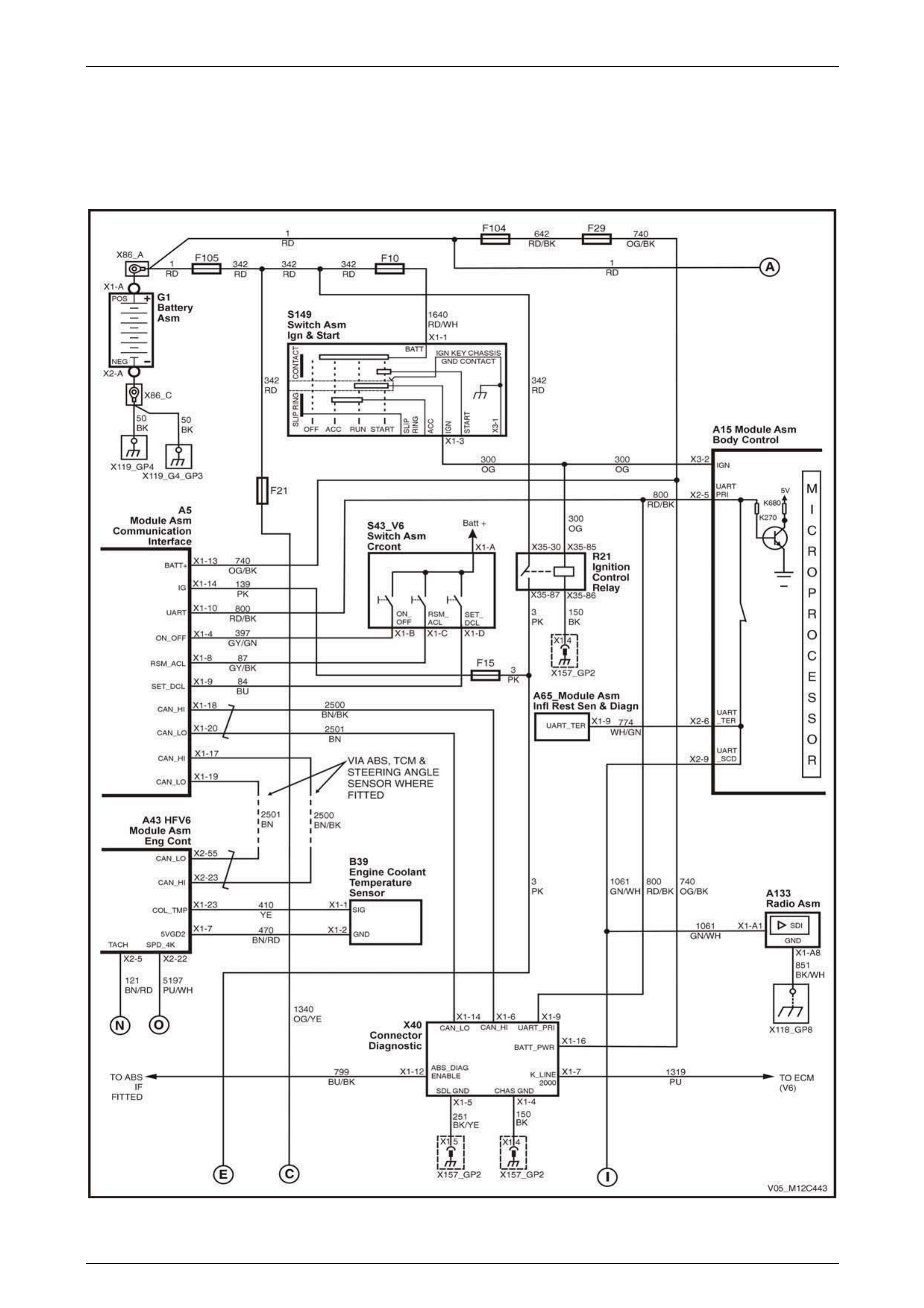
Instrumentation Page 12C – 80
Page 12C – 80
3 Wiring Diagrams and
Connectors
3.1 Wiring Diagrams – V6
Figure 12C – 225
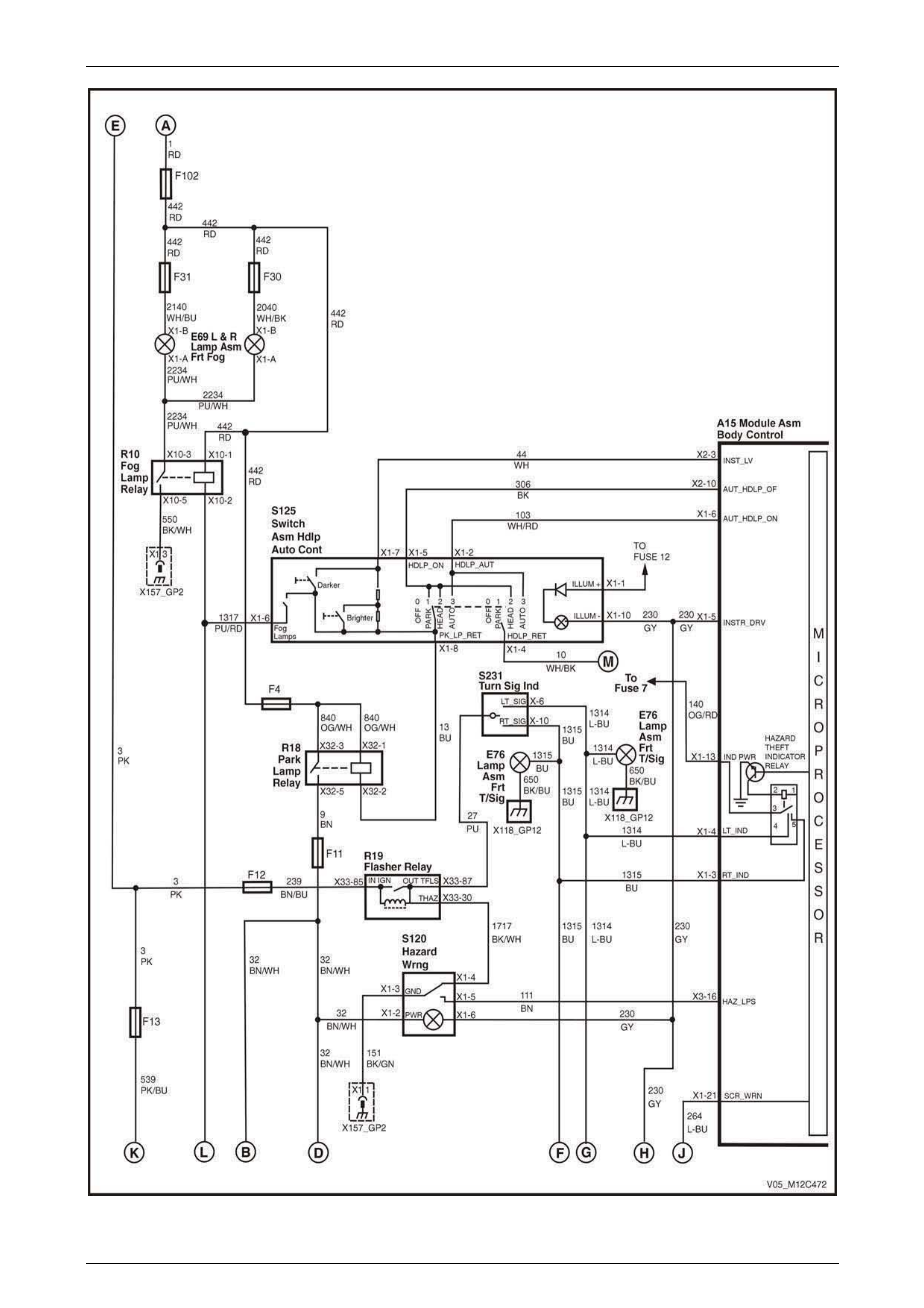
Instrumentation Page 12C – 81
Page 12C – 81
Figure 12C – 226

Instrumentation Page 12C – 82
Page 12C – 82
Figure 22C – 227

Instrumentation Page 12C – 83
Page 12C – 83
3.2 Wiring Diagrams – V8
Figure 12C – 228
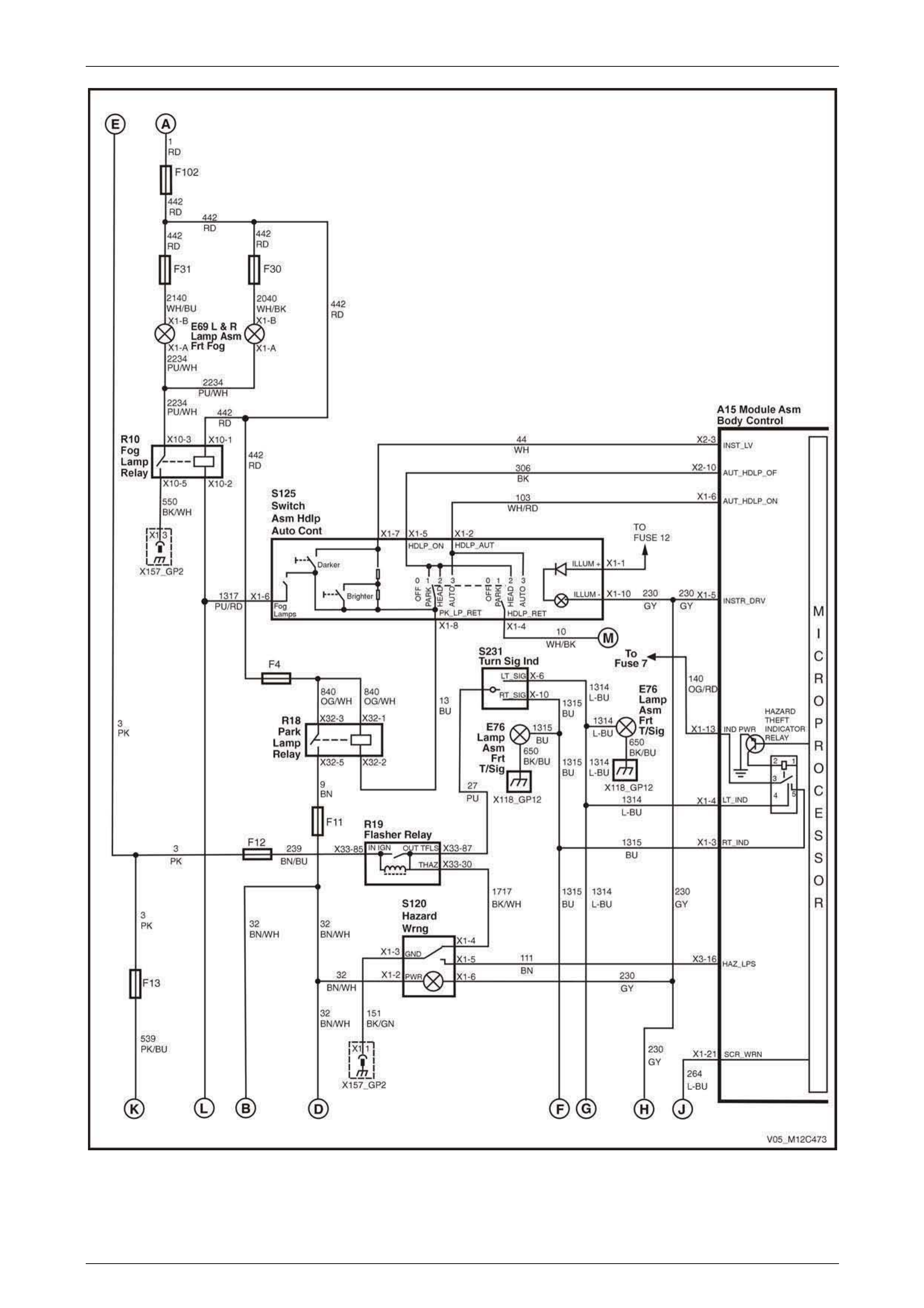
Instrumentation Page 12C – 84
Page 12C – 84
Figure 12C – 229
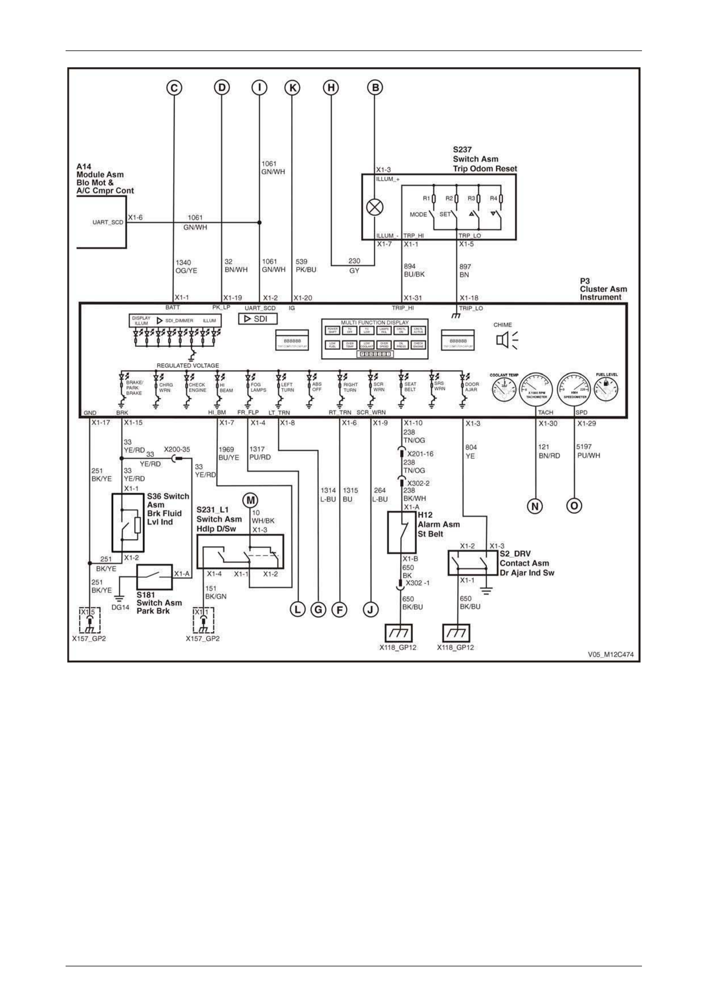
Instrumentation Page 12C – 85
Page 12C – 85
Figure 12C – 230
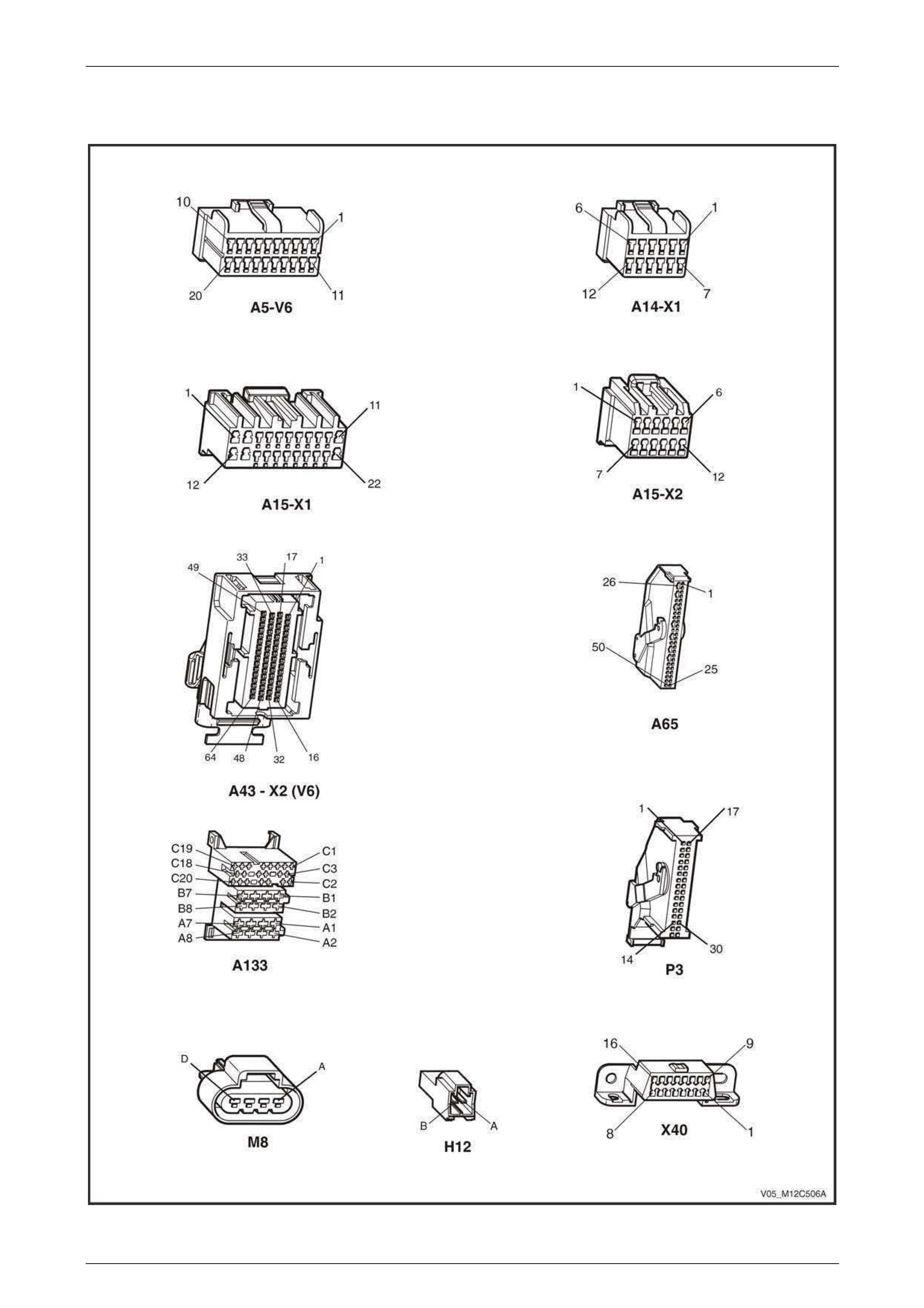
Instrumentation Page 12C – 86
Page 12C – 86
3.3 Connector Chart – V6
Figure 12C – 231
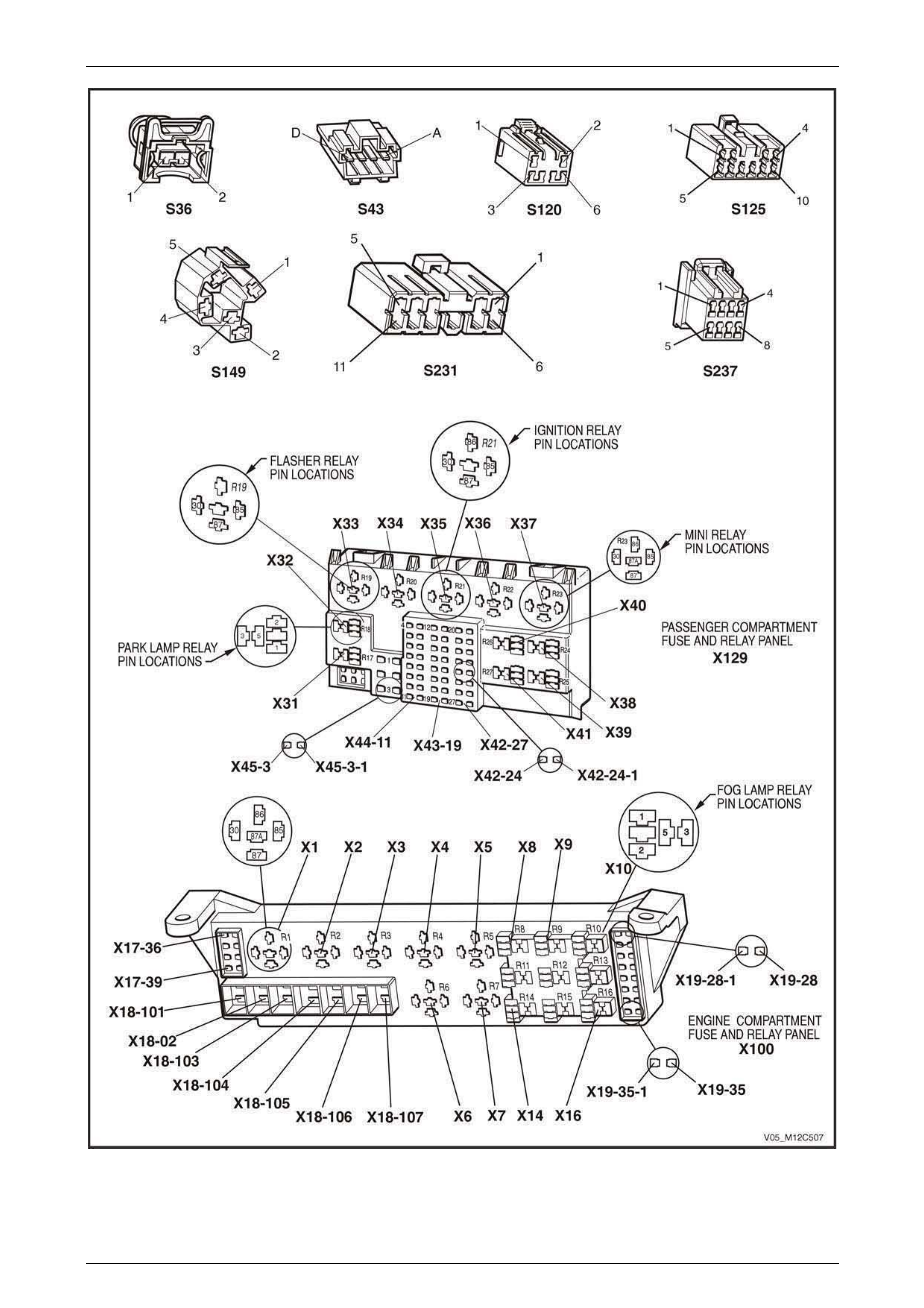
Instrumentation Page 12C – 87
Page 12C – 87
Figure 12C – 232
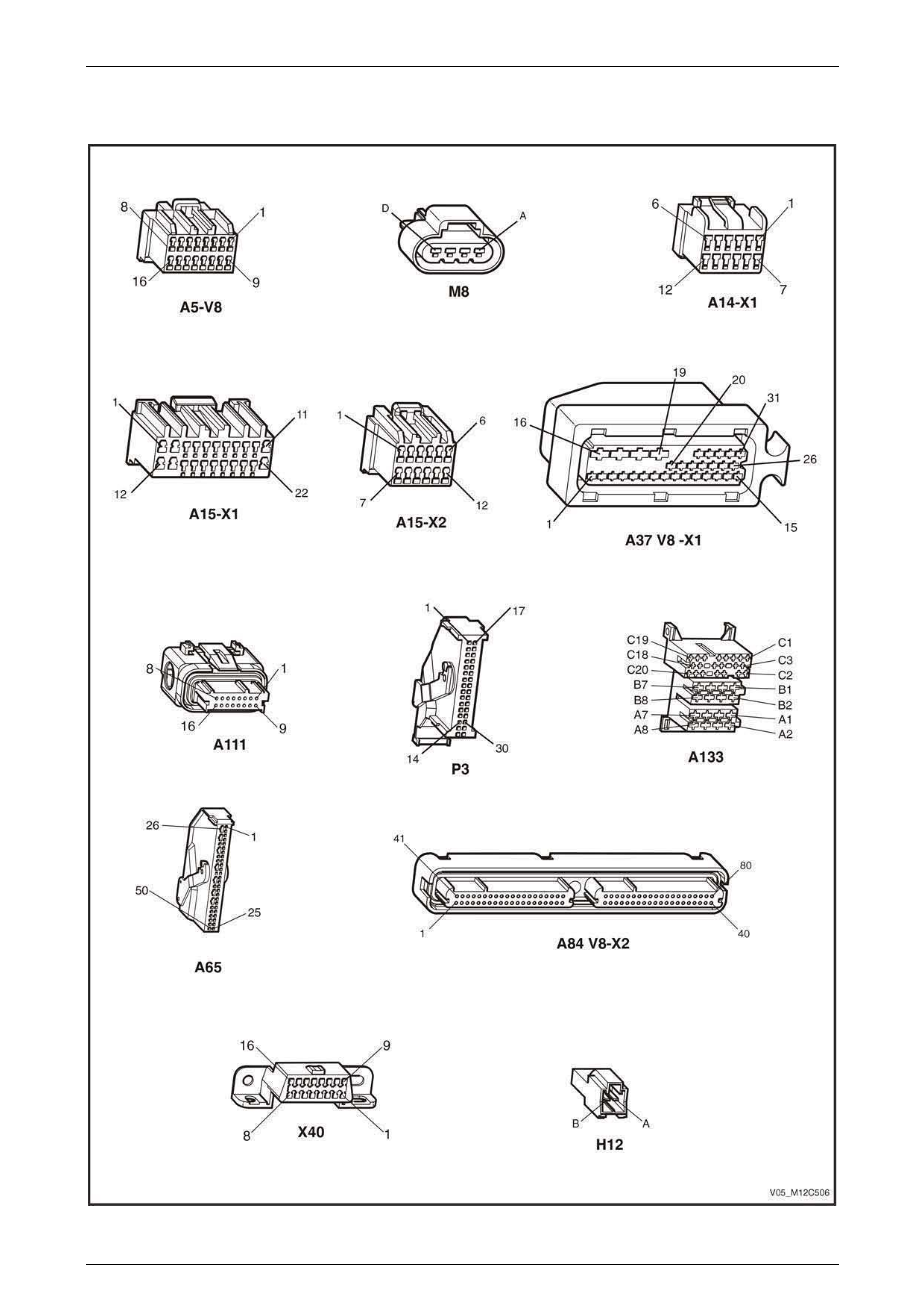
Instrumentation Page 12C – 88
Page 12C – 88
3.4 Connector Chart – V8
Figure 12C – 233

Instrumentation Page 12C – 89
Page 12C – 89
Figure 12C – 234
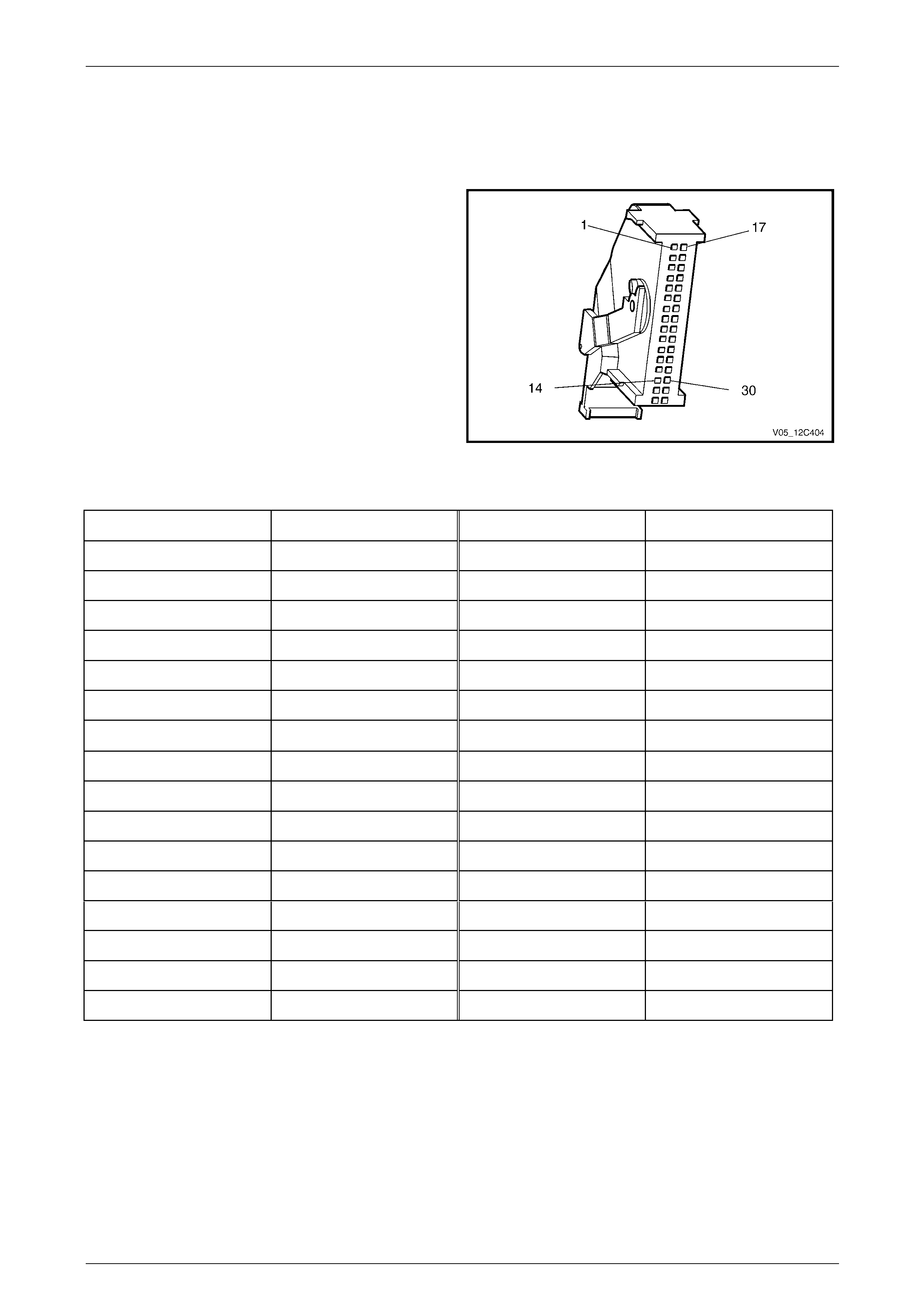
Instrumentation Page 12C – 90
Page 12C – 90
3.5 Instrument Cluster Inputs
P3 Connector Pin Locations
Figure 12C – 235 Identifies the pin locations on the
instrument cluster’s P3 connector.
Figure 12C – 235
The following table provides details on the instrument cluster connector and signal functions.
Pin Number Function Pin Number Function
X1-1 Battery X1-17 Ground
X1-2 UART Serial Data X1-18 Trip Computer Switch Lo
X1-3 Door Ajar X1-19 Park Lamps
X1-4 Front Fog Lamps X1-20 Ignition
X1-5 Spare X1-21 Spare
X1-6 Right Turn Indicator X1-22 Spare
X1-7 High Beam X1-23 Spare
X1-8 Left Turn Indicator X1-24 Spare
X1-9 Security Warning X1-25 Spare
X1-10 Seat Belt Switch X1-26 Spare
X1-11 Spare X1-27 Spare
X1-12 Spare X1-28 Spare
X1-13 Spare X1-29 Speedometer
X1-14 Spare X1-30 Tachometer
X1-15 Brake X1-31 Trip Computer Switch Hi
X1-16 Spare X1-32 Spare
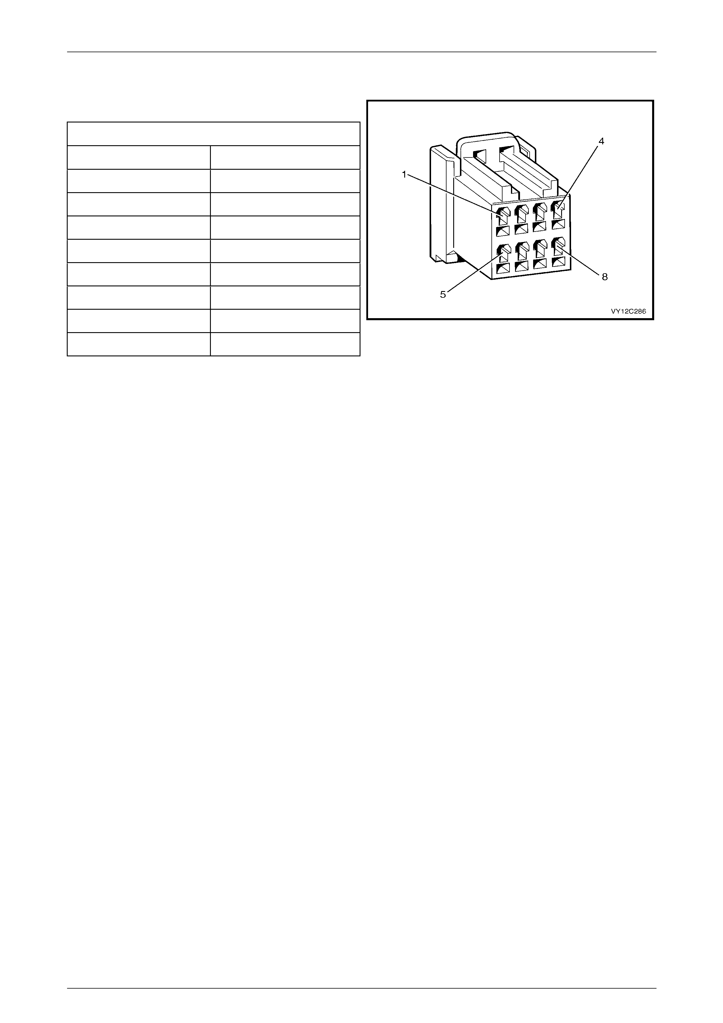
Instrumentation Page 12C – 91
Page 12C – 91
S237 Connector Pin Locations
Connector Details
Pin Number Function
X1–1 Enabled Switch
X1–2 Not Connected
X1–3 Illumination Positive
X1–4 Not Connected
X1–5 Ground
X1–6 Not Connected
X1–7 Illumination Ground
X1–8 Not Connected Figure 12C – 236
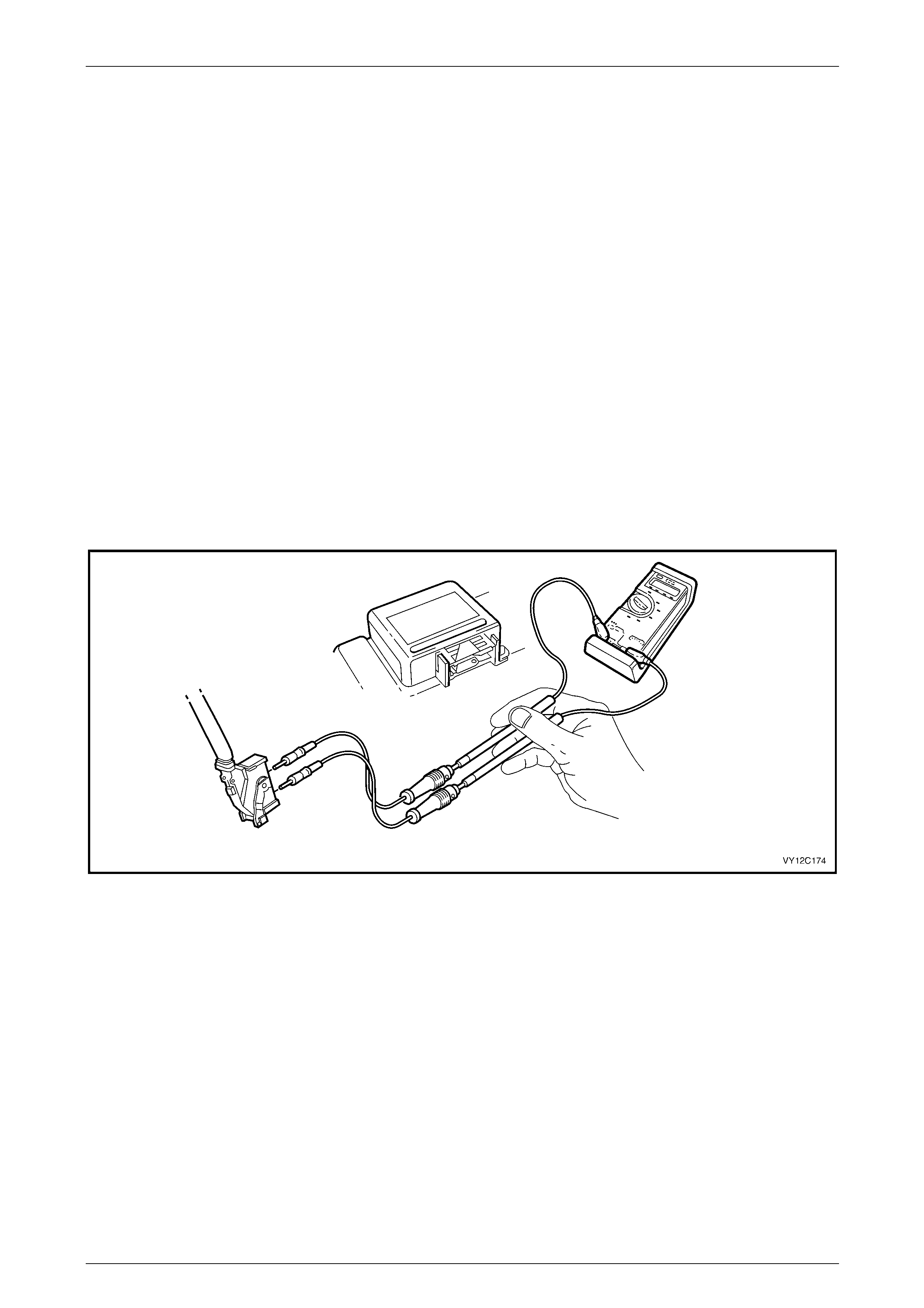
Instrumentation Page 12C – 92
Page 12C – 92
4 Diagnostics
The diagnostic system check is a preliminary procedure that checks to ensure the instrument cluster is communicating on
the serial data bus as well as helping identify any internal or external problem.
Fault diagnosis for the instrument cluster is divided into two areas; faults which can be remedied by checking the
operation of components connected to the instrument cluster and those which can be checked by using Tech 2.
The instrument cluster can provide a preliminary indication that there is a fault either on the serial data bus, within the
instrument cluster or the BCM. When the instrument cluster does not receive a valid or complete serial data message for
10 seconds, the MFD shows the message 'Service Error – Contact Dealer'. This error message indicates a short circuit
on the serial data bus, an open circuit to the instrument cluster or a fault within the instrument cluster. Pressing the
MODE button on the trip computer switch clears the error message. In this instance, the icon ⌧ is shown in the left-hand
side of the MFD. If the fault is associated with the fuel sender, the message displayed is 'Fuel Sender Error – Contact
Dealer', and the symbol is displayed on the left-hand side of the MFD.
Additionally, when a fault is detected, the instrument cluster sets a Diagnostic Trouble Code (DTC) that represents that
particular problem or failure.
The following tables are designed to provide fast and efficient fault location of the instrument cluster. Each diagnostic
reference consists of a diagnostic table and pertinent information including Diagnostic Trouble Code (DTC) setting
parameters and, in most tables, reference to circuit diagrams.
When carrying out wiring checks as directed by the diagnostic tables, rather than probe terminals and connectors with
incorrect sized multimeter connections, use the adaptors contained in connector test adaptor kit J35616-C (KM-609), as
shown in the following illustration. This will prevent any possibility of spreading or damaging wiring harness terminals,
which may later cause a system intermittent failure.
Figure 12C – 237
4.1 Diagnostic System Check
Circuit Description
When investigating any complaint of an instrument cluster problem or malfunction, always begin diagnosis with the
following Diagnostic System Check. This check is a preliminary procedure that ensures that the instrument cluster is
powered up, communicating on the serial data line, helping to identify a problem or malfunction, and directing the
technician to the appropriate diagnostic table.
With Tech 2 connected to the DLC and the ignition switched on, Tech 2 should display serial data communication. If
Tech 2 does not display serial data, the serial data circuit may be open or shorted.
The entertainment system and several other control modules are connected to the serial data line. The control modules
are the ECM, PCM, PIM, BCM, ABS or ABS / TCS, OCC and SRS. The entertainment system or any one of the control
modules could cause a fault on the serial data line. This fault could result in Tech 2 not being able to display serial data.

Instrumentation Page 12C – 93
Page 12C – 93
Test Description
3-4 Checks the operation of the indicators.
5 Checks the relevant fuses.
6-8 Checks the wiring harness serviceability.
9-10 Using Tech 2 to check for and clear set DTCs.
Diagnostic Aids
• By manipulating the harnesses at the various connectors, it is often possible to isolate the cause of the circuit
interruption. This harness can then be removed and repaired.
• Check for any damage to the harness, which could cause an intermittent open or short to ground or backed out
terminals at the instrument cluster connector, broken connector locks, improperly formed or damaged terminals.
• For wiring diagrams and connector charts, refer to 3 Wiring Diagrams and Connectors.
Diagnostic System Check Diagnostic Table
Step Action Yes No
1 Is this fault isolated to the system / component
Go to step 2
Refer to Section
OD Vehicle
Diagnostics
2 Has the Instrument Cluster Self Diagnostic test been performed?
NOTE
Annotate any functions of the instrument cluster that do
not work as part of the test. Go to step 3
Perform the test,
refer to 4.2
Instrument Cluster
Self Diagnostics
3 Turn the ignition on.
Do the instrument cluster warning indicators illuminate? Go to Step 9 Go to Step 4
4 Do any instrument cluster warning indicators remain illuminated after
5 seconds? Go to step 10 Go to step 5
5 Check the instrument cluster fuses F13 and F21 in instrument panel
compartment.
Are the fuses blown? Replace blown
fuses Go to Step 6
6 1 Remove the instrument cluster, refer to Section 1A3 Instrument
Panel and Console.
2 Using a multimeter set to measure voltage, probe between
connector P3 – X1 pin 1 and a known ground.
Does the multimeter indicate battery voltage? Go to Step 7 Repair or replace
circuit 1340
7 1 Turn the ignition on.
2 Using a multimeter set to measure voltage, probe between
connector P3 – X1 pin 20 and a known ground.
Does the multimeter indicate battery voltage? Go to Step 8 Repair or replace
circuit 539
8 Using a multimeter set to measure resistance, probe between
connector P3 – X1 pin 17, and a known ground.
Does the multimeter indicate continuity?
Replace the
Instrument Cluster,
refer to Section 1A3
Instrument Panel
and Console Repair or replace
circuit 251

Instrumentation Page 12C – 94
Page 12C – 94
Step Action Yes No
9 1 Connect Tech 2 to the DLC.
2 On Tech 2 select:
Diagnostic Trouble Codes / Clear DTC Information.
3 Cycle the ignition off to on.
4 On Tech 2 select:
Diagnostic Trouble Codes / Read DTC Information.
Has DTC 14 set?
Refer to 5.11 DTC
14 – No Serial
Communication
Data Go to Step 10
10 Are any other DTCs set? Refer to 5.1
Diagnostic Trouble
Code List
Refer to 6
Diagnostics For
Non DTC Faults
When all diagnosis and repairs are completed, clear all DTCs and check the system for correct operation.
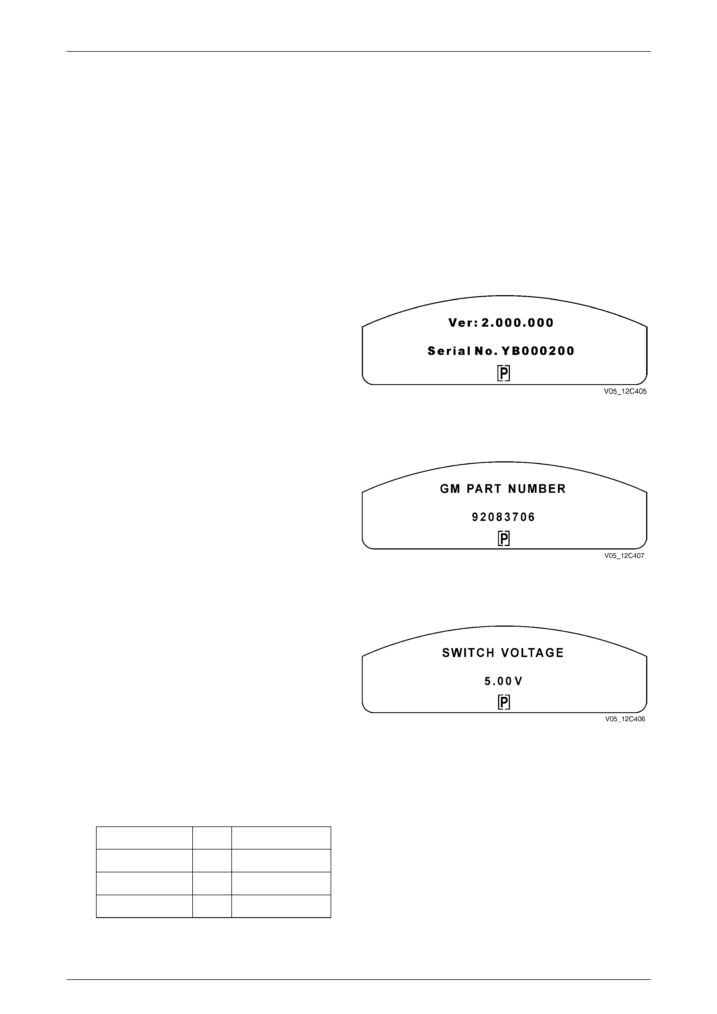
Instrumentation Page 12C – 95
Page 12C – 95
4.2 Instrument Cluster Self Diagnostics
Self Diagnostic Mode Operation
To enter the Instrument Cluster Self Diagnostic Mode, press the trip computer switch MODE and SET buttons
simultaneously while turning the ignition on. Further pressing the MODE button for less than 2 seconds will step through
the various instrument cluster information displays, which appear on the MFD. The vehicle may be driven while in
Diagnostic Mode.
To exit the Instrument Cluster Diagnostic Mode press the trip computer switch SET button for less than 2 seconds, or
switch the ignition off.
In sequence, the Instrument Cluster Diagnostic Mode screens are as follows:
Software Version
This screen provides details of the instrument cluster
software version.
Press the MODE button to continue.
Figure 12C – 238
GM Part Number
This screen provides details of the instrument cluster part
number.
Press the MODE button to continue.
Figure 12C – 239
Trip Computer Switch Voltage
This screen provides an indication of the operational status
of the trip computer switch.
NOTE
• When checking the MODE button voltage,
press and hold the button for more than 2
seconds otherwise the Diagnostic Mode will
advance to the Battery Voltage screen.
• When checking the SET button voltage,
press and hold the button for more than
2 seconds otherwise the system will exit the
Diagnostic Mode.
Press each button and the following nominal voltages should
be indicated:
MODE button – 3.9 – 4.28 V
SET button – 4.28 – 4.75 V
UP button – 3.26 – 3.55 V
DOWN button – 2.43 – 2.71 V
Press the MODE button to continue.
Figure 12C – 240
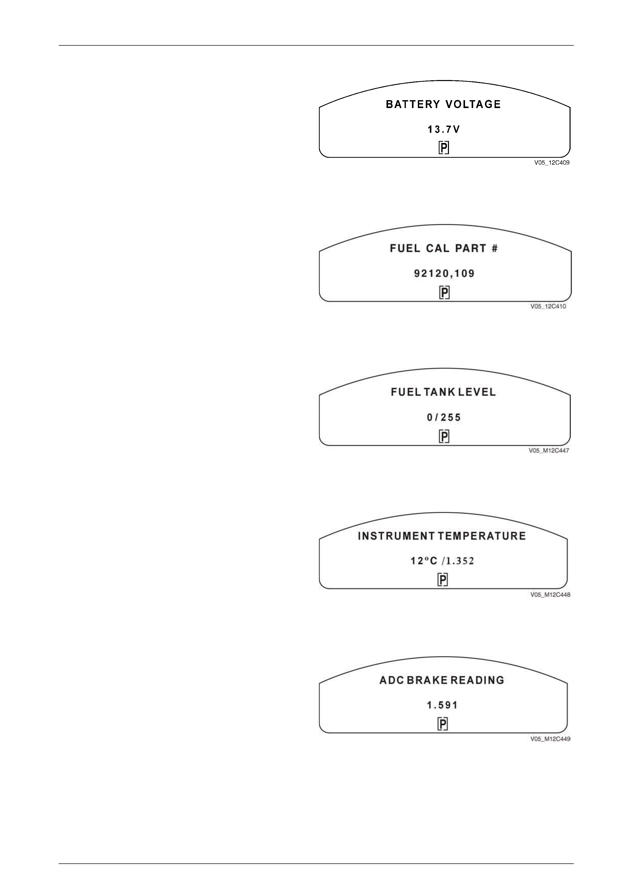
Instrumentation Page 12C – 96
Page 12C – 96
Battery Voltage
This screen provides an indication of the current battery
voltage if the display shows less than 11 Voltage charge the
vehicles battery before proceeding.
Press the MODE button to continue.
Figure 12C – 241
Fuel Calibration Part Number
When an instrument cluster is replaced, the fuel calibration
part number is to be entered using Tech 2, refer to
7.2 Programming.
This identifies the fuel tank size and fuel sender
specifications.
Press the MODE button to continue.
Figure 12C – 242
Fuel Tank level
The fuel level provided by the ECM (V6) or PCM (V8) This
value should increase as the tank is filled and decrease as
the tank is emptied.
0 indicates the fuel tank is empty while 255 indicates the fuel
tank is full.
Press the MODE button to continue.
Figure 12C – 243
Instrument Cluster Temperature
This is the ambient temperature of the instrument cluster
measured at the display.
If the temperature reading is much higher than the ambient
temperature, this indicates an internal problem with the
instrument cluster and it should be replaced.
Press the MODE button to continue.
Figure 12C – 244
ADC Brake Reading
The braking system uses a variable resistance network to
determine if the brake system is faulty.
This shows the current reading that the instrument cluster
has made of the resistor network, and is shown in Volts. The
standard operating value is from 0.800 to 2.800 V if the
reading is outside this range, refer to Section 5B ABS for
further diagnosis.
Figure 12C – 245
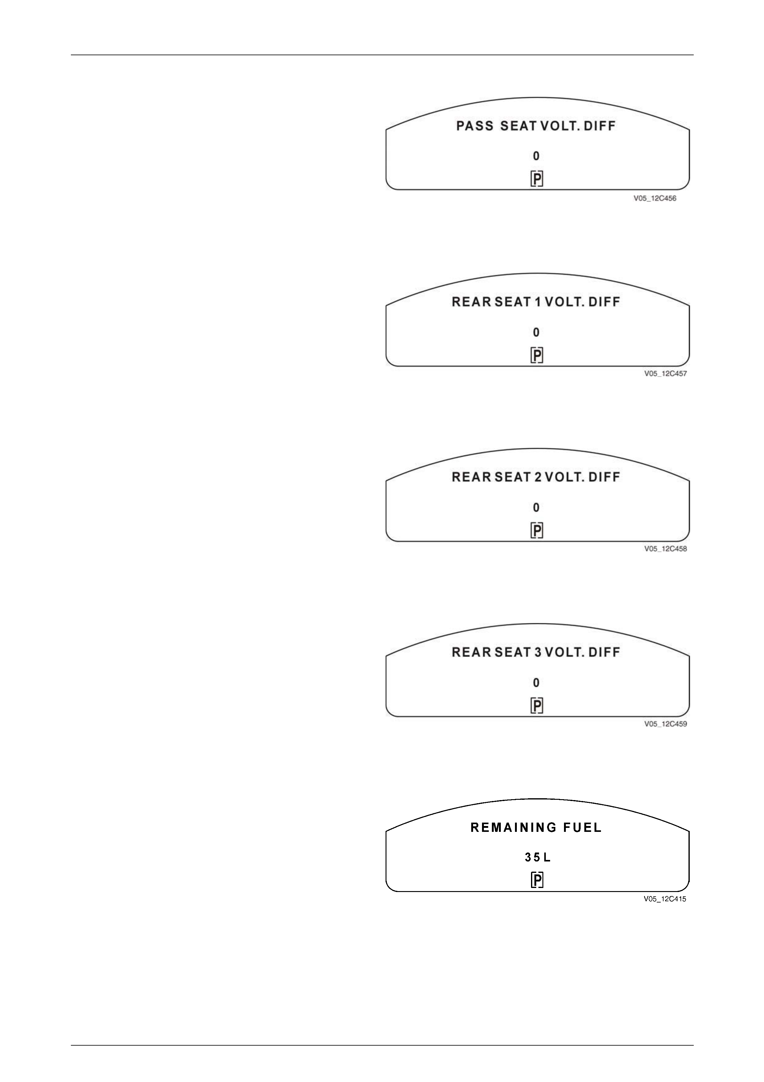
Instrumentation Page 12C – 97
Page 12C – 97
Passenger Seat Voltage Differential
This monitor is not fitted to vehicles but the display screens
are present on the cluster.
If the reading is anything but 0, it is an indication of a
harness problem or a hardware fault within the instrument
cluster.
Figure 12C – 246
Rear Seat Voltage Differential
This monitor is not fitted to vehicles but the display screens
are present on the cluster.
If the reading is anything but 0, it is an indication of a
harness problem or a hardware fault within the instrument
cluster.
Figure 12C – 247
Rear Seat 2 Voltage Differential
This monitor is not fitted to vehicles but the display screens
are present on the cluster.
If the reading is anything but 0, it is an indication of a
harness problem or a hardware fault within the instrument
cluster.
Figure 12C – 248
Rear Seat 3 Voltage Differential
This monitor is not fitted to vehicles but the display screens
are present on the cluster.
If the reading is anything but 0, it is an indication of a
harness problem or a hardware fault within the instrument
cluster.
Figure 12C – 249
Remaining Fuel
This screen provides an estimate of the fuel remaining in the
fuel tank to the nearest 5 litres.
Press the MODE button to continue.
Figure 12C – 250
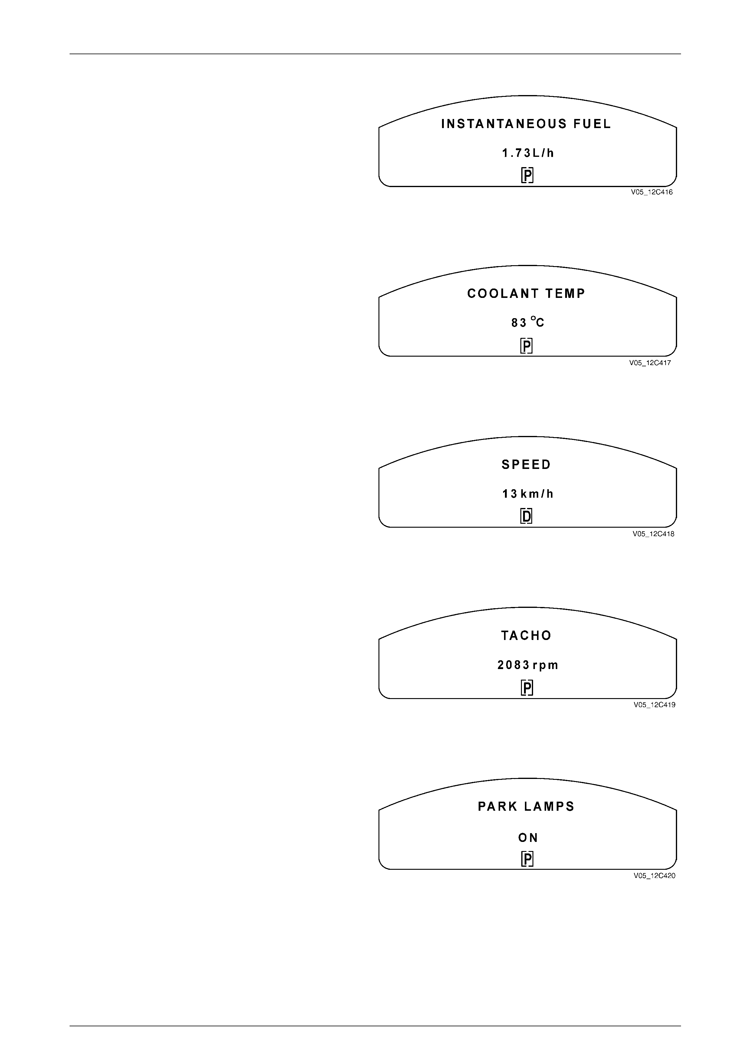
Instrumentation Page 12C – 98
Page 12C – 98
Instantaneous Fuel
This screen provides details of the last instantaneous fuel
reading stored in the instrument cluster.
Press the MODE button to continue.
Figure 12C – 251
Coolant Temperatu re
This screen provides an indication of the current coolant
temperature within the engine.
For further information refer to:
• Section 6B1 Engine Cooling – V6.
• Section 6B3 Engine Cooling – V8.
Press the MODE button to continue. Figure 12C – 252
Speed
This screen provides an indication of the current vehicle
speed; this can be compared with the analogue
speedometer readout as a cross-reference.
Press the MODE button to continue.
Figure 12C – 253
Tacho
This screen provides an indication of the current engine
speed in r.p.m. this can be compared with the analogue
tachometer readout as a cross-reference.
Press the MODE button to continue.
Figure 12C – 254
Park Lamps On / Off
The park lamps circuit provides illumination for the
instrument cluster. If the park lamps are shown as ON, the
instrument cluster should also be illuminated.
Press the MODE button to continue.
Figure 12C – 255
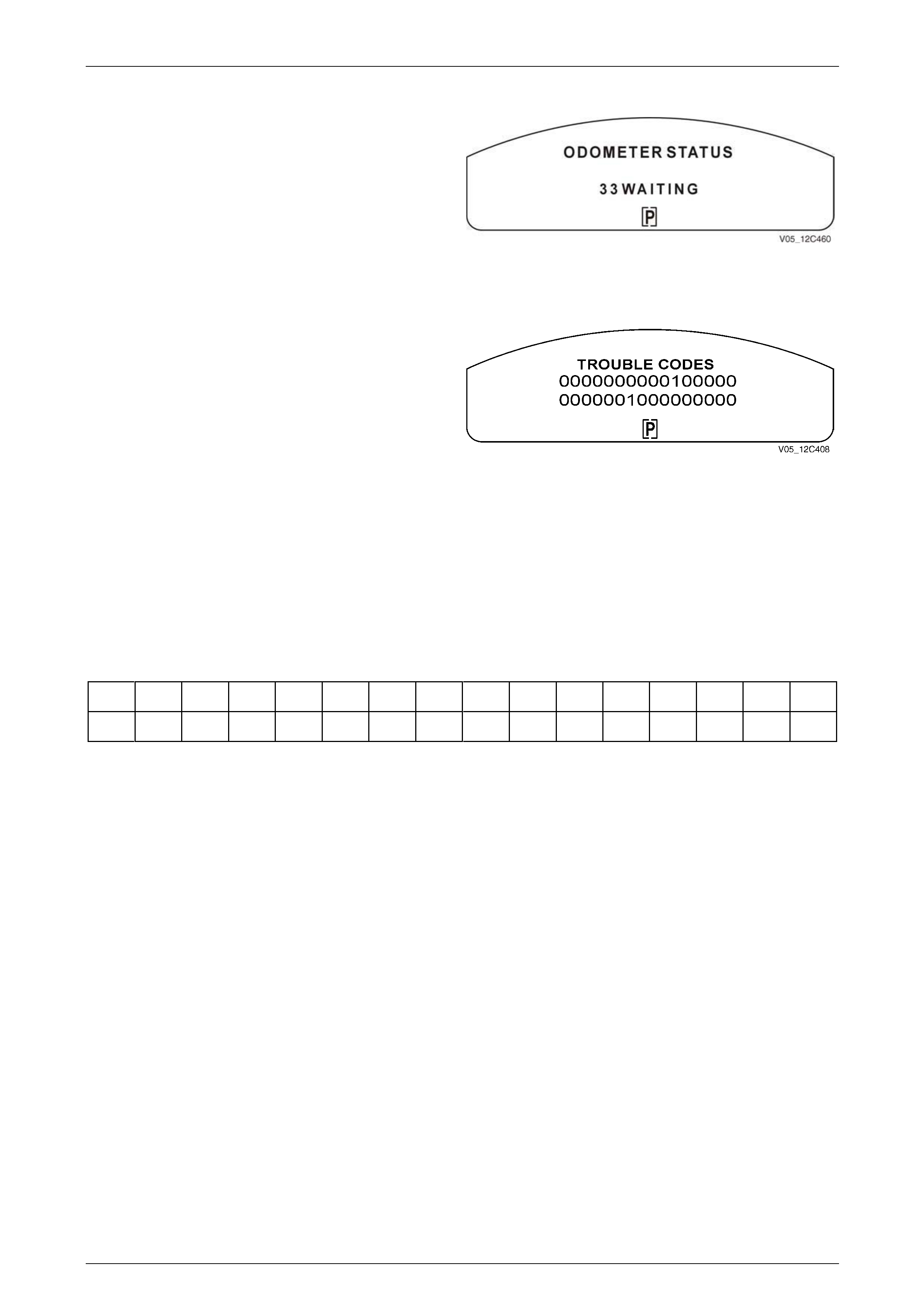
Instrumentation Page 12C – 99
Page 12C – 99
Odometer Status
This screen shows how many kilometres have been logged
on the vehicles odometer since the date of manufacture.
Figure 12C – 256 shows the vehicle has travelled 33
kilometres and is waiting for the next time the vehicle is
driven to add more kilometres to the reading.
Press the MODE button to continue.
Figure 12C – 256
Trouble Codes
To access the trouble code display hold the MODE and SET
buttons down while turning the ignition to the ON position
then use the MODE button to step to the Trouble Codes
display.
The Trouble Codes screen displays two rows of 16 digits
each. If no DTC is set, the 32 digits are all zeros (0).
However, if a DTC is set it is represented by the numeral
one (1) in the appropriate position in the rows.
The following table shows the location of each DTC
identifying digit. To determine the actual DTC number that
has been set, count the digits from the bottom right-hand
side, starting at zero. In the example shown in Figure 12C –
257, DTC 9 and DTC 21 have been set.
Press the MODE button to continue.
Refer to 5 Diagnostic Trouble Codes.
Figure 12C – 257
DTC Trouble Code Locations
31 30 29 28 27 26 25 24 23 22 21 20 19 18 17 16
15 14 13 12 11 10 9 8 7 6 5 4 3 2 1 0
NOTE
Use Tech 2 to access and reset any set DTCs.
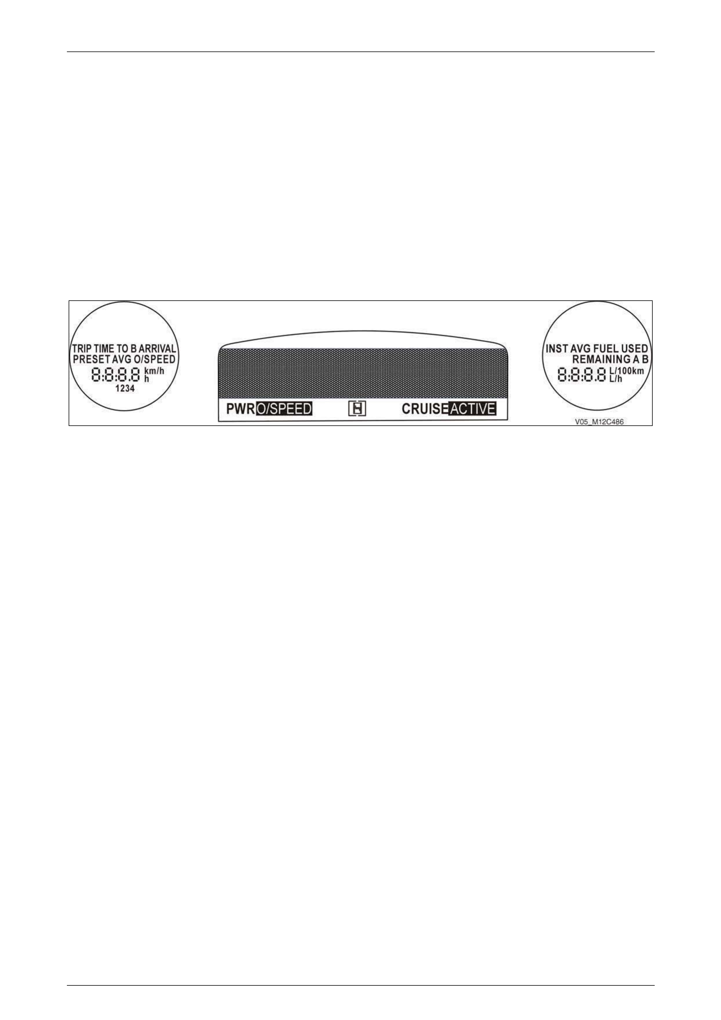
Instrumentation Page 12C – 100
Page 12C – 100
Full Test
The Instrument Cluster Self Diagnostic Mode also has a self-test function (full test) to verify correct instrument cluster
operation.
When activated the following occurs:
• The temperature gauge and the fuel gauge are set to the half-way mark (50%).
• The tachometer is set to 3000 r.p.m.
• The speedometer is set to 100 km/h.
• The chime is activated at 1 kHz.
• The indicator LED’s that are driven by either the internal microprocessor or from the serial data bus are illuminated.
These are SRS, Brake Park/Fail, Seat Belt, Security, ABS, Alternator Fail, and Fog lamps (if fitted).
All segments of the MFD and the side trip computer displays (triple-window cluster only) are illuminated.
FIGURE 12C – 258 NOTE
If any segments of the displays are missing
during the full test mode, the instrument cluster
must to be replaced.
Press the MODE button to return to the GM Part Number screen, or the SET button to exit the instrument cluster
diagnostic mode.

Instrumentation Page 12C – 101
Page 12C – 101
5 Diagnostic Tr ouble Codes
General Information
There are two types of DTC, current and history.
A Current DTC is active only for the period that the fault is present and is indicated by the icon/message on the
instrument cluster. When the fault is cleared, the Current DTC and the icon / message are also cleared.
The History DTC is set at the same time as the Current DTC, and is stored in memory within the instrument cluster to
provide information on vehicle system operation over a period of time. History DTC are read and cleared from memory by
Tech 2.
Each DTC presented on the instrument cluster screen is allocated a number from 0 to 31. The following table provides
details on each of these DTCs.
5.1 Diagnostic Trouble Code List
The engine controller for V6 is the ECM and for the V8 the PCM.
DTC No DTC Source Description Diagnostic Table
0 Not Used
1 Not Used
2 Not Used
3 ECM / PCM Fuel type mismatch Vehicle is configured as
LPG but the ECM is
reporting a petrol vehicle
4 ECM / PCM Auto transmission
mismatch The cluster is configured
as 4/5 speed manual but
the PCM / ECM reports the
opposite. Refer to 7.2
Programming
5 ECM / PCM Fuel invalid flag set F uel invalid flag in the PCM
poll response cleared
6 TPMS
Only for high level vehicles No TPMS poll response
detected for 10 seconds Refer to Section 10 Wheels
and Tyres
7 ESP No ESP poll response
detected for 10 seconds 5.3 DTC 7 – No Serial
Data from ABS / TCS /
ESP – V6
8 ABS No ABS poll response
detected for 10 seconds 5.4 DTC 8 – No Serial
Data from ABS / TCS
9 BCM No BCM broadcast
detected for 10 seconds 5.5 DTC 9 – No Serial
Data from BCM
10 OCC No OCC poll response
detected for 10 seconds 5.6 DTC 10 – No Serial
Data from OCC
11 ECM / PCM No PCM / ECM poll
response detected for 10
seconds
5.7 DTC 11 – No Serial
Data from ECM – V6
5.8 DTC 11 – No Serial
Data from PCM – V8
12 SDM No SDM poll response
detected for 10 seconds 5.9 DTC 12 – No Serial
Data from SDM
13 Instrument No instrument poll from
BCM detected for 10
seconds
5.10 DTC 13 – No
Instrument Poll from BCM

Instrumentation Page 12C – 102
Page 12C – 102
DTC No DTC Source Description Diagnostic Table
14 Serial communications No Serial communications
detected for 10 seconds 5.11 DTC 14 – No Serial
Communication Data
15 Radio No radio poll response
detected for 10 seconds 5.12 DTC 15 – No Serial
Data from Audio System
16 Fuel ECM / PCM Loss of ECM poll response
data or fuel level data at 0
or 255 for more than 10
seconds
5.13 DTC 16 – Fuel Level
System
17 Not Used
18
Not Used
Passenger seat N/A N/A
19 SDM Incorrect SDM module poll
response detected 5.14 DTC 19 – Incorrect
SDM Detected
20 Reserved
21 Trip switch Trip switch voltage below
normal operating range 5.15 DTC 21 or 22 – Trip
Switch Faulty
22 Trip switch Trip switch button or
buttons pressed for at least
one minute
5.15 DTC 21 or 22 – Trip
Switch Faulty
23 Reserved
24 EEPROM Incorrect EEPROM
checksum calculated after
a battery reset
5.16 DTC 24 – EEPROM
Checksum Failure
25 ROM Incorrect ROM checksum
calculated after a battery
reset
Not cleared
26 Reserved
27 Reserved
28 Reserved
29 Reserved
30 Reserved
31 Reserved


Instrumentation Page 12C – 105
Page 12C – 105
5.3 DTC 7 – No Serial Data from ABS / TCS /
ESP – V6
Circuit Description
The ABS (or ABS / TCS / ESP) module sends serial data along the GM LAN data bus, circuits 2500 and 2501 to the
PIM, which converts the data to UART protocol. It is then sent to the BCM via the primary UART bus (circuit 800) then to
the instrument cluster via the secondary UART bus (circuit1061) to indicate the status of the traction control. If traction
control has been disabled by the ABS / TCS / ESP module, the Traction Control Off warning will appear on the
instrument cluster MFD.
DTC 8 will set if there is no ABS data message on the bus for more than 10 seconds. In practice, the trouble code is set
somewhere between 10 and 20 seconds after the instrument cluster receives the last ABS data message. The DTC is
reset within 10 seconds of the arrival of an ABS data message on the bus. The DTC is logged as a History DTC.
Refer to 3 Wiring Diagrams and Connectors to aid in diagnosis.
Test Description
The following numbers refer to the step numbers in the diagnostic table:
2-3 Checks the ABS/TCS/ESP module using Tech 2.
4-6 Checks the condition of the data bus from the ABS module to the instrument cluster.
Diagnostic Table Notes
1 If the fault cannot be found in the harness then the fault may lie in the ABS, PIM or the BCM module, refer to the
diagnostic tables in:
• Section 6E1 Powertrain Interface Module – V6.
• Section 12J Body Control Module.
2 For Tech 2 information, refer to 2 Tech 2 Information.
DTC 7 Diagnostic Table
Step Action Yes No
1 Has the diagnostic system check been performed?
Go to step 2
Refer to
4.1 Diagnostic
System Check
2 1 Connect Tech 2 to the DLC.
2 On Tech 2 select:
Chassis / ABS/ECT/ESP.
Does Tech 2 display the ABS/TCS Identification information (i.e. Part
Number / Production Date)? Go to step 3
Refer to Section
5B1 ABS – V6 for
further diagnosis.
3 On Tech 2 select:
Vehicle / Module ECU presence check.
Does Tech 2 list the BCM, PIM and ABS as being present? Go to step 4 Refer to Note 1
4 Using a multimeter set to measure resistance, probe between
connector P3 – X1 pin 2 and a known ground.
Does the multimeter indicate continuity?
Repair or replace
circuit 1061 Go to step 5
5 Using a multimeter set to measure resistance, probe between
connector P3 – X1 pin 2 to battery voltage.
Does the multimeter indicate continuity? Repair or replace
circuit 1061 Go to step 6

Instrumentation Page 12C – 105
Page 12C – 105
Step Action Yes No
6 Using a multimeter set to measure resistance, probe between
connectors P3 – X1 pin 2 to A15 – X2 pin 9.
Does the multimeter indicate continuity? Go to step 7 Repair or replace
circuit 1061
7 1 Connect Tech 2 to the DLC.
2 On Tech 2 select:
Diagnostic Trouble Codes / Clear DTC Information.
3 Cycle the ignition off to on.
4 On Tech 2 select:
Diagnostic Trouble Codes / Read DTC Information.
Has DTC 7 set? Go to step 2 Go to Step 8
8 Are any other DTCs set? Refer to 5.1
Diagnostic Trouble
Code List System
serviceable
When all diagnosis and repairs are completed, clear all DTCs and check the system for correct operation.

Instrumentation Page 12C – 107
Page 12C – 107
5.4 DTC 8 – No Serial Data from ABS / TCS –
V8
Circuit Description
The ABS (or ABS / TCS) module sends serial data along the secondary serial data bus, (circuit 1061) to the instrument
cluster to indicate the status of the traction control, If traction control has been disabled by the ABS / TCS module, the
Traction Control Off warning will appear on the instrument cluster MFD.
DTC 8 will set if there is no ABS data message on the bus for more than 10 seconds. In practice, the trouble code is set
somewhere between 10 and 20 seconds after the instrument cluster receives the last ABS data message. The DTC is
reset within 10 seconds of the arrival of an ABS data message on the bus. The DTC is logged as a History DTC.
NOTE
The Tech 2 recognises the ABS / TCS Module as
ABS / ETC.
Refer to 3 Wiring Diagrams and Connectors to aid in diagnosis.
Test Description
The following numbers refer to the step numbers in the diagnostic table:
2 Checks the ABS/TCS module with Tech 2.
3-6 Checks the condition of the relevant wiring harnesses with a multimeter.
Diagnostic Table Notes
1 If the fault cannot be found in the harness then the fault may lie in the ABS module or the BCM, refer to the
diagnostic tables in:
• Section 12J Body Control Module.
2 For Tech 2 information, refer to 2 Tech 2 Information.
DTC 8 Diagnostic Table
Step Action Yes No
1 Has the diagnostic system check been performed?
Go to Step 2
Refer to
4.1 Diagnostic
System Check
2 1 Connect Tech 2 to the DLC.
2 On Tech 2 select:
Chassis / ABS/ETC.
Does Tech 2 display the ABS/TCS Identification information (i.e. Part
Number / Production Date)? Go to Step 3 Refer to Note 1
3 1 Remove the instrument cluster, refer to1A3 Instrument Panel
and Console.
2 Using a multimeter set to measure resistance, probe between
connectors A37 – X1 pin 11 and A15 – X2 pin 9.
Does the multimeter indicate continuity? Go to step 4
Repair or replace
circuit 1061
4 Using a multimeter set to measure resistance, probe between
connector P3 – X1 pin 2 and a known ground.
Does the multimeter indicate continuity?
Repair or replace
circuit 1061 Go to Step 5

Instrumentation Page 12C – 107
Page 12C – 107
Step Action Yes No
5 Using a multimeter set to measure resistance, probe between
connector P3 – X1 pin 2 and battery voltage.
Does the multimeter indicate continuity? Repair or replace
circuit 1061 Go to step 6
6 Using a multimeter set to measure resistance, probe between
connectors P3 – X1 pin 2 and A37 – X1 pin 11.
Does the multimeter indicate continuity? Go to step 7 Repair or replace
circuit 1061
7 1 Connect Tech 2 to the DLC.
2 On Tech 2 select:
Diagnostic Trouble Codes / Clear DTC Information.
3 Cycle the ignition off to on.
4 On Tech 2 select:
Diagnostic Trouble Codes / Read DTC Information.
Has DTC 8 set? Go to step 2 Go to Step 8
8 Are any other DTCs set? Refer to 5.1
Diagnostic Trouble
Code List System
serviceable
When all diagnosis and repairs are completed, clear all DTCs and check the system for correct operation.

Instrumentation Page 12C – 108
Page 12C – 108
5.5 DTC 9 – No Serial Data from BCM
Circuit Description
The BCM sends serial data along the secondary serial data bus (circuit 1061); the status of the various modules on the
serial data line is monitored by the instrument cluster.
DTC 9 will set if there is no BCM data message on the bus for more than 10 seconds. In practice, the trouble code is set
somewhere between 10 and 20 seconds after the instrument cluster receives the last BCM data message. The DTC is
reset within 10 seconds of the arrival of a BCM data message on the bus. The DTC is logged as a History DTC.
Refer to 3 Wiring Diagrams and Connectors to aid in diagnosis.
Test Description
The following numbers refer to the step numbers in the diagnostic table:
2 Checks if the BCM is functioning using Tech 2.
3-5 Checks the condition of the wiring harness from the BCM to the instrument cluster.
6 Checks DTCs using Tech 2.
Diagnostic Table Notes
1 Refer to Section 12J Body Control Module for further diagnosis.
2 For Tech 2 information, refer to 2 Tech 2 Information.
DTC 9 Diagnostic Table
Step Action Yes No
1 Was the Diagnostic System Check performed?
Go to Step 2
Refer to
4.1 Diagnostic
System Check
2 1 Connect Tech 2 to the DLC.
2 On Tech 2 select:
Body / Body Control Module.
3 Press the Confirm soft key.
Does Tech 2 display the BCM Identification information (i.e. Part
Number / Production Date)? Go to Step 3
Refer to Section
12J Body Control
Module for further
diagnosis
3 1 Turn the ignition off.
2 Remove the instrument cluster refer to Section 1A3 Instrument
Panel and Console.
3 Gain access to the BCM, refer to Note 1.
4 Disconnect BCM A15 – X2.
5 Using a multimeter set to measure resistance, probe between
connectors A15 – X2 pin 9 and P3 – X1 pin 2.
Does the multimeter indicate continuity? Go to Step 4 Repair or replace
circuit 1061
4 Using a multimeter set to measure resistance, probe between
connector P3 – X1 pin 2 and a known ground.
Does the multimeter indicate continuity? Repair or replace
circuit 1061 Go to Step 5
5 Using a multimeter set to measure resistance, probe between
connector P3 – X1 pin 2 and battery voltage.
Does the multimeter indicate continuity? Repair or replace
circuit 1061 Go to Step 6

Instrumentation Page 12C – 109
Page 12C – 109
Step Action Yes No
6 1 Connect Tech 2 to the DLC.
2 On Tech 2 select:
Diagnostic Trouble Codes / Clear DTC Information.
3 Cycle the ignition off to on.
4 On Tech 2 select:
Diagnostic Trouble Codes / Read DTC Information.
Has DTC 9 set? Go to step 2 Go to Step 7
7 Are any other DTCs set? Refer to 5.1
Diagnostic Trouble
Code List System
serviceable
When all diagnosis and repairs are completed, clear all DTCs and check the system for correct operation.

Instrumentation Page 12C – 110
Page 12C – 110
5.6 DTC 10 – No Serial Data from OCC
Circuit Description
The OCC module sends serial data to the instrument cluster along the secondary serial data bus, circuit 1061.
DTC 10 will set if there is no OCC data message on the bus for more than 10 seconds. In practice, the trouble code is set
somewhere between 10 and 20 seconds after the instrument cluster receives the last OCC data message. T he DTC is
reset within 10 seconds of the arrival of an OCC data message on the bus. The DTC is logged as a History DTC.
NOTE
This DTC will not set on vehicles with a manual
HVAC unit.
Refer to 3 Wiring Diagrams and Connectors to aid in diagnosis.
Test Description
The following numbers refer to the step numbers in the diagnostic table:
2 Checks the status of the OCC using Tech 2.
3-5 Checks the condition of the wiring harness from the OCC module to the instrument cluster.
6-7 Checks DTCs using Tech 2.
Diagnostic Table Notes
1 If the fault cannot be found in the harness then the fault may lie in the OCC module or the BCM, refer to Section 2F HVAC
Occupant Climate Control (Auto A/C) – Removal & Install or Section 12J Body Control Module for further diagnosis.
2 For Tech 2 information, refer to 2 Tech 2 Information.
DTC 10 Diagnostic Table
Step Action Yes No
1 Was the Diagnostic System Check performed?
Go to Step 2
Refer to
4.1 Diagnostic
System Check
2 1 Connect Tech 2 to the DLC.
2 On Tech 2 select:
Body / Occupant Climate Control.
3 Press the Confirm soft key.
Does Tech 2 display the OCC Identification information (i.e. Part
Number / Production Date)? Go to Step 3
Refer to Section
2F, HVAC
Occupant Climate
Control (Auto
A/C) – Removal &
Installation
3 1 Turn the ignition off.
2 Remove the instrument cluster; refer to Section 1A3 Instrument
Panel and Console.
3 Disconnect the OCC module A14 – X1 refer to, Section 2C
HVAC Climate Control (Auto A/C) Removal and Installation.
Using a multimeter set to measure resistance, probe between
connectors A14 – X1 pin 6 and P3 – X1 pin 2.
Does the multimeter indicate continuity? Go to Step 4 Repair or replace
circuit 1061
4 Using a multimeter set to measure resistance, probe between
connector P3 – X1 pin 2 and a known ground.
Does the multimeter indicate continuity? Repair or replace
circuit 1061 Go to Step 5

Instrumentation Page 12C – 111
Page 12C – 111
Step Action Yes No
5 Using a multimeter set to measure resistance, probe between
connector P3 – X1 pin 2 and battery voltage.
Does the multimeter indicate continuity? Repair or replace
circuit 1061 Go to Step 6
6 On Tech 2 select:
Diagnostic Trouble Codes / Clear DTC Information.
Has the DTC 10 set? Refer to Note 1 Go to Step 7
7 1 Connect Tech 2 to the DLC.
2 On Tech 2 select:
Diagnostic Trouble Codes / Clear DTC Information.
3 Cycle the ignition off to on.
4 On Tech 2 select:
Diagnostic Trouble Codes / Read DTC Information.
Has DTC 10 set? Go to step 2 Go to Step 8
8 Are any other DTCs set? Refer to 5.1
Diagnostic Trouble
Code List System
serviceable
When all diagnosis and repairs are completed, clear all DTC and check the system for correct operation.

Instrumentation Page 12C – 112
Page 12C – 112
5.7 DTC 11 – No Serial Data from ECM – V6
Circuit Description
The V6 engine uses an ECM (Engine Control Module); a Powertrain Interface Module (PIM) is required to convert the
serial data generated by the ECM into UART serial data that is compatible with the BCM.
The ECM sends serial data to the PIM on the GM LAN bus. The PIM then converts the data to UART protocol and sends
it via circuit 800 to the BCM. Serial data is then sent to the instrument cluster along the secondary UART bus, circuit
1061. The following data is read by the instrument cluster, which then indicates the status as appropriate on the MFD
and/or instrument cluster indicators.
• Oil pressure.
• High temperature.
• Power Mode.
• Check engine (powertrain).
• Engine oil life.
• Transmission oil life.
DTC 11 will set if there is no ECM data message on the bus for more than 10 seconds. In practice, the trouble code is set
somewhere between 10 and 20 seconds after the instrument cluster receives the last ECM data message. The DTC is
reset within 10 seconds of the arrival of the ECM data message on the bus. The DTC is logged as a History DTC.
Refer to 3 Wiring Diagrams and Connectors to aid in diagnosis.
Test Description
The following numbers refer to the step numbers in the diagnostic table:
2-4 Checks the status of the modules using Tech 2.
5 Checks DTCs using Tech 2.
Diagnostic Table Notes
1 For further information on the ECM, refer to Section 6C1 Engine Management – V6.
2 For further information on the BCM, refer to Section 12J Body Control Module.
3 For Tech 2 information, refer to 2 Tech 2 Information.
DTC 11 Diagnostic Table
Step Action Yes No
1 Was the Diagnostic System Check performed?
Go to Step 2
Refer to
4.1 Diagnostic
System Check
2 1 Connect Tech 2 to the DLC.
2 On Tech 2 select:
Vehicle / Engine (select appropriate engine) then press the
Info soft key.
Does Tech 2 display the Engine identification information (i.e. Part
Number / Production Date)? Go to Step 3
Refer to Section
6C, Engine
Management
3 On Tech 2 select:
Chassis / PIM / Read DTC Information.
Have any DTCs set?
Refer to Section
6E1Powertrain
Interface Module –
V6 Go to step 4

Instrumentation Page 12C – 113
Page 12C – 113
Step Action Yes No
4 On Tech 2 select:
Body / BCM / Read DTC Information.
Have any DTCs set?
Refer to Section
12J Body Control
Module Go to step 5
5 1 Connect Tech 2 to the DLC.
2 On Tech 2 select:
Diagnostic Trouble Codes / Clear DTC Information.
3 Cycle the ignition off to on.
4 On Tech 2 select:
Diagnostic Trouble Codes / Read DTC Information.
Has DTC 11 set? Go to step 2 Go to Step 6
6 Are any other DTCs set? Refer to 5.1
Diagnostic Trouble
Code List System
serviceable
When all diagnosis and repairs are completed, clear all DTC and check the system for correct operation.

Instrumentation Page 12C – 114
Page 12C – 114
5.8 DTC 11 – No Serial Data from PCM – V8
Circuit Description
A PCM (Powertrain Control Module) is used with the GEN III V8 engine; a Powertrain Interface Module (PIM) is required
to convert the serial data generated by the PCM into UART serial data that is compatible with the BCM.
The PCM sends serial data to the PIM on the class 2 data bus. The PIM then converts the data to UART protocol and
sends it via circuit 800 to the BCM. Serial data is then sent to the instrument cluster along the secondary serial data bus,
circuit 1061. The following data is read by the instrument cluster, which then indicates the status as appropriate on the
MFD and/or cluster indicators:
• Oil pressure.
• High temperature.
• Power Mode.
• Check engine (powertrain).
• Engine oil life.
• Transmission oil life.
DTC 11 will set if there is no PCM data message on the bus for more than 10 seconds. In practice, the trouble code is set
somewhere between 10 and 20 seconds after the instrument cluster receives the last PCM data message. The DTC is
reset within 10 seconds of the arrival of the PCM data message on the bus. The DTC is logged as a History DTC.
Refer to 3 Wiring Diagrams and Connectors to aid in diagnosis.
Test Description
The following numbers refer to the step numbers in the diagnostic table:
2-4 Checks the status of the modules using Tech 2.
5-6 Checks DTCs using Tech 2.
Diagnostic Table Notes
1 For Tech 2 information, refer to 2 Tech 2 Information.
DTC 11 Diagnostic Table
Step Action Yes No
1 Was the Diagnostic System Check performed?
Go to Step 2
Refer to
4.1 Diagnostic
System Check
2 1 Connect Tech 2 to the DLC.
2 On Tech 2 select:
Vehicle / Engine (select appropriate engine) Then press the
Info soft key.
3 Press the Confirm soft key.
Does Tech 2 display the Engine identification information (i.e. Part
Number / Production Date)? Go to Step 3
Refer to, Section
6E3 Powertrain
Interface Module –
GEN III V8
3 On Tech 2 select:
Chassis / PIM / Read DTC Information.
Have any DTCs set?
Refer to Section
6E3 Powertrain
Interface Module –
GEN III V8 Go to step 4
4 On Tech 2 select:
Body / BCM / Read DTC Information.
Have any DTCs set?
Refer to Section
12J Body Control
Module Go to step 5

Instrumentation Page 12C – 115
Page 12C – 115
Step Action Yes No
5 1 On Tech 2 select:
Diagnostic Trouble Codes / Clear DTC Information.
2 Cycle the ignition off to on.
3 On Tech 2 select:
Diagnostic Trouble Codes / Read DTC Information.
Has DTC 11 set? Go to step 2 Go to Step 8
6 Are any other DTCs set? Refer to 5.1
Diagnostic Trouble
Code List System
serviceable
When all diagnosis and repairs are completed, clear all DTC and check the system for correct operation.

Instrumentation Page 12C – 116
Page 12C – 116
5.9 DTC 12 – No Serial Data from SDM
Circuit Description
The SRS Sensing and Diagnostic Module (SDM) sends serial data along the tertiary serial data bus, circuit 774, to the
BCM and then on to the instrument cluster on the secondary serial data bus, circuit 1061. This is read by the instrument
cluster, which displays the status of the SDM on the MFD and cluster indicator.
NOTE
There are two versions of SDM used by the SRS;
Version 8.0 is used on vehicles with 2-loop 3-loop
or 4-loop systems (left-hand drive only), while
version 8.1 is used on vehicles with a 6-loop
system. For more information, refer to
Section 12M Occupant Protection System.
DTC 12 will set if there is no serial data being received from the SDM. The DTC is reset within 10 seconds on the arrival
of a SDM data message on the bus. The DTC is logged as a History DTC.
Refer to 3 Wiring Diagrams and Connectors to aid in diagnosis.
Test Description
The following numbers refer to the step numbers in the diagnostic table:
2 Checks the status of the SDM using Tech 2.
3-4 Checks the condition of the wiring harness.
5-6 Checks DTCs using Tech 2.
Diagnostic Table Notes
1 For Tech 2 information, refer to 2 Tech 2 Information.
DTC 12 Diagnostic Table
Step Action Yes No
1 Was the Diagnostic System Check performed?
Go to Step 2
Refer to
4.1 Diagnostic
System Check
2 1 Connect Tech 2 to the DLC.
2 On Tech 2 select:
Body / SRS.
3 Press the Confirm soft key.
Does Tech 2 display the SDM identification information (i.e. Part
Number / Production Date)? Go to Step 3
Refer to Section
12M Occupant
Protection System
3 1 Remove the instrument cluster, refer to Section 1A3 Instrument
Panel and Console .
2 Using a multimeter set to measure resistance, probe between
connectors A15 – X2 pin 9 and P3 – X1 pin 2.
Does the multimeter indicate continuity? Go to Step 4 Repair or replace
circuit 1061

Instrumentation Page 12C – 117
Page 12C – 117
Step Action Yes No
4 1 If necessary, disconnect BCM A15 – X2.
2 Using a multimeter set to measure resistance, probe between
connectors A15 – X2 pin 6 and A15 – X2 pin 9.
Does the multimeter indicate continuity?
Go to Step 5
Check the BCM
connectors for
terminal retention. If
serviceable,
replace the BCM
refer to Section
12J Body Control
Module
5 1 Connect Tech 2 to the DLC.
2 On Tech 2 select:
Diagnostic Trouble Codes / Clear DTC Information.
3 Cycle the ignition off to on.
4 On Tech 2 select:
Diagnostic Trouble Codes / Read DTC Information.
Has DTC 12 set? Go to step 2 Go to Step 6
6 Are any other DTCs set? Refer to 5.1
Diagnostic Trouble
Code List System
serviceable
When all diagnosis and repairs are completed, clear all DTC and check the system for correct operation.

Instrumentation Page 12C – 118
Page 12C – 118
5.10 DTC 13 – No Instrument Poll from BCM
Circuit Description
The BCM uses the secondary serial data bus (circuit 1061) to send data to the instrument cluster.
DTC 13 will set if there is no instrument poll from the BCM for more than 10 seconds. In practice, the trouble code is set
somewhere between 10 and 20 seconds after the instrument cluster receives the last instrument poll. T he DTC is reset
within 10 seconds of the arrival of an instrument poll from the BCM. The DTC is logged as a History DTC.
Refer to 3 Wiring Diagrams and Connectors to aid in diagnosis.
Test Description
The following numbers refer to the step numbers in the diagnostic table:
2-3 Checks the status of the BCM using Tech 2.
4-6 Checks the condition of the wiring harness.
8 Checks DTCs using Tech 2.
Diagnostic Table Notes
1 For Tech 2 information, refer to 2 Tech 2 Information.
DTC 13 Diagnostic Table
Step Action Yes No
1 Was the Diagnostic System Check performed?
Go to Step 2
Refer to
4.1 Diagnostic
System Check
2 1 Connect Tech 2 to the DLC.
2 On Tech 2 select:
Body / Body Control Module.
Does Tech 2 display the BCM identification information (i.e. Part
Number / Production Date)? Go to Step 3
Refer to Section
12J Body Control
Module for further
diagnosis
3 On Tech 2 select:
Body / Body control module / Diagnostic Trouble Codes / Read
DTC information.
Have any DTCs set?
Refer to Section
12J Body Control
Module Go to Step 4
4 Using a multimeter set to measure resistance, back probe connectors
A15 – X2 pin 5 and A15 – X2 pin 9.
Does the multimeter indicate continuity? Go to Step 5
Replace the BCM
refer to Section
12J Body Control
Module
5 Using a multimeter set to measure resistance, probe circuit 1061 for
open circuit, short to ground or short to battery voltage.
Did you find a fault condition?
NOTE
Disconnect each control module in circuit 1061 one at a
time to isolate the fault in the circuit or to identify the
control module causing the fault. Refer to Section
12J Body Control
Module Go to step 6

Instrumentation Page 12C – 119
Page 12C – 119
Step Action Yes No
6 1 Remove the instrument cluster, refer to Section 1A3 Instrument
Panel and Console.
2 Gain access to the BCM, refer to
Section 12J Body Control Module.
3 Disconnect BCM A15 – X2.
4 Using a multimeter set to measure resistance, probe between
connectors A15 – X2 pin 9 and P3 – X1 pin 2.
Does the multimeter indicate continuity? Go to Step 7 Repair or replace
circuit 1061
7 1 Connect Tech 2 to the DLC.
2 On Tech 2 select:
Diagnostic Trouble Codes / Clear DTC Information.
3 Cycle the ignition off to on.
4 On Tech 2 select:
Diagnostic Trouble Codes / Read DTC Information.
Has DTC 13 set? Go to step 2 Go to Step 6
8 Are any other DTCs set? Refer to 5.1
Diagnostic Trouble
Code List System
serviceable
When all diagnosis and repairs are completed, clear all DTC and check the system for correct operation.

Instrumentation Page 12C – 120
Page 12C – 120
5.11 DTC 14 – No Serial Communication Data
Circuit Description
When investigating any complaint of an instrument cluster problem or malfunction, always begin diagnosis with the
Diagnostic System Check. This check is a preliminary procedure that checks that the instrument cluster is powered up,
communicating on the serial data line, helping to identify a problem or malfunction and directing the reader to the
appropriate diagnostic table.
With Tech 2 connected to the DLC and ignition switched on, Tech 2 should display serial data communication. If Tech 2
does not display serial data, the serial data circuit maybe open or shorted.
Several other control modules are connected to the UART serial data lines:
Module Data Bus Allocations for V6 and V8
The primary UART bus is connected to the PIM and the DLC connector.
The secondary UART bus is connected to all other modules in the vehicle except the SDM, which connects to the tertiary
UART bus.
Any of these control modules could cause a fault on the serial data line. This fault could result in Tech 2 not being able to
display serial data.
DTC 14 will set if there is no serial data message on the serial data bus for more than 10 seconds. In practice, the trouble
code is set somewhere between 10 and 20 seconds after the instrument cluster receives the last serial data message.
The trouble code is reset within 10 seconds of the arrival of an instrument cluster poll from the BCM. The DTC is logged
as a History DTC.
Refer to 3 Wiring Diagrams and Connectors to aid in diagnosis.
Test Description
The following numbers refer to the step numbers in the diagnostic table:
2-3 Checks the status of the BCM using Tech 2.
4-7 Checks the condition of the wiring harness.
8-9 Checks DTCs using Tech 2.
Diagnostic Table Notes
1 For Tech 2 information, refer to 2 Tech 2 Information.

Instrumentation Page 12C – 121
Page 12C – 121
DTC 14 Diagnostic Table
Step Action Yes No
1 Was the Diagnostic System Check performed?
Go to Step 2
Refer to
4.1 Diagnostic
System Check
2 1 Connect Tech 2 to the DLC.
2 On Tech 2 select:
Body / Body Control Module.
Does Tech 2 display the BCM identification information (i.e. Part
Number / Production Date)? Go to Step 3
Refer to Section
12J Body Control
Module for further
diagnosis
3 On Tech 2 select:
Body / Body Control Module / Diagnostic Trouble Codes / Read
DTC information.
Has any DTC set? Refer to Section
12J Body Control
Module Go to Step 4
4 1 Gain access to the BCM, refer to 12J Body Control Module.
2 Using a multimeter set to measure resistance, back probe
connectors A15 – X2 pin 5 and A15 – X2 pin 9.
Does the multimeter indicate continuity? Go to Step 5
Replace the BCM
refer to Section
12J Body Control
Module
5 Using a multimeter set to measure resistance, probe circuit 1061 for
open circuit, short to ground or short to battery voltage.
Did you find a fault condition?
NOTE
Disconnect each control module in circuit 1061 one at a
time to isolate the fault in the circuit or to identify the
control module causing the fault.
Refer to Section
12J Body Control
Module Go to step 6
6 1 Remove the instrument cluster, refer to Section 1A3 Instrument
Panel and Console.
2 Gain access to the BCM refer to Section 12J Body Control
Module.
3 Disconnect BCM A15 – X2.
4 Using a multimeter set to measure resistance, probe between
connectors A15 – X2 pin 9 and P3 – X1 pin 2.
Does the multimeter indicate continuity? Go to Step 7 Repair or replace
circuit 1061
7 Using a multimeter set to measure resistance, probe between
connector P3 – X1 pin 17 and a known ground.
Does the multimeter indicate continuity? Go to Step 8
Repair ground
circuit as
necessary
8 1 Connect Tech 2 to the DLC.
2 On Tech 2 select:
Diagnostic Trouble Codes / Clear DTC Information.
3 Cycle the ignition off to on.
4 On Tech 2 select:
Diagnostic Trouble Codes / Read DTC Information.
Has DTC 14 set? Go to step 2 Go to Step 8
9 Are any other DTCs set? Refer to 5.1
Diagnostic Trouble
Code List System
serviceable
When all diagnosis and repairs are completed, clear all DTC and check the system for correct operation.

Instrumentation Page 12C – 122
Page 12C – 122
5.12 DTC 15 – No Serial Data from Audio
System
Circuit Description
The audio system sends serial data to the instrument cluster along the secondary serial data bus, circuit 1061.
DTC 15 will set if there is no radio data message on the bus for more than 10 seconds. In practice, the trouble code is set
somewhere between 10 and 20 seconds after the instrument cluster receives the last Radio data message. The DTC is
reset within 10 seconds of the arrival of a Radio data message on the bus. The DTC is logged as a History DTC.
NOTE
If the vehicle is fitted with an aftermarket
entertainment system, DTC 15 will always be set.
Refer to 3 Wiring Diagrams and Connectors to aid in diagnosis.
Test Description
The following numbers refer to the step numbers in the diagnostic table:
2-3 Checks the status of the audio system using Tech 2.
4 Checks the condition of the wiring harness.
5 Checks DTCs using Tech 2.
Diagnostic Table Notes
1 For Tech 2 information, refer to. 2 Tech 2 Information
DTC 15 Diagnostic Table
Step Action Yes No
1 Was the Diagnostic System Check performed?
Go to Step 2
Refer to
4.1 Diagnostic
System Check
2 1 Connect Tech 2 to the DLC.
2 On Tech 2 select:
Diagnostics / Model Year / Vehicle / Body / Audio System.
Does Tech 2 display the AHU identification information (i.e. Part
Number / Production Date)? Go to Step 3
Refer to Section
12D Entertainment
System
3 On Tech 2 select:
Audio System / Diagnostic Trouble Codes / Read DTC
information.
Has any DTC set? Go to Step 4
Refer to Section
12D Entertainment
System
4 Using a multimeter set to measure resistance, probe between
connectors A133 – X1 pin A1 and P3 – X1 pin 2.
Does the multimeter indicate continuity? Go to Step 5 Repair or replace
circuit 1061

Instrumentation Page 12C – 123
Page 12C – 123
Step Action Yes No
5 1 Connect Tech 2 to the DLC.
2 On Tech 2 select:
Diagnostic Trouble Codes / Clear DTC Information.
3 Cycle the ignition off to on.
4 On Tech 2 select:
Diagnostic Trouble Codes / Read DTC Information.
Has DTC 15 set? Go to step 2 Go to Step 6
6 Are any other DTCs set? Refer to 5.1
Diagnostic Trouble
Code List System
serviceable
When all diagnosis and repairs are completed, clear all DTC and check the system for correct operation.

Instrumentation Page 12C – 124
Page 12C – 124
5.13 DTC 16 – Fuel Level System
Circuit Description
The ECM (V6) or PCM (V8) supplies a 5-volt reference voltage and a ground circuit to the fuel gauge sender unit. The
fuel sender provides a voltage value to the ECM or PCM, which converts it to data to be sent to the PIM via GM LAN for
(V6) or the class 2 data bus for (V8). The PIM then converts the data to UART protocol and sends it to the BCM, which in
turn transfers the data to the instrument cluster via the secondary UART bus. The fuel sender resistance will vary
between 40 ± 5 Ω and 250 ± 5 Ω from no fuel in the tank, to a full tank.
Refer to 3 Wiring Diagrams and Connectors to aid in diagnosis.
Test Description
The following numbers refer to the step numbers in the diagnostic table:
3-7 Checks the system using Tech 2.
Diagnostic Table Notes
1 For Tech 2 information, refer to 2 Tech 2 Information.
DTC 16 Diagnostic Table
Step Action Yes No
1 Was the Diagnostic System Check performed?
Go to Step 2
Refer to
4.1 Diagnostic
System Check
2 Did the fuel gauge respond during the self-test in step 1?
Go to Step 3
Replace the
instrument cluster
refer to Section 1A3
Instrument Panel
and Console
3 On Tech 2 select:.
Pow ertrain Interface Module / Di agnostic Trouble Codes / Read
DTC Information.
Have any DTCs set?
Refer to Section
6E1 Powertrain
Interface Module –
V6 or
Section 6E3
Powertrain Interface
Module – Gen IIIV8 Go to Step 4
4 On Tech 2 select:.
Diagnostics / Model Year / Vehicle / Module ECU Presence Check.
NOTE
Tech 2 calls the ECM or PCM, Engine.
Does Tech 2 show the ECM or PCM as present? Go to Step 5
Refer to Section
6C1-2 Engine
Management – V6 –
Diagnostics or
Section 6C3 – 2
Powertrain
Management – GEN
III V8 – Diagnostics
5 On Tech 2 select:.
Engine/ Select Engine Type / Data Display / Instrument Data
Scroll down to Fuel Level and Fuel Level Sensor displays.
Does Tech 2 show that the ECM (V6) or PCM (V8) as receiving a fuel
level signal? Eg: Fuel Level – 20 Litres and Fuel Level Sensor –2.5V
Refer to Section
6C1-2 Engine
Management – V6 –
Diagnostics or
Section 6C3 – 2
Powertrain
Management – GEN
III V8 – Diagnostics Go to Step 6

Instrumentation Page 12C – 125
Page 12C – 125
Step Action Yes No
6 1 Connect Tech 2 to the DLC.
2 On Tech 2 select:
Diagnostic Trouble Codes / Clear DTC Information.
3 Cycle the ignition off to on.
4 On Tech 2 select:
Diagnostic Trouble Codes / Read DTC Information.
Has DTC 16 set? Go to step 2 Go to Step 7
7 Are any other DTCs set? Refer to 5.1
Diagnostic Trouble
Code List System serviceable
When all diagnosis and repairs are completed, clear all DTCs and check the system for correct operation.

Instrumentation Page 12C – 126
Page 12C – 126
5.14 DTC 19 – Incorrect SDM Detected
Circuit Description
The SRS Sensing and Diagnostic Module (SDM) sends serial data along the serial data line via the BCM. This is read by
the instrument cluster, which displays the status of the SDM on the MFD and the SRS indicator.
Refer to 3 Wiring Diagrams and Connectors to aid in diagnosis.
Test Description
The following numbers refer to the step numbers in the diagnostic table:
2 Checks for any set DTCs using Tech 2.
4 Programming using Tech 2.
5 Checks DTCs using Tech 2.
Diagnostic Table Notes
1 For Tech 2 information, refer to 2 Tech 2 Information.
DTC 19 Diagnostic Table
Step Action Yes No
1 Was the Diagnostic System Check performed?
Go to Step 2
Refer to
4.1 Diagnostic
System Check
2 1 Connect Tech 2 to the DLC.
2 On Tech 2 select:
Body / Instrument / Diagnostic Trouble Codes / Read DTC
Information.
Is DTC 12 set?
Refer to 5.9 DTC
12 – No Serial Data
from SDM Go to Step 3
3 Check that the correct SMD has been fitted to the vehicle.
Has the correct SMD been fitted? Go to step 4 Replace with the
correct SMD
4 On Tech 2 select:
Body / Instrument / Program / Configuration
and program the instrument cluster, refer to 7.2 Programming.
Was programming completed successfully? Go to step 5 Repeat this Step
5 1 Connect Tech 2 to the DLC.
2 On Tech 2 select:
Diagnostic Trouble Codes / Clear DTC Information.
3 Cycle the ignition off to on.
4 On Tech 2 select:
Diagnostic Trouble Codes / Read DTC Information.
Is DTC 19 still set?
Replace the
Instrument Cluster
refer to Section 1A3
Instrument Panel
and Console Go to Step 6
6 Are any other DTCs set? Refer to 5.1
Diagnostic Trouble
Code List System serviceable
When all diagnosis and repairs are completed, clear all DTC and check the system for correct operation.

Instrumentation Page 12C – 127
Page 12C – 127
5.15 DTC 21 or 22 – Trip Switch Faulty
Circuit Description
The resistance presented to the instrument cluster on terminal X1-31 is dependent upon the button selected on the trip
computer switch.
DTC 21 will set if the trip computer switch resistance is less than 1000 Ω for 100 ms. The DTC is reset as soon as the
switch resistance is greater than 1000 Ω. The DTC is logged as a History DTC.
Refer to 3 Wiring Diagrams and Connectors to aid in diagnosis.
Test Description
The following numbers refer to the step numbers in the diagnostic table:
2 Checks the system using Tech 2.
3-6 Checks the switch assembly.
7-8 Checks DTCs using Tech 2.
Diagnostic Table Notes
1 For Tech 2 information, refer to 2 Tech 2 Information.
2 Refer to Section 1A3 Instrument Panel and Console.
DTC 21 or 22 Diagnostic Table
Step Action Yes No
1 Was the Diagnostic System Check performed?
Go to Step 2
Refer to
4.1 Diagnostic
System Check
2 1 Connect Tech 2 to the DLC.
2 On Tech 2 select:
Body / Body Control Module.
Does Tech 2 display the AHU Identification information (i.e. Part
Number / Production Date)? Go to Step 3
Refer to Section
12J Body Control
Module for further
diagnosis
3 Check the switch for obvious signs of damage.
Is the switch serviceable? Go to Step 4
Replace the switch
refer to Section
1A3 instrument
Panel and Console
4 1 Remove the switch, refer to Section 1A3 instrument Panel and
Console.
2 Using a multimeter set to measure resistance, test the switch as
detailed in 3 Wiring Diagrams and Connectors.
Is the switch serviceable? Go to Step 5
Replace the switch
refer to Section
1A3 instrument
Panel and Console
5 1 Remove the instrument cluster, refer to Section 1A3 Instrument
Panel and Console.
2 Using a multimeter set to measure resistance, probe between
connector P3 – X1 pin 31 and a known ground.
Does the multimeter indicate continuity? Repair or replace
circuit 894 Go to Step 6
6 Using a multimeter set to measure resistance, probe between
connector P3 – X1 pin 18 and a known ground.
Does the multimeter indicate continuity? Repair or replace
circuit 897 Go to Step 6

Instrumentation Page 12C – 128
Page 12C – 128
Step Action Yes No
7 1 Connect Tech 2 to the DLC.
2 On Tech 2 select:
Diagnostic Trouble Codes / Clear DTC Information.
3 Cycle the ignition off to on.
4 On Tech 2 select:
Diagnostic Trouble Codes / Read DTC Information.
Has DTC 21 or 22 set? Go to step 2 Go to Step 7
8 Are any other DTCs set? Refer to 5.1
Diagnostic Trouble
Code List System
serviceable
When all diagnosis and repairs are completed, clear all DTC and check the system for correct operation.

Instrumentation Page 12C – 129
Page 12C – 129
5.16 DTC 24 – EEPROM Checksum Failure
Circuit Description
The EEPROM (Electrically Erasable Programmable Read Only Memory) is part of the printed circuit board housed within
the instrument cluster. It stores variables required in the operation of the instrument cluster and in the interpretation of the
incoming data and can be programmed for different instrument levels. If DTC 24 was set because of interrupted
instrument programming, then the following diagnostic table will need to be followed.
DTC 24 will set if the EEPROM checksum is incorrect. The testing of the EEPROM checksum occurs every time the
ignition is turned on. The DTC is reset when the EEPROM checksum is tested as being correct. The DTC is logged as a
History DTC.
Refer to 3 Wiring Diagrams and Connectors to aid in diagnosis.
Test Description
The following numbers refer to the step numbers in the diagnostic table:
2 Checks the programming configuration using Tech 2.
3-4 Checks DTCs using Tech 2.
Diagnostic Table Notes
1 If the programmed instrument cluster values are corrupted, reprogramming can be carried out via Tech 2,
refer to 7.2 Programming.
2 For Tech 2 information, refer to 2 Tech 2 Information.
DTC 24 Diagnostic Table
Step Action Yes No
1 Was the Diagnostic System Check performed?
Go to Step 2
Refer to
4.1 Diagnostic
System Check
2 1 Connect the Tech 2 to the DLC.
2 On Tech 2 select:
Body / Instrument / Program / Configuration
and program the instrument cluster, refer to 7.2 Programming.
Check the displayed items to verify the correct configuration
programming.
Is programming completed successfully? Go to Step 3
Replace the
instrument cluster
refer to Section
1A3 Instrument
Panel and
Console
3 1 On Tech 2 select:
Diagnostic Trouble Codes / Clear DTC Information.
2 Cycle the ignition off to on.
3 On Tech 2 select:
Diagnostic Trouble Codes / Read DTC Information.
Has DTC 24 set? Go to step 2 Go to Step 4
4 Are any other DTCs set? Refer to 5.1
Diagnostic Trouble
Code List System
serviceable
When all diagnosis and repairs are completed, clear all DTC and check the system for correct operation.

Instrumentation Page 12C – 130
Page 12C – 130
6 Diagnostics For Non DTC Faults
The instrument cluster indicators and MFD are triggered by information or signals which can be either internally
generated, or be input to the cluster via the serial data bus from an external module or component, or hard-wired from a
module or switch. Some of these components do not set a DTC in the event of a component failure. The following
diagnostic procedures are devised to assist in these cases:
• Diagnosis for Hard-wired Input Signals • Alternator Warning
• Diagnosis for instrument cluster functions • Trip Computer Switch
• Front Fog Lamps On • Instrument Illumination
• Turn Signal Indicator Lamps • Brake Fail / Park Brake Warning
• High Beam Indicator Lamp • Brake Fluid Warning
• Security Status Indicator • Speedometer Diagnosis
• ABS OFF Warning Indicator • Tachometer Diagnosis
• Cruise Control • Coolant Temperature Gauge Diagnosis
• Low Traction Control Display • Fuel Level Gauge Diagnosis
Diagnosis For Hard-wired Input Signals
The following table provides diagnostic information for the instrument cluster hard-wired inputs.
Display Indicator / MFD Action
Front Fog Lamps Indicator Refer to 6.1 Front Fog Lamp Indicator Not W orking
Left Turn Indicator Refer to 6.2 Turn Signal Indicator
Right Turn Indicator Refer to 6.2 Turn Signal Indicator
High Beam Indicator Refer to 6.3 High Beam Indicator
Security Indicator Refer to 6.4 Security Status Indicator
Trip Computer
Switch MFD Refer to6.13 Trip Computer Switch
Brake (Park/Fail) Indicator / MFD Refer to 6.15 Brake Fail / Park Brake Warning
Speedometer Gauge Refer to 6.16 Speedometer Diagnosis
Tachometer Gauge Refer to 6.17 Tachometer Diagnosis
Seat Belt Indicator Check seat belt switch, refer to 12M Occupant Protection System if
serviceable replace the instrument cluster; refer to 1A3 Instrument
Panel and Console.
Diagnosis For Serial Data Input Signals
The following table provides diagnostic information for the instrument cluster serial data inputs
Display Indicator / MFD Action
ABS off (V6) Indicator / MFD Refer to6.5 ABS OFF Warning Indicator – V6
ABS off (V8) Indicator / MFD Refer to 6.6 ABS OFF Warning Indicator – V8
Cruise Control (V6) MFD Refer to 6.7 Cruise Control – V6
Cruise Control (V8) MFD Refer to 6.8 Cruise Control – V8
Low Traction (V6) MFD Refer to 6.9 Low Traction Control Display – V6
Low Traction (V8) MFD Refer to 6.10 Low Traction Control Display – V8
Alternator (V6) Indicator / MFD Refer to 6.11 Alternator Warning – V6
Alternator (V8) Indicator / MFD Refer to 6.12 Alternator Warning – V8
Illumination Instrument Refer to 6.14 Instrument Illumination
Coolant Temp Gauge Refer to 6.18 Coolant Temperature Gauge Diagnostic
Fuel Level Gauge Refer to 6.19 Fuel Level Gauge Diagnosis

Instrumentation Page 12C – 131
Page 12C – 131
6.1 Front Fog Lamp Indicator Not Working
Circuit Description
When activating the front fog lamps by pulling the fog lamp switch out while the headlamp switch (S125) is in the PARK,
HEAD or AUTO positions, the fog lamp relay (R10) is energised via the BCM. This action turns on the front fog lamps
and illuminates the front fog lamp indicator in the instrument cluster; the following fuses protect the fog lamp circuit.
Ensure the fuses are serviceable before proceeding.
• F30 – Front right fog lamp.
• F31 – Front left fog lamp.
• F102 – Fog lamp relay and lamps.
Refer to 3 Wiring Diagrams and Connectors to aid in diagnosis.
Test Description
The following numbers refer to the step numbers in the diagnostic table:
2 Checks if the fog lamps are functioning.
3 Checks if the fog lamp indicator in the instrument cluster is functioning.
4 Checks the hard wire connection to the instrument cluster.
Diagnostic Table Notes
1 For all wiring harness fault diagnoses, refer to Section 12P Wiring Diagrams.
2 Refer to Section 12O Fuses, Relays and Wiring Harnesses.
Front Fog Lamp Indicator Not Working Diagnostic Table
Step Action Yes No
1 Was the Diagnostic System Check performed?
Go to Step 2
Refer to
4.1 Diagnostic
System Check
2 1 Turn the ignition switch on, and set the headlamp switch to the
PARK, HEAD or AUTO positions.
2 Turn the front fog lamps on.
Do the front fog lamps illuminate? Go to Step 3
Check the Park
Lamp / Fog Lamp
circuit and electrical
supply, refer to
Note 1
3 Does the front fog lamp indicator in the instrument cluster illuminate? System serviceable Go to Step 4
4 1 Turn the fog lamps off.
2 Turn the ignition off.
3 Remove the instrument cluster, refer to Section 1A3 Instrument
Panel and Console.
4 Using a multimeter set to measure resistance, probe between
connectors P3 – X1 pin 4 and S125 – X1 pin 6.
Does the multimeter indicate continuity?
Replace the
instrument cluster;
refer to Section 1A3
Instrument Panel
and Console Repair or replace
circuit 1317
When all diagnosis and repairs are completed, check the system for correct operation.

Instrumentation Page 12C – 132
Page 12C – 132
6.2 Turn Signal Indicator
Circuit Description
The turn signal circuit 239 has its battery supply provided by R21, the ignition control relay. T his means the ignition switch
must be in the ON position before the turn indicator circuit is activated. This circuit is protected by fuse F12 and F105.
When the hazard warning switch S120 is activated, a vehicle ground is placed on BCM connector A15 – X3 pin 16 via
circuits 151 and 111 to indicate to the BCM the hazard lamps are required to flash. The BCM then pulses its internal
Hazard / Theft indicator relay, which places battery voltage on its moving contact to appear on the two vehicle marker
lamp circuits simultaneously.
Under normal conditions, when S231 is moved to indicate a left or right turn, battery voltage passes through the flasher
relay R19, circuit 27 and S231 to the left-hand (circuit 1314) or right-hand (circuit 1315) turn signal indicator lamps and
the corresponding instrument cluster indicators.
NOTE
• It is presumed in this diagnostic check that the
external turn signal indicators function
correctly.
• The following tests assume the BCM in the
vehicle is functioning normally.
Refer to 3 Wiring Diagrams and Connectors to aid in diagnosis.
Test Description
The following numbers refer to the step numbers in the diagnostic table:
2-3 Checks the turn signal harness connection at the instrument cluster.
Diagnostic Table Notes
1 All turn signal indicator lamps obtain their battery supplies from two separate sources depending on what function
they are performing:
2 For further information, refer to Section 12J Body Control Module.
4 For Tech 2 information, refer to 2 Tech 2 Information.

Instrumentation Page 12C – 133
Page 12C – 133
Turn Signal Indicator Diagnostic Table
NOTE
• It is presumed in this diagnostic check that the
external turn signal indicators function
correctly.
• The following tests assume the BCM in the
vehicle is functioning normally.
Step Action Original Display Yes No
1 Has the Diagnostic System Check been performed?
Go to Step 2
Refer to
4.1 Diagnostic
System Check
2 1 Remove the instrument cluster
2 Disconnect connector P3 – X1.
3 Using a multimeter set to measure voltage, probe P3 – X1 pin 8
and turn on the left indicator.
Does the multimeter indicate 12 V? Go to Step 3 Repair or replace
circuit 1314
3 Using a multimeter set to measure voltage, probe P3 – X1 pin 6 and
turn on the right indicator.
Does the multimeter indicate 12 V?
Replace instrument
cluster, refer to
Section 1A3
Instrument Panel
and Console Repair or replace
circuit 1315
When all diagnosis and repairs are completed, check the system for correct operation.

Instrumentation Page 12C – 134
Page 12C – 134
6.3 High Beam Indicator
When the headlamp dipswitch lever (S231) is pressed into the HIGH BEAM position, Level 1 headlamps require that the
low beam be switched off while the high beam lamps are on. In Level 2 and 3 vehicles, both the low and high beam
lamps are operated simultaneously. Therefore, the circuitry associated with the dipswitch reflects this difference.
Circuit Description
When high beam is selected, the switch S231 supplies an earth to the instrument cluster P3 – X1 pin 7 that illuminates
the high beam indicator LED.
Refer to 3 Wiring Diagrams and Connectors to aid in diagnosis.
Test Description
The following numbers refer to the step numbers in the diagnostic table:
2 Checks if the high beam lights are functioning.
3 Checks if the high beam indicator in the instrument cluster is functioning.
4 Checks the wiring harness from the instrument cluster to the headlight switch.
Diagnostic Table Notes
1 Refer to Section 12P Wiring Diagrams for further information.
2 For Tech 2 information, refer to 2 Tech 2 Information.
High Beam Indicator Diagnostic Table
Step Action Yes No
1 Has the Diagnostic System Check been performed?
Go to Step 2
Refer to
4.1 Diagnostic
System Check
2 With the headlight switch in the ON position, activate the HIGH BEAM
switch.
Do the high beam lamps illuminate?
Go to Step 3
Check the
Headlamp (High
Beam) circuit.
Check the electrical
supply and fuses
F102 and F31, refer
to Note 1
3 Does the high beam indicator in the instrument cluster illuminate? System serviceable Go to Step 4
4 1 Turn the ignition off.
2 Remove the instrument cluster, refer to Section 1A3 Instrument
Panel and Console.
3 Using a multimeter set to measure voltage, probe between
connector P3 – X1 pin 7, and a known ground.
4 Activate the high beam switch and note the voltage reading.
5 Release the high beam switch and note the voltage reading.
Does the multimeter indicate High beam OFF = 12 V
Does the multimeter indicate High beam ON = 0 V
Replace the
instrument cluster;
refer to Section 1A3
Instrument Panel
and Console
Repair or replace
circuit 1969 or
replace the turn
signal indicator
switch assembly
When all diagnosis and repairs are completed, check the system for correct operation.


Instrumentation Page 12C – 136
Page 12C – 136
6.5 ABS OFF Warning Indicator – V6
The ABS Off indicator is illuminated for 5 seconds after the ignition has been switched from the OFF to the ON position. If
the ABS system is functioning normally, the warning indicator will extinguish after the 5-second period. If the ignition
switch is moved to the START position and the engine commences to run during this period, then the ABS warning
indicator will extinguish before the 5-second period has elapsed.
If there is a fault within the ABS / TCS module at ignition on, or during normal operation, the module is disabled and the
ABS Off indicator remains illuminated. Additionally, the MFD displays an animated icon, which can be cleared by
pressing the Mode button on the trip computer switch. The ABS off indicator remains illuminated until the condition is
cleared.
Circuit Description
The ABS (A38) module is connected to the GM LAN circuit 2500 and 2501 it sends data to the PIM, which converts it to
UART protocol. It is then sent to the BCM via circuit 800 and then via the secondary UART bus to the instrument cluster
(P3).
Should a fault exist in the ABS system the instrument cluster will display the appropriate message.
Refer to 3 Wiring Diagrams and Connectors to aid in diagnosis.
Test Description
The following numbers refer to the step numbers in the diagnostic table:
2-4 Checks if the ABS indicator in the instrument cluster is functioning.
Diagnostic Table Notes
1 Refer to Section 12J Body Control Module for further diagnosis.
2 For further information on the data bus communication system, refer to
Section 6E1 Powertrain Interface Module – V6.
3 For Tech 2 information, refer to 2 Tech 2 Information.
ABS OFF Warning Indicator – V6 Diagnostic Table
Step Action Yes No
1 Has the Diagnostic System Check been performed?
Go to Step 2
Refer to
4.1 Diagnostic
System Check
2 In the self diagnostic mode, does the ABS warning indicator
illuminate?
Go to step 3
Replace the
instrument cluster,
refer to Section 1A3
Instrument Panel
and Console
3 Turn the ignition from off to on.
Does the ABS Off warning indicator illuminate? Go to Step 4 Refer to Section
5B1 ABS – V6
4 Cycle the ignition from on to off to on while waiting for the ABS off
warning indicator to extinguish.
Does the ABS off warning indicator extinguish approximately
5 seconds after switching the ignition to on? System serviceable Refer to Section
5B1 ABS – V6
When all diagnosis and repairs are completed, clear all DTCs and check the system for correct operation.

Instrumentation Page 12C – 137
Page 12C – 137
6.6 ABS OFF Warning Indicator – V8
ABS OFF Warning Lamp Operation
The ABS Off indicator is illuminated for 5 seconds after the ignition has been switched from the OFF to the ON position. If
the ABS system is functioning normally, the warning indicator will extinguish after the 5-second period. If the ignition
switch is moved to the START position and the engine commences to run during this period, then the ABS warning
indicator will extinguish before the 5-second period has elapsed.
If there is a fault within the ABS / TCS module at ignition on, or during normal operation, the module is disabled and the
ABS Off indicator remains illuminated. Additionally, the MFD displays an animated icon, which can be cleared by
pressing the Mode button on the trip computer switch. The ABS off indicator remains illuminated until the condition is
cleared.
Circuit Description
The ABS system is connected to the instrument cluster via the Secondary UART serial data communication system.
Should a fault develop in the ABS system, the A37 module will send its warning indicator message to the instrument
cluster via the joint Secondary serial data system, where the instrument cluster will display the appropriate message.
Refer to 3 Wiring Diagrams and Connectors to aid in diagnosis.
Test Description
The following numbers refer to the step numbers in the diagnostic table:
2-4 Checks if the ABS indicator in the instrument cluster is functioning.
Diagnostic Table Notes
1 For information on using and connecting Tech 2 to the vehicle, refer to Section OC Tech 2.
2 For further information on the data bus communication system, refer to
Section 6E3 Powertrain Interface Module – GEN III V8.
3 .For Tech 2 information, refer to 2 Tech 2 Information.
ABS OFF Warning Indicator – V8 Diagnostic Table
Step Action Yes No
1 Has the Diagnostic System Check been performed?
Go to Step 2
Refer to
4.1 Diagnostic
System Check
2 In the self diagnostic mode, does the ABS warning indicator
illuminate?
Go to step 3
Replace the
instrument cluster,
refer to Section 1A3
Instrument Panel
and Console
3 Turn the ignition from off to on.
Does the ABS Off warning indicator illuminate? Go to Step 4
Refer to Section
5B5 ABS – Gen III
V8
4 Cycle the ignition from on to off to on while waiting for the ABS off
warning indicator to extinguish.
Does the ABS off warning indicator extinguish approximately
5 seconds after switching the ignition to on? System serviceable
Refer to Section
5B5 ABS – Gen III
V8
When all diagnosis and repairs are completed, clear all DTCs and check the system for correct operation.

Instrumentation Page 12C – 138
Page 12C – 138
6.7 Cruise Control – V6
The PIM has the cruise controls connected to it from the turn signal and cruise control switch assembly, When the PIM
receives the commands from these controls, it sends these commands as messages via the GM LAN to the ECM, which
implements the commands.
Circuit Description
When the PIM receives the Cruise on signal from the cruise control switches (S43), the PIM sends the associated
CRUISE command to the ECM via the GM LAN. The ECM sends a Cruise Enabled data message to the MFD via the
PIM to the (P3) instrument cluster. The Cruise Enabled message is displayed for 2 seconds on the MFD and then
reduces to a minimised display.
When the cruise control is then activated, the instrument cluster receives the Cruise Active signal from the ECM. The
cruise control CRUISE ACTIVE MFD message then appears for 2 seconds before becoming a minimised display.
When the cruise control is deactivated, the Cruise Inactive signal is sent from the ECM to the instrument cluster. The
cruise control ACTIVE icon extinguishes immediately and the Cruise Inactive animation is displayed for 2 seconds.
When the cruise control is disabled by pressing the cruise ON–OFF on the cruise control switch, the Cruise Off signal is
sent from the ECM to the instrument cluster. The CRUISE icon extinguishes immediately and the Cruise Off animation is
displayed for 2 seconds.
NOTE
The 2 second cruise enabled animation will only
display on the MFD screen if alerts or warnings
are inactive.
Refer to 3 Wiring Diagrams and Connectors to aid in diagnosis.
Test Description
The following numbers refer to the step numbers in the diagnostic table:
2-5 Checks if the cruise control display in the MFD is functioning.
6 Checks the MFD cruise control animation using Tech 2.
Diagnostic Table Notes
1 For Tech 2 information, refer to 2 Tech 2 Information.
Cruise Control – V6 Diagnostic Table
Step Action Yes No
1 Has the Diagnostic System Check been performed?
Go to Step 2
Refer to
4.1 Diagnostic
System Check
2 1 Turn the ignition on.
2 Press the cruise ON–OFF button on the cruise control switch
assembly.
Does the CRUISE icon in the instrument cluster illuminate and the
Cruise Enable animation display for 2 seconds on the MFD? Go to Step 3 Go to Step 6
3 With the vehicle travelling at greater than 40 km/h press the cruise set
switch, located on the cruise control switch assembly.
Does the CRUISE ACTIVE icon in the instrument cluster MFD
illuminate and is the Cruise Active animation displayed for 2 seconds? Go to Step 4 Go to Step 6
4 Press the cruise ON–OFF button on the cruise control switch
assembly.
Does the cruise ACTIVE icon extinguish and is the Cruise Inactive
animation displayed for 2 seconds. Go to Step 5 Go to Step 6

Instrumentation Page 12C – 139
Page 12C – 139
Step Action Yes No
5 Press the cruise ON–OFF button located on the cruise control switch
assembly.
Does the CRUISE icon extinguish and is the Cruise Off animation
displayed for 2 seconds? System serviceable Go to Step 6
6 1 Connect Tech 2 to the DLC.
2 Turn the ignition on.
3 On Tech 2 select:
Body / Powertrain Interface Module / Miscellaneous Tests /
Cruise Control.
Conduct the test as directed by soft keys at the bottom of the
Tech 2 screen.
Does the CRUISE icon illuminate and is the Cruise Enable animation
displayed for 2 seconds, then the CRUISE icon extinguishes and is
the Cruise Off animation displayed for 2 seconds when the test is
cancelled? Refer to Section
12E Cruise Control
Replace the
instrument cluster;
refer to Section 1A3
Instrument Panel
and Console
When all diagnosis and repairs are completed, clear all DTCs and check the system for correct operation

Instrumentation Page 12C – 140
Page 12C – 140
6.8 Cruise Control – V8
The A5 Powertrain Interface Module (PIM) has the ON–OFF cruise switch connected to it while the TAC (Throttle
Actuator Control) has the RSM / ACL and SET / DCL controls connected to it from switch assembly. The TAC
communicates with the PCM via the UART Bus, the PCM communicates with the PIM via the class 2 data bus.
Circuit Description
The cruise switches on the Cruise Control stalk connect between the PIM and the throttle actuator control module.
When the cruise control is turned ON by ON–OFF switch, the PIM sends the associated CRUISE ON command to the
Powertrain Control Module via the Class 2 data communications system. The PCM sends a message to the instrument
cluster via serial data. All instrument cluster cruise control massages are received from the PCM, via the serial data bus.
The message received depends on the cruise control signals sent from the PIM and TAC modules to the PCM. The
Cruise Enabled message is displayed for 2 seconds on the MFD and then reduces to a minimised display.
Refer to 3 Wiring Diagrams and Connectors to aid in diagnosis.
Test Description
The following numbers refer to the step numbers in the diagnostic table:
2-5 Checks if the cruise control display in the MFD is functioning.
6 Checks if the cruise control display in the MFD is functioning using Tech 2.
Diagnostic Table Notes
1 For Tech 2 information, refer to 2 Tech 2 Information.
Cruise Control (V8) Diagnostic Table
Step Action Yes No
1 Has the diagnostic system check been performed?
Go to Step 2
Refer to
4.1 Diagnostic
System Check
2 1 Turn the ignition on.
2 Press the cruise ON–OFF button located on the cruise control
switch assembly.
Does the CRUISE icon in the instrument cluster MFD illuminate and
the Cruise Enable animation run for 2 seconds? Go to Step 3 Go to Step 6
3 With the vehicle travelling at greater than 40 km/h press the cruise Set
switch, located on the cruise control switch assembly.
Does the CRUISE ACTIVE icon in the instrument cluster MFD
illuminate and is the Cruise Active animation displayed for 2 seconds? Go to Step 4 Go to Step 6
4 Press the cruise ON–OFF button located on the cruise control switch
assembly.
Does the cruise ACTIVE icon extinguish and is the Cruise Inactive
animation displayed for 2 seconds. Go to Step 5 Go to Step 6
5 Press the cruise ON–OFF button located on the cruise control switch
assembly.
Does the CRUISE icon extinguish and is the Cruise Off animation
displayed for 2 seconds? System serviceable Go to Step 6

Instrumentation Page 12C – 141
Page 12C – 141
Step Action Yes No
6 1 Connect Tech 2 to the DLC.
2 Turn the ignition on.
3 On Tech 2 select:
Body / Powertrain Interface Module / Miscellaneous Tests /
Cruise Control.
Conduct the test as directed by soft keys at the bottom of the
Tech 2 screen.
Does the CRUISE icon illuminate and is the Cruise Enable animation
displayed for 2 seconds, and does the CRUISE icon extinguish and is
the Cruise Off animation displayed for 2 seconds when the test is
cancelled?
Instrument cluster
serviceable
Refer to Section
12E Cruise Control
Replace the
instrument cluster;
refer to Section 1A3
Instrument Panel
and Console
When all diagnosis and repairs are completed, clear all DTCs and check the system for correct operation

Instrumentation Page 12C – 142
Page 12C – 142
6.9 Low Traction Control Display – V6
Circuit Description
When a low traction event occurs the ABS/TCS/ESP module sends a signal on the GM LAN to the PIM. This converts
the signal to UART protocol and sends it to the BCM. The instrument cluster receives a signal from the BCM via the
secondary UART bus and displays the ‘Low Traction’ warning message. When the Mode button on the trip computer
switch assembly is pressed, the warning message minimises to a low traction control-warning icon on the right of the
MFD. This warning icon remains illuminated while the low traction situation exists.
Refer to 3 Wiring Diagrams and Connectors to aid in diagnosis.
Test Description
The following numbers refer to the step numbers in the diagnostic table:
2 Checks the MFD low traction` animation using Tech 2.
Diagnostic Table Notes
1 To replace the instrument cluster, refer to Section 1A3 Instrument Panel and Console.
2 For Tech 2 information, refer to 2 Tech 2 Information.
Low Traction Control Display – V6 No ESP Diagnostic Table
Step Action Yes No
1 Has the diagnostic system check been performed?
Go to Step 2
Refer to
4.1 Diagnostic
System Check
2 1 Connect Tech 2 to the DLC.
2 Turn the ignition on.
3 On Tech 2 select:
Body / Instrument / Miscellaneous Tests / MFD Test / Low
Traction Warning. Conduct the test as directed by soft keys at
the bottom of the Tech 2 screen.
Does the low traction animated symbol and the fixed text Low Traction
warning in the instrument cluster illuminate?
Refer to Section 5B-
1 ABS V6 for further
diagnosis
Replace the
instrument cluster;
refer to Section 1A3
Instrument Panel
and Console
When all diagnosis and repairs are completed, clear all DTCs and check the system for correct operation.
Low Traction Control Display – V6 With ESP Diagnostic Table
Step Action Yes No
1 Has the diagnostic system check been performed?
Go to Step 2
Refer to
4.1 Diagnostic
System Check
2 1 Connect Tech 2 to the DLC.
2 Turn the ignition on.
3 On Tech 2 select:
Body / Instrument / Miscellaneous Tests / MFD Test / ESP
Warning. Conduct the test as directed by soft keys at the bottom
of the Tech 2 screen.
Does the low traction animated symbol and the fixed text Low Traction
warning in the instrument cluster illuminate?
Refer to Section 5B-
1 ABS V6 for further
diagnosis
Replace the
instrument cluster;
refer to Section 1A3
Instrument Panel
and Console
When all diagnosis and repairs are completed, clear all DTCs and check the system for correct operation.

Instrumentation Page 12C – 143
Page 12C – 143
6.10 Low Traction Control Display – V8
Circuit Operation
When a low traction event occurs, the instrument cluster receives a signal from the ABS / TCS module via the
secondary UART bus and displays the Low Traction warning message. When the Mode button on the trip computer
switch assembly is pressed, the warning message minimises to a low traction control-warning icon on the right of the
MFD. This warning icon remains illuminated while the low traction situation exists.
Refer to 3 Wiring Diagrams and Connectors to aid in diagnosis.
Test Description
The following numbers refer to the step numbers in the diagnostic table:
2 Checks the MFD low traction` animation using Tech 2.
Diagnostic Table Notes
1 For Tech 2 information, refer to 2 Tech 2 Information.
Low Traction Control Display – V8 Diagnostic Table
Step Action Yes No
1 Has the diagnostic system check been performed?
Go to Step 2
Refer to
4.1 Diagnostic
System Check
2 1 Connect Tech 2 to the DLC.
2 Turn the ignition on.
3 On Tech 2 select:
Body / Instrument / Miscellaneous Tests / MFD Test / Low
Traction.
Conduct the test as directed by soft keys at the bottom of the
Tech 2 screen.
Does the low traction animated symbol and the fixed text Low
Traction warning in the instrument cluster display? Go to step 3
Replace the
instrument cluster;
refer to Section 1A3
Instrument Panel
and Console
3 1 Turn the ignition off.
2 Disconnect the ABS / TCS module A37 connector X1.
3 Start the vehicle and allow the engine to idle.
Does the low traction animated symbol and the fixed text Low
Traction warning in the instrument cluster display?
Refer to Section 5B-
5
A
BS V8 for further
diagnosis
Replace the
instrument cluster;
refer to Section 1A3
Instrument Panel
and Console
When all diagnosis and repairs are completed, clear all DTCs and check the system for correct operation

Instrumentation Page 12C – 144
Page 12C – 144
6.11 Alternator Warning – V6
Operation
The Alternator Warning indicator is only illuminated for 6 seconds after the ignition is switched to the on position with the
engine not running.
If the Alternator data to the instrument cluster via the secondary UART bus is active and the engine speed has equalled
or exceeded 150 r.p.m for at least 5 seconds, the indicator is illuminated and / or the animated icon is displayed on the
MFD. The animated icon is only displayed if the engine is running, and remains displayed until the trip computer switch
MODE button is pressed, at which point the MFD reverts back to the previously displayed trip computer screen.
Circuit Description
The alternator has two signal wires connected to the ECM. These form the monitoring components of the alternator
system.
The ECM monitors the voltages produced on these lines, and if the alternator should be seen by the ECM to be
malfunctioning, it sends the Alternator Fault warning message to the PIM via the GM LAN, The PIM converts the data to
UART protocol and sends it to the BCM which is then sent to the instrument cluster via the secondary UART bus.
Refer to 3 Wiring Diagrams and Connectors to aid in diagnosis.
Test Description
The following numbers refer to the step numbers in the diagnostic table:
2 Checks if the Alternator warning LED is functioning.
3 Checks the MFD Alternator animation using Tech 2.
Diagnostic Table Notes
1 For Tech 2 information, refer to 2 Tech 2 Information.
Alternator Warning – V6 Diagnostic Table
Step Action Yes No
1 Has the diagnostic system check been performed?
Go to Step 2
Refer to
4.1 Diagnostic
System Check
2 Turn the ignition from off to on.
Does the alternator warning indicator illuminate for 6 seconds? System serviceable Go to Step 3
3 1 Connect the Tech 2 to the DLC.
2 On Tech 2 select:
Body / Instrument / Miscellaneous Tests / Input overrides /
Alternator.
3 Select Tell Tale test and conduct the test as directed by soft
keys at the bottom of the Tech 2 screen then select Warning test
and repeat.
Does the Alternator animated symbol display and the, Alternator
warning LED in the instrument cluster illuminate?
Refer to Section
6C1-2 Engine
Management – V6 –
Diagnostics
Replace the
instrument cluster;
refer to Section 1A3
Instrument Panel
and Console
When all diagnosis and repairs are completed, clear all DTCs and check the system for correct operation

Instrumentation Page 12C – 145
Page 12C – 145
6.12 Alternator Warning – V8
Operation
The Alternator Warning indicator is only illuminated for 6 seconds after the ignition is switched to the on position with the
engine not running.
If the Alternator data to the instrument cluster via the secondary UART bus is active and the engine speed has equalled
or exceeded 150 r.p.m for at least 5 seconds, the indicator is illuminated and / or the animated icon is displayed on the
MFD. The animated icon is only displayed if the engine is running, and remains displayed until the trip computer switch
MODE button is pressed, at which point the MFD reverts back to the previously displayed trip computer screen.
Circuit Description
The alternator has two signal wires connected to the PCM. These form the monitoring components of the alternator
system.
The PCM monitors the voltages produced on these lines, and if the alternator should be seen by the PCM to be
malfunctioning, it sends the Alternator Fault warning message to the PIM via the GM LAN, The PIM converts the data to
UART protocol and sends it to the BCM which is then sent to the instrument cluster via the secondary UART bus.
Refer to 3 Wiring Diagrams and Connectors to aid in diagnosis.
Test Description
The following numbers refer to the step numbers in the diagnostic table:
2 Checks if the Alternator warning LED is functioning.
3 Checks the MFD Alternator animation using Tech 2.
Diagnostic Table Notes
1 For Tech 2 information, refer to 2 Tech 2 Information.
Alternator Warning – V8 Diagnostic Table
Step Action Yes No
1 Has the diagnostic system check been performed?
Go to Step 2
Refer to
4.1 Diagnostic
System Check
2 Turn the ignition from off to on.
Does the alternator warning indicator illuminate for 6 seconds? System serviceable Go to Step 3
3 1 Connect the Tech 2 to the DLC.
2 On Tech 2 select:
Body / Instrument / Miscellaneous Tests / Input overrides /
Alternator.
3 Select Tell Tale test and conduct the test as directed by soft
keys at the bottom of the Tech 2 screen then select Warning test
and repeat.
Does the Alternator animated symbol display and the, Alternator
warning LED in the instrument cluster illuminate?
Refer to Section
6C3-2 Powertrain
Management – GEN
III V8 – Diagnostics
Replace the
instrument cluster;
refer to Section 1A3
Instrument Panel
and Console
When all diagnosis and repairs are completed, clear all DTCs and check the system for correct operation.

Instrumentation Page 12C – 146
Page 12C – 146
6.13 Trip Computer Switch
Operation
The trip computer switch assembly has its four switches and internal resistors connected across the switch sensing
circuits. When any one of the four switches are pressed, the instrument cluster is able to detect a switch has been
pressed, due to varying voltage inputs.
Circuit Description
The resistance presented to the instrument cluster between terminals P3 – X1 pin 31 and P3 – X1 pin 18 and is
dependent on which button has been pressed on the trip computer switch. The instrument cluster provides a technical
feature whereby each switch’s voltage that is presented to the instrument cluster when pressed can be read directly on
the MFD when in self diagnostic mode, refer to 4.2 Instrument Cluster Self Diagnostics.
Refer to 3 Wiring Diagrams and Connectors to aid in diagnosis.
Test Description
The following numbers refer to the step numbers in the diagnostic table:
2 Checks if the switch voltage levels in self-test mode.
3 Checks if any DTCs are set using Tech 2.
4 Checking the status and functionality of the trip computer switches using Tech 2.
5-7 Checks the switch function using a multimeter.
8 Checks the switch harness wiring for continuity.
Diagnostic Table Notes
1 For Tech 2 information, refer to 2 Tech 2 Information.
Trip Computer Switch Diagnostic Table
Step Action Yes No
1 Has the diagnostic system check been performed?
Go to Step 2
Refer to
4.1 Diagnostic
System Check
2 1 Put the instrument cluster into Self Diagnostic Mode Operation
by holding the MODE and SET buttons while turning the ignition
on.
NOTE
For further information on Self Diagnostic Mode, refer to
4.2 Instrument Cluster Self Diagnostics.
2 Press the Mode switch several times to display the switch
voltage screen.
3 Hold each button for more than 2 seconds while noting the
button voltages being displayed.
Do the MFD values correspond to those recorded in the table below?
• MODE 4.09 V ± 0.19 V
• SET 4.515 V ± 0.235 V
• UP 3.405 V ± 0.145 V
• DOWN 2.57 V ± 0.14 V System serviceable Go to Step 3

Instrumentation Page 12C – 147
Page 12C – 147
Step Action Yes No
3 1 Connect Tech 2 to the DLC.
2 On Tech 2 select:
Body / Instrument / Diagnostic Trouble Codes / Read DTC
Information.
Is DTC 21 or DTC 22 set?
Replace the trip
computer switch,
refer to Section 1A3
Instrument Panel
and Console Go to Step 4
4 1 On Tech 2 select:
Data Display / Inputs.
2 Scroll to the Trip Computer Switch status, then Press the trip
computer switch DOWN button while watching the button status
on the Tech 2 screen.
3 Repeat for the remaining trip computer switch buttons.
Does the Tech 2 display the switch status as ON when each button is
pressed?
Replace the
instrument cluster;
refer to Section 1A3
Instrument Panel
and Console Go to Step 5
5 1 Turn the ignition off.
2 Remove the trip computer switch, refer to Section 1A3
Instrument Panel and Console.
3 Using a multimeter set to measure resistance, test the switch as
detailed in 3 Wiring Diagrams and Connectors.
Is the switch serviceable? Go to Step 6
Replace the trip
computer switch,
refer to Section 1A3
Instrument Panel
and Console
6 1 Remove the instrument cluster, refer to Section 1A3 Instrument
Panel and Console.
2 Using a multimeter set to measure resistance, probe between
connectors P3 – X1 pin 31 and S237 – X1 pin 1.
Does the multimeter indicate continuity? Go to Step 7 Repair or replace
circuit 844
7 Using a multimeter set to measure resistance, probe between
connectors P3 – X1 pin 18 and S237 – X1 pin 5.
Does the multimeter indicate continuity?
Replace the
instrument cluster;
refer to Section 1A3
Instrument Panel
and Console Repair or replace
circuit 897
When all diagnosis and repairs are completed, clear all DTCs and check the system for correct operation.

Instrumentation Page 12C – 148
Page 12C – 148
6.14 Instrument Illumination
Operation
The slider on the headlamp switch controls the dial, pointer and MFD illumination. Moving the slider varies the input
voltage to the body control module (BCM), which in turn sends a software value of the illumination level to the instrument
cluster via the secondary UART bus. The instrument cluster interprets the illumination level, and controls the illumination
level of the instrument accordingly.
Circuit Description
The headlamp switch incorporates a variable intensity instrument cluster illumination control (slider) and a four-position
switch (or five position with fog lamps) for Off, Park, Headlamps, Auto Headlamps On and fog lamps switch mode.
With the switch in the off position (open circuit), the MFD (and side LCD’s for triple-window cluster) are set at maximum
backlighting. When the switch is in the Park, Headlamp or Auto positions, a 12-volt signal is supplied to the instrument
cluster from the park lamp relay and the MFD (and side LCDs for triple-window cluster) are set to a reduced level of
backlighting.
The dial and pointer illumination are controlled by the slider control on the headlamp switch. The slider varies an input
voltage to the BCM, which in turn transmits an illumination level to the instrument cluster via the secondary UART bus.
Refer to 3 Wiring Diagrams and Connectors to aid in diagnosis.
Test Description
The following numbers refer to the step numbers in the diagnostic table:
2-4 Checks if the illumination is operational.
5 Checks if any DTCs are set using Tech 2.
8 Checks the illumination supply voltage to the instrument cluster.
9 Checks the illumination level using Tech 2.
Diagnostic Table Notes
1 For Tech 2 information, refer to 2 Tech 2 Information.
Instrument Illumination Diagnostic Table
Step Action Yes No
1 Has the diagnostic system check been performed?
Go to Step 2
Refer to
4.1 Diagnostic
System Check
2 Turn the ignition on.
Is the MFD (and side LCD’s for triple-window cluster) backlit? Go to Step 3
Check fuse F13 in
X129
Go to Step 4
3 With the ignition in the ON position, set the headlamp switch to the
PARK position.
Is the MFD (and side LCD’s for triple-window cluster) set to a reduced
backlight? Go to Step 4 Go to Step 5
4 With the ignition in the ON position and the headlamp switch in the
PARK position, vary the slider position to vary the dial and pointer
illumination level.
Does the dial and pointer illumination level vary? System serviceable Go to Step 9

Instrumentation Page 12C – 149
Page 12C – 149
Step Action Yes No
5 1 Connect Tech 2 to the DLC.
2 Check that the ignition is in the ON position and the headlamp
switch is in the PARK position.
3 On Tech 2 select:
Body / Instrument / Data Display / Instrument.
4 Scroll to the Park Lamp Switch Input signal.
Does the Tech 2 display ON?
Replace the
instrument cluster;
refer to Section 1A3
Instrument Panel
and Console Go to Step 6
6 Check that the ignition is in the ON position and the headlamp switch
is in the PARK position.
Do the park lamps operate? Go to Step 7
Refer to Section
12J Body Control
Module for further
diagnosis
7 Check the condition of the instrument cluster illumination Fuse F11.
Is the Fuse serviceable? Go to Step 8 Replace fuse F11
8 1 Remove the instrument cluster, refer to Section 1A3 Instrument
Panel and Console.
2 Check that the ignition is in the ON position and the headlamp
switch is in the PARK position.
3 Using a multimeter set to measure voltage, probe between
connector P3 – X1 pin 19 and a known ground.
Does the multimeter indicate battery voltage?
Replace the
instrument cluster;
refer to Section 1A3
Instrument Panel
and Console Repair or replace
circuit 32
9 1 Connect Tech 2 to the DLC.
2 Check that the ignition is in the ON position and the headlamp
switch is in the PARK position.
3 On Tech 2 select:
Miscellaneous Tests / Illumination / Pointers.
Use the Up and Down soft keys to increase and decrease the
illumination level of the pointers.
4 On Tech 2 select:
Miscellaneous Tests / Illumination / Dials.
Use the Up and Down soft keys to increase and decrease the
illumination level of the dials.
Does the illumination vary in both instances?
Refer to Section
12J Body Control
Module for further
diagnosis
Replace the
instrument cluster;
refer to Section
1A3 Instrument
Panel and Console
When all diagnosis and repairs are completed, clear all DTCs and check the system for correct operation.

Instrumentation Page 12C – 150
Page 12C – 150
6.15 Brake Fail / Park Brake Warning
Brake Fail / Park Brake Warning
Operation
All vehicles are equipped with switches that sense the state of the braking system and whether the driver has applied the
handbrake. Whenever the braking system fails or the handbrake is applied, a warning indicator illuminates within the
instrument cluster together with an MFD message.
Vehicles fitted with Electronic Stability Program (ESP) require to know if the handbrake has been applied, as this will
affect the handling performance of the vehicle. A separate handbrake circuit to the ESP module has been provided to
accommodate this facility.
Circuit Description
For wiring diagrams and connector charts, refer to 3 Wiring Diagrams and Connectors.
The brake warning indicator is illuminated when the park brake has been applied and its switch is on, or when the vehicle
speed is greater than 8 km/h and there is a brake warning. The brake warning indicator illuminates and displays an
animated icon on the MFD. The exclamation mark in the centre of the icon flashes until the MODE button on the trip
computer switch is pressed. The MFD then reverts to the previously displayed trip computer screen. Should the vehicle’s
brake system fail, the same sequence of warning messages (and audible alarms) will be presented to the driver.
Brake Fluid Warning
Operation
The brake fluid warning uses the handbrake warning light to indicate that there is a hydraulic problem in the braking
system.
A fault occurring in the Electronic Brake Distribution System also uses this warning message.
Circuit Description
In vehicles that have an ESP module the signal is sent via the GM LAN to the PIM that in turn converts the data to UART
protocol and sends it to the BCM (X2 pin 5 circuit 800) it is then transferred to the instrument cluster via the secondary
UART bus (X1 pin 2 circuit 1061).
Refer to 3 Wiring Diagrams and Connectors to aid in diagnosis.
Test Description
The following numbers refer to the step numbers in the diagnostic table:
2-4 Checks if the brake fail warning is operational.
5 Checks if the brake-warning indicator illuminates and the MFD animated icon is displayed.
6 Checks the status of the park brake fail warning signal using Tech 2.
7 Checks the operation of the brake switch.
8-9 Checks the harness from the brake pressure switch to the instrument cluster.
Diagnostic Table Notes
1 Refer to Section 12J Body Control Module for further diagnosis.
2 For Tech 2 information, refer to 2 Tech 2 Information.

Instrumentation Page 12C – 151
Page 12C – 151
Brake Fail / Park Brake Warning Diagnostic Table
Step Action Yes No
1 Has the diagnostic system check been performed?
Go to Step 2
Refer to
4.1 Diagnostic
System Check
2 1 Turn the ignition on.
2 Ensure that the park brake is engaged.
Does the brake-warning indicator illuminate? Go to Step 3 Go to Step 5
3 With the ignition in the ON position, release the park brake.
Does the Brake Warning indicator extinguish? Go to Step 4 Go to Step 8
4 Drive the vehicle at a speed greater than 8 km/h.
In the event of a brake warning, does the brake warning indicator
illuminate and is the MFD animated icon displayed?
The warning
indicator is
serviceable.
There is a problem
with the brakes,
refer to Section 5A
Service and Park
Braking System Go to Step 9
5 1 Connect Tech 2 to the DLC.
2 Check that the ignition is in the ON position.
3 On Tech 2 select:
Body / Instrument / Miscellaneous Tests / Input Overrides /
Park Brake and Brake Fail.
Conduct the test as directed by the soft keys at the bottom of the
Tech 2 screen.
Does the brake warning indicator illuminate and is the MFD animated
icon displayed? Go to Step 6
Replace the
instrument cluster;
refer to Section 1A3
Instrument Panel
and Console
6 1 Check that the ignition is in the ON position and the park brake
is engaged.
2 On Tech 2 select:
Data Display / Instrument.
3 Scroll to the Park Brake and Brake Fail Input signal.
Does Tech 2 display the status of the Park Brake and Brake Fail Input
signal as ON?
Replace the
instrument cluster.
Refer to Section
1A3 Instrument
Panel and Console Go to Step 7
7 1 Check that the ignition is in the ON position.
2 Using a jumper lead, back probe connector S36 – X1 pin 1 and a
known ground.
Does the Brake Warning indicator illuminate?
Replace defective
brake fluid switch,
refer to Section 5A
Service and Park
Braking System Go to Step 8
8 1 Chock the wheels.
2 Remove the instrument cluster, refer to Section 1A3 Instrument
Panel and Console.
3 Release the park brake.
4 Using a multimeter set to measure resistance, probe between
connector P3 – X1 pin 15 and a known ground.
Does the multimeter indicate continuity?
Repair or replace
circuit 33. If no fault
found with circuit 33,
check for a
defective park brake
switch, refer to
Section 5A, Service
and Park Braking
System
Replace the
instrument cluster,
refer to Section 1A3
Instrument Panel
and Console
9 1 Remove the instrument cluster, refer to Section 1A3 Instrument
Panel and Console.
2 Chock, the vehicle wheels then release the park brake.
3 Using a multimeter set to measure resistance, probe between
connectors P3 – X1 pin 15 and S36 – X1 pin 1.
Does the multimeter indicate continuity?
Check for a
defective brake fluid
switch; refer to
Section 5A Service
and Park Braking
System Repair or replace
circuit 33
When all diagnosis and repairs are completed, clear all DTCs and check the system for correct operation.

Instrumentation Page 12C – 152
Page 12C – 152
6.16 Speedometer Diagnosis
NOTE
There may be a mismatch of ± 2 km/h when the
MFD digital speedometer readout is compared to
the analogue speedometer reading. This is within
design specifications.
Circuit Description – V6
The vehicle speed sensor is located in the transmission and generates vehicle speed pulses then sends them to the
ECM then via circuit 5197. The ECM then sends this signal to the instrument cluster P3 – X1 pin 29.
Refer to 3 Wiring Diagrams and Connectors to aid in diagnosis.
Circuit Description – V8
The vehicle speed sensor is located in the transmission and generates vehicle speed pulses then sends them to the
PCM then via circuit 5197 to the instrument cluster P3 – X1 pin 29.
Refer to 3 Wiring Diagrams and Connectors to aid in diagnosis.
Test Description
The following numbers refer to the step numbers in the diagnostic table:
3 Road test the vehicle.
5 Checks the speedometer using Tech 2.
7 Checks the accuracy of the speedometer reading using Tech 2.
8 Compares the speedometer reading with the Tech 2 display under actual driving conditions.
Diagnostic Table Notes
1 For Tech 2 information, refer to 2 Tech 2 Information.
2 Refer to 7.2 Programming. For speedometer PPK values.
Speedometer Diagnostic Table
Step Action Yes No
1 Has the diagnostic system check been performed?
Go to Step 2
Refer to
4.1 Diagnostic
System Check
2 During self-test mode, does the speedometer display 100 km/h?
Go to step 3
Replace the
instrument cluster
refer to Section
1A3 Instrument
Panel and Console
3 Does the speedometer respond when the vehicle is travelling at more
than 2 km/h? Go to Step 4 Go to Step 5
4 Does the speedometer display the correct speed of the vehicle? System serviceable Refer to 7.2
Programming

Instrumentation Page 12C – 153
Page 12C – 153
Step Action Yes No
5 1 Connect Tech 2 to the DLC.
2 Turn the ignition on.
3 On Tech 2 select:
Body / Instrument / Miscellaneous Tests / Gauge Control
Tests / Speedometer.
Conduct the test as directed by the soft keys at the bottom of
the Tech 2 screen.
Does the speedometer pointer move? Go to Step 6
Replace the
instrument cluster
refer to Section
1A3 Instrument
Panel and Console
6 1 Check that the ignition is in the Off position.
2 Disconnect the PCM connector A84.
3 Using a multimeter set to measure resistance, probe circuit
5197 for the following:
• Open circuit.
• Short to ground.
• Short to battery.
Is the circuit serviceable?
For V6 engine,
refer to Section
6C1 Engine
Management – V6
For GEN III V8
engine, refer to
Section 6C3
Powertrain – GEN
III V8 Repair or replace
circuit 5197
7 On Tech 2 select:
Miscellaneous Tests / Input Overrides.
Does the Speedometer reading increment to the same readings as
displayed on Tech 2 and the MFD? Go to Step 8
Replace the
instrument cluster
refer to Section
1A3 Instrument
Panel and Console
8 1 On Tech 2 select:
Data Display / Instrument.
2 Scroll to the Vehicle Speed.
3 Road test the vehicle.
Does the speedometer pointer reading match the Tech 2 display
within the specified values?
• 60 km/h = –0 / +2
• 100 km/h =–0 / +2
• 160 km/h =–0 / +3
For V6 engine,
refer to Section
6C1 Engine
Management – V6
For GEN III V8
engine, refer to
Section 6C3
Powertrain – GEN
III V8
Program the PPK
values, refer to 7.2
Programming
When all diagnosis and repairs are completed, clear all DTCs and check the system for correct operation.

Instrumentation Page 12C – 154
Page 12C – 154
6.17 Tachometer Diagnosis
Circuit Description – V6
The crankshaft position sensor generates AC pulses as the engine rotates sending them to the ECM, which converts
them to DC pulses then sends them to the instrument cluster. The tachometer counts the number of pulses to determine
the speed (r.p.m) of the engine.
Refer to 3 Wiring Diagrams and Connectors to aid in diagnosis.
Circuit Description – V8
The crankshaft position sensor generates AC pulses as the engine rotates sending them to the PCM, which converts
them to DC pulses then sends them to the instrument cluster. The tachometer circuit counts the number of pulses to
determine the speed (r.p.m) of the engine.
Refer to 3 Wiring Diagrams and Connectors to aid in diagnosis.
Test Description
The following numbers refer to the step numbers in the diagnostic table:
2 Use the instrument cluster self-diagnostic mode to drive the tachometer.
5 Checks the tachometer using Tech 2.
6 Checks the tachometer drive frequency using a multimeter and Tech 2.
7 Checks the accuracy of the tachometer readout using Tech 2.
8 Comparing the tachometer reading with the Tech 2 display with the engine running.
Diagnostic Table Notes
1 For Tech 2 information, refer to 2 Tech 2 Information.
Tachometer Diagnostic Table
Step Action Yes No
1 Has the diagnostic system check been performed?
Go to Step 2
Refer to
4.1 Diagnostic
System Check
2 During self-test mode, does the tachometer display 3000 r.p.m?
Go to step 3
Replace the
instrument cluster
refer to Section
1A3 Instrument
Panel and Console
3 Start the engine.
Does the tachometer respond when increasing the engine r.p.m? Go to Step 4 Go to Step 5
4 Does the tachometer give an accurate r.p.m reading of the engine? System serviceable Go to Step 6
5 1 Connect Tech 2 to the DLC.
2 Turn the ignition on.
3 On Tech 2 select:
Body / Instrument / Miscellaneous Tests / Gauge Control
Tests / Tachometer.
Conduct the test as directed by the soft keys at the bottom of
the Tech 2 screen.
Does the tachometer pointer move? Go to Step 7
Replace the
instrument cluster
refer to Section
1A3 Instrument
Panel and Console

Instrumentation Page 12C – 155
Page 12C – 155
Step Action Yes No
6 1 Turn the ignition off.
2 Remove the instrument cluster, refer to Section 1A3 Instrument
Panel and Console.
3 Using a multimeter set to measure Frequency, measure
between connector P3 – X1 pin 30, and a known ground.
4 On Tech 2 select:
Engine / Data display / Engine data1.
5 Start the engine and monitor the r.p.m with Tech-2.
Is the frequency reading as follows?
• 23.4 Hz at 700 r.p.m,
• 50 Hz at 1500 r.p.m
• 83.5 Hz at 2500 r.p.m?
Tolerance, ±1.7 Hz
Replace the
instrument cluster
refer to Section 1A3
Instrument Panel
and Console
For V6 engine,
refer to Section
6C1 Engine
Management – V6
For V8 engine,
refer to Section
6C3 Powertrain –
GEN III V8
Go to Step 7
7 1 On Tech 2 select:
Instrument / Miscellaneous Tests / Input Overrides / Engine
Speed.
2 Conduct the test as directed by the soft keys at the bottom of
the Tech 2 screen.
Is the tachometer accurate to ±50 r.p.m between 500 r.p.m and
6500 r.p.m? Go to Step 8
Replace the
instrument cluster
refer to Section
1A3 Instrument
Panel and Console
8 1 On Tech 2 select:
Diagnostics / display / Engine data1.
2 Scroll to the Engine Speed signal.
3 Start the engine and vary the engine speed.
Does the tachometer pointer reading match the Tech 2 display within
the specified value?
Accurate to ±50 r.p.m between 500 r.p.m and 6500 r.p.m?
For V6 engine,
refer to Section
6C1 Engine
Management – V6
For V8 engine,
refer to Section
6C3 Powertrain –
GEN III V8
Replace the
instrument cluster
refer to Section
1A3 Instrument
Panel and Console
When all diagnosis and repairs are completed, clear all DTCs and check the system for correct operation.

Instrumentation Page 12C – 156
Page 12C – 156
6.18 Coolant Temperature Gauge Diagnostic
Circuit Description – V6
The ECT Sensor (Engine Coolant Temperature) is a thermistor mounted in the engine coolant stream. Low engine
coolant temperature produces a high sensor resistance, while high engine coolant, temperature causes a low sensor
resistance.
The sensor sends voltage changes to the ECM, which then converts it to data and sends it via the GM LAN bus to the
PIM. The PIM converts the GM LAN data to UART protocol and sends this to the BCM. The instrument cluster receives
the data via the BCM secondary UART bus.
Refer to 3 Wiring Diagrams and Connectors to aid in diagnosis.
Circuit Description – V8
The ECT Sensor (Engine Coolant Temperature) is a thermistor mounted in the engine coolant stream. Low engine
coolant temperature produces a high sensor resistance, while high engine coolant, temperature causes a low sensor
resistance.
The sensor sends voltage changes to the PCM, which then converts it to data and sends it via the class 2 data bus to the
PIM. The PIM converts the class 2 data to UART protocol and sends this to the BCM. The instrument cluster receives the
data via the BCM secondary UART bus.
Refer to 3 Wiring Diagrams and Connectors to aid in diagnosis.
Test Description
The following numbers refer to the step numbers in the diagnostic table:
2 Use the instrument cluster self diagnostic mode to drive the temperature gauge.
4 Commanding the temperature gauge using Tech 2.
Diagnostic Table Notes
1 For Tech 2 information, refer to 2 Tech 2 Information.
Coolant Temperature Gauge Diagnostic Table
Step Action Yes No
1 Has the diagnostic system check been performed?
Go to Step 2
Refer to
4.1 Diagnostic
System Check
2 Did the temperature gauge respond during the self diagnostic test in
step 1? Go to step 3 Go to Step 4
3 Turn the ignition on.
Does the temperature gauge pointer move past the C position and
display the accurate coolant temperature? System serviceable Go to Step 4
4 1 Connect Tech 2 to the DLC.
2 Turn the ignition on.
3 On Tech 2 select:
Body / Instrument / Miscellaneous Tests / Gauge Control
Tests / Temperature Gauge.
Conduct the test as directed by the soft keys at the bottom of
the Tech 2 screen.
Does the coolant temperature gauge pointer move to the correct
position when commanded by Tech 2?
For V6 engine,
refer to Section
6C1 Engine
Management – V6
For GEN III V8
engine, refer to
Section 6C3
Powertrain – GEN
III V8
Replace the
instrument cluster
refer to Section 1A3
Instrument Panel
and Console
When all diagnosis and repairs are completed, clear all DTCs and check the system for correct operation.

Instrumentation Page 12C – 157
Page 12C – 157
6.19 Fuel Level Gauge Diagnosis
Circuit Description – V6
The fuel sender unit sends its information to the ECM. The ECM converts this information to data and sends it via the GM
LAN to the PIM. The data is then converted by the PIM to UART protocol and sent on the UART bus to the BCM. The
instrument cluster receives the data via the BCM secondary UART bus.
Refer to 3 Wiring Diagrams and Connectors to aid in diagnosis.
Circuit Description – V8
The fuel sender unit sends its information to the PCM. The PCM converts this information to data and sends it via the GM
LAN to the PIM. The data is then converted by the PIM to UART protocol and sent on the UART bus to the BCM. The
instrument cluster receives the data via the BCM secondary UART bus.
Refer to 3 Wiring Diagrams and Connectors to aid in diagnosis.
Test Description
2 Use the instrument cluster self diagnostic mode to drive the fuel gauge.
4 Commanding the fuel gauge using Tech 2.
Diagnostic Table Notes
1 To replace the instrument cluster refer to 1A3 Instrument Panel and Console.
2 Refer to Section 8A1 Fuel system and Section 12P Wiring Diagrams.
3 For instrument cluster Tech 2 information, refer to 1.4 Ignition On System Check.
Fuel Level Gauge Diagnostic Table
Step Action Yes No
1 Has the diagnostic system check been performed?
Go to Step 2
Refer to
4.1 Diagnostic
System Check
2 Did the fuel gauge respond during the self-test in step 1? Go to step3 Go to Step 4
3 Turn the ignition on.
After a settling period, does the fuel level gauge pointer move and
display the accurate fuel level? System serviceable Go to Step 4
4 1 On Tech 2 select:
Miscellaneous Tests / Gauge Control Tests / Fuel Gauge.
2 Conduct the test as directed by the soft keys at the bottom of
the Tech 2 screen.
Does the fuel gauge pointer move to the correct position when
commanded?
Check the fuel
sender unit refer to
Section 8A1 Fuel
Tank
Replace the
instrument cluster
refer to Section
1A3 Instrument
Panel and
Console
When all diagnosis and repairs are completed, clear all DTCs and verify correct operation
Techline


Instrumentation Page 12C – 159
Page 12C – 159
7 Service Operations
ATTENTION
All fasteners are important attaching parts as they affect the performance of vital components and/or could
result in major repair expense. Where specified, fasteners must be replaced with parts of the same part
number or a GM approved equivalent. Do not use fasteners of an inferior quality or substitute design.
Torque values must be used as specified during reassembly to ensure proper retention of all components.
Fastener torque wrench specifications may be preceded by the following symbols:
Fasteners must be replaced after loosening.
Vehicle must be at curb height before final tightening.
Fasteners either have microencapsulated sealant applied or incorporate a mechanical thread lock and
should only be re-used once. If in doubt, replacement is recommended.
If one of these symbols preced es a fastener torque w rench specification, the recommen dation regarding that
fastener must be adhered to.
7.1 Instrument Cluster Removal And
Reinstallation
Trim Removal and Reinstallation
Refer to, Section 1A3 Instrument panel and Console.
Instrument Removal and Reinstallation
Refer to, Section 1A3 instrument Panel and Console.
Sensor Removal and Reinstallation
Refer to:
• Section 2C HVAC Climate Control (Manual A/C) Removal and Installation.
• Section 2F Occupant Climate Control (Auto A/C) – Removal and Installation.
Trip Computer Switch Removal and Reinstallation
Refer to, Section 1A3 instrument Panel and Console.
Trip Computer Switch Testing
With a multimeter set to measure resistance, check the resistance of the trip computer switch contacts using the following
table, If resistance is not as specified at any switch position, replace the switch assembly.
Function / Button Pressed Switch Contacts Resistance Reading
MODE 1 and 5 20 KΩ
SET 1 and 5 40.2 KΩ
UP 1 and 5 10 KΩ
DOWN 1 and 5 4.99 KΩ
ILLUMINATION 3 and 7 Continuity

Instrumentation Page 12C – 160
Page 12C – 160
7.2 Programming
Tech 2 Instrument Cluster Configuration.
If a replacement cluster has been fitted to a vehicle and requires to be programmed, the vehicle type must first be
selected followed by the country and then the engine type. The engine type is required only for some countries and that is
highlighted below. The original odometer reading, together with other important vehicle parameters, must be programmed
into the replacement instrument cluster.
NOTE
When an engine type has been selected, the
Tacho Pulses Per Revolution (PPR) value for the
vehicle is automatically loaded into the cluster at
this time. This enables Tech 2 to set up the
parameters that are required legally for that
country without the dealer’s technician
inadvertently entering in an incorrect value.
Programming
There are two parts to the cluster software requiring to be programmed. One section is the Police Speedo Calibration (if
selected) and the other section is the Fuel Code file.
Police Speedo Calibration
To enter this calibration mode, the cluster must have the Police Mode enabled first. Tech 2 is then able to access the
software adjustment values, which adjusts the percentage of the nominal PPK value so that the speedometer can be
tuned on the dynamometer for the Police.
Fuel Gauge Calibration
This sets the correct parameters for the gauge to give an accurate reading of the fuel tank level.
Configuration
1 Provides details of the instrument clusters current configuration.
2 To modify any item, select the item using the Up and Down arrows and press the modify soft key or the enter key
and the appropriate screen will be displayed.
Odometer Reset
It is only possible to program the odometer reading on an instrument once the TIS approval (enable programming) has
been obtained and no more than 100km has been registered on the odometer.
Speedometer Calibration
1 Speedometer calibration is only possible when police mode has been enabled.
2 On Tech 2 select:
Program / speedometer calibration.
Reset Service Interval
1 On Tech 2 select:
Program / Reset Service Interval.
2 If a Service Reset is not required or the distance to the next service is more than 1000 km, Tech 2 displays a
service reset is not possible. Press the confirm soft key to return to the Program menu.
Reset Trip Computer Settings
1 On Tech 2 select:
Program / Reset Trip Computer Settings.
2 Press the Reset soft key to reset the trip computer settings or press the abort soft key to abandon the process.

Instrumentation Page 12C – 161
Page 12C – 161
Fuel Calibration Settings
Fuel Code file
A fuel code file database that provides a vehicle’s fuel sender Part Number and its Index and software Version Number is
available to dealers for them to input the correct fuel calibration data into the instrument cluster to suit the vehicle. The
code file is predefined and not adjustable by the dealer. Select the correct vehicle configuration from the following table.
NOTE
Updated versions of this table will be available to
Holden dealers as required.
Body Style P/No. Index Version
Sedan 92166016 20 2
Fuel Gauge Calibration
Using Tech 2 select:
Body / Instrument / Program / Fuel Gauge Calibration.
When an instrument cluster is replaced, the Fuel Calibration Part Number is to be entered using Tech 2. This identifies
the fuel tank size and fuel sender type.
The Index number identifies the fuel calibration part number, which is associated with the particular vehicle configuration.
The Version number identifies the software version. Only the Index number can be changed.
Fuel Calibration Details
1 On Tech 2 select:
Program / Fuel Gauge Calibration.
2 The Code Index Number and the Code Version Number are displayed. To change the Code Index Number, press
the Modify soft key. To exit without making a change, press the Okay soft key.
3 Use the Up and Down arrow keys to highlight a vehicle type and press the Enter key.
4 Follow the Tech 2 screen prompts to complete the programming.
5 Enter the instrument cluster Self Diagnostic Mode. Press the trip computer switch MODE button until the Fuel
Calibration Part Number is displayed on the MFD. Verify that the Fuel Calibration Part Number displayed is correct.
Configuration
1 On Tech 2select:
Program / Configuration.
2 The Configuration Menu will be displayed showing the current vehi cle configuration.
3 To modify any item select the item using the Up, Down arrows, and press the Modify soft key or the Enter key. The
appropriate screen will be displayed.
Country
1 Use the Up and Down arrow keys to highlight a country in the menu.
2 When selected, press the Modify soft key to advance to the Engine Type selection screen. Note that if Brazil is
selected, pressing the Modify soft key will return to the Configuration Menu, as there is only one engine
configuration for this country.
3 To exit the Country screen without changing the selection shown, press the Exit key to advance to the Engine Type
selection screen.

Instrumentation Page 12C – 162
Page 12C – 162
Engine Type
1 Use the Up and Down arrow keys to highlight the engine type in the menu.
2 When selected, press the Enter key to return to the Configuration Menu.
3 To return to the Configuration Menu without changing the selection shown, press the Exit key.
Speedometer Pulses
1 Select the speedometer pulses per kilometre for the correct tyre size from the following table.
2 If necessary, use the Left and Right arrow keys to scroll across the number displayed on the Tech 2 screen and
modify using the numeral keys.
3 When selected, press the Enter key to return to the Configuration Menu.
4 To return to the Configuration Menu without changing the selection shown, press the Exit key.
Vehicle Speed PPK Values
V8 4-speed Auto
Vehicle Configuration
Body Style Engine Transmission Differential Drive
Sedan V8
(LS1)
4 Speed Auto
(MK2 / MD6 / M30 /
M32)
3.07 / 3.08
(G44 / GU4)
Rear Wheel Drive
PPK V
a
lues
Tyre/wheel Option Code PPK
215/60R16 QFH 6100
225/50R16 QQQ 6400
225/55R16 QXC 6173
235/45R17 QNZ 6210
235/40R18 QUG 6230
225/55R17 QBB 5900
225/50R17 QWI 6100
215/65R15 QHK 6100
215/65R16 QIJ 6900

Instrumentation Page 12C – 163
Page 12C – 163
V6 5-speed Auto
Vehicle Configuration
Body Style Engine Transmission Differential Drive
Sedan V6
(LE0 / LY7 / LW2)
5 Speed Auto
(MX5 / M82)
2.87
(GT9)
Rear Wheel Drive
PPK Values
Tyre/wheel Option Code PPK
205/65R15 QZA/QAH 6100
225/60R15 QWH 6050
215/60R16 QFH 5900
225/50R16 QQQ 6200
225/55R16 QXC 6080
235/45R17 QNZ 6100
235/40R18 QUG 6100
225/55R17 QBB 5800
225/50R17 QWI 6000
215/65R15 QHK 6000
215/65R16 QIJ 5700
SRS Configuration
1 Use the Up and Down arrow keys to highlight the appropriate vehicle SRS configuration in the menu.
2 Configuration of the various SRS systems is as follows:
• A 2-loop system is for left-hand drive vehicles with pretensioners only.
• A 3-loop system is for vehicles with pretensioners and driver’s airbag only.
• A 4-loop system is for vehicles with pretensioners, driver’s airbag and front passenger’s airbag only.
• A 6-loop system is for vehicles with pretensioners, driver’s airbag, front passenger’s airbag and side impact
airbags.
2 When selected, press the Enter key to return to the Configuration Menu.
3 To return to the Configuration Menu without changing the selection shown, press the Exit key.
Transmission Type
1 Use the Up and Down arrow keys to highlight the transmission type in the menu.
2 When selected, press the Enter key to return to the Configuration Menu.
3 To return to the Configuration Menu without changing the selection shown, press the Exit key.
Police Mode
1 Use the Up and Down arrow keys to highlight No / Yes in the menu as required.
2 When selected, press the Enter key to return to the Configuration Menu.
3 To return to the Configuration Menu without changing the selection shown, press the Exit key.

Instrumentation Page 12C – 164
Page 12C – 164
Seat Belt Warning
Select from the Tech 2 soft keys to turn seat belt warning function on or off.
Program Settings
1 Press the Quit soft key to abandon the programming process, or press the Program soft key to initiate the
programming process.
2 Press the Confirm soft key when notified that the programming has been completed successfully.
3 Turn the ignition off and on again to accept the programming changes.
4 and 5 Speed Automatic Transmission
The instrument cluster must be programmed to match the transmission fitted to the vehicle, Either 4 or 5 speed automatic
transmissions are used.
Transmission Programming
1 Fit the instrument cluster; refer to Section 1A3 Instrument Panel and Console.
2 Connect Tech 2 to the DLC.
3 On Tech 2 select:
Body / Instrument / Program / Configuration / Transmission type.
4 Select from the transmission types listed to match the vehicle with the up down arrow keys, then use the Modify soft
key to change the transmission type.
Odometer
NOTE
It is only possible to program the odometer
reading on an instrument cluster once and
the TIS approval (Enable Programming) has been
obtained and on an instrument which presently
reads no more than 100 km, refer to Section 0C
Tech 2 for further details to enable programming.
1 From the Program Menu select Odometer and press the Enter key.
2 Press the Abort soft key to abandon the process, or press the Modify soft key to continue.
NOTE
If TIS approval (Enable Programming) has been
obtained, this message will not appear. If TIS
approval has not been obtained, this message will
appear and programming is not possible, refer to
Section 0C Tech 2 for further details to enable
programming.
3 Use the Left and Right arrow keys to scroll across the number displayed on the Tech 2 screen and modify using
the numeral keys.
4 Press the Enter key to continue.
NOTE
This is the last chance to get the odometer value
correct. Ensure that the value is correct before
proceeding.

Instrumentation Page 12C – 165
Page 12C – 165
5 Check that the odometer value displayed on the Tech 2 screen is correct.
• If the value is incorrect, press the Not Okay soft key to return to the previous screen and enter the correct
value.
• If the value is correct, press the Okay soft key to continue programming.
6 Press the Confirm soft key when notified that the programming has been completed successfully.
7 Turn the ignition off and on again to accept the programming changes.
Speedometer Calibration
NOTE
Speedometer calibration is only possible when
Police Mode has been enabled.
1 On Tech 2 select:
Body / Instrument / Program / Configuration / Speedometer Pulses and press the Enter key.
NOTE
If Police Mode has been enabled, this screen will
not appear. If Police Mode is disabled, this screen
will appear and speedometer calibration is not
possible, refer to 1.6 Trip Computer.
2 Use the Left and Right arrow keys to scroll across the number displayed on the Tech 2 screen and modify using
the numeral keys.
3 Press the Enter key to continue.
4 Press the Confirm soft key when notified that the programming has been completed successfully.
5 Turn the ignition off and on again to accept the programming changes.
Reset Service Interval
1 On Tech 2 select:
Body / Instrument / Program / Reset Service Interval.
NOTE
If a Service Reset is not required or the distance
to the next service is more than 1000 km, Tech 2
displays this screen and a Service Reset is not
possible. Press the Confirm soft key to return to
the Program Menu.
2 Press the Abort soft key to abandon the process, or the Reset soft key to reset the service interval.
3 Press the Confirm soft key when notified that the programming has been completed successfully.
4 Turn the ignition off and on again to accept the programming changes.
Reset Trip Computer Settings
1 On Tech 2 select:
Program / Reset Trip Computer Settings.
2 Press the Abort soft key to abandon the process, or the Reset soft key to reset the service interval.
3 Press the Confirm soft key when notified that the programming has been completed successfully.
4 Turn the ignition off and on again to accept the programming changes.
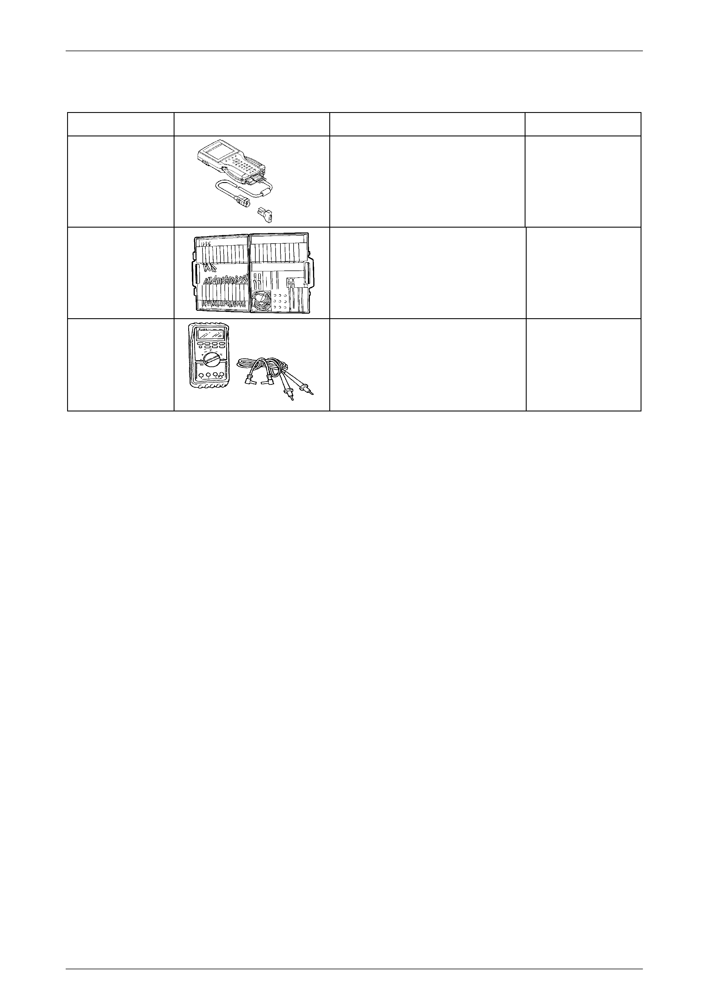
Instrumentation Page 12C – 166
Page 12C – 166
8 Special Tools
Tool Number Illustration Description Tool Classification
7000086I
TECH 2 DIAGNOSTIC SCAN TOOL
Used for diagnosis of vehicle electrical
system
Previously released.
Mandatory
J35616-A
(KM609)
CONNECTOR TEST ADAPTOR KIT
Used when carrying out electrical
Diagnostic System Checks
Previously released.
Desirable
3588
(J39200)
DIGITAL MULTIMETER
Must have at least 10 MΩ input
impedance and be capable of reading
frequencies
Previously released.
Mandatory