
Dual Park Assist Page 12F2–1
Section 12F2
Dual Park Assist
ATTENTION
Before performing any service operation or other procedure described in this Section, refer to Section
00 Warnings, Cautions and Notes for correct workshop practices with regard to safety and/or property damage.
1 General Information ...............................................................................................................................4
1.1 Operation................................................................................................................................................................ 5
Detection and Warning.......................................................................................................................................... 5
Provisions for Towbar Fitment............................................................................................................................ 6
1.2 Components........................................................................................................................................................... 7
Control Module Assembly..................................................................................................................................... 7
Override Switch and LED...................................................................................................................................... 8
Alarm Assemblies.................................................................................................................................................. 8
Front................................................................................................................................................................... 8
Rear ................................................................................................................................................................... 8
Front Object Sensor Assembly............................................................................................................................. 8
Rear Object Sensor Assembly............................................................................................................................ 10
Wiring Harness Assembly................................................................................................................................... 12
2 Wiring Diagrams and Connector Charts............................................................................................13
2.1 Wiring Diagrams .................................................................................................................................................. 13
Object Sensors – All............................................................................................................................................ 14
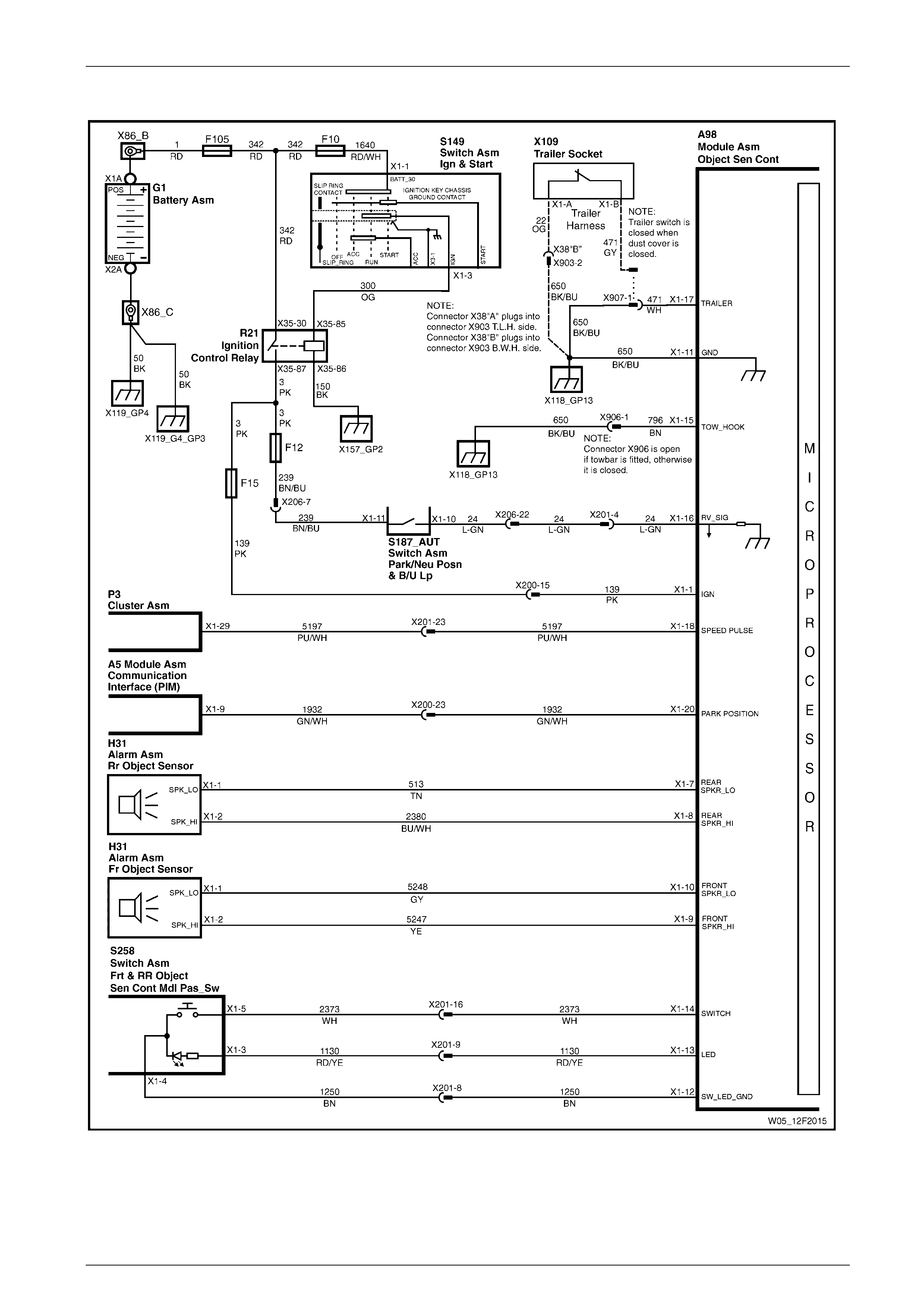
Control Circuits – V6 Engine............................................................................................................................... 15
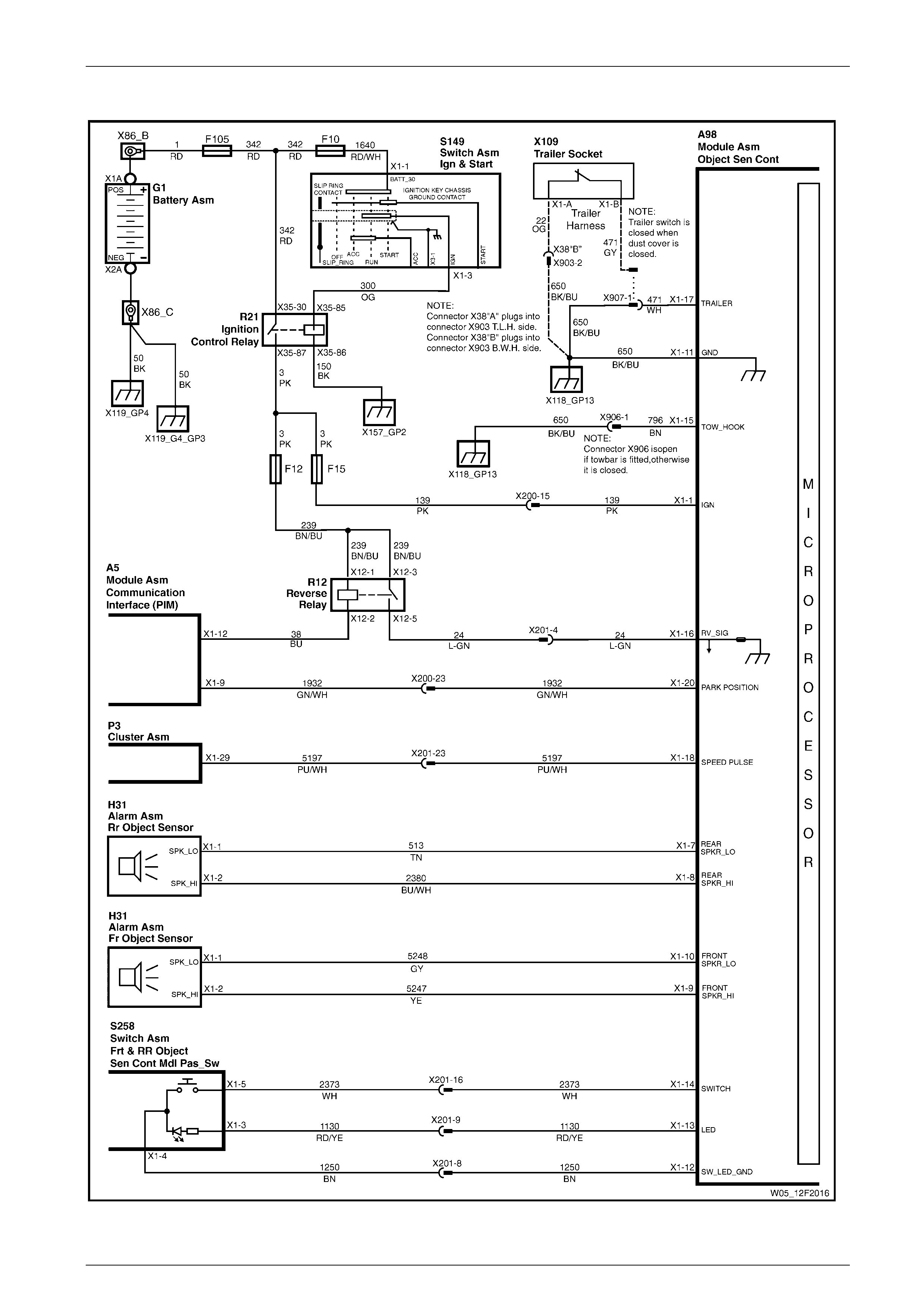
Control Circuits – V8 Engine............................................................................................................................... 16
2.2 Connector Charts................................................................................................................................................. 17
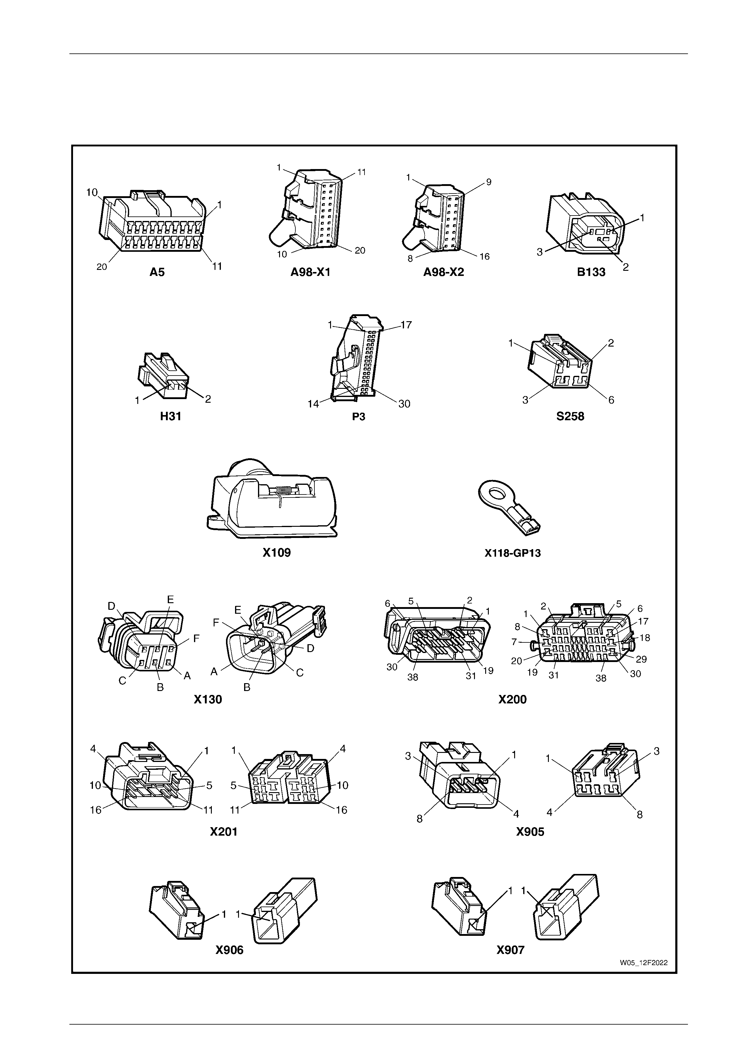
V6 Engine ............................................................................................................................................................. 17
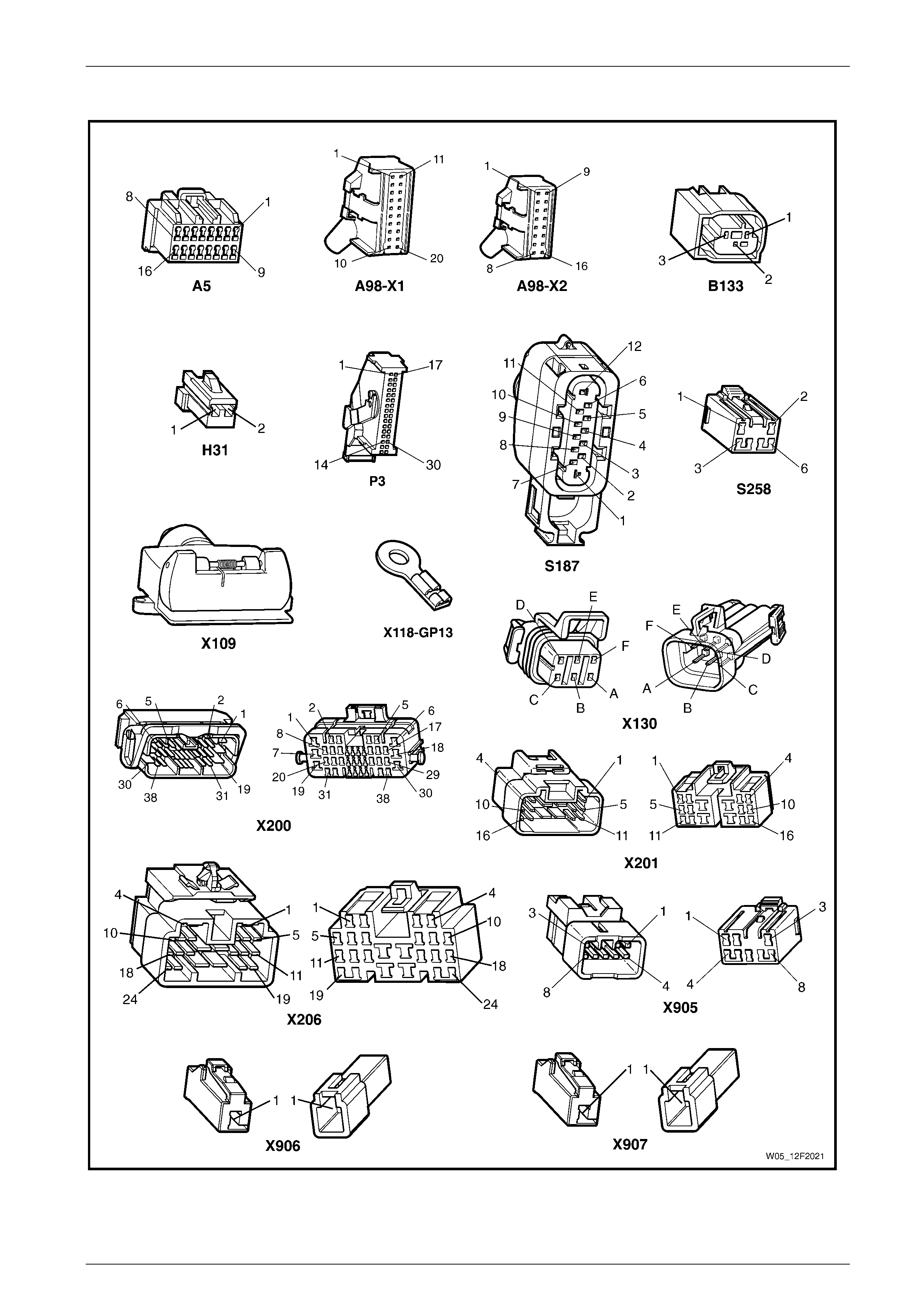
V8 Engine ............................................................................................................................................................. 18
2.3 Connector Information ........................................................................................................................................ 19
Connector A98 – X1............................................................................................................................................. 19
Connector A98 – X2............................................................................................................................................. 19
3 Diagnostics...........................................................................................................................................20
3.1 Prerequisites........................................................................................................................................................ 20
Equipment ............................................................................................................................................................ 20
Testing Procedures ............................................................................................................................................. 20
3.2 Electrical Diagnosis............................................................................................................................................. 21
3.3 Electrical Self Test Diagnosis............................................................................................................................. 22
3.4 Ground Connection Circuit Test......................................................................................................................... 24
Introduction.......................................................................................................................................................... 24
Circuit Description............................................................................................................................................... 24
Test Descriptions................................................................................................................................................. 24
Diagnostic Table Notes ....................................................................................................................................... 24
Diagnostic Table.................................................................................................................................................. 24
3.5 Power Input Circuit Test...................................................................................................................................... 26
Introduction.......................................................................................................................................................... 26
Circuit Description............................................................................................................................................... 26
Diagnostic Table Notes ....................................................................................................................................... 26
Diagnostic Table.................................................................................................................................................. 26
3.6 Override Switch Circuit Test............................................................................................................................... 27
Introduction.......................................................................................................................................................... 27
Circuit Description............................................................................................................................................... 27
Page 12F2–1

Dual Park Assist Page 12F2–2
Diagnostic Table Notes ....................................................................................................................................... 27
Diagnostic Table.................................................................................................................................................. 27
3.7 LED Circuit Test................................................................................................................................................... 28
Introduction.......................................................................................................................................................... 28
Circuit Description............................................................................................................................................... 28
Diagnostic Table Notes ....................................................................................................................................... 28
Diagnostic Table.................................................................................................................................................. 28
3.8 Transmission Park / Neutral Position Input Circuit Test.................................................................................. 29
V6 Engine ............................................................................................................................................................. 29
Introduction ...................................................................................................................................................... 29
Circuit Description............................................................................................................................................ 29
Test Description ............................................................................................................................................... 29
Diagnostic Table Notes .................................................................................................................................... 29
Diagnostic Table............................................................................................................................................... 29
V8 Engine ............................................................................................................................................................. 31
Introduction ...................................................................................................................................................... 31
Circuit Description............................................................................................................................................ 31
Test Description ............................................................................................................................................... 31
Diagnostic Table Notes .................................................................................................................................... 31
Diagnostic Table............................................................................................................................................... 31
3.9 Transmission Reverse Position Input Circuit Test........................................................................................... 33
4 Speed Auto Transmission................................................................................................................................ 33
Introduction ...................................................................................................................................................... 33
Circuit Description............................................................................................................................................ 33
Test Description ............................................................................................................................................... 33
Diagnostic Table Notes .................................................................................................................................... 33
Diagnostic Table............................................................................................................................................... 33
5 Speed Auto Transmission................................................................................................................................ 35
Introduction ...................................................................................................................................................... 35
Circuit Description............................................................................................................................................ 35
Test Description ............................................................................................................................................... 35
Diagnostic Table Notes .................................................................................................................................... 35
Diagnostic Table............................................................................................................................................... 35
3.10 Speed Signal Input Circuit Test.......................................................................................................................... 37
Introduction.......................................................................................................................................................... 37
Circuit Description............................................................................................................................................... 37
Diagnostic Table Notes ....................................................................................................................................... 37
Diagnostic Table.................................................................................................................................................. 37
3.11 No Audible Tone From Front Alarm................................................................................................................... 38
Introduction.......................................................................................................................................................... 38
Circuit Description............................................................................................................................................... 38
Diagnostic Table Notes ....................................................................................................................................... 38
Diagnostic Table.................................................................................................................................................. 38
3.12 No Audible Tone From Rear Alarm .................................................................................................................... 39
Introduction.......................................................................................................................................................... 39
Circuit Description............................................................................................................................................... 39
Diagnostic Table Notes ....................................................................................................................................... 39
Diagnostic Table.................................................................................................................................................. 39
3.13 Front Object Sensor Circuit Test........................................................................................................................ 40
Introduction.......................................................................................................................................................... 40
Circuit Description............................................................................................................................................... 40
Test Descriptions................................................................................................................................................. 40
Diagnostic Table Notes ....................................................................................................................................... 40
Diagnostic Table.................................................................................................................................................. 40
3.14 Rear Object Sensor Circuit Test......................................................................................................................... 42
Introduction.......................................................................................................................................................... 42
Circuit Description............................................................................................................................................... 42
Test Description................................................................................................................................................... 42
Diagnostic Table Notes ....................................................................................................................................... 42
Diagnostic Table.................................................................................................................................................. 42
Page 12F2–2

Dual Park Assist Page 12F2–3
Page 12F2–3
4 Service Operations...............................................................................................................................44
4.1 Dual Park Assist Control Module Assembly...................................................................................................... 44
Remove................................................................................................................................................................. 44
Disassemble......................................................................................................................................................... 44
Reassemble.......................................................................................................................................................... 45
Reinstall................................................................................................................................................................ 45
4.2 Dual Park Assist Override Switch Assembly..................................................................................................... 46
Remove................................................................................................................................................................. 46
Reinstall................................................................................................................................................................ 47
4.3 Dual Park Assist Alarm Assemblies................................................................................................................... 48
Front...................................................................................................................................................................... 48
Remove............................................................................................................................................................ 48
Reinstall ........................................................................................................................................................... 48
Rear....................................................................................................................................................................... 49
Remove............................................................................................................................................................ 49
Reinstall ........................................................................................................................................................... 49
4.4 Front Object Sensor Assembly........................................................................................................................... 50
Remove................................................................................................................................................................. 50
Reinstall................................................................................................................................................................ 51
4.5 Rear Object Sensor Assembly............................................................................................................................ 52
Remove................................................................................................................................................................. 52
Reinstall................................................................................................................................................................ 53
5 Torque Wrench Specifications............................................................................................................54

Dual Park Assist Page 12F2–4
1 General Information
Dual Park Assist (DPA) is an electronic system designed to provide an acoustic tone informing the driver of obstacles at or
near the front or rear of the vehicle during lo w spee d manoeuvres such as parking.
The DPA does not relieve the driver of duty of
care when reversing the vehicle. Caution must
always be exercised when driving at any time.
The DPA primarily consists of eight ultrasonic object sensor assemblies (four mounted in each bumper fascia), an
electronic control module assembly, two alarm assemblies, and an override switch. Sonar is used to detect the presence of
obstacles within a defined area, b y measurin g the time between the transmission and reception (echo) of sound waves.
When the system is active, the sensors sequentially transmi t short ultrasonic pulses and then listen for an echo reflected
from an object within range. The el ectronic control module uses echo data from one or more sensors to calculate the
distance to the obstacle.
An audible intermittent tone is sounded through the appropriate alarm informing the driver that an obstacle has been
detected within the range of the system. The front alarm informs the driver of objects at the front of the vehicle, while the
rear alarm informs the driver of objects at the rear of the vehicle. As the distance to the obstacle draws closer, the
frequency of the tone increases until it becomes constant at a distance of approximately 30 cm, or 45 cm at the rear of
vehicles fitted with a towbar. The DPA switch, mounted in the centre console, incorporates an LED which illuminates when
the system is on.
NOTE
Some sound absorbing or reflecting materials can
effect the range of detection. In extreme cases,
temporary non-detection of ob stacles can result.
When the sensors at both the front and rear are active, the DPA only signifies the closest detected object at either end of
the vehicle. The system does not operate the front and rear alarms at the same time. If there is an object the same
distance from each end of the vehicle and the sensors at both the front and rear are active, the object at the rear is the
reported item.
When the vehicle has been stationary with an object in range for more than five seconds, the DPA goes into time out
mode. In this mode, the warning tones stop until the vehicle moves closer to the object, at which time the warning tones
resume.
While operational, the control module constantly monitors the system for faults. Should a fault occur, an audible warning is
indicated to the driver through the front park assist alarm, an d the LED in the DPA switch will flash. A diagnosis system
aids the technician in locating the source of the fault.
Page 12F2–4

Dual Park Assist Page 12F2–5
1.1 Operation
Detection and Warning
The DPA is engaged when the ignition is on and,
• the transmission selector is moved from park or neutral to a drive gear, or
• the DPA override switch is pressed while the vehicle speed is below 25 km/h (assuming the DPA was disengaged)
and the transmission selector is in a drive gear.
When the ignition is on and reverse gear is selected, a tone will sound from the rear alarm for a period of 0.5 seconds to
indicate system readiness, and both th e front and rear sensors are active. When the ignition is on and a ny forward gear is
selected, a tone will sound from the front alarm for a period of 0.5 secon ds to indicate system readiness, and only the front
sensors are active.
NOTE
There is a slight delay in the system becoming
engaged. This is to allow for the shift selector
passing through Reverse when moving from Park
to Drive, etc.
The DPA is disengaged when:
• the ignition is switched off, or
• the vehicle speed rises above 25 km/h, or
• the DPA override switch is pressed (assumi ng the DPA was engaged).
NOTE
When the vehicle speed rises above 25 km/h in
reverse the system is not disengaged, but
becomes inactive until the speed becomes less
than 25 km/h.
During operation, the DPA control module provides a voltage to each sensor sequentially which is converted into an
ultrasonic pulse. Where an object is within the detection range, the ultrasonic pulse is reflected (echoed) and received b y
the same and/or adjacent sensors.
The echoes are amplified, processed and returned to the control module as a digital signal. The DPA control module
processes this information and informs the driver of the obj ect by activating an intermittent acoustic tone through the
appropriate alarm.
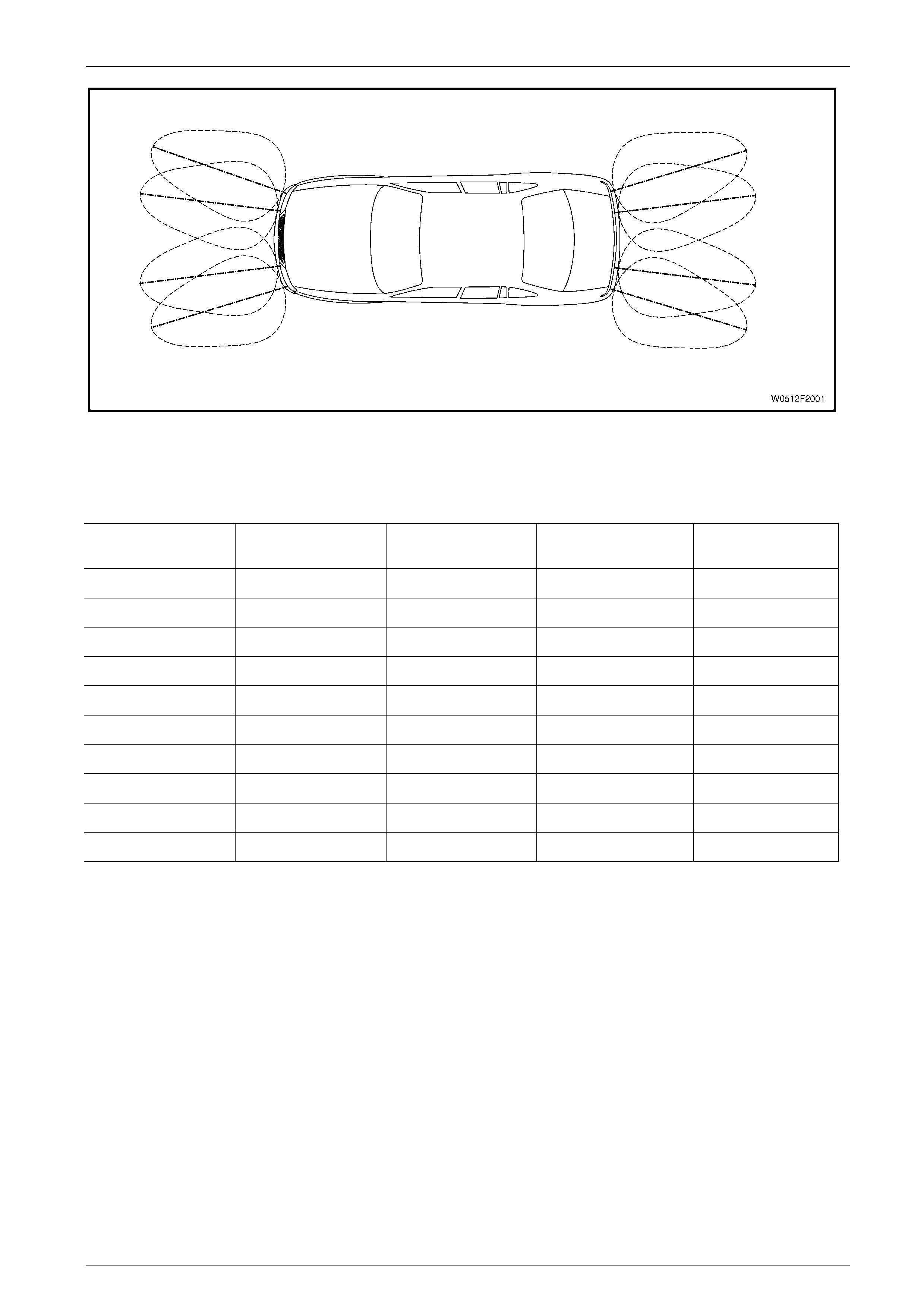
The front and rear object sensors are mou nted onto the b umper fascias in arrangements that provide a slight overlap of
the respective polar patterns, refer to Figure 12F2 – 1. This provides the best coverage of the detection areas. The
maximum detection distance of 150 cm is set by the control module software.
Page 12F2–5
Dual Park Assist Page 12F2–6
Figure 12F2 – 1
The detection areas are divided into five warning zones for each end of the vehicle. As listed in the following table, the
tone-on to tone-off period shortens as the distance to the detected ob ject decreases.
Warning Range (cm) Frequency (Hz) Front
Object Frequency (Hz) Rear
Object Tone On Time (ms) Tone Off Time (ms)
Less than 30 1000 1200 Continuous
30 – 40 1000 1200 70 70
40 – 60 1000 1200 70 140
60 – 80 1000 1200 70 210
80 – 100 1000 1200 70 280
100 – 120 1000 1200 70 350
120 – 150 1000 1200 70 420
Hardware Error 700 700 Continuous at power up
Error Message 700 700 Continuous at power up
Ready Tone 1600 1600 500
Provisions for Towbar Fitment
When a towbar is fitted, the continuous tone rear activation area is increased from 30 to 45cm to allow for the length of the
towbar tongue. This is achieved by the towbar installer disconnecting the white wiring connector X906, causing an open in
the power supply circuit 24 and 796 to the control modul e (pin 15).
When the correct accessory trailer wiring harness is insta lled, the system can be temporarily disabled whil e towing. The
black connector X907 (5) in circuit 650 and 471 is also disconnected by the installer and the grey wire in the trailer h arness
connected.
While the trailer socket dust-flap is closed, a magnet in the dust-flap closes a reed-switch in the trailer socket which
connects this circuit to ground through circuit 22.
When the dust-flap is opened, as in connecting a trailer plug, the switch opens. The control module detects the open circuit
and disables the system.
If a bicycle carrier is fitted onto the towbar, a licence plate lamp and tail lamp should be fitted to the carrier and plugged
into the trailer socket. This will also temporarily disabl e the system, as it is highly likely the bicycles will cause a
disturbance to the detection field.
The dual park assist can also be disabled by disconnecting connector X907. In this instance, the presence or absence of a
connector in the trailer socket is ignored.
Page 12F2–6
Dual Park Assist Page 12F2–7
1.2 Components
Control Module Assembly
The role of the control module is to trigger ultrasonic pulses sequentially from each sensor and monitor the sensors for any
received pulses (echoes from an object). The signals are then filtered and the distance of the object is calculated from the
time elapsed between the transmission of the signal a nd its reception using triangulation dat a from one or more sensors.
The control module controls the output tones throug h the alarms, and has a self-diagnosis function.
The control module also provi des a stable voltage supply to the object sensors and circuits to protect the sensors against
over-voltage.
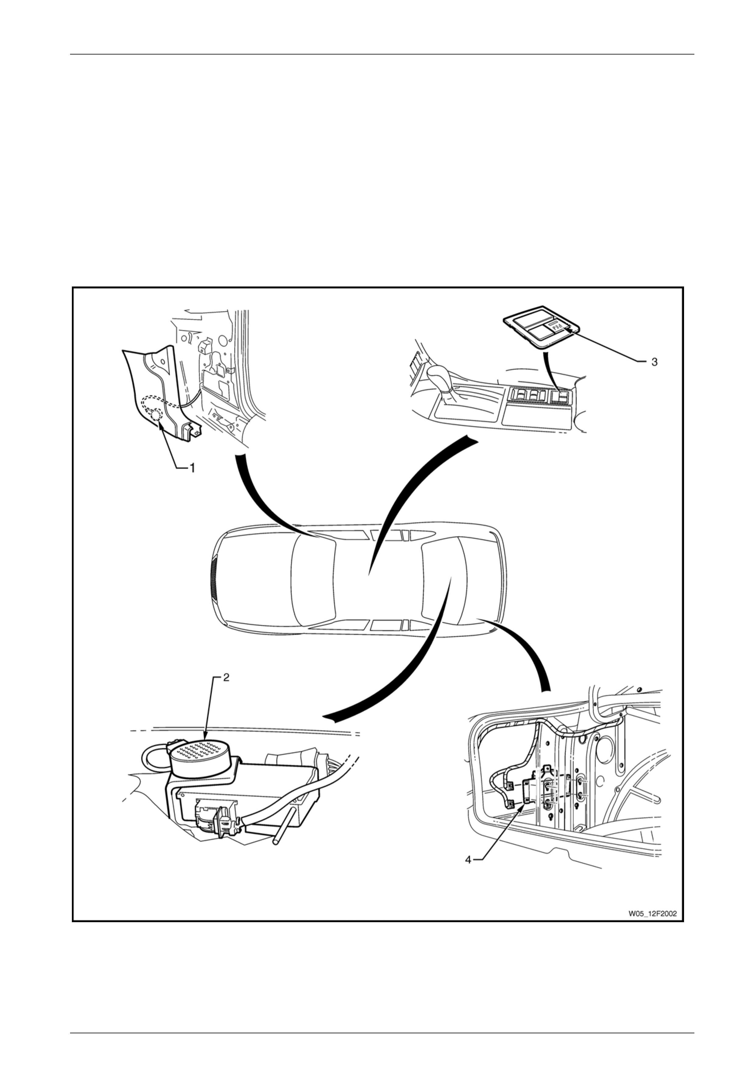
The dual park assist control modu le and bracket are mounted as an assembly in the left side of the rear compartment,
refer to Figure 12F2 – 2.
Figure 12F2 – 2
Legend
1 Front Alarm Assembly
2 Rear Alarm Assembly 3 Override Switch
4 Control Module
Page 12F2–7
Dual Park Assist Page 12F2–8
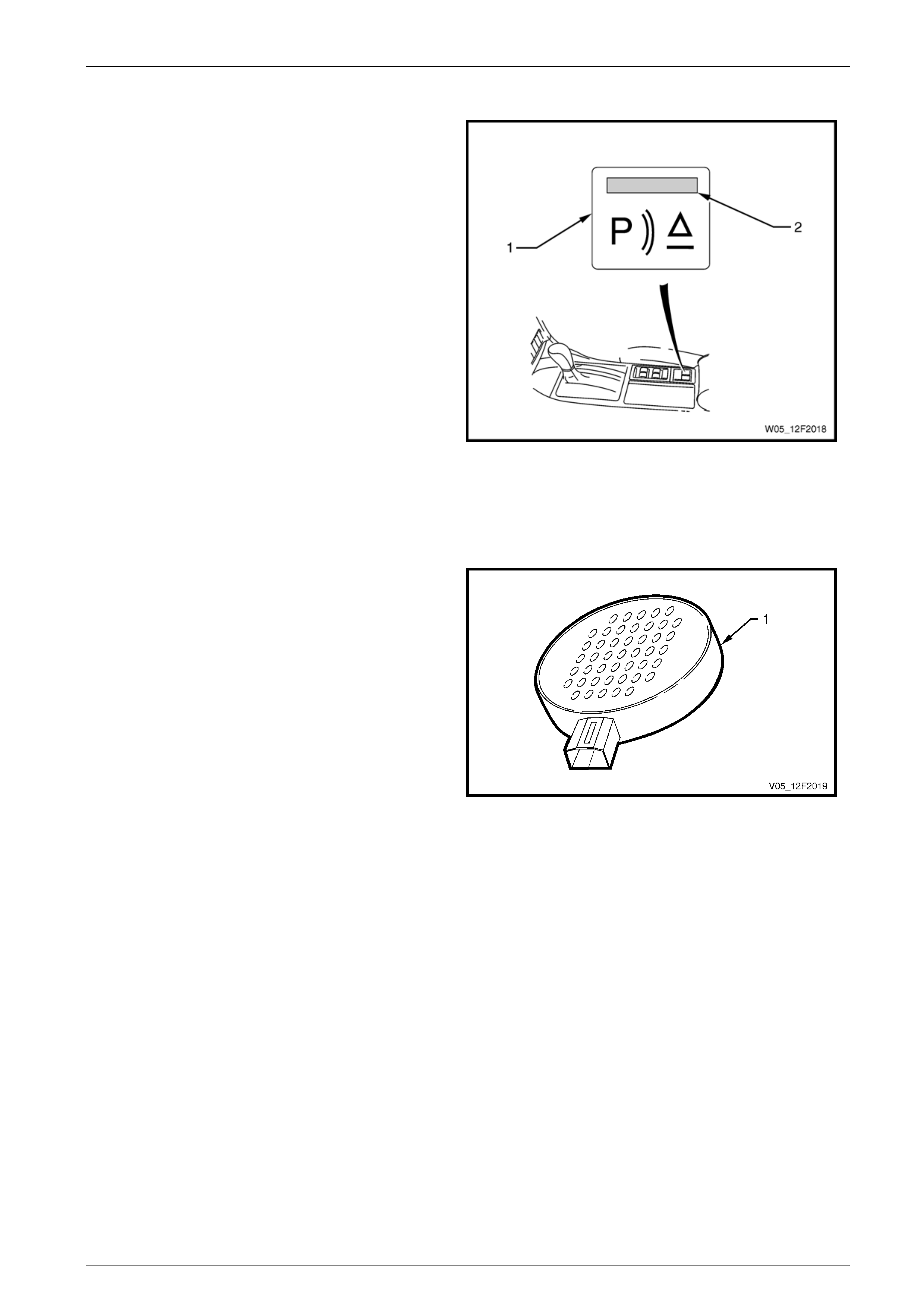
Override Switch and LED
The dual park assist (DPA) override switch (1) is used to
override the current status of the DPA system. For example,
if the system has been engaged through use of the
transmission selector, the DPA override switch can be used
to disengage the system.
The DPA override switch also incorporates the DPA system
LED (2), which indicates system function. The LED is
illuminated when the system is on.
Figure 12F2 – 3
Alarm Assemblies
Front
The dual park assist (DPA) front alarm asse mbly (1)
provides an audible tone to the driver to indicate DPA
system status and objects detected at the front of the
vehicle. The DPA front alarm assembly is mounted to the
inside of the right-hand front body hinge pil lar trim assembly,
refer to (1) in Figure 12F2 – 2.
Rear
The DPA rear alarm assembly (1) provides an audible tone
to the driver to indicate DPA system status and objects
detected at the rear of the vehicle. The DPA rear al arm
assembly is mounted to the tyre pressure monitor module
bracket, on the right-hand side of the rear windo w panel,
refer to (2) in Figure 12F2 – 2. Figure 12F2 – 4
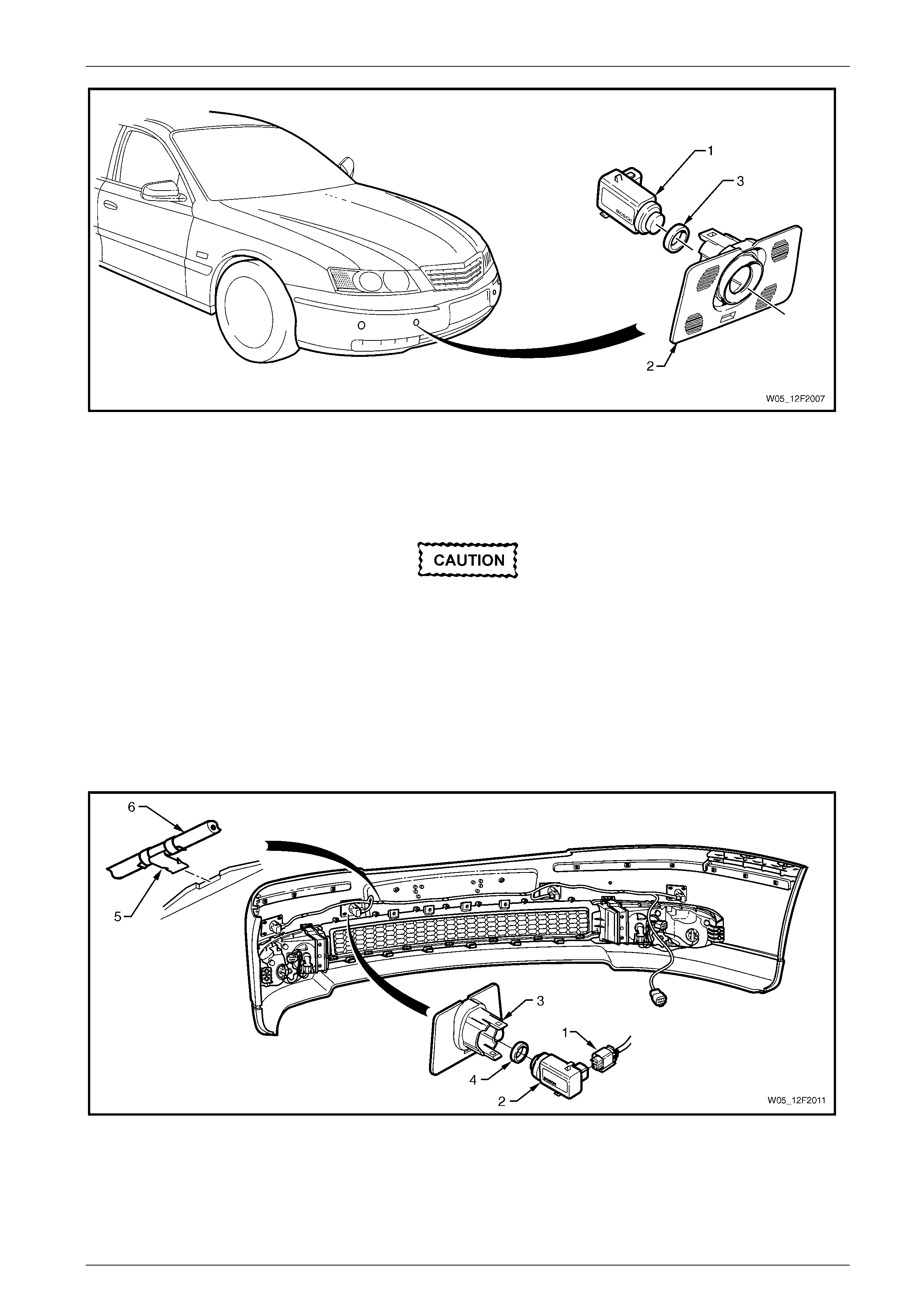
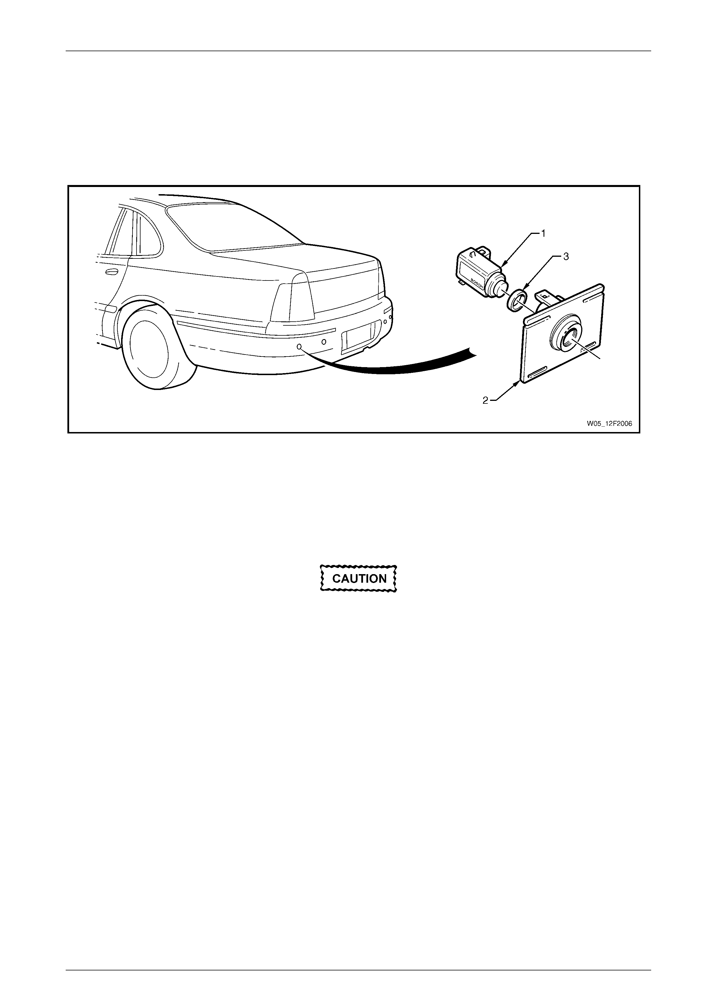
Front Object Sensor Assembly
There are four sensors mounted in the front bumper fascia. Each sensor operates as a transmitter and receiver of
ultrasonic pulses. The receiv ed electronic pulses (echoes) are amplified, processed a nd returned to the control module as
a digital signal.
Each of the four front object sensor assemblies (1) are mounted in a front object sensor housing (2) which is ultrasonically
welded to the front bumper fascia. The housings allow easy removal of the sensor and front object sensor ring (3), refer to
Figure 12F2 – 5.
Page 12F2–8
Dual Park Assist Page 12F2–9
Figure 12F2 – 5
If the front bumper fascia assembly is to be replaced, the front object sensor housings must be replaced. The new
housings can be attached to the new fascia with special adhesive, refer to Section 1D Bumper Bars. New housings are to
be painted to match the bumper fascia using similar methods to painting the fascia, refer to Section 1D Bumper Bars.
The front object sensor is supplied with the exposed surface painted in the vehicle’s body colour.
• Rep lace ment fron t object sen sor as semb lies
are supplied pre-painted in the vehicle's
body colour. Do not apply further paint to
the front object sen sor assemblies, as it w ill
have a detrimental effect on the operation of
the front object sensor assemblies.
• The front object sensor ring prevents
vibrations from the front object sensor
assembly being transferred to the
surrounding components. Incorrect fitment
will change the characteristics of the front
object sensor ass embly.
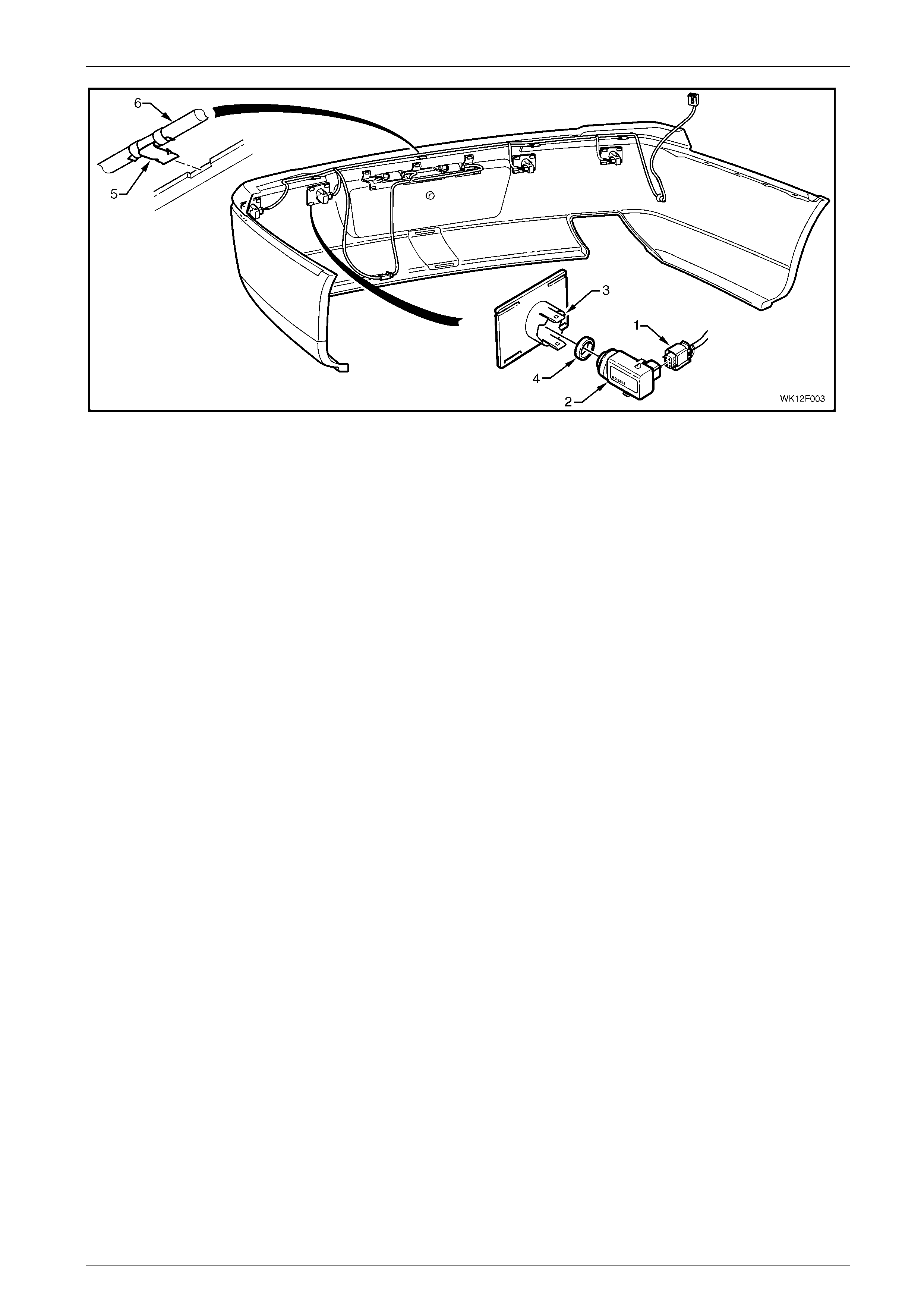
Figure 12F2 – 6
Legend
1 Front Object Sensor Connector
2 Front Object Sensor Assembly
3 Front Object Sensor Housing
4 Front Object Sensor Ring
5 Clip (4 places)
6 Wiring Harness
Page 12F2–9
Dual Park Assist Page 12F2–10
Rear Object Sensor Assembly
There are four sensors mounted in the rear bumper fascia. Each sensor operates as a transmitter and receiver of
ultrasonic pulses. The receiv ed electronic pulses (echoes) are amplified, processed a nd returned to the control module as
a digital signal.
Each of the four rear object sensor assemblies (1) are mounted in a rear object sensor housing (2) which is heat-staked
to the rear bumper fascia. The housings a llow easy removal of the sensor and re ar object sensor ring (3), refer to
Figure 12F2 – 7.
Figure 12F2 – 7
If the rear bumper fascia assembly is to be replaced, undamaged housings can be removed from the bumper fascia by
cutting the four attaching heat-stakes. T he housing can then be heat-staked onto th e new fascia with a soldering iron, refer
to Section 1D Bumper Bars. If the housings are dam aged, replacement parts are available. New housings are to be
painted to match the bumper fascia using similar methods to painting the fascia, refer to Section 1D Bumper Bars.
The rear object sensor is supplied with the exposed surface painted in the vehicle’s body c olo ur.
• Replacement rear object sensor assemblies
are supplied pre-painted in the vehicle's
body colour. Do not apply further paint to
the rear object sensor assemblies, as it will
have a detrimental effect on the operation of
the rear object senso r assemblies.
• The rear object sensor ring prevents
vibrations from the rear object sensor
assembly being transferred to the
surrounding components. Incorrect fitment
will change the characteristics of the rear
object sensor ass embly.
Page 12F2–10
Dual Park Assist Page 12F2–11
Figure 12F2 – 8
Legend
1 Rear Object Sensor Connector
2 Rear Object Sensor Assembly
3 Rear Object Sensor Housing
4 Rear Object Sensor Ring
5 Clip (4 places)
6 Wiring Harness
Page 12F2–11
Dual Park Assist Page 12F2–12
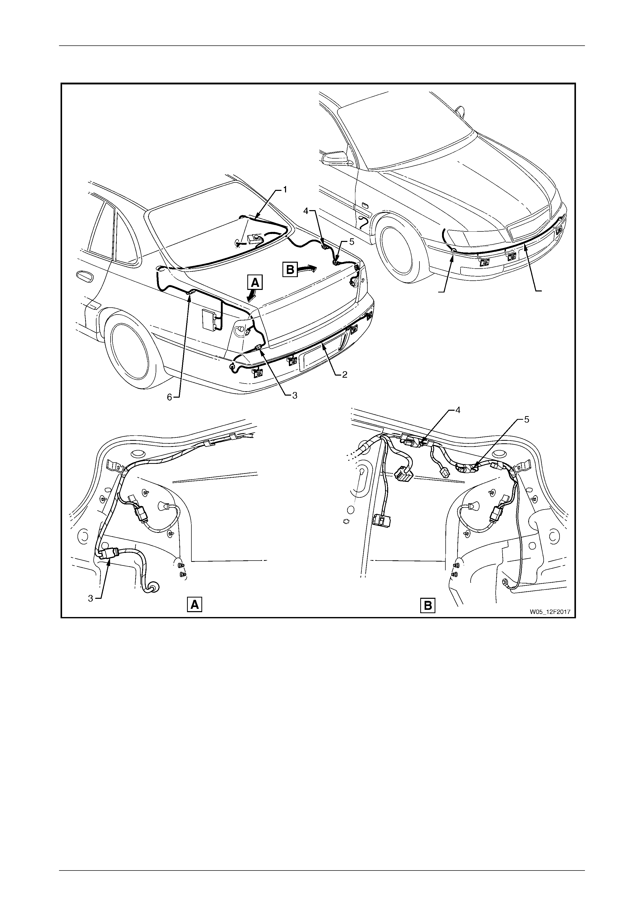
Wiring Harness Assembly
Figure 12F2 – 9
Legend
1 Body Wiring Harness
2 Rear Object Sensor Harness
3 Rear Object Sensor to Body Harness Connector X905
4 Towbar Tongue Modification Connector X906 (white)
5 Trailer Harness Connector X907 (black)
6 Diagnosis Connector X156
Page 12F2–12

Dual Park Assist Page 12F2–13
2 Wiring Diagrams and Connector
Charts
2.1 Wiring Diagrams
Page 12F2–13
Dual Park Assist Page 12F2–14
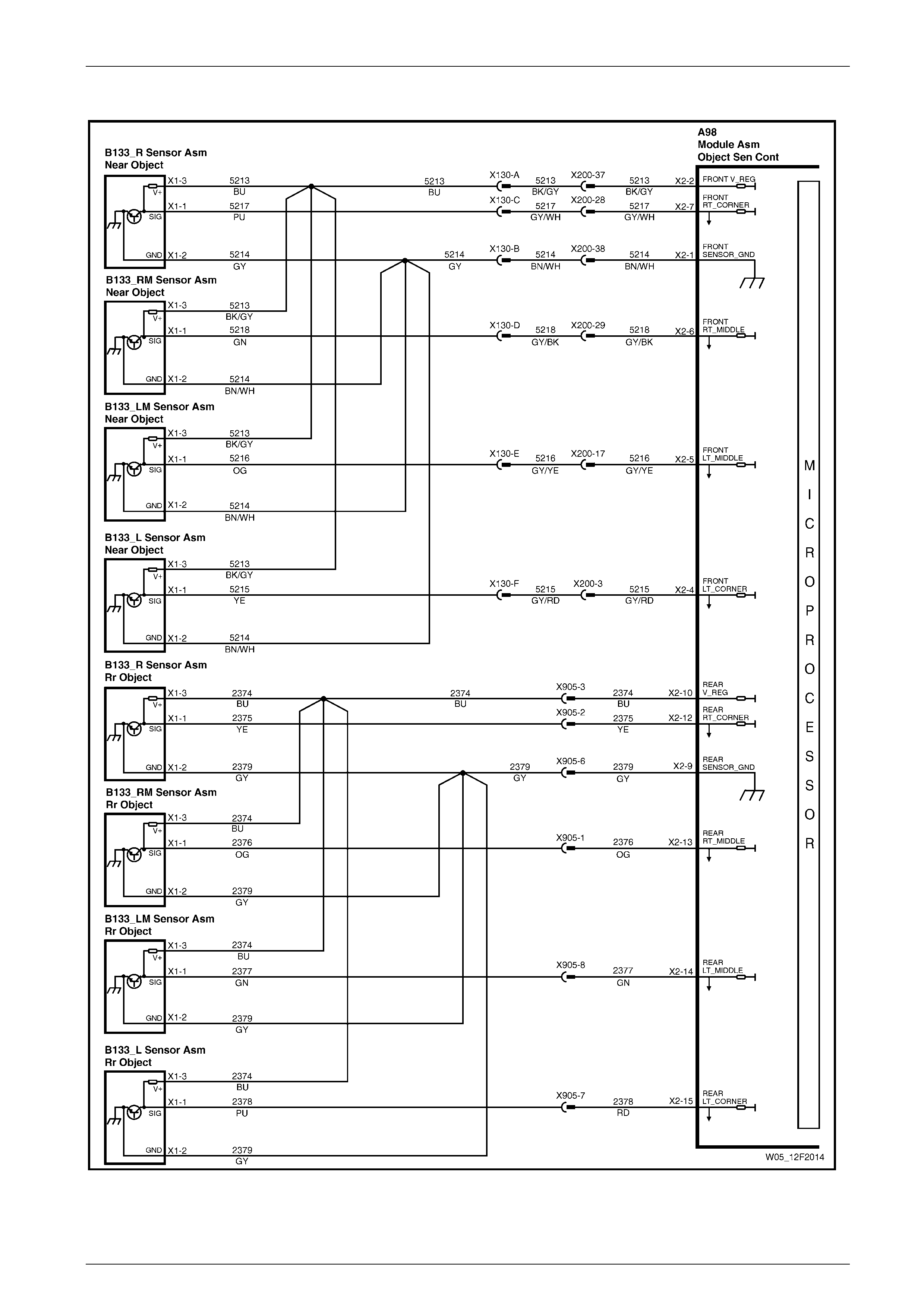
Object Sensors – All
Figure 12F2 – 10
Page 12F2–14
Dual Park Assist Page 12F2–15
Control Circuits – V6 Engine
Figure 12F2 – 11
Page 12F2–15
Dual Park Assist Page 12F2–16
Control Circuits – V8 Engine
Figure 12F2 – 12
Page 12F2–16
Dual Park Assist Page 12F2–17
2.2 Connector Charts
V6 Engine
Figure 12F2 – 13
Page 12F2–17
Dual Park Assist Page 12F2–18
V8 Engine
Figure 12F2 – 14
Page 12F2–18

Dual Park Assist Page 12F2–19
2.3 Connector Information
Connector A98 – X1
Pin Number Circuit Number Designation Wire Colour
1 139 Power Pink
7 513 Rear alarm - Tan
8 2380 Rear alarm + Blue / White
9 5247 Front alarm + Yellow
10 5248 Front alarm - Grey
11 650 Ground Black / Blue
12 1250 Switch and LED ground Brown
13 1130 LED supplyn Red / Yellow
14 2373 Switch signal White
15 796 Towbar offset signal Brown
16 24 Reverse signal Light Green
17 471 Trailer connected signal White
18 5197 Speed signal Purple / White
20 1932 Park / Neutral signal Green / White
Connector A98 – X2
Pin Number Circuit Number Designation Wire Colour
1 5214 Front sensor ground Brown / White
2 5213 Front sensor feed Black / Grey
4 5215 Sensor signal front outer left Grey / Red
5 5216 Sensor signal front middle left Grey / Yellow
6 5218 Sensor signal front middle right Grey / Black
7 5217 Sensor signal front outer right Grey / White
9 2379 Rear sensor ground Grey
10 2374 Rear sensor feed Blue
12 2375 Sensor signal rear outer right Yellow
13 2376 Sensor signal rear middle right Orange
14 2377 Sensor signal rear middle left Green
15 2378 Sensor signal rear outer left Red
Page 12F2–19

Dual Park Assist Page 12F2–20
3 Diagnostics
This Section provides charts to assist in the diagnosis and repa ir of the dual park assist (DPA) system.
3.1 Prerequisites
Equipment
The following equipment is required to diagnose the DPA system:
• an unpowered test lamp with a current dra w of less than 3 A, and
• a digital multimeter with a minimum impe dance of 10 MΩ.
Testing Procedures
Adhere to the following points when performing
diagnostic testing on components:
• Take care when using testing equipment to
diagnose wiring harness connectors.
Backprobe the connector to avoid terminal
damage.
• When tests are required on connector
terminals, use the adapters in the connector
adapter kit KM–609 to prevent damage to
the terminals.
• Unless the multimeter being used has an
auto-ranging function, ensure the correct
range is selected.
• When backprobing connectors, ensure the
test lamp ground lead is connected to an
appropriate ground point on the vehicle.
Ensure this ground point is not part of the
circuit being tested.
• Where it is possible to touch connector
pins, correct Electro-Static Discharge (ESD)
protection procedures, including the use of
a grounded wrist strap and an anti-static
mat, must be followed.
NOTE
When following the steps in the diagnostic tables,
perform them in the order cited. If the required
nominal value or result is not achieved, rectify the
problem before proceeding.
Page 12F2–20

Dual Park Assist Page 12F2–21
3.2 Electrical Diagnosis
After the dual park assist (DPA) system initialises, a ready tone sounds for a period of 0.5 seconds. While operational, the
DPA control module monitors the system and should a fault be detected, a continuous 700 Hz tone sounds and the DPA
LED flashes at a continuous rate of 1 Hz.
NOTE
Interference in the detection area by certain
activity, such as heavy machinery and truck air
brakes, may cause the module to trigger the
700 Hz fault tone from the DP A front alarm u ntil the
interference ceases.
Page 12F2–21

Dual Park Assist Page 12F2–22
3.3 Electrical Self Test Diagnosis
The DPA system incorporates a self diagnostic function.
Using this electrical self test may assist in
locating the area where the fault has occurred,
however the relevant circuit diagnostic test
should be consulted before replacing any
components.
NOTE
Faults are stored in non-volatile memory within the
DPA control module while present. History faults
are not retained.
The DPA system is placed in diagnostic mode b y the following method:
NOTE
There must be an object free area of at le ast 50 cm
around all sensors while performing this test.
1 Hold down the DPA override switch.
2 Switch on the ignition. Do not start the engine.
3 Continue to hold down the DPA override switch for 5 seconds.
4 Note the tones and refer to the relevant diagnostic tests.
NOTE
If more than one error is detected, the tone will be
output in sequence separated by the End pause.
The sequence of faults will be repeated
continuously while the system remains in self-
diagnosis mode.
The system reports the status of the front components followed by the status of the rear components.
Page 12F2–22

Dual Park Assist Page 12F2–23
No Fault Continuous cyclic tone of 3 seconds on, 3 seconds off (Start and End tone onl y)
Left Sensor Fault Start On Off End
Left Middle Sensor Fault Start On Off On Off End
Right Middle Sensor Fault Start On Off On Off On Off End
Right Sensor Fault Start On Off On Off On Off On Off End
ECM Fault Start Int Int Int End
The complete sequence occu rs in the following order:
• DPA front alarm
• Start
• Component specific fault / no fault sequence ( s) for front DPA components including the DPA control
module
• End
• DPA rear alarm
• Start
• Component specific fault / no fault sequence ( s) for rear DPA components including the DPA control
module
• End
Legend
Start – Tone on for three seconds and off for one second.
On – Tone on for one second.
Off – Tone off for one second.
End – Tone off for two seconds.
Int – Interval tone (0.5 second on, 0.5 second off).
Page 12F2–23

Dual Park Assist Page 12F2–24
3.4 Ground Connection Circuit Test
Introduction
This test is used by the technician to aid in the diagnosis of the dual park assist (DPA) system ground circ uits.
Circuit Description
The DPA control module is grounded through three circuits. Circuit 650 is a dedicated ground circuit, while circuit 471
provides a connection to allo w integration of a trailer harness switch. Circuit 796 allows the DPA control module to
determine if there is a towbar fitted. When the DPA control module does not detect ground at connector A98 – X1 pin 15
(because harness connector X906 is d isconnected) the module modifies the rear detection area to all ow for a towbar
tongue.
Refer to 2 Wiring Diagrams and Connector Charts to aid i n diagnosis.
Test Descriptions
The following numbers refer to the step numbers in the diagnostic table:
1 Tests if the towbar tongue modification circui t is serviceable.
2 Tests if the towbar tongue modification conn ector X906 is correctly set.
3 Tests if the towbar tongue modification conn ector X906 is correctly set.
7 Tests if the switch in the trailer harness is open. The system is disabled if the switch in the trailer harness is open.
Diagnostic Table Notes
1 For all wiring harness fault diagnoses, refer to Section 12P Wiring Diagrams.
2 For wiring harness repairs, refer to Section 12P Wiring Diagrams.
3 Refer to Section 12O Fuses, Relays and Wiring Harnesses for harness routeing.
4 If the fault is deemed to be intermittent, refer to Section 12P Wiring Diagrams.
Diagnostic Table
Step Action Yes No
1 1 Disconnect connector A98 – X1 from the DPA control module.
2 Using a multimeter set to measure resistance, probe between
connector A98 – X1 pin 15 and a known ground (refer to
Note 1).
Does the multimeter indicate less than 5 Ω?
If the vehicle is fitted
with a towbar go to
Step 2.
If the vehicle is not
fitted with a towbar
go to Step 4
If the vehicle is fitted
with a towbar go to
Step 4.
If the vehicle is not
fitted with a towbar
go to Step 3
2 Is connector X906 disconnected (to modify the sensor detection range
for the towbar tongue)? Repair or replace
circuit 796 (refer to
Note 2).
Go to Step 4
Disconnect
connector X906.
Go to Step 1
3 Is connector X906 disconnected (to modify the sensor detection range
for the towbar tongue)?
Connect connector
X906.
Go to Step 1
Repair or replace
circuits 796 or 650
between connector
X906 pin 1 and
ground point
X118_GP13 (refer
to Note 2).
Go to Step 4
Page 12F2–24

Dual Park Assist Page 12F2–25
Step Action Yes No
4 Using a multimeter set to measure resistance, probe between
connector A98 – X1 pin 11 and a known ground (refer to Note 1).
Does the multimeter indicate less than 5 Ω?
Go to Step 5
Repair or replace
circuit 650 between
connector A98 – X1
pin 11 and ground
point X118_GP13
(refer to Note 2).
Go to Step 5
5 Using a multimeter set to measure resistance, probe between
connector A98 – X1 pin 17 and a known ground (refer to Note 1).
Does the multimeter indicate less than 5 Ω? Ground circuits are
serviceable Go to Step 6
6 Is the vehicle fitted with a trailer harness?
Go to Step 7
Repair or replace
circuit 471 or circuit
650 between
connector X907 pin
1 and ground point
X118_GP13 (refer
to Note 2)
7 Inspect the trailer harness socket.
Is anything plugged into the socket or is the socket dust flap ope n?
The trailer socket
switch is open.
Remove the plug
from the socket or
close the flap.
Repeat Step 2 Go to Step 8
8 Using a multimeter set to measure resistance, probe between
connectors A98 – X1 pin 17 and X907 pin 1 (refer to Note 1).
Does the multimeter indicate less than 5 Ω? Go to Step 9
Repair or replace
circuit 471 (refer to
Note 2)
9 Using a multimeter set to measure resistance, probe between
connectors X907 pin 1 and X903 pin 2 (refer to Note 1).
Does the multimeter indicate less than 5 Ω?
Go to Step 10
Repair or replace
the trailer harness
(refer to Note 2)
10 Using a multimeter set to measure resistance, probe between
connector X903 pin 2 and a known ground (refer to Note 1).
Does the multimeter indicate less than 5 Ω? Ground circuits are
serviceable
Repair or replace
circuit 650 between
connector X903 pin
2 and ground point
X118_GP13 (refer
to Note 2)
When all diagno sis and repairs are completed, check the system fo r correct operation.
Page 12F2–25

Dual Park Assist Page 12F2–26
3.5 Power Input Circuit Test
NOTE
Prior to performing this test, ensure the ground
circuits function correctly and nothing is connected
into the trailer socket.
Introduction
This test is used by the technician to aid in the diagnosis of the dual park assist (DPA) system power circuit.
Circuit Description
The DPA control module is powere d via connector A98 – X1 pin 1 when the ignition is on.
Refer to 2 Wiring Diagrams and Connector Charts to aid i n diagnosis.
Diagnostic Table Notes
1 For all wiring harness fault diagnoses, refer to Section 12P Wiring Diagrams.
2 For wiring harness repairs, refer to Section 12P Wiring Diagrams.
3 Refer to Section 12O Fuses, Relays and Wiring Harnesses for harness routeing.
4 If the fault is deemed to be intermittent, refer to Section 12P Wiring Diagrams.
Diagnostic Table
Step Action Yes No
1 1 Backprobe connector A98 – X1 pin 1 with a test lamp (refer to
Note 1).
2 Switch the ignition on.
Does the test lamp illuminate? The power supply is
serviceable Go to Step 2
2 Check Fuse 15 in the passenger compartment fuse and relay panel
assembly and Fuse 105 in the eng ine compartment fuse and relay
panel assembly.
Are the fuses serviceable? Go to Step 3
Replace fuse and
retest. If the fuse
blows again test for
a short to ground
(refer to Note 1)
3 Backprobe connector X129 – X35 pin 87 with a test lamp (refer to
Note 1).
Does the test lamp illuminate? Repair or replace
circuit 139 (refer to
Note 2)
Repair the ignition
control relay R21
control circuits or
replace the relay as
required (refer to
Note 1)
When all diagno sis and repairs are completed, check the system fo r correct operation.
Page 12F2–26

Dual Park Assist Page 12F2–27
3.6 Override Switch Circuit Test
NOTE
Prior to performing this test, ensure the ground a nd
power circuits function correctly and nothing is
connected into the trailer socket.
Introduction
This test is used by the technician to aid in the diagnosis of the dual park assist (DPA) override switch circuits.
Circuit Description
The DPA override switch is connected to the DPA control module assembly through circuits 1250 and 2373. The DPA
control module supplies 1 2 V on circuit 2373 and a ground through circuit 1250. When the DPA override switch is pressed,
circuit 2373 is grounded an d the DPA control module engages or disengages the DPA system.
Refer to 2 Wiring Diagrams and Connector Charts to aid i n diagnosis.
Diagnostic Table Notes
1 For all wiring harness fault diagnoses, refer to Section 12P Wiring Diagrams.
2 For wiring harness repairs, refer to Section 12P Wiring Diagrams.
3 Refer to Section 12O Fuses, Relays and Wiring Harnesses for harness routeing.
4 If the fault is deemed to be intermittent, refer to Section 12P Wiring Diagrams.
Diagnostic Table
Step Action Yes No
1 Perform the self diagnostic test, refer to 3.3 Electrical Self Test
Diagnosis.
Does the DPA system enter diagnostic mode? The DPA override
switch is serviceable Go to Step 2
2 Backprobe connector A98 – X1 pin 1 4 with a test lamp (refer to
Note 1).
Does the test lamp illuminate? Go to Step 4 Go to Step 3
3 1 Disconnect connector A98 – X1 from the DPA control module.
2 Disconnect connector S258 – X1 from the DPA overrid e switch.
3 Using a multimeter set to measure resistance, probe between
connector S258 – X1 pin 5 and a known ground (refer to
Note 1).
Does the multimeter indicate continuity?
Repair or replace
circuit 2373
(refer to Note 2)
Replace the DPA
control module,
refer to 4.1 Dual
Park Assist Control
Module Assembly
4 Backprobe connector S258 – X1 pin 5 with a test lamp (refer to
Note 1).
Does the test lamp illuminate? Go to Step 5
Repair or replace
circuit 2373
(refer to Note 2)
5 Using a multimeter set to measure resistance, probe between
connector S258 – X1 pin 4 and a known ground (refer to Note 1).
Does the multimeter indicate less than 5 Ω?
Replace the DPA
override switch,
refer to 4.2 Dual
Park Assist Override
Switch Assembly Go to Step 6
6 Using a multimeter set to measure resistance, probe between
connector A98 – X1 pin 12 and a known ground (refer to Note 1).
Does the multimeter indicate less than 5 Ω? Repair or replace
circuit 1250 (refer to
Note 2)
Replace the DPA
control module,
refer to 4.1 Dual
Park Assist Control
Module Assembly
When all diagno sis and repairs are completed, check the system fo r correct operation.
Page 12F2–27

Dual Park Assist Page 12F2–28
3.7 LED Circuit Test
NOTE
Prior to performing this test, ensure the ground a nd
power circuits function correctly and nothing is
connected into the trailer socket.
Introduction
This test is used by the technician to aid in the diagnosis of the dual park assist (DPA) LED circuits.
Circuit Description
The DPA LED is connected to the DPA control module asse mbly through circuits 1250 and 1130. The DPA control module
supplies 12 V on circuit 1130 when the DPA system is engaged, and a ground through circuit 1250.
Refer to 2 Wiring Diagrams and Connector Charts to aid i n diagnosis.
Diagnostic Table Notes
1 For all wiring harness fault diagnoses, refer to Section 12P Wiring Diagrams.
2 For wiring harness repairs, refer to Section 12P Wiring Diagrams.
3 Refer to Section 12O Fuses, Relays and Wiring Harnesses for harness routeing.
4 If the fault is deemed to be intermittent, refer to Section 12P Wiring Diagrams.
Diagnostic Table
Step Action Yes No
1 1 Switch on the ignition with the engine n ot running.
2 Engage Reverse gear.
3 Ensure the rear alarm signals the system is engaged.
Does the LED illuminate?
The DPA LED
circuits are
serviceable Go to Step 2
2 Backprobe connector A98 – X1 pin 1 3 with a test lamp (refer to
Note 1).
Does the test lamp illuminate? Go to Step 4 Go to Step 3
3 1 Disconnect connector A98 – X1 from the DPA control module.
2 Disconnect connector S258 – X1 from the DPA overrid e switch.
3 Using a multimeter set to measure resistance, probe between
connector S258 – X1 pin 3 and a known ground (refer to
Note 1).
Does the multimeter indicate continuity?
Repair or replace
circuit 1130
(refer to Note 2)
Replace the DPA
control module,
refer to 4.1 Dual
Park Assist Control
Module Assembly
4 Backprobe connector S258 – X1 pin 3 with a test lamp (refer to
Note 1).
Does the test lamp illuminate? Go to Step 5
Repair or replace
circuit 1130
(refer to Note 2)
5 Using a multimeter set to measure resistance, probe between
connector S258 – X1 pin 4 and a known ground (refer to Note 1).
Does the multimeter indicate less than 5 Ω?
Replace the DPA
override switch,
refer to 4.2 Dual
Park Assist Override
Switch Assembly Go to Step 6
6 Using a multimeter set to measure resistance, probe between
connector A98 – X1 pin 12 and a known ground (refer to Note 1).
Does the multimeter indicate less than 5 Ω? Repair or replace
circuit 1250
(refer to Note 2)
Replace the DPA
control module,
refer to 4.1 Dual
Park Assist Control
Module Assembly
When all diagno sis and repairs are completed, check the system fo r correct operation.
Page 12F2–28

Dual Park Assist Page 12F2–29
3.8 Transmission Park / Neutral Position Input
Circuit Test
V6 Engine
NOTE
Prior to performing this test, ensure the ground
circuits function correctly and nothing is connected
into the trailer socket.
Introduction
This test is used by the technician to aid in the diagnosis of the dual park assist (DPA) system transmission park / neutral
position input circuits.
Circuit Description
The DPA control module supplies 1 2 V to circuit 1932 through connector A98 – X1 pin 20 when the ignition is on. When
the transmission is in park or neutral, the powertrain interface module (PIM) grounds circuit 1932 and the DPA control
module detects less than 2 V at connector A98 – X1 pin 20. This signal enables the DPA control modul e to determine
whether the transmission is in park / neutral or in a drive gea r .
Refer to 2 Wiring Diagrams and Connector Charts to aid i n diagnosis.
Test Description
The following numbers refer to the step numbers in the diagnostic table:
3 Tests if the DPA control module is prov iding a 12 V output to circuit 1932.
4 Tests if there is a short to ground in circuit 1932.
5 Tests if there is continuity in circuit 1932.
6 Tests whether there is a fault in the CAN bus communication net work or the PIM, or if the PIM is not receiving the
correct signal from the transmission control module (TCM). If the PIM does not control circuit 1932 correctly, there is
a fault in either the PIM, the CAN bus communication network, the TCM, or the transmission selector position switch.
Diagnostic Table Notes
1 For all wiring harness fault diagnoses, refer to Section 12P Wiring Diagrams.
2 For wiring harness repairs, refer to Section 12P Wiring Diagrams.
3 Refer to Section 12O Fuses, Relays and Wiring Harnesses for harness routeing.
4 If the fault is deemed to be intermittent, refer to Section 12P Wiring Diagrams.
5 For information on using and conn ecting Tech 2 to the vehicle, refer to Section 0C Tech 2.
Diagnostic Table
Step Action Yes No
1 1 Backprobe connector A98 – X1 pin 20 with a test lamp (refer to
Note 1).
2 Switch the ignition on and sele ct reverse gear.
Does the test lamp illuminate? Go to Step 2 Go to Step 3
2 1 Place the transmission in Park.
2 Backprobe connector A98 – X1 pin 20 with a test lamp (refer to
Note 1).
Does the test lamp illuminate? Go to Step 5
The transmission
park / neutral
position input circuit
is serviceable
Page 12F2–29

Dual Park Assist Page 12F2–30
Step Action Yes No
3 1 Disconnect connector A98 – X1 from the DPA control module.
2 Backprobe the DPA control module A98 – X1 pin 20 with a test
lamp (refer to Note 1).
Does the test lamp illuminate? Go to Step 4
Replace the DPA
control module,
refer to 4.1 Dual
Park Assist Control
Module Assembly
4 1 Disconnect connector A156 – X1 from the PIM.
2 Using a multimeter set to measure resistance, probe between
connector A98 – X1 pin 20 and a known ground (refer to
Note 1).
Does the multimeter indicate continuity? Repair circuit 1932
(refer to Note 2) Go to Step 6
5 1 Disconnect connector A98 – X1 from the DPA control module.
2 Disconnect connector A156 – X1 from the PIM.
3 Using a multimeter set to measure resistance, probe between
connectors A98 – X1 pin 20 and A15 6 – X1 pin 9 (refer to
Note 1).
Does the multimeter indicate continuity? Go to Step 6 Repair circuit 1932
(refer to Note 2)
6 1 Connect Tech 2 to the DLC (refer to Note 5).
2 On Tech 2 select:
Body / PIM / Diagnostic Trouble Codes / Read DTC
Information.
Does any of the following DTCs set?
B1000, B1009, B1013, B1014, B1019, U1304, U2100, or U2106.
Refer to 6E1
Powertrain Interface
Module – V6 Go to Step 7
7 On Tech 2 select:
Transmission / Data Display and scroll to Shift Selector Position.
Does Tech 2 display Drive when the transmission is placed in Drive?
Replace the PIM,
refer to 6E1
Powertrain Interface
Module – V6
Refer to the
appropriate
Automatic
Transmission
Section
When all diagno sis an d repairs are completed, clear all DTCs and check the system for correct operation.
Page 12F2–30

Dual Park Assist Page 12F2–31
V8 Engine
NOTE
Prior to performing this test, ensure the ground
circuits function correctly and nothing is connected
into the trailer socket.
Introduction
This test is used by the technician to aid in the diagnosis of the dual park assist (DPA) system transmission park / neutral
position input circuits.
Circuit Description
The DPA control module provi des 12 V to circuit 1932 through connector A98 – X1 pin 20 when the ignition is on. When
the transmission is in park or neutral, the powertrain interface module (PIM) grounds circuit 1932 and the DPA control
module will detect less than 2 V at connector A98 – X1 pin 20. Using this signal, the DPA control module determines
whether the transmission is in park / neutral or in a drive gea r .
Refer to 2 Wiring Diagrams and Connector Charts to aid i n diagnosis.
Test Description
The following numbers refer to the step numbers in the diagnostic table:
3 Tests if the DPA control module is prov iding a 12 V output to circuit 1932.
4 Tests if there is a short to ground in circuit 1932.
5 Tests if there is continuity in circuit 1932.
6 Tests whether there is a fault in the PIM, or if the PIM is receiving the correct signal from the transmission selector
position switch. If the PIM does not control circuit 1932 correctly, there is a fault in either the PIM or the transmission
selector position switch.
Diagnostic Table Notes
1 For all wiring harness fault diagnoses, refer to Section 12P Wiring Diagrams.
2 For wiring harness repairs, refer to Section 12P Wiring Diagrams.
3 Refer to Section 12O Fuses, Relays and Wiring Harnesses for harness routeing.
4 If the fault is deemed to be intermittent, refer to Section 12P Wiring Diagrams.
5 For information on using and conn ecting Tech 2 to the vehicle, refer to Section 0C Tech 2.
Diagnostic Table
Step Action Yes No
1 1 Backprobe connector A98 – X1 pin 20 with a test lamp (refer to
Note 1).
2 Switch the ignition on and sele ct reverse gear.
Does the test lamp illuminate? Go to Step 2 Go to Step 3
2 1 Place the transmission in Park.
2 Backprobe connector A98 – X1 pin 20 with a test lamp (refer to
Note 1).
Does the test lamp illuminate? Go to Step 5
The transmission
park / neutral
position input circuit
is serviceable
3 1 Disconnect connector A98 – X1 from the DPA control module.
2 Backprobe the DPA control module A98 – X1 pin 20 with a test
lamp (refer to Note 1).
Does the test lamp illuminate? Go to Step 4
Replace the DPA
control module,
refer to 4.1 Dual
Park Assist Control
Module Assembly.
Page 12F2–31

Dual Park Assist Page 12F2–32
Step Action Yes No
4 1 Disconnect connector A156 – X1 from the PIM.
2 Using a multimeter set to measure resistance, probe between
connector A98 – X1 pin 20 and a known ground (refer to
Note 1).
Does the multimeter indicate continuity? Repair circuit 1932
(refer to Note 2) Go to Step 6
5 1 Disconnect connector A98 – X1 from the DPA control module.
2 Disconnect connector A156 – X1 from the PIM.
3 Using a multimeter set to measure resistance, probe between
connectors A98 – X1 pin 20 and A15 6 – X1 pin 9 (refer to
Note 1).
Does the multimeter indicate continuity? Go to Step 6 Repair circuit 1932
(refer to Note 2)
6 1 Connect Tech 2 to the DLC (refer to Note 5).
2 On Tech 2 select:
Body / PIM / Diagnostic Trouble Codes / Read DTC
Information.
Does any of the following DTCs set?
B1009, B1019, U1000, or U1001.
Refer to 6E3
Powertrain Interface
Module – Gen III V8 Go to Step 7
7 On Tech 2 select:
Transmission / Data Display and scroll to Shift Selector Position.
Does Tech 2 display Drive when the transmission is placed in Drive?
Replace the PIM,
refer to 6E3
Powertrain Interface
Module – Gen III V8
Refer to
7C4 Automatic
Transmission –
4L60E – On-vehicle
Servicing
When all diagno sis an d repairs are completed, clear all DTCs and check the system for correct operation.
Page 12F2–32

Dual Park Assist Page 12F2–33
3.9 Transmission Reverse Position Input
Circuit Test
4 Speed Auto Transmission
NOTE
Prior to performing this test, ensure the ground
circuits function correctly and nothing is connected
into the trailer socket.
Introduction
This test is used by the technician to aid in the diagnosis of the dual park assist (DPA) system transmission revers e
position input circuits.
Circuit Description
The DPA control module is provided with power to connector A98 – X1 pin 16 when the ignition is o n and reverse gear is
selected.
Refer to 2 Wiring Diagrams and Connector Charts to aid i n diagnosis.
Test Description
The following numbers refer to the step numbers in the diagnostic table:
3 Tests if the ignition control relay is supplying battery voltage to circuits 3 and 239. If not, there will be other systems
inoperable, including e ngine/powertrain management.
Diagnostic Table Notes
1 For all wiring harness fault diagnoses, refer to Section 12P Wiring Diagrams.
2 For wiring harness repairs, refer to Section 12P Wiring Diagrams.
3 Refer to Section 12O Fuses, Relays and Wiring Harnesses for harness routeing.
4 If the fault is deemed to be intermittent, refer to Section 12P Wiring Diagrams.
Diagnostic Table
Step Action Yes No
1 1 Backprobe connector A98 – X1 pin 16 with a test lamp (refer to
Note 1).
2 Switch the ignition on and sele ct reverse gear.
Does the test lamp illuminate?
The reverse position
input circuit is
serviceable Go to Step 2
2 Check Fuse 12 in the passenger compartment fuse and relay panel
assembly and Fuse 105 in the eng ine compartment fuse and relay
panel assembly.
Are the fuses serviceable? Go to Step 3
Replace fuse and
retest. If the fuse
blows again test for
a short to ground
(refer to Note 1)
3 Backprobe connector X129 – X35 pin 87 with a test lamp (refer to
Note 1).
Does the test lamp illuminate? Go to Step 4
Repair the ignition
control relay R21
control circuits or
replace the relay
(refer to Note 1)
4 Backprobe connector S187 – X1 pin 11 with a test lamp (refer to
Note 1).
Does the test lamp illuminate? Go to Step 5
Repair or replace
circuits 239 or 3
(refer to Note 2)
Page 12F2–33

Dual Park Assist Page 12F2–34
Step Action Yes No
5 Backprobe connector S187 – X1 pin 9 with a test lamp (refer to
Note 1).
Does the test lamp illuminate? Repair or replace
circuit 24 (refer to
Note 2)
Replace the back-
up lamp switch,
refer to
7C4 Automatic
Transmission –
4L60E – On-vehicle
Servicing
When all diagno sis and repairs are completed, check the system fo r correct operation.
Page 12F2–34

Dual Park Assist Page 12F2–35
5 Speed Auto Transmission
NOTE
Prior to performing this test, ensure the ground
circuits function correctly and nothing is connected
into the trailer socket.
Introduction
This test is used by the technician to aid in the diagnosis of the dual park assist (DPA) system transmission revers e
position input circuits.
Circuit Description
The DPA control module is provided with power to connector A98 – X1 pin 16 when the ignition is o n and reverse gear is
selected.
Refer to 2 Wiring Diagrams and Connector Charts to aid i n diagnosis.
Test Description
The following numbers refer to the step numbers in the diagnostic table:
3 Tests if the ignition control relay is supplying battery voltage to circuits 3 and 239. If not, there will be other systems
inoperable, including e ngine/powertrain management.
5 Tests if the reverse relay is supplying battery voltage to circuit 24. If the reverse relay R12 does not operate, the DPA
system will not operate correctly. In addition, the reverse lights will not operate.
9 Tests whether there is a fault in the CAN bus communication network or the powertrain interface module (PIM), or if
the PIM is receiving the correct signal from the transmission control module (TCM). If the PIM does not ground circuit
38, there is a fault in either the PIM, the CAN bus communication network, the TCM, or the transmission selector
position switch inside the transmission.
Diagnostic Table Notes
1 For all wiring harness fault diagnoses, refer to Section 12P Wiring Diagrams.
2 For wiring harness repairs, refer to Section 12P Wiring Diagrams.
3 Refer to Section 12O Fuses, Relays and Wiring Harnesses for harness routeing.
4 If the fault is deemed to be intermittent, refer to Section 12P Wiring Diagrams.
5 For information on using and conn ecting Tech 2 to the vehicle, refer to Section 0C Tech 2.
Diagnostic Table
Step Action Yes No
1 1 Backprobe connector A98 – X1 pin 16 with a test lamp (refer to
Note 1).
2 Switch the ignition on and sele ct reverse gear.
Does the test lamp illuminate?
The reverse position
input circuit is
serviceable Go to Step 2
2 Check Fuse 12 in the passenger compartment fuse and relay panel
assembly and Fuse 105 in the eng ine compartment fuse and relay
panel assembly.
Are the fuses serviceable? Go to Step 3
Replace fuse and
retest. If the fuse
blows again test for
a short to ground
(refer to Note 1)
3 Backprobe connector X129 – X35 pin 87 with a test lamp (refer to
Note 1).
Does the test lamp illuminate?
Go to Step 4
Repair the ignition
control relay R21
control circuits or
replace the relay as
required (refer to
Note 1)
Page 12F2–35

Dual Park Assist Page 12F2–36
Step Action Yes No
4 Backprobe connector X100 – X12 pin 3 with a test lamp (refer to
Note 1).
Does the test lamp illuminate? Go to Step 5
Repair or replace
circuits 239 or 3
(refer to Note 2)
5 Backprobe connector X100 – X12 pin 5 with a test lamp (refer to
Note 1).
Does the test lamp illuminate?
Repair or replace
circuit 24
(refer to Note 2) Go to Step 6
6 Backprobe connector X100 – X12 pin 1 with a test lamp (refer to
Note 1).
Does the test lamp illuminate? Go to Step 7
Repair or replace
circuit 239
(refer to Note 2)
7 1 Remove the reverse relay R12.
2 Using a multimeter set to measure resistance, probe between
connector X100 – X12 pin 2 and a known ground (refer to
Note 1).
Does the multimeter indicate less than 5 Ω? Replace the reverse
relay R12 Go to Step 8
8 Using a multimeter set to measure resistance, probe between
connectors X100 – X12 pin 2 and A156 – X1 pin 12 (refer to Note 1).
Does the multimeter indicate less than 5 Ω? Go to Step 9
Repair or replace
circuit 38
(refer to Note 2)
9 1 Connect Tech 2 to the DLC (refer to Note 5).
2 On Tech 2 select:
Body / PIM / Diagnostic Trouble Codes / Read DTC
Information.
Does any of the following DTCs set?
B1000, B1009, B1013, B1014, B1019, U1304, U2100, or U2106.
Refer to 6E1
Powertrain Interface
Module – V6 Go to Step 10
10 On Tech 2 select:
Transmission / Data Display and scroll to Shift Selector Position.
Does Tech 2 display Reverse when the transmission is placed in
Reverse?
Replace the PIM,
refer to 6E1
Powertrain Interface
Module – V6
Refer to 7E2
Automatic
Transmission –
5L40E – Electrical
Diagnosis
When all diagno sis an d repairs are completed, clear all DTCs and check the system for correct operation.
Page 12F2–36

Dual Park Assist Page 12F2–37
3.10 Speed Signal Input Circuit Test
NOTE
Prior to performing this test, ensure the ground a nd
power circuits function correctly and nothing is
connected into the trailer socket.
Introduction
This test is used by the technician to aid in the diagnosis of the dual park assist (DPA) speed input circuits.
Circuit Description
The DPA control module receiv es a vehicle speed signal via circuit 5197.
Refer to 2 Wiring Diagrams and Connector Charts to aid i n diagnosis.
Diagnostic Table Notes
1 For all wiring harness fault diagnoses, refer to Section 12P Wiring Diagrams.
2 For wiring harness repairs, refer to Section 12P Wiring Diagrams.
3 Refer to Section 12O Fuses, Relays and Wiring Harnesses for harness routeing.
4 If the fault is deemed to be intermittent, refer to Section 12P Wiring Diagrams.
Diagnostic Table
Step Action Yes No
1 1 Start the engine.
2 Engage a forward drive ge ar.
3 Ensure the LED in the s witch is illuminated and/or the front
alarm signals the system is engaged.
4 Drive the vehicle in excess of 25 km/h.
Does the LED extinguish when the vehicle exceeds 25 km/h? Speed Signal Input
Circuit Serviceable Go to Step 2
2 Does the vehicle speedometer work? Go to Step 3 Refer to 12C
Instrumentation
3 1 Stop the vehicle.
2 Switch the ignition to the OFF position.
3 Disconnect connector A98 – X1 from the DPA control module.
4 Disconnect connector P3 – X1 from the instrument cluster.
5 Using a multimeter set to measure resistance, probe between
connectors P3 – X1 pin 29 and A98 – X1 pin 18 (refer to
Note 1).
Does the multimeter indicate less than 5 Ω? Go to Step 4
Repair or replace
circuit 5197 (refer to
Note 2)
4 Using a multimeter set to measure resistance, probe between
connector A98 – X1 pin 18 and a known ground (refer to Note 1).
Does the multimeter indicate less than 5 Ω? Repair or replace
circuit 5197 (refer to
Note 2)
Replace the DPA
control module,
refer to 4.1 Dual
Park Assist Control
Module Assembly
When all diagno sis and repairs are completed, check the system fo r correct operation.
Page 12F2–37

Dual Park Assist Page 12F2–38
3.11 No Audible Tone From Front Alarm
NOTE
Prior to performing this test, ensure the ground a nd
power circuits function correctly and nothing is
connected into the trailer socket.
Introduction
This test is used by the technician to aid in the diagnosis of the circuits for the dual park assist (DPA) alarms.
Circuit Description
The DPA front alarm assembly is connected to the DPA control module assembly through circuits 5247 and 5248.
Refer to 2 Wiring Diagrams and Connector Charts to aid i n diagnosis.
Diagnostic Table Notes
1 For all wiring harness fault diagnoses, refer to Section 12P Wiring Diagrams.
2 For wiring harness repairs, refer to Section 12P Wiring Diagrams.
3 Refer to Section 12O Fuses, Relays and Wiring Harnesses for harness routeing.
4 If the fault is deemed to be intermittent, refer to Section 12P Wiring Diagrams.
Diagnostic Table
Step Action Yes No
1 1 Switch the ignition on with the engine not running.
2 Select a forward gear.
3 Ensure the DPA system is engaged.
Does an audible tone sound from the front alarm? DPA front alarm
serviceable Go to Step 2
2 1 Disconnect connector H31 – X1 from the front DPA alarm.
2 Using a multimeter set to measure resistance, probe across the
alarm terminals (refer to Note 1).
Does the multimeter indicate 95 – 10 5 Ω? Go to Step 3
Replace the front
DPA alarm, refer to
4.3 Dual Park
Assist Alarm
Assemblies
3 1 Disconnect connector A98 – X1 from the DPA control module.
2 Using a multimeter set to measure resistance, probe between
connectors A98 – X1 pin 10 and H3 1 – X1 pin 1 (refer to
Note 1).
Does the multimeter indicate continuity? Go to Step 4
Repair or replace
circuit 5248
(refer to Note 2)
4 Using a multimeter set to measure resistance, probe between
connectors A98 – X1 pin 9 and H31 – X1 pin 2 (refer to Note 1).
Does the multimeter indicate continuity? Go to Step 5
Repair or replace
circuit 5247
(refer to Note 2)
5 Using a multimeter set to measure resistance, probe between
connector A98 – X1 pin 10 and a known ground (refer to Note 1).
Does the multimeter indicate continuity?
Repair or replace
circuit 5248
(refer to Note 2) Go to Step 6
6 Using a multimeter set to measure resistance, probe between
connector A98 – X1 pin 9 and a known ground (refer to Note 1).
Does the multimeter indicate continuity? Repair or replace
circuit 5247
(refer to Note 2)
Replace the DPA
control module,
refer to 4.1 Dual
Park Assist Control
Module Assembly
When all diagno sis and repairs are completed, check the system fo r correct operation.
Page 12F2–38

Dual Park Assist Page 12F2–39
3.12 No Audible Tone From Rear Alarm
NOTE
Prior to performing this test, ensure the ground a nd
power circuits function correctly and nothing is
connected into the trailer socket.
Introduction
This test is used by the technician to aid in the diagnosis of the circuits for the dual park assist (DPA) alarms.
Circuit Description
The DPA rear alarm assembly is connected to the DPA control module assembly through circuits 513 an d 2380.
Refer to 2 Wiring Diagrams and Connector Charts to aid i n diagnosis.
Diagnostic Table Notes
1 For all wiring harness fault diagnoses, refer to Section 12P Wiring Diagrams.
2 For wiring harness repairs, refer to Section 12P Wiring Diagrams.
3 Refer to Section 12O Fuses, Relays and Wiring Harnesses for harness routeing.
4 If the fault is deemed to be intermittent, refer to Section 12P Wiring Diagrams.
Diagnostic Table
Step Action Yes No
1 1 Switch the ignition on with the engine not running.
2 Select reverse gear.
3 Ensure the DPA system is engaged.
Does an audible tone sound from the rear alarm? DPA rear alarm
serviceable Go to Step 2
2 1 Disconnect connector H31 – X1 from the rear DPA alarm.
2 Using a multimeter set to measure resistance, probe across the
alarm terminals (refer to Note 1).
Does the multimeter indicate 95 – 10 5 Ω? Go to Step 3
Replace the rear
DPA alarm, refer to
4.3 Dual Park
Assist Alarm
Assemblies
3 1 Disconnect connector A98 – X1 from the DPA control module.
2 Using a multimeter set to measure resistance, probe between
connectors A98 – X1 pin 7 and H31 – X1 pin 1 (refer to Note 1).
Does the multimeter indicate continuity? Go to Step 4
Repair or replace
circuit 513
(refer to Note 2)
4 Using a multimeter set to measure resistance, probe between
connectors A98 – X1 pin 8 and H31 – X1 pin 2 (refer to Note 1).
Does the multimeter indicate continuity? Go to Step 5
Repair or replace
circuit 2380
(refer to Note 2)
5 Using a multimeter set to measure resistance, probe between
connector A98 – X1 pin 7 and a known ground (refer to Note 1).
Does the multimeter indicate continuity?
Repair or replace
circuit 513
(refer to Note 2) Go to Step 6
6 Using a multimeter set to measure resistance, probe between
connector A98 – X1 pin 8 and a known ground (refer to Note 1).
Does the multimeter indicate continuity? Repair or replace
circuit 2380 (refer to
Note 2)
Replace the DPA
control module,
refer to 4.1 Dual
Park Assist Control
Module Assembly
When all diagno sis and repairs are completed, check the system fo r correct operation.
Page 12F2–39

Dual Park Assist Page 12F2–40
3.13 Front Object Sensor Circuit Test
NOTE
Prior to performing this test, ensure the ground a nd
power circuits function correctly and nothing is
connected into the trailer socket.
Introduction
This test is used by the technician to aid in the diagnosis of the dual park assist (DPA) system front object sensor circuit s.
Circuit Description
The DPA system front object sensors share common power and ground circuits. Each front object sensor has a dedicated
signal return circuit.
Refer to 2 Wiring Diagrams and Connector Charts to aid i n diagnosis.
Test Descriptions
The following numbers refer to the step numbers in the diagnostic table:
3 Checks if the DPA control module is supplying voltage to the front object sensors.
4 Checks if the DPA control module is providing a ground to the front object sensors.
Diagnostic Table Notes
1 For all wiring harness fault diagnoses, refer to Section 12P Wiring Diagrams.
2 For wiring harness repairs, refer to Section 12P Wiring Diagrams.
3 Refer to Section 12O Fuses, Relays and Wiring Harnesses for harness routeing.
4 If the fault is deemed to be intermittent, refer to Section 12P Wiring Diagrams.
Diagnostic Table
Step Action Yes No
1 1 Disconnect connectors B133 – X1 from the four front object
sensors.
2 Disconnect connector A98 – X2 from the DPA control module.
3 Using a multimeter set to measure resistance, probe between
connector A98 – X2 pin 2 and each sensor connector B133 – X1
pin 3 (refer to Note 1).
Does the multimeter indicate continuity in each test? Go to Step 2
Repair or replace
circuit 5213
(refer to Note 2)
2 Using a multimeter set to measure resistance, probe between
connector A98 – X2 pin 2 and a known ground (refer to Note 1).
Does the multimeter indicate continuity?
Repair or replace
circuit 5213
(refer to Note 2) Go to Step 3
3 1 Switch the ignition on with the engine not running.
2 Using a multimeter set to measure voltage, probe b etween
control module A98 – X2 pin 2 and a known ground (refer to
Note 1).
Does the multimeter indicate 7.8 – 8.2 V? Go to Step 4
Replace the DPA
control module,
refer to 4.1 Dual
Park Assist Control
Module Assembly
Page 12F2–40

Dual Park Assist Page 12F2–41
Step Action Yes No
4 Using a multimeter set to measure resistance, probe between control
module A98 – X2 pin 1 and a known ground (refer to Note 1).
Does the multimeter indicate less than 5 Ω? Go to Step 5
Replace the DPA
control module,
refer to 4.1 Dual
Park Assist Control
Module Assembly
5 Using a multimeter set to measure resistance, probe between
connector A98 – X2 pin 1 and each sensor connector B133 – X1 pin 2
(refer to Note 1).
Does the multimeter indicate continuity in each test? Go to Step 6
Repair or replace
circuit 5214
(refer to Note 2)
6 Using a multimeter set to measure resistance, probe between
connector A98 – X2 pins 4, 5, 6, or 7 and the relevant sensor
connector B133 – X1 pin 1 (refer to Note 1).
Does the multimeter indicate continuity in each test? Go to Step 7
Repair or replace
circuit(s) 5215,
5216, 5218, or 5217
as appropriate
(refer to Note 2)
7 Using a multimeter set to measure resistance, probe between
connector A98 – X2 pins 4, 5, 6, or 7 and a known ground (refer to
Note 1).
Does the multimeter indicate continuity in any test?
Repair or replace
circuit(s) 5215,
5216, 5218, or 5217
as appropriate (refer
to Note 2)
Replace the faulty
front object sensor
as appropriate, refer
to 4.4 Front Object
Sensor Assembly
When all diagno sis and repairs are completed, check the system fo r correct operation.
Page 12F2–41

Dual Park Assist Page 12F2–42
3.14 Rear Object Sensor Circuit Test
NOTE
Prior to performing this test, ensure the ground a nd
power circuits function correctly and nothing is
connected into the trailer socket.
Introduction
This test is used by the technician to aid in the diagnosis of the dual park assist (DPA) system rear object sensor circuits.
Circuit Description
The DPA system rear object sensors share common power and ground circuits. Each rear object sensor has a de dicated
signal return circuit.
Refer to 2 Wiring Diagrams and Connector Charts to aid i n diagnosis.
Test Description
The following numbers refer to the step numbers in the diagnostic table:
3 Checks if the DPA control module is supplying voltage to the rear object sensors.
4 Checks if the DPA control module is providing a ground to the rear object sensors.
Diagnostic Table Notes
1 For all wiring harness fault diagnoses, refer to Section 12P Wiring Diagrams.
2 For wiring harness repairs, refer to Section 12P Wiring Diagrams.
3 Refer to Section 12O Fuses, Relays and Wiring Harnesses for harness routeing.
4 If the fault is deemed to be intermittent, refer to Section 12P Wiring Diagrams.
Diagnostic Table
Step Action Yes No
1 1 Disconnect connectors B133 – X1 from the four rear object
sensors.
2 Disconnect connector A98 – X2 from the DPA control module.
3 Using a multimeter set to measure resistance, probe between
connector A98 – X2 pin 10 and each sensor connector B133 –
X1 pin 3 (refer to Note 1).
Does the multimeter indicate continuity in each test? Go to Step 2
Repair or replace
circuit 2374
(refer to Note 2)
2 Using a multimeter set to measure resistance, probe between
connector A98 – X2 pin 10 and a known ground (refer to Note 1).
Does the multimeter indicate continuity?
Repair or replace
circuit 2374 (refer to
Note 2) Go to Step 3
3 1 Switch the ignition on with the engine not running.
2 Using a multimeter set to measure voltage, probe b etween
control module A98 – X2 pin 10 an d a known ground (refer to
Note 1).
Does the multimeter indicate 7.8 – 8.2 V? Go to Step 4
Replace the DPA
control module,
refer to 4.1 Dual
Park Assist Control
Module Assembly
Page 12F2–42

Dual Park Assist Page 12F2–43
Step Action Yes No
4 Using a multimeter set to measure resistance, probe between control
module A98 – X2 pin 9 and a known ground (refer to Note 1).
Does the multimeter indicate less than 5 Ω? Go to Step 5
Replace the DPA
control module,
refer to 4.1 Dual
Park Assist Control
Module Assembly
5 Using a multimeter set to measure resistance, probe between
connector A98 – X2 pin 9 and each sensor connector B133 – X1 pin 2
(refer to Note 1).
Does the multimeter indicate continuity in each test? Go to Step 6
Repair or replace
circuit 2379 (refer to
Note 2)
6 Using a multimeter set to measure resistance, probe between
connector A98 – X2 pins 12, 13, 14, or 15 and the relevant sensor
connector B133 – X1 pin 1 (refer to Note 1).
Does the multimeter indicate continuity in each test? Go to Step 7
Repair or replace
circuit(s) 2378,
2377, 2376, or 2375
as appropriate
(refer to Note 2)
7 Using a multimeter set to measure resistance, probe between
connector A98 – X2 pins 12, 13, 14, or 15 and a known ground (refer
to Note 1).
Does the multimeter indicate continuity in any test?
Repair or replace
circuit(s) 2378,
2377, 2376, or 2375
as appropriate
(refer to Note 2)
Replace the faulty
rear object sensor
as appropriate, refer
to 4.5 Rear Object
Sensor Assembly
When all diagno sis and repairs are completed, check the system fo r correct operation.
Page 12F2–43
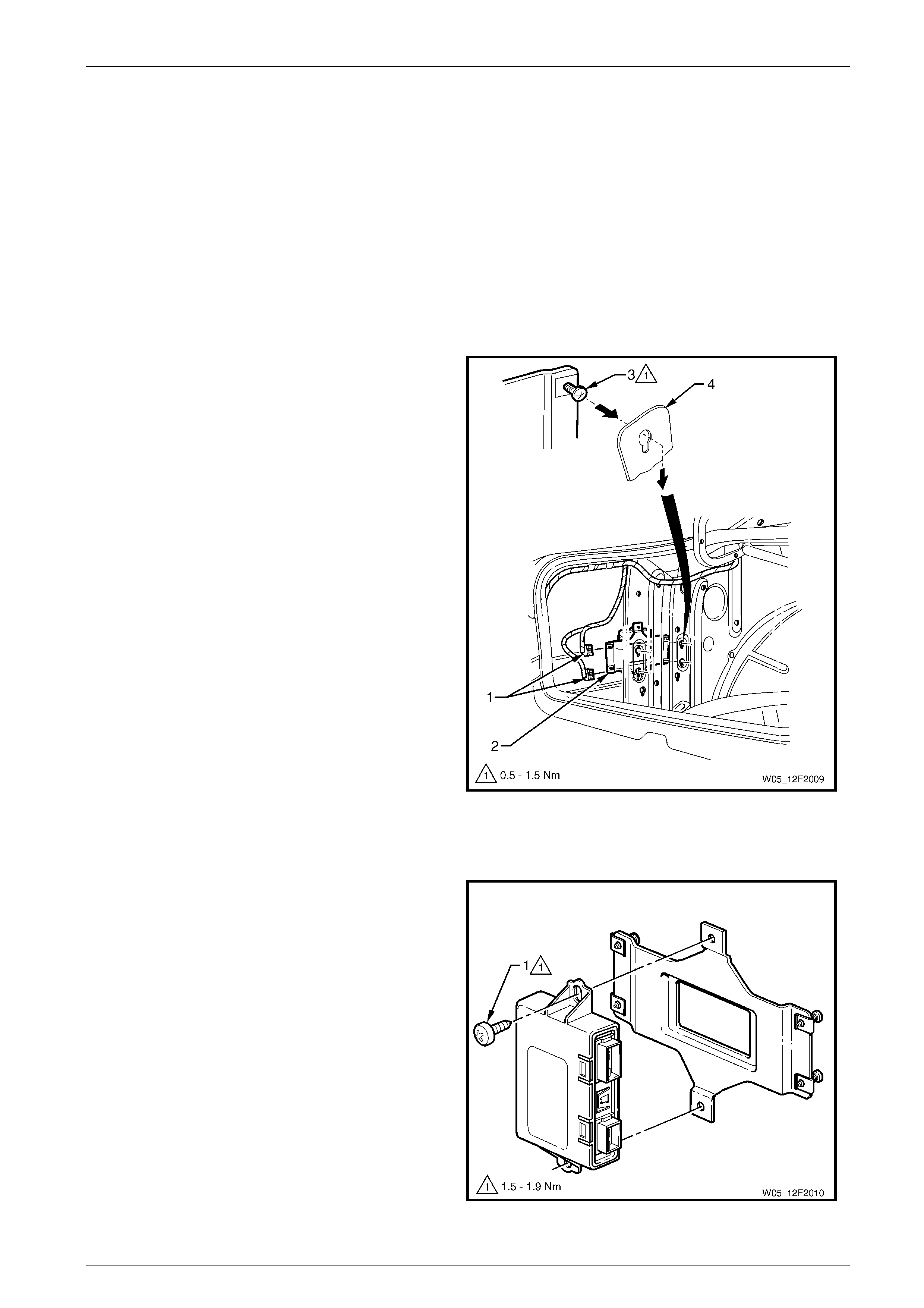
Dual Park Assist Page 12F2–44
4 Service Operations
4.1 Dual Park Assist Control Module
Assembly
LT Section No. —
Remove
1 Working from inside the rear compartment, remove the left-hand side quarter inner rear side carpet, refer to
Section 1A8 Headlining and Interior Trim.
2 Disconnect the wiring connectors (1) from the dual
park assist (DPA) control module assembly (2).
3 Loosen the scre ws (3), two places, and slide the
module upwards to release the screw heads from the
slots in the inner side panel (4).
4 Withdraw the control module assembly from the rear
compartment.
Figure 12F2 – 15
Disassemble
1 Remove the screw (1), two places, securing the DPA
control module to the DPA control module bracket.
Figure 12F2 – 16
Page 12F2–44

Dual Park Assist Page 12F2–45
Reassemble
Reassembly of the dual park assist control module assembly is the reverse of the removal procedure. T ighten the screw
attaching the DPA module assembl y to the correct torque specification.
Dual park assist control module to DPA
control module bracket attaching screw
torque specification..............................................3.5 Nm
Reinstall
Reinstallation of the dual park assist control module assembly is the reverse of the removal procedure. Insert the screw
attaching the DPA control module to the DP A control module bracket and tighten to the correct torque specification.
Dual park assist control module assembly
attaching screw torque specification...........0.5 – 1.5 Nm
Page 12F2–45
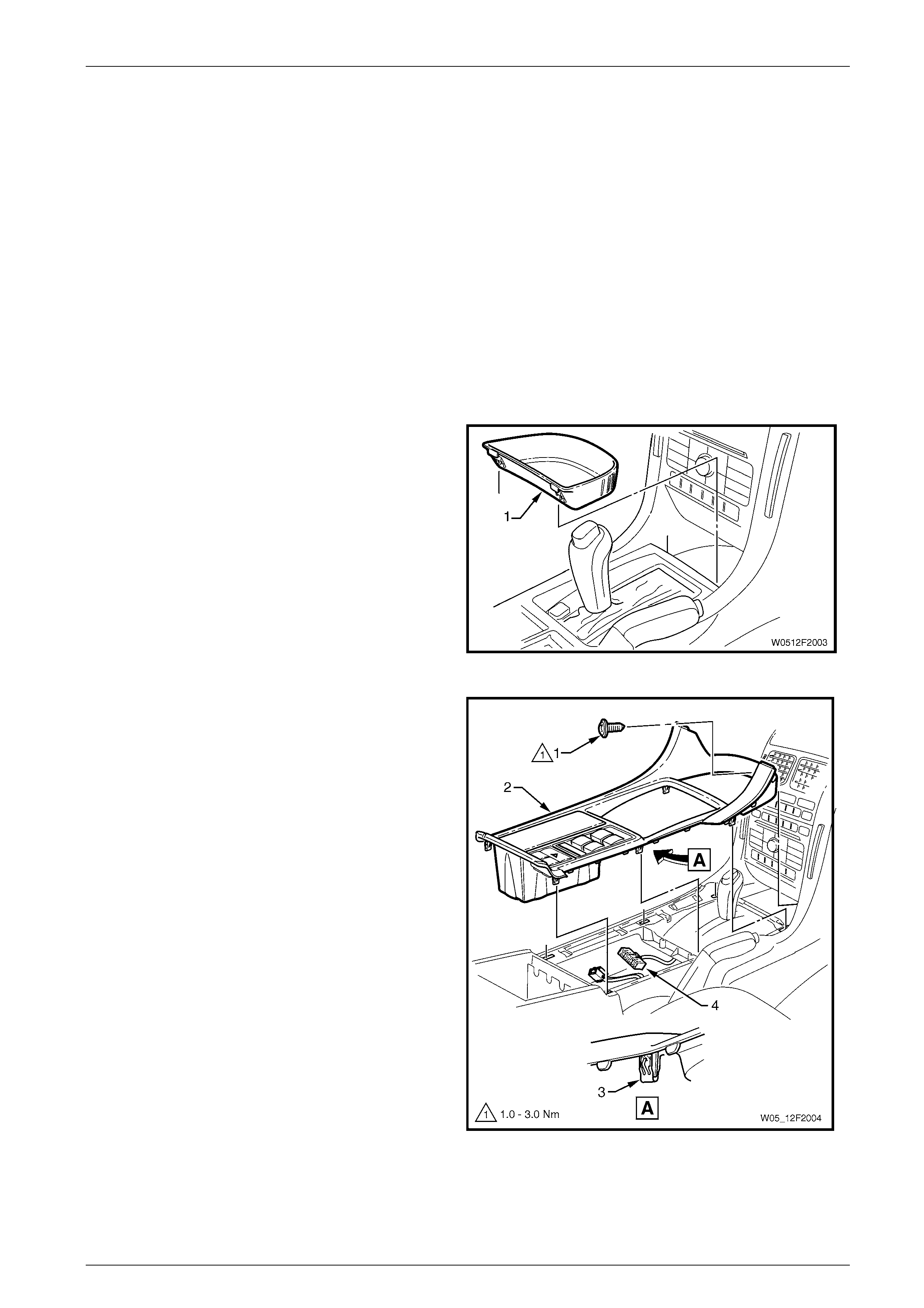
Dual Park Assist Page 12F2–46
4.2 Dual Park Assist Override Switch
Assembly
LT Section No. — XX–XXX
Remove
1 Ensure the ignition s witch is in the OFF position.
2 Remove the fusible link F102, refer to Section 12O Fuses, Relays and Wiring Harnesses.
3 If required, remove the following navigation system equipment:
a Remote control cradle
b Navigation monitor escutcheon
Refer to Section 12L Navigation S ystem .
4 Remove the floor console front compartment liner (1)
by lifting it upwards to disengage the ret aining lugs.
Figure 12F2 – 17
5 Remove the screw (1) attaching the floor console
cover assembly (2).
6 Prise the cover from the floor console assembly in six
places (3).
7 Lift the cover assembly up from the rear and
disconnect the wiring connector (4) from the side
window switch assembly and all the wiring connectors
from the auxiliary switches fitted.
NOTE
Note which wiring connectors are connected to
their relevant switch assembly.
8 Remove the cover assembly.
Figure 12F2 – 18
Page 12F2–46
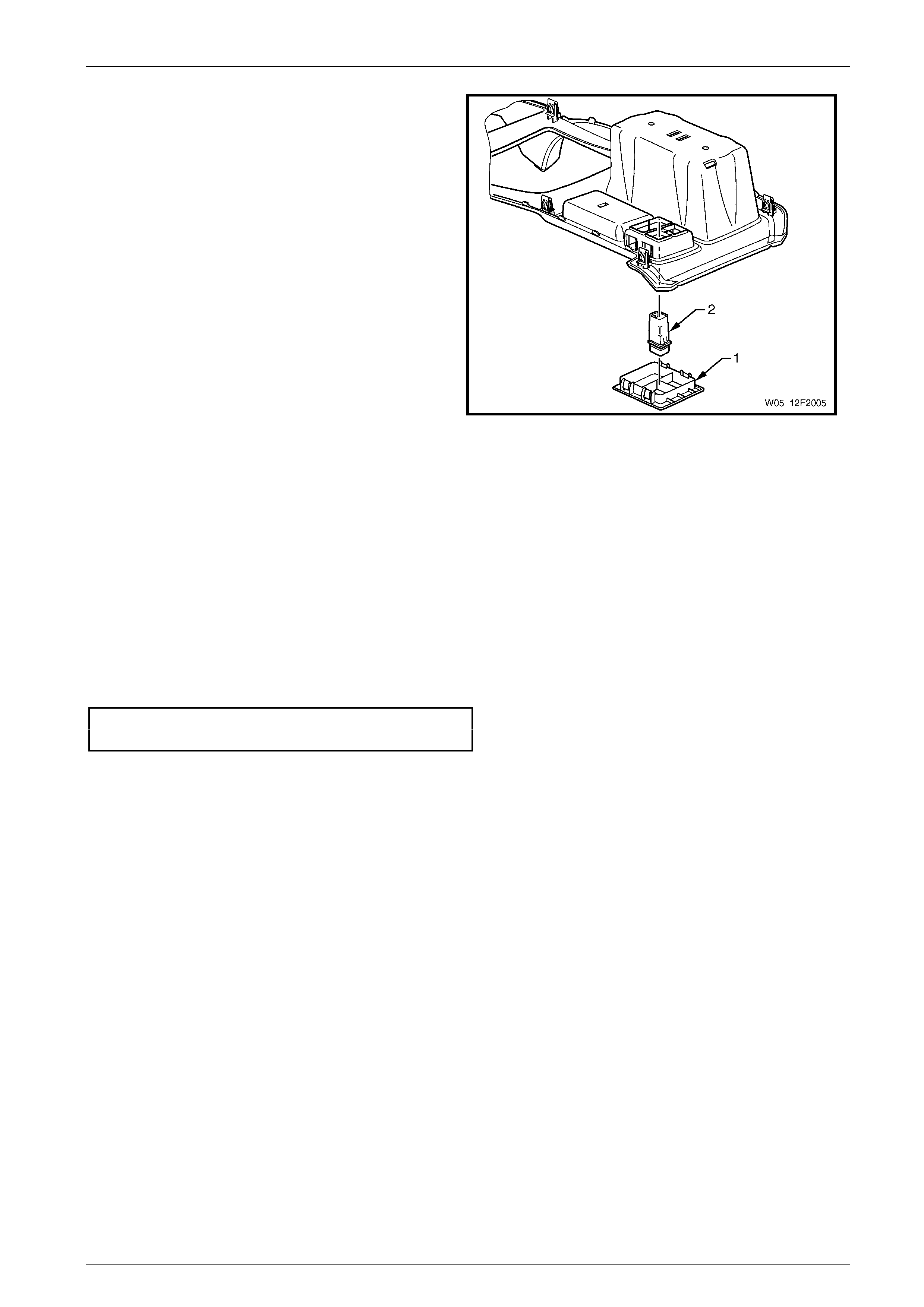
Dual Park Assist Page 12F2–47
9 From the underside of the cover assembly, depress
the four tabs securing the auxiliary switch bezel
assembly (1). Remove the bezel assembly.
NOTE
Record the orientatio n and position of the switch
assembly being removed.
10 As required, depress the two tabs securing the switch
assembly (2) to the console cover assem bl y and
remove the switch.
Figure 12F2 – 19
Reinstall
Reinstallation of the dual park assist override switch assembly is the reverse of the removal procedure, noting the
following:
1 Insert the switch assembly into the switch bezel assembly ensuri ng the position and orientation are correct.
2 Insert the bezel into the cover assembly and ensure that it locks into pl ace securely.
3 Lift the cover assembly onto the front floor console inserting the front of the cover first.
4 Connect all the wiring connectors to the switch assemblies ensuring that each switch is mated to the correct
connector.
5 Insert the screw attaching the floor console cover assembly and tighten to the correct torque specification.
Floor console cover assembly attaching
screw torque specification...........................1.0 – 3.0 Nm
Page 12F2–47
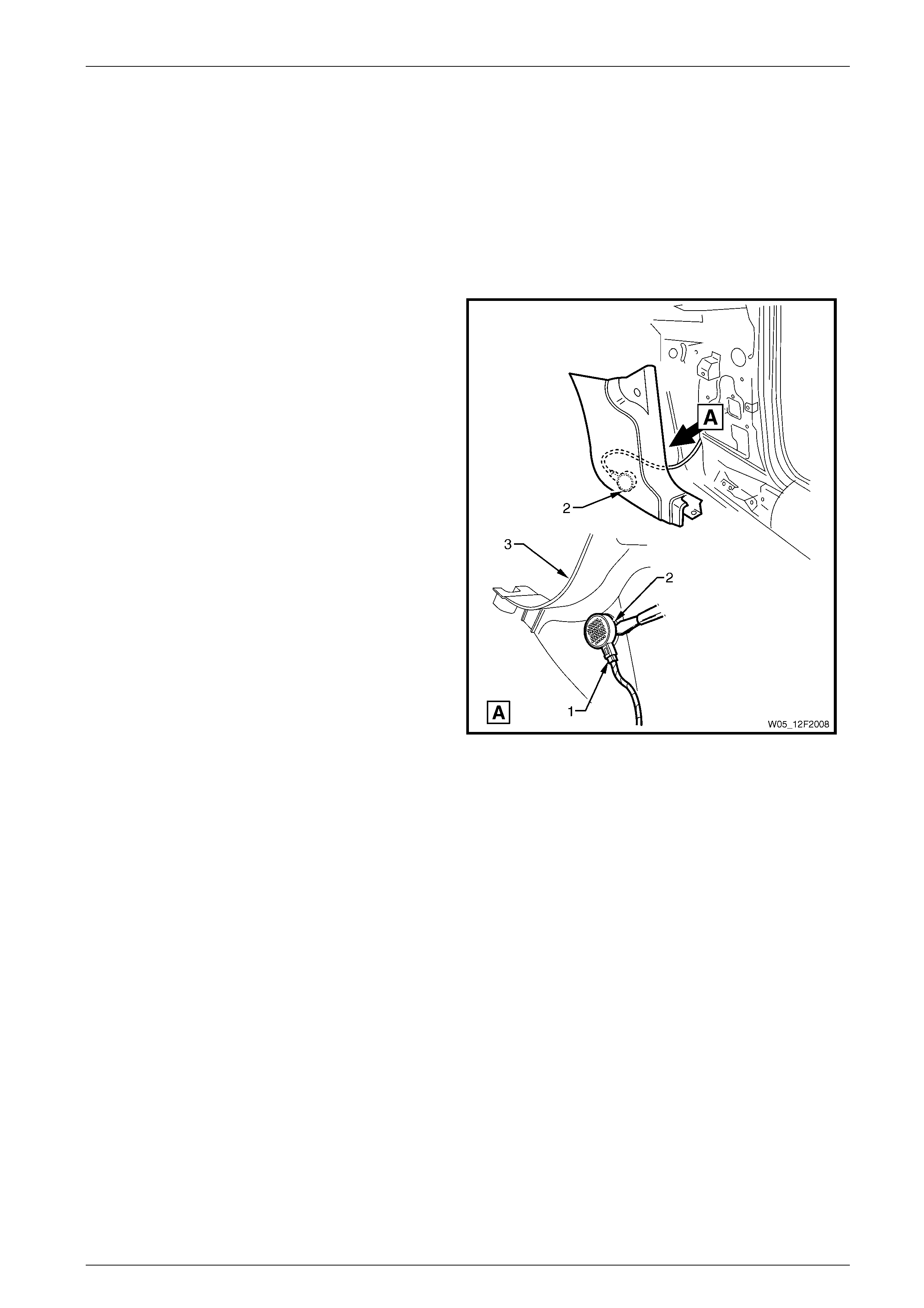
Dual Park Assist Page 12F2–48
4.3 Dual Park Assist Alarm Assemblies
LT Section No. — XX–XXX
Front
Remove
1 Remove the right-hand front body hinge pillar trim assembly, refer to Section 1A8 Headlining and Interior Trim.
2 Disconnect the wiring connector (1) from the dual park
assist (DPA) front alarm assembly (2).
3 Using a knife or paint scraper, carefully prise the DPA
front alarm assembly from the body hinge pillar trim
assembly (3), separating the double-sided tape.
4 Remove the DPA front alarm assembly.
Figure 12F2 – 20
Reinstall
Reinstallation of the dual park assist front alarm assembly is the reverse of the removal procedure, noting the following:
1 If reusing the DPA front alarm, remove any remaining double-sided tape from the body hinge pillar trim and alarm.
Apply new tape such as 3M 4428 or equival ent.
2 Peel off the adhesive backing paper a nd affix the DPA front alarm assembly on to the body hinge pillar trim, ensuring
it is correctly positioned.
Page 12F2–48
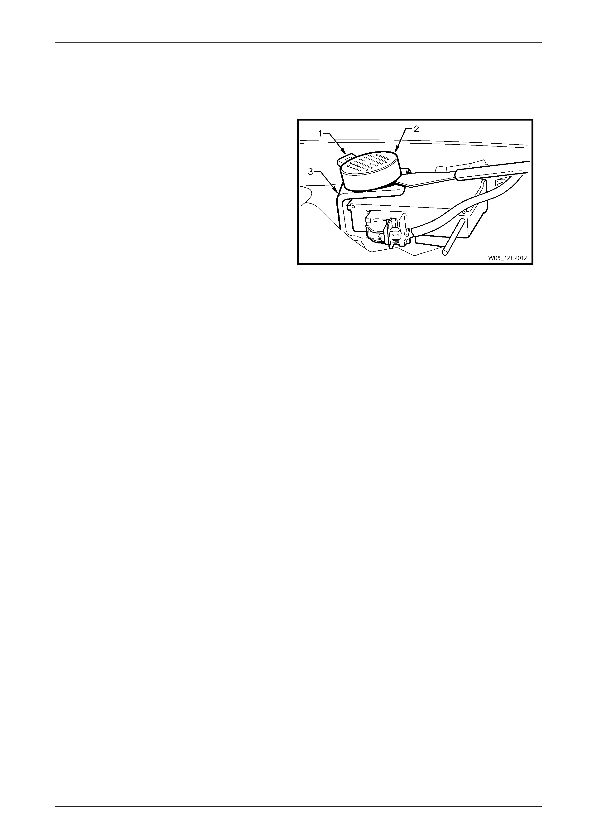
Dual Park Assist Page 12F2–49
Rear
Remove
1 Remove the rear window trim panel assembl y, refer to Section 1A8 Hea dlining and Interior Trim.
2 Disconnect the wiring connector (1) from the dual park
assist (DPA) rear alarm assembly (2).
3 Using a knife or paint scraper, carefully prise the DPA
rear alarm assembly from the tyre pressure monitor
control module bracket (3), separating the double-
sided tape.
4 Remove the DPA rear alarm assembly.
Figure 12F2 – 21
Reinstall
Reinstallation of the dual park assist rear alarm assembly is the reverse of the removal procedure, noting the following:
1 If reusing the DPA rear alarm, remove any remaini ng double-sided tape from the control module and alarm. Apply
new tape such as 3M 4428 or equival ent.
2 Peel off the adhesive backing paper a nd affix the DPA rear alarm assembly on to the tyre pressure monitor control
module bracket, ensuring it is correctly positioned.
Page 12F2–49
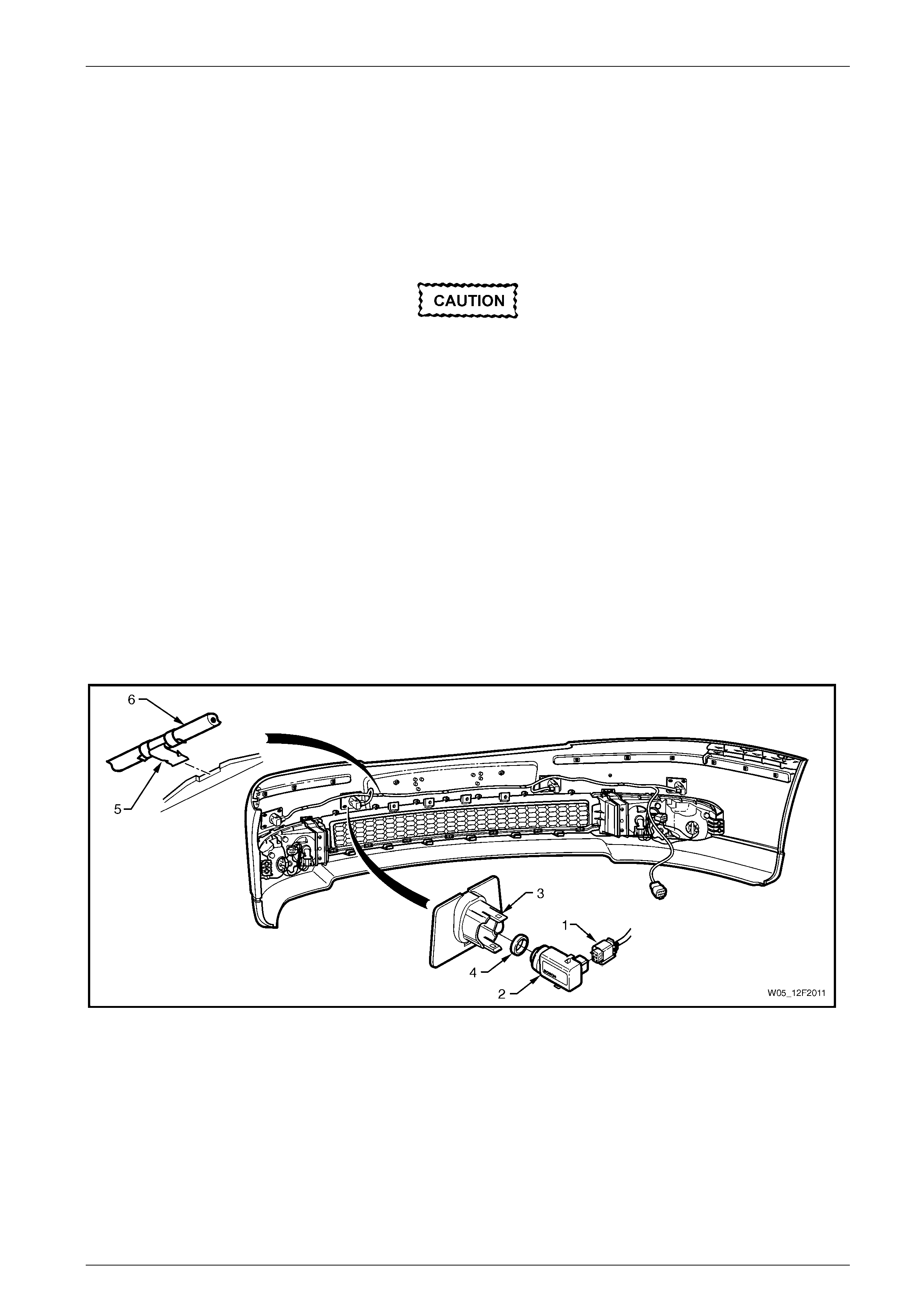
Dual Park Assist Page 12F2–50
4.4 Front Object Sensor Assembly
LT Section No. — XX–XXX
Remove
1 Remove the front bumper fascia assembly, refer to Section 1D Bumper Bars.
Replacement front object sensor assemblies
are supplied pre-painted in the vehicle's body
colour. Do not apply further paint to the front
object sensor assemblies, as it will have a
detrimental effect on the operation of the front
object sensor assemblies.
2 Disconnect the wiring connector (1) from the front object sensor assembly (2), refer to Figure 12F2 – 22.
3 Lift the top and bottom housing tabs (3) and remove the sensor assembly with the front object sensor ring (4) from
the front object sensor housing.
4 If required, remove the sensor ring from the sensor.
NOTE
For removal procedures of the front object sensor
housing assembly, refer to Section 1D Bumper
Bars.
5 If required, remove the wiring harness (6) by prising the clip (5), five places from the bumper fascia rib.
Figure 12F2 – 22
Page 12F2–50

Dual Park Assist Page 12F2–51
Reinstall
The front object sensor ring prevents vibrations
from the front object sensor assembly being
transferred to the surrounding components.
Incorrect fitment will chan ge the characteristics
of the front object sensor assembly.
Reinstallation of the front object sensor assembly is the reverse of the removal procedure, noting the following:
1 Ensure the sensors are correctly installed in the housing with the connector side facing to the centrel in e of the
vehicle.
2 Attach the wiring harness to the upper side of the bumper fascia rib, aligning each clip at the notches.
Page 12F2–51

Dual Park Assist Page 12F2–52
4.5 Rear Object Sensor Assembly
LT Section No. — XX–XXX
Remove
1 Remove the rear bumper fascia assembly, refer to Section 1D Bumper Bars.
Replacement rear object sensor assemb lies are
supplied pre-painted in the vehicle's body
colour. Do not apply further paint to the rear
object sensor assemblies, as it will have a
detrimental effect on the operation of the rear
object sensor assemblies.
2 Disconnect the wiring connector (1) from the rear object sens or assembly (2), refer to Figure 12F2 – 23.
3 Lift the top and bottom housing tabs (3) and remove the sensor assembly with the rear object sensor ring (4) from the
rear object sensor housing.
4 If required, remove the sensor ring from the sensor.
NOTE
For removal procedures of the rear object sensor
housing assembly, refer to Section 1D Bumper
Bars.
5 If required, remove the wiring harness (6) by prising the clip (5), four places, from the bumper fascia rib.
Page 12F2–52
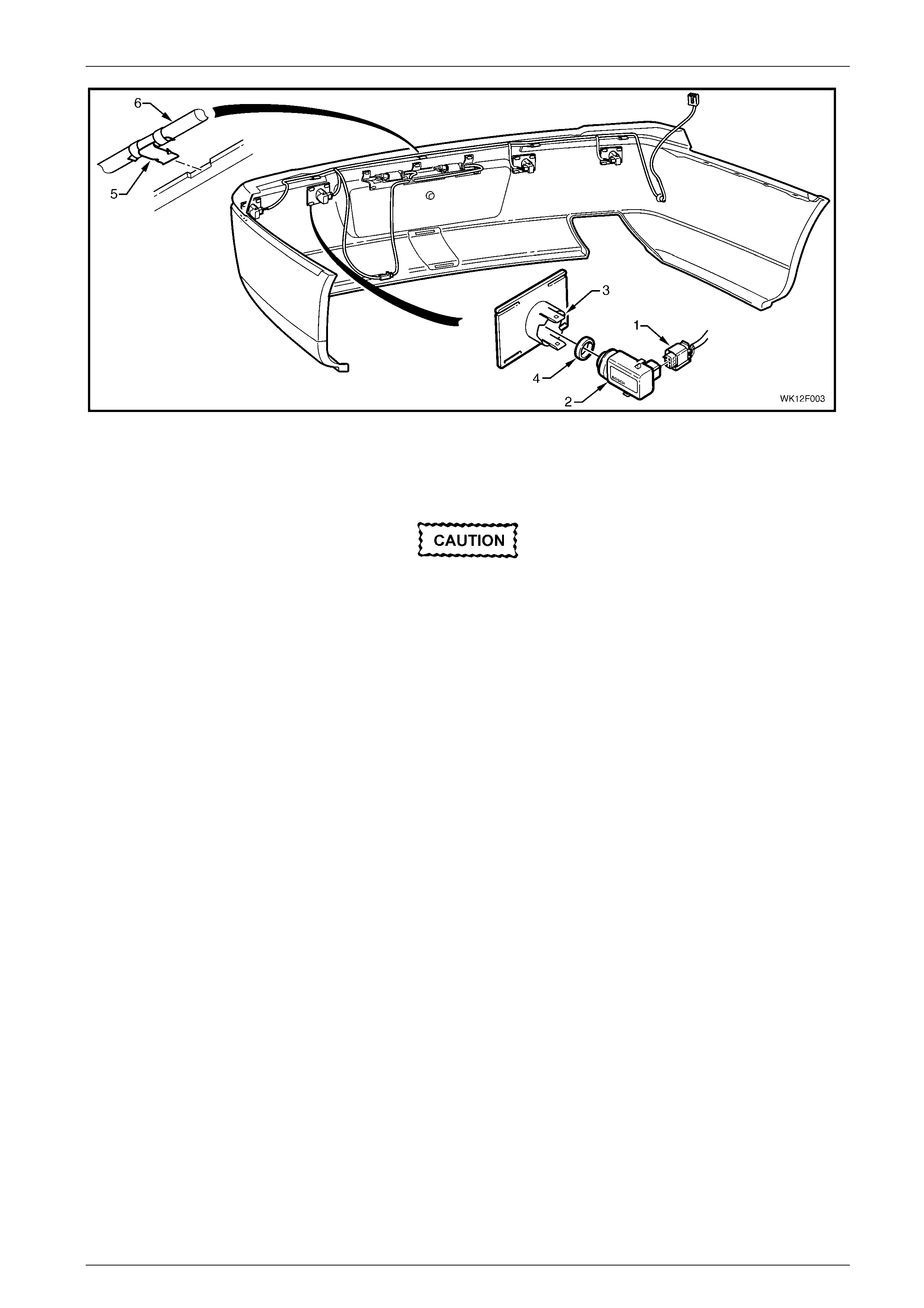
Dual Park Assist Page 12F2–53
Figure 12F2 – 23
Reinstall
The rear object sensor ring prevents vibrations
from the rear object sensor assembly being
transferred to the surrounding components.
Incorrect fitment will chan ge the characteristics
of the rear object sensor a ssembly.
Reinstallation of the rear obje ct sensor assembly is the reverse of the removal procedure, noting the following.
1 Ensure the sensors are correctly installed in the housing with the connector side facing to the centrel in e of the
vehicle.
2 Attach the wiring harness to the upper side of the bumper fascia rib, aligning each clip at the notches.
Page 12F2–53

Dual Park Assist Page 12F2–54
5 Torque Wrench Specifications
Dual Park Assist Control Module to DPA Module Bracket
Attaching Screw .....................................................................................3.5 Nm
Dual Park Assist Control Module Assembly Attaching Screw........0.5 – 1.5 Nm
Floor Console Cover Assembly Attaching Screw..........................1.0 – 3.0 Nm
Page 12F2–54