
Cellular Phone Page 12G–1
Section 12G
Cellular Phone
ATTENTION
Before performing any service operation or other procedure described in this Section, refer to Section 00
Warnings, Cautions and Notes for correct workshop practices with regard to safety and/or property damage.
1 General Information ...............................................................................................................................2
1.1 After-market Hands-free Kit Connection ............................................................................................................. 2
Radio Telephone Mute........................................................................................................................................... 2
Radio Telephone Input..........................................................................................................................................2
1.2 Antenna Coupling Box and Lead.......................................................................................................................... 3
2 Service Operations.................................................................................................................................4
2.1 Cellular Phone Connector..................................................................................................................................... 4
2.2 Wiring Diagram ...................................................................................................................................................... 6
Without Telematics................................................................................................................................................ 6
With Telematics...................................................................................................................................................... 7
2.3 Connector Chart..................................................................................................................................................... 8
2.4 Cellular Phone Antenna Coupling Box Assembly .............................................................................................. 9
Remove................................................................................................................................................................... 9
Reinstall.................................................................................................................................................................. 9
2.5 Cellular Phone Antenna Lead............................................................................................................................. 10
3 Torque Wrench Specifications............................................................................................................11
Page 12G–1

Cellular Phone Page 12G–2
1 General Information
This Section describes the following cellular phone components:
• After-market hands-free kit connection to the vehicle wiring harness.
• Antenna coupling box assembly and antenna lead.
1.1 After-market Hands-free Kit Connection
A cellular phone wiring connector is taped b ack to the front bod y wiring harness and is located at the front of the centre
console on the passenger-side. To access the connector, removal of the left-hand instrument panel l ower extension side
panel is required, which is describe d in this Section. A connection kit is available through an authoris ed dealer.
The connector provides constant and accessory position battery power outputs and ground connection for the cellu lar
phone. It also provides the following connections that interface with the entertainment system when a telephone hands-
free kit with the appropriate functions is connected.
Radio Telephone Mute
Whenever a call is made or receive d, the entertainment system will display VOICE IN and the volume of the radio will be
muted or the CD will be paused. A suitable hands-free cellular phone kit with a mute outpu t function is required to be
connected to pin X1_4 (mute) of the cellular p hone connector.
Radio Telephone Input
This function allows the audio from a suitable hands-free cellular telephone kit to be reproduced through the vehicle’s
speakers. A suitable hands-free cellul ar phone kit with mute output and external speake r functions is required and is
connected to pins X1_4 (mute), X1_5 (voice signal) and X1_6 (voice return) of the cellular phone connector.
The phone input has independent volume and tone from the normal audio sources. The volume, bass, treble, fader an d
balance can be adjusted to suit the particular phone / preference whenever VOICE IN is displaye d on the entertainment
system. These settings will then be used whenever the phone input is activated, and does not interfere with the settings
for radio or CD playback.
With both functions, the entertainment system returns to the previous playing mode and audio settings when the call
ends.
NOTE
Before connecting a cellul ar phone hands-free kit
to the vehicle, refer to the relevant installation or
operators manual(s) for the correct installation
procedures.
Page 12G–2

Cellular Phone Page 12G–3
1.2 Antenna Coupling Box and Lead
An antenna coupling box assembly and antenna lead for the cellular phone are installed ready for the installation of a
cellular phone. The coiled-u p antenna lead is located on the back of the left-hand instrument panel lower trim plate
assembly.
An antenna mast and base assembly are supplied as a kit with the vehicle, together with installation instructions.
Page 12G–3
Cellular Phone Page 12G–4
2 Service Operations
NOTE
For diagnosis procedures for the cellular
phone connection circuits refer to Section 12D
Entertainment System.
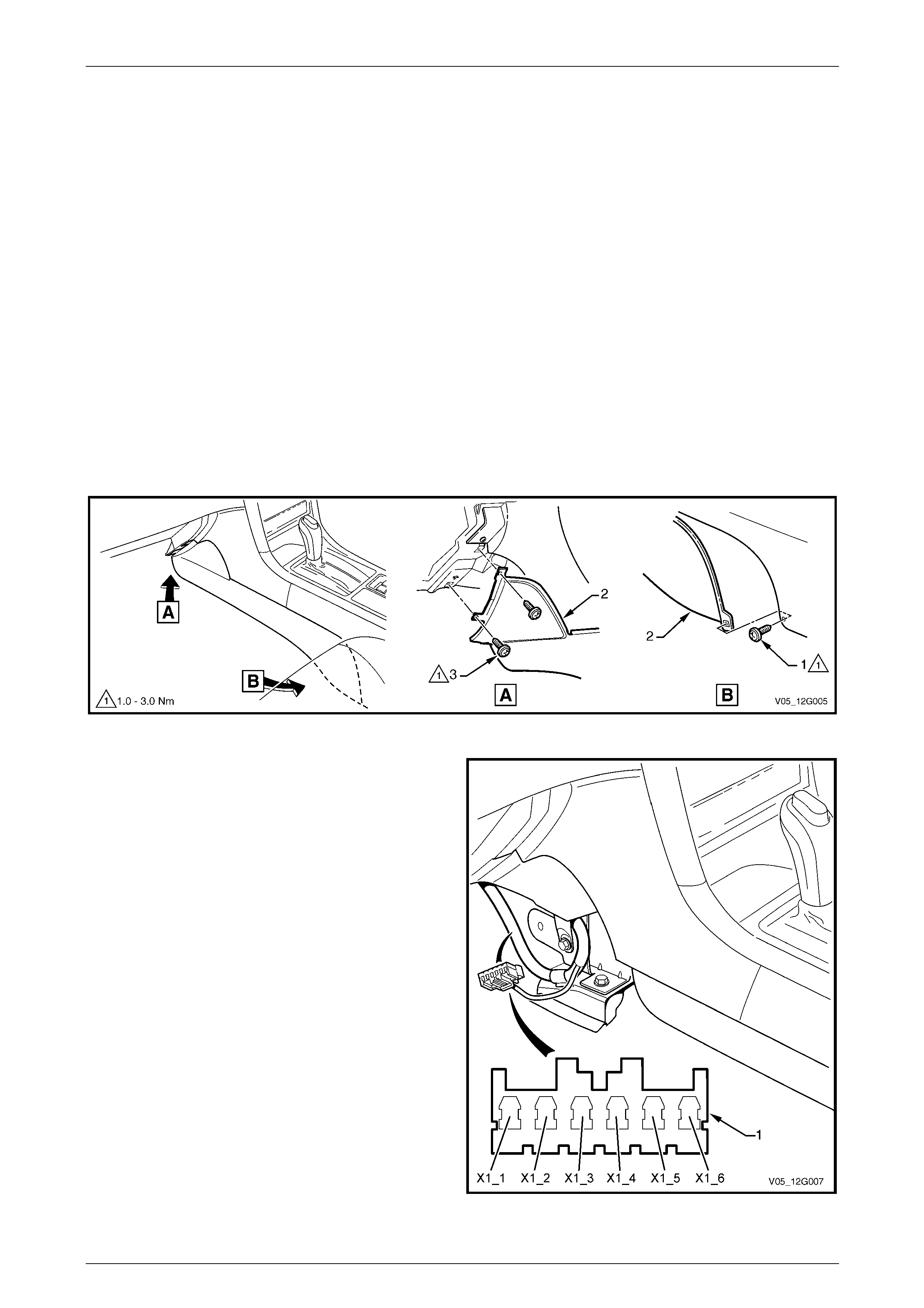
2.1 Cellular Phone Connector
1 To access the cellular phone connector, perform the following:
a Move the front passenger seat to its most rearward position.
b Remove the instrument panel compartment, refer to Section 1A3 Instrumen t Panel and Console.
c Remove the screw (1) attaching the left-hand instrument panel lower extension side trim (2) to the floor
console.
d Remove the two screws (3) attaching the sid e trim to the instrument pan el.
e Remove the side trim.
Figure 12G – 1
2 Locate the front body wiring harness where it is
clipped to the cockpit module mounti ng bracket. The
cellular phone connector (1) is taped back to the
harness across the retaining clip.
3 Remove the tape to access the connector.
4 As required, connect the cellul ar phone hands-free
kit to the applicable terminals. Also refer to
2.2 Wiring Diagram and 2.3 Connector Ch art.
• X1_1 Battery voltage supply
• X1_2 Vehicle ground
• X1_3 Ignition accessory position volt age supply
• X1_4 Radio mute input
• X1_5 Voice signal
• X1_6 Voice return
5 Securely tape back the cellular phone connector and
additional wiring as required.
6 Reinstall the removed compo nents following the
reverse of the removal procedure.
Figure 12G – 2
Page 12G–4

Cellular Phone Page 12G–5
7 Tighten the Instrument panel lower extension
side trim panel screws to the correct torque specification.
Instrument panel lower extension
side trim panel attaching screw
torque specification.....................................1.0 – 3.0 Nm
Page 12G–5
Cellular Phone Page 12G–6
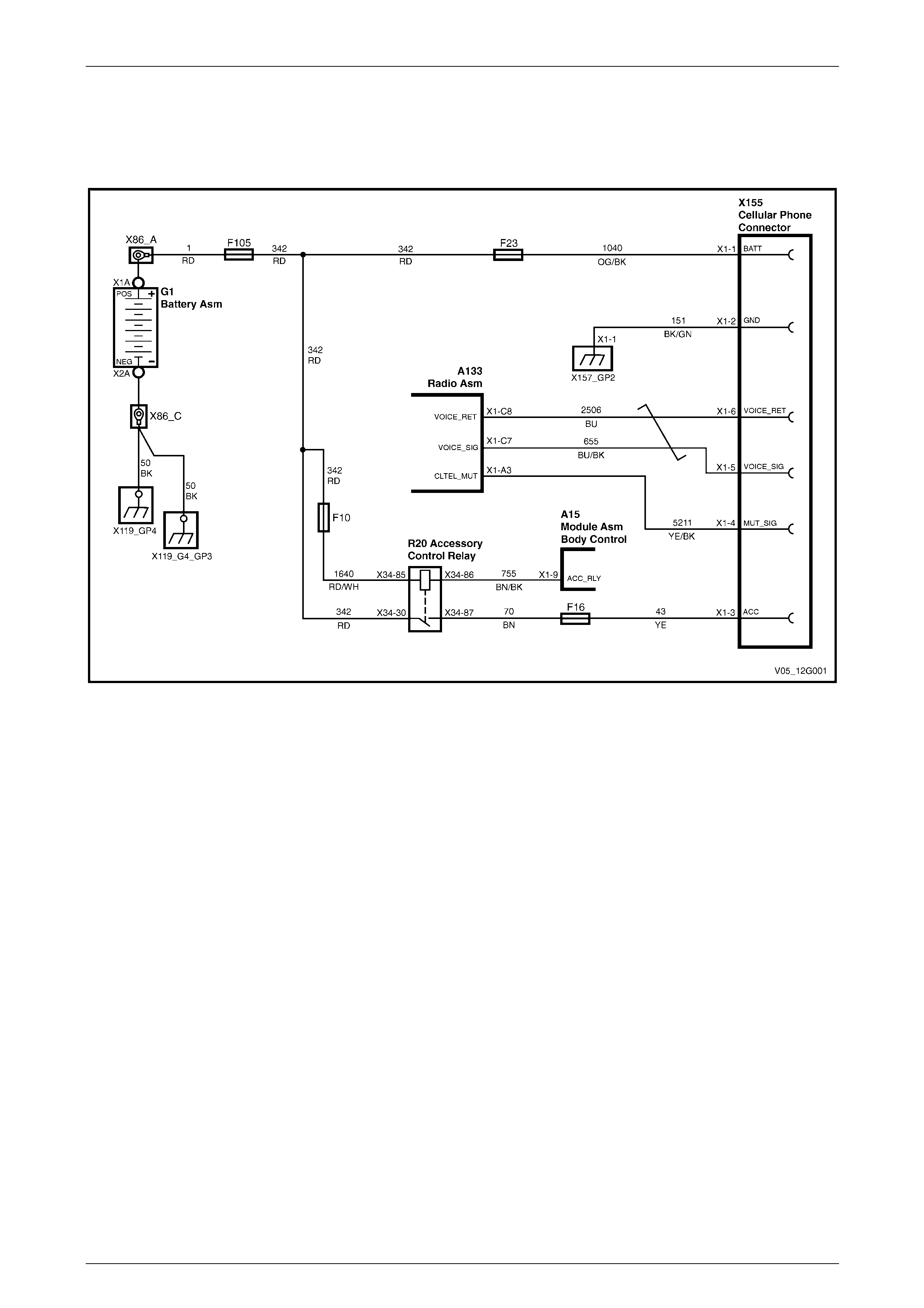
2.2 Wiring Diagram
Without Telematics
Figure 12G – 3
Page 12G–6
Cellular Phone Page 12G–7
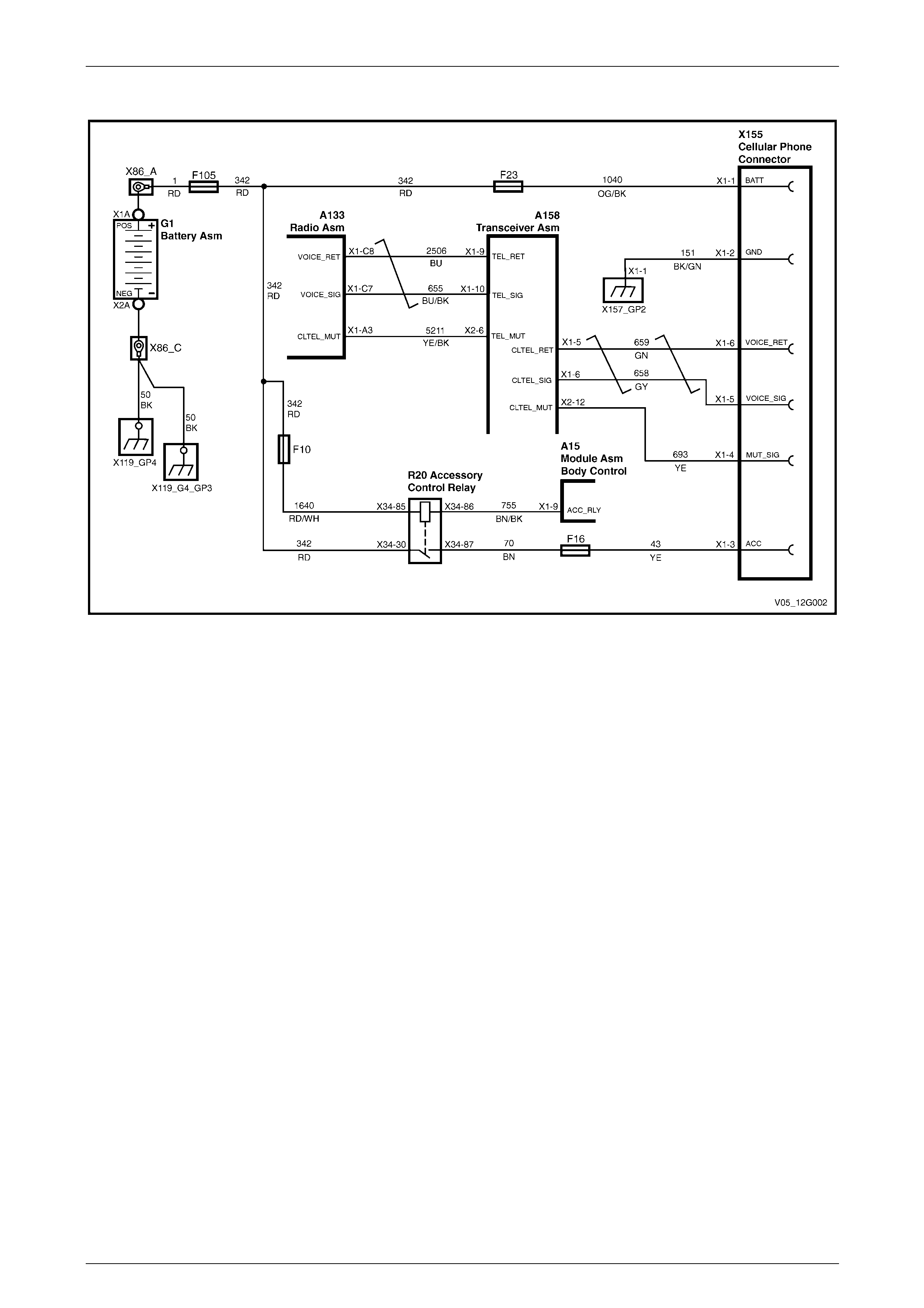
With Telematics
Figure 12G – 4
Page 12G–7
Cellular Phone Page 12G–8
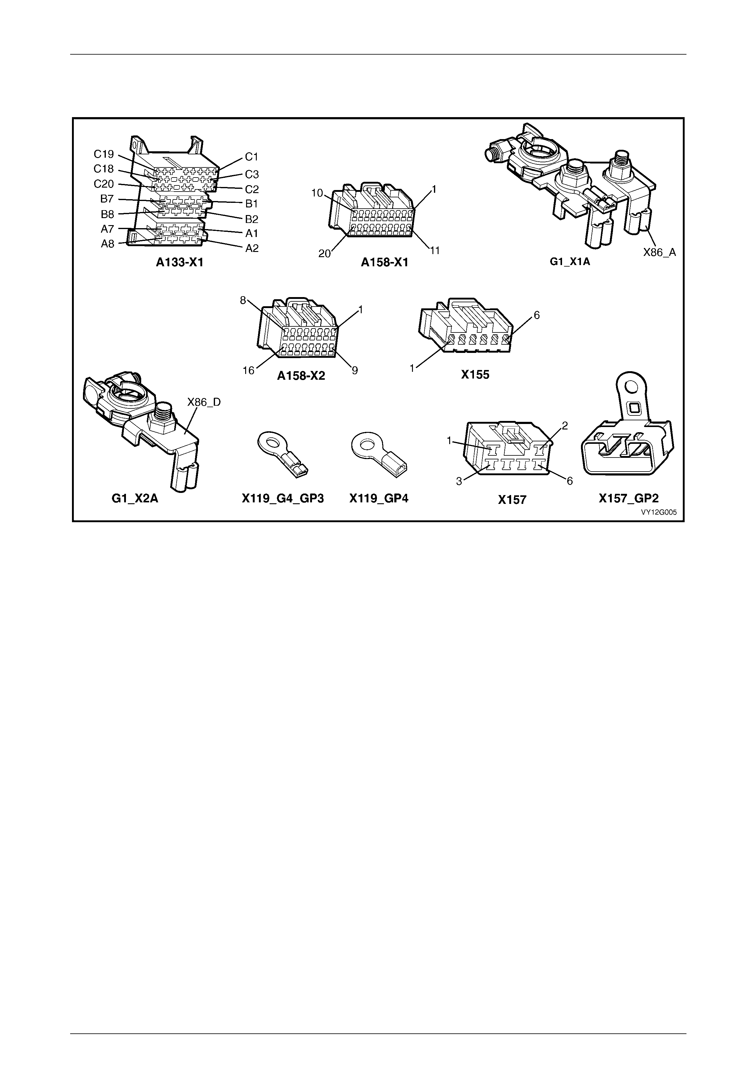
2.3 Connector Chart
Figure 12G – 5
Page 12G–8
Cellular Phone Page 12G–9
2.4 Cellular Phone Antenna Coupling Box
Assembly
NOTE
Due to the special adhesive t hat is used to attach
the coupling box assembly to the rear window
glass, if the box is removed it must be replac ed.
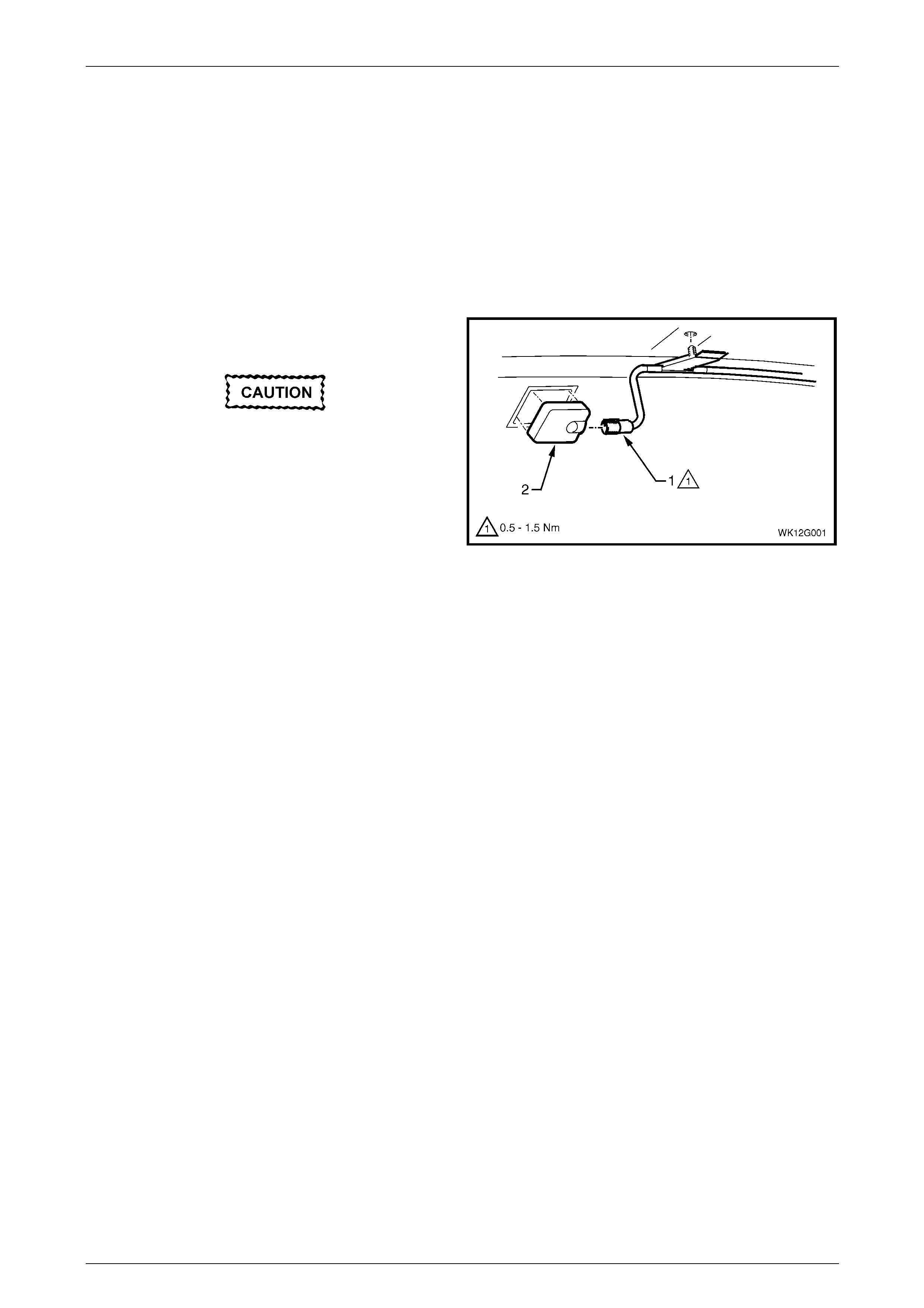
Remove
1 Unscrew the cellular phone antenna lead (1) from the
coupling box assembl y (2).
Take care if using a metallic instrument to
remove the coupling box assembly as
damage to the window may result.
2 Carefully prise the coupling box assembly from the
centre of the rear window. If required, use a flat-bladed
instrument, e.g. spatula or scraper.
3 Discard the coupling box.
4 Remove any residue ad hesive material from the
window.
Figure 12G – 6
Reinstall
1 Clean the window coupling b ox attaching area using isopropyl alcohol and ensure that all adhesive residue is
removed.
2 Remove the backing from the new coupling box adhesive.
3 Align the coupling box with the guide marks on the window, ensur ing that the cable connector is positioned to the
left-hand side of the vehicle
4 Press the coupling box firml y into position on the window.
5 Connect the cellular phone antenna lead and hand tighten the connector screw securely.
Page 12G–9
Cellular Phone Page 12G–10
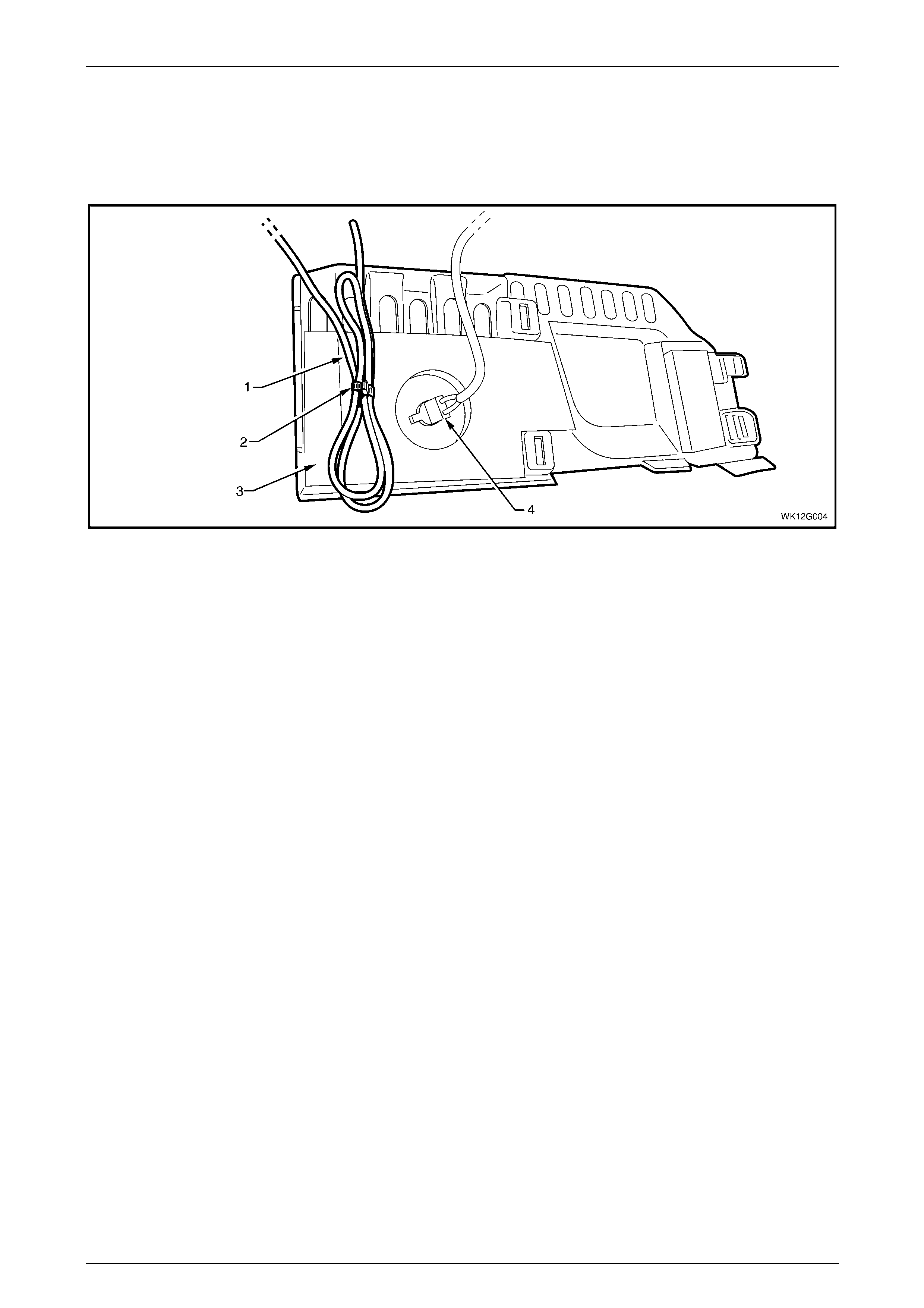
2.5 Cellular Phone Antenna Lead
The cellular phone antenna lead is connected to the coupling bo x assembly and is routed along the left-hand side of the
vehicle to the instrument panel. T he end of the lead (1) is coiled-up and a retaining clip (2) secures it to the back of the
left-hand instrument panel lower trim plate assembly (3), refer to Figure 12G – 7.
Figure 12G – 7
Legend
1 Cellular Phone Antenna Lead
2 Retaining Clip 3 Left Instrument Panel Lower Trim Plate Assembly
4 Stepwell Lamp
For further information on the routing of the cellular pho ne antenna lead refer to Section 12O Fuses, Relays and Wiring
Harnesses.
If access is required to the cellular phone antenna lead end when installing a cellular phone, remove the instrument
panel lower trim plate assembly, refer to Section 1A3 Instrument Panel a nd Console.
To access the complete lead, in addition to the previous step, remove the following left-hand trim components referring to
1A8 Headlining and Interior Trim:
• side sill trim assembly,
• body hinge pillar trim assembly,
• body lock pillar garnish,
• body lock pillar lower trim assembly,
• rear window trim panel, and
• lower the rear of the headlining assembly.
Page 12G–10

Cellular Phone Page 12G–11
3 Torque Wrench Specifications
Instrument Panel Lower Extension Side Trim Panel
Attaching Screw ............................................................................1.0 – 3.0 Nm
Page 12G–11