
Rear-view Mirrors Page 12H-1
Section 12H
Rear-view Mirrors
ATTENTION
Before performing any service operation or other procedure described in this Section, refer to Section 00
Warnings, Cautions and Notes for correct workshop practices with regard to safety and/or property damage.
1 General Information ...............................................................................................................................3
1.1 Interior Rear-view Mirror .......................................................................................................................................3
Manual Day/Night Adjustment.............................................................................................................................. 3
Electro-chromatic Day/Night Adjustment............................................................................................................ 3
Telematics .............................................................................................................................................................. 3
1.2 Exterior Rear-view Mirrors.................................................................................................................................... 4
Memory and Heated Exterior Rear-vie w Mirrors................................................................................................. 4
2 Diagnostics, Electro-chromatic Interior Rear-v iew Mirror .................................................................5
2.1 Prerequisites.......................................................................................................................................................... 5
Equipment .............................................................................................................................................................. 5
Testing Procedures ............................................................................................................................................... 5
2.2 Electro-chromatic Interior Rear-view Mirror, Diagnostic Procedure s............................................................... 6
Introduction............................................................................................................................................................ 6
Test Description..................................................................................................................................................... 6
Diagnostic Table Notes ......................................................................................................................................... 6
Diagnostic Table....................................................................................................................................................6
2.3 Wiring Diagram: V6................................................................................................................................................ 8
2.4 Wiring Diagram: V8................................................................................................................................................ 9
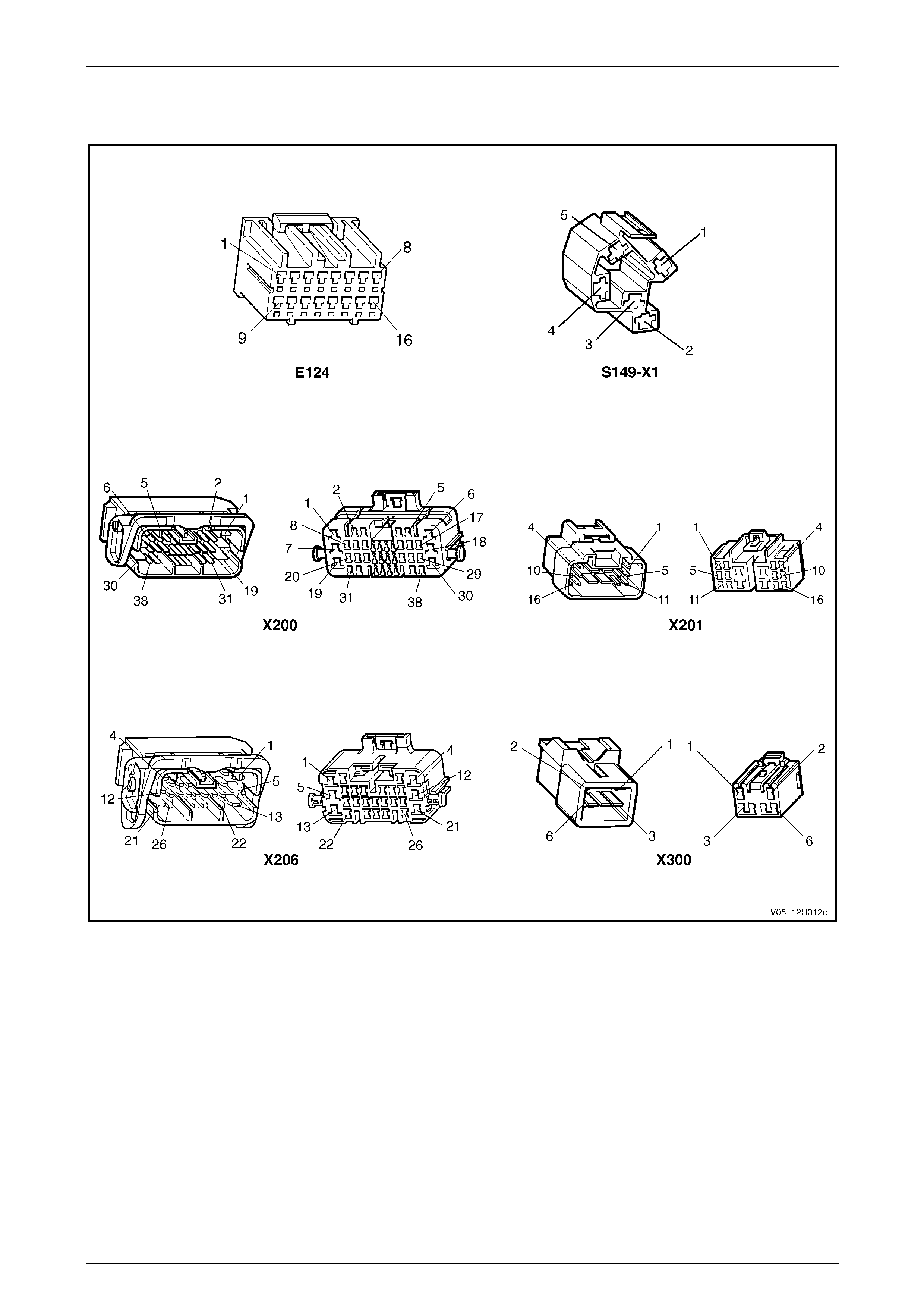
2.5 Connector Chart................................................................................................................................................... 10
2.6 Electro-chromatic Interior Rear-view Mirror, Functional Check...................................................................... 11
3 Diagnostics, Exterior Rear-view Mirror..............................................................................................12
3.1 Prerequisites........................................................................................................................................................ 12
Equipment ............................................................................................................................................................ 12
Testing Procedures ............................................................................................................................................. 12
3.2 Exterior Rear-view Mirror, Diagnostic Procedures........................................................................................... 13
Introduction.......................................................................................................................................................... 13
Test Description................................................................................................................................................... 13
Diagnostic Table Notes ....................................................................................................................................... 13
Diagnostic Table.................................................................................................................................................. 13
3.3 Wiring Diagram .................................................................................................................................................... 15
3.4 Connector Chart................................................................................................................................................... 16
3.5 Mirror Control Switch, Functional Check .......................................................................................................... 17
3.6 Exterior Rear-view Mirror Assembly, Functional Check .................................................................................. 18
3.7 Heated Mirror Glass, Functional Check............................................................................................................. 19
4 Service Operations – Interior Rear-view Mirror.................................................................................20
4.1 Interior Rear-view Mirror, Except Telematics.................................................................................................... 20
Remove................................................................................................................................................................. 20
Reinstall................................................................................................................................................................ 20
4.2 Interior Rear-view Mirror, Telematics................................................................................................................. 21
Remove................................................................................................................................................................. 21
Reinstall................................................................................................................................................................ 21
Page 1A6-1

Rear-view Mirrors Page 12H-2
5 Service Operations – Exterior Rear-view Mirror ...............................................................................22
5.1 Exterior Mirror Glass ........................................................................................................................................... 22
Remove................................................................................................................................................................. 22
Reinstall................................................................................................................................................................ 23
5.2 Exterior Rear-view Mirror Assembly.................................................................................................................. 24
Remove................................................................................................................................................................. 24
Reinstall................................................................................................................................................................ 25
5.3 Mirror Control Switch.......................................................................................................................................... 26
Remove................................................................................................................................................................. 26
Reinstall................................................................................................................................................................ 26
6 Special Tools ........................................................................................................................................27
7 Torque Wrench Specifications............................................................................................................28
Page 1A6-2
Rear-view Mirrors Page 12H-3
1 General Information
This Section describes the operation, dia gnosis and service operations for the internal rear-view mirror and electrically
adjustable exterior rear-view mirrors.
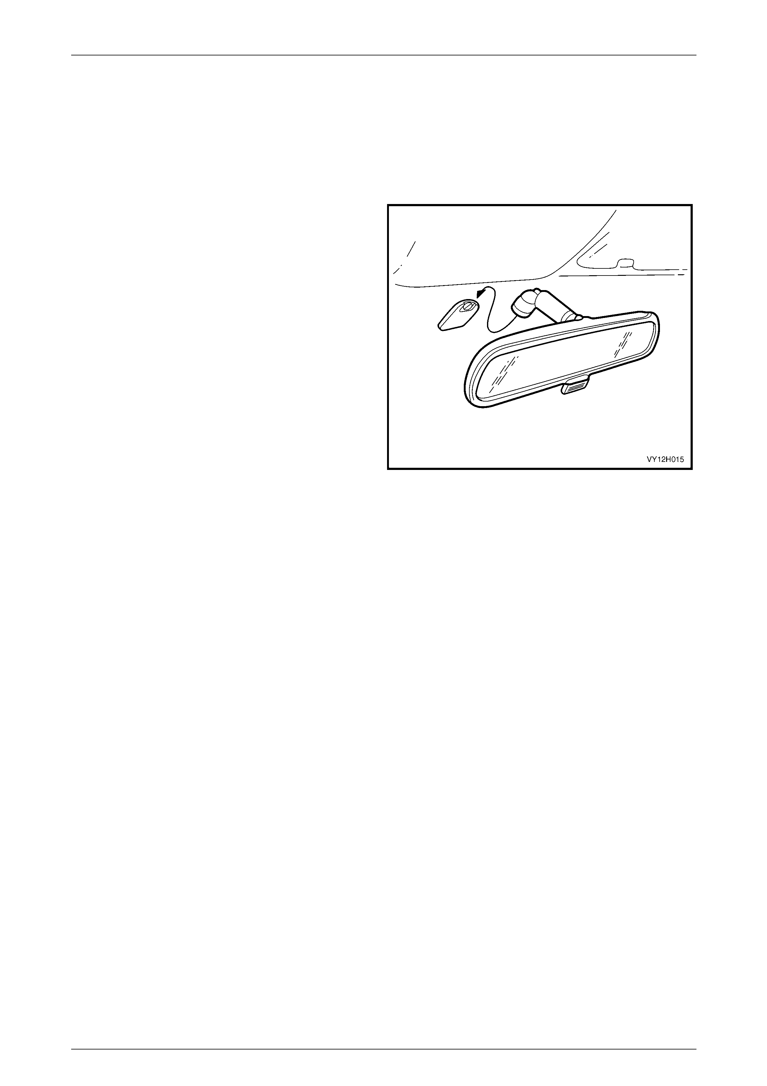
1.1 Interior Rear-view Mirror
The interior rear-view mirror is mounted on a boss which is
attached the centre of the windscreen. The boss is part of
the windscreen assembly. Two types of interior rear-view
mirror are available depending on the model level and/or
options fitted. These are:
• Manual day/night adjustme nt or,
• electro-chromatic day/night adjustment with
Telematics controls.
Figure 12H – 1
Manual Day/Night Adjustment
To reduce the glare of light reflected from following vehicles at night, the lever at the base of the mirror can be pull ed
rearward to tilt the mirror. This enables rear vision to be maintained, but reduces the glare.
The lever should be reset to the forward position for daytime driving.
Electro-chromatic Day/Night Adjustment
The electro-chromatic interior rear-view mirror incorporates an electronically controlled mirror cell that darkens in
response to an applied electrical voltage. The mirror incorporates two light sensors.
An ambient light sensor is located on the forward facing side of the mirror and is used to automatically activate the
system when ambient light levels fall below a predetermined level. The second l ight se nsor is mounted on the rearward
facing side of the mirror and is used to detect light from the headlights of a following vehicle.
A two position switch is located near the base of the mirror which allows the system to be set to an AUTO or OFF
position.
When off, the mirror will only operate as a single function mirror (daytime only). When switched to the AUTO position, the
mirror will function in daytime mode until the ambient light falls below the predetermined level. When light from a
following vehicle is detected, the mirror will automatically change colour, re ducing the glare.
If at anytime while in auto mode reverse ge ar is selected, the mirror will remain in, or revert to the daytime mode.
Telematics
Vehicles fitted with the Telematics option are also fitted with an electro-chromatic interior rear-view mirror. In addition the
mirror includes some features and contro ls of the Telematics system. For further information on Telematics, refer to
Section 12K Telematics.
Page 1A6-3
Rear-view Mirrors Page 12H-4
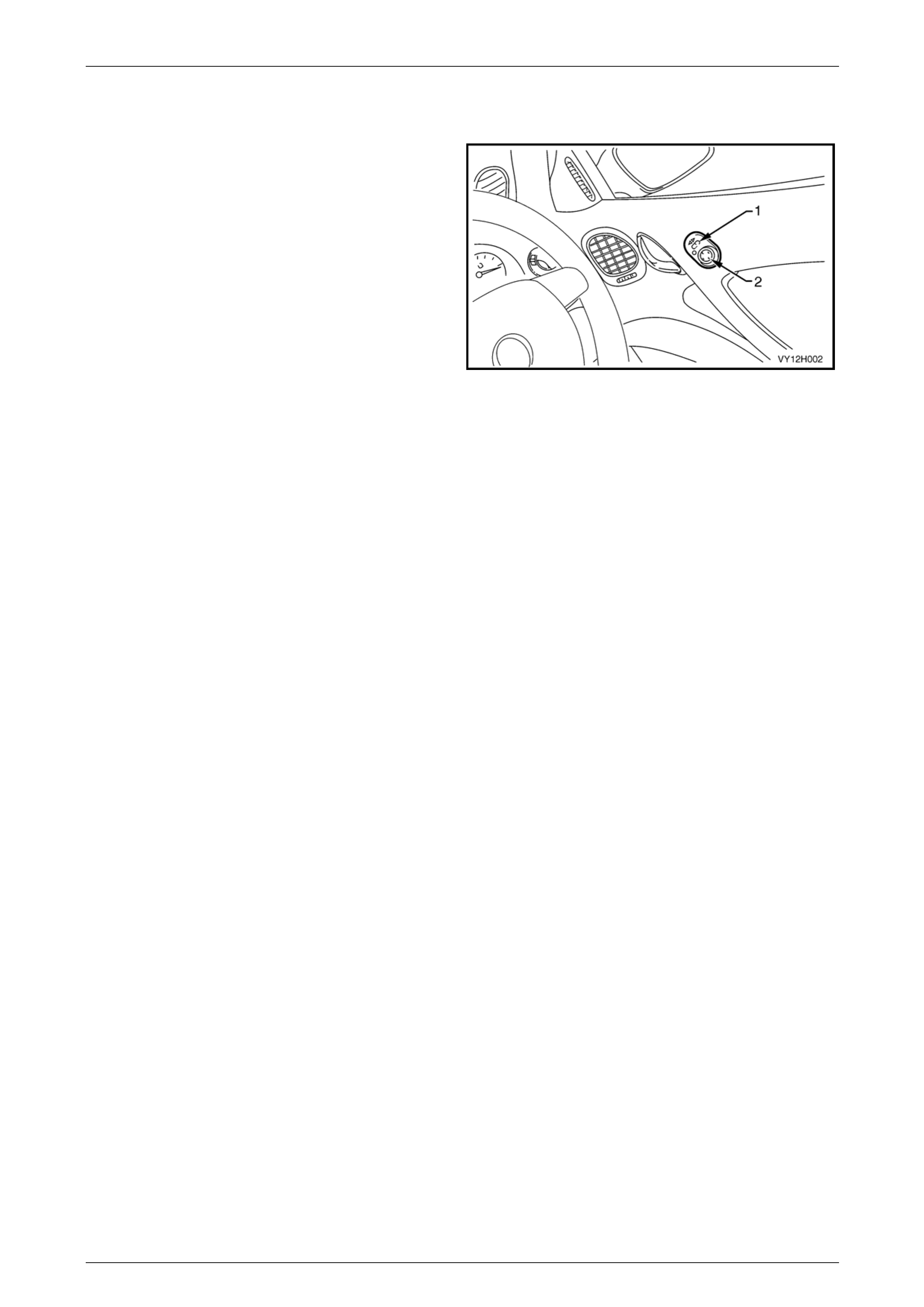
1.2 Exterior Rear-view Mirrors
The exterior rear-view mirrors are electrically controlled by
an adjustment switch fitted to the driver’s door trim. The
switch has two controls:
• side select switch (1) for operating the re quired mirror,
and
• directional toggle s witch (2) for adjusting the mirror
glass position.
Two reversible electric motors are fitted within each mirror
housing, one operating vertical movement and the other
horizontal movement.
Figure 12H – 2
The exterior rear-view mirror hous ings are colour coded complete ly body colour. Replac ement exterior rear-view mirror
assemblies are supplied all black. As required, the complet e mirror bod y will require painting. Mask off the required
sections and follow the correct refinishing techniques for acrylate styrene acrylonitrile (ASA) plastic.
Memory and Heated Exterior Rear-view Mirrors
Vehicles fitted with front seats that include a position memor y function als o include position memory of the exterior rear-
view mirrors. This is part of the priority key function and is controlled by an exteri or rear-v iew mirror module fitted to the
driver’s front door inner panel and the seat memory module.
This provides the ability for the driver’s seat and rear-view mirror positions to be stored for several different drivers and
recalled at the press of the remote key or memory button o n the side of the driver’s seat. Also on these vehicles, when
reverse gear is selected the passenger side mirror automatically dips to aid parking manoeuvres.
The exterior rear-vie w mirrors also incorporate a heating element within the mirror glass. W hen the rear window demister
is operational, the mirror heating element also operates.
For further information on the operation and electrical diagnostic informati on for the memory and heated exterior rear-
view mirrors, refer to Section 1A7 Seat Assemblies.
For information relating to the replacement of the heated mir ror glass refer to 5.1 Exterior Mirror Glass.
Page 1A6-4

Rear-view Mirrors Page 12H-5
2 Diagnostics, Electro-chromatic
Interior Rear-view Mirror
2.1 Prerequisites
Equipment
The following equipment is required to diagnose the electro-chromatic function of the interior rear-view mirror:
• an unpowered test lamp with a current dra w of less than 3 A,
• a digital multimeter with a minimum impe dance of 10 MΩ, refer to Section 12P Wiring Diagrams,
• connector adapter kit, special tool No. KM–609.
Testing Procedures
The following points must be adhered to
when performing diagnostic testing on
components:
• Take care when using testing equipment
to diagnose wiring harness connectors. It
is preferred the technician backprobe the
connector to avoid terminal damage.
• When tests are required on connector
terminals, use the adapters in the
connector adapter kit KM-609 to prevent
damage to the terminals.
• Unless the multimeter being used has an
auto-ranging function, ensure the correct
range is selected.
• When backpro bing connectors, ensure the
test lamp ground lead is connected to an
appropriate ground point on the vehicle.
Ensure this ground point is not part of the
circuit being tested.
Page 1A6-5

Rear-view Mirrors Page 12H-6
2.2 Electro-chromatic Interior Rear-view
Mirror, Diagnostic Procedures
Introduction
This test is used to aid in diagnosing faults in the electro-chromatic function of the interior rear-view mirror.
Test Description
The following numbers refer to the step numbers in the diagnostic table:
1 Checks if the functional check has been performed.
2 Checks if there is a faulty power circuit.
3 Checks if there is a faulty input from the back-up lamp circuit.
4 Checks if there is a faulty ground circuit.
5 Checks if the back-up lamps function correctly. The electro-chromatic mirror takes an input from the back-up lamp
circuit. If the back-up lamps do function, the problem is isolated to circuit 24, or connector X300.
6 Checks if connector X300 is secure.
7 Checks if the ground point associated with the system is serviceable.
8 Isolates the problem to either circuit 24 or cir c uit 139.
Diagnostic Table Notes
1 For all wiring harness fault diagnosis, refer to Section 12P Wiring Diagrams.
2 For wiring harness repairs, refer to Section 12P Wiring Diagrams.
3 Refer to Section 12O Fuses, Relays and Wiring Harnesses for harness rout eing.
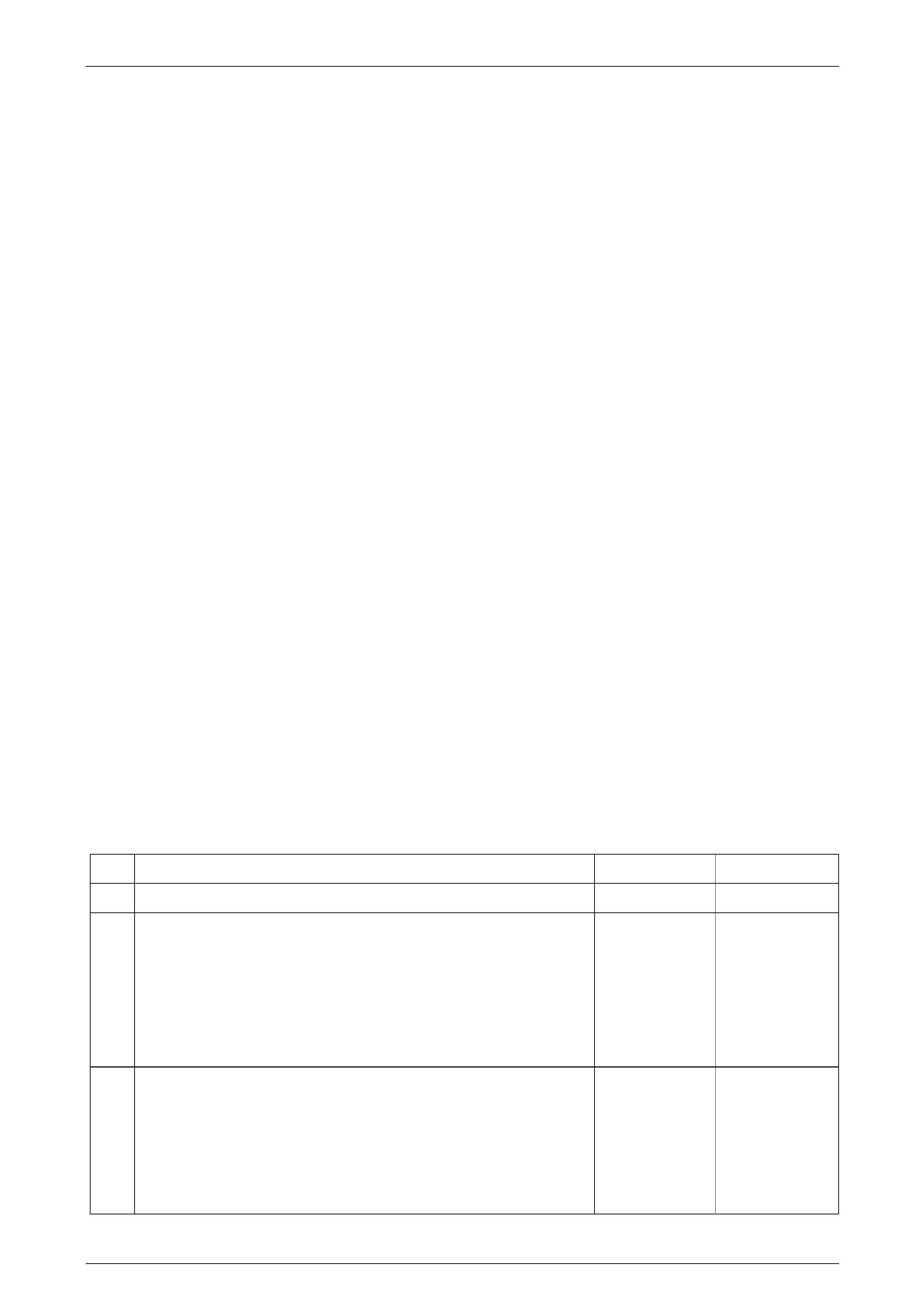
Diagnostic Table
Step Action Yes No
1 Has the electro-chromatic interior rear-view mirror functional check
been performed?
Go to Step 2
Perform function
check, refer to
2.6 Electro-
chromatic Interior
Rear-view Mirror,
Functional Check
2 1 Disconnect connector E124 – X1 from the electro-chromatic
interior rear-view mirror.
2 Turn the ignition switch on.
3 Backprobe the connector E124 – X1 pin 13 with a unpowered
test lamp (refer to Note 1).
Does the test lamp illuminate? Go to Step 3
Repair or replace
circuit 139 or 3.
(refer to Note 1)
3 1 Select reserve gear.
2 Backprobe the connector E124 – X1 pin 9 with a unpowered test
lamp (refer to Note 1).
Does the test lamp illuminate? Go to Step 4 Go to Step 5
4 Using a multimeter set to measure resistance, probe between
connector E124 – X1 pin 8 and a known ground (refer to Note 1).
Does the multimeter indicate continuity?
Replace the interior
rear-view mirror
assembly, refer to
4.3 Interior Rear-
view Mirror,
Telematics Go to Step 7
Page 1A6-6

Rear-view Mirrors Page 12H-7
Step Action Yes No
5 Select reserve gear.
Do the back-up lamps operated correctly? Go to Step 6
Repair or replace
back-up lamps
circuit.
(refer to Note 1)
6 Is connector X300 secure? (refer to Note 3) Go to Step 8 Ensure the
connector is secure
7 Ensure the following ground point is secure and has good contact with
the vehicle structure:
• X118 – GP12 located in the middle of the transmission tunnel.
Is the ground point secure to the vehicle with a good contact?
Repair or replace
circuit 650
(refer to Note 2) Repair or replace
ground point
8 Did the test lamp illuminate in Step 2? Repair or replace
circuit 24
(refer to Note 2)
Repair or replace
circuit 139
(refer to Note 2)
When all diagno sis and repairs are completed, check the system for correct operation.
Page 1A6-7
Rear-view Mirrors Page 12H-8
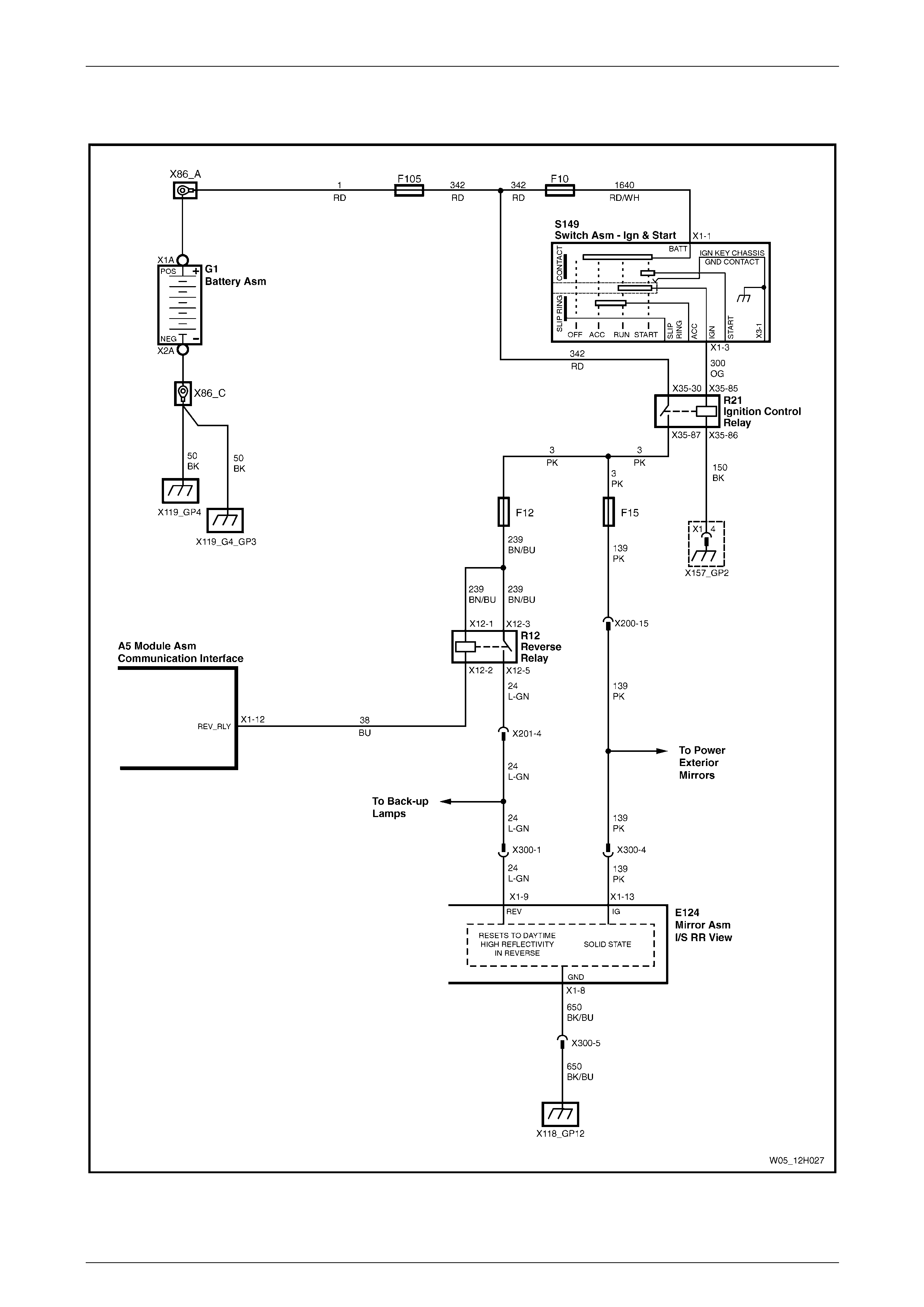
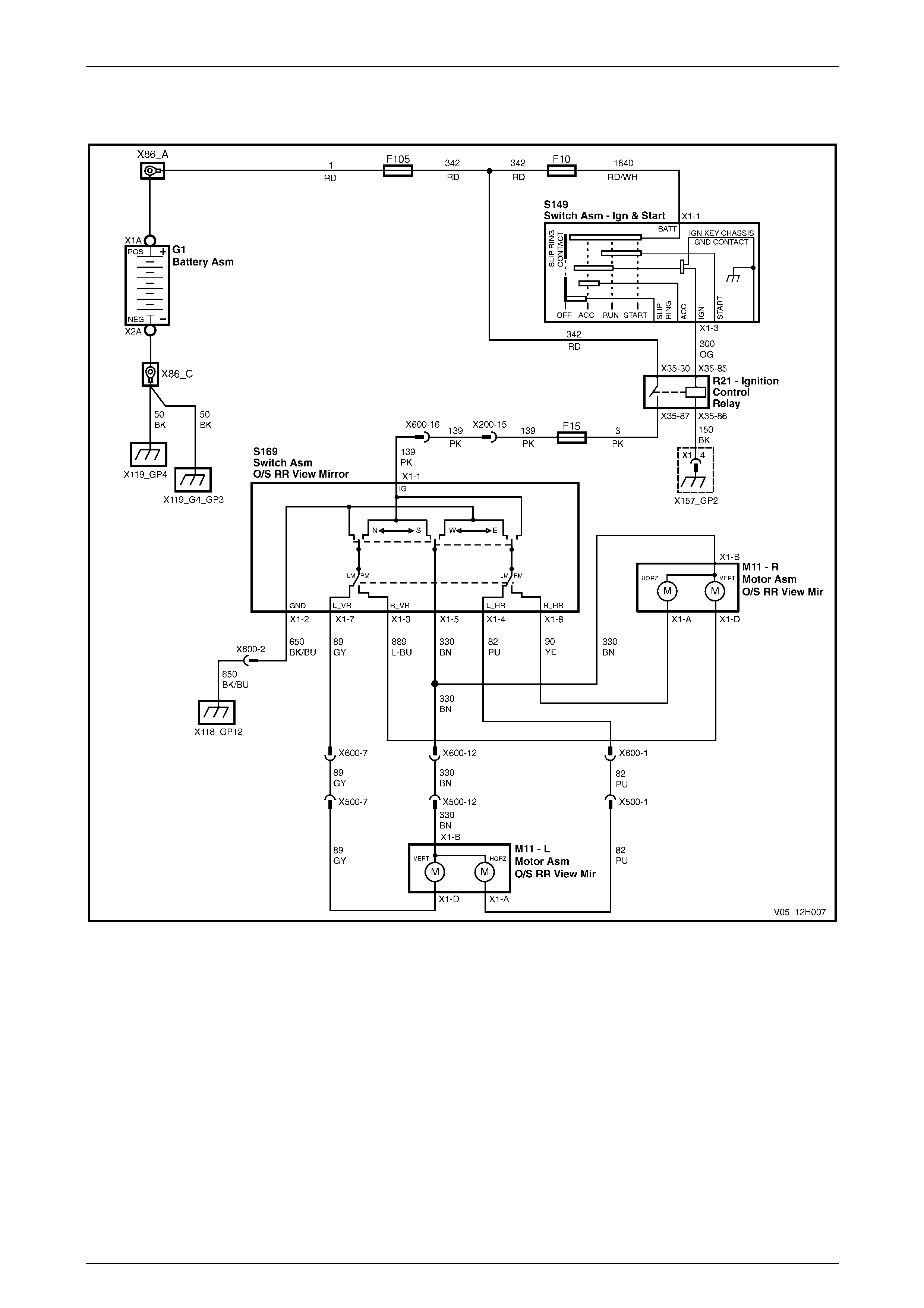
2.3 Wiring Diagram: V6
Figure 12H – 3
Page 1A6-8
Rear-view Mirrors Page 12H-9
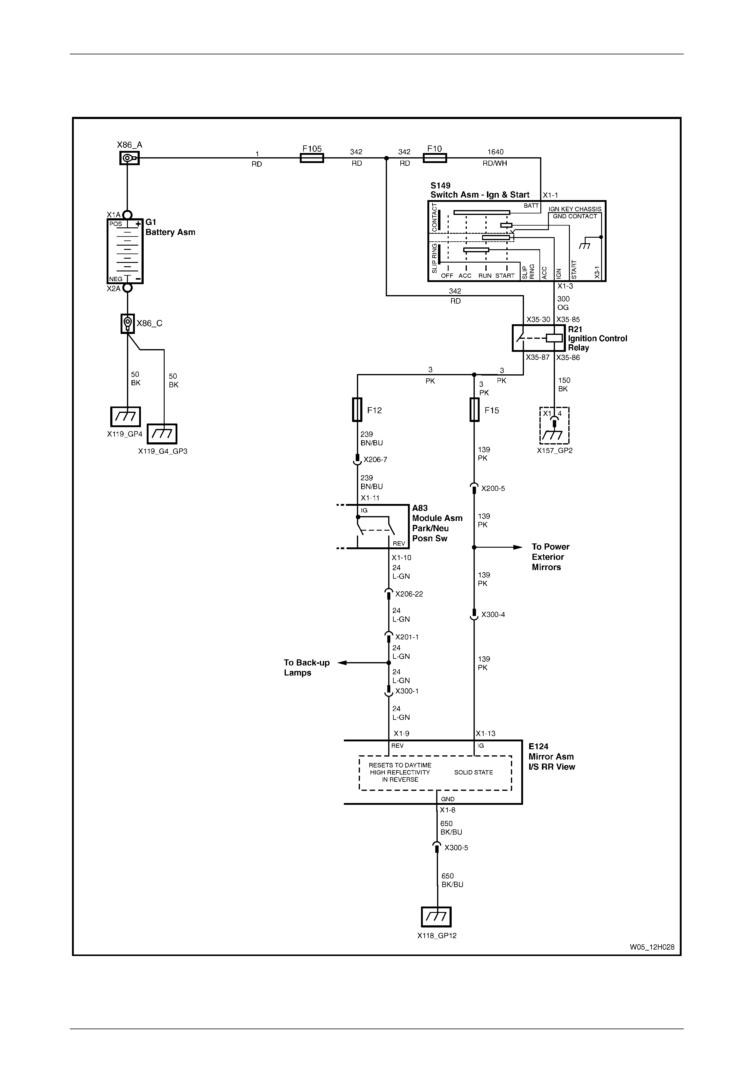
2.4 Wiring Diagram: V8
Figure 12H – 4
Page 1A6-9
Rear-view Mirrors Page 12H-10
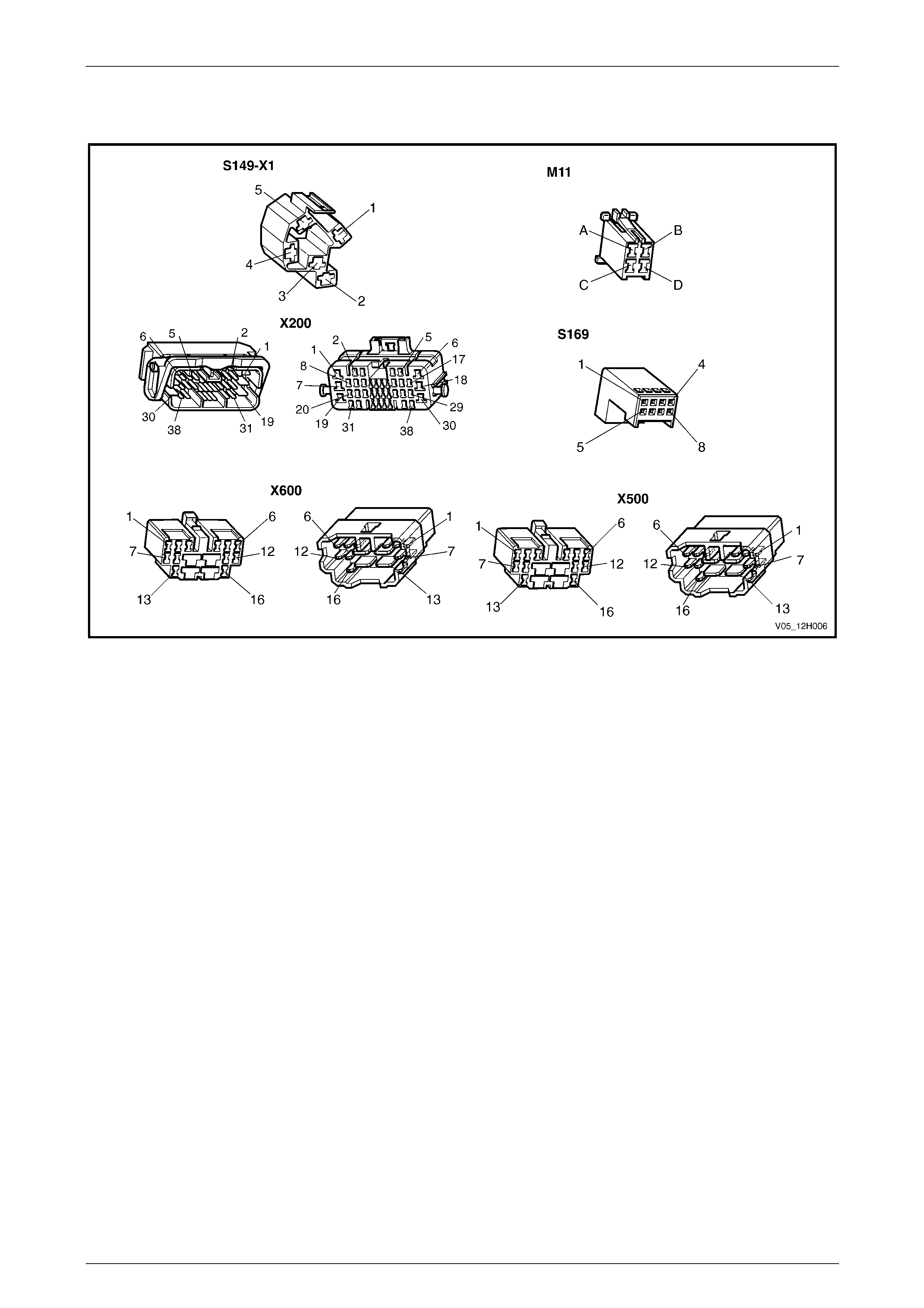
2.5 Connector Chart
Figure 12H – 5
Page 1A6-10
Rear-view Mirrors Page 12H-11
2.6 Electro-chromatic Interior Rear-view
Mirror, Functional Check
1 With the mirror installed, cover the forward facing
ambient light sensor, using a piec e of black electrical
tape.
2 Turn the ignition switch on.
3 Set mirror switch to the AUTO position.
4 Observe the green LED on the mirror assembly is
illuminated.
5 Shine a beam of light (torch) onto the rearward facing
light sensor and ensure the m irror darke ns.
NOTE
The rearward facing light sensor is located
adjacent to the green LED, to the left of the
AUTO switch.
6 With the ignition switch on, select reverse gear, the
mirror should return to full reflectance within 5 – 10
seconds.
7 Repeat Step 5 and set the mirror switch to the OFF
position (LED off). The mirror should return to full
reflectance within 5 – 10 seconds.
NOTE
If the mirror does not function according to the
above procedure, perform a diagnostic test,
refer to 2.2 Electro-chromatic Interior Rear-vie w
Mirror, Diagnostic Procedures.
Figure 12H – 6
Page 1A6-11

Rear-view Mirrors Page 12H-12
3 Diagnostics, Exterior Rear-view
Mirror
3.1 Prerequisites
Equipment
The following equipment is required to diagnose the exterior rear-view mirror:
• an unpowered test lamp with a current dra w of less than 3 A,
• a digital multimeter with a minimum impe dance of 10 MΩ, refer to Section 12P Wiring Diagrams
• connector adapter kit, special tool No. KM–609.
Testing Procedures
The following points must be adhered to
when performing diagnostic testing on
components:
• Take care when using testing equipment
to diagnose wiring harness connectors. It
is preferred the technician backprobe the
connector to avoid terminal damage.
• When tests are required on connector
terminals, use the adapters in the
connector adapter kit KM–609 to prevent
damage to the terminals.
• Unless the multimeter being used has an
auto-ranging function, ensure the correct
range is selected.
• When backpro bing connectors, ensure the
test lamp ground lead is connected to an
appropriate ground point on the vehicle.
Ensure this ground point is not part of the
circuit being tested.
Page 1A6-12
Rear-view Mirrors Page 12H-13
3.2 Exterior Rear-view Mirror, Diagnostic
Procedures
Introduction
This test is used to aid in diagnosing faults with the exterior rear-view mirror. If the problem is with the heated mirror
glass refer to 3.7 Heated Mirror Glass, Functional Check. For all oth er pro blems d iag nose the problem by following this
diagnostic procedure.
Test Description
The following numbers refer to the step numbers in the diagnostic table:
1 Checks if both rear-view mirrors are inoperative.
2 Checks if the fusible link associated with the system is serviceable.
3 Checks for power to the mirror control switch.
4 Checks the ground circuit of the mirror control switch.
5 Checks if the mirror control switch is serviceable.
6 Checks circuit 330. If both mirrors are still inoperative, the problem is isolated to the mirror assemblies.
7 Checks if connectors X600 and X200 ar e secure.
8 Checks if connector X600 is secure.
9 Checks if the ground point associated with the system is serviceable.
10 Checks if the mirror control switch is serviceable.
11 Checks if the mirror assembly is serviceable.
12 Checks for continuity in the circuits bet ween the mirror control switch and the mirror assembly.
Diagnostic Table Notes
1 For all wiring harness fault diagnosis, refer to Section 12P Wiring Diagrams.
2 For wiring harness repairs, refer to Section 12P Wiring Diagrams.
3 Refer to Section 12O Fuses, Relays and Wiring Harnesses for harness rout eing.
Diagnostic Table
Step Action Yes No
1 Are both electric rear-view mirrors inoperative? Go to Step 2 Go to Step 10
2 Inspect fusible link F15, located in the p assenger compartment fuse
panel. (refer to Note 3).
Is fusible link F15 serviceable ?
Go to Step 3
Replace the fusible
link.
If the fusible link
becomes
unserviceable
again, repair or
replace circuit 139
(refer to Note 2)
3 1 Remove the mirror control switch. Refer to 5.6 Mirror Control
Switch.
2 Turn the ignition switch on.
3 Backprobe connector S169 – X1 pin 1 with a unpo wered te st lamp
(refer to Note 1).
Does the test light illuminate? Go to Step 4 Go to Step 7
Page 1A6-13

Rear-view Mirrors Page 12H-14
Step Action Yes No
4 Using a multimeter set to measure resistance, probe between connector
S169 – X1 pin 2, and a known ground (refer to Note 1).
Does the multimeter indicate continuity? Go to Step 5 Go to Step 8
5 Perform the functional check of the Mirror Control Switch, refer to
3.5 Mirror Control Switch, Functional Check.
Does the Mirror Control S witch operate correctly? Go to Step 6
Replace mirror
control switch,
refer to.5.6 Mirror
Control Switch
6 Repair or replace circuit 330 (refer to Note 2).
Do both mirrors function correctly? System
Serviceable Go to Step 11
7 Is connector X600 and connec tor X200 secure? (refer to Note 3) Repair or replace
circuit 139 (refer to
Note 2)
Ensure the
connector is
secure
8 Is connector X600 secure? (refer to Note 3)
Go to Step 9
Ensure the
connector is
secure
9 Ensure the following ground point is secure and has good contact with
the vehicle structure:
• X118 – GP12 located in the middle of the transmission tunnel.
Is the ground point secure to the vehicle with a good contact?
Repair or replace
circuit 650 (refer to
Note 2) Repair or replace
ground point
10 Preform the functional check of the Mirror Control Switch, refer to
3.5 Mirror Control Switch, Functional Check.
Does the Mirror Control S witch operate correctly? Go to Step 11
Replace mirror
control switch,
refer to.5.6 Mirror
Control Switch
11 Preform the functional check of the inoperable exterior mirror, refer to
3.6 Exterior Rear-view Mirror Assembly, Function al Check.
Does that mirror function correctly? Go to Step 12
Replace mirror
assembly, refer to
5.4 Exterior Rear-
view Mirror
Assembly.
12 1 If the right mirror is inoperable, use a multimeter set to measure
resistance to probe bet ween:
• Connector S169 – X1 pin 3 and connector M11-R – X1 pin D.
• Connector S169 – X1 pin 8 and connector M11-R – X1 pin A.
• Connector S169 – X1 pin 5 and connector M11-R – X1 pin B.
2 If the left mirror is inoperable, use a multimeter set to measure
resistance to probe bet ween:
• Connector S169 – X1 pin 4 and connector M11-L – X1 pin A.
• Connector S169 – X1 pin 7 and connector M11-L – X1 pin D.
• Connector S169 – X1 pin 5 and connector M11-L – X1 pin B.
Does the multimeter indicate continuity in each of these circuits? System
Serviceable
Repair or replace
the open circuit(s)
(refer to Note 2)
When all diagno sis and repairs are completed, check the system for correct operation.
Page 1A6-14
Rear-view Mirrors Page 12H-15
3.3 Wiring Diagram
Figure 12H – 7
Page 1A6-15
Rear-view Mirrors Page 12H-16
3.4 Connector Chart
Figure 12H – 8
Page 1A6-16
Rear-view Mirrors Page 12H-17
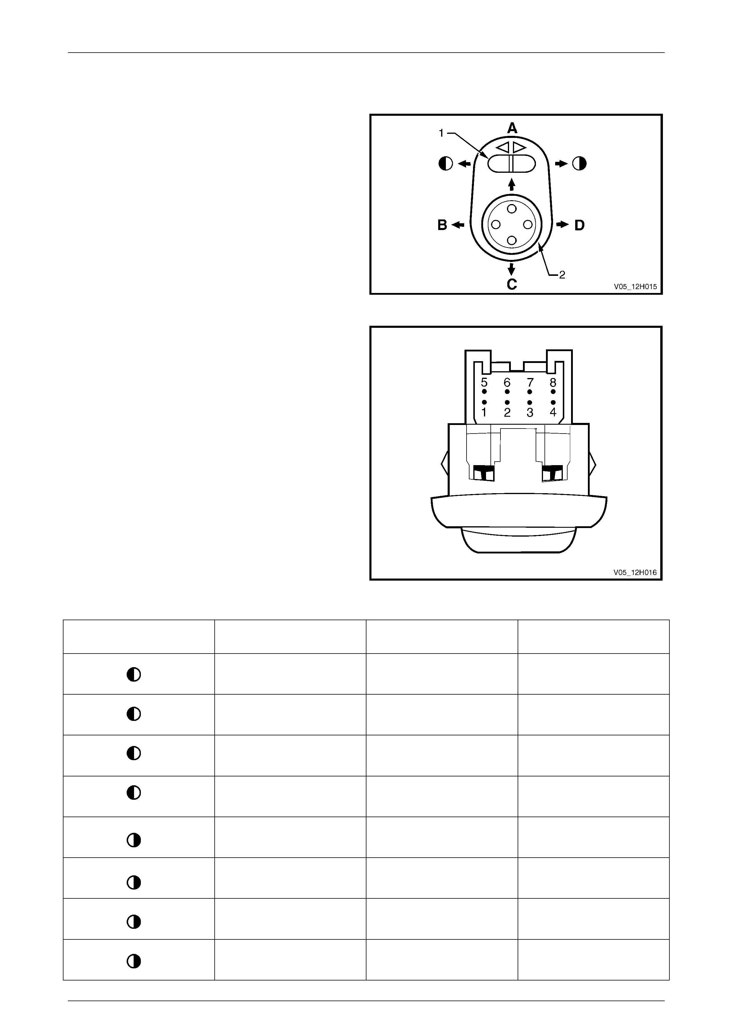
3.5 Mirror Control Switch, Functional Check
1 If required remove the mirror control switch, refer to
5.3 Mirror Control Switch.
2 The mirror control switch comprises of two switches:
• mirror select switch (1).
• mirror direction switch (2).
Figure 12H – 9
3 Using the table below set the switches on the mirror
control switch as indicated. Using a multimeter, test for
continuity between the switch terminals listed.
4 If the switch fails any part of the test, replace the
switch assembly with a serviceable item.
5 Otherwise reinstall the existing mirror control switch
refer to 5.3 Mirror Control Switch.
Figure 12H – 10
Mirror Select Switch
Position Mirror Direction Switch
Position Switch Terminals Indication If Switch Is
Serviceable
A 1 and 5
2 and 7 Continuity
B 1 and 5
2 and 4 Continuity
C 1 and 7
2 and 5 Continuity
D 1 and 4
2 and 5 Continuity
A 1 and 5
2 and 3 Continuity
B 1 and 5
2 and 8 Continuity
C 1 and 3
2 and 5 Continuity
D 1 and 8
2 and 5 Continuity
Page 1A6-17
Rear-view Mirrors Page 12H-18
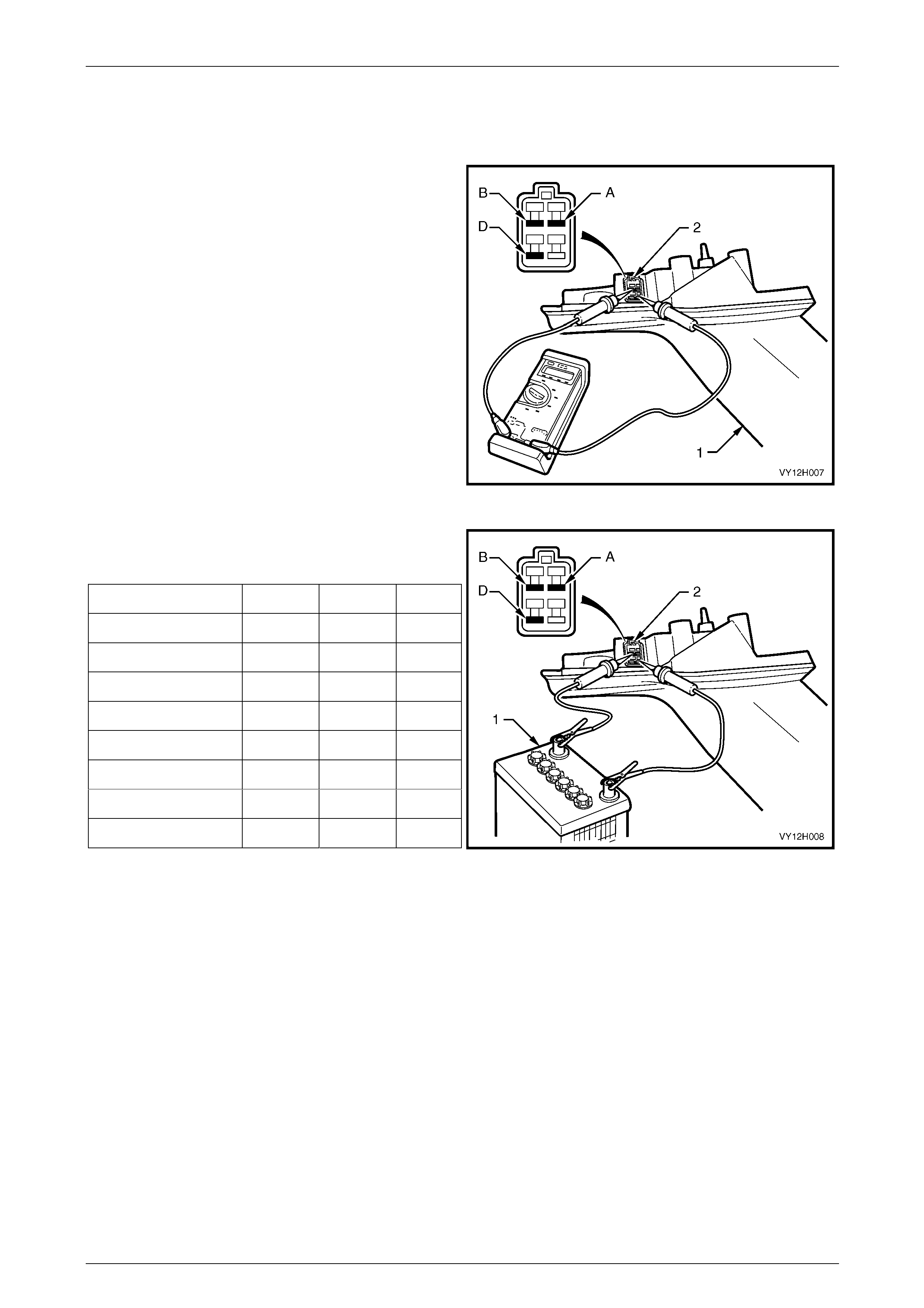
3.6 Exterior Rear-view Mirror Assembly,
Functional Check
1 If required remove the exterior rear-view mirror
assembly (1), refer to 5.2 Exterior Rear-view Mirror
Assembly.
2 Using a multimeter, test for continuity between the
connector terminals (2) listed below:
• A and B
• A and D
• B and D
If the ohmmeter indicates an open circuit or a
resistance of more than 200 Ω bet ween any of these
terminals, replace the mirror assembly with a
serviceable item.
3 If continuity exists between all the listed co nnector
terminals, proceed to step 4
Figure 12H – 11
4 Connect the positive (+) and negative (-) leads from a
12 volt battery (1) to the connector terminals (2), as
outlined in the following chart.
Mirror Movement Term. A Term. B Term. D
Left-hand mirror – In - +
Out + -
Up + -
Down - +
Right-hand mirror – In + -
Out - +
Up + -
Down - +
5 Observe the mirror movement. If the movement of the
mirror is not as shown in the above chart, replace the
mirror assembly with a serviceable item.
Figure 12H – 12
Page 1A6-18
Rear-view Mirrors Page 12H-19
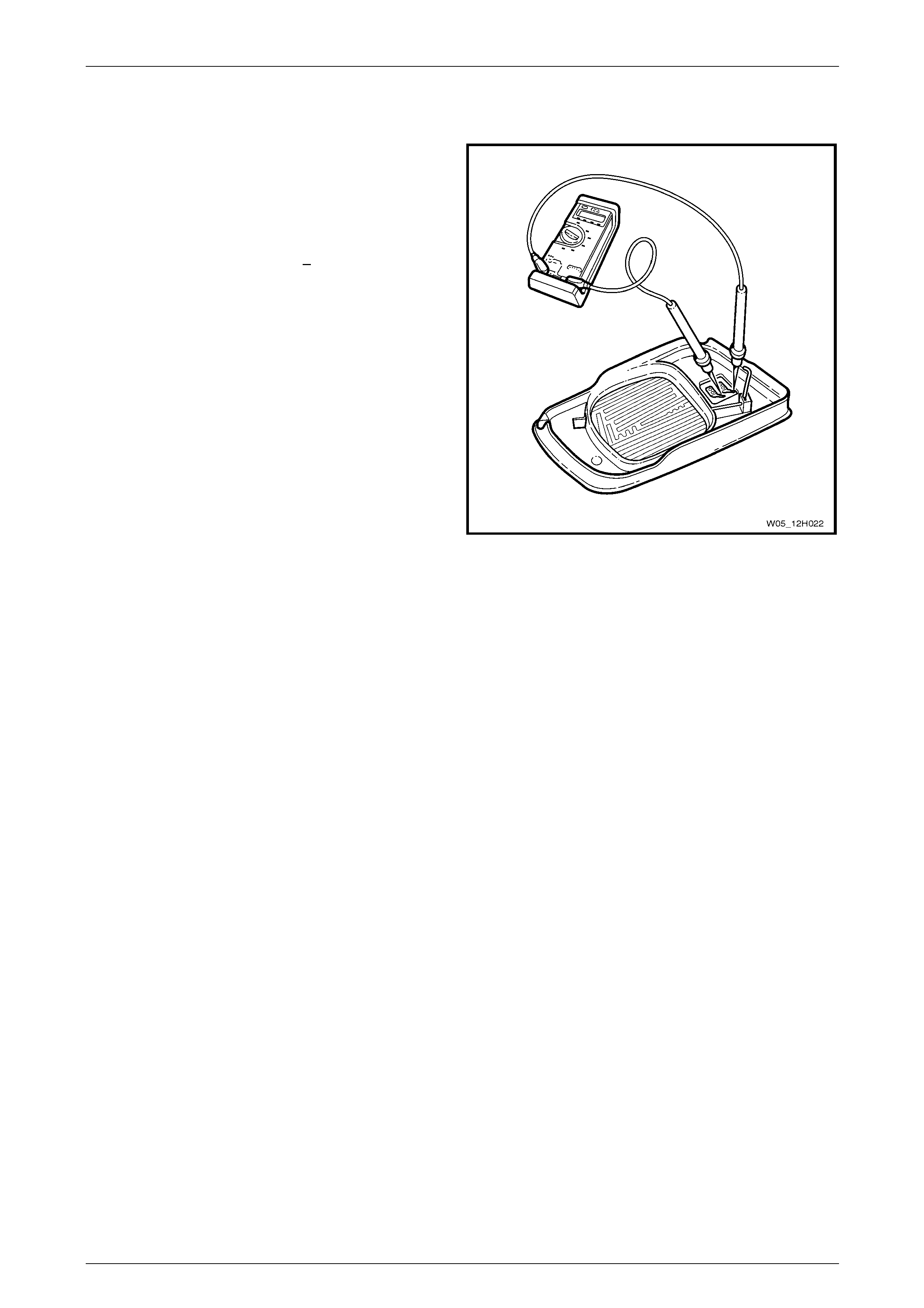
3.7 Heated Mirror Glass, Functional Check
1 Remove the heated mirror glass, refer to
5.1 Exterior Mirror Glass.
2 Using a suitable digital multim eter, measure the
resistance between the two heater element spade
terminals.
3 The resistance should be 1 5 + 2 Ω. If the resistance of
the heater element is outside this range, replace the
heated mirror glass with a serviceable item.
NOTE
If the heated mirror glass passes the functional
check, yet does not function c orrectly when fitted
to the vehicle refer to Section 1A7 Seat
Assemblies for a full diagnostic proced ure.
Figure 12H – 13
Page 1A6-19
Rear-view Mirrors Page 12H-20
4 Service Operations – Interior
Rear-view Mirror
4.1 Interior Rear-view Mirror, Except
Telematics
LT Section No. — 14–025
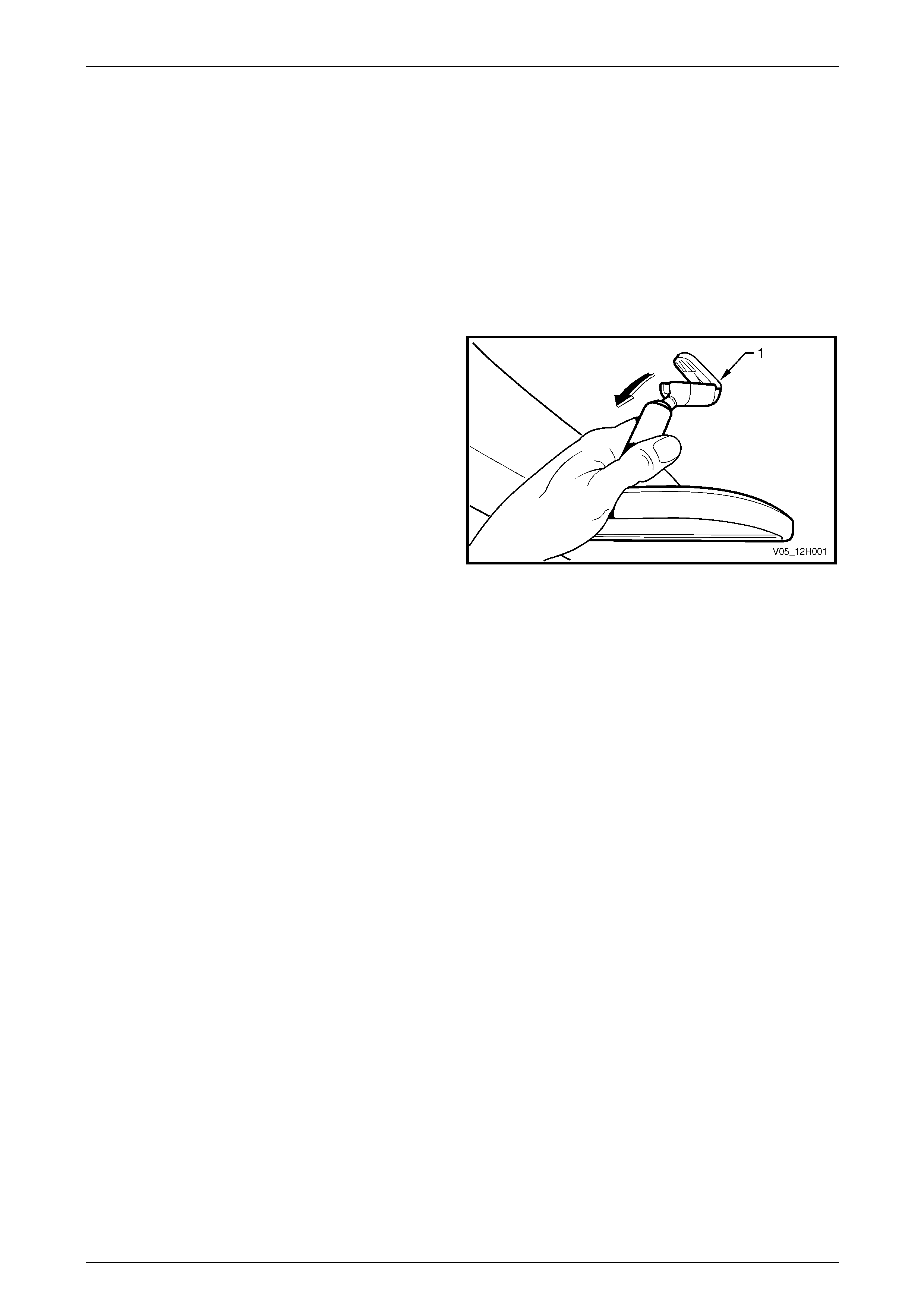
Remove
Firmly grasp the interior rear-vie w mirror assembly and
disengage the mirror from the windshie ld boss (1) by pulling
firmly and smoothly in a downward, peeling motion.
NOTE
The windshield boss is not ser viced se par atel y, it
is part of the windshield assembly.
Figure 12H – 14
Reinstall
Slide the interior rear-view mirror assembly from the top of the boss downwards, ensurin g that it is pushed down fully
onto the boss. An audible click should occur as the mirror assembly locks into position.
Page 1A6-20
Rear-view Mirrors Page 12H-21
4.2 Interior Rear-view Mirror, Telematics
LT Section — 09–540–1
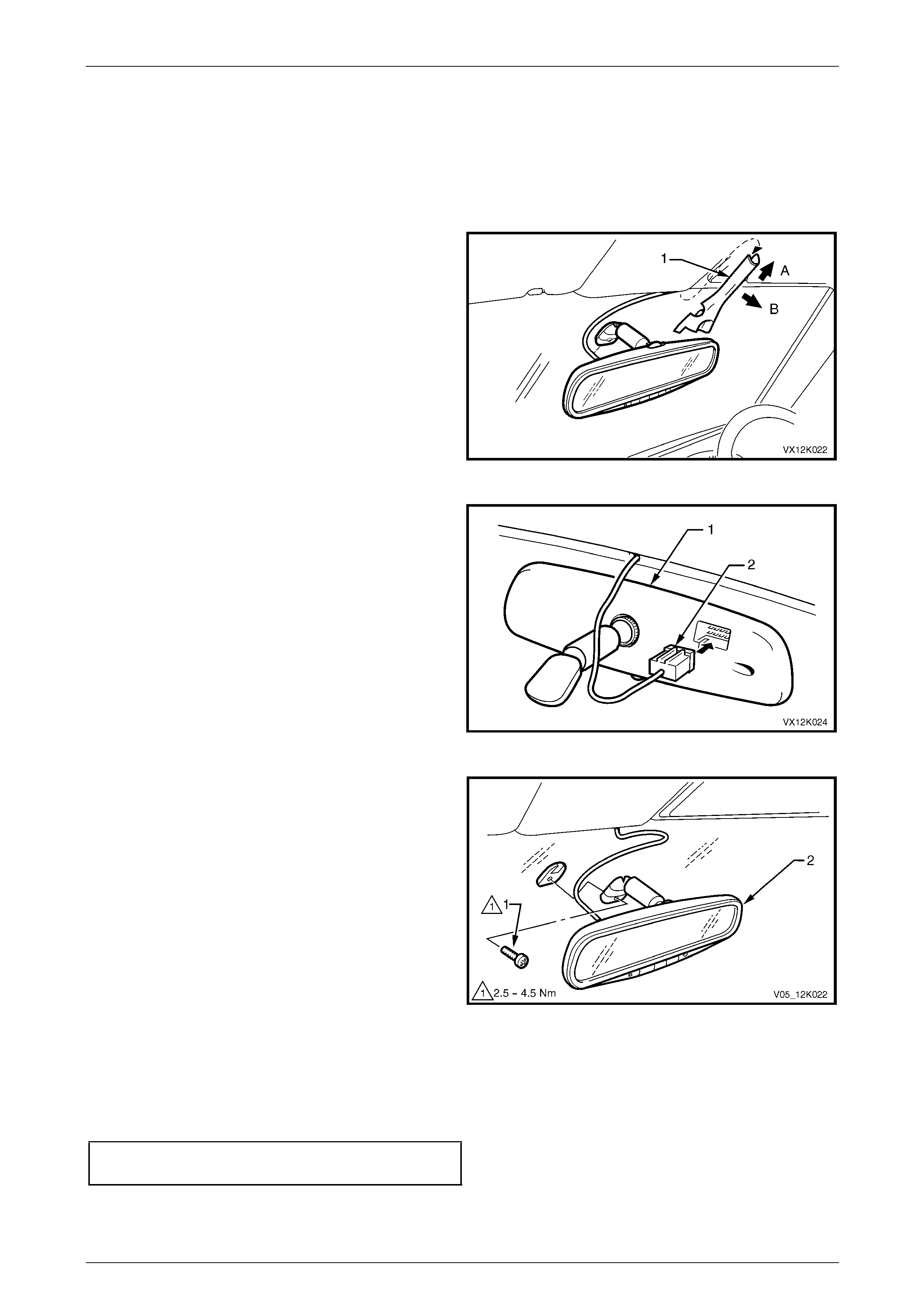
Remove
1 Remove the mirror wiring harness cover (1) by sliding
it upwards slightly (direction A), then pulling it
outwards (direction B).
NOTE
It may assist removal to carefully pull down the
headlining trim slightly while sliding the mirror
wiring harness cover.
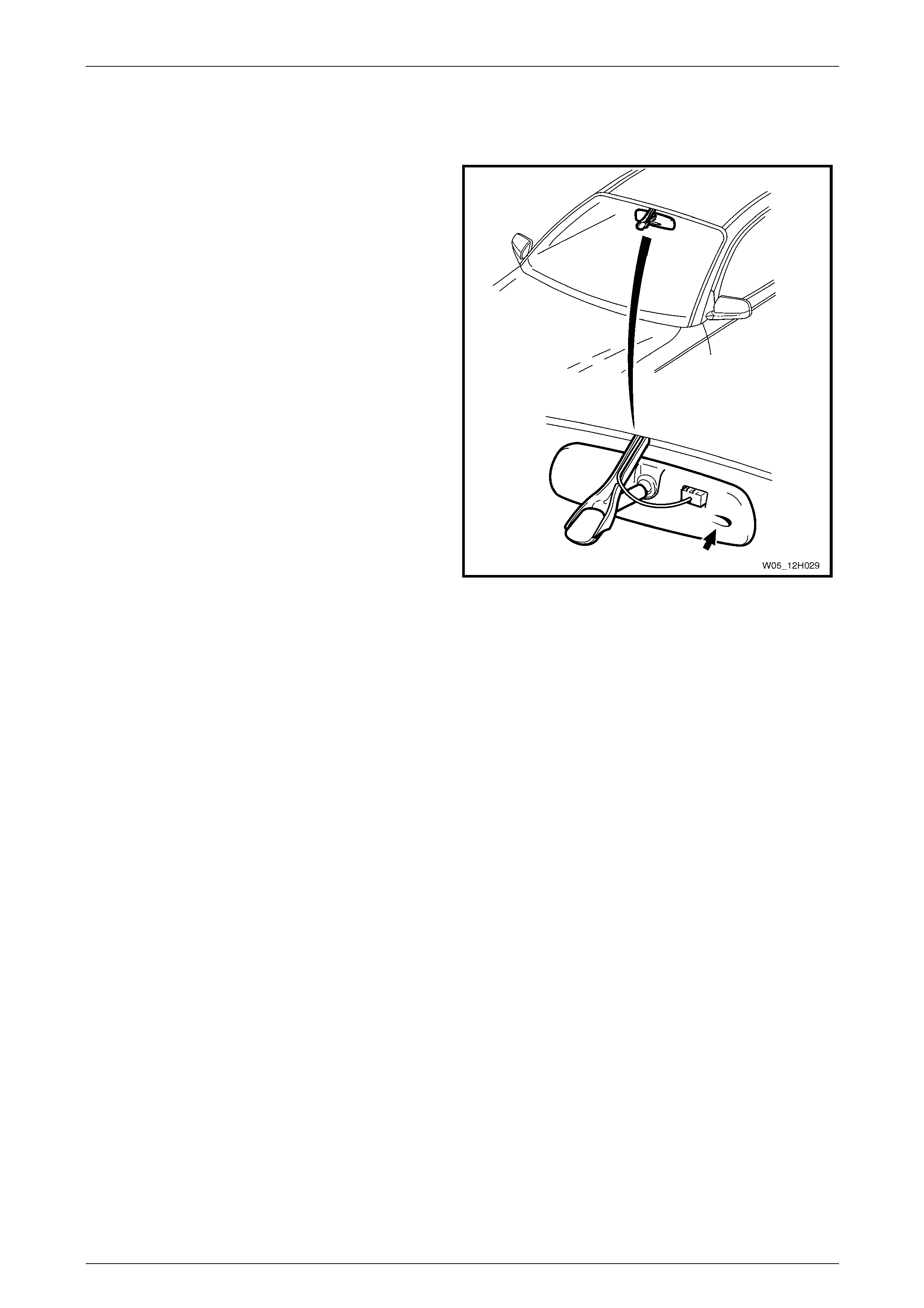
Figure 12H – 15
2 Disconnect the interior rear-view mirror wiring
connector (2) from the rear of the mirror (1).
Figure 12H – 16
3 Remove the interior rear-view mirror retaining
screw (1) and disengage the interior mirror from the
boss on the windscreen by sliding the mirror (2)
upward.
Figure 12H – 17
Reinstall
Reinstallation for the interi or rear-view mirror is the reverse of the removal procedure. Ensure the screw is tighten to the
correct torque specification.
Interior rear-view mirror retaining
screw torque specification...........................2.5 – 4.5 Nm
Page 1A6-21
Rear-view Mirrors Page 12H-22
5 Service Operations – Exterior
Rear-view Mirror
ATTENTION
All fasteners are important attaching parts as they affect the performance of vital components and/or could
result in major repair expense. Wh ere specified in this Section, fasteners MUST be replaced with parts of the
same part number or an app roved equivalent. Do not use fasteners of an inferior quality or substitute desig n.
Torque values must be used as specified during reassembly to ensure proper retention of all components.
Throughout this Section, fastener torq u e wrench specifications may be accompanied with the following
identification mark:
Fasteners must be replaced after lo osening.
If one of these identification marks is present alongside a fastener torque wrench specification, the
recommendation regarding that fastener must be adhered to.
5.1 Exterior Mirror Glass
LT Section No. — 10–400
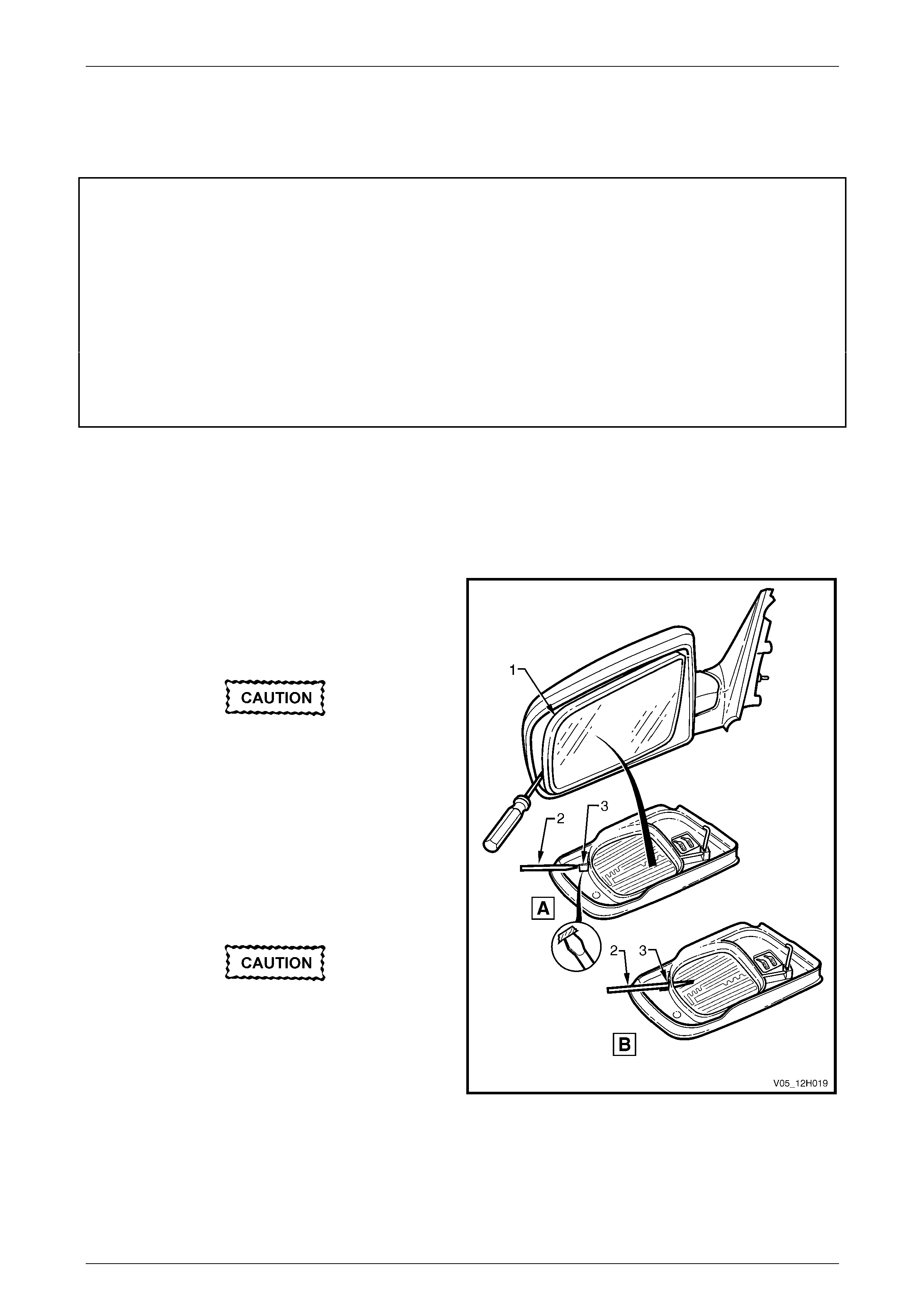
Remove
1 Adjust the mirror glass (1) so it is in the fully upward
and inward position.
2 Wrap the end of a flat blade scre wdriver (2) with tape
or a clean shop rag.
The heater element is fitted to the rear of the
mirror glass and is susceptible to damage
during mirror glass removal. Extreme care
must be taken while removing the mirror
glass.
3 Insert the screwdriver into the slot (3) on the inside of
the mirror glass, refer to View A.
4 Gently lever the mirror glass away from the motor
assembly while slowly inserting the scre wdriv er further
into the assembly, refer to View B.
Two wires are attached to the rear of the
mirror glass. When disconnecting the two
wires, the female terminals should not come
in contact with an y part of the heater element
or damage to the element may occur.
Figure 12H – 18
5 Mark one of the two heater wires to ensure it is refitted to the correct terminal during reassembly.
6 Disconnect both heater wires from the heater element on the rear of the mirror glass.
7 Remove the mirror glass from the motor assembly.
Page 1A6-22
Rear-view Mirrors Page 12H-23
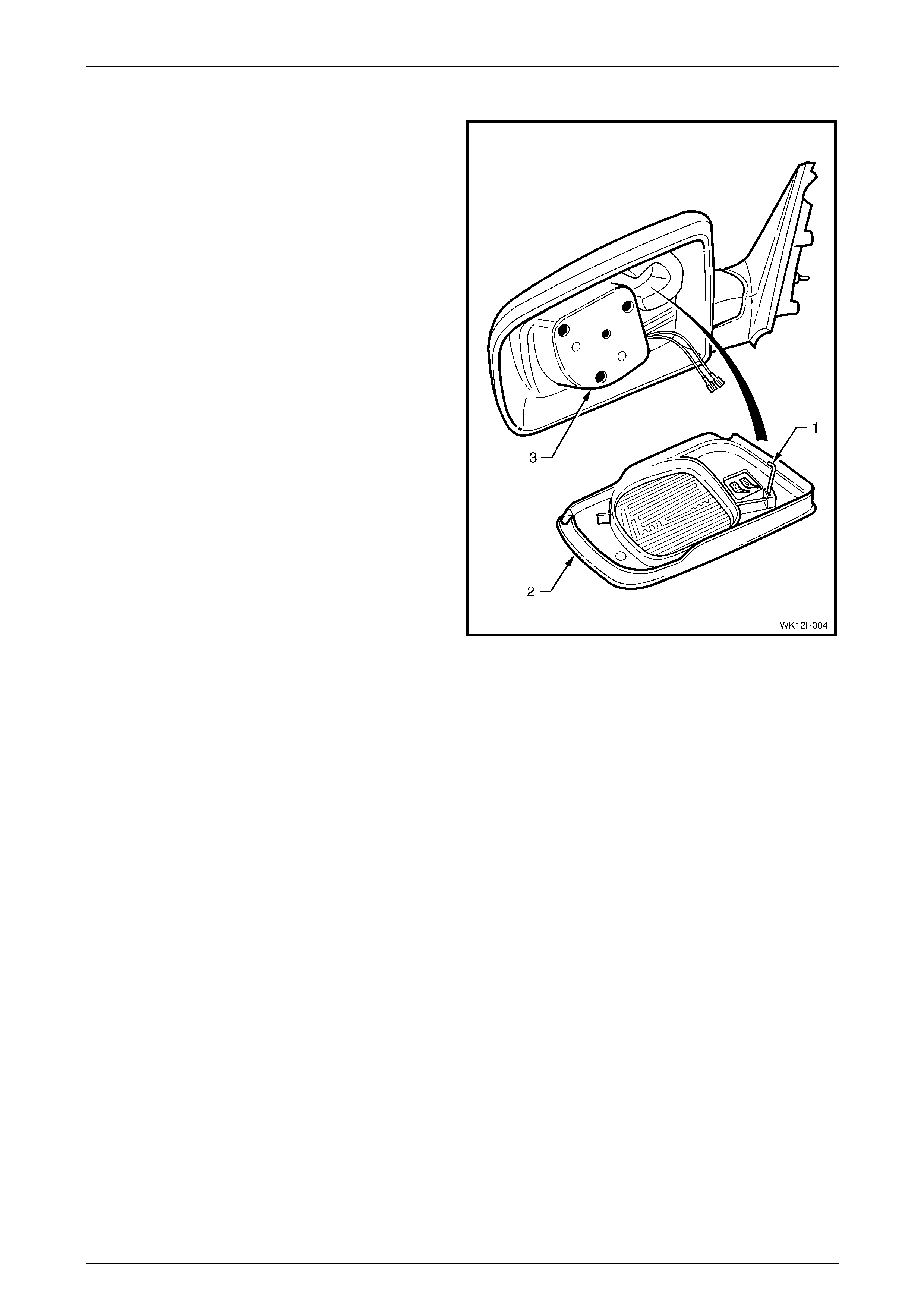
Reinstall
1 Ensure the anti-vibration sprin g rod (1) is at a right
angle to the mirror glass (2) and that it aligns with the
corresponding aperture in the mirror housing.
2 Ensure the two heater wires are refitted correctly.
3 Support the mirror housing and push the mirror glass
squarely onto the motor asse mbly (3) until it is firmly
seated.
Figure 12H – 19
Page 1A6-23
Rear-view Mirrors Page 12H-24
5.2 Exterior Rear-view Mirror Assembly
LT Section No. — 10–400
Remove
1 Remove fuse F15 from the passenger compartment fuse panel. Refer to Section 12O Fuses, Relays and Wiring
Harnesses.
2 Remove the mirror inner dress cover (1) by gently
prising the cover away from the door and slidin g it
back (towards the side window).
3 Pull the door demist duct (2) up and out of the door
trim panel.
Figure 12H – 20
4 Remove the front door trim panel assembly to gain
access to the retaining screws. Refer to Section 1A5
Front and Rear Door Assemblies.
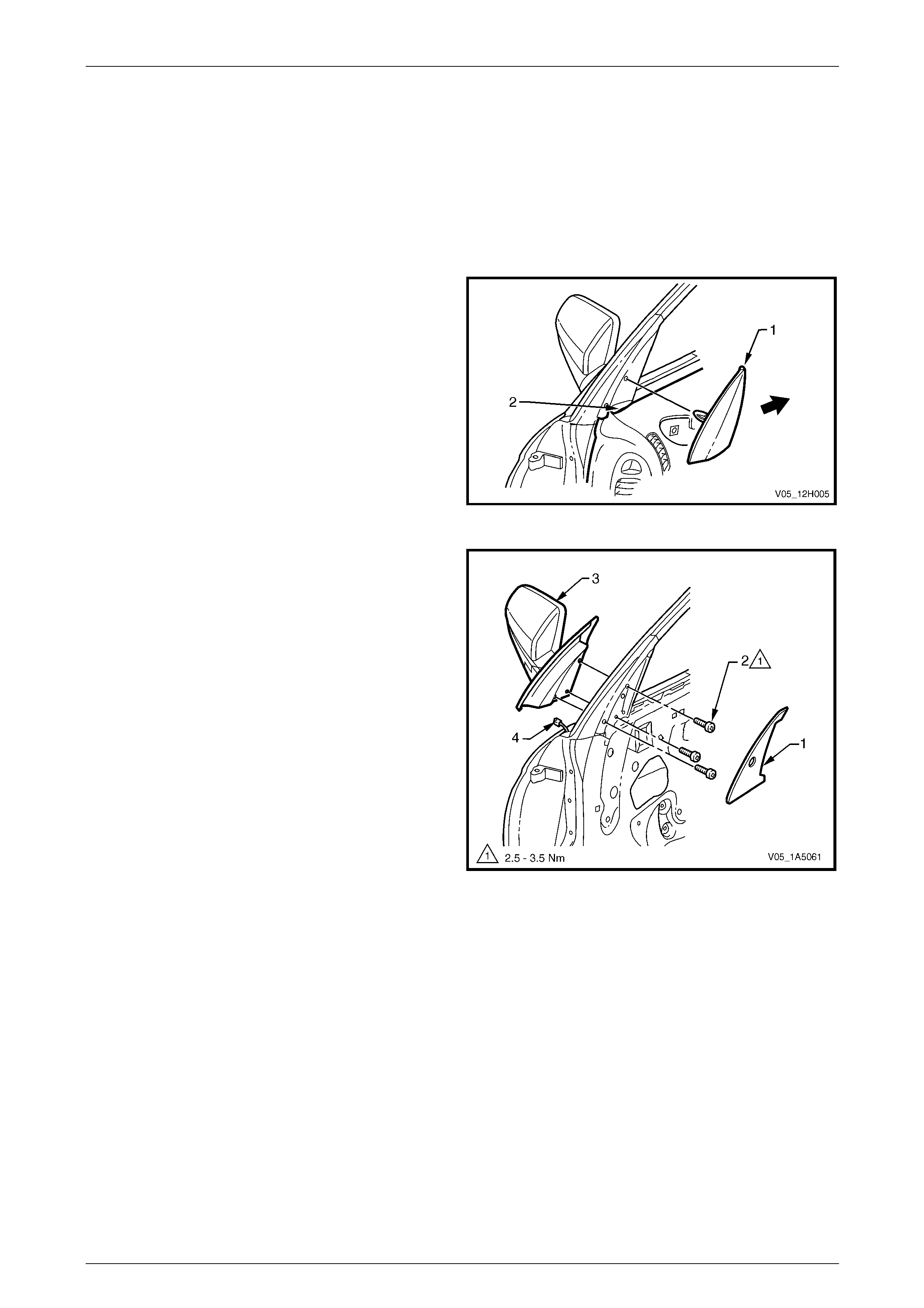
5 Peel back the exterior rear-vi ew mirror self-adhesive
seal (1).
6 Remove the three screws (2) attaching the exterior
rear-view mirror assembly (3) to the front door
assembly.
7 While supporting the exterior door re ar-view mirror,
disconnect the wiring connector (4) and remove the
exterior rear-view mirror.
Figure 12H – 21
Page 1A6-24
Rear-view Mirrors Page 12H-25
Reinstall
1 Ensure the wiring for the mirror is correctly routed.
2 Tighten the screws attaching the exteri or rear-view mirror assembly to the correct torque specification.
Exterior rear-view mirror assembly
attaching screw torque specification...........2.5 – 3.5 Nm
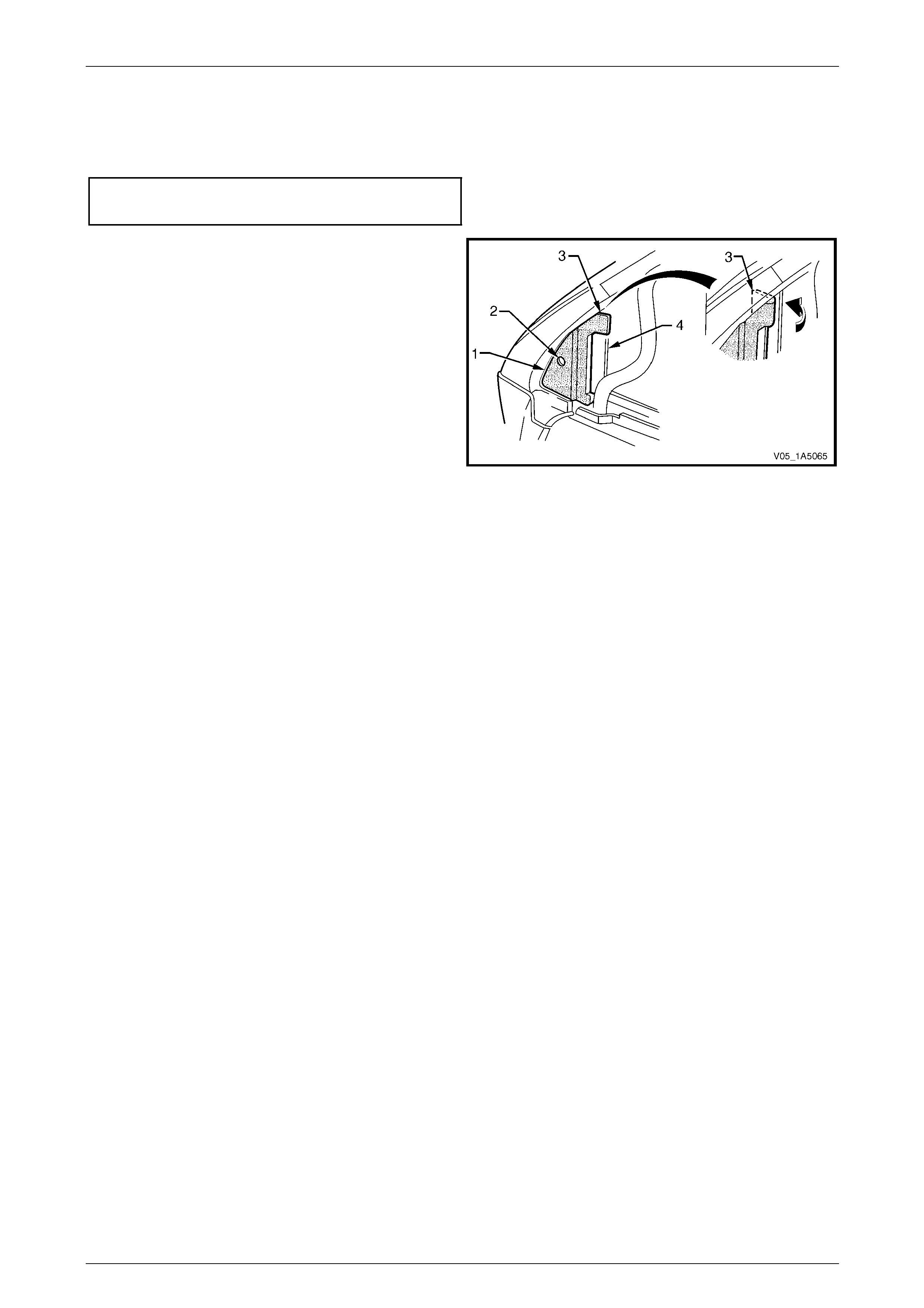
3 Reinstall the exterior rear-view mirror self-adhesive
seal (1) aligning the hole (2) in the seal with the hole
for the front door window defogger outlet clip.
4 Wrap the upper ear (3) of the seal into the front door
window guide channel (4).
5 Reinstall the front door trim pane l assembly, in the
reverse order to the removal procedure.
6 Reinstall the door demist duct, ensuring the duct clips
into position.
7 Reinstall fuse F15.
8 Check for correct mirror operation. Figure 12H – 22
Page 1A6-25
Rear-view Mirrors Page 12H-26
5.3 Mirror Control Switch
LT Section No. — 02–775
Remove
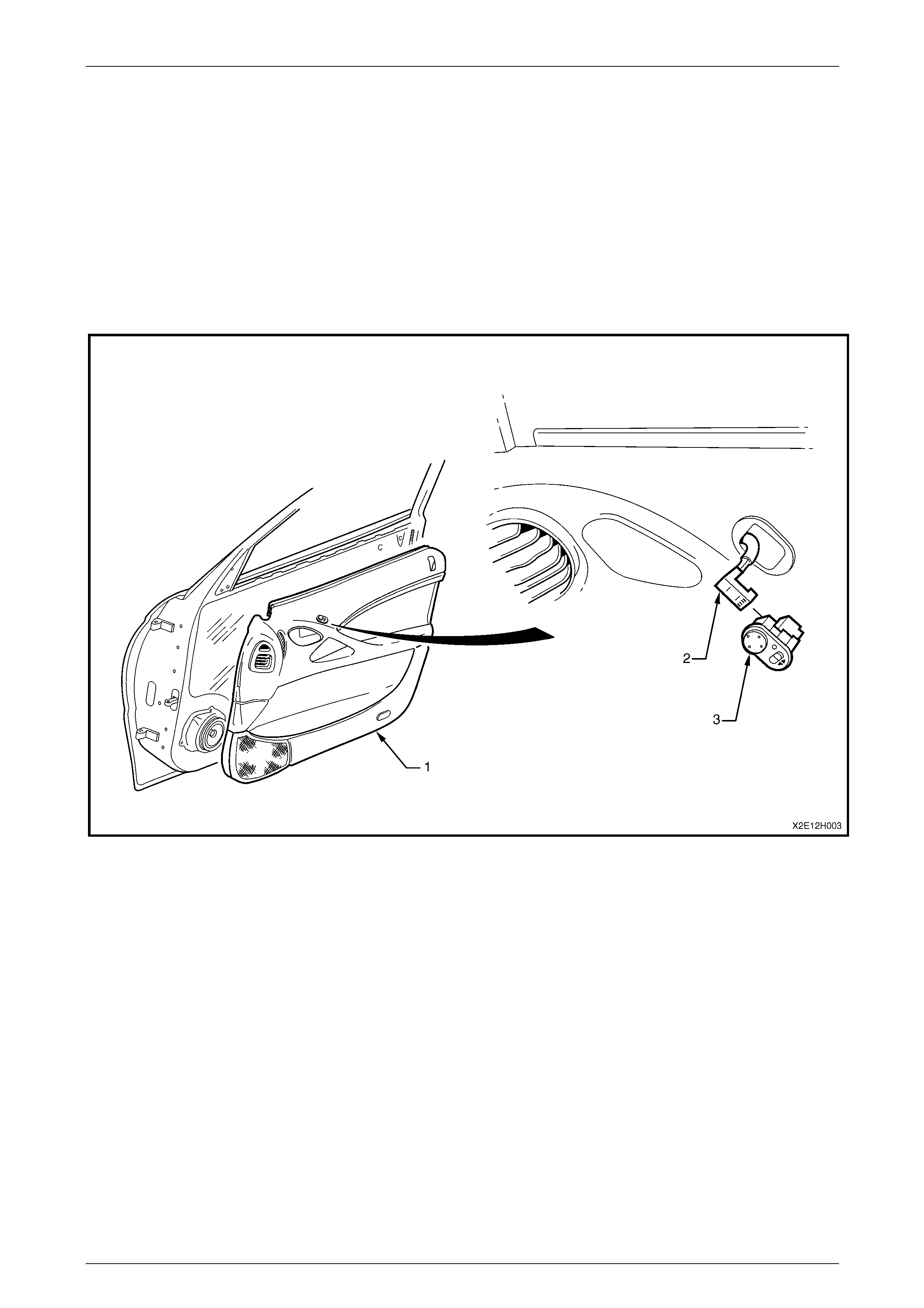
1 Remove the front door trim panel assembly (1). Refer to Section 1A5 Front and Re ar Door Assemblies. Refer to
Figure 12H – 23.
2 Disconnect the wiring connector (2) from the mirror control switch (3).
3 From the back of the front door trim panel assembly, push the control switch to free it and remove it.
Figure 12H – 23
Reinstall
Reinstallation of the mirror control switch is the reverse of the removal procedure.
Page 1A6-26
Rear-view Mirrors Page 12H-27
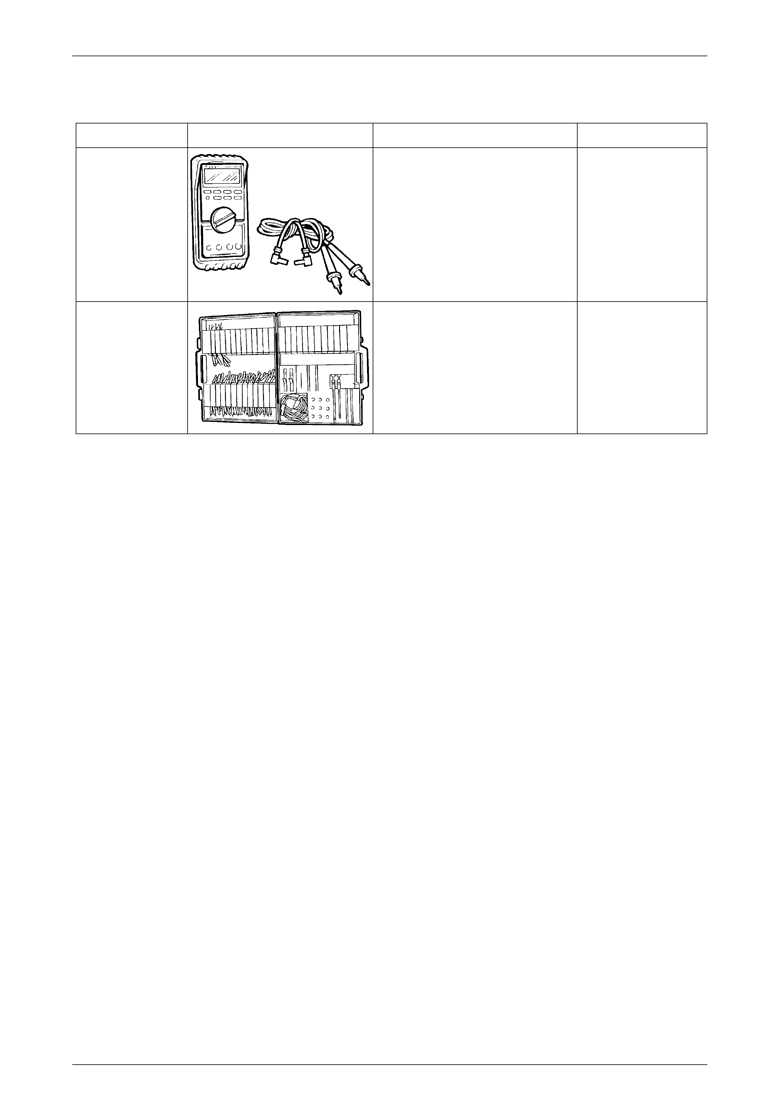
6 Special Tools
Tool Number Illustration Description Tool Classification
J39200 Digital Multimeter
Must have at least 10 MΩ input
impedance and be capable of reading
frequencies.
Previously released.
Available
KM609 Connector Test Adaptor Kit
Used when carrying out electric al
diagnostic circuit checks.
Previously released
Desirable
Page 1A6-27

Rear-view Mirrors Page 12H-28
7 Torque Wrench Specifications
Interior Rear-view Mirror Retaining Screw.....................................2.5 – 4.5 Nm
Exterior Mirror Assembly Attaching Screw.................................2.5 – 3.5 Nm
Page 1A6-28