
Multi-function Display Page 12I–1
Page 12I–1
Section 12I
Multi-function Display
ATTENTION
Before performing any service operation or other procedure described in this section, refer to Section 00
Warnings, Cautions and Notes for correct w orkshop practices with regard to safety and/or property damage.
1 General Information...............................................................................................................................3
1.1 General Description............................................................................................................................................... 3
MFD Installation..................................................................................................................................................... 3
MFD Serviceability................................................................................................................................................. 3
1.2 MFD Communication............................................................................................................................................. 4
MFD Communication with Occupant Climate Control (OCC) Module............................................................... 4
MFD Communication w i th Audio Head Unit (AHU)............................................................................................. 4
1.3 MFD Screen Displays ............................................................................................................................................ 5
Time / Date Display................................................................................................................................................ 5
Radio Operation..................................................................................................................................................... 5
Heating Ventilation and Air-conditioning (HVAC) System Operation................................................................6
Rear Remote Control............................................................................................................................................. 7
Fixed Icons............................................................................................................................................................. 8
1.4 Setting MFD Time / Date........................................................................................................................................ 9
Procedure – Normal............................................................................................................................................... 9
Procedure – Audio Head Unit Removed .............................................................................................................. 9
1.5 MFD Illumination.................................................................................................................................................. 10
Illumination Adjustment...................................................................................................................................... 10
Illumination Adjustment Signal Path.................................................................................................................. 10
2 Tech 2 Information ...............................................................................................................................11
2.1 Tech 2 Test Modes............................................................................................................................................... 11
Body Menu............................................................................................................................................................ 11
Normal Mode........................................................................................................................................................ 11
Diagnostic Trouble Codes .................................................................................................................................. 11
Data Display ......................................................................................................................................................... 12
Data List........................................................................................................................................................... 12
Data Display List .............................................................................................................................................. 12
System Identification........................................................................................................................................ 12
Snapshot .............................................................................................................................................................. 13
Miscellaneous Tests............................................................................................................................................ 13
Park Lamp Input............................................................................................................................................... 13
All Segments........................................................................................................................................................ 14
Chequered Pattern............................................................................................................................................... 14
HVAC LCD Display Test ...................................................................................................................................... 15
Procedure......................................................................................................................................................... 15
3 Wiring Diagrams and Connectors......................................................................................................16
3.1 Wiring Diagram .................................................................................................................................................... 16
3.2 Connector Chart................................................................................................................................................... 17
3.3 Connector Information ........................................................................................................................................ 18
Multi-function Display ......................................................................................................................................... 18
Techline

Multi-function Display Page 12I–2
Page 12I–2
4 Diagnostics...........................................................................................................................................19
Equipment ............................................................................................................................................................ 19
Diagnostic Trouble Codes .................................................................................................................................. 19
4.1 Diagnostic System Check................................................................................................................................... 20
Circuit Description............................................................................................................................................... 20
Test Description................................................................................................................................................... 20
Diagnostic Table Notes ....................................................................................................................................... 20
Diagnostic System Check Diagnostic Table...................................................................................................... 20
5 Diagnostic Trouble Codes...................................................................................................................22
5.1 Diagnostic Trouble Codes List........................................................................................................................... 22
5.2 DTC-10 – No GMLAN Communication from OCC System................................................................................ 23
Circuit Description............................................................................................................................................... 23
Test Description................................................................................................................................................... 23
Diagnostic Table Notes ....................................................................................................................................... 23
DTC-10 Diagnostic Table..................................................................................................................................... 23
5.3 DTC-15 – No Serial Data from the Audio System.............................................................................................. 25
Circuit Description............................................................................................................................................... 25
Test Description................................................................................................................................................... 25
Diagnostic Table Notes ....................................................................................................................................... 25
DTC-15 Diagnostic Table..................................................................................................................................... 25
5.4 DTC-24 – EEPROM Error..................................................................................................................................... 27
Test Description................................................................................................................................................... 27
Diagnostic Table Notes ....................................................................................................................................... 27
DTC-24 Diagnostic Table..................................................................................................................................... 27
6 Diagnostics for Non DTC Faults.........................................................................................................28
6.1 No Power .............................................................................................................................................................. 28
Circuit Description............................................................................................................................................... 28
Test Description................................................................................................................................................... 28
Diagnostic Table Notes ....................................................................................................................................... 28
No Pow er Diagnostic Table................................................................................................................................. 28
6.2 No Illumination or Dimming Control .................................................................................................................. 29
Circuit Description............................................................................................................................................... 29
Test Description................................................................................................................................................... 29
Diagnostic Table Notes ....................................................................................................................................... 29
Diagnostic Table.................................................................................................................................................. 29
6.3 No Audio Information Displayed ........................................................................................................................ 31
Circuit Description............................................................................................................................................... 31
Test Description................................................................................................................................................... 31
Diagnostic Table Notes ....................................................................................................................................... 31
No Audio Information Displayed Diagnostic Table........................................................................................... 31
7 Service Operations...............................................................................................................................33
7.1 Programming........................................................................................................................................................ 33
Program Code Index............................................................................................................................................ 33
7.2 Multi-function Display ......................................................................................................................................... 34
8 Special Tools ........................................................................................................................................35
Multi-function Display Page 12I–3
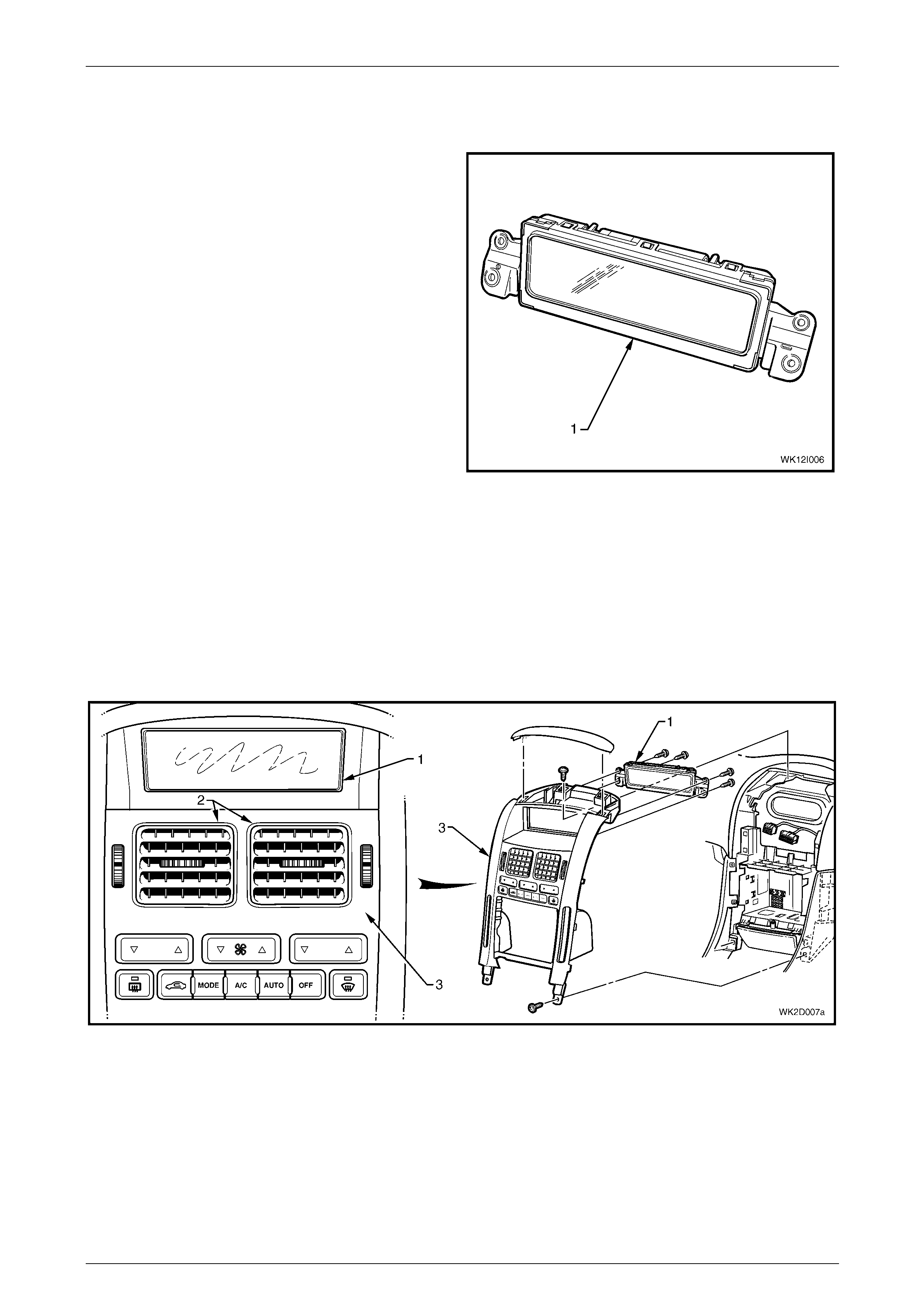
1 General Information
A Multi-function Display (MFD) (1) is fitted to the instrument
panel centre trim. Further information relating to the MFD
can be found in the following:
• Section 12D Entertainment System.
• Section 2D HVAC Occupant Climate Control (Auto
A/C) – Description and Operation.
• Owners handbook and audio supplement.
Figure 12I – 1
1.1 General Description
The MFD has a liquid crystal display, used to convey to the vehicle occupants the active functions and settings of the
Audio Head Unit (AHU) and Occupant Climate Control (OCC).
MFD Installation
The MFD (1) is located above the face level centre vents (2) and is attached to the back of the instrument panel centre
trim assembly (3) at four points.
Figure 12I – 2
MFD Serviceability
The MFD has no serviceable items. LED's are used to provide illumination. If any component fails to function, the module
must be replaced.
Page 12I–3

Multi-function Display Page 12I–4
1.2 MFD Communication
MFD Communication with Occupant Climate Control (OCC) Module
GMLAN protocol is used as the communication method between these two modules
For further information on GMLAN, refer to Section 6E1 Powertrain Interface Module – V6.
If there is no communication between the MFD and the OCC control module for more than 10 seconds, the OCC section
of the MFD screen will go blank and a DTC will be set.
MFD Communication with Audio Head Unit (AHU)
The MFD is connected to the audio system via the tertiary UART serial data bus.
For further information on UART serial communications, refer to Section 12J Body Control Module.
Page 12I–4
Multi-function Display Page 12I–5
1.3 MFD Screen Displays
The MFD displays the active functions of the entertainment system (AHU) and of the occupant climate control (OCC)
when one or both are in operation. The top portion of the MFD is dedicated to HVAC settings. The lower portion
(separated by a dividing line) is dedicated to audio system functions and displays the current time / date.
The following figures show views of selected MFD screen displays to provide an overview of normal functions.
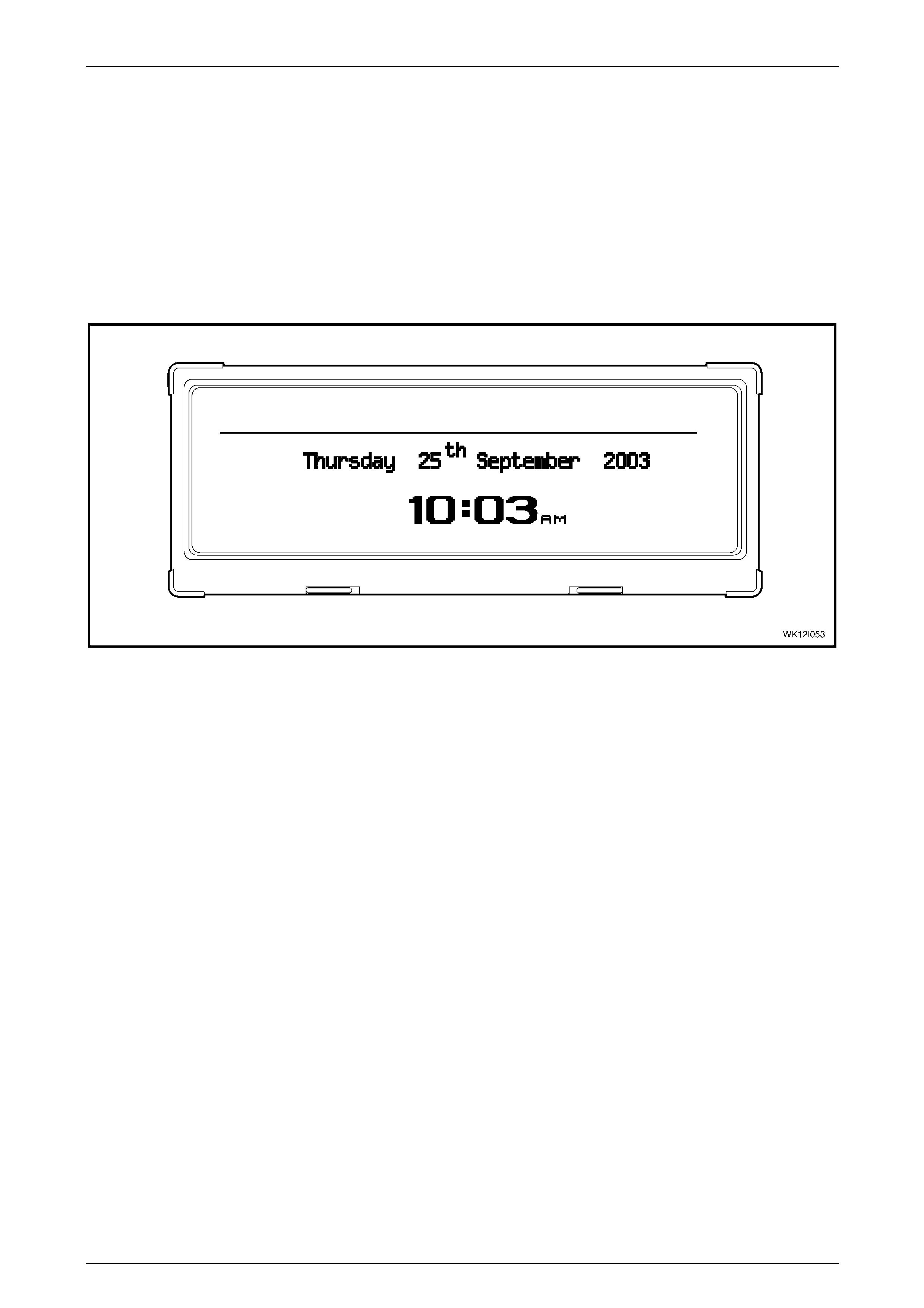
Time / Date Display
When the ignition is off, the date and time is displayed but the LCD will not be illuminated. When the ignition is on and the
audio system is off, the date and time will be displayed, and the LCD will be illuminated.
Figure 12I – 3
Radio Operation
When the key is in the ACC or ignition position and the audio system is operating with no auxiliary functions enabled, the
standard FM1 band radio preset display will appear as follows. If a station is manually selected, the indication PRESET 2
will cease to appear.
NOTE
For CD and DVD player information, refer to the
audio system Handbook.
Page 12I–5
Multi-function Display Page 12I–6
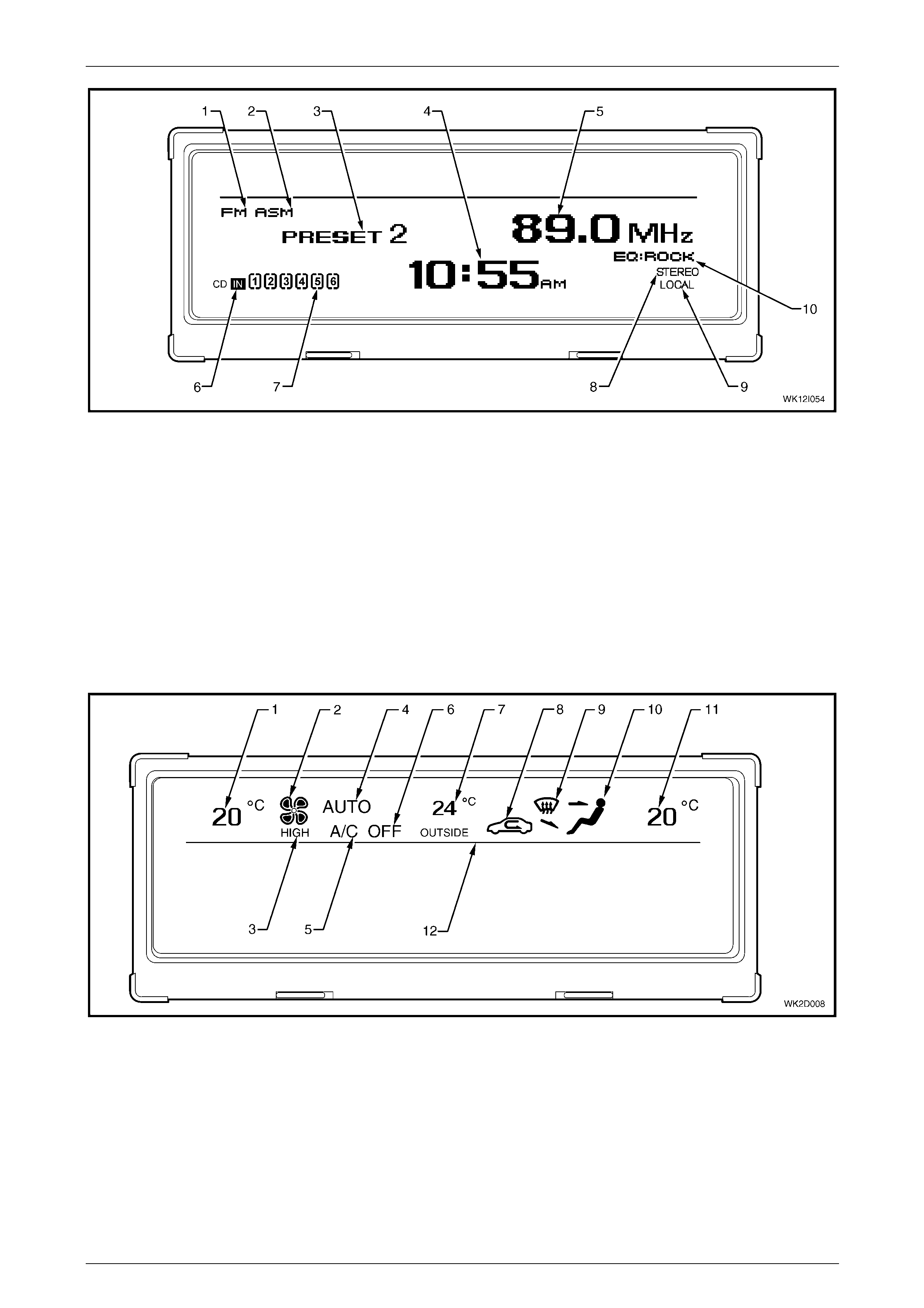
Figure 12I – 4
Legend
1 AM / FM Frequency Indicator 6 CD Inserted Indicator
2 Automatic Station Memory Indicator 7 CD Playing / Total Loaded Indicator
3 Station Preset Number 8 Stereo Sound Output Indicator
4 Time Display 9 Local / Distant Station Selection Indicator
5 Station Frequency Display 10 Equaliser Setting: Rock / Pop / Jazz / Classic / Vocal / Off
Heating Ventilation and Air-conditioning (HVAC) System Operation
The icons and information above the separation line of the MFD are devoted to Occupant Climate Control (Auto A/C)
heating and ventilation functions. The outside temperature is also displayed.
Figure 12I – 5
1 Left-hand Side Temperature Setting 7 Outside of Vehicle Temperature Indicator
2 Blower Fan 1, 2, 3, and 4 Speed Indicator 8 Recirculation Mode Active Indicator
3 Blower Fan Maximum Speed Indicator 9 Windscreen Demist Mode Active Indicator
4 OCC System In Auto Mode Indicator 10 Foot / Face / Bi-level Ventilation Mode Indicator
5 Air-conditioning On Indicator 11 Right-hand Side Temperature Setting
6 Air-conditioning Off Indicator 12 Audio / Time / Date Display and HVAC Display Separation Line
Page 12I–6

Multi-function Display Page 12I–7
Rear Remote Control
The rear passengers can access the rear remote control (1), which is fitted to the centre of the headlining (2) forward of
the rear passenger compartment. This unit combines a number of entertainment system and Occupant Climate Control
functions.
Figure 12I – 6
When the headphone switch on the audio head unit is pressed and held for more than 2 seconds, the following screen
will appear indicating the rear remote cannot be used to alter audio system settings. The heating and ventilation controls
will remain operational from the rear remote control. The words REAR REMOTE LOCKED will be displayed on the MFD
screen for 3 seconds. After 3 seconds, the REAR REMOTE LOCKED message will then minimise and continue to be
displayed at the top, right-hand corner of the screen.
Figure 12I – 7
When the headphone switch on the audio head unit is pressed and held for more than 2 seconds while the rear remote is
in a locked state, the MFD screen will display a REAR REMOTE UNLOCKED message for 3 seconds. After 3 seconds,
the existing screen details displayed prior to pressing the headphone switch will then be displayed again without the
minimised REAR REMOTE LOCKED indication. Rear passengers may then alter audio settings via the rear remote
control.
For further information relating to the rear remote control, refer to Section 12D Entertainment System.
Page 12I–7
Multi-function Display Page 12I–8
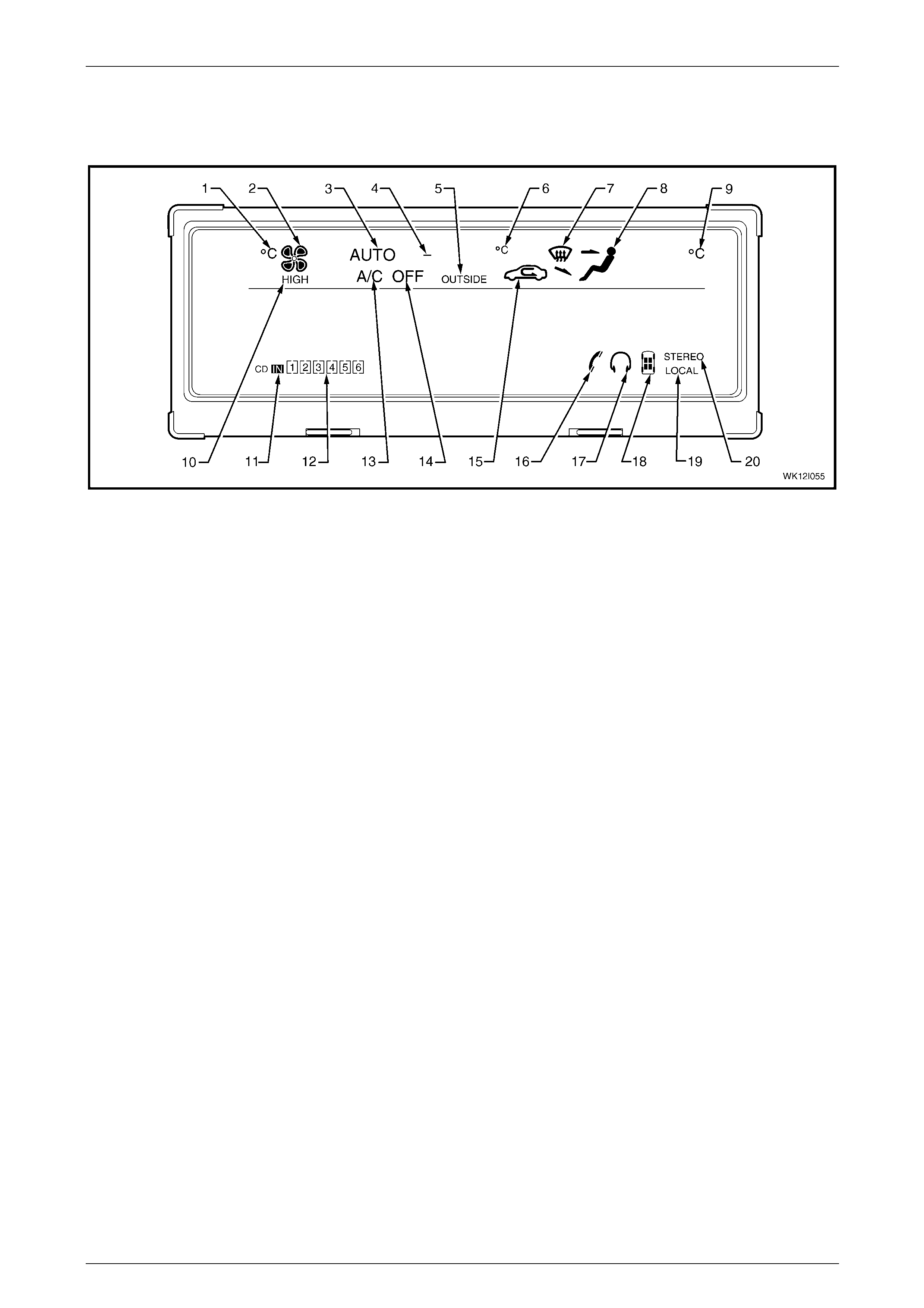
Fixed Icons
The following figure shows all available fixed icons on the MFD. They are displayed depending on the selected audio
system and HVAC system settings.
Figure 12I – 8
Legend
1 Left-hand Side Temperature Degree Celsius 11 CD Inserted Indicator
2 Blower Fan 1, 2, 3, and 4 Speed Indicator 12 CD Playing / Total Loaded Indicator
3 OCC System In Auto Mode Indicator 13 Air-conditioning On Indicator
4 Outside Temperature Minus Indicator 14 Air-conditioning Off Indicator
5 Outside Temperature Indicator 15 Recirculation Mode Active Indicator
6 Outside Temperature Degree Celsius 16 Phone Operation Indicator
7 Windscreen Demist Mode Active Indicator 17 Earphone Operation Indicator
8 Foot / Face / Bi-level Ventilation Mode Indicator 18 Listening Position (POS) Indicator
9 Right-hand Side Temperature Degree Celsius 19 Local / Distant Station Selection Indicator
10 Blower Fan Maximum Speed Indicator 20 Stereo Sound Output Indicator
If the OCC (Auto A/C) is active, the following icons are visible, if the ignition is in the ACC or ON position:
• Blower fan speed indicator (sequential shading and the word HIGH depending on blower fan speed setting).
• °C symbols for temperatures (unless Lo or Hi is chosen via the temperature switches).
• Passenger graphic showing current mode of airflow.
• OUTSIDE – this indicates outside air temperature.
If the audio system is active, the icons are visible, while the accessories or ignition is in the on position are:
• CD IN boxes.
• STEREO – automatically comes on when in FM or CD mode.
• HEADPHONE – this symbol is displayed when the headphones are plugged in or the Headphone button pressed
on the AHU.
Page 12I–8

Multi-function Display Page 12I–9
1.4 Setting MFD Time / Date
The time / date display function of the MFD is usually set through the Audio Head Unit (AHU). However, it is not
dependant on the AHU to maintain this setting.
Procedure – Normal
When the audio system is on, the MFD displayed time and date can be set through the AHU as follows.
1 Press the TIME button for more than 2 seconds. T he hour segment of the MFD screen will flash.
2 Adjust the hour setting using the SEEK TRACK and SEEK TRACK buttons.
3 To adjust the minute setting, press the TIME button again. The minute segment of the MFD screen will flash.
4 Adjust the minute setting using the SEEK TRACK and SEEK TRACK buttons.
5 Repeat this procedure until the year, month and date are set.
NOTE
The Program function of Tech 2 allows the MFD
time display to be set to a 24 hour clock or a
12 hour clock setting, refer to 7.1 Programming.
Procedure – Audio Head Unit Removed
If the audio system has been removed or replaced by a non-standard system, the MFD displayed time and date can be
set through the OCC control module as follows:
1 Turn the ignition on.
2 Press and hold both the AUTO and the driver’s side temperature ▲ buttons on the OCC control module for more
than 4 seconds. The hour segment of the MFD screen will flash.
3 Adjust the hours setting using the driver’s side ▲ and ▼ buttons.
4 To adjust the minute setting, press the AUTO button again. The minute segment of the MFD screen will flash.
5 Adjust the minute setting using the same ▲ and ▼ buttons.
6 Repeat this procedure until the year, month and date are set.
7 To exit this procedure, press and hold the OFF button for more than 2 seconds.
Page 12I–9
Multi-function Display Page 12I–10
1.5 MFD Illumination
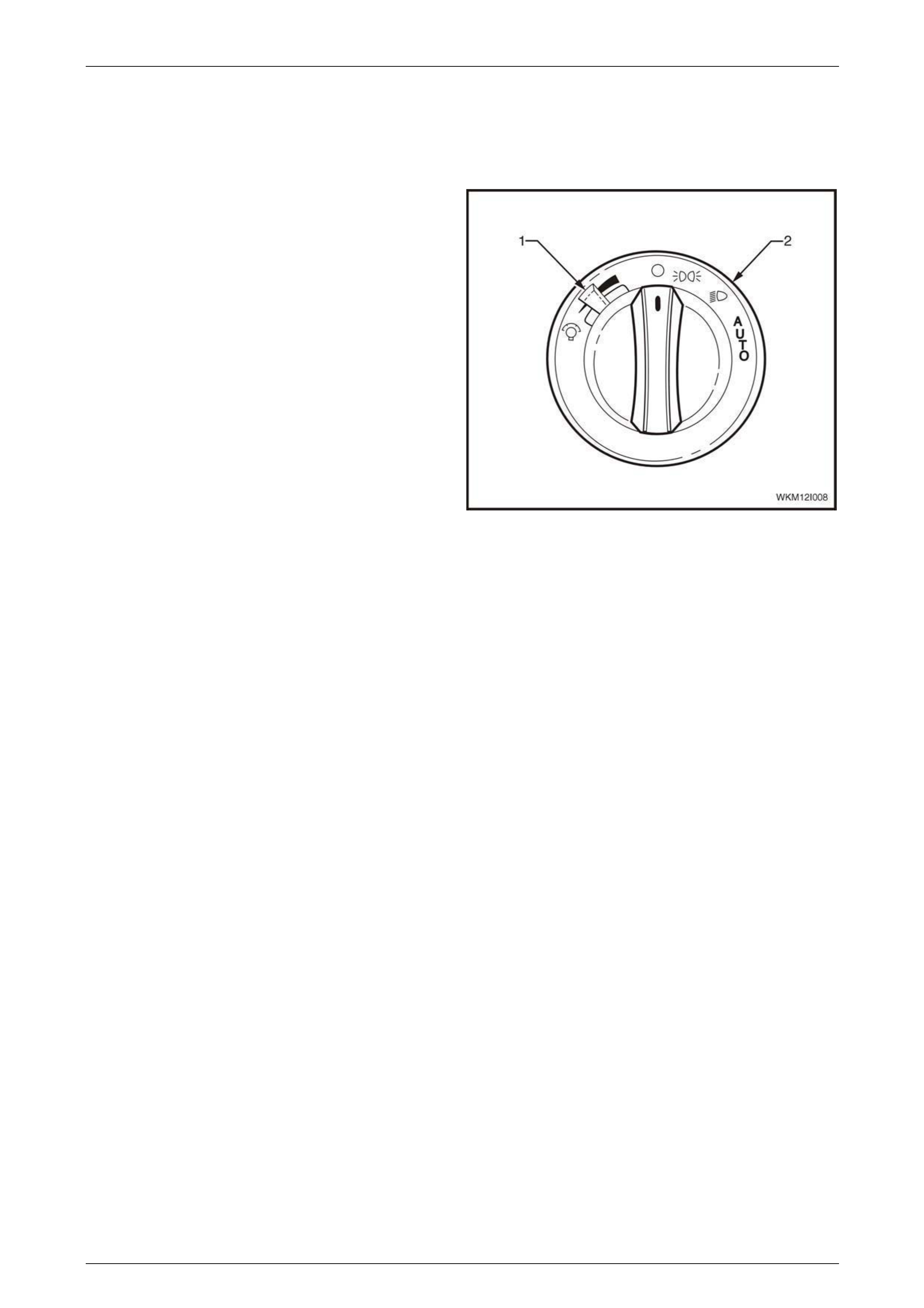
Illumination Adjustment
The MFD illumination level can be set from 0 to 100% using
the variable intensity illumination control slider (1) located on
the headlamp switch (2) while the park lamps are in the on
position.
When the park lamps are off, the MFD will be at full
illumination.
Illumination Adjustment Signal Path
The selected illumination level is sent to the MFD via the
BCM and the OCC control module. If there is a loss of
GMLAN communication between the MFD and the OCC
control module, the illumination level cannot be controlled by
the control slider at the headlamp switch.
Figure 12I – 9
Page 12I–10
Multi-function Display Page 12I–11
2 Tech 2 Information
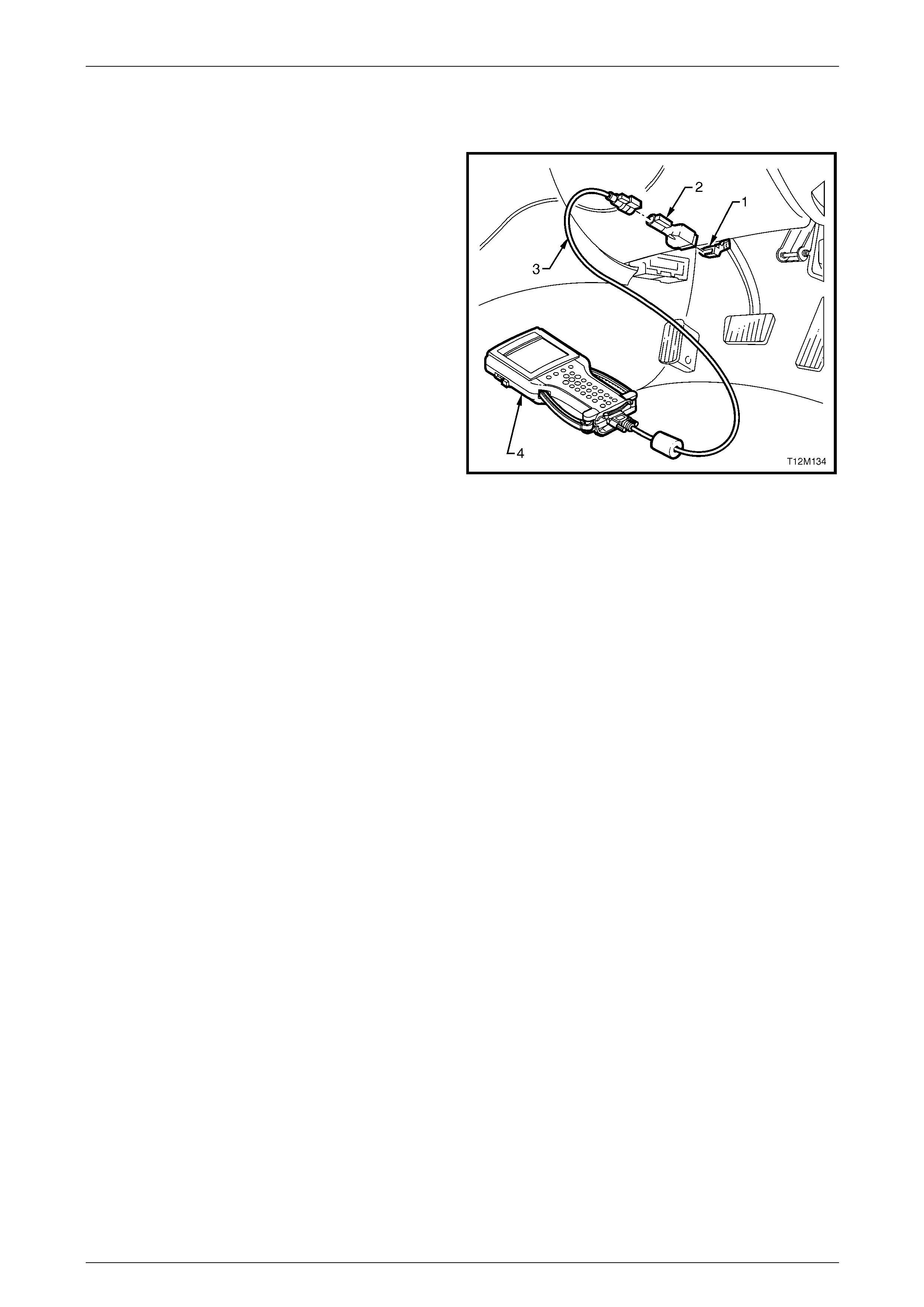
Tech 2, with the appropriate software, cables and adaptors,
is capable of reading serial data associated with the MFD
when connected to the Data Link Connector (DLC).
1 Data Link Connector (DLC).
2 DLC Adaptor.
3 DLC Cable.
4 Tech 2.
For additional general information on connecting and
operating Tech 2, refer to Section 0C Tech 2.
Figure 12I – 10
2.1 Tech 2 Test Modes
A prerequisite of the diagnostics is for the user to be familiar with the proper use of Tech 2. The following pages provide a
brief explanation for diagnosing the MFD. If additional information is required on the operation of Tech 2, reference
should be made to either Section 0C Tech 2 or the Tech 2 User’s Guide.
• With the ignition turned off, connect Tech 2 to the Data Link Connector (DLC) using the DLC Adaptor, refer to
Figure 12I – 10
Body Menu
On Tech 2 select:
Body / Multi Function Display.
The following functions will now be available:
• Normal Mode.
• Diagnostic Trouble Codes.
• Data Display.
• Snapshot.
• Miscellaneous Tests.
• Program.
Normal Mode
Displays the details of the serial data received by the MFD.
Diagnostic Trouble Codes
On Tech 2 select:
Body / Multi Function Display / Diagnostic Trouble Codes.
• Read DTC Information: If this mode is selected, a listing of all (if any) DTCs have been set by the MFD will be
displayed.
• Clear DTC Information: DTCs can be cleared in this mode by simply selecting Clear DTC Information, pressing
the Enter key on Tech 2 and confirming the action as instructed by Tech 2.
Page 12I–11

Multi-function Display Page 12I–12
Data Display
The Data Display function allows the status of the MFD inputs and outputs to be monitored, as well as the system
identification details.
On Tech 2 select:
Body / Multi Function Display / Data Display.
• Data List: When this mode is selected a listing of all serial data associated with the MFD will be displayed.
• System Identification: Provides details of system identification.
Data List
The serial data from the MFD can be checked and tested by selecting the item and pressing the soft key. The list can be
scrolled through by using the up and down arrow keys.
Data Display List
Tech 2 Display Range Remarks
Battery Voltage Volts This is unregulated voltage and can vary
according to the power load drawn by other
systems operating in the vehicle e.g. rear
demister.
Park Lamp Switch On / Off Park lamp status at connector P5 – X1 pin 3.
Displays On when the park lamp is on.
Accessory Relay On / Off Accessory relay status at connector P5 – X1
pin 12. Displays On when the accessory relay
is on.
MFD Illumination 0 – 100% Illumination level is set with the variable
intensity illumination control slider on the
headlamp switch, refer to 1.5 MFD Illumination
DTC Status No DTC / DTCs Set Indicates if any DTCs are set
Number of ignition cycles
since last DTC 0 – 255 5 Cycles
System Identification
The System Identification screen provides production information relevant to the MFD.
• Identifier.
• Software Version.
• EEPROM Version.
• Hardware Version.
• Manufacturer Change Index.
• Production Date.
• Part Number.
• TAG Number.
• Code Index.
• Code Version.
• 12 / 24 Hour Clock.
• VAP Process Number.
Page 12I–12

Multi-function Display Page 12I–13
Snapshot
1 On Tech 2 select:
Body / Multi Function Display / Snapshot.
2 The Tech 2 can be used to record system information occurring at a particular moment in time, and this is called a
snapshot. For further information, refer to Section 0C Tech 2.
Miscellaneous Tests
Tech 2 can be used to verify correct operation of the various functions of the MFD to assist in isolating a fault condition
and to force various functions on or off and monitor the response.
1 On Tech 2 select:
Body / Multi Function Display / Miscellaneous Tests.
2 Scroll through the Miscellaneous Tests using Tech 2 up and down arrows.
Park Lamp Input
The selected illumination level is sent from the headlamp switch to the MFD via the BCM and the OCC control module.
When the park lamps are switched off, the MFD is at full illumination. When the park lamps are switched on, the MFD
dims to the level previously set by the variable intensity illumination control slider on the headlight switch.
NOTE
If the illumination intensity is set to 0%, the MFD
LEDs will turn off when the park lamps are
switched on.
1 Turn the ignition on and the park lamps on.
2 Reduce MFD Illumination to less than 60% using the variable intensity illumination control slider on the headlight
switch.
3 On Tech 2 select:
Park Lamp Input.
4 Tech 2 will display the current park lamp switch status and MFD illumination.
5 Press the On soft key on Tech 2 to switch the park lamps on. Verify the MFD dims and the park lamp switch status
is displayed on the Tech 2 screen.
6 Press the Off soft key on the Tech 2 to switch the park lamps off. Verify the MFD brightens and the park lamp
switch status is displayed on the Tech 2 screen.
7 Press the Quit soft key to exit the test.
Page 12I–13
Multi-function Display Page 12I–14
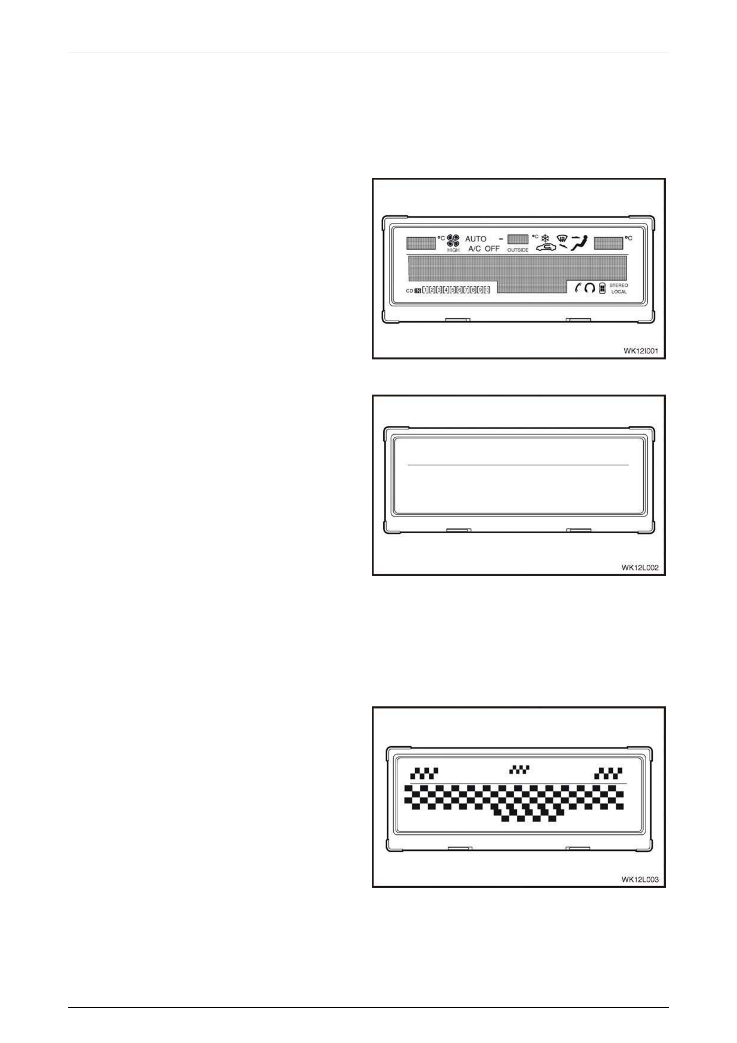
All Segments
This test verifies the MFD is able to illuminate all segments.
1 On Tech 2 select:
Body / Multi Function Display / Miscellaneous Tests / All Segments.
2 Using Tech 2 soft keys turn all segments On/Off.
3 Press the On soft key on Tech 2 to switch all
segments on. Tech 2 will display the All Segments
parameter as On.
The MFD will display all segments as shown.
Figure 12I – 11
1 Press the Off soft key on Tech 2 to switch all
segments off.
2 Press the Quit soft key on Tech 2 to exit the All
Segments test.
To test the Illumination of OCC specific information (upper
section of MFD display); refer to HVAC LCD Display Test.
Figure 12I – 12
Chequered Pattern
1 On Tech 2 select:
Body / Multi Function Display / Miscellaneous Tests / Chequered Pattern.
2 Tech 2 will display the status of the Chequered Pattern test.
3 Press the On soft key on Tech 2 to switch Chequered
Pattern on.
Tech 2 will display the Chequered Pattern parameter
as On.
Figure 12I – 13
Page 12I–14
Multi-function Display Page 12I–15
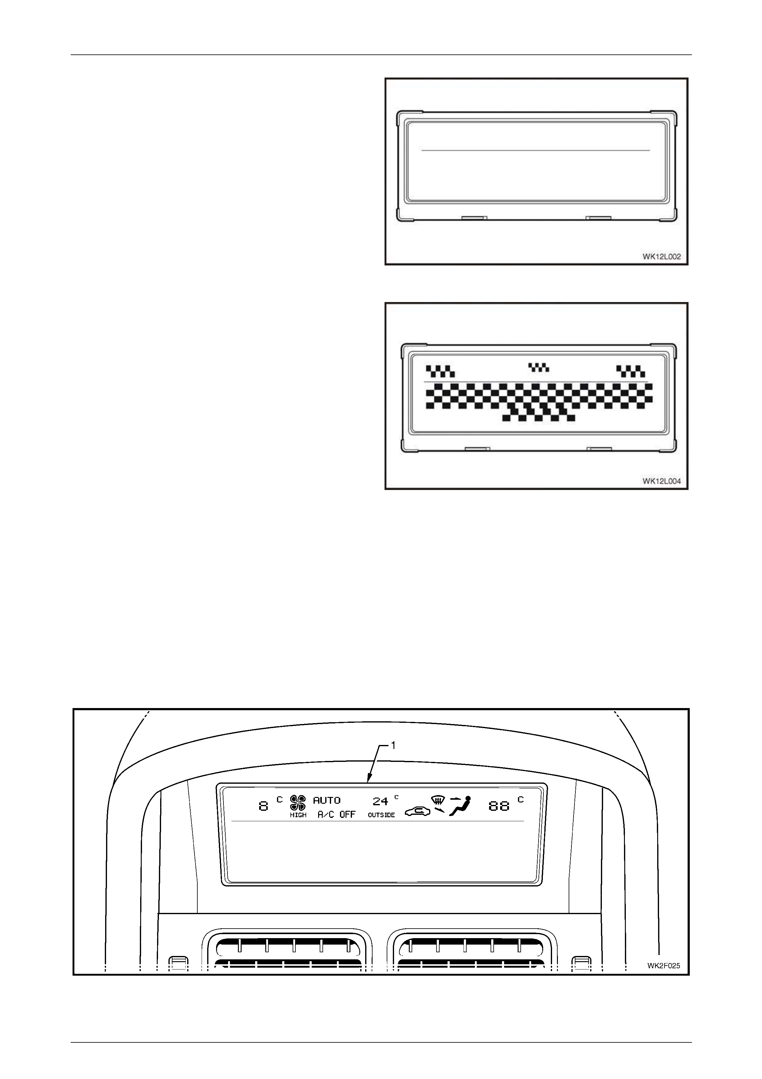
4 Press the Off soft key on Tech 2 to switch Chequered
Patterns off.
The MFD will display a blank screen as show.
Figure 12I – 14
5 Press the Inverse soft key on Tech 2 to switch the
Inverse Chequered Pattern on.
Tech 2 will show a chequered pattern as shown.
6 Press the Quit soft key on Tech 2 to exit the
Chequered Pattern test.
Figure 12I – 15
HVAC LCD Display Test
To ensure all HVAC related segments are functioning correctly and are properly displayed on the MFD screen. A further
test can be carried out through the Occupant Climate Control menu of Tech 2.
Procedure
On Tech 2 select:
Body / Occupant Climate Control / Miscellaneous Tests / LCD Display Test.
Using the On/Off soft keys on Tech 2, activate and deactivate the upper section of the MFD. The MFD should display
upper screen detail identical to the one shown in Figure 12I – 16. All segments should appear for approximately
5 seconds after the On soft key is activated.
Figure 12I – 16
Page 12I–15
Multi-function Display Page 12I–16
3 Wiring Diagrams and
Connectors
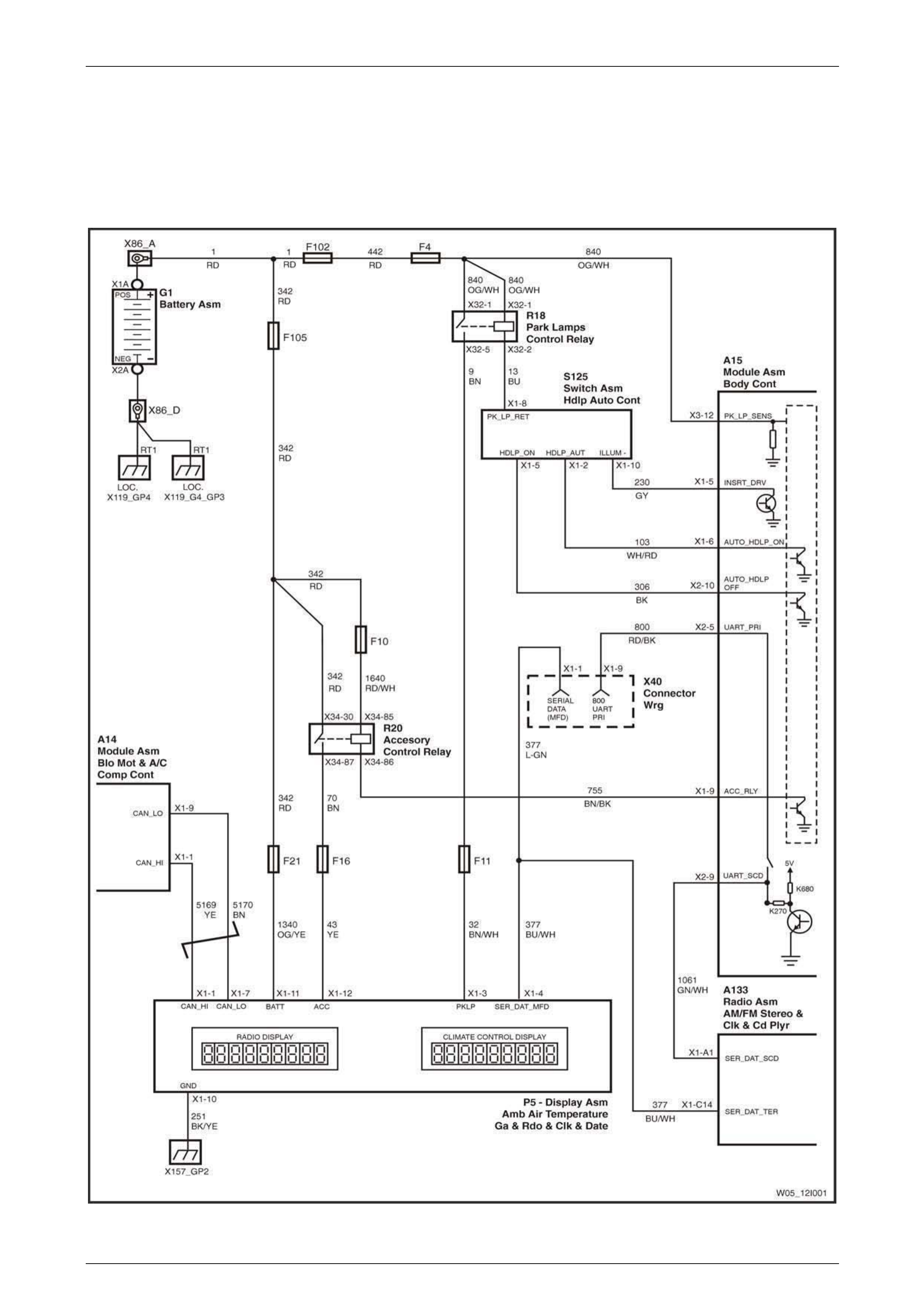
3.1 Wiring Diagram
Figure 12I – 17
Page 12I–16
Multi-function Display Page 12I–17
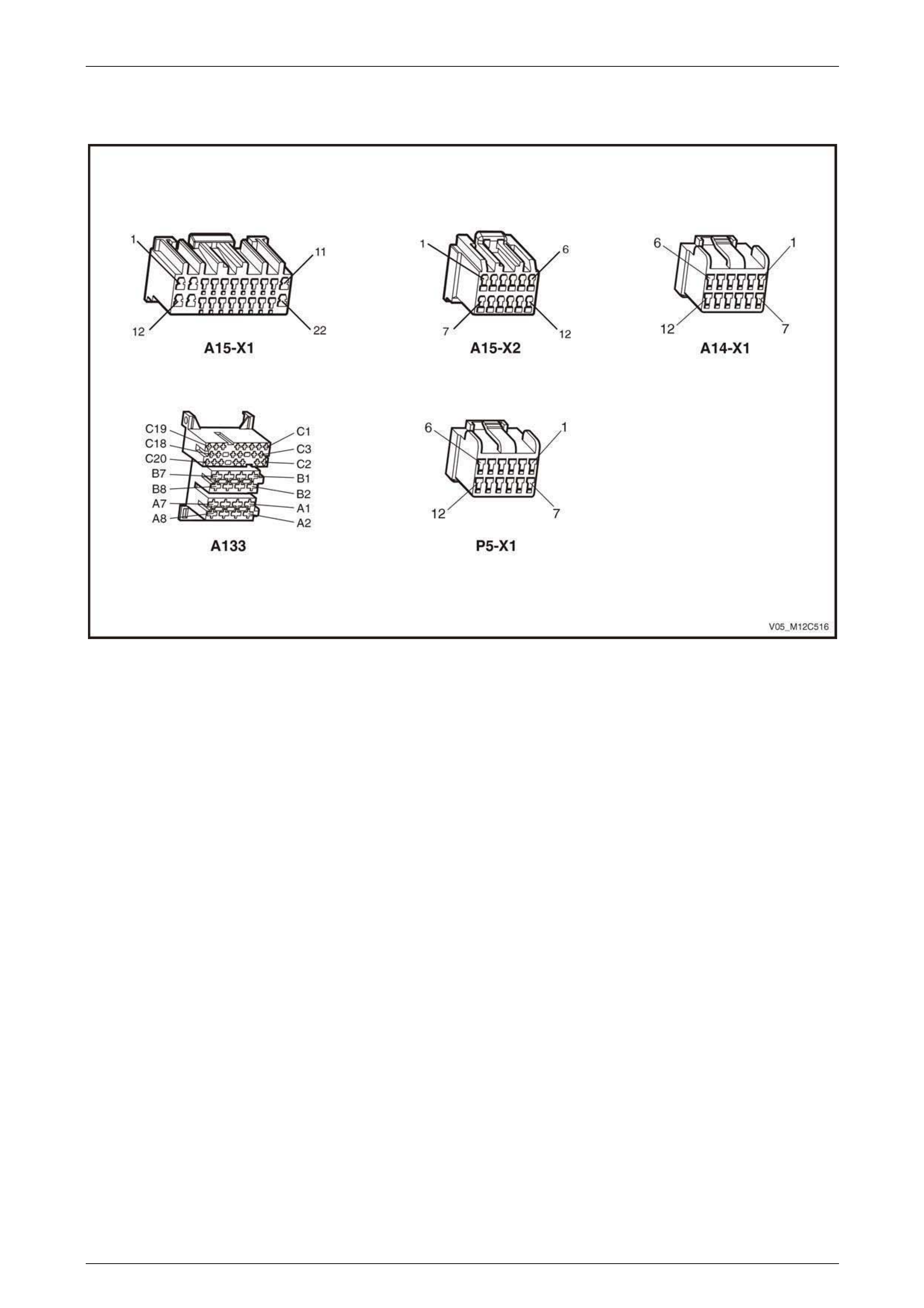
3.2 Connector Chart
Figure 12I – 18
Page 12I–17
Multi-function Display Page 12I–18
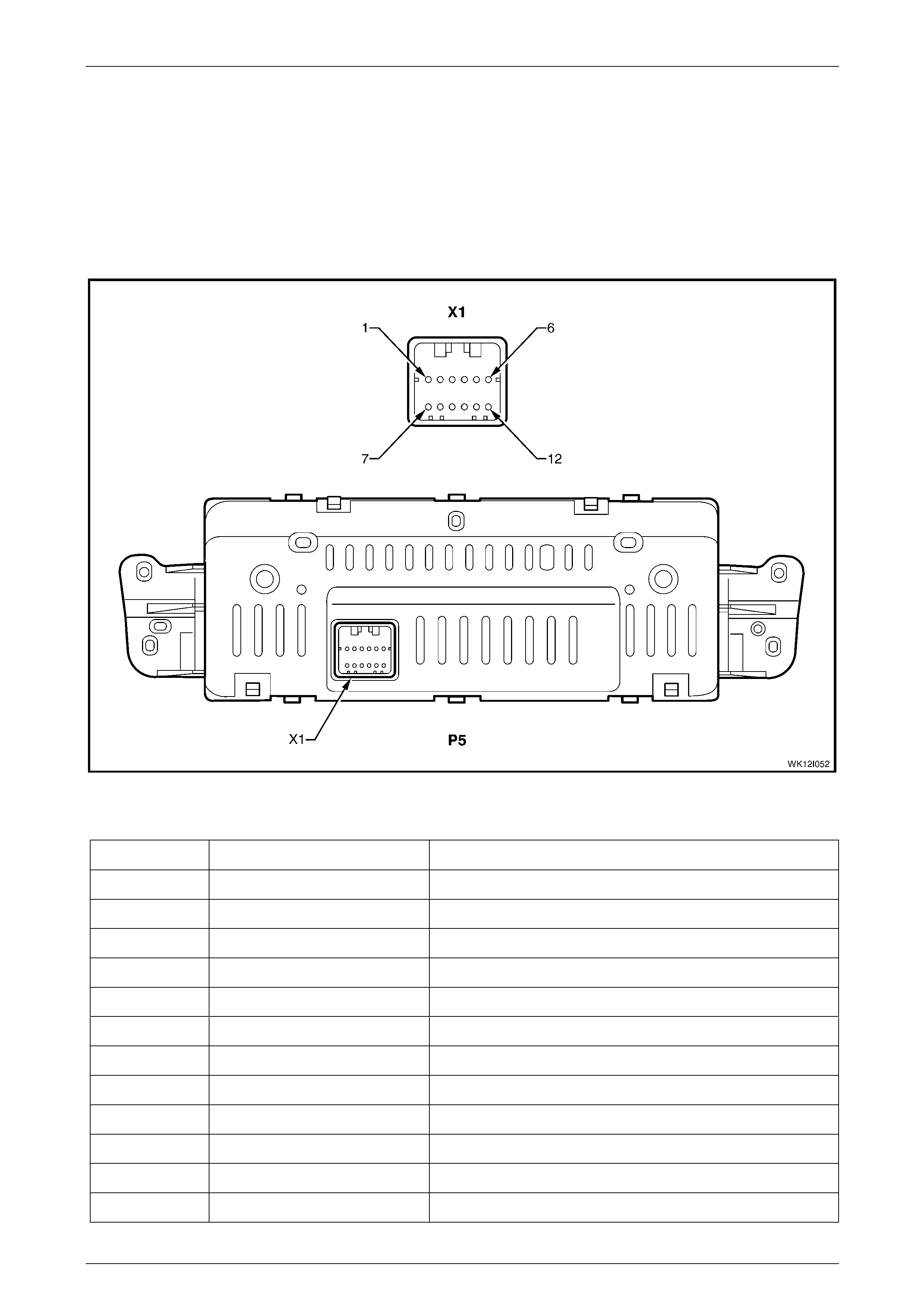
3.3 Connector Information
Multi-function Display
The module is designated as P5 and the connector located on the rear of the module housing is designated as connector
X1.
Figure 12I – 19 provides a view of the connector pin assignments and the tables following provide information on their
function.
Figure 12I – 19
Pin Number Wire Colour Function
X1-1 Yellow High speed GMLAN serial data bus (CAN HIGH)
X1-2 – Not used
X1-3 Brown / White Park lamp signal
X1-4 Blue / White UART serial data bus
X1-5 – Not used
X1-6 – Not used
X1-7 Brown High speed GMLAN serial data bus (CAN LOW)
X1-8 – Not used
X1-9 – Not used
X1-10 Black / Yellow Ground
X1-11 Orange / Yellow Battery voltage
X1-12 Yellow Accessory voltage
Page 12I–18

Multi-function Display Page 12I–19
4 Diagnostics
Equipment
The following equipment is required to diagnose the MFD.
• Digital multimeter with a minimum input impedance of 10 MΩ.
• Tech 2 diagnostic tool.
• Connector test adaptor kit KM–609
The following points must be adhered to
when performing diagnostic testing on
components.
• Take care when using test equipment to
diagnose wiring harness connectors. It is
preferred that the technician back probe
the connector to avoid terminal damage.
• When tests are required on connector
terminals, use the adapters in the
connector adapter kit KM–609 to prevent
damage to the terminals.
• Unless the multimeter being used has an
auto-ranging function, ensure the correct
range is selected.
• When back probing connectors, ensure
the multimeter ground lead is connected
to an appropriate ground point on the
vehicle. Ensure this ground point is not
part of the circuit being tested.
NOTE
When following the steps in the diagnostic tables,
perform them in the order cited. If the required
nominal value or result is not achieved, rectify the
problem before proceeding any further.
Diagnostic Trouble Codes
When a fault is detected, the multi-function display sets a diagnostic trouble code (DTC) this represents a particular
problem or failure, The DTC remains current as long as the fault remains, and is cleared when the fault is rectified the
DTC can be read and cleared using Tech 2.
NOTE
The MFD is not a serviceable item if it develops
any internal fault the unit must be replaced.
Page 12I–19

Multi-function Display Page 12I–20
4.1 Diagnostic System Check
This test is used to aid in diagnosing the Multi-function Display (MFD) and internal illumination.
Circuit Description
The MFD displays information from the radio and the OCC. If the values displayed on the MFD are incorrect, the most
likely source of the fault lies with either the AHU or the OCC.
Audio information is communicated to the MFD via the UART data bus. The UART data bus can be diagnosed using
Tech 2.
OCC information is communicated to the MFD via a dedicated GMLAN data bus. The GMLAN communications between
the OCC and MFD is one way, with the OCC sending information and the MFD receiving it.
With the ignition off, the MFD draws power directly from the battery. In this mode, the MFD only displays time and date
information. With the ignition on, the MFD displays Audio and OCC information (if the OCC is turned on). These functions
are powered through the accessory control relay R20. When the park lamps are on, the illumination of the MFD is
controlled by the park lamps relay R18. The illumination can be adjusted using the variable intensity illumination control
slider on the headlamp switch. If the illumination is set to 0%, the MFD screen will be blank while the headlamps are on.
When the ignition is on and the park lamps are off, the MFD is at maximum illumination.
For circuit information, refer to 3 Wiring Diagrams and Connectors.
Test Description
The following numbers refer to the step numbers in the diagnostic table:
3 Checks if the audio system is functioning.
5-6 Checks if the MFD is receiving data from the audio system and the OCC.
Diagnostic Table Notes
1 For all fuse, relay locations and wiring harness information, refer to Section 12O Fuses, Relays and Wiring
Harnesses.
2 For information on using and connecting Tech 2 to the vehicle, refer to Section 0C Tech 2.
Diagnostic System Check Diagnostic Table
Step Action Yes No
1 Is the fault specifically isolated to this system?
Go to Step 2
Refer to
OD Vehicle
Diagnostics
2 Turn the ignition off and the park lamps off.
Does MFD display time and date? Go to Step 3
Refer to
No Power
Diagnostic Table
3 1 Turn the ignition on.
2 Turn on the OCC blower fan.
Does the blower fan operate? Go to Step 4
Refer to
2E HVAC Occupant
Climate control
(Auto A/C) –
Diagnostics
4 Does the MFD display all OCC information?
Go to Step 5
Refer to
5.3 DTC-10 – No
GMLAN
Communication
from OCC System
5 Does MFD Illumination backlighting come on?
Go to Step 6
Refer to
6.2 No Illumination
or Dimming Control
6 With the ignition on turn the audio system on.
Does the audio system power up? Go to Step 7
Refer to
12D Entertainment
System
Page 12I–20

Multi-function Display Page 12I–21
Step Action Yes No
7 Does MFD display all audio information?
Go to Step 8
Refer to
6.3 No Audio
Information
Displayed
8 1 Connect Tech 2 to the DLC.
2 On Tech 2 select:
Body / Multi Function Display / Diagnostic Trouble Codes /
Read DTC Information.
Are any current DTCs set?
Refer to
5.1 Diagnostic
Trouble Codes list Go to Step 9
9 1 On Tech 2 select:
Diagnostic Trouble Codes / Clear DTC Information.
2 On Tech 2 select:
Read DTC Information.
Are any history DTCs set?
Refer to relevant
DTC diagnostic
table System serviceable
When all diagnosis and repairs are completed, clear all DTCs and check the system for correct operation.
Page 12I–21

Multi-function Display Page 12I–22
5 Diagnostic Tr ouble Codes
5.1 Diagnostic Trouble Codes List
DTC No DTC Source Description Diagnostic Table
10 Occupant Climate Control No Serial Data Refer to 5.3 DTC-10 – No
GMLAN Communication
from OCC System
15 Audio System No serial data Refer to 5.4 DTC-15 – No
Serial Data from the Audio
System
24 EEPROM Internal error Refer to 5.5 DTC-24 –
EEPROM Error
Page 12I–22

Multi-function Display Page 12I–23
5.2 DTC-10 – No GMLAN Communication
from OCC System
Circuit Description
With the ignition in the accessories or on position, this DTC will set if the MFD does not receive GMLAN communications
from the OCC for more than 10 seconds.
For circuit information, refer to 3 Wiring Diagrams and Connectors.
Test Description
The following numbers refer to the step numbers in the diagnostic table:
2-4 Checks the operation using Tech 2.
5 Checks the voltage on the GMLAN data bus.
6-7 Checks for short on circuit 5169.
8 Checks the voltage on the GMLAN data bus.
10 Checks for short on circuit 5170.
Diagnostic Table Notes
For information on using and connecting Tech 2 to the vehicle, refer to Section 0C Tech 2.
DTC-10 Diagnostic Table
Step Action Yes No
1 Has the Diagnostic System Check been performed?
Go to Step 2
Perform
4.1 Diagnostic
System Check
2 1 Connect Tech 2 to the DLC.
2 On Tech 2 select:
Body / Multi Function Display.
Does Tech 2 display MFD Information? Go to Step 3
Refer to
5.4 DTC-15 – No
Serial Data from the
Audio System for
further diagnosis
3 On Tech 2 select:
Body / Occupant Climate Control.
Does Tech 2 display OCC Information? Go to Step 4
Refer to
2E HVAC Occupant
Climate Control
(Auto A/C)–
Diagnostics
4 1 On Tech 2 select:
Body / Multi-function Display / Miscellaneous Tests /
Display / All Segments.
2 Perform the all segments illumination test. Refer to
Miscellaneous Tests.
Does the MFD display all segments? Go to Step 5
Replace MFD,
refer to
1A3 Instrument
Panel and Console
Page 12I–23

Multi-function Display Page 12I–24
Step Action Yes No
5 1 Turn the ignition Off.
2 Remove the MFD, refer to 1A3 Instrument Panel and Console.
3 Remove the OCC controller; refer to
2F HVAC Occupant Climate Control (Auto A/C) – Removal and
Installation.
4 Reconnect the two OCC wiring harness connectors to the rear of
the OCC control module.
5 Turn the Ignition On.
6 Using a multimeter set to measure voltage, probe between
connector P5 – X1 pin 1, and a known ground.
Does the multimeter indicate approximately 2.5 V? Go to Step 8 Go to Step 6
6 Using a multimeter set to measure resistance, probe between
connector P5 – X1 pin 1 and a known ground.
Does the multimeter indicate open circuit, no continuity? Go to Step 7 Repair short in
circuit 5169
7 Using a multimeter set to measure resistance, probe between
connector P5 – X1 pin 1 and a known ground.
Does the multimeter indicate continuity? Repair or replace
circuit 5169 Go to Step 11
8 1 Turn the ignition to the On position.
2 Using a multimeter set to measure voltage, probe between
connector P5 – X1 pin 7 and a known ground.
Does the multimeter indicate approximately 2.5 V?
Replace MFD
module, refer to
1A3 Instrument
Panel and Console Go to Step 9
9 1 Disconnect wiring harness connectors from the OCC controller.
2 Using a multimeter set to measure resistance, probe between
connectors P5 – X1 pin 7 and A14 – X1 pin 9.
Does the multimeter indicate continuity? Go to Step 10 Repair or replace
circuit 5170
10 Using a multimeter set to measure resistance, probe between
connector P5 – X1 pin 7 and a known ground.
Does the multimeter indicate continuity? Repair or replace
circuit 5170 Go to Step 11
11 1 Replace the OCC control module with a known good module;
refer to 2F HVAC Auto Remove & Install.
2 Connect Tech 2 to the DLC.
3 On Tech 2 select:
Body / Occupant Climate Control / Miscellaneous Tests /
LCD Display Test.
Were all the segments on the top half of the MFD displayed? System serviceable
Reinstall the original
OCC controller and
replace the MFD,
refer to
1A3 Instrument
Panel and Console
When all diagnosis and repairs are completed, clear all DTCs and check the system for correct operation.
Page 12I–24

Multi-function Display Page 12I–25
5.3 DTC-15 – No Serial Data from the Audio
System
Circuit Description
With the ignition on, this DTC will set if the MFD does not receive serial data from the audio system for more than 10
seconds.
For circuit information, refer to 3 Wiring Diagrams and Connectors.
Test Description
The following numbers refer to the step numbers in the diagnostic table:
1-3 Checks the operation using Tech 2.
5 Checks the wiring harness continuity from the MFD connector to the park lamp relay.
6 Checks for a short circuit to ground on serial data line.
7-10 Checks for correct voltage on GMLAN bus.
Diagnostic Table Notes
1 For all fuse, relay locations and wiring harness information refer to Section 12O Fuses, Relays and Wiring
Harnesses.
2 For information on using and connecting Tech 2 to the vehicle, refer to Section 0C Tech 2.
DTC-15 Diagnostic Table
1 Has the Diagnostic System Check been performed?
Go to Step 2
Perform
4.1 Diagnostic
System Check
2 1 Connect Tech 2 to the DLC.
2 On Tech 2 select:
Body / Multi Function Display / Diagnostic Trouble Codes /
Read DTC Information.
Is the history DTC 15 – No Serial Data from Audio System set?
Refer to
12D Entertainment
System
Check circuits for
intermittent faults,
refer to
12P Wiring
Diagrams
3 1 Turn Ignition on.
2 Turn Radio on.
3 On Tech 2 select:
Body / Audio System.
Does Tech 2 display Audio System Information? Go to Step 4
Refer to
12D Entertainment
System
4 1 On T ech 2 select:
Body / Audio System / Miscellaneous Tests / Display.
2 Press the On soft key on Tech 2.
Are all segments displayed on the lower half of the MFD? Go to Step 8 Go to Step 5
Page 12I–25

Multi-function Display Page 12I–26
5 1 Turn the ignition off.
2 Remove the MFD, refer to 1A3 Instrument Panel and Console.
3 Reinstall the AHU.
4 Disconnect Tech 2 from the DLC.
5 Turn the ignition to ACC position.
6 Using a multimeter set to measure voltage, probe between
connector P5 – X1 pin 4 and a known ground.
Does the multimeter indicate approximately 2 – 4 V?
Replace the MFD,
refer to
1A3 Instrument
Panel and Console Go to Step 6
6 1 Turn the ignition off.
2 Remove the AHU.
3 Using a multimeter set to measure resistance, probe between
connectors P5 – X1 pin 4 and A133 – X1 pin C14.
Does the multimeter indicate continuity? Go to Step 7 Repair or replace
circuit 377
7 1 Turn the ignition off.
2 Using a multimeter set to measure resistance, probe between
connector P5 – X1 pin 4 and a known ground.
Does the multimeter indicate open circuit, no continuity?
Replace AHU.
Refer to
12D Entertainment
System Repair or replace
circuit 377
8 1 T urn Ignition off.
2 Using a multimeter set to measure voltage, probe between
connector X40 – X1 pin 1 and a known ground.
Does the multimeter indicate approximately 2 – 4 V?
Refer to
0D Vehicle
Diagnostics Go to Step 9
9 Was the voltage at step 7 higher than the specified value? Go to Step 10 Go to Step 11
10 1 Remove the AHU, Refer to 12D Entertainment System.
2 Using a multimeter set to measure voltage, probe between
connector X40 – X1 pin 1 and a known ground.
Does the multimeter indicate a voltage above 4 V? Repair or replace
circuit 377
Replace the AHU,
refer to
12D Entertainment
System
11 1 Remove the AHU, Refer to 12D Entertainment System.
2 Using a multimeter set to measure resistance, probe between
connector X40 – X1 pin 1 and a known ground.
Does the multimeter indicate a voltage below 2 V? Repair or replace
circuit 377
Replace the AHU,
refer to
12D Entertainment
System
When all diagnosis and repairs are completed, clear all DTCs and check the system for correct operation.
Page 12I–26

Multi-function Display Page 12I–27
5.4 DTC-24 – EEPROM Error
The internal fault detection is handled inside the MFD. No external circuits are involved.
If this DTC has set, replace the MFD.
For circuit information, refer to 3 Wiring Diagrams and Connectors
Test Description
The following numbers refer to the step numbers in the diagnostic table:
1 Using Tech 2 to diagnose the MFD.
Diagnostic Table Notes
For information on using and connecting Tech 2 to the vehicle, refer to Section 0C Tech 2.
DTC-24 Diagnostic Table
Step Action Yes No
1 1 Connect Tech 2 to the DLC.
2 On Tech 2 select:
Body / Multi Function Display / Diagnostic Trouble Codes /
Read DTC Information.
Is the DTC 24 – EEPROM Error set?
Replace MFD,
refer to
1A3 Instrument
Panel and
Console System serviceable
When all diagnosis and repairs are completed, clear all DTCs and check the system for correct operation.
Page 12I–27

Multi-function Display Page 12I–28
6 Diagnostics for Non DTC Faults
6.1 No Power
Circuit Description
The MFD is permanently powered via fuse F21 with the ignition key in the OFF position, the time and date will still be
displayed but will not be illuminated. When the ignition key is turned to the accessories or ignition position and the audio
and OCC (Auto A/C) systems are off, the time and date will continue to be displayed and illuminated. Accessory power to
the MFD is supplied by fuse F16 via the accessory control relay. The accessory control relay is switched on by the BCM
when the ignition key is turned to the accessory position.
For wiring diagrams and connectors, refer to 3 Wiring Diagrams and Connectors
Test Description
The following numbers refer to the step numbers in the diagnostic table:
2 Checks the MFD 12 V supply connection.
3 Checks the MFD ground connection.
Diagnostic Table Notes
For all fuse, relay locations and wiring harness information refer to Section 12O Fuses, Relays and Wiring Harnesses.
No Power Diagnostic Table
Step Action Yes No
1 Has the Diagnostic System Check been performed?
Go to Step 2
Perform
4.1 Diagnostic
System Check
2 Check fuses F21, F105.
Are these fuses serviceable? Go to Step 3 Replace the
faulty fuse
3 1 Turn the ignition off.
2 Remove the MFD, refer to 1A3 Instrument Panel and Console
and Console and Console.
3 Using a multimeter set to measure voltage, probe between
connector P5 – X1 pin 11 and a known ground.
Does the multimeter indicate battery voltage? Go to Step 4 Repair or replace
circuits 1340, 342.
4 Using a multimeter set to measure resistance, probe between
connector P5 – X1 pin 10 and a known ground.
Does the multimeter indicate continuity?
Replace MFD,
refer to
1A3 Instrument
Panel and Console
Repair or replace
circuit 251 and / or
ground point X157–
GP2
When all diagnosis and repairs are completed, check the system for correct operation.
Page 12I–28

Multi-function Display Page 12I–29
Page 12I–29
6.2 No Illumination or Dimming Control
Circuit Description
When the park lamps are on, reduced illumination of the MFD is controlled through the park lamps control relay R18 at connector X1
pin 3 of the MFD. The illumination can be adjusted using the variable intensity illumination control slider on the headlamp switch. The
selected setting is sent to the BCM and forwarded to the OCC control module via the data bus. The OCC control module passes this
message to the MFD via the GMLAN bus communications linking the two modules. If the illumination is set to 0%, the MFD screen will
be blank while the headlamps are on. When the ignition is on and the park lamps are off, the MFD is at maximum illumination.
For circuit information, refer to 3 Wiring Diagrams and Connectors.
Test Description
The following numbers refer to the step numbers in the diagnostic table:
4 Checks the 12 V park lamp supply to the MFD.
5 Checks the continuity of the wiring harness from the MFD connector to the park lamp relay.
6 Checks for a short circuit to ground.
Diagnostic Table Notes
1 For all fuse and relay locations and wiring harness information refer to Section 12O Fuses, Relays and Wiring
Harnesses.
2 No Illumination or No Dimming Control.
Diagnostic Table
Step Action Yes No
1 Has the Diagnostic System Check been performed?
Go to Step 2
Perform
4.1 Diagnostic
System Check
2 1 Turn ignition on.
2 Turn park lamps on.
3 Adjust the illumination using the variable intensity illumination
control slider on the headlamp switch.
Does the MFD illumination respond to changes in dimming level? System serviceable Go to Step 3
3 Does the instrument cluster illumination respond to changes in
dimming level?
Go to Step 4
Refer to
12J Body Control
Module for further
Information
4 Check if fuse F11 is serviceable.
Go to Step 5
Replace the
faulty fuse
5 1 Turn the park lamps off.
2 Turn the ignition off.
3 Remove the MFD refer to, 1A3_Instrument Panel.
4 Turn the ignition on.
5 Turn the park lamps on.
6 Using a multimeter set to measure voltage, probe between the
connector P5 – X1 pin 3 and a known ground.
Does the multimeter indicate battery voltage?
Replace the MFD,
refer to
1A3 Instrument
Panel and Console Go to Step 6

Multi-function Display Page 12I–30
Step Action Yes No
6 1 Turn the ignition Off.
2 Turn the park lamps Off.
3 Using a multimeter set to measure resistance, probe between
the connectors P5 – X1 pin 3 and R18 – X32 pin 5.
Does the multimeter indicate continuity? Go to Step 7
Repair or replace
circuit 32 or 9,
refer to
12O Fuses, Relays
and Wiring
Harnesses
7 Using a multimeter set to measure resistance, probe between
connector P5 – X1 pin 3, and a known ground.
Does the multimeter indicate an open circuit, no continuity? System serviceable
Repair or replace
circuit 32
Check for blown
fuse F11
When all diagnosis and repairs are completed, check the system for correct operation.
Page 12I–30

Multi-function Display Page 12I–31
6.3 No Audio Information Displayed
Circuit Description
A failure to display radio information on the MFD can be caused by any of the following conditions.
• Faulty audio head unit.
• Faulty MFD.
• Installation of a foreign or lower level audio system.
• Loss of power to the MFD.
• Loss of serial communication between the MFD and the audio system.
For circuit information, refer to 3 Wiring Diagrams and Connectors.
Test Description
The following numbers refer to the step numbers in the diagnostic table:
1-5 Checks the operation using Tech 2.
6-7 Checks the MFD 12 V accessory supply.
8 Checks the MFD ground connection.
Diagnostic Table Notes
1 For all fuse, relay locations and wiring harness information refer to Section 12O Fuses, Relays and Wiring
Harnesses.
2 For information on using and connecting Tech 2 to the vehicle, refer to Section 0C Tech 2.
No Audio Information Displayed Diagnostic Table
Step Action Yes No
1 Has the Diagnostic System Check been performed?
Go to Step 2
Perform
4.1 Diagnostic
System Check
2 1 Connect Tech 2 to the DLC.
2 On Tech 2 select:
Body / Audio System.
Does Tech 2 display audio system identification data? Go to Step 3
Refer to
12D Entertainment
System
3 On Tech 2 select:
Body / Multi-function Display.
Does Tech 2 display MFD system identification data? Go to Step 4 Go to Step 6
4 1 On Tech 2 select:
Body / Audio System / Data Display / System Identification.
2 Find the audio system identifier number.
Is the identifier number one of the following? 306, 311, 411, 601 Go to Step 5
Remove AHU and
replace with the
correct AHU,
refer to
12D Entertainment
System
5 1 On Tech 2 select:
Body / Multi-function Display / Miscellaneous Tests / All
Segments.
2 Perform the all segments On / Off using the soft keys
Does the MFD display all segments?
Replace MFD,
refer to
1A3 Instrument
Panel and Console
Page 12I–31

Multi-function Display Page 12I–32
Step Action Yes No
6 1 Turn the ignition off.
2 Remove the MFD refer to, 1A3 Instrument Panel and Console.
3 Turn the ignition to the ACC position.
4 Using a multimeter set to measure voltage, probe between
connector P5 – X1 pin 12, and a known ground.
Does the multimeter indicate battery voltage?
Repair or replace
circuits 43 or 70 or
replace fuse F16
7 Using a multimeter set to measure resistance, probe between
connector P5 – X1 pin 10, and a known ground.
Does the multimeter indicate continuity?
Replace MFD,
refer to
1A3 Instrument
Panel and Console
Repair or replace
circuit 251 and / or
ground point X157–
GP2 (right-hand
inner fender panel)
When all diagnosis and repairs are completed, clear all DTCs and check the system for correct operation.
Page 12I–32

Multi-function Display Page 12I–33
7 Service Operations
7.1 Programming
The Program function allows the MFD time display to be changed from a 24-hour clock to a 12-hour clock.
1 On Tech 2 select:
Body / Multi Function Display / Program.
2 Scroll through the Program list using the Tech 2 up and down arrows.
Program Code Index
The code index number identifies the MFD and vehicle configuration, and the code version number identifies the software
version. Only the code index number can be changed. The following table details the code index numbers for the various
models in the WL Series vehicles. The following code indexes are available:
A 12-Hour clock.
B 24-Hour clock.
1 On Tech 2 select:
Program Code Index.
2 Press the Modify soft key on Tech 2 to modify the Code Version. Press the Okay soft key to retain the current
setting.
3 Use the up and down arrow keys on Tech 2 to scroll to the desired clock setting. To program the selection press the
Program soft key on Tech 2. If you do not wish to program a clock setting, press the Abort soft key on Tech 2 to exit
the menu.
Page 12I–33

Multi-function Display Page 12I–34
7.2 Multi-function Display
Using tools to prise off components may
damage the instrument panel, the instrument
panel upper centre trim and / or the centre
trim assembly.
NOTE
Refer to Section 1A3 Instrument Panel and
Console for removal and reinstallation
instructions for the MFD.
Page 12I–34
Multi-function Display Page 12I–35
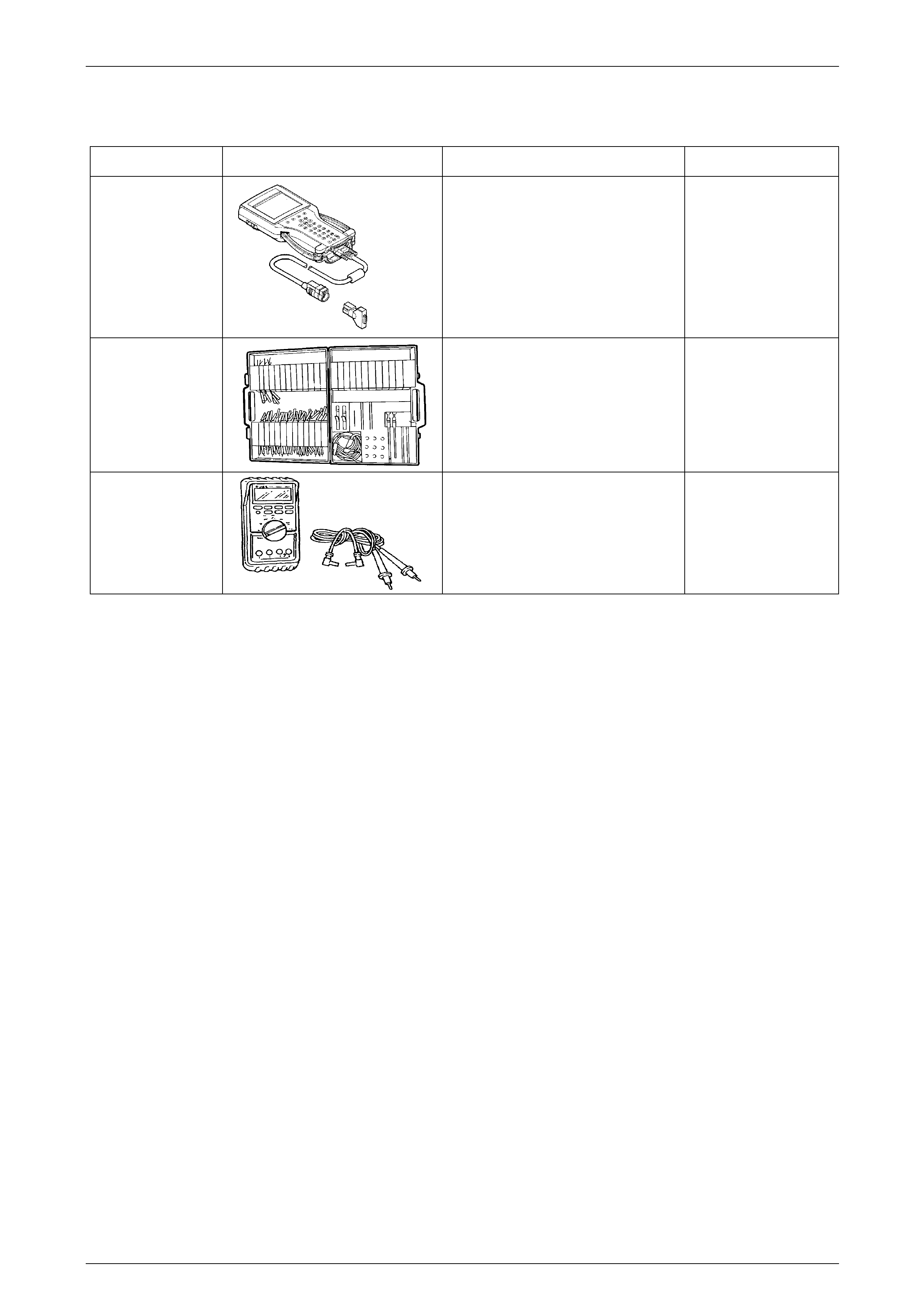
8 Special Tools
Tool Number Illustration Description Tool Classification
7000086I
Tech 2
Diagnostic Scan Tool
Used for diagnosis of vehicle electrical
system
Previously released
Mandatory
J35616-C
(KM609)
Connector Test Adaptor Kit
Used when carrying out electrical
diagnostic circuit checks
Previously released.
Desirable
3588
(J39200)
Digital Multimeter
Must have at least 10 MΩ input
impedance and be capable of reading
frequencies
Previously released.
Mandatory
Page 12I–35