
Telematics Page 12K–1
Page 12K–1
Section 12K
Telematics
ATTENTION
Before performing any service operation or other procedure described in this Section, refer to Section 00
Warnings, Cautions and Notes for correct w orkshop practices wi th regard to safety and/or property damage.
1 General Information...............................................................................................................................7
2 Principles of Operation..........................................................................................................................9
2.1 Operating Modes.................................................................................................................................................... 9
Pre-delivery Mode..................................................................................................................................................9
Service Mode.......................................................................................................................................................... 9
Active Mode............................................................................................................................................................ 9
Stand-by Mode..................................................................................................................................................... 10
Sleep Mode........................................................................................................................................................... 10
Battery Saver Mode.............................................................................................................................................. 10
2.2 Alerts..................................................................................................................................................................... 11
Airbag Activation Alert ........................................................................................................................................ 11
Low Battery Voltage Alert ................................................................................................................................... 11
Battery Removal Alert.......................................................................................................................................... 11
Unauthorised Entry Alert..................................................................................................................................... 11
2.3 Holden Assist Remote Requests........................................................................................................................ 12
Engine Immobilisation......................................................................................................................................... 12
Remote Unlocking ............................................................................................................................................... 12
2.4 Telematics Module............................................................................................................................................... 13
2.5 Interior Rear-view Mirror ..................................................................................................................................... 14
Telematics Button Pad ........................................................................................................................................ 14
End Call / Information Button............................................................................................................................ 14
HOLDEN ASSIST Button................................................................................................................................. 14
Microphone....................................................................................................................................................... 14
Emergency Button............................................................................................................................................ 15
Status Indicator LEDs....................................................................................................................................... 16
2.6 Audio System Interface....................................................................................................................................... 17
Audio System and Right-hand Front Speakers................................................................................................. 17
Audible Tones...................................................................................................................................................... 17
2.7 Backup Battery..................................................................................................................................................... 19
2.8 Battery Voltage..................................................................................................................................................... 20
2.9 Backup Battery Charger...................................................................................................................................... 21
2.10 Serial Data ............................................................................................................................................................ 22
V6 Engine ............................................................................................................................................................. 23
GEN III V8 Engine................................................................................................................................................. 26
2.11 Driver's Door Ajar Switch.................................................................................................................................... 29
2.12 Passenger Door Ajar Switches........................................................................................................................... 30
2.13 Alarm Input (Theft Deterrent Horn)..................................................................................................................... 31
V6 Engine ............................................................................................................................................................. 31
GEN III V8 Engine................................................................................................................................................. 32
Techline

Telematics Page 12K–2
Page 12K–2
2.14 Telematics Antenna............................................................................................................................................. 33
GPS Antenna........................................................................................................................................................ 33
GSM Antenna ....................................................................................................................................................... 34
2.15 Fuel Pump Relay Drive Circuit............................................................................................................................ 35
V6 Engine ............................................................................................................................................................. 35
GEN III V8 Engine................................................................................................................................................. 36
2.16 Wiring Harnesses................................................................................................................................................. 37
2.17 Connector Diagrams............................................................................................................................................ 38
3 Tech 2 Diagnostics for Telematics.....................................................................................................39
3.1 Basic Knowledge Required................................................................................................................................. 39
Basic Electrical Circuits...................................................................................................................................... 39
Use of Circuit Testing Tools............................................................................................................................... 39
3.2 Connecting Tech 2............................................................................................................................................... 40
3.3 Tech 2 Test Modes............................................................................................................................................... 41
System Select Menu ............................................................................................................................................ 41
Application Menu................................................................................................................................................. 42
F0: Diagnostic Trouble Codes.......................................................................................................................... 42
F1: Data Display............................................................................................................................................... 43
F2: Snapshot Options....................................................................................................................................... 49
F3: Miscellaneous Tests................................................................................................................................... 49
F4: Additional Functions................................................................................................................................... 51
F5: Program ..................................................................................................................................................... 52
4 Diagnostics...........................................................................................................................................54
4.1 Basic Knowledge and Tools Required............................................................................................................... 54
4.2 Diagnostic Precautions....................................................................................................................................... 55
Blocking Drive Wheels ........................................................................................................................................ 56
Visual / Physical Inspection................................................................................................................................ 56
4.3 Diagnostic Table Description.............................................................................................................................. 57
Diagnostic Tables Components ......................................................................................................................... 57
4.4 Strategy-based Diagnostics................................................................................................................................ 59
4.5 On-board Diagnostic System Check.................................................................................................................. 61
4.6 Diagnostic Trouble Codes .................................................................................................................................. 62
Diagnostic Trouble Codes .................................................................................................................................. 63
4.7 Telematics Module Connector Descriptions ..................................................................................................... 64
4.8 Diagnostic Tables................................................................................................................................................ 65
On-board Diagnostic System Check.................................................................................................................. 65
Circuit Description............................................................................................................................................ 65
Test Description ............................................................................................................................................... 65
DTC 1 — No Serial Data From BCM.................................................................................................................... 67
Circuit Description............................................................................................................................................ 67
Conditions for Setting the DTC......................................................................................................................... 67
Action Taken When the DTC Sets.................................................................................................................... 67
Test Description ............................................................................................................................................... 67
Diagnostic Table............................................................................................................................................... 67
DTC 2 — No Serial Data From Instrument ......................................................................................................... 68
Circuit Description............................................................................................................................................ 68
Conditions For Setting the DTC........................................................................................................................ 68
Action Taken When the DTC Sets.................................................................................................................... 68
Test Description ............................................................................................................................................... 68
Diagnostic Table............................................................................................................................................... 68
DTC 3 — No Serial Data From Sensing Diagnostic Module............................................................................. 69
Circuit Description............................................................................................................................................ 69
Conditions For Setting the DTC........................................................................................................................ 69
Action Taken When the DTC Sets.................................................................................................................... 69
Test Description ............................................................................................................................................... 69
Diagnostic Table............................................................................................................................................... 69

Telematics Page 12K–3
Page 12K–3
DTC 4 — No Serial Data From Audio System.................................................................................................... 70
Circuit Description............................................................................................................................................ 70
Conditions For Setting the DTC........................................................................................................................ 70
Action Taken When the DTC Sets.................................................................................................................... 70
Test Description ............................................................................................................................................... 70
Diagnostic Table............................................................................................................................................... 70
DTC 5 — No Serial Data....................................................................................................................................... 71
Circuit Description............................................................................................................................................ 71
Conditions for Setting the DTC......................................................................................................................... 71
Action Taken When the DTC Sets.................................................................................................................... 71
Test Description ............................................................................................................................................... 71
Diagnostic Table............................................................................................................................................... 72
DTC 8 — SIM Mismatch....................................................................................................................................... 72
Conditions For Setting the DTC........................................................................................................................ 72
Action Taken When the DTC Sets.................................................................................................................... 72
Test Description ............................................................................................................................................... 72
Diagnostic Table............................................................................................................................................... 72
DTC 9 — Vehicle Battery Voltage Too High....................................................................................................... 73
Circuit Description............................................................................................................................................ 73
Conditions for Setting the DTC......................................................................................................................... 73
Action Taken When the DTC Sets.................................................................................................................... 73
Test Description ............................................................................................................................................... 73
Diagnostic Table............................................................................................................................................... 73
DTC 10 — Vehicle Battery Voltage Too Low ..................................................................................................... 74
Circuit Description............................................................................................................................................ 74
Conditions for Setting the DTC......................................................................................................................... 74
Action Taken When the DTC Sets.................................................................................................................... 74
Test Description ............................................................................................................................................... 74
Diagnostic Table............................................................................................................................................... 75
DTC 11 — RAM Error........................................................................................................................................... 76
Conditions for Setting the DTC......................................................................................................................... 76
Action Taken When the DTC Sets.................................................................................................................... 76
Test Description ............................................................................................................................................... 76
Diagnostic Table............................................................................................................................................... 76
DTC 12 — EEPROM Error.................................................................................................................................... 76
Conditions for Setting the DTC......................................................................................................................... 76
Action Taken When the DTC Sets.................................................................................................................... 76
Test Description ............................................................................................................................................... 76
Diagnostic Table............................................................................................................................................... 76
DTC 13 — Backup Battery Timer Expired.......................................................................................................... 77
Circuit Description............................................................................................................................................ 77
Conditions for Setting the DTC......................................................................................................................... 77
Action Taken When the DTC Sets.................................................................................................................... 77
Test Description ............................................................................................................................................... 77
Diagnostic Table............................................................................................................................................... 77
DTC 14 — Backup Battery Voltage Too High .................................................................................................... 78
Circuit Description............................................................................................................................................ 78
Conditions for Setting the DTC......................................................................................................................... 78
Action Taken When the DTC Sets.................................................................................................................... 78
Test Description ............................................................................................................................................... 78
Diagnostic Table............................................................................................................................................... 78
DTC 15 — Backup Battery Voltage Too Low..................................................................................................... 79
Circuit Description............................................................................................................................................ 79
Conditions for Setting the DTC......................................................................................................................... 79
Action Taken When the DTC Sets.................................................................................................................... 79
Test Description ............................................................................................................................................... 79
Diagnostic Table............................................................................................................................................... 79

Telematics Page 12K–4
Page 12K–4
DTC 16 — Backup Battery Not Detected............................................................................................................ 80
Circuit Description............................................................................................................................................ 80
Conditions for Setting the DTC......................................................................................................................... 80
Action Taken When the DTC Sets.................................................................................................................... 80
Test Description ............................................................................................................................................... 80
Diagnostic Table............................................................................................................................................... 80
DTC 17 — Microphone Not Detected.................................................................................................................. 81
Circuit Description............................................................................................................................................ 81
Conditions for Setting the DTC......................................................................................................................... 81
Action Taken When the DTC Sets.................................................................................................................... 81
Test Description ............................................................................................................................................... 81
Diagnostic Table............................................................................................................................................... 81
DTC 18 — Microphone Circuit Voltage Too Low............................................................................................... 82
Circuit Description............................................................................................................................................ 82
Conditions for Setting the DTC......................................................................................................................... 82
Action Taken When the DTC Sets.................................................................................................................... 82
Test Description ............................................................................................................................................... 82
Diagnostic Table............................................................................................................................................... 82
DTC 19 — Microphone Circuit Voltage Too High.............................................................................................. 83
Circuit Description............................................................................................................................................ 83
Conditions for Setting the DTC......................................................................................................................... 83
Action Taken When the DTC Sets.................................................................................................................... 83
Test Description ............................................................................................................................................... 83
Diagnostic Table............................................................................................................................................... 83
DTC 21 — Speaker Circuit Voltage Too Low..................................................................................................... 84
Circuit Description............................................................................................................................................ 84
Conditions for Setting the DTC......................................................................................................................... 84
Action Taken When the DTC Sets.................................................................................................................... 84
Test Description ............................................................................................................................................... 84
Diagnostic Table............................................................................................................................................... 85
DTC 22 — Speaker Circuit Voltage Too High .................................................................................................... 86
Circuit Description............................................................................................................................................ 86
Conditions for Setting the DTC......................................................................................................................... 86
Action Taken When the DTC Sets.................................................................................................................... 86
Test Description ............................................................................................................................................... 86
Diagnostic Table............................................................................................................................................... 87
DTC 30 — Keypad Circuit Voltage Too High ..................................................................................................... 88
Circuit Description............................................................................................................................................ 88
Conditions for Setting the DTC......................................................................................................................... 88
Action Taken When the DTC Sets.................................................................................................................... 88
Test Description ............................................................................................................................................... 88
Diagnostic Table............................................................................................................................................... 89
DTC 39 — Telephone Number Error................................................................................................................... 90
Conditions for Setting the DTC......................................................................................................................... 90
Action Taken When the DTC Sets.................................................................................................................... 90
Test Description ............................................................................................................................................... 90
Diagnostic Table............................................................................................................................................... 90
DTC 40 — Vehicle Identification Number Mismatch......................................................................................... 90
Conditions for Setting the DTC......................................................................................................................... 90
Action Taken When the DTC Sets.................................................................................................................... 90
Test Description ............................................................................................................................................... 90
Diagnostic Table............................................................................................................................................... 90
DTC 42 — Fuel Pump Circuit Voltage Too Low................................................................................................. 91
Circuit Description............................................................................................................................................ 91
Conditions for Setting the DTC......................................................................................................................... 91
Action Taken When the DTC Sets.................................................................................................................... 91
Test Description ............................................................................................................................................... 91
Diagnostic Table............................................................................................................................................... 91

Telematics Page 12K–5
Page 12K–5
DTC 43 — Fuel Pump Circuit Voltage Too High................................................................................................ 92
Circuit Description............................................................................................................................................ 92
Conditions for Setting the DTC......................................................................................................................... 92
Action Taken When the DTC Sets.................................................................................................................... 92
Test Description ............................................................................................................................................... 92
Diagnostic Table............................................................................................................................................... 92
DTC 45 — End Call / Information Button Stuck................................................................................................. 93
Circuit Description............................................................................................................................................ 93
Conditions for Setting the DTC......................................................................................................................... 93
Action Taken When the DTC Sets.................................................................................................................... 93
Test Description ............................................................................................................................................... 93
Diagnostic Table............................................................................................................................................... 93
DTC 46 — HOLDEN ASSIST Button Stuck......................................................................................................... 94
Circuit Description............................................................................................................................................ 94
Conditions for Setting the DTC......................................................................................................................... 94
Action Taken When the DTC Sets.................................................................................................................... 94
Test Description ............................................................................................................................................... 94
Diagnostic Table............................................................................................................................................... 94
DTC 47 — Emergency Button Stuck .................................................................................................................. 95
Circuit Description............................................................................................................................................ 95
Conditions for Setting the DTC......................................................................................................................... 95
Action Taken When the DTC Sets.................................................................................................................... 95
Test Description ............................................................................................................................................... 95
Diagnostic Table............................................................................................................................................... 95
4.9 Symptoms Tables................................................................................................................................................ 96
No Serial Data....................................................................................................................................................... 96
Circuit Description............................................................................................................................................ 96
Test Description ............................................................................................................................................... 96
Diagnostic Table............................................................................................................................................... 97
Status Indicator LEDs Do Not Illuminate........................................................................................................... 99
Circuit Description............................................................................................................................................ 99
Test Description ............................................................................................................................................... 99
Diagnostic Table............................................................................................................................................. 100
Vehicle Battery Voltage..................................................................................................................................... 101
Circuit Description.......................................................................................................................................... 101
Test Description ............................................................................................................................................. 101
Diagnostic Table............................................................................................................................................. 101
Backup Battery................................................................................................................................................... 102
Circuit Description.......................................................................................................................................... 102
Test Description ............................................................................................................................................. 102
Diagnostic Table............................................................................................................................................. 103
No GPS Signal.................................................................................................................................................... 104
Circuit Description.......................................................................................................................................... 104
Test Description ............................................................................................................................................. 104
Diagnostic Table............................................................................................................................................. 104
No GSM Signal................................................................................................................................................... 105
Circuit Description.......................................................................................................................................... 105
Test Description ............................................................................................................................................. 105
Diagnostic Table............................................................................................................................................. 105
Emergency Button............................................................................................................................................. 106
Circuit Description.......................................................................................................................................... 106
Test Description ............................................................................................................................................. 106
Diagnostic Table............................................................................................................................................. 106
HOLDEN ASSIST Button ................................................................................................................................... 108
Circuit Description.......................................................................................................................................... 108
Test Description ............................................................................................................................................. 108
Diagnostic Table............................................................................................................................................. 108

Telematics Page 12K–6
Page 12K–6
End Call / Information Button ........................................................................................................................... 110
Circuit Description.......................................................................................................................................... 110
Test Description ............................................................................................................................................. 110
Diagnostic Table............................................................................................................................................. 110
Theft Deterrent Horn Circuit.............................................................................................................................. 112
Circuit Description.......................................................................................................................................... 112
Test Description ............................................................................................................................................. 112
Diagnostic Table............................................................................................................................................. 112
Driver's Door Ajar Switch.................................................................................................................................. 113
Circuit Description.......................................................................................................................................... 113
Test Description ............................................................................................................................................. 113
Diagnostic Table............................................................................................................................................. 113
Passengers Door Ajar Switches....................................................................................................................... 114
Circuit Description.......................................................................................................................................... 114
Test Description ............................................................................................................................................. 114
Diagnostic Table............................................................................................................................................. 114
Microphone ........................................................................................................................................................ 116
Circuit Description.......................................................................................................................................... 116
Test Description ............................................................................................................................................. 116
Diagnostic Table............................................................................................................................................. 116
Fuel Pump Relay Drive Circuit.......................................................................................................................... 117
Circuit Description.......................................................................................................................................... 117
Test Description ............................................................................................................................................. 117
Diagnostic Table............................................................................................................................................. 117
Audio Mute ......................................................................................................................................................... 118
Circuit Description.......................................................................................................................................... 118
Test Description ............................................................................................................................................. 118
Diagnostic Table............................................................................................................................................. 118
Audio System Interface..................................................................................................................................... 120
Circuit Description.......................................................................................................................................... 120
Test Description ............................................................................................................................................. 120
Diagnostic Table............................................................................................................................................. 121
Unable to Make or Receive a Call..................................................................................................................... 123
Circuit Description.......................................................................................................................................... 123
Test Description ............................................................................................................................................. 123
Code Index..................................................................................................................................................... 123
Diagnostic Table............................................................................................................................................. 123
Holden Assist Telematics System Test............................................................................................................ 124
5 Service Operations.............................................................................................................................125
5.1 Telematics Module............................................................................................................................................. 125
Remove............................................................................................................................................................... 125
Reinstall.............................................................................................................................................................. 126
Telematics Module Changeover ....................................................................................................................... 126
5.2 Backup Battery................................................................................................................................................... 127
Remove............................................................................................................................................................... 127
Reinstall.............................................................................................................................................................. 127
5.3 Telematics Antenna........................................................................................................................................... 128
Remove............................................................................................................................................................... 128
Reinstall.............................................................................................................................................................. 129
5.4 Interior Rear-view Mirror ................................................................................................................................... 130
Remove............................................................................................................................................................... 130
Reinstall.............................................................................................................................................................. 130
6 Torque Wrench Specifications .........................................................................................................131

Telematics Page 12K–7
Page 12K–7
1 General Information
The telematics system has been developed using some of the most advanced Global Positioning System (GPS) and
telecommunications technology, global system for mobile (GSM) communications available. The telematics system
provides in-vehicle safety, security and information services by providing a two-way, hands-free communication to either
the Holden Assist Centre or, in an emergency, to the National Emergency Response Centre (NERC™).
The Holden Assist Centre provides several services, including:
• remote door unlocking,
• connection to Holden Roadside Assistance,
• low battery alert, and
• accident enquiry.
If theft of the vehicle is attempted, the telematics system can track the vehicle and, in certain circumstances, remotely
immobilise the engine. For a full list of services provided by the Holden Assist Centre, refer to the Holden Assist
Handbook Supplement.
The link between the vehicle and the Holden Assist Centre or the NERC™ uses GPS for vehicle location and tracking,
and the Australian digital mobile phone network to transmit and receive voice and Short Message Service (SMS) data. If
the vehicle is outside network coverage, the link to and from the vehicle is not available and no services can be provided.
Signal strength may be affected in locations like basement car parks or tunnels. When the vehicle emerges from the
obstruction or re-enters the digital phone network area the signal becomes available again.
A vehicle equipped with the Telematics system is delivered from the vehicle assembly plant to the retail outlet with the
telematics system in the pre-delivery mode. During vehicle pre-delivery, the telematics module pre-delivery mode must
be disabled and the service mode enabled using Tech 2. In service mode, limited service is provided until the customer
has signed the terms and conditions document and has set up the telematics system by pressing the HOLDEN ASSIST
button located in the telematics button pad on the interior rear-view mirror. The Holden Assist Centre operator then
disables the service mode and the telematics system becomes fully operational. The set-up procedure information is
provided in the Holden Assist Handbook Supplement.
The telematics module has a built-in diagnostic system that identifies system operational problems and alerts the driver
by illuminating the red LED in the interior rear-view mirror. If the LED continuously illuminates when the ignition is on, the
telematics system is not functional; the cause of the lamp illuminating should be checked as soon as possible.
Figure 12K – 1
Telematics Page 12K–8
Page 12K–8
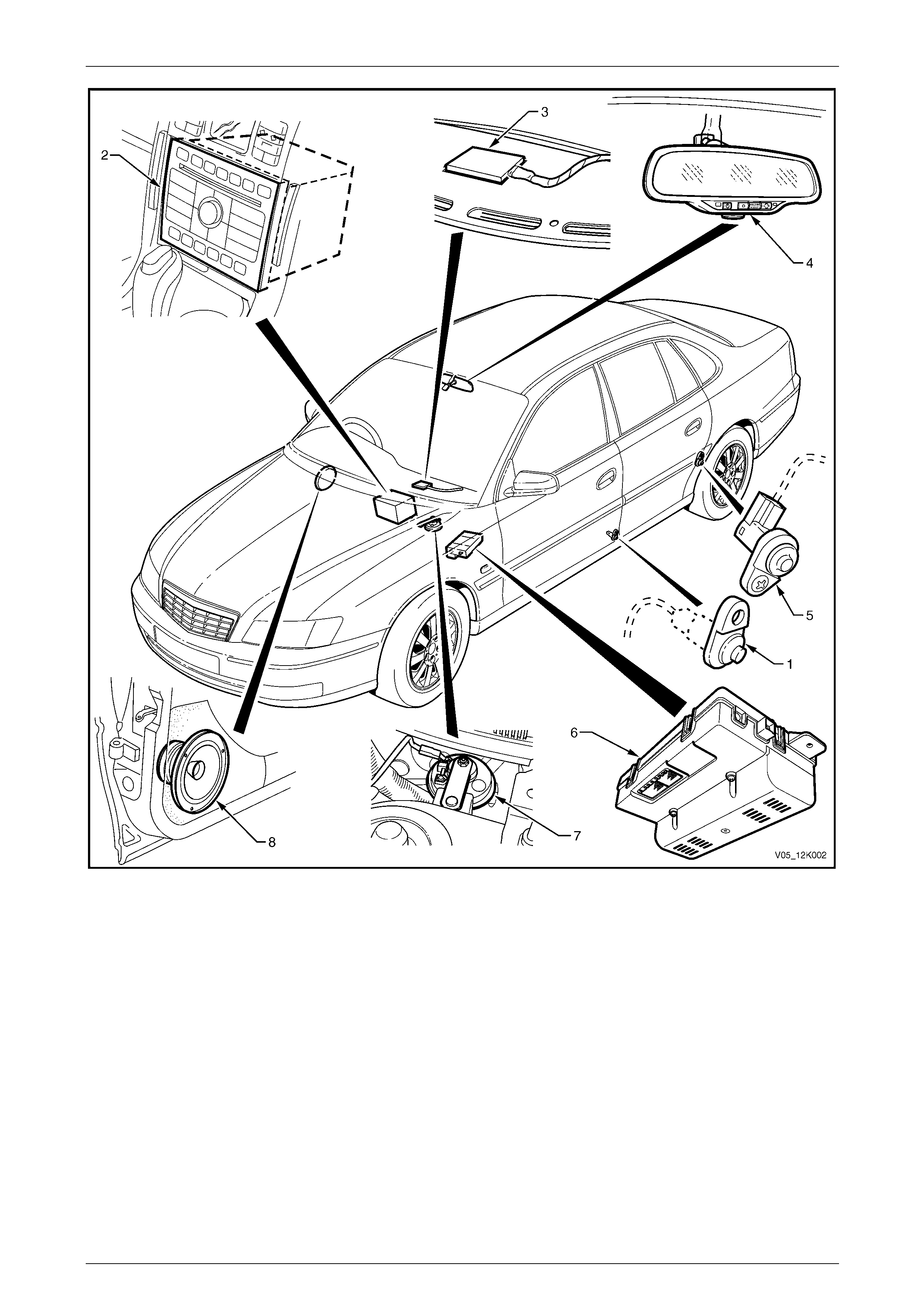
Figure 12K – 2
Legend
1 Front Door Ajar Switch (both sides)
2 Audio Head Unit
3 Telematics Antenna
4 Interior Rear-view Mirror
5 Rear Door Ajar Switch (both sides)
6 Telematics Module
7 Theft Deterrent Horn
8 Right Front Door Speaker

Telematics Page 12K–9
Page 12K–9
2 Principles of Operation
2.1 Operating Modes
The telematics system has six modes of operation:
• pre-delivery mode,
• service mode,
• active mode,
• stand-by mode,
• sleep mode, and
• battery saver mode.
These operating modes minimise the system current draw and allow features to be enabled or disabled depending on the
operating mode.
Pre-delivery Mode
In the pre-delivery mode the system is not operational. The vehicle is delivered from the assembly plant to the dealer with
the telematics system in the pre-delivery mode. Before the vehicle is delivered to the customer, the telematics system
must be taken out of the pre-delivery mode using Tech 2, refer to 3.3 Tech 2 Test Modes. In pre-delivery mode, the
telematics module communicates only with Tech 2 and only when the ignition is set to the ON position.
Service Mode
When the vehicle is scheduled to be serviced, the telematics system service mode should be activated. The customer
may request the Holden Assist Centre to remotely enable or disable service mode. A service technician can also enable
or disable service mode with Tech 2, refer to 3.3 Tech 2 Test Modes.
When service mode is activated, the telematics module ignores all button activation except for the HOLDEN ASSIST
button. In addition, the telematics module does not transmit alert messages for unauthorised entry or low battery, but
does transmit an airbag activation alert.
Active Mode
This is the normal telematics system operating mode. In active mode, the telematics system is fully functional and can
make and receive calls, and transmit data via the GSM network. In this mode, the telematics module draws
approximately 150 mA.

Telematics Page 12K–10
Page 12K–10
Stand-by Mode
The telematics module enters the stand-by mode:
• two hours after the ignition has been turned off,
• two minutes after the ignition has been turned off and a door has been opened and closed, or
• two minutes after the conclusion of a call while the ignition is off and stand-by mode is pending.
In stand-by mode the GPS, audio and keypad buttons are turned off to reduce the standing current of the telematics
module.
The telematics module activates from the stand-by mode if:
• an incoming message or call is received,
• the ignition is turned on,
• any door is opened,
• the alarm is triggered,
• the vehicle battery is disconnected, or
• a Tech 2 diagnostic request is detected.
Sleep Mode
The telematics module enters the sleep mode:
• on request from the Holden Assist Centre,
• 30 minutes after a low battery alert has been sent to the Holden Assist Centre, or
• after five days of uninterrupted ignition off.
The telematics module monitors only the inputs required for it to be activated from the sleep mode and activates if:
• any door is opened,
• the alarm is triggered, or
• a battery removal alert is detected.
Battery Saver Mode
The battery saver mode limits the standing current of the telematics module while still providing the ability to remotely
unlock the vehicle. After 24 hours of inactivity (that is, ignition on, any door opened, SMS received, unauthorised entry
alert or low battery alert) the telematics module enters the battery saver mode.
In battery saver mode, the telematics module switches between sleep mode and active mode. During active mode, the
telematics module logs onto the GSM network and any pending remote unlock SMS messages stored in the network are
received by the telematics module; the doors will then be unlocked. If no SMS messages are received, the telematics
module returns to sleep mode. After four days in the battery saver mode and with no activity, the telematics module
enters the sleep mode.

Telematics Page 12K–11
Page 12K–11
2.2 Alerts
Airbag Activation Alert
If the vehicle is involved in an accident in which the airbags and/or the seatbelt pre-tensioners are activated, an airbag
activation alert message is transmitted to the Holden Assist Centre. If the Holden Assist Centre operator is unable to
contact the driver via two-way voice communication in the vehicle or if the driver can not respond, the operator hands the
call over to the NERC™, who then contacts the police. The police may then contact the ambulance service. For further
information regarding the airbag activation alert, refer to the Holden Assist Handbook Supplement.
Low Battery Voltage Alert
If the vehicle battery voltage falls below a preset voltage for longer than 30 minutes, the telematics module transmits a
low battery alert message to the Holden Assist Centre. The low battery alert voltage is displayed in the Tech 2 data list.
For further information regarding the low battery alert, refer to the Holden Assist Handbook Supplement.
Battery Removal Alert
If the vehicle battery is disconnected (that is, the battery voltage is less than 1 volt), the telematics module transmits a
battery removal alert message to the Holden Assist Centre. For further information regarding the battery removal alert,
refer to the Holden Assist Handbook Supplement.
Unauthorised Entry Alert
If the vehicle entry deterrent system is triggered for more than 20 seconds, the telematics module transmits an
unauthorised entry alert message to the Holden Assist Centre. For further information regarding the unauthorised entry
alert refer to the Holden Assist Handbook Supplement.

Telematics Page 12K–12
Page 12K–12
2.3 Holden Assist Remote Requests
Engine Immobilisation
If the vehicle is stolen, the NERC™ can remotely immobilise the engine by sending an engine immobilise message to the
telematics module. This function can be activated only by the NERC™ under instruction from the police. The engine
remains immobilised until the remobilise message is received from the NERC™. There are two types of remote
immobilisation:
• immediate engine immobilisation
(When an immediate engine immobilisation message is received from the NERC™, the telematics module
immediately turns off the fuel pump relay (cutting off the fuel supply to the engine) and commands the body control
module (BCM) via the serial data circuit to flash the indicators until either Holden Assist sends another signal to turn
the indicators off or until power fails.)
• under 10 kph engine immobilisation
(When an under 10 kph engine immobilisation message is received from the NERC™, the telematics module waits
until the vehicle speed is less than 10 kph before turning off the fuel pump relay (cutting off the fuel supply to the
engine) and commanding the BCM (via the serial data circuit) to begin flashing the indicators until either Holden
Assist sends another signal to turn the indicators off or until power fails.)
Remote Unlocking
After receiving a remote unlock message from the Holden Assist Centre, the telematics module commands the BCM (via
the serial data circuit) to unlock the doors. When any door is opened after a remote unlock, the alarm is activated. To turn
off the alarm, locate the keys and either press the unlock button or turn on the ignition. If the telematics module is
operating in battery saver mode, the remote unlock may be delayed for up to 15 minutes.
NOTE
A remote unlock message from the Holden Assist
Centre does not function while Tech 2 is
accessing any module diagnostic information.
Telematics Page 12K–13
Page 12K–13
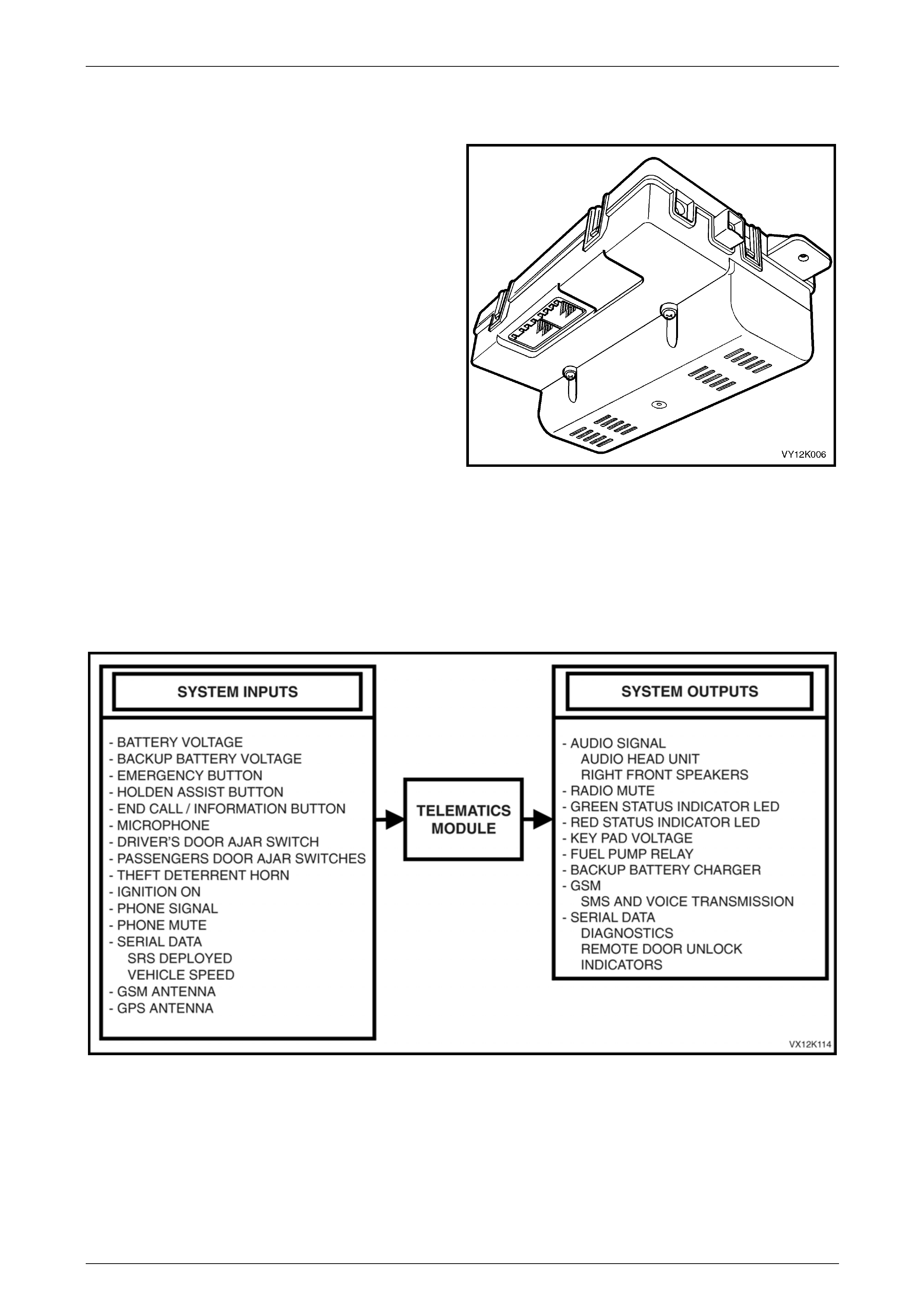
2.4 Telematics Module
The telematics module, located under the instrument panel
(above and to the left of the instrument panel compartment)
controls the operation of the telematics system. The
telematics module consists of a GPS and GSM engine and
a serial data Interface. The telematics module monitors
vehicle operating conditions (via discrete inputs and the
serial data bus) and controls system outputs.
The telematics module also receives GPS data via the GPS
antenna, and receives and transmits GSM data via the GSM
antenna.
The telematics module interfaces with other control modules
in the vehicle via the serial data circuit normal mode
message. For further information on the serial data bus and
normal mode message, refer to
Section 12J Body Control Module. Tech 2 can also
communicate with the telematics module via the serial data
circuit.
Figure 12K – 3
NOTE
If a new telematics module is installed, the new
telematics module must be registered with the
Holden Assist Centre. To register the new
telematics module with the Holden Assist Centre,
refer to Telematics Module Changeover.
Figure 12K – 4
Telematics Page 12K–14
Page 12K–14
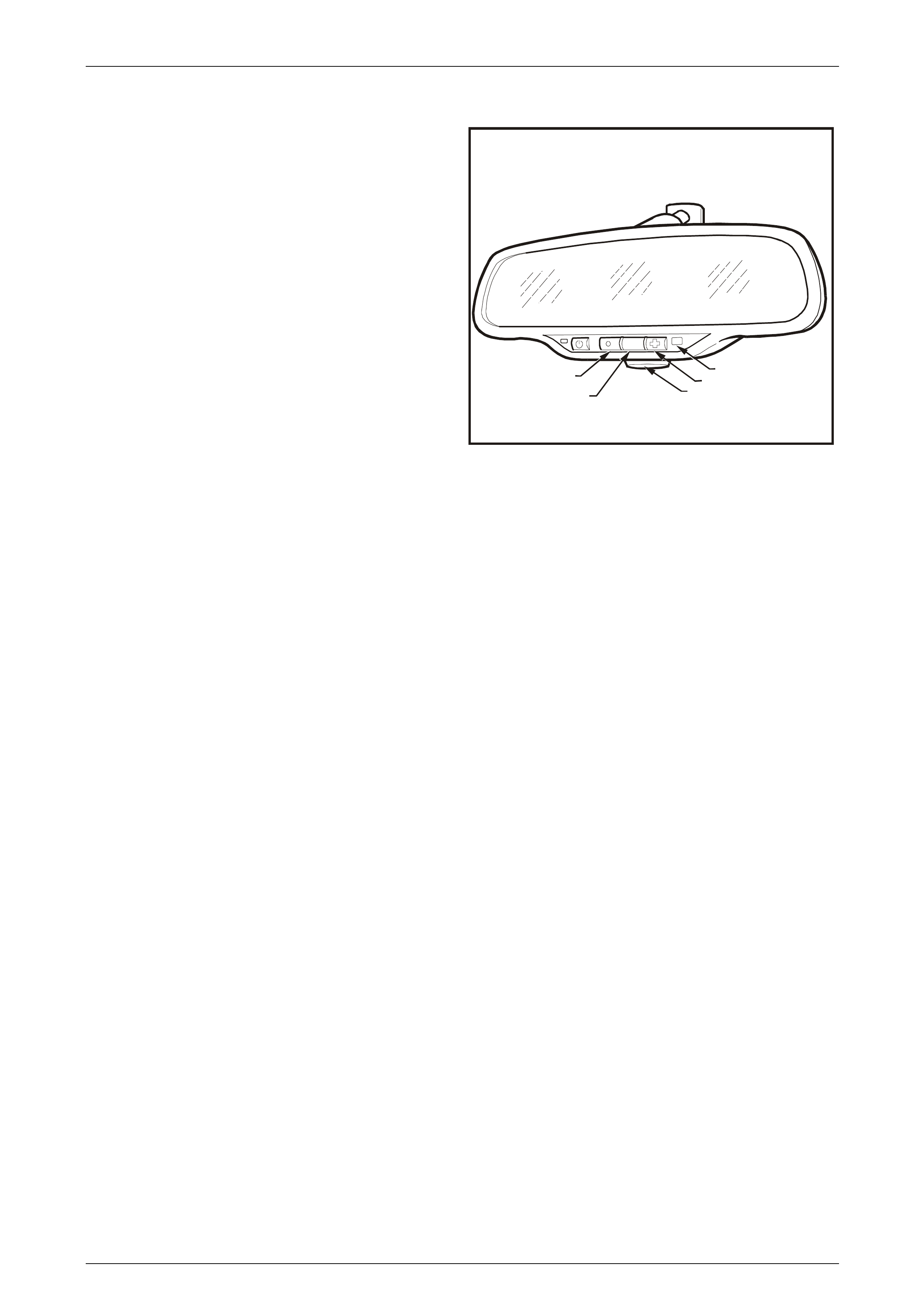
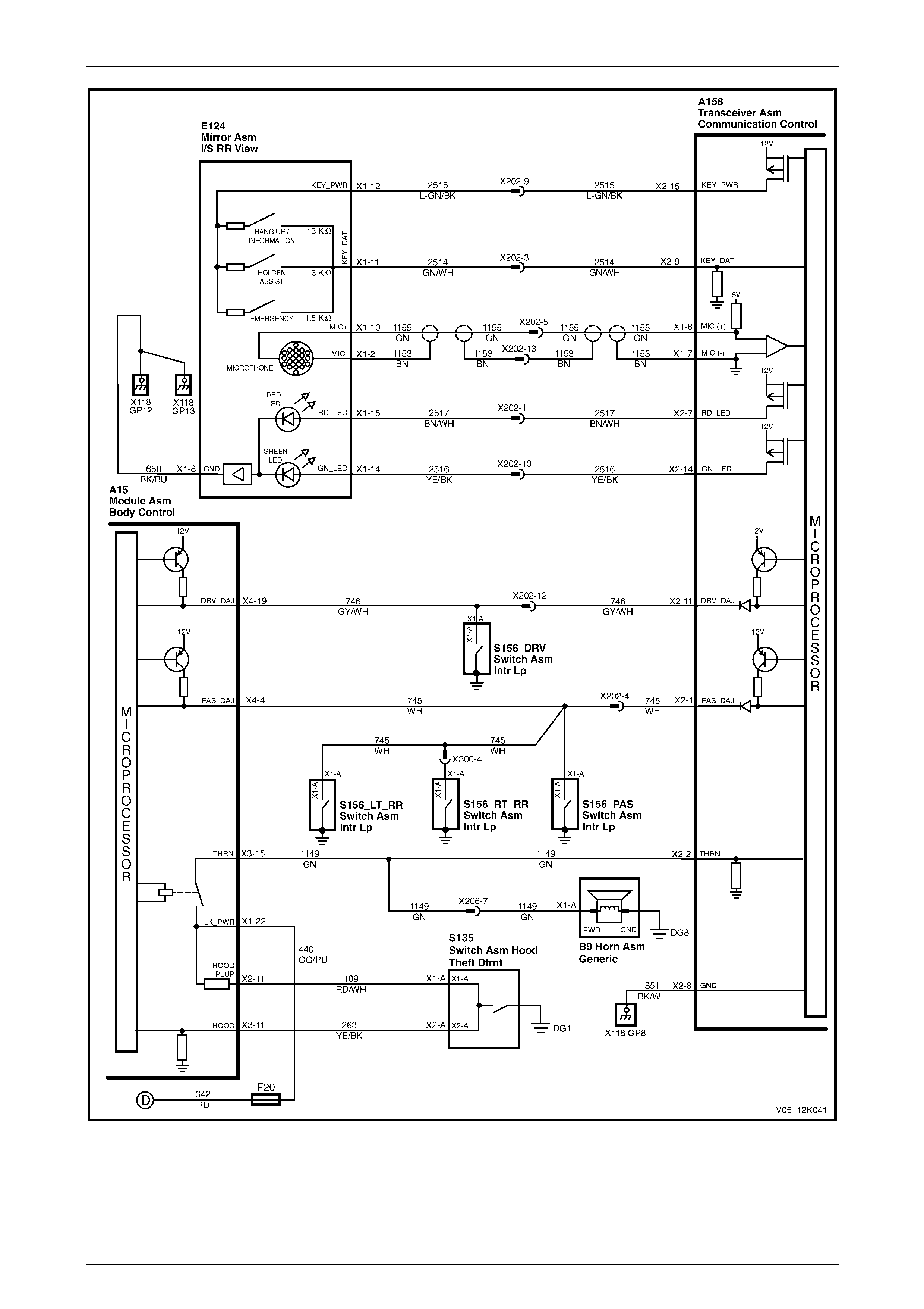
2.5 Interior Rear-view Mirror
The interior rear-view mirror assembly contains the
telematics button pad, microphone and status LEDs.
Legend
1 End Call / Information Button
2 HOLDEN ASSIST Button
3 Microphone
4 Emergency Button
5 Status Indicator LEDs
VX12K008
HOLDEN
ASSIST
1
2
4
3
5
Figure 12K – 5
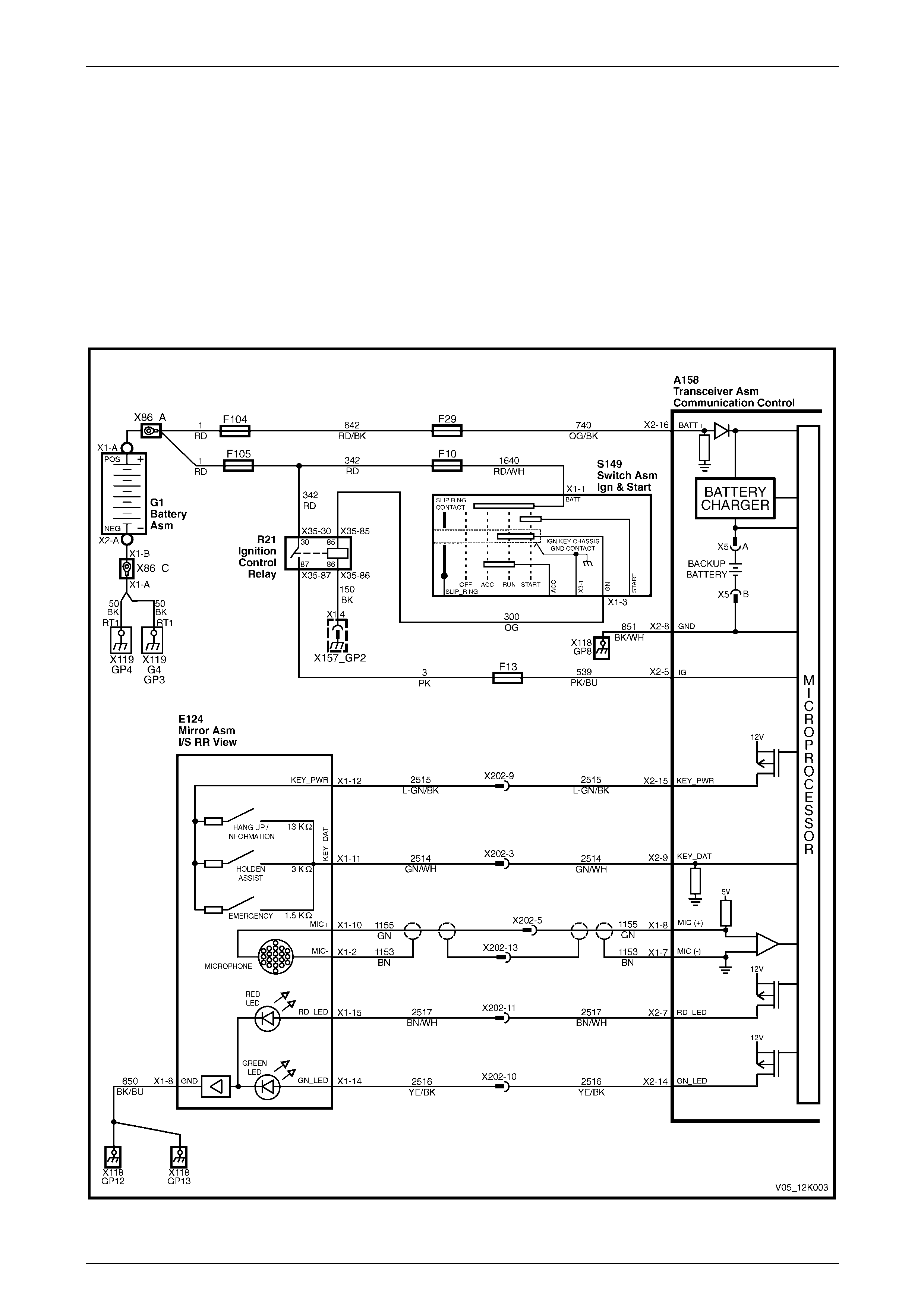
Telematics Button Pad
The telematics button pad is a resistor-encoded switch (that is, each button has a discrete resistor connected to it). The
telematics module uses a voltage divider circuit to determine which button has been pressed. The telematics module
A158 supplies a 12 V signal to E124 – X1 pin 12 of the rear-view mirror connector circuit 2515, refer to Figure 12K – 6.
When a button is pressed, the corresponding switch is closed and circuit 2514 is connected to ground through a resistor,
each switch having a different value resistor. The telematics module monitors the voltage on circuit 2514 at A158 – X2
pin 9 that changes when any of the buttons are pressed.
End Call / Information Button
When the end call / information button is pressed, the voltage at A158 – X2 pin 9 of the telematics module is
approximately 0.7 V; the telematics module determines this voltage as activation of the end call / information button.
• If the end call / information button is pressed to make a call, a connection is made to the Holden Assist Centre
information service.
• If the end call / information button is pressed while a call is connected, the call is disconnected, but does not
disconnect a call while the call is ringing the Holden Assist Centre information service number or the Holden Assist
Centre number.
This button can not disconnect an emergency call or a Holden Assist Centre call that has been upgraded to emergency
call status.
HOLDEN ASSIST Button
When the HOLDEN ASSIST button is pressed, the voltage at A158 – X2 pin 9 of the telematics module is approximately
2.3 V; the telematics module determines this voltage as a HOLDEN ASSIST button activation. The telematics module
initiates a voice call to the Holden Assist Centre, then sends an SMS message containing status and location data. If the
call can not be connected, the telematics module immediately reattempts to connect the call a second time. If the second
attempt also fails, the telematics module waits for 60 seconds, then makes a third and final attempt.
Microphone
The active microphone in the interior rear-view mirror allows two-way voice communication between the vehicle
occupants and the Holden Assist Centre.
Telematics Page 12K–15
Page 12K–15
Emergency Button
When the emergency button is pressed, the voltage at A158 – X2 pin 9 of the telematics module is approximately 3.8 V;
the telematics module determines this voltage as activation of the emergency button. The telematics module initiates a
voice call to an operator at the NERC™, then sends an SMS message containing status and location data. If the call can
not be connected, the telematics module immediately reattempts to connect the call a second time. If the second attempt
also fails, the telematics module waits for 60 seconds, then makes a third and final attempt.
If the emergency button is pressed while a Holden Assist Centre call is in progress, the status of the call is upgraded to
an emergency call. The telematics module software can not terminate the call by pressing the end call / information
button.
If the emergency button is pressed while the vehicle is outside GSM network range, the telematics module enters the
emergency call mode; the emergency call request is retained. When contact is re-established with the GSM network, the
emergency call will be placed immediately.
Figure 12K – 6

Telematics Page 12K–16
Page 12K–16
Status Indicator LEDs
The red and green status indicator LEDs in the interior rear-view mirror indicate the current status of the telematics
system. The telematics module activates the LEDs by switching a 12 V power supply to each LED on or off. The
brightness of the LEDs is controlled by the interior rear-view mirror electronics that varies the brightness of the LEDs
depending on the ambient light and the position of the ignition switch. If the ambient light is low, the brightness of the
LEDs decreases when the ignition is on. If the ambient light is high, there is no change to the brightness of the LEDs
when the ignition is turned on.
LED Condition Current Status
Green Continuous Self-test pass, system OK (no current DTC logged).
Green Flashing
(0.5 second on / 0.75 second off) System OK (no current DTC logged), and
• call being connected, or
• call in progress,
• emergency call mode.
Red Continuous Self-test failure (current DTC logged), or
• unit is in service mode, or
• system test in progress.
Red Flashing
(0.5 second on / 0.75 second off) Self-test failure (current DTC logged), and
• call being connected, or
• call in progress.
Red and Green OFF • performing power-up self-test, or
• stand-by mode, or
• sleep mode.
Orange
(Red and Green) Continuous Vehicle is out of GSM network range
Orange
(Red and Green) Flashing Telematics module is in emergency call mode
Red/Green Alternate Flashing
(0.5 second alternating)
(5.0 second duration after ignition is
turned on)
Unit in service mode, or
Unit in VAP mode.
The colour of the LED indicates the status of the telematics system. If there is a system fault during a call, the LED
flashes red. If there are no system faults, the LED flashes green.
Telematics Page 12K–17
Page 12K–17
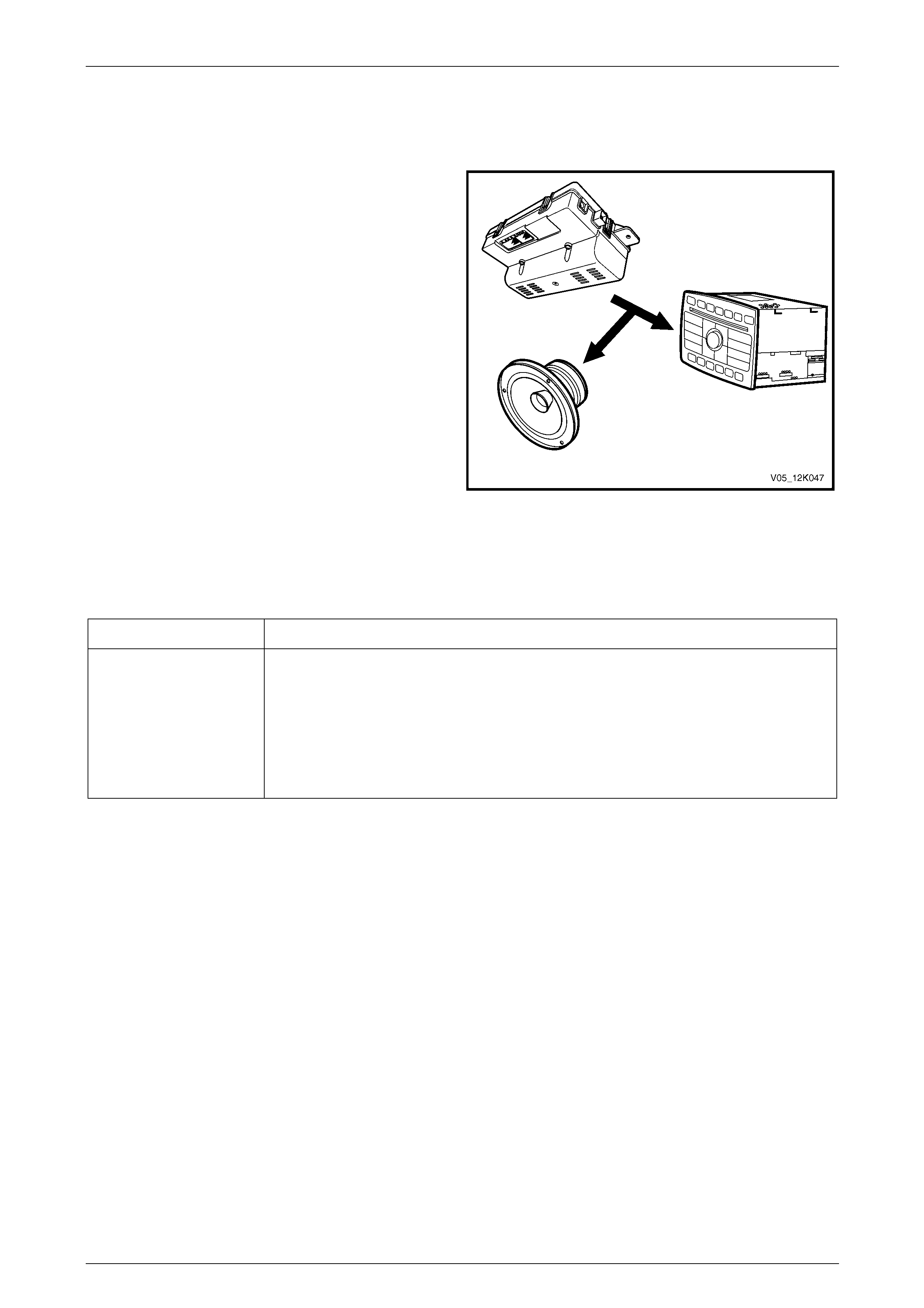
2.6 Audio System Interface
Audio System and Right-hand Front Speakers
The telematics system uses the vehicle audio system for
voice communication from the Holden Assist Centre. The
telematics module also detects if the audio system is not
operational and, if not operational, switches from the vehicle
audio system to the right-hand front speakers.
When the telematics audio is activated, the radio mute
signal also activates and the telematics module grounds the
radio mute circuit 5211 causing the circuit voltage to be
reduced to less than 2 V. This low voltage is detected by the
radio as a mute request and, when received, the audio
system mutes. The volume of the telematics call can then be
adjusted using the audio system volume control. If the
telematics module switches to the right-hand front speakers,
the volume is fixed by the telematics module.
While the telematics system is not on a call, the audio and
mute request from the cellular telephone connector is
passed through the telematics module to the audio system.
When a Holden Assist Centre call is active, the telematics
module ignores the phone audio and transmits the
telematics audio to the audio system. Figure 12K – 7
Audible Tones
Audible tones indicate the status of the telematics system and are broadcast via the speaker to alert certain operating
conditions.
Tone Operating Condition
Five Tones Attempting to make a call when the vehicle is not within GSM network range. If the five
tones occur after the ignition is turned off, the vehicle is not within GSM network range.
The five audible tones warn that:
• the service mode is active, or
• a system malfunction has been detected and a diagnostic trouble code has been
stored in the telematics module.
Telematics Page 12K–18
Page 12K–18
Figure 12K – 8
Telematics Page 12K–19
Page 12K–19
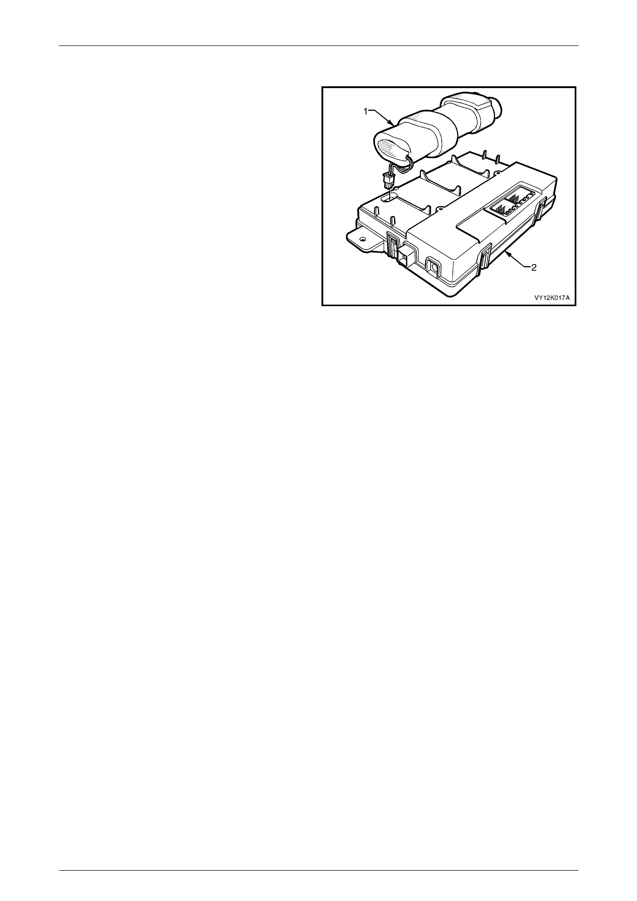
2.7 Backup Battery
The backup battery (1) is housed in the battery compartment
of the telematics module. The backup battery provides
power to the telematics module for at least 30 minutes if the
vehicle battery is discharged or disconnected. The
telematics module has a backup battery charging circuit that
maintains the backup battery state of charge. This circuit
also includes an overcurrent protection device. The
telematics module has a backup battery timer that monitors
the time the backup battery has been in the vehicle.
After the backup battery has been in the vehicle for five
years (43 680 hours) it has reached the end of its useful life
because internal deterioration causes low charge
acceptance. DTC 13 will be set and the red status LED
illuminates. For further information refer to
DTC 13 — Backup Battery Timer Expired.
Figure 12K – 9
Telematics Page 12K–20
Page 12K–20
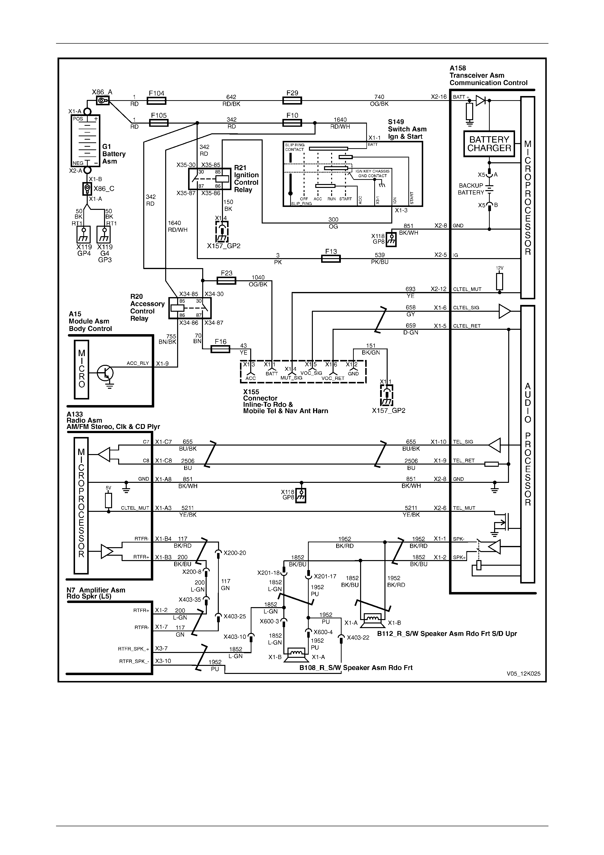
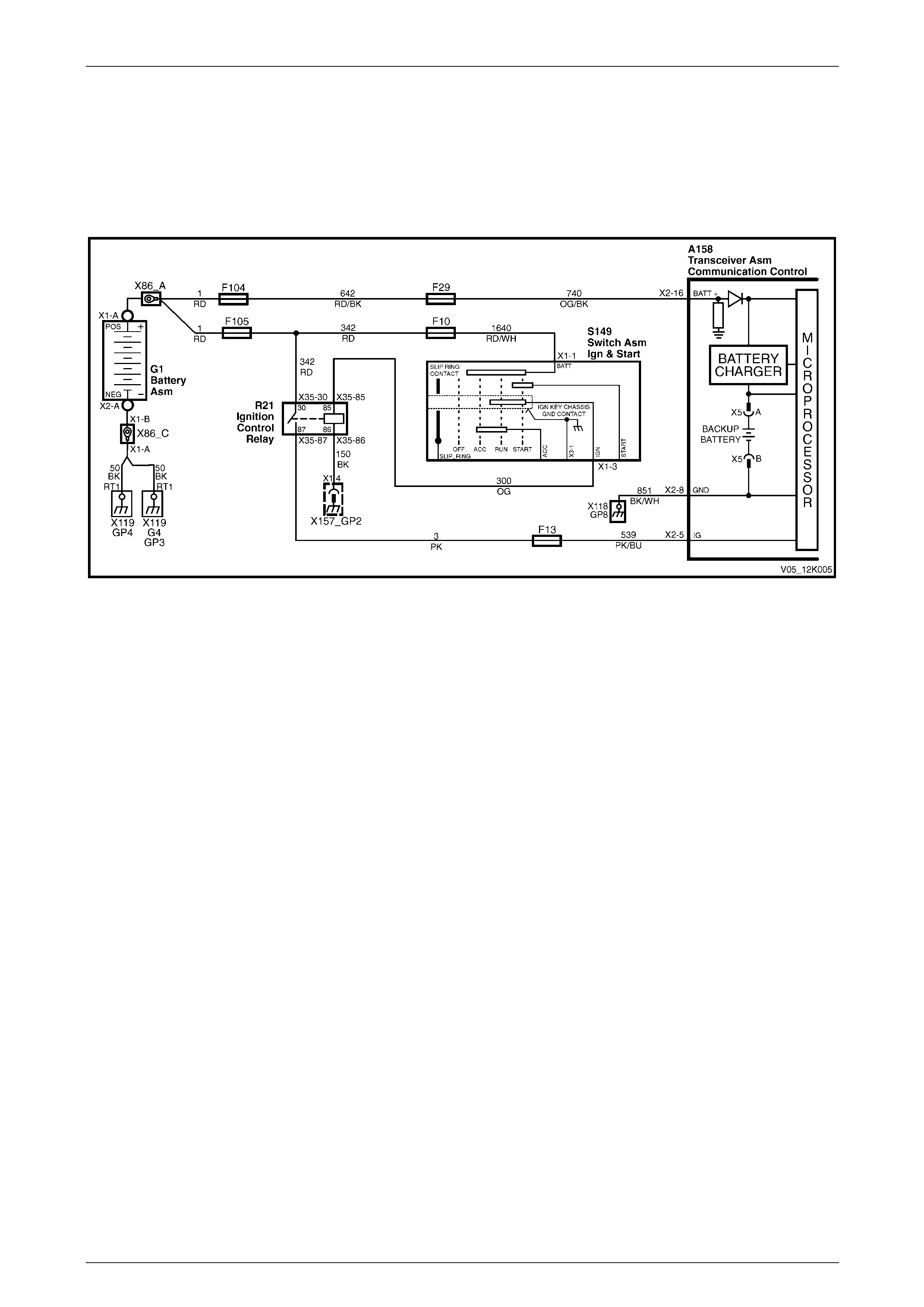
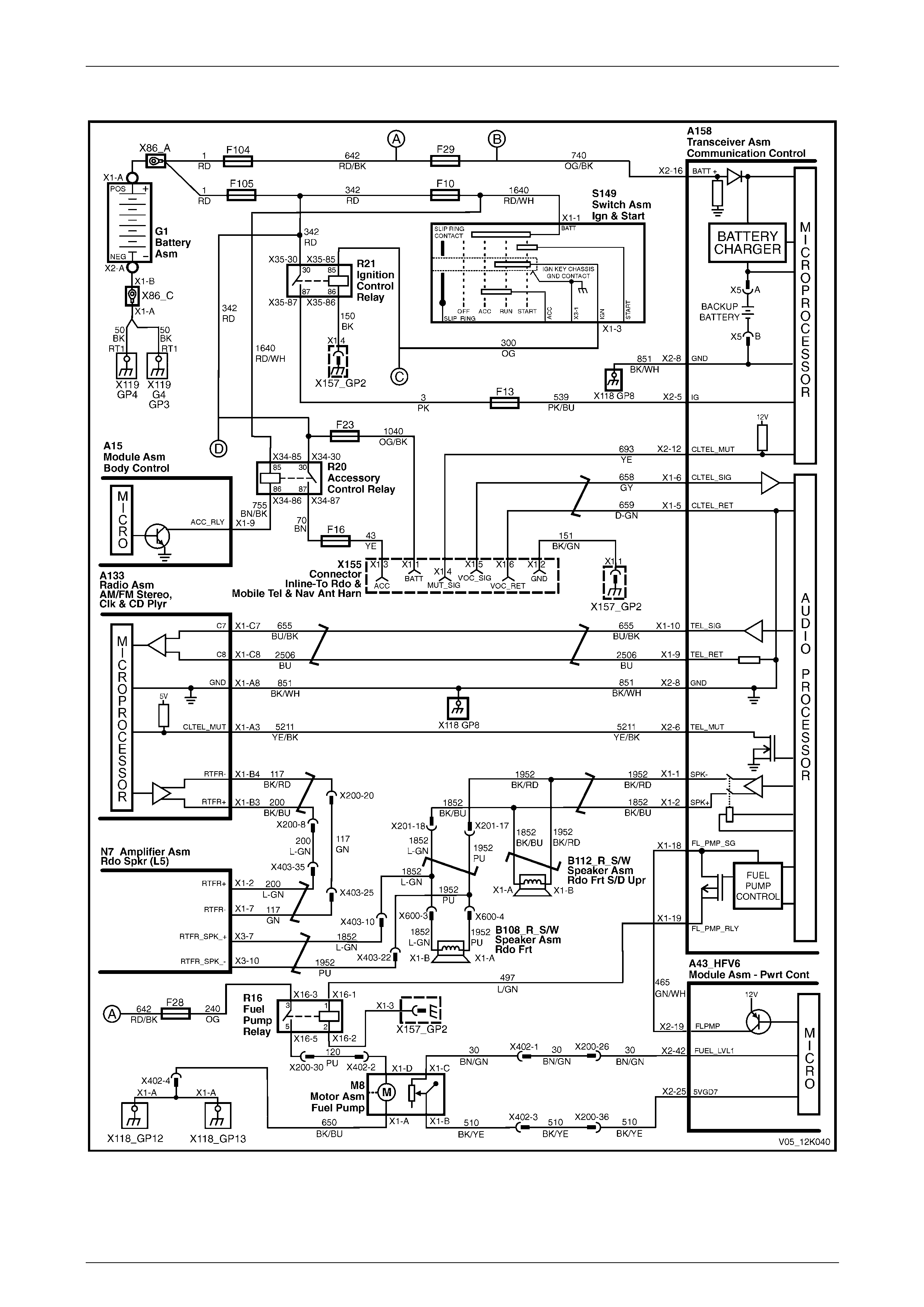
2.8 Battery Voltage
Battery voltage is applied to the telematics module A158 – X2 pin 16 at all times via circuit 740, fuse F29 and fusible
link F104, refer to Figure 12K – 10. If the battery output below a preset voltage for longer than 30 minutes, the telematics
module transmits a low battery alert to the Holden Assist Centre. For further information, refer to
Low Battery Voltage Alert. If the battery is removed, the telematics module transmits a Battery Removal Alert to the
Holden Assist Centre. For further information, refer to Battery Removal Alert.
Figure 12K – 10

Telematics Page 12K–21
Page 12K–21
2.9 Backup Battery Charger
The telematics module constantly monitors both vehicle battery voltage and backup battery voltage. The charging circuit
constantly monitors the backup battery voltage to determine if the backup battery needs to be charged; charging is
performed at a maximum of 300 mA. For the wiring diagram, refer to Figure 12K – 10.

Telematics Page 12K–22
Page 12K–22
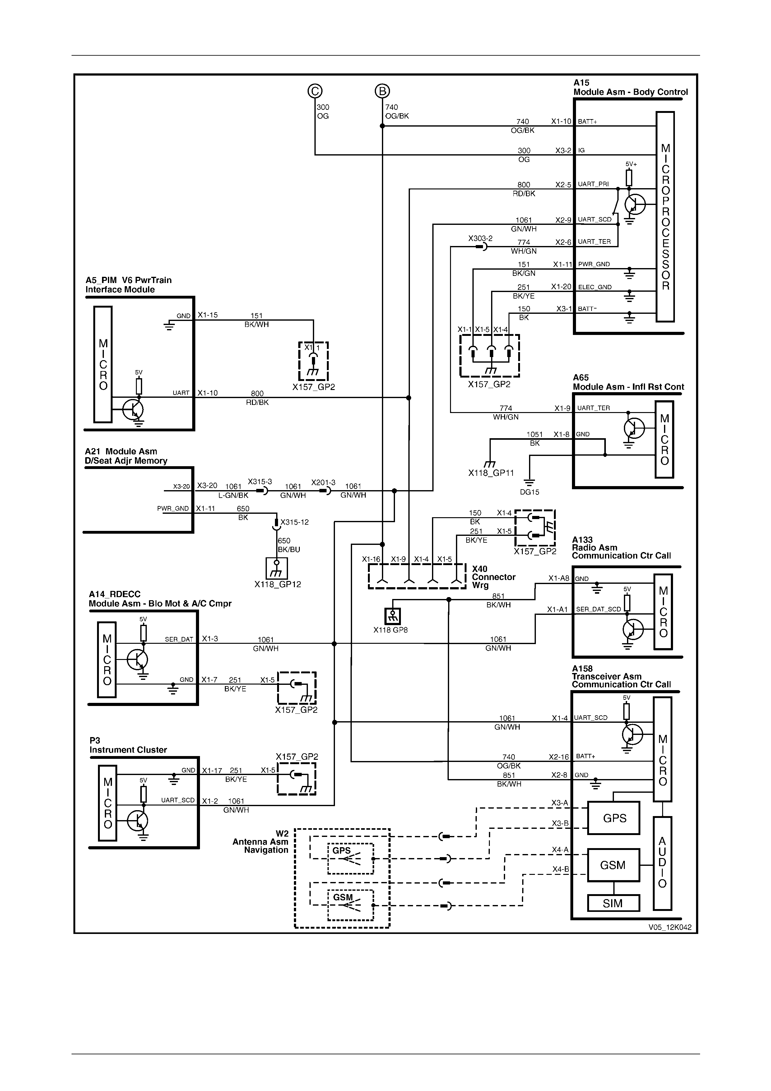
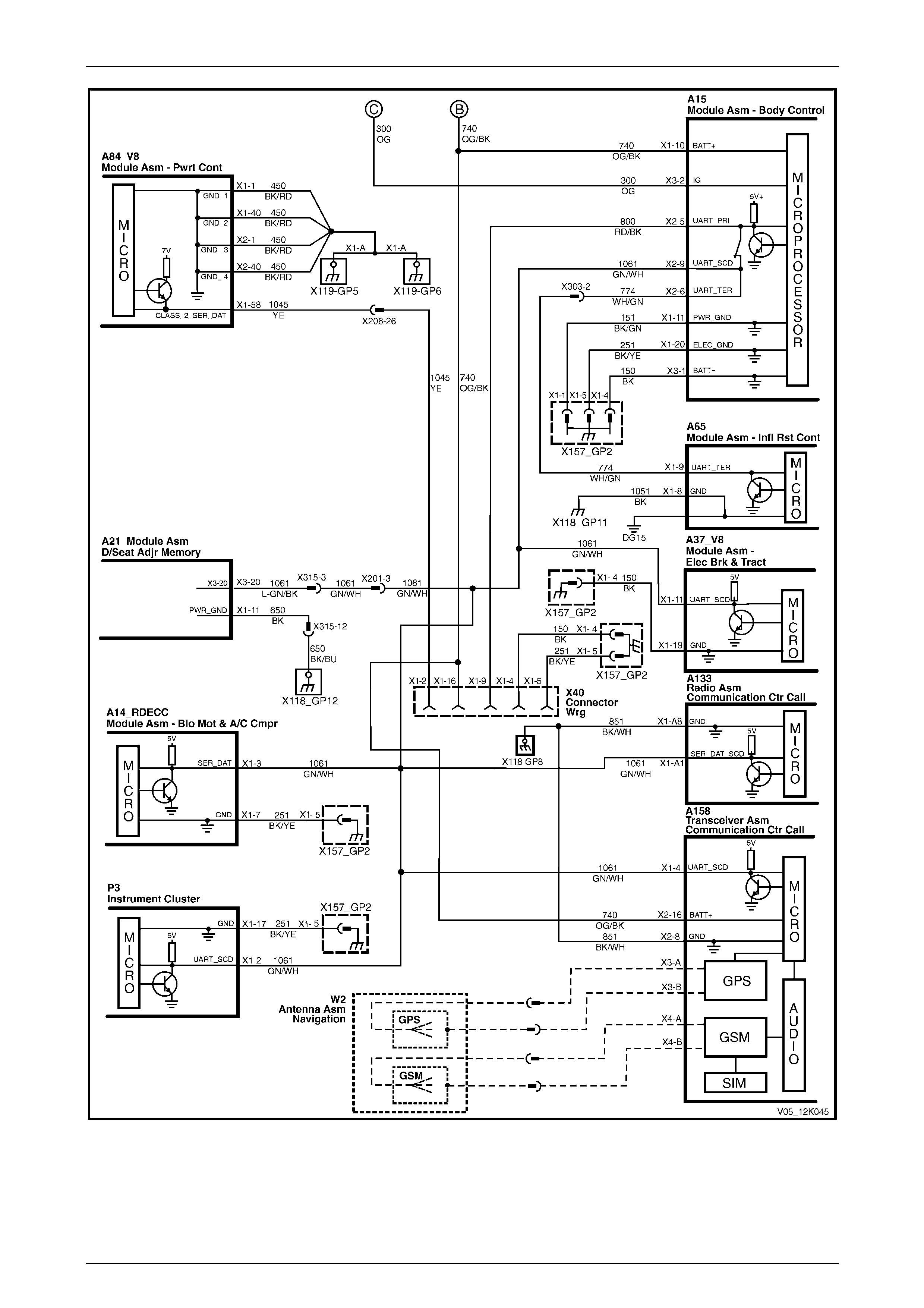
2.10 Serial Data
The telematics module monitors the auxiliary serial data circuit 1061 normal mode message for:
• airbag deployed this ignition cycle data from the supplemental restraint system (SRS) sensing diagnostic module
(SDM), and
• vehicle speed data from the powertrain control module (PCM).
For further information on the serial data bus and normal mode message, refer to Section 12J Body Control Module.
If the telematics module receives a remote unlock message from the Holden Assist Centre, the telematics module
requests the BCM (via the serial data circuit) to unlock the doors. For further information on the BCM door lock operation,
refer to Section 12J Body Control Module.
If the telematics module receives an immobilise message from the NERC™, the telematics module turns off the fuel
pump relay cutting off the fuel supply to the engine and requests the BCM (via the serial data circuit) to flash the
indicators, refer to 2.15 Fuel Pump Relay Drive Circuit. For further information on the BCM indicator operation, refer to
Section 12J Body Control Module.
Telematics Page 12K–23
Page 12K–23
V6 Engine
Figure 12K – 11
Telematics Page 12K–24
Page 12K–24
Figure 12K – 12
Telematics Page 12K–25
Page 12K–25
Figure 12K – 13

Telematics Page 12K–26
Page 12K–26
GEN III V8 Engine
Figure 12K – 14

Telematics Page 12K–27
Page 12K–27
Figure 12K – 15
Telematics Page 12K–28
Page 12K–28
Figure 12K – 16
Telematics Page 12K–29
Page 12K–29
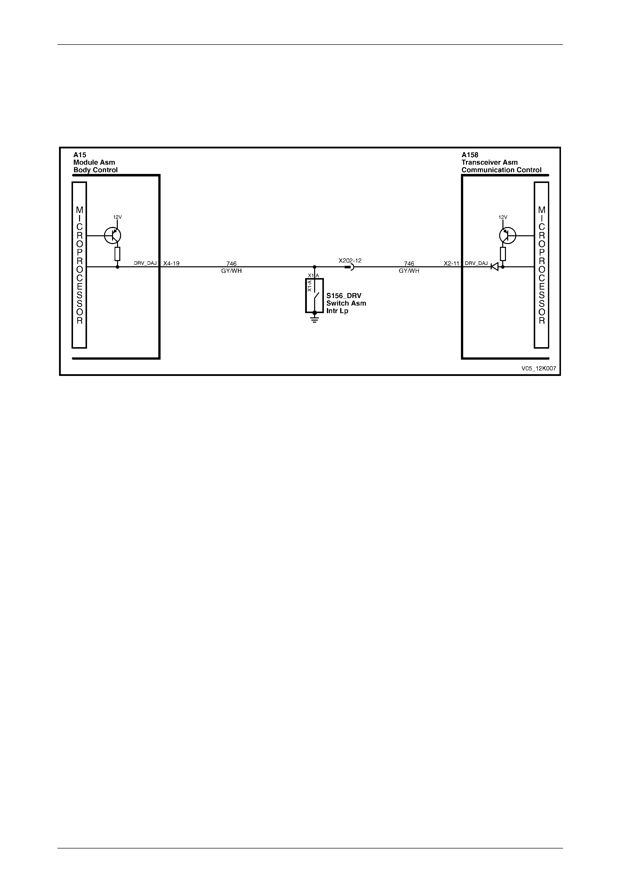
2.11 Driver's Door Ajar Switch
The telematics module uses the driver's door ajar input signal to determine if the driver's door is opened or closed. When
the driver's door is open, the driver's door ajar switch grounds A158 – X2 pin 11 of the telematics module via circuit 746;
this causes the voltage to reduce to less than 0.2 V (driver's door open), refer to Figure 12K – 17. The low voltage at
A158 – X2 pin 11 is detected by the telematics module as the driver's door open input signal, one of the inputs used to
determine the system operating mode, refer to 2.1 Operating Modes.
Figure 12K – 17
Telematics Page 12K–30
Page 12K–30
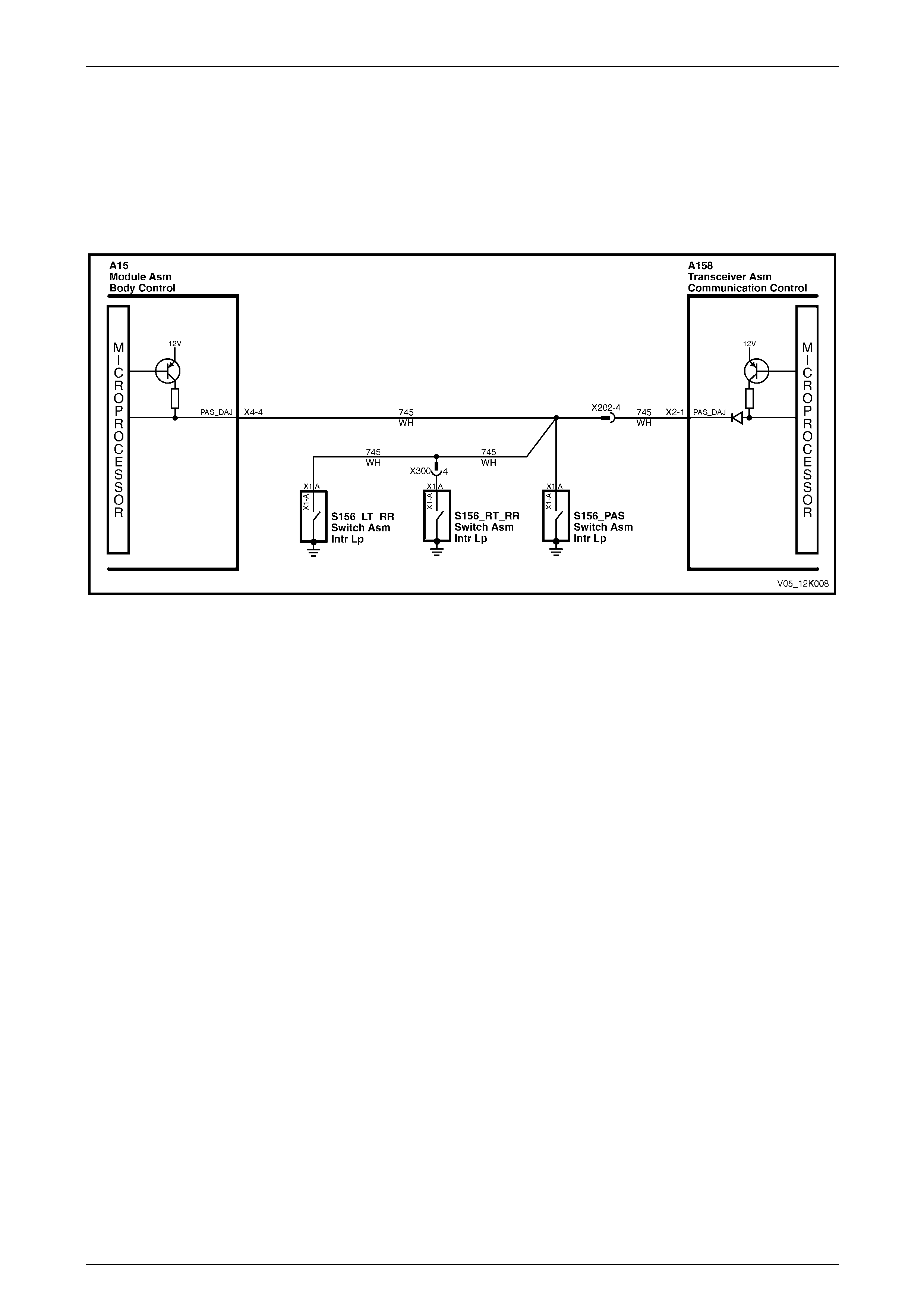
2.12 Passenger Door Ajar Switches
The telematics module uses the passenger door ajar input signal to determine if any of the passenger doors are open or
if all passenger doors are closed. If the right-hand rear, left-hand front or left-hand rear door is open, A158 – X2 pin 1 of
the telematics module is grounded via circuit 745, refer to Figure 12K – 18. This grounding causes the voltage at
A158 – X2 pin 1 to be reduced to less than 0.2 V (if any one of the passenger doors is opened). The telematics module
determines the low voltage at A158 – X2 pin 1 as the passenger door open input signal, one of the inputs used to
determine the system operating mode, refer to 2.1 Operating Modes.
Figure 12K – 18
Telematics Page 12K–31
Page 12K–31
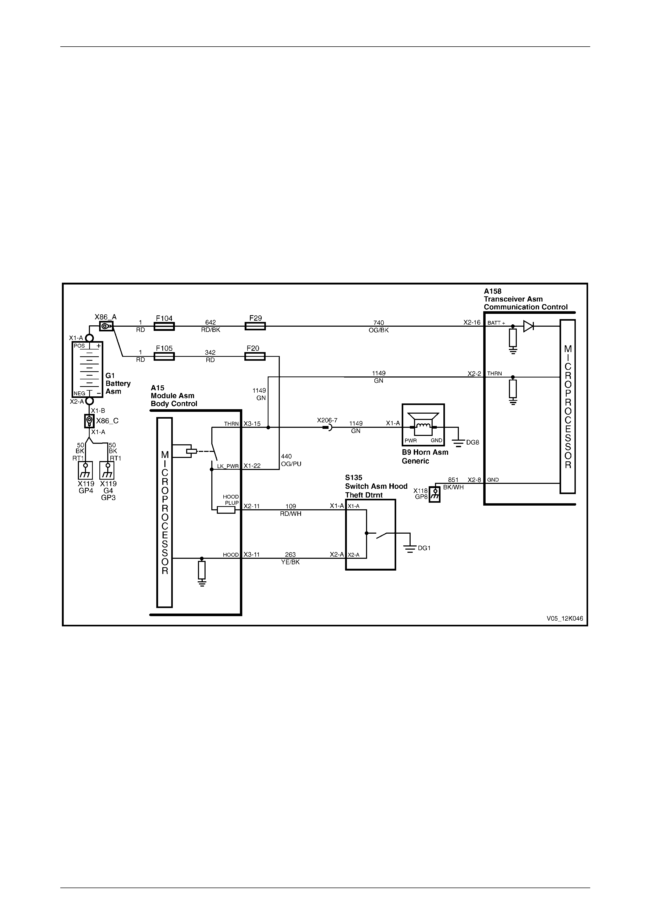
2.13 Alarm Input (Theft Deterrent Horn)
The telematics module monitors the theft deterrent horn circuit to determine if the alarm has been triggered. If the alarm
has been triggered, the BCM pulses the horns at 1 Hz. To pulse the theft deterrent horn, the BCM supplies 12 V to the
theft deterrent horn (circuit 1149). When the theft deterrent horn circuit is activated, the voltage at A158 – X2 pin 2 of the
telematics module increases; the telematics module determines this high voltage as the theft deterrent system having
been triggered, refer to:
• Figure 12K – 19 (for vehicles fitted with a V6 engine), or
• Figure 12K – 20 (for vehicles fitted with a GEN III V8 engine).
If the vehicle theft deterrent system is triggered for longer than 20 seconds, the telematics module transmits an
unauthorised entry alert message to the Holden Assist Centre. For further information on the unauthorised entry alert,
refer to the Holden Assist Handbook Supplement.
V6 Engine
Figure 12K – 19
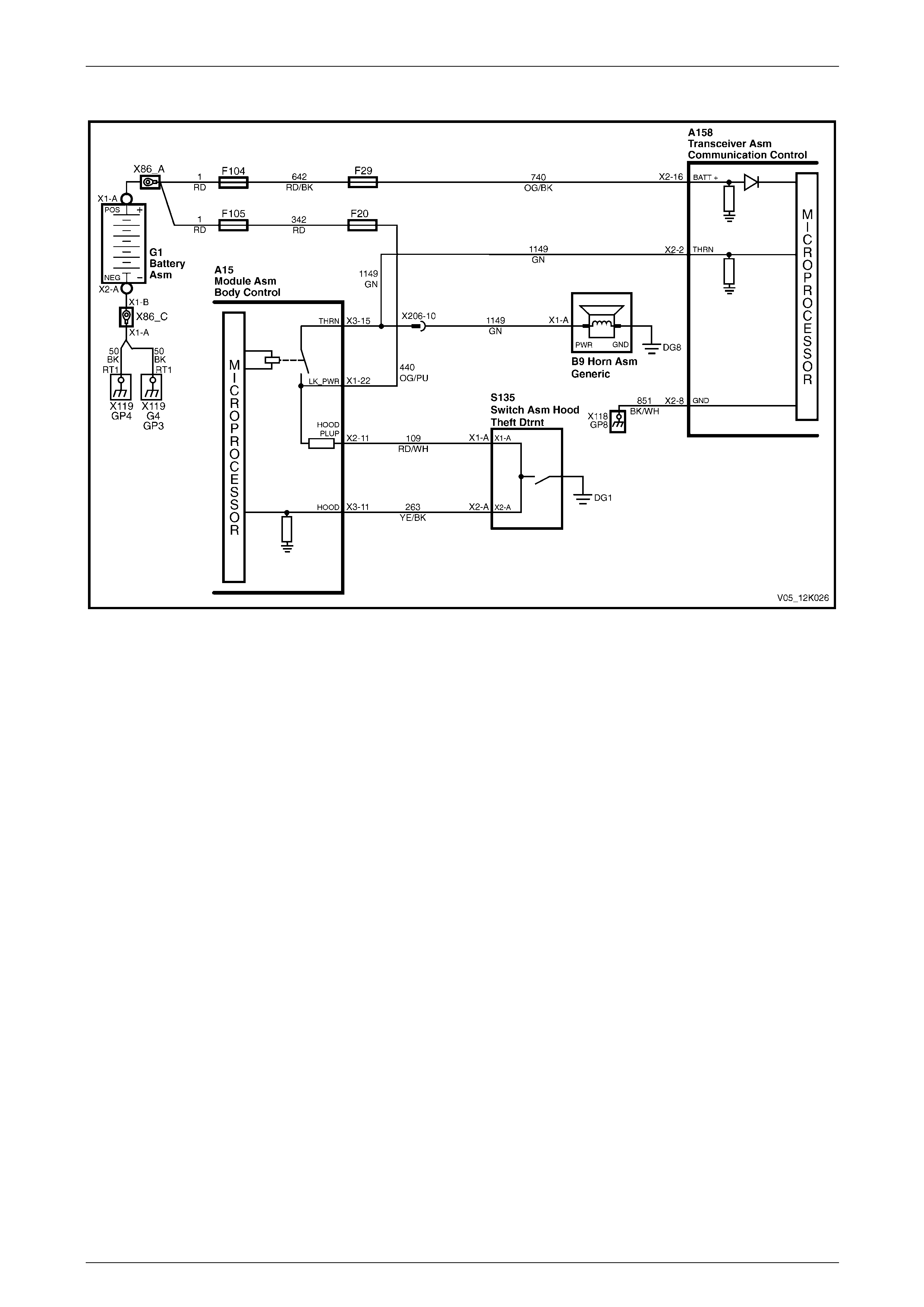
Telematics Page 12K–32
Page 12K–32
GEN III V8 Engine
Figure 12K – 20
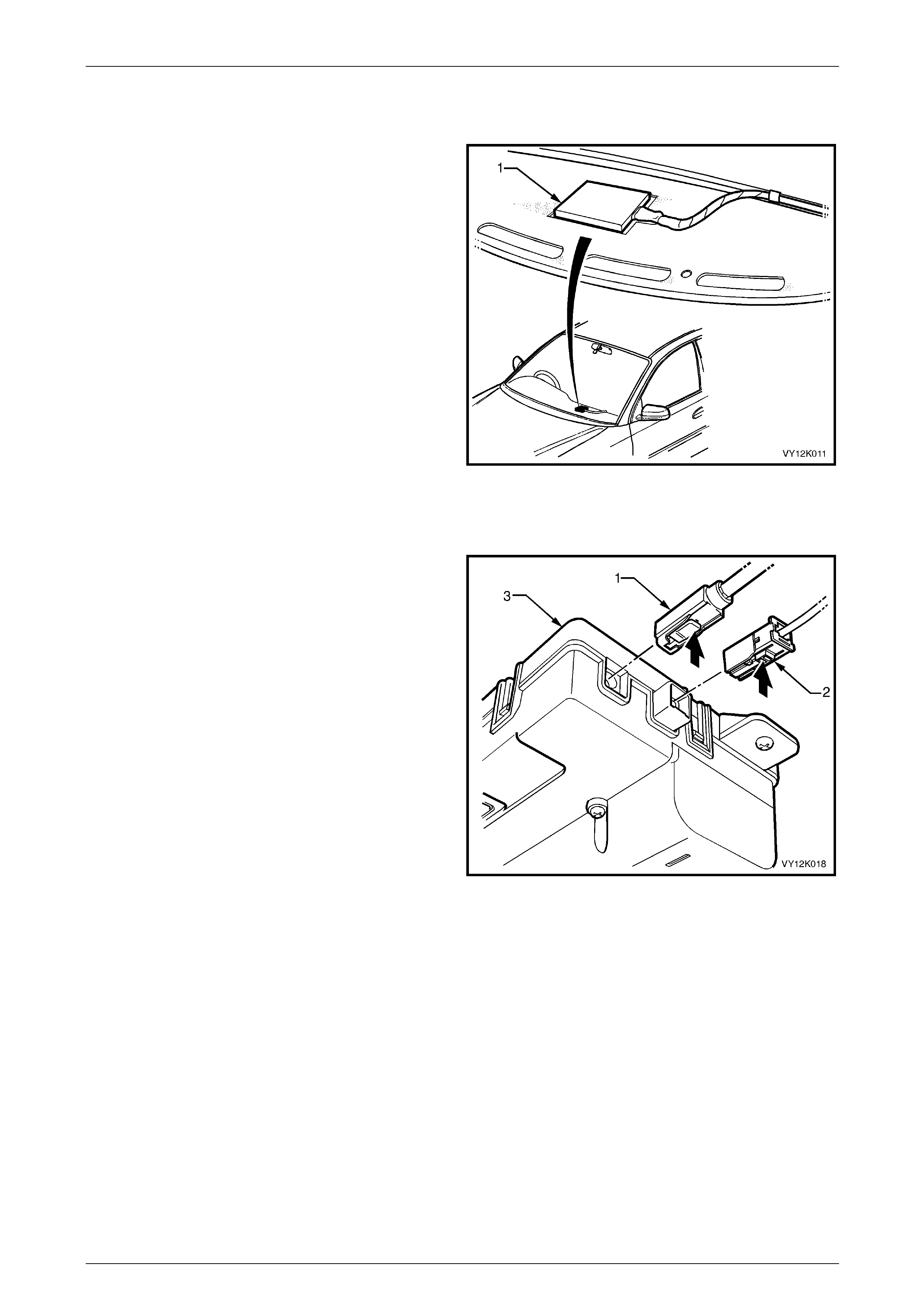
Telematics Page 12K–33
Page 12K–33
2.14 Telematics Antenna
The telematics antenna (1) contains both the GPS and GSM
antennas in one unit and is located under the instrument
panel. The telematics antenna has two leads, one for the
GPS antenna, the other for the GSM antenna.
NOTE
The area directly above the telematics antenna
should be free from obstructions as they may
adversely affect antenna operation and the
system may not have full functionality.
Aftermarket window tinting may also affect the
antenna operation.
Figure 12K – 21
GPS Antenna
The GPS antenna receives signals from a series (known as
a constellation) of 27 satellites (nominally 24) that orbit the
earth at an altitude of 20 372 km. Signals from four satellites
must be received by a GPS receiver to calculate an
accurate three-dimensional position. If only three satellite
signals are received, a two-dimensional position is attained,
but with reduced accuracy; the telematics module can not
determine the altitude of the vehicle. The position calculated
by the GPS receiver is accurate to between 30 metres and
100 metres. The GPS antenna must not be obscured by any
objects, such as underground car parks, tunnels, bridges or
buildings; any of these may affect GPS reception. The GPS
antenna is connected to the telematics module by a plug-in
connector (1). For the wiring diagram, refer to Figure 12K –
23.
The telematics module triangulates data from the GPS
satellites to determine the location of the vehicle. The
satellites constantly broadcast radio signals and the
telematics GPS module compares the time taken for the
signals to reach the GPS module. The telematics module
calculates its location by converting time intervals into
distance covered from the previous update. The telematics
module receives GPS data, decodes it, then transmits the
location of the vehicle via SMS when requested by the
Holden Assist Centre or the NERC™.
Figure 12K – 22
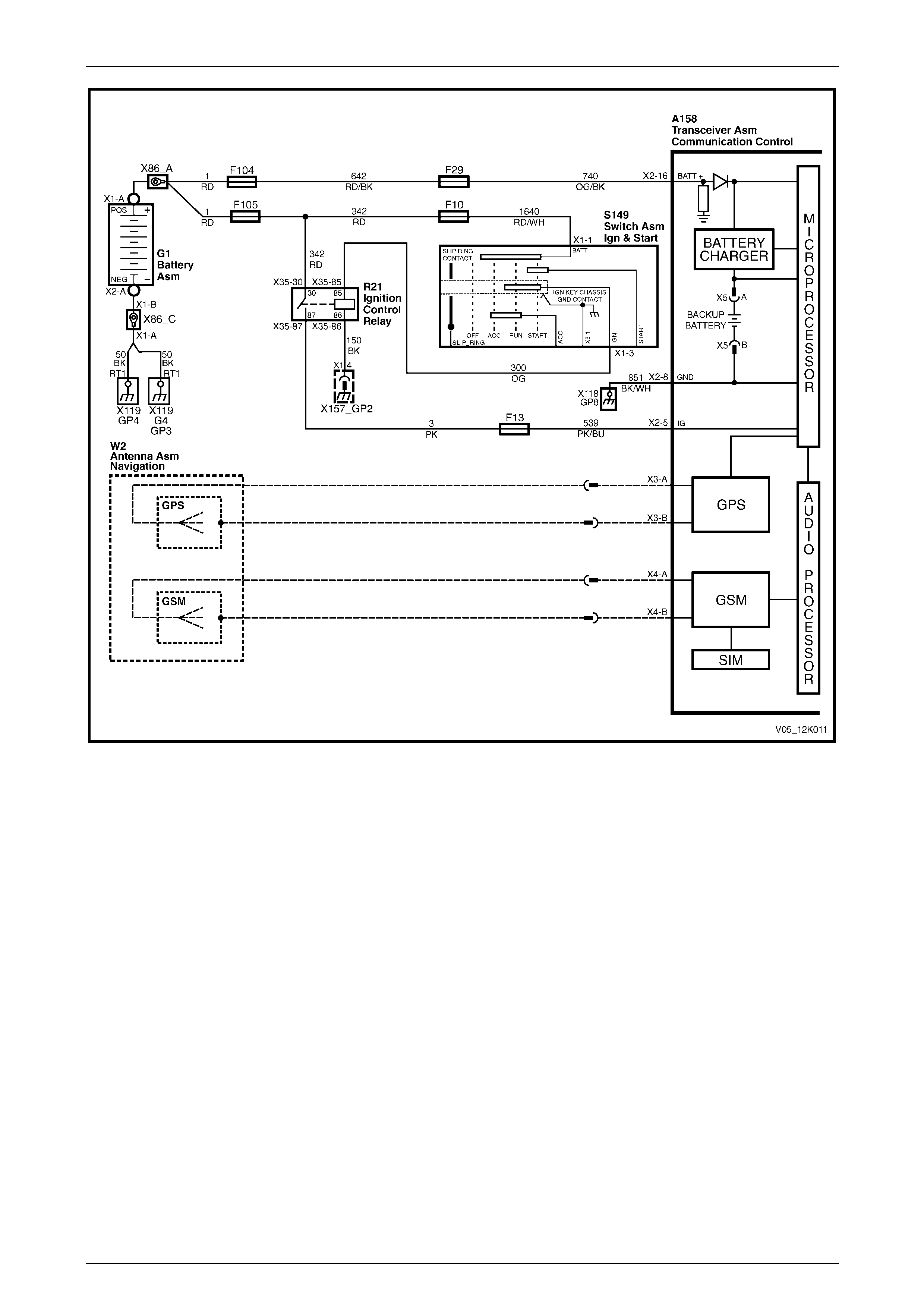
Telematics Page 12K–34
Page 12K–34
Figure 12K – 23
GSM Antenna
The telematics module uses the GSM antenna to transmit and receive voice and data signals across the GSM network.
The GSM antenna transmits and receives voice and data signals via the GSM network. The telematics module uses the
GSM network to transmit and receive voice and data. Signal strength may be affected in locations like basement car
parks or tunnels. As the vehicle emerges from the obstruction or re-enters the digital phone network area, the signal
becomes available again and any stored data is transmitted. The GSM antenna is connected to the telematics module by
a plug-in connector (2), refer to Figure 12K – 22. For the wiring diagram, refer to Figure 12K – 23.
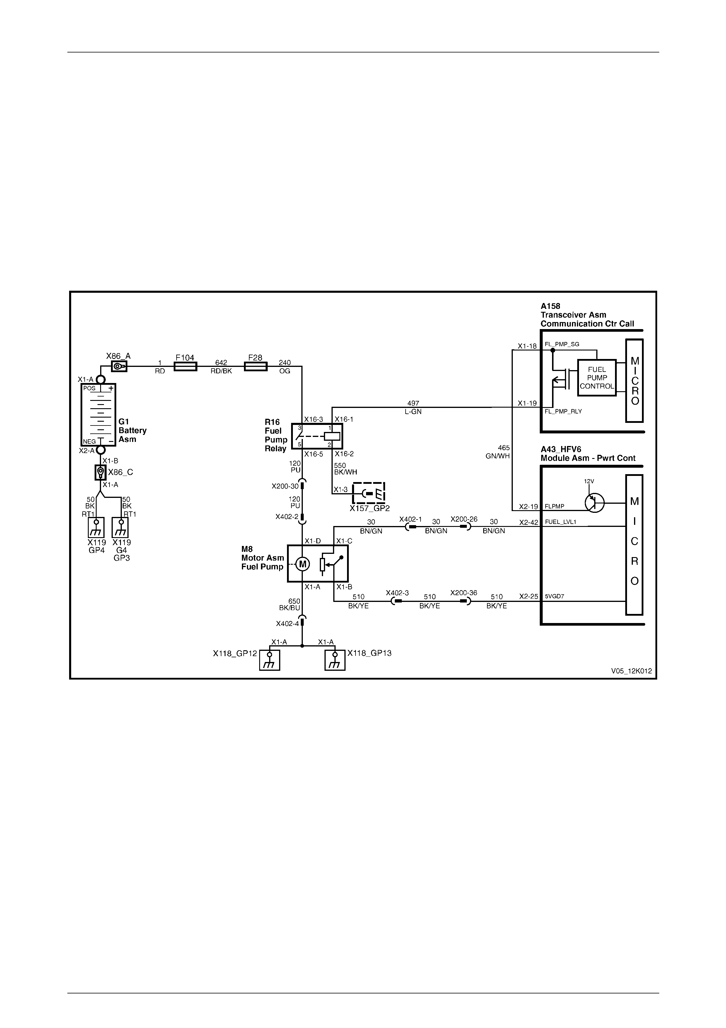
Telematics Page 12K–35
Page 12K–35
2.15 Fuel Pump Relay Drive Circuit
The PCM energises the fuel pump relay drive circuit via A158 – X1 pin 19 (circuit 497) and A158 – X1 pin 18 (circuit 465)
of the telematics module, refer to:
• Figure 12K – 24 (for vehicles fitted with a V6 engine), or
• Figure 12K – 25 (for vehicles fitted with a GEN III V8 engine).
The fuel pump relay drive circuit is grounded through circuit 550 at ground location X157_GP2. The telematics module
can immobilise the vehicle by opening the fuel pump relay drive circuit, causing the fuel pump to stop operating. This
function can be activated only by the NERC™ under instruction from the police. For further information, refer to
2.3 Holden Assist Remote Requests.
V6 Engine
Figure 12K – 24
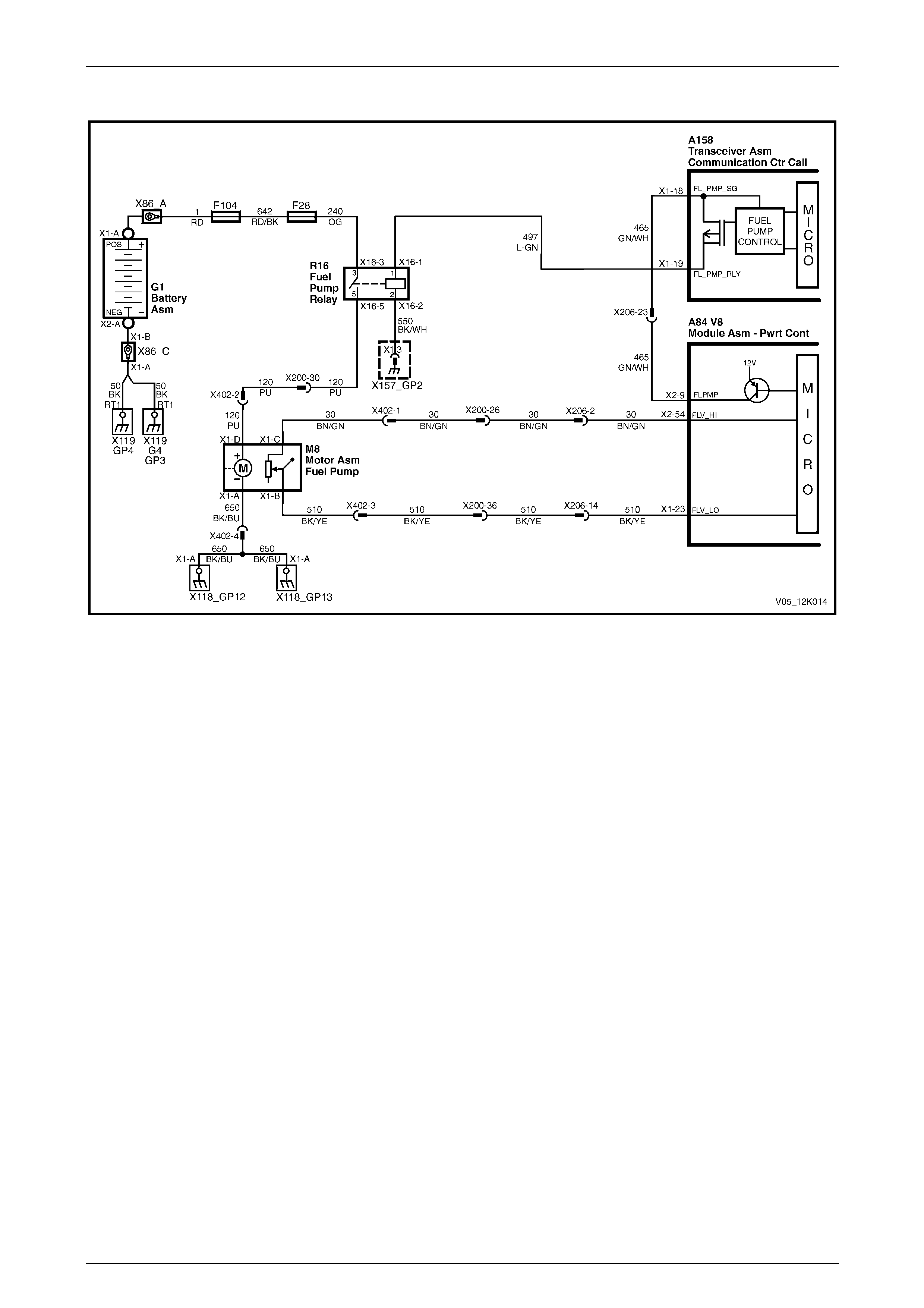
Telematics Page 12K–36
Page 12K–36
GEN III V8 Engine
Figure 12K – 25
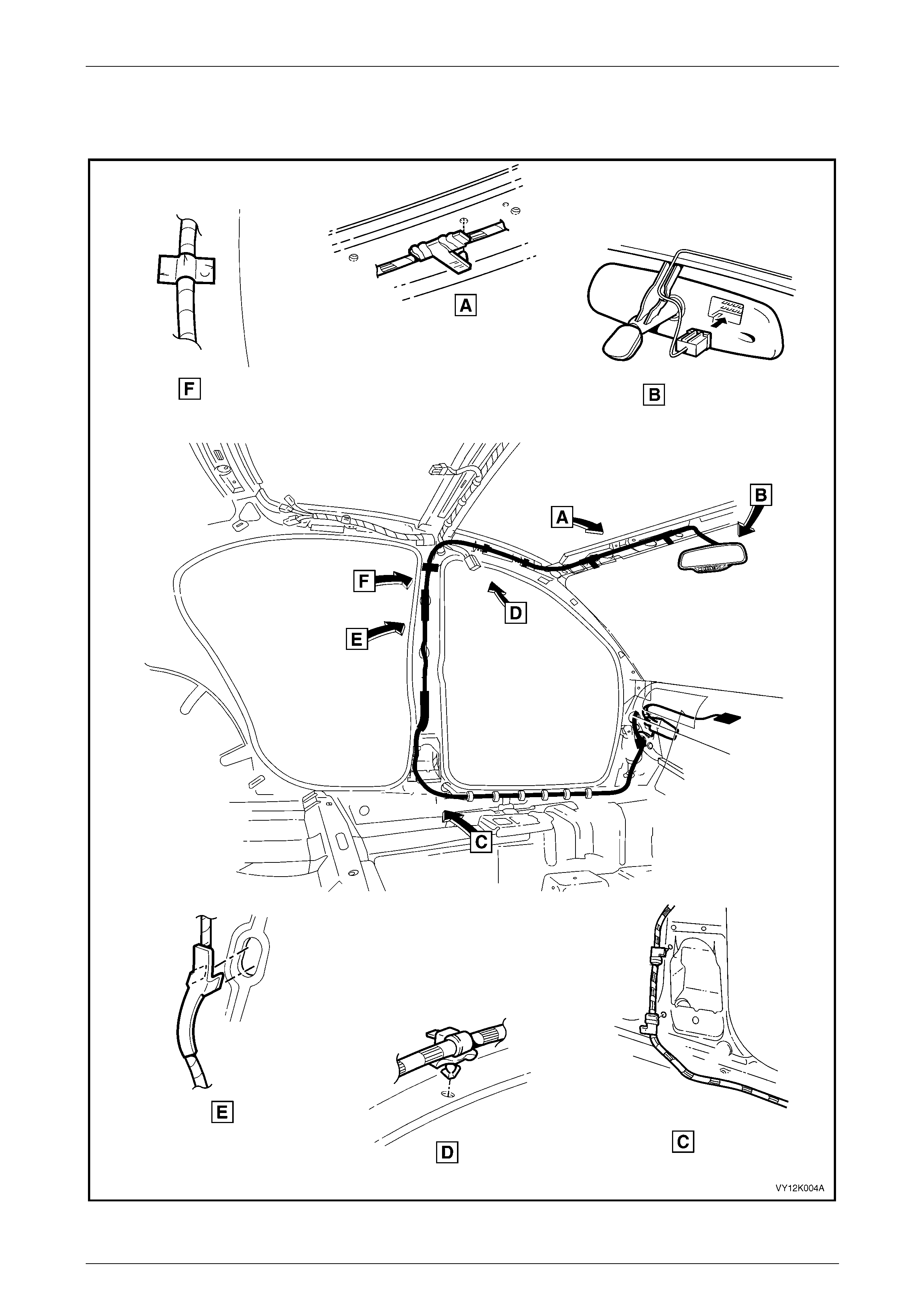
Telematics Page 12K–37
Page 12K–37
2.16 Wiring Harnesses
Vehicles equipped with the telematics system have specific main and body harnesses.
Figure 12K – 26
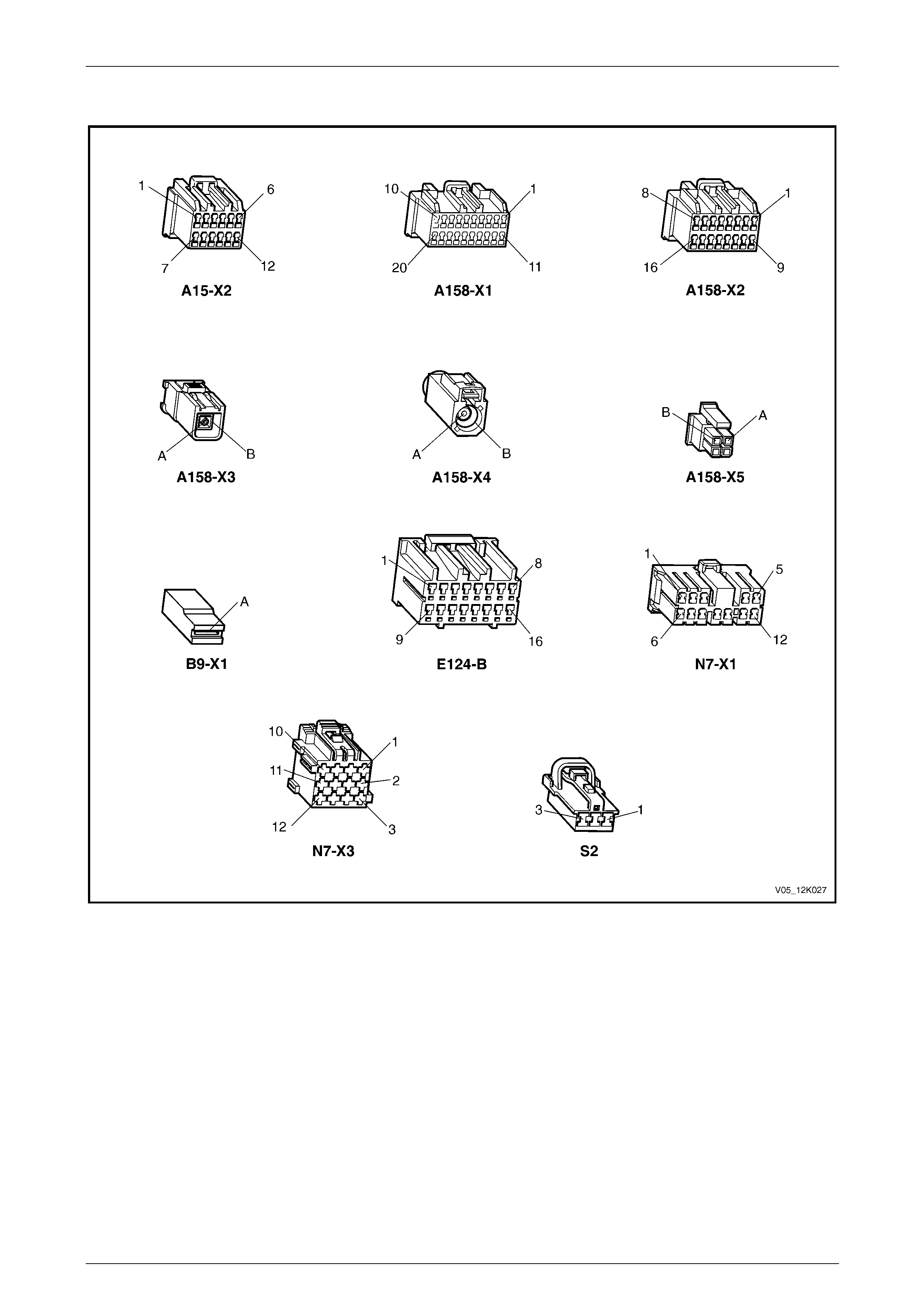
Telematics Page 12K–38
Page 12K–38
2.17 Connector Diagrams
Figure 12K – 27

Telematics Page 12K–39
Page 12K–39
3 Tech 2 Diagnostics for
Telematics
Tech 2 is a small, hand-held computer that provides the operator with information that allows system faults to be
analysed. A data link connector (DLC) is used by the assembly plant to perform end-of-line tests. This connector can also
be used by technicians to monitor certain inputs and outputs as detected by the telematics module. Tech 2 reads and
displays information about the serial data supplied to the data link connector from the telematics module.
3.1 Basic Knowledge Required
Before diagnosing the telematics system, you
must have a good understanding of electrical
system basics and the use of circuit testing
tools. Without this basic knowledge it will be
difficult to use the diagnostic procedures
detailed in this Section.
Refer to Section 12P Wiring Diagrams for information regarding basic electrical theory, and troubleshooting procedures
and hints, as well as the use of circuit testing tools.
Basic Electrical Circuits
You should understand:
• the theory of electricity, including:
• series and parallel circuits, and
• voltage drops across series resistors;
• the meaning of:
• voltage (volts / V),
• current (amps / A), and
• resistance (ohms / Ω);
• what happens in a circuit with an open or a wire shorted either to voltage or to ground; and
• be able to read a wiring diagram.
Use of Circuit Testing Tools
You should:
• know how to use a jumper lead to test circuits;
• be familiar with the use of a high input impedance (10 megohm) digital multimeter, such as tool No. J39200 or
equivalent and be able to measure voltage, current, and resistance; and
• be familiar with the correct use of the Tech 2 diagnostic tool.
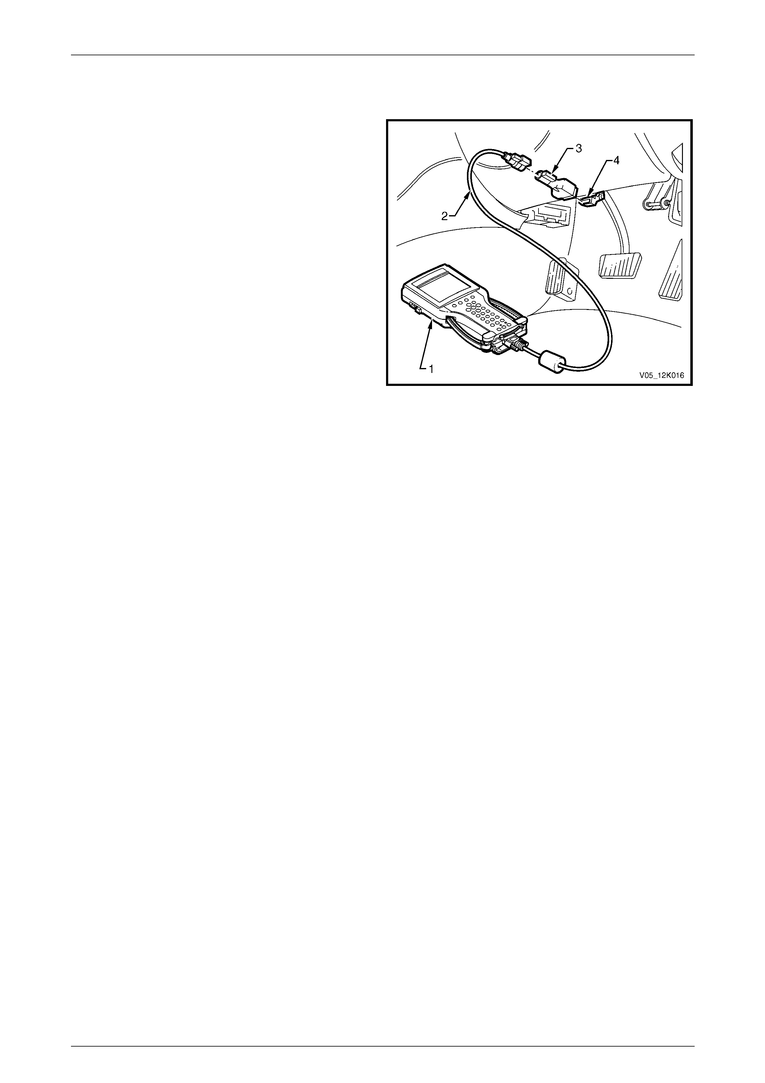
Telematics Page 12K–40
Page 12K–40
3.2 Connecting Tech 2
Tech 2 (1), with the appropriate software, cable (2) and
adapter (3) can read telematics module serial data, when
connected to the data link connector (4) (DLC). The DLC is
connected to the instrument panel lower right hand trim, to
the right of the steering column.
For further general information on connecting and operating
Tech 2, refer to Section 0C Tech 2.
Legend
1 Tech 2
2 DLC Cable
3 DLC Adapter
4 DLC
Figure 12K – 28
Tech 2 has six test modes for diagnosing the telematics module:
• Mode F0: Diagnostic Trouble Codes
In this test mode, Tech 2 can display and clear DTCs.
• Mode F1: Data Display
In this test mode, Tech 2 displays the telematics module inputs and outputs status.
• Mode F2: Snapshot
In this test mode, Tech 2 captures telematics module data before and after a forced manual trigger.
• Mode F3: Miscellaneous Tests
In this test mode, Tech 2 performs various tests to assist in isolating problems during troubleshooting.
• Mode F4: Additional Functions
In this test mode, Tech 2 performs a system function test of the:
• end call / information button,
• HOLDEN ASSIST button,
• microphone,
• speaker,
• emergency button, and
• status indicator LEDs.
• Mode F5: Program
In this test mode, Tech 2 allows programming of various features by enabling or disabling the feature or adjusting
settings.

Telematics Page 12K–41
Page 12K–41
3.3 Tech 2 Test Modes
As a prerequisite to this diagnostic section,
you must be familiar with the correct use of
Tech 2. The following information illustrates
only the telematics module Tech 2 screen
displays and provides an explanation of their
function for diagnosing the telematics
module. For further information on the
operation of Tech 2, refer to:
• Section 0C Tech 2, or
• the
Tech 2 User's Guide
.
System Select Menu
1 Connect Tech 2 to the DLC.
2 Turn on the ignition.
3 Turn on Tech 2.
4 Select F0: Diagnostics from the main menu.
5 Select the model year and vehicle type.
6 Select F3: Body, then press ENTER.
The F3: Body mode contains all functions to:
• test, diagnose, monitor and program vehicle body systems (including the telematics module); and
• check all DTCs that may be set in the vehicle.
7 Select Telematics Module, then press ENTER.
The telematics module system identification screen displays:
• Identifier
(the diagnostic data identifier)
• Part number
(telematics module part number)
• Production Date
(telematics module production date, in DDMMYY format)
• Software Version Number
(for example, 001.000.002)
• SIM Serial Number
(SIM serial number)
• Telematics Module
(telematics module serial number)
• Code Index
(software index number)
• Code Version
(software version number)
• VAP Process Number
(vehicle assembly plant process number)
• TIS Hardware Key Serial
(TIS 2000 hardware key number)
• VIN Digit 1–17
(Vehicle Identification Number digits 1–17)
8 Press the Confirm softkey; Tech 2 displays the telematics module application menu.

Telematics Page 12K–42
Page 12K–42
Application Menu
The following functions are available:
• F0: Diagnostic Trouble Codes
• F1: Data Display
• F2: Snapshot
• F3: Miscellaneous Tests
• F4: Additional Functions
• F5: Program
F0: Diagnostic Trouble Codes
In this test mode, DTCs stored by the telematics module can be displayed or cleared. When F0: Diagnostic Trouble
Codes is selected, two modes are available:
• F0: Read DTC Information:
All current DTCs are displayed.
• F1: Clear DTC Information (History DTCs):
The telematics module can store history data for six DTCs.
F0: Read DTC Information
When F0: Read DTC Information is selected, Tech 2 displays:
• the DTC number,
• DTC status (either current or history),
• DTC description,
• times occurred,
• ignition cycles since the DTC last set, and
• number of DTCs set.
NOTE
Times occurred and ignition cycles since DTC
last set is available only for the six most recent
DTCs.
F1: Clear DTC Information
When F1: Clear DTC Information is selected, Tech 2 displays:
'Do you want to clear DTCs? (Yes / No)'
• Press the YES softkey to clear all DTC information.
• Press the NO softkey to exit this menu.

Telematics Page 12K–43
Page 12K–43
F1: Data Display
NOTE
Before referring to any data display to diagnose a
system problem, the telematics on-board diag-
nostic system must be performed.
F0: Inputs and Outputs
In this test mode, Tech 2 checks if the telematics module is receiving one or more inputs from the appropriate sensor(s)
or antenna(s). If the sensor(s) or antenna(s) input(s) are not being received, perform the relevant system diagnosis as
defined in the following table.
This following table lists typical data parameters, display units, relevant telematics module pin number, nominal values
and specific diagnostic tables. If data does not match the nominal value defined in this table, refer to the specific
diagnostic table for that data parameter.
Data
Parameter Display
Unit Pin
No. Nominal
Values Diagnostic
Table
Battery
Voltage Volts X2 – 16 ±0.5 V of nominal battery voltage Refer to Vehicle Battery Voltage.
Backup
Battery
Voltage
Volts X5 – A
X5 – B >7.2 V Refer to Backup Battery.
Backup
Battery
Charger
Active
Inactive X5 – A
X5 – B Backup battery charger displays
'Active' when the telematics backup
battery is being charged via the
telematics backup battery charging
circuit.
Refer to Backup Battery.
Ignition
Switch On
Off X2 – 5 Current status of ignition switch. Refer to No Serial Data.
Accessories
Switch On
Off SD Current status of accessories
switch. Refer to No Serial Data.
Operating
Mode
VAP
Pre-Delivery
Service
Active
Stand-by
Sleep
Int Telematics module operating mode.
Displays 'Active' when operating.
Refer to 2.1 Operating Modes.
Refer to F0: Operating Mode.
Fuel Pump
Relay Drive
Circuit
Active
Inactive X1 – 18
X1 – 19 Fuel pump relay drive circuit should
be active at all times. Displays
'Inactive' if remote immobilisation
has been requested.
Refer to Fuel Pump Relay Drive
Circuit diagnostic table.
Keypad
Supply Voltage On
Off X2 – 15 Displays the commanded state of
the interior rear-view mirror keypad
supply voltage. Should be 'On'
whenever this system is in active
mode or service mode.
Refer to F3: Keypad Supply
Voltage.
Keypad
Signal Voltage Volts X2 – 9 Signal voltage from the resistor
encoded keypad in the interior rear-
view mirror. Varies depending upon
which button is pressed:
• Emergency: 3.8 V
• HOLDEN ASSIST: 2.3 V
• End Call / Information: 0.7 V
Refer to End Call / Information
Button diagnostic table.
NOTE
This makes a call to the Holden Assist Centre.

Telematics Page 12K–44
Page 12K–44
Data
Parameter Display
Unit Pin
No. Nominal
Values Diagnostic
Table
End Call /
Information
Button
On
Off X2 – 9 End Call / Information button status
displays 'On' when button is
pressed.
Refer to End Call / Information
Button.
NOTE
This makes a call to the Holden Assist Centre.
Holden
Assist
Button
On
Off X2 – 9 HOLDEN ASSIST button status
displays 'On' when button is
pressed.
Refer to HOLDEN ASSIST Button.
NOTE
This makes a call to the Holden Assist Centre.
Emergency
Button On
Off X2 – 9 Emergency button status displays
'On' when button is pressed. Refer to Emergency Button.
NOTE
This makes a call to the NERC™.
The operation of this button should be tested
only using the F1: Function Test menu.
Red
Status
LED
On
Off X2 – 7 Displays the commanded state of
the interior rear-view mirror red
status LED.
Refer to Status Indicator LEDs Do
Not Illuminate.
Green
Status
LED
On
Off X2 – 9 Displays the commanded state of
the interior rear-view mirror green
status LED.
Refer to Status Indicator LEDs Do
Not Illuminate.
Indicator
Drive On
Off SD Display should change from 'Off' to
'On' when the telematics module
commands the indicators on.
Refer to F7: Indicators.
Theft
Deterrent
Horn
On
Off X2 – 2 Displays the commanded state of
the theft deterrent horn. Refer to Theft Deterrent Horn
Circuit.
Driver's
Door Door Closed
Door Open X2 – 11 Driver's door ajar switch status,
should display 'Door Open' when
the driver's door is open.
Refer to Driver's Door Ajar Switch.
Passengers
Doors Door Closed
Door Open X2 – 1 Passengers door ajar switch status,
should display 'Door Open' when
any passenger door is open.
Refer to Passengers Door Ajar
Switches.
Phone
Mute
Input
Active
Inactive X2 – 12 When 'Active', the audio system
mute is required by the telematics
module.
Refer to Audio Mute.
Audio
Source Hands-free
Telematics
Module
Tone
Generation
Int Displays the current audio source. Refer to Audio Mute.
Unauthorised
Entry
Alert
Delay
Seconds Int Displays the time (in seconds)
between the theft deterrent system
activating and an unauthorised entry
alert (UEA) is sent to the Holden
Assist Centre.
N/A

Telematics Page 12K–45
Page 12K–45
Data
Parameter Display
Unit Pin
No. Nominal
Values Diagnostic
Table
Low
Battery
Alert
Delay
Seconds Int Displays the time (in seconds) after
the battery voltage has reached the
low battery alert (LBA) threshold
and an LBA is sent to the Holden
Assist Centre.
N/A
Vehicle
Speed Km/h SD Displays the current vehicle speed. Refer to DTC 5 — No Serial Data.
SRS
Deployed
This
ignition
Cycle
Yes
No SD Displays the status of the SRS
deployed this ignition cycle serial
data message.
Refer to DTC 3 — No Serial Data
From Sensing Diagnostic Module.
Radio
Status On
Off SD Displays the current status of the
radio. Refer to DTC 5 — No Serial Data.
Low Battery
Alert
Threshold 1
Volts Int Displays the battery voltage at
which an LBA is sent to the Holden
Assist Centre.
N/A
Low Battery
Alert
Threshold 1
Timeout
Minutes Int Displays the length of time the
battery must be at low battery alert
threshold 1 before an LBA is set.
N/A
Low Battery
Alert
Threshold 2
Volts Int Displays the battery voltage at
which an LBA is sent to the Holden
Assist Centre.
N/A
Low Battery
Alert
Threshold 2
Timeout
Minutes Int Displays the length of time the
battery must be at LBA Threshold 2
before an LBA is set.
N/A
Low Battery
Alert
Threshold 3
Volts Int Displays the battery voltage at
which an LBA is sent to the Holden
Assist Centre.
N/A
Low Battery
Alert
Threshold 3
Timeout
Seconds Int Displays the length of time that the
battery must be at LBA Threshold 3
before an LBA is set.
N/A
Backup
Battery
In Vehicle
Timer
Hour Int Displays the length of time the
backup battery has been in the
vehicle.
N/A
Backup
Battery
Charge
Time
Hour Int Displays the backup battery charge
time. N/A
Backup
Battery
Operating
Time
Minutes Int Displays the length of time the
telematics system has been
operating on the backup battery.
N/A
SD = Serial Data Int = Internal Telematics Module Value N/A = Not Applicable

Telematics Page 12K–46
Page 12K–46
F1: Global Positioning System
In F1: Global Positioning System test mode, Tech 2 displays global positioning system (GPS) information.
NOTE
If the 'Time of Last Known GPS Fix' data list
parameter is incrementing, the telematics module
is receiving data from GPS satellites.
Data
Parameter Display Nominal
Values Diagnostic
Table
GPS Module Inactive
Active GPS module status: should display 'Active'
when the GPS module is operational.
Time of Last Known GPS
Fix Hours
Minutes
Seconds
Displays the time of the last known GPS fix.
Distance from Last Known
GPS Fix Metres Display the distance (in metres) from the last
known GPS fix.
GPS Satellites Visible Displays the number of satellites visible,
when the module had a GPS fix.
Latitude Degrees
Minutes
Seconds
Displays the last known latitude of the vehicle
(for example, –37° 52' 27")
Minus (–) = south
Longitude Degrees
Minutes
Seconds
Displays the last known longitude of the
vehicle (for example, 144° 45' 14")
Minus (–) = west
UTC
(Coordinated Universal
Time)
Hours
Minutes
Seconds
Displays the coordinated universal time.
UTC Date Day
Month
Year
Displays the current UTC date.
Refer to No
GPS Signal.

Telematics Page 12K–47
Page 12K–47
F2: GSM
In this test mode, Tech 2 displays Global System for Mobile (GSM) communications information.
Data
Parameter Display Nominal
Values Diagnostic
Table
GSM
Module Active
Inactive Displays 'Active' if the GSM module is active
and registered on the mobile phone network.
GSM
RSSI Displays the GSM signal strength
(Received Signal Strength Indication) as
an Arabic numeral.
GSM
Signal Strength –50 dBm to –113 dBm Displays the GSM signal strength in decibels
per milliwatt (dBm).
Last SMS
Message Status none
sending
sent
failed
invalid
Displays the status of the last SMS message.
GSM
Registration none
home
seeking
unknown
roaming
Display the current GSM registration.
Refer to No
GSM Signal.
F3: GSM Call Register
In this test mode, Tech 2 displays the last 10 GSM calls made or received.
Data Parameter Display
GSM Call Number 1
GSM Call Number 2
GSM Call Number 3
GSM Call Number 4
GSM Call Number 5
GSM Call Number 6
GSM Call Number 7
GSM Call Number 8
GSM Call Number 9
GSM Call Number 10
Refer to GSM Call
Register Display Table

Telematics Page 12K–48
Page 12K–48
Tech 2 can display any of the following incoming or outgoing calls for any or all of the ten call registers.
GSM Call Register Display Table
Display Description
No Activity Displayed if there is no GSM register data stored in the telematics module; this occurs after
performing a GSM call register reset.
Unlock An remote unlock request has been received from the Holden Assist Centre.
Unlock and Status An unlock request and telematics module operating mode status request has been received from
the Holden Assist Centre.
Unlock and Position An unlock request and vehicle position request has been received from the Holden Assist
Centre.
Lock A lock request has been received from the Holden Assist Centre.
Lock and Status A lock request and telematics module operating mode status request has been received from the
Holden Assist Centre.
Lock and Position A lock request and vehicle position request has been received from the Holden Assist Centre.
Information An information call has been sent to the Holden Assist Centre.
HOLDEN ASSIST A HOLDEN ASSIST call has been sent to the Holden Assist Centre.
Emergency A emergency call has been sent to the Holden Assist Centre.
Low Battery A low battery alert (LBA) has been sent to the Holden Assist Centre.
Airbag A airbag deployed alert has been sent to the Holden Assist Centre.
Unauthorised Entry An unauthorised entry alert (UEA) has been sent to the Holden Assist Centre.
Position A current vehicle position request has been received from the Holden Assist Centre.
Tracking A vehicle tracking request has been received from the Holden Assist Centre.
Tracking Change A change vehicle tracking request has been received from the Holden Assist Centre.
Vehicle Locate A vehicle locate request has been received from the Holden Assist Centre.
Immobilisation An immobilisation request has been received from the Holden Assist Centre.
Remobilise A remobilise request has been received from the Holden Assist Centre.
Parameter Update A parameter update request has been received from the Holden Assist Centre.
Identification An identification request has been received from the Holden Assist Centre.
Modify Operation A modify operation request has been received from the Holden Assist Centre.
Acknowledge An acknowledge has been set from the telematics module to the Holden Assist Centre.
F4: Telephone Number
In this test mode, Tech 2 displays the telephone numbers to which calls have been made, refer to System Select Menu.
F5: System Identification
In this test mode, Tech 2 displays system identification information, refer to System Select Menu.

Telematics Page 12K–49
Page 12K–49
F2: Snapshot Options
In this mode, Tech 2 captures data before and after a forced manual trigger.
The snapshot options test mode helps isolate intermittent or transient problems by storing telematics module data
parameters immediately before and immediately after a problem occurs.
• F0: Inputs and Outputs
• F1: Global Positioning System
• F2: GSM
• F3: GSM Call Register
• F4: System Identification
F3: Miscellaneous Tests
In this mode, Tech 2 tests various components of the telematics system (for example, status LEDs, radio mute or fuel
pump circuit) to assist in problem isolation during troubleshooting.
Each test operates for four seconds. Further activation of the softkey tests for another four seconds. After selecting
miscellaneous tests, the following tests are available:
• F0: Fuel Pump Circuit
• F1: Red Status LED
• F2: Green Status LED
• F3: Keypad Supply Voltage
• F4: Audio System Mute
• F5: Backup Battery Charger
• F6: Unlock Doors
• F7: Indicators
• F8: Audio Output
F0: Fuel Pump Circuit
Precondition: system not in pre-delivery mode.
This mode activates and deactivates the fuel pump relay drive circuit by pressing the Inactive or Active softkeys.
When inactive, the telematics module opens the fuel pump relay drive ground circuit, stopping the fuel pump. The fuel
pump relay drive circuit changes from approximately 12 V (with the engine operating) to 1.4 V (when the engine is not
operating).
Press the Quit softkey to exit the fuel pump circuit test.
If this miscellaneous test is unsuccessful, replace the telematics module refer to 5.1 Telematics Module.
F1: Red Status LED
Precondition: system not in pre-delivery mode.
This mode turns the red status LED on and off using the On and Off softkeys.
Press the Quit softkey to exit the Red Status LED test.
If this miscellaneous test is unsuccessful, refer to Status Indicator LEDs Do Not Illuminate.

Telematics Page 12K–50
Page 12K–50
F2: Green Status LED
Precondition: system not in pre-delivery mode.
This mode turns the green status LED on and off using the On and Off softkeys.
Press the Quit softkey to exit the Green Status LED test.
If this miscellaneous test is unsuccessful, refer to Status Indicator LEDs Do Not Illuminate.
F3: Keypad Supply Voltage
Precondition: system not in pre-delivery mode.
This test turns the supply voltage from the telematics module to the keypad on and off using the On and Off softkeys.
When the keypad supply voltage is turned off, the keypad illumination extinguishes and the keypad buttons do not
function.
Press the Quit softkey to exit the Keypad Supply Voltage test.
If this miscellaneous test is unsuccessful, refer to Status Indicator LEDs Do Not Illuminate.
F4: Audio System Mute
Precondition: system not in pre-delivery mode.
This mode activates and deactivates the telematics audio system mute circuit:
• Press the Active softkey to activate the audio system mute.
• Press the Inactive softkey to deactivate the radio mute.
• Press the Quit softkey to exit the Audio System Mute test.
If this miscellaneous test is unsuccessful, refer to Audio Mute.
F5: Backup Battery Charger
Precondition: system not in pre-delivery mode.
This mode activates and deactivates the telematics backup battery charging circuit:
• Press the Active softkey to activate the backup battery charger.
• Press the Inactive softkey to make the backup battery charger inactive.
• Press the Quit softkey to exit the Backup Battery Charger test.
If this miscellaneous test is unsuccessful, refer to Backup Battery.
F6: Unlock Doors
Precondition: system not in pre-delivery mode.
This mode locks and unlocks the doors:
• Press the Lock softkey to send a lock request from the telematics module via the serial data bus to the BCM. When
the BCM receives this request from the telematics module all doors lock.
• Press the Unlock softkey to send an unlock request from the telematics module via the serial data bus to the BCM.
When the BCM receives this request from the telematics module all doors unlock.
• Press the Quit softkey to exit the Unlock Doors test. Tech 2 sends an Unlock request to the BCM, unlocking the
doors before quitting this test.
If this miscellaneous test is unsuccessful, refer to Section 12J Body Control Module.

Telematics Page 12K–51
Page 12K–51
F7: Indicators
Precondition: system not in pre-delivery mode.
This mode flashes the indicators On and Off:
• Press the On softkey to send an indicators on/off request from the telematics module via the serial data bus to the
BCM. When the BCM receives this request from the telematics module the indicators flash on and off.
• Press the Off softkey to request the telematics module stop sending the indicators on/off request.
• Press the Quit softkey to exit the Indicators test.
If this miscellaneous test is unsuccessful, refer to Section 12J Body Control Module.
F8: Audio Output
Precondition: system not in pre-delivery mode.
This mode tests both the audio system and front right speaker channel outputs.
• Press the Audio System softkey to send a test tone to the audio head unit (AHU) from the telematics module. This
test tone can be heard through all audio system speaker channels.
• Press the Front Right softkey to send a test tone to the right front speaker channel from the telematics module. This
test tone can be heard through the front right speaker channel. When this occurs a mute signal is sent to the AHU.
• Press the Abort softkey to exit the Audio Output test.
If this miscellaneous test is unsuccessful, refer to Audio Mute.
F4: Additional Functions
When additional functions has been selected, the following telematics module resets are available:
• F0: GSM Call Register Reset
• F1: Backup Battery Timer Reset
• F2: Telematics Module Reset
• F3: SIM Reset
F0: GSM Call Register Reset
This additional function resets the GSM call register data list. All GSM call register data list parameters then display 'No
Activity' until a call is made or received.
When selected, Tech 2 displays 'Do you w an t to reset the GSM Call Register?':
• Press the Yes softkey to reset the GSM call register
• Press the No softkey to exit the function.
After completing the reset, Tech 2 displays 'GSM Call Register Reset Completed!'.
• Press the Confirm softkey to exit the GSM Call Register Reset test.
F1: Backup Battery Timer Reset
This additional function resets the backup battery timer. Perform this option only after replacing the backup battery.
Tech 2 displays 'Please get programming approval from TIS!', refer to Section 0C Tech 2.
1 Press the Confirm softkey to acknowledge that programming approval from TIS has been given.
2 Return to F4: Additional Functions.
3 Select F1: Backup Battery Timer. Tech 2 displays 'Do you want to reset the Backup Battery Timer?'.
4 Either:
• Press the Yes softkey to clear the GSM call register. After resetting the GSM call register, Tech 2 displays
'Backup Battery Timer Reset Completed!'.
• Press the No softkey to exit the function.
5 Press the Confirm softkey to exit the Backup Battery Timer Reset test.

Telematics Page 12K–52
Page 12K–52
F2: Telematics Module Reset
This additional function resets the telematics module. When selected, Tech 2 displays 'Do you wan t to reset the
Telematics Module?'.
• Press the Yes softkey to reset the telematics module.
• Press the No softkey to exit the function.
After completing the reset, Tech 2 displays 'Telematics Module Reset Completed!'.
• Press the Confirm softkey to exit the Telematics Module Reset test.
F5: Program
In this mode, Tech 2 programs the telematics module. After selecting the Program option, three options are available:
• F0: Operating Mode
• F1: Program VIN
• F2: Program Code Index
F0: Operating Mode
This programming mode allows you to program the telematics module into one of four operating modes. Press the
appropriate softkey to program the telematics module into the selected operating mode:
• Service Mode:
Press the Service softkey to switch the telematics module to service mode.
• Sleep Mode:
Press the Sleep softkey to switch the telematics module to active mode. The telematics module switches to sleep
mode:
• two minutes after Tech 2 is removed,
• the ignition has been switched off, and
• all doors have been shut.
• Pre-delivery Mode:
Vehicles are delivered to the dealer with the pre-delivery mode enabled.
a Press the Pre-Delivery softkey. Tech 2 displays the request 'Please get programming approval from TIS!',
refer to Section 0C Tech 2.
b Press the Confirm softkey to acknowledge that programming approval from TIS has been given. After
enabling programming, Tech 2 returns control to the Operating Mode screen.
c Press the Pre-Delivery softkey; Tech 2 enables the pre-delivery mode.
d With the pre-delivery mode enabled, turn off the telematics system.
e Press the Service softkey to disable the pre-delivery mode and enable the service mode. Tech 2 displays the
request 'Please get programming approval from TIS!', refer to Section 0C Tech 2.
f Press the Confirm softkey to acknowledge that programming approval from TIS has been given.
After selecting F0: Operating Mode, Tech 2 displays the current telematics module operating mode. To
change the operating mode, press the appropriate softkey and the telematics module switches to the selected
operating mode.
NOTE
TIS Approval is required to enable or disable Pre-
delivery mode. If Pre-delivery mode is enabled,
only the Service Mode softkey is displayed.
g Press the Exit key to quit.

Telematics Page 12K–53
Page 12K–53
F2: Program Code Index
Precondition: system not in pre-delivery mode.
In this mode, Tech 2 displays the code index and programmed code version. An option exists to reprogram the code
version.
• Code Index:
The code index identifies the telematics software level. A higher number indicates the latest version of the software.
• Code Version:
The code version identifies the calibration level. Each software level may have different code versions; a higher
number indicates the latest version of calibration.
1 Press the Modify softkey to change the software level.
2 Enter the code index using the numerical keypad.
NOTE
Enter leading zeroes when defining this field.
3 Press the Enter key to program.

Telematics Page 12K–54
Page 12K–54
4 Diagnostics
All telematics system diagnosis information is contained in this Section:
• Refer to 1 General Information for wiring diagrams and auxiliary information on telematics module connector end
views and nominal voltages, and component locations.
• Refer to 4.5 On-board Diagnostic System Check for information to start telematics system diagnosis. This check
verifies the diagnostic circuits are operating properly, then refers to the correct diagnostic table for diagnosis.
4.1 Basic Knowledge and Tools Required
To use this Service Information effectively, refer to 3.1 Basic Knowledge Required for minimum requirements on basic
electrical circuits and use of circuit testing tools.
To perform system diagnosis, Tech 2 is required. Tech 31 or a digital multimeter with 10 megohm impedance, a test light
and jumper wires are also required.
Ensure you can use these tools before trying
to diagnose a fault.
When taking readings from wiring harness
connectors, backprobe individual connectors
whenever possible to avoid damage to
connectors and possible subsequent
connection failure. Perform wiring checks as
directed by the diagnostic tables, rather than
probe connectors with incorrect-sized
multimeter connections. Use the adapters
contained in connector test adapter kit
KM–609 to prevent spreading or damaging
w i ring harness connectors.
Testing various systems also allows access to specific wiring harness connectors. For the location of these connectors,
refer to Section 12P Wiring Diagrams.

Telematics Page 12K–55
Page 12K–55
4.2 Diagnostic Precautions
Before performing any service operation or other procedure described in this Section,
refer to Section 00 Warnings, Cautions and Notes for correct workshop practices with respect to safety and/or property
damage.
Adhere to the following requirements when working on vehicles:
• Disconnect the negative battery cable before removing any system component.
• Do not start the engine without the battery being connected correctly.
• Do not separate the battery from the on-board electrical system while the engine is running.
• When charging the battery, disconnect it from the vehicle electrical system.
• Do not subject the telematics module to temperatures above 80°C (for example, a paint oven). Remove the
telematics module from the vehicle if this temperature will be exceeded.
• Ensure all cable harness plugs are connected correctly and that battery terminals are thoroughly clean.
Do not force conn ectors into place; if they are
oriented correctly, force is unnecessary.
• Harness connectors are designed to fit in only one way. Failure to ensure correct orientation of connector
components can cause damage to the connector, the telematics module or other vehicle components or systems.
• Do not connect or disconnect telematics module cable harness connectors when the ignition is on.
• Before attempting any electric arc welding on the vehicle, disconnect the battery leads and the telematics module
connectors.
• Use only the test equipment specified in the diagnostic tables; other test equipment may either give incorrect results
or damage operational components.
• All voltage measurements using a voltmeter must use a digital voltmeter with an internal impedance rating of at
least 10 000 000 Ω (10 megohms).
• When a test light is specified, use a low-power test light; do not use a high-wattage test light. Although a particular
brand of test light is not suggested, a simple test on any test light ensures it will be adequate for circuit testing.
Connect an accurate ammeter (such as a high-impedance digital multimeter) in series with the test light being
tested and power the test light-ammeter circuit with the vehicle battery.
• If the ammeter indicates less than 0.3 A (300 mA) current flow, the test light may be used.
• If the ammeter indicates more than 0.3 A (300 mA) current flow, the test light must not be used.

Telematics Page 12K–56
Page 12K–56
Blocking Drive Wheels
Block the vehicle drive wheels and apply the
parking brake firmly before checking the
system.
Visual / Physical Inspection
Inspect the vehicle visually and physically
before performing any diagnostic procedure.
This visual / physical inspection is very important; it must be done carefully and thoroughly. A full inspection may resolve
the problem without further steps:
• Inspect all electrical wires for correct routeing, pinches, cuts or disconnections.
• Inspect wires that are difficult to see.
• Inspect all wires for proper connections, burned or chafed spots, or contact with sharp edges or hot exhaust
manifolds.

Telematics Page 12K–57
Page 12K–57
4.3 Diagnostic Table Description
Diagnostic tables provide fast and efficient means of fault location for all functions associated with the telematics module.
Diagnostic table steps are explained by the corresponding numbered paragraph on the page preceding the diagnostic
table under the heading 'Test Description'.
For information to start telematics system diagnosis, refer to 4.5 On-board Diagnostic System Check. This check verifies
the diagnostic circuits are operating properly, then refers to the correct diagnostic table for diagnosis.
After correcting a fault and clearing all DTCs, repeat the On-Board Diagnostic System Check to ensure the proper repairs
have been made.
Diagnostic Tables Components
Diagnostic tables typically have the following information:
• DTC number and description
(This defines the DTC and contains a circuit diagram showing the components for the circuit.)
• circuit description
(This describes the circuit and clarifies the intent of the preceding circuit diagram.)
• conditions for setting the DTC
(This describes the condition or conditions that set the DTC.)
• action taken when the DTC sets
(This describes the effect(s) on the telematics system.)
• test description
(This describes the action(s) taken that help to resolve the problem; this description also contains a three-quarter
view of the connectors listed in the diagnostic tables.)
• diagnostic table
(Steps in troubleshooting tables instruct either to make a specific repair or to continue diagnosis. Each step has one
or more parts. If further diagnosis is needed, the step lists the next step in the diagnosis.)
NOTE
If the condition is intermittent, the troubleshooting
table directs control to the diagnostic aids on the
preceding page. Suggestions for diagnosing
intermittent conditions and an explanation of how
some faults can occur are listed. Diagnostic
tables help to solve active conditions, not
intermittent conditions.
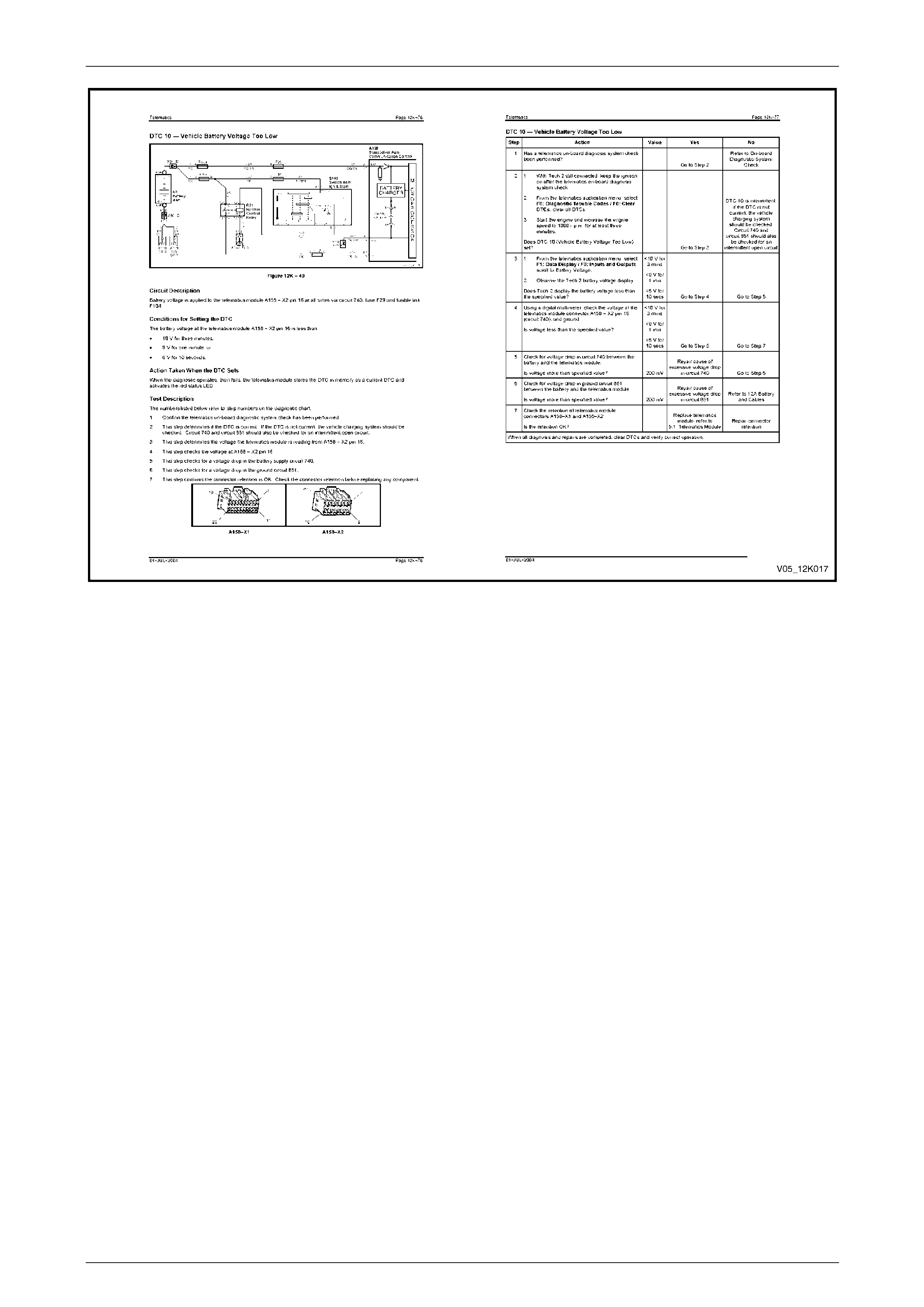
Telematics Page 12K–58
Page 12K–58
Figure 12K – 29

Telematics Page 12K–59
Page 12K–59
4.4 Strategy-based Diagnostics
NOTE
For an explanation of the steps and logic in
diagnosing faults, refer to Figure 12K – 30.
Strategy-based diagnosis is a uniform approach to repair all electrical and electronic systems. The diagnostic flow is used
to resolve a problem with an electrical / electronic system and is a starting point when repairs are necessary. The steps
below instruct technicians how to proceed with a diagnosis. The steps below refer to the step numbers found in the
strategy-based diagnostic table, refer to Figure 12K – 30.
1 Verify the driver's concern:
To verify the driver's concern, the technician must know the normal operation of the system being diagnosed.
2 Preliminary check:
Conduct a thorough visual and operational inspection, review the service history, detect unusual sounds or odours,
and gather diagnostic trouble code information to achieve effective repair.
3 Service information system check(s):
On-board diagnostic system checks verify proper operation of the system. This lead to an organised approach to
diagnostics.
4 Check bulletins and other service information:
This should include, service techlines, all retailer letters and service training publications.
5 Service diagnostics (paper / electronic):
a current DTC stored:
Follow the designated DTC table exactly to make an effective repair.
b symptom — no DTCs:
Select the symptom from the diagnostic tables and:
• follow the diagnostic paths or suggestions to complete the repair, or
• refer to the applicable component or system checks.
c No published diagnostics:
Analyse the complaint and develop a plan for diagnosis. Use the wiring diagrams and theory of operation for
the system being repaired.
Call Technical Assistance for advice about similar cases when a repair history may be available. Combine
technician knowledge with efficient use of the available Service Information.
d Intermittent faults:
These are conditions that are not always present. To resolve intermittent faults:
(1) Observe history DTCs, DTC modes and freeze frame data if available.
(2) Evaluate the symptoms and conditions described by the driver.
(3) Use a check-list or other method to identify the faulty circuit or electrical system component.
(4) Follow the suggestions for intermittent diagnosis in the service documentation.
Tech 2, Tech 31 and a digital multimeter can capture data that may assist in detecting intermittent
faults.
e Vehicle operates as designed / no trouble found:
This condition exists when the vehicle operates normally (that is, the condition described by the driver may be
normal). Verify against another vehicle that is known to be operating normally; the condition may be
intermittent. Contact Technical Assistance if the concern is common. Verify the complaint under the
conditions described by the driver before releasing the vehicle.
6 Re-examine the driver's concern:
When the complaint can not be successfully found or isolated, re-evaluate the complaint. The complaint should be
re-verified and could be intermittent or normal as described in step 5c or step 5e.
7 Repair and verification tests:
After isolating the cause, the repair should be completed. Then validate for proper operation and verify that the
symptom has been corrected. This may involve road testing or other methods to verify the complaint has been
resolved:
• under the conditions noted by the driver, and/or
• if a DTC was diagnosed, verify the repair by duplicating the conditions present when the DTC was set.

Telematics Page 12K–60
Page 12K–60
Figure 12K – 30

Telematics Page 12K–61
Page 12K–61
4.5 On-board Diagnostic System Check
A visual and physical vehicle inspection must
precede an on-board diagnostic system check
to ensure an accurate diagnosis is made to
find the cause of system malfunctions or
failures.
An on-board diagnostic system check preceding all diagnostic procedures, represents an organised approach to
identifying system problems. The on-board diagnostic system check subjects the vehicle to an initial system check, then
directs the technician to other tables in the Service Information.
NOTE
The diagnostic section may result in
accessing subsequent tables; perform the listed
actions in the correct sequence, refer to
4.9 Symptoms Tables.
The telematics module uses many input signals and controls many output functions. If the correct diagnostic sequence is
not followed, incorrect diagnosis and replacement of serviceable components may result.
Diagnostic tables incorporate diagnosis procedures using Tech 2 when possible.
Refer to 3 Tech 2 Diagnostics for Telematics for introductory information about Tech 2 and the data link connector
(DLC).
To diagnose a problem, follow these steps:
1 Are the on-board diagnostics functioning? Determine this by performing the on-board diagnostic system check that
precedes all diagnostic procedures or fault-finding system failures.
If the on-board diagnostics have failed, the on-board diagnostic system check leads to a diagnostic table to correct
the problem. If the on-board diagnostics are working correctly, the next step is:
2 Is there a diagnostic trouble code (DTC) stored? If a diagnostic trouble code is stored, go to the appropriate
numbered diagnostic trouble code table to determine if the fault is present. If no diagnostic trouble code is stored,
then:
3 Observe serial data transmitted by the telematics module (this involves reading Tech 2 information). For information
on and the meaning of Tech 2 displays, refer to 3.2 Connecting Tech 2. Typical data readings under a particular
operating condition are detailed on the Tech 2 data page. If the tested data does not match the typical data, refer to
the diagnostic information for that data parameter.

Telematics Page 12K–62
Page 12K–62
4.6 Diagnostic Trouble Codes
When the telematics module detects an operating parameter outside its calibrated values, it sets a DTC and stored this
DTC into memory as a current DTC. When a current DTC is set, the red status LED may illuminated when the ignition is
on.
The six most recent DTCs are logged into the telematics module memory into the DTC list. If more than six DTCs are set,
only history data for the last six is tracked. The oldest DTC is removed from the DTC list regardless of its position within
the list.
NOTE
After a DTC is removed from the DTC List, it is
maintained in the telematics module memory as a
history DTC, but there no DTC history data is
kept for this DTC.
DTC history data contained in the DTC List is:
• list position
(the position (1–6) within the list,
• DTC number
(the number that identifies a particular fault condition),
• occurrence count
(the number of times (0–255) a fault condition has been detected), and
• history count
(the number of ignition cycles (0–255) since the fault was last detected.
'0' indicates the fault has occurred on the current ignition cycle;
'255' indicates the fault occurred 255 or more ignition cycles ago).
Conditions vary that cause fault detection algorithms to set a DTC. A particular DT C is set once per ignition cycle. When
a DTC is set, the following occurs:
• If the DTC does not exist in the DTC list, it is inserted into the list at the first vacant location with the occurrence
count set to '1' and the history count set to '0'. If the DTC list is full, the oldest DTC is removed from the DTC list.
The history count determines the age of a DTC list entry. The item in the DTC list with the highest history count is
removed to make space for the new DTC.
• If the DTC already exists in the DTC List, the occurrence count is incremented (to a maximum of 255, when it is no
longer incremented). Each time the DTC is set, the history count is cleared.
The algorithms ensure the six most recent fault conditions are tracked. The occurrence and history counters determine
how often the fault has occurred and the time since the fault last occurred. For example:
• If the DTC occurrence count is '1' and the history count is '201', the fault condition existed only once, 201 ignition
cycles ago.
• If a fault had an occurrence count of '4' and a history count of '0', the fault has been detected four times and was
detected on the current ignition cycle.
DTCs are not removed from the list unless six newer fault conditions occur that push the oldest fault off the DTC list or
they are cleared using Tech 2.
NOTE
After a DTC is removed from the DTC List, it is
maintained in the telematics module memory as a
history DTC, but there no DTC history data is
kept for this DTC.

Telematics Page 12K–63
Page 12K–63
Diagnostic Trouble Codes
DTC
No. Tech 2 Display Red
Status LED
Illuminated
1 No Serial Data From BCM No
2 No Serial Data From Instrument No
3 No Serial Data From SDM Yes
4 No Serial Data From Audio System No
5 No Serial Data Yes
8 SIM Mismatch No
9 Vehicle Battery Voltage Too High No
10 Vehicle Battery Voltage Too Low Yes
11 RAM Error Yes
12 EEPROM Error Yes
13 Backup Battery Timer Expired Yes
14 Backup Battery Voltage Too High Yes
15 Backup Battery Voltage Too Low Yes
16 Backup Battery Not Detected Yes
17 Microphone Not Detected Yes
18 Microphone Circuit Voltage Too Low Yes
19 Microphone Circuit Voltage Too High Yes
21 Speaker Circuit Voltage Too Low Yes
22 Speaker Circuit Voltage Too High Yes
30 Keypad Circuit Voltage Too High Yes
39 Telephone Number Error Yes
44 GSM Not Logged With Signal Strength Present Yes
45 End Call / Information Button Stuck Yes
46 HOLDEN ASSIST Button Stuck Yes
47 Emergency Button Stuck Yes

Telematics Page 12K–64
Page 12K–64
4.7 Telematics Module Connector
Descriptions
Pin No.
A158 Circuit
No. Circuit
Colour IVED
Abbreviation Description Circuit
Type
X1 – 1 117
1952 Black / Red SPK_– Speaker Negative (L1, L2, L4)
Speaker Negative (L5) Output
X1 – 2 200
1852 Black / Blue SPK_+ Speaker Positive (L1, L2, L4)
Speaker Positive (L5) Output
X1 – 4 1061 Green / White UART_SCD Serial Data (Secondary) I/O
X1 – 5 659 Dark Green CLTEL_RET Phone Signal In Ground Ground
X1 – 6 658 Grey CLTEL_SIG Phone Signal In Input
X1 – 7 1153 Brown MIC– Microphone Negative Ground
X1 – 8 1155 Green MIC+ Microphone Positive Input
X1 – 9 2506 Blue TEL_RET Phone Signal Out Ground Ground
X1 – 10 655 Blue / Black TEL_SIG Phone Signal Out Output
X1 – 18 465 Green / White FL_PMP_SG Fuel Pump Relay In Input
X1 – 19 497 Light Green FL_PMP_RLY Fuel Pump Relay Out Output
X2 – 1 745 White PAS_DAJ Passenger Door Switches Input
X2 – 2 1149 Green THRN Theft Deterrent Horn Relay Input
X2 – 5 539 Pink / Blue IG Ignition Input
X2 – 6 5211 Yellow / Black TEL_MUT Radio Mute Output
X2 – 7 2517 Brown / White RD_LED Red LED Output
X2 – 8 851 Black / White GND Ground Ground
X2 – 9 2514 Green / White KEY_DAT Key Pad Signal Input
X2 – 11 746 Grey / White DRV_DAJ Driver' s Door Switch Input
X2 – 12 693 Yellow CLTEL_MUT Phone Mute In Input
X2 – 14 2516 Yellow / Black GN_LED Green LED Output
X2 – 15 2515 Light Green / Black KEY_PWR Key Pad Supply Voltage Output
X2 – 16 740 Orange / Black BATT+ Battery Positive B+
X3 – A N/A N/A N/A GPS Antenna Signal Input
X3 – B N/A N/A N/A GPS Antenna Ground Ground
X4 – A N/A N/A N/A GSM Antenna Signal Input
X4 – B N/A N/A N/A GSM Antenna Ground Ground
X5 – A N/A N/A N/A Back Up Battery Positive 7.2 V
X5 – B N/A N/A N/A Back Up Battery Negative Ground

Telematics Page 12K–65
Page 12K–65
4.8 Diagnostic Tables
On-board Diagnostic System Check
Circuit Description
The on-board diagnostic system check is an organised approach to identify a telematics system fault. This check must be
the starting point for any system diagnostics and directs the service technician to the next logical step in diagnosing a
fault. Understanding the diagnostic table and using it correctly reduces diagnostic time and minimises the risk of
replacing a serviceable component. For the wiring diagram, refer to Figure 12K – 6.
Test Description
The following numbers refer to the step numbers in the diagnostic table:
1 If the red or green, or both (orange) status indicator LEDs are illuminated, the telematics module is powered up and
supplying power to the interior rear-view mirror.
2 Confirms Tech 2 operation and that Tech 2 is being powered up.
3 Confirms that Tech 2 can communicate with the telematics module.
4 The VIN defined in the telematics module must match the vehicle VIN for correct telematics system operation.
5 If the engine starts and operates, the fuel pump relay drive circuit is OK.
6 This step checks if there are any current DTCs. If so, refer to the applicable diagnostic table.
7 This step determines if the telematics module is in pre-delivery mode.
• In pre-delivery mode, the telematics module is turned off.
• If pre delivery mode is enabled, disable it and perform the on-board diagnostic system check again.
8 In this step, refer to the nominal values in the telematics data list. If the values in the Tech 2 data list do not meet
the nominal values listed, refer to the applicable diagnostic table.
9 In this step, all Tech 2 miscellaneous tests are conducted and all tests should pass successfully. If any test fails,
refer to the applicable diagnostic table.
10 The vehicle must be positioned where the GSM signal strength is more than –90 dBm and the GPS data list
parameter 'Time of Last Known GPS Fix' updates. Then, begin the Holden Assist telematics system test, refer to
Holden Assist Telematics System Test.
11 This step confirms the connector retention is OK. Check the connector retention before replacing any component.
12 The telematics system is operating as designed and has passed the on-board diagnostic system check. Discuss
the system complaint with the driver (system subscriber) of the vehicle to ensure he/she understands the correct
operation of the system. If the problem persists, ask the driver to demonstrate the problem.

Telematics Page 12K–66
Page 12K–66
Step Action Yes No
1 Is the fault isolated to the Telematics system? Go to step 2 Refer to Section 0D
Vehicle Diagnostics
2 Turn on the ignition, but with the engine off.
Are the red or green, or both (orange) status indicator
LEDs in the interior rear-view mirror illuminated? Go to step 3 Refer to Status Indicator
LEDs Do Not Illuminate
3 1 Turn off the ignition, then install Tech 2 to the
DLC.
2 Turn on the ignition, then turn on Tech 2.
Does Tech 2 power up and display the title display
screen? Go to step 4 Refer to Section 0C Tech
2
4 Press the ENTER key, then select:
Diagnostics / (3) 2004 / VZ Commodore / F4: Body /
Telematics Module; follow the screen instructions.
Does Tech 2 display telematics system identification
information? Go to step 5 Go to No Serial Data
5 Did the VIN displayed in step 3 match the VIN of the
vehicle? Go to step 6 Go to step 12
6 Does the engine start and operate? Go to step 7 Go to Fuel Pump Relay
Drive Circuit
7 From the telematics application menu, select:
F0: Diagnostic Trouble / F0: Read DTC Information.
Are there any current DTCs? Go to the applicable DTC
diagnostic table Go to step 8
8 1 From the telematics application menu, select:
F1: Data Display / F0: Inputs and Outputs.
2 Scroll to 'Operating Mode'.
Does Tech 2 display 'Pre-Delivery'?
Disable pre-delivery
mode, refer to
F5: Program Go to step 9
9 From the telematics application menu, select:
F1: Data Display, refer to F1: Data Display.
Do the telematics data list parameters match the
nominal values? Go to step 10
Refer to the appropriate
data display diagnostic
table
10 1 From the telematics application menu, select:
F3: Miscellaneous Tests, refer to
F3: Miscellaneous Tests.
2 Perform all the miscellaneous tests.
Were all the miscellaneous tests successful? Go to step 11
Refer to the applicable
miscellaneous test failure
diagnostic table
11 1 Position the vehicle where the GSM Signal
strength is more than –90 dBm and the GPS data
list parameter 'Time of Last Known GPS Fix'
updates.
2 Perform a Holden Assist telematics system test,
refer to Holden Assist Telematics System Test.
Was the Telematics System Test successful? Go to step 13 Go to step 12
12 Check the retention of telematics module connectors
A158 – X1 and A158 – X2.
Is the retention OK?
Replace the telematics
module, refer to 5.1
Telematics Module Repair connector
retention
13 The telematics system is operating correctly.
If the owner (system subscriber) complained about a system fault, discuss the complaint with the owner and, if
the problem persists, ask the driver to demonstrate the problem.

Telematics Page 12K–67
Page 12K–67
DTC 1 — No Serial Data From BCM
Circuit Description
The telematics module monitors the auxiliary serial data circuit 1061 normal mode message for:
• airbag deployed this ignition cycle from the SRS SDM,
• vehicle speed from the PCM, and
• audio system status data from the audio head unit.
For further information regarding the serial data bus and normal mode message,
refer to Section 12J Body Control Module.
If the telematics module receives a 'Remote Unlock' message from the Holden Assist Centre, the telematics module
requests the BCM (via the serial data circuit) to unlock the doors. For further information regarding the BCM door lock
operation, refer to Section 12J Body Control Module.
If the telematics module receives an 'Immobilise' message from the Holden Assist Centre, the telematics module turns off
the fuel pump relay cutting off the supply of fuel to the engine and request the BCM (via the serial data circuit) to flash the
indicators. For further information regarding the BCM indicator operation,
refer to Section 12J Body Control Module. For the wiring diagrams, refer to:
• Figure 12K – 11, Figure 12K – 12 and Figure 12K – 13 (for vehicles fitted with a V6 engine), or
• Figure 12K – 14, Figure 12K – 15 and Figure 12K – 16 (for vehicles fitted with a GEN III V8 engine).
Conditions for Setting the DTC
The telematics module does not receive any BCM serial data for more than 10 seconds.
Action Taken When the DTC Sets
When the diagnostic operates, then fails, the telematics module stores the DTC in memory as a current DTC.
Test Description
The following numbers refer to the step numbers in the diagnostic table:
1 This step confirms the telematics on-board diagnostic system check has been performed.
2 If 'No Communication with the Vehicle' or 'No Data' is displayed next to BCM DTC status, there is no
communication between Tech 2 and the BCM. If Tech 2 can communicate with the BCM, the primary serial data
(circuit 800) and the BCM are OK.
3 If DTC 1 is intermittent, check for an open or short to ground or voltage in circuit 1061.
Diagnostic Table
Step Action Yes No
1 Has a telematics on-board diagnostic system check been performed?
Go to step 2
Refer to On-board
Diagnostic System
Check
2 1 W ith Tech 2 still connected, keep the ignition on after the
telematics on-board diagnostic system check.
2 From the Tech 2 system select menu, select:
F5: Vehicle DTC Check / Ignition On; follow the screen
instructions.
3 Does Tech 2 display 'No Communication with Vehicle' or
'BCM DTC Status, No Data'?
NOTE
If 'No Data' is displayed next to BCM DTC Status, there is
no communication between Tech 2 and the BCM.
Refer to Section
12J Body Control
Module Go to step 3
3 1 W ith Tech 2 still connected, keep the ignition on, but the engine
off.
2 From the telematics menu, select:
F0: Diagnostic Trouble Codes / F1: Clear DTC Information;
clear the telematics module DTCs.
3 Keep the ignition on for at least 10 seconds.
Does DTC 1 set?
Replace telematics
module, refer to 5.1
Telematics Module
DTC 1 is
intermittent; check
for an open or short
to ground or
voltage in
circuit 1061
When all diagnosis and repairs are completed, clear DTCs and verify correct operation.

Telematics Page 12K–68
Page 12K–68
DTC 2 — No Serial Data From Instrument
Circuit Description
The telematics module monitors the auxiliary serial data circuit 1061 normal mode message for:
• airbag deployed this ignition cycle from the SRS SDM,
• vehicle speed from the PCM, and
• audio system status data from the audio head unit.
For further information regarding the serial data bus and normal mode message,
refer to Section 12J Body Control Module.
If the telematics module receives a 'Remote Unlock' message from the Holden Assist Centre, the telematics module
requests the BCM (via the serial data circuit) to unlock the doors. For further information regarding the BCM door lock
operation, refer to Section 12J Body Control Module.
If the telematics module receives an 'Immobilise' message from the Holden Assist Centre, the telematics module turns off
the fuel pump relay cutting off the supply of fuel to the engine and request the BCM (via the serial data circuit) to flash the
indicators. For further information regarding the BCM indicator operation,
refer to Section 12J Body Control Module. For the wiring diagrams, refer to:
• Figure 12K – 11, Figure 12K – 12 and Figure 12K – 13 (for vehicles fitted with a V6 engine), or
• Figure 12K – 14, Figure 12K – 15 and Figure 12K – 16 (for vehicles fitted with a GEN III V8 engine).
Conditions For Setting the DTC
The telematics module does not receive any instrument serial data for more than 10 seconds.
Action Taken When the DTC Sets
When the diagnostic operates, then fails, the telematics module stores the DTC into memory as a current DTC and
activates the red status LED.
Test Description
The following numbers refer to the step numbers in the diagnostic table:
1 This step confirms the telematics on-board diagnostic system check has been performed.
2 If 'No Data' is displayed next to instrument DTC status, there is no communication between Tech 2 and the
instrument. If Tech 2 can communicate with the instruments, the secondary serial data (circuit 1061) and the
instruments are OK.
3 If DTC 1 is intermittent, check for an open or short to ground or voltage in circuit 1061.
Diagnostic Table
Step Action Yes No
1 Has a telematics on-board diagnostic system check been performed?
Go to step 2
Refer to On-board
Diagnostic System
Check
2 1 With Tech 2 still connected, keep the ignition on after the
telematics on-board diagnostic system check.
2 From the Tech 2 system select menu, select:
F5: Vehicle DTC Check / Ignition On; follow the screen
instructions.
3 Does Tech 2 display 'Instrument DTC Status' or 'No Data'?
NOTE
If 'No Data' is displayed next to BCM DTC Status, there is
no communication between Tech 2 and the BCM.
Refer to
Section 12C
Instrumentation Go to step 3
3 1 With Tech 2 still connected, keep the ignition on, but the engine
off.
2 From the telematics menu, select:
F0: Diagnostic Trouble Codes / F1: Clear DTC Information;
clear the telematics module DTCs.
3 Keep the ignition on for at least 10 seconds.
Does DTC 2 set?
Replace telematics
module, refer to 5.1
Telematics Module
DTC 2 is
intermittent; check
for an open or short
to ground or
voltage in
circuit 1061
When all diagnosis and repairs are completed, clear DTCs and verify correct operation.

Telematics Page 12K–69
Page 12K–69
DTC 3 — No Serial Data From Sensing Diagnostic Module
Circuit Description
The telematics module monitors the auxiliary serial data circuit 1061 normal mode message for:
• airbag deployed this ignition cycle from the SRS SDM,
• vehicle speed from the PCM, and
• audio system status data from the audio head unit.
For further information regarding the serial data bus and normal mode message,
refer to Section 12J Body Control Module.
After receiving an airbag deployed this ignition cycle from the SRS SDM, the telematics module sends an 'Airbag
Activation Alert' to the NERC™, refer to Airbag Activation Alert. For the wiring diagrams, refer to:
• Figure 12K – 11, Figure 12K – 12 and Figure 12K – 13 (for vehicles fitted with a V6 engine), or
• Figure 12K – 14, Figure 12K – 15 and Figure 12K – 16 (for vehicles fitted with a GEN III V8 engine).
Conditions For Setting the DTC
The telematics module does not receive any SDM serial data for more than 10 seconds.
Action Taken When the DTC Sets
When the diagnostic operates, then fails, the telematics module stores the DTC into memory as a current DTC.
Test Description
The following numbers refer to the step numbers in the diagnostic table:
1 This step confirms the telematics on-board diagnostic system check has been performed.
2 If 'No Data' is displayed next to SDM DTC status, there is no communication between Tech 2 and the SDM. If
Tech 2 can communicate with the SDM, the secondary circuit 1061, tertiary serial data circuit 774 and the SDM are
OK.
3 If DTC 3 is intermittent, check for an open or short to ground or voltage in circuit 1061and circuit 774.
Diagnostic Table
Step Action Yes No
1 Has a telematics on-board diagnostic system check been performed?
Go to step 2
Refer to On-board
Diagnostic System
Check
2 1 With Tech 2 still connected, keep the ignition on after the
telematics on-board diagnostic system check.
2 From the Tech 2 system select menu, select:
F5: Vehicle DTC Check / Ignition On; follow the screen
instructions.
3 Does Tech 2 display 'SDM DTC Status' or 'No Data'?
NOTE
If 'No Data' is displayed next to BCM DTC Status, there is
no communication between Tech 2 and the BCM.
Refer to Section
12M Occupant
Protection System Go to step 3
3 1 With Tech 2 still connected, keep the ignition on, but the engine
off.
2 From the telematics menu, select:
F0: Diagnostic Trouble Codes / F1: Clear DTC Information;
clear the telematics module DTCs.
3 Keep the ignition on for at least 10 seconds.
Does DTC 2 set?
Replace telematics
module, refer to 5.1
Telematics Module
DTC 2 is
intermittent; check
for an open or short
to ground or
voltage in
circuit 1061 and
circuit 774
When all diagnosis and repairs are completed, clear DTCs and verify correct operation.

Telematics Page 12K–70
Page 12K–70
DTC 4 — No Serial Data From Audio System
Circuit Description
The telematics module monitors the auxiliary serial data circuit 1061 normal mode message for:
• airbag deployed this ignition cycle from the SRS SDM,
• vehicle speed from the PCM, and
• audio system status data from the audio system.
For further information regarding the serial data bus and normal mode message,
refer to Section 12J Body Control Module. For the wiring diagrams, refer to:
• Figure 12K – 11, Figure 12K – 12 and Figure 12K – 13 (for vehicles fitted with a V6 engine), or
• Figure 12K – 14, Figure 12K – 15 and Figure 12K – 16 (for vehicles fitted with a GEN III V8 engine).
Conditions For Setting the DTC
The telematics module does not receive any audio system serial data for more than 10 seconds.
Action Taken When the DTC Sets
When the diagnostic operates, then fails, the telematics module stores the DTC in memory as a current DTC.
Test Description
The following numbers refer to the step numbers in the diagnostic table:
1 This step confirms the telematics on-board diagnostic system check has been performed.
2 If 'No Data' is displayed next to audio system DTC status, there is no communication between Tech 2 and the
audio system.
3 If DTC 4 is intermittent, check for an open or short to ground or voltage in circuit 1061.
Diagnostic Table
Step Action Yes No
1 Has a telematics on-board diagnostic system check been performed?
Go to step 2
Go to On-board
Diagnostic System
Check
2 1 With Tech 2 still connected, keep the ignition on after the
telematics on-board diagnostic system check.
2 From the Tech 2 system select menu, select:
F5: Vehicle DTC Check / Ignition On; follow the screen
instructions.
3 Does Tech 2 display 'Audio System DTC Status' or 'No Data'?
NOTE
If 'No Data' is displayed next to BCM DTC Status, there is
no communication between Tech 2 and the BCM. Refer to Section
12D Entertainment
System Go to step 3
3 1 With Tech 2 still connected, keep the ignition on, but the engine
off.
2 From the telematics menu, select:
F0: Diagnostic Trouble Codes / F1: Clear DTC Information;
clear the telematics module DTCs.
3 Keep the ignition on for at least 10 seconds.
Does DTC 4 set?
Replace telematics
module, refer to 5.1
Telematics Module
DTC 4 is
intermittent; check
for an open or short
to ground or
voltage in
circuit 1061
When all diagnosis and repairs are completed, clear DTCs and verify correct operation.

Telematics Page 12K–71
Page 12K–71
DTC 5 — No Serial Data
Circuit Description
The telematics module monitors the auxiliary serial data circuit 1061 normal mode message for:
• airbag deployed this ignition cycle from the SRS SDM,
• vehicle speed from the PCM, and
• audio system status data from the audio system.
For further information regarding the serial data bus and normal mode message,
refer to Section 12J Body Control Module.
If the telematics module receives a 'Remote Unlock' message from the Holden Assist Centre, the telematics module
requests the BCM (via the serial data circuit) to unlock the doors. For further information regarding the BCM door lock
operation, refer to Section 12J Body Control Module.
If the telematics module receives an 'Immobilise' message from the Holden Assist Centre, the telematics module turns off
the fuel pump relay cutting off the supply of fuel to the engine and request the BCM (via the serial data circuit) to flash the
indicators. For further information regarding the BCM indicator operation,
refer to Section 12J Body Control Module. For the wiring diagrams, refer to:
• Figure 12K – 11, Figure 12K – 12 and Figure 12K – 13 (for vehicles fitted with a V6 engine), or
• Figure 12K – 14, Figure 12K – 15 and Figure 12K – 16 (for vehicles fitted with a GEN III V8 engine).
Conditions for Setting the DTC
The telematics module does not receive any serial data for more than 10 seconds.
Action Taken When the DTC Sets
When the diagnostic operates, then fails, the telematics module stores the DTC in memory as a current DTC and
activates the red status LED.
Test Description
The following numbers refer to the step numbers in the diagnostic table:
1 This step confirms the telematics on-board diagnostic system check has been performed.
2 This step determines if Tech 2 can communicate with the BCM.
3 If DTC 5 is intermittent, check for an open or short to ground or voltage in circuit 774, circuit 800 or circuit 1061.
Diagnostic Table
Step Action Yes No
1 Has a telematics on-board diagnostic system check been performed?
Go to step 2
Refer to On-board
Diagnostic System
Check
2 1 With Tech 2 still connected, keep the ignition on after the
telematics on-board diagnostic system check.
2 From the Tech 2 system select menu, select:
F5: Vehicle DTC Check / Ignition On; follow the screen
instructions.
3 Does Tech 2 Display 'No Communication with Vehicle' or
'BCM DTC Status, No Data'?
NOTE
If 'No Data' is displayed next to BCM DTC Status, there is
no communication between Tech 2 and the BCM.
Refer to Section
12J Body Control
Module Go to step 3
3 1 With Tech 2 still connected, keep the ignition on, but the engine
off.
2 From the telematics menu, select:
F0: Diagnostic Trouble Codes / F1: Clear DTC Information;
clear the telematics module DTCs.
3 Keep the ignition on for at least 10 seconds.
Does DTC 5 set?
Replace telematics
module, refer to 5.1
Telematics Module
DTC 5 is
intermittent; check
for an open or short
to ground or
voltage in
circuit 774,
circuit 800 or
circuit 1061
When all diagnosis and repairs are completed, clear DTCs and verify correct operation.

Telematics Page 12K–72
Page 12K–72
DTC 8 — SIM Mismatch
Conditions For Setting the DTC
During the telematics module self-test, a faulty or incorrect SIM is detected.
Action Taken When the DTC Sets
When the diagnostic operates, then fails, the telematics module stores the DTC in memory as a current DTC and
activates the red status LED.
Test Description
The following numbers refer to the step numbers in the diagnostic table:
1 This step confirms the telematics on-board diagnostic system check has been performed. If the SIM is faulty or an
incorrect SIM is detected, replace the telematics module.
Diagnostic Table
Step Action Yes No
1 Has a telematics on-board diagnostic system check been performed? Replace telematics
module, refer to 5.1
Telematics Module
Refer to On-board
Diagnostic System
Check
When all diagnosis and repairs are completed, clear DTCs and verify correct operation.

Telematics Page 12K–73
Page 12K–73
DTC 9 — Vehicle Battery Voltage Too High
Circuit Description
Battery voltage is applied to the telematics module A158 – X2 pin 16 at all times via circuit 740, fuse F29 and fusible link
F104. For the wiring diagram, refer to Figure 12K – 10.
Conditions for Setting the DTC
The voltage at the telematics module A158 – X2 pin 16 is more than 16 V for more than one second.
Action Taken When the DTC Sets
When the diagnostic operates, then fails, the telematics module stores the DTC into memory as a current DTC and
activates the red status LED.
Test Description
The following numbers refer to the step numbers in the diagnostic table:
1 This step confirms the telematics on-board diagnostic system check has been performed.
2 This step determines if the DTC is current.
3 This step determines if there is a current fault with the charging system.
Diagnostic Table
Step Action Yes No
1 Has a telematics on-board diagnostic system check been performed?
Go to step 2
Refer to On-board
Diagnostic System
Check
2 1 With Tech 2 still connected, keep the ignition on after the
telematics on-board diagnostic system check.
2 From the telematics application menu, select:
F0: Diagnostic Trouble Codes / F0: Clear DTCs; clear all
DTCs.
3 Start the engine and increase the engine speed to 1000 r.p.m.
for one minute.
Does DTC 9 set? Go to step 3
DTC 9 is
intermittent;
if the DTC is not
current, check the
vehicle charging
system, refer to
Section 12A Battery
and Cables
3 1 From the telematics application menu, select:
F1: Data Display / F0: Inputs and Outputs; scroll to Battery
Voltage.
2 Observe the Tech 2 battery voltage display.
Does Tech 2 display the battery voltage as >16 V?
Refer to Section
12A Battery and
Cables
Repair cause of
excessive voltage
in circuit 740
When all diagnosis and repairs are completed, clear DTCs and verify correct operation.

Telematics Page 12K–74
Page 12K–74
DTC 10 — Vehicle Battery Voltage Too Low
Circuit Description
Battery voltage is applied to the telematics module A158 – X2 pin 16 at all times via circuit 740, fuse F29 and fusible link
F104. For the wiring diagram, refer to Figure 12K – 10.
Conditions for Setting the DTC
The battery voltage at the telematics module A158 – X2 pin 16 is less than:
• 10 V for three minutes,
• 9 V for one minute, or
• 6 V for 10 seconds.
Action Taken When the DTC Sets
When the diagnostic operates, then fails, the telematics module stores the DTC in memory as a current DTC and
activates the red status LED.
Test Description
The following numbers refer to the step numbers in the diagnostic table:
1 This step confirms the telematics on-board diagnostic system check has been performed.
2 This step determines if the DTC is current.
3 This step determines the battery voltage.
4 This step checks the voltage at connector A158 – X2 pin 16.
5 This step checks for a voltage drop in the battery supply circuits.

Telematics Page 12K–75
Page 12K–75
Diagnostic Table
Step Action Yes No
1 Has a telematics on-board diagnostic system check been performed?
Go to step 2
Refer to On-board
Diagnostic System
Check
2 1 With Tech 2 still connected, keep the ignition on after the
telematics on-board diagnostic system check.
2 From the telematics application menu, select:
F0: Diagnostic Trouble Codes / F0: Clear DTCs; clear all
DTCs.
3 Start the engine and increase the engine speed to 1000 r.p.m.
for at least three minutes.
Does DTC 10 set? Go to step 3
DTC 10 is
intermittent; if the
DTC is not current,
the vehicle
charging system
should be checked.
Circuit 740 and
circuit 851 should
also be checked for
an intermittent open
circuit
3 1 From the telematics application menu, select:
F1: Data Display / F0: Inputs and Outputs; scroll to Battery
Voltage.
2 Observe the Tech 2 battery voltage display.
Does Tech 2 display:
• <10 V for 3 mins,
• <9 V for 1 min, or
• <6 V for 10 secs? Go to step 4 Go to step 5
4 Using a digital multimeter, probe between connector A158 – X2
pin 16 and ground.
Is the voltage:
• <10 V for 3 mins,
• <9 V for 1 min, or
• <6 V for 10 secs? Go to step 5 Go to step 5
5 Check for a voltage drop in circuit 1, circuit 642 and circuit 740.
Is the voltage drop on any of these circuits >200 mV?
Repair cause of
excessive voltage
drop in circuit 1,
circuit 642 and/or
circuit 740 Replace the
telematics module
When all diagnosis and repairs are completed, clear DTCs and verify correct operation.

Telematics Page 12K–76
Page 12K–76
DTC 11 — RAM Error
Conditions for Setting the DTC
DTC 11 sets if the telematics module detects a fault with the internal memory (RAM) during the telematics module self-
test.
Action Taken When the DTC Sets
When the diagnostic operates, then fails, the telematics module stores the DTC in memory as a current DTC and
activates the red status LED.
Test Description
The following numbers refer to the step numbers in the diagnostic table:
1 This step confirms the telematics on-board diagnostic system check has been performed.
Diagnostic Table
Step Action Yes No
1 Has a telematics on-board diagnostic system check been performed? Replace the
telematics module,
refer to 5.1
Telematics Module
Refer to On-board
Diagnostic System
Check
When all diagnosis and repairs are completed, clear DTCs and verify correct operation.
DTC 12 — EEPROM Error
Conditions for Setting the DTC
DTC 12 sets if the telematics module detects a fault with the EEPROM during the telematics module self-test.
Action Taken When the DTC Sets
When the diagnostic operates, then fails, the telematics module stores the DTC in memory as a current DTC and
activates the red status LED.
Test Description
The following numbers refer to the step numbers in the diagnostic table:
1 This step confirms the telematics on-board diagnostic system check has been performed.
Diagnostic Table
Step Action Yes No
1 Has a telematics on-board diagnostic system check been performed? Replace the
telematics module,
refer to 5.1
Telematics Module
Refer to On-board
Diagnostic System
Check
When all diagnosis and repairs are completed, clear DTCs and verify correct operation.

Telematics Page 12K–77
Page 12K–77
DTC 13 — Backup Battery Timer Expired
Circuit Description
The backup battery is housed in the telematics module battery compartment. The backup battery provides power to the
telematics module for at least 30 minutes after the vehicle battery is discharged or disconnected. The telematics module
has a backup battery charging circuit that maintains the backup battery state of charge. This circuit also includes an
overcurrent protection device. After the backup battery has been in the vehicle for five years (43 680 hours) it is deemed
to have reached the end of its useful life because internal deterioration has caused low charge acceptance; DTC 13 sets
and the red status LED illuminates. For the wiring diagram, refer to Figure 12K – 10.
Conditions for Setting the DTC
DTC 13 sets if the backup battery timer in the telematics module has exceeded five years (43 680 hours). At this time the
backup battery is deemed to have reached the end of its useful life because internal deterioration has caused low charge
acceptance.
Action Taken When the DTC Sets
When the backup battery timer exceeds five years, the telematics module stores the DTC into memory as a current DTC
and activates the red status LED.
Test Description
The following numbers refer to the step numbers in the diagnostic table:
1 This step confirms the telematics on-board diagnostic system check has been performed.
2 If the backup battery timer has exceeded five years (43 680 hours), the backup battery needs to be replaced.
3 After the backup battery has been replaced, the backup battery timer must be reset using Tech 2.
4 This step checks the DTC has been cleared and that a fault in the telematics module is not causing the DT C to set.
Diagnostic Table
Step Action Yes No
1 Has a telematics on-board diagnostic system check been performed?
Go to step 2
Refer to On-board
Diagnostic System
Check
2 1 With Tech 2 still connected, keep the ignition on after the
telematics on-board diagnostic system check.
2 Replace the telematics module backup battery, refer to
5.2 Backup Battery.
Has the telematics module backup battery been replaced? Go to step 3
Replace the
telematics module
backup battery
3 Reset the telematics module backup battery timer, refer to
F1: Backup Battery Timer Reset.
Has the telematics module backup battery timer been reset? Go to step 4
Reset telematics
module backup
battery timer
4 1 With Tech 2 still connected, keep the ignition on, but the engine
off.
2 From the telematics menu, select:
F0: Diagnostic Trouble Codes / F1: Clear DTC Information;
clear the telematics module DTCs.
3 Keep the ignition on for at least 10 seconds.
Is DTC 13 set?
Replace telematics
module, refer to 5.1
Telematics Module
Refer to On-board
Diagnostic System
Check
When all diagnosis and repairs are completed, clear DTCs and verify correct operation.

Telematics Page 12K–78
Page 12K–78
DTC 14 — Backup Battery Voltage Too High
Circuit Description
The backup battery is housed in the telematics module battery compartment. The backup battery provides power to the
telematics module for at least 30 minutes after the vehicle battery is discharged or disconnected. The telematics module
has a backup battery charging circuit that maintains the backup battery state of charge. This circuit also includes an
overcurrent protection device. For the wiring diagram, refer to Figure 12K – 10.
Conditions for Setting the DTC
DTC 14 sets if the backup battery voltage is more than 9.8 V for more than one second.
Action Taken When the DTC Sets
When the diagnostic operates, then fails, the telematics module stores the DTC in memory as a current DTC and
activates the red status LED.
Test Description
The following numbers refer to the step numbers in the diagnostic table:
1 This step confirms the telematics on-board diagnostic system check has been performed.
2 This step checks the retention of the backup battery connectors.
3 If DTC 14 does not set, the DTC is intermittent.
4 This step checks the backup battery voltage.
5 This step checks the open circuit voltage of the backup battery.
Diagnostic Table
Step Action Yes No
1 Has a telematics on-board diagnostic system check been performed?
Go to step 2
Refer to On-board
Diagnostic System
Check
2 Check the retention of connector A158 – X5.
Is the retention OK? Go to step 3 Repair connector
retention
3 1 With Tech 2 still connected, keep the ignition on after the
telematics on-board diagnostic system check.
2 From the telematics application menu, select:
F0: Diagnostic Trouble Codes / F0: Clear DTCs; clear all
DTCs.
3 Start the engine and increase the engine speed to 1000 r.p.m.
for at least five minutes.
Does DTC 14 set? Go to step 4
DTC 14 is
intermittent if DTC
does not set
4 1 From the telematics application menu, select:
F1: Data Display / F0: Inputs and Outputs; scroll to Backup
Battery Voltage.
2 With the engine idling, observe the Tech 2 battery voltage
display.
Does Tech 2 display the battery voltage as >7.5 V? Go to step 5
Replace the
telematics module,
refer to 5.1
Telematics Module
5 1 Disconnect connector A158 – X5.
2 Using a digital multimeter, probe between A158 – X5 pin A and
ground.
Is the backup battery voltage >7.5 V? Backup battery OK
Replace backup
battery, refer to 5.2
Backup Battery
When all diagnosis and repairs are completed, clear DTCs and verify correct operation.

Telematics Page 12K–79
Page 12K–79
DTC 15 — Backup Battery Voltage Too Low
Circuit Description
The backup battery is housed in the telematics module battery compartment. The backup battery provides power to the
telematics module for at least 30 minutes after the vehicle battery is discharged or disconnected. The telematics module
has a backup battery charging circuit that maintains the backup battery state of charge. This circuit also includes an
overcurrent protection device. For the wiring diagram, refer to Figure 12K – 10.
Conditions for Setting the DTC
DTC 15 sets if the backup battery voltage is less than 5.5 V for more than three minutes.
Action Taken When the DTC Sets
When the diagnostic operates, then fails, the telematics module stores the DTC in memory as a current DTC and
activates the red status LED.
Test Description
The following numbers refer to the step numbers in the diagnostic table:
1 This step confirms the telematics on-board diagnostic system check has been performed.
2 This step checks the retention of the backup battery connectors.
3 If DTC 15 does not set, the DTC is intermittent.
4 This step checks the backup battery voltage.
5 This step checks the open circuit voltage of the backup battery.
Diagnostic Table
Step Action Yes No
1 Has a telematics on-board diagnostic system check been performed?
Go to step 2
Refer to On-board
Diagnostic System
Check
2 Check the retention of connector A158 – X5.
Is the retention OK? Go to step 3 Repair connector
retention
3 1 With Tech 2 still connected, keep the ignition on after the
telematics on-board diagnostic system check.
2 From the telematics application menu, select:
F0: Diagnostic Trouble Codes / F0: Clear DTCs; clear all
DTCs.
3 Start the engine and increase the engine speed to 1000 r.p.m.
for at least five minutes.
Does DTC 15 set? Go to step 4
DTC 15 is
intermittent if DTC
does not set
4 1 From the telematics application menu, select:
F1: Data Display / F0: Inputs and Outputs; scroll to Backup
Battery Voltage.
2 With the engine idling, observe the Tech 2 battery voltage
display.
Does Tech 2 display the backup battery voltage as <5.5 V? Go to step 5
Replace the
telematics module,
refer to 5.1
Telematics Module
5 1 Disconnect connector A158 – X5.
2 Using a digital multimeter, probe between A158 – X5 pin A and
ground.
Is the backup battery voltage <5.5 V?
Replace backup
battery, refer to 5.2
Backup Battery Backup battery OK
When all diagnosis and repairs are completed, clear DTCs and verify correct operation.

Telematics Page 12K–80
Page 12K–80
DTC 16 — Backup Battery Not Detected
Circuit Description
The backup battery is housed in the telematics module battery compartment. The backup battery provides power to the
telematics module for at least 30 minutes after the vehicle battery is discharged or disconnected. The telematics module
has a backup battery charging circuit that maintains the backup battery state of charge. This circuit also includes an
overcurrent protection device. For the wiring diagram, refer to Figure 12K – 10.
Conditions for Setting the DTC
DTC 16 sets if the backup battery voltage is less than 1 V.
Action Taken When the DTC Sets
When the diagnostic operates, then fails, the telematics module stores the DTC in memory as a current DTC and
activates the red status LED.
Test Description
The following numbers refer to the step numbers in the diagnostic table:
1 This step confirms the telematics on-board diagnostic system check has been performed.
2 This step checks the retention of the backup battery connectors.
3 If DTC 16 does not set, the DTC is intermittent.
4 This step checks the backup battery voltage.
5 This step checks the open circuit voltage of the backup battery.
Diagnostic Table
Step Action Yes No
1 Has a telematics on-board diagnostic system check been performed?
Go to step 2
Refer to On-board
Diagnostic System
Check
2 Check the retention of connector A158 – X5.
Is the retention OK? Go to step 3 Repair connector
retention
3 1 With Tech 2 still connected, keep the ignition on after the
telematics on-board diagnostic system check.
2 From the telematics application menu, select:
F0: Diagnostic Trouble Codes / F0: Clear DTCs; clear all
DTCs.
3 Start the engine and increase the engine speed to 1000 r.p.m.
for at least five minutes.
Does DTC 16 set? Go to step 4
DTC 16 is
intermittent if DTC
does not set
4 1 From the telematics application menu, select:
F1: Data Display / F0: Inputs and Outputs; scroll to Backup
Battery Voltage.
2 With the engine idling, observe the Tech 2 battery voltage
display.
Does Tech 2 display the backup battery voltage as <1.0 V? Go to step 5
Replace the
telematics module,
refer to 5.1
Telematics Module
5 1 Disconnect connector A158 – X5.
2 Using a digital multimeter, probe across A158 – X5 pin A and
A158 – X5 pin B.
Is the backup battery voltage <1.0 V?
Replace backup
battery, refer to 5.2
Backup Battery Backup battery OK
When all diagnosis and repairs are completed, clear DTCs and verify correct operation.

Telematics Page 12K–81
Page 12K–81
DTC 17 — Microphone Not Detected
Circuit Description
The active microphone in the interior rear-view mirror provides two-way voice communication between the vehicle
occupants and Holden Assist Centre. During the system self-test, the microphone and circuit are tested to determine if
there is a microphone or microphone circuit malfunction. For the wiring diagram, refer to Figure 12K – 6.
Conditions for Setting the DTC
DTC 17 sets if the microphone circuit (circuit 1155) input voltage is more than 2.5 V.
Action Taken When the DTC Sets
When the diagnostic operates, then fails, the telematics module stores the DTC in memory as a current DTC and
activates the red status LED.
Test Description
The following numbers refer to the step numbers in the diagnostic table:
1 This step confirms the telematics on-board diagnostic system check has been performed.
2 This step determines if DTC 17 is intermittent.
3 This step checks the telematics module is supplying 5 V to the microphone.
4 If the voltage is more than 5 V, circuit 1155 is shorted to voltage.
5 If the voltage is less than 5 V, circuit 1155 is shorted to ground.
6 This step checks if the telematics module is supplying 5 V to circuit 1155.
7 This step determines if circuit 1153 has continuity.
8 Before replacing the mirror, check the retention of connector E124 – X1.
Diagnostic Table
Step Action Yes No
1 Has a telematics on-board diagnostic system check been performed?
Go to step 2
Refer to On-board
Diagnostic System
Check
2 1 With Tech 2 still connected, keep the ignition on after the
telematics on-board diagnostic system check.
2 From the telematics application menu, select:
F0: Diagnostic Trouble Codes / F0: Clear DTCs; clear all
DTCs.
3 Turn off the ignition, then turn it on for at least one minute.
Does DTC 17 set? Go to step 3
DTC 17 is
intermittent if DTC
does not set
3 1 Turn off the ignition.
2 Disconnect connector E124 – X1.
3 Turn on the ignition, but with the engine off.
4 Using a digital multimeter, probe connector E124 – X1 pin 10.
Is the voltage 5 V? Go to step 7 Go to step 4
4 In step 3, was the voltage >5 V? Repair short to
voltage in
circuit 1155 Go to step 5
5 In step 3, was the voltage <5 V? Go to step 6 Go to step 7
6 Using a digital multimeter, probe connector A158 – X1 pin 8.
Is the voltage 5 V? Repair open or
short to ground in
circuit 1155 Go to step 9
7 Using a digital multimeter, probe between connectors A158 – X1 pin 7
and E124 – X1 pin 2.
Is there continuity? Repair open
circuit 1153 Go to step 8
8 Check the retention of connector E124 – X1.
Is the retention OK? Replace interior
rear-view mirror,
5.4 Interior Rear-
view Mirror Repair connector
retention
When all diagnosis and repairs are completed, verify correct operation.

Telematics Page 12K–82
Page 12K–82
DTC 18 — Microphone Circuit Voltage Too Low
Circuit Description
The active microphone in the interior rear-view mirror provides two-way voice communication between the vehicle
occupants and Holden Assist Centre. During the system self-test, the microphone and circuit are tested to determine if
there is a microphone or microphone circuit malfunction. For the wiring diagram, refer to Figure 12K – 6.
Conditions for Setting the DTC
DTC 18 sets if the telematics module detects the microphone circuit (circuit 1155) input voltage is less than 1.8 V.
Action Taken When the DTC Sets
When the diagnostic operates, then fails, the telematics module stores the DTC in memory as a current DTC and
activates the red status LED.
Test Description
The following numbers refer to the step numbers in the diagnostic table:
1 This step confirms the telematics on-board diagnostic system check has been performed.
2 This step determines if DTC 18 is intermittent.
3 This step checks the telematics module is supplying 5 V to the microphone.
4 If the voltage is more than 5 V, circuit 1155 is shorted to voltage.
5 If the voltage is less than 5 V, circuit 1155 is shorted to ground.
6 This step checks if the telematics module is supplying 5 V to circuit 1155.
7 This step determines if circuit 1153 has continuity.
8 Before replacing the mirror, check the retention of connector E124 – X1.
Diagnostic Table
Step Action Yes No
1 Has a telematics on-board diagnostic system check been performed?
Go to step 2
Refer to On-board
Diagnostic System
Check
2 1 With Tech 2 still connected, keep the ignition on after the
telematics on-board diagnostic system check.
2 From the telematics application menu, select:
F0: Diagnostic Trouble Codes / F0: Clear DTCs; clear all
DTCs.
3 Turn off the ignition, then turn it on for at least one minute.
Does DTC 18 set? Go to step 3
DTC 18 is
intermittent if DTC
does not set
3 1 Turn the ignition off.
2 Disconnect connector E124 – X1.
3 Turn the ignition on, but with the engine off.
4 Using a digital multimeter, probe connector E124 – X1 pin 10.
Is the voltage 5 V? Go to step 7 Go to step 4
4 In step 3, was the voltage >5 V? Repair short to
voltage in
circuit 1155 Go to step 5
5 In step 3, was the voltage <5 V? Go to step 6 Go to step 7
6 Using a digital multimeter, probe connector A158 – X1 pin 8.
Is voltage 5 V? Repair open or
short to ground in
circuit 1155 Go to step 8
7 Using a digital multimeter, probe between connectors A158 – X1 pin 7
and E124 – X1 pin 2.
Is there continuity? Go to step 8 Repair open
circuit 1153
8 Check the retention of connector E124 – X1.
Is the retention OK? Replace interior
rear-view mirror,
refer to 5.4 Interior
Rear-view Mirror Repair connector
retention
When all diagnosis and repairs are completed, verify correct operation.

Telematics Page 12K–83
Page 12K–83
DTC 19 — Microphone Circuit Voltage Too High
Circuit Description
The active microphone in the interior rear-view mirror provides two-way voice communication between the vehicle
occupants and Holden Assist Centre. During the system self-test, the microphone and circuit are tested to determine if
there is a microphone or microphone circuit malfunction. For the wiring diagram, refer to Figure 12K – 6.
Conditions for Setting the DTC
DTC 19 sets if the telematics module detects the microphone circuit (circuit 1155) input voltage is more than 4.8 V.
Action Taken When the DTC Sets
When the diagnostic runs and fails, the telematics module stores the DTC into memory as a current DTC and activates
the red status LED.
Test Description
The following numbers refer to the step numbers in the diagnostic table:
1 This step confirms the telematics on-board diagnostic system check has been performed.
2 This step determines if DTC 19 is intermittent.
3 This step checks the telematics module is supplying 5 V to the microphone.
4 If the voltage is more than 5 V, circuit 1155 is shorted to voltage.
5 If the voltage is less than 5 V, circuit 1155 is shorted to ground.
6 This step checks if the telematics module is supplying 5 V to circuit 1155.
7 This step determines if circuit 1153 has continuity.
8 Before replacing the mirror, check the retention of connector E124 – X1.
Diagnostic Table
Step Action Yes No
1 Has a telematics on-board diagnostic system check been performed?
Go to step 2
Refer to On-board
Diagnostic System
Check
2 1 With Tech 2 still connected, keep the ignition on after the
telematics on-board diagnostic system check.
2 From the telematics application menu, select:
F0: Diagnostic Trouble Codes / F0: Clear DTCs; clear all
DTCs.
3 Turn off the ignition, then turn it on for at least one minute.
Does DTC 19 set? Go to step 3
DTC 19 is
intermittent if DTC
does not set
3 1 Turn off the ignition.
2 Disconnect connector E124 – X1.
3 Turn the ignition on, but with the engine off.
4 Using a digital multimeter, probe connector E124 – X1 pin 10.
Is the voltage 5 V? Go to step 7 Go to step 4
4 In step 3 was the voltage >5 V? Repair short to
voltage in
circuit 1155 Go to step 5
5 In step 3 was the voltage <5 V? Go to step 6 Go to step 7
6 Using a digital multimeter, probe connector A158 – X1 pin 8.
Is voltage 5 V? Repair open or
short to ground in
circuit 1155 Go to step 8
7 Using a digital multimeter, probe between connectors A158 – X1 pin 7
and E124 – X1 pin 2.
Is there continuity? Go to step 8 Repair open
circuit 1153
8 Check the retention of connector E124 – X1.
Is the retention OK? Replace interior
rear-view mirror,
refer to 5.4 Interior
Rear-view Mirror Repair connector
retention
When all diagnosis and repairs are completed, verify correct operation.

Telematics Page 12K–84
Page 12K–84
DTC 21 — Speaker Circuit Voltage Too Low
Circuit Description
The telematics system uses the vehicle audio system to provide voice communication from the Holden Assist Centre.
The telematics module can also detect if the audio system is not operational and switches from the vehicle audio system
to the right-hand front speakers if it detects the audio system is not operational.
Audible tones indicate the system status and are broadcast via the speaker to alert the customer to certain operating
conditions.
When the telematics audio is activated, the radio mute signal is also activated and the telematics module grounds the
radio mute (circuit 5211) causing the circuit voltage to be reduced to less than 2 V. This low voltage is detected by the
radio as a mute request and, when received, the audio system mutes.
While the telematics system is not on a call, the audio and mute request from the cellular telephone connector is passed
through the telematics module to the audio system. When a Holden Assist Centre call is active, the telematics module
ignores the phone audio and transmits the telematics audio to the audio system.
Audible tones indicate the status of the telematics system and are broadcast via the speaker to alert certain operating
conditions.
Tone Operating Condition
Five Tones Attempting to make a call when the vehicle is not within GSM network range. If the five
tones occur after the ignition is turned off, the vehicle is not within GSM network range.
The five audible tones warn that:
• the service mode is active, or
• a system malfunction has been detected and a diagnostic trouble code has been
stored in the telematics module.
For the wiring diagram, refer to Figure 12K – 8.
Conditions for Setting the DTC
The output voltage of the audio amplifier circuit is measured to detect if the speaker is shorted to ground. This test is
performed when the ignition is turned on and only if:
• the audio system is off,
• the emergency speakers are switched in, and
• the telematics audio output is muted.
DTC 21 sets if the emergency speaker circuit voltage is less than 1.8 V.
Action Taken When the DTC Sets
When the diagnostic operates, then fails, the telematics module stores the DTC in memory as a current DTC and
activates the red status LED.
Test Description
The following numbers refer to the step numbers in the diagnostic table:
1 This step confirms the telematics on-board diagnostic system check has been performed.
2 This step determines if DTC 21 is intermittent.
3 This step checks for a short to ground in circuit 1952.
4 This step checks for a short to ground in circuit 1852.
5 This step checks for a short to ground in circuit 1952.
6 This step checks if speaker B112 is shorted to ground.
7 This step checks if speaker B108 is shorted to ground.
8 This step checks if there is an internal fault in the telematics module (speaker connection A158 – X1 pin 2).
9 This step checks if there is an internal fault in the telematics module (speaker connection A158 – X1 pin 1).

Telematics Page 12K–85
Page 12K–85
Diagnostic Table
Step Action Yes No
1 Has a telematics on-board diagnostic system check been performed?
Go to step 2
Refer to On-board
Diagnostic System
Check
2 1 With Tech 2 still connected, keep the ignition on after the
telematics on-board diagnostic system check.
2 From the telematics application menu, select:
F0: Diagnostic Trouble Codes / F0: Clear DTCs;
clear all DTCs.
3 Keep the ignition on, but with the engine off.
4 Turn off the audio system.
5 Press the End Call/Information button.
Does DTC 21 set? Go to step 3
DTC 21 is
intermittent if DTC
does not set
3 1 Turn off the ignition.
2 Disconnect connectors A158 – X1 and A133 – X1.
3 Turn the ignition on, but with the engine off.
4 Using a digital multimeter, probe between connector A158 – X1
pin 1 and ground.
Is the resistance >1 MΩ? Go to step 4 Go to step 9
4 1 Disconnect all speakers connected to circuit 1852 and
circuit 1952.
2 Using a digital multimeter, probe between connector A158 – X1
pin 2 and ground.
Is the resistance >1 MΩ? Go to step 5
Repair short to
ground in
circuit 1852
5 Using a digital multimeter, probe between connector A158 – X1 pin 1
and ground.
Is the resistance >1 MΩ? Go to step 6
Repair short to
ground in
circuit 1952
6 Using a digital multimeter, probe between connector B112 – X1 pin B
and ground.
Is the resistance >1 MΩ? Go to step 7
Speaker B112 is
shorted to ground;
replace speaker
7 Using a digital multimeter, probe between connector B108 – X1 pin A
and ground.
Is the resistance >1 MΩ? Go to step 8
Speaker B108 is
shorted to ground;
replace speaker
8 Using a digital multimeter, probe between connector A158 – X1 pin 2
and ground.
Is the resistance >1 MΩ? Go to step 9 Go to step 9
9 Using a digital multimeter, probe between connector A158 – X1 pin 1
and ground.
Is the resistance >1 MΩ?
Refer to Section
12D Entertainment
System
Replace telematics
module, refer to 5.1
Telematics Module
When all diagnosis and repairs are completed, clear DTCs and verify correct operation.

Telematics Page 12K–86
Page 12K–86
DTC 22 — Speaker Circuit Voltage Too High
Circuit Description
The telematics system uses the vehicle audio system to provide voice communication from the Holden Assist Centre.
The telematics module can also detect if the audio system is not operational and switches from the vehicle audio system
to the right-hand front speakers if it detects the audio system is not operational.
Audible tones indicate the system status and are broadcast via the speaker to alert the customer to certain operating
conditions.
When the telematics audio is activated, the radio mute signal is also activated and the telematics module grounds the
radio mute (circuit 5211) causing the circuit voltage to be reduced to less than 2 V. This low voltage is detected by the
radio as a mute request and, when received, the audio system mutes.
While the telematics system is not on a call, the audio and mute request from the cellular telephone connector is passed
through the telematics module to the audio system. When a Holden Assist Centre call is active, the telematics module
ignores the phone audio and transmits the telematics audio to the audio system.
Audible tones indicate the status of the telematics system and are broadcast via the speaker to alert certain operating
conditions.
Tone Operating Condition
Five Tones Attempting to make a call when the vehicle is not within GSM network range. If the five
tones occur after the ignition is turned off, the vehicle is not within GSM network range.
The five audible tones warn that:
• the service mode is active, or
• a system malfunction has been detected and a diagnostic trouble code has been
stored in the telematics module.
For the wiring diagram, refer to Figure 12K – 8.
Conditions for Setting the DTC
The output voltage of the audio amplifier circuit is measured to detect if the speaker is shorted to ground. This test is
performed when the ignition is turned on and only if:
• the audio system is off,
• the emergency speakers are switched in, and
• the telematics audio output is muted.
DTC 22 sets if the emergency speaker circuit voltage is more than 2.5 V.
Action Taken When the DTC Sets
When the diagnostic operates, then fails, the telematics module stores the DTC in memory as a current DTC and
activates the red status LED.
Test Description
The following numbers refer to the step numbers in the diagnostic table:
1 This step confirms the telematics on-board diagnostic system check has been performed.
2 The step determines if DTC 22 is intermittent.
3 This step checks for a short to voltage in circuit 1952.
4 This step checks for a short to ground in circuit 1852.
5 This step checks for a short to ground in circuit 1952.
6 This step checks if speaker B112 is shorted to ground.
7 This step checks if speaker B108 is shorted to ground.
8 This step checks if there is an internal fault in the telematics module (speaker connection A158 – X1 pin 2).
9 This step checks if there is an internal fault in the telematics module (speaker connection A158 – X1 pin 1).

Telematics Page 12K–87
Page 12K–87
Diagnostic Table
Step Action Yes No
1 Has a telematics on-board diagnostic system check been performed?
Go to step 2
Refer to On-board
Diagnostic System
Check
2 1 With Tech 2 still connected, keep the ignition on after the
telematics on-board diagnostic system check.
2 From the telematics application menu, select:
F0: Diagnostic Trouble Codes / F0: Clear DTCs;
clear all DTCs.
3 Keep the ignition on, but with the engine off.
4 Turn off the audio system.
5 Press the End Call/Information button.
Does DTC 22 set? Go to step 3
DTC 22 is
intermittent if DTC
does not set
3 Using a digital multimeter, probe between connector A158 – X1 pin 1
and ground.
Is the voltage >2.5 V? Go to step 4 Go To step 4
4 Using a digital multimeter, probe between connector A158 – X1 pin 2
and ground.
Is the voltage >2.5 V? Go to step 5 Go To step 8
5 1 Turn the ignition off.
2 Disconnect connector N7 – X3.
3 Turn the ignition on, but with the engine off.
4 Using a digital multimeter, probe between connector A158 – X1
pin 1 and ground.
Is the voltage >2.5 V? Go to step 6 Go to step 6
6 Using a digital multimeter, probe between connector A158 – X1 pin 2
and ground).
Is the voltage >2.5 V? Go to step 7
Replace radio
(audio head unit),
refer to Section
12D Entertainment
System
7 1 Using Tech 2, enable the telematics module service mode, refer
to 3.3 Tech 2 Test Modes.
NOTE
Ensure the telematics module remains in service mode
until this diagnostic table is completed.
2 Turn the ignition off.
3 Disconnect connectors A158 – X1 and A158 – X2.
4 Turn on the ignition, but with the engine off.
5 Using a digital multimeter, probe between connector A158 – X1
pin 1 and ground.
Is the voltage >2.5 V?
Repair the short
to voltage in
circuit 1952 Go to step 8
8 Using a digital multimeter, probe between connector A158 – X1 pin 2
and ground.
Is the voltage >2.5 V?
Repair the short
to voltage in
circuit 1852
Replace telematics
module, refer to 5.1
Telematics Module
When all diagnosis and repairs are completed, clear DTCs and verify correct operation.

Telematics Page 12K–88
Page 12K–88
DTC 30 — Keypad Circuit Voltage Too High
Circuit Description
When the emergency button is pressed, the voltage at A158 – X2 pin 9 of the telematics module is approximately 3.8 V;
the telematics module determines this voltage as activation of the emergency button. The telematics module initiates a
voice call to an operator at the NERC™, then sends an SMS message containing status and location data. If the call can
not be connected, the telematics module immediately reattempts to connect the call a second time. If the second attempt
also fails, the telematics module waits for 60 seconds, then makes a third and final attempt.
If the emergency button is pressed while a Holden Assist Centre call is in progress, the status of the call is upgraded to
an emergency call. The telematics module can not terminate the call by pressing the end call / information button.
If the emergency button is pressed while the vehicle is outside GSM network range, the telematics module enters the
emergency call mode; the emergency call request is retained. When contact is re-established with the GSM network, the
emergency call will be placed immediately. For the wiring diagram, refer to Figure 12K – 6.
Conditions for Setting the DTC
During the telematics module self-test, the keypad circuit voltage is measured to detect if the circuit voltage is too high.
This self-test is performed when the telematics system is powering up, when power to the keypad is off.
DTC 30 is set if the keypad circuit voltage is high (logic 1) during the self-test.
Action Taken When the DTC Sets
When the diagnostic operates, then fails, the telematics module stores the DTC in memory as a current DTC and
activates the red status LED.
Test Description
The following numbers refer to the step numbers in the diagnostic table:
1 This step confirms the telematics on-board diagnostic system check has been performed.
2 The step checks for a short to voltage in circuit 2515.
3 This step determines if the telematics module can turn off the power supply to circuit 2515.
4 This step checks if the interior rear-view mirror is causing the short to voltage.

Telematics Page 12K–89
Page 12K–89
Diagnostic Table
Step Action Yes No
1 Has a telematics on-board diagnostic system check been performed?
Go to step 2
Refer to On-board
Diagnostic System
Check
2 1 With Tech 2 still connected, keep the ignition on after the
telematics on-board diagnostic system check.
2 Using Tech 2, enable the telematics module service mode, refer
to 3.3 Tech 2 Test Modes.
NOTE
Ensure the telematics module remains in service mode
until this diagnostic table is completed.
3 Turn off the ignition.
4 Disconnect connectors A158 – X1 and A158 – X2.
5 Turn on the ignition, but with the engine off.
6 Using a digital multimeter, probe between A158 – X2 pin 15 and
ground.
Is the voltage >0.2 V? Go to step 4 Go to step 3
3 1 Reconnect connectors A158 – X1 and A158 – X2.
2 From the telematics application menu, select:
F3: Miscellaneous Tests / F3: Keypad Supply Voltage.
3 Using a digital multimeter, probe between A158 – X2 pin 15 and
ground while commanding the keypad supply voltage off.
Is the voltage >0.2 V when the keypad supply voltage is commanded
off? Go to step 4
DTC 30 is
intermittent if the
voltage is less than
0.2 V when the
keypad voltage is
commanded off
4 1 Turn off the ignition.
2 Disconnect the interior rear-view mirror connector E124 – X1.
3 Turn on the ignition, but with the engine off.
4 Using a digital multimeter, probe between A158 – X2 pin 15 and
ground.
Is the voltage >0.2 V?
Repair short to
voltage in
circuit 2515
Replace the interior
rear-view mirror,
refer to 5.4 Interior
Rear-view Mirror
When all diagnosis and repairs are completed, clear DTCs and verify correct operation.

Telematics Page 12K–90
Page 12K–90
DTC 39 — Telephone Number Error
Conditions for Setting the DTC
During the telematics module self-test, an incorrect phone number is detected.
Action Taken When the DTC Sets
When the diagnostic operates, then fails, the telematics module stores the DTC in memory as a current DTC and
activates the red status LED. For the wiring diagram, refer to Figure 12K – 3.
Test Description
The number listed below refers to the step number in the diagnostic table.
1 This step confirms the telematics on-board diagnostic system check has been performed; replace the telematics
module if an incorrect phone number is detected.
Diagnostic Table
Step Action Yes No
1 Has a telematics on-board diagnostic system check been performed? Replace telematics
module, refer to 5.1
Telematics Module
Refer to On-board
Diagnostic System
Check
When all diagnosis and repairs are completed, clear DTCs and verify correct operation.
DTC 40 — Vehicle Identification Number Mismatch
Conditions for Setting the DTC
During the telematics module self-test, an incorrect vehicle identification number is detected.
Action Taken When the DTC Sets
When the diagnostic operates, then fails, the telematics module stores the DTC in memory as a current DTC and
activates the red status LED. For the wiring diagram, refer to Figure 12K – 3.
Test Description
The number listed below refers to the step numbers in the diagnostic table.
1 This step confirms the telematics on-board diagnostic system check has been performed; replace the telematics
module if an incorrect vehicle identification number is detected.
Diagnostic Table
Step Action Yes No
1 Has a telematics on-board diagnostic system check been performed? Replace telematics
module, refer to 5.1
Telematics Module
Refer to On-board
Diagnostic System
Check
When all diagnosis and repairs are completed, clear DTCs and verify correct operation.

Telematics Page 12K–91
Page 12K–91
DTC 42 — Fuel Pump Circuit Voltage Too Low
Circuit Description
The PCM energises the fuel pump relay drive circuit via A158 – X1 pin 18 (circuit 465) and A158 – X1 pin 19 (circuit 497)
of the telematics module. The fuel pump relay drive circuit is grounded through circuit 550 at ground location X157_GP2.
The telematics module can immobilise the vehicle by opening the fuel pump relay drive circuit, causing the fuel pump to
stop operating. This function can be activated only by the NERC™ under instruction from the police.
For the wiring diagrams, refer to:
• Figure 12K – 24 (for vehicles fitted with a V6 engine), or
• Figure 12K – 25 (for vehicles fitted with a GEN III V8 engine).
Conditions for Setting the DTC
During the telematics module self-test, the fuel pump relay drive circuit voltage is measured to detect if the circuit voltage
is too low.
DTC 42 sets if the fuel pump relay circuit voltage is low (logic 0) during the self-test.
Action Taken When the DTC Sets
When the diagnostic operates, then fails, the telematics module stores the DTC in memory as a current DTC and
activates the red status LED.
Test Description
The following numbers refer to the step numbers in the diagnostic table:
1 This step confirms the telematics on-board diagnostic system check has been performed.
2 This step confirms the DTC is current or intermittent.
3 This step checks if circuit 465 is shorted to ground.
4 This step determines if the fuel pump relay is causing the short to ground.
Diagnostic Table
Step Action Yes No
1 Has a telematics on-board diagnostic system check been performed?
Go to step 2
Refer to On-board
Diagnostic System
Check
2 1 With Tech 2 still connected, keep the ignition on after the
telematics on-board diagnostic system check.
2 From the telematics application menu, select:
F0: Diagnostic Trouble Codes / F0: Clear DTCs; clear all
DTCs.
3 Start the engine and allow to idle for one minute.
Does DTC 42 set? Go to step 3
DTC 42 is
intermittent if the
fuel pump relay
drive circuit has an
open circuit, or a
short to ground or
voltage
3 1 Using Tech 2, enable the telematics module service mode, refer
to F0: Operating Mode. NOTE
Ensure the telematics module remains in service mode
until this diagnostic table is completed.
2 Turn off the ignition.
3 Disconnect the connectors A158 – X1 and A158 – X2.
4 Using a digital multimeter, probe between A158 – X1 pin 18 and
ground.
Is the resistance <1 Ω? Go to step 4 Go to step 4
4 1 Remove the fuel pump relay.
2 Using a digital multimeter, probe between A158 – X1 pin 18 and
ground.
Is the resistance <1 Ω?
Repair short to
ground in
circuit 465 Replace fuel
pump relay
When all diagnosis and repairs are completed, clear DTCs and verify correct operation.

Telematics Page 12K–92
Page 12K–92
DTC 43 — Fuel Pump Circuit Voltage Too High
Circuit Description
The PCM energises the fuel pump relay drive circuit via A158 – X1 pin 18 (circuit 465) and A158 – X1 pin 19 (circuit 497)
of the telematics module. The fuel pump relay drive circuit is grounded through circuit 550 at ground location X157_GP2.
The telematics module can immobilise the vehicle by opening the fuel pump relay drive circuit, causing the fuel pump to
stop operating. This function can be activated only by the NERC™ under instruction from the police.
For the wiring diagrams, refer to:
• Figure 12K – 24 (for vehicles fitted with a V6 engine), or
• Figure 12K – 25 (for vehicles fitted with a GEN III V8 engine).
Conditions for Setting the DTC
During the telematics module self-test, the fuel pump relay drive circuit voltage is measured to detect if the circuit voltage
is too high.
DTC 43 sets if the fuel pump relay circuit voltage is high (logic 1) during the self-test.
Action Taken When the DTC Sets
When the diagnostic operates, then fails, the telematics module stores the DTC in memory as a current DTC and
activates the red status LED.
Test Description
The following numbers refer to the step numbers in the diagnostic table:
1 This step confirms the telematics on-board diagnostic system check has been performed.
2 This step confirms that DTC 43 is current and not intermittent.
3 This step checks if circuit 465 is shorted to BATT+.
4 This step determines if the fuel pump relay is causing the short to BATT+.
Diagnostic Table
Step Action Yes No
1 Has a telematics on-board diagnostic system check been performed?
Go to step 2
Refer to On-board
Diagnostic System
Check
2 1 With Tech 2 still connected, keep the ignition on after the
telematics on-board diagnostic system check.
2 From the telematics application menu, select:
F0: Diagnostic Trouble Codes / F0: Clear DTCs; clear all
DTCs.
3 Start the engine and allow to idle for one minute.
Does DTC 43 set? Go to step 3
DTC 43 is
intermittent if
circuit 465 has an
open circuit, or a
short to ground or
voltage
3 1 Using Tech 2, enable the telematics module service mode, refer
to F0: Operating Mode. NOTE
Ensure the telematics module remains in service mode
until this diagnostic table is completed.
2 Turn off the ignition.
3 Disconnect the connectors A158 – X1 and A158 – X2.
4 Disconnect the battery negative terminal.
5 Using a digital multimeter, probe between A158 – X1 pin 18 and
the battery (BATT+) terminal.
Is the resistance <1 Ω? Go to step 4 Go to step 4
4 1 Remove the fuel pump relay.
2 Using a digital multimeter, probe between A158 – X1 pin 18 and
the battery (BATT+) terminal.
Is the resistance <1 Ω? Repair short to B+
in circuit 465 Replace fuel
pump relay
When all diagnosis and repairs are completed, clear DTCs and verify correct operation.

Telematics Page 12K–93
Page 12K–93
DTC 45 — End Call / Information Button Stuck
Circuit Description
The telematics button pad is a resistor-encoded switch, each button having a separate and different value resistor
connected to it. The telematics module uses a voltage divider circuit to determine which button has been pressed. The
telematics module supplies a 12 V signal to E124 – X1 pin 12 of the rear-view mirror connector (circuit 2515). When a
button is pressed, the corresponding switch is closed and circuit 2514 is connected to ground through a resistor, each
switch having a different value resistor. The telematics module monitors the voltage on circuit 2514 at A158 – X2 pin 9;
this voltage changes when any of the buttons are pressed.
When the end call / information button is pressed, the voltage at A158 – X2 pin 9 of the telematics module is
approximately 0.7 V; the telematics module determines this voltage as activation of the end call / information button:
• If the end call / information button is pressed to make a call, a connection is made to the Holden Assist Centre
information service.
• If the end call / information button is pressed while a call is connected, the call is disconnected, but does not
disconnect a call while the call is ringing the Holden Assist Centre information service number or the Holden Assist
Centre number.
This button can not disconnect an emergency call or a Holden Assist Centre call that has been upgraded to emergency
call status. For the wiring diagram, refer to Figure 12K – 6.
Conditions for Setting the DTC
DTC 45 sets if the keypad circuit voltage is at 0.7 V for more than 10 seconds.
Action Taken When the DTC Sets
When the diagnostic operates, then fails, the telematics module stores the DTC in memory as a current DTC and
activates the red status LED.
Test Description
The following numbers refer to the step numbers in the diagnostic table:
1 This step confirms the telematics on-board diagnostic system check has been performed.
2 This step determines if DTC 45 is intermittent.
3 This step checks the voltage on circuit 2514.
4 This step checks if the interior rear-view mirror is causing DTC 45 to set.
Diagnostic Table
Step Action Yes No
1 Has a telematics on-board diagnostic system check been performed?
Go to step 2
Refer to On-board
Diagnostic System
Check
2 1 With Tech 2 still connected, keep the ignition on after the
telematics on-board diagnostic system check.
2 From the telematics application menu, select:
F0: Diagnostic Trouble Codes / F0: Clear DTCs; clear all
DTCs.
3 Keep the ignition on for at least one minute.
Does DTC 45 set? Go to step 3
DTC 45 is
intermittent if
circuit 2514 has an
intermittent open, a
short to voltage or
ground, or an
intermittent internal
short in the interior
rear-view mirror
3 Using a digital multimeter, probe between connector E124 – X1
pin 11 and ground.
Is the voltage 0.7 V? Go to step 4 Go to step 4
4 1 Turn off the ignition.
2 Disconnect connector E124 – X1.
3 Turn on the ignition.
4 Using a digital multimeter, probe between connector E124 – X1
pin 11 and ground.
Is the voltage 0.7 V?
Replace the
telematics module,
refer to 5.1
Telematics Module
Replace interior
rear-view mirror,
refer to 5.4 Interior
Rear-view Mirror
When all diagnosis and repairs are completed, clear DTCs and verify correct operation.

Telematics Page 12K–94
Page 12K–94
DTC 46 — HOLDEN ASSIST Button Stuck
Circuit Description
The telematics button pad is a resistor-encoded switch, each button having a separate and different value resistor
connected to it. The telematics module uses a voltage divider circuit to determine which button has been pressed. The
telematics module supplies a 12 V signal to E124 – X1 pin 12 of the rear-view mirror connector (circuit 2515). When a
button is pressed, the corresponding switch is closed and circuit 2514 is connected to ground through a resistor, each
switch having a different value resistor. The telematics module monitors the voltage on circuit 2514 at A158 – X2 pin 9;
this voltage changes when any of the buttons are pressed.
When the HOLDEN ASSIST button is pressed, the voltage at A158 – X2 pin 9 of the telematics module is approximately
2.3 V. The telematics module determines this voltage at A158 – X2 pin 9 as a HOLDEN ASSIST button activation. The
telematics module initiates a voice call to the Holden Assist Centre, then sends an SMS message containing status and
location data. If the call can not be connected, the telematics module immediately reattempts to connect the call a second
time. If the second attempt also fails, the telematics module waits for 60 seconds and makes a third and final attempt. For
the wiring diagram, refer to Figure 12K – 6.
Conditions for Setting the DTC
DTC 46 sets if the keypad circuit voltage is at 2.3 V for more than 10 seconds.
Action Taken When the DTC Sets
When the diagnostic operates, then fails, the telematics module stores the DTC in memory as a current DTC and
activates the red status LED.
Test Description
The following numbers refer to the step numbers in the diagnostic table:
1 This step confirms the telematics on-board diagnostic system check has been performed.
2 This step determines if DTC 46 is intermittent.
3 This step checks the voltage on circuit 2514.
4 This step checks if the interior rear-view mirror is causing DTC 46 to set.
Diagnostic Table
Step Action Yes No
1 Has a telematics on-board diagnostic system check been performed?
Go to step 2
Refer to On-board
Diagnostic System
Check
2 1 With Tech 2 still connected, keep the ignition on after the
telematics on-board diagnostic system check.
2 From the telematics application menu, select:
F0: Diagnostic Trouble Codes / F0: Clear DTCs; clear all
DTCs.
3 Keep the ignition on for at least one minute.
Does DTC 46 set? Go to step 3
DTC 46 is
intermittent if
circuit 2514 has an
intermittent open, a
short to voltage or
ground, or an
intermittent internal
short in the interior
rear-view mirror
3 Using a digital multimeter, probe between connector E124 – X1
pin 11 and ground.
Is the voltage 2.3 V? Go to step 4 Go to step 4
4 1 Turn off the ignition.
2 Disconnect the interior rear-view mirror connector.
3 Turn on the ignition.
4 Using a digital multimeter, probe between connector E124 – X1
pin 11 and ground.
Is the voltage 2.3 V?
Replace the
telematics module,
refer to 5.1
Telematics Module
Replace interior
rear-view mirror,
refer to 5.4 Interior
Rear-view Mirror
When all diagnosis and repairs are completed, clear DTCs and verify correct operation.

Telematics Page 12K–95
Page 12K–95
DTC 47 — Emergency Button Stuck
Circuit Description
The telematics button pad is a resistor-encoded switch, each button having a separate and different value resistor
connected to it. The telematics module uses a voltage divider circuit to determine which button has been pressed. The
telematics module supplies a 12 V signal to E124 – X1 pin 12 of the rear-view mirror connector (circuit 2515). When a
button is pressed, the corresponding switch is closed and circuit 2514 is connected to ground through a resistor, each
switch having a different value resistor. The telematics module monitors the voltage on circuit 2514 at A158 – X2 pin 9;
this voltage changes when any of the buttons are pressed.
When the emergency button is pressed, the voltage at A158 – X2 pin 9 of the telematics module is approximately 3.8 V;
the telematics module determines this voltage as activation of the emergency button. The telematics module initiates a
voice call to an operator at the NERC™, then sends an SMS message containing status and location data. If the call can
not be connected, the telematics module immediately reattempts to connect the call a second time. If the second attempt
also fails, the telematics module waits for 60 seconds, then makes a third and final attempt.
If the emergency button is pressed while a Holden Assist Centre call is in progress, the status of the call is upgraded to
an emergency call. The telematics module can not terminate the call by pressing the end call / information button.
If the emergency button is pressed while the vehicle is outside GSM network range, the telematics module enters the
emergency call mode; the emergency call request is retained. When contact is re-established with the GSM network, the
emergency call will be placed immediately. For the wiring diagram, refer to Figure 12K – 6.
Conditions for Setting the DTC
DTC 47 sets if the keypad circuit voltage is at 3.8 V for more than 10 seconds.
Action Taken When the DTC Sets
When the diagnostic operates, then fails, the telematics module stores the DTC in memory as a current DTC and
activates the red status LED.
Test Description
The following numbers refer to the step numbers in the diagnostic table:
1 This step confirms the telematics on-board diagnostic system check has been performed.
2 This step determines if DTC 47 is intermittent.
3 This step checks the voltage on circuit 2514.
4 This step checks if the interior rear-view mirror is causing DTC 47 to set.
Diagnostic Table
Step Action Yes No
1 Has a telematics on-board diagnostic system check been performed?
Go to step 2
Refer to On-board
Diagnostic System
Check
2 1 With Tech 2 still connected, keep the ignition on after the
telematics on-board diagnostic system check.
2 From the telematics application menu, select:
F0: Diagnostic Trouble Codes / F0: Clear DTCs; clear all
DTCs.
3 Keep the ignition on for at least one minute.
Does DTC 47 set? Go to step 3
DTC 47 is
intermittent if
circuit 2514 has an
intermittent open, a
short to voltage or
ground, or an
intermittent internal
short in the interior
rear-view mirror
3 Using a digital multimeter, probe between connector E124 – X1
pin 11 and ground.
Is the voltage 3.8 V? Go to step 4 Go to step 4
4 1 Turn off the ignition.
2 Disconnect the interior rear-view mirror connector.
3 Turn on the ignition.
4 Using a digital multimeter, probe between connector E124 – X1
pin 11 and ground.
Is the voltage 3.8 V?
Replace the
telematics module,
refer to 5.1
Telematics Module
Replace interior
rear-view mirror,
refer to 5.4 Interior
Rear-view Mirror
When all diagnosis and repairs are completed, clear DTCs and verify correct operation.

Telematics Page 12K–96
Page 12K–96
4.9 Symptoms Tables
No Serial Data
Circuit Description
The telematics module monitors the auxiliary serial data circuit 1061 normal mode message for:
• airbag deployed this ignition cycle from the SRS SDM,
• vehicle speed from the PCM, and
• audio system status data from the audio head unit.
For further information regarding the serial data bus and normal mode message,
refer to Section 12J Body Control Module.
If the telematics module receives a 'Remote Unlock' message from the Holden Assist Centre, the telematics module
requests the BCM (via the serial data circuit) to unlock the doors. For further information regarding the BCM door lock
operation, refer to Section 12J Body Control Module.
If the telematics module receives an 'Immobilise' message from the Holden Assist Centre, the telematics module turns off
the fuel pump relay cutting off the supply of fuel to the engine and requests the BCM (via the serial data circuit) to flash
the indicators. For further information regarding the BCM indicator operation,
refer to Section 12J Body Control Module. For the wiring diagrams, refer to:
• Figure 12K – 11, Figure 12K – 12 and Figure 12K – 13 (for vehicles fitted with a V6 engine), or
• Figure 12K – 14, Figure 12K – 15 and Figure 12K – 16 (for vehicles fitted with a GEN III V8 engine).
Test Description
The following numbers refer to the step numbers in the diagnostic table:
1 This step confirms the telematics on-board diagnostic system check has been performed.
2 This step determines if Tech 2 can communicate with the BCM.
3 This step determines if Tech 2 can communicate with other control modules on the secondary serial data circuit.
4 This step checks the voltage on the secondary data circuit at the telematics module connector.
5 If the secondary serial data circuit voltage is steady or more than 5 V, there is a short to voltage on circuit 1061.
6 Disconnect each control module on the serial data circuit to determine if that module is causing the short to voltage.
7 This step checks the continuity of circuit 1061.
8 This step checks for an open circuit in the BCM data bus isolator.
9 This step checks for a short to ground on circuit 1061.
10 This step check for battery voltage at the telematics module.
11 This step checks for ignition voltage at the telematics module.
12 This step checks the telematics module ground circuit.

Telematics Page 12K–97
Page 12K–97
Diagnostic Table
Step Action Yes No
1 Has a telematics on-board diagnostic system check been performed?
Go to step 2
Refer to On-board
Diagnostic System
Check
2 1 With Tech 2 still connected, keep the ignition on after the
telematics on-board diagnostic system check.
2 From the Tech 2 system select menu, select:
F5: Vehicle DTC Check / Ignition On; follow the screen
instructions.
3 Does Tech 2 display 'No Communication with Vehicle' or
'BCM DTC Status, No Data'?
NOTE
If 'No Data' is displayed next to BCM DTC Status, there is
no communication between Tech 2 and the BCM. Refer to Section
12J Body Control
Module Go to step 3
3 In step 2 did Tech 2 display 'No Data' for all of the following control
modules?
• INS DTC Status,
• ABS DTC Status,
• OCC DTC Status, and
• Audio System. Go to step 4 Go to step 7
4 1 Turn off the ignition.
2 Disconnect connectors A158 – X1 and A158 – X2.
3 Turn on the ignition.
4 Using a digital multimeter, probe connector A158 – X1 pin 4.
Does the voltage vary between 3–5 V? Go to step 9 Go to step 5
5 In step 4, is the voltage on circuit 1061 >5 V? Go to step 6 Go to step 7
6 NOTE
Disconnect each control module connected to circuit 1061
one at a time to isolate the fault in the circuit or to identify
the control module causing the fault.
Repair the short to voltage in circuit 1061.
Has short to voltage been repaired? Verify repair Complete action
7 Using a digital multimeter, probe between connectors A158 – X1 pin 4
and A15 – X2 pin 9.
Does continuity exist? Go to step 8 Repair open in
circuit 1061

Telematics Page 12K–98
Page 12K–98
Step Action Yes No
8 Using a digital multimeter, probe between connectors A15 – X2 pin 5
and A15 – X2 pin 9.
Go to step 9
If the data bus
isolator is open,
replace the body
control module,
refer to Section 12J
Body Control
Module.
9 NOTE
Disconnect each control module connected to circuit 1061
one at a time to isolate the fault in the circuit or to identify
the control module causing the fault.
Check for a short to ground in circuit 1061.
Is circuit 1061 shorted to ground?
Repair short to
ground in
circuit 1061 Go to step 10
10 Using a digital multimeter, probe A158 – X2 pin 16.
Is the voltage 12 V? Go to step 11 Repair open in
circuit 740
11 1 Turn the ignition off, then on again, but with the engine off.
2 Using a digital multimeter, probe connector A158 – X2 pin 5.
Is the voltage 12 V? Go to step 12 Repair open in
circuit 539
12 1 Turn off the ignition.
2 Reconnect connectors A158 – X1 and A158 – X2.
3 Turn on the ignition.
4 Perform a voltage drop between connector A158 – X2 pin 8 and
ground.
Is the voltage >0.15 V?
Replace the
telematics module,
refer to 5.1
Telematics Module Repair ground
circuit as necessary
When all diagnosis and repairs are completed, clear DTCs and verify correct operation.

Telematics Page 12K–99
Page 12K–99
Status Indicator LEDs Do Not Illuminate
Circuit Description
The red and green status indicator LEDs in the interior rear-view mirror indicate the current status of the telematics
system. The telematics module activates the LEDs by turning on or off a 12 V power supply to each LED. The interior
rear-view mirror electronic components control the brightness of the LEDs and vary the brightness of the LEDs
depending on the ambient light and the ignition switch position:
• If the ambient light is low, the brightness of the LEDs decreases when the ignition is on.
• If the ambient light is high, the brightness of the LEDs does not change when the ignition is turned on.
The colour of the LED indicates the status of the system.
• If there is a system fault during a call, the LED flashes red.
• If there are no system faults, the LED flashes green.
For the wiring diagram, refer to Figure 12K – 6.
Test Description
The following numbers refer to the step numbers in the diagnostic table:
1 This step confirms the telematics on-board diagnostic system check has been performed.
2 If the telematics module is in pre-delivery mode, the status LEDs do not illuminate.
3 This step checks if Tech 2 commands the red status LED on and off; if so, the red LED and circuit are OK.
4 This step checks red status LED supply voltage on circuit 2517.
5 This step checks that the telematics module can command the red status LED supply on and off.
6 This step checks if Tech 2 commands the green status LED on and off; if so, the green LED and circuit are OK.
7 This step checks green status LED supply voltage on circuit 2516.
8 This step checks that the telematics module commands the green status LED supply on and off.
9 This step checks the integrity of the interior rear-view mirror ground (circuit 650).

Telematics Page 12K–100
Page 12K–100
Diagnostic Table
Step Action Yes No
1 Has a telematics on-board diagnostic system check been performed?
Go to step 2
Refer to On-board
Diagnostic System
Check
2 1 With Tech 2 still connected, keep the ignition on after the
telematics on-board diagnostic system check.
2 From the Tech 2 telematics application menu, select:
F1: Data Display / F0: Inputs and Outputs.
3 Scroll to Operating Mode.
Does Tech 2 display the operating mode as 'Active'? Go to step 3
Program the
telematics into
active mode, refer
to F0: Operating
Mode
3 1 From the Tech 2 telematics application menu, select:
F3: Miscellaneous Tests / F1: Red Status LED.
2 Command the LED on and off.
Did the red status LED illuminate?
Red status LED
is OK.
Go to step 6 Go to step 4
4 1 Using a digital multimeter, probe mirror assembly connector
E124 – X1 pin 15.
2 Command the red LED on and off.
Is the voltage 12 V? Go to step 9 Go to step 5
5 1 Using a digital multimeter, probe harness connector E124 – X1
pin 15.
2 Command the red LED on and off.
Is the voltage 12 V? Repair open
circuit 2517 Go to step 9
6 1 From the telematics application menu, select:
F3: Miscellaneous Tests / F2: Green Status LED.
2 Command the green LED on and off.
Did the green status LED illuminate? Green status LED
is OK Go to step 7
7 1 Using a digital multimeter, probe connector E124 – X1 pin 14.
2 Command the green LED on and off.
Is the voltage 12 V? Go to step 9 Go to step 8
8 1 Using a digital multimeter, probe connector A158 – X2 pin 14.
2 Command the green LED on and off.
Is the voltage 12 V? Repair open circuit
2516 Go to step 9
9 Using a digital multimeter, probe between connector E124 – X1 pin 8
and ground.
Is the resistance <1 Ω?
Replace rear-view
mirror, refer to 5.4
Interior Rear-view
Mirror
Repair open
circuit 650 between
E124 connector
and ground
X118_GP13
When all diagnosis and repairs are completed, verify correct operation.

Telematics Page 12K–101
Page 12K–101
Vehicle Battery Voltage
Circuit Description
Battery voltage is applied to the telematics module A158 – X2 pin 16 at all times via circuit 740, fuse F29 and fusible link
F104. If the battery voltage falls below a preset voltage for longer than 30 minutes, the telematics module transmits a
Low Battery Alert to the Holden Assist Centre, refer to Low Battery Voltage Alert. If the battery is removed, the telematics
module transmits a Battery Removal Alert to the Holden Assist Centre, refer to Battery Removal Alert. For the wiring
diagram, refer to Figure 12K – 10.
Test Description
The following numbers refer to the step numbers in the diagnostic table:
1 This step confirms the telematics on-board diagnostic system check has been performed.
2 This step checks the open circuit voltage of the vehicle battery.
3 The displayed battery voltage should be within 0.5 V of the battery open circuit voltage in step 2.
4 This step measures the voltage at the telematics module connector A158 – X2 pin 16.
5 This step checks the continuity of circuit 740.
6 This step checks the continuity of circuit 851.
Diagnostic Table
Step Action Yes No
1 Has a telematics on-board diagnostic system check been performed?
Go to step 2.
Refer to On-board
Diagnostic System
Check.
2 1 With Tech 2 still connected, keep the ignition on after the
telematics on-board diagnostic system check.
2 Using a digital multimeter, measure the vehicle battery voltage,
refer to Section 12A Battery and Cables.
Is the vehicle battery open circuit voltage >12.4 V? Go to step 3
Refer to Section
12A Battery and
Cables.
3 1 From the telematics application menu, select:
F1: Data Display / F0: Input and Outputs.
2 Scroll to Battery Voltage.
Is the voltage 12 V? Vehicle battery
voltage OK. Go to step 4.
4 Using a digital multimeter, probe between connector A158 – X2
pin 16 and ground.
Is the voltage 12 V? Go to step 6. Go to step 5.
5 Using a digital multimeter, probe between F29 and A158 – X2 pin 16.
Is resistance <1 Ω? Go to step 6.
Repair cause of
high resistance in
circuit 740.
6 Using a digital multimeter, probe between connector A158 – X2 pin 8
and ground.
Is resistance <1 Ω? Go to step 7.
Repair cause of
high resistance in
circuit 851.
When all diagnosis and repairs are completed, verify correct operation.

Telematics Page 12K–102
Page 12K–102
Backup Battery
Circuit Description
The backup battery is housed in the battery compartment of the telematics module. The backup battery provides power
to the telematics module for at least 30 minutes if the vehicle battery is discharged or disconnected. The backup battery
charging circuit maintains the backup battery in a state of charge and includes an overcurrent protection device. For the
wiring diagram, refer to Figure 12K – 10.
Test Description
The following numbers refer to the step numbers in the diagnostic table:
1 This step confirms the telematics on-board diagnostic system check has been performed.
2 This step checks vehicle battery voltage. If the vehicle battery is not at the specified value, check the vehicle battery
voltage.
3 This step uses Tech 2 to check backup battery voltage.
4 This step uses Tech 2 to check battery charger status. The backup battery charger should be able to be switched
from 'Active' to 'Inactive'.
5 This step checks that the backup battery charger is functioning, the backup battery should display 'Active' when the
ignition is on and the backup battery voltage is less than 7.5 V.
6 This step checks backup battery voltage using Tech 2.
7 This step checks the backup battery terminal voltage using a digital multimeter.
8 This step confirms the backup battery connector retention is OK. Check the connector retention before replacing
any component.

Telematics Page 12K–103
Page 12K–103
Diagnostic Table
Step Action Yes No
1 Has a telematics on-board diagnostic system check been performed?
Go to step 2
Refer to On-board
Diagnostic System
Check
2 1 With Tech 2 still connected, keep the ignition on after the
telematics on-board diagnostic system check.
2 From the telematics application menu, select:
F1: Data Display / F0: Input and Outputs.
3 Scroll to Battery Voltage.
Is the battery voltage >12.4 V? Go to step 3 Refer to Vehicle
Battery Voltage
3 Scroll to Backup Battery Voltage.
Is the backup battery voltage >7.5 V? Go to step 4 Go to step 7
4 1 From the telematics application menu, select:
F2: Miscellaneous Tests / F5: Backup Battery Charger.
2 Perform a backup battery charger test.
Does the backup battery charger switch from 'Active' to 'Inactive'
when commanded? Go to step 6 Go to step 5
5 Start the engine and increase the engine speed to 2000 r.p.m.
Does Backup Battery Charger display 'Active'? Go to step 6 Go to step 7
6 1 Scroll to Backup Battery Voltage.
2 Turn off the engine, but keep the ignition on.
Is backup battery voltage >7.5 V? Backup battery and
charging circuit OK Go to step 7
7 1 Turn off the ignition.
2 Remove the telematics module, refer to 5.1 Telematics Module.
3 Remove the telematics module backup battery, refer to 5.2
Backup Battery.
4 Using a digital multimeter, probe between A158 – X5 pin A and
A158 – X5 pin B.
Is the voltage >7.5 V? Go to step 8 Go to step 8
8 Check the retention of connectors A158 – X5 pin A and A158 – X5
pin B.
Is the retention OK?
Replace backup
battery, refer to 5.2
Backup Battery Repair connector
retention
When all diagnosis and repairs are completed, verify correct operation.

Telematics Page 12K–104
Page 12K–104
No GPS Signal
Circuit Description
The telematics antenna contains both the GPS and GSM antennas in one unit and is located under the instrument panel.
The telematics antenna has two leads, one for the GPS antenna, the other for the GSM antenna.
The GPS antenna receives signals from a series (known as a constellation) of 27 satellites (nominally 24) that orbit the
earth at an altitude of 20 372 km. Signals from four satellites must be received by a GPS receiver to calculate an
accurate three-dimensional position. If only three satellite signals are received, a two-dimensional position is attained, but
with reduced accuracy; the telematics module can not determine the altitude of the vehicle. The position calculated by the
GPS receiver is accurate to between 30 metres and 100 metres. The GPS antenna must not be obscured by any objects,
such as underground car parks, tunnels, bridges or buildings; any of these may affect GPS reception. The GPS antenna
is connected to the telematics module by a plug-in connector.
The telematics module triangulates data from the GPS satellites to determine the location of the vehicle. The satellites
constantly broadcast radio signals and the telematics GPS module compares the time taken for the signals to reach the
GPS module. The telematics module calculates its location by converting time intervals into distance covered from the
previous update. The telematics module receives GPS data, decodes it, then transmits the location of the vehicle via
SMS when requested by Holden Assist Centre or the NERC™. For the wiring diagram, refer to Figure 12K – 23.
Test Description
The following numbers refer to the step numbers in the diagnostic table:
1 This step confirms the telematics on-board diagnostic system check has been performed.
2 The GPS module should be active at all times.
3 If there is no GPS signal, move the vehicle to a location with an unobstructed view of the sky.
4 Installing a GPS antenna known to provide an accurate position confirms if the problem is being caused by the GPS
antenna or the telematics module.
5 This step confirms the antenna is causing the problem, before replacing it.
Diagnostic Table
Step Action Yes No
1 Has a telematics on-board diagnostic system check been performed?
Go to step 2
Refer to On-board
Diagnostic System
Check
2 1 With Tech 2 still connected, keep the ignition on after the
telematics on-board diagnostic system check.
2 From the telematics application menu, select:
F1: Data Display / F1: Global Positioning System.
3 Scroll to GPS Module.
Does Tech 2 display the GPS Module as 'Active'? Go to step 3 Go to step 5
3 Scroll to Time of Last Known GPS Fix.
NOTE
The position of the vehicle affects the GPS signal. Move
the vehicle to a location with an unobstructed view of the
sky. If possible, confirm the GPS position with a GPS
antenna known to provide an accurate position. If the
Time of Last Known GPS Fix data list parameter is
incrementing, the telematics module is receiving data from
the GPS constellation. NOTE
Aftermarket window tinting may affect the GPS antenna
operation.
Is the Time of Last Known GPS Fix display incrementing? GPS Antenna OK Go to step 4
4 Check connector A158 – X3 for correct installation and retention.
Is the GPS antenna installation and retention OK? Go to step 5
Repair connector
installation or
retention
5 1 Temporarily install a GPS antenna known to allow an accurate
position to be provided.
2 Scroll to Time of Last Known GPS Fix.
Is the Time of Last Known GPS Fix display incrementing?
Replace the
telematics antenna,
refer to 5.3
Telematics
Antenna
Replace the
telematics module,
refer to 5.1
Telematics Module
When all diagnosis and repairs are completed, verify correct operation.

Telematics Page 12K–105
Page 12K–105
No GSM Signal
Circuit Description
The telematics antenna contains both the GPS and GSM antennas and is located under the instrument panel. The
antenna has two leads, one for the GPS antenna and the other for the GSM antenna. The GSM antenna transmits and
receives voice and data signals via the GSM network. The telematics module uses the GSM network to transmit and
receive voice and data. Signal strength may be affected in locations like basement car parks or tunnels. As the vehicle
emerges from the obstruction or re-enters the digital phone network area, the signal becomes available again and any
stored data is transmitted. The GSM antenna is connected to the telematics module by a plug-in connector. For the
wiring diagram, refer to Figure 12K – 23.
Test Description
The following numbers refer to the step numbers in the diagnostic table:
1 This step confirms the telematics on-board diagnostic system check has been performed.
2 The GSM module should be active at all times.
3 If there is no GSM signal, move the vehicle to a location that has a better GSM signal and check the signal strength
again.
4 This step checks whether the GSM antenna connector is correctly installed and the retention is OK.
5 If the signal strength still displays 'No Signal' or 'Invalid' after replacing the antenna, the telematics module is
faulty.
Diagnostic Table
Step Action Yes No
1 Has a telematics on-board diagnostic system check been performed?
Go to step 2
Refer to On-board
Diagnostic System
Check
2 1 With Tech 2 still connected, keep the ignition on after the
telematics on-board diagnostic system check.
2 From the telematics application menu, select:
F1: Data Display / F2: GSM.
3 Scroll to GSM Module.
Does Tech 2 display the GSM Module as 'Active'? Go to step 3 Go to step 5
3 Scroll to GSM Signal Strength.
NOTE
If there is no GSM signal, either the telematics antenna or
telematics module are faulty. The GSM signal strength
can vary from 1 to 32; less than 13 could cause a call
dropout. Move the vehicle to a location that has a better
GSM signal and check the signal strength again.
Does Tech 2 display GSM Signal Strength as either 'No Signal' or
'Invalid'? Go to step 4 GSM Antenna OK
4 Check connector A158 – X4 for correct installation and retention.
Is the GSM antenna connector installation and retention OK? Go to step 5
Repair connector
installation or
retention
5 Replace the telematics antenna.
Does Tech 2 display GSM Signal Strength as either 'No Signal' or
'Invalid'?
Replace telematics
module, refer to 5.1
Telematics Module GSM Antenna OK
When all diagnosis and repairs are completed, verify correct operation.

Telematics Page 12K–106
Page 12K–106
Emergency Button
Circuit Description
When the emergency button is pressed, the voltage at A158 – X2 pin 9 of the telematics module is approximately 3.8 V;
the telematics module determines this voltage as activation of the emergency button. The telematics module initiates a
voice call to an operator at the NERC™, then sends an SMS message containing status and location data. If the call can
not be connected, the telematics module immediately reattempts to connect the call a second time. If the second attempt
also fails, the telematics module waits for 60 seconds, then makes a third and final attempt.
If the emergency button is pressed while a Holden Assist Centre call is in progress, the status of the call is upgraded to
an emergency call. The telematics module can not terminate the call by pressing the end call / information button.
If the emergency button is pressed while the vehicle is outside GSM network range, the telematics module enters the
emergency call mode; the emergency call request is retained. When contact is re-established with the GSM network, the
emergency call will be placed immediately. For the wiring diagram, refer to Figure 12K – 6.
Test Description
The following numbers refer to the step numbers in the diagnostic table:
1 This step confirms the telematics on-board diagnostic system check has been performed.
2 This step confirms the telematics module is powering up the keypad.
3 This step confirms the telematics module has commanded the keypad supply voltage on.
4 The keypad signal voltage should display 0.0 V when there is no key being pressed.
5 Service mode should be enabled so the telematics module does not call NERC™ when the emergency button is
pressed.
6 When circuit 2414 and circuit 2415 are jumped together Tech 2 displays a keypad signal voltage of 12.0 V.
7 This step confirms the telematics module is supplying battery voltage to circuit 2515 at the telematics module
connector A158 – X2 pin 15.
8 This step confirms the telematics module is supplying battery voltage to circuit 2515 at the telematics rear-view
mirror connector E124 – X1 pin 12.
9 This step checks the rear-view mirror ground is OK
10 This step checks the complete emergency button and circuits.
11 This step checks the resistance of the rear-view mirror emergency button.
Diagnostic Table
Step Action Yes No
1 Has a telematics on-board diagnostic system check been performed?
Go to step 2
Refer to On-board
Diagnostic System
Check
2 With Tech 2 still connected, keep the ignition on after the telematics
on-board diagnostic system check.
Does the keypad back lighting illuminate? Go to step 5 Go to step 3
3 1 From the telematics application menu, select:
F1: Data display / F0: Inputs and Outputs.
2 Scroll to Keypad Supply Voltage.
Does Tech 2 display keypad supply voltage 'On'? Go to step 4 Go to step 11
4 1 From the telematics application menu, select:
F1: Data Display / F0: Data List.
2 Scroll to Keypad Signal Voltage.
Does Tech 2 display 0.0 V as the keypad signal voltage? Go to step 5 Go to step 6

Telematics Page 12K–107
Page 12K–107
Step Action Yes No
5 1 Using Tech 2, enable the telematics module service mode, refer
to F0: Operating Mode.
NOTE
The telematics module should remain in service mode
until this diagnostic table is completed.
2 Press the emergency button.
Does Tech 2 display 3.8 V as the keypad signal voltage?
Emergency button
OK. Check for
intermittent open or
short to voltage or
ground in
circuit 2514 Go to step 6
6 1 Turn off the ignition.
2 Disconnect the rear-view mirror connector E124 – X1.
3 Turn the ignition on, but with the engine off.
4 Jumper connectors E124 – X1 pin 11 and E124 – X1 pin 12
together.
Does Tech 2 display 12.0 V as the keypad signal voltage? Go to step 11 Go to step 7
7 Using a digital multimeter, probe between connector A158 – X2
pin 15 and ground.
Is the voltage 12 V? Go to step 8 Go to step 11
8 1 Turn the ignition on, but with the engine off.
2 Disconnect connector E124 – X1.
3 Turn the ignition on, but with the engine off.
4 Using a digital multimeter, probe between connector E124 – X1
pin 12 and ground.
Is the voltage 12 V? Go to step 9 Repair open in
circuit 2515
9 1 Turn off the ignition.
2 Disconnect the battery negative terminal.
3 Turn the ignition on, but with the engine off.
4 Using a digital multimeter, probe between connector E124 – X1
pin 8 and ground.
Is the resistance <1 Ω? Go to step 10 Repair open in
circuit 650
10 1 Turn off the ignition.
2 Reconnect connector E124 – X1.
3 Disconnect connectors A158 – X1 and A158 – X2.
4 Turn the ignition on, but with the engine off.
5 Using a digital multimeter, probe between connectors
A158 – X2 pin 15 and A158 – X2 pin 9.
Is the resistance 1.5 kΩ when the emergency button is pressed? Go to step 11 Go to step 11
11 1 Turn off the ignition.
2 Resconnect connectors A158 – X1 and A158 – X2.
3 Disconnect connector E124 – X1.
4 Turn the ignition on, but with the engine off.
5 Using a digital multimeter, probe between connectors
E124 – X1 pin 12 and E124 – X1 pin 11.
Is the resistance 1.5 kΩ when the emergency button is pressed? Repair open in
circuit 2514
Replace interior
rear-view mirror,
refer to 5.4 Interior
Rear-view Mirror
When all diagnosis and repairs are completed, verify correct operation.

Telematics Page 12K–108
Page 12K–108
HOLDEN ASSIST Button
Circuit Description
When the HOLDEN ASSIST button is pressed, the voltage at A158 – X2 pin 9 of the telematics module is approximately
2.3 V; the telematics module determines this voltage as a HOLDEN ASSIST button activation. The telematics module
initiates a voice call to the Holden Assist Centre, then sends an SMS message containing status and location data. If the
call can not be connected, the telematics module immediately reattempts to connect the call a second time. If the second
attempt also fails, the telematics module waits for 60 seconds, then makes a third and final attempt. For the wiring
diagram, refer to Figure 12K – 6.
Test Description
The following numbers refer to the step numbers in the diagnostic table:
1 This step confirms the telematics on-board diagnostic system check has been performed.
2 Confirms that the telematics module is powering up the keypad.
3 This step confirms the telematics module has commanded the keypad supply voltage on.
4 The keypad signal displays 'On' when the telematics module is in active mode.
5 Disable the GSM antenna during this test so the telematics module does not call the Holden Assist Centre when the
HOLDEN ASSIST button is pressed.
6 When circuit 2414 and circuit 2415 are bridged, Tech 2 displays a 12.0 V keypad signal.
7 This step confirms the telematics module is supplying battery voltage to circuit 2515 at the telematics module
connector A158 – X2 pin 15.
8 This step confirms the telematics module is supplying battery voltage to circuit 2515 at the rear-view mirror
connector E124 – X1 pin 12.
9 This step checks the rear-view mirror ground circuit 650 is OK.
10 This step checks the HOLDEN ASSIST button and circuits.
11 This step checks the resistance of the rear-view mirror HOLDEN ASSIST button.
Diagnostic Table
Step Action Yes No
1 Has a telematics on-board diagnostic system check been performed?
Go to step 2
Refer to On-board
Diagnostic System
Check
2 1 With Tech 2 still connected, keep the ignition on after the
telematics on-board diagnostic system check.
2 Turn the ignition on, but with the engine off.
Does the keypad back lighting illuminate? Go to step 5 Go to step 3
3 1 From the telematics application menu, select:
F1: Data Display / F0: Inputs and Outputs.
2 Scroll to Keypad Supply Voltage.
Does Tech 2 display 'Keypad Supply Voltage On'? Go to step 4 Go to step 11
4 1 From the telematics application menu, select:
F1: Data Display / F0: Inputs and Outputs.
2 Scroll to Keypad Signal Voltage.
Does Tech 2 display the keypad signal voltage as 0.0 V? Go to step 5 Go to step 6

Telematics Page 12K–109
Page 12K–109
Step Action Yes No
5 1 Disconnect the GSM Antenna.
NOTE
Ensure the GSM Antenna remains disconnected until this
diagnostic table is completed.
2 Press the HOLDEN ASSIST button.
Does Tech 2 display the keypad signal voltage as 2.3 V?
The HOLDEN
ASSIST button is
OK. Check for
intermittent open
short to voltage or
ground in
circuit 2514 Go to step 6
6 1 Turn off the ignition.
2 Disconnect connector E124 – X1.
3 Turn the ignition on, but with the engine off.
4 Using a jumper lead, bridge connectors E124 – X1 pin 11 and
E124 – X1 pin 12.
Does Tech 2 display the keypad signal voltage as 12.0 V? Go to step 11 Go to step 7
7 Using a digital multimeter, probe between connector A158 – X2
pin 15 and ground.
Is the voltage 12.0 V? Go to step 8 Go to step 11
8 1 Turn off the ignition.
2 Ensure connector E124 – X1 is still disconnected.
3 Turn the ignition on, but with the engine off.
4 Using a digital multimeter, probe between connector E124 – X1
pin 12 and ground.
Is the voltage 12.0 V? Go to step 9 Repair open in
circuit 2515
9 1 Turn off the ignition.
2 Disconnect the battery negative terminal.
3 Ensure connector E124 – X1 is still disconnected.
4 Turn on the ignition, but with the engine off.
5 Using a digital multimeter, probe between connector E124 – X1
pin 8 and ground.
Is the resistance <1 Ω? Go to step 10 Repair open in
circuit 650
10 1 Turn off the ignition.
2 Reconnect connector E124 – X1.
3 Disconnect connectors A158 – X1 and A158 – X2.
4 Turn on the ignition, but with the engine off.
5 Using a digital multimeter, probe between connectors
A158 – X2 pin 15 and A158 – X2 pin 9.
Is the resistance 3 kΩ when the HOLDEN ASSIST button is pressed? Go to step 11 Go to step 11
11 1 Turn off the ignition.
2 Disconnect connector E124 – X1.
3 Turn on the ignition, but with the engine off.
4 Using a digital multimeter, probe between connectors
E124 – X1 pin 12 and E124 – X1 pin 11.
Is the resistance 3 kΩ when the HOLDEN ASSIST button is pressed? Repair open in
circuit 2514
Replace interior
rear-view mirror,
refer to 5.4 Interior
Rear-view Mirror
When all diagnosis and repairs are completed, verify correct operation.

Telematics Page 12K–110
Page 12K–110
End Call / Information Button
Circuit Description
When the end call / information button is pressed, the voltage at A158 – X2 pin 9 of the telematics module is
approximately 0.7 V; the telematics module determines this voltage as activation of the end call / information button:
• If the end call / information button is pressed to make a call, a connection is made to the Holden Assist Centre
information service.
• If the end call / information button is pressed while a call is connected, the call is disconnected, but does not
disconnect a call while the call is ringing the Holden Assist Centre information service number or the Holden Assist
Centre number.
The end call / information button can not disconnect an emergency call or a Holden Assist Centre call that has been
upgraded to emergency call status. For the wiring diagram, refer to Figure 12K – 6.
Test Description
The following numbers refer to the step numbers in the diagnostic table:
1 This step confirms the telematics on-board diagnostic system check has been performed.
2 This step confirms the telematics module is powering up the keypad.
3 This step confirms the telematics module has commanded the keypad supply voltage on.
4 The keypad signal should display 'On' when the telematics module is in active mode.
5 Enable service mode so the telematics module does not make call when the end call / information button is
pressed.
6 When circuit 2514 and circuit 2515 are jumped together, Tech 2 displays a 12 V keypad signal.
7 This step confirms the telematics module is supplying battery voltage to circuit 2515 at the telematics module
connector A158 – X2 pin 15.
8 This step confirms the telematics module is supplying battery voltage to circuit 2515 at the telematics rear-view
mirror connector E124 – X1 pin 12.
9 This step checks the rear-view mirror ground is OK
10 This step checks all end call / information button and circuits.
11 This step checks the resistance of the rear-view mirror end call / information button.
Diagnostic Table
Step Action Yes No
1 Has a telematics on-board diagnostic system check been performed?
Go to step 2
Refer to On-board
Diagnostic System
Check
2 1 With Tech 2 still connected, keep the ignition on after the
telematics on-board diagnostic system check.
2 Turn the ignition on, but with the engine off.
Does the keypad back lighting illuminate? Go to step 5 Go to step 3
3 1 From the telematics application menu, select:
F1: Data Display / F0: Inputs and Outputs.
2 Scroll to Keypad Supply Voltage.
Does Tech 2 display 'Keypad Supply Voltage On'? Go to step 4 Go to step 11
4 1 From the telematics application menu, select:
F1: Data Display / F0: Inputs and Outputs.
2 Scroll to Keypad Signal Voltage.
Does Tech 2 display the keypad signal voltage as 0.0 V? Go to step 5 Go to step 6

Telematics Page 12K–111
Page 12K–111
Step Action Yes No
5 1 Using Tech 2, enable the telematics module service mode, refer
to F0: Operating Mode.
NOTE
Ensure the telematics module remains in service mode
until this diagnostic table is completed.
2 Press the end call / information button.
Does Tech 2 display the keypad signal voltage as 0.7 V?
End Call /
Information Button
OK. Check for an
intermittent fault in
circuit 2514 Go to step 6
6 1 Turn off the ignition.
2 Disconnect connector E124 – X1.
3 Turn the ignition on, but with the engine off.
4 Using a jumper lead, bridge connectors E124 – X1 pin 11 and
E124 – X1 pin 12.
Does Tech 2 display the keypad signal voltage as 12.0 V? Go to step 11 Go to step 7
7 Using a digital multimeter, probe between connector A158 – X2
pin 15 and ground.
Is the voltage 12.0 V? Go to step 8 Go to step 11
8 1 Turn off the ignition.
2 Ensure connector E124 – X1 is still disconnected.
3 Turn the ignition on, but with the engine off.
4 Using a digital multimeter, probe between connector E124 – X1
pin 12 and ground.
Is the voltage 12.0 V? Go to step 9 Repair open in
circuit 2515
9 1 Turn off the ignition.
2 Disconnect the battery negative terminal.
3 Ensure connector E124 – X1 is still disconnected.
4 Turn the ignition on, but with the engine off.
5 Using a digital multimeter, probe between connector E124 – X1
pin 8 and ground.
Is the resistance <1 Ω? Go to step 10 Repair open in
circuit 650
10 1 Turn off the ignition.
2 Reconnect connector E124 – X1.
3 Disconnect connectors A158 – X1 and A158 – X2.
4 Turn the ignition on, but with the engine off.
5 Using a digital multimeter, probe between connectors
A158 – X2 pin 15 and A158 – X2 pin 9.
Is the resistance 13 kΩ when the end call / information button is
pressed? Go to step 11 Go to step 11
11 1 Turn off the ignition.
2 Disconnect connector E124 – X1.
3 Turn the ignition on, but with the engine off.
4 Using a digital multimeter, probe between connectors
E124 – X1 pin 12 and E124 – X1 pin 11.
Is the resistance 13 kΩ when the end call / information button is
pressed? Repair open in
circuit 2514
Replace interior
rear-view mirror,
refer to 5.4 Interior
Rear-view Mirror
When all diagnosis and repairs are completed, verify correct operation.

Telematics Page 12K–112
Page 12K–112
Theft Deterrent Horn Circuit
Circuit Description
The telematics module monitors the theft deterrent horn circuit to determine if the alarm has been triggered. If the alarm
has been triggered, the BCM pulses the horns at 1 Hz. To pulse the theft deterrent horn, the BCM supplies 12 V to the
theft deterrent horn (circuit 1149). When the theft deterrent horn circuit is activated, the voltage at A158 – X2 pin 2 of the
telematics module increases; the telematics module determines this high voltage as the theft deterrent system having
been triggered. If the vehicle theft deterrent system is triggered for longer than 20 seconds, the telematics module
transmits an unauthorised entry alert message to the Holden Assist Centre. For further information on the unauthorised
entry alert, refer to the Holden Assist Handbook Supplement. For the wiring diagram, refer to:
• Figure 12K – 19 (for vehicles fitted with a V6 engine), or
• Figure 12K – 20 (for vehicles fitted with a GEN III V8 engine).
Test Description
The following numbers refer to the step numbers in the diagnostic table:
1 This step confirms the telematics on-board diagnostic system check has been performed.
2 This step confirms the telematics module is receiving a theft deterrent horn signal.
3 This step confirms the telematics module is supplying 12 V to circuit 1149.
4 This step confirms circuit 1149 is OK.
Diagnostic Table
Step Action Yes No
1 Has a telematics on-board diagnostic system check been performed?
Go to step 2
Refer to On-board
Diagnostic System
Check
2 1 With Tech 2 still connected, keep the ignition on after the
telematics on-board diagnostic system check.
2 Using Tech 2, enable the telematics module service mode, refer
to F0: Operating Mode.
NOTE
Ensure the telematics module remains in service mode
until this diagnostic table is completed.
3 Open the driver's window.
4 Shut all doors.
5 Enable the theft deterrent system by pressing once on the
LOCK button on the remote key.
6 From the telematics application menu, select:
F1: Data Display / F0: Inputs and Outputs.
7 Scroll to Theft Deterrent Horn.
8 Trigger the theft deterrent system by lifting the driver's door lock
snip and opening the driver's door.
9 Does Tech 2 display the theft deterrent horn on and off in time
with theft deterrent horn?
Disarm the theft
deterrent system by
pressing the unlock
button on the
remote key
The theft deterrent
horn circuit is OK
Check for
intermittent in
circuit 1149
Disarm the theft
deterrent system by
pressing the unlock
button on the
remote key
Go to step 3
3 In step 2, did the theft deterrent horn sound when the alarm was
triggered? Go to step 4
Refer to Section
12J Body Control
Module
4 Using a digital multimeter, probe between connectors A158 – X2 pin 2
and A15 – X3 pin 15.
Is there continuity?
Replace telematics
module, refer to 5.1
Telematics Module Repair open in
circuit 1149
When all diagnosis and repairs are completed, verify correct operation.

Telematics Page 12K–113
Page 12K–113
Driver's Door Ajar Switch
Circuit Description
The telematics module uses the driver's door ajar input signal to determine if the driver's door is opened or closed. When
the driver's door is open, the driver's door ajar switch grounds A158 – X2 pin 11 of the telematics module via circuit 746;
this causes the voltage to reduce to less than 0.2 V (driver's door open). The low voltage at A158 – X2 pin 11 is detected
by the telematics module as the driver's door open input signal, one of the inputs used to determine the system operating
mode, refer to 2.1 Operating Modes. When a driver's door open input signal is received, the telematics module switches
from its current operating mode to active mode. For the wiring diagram, refer to
Figure 12K – 17.
Test Description
The following numbers refer to the step numbers in the diagnostic table:
1 This step confirms the telematics on-board diagnostic system check has been performed.
2 This test uses Tech 2 to determine if the driver's door ajar switch is operating correctly.
3 This step uses Tech 2 to determine if the BCM is receiving the accurate driver's door ajar switch data.
4 If Tech 2 displays 'Driver's Door Closed' when the driver's door is open, circuit 746 may be shorted to ground.
5 If Tech 2 displays 'Driver's Door Open' when the door is closed, circuit 746 may be open or shorted to voltage.
6 This step checks if circuit 746 is shorted to ground.
7 This step checks if circuit 746 is open or shorted to voltage.
8 This step determines if the pulsed pull-up in the telematics module is OK.
Diagnostic Table
Step Action Yes No
1 Has a telematics on-board diagnostic system check been performed?
Go to step 2
Refer to On-board
Diagnostic System
Check
2 1 With Tech 2 still connected, keep the ignition on after the
telematics on-board diagnostic system check.
2 From the telematics application menu, select:
F1: Data Display / F0: Inputs and Outputs.
3 Scroll to Driver's Door.
Does Tech 2 display 'Driver's Door Open' when the driver's door is
open and 'Driver's Door Closed' when the driver's door is closed?
Driver's door ajar
switch and circuit is
operating correctly Go to step 3
3 1 From the body control module application menu, select:
F2: Data Display / F0: Inputs and Outputs.
2 Scroll to Driver's Door.
Does Tech 2 display 'Driver's Door Open' when the driver's door is
open and 'Driver's Door Closed' when the driver's door is closed? Go to step 4
Refer to Section
12J Body Control
Module
4 In step 2, did Tech 2 display 'Driver's Door Open' when the driver's
door is closed? Go to step 6 Go to step 5
5 In step 2, did Tech 2 display 'Driver's Door Closed' when the driver's
door is open? Go to step 7 Go to step 8
6 Check for short to ground in circuit 746.
Is circuit 746 shorted to ground? Repair short to
ground in
circuit 746 Go to step 8
7 Check for open or short to voltage in circuit 746.
Is circuit 746 open or shorted to voltage? Repair open or
short to voltage in
circuit 746 Go to step 8
8 1 Turn off the ignition.
2 Disconnect the BCM connectors.
3 Turn the ignition on, but with the engine off; ensure the driver's
door is closed.
4 Using a digital multimeter, probe connector A158 – X2 pin 11.
Is the voltage >5.0 V?
Check for an
intermittent open or
short to voltage or
ground in
circuit 746
Replace telematics
module, refer to 5.1
Telematics Module
When all diagnosis and repairs are completed, clear DTCs and verify correct operation.

Telematics Page 12K–114
Page 12K–114
Passengers Door Ajar Switches
Circuit Description
The telematics module uses the passenger door ajar input signal to determine if any of the passenger doors are open or
if all passenger doors are closed. If the right-hand rear, left-hand front or left-hand rear door is open, A158 – X2 pin 1 of
the telematics module is grounded via circuit 745. This grounding causes the voltage at A158 – X2 pin 1 to be reduced to
less than 0.2 V (if any one of the passenger doors is opened). The telematics module determines the low voltage at
A158 – X2 pin 1 as the passenger door open input signal, one of the inputs used to determine the system operating
mode, refer to 2.1 Operating Modes. For the wiring diagram, refer to Figure 12K – 18.
Test Description
The following numbers refer to the step numbers in the diagnostic table:
1 This step confirms the telematics on-board diagnostic system check has been performed.
2 This step uses Tech 2 to determine if the passengers door ajar switch is operating correctly when any doors are
open.
3 This step uses Tech 2 to determine if the passengers door ajar switch is operating correctly when all doors are
closed.
4 This step uses Tech 2 to determine if the BCM is receiving accurate passengers door ajar switch data when any
doors are open.
5 This step uses Tech 2 to determine if the BCM is receiving accurate passengers door ajar switch data when all
doors are closed.
6 If Tech 2 displays 'Passenger Door Open' when the door is closed, circuit 745 may be open or shorted to voltage.
7 If Tech 2 displays 'Passenger Door Closed' when the door is open, circuit 745 may be shorted to ground.
8 This step checks if circuit 745 is shorted to ground.
9 This step checks if circuit 745 is open or shorted to voltage.
10 This step determines if the pulsed pull-up in the telematics module is OK.
Diagnostic Table
Step Action Yes No
1 Has a telematics on-board diagnostic system check been performed?
Go to step 2
Refer to On-board
Diagnostic System
Check
2 1 With Tech 2 still connected, keep the ignition on after the
telematics on-board diagnostic system check.
2 From the telematics application menu, select:
F1: Data Display / F0: Inputs and Outputs.
3 Ensure one passenger door is open or ajar.
4 Scroll to Passenger Door.
Does Tech 2 display 'Passenger Door Open' when any passenger
doors are open? Go to step 3 Go to step 3
3 Close all doors.
Does Tech 2 display 'Passenger Door Closed' when all passenger
doors are closed? Go to step 4 Go to step 4

Telematics Page 12K–115
Page 12K–115
Step Action Yes No
4 1 From the body application menu, select:
Body Control Module, then:
F1: Data Display / F0: Inputs and Outputs.
2 Ensure one passenger door is open or ajar.
3 Scroll to Passenger Door.
Does Tech 2 display 'Passenger Door Open' when any passenger
doors are open? Go to step 5 Go to step 5
5 Close all doors.
Does Tech 2 display 'Passenger Door Closed' when all passenger
doors are closed?
Passengers door
ajar switches are
operating correctly
Refer to Section
12J Body Control
Module
6 In step 2 and step 3, did Tech 2 display 'Passenger Door Open'
when all passenger doors are closed? Go to step 8 Go to step 7
7 In step 2 and step 3, did Tech 2 display 'Passenger Door Closed'
when any passenger doors are open? Go to step 9 Go to step 10
8 Check for short to ground in circuit 745.
Is circuit 745 shorted to ground?
Repair short to
ground in
circuit 745 Go to step 10
9 Check for open or short to voltage in circuit 745.
Is circuit 745 open or shorted to voltage?
Repair open or
short to voltage in
circuit 745 Go to step 10
10 1 Turn off the ignition.
2 Disconnect the BCM connectors.
3 Turn on the ignition and close all doors.
4 Using a digital multimeter, probe connector A158 – X2 pin 1.
Is the voltage >5.0 V?
Check for an
intermittent on
circuit 745
Replace telematics
module, refer to 5.1
Telematics Module
When all diagnosis and repairs are completed, verify correct operation.

Telematics Page 12K–116
Page 12K–116
Microphone
Circuit Description
The active microphone in the interior rear-view mirror allows two way voice communication between the vehicle
occupants and Holden Assist Centre. For the wiring diagram, refer to Figure 12K – 6.
Test Description
The following numbers refer to the step numbers in the diagnostic table:
1 This step confirms the telematics on-board diagnostic system check has been performed.
2 This step checks the telematics module is supplying 5 V to the microphone.
3 If the voltage is more than 5 V, circuit 1155 is shorted to voltage.
4 If the voltage is less than 5 V, circuit 1155 is open or shorted to ground.
5 This step checks if the telematics module is supplying 8 V to circuit 1155.
6 This step determines if circuit 1153 has continuity.
7 This step confirms the interior rear-view mirror connector E124 – X1 retention is OK. Check the connector retention
before replacing the interior rear-view mirror.
Diagnostic Table
Step Action Yes No
1 Has a telematics on-board diagnostic system check been performed?
Go to step 2
Refer to On-board
Diagnostic System
Check
2 1 With Tech 2 still connected, keep the ignition on after the
telematics on-board diagnostic system check.
2 Turn off the ignition.
3 Disconnect connector E124 – X1.
4 Turn the ignition on, but with the engine off.
5 Using a digital multimeter, probe connector E124 – X1 pin 10.
Is the voltage 5 V? Go to step 4. Go to step 3
3 In step 2 (part 5), was the voltage >5 V? Repair short to
voltage in
circuit 1155 Go to step 4
4 In step 2 (part 5), was the voltage <5 V? Go to step 5 Go to step 6
5 1 Keep on the ignition.
2 Ensure connector E124 – X1 is still disconnected.
3 Using a digital multimeter, probe connector A158 – X1 pin 8.
Is the voltage 5 V?
Repair open or
short to ground in
circuit 1155 Go to step 7
6 Using a digital multimeter, probe between connectors A158 – X1 pin 7
and E124 – X1 pin 2.
Is there continuity? Go to step 7 Repair open
circuit 1153
7 Check the retention of connector E124 – X1.
Is the retention OK?
Replace rear-view
mirror, refer to 5.4
Interior Rear-view
Mirror
Replace telematics
module, refer to 5.1
Telematics Module
When all diagnosis and repairs are completed, verify correct operation.

Telematics Page 12K–117
Page 12K–117
Fuel Pump Relay Drive Circuit
Circuit Description
The PCM energises the fuel pump relay drive circuit via A158 – X1 pin 18 (circuit 465) and A158 – X1 pin 19 (circuit 497)
of the telematics module. The fuel pump relay drive circuit is grounded through circuit 550 at ground location X157_GP2.
The telematics module can immobilise the vehicle by opening the fuel pump relay drive circuit, causing the fuel pump to
stop operating. This function can be activated only by the NERC™ under instruction from the police. For further
information, refer to Engine Immobilisation.
For the wiring diagrams, refer to:
• Figure 12K – 24 (for vehicles fitted with a V6 engine), or
• Figure 12K – 25 (for vehicles fitted with a GEN III V8 engine).
Test Description
The following numbers refer to the step numbers in the diagnostic table:
1 This step confirms the telematics on-board diagnostic system check has been performed.
2 This step confirms that the fuel pump relay drive circuit within the telematics module is active.
3 This step confirms that battery voltage is being supplied to the telematics module fuel pump relay drive circuit from
the PCM.
4 This step confirms the fuel pump relay drive circuit in the telematics module is OK and applying voltage to
circuit 497.
Diagnostic Table
Step Action Yes No
1 Has a telematics on-board diagnostic system check been performed?
Go to step 2
Refer to On-board
Diagnostic System
Check
2 1 With Tech 2 still connected, keep the ignition on after the
telematics on-board diagnostic system check.
2 From the telematics application menu, select:
F1: Data Display / F0: Inputs and Outputs.
3 Scroll to Fuel Pump Relay Drive Circuit.
Does Tech 2 display 'Fuel Pump Relay Drive Circuit Active'? Go to step 3 Go to step 4
3 1 Using a digital multimeter, probe connector A158 – X1 pin 18.
2 Turn off the ignition for at least 20 seconds, then turn it on.
Is the voltage 12.0 V for at least two seconds when the ignition is
turned from off to on?
Go to step 4
Refer to either:
• Section 6C1
Engine
Management -
V6, or
• Section 6C3–2
Powertrain
Management
GEN III V8 -
Diagnostics
4 1 Using a digital multimeter, probe connector A158 – X1 pin 19.
2 Turn off the ignition for at least 20 seconds, then turn it on.
Is the voltage 12.0 V for at least two seconds when the ignition is
turned from off to on?
Refer to either:
• Section 6C1
Engine
Management -
V6, or
• Section 6C3–2
Powertrain
Management
GEN III V8 -
Diagnostics
Replace telematics
module, refer to 5.1
Telematics Module
When all diagnosis and repairs are completed, clear DTCs and verify correct operation.

Telematics Page 12K–118
Page 12K–118
Audio Mute
Circuit Description
When the telematics audio is activated, the radio mute signal also activates and the telematics module grounds the radio
mute circuit 5211 causing the circuit voltage to be reduced to less than 2 V. This low voltage is detected by the radio as a
mute request and, when received, the radio mutes. For the wiring diagram, refer to Figure 12K – 8.
Test Description
The following numbers refer to the step numbers in the diagnostic table:
1 This step confirms the telematics on-board diagnostic system check has been performed.
2 The audio system should only display 'Audio Source / External Source' when the telematics module is telephone
signal line is active.
3 This step determines if the telematics module commands the radio to mute when the mobile phone connector mute
signal line is grounded.
4 This step determines if the telematics module turns the audio system mute active circuit on and off.
5 If the radio mutes when commanded the radio mute is working correctly.
6 This step confirms the radio is supplying 5 V to circuit 5211.
7 If the radio mutes when circuit 5211 is grounded, circuit 5211 and the audio system are OK.
8 This step checks for an open in circuit 5211
9 This step checks for an open or short in circuit 693.
Diagnostic Table
Step Action Yes No
1 Has a telematics on-board diagnostic system check been performed?
Go to step 2
Refer to On-board
Diagnostic System
Check
2 1 With Tech 2 still connected, keep the ignition on after the
telematics on-board diagnostic system check.
2 Turn the audio system on.
3 From the audio system application menu, select:
F1: Data Display / F0 Inputs and Outputs.
4 Scroll to Audio Source.
Does Tech 2 display 'Audio Source / External Source'? Go to step 8 Go to step 3
3 1 Ensure the audio system remains on.
2 Using a fused jumper wire, jumper the mobile phone connector
mute signal input A158 – X2 pin 12 to ground.
3 Scroll to Audio Source.
Does Tech 2 display 'Audio Source / External Source'? Go to step 5 Go to step 4
4 1 Ensure the audio system remains on.
2 From the telematics application menu, select:
F3: Miscellaneous Test / F4: Audio System Mute.
Does Tech 2 display 'Audio System Mute Active' and 'Audio
System Mute Inactive' when commanded? Go to step 5 Go to step 9
5 In step 3 did the audio system mute when the Tech 2 displayed
'Audio System Mute Active'? Audio system
mute OK Go to step 6

Telematics Page 12K–119
Page 12K–119
Step Action Yes No
6 1 Ensure the audio system remains on.
2 Disconnect connectors A158 – X1 and A158 – X2.
3 Using a digital multimeter, probe connector A158 – X2 pin 6.
Is the voltage 5 V? Go to step 7 Go to step 8
7 1 Ensure the audio system remains on.
2 Using a fused jumper wire, jumper circuit 5211 to ground.
Did the radio mute? Go to step 8
Replace audio
system audio head
unit, refer to
Section 12D
Entertainment
System
8 1 Disconnect the telematics module connectors A158 – X1 and
A158 – X2.
2 Ensure the audio system remains on.
3 From the audio system application menu, select:
F1: Data Display / F0 Inputs and Outputs.
4 Scroll to Audio Source.
Does Tech 2 display 'Audio Source / External Source'?
Repair short to
ground in
circuit 5211 Go to step 9
9 Using a digital multimeter, check for an open circuit or short to ground
in circuit 693.
Is circuit 693 open or shorted to ground?
Repair open or
short to ground in
circuit 693
Replace the
telematics module,
refer to 5.1
Telematics Module
When all diagnosis and repairs are completed, verify correct operation.

Telematics Page 12K–120
Page 12K–120
Audio System Interface
Circuit Description
The telematics system uses the vehicle audio system for voice communication from the Holden Assist Centre. The
telematics module also detects if the audio system is not operational and, if not operational, switches from the vehicle
audio system to the right-hand front speakers.
When the telematics audio is activated, the radio mute signal also activates and the telematics module grounds the radio
mute circuit 5211 causing the circuit voltage to be reduced to less than 2 V. This low voltage is detected by the radio as a
mute request and, when received, the audio system mutes. The volume of the telematics call can then be adjusted using
the audio system volume control. If the telematics module switches to the right-hand front speakers, the volume is fixed
by the telematics module.
While the telematics system is not on a call, the audio and mute request from the cellular telephone connector is passed
through the telematics module to the audio system. When a Holden Assist Centre call is active, the telematics module
ignores the phone audio and transmits the telematics audio to the audio system.
Audible tones indicate the status of the telematics system and are broadcast via the speaker to alert certain operating
conditions. For the wiring diagram, refer to Figure 12K – 8.
Test Description
The following numbers refer to the step numbers in the diagnostic table:
1 This step confirms the telematics on-board diagnostic system check has been performed.
2 This step determines if the telematics module or mobile phone circuit is causing the audio system to mute.
3 This step determines if the radio mutes when the mobile phone connector mute signal line is grounded.
4 This step uses the Tech 2 audio output miscellaneous test to determine if the audio interface is operating correctly.
5 To confirm correct operation of the audio interface, connect a hands-free kit to the mobile phone connector.
6 This step checks for a short to voltage or short to ground on circuit 655 and circuit 2506.
7 The service mode should be enabled, so the telematics module does not send out an unauthorised entry alert when
the telematics module is disconnected. Disconnecting the telematics module determines if the short to voltage or
ground in circuit 655 and circuit 2506 is caused by the telematics module.
8 Removing the radio audio head unit determines if the short to voltage or ground in circuit 655 and circuit 2506 is
caused by the audio system audio head unit.
9 This step checks for an open in circuit 655 and circuit 2506.
10 This step checks for a short to voltage or short to ground in circuit 658 and circuit 659.
11 This step determines if the telematics module is causing the short to voltage or short to ground in circuit 658 and
circuit 659.
12 This step checks for an open in circuit 658 and circuit 659.

Telematics Page 12K–121
Page 12K–121
Diagnostic Table
Step Action Yes No
1 Has a telematics on-board diagnostic system check been performed?
Go to step 2
Refer to On-board
Diagnostic System
Check
2 1 With Tech 2 still connected, keep the ignition on after the
telematics on-board diagnostic system check.
2 Turn the audio system on, and set the volume and tune the
radio so the audio can be clearly heard.
Is the audio output OK? (It should not be muted.) Go to step 3 Refer to Audio
Mute
3 1 Ensure the audio system is still on and the volume set and the
radio tuned so the audio can be clearly heard.
2 Using a fused jumper wire, jumper the mobile phone connector
X155 – X1 pin 4 to ground.
Does the audio system mute? Go to step 4 Refer to Audio
Mute
4 1 Remove the fused jumper wire from connector X155 – X1.
2 Ensure the audio system is still on.
3 From the telematics system application menu, select:
F3: Miscellaneous Tests / F8 Audio Output, refer to F8:
Audio Output.
Was the audio output test successful? Go to step 5 Go to step 6
5 1 Connect a mobile phone hands-free kit to connector
X155 – X1.
2 With the mobile phone installed into the hands-free kit, make a
call.
Does the audio system mute when making a call (that is, can the
caller communicate through the audio system)? System OK Go to step 6
6 Using a digital multimeter, check for a short to ground or voltage on
circuit 655 or circuit 2506.
Is either circuit shorted to ground or voltage? Go to step 7 Go to step 9
7 1 Using Tech 2, enable the telematics module service mode, refer
to F0: Operating Mode.
NOTE
Ensure the telematics module remains in service mode
until this diagnostic table is completed.
2 Turn off the ignition.
3 Disconnect connectors A158 – X1 and A158 – X2.
4 Turn on the ignition, but with the engine off.
5 Using a digital multimeter, check for a short to ground or voltage
on circuit 655 or circuit 2506.
Is either circuit shorted to ground or voltage? Go to step 8 Go to step 12

Telematics Page 12K–122
Page 12K–122
Step Action Yes No
8 1 Turn off the ignition.
2 With the telematics module connectors
A158 – X1 and A158 – X2 still disconnected, remove the audio
system audio head unit.
3 Turn on the ignition, but with the engine off.
4 Using a digital multimeter, check for a short to ground or voltage
on circuit 655 or circuit 2506.
Is either circuit still shorted to ground or voltage?
Repair cause of
short to voltage or
ground
Replace audio
system audio head
unit, refer to
Section 12D
Entertainment
System
9 Using a digital multimeter, measure for continuity on circuit 655 or
circuit 2506.
Is there continuity? Go to step 10 Repair open circuit
10 Using a digital multimeter, check for a short to ground or voltage on
circuit 658 or circuit 659.
Is either circuit shorted to ground or voltage?
Repair cause of
short to voltage or
ground Go to step 11
11 1 Turn off the ignition.
2 Reconnect connectors A158 – X1 and A158 – X2.
3 Turn on the ignition, but with the engine off.
4 Using a digital multimeter, check for a short to ground or voltage
on circuit 658 or circuit 659.
Is either circuit shorted to ground or voltage? Go to step 12 Go to step 12
12 Using a digital multimeter, measure for continuity on circuit 658 or
circuit 659.
Is there continuity?
Replace telematics
module, refer to 5.1
Telematics Module Repair open circuit
When all diagnosis and repairs are completed, clear DTCs and verify correct operation.

Telematics Page 12K–123
Page 12K–123
Unable to Make or Receive a Call
Circuit Description
The link between the vehicle and the Holden Assist Centre or the NERC™ uses GPS for vehicle location and tracking,
and the Australian digital mobile phone network to transmit and receive voice and Short Message Service (SMS) data. If
the vehicle is outside network coverage, the link to and from the vehicle is not available and no services can be provided.
Signal strength may be affected in locations like basement car parks or tunnels. When the vehicle emerges from the
obstruction or re-enters the digital phone network area the signal becomes available again. For the wiring diagram, refer
to Figure 12K – 23.
Test Description
The following numbers refer to the step numbers in the diagnostic table:
1 This step confirms the telematics on-board diagnostic system check has been performed.
2 For the telematics system to operate correctly, the VIN displayed by Tech 2 must match the actual VIN registered
for that vehicle.
3 For the telematics module to make or receive calls, the GSM must be active.
4 During this step the telematics module must be reprogrammed with the correct code index.
5 Five beeps when attempting to make a call indicates no GSM signal is available, refer to No GSM Signal.
6 If the telematics module makes a call, but is continually connected to a recorded message, the module can make
calls, but the number being called is not allowed.
Code Index
NOTE
Enter leading zeroes when defining this field.
Diagnostic Table
Step Action Yes No
1 Has a telematics on-board diagnostic system check been performed?
Go to step 2
Refer to On-board
Diagnostic System
Check
2 1 With Tech 2 still connected, keep the ignition on after the
telematics on-board diagnostic system check.
2 From the body application menu, select telematics module and
follow screen instructions.
At the telematics module system identification screen, does the VIN
displayed match the VIN registered for that vehicle? Go to step 3 Go to step 6
3 1 From the telematics application menu, select:
F1: Data Display / F2: GSM Data.
2 Scroll to GSM Module.
Does Tech 2 display the 'GSM Module Active'? Go to step 4 Go to step 6
4 1 From the telematics module application menu, select:
F5: Program / F2: Program Code Index.
2 Reprogram the code index to the correct number, refer to
F2: Program Code Index.
Has the problem been rectified?
Complete the
diagnostic check,
refer to On-board
Diagnostic System
Check Go to step 5
5 Did you hear five beeps when a keypad button is pressed?
OR
Does the red status LED illuminate constantly when the ignition is on? Refer to No GSM
Signal Go to step 6
6 When making a call, does the telematics module connect to the
network, but only to a recorded message saying the number is not
available from this service? Replace telematics
module, refer to 5.1
Telematics Module
Complete the
diagnostic check,
refer to On-board
Diagnostic System
Check
When all diagnosis and repairs are completed, clear DTCs and verify correct operation.

Telematics Page 12K–124
Page 12K–124
Holden Assist Telematics System Test
This Holden Assist Telematics System Test should be performed only as the final steps in the telematics on-board
diagnostic system check. All other steps in the on-board diagnostic system check must be completed and have been
successful before performing this Holden Assist Telematics System Test:
1 Turn on the ignition.
2 Connect Tech 2 to the vehicle.
3 From the Tech 2 telematics application menu:
a Select F1: Data Display / F1: Global Positioning System, then scroll to GPS 2D or 3D Fix and note the current
time of last known GPS fix.
b Select F1: Data Display / F2: GSM, scroll to GSM Signal Strength and note the current GSM signal strength.
4 Position the vehicle where the time of last known GPS fix display is updating and the GSM signal strength is more
than –90 dBm. NOTE
You may need to switch between the data list
using the Next List and Previous List softkeys.
5 Program the telematics module into active mode, refer to F0: Operating Mode. Disconnect Tech 2 from the vehicle.
6 Press the HOLDEN ASSIST button.
7 When the call is answered, identify yourself and your retail outlet, and request a Holden Assist Telematics System
Test. (For example, "Hello, this is Robert Smith from Jonestown Holden, could you please perform a Holden
Telematics System Test?")
8 The Holden Assist operator then performs a Holden Telematics System Test. During the test, the operator informs
you that you pressed the HOLDEN ASSIST button and they have received a 'fix' on the location of the vehicle.
9 Depending on the current Holden Assist telematics system status, the operator can either remotely unlock the
doors or enable the telematics module service mode. The operator will inform which function they are going to
perform.
If the operator is going to perform a remote unlock, perform step 9a; if the operator is going to enable service mode,
perform step 9b.
a Remote unlock — the operator sends a remote request to unlock the vehicle:
(1) Lower the driver's window.
(2) Shut and lock all doors.
(3) The operator sends a remote unlock request, the doors should then unlock within 30 seconds (the time
to unlock varies depending on the volume of SMS traffic).
(4) After receiving a verification message that the doors have unlocked, the operator informs you the
system has passed the Holden Assist Telematics Test.
(5) Thank the Holden Assist operator.
(6) Press the End Call / Information button to end the call.
b Remote enable — the operator sends a remote request to enable service mode:
(1) After receiving a verification message that the service mode has been enabled, the operator informs you
the system has passed the Holden Assist Telematics Test.
(2) Thank the Holden Assist operator.
(3) Press the End Call / Information button to end the call.
(4) Connect Tech 2 to the vehicle.
(5) From the telematics application menu, select F1: Data Display / F0: Inputs and Outputs, scroll to
Operating Mode. The operating mode should display Service.
(6) Program the telematics module into active mode, refer to F0: Operating Mode.
10 Press the Emergency Button.
11 When the call is answered, identify yourself and your retail outlet, and request a Holden Telematics System Test.
(For example, "Hello, this is Robert Smith from Jonestown Holden, could you please perform a Holden Telematics
System Test?").
12 The NERC™ then performs a Holden Telematics System Test. During the test the operator will inform you that you
pressed the emergency button and they have received a 'fix' on the location of the vehicle. The operator will then
end the call.
13 If all the above steps have been completed successfully the system has passed the Holden Telematics System
Test.
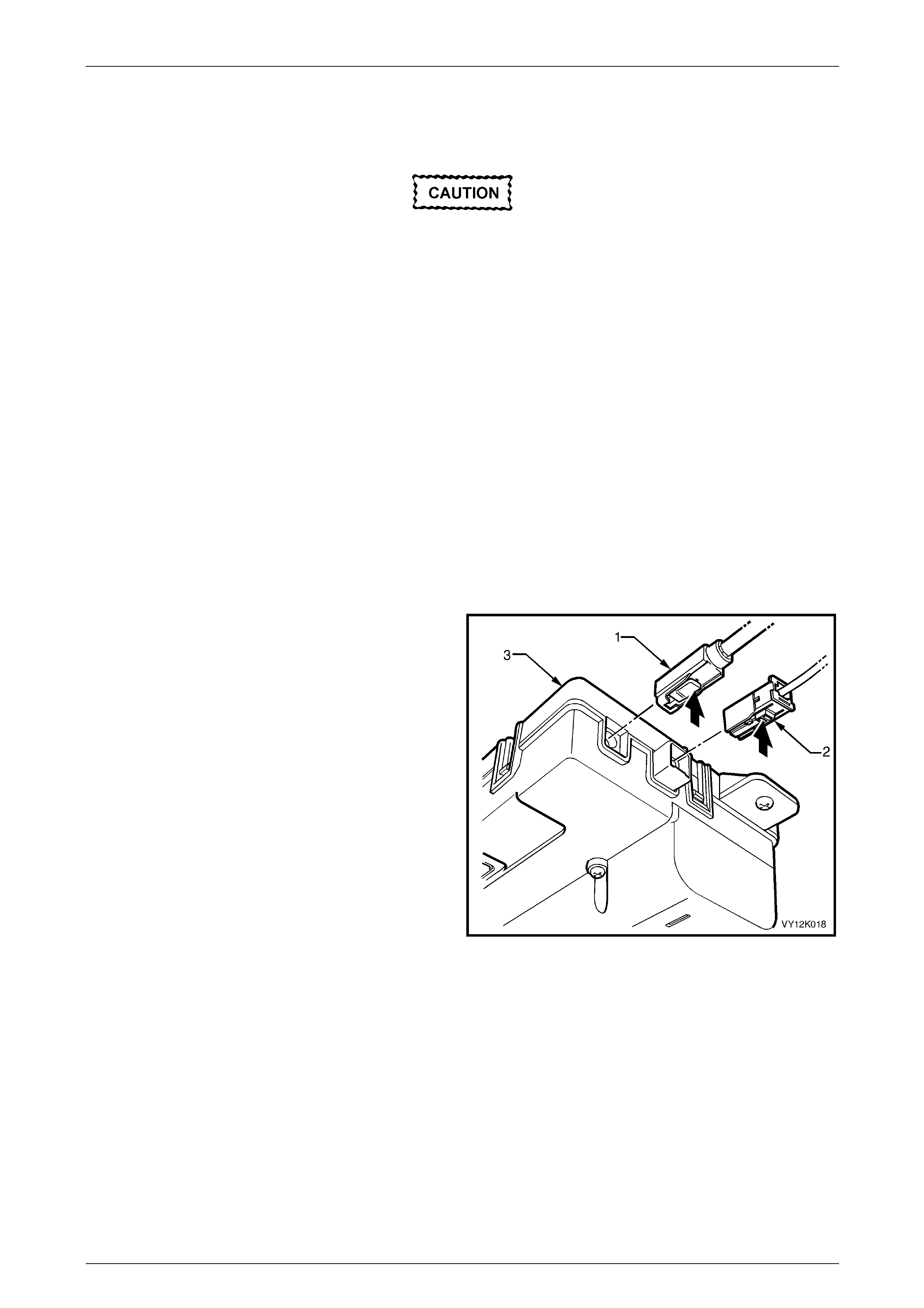
Telematics Page 12K–125
Page 12K–125
5 Service Operations
Enable service mode on the telematics
module before performing any service
procedure on the vehicle that involves
disconnecting the battery cables or any
procedure that may cause the battery voltage
to fall below 12 V. For further information,
refer to F0: Operating Mode.
If the telematics module service mode is not enabled:
• a battery removal alert (when the battery is disconnected), or
• a low battery voltage alert (when the battery voltage is low)
is transmitted to the Holden Assist Centre.
5.1 Telematics Module
LT Section No. — 09–540–1
Remove
1 Using Tech 2, put the telematics module into service
mode, refer to F0: Operating Mode.
2 Disconnect the negative battery cable from the battery.
3 Remove the instrument panel compartment, refer to
Section 1A3 Instrument Panel and Console.
4 Remove the left-hand side instrument panel
lower trim plate assembly, refer to
Section 1A3 Instrument Panel and Console.
5 Remove the air conditioning vacuum tank, refer to
Section 2C HVAC Climate Control (Manual A/C) —
Removal and Reinstallation.
6 Disconnect the GPS antenna connector (1) and the
GSM antenna connector (2) from the telematics
module (3).
Figure 12K – 31
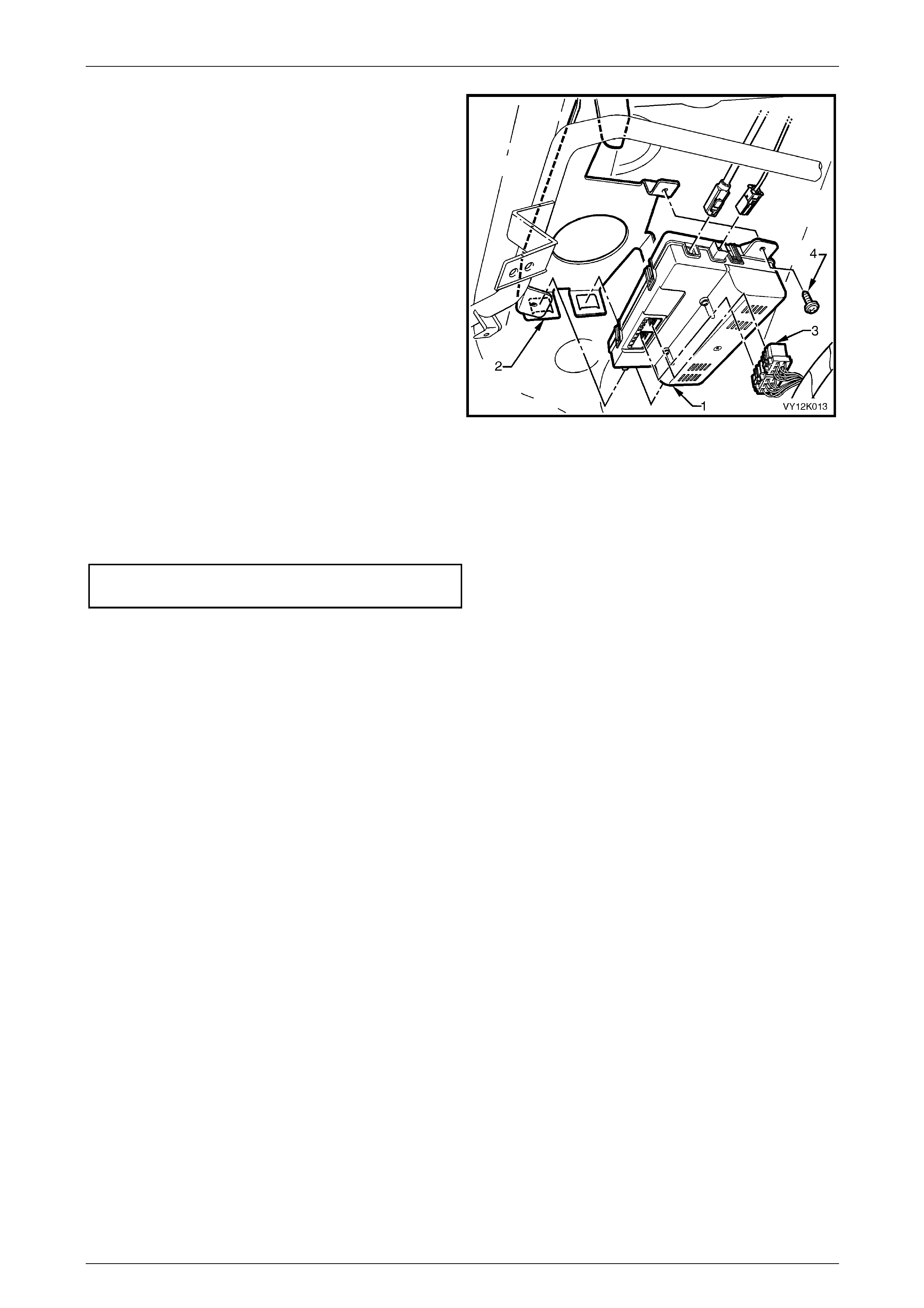
Telematics Page 12K–126
Page 12K–126
7 Disconnect the harness connector (3), from the
telematics module (1).
8 Remove the telematics module retaining screw (4).
9 Lower the front end of the telematics module and slide
it out of the retaining bracket.
Figure 12K – 32
Reinstall
Reinstallation of the telematics module is the reverse of the removal procedure, noting the following:
1 Tighten the telematics module retaining screw to the correct torque specification.
Telematics Module Retaining Screw
Torque Specification ...................................1.0 – 3.0 Nm
2 Use Tech 2 to disable the telematics module service mode, refer to F0: Operating Mode.
NOTE
If the telematics module service mode remains
enabled, the telematics system does not have full
functionality.
Telematics Module Changeover
If a new telematics module has been installed, it must be registered with the Holden Assist Centre. To register the new
telematics module with the Holden Assist Centre:
1 After the new telematics module has been installed, turn on the ignition and press the HOLDEN ASSIST button to
make a call to the Holden Assist Centre.
2 When the Holden Assist Centre operator answers, inform the operator who you are and what retail outlet you are
from, and that you have just installed a new telematics module into the vehicle. You will also be required to provide
the operator with the complete VIN and, if the vehicle is registered, the registration number of the vehicle.
3 The new telematics module is now registered to this vehicle.
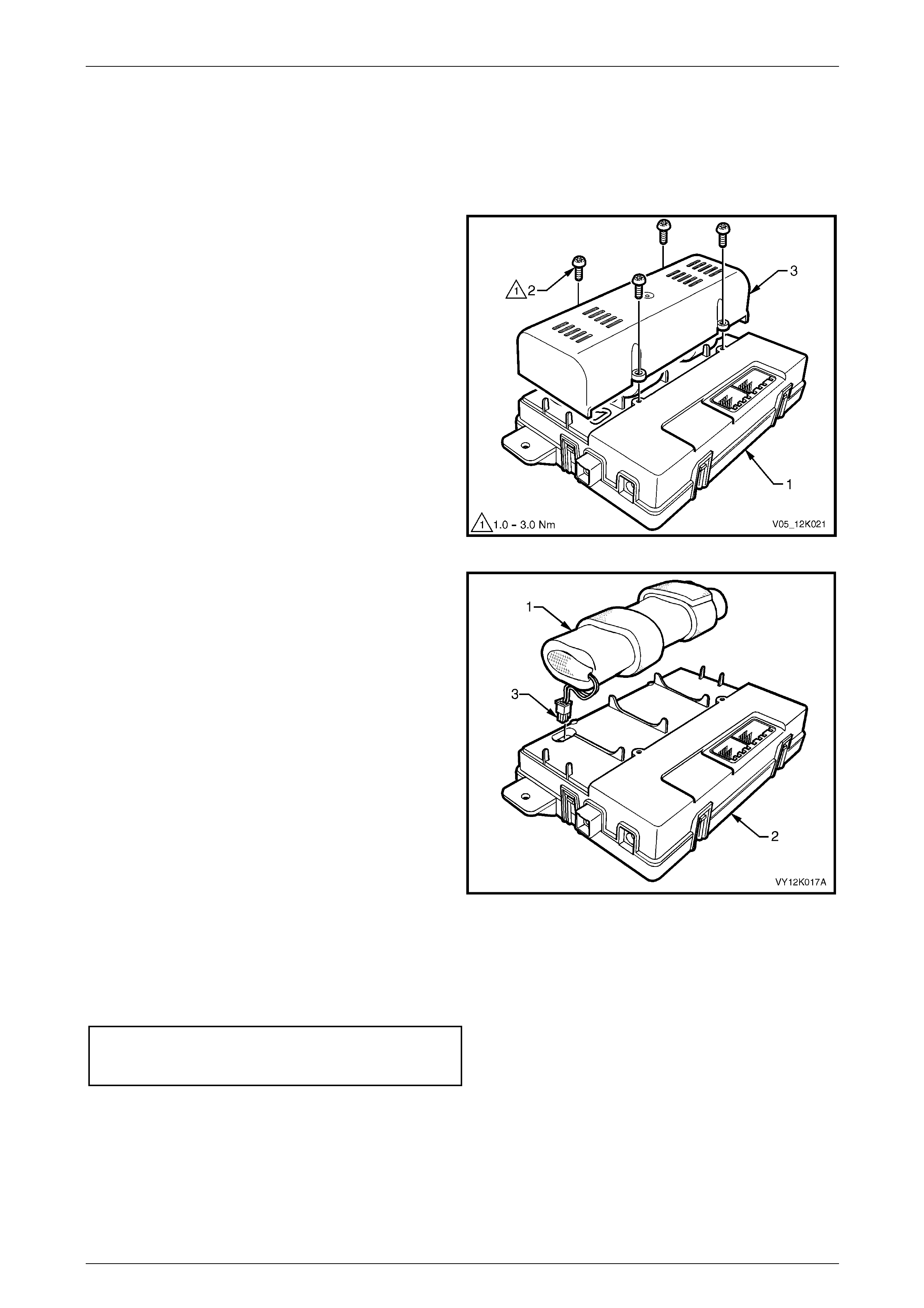
Telematics Page 12K–127
Page 12K–127
5.2 Backup Battery
LT Section No. — 09–540–1
Remove
1 Using Tech 2, enable the telematics module service
mode, refer to F0: Operating Mode.
2 Remove the telematics module (1), refer to
5.1 Telematics Module.
3 Remove the retaining screws (2), four places, and
remove the backup battery cover (3).
Figure 12K – 33
4 Disconnect the backup battery connector (3) from the
telematics module (2).
Figure 12K – 34
Reinstall
Reinstallation of the backup battery is the reverse of the removal procedure, noting the following:
1 Tighten the backup battery cover retaining screws to the correct torque specification.
Telematics Backup Battery
Cover Retaining Screws
Torque Specification ...................................1.0 – 3.0 Nm
2 Use Tech 2 to reset the backup battery timer, refer to F1: Backup Battery Timer Reset.
3 Use Tech 2 to disable the telematics module service mode, refer to F0: Operating Mode.
NOTE
If the telematics module service mode remains
enabled, the telematics system does not have full
functionality.
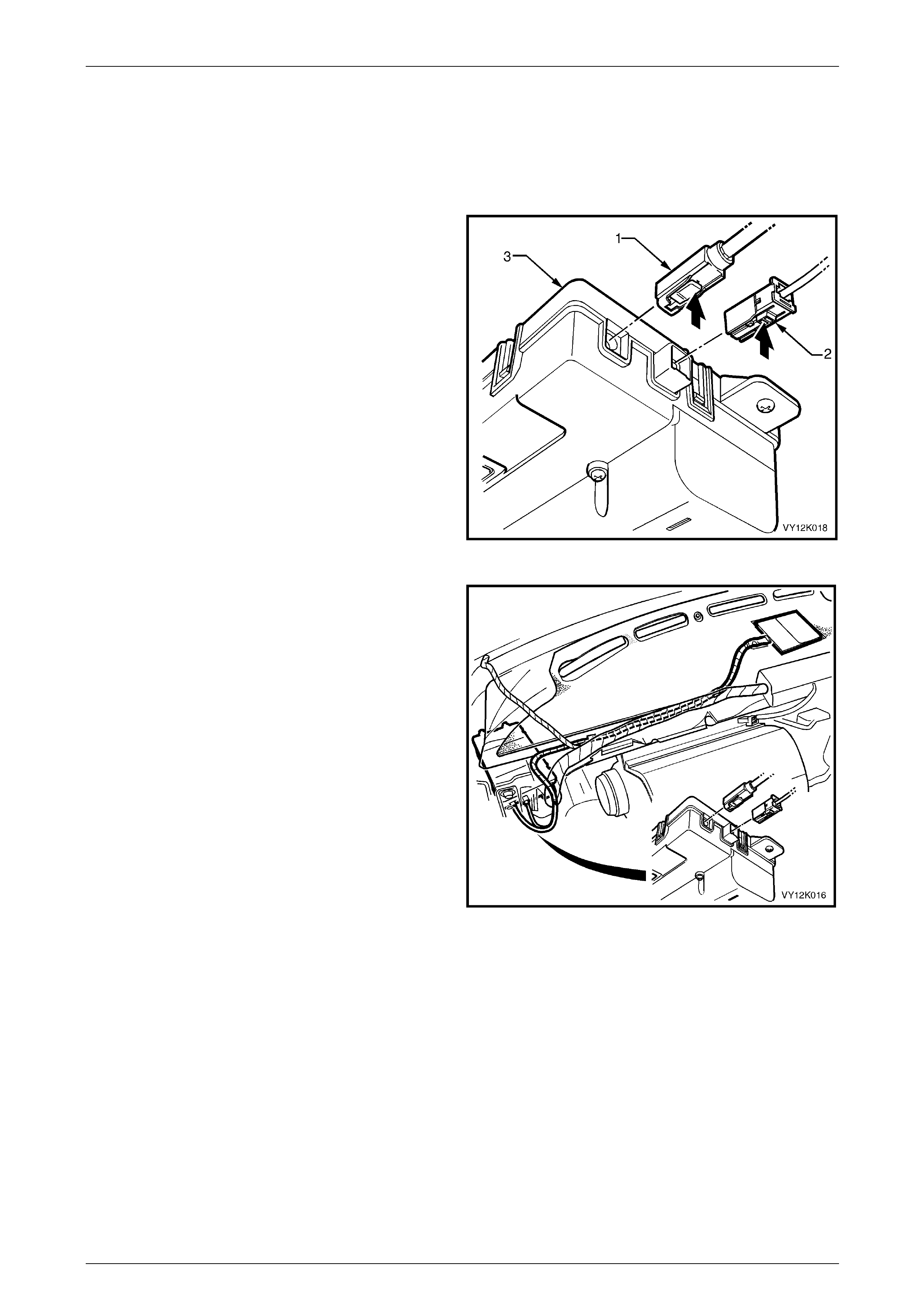
Telematics Page 12K–128
Page 12K–128
5.3 Telematics Antenna
LT Section No. — 09–540–1
Remove
1 Using Tech 2, put the telematics module into service
mode, refer to F0: Operating Mode.
2 Disconnect the negative battery cable from the battery.
3 Remove the instrument panel pad assembly, refer to
Section 1A3 Instrument Panel and Console.
4 Disconnect the GPS antenna connector (1) and the
GSM antenna connector (2) from the telematics
module (3).
Figure 12K – 35
5 Remove the telematics antenna lead retaining clips.
Figure 12K – 36

Telematics Page 12K–129
Page 12K–129
6 Use a commercially available paint scraper (2) to prise
the telematics antenna (1) from the dash panel.
Figure 12K – 37
Reinstall
1 Ensure the mating surface between the dash panel
and the telematics antenna is clean.
2 If reinstalling the original telematics antenna, remove
the used double-sided tape and apply new double-
sided tape (3M™ 4428 or equivalent), meeting Holden
Standard HN2021 Type 6 to the telematics antenna
mating surface.
3 Remove the backing from the double-sided tape.
4 Reinstall the telematics antenna to the dash panel:
a Align the antenna into the cut-out in the dash
panel insulation.
b Press down firmly on the antenna.
5 Reinstall the telematics antenna lead retaining clips.
Figure 12K – 38
6 Reinstall the GSM and GPS antenna connectors to the
telematics module.
7 Reinstall the instrument panel pad assembly, refer to
Section 1A3 Instrument Panel and Console.
8 Reconnect the negative battery cable to the battery.
9 Use Tech 2 to disable the telematics module service
mode, refer to F0: Operating Mode.
NOTE
If the telematics module service mode remains
enabled, the telematics system does not have
full functionality.
Figure 12K – 39


Telematics Page 12K–131
Page 12K–131
6 Torque Wrench Specifications
Telematics Module Retaining Screws..........................................1.0 – 3.0 Nm
Telematics Backup Battery Cover Retaining Screws................... 1.0 – 3.0 Nm
Interior Rear-view Mirror Retaining Screw...................................2.5 – 4.5 Nm