
Wiring Diagrams Page 12P–1
Page 12P–1
Section 12P
Wiring Diagrams
ATTENTION
Before performing any service operation or other procedure described in this Section, refer to Section 00
Warnings, Cautions and Notes for correct workshop practices with regard to safety and/or property damage.
1 General Information ...............................................................................................................................4
2 Electrical Circuit Diagnosis...................................................................................................................5
Step 1 Identify the Problem............................................................................................................................... 5
Step 2 Specify the Problem............................................................................................................................... 5
Step 3 Investigate the Problem......................................................................................................................... 5
Step 4 Develop Possible Causes...................................................................................................................... 6
Step 5 Isolate the Most Possible Cause........................................................................................................... 6
Step 6 Verify ....................................................................................................................................................... 6
Problem Example................................................................................................................................................... 6
Step 1 Identify the Problem ............................................................................................................................ 6
Step 2 Specify the Problem ............................................................................................................................ 6
Step 3 Investigate the Problem....................................................................................................................... 6
Step 4 Develop Possible Causes ................................................................................................................... 7
Step 5 Isolate the Most Possible Cause ......................................................................................................... 8
Step 6 Verify ................................................................................................................................................... 8
3 Test Procedures .....................................................................................................................................9
3.1 Electrical Fault Diagnosis..................................................................................................................................... 9
Possible Electrical Malfunctions.......................................................................................................................... 9
Circuit Faults........................................................................................................................................................ 10
Open ................................................................................................................................................................ 10
Short to Earth ................................................................................................................................................... 10
Short to Voltage................................................................................................................................................ 10
High Resistance Problems ............................................................................................................................... 10
3.2 Troubleshooting Test Equipment....................................................................................................................... 11
Jumper Wire......................................................................................................................................................... 11
Test Light.............................................................................................................................................................. 12
Self-Powered Test Light...................................................................................................................................... 13
Multimeters........................................................................................................................................................... 13
3.3 Digital Multimeter................................................................................................................................................. 14
Use Of A Multimeter............................................................................................................................................. 14
Selection Of Multimeters..................................................................................................................................... 14
Voltage Measurement.......................................................................................................................................... 15
Resistance Measurement.................................................................................................................................... 16
Resistance Testing........................................................................................................................................... 16
Continuity Testing ............................................................................................................................................... 16
Diode Testing....................................................................................................................................................... 17
Current Measurement.......................................................................................................................................... 17
4 Diagnostic Tests...................................................................................................................................18
4.1 Testing For Voltage ............................................................................................................................................. 18
4.2 Testing For Continuity......................................................................................................................................... 19
4.3 Testing For Voltage Drop.................................................................................................................................... 20

Wiring Diagrams Page 12P–1
Page 12P–1
Section 12P
Wiring Diagrams
ATTENTION
Before performing any service operation or other procedure described in this Section, refer to 00 Warnings,
Cautions and Notes for correct workshop practices with regard to safety and/or property damage.
1 General Information ...............................................................................................................................4
2 Electrical Circuit Diagnosis...................................................................................................................5
Step 1 Identify the Problem............................................................................................................................... 5
Step 2 Specify the Problem............................................................................................................................... 5
Step 3 Investigate the Problem......................................................................................................................... 5
Step 4 Develop Possible Causes...................................................................................................................... 5
Step 5 Isolate the Most Possible Cause........................................................................................................... 6
Step 6 Verify ....................................................................................................................................................... 6
Problem Example................................................................................................................................................... 6
Step 1 Identify the Problem ............................................................................................................................ 6
Step 2 Specify the Problem ............................................................................................................................ 6
Step 3 Investigate the Problem....................................................................................................................... 6
Step 4 Develop Possible Causes ................................................................................................................... 6
Step 5 Isolate the Most Possible Cause ......................................................................................................... 7
Step 6 Verify ................................................................................................................................................... 8
3 Test Procedures .....................................................................................................................................9
3.1 Electrical Fault Diagnosis..................................................................................................................................... 9
Possible Electrical Malfunctions.......................................................................................................................... 9
Circuit Faults........................................................................................................................................................ 10
Open ................................................................................................................................................................ 10
Short to Earth ................................................................................................................................................... 10
Short to Voltage................................................................................................................................................ 10
High Resistance Problems ............................................................................................................................... 10
3.2 Troubleshooting Test Equipment....................................................................................................................... 11
Jumper Wire......................................................................................................................................................... 11
Test Light.............................................................................................................................................................. 12
Self-Powered Test Light...................................................................................................................................... 13
Multimeters........................................................................................................................................................... 13
3.3 Digital Multimeter................................................................................................................................................. 14
Use Of A Multimeter............................................................................................................................................. 14
Selection Of Multimeters..................................................................................................................................... 14
Voltage Measurement.......................................................................................................................................... 15
Resistance Measurement.................................................................................................................................... 16
Resistance Testing........................................................................................................................................... 16
Continuity Testing ............................................................................................................................................... 16
Diode Testing....................................................................................................................................................... 17
Current Measurement.......................................................................................................................................... 17
4 Diagnostic Tests...................................................................................................................................18
4.1 Testing For Voltage ............................................................................................................................................. 18
4.2 Testing For Continuity......................................................................................................................................... 19
4.3 Testing For Voltage Drop.................................................................................................................................... 20

Wiring Diagrams Page 12P–2
Page 12P–2
4.4 Testing For Short To Earth.................................................................................................................................. 21
Using A Test Light Or Voltmeter......................................................................................................................... 21
Using A Self-Powered Test Light Or Ohmmeter................................................................................................ 22
Using A Short Finder........................................................................................................................................... 22
Using A Compass................................................................................................................................................ 22
Using A Circuit Breaker....................................................................................................................................... 22
4.5 Operating A Short Finder.................................................................................................................................... 23
Measuring Current............................................................................................................................................... 24
4.6 Detecting Intermittent Electrical Faults ............................................................................................................. 25
Diagnostic Procedure.......................................................................................................................................... 25
Checking Terminal Contact................................................................................................................................. 25
Meter Connections............................................................................................................................................... 26
Additional Information....................................................................................................................................... 26
5 Wiring Repair Procedures...................................................................................................................27
5.1 General Information............................................................................................................................................. 27
5.2 Performing Wiring Harness Repairs .................................................................................................................. 28
Soldering .............................................................................................................................................................. 28
The Five Points To Soldering.............................................................................................................................. 28
Step 1 Soldering Preparation ....................................................................................................................... 28
Step 2 Iron Preparation ................................................................................................................................ 29
Step 3 Forming a Heat Bridge ...................................................................................................................... 29
Step 4 Soldering Iron Removal..................................................................................................................... 29
Step 5 Prevent Job Movement ..................................................................................................................... 30
Joining Wire ......................................................................................................................................................... 30
Twist Joint ........................................................................................................................................................ 30
Splice Joint....................................................................................................................................................... 30
The Y Junction ................................................................................................................................................. 31
The T Junction.................................................................................................................................................. 31
5.3 Splicing Wiring Using Splice Clips..................................................................................................................... 32
Step 1 Open the Harness................................................................................................................................. 32
Step 2 Cut the Wire.......................................................................................................................................... 32
Step 3 Select the Correct Size and Type of Wire........................................................................................... 32
Step 4 Strip the Insulation............................................................................................................................... 33
Metric Size ....................................................................................................................................................... 33
AWG................................................................................................................................................................. 33
Step 5 Crimping the Joint................................................................................................................................ 34
Step 6 Solder.................................................................................................................................................... 35
Step 7 Tape the Splice..................................................................................................................................... 37
5.4 ABS And SRS Wiring Repair............................................................................................................................... 38
ABS And SRS Wire Pigtail Repair ...................................................................................................................... 38
Wiring Repair........................................................................................................................................................ 38
Step 1 Open the Harness ............................................................................................................................. 39
Step 2 Cut the Wire ...................................................................................................................................... 39
Step 3 Select the Correct Size and Type of Wire ......................................................................................... 39
Step 4 Strip the Insulation ............................................................................................................................ 40
Step 5 Select and Position the Splice Sleeve............................................................................................... 40
Step 6 Insert First Wire Into Splice Sleeve and Crimp..................................................................................40
Step 7 Crimp the Second Wire in the Splice................................................................................................. 41
Step 8 Shrink the Insulation around the Splice............................................................................................. 41
Step 9 Close the Harness............................................................................................................................. 41
ABS And SRS Wiring Splice Repair................................................................................................................... 41
5.5 Splicing Twisted Or Shielded Cable................................................................................................................... 42
Step 1 Strip the Cable...................................................................................................................................... 42
Step 2 Prepare the Splice................................................................................................................................ 42
Step 3 Reassemble the Cable ......................................................................................................................... 43
Step 4 Tape the Joint....................................................................................................................................... 43

Wiring Diagrams Page 12P–3
Page 12P–3
5.6 Splicing In-Line Harness Diodes........................................................................................................................ 44
Step 1 Open the Harness................................................................................................................................. 44
Step 2 Remove Diode ...................................................................................................................................... 44
Step 3 Install the New Diode ........................................................................................................................... 45
5.7 Heated Oxygen Sensor (HO2S) Wiring Repairs ................................................................................................ 46
5.8 Terminal Removal................................................................................................................................................ 47
Push to Seat Connectors .................................................................................................................................... 47
Pull-to-Seat Connectors...................................................................................................................................... 47
Repairing Push-To-Seat And Pull-To-Seat Connectors ................................................................................... 47
Weather Pack® Connectors................................................................................................................................ 49
6 Reading 12P Wiring Diagrams............................................................................................................50
General Information............................................................................................................................................. 50
Sheet Identification.............................................................................................................................................. 51
Wire Identification................................................................................................................................................ 51
Wire Colour Abbreviations.................................................................................................................................. 51
Wiring Harness Abbreviations............................................................................................................................ 52
Wiring Harness Visual Identification.................................................................................................................. 53
Connectors........................................................................................................................................................... 53
Grid Reference..................................................................................................................................................... 53
Continuation Reference ...................................................................................................................................... 54
Multiple Continuation References...................................................................................................................... 54
Assembly Identification....................................................................................................................................... 54
Assembly Legend................................................................................................................................................ 55
Assembly Continuation....................................................................................................................................... 55
Assembly Connector Identification.................................................................................................................... 55
Assembly Circuit Identification .......................................................................................................................... 56
Information Within An Assembly........................................................................................................................ 56
Harness Splices................................................................................................................................................... 56
Ground Locations................................................................................................................................................ 57
Circuit Symbols.................................................................................................................................................... 58
7 Connector Location Illustrations........................................................................................................59
8 Electrical Schematics Contents..........................................................................................................61
9 Module Location Charts ......................................................................................................................62
Electrically Operated Mechanical Devices......................................................................................................... 62
Indicators, Alarms and Signal Devices.............................................................................................................. 62
Inductors .............................................................................................................................................................. 63
Measurement, Display and Test Devices........................................................................................................... 63
Modules, Systems and Sub-Assemblies ........................................................................................................... 64
Motors................................................................................................................................................................... 67
Other Devices and Equipment............................................................................................................................ 67
Power Supplies.................................................................................................................................................... 68
Regulators and Amplifiers .................................................................................................................................. 68
Resistors .............................................................................................................................................................. 68
Semi Conductors................................................................................................................................................. 68
Switches ............................................................................................................................................................... 69
Transducers ......................................................................................................................................................... 70
Transmission Paths, Conductors and Antennas.............................................................................................. 72
10 Special Tools ........................................................................................................................................73

Wiring Diagrams Page 12P–4
Page 12P–4
1 General Information
Wiring diagrams are found throughout various Sections of the Service Information. The wiring diagrams contained in this
Service Information are the specific systems wiring diagrams for MY2006 WL Sedan. These wiring diagrams are based
on the Integrated Vehicle Electrical Design (IVED) wiring diagrams. There are two types of wiring diagrams used in this
Service Information:
• Service Information Wiring Diagrams.
• Section 12P Electrical Schematics.
The Service Information wiring diagrams only refer to the system under discussion and are used to:
• Present the overall circuitry for a total system.
• Assist in explaining the operation of part of a total system.
• Assist in diagnostics.
This Section is designed to assist technicians in understanding both forms of wiring diagrams.
Additional wiring, wiring harness and specific wiring harness installation information is contained in Section 12O Fuses,
Relays and Wiring Harnesses in this Service Information. Further information on developing a diagnostic procedure for
electrical circuit diagnosis, electrical circuit test procedures, diagnostic tests and wiring repair procedures is contained in
this Section.

Wiring Diagrams Page 12P–5
Page 12P–5
2 Electrical Circuit Diagnosis
The system wiring diagrams should be referred to when diagnosing vehicle electrical problems.
These diagrams should ALWAYS be the starting point when troubleshooting electrical problems.
The diagrams illustrate how a particular circuit should work by design, and should be understood before trying to
determine why it does not work.
NOTE
It is important to realise that no attempt is made
on the diagrams to represent components and
wiring as they appear in the vehicle
geographically.
For example, a metre length of wire is treated no differently in a wiring diagram from one which is only a few centimetres
long. Similarly, switches and other components are shown as simply as possible in schematic format and in an
inactivated state, with basic function only being shown.
The following six-step procedure is recommended when diagnosing a vehicle electrical problem.
Step 1 Identify the Problem
Does a problem really exists?
To identify the problem, listen patiently and carefully to the owner/operator of the vehicle.
Step 2 Specify the Problem
Question the owner/operator to establish:
Is there a problem?
What is the problem?
Where is the problem?
How serious or extensive is the problem?
How often does the problem occur?
Does a trend exist?
Perform a system check to be sure you understand what is wrong.
Do not waste time fixing only part of the problem. Do not begin disassembly of components or testing until you have
narrowed down the possible causes.
Step 3 Investigate the Problem
Are you totally familiar with the system?
Read the system wiring diagram.
Study the diagram to understand how the affected circuit should work.
Check circuits that share wiring with the problem circuit. If the shared circuits operate correctly, then the shared wiring
must be OK. The cause of the problem must be within the wiring or components used by the problem circuit.
If several circuits fail at the same time, chances are the power (fuse) or ground circuit is faulty.
Step 4 Develop Possible Causes
Make yourself a mental or written check list.
Ask yourself would this cause the problem?
Use the system wiring diagram to develop a set of test points.
Narrow down the possible causes.

Wiring Diagrams Page 12P–6
Page 12P–6
Step 5 Isolate the Most Possible Cause
You must have the knowledge and the special tools/equipment.
Carry out the necessary tests and measurements as given in the appropriate system diagnosis, e.g. ENGINE
MANAGEMENT SYSTEM, CRUISE CONTROL, or at the test points that you have developed from the wiring diagrams.
TEST, DON'T GUESS.
Before replacing a component, check power, signal and ground wires at the component wiring harness connector. If
these check OK, the component is most likely to be faulty. FIND THE CAUSE AND REPAIR.
Step 6 Verify
Test the repair.
Has the problem been fixed?
Ask yourself why did the problem occur/part fail?
Will it happen again?
Have I created any other problems?
CURE THE CAUSE NOT THE EFFECT.
OPERATE THE CIRCUIT AND ROAD TEST THE VEHICLE BEFORE RETURNING IT TO THE CUSTOMER.
Problem Example
Step 1 Identify the Problem
A customer brings in a vehicle reporting that the headlamps are not operating correctly.
Step 2 Specify the Problem
The driver is questioned and it is established that the LH headlamp is not operating on high beam, or when the flash
switch is operated.
Step 3 Investigate the Problem
Perform a system check on the headlamp circuit. It is noted that:
1 Headlamps operate correctly on low beam.
2 On high beam, the headlamp high beam lamps operate correctly but the left hand headlamp inboard high beam
lamp does not operate on high beam.
3 When the high beam flash switch is operated, the LH headlamp inboard high beam lamp still does not operate on
high beam.
READ THE SYSTEM WIRING DIAGRAM.
This is the step that will save time and labour. Remember, it is essential to understand how a system should work, before
trying to determine why it doesn't work.
Step 4 Develop Possible Causes
Once the circuit is understood, read the diagram again, this time keeping in mind what you have learned by operating the
circuit. It is recommended to read the System Wiring Diagram from the battery positive terminal or fuse (being the source
of electrical supply) to ground (battery negative terminal).
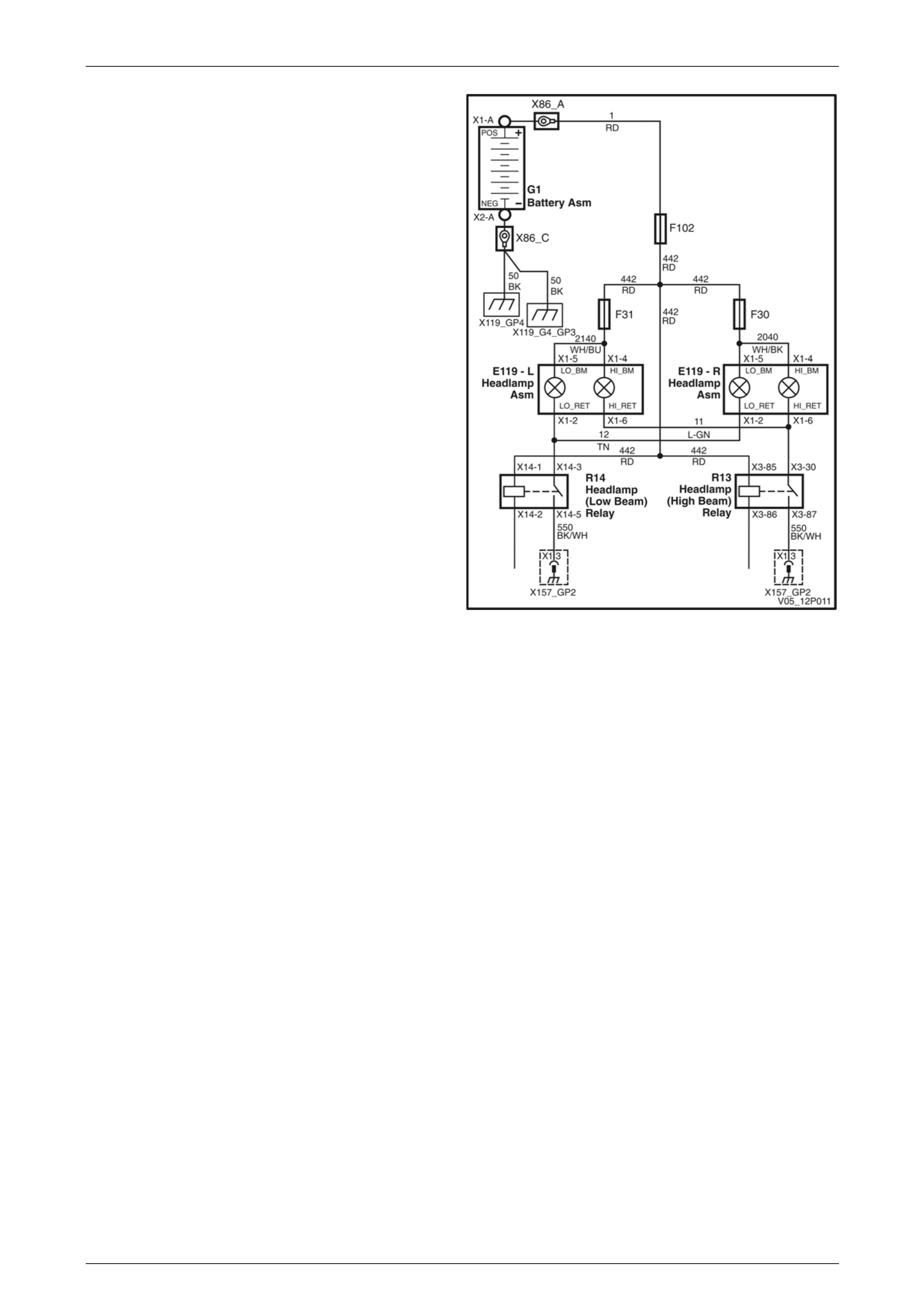
As both low beam headlamps work, fuses F102, F31 and F30, the headlamp switch, low beam headlamp relay, the low
beam ground circuit, and both low beam headlamp filaments are OK. Furthermore, since the RH inboard high beam lamp
works on high beam and flash, the headlamp and flash switch and the high beam head lamp relay are OK.
Since the LH outboard high beam headlamp is working correctly, the lead from the headlamp relay to the lamp assembly
must be OK. Therefore the fault must be in circuit 2140 between the splice after fuse F31 and connector E119_L–X1 pin
4.
Wiring Diagrams Page 12P–7
Page 12P–7
The cause must be:
1 In circuit 2140, from the splice after fuse F31 to
connector E119_L–X1 pin 4.
2 In the lead from connector E119_L–X1 pin 4 to the LH
inboard high beam headlamp bulb.
3 The LH headlamp high beam bulb.
The possible causes have been quickly narrowed down to a
specific area prior to working on the vehicle itself.
Read the system wiring diagram again to develop a set of
test points. Start from the positive and proceed to the
negative/ground.
Figure 12P – 1
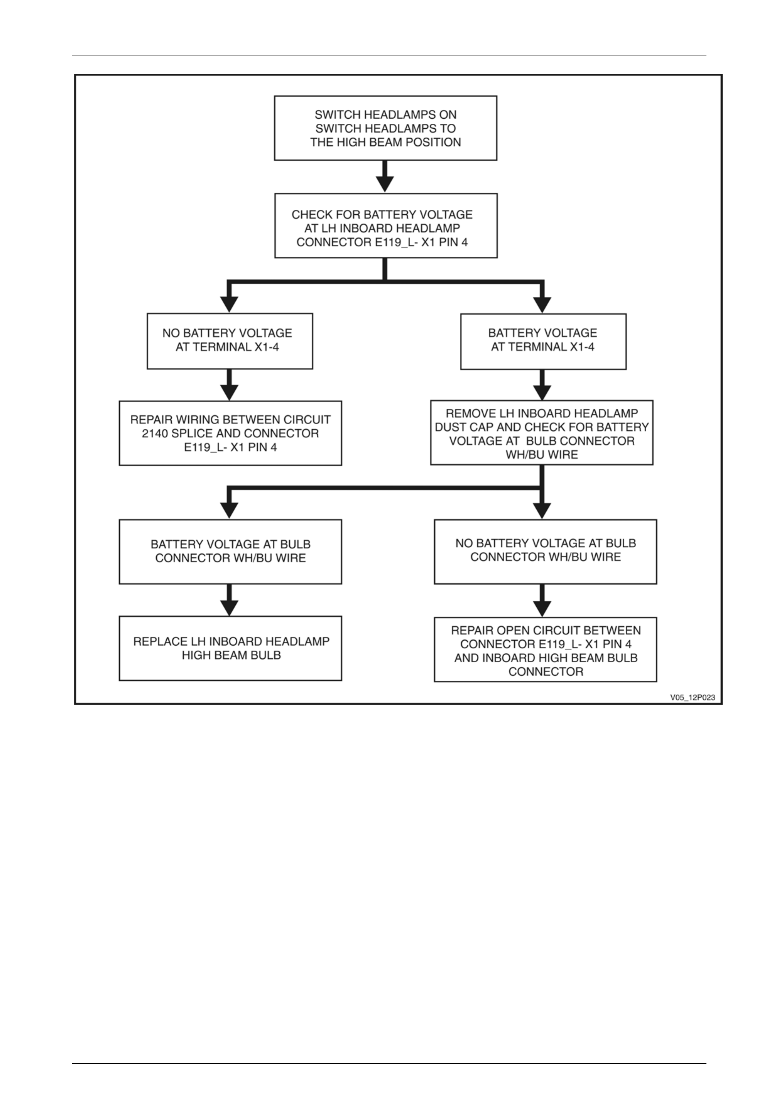
Step 5 Isolate the Most Possible Cause
Figure 12P – 2 is an example of how to isolate the cause of the problem. Remembering it has already been determined
the fault is between the splice after fuse F31 and the LH inboard high beam headlamp bulb, check the simple things first.
Wiring Diagrams Page 12P–8
Page 12P–8
Figure 12P – 2
Step 6 Verify
Test the repair by performing a system check on the headlamp circuit. This of course means making sure that both high
beam lamps, both low beam lamps and high beam indicator are all working. Ask yourself:
Has the problem been fixed?
Why did the problem occur or why did the part fail?
Will it happen again?
Have I created any other problems?
CURE THE CAUSE NOT THE EFFECT.
OPERATE THE CIRCUIT AND ROAD TEST THE VEHICLE BEFORE RETURNING IT TO THE CUSTOMER.

Wiring Diagrams Page 12P–9
Page 12P–9
3 Test Procedures
3.1 Electrical Fault Diagnosis
The proper operation of electrical circuits especially low amperage input/output circuits (electronic components etc)
depend upon good continuity between circuit connectors.
It is important before component replacement and/or during normal trouble shooting procedures that a thorough visual
inspection of all terminals or connectors is performed and any questionable mating connector/terminals be repaired or
replaced.
All mating surfaces should be clean, properly formed, clean and making positive contact.
Some typical causes of connector problems are:
1 Improperly formed contacts and/or connector plugs.
2 Damaged contacts or plugs due to improper engagement.
3 Corrosion, body sealer or other contaminants on the contact mating surfaces.
4 Incomplete mating of the connector halves during initial assembly or during subsequent trouble shooting or repairs.
5 Tendency for connectors to come apart due to vibration and/or temperature cycling.
6 Terminal not fully seated in connector body (terminal backed out).
7 Inadequate terminal crimps to the wire or poor solder joint.
NOTE
When inserting test probes during diagnosis,
always try to test from the back of the terminal
and avoid spreading terminals as this may cause
poor continuity.
IMPORTANT: Do not backprobe 'Weather Pack'
type connectors as damage to the cable seals will
result.
When carrying out wiring checks, rather than probe terminals and connectors with incorrect sized multimeter or test lead
connectors, use adaptors included in kit J35616-A or KM-609. This is will prevent any possibility of spreading or
damaging wiring harness terminals.
Possible Electrical Malfunctions
There are five possible electrical malfunctions, as follows:
1 Loss of battery power (loose connections/corrosion).
2 Defective device.
3 High resistance (dirty, loose or corroded connections).
4 Open circuit.
5 Earthed or short circuit.
Electrical circuits should be tested at:
1 Easily disconnected connections.
2 Easy to reach access points.

Wiring Diagrams Page 12P–10
Page 12P–10
Circuit Faults
The various failures that occur in a circuit will dictate what must be done to repair the problem. These failures can be
categorised as follows:
Open
An open circuit is a physical break in the path of current flow. In a series circuit, the circuit stops operating. In parallel
circuits, an open in one individual circuit will stop the operation of that particular circuit, but other individual parallel
circuits will continue to operate. The ohmmeter is useful in finding an open circuit with continuity checks.
Short to Earth
A short to earth is where the circuit is earthed due to an insulation breakage. The conductor touches earth, causing a
fuse or fusible link to blow. If there is no fuse, the circuit may burn, and even cause flames. If the short occurs after the
load, circuit control may be lost causing the circuit to operate when it is not wanted. The test light is a good device in this
case. Insert the test light in place of the fuse. Disconnect circuit components in a systematic and logical manner. When
the test light goes out, the part of the circuit with the short to earth will be found.
Short to Voltage
The short to voltage is a condition where a circuit, due to insulation breakage, causes the conductor to contact the
voltage of another circuit. This will cause the circuit (or both circuits) to operate improperly. This problem can cause odd
things to occur and can be difficult to find. To locate this type of problem, a thorough examination, using the diagnostic
procedure described at the beginning of this Section, must be performed. Observe the symptoms to recognise
associated circuits involved. Isolation by removing fuses will help isolate the circuit branches involved. Then voltage and
resistance checks at strategic locations will isolate the problem.
High Resistance Problems
A high resistance problem is often hardest to find. This is a condition where it is important to use test meters. High
resistance can be caused by loose, dirty or corroded connectors. Current flow will be lowered, which can cause incorrect
circuit operation or inoperative components.

Wiring Diagrams Page 12P–11
Page 12P–11
3.2 Troubleshooting Test Equipment
Jumper Wire
A jumper wire is an in-line fuse holder connected to a set of
test leads and it is use for by-passing open circuits. The in-
line fuse holder (1) should be fitted with a five-amp fuse.
Never use a jumper wire across any load as this will cause a
direct battery short and blow the fuse. When properly used,
jumper wires are simple, effective testing aids. They are
used to complete a circuit by allowing current to 'jump'
across a suspected open or break, and so act as a test of
continuity.
When a jumper wire is used, it replaces a suspected faulty
portion of a circuit with a known good conductor. If the
circuit works properly when the jumper wire is in place, but
does not work properly without the jumper wire, an open
circuit is indicated in the area that has been jumped. Use a
jumper wire to by-pass only non-resistive parts of a circuit,
such as switches, connectors and sections of wiring.
V
Y12P203
1
Figure 12P – 3
V
Y12P204
1
2
5
6
34
8
7
9
M
3
3
3
8
8
Figure 12P – 4
Legend
1 Alligator clips with in-line fuse
2 Alligator clips
3 Pin terminal
4 Spade terminal
5 Probe tip
6 Alligator clip
7 Battery
8 Switch
9 Motor
Wiring Diagrams Page 12P–12
Page 12P–12
Test Light
A test light is made up of a 12 volt light bulb with a pair of
leads attached and is used to test for voltage. After earthing
one lead, touch the other lead to various points along the
circuit where voltage should be present. When the bulb
illuminates, there is voltage present at the point being
tested.
Never use a low-impedance test light on circuits that
contain solid-state components, since damage to these
components may result.
Legend
1 Fuse
2 Connector
3 Probe
4 Test Light
5 Motor
V
Y12P205
1
3
4
5
2
M
Figure 12P – 5
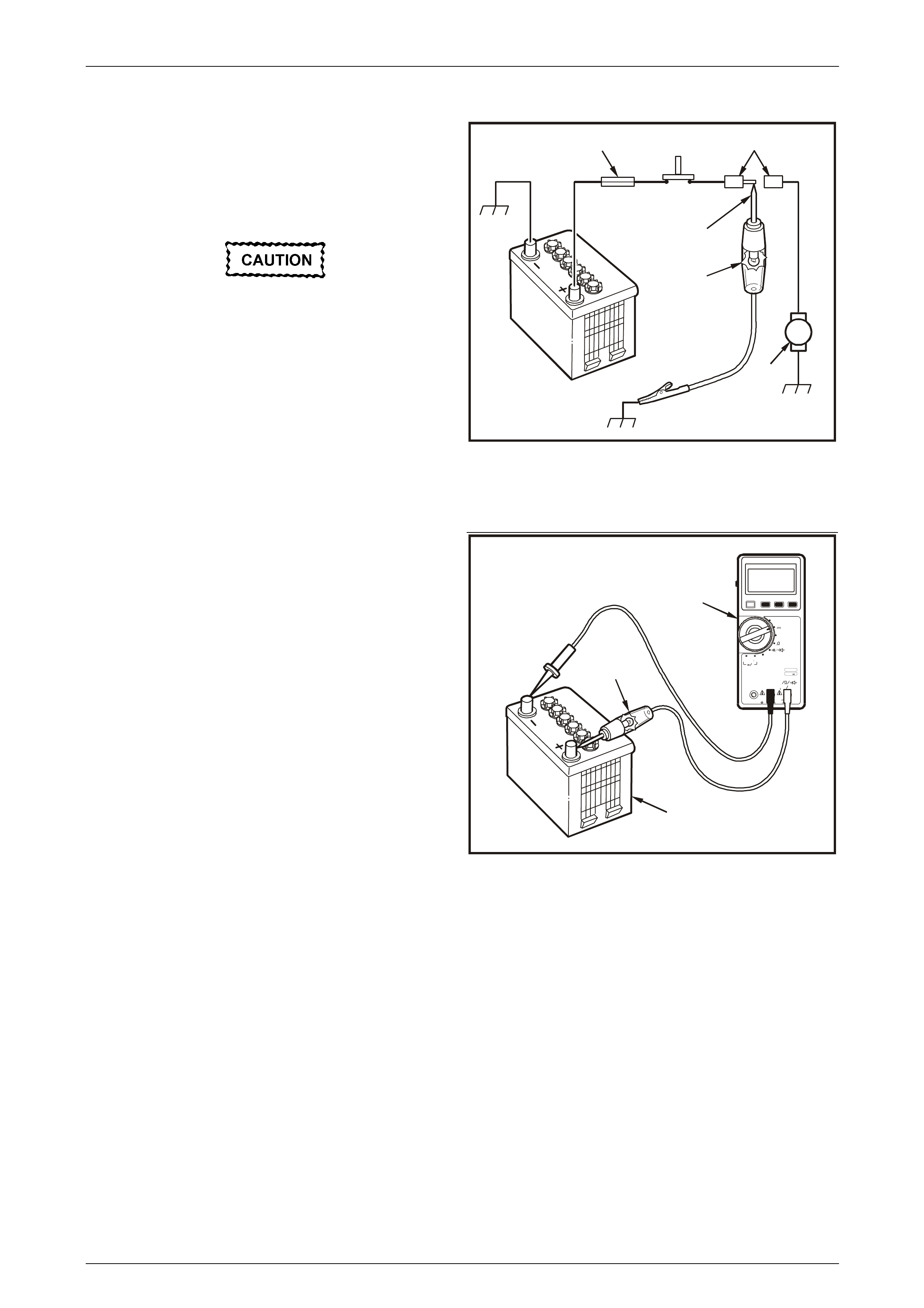
When a test light is specified, a LOW-POWER test light
must be used. Do not use a high wattage test light. While a
particular brand of test light is not suggested, a simple test
on any test light will ensure it's suitability for circuit testing.
Connect an accurate ammeter such as the high-impedance
digital multimeter (1) in series with the test light (2) being
tested, and power the test light - ammeter circuit with the
vehicle battery (3). If the ammeter indicates less than 0.3 A
(300 mA) current flow, the test light is OK to use. If more
than 0.3 A (300 mA), DO NOT USE.
V
Y12P206
1
2
3
~
POW ER
FUSED
1000V
MAX 750V~
1000V---
MAX
10A COM uA mA
V
DATA
HOLD SELECT RANGE
ºC
V
~V
ADP
mA/A uA
P U SH SE L E C T
P U SH SE L E C T
1
kHz
0.3% V
~
DC AMPS
Figure 12P – 6

Wiring Diagrams Page 12P–13
Page 12P–13
Self-Powered Test Light
A self-powered test light is used to check for continuity. This tool is made up of a 3 V light bulb, battery and two leads. If
the leads are touched together, the bulb will illuminate.
A self-powered test light is used only on an unpowered circuit. First, disconnect the vehicle's battery, or remove the fuse
which feeds the circuit being worked on. Select two specific points along the circuit through which there should be
continuity. Connect one lead of the self-powered test light to each point. If there is continuity, the test light's circuit will be
completed and the bulb will illuminate.
An increasing number of circuits include solid state control modules. Voltages in these circuits should be tested ONLY
with a 10 Megohm or higher impedance digital voltmeter or multimeter.
Never use a self-pow ered test light on circuits
that contain solid-state components, since
damage to these components may result.
Multimeters
Analogue versus Digital Meters
Digital multimeters outperform most types of analogue meters for a variety of reasons. Digital multimeters are more
accurate. The internal circuitry is not the only factor affecting analogue meter accuracy. The pointer can appear to be in
different positions when the gauge is viewed from different angles. Digital displays leave no such doubt about there
reading.
The digital multimeter shows a + symbol in front of the reading when the positive meter lead is connected to a positive
power source and the negative lead is connected to earth. If the digital multimeter leads are reversed, a – symbol
appears in front of the reading to indicate reverse polarity.
A digital multimeter, has an electronic digital readout of the value of the measurement being made. This type of meter
has electronic circuitry for precise measurements. It can be accurate within 0.1 percent, much more accurate than
analogue meters. The digital multimeter is becoming the preferred choice for electrical diagnosis and testing, especially
for testing electronic systems.
The impedance of an analogue meter is less than 10 Megohm. A meter with less than 10 Megohm impedance must not
be used on circuits that contain solid state components because:
The low impedance of the meter could cause incorrect readings.
The meter could allow too much current to flow through the circuit being tested.
The excess current could damage sensitive electronic components.
A digital multimeter with at least 10 Megohm input impedance is needed for use on Holden vehicles. This input
impedance applies to the meter only when it is used on the voltage scale. This means that the meter resists loading
down the circuit being measured with a resistance of 10 million ohms. On automotive circuits, this high resistance
permits measurement of very sensitive circuits without damaging or altering them.
NOTE
Impedance is the resistance to current flow
through the meter, from one lead to the other
lead. High input impedance provides greater
sensitivity, and prevents the meter from affecting
the circuit being tested. Resistance is measured
in ohms. Impedance and resistance both mean
'opposition to current flow'.

Wiring Diagrams Page 12P–14
Page 12P–14
3.3 Digital Multimeter
One of the most useful diagnostic tools is the digital multimeter. These basic operating procedures for a multimeter may
vary with the make of meter and the manufacturer's operating instructions should be read and understood before using
the multimeter.
Use Of A Multimeter
1 Always turn meter OFF when not in use.
2 Ensure the meter face reads zero.
3 If applicable, touch the leads together then adjust the resistance reading to zero each time a resistance range is
selected or changed.
4 If you are not sure of the reading you expect to get, always select the highest scale, then reduce to allow an
effective reading.
5 When measuring current, ensure the meter can handle the load and that the test leads are in the correct jacks.
6 Treat the instrument with the respect it deserves.
NOTE:
Voltage readings are taken in parallel (i.e. over the load).
Current readings are taken in series (i.e. break the circuit and use meter leads to complete the open circuit).
Resistance: Disconnect all external power, which includes the discharging of capacitors in electronic components.
Selection Of Multimeters
The best type of multimeter is one which has:
Internal protection so that it cannot be damaged if, for example, voltage is put through when the meter is set on ohms.
The fuse protects the meter and is the only thing that has to be replaced.
One that you can use to carry out a diode check facility which also provides an audible signal.
An audible signal when carrying out continuity checks.
A data hold facility so when a reading is taken that reading will remain on the display after the leads are removed.
A multimeter today also has to have a high impedance factor. The common analogue type multimeter may be inadequate
and may actually damage sensitive electronic circuitry. Analogue meters, due to their low internal resistance (input
impedance), draw too much power from the device they are testing for use on computers. Many analogue meters use
9 volts to power the resistance test which is enough to destroy sensitive digital components. Digital multimeters have an
input impedance of about 10 Megohms which is much higher than analogue multimeters. The high impedance means
that the meter will draw very little power from the device under test. This means the meter will provide a more accurate
measurement and will not damage delicate electronic components.
The multimeter used should also be able to test temperature and high amperages. This allows the one tool to do a vast
amount of work in the area of diagnosis.
Auto diagnosis is the art of the mechanical trade. To be able to fault find, rectify the fault and have the vehicle back to the
owner/operator with minimum delay is what leads to repeat business for the workshop. To do this you must be able to
refer to available literature, apply basic theories and use the correct test equipment.
Wiring Diagrams Page 12P–15
Page 12P–15
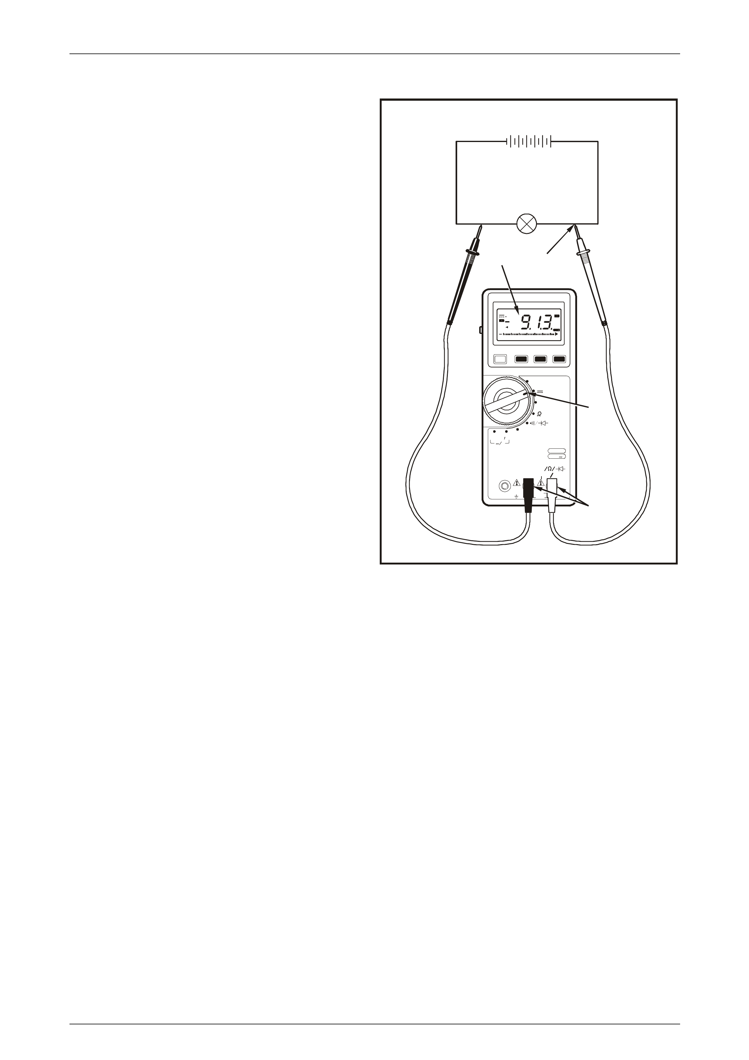
Voltage Measurement
With the Volts DC mode selected, the digital multimeter will
operate as a voltmeter.
When using a voltmeter, the circuit power must be ON and
the voltmeter must be connected with the correct polarity.
This means the red lead should be on the positive (+) side
of the load or circuit and the black lead should be on the
negative (–) side of the load or circuit.
The voltmeter must be connected in parallel with the load or
circuit. It has a high internal resistance and takes only a
small amount of current. The meter will display the voltage
difference between the points where the meter leads are
attached. If the voltmeter is connected in series, the meter's
high internal resistance will reduce the circuit current,
resulting in an incorrect reading.
Testing for correct supply voltage is usually the first thing
measured in a circuit. If there is no voltage present, or if the
supply voltage is too high or too low, the voltage problem
should be corrected before further testing.
NOTE
Voltage readings should always be taken in
parallel, i.e. across the load.
To make the reading:
1 Select VOLTS DC.
2 Plug the black test probe into the COM input jack and
the red test probe into the V input jack.
3 Touch the probe tips to the circuit across the load or
power source.
4 View the reading, being sure to note the unit of
measurement.
D H
R H
~
0102030
m V
Mk
+
V
Y12P208
1
2
34
~
POWER
FUSED
1000V
MAX 750V~
1000V---
MAX
10A COM uA mA
V
DATA
HOLD SELECT RANGE
ºC
V
~V
A
DP
mA/A uA
PUSH SE LECT
PUSH SE LE CT
1
kHz
0.3% V
~
Figure 12P – 7
Wiring Diagrams Page 12P–16
Page 12P–16
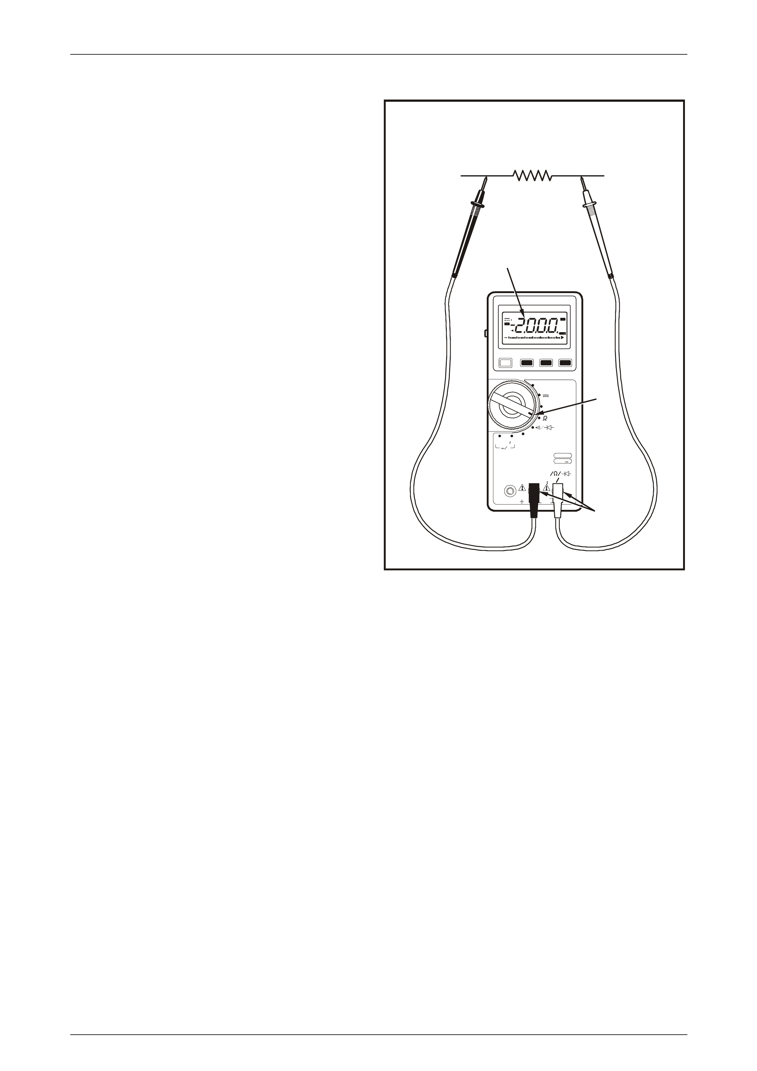
Resistance Measurement
With the resistance mode selected, the digital multimeter will
operate as an ohmmeter.
The ohmmeter can be connected without regard to polarity,
unless there is a diode in the circuit. Always remember,
however, that an ohmmeter must NEVER be connected to a
live circuit, which could blow a fuse in the meter or damage
the meter.
The ohmmeter has its own battery, which provides the
necessary voltage for testing. If an ohmmeter is connected
into a 'live' circuit the ohmmeter will be damaged.
Components or circuits MUST BE DISCONNECTED FROM
THE POWER SOURCE when being tested.
Resistance Testing
Resistance measurements must be made with the circuit
power OFF, otherwise damage to the meter or the circuit
may result.
To make the resistance test:
1 Remove the power from the circuit and select Ω.
2 Plug the black test probe into the COM input jack and
the red test probe into the Ω input jack.
3 Touch the probe tips across the component or the part
of the circuit to be tested.
4 View the reading, being sure to note the unit of
measurement.
NOTE
1000 ohms = 1 kΩ.
1 000 000 ohms = 1 MΩ.
D H
R H
~
0102030
m V
Mk
+
V
Y12P209
2
1
4
~
POWER
FUSED
1000V
MAX 750V~
1000V---
MAX
10A COM uA mA
V
DATA
HOLD SELECT RANGE
ºC
V
~V
A
DP
mA/A uA
PUSH SE LECT
PUSH SE LE CT
1
kHz
0.3% V
~
Figure 12P – 8
Continuity Testing
A continuity test is a quick test that distinguishes between an open and a closed circuit.
A digital multimeter with a continuity beeper allows you to complete many continuity tests easily and quickly as the meter
beeps when it detects a closed circuit. The level of resistance required to trigger the beeper varies from model to model
of meter.
Continuity tests determine:
• Good or blown fuses.
• Open or shorted conductors.
• Operation of switches.
• Circuit paths.
NOTE
Circuits which include any solid state control
modules, such as the Powertrain Control Module
(PCM), should be tested only with a 10 Megohm
or higher impedance digital multimeter.
Diodes and solid state components in a circuit can cause an ohmmeter to give a false reading. To find out if a component
is affecting a measurement, take a reading once, reverse the leads and take a second reading. If the readings differ, the
solid state component is affecting the measurement.

Wiring Diagrams Page 12P–17
Page 12P–17
Diode Testing
A diode is like an electronic switch. It can be turned ON if the voltage is above a certain level, generally about 0.6 V for a
silicon diode, and allows current to flow in one direction.
Some meters have a special mode called diode test. In this mode the readings across the diode should be 0.6 V to 0.7 V
in one direction and indicate an open circuit in the other. This indicates a good diode. If both readings are open circuit,
the diode is open. If both readings indicate continuity, the diode is shorted.
Current Measurement
With the AMPS DC mode selected, the digital multimeter will
operate as an ammeter.
An ammeter is an instrument that measures current flow in a
circuit. For this reason ammeters MUST be connected in
series. The ammeter must also be connected into the circuit
according to polarity.
Current measurements are different from other
measurements made with a digital multimeter. Current
measurements are made in series, unlike voltage or
resistance measurements, which are made in parallel. The
entire current being measured flows through the meter.
Also, the tests probes must be plugged into a different set of
input jacks on the meter.
Do not leave the test leads plugged into the
current input jacks and then attempt a
voltage measurement. This causes a direct
short across the source voltage through the
low-value resistor inside the digital
multimeter and if the meter is not adequately
protected, can cause extreme damage to the
meter and to the circuit, and injury to the
operator.
To take a current reading:
1 Remove the power from the circuit, cut or open the
circuit and select A.
2 Plug the black test probe into the COM input jack and
the red test probe into the 10A input jack.
3 Touch the probe tips across the cut or open circuit as
shown in Figure 12P – 9.
4 View the reading, being sure to note the unit of
measurement.
NOTE
If the test leads are reversed, a – sign shows on
the meter display.
D H
R H
~
0102030
m V
Mk
+
V
Y12P210
1
2
43
~
POWER
FUSED
1000V
MAX 750V~
1000V---
MAX
10A COM uA mA
V
DATA
HOLD SELECT RANGE
ºC
V
~V
ADP
mA/A uA
PUSH SE LECT
PUSH SE LE CT
1
kHz
0.3% V
~
Figure 12P – 9
Wiring Diagrams Page 12P–18
Page 12P–18
4 Diagnostic Tests
4.1 Testing For Voltage
To perform a voltage test:
1 Connect one lead of a test light to a good ground. If
using a voltmeter, ensure the voltmeter's negative
(COM) lead is connected to ground (battery negative).
2 Switch the meter to V and connect the other lead of
the test light or voltmeter to a selected test point on a
connector or terminal.
3 If the test light illuminates, there is voltage present. If
using a voltmeter, note the voltage reading. It should
be within one volt of the measured battery voltage,
unless otherwise specified in the system diagnosis.
Legend
1 Power from battery
2 Fuse
3 Switch
4 Relay coil
5 Meter
6 Voltage test point
7 Voltage test point
VY12P211
2
4
3
5
6
7
1
D H
R H
~
0102030
m V
Mk
+
~
POWER
FUSED
1000V
MAX 750V~
10 00V -- -
MAX
10A COM uA mA
V
DATA
HOLD SELECT RANGE
ºC
V
~V
ADP
mA/A uA
PUSH SEL ECT
PUSH SEL ECT
1
kHz
0.3% V
~
V
Figure 12P – 10
Wiring Diagrams Page 12P–19
Page 12P–19
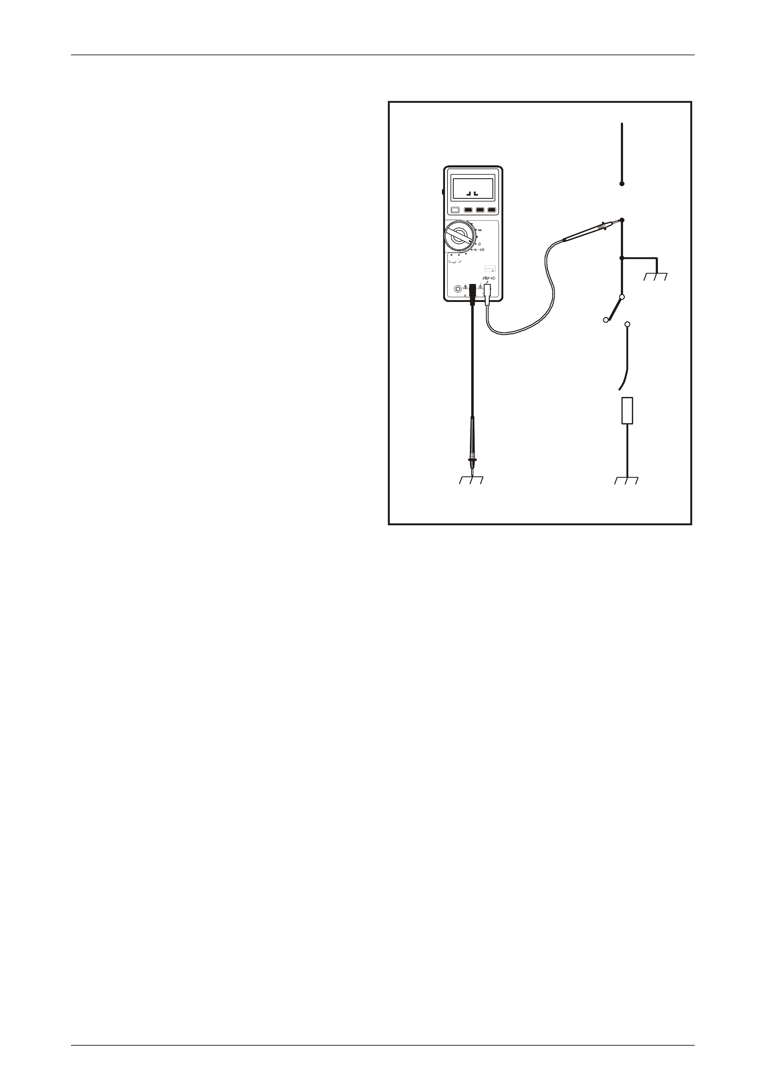
4.2 Testing For Continuity
To test for continuity:
1 Disconnect the battery earth lead.
2 Connect one lead of a self-powered test light or
ohmmeter to one end of the part of the circuit under
test.
3 Switch the meter to Ω and connect the other lead to
the other end of the circuit.
4 If the self-powered test light illuminates, there is
continuity. If you are using an ohmmeter, low or no
resistance means good continuity.
Legend
1 Meter switched to ohms
2 Switch terminal
V
Y12P212
2
1
D H
R H
~
0102030
m V
Mk
+
~
POWER
FUSED
1000V
MAX 750V~
1000 V---
MAX
10A COM uA mA
V
DATA
HOLD S ELECT RANG E
ºC
V
~V
ADP
mA/A uA
PUSH SEL ECT
PUSH SEL ECT
1
kHz
0.3% V
~
O
Figure 12P – 11
Wiring Diagrams Page 12P–20
Page 12P–20
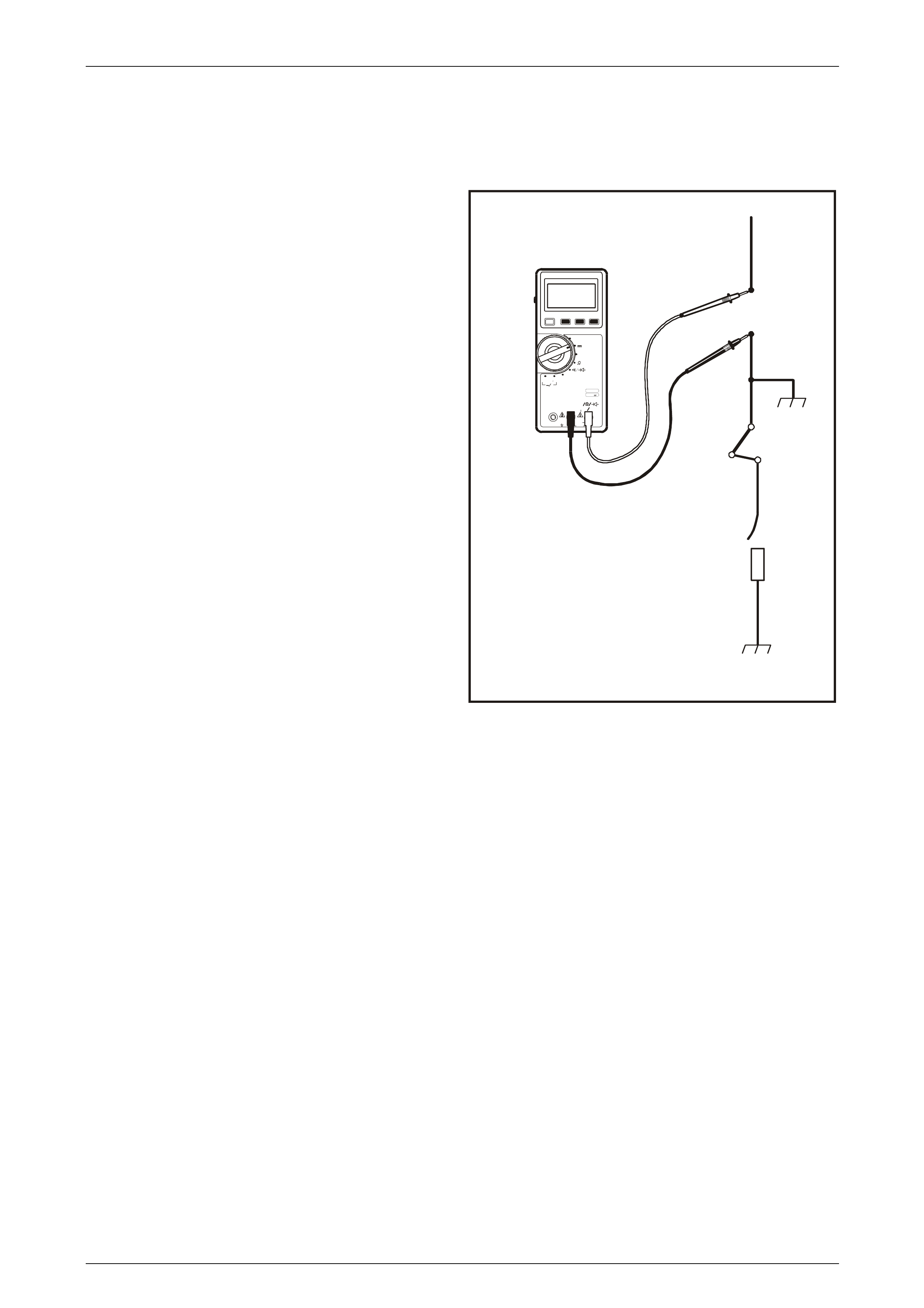
4.3 Testing For Voltage Drop
This test checks for voltage being lost along a wire or
through a connection or switch.
1 Switch the voltmeter to V and connect the positive
lead to the end of the wire (or to one side of the
connection or switch) which is closest to the battery.
2 Connect the negative lead to the other end of the wire
(or other side of the connection or switch).
3 Operate the circuit.
4 The voltmeter will show the difference in voltage
between the two points. A difference (or drop) of more
than 1 volt indicates a problem.
Legend
1 Power from battery
2 Fuse
3 Switch
4 Relay coil
5 Meter
V
Y12P213
2
3
5
1
D H
R H
~
0102030
m V
Mk
+
~
POWER
FUSED
1000V
MAX 750V~
10 00V -- -
MAX
10A COM uA mA
V
DATA
HOLD SELECT RANGE
ºC
V
~V
ADP
mA/A uA
PUSH SEL ECT
PUSH SEL ECT
1
kHz
0.3% V
~
V
4
Figure 12P – 12
Wiring Diagrams Page 12P–21
Page 12P–21
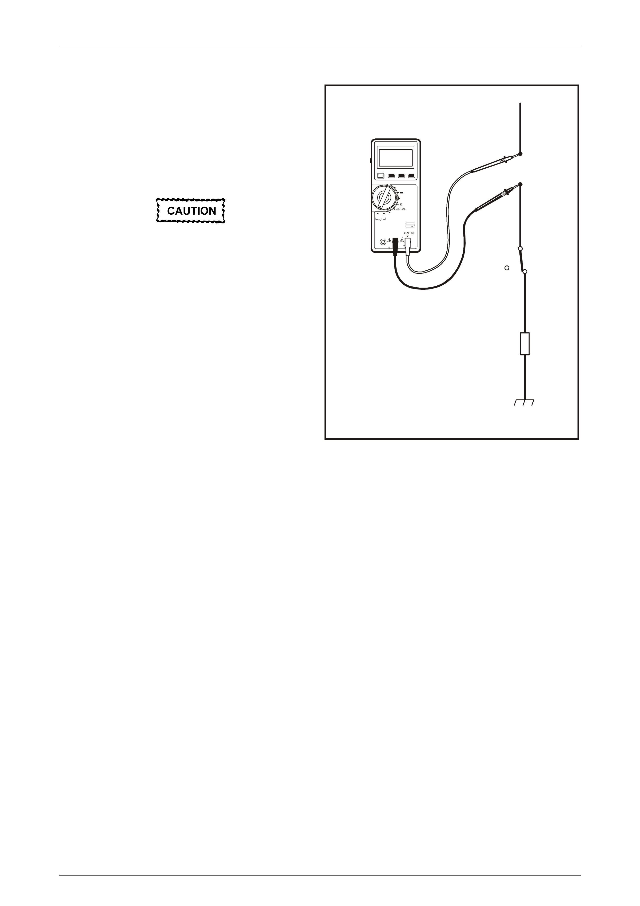
4.4 Testing For Short To Earth
Using A Test Light Or Voltmeter
To test for a short to earth using a test light or a voltmeter:
1 Remove the blown fuse and disconnect the load.
2 Ensure that fuse block is powered and connect a test
light or voltmeter across the fuse terminals.
3 Beginning near the fuse block, wiggle the harness
from side to side. Continue this at convenient points
about 150 mm apart while watching the test light or
voltmeter.
4 If the test light illuminates, or the voltmeter registers,
there is a short to earth in the wiring near that point.
Legend
1 Power from battery with fuse removed
2 Starting test point
3 Switch
4 Disconnected load
5 Meter set to volts
6 Short to earth
V
Y12P214
1
2
6
3
5
D H
R H
~
0102030
m V
Mk
+
~
POWER
FUSED
1000V
MAX 750V~
10 00V -- -
MAX
10A COM uA mA
V
DATA
HOLD SELECT RANGE
ºC
V
~V
ADP
mA/A uA
PUSH SEL ECT
PUSH SEL ECT
1
kHz
0.3% V
~
V
4
Figure 12P – 13
Wiring Diagrams Page 12P–22
Page 12P–22
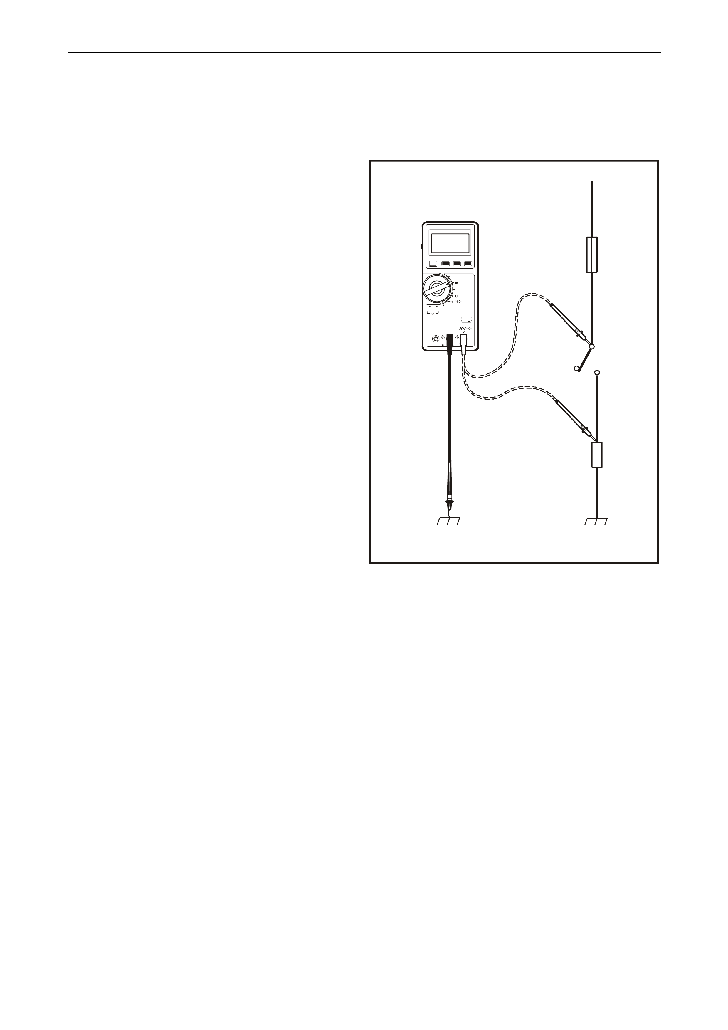
Using A Self-Powered Test Light Or Ohmmeter
To test for a short to earth using a self-powered test light or
an ohmmeter:
1 Remove the blown fuse and disconnect the battery
and load.
2 Connect one lead of a self-powered test light or
ohmmeter to the fuse terminal on the load side.
3 Connect the other lead to a known good earth.
4 Beginning near the fuse block, wiggle the harness
from side to side. Continue this at convenient points
about 150 mm apart while watching the self-powered
test light or ohmmeter.
5 If the self-powered test light illuminates or flickers, or
the ohmmeter changes or registers, there is a short to
earth in the wiring near that point.
Legend
1 Power from battery with fuse removed
2 Starting test point
3 Switch
4 Disconnected load
5 Meter set to ohms
6 Short to earth
V
Y12P215
1
2
6
3
5
D H
R H
~
0102030
m V
Mk
+
~
POWER
FUSED
1000V
MAX 750V~
10 00V -- -
MAX
10A COM uA mA
V
DATA
HOLD SELECT RANGE
ºC
V
~V
ADP
mA/A uA
PUSH SEL ECT
PUSH SEL ECT
1
kHz
0.3% V
~
O
4
Figure 12P – 14
Using A Short Finder
A short finder is a device used for locating hidden shorts. These create a magnetic field in the shorted circuit and allow
you to read its location through body trim or sheet metal.
Using A Compass
An ordinary magnetic compass may be used to locate earthed circuits. It makes use of the fact that a wire carrying
current creates a magnetic field. In circuits that are protected by a circuit breaker, a short or earth can be quickly located
by use of an ordinary magnetic compass. Turn the circuit breaker on and off and start following the wiring with the
compass, the compass will 'kick' each time the circuit breaker closes. As the compass passes the point of the short or
earth, the compass will stop 'kicking'. Thus, the compass can pinpoint the problem without removing trim, cover plates or
tape. If the circuit is fused, the problem can be found in the same manner by substituting a circuit breaker for the fuse.
Using A Circuit Breaker
By using a circuit breaker as a substitute for a fuse, other tools can be more effectively used to find troubles. A turn
signal flasher makes a convenient circuit breaker. Solder a lead to each terminal of the turn signal flasher, and each lead
with a terminal from an old fuse. If this unit is inserted in the junction block in place of a fuse, it may operate too fast to
produce good compass needle deflection. To slow it down, insert a rheostat in series with the flasher. By cutting in
additional resistance, the flashing rate of the unit may be slowed down to produce good compass needle deflection.
Wiring Diagrams Page 12P–23
Page 12P–23
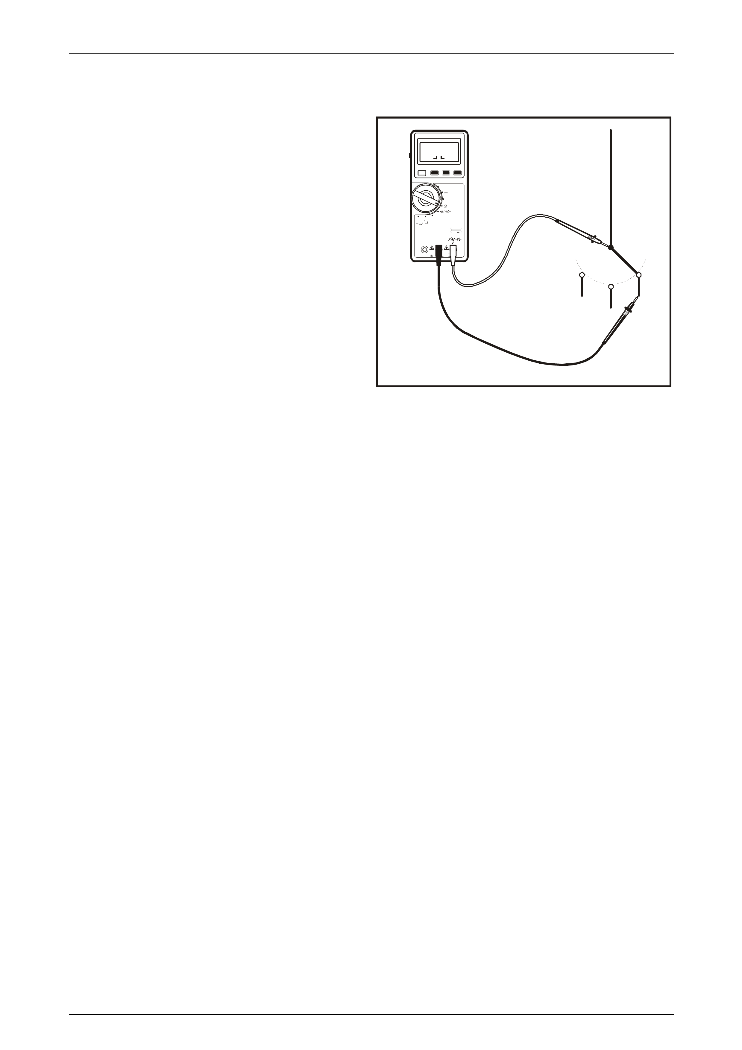
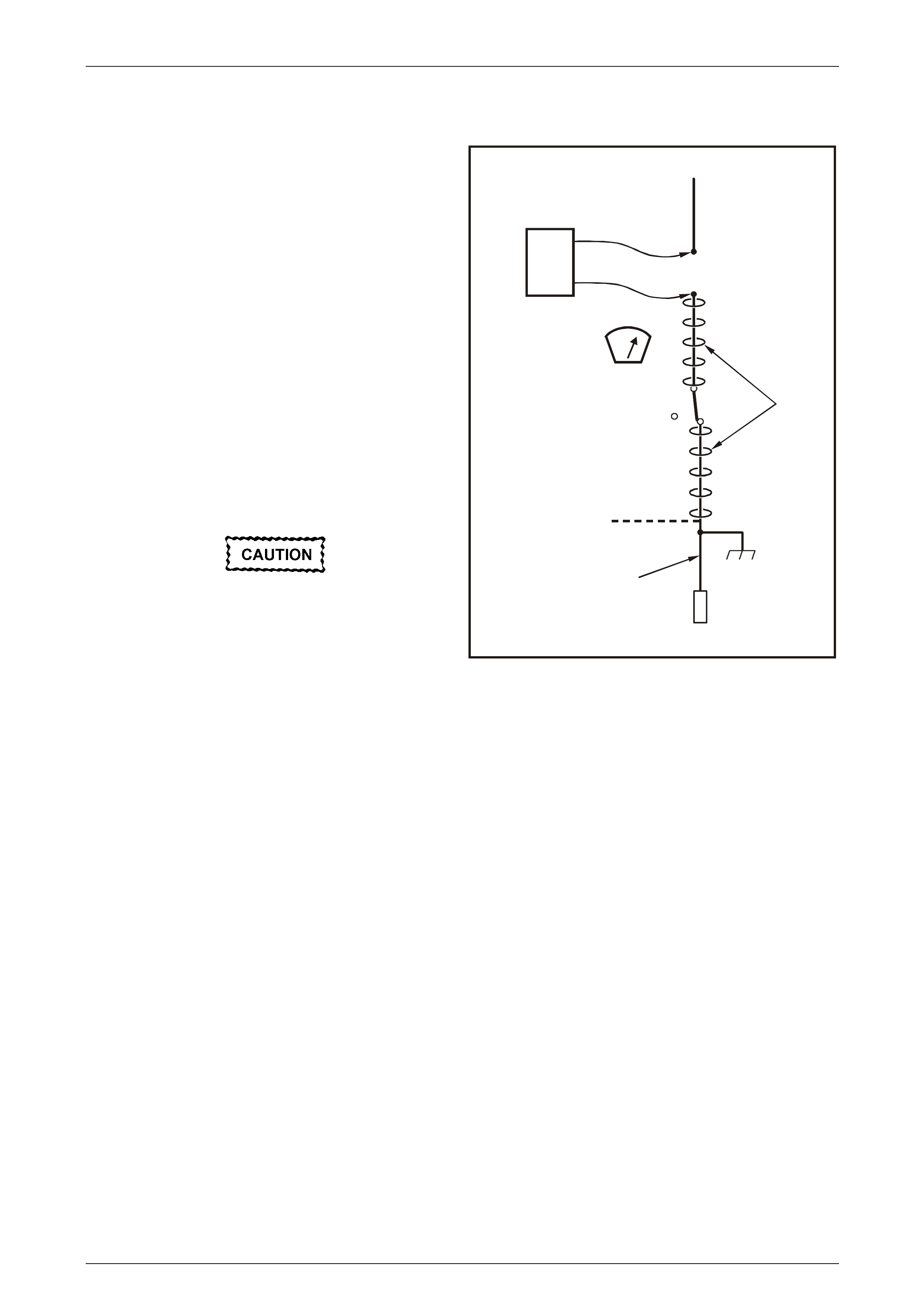
4.5 Operating A Short Finder
To use a short finder:
1 Remove the blown fuse, leaving the battery
connected.
2 Connect the short finder (2) across the fuse terminals.
3 Close all switches (6) in series with the circuit you are
troubleshooting.
4 Operate the short finder. The short finder will pulse
current to the short. This creates a pulsating magnetic
field (5) surrounding the circuit wiring between the fuse
block and the short.
5 Beginning at the fuse block, slowly move the short
finder meter (4) along the circuit wiring. The short
finder meter will show current pulses through sheet
metal and body trim. As long as the meter is between
the fuse block and the short, the needle will move with
each current pulse. When you have moved the meter
past the point of the short, the needle will stop moving
(10). Examine the wiring in that area for the short to
earth.
Never use a short finder on circuits that
contain solid-state components, since
damage to these components may result.
NOTE
Short finders are particularly useful for 'hidden'
shorts as the meter will read the short location
through body trim or sheet metal.
V
Y12P216
1
2
4
3
7
6
8
9
5
10
Figure 12P – 15
Legend
1 Power from battery with fuse removed
2 Short finder pulse generator
3 Fuse panel with fuse removed
4 Short finder meter
5 Pulsating magnetic field
6 Switch
7 Short to earth
8 Solenoid
9 No pulsating magnetic field
10 Needle stops moving here
Wiring Diagrams Page 12P–24
Page 12P–24
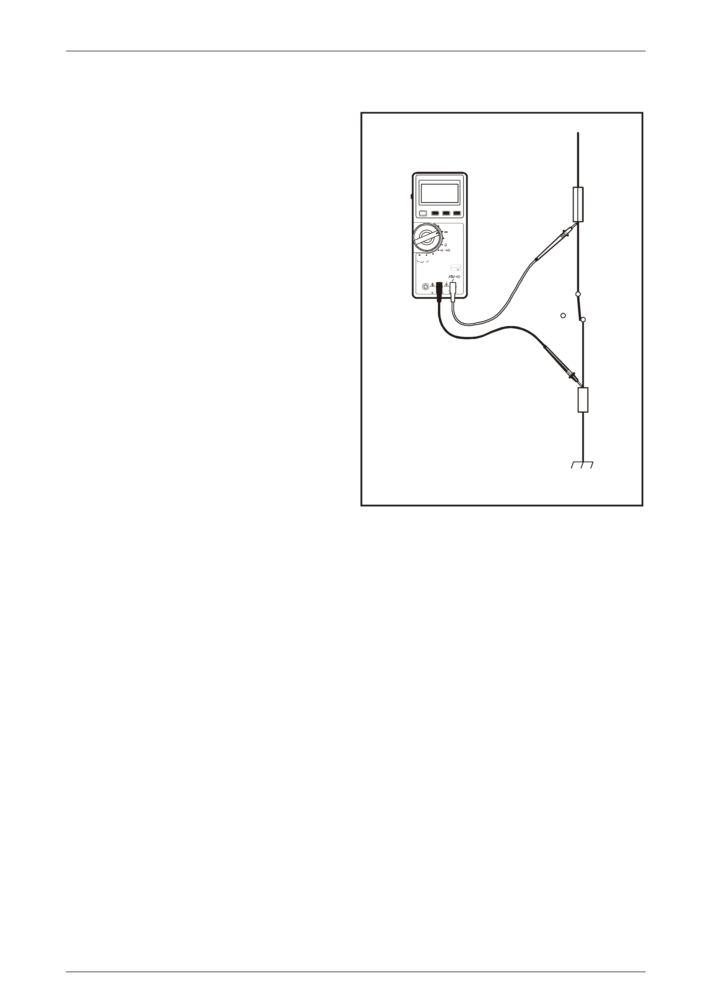
Measuring Current
To measure the current flowing in a circuit, the ammeter
must be connected in series in the circuit. Current
measurements always involve a component being removed
or disconnected from the circuit or the circuit being opened.
The circuit current flows through the meter, which displays
the current in amps or milliamps.
Two commonly used locations for taking current
measurements are at a fuse and at the battery.
Never use a meter set on a current scale to
measure voltage. Severe damage to the
meter, the circuit, or both will result.
Legend
1 Power from battery with fuse removed
2 Fuse block
3 Meter set to ohms
4 Switch
5 Load
V
Y12P217
1
2
D H
R H
~
0102030
m V
Mk
+
~
POWER
FUSED
1000V
MAX 750V~
10 00V -- -
MAX
10A COM uA mA
V
DATA
HOLD SELECT RANGE
ºC
V
~V
ADP
mA/A uA
PUSH SEL ECT
PUSH SEL ECT
1
kHz
0.3% V
~
A
4
3
5
Figure 12P – 16

Wiring Diagrams Page 12P–25
Page 12P–25
4.6 Detecting Intermittent Electrical Faults
Diagnostic Procedure
This procedure can be used to detect intermittent terminal contact or a broken wire with an intermittent connection inside
its insulation.
Some digital multimeters, such as Tool No. 3588, have the ability to monitor current, resistance or voltage while
recording the minimum (MIN) and maximum (MAX) values measured.
When diagnosing circuits that have voltage applied, use the voltage setting to monitor a connector or part of a circuit
which may have an intermittent connection, but at the time is operating normally. Using Tool No. 3588:
1 Set the digital multimeter to read voltage. Since the MIN MAX mode does not use auto ranging, manually select the
voltage range necessary before proceeding.
2 Connect the meter to both sides of a suspect connector (still connected) or from one end of a suspect circuit to the
other. This will continuously monitor the terminal contacts or length of wire being checked.
3 Press the MIN MAX button. The meter should read 100 ms RECORD (100 millisecond record) and emit a 0.25
second beep. The meter is now ready to record and will generate an audible tone for any change in voltage. At this
point, press the PEAK MIN MAX button, which will record any voltage variations that occur for at least 1
millisecond.
4 Simulate the condition that may be causing an intermittent connection, either by wiggling connections or wiring, test
driving or performing other operations. If an open or resistance is created, a voltage drop will occur and the meter
will emit a tone for as long as the open or resistance exists. Any change in voltage will cause the meter to emit a
tone for no less than 0.25 second.
Use the MIN and MAX values when the meter is out of sight or sound range, in noisy areas or for test driving when it may
not be possible to monitor the meter.
To check the MIN and MAX recorded voltages, press MIN MAX button once for MAX and twice for MIN. A variation
between MIN and MAX recorded voltages (unless nearly 0 volts) suggests an intermittent open or resistance exists and
should be repaired as necessary. Refer to 5 Wiring Repair Procedures in this Section for repair procedures.
NOTE
The 100 ms RECORD mode is NOT the amount
of time allowed to perform a specific procedure. It
is the amount of time used to record each
snapshot of information used for calculating AVG
when in the MIN MAX mode.
Checking Terminal Contact
Before replacing a suspect faulty component, it is important to check terminal contact between a connector and the
component, or between in-line mating connectors.
Frequently, a diagnostic chart leads to a step that reads for example ‘Check for poor connection’. Mating terminals must
be inspected to ensure good terminal contact. A poor connection between the male and female terminals at a connector
may be the result of contamination or deformation.
Contamination is caused by the connector bodies being improperly connected, a missing or damaged connector seal, or
damage to the connector itself, exposing the terminals to moisture and dirt. Contamination, usually in the engine
compartment or underbody connectors, leads to terminal corrosion, causing an open circuit or intermittently open circuit.
Deformation is caused by probing the mating side of a connector terminal without the proper adaptor, improperly joining
the connector bodies or repeatedly separating and reconnecting the connector bodies together. Deformation, usually to
the female terminal contact tang, can result in poor terminal contact, causing an open or intermittently open circuit.
To check terminal contact:
1 Separate the connector bodies or the component connector.
2 Inspect the connector bodies or component for contamination. Contamination will result in a white or green build-up
within the connector body or between the terminals, causing high resistance, intermittent contact, or an open
circuit. An engine compartment or underbody connector that shows signs of contamination should be replaced if it
is serviced (refer to VZ Parts information for connectors that are serviced) or the relevant wiring harness should be
replaced.

Wiring Diagrams Page 12P–26
Page 12P–26
3 Using an equivalent male terminal, check the retention force of the female terminal in question by inserting and
removing the male terminal to the female terminal in the connector body. Good terminal contact will require a
certain amount of force to separate the terminals.
4 Using a known good condition equivalent female terminal, compare the retention force of this terminal to the female
terminal in question by inserting and removing the male terminal. If the retention force is significantly different
between the two female terminals, replace the female terminal in question.
If a visual (physical) check does not reveal the cause of the problem, the vehicle may be able to be driven with a digital
multimeter connected to the suspected circuit. An abnormal voltage reading when the problem occurs indicates the
problem may be in that circuit.
Meter Connections
The procedure for detecting intermittent faults was based on the digital multimeter set to read voltage. Whether using
current, voltage or resistance settings to detect intermittent faults, it will be necessary to connect the meter into the
circuit.
The following are examples of various methods of connecting the meter into a circuit to be checked.
1 Backprobe both ends of the connector and either hold meter leads in place while manipulating the connector or,
tape the leads to the harness for continuous monitoring while performing other operations or while test driving.
Do not backprobe 'Weather Pack' type
connectors as damage to the cable seals will
result.
2 Disconnect the harness at both ends of a suspect circuit where it connects either to a component or to other
harnesses. Use connector test adaptor kit, Tool No. J35616-A or KM-609 to connect the meter onto the circuit.
Additional Information
Turn off power to the test circuit before attempting in-circuit resistance measurements to prevent false readings or
damage to the meter. Do not use the meter to measure resistance through a solid state module. Continuity tests that
work well for detecting intermittent shorts to earth can be performed by setting the meter to ohms when pressing the
PEAK MIN MAX button. An audible tone will be heard whenever the meter detects continuity for at least 1 millisecond.
The instruction manual accompanying the multimeter is often a good source of information and should be read
thoroughly before using the meter as well as kept on hand for reference during new procedures.

Wiring Diagrams Page 12P–27
Page 12P–27
5 Wiring Repair Procedures
5.1 General Information
Except for some specific connector bodies, wiring harness terminals, terminal seals and connector bodies are generally
not serviced individually.
Specific terminals, with seals (if fitted) are serviced only as an assembly with a wiring pigtail attached. Refer to VZ Parts
Information for a listing of serviced terminals and connector bodies.
When conducting wiring harness repairs that involve replacement of damaged terminal/s, remove the terminal/s from the
connector body (refer instructions in this Volume) and splice new terminal/s with wiring pigtail into the wiring harness
(refer instructions in this Volume).
If a specific wiring harness terminal or connector body is damaged beyond repair, and the terminal or connector body is
not serviced, that particular wiring harness must be replaced.
Specific instructions on how to replace each individual wiring harness are not included in this manual. Installation details
of wiring harnesses are included on the wiring installation diagrams in Section 12O Fuses, Relays & Wiring harnesses.
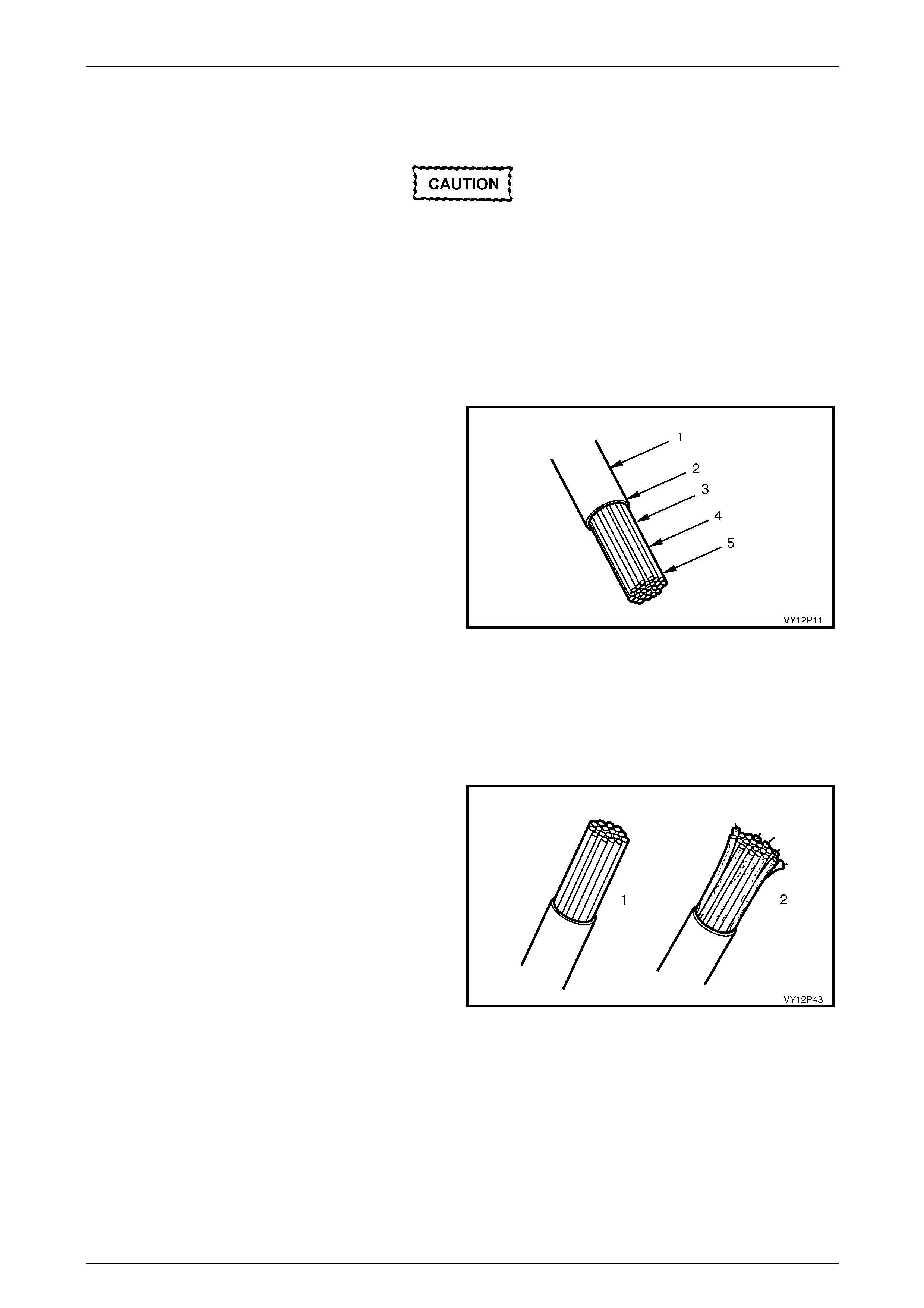
Wiring Diagrams Page 12P–28
Page 12P–28
5.2 Performing Wiring Harness Repairs
Special wiring repair procedures have been
developed for use on the ABS and SRS due to
the sensitive nature of their circuitry. The
procedures in 5.4 ABS And SRS Wiring Repair
are the only recommended and approved ABS
and SRS wiring repair methods. The following
wiring repair methods are not to be used on ABS
or SRS wiring.
Soldering
These are the five points upon which an electrical soldering
joint is judged.
With electrical wiring only resin flux can be used. Acid flux
creates a corrosion problem that makes it unsuitable for this
work.
Do not clean resin flux off after soldering as the resin acts
as an anti-corrosive to protect the soldered area.
Legend
1 Little or no solder penetration into the insulated area
2 Undamaged insulation
3 Full solder penetration
4 Smooth, glossy finish
5 No excess solder
Figure 12P – 17
The Five Points To Soldering
Step 1 Soldering Preparation
The job must be clean and bright (1). Acid corroded or
greasy wiring ends (2) should be stripped back.
Keep the job and your hands clean at all times.
Figure 12P – 18

Wiring Diagrams Page 12P–29
Page 12P–29
Step 2 Iron Preparation
The soldering iron (1) must be tinned and hot BEFORE
application. Preheat the soldering iron to slightly above
solder melting point before applying solder (2) or applying it
to the job to allow for heat loss on contact.
The commencement of 'flux spit' is an indication of correct
preheat temperature.
Figure 12P – 19
Step 3 Forming a Heat Bridge
Apply the full face of the soldering iron to the job and
immediately add solder to the 'V' formed by the iron and the
job.
This is known as heat bridge where the melting solder
speeds up the heat transfer and cuts down the job heating
time.
Figure 12P – 20
Step 4 Soldering Iron Removal
Remove the soldering iron (1) the instant the job is
complete. This prevents the solder (2) travelling outside the
intended deposit area.
VY12P46
2
1
Figure 12P – 21
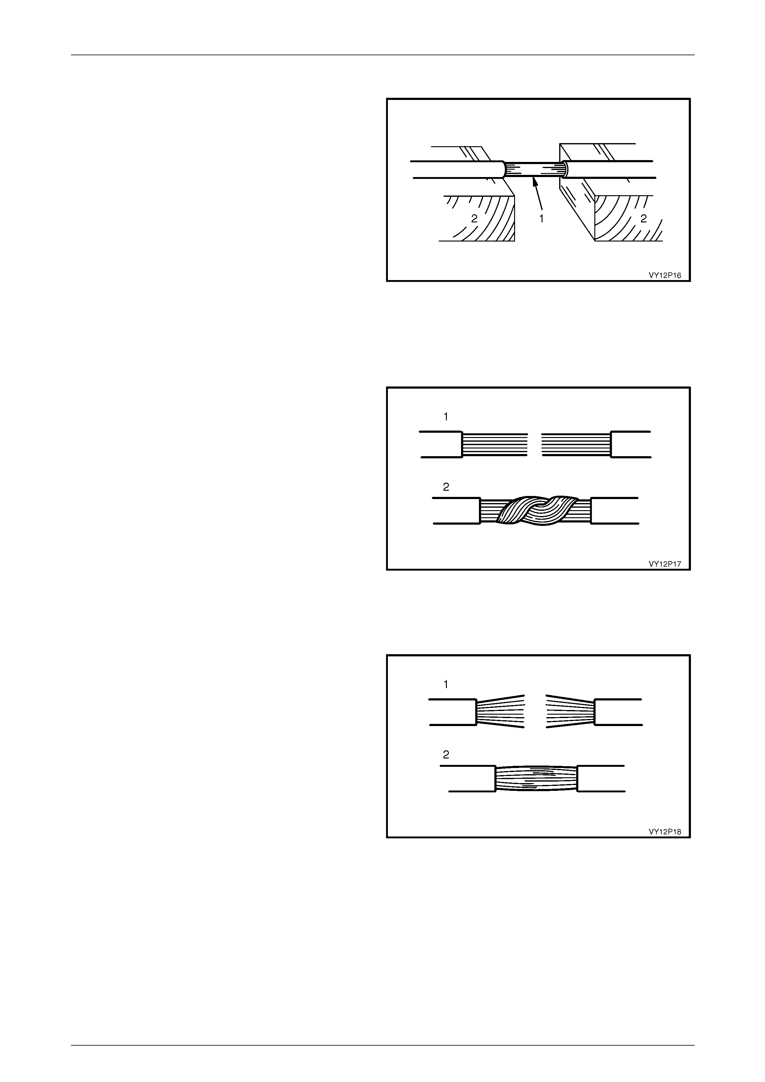
Wiring Diagrams Page 12P–30
Page 12P–30
Step 5 Prevent Job Movement
Prevent job movement until the solder cools.
A soldered joint (1) can be weakened if the two components
being joined move in relation to each other just as the liquid
solder changes to a solid state.
Making a second attempt to solder the joint is undesirable
as prolonged heating is necessary to remelt the solder.
Arrange support (2) before you start and use it until the
solder cools.
Figure 12P – 22
Joining Wire
Twist Joint
The twist joint is simple and strong.
1 Strip 20 mm of insulation from each wire (1).
2 Twist the strands to compact them.
3 Join them together by twisting (2).
4 Complete the join by soldering.
5 Use PVC tape to insulate the joint.
NOTE
To prevent a short or earthed circuit, remove all
the 'spikes' from the join before insulating.
Spikes can be formed by wire strands or solder
itself. These can cut through the insulation. Figure 12P – 23
Splice Joint
To splice join conductors:
1 Strip back 20 mm of insulation and spread the strands
(1).
2 Push the strands together and twist the ends in
opposite directions to compact the joint (2).
3 Solder the joint.
4 Use PVC tape to insulate the joint.
NOTE
A good splice may be a little harder to achieve
but it makes a neater join that is less bulky when
taped. Figure 12P – 24
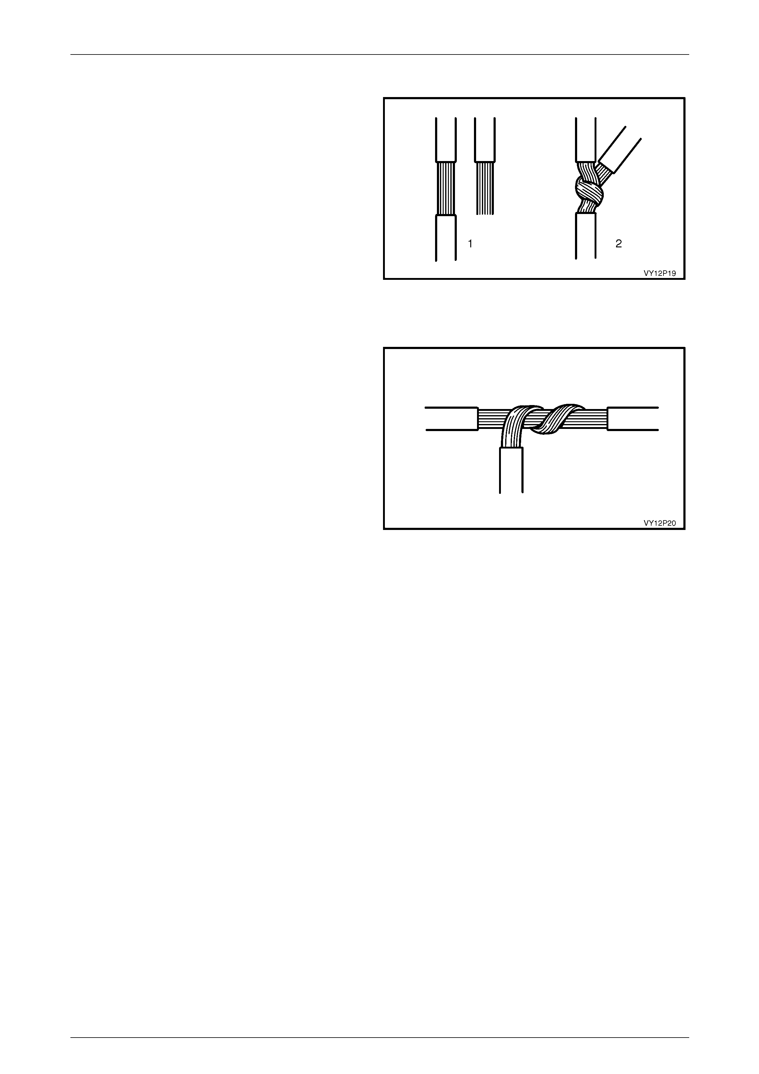
Wiring Diagrams Page 12P–31
Page 12P–31
The Y Junction
The Y junction is used to install a branch connection parallel
with the original.
1 Use a sharp blade to remove approximately 20 mm of
insulation from the original wire (1).
2 Strip the insulation on the branch wire by
approximately 20 mm.
3 Twist the branch wire around the original wire (2).
4 Solder the connection.
5 Use PVC tape to insulate the joint.
Figure 12P – 25
The T Junction
The T junction is used to achieve a 90 degree branch
connection.
1 Use a sharp blade to remove approximately 20 mm of
insulation from the original wire.
2 Strip the insulation on the branch wire by
approximately 20 mm.
3 Twist the branch wire around the original wire.
4 Solder the connection.
5 Use PVC tape to insulate the joint.
Figure 12P – 26
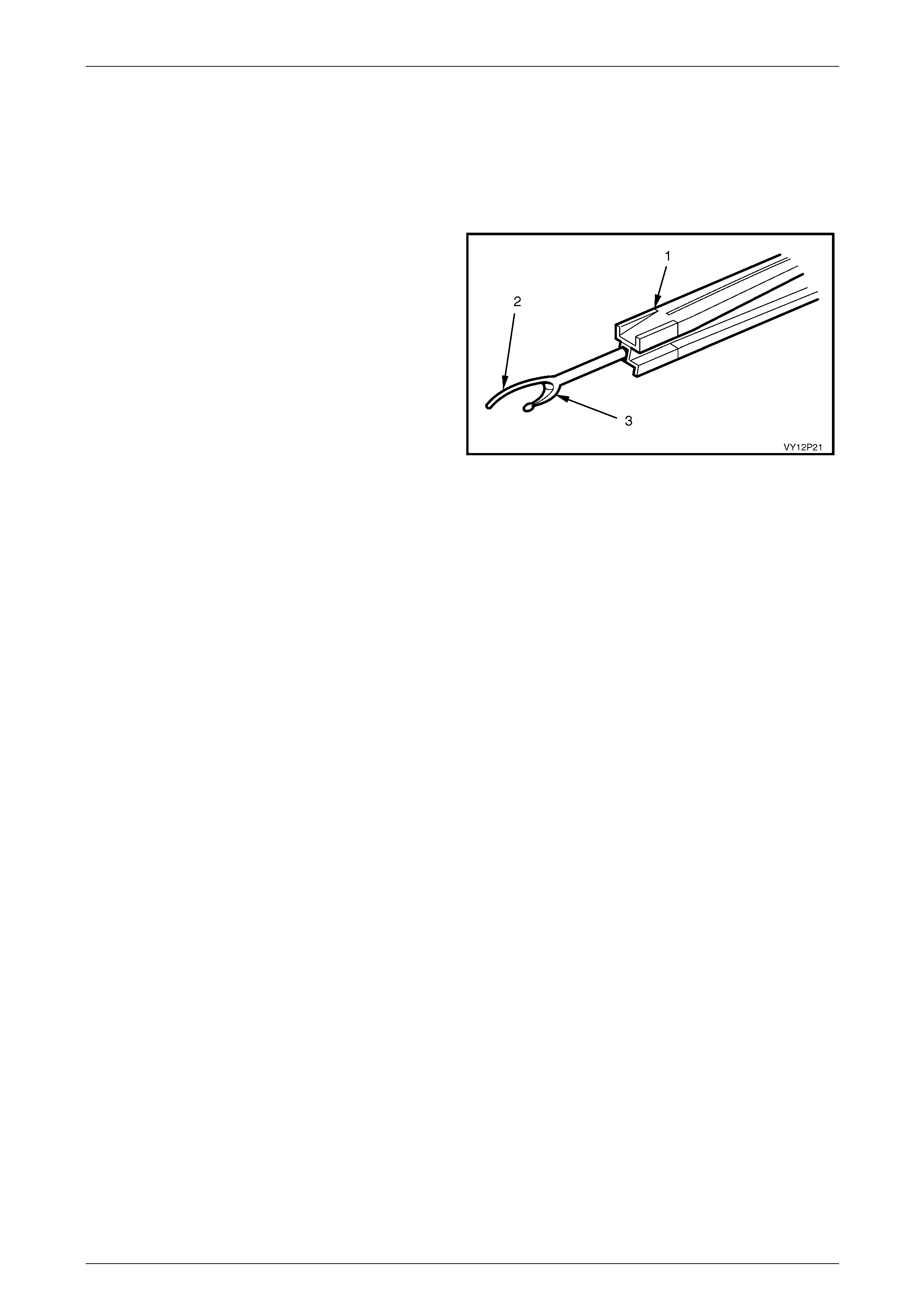
Wiring Diagrams Page 12P–32
Page 12P–32
5.3 Splicing Wiring Using Splice Clips
Splice clips are included in Terminal Repair Kit, Tool No. J38125-A. The splice clip is a general-purpose wire repair
device. It may not be acceptable for applications having special requirements such as moisture sealing.
Step 1 Open the Harness
A wiring harness may be wrapped in tape or enclosed in a
plastic conduit.
If it is conduit encased, simply open the conduit and pull out
the desired wire.
If the harness is wrapped in tape, use a seam splitter (1) to
open the harness. This prevents damage to the insulation of
the wire inside the harness. Seam splitters are readily
available from sewing supply stores.
When using a seam splitter, use the blade with the pointed
end (2) to start a small split in the tape away from any wires.
Use the blade with the rounded end (3) to slit the tape as far
as necessary. Be careful to avoid cutting into any wire
insulation. Figure 12P – 27
Step 2 Cut the Wire
Leave as much wire on the harness as possible. More can be cut off later to adjust the location of the splice if necessary.
NOTE
Ensure that each splice is at least 40 mm away
from other splices, harness branches and
connectors. This helps prevent moisture from
bridging adjacent splices and causing damage.
Do not nick or cut any copper strands as this
could limit the current-carrying capabilities of the
wire.
Step 3 Select the Correct Size and Type of Wire
The wire must be of a size equal to or greater than the original except for fusible links. The wire insulation must have the
same or higher temperature rating:
General purpose insulation (PVC) is used in areas not subject to high temperatures.
Cross-linked polyethylene (XLPE) insulation wire is used where high temperatures are expected.
NOTE
XLPE insulated wire may be used to replace
PVC, but PVC must not be used to replace
XLPE. XLPE insulation is not fuel resistant, so
XLPE covered wire must not be used where there
is the possibility of fuel contact.
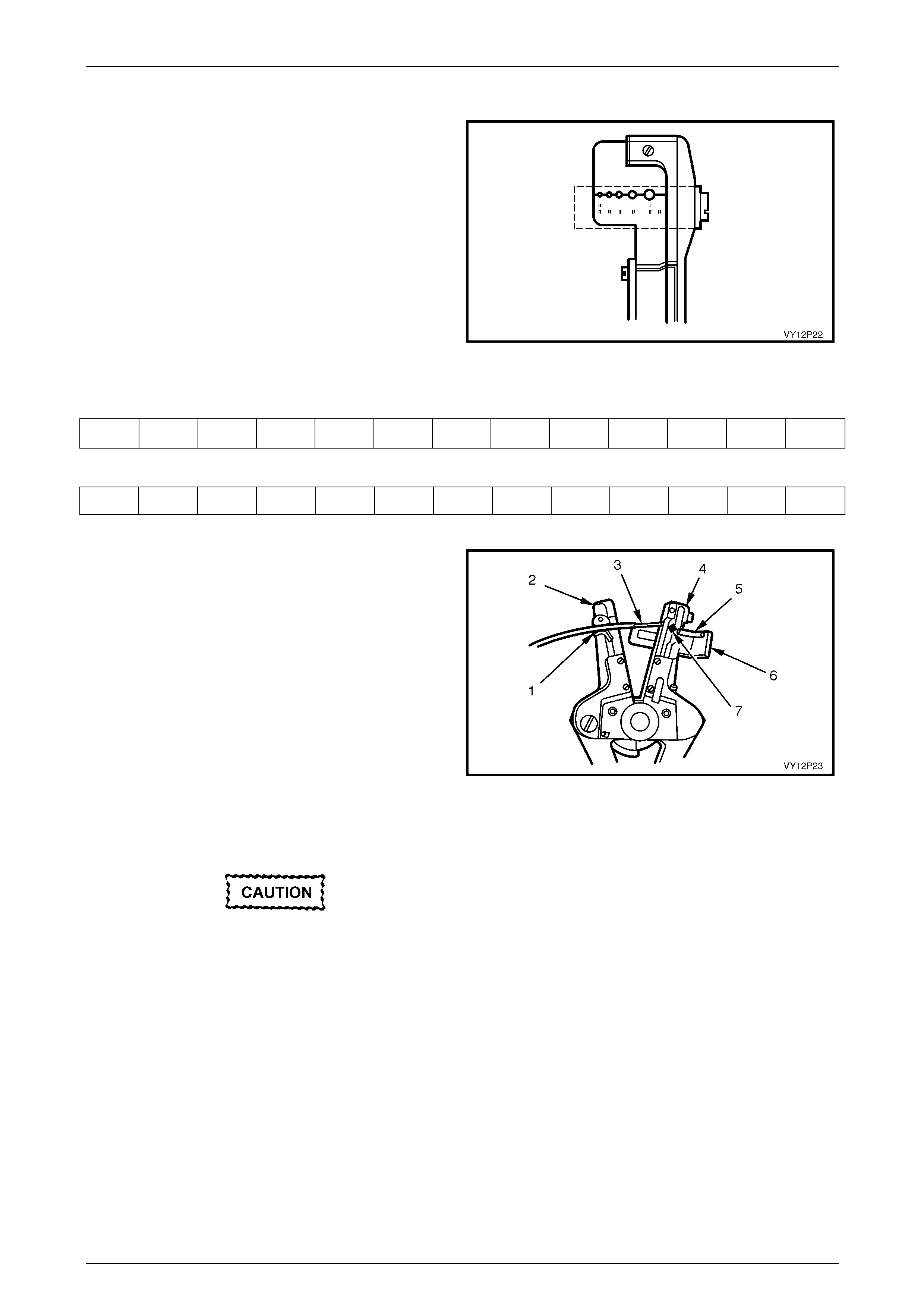
Wiring Diagrams Page 12P–33
Page 12P–33
Step 4 Strip the Insulation
Find the wire size using a wire gauge (AWG).
A wire stripper, labelled in AWG sizes, is needed for
stripping away the insulation. If the wire size is not known,
start with the largest stripper hole and work down until a
clean strip of insulation is removed without nicking or cutting
the wire. Set the stripper guide to a 7.5 mm long strip.
The splice should be at least 40 mm away from any other
splices or outlets.
Figure 12P – 28
Metric Size
0.22 0.35 0.5 0.8 1.0 2.0 3.0 5.0 8.0 13.0 19.0 32.0 50.0
AWG
24 22 20 18 16 14 12 10 8 6 4 2 1/0
Use the following procedure when using a wire stripper:
Hold both handles in the right hand, with gripper jaws to the
left.
Hold the wire in the left hand and press the end of the wire
against the guide and up into the correct notch of the upper
blade.
Close left handle first, to grip the wire firmly before cutting
the insulation.
If the stripper castings stick open after stripping the wire,
pull the handles outward to snap the tool closed.
Check the stripped wire for nicks or cut strands.
If the wire is damaged, repeat the procedure on a new
section of wire. The two stripped sections of wire to be
joined should be of equal length.
Do not place your fingers between the
gripper casting and the cutter casting at any
time. Do not lay these castings against your
hands when open. The stripper castings are
designed to snap shut when fully opened,
and may cause injury.
Figure 12P – 29
Legend
1 Gripper jaws
2 Gripper casting
3 Stripped wire
4 Cutter casting
5 Insulation
6 Guide
7 Blades
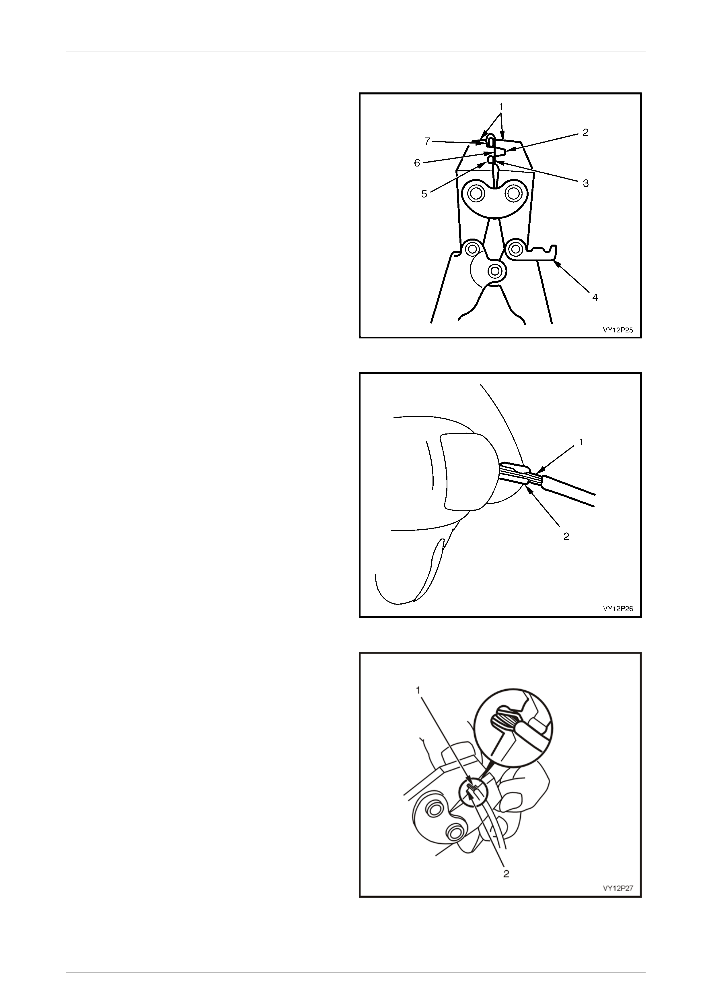
Wiring Diagrams Page 12P–34
Page 12P–34
Step 5 Crimping the Joint
1 Select the correct sized clip.
2 Unlock the crimping tool.
3 Slightly close the clip using the nose of the crimping
tool as shown in Figure 12P – 30.
4 Select the correct crimper anvil.
Legend
1 Nose
2 Former
3 Small anvil
4 Lock
5 Former
6 Large anvil
7 Clip
Figure 12P – 30
5 Overlap the two stripped wire ends (1) and hold them
between the thumb and forefinger as shown in Figure
12P – 31.
6 Centre the splice clip (2) under the stripped wires and
hold in place as shown.
• Ensure that the wires extend beyond the clip in each
direction.
• Ensure no insulation is caught under the clip.
• Strands of wire are not cut or loose.
Figure 12P – 31
7 Fully open the crimping tool and rest one handle on a
firm, flat surface.
8 Centre the back of the splice clip on the proper anvil
(2) and close the crimping tool to the point where the
former touches the wings of the clip (1).
9 Verify the clip and wires are still in the correct position
before closing the crimping tool with steady pressure.
Figure 12P – 32
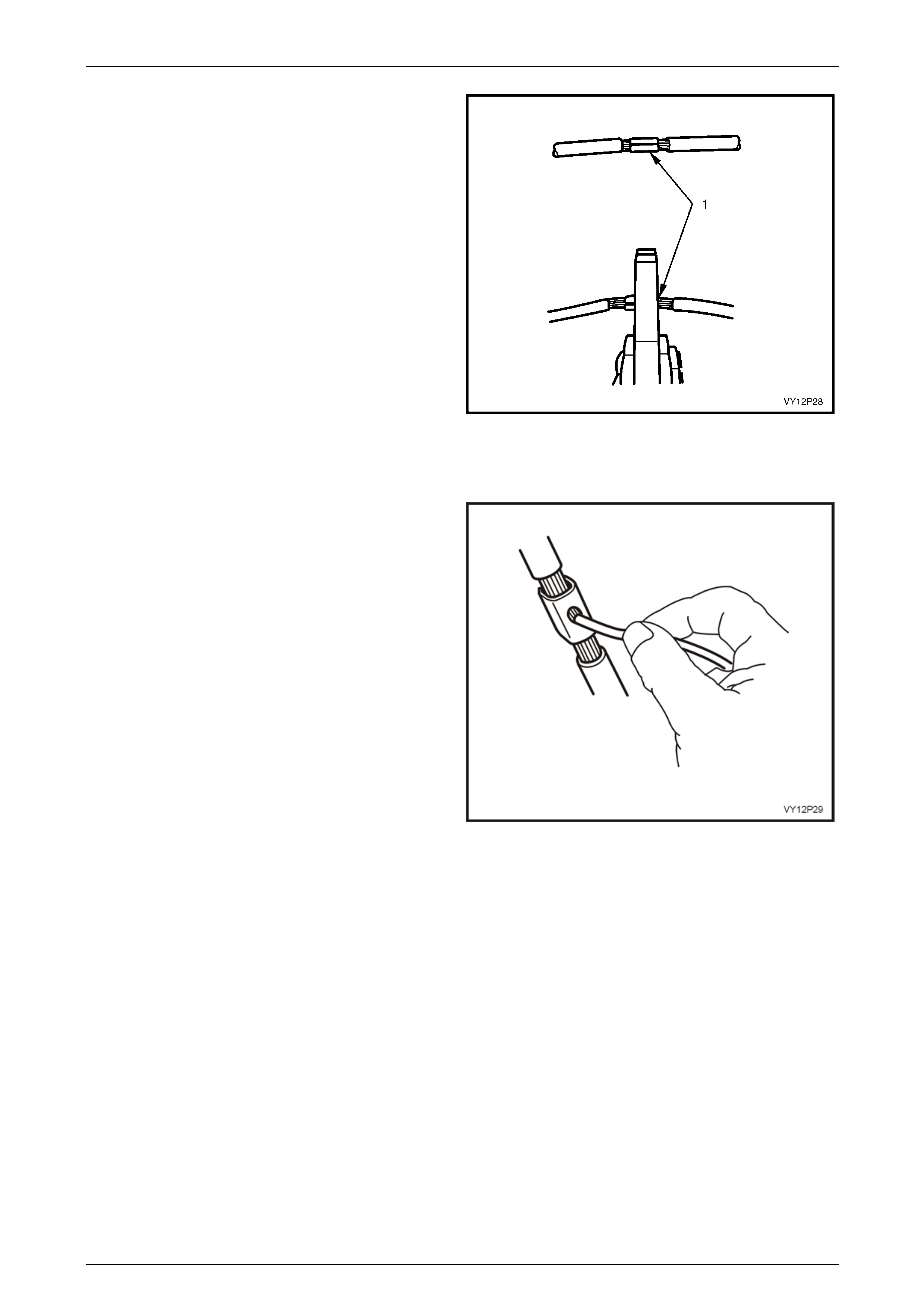
Wiring Diagrams Page 12P–35
Page 12P–35
10 Crimp the splice clip a second and third time, once at
each end (1). Do not let the crimping tool extend
beyond the edge of the clip when doing so.
Figure 12P – 33
Step 6 Solder
Apply 50/50 resin core solder to the hole in the back of the
clip as shown in Figure 12P – 34.
Figure 12P – 34
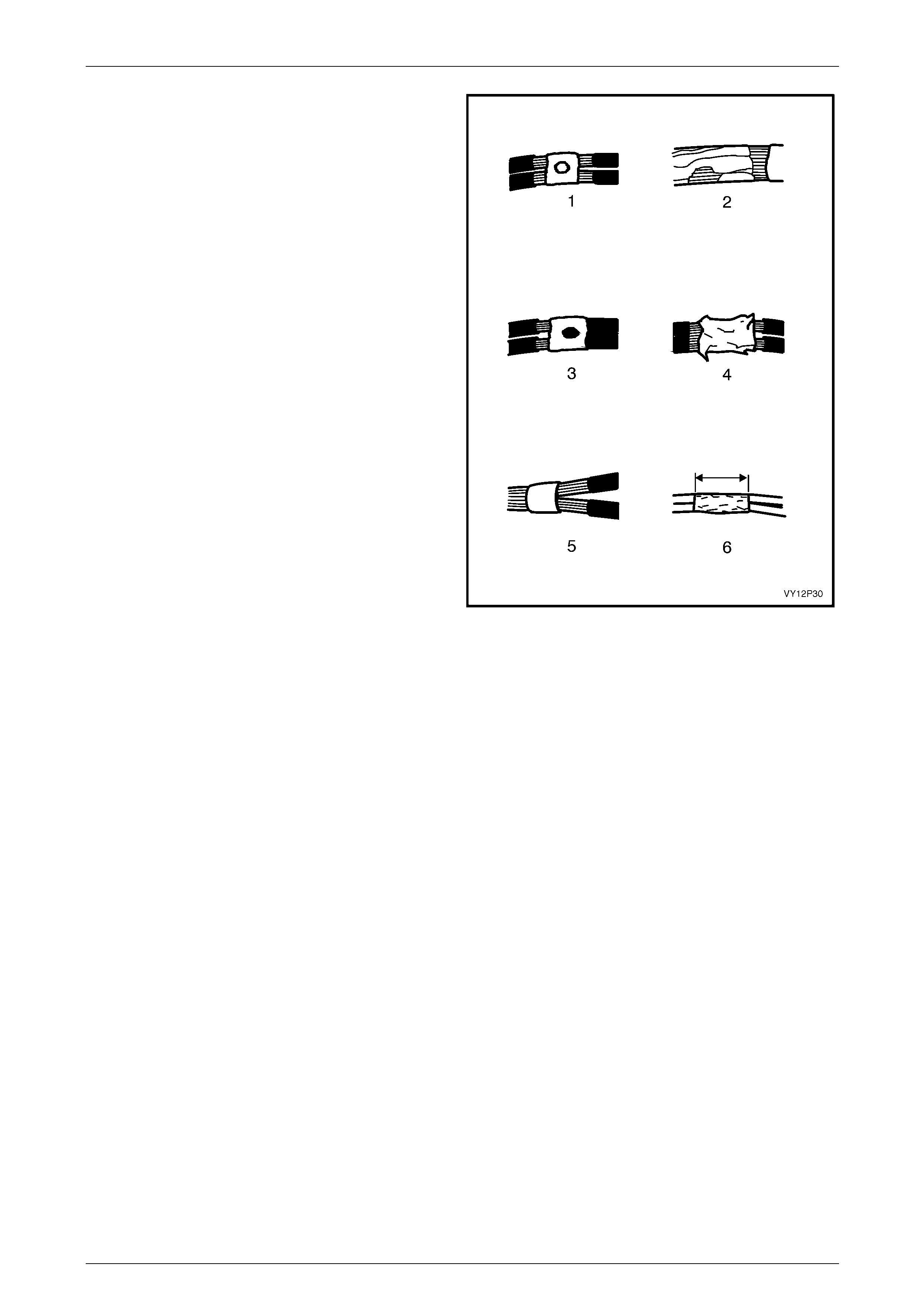
Wiring Diagrams Page 12P–36
Page 12P–36
Ensure there are none of the faults shown in Figure
12P – 35
Legend
1 Poor solder application with bad solder fillets
2 Excessive burning which cannot be covered with 50 mm
splice tape
3 Insulation clamped under the clip
4 Sharp solder spikes
5 Wires not fully inserted into the clip
6 Tape width less than 50 mm
Figure 12P – 35
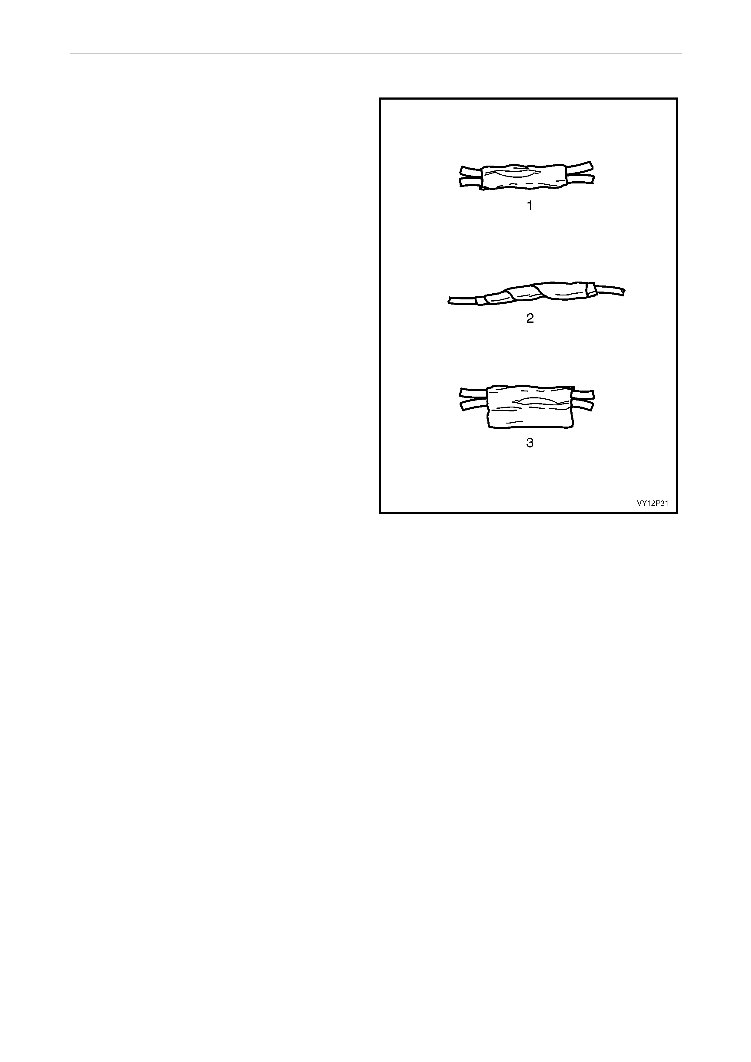
Wiring Diagrams Page 12P–37
Page 12P–37
Step 7 Tape the Splice
Centre and roll a 50 mm x 50 mm piece of tape around the
splice joint.
If the wire is not in conduit or another harness covering,
tape it again using a winding motion, entirely overlapping
the first piece.
Legend
1 Example of properly rolled tape
2 Tape again if needed
3 Example of bad (flagged) taping
Figure 12P – 36

Wiring Diagrams Page 12P–38
Page 12P–38
5.4 ABS And SRS Wiring Repair
Special wiring repair procedures have been developed for use on the Anti-lock Braking System (ABS) and Supplemental
Restraint System (SRS) due to the sensitive nature of the circuitry. These specific procedures and instructions must be
followed when working with ABS and SRS wiring, and wiring components (such as connectors and terminals). Terminal
Repair Kit, Tool No. J38125-A contains special sealed splices for use in repairing ABS and SRS wiring.
A special crimping tool, heat torch, and instruction manual for these splices are also included.
Two critical features of the sealed splices are a special heat shrink sleeve with sealing adhesive to produce an
environmentally sealed splice and a cross hatched (knurled) core crimp to provide necessary contact integrity for the
sensitive, low energy circuits.
Terminal Repair Kit J38125-A also serves as a generic terminal repair kit. The kit contains a large sampling of common
GM electrical terminals and the correct tools to attach them to wires and remove them from connectors. The terminals in
the kit are NOT to be used to replace damaged terminals in the ABS and SRS wiring.
The following procedure for repairing ABS
and SRS wiring is the only recommended and
approved repair method. No alternative repair
methods are to be used.
ABS And SRS Wire Pigtail Repair
Read and understand the instruction repair manual before conducting ABS and SRS wiring repairs using this kit.
If a wiring pigtail (a wire or wires attached directly to the device, not by a connector) is damaged, the entire component
(with pigtail) must be replaced.
Examples of pigtail components are the wheel speed sensors or clock spring coil. Absolutely no wire, connector or
terminal repairs are to be attempted on these components, REPLACE THE COMPONENT.
Wiring Repair
NOTE
Before conducting SRS wiring repair, disable the
SRS, refer to Section 12M Occupant Protection
System.
If any wiring, except the pigtail, is damaged, the wiring should be repaired by splicing in a new section of wire of the
same gauge size (0.5, 0.8, 1.0, etc.). The splices and Splice Crimping Tool from Terminal Repair Kit J38125-A must be
used for these repairs.
The following wiring repair procedures must be used to ensure the integrity of the sealed splice application.

Wiring Diagrams Page 12P–39
Page 12P–39
Step 1 Open the Harness
A wiring harness may be wrapped in tape or enclosed in a
plastic conduit.
If it is conduit encased, simply open the conduit and pull out
the desired wire.
If the harness is wrapped in tape, use a seam splitter (1) to
open the harness. This prevents damage to the insulation of
the wire inside the harness. Seam splitters are readily
available from sewing supply stores.
When using a seam splitter, use the blade with the pointed
end (2) to start a small split in the tape away from any wires.
Use the blade with the rounded end (3) to slit the tape as far
as necessary. Be careful to avoid cutting into any wire
insulation.
The crimp and sealed splice sleeves may be used on all
types of insulation except Tefzel and coaxial and may only
be used to form a one-to-one splice.
Figure 12P – 37
Step 2 Cut the Wire
Leave as much wire on the harness as possible. More can be cut off later to adjust the location of the splice if necessary.
NOTE
Ensure that each splice is at least 40 mm away
from other splices, harness branches and
connectors. This helps prevent moisture from
bridging adjacent splices and causing damage.
Do not nick or cut any copper strands as this
could limit the current-carrying capabilities of the
wire.
Step 3 Select the Correct Size and Ty pe of Wire
The wire must be of a size equal to or greater than the original except for fusible links. The wire insulation must have the
same or higher temperature rating:
General purpose insulation (PVC) is used in areas not subject to high temperatures.
Cross-linked polyethylene (XLPE) insulation wire is used where high temperatures are expected.
NOTE
XLPE insulated wire may be used to replace
PVC, but PVC must not be used to replace
XLPE. XLPE insulation is not fuel resistant, so
XLPE covered wire must not be used where there
is the possibility of fuel contact.
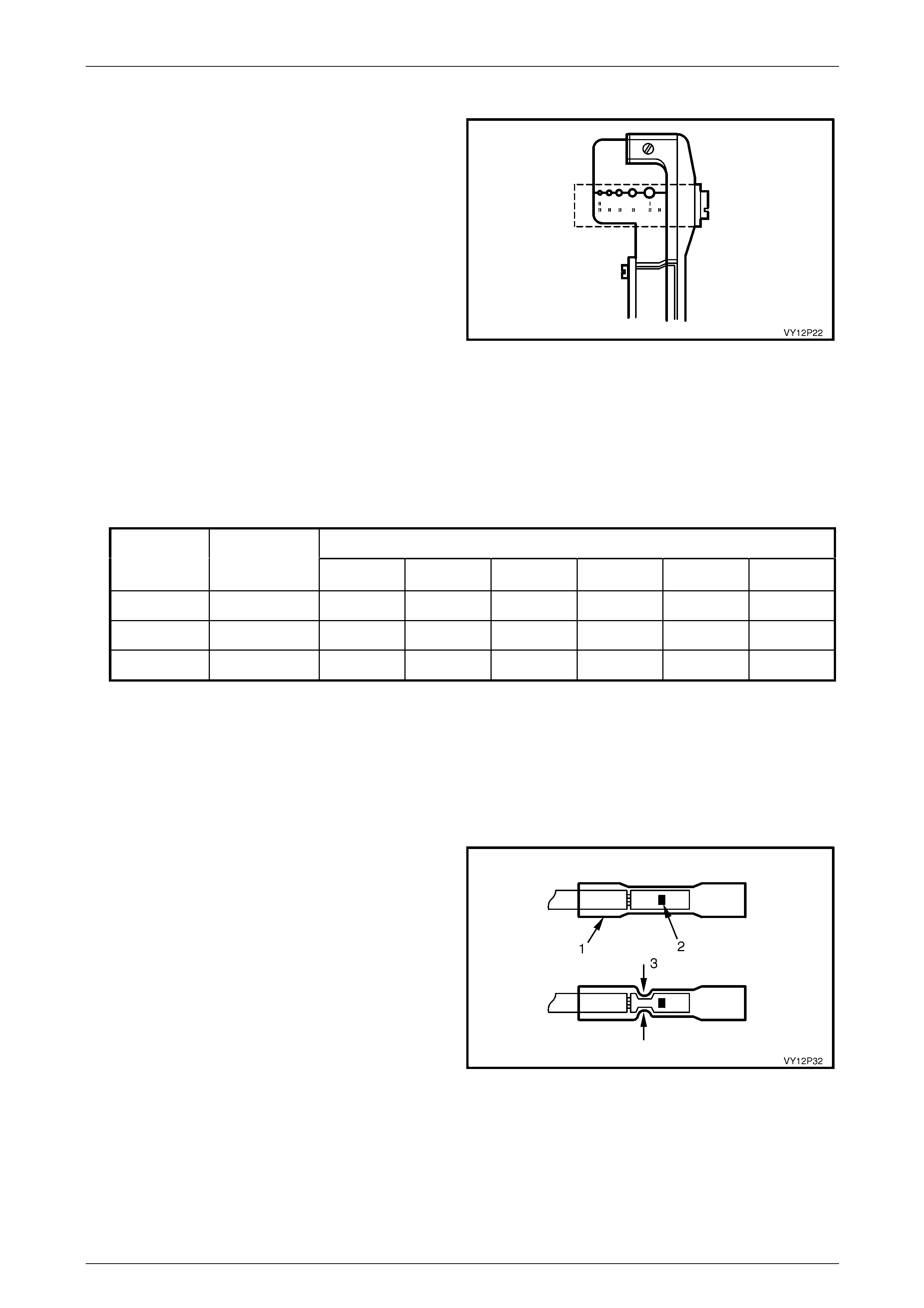
Wiring Diagrams Page 12P–40
Page 12P–40
Step 4 Strip the Insulation
NOTE
The following procedures must be followed in the order
listed. If wire strands are damaged, the procedure must be
repeated until a clean strip with all wire strands intact is
obtained.
If it is necessary to add a length of wire to the existing
harness, be certain to use the same size as the original
wire.
To find the correct wire size, either find the wire on the ABS
or SRS wiring diagram, or measure it with a wire gauge.
If unsure about the wire size, begin with the largest opening
in the wire stripper and work down until achieving a clean
strip of the insulation. Strip approximately 7.5 mm of
insulation from each wire to be spliced. Be careful to avoid
nicking or cutting any of the strands. Check the stripped wire
for nicks or cut strands. If the wire is damaged, repeat this
procedure after removing the damaged section.
Figure 12P – 38
Step 5 Select and Position the Splice Sleeve
Select the proper sealed splice sleeve according to wire size. The splice sleeves and tool nests are colour coded (refer to
Table 12P-1).
WIRE SIZE (mm)
SPLICE
CRIMP
PART No.
CRIMP TOOL
NEST
COLOUR 0.5 0.8 1.0 2.0 3.0 5.0
12089189 RED SALMON SALMON
12089190 BLUE BLUE BLUE
12089191 YELLOW YELLOW YELLOW
Table 12P-1
Using the J38125-A Splice Crimp Tool, position the splice sleeve in the proper colour nest of the hand crimp tool. Place
the splice sleeve in the nest so that the crimp falls midway between the end of the barrel and the stop.
The sleeve has a stop in the middle of the barrel to prevent the wire from going further. Close the hand crimper handles
slightly to hold the splice sleeve firmly in the proper nest.
Step 6 Insert First Wire Into Splice Sleeve and Crimp
1 Insert the wire into the splice sleeve (1) until it hits the
barrel stop (2).
2 Close the handles of the crimp tool tightly at position
(3) until the crimper handles open when released. The
crimper handles will not open until the proper amount
of pressure has been applied to the splice sleeve.
3 Gently tug the wire to ensure the crimp is secure.
Figure 12P – 39
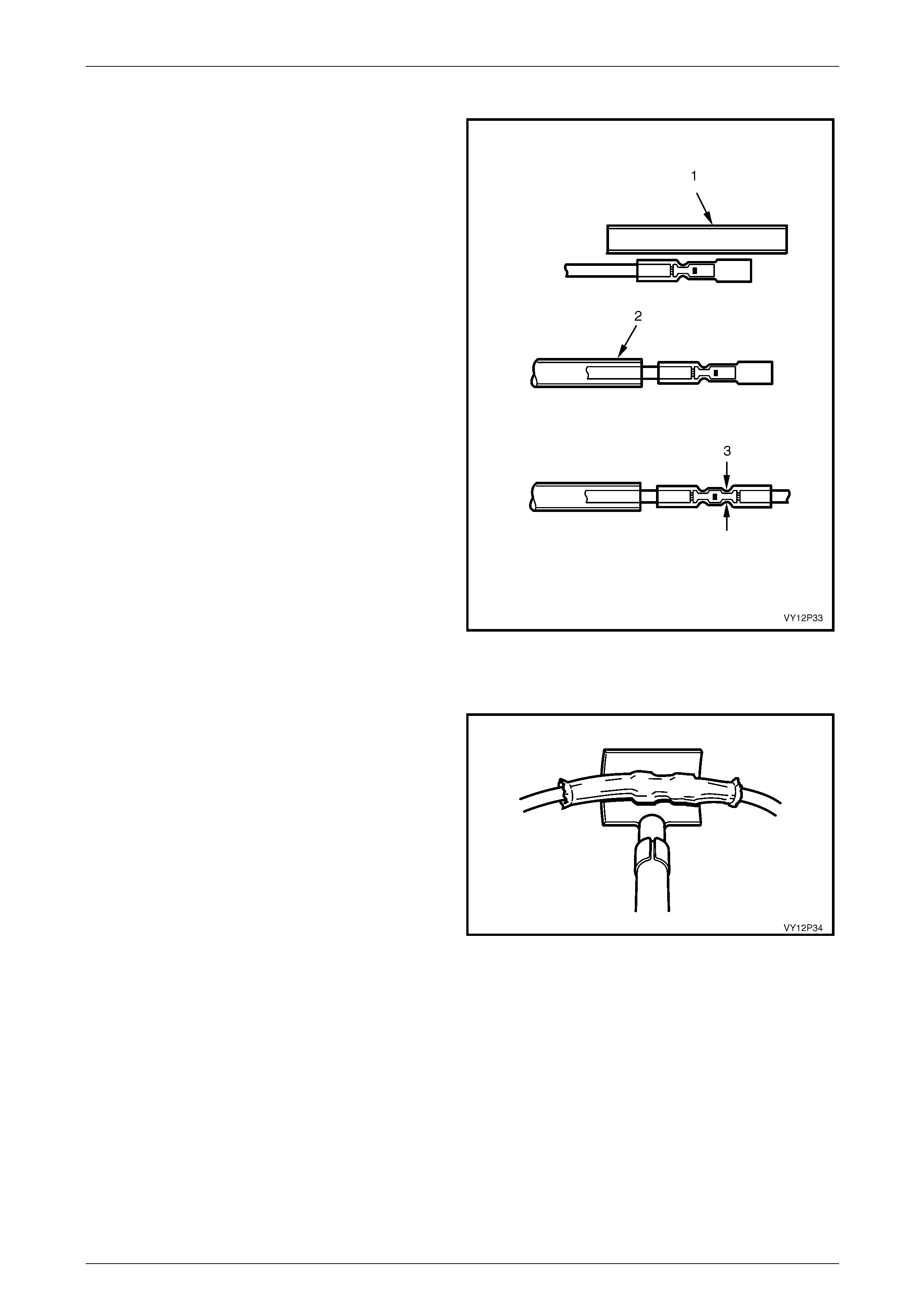
Wiring Diagrams Page 12P–41
Page 12P–41
Step 7 Crimp the Second Wire in the Splice
1 Cut a length of heat shrink tubing (1) which will allow
an overlap of at least 10 mm at each end of the finally
crimped joint.
2 Slide the heat shrink tubing over the harness wire
which has already been crimped (2).
3 Repeat the Step 5 operations for the second end of
the splice (3).
Figure 12P – 40
Step 8 Shrink the Insulation around the Splice
1 Bring the ultratorch (part of J38125-A) to operating
temperature.
2 Using the torch, apply heat where the barrel is crimped
as shown in Figure 12P – 41.
3 Gradually move the heat barrel from the centre toward
each end of the tubing, softening and shrinking the
tubing completely as the heat is moved along the
insulation. A small amount of sealant will come out of
the end of the tubing when sufficient shrinking is
achieved.
4 Allow the splice sleeve to cool.
Step 9 Close the Harness
Using a multimeter, check continuity of repaired wiring. If
wiring is OK, tape the harness wires.
Figure 12P – 41
ABS And SRS Wiring Splice Repair
If any of the original equipment splices (three wires or more) in the ABS and SRS wiring are damaged they should be
repaired by applying a new splice (not sealed) from the Terminal Repair Kit J38125-A. Carefully follow the instructions
included in the kit for proper splice clip application. Cloth duct tape may be substituted for splice tape if necessary.
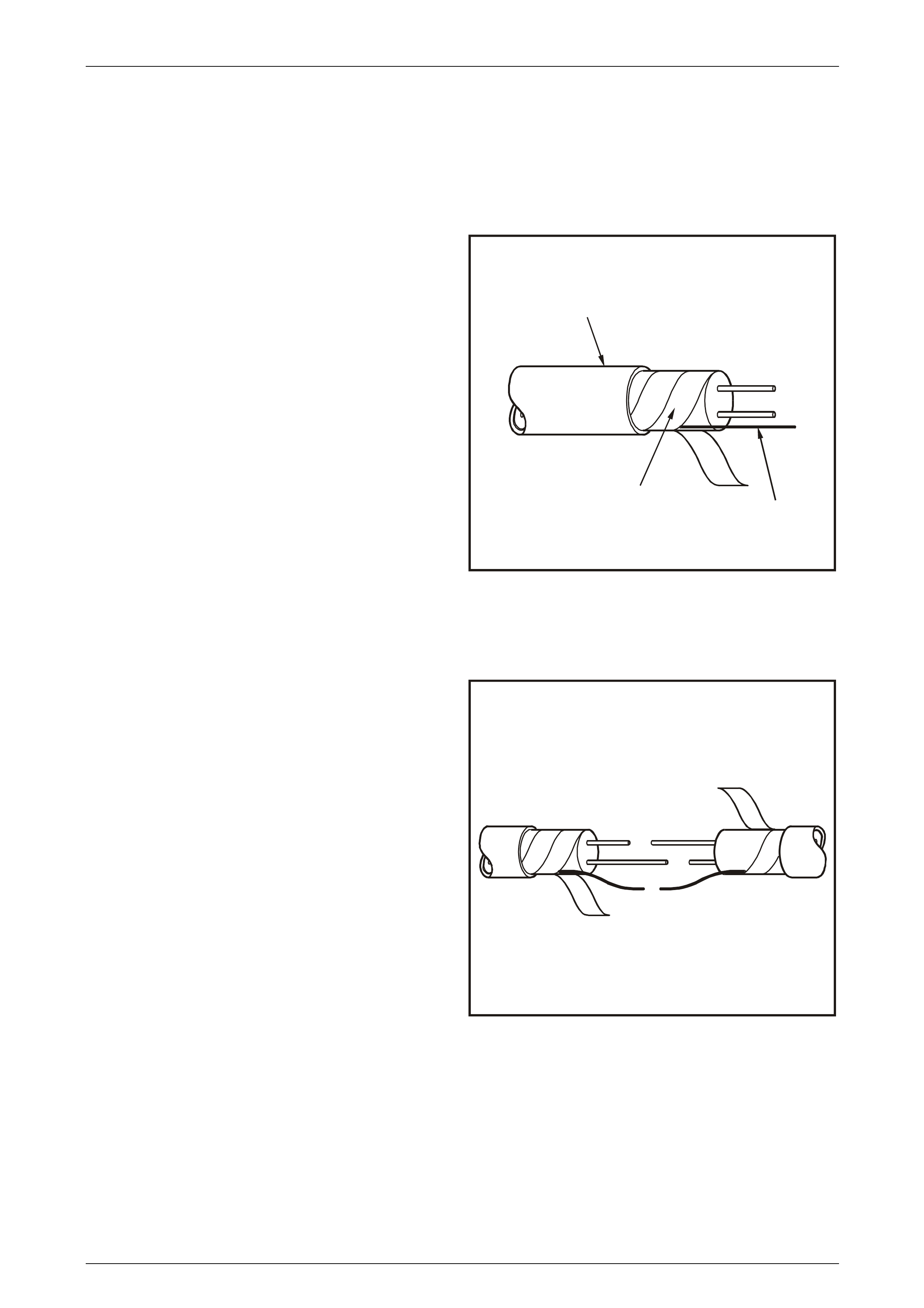
Wiring Diagrams Page 12P–42
Page 12P–42
5.5 Splicing Twisted Or Shielded Cable
Twisted or shielded cable is used to protect wiring from electrical noise. Two-conductor cable is used between the radio
and the Delco-Bose speaker amplifier units and other applications where low level, sensitive signals must be carried.
Step 1 Strip the Cable
1 Remove the outer jacket (1). Use care not to cut into
the drain wire (2) of the mylar tape(3).
2 Unwrap the mylar tape. Do not remove the tape
because it will be used to re-wrap the conductors after
the splice has been made.
V
Y12P47
1
2
3
Figure 12P – 42
Step 2 Prepare the Splice
1 Straighten the conductors and stagger the splices by
65 mm.
2 Follow the instructions for splicing copper wire.
V
Y12P48
Figure 12P – 43
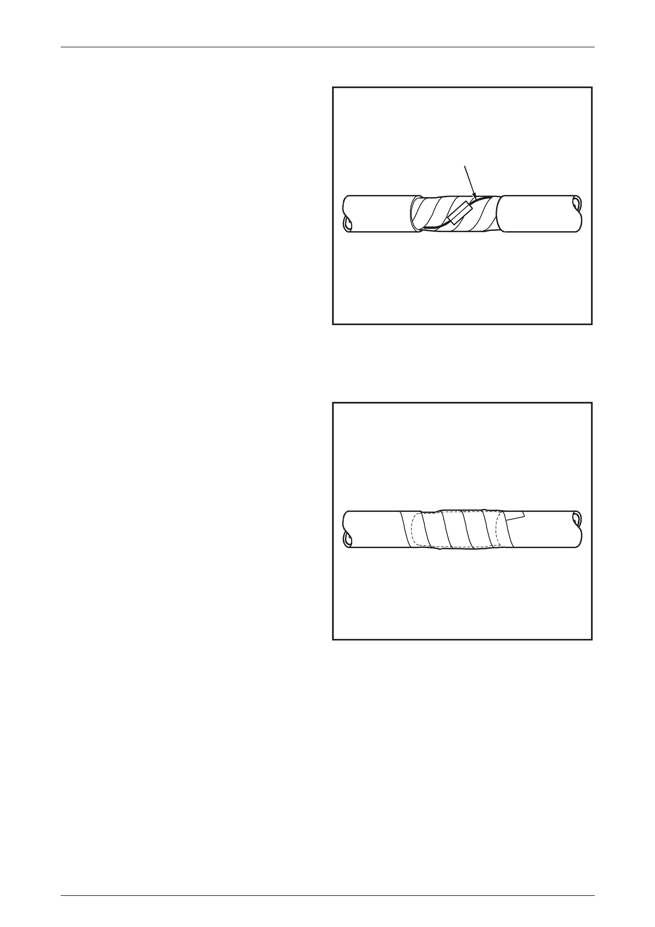
Wiring Diagrams Page 12P–43
Page 12P–43
Step 3 Reassemble the Cable
1 Re-wrap the conductors with the mylar tape, taking
care not to wrap the drain wire (1) in the tape.
NOTE
Apply the mylar tape with the aluminium side
inward to ensure good electrical connection.
2 Follow the instructions for splicing copper wire and
splice the drain wire.
3 Wrap the drain wire around the conductors and tape
with mylar tape.
V
Y12P49
1
Figure 12P – 44
Step 4 Tape the Joint
Tape over the entire cable using a winding motion while
applying the tape.
VY12P50
Figure 12P – 45
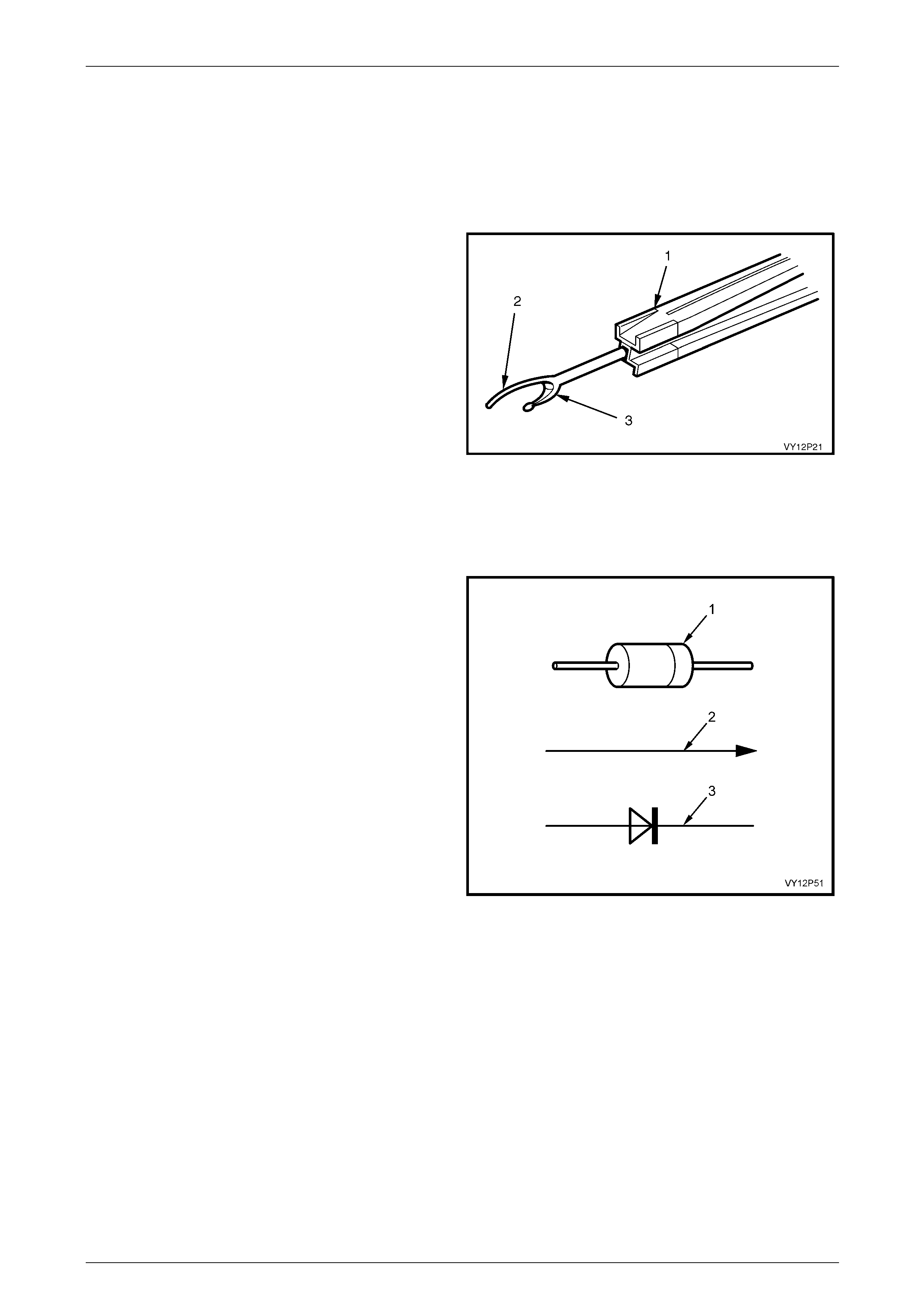
Wiring Diagrams Page 12P–44
Page 12P–44
5.6 Splicing In-Line Harness Diodes
Many vehicle electrical systems use a diode to isolate circuits and protect the components from voltage spikes. To install
a new diode:
Step 1 Open the Harness
A wiring harness may be wrapped in tape or enclosed in a
plastic conduit.
If it is conduit encased, simply open the conduit and pull out
the desired wire and diode.
If the harness is wrapped in tape, use a seam splitter (1) to
open the harness. This prevents damage to the insulation of
the wire inside the harness. Seam splitters are readily
available from sewing supply stores.
When using a seam splitter, use the blade with the pointed
end (2) to start a small split in the tape away from any wires.
Use the blade with the rounded end (3) to slit the tape as far
as necessary. Be careful to avoid cutting into any wire
insulation.
If the diode is taped to the harness, remove all of the tape.
Figure 12P – 46
Step 2 Remove Diode
1 Check and record the orientation and current flow
direction and of the diode.
NOTE
The colour band (1) or the letter K impressed
into the end of the diode indicated the cathode.
2 Remove the faulty diode from the harness using a
suitable soldering tool.
NOTE
If the diode is located next to a connector
terminal, remove the terminal from the connector
to prevent heat damage from the soldering tool.
3 Strip away as much insulation from the wire as is
needed to attach the new diode.
Figure 12P – 47
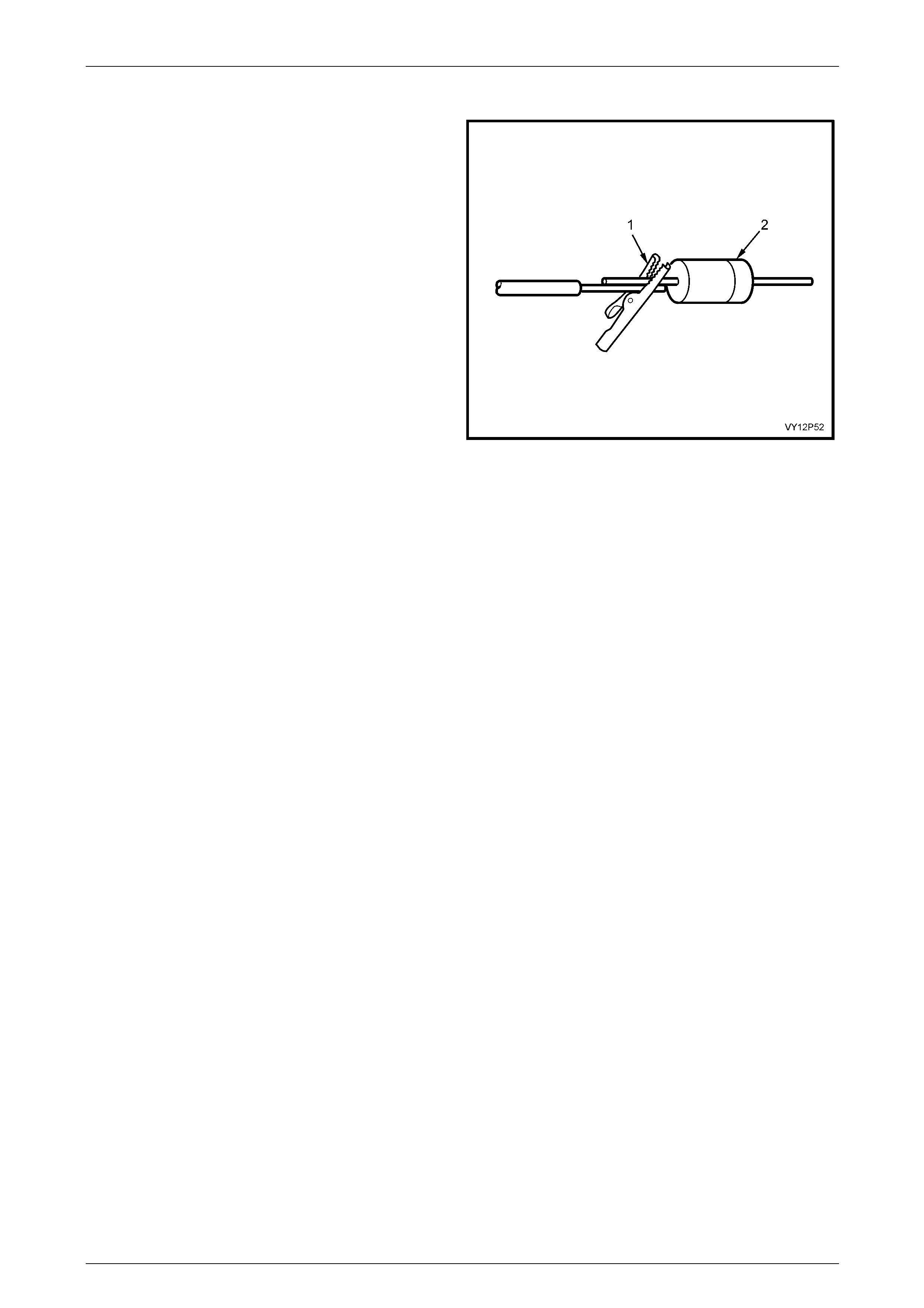
Wiring Diagrams Page 12P–45
Page 12P–45
Step 3 Install the New Diode
1 Check the current flow direction of the new diode,
being sure to install the new diode with the correct
bias.
2 Solder the new diode to the wire using 50/50 resin
cored solder.
NOTE
Use heat sinks across the diode wire ends to
protect the diode from excessive heat.
3 If removed, reinstall the terminal into the connector.
4 To prevent shorts to ground and water intrusion,
completely cover all exposed wire and diode
attachment points with tape.
5 Tape the diode to the harness or connector using
electrical tape.
Figure 12P – 48

Wiring Diagrams Page 12P–46
Page 12P–46
5.7 Heated Oxygen Sensor (HO2S) Wiring
Repairs
NOTE
Do not solder repairs as this could result in the air
reference being obstructed.
If the heated oxygen sensor pigtail wiring, connector or terminal is damaged, the entire oxygen sensor assembly must be
replaced. Do not attempt to repair the wiring, connector or terminals. For the sensor to function properly, it must have a
clean air reference. The clean air reference is obtained through the oxygen sensor signal and heater wires. Any attempt
to repair the wires, connectors or terminals could result in the obstruction of the air reference and degrade the oxygen
sensor performance.
The following guidelines should be used when servicing the heated oxygen sensor:
Do not apply contact cleaner or other materials to the sensor or vehicle harness connectors. These materials may get
into the sensor causing poor performance.
The sensor pigtail and harness wires must not be damaged or the wires inside exposed. This could provide a path for
foreign materials to enter the sensor and cause performance problems.
Do not sharply bend or kink the sensor or vehicle lead wires. Sharp bends and kinks could block the reference air path
through the lead wire.
Do not remove or disconnect the oxygen sensor ground wire where fitted. Vehicles with a ground wire sensor may rely
on this ground as the only ground contact to the sensor. Removing the ground wire will also cause poor engine
performance.
To prevent damage due to water intrusion, ensure the peripheral seal on the vehicle harness connector remains intact.
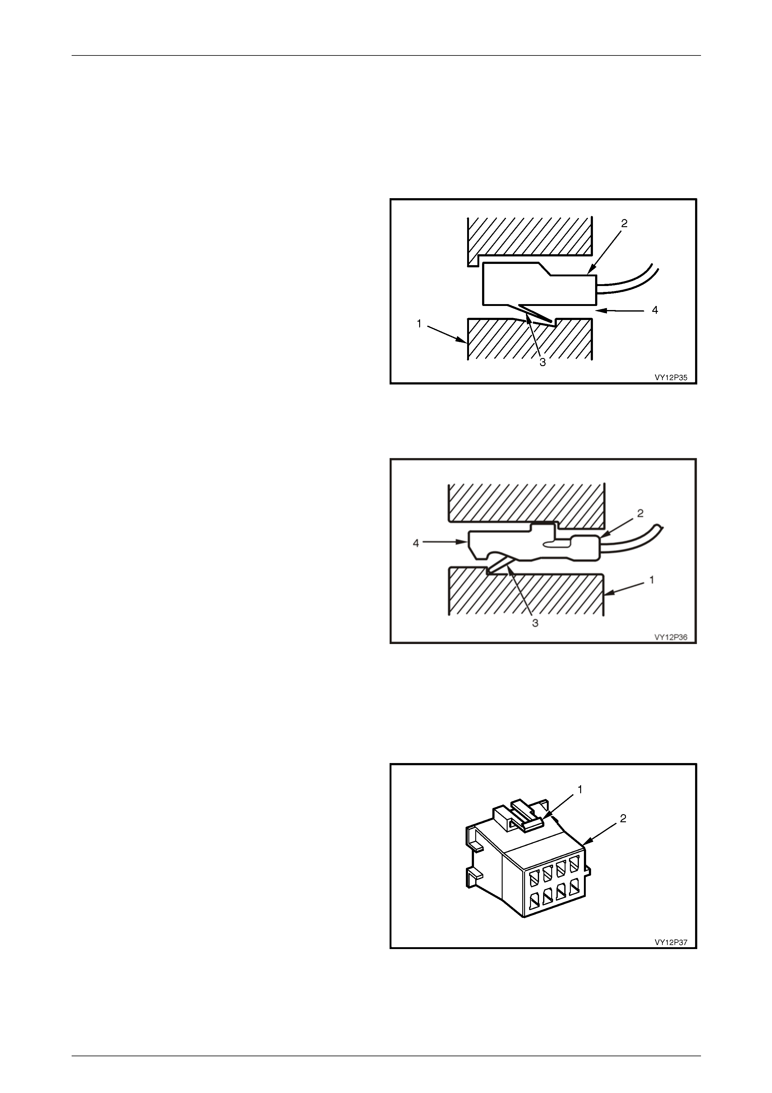
Wiring Diagrams Page 12P–47
Page 12P–47
5.8 Terminal Removal
The following general terminal removal procedures can be used on most types of connectors. The removal procedures
are divided into three general groups; Push-to-Seat, Pull-to-Seat and Weather Pack ®.
Push to Seat Connectors
Push-to-Seat connectors, refer to Figure 12P – 49, are
those which have the terminal inserted in the rear of the
connector body when assembled.
Legend
1 Connector body
2 Terminal
3 Locking tan
4 Insertion direction
Figure 12P – 49
Pull-to-Seat Connectors
Pull-to-Seat connectors, refer to Figure 12P – 50, have the
terminal inserted in the front of the connector body when
assembled.
Use the proper pick(s) or tool(s) that apply to the
appropriate terminal and connector.
Legend
1 Connector body
2 Terminal
3 Locking tang
4 Insertion direction
Figure 12P – 50
Repairing Push-To-Seat And Pull-To-Seat Conne ctors
The following steps will enable repair of Push-to-Seat or Pull-to-Seat type connectors. The steps are illustrated with
typical connectors. A specific connector may differ, but the repair steps are similar. Some connectors do not require all
the steps shown.
To repair a connector:
1 Lift up the connector body retaining tangs (1) and pull
mating connector bodies (2) apart, or disconnect the
connector from the component.
2 Remove any anti - backout combs that may be fitted to
the connector.
Anti-backout combs are designed to keep the terminal from
backing out of the connector.
NOTE
The anti-backout combs must be removed prior
to terminal removal and must be replaced when
the terminal is repaired and reseated. Figure 12P – 51
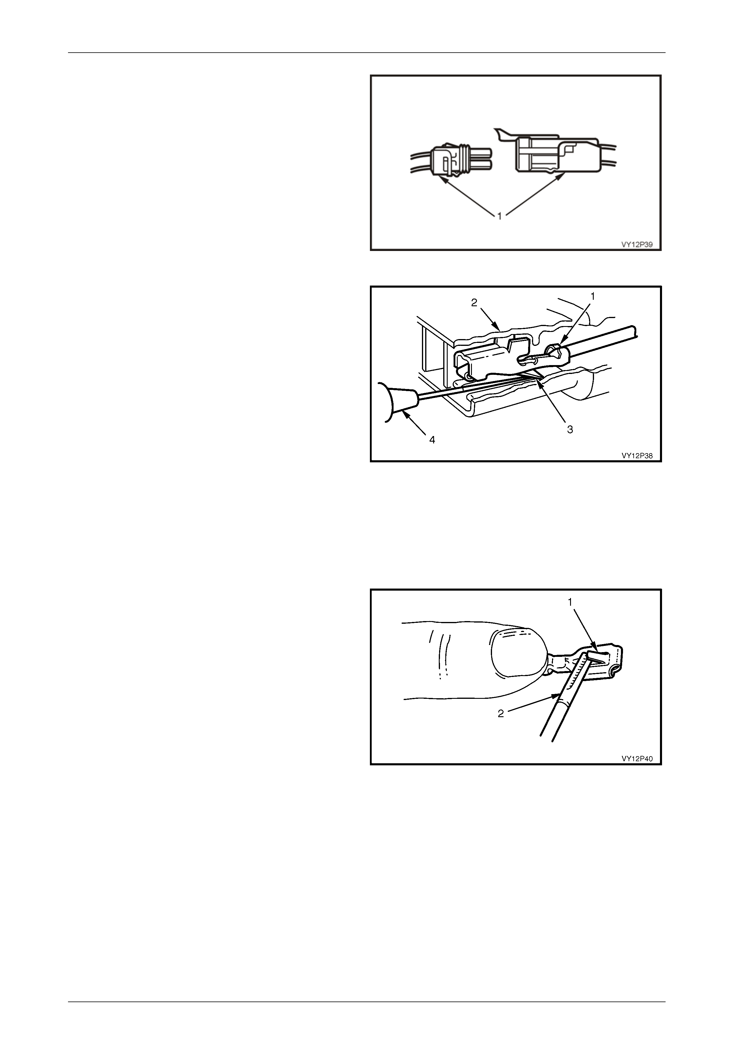
Wiring Diagrams Page 12P–48
Page 12P–48
3 If fitted, open any connector secondary locks (1).
A secondary lock aids in terminal retention and is usually
moulded as part of the connector body.
Figure 12P – 52
4 Grasp the lead and push the terminal (1) to the
forward most position in the connector body (2). Hold
the lead at this position.
5 Locate the terminal lock tang (3) in the connector
canal.
6 Insert the proper size pick (4) (refer to Terminal Repair
Kit J38125-A) straight into the connector canal at the
mating end of the connector.
7 Depress the locking tang to unseat the terminal.
8 For push-to-seat connectors, gently pull on the lead to
remove the terminal through the back of the
connector.
9 For pull-to-seat connectors, gently push on the lead to
remove the terminal through the front of the connector.
NOTE
Never use force to remove a terminal from a
connector.
Figure 12P – 53
10 Inspect terminal and connector for damage.
11 Repair or replace parts as necessary.
Refer to VZ Parts Information for availability of
terminal / pigtail or connector body assemblies that are
serviced separately.
12 Reform lock tang (1) using a wide pick (2) and reseat
terminal in connector body.
13 Reinstall any anti-backout combs and join the
connector bodies.
Figure 12P – 54
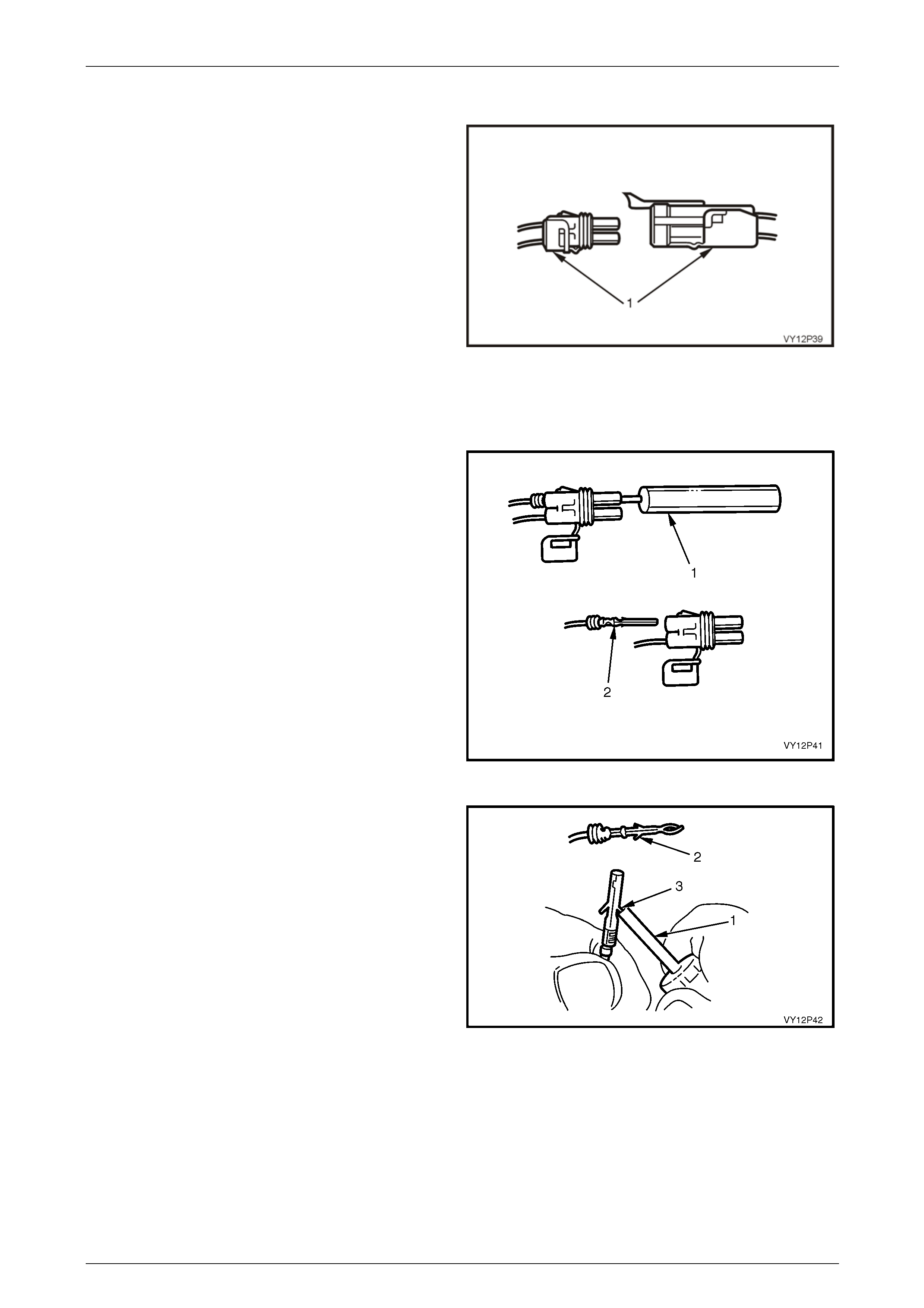
Wiring Diagrams Page 12P–49
Page 12P–49
Weather Pack® Connectors
To remove Weather Pack® terminals:
1 Lift up the connector body retaining tangs and pull the
mating connector bodies apart, or disconnect the
connector from the component.
2 If fitted, open secondary lock (1) or remove the anti-
backout comb.
A secondary lock aids in terminal retention and is usually
moulded to the connector body.
Anti-backout combs are designed to keep the terminal from
backing out of the connector.
NOTE
The anti-backout combs must be removed
before terminal removal and must be replaced
when the terminal is repaired and reseated.
Figure 12P – 55
3 Grasp the lead and push the terminal to the forward
most position. Hold the lead at this position.
4 Insert the Weather Pack® terminal removal tool (1)
into the front (mating end) of the connector cavity until
it rests on the cavity shoulder.
5 Gently pull on the lead (2) to remove the terminal
through the back of the connector.
NOTE
Never use force to remove a terminal from a
connector.
6 Inspect the terminal and connector for damage.
7 Repair or replace parts as necessary. Refer to VZ
Parts Information for availability of terminal / pigtail or
connector body assemblies that are serviced
separately. Figure 12P – 56
8 Use the Weather Pack® pick (1) to reform the male
lock tang (2) or the female lock tang (3).
9 Reseat the terminal in the connector body.
10 Close the secondary lock and reinstall the connector
to the component or mating connector.
Figure 12P – 57
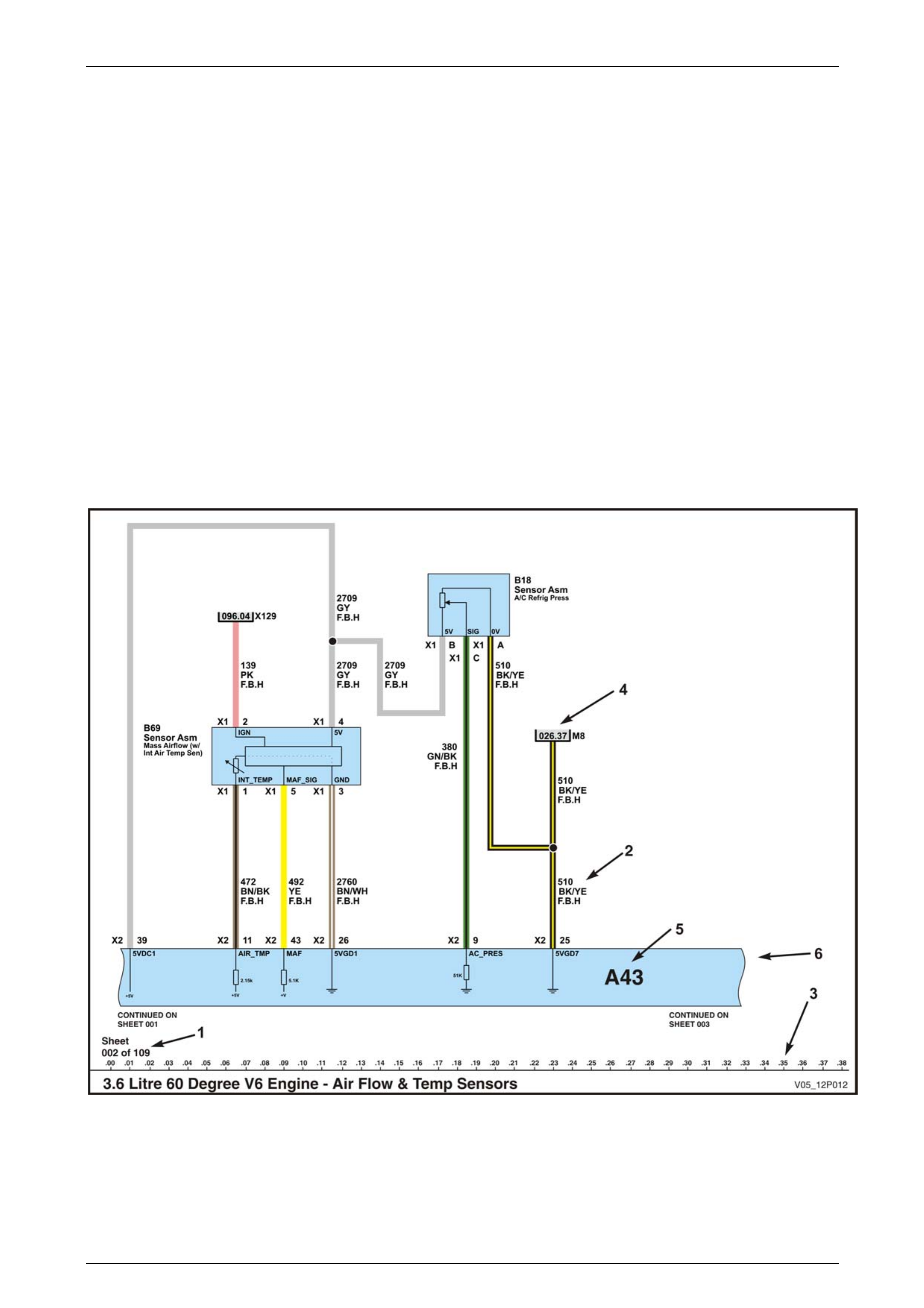
Wiring Diagrams Page 12P–50
Page 12P–50
6 Reading 12P Wiring Diagrams
General Information
Wiring diagrams are found in all Sections of the Service Manual. The wiring diagrams are based on the Integrated
Vehicle Electrical Design (IVED) wiring diagrams, which are used by major manufacturers throughout the world. The
wiring diagrams are used to:
Present the overall circuitry for a total system.
Assist in explaining the operation of part of a total system.
Assist in diagnostics.
These notes are designed to assist technicians in understanding the 12P wiring diagrams.
Additional wiring, wiring harness and specific wiring harness installation information is contained in the Holden Service
Information Package (SIP) CD-ROM. Also contained is additional information on developing a diagnostic procedure for
electrical circuit diagnosis, electrical circuit test procedures, diagnostic tests and wiring repair procedures.
The coloured 12P Electrical Schematic Wiring Diagrams cover every electrical circuit in the vehicle. Because of this, the
wiring diagrams tend to be large and complex, sometimes spreading over several sheets for a single piece of equipment
within the vehicle. The equipment is grouped according to the table of contents at the start of the Electrical Schematic
Wiring Diagrams.
Figure 12P – 58
Legend
1 Sheet identification
2 Wire identification
3 Grid reference
4 Continuation reference
5 Assembly identification
6 Assembly continuation
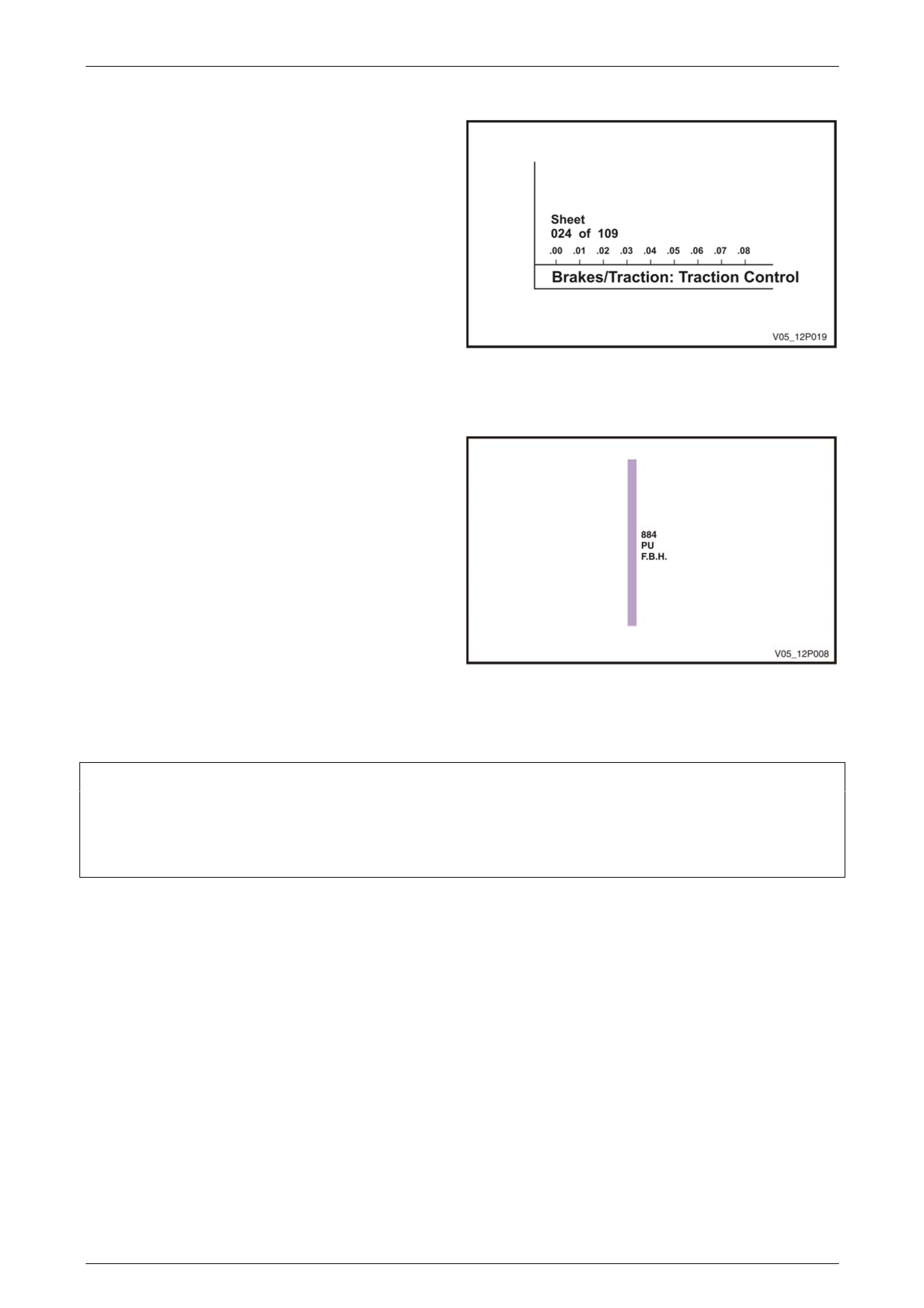
Wiring Diagrams Page 12P–51
Page 12P–51
Sheet Identification
The bottom left corner of each wiring electrical schematic
diagram sheet identifies the sheet.
The sheet number is shown as well as a title for the sheet.
The sheet title describes the circuits covered on that
particular sheet.
Figure 12P – 59
Wire Identification
The number alongside the wire is the circuit number. The
circuit number is unique to that circuit and is not repeated
for any other circuit.
The letters under the circuit number indicate the wire colour.
The wire colour in Figure 12P – 60 is purple. If the wire is
two-coloured, the first colour indicates the main body colour
of the wire and the second colour refers to the thin colour
stripe. For example, a purple wire with a red stripe would be
shown PU/RD.
The letters under the wire colour indicate which wiring
harness this wire belongs to. In this example, F.B.H.
indicates the Front Body Harness.
A list of Wire Colour and Wiring Harness Abbreviations is
given in this Section.
Figure 12P – 60
Wire Colour Abbreviations
BK Black D-GN Dark green L-GN Light green RD Red
BU Blue GN Green OG Orange TN Tan
BN Brown GY Grey PK Pink WH White
D-BU Dark blue L-BU Light blue PU Purple YE Yellow

Wiring Diagrams Page 12P–52
Page 12P–52
Wiring Harness Abbreviations
Figure 12P – 61
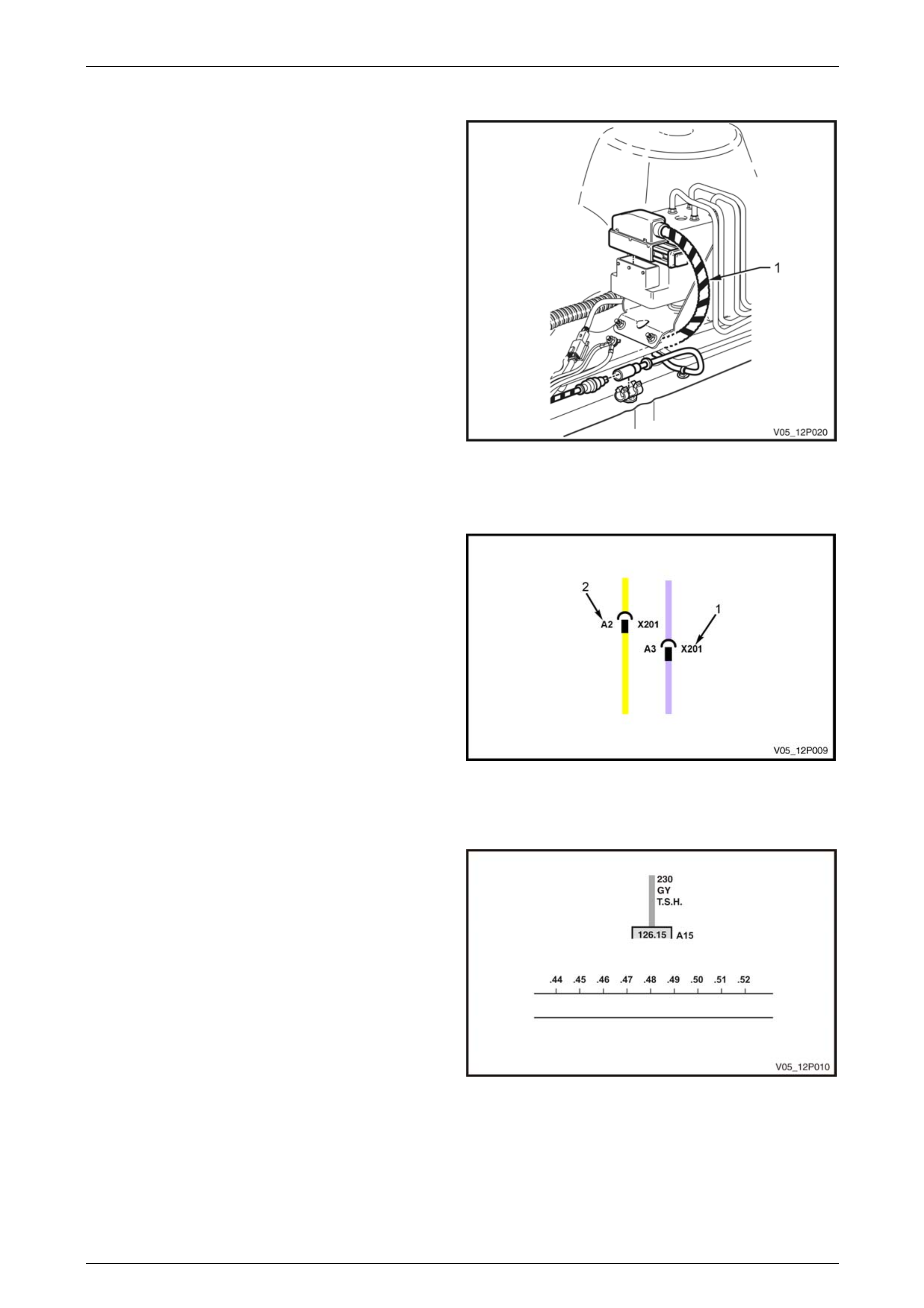
Wiring Diagrams Page 12P–53
Page 12P–53
Wiring Harness Visual Identification
When some wiring harnesses are shown in location
illustrations, they have a distinctive identification.
Using the coding shown in the Wiring Harness Abbreviation
list, the wiring harness (1) shown in Figure 12P – 62 is
identified as the front body harness.
Figure 12P – 62
Connectors
Connectors generally have a two number identification.
The connector identification number (1) – in Figure 12P –
63, indicates the wires are joined by an X201 connector.
The (2) alphanumeric identifies the pin in the connector – in
this example, the yellow wire is joined at pin A2 and the
purple wire is joined at pin A3 in connector X201.
The pin identifier (2) may be either a letter, a number or an
alphanumeric combination.
The connector physical appearance and pin locations may
be identified from the illustrated connector listing at the end
of this Section.
Figure 12P – 63
Grid Reference
A series of evenly spaced grid reference numbers are
spread across the bottom of each sheet.
These grid references are used to establish the position of
circuits on the sheet. For example, the circuit 230, grey wire
shown in Figure 12P – 64 is at Grid 48.
Figure 12P – 64
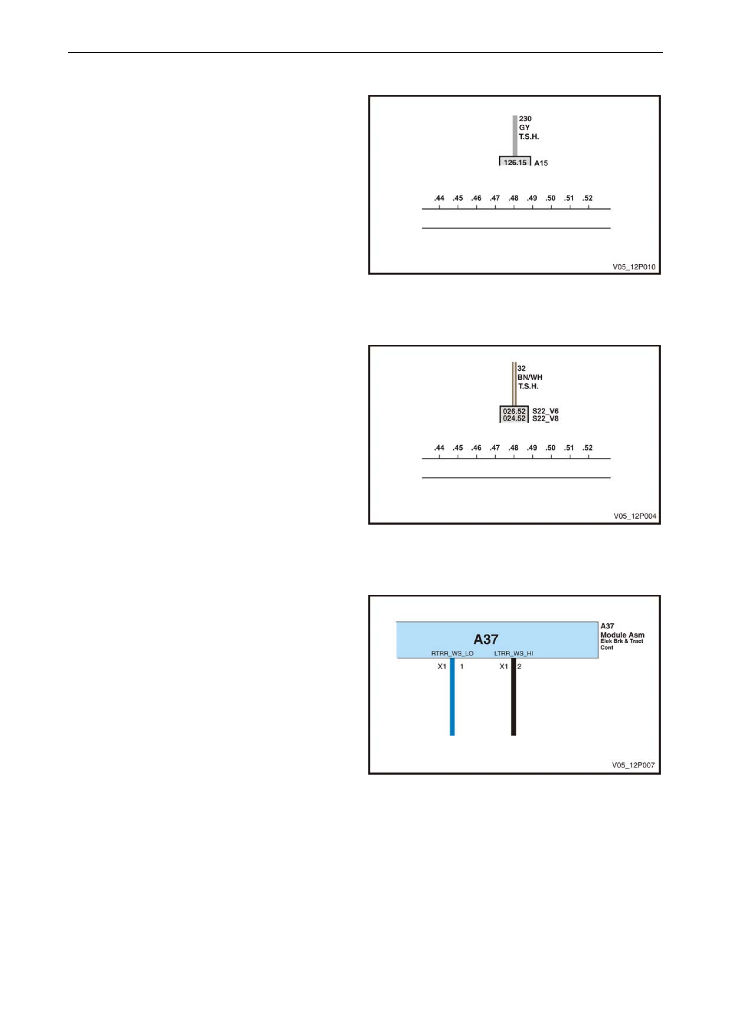
Wiring Diagrams Page 12P–54
Page 12P–54
Continuation Reference
The circuit 230 grey wire shown in Figure 12P – 65 is at grid
reference 48. The open box at the bottom of the circuit
contains the Continuation Reference, which indicates the
circuit continues on Sheet 126 at grid reference 15.
The A15 alongside the open box indicates the continuation
of the circuit is connected to assembly A15.
Figure 12P – 65
Multiple Continuation References
In Figure 12P – 66, circuit 32 continues on Sheet 26, Sheet
25 or Sheet 24. The sheet selected depends on whether the
vehicle has a V6 or V8 engine.
Figure 12P – 66
Assembly Identification
An assembly in a coloured electrical schematic wiring
diagram is usually identified by an alphanumeric in large
characters on the body of the assembly. It is also identified
by an abbreviated text reference at the end of the assembly.
In this example, the assembly is the Electronic Braking and
Traction Control Assembly.
If only the alphanumeric on the body of the assembly is
given, the specific assembly identity may be determined
from the assembly connector information included at the
end of this Section. The type of assembly may be identified
by the initial letter of the code as shown in the assembly
legend.
Figure 12P – 67
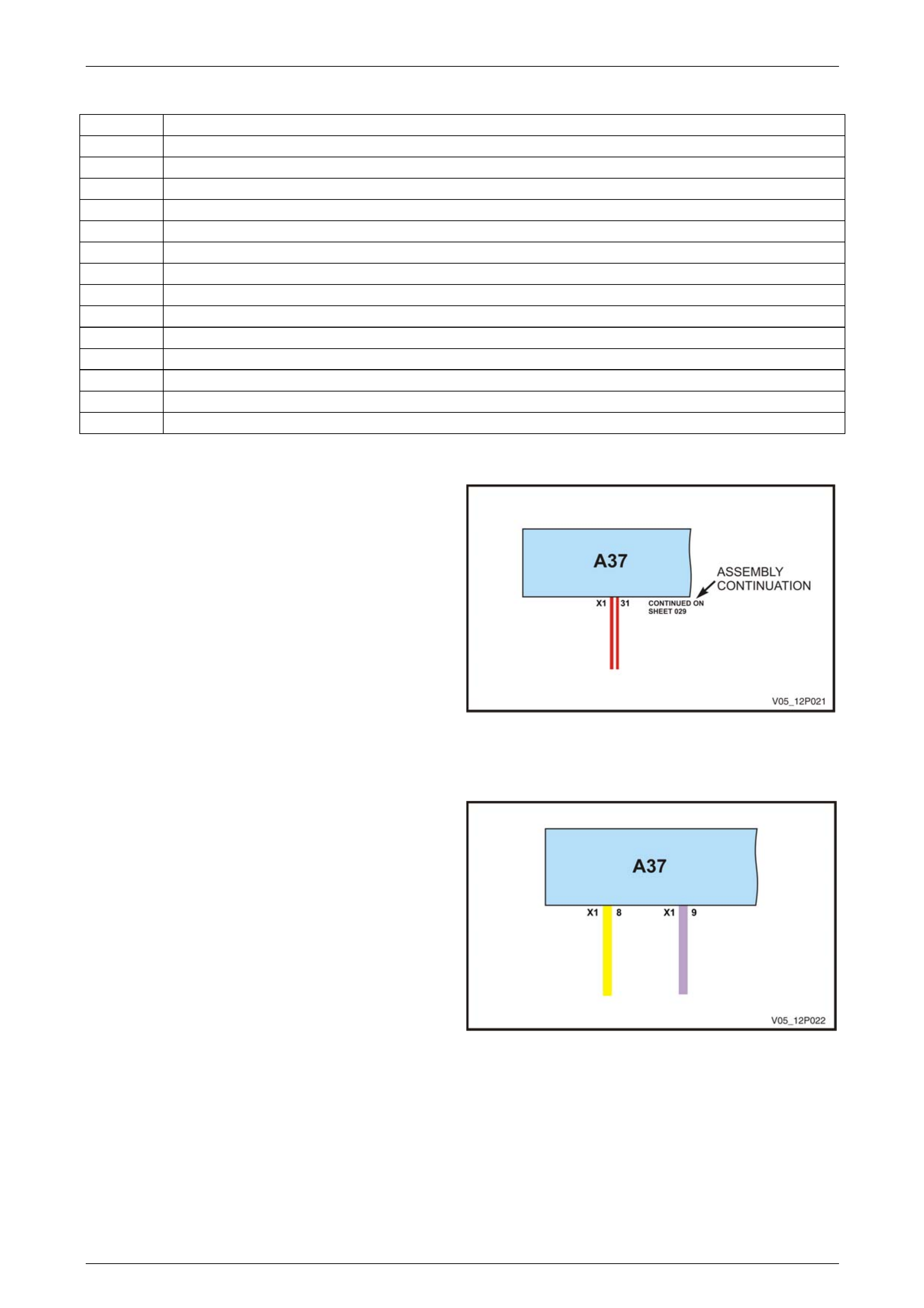
Wiring Diagrams Page 12P–55
Page 12P–55
Assembly Legend
A SYSTEMS, SUB-ASSEMBLIES AND MODULES
B TRANSDUCERS
E OTHER DEVICES AND EQUIPMENT
G POWER SUPPLIES
H INDICATORS, ALARMS AND SIGNAL DEVICES
L INDUCTORS
M MOTORS
N REGULATORS AND AMPLIFIERS
P MEASUREMENT, DISPLAY AND TEST DEVICES
R RESISTORS
S SWITCHES
V SEMI-CONDUCTORS
W TRANSMISSION PATHS, CONDUCTORS AND ANTENNAS
X TERMINALS, PLUG AND SOCKET CONNECTIONS
Y ELECTRICALLY OPERATED MECHANICAL DEVICES
Assembly Continuation
When there are too many circuits connected to one
assembly to fit on one sheet, the assembly is continued on
another sheet.
This is indicated by an unfinished end to the assembly
illustration and a direction to the continuation sheet number.
In Figure 12P – 68, assembly A37 is shown as continuing
on sheet 29.
Figure 12P – 68
Assembly Connector Identification
If an assembly has many wiring connections, it may have
more than one connector joining it to the wiring harness.
These connectors are usually numbered X1, X2, X3.
Assembly connectors generally have a two number
identification with the identification numbers shown on either
side of the wire adjacent to the assembly.
The first number is the connector identification number – in
Figure 12P-20, the wires are connected at the Assembly
A37 X1 connector.
The second number identifies the pin in the connector – in
this example, the yellow wire is joined at pin 8 and the
purple wire is joined at pin 9 in the A37 X1 connector.
The connector physical appearance and pin locations may
be identified from the illustrated connector listing at the end
of this Section.
Figure 12P – 69
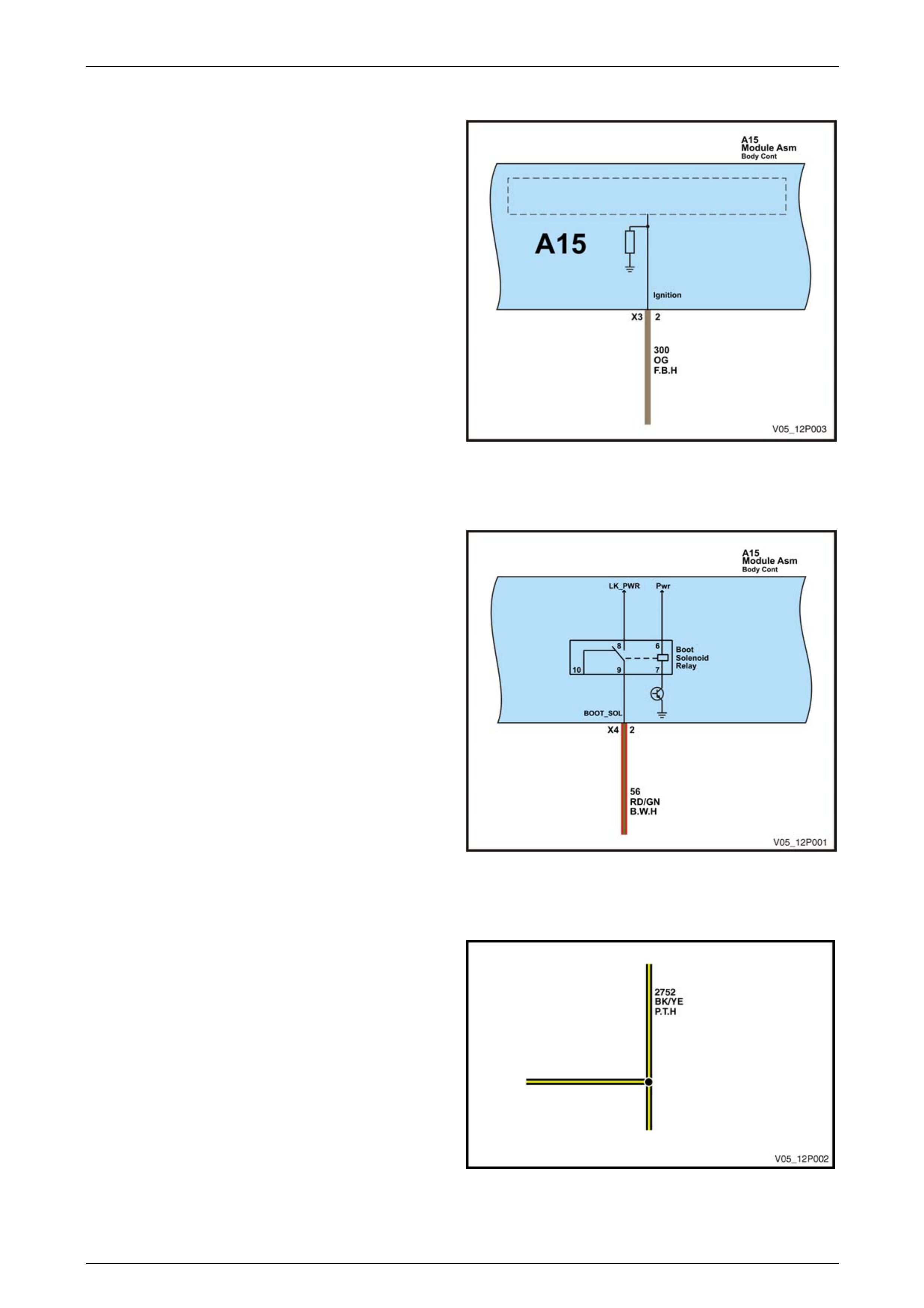
Wiring Diagrams Page 12P–56
Page 12P–56
Assembly Circuit Identification
Where it assists in understanding the circuit, a wire may be
identified at the point where it connects with an assembly.
In Figure 12P – 70, the orange wire supplies a signal to the
Body Control Module from the ignition contact on the ignition
switch.
Figure 12P – 70
Information Within An Assembly
Where it will clarify the operation of a circuit, the first stage
of an assembly operation is shown.
Figure 12P – 71 shows the operation of the Boot Solenoid
Relay within the Body Control Module and the effect this has
on circuit 56.
Figure 12P – 71
Harness Splices
A harness splice is shown in Figure 12P – 72. A harness
splice is where a number of wires are bonded together
within a wiring harness.
Figure 12P – 72
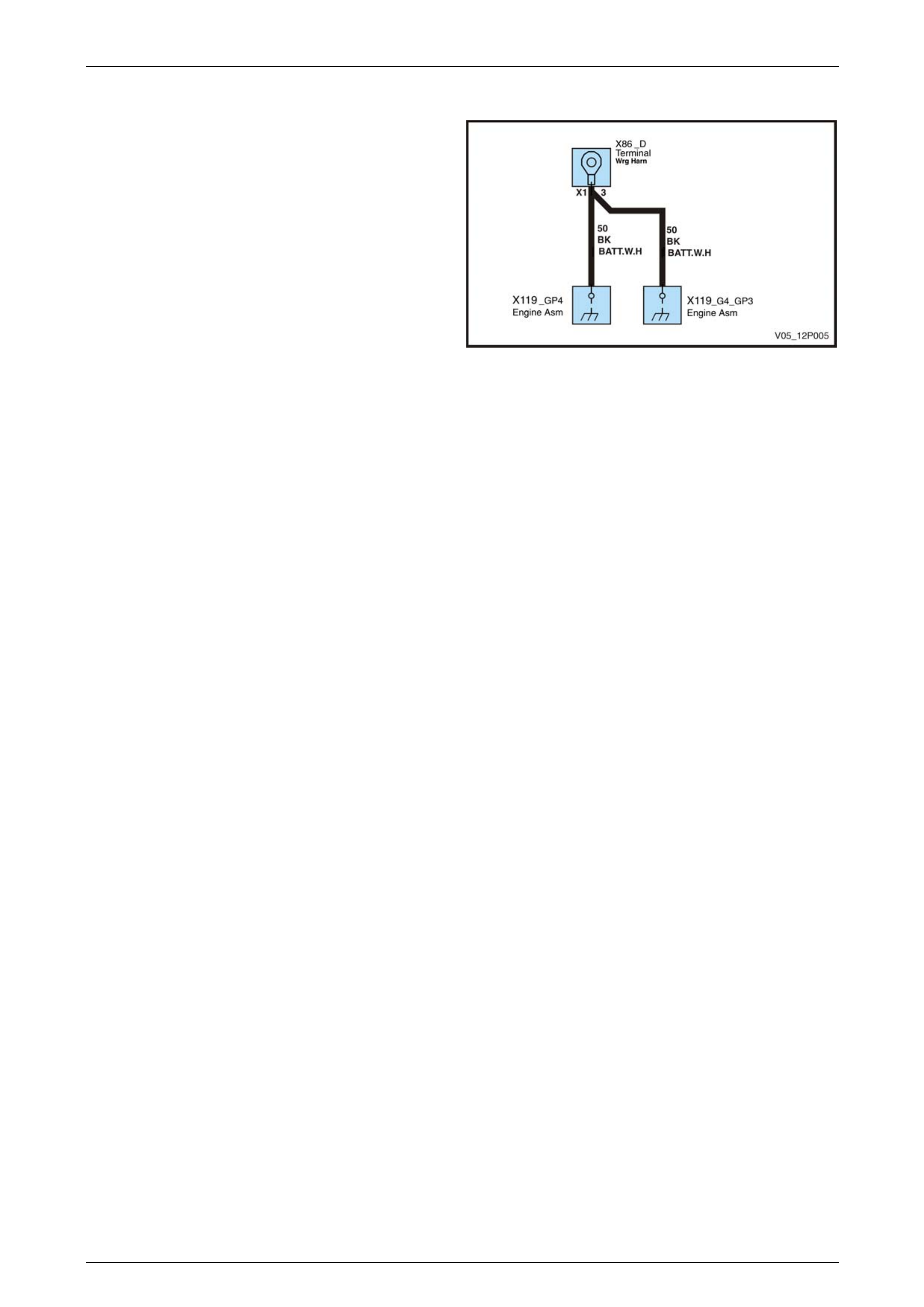
Wiring Diagrams Page 12P–57
Page 12P–57
Ground Locations
Where ground location points are shown, they are identified
by the type of connector (in this case X119), and the
location of the Ground Point termination. In Figure 12P – 73
there are two ground points – GP3 and GP4.
The physical location of these ground points is given as the
Engine Assembly in Figure 12P – 73 and is shown in the
Ground Point diagram in this Section.
Figure 12P – 73
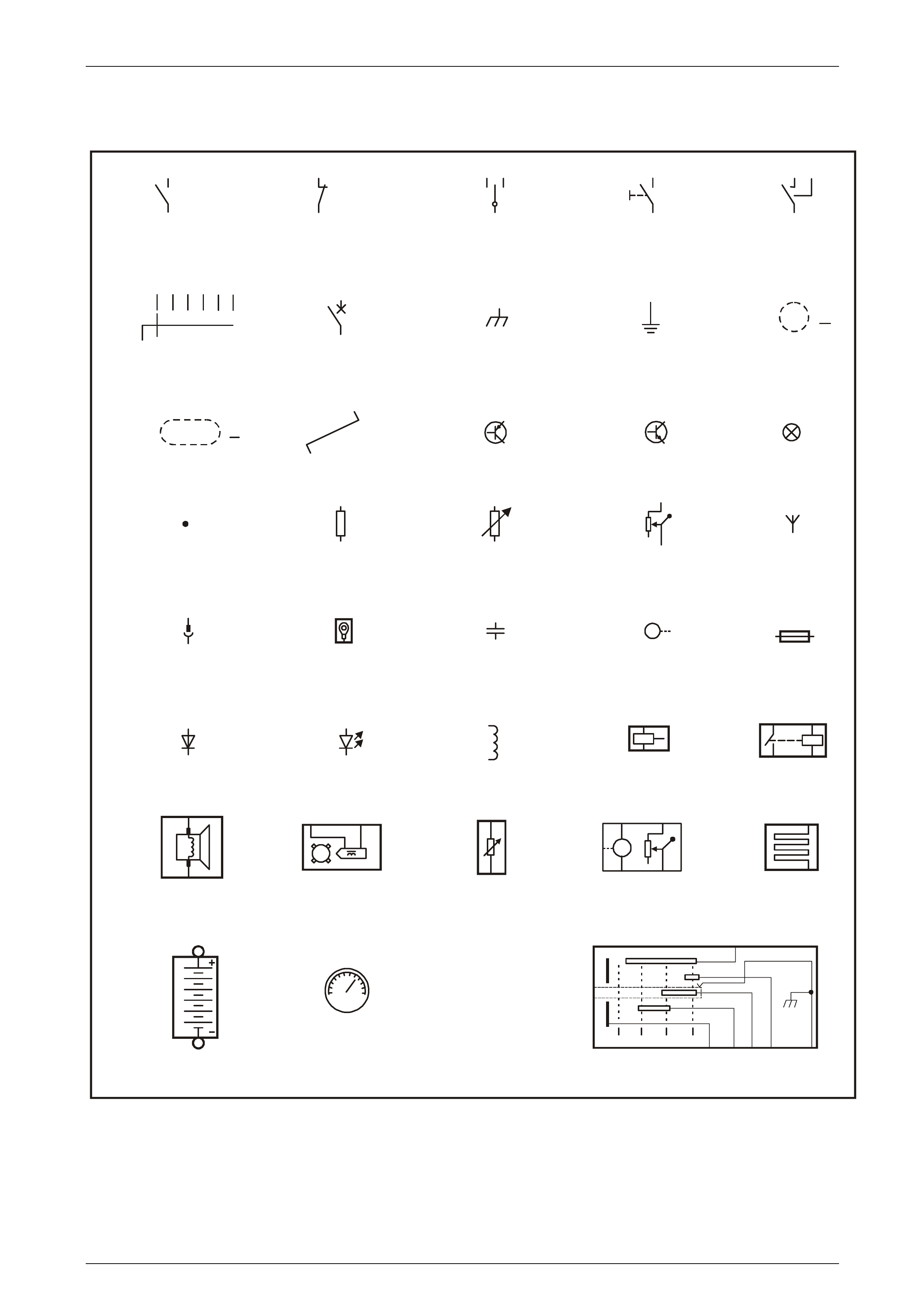
Wiring Diagrams Page 12P–58
Page 12P–58
Circuit Symbols
Standard circuit symbols are used in the wiring diagrams and are shown in Figure 12P – 74.
S
WIRE SHIELD
CIRCUIT
BREAKER
MULTI POSITION
SWITCH
GROUND /
EARTH 2
GROUND /
EARTH
FUEL LEVEL
SENDER
WIRE SPLICE ANTENNAVARIABLE RESISTORRESISTOR
MANUALLY OPERATED
SWITCH
BREAK CONTACT
SWITCH
SWITCH WITH
CENTRE OFF
SWITCH WITH
TWO MAKES
MAKE CONTACT
SWITCH
55
TWISTED PAIR
SYMBOL
PNP TRANSISTOR NPN TRANSISTOR
INDUCTOR
LAMP
X1-A
X2-A
POS
NEG
RH
LH
BATTERY
PWR
GND
HORN /
SPEAKER
RET SIG
MAGNETIC
SENSOR
RESISTOR
M
FUEL PUMP WITH
LEVEL SENDER
IGNITION SWITCH
SENSOR
M
CAPACITOR ELECTRIC MOTORPLUG TYPE
CONNECTOR
F104
FUSELUG TYPE
CONNECTOR
SPEEDOMETER
KMH
SPEEDOMETER
0200
LED
31
25
RELAY
L2
Coil Asm
F/Injector
COIL - FUEL
INJECTOR
DIODE
X3-1
START
IGN
ACC
START
BATT IGN KEY CHASSIS
GND CONTACT
RUNACCOFF
SLIP
RING
CONTACT
BATT
SLIP RING
VY12P112
MULTIPLE
S
SINGLE
WIRE SHIELD
Figure 12P – 74
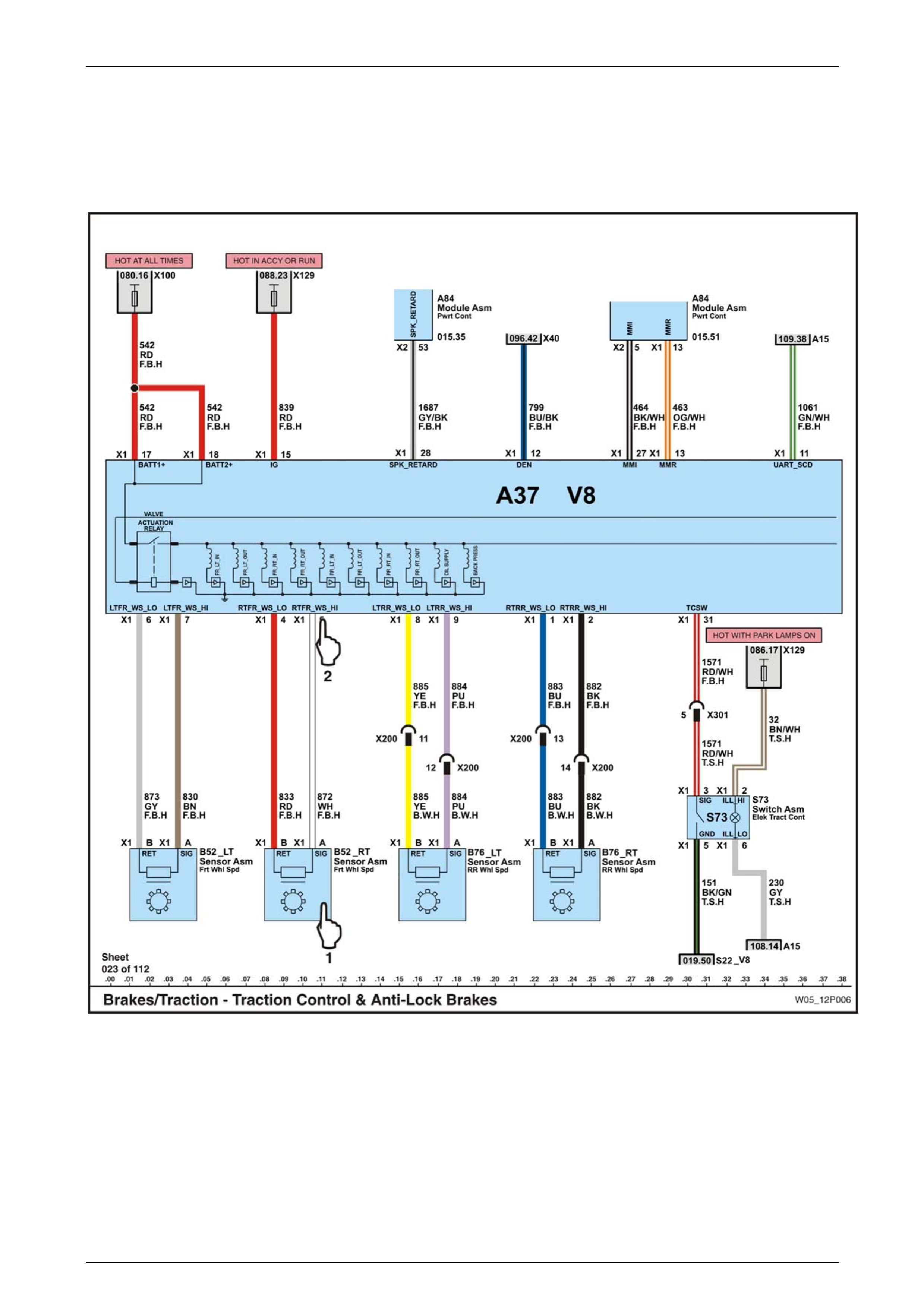
Wiring Diagrams Page 12P–59
Page 12P–59
7 Connector Location Illustrations
A coloured Electrical Schematic Diagram such as the one shown in Figure 12P – 75 shows a number of connectors. To
locate the position of the connectors on the vehicle and to identify the pin numbers on the connector, a system of links is
used.
Figure 12P – 75
When the cursor is moved over the connector or assembly on a computer screen, it changes to a pointing finger. If the
left mouse button is clicked while the cursor is at position (1) in Figure 12P – 75, the Connector Location Illustration
shown in Figure 12P – 76 appears.
The Connector Location Illustration has the connector information highlighted and detailed views of the connector
physical location in the vehicle shown.
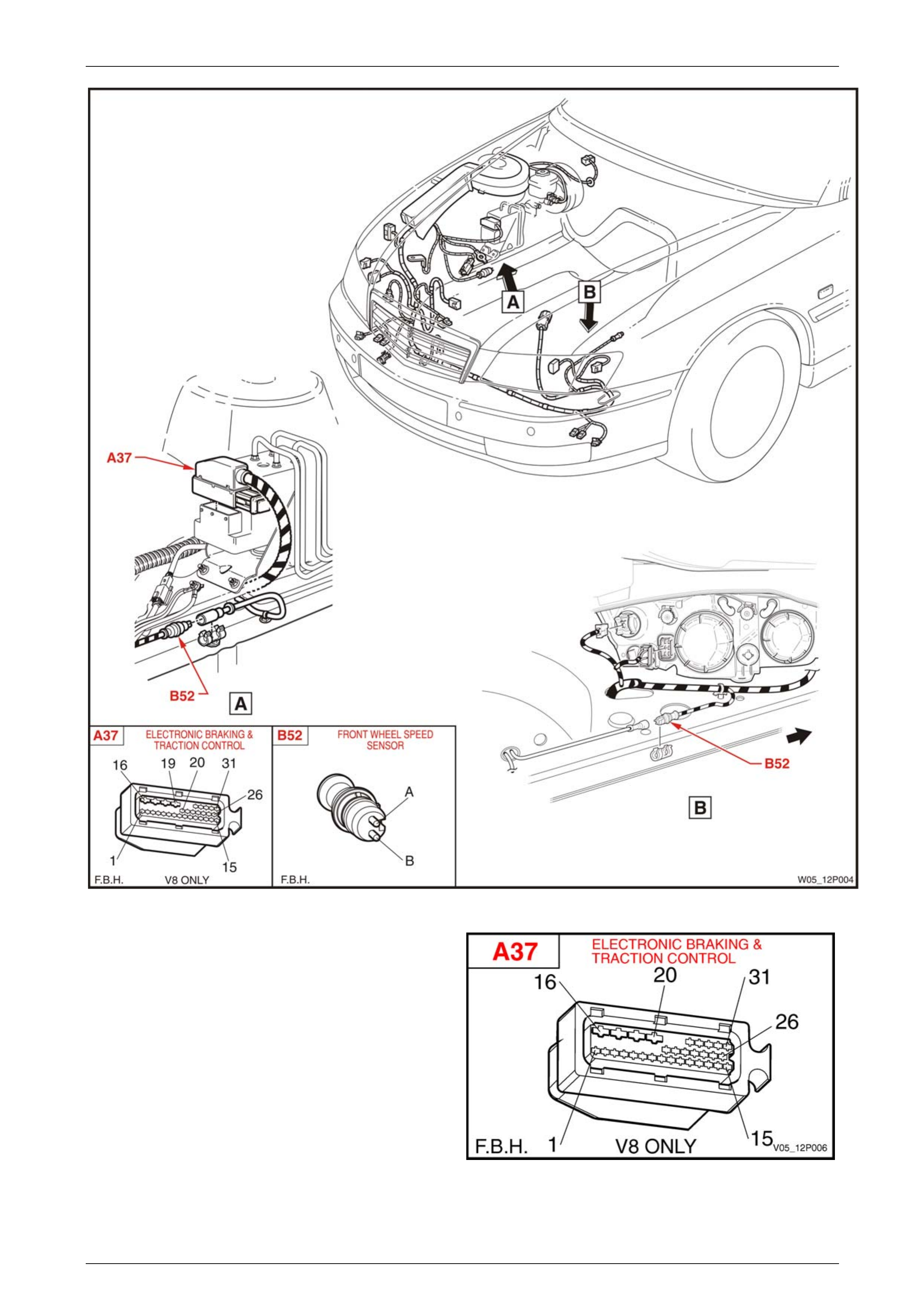
Wiring Diagrams Page 12P–60
Page 12P–60
Figure 12P – 76
When the cursor is moved over the connector pin number, it
changes to a pointing finger. If the left mouse button is
clicked while the cursor is at position (2) in Figure 12P – 75,
details of the connector and the connector pin numbers
appear as shown in Figure 12P – 77.
Figure 12P – 77

Wiring Diagrams Page 12P–61
Page 12P–61
8 Electrical Schematics Contents
System Wiring Diagram Descrip tio n Diagram Sheet No.
Aftermarket provisions 109
Brakes 032 to 033
Charge / energy store 093
Engine 001 to 027
Engine / transmission cooling 040 to 041
Entertainment 075 to 088
Entry control 048 to 049
Exterior lighting 052 to 062
Fuel storage and handling 034
Fuse chart and relay box layout 00A
Ground points and paths 00B to 00C
Horn 092
HVAC 035 to 039
Integrating component 115 to 123
Integrating function 124
Interior lighting 044 to 046
Memory seats 043
Mirrors 063 to 066
Moveable roof 051
Occupant information 068 to 074
Occupant protection 047
Power and ground distribution 094 to 108
Power seats 042
Power windows 050
Serial data links 110 to 114
Suspension 031
Telephone 090 to 091
Theft deterrent 089
Transmission 028 to 030
Washer / wipers 067

Wiring Diagrams Page 12P–62
Page 12P–62
9 Module Location Charts
Electrically Operated Mechanical Devices
Component Code Location
Actuator temperature valve (air mix motor) Y037 035.22
035.36
Camshaft position actuator Y004 010.39
010.44
010.48
010.52
Canister purge solenoid valve Y123 004.01
022.52
Drivers seat adjuster horizontal actuator Y064 042.17
043.24
Drivers seat belt tensioner Y128 047.42
Drivers seat inner adjuster front vert actuator Y067 042.21
043.04
Drivers seat inner adjuster rear vert actuator Y069 042.25
043.16
Drivers seat recline actuator Y074 042.13
043.33
Front side door lock actuator Y013 048.05
048.47
Inside air valve vacuum solenoid Y019 035.29
Intake manifold runner control Y021 010.35
Passengers seat adjuster horizontal actuator Y081 042.42
Passengers seat belt tensioner Y129 047.33
Passengers seat inner adjuster front vert actuator Y084 042.45
Passengers seat inner adjuster rear vert actuator Y086 042.49
Passengers seat recline actuator Y091 042.37
Rear compartment lid latch actuator Y029 049.35
Rear side door lock actuator Y031 048.16
048.27
Reverse lock out solenoid Y144 001.52
021.07
Throttle actuator Y038 007.36
014.11
020.21
Indicators, Alarms and Signal Devices
Component Code Location
Rear object sensor alarm H031 071.14
072.17
073.15
Seat belt alarm H012 042.01
043.46

Wiring Diagrams Page 12P–63
Page 12P–63
Inductors
Component Code Location
A/C clutch coil L007 038.26
038.43
Fuel injector solenoid L002 003.02
003.07
003.12
003.17
003.24
003.29
003.34
003.39
011.02
011.07
011.12
011.17
011.22
011.27
011.32
002.02
002.06
002.09
002.12
002.15
002.19
002.22
002.25
Ignition coil assembly L003 016.14
016.19
016.24
016.34
016.38
016.44
Measurement, Display and Test Devices
Component Code Location
Ambient air temperature gauge, radio, clock and date display P005 035.48
069.29
Driver information display P006 074.37
DVD screen P020 085.26
086.29
087.23
088.19
Instrument cluster P003 068.25
070.29
070.29
111.19
112.28

Wiring Diagrams Page 12P–64
Page 12P–64
Modules, Systems and Sub-Assemblies
Component Code Location
Audio interface module A156 079.24
111.39
Automatic level control module A008-COMP 031.44
Automatic level control module A008-SNSR 031.17
Blower motor & A/C compressor A014 035.25
069.32
111.15
112.22
Blower & air inlet A013 036.22
Body control A015 043.45
048.42
049.24
049.36
050.03
050.11
050.15
050.41
050.44
050.52
052.09
053.13
059.22
067.50
068.23
070.24
076.16
077.16
089.11
089.26
089.38
089.45
092.11
111.05
112.10
115.30
116.25
117.25
118.25
119.25
120.25
121.25
122.25
123.25
Communication centre call A158 065.16
091.26
111.27
112.37
Communication interface A005 007.11
027.06
027.22
111.13
112.10
113.27
114.30
Daytime running lamp control A025 054.33
Driver information display control A035 074.16

Wiring Diagrams Page 12P–65
Page 12P–65
Component Code Location
Drivers seat adjuster memory A021 043.25
064.11
111.43
112.42
Electronic brake and traction control A037 005.49
033.25
112.48
Electronic ignition control A040 006.14
006.31
025.28
025.44
Engine control A043 007.20
008.25
009.25
010.25
011.25
012.25
013.25
014.25
015.25
016.25
017.19
018.25
019.25
020.25
021.25
022.25
023.25
024.25
025.25
026.13
111.54
111.46
Front side rail inflator restraint A096 047.24
047.38
Headphone control assembly A164 082.20
082.36
Inflation restraint sensor A065 047.25
111.11
112.18
Inflation restraint side impact sensor A066 047.30
047.45
Instrument panel inflator restraint A062 047.03
Interior lamp control module A068 044.44
Low tyre pressure monitor indicator A157 070.43
111.31
Navigation control A139 074.29
Object sensor control A146 072.25
073.25
Outside rear view mirror memory A073 064.27

Wiring Diagrams Page 12P–66
Page 12P–66
Component Code Location
Powertrain control A084 001.25
002.25
003.25
004.25
005.25
006.25
006.25
027.47
028.25
033.15
033.28
112.21
Radio, clock & CD player A133 075.25
076.25
077.25
082.20
084.22
087.25
087.39
111.23
112.32
115.33
Radio control module A094 035.51
037.29
075.44
Radio/Video antenna signal module A095 084.20
085.25
086.28
Rear object sensor control A098 071.24
Steering wheel inflator restraint A106 047.15
Sunroof control A108 051.25
Throttle actuator control A111 007.23
027.19
113.10
Transmission control A112 029.25
030.25
111.34
111.51
Vehicle dynamic control A116 032.21
111.45
111.54
Video player assembly A152 076.46
077.30
077.43
084.22
085.26
087.27
088.14
Wiper dwell system A121 067.50

Wiring Diagrams Page 12P–67
Page 12P–67
Motors
Component Code Location
Front side window regulator M010 050.11
050.44
Rear side window regulator M014 050.19
050.32
Blower motor M003 036.24
Engine cooling fans M007 040.33
041.28
Fuel pump motor M008 034.35
Outside rear view mirror M011 043.36
063.28
063.45
064.07
064.49
Starter motor M015 093.20
Sunroof actuator motor M016 051.28
Washer motor M019 067.30
Wiper motor M017 067.14
Other Devices and Equipment
Component Code Location
Automatic transmission control position indicator lamp E125 044.53
Back/up lamp E056 058.25
058.40
Dome lamp E067 045.06
Front cornering lamp E017 055.24
055.32
Front floor console compartment lamp E016 046.29
Front fog lamp E069 062.16
062.34
Front side door courtesy lamp E072 044.01
044.06
Front side turn signal lamp E075 059.07
059.46
Headlamp E119 052.38
052.50
053.35
053.46
056.04
056.50
High mounted stop lamp E079 060.27
High mounted stop lamp E080 053.16
060.16
Ignition lock cylinder bulb E030 044.47
Inside rear view mirror E124 065.27
066.27
091.24

Wiring Diagrams Page 12P–68
Page 12P–68
Component Code Location
Instrument panel compartment lamp E082 046.42
Reading lamp E094 045.30
045.38
Rear compartment courtesy lamp E036 046.15
Rear licence plate lamp E044 060.39
Rear side door courtesy lamp E099 044.17
044.22
Rear turn signal lamp E101 059.13
059.40
Step well lamp E105 044.36
044.41
Sun shade lamp E120 045.16
045.22
Tail lamp E106 056.17
056.37
Turn signal lamp E076 059.01
059.52
Vanity lamp E090 045.45
045.51
Power Supplies
Component Code Location
Battery G001 093.04
Generator G008 093.36
Regulators and Amplifiers
Component Code Location
Radio antenna amplifier N003 076.05
077.04
Radio rear speaker amplifier N006 082.29
Radio speaker amplifier N007 080.26
111.35
Resistors
Component Code Location
Rear window defog R022 039.23
Semi Conductors
Component Code Location
A/C compressor suppression diode V005 038.32
038.49
049.42
Level ride suppression diode V008 031.31

Wiring Diagrams Page 12P–69
Page 12P–69
Switches
Component Code Location
Automatic transmission downshift switch S018 114.23
Automatic transmission shift program switch S022 028.51
114.15
Automatic transmission shift program paddle switch S023 115.10
Brake fluid level indicator switch S036 068.03
Cruise control switch S043 027.06
027.20
114.27
Door lock switch S063 048.36
Driver seat adjuster memory switch S052 043.25
Driver seat adjuster & recline switch S051 042.18
043.09
Electronic traction control switch S073 033.32
114.32
114.40
Front top stowage compartment lamp switch S094 046.28
Hazard warning switch S120 059.22
Headlamp automatic control switch S125 052.14
053.14
Hood theft deterrent switch S135 089.39
Ignition & start switch S149 124.28
Instrument panel lamp switch S142 046.41
Interior lamp switch S156 123.05
123.17
123.17
123.22
Outside rear view mirror remote control switch S169 063.25
064.27
Park brake switch S181 068.09
Passenger seat adjuster & recline switch S176 042.44
PRNDL switch S187 028.41
030.44
057.20
097.36
Radio control switch S208 115.29
Rear compartment courtesy lamp switch S189 046.15
089.25
Rear compartment lid release switch S195 049.23
Side window (master) switch S222 050.28
Side window switch S221 050.23
050.32
Steering wheel horn switch S007 092.23

Wiring Diagrams Page 12P–70
Page 12P–70
Component Code Location
Stop lamp, traction & cruise control release switch S220 005.45
013.24
019.47
027.45
061.30
Sun roof switch S228 051.27
Trip odometer reset switch S237 068.47
Turn signal & headlamp switch S231 052.17
053.16
055.37
059.32
Windshield wiper & washer switch S247 067.21
Front and rear object detection switch S258 072.50
Transducers
Component Code Location
A/C refrigeration pressure sensor B018 001.24
009.18
020.49
Accelerator pedal position sensor B022 007.16
014.40
021.41
Ambient air temperature sensor B023 035.07
Ambient light sensor B055 116.11
Camshaft position sensor B028 004.35
010.05
010.13
010.20
010.28
026.17
Crankshaft position sensor B030 004.49
016.51
026.05
Duct air temperature sensor B034 035.13
Engine coolant temperature sensor B039 004.11
009.32
020.36
Engine oil level sensor B041 012.24
Engine oil pressure sensor B042 001.43
012.12
020.17
Front wheel speed sensor B052 032.06
032.11
033.03
033.10
Heated oxygen sensor B056 015.39
Heated oxygen sensor B057 002.06
015.07
023.28
023.39
Heated oxygen sensor B058 015.50

Wiring Diagrams Page 12P–71
Page 12P–71
Component Code Location
Heated oxygen sensor B166 002.33
015.22
023.05
023.16
Horn B009 089.11
092.37
092.47
Inside air temperature sensor B059 035.01
Knock sensor B065-SNSR1 004.20
Knock sensor B065-SNSR2 004.26
Knock sensor B065 016.03
016.11
025.03
025.11
M.A.P. Sensor B067 001.33
009.46
020.15
Mass airflow with intake air temperature sensor B069 001.11
009.08
020.06
Navigation speaker assembly B104 074.48
Radio front speaker dash upper B112 078.03
078.54
081.05
081.52
Radio RH & LH front speaker B108 078.03
078.53
081.11
081.47
Radio RH & LH front speaker B116 078.18
078.38
Radio RH & LH rear speaker B117 078.18
078.38
081.19
081.39
Rear object sensor B133 071.06
071.17
071.28
071.39
072.06
072.17
072.29
072.40
073.06
073.17
073.39
073.40
Rear speaker radio amplifier B131 080.26
080.41
082.30
082.43
Rear wheel speed sensor B076 032.18
032.25
033.17
033.24

Wiring Diagrams Page 12P–72
Page 12P–72
Component Code Location
Steering angle sensor B161 032.48
111.24
Vehicle speed sensor B083 028.44
030.44
Yaw rate sensor B085 032.37
Transmission Paths, Conductors and Antennas
Component Code Location
Radio antenna W004 076.07
077.07
Radio power antenna W006 076.18
077.18
119.43
Navigation antenna W002_GPS_1 091.41
Navigation antenna W002_GPS_2 074.39
Navigation antenna W002_GSM_1 091.41
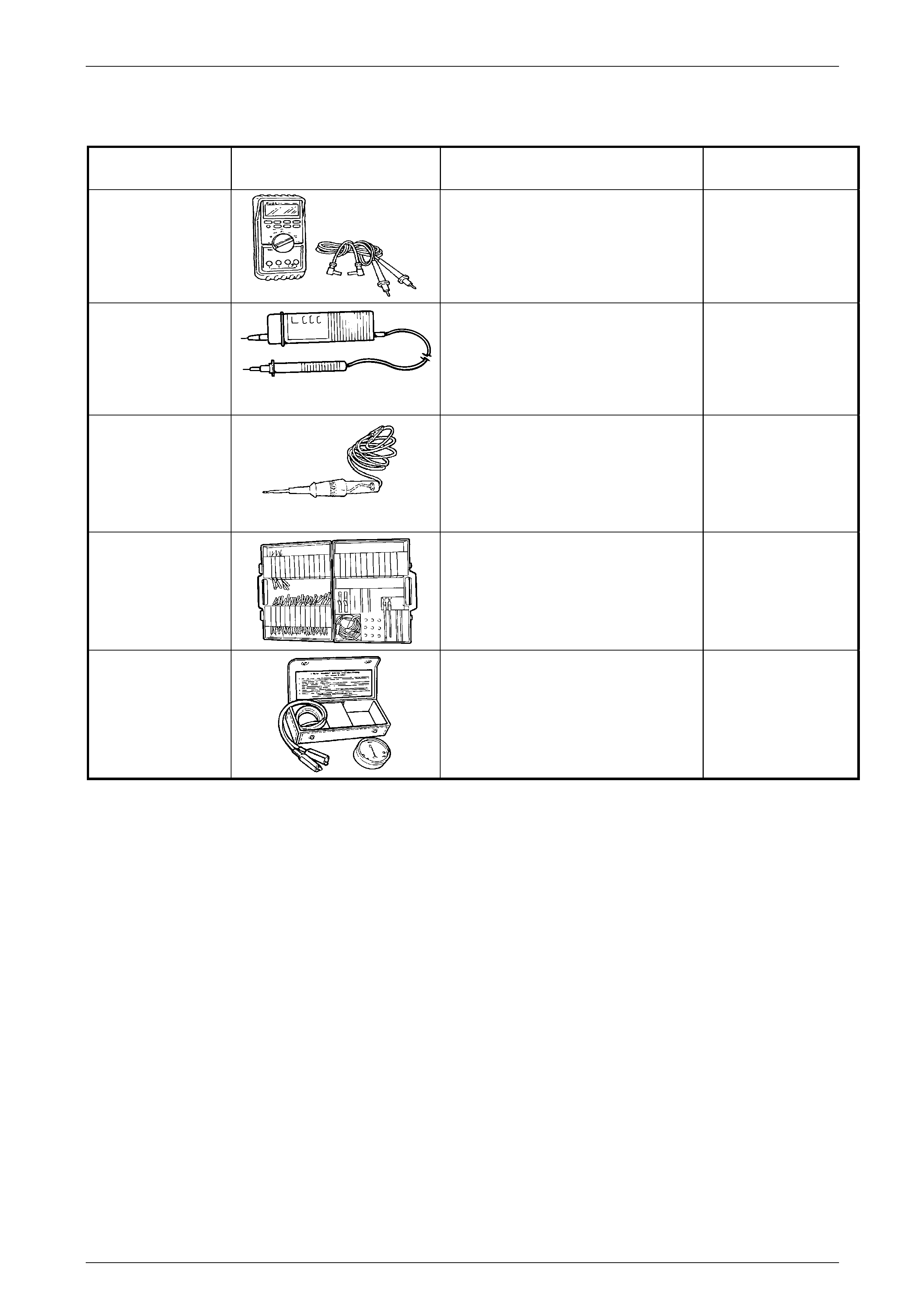
Wiring Diagrams Page 12P–73
Page 12P–73
10 Special Tools
TOOL NUMBER ILLUSTRATION DESCRIPTION TOOL
CLASSIFICATION
3588
(3545GM)
DIGITAL MULTIMETER
Must have at least 10 MΩ input
impedance and be capable of reading
frequencies.
Previously released.
Available
J21008-A
SELF POWERED TEST LIGHT
Used during electrical circuit diagnostic
checks (or use commercially available
equivalent).
Previously released.
Mandatory
J34142-B
or
CT-40-C
UNPOWERED TEST LIGHT
Must have current draw of less than
0.3 A.
Previously released.
Mandatory
J35616-A
(KM609)
CONNECTOR TEST ADAPTOR KIT
Used when carrying out electrical
diagnostic circuit checks.
Previously released.
Desirable
J8681-A
UNIVERSAL SHORT FINDER
Used during electrical circuit diagnostic
checks for detecting short circuits.
Previously released.
Desirable