
HVAC Occupant Climate Control (Auto A/C) – Diagnostics Page 2E–1
Page 2E–1
Section 2E
HVAC Occupant Climate Control (Auto A/C) –
Diagnostics
ATTENTION
Before performing any Service Operation or other procedure described in this Section, refer to Section 00
Warnings, Cautions and Notes for correct workshop practices with regard to safety and / or property damage.
1 General Information ...............................................................................................................................5
1.1 Introduction............................................................................................................................................................ 5
2 Wiring Diagrams and Connector Charts..............................................................................................6
2.1 Wiring Diagram V6................................................................................................................................................. 6
2.2 Wiring Diagram V8................................................................................................................................................. 8
2.3 Connector Chart................................................................................................................................................... 10
2.4 Serial Databus Diagram V6 ................................................................................................................................. 12
2.5 Serial Databus Diagram V8 ................................................................................................................................. 13
2.6 Connector Information ........................................................................................................................................ 14
OCC Control Module............................................................................................................................................ 14
Module Side — A14 – X1................................................................................................................................. 14
Module Side — A14 – X2................................................................................................................................. 15
3 Tech 2 Information ...............................................................................................................................16
3.1 Tech 2 Diagnostics.............................................................................................................................................. 16
Test Modes........................................................................................................................................................... 16
Normal Mode.................................................................................................................................................... 16
Diagnostic Trouble Codes................................................................................................................................ 16
Data Display..................................................................................................................................................... 16
Snapshot.......................................................................................................................................................... 17
Miscellaneous Tests......................................................................................................................................... 17
Programming.................................................................................................................................................... 17
3.2 Normal Mode........................................................................................................................................................ 18
Normal Mode Parameters.................................................................................................................................... 18
3.3 Data Display ......................................................................................................................................................... 19
Data List................................................................................................................................................................ 19
Data List Parameters........................................................................................................................................ 19
Switch Data........................................................................................................................................................... 20
OCC Switch Data Parameters.......................................................................................................................... 20
System Identification........................................................................................................................................... 21
System Identification Parameters..................................................................................................................... 21
Air Mix Door Calibration Positions..................................................................................................................... 21
Air Mix Door Calibration Positions Parameters ................................................................................................ 21
3.4 Miscellaneous Tests............................................................................................................................................ 22
3.5 Program................................................................................................................................................................ 25
Calibrate Air Mix Door......................................................................................................................................... 25
Program Code Index............................................................................................................................................ 26
Code Index Details........................................................................................................................................... 26
4 Diagnostics...........................................................................................................................................27
4.1 Introduction.......................................................................................................................................................... 27
4.2 Precautions .......................................................................................................................................................... 28
Techline

HVAC Occupant Climate Control (Auto A/C) – Diagnostics Page 2E–2
Page 2E–2
4.3 Diagnostic Trouble Code Tables........................................................................................................................ 29
Multiple DTCs Fault Condition............................................................................................................................ 29
4.4 DTC Overview....................................................................................................................................................... 30
4.5 Intermittent Faults................................................................................................................................................ 31
4.6 Diagnostic System Check................................................................................................................................... 32
Circuit Description............................................................................................................................................... 32
Test Description................................................................................................................................................... 32
Diagnostic Table Notes ....................................................................................................................................... 32
Diagnostic Table.................................................................................................................................................. 33
4.7 OCC System Does Not Power Up....................................................................................................................... 34
Circuit Description............................................................................................................................................... 34
Test Description................................................................................................................................................... 34
Diagnostic Table Notes ....................................................................................................................................... 34
OCC System Does Not Power Up Diagnostic Table ......................................................................................... 34
4.8 Rear Demist Function Inoperative...................................................................................................................... 35
Circuit Description............................................................................................................................................... 35
Test Description................................................................................................................................................... 35
Diagnostic Table Notes ....................................................................................................................................... 35
Rear Demist Function Inoperative Diagnostic Table........................................................................................ 35
4.9 OCC Module Illuminati on In ope ra tive ................................................................................................................ 37
Circuit Description............................................................................................................................................... 37
Test Description................................................................................................................................................... 37
Diagnostic Table Notes ....................................................................................................................................... 37
OCC Module Illumination Inoperative Diagnostic Table................................................................................... 37
4.10 Rear Remote Control Inoperative....................................................................................................................... 39
Circuit Description............................................................................................................................................... 39
Test Description................................................................................................................................................... 39
Diagnostic Table Notes ....................................................................................................................................... 39
Rear Remote Control Inoperative Diagnostic Table ......................................................................................... 39
4.11 Diagnostic Trouble Code List............................................................................................................................. 41
4.12 DTC 13 – Ambient Temperature Sensor Voltage Too High.............................................................................. 42
Circuit Description............................................................................................................................................... 42
Test Description................................................................................................................................................... 42
Diagnostic Aids.................................................................................................................................................... 42
Diagnostic Table Notes ....................................................................................................................................... 42
DTC 13 Diagnostic Table..................................................................................................................................... 42
4.13 DTC 14 – Ambient Temperature Sensor Voltage Too Low............................................................................... 44
Circuit Description............................................................................................................................................... 44
Test Description................................................................................................................................................... 44
Diagnostic Aids.................................................................................................................................................... 44
Diagnostic Table Notes ....................................................................................................................................... 44
DTC 14 Diagnostic Table..................................................................................................................................... 44
4.14 DTC 15 – In-car Temperature Sensor Voltage Too High................................................................................... 46
Circuit Description............................................................................................................................................... 46
Test Description................................................................................................................................................... 46
Diagnostic Aids.................................................................................................................................................... 46
Diagnostic Table Notes ....................................................................................................................................... 46
DTC 15 Diagnostic Table..................................................................................................................................... 46
4.15 DTC 16 – In-car Temperature Sensor Voltage Too Low ................................................................................... 48
Circuit Description............................................................................................................................................... 48
Test Description................................................................................................................................................... 48
Diagnostic Aids.................................................................................................................................................... 48
Diagnostic Table Notes ....................................................................................................................................... 48
DTC 16 Diagnostic Table..................................................................................................................................... 48
4.16 DTC 17 – Evaporative Temperature Sensor Voltage Too High........................................................................50
Circuit Description............................................................................................................................................... 50
Test Description................................................................................................................................................... 50
Diagnostic Aids.................................................................................................................................................... 50
Diagnostic Table Notes ....................................................................................................................................... 50
DTC 17 Diagnostic Table..................................................................................................................................... 50

HVAC Occupant Climate Control (Auto A/C) – Diagnostics Page 2E–3
Page 2E–3
4.17 DTC 18 – Evaporative Temperature Sensor Voltage Too Low.........................................................................52
Circuit Description............................................................................................................................................... 52
Test Description................................................................................................................................................... 52
Diagnostic Aids.................................................................................................................................................... 52
Diagnostic Table Notes ....................................................................................................................................... 52
DTC 18 Diagnostic Table..................................................................................................................................... 52
4.18 DTC 19 – Sun Load Sensor Error ....................................................................................................................... 54
Circuit Description............................................................................................................................................... 54
4.19 DTC 35 and 36 – Serial Data Error...................................................................................................................... 55
DTC Descriptor..................................................................................................................................................... 55
Circuit Description............................................................................................................................................... 55
Test Description................................................................................................................................................... 55
Diagnostic Aids.................................................................................................................................................... 55
Diagnostic Table Notes ....................................................................................................................................... 55
DTC 35 and 36 Diagnostic Table......................................................................................................................... 56
4.20 DTC 37, 38 and 39 – OCC Memory Error............................................................................................................ 57
DTC Descriptor..................................................................................................................................................... 57
Circuit Description............................................................................................................................................... 57
DTC 37............................................................................................................................................................. 57
DTC 38............................................................................................................................................................. 57
DTC 39............................................................................................................................................................. 57
Test Description................................................................................................................................................... 57
Diagnostic Aids.................................................................................................................................................... 57
Diagnostic Table Notes ....................................................................................................................................... 57
DTC 37, 38 and 39 Diagnostic Table................................................................................................................... 58
4.21 DTC 40 – Air Mix Door Motor Driver Error ......................................................................................................... 59
Circuit Description............................................................................................................................................... 59
Test Description................................................................................................................................................... 59
Diagnostic Aids.................................................................................................................................................... 59
Diagnostic Table Notes ....................................................................................................................................... 59
DTC 40 Diagnostic Table..................................................................................................................................... 60
4.22 DTC 41 – Solenoid Driver Error .......................................................................................................................... 62
Circuit Description............................................................................................................................................... 62
Test Description................................................................................................................................................... 62
Diagnostic Table Notes ....................................................................................................................................... 62
DTC 41 Diagnostic Table..................................................................................................................................... 62
4.23 DTC 43 and 44 – Driver’s Air Mix Door Motor Feedback Circuit Voltage Error .............................................. 66
DTC Descriptor..................................................................................................................................................... 66
Circuit Description............................................................................................................................................... 66
Test Description................................................................................................................................................... 66
Diagnostic Aids.................................................................................................................................................... 66
Diagnostic Table Notes ....................................................................................................................................... 67
DTC 43 and 44 Diagnostic Table......................................................................................................................... 67
4.24 DTC 45 and 46 – Passenger Air Mix Door Motor Feedback Circuit Voltage Error.......................................... 70
DTC Descriptor..................................................................................................................................................... 70
Circuit Description............................................................................................................................................... 70
Test Description................................................................................................................................................... 70
Diagnostic Aids.................................................................................................................................................... 71
Diagnostic Table Notes ....................................................................................................................................... 71
DTC 45 and 46 Diagnostic Table......................................................................................................................... 71
4.25 DTC 47 and 48 – Driver Air Mix Calibration Error.............................................................................................. 74
DTC Descriptor..................................................................................................................................................... 74
Circuit Description............................................................................................................................................... 74
Test Description................................................................................................................................................... 74
Diagnostic Aids.................................................................................................................................................... 74
Diagnostic Table Notes ....................................................................................................................................... 74
DTC 47 and 48 Diagnostic Table......................................................................................................................... 75
4.26 DTC 49 and 50 – Passenger Air Mix Calibration Error...................................................................................... 76
DTC Descriptor..................................................................................................................................................... 76
Circuit Description............................................................................................................................................... 76

HVAC Occupant Climate Control (Auto A/C) – Diagnostics Page 2E–4
Page 2E–4
Test Description................................................................................................................................................... 76
Diagnostic Aids.................................................................................................................................................... 76
Diagnostic Table Notes ....................................................................................................................................... 76
DTC 49 and 50 Diagnostic Table......................................................................................................................... 77
5 Electrical Specifications......................................................................................................................78
5.1 In-car Air Temperature Sensor Resistance Chart............................................................................................. 78
5.2 Ambient Air Temperature Sensor Resistance Chart......................................................................................... 79
5.3 Evaporative Temperature Sensor Resistance Chart......................................................................................... 80
6 Special Tools ........................................................................................................................................81

HVAC Occupant Climate Control (Auto A/C) – Diagnostics Page 2E–5
Page 2E–5
1 General Information
1.1 Introduction
This Section contains the diagnostic ch arts for all DTCs associated with the occupant climate control (OCC) module
and the components that it controls. This should not be the starting point for diagnosing the OCC, refer to
Section 2B HVAC Climate Control (Auto A/C) – Service and Diagnosis.
Along with the diagnostic charts, details of the Tech 2 function and wiring diagrams with connector charts for the OCC
are also included
When starting diagnosis in this Section, always start with the diagnostic system check, 4.6 Diagnostic System Check
HVAC Occupant Climate Control (Auto A/C) – Diagnostics Page 2E–6
Page 2E–6
2 Wiring Diagrams and Connector
Charts
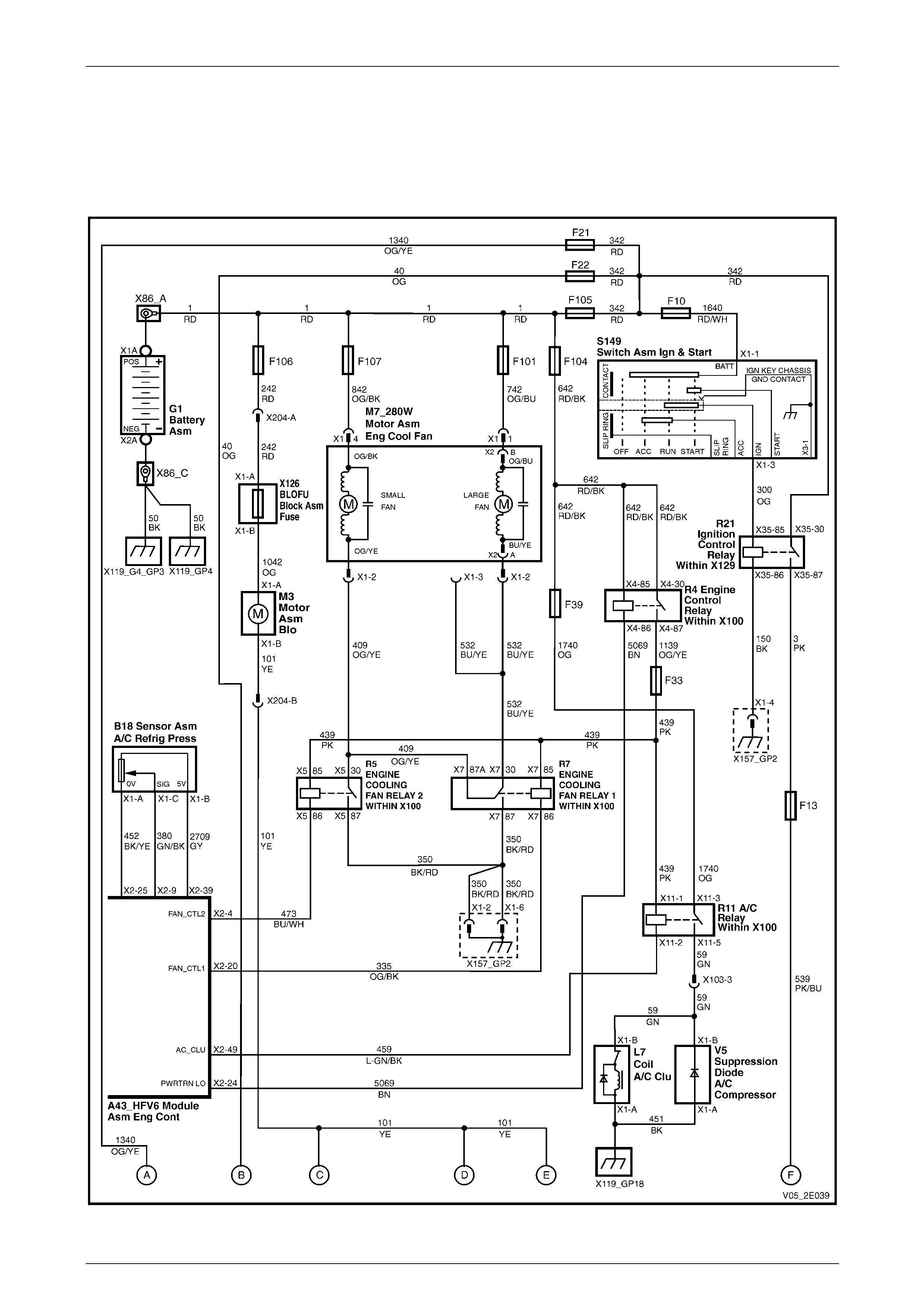
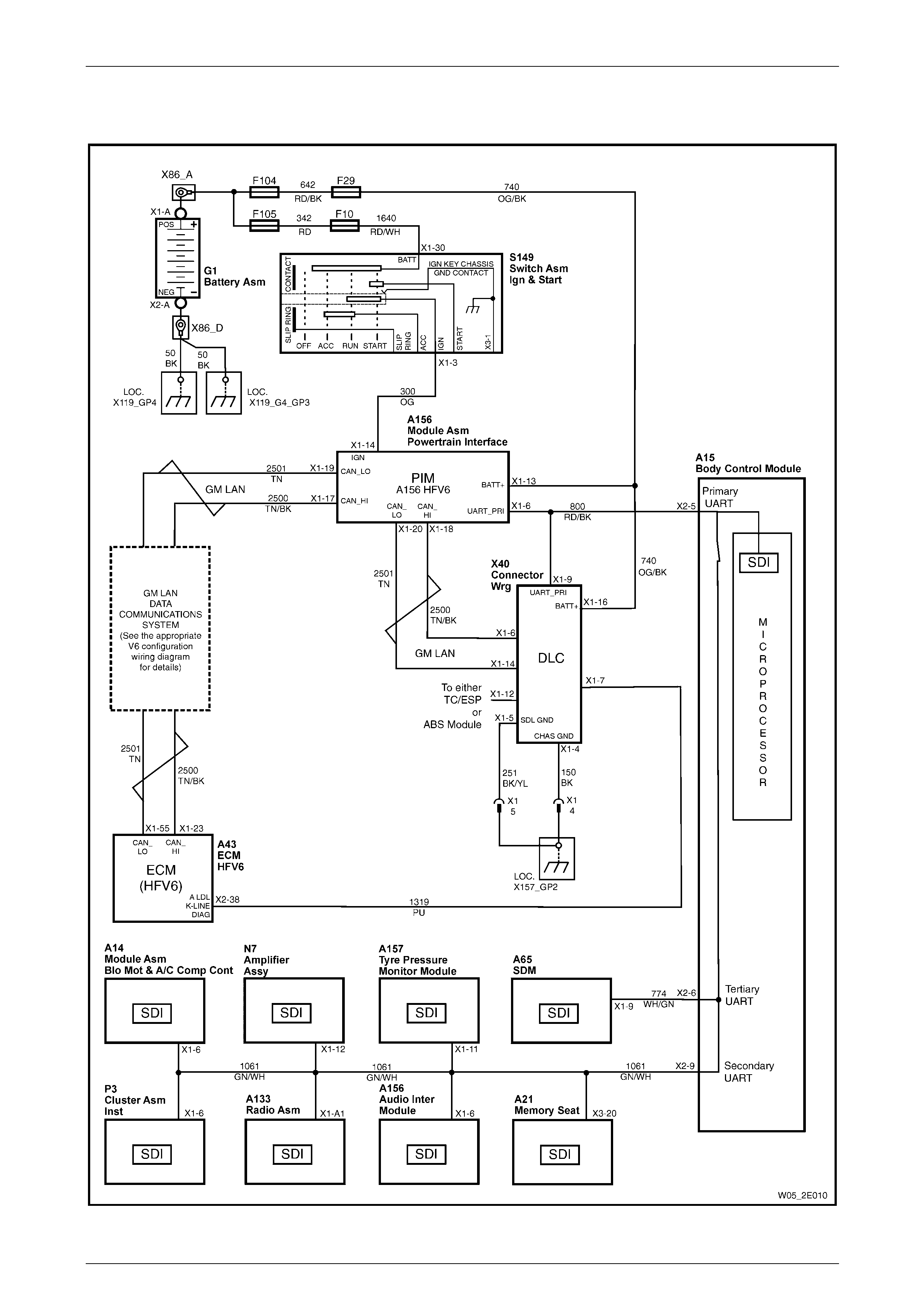
2.1 Wiring Diagram V6
Figure 2E – 1
HVAC Occupant Climate Control (Auto A/C) – Diagnostics Page 2E–7
Page 2E–7
Figure 2E – 2
HVAC Occupant Climate Control (Auto A/C) – Diagnostics Page 2E–8
Page 2E–8
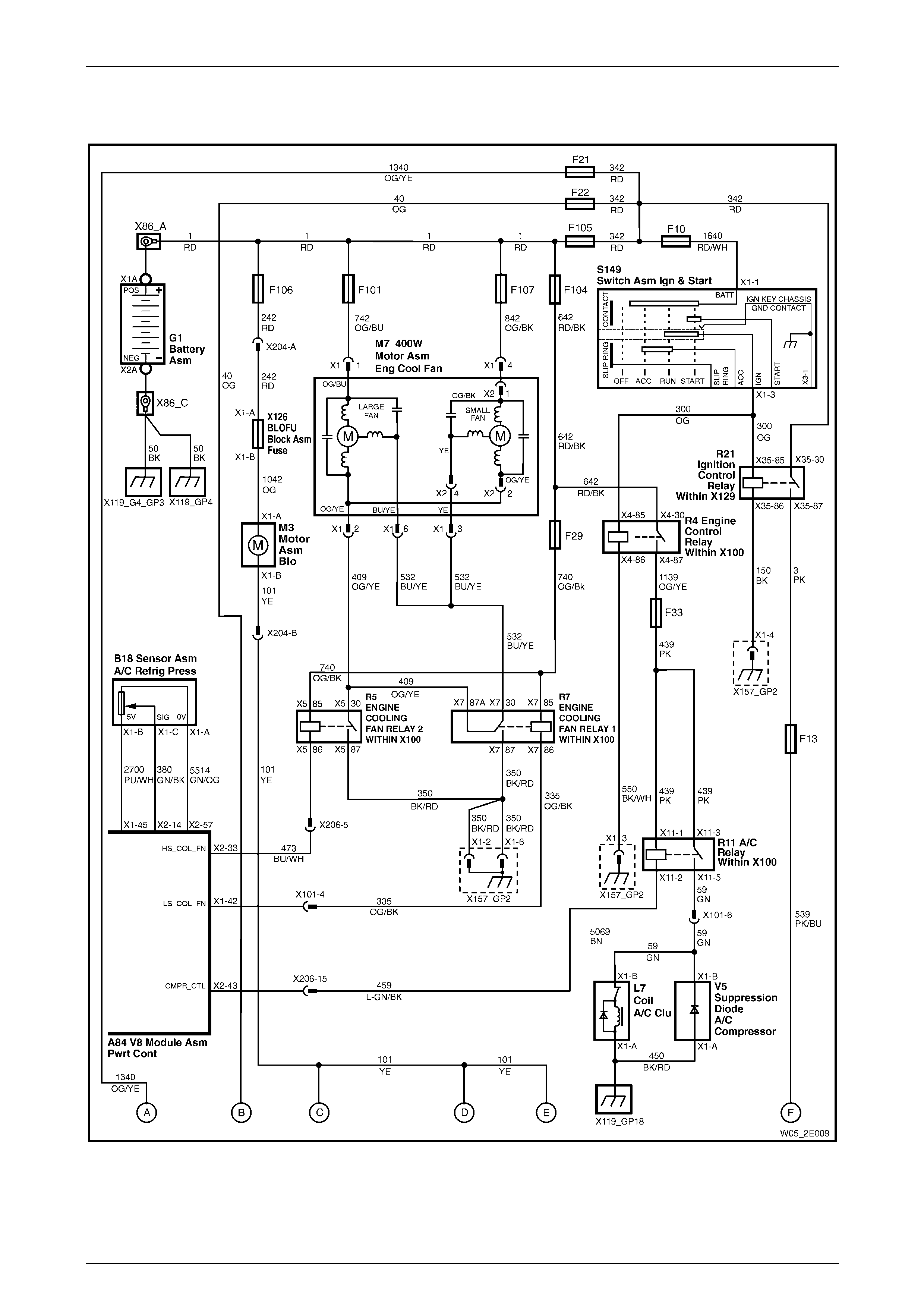
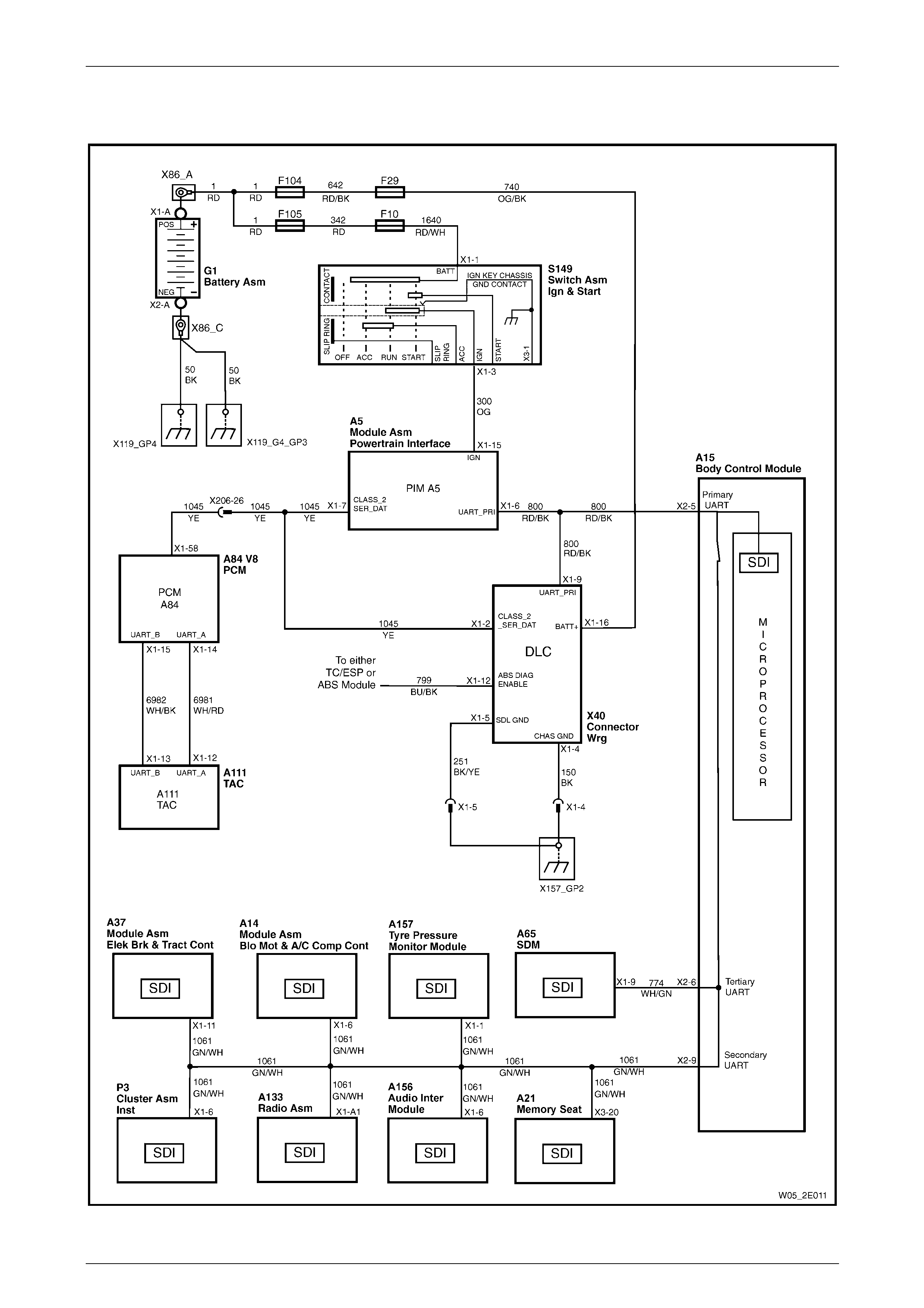
2.2 Wiring Diagram V8
Figure 2E – 3

HVAC Occupant Climate Control (Auto A/C) – Diagnostics Page 2E–9
Page 2E–9
Figure 2E – 4
HVAC Occupant Climate Control (Auto A/C) – Diagnostics Page 2E–10
Page 2E–10
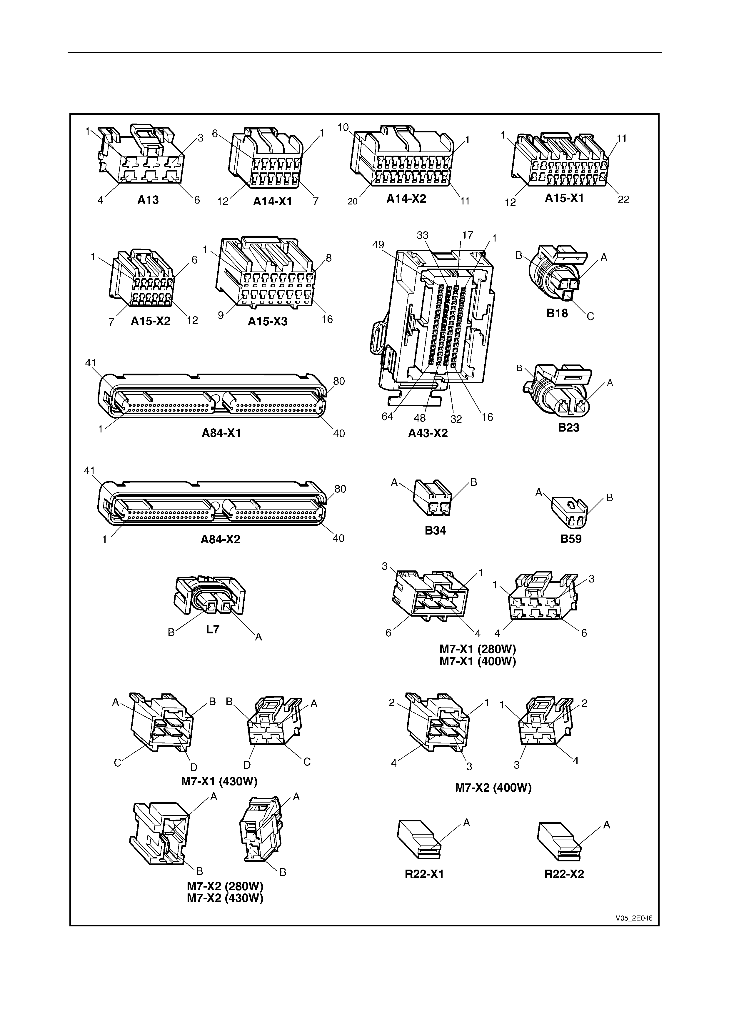
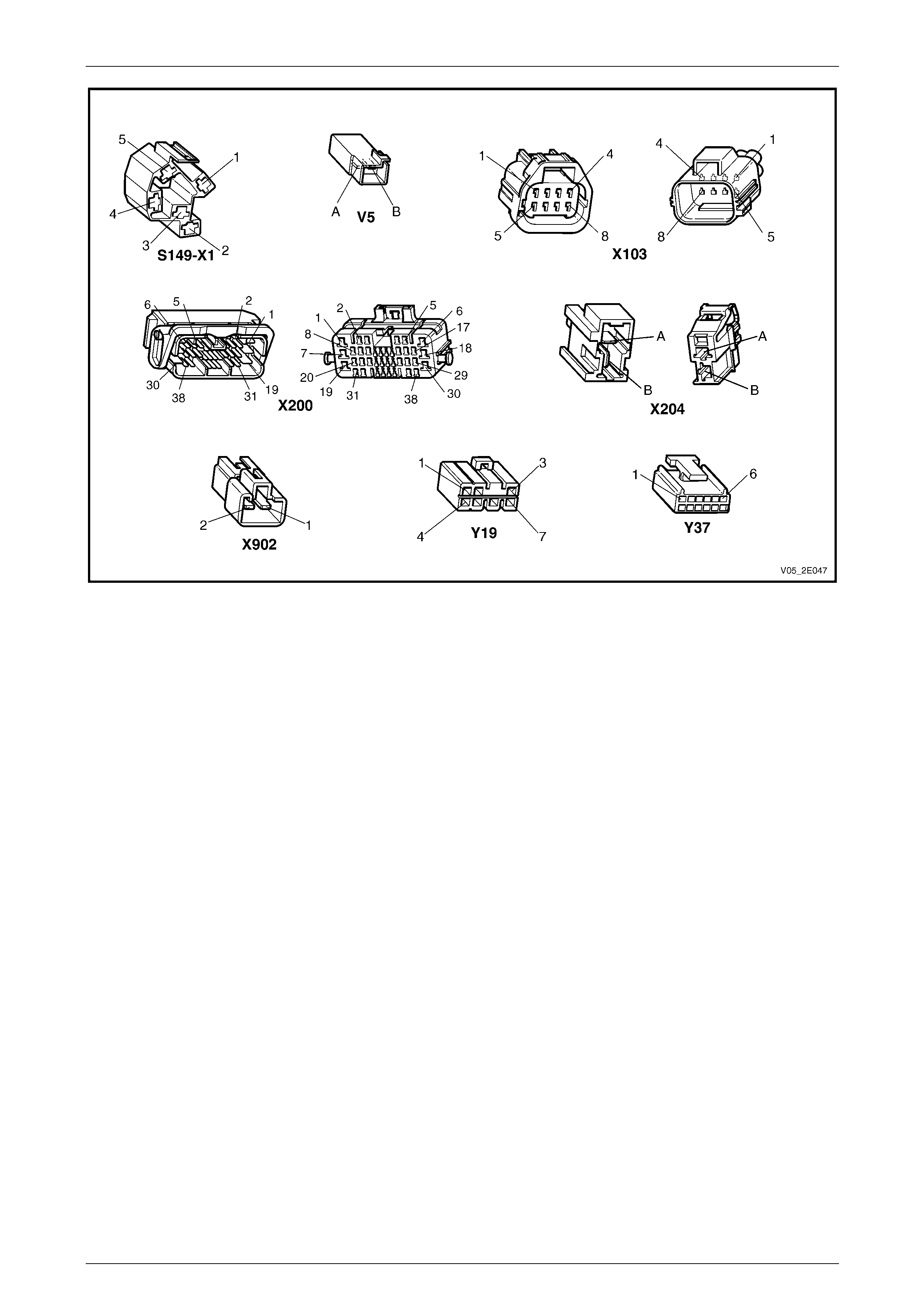
2.3 Connector Chart
Figure 2E – 5
HVAC Occupant Climate Control (Auto A/C) – Diagnostics Page 2E–11
Page 2E–11
Figure 2E – 6
HVAC Occupant Climate Control (Auto A/C) – Diagnostics Page 2E–12
Page 2E–12
2.4 Serial Databus Diagram V6
Figure 2E – 7
HVAC Occupant Climate Control (Auto A/C) – Diagnostics Page 2E–13
Page 2E–13
2.5 Serial Databus Diagram V8
Figure 2E – 8
HVAC Occupant Climate Control (Auto A/C) – Diagnostics Page 2E–14
Page 2E–14
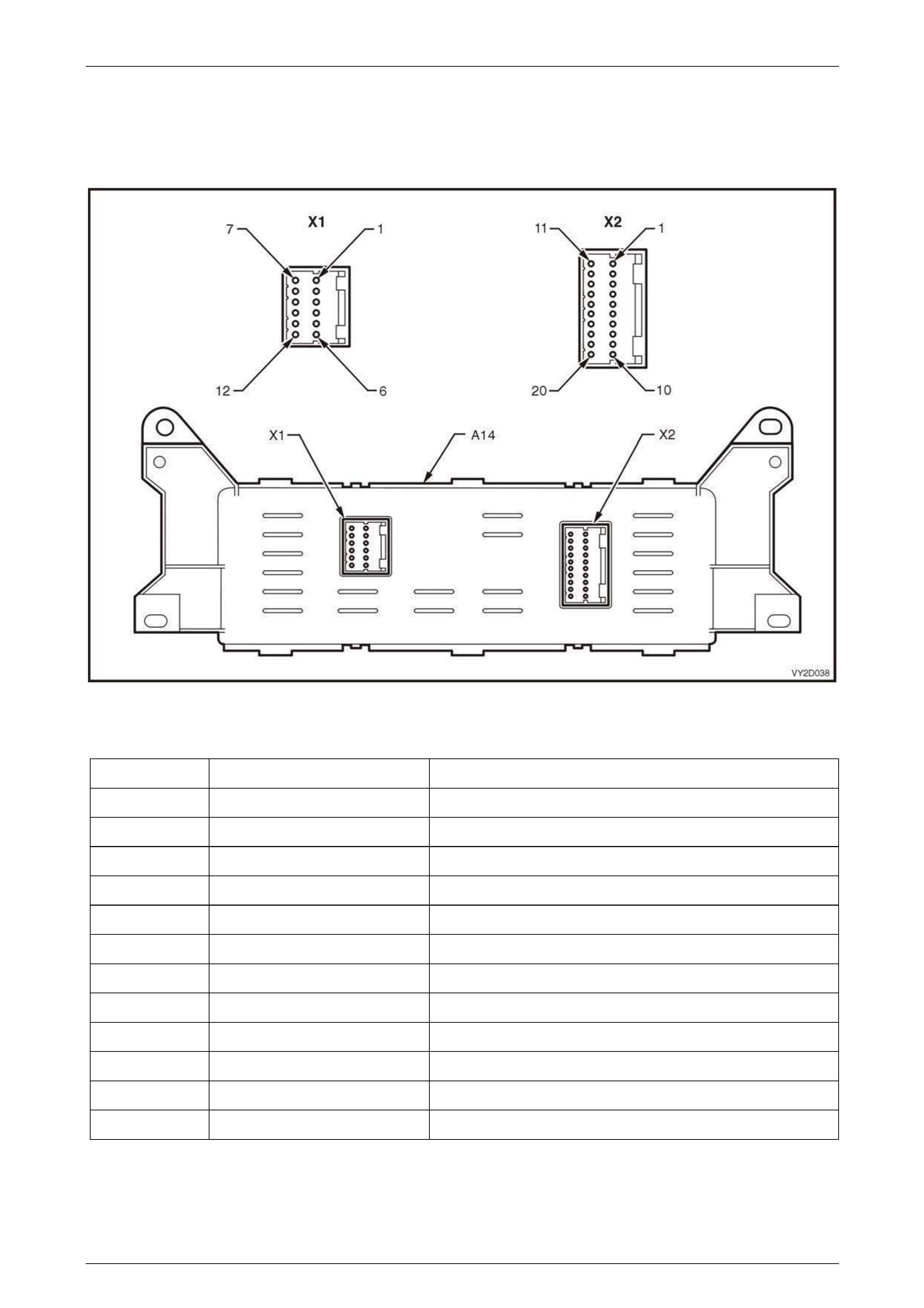
2.6 Connector Information
OCC Control Module
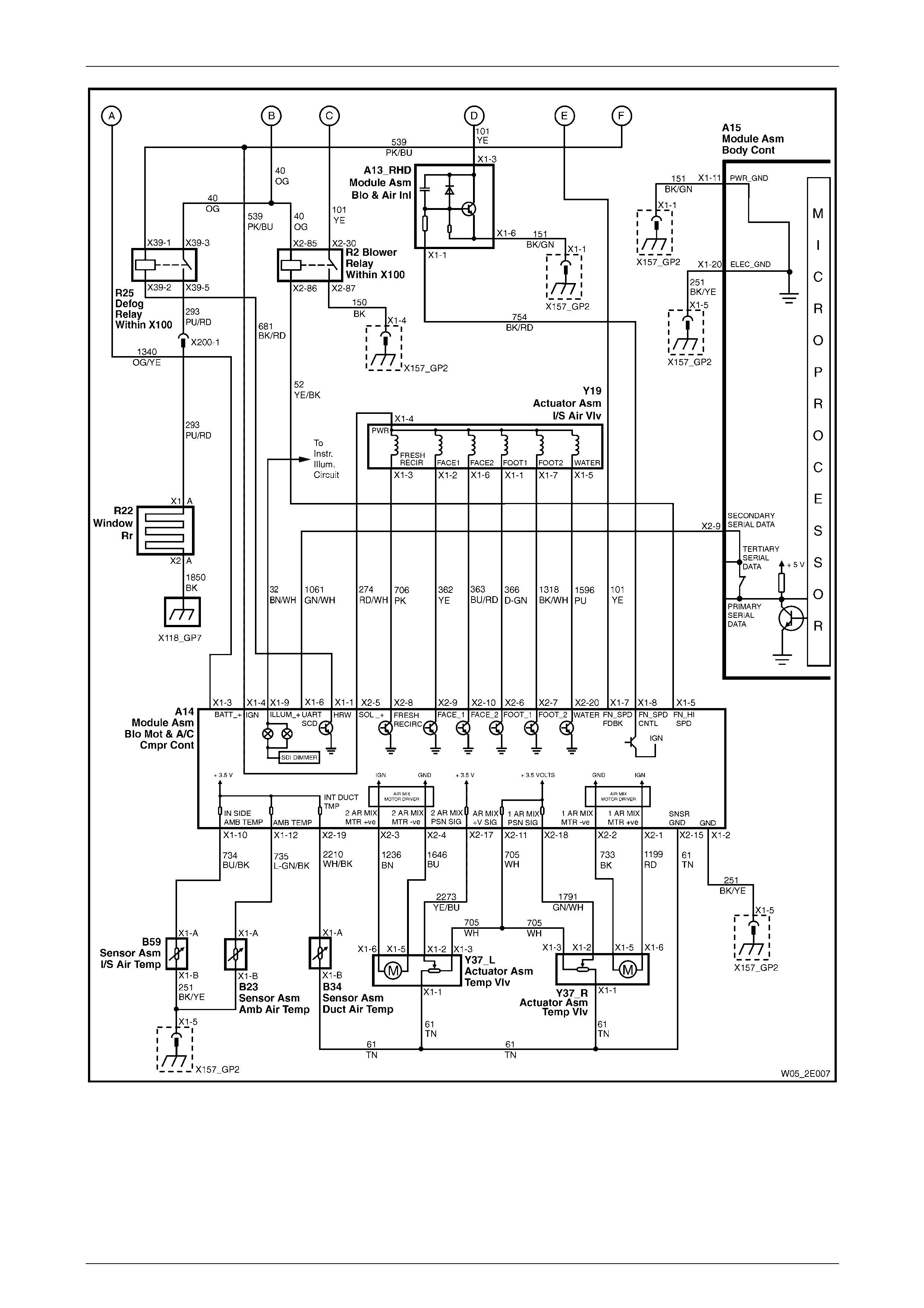
Figure 2E – 9
Module Side — A14 – X1
Pin Number Wire Colour Function
X1-1 BK/RD Rear Window Demister
X1-2 BK/YE Ground
X1-3 OG/YE Battery Voltage
X1-4 PK/BU Ignition Voltage
X1-5 YE/BK Fan Speed High – Blower Relay
X1-6 GN/WH UART Serial Databus
X1-7 YE Fan Speed Feedb ack
X1-8 BK/RD Fan Speed Control
X1-9 BN/WH Instrument Illumination
X1-10 BU/BK In-car Temperature Signal
X1-11 – Not Used
X1-12 L-GN/BK Ambient Air Temperature Signal

HVAC Occupant Climate Control (Auto A/C) – Diagnostics Page 2E–15
Page 2E–15
Module Side — A14 – X2
Pin Number Wire Colour Function
X2-1 RD Left Air Mix Door Motor + ve
X2-2 BK Right Air Mix Door Motor – ve
X2-3 BN Left Air Mix Door Motor + ve
X2-4 BU Right Air Mix Door Motor – ve
X2-5 RD/WH Solenoid Supply Voltage
X2-6 D-GN Foot 1 Select – No. 1 Solenoid
X2-7 BK/WH Foot 2 Select – No. 2 Solenoid
X2-8 PK Fresh / Recirc Select – No. 5 Solenoid
X2-9 YE Face 1 Select – No. 4 Solenoid
X2-10 BU/RD Face 2 Select – No. 3 Solenoid
X2-11 WH Air Mix Motor Position Sensor Supply Voltage
X2-12 – Not Used
X2-13 – Not Used
X2-14 – Not Used
X2-15 TN Sensor Ground
X2-16 – Not Used
X2-17 YE/BU Air Mix Motor Position Signal
X2-18 GN/WH Air Mix Motor Position Signal
X2-19 WH/BK Evaporative Temperature Sens or Signal
X2-20 PU Water Select – No. 6 Solenoid
HVAC Occupant Climate Control (Auto A/C) – Diagnostics Page 2E–16
Page 2E–16
3 Tech 2 Information
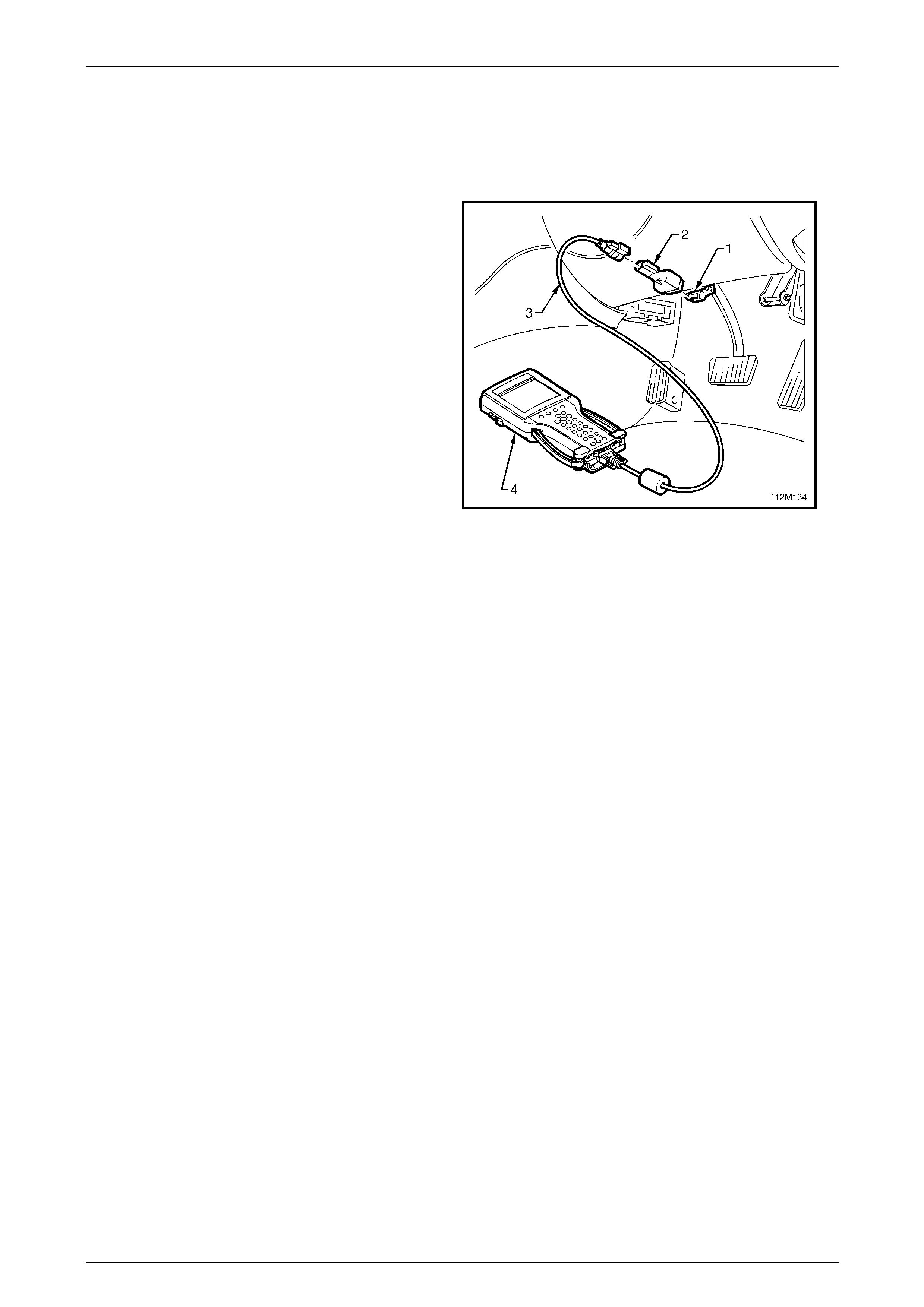
3.1 Tech 2 Diagnostics
Tech 2, with appropriate software, cable and ada pters,
when connected to the Serial Data Link Connector (DL C),
can read occupant climate control (OCC) data. The DLC is
attached to the instrument panel trim retainer beneath the
steering wheel
Legend
1 Data Link Connector (DLC)
2 DLC Adaptor
3 DLC Cable
4 Tech 2 diagnostic tool.
For additional general information on connecting and
operating Tech 2, refer to Section 0C Tech 2.
Figure 2E – 10
Test Modes
Tech 2 has five test modes for diagnosing the OCC. To navigate to these various test modes, on T ech 2 select:
Diagnostics / Model Year / Model / Body / Occupant Climate Control
and follow Tech 2’s prompts. Tech 2 will then display the following Menu options:
Normal Mode
In this mode, the Tech 2 monitors the communic ation between control modules on the serial d atabus. T he information
displayed on the Tech 2 screen in this mode is what the OCC is communicating to the other modules via the seria l data
line. For further detail, refer to 3.2 Normal Mode.
Diagnostic Trouble Codes
If Diagnostic Trouble Codes is selected, a list is displayed which contains:
• Read DTC Information – Once selected, both current and history Diagnostic Trouble Codes (DTCs) stored will be
displayed.
• Clear DTC Information – Once selected, stored DTCs can be cleared from memory by following the Tech 2
prompts.
NOTE
For a complete list of OCC DTCs. For further
information on Tech 2 and its functions, refer to
Section 0C Tech 2.
Data Display
If Data Display is selected, a selection list is displayed which contains:
• Data List – Once selected, a list of OCC inputs and outputs are displayed a long with their status.
• Swit ch Dat a – Once selected, Tech 2 displays the status of the OCC switches.
• System Identification – Once selected, Tech 2 displa ys the OCC system control module identification data which
contains, Software Version, Manufacturer Hard ware, EEPROM Version, Production Date, Identifier and Part
number.
• Air Mix Door Calibration Positions – Once selected, Tech 2 will display the parameters associated with the mix
door calibration and associated voltages.
For further detail, refer to 3.3 Data Display.

HVAC Occupant Climate Control (Auto A/C) – Diagnostics Page 2E–17
Page 2E–17
Snapshot
In this test mode, Tech 2 captures OCC data before and after a forced trigger
Miscellaneous Tests
If Miscellaneous Tests is selected, a selection list is displayed which contains:
• Drivers Air Mix Door – Tech 2 can command the driver’s air mix door open and closed in percentage in crements
thus controlling the temperature e xhausted from the driver’s centre air vent.
• Passengers Air Mix Door – Tech 2 can command the passengers air mi x door open and closed in percentage
increments thus controlling the temperatur e ex ha usted from the driver’s centre air vent.
• Blower Speed – T ech 2 can control the blower fan in 10 percent increments from 0 to 100% (0% being off and
100% being full speed)
• Maximum Fan Relay – Tech 2 can command the maximum fan relay on and off.
• LCD Display Test – Tech 2 can command all the HVAC symbols on the multi-function display (MFD) on and off.
• Outlet Mode – With the blower fan at 60%, Tech 2 can toggle through the various o utlet modes of the OCC module
and therefore change the p osition of where the air is exhausted. These are Demist, Face, Bi-Level, Blen d and F oot.
• Illumination – Tech 2 can command the illumination of the OCC module control buttons to increase and decrease.
• Front Demist LED – Tech 2 can command the front demist LED on and off.
• Rear Demist LED – Tech 2 can command the rear demist LED on and off.
• Rear Demist Relay – Tech 2 can command the rear demist relay on and off.
• A/C Request – Tech 2 can command the A/C request on and off thus engaging/disengaging the compressor clutch
• Solenoids – On selected, Tech 2 can command the following solenoids to energise and de-energise:
• Face 1 Solenoid
• Face 2 Solenoid
• Foot 1 Solenoid
• Foot 2 Solenoid
• Fresh / Recirculate Solen oid
• Water Valve Solenoid
For further detail, refer to 3.4 Miscellaneous Tests.
Programming
If Programming is selected, a selection list is displayed which contains:
• Calibrate Air Mix Door – Tech 2 can be used to calibrate the air mix do ors so they are driven to full open and
close
• Program Code Index – Tech 2 can program the OCC depending of what type (i.e. single zone, dual zone, right-
hand or left-hand drive) OCC is fitted to the vehicle.
For further detail, refer to 3.5 Program.

HVAC Occupant Climate Control (Auto A/C) – Diagnostics Page 2E–18
Page 2E–18
3.2 Normal Mode
In the Normal Mode, information the OCC module is communicating to other control modules, via the s erial data line, is
displayed. In this mode the foll owing is displayed.
Normal Mode Parameters
Tech 2 Parameter Units Displayed Typical Data Value
MFD Message (Multi Func Yes / No Varies
A/C Request (Air Condit On / Off Varies
Rear Window Heater Stat Volts Varies
DTC Set Yes / No Varies
Ambient Temperature °C Varies
For example: As displayed, the A/C request status is ‘(Air Condit off’. This means the OCC module is communicating
with the BCM, informing the air conditioning compressor is currently turned off.

HVAC Occupant Climate Control (Auto A/C) – Diagnostics Page 2E–19
Page 2E–19
3.3 Data Display
If the Data Display mode is selected, an additional menu will appear giving the operator the optio n of selecting:
• Data List,
• Switch Data,
• System Identification, or
• Air Mix Door Calibration Positions.
Data List
Once in this mode, a list of OCC related compon ents, input and outputs and the associated values or status
Data List Parameters
Tech 2 Parameter Units Displayed Typical Data Value
System Status On / Off Varies
Battery Voltage Volts Approx 13.5 V
Ignition Status On / Off Varies
Air Conditioning Request Yes / No Varies
Evaporative Temperatur e Sensor Volts 0 to 3.5 ± 0.2 V
Evaporative Temperatur e °C Varies
Ambient Temperature Sensor Volts 0 to 3.5 ± 0.2 V
Ambient Temperature °C Varies
Dampened Ambient Temperature °C Varies
In Car Temperature Sensor Volts 0 to 3.5 ± 0.2 V
In Car Temperature °C Varies
Blower Fan Speed Manual: 1234 and HIGH, Auto: Low,
Mid and High Varies
Desired Blower Fan Spee d Percent Varies
Blower Fan Speed Control Percent Varies
Blower Fan Speed Feedback Voltag e Volts Varies
Drivers Air Mix Motor Position Desired Percent Varies
Passengers Air Mix Motor Position
Desired Percent Varies
Drivers Air Mix Motor Position Feedback Percent Varies
Passengers Air Mix Motor Position
Feedback Percent Varies
Drivers Air Mix Motor Position Feedback
Voltage Volts 0 to 3.5 ± 0.2 V
Passengers Air Mix Motor Position
Feedback Voltage Volts 0 to 3.5 ± 0.2 V
Engine Coolant Temperature °C Varies
Sun Load Steps 0 – 255
Driver Set Temperature °C Varies
Passenger Set Temperature °C Varies

HVAC Occupant Climate Control (Auto A/C) – Diagnostics Page 2E–20
Page 2E–20
Tech 2 Parameter Units Displayed Typical Data Value
Operating Mode Manual/auto Varies
Outlet Mode Face / foot / blend / bi-level Varies
Inlet Mode Fresh / Recirc Varies
Startup Strategy None, Recirc / Delay, Demist /
Delay, Purge, A/C Purge, Fresh /
Delay
Varies
Fresh / Recirculation Solenoid Off / On Varies
Water Valve Solenoid Off / On Varies
Water Valve Closed / Open Varies
Face 2 Solenoid Off / On Varies
Face 1 Solenoid Off / On Varies
Foot 2 Solenoid Off / On Varies
Foot 1 Solenoid Off / On Varies
High Fan Rela y Inactive: 12 V Active: 0 V Varies
Rear Demist Relay Off / On Varies
Park Lamp Input Off / On Varies
Front Demist LED Off / On Varies
Rear Demist LED Off / On Varies
Switch Data
NOTE
The OCC module buttons will need to be held on
when checking the functionality with Tech 2 due
to a normal delay in information transfer.
Once this mode is selected, Tech 2 will display the status of the OCC module switches.
OCC S witch Data Parameters
Tech 2 Parameter Units Displayed Typical Data Value
Off Switch Off / On Varies
Auto Switch Off / On Varies
Driver Temp. Down Switch
(Temperature) Off / On Varies
Driver Temp. Up Switch (Temperature) Off / On Varies
Recirculation Switch Off / On Varies
Front Demist Switch Off / On Varies
Rear Demist Switch Off / On Varies
Fan Down Switch Off / On Varies
Fan Up Switch Off / On Varies
Mode Switch Off / On Varies
Outside Temperature Switch Off / On Varies
Air Conditioning Switch Off / On Varies

HVAC Occupant Climate Control (Auto A/C) – Diagnostics Page 2E–21
Page 2E–21
System Identification
Once this mode is selected the system identification informa tion will be displayed.
System Identification Parameters
Tech 2 Parameter Typical Data Value
Software Version Varies
Manufacturer Hardware V Varies
EEPROM Version Varies
Production Date Varies
Identifier Varies
Part number Varies
VIN Varies
Code Index 1, 2 or 3
Code Version Varies
Zone Configuration Single or Dual Zone
Drive Configuration Right or Left Hand Drive
Air Mix Door Calibration Positions
Once this mode is selected, Tech 2 displays the position of the air mix d oor as a voltage.
Air Mix Door Calibration Positions Parameters
Tech 2 Parameter Units Displayed Typical Data Value
Drivers Minimum Low Volts Varies
Passengers Minimum Low Volts Varies
Drivers Minimum High Volts Varies
Passengers Minimum High Volts Varies
Drivers Minimum Value Achieved Volts Varies
Passengers Minimum Value Achieved Volts Varies
Drivers Minimum Calibrated Value Volts Varies
Passengers Minimum Calibrated Value Volts Varies
Drivers Maximum Low Volts Varies
Passengers Maximum Low Volts Varies
Drivers Maximum High Volts Varies
Passengers Maximum High Volts Varies
Drivers Maximum Value Achieved Volts Varies
Passengers Maximum Value Achieved Volts Varies
Drivers Maximum Calibrated Value Volts Varies
Passengers Maximum Calibrated Val ue Volts Varies

HVAC Occupant Climate Control (Auto A/C) – Diagnostics Page 2E–22
Page 2E–22
3.4 Miscellaneous Tests
In the Miscellaneous Test mode, tests can be carried out to the OCC system that will test for proper operation of the
various OCC functions. In this mode, testing and observing the results can confirm correc t operation or identify error
conditions.
NOTE
During the Miscellaneous Tests, the blower fan
will be driven at approximately 60% for all tests
excluding the Blower Speed test.
Tech 2
Miscellaneous Tests Description
Drivers Air Mix Door
• The OCC commands the driv ers air mix door open and closed to adjust the temperature
exhausted at the outlet vents.
• In this test, the engine must be running and at operating temperature. The blower fan
speed must be above 60%.
• Tech 2 can manually position the drivers air mix door open and closed using the
Increase and Decrease soft keys.
• Using the Increase soft key will open the door thus increasing the temperature
exhausted.
• Using the Decrease soft key will close the door thus decreasing the temperature
exhausted.
• A thermometer placed in the right-hand centre vent outlet can confirm the doors
operation.
Passengers Air Mix
Door
• The OCC commands the passeng ers air mix door open and closed to adjust the
temperature exhausted at the outlet vents.
• In this test, the engine must be running and at operating temperature. The blower fan
speed must be above 60%.
• Tech 2 can manually position the passenger s air mix door open and close d using the
Increase and Decrease soft keys.
• Using the Increase soft key will open the door thus increasing the temperature
exhausted.
• Using the Decrease soft key will close the door thus decreasing the temperature
exhausted.
• A thermometer placed in the left-hand centre vent outlet can confirm the doors oper ation.
Blower Speed
• The OCC controls the blower speed either automatically or manually when the operator
overrides the automatic function of the OCC.
• In this test, the engine must be running.
• Tech 2 can manually contro l the sp eed of the blower fan using the Increase and
Decrease soft keys.
• Tech 2 displays the blower fan speed as a percentage; 0% being off and 100% bein g the
maximum speed. Tech 2 will increase or decrease the fan speed in 10% increments
between the minimum and maximum values.

HVAC Occupant Climate Control (Auto A/C) – Diagnostics Page 2E–23
Page 2E–23
Tech 2
Miscellaneous Tests Description
Maximum Fan Relay
• The OCC controls the maximu m blower fan speed by providing a ground cir cuit for the
blower relay (R2) which is located on the engine compartment fuse and relay panel
assembly. Refer to 12O Fuses, Relays and Wiring Harnesses for the location of the
blower relay.
• During normal oper ation, the relay will be open at all b lower fan speeds less than
maximum.
• In this test, the ignition must be in the On position.
• Tech 2 can manually turn the blower relay on and off using the Off and On soft keys.
NOTE
The blower fan will operate at 100% speed when the blower relay is turned on.
• When the relay is toggled from off to on or visa versa, an audi ble click should be heard
from the relay.
LCD Display Test
• The OCC module and the multi-function display (MFD) are connected via a serial
databus. Depending in what automatic mode or manual conf iguration the OCC module is
in, the module will inform the MFD to turn on and off certain symbols.
• In this test, the ignition must be in the On position.
• Tech 2 can manually turn on all the MF Ds HVAC symbols on and off using the Off and
On soft keys.
Outlet Mode
• The multiple solenoids that control which vents are used to exhaust the air, are controlled
by the OCC module. When in automatic mode, the OCC module sel ects which vents are
to be used and energises the correct solenoi ds. This can be over ridden by the operator
by pressing either the mode or front demist buttons. The OCC module will then use the
vents which the operator has selected.
• In this test, the engine must be running.
• Tech 2 can manually select the outlet modes of the OCC module by using the Previous
Mode and Next Mode soft keys. Tech 2 will toggle through the follo wing modes:
• Demist (demister vents only)
• Face (face level vents only)
• Bi-Level (face and foot level vents)
• Blend (demist and foot level vents), and
• Foot (foot level vents only)
• While this test is in operation, the blower fan speed will be above 60%.
Illumination
• Along with all other switches and instrument cluster, the illumination level of the OCC
module buttons is controlled by the body control module (BCM). The BCM receives the
illumination level input from the slider on the headlamp switch assembly and then
broadcasts this level through the UART serial databus. For further information on the
BCM, refer to 12J Body Control Module.
• In this test, the ignition must be in the On position.
• Tech 2 can command the illumination of the OCC module control buttons to increase or
decrease using the Increase and Decrease soft keys. The illumi nation has a range of
0 to 100% with 100% percent being the brightest setting. Tech 2 increases or decreases
the illumination in 10% increments.
NOTE
This test only affects the OCC module’s control buttons. None of the other
components illumination is tested.

HVAC Occupant Climate Control (Auto A/C) – Diagnostics Page 2E–24
Page 2E–24
Tech 2
Miscellaneous Tests Description
Front Demist LED
• Front demist is a function of the OCC module. With the engine running and pressing the
front demist button, the OCC module changes the outlets to demist and turns on the air
conditioning. The front demist button LED sh ould illuminate.
• In this test, the ignition must be in the On position.
• Tech 2 can manually turn the front demist button LED on and off using the Off and On
soft keys.
Rear Demist LED
• Rear demist is a function of the OCC module. Pressing the r ear demist button supplies a
ground circuit for the defog relay (R25) thus energisi ng it. With the relay energised, power
will be supplied to the rear demist heater element. T he rear demist button LED should
illuminate.
• In this test, the ignition must be in the On position.
• Tech 2 can manually turn the rear demist button LED on and off using the Off and On
soft keys.
Rear Demist Relay
• Rear demist is a function of the OCC module. Pressing the r ear demist button supplies a
ground circuit for the defog relay (R25) thus energisi ng it. With the relay energised, power
will be supplied to the rear demist heater element. T he rear demist relay is located on the
instrument panel fuse and relay panel assembly. Refer to 12O Fuses, Relays and Wirin g
Harnesses for the location of the rear demist relay.
• In this test, the ignition must be in the On position.
• Tech 2 can manually turn the rear demist relay on and off using the Off and On soft keys.
• When the relay is toggled from off to on or visa versa, an audi ble click should be heard
from the relay.
A/C Request
• The OCC module controls the airconditioning function. If in the automatic mode, the OCC
will turn on the air conditioni ng as required. In manual, pressing the air conditioner button
will toggle the air conditioning on and off.
• When the OCC module requests the airconditioning to turn on or off, the request is sent
by serial data to the engine control module (ECM). The ECM then provides a ground
circuit for the A/C relay (R11) which energise s. With the A/C relay energised, power is
supplied to the A/C clutch coil which engages the compressor clutch. Refer to 12O Fuses,
Relays and Wiring Harness for the location of the A/C relay.
NOTE
In this test a blower fan speed is automatically selected.
NOTE
A three second delay will occur until the compressor clutc h has engaged. This is a
normal condition.
• In this test, the engine must be running.
• Tech 2 can command the OCC to send a A/C request by using the Off and On soft keys.
• When a A/C request to turn on the air conditioning is sent, there should be an audib le
click heard from the A/C relay and the compressor should engage. The Air Conditioning
Request para m eter on Tech 2 will display Yes.
• When a A/C request to turn off the airconditio ning is sent, there should be an audible click
heard from the A/C relay and the compressor should disengage. The Air Conditioning
Request para m eter on Tech 2 will display No.
Solenoids
• The OCC module controls the HVAC solenoids either automatically when the module is in
automatic mode, or manually when a manual input is detected from the operator.
• The OCC supplies a ground circuit to the specific solenoid thus energis ing it.
• In this test, the ignition must be in the On position.
• Tech 2 has six individual tests for the solenoids. Each test is controlled by the Off and On
soft key which will de-energise and energise the selected solenoid respectively.

HVAC Occupant Climate Control (Auto A/C) – Diagnostics Page 2E–25
Page 2E–25
3.5 Program
In this mode, Tech 2 allows the programming of the OCC module.
When the Program option is selected, the following two choices will be availabl e:
• Calibrate Air Mix Door
• Program Code Index
Calibrate Air Mix Door
In this mode, the air mix doors may be recalibrated / programmed so they drive to the full hot and full cold stops.
NOTE
During the calibration procedure, Tech 2
describes the air mix door function as, Driv ers Air
Mix Door and not as, Air Mix Door.
The calibration mode looks at the full movement in both directions (open and closed) of the air mix doors/motors and
compares the actual voltage values to known base values. If they are different, the OCC software will compensate.
1 To calibrate the air mix door, connect Tech 2 to the DLC and with the engine running, select:
Body / Occupant Climate Control / Program / Calibrate Air Mix Door.
2 Press the Calibrate soft key on Tech 2.
NOTE
While an air mix door is performing the
recalibration process, Tech 2 will display a
momentary Calibration Active screen showing
two percentage bar filling from left to right. This
symbolises the air mix door being driven from
closed to open and back to closed again.
3 When the air mix doors have been successfully recalibrated, Tech 2 will display the percentage of variati on
between the base value and the pre-c alibration value. If this variation is greater than 5%, a noticeabl e difference
should be felt and could have contributed to a customer complaint.
4 If the recalibration programming is unsuccessful, repeat the program again, as the system may have ‘crashed’
during this process.
5 During programming, a DTC 47, 48, 49 or 50 could be set. On Tech 2 sele ct:
Body / Occupant Climate Control / Diagnostic Trouble Codes / Clear DTC Information.
Follow the Tech 2 prompts and clear the DT Cs.
NOTE
If the recalibration programming of the air mix
door continues to be unsuccessful, Tech 2 will
display a Programming Failed! screen. The
message ‘Driver Error in Maximum Position’
defines the problem sector of air mix door
movement. This example means the air mix door
had difficulty in the maximum (fully open) sector
of door movement.
This may caused by a variet y of reasons such as
the air mix door fouling within the HVAC case,
damaged or sticking external linkages between
the air mix door and air mix d oor motor.
Press the Confirm key to view the results of the
air mix door calibration.

HVAC Occupant Climate Control (Auto A/C) – Diagnostics Page 2E–26
Page 2E–26
Program Code Index
In this mode, the code index and programmed code version are displayed, as well as providing the operator the option of
reprogramming the code version of the OCC system to the latest level.
The code index screen will display the current code version (software calibration) loaded into the OCC module. The code
version identifies the programmed level of OCC calibration. A higher number indicates a later version of calibr ation
loaded into the OCC module. This calibration can be updated, if necessary, by using Tech 2.
In the centre of the screen, a Code Index will be disp layed indicating th e application of the software. This will be one of
the following:
Code Index Details
Application Index
Dual Zone 2
The Code Index must match the vehicle type and OCC system configuration.
1 To update the calibration pres s the Modify Soft key on Tech 2.
2 A momentary Calibrati on Active screen will be displayed on Tech 2 sho wing a percentage bar filling from left to
right. This symbolises that recalibrating of the OCC module is taking place.
NOTE
If programming is unsuccessful, repeat the
program again, as the reprogramming procedure
may have ‘crashed’ during this process.
3 After the OCC module has been successfully reprogrammed, Tech 2 will display a Programming Completed
screen.
4 Follow any Tech 2 screen prompts when programming is completed.

HVAC Occupant Climate Control (Auto A/C) – Diagnostics Page 2E–27
Page 2E–27
4 Diagnostics
4.1 Introduction
The OCC diagnostic proced ure is organised in a logical structure that begins with the Diagnostic S ystem Check and as
such must always be used as the starting point. The Diag nostic System Check direct the technician to the logical steps
necessary to diagnosing the OCC mod ule.

HVAC Occupant Climate Control (Auto A/C) – Diagnostics Page 2E–28
Page 2E–28
4.2 Precautions
When tests are required on connector
terminals, use the adapters in connector
adaptor kit KM609 to prevent damage to
terminals.

HVAC Occupant Climate Control (Auto A/C) – Diagnostics Page 2E–29
Page 2E–29
4.3 Diagnostic Trouble Code Tables
The Diagnostic System Check and the DTC list, directs the technician to the appropriate d iagnostic trouble code (DTC)
tables if there is a DTC currently stored in the TCM.
The diagnostic tables locate a faulty circuit or component through a logic based on the process of elimination. These
diagnostic tables are developed with the following assumptions:
• the vehicle functioned correctly at the time of assembly,
• there are no multiple faults, and
• the problem currently exists.
Understanding and the correct use of the diagnostic tables are essential to reduce d iagnostic time and to prevent
misdiagnosis.
Multiple DTCs Fault Condition
Some fault conditions trigger multiple comp onent DTCs even if the fault condition exists only on a single component. If
there are multiple DTCs stored in the BCM, the service tech nician must view and record all DTCs logge d.
Relationship between the logged DTCs can then be analysed to determine the source of the fault condition. Always
begin the diagnostic process with the DTC table of the fault condition that may trigger other DTCs to set.
The following fault conditions ma y trigger multiple DTCs:
• A fault in the serial data communication circuit.
• A system voltage that is too low may cause incorrect OCC operation.
• A system voltage that is too high may damage the OCC and/or other components.
• Fault condition in the OCC Read Only Memory (ROM) or Random Access Memory (RAM).
• Fault condition in the OCC internal circuitry or programming.
• Improperly connected sensor or component wiring connector.

HVAC Occupant Climate Control (Auto A/C) – Diagnostics Page 2E–30
Page 2E–30
4.4 DTC Overview
The maximum number of individual DTCs associated with the OCC system is 21. The five most recent DTCs that have
occurred will be logged into EEPROM in the BCM into a table known as the DTC List. The DTC List only has space
allocated for five entries. Therefore, if more than five DTCs are logged, only the last five will be tracked. That is, the
oldest DTC will be removed from the list regardless of its position within the list.
The format of the DTC List is as follows:
List Position Position within the list numbered from 1 to 5.
DTC Number The DTC number is the number use d to identif y a particular fault conditi on.
Occurrence Count (0 to
255) The Occurrence Count is the number of times the particular fault condition has been
detected.
History Count
(0 to 255) The History Count is the number of ignitio n cycles that have occurred since the fault was
last detected. A count of 0 indicates the fault has occurred on the current ignition cycle,
while a count of 255 indicates the fault occurred 255 or more ignition cycles ago.
Algorithms for detecting each fault condition and setting the corresponding DTC vary. However, a particular DTC is only
set once per ignition cycle. When a DT C is set, the following occurs:
• If the DTC does not exist in the DTC List, it is inserted into the list at the first vacant location with the Occurrence
Count set to 1 and the History Count set to 0. In the event of the DTC List being full, the oldest DTC will be
removed from the list. The History Count determines the age of a DTC List entry. The item in the list with the
highest History Count will be remove d to make space for the new DTC.
• If the DTC already exists in the DTC List, then the Occurrence Count will be incremented (up to 255, at which point
it is no longer incremented). Each time the DTC is set, the History Count is cleared.
This procedure ensures the five most recent fault conditions are tracked. The Occurrence and History Counters provide a
means of determining how often the fault has occurred, and how long it has been since the fault last occurred. F or
instance, if the DTC Occurrence Count is 1, and the History Count is 201, then it can be determined the fault condition
existed only once, and it happened 201 ignition cycles ago (and has not been detected sinc e). Another example would
be an Occurrence Count of 4 and a History Count of 0. This would indicate the fault has been detected a total of four
times, and that it was detected on the current ignition c ycle.
The DTCs are not removed from the list unless five newer fault conditions occur pushing the oldest fault off the list, or
they are cleared using Tech 2.

HVAC Occupant Climate Control (Auto A/C) – Diagnostics Page 2E–31
Page 2E–31
4.5 Intermittent Faults
Problems may or may not store a DTC, indicating an intermittent problem. DO NOT use the diagnostic code charts for
intermittent problems. When using the code charts the fault must be present to locate the problem. If a fault is
intermittent, use of diagnostic trouble code charts may result in replacement of good parts.
Most intermittent problems are caused by faulty electrical connections or wiring. Perform careful visual/ph ysic al checks of
the applicable circuit.
Check for:
a Poor mating of the connector halves or a terminal not fully seated in the connector body (backed out).
b Improperly formed or damaged termin al. All connector terminals in the suspect circuit shou ld be carefully reformed
or replaced to insure proper contact tensi on.
c Poor terminal to wire connection. This requires removi ng the terminal from the conn ector body to check as outlined
in service operations.
d Loose OCC ground circuit terminals.
NOTE
• If a visual / physical check does not find the
cause of the problem, the car can be driven
with a multimeter connected to a suspected
circuit. Tech 2 can also be used to help dete ct
intermittent conditions. An abnormal voltage,
or Tech 2 reading, when the problem occurs,
indicates the probl em may be in that circuit. If
the wiring and connectors are serviceable,
and a diagnostic trouble code was stored for a
circuit having a sensor, substitute a known
good sensor and recheck.
• Loss of diagnostic code memory. To check,
disconnect Ambient Air Temperature sensor
and turn the ignition on until the ‘X’ symbol is
displayed on the multi-fu nction display (MFD).
DTC 13 should be stored and kept in memory
when ignition is turned off. If not, the OCC
module is faulty.
• Check for electrical system interference
caused by a defective relay, OCC driven
solenoid, or switch. They can cause a sharp
electrical surge. Normally, the problem will
occur when the faulty component is oper ated.
• Check for improper installation of non-factory
installed electrical options such as lights,
2-way radios, etc.
• Refer to Section 12P Wiring Diagrams for
further information.

HVAC Occupant Climate Control (Auto A/C) – Diagnostics Page 2E–32
Page 2E–32
4.6 Diagnostic System Check
Circuit Description
When investigating any complaint of an OCC problem or malfunction, always be gin diagnosis with the follo wing
diagnostic system check. T his check is a prel iminary procedure that checks to ensure the OCC is communicating on the
serial data line as well as helping to identify a problem or malfunction and directing the reader to the appropriate
diagnostic chart in this Section.
With Tech 2 connected to the DLC and the ignition switched on, Tech 2 should display se rial data communication. If
Tech 2 does not display serial data, the serial data circuit may be open or shorted.
In addition to the OCC module, there are several other control modules th at are connected to the serial data lin e (AHU,
BCM, instruments and SDM). Any one of these control modules could cause a fault on the serial data line. This fault
could result in Tech 2 not being able to display serial data.
Test Description
The following numbers refer to the step numbers in the diagnostic table:
3 This test checks if the OCC module is being powered up.
5 Checks if Tech 2 can communicate with the OCC module. Confirms if the OCC module has power, ground and
serial data communications.
6 This test checks if the OCC module has stored a current Diagnostic Trouble Code.
7 Check if the air mix door is within calibration.
8 Check if there is a rear demist function problem.
9 Checks if there is an OCC module button problem. Completes the check of the OCC module and refers to an
overall air conditioning s ystem check..
Diagnostic Table Notes
1 For all wiring fault diagnoses, refer to Section 12P Wiring Diagrams.
2 For wiring repairs, refer to Section 12 P Wiring Diagrams.
3 Refer to Section 12O Fuses, Relays and Wiring Harnesses for harness routeing.
4 If a fault is deemed intermittent, refer to 4.5 Intermittent Faults.
5 For information on Tech 2, refer to 3.1 Tech 2 Diagnostics.

HVAC Occupant Climate Control (Auto A/C) – Diagnostics Page 2E–33
Page 2E–33
Diagnostic Table
Step Action Yes No
1 Is the fault specifically isolated to this system / module? Go to Step 2 Refer to
0D Vehicle Diagnostics
2 Have you read the Basic Diagnostic Requirements, Diagnostic
Precautions and Preliminar y Checks? Go to Step 3 Refer to
0D Vehicle Diagnostic
3 1 Turn the ignition on.
2 Turn on the OCC system.
Does OCC module LCD screen activate? Go to Step 4
Refer to
4.7 OCC System
Does Not Power Up
4 1 Connect Tech 2 to the DLC.
2 Turn the ignition on.
3 Push power button on Tech 2.
Does Tech 2 power up? Go to Step 5 Refer to 0C Tech 2
5 On Tech 2 select:
Body / Occupant Climate Control.
Does Tech 2 display OCC System Identification Screen
information (i.e. part number etc.)? Go to Step 6 Refer to 12J Body
Control Module
6 With Tech 2 connected and the ignition on, select:
Diagnostic Trouble Codes / Read DTC Information.
Does Tech 2 display any DTCs? Go to Step 7
7 With Tech 2 connected the ignition on and OCC system
selected, select:
Program / Calibrate Air Mix Door / Calibrate.
Does Tech 2 display a value greater than 5%? Go to Step 8
8 Has the customer complained the rear demist function does not
operate correctly? Refer to
4.8 Rear Demist
Function Inoperative Go to Step 9
9 Has the customer complained the OCC module buttons do not
illuminate? Refer to
4.9 OCC Module
Illumination Inoperative
Refer to
2B HVAC Climate
Control (Manual A/C) –
Service and Diagnosis
When all diagno sis an d repairs are completed, check the system for correct operation.

HVAC Occupant Climate Control (Auto A/C) – Diagnostics Page 2E–34
Page 2E–34
4.7 OCC System Does Not Power Up
Circuit Description
Battery power is supplied to the OCC module, terminal X1 pin 4, with the ignition switch in the ignition or start positions
through fuse F13 (located in the pass en ger compartment fuse panel).
Refer to 2 Wiring Diagrams and Connector Charts to aid i n diagnosis.
Test Description
The following numbers refer to the step numbers in the diagnostic table:
1 The diagnostic circuit test is the beginning of all diagnostics and should be performed whenever diagnosing an
OCC system complaint.
2 This test checks if the fuse F13 is serviceable.
3 This test determines if power is being su pplied to fuse F13.
4 Checks if there is power to the OCC module. Isolates whether circuit 539 is faulty.
5 Checks if there is a ground circuit. Isolates whether circuit 251 or the OCC module is faulty.
Diagnostic Table Notes
1 For all wiring fault diagnoses, refer to Section 12P Wiring Diagrams.
2 For wiring repairs, refer to Section 12P Wiring Diagrams.
3 Refer to Section 12O Fuses, Relays and Wiring Harnesses for harness routeing.
4 If a fault is deemed intermittent, refer to 4.5 Intermittent Faults.
5 For information on Tech 2, refer to 3.1 Tech 2 Diagnostics.
OCC System Does Not Power Up Diagnostic Table
Step Action Yes No
1 Has the Diagnostic System Check been performed?
Go to Step 2
Refer to
4.6 Diagnostic
System Check
2 Check fuse F13.
Is the fuse blown?
Replace the fuse. If it
blows again, test its
circuit for a short to
ground Go to Step 3
3 1 Turn the ignition on.
2 Using a multimeter set to measure voltage, probe
between the front of fuse F13 and a kn own ground
Does the multimeter display battery voltage? Go to Step 4 Repair or replace
circuit 3
4 1 Remov e the OCC mod ule, refer to 2F HVAC Occupant
Climate Control (Auto A/C) – Removal and Installation.
2 Turn the ignition on and ensure the OCC is off.
3 Using a multimeter set to measure voltage, probe
between the A14 – X1 pin 4 and a known ground.
Does the multimeter display battery voltage? Go to Step 5 Repair or replace
circuit 539
5 Using a multimeter set to measure resistance, probe between
the A14 – X1 pin 2 and a known ground.
Does the multimeter display continuity?
Replace the OCC
module, refer to
2F HVAC Occupant
Climate Control
(Auto A/C) –
Removal and
Installation Repair or replace
circuit 251
When all diagno sis an d repairs are completed, check the system for correct operation.

HVAC Occupant Climate Control (Auto A/C) – Diagnostics Page 2E–35
Page 2E–35
4.8 Rear Demist Function Inoperative
Circuit Description
The rear demist function is activated by a button on th e OCC module. When pressed, the OCC module supplies a
ground circuit for the defog relay R25, thus energisin g the relay. The relay then applies battery voltage to the rear demist
element.
Refer to 2 Wiring Diagrams and Connector Charts to aid i n diagnosis.
Test Description
The following numbers refer to the step numbers in the diagnostic table:
2 Checks if the relay R25 energises when the rear demist button is pressed. Confirms the controlling circuit for the
relay is serviceabl e
3 Check if the relay is at fault.
4 Checks if there is power supplied to the coil side of the relay. Isolates whether circuit 539 is faulty.
5 Checks if the relay energises when the control circuit is shorted to ground. Isolates whether the OCC module or
circuit 539 is faulty.
6 Checks if there is power to the switch side of the relay. Isolates whether circuit 40 is faulty.
7-8 Checks if circuit 293 is open circuit or shorted to ground.
9 Check if the ground circuit for the rear window heater element is serviceable. Isolates whether circuit 1850 is faulty.
10 Visually inspect the element for nicks or breaks.
Diagnostic Table Notes
1 For all wiring fault diagnoses, refer to Section 12P Wiring Diagrams.
2 For wiring repairs, refer to Section 12P Wiring Diagrams.
3 Refer to Section 12O Fuses, Relays and Wiring Harnesses for harness routeing.
4 If a fault is deemed intermittent, refer to 4.5 Intermittent Faults.
5 For information on Tech 2, refer to 3.1 Tech 2 Diagnostics.
Rear Demist Function Inoperative Diagnostic Table
Step Action Yes No
1 Has the Diagnostic System Check been performed?
Go to Step 2
Refer to
4.6 Diagnostic
System Check
2 1 Gain access to the instrument panel fuse and relay
panel assembly X100, refer to 12O F uses, Relays and
Wiring Harnesses.
2 Turn the ignition on.
3 Press the rear demist button on the OCC module.
Was an audible click heard from relay R3? Go to Step 6 Go to Step 3
3 1 Replace relay R3 with a known good relay.
2 Press the rear demist button on the OCC module.
Was an audible click heard from relay R 3? Leave the known
good relay in place
Replace with original
relay.
Go to Step 4

HVAC Occupant Climate Control (Auto A/C) – Diagnostics Page 2E–36
Page 2E–36
Step Action Yes No
4 1 Remov e relay R3 from the instrument panel fuse and
relay panel assembl y X100, refer to 12O Fuses, Relays
and Wiring Harnesses.
2 Turn the ignition on.
3 Using a multimeter set to measure voltage, probe
between connector X3 pin 85 and a known ground,
refer to 12O Fuses, Relays and Wiring Harnesses.
Does the multimeter display battery voltage? Go to Step 5 Repair or replace
circuit 539
5 1 Insert relay R3
2 Gain access to the OCC module, refer to 2F HVAC
Occupant Climate Control (Aut o A/C) – Removal and
Installation.
3 Using a fused jumper lead, ba ckprobe between A14 –
X1 pin 1 and a known ground.
Was an audible click heard from relay R 3?
Replace the OCC
module, refer to
2F HVAC Occupant
Climate Control
(Auto A/C) –
Removal and
Installation Repair or replace
circuit 681
6 1 Remov e relay R3 from the instrument panel fuse and
relay panel assembly.
2 Using a multimeter set to measure voltage, probe
between connector X3 pin 30 and a known ground,
refer to 12O Fuses, Relays and Wiring Harnesses.
Does the multimeter display battery voltage? Go to Step 7 Repair or replace
circuit 40
7 1 Gain access to the rear demist connector L4 – X2 pin A,
refer to 1A8 Headlining and Interior Trim.
2 Disconnect connector L4 – X2pin A.
3 Using a multimeter set to measure resistance probe
between connector R3 – X3 pin 87 (on fuse and relay
panel assembly) and L4 – X2 pin A.
Does the multimeter display continuity? Go to Step 8 Repair or replace
circuit 293
8 Using a multimeter set to measure resistance probe between
harness connector L4 – X2 pin A and a known ground.
Does the multimeter display continuity? Go to Step 9 Repair or replace
circuit 293
9 Using a multimeter set to measure resistance probe between
harness connector L4 – X3 pin A and a known ground.
Does the multimeter display continuity? Go to Step 10 Repair or replace
circuit 1850
10 Visually inspect the rear window heater element.
Are there any noticeable breaks in the element? Repair the element
with a commercially
available kit
Replace the rear
window assembly,
refer to 1A5
Stationary Windows
When all diagno sis an d repairs are completed, check the system for correct operation.

HVAC Occupant Climate Control (Auto A/C) – Diagnostics Page 2E–37
Page 2E–37
4.9 OCC Module Illumination Inoperative
Circuit Description
The OCC module buttons will illumi nate when the park lamps are turned on. The level of i llumination is controlled by the
BCM through serial data to the OCC module. When BCM receives an input from the illumination slider on the headlamp
assembly switch, it will broadcast the request to either increase or decrease the illumination level of various internal
components including the OCC module buttons and instrument cluster.
Refer to 2 Wiring Diagrams and Connector Charts to aid i n diagnosis.
Test Description
The following numbers refer to the step numbers in the diagnostic table:
2 The OCC module receive illumination levels via serial data from the BCM. Checks if there are any serial data faults.
3 Checks if the OCC module buttons illuminate when the park lamps are turned on.
4 Checks if the OCC module buttons increase and decrease illumination intensity when controlled by the headlamp
switch assembly.
5 Checks if any other module’s illumination was increased or decreased. Isolates whether it is an OCC module or
BCM fault.
6 Provides a ground for the OCC module illumination circuit. Isolates whether the module or circuit 32 is at fault.
Diagnostic Table Notes
1 For all wiring fault diagnoses, refer to Section 12P Wiring Diagrams.
2 For wiring repairs, refer to Section 12P Wiring Diagrams.
3 Refer to Section 12O Fuses, Relays and Wiring Harnesses for harness routeing.
4 If a fault is deemed intermittent, refer to 4.5 Intermittent Faults.
5 For information on Tech 2, refer to 3.1 Tech 2 Diagnostics.
OCC Module Illumination Inoperative Diagnostic Table
Step Action Yes No
1 Has the Diagnostic System Check been performed?
Go to Step 2
Refer to
4.6 Diagnostic
System Check
2 During the Di agnostic System Check, was DTC 35 or 36 set? Refer to
4.19 DTC 35 and 36
– Serial Data Error Go to Step 3
3 1 Turn on the OCC.
2 Turn on the park lamps
Do the OCC buttons illuminate? Go to Step 4 Go to Step 6
4 Move the slider on the headlamp switch assembly to increase
and then decrease the OCC modu le button illumination?
Did the OCC module buttons increase and decrease in
illumination? System serviceable Go to Step 5
5 During Step 4, did the instrument cluster illumination increase
and decrease? Replace the OCC
Module, refer to
2F HVAC Occupant
Climate Control
(Auto A/C) –
Removal and
Installation Refer to 12J Body
Control Module

HVAC Occupant Climate Control (Auto A/C) – Diagnostics Page 2E–38
Page 2E–38
Step Action Yes No
6 1 Gain access to the OCC module, refer to 2F HVAC
Occupant Climate Control (Aut o A/C) – Removal and
Installation.
2 Using a fused test lead, backprobe between connector
A14 – X1 pin 9 and a known ground.
Do the OCC module buttons illuminate? Repair or replace
circuit 32
Replace the OCC
Module, refer to 2F
HVAC Occupant
Climate Control
(Auto A/C) –
Removal and
Installation
When all diagno sis an d repairs are completed, check the system for correct operation.

HVAC Occupant Climate Control (Auto A/C) – Diagnostics Page 2E–39
Page 2E–39
4.10 Rear Remote Control Inoperative
Circuit Description
The rear remote control contains five switch functions; fan speed up, fan down, temperature up and temperature do wn.
When all the switches are at rest, the OCC module receives a constant 5 V feedback signal. When any of these buttons
are pressed, a resister in series with the button pressed, varies the feedback voltage that the OCC module receives.
Refer to 2 Wiring Diagrams and Connector Charts to aid i n diagnosis.
Test Description
The following numbers refer to the step numbers in the diagnostic table:
2 When the rear remote control buttons are in their neutral stat e, the OCC module should read 5 V.
3 Checks if there is a short to ground in circuit 5524.
4 Checks that when the individual buttons are pressed, that the OCC module receives the correct voltage.
5 Checks if the rear remote control ground circuit is serviceable. Isolates whether circuit 251 or the rear remote
control is faulty.
Diagnostic Table Notes
1 For all wiring fault diagnoses, refer to Section 12P Wiring Diagrams.
2 For wiring repairs, refer to Section 12P Wiring Diagrams.
3 Refer to Section 12O Fuses, Relays and Wiring Harnesses for harness routeing.
4 If a fault is deemed intermittent, refer to 4.5 Intermittent Faults.
5 For information on Tech 2, refer to 3.1 Tech 2 Diagnostics.
Rear Remote Control Inoperative Diagnostic Table
Step Action Yes No
1 Has the Diagnostic System Check been performed?
Go to Step 2
Refer to
4.6 Diagnostic
System Check
2 1 Connect Tech 2 to the DLC.
2 On Tech 2 select:
Rear Remote Control Input.
Does Tech 2 display less than 5 V? Go to Step 3 Go to Step 4
3 1 Remove the rear remote control, refer to 1A8
Headlining and Interior Trim.
2 On Tech 2 select:
Body / Occupant Climate Control / Data Display /
Switch Data / Rear Remote Control Input.
Does Tech 2 display less than 5 V? Repair or replace
circuit 5527 Go to Step 4

HVAC Occupant Climate Control (Auto A/C) – Diagnostics Page 2E–40
Page 2E–40
Step Action Yes No
4 1 If disconnected, connect A94 – X1.
2 On Tech 2 select:
Body / Occupant Climate Control / Data Display /
Switch Data / Rear Remote Control Input.
3 Monitor the input voltage and press the foll owing
buttons on the rear remote control:
• Temperature down = 0.6 V
• Temperature up = 1.2 V
• Fan down = 2.8 V
• Fan up = 2.2 V
• Both fan buttons (Auto) = 1.7 V
Did Tech 2 display the correct voltage when the above
buttons were pressed?
Replace the OCC
module, refer to 2F
HVAC Occupant
Climate Control
(Auto A/C) –
Removal and
Installation Go to Step 5
5 Using a multimeter set to measure resistance, probe between
connector A94 – X1 pin 2 and a known ground.
Does the multimeter display continuity?
Replace the rear
remote control, refer
to 1A8 Headlining
and Interior Trim Repair or replace
circuit 251
When all diagno sis an d repairs are completed, check the system for correct operation.

HVAC Occupant Climate Control (Auto A/C) – Diagnostics Page 2E–41
Page 2E–41
4.11 Diagnostic Trouble Code List
The table below describes the DTCs that are generated when a fault occurs with the OCC system.
DTC Description Diagnostic Table
13 Ambient Temperature Sensor Voltage Too High. 4.12 DTC 13 – Ambient Temperature Sensor
Voltage Too High
14 Ambient Temperature Sensor Voltage Too Low. 4.13 DTC 14 – Ambient Temperature Sensor
Voltage Too Low
15 In-car Temperature Sensor Voltag e Too High. 4.14 DTC 15 – In-car T emperature Sensor
Voltage Too High
16 In-car Temperature Sensor Voltage Too Low. 4.15 DTC 16 – In-car Temperature Sensor
Voltage Too Low
17 Evaporative Temperatur e Se nsor Voltage Too High. 4.16 DTC 17 – Evaporative Temperature
Sensor Voltage Too High
18 Evaporative Temperatur e Se nsor Voltage Too Low. 4.17 DTC 18 – Evaporative Temperature
Sensor Voltage Too Low
19 Sun Load Sensor Error. 4.18 DTC 19 – Sun Load Sen s or Error
35 No Serial Data From PCM 4.19 DTC 35 and 36 – Serial Data Error
36 No Serial Data From BCM. 4.19 DTC 35 and 36 – Serial Data Error
37 ROM Checksum Error 4.20 DTC 37, 38 and 39 – OCC Memory Error
38 EEPROM Checksum Error 4.20 DTC 37, 38 and 39 – OCC Memory Error
39 RAM Error 4.20 DTC 37, 38 and 39 – OCC Memory Error
40 Air Mix Door Motor Driver Error 4.21 DTC 40 – Air Mix Door Motor Driver Error
41 Solenoid Driver Error 4.22 DTC 41 – Solenoid Drive r Error
43 Driver’s Air Mix Door Motor Feedback Circuit Voltage Too Low 4.23 DT C 43 and 44 – Driver’s Air Mix Door
Motor Feedback Circuit Voltage Error
44 Driver’s Air Mix Door Motor Feedback Circuit Voltage Too High 4.23 DTC 43 and 44 – Driver’s Air Mix Door
Motor Feedback Circuit Voltage Error
45 Passengers Air Mix Door Motor Feedback Circuit Voltage Too
Low 4.24 DTC 45 and 46 – Passenger Air Mix
Door Motor Feedback Circuit Voltage Error
46 Passengers Air Mix Door Motor Feedback Circuit Voltage Too
High 4.24 DTC 45 and 46 – Passenger Air Mix
Door Motor Feedback Circuit Voltage Error
49 Passenger Air Mix Min Calibration Error 4.26 DTC 49 and 50 – Passenger Air Mix
Calibration Error
50 Passenger Air Mix Calibration Error 4.26 DTC 49 and 50 – Passenger Air Mix
Calibration Error

HVAC Occupant Climate Control (Auto A/C) – Diagnostics Page 2E–42
Page 2E–42
4.12 DTC 13 – Ambient Temperature Sensor
Voltage Too High
Circuit Description
The ambient temperature sen s or (ATS) uses a thermistor to control the signal voltage at the OCC module. The OCC
module applies a voltage of approximately 5 V to the sensor. When the air is cold, the ATS resistance is high, therefore
the OCC module will sense a high signal voltage. If the ambient air is warm, the ATS resistance is lo w therefore the OCC
module will sense a low signal voltage.
DTC 13 will set if:
• the ATS sensor signal voltage is more than 3.5 ± 0.2 V, or
• the ATS sensor wiring harness (circuit 735) or connectors are open circuited for a peri od of 10 seconds.
Refer to 2 Wiring Diagrams and Connector Charts to aid i n diagnosis.
Test Description
The following numbers refer to the step numbers in the diagnostic table:
2 Checks if the conditions for setting the DTC are present or if fault is intermittent.
3 Checks if the OCC module is supplying approximately 5 V to the sensor. Isolates whether there is a supply or
sensor fault.
4 Isolates if the sensor or circuit the ground circuit 251 is fa ulty.
5-6 Checks circuit 735 for an open circuit or a short to voltage. Isolates whether circuit 735 or the OCC module is faulty.
Diagnostic Aids
• The default temperature for an open circuit is 22.5 °C.
• If the vehicle is left idling for an extended per iod, the amb ient temperature readings will rise owing to heat radiated
by the A/C condenser and lack of airflow.
Diagnostic Table Notes
1 For all wiring fault diagnoses, refer to Section 12P Wiring Diagrams.
2 For wiring repairs, refer to Section 12P Wiring Diagrams.
3 Refer to Section 12O Fuses, Relays and Wiring Harnesses for harness routeing.
4 If a fault is deemed intermittent, refer to 4.5 Intermittent Faults.
5 For information on Tech 2, refer to 3.1 Tech 2 Diagnostics.
DTC 13 Diagnostic Table
Step Action Yes No
1 Has the Diagnostic System Check been performed?
Go to Step 2
Refer to
4.6 Diagnostic
System Check
2 1 Connect Tech 2 to the DLC.
2 On Tech 2 select:
Body / Occupant Climate Control / Data Display / Data
List / Ambient Air Temperature Sensor.
Does Tech 2 display a value above 3.4 V? Go to Step 3
DTC 13 is intermittent.
If no additional DTCs
were stored, refer
4.5 Intermittent Faults

HVAC Occupant Climate Control (Auto A/C) – Diagnostics Page 2E–43
Page 2E–43
Step Action Yes No
3 1 Gain access to the ambient air temperature sensor, refer
to 2F HVAC Occupant Climate Control (Auto A/C) –
Removal and Installation.
2 Turn ignition on.
3 Disconnect connector B23 – X1.
4 Using a multimeter set to measure voltage, probe
between harness connector B 23 – X1 pin A and a known
ground.
Does the multimeter display approximately 5 V? Go to Step 4 Go to Step 5
4 1 Using a multimeter set to measure resistance, probe
between sensor connector B23 – X1 pin A and pin B.
2 Compare results with the ambient air temp erature sensor
resistance chart, refer to 5.2 Ambient Air Temperature
Sensor Resistance Chart.
Is the resistance of the sensor within acceptable p arameters? Repair or replace
circuit 251
Replace the ambient
air temperature sensor,
refer to 2F HVAC
Occupant Climate
Control (Auto A/C) –
Removal and
Installation
5 1 Gain access to the OCC module, refer to 2F HVAC
Occupant Climate Control (Aut o A/C) – Removal and
Installation.
2 Disconnect connector A14 – X1.
3 Using a multimeter set to measure resistance, probe
between harness connector B 23 – X1 pin A and A14 –
X1 pin 12.
Does the multimeter display continuity? Go to Step 6 Repair or replace
circuit 735
6 1 Connect connector A14 – X1 and B23 – X1.
2 On Tech 2 select:
Body / Occupant Climate Control / Data Display / Data
List / Ambient Air Temperature Sensor.
Does Tech 2 display a va lue above 3.4 V?
Test circuit 735 for a
short to voltage. Repair
or replace circuit 735
Replace the OCC
module, refer to 2F
HVAC Occupant
Climate Control (Auto
A/C) – Removal and
Installation

HVAC Occupant Climate Control (Auto A/C) – Diagnostics Page 2E–44
Page 2E–44
4.13 DTC 14 – Ambient Temperature Sensor
Voltage Too Low
Circuit Description
The ambient air temperature sensor (ATS) uses a thermistor to control the signal voltage t o the OCC module. The OCC
module applies a voltage of 3.5 ± 0.2 V to the sensor. When the air is cold, the ATS resistance is high therefore the OCC
module will sense a high signal voltage. If the air is warm, the ATS resistance is low therefore the OCC module will
sense a low signal voltage.
DTC 14 will set if the AT S sensor signal voltage is less than 0.3 V.
Refer to 2 Wiring Diagrams and Connector Charts to aid i n diagnosis.
Test Description
The following numbers refer to the step numbers in the diagnostic table:
2 This test checks if the conditions that would set the DTC, are prese nt.
3 Checks if the sensor is serviceable.
4 Checks circuit 735 for a short to ground. Isolates if the OCC module or cir cuit 735 is faulty.
Diagnostic Aids
• The default temperature for a short-circuit is 22.5 °C.
• If the vehicle is left idling for an extended per iod, the amb ient temperature readings will rise owing to heat radiated
by the A/C condenser and lack of airflow.
Diagnostic Table Notes
1 For all wiring fault diagnoses, refer to Section 12P Wiring Diagrams.
2 For wiring repairs, refer to Section 12P Wiring Diagrams.
3 Refer to Section 12O Fuses, Relays and Wiring Harnesses for harness routeing.
4 If a fault is deemed intermittent, refer to 4.5 Intermittent Faults.
5 For information on Tech 2, refer to 3.1 Tech 2 Diagnostics.
DTC 14 Diagnostic Table
Step Action Yes No
1 Has the Diagnostic System Check been performed?
Go to Step 2
Refer to
4.6 Diagnostic
System Check
2 1 Connect Tech 2 to the DLC.
2 On Tech 2 select:
Body / Occupant Climate Control / Data Display / Data
List / Ambient Air Temperature Sensor.
Does Tech 2 display a va lue less than 0.4 V? Go to Step 3
DTC 14 intermittent. If
no additional DTCs
were stored, refer
4.5 Intermittent Faults

HVAC Occupant Climate Control (Auto A/C) – Diagnostics Page 2E–45
Page 2E–45
Step Action Yes No
3 1 Gain access to the ambient air temperature sensor, refer
to 2F HVAC Occupant Climate Control (Auto A/C) –
Removal and Installation.
2 Using a multimeter set to measure resistance, probe
between sensor connector B23 – X1 pin A and pin B.
3 Compare results with the ambient air temp erature sensor
resistance chart, refer to 5.2 Ambient Air Temperature
Sensor Resistance Chart.
Is the resistance of the sensor within acceptable p arameters? Go to Step 4
Replace the ambient
air temperature sensor,
refer to 2F HVAC
Occupant Climate
Control (Auto A/C) –
Removal and
Installation
4 1 Gain access to the OCC module, refer to 2F HVAC
Occupant Climate Control (Aut o A/C) – Removal and
Installation.
2 Disconnect connector A14 – X1.
3 Using a multimeter set to measure resistance, probe
between harness connector A 14 – X1 pin 12 and a known
ground.
Does the multimeter display continuity? Repair or replace
circuit 735
Replace the OCC
module, refer to
2F HVAC Occupant
Climate Control (Auto
A/C) – Removal and
Installation
When all diagno sis an d repairs are completed, clear all DTCs and check the system fo r correct operation.

HVAC Occupant Climate Control (Auto A/C) – Diagnostics Page 2E–46
Page 2E–46
4.14 DTC 15 – In-car Temperature Sensor
Voltage Too High
Circuit Description
The In-car Temperature Sensor (IT S ) is a thermistor used to vary voltage signals to control the signal voltage to the OCC
module. The OCC module applies a voltage of 3.5 ± 0.2 V to the sensor, via circuit 734. When the vehicle interior air is
cold, the ITS resistance is high therefore the OCC module will sense a high signal voltage. If the air is warm, the ITS
resistance is low, therefore the OCC modu le will sense a low signal voltage.
DTC 15 will set:
• if the ITS signal voltage is more than 3.5 ± 0.2 V, or
• the ITS sensor wiring harness (circuit 734) or connectors are open circuited for 10 secon ds.
Refer to 2 Wiring Diagrams and Connector Charts to aid i n diagnosis.
Test Description
The following numbers refer to the step numbers in the diagnostic table:
2 Checks if the conditions for setting the DTC are present or if fault is intermittent.
3 Checks if the OCC module is supplying approximately 5 V to the sensor. Isolates whether there is a supply or
sensor fault.
4 Isolates if the sensor or circuit the ground circuit 251 is fa ulty.
5-6 Checks circuit 734 for an open circuit or a short to voltage. Isolates whether circuit 734 or the OCC module is faulty.
Diagnostic Aids
The default temperature for an open circuit is 22.5 °C.
Diagnostic Table Notes
1 For all wiring fault diagnoses, refer to Section 12P Wiring Diagrams.
2 For wiring repairs, refer to Section 12P Wiring Diagrams.
3 Refer to Section 12O Fuses, Relays and Wiring Harnesses for harness routeing.
4 If a fault is deemed intermittent, refer to 4.5 Intermittent Faults.
5 For information on Tech 2, refer to 3.1 Tech 2 Diagnostics.
DTC 15 Diagnostic Table
Step Action Yes No
1 Has the Diagnostic System Check been performed?
Go to Step 2
Refer to
4.6 Diagnostic
System Check
2 1 Connect Tech 2 to the DLC.
2 On Tech 2 select:
Body / Occupant Climate Control / Data Display / Data
List / In-car Temperature Sensor.
Does Tech 2 display a va lue above 3.4 V? Go to Step 3
DTC 15 is intermittent.
If no additional DTCs
were stored, refer
4.5 Intermittent Faults

HVAC Occupant Climate Control (Auto A/C) – Diagnostics Page 2E–47
Page 2E–47
Step Action Yes No
3 1 Gain access to the in-car air temperature sensor, refer to
1A3 Instrument Panel and Console.
2 Turn ignition on.
3 Disconnect connector B59 – X1.
4 Using a multimeter set to measure voltage, probe
between harness connector B 59 – X1 pin A and a known
ground.
Does the multimeter display a pproximately 5 V? Go to Step 4 Go to Step 5
4 1 Using a multimeter set to measure resistance, probe
between sensor connector B59 – X1 pin A and pin B.
2 Compare results with the in-car air temperature sensor
resistance chart, refer to 5.1 In-car Air Temperature
Sensor Resistance Chart.
Is the resistance of the sensor within acceptable p arameters? Repair or replace
circuit 251
Replace the in-car air
temperature sensor,
refer to 1A3 Instrument
Panel and Console.
5 1 Gain access to the OCC module, refer to 2F HVAC
Occupant Climate Control (Aut o A/C) – Removal and
Installation.
2 Disconnect connector A14 – X1.
3 Using a multimeter set to measure resistance, probe
between harness connector B 59 – X1 pin A and A14 –
X1 pin 10.
Does the multimeter display continuity? Go to Step 6 Repair or replace
circuit 734
6 1 Connect connector A14 – X1 and B23 – X1.
2 On Tech 2 select:
Body / Occupant Climate Control / Data Display / Data
List / In-car Temperature Sensor.
Does Tech 2 display a va lue above 3.4 V?
Test circuit 734 for a
short to voltage. Repair
or replace circuit 734
Replace the OCC
module, refer to
2F HVAC Occupant
Climate Control (Auto
A/C) – Removal and
Installation
When all diagno sis an d repairs are completed, clear all DTCs and check the system fo r correct operation.

HVAC Occupant Climate Control (Auto A/C) – Diagnostics Page 2E–48
Page 2E–48
4.15 DTC 16 – In-car Temperature Sensor
Voltage Too Low
Circuit Description
The in-car temperature sensor (ITS) is a thermistor used to vary voltage signals to the OCC module. The OCC module
applies a voltage of 3.5 ± 0.2 V to the sensor. When the vehicle interior air is cold, the ITS resistance is high, therefore
the OCC module will sense a high signal vo ltage. If the air is warm, the ITS resistance is low, therefore the OCC module
will sense a low signal voltag e.
DTC 16 will set if the IT S signal voltage is less than 0.3 V.
Refer to 2 Wiring Diagrams and Connector Charts to aid i n diagnosis.
Test Description
The following numbers refer to the step numbers in the diagnostic table:
2 This test checks if the conditions that would set the DTC, are prese nt.
3 Checks if the sensor is serviceable.
4 Checks circuit 734 for a short to ground. Isolates if the OCC module or cir cuit 734 is faulty.
Diagnostic Aids
The default temperature for a short circuit is 22.5 °C.
Diagnostic Table Notes
1 For all wiring fault diagnoses, refer to Section 12P Wiring Diagrams.
2 For wiring repairs, refer to Section 12P Wiring Diagrams.
3 Refer to Section 12O Fuses, Relays and Wiring Harnesses for harness routeing.
4 If a fault is deemed intermittent, refer to 4.5 Intermittent Faults.
5 For information on Tech 2, refer to 3.1 Tech 2 Diagnostics.
DTC 16 Diagnostic Table
Step Action Yes No
1 Has the Diagnostic System Check been performed?
Go to Step 2
Refer to
4.6 Diagnostic
System Check
2 1 Connect Tech 2 to the DLC.
2 On Tech 2 select:
Body / Occupant Climate Control / Data Display / Data
List / In-car Temperature Sensor.
Does Tech 2 display a value less than 0.4 V? Go to Step 3
DTC 16 intermittent. If
no additional DTCs
were stored, refer
4.5 Intermittent Faults
3 1 Gain access to the in-car air temperature sensor, refer to
1A3 Instrument Panel and Console.
2 Using a multimeter set to measure resistance, probe
between sensor connector B59 – X1 pin A and pin B.
3 Compare results with the in-car air temperature sensor
resistance chart, refer to 5.1 In-car Air Temperature
Sensor Resistance Chart.
Is the resistance of the sensor within acceptable p arameters? Go to Step 4
Replace the in-car air
temperature sensor,
refer to 1A3 Instrument
Panel and Console

HVAC Occupant Climate Control (Auto A/C) – Diagnostics Page 2E–49
Page 2E–49
Step Action Yes No
4 1 Gain access to the OCC module, refer to 2F HVAC
Occupant Climate Control (Aut o A/C) – Removal and
Installation.
2 Disconnect connector A14 – X1.
3 Using a multimeter set to measure resistance, probe
between harness connector A 14 – X1 pin 10 and a known
ground.
Does the multimeter display continuity? Repair or replace
circuit 735
Replace the OCC
module, refer to
2F HVAC Occupant
Climate Control (Auto
A/C) – Removal and
Installation
When all diagno sis an d repairs are completed, clear all DTCs and check the system fo r correct operation.

HVAC Occupant Climate Control (Auto A/C) – Diagnostics Page 2E–50
Page 2E–50
4.16 DTC 17 – Evaporative Temperature
Sensor Voltage Too High
Circuit Description
The Evaporative T emperature Sensor (ETS) uses a thermistor to vary voltage signals to th e OCC module. The OCC
module applies a voltage of 3.6 ± 0.18 V to the sensor. When the air is cold, the ETS resistance is high, therefore the
OCC module will sense a high signal voltage. If the air is warm the resistance is low, therefore the OCC module will
sense a low signal voltage.
DTC 17 will set:
• if the ETS signal voltage is more than 3.4 V, or
• the ETS sensor wiring harness (circuit 2210) or connectors are open circuited for 10 seconds.
Refer to 2 Wiring Diagrams and Connector Charts to aid i n diagnosis.
Test Description
The following numbers refer to the step numbers in the diagnostic table:
2 This test checks if the conditions that would set the DTC, are prese nt.
3-4 Checks if the sensor is serviceable. Isolates whether 2210 and/or 61 are open circuit or shorted together, or the
sensor is faulty.
5 Checks if the OCC module is supplying the correct voltage to the sensor. Isolates whether the OCC module or
circuit 2210 has a short to voltage.
Diagnostic Aids
The default temperature for an open circuit is 5 °C.
Diagnostic Table Notes
1 For all wiring fault diagnoses, refer to Section 12P Wiring Diagrams.
2 For wiring repairs, refer to Section 12P Wiring Diagrams.
3 Refer to Section 12O Fuses, Relays and Wiring Harnesses for harness routeing.
4 If a fault is deemed intermittent, refer to 4.5 Intermittent Faults.
5 For information on Tech 2, refer to 3.1 Tech 2 Diagnostics.
DTC 17 Diagnostic Table
Step Action Yes No
1 Has the Diagnostic System Check been performed?
Go to Step 2
Refer to
4.6 Diagnostic
System Check
2 1 Connect Tech 2 to the DLC.
2 On Tech 2 select:
Body / Occupant Climate Control / Data Display / Data
List / Evap Temperature Sensor.
Does Tech 2 display a value above 3.4 V? Go to Step 3
DTC 17 intermittent. If
no additional DTCs
were stored, refer
4.5 Intermittent Faults

HVAC Occupant Climate Control (Auto A/C) – Diagnostics Page 2E–51
Page 2E–51
Step Action Yes No
3 1 Gain access to the OCC module, refer to 2F HVAC
Occupant Climate Control (Aut o A/C) – Removal and
Installation.
2 Disconnect connector A14 – X1.
3 Using a multimeter set to measure resistance, probe
between harness connector A 14 – X2 pin 19 and 15.
4 Compare results with the evaporative temperature sensor
resistance chart, refer to 5.3 Evaporative Temperature
Sensor Resistance Chart.
Is the resistance of the sensor within acceptable parameters? Go to Step 5 Go to Step 4
4 1 Gain access to the evaporative temperature sensor, refer
to 2F HVAC Occupant Climate Control (Auto A/C) –
Removal and Installation
2 Disconnect connector B34 – X1.
3 Using a multimeter set to measure resistance, probe
between B34 – X1 p in A and B34 – X1 pin B.
4 Compare the results with the evaporative temperature
senor resistance chart, refer to 5.3 Evaporative
Temperature Sensor Resistance Chart.
Is the resistance of the sensor within acceptable p arameters Repair or circuits 2210
and or 61
Replace the
evaporative
temperature sensor,
refer to
2F HVAC Occupant
Climate Control (Auto
A/C) – Removal and
Installation
5 Using a multimeter set to measure voltage, probe between
module connector A14 – X2 pin 19 an d ground.
Does the multimeter display approximately 5 V? Repair or replace
circuit 2210
Replace the OCC
module, refer to
2F HVAC Occupant
Climate Control (Auto
A/C) – Removal and
Installation
When all diagno sis an d repairs are completed, clear all DTCs and check the system fo r correct operation.

HVAC Occupant Climate Control (Auto A/C) – Diagnostics Page 2E–52
Page 2E–52
4.17 DTC 18 – Evaporative Temperature
Sensor Voltage Too Low
Circuit Description
The evaporative temperature sensor (ETS) uses a thermistor to control the signal voltage to the OCC module. The OCC
module applies a voltage of 3.6 ± 0.18 V to the sensor. When the air off the evaporator core is cold, the ETS resistance
is high, therefore the OCC module will sense a high signal voltage. If the air is warm, the ETS resistance is low, therefore
the OCC module will sense a low signal voltage.
DTC 18 will set if the ETS signal voltage is less than 0.3 V.
Refer to 2 Wiring Diagrams and Connector Charts to aid i n diagnosis.
Test Description
The following numbers refer to the step numbers in the diagnostic table:
2 Checks if the conditions that would set the DTC, is present.
3-4 Checks if the sensor is serviceable. Isolates whether 2210 and/or 61 are open circuit or shorted together, or the
sensor is faulty.
5 Checks if circuit 2210 is shorted to ground. Isolates whether circuit 221 0 o r the OCC module is faulty.
Diagnostic Aids
The default temperature for a short circuit is 5 °C.
Diagnostic Table Notes
1 For all wiring fault diagnoses, refer to Section 12P Wiring Diagrams.
2 For wiring repairs, refer to Section 12P Wiring Diagrams.
3 Refer to Section 12O Fuses, Relays and Wiring Harnesses for harness routeing.
4 If a fault is deemed intermittent, refer to 4.5 Intermittent Faults.
5 For information on Tech 2, refer to 3.1 Tech 2 Diagnostics.
DTC 18 Diagnostic Table
Step Action Yes No
1 Has the Diagnostic System Check been performed?
Go to Step 2
Refer to
4.6 Diagnostic
System Check
2 1 Connect Tech 2 to the DLC.
2 On Tech 2 select:|
Body / Occupant Climate Control / Data Display / Data
List / Evap Temperature Sensor.
Does Tech 2 display a value less than 0.4 V? Go to Step 3
DTC 18 intermittent. If
no additional DTCs
were stored, refer to
4.5 Intermittent Faults

HVAC Occupant Climate Control (Auto A/C) – Diagnostics Page 2E–53
Page 2E–53
Step Action Yes No
3 1 Gain access to the OCC module, refer to 2F HVAC
Occupant Climate Control (Aut o A/C) – Removal and
Installation.
2 Disconnect connector A14 – X1.
3 Using a multimeter set to measure resistance, probe
between harness connector A 14 – X2 pin 19 and 15.
4 Compare results with the evaporative temperature sensor
resistance chart, refer to 5.3 Evaporative Temperature
Sensor Resistance Chart.
Is the resistance of the sensor within acceptable parameters? Go to Step 5 Go to Step 4
4 1 Gain access to the evaporative temperature sensor, refer
to 2F HVAC Occupant Climate Control (Auto A/C) –
Removal and Installation
2 Disconnect connector B34 – X1.
3 Using a multimeter set to measure resistance, probe
between B34 – X1 p in A and B34 – X1 pin B.
4 Compare the results with the evaporative temperature
senor resistance chart, refer to 5.3 Evaporative
Temperature Sensor Resistance Chart.
Is the resistance of the sensor within acceptable p arameters Repair or circuits
2210 and or 61
Replace the
evaporative
temperature sensor,
refer to
2F HVAC Occupant
Climate Control (Auto
A/C) – Removal and
Installation
5 1 Gain access to the evaporative temperature sensor, refer
to 2F HVAC Occupant Climate Control (Auto A/C) –
Removal and Installation
2 Disconnect connector B34 – X1.
3 Using a multimeter set to measure resistance, probe
between harness connector A 14 – X2 pin 19 and a known
ground.
Does the multimeter display continuity? Repair or replace
circuit 2210
Replace the OCC
module, refer to
2F HVAC Occupant
Climate Control (Auto
A/C) – Removal and
Installation
When all diagno sis an d repairs are completed, clear all DTCs and check the system fo r correct operation.

HVAC Occupant Climate Control (Auto A/C) – Diagnostics Page 2E–54
Page 2E–54
4.18 DTC 19 – Sun Load Sensor Error
Circuit Description
The sun load sensor is mounted in the instrument panel pa d between the demist ducts to monitor the amount of sun load
and ambient light in front of the vehicle. The ambient light monitored is used by the BCM for Auto Lights On operation
(twilight sentinel) and the sun load monitored is used by the OCC module. The BCM monitors the voltage from this
sensor via circuit 1784 and converts this voltage signal into step values, which it sends to the OCC module via the
auxiliary serial data line, circuit 1061. T he message value sent will vary betwee n 0 an d 254, depending on the amou nt of
sun load detected. As an example, a value of 1 = no sun load, whereas a value of 253 = maximum su n load.
DTC 19 will set if the BCM sends a sun load sensor va lue of 254 to the OCC module for 10 seconds. The BCM will send
this value if it detects an open circuit value (i.e. it voltage is too high). If it detects a short circuit (i.e. the voltage is too
low) occurring in either the RX Data line (circuit 218) or the Twilight Level (circuit 1784) lines, it will send a 0 value.
Refer to Section 12J Body Control Module to diagnose the sun load sensor.

HVAC Occupant Climate Control (Auto A/C) – Diagnostics Page 2E–55
Page 2E–55
4.19 DTC 35 and 36 – Serial Data Error
DTC Descriptor
This diagnostic covers the following DTCs:
• DTC 35 – No Serial Data from BCM
• DTC 36 – No Serial Data from PCM
Circuit Description
With Tech 2 connected to the DLC and ignition switched on, Tech 2 should display serial data communi cation. If Tech 2
does not display serial data, the serial data circuit may be open or shorted.
There are several other control modules that are connected to the serial data line (ECM, BCM, ABS/TCS, instruments
and SDM. Any of these control modules could cause a fault on the serial data line. This fault could result in Tech 2 not
being able to display serial data.
DTC 35 will set if the serial dat a line (circuits 1061 or 800) a r e interrupted and the OCC does not receive data from the
PCM or BCM for 10 seconds.
DTC 36 will set if the BCMs serial data line circuits 800 (Primary), 1061 (Secondary) or 774 (Tertiary) are interrupted and
the OCC module does not receive data from the PIM or BCM for 10 seconds.
For further information on the serial databus, refer to Section 12J Body Control Module.
Refer to 2 Wiring Diagrams and Connector Charts to aid i n diagnosis.
Test Description
The following numbers refer to the step numbers in the diagnostic table:
2-3 Checks if the BCM and ECMs are functioning on the serial databus. If not the fault is not isolates to the OCC
module.
4 Checks if the serial data circuit between the OCC module and the BCM. Isolates whether circuit 1061 is faulty.
5 Checks if the ground circuit of the OCC module is serviceable. Isolates whether circuit 251 or the OCC module is
faulty.
Diagnostic Aids
A fault with the serial data circuit could be caused by one or more of the various control modules connected to this serial
data circuit.
Diagnostic Table Notes
1 For all wiring fault diagnoses, refer to Section 12P Wiring Diagrams.
2 For wiring repairs, refer to Section 12P Wiring Diagrams.
3 Refer to Section 12O Fuses, Relays and Wiring Harnesses for harness routeing.
4 If a fault is deemed intermittent, refer to 4.5 Intermittent Faults.
5 For information on Tech 2, refer to 3.1 Tech 2 Diagnostics.

HVAC Occupant Climate Control (Auto A/C) – Diagnostics Page 2E–56
Page 2E–56
DTC 35 and 36 Diagnostic Table
Step Action Yes No
1 Has the Diagnostic System Check been performed?
Go to Step 2
Refer to
4.6 Diagnostic
System Check
2 1 Connect T ech 2 to the DLC.
2 On Tech 2 select:
Vehicle / Module/ECU Presence Check.
Can Tech 2 communicate with the BCM and ECM?
NOTE
If No Data is displayed next to a module, then
there is no communication between Tech 2 and
that module. Go to Step 3 Refer to 12J Body
Control Module
3 In Step 2, did Tech 2 communicate with all control modules
fitted to the vehicle except the OCC control module? Go to Step 4 Refer to 12J Body
Control Module
4 1 Gain access to the BCM, refer to 12J Body Control
Module.
2 Gain access to the OCC module, refer to 2F HVAC
Occupant Climate Control (Aut o A/C) – Removal and
Installation.
3 Using a multimeter set to measure resistance,
backprobe between connector A15 – X2 pin 9 and
A14 – X1 pin 6.
Does the multimeter display continuity? Go to Step 5 Replace or repair
circuit 1061
5 Using a multim eter set to measure voltage, backprobe
between connector A14 – X1 pin 2 and a known ground.
Does the multimeter display continuity?
Replace the OCC
control module.
Refer to 2F HVAC
Occupant Climate
Control (Auto A/C) –
Removal and
Installation Repair or replace
circuit 251
When all diagno sis an d repairs are completed, clear all DTCs and check the system fo r correct operation.

HVAC Occupant Climate Control (Auto A/C) – Diagnostics Page 2E–57
Page 2E–57
4.20 DTC 37, 38 and 39 – OCC Memory Error
DTC Descriptor
This diagnostic covers the following DTCs:
• DTC 37 – ROM Checksum Error
• DTC 38 – EEPROM Checksum Error
• DTC 39 – RAM Error
Circuit Description
DTC 37
When DTC 37 is set, it indicates a failure attributed to the A14 module’s processor. DTC 37 will set if the ROM checksum
is incorrect. The testing of the ROM checksum occurs every time the OCC s ystem is reset due to battery disconnection
or low power conditions.
DTC 38
The function of the EEPROM is to store data used to control operating parameters of the OCC system.
When DTC 38 is set, and the EEPROM checksum is incorrect. The OCC system calibration is corrupted or the EEPROM
in the OCC module has failed. The testing of the EEPROM occurs whenever the ignition is turned on.
DTC 39
The function of the RAM is to store data used to control operating parameters of the OCC system.
When DTC 39 is set, it indicates the RAM ha s been corrupted or failed. The RAM is tested every time the cluster
performs a cold reset due to battery disconnection.
Test Description
The following numbers refer to the step numbers in the diagnostic table:
2 Checks if OCC module is faulty by re-programming the OCC module.
3 Checks if the DTC is current. Isolates if OCC module is faulty.
Diagnostic Aids
If the OCC system programming is corrupted, recalibr ation can be carried out via Tech 2. To calibrate the system refer to
3.5 Program.
Diagnostic Table Notes
1 For all wiring fault diagnoses, refer to Section 12P Wiring Diagrams.
2 For wiring repairs, refer to Section 12P Wiring Diagrams.
3 Refer to Section 12O Fuses, Relays and Wiring Harnesses for harness routeing.
4 If a fault is deemed intermittent, refer to 4.5 Intermittent Faults.
5 For information on Tech 2, refer to 3.1 Tech 2 Diagnostics.

HVAC Occupant Climate Control (Auto A/C) – Diagnostics Page 2E–58
Page 2E–58
DTC 37, 38 and 39 Diagnostic Table
Step Action Yes No
1 Has the Diagnostic System Check been performed?
Go to Step 2
Refer to
4.6 Diagnostic
System Check
2 Reprogram the OCC module Code Version using Tech 2.
Refer to 3.5 Program.
Was programming successful?
Go to Step 3
Repeat this Step at
least twice, as the
system may have
crashed during this
process.
Replace the OCC
module. Refer to
2F HVAC Occupant
Climate Control (Auto
A/C) – Removal and
Installation
3 On Tech 2 select:
Body / Occupant Control Module / Diagnostic Trouble
Codes / Clear DTC Information
and clear DTCs.
Were all DTCs cleared? System serviceable
Replace the OCC
module. Refer to
2F HVAC Occupant
Climate Control (Auto
A/C) – Removal and
Installation
When all diagno sis an d repairs are completed, clear all DTCs and check the system fo r correct operation.

HVAC Occupant Climate Control (Auto A/C) – Diagnostics Page 2E–59
Page 2E–59
4.21 DTC 40 – Air Mix Door Motor Driver Error
Circuit Description
The air mix motor is an electric motor used to operate the air mix door. The electric motor is sent a voltage signal of
12.5 V from the OCC module which causes the motor to turn, and in turn moves the air mix door either towards or away
from the heater core. The direction change takes plac e by reversing the polarity of this motor.
A potentiometer (PBR) is housed in the air mix motor circuit which, feeds door position signals (i n the range of 0.0 to
3.6 ± 0.18 V) back to the OCC module as to the positioning of the motor and consequently the air mix door.
DTC 40 will set when the Air Mix Motor Driver detects an error condition f or a period of 1 second. An error condition
occurs when the Air Mix Motor Outputs are dra wing excessive current or operating with an excessive voltage.
Refer to 2 Wiring Diagrams and Connector Charts to aid i n diagnosis.
Test Description
The following numbers refer to the step numbers in the diagnostic table:
2 Checks the OCC module voltage feedback with the motor circuit disconnected. Isolates if the OCC module is faulty.
3 Checks whether the resistance across terminals X2-1 and X2-2 indicates a faulty connector or open circ uit.
4 Checks whether the resistance across terminals X2-1 and X2-2 indicates a faulty circuit or air mix door motor.
5 Checks circuit 1199 for a short to ground or s hort to circuits 61 or 274.
6 Checks circuit 733 for a short to ground or short to circuits 61 or 274.
7 Checks if circuits 733 and 1199 are shorte d together. Isolates if the circuits or the air mix door motor is fault y.
8 Checks if there is an open circuit in circuit 1199.
9 Checks if there is an open circuit in circuit 733. Isolates whether circuit 733 or the air mix door motor is faulty.
10-11 Checks if there are any other air mix door motor faults
12-13 Checks if there are any physical faults with the air mix door. Isolates whether the air mix door or the OCC
module is faulty.
Diagnostic Aids
• An air mix motor or door problem will always be associated with non-regulated or incorrect temperatures from
mode positions.
• The OCC module, during calibration, sets a minimum and a maximum PBR value for the air mix motor in its
memory. It is these values which determine the operating range of the air mix motor and against which all
movements of the air mix adjustment are scaled. Any PBR signal value outside the minimum or maximum value
are considered a motor fault.
• The OCC module monitors the rate of change of PBR signal during air mix motor movement. If this rate of change
falls to 0 (such as a broken air mix motor wire or physical jamb), the OCC module will recognise the stoppage and
set the fault code.
• If DTC 40 was present before turning the ignition off, when the ignition is turned on again, the OCC module will
automatically try to recalibr ate the air mix door. This takes approximately 15 seconds. If the recalibration fails, then
DTC 40 will be set again.
Diagnostic Table Notes
1 For all wiring fault diagnoses, refer to Section 12P Wiring Diagrams.
2 For wiring repairs, refer to Section 12P Wiring Diagrams.
3 Refer to Section 12O Fuses, Relays and Wiring Harnesses for harness routeing.
4 If a fault is deemed intermittent, refer to 4.5 Intermittent Faults.
5 For information on Tech 2, refer to 3.1 Tech 2 Diagnostics.

HVAC Occupant Climate Control (Auto A/C) – Diagnostics Page 2E–60
Page 2E–60
DTC 40 Diagnostic Table
Step Action Yes No
1 Has the Diagnostic System Check been performed?
Go to Step 2
Refer to
4.6 Diagnostic
System Check
2 1 Gain access to the OCC module, refer to 2F HVAC
Occupant Climate Control (Aut o A/C) – Removal and
Installation.
2 Disconnect connector A14 – X2.
3 Connect Tech 2 to the DLC.
4 On Tech 2 select:
Body / Occupant Climate Control / Data Display / Data
List / Drivers Air Mix Door Feedback.
Does Tech 2 display a va lue more than 3.4 V? Go to Step 3
Replace the OCC
module. Refer to
2F HVAC Occupant
Climate Control (Auto
A/C) – Removal and
Installation
3 Using a multimeter set to measure resistance, probe between
connector A14 – X2 pin 1 and A14 – X2 pin 2.
Does the multimeter display l ess than 8 0 Ω? Go to Step 4 Go to Step 8
4 In Step 3, did the multimeter display less than 70 Ω? Go to Step 7 Go to Step 5
5 Using a multimeter set to measure resistance, probe between
connector A14 – X2 pin 1 and the following:
• a known ground
• A14 – X2 pin 15
• A14 – X2 pin 5
Does the multimeter display c ontinuity in any of the above
tests? Repair or replace
circuit 1199 Go to Step 6
6 Using a multimeter set to measure resistance, probe between
connector A14 – X2 pin 2 and the following:
• a known ground
• A14 – X2 pin 15 (circuit 61)
• A14 – X2 pin 5 (circuit 274)
Does the multimeter display c ontinuity in any of the above
tests? Repair or replace
circuit 733 Go to Step 10
7 1 Gain access to the air mix door motor, refer to 2F HVAC
Occupant Climate Control (Aut o A/C) – Removal and
Installation.
2 Disconnect connector Y37 – X1.
3 Using a multimeter set to measure resistance, probe
between connector A14 – X2 pin 1 and A14 – X2 pin 2.
Does the multimeter display continuity Repair circuit 1199
and / or 733
Replace the air mix
door motor, refer to
2F HVAC Occupant
Climate Control (Auto
A/C) – Removal and
Installation
8 1 Gain access to the air mix door motor, refer to 2F HVAC
Occupant Climate Control (Aut o A/C) – Removal and
Installation.
2 Using a multimeter set to measure resistance, backprob e
between A14 – X2 p in 1 and Y37 – X1 pin 1
Does the multimeter display continuity? Go to Step 9 Repair or replace
circuit 1199

HVAC Occupant Climate Control (Auto A/C) – Diagnostics Page 2E–61
Page 2E–61
Step Action Yes No
9 Using a multimeter set to measure resistance, probe between
A14 – X2 pin 2 and Y37 – X1 pin 5
Does the multimeter display continuity?
Replace air mix door
motor refer to 2F
HVAC Occupant
Climate Control (Auto
A/C) – Removal and
Installation Repair or replace
circuit 733
10 On Tech 2 select:
Body / Occupant Climate Control / Diagnostic Trouble
Codes / Read DTC Information.
Is DTC 43 set as a current DTC?
Refer to 4.23 DTC 43
and 44 – Driver’s Air
Mix Door Motor
Feedback
Circuit Voltage Go to Step 11
11 Is DTC 44 set as a current DTC? Refer to 4.23 DTC 43
and 44 – Driver’s Air
Mix Door Motor
Feedback
Circuit Voltage Go to Step 12
12 1 Remove the air mix door motor assembly refer to
2F HVAC Occupant Climate Control (Auto A/C) –
Removal and Installation.
2 Move the air mix door by hand.
Is the door physically jammed or broken? Repair air mix door Go to Step 13
13 Replace the air mix door motor assembly, refer to 2F HVAC
Occupant Climate Control (Aut o A/C) – Removal and
Installation.
Is the problem resolved? System serviceable
Replace the OCC
module, 2F HVAC
Occupant Climate
Control (Auto A/C) –
Removal and Installation
When all diagno sis an d repairs are completed, clear all DTCs and check the system fo r correct operation.

HVAC Occupant Climate Control (Auto A/C) – Diagnostics Page 2E–62
Page 2E–62
4.22 DTC 41 – Solenoid Driver Error
Circuit Description
The solenoid pack is activated when the OCC system is turned on. Individual solenoids a r e grounded via the OCC
module. In accordance to switching signals generated manually or automatically at the OCC module, the solenoi d pack
directs vacuum to the various vacuum actuators to achieve the desired ventilation mode. It also activates the water valve
for heating and demisting purposes.
DTC 41 will set when the Sole noid Driver detects an error condition for a perio d of 1 seco nd. An error condition occurs
when the Solenoid Outputs are drawing excessive current and / or have reached an ove r temperature condition.
Refer to 2 Wiring Diagrams and Connector Charts to aid i n diagnosis.
Test Description
The following numbers refer to the step numbers in the diagnostic table:
2 Checks if any of the solenoid functions work.
3 Checks if there is power to the solenoid pack. Isolates a fault in circuit 274.
4-7 Checks the Face 1 solenoid’s functionality and control circuit. Isolates whether the solenoid pack, control circuit or
the OCC module is at fault.
8-11 Checks the Face 2 solenoid’s functionality and control circuit. Isolates whether the solenoid pack, control circuit or
the OCC module is at fault.
12-15 Checks the Foot 1 solenoid’s functionality and control circuit. Isolates whether the solenoid pack, control circuit
or the OCC module is at fault.
16-19 Checks the Foot 2 solenoid’s functionality and control circuit. Isolates whether the solenoid pack, control circuit
or the OCC module is at fault.
20-23 Checks the Fresh/Recirculation solenoid’s functionality and control circuit. Isolates whether the solenoid pack,
control circuit or the OCC module is at fault.
24-27 Checks the Water Valve solenoid’s functionality and control circuit. Isolates whether the solenoid pack, c ontrol
circuit or the OCC module is at fault.
Diagnostic Table Notes
1 For all wiring fault diagnoses, refer to Section 12P Wiring Diagrams.
2 For wiring repairs, refer to Section 12P Wiring Diagrams.
3 Refer to Section 12O Fuses, Relays and Wiring Harnesses for harness routeing.
4 If a fault is deemed intermittent, refer to 4.5 Intermittent Faults.
5 For information on Tech 2, refer to 3.1 Tech 2 Diagnostics.
DTC 41 Diagnostic Table
Step Action Yes No
1 Has the Diagnostic System Check been performed?
Go to Step 2
Refer to
4.6 Diagnostic
System Check
2 1 Turn the engine on.
2 Press the mode button to step through the various modes
that are available.
3 Turn the engine off.
Does the air vent exhaust change from the original start
position? Go to Step 5 Go to Step 3

HVAC Occupant Climate Control (Auto A/C) – Diagnostics Page 2E–63
Page 2E–63
Step Action Yes No
3 1 Gain access to the vacuum solenoid pack, refer to 2F
HVAC Occupant Climate Control (Auto A/C) – Removal
and Installation.
2 Using a multimeter set to measure voltage, backpro be
between connector Y19 – X1 pin 4 and a known ground.
Does the multimeter display battery voltage? Go to Step 4 Repair or replace
circuit 274
4 1 Connect Tech 2 to the DLC.
2 On Tech 2 select:
Body / Occupant Climate Control / Miscellaneous
Tests / Solenoids.
3 Activate the Face 1 Solenoid using the Tech 2 soft key.
Does the Face 1 solenoid activate?
NOTE
You will hear an au dible click from the solenoid pack
when the solenoid energises. Go to Step 8 Go to Step 5
5 Test the vacuum solenoid pack, refer to 2F HVAC Occupant
Climate Control (Auto A/C) – Removal and Installation.
Is the solenoid pack serviceable?
Go to Step 6
Replace the vacuum
solenoid pack, refer to
2F HVAC Occupant
Climate Control (Auto
A/C) – Removal and
Installation
6 1 Turn the ignition off.
2 Using a multimeter set to measure resistance, backprob e
between connector Y19 – X1 pin 2 and A14 – X2 pin 9.
Does the multimeter display continuity? Go to Step 7 Repair or replace
circuit 362
7 1 Disconnect connector Y19 – X1.
2 Using a multimeter set to measure resistance, probe
between harness connector Y 19 – X1 pin 2 and a known
ground.
Does the multimeter display continuity?
Replace the OCC
module, refer to
2F HVAC Occupant
Climate Control (Auto
A/C) – Removal and
Installation Repair or replace
circuit 362
8 1 On Tech 2 select:
Body / Occupant Climate Control / Miscellaneous
Tests / Solenoids.
2 Activate the Face 2 Solenoid using the Tech 2 soft key.
Does the Face 2 solenoid activate?
NOTE
You will hear an au dible click from the solenoid pack
when the solenoid energises. Go to Step 12 Go to Step 9
9 Test the vacuum solenoid pack, refer to 2F HVAC Occupant
Climate Control (Auto A/C) – Removal and Installation.
Is the solenoid pack serviceable?
Go to Step 10
Replace the vacuum
solenoid pack, refer to
2F HVAC Occupant
Climate Control (Auto
A/C) – Removal and
Installation
10 1 Turn the ignition off.
2 Using a multimeter set to measure resistance, backprob e
between connector Y19 – X1 pin 6 and A1 4 – X2 pin 10.
Does the multimeter display continuity? Go to Step 11 Repair or replace
circuit 363

HVAC Occupant Climate Control (Auto A/C) – Diagnostics Page 2E–64
Page 2E–64
Step Action Yes No
11 1 Disconnect connector Y19 – X1.
2 Using a multimeter set to measure resistance, probe
between harness connector Y 19 – X1 pin 6 and a known
ground.
Does the multimeter display continuity?
Replace the OCC
module, refer to
2F HVAC Occupant
Climate Control (Auto
A/C) – Removal and
Installation Repair or replace
circuit 363
12 1 On Tech 2 select:
Body / Occupant Climate Control / Miscellaneous
Tests / Solenoids.
2 Activate the Foot 1 Solenoid using the Tech 2 soft key.
Does the Foot solenoid activate?
NOTE
You will hear an au dible click from the solenoid pack
when the solenoid energises. Go to Step 16 Go to Step 13
13 Test the vacuum solenoid pack, refer to 2F HVAC Occupant
Climate Control (Auto A/C) – Removal and Installation.
Is the solenoid pack serviceable?
Go to Step 14
Replace the vacuum
solenoid pack, refer to
2F HVAC Occupant
Climate Control (Auto
A/C) – Removal and
Installation
14 1 Turn the ignition off.
2 Using a multimeter set to measure resistance, backprob e
between connector Y19 – X1 pin 1 and A14 – X2 pin 6.
Does the multimeter display continuity? Go to Step 15 Repair or replace
circuit 366
15 1 Disconnect connector Y19 – X1.
2 Using a multimeter set to measure resistance, probe
between harness connector Y 19 – X1 pin 1 and a known
ground.
Does the multimeter display continuity?
Replace the OCC
module, refer to
2F HVAC Occupant
Climate Control (Auto
A/C) – Removal and
Installation Repair or replace
circuit 366
16 1 On Tech 2 select:
Body / Occupant Climate Control / Miscellaneous
Tests / Solenoids.
2 Activate the Foot 2 Solenoid using the Tech 2 soft key.
Does the Foot 2 solenoid acti vate?
NOTE
You will hear an au dible click from the solenoid pack
when the solenoid energises. Go to Step 20 Go to Step 17
17 Test the vacuum solenoid pack, refer to 2F HVAC Occupant
Climate Control (Auto A/C) – Removal and Installation.
Is the solenoid pack serviceable?
Go to Step 18
Replace the vacuum
solenoid pack, refer to
2F HVAC Occupant
Climate Control (Auto
A/C) – Removal and
Installation
18 1 Turn the ignition off.
2 Using a multimeter set to measure resistance, backprob e
between connector Y19 – X1 pin 7 and A14 – X2 pin 7.
Does the multimeter display continuity? Go to Step 19 Repair or replace
circuit 1318
19 1 Disconnect connector Y19 – X1.
2 Using a multimeter set to measure resistance, probe
between harness connector Y 19 – X1 pin 7 and a known
ground.
Does the multimeter display continuity?
Replace the OCC
module, refer to
2F HVAC Occupant
Climate Control (Auto
A/C) – Removal and
Installation Repair or replace
circuit 1318

HVAC Occupant Climate Control (Auto A/C) – Diagnostics Page 2E–65
Page 2E–65
Step Action Yes No
20 1 On Tech 2 select:
Body / Occupant Climate Control / Miscellaneous
Tests / Solenoids.
2 Activate the Fresh/Recirculation Solenoid using the
Tech 2 soft key.
Does the Fresh/Recirculati on solenoid activate?
NOTE
You will hear an au dible click from the solenoid pack
when the solenoid energises. Go to Step 24 Go to Step 21
21 Test the vacuum solenoid pack, refer to 2F HVAC Occupant
Climate Control (Auto A/C) – Removal and Installation.
Is the solenoid pack serviceable?
Go to Step 22
Replace the vacuum
solenoid pack, refer to
2F HVAC Occupant
Climate Control (Auto
A/C) – Removal and
Installation
22 1 Turn the ignition off.
2 Using a multimeter set to measure resistance, backprob e
between connector Y19 – X1 pin 3 and A14 – X2 pin 8.
Does the multimeter display continuity? Go to Step 23 Repair or replace
circuit 706
23 1 Disconnect connector Y19 – X1.
2 Using a multimeter set to measure resistance, probe
between harness connector Y 19 – X1 pin 3 and a known
ground.
Does the multimeter display continuity?
Replace the OCC
module, refer to
2F HVAC Occupant
Climate Control (Auto
A/C) – Removal and
Installation Repair or replace
circuit 706
24 1 Connect connector Y18 – X1.
2 On Tech 2 select:
Body / Occupant Climate Control / Miscellaneous
Tests / Solenoids.
3 Activate the Water Valve Solenoid using the Tech 2 soft
key.
Does the water valve solenoid activate?
NOTE
You will hear an audible click from the solenoid
when the solenoid energises. System serviceable Go to Step 25
25 Test the vacuum solenoid pack, refer to 2F HVAC Occupant
Climate Control (Auto A/C) – Removal and Installation.
Is the solenoid pack serviceable?
Go to Step 26
Replace the water
valve solenoid, refer to
2F HVAC Occupant
Climate Control (Auto
A/C) – Removal and
Installation
26 1 Turn the ignition off.
2 Using a multimeter set to measure resistance, backprob e
between connector Y19 – X1 pin 5 and A1 4 – X2 pin 20.
Does the multimeter display continuity? Go to Step 27 Repair or replace
circuit 1596
27 1 Disconnect connector Y18 – X1.
2 Using a multimeter set to measure resistance, probe
between harness connector Y 19 – X1 pin 5 and a known
ground.
Does the multimeter display continuity?
Replace the OCC
module, refer to
2F HVAC Occupant
Climate Control (Auto
A/C) – Removal and
Installation Repair or replace
circuit 1596
When all diagno sis an d repairs are completed, clear all DTCs and check the system fo r correct operation.

HVAC Occupant Climate Control (Auto A/C) – Diagnostics Page 2E–66
Page 2E–66
4.23 DTC 43 and 44 – Driver’s Air Mix Door
Motor Feedback Circuit Voltage Error
DTC Descriptor
This diagnostic covers the following DTCs:
• DTC 43 – Driver’s Air Mix Door Motor Feedback Circuit Voltage Too Low
• DTC 44 – Driver’s Air Mix Door Motor Feedback Circuit Voltage Too Hig h
Circuit Description
The air mix motor is an electric motor used to operate the air mix door. The electric motor is sent a voltage signal of
12.5 V from the OCC module which causes the motor to turn, and in turn moves the air mix door towards or away from
the heater core. The direction change takes place by reversing the polarity of this motor.
A potentiometer (PBR) is housed in the air mix motor circuit, which feeds signals (in the range 0.0 to 3.6 ± 0.18 V) back
to the OCC module as to the positioning of the motor and c onsequently the air mix door.
DTC 43 will set when the feedback signal from the driver’s air mix motor is open circuit for a period of 10 seconds.
DTC 44 will set when the feedback signal from the driver's air mix motor is short circuit for a period of 10 seconds.
Refer to 2 Wiring Diagrams and Connector Charts to aid i n diagnosis.
Test Description
The following numbers refer to the step numbers in the diagnostic table:
2 Checks whether the resistance across terminals X2-1 and X2-2 indicates a faulty connector or open circ uit.
3 Checks circuit 705 for a short to ground or short to circuits 733, 119 9 or 274.
4 Checks circuit 1971 for a short to ground or s hort to circuits 733, 1199 or 274.
5 This test checks if the resistance value of the potentiometer does not e xceed maximum acceptab le tolerance.
6 This test checks if the resistance value of the potentiometer is not less than the minim um acceptable tolerance.
7 This test checks if the signal from the potentiometer does not exceed maximum acceptable tolerance.
8 This test checks if the signal from the potentiometer is not less than minimum accepta bl e tolera nce.
9 Checks if the OCC module is supplying the correct voltage to the feedback sensor. Isolates whether the OCC
module is at fault.
10 Checks for shorts between circuits 705, 1791 and 61. Isolates whether the air mix door motor or the associated
circuits is at fault.
11 Checks for an open circuit in 705, 17 91 and 61. Isolates whether the air mix door motor or associated circuits are at
fault.
12 Checks there are no other air mix door motor faults.
13-14 Checks if there are any physical faults with the air mix door. Isolates whether the air mix door or the OCC
module is faulty.
Diagnostic Aids
• An air mix motor or door problem will always be associated with non-regulated or incorrect temperatures from
mode positions.
• The OCC module, during calibration, sets a minimum and a maximum PBR value for the air mix motor in its
memory. It is these values which determine the operating range of the air mix motor and against which all
movements of the air mix adjustment are scaled. Any PBR signal value outside the minimum or maximum value
are considered a motor fault.
• The OCC module monitors the rate of change of PBR signal during air mix motor movement. If this rate of change
falls to 0 (such as a broken air mix motor wire or physical jamb), the OCC module will recognise the stoppage and
set the fault code.
• If DTC 43 and/or DTC 44 was present before turning the ignition off, when the ignition is turned on again, the OCC
module will automatically try to recalibrate the air mix door. This takes approximately 15 seconds. If the
recalibration fails, then DTC 43 will be set again.

HVAC Occupant Climate Control (Auto A/C) – Diagnostics Page 2E–67
Page 2E–67
Diagnostic Table Notes
1 For all wiring fault diagnoses, refer to Section 12P Wiring Diagrams.
2 For wiring repairs, refer to Section 12P Wiring Diagrams.
3 Refer to Section 12O Fuses, Relays and Wiring Harnesses for harness routeing.
4 If a fault is deemed intermittent, refer to 4.5 Intermittent Faults.
5 For information on Tech 2, refer to 3.1 Tech 2 Diagnostics.
DTC 43 and 44 Diagnostic Table
Step Action Yes No
1 Has the Diagnostic System Check been performed?
Go to Step 2
Refer to
4.6 Diagnostic
System Check
2 1 Gain access to the OCC module, refer to 2F HVAC
Occupant Climate Control (Aut o A/C) – Removal and
Installation.
2 Disconnect connector A14 – X2.
3 Connect Tech 2 to the DLC.
4 On Tech 2 select:
Body / Occupant Climate Control / Data Display / Data
List / Drivers Air Mix Door Feedback.
Does Tech 2 display a value more than 3.4 V? Go to Step 3
Replace the OCC
module, refer to
2F HVAC Occupant
Climate Control (Auto
A/C) – Removal and
Installation
3 Using a multimeter set to measure resistance, probe between
connector A14 – X2 pin 11 and the following:
• a known ground
• A14 – X2 pin 2 (circuit 733)
• A14 – X2 pin 1 (circuit 1199)
• A14 – X2 pin 5 (circuit 274)
Does the multimeter display c ontinuity in any of the above
tests?
NOTE
Continuity confirms a short in circuit 705. Repair or replace
circuit 705 Go to Step 4
4 Using a multimeter set to measure resistance, probe between
connector A14 – X2 pin 18 and the following:
• a known ground
• A14 – X2 pin 2 (circuit 733)
• A14 – X2 pin 1 (circuit 1199)
• A14 – X2 pin 5 (circuit 274)
Does the multimeter display c ontinuity in any of the above
tests?
NOTE
Continuity confirms a short in circuit 1791. Repair or replace
circuit 1791 Go to Step 5
5 1 Disconnect connector Y37 L – X1.
2 Using a multimeter set to measure resistance, probe
between connector A14 – X2 pins 11 and 15.
Does the multimeter display l ess than 1 2 kΩ Go to Step 6 Go to Step 11

HVAC Occupant Climate Control (Auto A/C) – Diagnostics Page 2E–68
Page 2E–68
Step Action Yes No
6 In Step 6, did the multimeter display more than 8 kΩ? Go to Step 7 Go to Step 10
7 Using a multimeter set to measure resistance, probe between
connector A14 – X2 pins 11 and 18.
Does the multimeter display less than 8.5 kΩ? Go to Step 8 Go to Step 11
8 In Step 8, did the multimeter display more than 1.5 kΩ? Go to Step 9 Go to Step 10
9 1 Connect A14 – X2.
2 Gain access to the air mix door motor, refer to 2F HVAC
Occupant Climate Control (Aut o A/C) – Removal and
Installation.
3 Disconnect connector Y37 – X1.
3 Turn the ignition on.
4 Using a multimeter set to measure voltage, probe
between harness connector Y37 – X1 pin 1 and Y37 – X1
pin 3.
Does the multimeter display 3. 4 – 3.8 V? Go to Step 12
Replace the OCC
module, refer to 2F
HVAC Occupant
Climate Control (Auto
A/C) – Removal and
Installation
10 1 Gain access to the air mix door motor, refer to 2F HVAC
Occupant Climate Control (Aut o A/C) – Removal and
Installation.
2 Disconnect connector Y37 – X1.
3 Using a multimeter set to measure resistance, probe
between the following connectors:
• A14 – X2 pins 11 and 15
• A14 – X2 pins 15 and 18
• A14 – X2 pins 11 and 18
Does the multimeter display c ontinuity in any of the above
tests?
NOTE
Continuity confirms a short between the two circuits
being probed. Repair or replace the
circuit(s)
Replace the air mix
door motor, refer to 2F
HVAC Occupant
Climate Control (Auto
A/C) – Removal and
Installation
11 1 Gain access to the air mix door motor, refer to 2F HVAC
Occupant Climate Control (Aut o A/C) – Removal and
Installation.
2 Using a multimeter set to measure resistance, backprob e
between the following connectors:
• A14 – X2 pin 11 and Y37 – X1 pin 3
• A14 – X2 pin 15 and Y37 – X1 pin 1
• A14 – X2 pin 18 and Y37 – X1 pin 2
Does the multimeter display continuity in all the above test?
NOTE
No continuity confirms an open circuit in the circuit
being tested.
Replace the air mix
door motor, refer to 2F
HVAC Occupant
Climate Control (Auto
A/C) – Removal and
Installation Repair or replace the
circuit(s)
12 On Tech 2 select:
Body / Occupant Climate Control / Diagnostic Trouble
Codes / Read DTC Information.
Is DTC 40 currently recorded in Tech 2?
Refer to 4.21 DTC 40
– Air Mix Door Motor
Driver Error Go to Step 13

HVAC Occupant Climate Control (Auto A/C) – Diagnostics Page 2E–69
Page 2E–69
Step Action Yes No
13 1 Remove the driver’s air mix motor assembly, refer to 2F
HVAC Occupant Climate Control (Auto A/C) – Removal
and Installation.
2 Move the air mix door by hand.
Is the door physically jammed or broken? Repair air mix door Go to Step 14
14 1 Replace the air mix motor assembly, refer to 2F HVAC
Occupant Climate Control (Aut o A/C) – Removal and
Installation.
Is the problem fixed? System OK
Replace the OCC
module, refer to 2F
HVAC Occupant
Climate Control (Auto
A/C) – Removal and
Installation
When all diagno sis an d repairs are completed, clear all DTCs and check the system fo r correct operation.

HVAC Occupant Climate Control (Auto A/C) – Diagnostics Page 2E–70
Page 2E–70
4.24 DTC 45 and 46 – Passenger Air Mix Door
Motor Feedback Circuit Voltage Error
DTC Descriptor
This diagnostic covers the following DTCs:
• DTC 45 – Passenger Air Mix Door Motor Feedback Circuit Voltage Too Low
• DTC 46 – Passenger Air Mix Door Motor Feedback Circuit Voltage Too High
Circuit Description
The air mix motor is an electric motor used to operate the air mix door. The electric motor is sent a voltage signal of
12.5 V from the OCC module which causes the motor to turn, and in turn moves the air mix door towards or away from
the heater core. The direction change takes place by reversing the polarity of this motor.
A potentiometer (PBR) is housed in the air mix motor circuit, which feeds signals (in the range 0.0 to 3.6 ± 0.18 V) back
to the OCC module as to the positioning of the motor and c onsequently the air mix door.
DTC 45 will set when the feedback signal from the passenger’s air mix mot or is open circuit for a period of 10 seconds.
DTC 46 will set when the feedback signal from the passenger's air mix mot or is short circuit for a period of 10 seconds.
Refer to 2 Wiring Diagrams and Connector Charts to aid i n diagnosis.
Test Description
The following numbers refer to the step numbers in the diagnostic table:
1 Ensures the diagnostic circuit check has been performed.
2 Checks whether the resistance across terminals X2-3 and X2-4 indicates a faulty connector or open circ uit.
3 Checks circuit 705 for a short to ground or short to circuits 1646, 12 36 or 274.
4 Checks circuit 2273 for a short to ground or s hort to circuits 1646, 1236 or 274.
5 This test checks if the resistance value of the potentiometer does not e xceed maximum acceptab le tolerance.
6 This test checks if the resistance value of the potentiometer is not less than the minim um acceptable tolerance.
7 This test checks if the signal from the potentiometer does not exceed maximum acceptable tolerance.
8 This test checks if the signal from the potentiometer is not less than minimum accepta bl e tolera nce.
9 Checks if the OCC module is supplying the correct voltage to the feedback sensor. Isolates whether the OCC
module is at fault.
10 Checks for shorts between circuits 705, 2273 and 61. Isolates whether the air mix door motor or the associated
circuits is at fault.
11 Checks for an open circuit in 705, 17 91 and 61. Isolates whether the air mix door motor or associated circuits are at
fault.
12 Checks there are no other air mix door motor faults.
13-14 Checks if there are any physical faults with the air mix door. Isolates whether the air mix door or the OCC
module is faulty.

HVAC Occupant Climate Control (Auto A/C) – Diagnostics Page 2E–71
Page 2E–71
Diagnostic Aids
• An air mix motor or door problem will always be associated with non-regulated or incorrect temperatures from
mode positions.
• The OCC module, during calibration, sets a minimum and a maximum PBR value for the air mix motor in its
memory. It is these values which determine the operating range of the air mix motor and against which all
movements of the air mix adjustment are scaled. Any PBR signal value outside the minimum or maximum value
are considered a motor fault.
• The OCC module monitors the rate of change of PBR signal during air mix motor movement. If this rate of change
falls to 0 (such as a broken air mix motor wire or physical jamb), the OCC module will recognise the stoppage and
set the fault code.
• If DTC 43 and/or DTC 44 was present before turning the ignition off, when the ignition is turned on again, the OCC
module will automatically try to recalibrate the air mix door. This takes approximately 15 seconds. If the
recalibration fails, then DTC 43 will be set again.
Diagnostic Table Notes
1 For all wiring fault diagnoses, refer to Section 12P Wiring Diagrams.
2 For wiring repairs, refer to Section 12P Wiring Diagrams.
3 Refer to Section 12O Fuses, Relays and Wiring Harnesses for harness routeing.
4 If a fault is deemed intermittent, refer to 4.5 Intermittent Faults.
5 For information on Tech 2, refer to 3.1 Tech 2 Diagnostics.
DTC 45 and 46 Diagnostic Table
Step Action Yes No
1 Has the Diagnostic System Check been performed?
Go to Step 2
Refer to
4.6 Diagnostic
System Check
2 1 Gain access to the OCC module, refer to 2F HVAC
Occupant Climate Control (Aut o A/C) – Removal and
Installation.
2 Disconnect connector A14 – X2.
3 Connect Tech 2 to the DLC.
4 On Tech 2 select:
Body / Occupant Climate Control / Data Display / Data
List / Passengers Air Mix Door Feedb ack.
Does Tech 2 display a value more than 3.4 V? Go to Step 3
Replace the OCC
module, refer to
2F HVAC Occupant
Climate Control (Auto
A/C) – Removal and
Installation
3 Using a multimeter set to measure resistance, probe between
connector A14 – X2 pin 11 and the following:
• a known ground
• A14 – X2 pin 4 (circuit 1646)
• A14 – X2 pin 3 (circuit 1236)
• A14 – X2 pin 5 (circuit 274)
Does the multimeter display c ontinuity in any of the above
tests?
NOTE
Continuity confirms a short in circuit 705. Repair or replace
circuit 705 Go to Step 4

HVAC Occupant Climate Control (Auto A/C) – Diagnostics Page 2E–72
Page 2E–72
Step Action Yes No
4 Using a multimeter set to measure resistance, probe between
connector A14 – X2 pin 17 and the following:
• a known ground
• A14 – X2 pin 4 (circuit 1646)
• A14 – X2 pin 3 (circuit 1236)
• A14 – X2 pin 5 (circuit 274)
Does the multimeter display c ontinuity in any of the above
tests?
NOTE
Continuity confirms a short in circuit 2273. Repair or replace
circuit 2273 Go to Step 5
5 1 Disconnect connector Y37 R - X1
2 Using a multimeter set to measure resistance, probe
between connector A14 – X2 pins 11 and 15.
Does the multimeter display l ess than 1 2 kΩ Go to Step 6 Go to Step 11
6 In Step 6, did the multimeter display more than 8 kΩ? Go to Step 7 Go to Step 10
7 Using a multimeter set to measure resistance, probe between
connector A14 – X2 pins 11 and 17.
Does the multimeter display less than 8.5 kΩ? Go to Step 8 Go to Step 11
8 In Step 8, did the multimeter display more than 1.5 kΩ? Go to Step 9 Go to Step 10
9 1 Connect A14 – X2.
2 Gain access to the air mix door motor, refer to 2F HVAC
Occupant Climate Control (Aut o A/C) – Removal and
Installation.
3 Disconnect connector Y37 R – X1.
3 Turn the ignition on.
4 Using a multimeter set to measure voltage, probe
between harness connector Y 37 L – X1 pin 1 and Y37 –
X1 pin 3.
Does the multimeter display 3 . 4 – 3.8 V? Go to Step 12
Replace the OCC
module, refer to 2F
HVAC Occupant
Climate Control (Auto
A/C) – Removal and
Installation
10 1 Gain access to the air mix door motor, refer to 2F HVAC
Occupant Climate Control (Aut o A/C) – Removal and
Installation.
2 Disconnect connector Y37 R – X1.
3 Using a multimeter set to measure resistance, probe
between the following connectors:
• A14 – X2 pins 11 and 15
• A14 – X2 pins 15 and 17
• A14 – X2 pins 11 and 17
Does the multimeter display c ontinuity in any of the above
tests?
NOTE
Continuity confirms a short between the two circuits
being probed. Repair or replace the
circuit(s)
Replace the air mix
door motor, refer to 2F
HVAC Occupant
Climate Control (Auto
A/C) – Removal and
Installation

HVAC Occupant Climate Control (Auto A/C) – Diagnostics Page 2E–73
Page 2E–73
Step Action Yes No
11 1 Gain access to the air mix door motor, refer to 2F HVAC
Occupant Climate Control (Aut o A/C) – Removal and
Installation.
2 Using a multimeter set to measure resistance, backprob e
between the following connectors:
• A14 – X2 pin 11 and Y37 L – X1 pin 3
• A14 – X2 pin 15 and Y37 L – X1 pin 1
• A14 – X2 pin 18 and Y37 L – X1 pin 2
Does the multimeter display continuity in all the above test?
NOTE
No continuity confirms an open circuit in the circuit
being tested.
Replace the air mix
door motor, refer to 2F
HVAC Occupant
Climate Control (Auto
A/C) – Removal and
Installation Repair or replace the
circuit(s)
12 On Tech 2 select:
Body / Occupant Climate Control / Diagnostic Trouble
Codes / Read DTC Information.
Is DTC 40 currently recorded in Tech 2?
Refer to 4.21 DTC 40
– Air Mix Door Motor
Driver Error Go to Step 13
13 1 Remove the passenger's air mix motor assembly, refer to
2F HVAC Occupant Climate Control (Auto A/C) –
Removal and Installation.
2 Move the passenger's air mix door b y han d.
Is the door physically jammed or broken? Repair air mix door Go to Step 14
14 Replace the passenger's air mix motor assembly, refer to 2F
HVAC Occupant Climate Control (Auto A/C) – Removal and
Installation.
Is the problem fixed? System serviceable
Replace the OCC
module, refer to 2F
HVAC Occupant
Climate Control (Auto
A/C) – Removal and
Installation
When all diagno sis an d repairs are completed, clear all DTCs and check the system fo r correct operation.

HVAC Occupant Climate Control (Auto A/C) – Diagnostics Page 2E–74
Page 2E–74
4.25 DTC 47 and 48 – Driver Air Mix
Calibration Error
DTC Descriptor
This diagnostic covers the following DTCs:
• DTC 47 – Driver Air Mix min. Calibrati on Error
• DTC 48 – Driver Air Mix Max. Calibration Error
Circuit Description
The air mix motor is an electric motor used to operate the air mix doors. The electric motor is sent a volt age signal of
12.5 V from the OCC module which causes the motor to turn, which move s the air mix doors towards or away from the
heater core, the direction change takes place by reversing the polarity of this motor.
A potentiometer (PBR) is housed in the air mix motor circuit, which feeds signals (in the range 0.0 to 3.6 ± 0.18 V) back
to the OCC module as to the positioning of the motor and c onsequently the air mix door.
DTC 47 will set: if the PBR feedback sign al fails to reach the requested value. This will occur if the PBR or motor is open
or short circuited, or an air mix door is jamm ed or sticking.
Refer to 2 Wiring Diagrams and Connector Charts to aid i n diagnosis.
Test Description
The following numbers refer to the step numbers in the diagnostic table:
2 Checks if the DTC is current.
3 Checks if the air mix door motor is moving. Tech 2 also displays the appropriate corresponding feedback voltage.
4 Checks if the motor is stopping within the correct range at full col d setting .
5 Checks if the motor is stopping within the correct range at full hot setting.
6 Attempts to recalibrate and check DTC is still current.
7 Determines if a PBR fault or motor fault is the likely cause of the problem.
8 Checks fault has been rectified.
Diagnostic Aids
• An air mix motor or door problem will always be associated with non-regulated or incorrect temperatures from
mode positions.
• The OCC module, during calibration, sets a minimum and a maximum PBR value for the air mix motor in its
memory. It is these values which determine the operating range of the air mix motor and against which all
movements of the air mix adjustment are scaled. Any PBR signal value outside the minimum or maximum value
are considered a motor fault.
• The OCC module monitors the rate of change of PBR signal during air mix motor movement. If this rate of change
falls to 0 (such as a broken air mix motor wire or physical jamb), the OCC module will recognise the stoppage and
set the fault code.
• If DTC 47 was present before turning the ignition off, when the ignition is turned on again, the OCC module will
automatically try to recalibr ate the air mix door. This takes approximately 15 seconds. If the recalibration fails, then
DTC 47 will be set again.
Diagnostic Table Notes
1 For all wiring fault diagnoses, refer to Section 12P Wiring Diagrams.
2 For wiring repairs, refer to Section 12P Wiring Diagrams.
3 Refer to Section 12O Fuses, Relays and Wiring Harnesses for harness routeing.
4 If a fault is deemed intermittent, refer to 4.5 Intermittent Faults.
5 For information on Tech 2, refer to 3.1 Tech 2 Diagnostics.

HVAC Occupant Climate Control (Auto A/C) – Diagnostics Page 2E–75
Page 2E–75
DTC 47 and 48 Diagnostic Table
Step Action Yes No
1 Has the Diagnostic System Check been performed?
Go to Step 2
Refer to
4.6 Diagnostic
System Check
2 1 Turn the ignition off.
2 Connect Tech 2 to the DLC.
3 On Tech 2 select:
Body / Occupant Climate Control / Diagnostic Trouble
Codes / Read Current DTC Information.
Does DTC 47 or DTC 48 display as a current DTC? Go to Step 3 Go to Step 8
3 1 On Tech 2 select:
Body / Occupant Climate Control / Miscellaneous
Tests / Drivers Side Air Mix Motor – Doo r Mo vement.
2 Using the soft keys on Tech 2, Increase the air mix doors
to maximum then Decrease to minimum.
Does the voltage value on Tech 2 change accordingly? Go to Step 4 Go to Step 7
4 Using the soft keys on Tech 2, Decrease the air mix door to
minimum.
Does Tech 2 display a va lue between 0.6 – 0.9 V? Go to Step 5
Refer to 4.21 DTC 40
– Air Mix Door Motor
Driver Error
5 Using the soft keys on Tech 2, Increase the air mix door to
maximum.
Does Tech 2 display a va lue within 2.6 –2.9 V? Go to Step 6
Refer to 4.21 DTC 40
– Air Mix Door Motor
Driver Error
6 1 On Tech 2 select:
Body / Occupant Climate Control / Program /
Calibrate Air Mix Door.
2 Reprogram the air mix door.
3 Turn the ignition off.
4 Turn the ignition on.
5 On Tech 2 select:
Body / Occupant Climate Control / Diagnostic Trouble
Codes / Read Current DTC Information.
Does DTC 47 or 48 set as the current DTC? Go to Step 9
7 In Step 3, did Tech 2 display less than 0.3 V or more than
3.4 V? Refer to 4.23 DTC 43
and 44 – Driver’s Air
Mix Door Motor
Feedback
Circuit Voltage
Refer to 4.21 DTC 40
– Air Mix Door Motor
Driver Error
8 1 On Tech 2 select:
Body / Occupant Climate Control / Miscellaneous
Tests / Drivers Side Air Mix Motor – Doo r Mo vement.
2 Using the soft keys on Tech 2, Increase to maximum
then Decrease to minimum.
Does DTC 47 or 48 set as a current DTC? Go to Step 3
Recalibration o f air mix
door may have
corrected fault or the
DTC is intermittent.
Carry out air mix door
calibration if not
already done so, refer
to 3.5 Program
When all diagno sis an d repairs are completed, clear all DTCs and check the system fo r correct operation.

HVAC Occupant Climate Control (Auto A/C) – Diagnostics Page 2E–76
Page 2E–76
4.26 DTC 49 and 50 – Passenger Air Mix
Calibration Error
DTC Descriptor
This diagnostic covers the following DTCs:
• DTC 49 – Passenger Air Mix min. Cali bration Error
• DTC 50 – Passenger Air Mix Max. Calibration Error
Circuit Description
The air mix motor is an electric motor used to operate the air mix doors. The electric motor is sent a volt age signal of
12.5 V from the OCC module which causes the motor to turn, which move s the air mix doors towards or away from the
heater core, the direction change takes place by reversing the polarity of this motor.
A potentiometer (PBR) is housed in the air mix motor circuit, which feeds signals (in the range 0.0 to 3.6 ± 0.18 V) back
to the OCC module as to the positioning of the motor and c onsequently the air mix door.
DTC 49 and / or DTC 50 will set if the PBR feedback sig nal fails to reach the requested value. This will occur if the PBR
or motor is open or short circuited, or an air mix door is jammed or sticking.
Refer to 2 Wiring Diagrams and Connector Charts to aid i n diagnosis.
Test Description
The following numbers refer to the step numbers in the diagnostic table:
1 Ensures the Diagnostic Circui t Check has been performed.
2 Checks if the DTC is current.
3 Checks if the air mix door motor is moving. Tech 2 also displays the appropriate corresponding feedback voltage.
4 Checks if the motor is stopping within the correct range at full col d setting .
5 Checks if the motor is stopping within the correct range at full hot setting.
6 Attempts to recalibrate and check DTC is still current.
7 Determines if a PBR fault or motor fault is the likely cause of the problem.
8 Checks fault has been rectified.
Diagnostic Aids
• An air mix motor or door problem will always be associated with non-regulated or incorrect temperatures from
mode positions.
• The OCC module, during calibration, sets a minimum and a maximum PBR value for the air mix motor in its
memory. It is these values which determine the operating range of the air mix motor and against which all
movements of the air mix adjustment are scaled. Any PBR signal value outside the minimum or maximum value
are considered a motor fault.
• The OCC module monitors the rate of change of PBR signal during air mix motor movement. If this rate of change
falls to 0 (such as a broken air mix motor wire or physical jamb), the OCC module will recognise the stoppage and
set the fault code.
• If DTC 49 and / or DTC 50 was present before turning the ignition off, when the ignition is turned on again, the
OCC module will automatically try to recalibrate the air mix door. This takes approximately 15 seconds. If the
recalibration fails, then DT C 49 and / or DTC 50 will be set again.
Diagnostic Table Notes
1 For all wiring fault diagnoses, refer to Section 12P Wiring Diagrams.
2 For wiring repairs, refer to Section 12P Wiring Diagrams.
3 Refer to Section 12O Fuses, Relays and Wiring Harnesses for harness routeing.
4 If a fault is deemed intermittent, refer to 4.5 Intermittent Faults.
5 For information on Tech 2, refer to 3.1 Tech 2 Diagnostics.

HVAC Occupant Climate Control (Auto A/C) – Diagnostics Page 2E–77
Page 2E–77
DTC 49 and 50 Diagnostic Table
Step Action Yes No
1 Has the Diagnostic System Check been performed?
Go to Step 2
Refer to
4.6 Diagnostic
System Check
2 1 Turn the ignition off.
2 Connect Tech 2 to the DLC.
3 On Tech 2 select:
Diagnostics / Model Year / Vehicle Body /
Occupant Climate Control / Diagnostic Trouble Codes
/ Read Current DTC Information.
Does DTC 49 or DTC 50 display as a current DTC? Go to Step 3 Go to Step 8
3 1 On Tech 2 select:
Body / Occupant Climate Control / Miscellaneous
Tests / Passengers Side Air Mix Motor – Door
Movement.
2 Using the soft keys on Tech 2, Increase the air mix doors
to maximum then Decrease to minimum.
Does the voltage value on Tech 2 change accordingly? Go to Step 4 Go to Step 7
4 With Passengers Side Air Mix Motor – Door Movement test
still selected, Decrease the air mix door to minimum using the
soft keys on Tech 2.
Does Tech 2 display a va lue between 0.6 – 0.9 V? Go to Step 5
Refer to 4.21 DTC 40
– Air Mix Door Motor
Driver Error
5 With Passengers Side Air Mix Motor – Door Movement test
still selected, Increase the a ir mix door to maximum using the
soft keys on Tech 2.
Does Tech 2 display a va lue within 2.6 –2.9 V? Go to Step 6
Refer to 4.21 DTC 40
– Air Mix Door Motor
Driver Error
6 1 On Tech 2 select:
Body / Occupant Climate Control / Program /
Calibrate Air Mix Door.
2 Reprogram the air mix door.
3 Turn the ignition to the Off position.
4 Turn the ignition to the On position.
5 On Tech 2 select:
Body / Occupant Climate Control / Diagnostic Trouble
Codes / Read Current DTC Information.
Does DTC 49 or 50 set as the current DTC?
Refer to 4.21 DTC 40
– Air Mix Door Motor
Driver Error Go to Step 9
7 In Step 3, did Tech 2 display less than 0.3 V or more than
3.4 V? Refer to 4.24 DTC 45
and 46 – Passenger
Air Mix Door Motor
Feedback
Circuit Voltage Error
Refer to 4.21 DTC 40
– Air Mix Door Motor
Driver Error
8 1 On Tech 2 select:
Body / Occupant Climate Control / Miscellaneous
Tests / Passengers Side Air Mix Motor – Door
Movement.
2 Using the soft keys on Tech 2, Increase to maximum
then Decrease to minimum.
Does DTC 49 or 50 set as a current DTC? Go to Step 3
Recalibration o f air mix
door may have
corrected fault or the
DTC is intermittent.
Carry out air mix door
calibration if not
already done so, refer
to 3.5 Program
When all diagno sis an d repairs are completed, clear all DTCs and check the system fo r correct operation.

HVAC Occupant Climate Control (Auto A/C) – Diagnostics Page 2E–78
Page 2E–78
5 Electrical Specifications
5.1 In-car Air Temperature Sensor
Resistance Chart
Ambient°C Resistance Ω
5 7009 – 7536
10 5477 – 5856
15 4310 – 4583
20 3416 – 3612
25 2725 – 2865
30 2175 – 2299
35 1746 – 1857
40 1410 – 1508
45 1145 – 1231
50 935 – 1010

HVAC Occupant Climate Control (Auto A/C) – Diagnostics Page 2E–79
Page 2E–79
5.2 Ambient Air Temperature Sensor
Resistance Chart
Ambient°C Resistance Ω
0 15920 – 16750
10 9715 – 1019 3
20 6107 – 6389
30 3943 – 4115
40 2610 – 2717
50 1767 – 1836
60 1201 – 1291

HVAC Occupant Climate Control (Auto A/C) – Diagnostics Page 2E–80
Page 2E–80
5.3 Evaporative Temperature Sensor
Resistance Chart
Ambient°C Resistance Ω
5 4300 – 4850
10 3600 – 4050
15 2950 – 3250
20 2320 – 2625
25 1990 – 2200
30 1675 – 1850
35 1330 –1470
40 1140 – 1260
45 950 – 1050
50 850 - 950
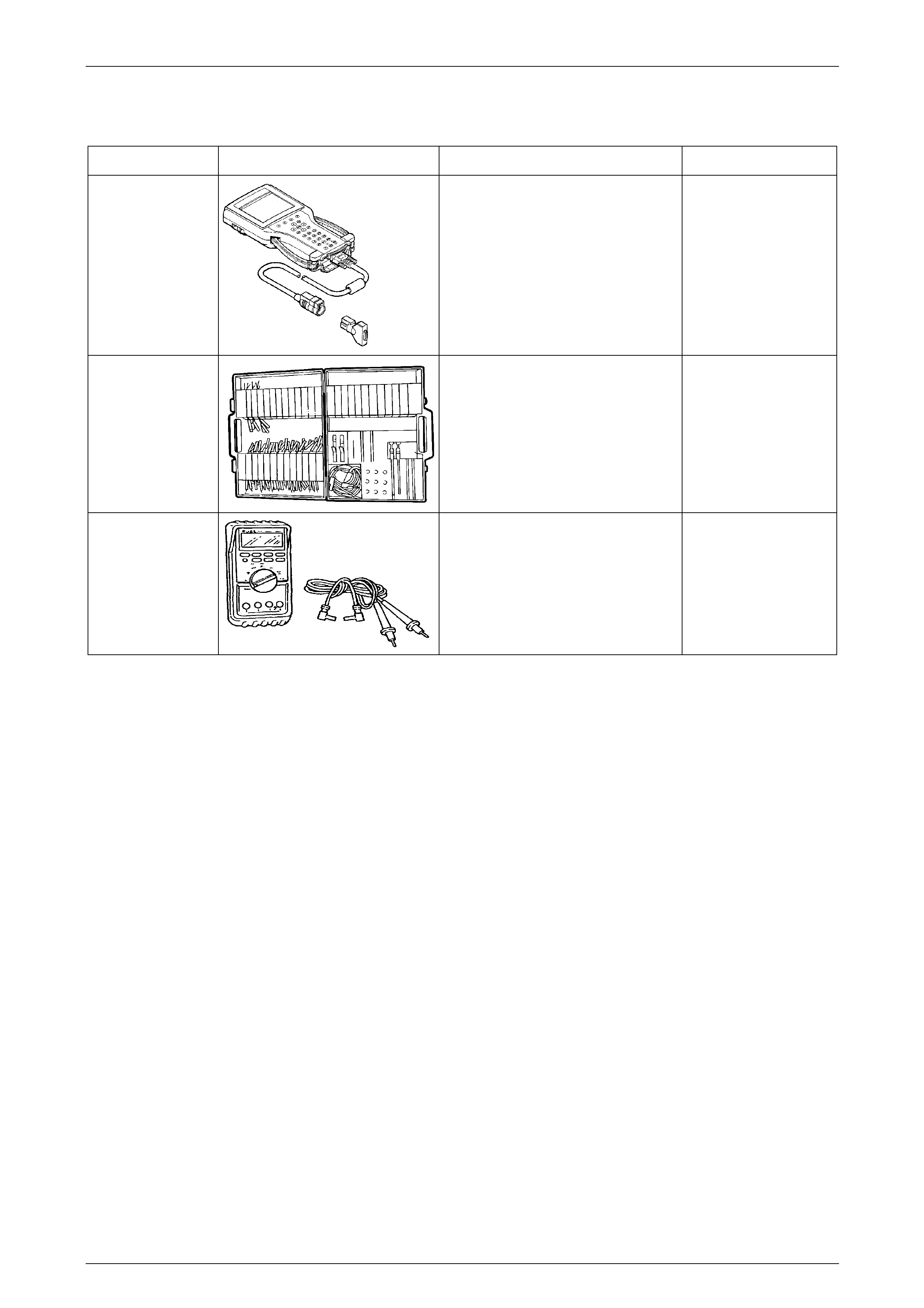
HVAC Occupant Climate Control (Auto A/C) – Diagnostics Page 2E–81
Page 2E–81
6 Special Tools
Tool Number Illustration Description Tool Classification
7000086I Tech 2 Diagnostic Scan Tool
Used for diagnosis of vehicle
electrical system.
Previously released.
J35616-A
(KM609)
Connector Test Adaptor Kit
Used when carrying out electric al
diagnostic circuit checks.
Previously released.
Desirable
3588
(J39200)
Digital Multimeter
Must have at least 10 MΩ input
impedance and be capable of reading
frequencies.
Previously released.
Available