
HVAC Occupant Climate Control (Auto A/C) – Removal and Installation Page 2F-1
Page 2F-1
Section 2F
HVAC Occupant Climate Control (Auto A/C) –
Removal and Installation
ATTENTION
Before performing any service operation or other procedure described in this Section, refer to Section 00
Warnings, Cautions and Notes for correct workshop practices with regard to safety and / or property damage.
1 General Information ...............................................................................................................................2
2 Service Operations.................................................................................................................................3
2.1 OCC Control Module.............................................................................................................................................. 3
Replace................................................................................................................................................................... 3
2.2 Sun Load Sensor ................................................................................................................................................... 4
Replace................................................................................................................................................................... 4
2.3 In-car Temperature Sensor ................................................................................................................................... 5
Replace................................................................................................................................................................... 5
Test ......................................................................................................................................................................... 5
2.4 Evaporator Temperature Sensor.......................................................................................................................... 6
Remove................................................................................................................................................................... 6
Test ......................................................................................................................................................................... 6
Reinstall.................................................................................................................................................................. 7
2.5 Aspirator Tube and Venturi................................................................................................................................... 8
Remove................................................................................................................................................................... 8
Reinstall.................................................................................................................................................................. 8
2.6 Ambient Temperature Sensor............................................................................................................................... 9
Remove................................................................................................................................................................... 9
Test ......................................................................................................................................................................... 9
Reinstall.................................................................................................................................................................. 9
2.7 Vacuum Solenoid Pack ....................................................................................................................................... 10
Remove................................................................................................................................................................. 10
Test ....................................................................................................................................................................... 11
Table 1 ............................................................................................................................................................. 11
Table 2 ............................................................................................................................................................. 11
Reinstall................................................................................................................................................................ 12
2.8 Air Mix Door Motor............................................................................................................................................... 13
Remove................................................................................................................................................................. 13
Reinstall................................................................................................................................................................ 13
2.9 Rear Remote Control Assembly......................................................................................................................... 14
Remove................................................................................................................................................................. 14
Reinstall................................................................................................................................................................ 14
3 Torque Wrench Specifications............................................................................................................15

HVAC Occupant Climate Control (Auto A/C) – Removal and Installation Page 2F-2
Page 2F-2
1 General Information
This Section describes the removal and installation procedures of the electronic control components of the occupant
climate control (OCC) system. For removal and installation procedures of the heater and air-conditioner components not
covered in this Section, refer to Section 2C HVAC Climate Control (Manual A/C) – Removal and Installation.

HVAC Occupant Climate Control (Auto A/C) – Removal and Installation Page 2F-3
Page 2F-3
2 Service Operations
2.1 OCC Control Module
Replace
For removal and installation of the OCC control module, refer to Section 1A3 Instrument Panel and Console.
NOTE
If the OCC control module is repl aced, the air mix
door / motor function must be calibrated to the
new OCC control module. Failure to do so may
cause poor OCC system performance. Refer to
2.8 Air Mix Door Motor.


HVAC Occupant Climate Control (Auto A/C) – Removal and Installation Page 2F-5
Page 2F-5
2.3 In-car Temperature Sensor
LT Section No. — 08–200
Replace
For removal and installation of the in-car temperature sensor, refer to Section 1A3 Instrument Panel and Console.
Test
1 Using an ohmmeter, measure the resistance across the in-car temperature sensor terminals.
2 Using a digital thermometer pl aced as close to the sensor as possible, measure the temperature.
3 Compare the readings with the table (should be within ± 3°C).
4 If the in-car temperature sensor fails any pa r t of the test, replac e the sensor with a serviceable item.
Air Temperature °C Sensor Resistance Ω
5 7009 – 7536
10 5477 – 5856
15 4310 – 4583
20 3416 – 3612
25 2725 – 2865
30 2175 – 2299
35 1746 – 1857
40 1410 – 1508
45 1145 – 1231
50 935 – 1010
HVAC Occupant Climate Control (Auto A/C) – Removal and Installation Page 2F-6
Page 2F-6
2.4 Evaporator Temperature Sensor
LT Section No. — 08–150
Remove
1 Remove the instrument panel, refer to Section 1A3 Instrument Panel and Console.
2 Remove the HVAC unit and access the evaporator, refer to Section 2C HVAC Climate Control (Manual A/C) –
Removal and Installation.
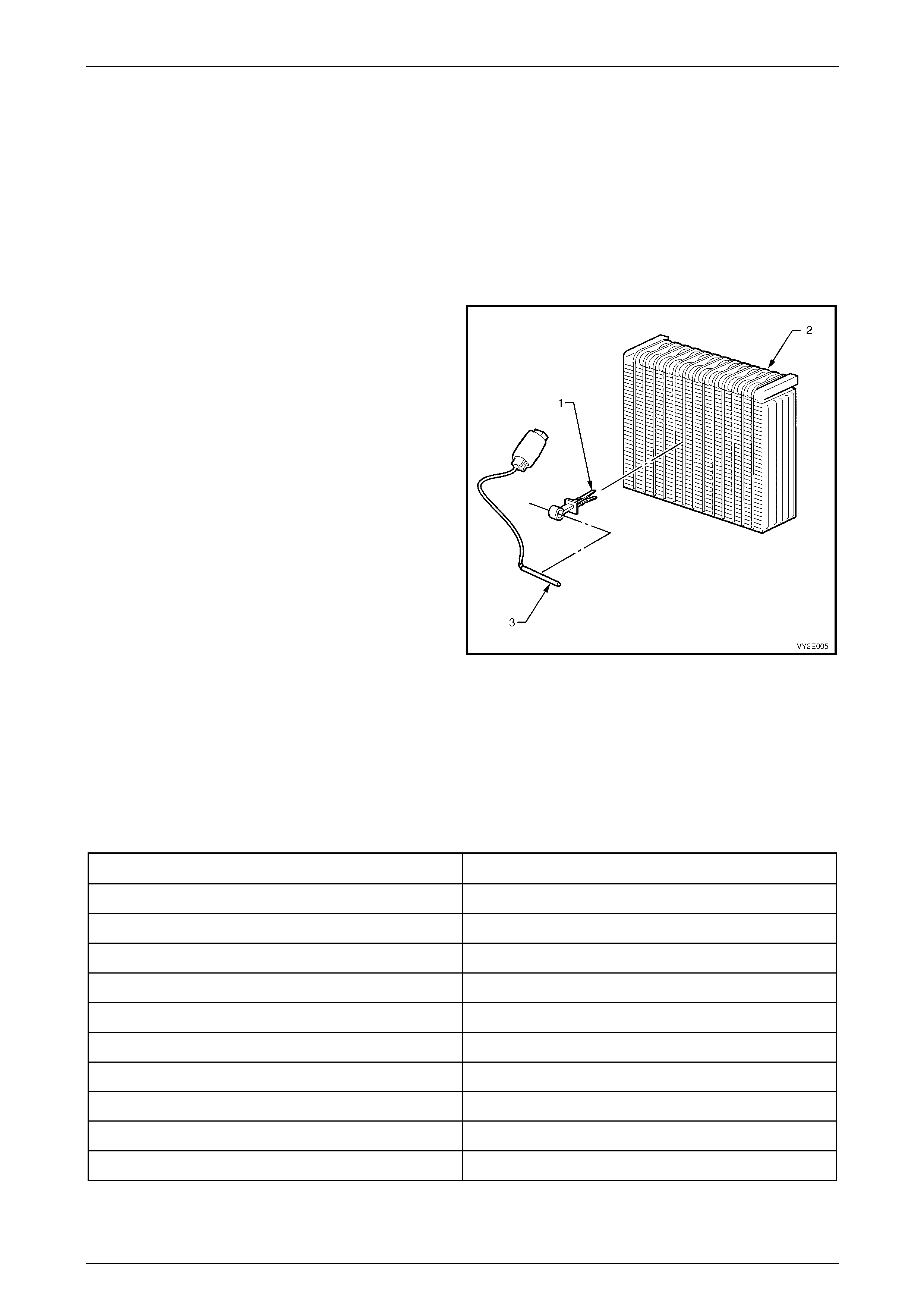
3 Disconnect the sensor wiring harness connector at the
front of the HVAC case.
4 Remove the clamp (1) from the evaporator (2) and
remove the evaporator temperature sensor (3).
Figure 2F – 1
Test
1 Using an ohmmeter, measure the resistance across the evaporator temperature sensor terminals.
2 Using a digital thermometer, placed as close to the sensor as possible, measure the temperature.
3 Compare the readings with the table (should be within ± 3°C).
4 If the evaporative temperature sensor fails any part of the test, replace the sensor with a serviceable item.
Air Temperature °C Resistance Ω
5 4300 – 4850
10 3600 – 4050
15 2950 – 3250
20 2320 – 2625
25 1990 – 2200
30 1675 – 1850
35 1330 – 1470
40 1140 – 1260
45 950 – 1050
50 850 – 950
HVAC Occupant Climate Control (Auto A/C) – Removal and Installation Page 2F-7
Page 2F-7
Reinstall
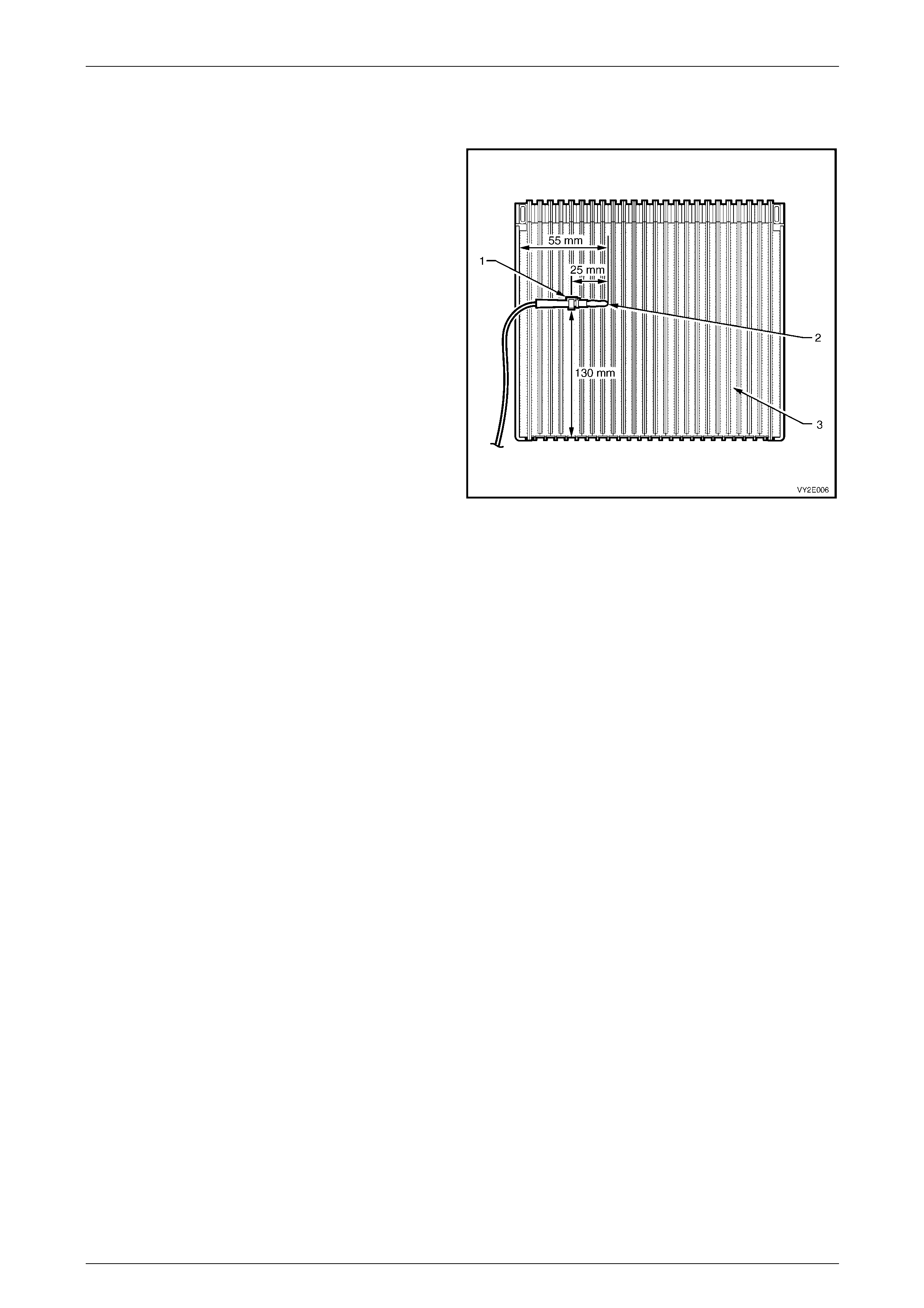
Reinstallation of the evaporator temperature sensor is the reverse of the removal proce dure, noting the following:
1 Ensure the clamp (1) is fitted over the sensor (2)
25 mm from the end.
2 Insert the clamp firmly into the evaporator fins (3) at
the dimensions shown.
3 Ensure the sensor harness is correctly installed in the
recess provided in the evaporator cover when the
cover is assembled to the case.
Figure 2F – 2
HVAC Occupant Climate Control (Auto A/C) – Removal and Installation Page 2F-8
Page 2F-8
2.5 Aspirator Tube and Venturi
LT Section No. — 08–150
Remove
1 Remove the instrument panel assembly, refer to Section 1A3 Instrument p anel and Console.
2 Remove HVAC unit, refer to Section 2C HVAC Climate Control (Manual A/C) – Removal and Installation.
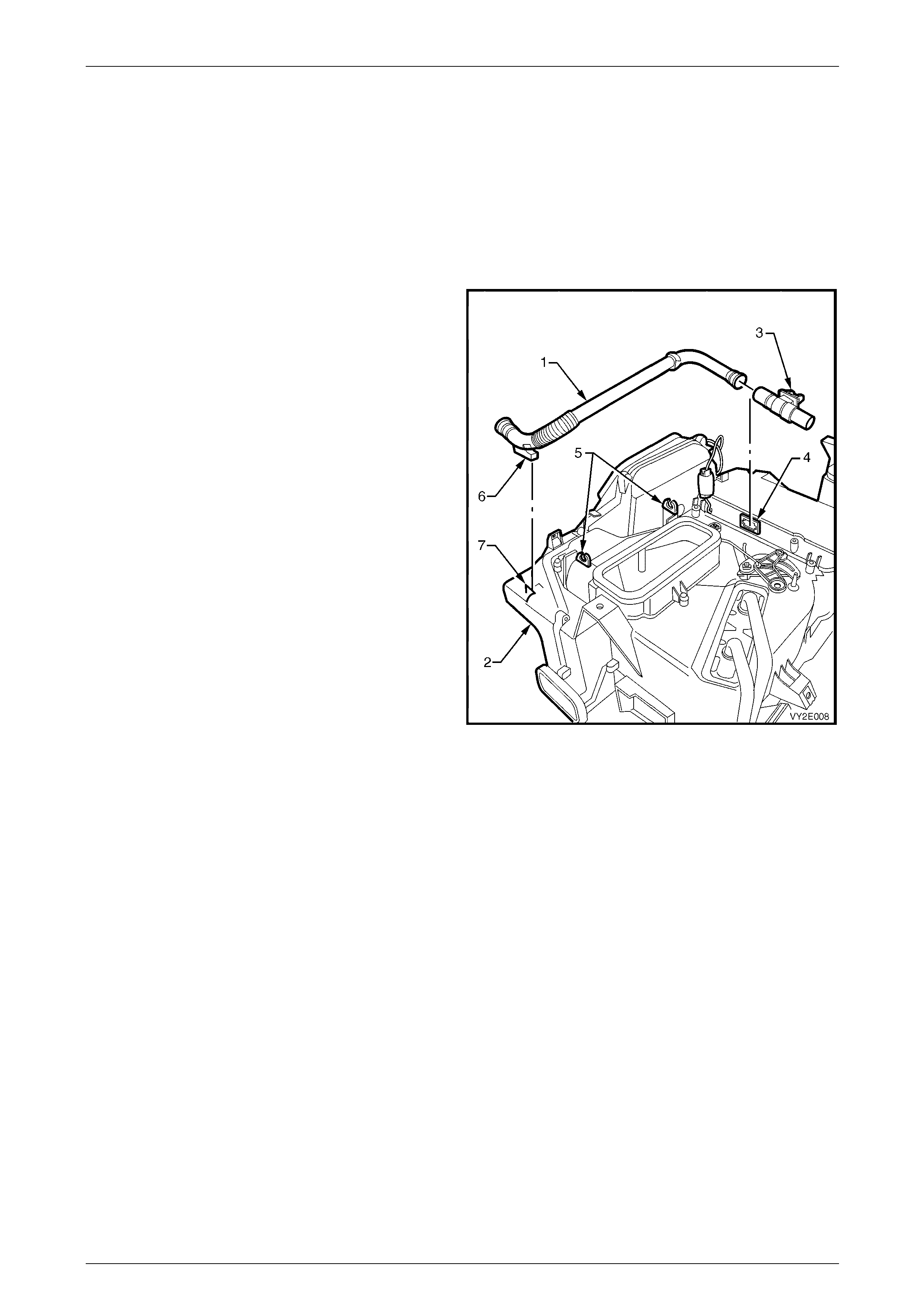
3 Note the location then remove any adhesive tape
retaining the aspirator tube (1) to the HVAC case (2).
4 Remove the aspirator tube and the venturi (3) as an
assembly from the HVAC case.
5 Remove the aspirator tube from the venturi.
Figure 2F – 3
Reinstall
Reinstallation of the aspirator tube and venturi is the reverse of the remo val procedure, noting the following:
1 When installing the venturi into the aspirator tube, ensure the tube is fully engaged into the venturi.
2 Ensure the venturi is fully seated into the HVAC case venturi hole (4) and the aspirator tube is correctly install ed
into the retaining clips (5) and the lug (6) is secured to the recess (7), refe r to Figure 2F – 3.
3 Install adhesive tape to the original locations as noted on removal.
HVAC Occupant Climate Control (Auto A/C) – Removal and Installation Page 2F-9
Page 2F-9
2.6 Ambient Temperature Sensor
LT Section No. — 08–200
Remove
1 Raise front of vehicle and support on safet y stands. Refer to Section 0A General Information for the location of
jacking and support points.
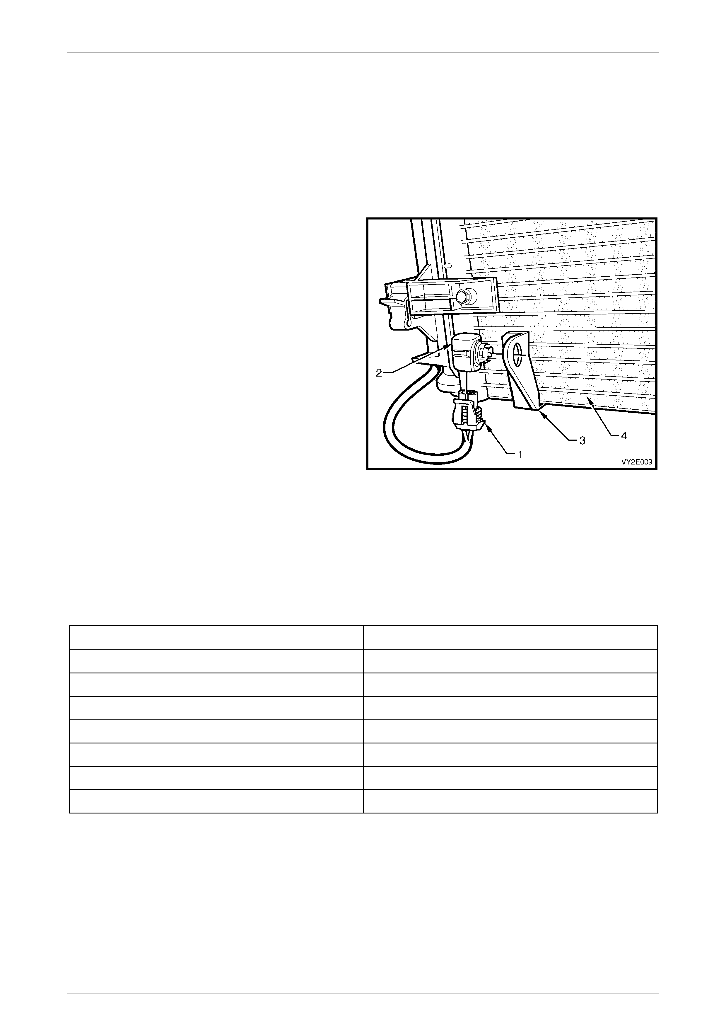
2 Remove the wiring harness connector (1) from the
ambient temperature sensor (2).
3 Using a flat blade screwdriver, carefully lever the
sensor away from the retaining bracket (3).
NOTE
The retaining bracket is not to be removed from
the condenser (4).
Figure 2F – 4
Test
1 Using an ohmmeter, measure the resistance across the ambient temperature sensor terminals.
2 Using a digital thermometer pl aced as close to the sensor as possible, measure the temperature.
3 Compare the readings with the table (should be within ± 3°C).
4 If the ambient temperature sensor fails any part of the test, replace the sensor with a serviceable item.
Air Temperature °C Resistance Ω
0 15920 – 16750
10 9715 – 1019 3
20 6107 – 6389
30 3943 – 4115
40 2610 – 2717
50 1767 – 1836
60 1201 – 1291
Reinstall
Reinstallation of the ambient temperature sensor is the reverse of the removal procedure .
HVAC Occupant Climate Control (Auto A/C) – Removal and Installation Page 2F-10
Page 2F-10
2.7 Vacuum Solenoid Pack
LT Section No. — 08–150
Remove
1 Remove the left-hand instrument panel lower trim plate assembly, refer to Section 1A3 Instrument Panel and
Console.
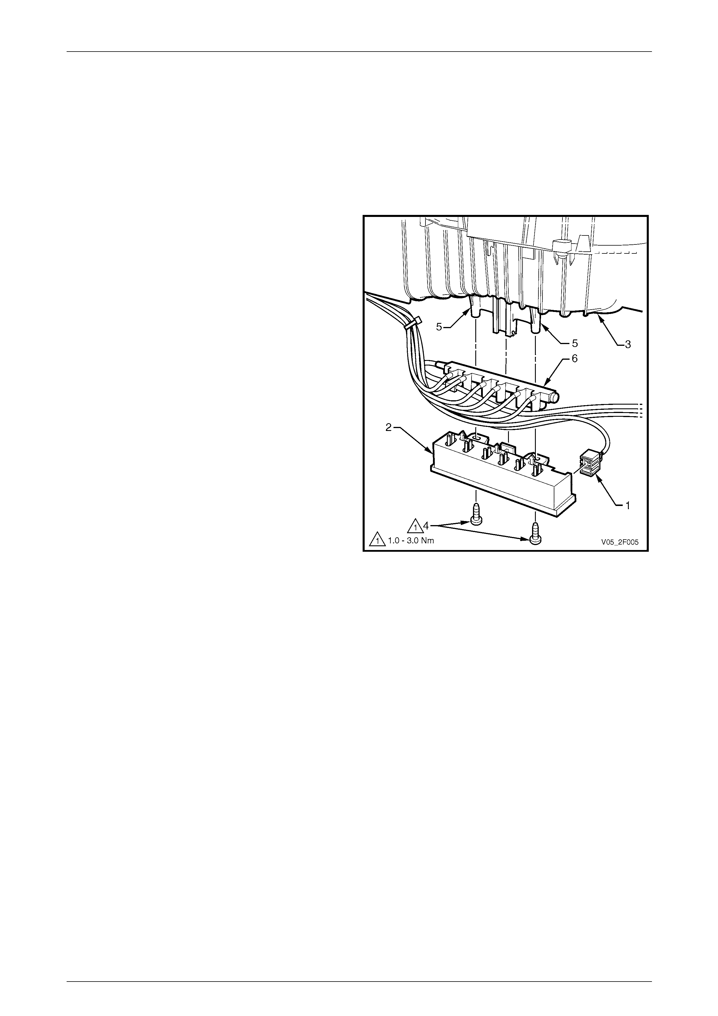
2 Disconnect the wiring harness connector (1) from the
vacuum solenoid pack (2).
3 Remove the vacuum lines from the retaini ng clips in
the HVAC unit (3) at the left hand end of the solenoid
pack.
4 Remove the two screws (4) attaching the sol enoid
pack to the lugs (5) on the HVAC unit case and move
the solenoid pack away from the case.
5 Disconnect the vacuum manifold (6) from the solenoid
pack and remove the pack.
Figure 2F – 5

HVAC Occupant Climate Control (Auto A/C) – Removal and Installation Page 2F-11
Page 2F-11
Test
NOTE
To test the vacuum retention of the vacuum
solenoid pack, refer to Section 2C HVAC Climate
Control (Manual A/C) – Removal and Installation.
1 Using an ohmmeter, measure the resistance across
the vacuum solenoid pack terminals and compare the
readings to the following tables.
2 If the resistance readings are not to specification or
there is continuity between any terminals other than
those listed, the solenoid pack is faulty.
3 If the solenoid pack fails any part of the test, replace
the complete solenoid pack.
Figure 2F – 6
Table 1
Connector Details
Pin Number Function
X1-1 Solenoid 4 – Foot 1
X1-2 Solenoid 2 – Face 1
X1-3 Solenoid 1 – Intake
X1-4 12 V Power
X1-5 Solenoid 6 – Water
X1-6 Solenoid 2 – Face 2
X1-7 Solenoid 5 – Foot 2
X1-8 Not Connected
Table 2
Solenoid Pack Contacts Resistance Ω
X1-4 and X1-1 109 – 111
X1-4 and X1-2 109 – 111
X1-4 and X1-3 109 – 111
X1-4 and X1-5 109 – 111
X1-4 and X1-6 109 – 111
X1-4 and X1-7 109 – 111

HVAC Occupant Climate Control (Auto A/C) – Removal and Installation Page 2F-12
Page 2F-12
Reinstall
Reinstallation of the vacuum solenoid pack is the reverse of the removal procedure. Tighten the attaching screws to the
correct torque specification.
Vacuum solenoid pack attaching
screw torque specification...........................1.0 – 3.0 Nm
HVAC Occupant Climate Control (Auto A/C) – Removal and Installation Page 2F-13
Page 2F-13
2.8 Air Mix Door Motor
LT Section No. — 08–150
NOTE
If an air mix door motor is replaced, the air mix
door / motor function must be calibrated to the
OCC control module. Failure to do so ma y cause
poor OCC system performance. Refer to Tech 2
Information in Section 2E HVAC Occupant
Climate Control (Auto A/C) – Diagnostics.
Remove
1 Remove the floor console and instrument panel, refer to Se ction 1A3 Instrument Panel and Console.
2 Remove the HVAC unit, refer to Section 2C HVAC Climate Control (Manual A/C) – Removal and Installation.
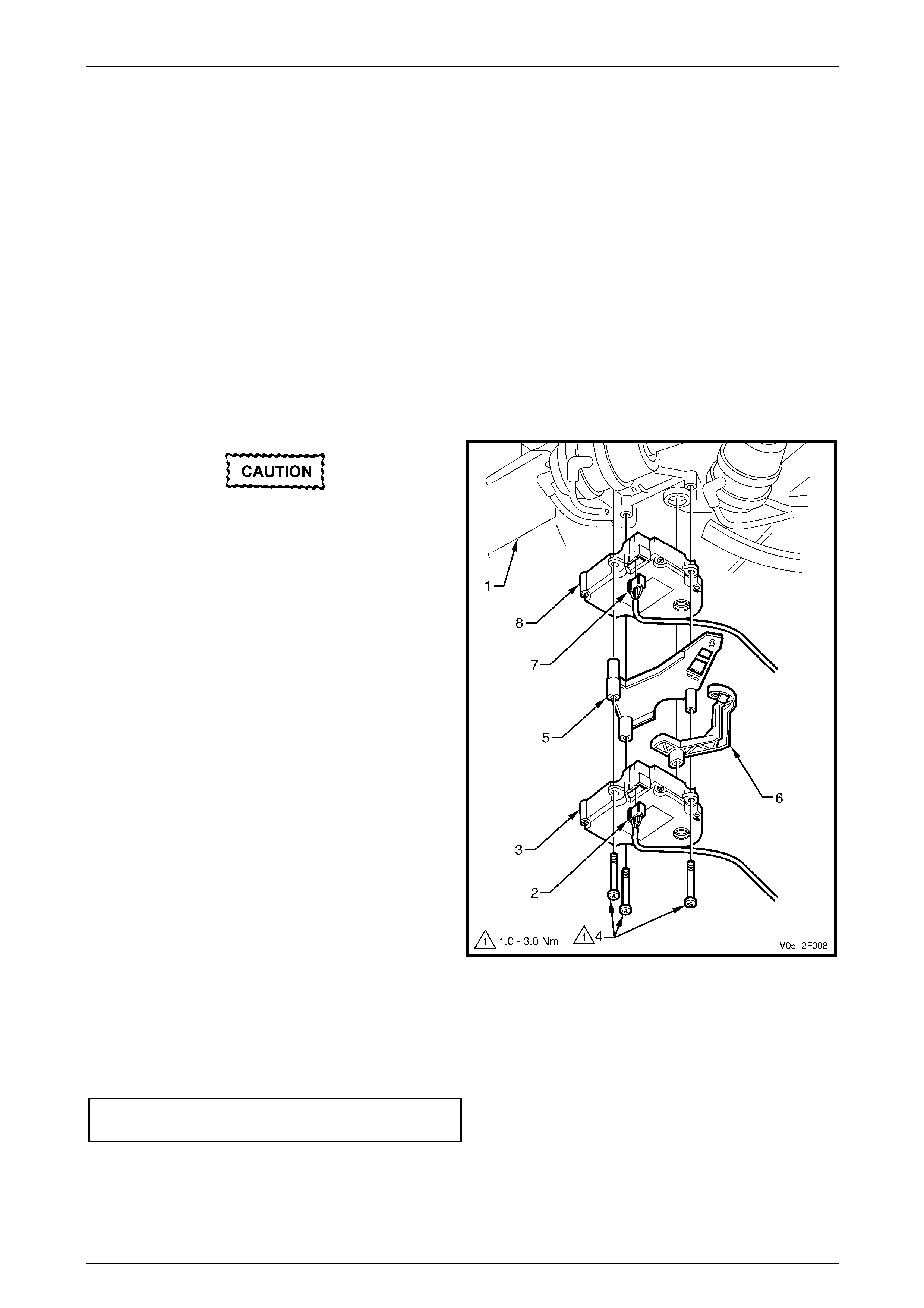
Prior to removing the harness connectors,
note which connector is installed to the
driver’s side air mix door motor and which
connector is installed to the front
passenger’s side air mix door motor. Do not
transpose the conn ecto rs.
3 From the underside of the HVAC unit (1), locate the
driver’s side air mix door moto r harness connector (2)
and disconnect from the motor (3).
4 Remove the three screws (4) attaching the air mix
door motors to the HVAC unit and remove the driver’s
side air mix door motor along wit h the intermediate
mounting plate (5) and activating lever (6).
5 Disconnect the harness connector (7) from the front
passenger's side air mix door motor (8).
6 Remove the front passenger's side air mix door motor
from the HVAC unit.
Figure 2F – 7
Reinstall
Reinstallation of the air mix door motor is the reverse of the removal procedure, noting the following:
1 Tighten the motors attaching screws to the correct torque specification.
Air mix door motor attaching screw
torque specification.....................................1.0 – 3.0 Nm
2 Ensure the correct connector is fitted to the corresponding air mix door motor, as noted on removal.
3 If required, perform the air mix door motor calibration procedure, refer to Tech 2 Information in
Section 2E HVAC Occupant Climate Control (Auto A/C) – Diagnostics.
HVAC Occupant Climate Control (Auto A/C) – Removal and Installation Page 2F-14
Page 2F-14
2.9 Rear Remote Control Assembly
LT Section No. — 09–500
Remove
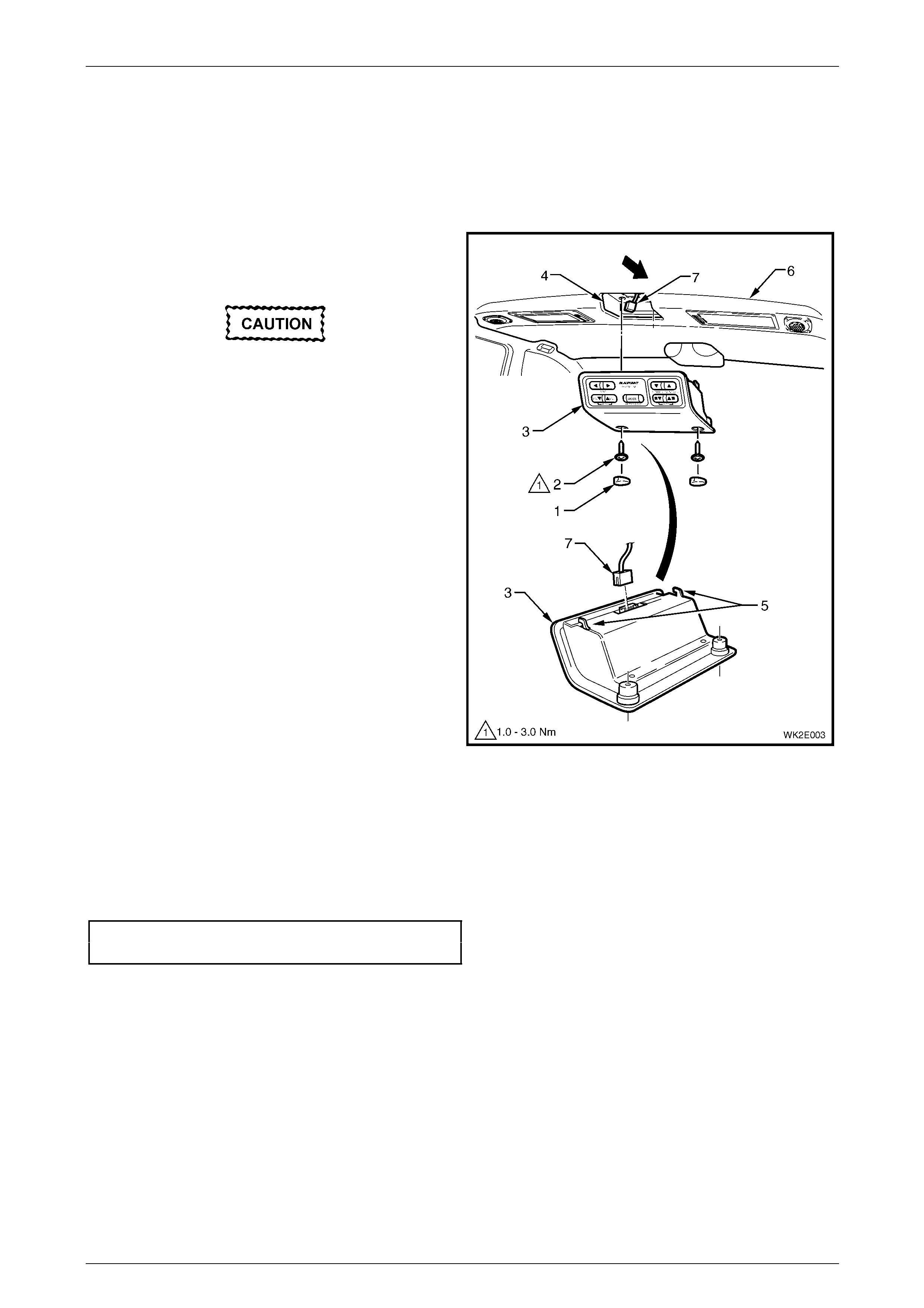
1 Remove the two blanking plug s (1) and two screws (2)
securing the rear remote control assembly (3) to the
headlining support (4).
Take extreme care when removing the
blanking plugs from the rear remote control
housing as the housing can be easily
damaged.
2 Disengage the locating lu gs (5) and lower the rear
remote control assembly from the headlini ng (6).
3 Disconnect the wiring harness connector (7) from the
rear remote control assembly and remove th e
assembly.
Figure 2F – 8
Reinstall
Reinstallation of the rear rem ote control assembly is the reverse of the removal procedure, noting the following:
1 For bulb replacement in the rear remote control, refer to Section 12B Lighting System.
2 Tighten the attaching screws to the correct torque specification.
Rear remote control attaching
screw torque specification...........................1.0 – 3.0 Nm

HVAC Occupant Climate Control (Auto A/C) – Removal and Installation Page 2F-15
Page 2F-15
3 Torque Wrench Specifications
Vacuum Solenoid Pack Attaching Screw.......................................1.0 – 3.0 Nm
Air Mix Door Motor Attaching Screw..............................................1.0 – 3.0 Nm
Rear Remote Control Attaching Screw..........................................1.0 – 3.0 Nm