
Rear Propeller Shaft and Universal Joints Page 4C1 – 1
Page 4C1 – 1
Section 4C1
Rear Propeller Shaft & Universal Joints
ATTENTION
Before performing any Service Operation or other procedure described in this Section, refer to Section 00
Warnings, Cautions and Notes for correct workshop practices with regard to safety and/or property damage.
1 General Information ...............................................................................................................................2
2 Service Operations.................................................................................................................................4
2.1 Propeller Shaft ....................................................................................................................................................... 4
Remove................................................................................................................................................................... 4
Front Coupling Attached to the Transmission Output Flange............................................................................. 4
For WL Models with a Sliding Front Yoke .......................................................................................................... 6
Reinstall.................................................................................................................................................................. 6
For WL Models with Front Coupling Attached to the Transmission Output Flange ............................................ 6
For WL Models with a Sliding Front Yoke .......................................................................................................... 7
2.2 Rubber Coupling.................................................................................................................................................... 8
Replace................................................................................................................................................................... 8
2.3 Centre Bearing Assembly ................................................................................................................................... 10
Remove................................................................................................................................................................. 10
Reinstall................................................................................................................................................................ 12
3 Specifications.......................................................................................................................................14
4 Torque Wrench Specifications............................................................................................................15
5 Special Tools ........................................................................................................................................16

Rear Propeller Shaft and Universal Joints Page 4C1 – 2
Page 4C1 – 2
1 General Information
The propeller shaft assembly is a two piece tubular design, incorporating a sealed for life centre support bearing. The
centre support bearing is a fully sealed ball bearing, mounted in a reinforced rubber cup. This centre bearing rubber cup
is supported in a cup guide and attache d to a carrier, which is bolted to the vehicle underbod y brace. Should a specific
tow bar package be fitted, a heat shield may also be fitted to the centre bearing carrier. No periodic servicing of the
centre bearing nor any u niversal joint, is required.
For those MY2005 WL vehicles with the GEN III V8 engine and 4 speed 4L60-E automatic transmission, servicing of the
centre bearing is not possible. The reason is that the interference fit of the splined joint between the front and rear
propeller shaft halves is such that special tools and high press forces are required to separate the two shafts. As this
operation would also re quire the re-balancing of the propeller shaft assembly, the centre bearing assembly and/or slinger
are also non-serviceable.
On those MY2005 WL vehicles fitted with the V6 engine and the 5 speed 5L40-E automatic transmission however, the
centre bearing and boot are s erviceable items.
Front Coupling Joint: While al l propeller shafts have a rubber coupling in this location, dep endent upon the transmission,
the coupling may be attached to the transmission output shaft flange by a bolt and nut (V6 5L4 0-E – automatic
transmission) or by being bolted to a slip yoke that is splined to the output shaft (GEN III V8 – 4L60-E automatic
transmission).
Centre Universal Joint: This is a conventional cross type universal joint (Hooke’s joint) mounted behind the centre
bearing. The cross t ype universal joint type is non-serviceable, as the bearing cups are set and retained by staking. This
requires sophisticated equi pment to ensure concentricity of the installed universal joint.
Rear Coupling Joint: The rear coupling is fixed to the rear final drive pinion flange by three, T orx headed special thread
formed bolts.
Rear Propeller Shaft and Universal Joints Page 4C1 – 3
Page 4C1 – 3
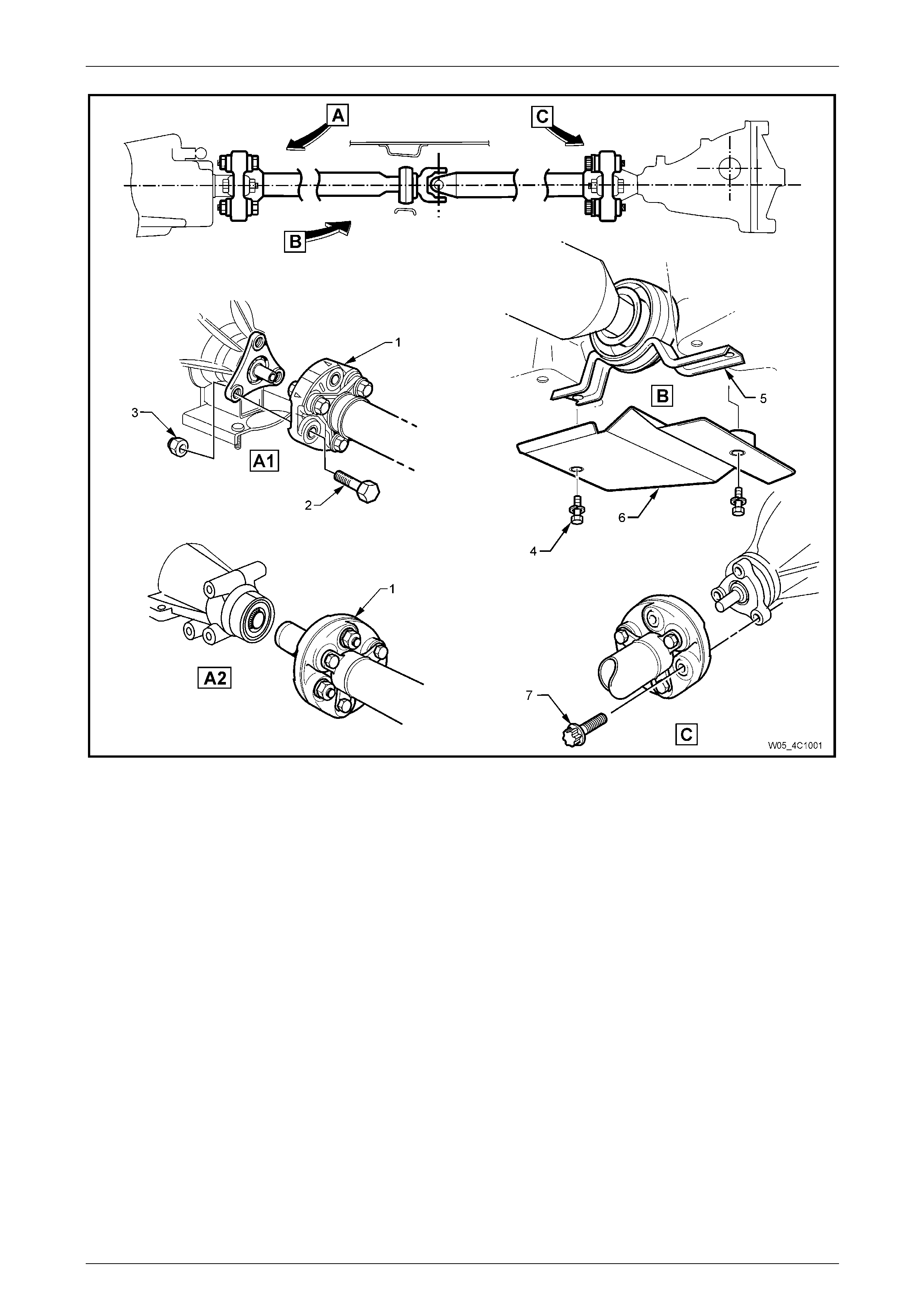
Figure 4C1 – 1
Legend
A1 Front Coupling – V6/5L40-E Automatic Transmission
A2 Front Coupling – GEN III V8/4L60-E Automatic Transmission
B Centre Bearing
C Rear Coupling to Final Drive Pinion Flange
1 Front Rubber Coupling
2 Coupling to Transmission Flange Bolt (3 Places)
3 Coupling to Transmission Flange Nut (3 Places)
4 Centre Bearing Cup Guide to Underfloor Bolt (2 Places)
5 Centre Bearing Cup Guide
6 Heat Shield – Centre Bearing (Where Fitted)
7 Rear Coupling To Final Drive Opinion Flange Bolt (3 Places)
Rear Propeller Shaft and Universal Joints Page 4C1 – 4
Page 4C1 – 4
2 Service Operations
ATTENTION
All fasteners are important attaching parts as they affect the performance of vital components and/or could
result in major repair expense. W here specified in this Section, fasteners MUST be replaced w ith parts of the
same part number or an approved equivalent. Do not use fasteners o f an inferior quality or substitute design.
Torque values must be used as specified during reassembly to ensure proper retention of all components.
Throughout this Section, fastener torque wrench specifications may be accompanied with the following
identification marks:
Fasteners must be repl aced after loosening.
Vehicle must be at curb height before final tightening.
Fasteners either have micro encapsulated sealant applied or incorporate a mechanical thread lock and
should only be re-used once. If in doubt, replacement is recommended.
If one or more of these identification marks is present alongside a fastener torque wrench specification, the
recommendation regarding that fastener must be adhered to.
2.1 Propeller Shaft
Remove
1 Raise the vehicle and suppor t in a safe manner. Refer to Section 0A General Information for location of jacking and
support points.
2 To provide access to the propeller shaft fasteners, it is recommend ed that the intermediate exhaust pipe,
intermediate and rear muffler assemblies be removed. For information regarding the removal and installation
procedures for these components, refer to Section 8B Exhaust System.
Front Coupling Attached to the Transmission Output Flange
A number of different methods of attaching
the front coupling to the transmission output
flange may be observed:
• Hexagon headed bolts into threaded
flange holes. With this method, the output
flange threads are of the 'Spiralock' form
that can only be loosened/tightened a
maximum of ten times. Because of the
safety factor involved, if the complete
vehicle service history is not known, then
both the flange and the bolts MUST be
replaced on reassembly.
• Studs installed into the transmission
output flange facing rearward, with the
flange being secured by nuts.
• Hexagon headed bolts and nuts. Figure
4C1 – 2 shows this method.
Rear Propeller Shaft and Universal Joints Page 4C1 – 5
Page 4C1 – 5
NOTE
If the reason for removing the propeller shaft is
not related to the front rubber coupling, then it is
recommended that the three bolts and nuts
securing the propeller shaft to the front coupling
be removed, leaving the coupling attached to the
transmission output shaft flange.
Release the park brake to relax any ‘wind-up’
in the flexible rubber coupling. Otherwise,
when the propeller shaft bolts are released
from the final drive pinion flange, personal
injury may result.
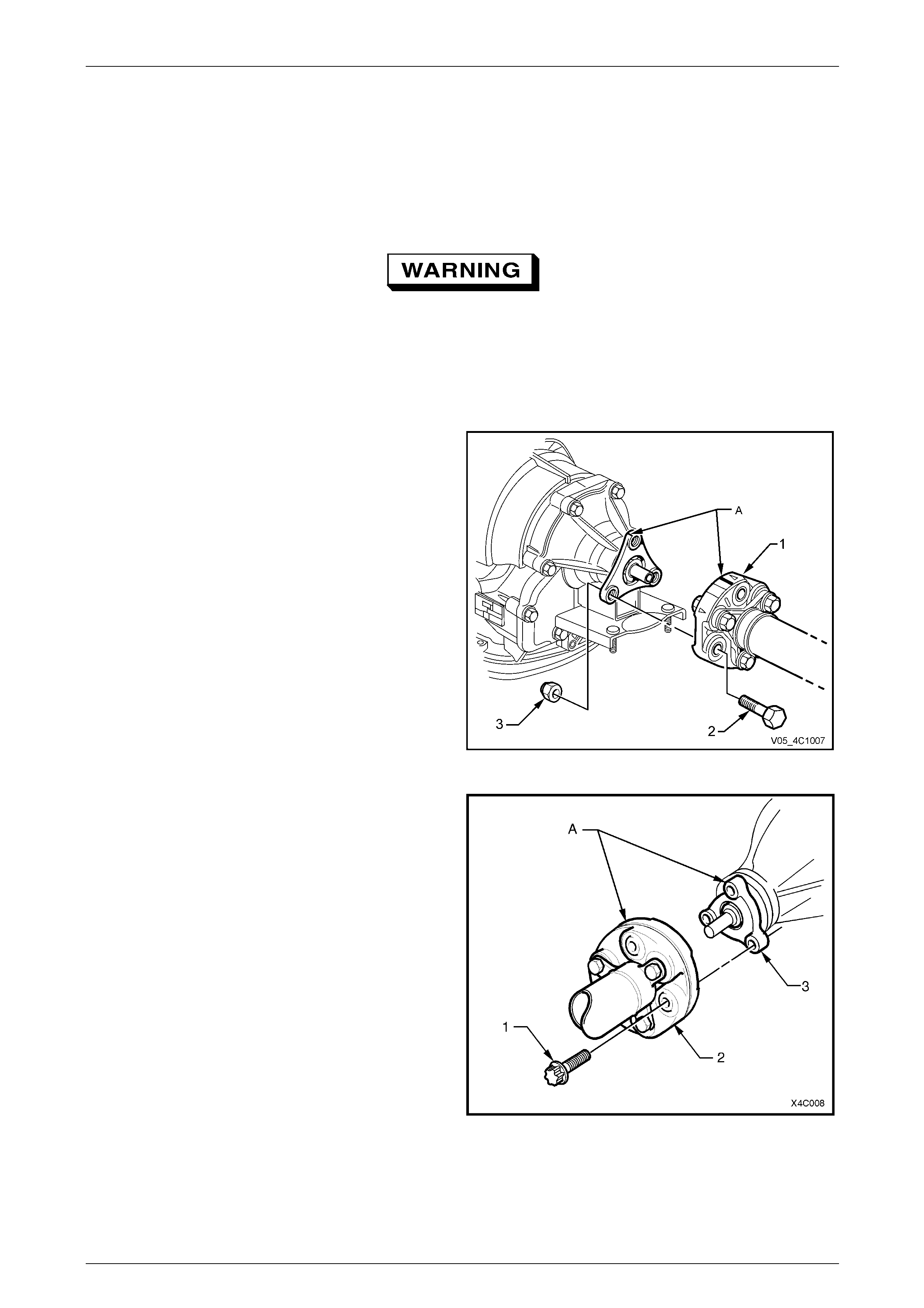
3 Select the Park position with the transmission selector lever.
4 To enable the propell er shaft to be reinsta lled in the
original position relative to the transmissi on output
shaft flange, use a felt tipped pen or similar t o ide ntify
the relationship (‘A’) of the t wo components.
5 Using suitable socket equipment, loosen the three
bolts (2) and nuts (3) and securing the front coupling
(1) to the transmission output flange
6 With the transmission shift lever in the Neutral position
and the park brake released, remove the three Torx
headed bolts.
Figure 4C1 – 2
7 To enable the propell er shaft to be reinsta lled in the
original position relative to the final drive pinion flange,
use a felt tipped pen or similar to identify the
relationship (‘A’) of the two components.
8 With the transmission in the Park position, check that
the park brake is firmly applied.
9 Use Torx socket K04425E20 or a commercially
available E20 Torx equivalent to loosen the three Torx
headed bolts (1) securing the propeller shaft rear
rubber coupling (2) to the pini on flange (3).
10 Release the park brake to relieve any torque loading
on the rubber coupling, then remove the three Torx
headed bolts (1)
Figure 4C1 – 3
Rear Propeller Shaft and Universal Joints Page 4C1 – 6
Page 4C1 – 6
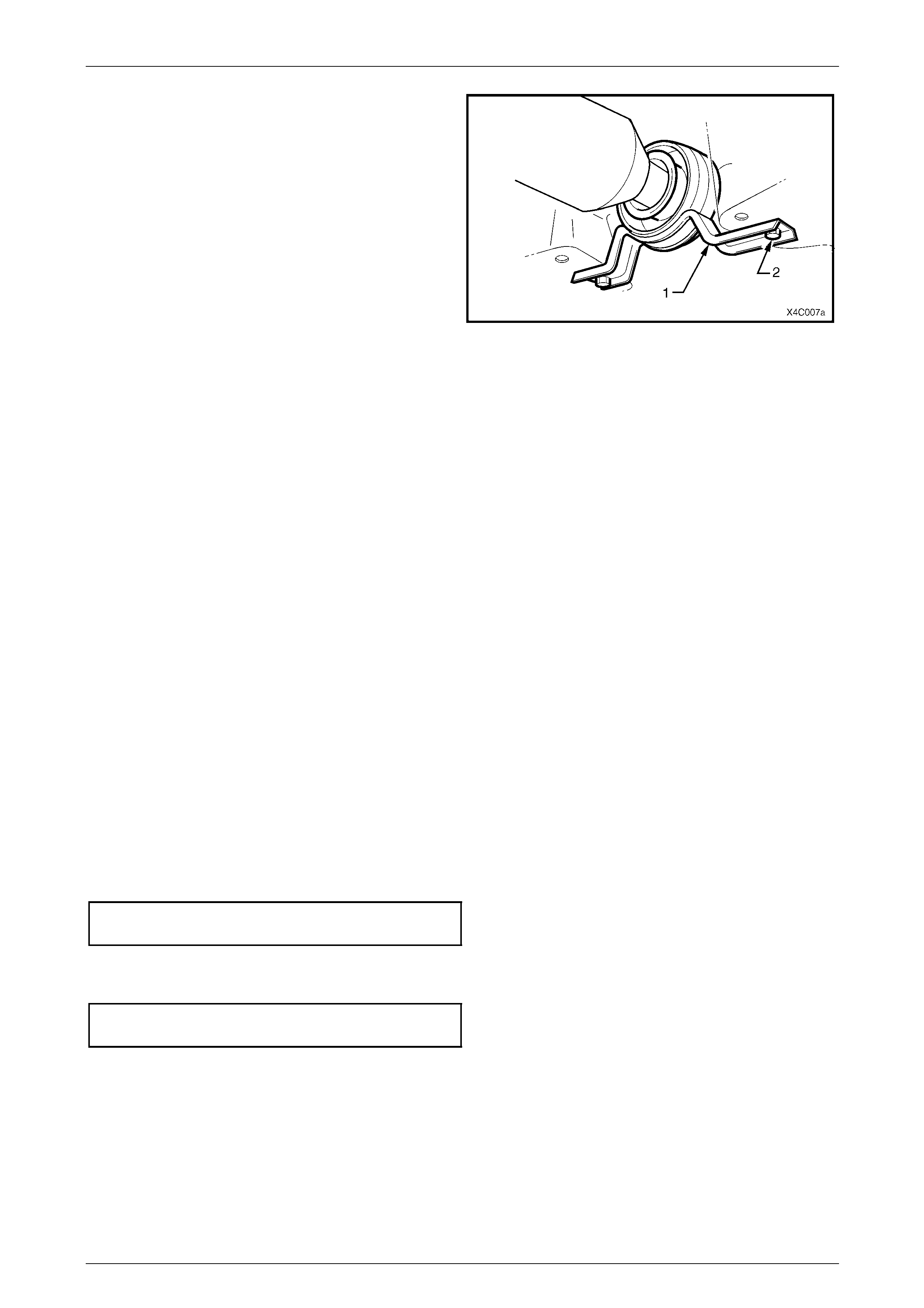
11 Remove the two centre bearing carrier (1) to
underbody reinforcement bolts (2).
12 While supporting the centre beari ng section, slide the
propeller shaft assembly forward to disengage from
the final drive pinion support pin, then lower the
assembly at the rear, sliding rearward to disengage
the front coupling.
13 Remove the propeller shaft assembly from the vehicle.
Figure 4C1 – 4
For WL Models with a Sliding Front Yoke
14 After completing all Steps except 4 to 6 inclusive, slide the propeller shaft assemb ly rearward to disengage the front
yoke from the transmission output shaft splines. Durin g this process:
a Locate a clean drain tray under the rear of the transmission to catch any spilled lubricant when the propeller
shaft is removed.
b Take care to protect the outer diameter of the front yoke. Nicks or abrasions will damage the transmission
extension seal during reassembly and result in subsequ ent lubricant leakage from this area.
c Insert a suitable plug in the end of the transmission re ar extension to prevent loss of transmission lubric ant.
Reinstall
Reinstallation is the reverse of removal procedures, except for the following items:
For WL Models with Front Coupling Attached to the Transmission Output Flange
1 Lubricate the transmission rear output shaft and final drive pinion spigots with a molybdenum disulphide grease
such as an NLGI No. 2 lithium soap based EP grease with molybdenum disulphide, such as Shell Retinax HDX2
grease or BP Energrease LMS-EP 23 (or eq uivalent).
2 Reinstall the front of the propeller shaft assembly first, supporting the centre and rear sections.
3 Align the marks made before removal (refer to Figure 4C1 – 2) and temporarily install either a coupling to flange
bolt and nut or nut to secure the propeller shaft in this position.
4 Install the rear coupling over the final drive pinion spigot, align the marks made before removal (refer to
Figure 4C1 – 3) and temporari ly install one of the Torx headed bolts to secure the coupl in g.
5 Raise the centre bearing assembly and install the bolts and spring washers to secure to the underbody
reinforcement. Tighten both bolts to the correct torque specification.
Centre bearing carrier to underbody
reinforcement bolt torque specification ................22 N.m
6 Provided no thread damage is evident, reinstall the original rear propeller shaft coupling to the final drive pinion
flange, Torx headed bo lts, tightening to the correct torque specification.
Propeller shaft rear coupling to pinion
flange bolt torque specification...........................115 N.m
Rear Propeller Shaft and Universal Joints Page 4C1 – 7
Page 4C1 – 7
7 If bolts are used to secure the coupling to the transmission output flange, provid ed no thread damage is evident,
the original front propeller shaft coupling bolts may be re-used up to a maximum of ten times:
a Reinstall the three bolts and tighten to the correct torque specification.
Front coupling to transmission output
flange bolt torque specification...........................115 N.m
b If bolts and nuts are used to secure the coupling to the tran smission output flange, install NEW bolts and nuts
and tighten to the correct torque specification.
Front coupling to transmission output
flange bolt and nut torque specification..............115 N.m
c If nuts are used to secure the front coupling to the transmission output flange studs, insta ll NEW nuts and
tighten to the correct torque specification.
Front coupling to transmission output
flange nut torque specification .............................85 N.m
8 Reinstall the exhaust system, refer to Section 8B Exhaust System, for the procedures an d clearances.
9 Lower the vehicle to the ground an d road test to check for correct operation.
For WL Models with a Sliding Front Yoke
1 Clean the sliding yoke bearing surface, inspect for nicks or other damage.
2 If considered serviceable, lubricate the sli ding yoke with the recommended transmission lubricant, reinstall to the
transmission output shaft splines.
3 Lubricate the final drive pinion spigot with a molybdenum disulp hide grease such as an NLGI No. 2 lithium soap
based EP grease with molybdenum disulph id e, such as Shell Retinax HDX2 grease or BP Energrease LMS-EP 23
(or equivalent).
4 While supporting the centre beari ng offer the rear coupling up to the final drive pinion flange and temporarily install
one of the retaining bolts to secure in this position.
5 Raise the centre bearing assembly and install the bolts with spring washers to secure to the underbody
reinforcement. Tighten both bolts to the correct torque specification.
Centre bearing carrier to underbody
reinforcement bolt torque specification ................22 N.m
6 Before installing the rear coupling to fin al drive flange bolts, align the marks made before remova l, refer to
Figure 4C1-3.
7 Provided no thread damage is evident, reinstall the original rear propeller shaft coupling to the final drive pinion
flange, Torx headed bo lts, tightening to the correct torque specification.
Rear coupling to pinion flange
bolt torque specification.....................................115 N.m
8 Reinstall the exhaust system, refer to Section 8B Exhaust System, for the procedures an d clearances.
9 Road test the vehicle to check for correct operation.
Rear Propeller Shaft and Universal Joints Page 4C1 – 8
Page 4C1 – 8
2.2 Rubber Coupling
ATTENTION
The following fasteners MUST be replaced when performin g these operations:
Front or rear rubber coupling to propeller shaft flange bolts and nuts.
Replace
1 Remove the propeller shaft. Refer to 2.1 Propeller Shaft in this Section.
2 Using a back-up spanner on each of the three propeller shaft to coupling bolts (2), loosen then remove the nuts (1).
Discard the removed bolts and nuts. Remove the coupling from the front of the propeller shaft.
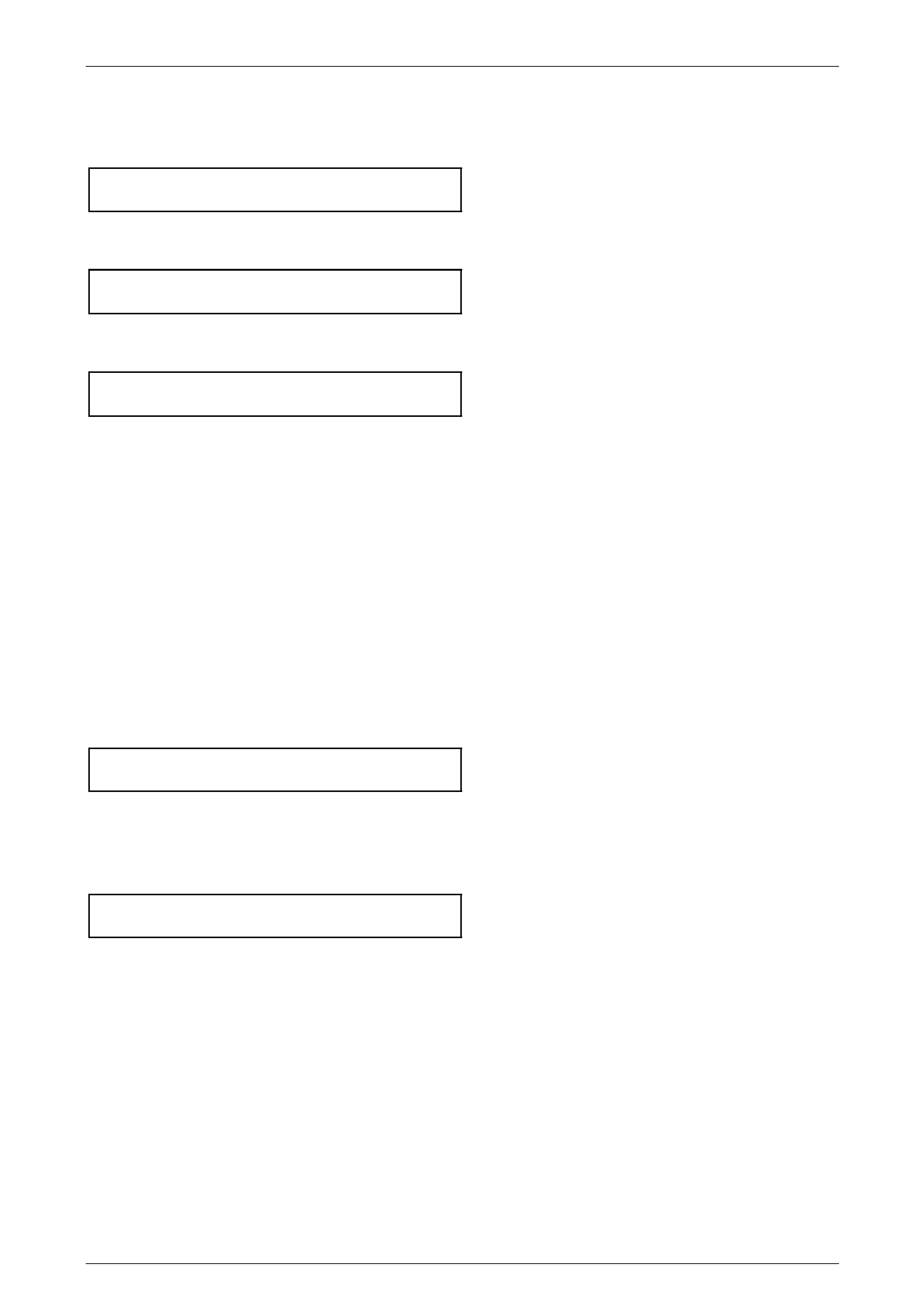
NOTE
View ‘A’ shows the rubber coupling to flange
arrangement (front or rear) while view ‘B’ shows
the front coupling arrangement when a slip yoke
is utilised.
Figure 4C1 – 5
Legend
1 Nut – Coupling to Propeller Shaft (3 Places)
2 Bolt – Coupling to Propeller Shaft (3 Places)
3 Nut – Coupling to Slip Yoke (3 Places)
4 Slip Yoke Flange
5 Bolt – Coupling to Slip Yoke (3 Places)
A Spigot Bush Requiring Lubrication
3 Referring to view ‘B’, use a back-up spanner on each of the three, propeller shaft slip yoke bolts (5), loosen then
remove the nuts (3). Discard the removed bolts and nuts. Remove the sliding yoke from the coupling.
Rear Propeller Shaft and Universal Joints Page 4C1 – 9
Page 4C1 – 9
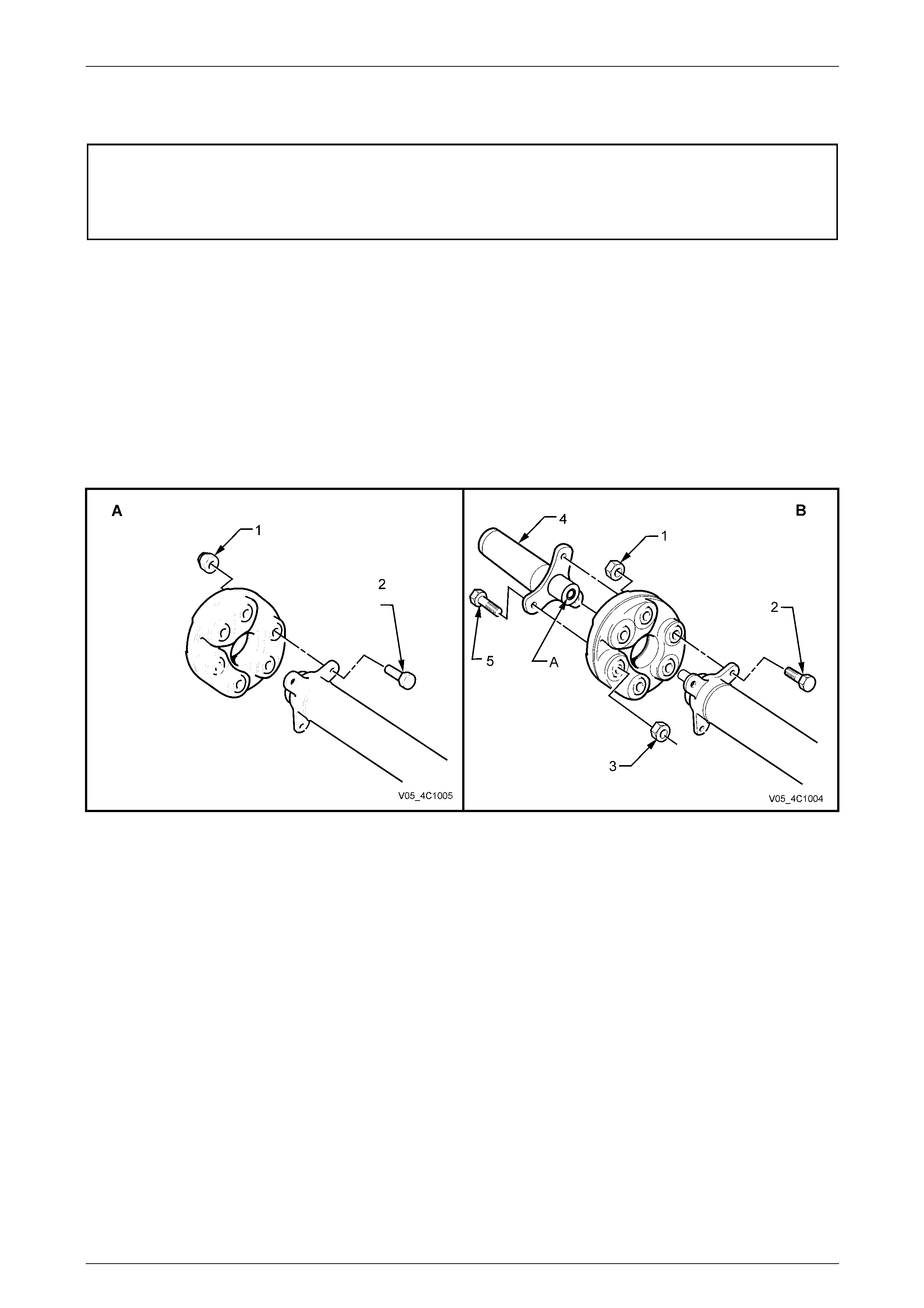
4 Install a replacement rubber coupling onto the end of
the propeller shaft, aligning the holes in such a way
that the triangular shape (‘A’) on the coupling ‘points’
to the propeller shaft flange lug (1), as shown.
5 Install NEW bolts and nuts to secure the couplin g to
the propeller shaft flange and tighten to the correct
torque specification, using a back-up sp anner on the
bolt head and angle wrench E 7115 to measure the
turn angle.
( ) Propeller shaft to rubber coupling
nut torque specification.......................................20 N.m,
then 55° turn angle
6 Lubricate the spigot bush in the propeller shaft end (or
the slip yoke bushing) with 0.5 gm of a molybdenum
disulphide grease such as an NLGI No. 2 lithi um soap
based EP grease with molybdenum disulph id e, such
as Shell Retinax HDX2 grease or BP Energrease
LMS-EP 23 (or equivalent). Figure 4C1 – 6
7 Reinstall the sliding yoke bush onto the propeller shaft spigot and align the three bolt holes.
NOTE
If the rear bolts were placed correctly (refer to
Step 4), the triangular shapes (’A’) will ‘point’ to
the sliding yoke flange bo lt holes.
8 Install NEW bolts and nuts to secure the couplin g to the slip yoke flange and tighten to the correct torque
specification, using a back-up spanner on the bolt head and angle wrench E 7115 to measure the turn a ngle.
Propeller shaft to rubber coupling
nut torque specification.......................................20 N.m,
then 55° turn angle
9 Reinstall the propeller shaft, Refer to 2.1 Propeller Shaft in this Sectio n.
Rear Propeller Shaft and Universal Joints Page 4C1 – 10
Page 4C1 – 10
2.3 Centre Bearing Assembly
NOTE
• This operation is not possible with the
propeller shaft fitted to GEN III V8 vehicles.
Refer to 1 General Information, in this Section
for further information.
• During the removal process described, the
rubber bearing support will be damaged,
resulting in the requirement for the complete
centre bearing assembl y to be replaced.
Remove
1 Remove the propeller shaft. Refer to 2.1 Propeller Shaft in this Section.
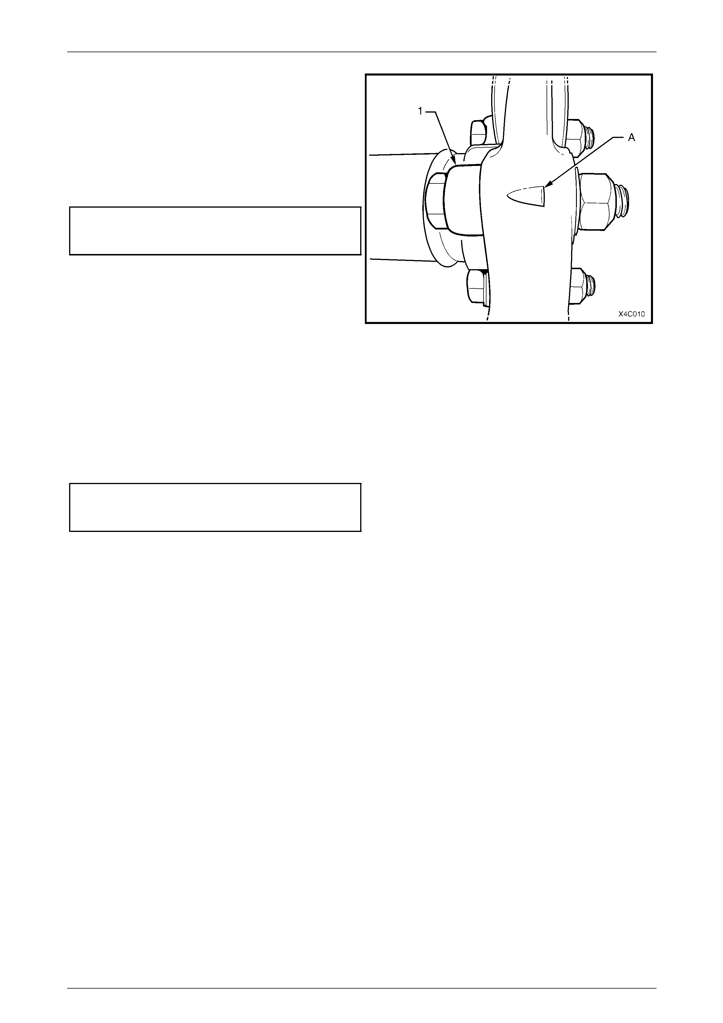
2 With the propeller shaft assembly (4) laying on a
workbench, use a screwdriver (1) or similar a nd lever
up on the boot clamp (2) releasing the te nsion.
Figure 4C1 – 7
This is a critical operation, as propeller shaft
phasing and balance will be affected if the
two propeller shaft halves are not aligned
correctly on reassembly.
3 Extend the sliding joint until a slight resistance is felt.
4 Using a felt tipped pen or similar, mark align m ent
marks on the front propeller shaft section (1) and the
rear (2)
Figure 4C1 – 8
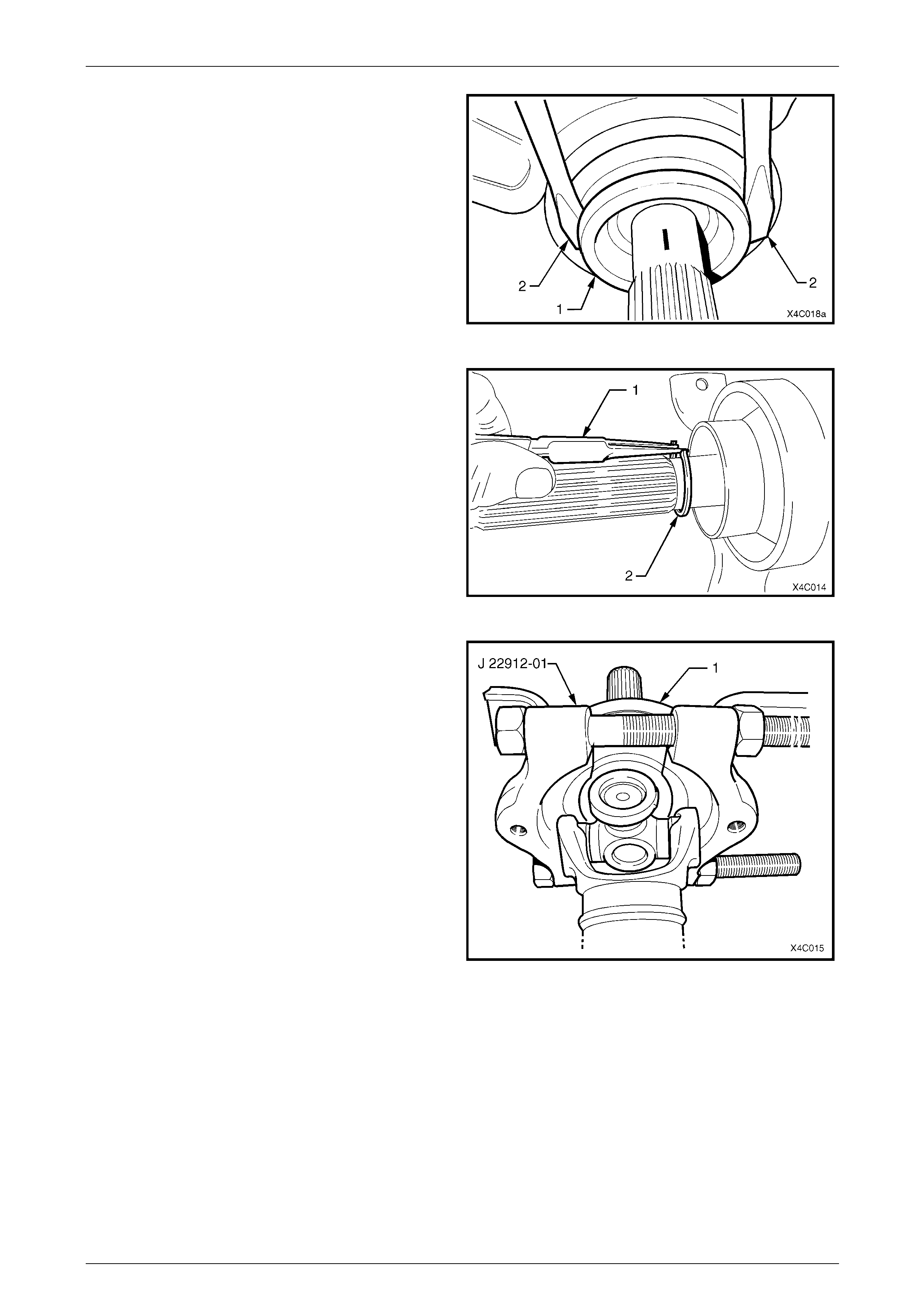
5 With the two propeller shaft halves extended, a snap
action is required to separate them, because of the O-
ring seal (3) mounted on the end of the re ar shaft (1).
6 Once separated, the ribbed boot (4) and O-ring seal
(3) are released.
NOTE
Once separated, the O-ring seal (3) may be
retained in the propeller shaft front half (2).
Retrieve by inserting a hooked piece of wire.
Figure 4C1 – 9
Rear Propeller Shaft and Universal Joints Page 4C1 – 11
Page 4C1 – 11
7 Remove the slinger (1), by levering off, using two
similar sized screwdrivers (2) or similar, as sho wn.
NOTE
Removal of the slinger is requir ed to gain access
to a circlip underneath.
8 Discard the removed slinger, as it will be dist orted
during the removal process.
Figure 4C1 – 10
9 Using suitable, commercial ly available circlip pliers (1),
remove the circlip (2) securing the centre bearing.
Figure 4C1 – 11
10 Install suitable press plates such as J 22912-01 under
the centre bearing, carrier (1) and rubb er support, with
the flat face towards the bearing and carrier (1).
11 Tighten the clamp nuts on the press plates until the
two halves are firmly secure around the bearing.
12 Support the press plates on the bed of an hydraulic
press and press the rear propeller shaft, splined shaft
from the centre bearing.
NOTE
This operation will damage the rubber bearing
support, requiring the cent re bearing, rubber and
carrier assembly to be replaced.
Figure 4C1 – 12
Rear Propeller Shaft and Universal Joints Page 4C1 – 12
Page 4C1 – 12
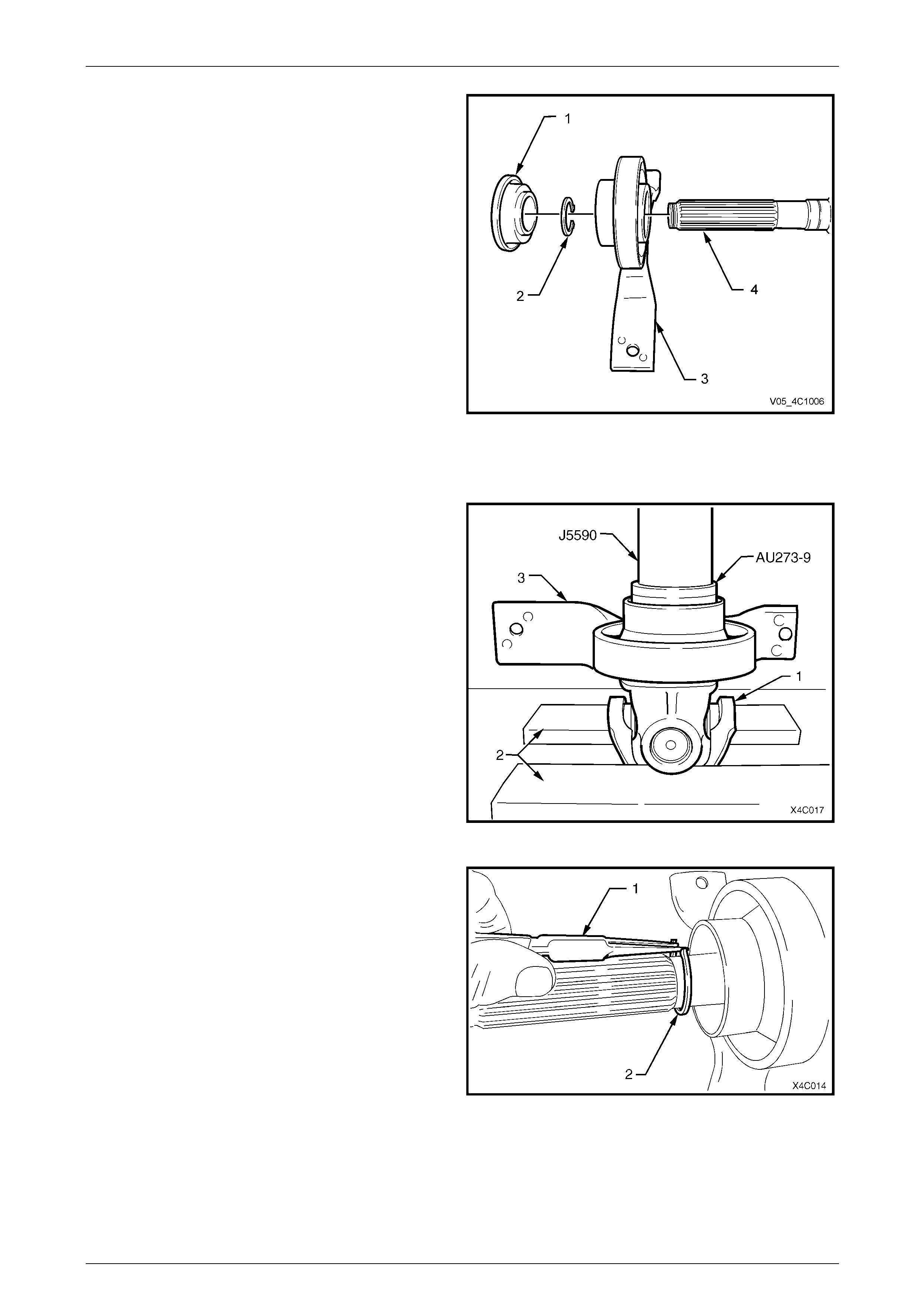
13 Shown is the relationship of the centre bear ing
assembly (3) to the rear propeller shaft (4) front half,
together with the slinger (1) and the retaining circlip
(2).
Figure 4C1 – 13
Reinstall
1 With the front universal joint ‘ears’ (1) supported on
press plates (2), press a NEW centre bearing
assembly (3) onto the front section of the rear
propeller shaft, using press tube J 5590 and adaptor
AU 273-9.
NOTE
If these tools are not available, then a 150 mm
length of pipe with an ID of 30 mm (and a wall
thickness of 5 mm), can be used as a substitute.
Figure 4C1 – 14
2 Install a NEW centre bearing retaining circlip (2), using
commercially available circlip pliers (1), taking care not
to over-stretch the circlip.
3 Install a NEW slinger, using press tube J 5590.
Figure 4C1 – 15
Rear Propeller Shaft and Universal Joints Page 4C1 – 13
Page 4C1 – 13
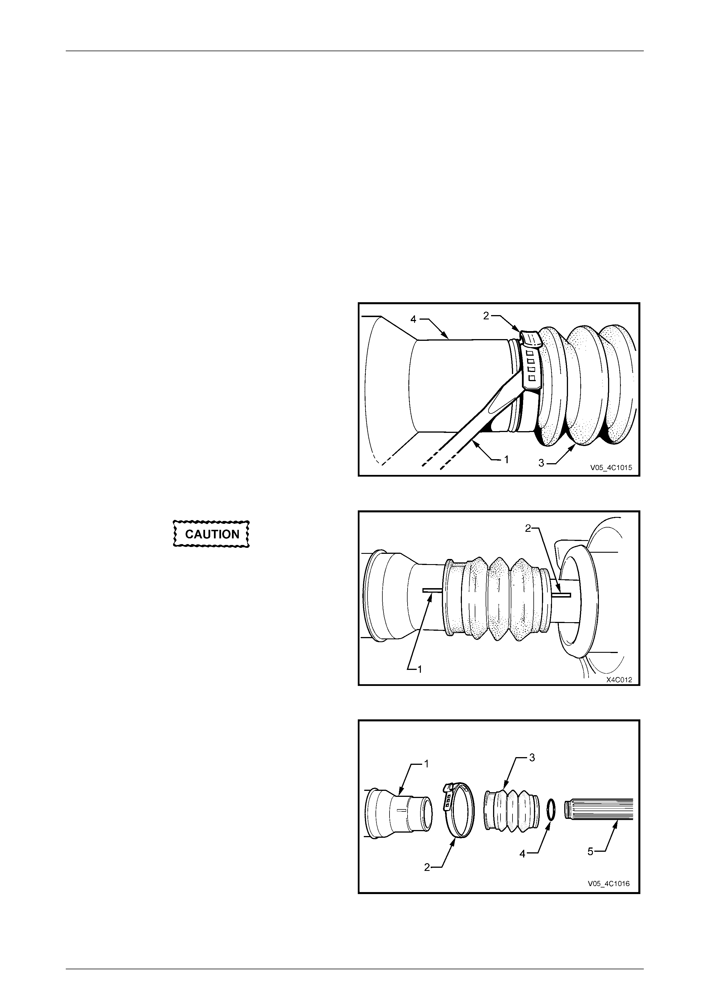
4 Install a NEW boot and ring assembly over the splines
of the rear propeller shaft.
5 Lubricate the splines of the rear prop eller shaft with
approximately 1 – 2 gm of molybdenum disulphide
grease with an NLGI No. 2 lithium soap based EP
grease with molybdenum disulphide, such as Shell
Retinax HDX2 grease or BP Energrease LMS-EP 23
(or equivalent).
6 Install a NEW O-ring seal onto the nos e of the rear
propeller shaft.
7 Taking care to align the two propeller shaft halves with
the marks made before disassembly (1 and 2), push
the two halves together until the O-ring seal clears the
inner splines of the front half.
NOTE
At this time it should be possi ble to slide the two
halves back and forth with little resistance.
Figure 4C1 – 16
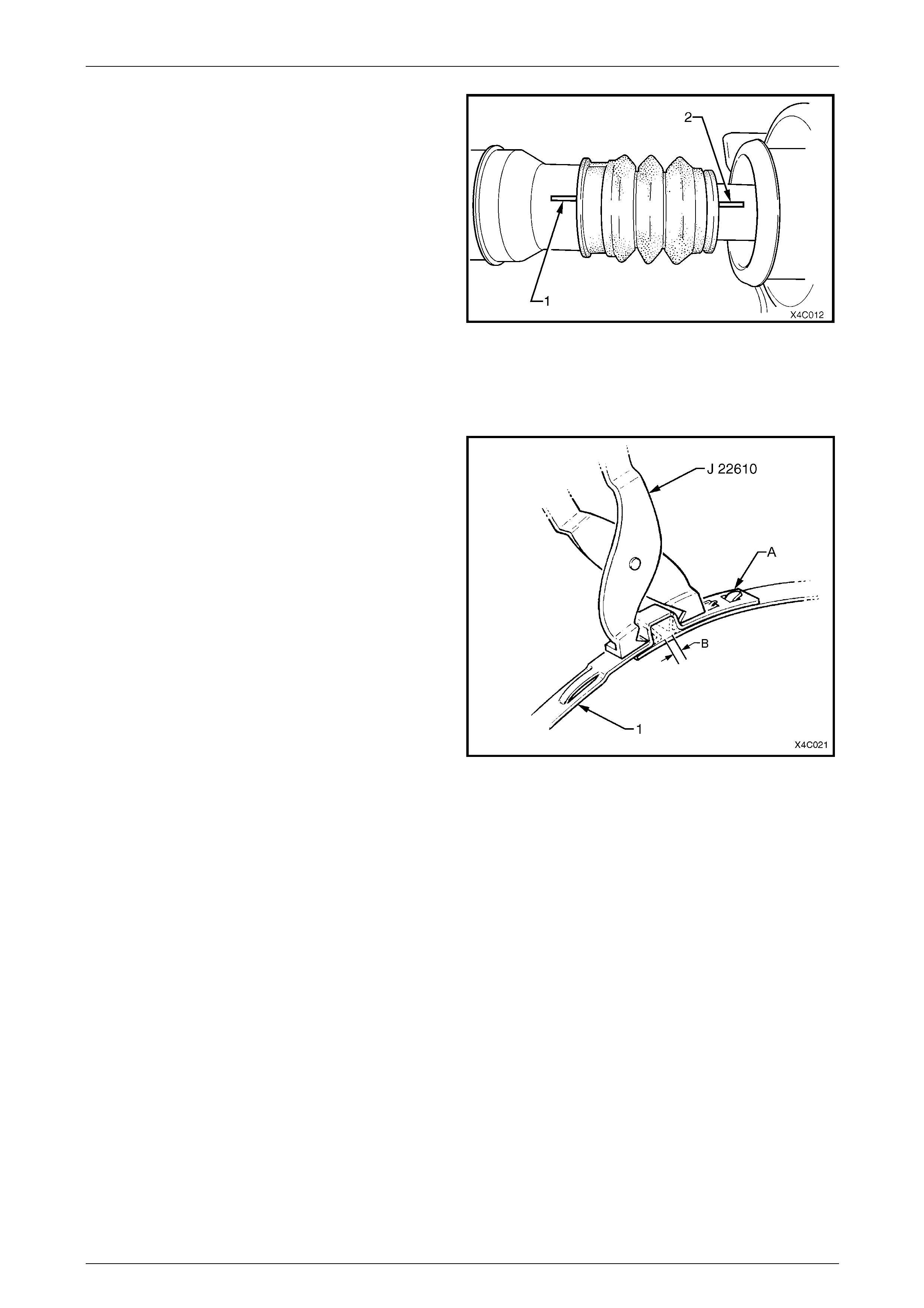
8 With the boot and ring assembly located correctly in
the grooved section of the front propeller shaft, install
a NEW retaining clamp to secure.
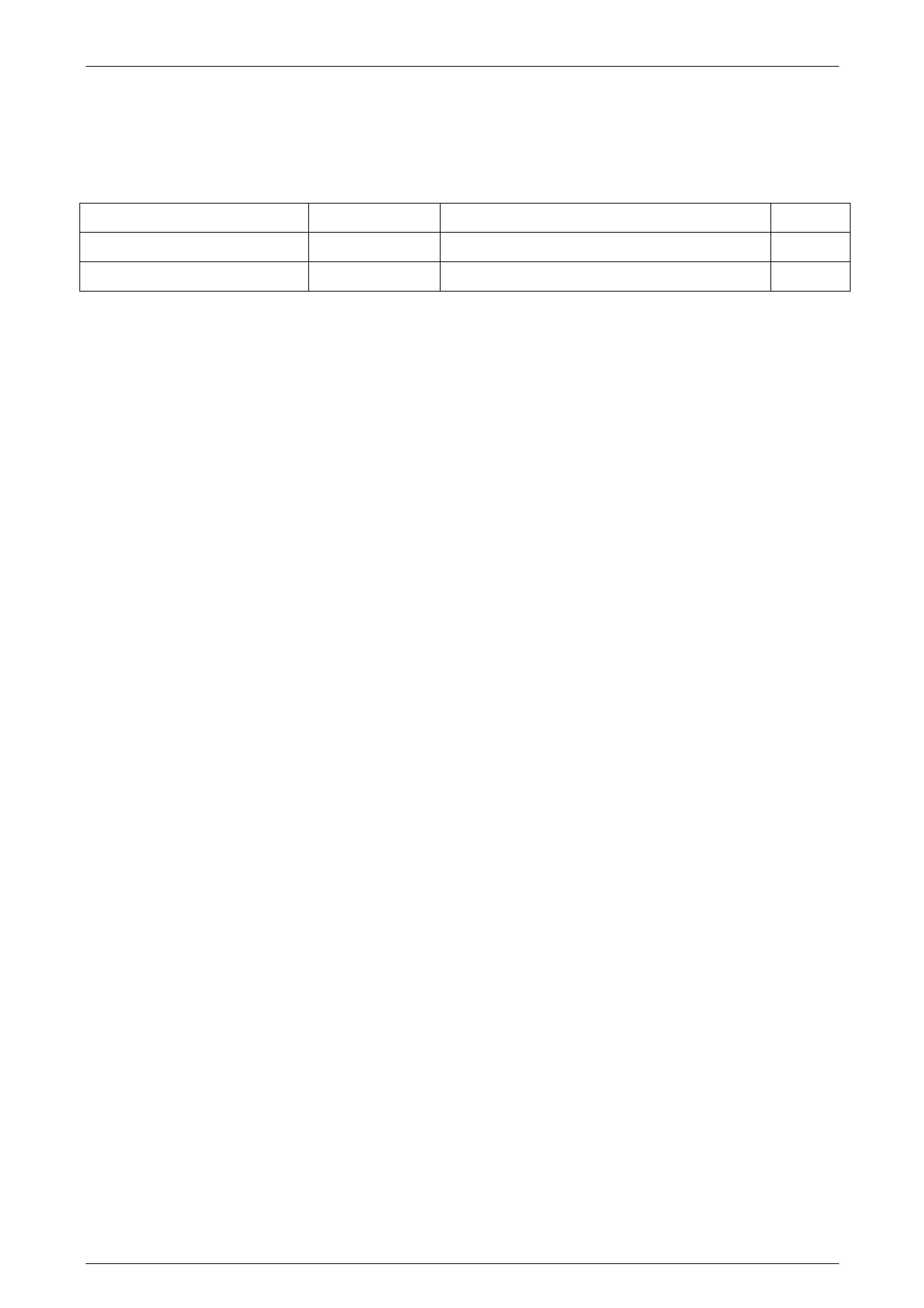
9 After installing a new clamp around the boot and ring
assembly bend the tab over as shown by ‘A’ in Figure
4C1-17.
10 Using keystone clamp pliers such as J 22610 or
commercial equivalent, tighten the clamp (1) until the
gap ‘B’ is from 1 – 2 mm.
11 Reinstall the propeller sh aft assembly. Refer
2.1 Propeller Shaft, in this Section.
Figure 4C1 – 17
Rear Propeller Shaft and Universal Joints Page 4C1 – 14
Page 4C1 – 14
3 Specifications
Propeller Shaft Identification
Refer to the digit identification letters on the tag attached to the rear propeller shaft tube and the following table.
Body Style Engine Transmission I.D. Code
WL Alloytec 190 (LY7) 5L40-E Automatic Transmission (M82) NY
WL GEN III V8 (LS1) 4L60-E Automatic Transmission (M30) NF
Centre Bearing
Type.........................................................................Rubber Mounted – Single Row Ball Race
Lubrication.........................................................................................................Sealed for Life
Universal Joints
Front..............................................................................................................Rubber Coupling
Centre.........................................................................................Non-Serviceable Cross Type
Rear...............................................................................................................Rubber Coupling

Rear Propeller Shaft and Universal Joints Page 4C1 – 15
Page 4C1 – 15
4 Torque Wrench Specifications
ATTENTION
Fasteners must be repl aced after loosening.
Vehicle must be at curb height before final tightening.
Fasteners either have micro encapsulated sealant applied or incorporate a mechanical thread lock and
should only be re-used once. If in doubt, replacement is recommended.
Centre Bearing Carrier to Underbody Reinforcement Bolt............................22 N.m
Front Rubber Coupling to Transmission Output Flange Nut.........................85 N.m
Front Rubber Coupling to Transmission Output Flange Bolt......................115 N.m
Front Rubber Coupling to Transmission Output Flange Bolt and Nut.........115 N.m
Propeller Shaft To Rubber Coupling Bolt and Nut...... 20 N.m , then 55° turn angle
Rear Rubber Coupling to Pinion Flange Torx Bolt......................................115 N.m
Rear Propeller Shaft and Universal Joints Page 4C1 – 16
Page 4C1 – 16
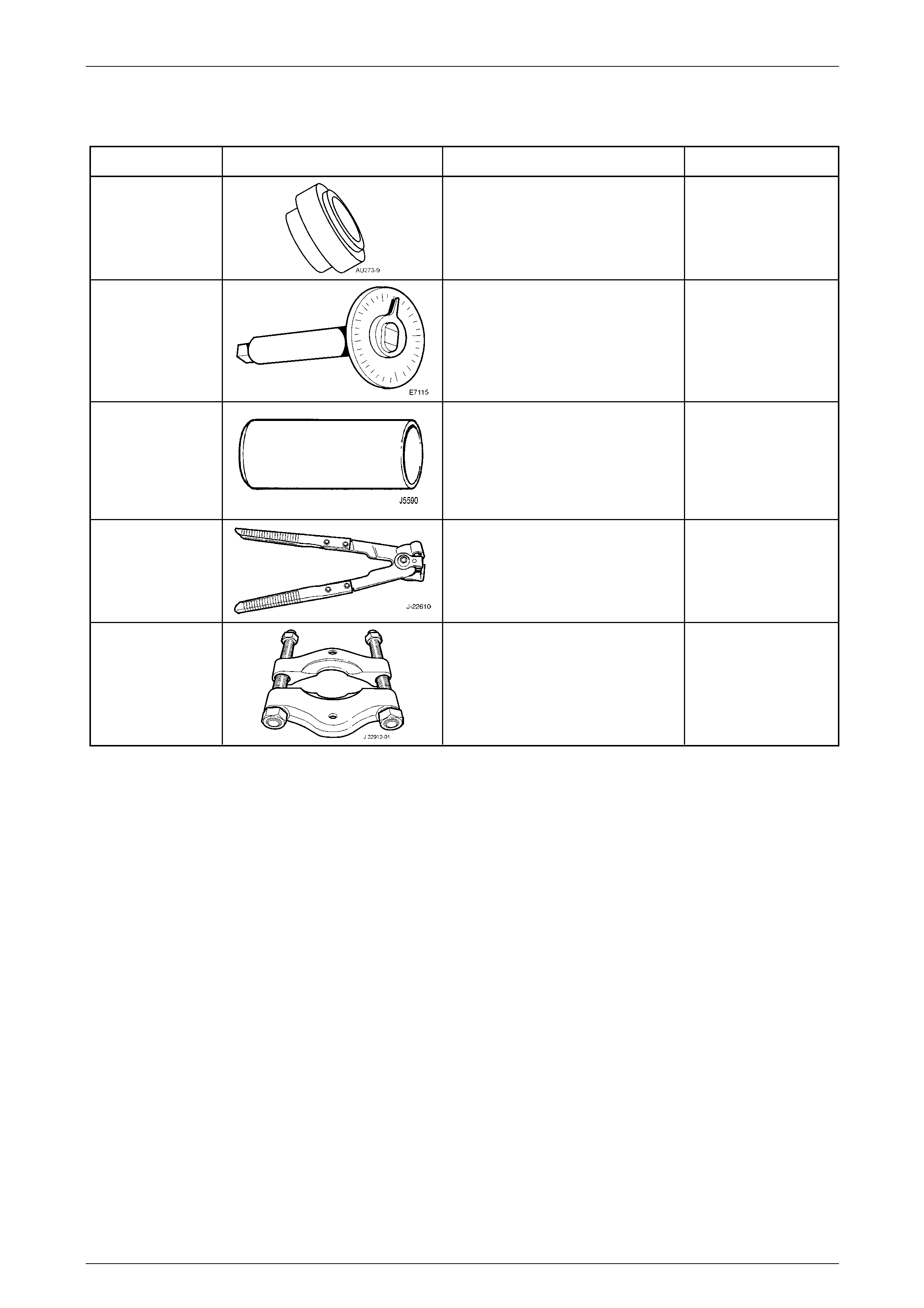
5 Special Tools
Tool Number Illustration Description Tool Classification
AU 273-9
Installer Adaptor
Used with J 5590 to install the centre
bearing to the rear propeller shaft.
Previously released.
Unique
E 7115
Angle Wrench
Used to tighten fasteners when an
angle torque is specified. Also
released as BT 8653-A
Previously released.
Unique
J 5590
Press Tube
Used to install centre bearing and the
slinger.
Previously released.
Unique
J 22610
Keystone Clamp Pliers
Used to tighten the constant velocity
joint boot clamps.
Previously released
Desirable
J 22912-01
Press Plates
Used for various pressing operations
Previously released.
Desirable