
Charging System – V6 Page 6D1-1-1
Section 6D1-1
Charging System – V6
ATTENTION
Before performing any service operations or other procedure described in this Section, refer to Section 00
Warnings, Cautions and Notes for correct workshop practices with regard to safety and / or property damage.
1 General Information...............................................................................................................................3
1.1 Components........................................................................................................................................................... 3
Generator................................................................................................................................................................ 3
Generator Types ................................................................................................................................................ 3
Voltage Regulator.................................................................................................................................................. 4
1.2 System Operation .................................................................................................................................................. 5
Operation ........................................................................................................................................................... 5
Alternator Warning ............................................................................................................................................. 5
2 Diagnosis ................................................................................................................................................6
2.1 Diagnostic General Information............................................................................................................................ 6
Basic Diagnostic Tools Required......................................................................................................................... 6
2.2 Tech 2 Data List ..................................................................................................................................................... 7
2.3 Diagnostic Systems Check................................................................................................................................... 8
2.4 Wiring Diagram ...................................................................................................................................................... 9
2.5 Charging System Inoperative / Malfunctioning................................................................................................. 10
Diagnostic Table Notes .................................................................................................................................... 10
Diagnostic Table 100A Generator.................................................................................................................... 10
Diagnostic Table 120A Generator.................................................................................................................... 10
3 Minor Service Operations....................................................................................................................11
3.1 Safety Precautions............................................................................................................................................... 11
3.2 Maintenance......................................................................................................................................................... 12
Regular Checks.................................................................................................................................................... 12
Lubrication........................................................................................................................................................ 12
3.3 On-vehicle Testing............................................................................................................................................... 13
On-vehicle Checks 100A Generator ................................................................................................................... 13
Prerequisites .................................................................................................................................................... 13
Generator Test................................................................................................................................................. 13
On-vehicle Checks 120A Generator ................................................................................................................... 16
Prerequisites .................................................................................................................................................... 16
Generator Test................................................................................................................................................. 16
Charging Circuit Voltage Drop Test................................................................................................................... 19
Prerequisites .................................................................................................................................................... 19
Voltage Drop Test ............................................................................................................................................ 19
4 Major Service Operations....................................................................................................................20
4.1 Generator.............................................................................................................................................................. 20
Remove................................................................................................................................................................. 20
Reinstall................................................................................................................................................................ 21
4.2 Generator Mounting Bracket............................................................................................................................... 22
Remove................................................................................................................................................................. 22
Reinstall................................................................................................................................................................ 22
4.3 Drive Belt Routing................................................................................................................................................ 23
Without Air Conditioning .................................................................................................................................... 23
With Air Conditioning.......................................................................................................................................... 24
Page 6D1-1–1

Charging System – V6 Page 6D1-1-2
5 Specifications – 100 A .........................................................................................................................25
6 Specifications – 120 A .........................................................................................................................26
7 Torque Wrench Specifications ...........................................................................................................27
8 Special Tools ........................................................................................................................................28
Page 6D1-1–2

Charging System – V6 Page 6D1-1-3
1 General Information
1.1 Components
Generator
The Mitsubishi generator can be identified visually by its two lower and one upper mounting lugs.
It is mounted to the lower right-hand side of the engine block. It is driven by the same drive belt that drives other engine
ancillaries and requires no periodic drive belt adjustment.
The generator has three phases, incorporating a rotor with six pole pairs fitted and two internal cooling fans; one on the
drive-end and one on the slip-ring end. The rotor is supported by ball bearings in both the drive and slip-ring end
housings. Surrounding the rotor is a stator, which has a three phase delta connected output winding construction on a
ring shaped lamination pack.
The output of the stator winding is rectified by eight diodes that are contained within the slip-ring end housing. Excitation
current is supplied to the rotor field coil via the voltage regulator, the brushes and slip-rings. The electronic voltage
regulator requires no adjustment in service.
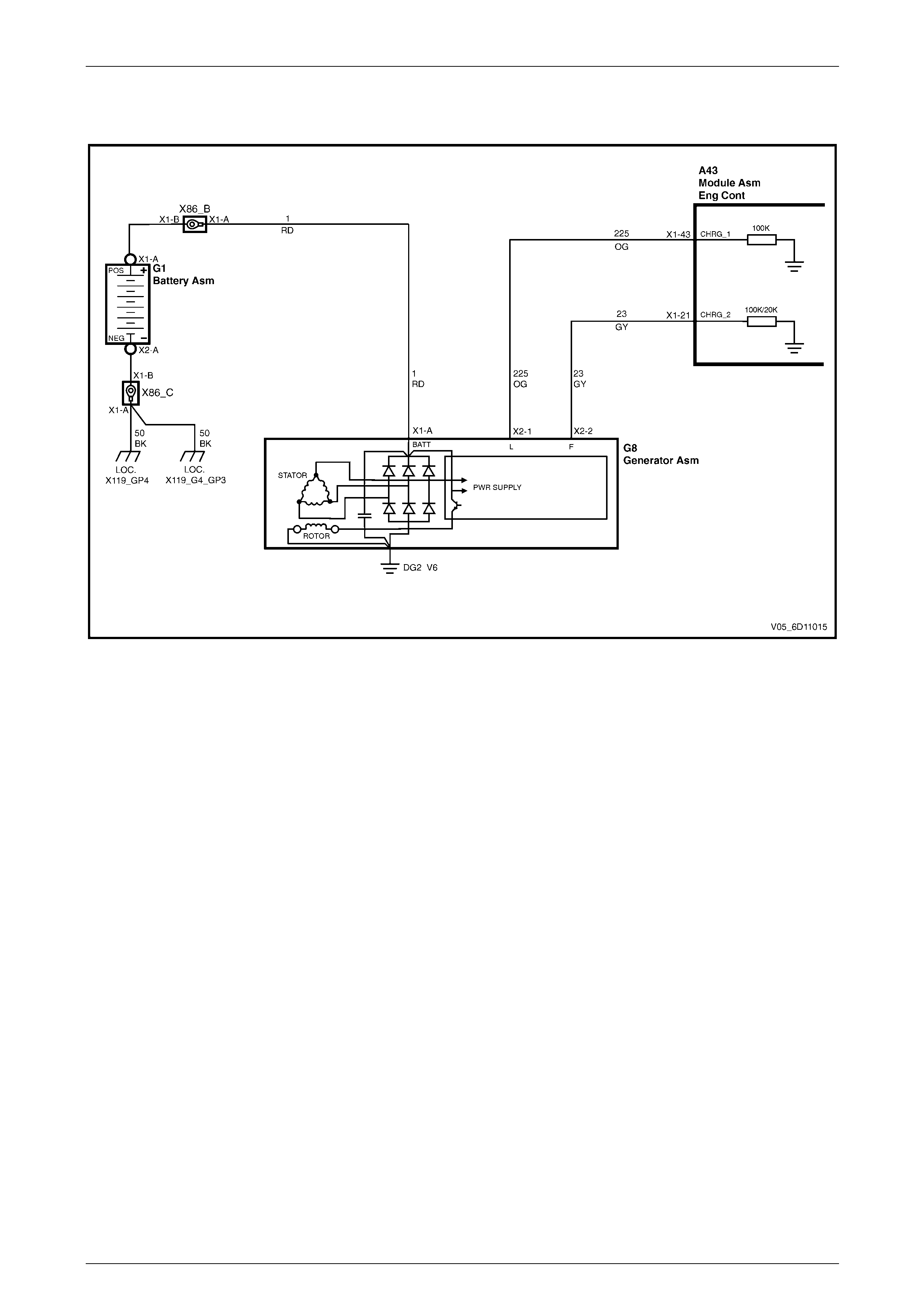
The generator has four external connections (refer to Figure 6D1-1 – 1):
• G8 – X1 pin A to the battery positive terminal X86 – B (circuit 1) – battery charging,
• G8 – X2 pin 1 to the ECM connection A43 – X1 pin 43 (circuit 225) – regulator monitoring,
• G8 – X2 pin 2 to the ECM connection A43 – X1 pin 21 (circuit 23) – battery voltage sensing, and
• ground connection via the installation bolts.
Generator Types
The 100 amp generator is fitted as standard to all vehicles, except as detailed in the following:
• The 120 amp generator is fitted as standard to vehicles fitted with the following production options:
• T82 (daytime running lights – Telstra option) or
• 9C1 (national police pack).
• The 120 amp generator is also available as a production option.
Page 6D1-1–3
Charging System – V6 Page 6D1-1-4
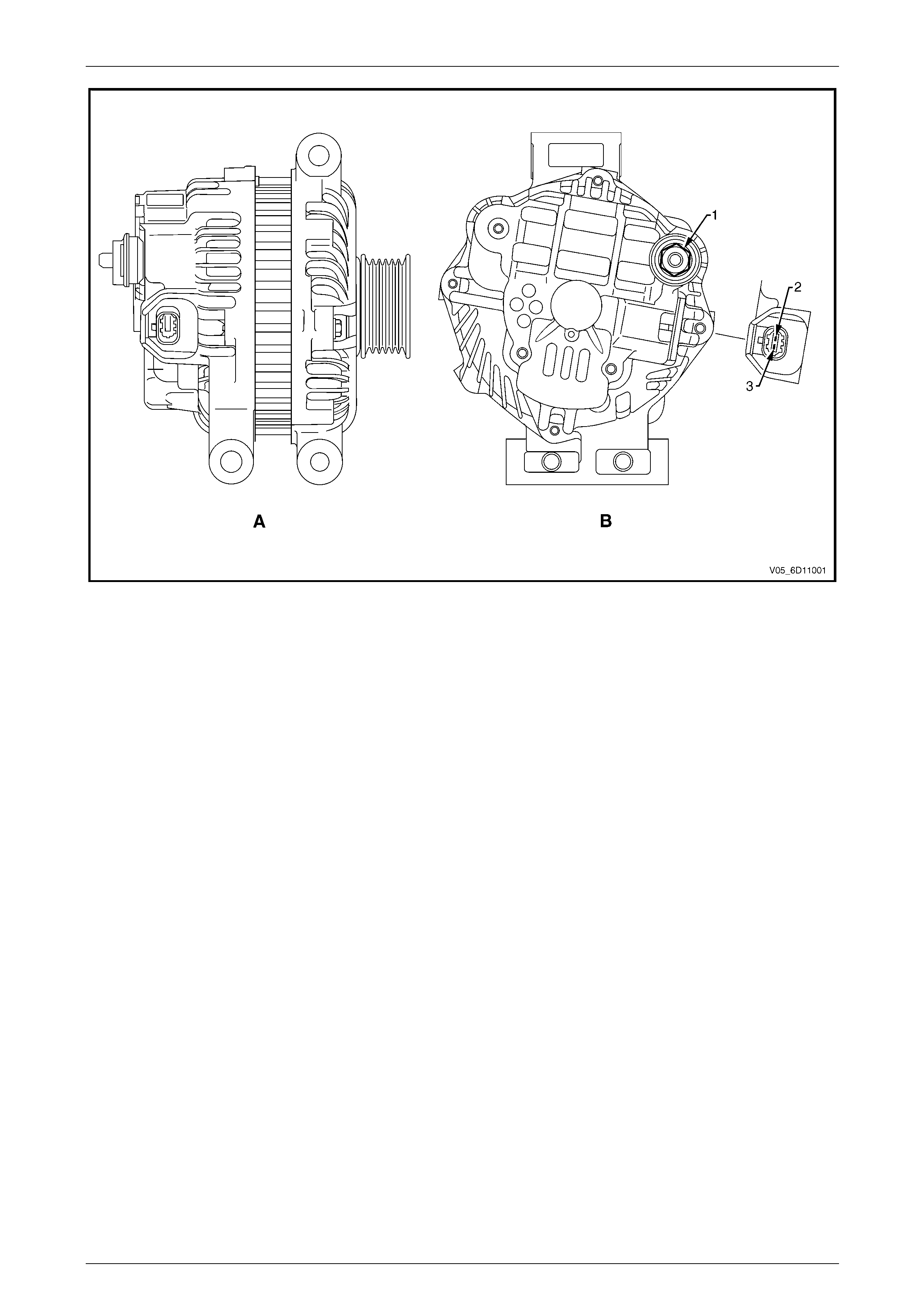
Figure 6D1-1 – 1
Legend
A Side View of Generator
B Rear View of Generator
1 G8 – X1 pin A
2 G8 – X2 pin 2
3 G8 – X2 pin 1
Voltage Regulator
The electronic voltage regulator requires no adjustment in service.
Page 6D1-1–4

Charging System – V6 Page 6D1-1-5
1.2 System Operation
Operation
With the ignition switch in the ON position and the engine at rest, current is supplied via the regulator to G8 – X2 pin 1
(circuit 225) and to the engine control module (ECM) at connector A43 – X1 pin 43. This initiates current flow (within the
regulator) from the generator G8 – X1 pin A, to the brushes and rotor winding, to ‘excite’ the circuit.
The current in the rotor winding creates magnetic fields between adjacent rotor poles.
With the engine running, the rotor spins, the stator windings cut through this field and induce voltage. As the engine
speed is increased, this induced voltage increases. Current then flows through the three-phase diode bridge in the
rectifier to convert the AC voltage to DC. This is supplied to the G8 – X1 pin A output and then to the battery terminal
X86 – B (circuit 1).
The regulator monitors the voltage to the battery. When this voltage reaches approximately 14.5 V, the regulator opens
the circuit through the rotor winding, causing the generator output voltage to drop. When the regulator senses a voltage
below a preset voltage, the regulator closes the circuit through the rotor winding and voltage to the battery again
increases. This cycle repeats very rapidly.
Alternator Warning
NOTE
All generator faults are displayed as Check
Alternator Warning on the instrument cluster
MFD, refer to Section 12C Instrumentation.
The ECM monitors the voltage on circuit 23 at A43 – X1 pin 21 and circuit 225 at A43 – X1 pin 43.
The voltage at regulator G8 – X2 pin 1(circuit 23) will remain low when a fault condition is detected in the generator or
associated external circuits. The voltage remains low (while the ignition switch is on) until the fault is repaired.
For more information on the alternator warning refer to Section 12C Instrumentation.
Fault conditions include the following:
• open circuit or excessive voltage drop in circuit 1,
• open circuit in the generator phase connection,
• overcharging conditions,
• short circuit in the regulator output stage,
• open circuit in the rotor winding,
• poor contact between the rectifier and the regulator, and / or
• high resistance in the fusible link assembly.
Page 6D1-1–5

Charging System – V6 Page 6D1-1-6
2 Diagnosis
2.1 Diagnostic General Information
Basic Diagnostic Tools Required
Use of incorrect electrical circuit diagnostic
tools when performing the generator
diagnostic procedures could result in
incorrect diagnostic results or damage to
components.
The following electrical circuit testing tools are required to perform the diagnostic procedures detailed in this Section:
• digital multimeter with 10 mega ohms impedance, and
• connector test adapter kit Tool No. KM609.
For further information on the use of these tools, refer to Section 12P Wiring Diagrams.
Page 6D1-1–6

Charging System – V6 Page 6D1-1-7
2.2 Tech 2 Data List
The Tech 2 displays the status of certain charging system parameters.
To view the data list:
1 Connect Tech 2 to the DLC.
2 On Tech 2 select:
Engine / V6 Engine / Data Display / Data List / Electrical/Theft Data.
Tech 2 Parameter Units Displayed Typical Display Values
Alternator L Terminal D Percentage Various
Page 6D1-1–7

Charging System – V6 Page 6D1-1-8
2.3 Diagnostic Systems Check
Step Action Yes No
1 Is the fault specifically isolated to this system / module?
Go to Step 2
Go to
0D Vehicle
Diagnostics
2 1 Connect Tech 2 to the DLC.
2 Ignition ON, engine OFF.
3 On Tech 2 select:
Engine / V6 Engine / Diagnostic Trouble codes / Read
DTC’s.
Are there any set DTC’s?
Go to the
appropriate DTC
table in
6C1-2 Engine
Management – V6
– Diagnostics.
Refer to
2.5 Charging
System Inoperative /
Malfunctioning
Reference to following information will assist when diagnosing charging circuit faults:
• for battery testing, refer to Section 12A Battery,
• for wiring diagram details, refer to Figure 6D1-1 – 2., and
• for electrical component locations, refer to Section 12O Fuses, Relays and Wiring Harnesses.
Page 6D1-1–8
Charging System – V6 Page 6D1-1-9
2.4 Wiring Diagram
Figure 6D1-1 – 2
Page 6D1-1–9
Charging System – V6 Page 6D1-1-10
2.5 Charging System Inoperative /
Malfunctioning
Diagnostic Table Notes
Reference to following information will assist when diagnosing charging system faults.
1 For all wiring harness fault diagnoses, refer to Section 12P Wiring Diagrams.
2 For wiring harness repairs, refer to Section 12P Wiring Diagrams.
3 Refer to Section 12O Fuses, Relays and Wiring Harnesses for harness routeing.
4 Ensure the battery, cables and connections are in good order. Refer to Section 12A Battery.
Diagnostic Table 100A Generator
Step Action Yes
No
1 Did you review 1.2 System Operation?
Go to Step 2
Go to
1.2 System
Operation
2 Did you perform 2.3 Diagnostic Systems Check?
Go to Step 3
Go to
2.3 Diagnostic
Systems Check
3 Perform the On-vehicle Checks 100A Generator.
Was the generator serviceable? Go to step 4
Replace the
generator.
Go to Step 5
4 Perform the Charging Circuit Voltage Drop Test.
Was the wiring serviceable?
Go to
12C Instrument
Cluster.
Go to Step 5
Repair as required
(refer to Note 2).
Go to Step 5
5 Operate the system to verify the repair.
Did you correct the condition? System OK Go to Step 2
When all diagnosis and repairs are completed, check the system for correct operation.
Diagnostic Table 120A Generator
Step Action Yes
No
1 Did you review 1.2 System Operation?
Go to Step 2
Go to
1.2 System
Operation
2 Did you read 2.3 Diagnostic Systems Check
Go to Step 3
Go to
2.3 Diagnostic
Systems Check
3 Perform the On-vehicle Checks 120A Generator
Was the generator serviceable? Go to step 4
Replace the
generator.
Go to Step 5
4 Perform the Charging Circuit Voltage Drop Test.
Was the wiring serviceable?
Go to
12C
Instrumentation.
Go to Step 5
Repair as required
(refer to Note 2).
Go to Step 5
5 Operate the system to verify the repair.
Did you correct the condition? System OK Go to Step 2
When all diagnosis and repairs are completed, check the system for correct operation.
Page 6D1-1–10

Charging System – V6 Page 6D1-1-11
3 Minor Service Operations
3.1 Safety Precautions
Observe the following precautions. Failure to observe these precautions will result in serious damage to the generator.
• Only use the generator and voltage regulator in a negative ground system.
• Always refer to Section 00 Warnings, Cautions and Notes before disconnecting the battery.
• When installing a battery, fit the positive (+) cable to the battery before fitting the negative cable.
• When a slave battery is used for starting purposes, ensure that both batteries are connected in parallel. That is,
positive terminals connected and negative terminals connected.
• Only use jumper leads that have surge protection.
• Disconnect both battery cables when charging the battery. This isolates the generator from the battery and from the
external charging equipment.
• Do not operate the generator within an open circuit or without a battery in the circuit.
• Do not disconnect the battery while the generator is running.
• Do not attempt to polarise the generator.
• Do not connect generator connector G8 – X2 pin 1 to 12 V (the battery or ignition circuits).
• Some battery powered timing lights can produce high transient voltages when connected or disconnected.
Only disconnect or connect timing lights when the engine is switched off.
Ensure the generator connector G8 – X2 pin 1
has a maximum sinking curren t o f 50mA.
Page 6D1-1–11

Charging System – V6 Page 6D1-1-12
3.2 Maintenance
LT Section No. — 02–140
Regular Checks
Check the following at regular intervals:
• generator terminals – for corrosion and loose connections,
• wiring – for continuity and damaged insulation,
• mounting bolts – for tightness,
• drive belt – for alignment and wear, and
• drive pulley – for damage and warping.
NOTE
The drive-belt adjustment for the engine
ancillaries (i.e. generator and water pump) is
provided by a spring-loaded tensioner. Therefore,
the drive belt does not require manual
adjustment.
Lubrication
High tolerance bearings are used in this generator. If the bearings are removed during the generator disassembly, new
bearings must be installed to restore the generator to original specification. The ball bearings supporting the rotor shaft
are pre-lubricated and sealed. Do not attempt to lubricate these during servicing.
Page 6D1-1–12
Charging System – V6 Page 6D1-1-13
3.3 On-vehicle Testing
LT Section No. — 02–140
On-vehicle Checks 100A Generator
Prerequisites
Before testing the generator output, ensure that:
• all generator circuit connections are clean and tight,
• the generator is always connected to the battery during testing (to prevent damage to the diodes),
• the battery is fully charged, and
• the specific gravity does not vary more than 0.025 between cells. (It is recommended the average specific gravity is
1.260 or higher). Refer to Section 12A Battery.
Carry out a load test on the battery to determine its ability to supply and accept current. This is a good indicator of the
general condition of the battery. For details of battery testing, refer to Section 12A Battery.
Inspect the drive belt and tensioner markings to determine if the drive belt is within operating limits. Replace the belt
if it is excessively worn or outside the operating range of the tensioner. For further details, refer to
Section 6A1 Engine Mechanical – V6.
Generator Test
Regulating Voltage Test
NOTE
Leave the generator wiring harness connector
G8 – X2 connected. Circuit 225, G8 – X2 pin 1, is
necessary as it provides initial field excitation.
1 Ensure the ignition switch is in the OFF position and all
electrical equipment is turned off.
Refer to Section 00 Warnings, Cautions and
Notes before disconnecting the battery.
2 Disconnect the battery ground cable at the battery.
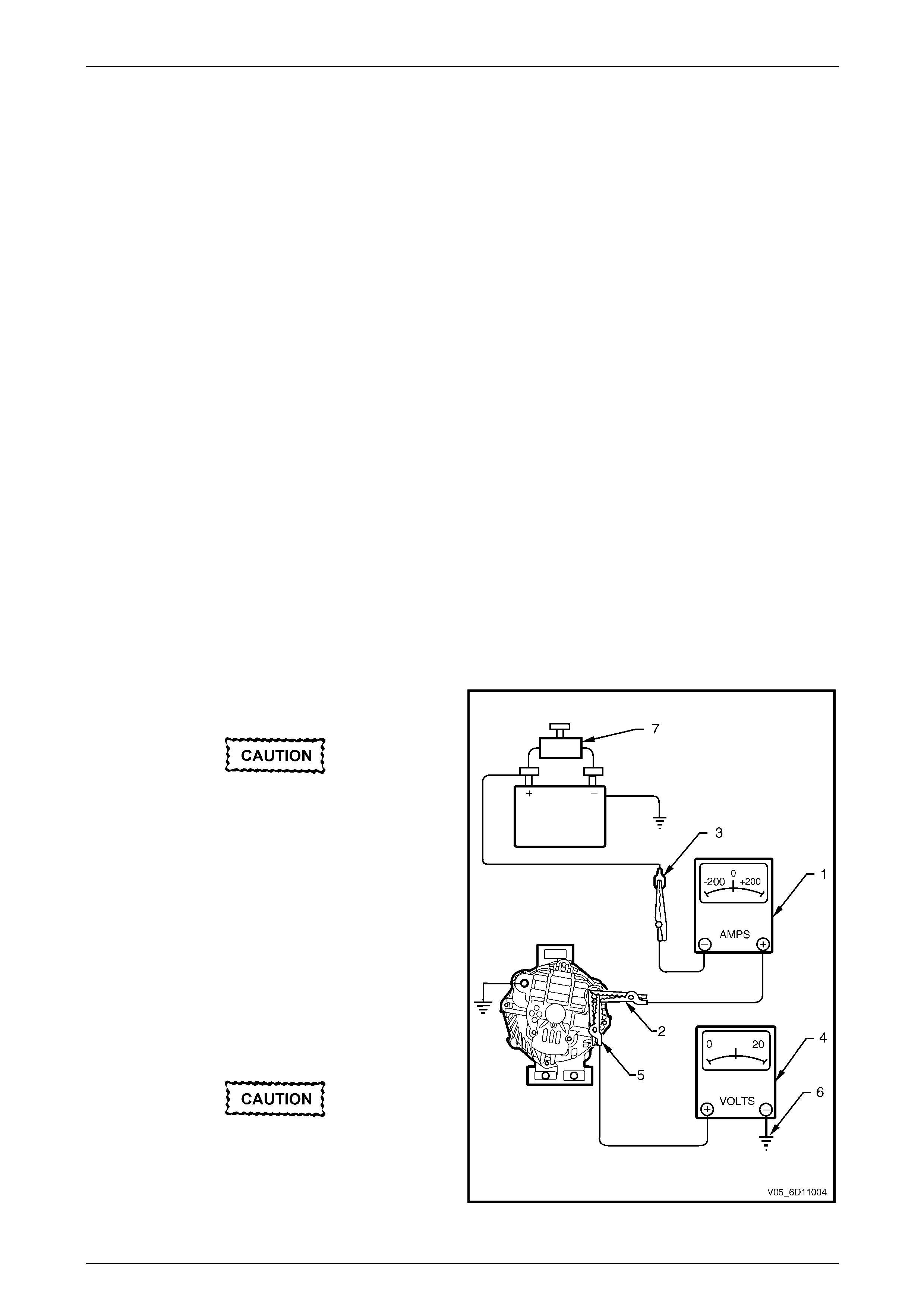
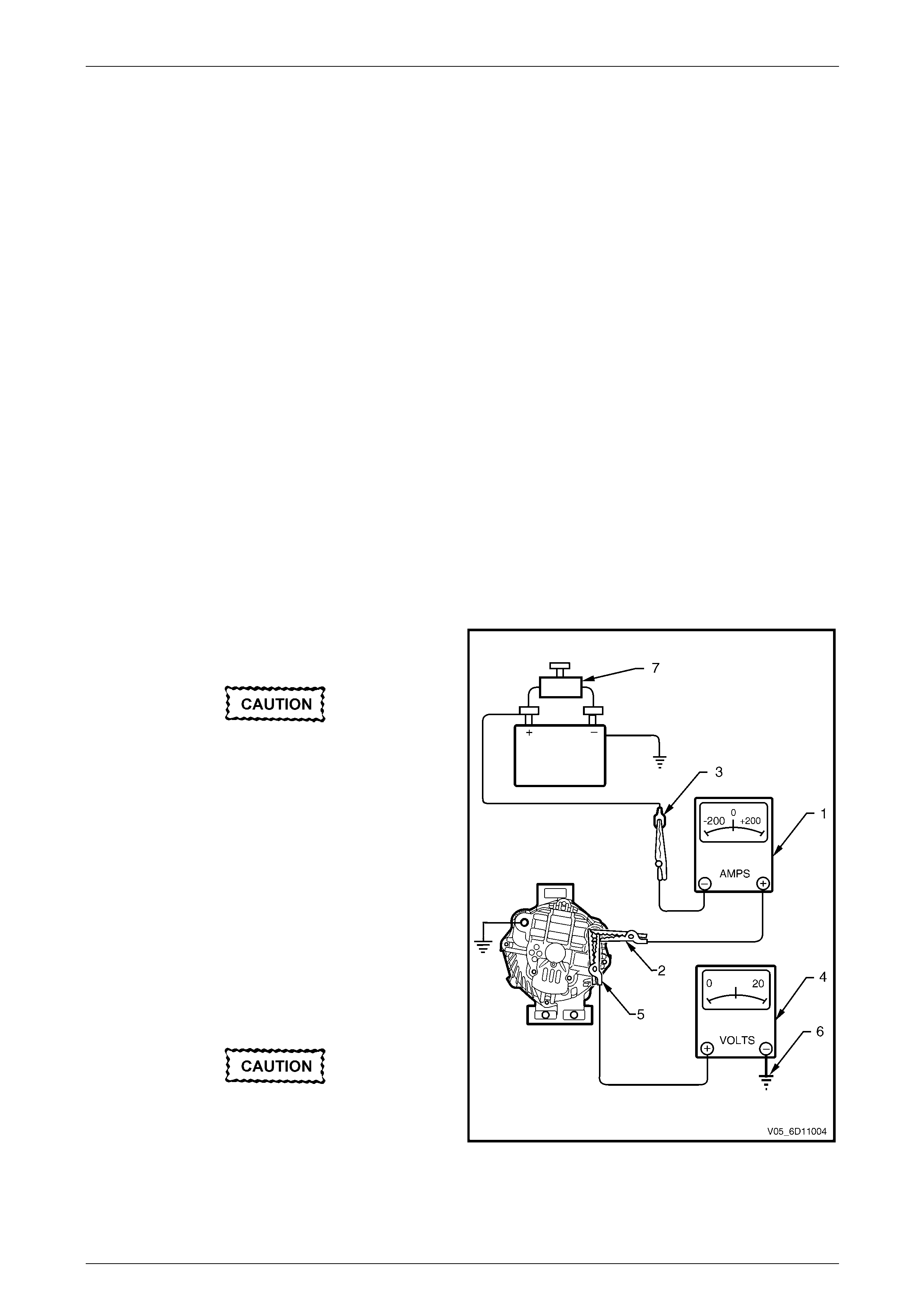
3 Disconnect the generator positive lead (circuit 1) from
the generator G8 – X1 pin A. Connect the positive lead
of a multimeter set to measure current (1) to G8 –
X1 pin A (2).
4 Connect that multimeter’s negative lead to the
disconnected generator positive lead (3).
5 Connect the positive lead of a multimeter set to
measure voltage, (4) to G8 – X1 pin A (5).
6 Connect that multimeter’s negative lead to a good
ground connection on the generator housing (6).
Insulate the terminal of the generator positive
lead (circuit 1) to prevent contact with any
metal part of the vehicle. If the terminal is
grounded, damage to the charging circuit
can result when the battery is reconnected.
Figure 6D1-1 – 3
Page 6D1-1–13
Charging System – V6 Page 6D1-1-14
7 Reconnect the battery ground cable.
8 Fit a loading device (7) across the battery terminals, e.g. an adjustable carbon pile.
The loading device must have a minimum
power consumption of 1000 W.
9 Record the voltage reading before starting the engine. (This reading should increase when the engine is running,
indicating generator output).
10 Start the engine.
11 Increase the engine speed to the value outlined in the chart below.
12 Using the reading from the multimeter set to measure current, adjust the loading device to apply a load within the
range outlined in the chart below.
13 Using the multimeter set to measure voltage, check the generator output voltage against the specification.
Engine RPM ...........................................................1275
Load................................................................5.0 – 10 A
Output Voltage...........................................13.8 – 15.4 V
Load Regula ion Tes t t
NOTE
The decrease in the voltage recorded during this
test should not exceed 0.5 V from the readings
obtained for the Regulating Voltage Test. If the
decrease in the regulating voltage is greater than
0.5 V, the regulator is defective. Replace the
regulator.
14 Increase the engine speed to the value outlined in the chart below.
15 Using the reading from the multimeter set to measure current, adjust the loading device to apply a load of about
90% of the generator’s full output.
16 Using the multimeter set to measure voltage, check the generator output voltage against the specification.
Engine RPM ...........................................................1900
Load........................................................................90 A
Output Voltage...........................................13.8 – 15.4 V
Full Load Output Test
Keep the time for this test to a minimum to
avoid undue heating and high engine speeds.
17 Increase the engine speed to the value outlined in the chart below.
19 Using the reading from the multimeter set to measure voltage, adjust the loading device to increase the load until
the generator output voltage drops to 13.5 V. Full generator output, outlined in the chart below, is required.
19 Record the current reading displayed on the multimeter set to measure current.
20 Reduce the engine speed to idle.
Page 6D1-1–14

Charging System – V6 Page 6D1-1-15
On completion of the generator output test,
return the engine to idle and disconnect the
loading device from the battery terminals.
This prevents excessive battery discharge.
21 Stop the engine.
22 Disconnect the battery ground cable (circuit 50) at the battery.
23 Remove all the multimeters.
24 Reconnect the generator positive lead (circuit 1) to G8 – X1 pin A.
25 Reconnect the battery ground cable (circuit 50) to the battery.
Engine RPM............................................................1900
Load................................................................5.0 – 10 A
Output Voltage...........................................13.8 – 15.4 V
Page 6D1-1–15
Charging System – V6 Page 6D1-1-16
On-vehicle Checks 120A Generator
Prerequisites
Before testing the generator output, ensure that:
• all generator circuit connections are clean and tight,
• the generator is always connected to the battery during testing (to prevent damage to the diodes),
• the battery is fully charged, and
• the specific gravity does not vary more than 0.025 between cells. (It is recommended the average specific gravity is
1.260 or higher). Refer to Section 12A Battery.
Carry out a load test on the battery to determine its ability to supply and accept current. This is a good indicator of the
general condition of the battery. For details of battery testing, refer to Section 12A Battery.
Inspect the drive belt and tensioner markings to determine if the drive belt is within operating limits. Replace the belt if it
is excessively worn or outside the operating range of the tensioner.
For further details, refer to Section 6A1 Engine Mechanical – V6.
Generator Test
Regulating Voltage Test
NOTE
Leave the generator wiring harness connector
G8 – X2 connected. Circuit 225, G8 – X2 pin 1, is
necessary as it provides initial field excitation.
1 Ensure the ignition switch is in the OFF position and all
electrical equipment is turned off.
Refer to Section 00 Warnings, Cautions and
Notes before disconnecting the battery.
2 Disconnect the battery ground cable at the battery.
3 Disconnect the generator positive lead (circuit 1) from
the generator G8 – X1 pin A. Connect the positive lead
of a multimeter set to measure current (1) to G8 –
X1 pin A (2).
4 Connect that multimeter’s negative lead to the
disconnected generator positive lead (3).
5 Connect the positive lead of a multimeter set to
measure voltage (4) to G8 – X1 pin A (5).
6 Connect that multimeter’s negative lead to a good
ground connection on the generator housing (6).
Insulate the terminal of the generator positive
lead (circuit 1) to prevent contact with any
metal part of the vehicle. If the terminal is
grounded, damage to the charging circuit
can result when the battery is reconnected. Figure 6D1-1 – 4
7 Reconnect the battery ground cable.
Page 6D1-1–16
Charging System – V6 Page 6D1-1-17
8 Fit a loading device (7) across the battery terminals, e.g. an adjustable carbon pile.
The loading device must have a minimum
power consumption of 1000 W.
9 Record the voltage reading before starting the engine. (This reading should increase when the engine is running,
indicating generator output.)
10 Start the engine.
11 Increase the engine speed to the value outlined in the chart below.
12 Using the reading from the multimeter set to measure current, adjust the loading device to apply a load within the
range outlined in the chart below.
13 Using the multimeter set to measure voltage, check the generator output voltage against the specification.
Engine RPM ...........................................................1300
Load................................................................5.0 – 10 A
Output Voltage...........................................13.8 – 15.4 V
Load Regula ion Tes t t
NOTE
The decrease in the voltage recorded during this
test should not exceed 0.5 V from the readings
obtained for the Regulating Voltage Test. If the
decrease in the regulating voltage is greater than
0.5 V, the regulator is defective. Replace the
regulator.
14 Increase the engine speed to the value outlined in the chart below
15 Using the reading from the multimeter set to measure current, adjust the loading device to apply a load of about
90% of the generator’s full output.
16 Using the multimeter set to measure voltage, check the generator output voltage against the specification.
Engine RPM............................................................2350
Load.......................................................................108 A
Output Voltage...........................................13.8 – 15.4 V
Full Load Output Test
Keep the time for this test to a minimum to
avoid undue heating and high engine speeds.
17 Increase the engine speed to the value outlined in the chart below
18 Using the reading from the multimeter set to measure voltage, adjust the loading device to increase the load until
the generator output voltage drops to 13.5 V. Full generator output, outlined in the chart below, is required.
19 Record the current reading displayed on the multimeter set to measure current.
20 Reduce the engine speed to idle.
Page 6D1-1–17
Charging System – V6 Page 6D1-1-18
On completion of the generator output test,
return the engine to idle and disconnect the
loading device from the battery terminals.
This prevents excessive battery discharge.
21 Stop the engine.
22 Disconnect the battery ground cable (circuit 50) at the battery.
23 Remove the multimeters.
24 Reconnect the generator positive lead (circuit 1) to G8 – X1 pin A.
25 Reconnect the battery ground cable (circuit 50) to the battery.
Engine RPM............................................................2350
Load................................................................5.0 – 10 A
Output Voltage...........................................13.8 – 15.4 V
Page 6D1-1–18

Charging System – V6 Page 6D1-1-19
Charging Circuit Voltage Drop Test
Prerequisites
Before testing the generator output, ensure that:
• all generator circuit connections are clean and tight,
• the generator is always connected to the battery during testing (to prevent damage to the diodes),
• the battery is fully charged, and
• the specific gravity does not vary more than 0.025 between cells. (It is recommended the average specific gravity is
1.260 or higher). Refer to Section 12A Battery.
Carry out a load test on the battery to determine its ability to supply and accept current. This is a good indicator of the
general condition of the battery. For details of battery testing, refer to Section 12A Battery.
Inspect the drive belt and tensioner markings to determine if the drive belt is within operating limits. Replace the belt if it
is excessively worn or outside the operating range of the tensioner.
For further details, refer to Section 6A1 Engine Mechanical – V6.
Voltage Drop Test
Ensure the generator connections are clean
and tight.
1 Connect the positive lead of a multimeter set to measure voltage to G8 – X1 pin A.
2 Connect the negative lead of the multimeter to the battery positive post.
3 Switch the headlamps on.
4 Start the engine.
5 Increase the engine speed to approximately 2500 r.p.m.
6 Record the voltage reading.
7 Reduce the engine speed to idle.
8 Connect the positive lead of a multimeter set to measure voltage to the battery negative post.
9 Connect the negative lead of the multimeter to the generator housing.
9 Increase the engine speed to approximately 2500 r.p.m.
10 Record the voltage reading.
11 Reduce the engine speed to idle.
12 Check the two readings. If the readings exceed 0.3 V, there is a high resistance in the charging circuit.
13 Trace the cause and correct the problem, refer to Section 12P Wiring Diagrams.
Page 6D1-1–19
Charging System – V6 Page 6D1-1-20
4 Major Service Operations
4.1 Generator
LT Section No. — 02–140
Remove
Refer to Section 00 Warnings, Cautions and
Notes before disconnecting the battery.
1 Disconnect the battery ground lead. Refer to Section 12A Battery.
2 Insert a ½ inch drive socket bar into the tensioner arm and rotate the tensioner arm clockwise.
3 Remove the drive belt from the generator pulley and release the tensioner. Refer to Section 6A1 Engine
Mechanical – V6 for further details as required.
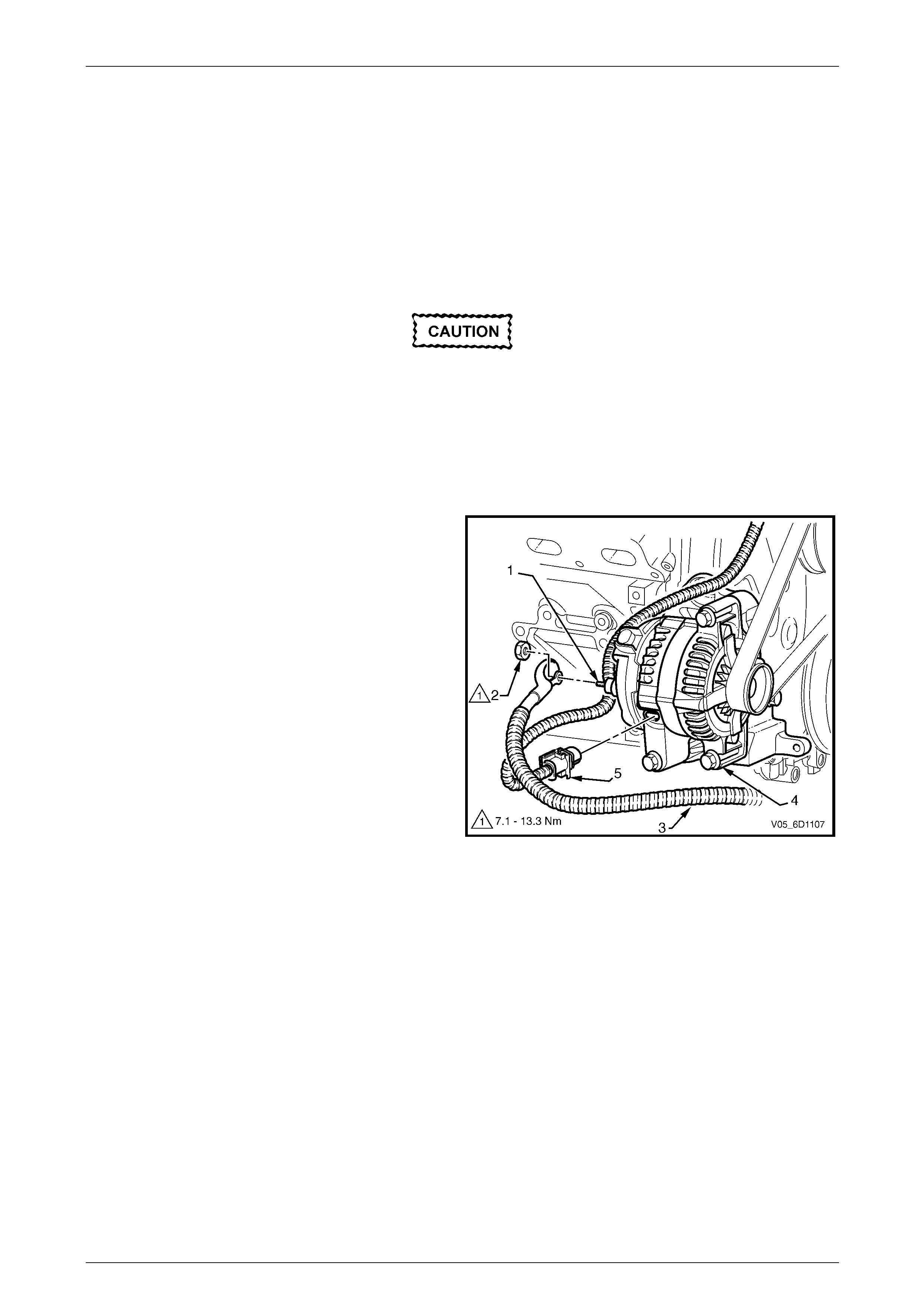
4 Pull the battery harness cap back from G8 – X1 pin
A (1), remove the nut (2) and remove the positive lead
(3) from the generator (4).
5 Disengage the connector retainer and remove the
battery harness connector (5) from the generator.
Figure 6D1-1 – 5
Page 6D1-1–20
Charging System – V6 Page 6D1-1-21
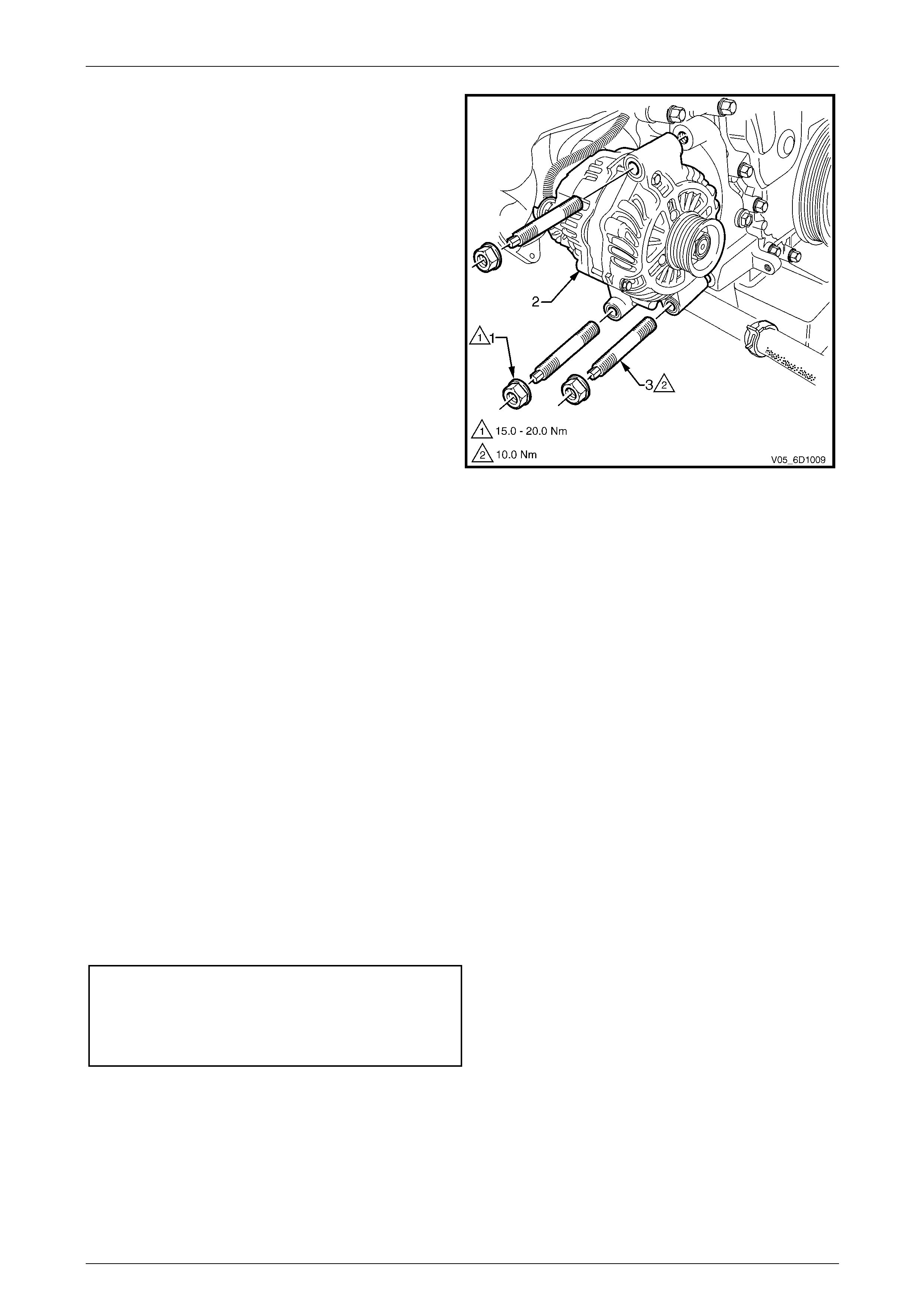
6 Remove the three nuts (1) retaining the generator (2)
to the generator bracket.
7 Remove the three generator mounting studs (3).
NOTE
Generator mounting studs have hexagonal outer
ends to enable their removal.
8 Remove the generator assembly from the vehicle.
Figure 6D1-1 – 6
Reinstall
Reinstallation of the generator is the reverse of the removal procedure, noting the following:
1 Tighten all fasteners to the correct torque specification.
2 Reconnect the battery ground lead.
3 Start the engine.
4 Check the generator warning indicator operation.
5 Check the drive belt is correctly routed and aligned.
NOTE
For vehicles without air conditioning, refer to Figure
6D1-1 – 8. for correct drive belt .
For vehicles fitted with air conditioning, refer to
Figure 6D1-1 – 9 for correct drive belt routing.
6 Check the generator output. Refer to 3.3 On-vehicle Testing.
7 Check the voltage regulator operation. Refer to 3.3 On-vehicle Testing.
8 Turn the ignition switch off.
Generator mounting studs..................................10.0 Nm
Generator retaining nuts .........................15.0 – 20.0 Nm
Battery harness to G8 – X1 pin A nut
torque specification...................................7.1 – 13.3 Nm
Page 6D1-1–21
Charging System – V6 Page 6D1-1-22
4.2 Generator Mounting Bracket
LT Section No. — 02–140
Remove
1 Remove the generator. Refer to 4.1 Generator.
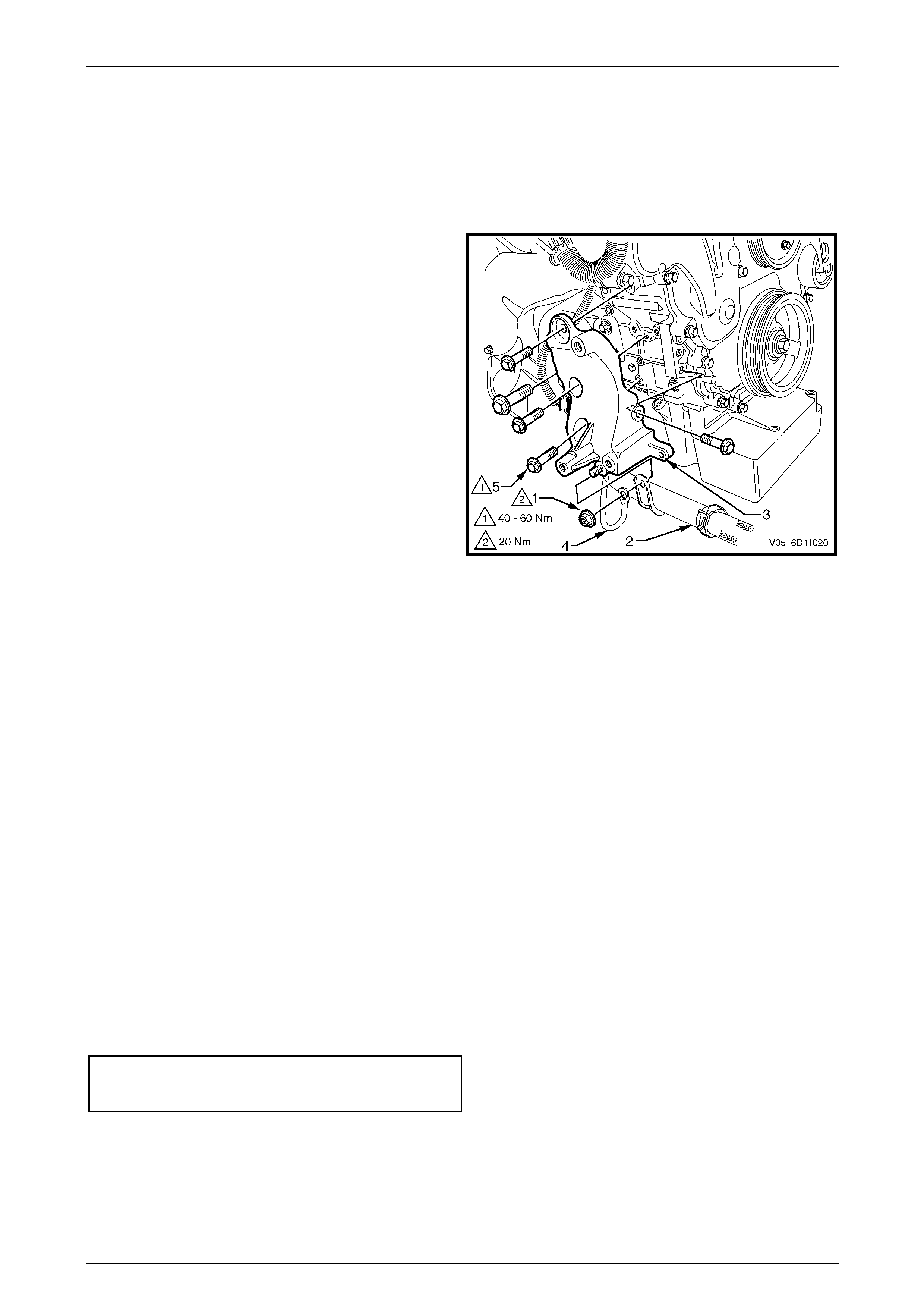
2 Remove the retaining nut (1) attaching the coolant inlet
pipe (2) to the bottom of the generator mounting
bracket (3).
3 Remove the earth strap (4) and flex the coolant inlet
pipe from the generator bracket.
4 Remove the bolts (5); five places, attaching the
generator mounting bracket to the engine block.
5 Remove the generator mounting bracket from the
vehicle.
Figure 6D1-1 – 7
Reinstall
Reinstallation of the generator mounting bracket is the reverse of the removal procedure, noting the following:
1 Tighten all fasteners to the correct torque specification.
2 Reconnect the battery ground lead.
3 Start the engine.
4 Check the generator warning indicator operation.
5 Check the drive belt is correctly routed and aligned.
NOTE
For vehicles without air conditioning, refer to
Figure 6D1-1 – 8. for correct drive belt .
For vehicles fitted with air conditioning, refer to
Figure 6D1-1 – 9 for correct drive belt routing.
6 Check the generator output. Refer to 3.3 On-vehicle Testing.
7 Check the voltage regulator operation. Refer to 3.3 On-vehicle Testing.
8 Turn the ignition switch off.
Generator mounting bracket bolts...........40.0 – 60.0 Nm
Coolant inlet pipe retaining nut...........................20.0 Nm
Page 6D1-1–22
Charging System – V6 Page 6D1-1-23
4.3 Drive Belt Routing
Without Air Conditioning
Ensure the drive belt ribs are correctly positioned in all pulleys and the crankshaft balancer.
NOTE
For detailed information relating to drive belt
service procedure, refer to Section 6A1 Engine
Mechanical – V6.
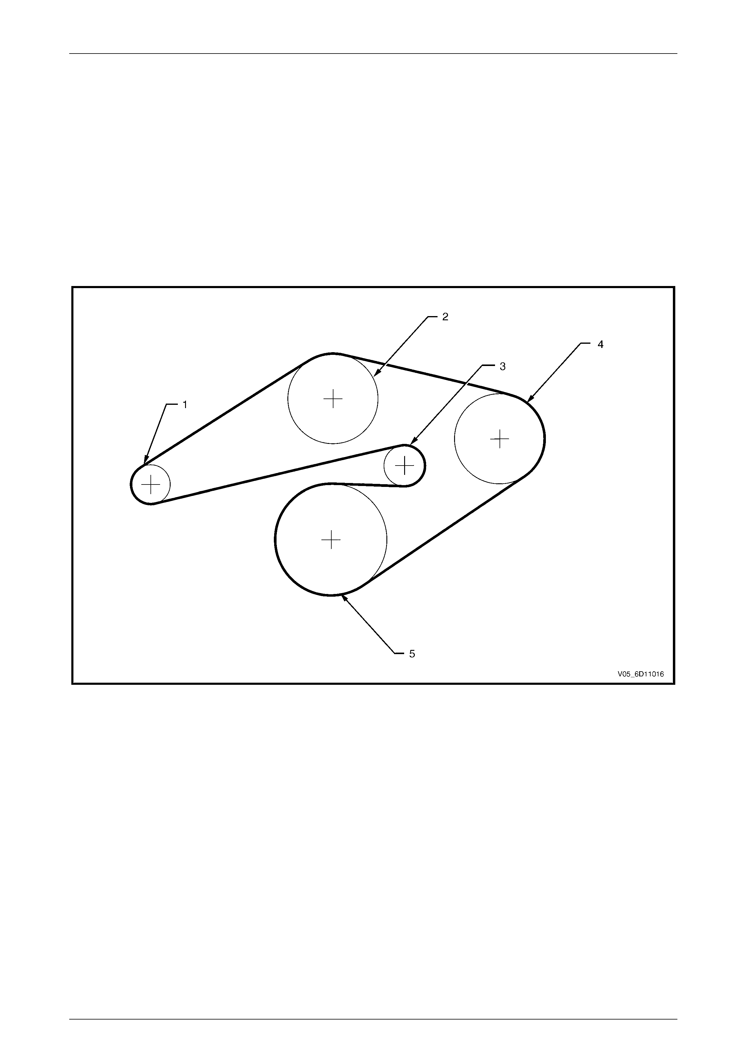
Figure 6D1-1 – 8 shows the drive belt routing for the V6 RWD engine without air-conditioning.
Figure 6D1-1 – 8
Legend
1 Generator
2 Water Pump
3 Tensioner
4 Power Steering
5 Crankshaft
Page 6D1-1–23
Charging System – V6 Page 6D1-1-24
With Air Conditioning
Ensure the drive belt ribs are correctly positioned in all pulleys and the crankshaft balancer.
NOTE
For detailed information relating to drive belt
service procedure, refer to Section 6A1 Engine
Mechanical – V6.
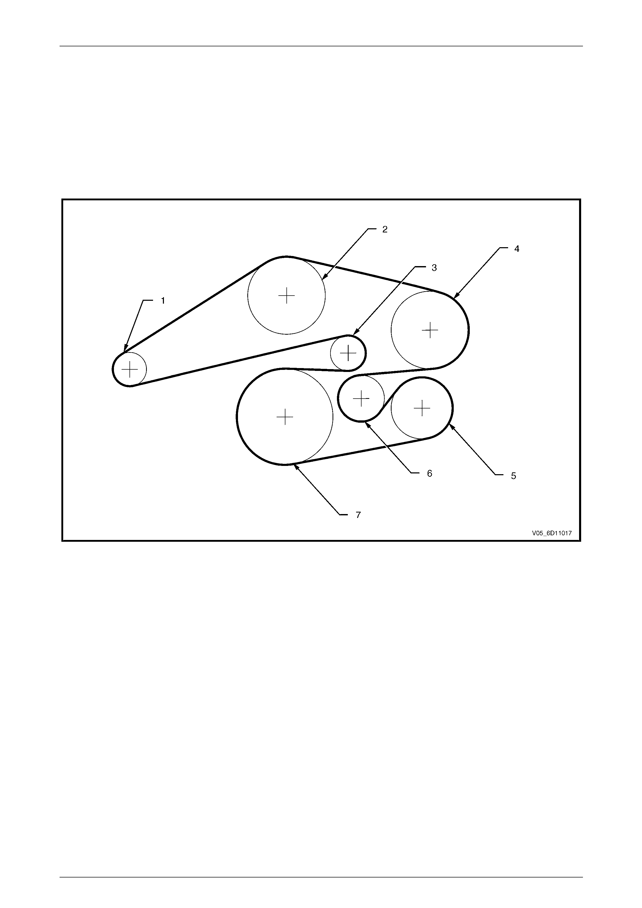
Figure 6D1-1 – 9 shows the drive belt routing for the V6 RWD engine with air-conditioning.
Figure 6D1-1 – 9
Legend
1 Generator
2 Water Pump
3 Tensioner
4 Power Steering
5 A/C Compressor
6 Idler
7 Crankshaft
Page 6D1-1–24

Charging System – V6 Page 6D1-1-25
5 Specifications – 100 A
Ground Polarity...........................................................................................................Negative
Nominal Voltage ............................................................................................................... 12 V
Nominal Output............................................................................................................... 100 A
Stator Phases.........................................................................................................................3
Stator Winding Connections ............................................................................................ Delta
Voltage Regulator Setting....................................................................................14.2 – 14.8 V
Rotor Winding Resistance @ 20°C.................................................................................. 2.1 V
Slip-ring Outer Diameter.............................................................................................22.7 mm
Slip-ring Service Limit.................................................................................................22.1 mm
Stator Winding Resistance @ 20°C.............................................................................0.098 Ω
Brush Length New......................................................................................................18.5 mm
Minimum Brush Length.................................................................................................5.0 mm
Direction of Rotation (viewed from pulley) ................................................................Clockwise
Page 6D1-1–25

Charging System – V6 Page 6D1-1-26
6 Specifications – 120 A
Ground Polarity...........................................................................................................Negative
Nominal Voltage ............................................................................................................... 12 V
Nominal Output............................................................................................................... 120 A
Stator Phases.........................................................................................................................3
Stator Winding Connections ............................................................................................ Delta
Voltage Regulator Setting....................................................................................14.2 – 14.8 V
Rotor Winding Resistance @ 20°C.................................................................................. 2.1 V
Slip-ring Outer Diameter.............................................................................................22.7 mm
Slip-ring Service Limit.................................................................................................22.1 mm
Stator Winding Resistance @ 20°C.............................................................................0.098 Ω
Brush Length New......................................................................................................18.5 mm
Minimum Brush Length.................................................................................................5.0 mm
Direction of Rotation (viewed from pulley) ................................................................Clockwise
Page 6D1-1–26

Charging System – V6 Page 6D1-1-27
7 Torque Wrench Specifications
...................................................................................................................Nm
Generator Mounting Studs .............................................................10.0 – 15.0
Generator Retaining Nuts...............................................................15.0 – 20.0
Generator Mounting Bracket Bolts..................................................40.0 – 60.0
Battery Harness to G8 – X1 pin A Nut..............................................5.0 – 12.0
Page 6D1-1–27
Charging System – V6 Page 6D1-1-28
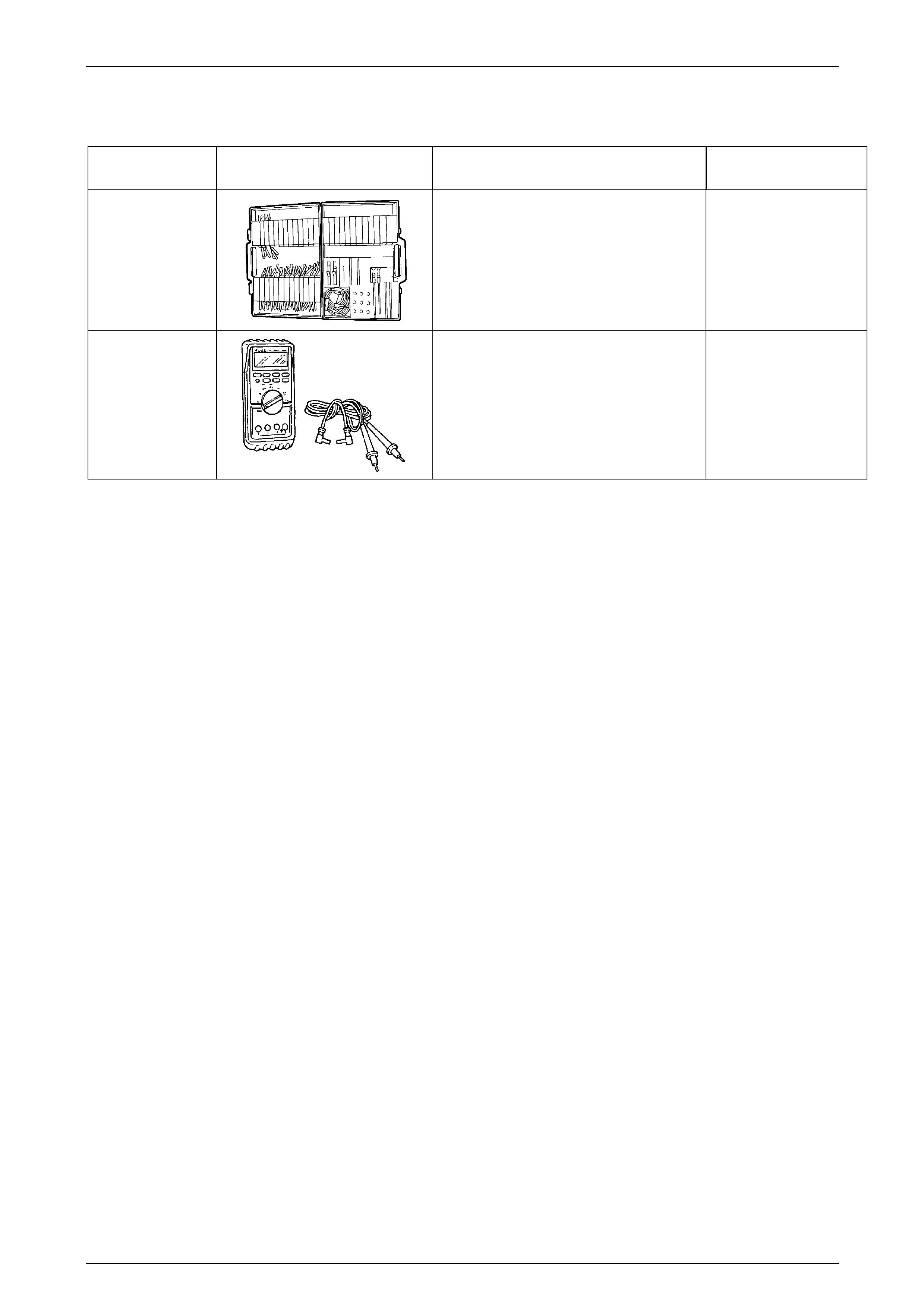
8 Special Tools
TOOL NUMBER ILLUSTRATION DESCRIPTION TOOL
CLASSIFICATION
J35616-A
(KM609)
CONNECTOR TEST ADAPTOR KIT
Used when carrying out electrical
diagnostic circuit checks.
Previously released.
Desirable
3588
(J39200)
DIGITAL MULTIMETER
Must have at least 10 MΩ input
impedance and be capable of reading
frequencies.
Previously released.
Available
Page 6D1-1–28