
Powertrain Interface Module – V6 Page 6E1–1
Page 6E1–1
Section 6E1
Powertrain Interface Module – V6
ATTENTION
Before performing any service operation or other procedure described in this Section, refer to Section 00
Warnings, Cautions and Notes for correct workshop practices with regard to safety and / or property damage.
1
General Information ...............................................................................................................................6
1.1
General Description............................................................................................................................................... 6
Serial Data Communication .................................................................................................................................. 6
Bus ..................................................................................................................................................................... 6
Serial Data ......................................................................................................................................................... 7
Serial Data Communication Protocols................................................................................................................ 7
Serial Data Layout.................................................................................................................................................. 8
2
Component Location..............................................................................................................................9
2.1
Engine Compartment............................................................................................................................................. 9
2.2
Interior................................................................................................................................................................... 10
3
Component Description and Operation .............................................................................................11
3.1
Powertrain Interface Module ............................................................................................................................... 11
Communication Gateway .................................................................................................................................... 11
3.2
Powertrain Interface Module Gateway Components ........................................................................................ 12
Engine Control Module........................................................................................................................................ 12
ABS-TCS / ESP Electronic Control Unit............................................................................................................. 12
Body Control Module........................................................................................................................................... 12
Automatic Transmission Control Module.......................................................................................................... 13
Steering Angle Sensor......................................................................................................................................... 13
3.3
Powertrain Interface Module Direct Input Switches.......................................................................................... 14
Active Select Switch ............................................................................................................................................ 14
Cruise Control Switch.......................................................................................................................................... 14
Electronic Stability Program Switch .................................................................................................................. 14
Power Mode Switch – Automatic Transmission................................................................................................ 15
4
Diagnostics ...........................................................................................................................................16
4.1
Diagnostic General Descriptions........................................................................................................................ 16
Diagnostic Trouble Code (DTC) Tables.............................................................................................................. 16
Multiple DTCs................................................................................................................................................... 16
Diagnostic Trouble Codes (DTCs)...................................................................................................................... 17
Status of DTCs................................................................................................................................................. 17
Conditions for Clearing DTCs........................................................................................................................... 17
Tech 2 PIM Diagnostic Tests............................................................................................................................... 17
Tech 2 Limitations ............................................................................................................................................ 17
Tech 2 Intermittent Fault Tests......................................................................................................................... 17
5
GM LAN Serial Communication Circuit..............................................................................................18
6
Wiring Diagram and Connector Chart ................................................................................................19
6.1
Wiring Diagram .................................................................................................................................................... 19
6.2
Power and Ground Wiring Diagram ................................................................................................................... 20
6.3
Connector Chart................................................................................................................................................... 21

Powertrain Interface Module – V6 Page 6E1–2
Page 6E1–2
6.4
Connector Information ........................................................................................................................................ 22
ABS-TCS / ESP Electronic Control Unit Connector Pin Specifications .......................................................... 22
Pin Description ................................................................................................................................................. 22
Active Select Switch Connector Pin Specifications ......................................................................................... 22
Pin Description ................................................................................................................................................. 22
Automatic Transmission Control Module – T68 Connector Pin Specifications ............................................. 23
Pin Description ................................................................................................................................................. 23
Body Control Module Connector Pin Specifications ........................................................................................ 23
Pin Description ................................................................................................................................................. 23
Cruise Control Switch Assembly Connector Pin Specifications .....................................................................23
Pin Description ................................................................................................................................................. 23
Data Link Connector Pin Specifications ............................................................................................................ 24
Pin Description ................................................................................................................................................. 24
Dual Park Assist Control Module Connector..................................................................................................... 24
Pin Description ................................................................................................................................................. 24
Electronic Stability Program Switch Connector Pin Specifications................................................................24
Pin Description ................................................................................................................................................. 24
Engine Control Module Connector Pin Specifications ..................................................................................... 25
Pin Description ................................................................................................................................................. 25
Ignition Switch Connector Pin Specifications................................................................................................... 25
Pin Description ................................................................................................................................................. 25
PIM Connector Pin Specifications...................................................................................................................... 26
Pin Description ................................................................................................................................................. 26
Power Mode Switch Connector Pin Specifications........................................................................................... 26
Pin Description ................................................................................................................................................. 26
Reverse Relay ...................................................................................................................................................... 27
Pin Description ................................................................................................................................................. 27
Steering Angle Sensor Connector Pin Specifications...................................................................................... 27
Pin Description ................................................................................................................................................. 27
7
Diagnostics Starting Point ..................................................................................................................28
7.1
Diagnostic Requirements, Precautions and Preliminary Checks.................................................................... 28
Basic Knowledge Required................................................................................................................................. 28
Basic Diagnostic Tools Required ....................................................................................................................... 28
Diagnostic Precautions ....................................................................................................................................... 28
Preliminary Checks.............................................................................................................................................. 29
7.2
Diagnostic System Check ................................................................................................................................... 30
7.3
Powertrain Interface Module – Module Presence Check Failure Diagnostic Table........................................ 32
7.4
Dual Park Assist Diagnosis................................................................................................................................. 33
7.5
Reverse Relay Diagnosis .................................................................................................................................... 34
Circuit Description............................................................................................................................................... 34
Additional Information......................................................................................................................................... 34
Test Description................................................................................................................................................... 34
Diagnostic Table .................................................................................................................................................. 34
8
Intermittent Fault Conditions ..............................................................................................................37
8.1
Intermittent Conditions Diagnostic Table.......................................................................................................... 37
Description ........................................................................................................................................................... 37
Diagnostic Table .................................................................................................................................................. 37
9
DTC Tables............................................................................................................................................39
9.1
DTC B1000, B1009, B1013 or B1014 – PIM Internal Fault ................................................................................. 39
DTC Description................................................................................................................................................... 39
Circuit Description............................................................................................................................................... 39
Additional Information......................................................................................................................................... 39
Conditions for Running the DTC ........................................................................................................................ 39
Conditions for Setting the DTC........................................................................................................................... 39
Action Taken When the DTC Sets ...................................................................................................................... 39

Powertrain Interface Module – V6 Page 6E1–3
Page 6E1–3
Conditions for Clearing the DTC ........................................................................................................................ 39
Test Description................................................................................................................................................... 40
DTC B1000, B1009, B1013 or B1014 Diagnostic Table ..................................................................................... 40
9.2
DTC U1304 – Lost Communications With UART System ................................................................................. 41
DTC Description................................................................................................................................................... 41
Circuit Description............................................................................................................................................... 41
Additional Information......................................................................................................................................... 41
Conditions for Running the DTC ........................................................................................................................ 41
Conditions for Setting the DTC........................................................................................................................... 41
Action Taken When the DTC Sets ...................................................................................................................... 41
Conditions for Clearing the DTC ........................................................................................................................ 41
Test Description................................................................................................................................................... 41
DTC U1304 Diagnostic Table .............................................................................................................................. 42
9.3
DTC U2100 – No Communication With CAN Bus (High Speed) ....................................................................... 43
DTC Description................................................................................................................................................... 43
Circuit Description............................................................................................................................................... 43
Additional Information......................................................................................................................................... 43
Conditions for Running the DTC ........................................................................................................................ 43
Conditions for Setting the DTC........................................................................................................................... 43
Action Taken When the DTC Sets ...................................................................................................................... 43
Conditions for Clearing the DTC ........................................................................................................................ 44
Test Description................................................................................................................................................... 44
DTC U2100 Diagnostic Table .............................................................................................................................. 44
9.4
DTC U2105 – CAN Bus No Communication With Engine Control Module...................................................... 46
DTC Description................................................................................................................................................... 46
Circuit Description............................................................................................................................................... 46
Additional Information......................................................................................................................................... 46
Conditions for Running the DTC ........................................................................................................................ 46
Conditions for Setting the DTC........................................................................................................................... 46
Action Taken When the DTC Sets ...................................................................................................................... 46
Conditions for Clearing the DTC ........................................................................................................................ 46
Test Description................................................................................................................................................... 47
DTC U2105 Diagnostic Table .............................................................................................................................. 47
9.5
DTC U2106 – CAN Bus No Communication With Transmission Control Module........................................... 49
DTC Description................................................................................................................................................... 49
Circuit Description............................................................................................................................................... 49
Additional Information......................................................................................................................................... 49
Conditions for Running the DTC ........................................................................................................................ 49
Conditions for Setting the DTC........................................................................................................................... 49
Action Taken When the DTC Sets ...................................................................................................................... 49
Conditions for Clearing the DTC ........................................................................................................................ 49
Test Description................................................................................................................................................... 50
DTC U2106 Diagnostic Table .............................................................................................................................. 50
9.6
DTC U2108 – CAN Bus No Communication With ABS-TCS / ESP Electronic Control Unit ........................... 52
DTC Description................................................................................................................................................... 52
Circuit Description............................................................................................................................................... 52
Additional Information......................................................................................................................................... 52
Conditions for Running the DTC ........................................................................................................................ 52
Conditions for Setting the DTC........................................................................................................................... 52
Action Taken When the DTC Sets ...................................................................................................................... 52
Conditions for Clearing the DTC ........................................................................................................................ 52
Test Description................................................................................................................................................... 53
DTC U2108 Diagnostic Table .............................................................................................................................. 53
9.7
DTC P0565 – Cruise Control On Signal Malfunction......................................................................................... 55
DTC Description................................................................................................................................................... 55
Circuit Description............................................................................................................................................... 55
Additional Information......................................................................................................................................... 55
Conditions for Running the DTC ........................................................................................................................ 55
Conditions for Setting the DTC........................................................................................................................... 55
Action Taken When the DTC Sets ...................................................................................................................... 55

Powertrain Interface Module – V6 Page 6E1–4
Page 6E1–4
Conditions for Clearing the DTC ........................................................................................................................ 55
Test Description................................................................................................................................................... 56
DTC P0565 Diagnostic Table............................................................................................................................... 56
9.8
DTC P0567 – Cruise Control Resume Signal Malfunction................................................................................ 57
DTC Description................................................................................................................................................... 57
Circuit Description............................................................................................................................................... 57
Additional Information......................................................................................................................................... 57
Conditions for Running the DTC ........................................................................................................................ 57
Conditions for Setting the DTC........................................................................................................................... 57
Action Taken When the DTC Sets ...................................................................................................................... 57
Conditions for Clearing the DTC ........................................................................................................................ 57
Test Description................................................................................................................................................... 58
DTC P0567 Diagnostic Table............................................................................................................................... 58
9.9
DTC P0568 – Cruise Control Set Signal Malfunction ........................................................................................ 59
DTC Description................................................................................................................................................... 59
Circuit Description............................................................................................................................................... 59
Additional Information......................................................................................................................................... 59
Conditions for Running the DTC ........................................................................................................................ 59
Conditions for Setting the DTC........................................................................................................................... 59
Action Taken When the DTC Sets ...................................................................................................................... 59
Conditions for Clearing the DTC ........................................................................................................................ 59
Test Description................................................................................................................................................... 60
DTC P0568 Diagnostic Table............................................................................................................................... 60
9.10
DTC P1611 – Wrong Security Code Entered...................................................................................................... 61
DTC Description................................................................................................................................................... 61
Circuit Description............................................................................................................................................... 61
Additional Information......................................................................................................................................... 61
Conditions for Running the DTC ........................................................................................................................ 61
Conditions for Setting the DTC........................................................................................................................... 61
Action Taken When the DTC Sets ...................................................................................................................... 61
Conditions for Clearing the DTC ........................................................................................................................ 62
Test Description................................................................................................................................................... 62
DTC P1611 Diagnostic Table............................................................................................................................... 62
9.11
DTC P1678 – Engine Control Module Identification Failed............................................................................... 63
DTC Description................................................................................................................................................... 63
Circuit Description............................................................................................................................................... 63
Additional Information......................................................................................................................................... 63
Conditions for Running the DTC ........................................................................................................................ 63
Conditions for Setting the DTC........................................................................................................................... 63
Action Taken When the DTC Sets ...................................................................................................................... 63
Conditions for Clearing the DTC ........................................................................................................................ 63
Test Description................................................................................................................................................... 64
DTC P1678 Diagnostic Table............................................................................................................................... 64
9.12
DTC P0826 – Active Select Switch Signal Malfunction..................................................................................... 65
DTC Description................................................................................................................................................... 65
Circuit Description............................................................................................................................................... 65
Additional Information......................................................................................................................................... 65
Conditions for Running the DTC ........................................................................................................................ 65
Conditions for Setting the DTC........................................................................................................................... 65
Action Taken When the DTC Sets ...................................................................................................................... 65
Conditions for Clearing the DTC ........................................................................................................................ 65
Test Description................................................................................................................................................... 65
DTC P0826 Diagnostic Table............................................................................................................................... 66
9.13
DTC B1019 – Transmission Control Module Configuration Mismatch............................................................ 67
DTC Description................................................................................................................................................... 67
Circuit Description............................................................................................................................................... 67
Additional Information......................................................................................................................................... 67
Conditions for Running the DTC ........................................................................................................................ 67
Conditions for Setting the DTC........................................................................................................................... 67
Action Taken When the DTC Sets ...................................................................................................................... 67

Powertrain Interface Module – V6 Page 6E1–5
Page 6E1–5
Conditions for Clearing the DTC ........................................................................................................................ 67
Test Description................................................................................................................................................... 67
DTC B1019 Diagnostic Table .............................................................................................................................. 68
9.14
DTC B2745 – Traction Control / Electronic Stability Program Switch Signal Malfunction ............................ 69
DTC Description................................................................................................................................................... 69
Circuit Description............................................................................................................................................... 69
Additional Information......................................................................................................................................... 69
Conditions for Running the DTC ........................................................................................................................ 69
Conditions for Setting the DTC........................................................................................................................... 69
Action Taken When the DTC Sets ...................................................................................................................... 69
Conditions for Clearing the DTC ........................................................................................................................ 69
Test Description................................................................................................................................................... 69
DTC B2745 Diagnostic Table .............................................................................................................................. 70
9.15
DTC B0980 – Power Mode Switch Signal Malfunction...................................................................................... 71
DTC Description................................................................................................................................................... 71
Circuit Description............................................................................................................................................... 71
Additional Information......................................................................................................................................... 71
Conditions for Running the DTC ........................................................................................................................ 71
Conditions for Setting the DTC........................................................................................................................... 71
Action Taken When the DTC Sets ...................................................................................................................... 71
Conditions for Clearing the DTC ........................................................................................................................ 71
Test Description................................................................................................................................................... 71
DTC B0980 Diagnostic Table .............................................................................................................................. 72
9.16
DTC B3924 – Wrong Environment Identifier Received from Body Control Module ....................................... 73
DTC Description................................................................................................................................................... 73
Circuit Description............................................................................................................................................... 73
Additional Information......................................................................................................................................... 73
Conditions for Running the DTC ........................................................................................................................ 73
Conditions for Setting the DTC........................................................................................................................... 73
Action Taken When the DTC Sets ...................................................................................................................... 73
Conditions for Clearing the DTC ........................................................................................................................ 73
Test Description................................................................................................................................................... 74
DTC B3924 Diagnostic Table .............................................................................................................................. 74
10
Service Operations...............................................................................................................................75
10.1
Safety and Precautionary Measures .................................................................................................................. 75
10.2
Powertrain Interface Module ............................................................................................................................... 76
Remove................................................................................................................................................................. 76
Reinstall................................................................................................................................................................ 77
11
PIM Security and Programming ..........................................................................................................78
11.1
Security and Programming Information............................................................................................................. 78
Vehicle Security Card .......................................................................................................................................... 78
Security Code....................................................................................................................................................... 78
Tech 2 PIM Security Information Data List ........................................................................................................ 79
11.2
PIM Reset Procedure ........................................................................................................................................... 80
11.3
PIM Configuration ................................................................................................................................................ 81
Configuring a New PIM........................................................................................................................................ 81
Configuring an Existing PIM ............................................................................................................................... 82
Programming the VIN .......................................................................................................................................... 82
11.4
BCM Link to ECM / PIM........................................................................................................................................ 83
12
Specifications .......................................................................................................................................84
13
Torque Wrench Specifications............................................................................................................85
14
Special Tools ........................................................................................................................................86

Powertrain Interface Module – V6 Page 6E1–6
Page 6E1–6
1 General Information
A powertrain interface module (PIM) is fitted that incorporate the following functionality:
• Communication protocol between the engine control module (ECM), transmission c ontrol module (TCM) and the
electronic control unit (ECU) of the antilock braking and traction control system, is General Motors Local Area
Network (GM LAN) .
• ECM to PIM and PIM to body control module (BCM) authentication for vehicle security.
• The following switches input directly into the PIM:
• Automatic transmission power mode switch.
• Electronic stability program enable / disable switch.
• Active select switch.
• Cruise control switch.
• Reverse lamp relay operation for the 5L40E automatic transmission is con t rolled by the PIM.
• The PIM provides a signal to the dual park assist control module when the automatic transmission is in either park
or neutral. For further information on the dual park assist system, refer to Section 12F2 Dual Park Assist.
1.1 General Description
Serial Data Communication
The various electronic control modules communicate with each other through the seria l data bus. The ECM, TCM and
ABS-TCS / ESP ECU communicate on the serial data bus using the GM LAN communication protocol, whilst the BCM
communicates with the instrument cluster, Audio Head Unit (AHU) and Oc cupant Protection System Sensing and
Diagnostic Module (SDM) using the universal asynchronous receive and transmit (UART) communication protocol.
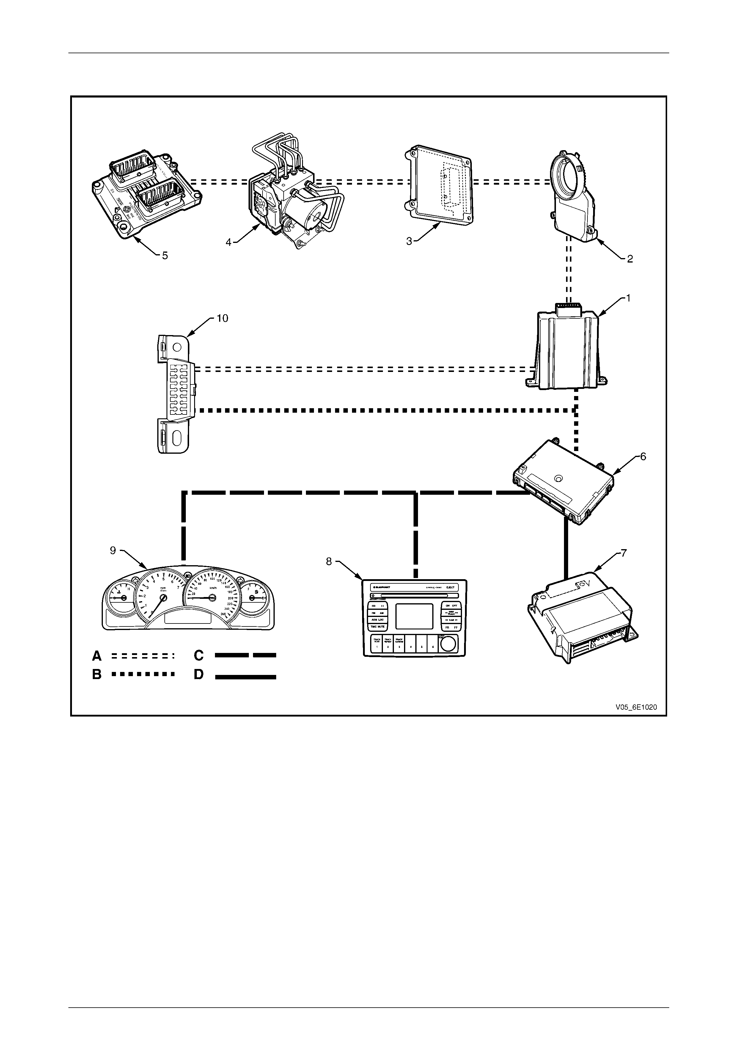
Figure 6E1 – 2 shows the serial data layout.
NOTE
Serial data components shown in Figure 6E1 – 2
will vary depending on vehicle options.
The PIM is integrated into the serial data network and acts as a transparent bi-directional translation device that enable s
the control modules on the GM LAN serial data bus to communicate with control modules on the UART serial data bus.
For further information on the UART serial data bus, refer to Section 12J Body Control Module.
Bus
A bus is a physical circuit or circuits which provides a communication path between two or more control modules.
UART Serial Data Bus
UART communication uses a single wire circuit. For further information on the UART serial data bus, refer to
Section 12J Body Control Module.
GM LAN Serial Data Bus
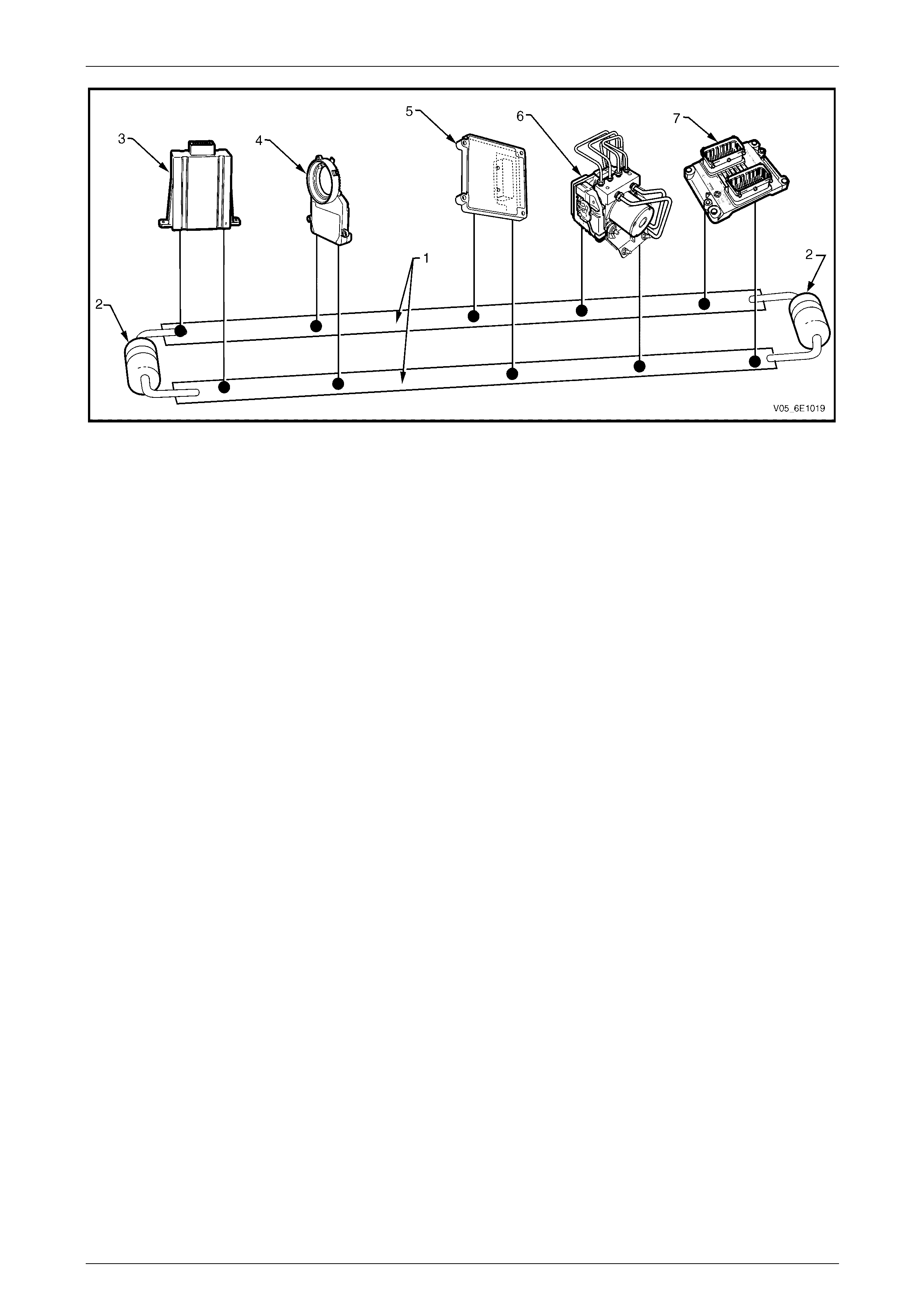
The GM LAN bus is a two wire circuit (1), refer to Figure 6E1 – 1. The GM LAN bus circuits are terminated with cut-off
resistors (2) which are locate d inside the two control modules at either end of the bus circuit. The purpose of these cut- off
resistors is to prevent data from returning as an echo after reaching the end of the GM LAN bus circu it.
NOTE
For illustration purposes, the cut-off resistors are
shown outside of the control modules.
The two control modules with the cut-off resistors
are the PIM and the ECM.
Powertrain Interface Module – V6 Page 6E1–7
Page 6E1–7
Figure 6E1 – 1
Legend
1 CAN Bus Lines
2 Cut-off Resistors (resistors are integrated into the PIM and
ECM)
3 Powertrain Interface Module (PIM)
4 Steering Angle Sensor
5 Transmission Control Module (TCM)
6 ABS-TCS / ESP Electronic Control Unit (ECU)
7 Engine Control Module (ECM)
Serial Data
When information is sent from one control module to another via the serial data bus, the information sent is known as
serial data. Serial data in its electronic form, is made up of rapi dly changing high to low voltage pu lses strung together.
Each string of voltage pulses represents a message.
• GM LAN serial data has two data lines along which serial data is sent. These lines are kn own as CAN_HI and
CAN_LO.
• CAN HI – The CAN HI data line is a 3.6 V data line that toggles the voltage between 2.5 V and 3.6 V
(referenced to ground). When there is no communication on the CAN HI data line, the system voltage
is 2.5 V.
• CAN LO – The CAN LO data line is a 2.5 V data line that toggles the voltage between 2.5 V and 1.4 V
(referenced to ground). When there is no communication on the CAN LO data line, the system voltage
is 2.5 V.
• UART serial data is a single 5 V data line that toggles the voltage to ground. When there is no communication o n
the data line, the system voltage is 5 V.
Serial Data Communication Protocols
General Motors Local Area Network (GM LAN)
GM LAN is a communication protocol based on the Controller Area Network physical layer. The main difference between
GM LAN and CAN is the way in which the messages are structured. It is a broadcast communic ations ch annel, not
master / slave like UART.
Universal Asynchronous Receive and Transmit (UART)
UART is a communication pro t ocol that has a master module which controls the message traffic on the serial data b us.
The body control module (BCM) is the UART bus master. The main difference b etween GM LAN and UART protocol is
that UART relies on the bus master to control the messaging, where as with GM LAN, the messaging is managed by
each of the control modules.
Powertrain Interface Module – V6 Page 6E1–8
Page 6E1–8
Serial Data Layout
Figure 6E1 – 2
Legend
1 Powertrain Interface Module (PIM)
2 Steering Angle Sensor
3 Transmission Control Module (TCM)
4 ABS-TCS / ESP Electronic Control Unit (ECU)
5 Engine Control Module (ECM)
6 Body Control Module (BCM)
7 Occupant Protection System Sensing and Diagnostic
Module (SDM)
8 Audio Head Unit (AHU)
9 Instrument Cluster
10 Data Link Connector
A GM LAN Serial Data Circuit
B Primary UART Serial Data Circuit
C Secondary UART Serial Data Circuit
D Tertiary UART Serial Data Circuit
NOTE
Serial data Components shown in Figur e 6E1 – 2
will vary depending on vehicle options.

Powertrain Interface Module – V6 Page 6E1–9
Page 6E1–9
2 Component Location
2.1 Engine Compartment
Figure 6E1 – 3
Legend
1 ABS-TCS / ESP Electronic Control Unit (ECU) 2 Engine Control Module (ECM)
Powertrain Interface Module – V6 Page 6E1–10
Page 6E1–10
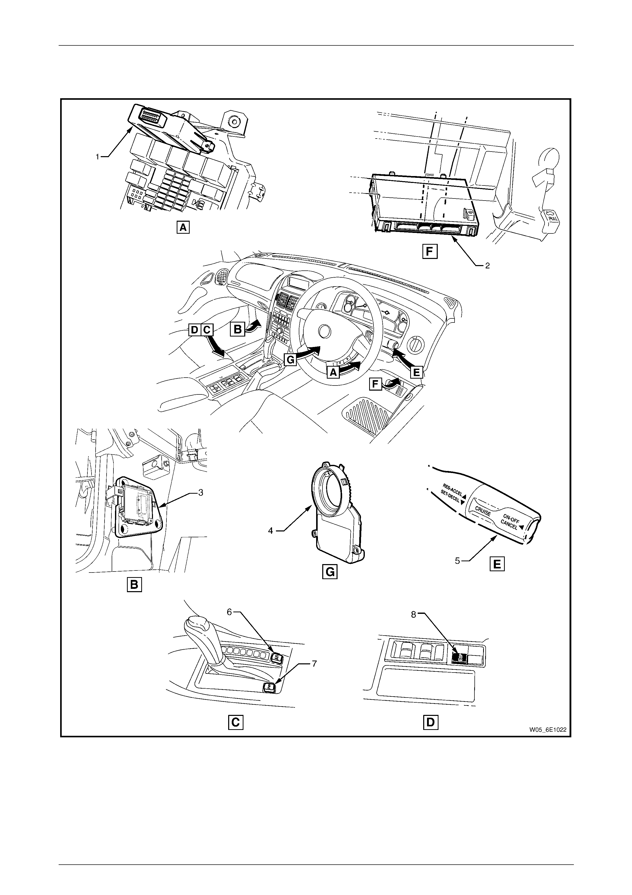
2.2 Interior
Figure 6E1 – 4
Legend
1 Powertrain Interface Module (PIM)
2 Body Control Module (BCM)
3 Transmission Control Module (TCM)
4 Steering Angle Sensor
5 Cruise Control Switch Assembly
6 Active Select Switch
7 Power Mode Switch – Automatic Transmission
8 Electronic Stability Program (ESP) Switch
Powertrain Interface Module – V6 Page 6E1–11
Page 6E1–11
3 Component Description and
Operation
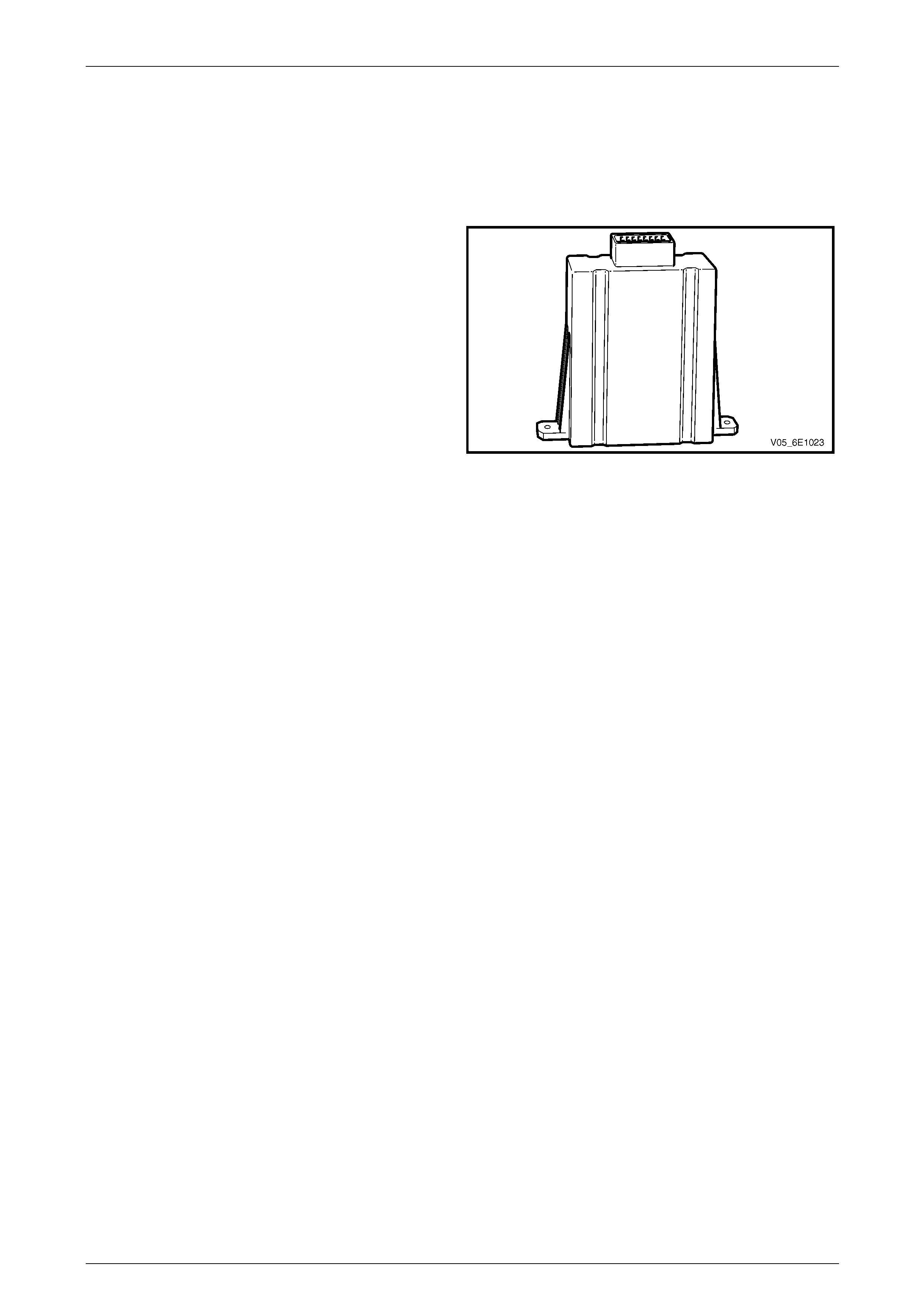
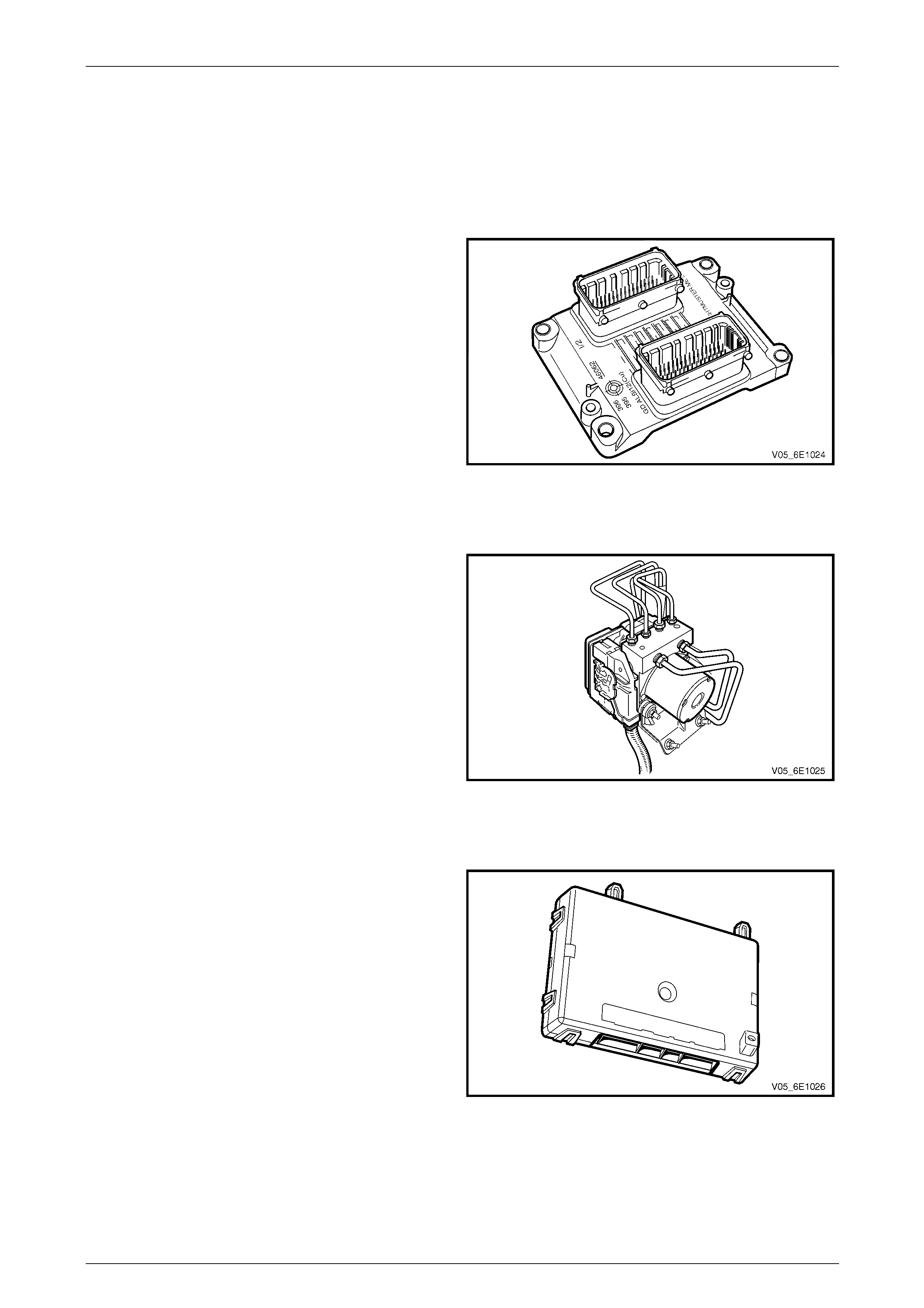
3.1 Pow ertrain Interface Module
The powertrain interface module (PIM) is located on the
driver's instrument panel outer bracket and is accessible by
lowering the instrument panel lower trim panel assembly.
Figure 6E1 – 5
Communication Gateway
The PIM performs the following functions:
• The PIM acts as the communication gateway between the GM LAN communications protocol an d the universal
asynchronous receive and transmit (UART) protocol.
As the GM LAN protocol is not compatible with UART, the PIM is integrated into the serial data commu nication
system to enable bi-directional communication flow between control modules on the UART side and the GM LAN
side of the communication net work.
• The PIM converts analogue si gnals from the cruise control and traction control switches into digital serial data.
• The PIM is responsible for au thenticating the body control module (BCM) prior to the engine control module (ECM)
authenticating the PIM. If any of these authentication processes fail, the vehicl e will not start. For further information
on the theft deterrent system, refer to Section 12J Body Control Module.
Powertrain Interface Module – V6 Page 6E1–12
Page 6E1–12
3.2 Pow ertrain Interface Module Gateway
Components
The following components use the PIM to communicate between the UART and GM LAN communication protocol:
Engine Control Module
The ECM is located at the right front of the engine
assembly.
The ECM communicates directly with the transmission
control module (TCM), ABS-TCS / ESP ECU and PIM via
the serial data network. The ECM, via the PIM, also
communicates with the BCM and instrument cluster.
The ECM is also an integral part of the vehicle security
system. For further information on vehicle security, refer to
Section 12J Body Control Module.
Figure 6E1 – 6
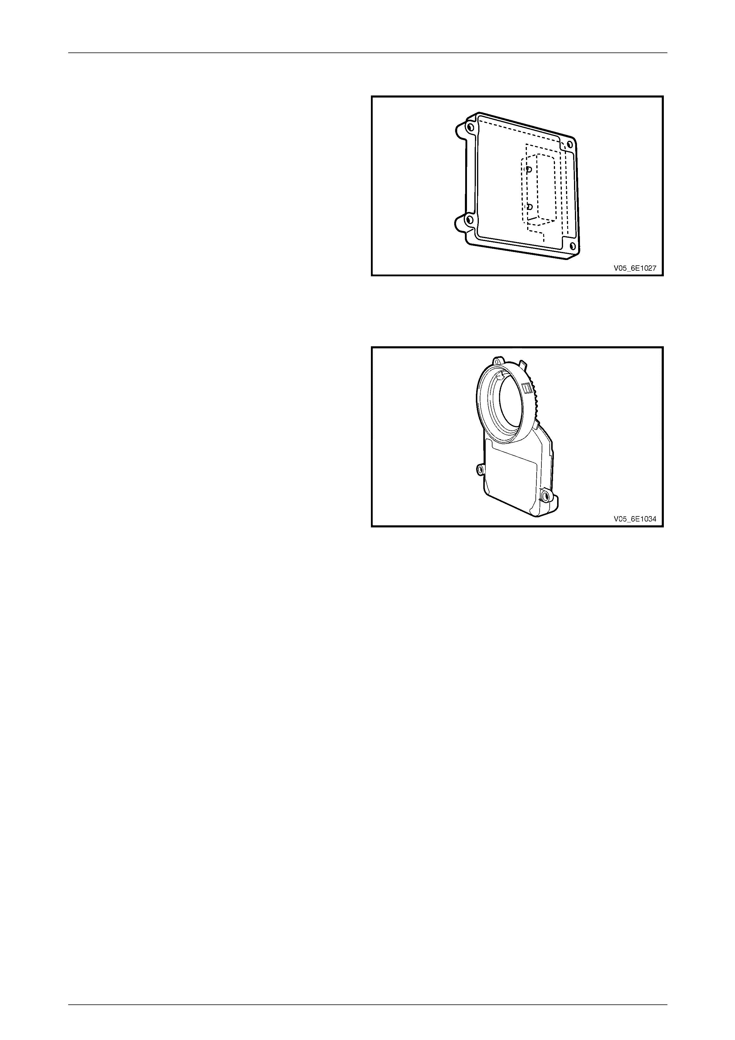
ABS-TCS / ESP Electronic Control Unit
The ABS-TCS / ESP ECU is located in the engine
compartment adjacent to the right-hand front wheelhouse
liner.
The primary role of the ABS-TCS / ESP is to efficiently
control the vehicle's braking and traction control operation.
To effectively do this, the ECU of the ABS-TCS / ESP
communicates with other vehicle s ystems such as the
engine management and automatic transmission systems.
This information exchange is achieved by connecting the
various system control modules via the serial data network.
For further information on the serial data network, refer to
1 General Information.
Figure 6E1 – 7
Body Control Module
The body control module (BCM) is mounted vertically
behind the instrument panel compartment.
The BCM controls various vehicle electrica l systems, and is
an integral part of the serial data communication network.
The BCM communicates with other vehicle modules using
the universal asynchronous receive and transmit (UART)
serial data protocol.
The BCM is connected to the PIM and the data link
connector (DLC) via the primary serial data circuit. The BCM
communicates via this circuit with the ECM, TCM and the
ABS-TCS / ESP ECU.
Refer to Section 12J Body Control Module for further
information on:
• serial data communication, a nd
• theft deterrent system.
Figure 6E1 – 8
Powertrain Interface Module – V6 Page 6E1–13
Page 6E1–13
Automatic Transmission Control Module
The transmission control module (T CM) is located behind
the left-hand lower hinge pillar trim.
The TCM's primary role is to efficientl y control transmission
shift points according to current driving and vehicle
operating conditions. To effectively do this, the TCM
requires information from other vehicl e systems such as the
engine management and automatic transmission systems.
This information exchanged is achieved by connecting the
various system control modules via the serial data network.
For further information on the serial data network, refer to
1 General Information.
Figure 6E1 – 9
Steering Angle Sensor
The steering angle sens or is attached to the Occupant
Protection System clock spring coil assembl y adaptor plate.
The steering angle sensor is used by the ABS-TCS / ESP /
ESP Electronic Control Unit to determine the amount and
direction of steering lock being app lied. The steering angle
sensor outputs this data on the GM LAN serial data bus. For
further information on the steering angle sensor, refer to
Section 5B ABS / TCS / ESP – General Information.
Figure 6E1 – 10
Powertrain Interface Module – V6 Page 6E1–14
Page 6E1–14
3.3 Pow ertrain Interface Module Direct Input
Switches
The following switches are dir ect wired to the PIM. These switches use the PIM to convert their input signals into seri al
data, which is then used by the various vehicle control modules to perform varying functions.
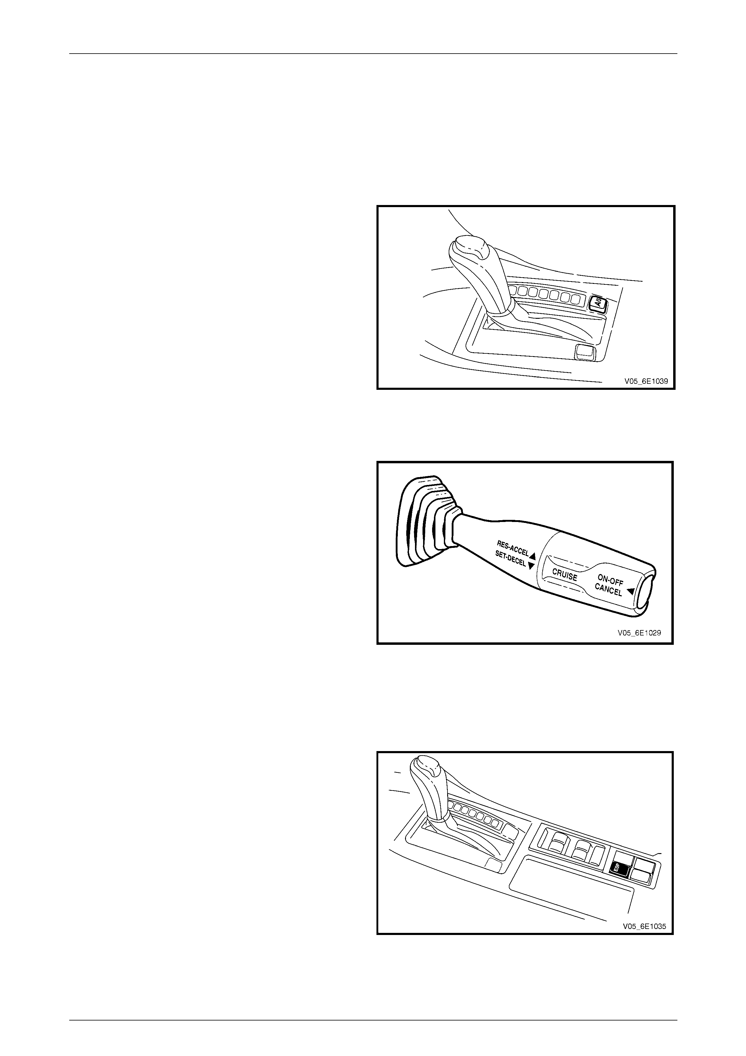
Active Select Switch
The active select switch is located at the rear of the floor
console.
The active select switch is a momentary contact switch that
enables or disables active select. T he active select switch
inputs directly into the PIM. When the switch is pressed,
the PIM sends a message on the serial data bus to the
automatic transmission control module. For further
information on active select, refer to Section 7E1 Automatic
Transmission – 5L40E – General Information.
Figure 6E1 – 11
Cruise Control Switch
The cruise control switch is located on th e right-hand side of
the steering column.
The switch is comprised of three momentary contact
switches which control the follo wing function s:
• cruise control push button switch (ON–OFF),
• cruise control resume – accelerate (RES–ACCEL),
and
• cruise control set – decelerate (SET–DECEL).
The three cruise control switches directly input into the PIM.
When any of these s witches are activated, the PIM sends a
message on the serial data bus to the ECM. For further
information on the cruise control system, refer to
Section 12E Cruise Control.
Figure 6E1 – 12
Electronic Stability Program Switch
The Electronic Stability Program (ESP) switch is located at
the rear of the floor console.
The ESP switch is a momentary contact s witch that enable s
or disables the ESP. The ESP switch inputs directly into the
PIM. When the ESP is pressed, the PIM sends a message
on the serial data bus to the ABS-TCS / ESP ECU. For
further information on the ABS-TCS / ESP, refer to
Section 5B ABS / TCS / ESP – General Information.
Figure 6E1 – 13

Powertrain Interface Module – V6 Page 6E1–15
Page 6E1–15
Power Mode Switch – Automatic Transmission
The power mode switch is located at the rear of the floor
console.
• The power mode switch is a momentary contact switch
that changes the transmission shift points. The power
switch inputs directly into the PIM. When the switch is
pressed, the PIM sends a message on the serial data
bus to the Transmission Control Module (TCM). For
further information on the automatic transmission,
refer to Section 7E1 Automatic Transmission – 5L40E
– General Information.
Figure 6E1 – 14

Powertrain Interface Module – V6 Page 6E1–16
Page 6E1–16
4 Diagnostics
4.1 Diagnostic General Descriptions
The powertrain interface module (PIM) diagnostic procedure is organised in a logical structure that beg ins with the
Diagnostic System Check. The Diagnostic S ystem Check directs the diagnostic procedure to the logical steps or
appropriate diagnostic tab le re quired to diagnose a PIM fault condition.
The diagnostic tables locate a faulty circuit or component through a logical based proc ess of elimination. Correct use of
the diagnostic tables is essential to reduce di agnostic time and to prevent misdiagnosis.
In addition, the Diagnostic System Check provides the following information:
• Identification of the PIM,
• condition of the diagnostic circuit, and
• identification and status of the DTCs if present.
Diagnostic Trouble Code (DTC) Tables
The diagnostic procedure is directed to a diagnostic trouble code (DTC) table if there are DT Cs currently stored in the
PIM.
The diagnostic tables are designed to locate a faulty circuit or component through a logical based process of elimination.
The diagnostic tables are developed with the following assumptions:
• the vehicle functioned correctly at the time of assembly,
• there are no multiple faults, and
• the problem currently exists.
Multiple DTCs
When performing a DTC check and there are multiple DTCs, the diagnostic process must begin with the most likely DTC
that may trigger other DTCs. The following situation is an exampl e of a DT C that may trigger other vehicle system DTCs
to set.
• If there is an open circuit condition with the CAN_HI circuit between the ABS-TCS / ESP ECU and the engine
control module (ECM), DTC U2105 Loss of Communicatio ns from ECM may set. This condition may also cause the
following DTCs to set in other control modules:
• Instrument cluster – DTC 11 No Serial Data from the ECM.
• ABS-TCS / ESP – DTC U2105 Lost Communication with the ECM.
• Transmission Control Module (TCM) – DTC U2105 Lost Communicati on with the ECM.
• Body Control Module (BCM) – DTC 7 No Serial Data from the ECM.
Knowledge of the PIM and Tech 2 limitations are important to reduce diagnostic time and to preve nt misdi agnosis. Refer
to 7.1 Diagnostic Requirements, Precautions and Preliminary Checks.

Powertrain Interface Module – V6 Page 6E1–17
Page 6E1–17
Diagnostic Trouble Codes (DTCs)
When the ignition s witch is turned on, the PIM performs an internal integrity check that detects and isolates any internal
faults. The PIM also monitors the cruise control and traction control switch circuit and the serial data bus for messages
from the control modules on the GM LAN bus and from the BCM on the UA RT bus. If a fault is detected by the PIM, it will
log a Diagnostic Trouble Code (DTC) that represents the fault detected. The DTCs stored in the PIM may be accessed
using Tech 2. Refer to Section 0C Tech 2 for further information on Tech 2.
Status of DTCs
The PIM designates the DT Cs logged into a Current or History DTC.
Current DTCs
If the fault condition that triggers the DTC is present during the last PIM self test, that DTC will be designated as a current
DTC.
History DTCs
If the fault condition that triggers the DTC is not present during the last PIM self test, that DTC will be designated as a
history DTC.
Conditions for Clearing DTCs
• If there is no DTC logged in the current PIM self test, the current DTC will be cleared.
• If there is no DTC logged after 100 consecutive drive cycles, the history DTC will be cleare d.
Tech 2 PIM Diagnostic Tests
NOTE
Refer to Section 0C Tech 2 and the Tech 2 Users
Manual for detailed information and instructions
regarding the use of Tech 2.
Tech 2 Limitations
Some DTCs trigger other DTCs to set, which causes Tech 2 to display multiple DTCs. In those situations, Tech 2 may
display more DT Cs than is neede d to rectify a fault.
When Tech 2 displays an o utp ut function, it displays only the command given by the PIM. If a connector is disconnected,
that fault will not register in the PIM output function. Tech 2 does not verify the command action.
The service technician must understand t he system being diagnosed as well as the corre c t use and limitations of Tech 2
to be able to perform diagnostic procedures efficiently and successfully.
Tech 2 Intermittent Fault Tests
The following are lists of Tech 2 diagnostic tests that may be used to diagnose intermittent faults:
• Wiggle test the suspected PIM wiring harness and connector while observing Tech 2 operating parameters of the
circuit being tested. If Tech 2 read-out fluctuates during this procedure, check the wiring harness circuit for loose
connection.
• Road test the vehicle in conditions that trigger the intermittent fault while an assistant observes the susp ected
Tech 2 operating parameter data.
• Capture and store data in the Snapshot mode when the fault occurs. The stored data may be repla yed at a slower
rate to aid in diagnostics. Refer to Tech 2 User Instructions for more infor mation o n the Snapshot function.
• Operate suspected components to test their operation using Tech 2 Output Control Data.
Powertrain Interface Module – V6 Page 6E1–18
Page 6E1–18
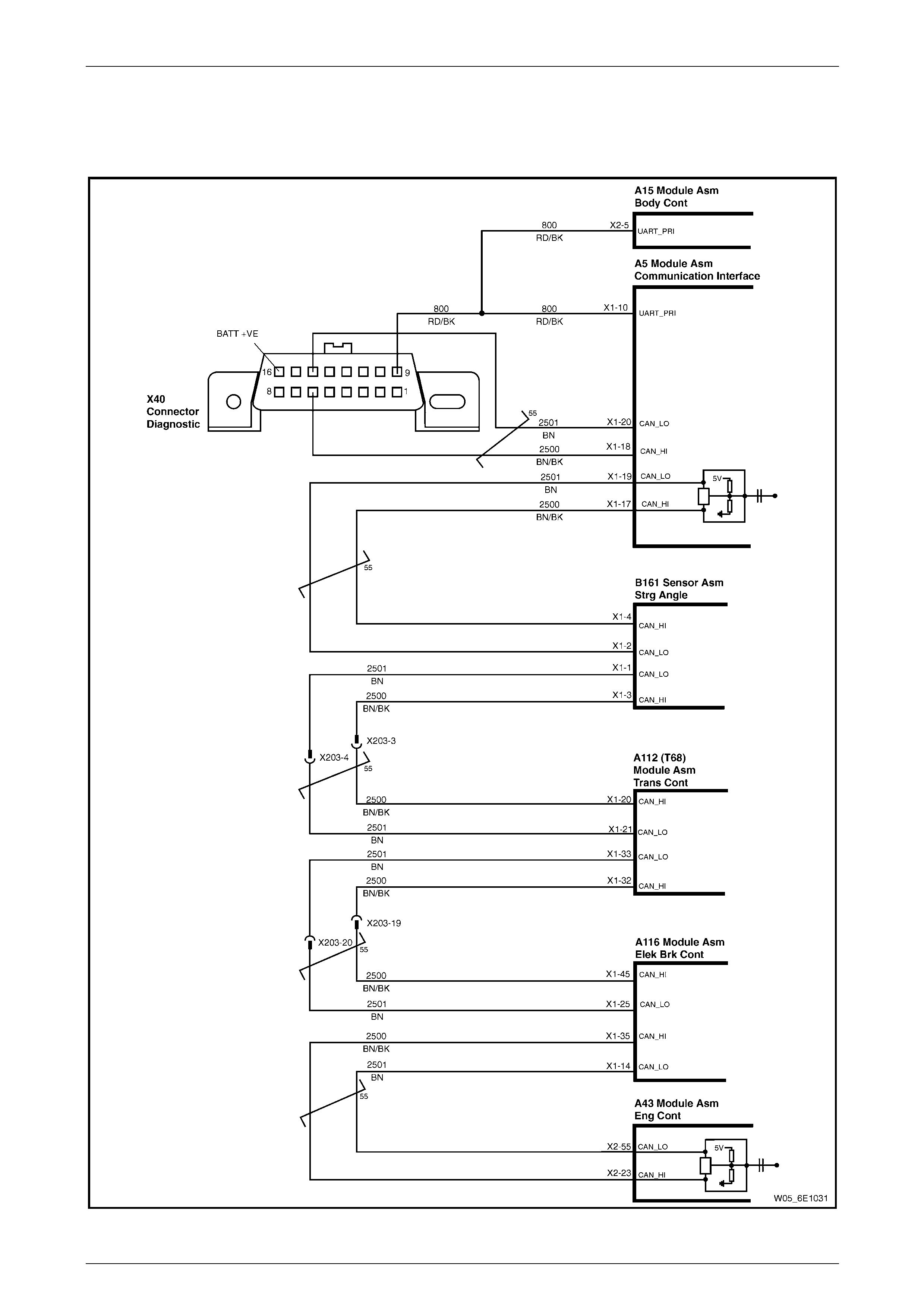
5 GM LAN Serial Communication
Circuit
Figure 6E1 – 15
Powertrain Interface Module – V6 Page 6E1–19
Page 6E1–19
6 Wiring Diagram and Connector
Chart
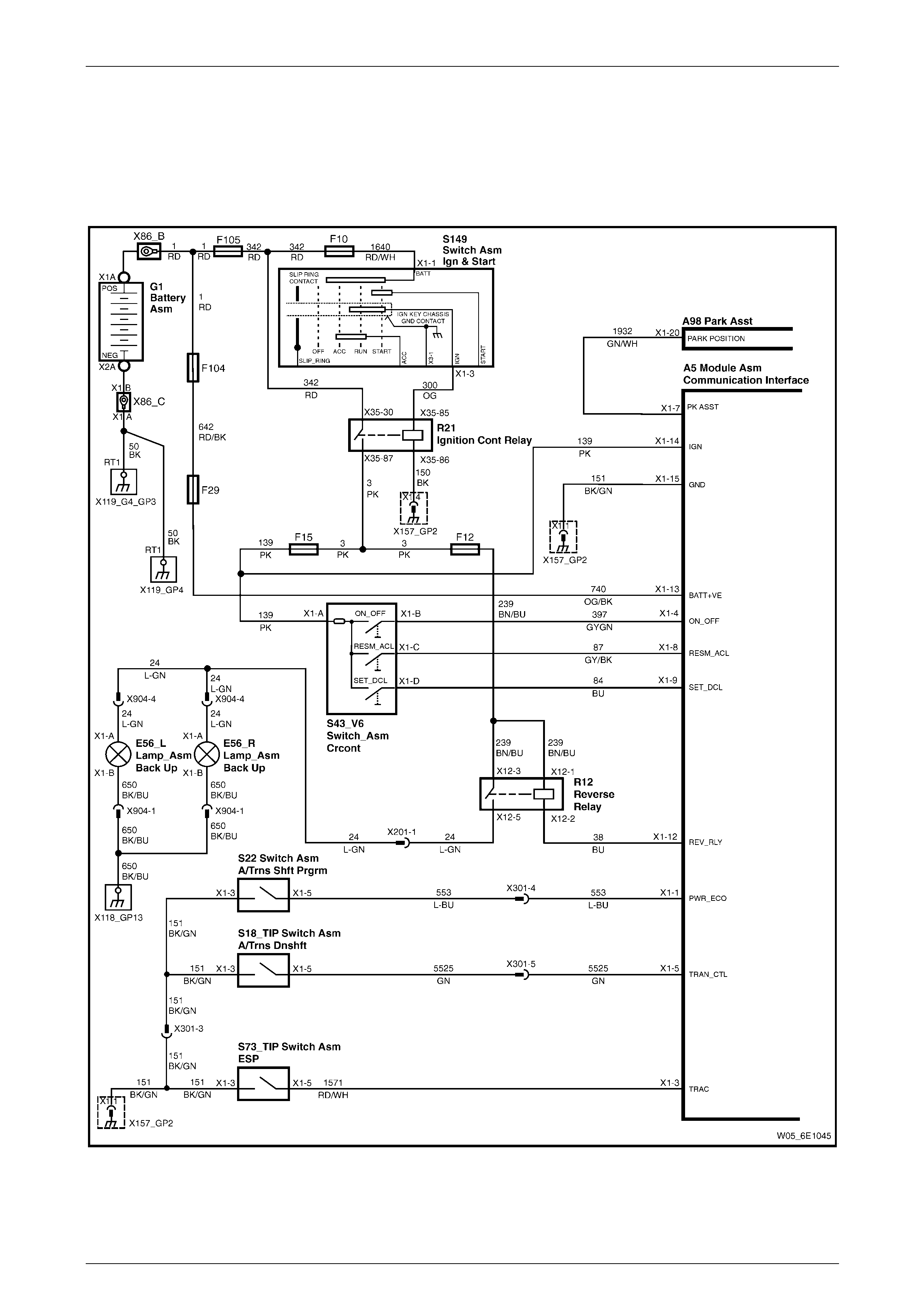
6.1 Wiring Diagram
Figure 6E1 – 16
Powertrain Interface Module – V6 Page 6E1–20
Page 6E1–20
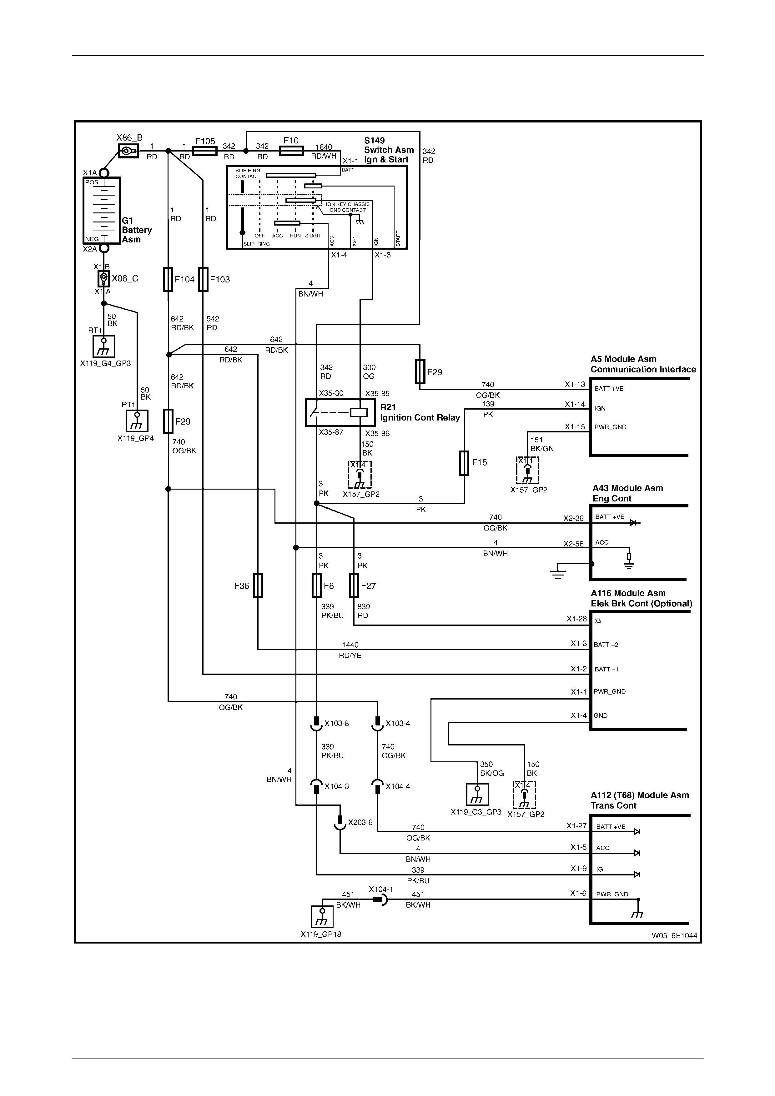
6.2 Power and Ground Wiring Diagram
Figure 6E1 – 17
Powertrain Interface Module – V6 Page 6E1–21
Page 6E1–21
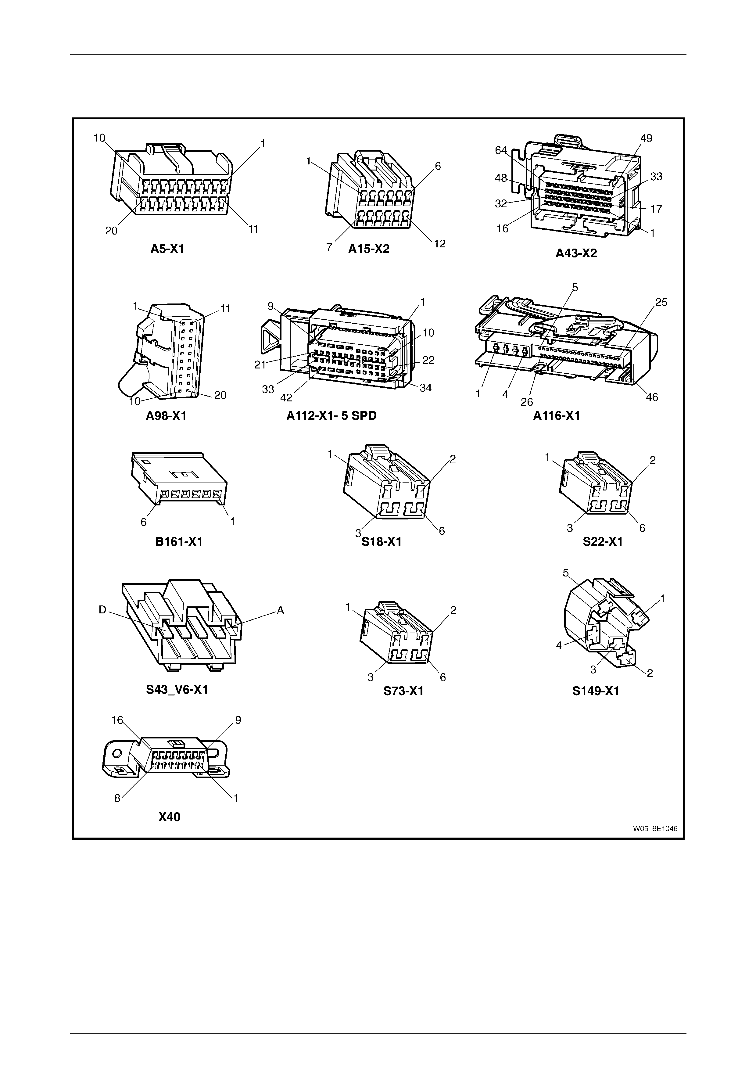
6.3 Connector Chart
Figure 6E1 – 18
Powertrain Interface Module – V6 Page 6E1–22
Page 6E1–22
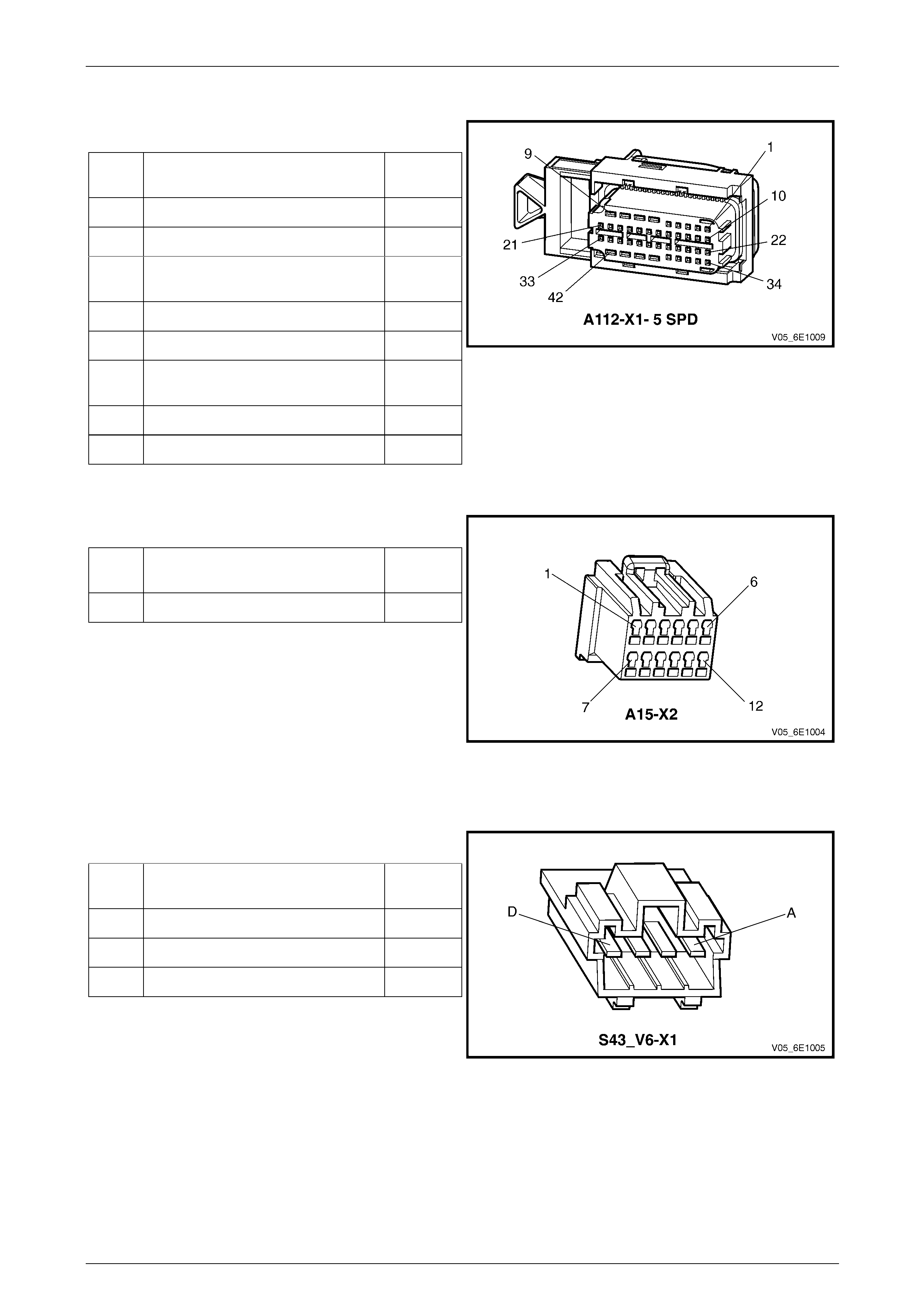
6.4 Connector Information
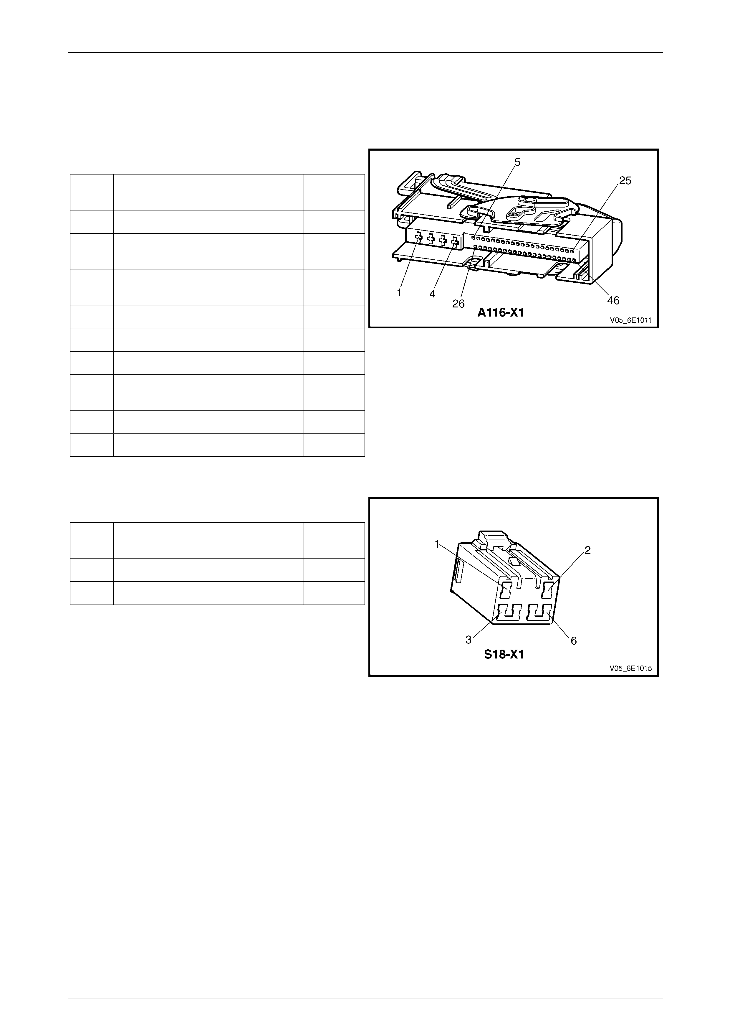
ABS-TCS / ESP Electronic Control Unit Connector Pin Specifications
Pin Description
Pin Function Circuit
Number
1 Main Ground Circuit 350
2 12 volts Uninterrupted Supply
Voltage – Fuse 103 542
3 12 volts Uninterrupted Supply
Voltage – Fuse 36 1440
4 Ground – ECU Ground Circuit 150
14 CAN_LO - Serial Data 2501
25 CAN_LO - Serial Data 2501
28 Switched Battery Voltage From
Ignition Control Relay – Fuse 27 839
35 CAN_HI - Serial Data 2500
45 CAN_HI - Serial Data 2500
Figure 6E1 – 19
Active Select Switch Connector Pin Specifications
Pin Description
Pin Function Circuit
Number
3 Active Select - Ground Circuit 151
5 Active Select - Signal Circuit 5525
Figure 6E1 – 20
Powertrain Interface Module – V6 Page 6E1–23
Page 6E1–23
Automatic Transmission Control Module – T68 Connector Pin Specifications
Pin Description
Pin Function Circuit
Number
5 Accessory Supply Voltage 4
6 Main Ground Circuit 451
9 Switched Battery Voltage From
Ignition Control Relay – Fuse 8 339
20 CAN_HI - Serial Data 2500
21 CAN_LO - Serial Data 2501
27 12 volts Uninterrupted Supply
Voltage – Fuse 29 740
32 CAN_HI - Serial Data 2500
33 CAN_LO - Serial Data 2501
Figure 6E1 – 21
Body Control Module Connector Pin Specifications
Pin Description
Pin Function Circuit
Number
5 UART Serial Data 800
Figure 6E1 – 22
Cruise Control Switch Assembly Connector Pin Specifications
Pin Description
Pin Function Circuit
Number
B On / Off Signal 397
C Resume / Accelerate Signal 87
D Set / Decelerate Signal 84
Figure 6E1 – 23
Powertrain Interface Module – V6 Page 6E1–24
Page 6E1–24
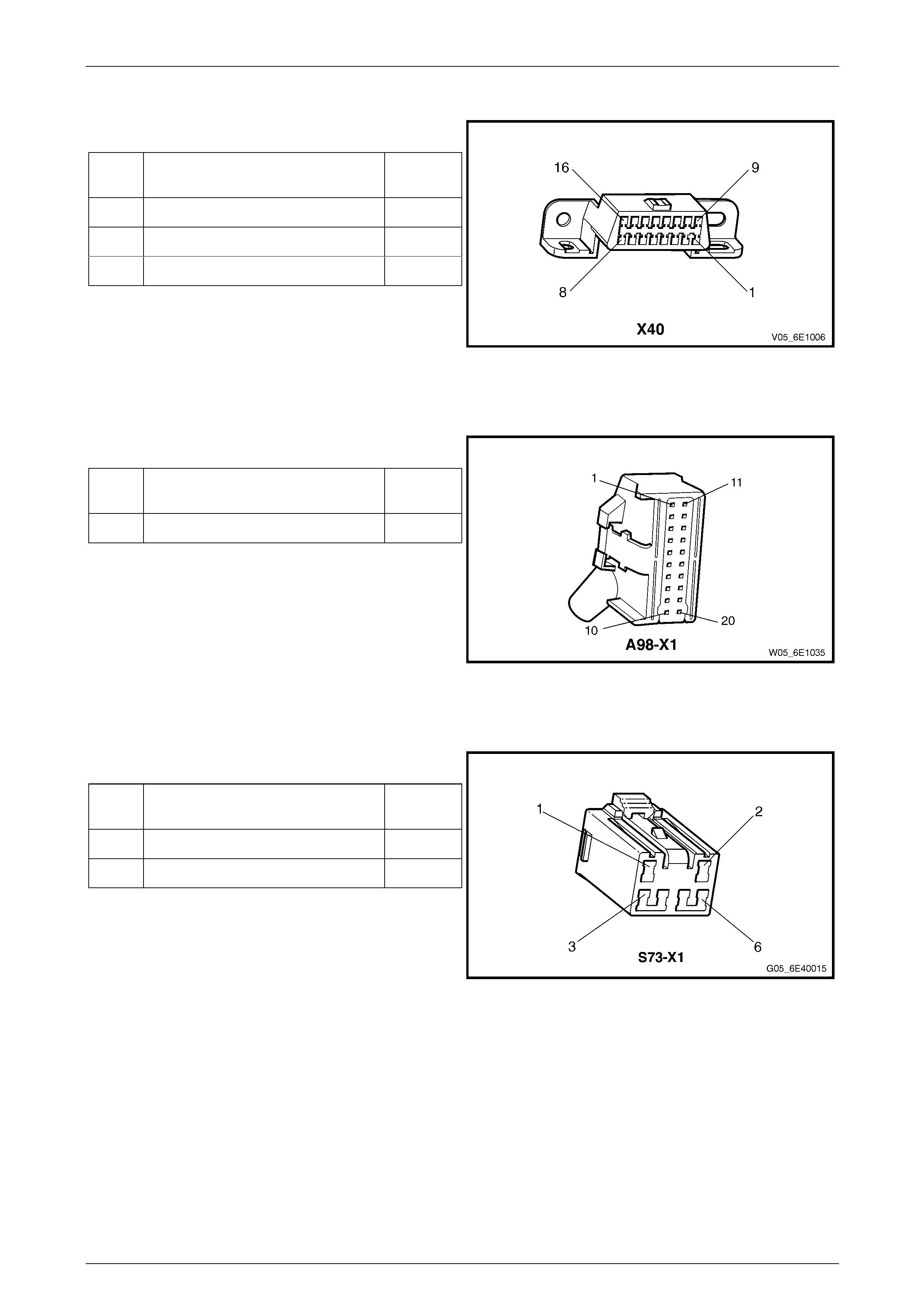
Data Link Connector Pin Specifications
Pin Description
Pin Function Circuit
Number
6 CAN_HI - Serial Data 2500
9 UART Serial Data Line 800
14 CAN_LO - Serial Data 2501
Figure 6E1 – 24
Dual Park Assist Control Module Connector
Pin Description
Pin Function Circuit
Number
20 Park / Neutral signal 1932
Figure 6E1 – 25
Electronic Stability Program Switch Connector Pin Specifications
Pin Description
Pin Function Circuit
Number
3 Traction Control - Ground Circuit 151
5 Traction Control - Signal Circuit 1571
Figure 6E1 – 26

Powertrain Interface Module – V6 Page 6E1–25
Page 6E1–25
Engine Control Module Connector Pin Specifications
Pin Description
Pin Function Circuit
Number
23 CAN_HI - Serial Data 2500
36 12 volts Uninterrupted Supply
Voltage – Fuse 29 740
55 CAN_LO - Serial Data 2501
58 Accessory Supply Voltage 4
Figure 6E1 – 27
Ignition Switch Connector Pin Specifications
Pin Description
Pin Function Circuit
Number
3 Ignition 300
4 Accessory 4
Figure 6E1 – 28
Powertrain Interface Module – V6 Page 6E1–26
Page 6E1–26
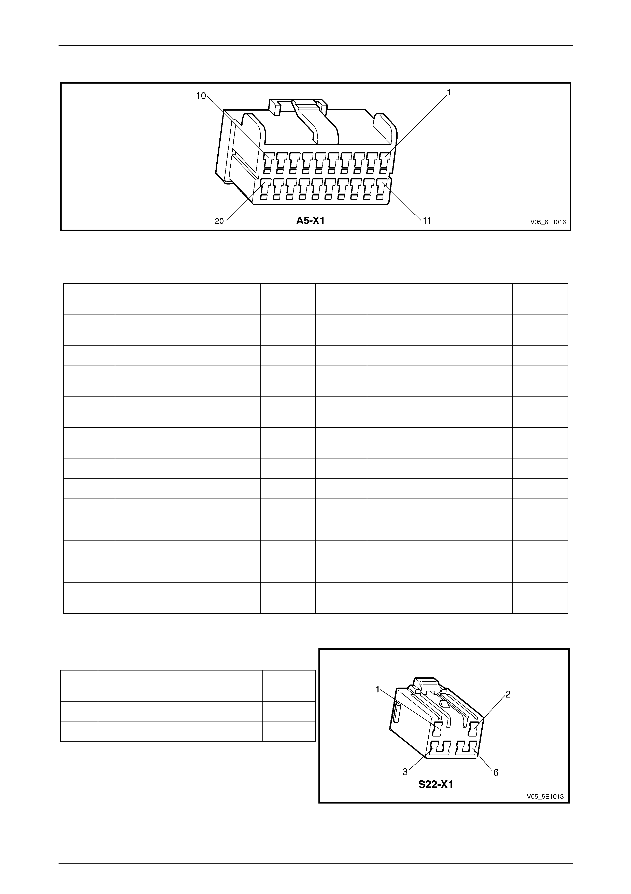
PIM Connector Pin Specifications
Figure 6E1 – 29
Pin Description
Pin Function
Circuit
Number Pin Function
Circuit
Number
1 Power Mode Switch – Ground
Signal Circuit 553 11 Not Connected –
2 Not Connected – 12 Reverse Relay Control – Circuit 38
3 Electronic Stability Program
Switch – Ground Signal Circuit 1571 13
12 V Uninterrupted Supply
Voltage – Fuse F29 740
4 Cruise Control Switch On, Off
or Cancel – 12 V Signal Circui t 397 14
Ignition Supply Voltage – Fuse
F15 139
5 Active Select Switch – Ground
Signal Circuit 5525 15 Main Ground Circuit 151
6 Not Connected – 16 Not Connected –
7 Park / Neutral Signal Circuit 1932 17 CAN_HI – Serial Data Circuit 2500
8 Cruise Control Resume or
Acceleration – 12 V Signal
Circuit 87 18 CAN_HI – Serial Data Circuit 2500
9 Cruise Control Set or
Deceleration – 12 V Signal
Circuit 84 19 CAN_LO – Serial Data Circuit 2501
10 UART Primary – Serial Data
Circuit 800 20 CAN_LO – Serial Data Circuit 2501
Power Mode Switch Connector Pin Specifications
Pin Description
Pin Function Circuit
Number
3 Power Mode - Ground Circuit 151
5 Power Mode - Signal Circuit 553
Figure 6E1 – 30

Powertrain Interface Module – V6 Page 6E1–27
Page 6E1–27
Reverse Relay
Pin Description
Pin Function Circuit
Number
1 Ignition Supply Voltage – Fuse F12 239
2 Reverse Relay – Ground Co ntrol
Circuit 38
3 Ignition Supply Voltage – Fuse F12 239
5 Backup Lamps – 12 V output 24
Figure 6E1 – 31
Steering Angle Sensor Connector Pin Specifications
Pin Description
Pin Function Circuit
Number
1 CAN_LO - Serial Data 2501
2 CAN_LO - Serial Data 2501
3 CAN_HI - Serial Data 2500
4 CAN_HI - Serial Data 2500
Figure 6E1 – 32

Powertrain Interface Module – V6 Page 6E1–28
Page 6E1–28
7 Diagnostics Starting Point
7.1 Diagnostic Requirements, Precautions
and Preliminary Checks
Basic Knowledge Required
A lack of basic understanding of electronics,
electrical wiring circuits and use of electrical
circuit testing tools when performing the PIM
diagnostic procedures could result in
incorrect diagnostic results or damage to
components.
In addition, understanding of the Engine Management System is essential to prevent misdiagnosis and compo nent
damage. Refer to Section 6C1-1 Engine Ma nagement – V6 – General Information.
Basic Diagnostic Tools Required
Use of incorrect electrical circuit diagnostic
tools when performing the PIM diagnostic
procedures could result in incorrect
diagnostic results or damage to components.
The following electrical circuit testing tools are required to perform the diagnostic procedures detailed in this Section:
• Tech 2, refer to Section 0C Tech 2 for further information.
• Test lamp, refer to Section 12P Wiring Diagrams for further information.
• Digital multimeter with 10 MΩ ohms impedance, refer to Section 12P Wiring Diagrams for further information.
• Connector test adapter kit Tool No. J35616-A.
Diagnostic Precautions
In addition to the safety and precautionary
measures listed in 10.1 Safety and
Precautionary Measures, the following
diagnostic precautions must be observed
when performing any PIM diagnostic
procedure:
• Use only the test equipment specified in the diagnostic tables. Other test equipment may either give incorrect
results or damage serviceable components.
• Do not clear any DTCs unless instructed.
• The fault must be present when using the DTC Diagnostic Tables. Otherwise, misdiagnosis or replacement of
serviceable parts may occur.
• Always use connector adapters such as those contained in connector test adapter kit Tool No. J35616-A to prevent
connector terminal damage.

Powertrain Interface Module – V6 Page 6E1–29
Page 6E1–29
• Thorough inspection of the wiring circuits and connectors listed in the diagnostic procedures must be performed,
otherwise misdiagnosis may occur.
• Inspect the electrical circuitry or connector terminals that are suspected to be causing the complaint for the
following conditions:
• backed-out connector terminals,
• improper wiring connector mating,
• broken wiring connector locks,
• damaged connector terminals, and
• physical damage to the wiring harness.
• Before replacing a component, inspect its connector terminal for corrosion or deformation that may cause the fault
condition.
Preliminary Checks
The PIM preliminar y check examines easily accessible components which may cause problems with the PIM. This visual
and physical inspection proc edure may quickly identify the fault condition and eliminate the need for additional diagnosis.
• Is the fault specifically isolated to this system / module? If unsure, refer to Section 0D Vehicle Dia gnostics.
• Refer to Service Techlines for releva nt information regarding the fault condition.
• Ensure the battery is fully charged.
• Check the battery connections for corrosion or a loose terminal.
• Perform a visual and physical inspection of the following:
• PIM component wiring harness and terminals for proper connections, pinches or cuts, and
• PIM wiring harness routing which may b e positioned very close to a high voltag e or high current devices such
as aftermarket audio systems.
NOTE
High voltage or high current devices may induce
electrical noise on a circuit, which can interfere
with normal circuit operation.
• The PIM is sensitive to Electro-magnetic Interference (EMI). Check for incor rect aftermarket theft deterrent
devices, lights or mobile phon e installations if an intermittent malfunction is suspected.

Powertrain Interface Module – V6 Page 6E1–30
Page 6E1–30
7.2 Diagnostic System Check
Step Action Yes No
1 Have you met the basic diagnostic requirements listed in the PIM
Diagnostic Starting Point?
Go to Step 2
Refer to
7.1 Diagnostic
Requirements,
Precautions and
Preliminary Ch ecks
2 Have you read the Diagnostic Precautions?
Go to Step 3
Refer to
7.1 Diagnostic
Requirements,
Precautions and
Preliminary Ch ecks
3 Have you performed the Preliminary Checks?
Go to Step 4
Refer to
7.1 Diagnostic
Requirements,
Precautions and
Preliminary Ch ecks
4 1 Switch off the ignition.
2 Connect Tech 2 to the Diagnostic Link Connector (DLC).
3 Switch on the ignition with the engine not running.
4 Press Tech 2 power button on.
Does Tech 2 screen illuminate and display Tech 2? Go to Step 5 Refer to 0C Tech 2
5 Using Tech 2, perform a Module / ECU Presence Check.
Does Tech 2 display the BCM as being Present? Go to Step 7 Go to Step 6
6 Refer to 12J Body Control Module to rectif y the BCM communication
fault.
Has the BCM communication fault been rectified? Go to Step 7 —
7 Does Tech 2 display the PIM as being Present?
Go to Step 8
Refer to
7.3 Powertrain
Interface Module –
Module Presence
Check Failure
Diagnostic Table
8 Using Tech 2, view and record all DTCs.
Does Tech 2 display any DTCs? Go to Step 9 8 Intermittent
Fault Conditions.
9 Does DTC B1000, B1009, B1013, or B1014 fail this ignition cycle? Refer to
9.1 DTC B1000,
B1009, B1013 or
B1014 – PIM
Internal Fault
Diagnostic Table Go to Step 10
10 Does DTC U2100 fail this ignition cycle? Refer to
9.3 DTC U2100 –
No Communication
With CAN Bus (High
Speed) Diagnostic
Table Go to Step 11
11 Does DTC U2106 fail this ignition cycle? Refer to
9.5 DTC U2106 –
CAN Bus No
Communication
With Transmission
Control Module Go to Step 12

Powertrain Interface Module – V6 Page 6E1–31
Page 6E1–31
Step Action Yes No
12 Does DTC U2108 fail this ignition cycle? Refer to
9.6 DTC U2108 –
CAN Bus No
Communication
With ABS-TCS /
ESP Diagnostic
Table Go to Step 13
13 Does DTC U2105 fail this ignition cycle? Refer to
9.4 DTC U2105 –
CAN Bus No
Communication
With Engine Control
Module Diagnostic
Table Go to Step 14
14 Does Tech 2 display multiple DTCs? Refer to the DTC
Table of the fault
condition that is
most likely to trigger
multiple DTCs.
Refer to
4.1 Diagnostic
General
Descriptions
for information on
multiple DTCs fault
condition Refer to the relevant
DTC table
When all diagno sis an d repairs are completed, clear all DTCs and check the system for correct op eratio n.

Powertrain Interface Module – V6 Page 6E1–32
Page 6E1–32
7.3 Powertrain Interface Module – Module
Presence Check Failure Diagnostic Table
Step Action Yes No
1 Has the Diagnostic System Check been performed?
Go to Step 2
Refer to
7.2 Diagnostic
System Check
2 Test the following PIM circuits for a high resistance, open circuit or
short to ground fault condition. Refer to 12P W iring Diagrams for
information on electrical diagnosis:
• 12 V battery supply circuit 740 ,
• 12 V ignition circuit 139, and
• ground circuit 151.
Has any fault been found and rectified? Go to Step 5 Go to Step 3
3 Test the UART serial data primary circuit 800 for a high resistance or
an open circuit fault condition
Has any fault been found and rectified? Go to Step 5 Go to Step 4
4 Replace the PIM. Refer to 10.2 Powertrain Interface Module.
Has the repair been completed? Go to Step 5 —
5 Using Tech 2, perform a Module / ECU Presence Check.
Does Tech 2 display the PIM as being Present? Go to Step 6
Refer to
7.2 Diagnostic
System Check
6 1 Using Tech 2, clear all DTCs.
2 Switch off the ignition for 30 seconds.
3 Check for DTCs.
Does Tech 2 display any PIM DTCs?
Refer to
7.2 Diagnostic
System Check Go to Step 7
7 Does Tech 2 display a ny other DTCs? Refer to the
appropriate Section System OK
When all diagno sis an d repairs are completed, clear all DTCs and check the system for correct op eratio n.


Powertrain Interface Module – V6 Page 6E1–34
Page 6E1–34
7.5 Reverse Relay Diagnosis
Circuit Description
The ignition control rel ay applies battery voltage to the coil circuit of the reverse relay through the ignition circuit. When
the ignition is turned to the ON position, the PIM grounds the reverse relay control circuit to activate the r everse relay.
When active, the reverse relay appl ies battery voltage to the backup lamp circuit to oper ate the backup lamps.
Additional Information
• Refer to 6 Wiring Diagram and Connector for the following information:
• PIM connector illustration and terminal assignment, and
• PIM wiring diagram.
• For intermittent fault conditions, refer to 8 Intermittent Fault Conditions.
• Always test the connectors related to this diagnostic procedure for shorted terminals or poor wiring connection
before replacing any component. Refer to Section 12P Wiring Diagrams for information on electric al fault diagnosis.
Test Description
The following numbers refer to the step numbers in the diagnostic table:
4 This step tests the reverse relay power circuits.
6 This step tests the reverse relay ground control circuit.
8 This step tests the backup lamp suppl y circuit 24.
Diagnostic Table
Step Action Yes No
1 Have you met the basic diagnostic requirements listed in the PIM
Diagnostic Starting Point?
Go to Step 2
7.1 Diagnostic
Requirements,
Precautions and
Preliminary Ch ecks
2 Have you read the Diagnostic Precautions?
Go to Step 3
7.1 Diagnostic
Requirements,
Precautions and
Preliminary Ch ecks
3 Have you performed the Preliminary Checks?
Go to Step 4
7.1 Diagnostic
Requirements,
Precautions and
Preliminary Ch ecks
4 1 Remove the reverse relay R12. Refer to 12O Fuses, Relays and
Wiring Harnesses.
2 Switch on the ignition with the engine not running.
3 Connect a test lamp between the ignition circuit of the reverse
relay, terminal X12 – 1 and a good ground.
4 Connect a test lamp between the ignition circuit of the reverse
relay, terminal X12 – 3 and a good ground.
Does the test lamp illuminate in both steps 3 & 4? Go to Step 6 Go to Step 5
5 Test the ignition voltage circuits 3 and 239 of the reverse relay for a
high resistance, open circuit or short to ground fault condition. Refer to
12P Wiring Diagrams for information on wiring circuit testing and
repair.
Has the repair been completed? Go to Step 6 —

Powertrain Interface Module – V6 Page 6E1–35
Page 6E1–35
Step Action Yes No
6 1 Connect a test lamp between the control circuit of the reverse
relay, terminal X12 – 2 and a B+.
2 Connect Tech 2 to the data link connector (DLC) and turn the
ignition switch on.
3 On Tech 2 select: Body / Powertrain Interface Module /
Miscellaneous Tests / Reverse Lamp Relay.
4 Using Tech 2, command the reverse relay on and then off.
Does the test lamp turn on and off when the reverse relay is
commanded on and off? Go to Step 8 Go to Step 7
7 Test the reverse relay grou nd control circuit 38 for a high resistance,
open circuit, short to ground or short to voltage fault condition. Refer
to 12P Wiring Diagrams for information o n wiring circuit testing and
repair.
Has any fault been found and rectified? Go to Step 14 Go to Step 13
8 1 Connect a fused jumper wire between the ignition circuit terminal
X12 – 3 and the backup lamp 12 V output terminal X12 – 5 of
the reverse relay.
2 Disconnect the backup lamp bulb socket assembly. Refer to 12B
Lighting System for information on disconnecting the socket
assembly.
3 Connect a test lamp between the backup lamp 12 V supply
terminal X1 – A and a good ground.
4 Switch on the ignition with the engine not running.
Does the fused jumper wire blow when the ignition is switched on? Go to Step 9 Go to Step 10
9 Repair the short to ground fault condition in the backup lamp 12 V
supply, circuit 24. Refer to 12P Wiring Diagrams for information on
wiring circuit testing and repair.
Has the repair been completed? Go to Step 14 —
10 Does the test lamp illuminate in step 8? Go to Step 12 Go to Step 11
11 Repair the high resistance or open circuit in the backup lamp 12 V
supply, circuit 24. Refer to 12P Wiring Diagrams for information on
wiring circuit testing and repair.
Has the repair been completed? Go to Step 14 —
12 Replace the reverse rel ay.
Has the repair been completed? Go to Step 14 —
13 Replace the PIM. Refer to 10.2 Powertrain Interface Module.
Has the repair been completed? Go to Step 14 —

Powertrain Interface Module – V6 Page 6E1–36
Page 6E1–36
Step Action Yes No
14 1 Connect T ech 2 to the data link connector (DLC) and turn the
ignition switch on.
2 On Tech 2 select: Body / Powertrain Interface Module /
Miscellaneous Tests / Reverse Lamp Relay.
3 Using Tech 2, command the reverse relay on and then off.
NOTE
If the backup lamps do not turn on when the reverse rel ay
is commanded on, check the backup lamp bulbs are in a
serviceable condition and there is a good earth at termina l
X1 – B of the backup lamp bulb socket assembly before
going to step 4. Refer to 12P Wiring Diagrams for
information on wiring circuit testing and repair.
Do the backup lamp bulbs turn on and then off when the reverse relay
is commanded on and off? System OK Go to Step 4
When all diagno sis an d repairs are completed, clear all DTCs and check the system for correct op eratio n.

Powertrain Interface Module – V6 Page 6E1–37
Page 6E1–37
8 Intermittent Fault Conditions
8.1 Intermittent Conditions Diagnostic Table
Description
A fault condition is intermittent if one of the following conditions exists:
• The fault condition is not al ways present.
• The fault condition cannot be presently duplicated.
• There is no Current DTC but a Histor y DTC is stored.
Diagnostic Table
Checks Actions
Preliminary • Perform the Preliminary Chec ks, refe r to 7.1 Diagnostic Re quirements,
Precautions and Preliminary Checks.
• Gather information from the customer regarding the conditions that trigger the
intermittent fault such as:
• At what engine or ambient temperature range do es the fault occur?
• Does the fault occur when operating aftermarket electrical equi pment inside
the vehicle?
• Does the fault occur on rough roads or in wet road conditions?
• If the intermittent fault is a start and then stall condition, check theft deterrent
system. Refer to 12J Body Control Module.
Harness / Connector Install Tech 2 and perform the Tech 2 Intermittent Fault Tests. Refer to
4.1 Diagnostic General Descriptio ns for information on Tech 2 ECU diagnostic tests.
Warning Indicator The following conditions may cause an intermittent Malfunction Indicator Lamp fault with
no DTC listed:
• Electromagnetic Interference (EMI) caused by a faulty relay, ECM controlled
solenoid, switch or other external source.
• Incorrect installation of aftermarket electrical equipment such as the following:
• mobile phones,
• theft deterrent alarms,
• lights, or
• radio equipment.
• Loose PIM ground connections.

Powertrain Interface Module – V6 Page 6E1–38
Page 6E1–38
Checks Actions
Temperature Related The Tech 2 Freeze Frame / Failure Rec ords or Snapshot data may be used if applicable
to the fault condition. Refer to 4.1 Diagnostic General Descriptions for information on
Tech 2 ECU diagnostic tests.
• If the intermittent fault is heat related, review the Tech 2 data in relationshi p to the
following:
• high ambient temperature,
• underhood / engine generate d heat,
• circuit generated heat due to a poor electrical connection or high electrical
load, and
• higher than normal load conditions (towing, etc.).
• If the intermittent fault is related to cold ambient or engine temperature, review the
Tech 2 data in relationship to the following:
• low ambient temperature, and
• the fault condition that occurs only on a cold start situation.
Additional Tests • Check for incorrect installation of aftermarket electrical equipment such as the
following:
• mobile phones,
• theft deterrent alarms,
• lights, or
• radio equipment.
• Check for electromagnetic Interference (EMI) caused by a faulty relay, ECM
controlled solenoid or switch. The fault is triggered when the relay or solenoid is
activated.
• Check the A/C compressor clutch and some rela ys that contain a clamping diode
or resistor for an open circuit.
• Check the generator for a faulty rectifier bridge that may allow A/C noise into the
PIM electrical circuit.
When all diagno sis an d repairs are completed, check the engine management system for correct operation.

Powertrain Interface Module – V6 Page 6E1–39
Page 6E1–39
9 DTC Tables
9.1 DTC B1000, B1009, B1013 or B1014 –
PIM Internal Fault
DTC Description
This diagnostic procedure supports the following DTCs:
• DTC B1000 – RAM Test Error
• DTC B1009 – EEPROM Checksum Error
• DTC B1013 – ROM Checksum Error
• DTC B1014 – Program ROM Checksum Error
Circuit Description
The powertrain interface module (PIM) is the control centre for the communication language conversion between GM
LAN serial data and UART serial data. If there is an internal microprocessor integrity fault condition with the PIM, DTCs
B1000 and / or B1009, B1013 and B1014 sets.
Additional Information
• Refer to 6 Wiring Diagram and Connector Chart for the foll owing information:
• PIM connector illustration and terminal assignment, and
• PIM wiring diagram.
• For intermittent fault conditions, refer to 8 Intermittent Fault Conditions.
• Since fault conditions in a wiring con nector may trigger DTCs, always test the connector s related to this diagnostic
procedure for shorted terminals or poor wiring connection before replacing any component. Refer to Section 12P
Wiring Diagrams for information on electrical fault diagnosis.
Conditions for Running the DTC
• Conditions for running the DTC are:
• The ignition is switched on.
• The ignition volt age is 10.0 – 16.0 V.
Conditions for Setting the DTC
An internal PIM fault exists.
Action Taken When the DTC Sets
The action taken when any of these DTCs set will depend on the severity of the error. This may vary from no visual or
audible warnings to a Check Powertrain and / or Service Vehicle Soon icon displayed on the instrument cluster multi-
function display.
Conditions for Clearing the DTC
Refer to 4.1 Diagnostic General Descriptions for information on the conditions for clearing DTCs.

Powertrain Interface Module – V6 Page 6E1–40
Page 6E1–40
Test Description
The following numbers refer to the step numbers in the diagnostic table:
2 This step checks if the DTC is current, and if so, indicates the PIM has an internal proble m.
3 This step checks the PIM ground and 12 V battery supply.
DTC B1000, B1009, B1013 or B1014 Diagnostic Table
Step Action Yes No
1 Has the Diagnostic System Check been performed?
Go to Step 2
Refer to
7.2 Diagnostic
System Check
2 1 Switch off the ignition for 30 seconds.
2 Operate the vehicle within the conditions for setting DTC B1000,
B1009, B1013 or B1014.
3 Using Tech 2, select the DTC displ ay function.
Does DTC B1000, B1009, B1013 or B1014 fail this ignition cycle? Go to Step 3
Refer to
Additional
Information I
n this Section
3 1 Test all ground circuits of the PIM for a high resistance or an
open circuit fault condition. Refer to 12P Wiring Diagrams for
information on electrical fault diagnosis.
2 Test the PIM fuses and replace as requ ired. Refer to 12O
Fuses, Relays and Wiring Harnesses.
3 Test the PIM battery supply voltage circuit for a high resistance,
open circuit or short to ground fault condition. Refer to 12P
Wiring Diagrams for information on el ectrical fault diagnosis.
Has any fault been found and rectified? Go to Step 5 Go to Step 4
4 Replace the PIM. Refer to 10.2 Powertrain Interface Module.
Has the repair been completed? Go to Step 5 —
5 1 Using Tech 2, clear the DTCs.
2 Switch off the ignition for 30 seconds.
3 Start the engine.
4 Operate the vehicle within the conditions for running the DTC.
Does DTC B1000, B1009, B1013 or B1 014 fail this ignition cycle? Go to Step 2 Go to Step 6
6 Using Tech 2, select the DTC displa y function.
Does Tech 2 display a ny DTCs?
Go to the
appropriate DTC
Table System OK
When all diagno sis an d repairs are completed, clear all DTCs and check the system for correct op eratio n.

Powertrain Interface Module – V6 Page 6E1–41
Page 6E1–41
9.2 DTC U1304 – Lost Communications With
UART System
DTC Description
This diagnostic procedure supports DTC U1304 – Lost Communications With UART System.
Circuit Description
The transmission control module (TCM), ABS-TCS / ESP electronic control module (ECU) and engine control module
(ECM) transmit and receive data using the GM LAN serial data protocol, while the body control module (BCM) and other
vehicle control modules use the univ ersal asynchronous receive and transmit (UART) serial data protocol.
As the GM LAN and UART protocols are not compatibl e, a powertrain interface module (PIM) is integrated into the serial
data system to enable communication b etween the two different protocols.
The PIM monitors the UART serial data bus for traffic, and if the PIM does not detect any traffic on the UART serial data
bus, DTC U1304 sets.
Additional Information
• Refer to 6 Wiring Diagram and Connector Chart for the foll owing information:
• PIM connector illustration and terminal assignment, and
• PIM wiring diagram.
• Refer to Section 12J Body Control Module for BCM diagnosis.
• For intermittent fault conditions, refer to 8 Intermittent Fault Conditions.
• Since fault conditions in a wiring con nector may trigger DTCs, always test the connector s related to this diagnostic
procedure for shorted terminals or poor wiring connection before replacing any component. Refer to Section 12P
Wiring Diagrams for information on electrical fault diagnosis.
Conditions for Running the DTC
• Conditions for running the DTC are:
• The ignition is switched on.
• The ignition volt age is 10.0 – 16.0 V.
Conditions for Setting the DTC
The PIM does not see any serial data communication on the UART serial data circuit 800 for longer than 10 seconds.
Action Taken When the DTC Sets
DTC U1304 sets when there is a communic ation failure on the UART serial data bus. Tech 2 accesses DTC information
via the UART serial data bus. If DTC U1304 is current, T ech 2 will be unabl e to display any PIM DTC information. If Tech
2 displays DTC U130 4, this DTC will only be displaye d as a history DTC.
NOTE
DTC U1304 may set as a current DTC if there is
a fault with the PIM.
Conditions for Clearing the DTC
Refer to 4.1 Diagnostic General Descriptions for information on the conditions for clearing DTCs.
Test Description
The following number refers to the step numbers in the diagnostic table:
3 This step checks if Tech 2 can communicate with the BCM.

Powertrain Interface Module – V6 Page 6E1–42
Page 6E1–42
DTC U1304 Diagnostic Table
Step Action Yes No
1 Has the Diagnostic System Check been performed?
Go to Step 2
Refer to
7.2 Diagnostic
System Check
2 1 Switch off the ignition for 10 seconds.
2 Operate the vehicle within the conditions for setting DTC U1304.
3 Using Tech 2, select the DTC displ ay function.
Does DTC U1304 fail this ignition cycle? Go to Step 3
Refer to Additional
Information in this
Section
3 Using Tech 2, view the BCM identification information.
Does Tech 2 display the BCM identification information? Go to Step 4 Refer to 12J Body
Control Module
4 Using Tech 2, view the BCM Normal Mode Data.
Does Tech 2 display normal mode data? Go to Step 5 Refer to 12J Body
Control Module
5 Replace the PIM. Refer to 10.2 Powertrain Interface Module.
Has the repair been completed? Go to Step 6 —
6 1 Using Tech 2, clear the DTCs.
2 Switch off the ignition for 30 seconds.
3 Start the engine.
4 Operate the vehicle within the conditions for running the DTC.
Does DTC U1304 fail this ignition cycle? Go to Step 2 Go to Step 7
7 Using Tech 2, select the DTC displa y function.
Does Tech 2 display a ny DTCs?
Go to the
appropriate DTC
Table System OK
When all diagno sis an d repairs are completed, clear all DTCs and check the system for correct op eratio n.

Powertrain Interface Module – V6 Page 6E1–43
Page 6E1–43
9.3 DTC U2100 – No Communication With
CAN Bus (High Speed)
DTC Description
This diagnostic procedure su pports DTC U2100 – No Communic ation W ith CAN Bus (High Speed).
Circuit Description
The transmission control module (TCM), ABS-TCS / ESP electronic control unit (ECU) and engine control module (ECM)
transmit and receive data using the GM LAN serial data protocol, while the body control module (BCM) and other vehicl e
control modules use the unive rsal asynchronous receive and transmit (UART ) serial data protocol.
As the GM LAN and UART protocols are not compatibl e, a powertrain interface module (PIM) is integrated into the serial
data system to enable communication b etween the two different protocols.
The PIM will detect if a short to ground or a short to voltage condition occurs on GM LAN circuits 2501 (CAN_LO line)
and 2500 (CAN_HI line). If either of these conditions occur, DTC U2100 sets.
Additional Information
• Refer to 6 Wiring Diagram and Connector for the following information:
• PIM connector illustration and terminal assignment, and
• PIM wiring diagram.
• For intermittent fault conditions, refer to 8 Intermittent Fault Conditions.
• Since fault conditions in a wiring con nector may trigger DTCs, always test the connector s related to this diagnostic
procedure for shorted terminals or poor wiring connection before replacing any component. Refer to Section 12P
Wiring Diagrams for information on electrical fault diagnosis.
Conditions for Running the DTC
Conditions for running the DTC are:
• The ignition is switched on.
• The ignition volt age is 10.0 – 16.0 V.
Conditions for Setting the DTC
The PIM detects a short to ground or short to voltage on the GM LAN circuits 2501 or 250 0 when the ignition is switched
on and the short condition exists for greater than five seconds.
NOTE
This DTC will only set when the ignition has
initially been turned to the ON position, and will
not set when the vehicle is being driven.
Action Taken When the DTC Sets
• When the DTC sets, the following icons are displayed on the instrument cluster multi-function display:
• Check Powertrain,
• Service Vehicle Soon,
• Fuel Gauge Error – Contact Retailer, and
• TCS Fail.
• The instrument cluster will also display an ABS Off warning indicator.

Powertrain Interface Module – V6 Page 6E1–44
Page 6E1–44
Conditions for Clearing the DTC
Refer to 4.1 Diagnostic General Descriptions for information on the conditions for clearing DTCs.
Test Description
The following numbers refer to the step numbers in the diagnostic table:
3 This step establishes if there is a fault with the ECM.
6 This step tests GM LAN serial data circuits 2500 an d 2501 between the PIM and the GM LAN component closest to
the PIM.
7 This step tests GM LAN serial data circuits 2500 and 2501 between the PIM and the data link connector.
DTC U2100 Diagnostic Table
Step Action Yes No
1 Has the Diagnostic System Check been performed?
Go to Step 2
Refer to
7.2 Diagnostic
System Check
2 1 Switch off the ignition for 10 seconds.
2 Operate the vehicle within the conditions for setting DTC U2100.
3 Using Tech 2, select the DTC displ ay function.
Does DTC U2100 fail this ignition cycle? Go to Step 3
Refer to Additional
Information in this
Section
3 1 Disconnect connector A43 – X2 from the ECM.
2 Switch off the ignition for 10 seconds.
3 Operate the vehicle within the conditions for setting DTC U2100.
4 Using Tech 2, select the DTC display function and check if DTC
U2100 fails this ignition cycle.
NOTE
Other DTCs may set when the ECM connector is
disconnected and the ignition is switched on. Disregard
DTCs that set under this condition on this DTC Table.
Does DTC U2100 fail this ignition cycle? Go to Step 5 Go to Step 4
4 Replace the ECM. Refer to 6C1-3 Engine Manageme nt – V6 –
Service Operations.
Has the repair been completed? Go to Step 11 —
5 1 If DTC U2100 failed in Step 3, disconnect the next GM LAN
component connector furthest from the PIM. Using Tech 2,
check if DTC U2100 fails.
NOTE
The number of GM LAN components fitted to the vehicle
will vary according to the vehicle configuration. When
determining which component to disconnect, refer to 5
GM LAN Serial Communication Circuit for the serial
communication circuit that represents the vehicle currently
being diagnos ed.
2 Repeat this procedure until the component connector closest to
the PIM has been disconnected, or DTC U2100 does not fail.
Does DTC U2100 fail this ignition cycle? Go to Step 6 Go to Step 9

Powertrain Interface Module – V6 Page 6E1–45
Page 6E1–45
Step Action Yes No
6 Test serial data circuits 2500 and 2501 between the GM LAN
component closest to the PIM and the PIM for a short to voltage, short
to ground or short together condition. Refer to 12P Wiring Diagrams
for information on wiring circuit testing and repair.
Has any fault been found and rectified? Go to Step 11 Go to Step 7
7 Test serial data circuits 2500 and 2501 between the PIM and the data
link connector for a short to voltage, short to ground or short together
condition. Refer to 12P Wiring Diagr ams for information on wiring
circuit testing and repair.
Has any fault been found and rectified? Go to Step 11 Go to Step 8
8 Replace the PIM. Refer to 10.2 Powertrain Interface Module.
Has the repair been completed? Go to Step 11 —
9 Test serial data circuits 2500 and 2501 between the conn ector which,
when disconnected, resulted in DTC U2100 not failing in Step 5 and
the next connector furthest away from the PIM for a short to voltage,
short to ground or short together condition. Refer to 12P Wiring
Diagrams for information on wiring circuit testing an d repair.
Has any fault been found and rectified? Go to Step 11 Go to Step 10
10 Replace the GM LAN component which is causing DTC U2100 to fail.
Refer to one of the following Sections for the component rep lacement
procedure:
• 5B ABS / TCS / ESP – General Information, or
• 7E4 Automatic Transmission – 5L40E – On-vehicle Servicing.
Has the repair been completed? Go to Step 11 —
11 1 Using Tech 2, clear the DTCs.
2 Switch off the ignition for 30 seconds.
3 Start the engine.
4 Operate the vehicle within the conditions for running the DTC.
Does DTC U2100 fail this ignition cycle? Go to Step 2 Go to Step 12
12 Using Tech 2, select the DTC displa y function.
Does Tech 2 display a ny DTCs?
Go to the
appropriate DTC
Table System OK
When all diagno sis an d repairs are completed, clear all DTCs and check the system for correct op eratio n.

Powertrain Interface Module – V6 Page 6E1–46
Page 6E1–46
9.4 DTC U2105 – CAN Bus No
Communication With Engine Control
Module
DTC Description
This diagnostic procedure su pports DTC U2105 – CAN Bus No Communication W ith Engine Control Module.
Circuit Description
The transmission control module (TCM), ABS-TCS / ESP electronic control unit (ECU) and engine control module (ECM)
transmit and receive data using the GM LAN serial data protocol, while the body control module (BCM) and other vehicl e
control modules use the unive rsal asynchronous receive and transmit (UART ) serial data protocol.
As the GM LAN and UART protocols are not compatibl e, a powertrain interface module (PIM) is integrated into the serial
data system to enable communication b etween the two different protocols.
The PIM continuousl y receiv es messages from the ECM. If the PIM does not receive a message within a predetermined
time, DTC U2105 sets.
Additional Information
• Refer to 6 Wiring Diagram and Connector for the following information:
• PIM connector illustration and terminal assignment, and
• PIM wiring diagram.
• Refer to Section 6C1-2 Engine Management – V6 – Diagnostics for diagnostic information.
• For intermittent fault conditions, refer to 8 Intermittent Fault Conditions.
• Since fault conditions in a wiring con nector may trigger DTCs, always test the connector s related to this diagnostic
procedure for shorted terminals or poor wiring connection before replacing any component. Refer to Section 12P
Wiring Diagrams for information on electrical fault diagnosis.
Conditions for Running the DTC
Conditions for running the DTC are:
• The ignition is switched on.
• The ignition volt age is 10.0 – 16.0 V.
Conditions for Setting the DTC
The PIM does not receive a message from the ECM for 100 milliseconds.
Action Taken When the DTC Sets
• When the DTC sets, the following icons ma y be displayed on the instrument cluster multi-function display:
• Check Powertrain,
• Service Vehicle Soon, and
• ABS Fail Message.
• The instrument cluster will also display an ABS Off warning indicator.
Conditions for Clearing the DTC
Refer to 4.1 Diagnostic General Descriptions for information on the conditions for clearing DTCs.

Powertrain Interface Module – V6 Page 6E1–47
Page 6E1–47
Test Description
The following numbers refer to the step numbers in the diagnostic table:
4 This step tests GM LAN serial data circuits 2500 an d 2501 and the GM LAN component closest to the ECM.
5 This step tests the integrity of the ECM 12 V ignition circuit and ground connections.
6 This step tests the internal GM LAN CAN_HI circuit in the GM LAN component.
7 This step tests the internal GM LAN CAN_LO circuit in the GM LAN component.
DTC U2105 Diagnostic Table
Step Action Yes No
1 Has the Diagnostic System Check been performed?
Go to Step 2
Refer to
7.2 Diagnostic
System Check
2 1 Switch off the ignition for 10 seconds.
2 Operate the vehicle within the conditions for setting DTC U2105.
3 Using Tech 2, select the DTC displ ay function.
Does DTC U2105 fail this ignition cycle? Go to Step 3
Refer to Additional
Information in this
Section
3 Using Tech 2, attempt to communicate with the ECM.
Does Tech 2 communicate with the ECM? Go to Step 10 Go to Step 4
4 Test serial data circuits 2500 and 2501 between the ECM and the GM
LAN component closest to the ECM for a high resistance or open
circuit fault condition. Refer to 12P Wiring Diagrams for information on
wiring circuit testing and repair.
NOTE
The number of GM LAN components fitted to the vehicle
will vary according to the vehicle configuration. When
determining which component to disconnect, refer to 5
GM LAN Serial Communication Circuit for the serial
communication circuit that represents the vehicle currently
being diagnos ed.
Has any fault been found and rectified? Go to Step 11 Go to Step 5
5 Test the following ECM circuits for a high resistance, op en circuit or
short to ground fault condition. Refer to 12P W iring Diagrams for
information on electrical diagnosis:
• 12 V battery supply circuit 740 ,
• 12 V accessory supply circuit 4, and
• all ECM ground connections.
Has any fault been found and rectified? Go to Step 11 Go to Step 6
6 1 Disconnect the GM LAN component connector closest to the
ECM.
2 Using a digital multimeter, measure the resistance between the
two CAN_LO terminals of the component.
NOTE
Refer to 5 GM LAN Serial Communication Circuit and
6 Wiring Diagram and Connector for the appropriate GM
LAN component terminal identification.
Does the digital multimeter displa y infinity? Go to Step 8 Go to Step 7

Powertrain Interface Module – V6 Page 6E1–48
Page 6E1–48
Step Action Yes No
7 Using a digital multimeter, measure the resistance between the two
CAN_HI terminals of the component.
Does the digital multimeter displa y infinity? Go to Step 8 Go to Step 9
8 Replace the GM LAN component which is causing DTC U2105 to fail.
Refer to one of the following for the component replacement
procedure:
• 5B ABS / TCS / ESP – General Information,
• 7E4 Automatic Transmission – 5L40E – On-vehicle Servicing, or
• 10.2 Powertrain Interface Module.
Has the repair been completed? Go to Step 11 —
9 Replace the ECM. Refer to 6C1-3 Engine Manageme nt – V6 –
Service Operations.
Has the repair been completed? Go to Step 11 —
10 Replace the PIM. Refer to 10.2 Powertrain Interface Module.
Has the repair been completed? Go to Step 11 —
11 1 Using Tech 2, clear the DTCs.
2 Switch off the ignition for 30 seconds.
3 Start the engine.
4 Operate the vehicle within the conditions for running the DTC.
Does DTC U2105 fail this ignition cycle? Go to Step 2 Go to Step 12
12 Using Tech 2, select the DTC display function.
Does Tech 2 display a ny DTCs?
Go to the
appropriate DTC
Table System OK
When all diagno sis an d repairs are completed, clear all DTCs and check the system for correct op eratio n.

Powertrain Interface Module – V6 Page 6E1–49
Page 6E1–49
9.5 DTC U2106 – CAN Bus No
Communication With Transmission
Control Module
DTC Description
This diagnostic procedure su pports DTC U2106 – CAN Bus No Communication W ith Transmission Control Module.
Circuit Description
The transmission control module (TCM), ABS-TCS / ESP electronic control unit (ECU) and engine control module (ECM)
transmit and receive data using the GM LAN serial data protocol, while the body control module (BCM) and other vehicl e
control modules use the unive rsal asynchronous receive and transmit (UART ) serial data protocol.
As the GM LAN and UART protocols are not compatibl e, a powertrain interface module (PIM) is integrated into the serial
data system to enable communication b etween the two different protocols.
The PIM continuousl y receiv es messages from the TCM. If the PIM does not receive a message within a predetermine d
time, DTC U2106 sets.
Additional Information
• Refer to 6 Wiring Diagram and Connector for the following information:
• PIM connector illustration and terminal assignment, and
• PIM wiring diagram.
• For intermittent fault conditions, refer to 8 Intermittent Fault Conditions.
• Since fault conditions in a wiring con nector may trigger DTCs, always test the connector s related to this diagnostic
procedure for shorted terminals or poor wiring connection before replacing any component. Refer to Section 12P
Wiring Diagrams for information on electrical fault diagnosis.
Conditions for Running the DTC
Conditions for running the DTC are:
• The ignition is switched on.
• The ignition volt age is 10.0 – 16.0 V.
Conditions for Setting the DTC
The PIM does not receive a message from the TCM for 1000 milliseconds, during the current ignition cycle.
Action Taken When the DTC Sets
• When the DTC sets, the following icons ma y be displayed on the instrument cluster multi-function display:
• Check Powertrain,
• Service Vehicle Soon, and
• ABS Fail Message.
• The instrument cluster will also display an ABS Off warning indicator.
Conditions for Clearing the DTC
Refer to 4.1 Diagnostic General Descriptions for information on the conditions for clearing DTCs.

Powertrain Interface Module – V6 Page 6E1–50
Page 6E1–50
Test Description
The following numbers refer to the step numbers in the diagnostic table:
4 This step tests the TCM power and ground circuits.
5 This step tests GM LAN serial data circuits 2500 an d 2501 and the GM LAN component closest to the TCM.
6 This step tests the internal GM LAN CAN_HI circuit in the GM LAN component.
7 This step tests the internal GM LAN CAN_LO circuit in the GM LAN component.
DTC U2106 Diagnostic Table
Step Action Yes No
1 Has the Diagnostic System Check been performed?
Go to Step 2
Refer to
7.2 Diagnostic
System Check
2 1 Switch off the ignition for 10 seconds.
2 Operate the vehicle within the conditions for setting DTC U2106.
3 Using Tech 2, select the DTC displ ay function.
Does DTC U2106 fail this ignition cycle? Go to Step 3
Refer to Additional
Information in this
Section
3 Using Tech 2, attempt to communicate with the TCM.
Does Tech 2 communicate with the TCM? Go to Step 10 Go to Step 4
4 Test the following TCM circuits for a high res istance, open circuit or
short to ground fault condition. Refer to 12P W iring Diagrams for
information on electrical diagnosis:
• 12 V battery supply voltage circuit 740,
• 12 V accessory supply circuit 4,
• Ignition Control Relay 12 V supply circuit 339, and
• all TCM ground connections.
Has any fault been found and rectified? Go to Step 11 Go to Step 5
5 Test serial data circuits 2500 and 2501 between the TCM and the GM
LAN component closest to the TCM (on the PIM side of the GM LAN
bus) for a high resistance or open circuit fault condition. Refer to 12P
Wiring Diagrams for information o n wiring circuit testing and repair.
NOTE
The number of GM LAN components fitted to the vehicle
will vary according to the vehicle configuration. When
determining which component to disconnect, refer to 5
GM LAN Serial Communication Circuit for the serial
communication circuit that represents the vehicle currently
being diagnos ed.
Has any fault been found and rectified? Go to Step 11 Go to Step 6

Powertrain Interface Module – V6 Page 6E1–51
Page 6E1–51
Step Action Yes No
6 1 Disconnect the GM LAN component connector closest to the
TCM (on the PIM side of the GM LAN bus).
2 Using a digital multimeter, measure the resistance between the
two CAN_LO terminals of the component.
NOTE
Refer to 5 GM LAN Serial Communication Circuit and
6 Wiring Diagram and Connector for the appropriate GM
LAN component terminal identification.
Does the digital multimeter displa y infinity? Go to Step 8 Go to Step 7
7 Using a digital multimeter, measure the resistance between the two
CAN_HI terminals of the component.
Does the digital multimeter displa y infinity? Go to Step 8 Go to Step 9
8 Replace the GM LAN component which is causing DTC U2106 to fail.
Refer to one of the following Sections for the component rep lacement
procedure:
• 5B ABS / TCS / ESP.– General Information,
• 7E4 Automatic Transmission – 5L40E – On-vehicle Servicing, or
• 10.2 Powertrain Interface Module.
Has the repair been completed? Go to Step 11 —
9 Replace the TCM. Refer to 7E4 Automatic Transmission – 5L40E –
On-vehicle Servicing for the repl acement procedure:
Has the repair been completed? Go to Step 11 —
10 Replace the PIM. Refer to 10.2 Powertrain Interface Module.
Has the repair been completed? Go to Step 11 —
11 1 Using Tech 2, clear the DTCs.
2 Switch off the ignition for 30 seconds.
3 Start the engine.
4 Operate the vehicle within the conditions for running the DTC.
Does DTC U2106 fail this ignition cycle? Go to Step 2 Go to Step 12
12 Using Tech 2, select the DTC displa y function.
Does Tech 2 display a ny DTCs?
Go to the
appropriate DTC
Table System OK
When all diagno sis an d repairs are completed, clear all DTCs and check the system for correct op eratio n.

Powertrain Interface Module – V6 Page 6E1–52
Page 6E1–52
9.6 DTC U2108 – CAN Bus No
Communication With ABS-TCS / ESP
Electronic Control Unit
DTC Description
This diagnostic procedure supports DTC U2108 – CAN Bus No Communication With ABS-TCS / ESP Electronic Control
Unit.
Circuit Description
The transmission control module (TCM), ABS-TCS / ESP electronic control unit (ECU) and engine control module (ECM)
transmit and receive data using the GM LAN serial data protocol, while the body control module (BCM) and other vehicl e
control modules use the unive rsal asynchronous receive and transmit (UART ) serial data protocol.
As the GM LAN and UART protocols are not compatibl e, a powertrain interface module (PIM) is integrated into the serial
data system to enable communication b etween the two different protocols.
The PIM continuousl y receiv es messages from the ABS-TCS / ESP ECU. If the PIM does not receive a message within a
predetermined time, DTC U2108 sets.
Additional Information
• Refer to 6 Wiring Diagram and Connector for the following information:
• PIM connector illustration and terminal assignment, and
• PIM wiring diagram.
• For intermittent fault conditions, refer to 8 Intermittent Fault Conditions.
• Since fault conditions in a wiring con nector may trigger DTCs, always test the connector s related to this diagnostic
procedure for shorted terminals or poor wiring connection before replacing any component. Refer to Section 12P
Wiring Diagrams for information on electrical fault diagnosis.
Conditions for Running the DTC
Conditions for running the DTC are:
• The ignition is switched on.
• The ignition volt age is 10.0 – 16.0 V.
Conditions for Setting the DTC
The PIM does not receive a message from the ABS-TCS / ESP ECU for 300 milliseconds, during the current ignition
cycle.
Action Taken When the DTC Sets
• When the DTC sets, the following icons ma y be displayed on the instrument cluster multi-function display:
• Check Powertrain, and
• Service Vehicle Soon.
• Service Vehicle Soon,
• ABS Fail Message, and
• The instrument cluster will also display an ABS Off warning indicator.
Conditions for Clearing the DTC
Refer to 4.1 Diagnostic General Descriptions for information on the conditions for clearing DTCs.

Powertrain Interface Module – V6 Page 6E1–53
Page 6E1–53
Test Description
The following numbers refer to the step numbers in the diagnostic table:
4 This step tests the ABS - TCS ECU power and ground circuits.
5 This step tests GM LAN serial data circuits 2500 and 2501 and the GM LAN component closest to the
ABS- TCS ECU.
6 This step tests the internal GM LAN CAN_HI circuit in the GM LAN component.
7 This step tests the internal GM LAN CAN_LO circuit in the GM LAN component.
DTC U2108 Diagnostic Table
Step Action Yes No
1 Has the Diagnostic System Check been performed?
Go to Step 2
Refer to
7.2 Diagnostic
System Check
2 1 Switch off the ignition for 10 seconds.
2 Operate the vehicle within the conditions for setting DTC U2108.
3 Using Tech 2, select the DTC displ ay function.
Does DTC U2108 fail this ignition cycle? Go to Step 3
Refer to Additional
Information in this
Section
3 Using Tech 2, attempt to communicate with the ABS-TCS / ESP ECU.
Does Tech 2 communicate with the ABS-TCS / ESP ECU? Go to Step 10 Go to Step 4
4 Test the following ABS-TCS / ESP circuits for a high resistance, open
circuit or short to ground fault condition. Refe r to 12P W iring Diagrams
for information on electrical diagnosis:
• 12 V battery supply voltage circuits 542, 642 and 1440,
• 12 V ignition supply circuits 839 and 3, and
• all ABS-TCS / ESP ground connections.
Has any fault been found and rectified? Go to Step 11 Go to Step 5
5 Test serial data circuits 2500 and 2501 between the
ABS-TCS / ESP ECU and the GM LAN component closest to the
ABS-TCS / ESP ECU (on the PIM side of the GM LAN bus) for a high
resistance or open circuit fault condition. Refer to 12P Wiring
Diagrams for information on wiring circuit testing and repair.
NOTE
The number of GM LAN components fitted to the vehicle
will vary according to the vehicle configuration. When
determining which component to disconnect, refer to 5
GM LAN Serial Communication Circuit for the serial
communication circuit that represents the vehicle currently
being diagnos ed.
Has any fault been found and rectified? Go to Step 11 Go to Step 6

Powertrain Interface Module – V6 Page 6E1–54
Page 6E1–54
Step Action Yes No
6 1 Disconnect the GM LAN component connector closest to the
ABS-TCS / ESP ECU (on the PIM side of the GM LAN bus).
2 Using a digital multimeter, measure the resistance between the
two CAN_LO terminals of the component.
NOTE
Refer to 5 GM LAN Serial Communication Circuit and
6 Wiring Diagram and Connector for the appropriate GM
LAN component terminal identification.
Does the digital multimeter displa y infinity? Go to Step 8 Go to Step 7
7 Using a digital multimeter, measure the resistance between the two
CAN_HI terminals of the component.
Does the digital multimeter displa y infinity? Go to Step 8 Go to Step 9
8 Replace the GM LAN component which is causing DTC U2108 to fail.
Refer to one of the following for the component replacement
procedure:
• 5B ABS / TCS / ESP.– General Information,
• 7E4 Automatic Transmission – 5L40E – On-vehicle Servicing, or
• 10.2 Powertrain Interface Module.
Has the repair been completed? Go to Step 11 —
9 Replace the ABS-TCS / ESP ECU. Refer to
5B ABS / TCS / ESP – General Information.
Has the repair been completed? Go to Step 11 —
10 Replace the PIM. Refer to 10.2 Powertrain Interface Module.
Has the repair been completed? Go to Step 11 —
11 1 Using Tech 2, clear the DTCs.
2 Switch off the ignition for 30 seconds.
3 Start the engine.
4 Operate the vehicle within the conditions for running the DTC.
Does DTC U2108 fail this ignition cycle? Go to Step 2 Go to Step 12
12 Using Tech 2, select the DTC displa y function.
Does Tech 2 display a ny DTCs?
Go to the
appropriate DTC
Table System OK
When all diagno sis an d repairs are completed, clear all DTCs and check the system for correct op eratio n.

Powertrain Interface Module – V6 Page 6E1–55
Page 6E1–55
9.7 DTC P0565 – Cruise Control On Signal
Malfunction
DTC Description
This diagnostic procedure su pports DTC P0565 – Cruise Control On Signal Malfunction.
Circuit Description
The cruise control on / off switch is a normally open switch that closes when the switch is activated. When activated, the
switch supplies signal voltage to the cruise control on signal circuit. The powertrain interface module (PIM) converts the
signal voltage input into serial data, which is used by the engine control module (ECM) to enable or disa ble the cruise
control system, and by the instrument cluster to display cruise control status.
Additional Information
• Refer to Section 12E Cruise Control for the following information:
• Cruise control switch description, operation and inspection procedures, and
• Cruise control wiring diagram.
• Refer to 6 Wiring Diagram and Connector for the following information:
• PIM connector illustration and terminal assignment, and
• PIM wiring diagram.
• For intermittent fault conditions, refer to 8 Intermittent Fault Conditions.
• Since fault conditions in a wiring con nector may trigger DTCs, always test the connector s related to this diagnostic
procedure for shorted terminals or poor wiring connection before replacing any component. Refer to Section 12P
Wiring Diagrams for information on electrical fault diagnosis.
Conditions for Running the DTC
Conditions for running the DTC are:
• The ignition is switched on.
• The ignition volt age is 10.0 – 16.0 V.
Conditions for Setting the DTC
The PIM detects the cruise control on / off function of the cruise co ntrol switch assembly is in the ON position for 60
seconds or more.
Action Taken When the DTC Sets
When the DTC sets, there is no icon displayed on the multi-function display.
If the cruise control is active at the time the DTC sets, the PIM will disable cruise co ntrol.
Conditions for Clearing the DTC
Refer to 4.1 Diagnostic General Descriptions for information on the conditions for clearing DTCs.
NOTE
If the fault is not evident for greater than 60
seconds, the DTC will become a histor y DTC and
cruise control can be resumed .

Powertrain Interface Module – V6 Page 6E1–56
Page 6E1–56
Test Description
The following numbers refer to the step numbers in the diagnostic table:
2 This step tests the cruise control on / off switch using Tech 2.
6 This step tests the cruise control on / off switch signal circuit.
DTC P0565 Diagnostic Table
Step Action Yes No
1 Has the Diagnostic System Check been performed?
Go to Step 2
Refer to
7.2 Diagnostic
System Check
2 Using Tech 2, view the cruise control on / off switch status parameter
in the PIM data list.
Does Tech 2 display Active? Go to Step 4 Go to Step 3
3 1 Switch off the ignition for 10 seconds.
2 Operate the vehicle within the conditions for setting DTC P0565.
3 Using Tech 2, select the DTC displ ay function.
Does DTC P0565 fail this ignition cycle? Go to Step 4
Refer to Additional
Information in this
Section
4 1 Disconnect connector S43 – X1 from the cruise control switch
assembly.
2 Using Tech 2, view the cruise control on / off switch status
parameter in the PIM data list.
Does Tech 2 display Active? Go to Step 6 Go to Step 5
5 Replace the cruise control s witch, refer to 12E Cruise Control.
Has the repair been completed? Go to Step 8 —
6 Test the cruise control on / off switch signal circuit for a short to
voltage. Refer to 12P Wiring Diagrams for informatio n on el ectrical
fault diagnosis.
Has any fault been found and rectified? Go to Step 8 Go to Step 7
7 Replace the PIM. Refer to 10.2 Powertrain Interface Module.
Has the repair been completed? Go to Step 8 —
8 1 Using Tech 2, clear the DTCs.
2 Switch off the ignition for 30 seconds.
3 Start the engine.
4 Operate the vehicle within the conditions for running the DTC.
Does DTC P0565 fail this ignition cycle? Go to Step 2 Go to Step 9
9 Using Tech 2, select the DTC displa y function.
Does Tech 2 display a ny DTCs?
Go to the
appropriate
DTC Table System OK
When all diagno sis an d repairs are completed, clear all DTCs and check the system for correct op eratio n.

Powertrain Interface Module – V6 Page 6E1–57
Page 6E1–57
9.8 DTC P0567 – Cruise Control Resume
Signal Malfunction
DTC Description
This diagnostic procedure su pports DTC P0567 – Cruise Control Resume Signal Malfunction.
Circuit Description
The cruise control resume switch is a normally open switch that closes when the s witch is activated. When activated, the
switch supplies signal voltage to the cruise control resume signal circuit. The powertrain interface module (PIM) converts
the signal voltage input into serial data, which is used by the engine control module (ECM) to resume cruise control
operation.
Additional Information
• Refer to Section 12E Cruise Control for the following information:
• Cruise control switch description, operation and inspection procedures, and
• Cruise control wiring diagram.
• Refer to 6 Wiring Diagram and Connector for the following information:
• PIM connector illustration and terminal assignment, and
• PIM wiring diagram.
• For intermittent fault conditions, refer to 8 Intermittent Fault Conditions.
• Since fault conditions in a wiring con nector may trigger DTCs, always test the connector s related to this diagnostic
procedure for shorted terminals or poor wiring connection before replacing any component. Refer to Section 12P
Wiring Diagram s for information on electrical fault diagnosis.
Conditions for Running the DTC
Conditions for running the DTC are:
• The ignition is switched on.
• The ignition volt age is 10.0 – 16.0 V.
Conditions for Setting the DTC
The PIM detects the cruise control resume function of the cruise control switch assembly is in the RESUME position for
60 seconds or more.
Action Taken When the DTC Sets
When the DTC sets, there is no icon displayed on the multi-function display.
If the cruise control is active at the time the DTC sets, the PIM will disable cruise co ntrol.
Conditions for Clearing the DTC
Refer to 4.1 Diagnostic General Descriptions for information on the conditions for clearing DTCs.
NOTE
If the fault is not evident for greater than 60
seconds, the DTC will become a histor y DTC and
cruise control can be resumed .

Powertrain Interface Module – V6 Page 6E1–58
Page 6E1–58
Test Description
The following numbers refer to the step numbers in the diagnostic table:
2 This step tests the cruise control resume switch using T ech 2.
6 This step tests the cruise control resume switch signal circuit.
DTC P0567 Diagnostic Table
Step Action Yes No
1 Has the Diagnostic System Check been performed?
Go to Step 2
Refer to
7.2 Diagnostic
System Check
2 Using Tech 2, view the cruise control resume switch status parameter
in the PIM data list.
Does Tech 2 display Res / Accel? Go to Step 4 Go to Step 3
3 1 Switch off the ignition for 10 seconds.
2 Operate the vehicle within the conditions for setting DTC P0567.
3 Using Tech 2, select the DTC displ ay function.
Does DTC P0567 fail this ignition cycle? Go to Step 4
Refer to Additional
Information in this
Section
4 1 Disconnect connector S43 – X1 from the cruise control switch
assembly.
2 Using Tech 2, view the cruise control resume s witch status
parameter in the PIM data list.
Does Tech 2 display Res / Accel? Go to Step 6 Go to Step 5
5 Replace the cruise control switch assembly, refer to 12E Cruise
Control.
Has the repair been completed? Go to Step 8 —
6 Test the cruise control resume switch signal circuit for a short to
voltage. Refer to 12P Wiring Diagrams for informatio n on el ectrical
fault diagnosis.
Has any fault been found and rectified? Go to Step 8 Go to Step 7
7 Replace the PIM. Refer to 10.2 Powertrain Interface Module.
Has the repair been completed? Go to Step 8 —
8 1 Using Tech 2, clear the DTCs.
2 Switch off the ignition for 30 seconds.
3 Start the engine.
4 Operate the vehicle within the conditions for running the DTC.
Does DTC P0567 fail this ignition cycle? Go to Step 2 Go to Step 9
9 Using Tech 2, select the DTC displa y function.
Does Tech 2 display a ny DTCs?
Go to the
appropriate DTC
Table System OK
When all diagno sis an d repairs are completed, clear all DTCs and check the system for correct op eratio n.

Powertrain Interface Module – V6 Page 6E1–59
Page 6E1–59
9.9 DTC P0568 – Cruise Control Set Signal
Malfunction
DTC Description
This diagnostic procedure su pports DTC P0568 – Cruise Control Set Signal Malfunction.
Circuit Description
The cruise control set switch is a normally open switch that closes when the switch is activated. When activated, the
switch supplies signal voltage to the cruise control set signal circuit. The powertrain interfa ce module (PIM) converts the
signal voltage input into serial data, which is used by the engine control module (ECM) to set the vehicle speed.
Additional Information
• Refer to Section 12E Cruise Control for the following information:
• Cruise control switch description, operation and inspection procedures, and
• Cruise control wiring diagram.
• Refer to 6 Wiring Diagram and Connector for the following information:
• PIM connector illustration and terminal assignment, and
• PIM wiring diagram.
• For intermittent fault conditions, refer to 8 Intermittent Fault Conditions.
• Since fault conditions in a wiring con nector may trigger DTCs, always test the connector s related to this diagnostic
procedure for shorted terminals or poor wiring connection before replacing any component. Refer to Section 12P
Wiring Diagrams for information on electrical fault diagnosis.
Conditions for Running the DTC
Conditions for running the DTC are:
• The ignition is switched on.
• The ignition volt age is 10.0 – 16.0 V.
Conditions for Setting the DTC
The PIM detects the cruise control set function of the cruise control switch assembly is in the SET position for 60
seconds or more.
Action Taken When the DTC Sets
When the DTC sets, there is no icon displayed on the multi-function display.
If the cruise control is active at the time the DTC sets, the PIM will disable cruise co ntrol.
Conditions for Clearing the DTC
Refer to 4.1 Diagnostic General Descriptions for information on the conditions for clearing DTCs.
NOTE
If the fault is not evident for greater than 60
seconds, the DTC will become a histor y DTC and
cruise control can be resumed .

Powertrain Interface Module – V6 Page 6E1–60
Page 6E1–60
Test Description
The following numbers refer to the step numbers in the diagnostic table:
2 This step tests the cruise control set switch using Tech 2.
6 This step tests the cruise control set switch signal circuit.
DTC P0568 Diagnostic Table
Step Action Yes No
1 Has the Diagnostic System Check been performed?
Go to Step 2
Refer to
7.2 Diagnostic
System Check
2 Using Tech 2, view the cruise control set switch status parameter in
the PIM data list.
Does Tech 2 display Active? Go to Step 4 Go to Step 3
3 1 Switch off the ignition for 10 seconds.
2 Operate the vehicle within the conditions for setting DTC P0568.
3 Using Tech 2, select the DTC displ ay function.
Does DTC P0568 fail this ignition cycle? Go to Step 4
Refer to Additional
Information in this
Section
4 1 Disconnect connector S43 – X1 from the cruise control switch
assembly.
2 Using Tech 2, view the cruise control set switch status
parameter in the PIM data list.
Does Tech 2 display Active? Go to Step 6 Go to Step 5
5 Replace the cruise control switch assembly, refer to 12E Cruise
Control.
Has the repair been completed? Go to Step 8 —
6 Test the cruise control set switch signal circuit for a short to voltage.
Refer to 12P Wiring Diagra ms for information on electrical fault
diagnosis.
Has any fault been found and rectified? Go to Step 8 Go to Step 7
7 Replace the PIM. Refer to 10.2 Powertrain Interface Module.
Has the repair been completed? Go to Step 8 —
8 1 Using Tech 2, clear the DTCs.
2 Switch off the ignition for 30 seconds.
3 Start the engine.
4 Operate the vehicle within the conditions for running the DTC.
Does DTC P0568 fail this ignition cycle? Go to Step 2 Go to Step 9
9 Using Tech 2, select the DTC displa y function.
Does Tech 2 display a ny DTCs?
Go to the
appropriate DTC
Table System OK
When all diagno sis an d repairs are completed, clear all DTCs and check the system for correct op eratio n.

Powertrain Interface Module – V6 Page 6E1–61
Page 6E1–61
9.10 DTC P1611 – Wrong Security Code
Entered
DTC Description
This diagnostic procedure su pports DTC P1611 – Wrong Security Code Entered.
Circuit Description
Tech 2 is used to program the powertrain interface modu le ( PIM). Before any programming, a security code must be
entered into Tech 2. The PIM will check if the code entered is correct before continuing. If the security code is incorrect,
DTC P1611 sets.
After an incorrect security code is entered, the PIM prevents any further attempts to enter a code until a predetermined
wait time elapses. There are several wait time stages, and for each stage, an incorrect security code may be entered
three times before the lockout time is escalated to the next stage. The lockout stages are as follows:
• Stage 1 wait time is 10 seconds.
• Stage 2 wait time is 10 seconds.
• Stage 3 wait time is 10 minutes.
• Stage 4 wait time is 20 minutes.
• Stage 5 wait time is 40 minutes.
• Stage 6 wait time is 80 minutes.
Additional Information
• Refer to 11.4 BCM Link to ECM / PIM for PIM Security Code.
• Refer to 6 Wiring Diagram and Connector for the following information:
• PIM connector illustration and terminal assignment, and
• PIM wiring diagram.
• For intermittent fault conditions, refer to 8 Intermittent Fault Conditions.
• Since fault conditions in a wiring con nector may trigger DTCs, always test the connector s related to this diagnostic
procedure for shorted terminals or poor wiring connection before replacing any component. Refer to Section 12P
Wiring Diagrams for information on electrical fault diagnosis.
Conditions for Running the DTC
Conditions for running the DTC are:
• The ignition is switched on.
• The ignition volt age is 10.0 – 16.0 V.
Conditions for Setting the DTC
An incorrect security code is entered into Tech 2 when attempting to program the PIM.
Action Taken When the DTC Sets
When the DTC sets, the following action is taken:
• The vehicle will not start whilst the PIM is in a lock-out state.
NOTE
When the DTC sets, there is n o icon d ispla yed o n
the instrument cluster multi-function display.

Powertrain Interface Module – V6 Page 6E1–62
Page 6E1–62
Conditions for Clearing the DTC
Refer to 4.1 Diagnostic General Descriptions for information on the conditions for clearing DTCs.
Test Description
The following number refers to the step numbers in the diagnostic table:
4 This step tests the PIM ground circuits and supply voltage.
DTC P1611 Diagnostic Table
Step Action Yes No
1 Has the Diagnostic System Check been performed?
Go to Step 2
Refer to
7.2 Diagnostic
System Check
2 1 Switch off the ignition for 30 seconds.
2 Using Tech 2, select the DTC displ ay function.
NOTE
Do not attempt to perform any Tech 2 function that
requires the PIM security code to be entered.
Does DTC P1611 fail this ignition cycle? Go to Step 5 Go to Step 3
3 Using Tech 2, attempt a programming function that requires the PIM
security code to be entered. Refer to 11 PIM Security and
Programming.
Has the programming function been successfully performed? System OK Go to Step 4
4 1 Test all ground circuits of the PIM for a high resistance or an
open circuit fault condition. Refer to 12P Wiring Diagrams for
information on electrical fault diagnosis.
2 Test the PIM ignition supply voltage circuit for a high resistance,
open circuit or short to ground fault condition. Refer to 12P
Wiring Diagrams for information on electrical fault diagnosis.
Has any fault been found and rectified? Go to Step 6 Go to Step 5
5 Replace the PIM. Refer to 10.2 Powertrain Interface Module.
Has the repair been completed? Go to Step 6 —
6 1 Using Tech 2, clear the DTCs.
2 Switch off the ignition for 30 seconds.
Does DTC P1611 fail this ignition cycle? Go to Step 2 Go to Step 7
7 Using Tech 2, select the DTC displa y function.
Does Tech 2 display a ny DTCs?
Go to the
appropriate DTC
Table System OK
When all diagno sis an d repairs are completed, clear all DTCs and check the system for correct op eratio n.

Powertrain Interface Module – V6 Page 6E1–63
Page 6E1–63
9.11 DTC P1678 – Engine Control Module
Identification Failed
DTC Description
This diagnostic procedure su pports DTC P1678 – Engine Control Mo dule Identification Failed.
Circuit Description
After the ignition switch is turned to the ON position, and the powertrain interface module (PIM) has auth enticate d the
body control module (BCM), the PIM sends an encrypted securit y code to the engine control module (ECM). The ECM
compares the received security code with its own security code, and if it is valid, the ECM enables the ve hicle to be
started. If the security code received by the ECM is incorrect, DTC P1678 sets.
Additional Information
• Refer to 11.4 BCM Link to ECM / PIM for information on the ECM to PIM Linking.
• Refer to Section 12J Body Control Module for the following information:
• BCM link to PIM, and
• Theft Deterrent System.
• Refer to 6 Wiring Diagram and Connector for the following information:
• PIM connector illustration and terminal assignment, and
• PIM wiring diagram.
• Refer to Section 6C1-2 Engine Management – V6 – Diagnostics for diagnostic information.
• For intermittent fault conditions, refer to 8 Intermittent Fault Conditions.
• Since fault conditions in a wiring con nector may trigger DTCs, always test the connector s related to this diagnostic
procedure for shorted terminals or poor wiring connection before replacing any component. Refer to Section 12P
Wiring Diagrams for information on electrical fault diagnosis.
Conditions for Running the DTC
Conditions for running the DTC are:
• The ignition is switched on.
• The ignition volt age is 10.0 – 16.0 V.
Conditions for Setting the DTC
The ECM does not receive a valid response from the PIM when an attempt is made to start the engine.
Action Taken When the DTC Sets
When the DTC sets, the following action is taken:
• The vehicle will not start during the current ignition cycle.
• An Immobiliser Failed icon is displayed on the instrument cluster multi-function display.
Conditions for Clearing the DTC
Refer to 4.1 Diagnostic General Descriptions for information on the conditions for clearing DTCs.

Powertrain Interface Module – V6 Page 6E1–64
Page 6E1–64
Test Description
The following numbers refer to the step numbers in the diagnostic table:
4 This step checks if the PIM and ECM have been linked together.
5 This step tests for faults within the ECM system that may cause DTC P1678 to set.
6 This step tests the PIM ground circuits and supply voltage.
DTC P1678 Diagnostic Table
Step Action Yes No
1 Has the Diagnostic System Check been performed?
Go to Step 2
Refer to
7.2 Diagnostic
System Check
2 1 Switch off the ignition for 30 seconds.
2 Operate the vehicle within the conditions for setting DTC P1678.
3 Using Tech 2, select the DTC displ ay function.
Does DTC P1678 fail this ignition cycle? Go to Step 3
Refer to Additional
Information in this
Section
3 Does DTC B3924 set at the same time? Refer to 9.16 DTC
B3924 – Wrong
Environment
Identifier Received
from Body Control
Module Go to Step 4
4 Using Tech 2, perform the PIM Link to ECM procedure. Refer to
11.4 BCM Link to ECM / PIM.
Has the linking procedure performed correctly? Go to Step 8 Go to Step 5
5 Check the ECM system. Refer to 6C1-2 Engine Management – V6 –
Diagnostics.
Has any fault been found and rectified? Go to Step 8 Go to step 6
6 1 Test all ground circuits of the PIM for a high resistance or an
open circuit fault condition. Refer to 12P Wiring Diagrams for
information on electrical fault diagnosis.
2 Test the PIM ignition supply voltage circuit for a high resistance,
open circuit or short to ground fault condition. Refer to 12P
Wiring Diagrams for information on electrical fault diagnosis.
Has any fault been found and rectified? Go to Step 8 Go to Step 7
7 Replace the PIM. Refer to 10.2 Powertrain Interface Module.
Has the repair been completed? Go to Step 8 —
8 1 Using Tech 2, clear the DTCs.
2 Switch off the ignition for 30 seconds.
3 Start the engine.
4 Operate the vehicle within the conditions for running the DTC.
Does DTC P1678 fail this ignition cycle? Go to Step 2 Go to Step 9
9 Using Tech 2, select the DTC displa y function.
Does Tech 2 display a ny DTCs?
Go to the
appropriate DTC
Table System OK
When all diagno sis an d repairs are completed, clear all DTCs and check the system for correct op eratio n.

Powertrain Interface Module – V6 Page 6E1–65
Page 6E1–65
9.12 DTC P0826 – Active Select Switch Signal
Malfunction
DTC Description
This diagnostic procedure su pports DTC P0826 – Active Select Switch Signal Malfunction.
Circuit Description
The active select switch is a normally open switch that closes when the switch is activated. W hen activated, the switch
supplies signal ground to the active select ground signal circuit. The powertrain interface module (PIM) converts the
signal ground input into serial data, which is used by the automatic transmission control module (TCM) to enable or
disable active select, and by the instrum ent cluster to displ ay active select control status.
Additional Information
• Refer to Section 7E1 Automatic Transmission – 5L4 0E – General Information:
• Active select switch description, operation and inspection procedure, and
• TCM wiring diagram.
• Refer to 6 Wiring Diagram and Connector for the following information:
• PIM connector illustration and terminal assignment, and
• PIM wiring diagram.
• For intermittent fault conditions, refer to 8 Intermittent Fault Conditions.
• Since fault conditions in a wiring con nector may trigger DTCs, always test the connector s related to this diagnostic
procedure for shorted terminals or poor wiring connection before replacing any component. Refer to Section 12P
Wiring Diagrams for information on electrical fault diagnosis.
Conditions for Running the DTC
Conditions for running the DTC are:
• The ignition is switched on.
• The ignition volt age is 10.0 – 16.0 V.
Conditions for Setting the DTC
The PIM detects the active select switch is activated for 60 seconds or more.
Action Taken When the DTC Sets
When the DTC sets, there is no icon displayed on the instrument cluster multi-function display.
Conditions for Clearing the DTC
Refer to 4.1 Diagnostic General Descriptions for information on the conditions for clearing DTCs.
Test Description
The following numbers refer to the step numbers in the diagnostic table:
2 This step tests the active select switch using Tech 2.
6 This step tests the active select switch signal circuit.

Powertrain Interface Module – V6 Page 6E1–66
Page 6E1–66
DTC P0826 Diagnostic Table
Step Action Yes No
1 Has the Diagnostic System Check been performed?
Go to Step 2
Refer to
7.2 Diagnostic
System Check
2 Using Tech 2, view the active select switch status paramete r in the
PIM data list.
Does Tech 2 display Active? Go to Step 4 Go to Step 3
3 1 Switch off the ignition for 10 seconds.
2 Operate the vehicle within the conditions for setting DTC P0826.
3 Using Tech 2, select the DTC displ ay function.
Does DTC P0826 fail this ignition cycle? Go to Step 4
Refer to Additional
Information in this
Section
4 1 Disconnect connector S18 – X1 from the active select switch.
2 Using Tech 2, view the active select s witch status parameter in
the PIM data list.
Does Tech 2 display Active? Go to Step 6 Go to Step 5
5 Replace the active select switch, refer to 1A3 Instrument Panel and
Console.
Has the repair been completed? Go to Step 8 —
6 Test the active select switch ground signal circuit for a short to ground.
Refer to 12P Wiring Diagra ms for information on electrical fault
diagnosis.
Has any fault been found and rectified? Go to Step 8 Go to Step 7
7 Replace the PIM. Refer to 10.2 Powertrain Interface Module.
Has the repair been completed? Go to Step 8 —
8 1 Using Tech 2, clear the DTCs.
2 Switch off the ignition for 30 seconds.
3 Start the engine.
4 Operate the vehicle within the conditions for running the DTC.
Does DTC P0826 fail this ignition cycle? Go to Step 2 Go to Step 9
9 Using Tech 2, select the DTC displa y function.
Does Tech 2 display a ny DTCs?
Go to the
appropriate DTC
Table System OK
When all diagno sis an d repairs are completed, clear all DTCs and check the system for correct op eratio n.

Powertrain Interface Module – V6 Page 6E1–67
Page 6E1–67
9.13 DTC B1019 – Transmission Control
Module Configuration Mismatch
DTC Description
This diagnostic procedure su pports DTC B1019 – Transmission Control Module Configuration Mismatch.
Circuit Description
The powertrain interface module (PIM) is configured for either a manual or automatic transmission vehicle. If the PIM is
configured for manual transmission and it receives any messages on the GM LAN which originate from the transmission
control module (TCM), DTC B1019 sets.
Additional Information
• Refer to 11.3 PIM Configuration for the following information:
• Transmission configuration.
• Refer to 6 Wiring Diagram and Connector for the following information:
• PIM connector illustration and terminal assignment, and
• PIM wiring diagram.
• For intermittent fault conditions, refer to 8 Intermittent Fault Conditions.
• Since fault conditions in a wiring con nector may trigger DTCs, always test the connector s related to this diagnostic
procedure for shorted terminals or poor wiring connection before replacing any component. Refer to Section 12P
Wiring Diagrams for information on electrical fault diagnosis.
Conditions for Running the DTC
Conditions for running the DTC are:
• The ignition is switched on.
• The ignition volt age is 10.0 – 16.0 V.
• The vehicle is fitted with an automatic transmission.
Conditions for Setting the DTC
Conditions for setting the DTC are:
• The PIM is configured for manual transmission and receives a message from the TCM via the GM LAN bus.
Action Taken When the DTC Sets
A check powertrain icon is displayed on the instrument cluster multi-function display.
Conditions for Clearing the DTC
Refer to 4.1 Diagnostic General Descriptions for information on the conditions for clearing DTCs.
Test Description
The following numbers refer to the step numbers in the diagnostic table:
2 This step determines if the PIM is configured for manual transmissio n.
5 This step tests the PIM ground circuits and supply voltage.

Powertrain Interface Module – V6 Page 6E1–68
Page 6E1–68
DTC B1019 Diagnostic Table
Step Action Yes No
1 Has the Diagnostic System Check been performed?
Go to Step 2
Refer to
7.2 Diagnostic
System Check
2 1 Switch off the ignition for 30 seconds.
2 Operate the vehicle within the conditions for setting DTC B1019.
3` Using Tech 2, select the DTC displa y function.
Does DTC B1019 fail this ignition cycle? Go to Step 3
Refer to Additional
Information in this
Section
3 Using Tech 2, check if the PIM is configured for manual transmission?
Is the PIM configured for manual transmission? Go to Step 4 Go to Step 5
4 Using Tech 2, configure the PIM for automatic transmission. Refer to
11.3 PIM Configuration.
Is the PIM configured for automatic transmission? Go to Step 7 Go to Step 5
5 1 Test all ground circuits of the PIM for a high resistance or an
open circuit fault condition. Refer to 12P Wiring Diagrams for
information on electrical fault diagnosis.
2 Test the PIM ignition supply voltage circuit for a high resistance,
open circuit or short to ground fault condition. Refer to 12P
Wiring Diagrams for information on electrical fault diagnosis.
Has any fault been found and rectified? Go to Step 7 Go to Step 6
6 Replace the PIM. Refer to 10.2 Powertrain Interface Module.
Has the repair been completed? Go to Step 7 —
7 1 Using Tech 2, clear the DTCs.
2 Switch off the ignition for 30 seconds.
3 Start the engine.
4 Operate the vehicle within the conditions for running the DTC.
Does DTC B1019 fail this ignition cycle? Go to Step 2 Go to Step 8
8 Using Tech 2, select the DTC displa y function.
Does Tech 2 display a ny DTCs?
Go to the
appropriate DTC
Table System OK
When all diagno sis an d repairs are completed, clear all DTCs and check the system for correct op eratio n.

Powertrain Interface Module – V6 Page 6E1–69
Page 6E1–69
9.14 DTC B2745 – Traction Control /
Electronic Stability Program Switch
Signal Malfunction
DTC Description
This diagnostic procedure su pports DTC B2745 – Traction Contro l / Electronic Stability Program S witch Signal
Malfunction.
Circuit Description
The electronic stability pr ogram (ESP) switch is a normally open switch that closes when the switch is activated. When
activated, the switch supplies signal ground to the traction control ground signal circuit. The powertrain interface module
(PIM) converts the signal ground input into serial data, which is used by the ABS-TCS / ESP electronic control unit (ECU)
to enable or disable ESP, and by the instrument cluster to display ESP control status.
Additional Information
• Refer to Section 5B ABS / TCS / ESP – General Information for the following information:
• Traction control switch description, operation and inspection procedure, a nd
• ABS-TCS / ESP wiring diagram.
• Refer to 6 Wiring Diagram and Connector for the following information:
• PIM connector illustration and terminal assignment, and
• PIM wiring diagram.
• For intermittent fault conditions, refer to 8 Intermittent Fault Conditions.
• Since fault conditions in a wiring con nector may trigger DTCs, always test the connector s related to this diagnostic
procedure for shorted terminals or poor wiring connection before replacing any component. Refer to Section 12P
Wiring Diagrams for information on electrical fault diagnosis.
Conditions for Running the DTC
Conditions for running the DTC are:
• The ignition is switched on.
• The ignition volt age is 10.0 – 16.0 V.
Conditions for Setting the DTC
The PIM detects the ESP switch is activated for 60 seconds or more.
Action Taken When the DTC Sets
A ESP OFF icon is displayed on the instrument cluster multi-function display.
Conditions for Clearing the DTC
Refer to 4.1 Diagnostic General Descriptions for information on the conditions for clearing DTCs.
Test Description
The following numbers refer to the step numbers in the diagnostic table:
2 This step tests the ESP switch using Tech 2.
6 This step tests the ESP switch signal circuit.

Powertrain Interface Module – V6 Page 6E1–70
Page 6E1–70
DTC B2745 Diagnostic Table
Step Action Yes No
1 Has the Diagnostic System Check been performed?
Go to Step 2
Refer to
7.2 Diagnostic
System Check
2 Using Tech 2, view the traction control / ESP switch status parameter
in the PIM data list.
Does Tech 2 display Active? Go to Step 4 Go to Step 3
3 1 Switch off the ignition for 10 seconds.
2 Operate the vehicle within the conditions for setting DTC B2745.
3 Using Tech 2, select the DTC displ ay function.
Does DTC B2745 fail this ignition cycle? Go to Step 4
Refer to Additional
Information in this
Section
4 1 Disconnect connector S73 – X1 from the ESP switch.
2 Using Tech 2, view the traction control / ESP switch status
parameter in the PIM data list.
Does Tech 2 display Active? Go to Step 6 Go to Step 5
5 Replace the traction control / ESP switch, refer to
5B ABS / TCS / ESP – General Information.
Has the repair been completed? Go to Step 8 —
6 Test the traction control / ESP switch ground signal circuit for a short
to ground. Refer to 12P Wiring Diagrams for information on electrical
fault diagnosis.
Has any fault been found and rectified? Go to Step 8 Go to Step 7
7 Replace the PIM. Refer to 10.2 Powertrain Interface Module.
Has the repair been completed? Go to Step 8 —
8 1 Using Tech 2, clear the DTCs.
2 Switch off the ignition for 30 seconds.
3 Start the engine.
4 Operate the vehicle within the conditions for running the DTC.
Does DTC B2745 fail this ignition cycle? Go to Step 2 Go to Step 9
9 Using Tech 2, select the DTC displa y function.
Does Tech 2 display a ny DTCs?
Go to the
appropriate DTC
Table System OK
When all diagno sis an d repairs are completed, clear all DTCs and check the system for correct op eratio n.

Powertrain Interface Module – V6 Page 6E1–71
Page 6E1–71
9.15 DTC B0980 – Power Mode Switch Signal
Malfunction
DTC Description
This diagnostic procedure su pports DTC B0980 – Power Mode Switch Signal Malfunction.
Circuit Description
The power mode switch is a normally open switch that closes when the switch is activated. When activ ated, the switch
supplies signal ground to the power ground signal circuit. The powertrain interface module (PIM) converts the signal
ground input into serial data, which is used by the automatic transmission control module (TCM) to enable or disable the
power mode, and by the instrument cluster to display power mode status.
Additional Information
• For the 5L40E automatic transmission, refer to Section 7E1 Automatic T r ansmission – 5L40E – General
Information:
• Power mode switch description, oper ation and inspection proced ure, and
• TCM wiring diagram.
• Refer to 6 Wiring Diagram and Connector for the following information:
• PIM connector illustration and terminal assignment, and
• PIM wiring diagram.
• For intermittent fault conditions, refer to 8 Intermittent Fault Conditions.
• Since fault conditions in a wiring con nector may trigger DTCs, always test the connector s related to this diagnostic
procedure for shorted terminals or poor wiring connection before replacing any component. Refer to Section 12P
Wiring Diagrams for information on electrical fault diagnosis.
Conditions for Running the DTC
Conditions for running the DTC are:
• The ignition is switched on.
• The ignition volt age is 10.0 – 16.0 V.
Conditions for Setting the DTC
The PIM detects the power mode switch is activated for 60 seconds or more.
Action Taken When the DTC Sets
When the DTC sets, there is no icon displayed on the multi-function display.
Conditions for Clearing the DTC
Refer to 4.1 Diagnostic General Descriptions for information on the conditions for clearing DTCs.
Test Description
The following numbers refer to the step numbers in the diagnostic table:
2 This step tests the power mode switch using Tech 2.
6 This step tests the power mode switch signal circuit.

Powertrain Interface Module – V6 Page 6E1–72
Page 6E1–72
DTC B0980 Diagnostic Table
Step Action Yes No
1 Has the Diagnostic System Check been performed?
Go to Step 2
Refer to
7.2 Diagnostic
System Check
2 Using Tech 2, view the power mode switch status parameter in the
PIM data list.
Does Tech 2 display Power? Go to Step 4 Go to Step 3
3 1 Switch off the ignition for 10 seconds.
2 Operate the vehicle within the conditions for setting DTC B0980.
3 Using Tech 2, select the DTC displ ay function.
Does DTC B0980 fail this ignition cycle? Go to Step 4
Refer to Additional
Information in this
Section
4 1 Disconnect connector S22 – X1 from the power mode switch.
2 Using Tech 2, view the po wer mode switch status parameter in
the PIM data list.
Does Tech 2 display Power? Go to Step 6 Go to Step 5
5 Replace the power mode switch. Refer to 1A3 Instrument Panel and
Console.
Has the repair been completed? Go to Step 8 —
6 Test the power mode switch ground sign al circuit for a short to ground.
Refer to 12P Wiring Diagra ms for information on electrical fault
diagnosis.
Has any fault been found and rectified? Go to Step 8 Go to Step 7
7 Replace the PIM. Refer to 10.2 Powertrain Interface Module.
Has the repair been completed? Go to Step 8 —
8 1 Using Tech 2, clear the DTCs.
2 Switch off the ignition for 30 seconds.
3 Start the engine.
4 Operate the vehicle within the conditions for running the DTC.
Does DTC B0980 fail this ignition cycle? Go to Step 2 Go to Step 9
9 Using Tech 2, select the DTC displa y function.
Does Tech 2 display a ny DTCs?
Go to the
appropriate DTC
Table System OK
When all diagno sis an d repairs are completed, clear all DTCs and check the system for correct op eratio n.

Powertrain Interface Module – V6 Page 6E1–73
Page 6E1–73
9.16 DTC B3924 – Wrong Environment
Identifier Received from Body Control
Module
DTC Description
This diagnostic procedure su pports DTC B3924 – Wrong Envir onment Identifier Received from Body Control Module
Circuit Description
After the ignition switch is turned to the ON position, the body control module (BCM) sends an encrypted security code to
the powertrain interface module (PIM). The PIM compares the received security code with its own security code, and if it
is valid, the PIM via the engine control module (ECM) enables the vehicle to be started. If the security code received by
the PIM is incorrect, DTC B3924 sets.
Additional Information
• Refer to Section 12J Body Control Module for the following information:
• BCM link to PIM, and
• Theft Deterrent System.
• Refer to 6 Wiring Diagram and Connector for the following information:
• PIM connector illustration and terminal assignment, and
• PIM wiring diagram.
• For intermittent fault conditions, refer to 8 Intermittent Fault Conditions.
• Since fault conditions in a wiring con nector may trigger DTCs, always test the connector s related to this diagnostic
procedure for shorted terminals or poor wiring connection before replacing any component. Refer to Section 12P
Wiring Diagrams for information on electrical fault diagnosis.
Conditions for Running the DTC
Conditions for running the DTC are:
• The ignition is switched on.
• The ignition volt age is 10.0 – 16.0 V.
• The PIM does not receive a valid response from the BCM.
Conditions for Setting the DTC
Conditions for setting the DTC are:
• The ignition is switched on.
• The ignition volt age is 10.0 – 16.0 V.
Action Taken When the DTC Sets
When the DTC sets, the following action is taken:
• The vehicle will not start during the current ignition cycle, and
• An Immobiliser Failed icon is displayed on the instrument cluster multi-function display.
Conditions for Clearing the DTC
Refer to 4.1 Diagnostic General Descriptions for information on the conditions for clearing DTCs.

Powertrain Interface Module – V6 Page 6E1–74
Page 6E1–74
Test Description
The following numbers refer to the step numbers in the diagnostic table:
3 This step checks if the PIM and ECM have been linked together.
4 This step tests for faults within the BCM system that may cause DTC B3924 to set.
6 This step tests the PIM ground circuits and supply voltage.
DTC B3924 Diagnostic Table
Step Action Yes No
1 Has the Diagnostic System Check been performed?
Go to Step 2
Refer to
7.2 Diagnostic
System Check
2 1 Switch off the ignition for 30 seconds.
2 Operate the vehicle within the conditions for setting DTC B3924.
3 Using Tech 2, select the DTC displ ay function.
Does DTC B3924 fail this ignition cycle? Go to Step 3
Refer to Additional
Information in this
Section
3 Using Tech 2, perform the BCM Link to PIM procedure. Refer to
12J Body Control Module.
Has the linking procedure bee n performe d correctly? Go to Step 7 Go to Step 4
4 Test the BCM system. Refer to 12J Body Control Module.
Has any fault been found and rectified? Go to Step 7 Go to Step 5
5 1 Test all ground circuits of the PIM for a high resistance or an
open circuit fault condition. Refer to 12P Wiring Diagrams for
information on electrical fault diagnosis.
2 Test the PIM ignition supply voltage circuit for a high resistance,
open circuit or short to ground fault condition. Refer to 12P
Wiring Diagrams for information on electrical fault diagnosis.
Has any fault been found and rectified? Go to Step 7 Go to Step 6
6 Replace the PIM. Refer to 10.2 Powertrain Interface Module.
Has the repair been completed? Go to Step 7 —
7 1 Using Tech 2, clear the DTCs.
2 Switch off the ignition for 30 seconds.
3 Start the engine.
4 Operate the vehicle within the conditions for running the DTC.
Does DTC B3924 fail this ignition cycle? Go to Step 2 Go to Step 8
8 Using Tech 2, select the DTC displa y function.
Does Tech 2 display a ny DTCs?
Go to the
appropriate DTC
Table System OK
When all diagno sis an d repairs are completed, clear all DTCs and check the system for correct op eratio n.

Powertrain Interface Module – V6 Page 6E1–75
Page 6E1–75
10 Service Operations
10.1 Safety and Precautionary Measures
The following safety and precautionary
measures must be followed when servicing
and diagnosing the powertrain interface
module (PIM) System. Otherwise, personal
injury and / or improper braking system
operation may occur:
• When using electric welding equipment, disconnect the wiring harness connector from the PIM.
• Never disconnect or reconnect the PIM wiring harness connector when the ignition is switched ON.
• Do not touch the PIM connector pins or soldered components on the PIM circuit board to prevent possible
Electrostatic Discharge damage.
• To avoid wiring connector ter m inal damage, always use suitable wiring harness test leads (such as those in Tool
No, J35616) when performing tests on the PIM wiring connector.
• The PIM is extremely se nsitive to Electro-Magnetic Interference (EMI). Ensure the PIM wiring harness is routed
correctly and securely fitted to mounting clips when performing service procedures.
• Due to the sensitive nature of the PIM circuitry, specific wiring repair procedures have bee n developed. These
procedures and instructions ar e detailed in Section 12P Wiring Diagrams and are the only recommended and
approved wiring repair methods.
• Ensure that all wiring harness connectors are seated correctly.
• Never disconnect the battery from the vehicle electrical system while the engine is running.
• Always disconnect the battery from the vehicle electrical system before ch arging.
• Do not use a fast charger for starting the vehicle.
• Ensure the battery cable terminals ar e secure.
• Before installing a new PIM, ensure the correct type is fitted. Always refer to the latest spare parts information.
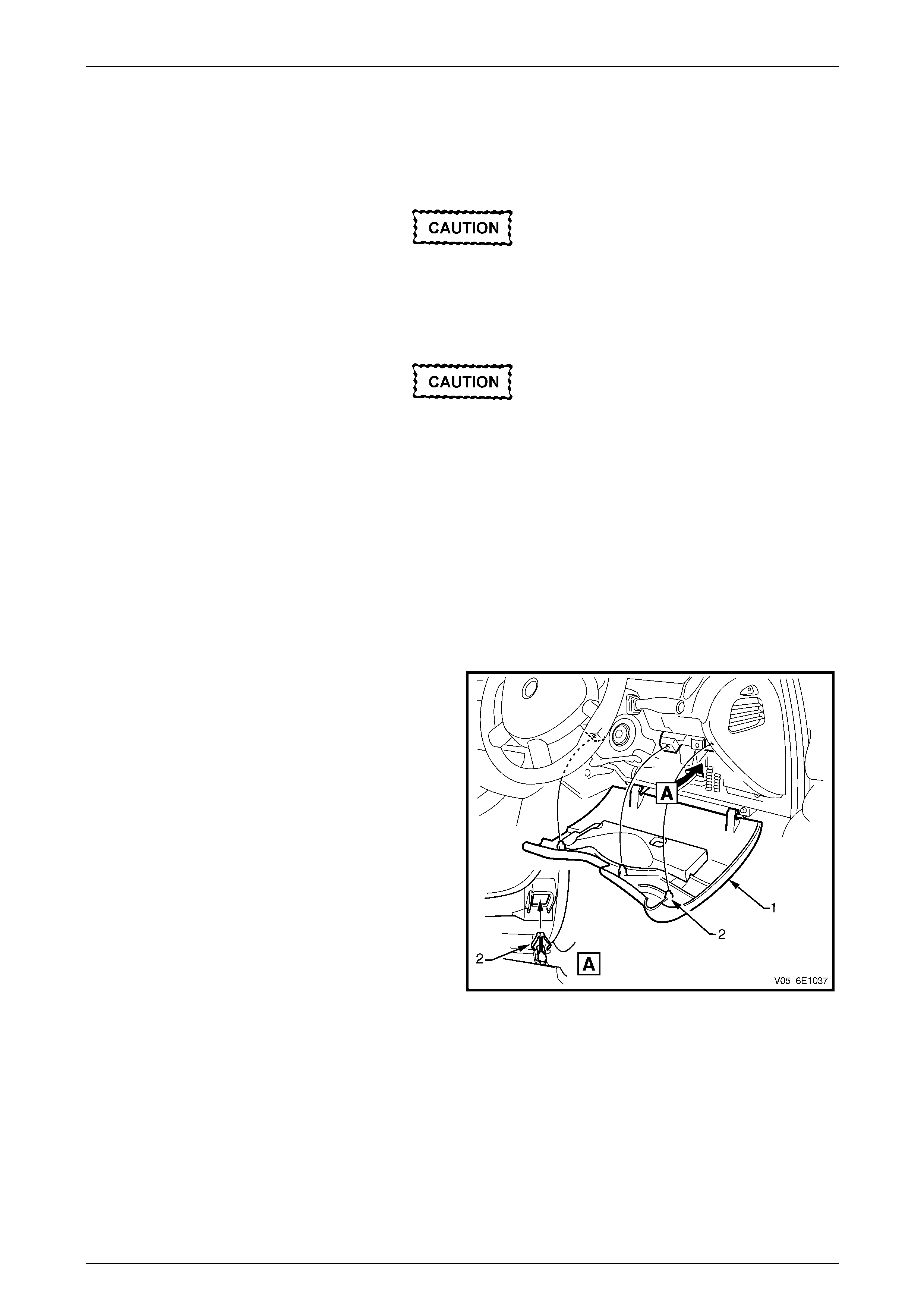
Powertrain Interface Module – V6 Page 6E1–76
Page 6E1–76
10.2 Powertrain Interface Module
LT Section No. — 99–150
Do not touch the powertrain interface module
pins as Electro static Discharge (ESD) damag e
may result. For further information on ESD,
refer to Section 00 Warnings Cautions and
Notes.
When replacing the PIM, the PIM must be
reset prior to removal. Failure to perform this
procedure will result in the inability to:
• Test the PIM for warrant y purp oses.
• Install the PIM into other vehicles.
Remove
1 If replacing the PIM, reset the PIM prior to PIM removal. Refer to PIM Reset in this Section.
2 Turn the ignition switch off.
3 Remove Fuse F21, refer to Section 12O Fuses, Relays and Wiring Harnes ses .
4 Grasp the upper edge of the i nstrument panel lower
trim panel assembly (1) and pull outwards to
disengage the three retaini ng clips (2).
5 Swing the panel assembly open.
Figure 6E1 – 33
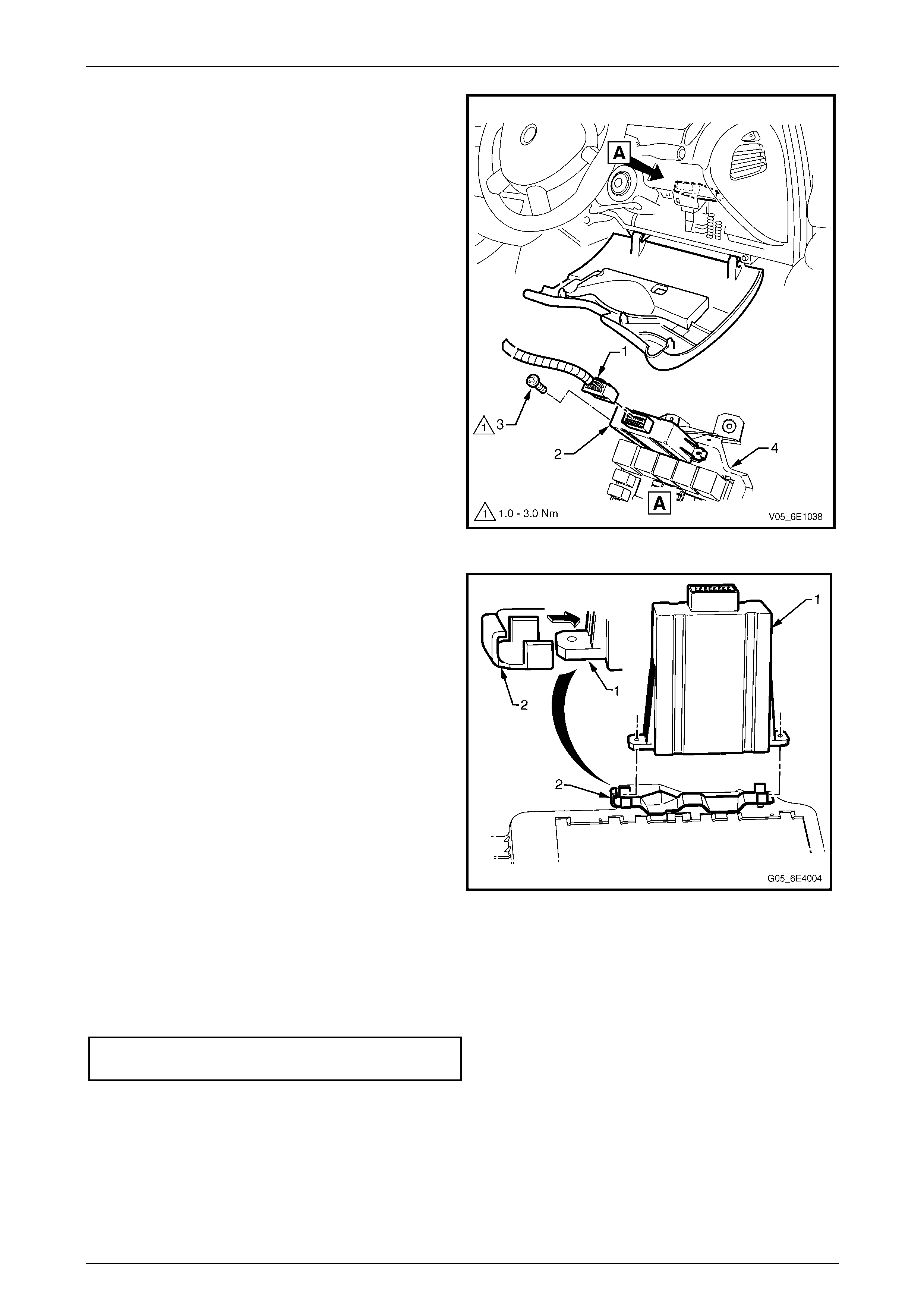
Powertrain Interface Module – V6 Page 6E1–77
Page 6E1–77
6 Disconnect the wiring harness connector (1) from the
powertrain interface module (PIM) (2).
7 Remove the screw (3) attaching the PIM to the
steering column bracket outer brace (4).
Figure 6E1 – 34
8 Slide the PIM (1) in the direction of the arrow to
disengage the PIM from the mounting bracket (2).
NOTE
To aid in the removal of the PIM, it may be
necessary to detach the fuse and relay block
from the steering column bracket outer brace,
refer to Section 1A3 Instrument Panel and
Console.
Figure 6E1 – 35
Reinstall
Reinstallation of the PIM is the reverse of the removal procedure, noting the following:
1 Tighten the attaching screw to the correct torque specification.
PIM attaching screw
torque specification.....................................1.0 – 3.0 Nm
2 If the PIM has been replaced, perform the following procedures:
• PIM service programming, refer to 11.4 BCM Link to ECM / PIM.
• PIM Configuration, refer to 11.3 PIM Configuration.
• Diagnostic system check, refer to 7.2 Diagnostic System Check.
3 Road test the vehicle and check for correct vehicle operation.
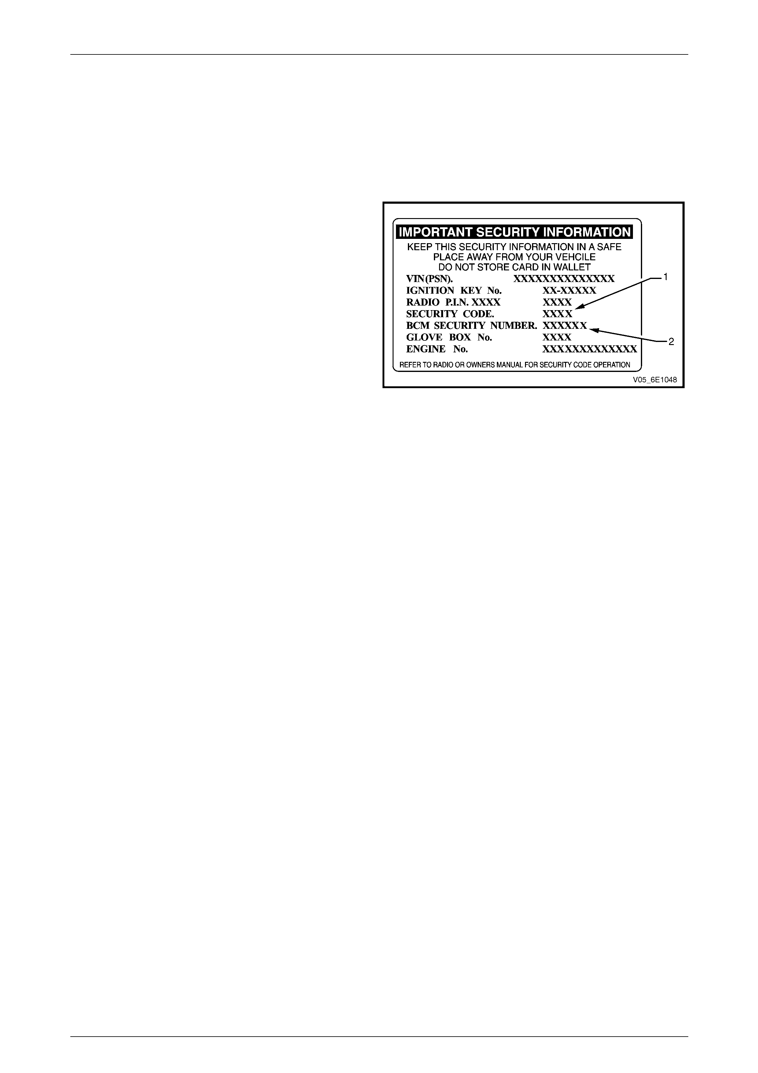
Powertrain Interface Module – V6 Page 6E1–78
Page 6E1–78
11 PIM Security and Programming
11.1 Security and Programming Information
Vehicle Security Card
When performing certain powertrain interface module (PIM)
programming functions using Tech 2, you may be prompted
to enter a four digit Security Code (1) a nd / or BCM six digit
Security Number (2). This information is found on the
vehicle security card issued with the vehicle when new. If
the card is unavailable, contac t the Holden Technical
Assistance (TAS) centre to obtain the relevant Security
Code and BCM security number.
Figure 6E1 – 36
Security Code
The security code is required when performing certai n PIM, BCM and ECM programming functions. When Tech 2
requests the security code to be entered, and an incorrect code is entered, the PIM will go into a security wait time stage.
This wait time stage will prevent any further attempts to enter the securit y code until the wait time has elapsed.
Should a second incorrect se curity code be entered after the initial wait time has elapsed, the PIM will go into a second
wait time stage. The wait time will increase each time an incorrect code is entered. When the correct code is entered the
wait time will reset back to its original value of 10 seconds.
NOTE
The ignition switch must be in the ON position
with the battery connected during the wait time
period.
The wait time stages are as follows:
• Stage 1 = 10 seconds.
• Stage 2 = 10 seconds.
• Stage 3 = 10 minutes.
• Stage 4 = 20 minutes.
• Stage 5 = 40 minutes.
• Stage 5 = 80 minutes.

Powertrain Interface Module – V6 Page 6E1–79
Page 6E1–79
Tech 2 PIM Security Information Data List
The Tech 2 PIM Security Information Data List displays the PIM's current security status.
To view the data list:
1 Connect Tech 2 to the data link connector (DLC) a nd turn the ignition switch on.
2 On Tech 2 select: Body / Powertrain Interface Module / Security / Security Information.
NOTE
The Tech 2 PIM Security Information Data List
typical display values are obtained from a
correctly operating vehicle under the following
conditions:
• ignition switched on,
• engine not running, and
• vehicle is stationary.
Tech 2 Parameter Units Displayed Typical Display Values
BCM / PIM Status Yes / No Yes
Security Code Programmed Yes / No Yes
Security Wait Time Inactive / Active Inactive
Security Wait Time Inactive / 0:00:00 Inactive
Security Code Correct Enter Yes / No Yes
Security Code Reset Counter 0 0

Powertrain Interface Module – V6 Page 6E1–80
Page 6E1–80
11.2 PIM Reset Procedure
Do not perform the reset procedure within
sixty seconds of turning the ignition switch
on. Failure to comply may result in the PIM
failing to reset.
When a PIM has been installed into a vehicle, it is security linked to the body control module (BCM) and engine control
module (ECM). Once this linking has been performed, the PIM cannot be installed in any other vehicle, unless the
security linking between the BCM and the ECM has been reset usin g the following procedure:
1 Prior to resetting the PIM, obtain the Security Code an d the BCM Security Number. For further information, refer to
Vehicle Security Card.
2 Connect Tech 2 to the data link connector (DLC) a nd turn the ignition switch on.
3 On Tech 2 select: Body / Powertrain Interface Module / Security / Reset PIM.
NOTE
When Tech 2 requests programming approval,
obtain TIS approval. For further information on
TIS approval, refer to Section 0C Tech 2.
NOTE
If a Tech 2 screen displ a ying Security Wait Time
Active, Please Wait! appears after selecting the
Reset PIM option, an incorrect security code has
been previously entered. Refer to 11.1 Security
and Programming Information for further
information.
4 When Tech 2 displays Enter Security Code, enter the security code, press the Enter key and then the Okay soft
key.
5 When Tech 2 displays Do you really want to Reset?, press the Reset soft key.
Do not turn the ignition switch off within 60
seconds of performing the PIM reset
procedure. Failure to co mply may result in th e
PIM failing to reset.
6 When Tech 2 displays Reset Completed Successfully, press the Confirm soft key to return to the Tech 2
Security screen.

Powertrain Interface Module – V6 Page 6E1–81
Page 6E1–81
11.3 PIM Configuration
When a new PIM has been inst alled into a vehicle, vehicle specific information such as the Vehicle Identification Number
(VIN), engine type etc, must be programmed into the PIM. To program:
• a new PIM, refer to Configuring a New PIM, in this Section,
• an existing PIM, refer to Configuring an Existing PIM, in this Section,
• the VIN number, refer to Programming the VIN, in this Section.
Configuring a New PIM
Although the following procedure is specific to changing the engine type, the proc edure for the remaining vehicle
parameters is identical.
1 Connect Tech 2 to the data link connector (DLC).
2 On Tech 2 select: Body / Powertrain Interface Module / Program / Program ECU.
3 Using the up or down arrow selection keys, select the Engine Type.
4 Press the Modify soft key.
5 Using the up or down arrow selection keys, select V6.
6 Press the Confirm soft key. Tech 2 reverts to the main Tech 2 Program ECU screen where the selection made in
the previous step is displayed .
7 Make the necessary changes for the remaining items shown in the T ech 2 Program ECU screen.
8 When finished, press the Program soft key.
9 Enter the VIN using the Tech 2 arrow selection keys.
NOTE
The left and right arrow selection keys move the
Tech 2 cursor along the VIN number, whilst the
up and down selection arrows change the
character value.
Numbers can also be entered by pressing the
number key's on Tech 2.
10 After entering the VIN, press the Enter key. The changes a re now programmed into the PIM.
Do not turn the ignition switch off within 60
seconds of configuring the PIM. Failure to
comply may result in the changes failing to be
programmed into the PIM.
11 When notified the process is completed, press the Confirm soft key to return to the Tech 2 Program screen.

Powertrain Interface Module – V6 Page 6E1–82
Page 6E1–82
Configuring an Existing PIM
Although the following procedure is specific to changing the transmission type, the procedure for changing any other
vehicle parameter is the same.
1 Connect Tech 2 to the data link connector (DLC).
2 On Tech 2 select: Body / Powertrain Interface Module / Program / Program Configuration.
3 Using the up or down arrow selection keys, select the Transmission Type.
4 Press the Modify soft key.
5 Using the up or down arrow selection keys, select the appropriate transmission.
6 Press the Confirm soft key. Tech 2 reverts to the main Tech 2 Program Configuration screen where the selection
made in the previous step is displa yed.
7 Make any other required changes for the remaining items.
8 When finished, press the Program soft key. The changes are now programmed into the PIM.
Do not turn the ignition switch off within 60
seconds of configuring the PIM. Failure to
comply may result in the changes failing to be
programmed into the PIM.
9 When notified t he process is completed, press the Confirm soft key to return to the Tech 2 Program screen.
Programming the VIN
1 Connect Tech 2 to the data link connector (DLC).
2 On Tech 2 select: Body / Powertrain Interface Module / Program / Program VIN.
3 Enter the VIN using the Tech 2 arrow selection keys.
NOTE
The left and right arrow selection keys move the
Tech 2 cursor along the VIN number, whilst the
up and down selection arrows change the
character value.
Numbers can also be entered by pressing the
number key's on Tech 2.
4 After entering the VIN number, press the Enter key. The changes are now programmed into the PIM.
Do not turn the ignition switch off within 60
seconds of programming the VIN. Failure to
comply may result in the changes failing to be
programmed into the PIM.
5 When notified t he process is completed, press the Confirm soft key to return to the Tech 2 Program screen.

Powertrain Interface Module – V6 Page 6E1–83
Page 6E1–83
11.4 BCM Link to ECM / PIM
Do not perform the BCM Link to ECM / PIM
procedure within sixty seconds of turning the
ignition switch on. Failure to comply may
result in the PIM failing to link.
When the powertrain interface modu le (PIM) has been replaced, it is necessary to security link the PIM to the body
control module (BCM) and engine control module (ECM) before the vehiclFigure 6E1 – 2 e will start.
NOTE
This linking procedure between the ECM and PIM
is also known as the Immobiliser Function
Programming.
1 Prior to performing the linking procedure, obtain the security code and BCM security number. For further
information, refer to Vehicle Security Card.
2 Connect Tech 2 to the data link connector (DLC).
3 On Tech 2 select: Body / Powertrain Interface Module / Security / BCM Link to ECM / PIM.
4 When Tech 2 displays BCM Replaced, press the No soft key.
5 When Tech 2 displays PIM / ECM Rep l aced?, press the Yes soft key.
6 When Tech 2 displays Select Engine Type use the up and down arrow selection keys to select the appropriate
engine type and then press the Enter key.
7 When Tech 2 displays Please Select, use the up and down arrow selection keys to select PIM Replaced, and then
press the Enter key.
NOTE
When Tech 2 requests programming approval,
obtain TIS approval. For further information on
TIS approval, refer to Section 0C Tech 2.
8 When Tech 2 displays BCM Security No., enter the BCM security number, press the Enter key.
9 When Tech 2 displays Turn Ignition Off!, turn the ignition switch off.
10 When Tech 2 displays Turn Ignition On, turn the ignition switch on.
11 When Tech 2 displays Enter Security Code, enter the security code and press the Enter key and then the Okay
soft key.
12 When Tech 2 displays Confirm Security Co d e, re-enter the security code, press the Enter key and then the Okay
soft key.
13 When Tech 2 displays Stop Engine – Turn Off Ignition, turn the ignition switch off.
14 When Tech 2 displays Turn Ignition On, turn the ignition switch on.
Do not turn the ignition switch off within 60
seconds of performing the BCM Link to
ECM / PIM procedure. Failure to comply may
result in the PIM failing to link with the
BCM / ECM.
15 When Tech 2 displays P ro gramming Successful, press the Confirm soft key to return to the Tech 2 Security
screen.

Powertrain Interface Module – V6 Page 6E1–84
Page 6E1–84
12 Specifications
Powertrain Interface Module Bus Cut-off Resistor....................................120 Ω
Engine Control Module Bus Cut-off Resistor............................................120 Ω

Powertrain Interface Module – V6 Page 6E1–85
Page 6E1–85
13 Torque Wrench Specifications
Powertrain Interface Module Attaching Screw...............................1.0 – 3.0 Nm
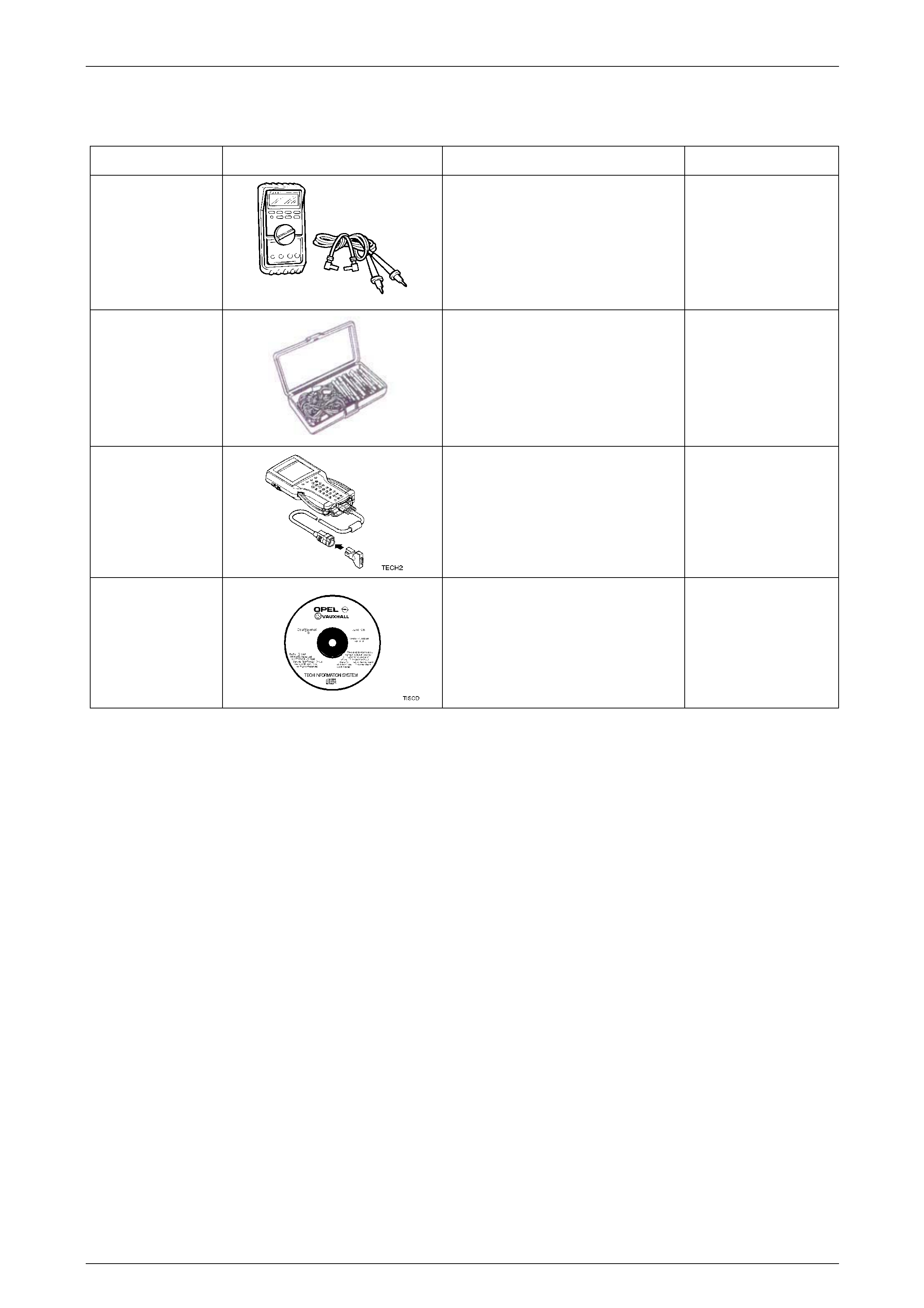
Powertrain Interface Module – V6 Page 6E1–86
Page 6E1–86
14 Special Tools
Tool Number Illustration Description Tool Classification
3588
Digital Multimeter
Also Previously released as J 39200 or
equivalent.
NOTE: The instrument must have 10
mega ohms impedanc e and be
capable of reading frequencies.
Mandatory
J35616
Connector Test Adaptor Kit
Used when carrying out electric al
diagnostic circuit checks.
Desirable
70000861
Tech 2 Diagnostic Scan Tool
Previously released.
Mandatory
N/A
Technical Information System (TIS)
CD ROM
Available to Authorised Dealers.
Mandatory