
Engine Cooling – GEN III V8 Page 6B3–1
Page 6B3–1
Section 6B3
Engine Cooling – GEN III V8
ATTENTION
Before performing any Service Operation or other procedure described in this Section, refer to Section 00
Warnings, Cautions and Notes for correct workshop practices with regard to safety and / or property damage.
1 General Information ...............................................................................................................................3
2 General Description ...............................................................................................................................4
2.1 Radiator Assembly ................................................................................................................................................ 4
2.2 Cooling Fans.......................................................................................................................................................... 6
Overview................................................................................................................................................................. 6
Relays................................................................................................................................................................ 6
Fan Motors......................................................................................................................................................... 6
Cooling System...................................................................................................................................................... 7
Operation ........................................................................................................................................................... 8
2.3 Coolant Pump....................................................................................................................................................... 15
2.4 Thermostat ........................................................................................................................................................... 16
2.5 Radiator Cap......................................................................................................................................................... 17
2.6 Coolant Recovery Reservoir............................................................................................................................... 18
2.7 Vapour Vent System............................................................................................................................................ 19
2.8 Air Baffles and Ducts........................................................................................................................................... 20
2.9 Engine Coolant Temperature Sensor................................................................................................................. 22
3 Service Operations...............................................................................................................................23
3.1 Service Notes....................................................................................................................................................... 23
Safety.................................................................................................................................................................... 23
Periodic Servicing................................................................................................................................................ 23
Environmental Issues.......................................................................................................................................... 23
3.2 Coolant Maintenance........................................................................................................................................... 24
Topping Up the Cooling System......................................................................................................................... 24
Testing Coolant Concentration........................................................................................................................... 25
Method 1 – Refractometer................................................................................................................................ 25
Method 2 – Hydrometer.................................................................................................................................... 27
3.3 Draining and Filling Cooling System ................................................................................................................. 29
Draining ................................................................................................................................................................ 29
Filling.................................................................................................................................................................... 30
3.4 Coolant Hoses...................................................................................................................................................... 31
3.5 Cleaning Cooling System.................................................................................................................................... 34
Cooling System Reverse Flush .......................................................................................................................... 34
Radiator............................................................................................................................................................ 34
Engine.............................................................................................................................................................. 35
Heater Hoses and Core.................................................................................................................................... 36
3.6 Engine Accessory Drive Belt Tension ............................................................................................................... 37
3.7 Engine Accessory Drive Belt.............................................................................................................................. 38
Remove................................................................................................................................................................. 38
Inspect .................................................................................................................................................................. 39
Install .................................................................................................................................................................... 40
3.8 Pressure Testing.................................................................................................................................................. 41
Radiator Cap Pressure Testing........................................................................................................................... 41
Cooling System Pressure Testing...................................................................................................................... 43
Techline
Techline

Engine Cooling – GEN III V8 Page 6B3–2
Page 6B3–2
3.9 Thermostat ........................................................................................................................................................... 44
Remove................................................................................................................................................................. 44
Test ....................................................................................................................................................................... 45
Disassemble......................................................................................................................................................... 45
Reassemble.......................................................................................................................................................... 46
Install .................................................................................................................................................................... 46
3.10 Coolant Recovery Reservoir............................................................................................................................... 47
Remove................................................................................................................................................................. 47
Inspect .................................................................................................................................................................. 48
Install .................................................................................................................................................................... 48
3.11 Oil Pan Under-tray ............................................................................................................................................... 49
Remove................................................................................................................................................................. 49
Install .................................................................................................................................................................... 49
3.12 Air Baffles and Ducts........................................................................................................................................... 50
Remove................................................................................................................................................................. 50
Reinstall................................................................................................................................................................ 50
3.13 Coolant Pump....................................................................................................................................................... 51
Remove................................................................................................................................................................. 51
Disassemble......................................................................................................................................................... 53
Clean and Inspect................................................................................................................................................ 54
Reassemble.......................................................................................................................................................... 54
Reinstall................................................................................................................................................................ 54
3.14 Cooling Fans and Shroud Assembly ................................................................................................................. 55
Remove................................................................................................................................................................. 55
Disassemble......................................................................................................................................................... 58
Reassemble.......................................................................................................................................................... 58
Install .................................................................................................................................................................... 58
3.15 Radiator ................................................................................................................................................................ 59
Remove................................................................................................................................................................. 59
Install .................................................................................................................................................................... 61
Radiator Repair Procedure ................................................................................................................................. 62
Repairable Leaks ............................................................................................................................................. 62
Repair Method.................................................................................................................................................. 63
Tube Blocking................................................................................................................................................... 63
Header Repair.................................................................................................................................................. 63
General Core Repair........................................................................................................................................ 64
Transmission Oil Cooler Leak Test .................................................................................................................. 64
Transmission Oil Cooler Seal Replacement..................................................................................................... 64
3.16 Flexible Transmission Cooler Hose ................................................................................................................... 65
Replace................................................................................................................................................................. 65
4 Engine Cooling System Diagnosis.....................................................................................................67
4.1 Poor Heater Operation......................................................................................................................................... 67
4.2 Leaking Cylinder Head Gasket ........................................................................................................................... 68
4.3 Question the Customer ....................................................................................................................................... 69
4.4 Diagnostic Chart.................................................................................................................................................. 70
4.5 Problems Not Requiring Disassembly of Cooling System............................................................................... 71
4.6 Problems Requiring Disassembly of Cooling System...................................................................................... 72
4.7 Black Light and Dye Leak Diagnosis Method.................................................................................................... 73
5 Specifications.......................................................................................................................................74
6 Torque Wrench Specifications............................................................................................................76
7 Special Tools .................................................................................................................. ......................77

Engine Cooling – GEN III V8 Page 6B3–3
Page 6B3–3
1 General Information
The cooling system for MY 2005 WL Series v ehicles fitted with GEN III V8 engines has been significantly modified. The
following list is a summary of new and modified compon ents:
• Revised radiator assembly (new tanks incorporating integral coolant fill point / pressure cap location and drain tap).
• New plumbing including radiator hoses and heater hos e (inlet radiator hose bridging pipe deleted).
• New side chutes and radiator shroud (common with Alloytec V6 vehicl es).
• New coolant recovery reservoir (common with Alloytec V6 vehicles) replaces pressur ised surge tank and hose.
• Modified cooling fan operating strategy and control (both coolin g fans controlled by the Powertrain Control Module).
All WL Series vehicles with the GEN III V8 engine, use a two stage cooli ng fan operation, wher e both fan motors will
operate either on low-speed (Stage 1) or high-speed (Stage 2).
With the 400 Watt cooling fan system, each fan motor is dual-speed and each has a different power rating – 180 and
220 Watt. Both fan motors fitted, operate either on low-speed (Stage 1) or high-s peed (Stage 2).
Operation of the cooling fans is depe nd ent on engine coolant temperature, vehicle speed, A/C request (where fitted) and
A/C system pressure. Refer to Section 6C3-1 Powertrain Management – GEN III V8 – General Information for further
information.
The air conditioning system condenser is mounted to the front of the radiator and is located and supported by four clips
moulded into the front of the plastic radiator tanks. The lower clips lock the condenser in place and can be released by
hand to facilitate condens er removal.
The condenser, filter drier receiver, radiator and the fan motors / blades / shroud assembly can be removed and installed
individually from the vehicle. For removal and installation procedures relating to air conditioning components, refer to
Section 2C HVAC Climate Control (Man ual A/C) – Removal and Installation.

Engine Cooling – GEN III V8 Page 6B3–4
Page 6B3–4
2 General Description
2.1 Radiator Assembly
When the vehicle is built, the air conditioning condenser, filter drier receiver, cooling fans, fan shrou d and radiator are
installed into the engine bay as a pre-assembled unit. This unit is described as the radiator assembly or as the
Condenser, Radiator and Fan Module (CRFM).
The radiator utilises an aluminium core and is of the cross-flow design. Plastic side tanks are attached to the core by the
use of clinch tabs. The clinch tabs are forme d as part of the core assembly.
Pegs are attached to the lower frame and the upper area of each side tank. These pegs are used to support the radiator
in four rubber mounts. The assembly is hel d in position by two spring clips at the upper mounting loc ations.
A high temperature rubber seal is used to seal the mating surface between the core and each side tank. The seal(s)
must be replaced any time the side tank is removed from the core.
NOTE
The radiator core side tanks or transmission oil
cooler CANNOT be replaced separately. If
there is a fault with any of these compone nts, the
radiator assembly must be replaced. Small
core repairs may be made, using an aluminised
silicon based liquid repair agent. Refer to
3.15 Radiator – Radiator Rep air Procedure in this
Section.
An automatic transmission oil cooler is located in the right-hand side radiator tank. The cooler pipes from and to the
transmission are connected to the oil cooler flexible hoses by means of quick connect fittings.
The air conditioning condenser is mounted to the front of the radiator and is located and supported by four clips moulded
into the front of the plastic radiator tanks. The lower clips lock the condenser in place and can be released by hand to
facilitate condenser removal. T he air conditioning receiver drier also forms a part of the complete assembly.
The cooling fan motors are each attached b y three screws to the one-piece plastic fan shroud. The fan shroud is
mounted to the rear of the radiator and is located and supported by four clips moulded into the rear of the plastic ra diator
tanks. The upper clips lock the fan shroud in place and can be released by hand to facilitat e fan shroud removal. The
shroud must be removed to facilitate fan motor and bl ade assembly removal.
Two harness connectors are mounted to the upper section of the fan shroud allowing the fan motor and blade
assemblies to be removed individually from the shroud. The fan motor and blade is balanced as a n assembly. These two
components are serviced only as a unit and must not be separated.
For a comprehensive description of the different operating strategies and electrical wiring for the 400W system, refer to
2.2 Cooling Fans in this Section.
The shroud, fan assemblies and transmiss ion cooler hoses can be removed and i nstalled individually from the vehicle.
For removal and installation procedures refer to 3.14 Cooling Fan and Shroud Assembly,
3.16 Flexible Transmission Cooler Hose and 3.15 Radiator in this Section. For removal and installatio n procedures
relating to the air conditioning assemblies in the CRFM, refer to Section 2C HVAC Climate Control (Manual A/C).

Engine Cooling – GEN III V8 Page 6B3–5
Page 6B3–5
Figure 6B3 – 1
Legend
1 RHS Fan and Fan Motor Assembly
2 Fan Shroud
3 RHS Fan Retaining Screw (3 places)
4 LHS Fan Retaining Screw (3 places)
5 LHS Fan and Fan Motor Assembly
6 Upper Transmission Cooling Line and Seal
7 Lower Transmission Cooling Line and Seal
8 Upper Radiator Insulators (2 places)
9 Radiator
10 Lower Radiator Insulators (2 places)
11 Upper Condenser Mounting Clips (2 places)
12 Upper Condenser Mounting Clip Screws (2 places)
13 Lower Condenser Mounting Clips (2 places)
14 Lower Condenser Mounting Clip Screws (2 places)
15 Condenser
16 Filter Drier Receiver Mounting Bracket
17 Filter Drier Receiver Mounting Bracket Screw
18 Filter Drier Receiver
19 O-ring
20 Ambient Air Temperature Sensor Mounting Bracket (Only OCC Auto A/C)
Engine Cooling – GEN III V8 Page 6B3–6
Page 6B3–6
2.2 Cooling Fans
Overview
All GEN III V8 vehicles are fitted with a high power cooling fan system consisting of two dual-speed fans, which operate
with a two-stage strategy as follows:
• Stage 1 – both fans operate at low speed.
• Stage 2 – both fans operate at high speed.
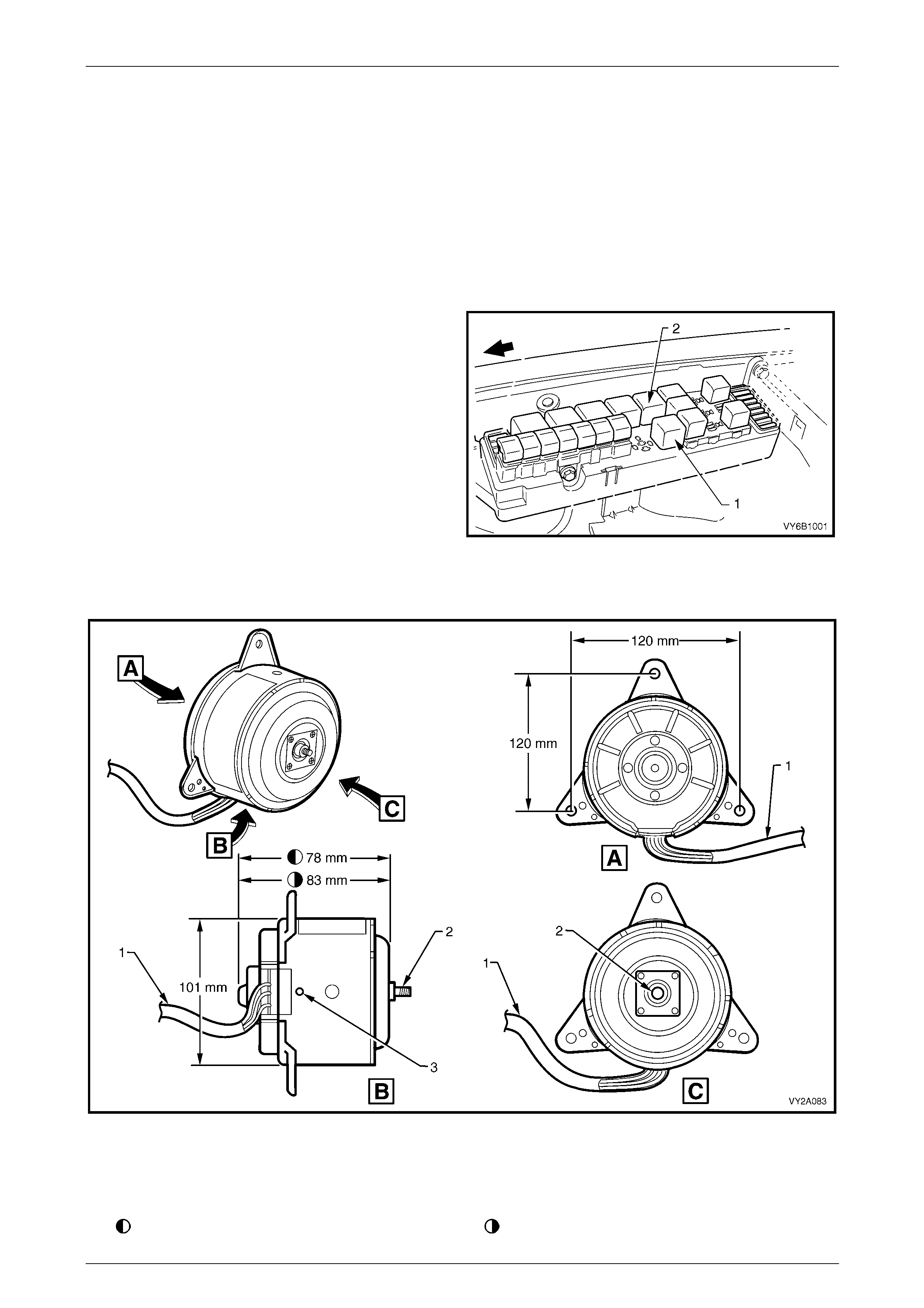
Relays
The engine coolin g fan relays are located in the fuse and
relay compartment under the hood.
Legend
1 Cooling Fan Relay 1 for low-speed fan operation.
2 Cooling Fan Relay 2 (in conjunction with Cooling Fan
Relay 1) for high-speed fan operation.
Figure 6B3 – 2
Fan Motors
Figure 6B3 – 3
Legend
1 Three-wire Harness 2 Armature Shaft 3 Drain Hole
Dimension applicable to small diameter fan blade Dimension applicable to large diameter fan blade
Engine Cooling – GEN III V8 Page 6B3–7
Page 6B3–7
All fan motors are 12 Volt, dual-speed types. Accordingly, the internal con struction of the fan motor consists of four
brushes and four permanent magnets. A three-wire pigtail harness is permanently attached to both motors and is
attached to the polypropylene fan shroud at two locations by integral clips moulded as part of the shroud. T he RHS motor
harness is connected directly to the engine h arness thro ugh a 6-pin connector. It also car r ies an additional 4-pin
connector that attaches to the LHS motor harness and en abl es individual removal of the LHS and RHS fan and motor
assemblies when necessary, refer to Figure 6B3 – 1. The two associated electrical connectors are attached to the
shroud by way of slide lock clips. The motor is attached to the polypropylene fan shroud by three bolts installed at the
threaded mounting flanges, which protrude symmetrically from the rear of the fan motor housi ng, refer to Figure 6B3 – 3.
Suppression capacitors locat ed at the fan motor brush holders are incorpor ated. These suppression capacitors help
eliminate fan motor noise through the ra dio speakers. As these capacitors are not service d separately, the motor
assembly must be replaced should a problem occur with either capacitor.
The enclosed fan motor housing is constructed of yellow zinc coated steel. A drain hole is located in the bottom of the
housing to allow for breathing and dra ining of any moisture ingress.
Both fan motors rotate in an anticlockwise direction when vie wed from the fan motor side.
Both LHS and RHS fan and motor are balanced as a unit and fan blades must not be separated from their respective
motors. Fan motors and blades are serviced only as an assembled unit. However, it should be noted that the central nut
attaching the fan blade to the motor shaft has a left-hand thread.
Cooling System
The cooling system includes two, dual-speed, engine cooling fan motors, both of which, drive fans with five,
asymmetrical blades that are designed to reduce air noise. T he larger, right fan is 354 mm in diameter and has a motor
rated at 220 Watts, while the smaller, left fan is 293 mm in diameter with a motor power rating of 180 Watts.
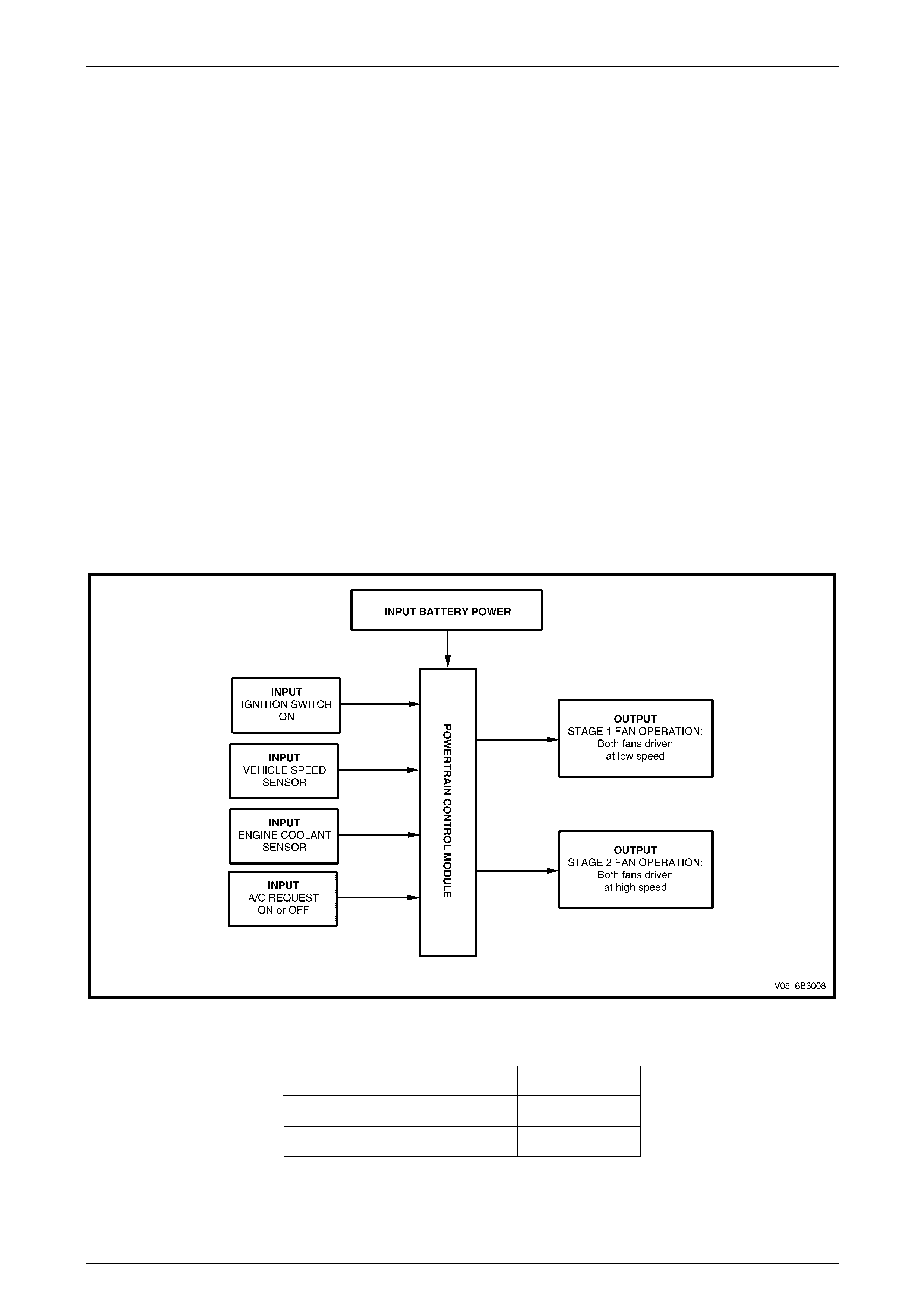
The following outlines the ope ration of the cooling system, at block level, also showing what inputs the Powertrain
Control Module (PCM) requires.
Figure 6B3 – 4
With 12 volts applied and the fans mount ed to the radiator with a condenser fitted, the operatin g speeds are:
Stage 1 Stage 2
Large Fan 2,350 ± 150 rpm 2,750 ± 150 rpm
Small Fan 2,050 ± 150 rpm 2,300 ± 150 rpm
Engine Cooling – GEN III V8 Page 6B3–8
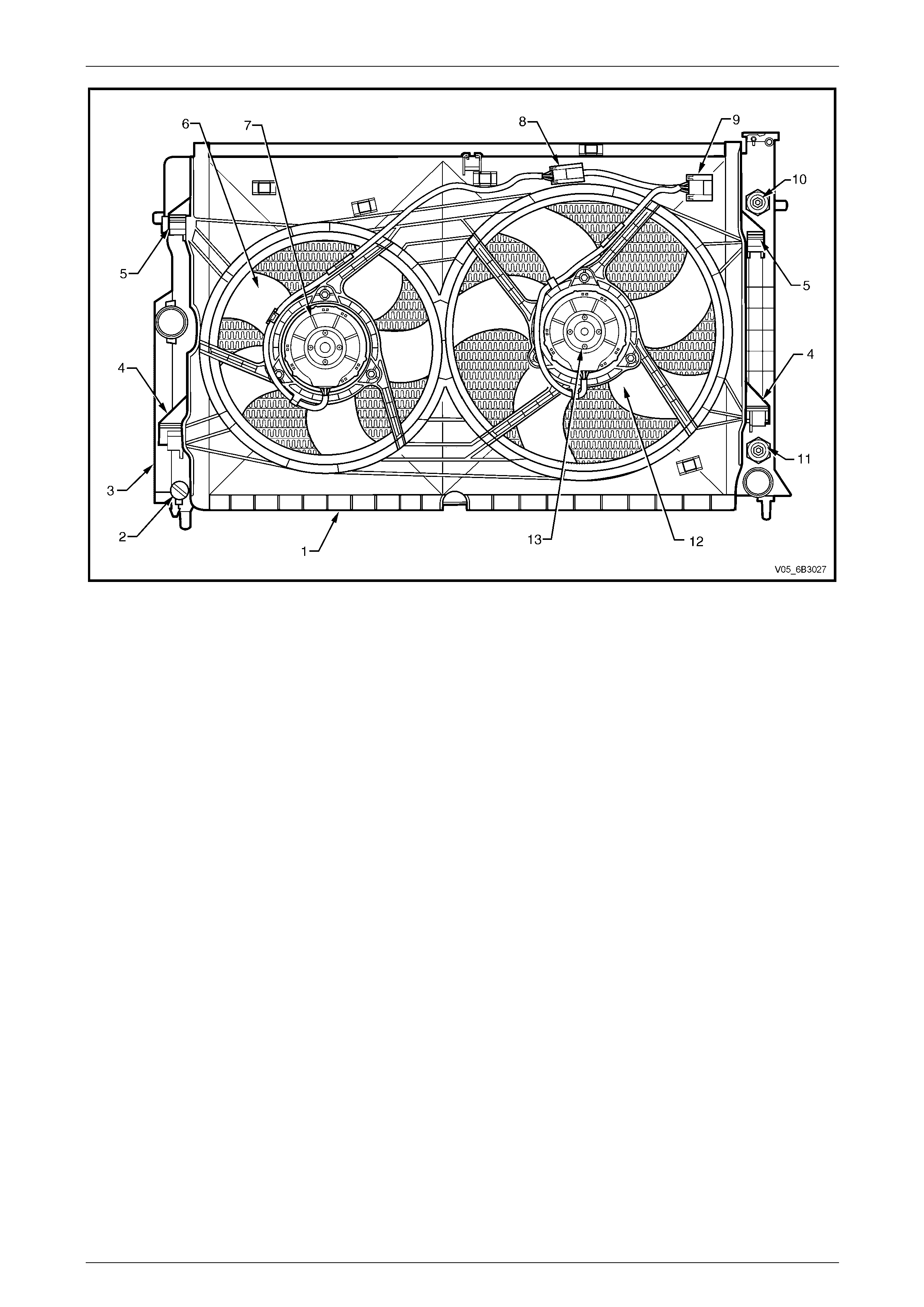
Page 6B3–8
Figure 6B3 – 5
Legend
1 Fan Shroud
2 Radiator Drain Tap
3 Radiator
4 Fan Shroud Lower Support
5 Fan Shroud Upper Support / Locking Retainer
6 Small, Left Fan – 5 Blade, 293 mm Diameter
7 Small, Left Fan Motor – 180 Watt, Dual-speed
8 Left Fan Motor Harness Connector (3 terminal)
9 Left and Right Fan Motor Harness Connector (5 terminal)
10 Oil Cooler, Upper Line Connection (Auto. Trans. only)
11 Oil Cooler, Lower Line Connection (Auto. Trans. only)
12 Large, Right Fan – 5 Blade, 354 mm Diameter
13 Large, Right Fan Motor – 220 Watt, Dual-speed
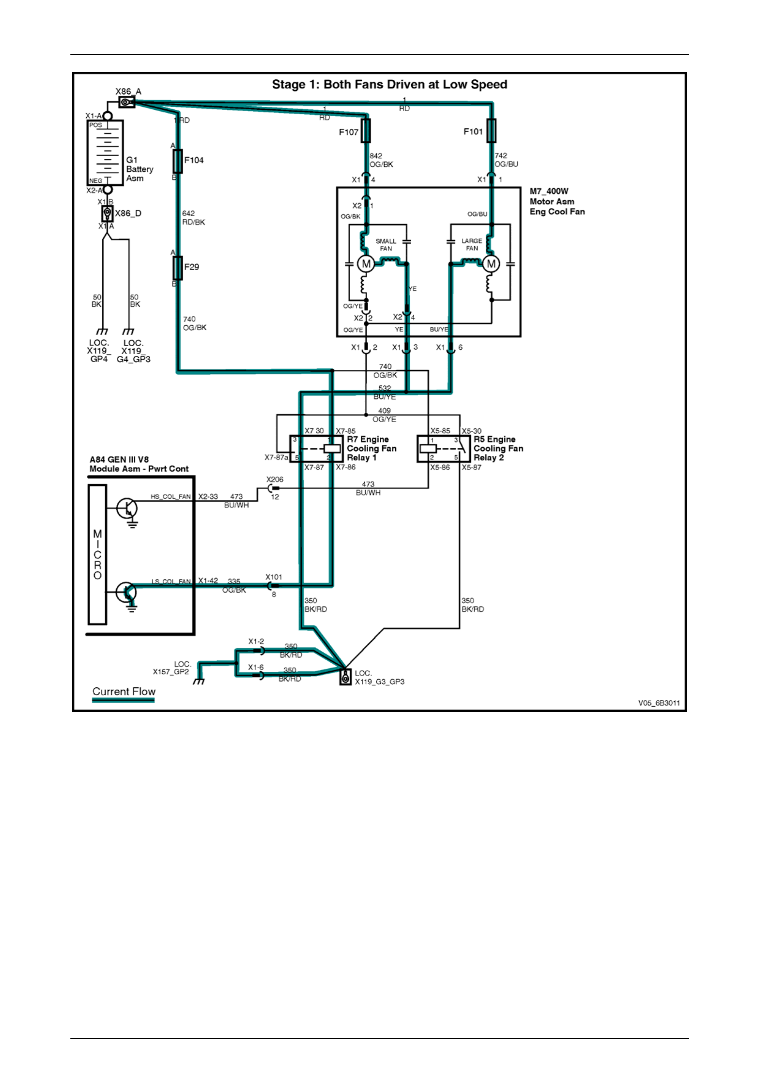
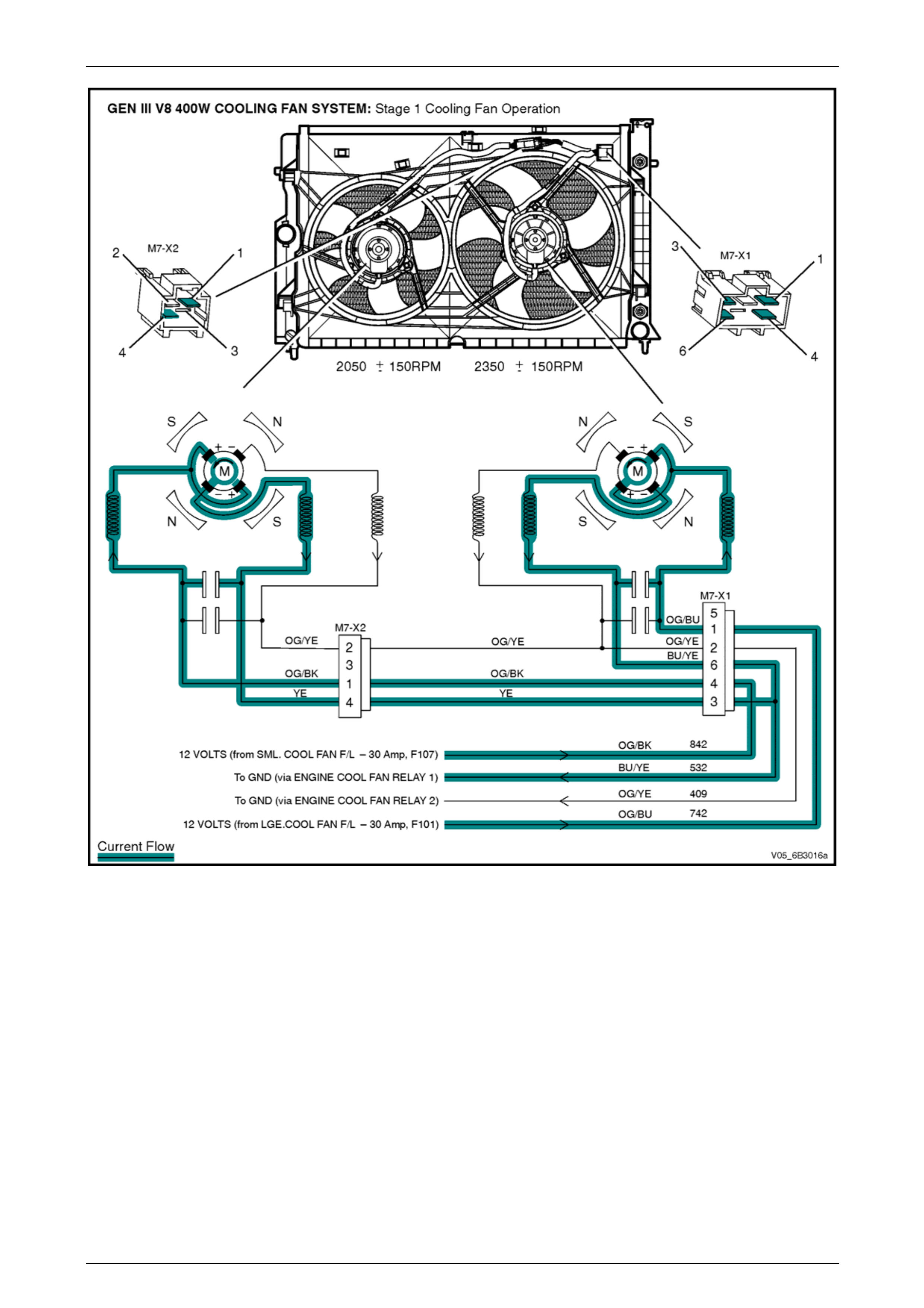
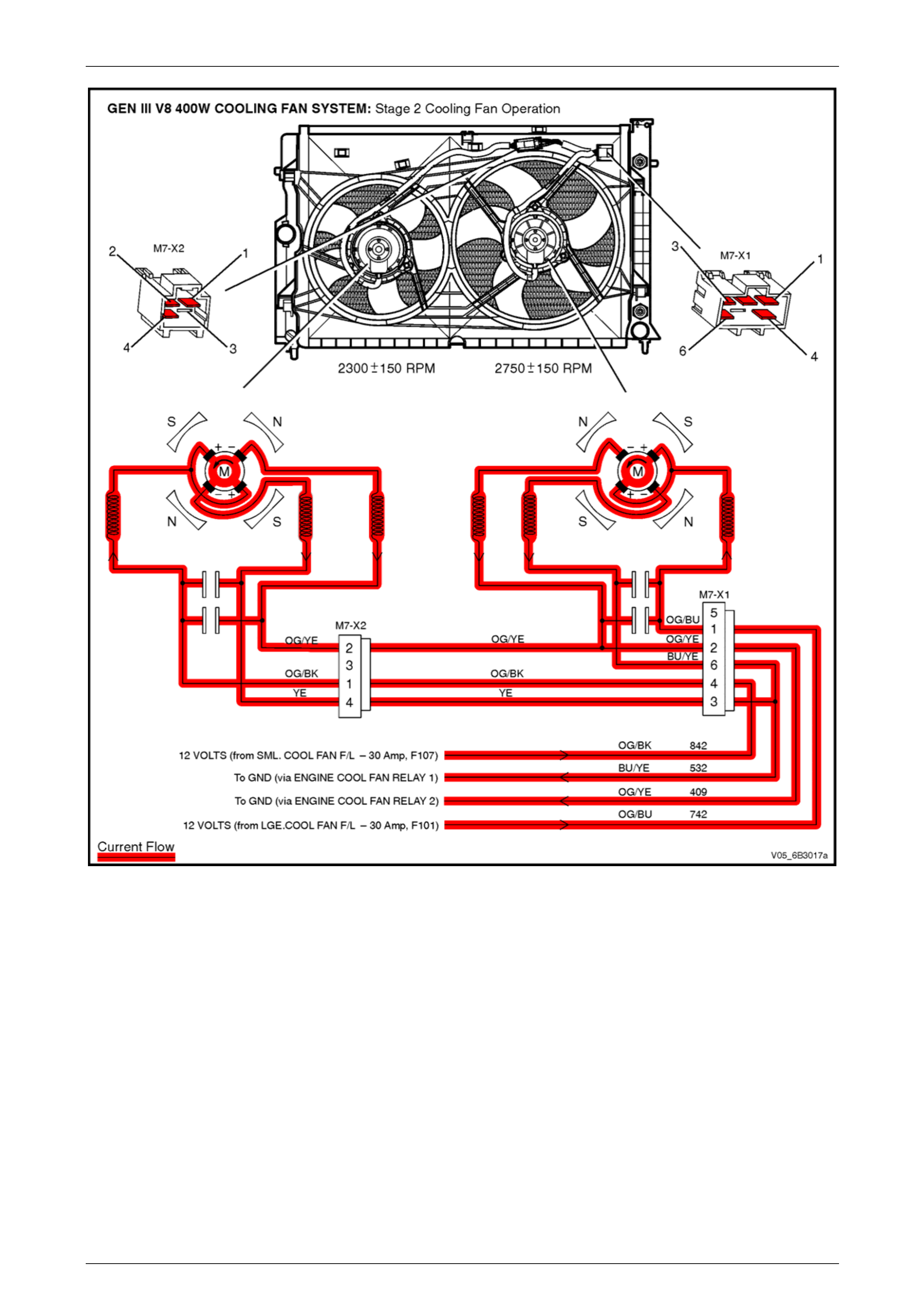
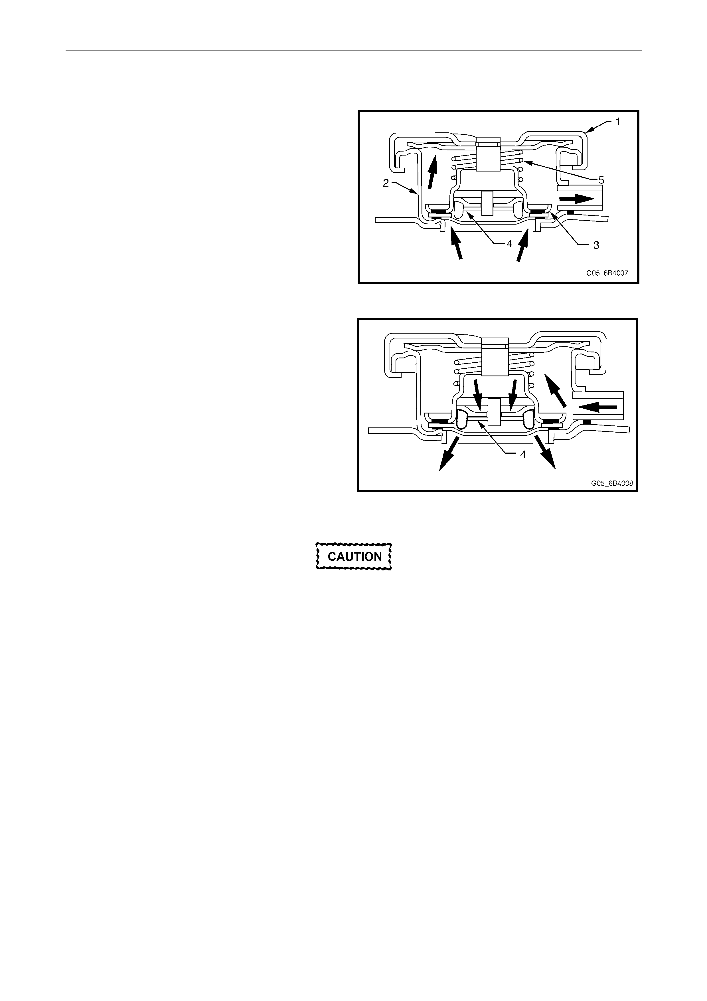
Operation
The electrical circuitry for each of the cooling fans has two negative and one positive terminal to achieve the dual-speed
requirement. In addition, the current draw is directed throug h separate neg ative termin als at the joint connector (9) in
Figure 6B3 – 5 for each fan motor to reduce the he at burden on the electrical connectors. Figure 6B3 – 6 shows how
current flows through one negative motor terminal of each fan at low operating speed. Current flows through both
negative terminals of each fan motor when operating at high speed.
The positive terminals are permanently connected to battery voltage, via fusible links F101 (lar ge fan) and F107 (small
fan).
Stage 1 Fan Operation
The PCM determines when to enable Stage 1, based on inputs from the A/C request signal, Engine Coolant
Temperature (ECT) sensor and the Vehicle Speed Sensor (VSS).
When the PCM determines that Stage 1 cooling fan operation is required it energises Engine Coo ling Fan Relay 1 (R7)
by suppling a ground sign al on circuit 335 causing the rela y to operate. Once Engine Cooling Fan Rela y 1 is operated it
provides a ground for the fan motors low-speed negative terminals via circuit 532. The engine cooling fans then operate
at low speed (Stage 1).
Engine Cooling – GEN III V8 Page 6B3–9
Page 6B3–9
Figure 6B3 – 6
Engine Cooling – GEN III V8 Page 6B3–10
Page 6B3–10
Figure 6B3 – 7

Engine Cooling – GEN III V8 Page 6B3–11
Page 6B3–11
Conditions for Stage 1 Fan Operati on
1 The PCM switches ON Engine Cool Fan Rela y 1 (R7) when the following conditions h ave b een met:
• Air conditioning request indicated (YES) and the vehicle speed is less than 30 km/h, or
• Air conditioning pressure is greater than 1,500 kPa, or
• Coolant temperature is greater than 108° C, or
• When a ECT sensor failure in conjunction with an Intake Air Temperature (IAT) sensor failure is detecte d by
the PCM. For additional information.
Refer to Section 6C3-2 Powertrain Management – GEN III V8 – Diagnostics, or
• When the ignition switch is turned from on to off and the engine coolant temperature is ab ove 113° C, the
PCM will continue to energise Engine Cool Fan Rela y 1 for four minutes.
2 The PCM switches OFF Engine Cool Fan Rel ay 1 when the following conditions have been met:
• Air conditioning request not indicated (NO) and the coolant temperature is less than 104° C, or
• Air conditioning request indic ated (YES) with pressure less than 1,170 kPa, vehicle speed greater than
50 km/h, and coolant temperature less than 108° C.
NOTE
The Stage 1 cooling fan operation has a
minimum run on time function of 30 seconds.
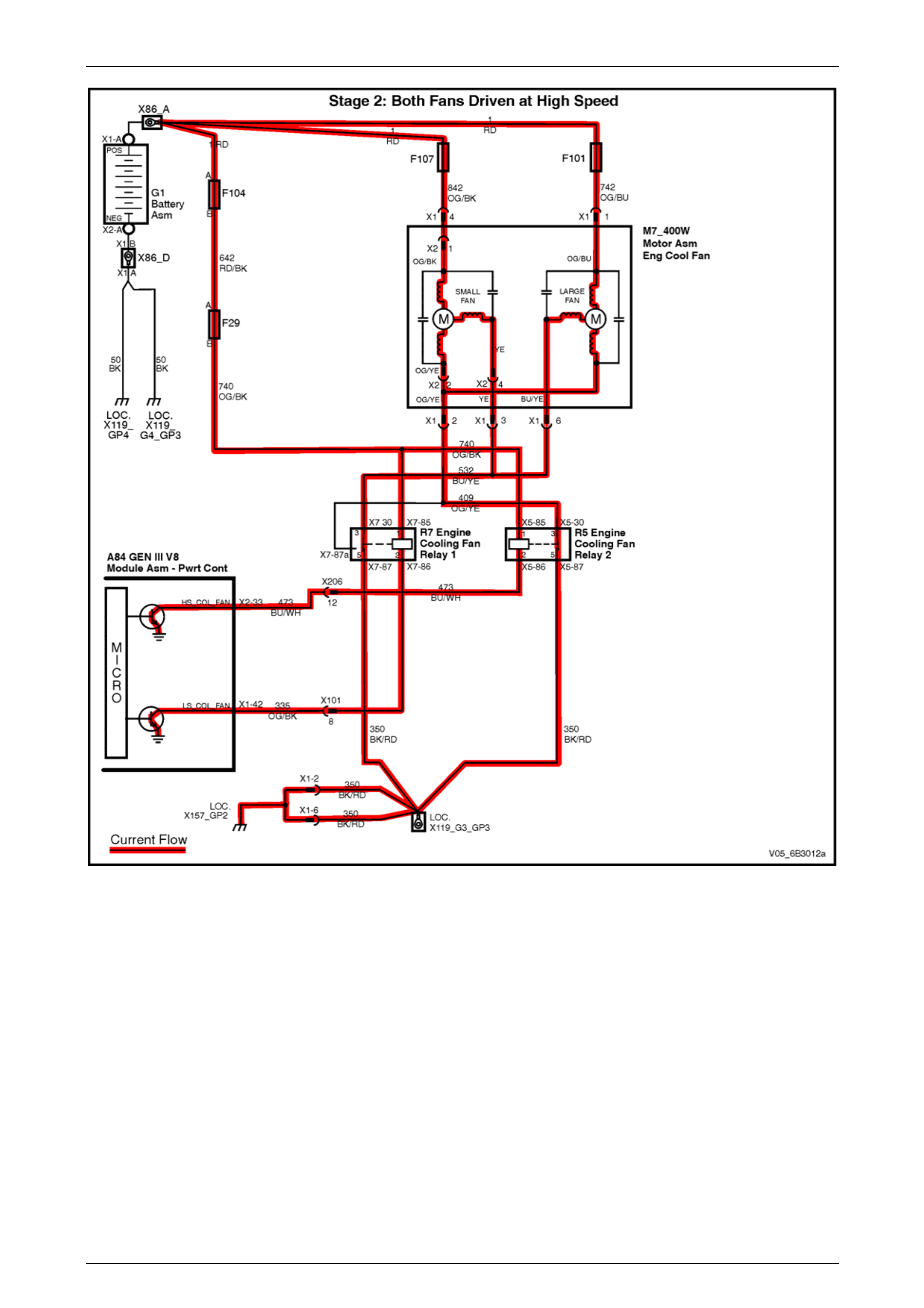
Stage 2 Fan Operation
When the PCM determines that Stage 2 cool ing fan operation is required. Figure 6B3 – 8 shows how the PCM energises
Engine Cooling Fan Relay 2 (R5) by suppling a ground signal on circuit 473 causing the relay to operat e. Once Engine
Cooling Fan Relay 2 has operated, it provides a ground for the fan motors high-speed negative terminals (internally
connected to the second negative brush of each fan motor) via circuit 409. As the low-speed negative terminals are still
grounded through Engine Coo ling F an Relay 1 (R7), the engine cooli ng fans will operate at high speed (S tage 2).
Engine Cooling – GEN III V8 Page 6B3–12
Page 6B3–12
Figure 6B3 – 8
Engine Cooling – GEN III V8 Page 6B3–13
Page 6B3–13
Figure 6B3 – 9

Engine Cooling – GEN III V8 Page 6B3–14
Page 6B3–14
Conditions for Stage 2 Fan Operati on
1 The Engine Cool F an Relay 2 cooling fa n relay will be turned ON if the Engine Co ol Fan Relay 1 has been
energised for 1 second and th e following conditions have been met:
• Engine coolant temperature is above 1 13° C, or
• Air conditioning pressure is greater than 2,400 kPa.
NOTE
If the Stage 1 cooling fan function is off when the
criteria for turning on the Stage 2 cooling fan
function are first met, the Stage 2 cooling fan
function will begin to operate 1 second after the
Stage 1 cooling fan function is switched on.
2 The PCM will turn the high-speed cooling fan function OFF when:
• The engine coolant temperature is less than 108.5° C, and
• Air conditioning request is not indicated (NO), or
• Air conditioning request is indicated (YES) and the press ure is less than 1,900 kPa.
NOTE
• The Stage 2 cooling fan operation has a
minimum run on time function of 30 seconds
after the ignition switch has been turned Off.
• The PCM determines operation of the two
dual-speed engine-cooling fans based on
A/C request, A/C system pressure (where
fitted), engine coolant temperature
and vehicle speed signal inputs. For further
details of the engine cooling fan operation
and diagnosis of the system. Refer to
Section 6C3-2 Powertrain Management –
GEN III V8 – Diagnostics.
Engine Cooling – GEN III V8 Page 6B3–15
Page 6B3–15
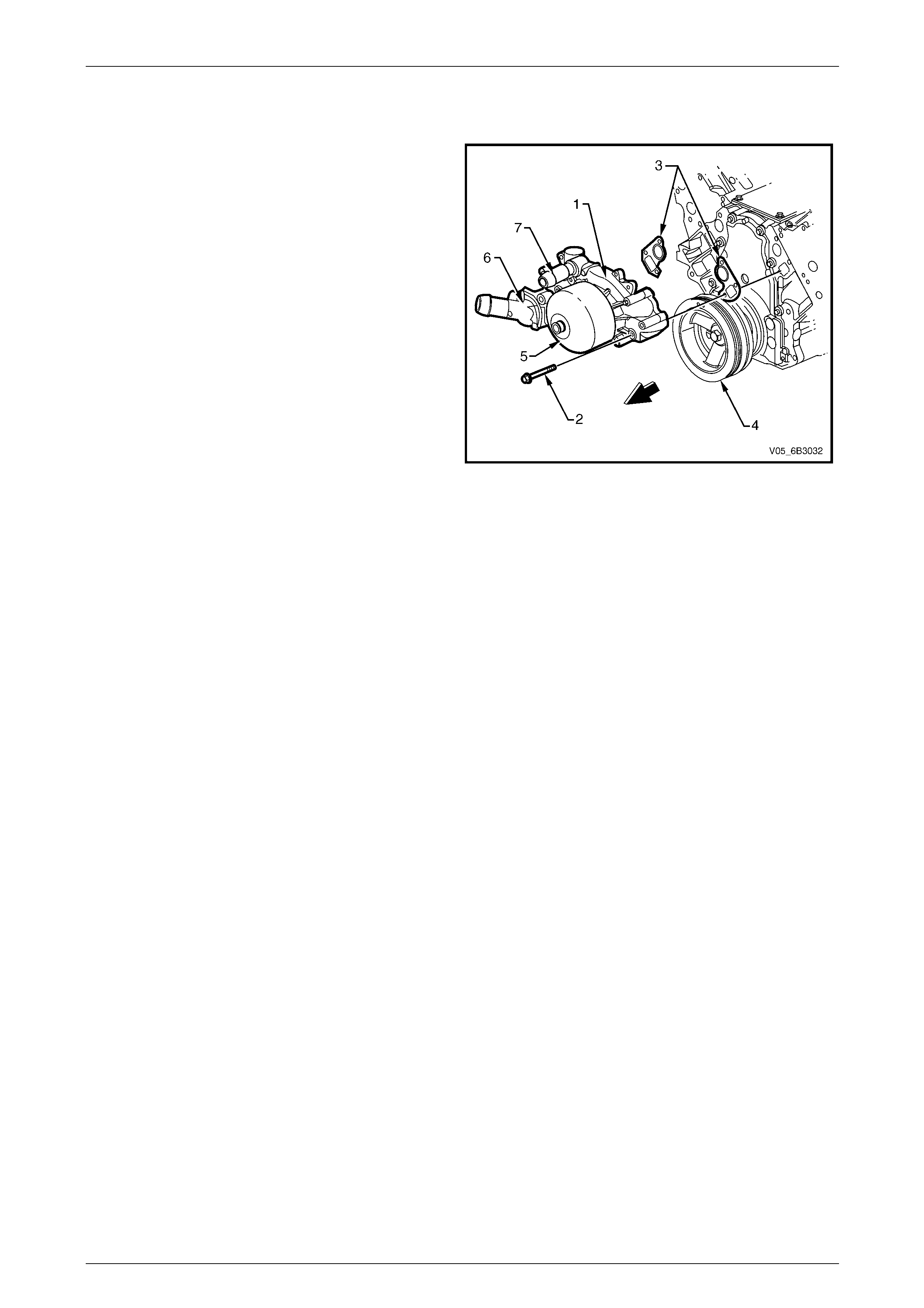
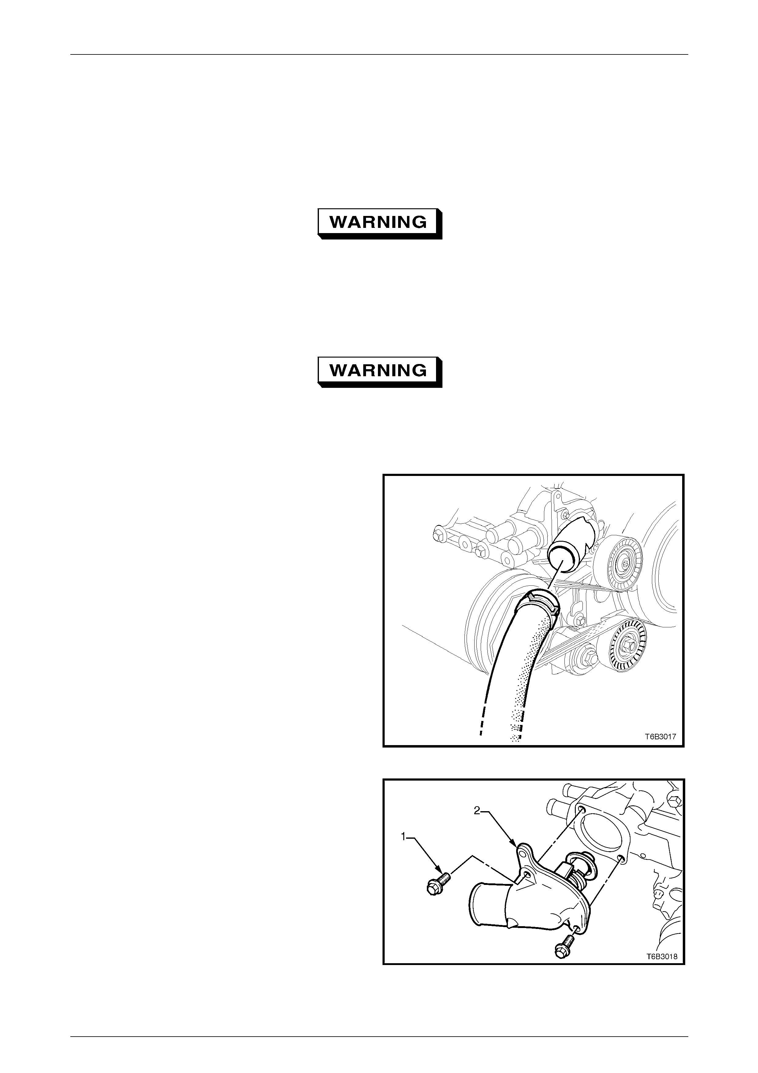
2.3 Coolant Pump
The coolant pump (1) is mounted to the front of the
cylinder block by six bolts (2) and sealed with two
gaskets (3). The coolant pump is driven by the
crankshaft pulley (4) via a serpentine drive belt, turning
the pump pulley (5), bolted to the coolant pu mp. Coolant
passes through the engine from the coolant pump inlet
via the thermostat (6) and exits via the coolant outlet (7)
located at the top of the coolant pump housing.
Figure 6B3 – 10
Engine Cooling – GEN III V8 Page 6B3–16
Page 6B3–16
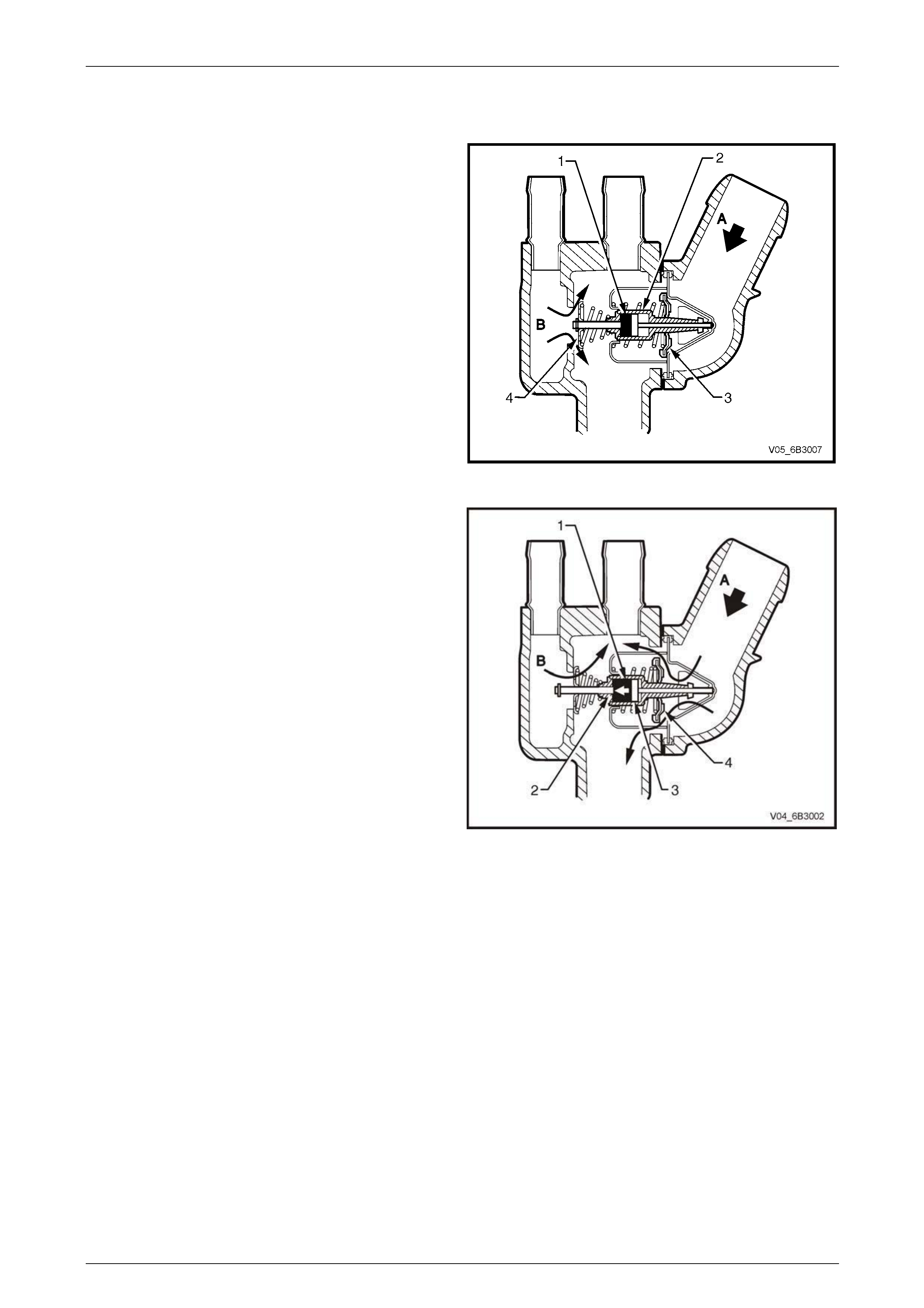
2.4 Thermostat
A wax pellet type thermostat is used to provi de fast engine
warm up and to regulate the coolant temper ature by
controlling the coolant flow.
The wax pellet (1) located in the thermostat brass body (2)
expands when heated and contracts when cooled.
When the engine coolant is cold, the flow control valve (3)
prevents coolant flow (A) from the radiator to the engine.
With the wax pellet contracted, the bypass valve (4) is held
open and allo ws coolant (B) circulati ng within the engine to
flow over the thermostat assembly.
The coolant flow over the thermostat brass body heats-up
the wax pellet at the same rate as the temperature increase
in the engine.
Figure 6B3 – 11
When the coolant warms up, the wax pellet (1) expands
pushing the thermostat brass body base (2) against the
piston and pin (3) causing the brass body to move within the
thermostat assembly
As the thermostat brass body moves back, th e flow control
valve (4) attached to the thermostat brass body moves with
it and allows the coolant from the radiator (A) to flow into the
engine. At the same time, the bypass valve begins to close.
When the bypass valve is closed, a reduc ed flow of coolant
will continue to bypass via large crescent shaped bleed
holes located on the bypass valve. This prevents hydraulic
lock of the heater system and allows some engi ne bypass
coolant (B) to flow over the thermostat assembly.
The rate that the control valve opens is balan c ed between
the force exerted by the expanding wax and the combining
force exerted by the bypass valve spring a nd the flow
control spring.
This controlled coolant flow during cold start and initial
warming of the engine provides a controlled warming cycle
necessary to control exhaust emissions during the critical
warm-up period.
Figure 6B3 – 12
NOTE
For thermostat service procedure refer to
3.9 Thermostat in this Section.
Engine Cooling – GEN III V8 Page 6B3–17
Page 6B3–17
2.5 Radiator Cap
The radiator pressure cap (1) fitted to the fille r neck (2) on
the right-hand side radiator tank causes the cooling system
to operate at above atmospheric pressure. The higher
pressure raises the boiling point of the cool ant, allowing the
engine to run at a higher tem perature and resulting in high er
efficiency of both the engine and the cooling system. The
radiator cap contains a pressure valve (3) a nd a vacuum
valve (4). The pressure valve is hel d against its seat by a
spring (5), which determines the maxim um o perating
pressure of the cooling system (120 kPa for the GEN III V8
engine).
Figure 6B3 – 13
The vacuum valve (4) is held against its seat by a light
spring (not illustrated) and opens during cool-do wn when
the pressure drops below atmospheric as a result of
contraction of the coolant. When the differenc e between
atmospheric and cooling syst em pressure becomes
sufficient to overcome the spring load, the vacuum valve
opens; then, under atmospheric pressure, coolant from the
overflow reservoir flows back into the cooling system in an
attempt to bring the cooling system pressure up to
atmospheric. In this way the radiator hoses are prevente d
from collapsing and the coolant is maintai ne d at the ide al
level within the radiator and engine.
Figure 6B3 – 14
Should the radiator pressure cap require
replacement, only fit the correct cap (w ith the
correct pressure-rating) for this engine. Refer
to the current release of Partfinder™ for this
information.
The cooling system is design ed to use a coolant, DEX-COOL® long-life cool ant or equivalent to GM specification 6277M
(a mixture of ethylene glyc ol antifreeze and corrosion inhibitors and water), rather than plain water to maintain the
integrity of the cooling system, and to prevent oxidation occurring within the engine.
NOTE
Some MY 2005 WL Series vehicle markets call
for DEX-COOL® long-life coolant and others for
its equivalent, known as Extended Life Anti-
freeze Coolant, conforming to GM specification
6277M. If in doubt regarding the correct coolant
to be used, refer to the MY 2005 WL Series
Owner’s Handbook.
Engine Cooling – GEN III V8 Page 6B3–18
Page 6B3–18
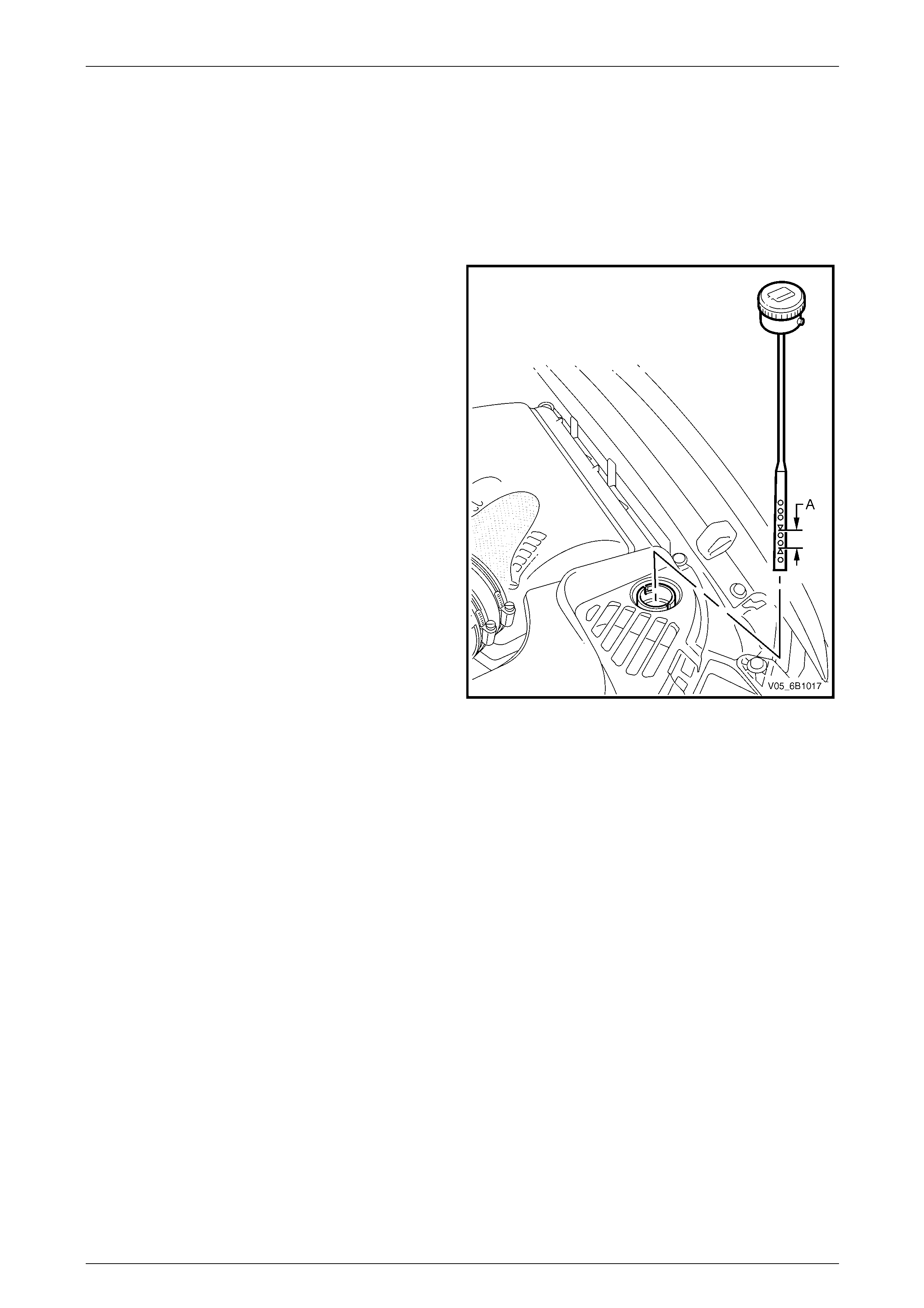
2.6 Coolant Recovery Reservoir
The coolant recovery reservoir is located on the left-hand side front of the engine compartment, between the radiator
support panel and the air cle aner assembly. A small diame ter hose connects the reservoir to the radiator overflow
connection.
As the engine temperature rises, the coolant is heated and expands. The coolant displaced by expans ion flows from the
radiator into the reservoir. When the engi ne cools down, the process is reversed with coolant flowing back into the
cooling system via the vacuum valve in the radiator cap.
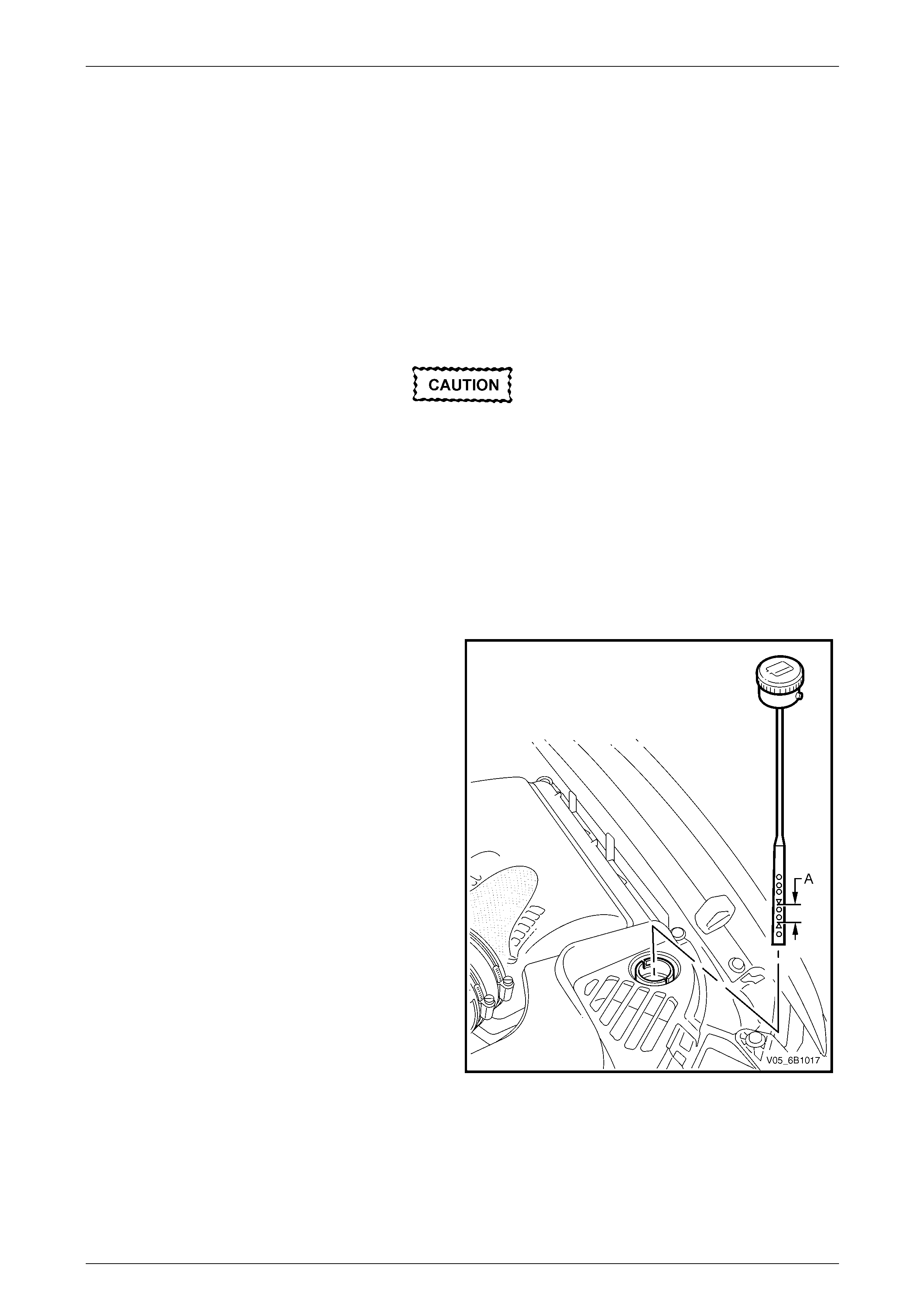
The coolant level should be maintained between the
indicator arrows (A) on the reservoir’s dipstick, when the
engine is cold.
Figure 6B3 – 15
Engine Cooling – GEN III V8 Page 6B3–19
Page 6B3–19
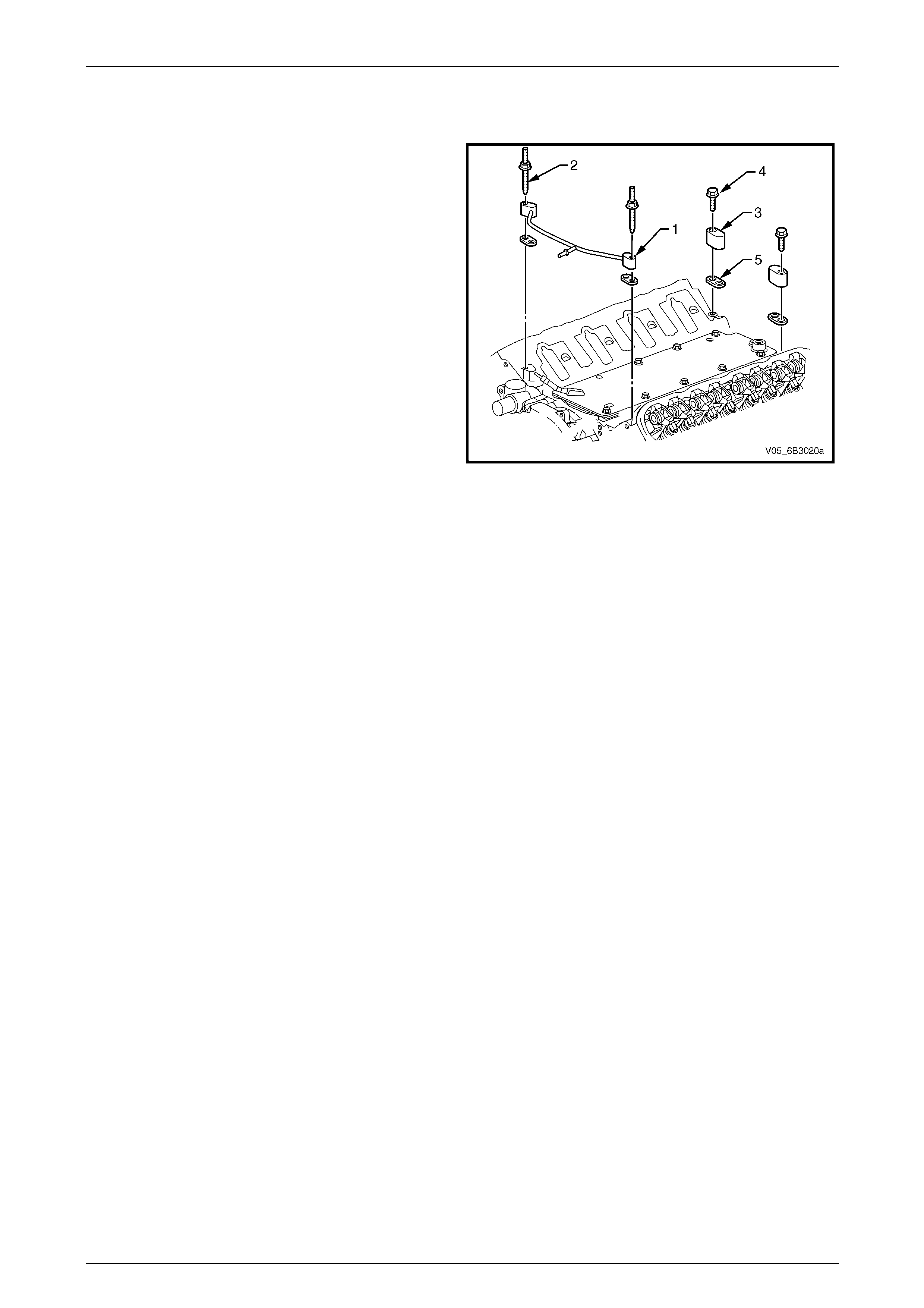
2.7 Vapour Vent System
Any vapour that develops in the eng ine or air trapped when
the cooling system is being filled is routed back to the
radiator. The vapour or air passes through a vent tube (1)
fastened to the front of the cylinder heads at two places by
double-ended studs (2). T he rear locations are blocked-off
by two vent covers (3) fastened to the rear of cylinder h ea ds
at two places by bolts (4). All four locations are sealed by
gaskets (5).
A small diameter hose connects the vent tube to the radiator
cap filler neck via a connectio n on the underside of the
throttle body.
Refer to Section 6A3 Engine Mechanical – GEN III V8 for
further information on the vapour vent system.
Figure 6B3 – 16
Engine Cooling – GEN III V8 Page 6B3–20
Page 6B3–20
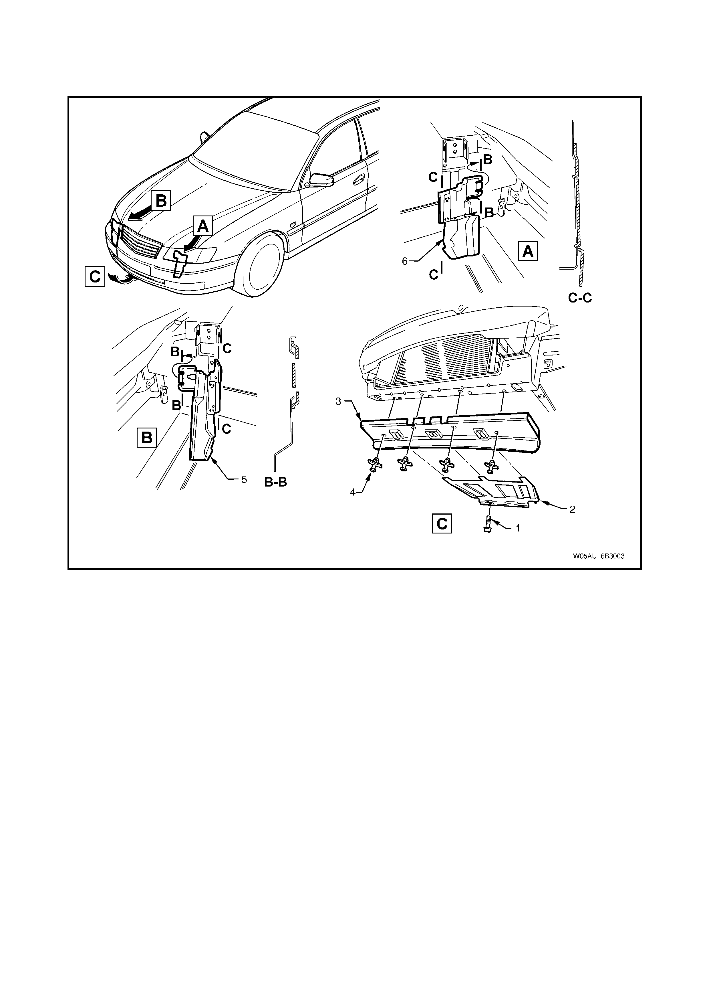
2.8 Air Baffles and Ducts
Figure 6B3 – 17
Legend
1 Screws (2 places)
2 Lower Air Chute Baffle Extension
3 Lower Air Chute Baffle
4 Plastic Scrivet Fasteners (4 places)
5 Lower Air Chute Extension Duct
6 Plastic Fasteners (2 places)
7 Right-hand Side Air Chute
8 Left-hand Side Air Chute
A lower air chute baffle and side chutes are fitted to the front end of the vehicle to direct and promote airflow through the
radiator to provide maximum cooling.
The purpose of the lower air chute baffle is to create a low-pressure area behind the radiator whilst the vehicle is at
speed. This enables additional airflow through the radiator core to maintain the desired engine cooling.
The air baffle or chutes should only be removed for service work. If either the air baffle or chutes are damaged, this will
reduce the cooling system efficiency, and therefore they must be replaced.
Engine Cooling – GEN III V8 Page 6B3–21
Page 6B3–21
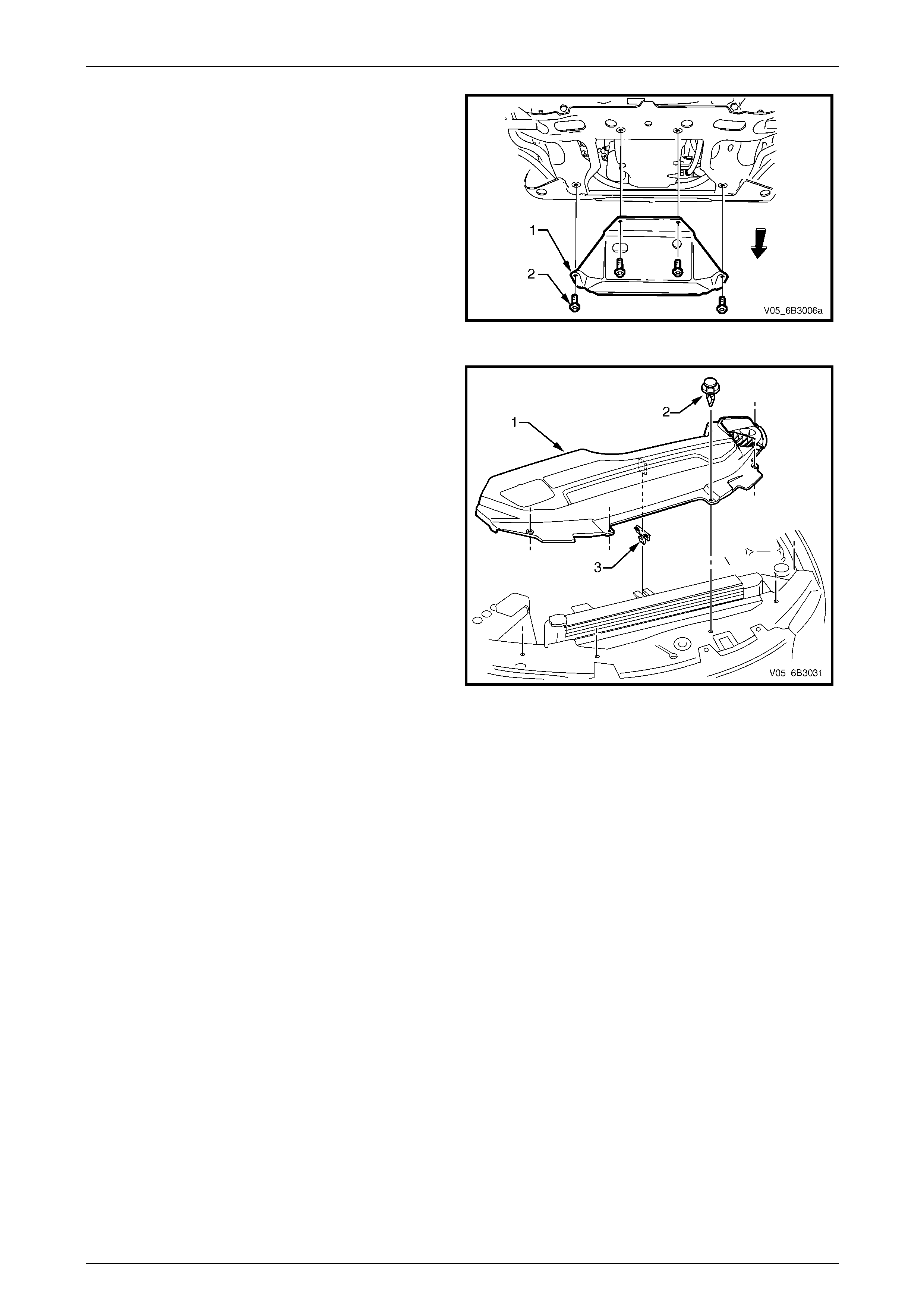
An oil pan under-tray (1) also forms an integral part of the
air flow system around the GEN III V8 engine and must
always be installed after removal for service operations,
such as engine oil draining and oil filter replacement.
NOTE
This under-tray is not designed as an oil pan
stone guard.
Figure 6B3 – 18
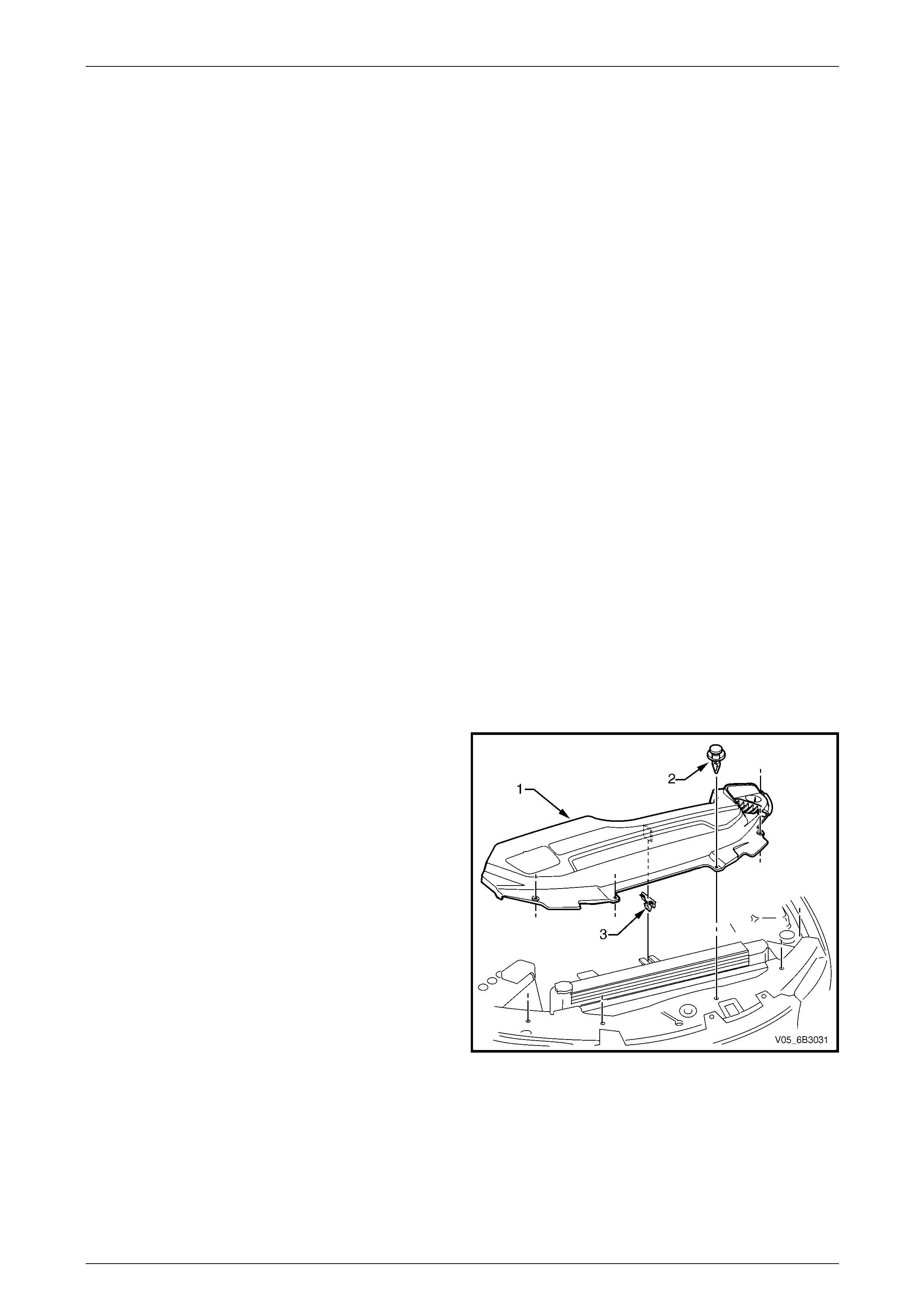
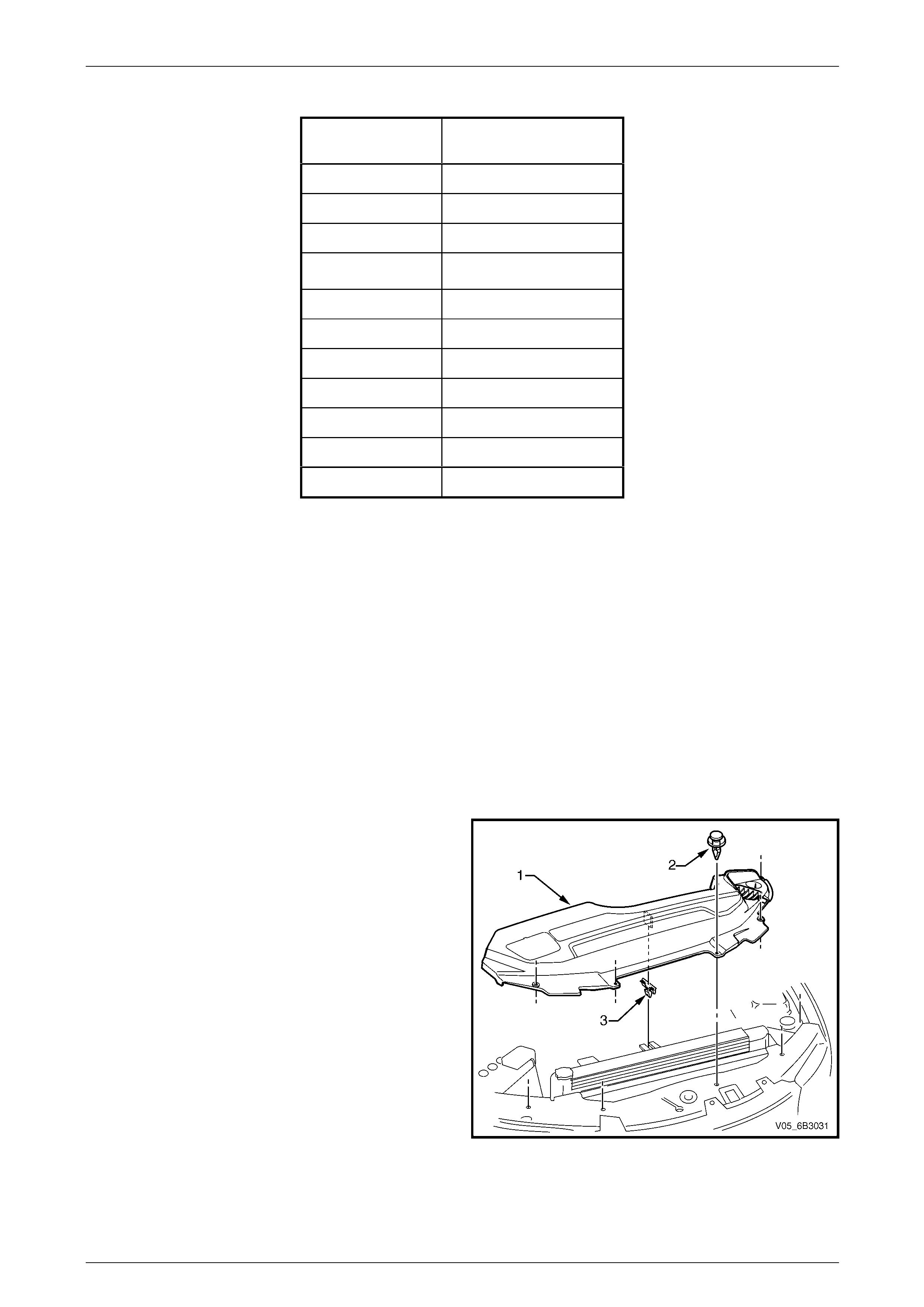
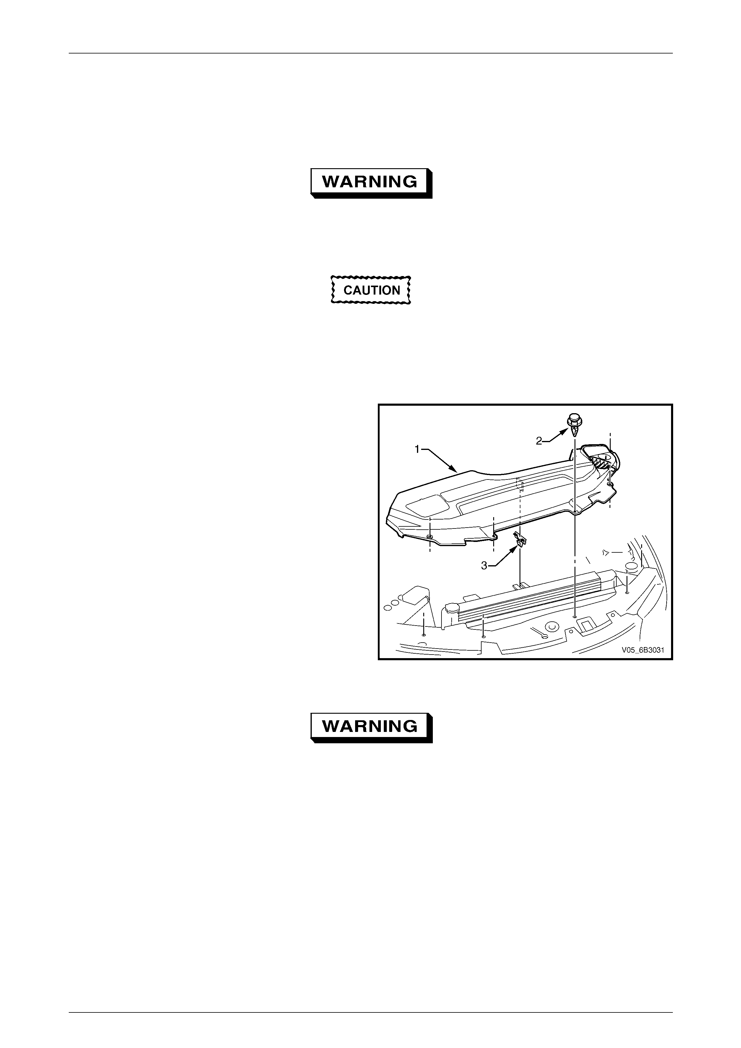
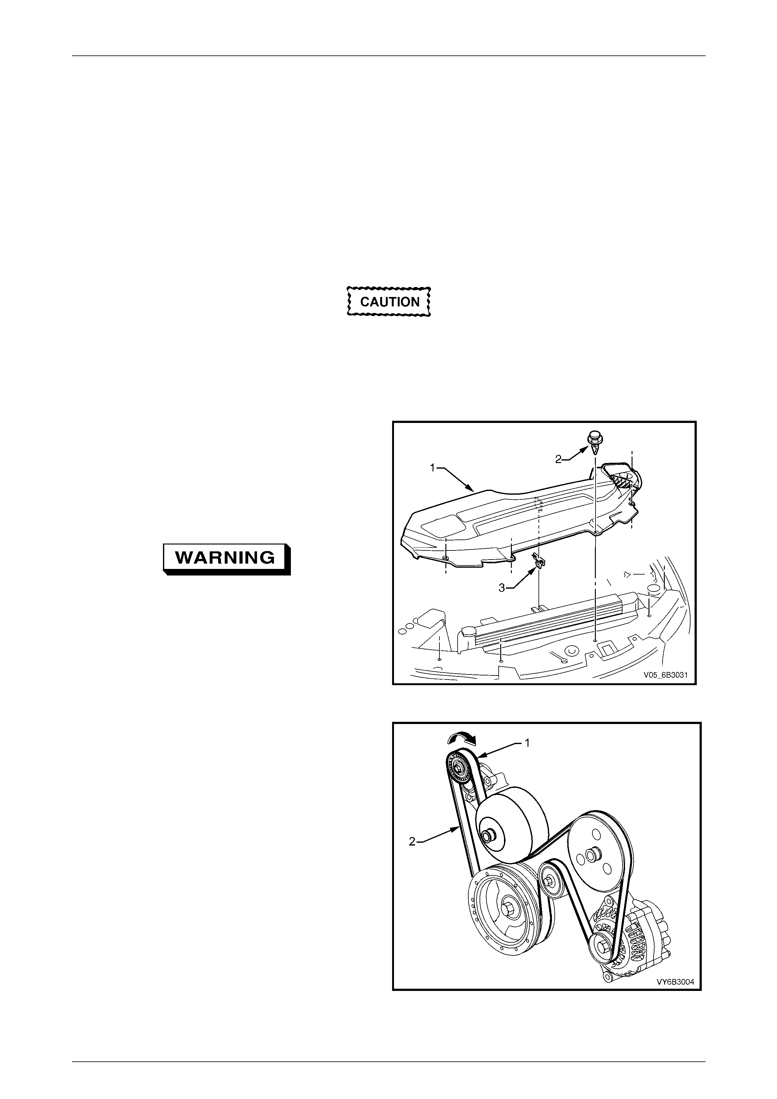
An upper radiator shroud (1) is fitted between the upper
radiator support panel and the radiator assembly to
minimise the recirculation of hot air from the rear of the
radiator back over the core and to direct cool incoming air
from the front of the vehicle through the radiator core. The
shroud is held in place by five plastic scrivets (2) and a
retaining clip (3).
Figure 6B3 – 19
Engine Cooling – GEN III V8 Page 6B3–22
Page 6B3–22
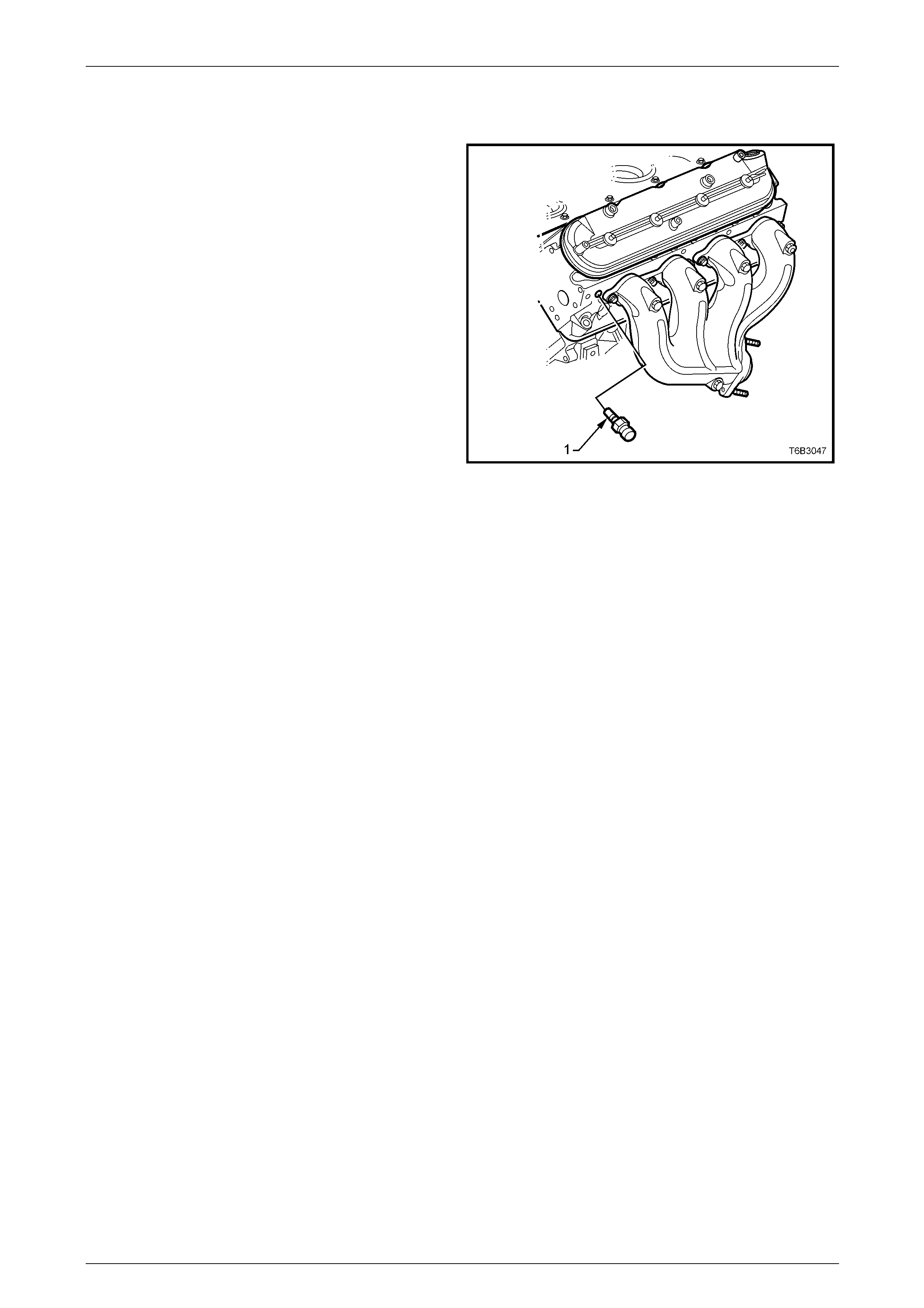
2.9 Engine Coolant Temperature Sensor
An Engine Coolant Temperatur e (ECT) sensor (1) is
mounted in the front of the left-hand side cylinder h ea d.
The coolant temperature sen sor gen erates a signal, which is
used by the Powertrain Control Module (PCM) for
calculation of the various powertrain management functions.
This information is transmitted to other control modules, e.g.
Instruments for the temperature gauge function, on the
serial data bus.
Refer to Section 6C3-1 Powertrain Management – GEN III
V8 – General Information for further information on the ECT
sensor.
Figure 6B3 – 20

Engine Cooling – GEN III V8 Page 6B3–23
Page 6B3–23
3 Service Operations
3.1 Service Notes
Safety
• Do not remove the radiator pressure cap
when the engine is hot, even if the cooling
system requires filling. Sudden release of
cooling system pressure is very
dangerous and may result in the coolant
surging out and over the person removing
the cap leading to possible serious injury.
• The vehicle is fitted with twin electric
radiator cooling fans. When working
around the engine compartment, keep
clear of the fans as they may start without
warning.
Before removing the radiator cap, all ow the engine to cool to ambient temperature (less than 50° C), place a shop rag
over the cap and slowly turn the cap anticlockwise to the detent position. Any residual pressure will be released into the
dam under the cap and thence to atmosphere through the coolant recovery reservoir. When it is clear that all cooling
system pressure has been released the cap may be further turned anticlockwise to the stop and then removed.
Periodic Servicing
The cooling system requires little attention except for maintaining the coolant to the correct level in the recovery reservoir
and periodic servicing at the time or distance intervals as outlined in Section 0B Lubricati on and Service.
Periodic servicing includ es:
1 Checking the coolant level. Refer to 3.3 Draining and Filling Cooling System in this Section.
2 Checking the coolant concentration. Refer to 3.2 Coolant Maintenance – Testing Coolant Concentration in this
Section.
3 Pressure test the cooling system and radiator cap. Refer to 3.8 Pressure Testing in this Section.
4 Check / tighten hose clamps and inspect all hoses. Refer to 3.4 Coolant Hoses in this Section. Replace hoses if
swollen or deteriorated.
Always wear protective safety glasses when
working with spring-type hose clamps. Failure
to do so may result in eye injury.
5 Clean out the cooling system, refer to 3.5 Cleaning Cooling System in this Section, and re fill.
Refer to 3.3 Draining and Filling Cooling System in this Section.
Environmental Issues
To reduce the impact on the environment and the maintenance cost, whenever the coolant is to be drained from the
engine, first check the service records to ascertain when the coolant was last changed. If more than six months’ life
remains before the next coola nt change is due, proceed as follows:
1 Drain the coolant from the engine into a cle an container with a capacity of at least 11 litres ensuring that the
coolant is not contaminated in the process.
2 Refill the cooling system with the drained coolant after repairs have been completed.
3 Top up as required, using a 50 / 50 mix of clean water and the recommended cool ant, which is either DEX-COOL®
long-life coolant or its equivalent, known as extended life anti-freeze coolant conforming to GM specification
6277M. Refer to 3.2 Coolant Maintenance and 3.3 Draini ng and Filling Cooling System in this Section, for the
necessary procedures and further information.
Engine Cooling – GEN III V8 Page 6B3–24
Page 6B3–24
3.2 Coolant Maintenance
The cooling system is design ed to use a coolant (a mixture of ethylene glycol antifreeze with added corr osion inhibitors,
and water), rather than plain water. T he use of glycol also raises the boiling point and incr eases the cooling system
efficiency. For this reason, it is of the utmost importance that the correct concentration level of ethylene glycol in the
cooling system is maintained.
Addition of plain water into the cooling system when 'topping-up' ma y dilute the coolant mixture to a point where the
antifreeze / anti-boil and corrosion inhibitor properties of ethylene glycol become ineffective.
The coolant should comprise of a mixture 50% ethylene gl ycol antifreeze / inhibitor with 50% clear, clean water.
Ethylene glycol conforming to the correct specificatio n is eith er named DEX-COOL® long-life coolant or its equivalent,
known as extended life anti-freeze coolant conforming to GM specification 6277M. Both are available i n a numb er of
different quantities. Check the current release of Partfinder ™ for specific details.
Do not mix different types of antifreeze
or corrosion inhibitors, as they may
be incompatible. If a different type has
been used in the cooling system, flush
the system with clean water, refer to
3.5 Cleaning Cooling System in this
Section and refill the cooling system
with the correct coolant. Refer to
3.3 Draining and Filling Cooling System in
this Section.
Topping Up the Cooling System
The coolant level must be maintain ed within the range
(A) between the marks on the coolant recovery reservoir
dipstick as shown in Figure 6B 3 – 11 when the engine
cold.
Premixed coolant (50% DEX-COOL® long-life coolant or
equivalent to GM specification 6277M with 50% clean,
good quality water) may be added as neces sary to
obtain the required level.
Refer to 3.3 Draining and Filling Cooling System in this
Section.
Figure 6B3 – 21
Engine Cooling – GEN III V8 Page 6B3–25
Page 6B3–25
Testing Coolant Concentration
To ensure the specified ethylene glycol concentration is maintained in the engine coolant, the coolant concentration must
be checked at the time or distance intervals outlined i n the MY 2005 WL Series Owner’s Handbook or Service Booklet in
the glove box.
NOTE
• While a number of coolant concentration
measuring devices are available, the two
preferred types are as described.
• The procedures detailed, apply to either
coolant type used.
Method 1 – Refractometer
NOTE
• Coolant tester, Tool No. J 26568, automatically
compensates for temperature .
• Ensure that the eyepiece of the tester is free
of coolant before looking through it.
• Before each use, swing back the plastic cove r
at the slanted end of the coolant tester,
exposing the measuring window and the
bottom of the plastic cover. Carefull y wipe the
measuring window dry with a tissue or clean,
soft cloth. Close the plastic cover.
1 Check the calibration of the coolant tester as follows:
a Place a few drops of distilled water (between 21 – 29°C) onto the measuring window, then close the plastic
cover.
b Point the tester toward any light source, look into the eyepiece and check that the indicated reading is zero. If
not, then recalibrate the tester as detailed at the end of this Test Method, Calibrating the T ester.
2 Remove the upper radiator shroud (1) as fol lows:
a Using a fine, flat-blade screwdriver to prise the
centre pin of the scrivet (2) upward and remove
the scrivet, five places.
b Lift up the radiator shroud to disengage the
retaining clip (3) and remove the shroud.
Figure 6B3 – 22
Engine Cooling – GEN III V8 Page 6B3–26
Page 6B3–26
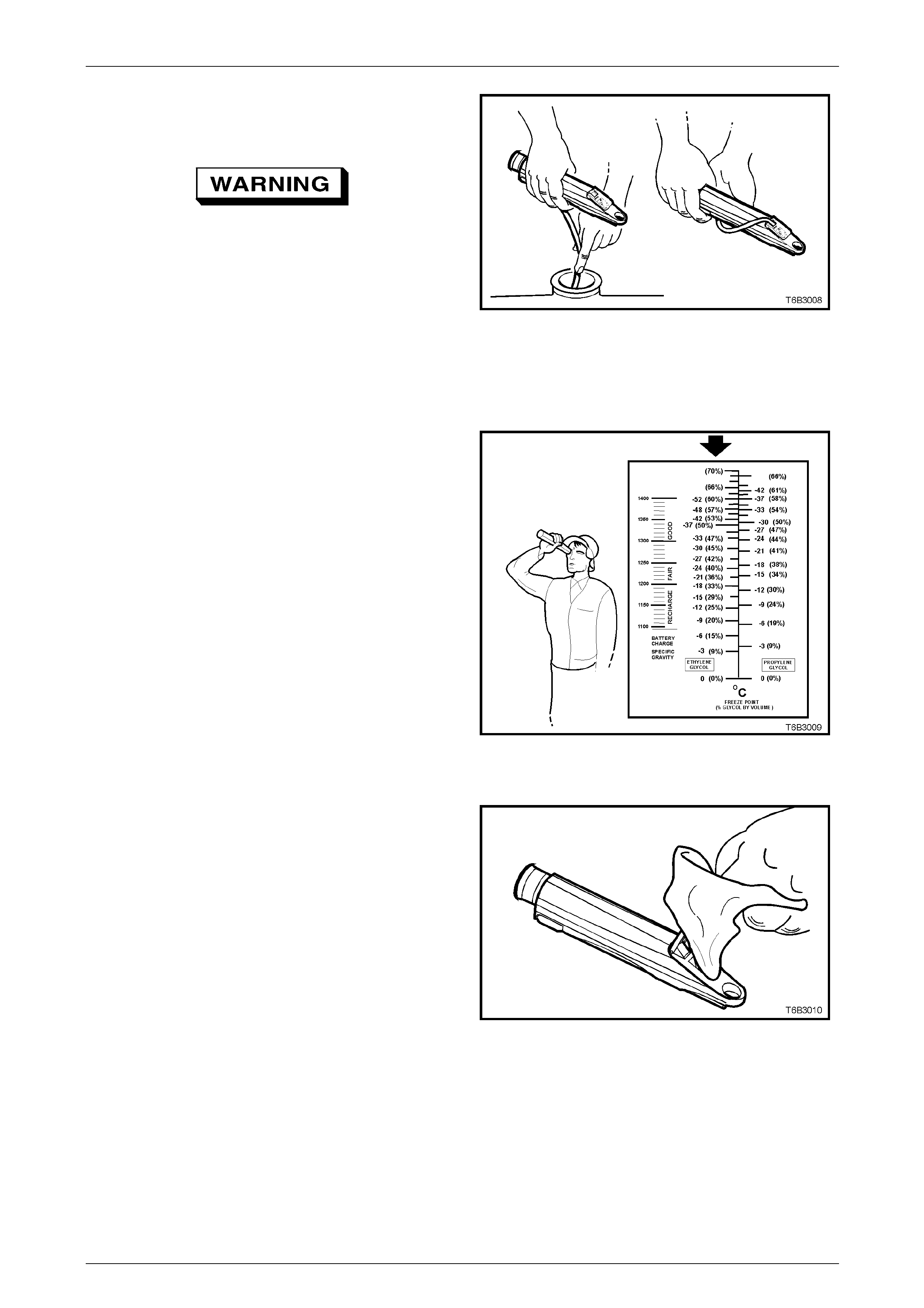
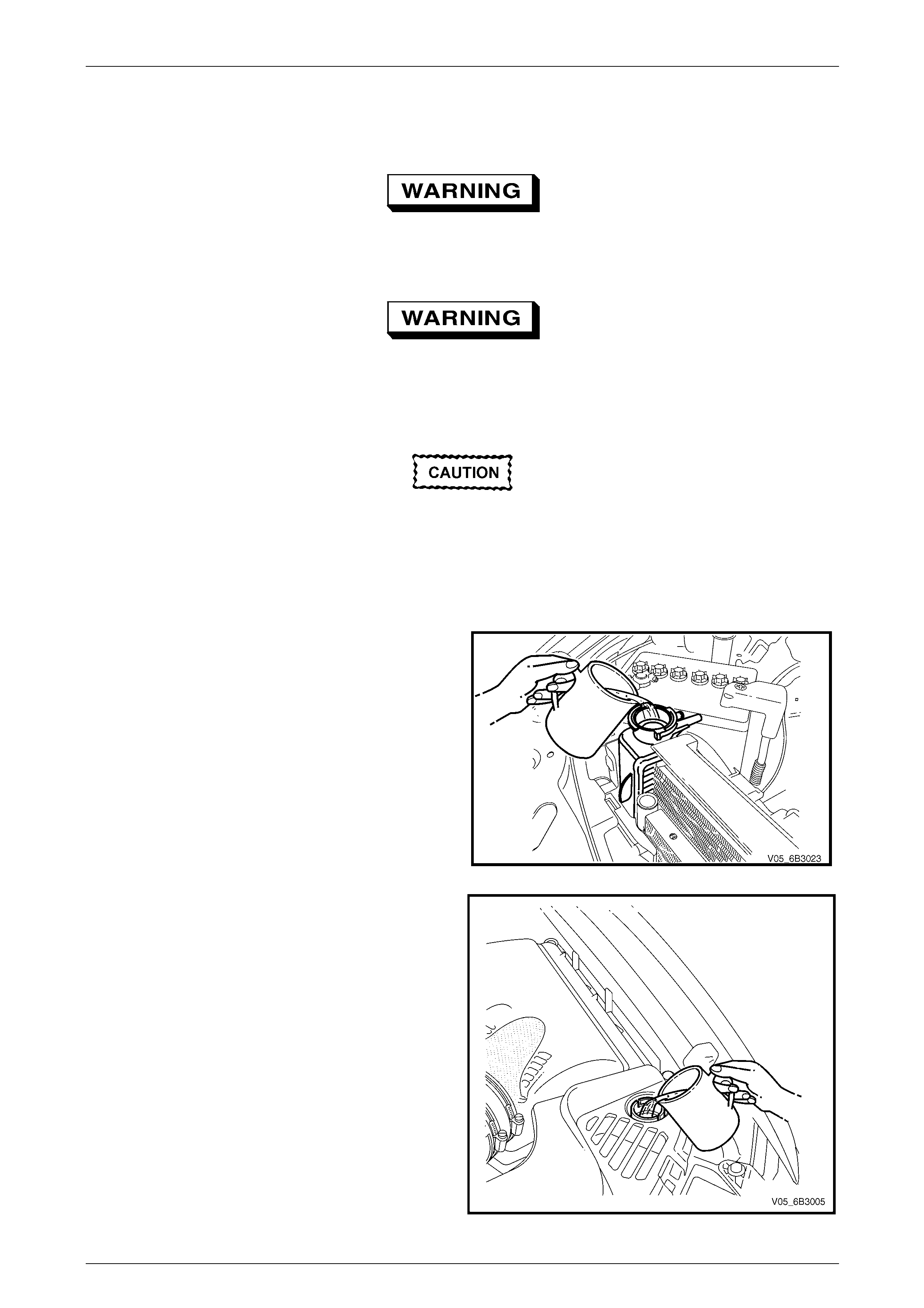
3 Release the tip of the bulb pump from under the
refractometer body. It is not necessary to remove the
complete pump from the tool.
Refer to 3.1 Service Notes in this Section,
for important safety items.
4 Carefully remove the radiat or cap from the right-hand
side radiator tank.
5 Insert the tube of the pump into the coolant and then
press the bulb to obtain a sample.
Figure 6B3 – 23
6 Bend the tube around and insert the end into the cover plate opening.
7 Press the pump bulb to deposit a few drops of coolant onto the measuring surface. Do not open the plas tic cover
when taking readings, as moisture evaporation will change the reading obtained.
8 Point the coolant tester toward any light source,
looking into the eyepiece.
a The coolant protection read ing is at the point
where the dividing line between the light and
dark, crosses the scale.
b The scale for ethylene glycol (bold arrow) is the
reference scale for either DEX-COOL® lon g-life
coolant or its equivalent, known as Extended
Life Anti-freeze Coolant conforming to GM
specification 6277M.
NOTE
The temperature scale is reversed from that of
a conventional thermometer. Below zero
readings are on the upper half of the scale.
9 A reading between – 30 and – 52° C (corresponding
to a coolant concentration between 45 – 60%), is
satisfactory for the GEN III V8 engine cooling
system.
Figure 6B3 – 24
NOTE
If the reading is not clear, then properly clean
and dry the measuring surface, then conduct
another test. Also ensure that there is sufficient
fluid on the measuring prism.
10 If the reading shows that the concentration level of
the coolant is inadequate, refer to the Coolant
Concentration table to determine the amount of
coolant that needs to be added to the coolant
recovery reservoir.
11 Install radiator cap and upper radiator shroud.
12 Start and run the engine until normal operating
temperature is reached, to allow the added coolant to
be distributed throughout the engine cooling system.
Figure 6B3 – 25
Engine Cooling – GEN III V8 Page 6B3–27
Page 6B3–27
Coolant Concentration
Concentration
Reading % Litres Of Coolant To Be
Added
0 5.50
5 4.95
10 4.40
15 3.85
20 3.30
25 2.75
30 2.20
35 1.65
40 1.10
45 0.55
50 0.00
Calibrating the Tester
The coolant tester calibration is checked at manufacture. If however, the calibration check detailed in Step 1 of this
method shows that the instrument is not reading correctly, then conduct the following recalibration procedure:
1 Remove the sealant covering the adjustme nt screw on the underneath of the tester.
2 With a distilled water sample on the measur ing surface, carefully adjust the screw until a zero reading is obtained.
NOTE
DO NOT completely remove the screw.
3 After recalibration, reseal the screw with a small amount of silicone sealant.
Method 2 – Hydrometer
1 Allow engine to cool to ambient temperature (less than 50° C).
2 Remove the upper radiator shroud (1) as fol lows:
a Using a fine, flat-blade screwdriver to prise the
centre pin of the scrivet (2) upward and remove
the scrivet, five places.
b Lift up the radiator shroud to disengage the
retaining clip (3) and remove the shroud.
Figure 6B3 – 26
Engine Cooling – GEN III V8 Page 6B3–28
Page 6B3–28
Refer to 3.1 Service Notes in this Section, for
important safety items.
3 Carefully remove the radiator cap fr om the right-hand side radiator tank.
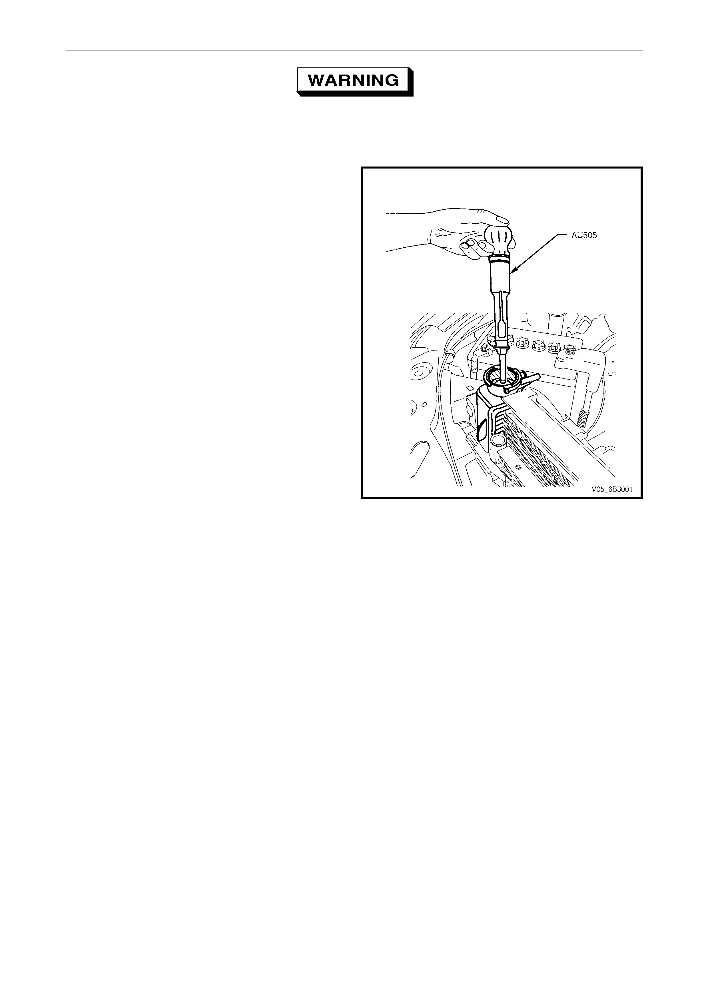
4 While holding the rubber bulb squeezed, insert
nozzle of coolant tester hydrometer, Tool No. AU505
into coolant. Releasing the rubber b ulb will then dra w
sufficient coolant into the tester to float hydrometer
bulb freely.
5 Hold tester at eye level and read scale on
hydrometer bulb at coolant level.
The reading shows the percentage of ethylene glycol
antifreeze contained in th e engine coolant.
6 The hydrometer reading should show 50% if the
coolant concentration is correct.
• If a reading of less than 50% is achieved, the
cooling system requires topping up with either
DEX-COOL® long-life coola nt or its equiva lent,
known as Extended Life Anti-freeze Coolant
conforming to GM specification 6277M.
• Refer to the Coolant Concentration table shown
for the previous method to determine how
much coolant additive of either type is re quired
to be added to the cooling system to bring the
coolant to the specified concentration.
7 Drain sufficient quantity of coolant from cooling
system to allow top-up with coolant additive, then
add the required amount of the correct additive.
Install coolant filler cap to the coolant outlet housing.
Figure 6B3 – 27
8 Install radiator cap and upper radiator shroud.
9 Start and run the engine until normal operating temperature is reached. This will allow the added coolant to be
distributed throughout the engine cooling system.
Engine Cooling – GEN III V8 Page 6B3–29
Page 6B3–29
3.3 Draining and Filling Cooling System
Draining
Refer to 3.1 Service Notes in this Section, for
important safety items.
1 Allow engine to cool to ambient temperature (less than 50° C).
Disconnection of the battery affects certain
vehicle electronic systems. Refer to
Section 00 Warnings, Cautions and Notes,
before removing the ground lead.
2 Disconnect the battery ground lead. Refer to Section 12A B attery.
3 Remove the upper radiator shroud (1) as fol lows:
a Using a fine, flat-blade screwdriver to prise the
centre pin of the scrivet (2) upward and remove
the scrivet, five places.
b Lift up the radiator shroud to disengage the
retaining clip (3) and remove the shroud.
4 Remove the oil pan under-tray.
Refer to 3.11 Oil Pan Under-tra y in this Section.
Figure 6B3 – 28
Refer to 3.1 Service Notes in this Section, for
important safety items.
5 Carefully remove the radiator cap fr om the right-hand side radiator tank.
6 Drain the coolant from the system via the radiator dra in tap on the lower LHS of the radiator. Attach a suitable piece
of rubber tubing to the tap outlet to help direct the flow of the coolant into a suitable container (capacity at least
11 litres). Refer to 3.1 Service Notes, Environmental Issues in this Section.
Engine Cooling – GEN III V8 Page 6B3–30
Page 6B3–30
Filling
During any service op eration that requires the cooling s ystem to be partly or completely drained, the following
instructions must be followed when refilling the cooling system, to ensure that all air is ble ed from system.
Refer to 3.1 Service Notes in this Section, for
important safety items.
1 Ensure that the drain tap at the bottom of the left-hand side radi ator tank is closed.
2 Ensure that all coolant hoses are correctly installed and firmly clamped.
Always wear eye protection when working
with spring-type hose clamps. Failure to do
so may result in eye injury.
3 If new coolant is required, make-up a mixture consisting of 50% DEX-COOL® long-life coolant or equivale nt to GM
specification 6277M and 50% clean, good quality water. The quantity required will depend on whether the cooling
system was completely drained, in which case approximately 11 litres will be required.
Do not mix different types of anti-
freeze or corrosion inhibitors, as they
may be incompatible. Always check which
coolant is to be added to the vehicle
being serviced. If a different type has been
used, or has been accidentally added,
flush the system with clean water. Refer to
3.5 Cleaning Cooling System in this Section.
4 Fill the system at the radiator cap as much as possible
with the engine off.
5 If releasing the vehicle to the customer, fill the coolant
reservoir to about 20 mm over the full mark on the
dipstick, before the thermostat opens.
6 Reconnect battery ground lead.
Refer to Section 12A Battery.
7 Alternatively run the engin e and wait until the
thermostat opens.
8 Top up at the radiator filler neck after the thermostat
has opened.
9 Pressure test the cooling system.
Refer to 3.8 Pressure Testing in this Section.
10 Check the level of coolant in the coolant recovery
reservoir and top-up as nec essary. Refer to
3.2 Coolant Maintenance – Topping-up Cooling
System in this Section.
11 Install the radiator cap.
12 Set the heater control to maximum, start and run the
engine until normal operating temperature is reached
to disperse the added coolant through the cooling
system.
13 Install the upper radiator shroud.
14 Install the oil pan under-tray.
Refer to 3.11 Oil Pan Under-tra y in this Section.
Figure 6B3 – 29
Figure 6B3 – 30

Engine Cooling – GEN III V8 Page 6B3–31
Page 6B3–31
3.4 Coolant Hoses
LT Section No. – 01 – 160
The coolant hose layout is shown in the following illustrations.
NOTE
The engine cooling fans, fan motors and
shroud are not shown in Figure 6B3 – 31 and
Figure 6B3 – 32 to more clearly show the hose
routing.
NOTE
Ensure that hose connections are thoroughly
cleaned before installing a ny new hose.

Engine Cooling – GEN III V8 Page 6B3–32
Page 6B3–32
Figure 6B3 – 31 – GEN III V8 Cooling Hose Layout
Legend
1 Hose – Heater, to Engine
2 Hose – Radiator Lower
3 Radiator
4 Hose – Vapour Vent Tube, Throttle Body to Radiator
5 Hose – Radiator Upper
6 Hose – Radiator to Coolant Recovery Reservoir
7 Housing – Thermostat
8 Hose – Heater, from Engine
Engine Cooling – GEN III V8 Page 6B3–33
Page 6B3–33
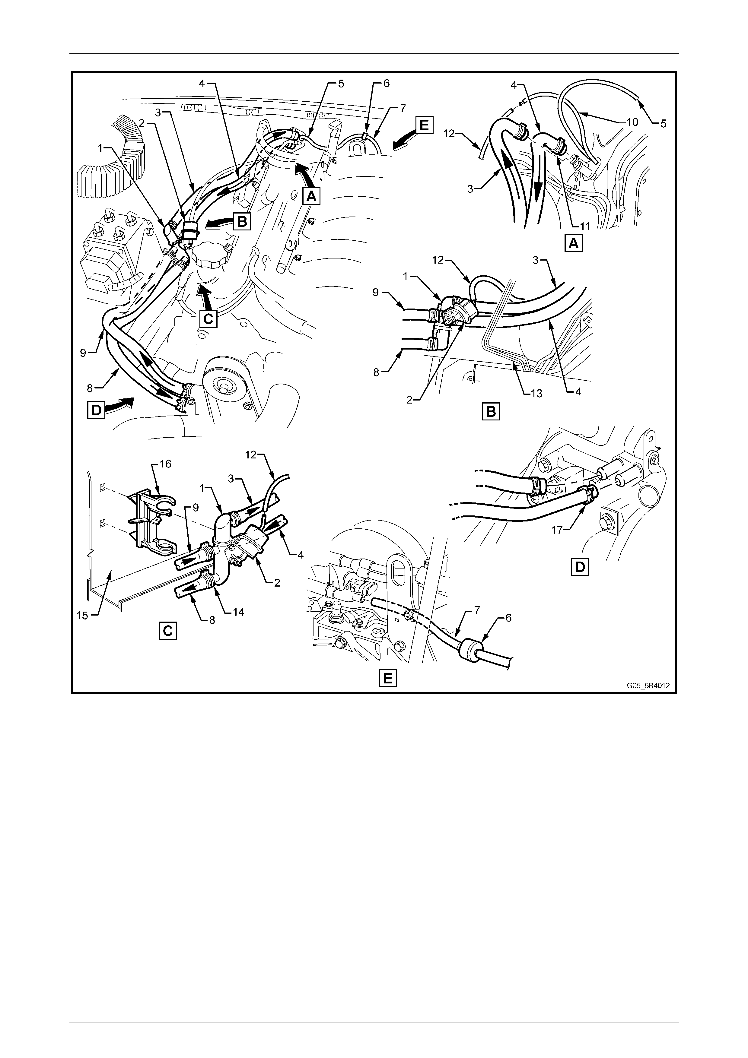
Figure 6B3 – 32 – GEN III V8 Heater Hose Layout
Legend
1 Water Valve
2 Water Valve Actuator
3 Heater Hose – To Cabin
4 Heater Hose – From Cabin
5 Vacuum Hose (2 piece) – HVAC Supply
6 Check Valve
7 Vacuum Hose – To Inlet Manifold
8 Heater Hose – To Engine
9 Heater Hose – From Engine
10 Vacuum Hose – To Water Valve Vacuum Switch
11 Hose Clamps – Heater Core (2 places)
12 Vacuum Hose – To Water Valve Actuator
13 Brake Lines
14 Hose Clamps – Water Valve (4 places)
15 Wheel House – RHS
16 Mounting Clip – Water Valve
17 Heater Hose Clamps – Engine (2 places)

Engine Cooling – GEN III V8 Page 6B3–34
Page 6B3–34
3.5 Cleaning Cooling System
NOTE
• Before carrying out reverse flushing
procedures, it is recommended that a
cleaning solution be use d to loosen scale and
corrosion. Use an approved radiator cleaner
following the instructions on the container
label.
• This operation should only be carried out
when the engine and radiator are at ambient
temperature.
• When using specialised cooling system
flushing equipment, conn ect the equipment as
recommended by the manufacturer.
Cooling System Reverse Flush
Radiator
1 Drain the cooling system. Refer to 3.3 Draining an d Filling Cooling S ystem – Draini ng in this Section.
Always wear eye protection when working
with spring-type hose clamps. Failure to do
so may result in eye injury.
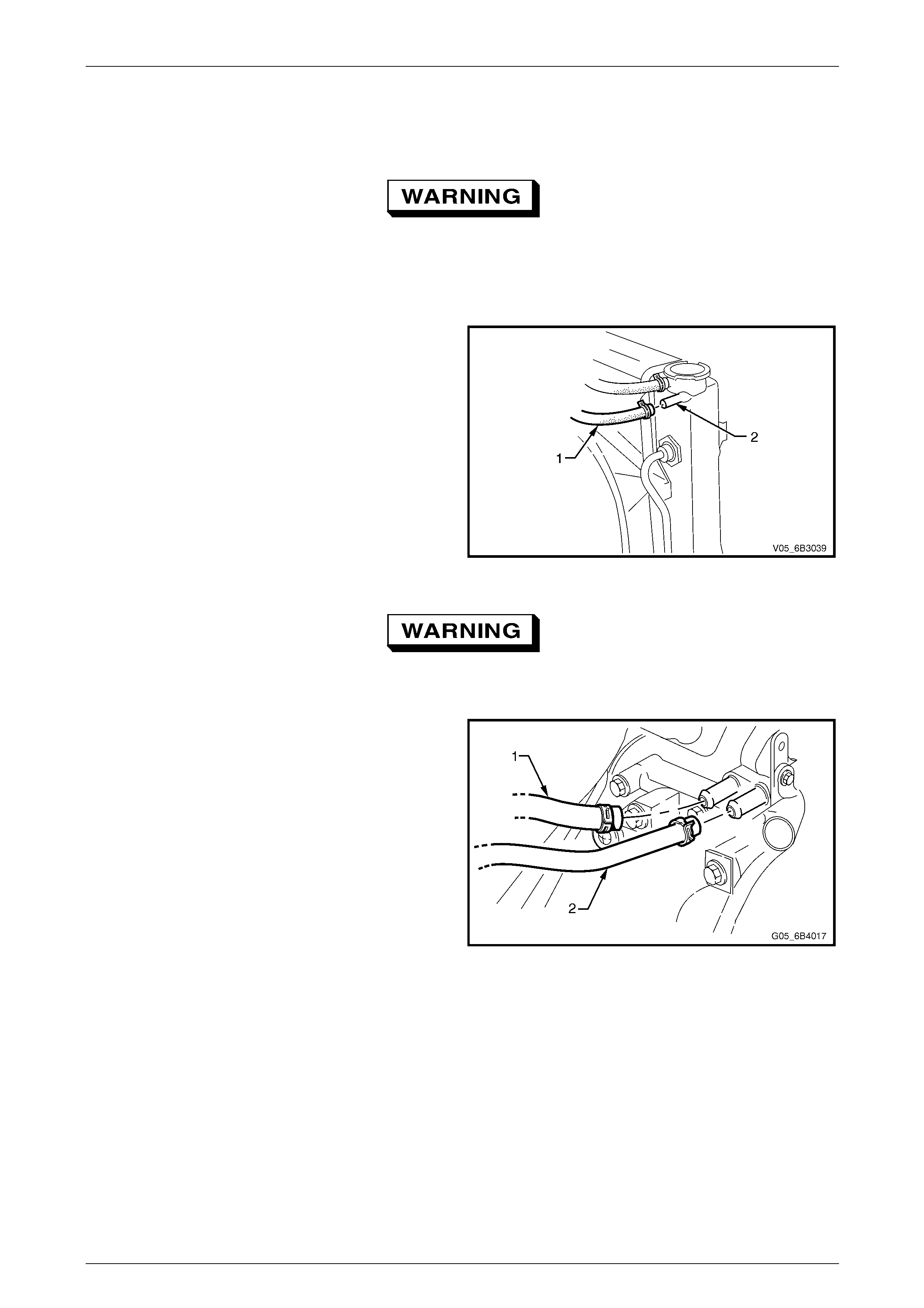
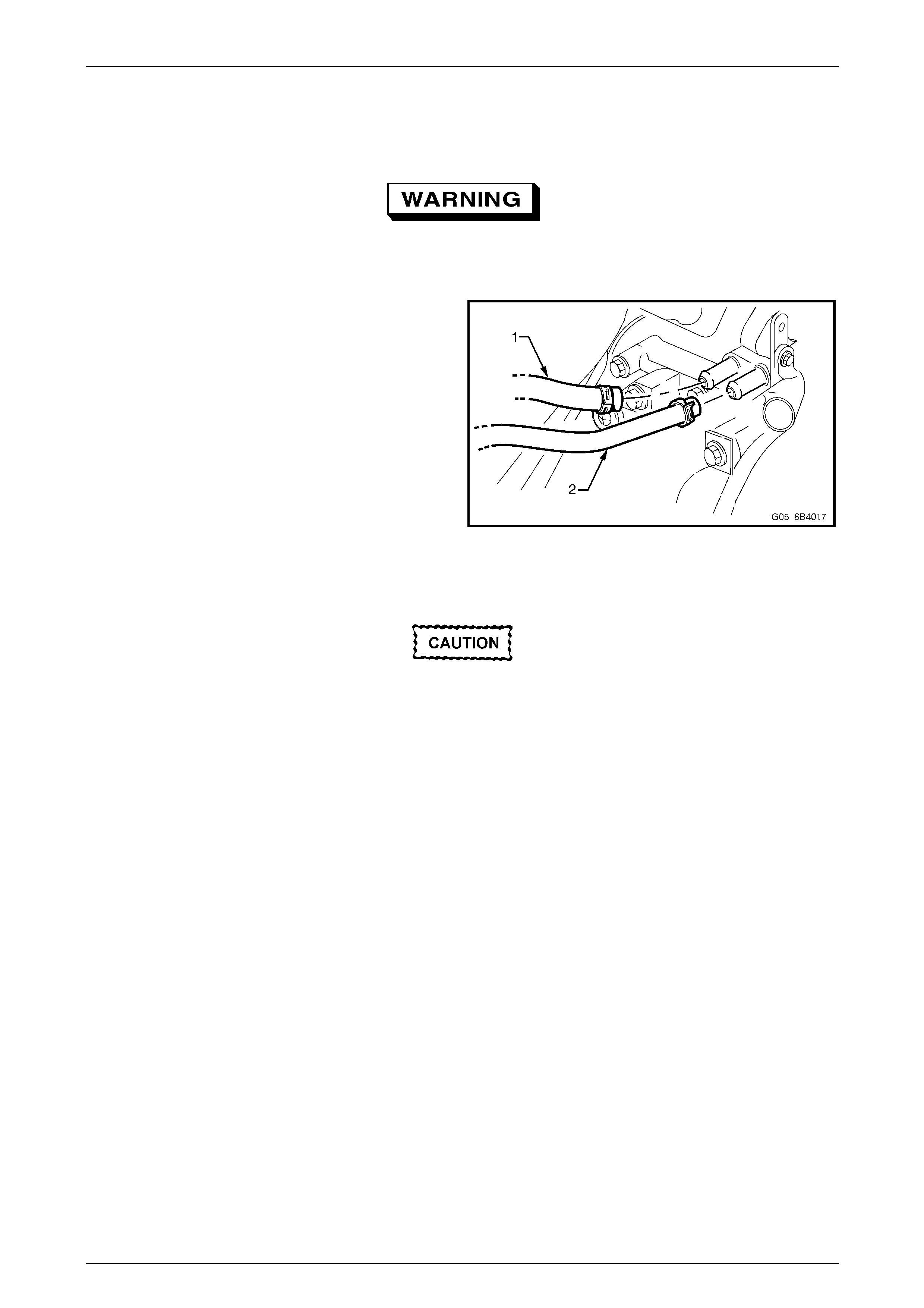
2 Remove the upper radiator hose (1) from the coolant
pump outlet.
3 Remove the engine coolant vapour ve nt hose (2) from
tube connection at the base of the throttle body and
temporarily plug the end of the hose.
Figure 6B3 – 33
4 Remove the lower radiator hose (1) from the
thermostat housing (2).
5 Attach a lead-away hose to the open end of the upper
radiator hose.
6 Attach a suitable piece of hose or ada ptor between the
flushing gun and the open end of the lower radiator
hose.
7 Connect and operate the flus hing equipment as
recommended by the manufacturer.
Apply air pressure gradually and not in
excess of 120 kPa, otherwise radiator
damage will result. Figure 6B3 – 34
8 Continue flushing until the water from the lead-away hose runs clean and clear.
9 Unplug the end of the vapour vent hose and continue flushing unti l the water from the vent hose runs clear.
10 Remove the coolant recovery reservoir, flus h it out with clean water and install.
Refer to 3.10 Coolant Recovery Reservo ir in this Section.
11 Install all disconnected hoses, ensuring that they are correctly positioned and securely clamped.
12 Install the cooling system. Refer to 3.3 Draining and Filling Cooling System – Filling in this Section.
13 Pressure test the cooling system. Refer to 3.8 Pressure Testing in this Section.
Engine Cooling – GEN III V8 Page 6B3–35
Page 6B3–35
Engine
1 Drain the cooling system. Refer to 3.3 Draining an d Filling Cooling S ystem – Draini ng in this Section.
Always wear eye protection when working
with spring-type hose clamps. Failure to do
so may result in eye injury.
2 Remove the upper and lo wer radiator hoses from the coolant pump outlet and thermostat connections.
Refer to Figure 6B3 – 33 and Figure 6B3 – 34.
3 Remove the engine coolant vapour ve nt hose (1) from
radiator connection (2) and te mporaril y plug the end of
the hose.
4 Remove the thermostat housing and thermo stat from
the coolant pump. Refer to 3.9 Thermostat in this
Section.
5 Remove the thermostat from the thermostat housing
and install the housing to the coolant pump.
Refer to 3.9 Thermostat in this Section.
Figure 6B3 – 35
Always wear eye protection when working
with spring-type hose clamps. Failure to do
so may result in eye injury.
6 Remove both heater hoses (1) and (2) from their
connections at the coolant pump, noting which hose
was connected to which connection. Seal the pump
connections by looping the co olant pump heater inlet
connection to the outlet connection using a suitable
piece of hose and two hose clamps.
7 Install a lead-away hose to the thermostat housing and
a length of suitable hose between the coolant pump
outlet fitting and the flushing equipment.
Figure 6B3 – 36
7 Connect and operate the flus hing equipment as recommended by the manufacturer.
8 Continue flushing until the water from the lead-away hose runs clear.
9 Unplug the end of the vapour vent hose and continue flushing unti l the water from the vent hose runs clear.
10 Reinstall the thermostat. Refer to 3.9 Thermostat in this Section.
11 Reinstall all disconnected hoses, ensuring that they are correctly positioned and securely clamped.
12 Fill the cooling system. Refer to 3.3 Draining and Filling Cooling System – Filling in this Section.
13 Pressure-test the cooling system. Refer to 3.8 Pressure Testing in this Section.
Engine Cooling – GEN III V8 Page 6B3–36
Page 6B3–36
Heater Hoses and Core
1 Drain the cooling system. Refer to 3.3 Draining an d Filling Cooling S ystem – Draini ng in this Section.
Always wear eye protection when working
with spring-type hose clamps. Failure to do
so may result in eye injury.
2 Remove both heater hoses (1) and (2) from their
connections at the coolant pump, noting which hose
was connected to which connection.
3 Direct the hose (1) that was connected to the cool ant
pump’s rear-most connection into a suita bl e container.
4 Attach the hose (2) from the front connection to the
flushing gun.
5 Cycle the heater switch to ensure that the water valve
is open.
Figure 6B3 – 37
6 Connect and operate the flus hing equipment as recommended by the manufacturer.
Apply air pressure gradually and not in
excess of 110 kPa, otherwise heater core
damage will result.
7 Install all disconnected hoses, ensuring that they are correctly positioned and securel y clamped.
NOTE
For heater hose routing, refer to Figure 6B3 – 32.
8 Fill the cooling system. Refer to 3.3 Draining and Filling Cooling System, Filling in this Section.
9 Pressure test the cooling system. Refer to 3.8 Pressure Testing in this Section.
Engine Cooling – GEN III V8 Page 6B3–37
Page 6B3–37
3.6 Engine Accessory Drive Belt Tension
Drive belt tension is provided b y a tensioner assembly (1).
The tensioner is an idler pulley mounted on a
spring-loaded arm that maintains the drive belt (2) at the
correct tension, without imposing undue loads on the
various components.
Figure 6B3 – 38
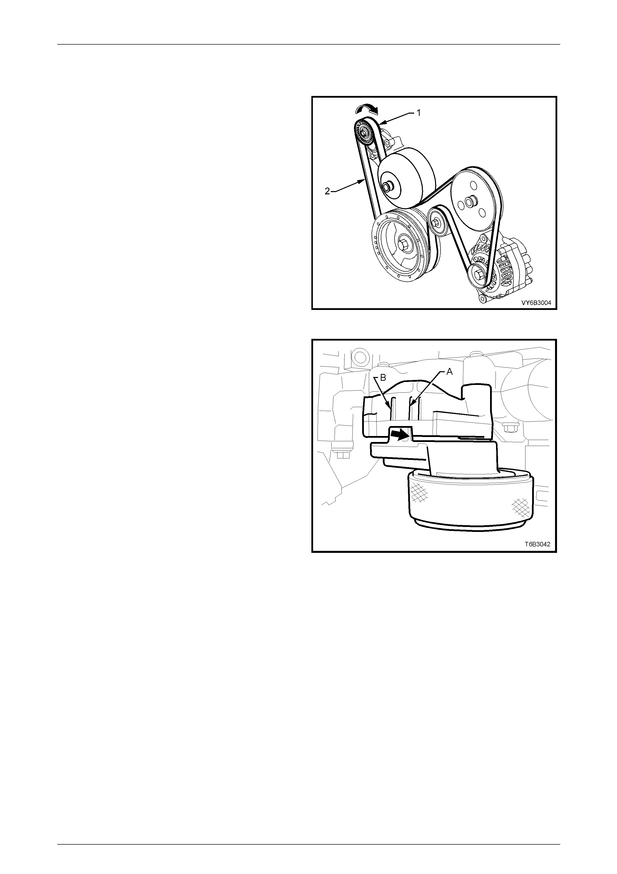
Drive belt tension is within the prescribed lim its if the
indicator (bold arro w) on the tensioner is between points
‘A’ and ‘B’ on the tensioner bracket.
If replacement is indicated.
Refer to 3.7 Engine Accessory Drive Belt in this Section.
Figure 6B3 – 39
Engine Cooling – GEN III V8 Page 6B3–38
Page 6B3–38
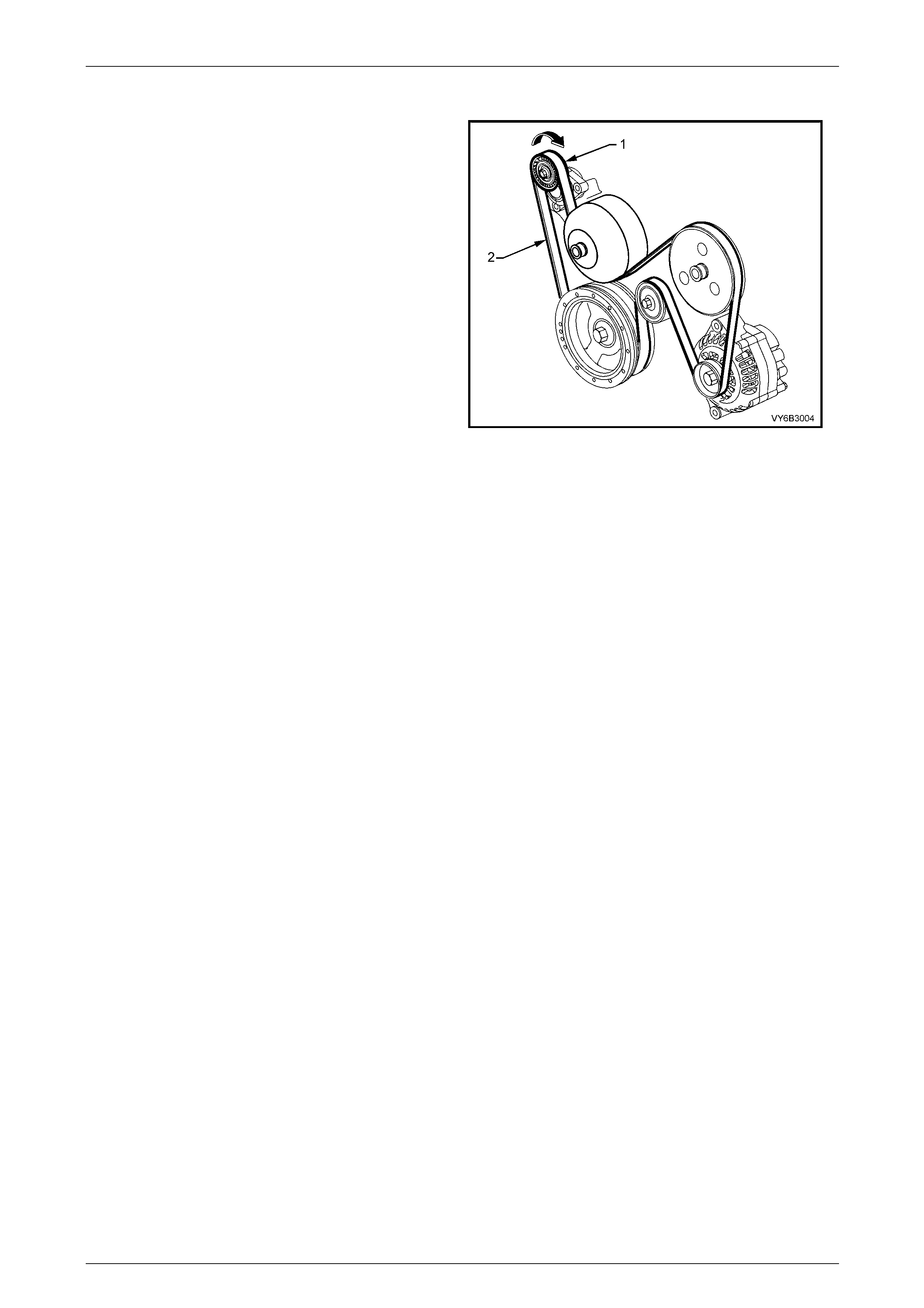
3.7 Engine Accessory Drive Belt
LT Section No. – 01 – 003
Remove
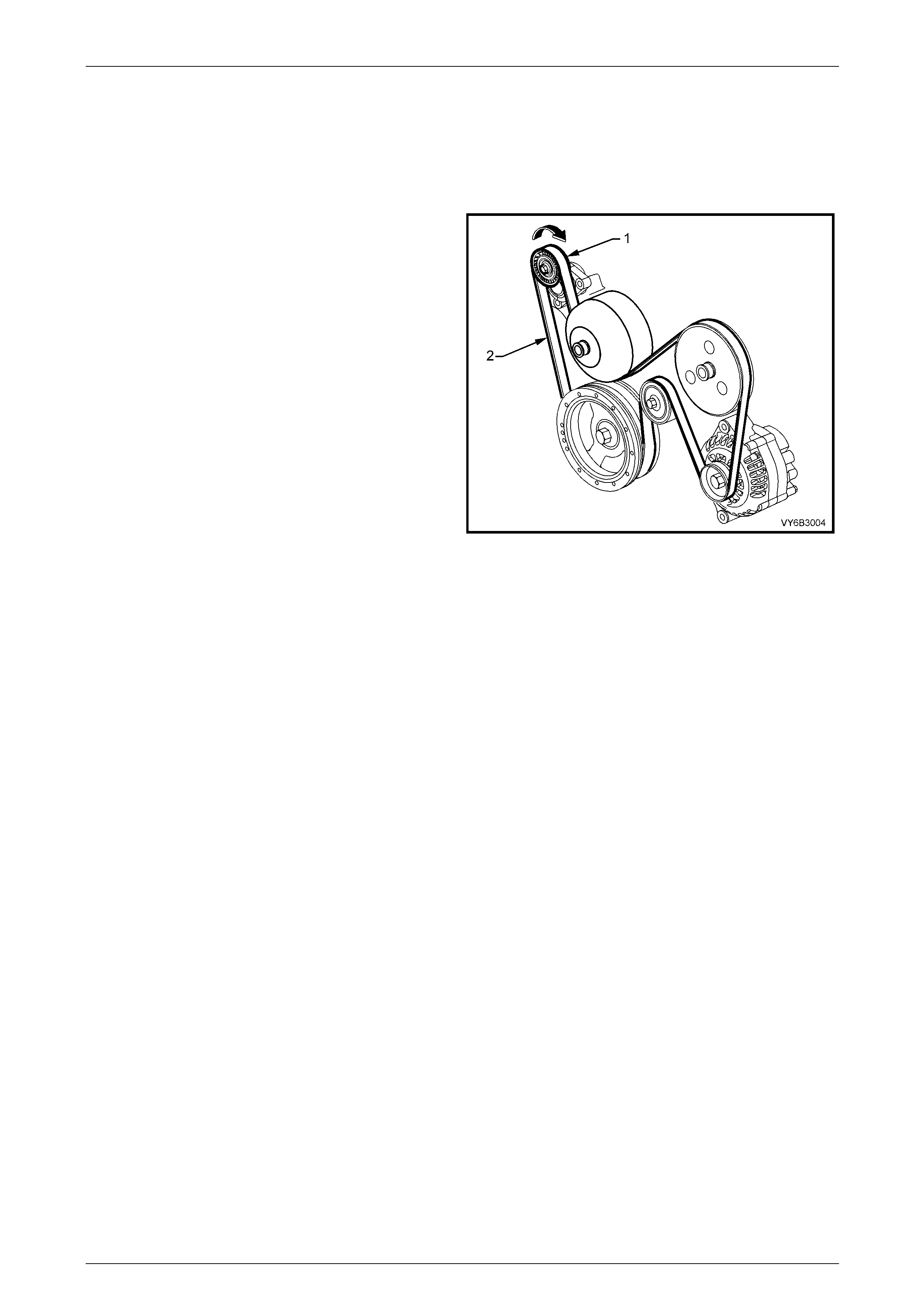
1 Using a 15 mm ring spanner, rotate the en gine
accessory drive belt tensioner (1) in the direction
indicated, to reduce belt tension.
2 While holding the tensi on er in the reduced tension
position, remove the accessory drive belt from the
engine, taking note of the belt routing.
Figure 6B3 – 40
Engine Cooling – GEN III V8 Page 6B3–39
Page 6B3–39
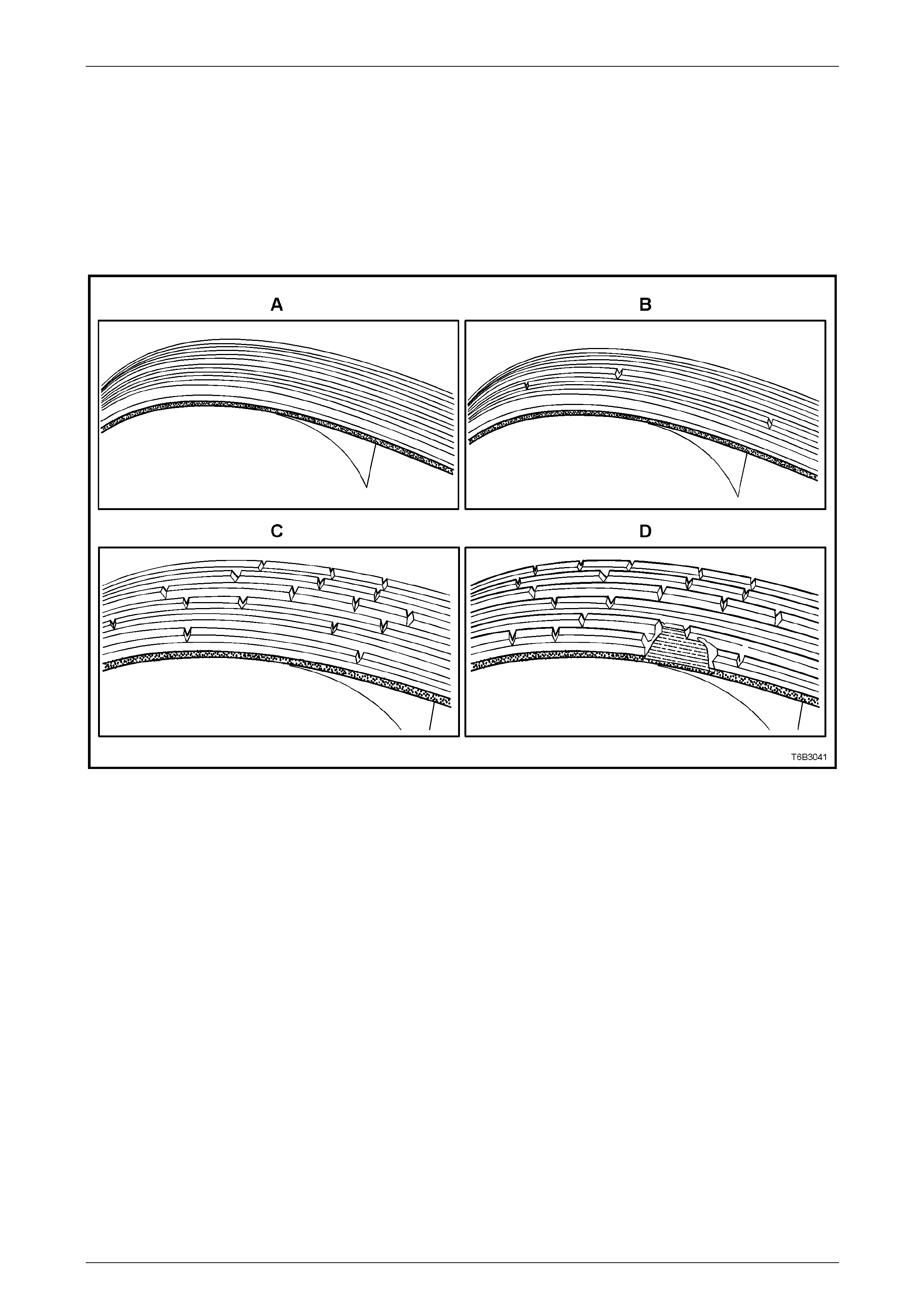
Inspect
The four views in Figure 6B3 – 41 show the various stages of drive belt wear, to assist in belt replacement decisions.
NOTE
Condition of the belt ribs can be better assessed
if the belt is wrapped over the coolant pump drive
pulley.
Figure 6B3 – 41
Legend
A New Belt: No cracks or chunks.
B Moderately Used Belt: Few cracks, with some wear on the ribs and in the grooves. Belt replacement not required.
C Severely Used Belt: Several cracks per 30 mm. Should be replaced before chunking occurs
D Failed Belt: Separation of rib material from backing (chunking). Belt must be replaced immediately.
Engine Cooling – GEN III V8 Page 6B3–40
Page 6B3–40
Install
Hold the tensioner in the unloaded position (arrow) with a
15 mm ring spanner, install the engine accessory drive
belt, routing in the same manner as noted on remova l
and as shown.
Figure 6B3 – 42
Engine Cooling – GEN III V8 Page 6B3–41
Page 6B3–41
3.8 Pressure Testing
Radiator Cap Pressure Testing
Refer to 3.1 Service Notes in this Section, for
important safety items.
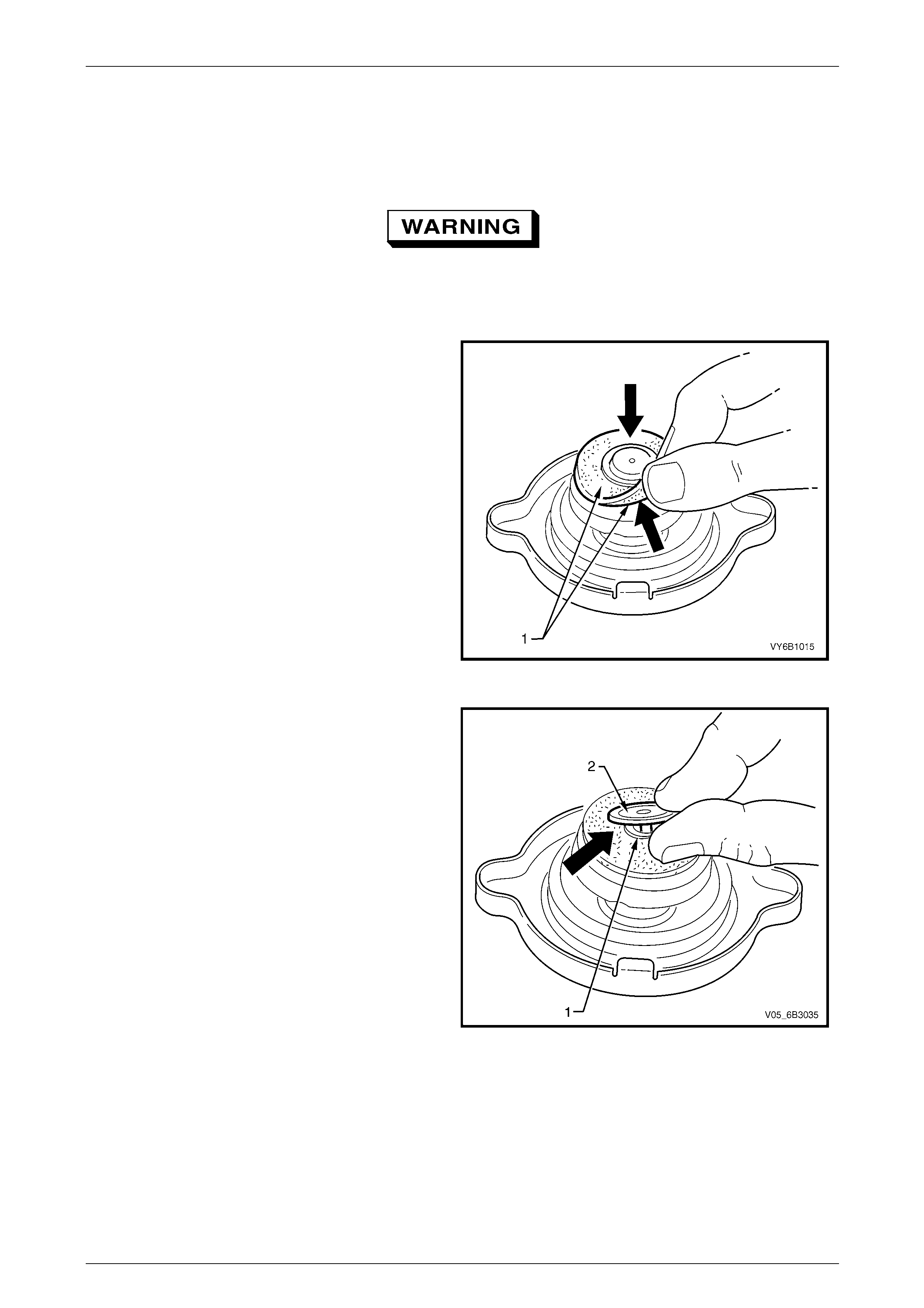
1 Allow engine to cool to ambient temperature (less than 50° C), then remove radiator cap.
2 Inspect and clean both sides (1) of radiator cap
gasket with a wet cloth.
NOTE
Use only water to wet cleaning cloth.
Figure 6B3 – 43
3 Lift centre vacuum valve. Clean and inspect the
gasket (1) and sealing surface of the under
valve (2).
Figure 6B3 – 44
Engine Cooling – GEN III V8 Page 6B3–42
Page 6B3–42
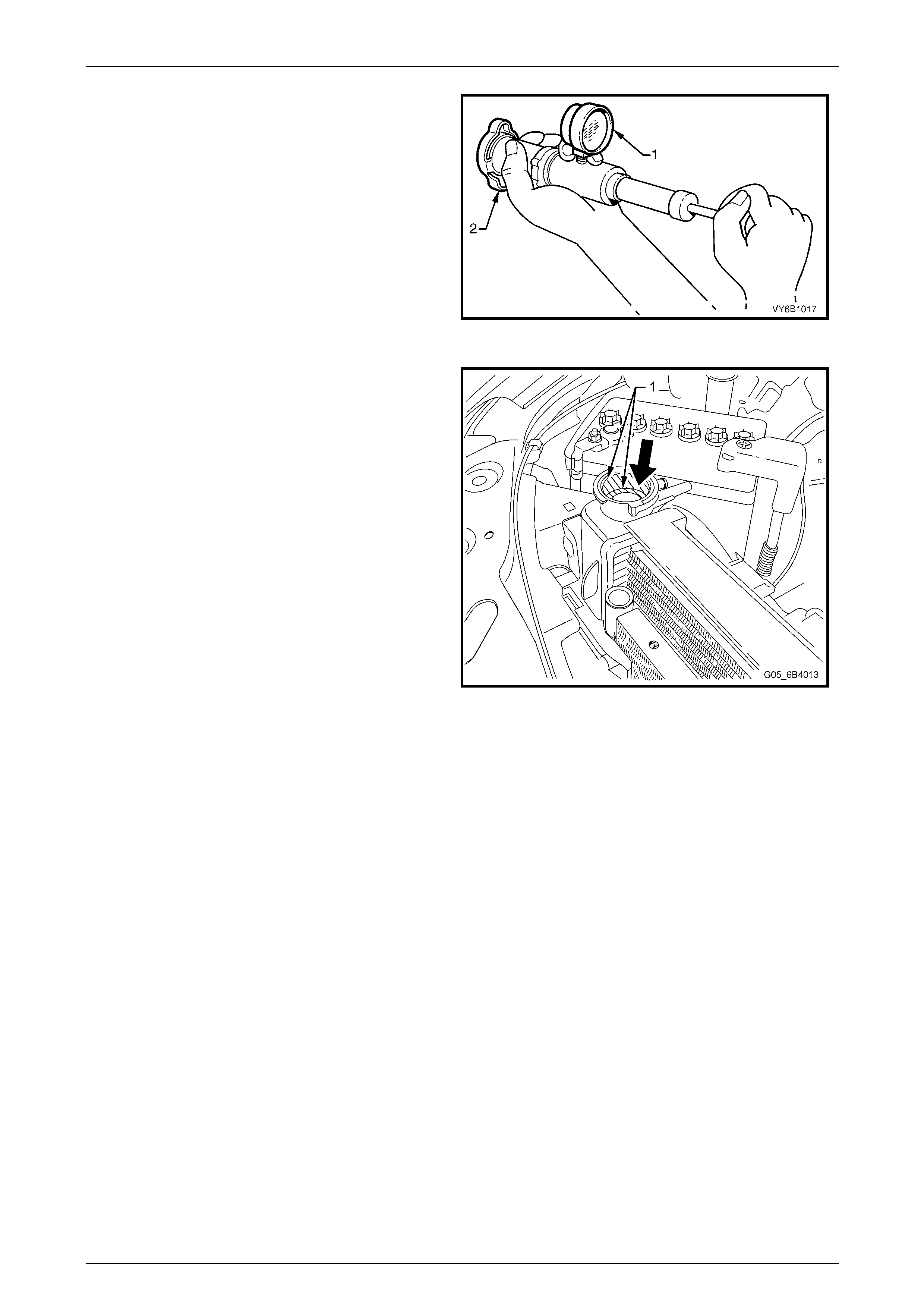
4 Attach radiator cap (1) to a commercially available
cooling system pressure tester (2).
5 Slowly pressurise the cap us ing the pressure tester
hand pump, noting the point a t which the cap
unloads.
6 The cap is serviceable if it unloads sl ightly above a
pressure of 125 kPa and holds pressure above
95 kPa. Should the cap fail to reach or hold the
specified pressures, install a new pressure cap.
Figure 6B3 – 45
7 Prior to installing the radiator cap ensure that the
radiator filler neck cap seating surface (1) is clean
and free from obstruction. Refer to Figure 6B3 – 46
Figure 6B3 – 46
Engine Cooling – GEN III V8 Page 6B3–43
Page 6B3–43
Cooling System Pressure Testing
Refer to 3.1 Service Notes in this Section, for
important safety items.
1 Allow the engine to cool to ambient temperature (less than 50° C), then carefully remove the radiator ca p.
2 Ensure that the coolant level is correct.
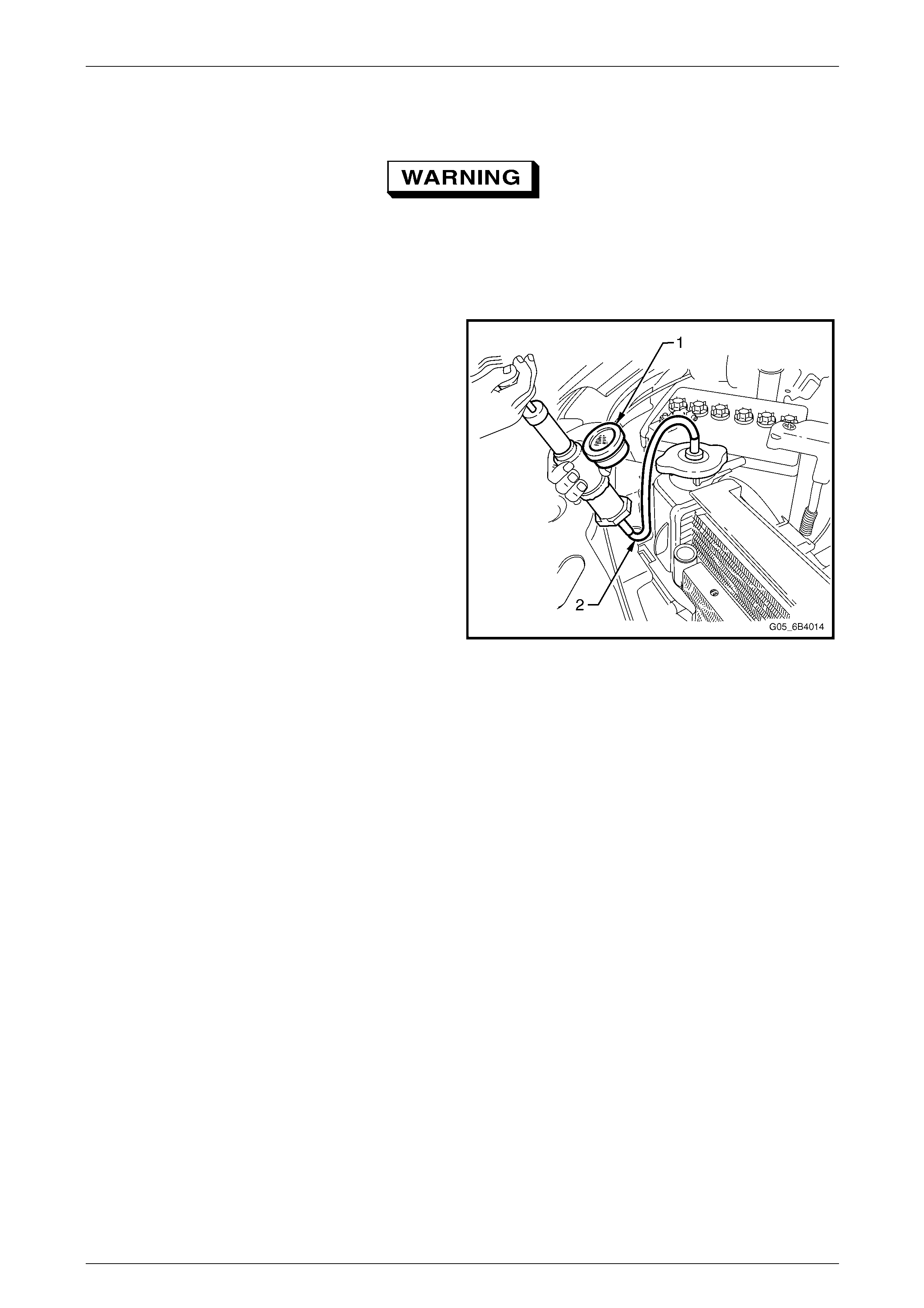
3 Connect a commerciall y available cooling system
pressure tester (1) to radiator filler neck by using the
hose supplied (2) or other arrangem ent and using
compressed air, blow dry any spilled coolant around
radiator filler neck. Pressurise cooling system to not
more than 120 kPa and check for leaks at the
following points:
• All hoses and hose connectio ns.
• Radiator seams and core.
• Corroded or faulty engine core plugs.
• Coolant pump and gaskets and O-ring sea ls.
• Check engine oil dipstick for evid ence of
engine oil contamination with coolant.
• Radiator drain tap and bleed screw.
• Vehicle heating system (e.g. heater cor e an d
water valve). Figure 6B3 – 47
NOTE
For heater component Removal and Installation,
refer to Section 2C HVAC Climate Control
(Manual A/C) – Removal and Install ation.
4 If pressure will not hold, there is a leak in the cooling system . Repair as required.
NOTE
If visible loss of coolant is not evident
from pressure testing, then the use of a dye
and black light, may be necessary. Refer to
4.7 Black Light and Dye Leak Diagnosis Method
in this Section.
Engine Cooling – GEN III V8 Page 6B3–44
Page 6B3–44
3.9 Thermostat
LT Section No. – 00 – 350
Remove
Refer to 3.1 Service Notes in this Section, for
important safety items.
1 Allow engine to cool to ambient temperature (less than 50° C), then remove radiator cap.
2 Drain the engine coolant into a suitable container. Refer to 3.3 Draining and Fillin g Cooling System in this Section.
Always wear protective safety glasses when
Disconnect radiato r hose from coolant inlet at
the thermostat housing. working with spring
type hose clamps. Failure to do so could
result in eye injury.
3 Disconnect radiator hose from coolant inlet at the
thermostat housing.
Figure 6B3 – 48
4 Remove thermostat housing bolts (1), and then
remove the housing (2), thermostat and O-ring seal
from the coolant pump.
Figure 6B3 – 49

Engine Cooling – GEN III V8 Page 6B3–45
Page 6B3–45
Test
5 Suspend thermostat (1) and a suitable thermometer
(2) in a container of 50 / 50 Extended Life Anti-freeze
Coolant (conforming to GM6277M) and water.
NOTE
Neither the thermostat nor thermometer should
rest on the bottom of the container because of
uneven concentration of heat at this point when
the container is heated.
6 Heat container until thermostat begins to open. Agitate
solution to ensure uniform temperature. Note
temperature and ensure t hermostat opens within
specified temperature range.
7 Continue heating the solution until the thermostat is
fully open. Again agitate the solution and take note of
the temperature
8 Install a new thermostat if it does not meet the
specified temperatures.
Thermostat Specifications
Opening Temperature................................. 86 ± 1.5° C
Fully Open Temperature .................................... 100° C
Figure 6B3 – 50
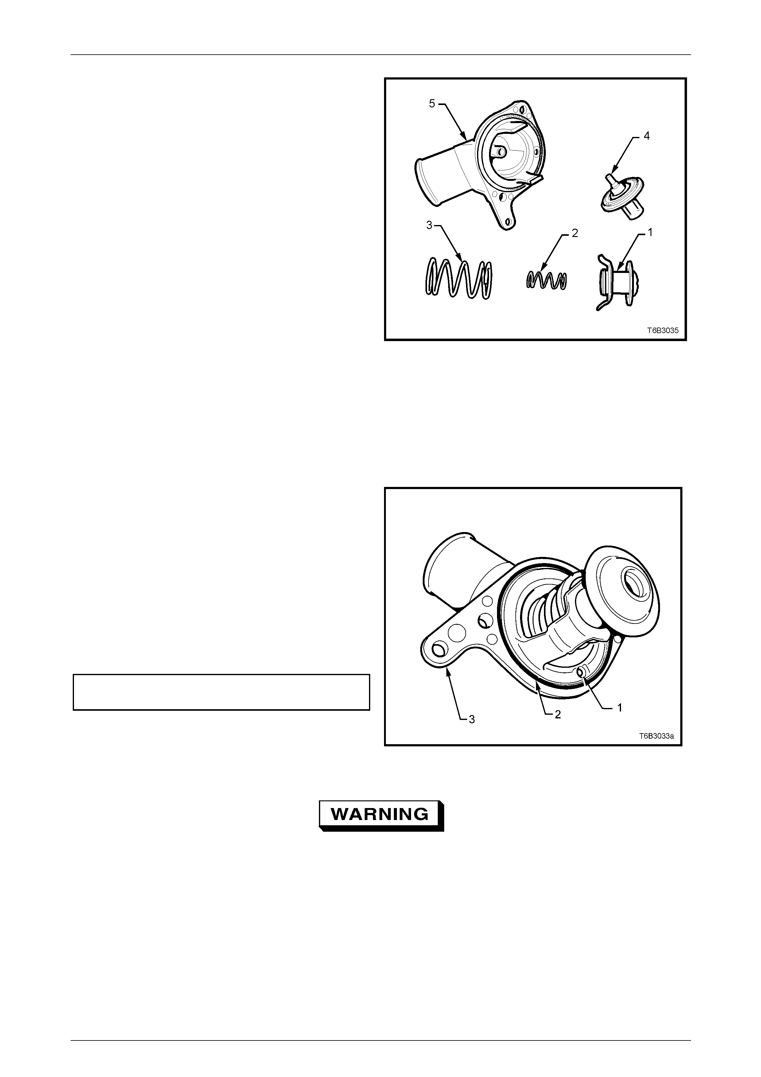
Disassemble
NOTE
Only dismantle the thermostat if a reverse
flushing operation of the cylinder block is to be
carried out. If testing shows that replacement is
required, the thermostat and housing are only
serviced as a complete assembly.
1 Secure the thermostat housing by gripping in a vice fitted with soft jaws.
Always wear protective safety glasses to
avoid potential eye injury.
2 While compressing the springs with one hand, rotate
the retaining bar from the housing lugs and release.
Figure 6B3 – 51
Engine Cooling – GEN III V8 Page 6B3–46
Page 6B3–46
3 Careful lay all parts out in ord er, for ease of
reassembly.
Legend
1 Bypass Valve
2 Bypass Valve Spring
3 Thermostat Closing Spring
4 Wax Pellet and Valve Assembly
5 Thermostat Housing
Figure 6B3 – 52
Reassemble
Reassembly is the reverse of disassembly procedures, exce pt that the valve seat in the thermostat housing must be
checked for corrosion, scratches or other damage a nd the valve-seating surface wiped with a clean rag.
Install
1 Shake the thermostat assembly to ensure that the
air bleed check ball (1) in the housing is free and not
jammed.
2 Thoroughly clean the coolant pump to thermostat
housing sealing surfaces, taking care not to scratch
any machined alloy surfaces.
3 Install the thermostat assembly, with a new O-
ring (2), fitted to the coolant pump housing (3).
4 Install the thermostat housing to coolant pump
housing attaching bolts and tighten to the correct
torque specification.
Thermostat housing to coolant pump bolt
torque specification..........................................14 N.m
Figure 6B3 – 53
Always wear protective safety glasses when
working with spring type hose clamps. Failure
to do so could result in eye injury.
5 Install the radiator hose and cl amp to the thermostat housing.
6 Refill cooling system. Refer to 3.3 Draining and Filling Cooling System in this Section.
7 Check for cooling system leaks. Refer to 3.8 Pressure Testing in this Section.
Engine Cooling – GEN III V8 Page 6B3–47
Page 6B3–47
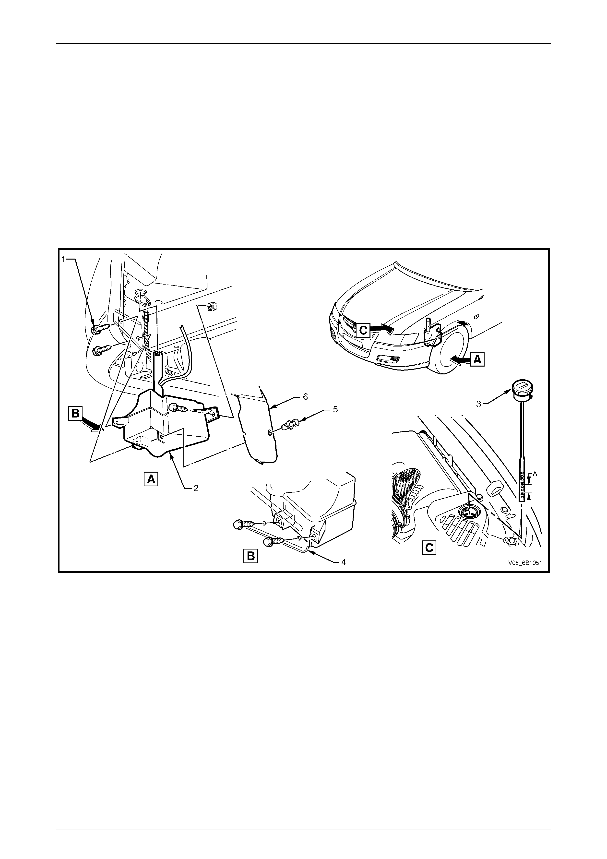
3.10 Coolant Recovery Reservoir
LT Section No. – 01 – 140
Remove
1 Remove the coolant recovery hose from the radiator filler neck, and then remove the hose from the fan shroud and
MAF air intake housing ret aining clips.
2 Raise front of vehicle and support on safet y stands. Refer to Section 0A General Information for the location of
jacking and support points.
3 Remove the scrivet fastener attaching the wheelhous e liner to the coolant recovery reservoir.
4 Remove reservoir assembly attaching screws, and remove reservoir assembly from under the vehicle.
Figure 6B3 – 54
Legend
1 Screw (3 places)
2 Reservoir 3 Coolant Dipstick
4 Console Front Panel 5 Scrivet Fastener
6 Wheelhouse Liner

Engine Cooling – GEN III V8 Page 6B3–48
Page 6B3–48
Inspect
1 Drain contents from reservoir assembly.
Always wear protective safety glasses to
avoid potential eye injury.
2 Clean reservoir assembly with water and dry, using compressed air.
3 Check reservoir and assembly for damage, for example abrasions, cracks or distortion. Replace if required.
Install
Installation of the reservoir assembly is the r everse of removal procedures, noting the foll owing points:
1 For ease of access, it may be necessary to remove the upper radiator shroud.
2 Refill cooling recovery reservoir and cooling system with the correct concentration of coolant.
Refer to 3.3 Draining and Filling Cooling System in this Section.
3 Check coolant recovery system for leaks.

Engine Cooling – GEN III V8 Page 6B3–49
Page 6B3–49
3.11 Oil Pan Under-tray
Remove
1 Raise front of vehicle and support on safet y stands. Refer to Section 0A General Information for the location of
jacking and support points.
2 Remove the four bolts (1) securing the under -tray (2) to the crossmember and remove tray from vehicle.
Install
1 While holding the under-tray up to the crossmember
with one hand, install all four securi ng bolts.
2 Tighten all four bolts to the correct torque
specification. DO NOT OVER TIGHTEN THE
BOLTS.
Oil pan under-tray bolt
torque specification..........................................30 N.m
Figure 6B3 – 55
Engine Cooling – GEN III V8 Page 6B3–50
Page 6B3–50
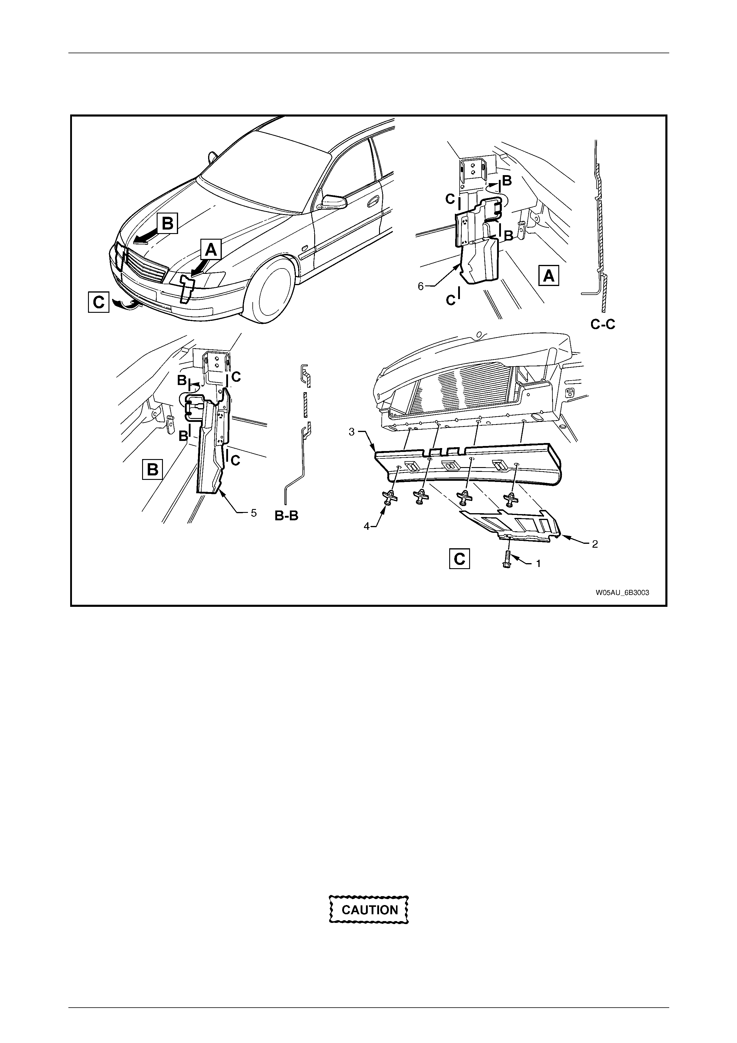
3.12 Air Baffles and Ducts
Figure 6B3 – 56
Remove
1 Raise front of vehicle and support on safet y stands. Refer to Section 0A General Information for the location of
jacking and support points.
2 Remove the oil pan under-tray. Refer 3.11 Oil Pan Under-tray in this Section.
3 Remove the two screws (1) securing the rear of the lower air chute baffle extension (2), lower the rear of the lower
air chute baffle extension, slide the baffle re arward to disengage from the lo wer front air chute baffle (3), then
remove from the vehicle.
4 Remove the four scrivet fasteners (4) securing the lower front air chute baffle to the crossmember and remove
lower front air chute baffle from the vehicle.
Reinstall
Installation is the reverse to removal proced ures.
Do not over tighten any of the fasteners.
Engine Cooling – GEN III V8 Page 6B3–51
Page 6B3–51
3.13 Coolant Pump
LT Section No. – 00 – 325
Remove
NOTE
Apart from the rear cover, O-ring and thermostat
assembly, the coolant pump is not serviceable
and if found to be faulty must be replaced as an
assembly.
Disconnection of the battery affects certain
vehicle electronic systems. Refer to
Section 00 Warnings, Cautions and Notes,
before removing the ground lead.
5 Disconnect the battery ground lead. Refer to Section 12A B attery.
6 Remove the upper radiator shroud (1) as fol lows:
a Using a fine, flat-blade screwdriver to prise the
centre pin of the scrivet (2) upward and
remove the scrivet, five places.
b Lift up the radiator shroud to disengage the
retaining clip (3) and remove the shroud.
Refer to 3.1 Service Notes in this Section,
for important safety items.
7 Allow engine to cool to ambient temperature (less
than 50° C), then slowly remove radiator cap from
the radiator.
Figure 6B3 – 57
8 Using a 15 mm ring spanner to move the belt
tensioner (1) in the clockwise direction indicated,
remove the engine accessor y drive belt (2). Refer to
3.7 Engine Accessory Drive Belt in this Section.
Figure 6B3 – 58
9 Drain engine coolant. Refer to 3.3 Draining and Filling Cooling System in this Section.
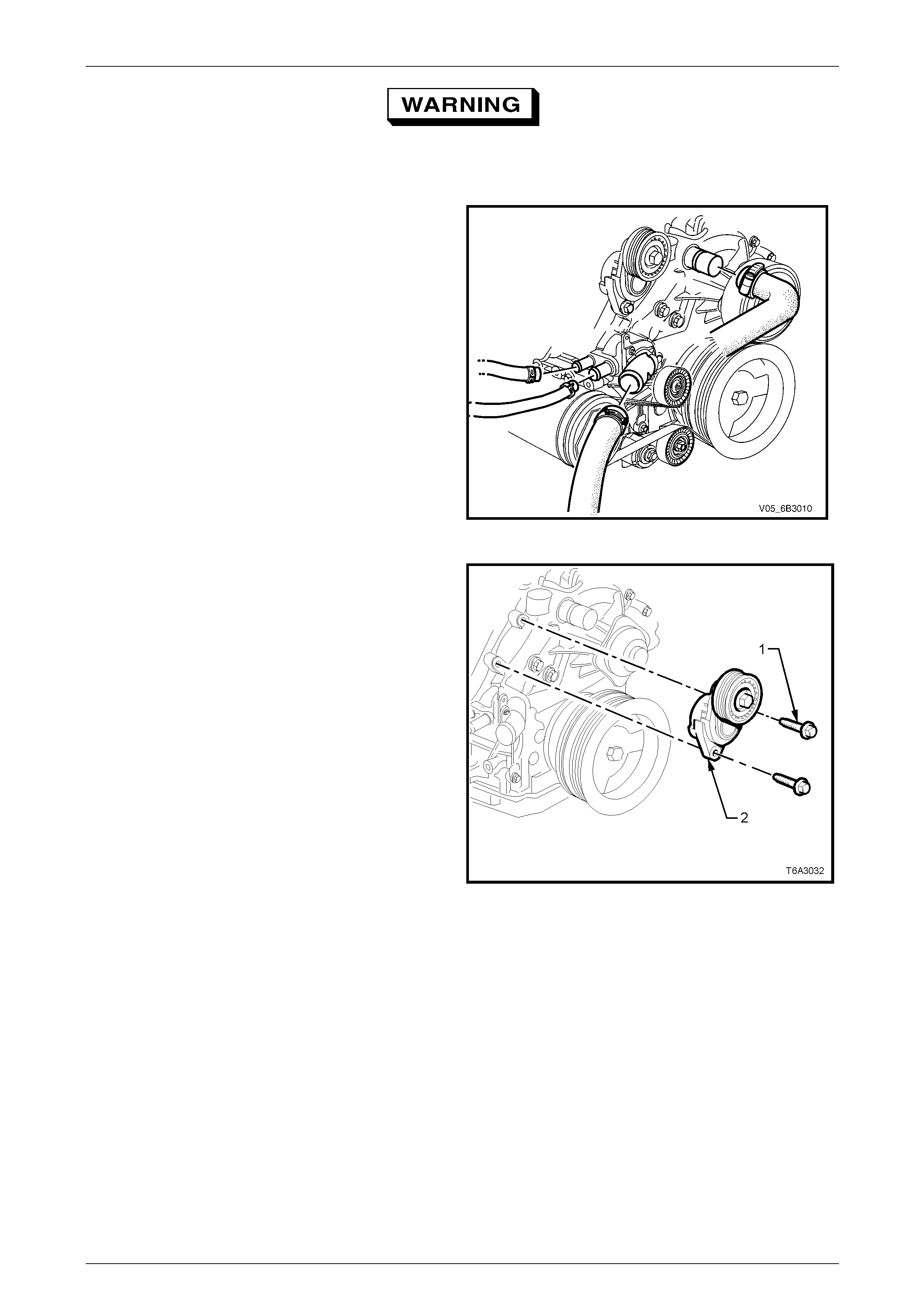
Engine Cooling – GEN III V8 Page 6B3–52
Page 6B3–52
Always wear protective safety glasses when
working with spring type hose clamps. Failure
to do so could result in eye injury.
10 Disconnect both heater hoses, the outlet and inlet
hoses from the coolant pump.
Figure 6B3 – 59
11 Remove the two bolts (1) securing the drive belt
tensioner (2) to the coolant pump housing and set
the tensioner to one side.
Figure 6B3 – 60
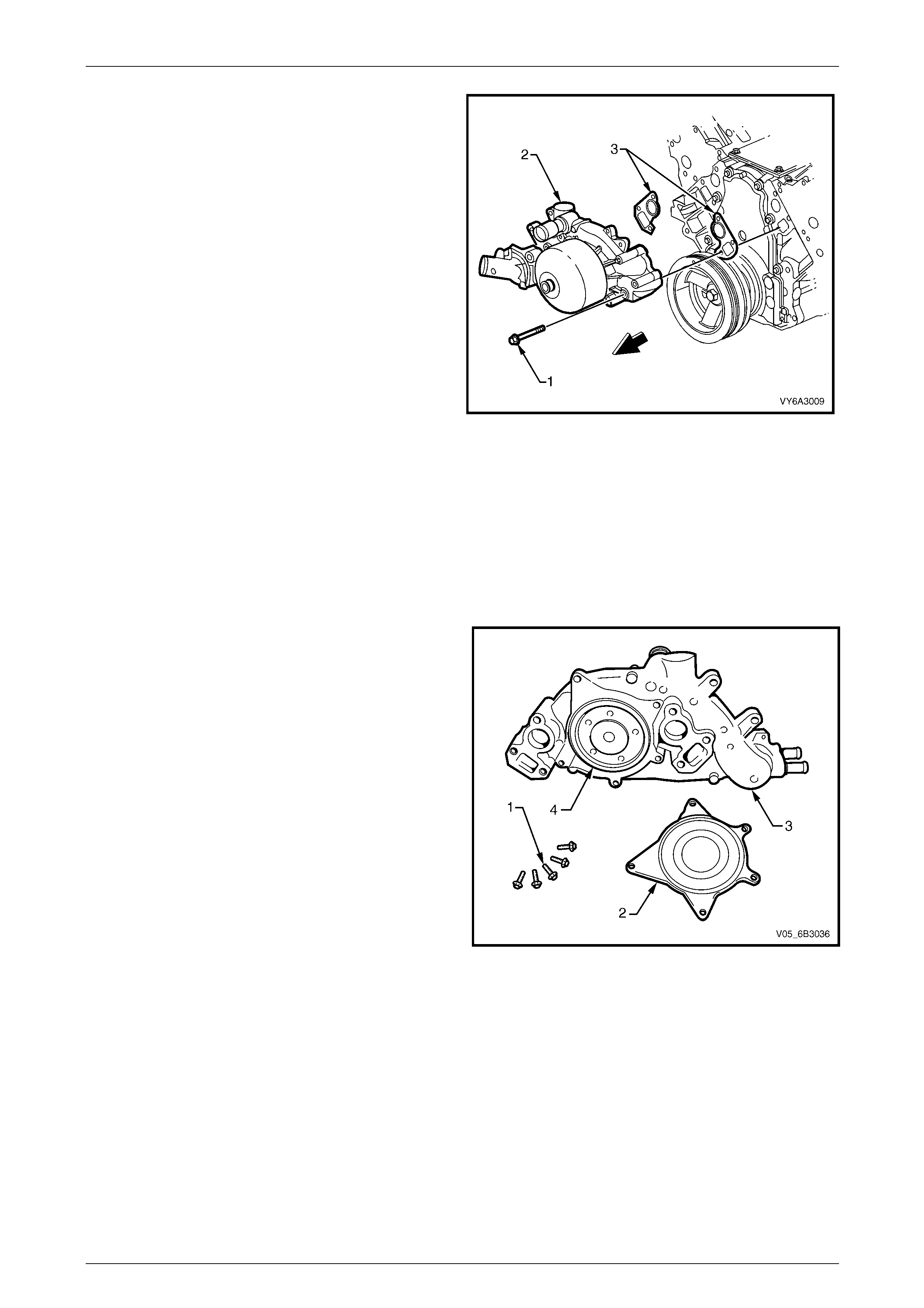
Engine Cooling – GEN III V8 Page 6B3–53
Page 6B3–53
12 Loosen, then remove the six bolts (1) securing the
coolant pump (2) to the cylinder block.
13 If necessary, use a soft-faced hammer to lightly tap
coolant pump housing (2) to dislodge it from the
cylinder block.
14 Remove coolant pump gaske ts (3) and discard.
Figure 6B3 – 61
Disassemble
NOTE
Apart from the service operations described here,
there are no ot her serviceable parts in the coolant
pump assembly and if required, then the
assembly must be replaced as a complete unit.
1 If required, remove the five bolts (1) securing the rear
cover (2) to the coolant pump (3). Tap with a
soft-faced hammer to dislodge the cover from the
pump body.
2 Remove the sealing O-ring (4) from the coola nt pump
body.
3 For thermostat remove, test and install procedures.
Refer to 3.9 Thermostat in this Section.
Figure 6B3 – 62
Engine Cooling – GEN III V8 Page 6B3–54
Page 6B3–54
Clean and Inspect
1 Remove the old gasket and any gasket material from the coolant pump se aling surfaces and cylinder bl ock, taking
care not to scratch the machined surfaces.
2 Clean all dirt and debris from the coolant pump housing.
3 Inspect the coolant pump for the following:
• Gasket surfaces for excessive scratches or gouging.
• Hose sealing surfaces for scratches, gouging or corrosion.
• Restrictions, corrosion or evidence of cavitation within the internal coolant passages or on the pump impell er.
• Excessive side-to-side play in the pulley shaft.
• A loose belt pulley or a pulle y with e xcess ive wear or scoring on the belt tracking area.
• Evidence of coolant leakage at the coolant outlet housing or rear cover gasket (if these parts have not been
removed).
• Leakage at the coolant pump vent hol e. A stain around the vent hole is ac ceptable. If leakage occurs
(dripping) with the engine running and the cooling system pressurised, replace the coolant pump.
Reassemble
1 Install a new O-ring seal to the cleaned groo ve in the pump housing, then install the cover and retaining bolts.
2 Gradually tighten every second bolt until the correct torque specification is reach ed.
Coolant pump rear cover
bolt torque specification.......................................14 N.m
Reinstall
Reinstallation is the reverse to removal e xcept for the following items:
1 Ensure that the coolant pump and cylinder block surfaces are clean and dr y.
2 Using two bolts on each side a s guides install new gaskets over them and i nstall the co olant pump to the cylinder
block.
3 Install remaining bolts and tighten to t he correct torque specification in two stages.
Coolant pump to cylinder
block bolt torque specification:
Stage 1: ...............................................................15 N.m
Stage 2: ...............................................................25 N.m
4 Install the engine accessory dr ive belt tensioner and attaching bolts, tightening to the correct torque specificatio n.
Engine accessory drive belt tensioner
bolt torque specification.......................................50 N.m
Always wear protective safety glasses when
working with spring type hose clamps. Failure
to do so could result in eye injury.
5 Install all removed radiator hoses and clamps.
6 Install the engine accessory dr ive belt. Refer 3.7 Engine Accessor y Drive B elt in this Section.
7 Refill cooling system. Refer to 3.3 Draining and Filling Cooling System in this Section.
8 Check for cooling system leaks. Refer to 3.8 Pressure Testing in this Section.
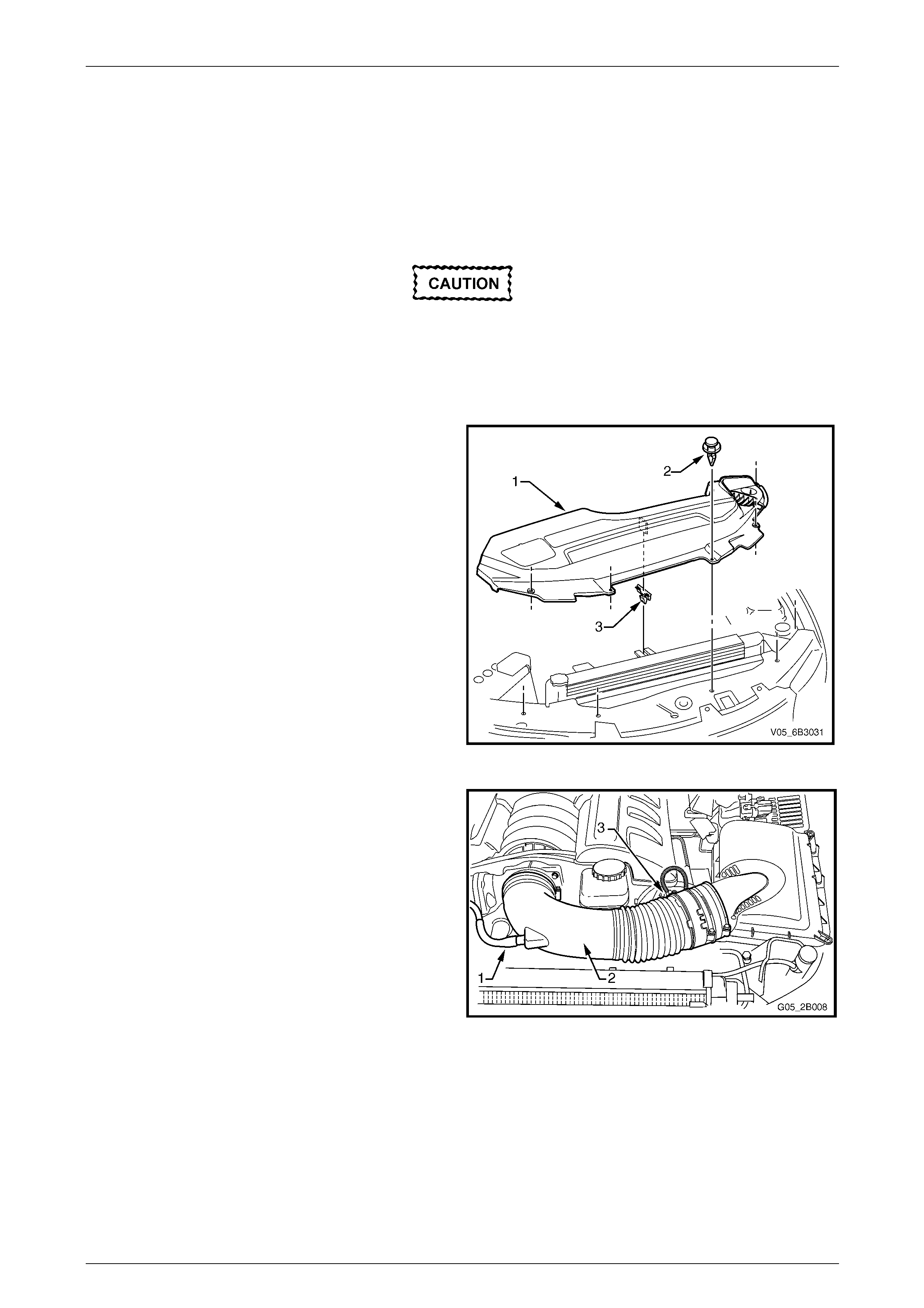
Engine Cooling – GEN III V8 Page 6B3–55
Page 6B3–55
3.14 Cooling Fans and Shroud Assembly
LT Section No. – 01 – 105
Remove
1 Allow the engine to cool to ambient temperature (less than 50° C).
Disconnection of the battery affects certain
vehicle electronic systems. Refer to
Section 00 Warnings, Cautions and Notes,
before removing the ground lead.
2 Disconnect the battery ground lead. Refer to Section 12A B attery.
3 Remove the upper radiator shroud (1) as fol lows:
a Using a fine, flat-blade screwdriver to prise the
centre pin of the scrivet (2) upward and remove
the scrivet, five places.
b Lift up the radiator shroud to disengage the
retaining clip (3) and remove the shroud.
Figure 6B3 – 63
4 Remove the intake duct and Mass Air F low (MAF) as
an assembly. Refer to
Section 6A3 Engine Mechanical – GEN III V8.
Figure 6B3 – 64
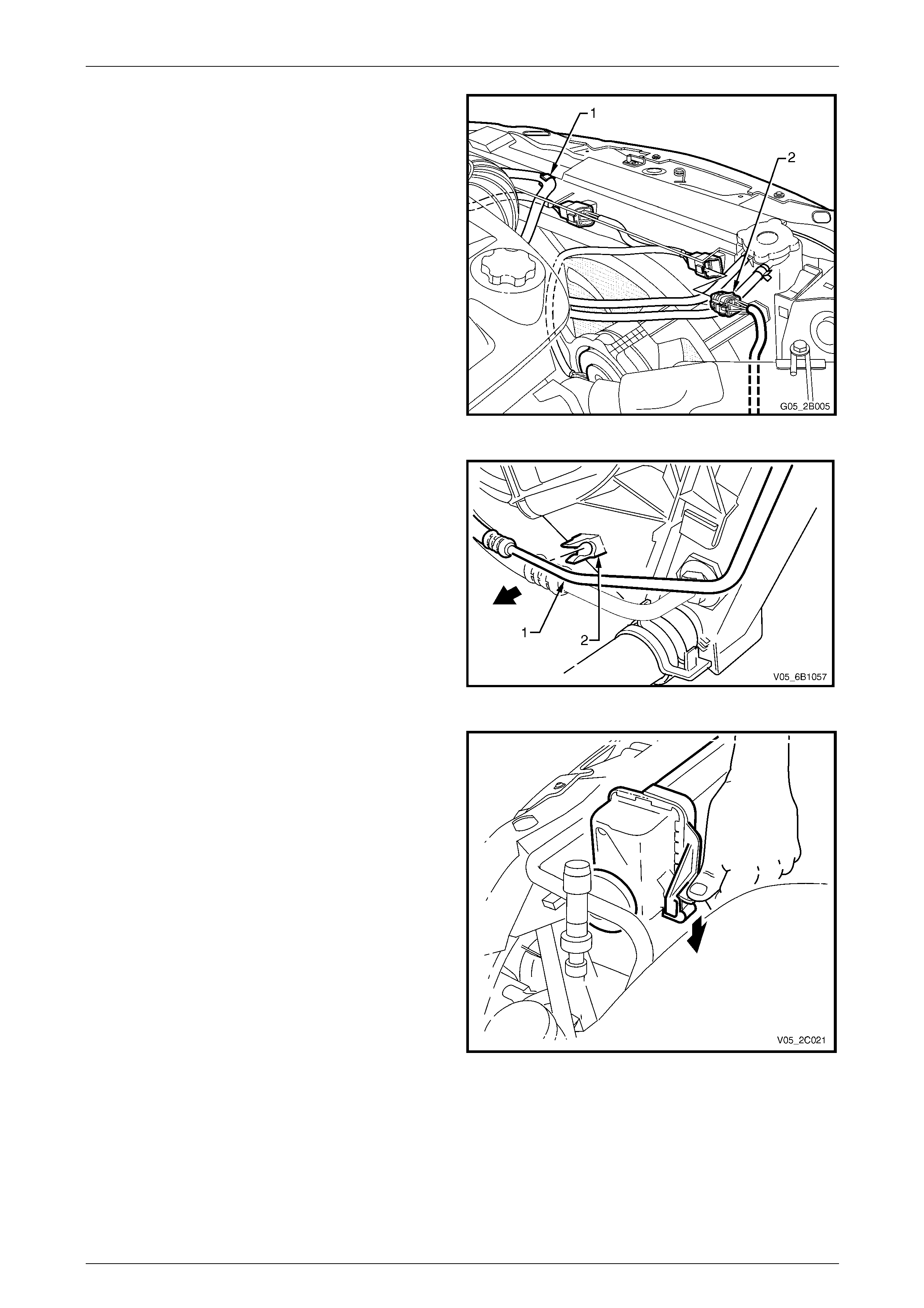
Engine Cooling – GEN III V8 Page 6B3–56
Page 6B3–56
5 Remove the coolant recovery hoses from the fan
shroud retaining clips (1).
6 Depress tang on main wiring harness to cooling fan
motor wiring harness connector and separ ate
connector (2).
Figure 6B3 – 65
7 Release the upper automatic transmissi on cooling
pipe (1) (if fitted) from the integral clip (2) on the fan
shroud.
Figure 6B3 – 66
8 While holding the shroud locking tang in the release
position, lift the shroud and fan assembly upwards.
Repeat for the opposite side.
Figure 6B3 – 67
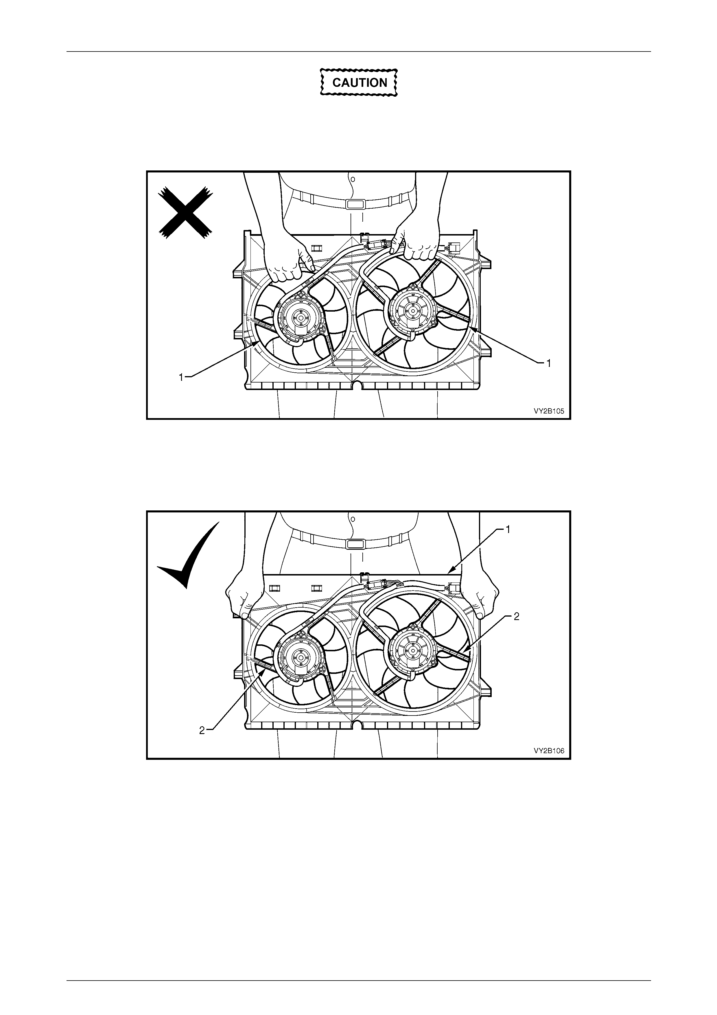
Engine Cooling – GEN III V8 Page 6B3–57
Page 6B3–57
When removing, transporting or installing the
fan assembly, do not grasp the assembly by
the fan rings (1) as this may bend the fan
motor shafts and cause fan vibrations
Figure 6B3 – 68
When handling the fan assembly, always hold
the assembly at the fan shroud (1) or fan
motor mounting struts (2).
Figure 6B3 – 69
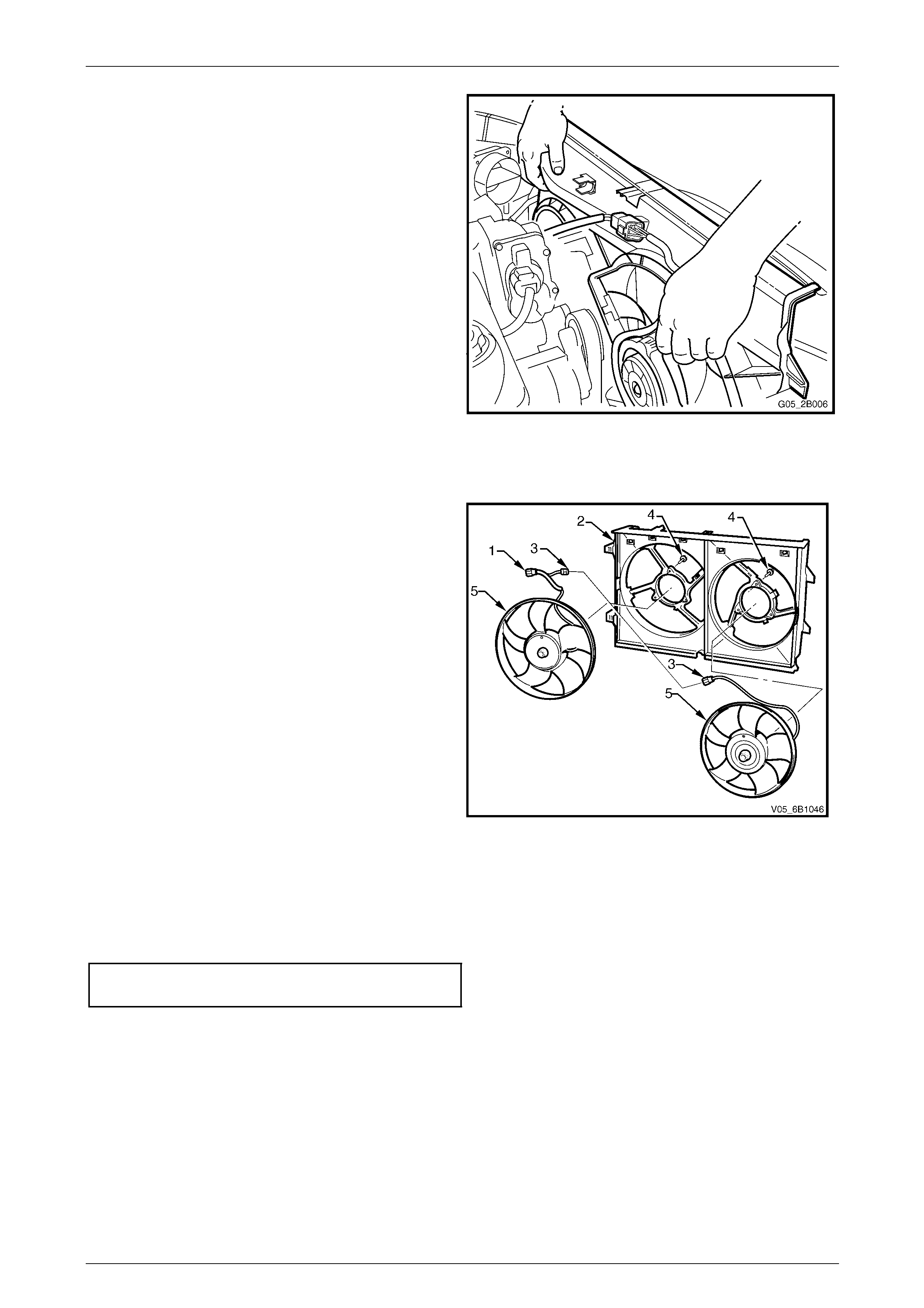
Engine Cooling – GEN III V8 Page 6B3–58
Page 6B3–58
9 Lift the shroud and fan assembly clear from the engine
bay, grasping the motor mounting struts.
Figure 6B3 – 70
Disassemble
1 Remove cooling fan and shro ud assembly as
previously described.
NOTE
Neither fan is to be separated from its fan
motor. The assembly is carefully balanced
during manufacture and duplicating this
balance on reassembly is not possible.
2 Remove the motor assembly wiring harness (1) from
the integral clips that form a part of the shroud (2).
3 Separate the intermediate wiring harness
connector (3).
4 Remove screws (4) attaching the motor assembly to
the shroud, then remove each motor, fan and wiring
assembly (5) from the shroud.
Figure 6B3 – 71
Reassemble
Reassembly is the reverse of disass embly procedures, noting the following points:
1 Tighten motor to shroud attaching screws to the correct torque specification. Do not over-tighten.
Fan motor to shroud screw
torque specification................................................5 N.m
2 Ensure that all wiring is routed correctly and secured by the integra l shroud clips.
Install
Installation of the cooling fan and shroud assembly is the reverse of removal procedures, noting the following points:
1 Ensure that fan and shroud assembly to radiator attaching clips are all fully engaged and that the two locking tangs
on the upper clips secure the shroud correctly.
2 Ensure that the top automatic transmission cooling pipe (if fitted) is installed to the shroud clip.
3 Check cooling fan operation. Refer to Section 6C3-2 Powertrain Management – GEN III V8 – Diagnostics. Also
check for the correct cooling fan rotational direction.
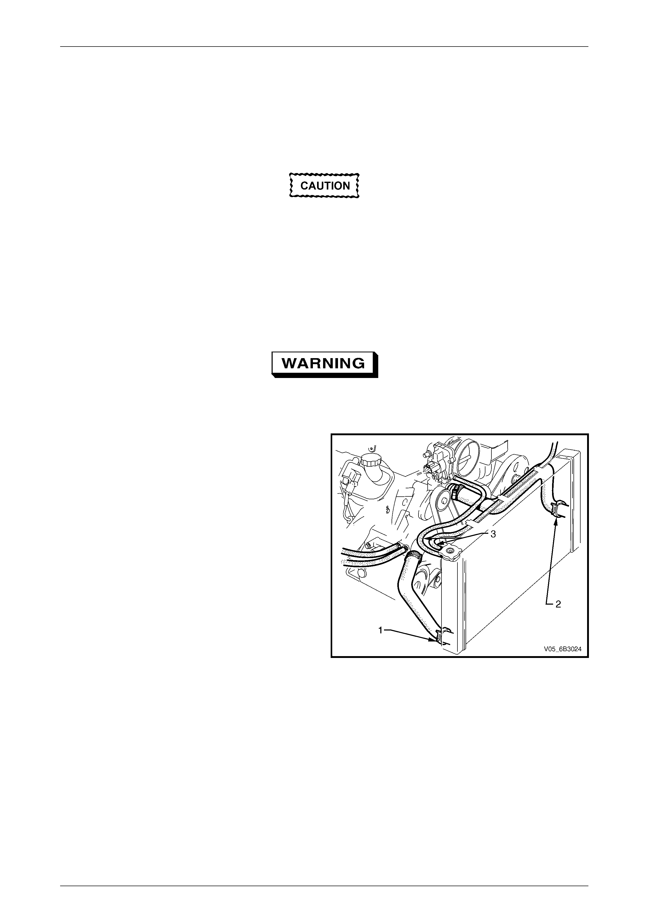
Engine Cooling – GEN III V8 Page 6B3–59
Page 6B3–59
3.15 Radiator
LT Section No. – 01 – 105
Remove
1 Allow the engine to cool to ambient temperature (less than 50° C).
Disconnection of the battery affects certain
vehicle electronic systems. Refer to
Section 00 Warnings, Cautions and Notes,
before removing the ground lead.
4 Disconnect the battery ground lead. Refer to Section 12A B attery.
5 Remove the radiator cooling fans and shroud assembly. Refer to 3.14 Cooling Fans and Shroud Assembly in this
Section.
6 Draining the coolant from the system. Refer to 3.3 Draining and Filling Cooling System in this Section.
Always wear protective safety glasses when
working with spring type hose clamps. Failure
to do so could result in eye injury.
7 Remove lower radiator hose (1) and u pper radiator
hose (2) from the radiator, after releasing the spring
type hose clamp, using suitabl e pli ers.
8 Remove the coolant recovery and va pour vent
hoses (3) from the radiator filler neck.
Figure 6B3 – 72
NOTE
If fitted with air conditioning, the condenser must
be separated from the radiator assembly. This
action will allow the radiator removal without
having to open any refrigerant lines.
9 Remove the radiator grille. Re fer to Section 1C Radiator Grille.
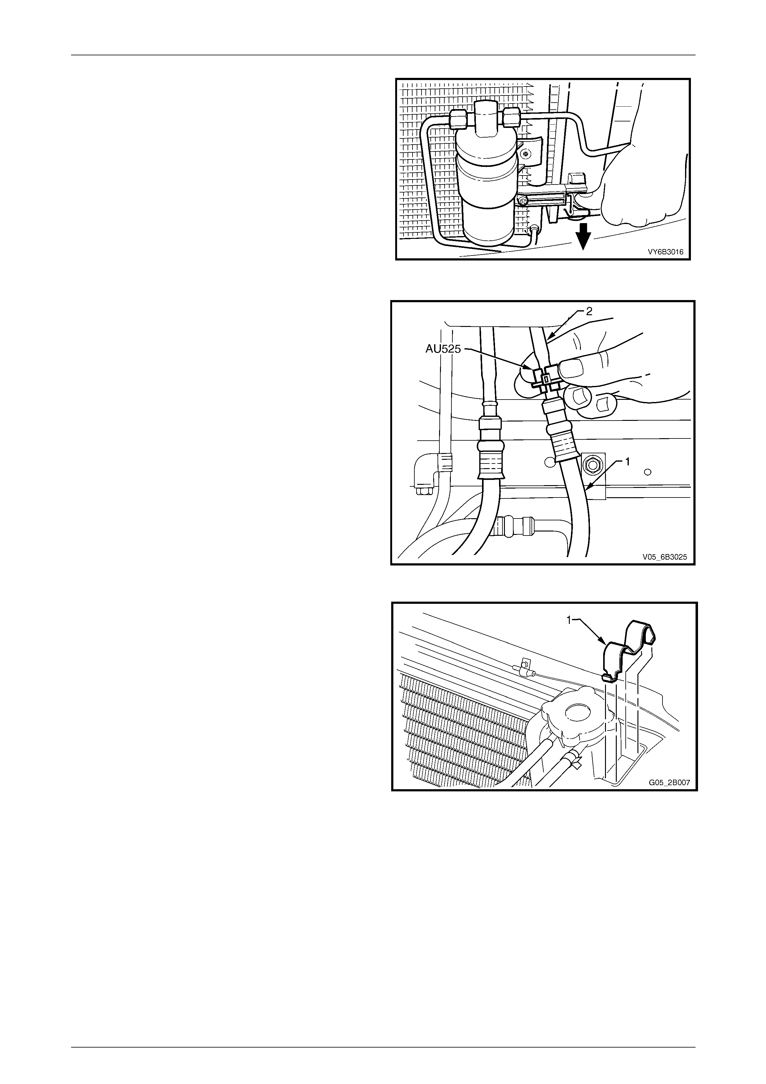
Engine Cooling – GEN III V8 Page 6B3–60
Page 6B3–60
10 Working through the grille ope ning, release one of
the clips securing the condens er to the radiator (bold
arrow). Do this by pressing down on the l ug with the
fingers of one hand, while lifting the condenser
assembly with the other. Repeat for the other side.
NOTE
It is not necessary to remove t he receiver drier,
nor disturb the air conditioning refrigerant
system (where fitted), for this operation. The
condenser can be lifted a s ufficient am ount with
the refrigerant pipes remaining attached.
11 Once released, pull the condenser assembly forward
to clear the radiator mounting lugs.
Figure 6B3 – 73
12 Disconnect the transmission oil cooler line quick
connect fittings, using Tool No . AU525:
a Open release tool AU525, then close a nd clip
around the pipe to be disconnected.
b While holding the flexible hose (1) with one
hand, push the tool into connection, to releas e,
and then pull back on the pipe (2) (or hose).
NOTE
If Tool No. AU525 is not available, the cooler
pipes can be disconnected from the cooler, in
the right side radiator tank. Refer to
3.16 Flexible Transmission Cooler Hose, in this
Section, for important information regardi ng this
procedure.
c Plug all openings to minimis e fluid loss and
prevent dirt entry.
Figure 6B3 – 74
13 Using a screwdriver, compress and lever out radiator
retaining clips (1) from radiator upper mounting
brackets.
14 Lift radiator upwards out of lower insulators. To
remove the radiator assembly from the vehicle, after
clearing the top insulators, move the radiator
rearward on the left side, then across to the left, to
allow the right side to clear the mounting br ackets.
15 Remove upper and lower insulators from the radiator.
Figure 6B3 – 75

Engine Cooling – GEN III V8 Page 6B3–61
Page 6B3–61
Install
Installation of the radiator is the reverse of removal procedures, noting the following points:
1 Before installing radiator, inspect core to ensure that there is no foreign matter such as insects in the core fins.
Clean out between core fins with compressed air, working from the engine side and blowing forwards.
2 Ensure that radiator lower mounting pins are correctly loc ated in lower insulators.
3 Ensure that upper insulators are insta lled on each of the upper mounting pins and radiato r retainers are correctly
installed on each side of the radi ator by checking that the clips engage on both sid es of the chan nel support
bracket.
4 If the vehicle is fitted with an automatic transmission, remove plugs from the removed cooling pipe ends and the
two quick connect fittings.
5 After wiping cooler pipe ends and smearin g clea n automatic transmission fluid over each flared pipe end, push into
the quick connect fitting to engage. As a security check, tug on each pipe to ensure correct engagement.
NOTE
If the transmission cooler pipe tube nuts were
removed from the right hand radiator tank,
inspect the sealing washer for serviceability
before reinstallation. Replace the sealing
washer(s) as required. Tighten the cooler pipe
tube nut to the correct torque specification.
Oil cooler pipe tube nut
torque specification..............................................25 N.m
6 Check the transmission fluid level. Refer to the follo wing references as required:
• Section 7C4 Automatic Transmission – 4L60E On-vehicle Servicing
7 After reinstalling the condenser assembly to the four retaining clips, ensure that the two lower clips have fully
engaged.
8 Install the radiator grille. Refer to Section 1C Radi ator Grille.
9 Install the following hoses:
a Lower radiator hose, securing with the hose clamp.
b Upper radiator hose, securing with the hose clamp.
c Coolant recovery and vapour vent hoses to the radiator filler neck.
10 Install the radiator cooling fans and shroud assembly. Refer to 3.14 Cool ing Fans and Shroud Assembly in this
Section. Ensure that electrical connectors and the transmission cooler lines are seated correctly in the integral
retainer clips before install upper rad iator shroud.
11 Refill cooling system, refer to 3.3 Draining and Filling Cooling System in this Section.
12 Check for coolant leaks. Refer to 3.8 Pressure Testing in this Section.
13 Reconnect battery ground lead. Refer to Section 12A B attery.
14 Check cooling fan operation. Refer to Section 6C3-2 Powertrain Management – GEN III V8 – Diagnostics, including
fan rotation direction.
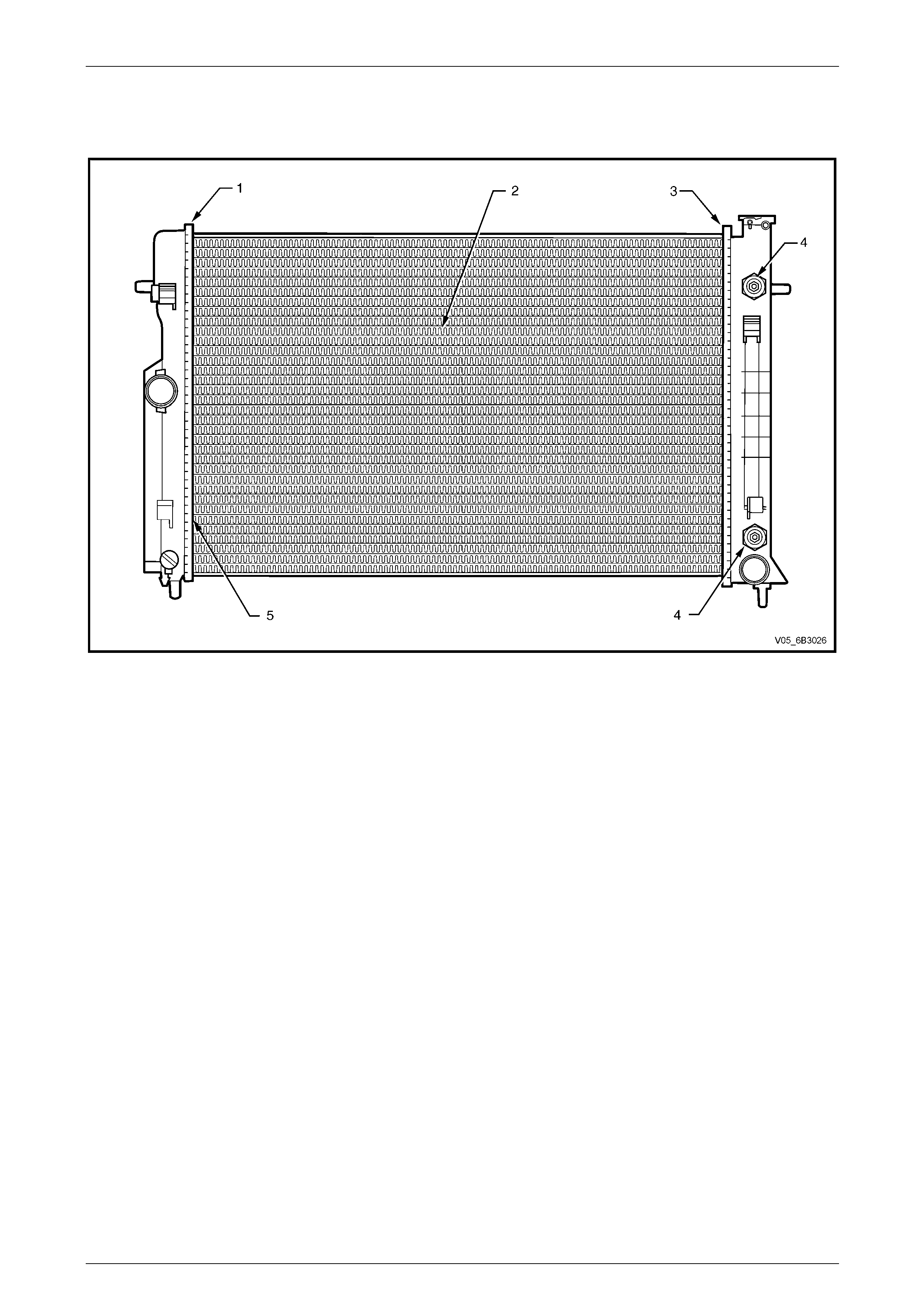
Engine Cooling – GEN III V8 Page 6B3–62
Page 6B3–62
Radiator Repair Procedure
Repairable Leaks
Figure 6B3 – 76
Legend:
1 Left-hand Side Tank Seal
2 Core Tubes
3 Right-hand Side Tank Seal
4 Oil Cooler Pipe Fittings
5 Joint Between Tube and Header
There are two types of leaks that can b e rep aire d on the aluminium-plastic radiator; core leaks and auto m atic
transmission oil cooler seal leaks. Leaks in the plastic tanks or the seals between the side tanks and the headers can not
be repaired, requiring the radiator to be replaced.
Core leaks may occur in a tube or in the joints between the tubes and the headers. Seal le aks may occur in the joints
between the plastic tanks and the headers or in the joints between the oil cooler fittings and the tank (vehicles with
automatic transmission).
While some leaks may be repaired while the radiator remains installed, it is strongly recommended that the radiator is
removed from the vehicle before attempting any repairs.
NOTE
Minor damage to tubes, or tube to header joint
(holes up to 1 mm diameter max.) can be
repaired. Core replacement is necessary if
damage is any greater.
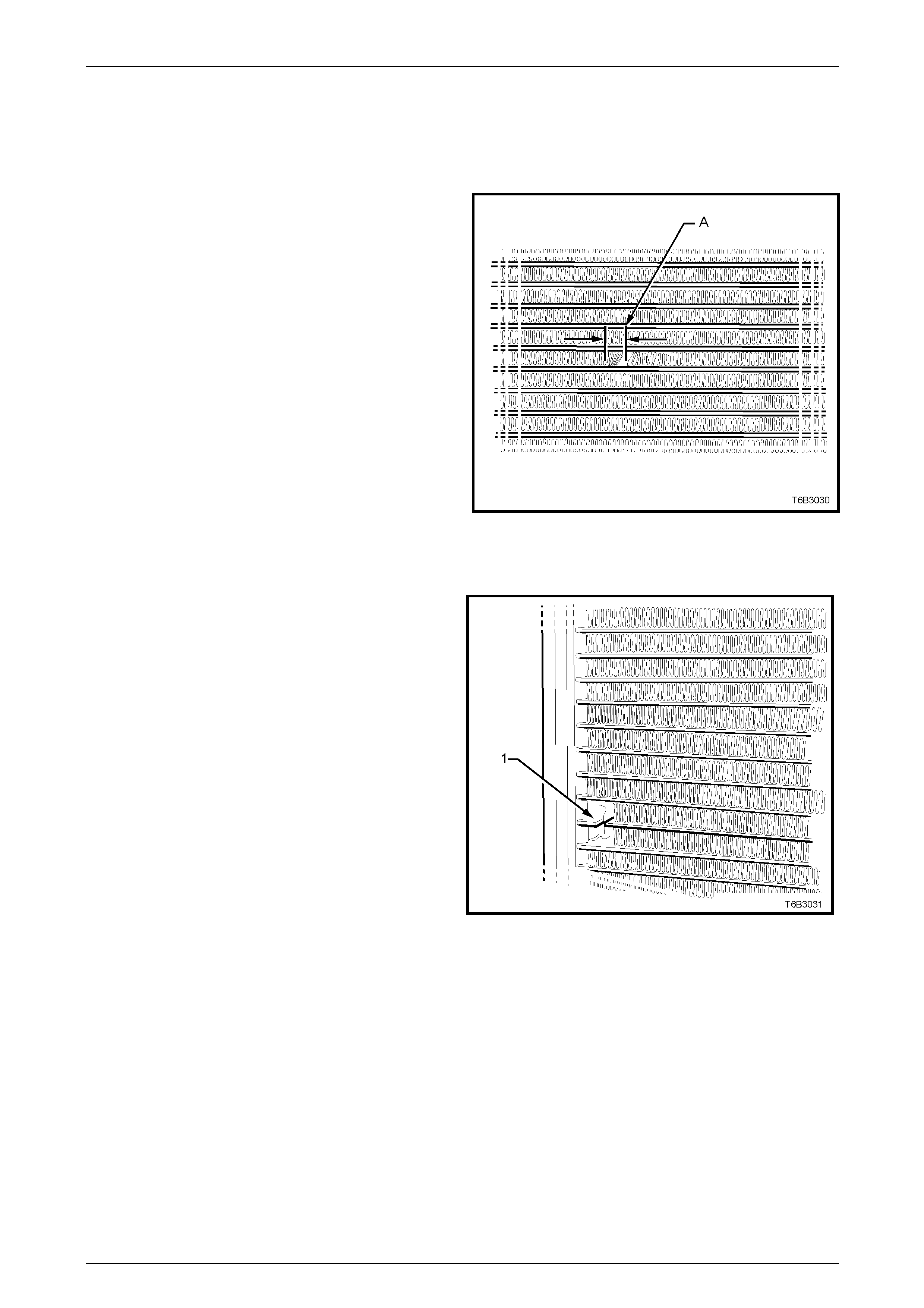
Engine Cooling – GEN III V8 Page 6B3–63
Page 6B3–63
Repair Method
Repairs to the aluminium radiator core should only be made using the recommended 'Aluminised Silicon' based l iquid
repair agent, in accordance with the recommended procedure outlined in General Cor e Repair, further on in this Section.
Refer to current release of Partfinder™ for the Aluminised Si licon base liquid part number.
For damaged areas that are between the cooling fi ns, it
may be necessary to remove some of the fins. Do not
remove more fins than is necessary. Usually 6 mm
(distance ‘A’) beyond the leak or dama ge area, up to a
maximum of 25 mm of total fin material, is enough to make
an effective repair.
Figure 6B3 – 77
Tube Blocking
If a tube is severely damaged, it can be blocked off.
NOTE
Do not block off more than two tubes in a
radiator. Blocking off more than two tubes will
reduce the cooling capacity and efficiency of
the system and possibly result in an
overheated engine.
The tube should be cut off 6 mm from the header (1) and
pinched shut before it is clean ed and sealed. Refer to
General Core Repair, further on in this Section.
Figure 6B3 – 78
Header Repair
If the header or a tube near the header requires a repair, the side tank is not to be removed. If the repair requires the
removal of the header tank, then the radiator must be replaced.
Engine Cooling – GEN III V8 Page 6B3–64
Page 6B3–64
General Core Repair
NOTE
The need for careful prepar ation of the surface in
the repair area cannot be ove r-emphasised. If the
leak area surface is not clean, the repair ma terial
will not adhere to the surface.
1 Drain the cooling system. Refer to 3.3 Draining and Filling Cooling System in this Section. Remove the radiator.
Refer 3.15 Radiator – Remove, in this Section.
2 If necessary, carefully cut away fins to expose the damaged area.
NOTE
Do not cut away more than 25 mm total of fin
material.
3 Clean away dirt etc. with water. Dry the affected area using hot air from a h air drier.
NOTE
Do not apply flame to dry damaged area.
4 Clean affected area with petrol to remove any traces of oil.
5 Thoroughly stir contents of repair a gent. In cases of extended shelf life, the silicon in solution may separate from
the thinner carrier. Should this occur, mix contents well until agent is homogeneous again.
6 Apply repair agent sparingly to damaged area. Do not apply an excessive amount, as this will cause a blockage of
the radiator tube.
Use a clean, dry wooden a pplicator to 'drip' the repair ag ent onto damaged area of radiator.
7 Allow radiator to stand in a clean, dr y area for a minimum of three hours (at ambient temperature of 20 – 30° C)
with adequate ventilation.
Do not apply flame to dry damaged area.
8 Install radiator. Refer to 3.15 Radiator – Install in this Section.
Transmission Oil Cooler Leak Test
If the transmission oil cooler is suspected of leaki ng transmission fluid, test it before replacing the radiator, as follows:
1 Disconnect oil cooler pipes from the flexible hose connections using release tool AU525.
2 Using suitable connectio ns plug one of the flexible hoses and connect an air supply to the other.
3 Lay the radiator flat on a benc h top and fill with clean water until both hose fittings are full and visible.
4 Apply air pressure GRADUALLY, increasing it up to a maximum of 120 kP a.
If bubbles appear in the water visible i n the radiator hose fittings, then the radiator assembly must be replaced.
Transmission Oil Cooler Seal Replacement.
It is strongly recommended that the transmission oil cooler connector fittings to the right-hand side radiator header tank,
not be disturbed. If coolant is found to leak from ether of these two areas then the radiator shou ld be replaced.
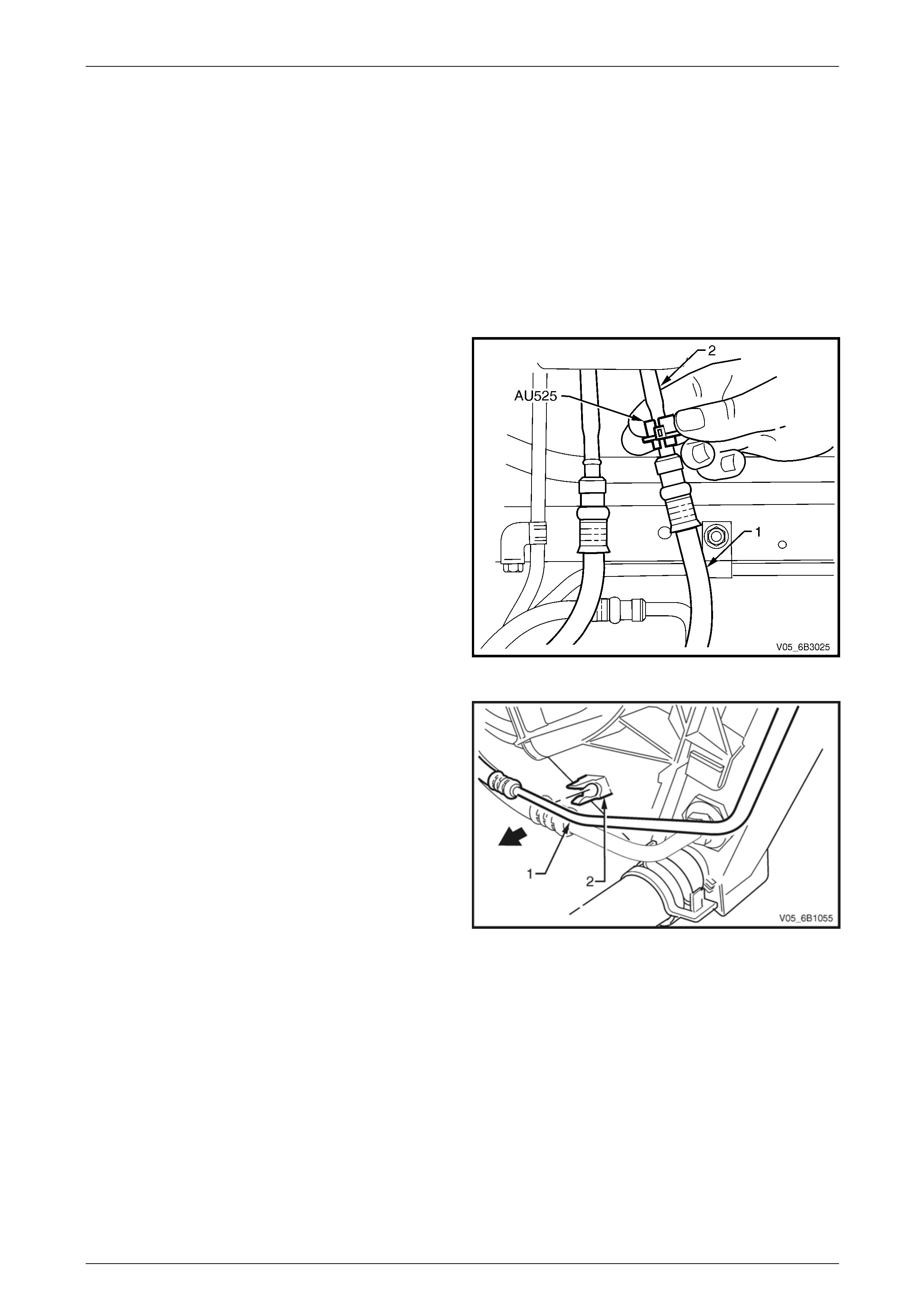
Engine Cooling – GEN III V8 Page 6B3–65
Page 6B3–65
3.16 Flexible Transmission Cooler Hose
LT Section No. – 04 – 150
Replace
NOTE
The flexible hoses are not serviced separately.
Therefore, should a hose require replacement,
then the hose and radiator to hose cooler pipe
assembly must be fitted.
1 Place a drip tray beneath the engine and radiator
section.
2 Disconnect the transmission cooler pipe(s) from the
flexible hose(s) using Tool No. AU525.
3 Open release tool AU525, then close a nd clip around
the pipe to be disconnected.
4 While holding the flexible hose (1) with one hand,
push the tool into connection, to release, and then
pull back on the pipe (2) (or hose).
5 Repeat for the second fitting, if required.
6 Plug both pipe openings and hoses to minimise fluid
loss and prevent foreign matter entry.
Figure 6B3 – 79
7 If removing the upper automatic transmission cooling
pipe (1), then release it from the integral clip (2) on
the fan shroud.
Figure 6B3 – 80
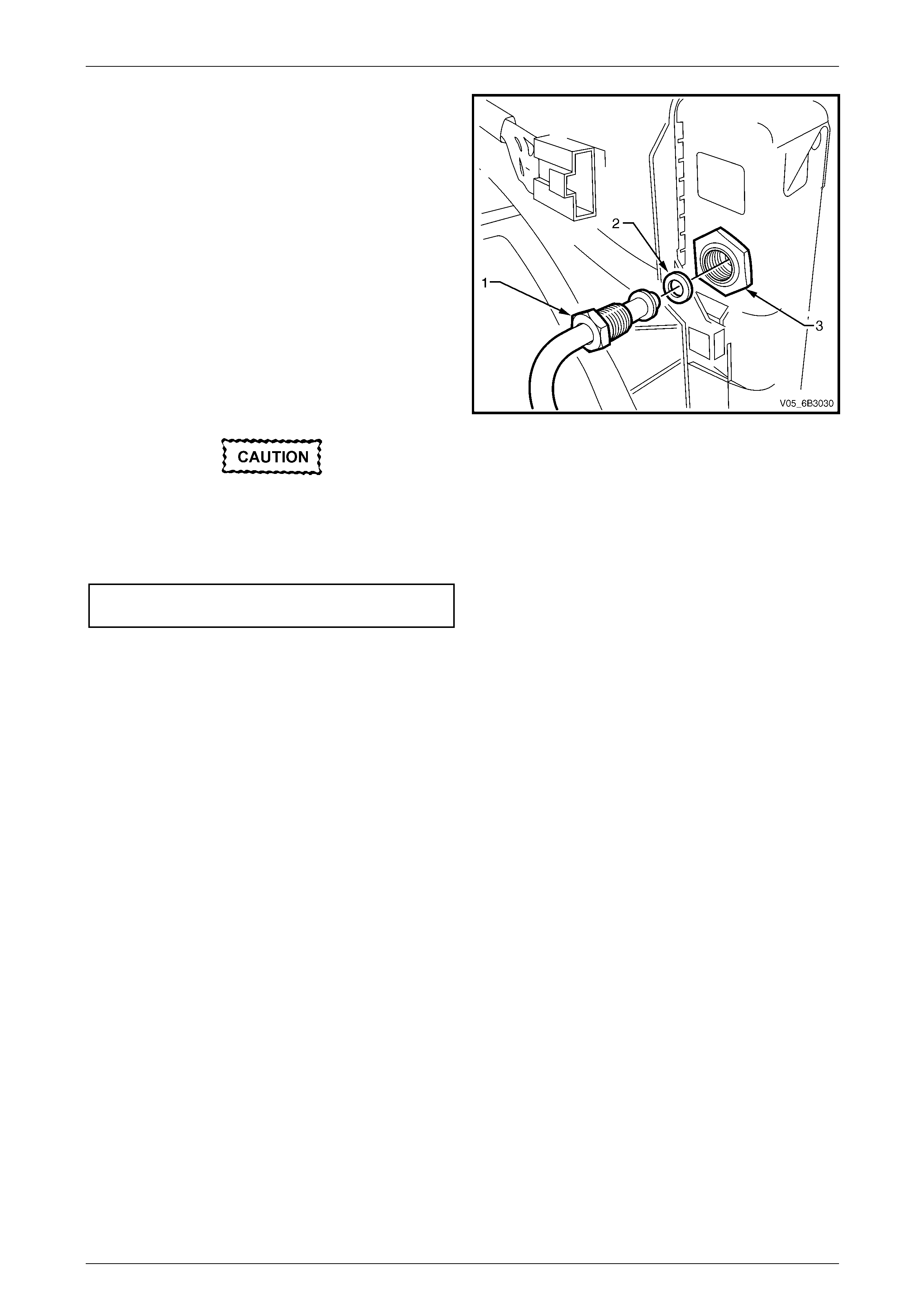
Engine Cooling – GEN III V8 Page 6B3–66
Page 6B3–66
8 Using a suitable set spanner, loosen the cooler pipe
tube nut (1), then remove, taking care not to lose the
sealing washer (2). Plug both open ends to prevent
fluid loss and / or dirt entry.
NOTE
A back-up spanner must be used on the larger
cooler, flare nut fitting (3) to prevent it from
loosening.
9 Repeat for the second pipe / hose assembly.
10 Before installing each pipe to the cool er, carefully
inspect the pipe-sealing washer. If the centre, silicone
portion shows signs of distress or damage, it must be
replaced.
11 Remove the plugging from the pipe and fittings, fit the
sealing washer to the clean ed pipe and install into the
cooler.
A back-up spanner must be used on the
larger cooler, flare nut fitting (3) to prevent it
from loosening.
12 Install the tube nut and tighten to the correct torque
specification.
Oil cooler pipe tube nut
torque specification..............................................25 N.m
Figure 6B3 – 81
13 Check the transmission fluid level. Refer to the following references as required:
• Section 7C4 Automatic Transmission – 4L60E On-vehicle Servicing

Engine Cooling – GEN III V8 Page 6B3–67
Page 6B3–67
4 Engine Cooling System
Diagnosis
4.1 Poor Heater Operation
Little or no heat coming from the heater, especiall y at idle could be an indication of a cooling system problem.
As the coolant level begins to get lower than normal, air enters the system to replace the missing coolant. The heater
core is one of the highest parts of the cooling system and therefore, the first area to lose coolant circulation.
At first, with a small amount of coolant loss, lack of heat will be most noticeable at idle. As driving spee d increases, the
engine pumps more coolant a nd more heat is now able to pass through the heater core.
If coolant level drops even lower, heater operation will become less effective, even during normal driving. Cooling and
engine systems can be adversely affected if problem is not corrected before overheating occurs.

Engine Cooling – GEN III V8 Page 6B3–68
Page 6B3–68
4.2 Leaking Cylinder Head Gasket
Combustion gases leaking past the cylinder head gask et can pr essurise the cooling system, forcing coolant out of the
system and into the coolant recover y res ervoir.
Indications are air bubbles in the coolant or an overflow condition of the recovery reservoir.

Engine Cooling – GEN III V8 Page 6B3–69
Page 6B3–69
4.3 Question the Customer
To avoid needless time and c ost in diagnosing cooling system complaints, the customer should be questioned about
driving conditions that place abnormal loads on the co oling system.
1 Is overheating occurring after prolonged idle, in gear, with air conditioning system operating?
If answer is YES – instruct owner on driving techniques that would avoid overheating such as:
• Idle in neutral as much as possible – increase engine rpm to get higher air flow (due to an increase in voltage
to the fan) and coolant flow through the rad iator.
• Turn air conditioning s ystem off during extended idling periods if overheatin g is indicated on temperature
gauge. Further diagnostic che cks should not be required.
2 Is overheating occurring after prolong ed driving in slo w city traffic, traffic jams, parades, etc?
If answer is YES, explain driving technique to the customer, that would avoid overheating – same as for prolonged
idle – No.1. Further diagnostic checks should not be required.
Engine Cooling – GEN III V8 Page 6B3–70
Page 6B3–70
4.4 Diagnostic Chart
If none of the above conditions apply, refer to the following Diagnosis Cha rt.
To effectively use this chart, question the customer to determine which of the following three categories apply to the
complaint:
1 If complaint is hot indication on temperatur e gauge.
Was temperature reading accompanied by boiling?
• If answer is YES, go to overheating on diagnosis chart.
• If answer is NO, check temperature gauge and sender.
2 If complaint is boiling – go to overheating on diagnosis chart.
3 If complaint is coolant loss. Determine if customer is filling the system corr ectly.
4 If incorrect filling is not the problem, go to coolant loss in the diagnosis chart.
Refer to 3.1 Service Notes in this Section, for
important safety items before removing the
radiator pressure cap or servicing the system.
The cooling system is designed to operate at
95 to 120 kPa and temperat ures n o t exce edin g
130°C.
Cooling System Diagnosis
Step Action Result Yes No
1 Check Temperature gauge reading High Temp.
Low Temp. Go to Step 2
Go to Step 6 –
2 Check drive belt condition and tension. Refer to
3.6 Engine Accessory Drive Be lt Tension and 3.7 Engine
Accessory Drive Belt in this Section. Refer also to
Section 6A3 Engine Mechanical – GEN III V8 Engine.
To
Specification Go to Step 3 Replace drive
belt or
tensioner.
3 Check coolant Boiling Go to Step 4 Go to Step 5
4 Check coolant level. Refer to 3.2 Coolant Maintenance in
this Section. Low Go to Step 10 Go to Step 6
5 Check radiator cap. Refer to 3.8 Pressure Testing –
Radiator Cap Pressure Testing in this Section OK? Go to Step 8 Replace
Coolant filler
cap
6 Check thermostat. Refer to 3.9 Thermostat in this
Section. OK? Go to Step 9 Go to Step 13
7 Check Engine Coolant Temperature (ECT) sensor. Refer
to Section 6C3-2 Powertrain Management – GEN III V8
– Diagnostics.
Faulty Replace Go to Step 12
8 Check cooling fan operation. Refer to Section 6C3-2
Powertrain Management – GEN III V8 – Diagnostics. Operational Go to Step 10 Repair
9 Check for collapsed upper or lower radiator hose. Collapsed Replace Go to Step 13
10 Visual system check Leaks Go to Step 13 Go to Step 11
11 Check coolant concentration. Refer to 3.2 Coolant
Maintenance – Testing Coola nt Conce ntratio n. To
Specification Go to Step 12 Correct
Concentration
Level
12 Check radiator core for bent fins, dirt, bugs or other
obstructions. Obstructed Clean or
straighten Go to Step 14
13 Pressure Test cooling system. Refer to 3.8 Pressure
Testing – Cooling System Pressure Testing in this
Section.
Leaks Repair System OK
14 If none of the above require repair, the problem is out of
ordinary or of a major natur e. Listed below are two
groups of problem areas that should b e checked in the
order as shown.

Engine Cooling – GEN III V8 Page 6B3–71
Page 6B3–71
4.5 Problems Not Requiring Disassembly of
Cooling System
1 Large obstructi ons blocking radiator or condenser airflow.
• Auxiliary oil coolers.
• License plate.
• Obstruction of radiator grille, for example, driving lights or mud.
2 Loose, damaged or missing a ir chute side panels.
3 Missing or damaged air baffle.
4 Cracked or loose coolant recover y system hos e.
5 Leaking heater compon ent such as the heater core or water valve.

Engine Cooling – GEN III V8 Page 6B3–72
Page 6B3–72
4.6 Problems Requiring Disassembly of
Cooling System
1 Damaged cooling fan or faulty motor operation.
2 Pressure test cooling system.
3 Defective coolant pump.
• Eroded or broken impeller van es.
• Failed bearing or seal – check for shaft or bearing end play.
4 Internally blocked radiator core.
5 Obstruction of coolant recovery system.
6 Internal system leaks.
• Head gaskets.
• Cracked cylinder block.
• Engine front cover.
• Intake manifold gaskets.
7 Blocked coolant passages in cylinder he ads or block – remove cylinder heads and check.
8 Blocked or damaged vapour vent system.
Engine Cooling – GEN III V8 Page 6B3–73
Page 6B3–73
4.7 Black Light and Dye Leak Diagnosis
Method
It is strongly recommended that the black light and dye method be used to diagnose and locate fluid leaks. This method
of leak detection is a proven, reliable method that identifies the specific leak source and / or location. The black light kit is
suitable for various types of leak detection, when used with the appropriate tracer dye and can be used for detecting
engine coolant, engine oil, transmission fluid, and air conditi oni ng refrigerant leaks. The following is a summary of the
steps involved in detecting a cooling system fluid leak using black li ght and dye.
Adding dye to the GEN III V8 engine cooling
system, may chang e the colour of the coolant
from an orange colour to a dark, muddy
green. As the use of extended life anti-freeze
coolant (conforming to GM6277M) to this
cooling system is mandatory and is not to be
mixed with other composition coolants, the
green colour could be misleading for future
top-up operations.
Therefore, should the coolant change colour
when the leak detection dye is added, then
the cooling system MUST be drained and n ew
extended life anti-freeze coolant (conforming
to GM6277M) coolant added. Refer to
3.3 Draining and Filling Cooling System, in
this Section.
1 Pour specified amount of dye into the cooling system via the coolant filler cap on the radiat or.
Refer 3.1 Service Notes in this Section.
2 Road test the vehicle under normal operati ng conditions.
3 Direct the black light towards the suspect area. Any fluid leak will app ear as a brightly coloured path leading to the
source.
4 Repair fluid leak and recheck to ensure that leak has been rectified.
5 Refer to the manufacturer’s directions when using this method.

Engine Cooling – GEN III V8 Page 6B3–74
Page 6B3–74
5 Specifications
General
Radiator Cap Pressure Rating Nominal.......................................................................120 kPa
Cooling System Capacity.......................................................................................... 11.0 litres
Coolant Corrosion Inhibitor......................................................................................... 5.5 litres
NOTE
DEX-COOL® long life coolant or equivalent, to
GM Specification 6277M, required when
changing coolant.
Thermostat
Type...............................................................................................Power element (wax pellet)
Starts to Open at.....................................................................................................86 ± 1.5° C
Fully Open at .................................................................................................................100° C
Coolant Pump
Type.........................................................................................................................Centrifugal
Drive.........................................................................................Multi-ribbed, Serpentine V-belt
Bearing Type ......................................................................................Double-row ball bearing
Radiator
Core Type........................................................................................ Aluminium crossflow core
Overall Width...............................................................................................................826 mm
Overall Height..............................................................................................................495 mm
Core Width...................................................................................................................674 mm
Core Height .................................................................................................................427 mm
Core Thickness..............................................................................................................35 mm
Plastic Tanks ...............................................................................Nylon 6,6 (30% Glass Filled)
Radiator Hoses
Lower – Number and type ................................................................................. One, Moulded
Upper – Number and type ................................................................................. One, Moulded

Engine Cooling – GEN III V8 Page 6B3–75
Page 6B3–75
Small Engine Cooling Fan (LHS)
Electric motor drive (Nominal Power Rating) ...........................................................180 Watts
Rotational Speed (with 12 volts applied, Radiator and Con denser installed)
– Stage 1 ..............................................................2,050 ± 150 rpm
– Stage 2 ..............................................................2,300 ± 150 rpm
Number of Blades...................................................................................................................5
Fan – Design ..........................................Asymmetrical spaced, curved blades with outer ring
Material..................................Nylon 6,6 (30% Glass Filled), with zinc coated metal hub insert
Diameter......................................................................................................................293 mm
Fan Motor – Type .........................................Dual-speed, 4 brush with 4 permanent magnets
Housing ...........................................................Semi-sealed, zinc-coated steel with drain hole
Direction of Rotation.............................................. Anticlockwise (as viewed from motor side)
Large Engine Cooling Fan (RHS)
Electric motor drive (Nominal Power Rating) ...........................................................220 Watts
Rotational Speed (with 12 volts applied, Radiator and Con denser installed)
– Stage 1 ..............................................................2,350 ± 150 rpm
– Stage 2 ..............................................................2,750 ± 150 rpm
Number of Blades...................................................................................................................5
Fan – Design ..........................................Asymmetrical spaced, curved blades with outer ring
Material..................................Nylon 6,6 (30% Glass Filled), with zinc coated metal hub insert
Diameter......................................................................................................................354 mm
Fan Motor – Type .........................................Dual-speed, 4 brush with 4 permanent magnets
Housing ...........................................................Semi-sealed, zinc-coated steel with drain hole
Direction of Rotation.............................................. Anticlockwise (as viewed from motor side)
Pressure Transducer
Low Pressure Cut Out .................................................................................................180 kPa
Low Pressure Cut In....................................................................................................240 kPa
High Pressure Cut Out..............................................................................................2,900 kPa
High Pressure Cut In ................................................................................................2,000 kPa

Engine Cooling – GEN III V8 Page 6B3–76
Page 6B3–76
6 Torque Wrench Specifications
Coolant Pump to Cylinder Block Bolts:
Stage 1........................................................................................15 N.m
Stage 2........................................................................................25 N.m
Coolant Pump Rear Cover Bolts ............................................................14 N.m
Engine Accessory Drive Belt Tensioner Bolt..........................................50 N.m
Fan Motor to Shroud Screws....................................................................5 N.m
Oil Cooler Pipe to Oil Cooler Tube Nut ..................................................25 N.m
Oil Pan Under-Tray Bolts........................................................................30 N.m
Thermostat Housing to Coolant Pump Bolts...........................................14 N.m
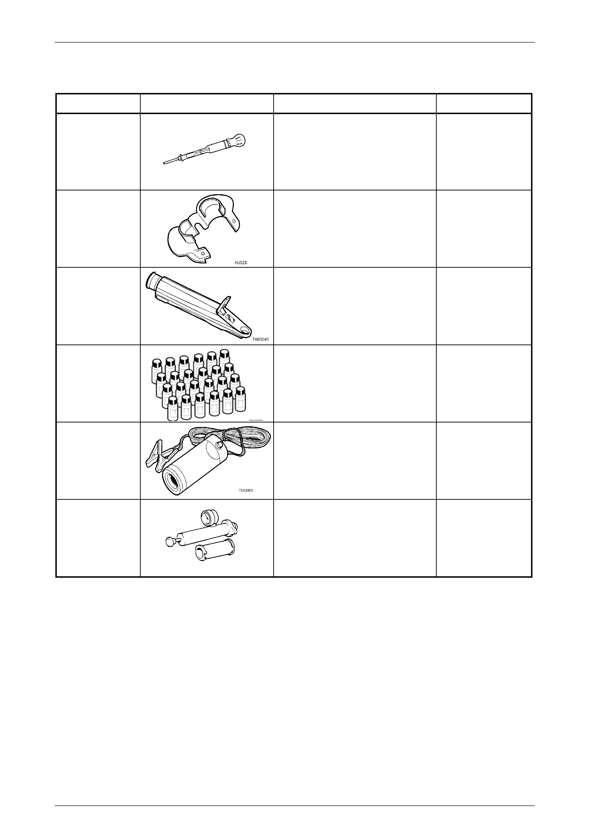
Engine Cooling – GEN III V8 Page 6B3–77
Page 6B3–77
7 Special Tools
Tool number Illustration Description Classification
AU505
COOLANT TESTER
Used for testing the coolant
concentration level.
Previously released.
Mandatory
AU525
QUICK CONNECT RELEASE TOOL
Used to release the quick connect
fittings on the automatic transmission
fluid cooler lines at the radiator end,
when the vehicle is so equipp ed.
Previously released.
Mandatory
J 26568
REFRACTOMETER
Used for testing coolant concentration
level. Previously released, as AU 435.
Mandatory
J28431–B FLUID DYE
Available in 24 x 1-ounc e bottles.
Used in conjunction with a black light
such as J42220 to locate the source
of various fluid leaks.
Previously released.
Desirable
J42220 BLACK LIGHT, LEAK DETECTION
LAMP
Used with dye, J28431–B to locate the
source of various vehicle fluid leaks.
Previously released.
Desirable
N/A COOLING SYSTEM PRESSURE
TESTER
Commercially available.
Mandatory