
Powertrain Management GEN III V8 – General Information Page 6C3-1–1
Page 6C3-1–1
Section 6C3-1
Powertrain Management GEN III V8 –
General Information
ATTENTION
Before performing any service operation or other procedure described in this Section, refer to Section 00
Warnings, Cautions and Notes for correct workshop practices with regard to safety and/or property damage.
1 General Information ...............................................................................................................................3
1.1 Introduction............................................................................................................................................................ 3
1.2 Emission Control................................................................................................................................................... 4
Euro 2 Emissions Standards ................................................................................................................................ 4
2 Component Locations ...........................................................................................................................5
2.1 Cylinder Numbering............................................................................................................................................... 5
2.2 Engine Compartment............................................................................................................................................. 6
2.3 Engine..................................................................................................................................................................... 7
2.4 Automatic Transmission....................................................................................................................................... 9
2.5 Interior .................................................................................................................................................................. 10
3 System Operation.................................................................................................................................11
3.1 Fuel Delivery System........................................................................................................................................... 12
Fuel System Modes of Operation....................................................................................................................... 12
Starting Mode................................................................................................................................................... 12
Clear Flood Mode............................................................................................................................................. 12
Run Mode......................................................................................................................................................... 13
Acceleration Mode............................................................................................................................................ 13
Power Enrichment Mode.................................................................................................................................. 13
Deceleration Mode........................................................................................................................................... 13
Fuel Shut-off Mode........................................................................................................................................... 13
Engine Protection Mode................................................................................................................................... 13
Battery Voltage Correction Mode..................................................................................................................... 14
Limp Mode ....................................................................................................................................................... 14
Speed Density Mode........................................................................................................................................ 14
Catalyst Protection Mode................................................................................................................................. 14
Short and Long Term Fuel Trim.......................................................................................................................... 14
3.2 Electronic Ignition (EI) System........................................................................................................................... 15
3.3 Throttle Actuator Control (TAC) System............................................................................................................ 16
Description........................................................................................................................................................... 16
Throttle Body Relearn Procedure..................................................................................................................... 17
3.4 Emission Control Systems.................................................................................................................................. 19
Evaporative Emission Control System .............................................................................................................. 19
Engine Ventilation System.................................................................................................................................. 19
3.5 Electric Cooling Fans.......................................................................................................................................... 20
3.6 Torque Management............................................................................................................................................ 21
4 System Components............................................................................................................................22
4.1 A/C Refrigerant Pressure Sensor....................................................................................................................... 22
4.2 Brake Pedal Switches.......................................................................................................................................... 23
Stop Lamp and BTSI Switch Assembly ............................................................................................................. 23
Cruise Control Release and Extended Brake Travel Switch Assembly.......................................................... 23

Powertrain Management GEN III V8 – General Information Page 6C3-1–2
Page 6C3-1–2
4.3 Cruise Control System ........................................................................................................................................ 24
4.4 Camshaft Position (CMP) Sensor....................................................................................................................... 25
4.5 Crankshaft Position (CKP) Sensor..................................................................................................................... 26
4.6 Engine Coolant Temperature (ECT) Sensor ...................................................................................................... 27
4.7 Engine Oil Pressure (EOP) Sensor..................................................................................................................... 28
4.8 Fuel Rail Assembly.............................................................................................................................................. 29
Fuel Injectors........................................................................................................................................................ 29
4.9 Heated Oxygen Sensors (HO2S)......................................................................................................................... 30
4.10 Ignition Coils / Modules....................................................................................................................................... 32
4.11 Intake Air Temperature (IAT) Sensor.................................................................................................................. 33
4.12 Knock Sensors (KS) ............................................................................................................................................ 34
4.13 Manifold Absolute Pressure (MAP) Sensor....................................................................................................... 35
4.14 Air Intake System................................................................................................................................................. 36
Mass Air Flow (MAF) Sensor............................................................................................................................... 36
Intake Air Temperature (IAT) Sensor.................................................................................................................. 37
4.15 Powertrain Control Module (PCM)...................................................................................................................... 38
Self Diagnosis...................................................................................................................................................... 38
Programming........................................................................................................................................................ 38
4.16 Vehicle Speed Sensor (VSS)............................................................................................................................... 40
5 Automatic Transmission Components ..............................................................................................41
5.1 Range Switch (PRNDL)........................................................................................................................................ 41
Range Switch Valid Combination Table............................................................................................................. 41
5.2 1-2 (A) and 2-3 (B) Shift Solenoid Valves........................................................................................................... 42
5.3 3-2 Shift Solenoid Valve Assembly .................................................................................................................... 43
5.4 Pressure Control Solenoid.................................................................................................................................. 44
5.5 Torque Converter Clutch (TCC) Solenoid Valv e................................................................................................ 45
5.6 Torque Converter Clutch PWM Solenoid Valve................................................................................................. 46
5.7 Fluid Pressure Switch Assembly........................................................................................................................ 47
Pressure Switch Valid Combination Table........................................................................................................ 47
5.8 Fluid Temperature (TFT) Sensor......................................................................................................................... 49
6 Abbreviations and Glossary of Terms...............................................................................................50

Powertrain Management GEN III V8 – General Information Page 6C3-1–3
Page 6C3-1–3
1 General Information
The GEN III V8 powertrain management
system incorporates functions and
components that could cause personal injury
or vehicle damage. Refer to Section 6C3-2
GEN III V8 Powertrain Management –
Diagnostics, and Section 6C3-3 GEN III V8
Powertrain Management – Service
Operations, before attempting any diagnosis
or repairs.
1.1 Introduction
The GEN III V8 engine and transmission assembl y incorp orates an electronic powertrain management system. T his
Section describes the operation and lo cations of the various systems and components enc ompassed by the powertrain
management system.
The powertrain management system is controlled b y the powertrain control module (PCM) which is located on the left-
hand side of the engine compartment.
The PCM controls:
• the fuel injection system,
• ignition timing and dwell,
• engine throttling,
• automatic transmission functions,
• the engine cooling fans, and
• the air-conditioner compressor clutch ( where fitted).
The engine and transmission incorporate sensors that provide input to the PCM, and a range of components that perform
functions as commanded by the PCM, refer to Figure 6C3-1 – 7.
The powertrain management system has a self diagnostic capa bil ity, as well as connections to enable diagnosis of faults.
If the PCM recognises operational problems it can alert the driver via the check powertrain icon in the instrument cluster
multi-function display. The PCM also interfaces with other systems in the vehicle as required.
The vehicle incorporates a the ft deterrent system. When the ignition switch is turned from off to on, the body control
module (BCM) will transmit serial security data to the PCM via the powertrain interface module (PIM). If the data
matches, the PCM and PIM will enable the starter relay and fuel injection. For further infor m ation and diagnosis of the
theft deterrent system, refer to Section 12J Body Control Module.
For further information on the PIM, refer to Section 6E3 Powertrain Interface Module – GEN III V8.
For further information on the air-conditioni ng system, refer to Section 2A HVAC Climate Control – Description and
Operation.
For the location of fuses, fusible links and relays, refer to Section 12O Fuses, Relays, an d Wiring Harnesses.

Powertrain Management GEN III V8 – General Information Page 6C3-1–4
Page 6C3-1–4
1.2 Emission Control
Euro 2 Emissions Standards
The vehicle has been configured to comply with Euro 2 vehicle emissions standards. Euro 2 is a European standard
which sets vehicle emissions targets to compel vehicle manufacturers to reduce harmful vehicle emissio ns such as
carbon monoxide (CO), hydrocarbons (HC) and the various oxides of nitrogen (NOx).
Australian Design Rule 79/00 implements the Euro 2 exhaust and evaporative emissions requirements for light veh icles
to reduce air pollution. The following tests are prescribed:
• average tailpipe emissions after a cold start,
• carbon monoxide emission at idling speed,
• emission of crankcase gases,
• evaporative emissions, and
• durability of pollution-control d evices.
Powertrain Management GEN III V8 – General Information Page 6C3-1–5
Page 6C3-1–5
2 Component Locations
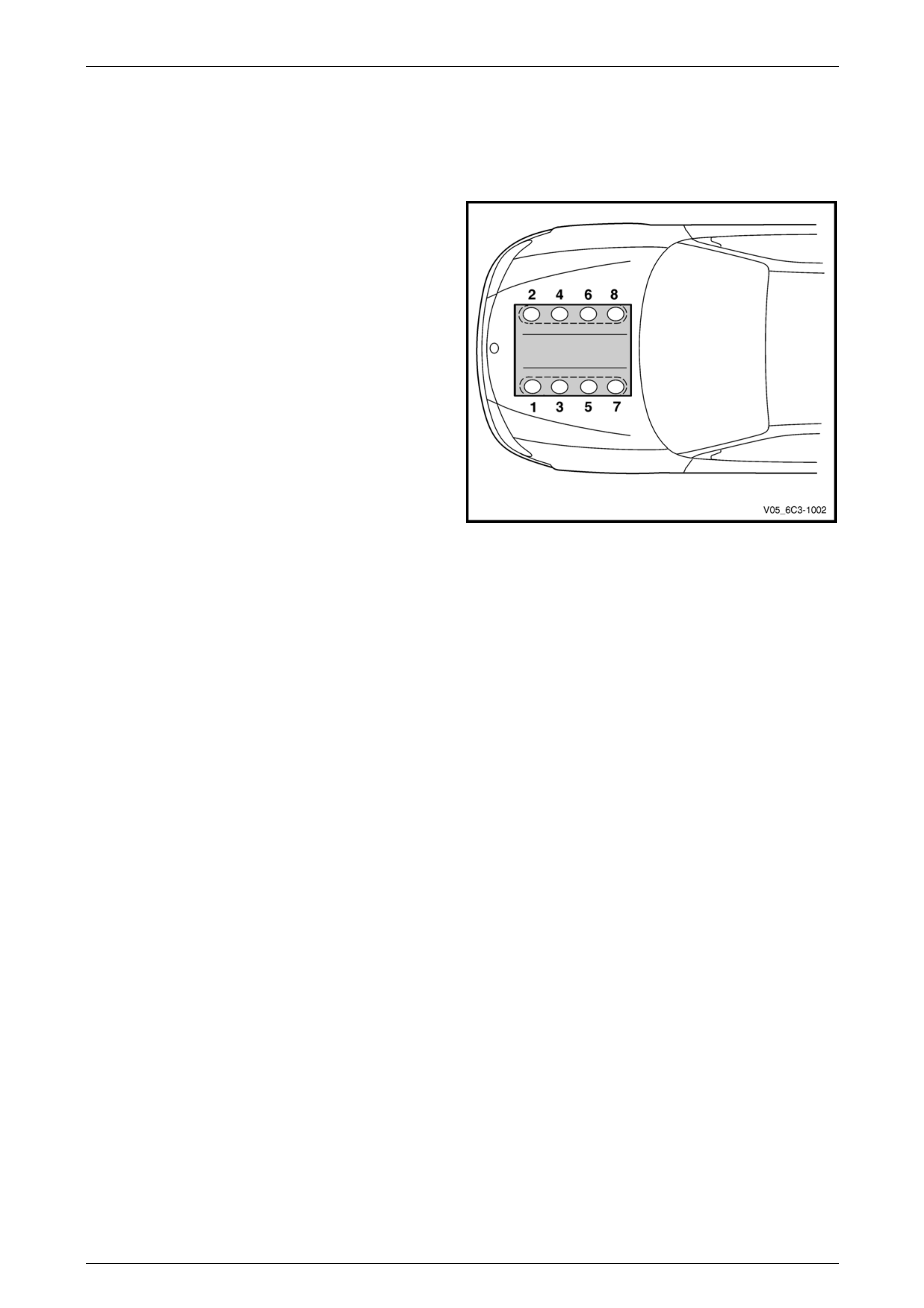
2.1 Cylinder Numbering
Engine cylinder identification follows the international
standard OBD II. This standard calls for the engine cylinder
bank number one to be identified by the location of cylinder
number one. Therefore the numbering for the GEN III V8
engine is:
• 1, 3, 5, 7 – Left-hand side (Bank 1),
• 2, 4, 6, 8 – Right-hand side (Bank 2).
The engine firing order is 1, 8, 7, 2, 6, 5, 4, 3.
Figure 6C3-1 – 1
Powertrain Management GEN III V8 – General Information Page 6C3-1–6
Page 6C3-1–6
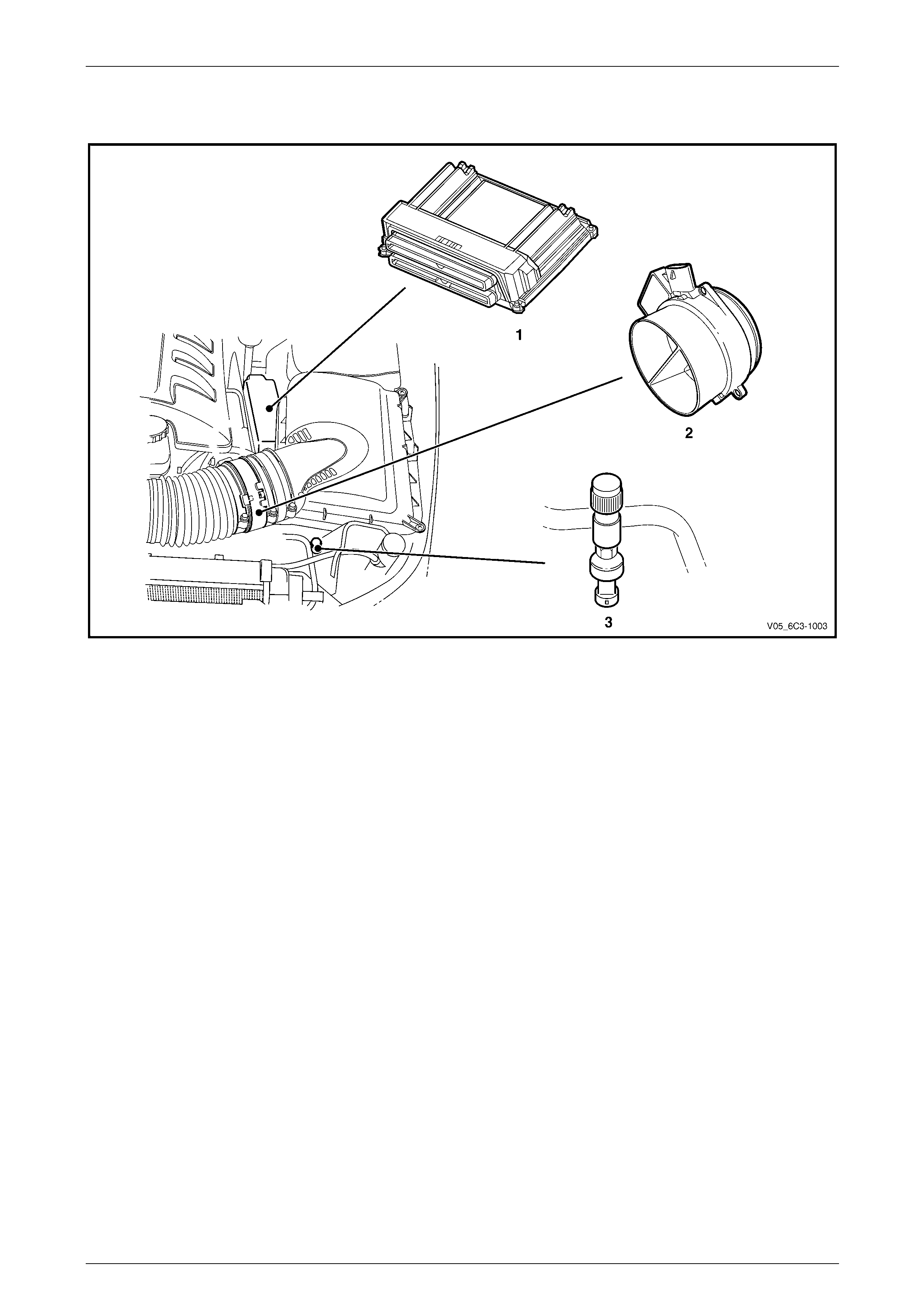
2.2 Engine Compartment
Figure 6C3-1 – 2
Legend
1 Powertrain Control Module (PCM)
2 Mass Air Flow (MAF) Sensor 3 Air-conditioner Refrigerant Pressure Sensor
Powertrain Management GEN III V8 – General Information Page 6C3-1–7
Page 6C3-1–7
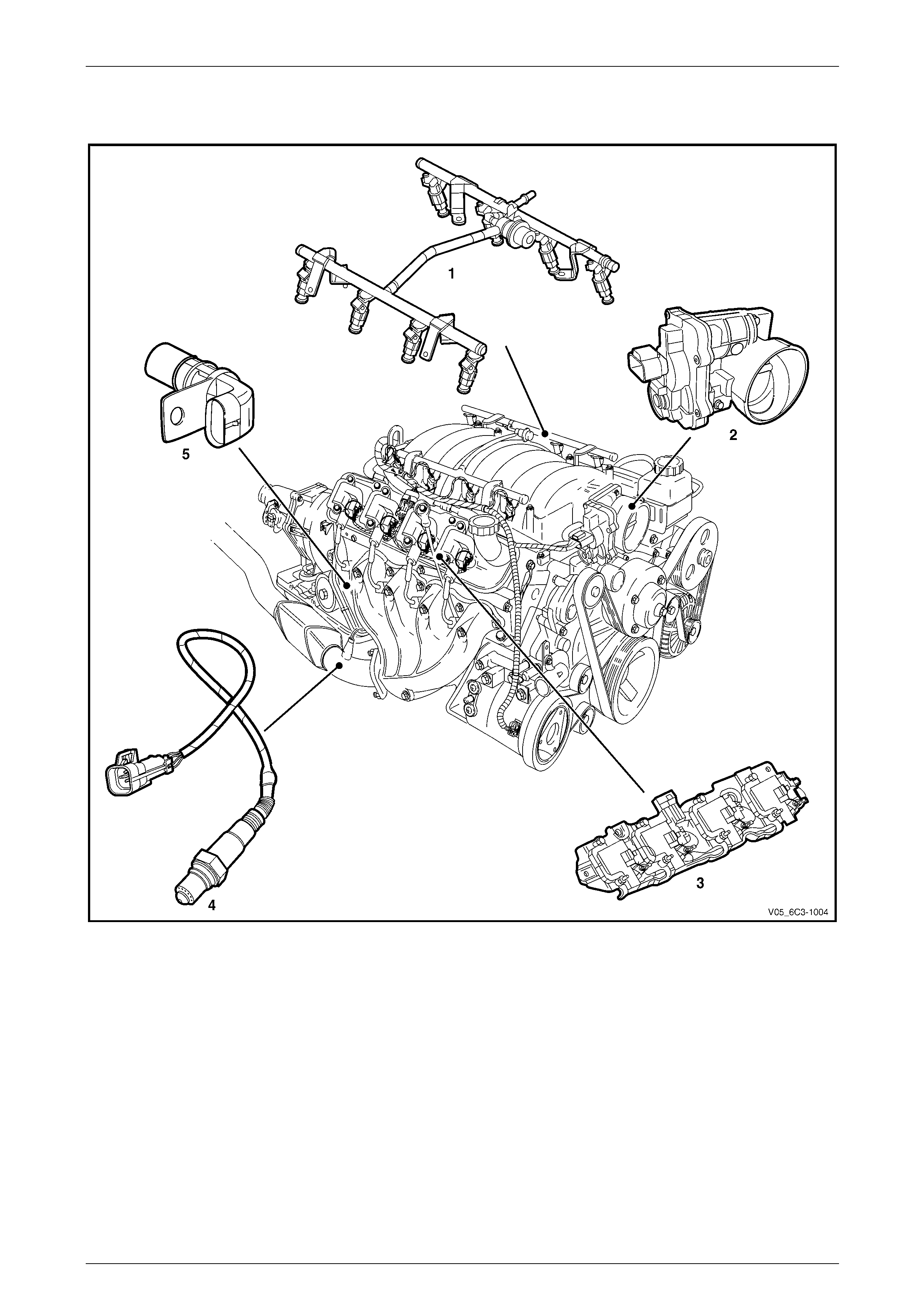
2.3 Engine
Figure 6C3-1 – 3
Legend
1 Fuel Rail Assembly (with fuel injectors)
2 Throttle Body
3 Ignition Coils/Modules Assembly, 2 Places
4 Heated Oxygen Sensor (HO2S), 2 places
5 Crankshaft Position (CKP) Sensor
Powertrain Management GEN III V8 – General Information Page 6C3-1–8
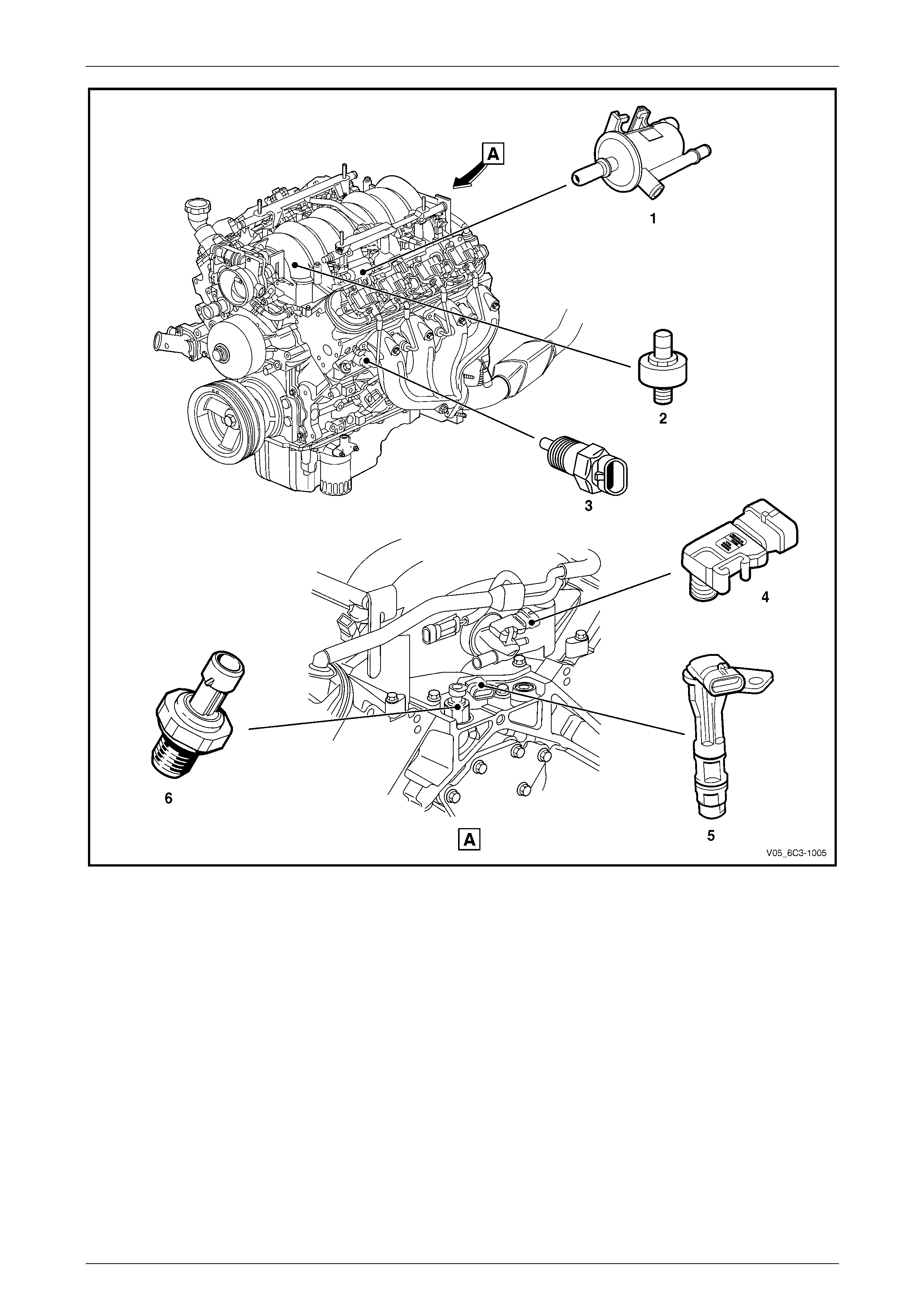
Page 6C3-1–8
Figure 6C3-1 – 4
Legend
1 Evaporative Canister Purge Solenoid
2 Knock Sensor, 2 Places
3 Engine Coolant Temperature (ECT) Sensor
4 Manifold Absolute Pressure (MAP) Sensor
5 Camshaft Position (CMP) Sensor
6 Engine Oil Pressure (EOP) Sensor
Powertrain Management GEN III V8 – General Information Page 6C3-1–9
Page 6C3-1–9
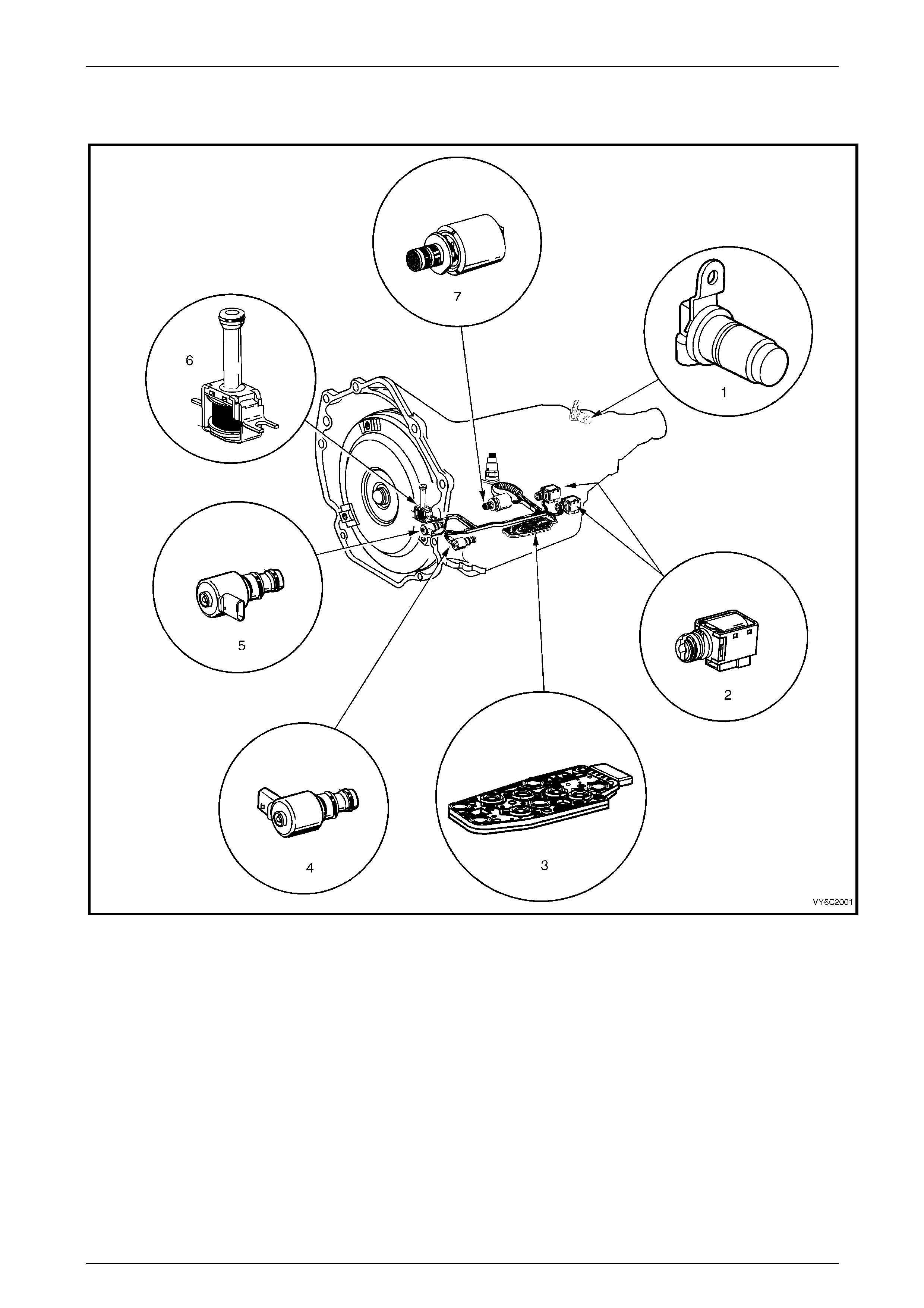
2.4 Automatic Transmission
Figure 6C3-1 – 5
Legend
1 Vehicle Speed Sensor
2 1-2 Shift Solenoid A and 2-3 Shift Solenoid B
3 Automatic Transmission Fluid Pressure (TFP) Manual
Valve Position Switch
4 3-2 Downshift Control Solenoid
5 Torque Converter Clutch Pulse Width Modulation (TCC
PWM) Solenoid Valve
6 Torque Converter Clutch (TCC) Solenoid Valve
7 Pressure Control Solenoid (PCS) Valve

Powertrain Management GEN III V8 – General Information Page 6C3-1–10
Page 6C3-1–10
2.5 Interior
Figure 6C3-1 – 6
Legend
1 Check Powertrain Icon
2 Accelerator Pedal Assembly
3 Data Link Connector (DLC)
4 Extended Brake Pedal Travel and Brake Pedal Cruise
Control Cancel Switch
5 Stop Lamp and BTSI Switch Assembly
Powertrain Management GEN III V8 – General Information Page 6C3-1–11
Page 6C3-1–11
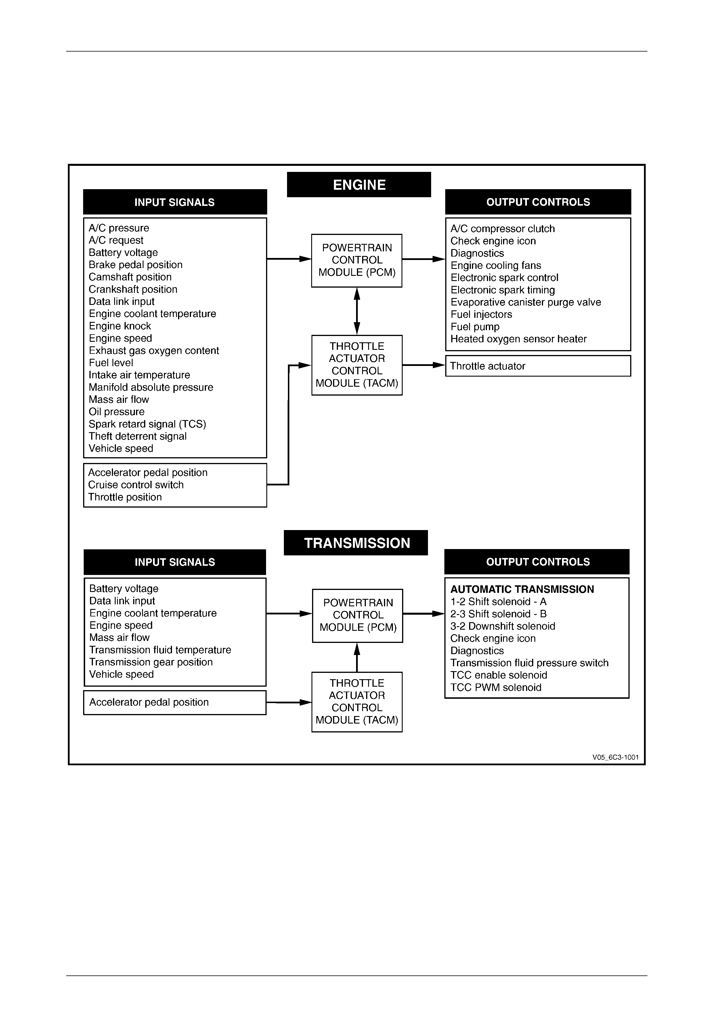
3 System Operation
The PCM is the control centre of the GEN III V8 powertrain management system and constantly monitors and evaluates
inputs from various sensors and switches. Based on these inputs, the PCM controls the operation of the powertrain
management system. Refer to Figure 6C3-1 – 7 for the illustration of the inputs and outputs of the PCM.
Figure 6C3-1 – 7

Powertrain Management GEN III V8 – General Information Page 6C3-1–12
Page 6C3-1–12
3.1 Fuel Delivery System
Unleaded fuel must be used to ensure correct emission parameters and engine operation. Leaded fuel can damage the
emission control system and can result in loss of emission warranty. Using unleaded fuel will also minimise any spark
plug fouling and e xtend engine oil life.
The function of the fuel and air control s yste m is to manage the delivery of fuel and air mixture to each cylinder,
optimising the performance and t he driveability of the engine und er all conditions. A modular fuel pump and sender
assembly delivers fuel from the fuel tank and provides infor mation on the fuel level.
The fuel supply system is a single lin e, on-demand design. With the fuel pressure regulator incorporated into the modular
fuel pump and sender assembly, the need for a return pipe from the engine is eliminated. Havin g a single line fuel supply
system reduces the internal temperature of the fuel tank by not returning hot fuel from the engine. In reducing the internal
temperature of the fuel tank, lower evaporative emissions are achieved.
An electric fuel pump contained in the modu lar fuel pump and sender assembly provides fuel at a pressure above the
regulated pressure which is supplied to the fuel rail. The fuel is then distributed through the fuel rail to six injectors
located directly above each cylind er’s two intake valves. A fuel pump relay allows the PCM to control the fuel pump.
The PCM controls each fuel in jector by energising the injector coil for a brief period once every other engine revolution.
The length of this brief period is carefully calculated by the PCM to deliver the correct amount of fuel for optimum engine
performance and emission control. The period of time when the injector is energised is called the pulse width and is
measured in milliseconds (thousandths of a second).
While the engine is running, the PCM is constantly monitoring the inputs and recalculating the appropriate pulse width for
each injector. The pulse width calculation is based on:
• the injector flow rate,
• mass of fuel passed by the energised injector per unit of time,
• the desired air/fuel ratio, and
• actual air mass in each cylinder.
The calculated pulse is timed to occur as each cylinder’s intake valve is closing to provide enough time for the fuel to
atomise completely and mix with the intak e air. Each injector is energised individually in the engine firing order, which is
known as sequential fuel injection.
Fuel System Modes of Operation
The PCM has several operati ng modes for fuel control, depending on the information received from the sensors.
Starting Mode
When the ignition s witch is turned on, the PC M energises the fuel pump circuit to operate the fuel p ump which builds
pressure in the fuel system. If the PCM does not receive reference pulses from the cranks haft position sensor, the fuel
pump circuit will be de-energised after 2 seconds. When the ignition switch is moved to the START position, the fuel
pump circuit will remain (or become) energised by the PCM once reference pulses are received from the crankshaft
position sensor.
As the engine begins to turn, a prime pulse may be injected to speed starting. As soon as the PCM can determine where
in the firing order the engine is, the PCM begins p ulsi ng the injectors. The PCM also monitors mass air flow, intake air
temperature, engine coolant temperature, and throttle position in order to determine the required injector pulse width for
starting.
Clear Flood Mode
If the engine is flooded with fuel during cranking and will not start, the clear flood mode can be manually selected by
depressing the accelerator pedal to wide open throttle (WOT). In this mode, the PCM will completely turn off the
injectors, and will maintain this state during engine cranking as long as th e PCM detects a WOT condition with engine
speed below 1,000 RPM.

Powertrain Management GEN III V8 – General Information Page 6C3-1–13
Page 6C3-1–13
Run Mode
The PCM changes to run mode when it reaches 480 RPM after being started. The run mode has two sub-modes called
Open Loop and Closed Loop.
Open Loop Mode
In open loop, the PCM ignores the signals from the heated oxygen sensors (HO2S), and calculates the required injector
pulse width based primarily on inputs from the mass air flow (MAF), Intake Air Temperature (IAT), and Engine Coolant
Temperature (ECT) sensors. In open loop the calculate d pu lse width may give an air/fuel ratio other than the ideal 14.7
to 1, for example when the engine is cold a richer mixture is needed. The system will stay in the open loop mode until the
HO2S produce a usable output.
Closed Loop Mode
Once the HO2S reaches operating temperature and starts producing its own signal voltage output, the PCM switches to
closed loop mode. In closed loop mode, the PCM initially calculates injector pulse width bas ed on the same sensors
used in open loop and ad ditionally, uses the oxyge n sensor signals to modify and fine tune the fuel pulse width
calculations to precisely maintain the ideal 14.7 to 1 air/fuel ratio.
Acceleration Mode
The PCM monitors changes in the acceler ato r pedal position (APP) and MAF sensor signals to determine when the
vehicle is being accelerated. The PCM will then increase the injector pulse width in order to provide more fuel
accordingly.
Power Enrichment Mode
Similar to Acceleration Mode, the PCM enters power enrichment mode when the PCM detects a large change in the
accelerator pedal position, providing extra fuel to the cylinders as required.
Deceleration Mode
The PCM monitors changes in the APP and MAF sensor signals to determine when the vehicle is being dece lerated. The
PCM will then decrease injector pulse width, or even shut the injectors off for short periods, to reduce exhaust emissions
and improve fuel econom y.
Fuel Shut-off Mode
The PCM has the ability to completely turn off some or all of the injectors when certain conditions are met. These fuel
shut-off modes allow the PCM to protect the engine from damage a nd to also improve the vehicle's drive ability.
The PCM will disable all eight injectors under the following conditions:
• ignition off – to prevent engine run-on,
• ignition on but no ignition refe rence signal – prevents flooding or backfiring,
• at high engine speed – above the red line (rev limiter),
• at high vehicle speed – above the rated tyre speed (vehicle speed limiter), or
• extended high speed closed throttle coast-do wn – reduc es engine emissions and increases engine braking.
The PCM will selectivel y disable the injectors under the following condition s :
• torque management enabled – transmission shifts or abusiv e maneouvres, or
• traction control enabled – in c onjunction with brake application.
Engine Protection Mode
Engine protection mode is en gaged to protect engine components from friction damage in the event of an engine over-
temperature condition being detected by the PCM.
When the PCM is in engine pr otection mode, fuel injectors are systematically disable d an d re-activated. The injectors
that have been shut down allow the air being drawn into the engine to assist with engine cooling.

Powertrain Management GEN III V8 – General Information Page 6C3-1–14
Page 6C3-1–14
Battery Voltage Correction Mode
The PCM can provide compensatio n to main tain acceptable vehicle driveabilit y when the PCM sees a low battery voltage
condition. The battery voltage adjustment is necessary since the changes in the voltage across the inj ector affect the
injector flow rate.
The PCM compensates by performing the following functions:
• increases the injector pulse width to maintain the correct amount of fuel being de livered, and
• increases the idle speed to increase the gen erator outp ut.
Limp Mode
In the event of a major internal problem, the PCM is equipped with a back-up fuel strategy for limp mode that will run the
engine until service can b e performed.
Speed Density Mode
If the PCM detects a malfunction with the MAF sensor circuit, the PCM will default to speed de nsity fuel management. In
speed density mode, the PCM will rely primarily on the MAP sensor instead of the MAF sensor si gnal to control engine
fuelling.
Catalyst Protection Mode
During sustained heav y loads, the PCM increases the pulse width to the injectors to provide extra fuel to prevent the
catalytic converters from overheating.
Short and Long Term Fuel Trim
Short term fuel trim (STFT) represents short term corrections to the fuel injector pulse width calculations based on the
HEGO sensor input signals to the PCM. STFT is not active until the HO2S sensor is at operational temperature.
By using the HO2S as the main reference point for control of engin e fuelling, the PCM can more accurately control the air
/ fuel ratio. This is because when using STFT the PCM reacts to actual results from combustion, and not expected
results (base settings). STFT is used by the PCM to make quick changes to the fuel injector pulse width over a short
period of time.
The values for STFT can be viewed as a percentage using Tech 2. Values greater than 0% indicate that the PCM is
increasing injector pulse width, and negative values (less than 0%) indicate reduced injector pulse widths.
Long term fuel trim (LTFT) represents long term corrections to the fuel injector pulse width calculatio ns based on the long
term trend of the STFT calculations. T he PCM monitors the STFT and will adjust the long term trend of the fuel injector
pulse width when the STFT has been at a particular value for a certain period of time. LT FT is not active until the HO2S
sensor is at operational temperature.
LTFT compensates for engi ne and component wear, condition of filters, and an y other system variations.
The LTFT function of the PCM is divided into 23 cells arranged by MAP sensor readings and engine RPM. Each cell
corresponds to a region on a MAP vs. RPM table. A value of 0% in a given cell indicates that no fuel adjustment is
needed for that engine load and speed condition. As the engine moves through its operating range, the LTFT changes to
the relevant cell. The PCM will read the LTFT value in each cell and adjust the fuel injector base pulse width accordin gly.
As the LTFT changes cell so does STFT, however STFT will only make short term corrections in the cell that the LTFT is
operating in. The ST FT adjustments occur after the LTFT correctio ns are made. In this way, the STFT can make minor
corrections to the injector pulse width in each cell quicker than if the corrections were made from 0% each time the PCM
changed cell.
If STFT and LTFT are both set at their maximum value limit, the fuel control system is out of the limits of control. This will
result in the system going into open loop op eration and a Diagnostic Trouble Code to be set.
The values for LTFT can be viewed as a percentage using Tech 2. Values greater than 0% ind icate that the PCM is
increasing injector pulse width, and negative values (less than 0%) indicate reduced injector pulse widths.
Tech 2 has the ability to reset all LTFT cells to 0%.
All LTFT cell values are reset to 0% when long term memory power to the PCM is removed.

Powertrain Management GEN III V8 – General Information Page 6C3-1–15
Page 6C3-1–15
3.2 Electronic Ignition (EI) System
The electronic ignition s ystem provides a sp ark to ignite the compressed air/fuel mixture at the correct time. The PCM
maintains correct spark timing and dwell for all driving conditions. The PCM calculates the optimum spark parameters
from information received from the various sensors and triggers the appropriate ignition modu le / coil to fire the spark
plug.
Powertrain Management GEN III V8 – General Information Page 6C3-1–16
Page 6C3-1–16
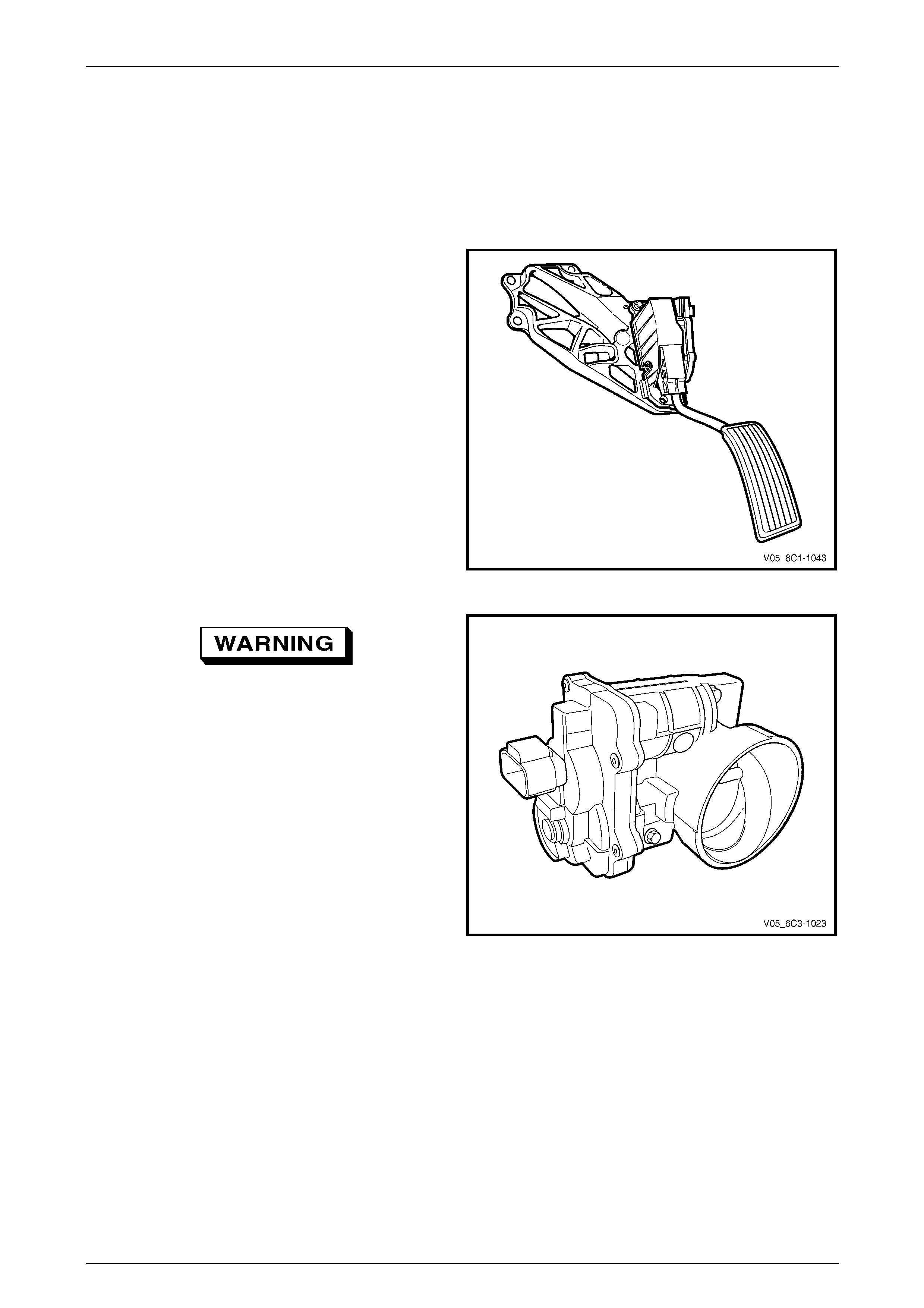
3.3 Throttle Actuator Control (TAC) System
Description
The throttle actuator control (TAC) system is used to impr ov e emissions, fuel economy and drive ability. The TAC system
deletes the mechanical link between the accelerator pedal and the throttle plate and eliminates the need for a cruise
control module and idle air co ntrol motor. The TAC system consists of:
• an accelerator pedal assembly which includes:
• accelerator pedal,
• accelerator pedal position (APP) sensor 1,
• accelerator pedal position (APP) sensor 2;
Figure 6C3-1 – 8
To avoid serious personal injury, never
attempt to rotate the throttle plate manually
whilst the throttle body harness connector is
connected to the throttle bod y.
• a throttle body assembly which includes:
• throttle position (TP) sensor 1,
• throttle position (TP) sensor 2,
• throttle actuator control motor, and
• throttle plate;
Figure 6C3-1 – 9
Powertrain Management GEN III V8 – General Information Page 6C3-1–17
Page 6C3-1–17
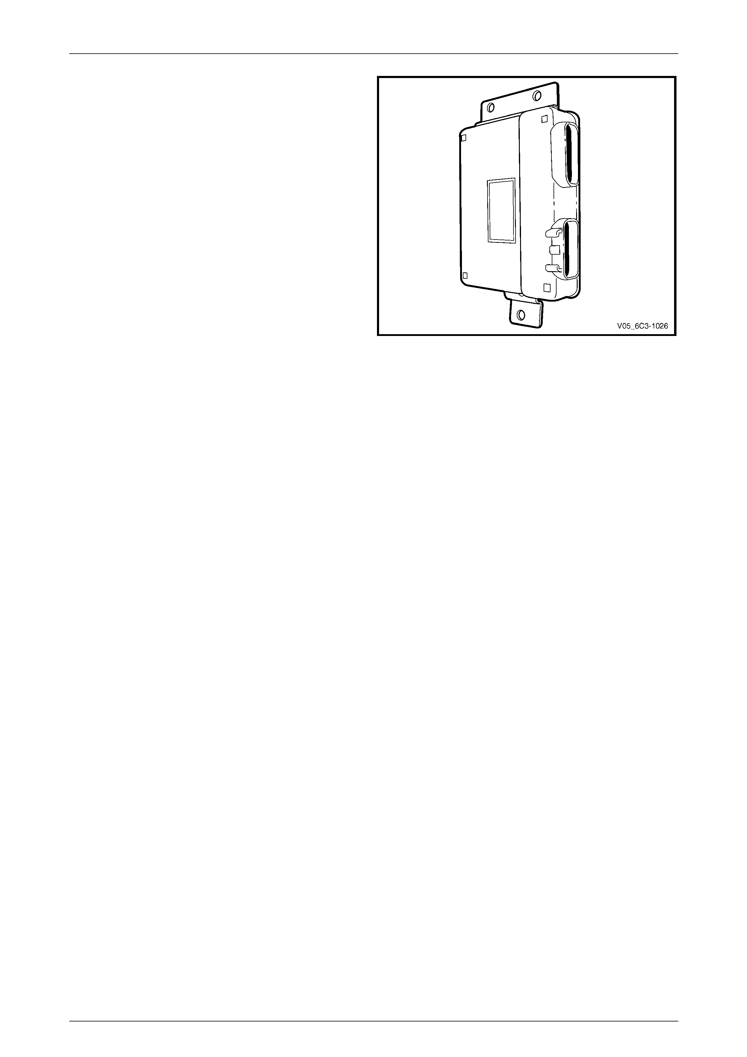
• a throttle actuator control module (TACM);
• a powertrain control module (PCM).
Figure 6C3-1 – 10
The TACM monitors the accelerator pedal position through the two APP sensors and forwards this signal to the PCM via
a dedicated serial data line. The PCM processes this information along with other system sensor inputs to command the
throttle plate to a certain position. T his throttle position requ est is sent back the TACM along the same serial data line,
and the TACM sends a pulse width modulated signal to the throttle body.
A direct current motor called the throttle actuator control motor controls the throttle plate. The TACM can operate this
motor in the forward or reverse direction by controlling battery voltage and/or grou nd to two internal drivers. When there
is no current flowing to the actuator motor, the throttle plate is held at a rest position of 7 percent open using a constant
force return spring.
The TACM monitors the throttle plate angle t hrough two TP sensors. Using this information, the TACM can precisely
adjust the throttle plate.
The TACM performs diagnostics that monitor the voltage levels of both APP sensors, both TP sensors and the throttle
actuator control motor circuit. It also monitors the spring return rate. T hese diagnostics are performed at different times
based on whether the engi ne is running, not running, or whether the TACM is currently in a throttle body relearn
procedure. This information is sent to the PCM for external diagnosis purposes.
Two sensors within the accelerator ped al assembly and throttle body assembly are used to provide redu ndancy. If a
malfunction is detected, the throttle plate is moved to a pre-determined po s ition.
Every ignition cycle, the TACM performs a quick throttle return spring test to ensure the throttle plate can return to the
7 percent rest position from the 0 percent position. This is to ensure that the throttle plate can be brought to the rest
position in case of an actuator motor circuit failure.
Throttle Body Relearn Procedure
The TACM stores values that inclu de the lowest possible TP sensor positions (0 percent), the rest positions (7 percent),
and the spring return rate. These values will only be erased or overwritten if the TACM is reprogrammed or if a throttle
body relearn procedure is performed.
NOTE
If the battery has been disconnected, the PCM
performs a throttle body relearn procedure once
the battery has been reconn ected and the ig nition
turned on.
The TACM performs a throttle body relearn procedure anytime the ign ition is turned on and the following conditions have
been met:
• the engine has been off for longer tha n 29 seconds,
• the engine speed is less than 40 RPM,
• the vehicle speed is 0 km/h,
• the engine coolant temperature (ECT) is between 5 – 60°C; if Tech 2 is used to perform the relearn procedure, the
ECT is between 5 – 100°C,

Powertrain Management GEN III V8 – General Information Page 6C3-1–18
Page 6C3-1–18
• the intake air temperature (IAT) is more than 5 – 60°C; if Tech 2 is used to perform the relearn procedure, the IAT
is between 5 – 100°C,
• the APP sensor angle is less than 15 percent, and
• ignition voltage is more than 10 volts.
The throttle body relearn procedure is performed 29 seconds after the ignition is turned on. The TACM commands the
throttle plate from the rest position (7 percent open) to full closed (0 percent), then to around 10 percent open. This
procedure takes about 6 – 8 seconds. If any faults occur in the TAC system, a DTC sets. At the start of this procedure,
the Tech 2 TAC Learn Counter parameter should display 0, then count up to 11 after the procedure is completed. If the
counter did not start at 0, or if the counter did not end at 11, a fault has occurred and a DTC should set.

Powertrain Management GEN III V8 – General Information Page 6C3-1–19
Page 6C3-1–19
3.4 Emission Control Systems
Evaporative Emission Control System
The evaporative emission con t rol system used is the
activated carbon (charcoal) canister storage method. Fuel
vapour is drawn from the fuel tank into the canister where it
is held by the activated carbon until the PCM commands the
Evaporative Emission (EVAP) purge solenoid valve to open.
Figure 6C3-1 – 11
The PCM energises the EVAP purge sole noid valve by
applying a Pulse Width Modulated (PWM) ground to the
EVAP purge solenoid valve control circuit.
When the PCM commands the EVAP valve (1) to open, the
fuel vapours are drawn from the canister line (2) into the
intake manifold where it is consumed in the normal
combustion process.
The PCM energises the EVAP valve when the appropriate
conditions have been met.
The EVAP purge PWM duty cycle varies according to
operating conditions determin ed by mass air flow, fuel trim
and intake air temperature. For further information on the
evaporative emission control system, refer to
Section 8A1 Fuel System.
Figure 6C3-1 – 12
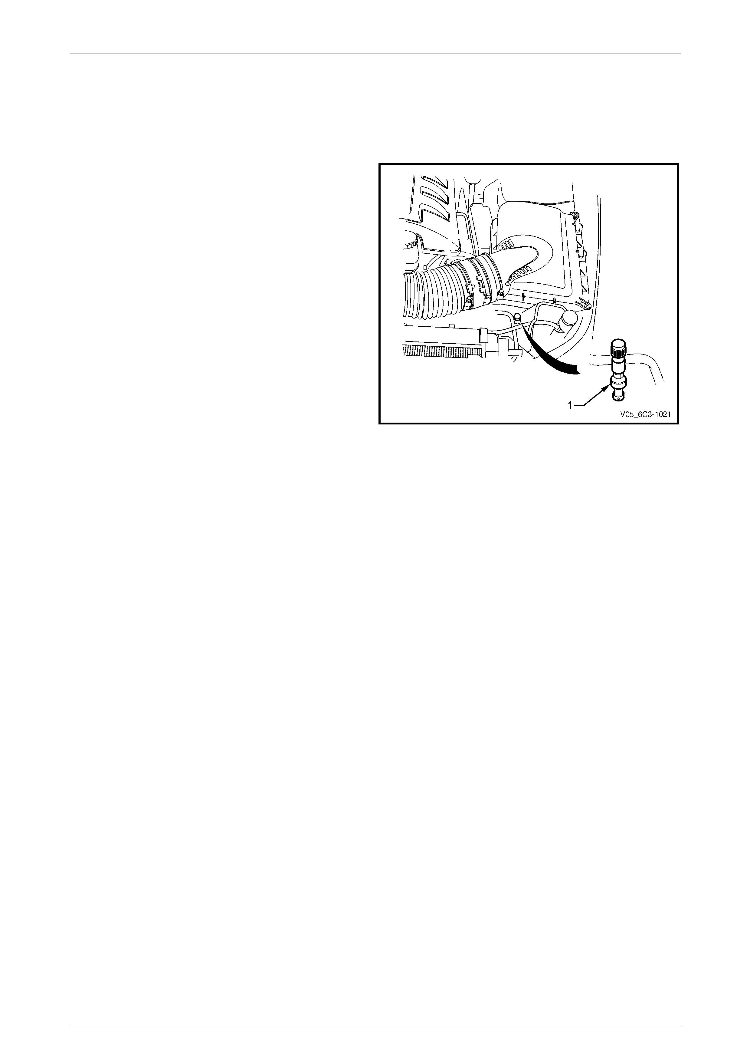
Engine Ventilation System
The engine ventilation system contains an oil separator (1)
and fixed internal flow-restricting orifice (2) located inside
the front right-hand corner of the valley cover. A hose is
routed from the valley cover to the intake manifold.
A breather pipe is routed from the intake manifold to the
right-hand camshaft cover and provides fresh filtered air
from the intake duct to the engine.
For further information of the engine ventilati on system,
refer to Section 6A3 Engine Mechanical – GEN III V8.
Figure 6C3-1 – 13

Powertrain Management GEN III V8 – General Information Page 6C3-1–20
Page 6C3-1–20
3.5 Electric Cooling Fans
The PCM controls the operation of two dual-speed electric engine cooling fans. The PCM operates the fans at either low
or high speed based on inputs from engine coolant temperature, vehicle speed and air-conditioner requ est. F or further
information on cooling fan ope ration, refer to Section 6B3 Engine Cooling – GEN III V8.

Powertrain Management GEN III V8 – General Information Page 6C3-1–21
Page 6C3-1–21
3.6 Torque Management
Torque management is a function of the PCM that reduces engine power during certain conditions.
Torque management is perform ed for the following reasons:
• to prevent over stressing the powertrain components,
• to prevent damage to the vehicle during certain abusive maneouvres, and
• to reduce the engine speed when the IAC is out of the normal operating range.
The PCM monitors the following sensors and engine parameters to calculate the engine output torque:
• air/fuel ratio,
• mass air flow,
• manifold absolute pressure,
• intake air temperature,
• spark advance,
• engine speed,
• engine coolant temperatur e, and
• A/C clutch status.
The PCM monitors the torque converter status, the transmission gear ratio, and the engine speed to determine if torque
reduction is required. T he PCM retards the spark as appropriate, to reduce the engine torque output if torque reduction is
required. The PCM also shuts off the fuel to certain injectors in order to reduce the engine power in the instance of an
abusive maneouvre.
The following are instances when an engine power reduction is likely to be experienced:
• during transmission up-shifts and do wnshifts,
• during heavy acceleration from a standing start,
• if the IAC is out of the normal operating range, or
• if the driver is performing harsh or abusive maneuvers, such as shifting into gear at high throttle angles or shifting
the transmission from reverse to drive in orde r to create a rocking motion.
The driver is unlikely to notice the torqu e mana gement actions in the first two instances. The engine power output will be
moderate at full throttle in the other two instances.
The PCM calculates the amount of spark retard that is necessary to reduce the engine power by the desired amount.
The PCM disables the fuel injectors for cylinders 1, 4, 6, and 7 if an abusive maneouvre occurs.
Powertrain Management GEN III V8 – General Information Page 6C3-1–22
Page 6C3-1–22
4 System Components
4.1 A/C Refrigerant Pressure Sensor
The PCM applies a positive 5 volts reference voltage and
ground to the air-conditioning (A/C) refrigerant pressure
sensor. The A/C pressure sensor provi des signal voltage to
the PCM that is proportional to the A/C refrigerant pressure.
The PCM monitors the A/C pressure sensor signal voltage
to determine the refrigerant pressure.
• The A/C pressure sensor volt age increases as the
refrigerant pressure increases.
• When the PCM detects that the refrigerant pressure
exceeds a predetermined value, the PCM activates
the cooling fans to reduce the refrigerant pre ssure.
• When the PCM detects that the refrigerant pressure is
too high or too low, the PCM disables the A/C clutch to
protect the A/C compressor from damage.
Figure 6C3-1 – 14
Powertrain Management GEN III V8 – General Information Page 6C3-1–23
Page 6C3-1–23
4.2 Brake Pedal Switches
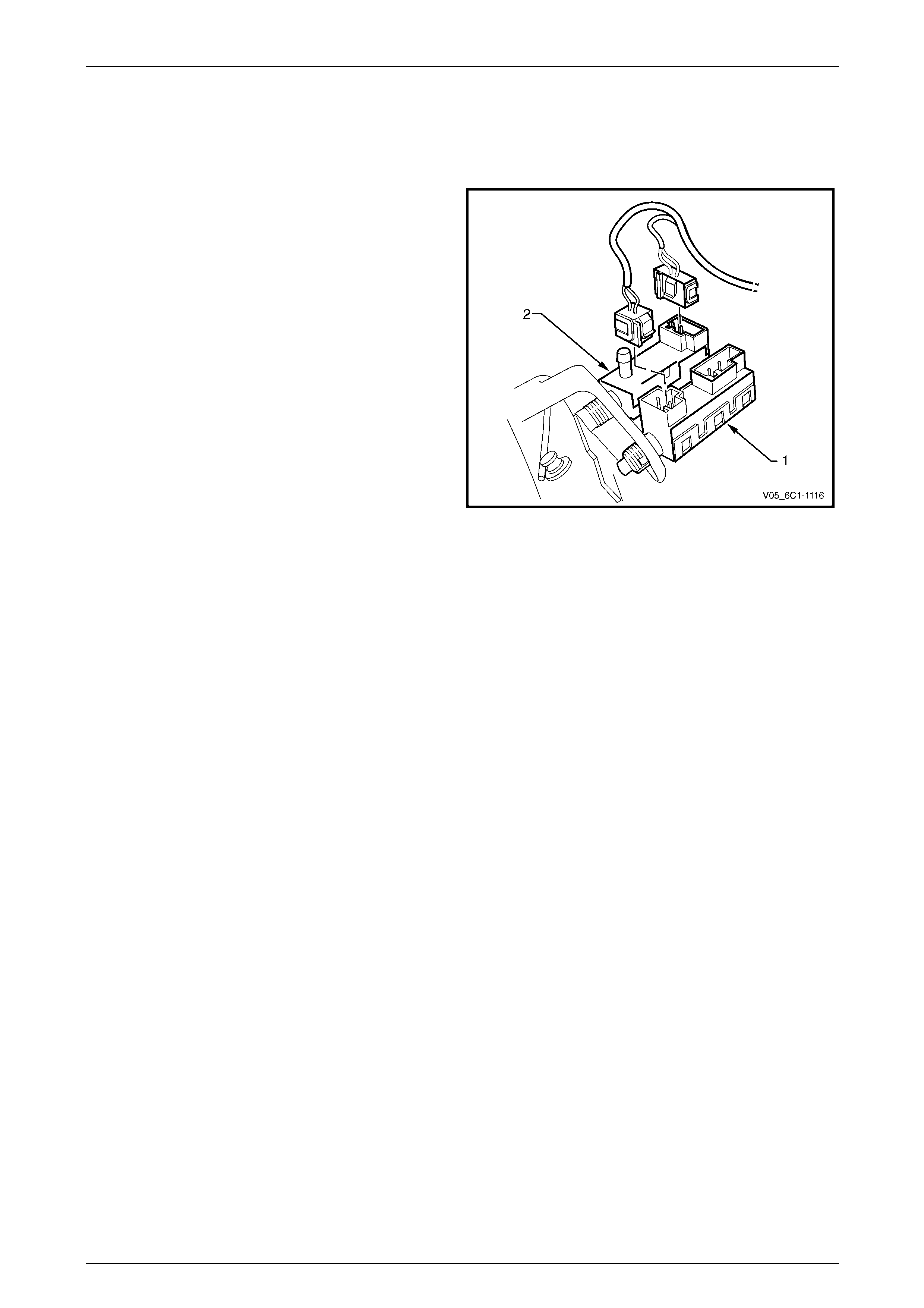
Stop Lamp and BTSI Switch Assembly
The stop lamp and BTSI s witch assembly (1) is located o n
the brake pedal support.
The powertrain control module (PCM) uses the stop lamp
switch signal voltage to determine when the brake pedal is
depressed.
The PCM uses this input for torque management, for
cross-referencing the stop lamp s witch against the cruise
control cancel switch for correct operation, etc. For further
information on brake torque management, refer to
3.6 Torque Management.
The stop lamp switch is a normally open switch with the
brake pedal at rest.
Figure 6C3-1 – 15
Cruise Control Release and Extended Brake Travel Switch Assembly
The cruise control release and extended brake travel switch assembly (2) is located on the brake pedal support. Refer to
Figure 6C3-1 – 15
The powertrain control module (PCM) uses the cruise control release switch signal voltage to determine when the brake
pedal is depressed. T he PCM uses this input to cancel cruise control operation, for cross-referencing the cruise control
release switch against the stop lamp s witch for correct operation, etc.
The powertrain control module (PCM) uses the extended brake travel switch signal voltage to determin e when full brake
pedal travel has been achieved. The PCM uses this input to compensate for the air being used by the brake booster.
Both of these switches are normally closed when the brake pedal is in the rest position, opening when the pedal is
pressed. Activation of this switch removes the signal to the PCM.
For further information on the cruise control system, refer to 4.3 Cruise Control System.

Powertrain Management GEN III V8 – General Information Page 6C3-1–24
Page 6C3-1–24
4.3 Cruise Control System
The cruise control system inte grates with the powertrain control system through the po wertrain interface module (PIM),
throttle actuator control module (TACM), and the powertrain control module (PCM), to control the electronic throttle
actuator and maintain the vehicle at the spe ed set by the driver.
When the cruise ON-OFF button is pressed, the PIM, on receiving the input from the cruise control switch, outputs a
signal to the TACM. The TACM communicates with the PCM via the dedicated serial data link, and the PCM verifies the
signal then commands the TACM to engag e the cruise co ntrol. The PCM also prov ides a signal for the instrument
cluster, via the PIM, to inform the user that the cruise control is engaged.
The user activates the cruise control at a desired speed above 40 kph by rotating the cruise control switch assembly to
SET–DECEL. The TACM receives the i np ut from the cruise control switch, communicates with the PCM via the
dedicated serial data link, and the PCM verifi es the signal. The PCM then commands the TACM to set the desired
speed. The PCM receives all the various inputs required to maintain the correct speed and then controls the throttle
plate, through the TACM, depending on the load on the engine (ascending or descending hills, etc.).
The cruise control is deactivated b y either pressing the brake pedal or by the cruise control ON-OF F button. In each of
these instances, the TACM receives an input when any of these switches are activated.
For further information on the cruise control system, refer to Section 12E Cruise Control.
Powertrain Management GEN III V8 – General Information Page 6C3-1–25
Page 6C3-1–25
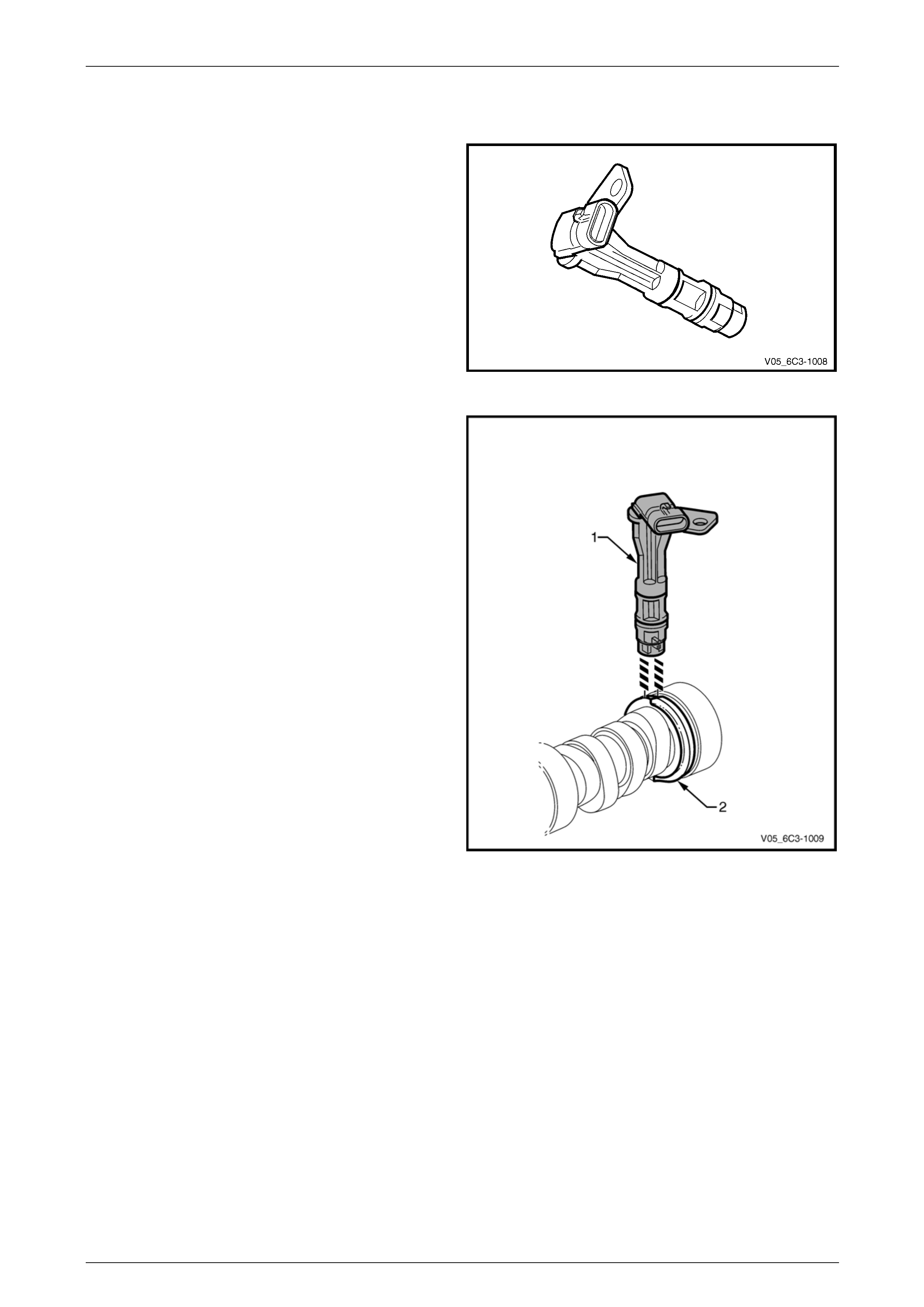
4.4 Camshaft Position (CMP) Sensor
The CMP sensor is used by the PCM to determine the
position of the camshaft. In conjunction with the crankshaft
position sensor, the CMP enables the PCM to determine
engine rotational position.
Figure 6C3-1 – 16
The CMP sensor operates on the dua l-Hall sensing
principle. The sensor contains two Hall elements (1) which
operate in conjunction with a two-track trigger wheel (2) on
the camshaft.
As the tracks on the trigger wheel pass the elements,
magnetic flux affects a voltage in the Hall elements. The
integrated circuit inside the sensor conditions the signal
generated by the Hall eleme nts to provide a rectangular
wave on / off signal to the PCM.
The PCM supplies the CMP sensors with a 12-volt
reference and a ground circui t.
Figure 6C3-1 – 17
Powertrain Management GEN III V8 – General Information Page 6C3-1–26
Page 6C3-1–26
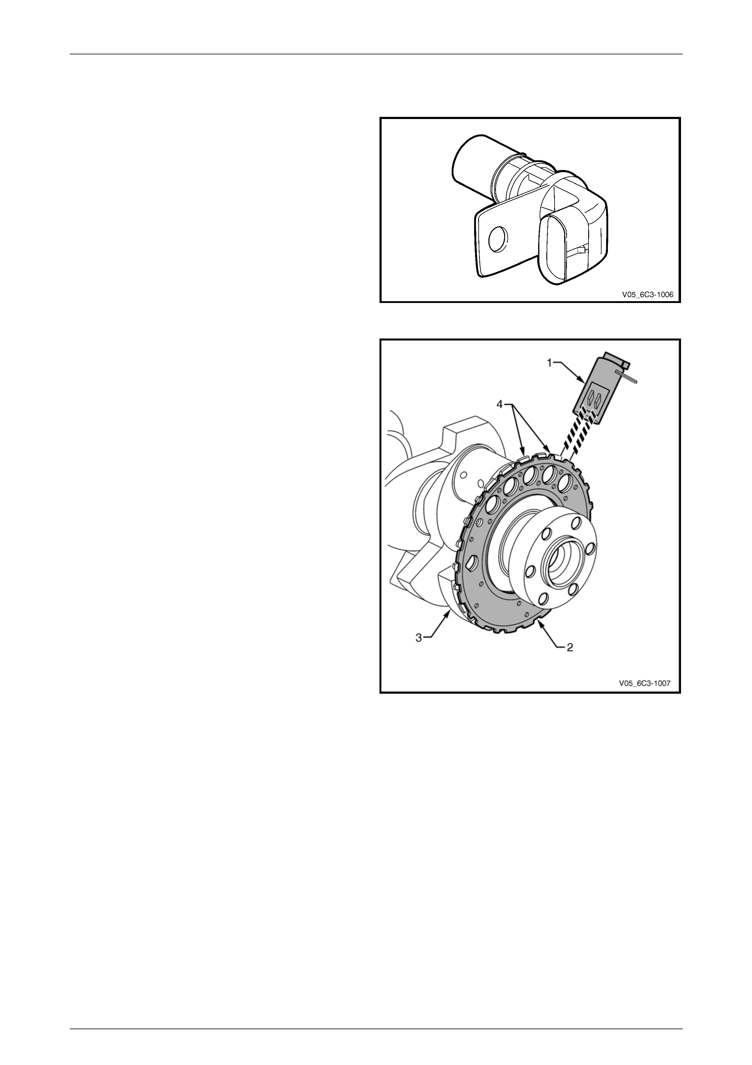
4.5 Crankshaft Position (CKP) Sensor
In conjunction with the camshaft position sensor, the
crankshaft position (CKP) sensor enables th e PCM to
determine engine rotational position. The CKP is also used
to determine engine speed (RPM).
Figure 6C3-1 – 18
The CKP sensor operates on the dual-Hall sensing
principle. The sensor contains two Hall elements (1) which
operate in conjunction with a two-track trigger wheel (2) on
the crankshaft (3).
As the tracks (4) on the trigger wheel pass the elements,
magnetic flux affects a voltage in the Hall elements. The
integrated circuit inside the sensor conditions the signal
generated by the Hall eleme nts to provide a rectangular
wave on / off signal to the PCM.
The PCM supplies the CKP sensors with a 12-volt reference
and a ground circuit.
Figure 6C3-1 – 19
Powertrain Management GEN III V8 – General Information Page 6C3-1–27
Page 6C3-1–27
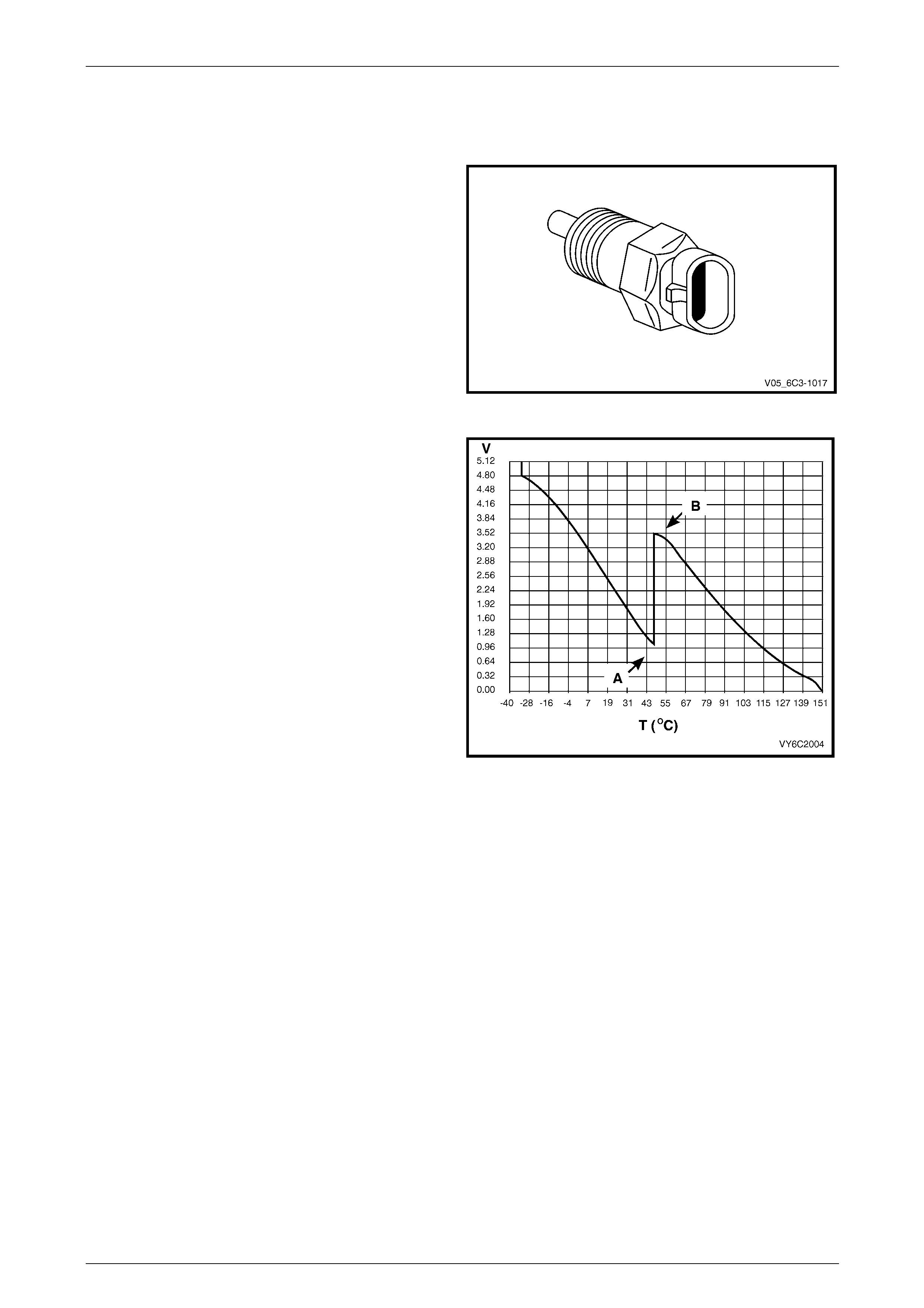
4.6 Engine Coolant Temperature (ECT)
Sensor
The engine coolant temperature (ECT) sensor is a
thermistor (a resistor that changes value based on
temperature) mounted in the engine coolant stream. Low
engine coolant temperature produces a high sensor
resistance (29 kΩ at –20° C) while high engine coolant
temperature causes low sensor resistance (180 Ω at
100° C).
Figure 6C3-1 – 20
The PCM uses a dual pull up resistor network to increase
the resolution through the entire operating range of engine
coolant temperature. When the coolant temp erature is less
than 51° C, both the 4K and 348 ohm resistors are used (A) .
When the coolant temperature reaches 51° C, the PCM
switches a short across the 4K resistor and only the 348
ohm resistor is used (B).
As the engine warms, the sensor resistance becomes less
and the voltage at the PCM coolant temper ature sensor
signal terminal should decrease from approximately 4.5
volts when cold to 0.9 volts at 51° C.
At this temperature the PCM switches the short across the
4k resistor, the voltage will then rise to 3.5 volts. The voltage
will again decrease as the coolant temperature increases
until at normal engine operating temperature (95° C), the
voltage should be less than 2.0 volts.
Figure 6C3-1 – 21
Powertrain Management GEN III V8 – General Information Page 6C3-1–28
Page 6C3-1–28
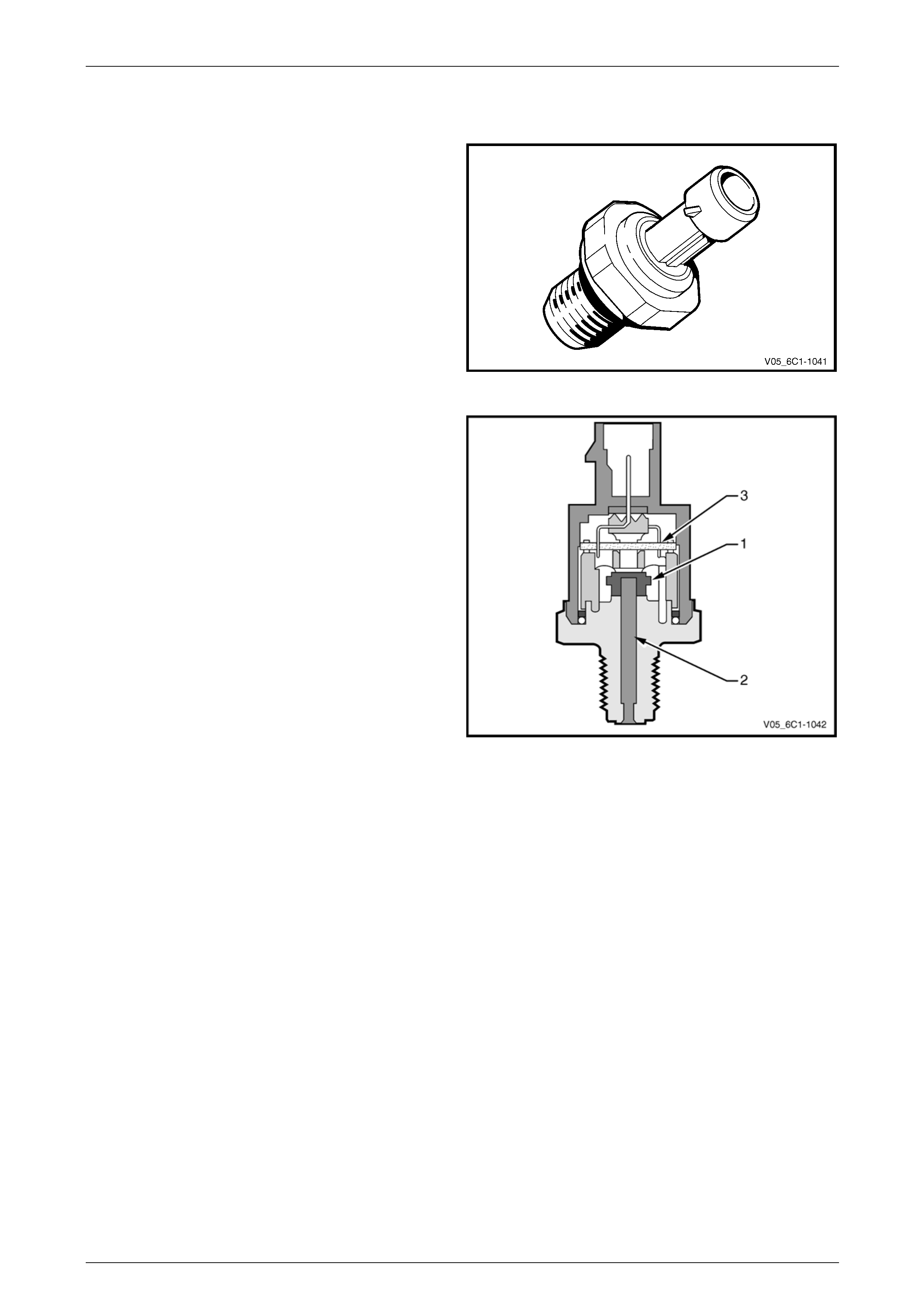
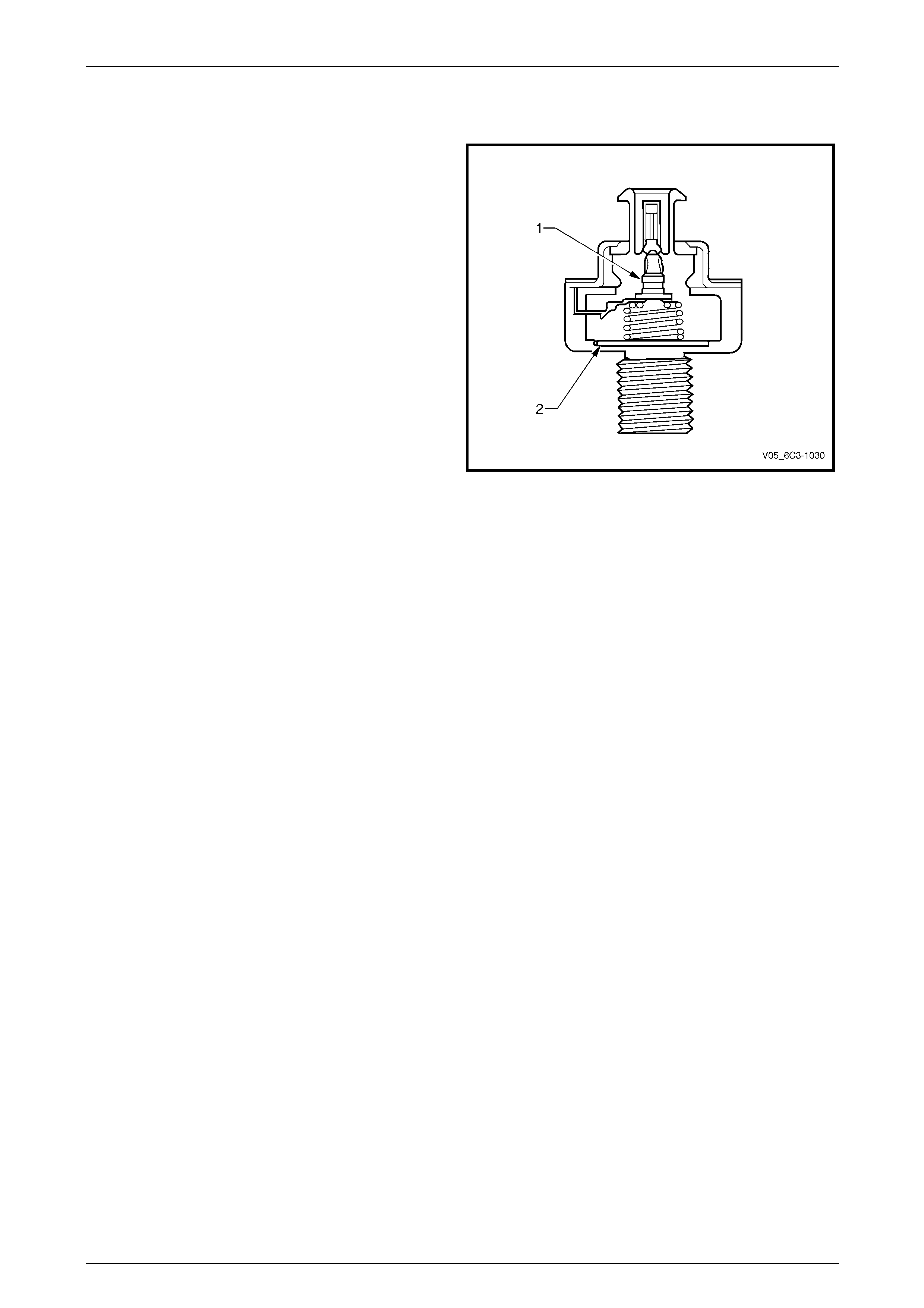
4.7 Engine Oil Pressure (EOP) Sensor
The engine oil pressur e (EOP) sensor measures engine oil
pressure. When the EOP sensor signal is below a certain
value, which increases with RPM, the PCM activates the
Check Oil warning icon in the i nstrument cluster multi-
function display (MFD).
Figure 6C3-1 – 22
The EOP sensor provides a voltag e signal to the PCM that
is a function of engine oil pressure. It does this through a
series of deformation resistors (1), which change resistance
when a mechanical force is applied. This force is applied to
the resistors by a diaphragm on which the engine oil
pressure acts (2).
The sensor has an internal ev aluation circuit (3) and is
provided with a five volt reference voltage, a ground and a
signal circuit.
Figure 6C3-1 – 23
Powertrain Management GEN III V8 – General Information Page 6C3-1–29
Page 6C3-1–29
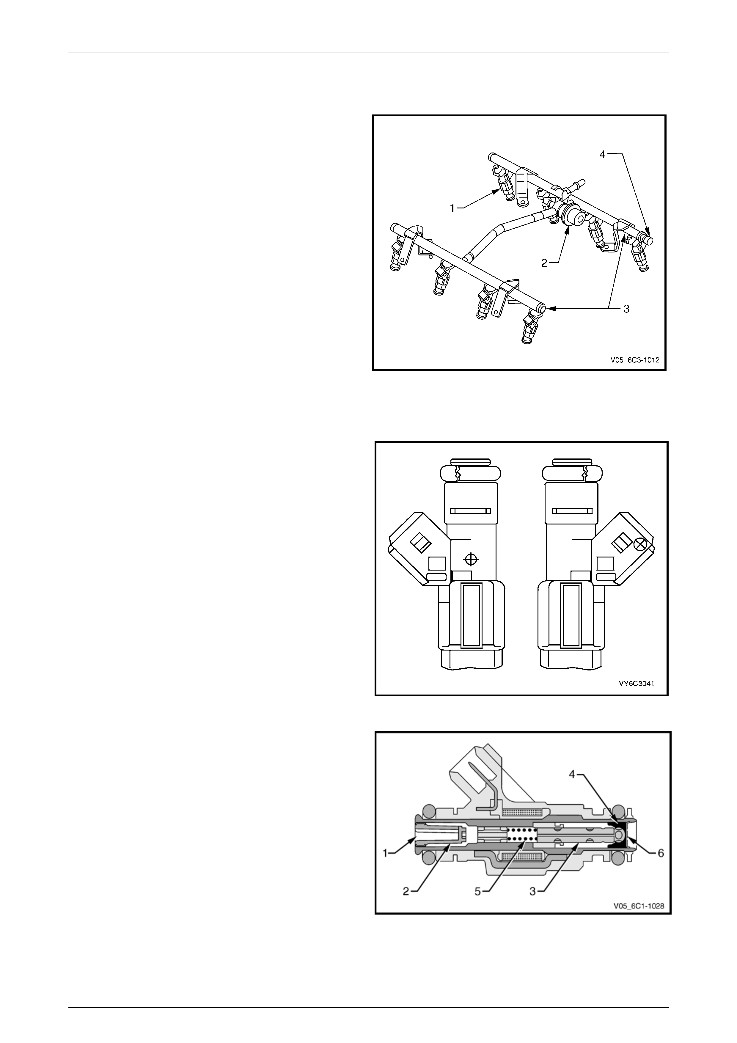
4.8 Fuel Rail Assembly
The fuel rail assembly is mou nted on th e lower intake
manifold and distributes fuel to each c ylinder through
individual fuel injectors. The fuel rail assembly consists of:
• eight individual fuel injectors (1),
• the fuel pulse dampener (2),
• the pipe (3) that carries fuel to each injector, and
• a fuel pressure test port (4).
Figure 6C3-1 – 24
Fuel Injectors
A fuel injector is a solenoid device that is cont rolled by the
PCM. The eight injectors deliver a precise amount of fuel
into the intake ports as requir ed by the engine. The injectors
are supplied with igniti on voltage through the EFI relay, and
are switched to ground by the PCM.
Figure 6C3-1 – 25
The fuel port (1) connects to the fuel rail. A strainer (2) is
provided in the port to protect the injector from fuel
contamination.
In the de-energised state (no voltage), the valve needle and
sealing ball assembly (3) are held against a cone-shaped
valve seat (4) by spring force (5) and fuel pressure.
When the injector is energise d by the PCM, the valve
needle, which has an integr al armature, is moved upward by
the injector solenoid’s magnetic field, un-seating the ball.
An orifice plate (6), located at the base of the injector has
several small holes which provide very fine atomisation of
the fuel. The plate is insensitive to fuel de posits ensuring
reliable fuel delivery.
The fuel is directed at each of the intake valves, causing the
fuel to become further vaporised before entering the
combustion chamber.
Figure 6C3-1 – 26
Powertrain Management GEN III V8 – General Information Page 6C3-1–30
Page 6C3-1–30
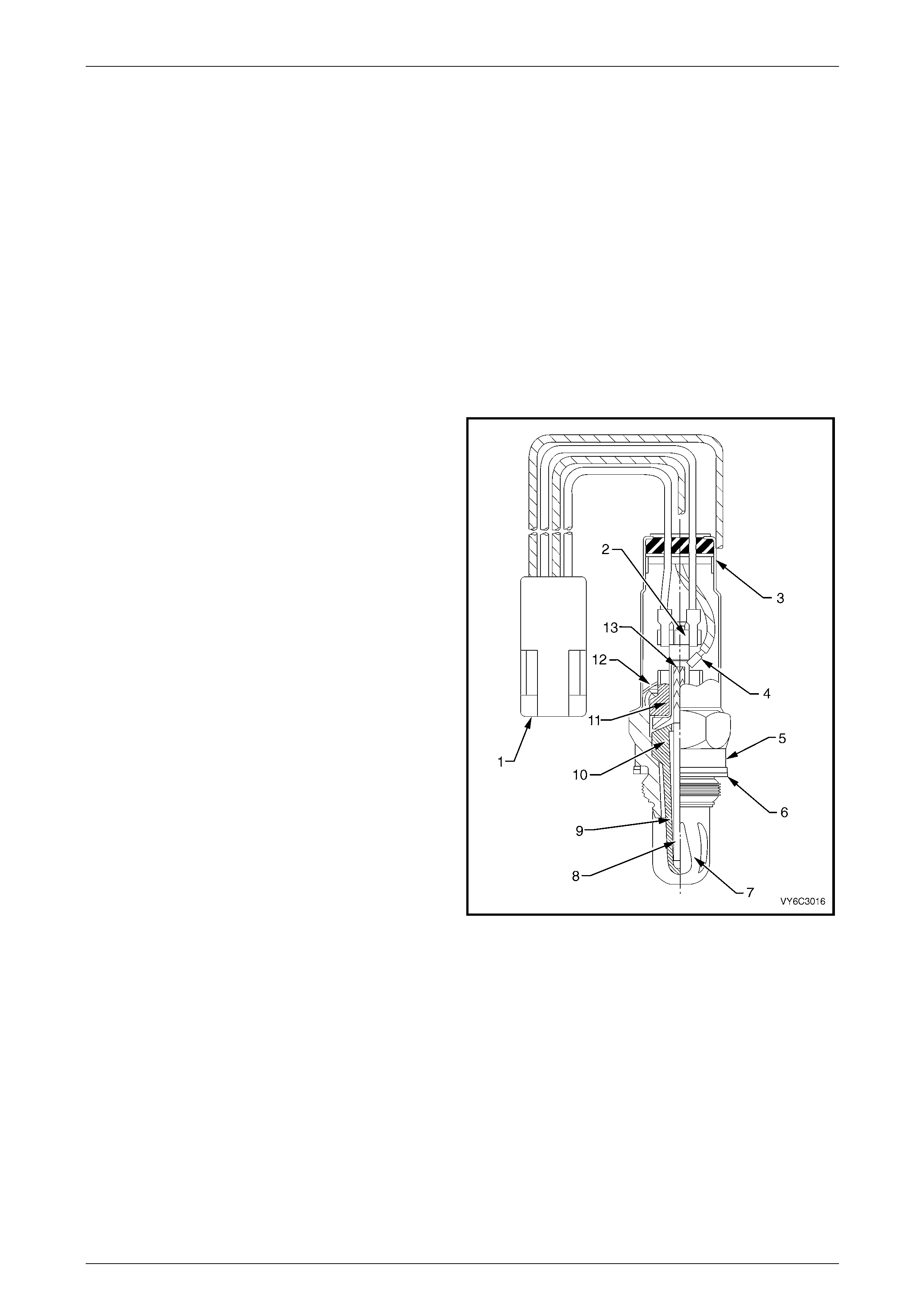
4.9 Heated Oxygen Sensors (HO2S)
The heated oxygen sensors (HO2S) are mounted in the exhaust pipe and enable the PCM to measure oxyge n conte nt in
the exhaust stream. The PCM uses this information to accurately control the air / fuel ratio, because the oxygen content
in the exhaust gas is indicative of the air / fuel ratio of engine combustion.
When the sensor is cold, it produces little or no signal voltage, therefore the PCM only reads the HO2S signal when the
HO2S sensor is warm. As soon as the HO2S are warm and outputting a usable signal, the PCM begins making fuel
mixture adjustments base d o n the HO2S signals. This is known as closed loop mode.
GEN III V8 engines have two HO2S, one HO2S upstream of the catalytic converter in each exhaust pipe.
NOTE
Some vehicles may be fitted with an additional
HO2S downstream of each catalytic converter.
These are fitted for production purposes but are
not used by the powertrain management s ystem.
The HO2S has four wires:
1 The internal heater element supply, which has 12 volts
continually applied whenever the ignition is on.
2 Heater element ground. When the sensors are cold,
the PCM applies maximum current (approximately four
amps) to the heater circuit, which graduall y reduces to
approximately 0.5 amps as the sensor reaches full
operating temperature.
3 Sensor signal to the PCM.
4 Sensor ground.
Legend
1 Four Wire In-line Connector
2 Heater Termination
3 Water Shield Assembly
4 Sensor Lead
5 Sensor Body
6 Seat Gasket
7 Outer Electrode and Protective Coating
8 Rod Heater
9 Inner Electrode
10 Zirconia Element
11 Insulator
12 Clip Ring
13 Gripper Figure 6C3-1 – 27
Powertrain Management GEN III V8 – General Information Page 6C3-1–31
Page 6C3-1–31
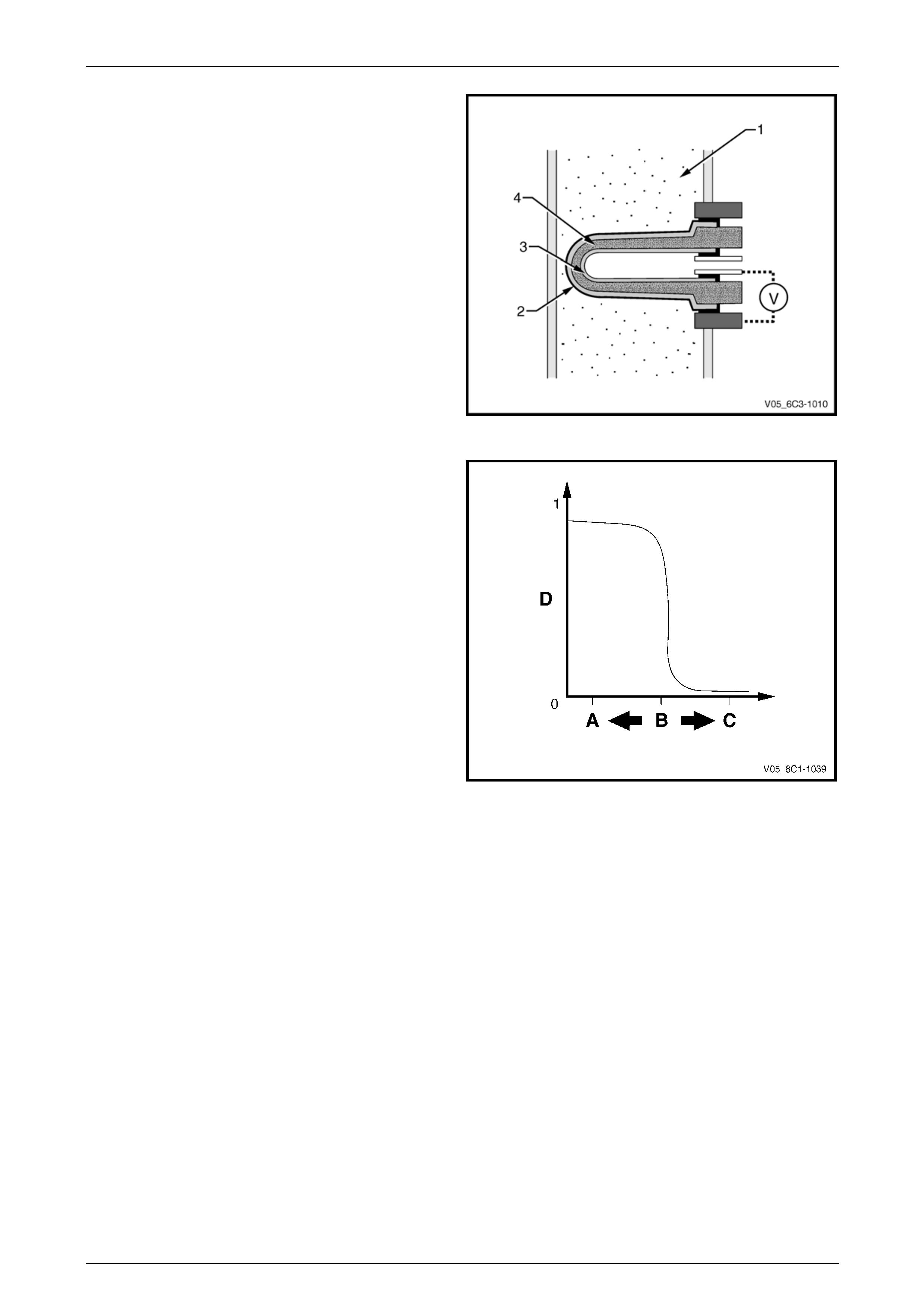
Measurement is achieved b y comparing the oxygen content
of the exhaust gas (1) to the oxygen content of a referenc e
gas (outside air) using the Nernst principle. Oxygen
molecules from the exhaust gas will accumu late on the
outer electrode (2), while oxygen molecules from the
reference gas will accumulate on the inner electrode (3).
This creates a voltage difference across the ceramic
element (4), between the two electrodes, which is the signal
voltage (V) to the PCM.
The PCM supplies a steady 450 millivolt, very low current
bias voltage to the oxygen sensor signal circuit. When the
sensor is cold and not produc ing any voltage, the PCM
detects only this steady bias voltage. As the sensor b egins
to become warm, its internal resistance decreases and it
begins produci ng a rapidly changing voltage that will
overshadow the steady bias voltage supplied by the PCM.
The PCM detects the changing voltage, and can begin
operating in closed lo op.
Figure 6C3-1 – 28
When the fuel system is correctly operating in closed loop
mode, the oxygen sensor voltage output is rapi dly changing
several times per second, fluctuating from approximately
100mV (high oxygen co ntent – lean mixture) to 900mV (low
oxygen content – rich mixture). The transition from rich to
lean occurs quickly at about 450-500 mV (A/F ratio 14.7:1,
or lambda = 1). Due to this, these HO2S are known as t wo-
step or switching type oxygen sensors.
Legend
A Rich Mixture
B A/F Ratio 14.7:1 (Lambda = 1)
C Lean Mixture
D Sensor Voltage
Figure 6C3-1 – 29
Powertrain Management GEN III V8 – General Information Page 6C3-1–32
Page 6C3-1–32
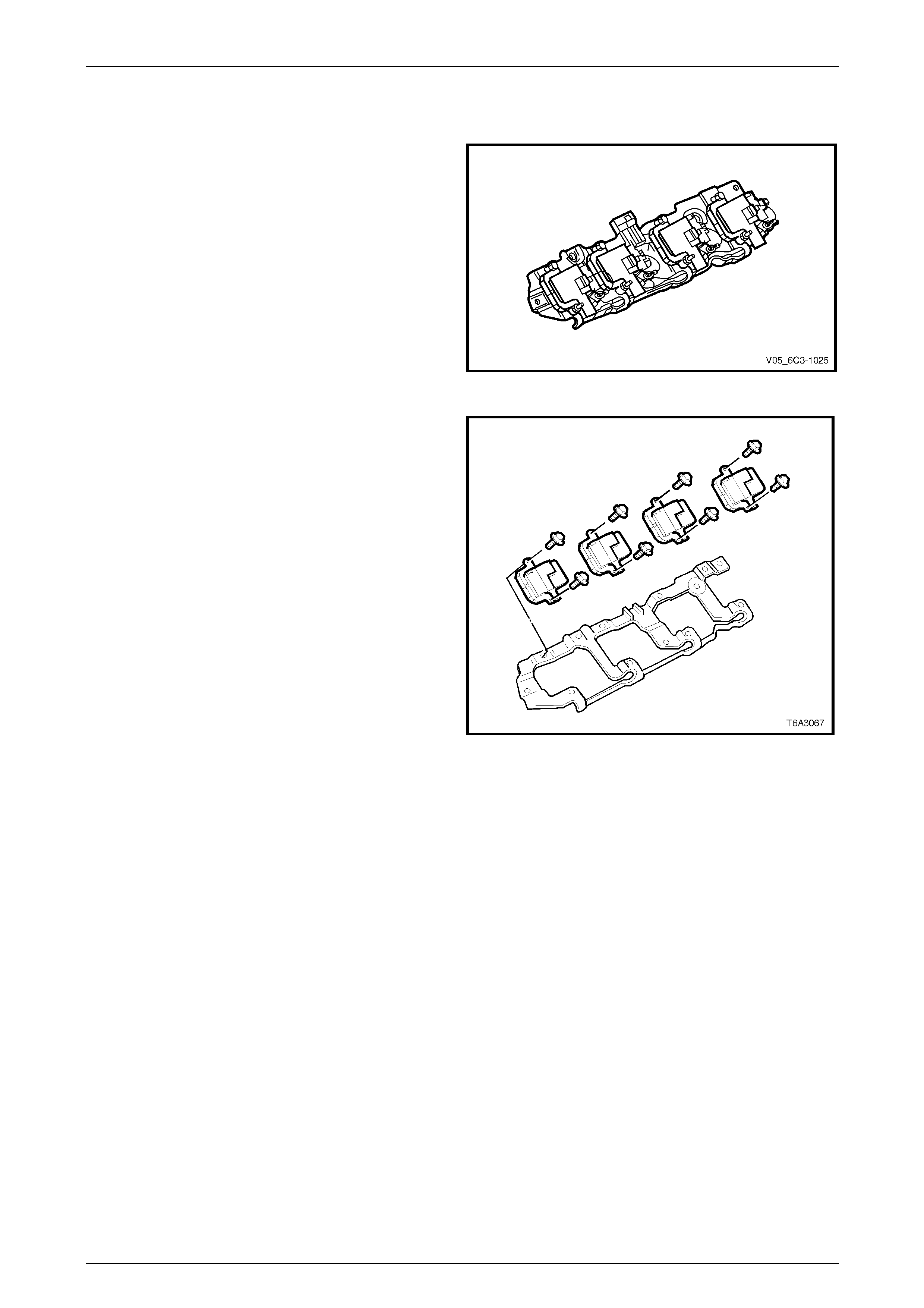
4.10 Ignition Coils / Modules
Eight ignition coils, four per cylind er ba nk, are individually
mounted to an ignition coil mountin g bracket that is bolted
to each rocker cover. Each coil has a short high tension
secondary ignit ion wire connecting it the relevant spark plug.
A printed circuit board, or driver module, is integrated with
each coil, and controls the firing of the coil based on in put
from the PCM.
Figure 6C3-1 – 30
The PCM is responsible for maintaining correct spark timing
and dwell for all driving conditions. The PCM calculates the
desired spark parameters from informatio n received from
the various sensors, and triggers the appropr iate ignition
module which then operates the coi l.
The ignition coil / modules are supplied with the following
circuits:
• Ignition feed circuit.
• Ignition control circuit.
• Ground circuit.
• Reference low circuit.
Figure 6C3-1 – 31

Powertrain Management GEN III V8 – General Information Page 6C3-1–34
Page 6C3-1–34
4.12 Knock Sensors (KS)
The knock sensor signal is used b y the PCM to provide
optimum ignition timing while minimising engine knock or
detonation.
The knock sensor is tuned to detect the frequency of the
vibration created by combustion knock. The vibration is
transferred through the cylinder block to the knock sensor.
Inside the sensor is a mass (1) that is excited by this
vibration, and the mass exerts a compressive force onto a
piezo-ceramic element (2). The compressive force causes a
charge transfer inside the element, so that an AC voltage
appears across the two outer faces of the element. The
amount of the AC voltage produced is proportional to the
amount of knock. This AC signal voltage to the PCM is
processed by a Digital Signal Noise Enhancement Filter
(DSNEF) module. This DSNEF module, an integral part of
the PCM, is used to determine if the AC signal coming in is
noise or actual detonation.
Figure 6C3-1 – 32
Powertrain Management GEN III V8 – General Information Page 6C3-1–35
Page 6C3-1–35
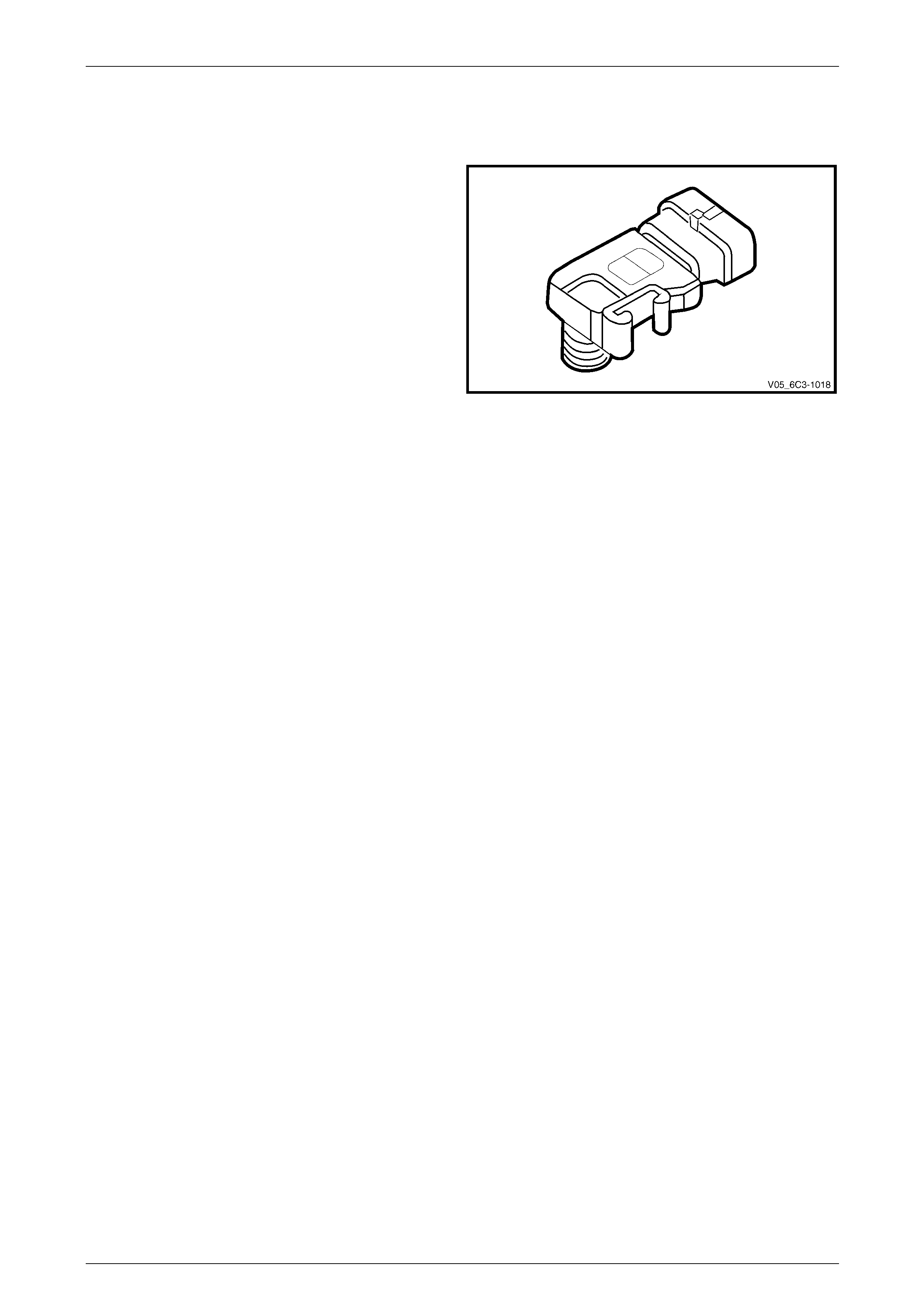
4.13 Manifold Absolute Pressure (MAP)
Sensor
The manifold absolute pressure (MAP) sensor is mounted to
the rear of inlet manifold so that its sensing element is
exposed to manifold pressure downstream of the throttle
body.
The PCM sends a 5-volt supply voltage to the MAP sensor.
As the manifold pressure varies, due to changes in engine
load, the output voltage of the sensor also chang es. By
monitoring the sensor output voltage, the control module
determines the manifold pressure.
The MAP sensor is used for the follo wing:
• ignition timing control, and
• speed density fuel manag ement default. Figure 6C3-1 – 33
Powertrain Management GEN III V8 – General Information Page 6C3-1–36
Page 6C3-1–36
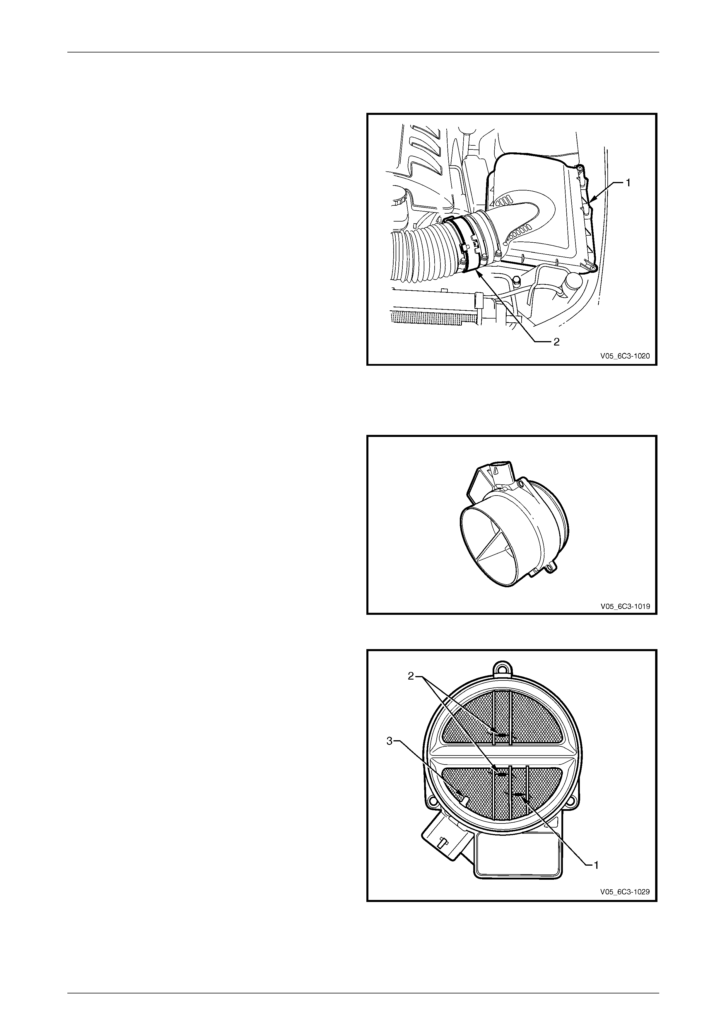
4.14 Air Intake System
The air intake system draws outside air through the an air
cleaner assembly (1). The air is then routed throu gh a mass
air flow (MAF) sensor (2) and into the throttle body and
intake manifold. The air is then directed into the intake
manifold runners, through the c ylinder he ads and into the
cylinders.
An arrow marked on the body of the MAF sensor indicates
correct air flow direction. The arrow must point toward the
engine.
Figure 6C3-1 – 34
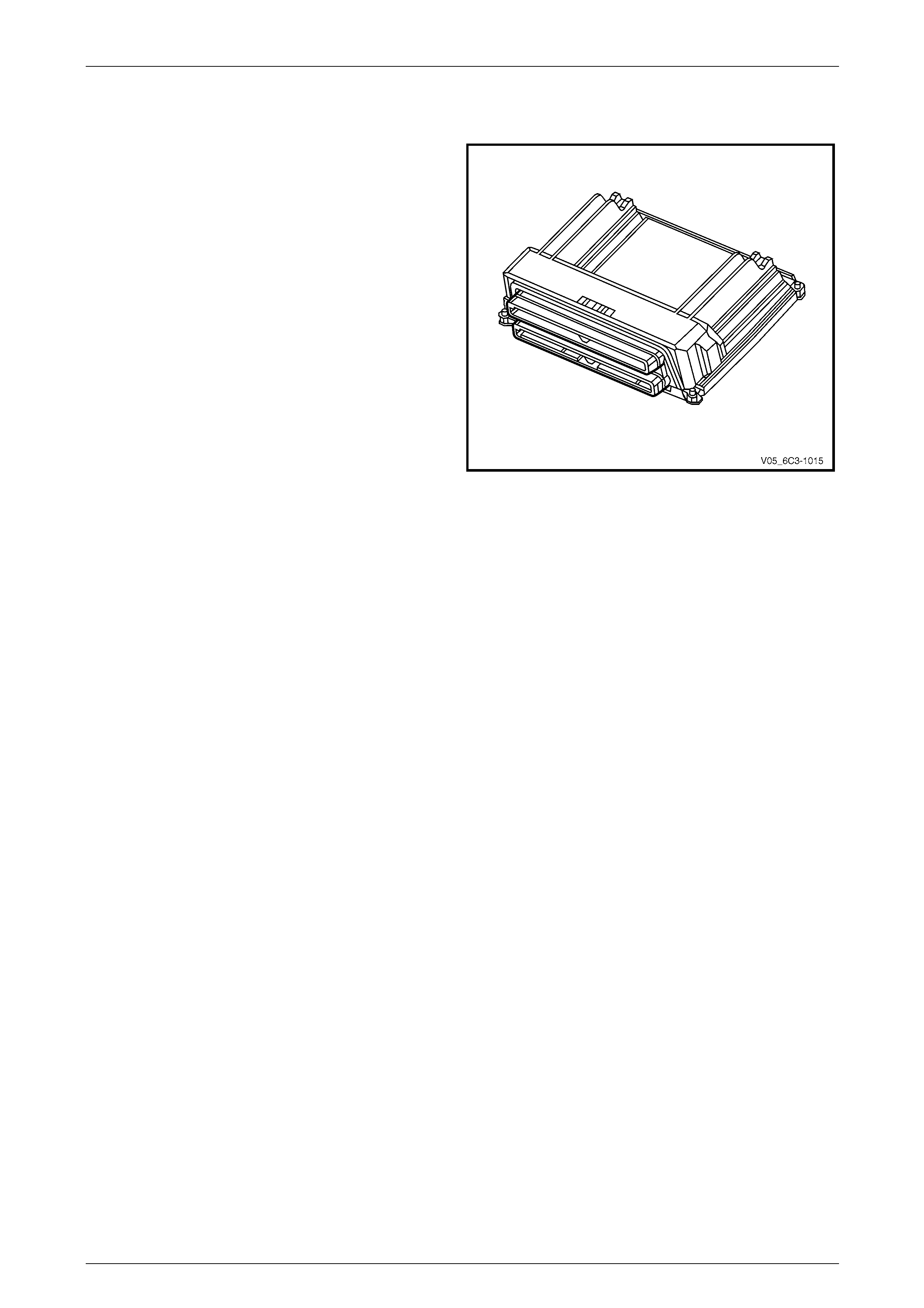
Mass Air Flow (MAF) Sensor
A heated element type mass air flow (MAF) sensor is
mounted in the air flow stream of the engine intake system.
The MAF sensor measures the mass of the air being
inducted into the engine, and is one of the key signals the
PCM uses to calculate the required fuel quantity to be
injected.
Figure 6C3-1 – 35
Three sensing elements are used in the MAF sensor. One
senses ambient air temperatur e (1) and is mounted in the
lower half of the sensor housing. The ambient temperature
sensor uses two calibrated resistors to establish a voltage
that is a function of ambient temperature.
The other two sensing elements (2) are heated to a
predetermined temperature that is significantly above
ambient air temperature. The t wo heated elements are
connected electrically in para llel and mounted directly in the
air flow stream of the sensor housing.
One sensor is in the top and the other sensor is in the
bottom of the sensor housing. This is done so that the air
meter is less sensitive to upstream airflo w variations that
could affect the flow of air through the housin g.
As air passes over the heated elements during engine
operation, they begin to cool. By measuring the amo unt of
electrical power required to maintain the heated elements at
the predetermined temperature above ambient temperature,
the mass air flow rate can be determined. Figure 6C3-1 – 36
Before being sent to the PCM, the small voltage signal generated in the mass air flow sensor is converted to a frequency
signal by a voltage oscill ator, to preserve the accuracy and resolution of the signal.

Powertrain Management GEN III V8 – General Information Page 6C3-1–37
Page 6C3-1–37
A large quantity of air passing through the se nsor (such as when accelerating) will be ind icated as a high frequency
output. A small quantity of air passi ng through the sensor will be indicated as a low frequency output (such as when
decelerating or at idle). T ech 2 displays MAF sensor information in frequency or in grams per second. At idle the
readings should be low and increase with engine RPM.
If a fault occurs in the MAF sensor circuit, the PCM will store a DTC in its memory, and will calculate a substitute mass
air flow signal based on speed density, using the engine speed, Manifo ld Absolute Pressure, and Intake Air Temperature
signals.
Intake Air Temperature (IAT) Sensor
The MAF sensor also incorporates the intake air temperature (IAT) sensor. The IAT sensor is a thermistor, (a resistor
that changes resistance with changes in temperature). Low intake air temperature produces high resistance in the
sensor, while high intake air temperature caus es low sensor resistance. The IAT sensor (3) is not serviced sep arately
from the MAF sensor, refer to Figure 6C3-1 – 36.
The PCM provides a 5 volt referenc e signal to the IAT and monitors the return signal which enables it to calculate the
intake air temperature. The PCM uses this signal to make corrections to the operating parameters of the system based
on changes in air intake temperature. The circuit voltage will vary dependin g on the resistance of the IAT sensor. The
voltage will be close to the 5 volt level when the sensor is cold, and will decrease as the sensor warms.
No field service adjustment is necessary or possible with the MAF or IAT sensors.
Powertrain Management GEN III V8 – General Information Page 6C3-1–38
Page 6C3-1–38
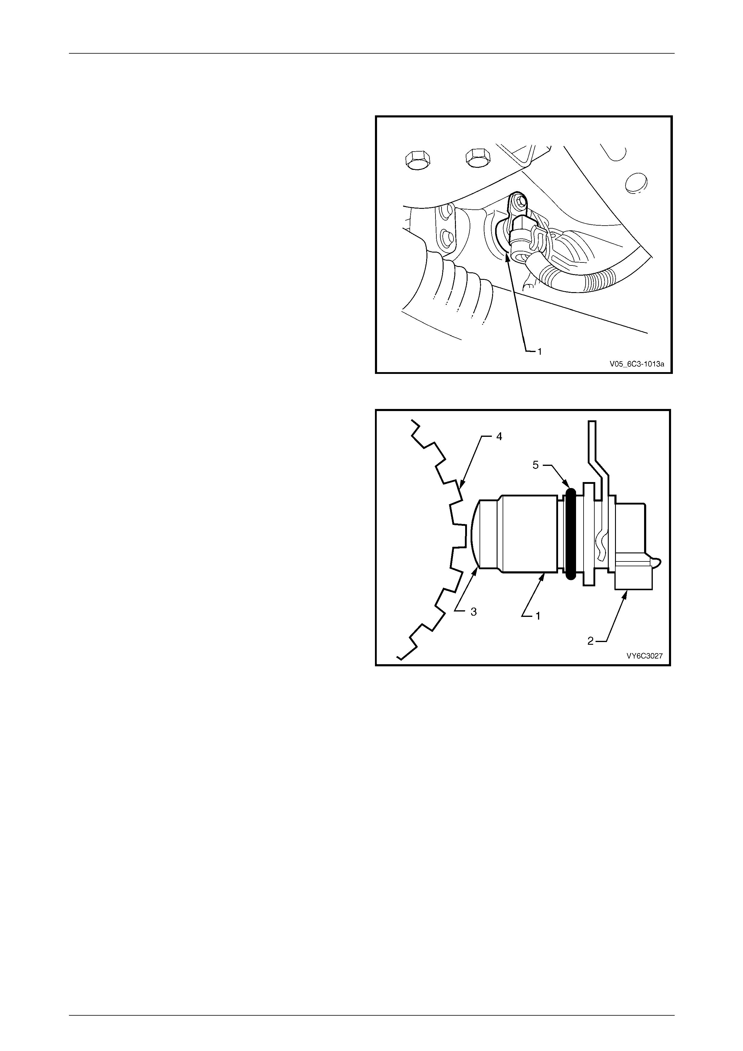
4.15 Powertrain Control Module (PCM)
Located at the left side of the engine compartment, the
powertrain control module (PCM) constantly monitors
information from various sensors and co ntrols the many
powertrain management functions, such as the fuel injection
and ignition systems, to provide optimal performance and
minimal emission output in all driving conditions.
The PCM also controls:
• electronic throttle actuation,
• on-board diagnostics,
• the engine cooling fans, and
• the A/C compressor clutch (where fitted).
Figure 6C3-1 – 37
The PCM supplies 5 volts to the various sensors through pull-up resistors to the internal r egulated power supplies.
The PCM controls output circuits such as the injectors, IAC, cooling fan relays, etc. b y controlling the ground circuits
through transistors or a device inside the PCM called a driver.
The exception to this is the fuel pump relay control circuit. The fuel pump r elay is the only PCM controlled circuit where
the PCM controls the +12 volts sent to the coil of the relay. The ground side of the fuel pump relay coil is connected to
engine ground.
The PCM also interfaces with other systems in the vehicle, such as automatic transmission, body control module
(through the PIM), anti-lock braking, traction control, etc.
Self Diagnosis
The PCM performs diagnostic tests on system components and constantly monitors the s ystem for faults.
When the PCM detects a malfunction, it also stores a diagnostic trouble code (DTC). A stored DTC will identify the
problem area(s) and is desig ned to assist the technician in rectifying the fault.
Depending on the type of DTC set, the PCM may command the instrument cluster multi-function displ ay check
powertrain icon to illuminate and warn the driver that there is a fault in the powertrain management system.
Communication to the Icon is through the controller area network (CAN) serial data communication line to the powertrain
interface module (PIM), and then universal asynchronous receive and transmit (UART) serial data to the instrument
cluster via the body control module (BCM). For further information on DTCs and the chec k powertrain icon, refer to
Section 6C3-2 Powertrain Management – GEN III V8 – Diagnostics.
Programming
The PCM features electronically erasable programmable read only memory (EEPROM) which contains program and
calibration information required to operate the po wertrain mana gement system. The service programming system (SPS)
has been incorporated with this PCM and enables a technician to directly update the data stored in the EEPROM. In
effect, the data in the memory matches the PCM to the vehicle to provide optimum performance, driveability and
emissions control.
Flash programming refers to the SPS used to transfer (or download) PCM data from a computer terminal and compact
disc-read only memory (CD-ROM) to the vehicle’s PCM. The system is designed so that the vehicle verification
procedures are required to eliminate EEPROM tampering that could increase engine emission levels.
There are three main flash pr ogramming techniques:
1 Direct programming (Pass Through). This is where the vehicle’s data link c onnector (DLC) is connected directly to
a computer terminal. On screen directions are then followed for downloadi ng.
2 Remote programming. Reprogramming information is downloaded from a computer terminal to Tech 2. Tech 2 is
then connected to the vehicle’s data link connector (DLC). On screen directions are then followed for downloading.

Powertrain Management GEN III V8 – General Information Page 6C3-1–39
Page 6C3-1–39
3 Off-board Programming. The off-board programming method is used when a re-programmable PCM must be
programmed while it is removed from the vehicle. For example, an independent repair facility may find it necessary
to replace a faulty PCM. On flash programming eq uipped vehicles, the replacement PCM must be programmed
with data for the specific vehicle identification number (VIN) or the vehicle may not operat e properly.
The vehicle is fitted with a theft deterrent system that interfaces with the PCM. If the PCM is replaced it must be
programmed with appropriate data to match the theft deterrent system.
For further information on the SPS, refer to Section 0C Tech 2.
Powertrain Management GEN III V8 – General Information Page 6C3-1–40
Page 6C3-1–40
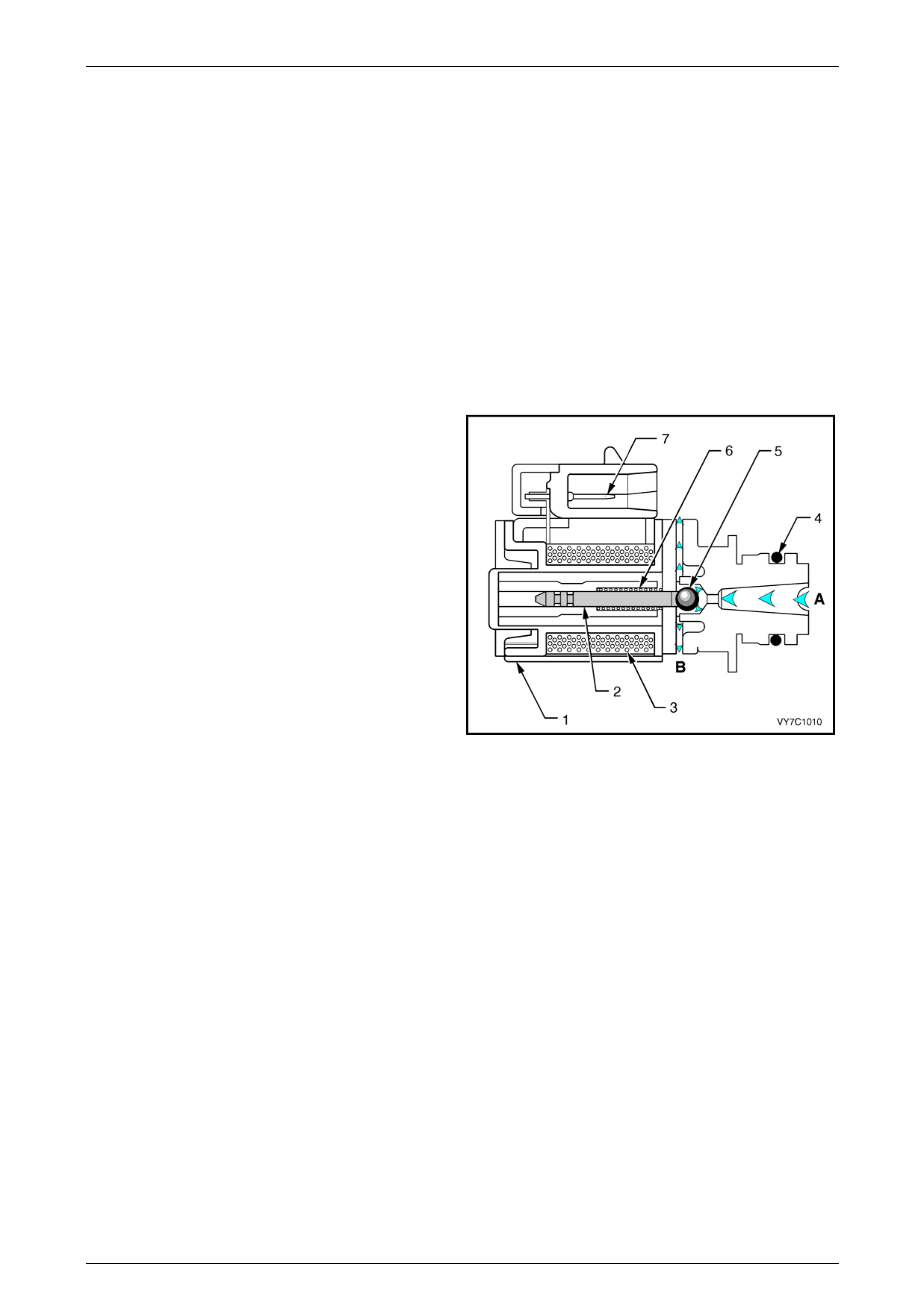
4.16 Vehicle Speed Sensor (VSS)
The PCM receives vehicle speed i nformatio n from the
vehicle speed sensor (VSS) located on the rear of the
transmission.
Figure 6C3-1 – 38
The VSS consists of a magnetic core and a coil. Mounted
on the transmission output shaft is a toothed rotor which
revolves past the VSS, causing fluctuations in the magnetic
field inside the sensor. The magn etic flux increases and
then decreases as the teeth move in and out of the
magnetic field, inducing an AC voltage i nto th e coil. An
increase in speed will increase the output voltage and
frequency.
This AC voltage produced in the VSS sensor circuit is fed
into the PCM. The PCM measures the AC voltage and
frequency to determine the vehicle speed. T he PCM also
sends this information to the instrument cluster.
Legend
1 Sensor Body
2 Electrical Connector
3 Magnetic Pickup
4 Reluctor Wheel (Rotor)
5 O-Ring Figure 6C3-1 – 39

Powertrain Management GEN III V8 – General Information Page 6C3-1–41
Page 6C3-1–41
5 Automatic Transmission
Components
5.1 Range Switch (PRNDL)
The transmission range (TR) switch is part of the transmission park / neutral position switch mounted on the transmission
manual shaft. The four inputs from the four switches contained in the transmission range switch indicate to the
powertrain control module (PCM) which position is selected by the transmission select or lever. The input voltage level at
the PCM is high (B+) when the transmission range switch is open, and low when the switch is closed to ground. T he
various combinations of the four inputs are interpreted by the PCM to determine the gear position selected.
Range Switch Valid Combination Table
Gear Selector
Position
Switch P
Position /
PCM Input
Sw i tch A
Position /
PCM Input
Switch B
Position /
PCM Input
Switch C
Position /
PCM Input
Park (P) Closed / 0 V Closed / 0 V Open / 12 V Open / 12 V
Reverse (R) Open / 12 V Closed / 0 V Closed / 0 V Open / 12 V
Neutral (N) Closed / 0 V Open / 12 V Closed / 0 V Open / 12 V
D Open / 12 V Open / 12 V Closed / 0 V Closed / 0 V
3 Closed / 0 V Closed / 0 V Closed / 0 V Closed / 0 V
2 Open / 12 V Closed / 0 V Open / 12 V Closed / 0 V
1 Closed / 0 V Open / 12 V Open / 12 V Closed / 0 V
Powertrain Management GEN III V8 – General Information Page 6C3-1–42
Page 6C3-1–42
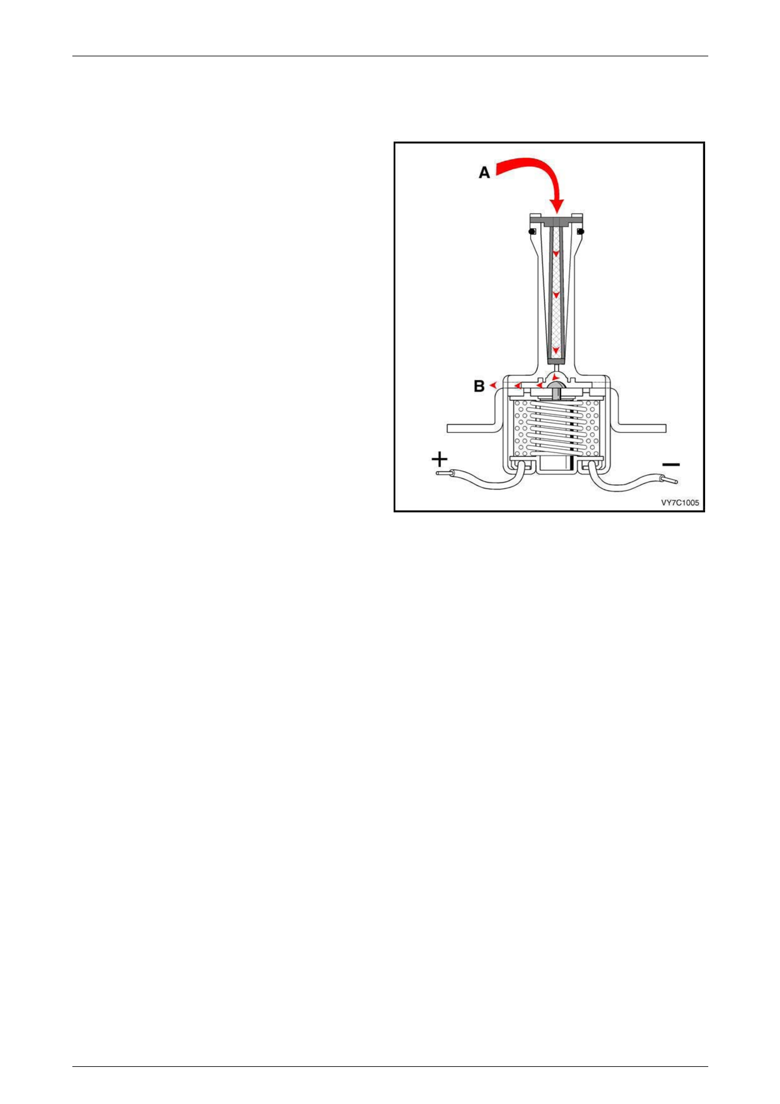
5.2 1-2 (A) and 2-3 (B) Shift Solenoid Valves
The 1-2 and 2-3 shift solenoid valves (also called A and B solenoids) are identical devices that control the movement of
the 1-2 and 2-3 shift valves (the 3-4 shift valve is not directly controlled by a shift solenoid). The solenoids are normally
open exhaust valves that work in four combinations to shift the transmission into different gears.
The PCM energises each solenoid by grounding the solenoid through an internal qu ad driver. This sends current through
the coil winding in the solenoid and moves the internal plunger out of the exhaust position. When on, the solenoid
redirects fluid to move a shift valve.
The shift solenoid should energise at a voltage of 7.5 volts or greater (measured across the terminals and de-energise
when the voltage is one volt or less. If both solenoids lose p ower, only third gear engages.
The manual valve can hydra ulically override the shift solenoids. Only in D4 do the shift solenoid states totally d etermine
what gear the transmission is in. In the other manual valve positions, the transmission shifts hydraulically and the shift
solenoid states catch up when the throttle position and the vehicl e speed fall into the correct ranges.
The PCM-controlled shift solenoids eliminate the need for throttle valve and governor pressures to control shift valve
operation.
Legend
1 Frame
2 Plunger
3 Coil Assembly
4 O-Ring
5 Metering Ball
6 Spring
7 Wiring Harness Connector Terminals
A Signal Fluid
B Exhaust
Figure 6C3-1 – 40
Powertrain Management GEN III V8 – General Information Page 6C3-1–43
Page 6C3-1–43
5.3 3-2 Shift Solenoid Valve Assembly
The 3-2 shift solenoid valve assembly is an on / off solenoid that is used to improve the 3-2 do wnshift. The solenoid
regulates the release of the 3-4 clutch and the 2-4 band apply.
Legend
1 Housing
2 Metering Ball
3 O-Ring
4 Fluid Screen
5 Plunger
6 Coil Assembly
7 Connector Terminals
8 Spring
A Pressure Apply
B Exhaust
C Pressure Control (3-2 Signal)
Figure 6C3-1 – 41
Powertrain Management GEN III V8 – General Information Page 6C3-1–44
Page 6C3-1–44
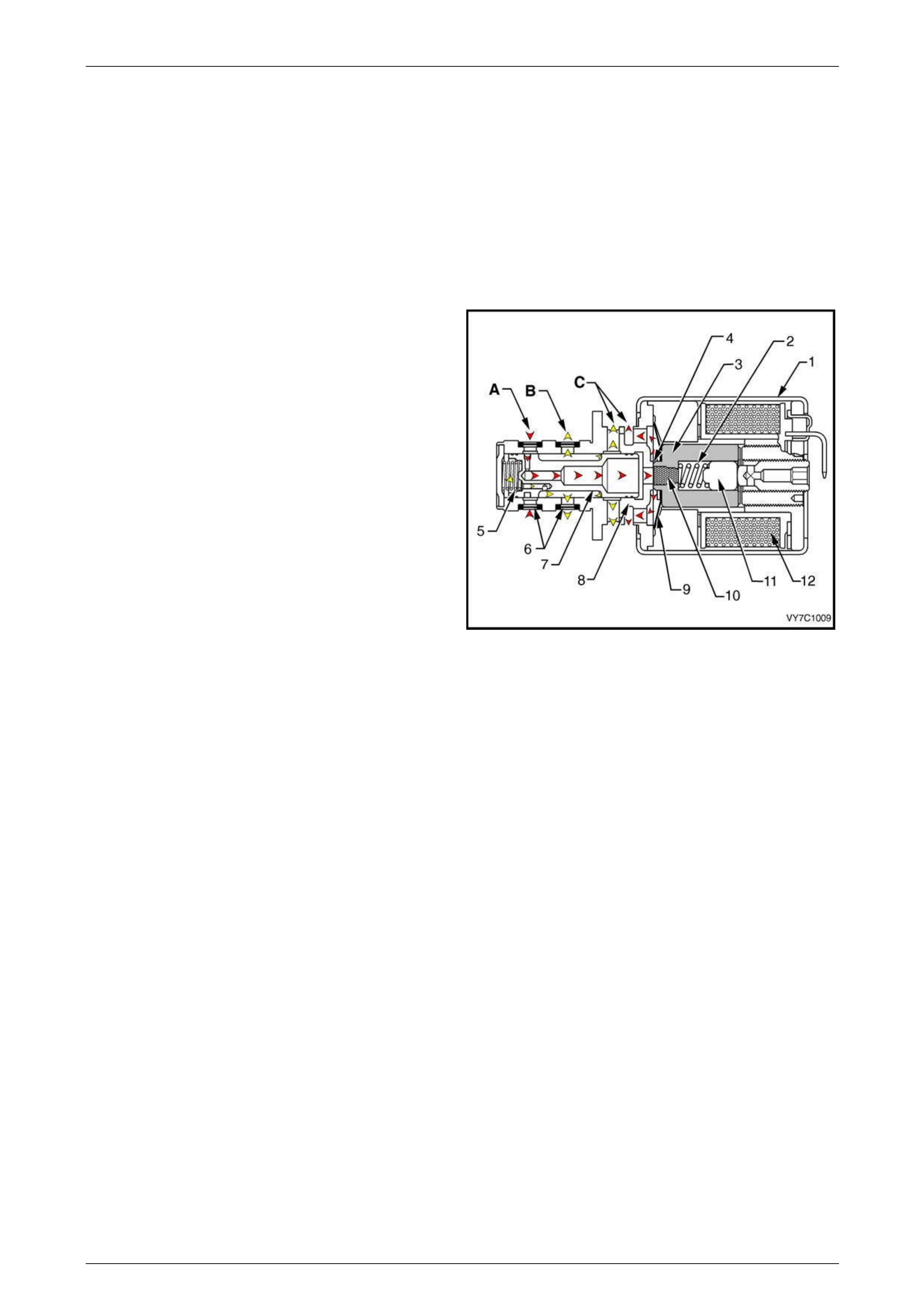
5.4 Pressure Control Solenoid
The transmission pressure control solenoid is an electronic pressure regu lator that controls pressure based on the
current flow through its coil winding. The magnetic field produced by the c oil moves the solenoid's internal valve which
varies pressure to the pressure regulator val v e.
The PCM controls the pressure control solenoid by commanding current between 100 and 1100 milliamps. This changes
the duty cycle of the solenoi d, which can range between 5 percent and 95 percent (typicall y less than 60 percent). 1100
milliamps corresponds to minimum line pressure, and 100 milliamps corresponds to maxi mum line pressure. If the
solenoid loses power, the transmission defaults to maximum line pressure.
The PCM commands the line pressur e valu es using inputs such as the throttle position sensor.
Legend
1 Frame
2 Spring
3 Armature
4 Variable Bleed Orifice
5 Spool Valve Spring
6 Fluid Screens
7 Spool Valve
8 Spool Valve Sleeve
9 Damper Spring
10 Restrictor
11 Push Rod
12 Coil Assembly
A Actuator Feed Limit (AFL) Fluid
B Torque Signal Fluid
C Exhausts Figure 6C3-1 – 42
Powertrain Management GEN III V8 – General Information Page 6C3-1–45
Page 6C3-1–45
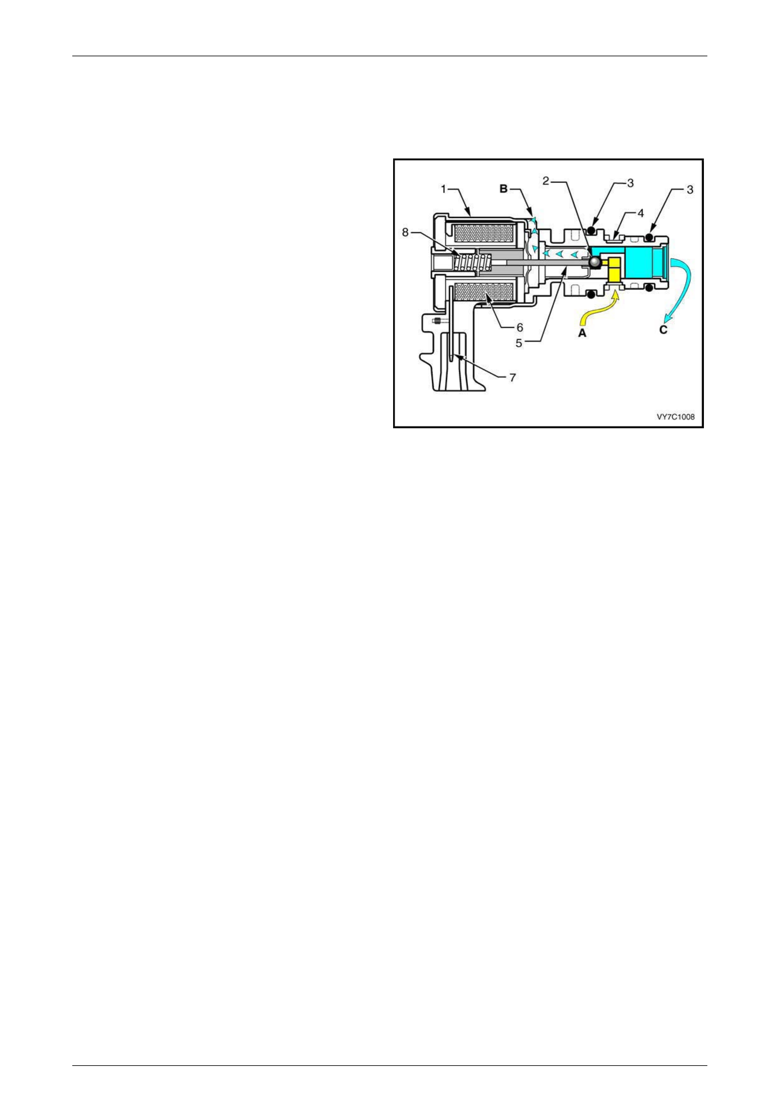
5.5 Torque Converter Clutch (TCC) Solenoid
Valve
The torque converter clutch solenoid valve is a normally
open exhaust valve that is used to control tor que converter
clutch apply and release. W hen grounded (energised) by
the PCM, the TCC solenoid valve stops converter signal oil
from exhausting. This causes converter signal oil pressure
to increase and shifts the TCC solenoi d valve into the apply
position.
Legend
A Converter Feed Fluid
B Exhaust
Figure 6C3-1 – 43
Powertrain Management GEN III V8 – General Information Page 6C3-1–46
Page 6C3-1–46
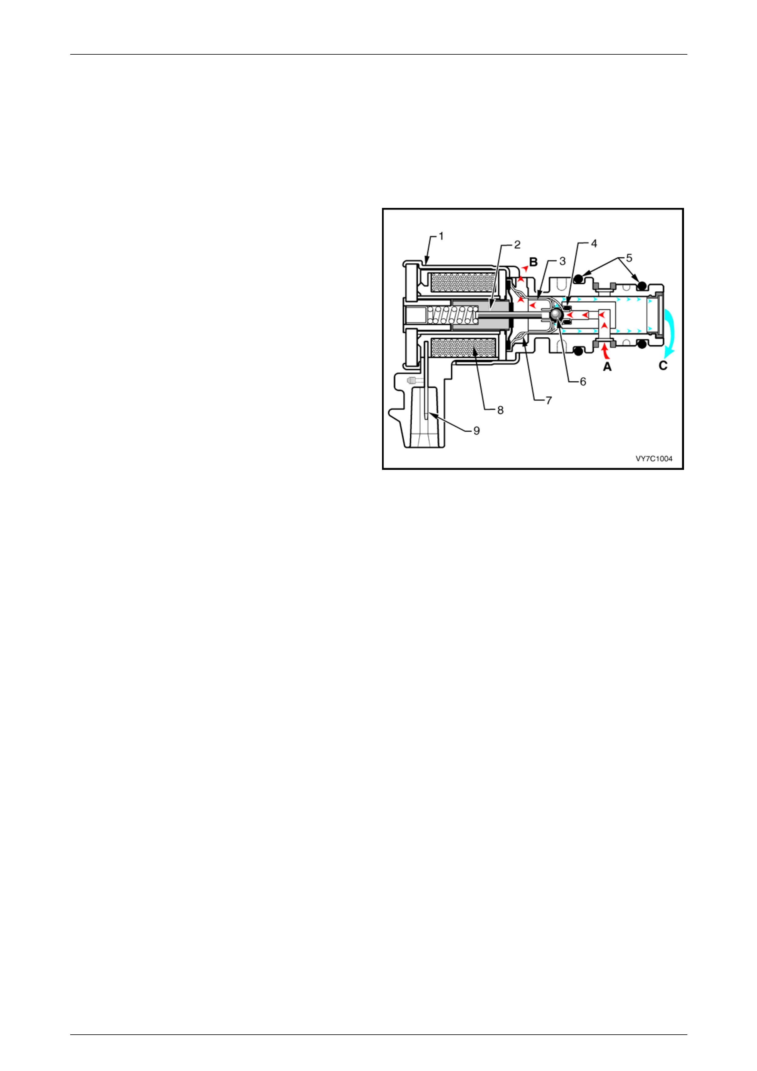
5.6 Torque Converter Clutch PWM Solenoid
Valve
The torque converter clutch PWM solenoid valve controls the fluid acting on the converter clutch valve, which then
controls the TCC apply and release. This solenoid is attached to the control valve body assembly within the transmission.
The TCC PWM solenoid valve provides smooth engagement of the torque converter clutch by operating on a negative
duty cycle a variable percent of on time.
Legend
1 Housing
2 Armature
3 Exhaust Seat
4 Internal O-Ring
5 O-Rings
6 Metering Ball
7 Inlet Seat
8 Coil Assembly
9 Connector Terminal
A Actuator Feed Limit (AFL) Fluid
B Exhaust
C Converter Clutch Signal (CCS) Fluid
Figure 6C3-1 – 44
Powertrain Management GEN III V8 – General Information Page 6C3-1–47
Page 6C3-1–47
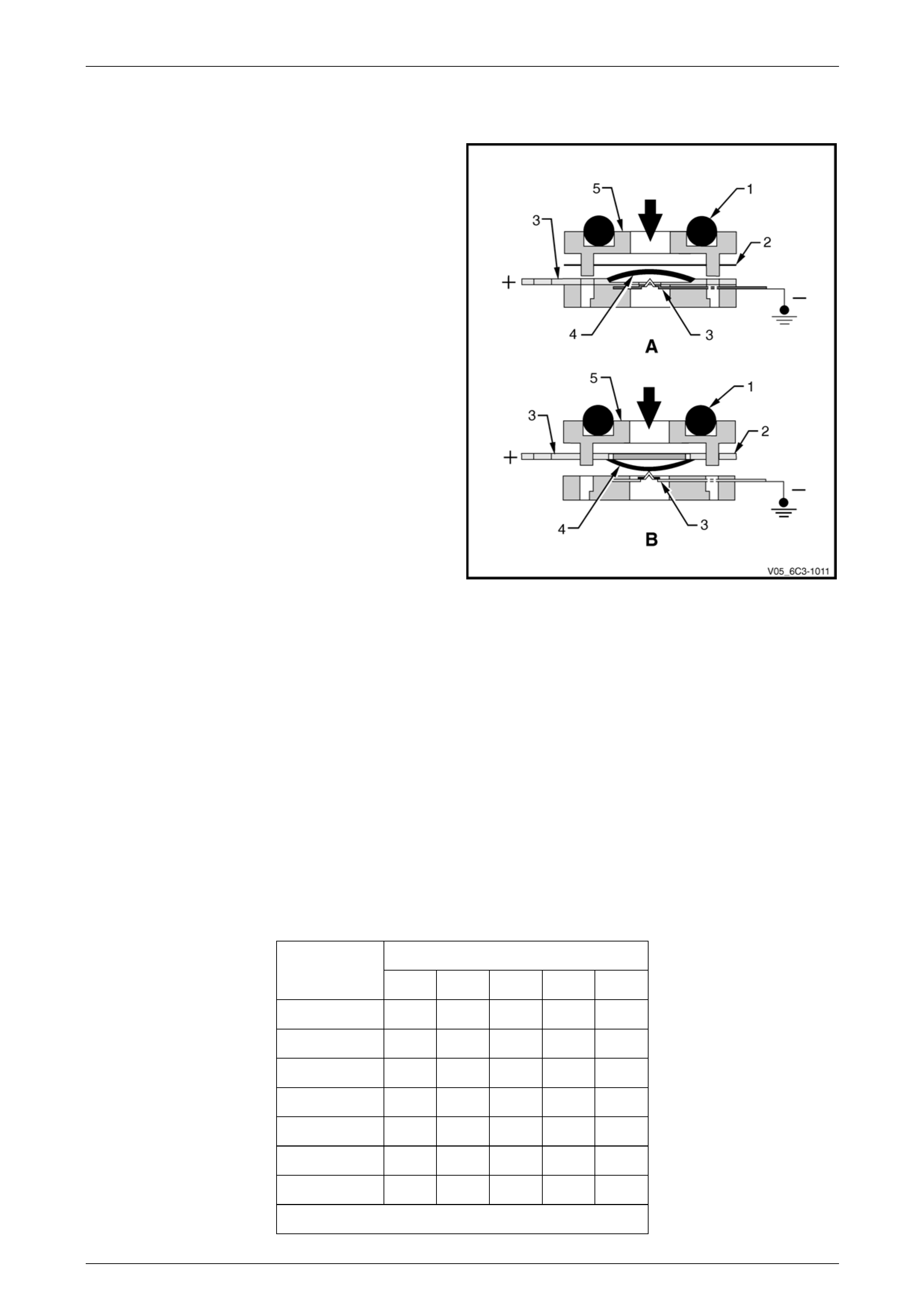
5.7 Fluid Pressure Switch Assembly
The transmission fluid pressure (TFP) manual valve position
switch assembly is used by the PCM to sense which gear
range has been selected by the driver. The TFP manual
valve position switch is located on the valve body and
consists of five pressure switches, two normall y closed and
three normally open, combined into one unit.
The normally open fluid pressure switches are the D4, LO
and Reverse fluid pressure s witches. They are normally
open and electrical current is stopped at these switches
when no fluid pressure is present. Fluid pressure moves the
diaphragm and contact element until the contact element
touches both the positive contact and the ground contact.
This creates a closed circuit and allows current to flow from
the positive contact, through the switch and to ground. The
normally closed fluid pressure switches are the D2 and D3
fluid pressure switches. T hey are normally closed and
electrical current is free to flow from the positive contact to
the ground contact when no fluid pressure is present. Fluid
pressure moves the diaphragm to disconnect the positive
and ground contacts. This opens the switch and stops
current from flowing through the s witch.
The PCM applies system voltage to the T F P manual valve
position switch assembly on three sep arate wires. An open
circuit measures 12 Volts while a grounded circuit measures
0 Volts. The switches are opened or closed by fluid
pressure. The combination of which switches are open and
closed is used by the PCM to determine actual manual
valve position. The TFP manual valve position switch
assembly cannot distinguish b etween Park and Neutral
because the monitored valve body pressures are identical in
both cases.
LO This switch will have hydraulic pressure applied to it in
manual 1st gear only and will be closed.
REV This switch will have hydraulic pressure applied to it in
reverse only and will be closed.
D2 This switch will have hydraulic pressure applied to it in
manual 1st and 2nd gear and will be open.
D3 This switch will have hydraulic pressure applied to it in
manual 1st, 2nd and 3rd gear and will be open.
D4 This switch will have hydraulic pressure applied to it in
all drive gears except revers e and will be closed.
Figure 6C3-1 – 45
Legend
1 O-Ring
2 Diaphragm
3 Contact
4 Contact Element
5 Body
A Normally Open
B Normally Closed
Pressure Switch Valid Combination Table
Fluid Pressure Switch
Range
Selected REV D4 D3 D2 LO
Park
Reverse X
Neutral
D X
3 X X
2 X X X
1 X X X X
X – Pressure Applied
Powertrain Management GEN III V8 – General Information Page 6C3-1–48
Page 6C3-1–48
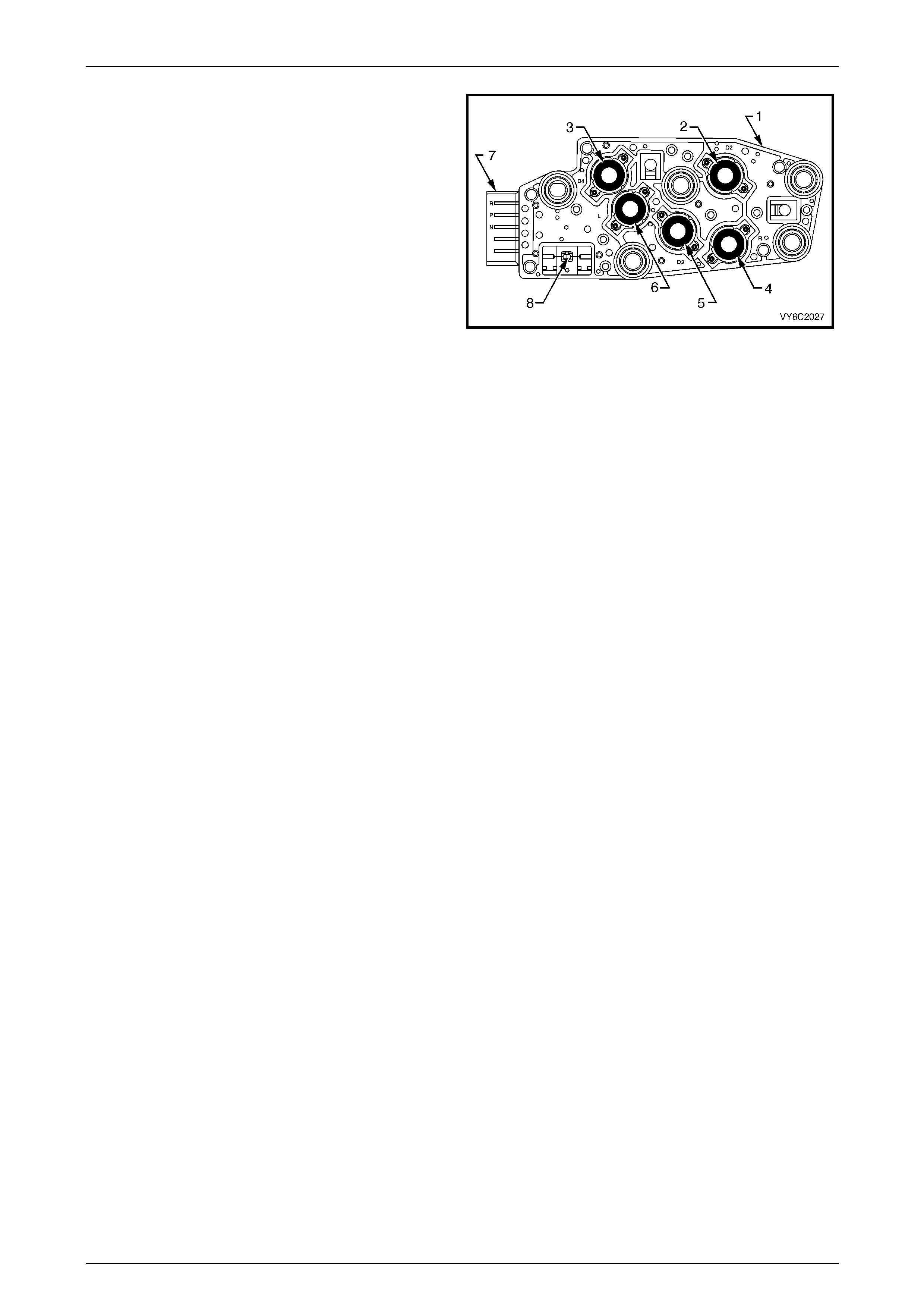
These TFP manual valve position switch inputs are used to
help control line pressure, torque converter clutch apply and
shift solenoid operation. T o monitor TFP manual valve
position switch operation, the PCM compares the actual
voltage combination of the switches to a TFP manual valve
position switch combination table stored in its memory.
Legend
1 Transmission Fluid Pressure Manual Valve Position Switch
2 D2 Indicator Switch
3 D4 Indicator Switch
4 Reverse Indicator Switch
5 D3 Indicator Switch
6 LO Indicator Switch
7 Five Pin Connector Terminal
8 Transmission Fluid Temperature Sensor
Figure 6C3-1 – 46
Powertrain Management GEN III V8 – General Information Page 6C3-1–49
Page 6C3-1–49
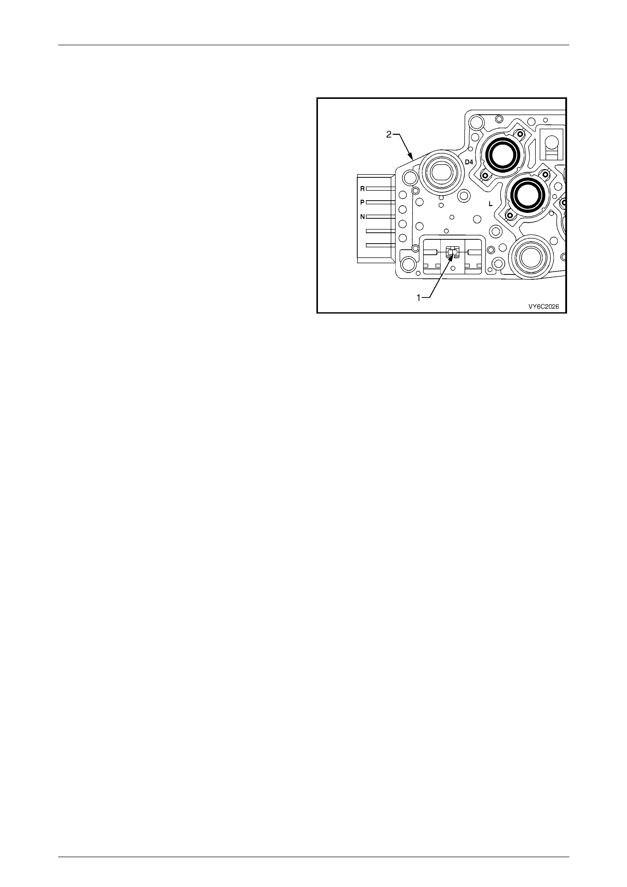
5.8 Fluid Temperature (TFT) Sensor
The automatic transmission fluid temperature (TFT) Sensor
(1) is part of the automatic transmission fluid pressure (TFP)
manual valve position switch assembly (2). This sensor
helps control torque converter clutch ap ply and shift quality.
The TFT sensor is a thermistor (a resistor which changes
value based on temperature). At low temperatures the
resistance is high, and at high temperatures the resistance
is low.
The PCM sends a 5 volt signal to the TFT sensor an d the
PCM measures the voltage drop in the circuit. The voltage is
high when the transmission is cold and low when the
transmission is hot.
Figure 6C3-1 – 47

Powertrain Management GEN III V8 – General Information Page 6C3-1–50
Page 6C3-1–50
6 Abbreviations and Glossary of
Terms
Abbreviations and terms used in this Section are listed below in alphabetical order with an explanation of the
abbreviation or term.
Abbreviation Description
A/C Air-conditioning
AC Alternating Current – An electrical current where the polarity is constantly changing between positive and
negative
A/F Air / Fuel (A/F Ratio)
Adaptive Learning Adaptive learning is the ability of the PCM to learn the particular characteristics of the system that it controls,
using features such as LTFT.
Analogue Signal An electrical signal that constantly varies in voltage within a given parameter
Barometric Pressure Barometric absolute pressure (atmospheric pressure)
CAN Controller Area Network – A type of serial data for communication between electronic devices.
Catalytic Converter A muffler-shaped device fitted in the exhaust system, usually close to the engine. Through chemical reaction,
a catalytic converter converts harmful gases produced by the combustion process such as HC, CO, and Nox,
into environmentally safe water vapour, carbon dioxide, and nitrogen.
CKT Circuit
Closed Loop A fuel control mode of operation that uses the signal from the exhaust oxygen sensor(s), to control the air / fuel
ratio precisely at a 14.7 to 1 ratio. This allows maximum efficiency of the catalytic converter.
CO Carbon Monoxide. One of the gases produced by the engine combustion process.
DC Direct Current
Digital Signal An electrical signal that is either on or off.
DLC Data Link Connector. Used at the assembly plant to evaluate the powertrain management system. For service,
it allows the use of Tech 2 in performing system checks.
DLC Data Stream An output from the PCM initiated by Tech 2 and transmitted via the Data Link Connector (DLC).
DMM (10 MΩ) Digital Multimeter. A multipurpose meter that has capability of measuring voltage, current flow and resistance.
A digital multimeter has an input impedance of 10MΩ (megohms), which means they draw very little power
from the device under test, they are very accurate and will not damage delicate electronic components
Driver An electronic device, usually a power transistor, that operates as an electrical switch.
DTC Diagnostic Trouble Code. If a fault occurs in the powertrain management system, the PCM may set a four digit
diagnostic trouble code (DTC) which represents the fault condition. Tech 2 is used to interface with the PCM
and access the DTC(s). The PCM may also operate the check powertrain icon in the instrument cluster multi-
function display.
Duty Cycle The time, in percentage, that a circuit is on versus off .
ECT Sensor Engine Coolant Temperature sensor. A device that provides a variable voltage to the PCM based on the
temperature of the engine coolant.
EEPROM Electrically Erasable Programmable Read Only Memory . A type of read only memory (ROM) that can be
electrically programmed, erased and reprogrammed using Tech 2. Also referred to as Flash Memory
EMI or Electrical
Noise An unwanted signal interfering with a required signal. A common example is the effect of high voltage power
lines on an AM radio.
Engine Braking A condition where the engine is used to slow the vehicle on closed throttle or low gear.
EPROM Erasable Programmable Read Only Memory. A type of Read Only Memory (ROM) that can be erased with
ultraviolet light and then reprogrammed.
ESD Electrostatic Discharge. The discharge of static electricity which has built up on an insulated material
EVAP Evaporative emission control system. Used to prevent fuel vapours from the fuel tank from entering into the
atmosphere. The vapours are stored in a canister that contains an activated charcoal element. The fuel
vapours are purged from the canister into the manifold to be burned in the engine.
GM LAN General Motors Local Area Network – A type of serial data for communication between electronic devices.
Fuse A thin metal strip which melts when excessive current flows through it, creating an open circuit and protecting
a circuit from damage.
HC Hydrocarbon. Result of unburned fuel produced by incomplete combustion.
Heavy Throttle Approximately 3/4 of accelerator pedal travel (75% throttle position)
IAT Sensor Intake Air Temperature sensor. A device that provides a variable voltage to the PCM based on the
temperature of air entering the intake system.
Ideal Mixture The air / fuel ratio which provides the best performance, while maintaining maximum conversion of exhaust
emissions, typically 14.7 to 1 on spark ignition engines
IGN Ignition

Powertrain Management GEN III V8 – General Information Page 6C3-1–51
Page 6C3-1–51
Abbreviation Description
Inputs Information from sensors (MAF, TP, etc.) and switches (A/C request, etc.) used by the PCM to determine how
to control its outputs.
Intermittent An electrical signal that occurs now and then; not continuously. In electrical circuits, refers to occasional open,
short, or ground in a circuit
Light Throttle Approximately 1/4 of accelerator pedal travel (25% throttle position)
Low A voltage less than a specific threshold. Operates the same as a ground and may, or may not, be connected
to chassis ground.
MAF Sensor Mass Air Flow Sensor. A device that provides a variable voltage to the PCM based on the amount of air flow
entering in the intake system.
Medium Throttle Approximately 1/2 of accelerator pedal travel (50% throttle position)
N.C Normally Closed. Switch contacts that are closed when they are in the normal operating position
N.O Normally Open. Switch contacts that are normally open when in the normal operating position
NOx Nitrogen Oxide. One of the pollutants found in spark ignition engine exhaust that is formed from normal
combustion and increases in severity with combustion temperature.
O2 Sensor Oxygen Sensor. A device located in the exhaust system that provides a variable voltage to the PCM based on
the oxygen content of exhaust gas.
May also include a heating circuit to provide faster initial warm-up (HO2 sensor).
OBD On Board Diagnostic
Open Loop PCM control of the fuel control system without the use of the oxygen sensor signal.
Output Functions that are controlled by the PCM, typically these can include solenoids and relays, etc.
PCM Powertrain control Module. An electronic device which controls the powertrain management system.
PCV Positive Crankcase Ventilation. Method of reburning crankcase fumes rather than passing them directly into
the atmosphere
PIM Powertrain Interface Module – The PIM acts as a communication translator between the PCM and other on-
board controllers that use a different serial data protocol.
PM Permanent Magnet
PWM Pulse Width Modulated. A digital signal turned on and off for a percentage of available cycle time. A signal that
is 30% on and 70% off would be termed a 30% on PWM signal.
Quad Driver A transistor in the PCM capable of operating four separate outputs. Outputs can be either on-off or pulse width
modulated.
RAM Random Access Memory. A microprocessor can write into or read from this memory as needed. This memory
is volatile and needs a constant power supply to be retained. If the power is lost or removed, RAM data is lost.
RPM Revolutions Per Minute
Serial Data Serial data is a series of rapidly changing voltage signals pulsed from high to low. These signals are typically 5
volts (UART), 7 volts (Class II), and 12 or 0 volts (high or low) and are transmitted through a wire often
referred to as the Serial Data Circuit.
SFI Sequential Fuel Injection. Method of injecting fuel into the engine one cylinder at a time in relation to the
engine’s firing order.
Solenoid An electromagnetic coil which creates a magnetic field when current is applied, causing a plunger or ball to
move.
Switch Device to opens and close a circuit, thereby controlling current flow.
Tech 2 Tech 2 is a peripheral device that aids in the diagnosis and repair of electronic systems such as powertrain
management, transmission control, ABS, etc. Tech 2 connects to the vehicle’s Data Link Connector (DLC).
TP Sensor Throttle Position sensor. A device that provides a variable voltage to the PCM based on the position of the
throttle plate.
Vacuum – manifold Vacuum sourced downstream of the throttle plate.
Vacuum – ported Vacuum sourced upstream of the throttle plate.
VSS Vehicle Speed Sensor. A permanent magnet type device that provides a digital voltage to the PCM.
UART Universal Asynchronous Receive and Transmit. A type of serial data for communicati on between electronic
devices.
WOT Wide Open Throttle – Full travel of the accelerator pedal (100% throttle position).