
5L40–E General Information 7E1 – 1
7E1 – 1
Section 7E1
Hydra-Matic 5L40–E Automatic Transmission: –
General Information
ATTENTION
Before performing any Service Operation or other procedure described in this Section, refer to Section 00
Warnings, Cautions and Notes for correct workshop practices with regard to safety and/or property damage.
1 Section Descriptions..............................................................................................................................2
Section 7E1: Hydra–matic 5L40–E Automatic Transmission – General Information.......................................... 2
Section 7E2: Hydra–matic 5L40–E Automatic Transmission – Electrical Diagnosis .......................................... 2
Section 7E3: Hydra–matic 5L40–E Automatic Transmission – Hydraulic/Mechanical Dia gnosis....................... 2
Section 7E4: Hydra–matic 5L40–E Automatic Transmission – On–Vehic le Servicing ....................................... 2
Section 7E5: Hydra–matic 5L40–E Automatic Transmission – Unit Repair........................................................ 2
2 Transmission Operation – Overview....................................................................................................3
2.1 General Description............................................................................................................................................... 3
Transmission Component Summary ................................................................................................................... 3
Transmission Identification .................................................................................................................................. 5
Transmission Speed Ranges................................................................................................................................ 5
‘Active Select’ Shift Control.................................................................................................................................. 6
Transmission Range Reference Chart................................................................................................................. 6
Transmission Adaptive Functions ....................................................................................................................... 7
Safety Mode Description....................................................................................................................................... 8
Transmission Shift Mode Operation .................................................................................................................... 8
Normal Mode Operation..................................................................................................................................... 8
Power Mode Operation ...................................................................................................................................... 8
Cruise Control Mode Operation.......................................................................................................................... 8
Active Select Mode Operation............................................................................................................................ 8
3 Service Notes..........................................................................................................................................9
3.1 Fasteners................................................................................................................................................................ 9
3.2 General Workshop Practice................................................................................................................................ 10
4 Transmission Definitions and Abbreviations....................................................................................11
4.1 Definitions ............................................................................................................................................................ 11
4.2 Abbreviations....................................................................................................................................................... 14
Techline
Techline
Techline

5L40–E General Information 7E1 – 2
7E1 – 2
1 Section Descriptions
A multi–section approach to the service inform ation for the Hydra–matic 5L40–E automatic transmission has been
adopted for MY 2005 VZ and WL Series vehicles. The Section breakdown is as follows:
Section 7E1: Hydra–matic 5L40–E Automatic Transmission – General Information
The purpose of this Section is to provide an overview of the 5L40–E automatic transmission, by briefly d escribi ng what
each of the various sub–sections contain.
In addition, an overvie w of the transmission features is provided, that includes:
• A general description of the transmissi on, its operation and control, as well as transmission identification
information.
• Some notes that address safe workshop practices when dealing with automatic transmissions.
• Service notes relating to fasteners and consumable items used at various stages throughout these Sections.
Section 7E2: Hydra–matic 5L40–E Automatic Transmission – Electrical Diagnosis
As this automatic transmission uses a separate Transmission Control Module (TCM), the information in this Section
covers all aspects of the TCM control of the transmission. Information includ es component locatio ns, system operation,
active select (where fitted), diagnostic trouble codes and el ectrical fault finding charts.
Section 7E3: Hydra–matic 5L40–E Automatic Transmission – Hydraulic/Mechanical Diagnosis
As distinct from the previous Section, 7E3 contains information that will assist in the diagnosis of the mechanical and
hydraulic components in the 5L40 –E automatic transmission.
The type of diagnostic information in this Section i nclu des transmission functional test, shift speed and line pressure
information. Other material contained in this Section refers to the fluid flow and circuit descriptions, plus fluid passage
identification diagrams relating to this transmission.
Section 7E4: Hydra–matic 5L40–E Automatic Transmission – On–Vehicle Servicing
Information in this Section covers transmission fluid level checking and diagnosis, as well specific information for
servicing some components while the transmission remains installed in the vehicle.
This Section also contains the necessary procedures for the removal and installation of the transmission.
Section 7E5: Hydra–matic 5L40–E Automatic Transmission – Unit Repair
This Section contains the procedures necessary for the disassembly, inspection, overhaul an d assembly operations of
the mechanical components, once the tran smission is removed from the vehicle. Also included is information relating to
measurement of certain clearances, the correct use of special service tools and torque wrench specifications required
during overhaul.

5L40–E General Information 7E1 – 3
7E1 – 3
2 Transmission Operation –
Overview
2.1 General Description
The Hydra–matic 5L40–E a fu lly automatic, five speed, rear drive, electronically controlled transmission. It consists
primarily of a four–element torque converter, one planetary gear set, friction and mechanical clutch es and a hydraulic
pressurization and control system.
The four–element torque converter contains a pump, a turbine, a pressure plate splined to the turbine, and a stator
assembly. The torque converter acts as a flui d coupling to smoothly transmit power from the engine to the transmission.
It also hydraulically provides additional torque multiplication wh en required. The pressure plate, when applied, provid es a
mechanical ‘direct drive’ coupling of the engine to the transmission.
The planetary gear set provides the five forward gear ratios and reverse. C hanging gear ratios is fully automatic and is
accomplished through the use of a T r ansmission Control Module (TCM). The TCM receives and monitors various
electronic sensor inputs and uses this inform ation to shift the transmission at the optimum time.
The TCM commands shift solenoids, within the transmission, on and off to control shift timing. The TCM controls shift
feel through the pressure control sole noid. The TCM also controls the apply and release of the torque converter clutch
which allows the engine to deliver the maximum fuel efficiency without sacrificing vehicle performance.
The hydraulic system primarily consists of a vane type pump, two control valve bodies, two channel plates, converter
housing and case. The pump maintains the working pressures neede d to stroke the clutch pistons that apply the friction
components. These friction components (when applied or released) support the automatic shifting qualities of the
transmission.
The friction components used in this transmission consist of nine multiple disc clutch packs. The multiple disc clutches
combine with four mechanical sprag clutches, to deliver six different gear ratios through the gear set. The gear set then
transfers torque though the output shaft.
There are no brake bands within this transmission.
Transmission Component Summary
Mechanical / Hydraulic Components Electrical Components
Torque converter assembly 1–2, 2–3 and 4–5 shift solenoids
Direct and reverse clutch assembly Transmission manual shift shaft switch assembly
Forward and coast clutch assembly Transmission pressure control (PC) solenoid
Input sun gear shaft and forward sprag clutch assembly TCC pulse width modulatio n (PW M) solenoid valve
Output shaft assembly, with rear internal gear Transmission fluid temperature (TFT) sensor
Intermediate clutch sprag assembly Transmission input speed se nsor (TISS)
Overdrive clutch housing Transmission output speed sensor (TOSS)
Low clutch sprag
Centre support
Input and reaction carrier
Fluid pump assembly
Control valve body and accumulator ass embly
5L40–E General Information 7E1 – 4
7E1 – 4
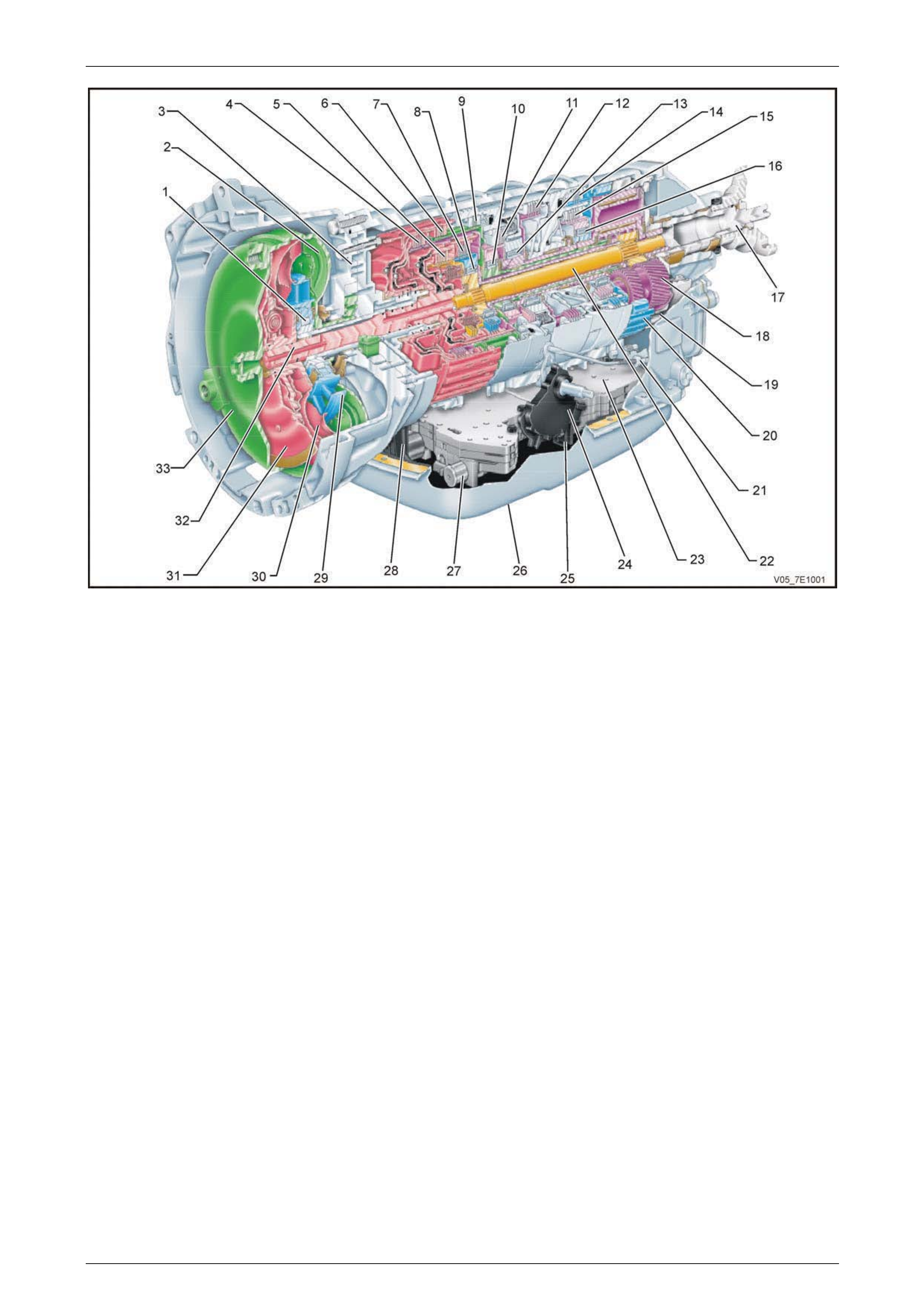
Figure 7E1 – 1 – Transmission Major Components & Assemblies
Legend
1 Stator Roller Clutch
2 Converter Pump
3 Torque Converter Housing/Pump
4 Direct Clutch
5 Coast Clutch
6 Reverse Clutch
7 Forward Clutch
8 Forward Sprag Clutch
9 Overdrive Clutch
10 Intermediate Sprag Clutch
11 Intermediate Clutch
12 Low/Reverse Clutch
13 Low Sprag Clutch
14 Second Coast Clutch
15 Second Clutch
16 Second Sprag Clutch
17 Output Shaft
18 Planetary Carrier
19 Rear Internal Gear
20 Front Internal Gear
21 Park Pawl Actuator
22 Input Sun Gear Shaft
23 Control Valve Body/Accumulatory
24 Transmission Manual Shaft Switch
25 Manual Valve
26 Transmission Fluid Pan
27 TOO PWM Solenoid Valve
28 Transmission Fluid Filter
29 Converter Stator
30 Converter Turbine
31 Pressure Plate
32 Forward/Coast Clutch Housing Shaft
33 Torque Converter
5L40–E General Information 7E1 – 5
7E1 – 5
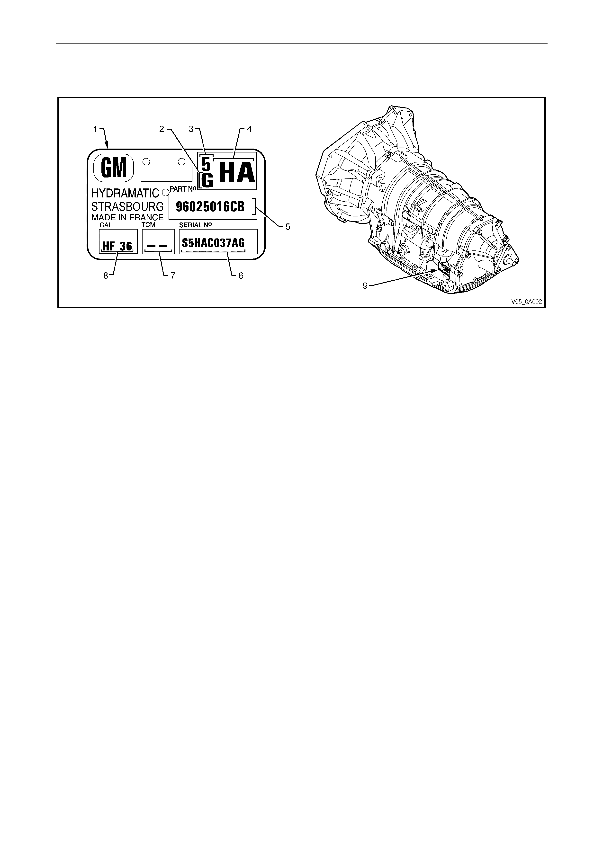
Transmission Identification
A transmission identification p late (item 9 in Figure 7E1 –2) is located on the left hand side rear of the transmission case.
Figure 7E1 - 2
Legend
1 Production Identification Plate 6 Serial Number
2 Transmission Family 7 Empty
3 Model Year 8 Calibration Code
4 Application – ‘HA’ = 3.6 litre V6 / ‘HB’ = V6 AWD / ‘HF’ = 2.8 litre V6 9 I.D. Tag Location
5 Part Number
Transmission Speed Ranges
The 5L40–E transmission can be operated in any one of the seven different positions shown on the shift quadrant.
P – Park position enables the engine to be started while preventing the vehicle from rolling either forward or backward.
For safety reason, the vehicle’s parkin g brake should be used in addition to the transmission ‘P ark’ position. Since the
output shaft is mechanically locked to the case through the parking pawl and rear internal gear, park position should not
be selected until the vehicle ahs come to a complete stop.
R – Reverse enables the vehicle to be operated in a rearward direction.
N – Neutral position enables t he engine to start and operated without driving the vehicle. If necessar y, this position
should be selected to restart the engine while the vehicle is moving.
D – Overdrive range should be used for all normal driving conditions for maximum efficie ncy and fuel economy.
Overdrive range allows the transmission to operate i n each of the five forward gear ratios. Downshifts to a lower gear, of
higher gear ratio are available for safe passing by depressing the accelerator or by manuall y selecting a lower gear with
the shift lever.
4 – Manual Fourth can be used for conditions where it may be desirable to use on ly four gear ratios. These conditions
include towing a trailer and driving on hilly terrain as previously described. This range is also helpful for engine braking
when descending slight grades. Upshifts and downshifts are the same as in Overdrive range for first, second, third and
fourth gears except that the transmission will not shift into fifth gear. Manual Fourth can be selected at any vehicle speed
but will downshift into fourth gear only at the road speed and throttle position calibrated within the TCM.
3 – Manual Third adds more performance for congested traffic and hilly terrain. It has the same starting ratio (first gear)
as Manual Fourth, but prevents the transmiss ion from shifting above third gear. Thus, Manual Third can be used to retain
third gear for acceleration and engine braking as desired. Manual Third can be selected at any vehicle speed but will
downshift into third gear only at the road speed an d throttle position calibrated within the TCM.
L – Manual Second again adds more performance for congested traffic and hilly terrain. It has the same starting ratio
(first gear) as Manual Third, but prevents the transmission from shifting above second gear. Thus, Manual Second can
be used to retain second gear for acceleration and engine braking as desired. Manual Second can be selected at any
vehicle speed but will downshift into second gear only at the road speed and throttle position calibrated within the TCM.
When the vehicle speed slows down, the transmission will shift into first gear, in the same way that a 2-1 downshift
occurs, when the shift selector is in the Drive range. Use of the ‘L’ range is particularly beneficial for maintaining
maximum engine braking when descending steep grades.
5L40–E General Information 7E1 – 6
7E1 – 6
‘Active Select’ Shift Control
When the momentary contact ‘A/S’ switch in the centre console cover is pressed and the Active Select mo de is
operational, the driver can change speed ratios either up or down, using the steering wheel mounted paddle shift pads
(marked ‘+’ for upshifts and – for downshifts), provided the vehicle is moving, the shift selector is in the ‘D’ position and
the shift desired, is within the TCM calibration.
Transmission Range Reference Chart
Figure 7E1 - 3

5L40–E General Information 7E1 – 7
7E1 – 7
Range D / 4 / 3 / 2 Neutral Reverse Park
Gear 1 1 2 2 3 3 4 5 – R –
Engine Braking NO YES NO YES NO YES YES YES – YES –
Ratio 3.24 3.24 2.21 2.21 1.60 1.60 1.00 0.75 – 3.03 –
1–2 Shift
Solenoid Valve OFF OFF ON ON ON ON OFF OFF
ON/OFF
ON/OFF
ON/OFF
2–3 Shift
Solenoid Valve ON ON ON ON OFF OFF OFF OFF
ON/OFF
ON/OFF
ON/OFF
4–5 Shift
Solenoid Valve OFF ON OFF ON OFF ON ON OFF
ON/OFF
ON/OFF
ON/OFF
TCC Solenoid
Valve OFF OFF
ON/OFF
ON/OFF
ON/OFF
ON/OFF
ON/OFF
ON/OFF
OFF
Direct Clutch APPLIED APPLIED
Coast Clutch APPLIED APPLIED APPLIED APPLIED APPLIED APPLIED APPLIED
Reverse Clutch APPLIED
Forward Clutch APPLIED APPLIED APPLIED APPLIED APPLIED APPLIED APPLIED APPLIED
Forward Clutch
Sprag LD LD LD LD LD LD LD
Overdrive Clutch APPLIED APPLIED
Intermediate
Clutch Sprag LD LD
Intermediate
Clutch APPLIED APPLIED APPLIED APPLIED
Low Clutch
Sprag LD LD
Low and Reverse
Clutch APPLIED APPLIED
Second Clutch APPLIED APPLIED APPLIED APPLIED APPLIED APPLIED
Second Clutch
Sprag LD LD
Second Coast
Clutch APPLIED
LD = Locked in Drive ON = Solenoid Ene rgised OFF = Solenoid De-Ene rgised
The solenoids state follows a shift pattern that depends upon vehicle speed and throttle position. It does not depend upon the selected gear.
Engine braking is electronically controlled by the TCM and is available as a calibrated function.
Transmission Adaptive Functions
The Hydra-matic 5L40-E uses a line pressure control system which has the abilit y to adapt the s ystem line press ure in
order to compensate for normal wear of clutch fibre plates, seals, springs, etc. The adapt feature is similar in function to
fuel control (integrator/block learn).
The Hydra-matic 5L40-E transmission uses the adapt function for garage shifts, upshifts, and TCC application. The TCM
monitors the input shaft speed in order to determine if the shift is occurring too fast or too slow and adjusts the pressure
control solenoid in order to maintain the correct shift feel.
As this adaptive feature is unique to any given transmission, it should be noted that any two different vehicles fitted with
the Hydra-matic 5L40-E automatic transmission, cou ld e xhibit different shift characteristics and have a different ‘feel’.
This is a normal phenomena.

5L40–E General Information 7E1 – 8
7E1 – 8
Safety Mode Description
If a major electrical system failure occurs which could affect vehicle safety or damage the transmission during normal
operation, the TCM enters a default safety mode. In this mode, the transmission operates in the following manner:
• The pressure control solenoid is commanded off and the line pressure is at maximum to minimise clutch slippage.
• The TCC solenoid is commanded off. The converter clutch is disabled.
• All three of the shift solenoids are commanded off. The transmission will operate in fifth gear if the vehicle has
successfully completed a 1-2 upsh ift in the current ig nition cycle. If the vehicle has not completed a 1-2 upshift in
the current ignition cycle, the transmission will operate in fourth gear. If the transmission is operating in fifth gear,
fourth gear may be obtained if the engine is stopped briefly and re-started.
In safety mode, the gear selector lever is ineffective at selecting forward gear ranges. In fourth or fifth gear, heat builds
up in the transmission quickly, particularly in stop and go traffic. Excessive heat bu ild-up may cause transmission failure
if the vehicle is driven for extended distances in the safety mode.
Transmission Shift Mode Operation
Normal Mode Operation
During economy mode operation, drivers may notice increased powertrain brakin g after releasing the accelerator pedal.
The vehicle will not coast freel y when the accelerator pedal is released, but will start to gradually slow down as if the
brakes were lightly applied. This feels very similar to what is experienced when releasing the accelerator pedal on a
vehicle equipped with a manual transmission.
Power Mode Operation
The power mode was designed to simulate the performance driving of a manual transmission equipped vehicle. This
means that, given certain driving conditi ons, the vehicle will maintain specific gears longer than a traditional automatic
transmission would. No attempt should be m ade to change or alter these operating characteristics.
Cruise Control Mode Operation
When the driver activates the cruise control (where fitted), the ‘Power’ icon in the Instrument, Multi-Function Display
(MFD) will be deactivated (provided the vehicle was operating in ‘Power’ mode) and the transmission shift pattern will
switch to the cruise control mode.
Through the electronic progra mming of the logic processes contained in the Transmission Control Module (TCM), the
frequency of gear shifting and torque converter clutch application and release is minimised. The end result of these logic
processes, is that transmission 'busyness' (a quick series of upshifts and downshifts, such as a '4-3-4' shift pattern) is
minimised.
Active Select Mode Operation
When activated by the driver pressing the m omentary contact ‘A/S’ switch in the centre console, changes to the upshift
and downshift of the transmission can be effected by tapping either the ‘+’ (upshift) or ‘–‘ (downshift) paddles l ocate d at
the steering wheel.
Provided the shift select lever is in the ‘D’ position and the vehicle in motion, the transmission shift pattern can then be
governed by the selection command ed. That is, the transmission shift pattern can be selected by the driver controls,
within the TCM programmed parameters.
With Active Select operational and the vehicle is brought to a stop, the transmission will shift down to first gear.

5L40–E General Information 7E1 – 9
7E1 – 9
3 Service Notes
In the interests of safety to personnel, equipment and to the vehicle and its components, the following notes should be
read and adhered to whenever servicing operations are to be carried out on the H ydra–m atic 5L4 0–E automatic
transmission. In addition, some of this information also refers to the adher ence to sound workshop practices and, to
achieve the design life of affected components; it is also recommended that these points be taken into account.
3.1 Fasteners
1 Always reinstall fasteners in the same location as they were removed.
2 If a fastener requires replacement, al ways use a part of the correct part number or of equ al size and strength or
stronger.
3 Tighten fasteners to correct torque value when required. Torque values are specified for dry, unlubricated fastener
threads.
4 Additional notes regarding the tightening of fasteners is located in Section 00 Warning, Cautions and Notes.

5L40–E General Information 7E1 – 10
7E1 – 10
3.2 General Workshop Practice
• Machined surfaces on alloy castings have
extremely sharp edges that can easily
cause injury and blood loss, through
severe cuts. Take extreme care when
working under these conditions.
• Always wear eye protection when using
compressed ai r o n components.
• Keep work area and tools clean.
• To avoid unnecessar y conta mination, always clean the exterior of the transmission before removi ng any parts.
• Do not use wiping cloths or rags because of the risk of lint being trapped in the transmission.
• Do not use solvents on:
• neoprene seals.
• composition faced clutch plates.
• thrust washers.
• Blow out all passages with compressed air. Only probe small passages with soft, thin wire.
• Handle parts with care to avoid nicks and scratches.
• Do not remove Teflon oil seal rings and compress external snap rings to maximise retention and security.
• Lubricate all internal parts with transmission fluid (only use Dexron® III unless otherwise directed), as they are
installed.
• When installing cap screws into aluminium castings:
• always use a torque wrench.
• always dip screw threads in transmission fluid (only use Dexron® III).
• stripped or damaged threads in aluminium castings may be reconditioned by using commercially available
thread inserts.
• Once removed, replace all ga skets, seals and O–rings with new parts and:
• always use seal protectors when indicated and do not use gasket cement or sealant on a ny joined face
unless specified to do so.

5L40–E General Information 7E1 – 11
7E1 – 11
4 Transmission Definitions and
Abbreviations
The following definitions and abbreviations are provided to establish a common language and assist the user / technician
in describing transmission related conditions. The use of these terms and / or conditions can be found in the various
parts of the automatic transmission sections of this Service Information, but more particularly, in Section 7E3 Hydraulic /
Mechanical Diagnosis.
Besides the following definitio ns and abbreviations, there are some additional definitions and abbreviati ons used when
describing transmission related cond itions, refer to Section 7E3 Hydraulic / Mechanical Diagnosis,
1.3 Transmission Definitions and Ab breviations, for details.
4.1 Definitions
Accumulator: A component of the transmission that absorb s hydraulic pressure during the apply of a clutch or band.
Accumulators are designed to control the quality of a shift from one gear to another.
Adaptive Learning: Programming within the Transmission Control Module (TCM) that automatically adjusts hydraulic
pressure in order to compensate for changes in the transmission (i.e. component wear).
Applied: An apply component that is holding another component to which it is splined or assembled with. Also referred
to as ‘engaged’.
Apply Components: Hydraulic operated cl utches, servos, bands, and mechanical one–way roller or spr ag clutches that
drive or hold members of a planetary g ear set.
Backing Plate: A steel plate in a clutch pack that is usually the last plat e in that clutch assembly (farthest from the clutch
piston).
Ball Check Valve: A spherical hydraulically operated controlled component (usually made of steel) that either seals or
opens fluid circuits. It is also referred to as a check valve or checkball.
Band: An apply component that consists of a flexible strip of steel and friction material that wraps around a drum. When
applied, it tightens around the drum and prevents the drum from rotating.
Brake Switch: An electrical device that provides signals to the TCM based on the position of the brake pedal. The TCM
uses this information to apply or releas e the torque converter clutch.
Centrifugal Force: A force that is imparted on an object (due to rotation) that increases as that object moves further
away from a centre / point of rotation.
Clutch Pack: An assembly of compone nts generally consisting of clutch plates, an apply plate and a backing plate.
Component: Any physical part of the transmission.
Control Valve Body: A machined metal casting that contains valve trains, and other hydraulically controlled components
that shift the transmission.
Coupling Speed: The speed at which a vehicle is travelling and no longer requires torque multiplicatio n through the
torque converter. At this point the stator free wheels to allow fluid leaving th e turbine to flow directly to the pump.
De-energise(d): To interrupt the electrical current that flows to an electronically controlled device mak ing it electrically
inoperable.
Direct Drive: A condition in a gear set where the input speed and the input torque equals the output speed and torque.
The gear ratio through the gear set is 1:1.
Downshift: A change in a gear ratio where input speed a nd torque increases.
Driver Shift Control: A selector system variant which is configured to be shifted only manually, and allows for engine
braking in first, second, third and fourth gears.
Duty Cycle: In reference to an electronically controlled solenoid, it is the amount of time (expressed as a percentage)
that current flows through the solenoid coil.

5L40–E General Information 7E1 – 12
7E1 – 12
Engine Control Module (ECM): An electronic device that manages the electrical system of the engi ne.
Energise(d): To supply a curr ent to an electronically controlled device enabling it to perform its designed function.
Engine Compression Braking: A condition where compression from the engine is used with the transmission to
decrease vehicle speed. Braki ng (slowing of the vehicle) occurs when a lower gear ratio is manually selected by moving
the gear selector lever.
Exhaust: The release of fluid pressure from a hydraulic circuit. (The words exhausts and exhausting are also used and
have the same intended meanin g).
Fluid: In this Service Information, ‘fluid’ refers primarily to Automatic Transmission Fluid (or ATF) and, for the Hydra–
matic 5L40–E transmission, the only recommended fluid is Dexron III®.
Fluid Pressur e: A pressure that is consistent throughout its circuit.
Force: A measurable effort that is exerted on an object (component).
Freewheeling: A condition where power is lost through a driving or holding device (i.e. roller or sprag clutches).
Friction Material: A heat and wear resistant fibrous material bonded to clutch plates a nd bands.
Gear: A round, toothed device that is used for transmitting torque through other components.
Gear Range: A specific speed to torque ratio at which the transmission is operating (i.e. 1st gear, 2nd gear etc.).
Gear Ratio: Revolutions of an input gear as compared to the revolutions of an output gear. It can also be expressed as
the number of teeth on a gear that it is in mesh with.
Hydraulic Circuit: A fluid passage that often includes the mechanical components in that circuit designed to perform a
specific function.
Input: A starting point for torque, revolutions or energy into another component of the transmission.
Internal Gear: The outermost member of a gear set that has gear teeth in constant mesh with planetary pinion gears of
the gear set.
Internal Leak: Loss of fluid pressure in a hydraulic circuit.
Land (Valve Land): The larger diameters of a spool valve that contact the valve bo dy bore or bushing.
Line Pressure: The main fluid pressure in a hydraulic system created by the pump and pressur e regulator valve.
Manual Valve: A spool valve that distributes fluid to various hydraulic circuits and is mechanically linked to the gear
selector lever.
Orifice: A restricting device (usually a hole in the spacer plate) for controlling pressure build up into another circuit.
Overdrive: An operating condition in the gear set allowing output speed to be higher than inp ut speed and output torque
to be lower than input torque.
Overrunning: The function of a one–way mechanical clutch that allows the clutch to freewheel during certain operating
conditions of the transmission.
Pinion Gear: A small toothed gear that meshes with a larger gear.
Planet Pinion Gears: Pinion gears (housed in a carrier) that are in constant mesh with a circumferential internal gear
and centralised sun gear.
Planetary Gear Set: An assembly of gears that consists of an internal gear, planet pinion gears with a carrier, and a sun
gear.
Pressure: A measurabl e force that is exerted on an area and expressed as kilopascals (kPa).
Pulse Width Modulated (PWM): An electronic signal that continuousl y cycles the ON and OFF time of a device (such as
a solenoid) while var ying the amount of ON time.

5L40–E General Information 7E1 – 13
7E1 – 13
Race (Inner of Outer): A highly polished steel surface that contacts bearings or sprag or roller elem ents.
Reduction (Gear Reduction): An operating condition in the gear set allowing output speed to be lower than input speed
and output torque to be higher that input torque.
Residual Fluid Pressure: E xcess pressure contained within an area after the supply pressure has been terminated.
Roller Clutch: A mechanical clutch (holding device) consisting of roller bearings assembled between inner and outer
races.
Safety Mode: A condition whereby a compo nent (i.e. engine or transmission) will partially function even if its electrical
system is disabled.
Servo: A spring loaded device consisting of a piston in a bore that is operated (stroked) by hydraulic pressure to apply or
release a band.
Solenoid Valve: An electronic device used to control transmission shift patterns or regulate fluid pressu re.
Spool Valve: A cylindrical hydraulic control device having a variety of land and valley diameters, used to control fluid
flow.
Sprag Clutch: A mechanical clutch (holding devic e) consisting of figure eight like elements assembled between inner
and outer races.
Throttle Position: The trave of the throttle plate that is expressed in percentages and measured by the throttle position
(TP) sensor.
Torque: A measurable twisting force expressed in terms of Newton–meters (N.m).
Torque Converter: A component of an automatic transmission, (attached to the engine flywheel) that transfers torque
from the engine to the transmission through a fluid coupling.
Transmission Control Module (TCM): An electronic device that manages the electrical system of the transmission.
Variable Capacity Pump: The device that provid es fluid for operating the hydraulic circuits in the transmission. T he
amount of fluid supplied varie s depending on vehicle operating con ditions.

5L40–E General Information 7E1 – 14
7E1 – 14
4.2 Abbreviations
AC – Alternating Current
A/C – Air Conditioning
ACC or ACCM – Accumulator
AFL – Actuator Feed Limit
AMP – Amperage
ASM –Assembly
AT – Automatic Transmission
°C – Degrees Celsius
CC – Converter Clutch
CONT – Control
CONV – Converter
DC – Direct Current
D.C. – Duty Cycle
DLC – Diagnostic Link Connector
DTC – Diagnostic Trouble Co de
D2 – Drive 2 (circuit)
D3 – Drive 3 (circuit)
D4 – Drive 4 (circuit)
D432 – Drive 432 (circuit)
ECM – Engine Control Module
ECT – Engine Coolant Temperature
EX – Exhaust
FD – Feed
Hz – Hertz
ISS – Input Speed Sensor
Km/h – kilometres per hour
MAP – Manifold Absolute Pressure
N – Neutral
NC – Normally Closed
N.m – Newton Metres
NO – Normally Open
ORF – Orifice
ORUN – Overrun
OSS – Output Speed Sensor
P – Park
PC – Pressure Control (solenoid)
PR – Park Reverse (circuit)
PRESS REG – Pressure Regulator
PWM – Pulse Width Modulated
R – Reverse
RPM – Revolutions per Minut e
SEL – Selective
SIG – Signal
SOL – Solenoid
SS – Shift Solenoid
TCC – Torque Converter Clutch
TCM – Transmission Control Module
TFP – Transmission Fluid Pressure
TFT – Transmission Fluid Temperature
TP – Throttle Position (sensor)
TRANS – Transmission
V – Volts
VSS – Vehicle Speed Sens or
2WD – 2 Wheel Drive
4WD – 4 Wheel Drive
AWD – All Wheel Drive