
4L60-E
HYDRA-MATIC
2
CONTENTS
INTRODUCTION..................................................................................... 3
HOW TO USE THIS BOOK ...................................................................... 4
UNDERSTANDING THE GRAPHICS ....................................................... 6
TRANSMISSION CUTAWAY VIEW (FOLDOUT) ....................................... 8
GENERAL DESCRIPTION ....................................................................... 9
PRINCIPLES OF OPERATION ............................................................... 9A
MAJOR MECHANICAL COMPONENTS (FOLDOUT) ...................... 10
RANGE REFERENCE CHART ......................................................... 11
TORQUE CONVERTER .................................................................. 12
APPLY COMPONENTS ................................................................. 15
PLANETARY GEAR SETS ............................................................. 24
HYDRAULIC CONTROL COMPONENTS........................................ 26
ELECTRICAL COMPONENTS ........................................................ 36
POWER FLOW ...................................................................................... 45
COMPLETE HYDRAULIC CIRCUITS ..................................................... 73
LUBRICATION POINTS......................................................................... 98
BUSHING AND BEARING LOCATIONS................................................. 99
SEAL LOCATIONS.............................................................................. 100
ILLUSTRATED PARTS LIST ................................................................ 101
BASIC SPECIFICATIONS .................................................................... 112
PRODUCT DESIGNATION SYSTEM ................................................... 113
GLOSSARY ........................................................................................ 114
ABBREVIATIONS ............................................................................... 116
INDEX................................................................................................ 117

PREFACE
All information contained in this book is based on the latest data available
at the time of publication approv al. T he right is reserved to mak e product or
publication changes, at any time, without notice.
No part of any GM Powertrain publication may be reproduced, stored
in any retrieval system or transmitted in any form or by any means,
including but not limited to electronic, mechanical, photocopying,
recording or otherwise, without the prior written permission of
Powertrain Group of General Motors Corporation. This includes all
text, illustrations, tables and charts.
© COPYRIGHT 2000 POWERTRAIN GROUP
General Motors Corporation
ALL RIGHTS RESERVED
The Hydra-matic 4L60-E Technician’s Guide is intended for automotive
technicians that are familiar with the operation of an automatic transaxle or
transmission. Technicians or other persons not having automatic transaxle
or transmission know-how may find this publication somewhat technically
complex if additional instruction is not provided. Since the intent of this
book is to explain the fundamental mechanical, hydraulic and electrical
operating principles, technical terms used herein are specific to the
transmission industry. However, words commonly associated with the
specific transaxle or transmission function have been defined in a Glossary
rather than within the text of this book.
The Hydra-matic 4L60-E Technician’s Guide is also intended to assist
technicians during the service, diagnosis and repair of this transaxle.
However, this book is not intended to be a substitute for other General
Motors service publications that are normally used on the job. Since there
is a wide range of repair procedures and technical specifications specific to
certain vehicles and transmission models, the proper service publication
must be referred to when servicing the Hydra-matic 4L60-E transmission.
1

The Hydra-matic 4L60-E Technician’s Guide is
another Po wertrain publication from the Technician’s
Guide series of books. The purpose of this
publication, as is the case with other Technician’s
Guides, is to provide complete information on the
theoretical operating characteristics of this
transmission. Operational theories of the mechanical,
hydraulic and electrical components are presented in
a sequential and functional order to better explain
their operation as part of the system.
In the first section of this book entitled “Principles
of Operation”, exacting explanations of the major
components and their functions are presented. In
every situation possible, text describes component
operation during the apply and release cyc le as well
as situations where it has no effect at all. The
descriptive text is then supported by numerous
graphic illustrations to further emphasize the
operational theories presented.
The second major section entitled “Power Flow”,
blends the information presented in the “Principles
of Operation” section into the complete transmission
assembly. The transfer of torque from the engine
through the transmission is graphically displayed on
a full page while a narrative description is provided
on a facing half page. The opposite side of the half
page contains the narrative description of the
hydraulic fluid as it applies components or shifts
valves in the system. Facing this partial page is a
hydraulic schematic that sho ws the position of v alv es,
ball check valves, etc ., as they function in a specific
gear range.
The third major section of this book displays the
“Complete Hydraulic Circuit” for specific gear
ranges. Foldout pages containing fluid flow
schematics and two dimensional illustra tions of major
components graphically display hydraulic circuits.
This information is extremely useful when tracing
fluid circuits for learning or diagnosis purposes.
The “Appendix” section of this book provides
additional transmission information regarding
lubrication circuits, seal locations, illustrated parts
lists and more. Although this information is available
in current model year Service Manuals, its inclusion
provides for a quick reference guide that is useful to
the technician.
Production of the Hydra-matic 4L60-E Technician’s
Guide was made possible through the combined efforts
of many staf f areas within the General Motors Powertrain
Group. As a result, the Hydra-matic 4L60-E Technician’s
Guide was written to provide the user with the most
current, concise and usable information available
reg arding this pr oduct.
3
INTRODUCTION

HOW TO USE THIS BOOK
specific fluid circuits that enable the mechanical
components to operate. The mechanical power
flow is graphically displayed on a full size page
and is followed b y a half page of descripti ve te xt.
The opposite side of the half page contains the
narrative description of the hydraulic fluid as it
applies components or moves valves in the system.
Facing this partial page is a hydr aulic schematic
which shows the position of valves, ball check
valves, etc., as they function in a specific gear
range. Also, located at the bottom of each half
page is a reference to the Complete Hydraulic
Circuit section that follows.
•The Complete Hydraulic Circuits section
(beginning on page 73) details the entire hydraulic
system. This is accomplished by using a foldout
circuit schematic with a facing page two
dimensional foldout drawing of each component.
The circuit schematics and component drawings
display only the fluid passages for that specific
operating range.
•Finally , the Appendix section contains a schematic
of the lubrication flow through the transmission,
disassembled view parts lists and transmission
specifications. This information has been included
to provide the user with convenient reference
information published in the appropriate vehicle
Service Manuals. Since component parts lists
and specifications may change over time, this
information should be verified with Service
Manual information.
First time users of this book may f ind the page layout
a little unusual or perhaps confusing. Ho wever, with
a minimal amount of exposure to this format its
usefulness becomes more obvious. If you are
unfamiliar with this publication, the following
guidelines are helpful in understanding the functional
intent for the various page layouts:
•Read the following section, “Understanding the
Graphics” to know how the graphic illustrations
are used, particularly as they relate to the
mechanical power flow and hydraulic controls
(see Understanding the Graphics page 6).
•Unfold the cutaway illustration of the Hydra-
matic 4L60-E (page 8) and refer to it as you
progress through each major section. This
cutaw ay provides a quick reference of component
location inside the transmission assembly and
their relationship to other components.
•The Principles of Operation section (beginning on
page 9A) presents information regarding the major
apply components and hydraulic control
components used in this transmission. This section
describes “how” specific components work and
interfaces with the sections that follow.
•The Power Flow section (beginning on page 45)
presents the mechanical and hydraulic functions
corresponding to specific gear ranges. This section
builds on the information presented in the
Principles of Operation section by showing
4
5
HOW TO USE THIS BOOK
Figure 1
TORQUE
CONVERTER
ASSEMBLY
(1)
PUMP
ASSEMBLY
(4)
TRANSMISSION
CASE
(8)
INPUT HOUSING
& SHAFT ASSEMBLY
(621)
OUTPUT
SHAFT
(687)
HELD
SPEED SENSOR
ROTOR
(699)
PARKING PAWL
RETURN SPRING
(80)
PARKING BRAKE
PAWL (81)
ENGAGED
PARKING LOCK
ACTUATOR
ASSEMBLY
(85)
INSIDE
DETENT
LEVER
(88)
MANUAL
SHAFT
(84)
REACTION
INTERNAL
GEAR
(684)
HELD
OIL
PUMP
ROTOR
(212)
➤
➤
1
POWER FROM
TORQUE
CONVERTER
(1)
NO POWER
TRANSMITTED TO
OUTPUT SHAFT
(687)
2
POWERFLOW
TERMINATED LO & REVERSE
CLUTCH
APPLIED
PARK
(Engine Running)
Figure 39
42
42B
Engine Running
COMPLETE HYDRAULIC CIRCUIT
PAGE 68
With the selector lever in the Park (P)
position, line pressure from the oil
pump is directed to the following:
Pressure Regulator Valve(218): Reg-
ulates pump output (line pressure)
according to the transmission
requirements. When pump
output exceeds the demand
of line pressure, fluid from
the pressure regulator
PARK
H
Y
D
R
A
-
M
A
T
I
C
4
L
6
0
-
E
BOTTOM
PAN
(SUMP)
➤
➤➤
3-4 SHIFT VALVE
LO OVERRUN
ACTUATOR FEED LIMIT
➤
FILTER
➤
LINE
LINE
COOLER
D4
REVERSE
PR
D3
D2
LO
PR
D2
D3
D3
LO
D4
D4
FWD CL FEED
PR
PR
REV INPUT
LO/REVERSE
LO/1ST
TORQUE SIGNAL
D3
EX
EX
EX
EX
AFL
AFL
AFL
1-2 SIGNAL
AFL
LINE
PR
LO/REVERSE
AFL
AFL
PR
RELEASE
APPLY
DECREASE
LINE
LINE
LINE
LINE
COOLER
COOLER
EX
FILTER (50)
FILTER
(232)
EX
EX
AIR
BLEED
AIR
BLEED LINE
PRESSURE
TAP
FILTER
(49)
➤
➤➤
➤
➤
➤➤
➤
➤➤
➤
➤
➤
➤
➤
➤➤ ➤➤➤
➤
➤
➤
➤
➤
➤➤
➤➤
➤➤
➤
➤➤
➤➤ ➤ ➤
➤➤
➤➤
➤
➤
➤
➤
➤
➤
➤
➤➤➤
➤
➤
➤
➤
➤
➤
➤
➤➤
➤
➤
➤
➤
➤➤➤
➤
➤
➤➤
➤
➤
➤➤
➤
➤➤➤
➤➤
➤
➤
➤➤➤
PRESSURE
RELIEF
VALVE
PUMP
ASSEMBLY
D2-N.C.
REV-N.O.
D3-N.C.
LO-N.O.
D4-N.O.
TEMP
SENSOR
➤
TFP
SWITCH
ASSEMBLY
➤
PARK
(Engine Running)
➤
➤
3-4 SIG
➤
AFL
➤
➤
➤
LO/REV
PR
➤
1-2 SIGNAL
4TH SIG
TORQUE SIG
➤
➤
➤
➤
➤
➤
➤
➤
➤➤
RELEASE
APPLY
➤
➤
➤
FORWARD CLUTCH
ACCUMULATOR
AFL (To 3-2 Control Solenoid)
➤
1c
2
TORQUE
CONVERTER
ASSEMBLY
#9
➤➤
#10
➤
LOW AND REVERSE
CLUTCH ASSEMBLY
1
2
COOLER
LUBE
➤
➤➤
➤➤
➤
➤
➤
4
10
TCC
SOLENOID
N.O.
OFF
EX
➤
EX
➤
➤
➤
➤
REGULATED APPLY
SUCTION
EX
➤➤
BOOST VALVE PRESS REG
EX
TORQUE SIGNAL
EX
CONV FD
EX
REVERSE INPUT
➤
➤
CONVERTER CLUTCH VALVE
EX
LINE
REGULATED APPLY
EX
EX
CC SIGNAL
ISOLATOR
REG APPLY
PRESSURE
CONTROL
SOLENOID
VALVE
8
32
9
25
23
26
27
29
2-3 SHUTTLE 2-3 SHIFT VALVE
EX
EX
EX
EX
D2
OVERRUN
D3
2ND
3-4 SIGNAL
EX
2-3 SIGNAL
SERVO FD
3-4 ACC
➤
➤
➤
2-3 SHIFT
SOLENOID
VALVE
N.O. ON
1-2 SHIFT VALVE
LO
D4
D4-3-2
2ND
EX
EX
1-2 SHIFT
SOLENOID
VALVE
N.O. ON
28
EX
PRND321
EX
EX
MANUAL VALVE
1a
1b
Figure 40
43
➤
➤➤
➤➤
➤
➤
➤
➤➤
➤
➤
➤
➤
➤➤
➤
➤
➤
➤
INPUT CLUTCH
HOUSING ASSEMBLY
24
REAR LUBE
FILTER
(49)
➤
➤
➤
➤
➤
➤
➤
RELEASE
APPLY
LO/REVERSE
PR
BOOST VALVE PRESS REG
BOTTOM
PAN
(SUMP)
(75)
FILTER
(72) REVERSE INPUT
REV INPUT
DECREASE
LINE
EX
FILTER
(232)
AIR
BLEED
(240)
1
SUCTION
LINE
EX
PRESSURE
RELIEF
VALVE
PUMP
ASSEMBLY
(4)
➤
➤➤
4
TCC
SOLENOID
(66)
N.O.
COOLER
LUBE
COOLER
SUCTION
CONVERTER & LUBE
MAINLINE
SOLENOID SIGNAL
ACCUMULATOR
ACTUATOR FEED LIMIT
TORQUE SIGNAL
FLUID PRESSURES
REVERSE INPUT
FORWARD CLUTCH FEED
#1
ACCUMULATOR
ORF ACC
2ND CLUTCH
3-4 ACCUMULATOR
1-2 ACCUMULATOR
19 3-4 ACCUM
ACCUM
EX
ORIFICED ACCUM
3-4 ACCUMULATOR
3-4 ACCUM
2ND CLUTCH
2ND CLUTCH
D3
REVERSE INPUT
D2-N.C.
REV-N.O. D3-N.C.
LO-N.O.
D4-N.O.
LO
TEMP
SENSOR
➤
TFP
SWITCH
ASSEMBLY
D2
D4
D3
D3
D3
EX
FORWARD ABUSE
FWD CL FD
3RD ACCUMULATOR EX
#7
11 3RD ACCUM
4TH
EX
EX
➤
4TH
2ND & 4TH
SERVO
REV ABUSE
EX
REVERSE
REVERSE INPUT
#12
D4
22
D4
D4
#4
13
3-4 SIGNAL
3-4 CL
3-4 CLUTCH
#2
12
3-4 CLUTCH
3RD ACCUM
3-4 CL
#8
16
2ND
2ND CL 2ND CL
2ND CL
2ND CL
2ND CLUTCH2ND CLUTCH
TORQUE SIG
FORWARD CLUTCH FEED
FORWARD
CLUTCH
ACCUMULATOR
EX
PR LO
LO
LO
FORWARD CLUTCH FEED
FORWARD CLUTCH FEED
FWD CL FEED
D3
D3
D3
14
3-4 CLUTCH
3RD ACCUMULATOR
3RD ACCUM
EX
AFL
3-2 SIGNAL
2ND
2ND
LINE
REGULATED APPLY
8REG APPLY
1-2 SHIFT VALVE
26
LO
D4
O’ EX
D4-3-2 2ND
25
1-2 SIGNAL
LO/1ST
27
1-2 SIGNAL
EX
ORIFICED EX
ORIFICED EX
EX
LO/1ST D4-3-2
D4
D4
2
➤
➤
➤
➤➤
➤
EX
CONV FD
EX
EX
EX
LINE LINE
LINE
PRESSURE
TAP
(39)
➤
➤
REGULATED APPLY
➤
➤
LUBE
LUBE
LUBE
LUBE
CASE (8)
CASE (8)
GASKET (47)
SPACER PLATE (48)
GASKET (52)
VALVE BODY (60)
SUCTION
LINE
LINE
3a
3b
3c
➤
➤
➤
➤
➤
➤➤
➤
➤
➤
➤
➤
➤
➤
D3
EX
3-4 SIGNAL
1-2 SIGNAL
4TH SIGNAL
3-4 SHIFT VALVE
1-2 SIGNAL
3-4 CLUTCH
OVERRUN CLUTCH
OVERRUN CLUTCH
OVERRUN CLUTCH
OVERRUN CLUTCH
OVERRUN CLUTCH
OVERRUN CLUTCH
12a
12b
12c
12d
12e
EX
EX
EX
32
AFL
AFL
30
D4
EX
31
ACCUMULATOR
ACCUMULATOR
EX
TORQUE SIGNAL
FILTERED AFL
D4
AFLAFL FILTER
(50)
10
43a
43b 44
11b
11c
11a
14b
14a
14c
LO OVERRUN
23
PR
LO/REV
LO/1ST LO/REVERSE
LO/REVERSE
PR PR
EX
22 10c
23 10b
9n
9o
22b
22a
10a
➤
10 9k
9g
9m
44a
43c 44
41a
41b
41c
41d
42b
42a
13a
13b
OIL
COOLER
PIPE
CONNECTOR
(10)
➤
➤
18a
18b
18c
18 17a
18 17b
20b
48b
48a
REGULATED APPLY
30a
30b
32a
37a
9b
9e
10 9d
9c
9a
9f
9h
31a
31b
31c
OVERRUN CLUTCH FEED
3-4 ACCUM
SERVO FEED
SERVO FEED
6
7
4TH4TH
OVERRUN CL
4TH SIGNAL2ND
EX
EX
3-4 RELAY 4-3 SEQUENCE VALVE
5
EX
SERVO FD
ORF EX
CASE (8)
REV INPUT
EX
(237)
17d
17c
17e
17f
17g
21
21
20d
20e
21a
20a
20c
1-2 ACCUMULATOR COVER (57)
25g
33c
33a
33b
27d
27c
27b
29
29
27a
28a
29b
29a
29d
40
29c
29e
29g28
28
29f
24a
24b
24c
24d
24e
24f
24g
24h
25a
25b
25d
25e
25f
25
25
24m
24k
REVERSE INPUT
#3
17
REVERSE INPUT
15c
15b
16
16
REVERSE
REVERSE INPUT
16a
15d
15a REVERSE
34f
34e
34d
34c
34a
34b
#6
OVERRUN CL FD
21
ORIFICED D2
#5
OVERRUN
OVERRUN OVERRUN
OVERRUN
36
36
35e
35d
39
35b
35c
36a
35a
38d
38e39
38c
38b
38a
EX
TORQUE SIGNAL
2ND CL
➤
➤
➤➤
➤
20
18
2-3 SHUTTLE 2-3 SHIFT VALVE
28
29
EX
EX
EX
EX
D2
OVERRUN
D3
D3
2ND
3-4 SIGNAL
EX
D4-3-2
2-3 SIGNAL
ACTUATOR FEED LIMIT
AFL
SERVO FD
3-4 ACC
FILTERED AFL
AFL
ACTUATOR FEED LIMIT
ACTUATOR FEED LIMIT
AFL
D2
2ND
2ND
2ND
2ND
D2
D2
D2
D2
ORIFICED D2
D2
D2
D2
VALVE BODY (60)
3-4 SIGNAL
➤
2ND
D4
PR 3-4 ACCUMULATOR
D4
EX
D4-3-2
LO
D4
2ND CLUTCH
D3
D3
FORWARD CLUTCH FEED ACTUATOR FEED LIMIT
TORQUE SIGNAL
SERVO FEED
➤
OVERRUN CLUTCH
LINE
9p
26a
➤
➤
➤➤
➤
➤
➤
➤
➤
➤➤➤
➤➤➤
➤
➤➤➤
➤
➤
➤
➤
➤
➤
➤
➤
➤
➤
➤
➤
➤
➤➤
➤
➤
➤➤➤
➤➤➤
➤
➤
➤
➤
➤
➤
➤
➤
➤
➤
➤➤
➤➤ ➤
➤
➤
➤➤➤
➤➤
PR
➤➤
➤
➤➤
➤
➤➤
➤➤➤➤➤
➤
➤
➤
➤
➤➤
➤
➤➤➤➤➤
➤➤
➤
➤
➤➤➤
OFF
CONVERTER CLUTCH VALVE
COOLER
RELEASE
APPLY
EX
➤
➤
➤
➤
➤
➤
EX
➤➤
➤
➤➤
➤
CONV FD
➤
➤
➤
➤
➤
➤
➤
➤
➤
➤
➤
REGULATED APPLY
3-2 CONTROL
EX
EX
CC SIGNAL
CC SIGNAL
ISOLATOR
REG APPLY
ACTUATOR FEED LIMIT
9
26b
TCC PWM
SOLENOID
VALVE
N.C.
1-2 SIGNAL
2ND
4TH SIGNAL
3-2
CONTROL
SOLENOID
VALVE
N.C.
OFF
#10
➤
LOW AND REVERSE
CLUTCH ASSEMBLY
REVERSE INPUT
CLUTCH ASSEMBLY
TORQUE
CONVERTER
ASSEMBLY
#9
➤➤
(237)
➤
(238)
➤
EX
2ND CLUTCH 3-4 CLUTCH
2ND
PRESSURE
CONTROL
SOLENOID
VALVE
2-3 SHIFT
SOLENOID
VALVE
N.O. ON
EX
1-2 SHIFT
SOLENOID
VALVE
N.O. ON
ACCUM VALVE
PRND321
D4
D4
REVERSE
D3
D2
LO EX
EX
LINE
➤
➤
➤
➤
➤
➤➤➤➤
➤
➤
➤
➤
➤
➤
➤➤➤ ➤
➤
➤
➤
➤
➤
➤
➤
➤
➤
➤
➤
➤
➤
➤
➤
➤
➤
➤
➤
➤
➤
➤➤➤➤➤
➤
➤
➤
➤
➤
➤
➤
➤
➤
➤
➤
➤
MANUAL VALVE
PR
EXEX
3-2 DOWNSHIFT
Engine Running
With the selector lever in the Park (P)
position, line pressure from the oil
pump is directed to the following:
Pressure Regulator Valve(218): Reg-
ulates pump output (line pressure)
according to the transmission
requirements. When pump
output exceeds the demand
of line pressure, fluid from
the pressure regulator
PARK
PARK
Engine Running
68
Figure 64
D4
PR
3
2
4
T
H
3
3
3
-
4
A
C
C
U
M
3
7
O
V
E
R
R
U
N
C
L
U
T
C
H
3
8
D
2
4
0
3
-
2
S
I
G
N
A
L
Engine Running
FOLDOUT ➤ 69
Figure 65
;
➤
➤
➤
➤
➤
➤
➤
➤
➤
➤
➤
➤ ➤
➤
➤
➤
➤
➤
➤
;;;
;;;
;;;;;;;
;;;;;;;
;;;;;;;
;;;;;;;
;;;;;;;
;;;;;;;
➤ ➤
;;
;;
;;
;;
;;
➤
➤
➤
➤➤
➤➤
➤
➤
;;
;;
;;;;
;;;;
;;;
;;;;
;;;;
;
;
PUMP BODY (200)
(Pump Cover Side) PUMP COVER (215)
(Pump Body Side) PUMP COVER (215)
(Case Side) CASE (103)
(Pump Cover Side)
CASE (103)
(Control Valve Body Side) SPACER PLATE (48)
(Case/Control Valve Body) CONTROL VALVE BODY (60)
(Case Side)
12 38
312
34
18
15
16
38
29
16
47 47
29 15 29
9
9
29
12
38 41 17
24
18
9
30
34
25 24
25 43 37
33
24
25
30 27 22 27
34
34
13
35
34
36
31 31
33
33
48
9
9
26 3
25
11
99
925
28 32
11
26
17 20 20
9
25
20
21 21
24
36 35
39
24
27
24
13
9
10
24 10
14
22
912 42
41 44
42
17
18
34
17
12 14
41
38
41
11
3
25
39
24 10
18
18
29
29
29
16
48
43
9
14
44
26
25
31
20
GASKET (47)
(Case/Spacer Plate) GASKET (52)
(Spacer Plate/Control Valve Body)
CASE (103)
(2-4 Servo Bore)
1-2 ACCUMULATOR COVER (57)
NOTE:
- INDICATES BOLT HOLES
- NON-FUNCTIONAL HOLES
HAVE BEEN REMOVED FROM
COMPONENT DRAWINGS TO
TO SIMPLIFY TRACING FLUID
FLOW.
- EXHAUST FLUID NOT SHOWN
21
25
25
20
28
#7/(40) 44
(11)
25
43
32
3
16
(237)
18
43
3
(240)
37
(237)
43
47
45
43
43
48
11
29
16
3
16 29 18
2
(240)
8
85
37
37
1
47
(232)
7
46
;
;;
45 47
3
3
8
43
5
4
2
4
4
48
43
3
6
1
43
2
7
47 46
43 11
3
16
37
37
5
37 8
29
18
29
1
(232)
2
43
47
16
(237)
37
(237)
4
(238)
2
(240)
PRESSURE RELIEF
VALVE BORE
➤
16
45
8
7
48
37
11 29 16
3
18
3
(39)
8
7
(10)
(10)
48 37 316291118
;;;;;;;
;;;;;;;
;;;;;;;
;;;;;;;
;;;;;;;
;;;;;;;
47 45
8
43
5
4
4
4
3
3
3
2
43
16
11
29
43
43
4637 47
48
7
4
2
3
1
3
13V
12a 38b
3a
12b
34b
18b
38d
18c
13b
15d
16a
38c
15a
9m
9n
11c
29e
29d
9o
27b/29
29a
29f/28
15b/16
35a
22b
27d
30a
30b
34f
25a 24h
31c
25b
33c
24g 34e
31b
31a
27a
33a
33b
32a
37a
36a
3c
26b
11b
9c
25f
28a
9e
9p
9b
9d/10
(50)
48b
43a
25d
3b 11a
20c
25g
21a
9f
20e/21
17f 20a
9g
10a
35c/39
35b
35d/36
24f
24d 24c 13a
24a24b
41d
17c
41c
12c
17b/18 18a17d
42a
43c/44 9h 12e
22a 14b
10c/22
42b
14a
12d
17e
34a 41a
41b 38a
24m/25
47
9k/10
(49)
10b/23
20b
24e
17g
20d/21
25e
9a
48a
26a
43b/44
24k/25
34c
34d
29c
29b
29g/28
15c/16
17a/18 14c
44a
38e/39
27c/29
35e/36
➤
7
➤
5
➤
6
➤
16
➤
17
➤
8
➤
9
➤
32
➤
10
➤
12
➤
18
➤
20
➤
21
➤
22
➤
13
➤
14
➤
23
➤
25
➤
29
➤
30
➤
31
➤
26
➤
27
➤
28
➤
24
➤➤
1
➤➤
2
➤➤
2
➤➤
4
➤➤
11
12 38
3
18
38
16
28
29
15
34
29
9
9
15
29
11
929
40
15 43
35 34
31
31 33 33
22
27
30
34
30
25 24 24
2431
25 43
48
26
33 37
36 32
25
28
9
26
9
311
25 25 3
910
11 21 20
25
9
10
17 20
35 35/39
24
27 24 24
13
13
22
14
22
912 42
14
12
24
24
18
38 41 17
41
12 42
17
17
34
12 34 41
38
17
44
47
923
20
17
9
9
48 44
34
29
29 18
24
14
43
10
25
41
38
34
9
9
947
9
9
3
3
25
25
11
11
26
47
26
47
25
47
3
10
43
47 11
43
33
31
24
30
37 36
28
11
34
25 24
22
24
35
34
30 27
31 32
47 25
29
9
15
40
28 29 29 16
15
43
15 12
38
3
341 47
17 34 38 41
34
18
12
17
42
43
12
18
47
47
14
43
14 42
922
23
10
9
17
17
24
38
13 24
43
42
41
3
33
31 24 24
17 47
13
17 20 20
27
#8
#6 #5
#3
#2 #12
#4
FORWARD
CLUTCH
ACCUMULATOR
BORE
➤
17
47
47
35
47
43
47
47
47 48
48
47
47
47
47 9
26
47 12 38
3
3
29
38
16
47 29
15
29
11
18
30 27 27
18
34
47
34
25 24
31
33
43
37 37
48
47
47
47
47
47 47
9
25
311
32 28 32
25
21
20
33
33
25
9
39
35
35 24 47
24 22
22 10 47
14
12
9
99
44
17 47 42
41
17
14
12
12
18
34
34
41
9
9
9
36
9
17
17
12
14
11
9
11
34
16 16
22
13 13
#10
#1
#7
(40)
37
18
11
29
16
3
29
341
38
44
(38)
28
47
43
47
48
36
33
9
33
38
19
26
47
47
2-4 SERVO BORE
➤
REAR
LUBE
TO
LOW AND
REVERSE
CLUTCH
➤➤
19
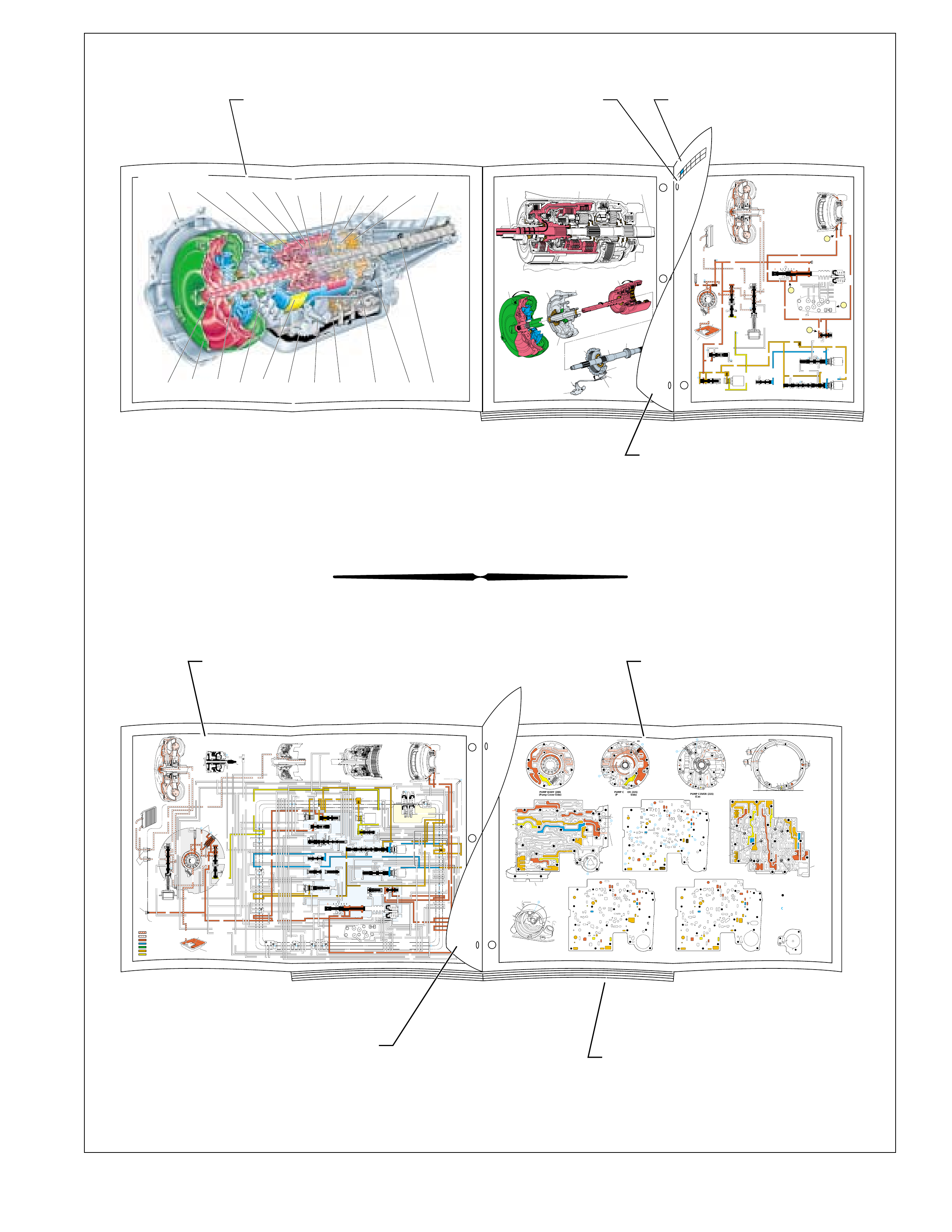
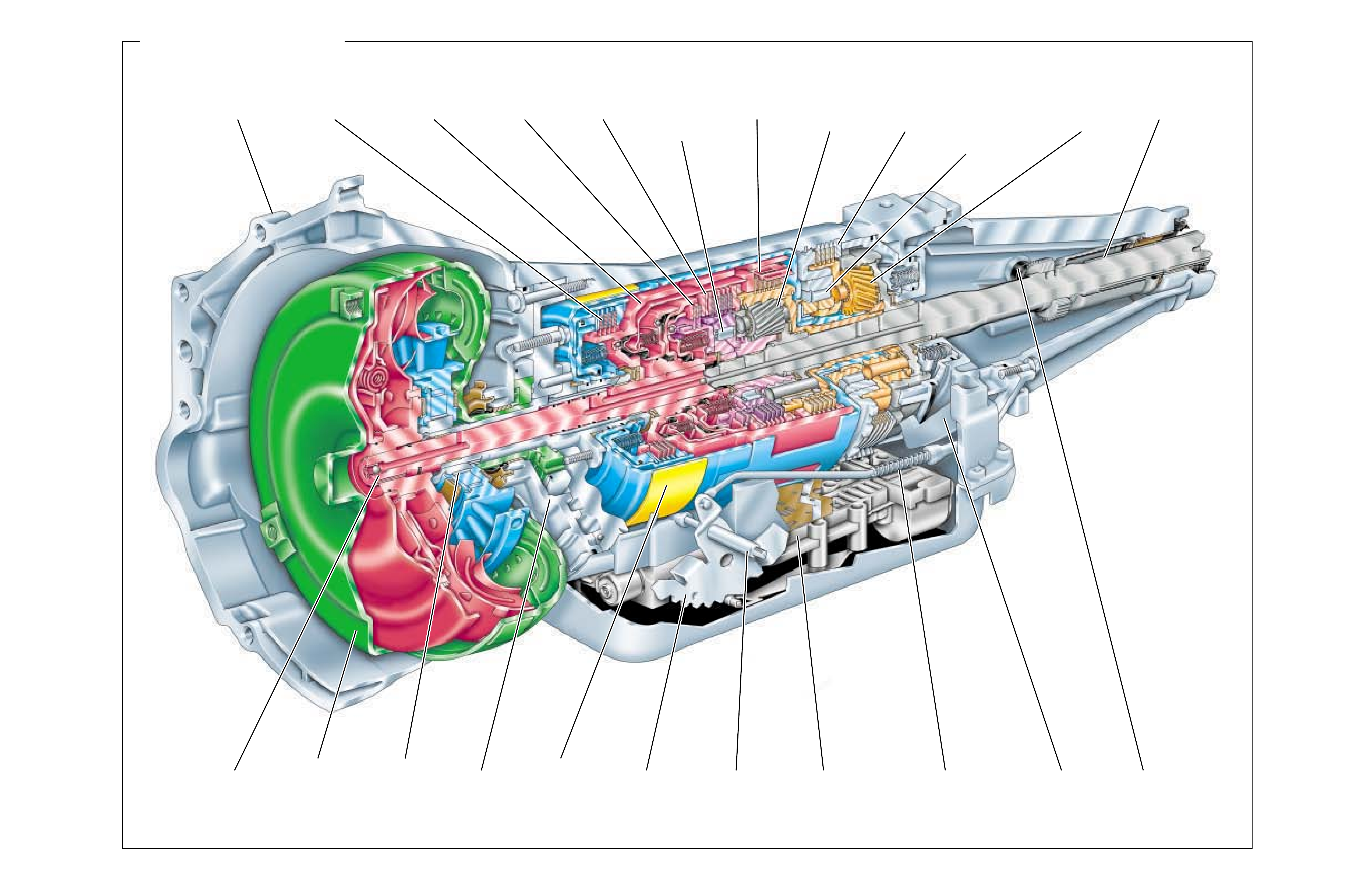
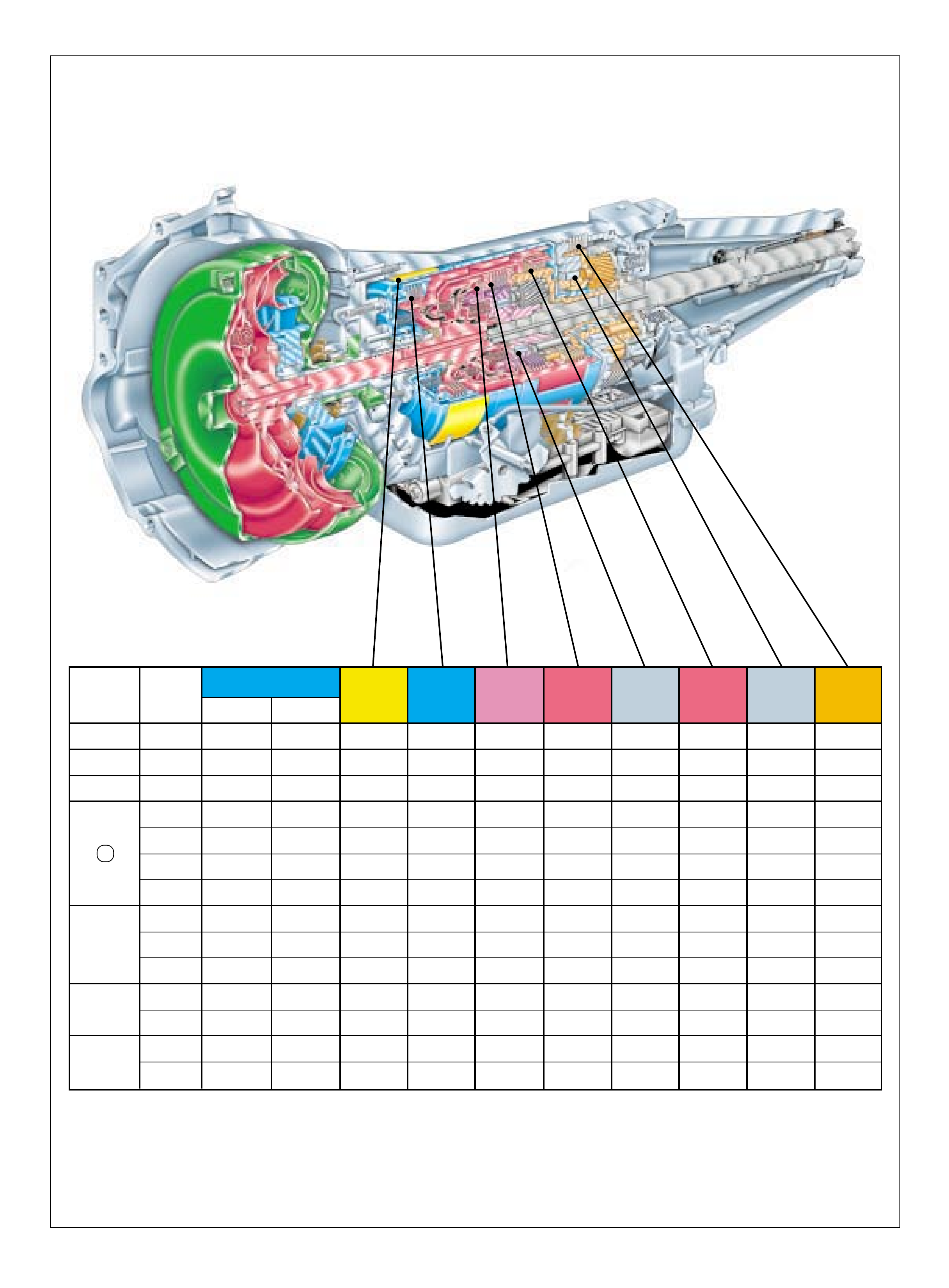
RANGE REFERENCE CHARTLARGE CUTAWAY VIEW
OF TRANSMISSION
(FOLDOUT)
HALF PAGE TEXT FOR EASY
REFERENCE TO BOTH PAGES
FLUID FLOW THROUGH
COMPONENTS (FOLDOUT)
COMPLETE ILLUSTRATED
PARTS LIST
FLUID FLOW SCHEMATIC —
(FOLDOUT)
HALF PAGE TEXT AND LEDGEND
PAGE NUMBER —
FOR REFERENCE TO
FLUID FLOW SCHEMATIC
➤
➤
➤
➤
➤
➤
➤
➤
CASE
ASSEMBLY REVERSE
INPUT CLUTCH INPUT CLUTCH
HOUSING OVERRUN
CLUTCH FORWARD
CLUTCH FORWARD
SPRAG CL
ASSEMBLY
3-4
CLUTCH INPUT
PLANETARY
GEARSET
LO AND
REVERSE
CLUTCH
TORQUE
CONVERTER
ASSEMBLY
STATOR
ROLLER
CLUTCH PUMP
ASSEMBLY
LO ROLLER
CLUTCH
ASSEMBLY
REACTION
PLANETARY
GEARSET
TURBINE
SHAFT
2-4
BAND
ASSEMBLY INSIDE
DETENT LEVER MANUAL
SHAFT CONTROL VALVE
ASSEMBLY PARKING LOCK
ACTUATOR ASSEMBLY SPEED
SENSOR
PARKING
PAWL
OUTPUT
SHAFT
➤
➤
➤
➤
➤
➤
➤
CASE
ASSEMBLY
(103)
CONVERTER
HOUSING
(102)
TORQUE
CONVERTER
(1)
SERVO
ASSEMBLY
(12-29)
TCC
SOLENOID
(66)
SPACER
PLATE
(48)
BOTTOM
PAN
(75)
FILTER
(72)
CONTROL
VALVE
ASSEMBLY
(60)
1-2 ACCUMULATOR
PISTON
(56)
SPACER PLATE
GASKETS
(47 & 52)
3-4 ACCUMULATOR
PISTON
(44)
➤
➤
➤
➤
➤
➤
➤
➤
➤
➤
➤
➤
➤
➤
➤
➤
UNDERSTANDING THE GRAPHICS
6
Figure 2
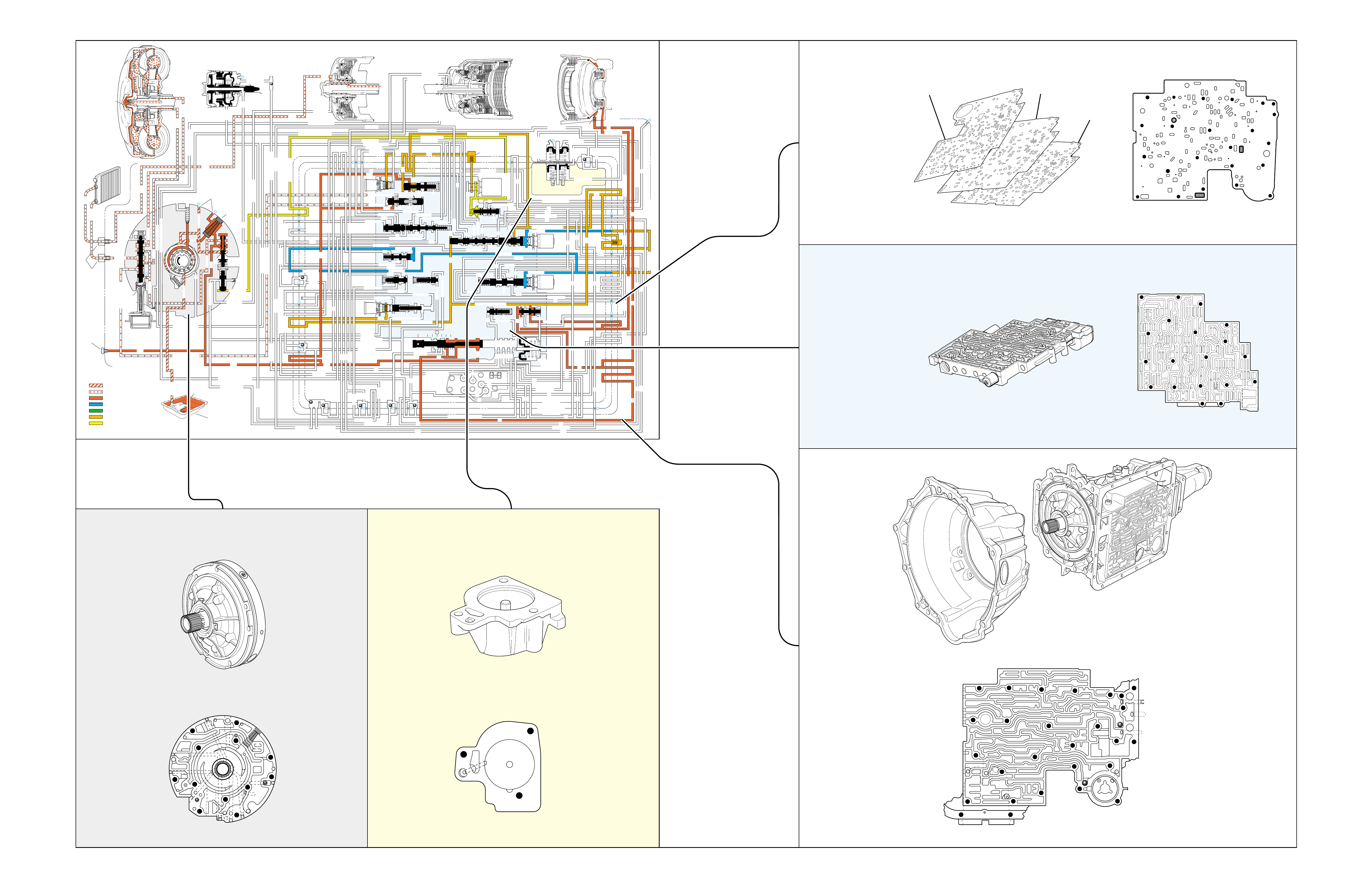
•A graphic schematic representation that displays
valves, checkballs, orif ices and so for th, required
for the proper function of transmission in a specific
gear range. In the schematic drawings, fluid
circuits are represented by straight lines and
orifices are represented by indentations in a circuit.
All circuits are labeled and color coded to provide
reference points between the schematic drawing
and the two dimensional line drawing of the
components.
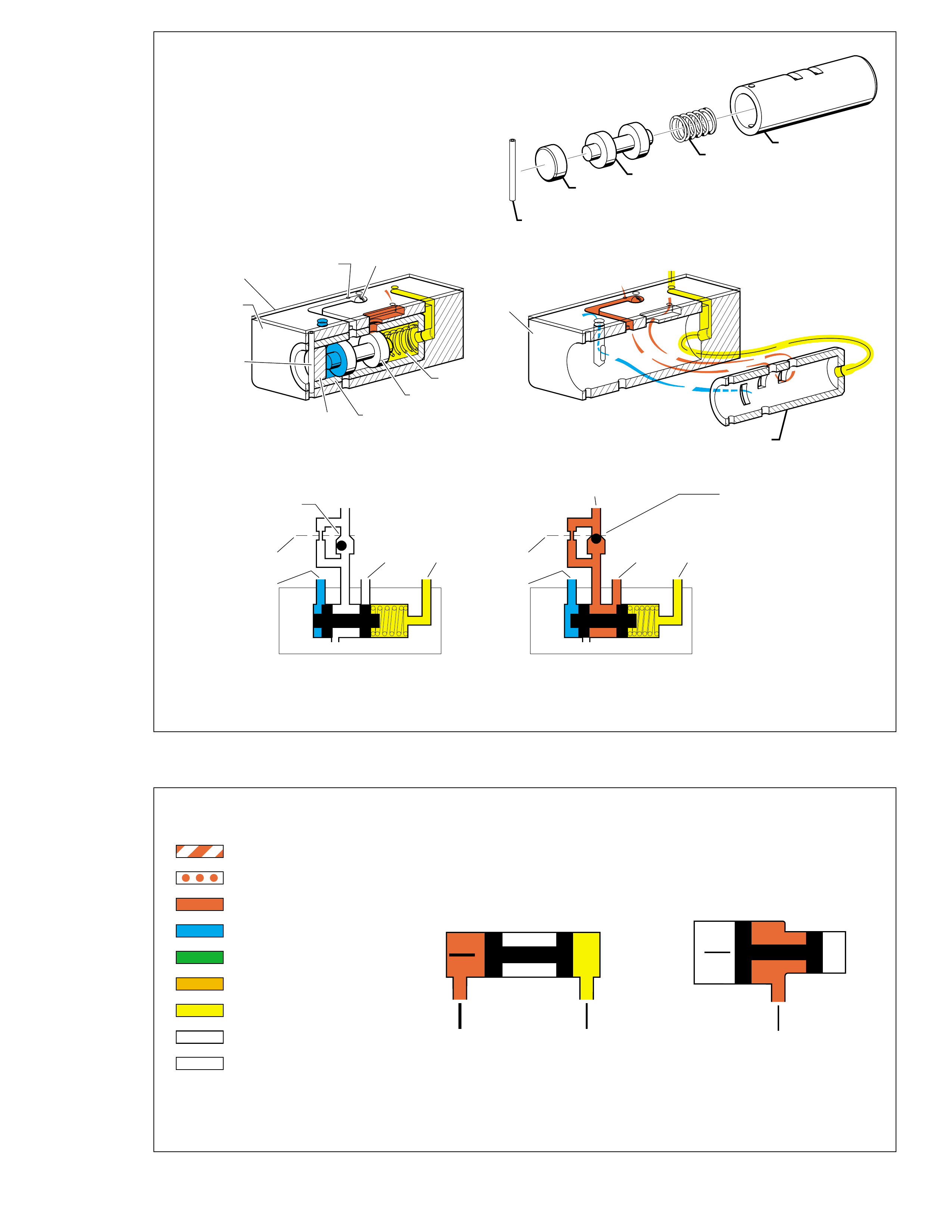
•Figure 4 (page 7B) provides an illustration of a
typical valve, bushing and valve train components.
A brief description of valve operation is also
provided to support the illustration.
•Figure 5 (page 7B) provides a color coded chart
that references different fluid pressures used to
operate the hydraulic control systems. A brief
description of how fluid pressures affect valve
operation is also provided.
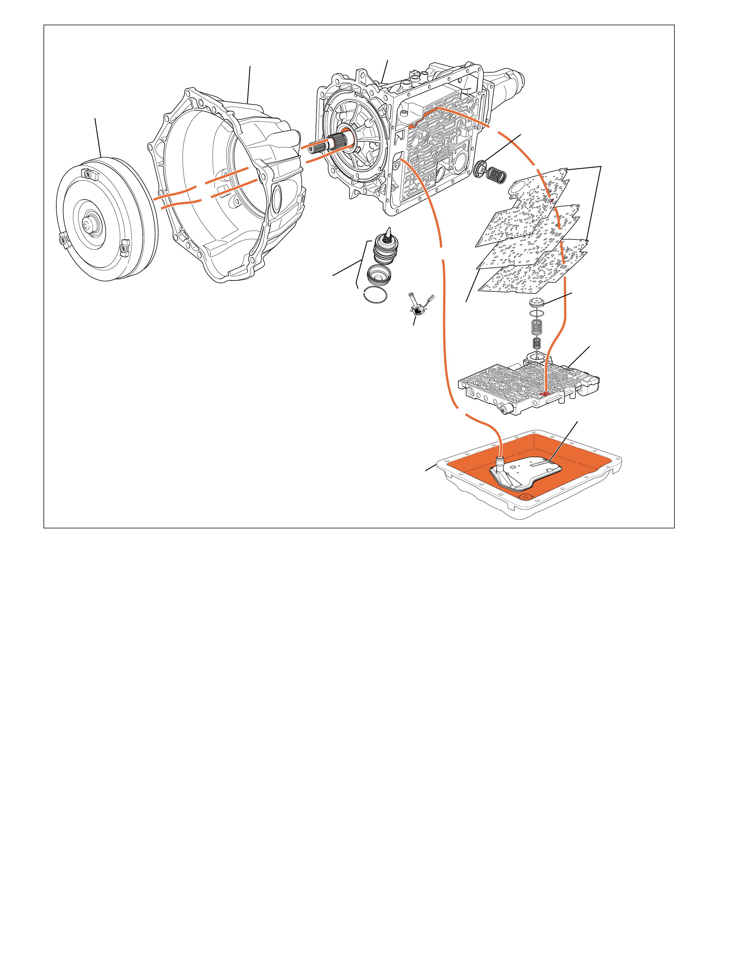
The flow of transmission fluid starts in the bottom
pan and is drawn through the filter, main case valve
body, transmission case, the oil pump assembly, and
into the torque converter. This is a general route for
fluid to flow that is more easily understood by
reviewing the illustrations provided in Figure 2.
However, fluid may pass between these and other
components many times before reaching a valve or
applying a clutch. For this reason, the graphics are
designed to show the e xact location where fluid passes
through a component and into other passages for
specific gear range operation.
To provide a better understanding of fluid flo w in the
Hydra-matic 4L60-E transmission, the components
involved with hydraulic control and fluid flow are
illustrated in three major formats. Figure 3 provides
an example of these formats which are:
•A three dimensional line drawing of the
component for easier part identification.
•A two dimensional line drawing of the component
to indicate fluid passages and orifices.
➤
➤➤
➤➤
➤
➤
➤
➤➤
➤
➤
➤
➤
INPUT CLUTCH
HOUSING ASSEMBLY
24
REAR LUBE
FILTER
(49)
➤
➤
➤
➤
➤
➤
➤
RELEASE
APPLY
LO/REVERSE
PR
BOOST VALVE PRESS REG
BOTTOM
PAN
(SUMP)
(75)
FILTER
(72) REVERSE INPUT
REV INPUT
DECREASE
LINE
EX
FILTER
(232)
AIR
BLEED
(240)
1
SUCTION
LINE
EX
PRESSURE
RELIEF
VALVE
PUMP
ASSEMBLY
(4)
➤
➤➤
4
TCC
SOLENOID
(66)
N.O.
COOLER
LUBE
COOLER
SUCTION
CONVERTER & LUBE
MAINLINE
SOLENOID SIGNAL
ACCUMULATOR
ACTUATOR FEED LIMIT
TORQUE SIGNAL
FLUID PRESSURES
REVERSE INPUT
FORWARD CLUTCH FEED
#1
ACCUMULATOR
ORF ACC
2ND CLUTCH
3-4 ACCUMULATOR
1-2 ACCUMULATOR
19
3-4 ACCUM
ACCUM
EX
ORIFICED ACCUM
3-4 ACCUMULATOR
3-4 ACCUM
2ND CLUTCH
2ND CLUTCH
D3
REVERSE INPUT
D2-N.C.
REV-N.O. D3-N.C.
LO-N.O.
D4-N.O.
LO
TEMP
SENSOR
➤
TFP
SWITCH
ASSEMBLY
D2
D4
D3
D3
D3
EX
FORWARD ABUSE
FWD CL FD
3RD ACCUMULATOR EX
#7
11
3RD ACCUM
4TH
EX
EX
➤
4TH
2ND & 4TH
SERVO
REV ABUSE
EX
REVERSE
REVERSE INPUT
#12
D4
22
D4
D4
#4
13
3-4 SIGNAL
3-4 CL
3-4 CLUTCH
#2
12
3-4 CLUTCH
3RD ACCUM
3-4 CL
#8
16
2ND
2ND CL 2ND CL
2ND CL
2ND CL
2ND CLUTCH2ND CLUTCH
TORQUE SIG
FORWARD CLUTCH FEED
FORWARD
CLUTCH
ACCUMULATOR
EX
PR LO
LO
LO
FORWARD CLUTCH FEED
FORWARD CLUTCH FEED
FWD CL FEED
D3
D3
D3
14
3-4 CLUTCH
3RD ACCUMULATOR
3RD ACCUM
EX
AFL
3-2 SIGNAL
2ND
2ND
LINE
REGULATED APPLY
8
REG APPLY
1-2 SHIFT VALVE
26
LO
D4
O’ EX
D4-3-2 2ND
25
1-2 SIGNAL
LO/1ST
27
1-2 SIGNAL
EX
ORIFICED EX
ORIFICED EX
EX
LO/1ST D4-3-2
D4
D4
2
➤
➤
➤
➤➤
➤
EX
CONV FD
EX
EX
EX
LINE LINE
LINE
PRESSURE
TAP
(39)
➤
➤
REGULATED APPLY
➤
➤
LUBE
LUBE
LUBE
LUBE
CASE (8)
CASE (8)
GASKET (47)
SPACER PLATE (48)
GASKET (52)
VALVE BODY (60)
SUCTION
LINE
LINE
3a
3b
3c
➤
➤
➤
➤
➤
➤➤
➤
➤
➤
➤
➤
➤
➤
D3
EX
3-4 SIGNAL
1-2 SIGNAL
4TH SIGNAL
3-4 SHIFT VALVE
1-2 SIGNAL
3-4 CLUTCH
OVERRUN CLUTCH
OVERRUN CLUTCH
OVERRUN CLUTCH
OVERRUN CLUTCH
OVERRUN CLUTCH
OVERRUN CLUTCH
12a
12b
12c
12d
12e
EX
EX
EX
32
AFL
AFL
30
D4
EX
31
ACCUMULATOR
ACCUMULATOR
EX
TORQUE SIGNAL
FILTERED AFL
D4
AFLAFL FILTER
(50)
10
43a
43b 44
11b
11c
11a
14b
14a
14c
LO OVERRUN
23
PR
LO/REV
LO/1ST LO/REVERSE
LO/REVERSE
PR PR
EX
22 10c
23 10b
9n
9o
22b
22a
10a
➤
10 9k
9g
9m
44a
43c 44
41a
41b
41c
41d
42b
42a
13a
13b
OIL
COOLER
PIPE
CONNECTOR
(10)
➤
➤
18a
18b
18c
18 17a
18 17b
20b
48b
48a
REGULATED APPLY
30a
30b
32a
37a
9b
9e
10 9d
9c
9a
9f
9h
31a
31b
31c
OVERRUN CLUTCH FEED
3-4 ACCUM
SERVO FEED
SERVO FEED
6
7
4TH4TH
OVERRUN CL
4TH SIGNAL2ND
EX
EX
3-4 RELAY 4-3 SEQUENCE VALVE
5
EX
SERVO FD
ORF EX
CASE (8)
REV INPUT
EX
(237)
17d
17c
17e
17f
17g
21
21
20d
20e
21a
20a
20c
1-2 ACCUMULATOR COVER (57)
25g
33c
33a
33b
27d
27c
27b
29
29
27a
28a
29b
29a
29d
40
29c
29e
29g28
28
29f
24a
24b
24c
24d
24e
24f
24g
24h
25a
25b
25d
25e
25f
25
25
24m
24k
REVERSE INPUT
#3
17
REVERSE INPUT
15c
15b
16
16
REVERSE
REVERSE INPUT
16a
15d
15a
REVERSE
34f
34e
34d
34c
34a
34b
#6
OVERRUN CL FD
21
ORIFICED D2
#5
OVERRUN
OVERRUN OVERRUN
OVERRUN
36
36
35e
35d
39
35b
35c
36a
35a
38d
38e39
38c
38b
38a
EX
TORQUE SIGNAL
2ND CL
➤
➤
➤➤
➤
20
18
2-3 SHUTTLE 2-3 SHIFT VALVE
28
29
EX
EX
EX
EX
D2
OVERRUN
D3
D3
2ND
3-4 SIGNAL
EX
D4-3-2
2-3 SIGNAL
ACTUATOR FEED LIMIT
AFL
SERVO FD
3-4 ACC
FILTERED AFL
AFL
ACTUATOR FEED LIMIT
ACTUATOR FEED LIMIT
AFL
D2
2ND
2ND
2ND
2ND
D2
D2
D2
D2
ORIFICED D2
D2
D2
D2
VALVE BODY (60)
3-4 SIGNAL
➤
2ND
D4
PR 3-4 ACCUMULATOR
D4
EX
D4-3-2
LO
D4
2ND CLUTCH
D3
D3
FORWARD CLUTCH FEED ACTUATOR FEED LIMIT
TORQUE SIGNAL
SERVO FEED
➤
OVERRUN CLUTCH
LINE
9p
26a
➤
➤
➤➤
➤
➤
➤
➤
➤
➤➤➤
➤➤➤
➤
➤➤➤
➤
➤
➤
➤
➤
➤
➤
➤
➤
➤
➤
➤
➤
➤➤
➤
➤
➤➤➤
➤➤➤
➤
➤
➤
➤
➤
➤
➤
➤
➤
➤
➤➤
➤➤ ➤
➤
➤
➤➤➤
➤➤
PR
➤➤
➤
➤➤
➤
➤➤
➤➤➤➤➤
➤
➤
➤
➤
➤➤
➤
➤➤➤➤➤
➤➤
➤
➤
➤➤➤
OFF
CONVERTER CLUTCH VALVE
COOLER
RELEASE
APPLY
EX
➤
➤
➤
➤
➤
➤
EX
➤➤
➤
➤➤
➤
CONV FD
➤
➤
➤
➤
➤
➤
➤
➤
➤
➤
➤
REGULATED APPLY
3-2 CONTROL
EX
EX
CC SIGNAL
CC SIGNAL
ACTUATOR FEED LIMIT
9
26b
TCC PWM
SOLENOID
VALVE
N.C.
1-2 SIGNAL
2ND
4TH SIGNAL
3-2
CONTROL
SOLENOID
VALVE
N.C.
OFF
#10
➤
LOW AND REVERSE
CLUTCH ASSEMBLY
REVERSE INPUT
CLUTCH ASSEMBLY
TORQUE
CONVERTER
ASSEMBLY
#9
➤➤
(237)
➤
(238)
➤
EX
2ND CLUTCH 3-4 CLUTCH
2ND
PRESSURE
CONTROL
SOLENOID
VALVE
2-3 SHIFT
SOLENOID
VALVE
N.O.
ON
EX
1-2 SHIFT
SOLENOID
VALVE
N.O.
ON
ACCUM VALVE
PRND321
D4
D4
REVERSE
D3
D2
LO
EX
EX
LINE
➤
➤
➤
➤
➤
➤➤➤➤
➤
➤
➤
➤
➤
➤
➤➤➤ ➤
➤
➤
➤
➤
➤
➤
➤
➤
➤
➤
➤
➤
➤
➤
➤
➤
➤
➤
➤
➤
➤
➤
➤
➤➤➤➤➤
➤
➤
➤
➤
➤
➤
➤
➤
➤
➤
➤
➤
MANUAL VALVE
PR
EXEX
3-2 DOWNSHIFT
ISOLATOR VALVE
REG APPLY
UNDERST ANDING THE GRAPHICS
Figure 3
PUMP COVER
CASE SIDE
THREE DIMENSIONAL
THREE DIMENSIONAL
TWO DIMENSIONAL
THREE DIMENSIONAL
TWO DIMENSIONAL
TWO DIMENSIONAL
GRAPHIC
SCHEMATIC
REPRESENTATION
TWO DIMENSIONAL
VALVE BODY SIDE
THREE DIMENSIONAL
TWO DIMENSIONAL
THREE DIMENSIONAL
CONTROL
VALVE BODY
ASSEMBLY (60)
CASE
ASSEMBLY
(103)
OIL PUMP
ASSEMBLY
(4)
1-2 ACCUMULATOR
COVER
(57)
VALVE BODY
SPACER
PLATE
(48)
FOLDOUT ➤ 7AFOLDOUT ➤ 7
GASKET
(47)
GASKET
(52)
SPACER
PLATE
(48)
CASE SIDE
➤
➤
➤
➤
➤
➤
➤
➤
➤
➤
➤
7B
FLUID PRESSURES
SUCTION
CONVERTER & LUBE
MAINLINE
SOLENOID SIGNAL
ACCUMULATOR
ACTUATOR FEED LIMIT
TORQUE SIGNAL
EXHAUST
DIRECTION OF FLOW
➤➤➤
➤
➤
AB
➤
➤
➤
➤
AB
➤
WITH EQUAL SURFACE AREAS
ON EACH END OF THE VALVE,
BUT FLUID PRESSURE "A"
BEING GREATER THAN FLUID
PRESSURE "B", THE V ALVE
WILL MO VE T O THE RIGHT.
WITH THE SAME FLUID PRESSURE
ACTING ON BOTH SURFACE "A"
AND SURFACE "B" THE VALVE
WILL MO VE T O THE LEFT. THIS
IS DUE TO THE LARGER SURFACE
AREA OF "A" THAN "B".
UNDERST ANDING THE GRAPHICS
TYPICAL BUSHING AND VALVE
Figure 4
Figure 5
➤
➤
➤
➤
➤
➤
➤
➤
➤
➤
➤
➤
➤
SPRING
RETAINING
PIN
BORE
PLUG
VALVE
BUSHING
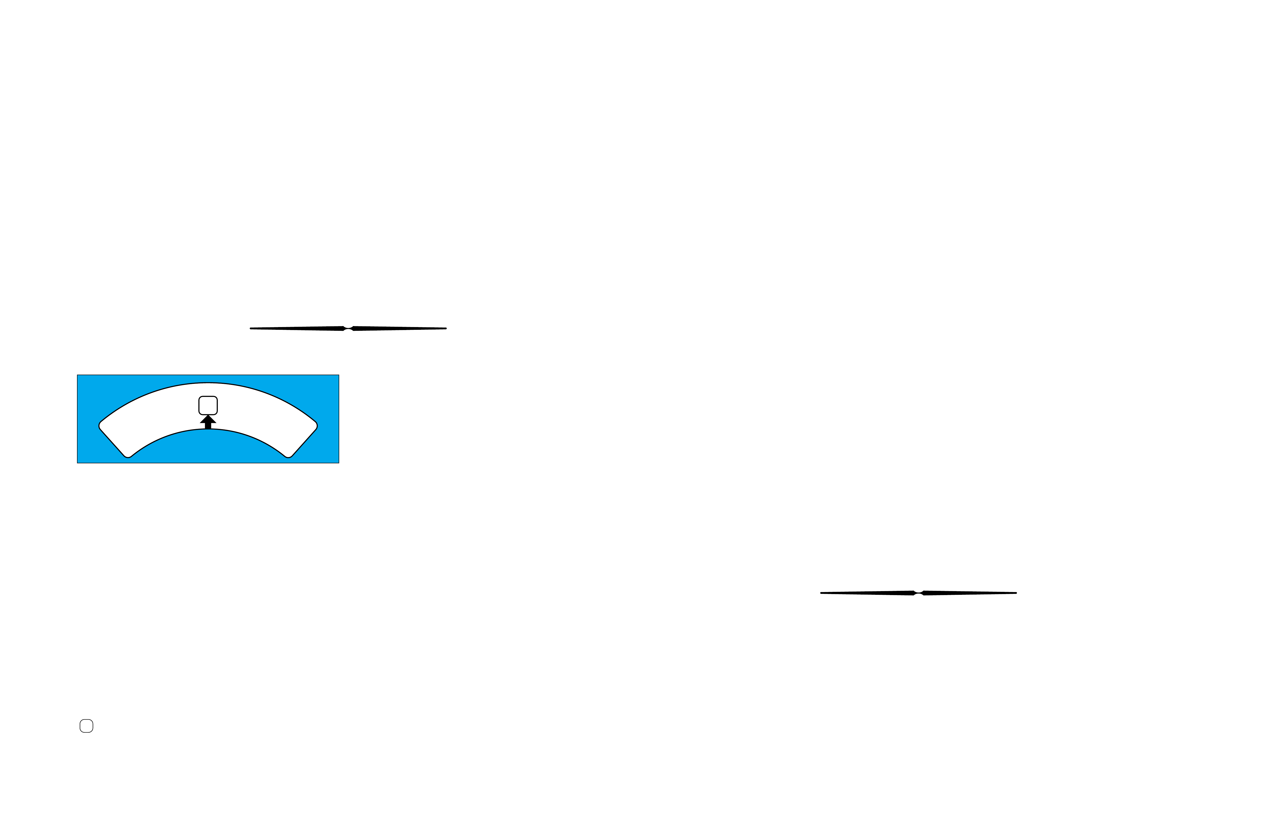
EXHAUST FROM THE
APPLY COMPONENT
UNSEATS THE
BALL CHECK VALVE,
THEREFORE CREATING
A QUICK RELEASE.
TO APPLY
COMPONENT APPLY FLUID SEATS
THE BALL CHECK VALVE
FORCING FLUID THROUGH
AN ORIFICE IN THE SPACER
PLATE, WHICH CREATES
A SLOWER APPLY.
WITH SIGNAL FLUID PRESSURE
GREATER THAN SPRING AND
SPRING ASSIST FLUID PRESSURE
THE VALVE MOVES OVER.
WITH SIGNAL FLUID PRESSURE
EQUAL TO OR LESS THAN
SPRING AND SPRING ASSIST
FLUID PRESSURE THE V ALVE
REMAINS IN CLOSED POSITION.
BUSHING
➤
VALVE
BODY
SPACER
PLATE
RESTRICTING
ORIFICE
BALL
CHECK
VALVE
RETAINING
PIN
BORE
PLUG
SPRING
VALVE
BUSHING
VALVE
BODY
➤
➤
➤
➤
➤
➤
➤
➤➤
➤
➤
➤➤
➤
➤
➤
SPACER
PLATE
SIGNAL
FLUID
APPLY
FLUID
SPRING
ASSIST
FLUID
EX
➤
➤
➤
➤
➤
➤
➤
➤
➤
➤
➤
➤
➤
➤
➤
➤
➤
SPACER
PLATE
SIGNAL
FLUID
APPLY
FLUID
SPRING
ASSIST
FLUID
EX
➤
➤
➤
➤
➤
➤
➤
NOTE: NOT ALL VALVES ARE
USED WITH A BUSHING
HYDRA-MATIC 4L60-E
8
Figure 6
CASE
ASSEMBLY REVERSE
INPUT CLUTCH INPUT CLUTCH
HOUSING OVERRUN
CLUTCH FORWARD
CLUTCH FORWARD
SPRAG
CLUTCH
ASSEMBLY
3-4
CLUTCH INPUT
PLANETARY
GEARSET
LOW AND
REVERSE
CLUTCH
TORQUE
CONVERTER
ASSEMBLY
STATOR
ROLLER
CLUTCH PUMP
ASSEMBLY
LOW AND
REVERSE
ROLLER
CLUTCH
ASSEMBLY
REACTION
PLANETARY
GEARSET
TURBINE
SHAFT
2-4
BAND
ASSEMBLY INSIDE
DETENT LEVER MANUAL
SHAFT CONTROL VALVE
ASSEMBLY PARKING LOCK
ACTUATOR ASSEMBLY SPEED
SENSOR
PARKING
PAWL
OUTPUT
SHAFT
8A
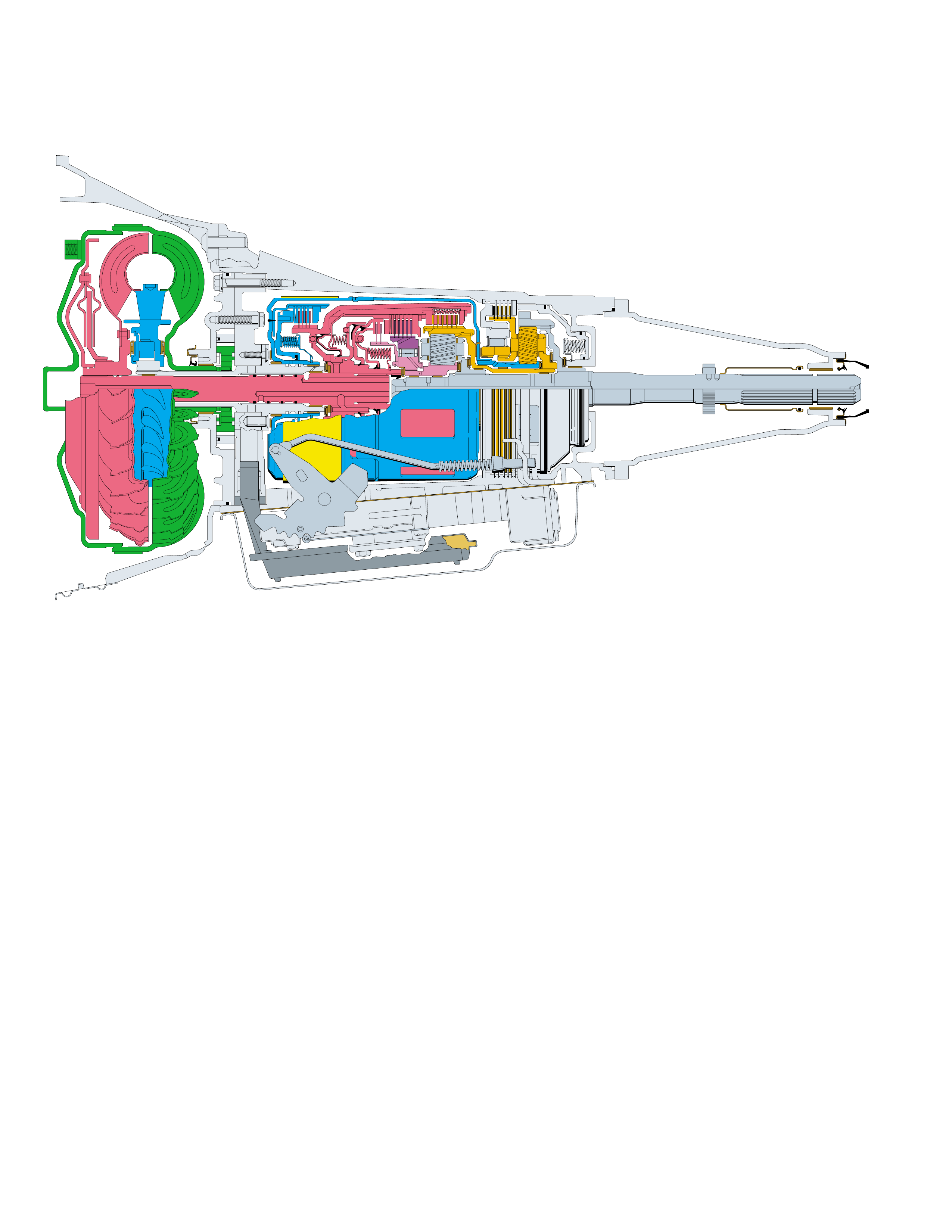
Figure 7
A cross sectional line drawing is typically the standard
method for illustrating either an individual mechanical
component or a complete transmision assembly.
However, unless a person is familiar with all the
individual components of the transmission,
distinguishing components may be diff icult in this type
of drawing. For this reason, a three dimensional
perspectiv e illustration (sho wn on page 8) is the primary
drawing used thr oughout this book.
The purpose for this type of illustration is to provide a
more e xacting graphic repr esentation of eac h component
and to show their relationship to other components
within the transmission assembly. It is also useful for
HYDRA-MATIC 4L60-E
CROSS SECTIONAL DRAWING
understanding the cross sectional line drawing by
comparing the same components from the three
dimensional perspective illustration. In this regard it
becomes an excellent teaching instrument.
Additionally, all the illustrations contained in this book
use a color scheme that is consistent throughout this
book. In other words, regardless of the type of
illustration or drawing , all components hav e an assigned
color and that color is used whenever that component
is illustrated. This consistenc y not only helps to provide
for easy component identification but it also enhances
the graphic and color continuity between sections.
The Hydra-matic 4L60-E is a fully automatic, four
speed, rear wheel drive, electronically controlled
transmission. It consists primarily of a four-element
torque converter, two planetary gear sets, friction and
mechanical clutches and a hydraulic pressur ization and
control system.
The four-element torque converter contains a pump, a
turbine, a pressure plate splined to the turbine, and a
stator assembly. The torque converter acts as a fluid
coupling to smoothly transmit power from the engine
to the transmission. It also hydraulically provides
additional torque multiplication when required. The
pressure plate, when applied, provides a mechanical
“direct dri v e” coupling of the engine to the transmission.
The two planetary g ear sets provide the f our forward gear
ratios and re v erse. Changing gear ratios is fully automatic
and is accomplished through the use of a Powertrain
Control Module (PCM). The PCM recei v es and monitors
v ar ious electronic sensor inputs and uses this infor mation
to shift the transmission at the optimum time.
The PCM commands shift solenoids, within the
transmission, on and off to control shift timing. The
PCM also controls the apply and release of the torque
converter clutch which allows the engine to deliver the
maximum fuel efficiency without sacrificing vehicle
performance.
The hydraulic system primarily consists of a vane type
pump, control v alve body and case. The pump maintains
the working pressures needed to stroke the servo and
clutch pistons that apply or release the friction
components. These friction components (when applied
or released) support the automatic shifting qualities of
the transmission.
The friction components used in this transmission
consist of five multiple disc clutches and one band.
The multiple disc clutches combine with two
mechanical components, one roller clutch and one sprag
clutch, to deliver five different gear ratios through the
gear sets. T he gear sets then transfer torque through the
output shaft.
for safe passing by depressing the accelerator or by
manually selecting a low er gear with the shift selector.
The transmission should not be operated in Overdrive
towing a trailer or driving on hilly terrain. Under such
conditions that put an extra load on the engine, the
transmission should be driven in a lower manual gear
selection for maximum efficiency.
D–Manual Third can be used for conditions where it
may be desirable to use only three gear ratios. These
conditions include towing a trailer and driving on hilly
terrain as described above. This range is also helpful
for engine braking when descending slight grades.
Upshifts and downshifts are the same as in Overdrive
range for first, second and third gears except that the
transmission will not shift into fourth gear.
2–Manual Second adds more performance for con-
gested traffic and hilly terrain. It has the same starting
ratio (first gear) as Man ual Third b ut pre vents the tr ans-
mission from shifting abov e second gear. Thus, Manual
Second can be used to retain second gear for accelera-
tion and engine braking as desired. Manual Second
can be selected at any v ehicle speed but will not do wn-
shift into second gear until the vehicle speed drops
below approximately 100 km/h (62 mph).
1–
Manual First can be selected at any vehicle speed.
If the transmission is in third or fourth gear it will
immediately shift into second gear. When the vehicle
speed slows to below approximately 48 to 56 km/h (30
to 35 mph) the transmission will then shift into first
gear . This is particularly beneficial for maintaining maxi-
mum engine braking when descending steep grades.
Figure 8
EXPLANATION OF GEAR RANGES
FOLDOUT ➤ 9
PRINCIPLES OF OPERATION
An automatic transmission is the mechanical
component of a vehicle that transfers power
(torque) from the engine to the wheels. It
accomplishes this task by providing a number
of forward gear ratios that automatically change
as the speed of the vehicle increases. The
reason for changing forward gear ratios is to
provide the performance and economy expected
from vehicles manufactured today. On the
performance end, a gear ratio that develops a
lot of torque (through torque multiplication) is
required in order to initially start a vehicle
moving. Once the vehicle is in motion, less
torque is required in order to maintain the
vehicle at a certain speed. When the vehicle
has reached a desired speed, economy becomes
the important factor and the transmission will
shift into overdrive. At this point output speed
is greater than input speed, and, input torque
is greater than output torque.
Another important function of the automatic
transmission is to allow the engine to be started
and run without transferring torque to the
wheels. This situation occurs whenever Park
(
P
) or Neutral (
N
) range has been selected.
Also, operating the vehicle in a rearward
direction is possible whenever Reverse (
R
)
range has been selected (accomplished by the
gear sets).
The variety of gear ranges in an automatic
transmission are made possible through the
interaction of numerous mechanically,
hydraulically and electronically controlled
components inside the transmission. At the
appropriate time and sequence, these
components are either applied or released and
operate the gear sets at a gear ratio consistent
with the driver’s needs. The following pages
describe the theoretical operation of the
mechanical, hydraulic and electrical
components found in the Hydra-matic 4L60-E
transmission. When an understanding of these
operating principles has been attained, diagnosis
of these transmission systems is made easier.
9A
GENERAL DESCRIPTION
P
R
N
D
D
2
1
The transmission can be operated in any one of the
seven different positions shown on the shift quadrant
(Figure 8).
P–Park position enables the engine to be started while
preventing the vehicle from rolling either forward or
backward. For safety reasons, the vehicle’s parking
brake should be used in addition to the transmission
“Park” position. Since the output shaft is mechanically
locked to the case through the parking pawl and reac-
tion internal gear, Park position should not be selected
until the vehicle has come to a complete stop.
R–Reverse enables the vehicle to be operated in a
rearward direction.
N–Neutral position enables the engine to start and
operate without driving the vehicle. If necessary, this
position should be selected to restart the engine while
the vehicle is moving .
D –Overdrive range should be used for all normal
driving conditions for maximum efficiency and fuel
economy. Overdrive range allows the transmission to
operate in each of the four forward gear ratios. Down-
shifts to a lower gear, or higher gear ratio are available

MAJOR MECHANICAL COMPONENTS
SPLINED
TOGETHER
SPLINED
TOGETHER
SPLINED
T O TORQ UE
CONVERTER TURBINE
SPLINED
TOGETHER SPLINED
TOGETHER
SPLINED
TOGETHER
SPLINED T O
OUTPUT SHAFT
(687)
SPLINED T O
REACTION
CARRIER
ASSEMBLY
(681)
LOCKS T OGETHER WITH
REVERSE INPUT
CLUTCH HOUSING
(605)
SPLINED
TOGETHER
SPLINED T O
REACTION
CARRIER
SHAFT
(666)
SPLINED T O
INPUT
CARRIER
ASSEMBLY
(662)
SPLINED
TOGETHER
TORQUE
CONVERTER
ASSEMBLY
(1)
PUMP
ASSEMBLY
(4)
MAIN
CASE
(103)
SERVO
ASSEMBLY
2-4 BAND
ASSEMBLY (602)
REVERSE INPUT
CLUTCH HOUSING
(605)
BAND
ANCHOR
PIN (41)
INPUT HOUSING
& SHAFT ASSEMBLY
(621)
FORWARD SPRAG
ASSEMBLY
(642)
OVERRUN
CLUTCH HUB
(639)
FORWARD CLUTCH
OUTER RACE
(644)
FORWARD
SPRAG CLUTCH
INNER RACE
AND INPUT
SUN GEAR
ASSEMBLY
(640)
INPUT CARRIER
ASSEMBLY
(662)
INPUT
INTERNAL
GEAR
(664)
REACTION
CARRIER
SHAFT
(666)
REACTION
SUN SHELL
(670)
REACTION
SUN GEAR
(673)
LOW AND REVERSE
CLUTCH SUPPORT
ASSEMBLY
(679)
LOW AND REVERSE
ROLLER CLUTCH
ASSEMBLY
(678)
LOW AND REVERSE
ROLLER CLUTCH
RACE
(675)
LOW AND REVERSE
CLUTCH PLATE
ASSEMBLY
(682)
REACTION
CARRIER
ASSEMBLY
(681)
OUTPUT
SHAFT
(687)
SPEED SENSOR
ROTOR
(699)
PARKING PAWL
RETURN SPRING
(80)
PARKING BRAKE
PAWL (81)
PARKING LOCK
ACTUATOR
ASSEMBLY
(85)
INSIDE
DETENT
LEVER
(88)
MANUAL
SHAFT
(84)
REACTION
INTERNAL
GEAR
(684)
MAIN
CASE
(103)
MAIN
CASE
(103)
LOCKS T OGETHER WITH
REACTION
SUN SHELL
(670)
10 Figure 9

COLOR LEGEND
MAJOR MECHANICAL COMPONENTS
The foldout graphic on page 10 contains a disassembled drawing
of the major components used in the Hydra-matic 4L60-E
transmission. This drawing, along with the cross sectional
illustrations on page 8 and 8A, show the major mechanical
components and their relationship to each other as a complete
assembly. Therefore, color has been used throughout this book
to help identify parts that are splined together, rotating at engine
speed, held stationary, and so forth. Color differentiation is
particularly helpful when using the Power Flow section for
understanding the transmission operation.
The color legend below provides the “general” guidelines that
were followed in assigning specific colors to the major
components. However, due to the complexity of this transmission,
some colors (such as grey) were used for artistic purposes rather
than based on the specific function or location of that component.
Components that are stationary.
Examples: Converter Housing (102), Main Case
(103), Oil Pump Assembly (4), Low and Reverse
Clutch Support (679), Extension Housing (31).
Components that rotate at engine speed.
Examples: Torque Converter Cover and Pump, and
the Oil Pump.
Components that rotate at turbine speed. Examples:
Converter Turbine, Pressure Plate, Turbine Shaft and
Input Housing Assembly (621).
Components that rotate at transmission output speed
and other components. Examples: Reaction Internal
Gear (684), Output Shaft (687), Speed Sensor Rotor
(699), Forward Sprag Assembly (642), and Low and
Reverse Roller Clutch Assembly (678).
Components such as the Stator in the Torque
Converter (1), the Reverse Input Clutch Housing
(605) and the Reaction Sun Shell (670).
Components such as the Reaction Carrier Assembly
(681) and the Input Internal Gear (664).
Components such as the Overrun Clutch Hub (639)
and the Forward Sprag Clutch Inner Race and Input
Sun Gear Assembly (640).
All bearings, bushings, gaskets and spacer plates.
All seals
10A

COLOR LEGEND
APPLY COMPONENTS
The Range Reference Chart on page 11, provides another
valuable source of information for explaining the overall function
of the Hydra-matic 4L60-E transmission. This chart highlights
the major apply components that function in a selected gear
range, and the specific gear operation within that gear range.
Included as part of this chart is the same color reference to each
major component that was previously discussed. If a component
is active in a specific gear range, a word describing its activity
will be listed in the column below that component. The row
where the activity occurs corresponds to the appropriate
transmission range and gear operation.
An abbreviated version of this chart can also be found at the top
of the half page of text located in the Power Flow section. This
provides for a quick reference when reviewing the mechanical
power flow information contained in that section.
10B
SHIFT SOLENOID VALVES 2-4 REVERSE OVERRUN FORWARD FORWARD 3-4 LO ROLLER LO/REV.
RANGE GEAR
1-2 2-3 BAND INPUT CLUTCH CLUTCH SPRAG CL. CLUTCH CLUTCH CLUTCH
CLUTCH ASSEMBLY
PARK
ON*ON*APPLIED
REVERSE
ON*ON*APPLIED APPLIED
NEUTRAL
ON*ON*
1st ON ON APPLIED HOLDING HOLDING
2nd OFF ON APPLIED APPLIED HOLDING
D
3rd OFF OFF APPLIED HOLDING APPLIED
4th ON OFF APPLIED APPLIED APPLIED
1st ON ON APPLIED HOLDING HOLDING
3
2nd OFF ON APPLIED APPLIED HOLDING
3rd OFF OFF APPLIED APPLIED HOLDING APPLIED
2
1st ** ON ON APPLIED APPLIED HOLDING HOLDING
*** 2nd OFF ON APPLIED APPLIED APPLIED HOLDING
1
1st ON ON APPLIED APPLIED HOLDING HOLDING APPLIED
*** 2nd OFF ON APPLIED APPLIED APPLIED HOLDING
*1-2 AND 2-3 SHIFT SOLENOID OPERATION AND THE SHIFT VALVE POSITIONING IN P, R, N RANGES ARE A FUNCTION OF THE
INPUT TO THE SOLENOIDS FROM THE VSS. UNDER NORMAL OPERATING CONDITIONS THE SOLENOIDS ARE ON IN P, R, N.
** A MANUAL SECOND - FIRST GEAR CONDITION IS ONLY AVAILABLE ON SOME MODELS. OTHERWISE, THIS CONDITION IS
ELECTRONICALLY PREVENTED.
*** IN MANUAL SECOND AND MANUAL FIRST, SOLENOID OPERATION IS A RESULT OF PCM CALIBRATION.
SOME CALIBRATIONS WILL ALLOW ALL THREE GEARS UNDER EXTREME CONDITIONS.
Figure 10 11
RANGE REFERENCE CHART
COLOR LEGEND
APPLY COMPONENTS
The Range Reference Chart on page 11, provides another
valuable source of information for explaining the overall function
of the Hydra-matic 4L60-E transmission. This chart highlights
the major apply components that function in a selected gear
range, and the specific gear operation within that gear range.
Included as part of this chart is the same color reference to each
major component that was previously discussed. If a component
is active in a specific gear range, a word describing its activity
will be listed in the column below that component. The row
where the activity occurs corresponds to the appropriate
transmission range and gear operation.
An abbreviated version of this chart can also be found at the top
of the half page of text located in the Power Flow section. This
provides for a quick reference when reviewing the mechanical
power flow information contained in that section.
10B
COLOR LEGEND
MAJOR MECHANICAL COMPONENTS
The foldout graphic on page 10 contains a disassembled drawing
of the major components used in the Hydra-matic 4L60-E
transmission. This drawing, along with the cross sectional
illustrations on page 8 and 8A, show the major mechanical
components and their relationship to each other as a complete
assembly. Therefore, color has been used throughout this book
to help identify parts that are splined together, rotating at engine
speed, held stationary, and so forth. Color differentiation is
particularly helpful when using the Power Flow section for
understanding the transmission operation.
The color legend below provides the “general” guidelines that
were followed in assigning specific colors to the major
components. However, due to the complexity of this transmission,
some colors (such as grey) were used for artistic purposes rather
than based on the specific function or location of that component.
Components that are stationary.
Examples: Converter Housing (102), Main Case
(103), Oil Pump Assembly (4), Low and Reverse
Clutch Support (679), Extension Housing (31).
Components that rotate at engine speed.
Examples: Torque Converter Cover and Pump, and
the Oil Pump.
Components that rotate at turbine speed. Examples:
Converter Turbine, Pressure Plate, Turbine Shaft and
Input Housing Assembly (621).
Components that rotate at transmission output speed
and other components. Examples: Reaction Internal
Gear (684), Output Shaft (687), Speed Sensor Rotor
(699), Forward Sprag Assembly (642), and Low and
Reverse Roller Clutch Assembly (678).
Components such as the Stator in the Torque
Converter (1), the Reverse Input Clutch Housing
(605) and the Reaction Sun Shell (670).
Components such as the Reaction Carrier Assembly
(681) and the Input Internal Gear (664).
Components such as the Overrun Clutch Hub (639)
and the Forward Sprag Clutch Inner Race and Input
Sun Gear Assembly (640).
All bearings, bushings, gaskets and spacer plates.
All seals
10A
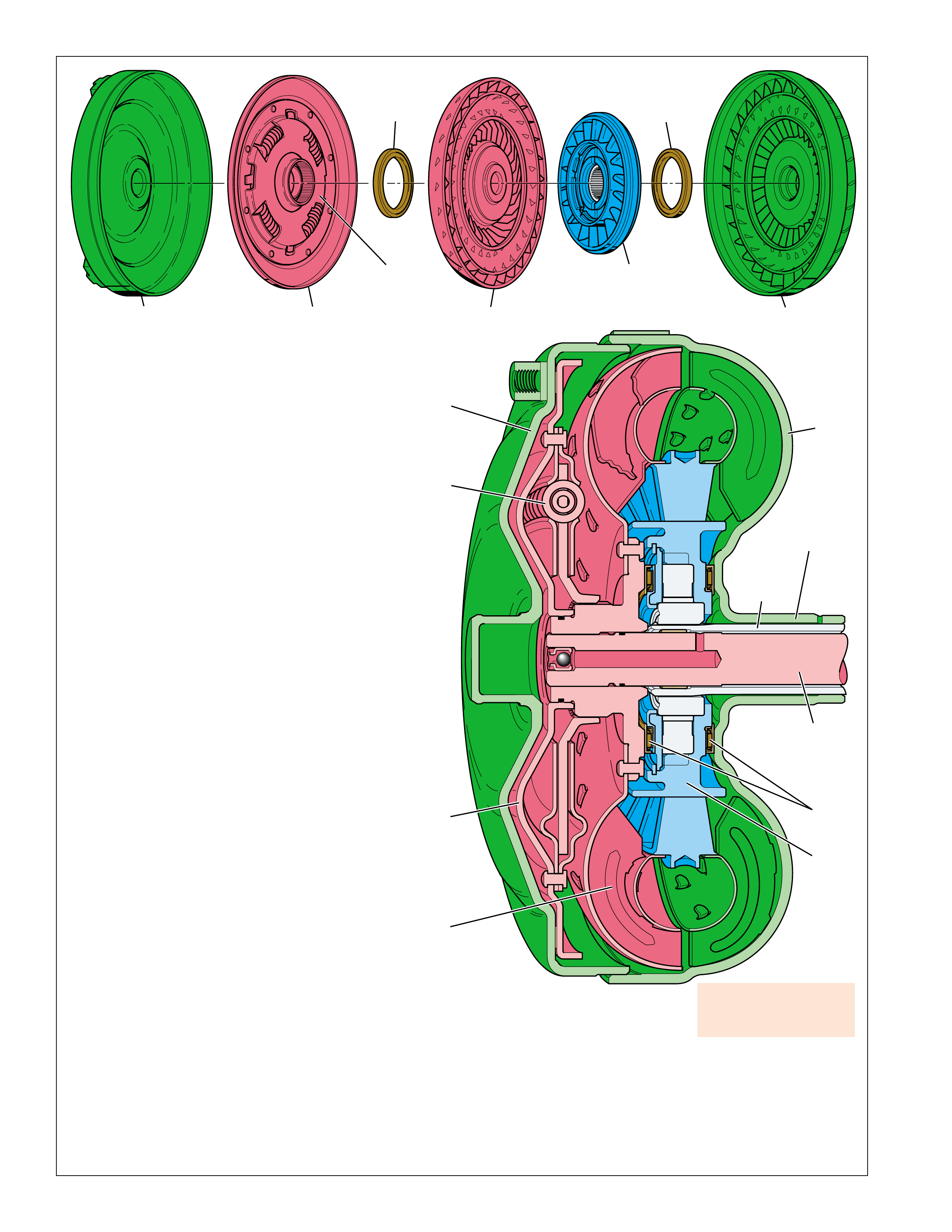
12
CONVERTER HOUSING
COVER ASSEMBLY
(A)
PRESSURE PLATE
ASSEMBLY
(B)
DAMPER
ASSEMBLY
(C) TURBINE
ASSEMBLY
(D)
STATOR
ASSEMBLY
(E) CONVERTER PUMP
ASSEMBLY
(G)
THRUST
BEARING
ASSEMBLY
(F)
THRUST
BEARING
ASSEMBLY
(F)
B
A
D
G
C
TURBINE
SHAFT
STATOR
SHAFT
(216)
CONVERTER
HUB
F
E
Figure 11
TORQUE CONVERTER
TORQUE CONVERTER:
The torque converter (1) is the primary component for
transmittal of power between the engine and the
transmission. It is bolted to the engine flywheel (also known
as the flexplate) so that it will rotate at engine speed.
Some of the major functions of the torque converter are:
•to provide for a smooth conversion of torque from the
engine to the mechanical components of the transmission.
•to multiply torque from the engine that enables the
vehicle to achieve additional performance when required.
•to mechanically operate the transmission oil pump (4)
through the converter hub.
•to provide a mechanical link, or direct drive, from the
engine to the transmission through the use of a torque
converter clutch (TCC).
The torque converter assembly is made up of the following
five main sub-assemblies:
•a converter housing cover assembly (A) which is welded
to the converter pump assembly (G).
•a converter pump assembly (G) which is the driving
member.
•a turbine assembly (D) which is the driven or output
member.
•a stator assembly (E) which is the reaction member
located between the converter pump and turbine
assemblies.
•a pressure plate assembly (B) splined to the turbine
assembly to enable direct mechanical drive when
appropriate.
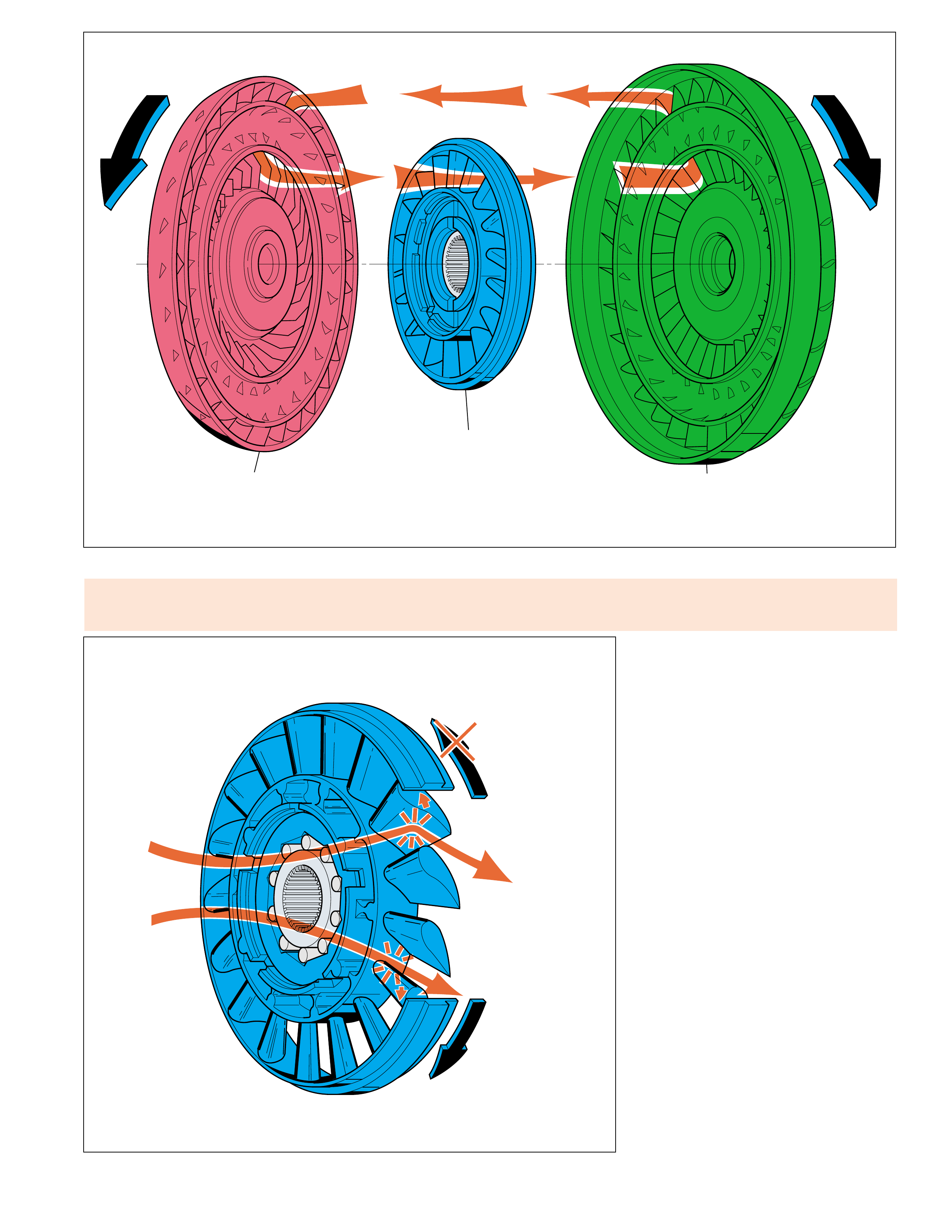
CONVERTER PUMP ASSEMBLY AND TURBINE
ASSEMBLY
When the engine is running the converter pump assembly
acts as a centrifugal pump by picking up fluid at its center
and discharging it at its rim between the blades (see Figure
12). The force of this fluid then hits the turbine blades
and causes the turbine to rotate. As the engine and
converter pump increase in RPM, so does the turbine.
PRESSURE PLATE, DAMPER AND
CONVERTER HOUSING ASSEMBLIES
The pressure plate is splined to the turbine hub and applies
(engages) with the converter cover to provide a mechanical
coupling of the engine to the transmission. When the
pressure plate assembly is applied, the amount of slippage
that occurs through a fluid coupling is reduced (but not
eliminated), thereby providing a more efficient transfer of
engine torque to the drive wheels.
Torque converter failure
could cause loss of drive
and or loss of power.
To reduce torsional shock during the apply of the pressure plate to the
converter cover, a spring loaded damper assembly (D) is used. The
pressure plate is attached to the pivoting mechanism of the damper
assembly which allows the pressure plate to rotate independently of
the damper assembly up to approximately 45 degrees. During
engagement, the springs in the damper assembly cushion the pressure
plate engagement and also reduce irregular torque pulses from the
engine or road surface.
13
STATOR
STATOR ROTATES
FREELY
STATOR HELD
FLUID FLOW REDIRECTED
CONVERTER AT
COUPLING SPEED
FLUID FLOW
FROM TURBINE
CONVERTER
MULTIPLYING
FLUID FLOW
TURBINE
ASSEMBLY
(D)
CONVERTER PUMP
ASSEMBLY
(G)
STATOR
ASSEMBLY
(E)
Figure 13
TORQUE CONVERTER
Stator roller clutch failure
•roller clutch freewheels in both directions can
cause poor acceleration at lo w speed. •roller clutch locks up in both directions can
cause poor acceleration at high speed. •Overheated f luid.
Figure 12
STATOR ASSEMBLY
The stator assembly is located between the
pump assembly and turbine assembly, and is
mounted on a one-way roller clutch. This one-
way roller clutch allows the stator to rotate in
one direction and prevents (holds) the stator
from rotating in the other direction. The
function of the stator is to redirect fluid
returning from the turbine in order to assist the
engine in turning the converter pump assembly.
At low vehicle speeds, when greater torque is
needed, fluid from the turbine hits the front
side of the stator blades (the converter is
multiplying torque). At this time, the one-way
roller clutch prevents the stator from rotating
in the same direction as the fluid flow, thereby
redirecting fluid to assist the engine in turning
the converter pump. In this mode, fluid leaving
the converter pump has more force to turn the
turbine assembly and multiply engine torque.
As vehicle speed increases and less torque is
required, centrifugal force acting on the fluid
changes the direction of the fluid leaving the
turbine such that it hits the back side of the
stator blades (converter at coupling speed).
When this occurs, the roller clutch overruns
and allows the stator to rotate freely. Fluid is
no longer being redirected to the converter
pump and engine torque is not being multiplied.
14
TORQUE CONVERTER
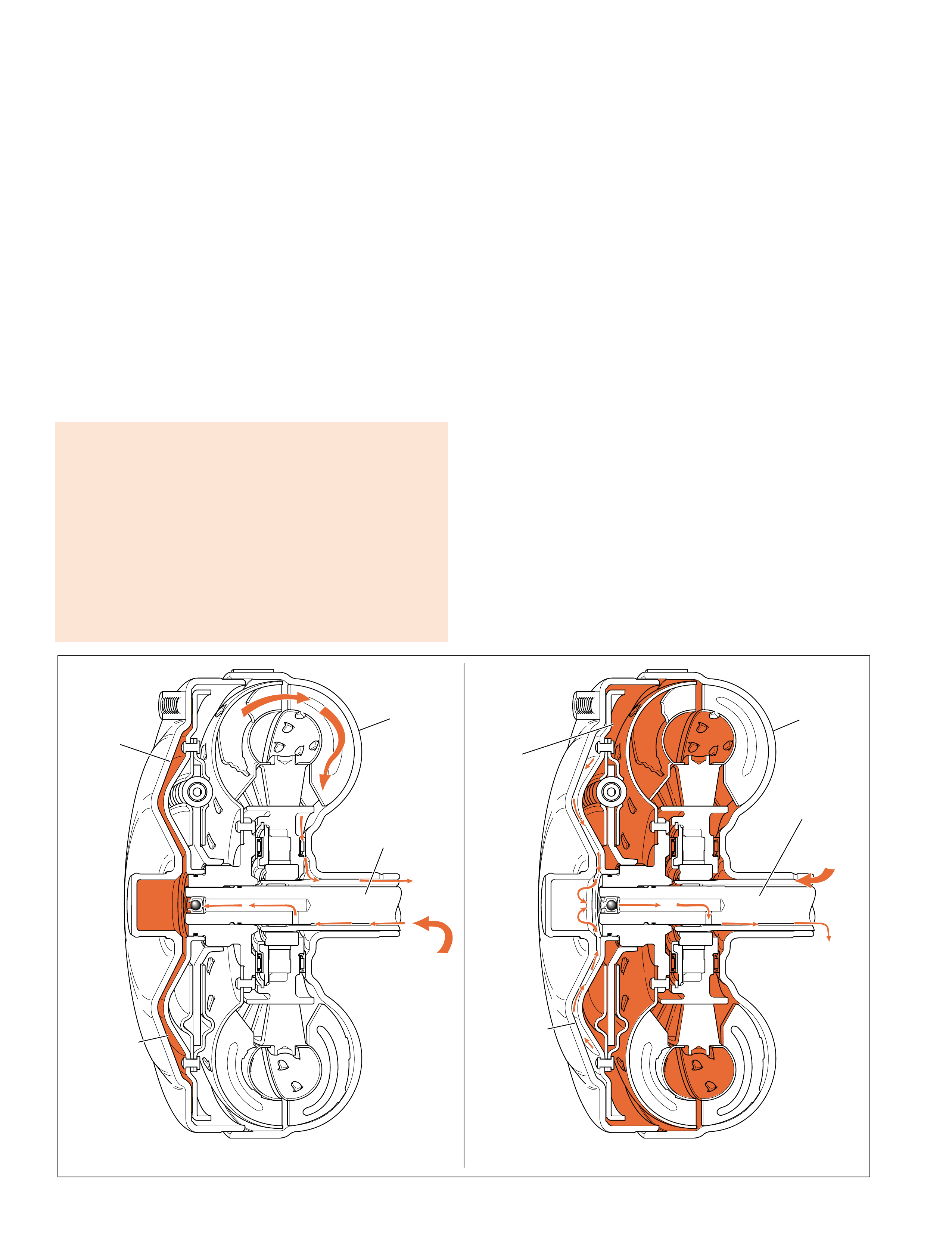
APPLY
When the PCM determines that the vehicle is at the
proper speed for the torque converter clutch to apply
it sends a signal to the TCC (PWM) solenoid valve.
The TCC (PWM) solenoid valve then regulates line
fluid from the pump into the re gulated apply passag e.
The regulated apply fluid then feeds the apply fluid
passage and applies the torque converter. The apply
passage is located between the turbine shaft and the
stator shaft. T he fluid flo ws between the shafts, then
passes into the torque converter on the apply side of
the pressure plate assembly. Release fluid is then
routed out of the torque converter between the turbine
shaft and the stator shaft.
Apply fluid pressure forces the pressure plate against
the torque converter cover to provide a mechanical
link between the engine and the turbine.
The TCC apply should occur in fourth gear (also
third gear in some applications), and should not apply
until the transmission fluid has reached a minimum
operating temperature of 8°C (46°F) and the engine
coolant temperature reaches 50°C (122°F).
For mor e information on TCC apply and release, see
Overdrive Range – Fourth Gear TCC Released and
Applied, pages 62–63.
RELEASE
When the torque converter clutch is released, fluid is
fed into the torque converter by the pump into the
release fluid passage. The release fluid passage is
located between the stator shaft (214) and the turbine
shaft (621). Fluid tra vels between the shafts and enter s
the release side of the pressure plate at the end of the
turbine shaft. The pressure plate is forced away from
the converter cover and allows the torque converter
turbine to rotate at speeds other than engine speed.
The release fluid then flows between the friction
element on the pressure plate and the con v erter co ver
to enter the apply side of the torque converter. The
fluid then exits the torque con v erter through the apply
passage, which is located between the torque
converter clutch hub and the stator shaft (214), and
enters the pump.
TCC APPLYTCC RELEASE
APPLY
FLUID
RELEASE
FLUID
➤
➤
➤
➤
➤
➤
RELEASE
FLUID
PRESSURE
PLATE
TORQUE
CONVERTER
ASSEMBLY
(1)
TURBINE
SHAFT
(621) APPLY
FLUID
RELEASE
FLUID
➤
➤
➤
➤
➤
➤
APPLY
FLUID
PRESSURE
PLATE
TORQUE
CONVERTER
ASSEMBLY
(1)
TURBINE
SHAFT
(502)
Figure 14
No TCC apply can be caused by:
•Electrical connectors, wiring harness or solenoid damaged
•Converter clutch valve stuck or assembled backwards
•Pump to case gasket mispositioned
•Orifice cup plug restricted or damaged
•Solenoid O-ring seal cut or damaged
•Turbine shaft O-ring seal cut or damaged
•Turbine shaft retainer and ball assembly restricted or damaged
•Control valve body TCC signal valve stuck
•Solenoid screen blocked
•TCC solenoid valve internal damage
•Engine speed sensor internal damage
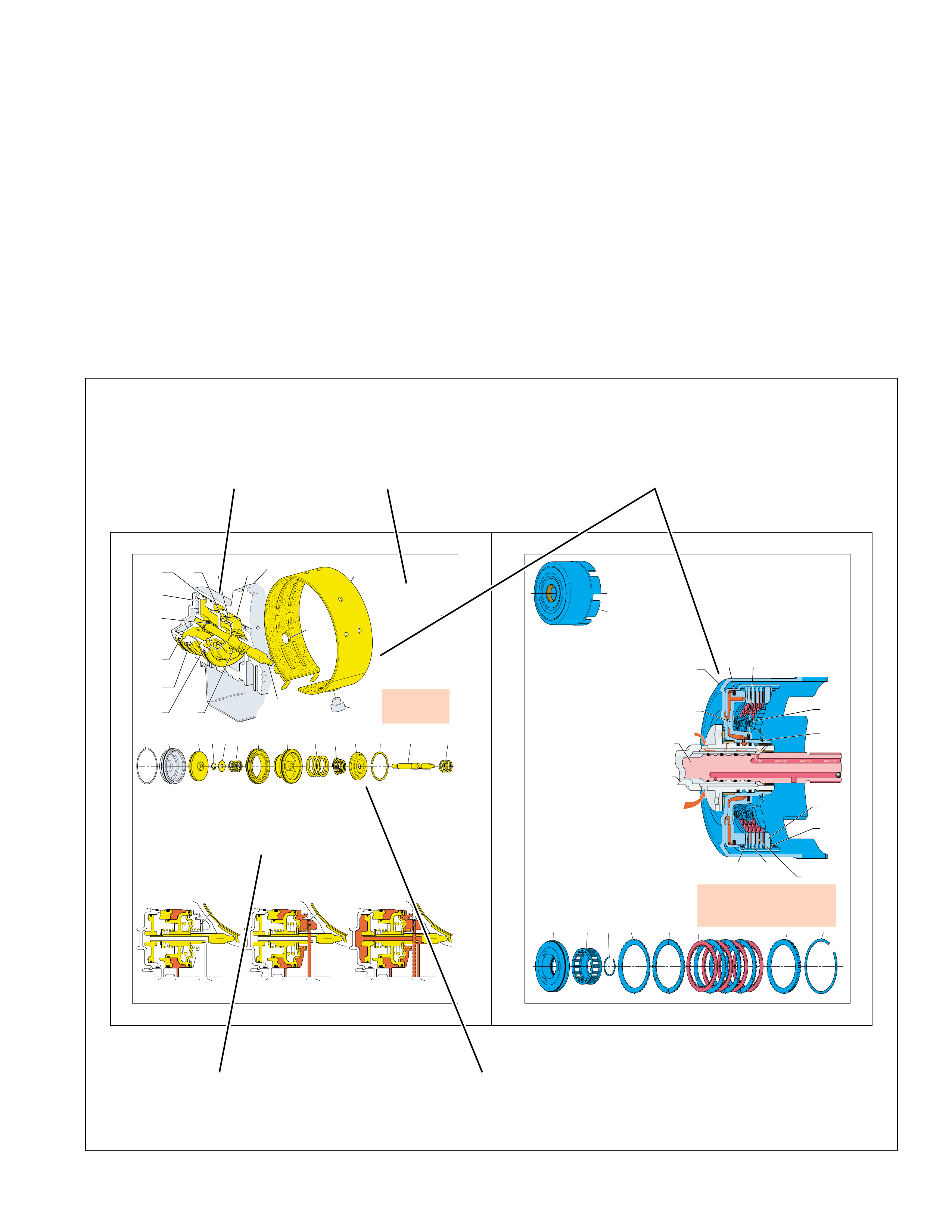
15
Figure 15
2-4 Band Applied – Second Gear
To apply the 2-4 band in Second gear,
2nd clutch fluid is routed to the apply
side of the 2nd apply piston (17). 2nd
clutch fluid pressure moves the piston
against servo cushion (16) and servo
return (12) spring forces. These spring
forces help cushion the 2-4 band apply in
Second gear. The 2nd apply piston moves
the apply pin (13) to compress the band
around the reverse input housing.
2-4 Band Release and 3-4 Clutch
Accumulation
In Third gear, 3rd accumulator fluid is
routed to the release side of the 2nd apply
piston. The surface area on the release
SERVO
ASSEMBLY
AND
2-4 BAND
The servo assembly and 2-4
band (602) are located in the
front of the transmission case
and applied in Second and
Fourth gears. In Third gear,
the servo assembly releases
the band and acts as an
accumulator for the 3-4 clutch
apply. The band is held
stationary to the transmission
case by the band anchor pin
(49) and wraps around the
reverse input housing (605).
When compressed by the
servo assembly, the 2-4 band
holds the reverse input
housing stationary to the
transmission case.
side of the 2nd apply piston (17) and
servo cushion spring retainer (15) is
greater than the surface area that 2nd
clutch fluid pressure covers on the apply
side of the piston. Therefore, the force
from 3rd accumulator fluid pressure, in
addition to servo return spring (12) force,
overcomes the force of 2nd clutch fluid
pressure. The 2nd apply piston then
moves the apply pin (13) away from the
2-4 band to release the band from the
reverse input housing.
3rd accumulator fluid is fed by 3-4 clutch
fluid which is used to apply the 3-4
clutch. The movement of the 2nd apply
piston against 2nd clutch fluid pressure
acts as an accumulator to absorb initial 3-
4 clutch apply fluid. This action helps
cushion the 3-4 clutch apply, as well as
release the 2-4 band.
2-4 Band Applied – Fourth Gear
In Fourth gear, 4th fluid is routed through
the center of the apply pin and acts on the
apply side of the 4th apply piston (25).
4th fluid pressure moves the 4th apply
piston (25) and apply pin (13) to apply
the band. The 4th apply piston moves
against the 4th apply spring (22) to help
cushion the band apply in Fourth gear.
No upshift in 1st gear could
be caused by a worn or
damaged 2-4 band or if the
band anchor pin is not
engaged.
REVERSE INPUT CLUTCH
The reverse input clutch is located in the
reverse input housing (605) and is used to
provide an input to drive the vehicle in
Reverse (R). The steel clutch plates (612A)
are splined to the reverse input housing while
the fiber clutch plates (612B) are splined to
the input housing and turbine shaft assembly
(621). When applied, the reverse input clutch
transfers engine torque from the input housing
to the reverse input housing.
Reverse Input Clutch Applied
To apply the reverse input clutch, reverse
input fluid is fed from the oil pump, through
the stator shaft (214) and to the reverse input
housing. Feed holes in the inner hub of the
reverse input housing allow reverse input fluid
to enter the housing behind the reverse input
clutch piston (607). Any air in the reverse
input fluid circuit will exhaust through the
fluid bleed hole to prevent excess cushion
during the clutch apply. As fluid pressure
increases, the piston compresses the steel,
fiber and belleville (611) clutch plates
together until they are held against the reverse
input clutch backing plate (613). The backing
plate is splined to the housing and held in
place by the retaining ring (614).
With the clutch plates applied, the belleville
plate is compressed to cover the fluid bleed
hole and prevent fluid from exhausting. The
belleville plate also functions to assist spring
force in cushioning the clutch apply. When
fully applied, the steel and fiber plates are
locked together to hold the reverse input
housing and input housing together.
No reverse/slips in reverse could be caused by:
•Porosity in the piston.
•Excessive clutch plate travel.
•Clutch plate retaining ring out of groove.
•Return spring assembly retaining ring out of groove.
•Belleville plate installed incorrectly.
R
everse
I
nput
Cl
utc
h
R
e
l
ease
To release the reverse input clutch,
reverse input fluid exhausts from the
reverse input housing and back through
the stator shaft. Without fluid pressure,
force from the piston spring assembly
and belleville plate moves the reverse
input clutch piston away from the clutch
pack. This disengages the clutch plates
from the backing plate and disconnects
the reverse input housing from the input
housing assembly.
Centrifugal force, resulting from th
reverse input housing rotating, force
residual fluid to the outside of the pisto
cavity. During the clutch release th
belleville plate moves away from th
fluid bleed hole. This allows residu
fluid at the outside of the piston housin
to exhaust through the bleed hole.
this fluid did not completely exhau
from behind the piston there could be
partial apply, or drag of the revers
input clutch plates.
THIRD GEAR – 2-4 SERVO RELEASEDSECOND GEAR – 2-4 SERVO APPLIED FOURTH GEAR – 2-4 SERVO APPLIED
➤
➤
➤
EX 2ND
CLUTCH 3RD
ACCUM 4TH
#7
CHECKBALL
➤
➤
➤
EX 2ND
CLUTCH 3RD
ACCUM 4TH
#7
CHECKBALL
➤
➤
➤
EX 2ND
CLUTCH 3RD
ACCUM 4TH
#7
CHECKBALL
➤
➤
➤
➤
➤
➤
2829 25 24 23 22 20 17 16 105 15 14 13 12
SPRING
RETAINER
(15)
2-4 BAND
ASSEMBLY
(602)
BAND
ANCHOR
PIN (41)
LUBE
WINDOW
CASE
(103)
RETAINER
RING
(14)
CUSHION
SPRING
(16)
APPLY PIN
SPRING
(22)
4TH APPLY
PISTON
(25)
INNER
SERVO PISTON
HOUSING
(20)
2ND APPLY
PISTON
(17)
SERVO
APPLY
PIN
(13)
RETURN
SPRING
(12)
2-4 SERVO
COVER
(28)
RETAINING
RING
(29)
614613612B612A611610607 609
REVERSE
INPUT
HOUSING
(605)
OUTER
SEAL
(608)
REVERSE
INPUT
HOUSING
(605)
PISTON
ASSEMBLY
(607)
INPUT
SHAFT
LUBE
SPRING
ASSEMBLY
(609)
RETAINING
RING
(610)
REVERSE
APPLY
FLUID
STATOR
SHAFT
(214)
RETAINING
RING
(614)
SELECTIVE
BACKING
PLATE
(613)
FIBER
PLATE
(612B)
STEEL
PLATE
(612A)
BELLEVILLE
PLATE
(611)
INNER
SEAL
(608)
Figure 16
16
APPLY COMPONENTS
Figure 17
17
APPLY COMPONENTS
APPLY COMPONENTS
CUTAWAY
VIEW
➤
BRIEF
DESCRIPTION
➤
FUNCTIONAL
DESACRIPTION
➤
DISASSEMBLED
VIEW
➤
MATING
OR
RELATED
COMPONENTS
➤
➤
The A pply Components section is designed to explain
the function of the hydraulic and mechanical holding
de vices used in the Hydra-matic 4L60-E transmission.
Some of these apply components, such as clutches
and bands, are hydraulically “applied” and “released”
in order to provide automatic gear range shifting.
Other components, such as a roller clutch or sprag
clutch, often react to a hydraulically “applied”
component by mechanically “holding” or “releasing”
another member of the transmission. This interaction
between the hydraulically and mechanically applied
components is then explained in detail and supported
with a graphic illustration. In addition, this section
shows the routing of fluid pressure to the individual
components and their internal functions when it
applies or releases.
The sequence in which the components in this section
have been discussed coincides with their physical
arrangement inside the transmission. This order
closely parallels the disassembly sequence used in
the Hydra-matic 4L60-E Unit Repair Section located
in Section 7 of the appropriate Service Manual. It
also correlates with the components shown on the
Range Reference Charts that are used throughout the
Pow er Flow section of this book. The correlation of
information between the sections of this book helps
the user more clearly understand the hydraulic and
mechanical operating principles for this transmission.
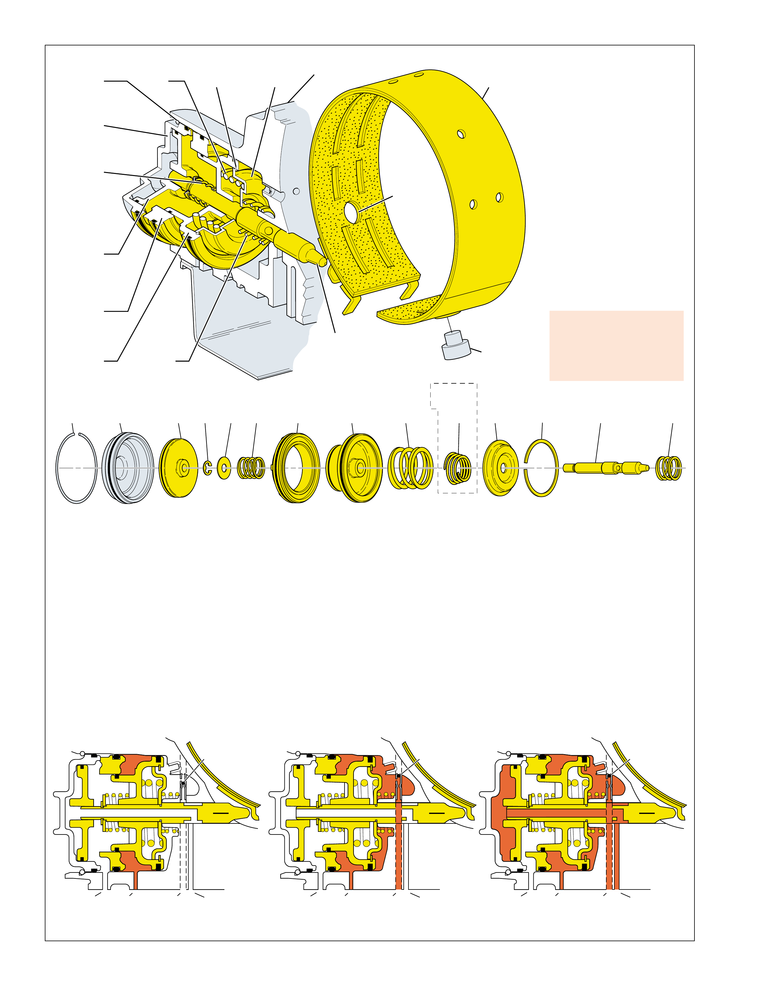
16
THIRD GEAR – 2-4 SERVO RELEASEDSECOND GEAR – 2-4 SERVO APPLIED FOURTH GEAR – 2-4 SERVO APPLIED
➤
➤
➤
EX 2ND
CLUTCH 3RD
ACCUM 4TH
#7
CHECKBALL
➤
➤
➤
EX 2ND
CLUTCH 3RD
ACCUM 4TH
#7
CHECKBALL
➤
➤
➤
EX 2ND
CLUTCH 3RD
ACCUM 4TH
#7
CHECKBALL
➤
➤
➤
➤
➤
➤
2829 25 24 23 22 20 17 16 105 15 14 13 12
SPRING
RETAINER
(15)
2-4 BAND
ASSEMBLY
(602)
BAND
ANCHOR
PIN (41)
LUBE
WINDOW
CASE
(103)
RETAINER
RING
(14)
CUSHION
SPRING
(16)
APPLY PIN
SPRING
(22)
4TH APPLY
PISTON
(25)
INNER
SERVO PISTON
HOUSING
(20)
2ND APPLY
PISTON
(17)
SERVO
APPLY
PIN
(13)
RETURN
SPRING
(12)
2-4 SERVO
COVER
(28)
RETAINING
RING
(29)
SOME
MODELS
APPLY COMPONENTS
Figure 16
2-4 Band Applied – Second Gear
To apply the 2-4 band in Second gear,
2nd clutch fluid is routed to the apply
side of the 2nd apply piston (17). 2nd
clutch fluid pressure moves the piston
against servo cushion (16) and servo
return (12) spring forces. These spring
forces help cushion the 2-4 band apply in
Second gear. The 2nd apply piston moves
the apply pin (13) to compress the band
around the reverse input housing.
2-4 Band Release and 3-4 Clutch
Accumulation
In Third gear, 3rd accumulator fluid is
routed to the release side of the 2nd apply
piston. The surface area on the release
SERVO ASSEMBLY AND
2-4 BAND
The servo assembly and 2-4
band (602) are located in the
front of the transmission case
and applied in Second and
Fourth gears. In Third gear,
the servo assembly releases
the band and acts as an
accumulator for the 3-4 clutch
apply. The band is held
stationary to the transmission
case by the band anchor pin
(49) and wraps around the
reverse input housing (605).
When compressed by the
servo assembly, the 2-4 band
holds the reverse input
housing stationary to the
transmission case.
side of the 2nd apply piston (17) and
servo cushion spring retainer (15) is
greater than the surface area that 2nd
clutch fluid pressure covers on the apply
side of the piston. Therefore, the force
from 3rd accumulator fluid pressure, in
addition to servo return spring (12) force,
overcomes the force of 2nd clutch fluid
pressure. The 2nd apply piston then
moves the apply pin (13) away from the
2-4 band to release the band from the
reverse input housing.
3rd accumulator fluid is fed by 3-4 clutch
fluid which is used to apply the 3-4
clutch. The movement of the 2nd apply
piston against 2nd clutch fluid pressure
acts as an accumulator to absorb initial 3-
4 clutch apply fluid. This action helps
cushion the 3-4 clutch apply, as well as
release the 2-4 band.
2-4 Band Applied – Fourth Gear
In Fourth gear, 4th fluid is routed through
the center of the apply pin and acts on the
apply side of the 4th apply piston (25).
4th fluid pressure moves the 4th apply
piston (25) and apply pin (13) to apply
the band. The 4th apply piston moves
against the 4th apply spring (22) to help
cushion the band apply in Fourth gear.
No upshift in 1st gear could
be caused by a worn or
damaged 2-4 band or if the
band anchor pin is not
engaged.
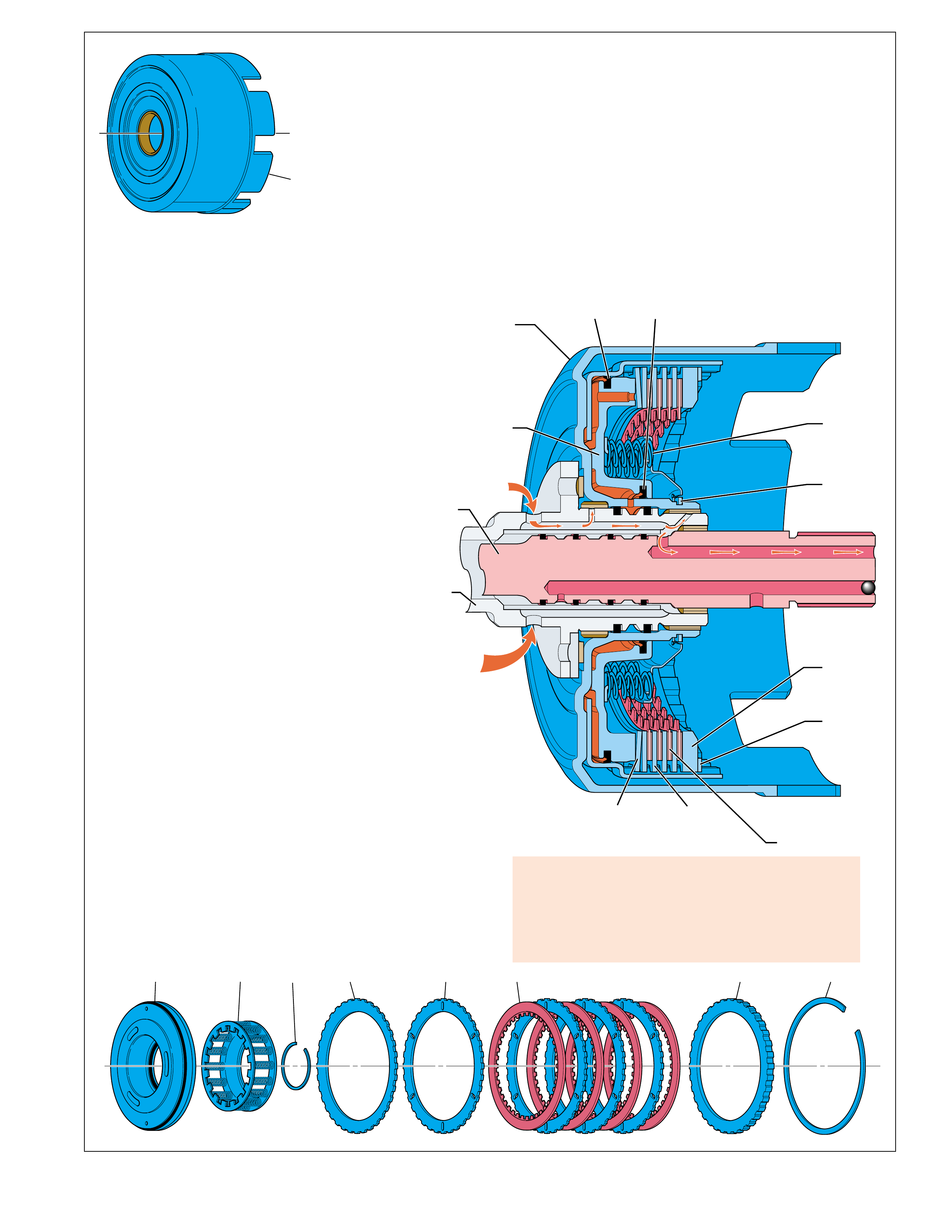
17
614613612B612A611610607 609
REVERSE
INPUT
HOUSING
(605)
OUTER
SEAL
(608)
REVERSE
INPUT
HOUSING
(605)
PISTON
ASSEMBLY
(607)
INPUT
SHAFT
LUBE
SPRING
ASSEMBLY
(609)
RETAINING
RING
(610)
REVERSE
APPLY
FLUID
STATOR
SHAFT
(214)
RETAINING
RING
(614)
SELECTIVE
BACKING
PLATE
(613)
FIBER
PLATE
(612B)
STEEL
PLATE
(612A)
BELLEVILLE
PLATE
(611)
INNER
SEAL
(608)
Figure 17
APPLY COMPONENTS
REVERSE INPUT CLUTCH
The reverse input clutch is located in the
reverse input housing (605) and is used to
provide an input to drive the vehicle in
Reverse (R). The steel clutch plates (612A)
are splined to the reverse input housing while
the fiber clutch plates (612B) are splined to
the input housing and turbine shaft assembly
(621). When applied, the reverse input clutch
transfers engine torque from the input housing
to the reverse input housing.
Reverse Input Clutch Applied
To apply the reverse input clutch, reverse input
fluid is fed from the oil pump, through the
stator shaft (214) and to the reverse input
housing. Feed holes in the inner hub of the
reverse input housing allow reverse input fluid
to enter the housing behind the reverse input
clutch piston (607). Any air in the reverse
input fluid circuit will exhaust through the
fluid bleed hole to prevent excess cushion
during the clutch apply. As fluid pressure
increases, the piston compresses the steel, fiber
and belleville (611) clutch plates together until
they are held against the reverse input clutch
backing plate (613). The backing plate is
splined to the housing and held in place by the
retaining ring (614).
With the clutch plates applied, the belleville
plate is compressed to cover the fluid bleed
hole and prevent fluid from exhausting. The
belleville plate also functions to assist spring
force in cushioning the clutch apply. When
fully applied, the steel and fiber plates are
locked together to hold the reverse input
housing and input housing together. No rev erse/slips in reverse could be caused by:
•Porosity in the piston.
•Excessive clutch plate travel.
•Clutch plate retaining ring out of groove.
•Return spring assembly retaining ring out of groove.
•Belleville plate installed incorrectly.
Reverse Input Clutch Release
To release the reverse input clutch,
reverse input fluid exhausts from the
reverse input housing and back through
the stator shaft. Without fluid pressure,
force from the piston spring assembly
and belleville plate moves the reverse
input clutch piston away from the clutch
pack. This disengages the clutch plates
from the backing plate and disconnects
the reverse input housing from the input
housing assembly.
Centrifugal force, resulting from the
reverse input housing rotating, forces
residual fluid to the outside of the piston
cavity. During the clutch release the
belleville plate moves away from the
fluid bleed hole. This allows residual
fluid at the outside of the piston housing
to exhaust through the bleed hole. If
this fluid did not completely exhaust
from behind the piston there could be a
partial apply, or drag of the reverse
input clutch plates.
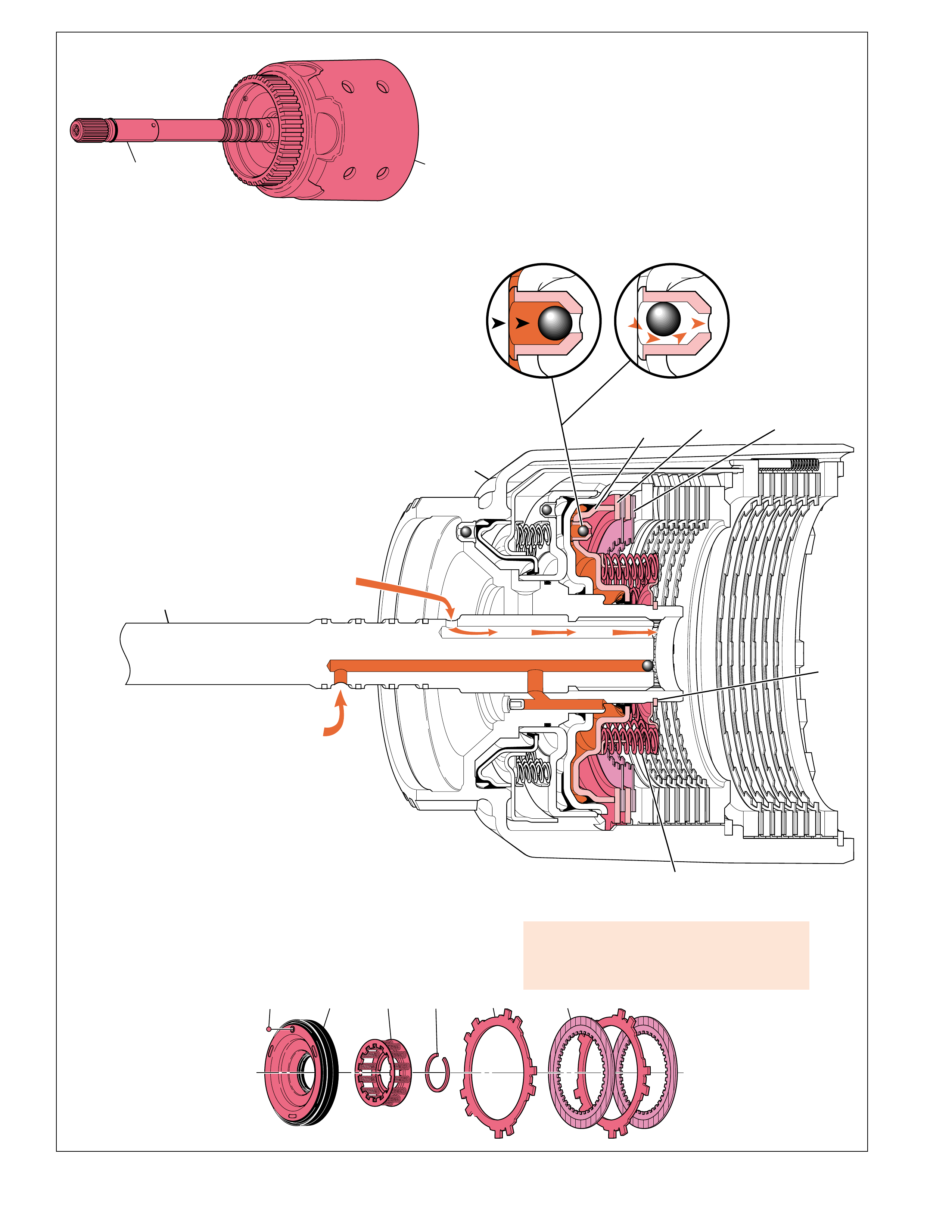
18
645A 645B632 634 635
633
TURBINE
SHAFT INPUT
HOUSING
(621)
FIBER
CLUTCH
PLATE
(645B)
STEEL
CLUTCH
PLATE
(645A)
OVERRUN
CLUTCH
PISTON
(632)
SNAP
RING
(635)
SPRING
ASSEMBLY
(634)
INPUT
HOUSING
(621)
LUBE
PASSAGE
TURBINE
SHAFT
OVERRUN
CLUTCH
APPLY
FLUID
OVERRUN CLUTCH CHECKBALL
APPLIED RELEASED
EX
633
633
Figure 18
APPLY COMPONENTS
OVERRUN CLUTCH
The overrun clutch assembly is located in the input
housing and turbine shaft assembly (621) and is only
applied in the Manual Gear ranges. The steel clutch
plates (645A) are splined to the input housing while the
fiber clutch plates (645B) are splined to the overrun
clutch hub (639). When applied, the overrun clutch
plates force the overrun clutch hub to rotate at the same
speed as the input housing. This prevents the forward
sprag clutch from being overrun during coast conditions,
thereby providing engine compression braking to slow
the vehicle.
Overrun Clutch Applied
To apply the overrun clutch, overrun clutch fluid is routed
through the turbine shaft and into the input housing
behind the overrun clutch piston (632).
Overrun clutch fluid pressure seats the overrun
clutch checkball (633), which is located in the
overrun clutch piston, and moves the piston
to compress the overrun
Overrun piston checkball not sealing or overrun
piston seals cut or damaged can cause no
overrun braking - manual 3-2-1.
clutch spring assembly (634).
Any air in the overrun clutch fluid circuit
will exhaust past the checkball before it fully
seats to prevent excess cushion during the clutch
apply. As fluid pressure increases, the piston compresses
the steel and fiber clutch plates together until they are
held against the forward clutch apply plate (646). When
fully applied, the steel and fiber plates are locked together
and hold the overrun clutch hub to the input housing.
Overrun Clutch Released
To release the overrun clutch, overrun clutch fluid
exhausts from the input housing and back through the
turbine shaft. Without fluid pressure, force from the
piston spring assembly moves the overrun clutch piston
away from the clutch pack. This disengages the clutch plates
from the forward clutch apply plate and disconnects the
overrun clutch hub from the input housing.
During the exhaust of overrun clutch fluid, the overrun clutch
checkball unseats (see illustration). Centrifugal force,
resulting from the input housing rotating, forces residual
overrun clutch fluid to the outside of the piston housing and
past the unseated checkball. If this fluid did not completely
exhaust from behind the piston there could be a partial apply,
or drag of the overrun clutch plates.
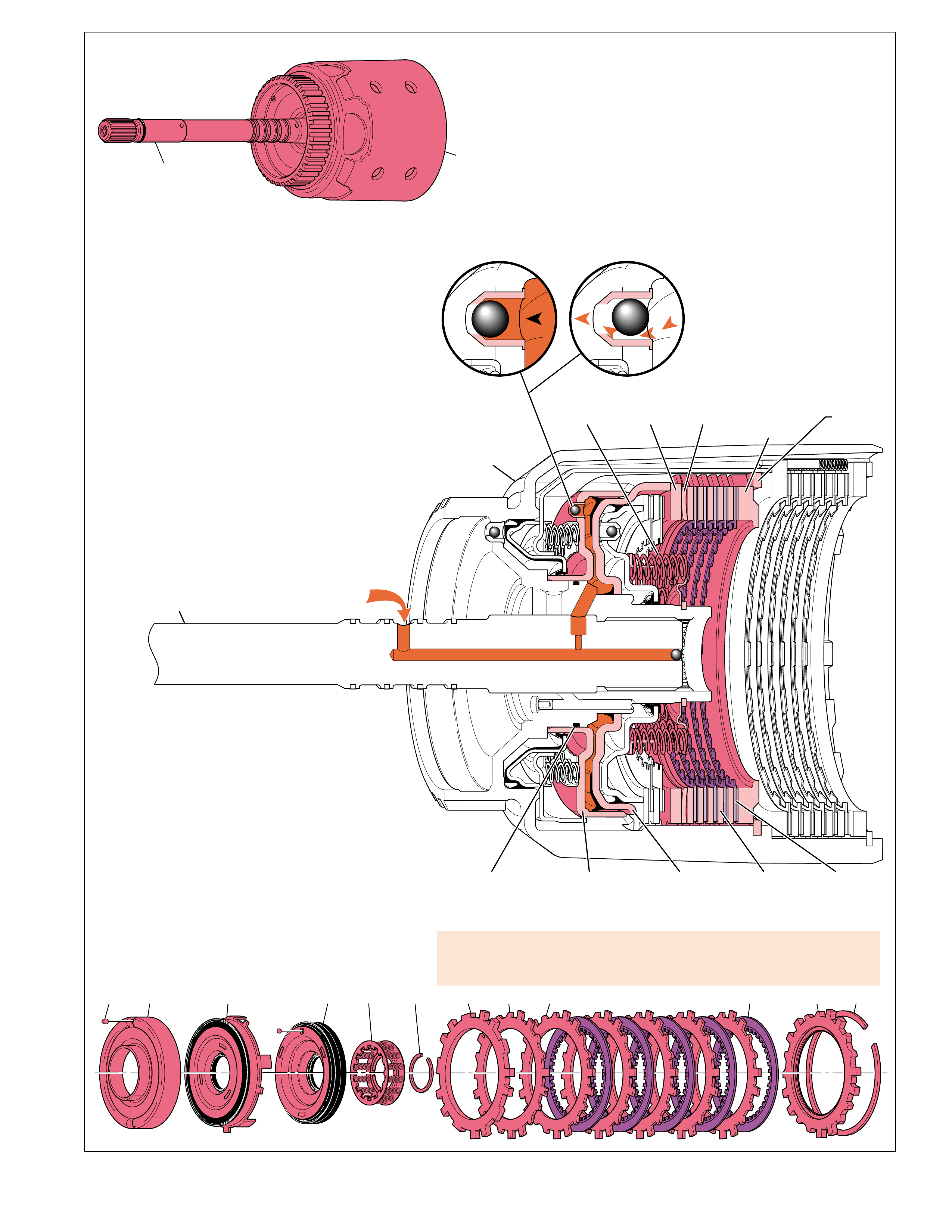
19
TURBINE
SHAFT
INPUT
HOUSING
(621)
FORWARD
CLUTCH
PISTON
(630)
SPRING
ASSEMBLY
(634)
INPUT
HOUSING
(621)
TURBINE
SHAFT FORWARD CLUTCH
APPLY FLUID
APPLY
PLATE
(646)
WAVED
PLATE
(648)
RETAINING
RING
(648)
O-RING
SEAL
(622)
FORWARD
CLUTCH
HOUSING
(628)
STEEL
PLATE
(649A)
FIBER
PLATE
(649B)
SELECTIVE
BACKING
PLATE
(650)
FORWARD CLUTCH HOUSING CHECKBALL
APPLIED RELEASED
627 627
EX
651 648 649A 650649B646630628 632 634 635627
Figure 19
APPLY COMPONENTS
FORWARD CLUTCH
The forward clutch assembly is located in the input
housing and turbine shaft assembly (621) and is applied
in all forward drive ranges. The steel clutch plates (649A)
are splined to the input housing while the fiber clutch
plates (649B) are splined to the forward clutch outer race
(644). When applied, the forward clutch plates transfer
engine torque from the input housing to the forward
clutch outer race and forward sprag clutch assembly.
Forward Clutch Applied
To apply the forward clutch, forward clutch feed fluid
is routed through the turbine shaft and into the input
housing behind the forward clutch piston (630).
Forward clutch feed fluid pressure seats the forward
clutch housing checkball, which is located in the
forward clutch housing (627), and moves the piston to
compress the piston spring assembly (634). Any air
in the forward clutch feed fluid circuit will
exhaust past the checkball before it fully seats
to prevent excess cushion during the clutch
apply. As fluid pressure increases, the piston
moves the apply plate (646) and compresses
Worn forward clutch plates, damaged forward clutch housing, damaged or
missing forward clutch piston seals, or porosity in forward clutch piston can
cause slips in 1st gear.
the steel and fiber clutch plates together until
they are held against the selective forward
clutch backing plate (650). The backing plate,
which is selective for assembly purposes, is
splined to the input housing and held in place by
the retaining ring (651).
Also included in the forward clutch assembly is a steel
waved plate (648) that, in addition to the spring
assembly, helps cushion the clutch apply. When fully
applied, the steel and fiber plates are locked together
and hold the input housing and forward clutch outer
race together.
Forward Clutch Released
To release the forward clutch, forward clutch feed fluid
exhausts from the input housing and back through the
turbine shaft. Without fluid pressure, force from the
piston spring assembly and waved plate moves the
forward clutch piston away from the clutch pack. This disengages
the clutch plates from the backing plate and disconnects the
input housing from the forward clutch outer race.
During the exhaust of forward clutch feed fluid, the forward
clutch housing checkball unseats (see illustration). Centrifugal
force, resulting from the input housing rotating, forces residual
forward clutch feed fluid to the outside of the piston housing
and past the unseated checkball. If this fluid did not completely
exhaust from behind the piston there could be a partial apply,
or drag of the forward clutch plates.

20
AIR BLEED
ORIFICE
CUP PLUG
(698)
TURBINE
SHAFT
INPUT
HOUSING
(621)
SPRING
ASSEMBLY
(634)
3-4 CLUTCH
APPLY RING
(625)
INPUT
HOUSING
(621)
TURBINE
SHAFT 3-4 CLUTCH
APPLY FLUID
STEPPED
APPLY
PLATE
(653)
RETAINING
RING
(656)
3-4 CLUTCH
PISTON
(623)
STEEL
PLATE
(654A)
FIBER
PLATE
(654B)
BOOST
SPRING
(600)
AIR BLEED
ORIFICE
CUP PLUG
(698)
3-4 CLUTCH CHECKBALL
APPLIED RELEASED
620
EX
620
626625623 656655653 654A 654B
APPLY COMPONENTS
Figure 20
3-4 CLUTCH
The 3-4 clutch assembly is located in the input
housing and turbine shaft assembly (621) and is
applied in Third and Fourth gears. The steel clutch
plates (654B/C) are splined to the input housing
while the fiber clutch plates (654A) are splined to
the input internal gear (664). When applied, the 3-4
clutch plates transfer engine torque from the input
housing to the input internal gear.
3-4 Clutch Applied
To apply the 3-4 clutch, 3-4 clutch fluid is routed
through the turbine shaft and into the input housing
behind the 3-4 clutch piston (623). 3-4 clutch fluid
pressure seats the 3-4 clutch checkball (620), which
is located in the input housing, and moves the piston
against the 3-4 clutch apply ring (625). The apply
ring compresses the 3-4 clutch spring assembly
(626) which helps cushion the 3-4 clutch apply. Any
air in the 3-4 clutch fluid circuit will exhaust past
the 3-4 clutch checkball before it fully seats to
prevent excess cushion during the clutch apply.
3-4 accumulator
piston seal or seal
groove damage or
porosity in the 3-4
accumulator piston
or bore can cause no
3-4 shift/slips or
rough 3-4 shift.
As fluid pressure increases, the apply ring
moves against the retainer ring plate (652)
and stepped apply plate (653). This force compresses
the steel and fiber clutch plates (654) together until
they are held against the selective 3-4 clutch backing
plate (655). The backing plate, which is selective
for assembly purposes, is splined to the input housing
and held in place by the retaining ring (656).
3-4 Clutch Released
To release the 3-4 clutch, 3-4 clutch fluid exhausts
from the input housing and back through the turbine
shaft. Without fluid pressure, force from the piston
spring assembly and boost springs (600) move the
3-4 clutch apply ring and piston away from the clutch
pack. This disengages the clutch plates from the
backing plate and disconnects the input housing from the
forward clutch outer race.
During the exhaust of 3-4 clutch fluid, the 3-4 clutch checkball
unseats (see illustration). Centrifugal force, resulting from
the input housing rotating, forces residual 3-4 clutch fluid to
the outside of the piston housing and past the unseated
checkball. If this fluid did not completely exhaust from behind
the piston there could be a partial apply, or drag of the 3-4
clutch plates.
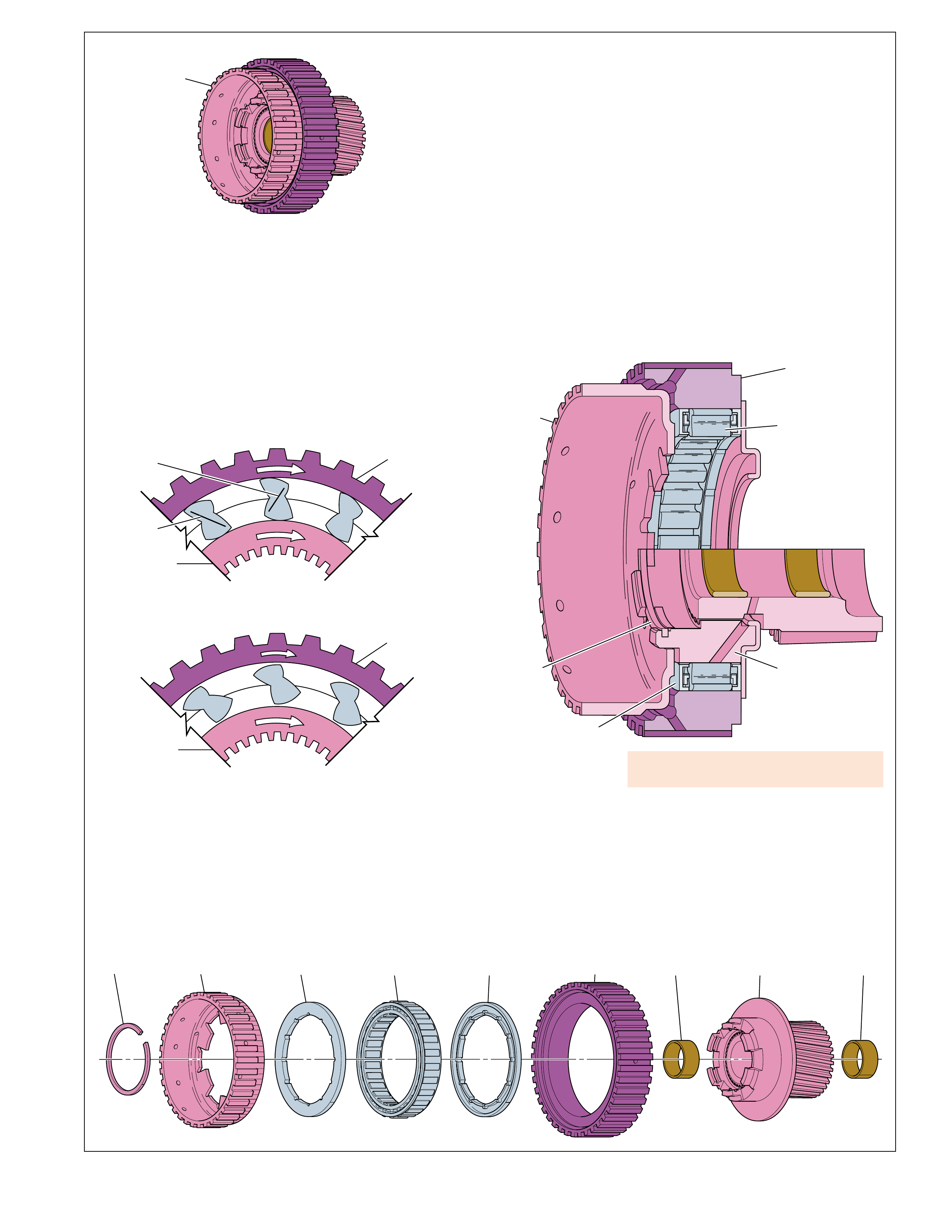
21
638 639 642
643 643 644 640657 659
OUTER
RACE
(644)
OVERRUN
CLUTCH
HUB
(639)
RETAINING
RING
(638)
SPRAG
RETAINER
(643)
FORWARD
SPRAG
ASSEMBLY
(642)
INNER RACE
AND INPUT
SUN GEAR
ASSEMBLY
(640)
FORWARD CLUTCH
SPRAG ASSEMBLY
(638-644)
SPRAG CLUTCH RELEASED
INNER RACE ROTATES FASTER THAN OUTER RACE
INNER
RACE
(640)
OUTER
RACE
(644)
F
R
E
E
SPRAG CLUTCH HOLDING
OUTER RACE DRIVING THE INNER RACE
INNER
RACE
(640)
OUTER
RACE
(644)
H
E
L
D
➤
➤
➤
➤
(A)
(B)
Figure 21
APPLY COMPONENTS
FORWARD SPRAG CLUTCH ASSEMBLY
The forward sprag clutch assembly (642) is located between the
forward clutch race (644) and the inner race and input sun gear
assembly (640). The inner race and input sun gear assembly is
connected to the overrun clutch hub (639) while the forward
clutch race is splined to the forward clutch plates. The sprag
clutch is a type of one-way clutch that transfers engine torque
from the forward clutch to the input sun gear during acceleration
in First, Second and Third gears in Overdrive Range. When the
throttle is released in these gear ranges the sprag clutch is overrun
to allow the vehicle to coast freely.
Installing the forward clutch sprag assembly
backwards can cause second gear starts.
Forward Sprag Clutch Holding
When the forward clutch is applied, engine torque is transferred
to the forward clutch race (644) which functions as the outer
race for the sprag assembly. The rotation of the outer race
pivots the sprags toward their long diagonals. The length of the
long diagonal (distance A) is greater than the distance between
the outer race and inner race (640). This causes the sprags to
“lock” between the inner and outer races and transfer engine
torque from the forward clutch race to the inner race and input
sun gear assembly (640).
Forward Sprag Clutch Released
The sprag clutch releases when the sprags pivot toward their
short diagonals. The length of the short diagonals (B) is less
than the distance between the inner and outer sprag races. This
occurs when power flow drives the input sun gear and sprag
race and retainer assembly faster than the forward clutch drives
the forward clutch race (644). During acceleration the sprag
clutch is overrun only in Fourth gear.
Coast Conditions
The sprag clutch is also overrun during coast conditions, or
deceleration, in the following gear ranges:
- Overdrive Range - First, Second and Third Gears
- Manual Third - First and Second Gears
- Manual Second - First Gear
During coast conditions, power from vehicle speed drives the
input sun gear faster than engine torque drives the forward
clutch race (644). In this situation, the inner race and input sun
gear assembly (640) overruns the sprag clutch and allows the
vehicle to coast freely.
Overrun Clutch Applied
When the overrun clutch is applied (see range reference chart) it
holds the overrun clutch hub and sun gear together. These
components are then forced to rotate at the same speed as the
input housing. This prevents the input sun gear from being
driven faster than the forward clutch race (644). During coast
conditions when the throttle is released, power from vehicle
speed is then transferred back to the torque converter and engine
compression slows the vehicle.
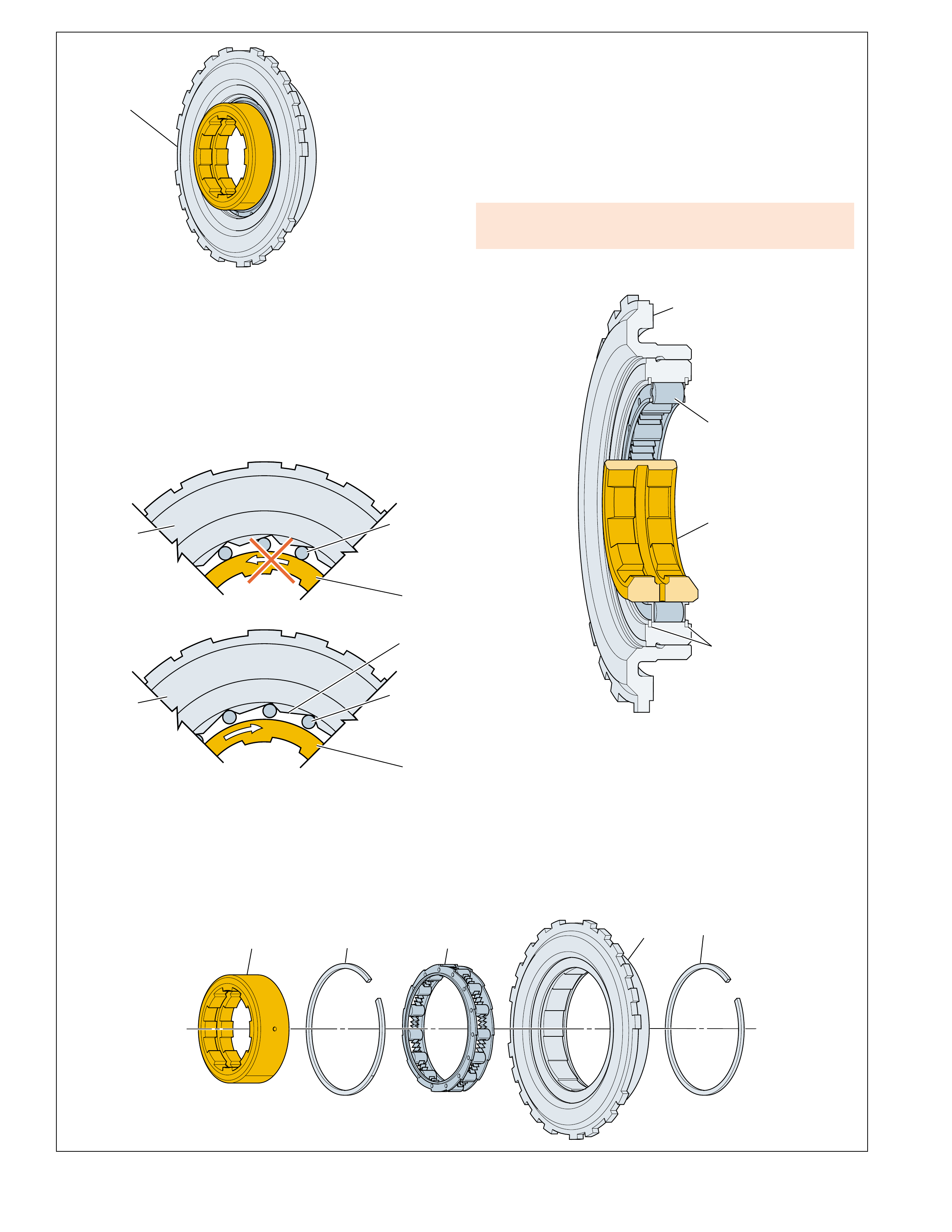
22
H
E
L
D
ROLLERS
HELD
LOW AND
REVERSE
CLUTCH
SUPPORT
(679)
ROLLER
CLUTCH
RACE
(675)
ROLLER CLUTCH HOLDING
F
R
E
E
RAMP
LOW AND
REVERSE
CLUTCH
SUPPORT
(679)
ROLLERS
FREE
ROLLER CLUTCH RELEASED
ROLLER
CLUTCH
RACE
(675)
675 677 678 677
679
LOW AND REVERSE
ROLLER CLUTCH
ASSEMBLY
(675-679)
LOW AND REVERSE
CLUTCH
SUPPORT
(679)
ROLLER
CLUTCH
RACE
(675)
ROLLER
CLUTCH
ASSEMBLY
(678)
RETAINING
RING
(677)
APPLY COMPONENTS
Figure 22
LOW AND REVERSE ROLLER CLUTCH
The low and reverse roller clutch (678) is a type of one-way
clutch used to prevent the reaction carrier assembly (681), reaction
carrier shaft (666) and input internal gear (664) from rotating in a
counterclockwise direction. The roller clutch is located between
the low and reverse clutch support (679) and the low roller clutch
race (675). The low roller clutch support functions as the outer
cam for the roller clutch and is splined to the transmission case.
The roller clutch race (675) is splined to the reaction carrier
assembly (681) and functions as the roller clutch inner race.
Lube passage plugged, damage to inner splines, or inadequate
spring tension in the low roller clutch can cause slips in 1st gear.
Roller Clutch Holding
The roller clutch is holding during acceleration in First gear.
When accelerating in First gear, the reaction carrier assembly
and inner race (675) attempt to rotate counterclockwise. This
action causes the rollers to roll up the ramps on the outer cam
and wedge between the inner race and outer cam. With the
rollers wedged and the low and reverse clutch support held
stationary to the transmission case, the reaction carrier assembly
is also held stationary.
Roller Clutch Released
The roller clutch is overrun by the reaction carrier assembly and
inner race when the throttle is released during First gear operation
with the selector lever in Overdrive, Manual Third and Manual
Second. When the throttle is released, power flow from vehicle
speed drives the reaction carrier assembly and inner race in a
clockwise direction. The inner race moves the rollers down the
ramp, overruns the rollers and rotates freely in a clockwise direction.
Low and Reverse Clutch Applied
In Manual First – First Gear, the low and reverse clutch is
applied to hold the reaction carrier assembly stationary to the
transmission case. The low and reverse clutch prevents the
reaction carrier and inner race from rotating clockwise and
overrunning the roller clutch when the throttle is released. Power
flow is then transferred back through the transmission gear sets
and to the torque converter, allowing engine compression to
slow the vehicle. The low and reverse clutch is also applied in
Reverse to provide the necessary power flow to obtain Reverse.
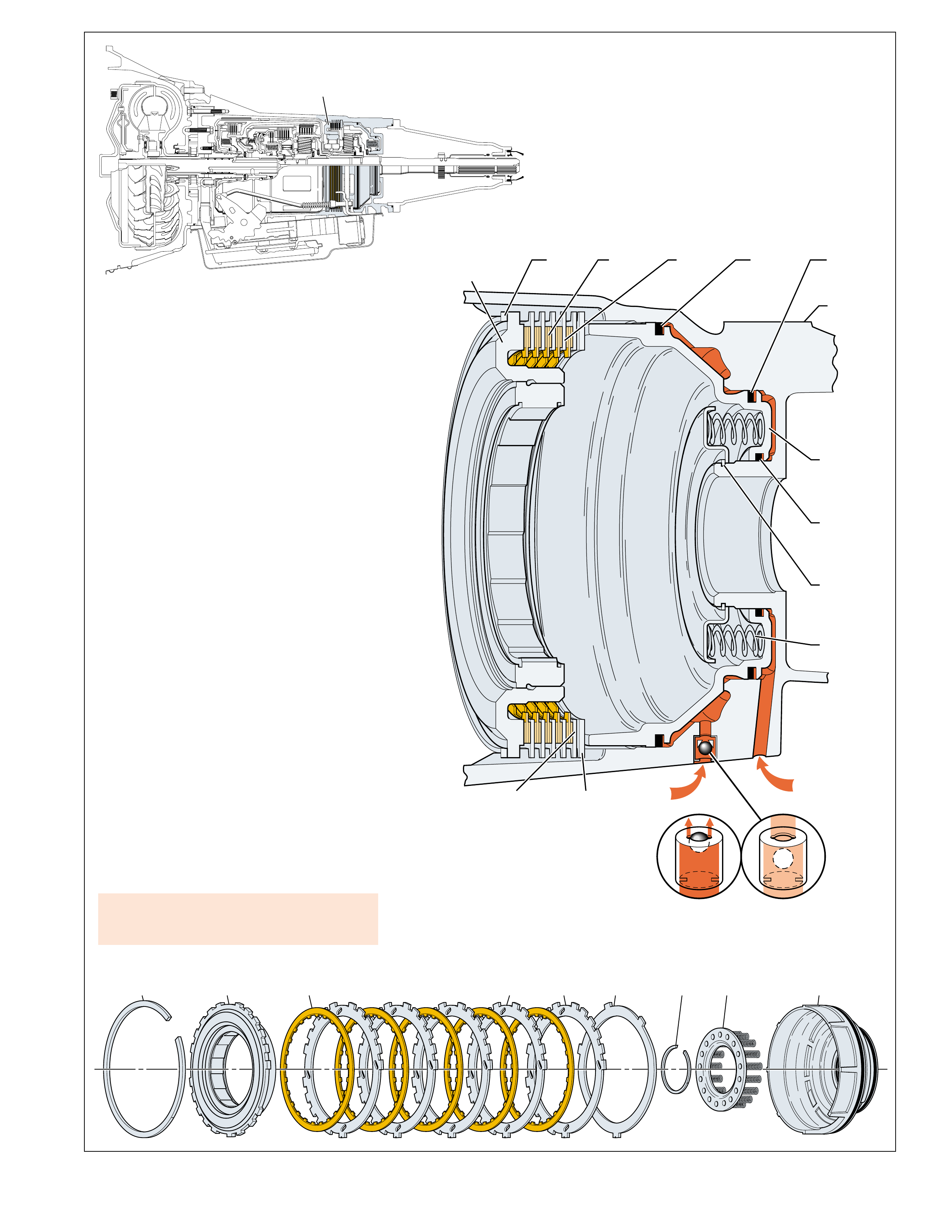
23
693 694 695682C 682B 682A682D676 679
LOW AND REVERSE
CLUTCH ASSEMBLY
LOW AND REVERSE
SUPPORT
ASSEMBLY
(679)
RETAINER
RING
(676)
FIBER
PLATE
(682C)
STEEL
PLATE
(682D)
OUTER
SEAL
(696)
CASE
(103)
CENTER
SEAL
(696)
INNER
SEAL
(696)
LOW AND
REVERSE
CLUTCH
PISTON
(695)
RETAINER
RING
(693)
SPRING
ASSEMBLY
(694)
LO/REVERSE
FLUID
PR
FLUID
WAVED
PLATE
(682A)
SELECTIVE
SPACER
PLATE
(682B)
DOUBLE ORIFICE
RETAINER & BALL ASSEMBLY
(42)
➤➤
RELEASEDAPPLIED
Figure 23
APPLY COMPONENTS
LOW AND REVERSE CLUTCH
The low and reverse clutch assembly is located
in the rear of the transmission case and is applied
in Park, Reverse and Manual First – First Gear.
The steel clutch plates (682A,B,D) are splined
to the transmission case while the fiber clutch
plates (682C) are splined to the reaction planetary
carrier (681). When applied, the low and reverse
clutch plates hold the reaction planetary carrier
stationary to the transmission case.
Low and Reverse Clutch Applied
To apply the low and reverse clutch, two
different fluids are routed to the low and reverse
clutch piston (695). In Manual First, lo/reverse
fluid is routed to the inner area of the clutch
piston. In Park and Reverse, PR fluid is routed
to the outer area of the low and reverse clutch
piston, in addition to lo/reverse fluid acting on
the inner area of the piston, to provide a greater
holding capacity of the clutch. Fluid pressure
moves the piston to compress the low and
reverse clutch piston spring assembly (634). PR
fluid seats the PR checkball and is orificed to
the piston to help control the clutch apply. Also
included in the forward clutch assembly is a
steel waved plate (682A) that, in addition to the
spring assembly, helps cushion the clutch apply.
As fluid pressure increases, the piston
compresses the steel and fiber clutch plates
together until they are held against the low and
reverse support assembly (679), which is also
splined to the transmission case. The spacer
plate (682B) is selective for assembly purposes.
Worn low and reverse clutch plates or porosity
in piston can cause no reverse/slips in reverse.
Low and Reverse Clutch Released
To release the low and reverse clutch, apply fluid pressure
exhausts from the behind the low and reverse clutch piston.
When exhausting, PR fluid unseats the PR checkball (42)
for a quick exhaust. Without fluid pressure, force from
the piston spring assembly and waved plate moves the
low and reverse clutch piston away from the clutch pack.
This disengages the clutch plates from the low and reverse
clutch support, thereby allowing the reaction carrier
assembly to rotate freely.
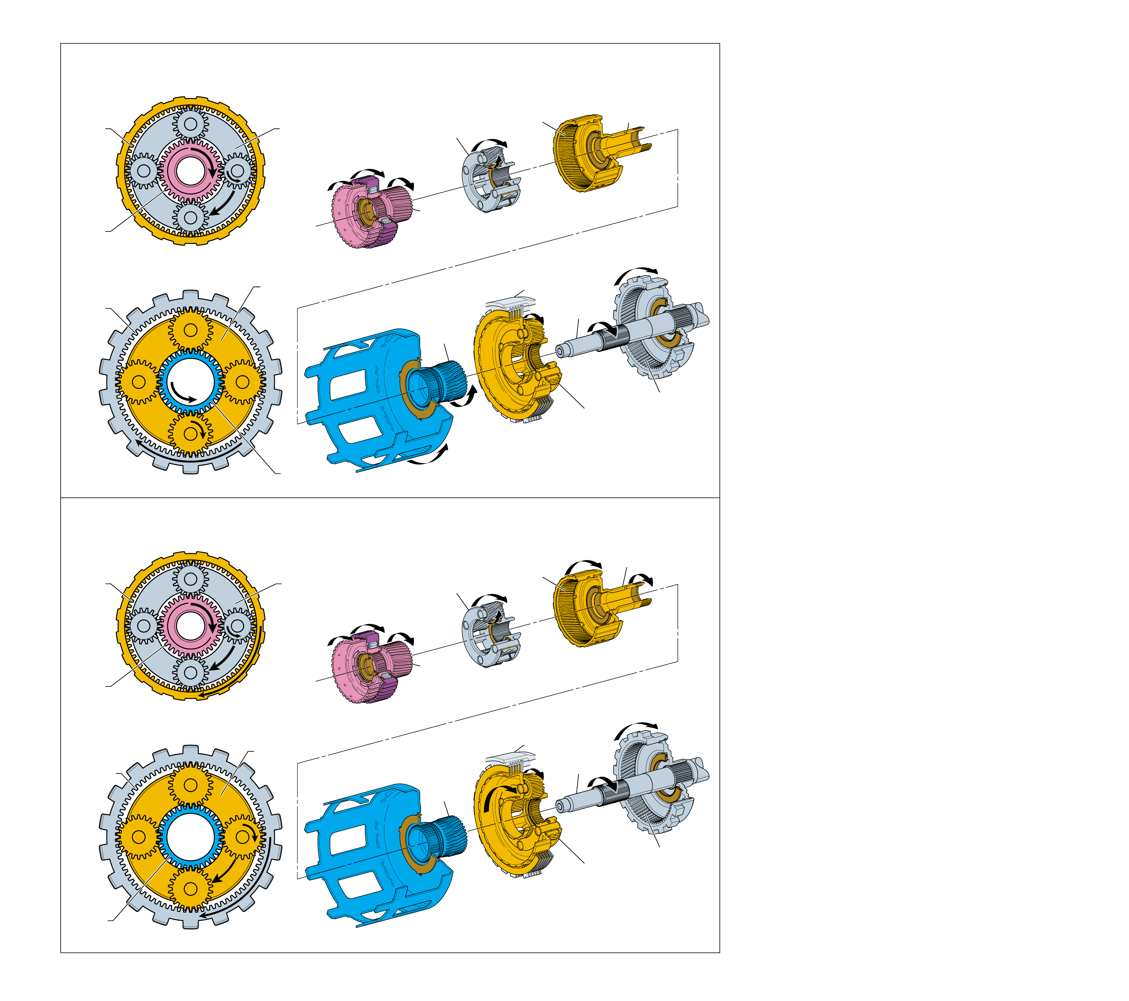
24
(681)
HELD
(684)
DRIVEN
(673)
REACTION
SUN
GEAR
(673)
HELD
REACTION
CARRIER
ASSEMBLY
(681)
DRIVEN
OUTPUT
SHAFT
(687)
REACTION
INTERNAL
GEAR
(684)
DRIVING
MAIN
CASE
(103)
INPUT
SUN
GEAR
(640)
DRIVING
INPUT
CARRIER
ASSEMBLY
(662)
DRIVEN
INPUT
INTERNAL
GEAR
(664)
DRIVEN
REACTION
CARRIER
SHAFT
(666)
DRIVEN
(664)
HELD
(640)
DRIVING
(662)
DRIVEN
(681)
DRIVEN
(684)
DRIVING
(673)
HELD
(664)
DRIVEN
(640)
DRIVING
(662)
DRIVEN
REACTION
SUN
GEAR
(673)
REACTION
CARRIER
ASSEMBLY
(681)
HELD
OUTPUT
SHAFT
(687)
REACTION
INTERNAL
GEAR
(684)
DRIVEN
MAIN
CASE
(103)
INPUT
SUN
GEAR
(640)
DRIVING
INPUT
CARRIER
ASSEMBLY
(662)
DRIVEN
INPUT
INTERNAL
GEAR
(664)
HELD
REACTION
CARRIER
SHAFT
(666)
HELD
PLANETARY GEAR SETS
REDUCTION - FIRST GEAR
Figure 24
REDUCTION - SECOND GEAR
Planetary gear sets are used in the Hydra-matic 4L60-E transmission
as the primary method of multiplying torque, or twisting force, of
the engine (known as reduction). A planetary gear set is also used
to reverse the direction of input torque, function as a coupling for
direct drive, and provide an overdrive gear ratio.
Planetary gear sets are so named because of their physical
arrangement. All planetary gear sets contain at least three main
components:
•a sun gear at the center of the gear set,
•a carrier assembly with planetary pinion gears that rotate around
the sun gear, and,
•an internal ring gear that encompasses the entire gear set.
This arrangement provides both strength and efficiency and also
evenly distributes the energy forces flowing through the gear
set. Another benefit of planetary gears is that gear clash, a
common occurrence in manual transmissions, is eliminated
because the gear teeth are always in mesh.
The Hydra-matic 4L60-E transmission consists of two planetary
gear sets, the input and reaction gear sets. Figures 24 and 25
show both of these gear sets and their respective components.
These figures also graphically explain how the planetary gear
sets are used in combination to achieve each of the transmissions
four forward drive gear ratios and Reverse.
Torque
When engine torque is transferred through a gear set the output
torque from the gear set can either increase, decrease or remain
the same. The output torque achieved depends on:
•which member of the gear set provides the input torque,
•which member of the gear set, if any, is held stationary,
and,
•which member of the gear set provides the output torque.
If output torque is greater than input torque the gear set is
operating in reduction (First, Second and Reverse gears). If
output torque is less than input torque the gear set is operating in
Overdrive (Fourth gear). When output torque equals input torque
the gear set is operating in direct drive (Third gear) and all gear
set components are rotating at the same speed.
Torque vs. Speed
One transmission operating condition directly affected by input
and output torque is the relationship of torque with output speed.
As the transmission shifts from First to Second to Third to
Fourth gear, the overall output torque to the wheels decreases as
the speed of the vehicle increases (with input speed and input
torque held constant). Greater output torque is needed at low
vehicle speed, First and Second gears, to provide the power for
moving the vehicle from a standstill. However, once the vehicle
is moving and the speed of the vehicle increases (Third and
Fourth gears), less output torque is required to maintain that
speed. This provides a more efficient operation of the powertrain.
REDUCTION
Increasing the output torque is known as operating in reduction
because there is a decrease in the speed of the output member
proportional to the increase in output torque. Therefore, with a
constant input speed, the output torque increases when the
transmission is in a lower gear, or higher gear ratio. In the
Hydra-matic 4L60-E, planetary gear set reduction occurs when
the transmission is operating in First, Second and Reverse gears.
In First gear, the input planetary gear set provides the gear
reduction to obtain a starting gear ratio of 3.06:1. Engine torque
is transferred to the input sun gear (640) while the input internal
gear (664) is prevented from rotating by the low roller clutch
(678). The input sun gear drives the input carrier pinions. As
the pinions rotate counterclockwise on their pins, the pinion
gears walk clockwise around the input internal gear. This action
drives the input carrier assembly and output shaft (687) clockwise
in the First gear reduction of 3.06:1.
24A
PLANETARY GEAR SETS
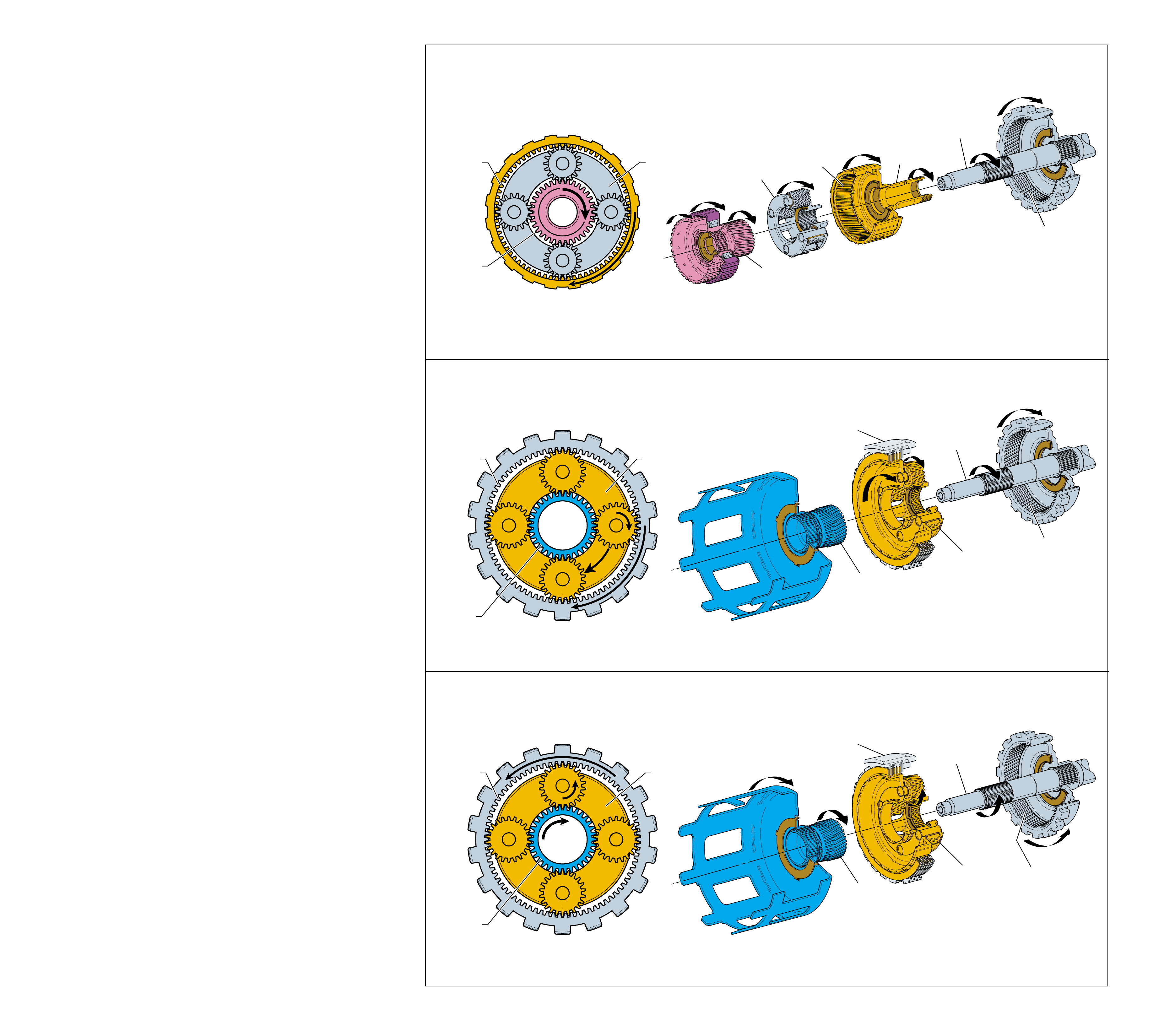
25
(664)
DRIVING
(640)
DRIVING
(662)
DRIVEN
(681)
HELD
(684)
DRIVEN
(673)
DRIVING
OUTPUT
SHAFT
(687)
REACTION
INTERNAL
GEAR
(684)
DRIVEN
INPUT
SUN
GEAR
(640)
DRIVING
INPUT
CARRIER
ASSEMBLY
(662)
DRIVEN
INPUT
INTERNAL
GEAR
(664)
DRIVING
REACTION
CARRIER
SHAFT
(666)
(681)
DRIVING
(684)
DRIVEN
(673)
HELD
REACTION
SUN
GEAR
(673)
HELD
REACTION
CARRIER
ASSEMBLY
(681)
DRIVING
OUTPUT
SHAFT
(687)
REACTION
INTERNAL
GEAR
(684)
DRIVEN
MAIN
CASE
(103)
REACTION
SUN
GEAR
(673)
DRIVING
REACTION
CARRIER
ASSEMBLY
(681)
HELD
OUTPUT
SHAFT
(687)
REACTION
INTERNAL
GEAR
(684)
DRIVEN
MAIN
CASE
(103)
PLANETARY GEAR SETS
REDUCTION - THIRD GEAR
Figure 25
REDUCTION - FOURTH GEAR
REDUCTION - REVERSE
In Second gear, both planetary gear sets, input and reaction, are
used to achieve the Second gear reduction of 1.63:1. Power flow
through the input gear set is similar to First gear to drive the
output shaft. However, in Second gear the reaction sun gear
(673) is held by applying the 2-4 band. The reaction internal gear
support (685) is splined to the output shaft and drives the reaction
carrier pinion gears clockwise. The pinion gears then walk
clockwise around the stationary reaction sun gear, thereby driving
the reaction carrier assembly (681) clockwise. The reaction carrier
drives the reaction carrier shaft and input internal gear clockwise.
The input internal gear then drives the input pinion gears in a
second reduction to achieve the Second gear ratio.
DIRECT DRIVE
Direct drive in a planetary gear set is obtained when any two
members of the gear set rotate in the same direction at the same
speed. This action forces the third member of the gear set to rotate
at the same speed. Therefore, in direct drive the output speed of
the transmission is the same as the input speed from the converter
turbine. Output speed will equal engine speed when the torque
converter clutch is applied (see Torque Converter - page 12).
Direct drive is obtained when input torque to the input planetary
gear set is transferred through both the input sun gear and the
input internal gear. The input pinion gears are wedged between
these components and forced to rotate at the same speed. The
input carrier then drives the output shaft at the same speed as
input torque to provide the direct drive 1:1 gear ratio.
OVERDRIVE
Operating the transmission in Overdrive allows the output speed
of the transmission to be greater than the input speed from the
engine. The vehicle can then maintain a given road speed with
reduced engine speed for increased fuel economy.
Overdrive is achieved through the reaction planetary gear set
and only occurs in Overdrive Range – Fourth Gear. The 2-4
band holds the reaction sun gear (673) stationary while input
torque is provided through the reaction carrier assembly (681).
As the carrier is driven clockwise, the reaction pinion gears
rotate clockwise on their pins as they walk clockwise around the
stationary sun gear. The pinion gears drive the reaction internal
gear (684) and output shaft (687) clockwise in an overdrive
ratio of .70:1.
REVERSE
In Reverse, the reaction planetary gear set is used to provide both
the gear reduction and reversal of engine torque needed. Engine
torque is provided through the reaction sun gear (673) which
drives the reaction pinion gears counterclockwise. The reaction
carrier assembly (681) is held stationary by the low roller clutch.
This allows the reaction pinion gears to drive the reaction internal
gear and output shaft counterclockwise in a reduction of 2.30:1.
24B
PLANETARY GEAR SETS
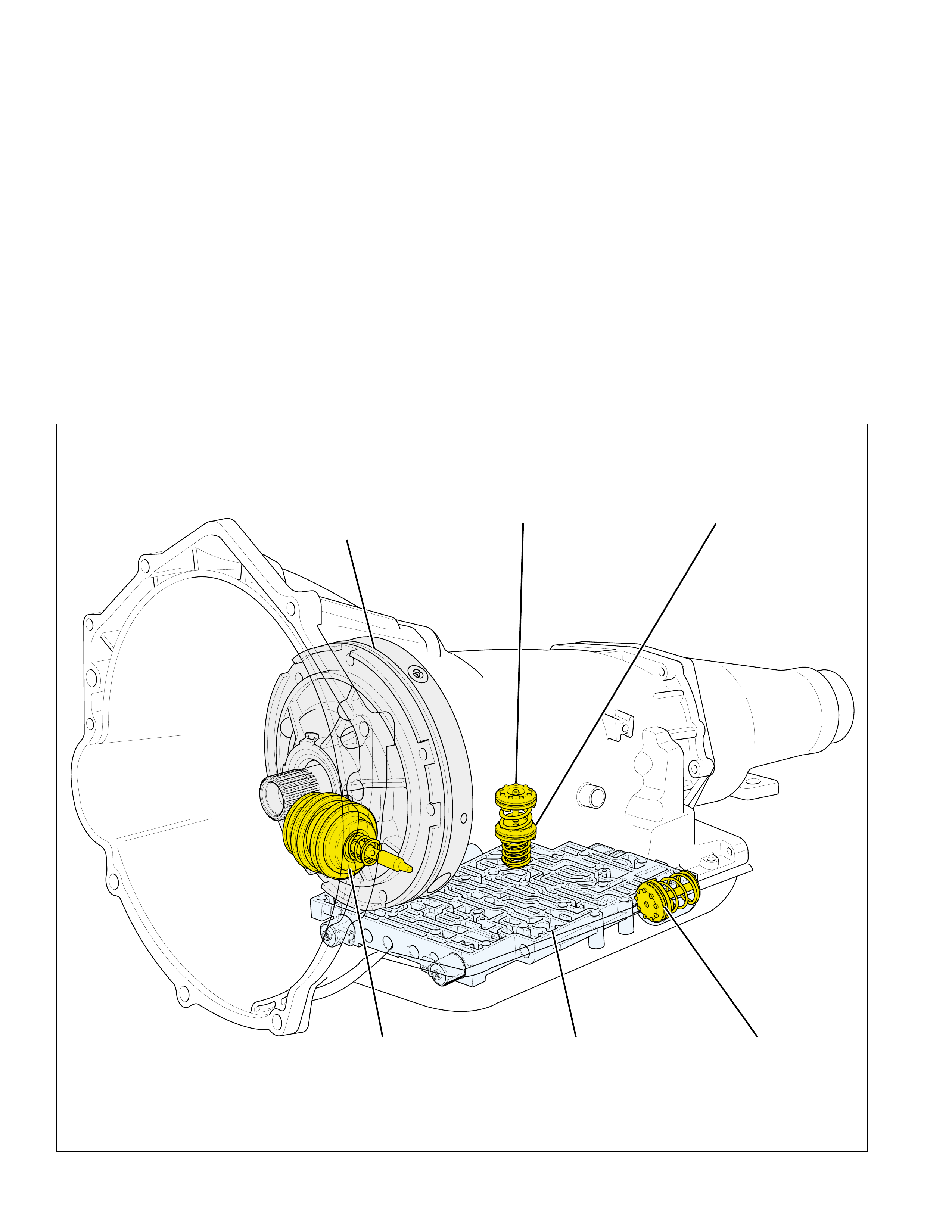
26 Figure 26
The previous sections of this book were used to
describe some of the mechanical component
operations of the Hydra-matic 4L60-E. In the
Hydraulic Control Components section a detailed
description of the individual components used in the
hydraulic system will be presented. These hydraulic
control components apply and release the clutch
packs, band and accumulators to provide automatic
shifting of the transmission.
HYDRAULIC CONTROL COMPONENTS
OIL PUMP
ASSEMBLY
(4)
3-4
ACCUMULATOR
2-4
SERVO
ASSEMBLY
CONTROL BODY
VALVE ASSEMBLY
(60)
FORWARD
CLUTCH
ACCUMULATOR
1-2
ACCUMULATOR
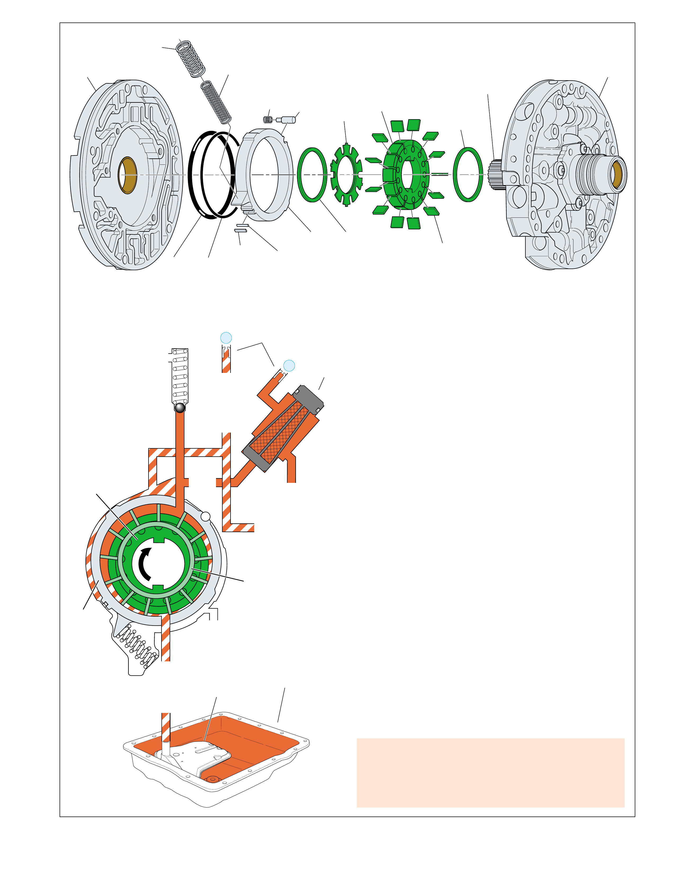
27
STATOR
SHAFT
(214)
VANE
RING
(210)
ROTOR
(212)
VANE
(213)
ROTOR
GUIDE
(211)
VANE
RING
(210)
PIVOT
PIN
(205)
PIVOT
PIN
SPRING
(204)
SLIDE
SPRING
(INNER)
(207)
SLIDE
SPRING
(OUTER)
(206)
PUMP
BODY
(200)
PUMP
COVER
(215)
SLIDE
(203)
SLIDE
SEAL
SUPPORT
(208)
SLIDE
SEAL
(209)
SEAL
RING
(201)
O-RING
SEAL
(202)
ROTOR
(212)
VANE
RING
(210)
BOTTOM
PAN
(SUMP)
(75)FILTER
(72)
DECREASE
DECREASE
FILTER
(232)
AIR
BLEED
(240)
1
LINE
LINE
EX
PRESSURE
RELIEF
VALVE
PUMP
ASSEMBLY
(4)
➤
➤➤
2
➤
➤
➤➤
➤
EX
➤
➤
➤
SUCTION
➤
➤➤➤
➤
➤
➤
SLIDE
(203)
HYDRAULIC CONTROL COMPONENTS
Figure 27
OIL PUMP ASSEMBLY
The oil pump assembly (4) contains a variable displacement
vane type pump located in the oil pump body (200). The oil
pump rotor (212) is keyed to the torque converter pump hub.
Therefore, when the engine is running, the converter pump hub
drives the rotor at engine speed. As the oil pump rotor and the
oil pump vanes (213) rotate, the area between the vanes increases
and fluid volume is positively displaced, thereby creating a
vacuum at the pump intake port. The vacuum force allows
atmospheric pressure acting on the fluid in the bottom pan to
prime the pump and pressurize the hydraulic system.
Fluid from the transmission bottom pan is drawn through the oil
filter assembly (72) and into the oil pump intake fluid circuit.
This fluid is forced into the oil pump through the intake port and
rotates around the oil pump slide (203) to the pump outlet port.
As the fluid rotates around the slide, the volume between the
pump vanes decreases before reaching the outlet port. Decreasing
the volume pressurizes the fluid and forces the fluid into the line
pressure fluid circuit. This fluid is directed to the pressure
regulator valve and becomes the main supply of fluid to the
various components and hydraulic circuits in the transmission.
When engine speed (RPM) increases, the volume of fluid being
supplied to the hydraulic system also increases because of the
faster rotation of the pump rotor and vanes. At a specified
calibrated pressure, (which varies with transmission model) the
pressure regulator valve will move far enough against spring
force to allow excess line pressure fluid to return to the suction
side of the pump vanes. The result is a control of the pump's
delivery rate of fluid to the hydraulic system.
Pump Related Diagnostic Tips
•Transmission Overheating
•Loss of drive
•High or low line pressure
•Oil out the vent tube
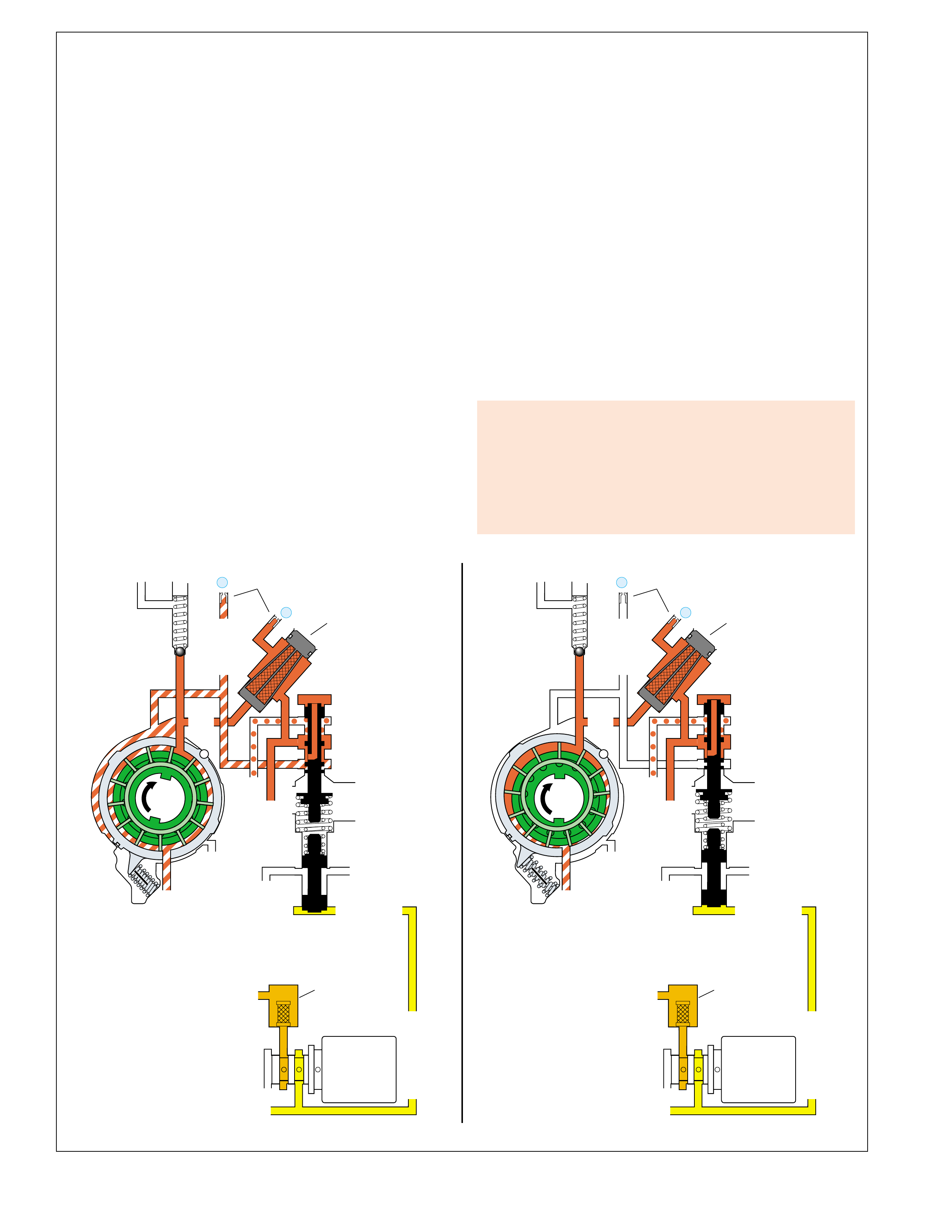
28
BOOST VALVE PRESS REG
DECREASE
LINE
EX
FILTER
(232)
1
SUCTION
LINE
EX
PRESSURE
RELIEF
VALVE
PUMP
ASSEMBLY
(4)
TORQUE SIG
2
EX
CONV FD
EX
EX
➤
EX
TORQUE SIGNAL
TORQUE SIGNAL
AFL FILTER
(50)
REVERSE INPUT
REVERSE INPUT
➤
➤
➤
➤
➤
➤➤
➤➤
➤
➤
PRESSURE
CONTROL
SOLENOID
VALVE
➤
➤
➤
➤
➤
➤
➤
➤
➤
REVERSE INPUT
BOOST VALVE PRESS REG
DECREASE
LINE
EX
FILTER
(232)
1
SUCTION
LINE
EX
PRESSURE
RELIEF
VALVE
PUMP
ASSEMBLY
(4)
TORQUE SIG
2
➤
➤
➤
➤➤
➤
EX
CONV FD
EX
EX
➤
EX
TORQUE SIGNAL
TORQUE SIGNAL
AFL FILTER
(50)
REVERSE INPUT
➤
➤
➤
➤
➤
➤➤
➤➤
➤
➤
PRESSURE
CONTROL
SOLENOID
VALVE
➤
➤
➤
➤
➤
➤
➤
➤
➤
MAXIMUM PUMP OUTPUTMINIMUM PUMP OUTPUT
AIR
BLEED
(240)
➤
➤
AIR
BLEED
(240)
➤
➤
PRESSURE REGULATION
moves the valve against spring force and torque signal fluid
pressure to a point where line pressure enters both the converter
feed and decrease fluid circuits. Decrease fluid pressure moves
the pump slide (203) against spring force and toward the center
of the pump body, causing the slide to partially cover the pump
intake port. This increases the concentricity between the pump
slide and rotor which decreases the vacuum affect on the fluid,
thereby decreasing line pressure.
Maximum Pressure Regulation
When engine torque is a maximum, the PCS regulates torque
signal fluid pressure to a maximum. Maximum torque signal
fluid pressure moves the boost valve against the isolator spring
to increase the force on the pressure regulator valve. This
moves the pressure regulator valve to block line pressure from
entering the decrease fluid circuit. With lower decrease fluid
pressure, pump slide spring force moves the slide against the
side of the pump body. This decreases the concentricity between
the slide and rotor which increases the vacuum affect on the
fluid. In this position line pressure is a maximum. The output
of the oil pump continuously varies between these minimum
and maximum points depending on vehicle operating conditions.
The main components that control line pressure are the pressure
control solenoid and pressure regulator valve. The fluid pressure
required to apply the clutches and band varies in relation to
throttle position and engine torque. At the pressure regulator
valve, line pressure is regulated in response to the following:
- torque signal fluid pressure routed from the pressure con-
trol solenoid (PCS) (this fluid pressure is proportional to
engine torque - see page 42). Torque signal fluid pressure
moves the boost valve (219) against the pressure regulator
isolator spring (218) which acts against the pressure regula-
tor valve.
- pressure regulator spring force.
- line pressure acting on the end of the pressure regulator
valve.
- reverse input fluid pressure acting on the boost valve in
Reverse.
The pressure regulator valve routes line pressure into both the
converter feed and decrease fluid circuits. Converter feed fluid
is routed to both the torque converter and cooler fluid circuits.
Decrease fluid pressure moves the oil pump slide against the
force of the pump slide springs (outer - 206, inner - 207).
Decrease fluid pressure and the position of the pump slide
constantly vary in relation to torque signal fluid pressure and
engine torque as controlled by the pressure regulator valve.
Minimum Pressure Regulation
When engine torque is a minimum, the PCS regulates torque
signal fluid pressure to a minimum. During these conditions,
line pressure acting on the end of the pressure regulator valve
Pressure Regulator Related
Diagnostic Tips
A stuck or damaged pressure regulator valve could cause:
•High or low line pressure
•Slipping clutches or bands or harsh apply
•Transmission overheating
•Low or no cooler/lube flow
HYDRAULIC CONTROL COMPONENTS
Figure 28
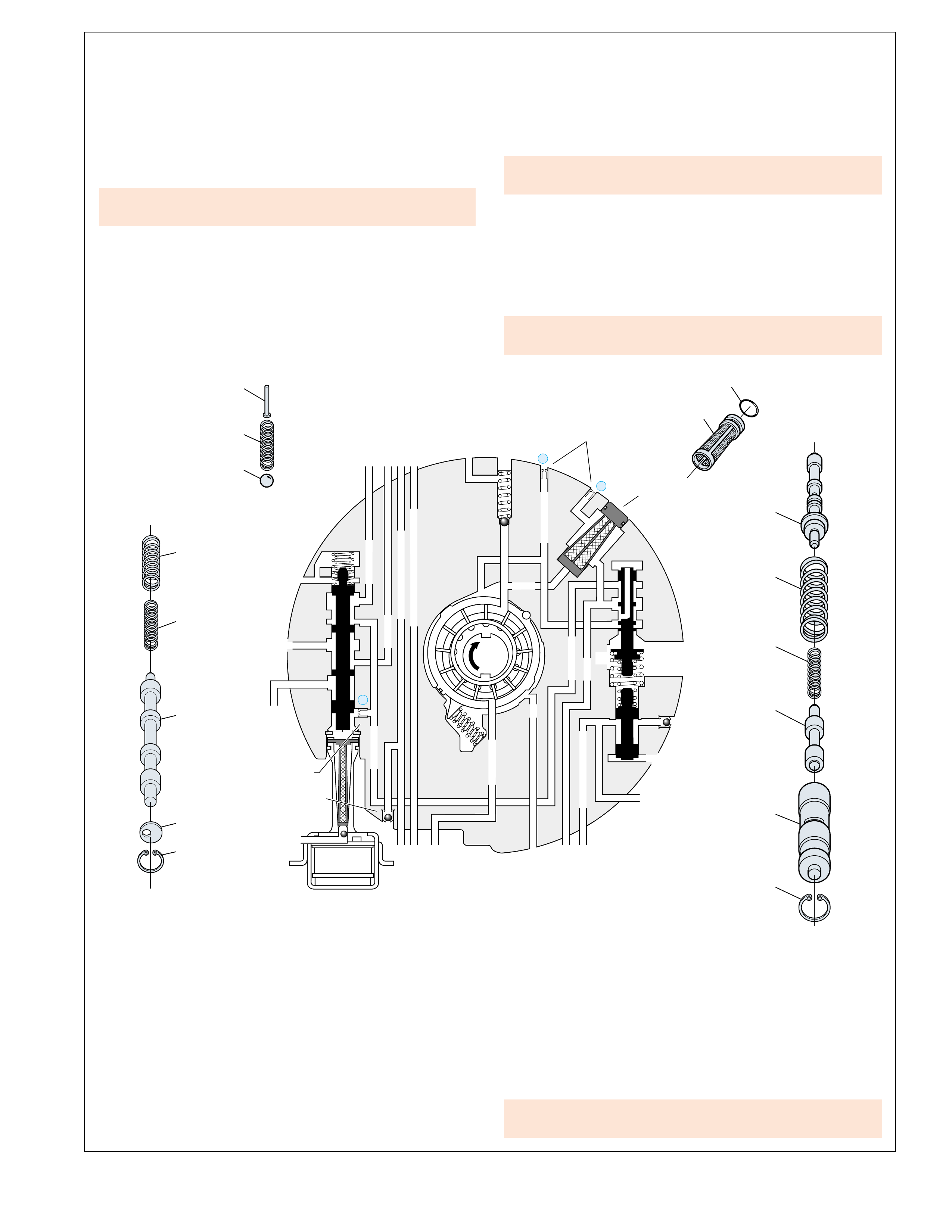
29
HYDRAULIC CONTROL COMPONENTS
Figure 29
Pressure Relief Ball (228)
The pressure relief ball and spring (229) prevent line pressure
from exceeding approximately 2240 to 2520 kPa (320 to 360
psi). Above this pressure, line fluid pressure moves the ball
against spring force and exhausts until line pressure decreases
sufficiently.
Torque Converter Clutch Solenoid
The Powertrain Control Module (PCM) controls the TCC
solenoid to apply and release the converter clutch. The TCC
solenoid is a normally open, ON/OFF solenoid that, when
energized (ON), initiates the converter clutch apply. Refer to
the Electronic Component Section for a complete description of
the TCC solenoid.
226
225
224
223
222
216
217
218
219
220
221
232
231
228
229
227
BOOST VALVE PRESS REG
REV INPUT
DECREASE
LINE
LINE
EX
FILTER
(232)
AIR
BLEED
(240)
1
SUCTION
SUCTION
LINE
EX
PRESSURE
RELIEF
VALVE
PUMP
ASSEMBLY
(4)
4
TCC
SOLENOID
(66)
N.O.
TORQUE SIG
FORWARD CLUTCH FEEDFORWARD CLUTCH FEED FORWARD CLUTCH FEED
2
➤
➤
➤
➤➤
➤
EX
CONV FD
EX
EX
EX
➤
➤
➤
OVERRUN CLUTCHOVERRUN CLUTCH OVERRUN CLUTCH
EX
(237)
REVERSE INPUT
REVERSE INPUT
EX
➤➤
CONVERTER CLUTCH VALVE
COOLER
RELEASE RELEASE
APPLY APPLY
EX
➤
➤
EX
➤
➤
CONV FD
➤
➤
➤
➤
➤
➤
➤
REGULATED APPLY
(237)
➤
(238)
➤
➤
➤
➤
➤
➤
➤
➤
➤
VALVES LOCATED IN THE OIL PUMP ASSEMBLY
Pressure Regulator Valve (216)
Regulates line pressure in relation to vehicle operating conditions
(see page 28 on Pressure Regulation). The pressure regulator
valve is biased by torque signal fluid pressure, pressure regulator
spring (217) force, line pressure routed to the end of the valve,
and reverse input fluid pressure acting on the boost valve in
Reverse. Line pressure is routed through the valve and into
both the converter feed and decrease fluid circuits.
Boost Valve (219)
Torque signal fluid pressure moves the boost valve against the
isolator spring (218). The isolator spring then exerts the force
from torque signal fluid pressure to the pressure regulator valve.
Therefore, line pressure increases as throttle position and engine
torque increase. Also, reverse input fluid pressure acting on the
boost valve increases the operating range of line pressure when
the transmission is in Reverse.
•A stuck pressure regulator valve could cause high or low oil
pressure.
•No TCC apply could be caused by internal damage to the
TCC solenoid.
•A pressure relief ball not seated or damaged could cause high
or low oil pressure.
Torque Converter Clutch Apply Valve (224)
Controlled by the TCC solenoid state and converter clutch signal
fluid pressure, it directs converter feed fluid pressure to either
the release or apply side of the converter clutch. The TCC
apply valve also directs fluid into the cooler fluid circuit. The
valve is held in the release position (as shown) by spring force
when the TCC solenoid is OFF. With the TCC solenoid ON,
converter clutch signal fluid pressure increases and moves the
valve into the apply position against spring force.
Retainer and Checkball Assemblies (237)
These two assemblies are located in the reverse input and overrun
clutch fluid circuits. Their function is to allow air to escape
from the fluid circuit when fluid pressure increases during clutch
apply. Also, when the clutch releases the ball unseats and
allows air into the circuit to displace the exhausting fluid.
Orifice Cup Plugs (238-240)
Various orifice cup plugs are located in the oil pump cover
(215) to provide fluid flow control in the transmission’s
hydraulic system.
•Torque converter clutch shudder could be caused by a
restricted or damaged orifice cup plug.

30
HYDRAULIC CONTROL COMPONENTS
VALVES LOCATED IN THE CONTROL VALVE BODY
3-4 Shift Valve (385)
Biased by 1-2 signal fluid pressure from the 1-2 shift solenoid,
spring force and D3 fluid pressure, the 3-4 shift valve controls
the routing of 3-4 signal fluid. To obtain Fourth gear, 1-2 signal
fluid pressure moves the valve against spring force and directs
3-4 signal fluid into the 4th signal fluid circuit. However, in
Manual Third, D3 fluid assists spring force and holds the valve
against 1-2 signal fluid pressure to prevent Fourth gear under
any conditions. In the downshifted position, the 4th signal fluid
circuit is open to an exhaust past the valve.
3-2 Downshift Valve (389)
The 3-2 downshift valve helps control the 2-4 band apply rate
during a 3-2 downshift. During the downshift, 3-4 clutch fluid
pressure holds the valve against spring force before exhausting.
This allows 2nd fluid to quickly fill the 2nd clutch fluid circuit
for a faster 2-4 band apply.
Reverse Abuse Valve (387)
The reverse abuse valve provides a faster apply of the reverse
input clutch when throttle position is greater than idle. During
these conditions, reverse fluid pressure increases and moves the
valve against spring force. Reverse fluid can then quickly fill
the reverse input fluid circuit. This bypasses the control of the
reverse input orifice (#17) for a faster clutch apply.
3-2 Control Solenoid Valve (394)
The 3-2 control solenoid valve is a normally closed ON/OFF
solenoid controlled by the PCM. The solenoid is used to route
actuator feed limit (AFL) fluid into the 3-2 signal fluid circuit to
control the position of the 3-2 control valve. The PCM controls
the solenoid state during a 3-2 downshift according to vehicle
speed.
3-2 Control Valve (391)
The 3-2 control valve regulates the exhaust of 3rd accumulator
fluid into the 3-4 clutch fluid circuit during a 3-2 downshift. This
regulation is controlled by 3-2 signal fluid pressure from the 3-2
control solenoid valve. At high vehicle speed, 3-2 signal fluid
pressure moves the valve against spring force to block exhausting
3rd accumulator fluid from entering the 3-4 clutch fluid circuit. At
low vehicle speed, 3-2 signal fluid pressure is OFF and the valve is
held in the open position by spring force to allow exhausting 3rd
accumulator fluid to enter the 3-4 clutch fluid circuit.
Manual Valve (340)
The manual valve is supplied with line pressure from the pressure
regulator valve and is mechanically linked to the gear selector
lever. When a gear range is selected, the manual valve directs
line pressure into various circuits by opening and closing fluid
passages. The fluid circuits fed by the manual valve include
Reverse, PR, D4, D3, D2 and lo.
Pressure Control Solenoid Valve (377)
Controlled by the PCM through a duty cycle operation, the
pressure control (PC) solenoid valve regulates AFL fluid pressure
into the torque signal fluid circuit. Torque signal fluid pressure
is regulated in response to engine torque and other vehicle
operating conditions. Torque signal fluid pressure is routed to
the boost valve to increase line pressure and to the accumulator
valve to help control shift feel.
Actuator Feed Limit Valve (374)
The AFL valve directs line pressure into the AFL fluid circuit.
Spring force acting on the valve limits AFL fluid pressure to a
maximum of approximately 795 kPa (115 psi). When line
pressure is above this value, orificed AFL fluid pressure moves
the valve against spring force to block line pressure, thereby
providing the limiting action. AFL fluid is routed to the shift
solenoids, the pressure control solenoid, the TCC PWM solenoid,
the 3-2 control solenoid and the 2-3 shift valve train.
Torque Converter Clutch Pulse Width Modulated (TCC PWM)
Solenoid Valve (396)
The TCC PWM solenoid valve is a normally closed, pulse
width modulated (PWM) solenoid controlled by the PCM in
relation to vehicle operating conditions. The TCC PWM
solenoid valve regulates actuator feed limit fluid into the CC
signal fluid circuit and is used to control the flow of line pressure
through the regulated apply valve and provides a smooth
engagement of the TCC.
Regulated Apply Valve (380) and Isolator Valve (398)
The regulated apply valve and isolator valve are used to control
the flow of line pressure into the regulated apply fluid circuit.
Regulated apply fluid pressure is controlled by the action of CC
signal fluid pressure on the isolator valve and orificed regulated
apply fluid pressure on the regulated apply valve.
3-4 Relay Valve (384) and 4-3 Sequence Valve (383)
These valves are used mainly to control the 4-3 downshift
timing. The valves direct various fluids into different fluid
circuits depending on the gear range. Spring force acting on
the 4-3 sequence valve tends to keep the valves in the
downshifted position. In Fourth gear, 4th signal fluid pressure
moves both valves against spring force and into the upshifted
position (see Overdrive Range – 4-3 Downshift on page 64).
Accumulator Valve (371)
The accumulator valve is biased by torque signal fluid pressure,
spring force and orificed accumulator fluid pressure at the end
of the valve. The valve regulates D4 fluid into accumulator
fluid pressure in relation to engine torque, as determined by
torque signal fluid pressure. Accumulator fluid pressure is
used to control shift feel during the 1-2 and 3-4 shifts. During
the 1-2 and 3-4 upshifts, the valve regulates the exhaust of
accumulator fluid to help control shift feel.
2-3 Shift Solenoid Valve (367)
Located at the end of the 2-3 shuttle valve, the 2-3 shift solenoid
valve is a normally open, ON/OFF type solenoid controlled by
the PCM. The solenoid is used to control 2-3 signal fluid
pressure at the end of the 2-3 shuttle valve and the positioning
of 2-3 shift valve train. When de-energized, the solenoid is
open and 2-3 signal fluid exhausts through the solenoid. When
energized, the solenoid is closed and blocks 2-3 signal fluid
from exhausting, thereby creating 2-3 signal fluid pressure at
the end of the 2-3 shuttle valve.
2-3 Shift Valve (368) and 2-3 Shuttle Valve (369)
The 2-3 shift valve train responds to AFL fluid pressure acting
on the 2-3 shift valve and 2-3 signal fluid pressure from the 2-3
shift solenoid valve at the 2-3 shuttle valve. Also, in Manual
Second and Manual First gear ranges, D2 fluid pressure is
routed between the two valves. D2 fluid pressure keeps the 2-3
shift valve in the downshifted position to prevent the
transmission from upshifting above Second gear regardless of
shift solenoid states. The valve train controls the routing and
•Stuck ON, exhaust plugged, would cause no TCC release in
2nd, 3rd or 4th gear.
•Stuck OFF, leaking o-ring, no voltage, would cause no TCC/
slip or soft apply.
•A regulated apply valve stuck or assembled incorrectly could
cause no TCC apply.
•A stuck 4-3 sequence valve could cause no overrun braking -
manual 3-2-1.
•A stuck accumulator valve could cause no 3-4 shift, slips or
rough 3-4 shift.
•A stuck 3-2 control valve could cause no 3-4 shift, slips or
rough 3-4 shift.
•High or low oil pressure could be caused by a scored or
damaged manual valve.
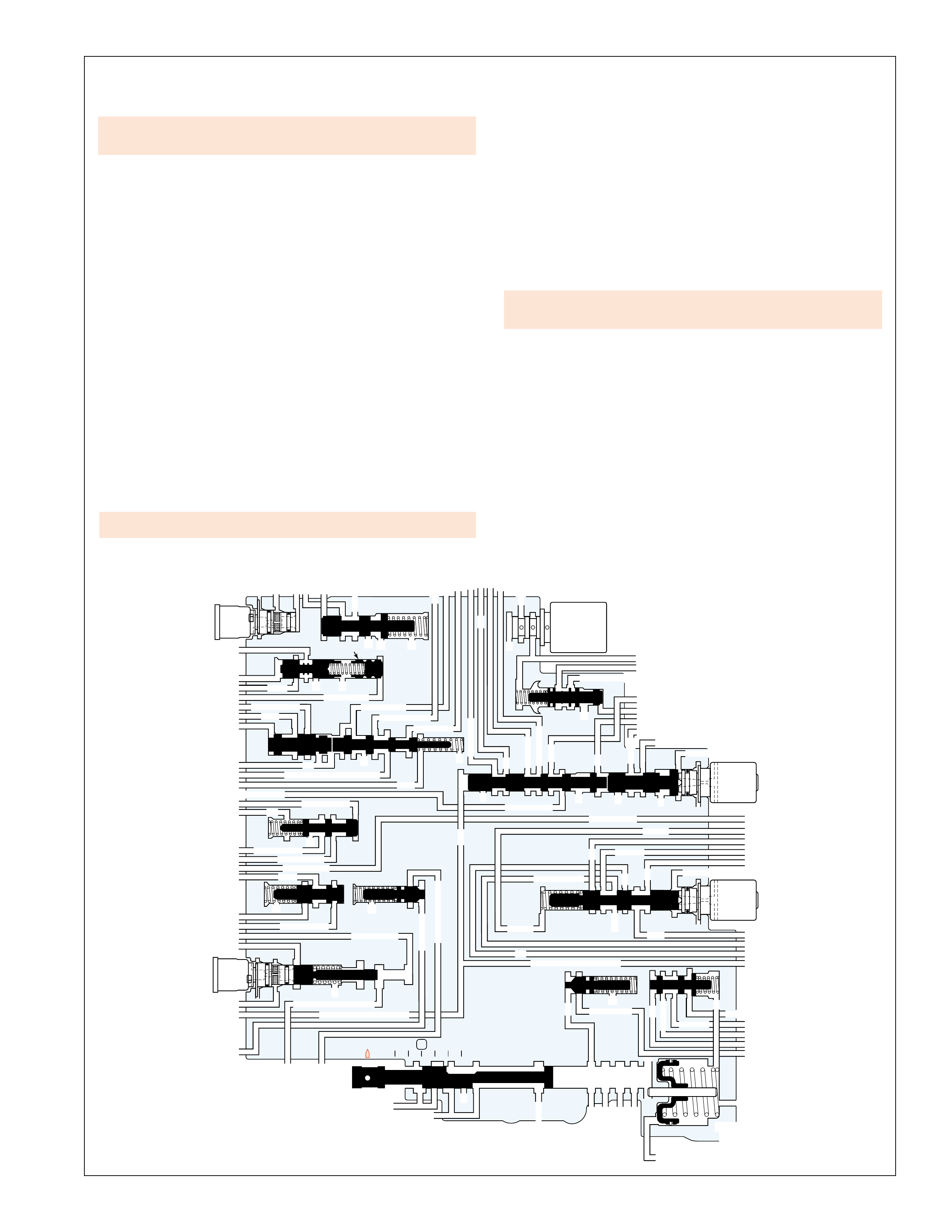
31
HYDRAULIC CONTROL COMPONENTS
VALVES LOCATED IN THE CONTROL VALVE BODY
EX
FORWARD ABUSE
FWD CL FD
FWD CL FD
REV ABUSE
EX
REVERSE
REVERSE INPUT
FORWARD
CLUTCH
ACCUMULATOR
EX
3-4 CLUTCH3-4 CLUTCH
3RD ACCUMULATOR
3RD ACCUM
EX
AFL
3-2 SIGNAL
LINELINE
1-2 SHIFT VALVE
LO
LO
D4
D4
O’ EX
D4-3-2 2ND 2ND
1-2 SIGNAL
LO/1ST LO/1ST
1-2 SIGNAL 1-2 SIGNAL
EX
ORIFICED EX
ORIFICED EX
D3D3
EX
3-4 SIGNAL3-4 SIGNAL
1-2 SIGNAL1-2 SIGNAL
4TH SIGNAL4TH SIGNAL
3-4 SHIFT VALVE
EX
EX
EX AFL
AFL
AFL
D4
EX
ACCUMULATOR
EX
LO OVERRUN
PR
PR
LO/REV
LO/REV
LO/1ST LO/1ST
LO/REVERSE
EX
OVERRUN CLUTCH FEEDOVERRUN CLUTCH FEED
3-4 ACCUM
3-4 ACCUM
SERVO FEEDSERVO FEED
4TH4TH
OVERRUN CL
OVERRUN CL
4TH SIGNAL 2ND2ND
EX
EX
3-4 RELAY 4-3 SEQUENCE VALVE
EXEX
SERVO FD
REVERSE
REVERSE INPUT
2-3 SHUTTLE 2-3 SHIFT VALVE
EX
EX
EX
EX
D2
D2
OVERRUN OVERRUN
D3
D3 D3
2ND
2ND
3-4 SIGNAL
EX
D4-3-2
D4-3-2
2-3 SIGNAL
AFL
SERVO FD
SERVO FD
SERVO FD
3-4 ACC
3-4 ACC
ACTUATOR FEED LIMIT ACTUATOR FEED LIMIT
ACTUATOR FEED LIMITACTUATOR FEED LIMIT
3-4 SIGNAL
EX EX
D4-3-2 D4-3-2
3-2 CONTROL
EX
EX
CC SIGNALCC SIGNAL
ACTUATOR FEED LIMIT
TCC PWM
SOLENOID
VALVE
N.C.
1-2 SIGNAL1-2 SIGNAL
3-2
CONTROL
SOLENOID
VALVE
N.C.
3-2 DOWNSHIFT
EX
2ND CLUTCH 3-4 CLUTCH3-4 CLUTCH
2ND2ND
PRESSURE
CONTROL
SOLENOID
VALVE
2-3 SHIFT
SOLENOID
VALVE
N.O.
EX
1-2 SHIFT
SOLENOID
VALVE
N.O.
ACCUM VALVE
PRND321
D4
D4
REVERSE
D3
D2
LO EX
EX
LINE
MANUAL VALVE
PR
REGULATED APPLY
REG APPLY
CC SIGNAL
LINE
FILTERED AFL
FWD CL FEED
TORQUE SIGNAL
ACTUATOR FEED LIMIT
ISOLATOR VALVE
REG APPLY
Figure 30
exhausting of various fluids to obtain the appropriate gear range
as determined by the PCM or gear selector lever.
1-2 Shift Solenoid Valve (367)
Located at the end of the 1-2 shift valve, the 1-2 shift solenoid
valve is a normally open, ON/OFF type solenoid controlled by
the PCM. The solenoid is used to control 1-2 signal fluid
pressure and the positioning of both the 1-2 shift valve and the
3-4 shift valve. When de-energized (OFF), the solenoid is open
and 1-2 signal fluid exhausts through the solenoid. When
energized (ON), the solenoid is closed and blocks 1-2 signal
fluid from exhausting, thereby creating 1-2 signal fluid pressure
at the 1-2 and 3-4 shift valves.
1-2 Shift Valve (366)
The 1-2 shift valve is biased by 1-2 signal fluid pressure, spring
force and D432 fluid pressure. The valve position depends on
the shift solenoid states. The 1-2 shift solenoid valve controls
1-2 signal fluid pressure and the 2-3 shift solenoid valve controls
the 2-3 shuttle valve position and D432 fluid pressure. The 1-2
shift valve directs D4 fluid into the 2nd fluid circuit to upshift
the transmission to Second gear. The valve also routes lo fluid
into the lo/1st fluid circuit in Manual First – First Gear. The
exhaust past the valve is an annulus exhaust in which exhausting
fluid, either 2nd fluid or lo/1st fluid, flows around the valve land
and through the valve body.
Forward Abuse Valve (357)
The forward abuse valve provides a faster apply of the forward
clutch when throttle position is greater than idle. During these
conditions, D4 fluid pressure increases and moves the valve
against spring force. D4 fluid can then quickly fill the forward
clutch feed fluid circuit. This bypasses the control of the forward
clutch accumulator orifice (#22) for a faster clutch apply.
Lo Overrun Valve (361)
In Reverse, PR fluid moves the valve against spring force and
fills the lo/reverse fluid circuit. In Manual First, the lo overrun
valve regulates lo/1st fluid pressure into the lo/reverse fluid
circuit. This regulation is biased by spring force and orificed lo/
reverse fluid pressure acting on the valve.
Forward Clutch Accumulator
Forward clutch accumulator spring force absorbs the initial
increase in forward clutch feed fluid pressure to cushion the
forward clutch apply. Refer to page 32 for a complete description
of accumulator function.
Note: Refer to the ‘Power Flow’ and ‘Complete Hydraulic
Circuit’ sections for a detailed explanation of each components
operation in a specific gear range. Also, refer to the ‘Electronic
Components’ section for a detailed description of each electronic
component.
•A stuck 2-3 shift valve could cause no reverse or slips in
reverse.
•A sticking 1-2 shift valve could cause no upshift in 1st gear.
•A stuck lo overrun valve could cause no reverse or slips in
reverse.
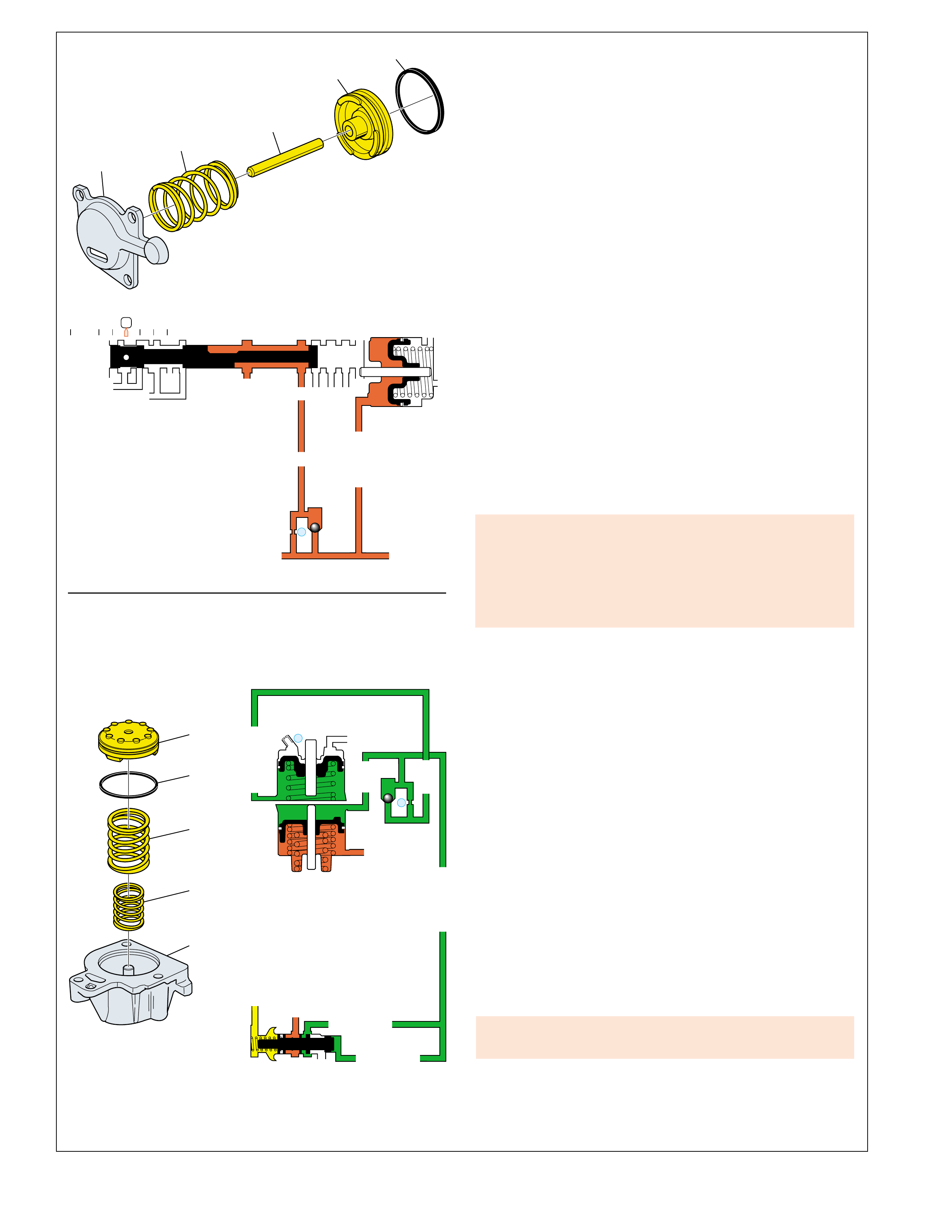
32
54
55
57
104
56
#12
D4
22
FORWARD
CLUTCH
ACCUMULATOR
EX
FWD CL FEED
FWD CL FEED
EX
PRND321
D4
REVERSE
D3
D2
LO
EX
EX
LINE
➤
➤
MANUAL VALVE
PR
➤➤
➤
➤
➤➤
➤
➤
➤➤
#1
ORF ACC
2ND CLUTCH
3-4 ACCUMULATOR
1-2 ACCUMULATOR
19
3-4 ACCUM
ACCUM
EX
ORIFICED ACCUM
D4
EX
ACCUMULATOR
ACCUMULATOR
ACCUMULATOR
TORQUE SIGNAL
18
➤
➤
➤
➤
➤
➤
➤
➤
➤
➤➤
➤
➤
➤
➤
➤➤
➤
➤
➤
➤➤
➤
➤
➤➤
ACCUM VALVE
EXAMPLE: 1-2 UPSHIFT
EXAMPLE: FORWARD CLUTCH ACCUMULATION
353
354
355
356
363
HYDRAULIC CONTROL COMPONENTS
Figure 31
ACCUMULATORS
An accumulator is a spring loaded device that absorbs a certain
amount of apply fluid pressure to cushion the apply of a clutch
or band. Apply fluid pressure directed to an accumulator piston
opposes a spring force, and an accumulator fluid pressure (except
in the forward clutch accumulator), to act like a shock absorber.
In the Hydra-matic 4L60-E transmission, accumulators are used
to control shift feel during the apply of the forward clutch, 2-4
band (in both Second and Fourth gears) and 3-4 clutch. During
the apply of a clutch or band, apply fluid pressure builds up
rapidly when the friction element begins to hold. As the fluid
pressure increases, it also moves the accumulator piston against
spring force and accumulator fluid pressure. Without an
accumulator in the apply fluid circuit, the rapid buildup of fluid
pressure would cause the clutch or band to apply very quickly and
possibly create a harsh shift. However, accumulator spring force
and accumulator fluid pressure absorb some of the initial apply
fluid pressure to allow a more gradual apply of the clutch or band.
FORWARD CLUTCH ACCUMULATOR
The forward clutch accumulator is located in the valve body
(350) and helps control the garage shift feel into a forward drive
range from Park, Reverse or Neutral. Forward clutch feed fluid
pressure that applies the forward clutch is also routed to the
forward clutch accumulator piston (354). Forward clutch feed
fluid pressure moves the accumulator piston against spring force
(356) as the clutch begins to apply. This action absorbs some of
the initial increase of clutch apply fluid pressure to cushion the
forward clutch apply.
1-2 and 3-4 ACCUMULATOR ASSEMBLIES
Accumulator Valve Function
The 1-2 and 3-4 accumulator assemblies help cushion the 2-4
band apply rate. These assemblies use an accumulator fluid
pressure to assist spring force. Accumulator fluid pressure is
regulated by the accumulator valve (371) in relation to torque
signal fluid pressure. The pressure control (PC) solenoid is
controlled by the PCM and regulates torque signal fluid pressure
in relation to engine torque, throttle position and other vehicle
operating conditions.
When engine torque is a maximum, a greater apply pressure is
required to prevent the band from slipping during apply and
hold the band against the reverse input housing. When engine
torque is a minimum, the band requires less apply force and a
slower apply rate. The regulating action of the accumulator
valve compensates for these various operating conditions by
increasing accumulator fluid pressure as engine torque and torque
signal fluid pressure increase.
1-2 ACCUMULATOR ASSEMBLY
The 1-2 accumulator assembly is used to control the apply feel
of the 2-4 band in Second gear. The assembly is located between
the spacer plate (48) and 1-2 accumulator cover (57) and consists
of a piston (56), spring (54) and apply pin.
Upshift Control
During a 1-2 upshift (as shown in Example), 2nd clutch fluid is
routed to both the servo assembly and the 1-2 accumulator
assembly. The rapid buildup of fluid pressure in the 2nd clutch
fluid circuit strokes the accumulator piston against spring force
Slips in 1st gear could be caused by:
•A missing, cut or damaged forward clutch accumulator
piston seal.
•A piston out of its bore.
•Porosity in the piston or valve body.
•A stuck abuse valve.
A stuck 1-2 accumulator piston could cause slipping or a rough
1-2 shift.
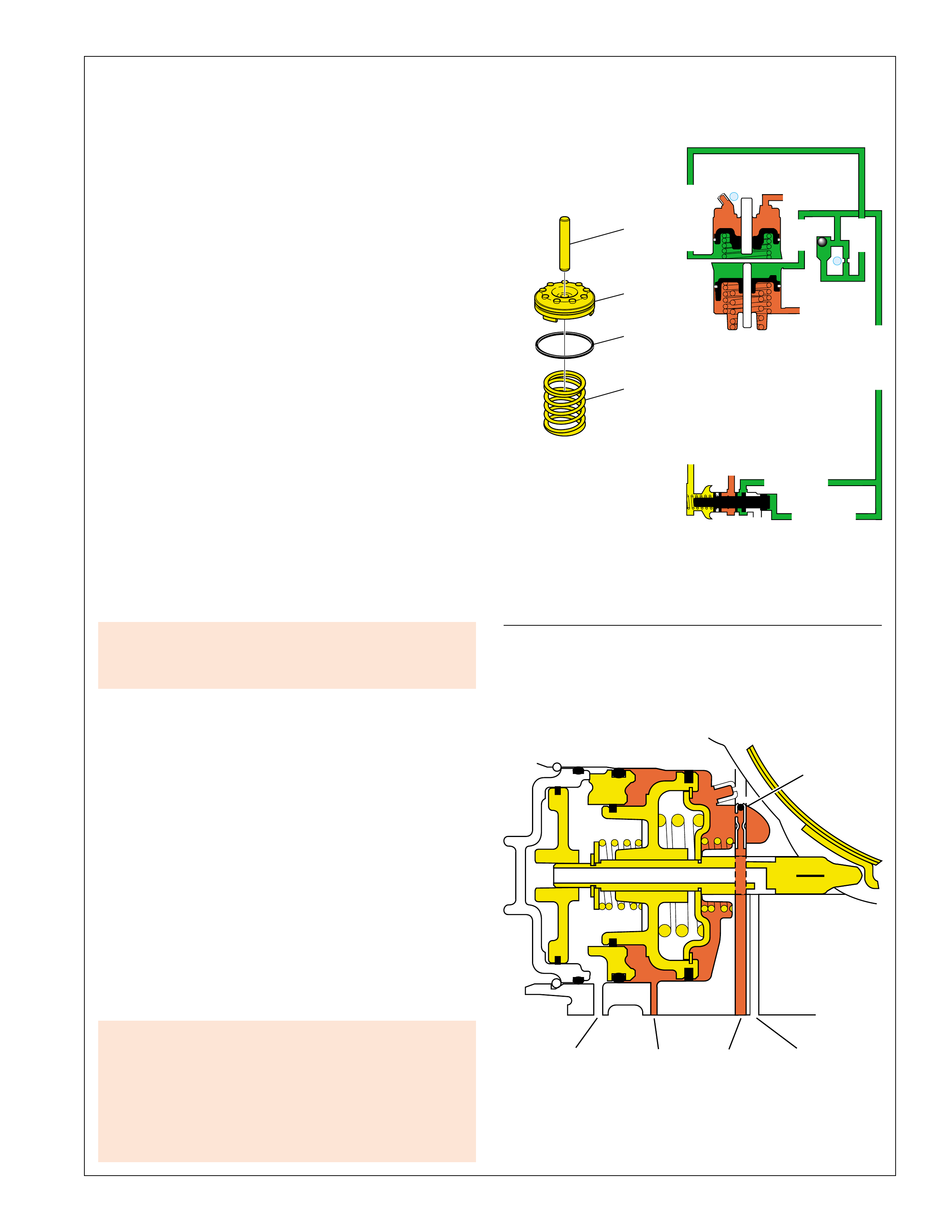
33
HYDRAULIC CONTROL COMPONENTS
Figure 32
➤
4TH
CLUTCH
3RD
ACCUM
2ND
CLUTCH
EXHAUST
➤
➤
➤
➤
➤➤➤
➤
#7
CHECKBALL
➤
➤
2-4 SERVO ASSEMBLY
EXAMPLE: 3-4 UPSHIFT
43
44
45
46
#1
ORF ACC
2ND CLUTCH
3-4 ACCUMULATOR
1-2 ACCUMULATOR
19
3-4 ACCUM
ACCUM
EX
ORIFICED ACCUM
D4
EX
ACCUMULATOR
ACCUMULATOR
ACCUMULATOR
TORQUE SIGNAL
18
➤
➤
➤
➤
➤
➤
➤
➤
➤
➤
➤
➤
➤➤
➤
➤
➤
➤
➤
➤
➤
➤➤
ACCUM VALVE
➤
➤
➤
•A 2nd servo apply piston seal missing, cut or damaged
could cause a slipping or rough 1-2 shift.
•A 4th servo piston installed backwards could cause slips
in 1st gear.
•No 3-4 shift, slips or rough 3-4 shift could be caused by
damaged piston seal grooves.
•A 2-4 servo assembly apply pin that is too short or too
long could cause no 2-3 shift or 2-3 shift slips, rough
or hunting.
No 3-4 shift, slips or rough 3-4 shift could be caused by:
•Porosity in 3-4 accumulator piston or bore.
•3-4 accumulator piston seal or seal grooves damaged.
and accumulator fluid pressure. This action absorbs some of the
initial buildup of 2nd clutch fluid pressure and provides a time
delay to cushion the 2-4 band apply.
As 2nd clutch fluid pressure moves the accumulator piston,
some accumulator fluid is forced out of the 1-2 accumulator
assembly. This fluid pressure is routed back to the accumulator
valve. The increase in accumulator fluid pressure acting on the
end of the accumulator valve moves the valve against spring
force and torque signal fluid pressure. This blocks D4 fluid and
regulates the exhaust of the excess accumulator fluid pressure
past the accumulator valve and through an exhaust port. This
regulation provides additional control for the accumulation of
2nd clutch fluid and apply of the 2-4 band.
Downshift Control
2nd clutch fluid pressure exhausts from the 1-2 accumulator
assembly during a 2-1 downshift. As spring force and
accumulator fluid pressure move the 1-2 accumulator piston
against exhausting 2nd clutch fluid, the accumulator valve
regulates more D4 fluid into the accumulator fluid circuit. This
regulation controls the rate at which accumulator fluid fills the
1-2 accumulator and the rate at which 2nd clutch fluid exhausts
from the accumulator.
3-4 ACCUMULATOR ASSEMBLY
The 3-4 accumulator assembly is located in the transmission
case and consists of a piston (44), piston spring (46) and piston
pin (43). The 3-4 accumulator assembly is the primary device
for controlling the apply feel of the 2-4 band in Fourth gear.
The 3-4 accumulator assembly functions similar to the 1-2
accumulator assembly. During a 3-4 upshift the 3-4 accumulator
absorbs the initial increase of 3-4 accumulator fluid pressure to
control the 2-4 band apply.
3-4 Accumulator Checkball (#1)
During a 4-3 downshift, accumulator fluid seats the #1 checkball
and is orificed into the orificed accumulator fluid circuit. This
orifice (#18) controls the increase of orificed accumulator fluid
pressure and the movement of the 3-4 accumulator piston against
exhausting 3-4 accumulator fluid.
2-3 UPSHIFT ACCUMULATION
During a 2-3 upshift, the 2-4 band releases as the 3-4 clutch
applies. To accomplish this, 3-4 clutch fluid that applies the 3-4
clutch is also routed into the 3rd accumulator fluid circuit. 3rd
accumulator fluid pressure is used to release the band while 3-4
clutch fluid pressure is used to apply the 3-4 clutch. 3rd
accumulator fluid pressure is routed to the 2-4 servo and moves
the 2nd apply piston against spring force and 2nd clutch fluid
pressure to release the band. This action functions as an
accumulator for the 3-4 clutch by absorbing some of the initial
increase in 3-4 clutch fluid pressure.

34
HYDRAULIC CONTROL COMPONENTS
BALL CHECK VALVE LOCATION AND FUNCTION
#1 3-4 ACCUMULATOR
Located in the transmission case, the 3-4 accumulator ball check
valve helps control the flow of accumulator fluid to the 3-4
accumulator. When the ball is seated, accumulator fluid is
forced through the #18 orifice. This action helps control the 2-4
band release during a 4-3 downshift.
#2 3RD ACCUMULATOR
Located in the valve body, the 3rd accumulator ball check valve
directs exhausting 3rd accumulator fluid through orifice #12
and to the 3-2 control valve. This helps control the 2-4 band
apply during a 3-2 downshift. During a 3-4 upshift, 3-4 clutch
fluid unseats the ball for a quick feed into the 3rd accumulator
fluid circuit.
Note: Some models do not include orifice #12 in the spacer
plate. For these models, all exhausting 3rd accumulator fluid is
routed to the 3-2 control valve.
#3 REVERSE INPUT
Located in the valve body, the reverse input ball check valve
controls the reverse input clutch apply when engine speed is at
idle. During these conditions, all reverse fluid feeding the reverse
input fluid circuit is routed to the ball, seats the ball, and is
forced through orifice #17. This slows the flow of reverse fluid
to cushion the reverse input clutch apply. When the reverse
input clutch releases, exhausting reverse input fluid unseats the
ball for a quick exhaust of fluid.
#4 3-4 CLUTCH EXHAUST
Located in the valve body, this ball check valve helps control
the 3-2 downshift. Exhausting 3-4 clutch and 3rd accumulator
fluids seat the ball and are forced through orifice #13. This
helps control the 3-4 clutch release rate and 2-4 band apply.
During a 3-4 upshift, 3-4 signal fluid unseats the ball for a quick
feed into the 3-4 clutch fluid circuit.
#5 OVERRUN CLUTCH FEED
Located in the valve body, it routes either overrun fluid or D2 fluid
into the overrun clutch feed fluid circuit while blocking the other
fluid circuit. Overrun clutch feed fluid feeds the overrun clutch
fluid circuit in the Manual gear ranges to apply the overrun clutch.
#6 OVERRUN CLUTCH CONTROL
Located in the valve body, the #6 ball check valve helps control
the overrun clutch apply rate. Overrun clutch feed fluid pressure
seats the ball and is forced through orifice #20. This orifice
slows the flow of overrun fluid to cushion the overrun clutch
apply. When the overrun clutch releases, overrun clutch feed
fluid unseats the ball for a quick exhaust.
#7 3RD ACCUMULATOR EXHAUST
Located in the transmission case, it unseats when 3rd accumulator
fluid exhausts from the 2-4 servo to prevent residual fluid pressure
from accumulating. Also, before 3rd accumulator fluid pressure
seats the ball during a 2-3 upshift, any air in the circuit exhausts
past the ball.
#8 1-2 UPSHIFT
Located in the valve body, the 1-2 upshift ball check valve helps
control the 2-4 band apply during a 1-2 upshift. During the
upshift, 2nd fluid pressure seats the ball and is forced through
the #16 orifice. This orifice slows the flow of 2nd fluid to help
cushion the band apply. When the band releases during a 2-1
downshift, exhausting 2nd clutch fluid unseats, and exhausts
past, the 1-2 upshift ball check valve.
#9 TCC APPLY
Located in the end of the turbine shaft, the #9 ball check valve is
a retainer and ball assembly that helps control the converter
clutch apply feel. As the converter clutch applies, exhausting
release fluid seats, and is orifice around the ball check valve.
This action slows the exhaust of release fluid to control the
converter clutch apply feel. When the converter clutch is
released, release fluid pressure unseats the ball check valve and
flows freely past the ball to keep the pressure plate disconnected
from the converter cover.
#10 LO/REVERSE CLUTCH APPLY
Located in the transmission case, the #10 ball check valve is a
retainer and ball assembly that helps control the lo and reverse
clutch apply feel. During the clutch apply, PR fluid pressure
seats, and is orificed around the ball check valve. This orifice
slows the increase of PR fluid pressure at the clutch piston to
cushion the apply feel. When the clutch releases, exhausting PR
fluid unseats the ball check valve for a quick exhaust.
#12 FORWARD CLUTCH ACCUMULATOR
Located in the valve body, it helps controls the forward clutch
apply when engine speed is at idle. During these conditions, all
D4 feeding the forward clutch feed fluid circuit is routed to the
ball, seats the ball, and is forced through orifice #22. This slows
the increase of forward clutch feed fluid pressure to cushion the
forward clutch apply. When the forward clutch releases,
exhausting forward clutch feed fluid unseats the ball for a quick
exhaust of fluid.
Ball Check Valves Related Diagnostic Tips
Understanding the design principle of each
ball check valve will help in the diagnosis of
hydraulic related conditions. For example:
•a harsh shift complaint could be a stuck or missing
ball check valve.
•
no overrun braking in manual 3-2-1 could be a mispositioned
checkball.
•high or low oil pressure could be caused by an omitted or
misassembled ball check valve.
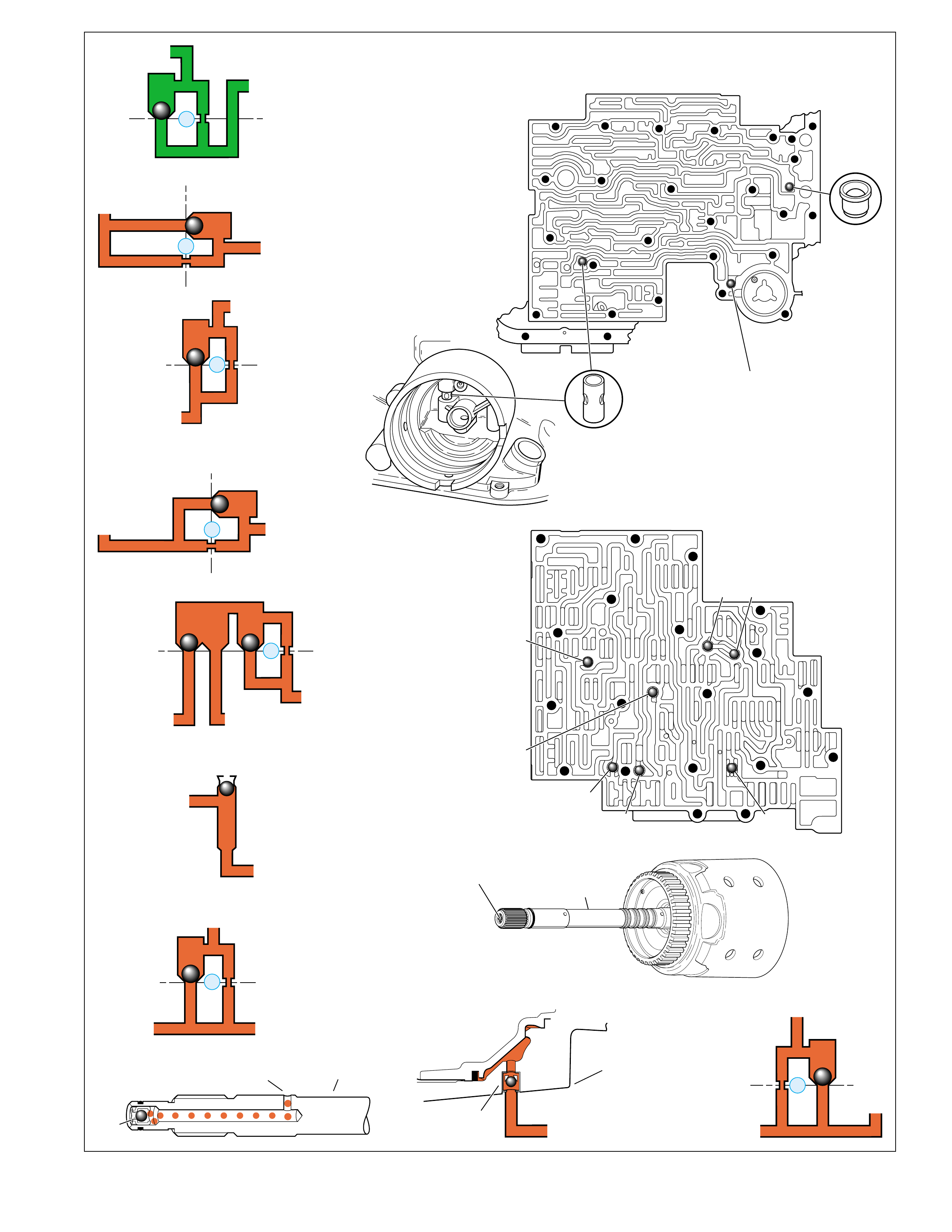
35
#9 INPUT
HOUSING
(621)
CONTROL VALVE BODY (60)
(Case Side)
#8
#6 #5
#3
#2 #12
#4
#7
#1
#10
SERVO
BORE
CASE (103)
(Control Valve Body Side)
3RD ACCUMULATOR
EX
#7
3RD ACCUM
➤
➤
#12
22
18 17a
18 17b
D4
FORWARD CL FEED
FWD CL FEED
➤
➤
➤
#6
OVERRUN CLUTCH FEED
ORIFICED D2
#5
OVERRUN
36
36
35e
35d
39
35b
35c
20
➤
➤
➤
➤➤
#4
13
3-4 SIGNAL
3-4 CLUTCH
27c
27b
29
29
➤
➤➤
#3
17
15c
15b
16
16
REV INPUT
REVERSE INPUT
➤
➤
➤
➤
#2
12
3-4 CLUTCH
29g28
28
29f
3RD ACCUMULATOR
➤
➤
➤
#1 ORIFICED ACCUMULATOR
21
21
20d
20e
21a
18
ACCUM
➤➤
➤
#8
16
2ND
2ND CL
➤
25
25
24m
24k
2ND CLUTCH
➤➤
➤
PR
#10
CASE
BOTTOM
➤
➤
TCC RELEASE
➤
➤
TURBINE
SHAFT
➤
#9
➤➤
HYDRAULIC CONTROL COMPONENTS
BALL CHECK VALVE LOCATION AND FUNCTION
Figure 33
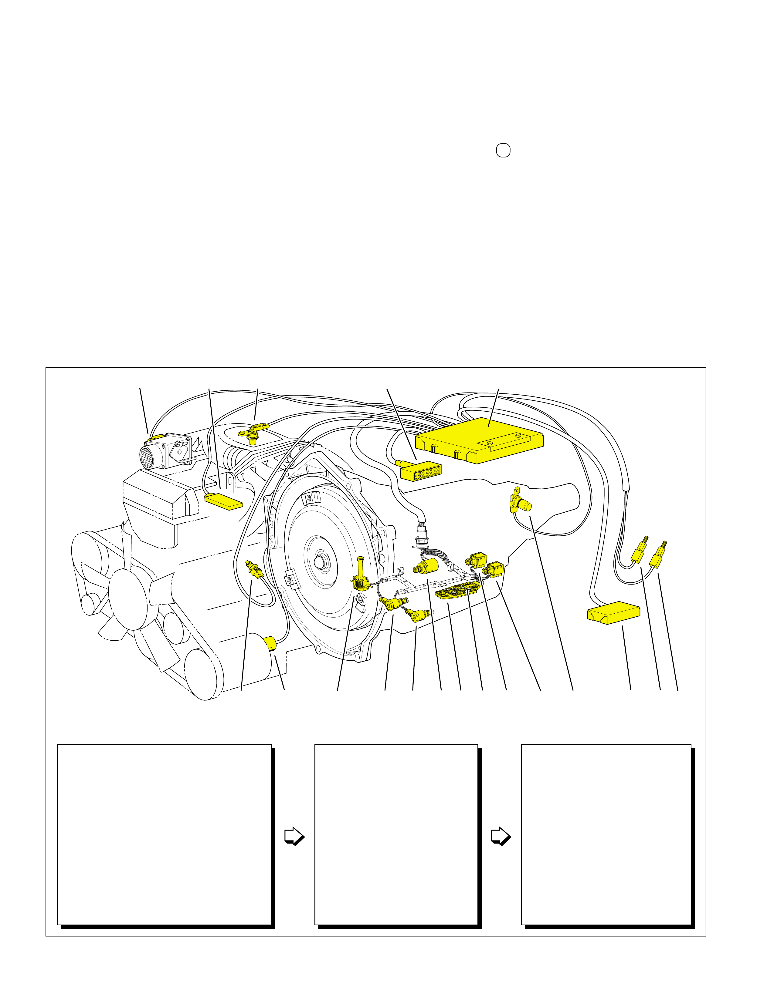
36
ELECTRICAL COMPONENTS
Figure 34
The Hydra-matic 4L60-E transmission incorporates electronic
controls that utilize a Powertrain Control Module (PCM). The
PCM gathers vehicle operating information from a variety of
sensors and control components located throughout the powertrain
(engine and transmission). The PCM then processes this
information for proper control of the following:
•transmission shift points - through the use of shift solenoids
•transmission shift feel - by adjusting line pressure through the use
of a pressure control solenoid
•TCC apply and release timing and feel - through the use of a TCC
solenoid and a TCC PWM solenoid
•the 3-2 downshift - through the use of a 3-2 control solenoid
Electronic control of these transmission operating
characteristics provides for consistent and precise shift points
and shift quality based on the operating conditions of both the
engine and transmission.
FAIL-SAFE MODE
“Fail-safe” mode is an operating condition when the transmission
will partially function if a portion of the electronic control system
becomes disabled. For example, if the wiring harness becomes
disabled, the PCM commands the fail-safe mode which causes
the electronic solenoids to default to OFF. The following changes
occur when the transmission is operating in the fail-safe mode:
•the pressure control solenoid is OFF, increasing line pressure to a
maximum to prevent any clutch or band slippage
•the TCC solenoid is OFF, preventing converter clutch apply
•the 3-2 control solenoid is OFF, providing a faster 3-2 downshift
•both shift solenoids are OFF
With both shift solenoids OFF, the transmission will operate in
Third gear when the selector lever is in the Overdrive position.
However, with the Hydra-matic 4L60-E transmission the driver
has some flexibility in gear selection during fail-safe mode.
Changing gears during fail-safe mode is accomplished by moving
the gear selector lever as follows:
Gear Selector Lever Position Transmission Gear Operation
Overdrive Range D Third gear
Drive Range (D) Third gear
Manual Second (2) Second gear
Manual First (1) Second gear
Reverse (R) Reverse
Park, Neutral (P, N) Park, Neutral
The downshift to First gear in Manual First is controlled
electronically for safety and durability reasons. This means that
the PCM must electronically command both shift solenoids to be
ON to obtain First gear.
NOTE: This section of the book contains “general” information
about electrical components that provide input information to
the PCM. Since this “input” information may vary between
vehicle applications, it is important that the appropriate
General Motors Service Manual is used during repair or
diagnosis of the transmission.
L
D3
R
D2
➤
➤
➤
➤
➤
➤
➤
➤➤
➤
➤
➤
➤
➤
➤
➤
➤
➤
➤
➤
➤
110
11
6
4
BEF DC32A9 87
PCMDLC
5
➤
INPUTS
INFORMATION SENSORS
1. VEHICLE SPEED SENSOR (VSS)
2. TRANMISSION FLUID TEMPERATURE (TFT) SENSOR
3. TFP MANUAL VALVE POSITION SWITCH
4. THROTTLE POSITION (TP) SENSOR
5. ENGINE SPEED SENSOR
6. ENGINE COOLANT TEMPERATURE (ECT) SENSOR
7. TCC BRAKE SWITCH
8. 4 WHEEL DRIVE LOW SWITCH
9. AIR CONDITIONING REQUEST
10. CRUISE CONTROL INFORMATION
11. MANIFOLD ABSOLUTE PRESSURE (MAP) SENSOR
ELECTRONIC CONTROLLERS
POWERTRAIN CONTROL MODULE
(PCM)
DIAGNOSTIC LINK CONNECTOR
(DLC)
OUTPUTS
ELECTRONICALLY CONTROLLED
TRANSMISSION COMPONENTS
A. PRESSURE CONTROL SOLENOID VALVE
B. TORQUE CONVERTER CLUTCH (TCC)
SOLENOID VALVE
C. 1-2 SHIFT SOLENOID VALVE
D. 2-3 SHIFT SOLENOID VALVE
E. 3-2 CONTROL SOLENOID VALVE
F. TCC PWM SOLENOID VALVE
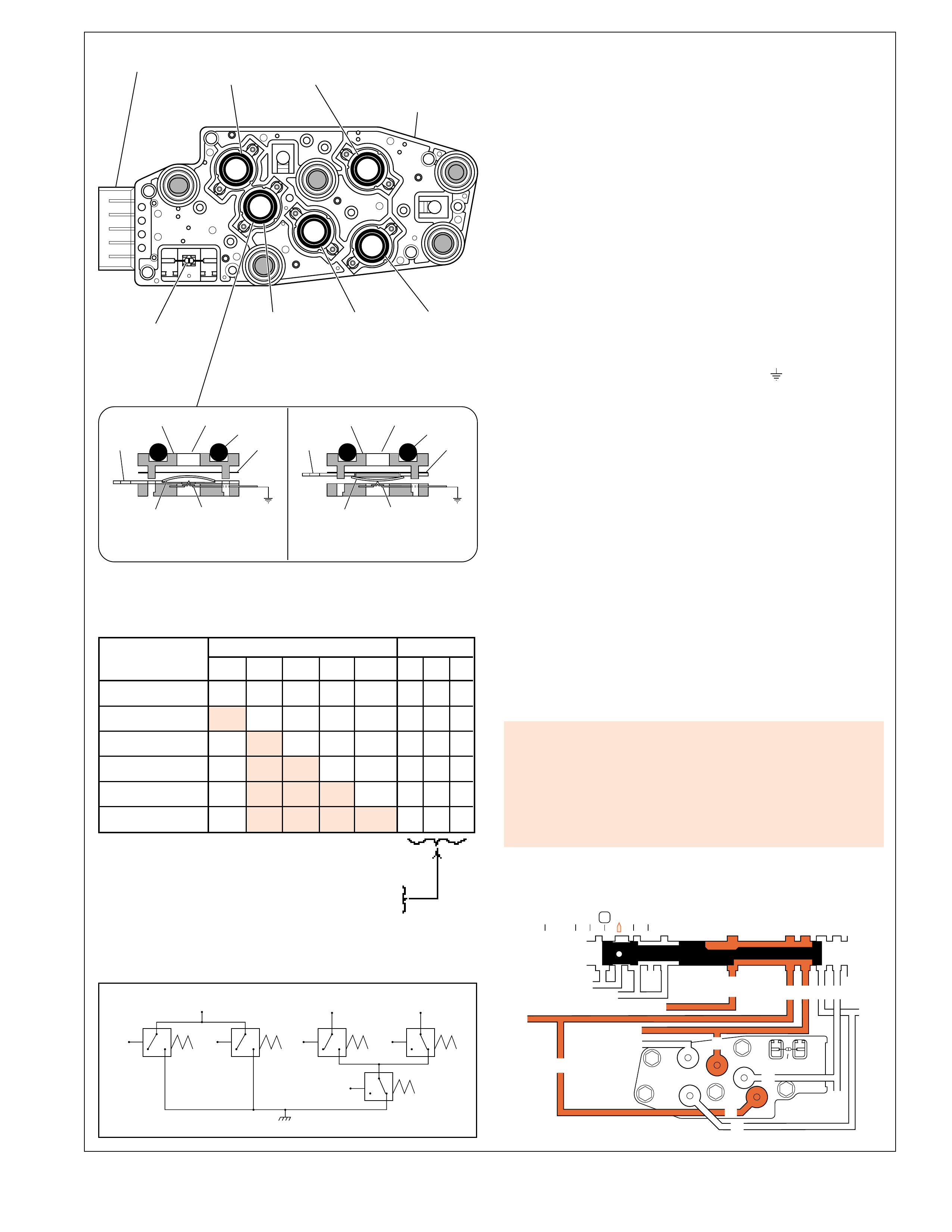
37
D4
L
D3
R
D2
NORMALLY OPEN NORMALLY CLOSED
➤
+
Diaphragm
Fluid
Body
Contact
Element Contact
O-Ring
Contact
Ground
–
R
REVERSE
INDICATOR
SWITCH
D3
INDICATOR
SWITCH
LO
INDICATOR
SWITCH
D2
INDICATOR
SWITCH
D4
INDICATOR
SWITCH
FIVE PIN
CONNECTOR TRANSMISSION
FLUID PRESSURE
MANU AL V AL VE
POSITION SWITCH
ASSEMBLY (69)
P
N
TEMPERATURE
SENSOR
N R P
REV LO D4
(N/O)
D2
SWITCH LOGIC MANUAL THIRD (3) (Engine Running)
D3
(N/O)
GROUND
(N/O)
(N/C)
(N/C)
+
➤
Diaphragm
Fluid
Body
Contact
Element Contact
O-Ring
Contact
Ground
–
D3
REVERSE INPUT
D2-N.C.
REV-N.O. D3-N.C.
LO-N.O.
D4-N.O.
LO
TEMP
SENSOR
➤
TFP
SWITCH
ASSEMBLY
D2
D4
D4
D4 D3
PRND321
D4
REVERSE
D3
D2
D2
LOLO
EX
EX
LINE
LINE
➤
➤
➤➤
➤
➤
➤
➤➤➤
➤➤
➤
MANUAL VALVE
PR
ELECTRICAL COMPONENTS
TRANSMISSION FLUID PRESSURE (TFP) MANUAL VALVE
POSITION SWITCH ASSEMBLY
The TFP manual valve position switch assembly is attached to
the control valve body and is used to signal the manual valve
position to the PCM. Various fluids are routed to the TFP manual
valve position switch depending on the manual valve position.
These fluids open and close the fluid pressure switches in the
TFP manual valve position switch to provide a signal to the PCM
indicating the gear range position of the manual valve. The
combination of opened and closed switches determines the voltage
measured at each of the three pins in the TFP manual valve
position switch electrical connector. An open circuit measures
12 volts while a grounded circuit measures 0 volts. The electrical
schematic and chart below show the TFP manual valve position
switch circuitry used to signal the manual valve position.
Normally Open Fluid Pressure Switch
The D4, Lo, and Reverse fluid pressure switches are normally
open and electrical current is stopped at these switches when no
fluid pressure is present. Fluid pressure moves the diaphragm
and contact element until the contact element touches both the
positive contact (+) and the ground contact ( ). This creates a
closed circuit and allows current to flow from the positive contact,
through the switch and to ground.
Normally Closed Fluid Pressure Switch
The D2 and D3 fluid pressure switches are normally closed and
electrical current is free to flow from the positive contact to the
ground contact when no fluid pressure is present. Fluid pressure
moves the diaphragm to disconnect the positive and ground
contacts. This opens the switch and stops current from flowing
through the switch.
Example: (Manual Third Range)
The hydraulic and electrical schematics below are shown in the
Drive Range (Manual Third) position (D or 3). D4 fluid pressure
closes the D4 fluid pressure switch and D3 fluid pressure opens
the D3 fluid pressure switch. With the D2 switch normally
closed, pins N and P measure 0 volts while pin R measures
approximately 12 volts. This combination signals the PCM that
the manual valve is in the Manual Third position.
Figure 35
A Transmission Fluid Pressure Manual Valve Position Switch
Assembly malfunction will set a DTC P1810 and the PCM will
command the following default actions:
• Maximum line pressure.
• Assume D4 shift pattern.
• TCC on in commanded fourth gear.
• The PCM stores DTC P1810 in PCM history.
RANGE FLUID* CIRCUIT+
INDICATOR REV D4 D3 D2 LO N R P
Park/Neutral 0 0 0 0 0 0 1 0
Reverse 1 0 0 0 0 1 1 0
Overdrive 0 1 0 0 0 0 1 1
Manual Third 0 1 1 0 0 0 0 1
Manual Second 0 1 1 1 0 0 0 0
Manual First 0 1 1 1 1 1 0 0
*: 1 = Pressurized
0 = Exhausted
+:1 = Grounded (Resistance <50 ohms, 0 volts)
0 = Open (Resistance >50k ohms, 12 volts)

38
TEMPERATURE SENSOR
VEHICLE SPEED SENSOR
FIGURE A: CONDITIONED SIGNAL
OUTPUT V OLTS
LOW SPEED
➤
5.0 HIGH SPEED
TIME
-50 -30 -10 10 30 50 70 90 110 130 150
110
100
90
80
70
60
50
40
30
20
10
0
Sensor Resistance (K ohms)
Temperature C
SENSOR RESIST ANCE VS. TEMPERA TURE
CONNECTOR RESISTOR
TRANSMISSION
FLUID PRESSURE
MANU AL V ALVE
POSITION SWITCH
ASSEMBLY (69)
O-RING
ELECTRICAL
CONNECTOR
MAGNETIC PICKUP
ROTOR (713)
SPEED SENSOR (10)
ELECTRICAL COMPONENTS
TRANSMISSION FLUID TEMPERATURE (TFT) SENSOR
The temperature sensor is a negative temperature coefficient
thermistor (temperature sensitive resistor) that provides
information to the PCM regarding transmission fluid
temperature. The temperature sensor is a part of the
transmission fluid pressure (TFP) manual valve position switch
assembly which is attached to the control valve body and
submersed in fluid in the transmission bottom pan. The
internal electrical resistance of the sensor varies in relation to
the operating temperature of the transmission fluid (see chart).
The PCM sends a 5 volt reference signal to the temperature
sensor and measures the voltage drop in the circuit. A lower
fluid temperature creates a higher resistance in the temperature
sensor, thereby measuring a higher voltage signal.
The PCM measures this voltage as another input to help
control TCC apply and line pressure. The PCM inhibits
TCC apply until transmission fluid temperature reaches
approximately 29°C (84°F). Also, when fluid temperatures
exceed 135°C (275°F), the PCM commands TCC apply at
all times in Fourth gear, as opposed to having a scheduled
apply. Applying the TCC reduces fluid temperatures created
by the fluid coupling in the converter.
VEHICLE SPEED SENSOR (VSS)
The vehicle speed sensor is a magnetic inductive pickup that
relays information relative to vehicle speed to the PCM. In
two wheel drive (2WD) applications, the VSS is located on
the transmission extension housing (31), opposite the speed
sensor rotor. The speed sensor rotor is attached to the
transmission output shaft and rotates with the output shaft at
transmission output speed. The speed sensor rotor has 40
serrations, or teeth, cut into it’s outside diameter.
The VSS consists of a permanent magnet surrounded by a
coil of wire. As the output shaft and speed sensor rotor
rotate, an alternating current (AC) is induced in the coil of
wire from the teeth on the rotor passing by the magnetic
pickup on the VSS. Whenever the vehicle is moving, the
VSS produces an AC voltage proportional to vehicle speed.
This AC signal is sent to the digital ratio adaptor converter
(DRAC) where it is converted to a direct current (DC) square
wave form. The DC signal is then sent to the PCM and
interpreted as vehicle speed. As vehicle speed increases and
more rotor teeth pass by the magnetic pickup on the VSS in
a given time frame, the frequency of the DC signal sent to
the PCM increases. The PCM interprets this increase in
frequency as an increase in vehicle speed (see Figure A).
Note: On four wheel drive (4WD) applications the VSS is
located on the transfer case.
Figure 36
Vehicle Speed Sensor Circuit Low will set DTC P0502 and the
PCM will command the following default actions:
• Freeze shift adapts.
• Maximum line pressure.
• Calculate A/T OSS from A/T ISS sensor output.
• DTC P0502 stores in PCM history.
TFT Sensor Circuit Range/Performance will set DTC P0711
and the PCM will command the following default actions:
• Freeze shift adapts.
• Defaults the TFT to 140°C (284°F) for shift
scheduling (hot mode pattern).
• DTC P0711 stores in PCM history.
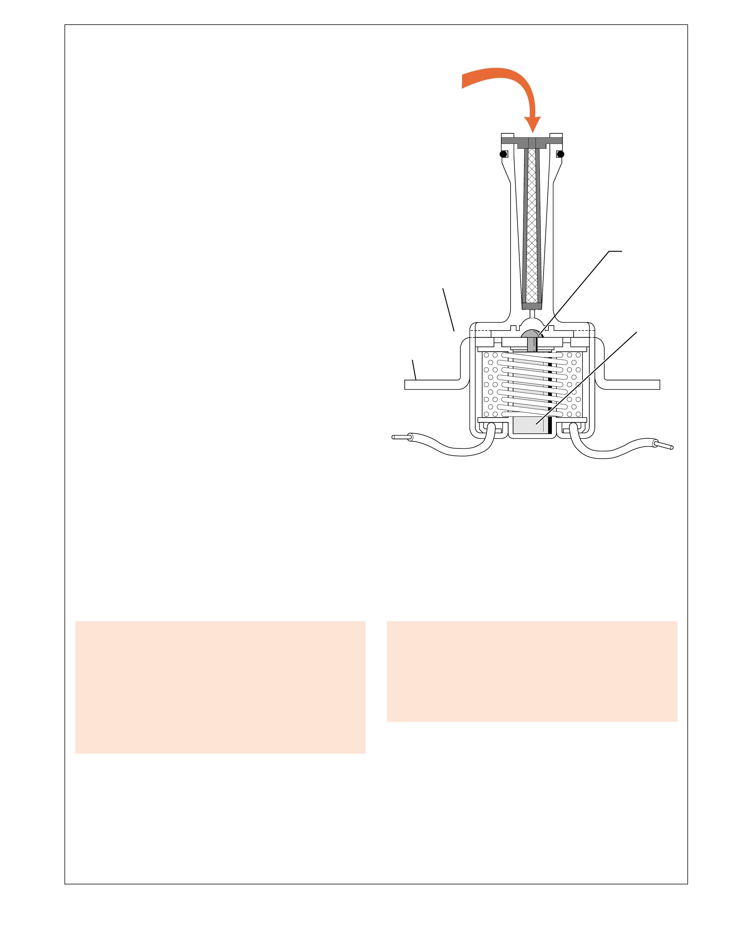
39
➤➤➤
➤
➤➤➤
TORQUE CONVERTER CLUTCH SOLENOID (NORMALLY OPEN)
+–
CONVERTER
FEED
FLUID
MOUNTING
FLANGE
STEEL
PLUNGER
VALVE
STEEL BAR
WRAPPED WITH
COPPER COIL
EXHAUST
ELECTRICAL COMPONENTS
TORQUE CONVERTER CLUTCH SOLENOID
The TCC solenoid is a normally open, ON/OFF solenoid that
the PCM controls to apply and release the converter clutch.
When de-energized, converter feed fluid pressure holds the valve
and plunger away from the exhaust port. This allows converter
feed fluid to exhaust through the solenoid. Without converter
feed fluid pressure at the end of the converter clutch apply
valve, spring force holds the valve in the release position.
When vehicle operating conditions are appropriate for TCC
apply, the PCM provides a ground for the TCC solenoid
electrical circuit. Electrical current flows through the coil
assembly in the solenoid which creates a magnetic field. The
magnetic field moves the plunger and valve to block the
exhaust port and prevent
converter feed
fluid from exhausting
through the solenoid.
Converter feed
fluid pressure increases
at the converter clutch apply valve and moves the valve into
the apply position against spring force.
Under normal operating conditions, the torque converter clutch
only applies in Fourth gear when in Overdrive range or Third
gear when in Manual Third gear range. However, at high
speeds under heavy throttle conditions, the PCM will command
TCC apply in Third gear when in Overdrive range. Also,
when transmission fluid temperature is above approximately
135°C (275°F), the TCC is applied all of the time in Fourth
gear to help reduce transmission fluid temperatures. Other
conditions that cause the PCM to change the operating state of
the TCC solenoid include:
•The TCC is released when the brake pedal is depressed.
•The TCC is released under minimum and maximum throttle
conditions.
•TCC apply is prevented until engine coolant temperature is above
approximately 20°C (68°F).
•TCC apply is prevented until transmission fluid temperature is
above approximately 29°C (84°F).
Figure 37
A continuous open, short to ground, or short to power in the
TCC solenoid valve circuit will set DTC P0740 TCC Enable
Solenoid Circuit Electrical and the PCM will command the
following default actions:
•The PCM illuminates the malfunction indicator lamp (MIL)
•The PCM inhibits TCC engagement
•The PCM inhibits 4th gear if the transmission is in hot mode
•The PCM freezes shift adapts from being updated
•The PCM stores Freeze Frame and Failure records
•The PCM stores DTC P0740 in PCM history
Low torque converter slip when the TCC is commanded OFF
will set DTC P0742 TCC System Stuck On and the PCM will
command the following default actions:
•The PCM illuminates the malfunction indicator lamp (MIL)
•The PCM freezes shift adapts from being updated
•The PCM stores Freeze Frame and Failure records
•The PCM stores DTC P0742 in PCM history
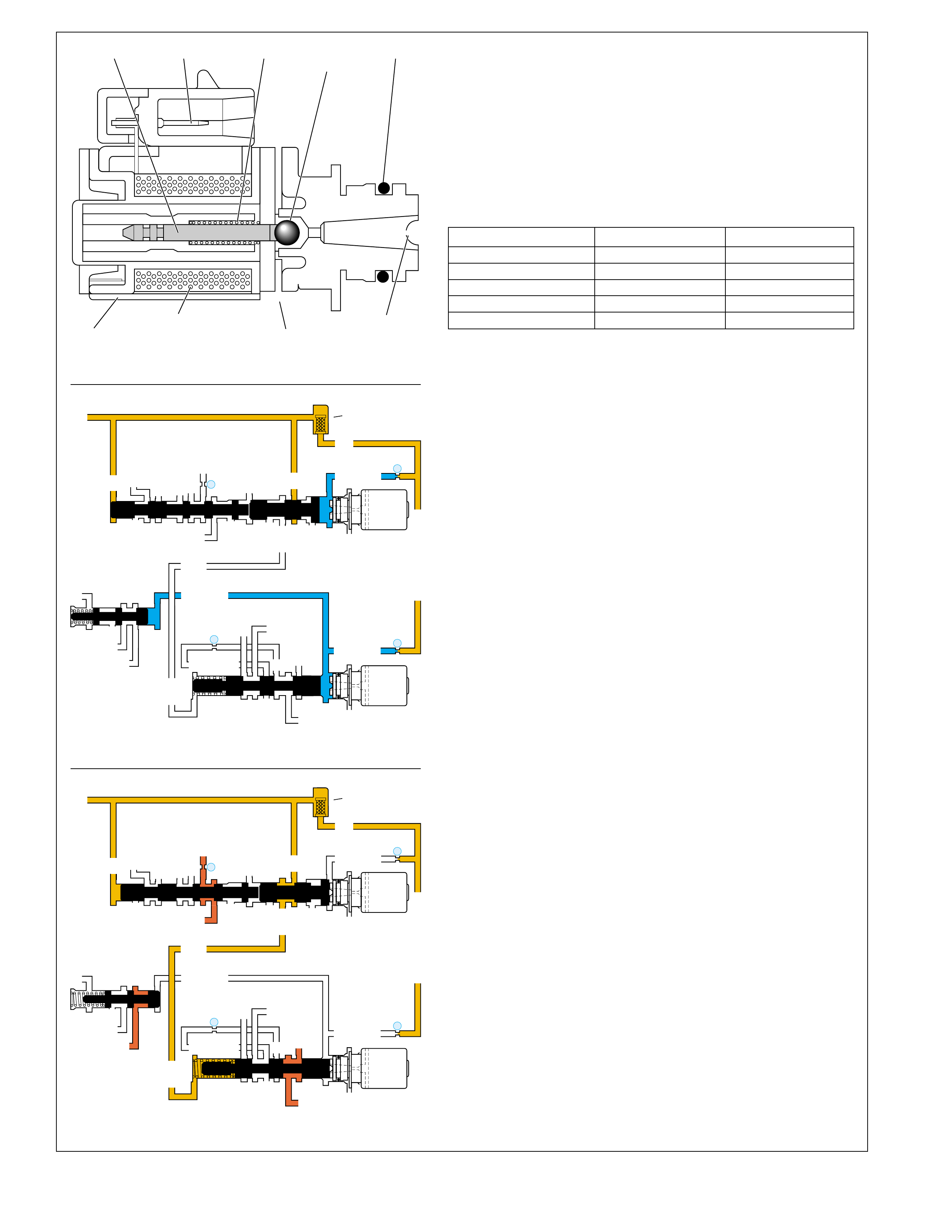
40
SHIFT SOLENOID VALVE (OFF)
EXAMPLE A: PARK/REVERSE/NEUTRAL/FIRST GEAR
EXAMPLE B: THIRD GEAR
➤➤➤
➤
➤
➤➤
➤
➤
➤
FRAME
PLUNGER METERING
BALL
COIL
ASSEMBLY
SPRINGCONNECTOR
EXHAUST SIGNAL
FLUID
O-RING
1-2 SHIFT VALVE
LO
D4
O’ EX
D4-3-2
2ND
1-2 SIGNAL
LO/1ST
EX
ORIFICED EX
D3
EX
3-4 SIGNAL
1-2 SIGNAL
4TH SIGNAL
3-4 SHIFT VALVE
2-3 SHUTTLE 2-3 SHIFT VALVE
EX
EX
EX
EX
D2
OVERRUN
D3
2ND
3-4 SIGNAL
EX
2-3 SIGNAL
AFL
ACTUATOR FEED LIMIT
AFL
AFL
SERVO FEED
3-4 ACCUM
D4-3-2
D4-3-2
➤
➤
➤
➤
➤
➤
➤
➤➤
➤
FILTER
(49)
➤
29
25
➤
➤
➤
➤
2-3 SHIFT
SOLENOID
VALVE
N.O.
ON
EX
1-2 SHIFT
SOLENOID
VALVE
N.O.
ON
AFL
➤
➤➤
28
26
➤ ➤
➤
➤
➤
➤
➤ ➤
➤ ➤
➤
➤
➤
➤
➤
➤
LO
D4
O’ EX
D4-3-2
2ND
1-2 SIGNAL
LO/1ST
EX
ORIFICED EX
D3
EX
3-4 SIGNAL
1-2 SIGNAL
4TH SIGNAL
EX
EX
EX
EX
D2
OVERRUN
D3
2ND
3-4 SIGNAL
EX
2-3 SIGNAL
AFL
ACTUATOR FEED LIMIT
AFL
AFL
SERVO FEED
3-4 ACCUM
D4-3-2
D4-3-2
➤
FILTER
(49)
➤
29
25
➤
➤
➤
➤
2-3 SHIFT
SOLENOID
VALVE
N.O.
OFF
EX
1-2 SHIFT
SOLENOID
VALVE
N.O.
OFF
AFL
➤
➤➤
28
26
➤
➤
➤
➤
1-2 SHIFT VALVE
3-4 SHIFT VALVE
2-3 SHUTTLE 2-3 SHIFT VALVE
➤
➤
➤
➤
➤➤
➤➤
➤
➤
ELECTRICAL COMPONENTS
SHIFT SOLENOID VALVES
The Hydra-matic 4L60-E transmission uses two identical, normally
open, electronic shift solenoid valves (1-2 and 2-3) to control upshifts
and downshifts in all forward gear ranges. These shift solenoid
valves work together in a combination of ON and OFF sequences to
control the positions of the 1-2 shift valve, 2-3 shift valve train and
3-4 shift valve. The PCM monitors numerous inputs to determine
the appropriate solenoid state combination and transmission gear for
the vehicle operating conditions. The following table shows the
solenoid state combination required to obtain each gear:
GEAR 1-2 SOLENOID 2-3 SOLENOID
Park, Reverse, Neutral ON ON
First ON ON
Second OFF ON
Third OFF OFF
Fourth ON OFF
Shift Solenoid De-energized (OFF)
The shift solenoids are OFF when the PCM opens the path to ground
for the solenoid’s electrical circuit. When OFF, solenoid signal fluid
pressure (blue color) moves the metering ball and plunger against
spring force, away from the fluid inlet port. Solenoid signal fluid is
then open to an exhaust port located on the side of the solenoid.
Shift Solenoid Energized (ON)
To energize the shift solenoids, the PCM provides a path to ground
for the solenoid’s electrical circuit. Electrical current passing through
the coil assembly in the solenoid creates a magnetic field that
magnetizes the solenoid core. The magnetized core repels the plunger
which seats the metering ball against the fluid inlet port. With the
ball seated, solenoid signal fluid is blocked from exhausting, thereby
creating fluid pressure in the solenoid signal fluid circuit.
1-2 Shift Solenoid (SS) Valve
Located at the end of the 1-2 shift valve, the 1-2 SS valve controls the
position of the 1-2 and 3-4 shift valves. The solenoid is fed 1-2 signal
fluid by the actuator feed limit fluid (AFL) circuit through orifice #25.
When energized (Example "A"), the solenoid blocks 1-2 signal fluid
from exhausting, thereby creating pressure in the 1-2 signal fluid
circuit. 1-2 signal fluid pressure holds the 1-2 shift valve against
spring force (downshifted position) in Park, Reverse, Neutral and First
gears. In Fourth gear, D432 fluid pressure assists spring force to keep
the 1-2 shift valve in the upshifted position against 1-2 signal fluid
pressure. Also, 1-2 signal fluid pressure holds the 3-4 shift valve in
the upshifted position against spring force.
When the 1-2 SS valve is de-energized in Second and Third gears
(Example "B"), 1-2 signal fluid exhausts through the solenoid. Spring
force holds the 1-2 shift valve in the upshifted position and the 3-4
shift valve in the downshifted position.
2-3 Shift Solenoid (SS) Valve
Located at the end of the 2-3 shuttle valve, the 2-3 SS valve controls
the position of the 2-3 shift valve train. The solenoid is fed 2-3
signal fluid by the AFL fluid circuit through orifice #29. When
energized by the PCM (Example "A"), 2-3 signal fluid pressure
holds the 2-3 shift valve train in the downshifted position against
AFL fluid pressure acting on the 2-3 shift valve.
When de-energized [Third and Fourth gears (Example "B")], 2-3
signal fluid exhausts through the solenoid. This allows AFL fluid
pressure acting on the 2-3 shift valve to move the shift valve train
into the upshifted position. In Manual Second, D2 fluid pressure
holds the 2-3 shift valve in the downshifted position against AFL
fluid pressure regardless of the 2-3 SS valve state.
Note: The feed orifices (#25 and #29) between the AFL and solenoid
signal fluid circuits are smaller than the exhaust ports through the solenoids.
This prevents fluid pressure buildup in the solenoid signal fluid circuits at
the end of the shift valves when the shift solenoids are OFF.
Figure 38
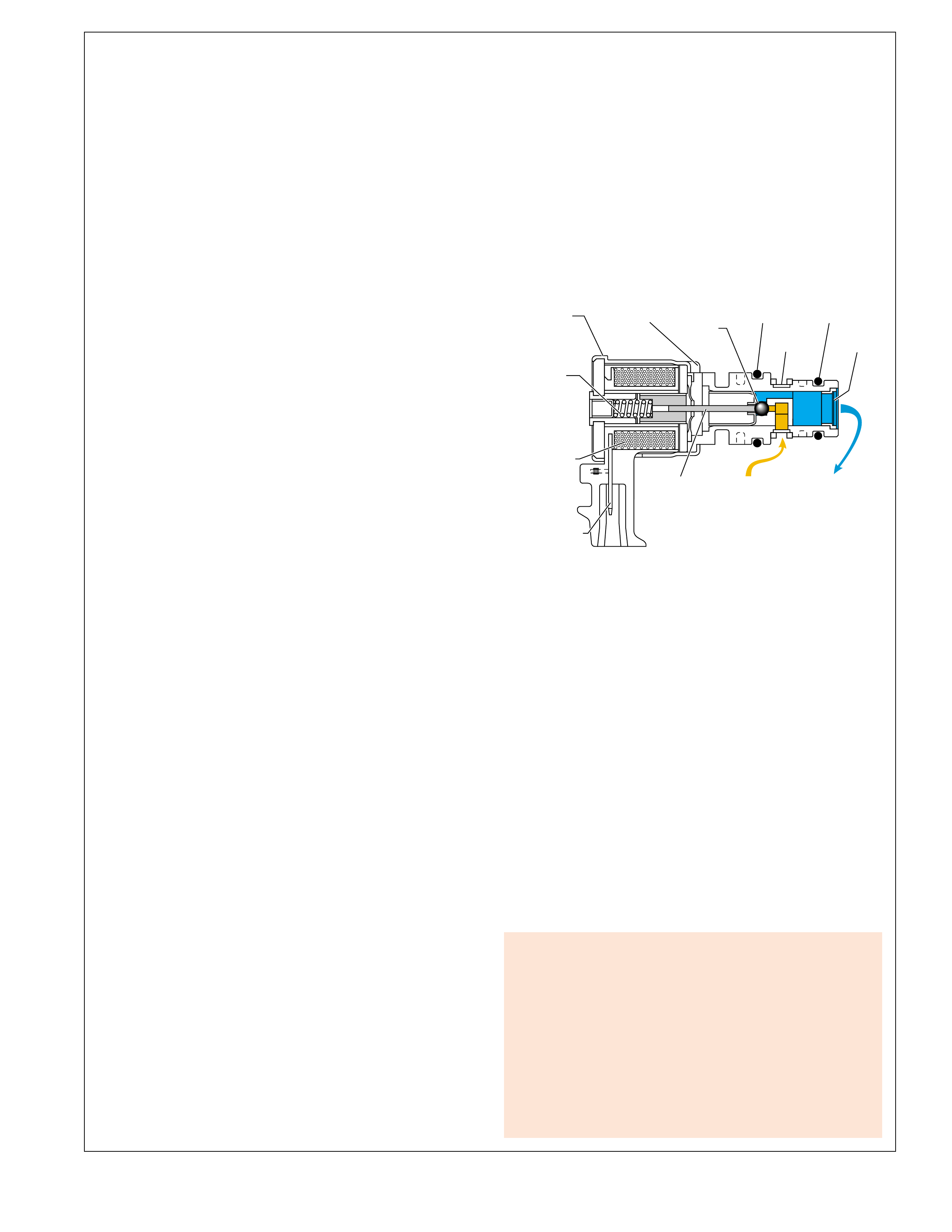
41
➤
➤➤➤
➤
➤➤
➤
3-2 CONTROL SOLENOID VALVE
EXHAUST
PLUNGER
CONNECTOR
METERING
BALL
COIL
ASSEMBLY
SPRING
HOUSING FLUID
SCREEN FLUID
SCREEN
PRESSURE
SUPPLY
(AFL)
PRESSURE
CONTROL
(3-2 SIGNAL)
O-RING O-RING
➤➤
➤
➤
➤
➤
ELECTRICAL COMPONENTS
3-2 CONTROL SOLENOID VALVE
The 3-2 control solenoid valve is a normally closed, 3-port ON/
OFF solenoid used to control the 3-2 downshift. During a 3-2
downshift, the 2-4 band is applied as the 3-4 clutch releases.
The timing between the 3-4 clutch release and 2-4 band apply
must be varied depending on vehicle speed and throttle position
(see downshift timing below). The 3-2 control solenoid valve
feeds AFL fluid into the 3-2 signal fluid circuit. 3-2 signal fluid
pressure shifts the 3-2 control valve to provide for these varying
requirements and achieve a precise control of the 3-2 downshift.
The solenoid is constantly fed 12 volts to the high (positive)
side and the PCM controls when the path to ground for the
electrical circuit is closed. When the PCM closes the solenoid
ground circuit, current flows through the solenoid and the ground
circuit is at a low voltage state (0 volts and solenoid energized).
Solenoid De-energized
When the solenoid is OFF, no current flows to the solenoid coil.
Spring force holds the plunger and metering ball against the
fluid inlet port to block AFL fluid from entering the 3-2 signal
fluid circuit. The 3-2 signal fluid circuit is open to an exhaust
through the solenoid. With the 3-2 signal fluid circuit empty,
spring force holds the 3-2 control valve open.
Solenoid Energized
The position of the metering ball is controlled by current flowing
through the solenoid coil. Current flowing through the solenoid
coil creates a magnetic field which moves the plunger and ball
against spring force to block the exhaust port thereby increasing
3-2 signal fluid pressure and the 3-2 control valve shifts.
3-2 Downshift Timing
The PCM energizes the 3-2 control solenoid valve when the
transmission is in Second, Third and Fourth gears. In all other
gear ranges, the solenoid is OFF. During a 3-2 downshift, the
solenoid is turned ON or OFF according to vehicle speed.
At lower vehicle speeds, the PCM operates the 3-2 control
solenoid valve in the OFF position. In the OFF position, the
solenoid is open, allowing AFL fluid to exhaust. With no AFL
fluid pressure entering the 3-2 signal fluid circuit, the 3-2 control
valve is kept in the open position by spring force to allow a
faster exhaust of 3rd accumulator fluid through an orifice into
the 3-4 clutch fluid circuit. A faster exhaust of the 3rd
accumulator exhaust fluid provides a faster apply of the 2-4
band, as needed at lower vehicle speeds.
At high vehicle speed, the PCM operates the 3-2 control solenoid
valve in the ON position allowing actuator feed limit fluid to
pass into the 3-2 signal fluid circuit. The 3-2 signal fluid
pressure shifts the 3-2 control solenoid into the closed position.
This action permits a slow apply of the 2-4 band by blocking off
3rd accumulator exhaust fluid from entering the 3-4 clutch fluid
circuit. This allows the engine speed to easily come up to the
necessary RPM before the 2-4 band is applied.
Figure 39
When the PCM detects a continuous open, short to ground or
short to power in the 3-2 SS valve assembly circuit, then DTC
P0785 3-2 Shift Solenoid Circuit Electrical sets and the PCM
will command the following default actions:
•The PCM illuminates the malfunction indicator lamp (MIL)
•The PCM commands a soft landing to third gear
•The PCM commands maximum line pressure
•The PCM inhibits TCC engagement
•The PCM inhibits 4th gear if the transmission is in hot mode
•The PCM freezes shift adapts from being updated
•The PCM stores Freeze Frame and Failure records
•The PCM stores DTC P0785 in PCM history
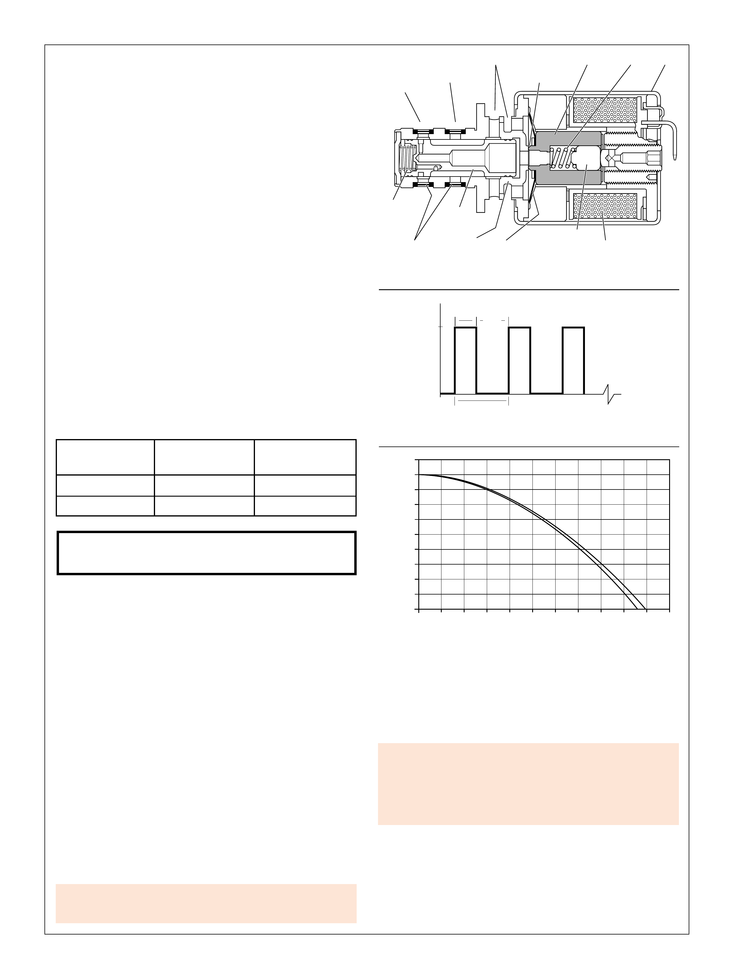
42
PRESSURE CONTROL SOLENOID VALVE CURRENT FLOW
➤
TIME
VOLTS
12
0
1 CYCLE = 1/292.5 SECOND
➤
➤
40% 60%
➤
➤
➤
➤
➤
(ON)
PRESSURE CONTROL SOLENOID VALVE POSITIVE DUTY CYCLE
PRESSURE CONTROL SOLENOID VALVE
➤
➤➤
➤
➤➤
➤
➤ ➤ ➤
➤
➤➤➤
➤
➤
➤
➤
➤
➤ ➤ ➤ ➤
➤
➤
➤
➤
➤
➤
➤
PUSH
ROD
FRAMESPRING
SPOOL
VALVE
ACTUATOR
FEED
LIMIT
FLUID
TORQUE
SIGNAL
FLUID
COIL
ASSEMBLY
EXHAUST ARMATURE
DAMPER
SPRING
FLUID
SCREENS
SPOOL
VALVE
SPRING
VARIABLE
BLEED
ORIFICE
SPOOL
VALVE
SLEEVE
0.0 0.1 0.2 0.3 0.4 0.60.5 0.7 0.8 0.9 1.0 1.1
INPUT CURRENT (AMP)
0
CONTROL PRESSURE (PSI)
10
20
30
40
50
60
70
80
90
100
ELECTRICAL COMPONENTS
Figure 40
Pressure Control Solenoid Valve
The pressure control (PC) solenoid valve is a precision electronic
pressure regulator that controls transmission line pressure based
on current flow through its coil windings. As current flow is
increased, the magnetic field produced by the coil moves the
solenoid’s plunger further away from the exhaust port. Opening
the exhaust port decreases the output fluid pressure regulated by
the PC solenoid valve, which ultimately decreases line pressure.
The PCM controls the PC solenoid valve based on various
inputs including throttle position, transmission fluid temperature,
MAP sensor and gear state.
Duty Cycle, Frequency and Current Flow
A “duty cycle” may be defined as the percent of time current is
flowing through a solenoid coil during each cycle. The number of
cycles that occur within a specified amount of time, usually
measured in seconds, is called “frequency”. Typically, the operation
of an electronically controlled pulse width modulated solenoid is
explained in terms of duty cycle and frequency.
The PCM controls the PC solenoid valve on a positive duty
cycle at a fixed frequency of 292.5 Hz (cycles per second). A
higher duty cycle provides a greater current flow through the
solenoid. The high (positive) side of the PC solenoid valve
electrical circuit at the PCM controls the PC solenoid valve
operation. The PCM provides a ground path for the circuit,
monitors average current and continuously varies the PC solenoid
valve duty cycle to maintain the correct average current flowing
through the PC solenoid valve.
Approximate
Duty Cycle Current Line Pressure
+ 5% 0.1 Amps Maximum
+40% 1.1 Amps Minimum
Pressure control solenoid valve resistance should measure
between 3.5 and 4.6 ohms when measured at 20°C (68°F).
The duty cycle and current flow to the PC solenoid valve are
mainly affected by throttle position (engine torque) and they are
inversely proportional to throttle angle (engine torque). In other
words, as the throttle angle (engine torque increases), the duty
cycle is decreased by the PCM which decreases current flow to the
PC solenoid valve. Current flow to the PC solenoid valve creates
a magnetic field that moves the solenoid armature toward the push
rod and against spring force.
Transmission Adapt Function:
Programming within the PCM also allows for automatic
adjustments in shift pressure that are based on the changing
characteristics of the transmission components. As the apply
components within the transmission wear, shift time (time required
to apply a clutch or band) increases. In order to compensate for
this wear, the PCM adjusts trim pressure by controlling the PC
solenoid valve in order to maintain the originally calibrated shift
timing. The automatic adjusting process is referred to as “adaptive
learning” and it is used to assure consistent shift feel plus increase
transmission durability. The PCM monitors the A/T ISS sensor
and A/T OSS during commanded shifts to determine if a shift is
occurring too fast (harsh) or too slow (soft) and adjusts the PC
solenoid valve signal to maintain a set shift feel.
A Pressure Control Solenoid electrical problem will set a DTC
P0748 and the PCM will command the following default actions:
• Disable the PC solenoid valve.
• Freeze shift adapts.
• DTC P0748 stores in PCM history.
Transmission adapts must be reset whenever the transmission is
overhauled or replaced (see appropriate service manual).
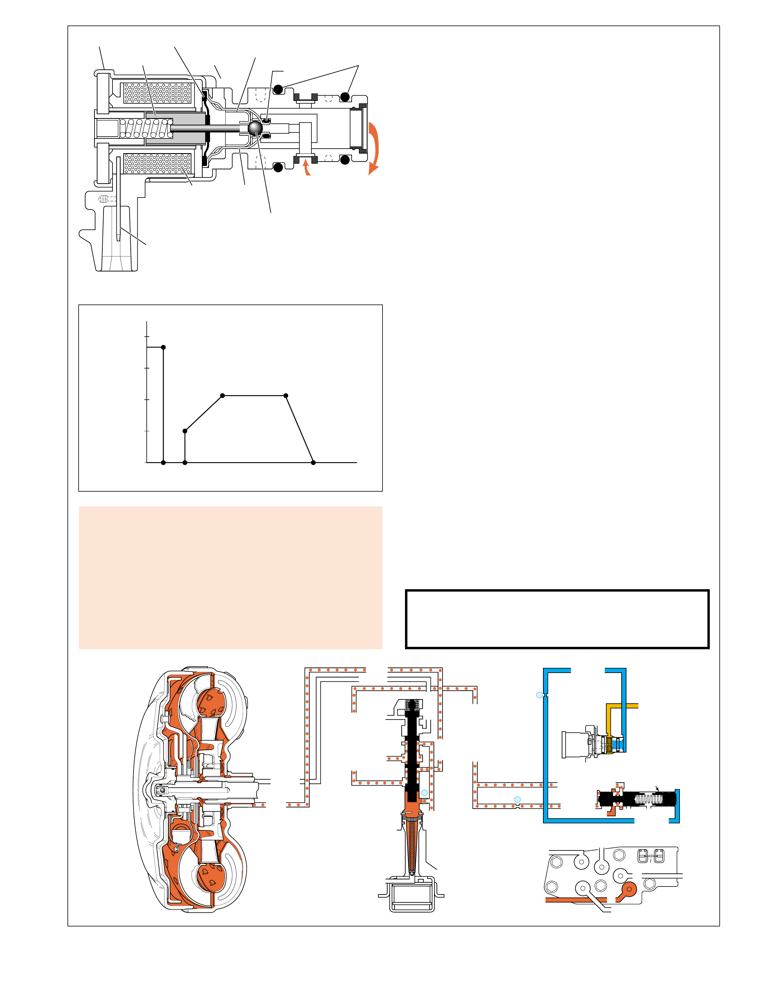
43
Torque Converter Clutch Pulse Width Modulated (TCC PWM)
Solenoid Valve
The TCC PWM solenoid valve is a normally closed, pulse
width modulated (PWM) solenoid used to control the apply and
release of the converter clutch. The PCM operates the solenoid
with a negative duty cycle at a fixed frequency of 32 Hz to
control the rate of TCC apply/release. The solenoid’s ability to
“ramp” the TCC apply and release pressures results in a smoother
TCC operation.
TCC PWM Solenoid Valve Operation
The TCC PWM solenoid valve is one electronic control
component of the TCC apply and release system. The other
electronic component is the TCC solenoid valve, which enables
TCC ON and OFF. The other components are all hydraulic
control or regulating valves. The illustration below shows all
the valves and the TCC PWM solenoid valve that make up the
TCC control system. (For more information on system operation
see pages 62 and 63 in the Powerflow section.)
In first gear, at approximately 13 km/h (8 mph), the PCM operates
the TCC PWM solenoid valve at approximately 90 percent duty
cycle (point S on the graph at left). This duty cycle is maintained
until a TCC apply is commanded. When vehicle operating
conditions are appropriate to apply the TCC, the PCM
immediately decreases the duty cycle to 0 percent, then increases
it to approximately 25% (see point C on graph). The PCM then
ramps the duty cycle up to approximately 50% to achieve
regulated apply pressure in vehicles equipped with the
Electronically Controlled Clutch Capacity. With the ECCC
system, the pressure plate does not fully lock to the torque
converter, instead a consistent slip of 20 to 40 RPM is regulated.
The rate at which the PCM increases the duty cycle controls the
TCC apply. Similarly, the PCM also ramps down the TCC
solenoid duty cycle to control TCC release. Under some high
torque or high vehicle speeds, the converter clutch is fully locked.
There are some operating conditions that prevent or enable TCC
apply under various conditions (refer to the Automatic
Transmission Fluid Temperature sensor description). Also, if
the PCM receives a high voltage signal from the brake switch,
signalling that the brake pedal is depressed, the PCM immediately
releases the TCC.
Note: Duty cycles given are for example only. Actual duty
cycles will vary depending on vehicle application and vehicle
operating conditions.
TCC PWM solenoid valve resistance should measure
between 10.0 and 11.5 ohms when measured at 20°C
(68°F). The resistance should measure between 15.0 and
17 ohms at 150°C (302°F).
A
S
D
B
E
C
F
ECCC
APPLY
FLUID
PRESSURE TIME
➤
100%
➤
0
25
50
75
PERCENT DUTY CYCLE
TCC (ECCC) APPLY AND RELEASE
➤
➤➤➤➤
➤
➤
➤
➤➤➤➤
➤
➤
➤
➤
➤
➤
➤
➤➤
TCC PWM SOLENOID VALVE
FRAME
COIL
ASSEMBLY
METERING
BALL
EXHAUST
EXHAUST
SEAT
ACTUATOR
FEED LIMIT
FLUID
CC
SIGNAL
FLUID
CONNECTOR
INLET
SEAT
ARMATURE
DIAPHRAGM
O-RINGINTERNAL
O-RING
When the PCM detects a continuous open, short to ground or
short to power in the TCC PWM solenoid valve circuit, then
DTC P1860 sets and the PCM will command the following
default actions:
•The PCM illuminates the malfunction indicator lamp (MIL)
•The PCM inhibits TCC engagement
•The PCM inhibits 4th gear if the transmission is in hot mode
•The PCM freezes shift adapts from being updated
•The PCM stores Freeze Frame and Failure records
•The PCM stores DTC P1860 in PCM history
➤➤➤➤
➤
➤
➤
➤
➤
➤
➤
➤➤
➤
➤
➤
➤
➤➤
➤➤➤
➤➤➤➤➤
RELEASE
RELEASE
APPLY
APPLY
➤
➤
➤
➤
LINE
REGULATED APPLY
REG APPLY
AFL
➤
EX
EX
CC SIGNAL
CC SIGNAL
9
TCC PWM
SOLENOID
VALVE
N.C.
➤
➤➤
➤
➤
➤
➤➤
➤
➤
➤
➤➤
➤➤
➤➤
D3
REVERSE INPUT
D2-N.C.
REV-N.O. D3-N.C.
LO-N.O.
D4-N.O.
LO
TEMP
SENSOR
➤
TFP
SWITCH
ASSEMBLY
TORQUE
CONVERTER
ASSEMBLY
D2
D4
➤
➤
➤➤
➤
➤➤
➤
➤
4
TCC
SOLENOID
(66)
N.O.
ON
COOLER
RELEASE
APPLY
EX
EX
➤➤
➤➤
➤➤➤
➤
➤
CONV FD
➤
➤
➤
REGULATED APPLY
REGULATED APPLY
CONVERTER CLUTCH VALVE
➤
➤
➤
8
ISOLATOR VALVE
REG APPLY
Figure 41
ELECTRICAL COMPONENTS

44
ELECTRICAL COMPONENTS
ELECTRICAL COMPONENTS EXTERNAL TO THE TRANSMISSION
THROTTLE POSITION (TP) SENSOR
The TPS is a potentiometer mounted to the throttle body that
provides the PCM with information relative to throttle angle
(accelerator pedal movement). The PCM provides a 5 volt
reference signal and a ground to the TPS and the sensor returns
a signal voltage that changes with throttle valve angle. This
signal varies from less than 1.0 volt at minimum throttle to
nearly 5.0 volts at wide-open throttle. The PCM uses this
information to modify fuel control, shift patterns, shift feel and
TCC apply and release timing. In general, with greater
accelerator pedal travel and higher TPS voltage signal, the
following conditions occur:
•The PCM delays upshifts or initiates a downshift
(through the shift solenoids) for increased acceleration.
•The PCM increases line pressure (through the pressure
control solenoid) to increase the holding force on the
clutches and/or band.
•The PCM keeps the TCC released during heavy acceleration.
The TCC is also released during minimum acceleration.
ENGINE COOLANT TEMPERATURE (ECT) SENSOR
The ECT sensor is a negative temperature coefficient resistor
(temperature sensitive resistor) mounted in the engine coolant
stream. Low coolant temperature produces high resistance in
the sensor while high coolant temperature produces low
resistance. With respect to transmission operation, the PCM
monitors the voltage signal from the sensor, which is high at
low coolant temperatures, to prevent TCC apply when coolant
temperature is below approximately 20°C (68°F).
ENGINE SPEED SENSOR
The PCM monitors engine speed as RPM through the ignition
module for gasoline engines. For diesel engine applications, a
separate engine speed sensor is used to monitor engine speed
from the crankshaft. This information is used to help determine
shift patterns and TCC apply and release timing.
TCC BRAKE SWITCH
The TCC brake switch is a normally closed switch when the
brake pedal is in the released position. When the brake pedal
is depressed, the switch is open and the PCM commands
TCC release.
AIR CONDITIONING (A/C) SWITCH SIGNAL
When the A/C cycling switch closes, the PCM is signaled
that the A/C compressor is ON. The PCM uses this
information to adjust transmission line pressure, shift timing
and TCC apply timing.
CRUISE CONTROL INFORMATION
The PCM monitors input signals from the cruise control switch
to alter shift patterns when the cruise control is engaged.
Depending on application, the PCM alters the shift pattern to
require a time limit to be met between the 3-2/2-3 shifts and the
4-3/3-4 shifts. This time limit prevents the transmission from
upshifting to quickly after downshifting when the cruise control
is engaged.
FOUR WHEEL DRIVE (4WD) LOW SWITCH
With 4WD applications, the VSS is located on the transfer case.
The 4WD Low switch signals the PCM that the vehicle is
operating in 4WD Low. The PCM then multiplies transfer case
output speed signal by the transfer case ratio in low range to
determine the transmission output shaft speed. The PCM uses
this information to provide earlier upshifts and prevent an
overspeed condition when operating in 4WD low.
MANIFOLD ABSOLUTE PRESSURE (MAP) SENSOR
The MAP sensor measures changes relative to intake manifold
pressure which results from changes in engine load and speed.
These changes are converted to a voltage output which is
monitored by the PCM in order to adjust line pressure and
shift timing.
ASSEMBLY LINE DIAGNOSTIC LINK (ALDL)
The ALDL is a multi-terminal connector wired to the PCM
that is located under the vehicle dash. The ALDL can be
used to diagnose conditions in the vehicle’s electrical system,
PCM and the transmission’s electrical components. Refer to
the appropriate General Motors Service Manual for specific
electrical diagnosis information.
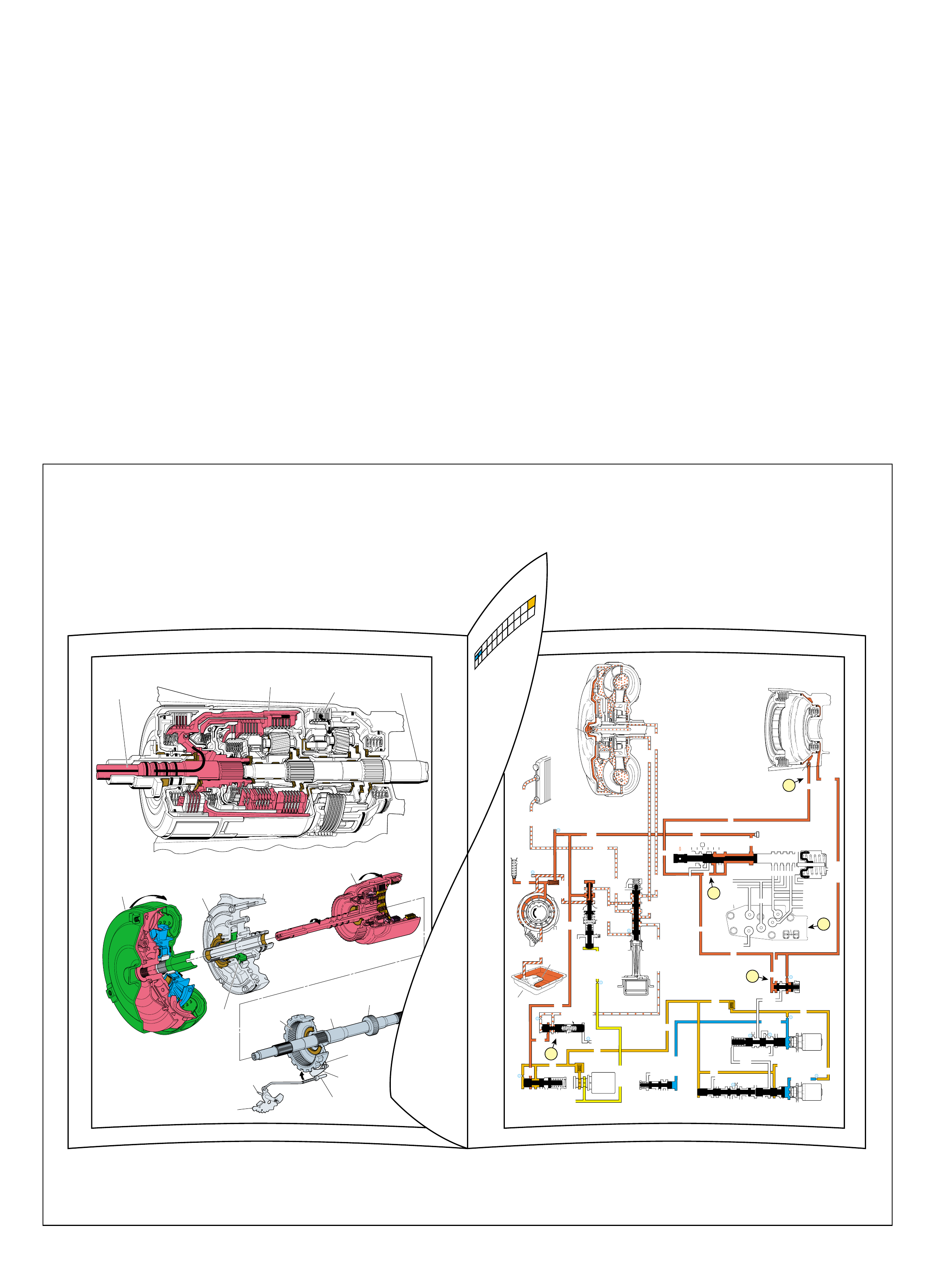
45
TORQUE
CONVERTER
ASSEMBLY
(1)
PUMP
ASSEMBLY
(4)
MAIN
CASE
(103)
INPUT HOUSING
& SHAFT ASSEMBLY
(621)
OUTPUT
SHAFT
(687)
HELD
SPEED SENSOR
ROTOR
(699)
PARKING PAWL
RETURN SPRING
(80)
PARKING BRAKE
PAWL (81)
ENGAGED
PARKING LOCK
ACTUATOR
ASSEMBLY
(85)
INSIDE
DETENT
LEVER
(88)
MANUAL
SHAFT
(84)
REACTION
INTERNAL
GEAR
(684)
HELD
OIL
PUMP
ROTOR
(212)
➤
➤
1
POWER FROM
TORQUE
CONVERTER
(1)
NO POWER
TRANSMITTED TO
OUTPUT SHAFT
(687)
2
POWERFLOW
TERMINATED LOW AND REVERSE
CLUTCH
APPLIED
➤
➤
BOTTOM
PAN
(SUMP)
➤
➤➤
3-4 SHIFT VALVE
LO OVERRUN
ACTUATOR FEED LIMIT
➤
FILTER
➤
LINE
LINE
COOLER
D4
REVERSE
PR
D3
D2
LO
PR
D2
D3
D3
LO
D4
D4
FWD CL FEED
PR
PR
REV INPUT
LO/REVERSE
LO/1ST
TORQUE SIGNAL
D3
EX
EX
EX
EX
AFL
AFL
AFL
1-2 SIGNAL
AFL
LINE
PR
LO/REVERSE
AFL
AFL
PR
RELEASE
APPLY
DECREASE
LINE
LINE
LINE
LINE
COOLER
COOLER
EX
FILTER (50)
FILTER
(232)
EX
EX
AIR
BLEED
AIR
BLEED LINE
PRESSURE
TAP
FILTER
(49)
➤
➤➤
➤
➤
➤➤
➤
➤➤
➤
➤
➤
➤
➤
➤➤ ➤➤➤
➤
➤
➤
➤
➤
➤➤
➤➤
➤➤
➤
➤➤
➤➤ ➤ ➤
➤➤
➤➤
➤
➤
➤
➤
➤
➤
➤
➤➤➤
➤
➤
➤
➤
➤
➤
➤
➤➤
➤
➤
➤
➤
➤➤➤
➤
➤
➤➤
➤
➤
➤➤
➤
➤➤➤
➤➤
➤
➤
➤➤➤
PRESSURE
RELIEF
VALVE
PUMP
ASSEMBLY
D2-N.C.
REV-N.O.
D3-N.C.
LO-N.O.
D4-N.O.
TEMP
SENSOR
➤
TFP
SWITCH
ASSEMBLY
➤
➤
➤
3-4 SIG
➤
AFL
➤
➤
➤
LO/REV
PR
➤
1-2 SIGNAL
4TH SIG
TORQUE SIG
➤
➤
➤
➤
➤
➤
➤
➤
➤➤
RELEASE
APPLY
➤
➤
➤
FORWARD CLUTCH
ACCUMULATOR
AFL (To 3-2 Control Solenoid)
➤
1c
2
TORQUE
CONVERTER
ASSEMBLY
#9
➤➤
#10
➤
LOW AND REVERSE
CLUTCH ASSEMBLY
1
2
COOLER
LUBE
➤
➤➤
➤➤
➤
➤
➤
4
10
TCC
SOLENOID
N.O.
OFF
EX
➤
EX
➤
➤
➤
➤
REGULATED APPLY
SUCTION
EX
➤➤
BOOST VALVE PRESS REG
EX
TORQUE SIGNAL
EX
CONV FD
EX
REVERSE INPUT
➤
➤
CONVERTER CLUTCH VALVE
EX
LINE
REGULATED APPLY
EX
EX
CC SIGNAL
PRESSURE
CONTROL
SOLENOID
VALVE
8
32
9
25
23
26
27
29
2-3 SHUTTLE 2-3 SHIFT VALVE
EX
EX
EX
EX
D2
OVERRUN
D3
2ND
3-4 SIGNAL
EX
2-3 SIGNAL
SERVO FD
3-4 ACC
➤
➤
➤
2-3 SHIFT
SOLENOID
VALVE
N.O. ON
1-2 SHIFT VALVE
LO
D4
D4-3-2
2ND
EX
EX
1-2 SHIFT
SOLENOID
VALVE
N.O. ON
28
EX
PRND321
EX
EX
MANUAL VALVE
1a
1b
ISOLATOR VALVE
REG APPLY
3
POWER FLOW
(Engine Running)
Figure 46
49
PARK
PARK
Figure 45
48
(Engine Running)
COMPLETE HYDRAULIC CIRCUIT
PAGE 74
With the selector lever in the Park (P)
position, line pressure from the oil
pump is directed to the following:
Pressure Regulator Valve(218): Reg-
ulates pump output (line pressure)
according to the transmission
requirements. When pump
output exceeds the demand
of line pressure, fluid from
the pressure regulator
PARK
(Engine Running)
48B
This section of the book describes how torque from
the engine is transferred through the Hydra-matic
4L60-E transmission allowing the vehicle to move
either in a forward or reverse direction. The
information that follows details the specific
mechanical operation, electrical, hydraulic and apply
components that are required to achieve a gear
operating range.
The full size, left hand pages throughout this section
contain drawings of the mechanical components used
in a specific r ange and gear. F acing this full page is a
half page insert containing a color coded range
reference chart at the top. This chart is one of the
key items used to understand the mechanical
operation of the transmission in each range and gear.
The text below this chart provides a detailed
explanation of what is occurring mechanically in
that range and gear.
The full size, right hand pages contain a simplified
version of the Complete Hydraulic Circuit that is
involved for that range and gear. Facing this full
page is a half page insert containing te xt and a detailed
e xplanation of what is occurring hydraulically in that
range and gear. A page number located at the bottom
of the half page of text provides a ready reference to
the complete Hydraulic Circuits section of this book
if more detailed information is desired.
It is the intent of this section to provide an overall
simplified explanation of the mechanical, hydraulic
and electrical operation of the Hydra-matic 4L60-E
transmission. If the operating principle of a clutch,
band or v alve is unc lear , refer to the pre vious sections
of this book for individual component descr iptions.
Figure 42
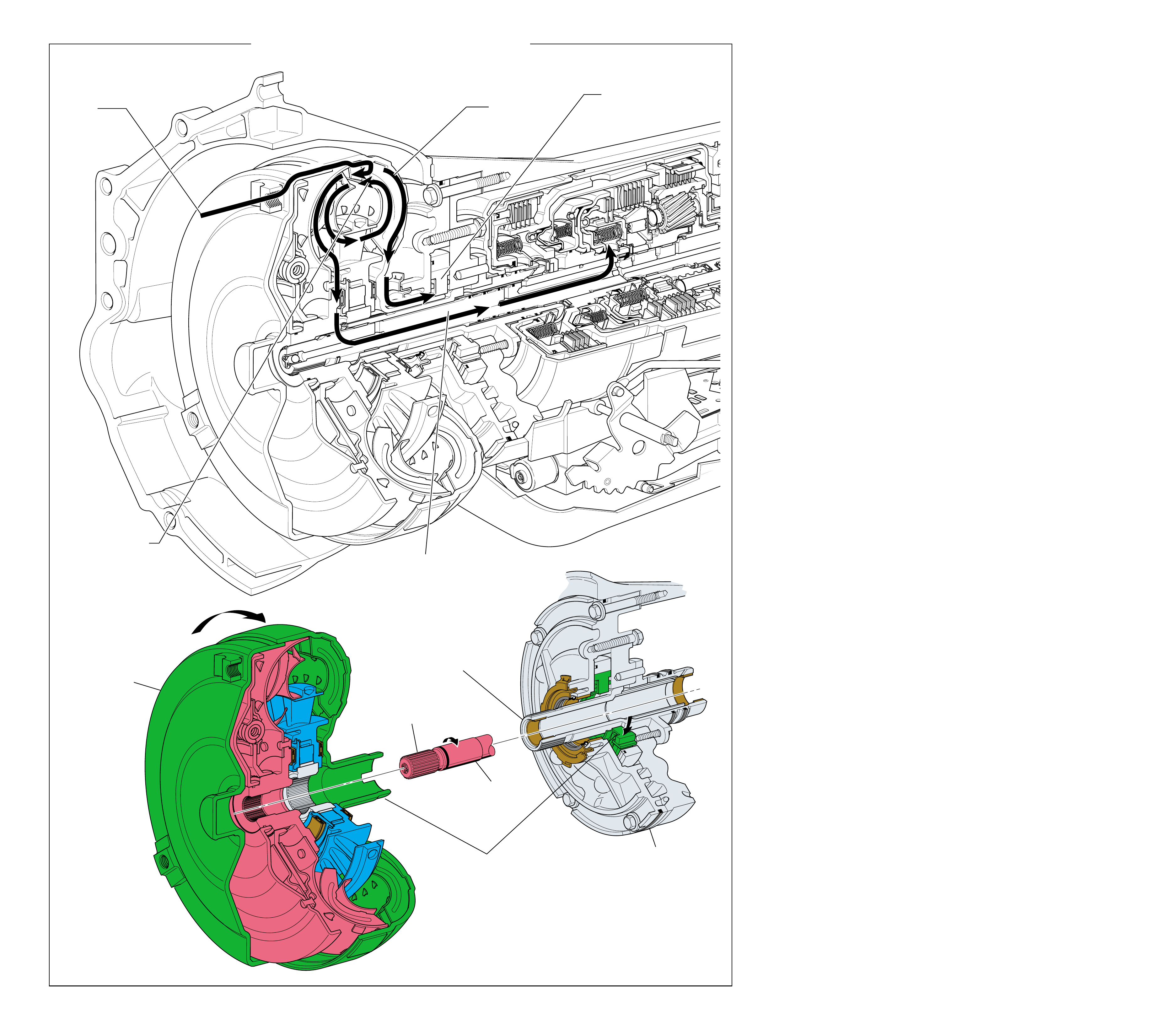
46 Figure 43
TURBINE
SHAFT
(621)
SPLINED TO
TORQUE CONVERTER
TURBINE ASSEMBLY
OIL PUMP
ASSEMBLY
(4)
TORQUE CONVERTER
ASSEMBLY
(1)
KEYED TO
OIL PUMP
ROTOR
(212)
SPLINED TO
TORQUE CONVERTER
STATOR ASSEMBLY
1
POWER FROM
THE ENGINE
3
FLUID COUPLING
DRIVES THE TURBINE
2
POWER TO
DRIVE OIL PUMP
2a
OIL PUMP
ROTOR
(205)
DRIVEN
4
TURBINE
SHAFT DRIVEN
MECHANICAL POWERFLOW FROM THE TORQUE CONVERTER
TO THE TURBINE SHAFT
(Engine Running)
MECHANICAL POWERFLOW FROM
THE TORQUE CONVERTER TO
THE TURBINE SHAFT
(Engine Running)
46A
The mechanical power flow in the Hydra-matic 4L60-E
transmission begins at the point of connection between the
torque converter and the engine flywheel. W hen the engine is
running, the torque converter cover (pump) is forced to rotate
at engine speed. As the torque converter rotates it multiplies
engine torque and transmits it to the input housing and turbine
shaft assembly (621). The turbine shaft provides the primary
link to the mechanical operation of the transmission.
The Hydra-matic 4L60-E automatic transmission requires a
constant supply of pressurized fluid to cool and lubricate all of
the components throughout the unit. It also requires a holding
force to be applied to the bands and clutches during the various
gear range operations. The oil pump assembly (4) and control
valve body assembly (60) provide for the pressurization and
distribution of fluid throughout the transmission.
1 Power from the Engine
Torque from the engine is transferred to the transmission through
the engine flywheel which is bolted to the torque converter.
2 Power to Drive the Oil Pump
The oil pump rotor (212) is keyed to the torque converter hub.
Therefore, the oil pump rotor also rotates at engine speed.
3 Fluid Coupling Drives the Turbine
Transmission fluid inside the torque converter (1) creates a fluid
coupling which in turn drives the torque converter turbine.
4 Input Housing and Turbine Shaft Assembly Driven
As the torque converter turbine rotates, the input housing and
turbine shaft assembly (621), which is splined to the torque
converter turbine, is also forced to rotate at turbine speed.
NO TE: To minimize the amount of repetitive te xt, the remaining
mechanical power flow descriptions will begin with the input
housing and turbine shaft assembly (621). The transfer of
torque from the engine through the torque converter to the
turbine shaft is identical in all gear ranges.
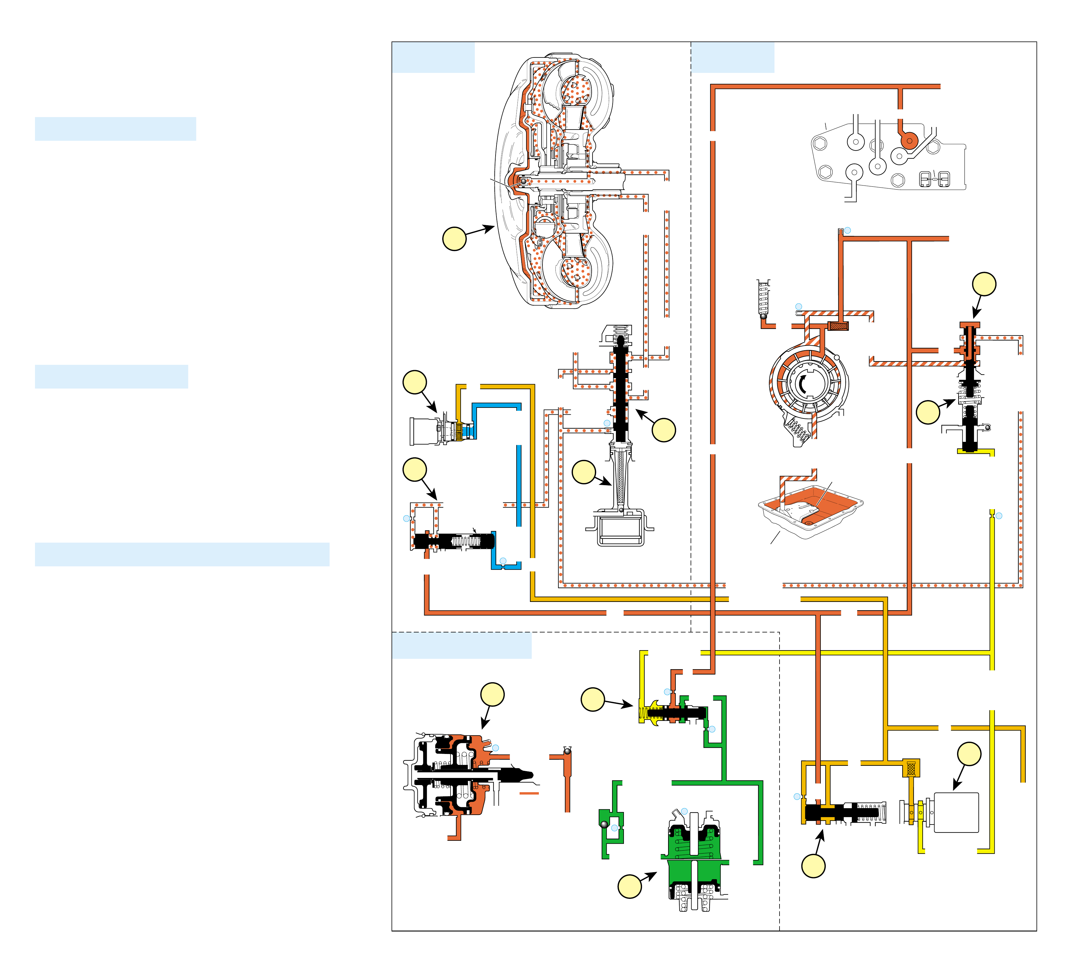
47
HYDRAULIC POWERFLOW – COMMON
FUNCTIONS FOR ALL RANGES
(Engine Running)
When the gear selector lever is in the Park (P) position and the
engine is running, fluid is drawn into the oil pump and line
pressure is directed to the pressure regulator valv e.
1 PRESSURE REGULATION
1a Pressure Regulator Valve:
Regulates pump output (line pressure) in response to torque
signal fluid pressure acting on the reverse boost valve, spring
force, and line pressure acting on the end of the valve. Line
pressure is directed to the manual valve, the regulated apply
valve, and the actuator feed limit valve. Also, line pressure feeds
the converter feed circuit through the pressure regulator valve.
1b Actuator Feed Limit (AFL) Valve:
Line pressure is routed through the valve and into the actuator
feed fluid circuit. The valve limits actuator feed fluid pressure
to a maximum pressure. Actuator feed fluid is routed to the
pressure control solenoid valve, the TCC PWM solenoid
valve, the 3-2 control solenoid valve, and also feeds the 1-2
signal and 2-3 signal fluid circuits.
1c Pressure Control (PC) Solenoid Valve:
Controlled by the PCM, the PC solenoid valve regulates
filtered actuator feed limit fluid pressure into the torque
signal fluid circuit.
2 SHIFT ACCUMULATION
2a Accumulator Valve:
D4 pressure is regulated into accumulator fluid pressure.
This regulation is basically controlled by torque signal fluid
pressure acting on one end of the valve and orificed
accumulator fluid on the other end of the valve.
2b 1-2 and 3-4 Accumulator Assemblies:
Accumulator fluid is routed to each of the accumulator
assemblies in preparation for upshifts and downshifts.
2c 2nd & 4th Servo:
In 3rd gear, 4th gear and manual 3rd gear, 3rd accumulator
fluid is routed to the 2nd & 4th servo, which acts as an
accumulator for the 3-4 clutch.
3 TORQUE CONVERTER (RELEASED POSITION ONLY)
3a Pressure Regulator Valve:
Line pressure is routed through the pressure regulator valve
and into the converter feed fluid circuit. Converter feed
fluid is routed to the converter clutch valve.
3b TCC PWM Solenoid Valve:
Actuator feed limit fluid is routed from the actuator feed
limit valve to the TCC PWM solenoid valve where it stops
in preparation for torque converter clutch apply.
3c Regulated Apply Valve:
Line pressure is routed through the regulated apply valve
into the regulated apply fluid circuit. Regulated apply fluid
is routed to the converter clutch valve in preparation for
TCC apply.
3d TCC Solenoid Valve:
Converter feed fluid is supplied to the TCC solenoid valve
in preparation for torque converter clutch apply.
3e Converter Clutch Valve:
Spring force holds the valve in the release position allowing
regulated converter feed fluid to enter the release circuit.
Release fluid is routed to the torque converter. Apply fluid
from the torque converter also passes through the converter
clutch valve into the cooler circuit.
3f Torque Converter:
Release fluid pressure is routed to the torque converter to
keep the TCC released. Fluid leaves the converter in the
apply fluid circuit and returns to the cooler through the
converter clutch valve.
2
SHIFT ACCUMULATION
COMMON HYDRAULIC FUNCTIONS FOR ALL RANGES
1
PRESSURE
REGULATION
3
TORQUE
CONVERTER
➤
➤
RELEASE
APPLY
➤
TORQUE
CONVERTER
ASSEMBLY
#9
➤➤
COOLER
RELEASE
APPLY
LINE
➤
➤➤➤➤
➤
➤
➤➤
➤➤
➤
➤
➤
4
TCC
SOLENOID
N.O.
OFF
EX
➤
EX
➤
➤
➤
➤
REG APPLY
CONV FD
CONVERTER FEED
➤➤
CONVERTER CLUTCH VALVE
LINE
REGULATED APPLY
EX
EX
CC SIGNAL
8
9
BOTTOM
PAN
(SUMP)
➤
➤➤
ACTUATOR FEED LIMIT
➤
FILTER
TORQUE SIGNAL
EX
EX
EX
LINE (to Manual Valve)
D4 (from Manual Valve)
AFL
AFL
DECREASE
LINE
LINE
LINE
LINE
LINE
FILTER (50)
FILTER
(232)
EX
EX
AIR
BLEED
AIR
BLEED
➤
➤➤
➤
➤➤
➤
➤
➤
➤
➤
➤➤
➤
➤➤
➤
➤
➤➤
➤➤
➤
➤
➤
➤
➤
➤
PRESSURE
RELIEF
VALVE
PUMP
ASSEMBLY
➤
ACTUATOR FEED LIMIT
➤
➤
➤
TORQUE SIG
➤
➤➤
1
2
10
SUCTION
EX
➤➤
BOOST VALVE PRESS REG
EX
TORQUE SIGNAL
EX
CONVERTER FEED
EX
REVERSE INPUT
➤
➤➤➤
➤➤ ➤➤
EX
PRESSURE
CONTROL
SOLENOID
VALVE
32
D4
LO
D2
D3
REVERSE INPUT
D2-N.C.
REV-N.O.
D3-N.C.
LO-N.O.
D4-N.O.
TEMP
SENSOR
➤
TFP
SWITCH
ASSEMBLY
➤
AFL
ACTUATOR FEED LIMIT
AFL
➤
➤➤➤
➤➤
➤
EX
CC SIGNAL
TCC PWM
SOLENOID
VALVE
N.C.
D4
D4 D4
TORQUE SIGNAL
2ND CLUTCH
ACCUMULATOR
ACCUM
➤➤➤
➤
➤
➤
➤
➤
➤
3-4 ACCUM
#1
18
➤
➤
3-4 ACCUMULATOR
1-2 ACCUMULATOR
19
EX
ORIFICED ACCUM
➤
➤
30
EX
ACCUM
31
➤
➤
➤
➤
➤
➤
ACCUM VALVE
➤
➤
3RD ACCUMULATOR
2ND CLUTCH
➤
EX
#7
11 3RD ACCUM
➤
2ND & 4TH
SERVO
11
4TH
EX
EX
➤
➤
➤
➤
➤
➤
➤
➤
➤
➤
➤
➤
➤➤➤➤
➤
➤➤
➤
ISOLATOR VALVE
REG APPLY
➤➤
➤
➤➤
➤
➤➤
➤
➤
➤
1a
3a
3d
3e
3c
3b
2a
2b
2c
1c
1b
3f
Figure 4446B
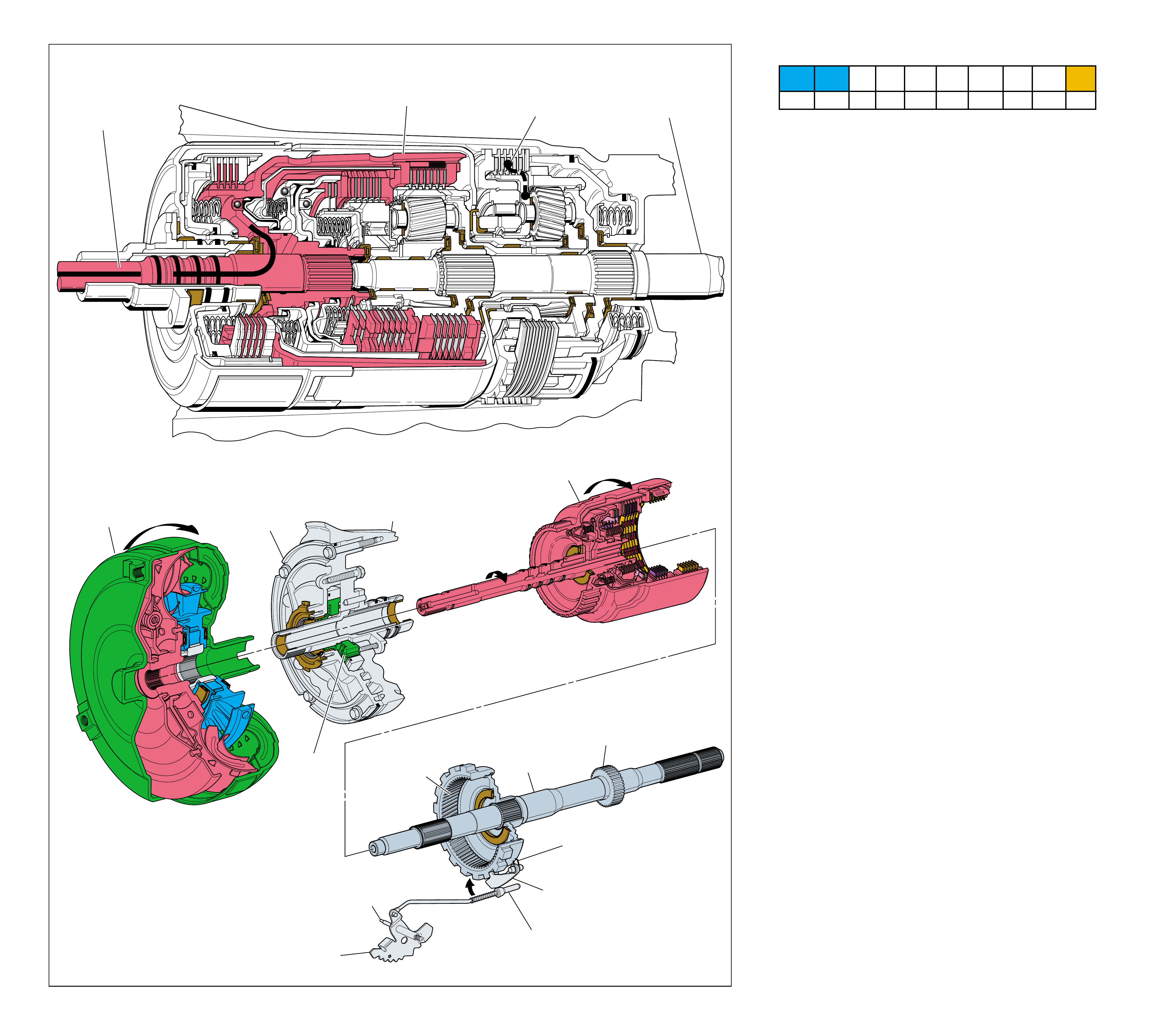
48 Figure 45
TORQUE
CONVERTER
ASSEMBLY
(1)
PUMP
ASSEMBLY
(4)
MAIN
CASE
(103)
INPUT HOUSING
& SHAFT ASSEMBLY
(621)
OUTPUT
SHAFT
(687)
HELD
SPEED SENSOR
ROTOR
(699)
PARKING PAWL
RETURN SPRING
(80)
PARKING BRAKE
PAWL (81)
ENGAGED
PARKING LOCK
ACTUATOR
ASSEMBLY
(85)
INSIDE
DETENT
LEVER
(88)
MANUAL
SHAFT
(84)
REACTION
INTERNAL
GEAR
(684)
HELD
OIL
PUMP
ROTOR
(212)
➤
➤
1
POWER FROM
TORQUE
CONVERTER
(1)
NO POWER
TRANSMITTED TO
OUTPUT SHAFT
(687)
2
POWERFLOW
TERMINATED LOW AND REVERSE
CLUTCH
APPLIED
PARK
(Engine Running)
48A
PARK
(Engine Running)
•The manual shaft (84) and manual valve (340) are in the Park
position. The parking lock actuator assembly (85) engages
the parking lock pawl (81) with the lugs on the reaction
internal gear (684).
•The reaction internal gear is held stationary by the parking
pawl.
•The reaction internal gear, which is splined to the output
shaft, is also held and the vehicle cannot move.
1 Power from Torque Converter
The turbine shaft, connected to the input housing (621), is
driven by the converter turbine.
2 Powerflow Terminated
The input housing contains three separate multiple disc
clutches: The overrun clutch, the forward clutch and the 3-4
clutch. All three clutches are released and powerflow is
terminated at the input housing.
Low and Reverse Clutch Applied
The low and reverse clutch plates (682) are applied and hold
the reaction carrier (681) stationary to the transmission case
(8). However, with power flow terminated at the input
housing, the low and reverse clutch has no effect on
transmission operation in Park.
Note: The vehicle should be completely stopped before selecting
Park range or internal damage to the transmission could occur.
Also, the manual linkage must be adjusted properly so the
indicator quadrants in the vehicle correspond with the inside
detent lever (88) in the transmission. If not adjusted properly,
an internal leak between fluid passages at the manual valve may
cause a clutch or band to slip or cause the transmission to not
hold in Park.
Refer to the appropriate General Motors Service Manual for the
proper manual linkage adjustment procedures.
1-2 SHIFT 2-3 SHIFT REVERSE FORWARD
SOLENOID SOLENOID 2-4 INPUT OVERRUN FORWARD SPRAG CL. 3-4 LO-ROLLER LO/REV
VALVE VALVE BAND CLUTCH CLUTCH CLUTCH ASSEMBLY CLUTCH CLUTCH CLUTCH
ON ON APPLIED
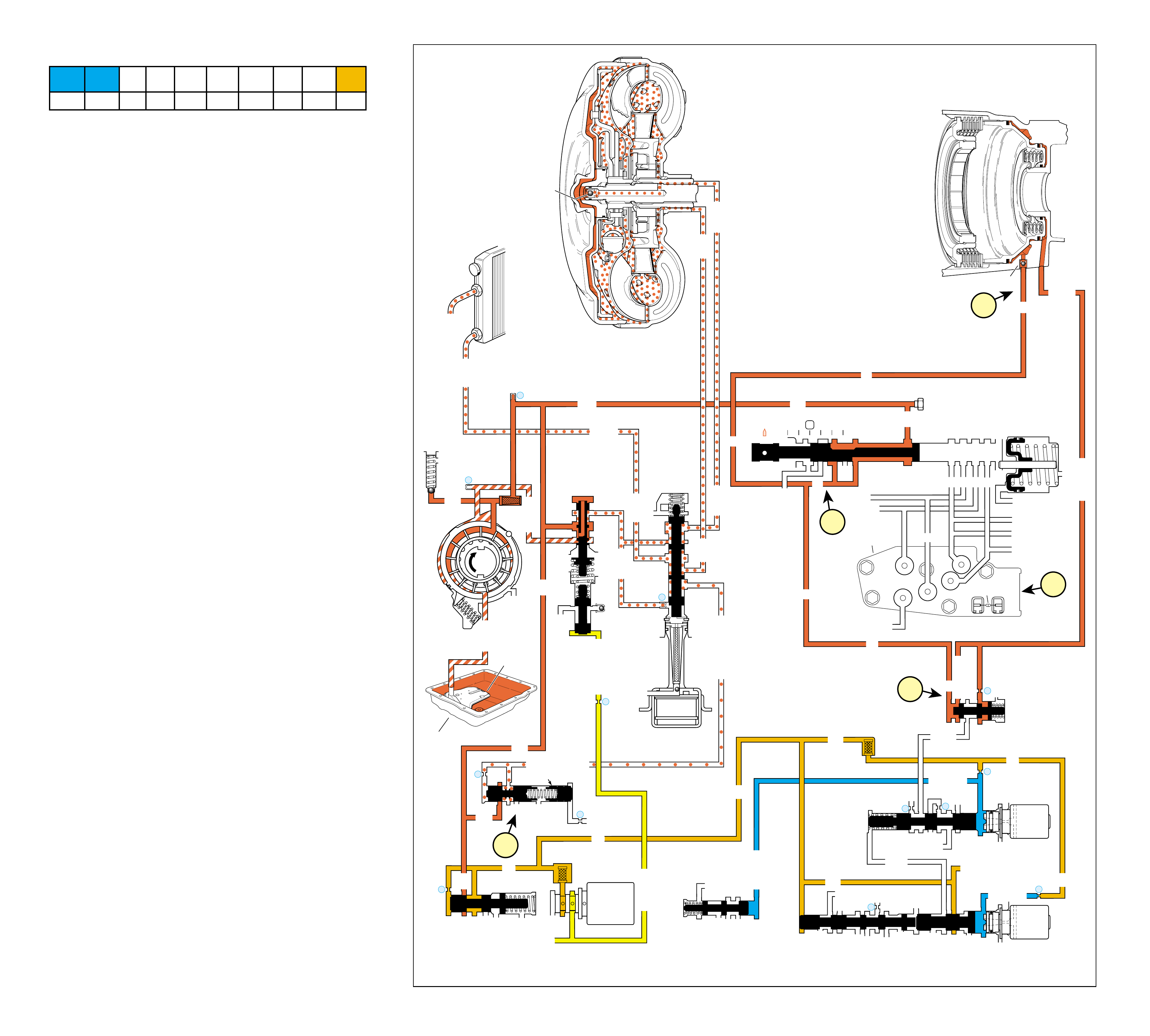
49
PARK
(Engine Running)
COMPLETE HYDRAULIC CIRCUIT
Page 74
Figure 46
FLUID PRESSURE DIRECTED IN PREPARATION FOR A SHIFT
1a Manual Valve:
Mechanically controlled by the gear selector lever, the manual
valve is in the Park (P) position and directs line pressure
from the pressure regulator valve into the PR fluid circuit.
1b Lo Overrun Valve:
PR fluid is sent from the manual valve to the lo overrun
valve where it shifts the valve and enters the low/reverse
fluid circuit.
1c Low and Reverse Clutch:
Low/reverse fluid is routed from the lo overrun valve to the
low and reverse clutch piston to apply the low and reverse
clutch plates.
2 Transmission Fluid Pressure (TFP) Manual Valve
Position Switch:
No fluid at the TFP manual valve position switch signals the
powertrain control module (PCM) that the transmission is in
either Park or Neutral range. The PCM then energizes, or
“turns ON” the 1-2 shift solenoid valve and the 2-3 shift
solenoid valve.
3 Regulated Apply Valve and Isolator Valve:
Line pressure is routed through the regulated apply valve
into the regulated apply fluid circuit. However, because the
TCC PWM solenoid valve is not ON, no CC signal fluid is
present and orificed regulated apply fluid is able to move
the valve enough to open the regulated apply fluid circuit to
an exhaust. This prevents any pressure build up in the
regulated apply fluid circuit in Park, Reverse, and Neutral.
Note: Refer to Shift Solenoid Valves on page 40 for a description
of solenoid and shift valve operation.
➤
➤
BOTTOM
PAN
(SUMP)
➤
➤➤
3-4 SHIFT VALVE
LO OVERRUN
ACTUATOR FEED LIMIT
➤
FILTER
➤
LINE
LINE
COOLER
D4
REVERSE
PR
D3
D2
LO
PR
D2
D3
D3
LO
D4
D4
FWD CL FEED
PR
PR
REV INPUT
LO/REVERSE
LO/1ST
TORQUE SIGNAL
D3
EX
EX
EX
EX
AFL
AFL
AFL
1-2 SIGNAL
AFL
LINE
PR
LO/REVERSE
AFL
AFL
PR
RELEASE
APPLY
DECREASE
LINE
LINE
LINE
LINE
COOLER
COOLER
EX
FILTER (50)
FILTER
(232)
EX
EX
AIR
BLEED
AIR
BLEED LINE
PRESSURE
TAP
FILTER
(49)
➤
➤➤
➤
➤
➤➤
➤
➤➤
➤
➤
➤
➤
➤
➤➤ ➤➤➤
➤
➤
➤
➤
➤
➤➤
➤➤
➤➤
➤
➤➤
➤➤ ➤ ➤
➤➤
➤➤
➤
➤
➤
➤
➤
➤
➤
➤➤➤
➤
➤
➤
➤
➤
➤
➤
➤➤
➤
➤
➤
➤
➤➤➤
➤
➤
➤➤
➤
➤
➤➤
➤
➤➤➤
➤➤
➤
➤
➤➤➤
PRESSURE
RELIEF
VALVE
PUMP
ASSEMBLY
D2-N.C.
REV-N.O.
D3-N.C.
LO-N.O.
D4-N.O.
TEMP
SENSOR
➤
TFP
SWITCH
ASSEMBLY
➤
PARK
(Engine Running)
➤
➤
3-4 SIG
➤
AFL
➤
➤
➤
LO/REV
PR
➤
1-2 SIGNAL
4TH SIG
TORQUE SIG
➤
➤
➤
➤
➤
➤
➤
➤
➤➤
RELEASE
APPLY
➤
➤
➤
FORWARD CLUTCH
ACCUMULATOR
AFL (To 3-2 Control Solenoid)
➤
1c
2
TORQUE
CONVERTER
ASSEMBLY
#9
➤➤
#10
➤
LOW AND REVERSE
CLUTCH ASSEMBLY
1
2
COOLER
LUBE
➤
➤➤
➤➤
➤
➤
➤
4
10
TCC
SOLENOID
N.O.
OFF
EX
➤
EX
➤
➤
➤
➤
REGULATED APPLY
SUCTION
EX
➤➤
BOOST VALVE PRESS REG
EX
TORQUE SIGNAL
EX
CONV FD
EX
REVERSE INPUT
➤
➤
CONVERTER CLUTCH VALVE
EX
LINE
REGULATED APPLY
EX
EX
CC SIGNAL
PRESSURE
CONTROL
SOLENOID
VALVE
8
32
9
25
23
26
27
29
2-3 SHUTTLE 2-3 SHIFT VALVE
EX
EX
EX
EX
D2
OVERRUN
D3
2ND
3-4 SIGNAL
EX
2-3 SIGNAL
SERVO FD
3-4 ACC
➤
➤
➤
2-3 SHIFT
SOLENOID
VALVE
N.O.
ON
1-2 SHIFT VALVE
LO
D4
D4-3-2
2ND
EX
EX
1-2 SHIFT
SOLENOID
VALVE
N.O.
ON
28
EX
PRND321
EX
EX
MANUAL VALVE
1a
1b
3
ISOLATOR VALVE
REG APPLY
1-2 SHIFT 2-3 SHIFT REVERSE FORWARD
SOLENOID SOLENOID 2-4 INPUT OVERRUN FORWARD SPRAG CL. 3-4 LO-ROLLER LO/REV
VALVE VALVE BAND CLUTCH CLUTCH CLUTCH ASSEMBLY CLUTCH CLUTCH CLUTCH
ON ON APPLIED
48B
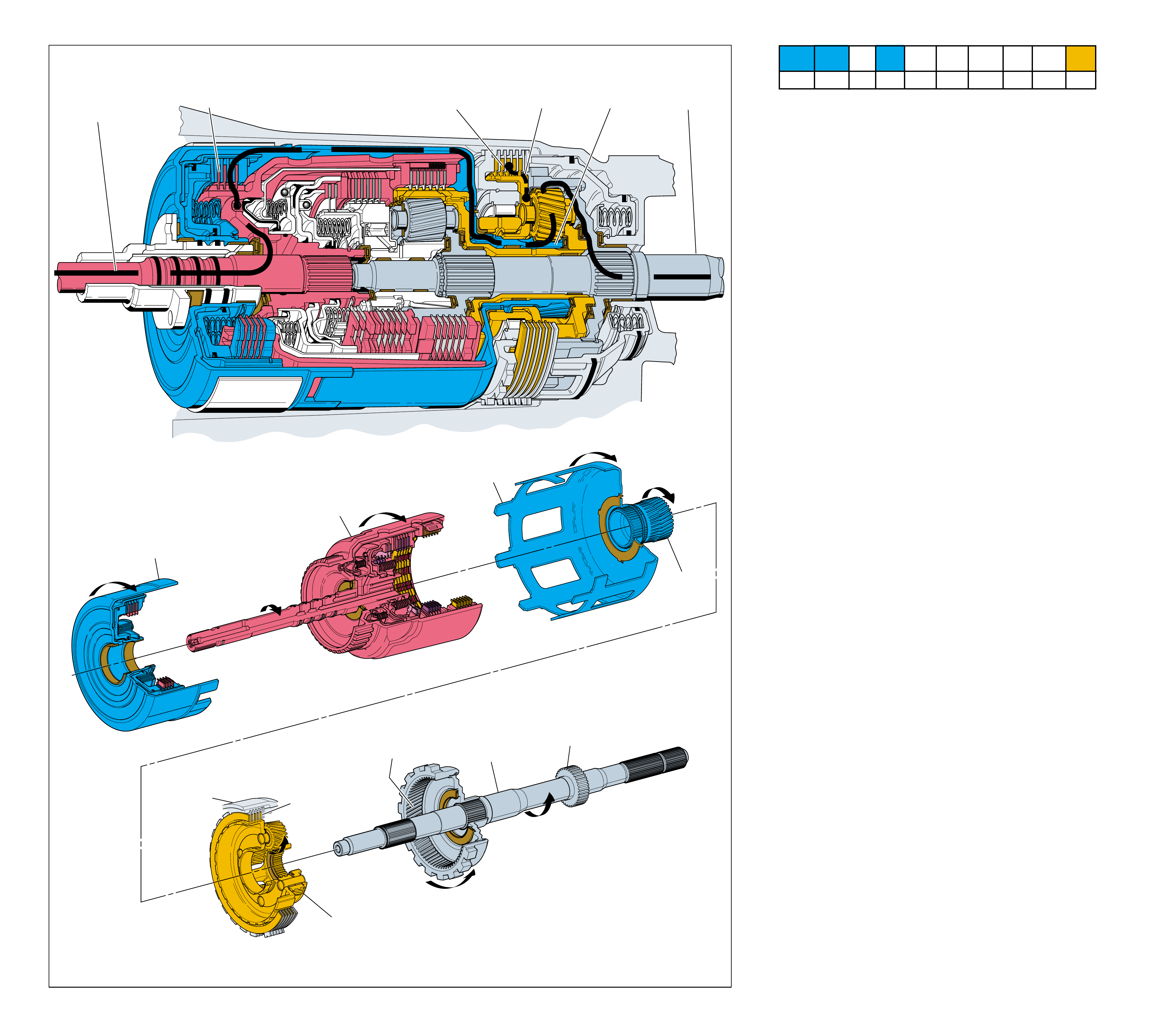
50 Figure 47
INPUT HOUSING
& SHAFT ASSEMBLY
(621)
OUTPUT
SHAFT
(687)
SPEED SENSOR
ROTOR
(699)
REACTION
INTERNAL
GEAR
(684)
REVERSE INPUT
CLUTCH (605)
APPLIED
REACTION
SUN SHELL
(670)
REACTION
SUN GEAR
(673)
LOW AND REVERSE
CLUTCH PLATE
ASSEMBLY
(682)
APPLIED
REACTION
CARRIER
ASSEMBLY
(681)
HELD
MAIN
CASE
(103)
➤
➤
➤
➤
➤
➤
➤
➤
1
POWER FROM
TORQUE
CONVERTER
(1)
POWER TO
DIFFERENTIAL
ASSEMBLY
2
REVERSE INPUT
CLUTCH (605)
APPLIED
4
LOW AND REVERSE
CLUTCH
APPLIED
5
REACTION
CARRIER
HELD
3
REACTION
SUN GEAR
DRIVEN
REVERSE
REVERSE
50A
In Reverse (R), torque from the engine is multiplied through the
torque converter and transmission gear sets to the vehicle’s
drive shaft and rear axle. The planetary gear sets operate in
reduction and also reverse the direction of input torque for a
reverse gear ratio of approximately 2.3:1.
•The manual shaft (84) and manual valve (340) are in the
Reverse position.
1 Power from Torque Converter
The turbine shaft, connected to the input housing (621), is
driven by the converter turbine.
2 Reverse Input Clutch Applied
The reverse input clutch plates (612) are applied and connect
the reverse input clutch housing (605) to the input housing.
Engine torque is transferred from the input housing, through
the clutch plates, and to the reverse input clutch housing.
The reverse input clutch housing is connected to the reaction
sun shell (670) and torque is transferred to the sun shell.
3 Reaction Sun Gear Driven
The reaction sun gear (673) is splined to the reaction sun
shell and is driven clockwise by the sun shell.
4 Low and Reverse Clutch Applied
As in Park range, the low and reverse clutch plates (682) are
applied and hold the reaction carrier (681) stationary to the
transmission case. This also holds the reaction carrier shaft
(666) and input internal gear (664) stationary.
5 Reaction Carrier Held
With the reaction carrier held by the low and reverse clutch,
the reaction sun gear drives the reaction carrier pinion gears
in a counterclockwise direction. The reaction carrier pinion
gears drive the reaction internal gear in a counterclockwise
direction. The reaction internal gear is splined to and drives
the output shaft (687) counterclockwise to obtain Reverse
and a gear reduction of approximately 2.3:1.
•The input carrier assembly (662), splined to the output shaft,
also rotates but has no affect in Reverse with all other clutches
released.
•When the throttle is released in Reverse, power from vehicle
speed is transferred back through the transmission gear train to
the engine. This action allows engine compression to slow the
vehicle. There is no coast condition in reverse.
1-2 SHIFT 2-3 SHIFT REVERSE FORWARD
SOLENOID SOLENOID 2-4 INPUT OVERRUN FORWARD SPRAG CL. 3-4 LO-ROLLER LO/REV
VALVE VALVE BAND CLUTCH CLUTCH CLUTCH ASSEMBLY CLUTCH CLUTCH CLUTCH
ON ON APPLIED APPLIED
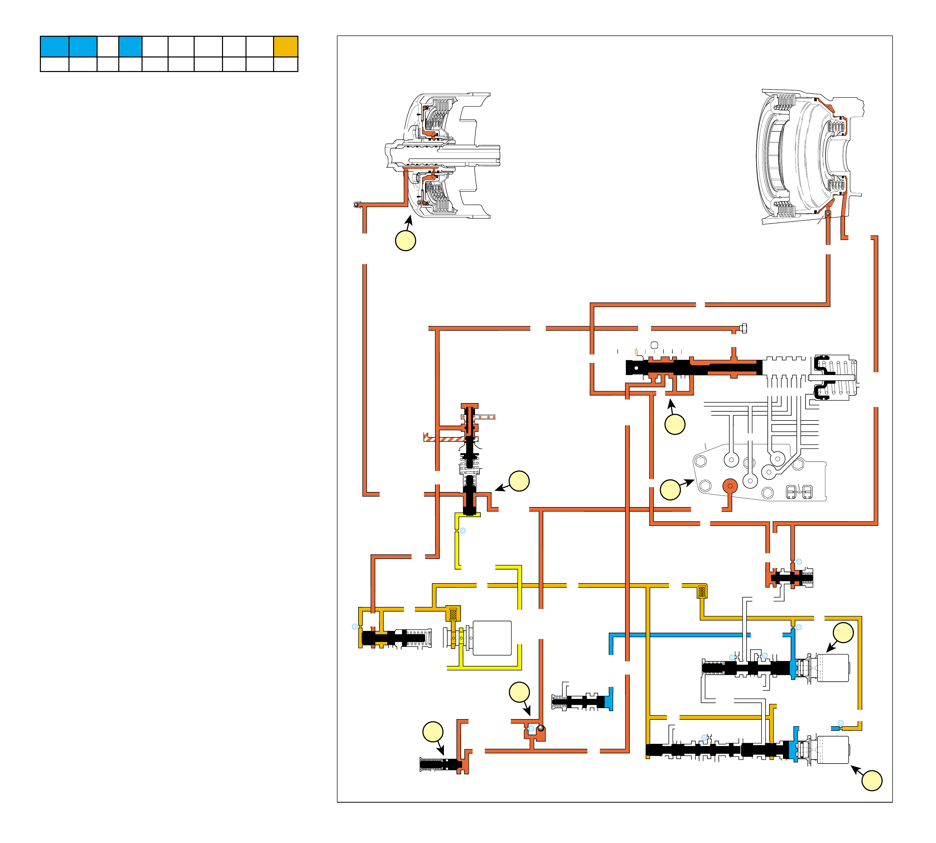
51
REVERSE
COMPLETE HYDRAULIC CIRCUIT
Page 76
Figure 48
REVERSE INPUT
CLUTCH ASSEMBLY
TORQUE SIG
LINE
REV INPUT
CONV FD
➤
AFL
➤
➤
EX
REV
REVERSE INPUT
REV
REV
REV INPUT
REV INPUT
➤➤➤
➤➤
➤
➤
➤
➤
➤
➤
➤
➤
➤
➤
➤
REVERSE INPUT
➤➤➤➤➤
➤
LINE (From Pump)
REVERSE
3-4 SHIFT VALVE
LO OVERRUN
LINE
LINE
D4
REVERSE
PR
D3
D2
LO
PR
D2
D3
D3
LO
D4
D4
FWD CL FEED
PR
PR
REV INPUT
LO/REVERSE
LO/1ST
D3
EX
AFL
AFL
AFL
1-2 SIGNAL
AFL
PR
LO/REVERSE
PR
EX
LINE
PRESSURE
TAP
FILTER
(49)
➤➤
➤
➤
➤
➤
➤
➤
➤
➤
➤
➤
➤➤
➤➤
➤
➤
➤➤➤
➤
➤
➤
➤
➤
➤➤
➤
➤
➤
➤
➤➤➤
➤
➤➤➤
➤
➤
➤
➤➤➤
D2-N.C.
REV-N.O.
D3-N.C.
LO-N.O.
D4-N.O.
TEMP
SENSOR
➤
TFP
SWITCH
ASSEMBLY
➤
➤
3-4 SIG
➤
➤
LO/REV
PR
1-2 SIGNAL
4TH SIG
➤
➤
FORWARD CLUTCH
ACCUMULATOR
AFL (To 3-2 Control Solenoid)
➤
3b
3a
1a
2b
2a
1b
2c
1c
#10
➤
LOW AND REVERSE
CLUTCH ASSEMBLY
25
23
26
27
29
2-3 SHUTTLE 2-3 SHIFT VALVE
EX
EX
EX
EX
D2
OVERRUN
D3
2ND
3-4 SIGNAL
EX
2-3 SIGNAL
SERVO FD
3-4 ACC
➤
➤
➤
2-3 SHIFT
SOLENOID
VALVE
N.O.
ON
1-2 SHIFT VALVE
LO
D4
D4-3-2
2ND
EX
EX
1-2 SHIFT
SOLENOID
VALVE
N.O.
ON
28
EX
PRND321
EX
EX
MANUAL VALVE
ACTUATOR FEED LIMIT
TORQUE SIGNAL
EX
EX
EX
AFL
AFL
DECREASE
LINE
LINE
LINE
FILTER (50)
➤
➤➤
➤
➤
➤
➤
➤
➤➤➤
➤
➤
➤
➤
➤
➤➤
➤
➤
➤
TORQUE SIG
➤
➤
10
BOOST VALVE PRESS REG
EX
EX
➤
EX
PRESSURE
CONTROL
SOLENOID
VALVE
32
EX
#3
17
➤
➤
➤
➤
REV ABUSE
When the gear selector lever is moved to the Reverse (R)
position (from the Park position) the following changes occur
in the transmission’s hydraulic and electrical systems.
1 PRESSURE REGULATION
1a Manual Valve:
With the manual valve in the reverse position, line pressure
is directed into the reverse fluid circuit from the PR fluid
circuit already pressurized in Park.
1b Pressure Regulator and Reverse Boost Valves:
Reverse input fluid at the reverse boost valve boosts line
pressure for the additional torque requirements in Reverse.
Torque signal fluid pressure from the pressure control (PC)
solenoid acting on the reverse boost valve also helps
determine line pressure in Reverse depending on throttle
position and other PCM input signals. Reverse input fluid is
also routed through the reverse boost valve and seats the air
bleed ball check valve located in the fluid pump.
1c Transmission Fluid Pressure (TFP) Manual Valve
Position Switch:
Reverse input fluid is routed to the TFP manual valve position
switch. The TFP manual valve position switch signals the
PCM that the transmission is in Reverse.
2 LOW AND REVERSE CLUTCH APPLIES
2a #3 Ball Check Valve:
Reverse fluid seats the reverse input ball check valve (#3)
and is orificed into the reverse input fluid circuit. This
orifice (#17) controls the reverse input clutch apply when
engine speed is approximately at idle.
Note: Remember that the function of an orifice is to control the
flow rate of fluid and rate of apply or release of a clutch or band.
2b Reverse Abuse Valve:
When engine speed is above idle, reverse fluid acts on the
reverse abuse valve to move the valve against spring force.
This allows reverse fluid to feed the reverse input fluid
circuit quickly, bypassing the control of orifice #17.
2c Reverse Input Clutch:
Reverse input fluid is then routed to the reverse input clutch
piston to apply the reverse input clutch plates to obtain
reverse gear.
3 FLUID PRESSURE DIRECTED IN PREPARATION
FOR A SHIFT
3a 1-2 Shift Solenoid (SS) Valve:
The 1-2 SS valve remains energized (ON). 1-2 signal fluid
pressure is high with the 1-2 SS valve energized and keeps
the 1-2 shift valve in the downshifted position against spring
force. 1-2 signal fluid is also routed to the 3-4 shift valve.
3b 2-3 Shift Solenoid (SS) Valve:
The 2-3 SS valve remains energized (ON). 2-3 signal fluid
is high with the 2-3 SS valve energized and keeps the 2-3
shift valve and the 2-3 shuttle valve in the downshifted
position.
1-2 SHIFT 2-3 SHIFT REVERSE FORWARD
SOLENOID SOLENOID 2-4 INPUT OVERRUN FORWARD SPRAG CL. 3-4 LO-ROLLER LO/REV
VALVE VALVE BAND CLUTCH CLUTCH CLUTCH ASSEMBLY CLUTCH CLUTCH CLUTCH
ON ON APPLIED APPLIED
50B
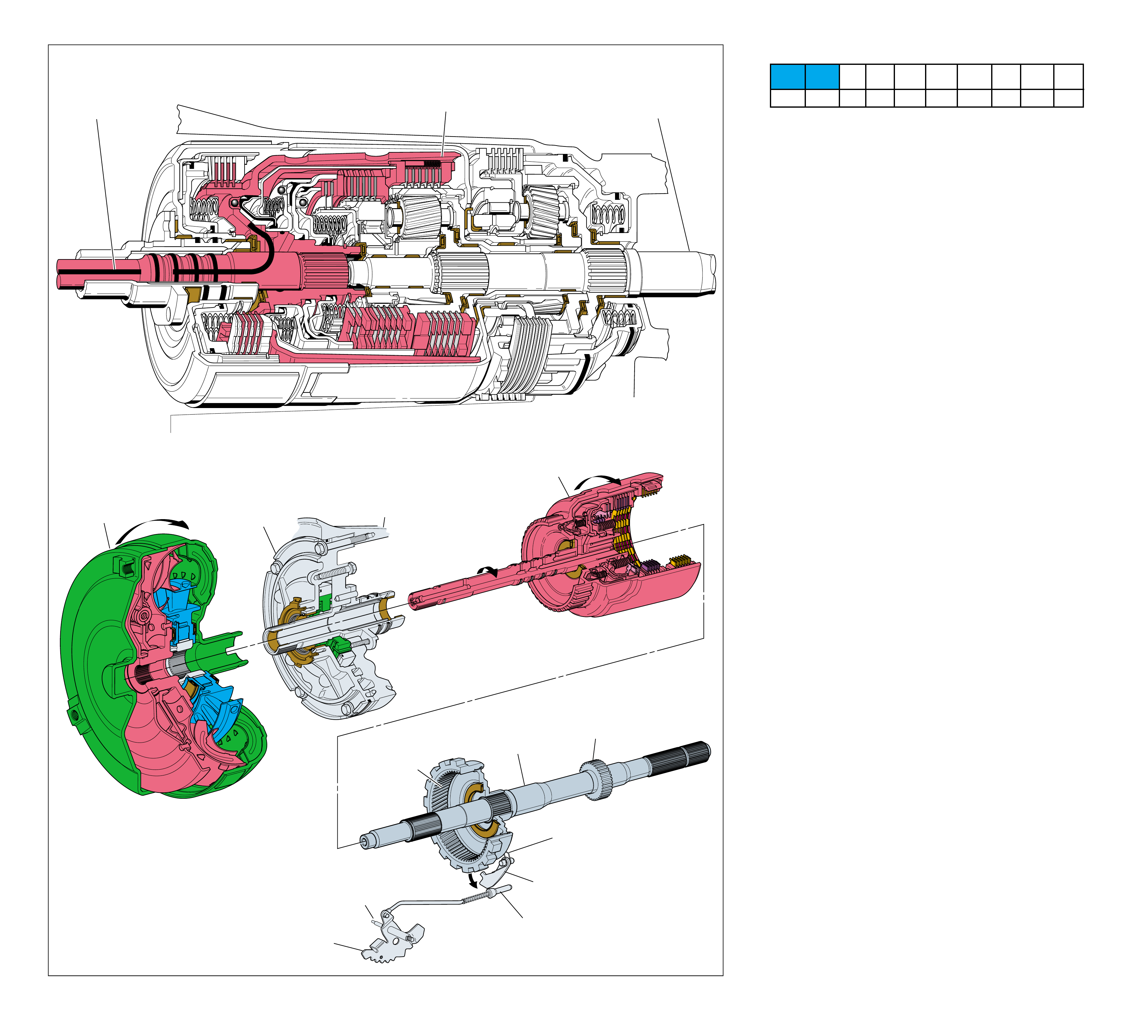
52 Figure 49
TORQUE
CONVERTER
ASSEMBLY
(1)
PUMP
ASSEMBLY
(4)
MAIN
CASE
(103)
INPUT HOUSING
& SHAFT ASSEMBLY
(621)
OUTPUT
SHAFT
(687)
SPEED SENSOR
ROTOR
(699)
PARKING PAWL
RETURN SPRING
(80)
PARKING BRAKE
PAWL (81)
DISENGAGED
PARKING LOCK
ACTUATOR
ASSEMBLY
(85)
INSIDE
DETENT
LEVER
(88)
MANUAL
SHAFT
(84)
REACTION
INTERNAL
GEAR
(684)
➤
➤
1
POWER FROM
TORQUE
CONVERTER
(1)
2
POWERFLOW
TERMINATED
NO POWER
TRANSMITTED TO
OUTPUT SHAFT
(687)
NEUTRAL
(Engine Running)
NEUTRAL
(Engine Running)
52A
When the gear selector lever is placed in the Neutral (N) posi-
tion, mechanical power flow is identical to Park (P) range,
except that the parking lock actuator assembly (85) is disen-
gaged. The parking pawl return spring (80) releases the parking
lock pawl (81) from the lugs on the reaction internal gear (684).
With the parking lock pawl disengaged the output shaft is free
to rotate, allowing the vehicle to roll.
•The manual shaft (84) and manual valve (340) are in the
Neutral position.
1 Power from Torque Converter
The turbine shaft, connected to the input housing (621), is
driven by the converter turbine.
2 Powerflow Terminated
The input housing contains three separate multiple disc
clutches: The overrun clutch, the forward clutch and the 3-4
clutch. All three clutches are released and powerflow is
terminated at the input housing.
Neutral range may be selected for starting the engine when
the vehicle is standing still or moving down the road.
1-2 SHIFT 2-3 SHIFT REVERSE FORWARD
SOLENOID SOLENOID 2-4 INPUT OVERRUN FORWARD SPRAG CL. 3-4 LO-ROLLER LO/REV
VALVE VALVE BAND CLUTCH CLUTCH CLUTCH ASSEMBLY CLUTCH CLUTCH CLUTCH
ON ON

53
NEUTRAL
(Engine Running)
COMPLETE HYDRAULIC CIRCUIT
Page 78 Figure 50
NEUTRAL
(Engine Running)
➤➤➤ ➤
➤
➤
➤
➤
➤
➤➤➤➤➤➤
➤➤➤➤➤➤
➤➤➤
➤➤ ➤➤
➤➤➤➤➤➤ ➤➤➤➤➤➤
➤➤➤➤➤
➤
➤➤➤
➤
➤
➤➤➤
➤➤➤
➤➤➤➤➤ ➤
➤➤➤➤➤➤➤➤➤
➤➤➤➤
➤
➤
➤
➤➤➤
➤➤➤➤➤➤
➤➤
➤➤➤➤➤➤➤ ➤➤➤➤➤➤
➤
➤➤
➤➤➤➤➤➤➤➤➤➤➤➤➤➤➤➤➤ ➤
➤
➤➤➤➤➤➤➤➤
➤➤
➤➤
➤➤
➤
➤➤ ➤➤➤➤➤➤➤
➤
➤➤➤➤➤
➤➤➤➤➤➤➤➤➤➤➤➤
➤
➤➤ ➤
➤➤
➤➤
➤➤➤
➤
➤
➤➤
➤
➤
➤
➤
➤➤➤➤➤
➤
REVERSE INPUT
CLUTCH ASSEMBLY
TORQUE SIG
LINE
REV INPUT
CONV FD
➤
AFL
➤
➤
EX
REV
REVERSE INPUT
REV
REV
REV INPUT
REV INPUT
REVERSE INPUT
LINE (From Pump)
3-4 SHIFT VALVE
LO OVERRUN
LINE
LINE
D4
REVERSE
PR
D3
D2
LO
PR
D2
D3
D3
LO
D4
D4
FWD CL FEED
PR
PR
REV INPUT
LO/REVERSE
LO/1ST
D3
EX
AFL
AFL
AFL
1-2 SIGNAL
AFL
PR
LO/REVERSE
PR
EX
LINE
PRESSURE
TAP
FILTER
(49)
➤➤
➤
➤
➤
➤
➤
➤➤
➤
➤
➤
➤
➤➤➤
➤
➤➤➤
D2-N.C.
REV-N.O.
D3-N.C.
LO-N.O.
D4-N.O.
TEMP
SENSOR
➤
TFP
SWITCH
ASSEMBLY
➤
➤
3-4 SIG
➤
LO/REV
PR
1-2 SIGNAL
4TH SIG
➤
➤
FORWARD CLUTCH
ACCUMULATOR
AFL (To 3-2 Control Solenoid)
➤
2b
2a
2c
1a
1b
1e
1d
1c
1f
#10
➤
LOW AND REVERSE
CLUTCH ASSEMBLY
25
23
26
27
29
2-3 SHUTTLE 2-3 SHIFT VALVE
EX
EX
EX
EX
D2
OVERRUN
D3
2ND
3-4 SIGNAL
EX
2-3 SIGNAL
SERVO FD
3-4 ACC
➤
➤
➤
2-3 SHIFT
SOLENOID
VALVE
N.O.
ON
1-2 SHIFT VALVE
LO
LO
D4
D4-3-2
2ND
EX
EX
1-2 SHIFT
SOLENOID
VALVE
N.O.
ON
28
EX
PRND321
EX
EX
MANUAL VALVE
ACTUATOR FEED LIMIT
TORQUE SIGNAL
EX
EX
EX
AFL
AFL
DECREASE
LINE
LINE
LINE
FILTER (50)
➤
➤➤
➤
➤
➤
➤
➤
➤➤➤
➤
➤
➤
➤
➤
➤➤
➤
➤
TORQUE SIG
➤
➤
10
BOOST VALVE PRESS REG
EX
EX
➤
EX
PRESSURE
CONTROL
SOLENOID
VALVE
32
EX
#3
17
REV ABUSE
When the gear selector lever is moved to the Neutral (N)
position, the manual v alve also mo ves and blocks line pr essure
from entering any other fluid circuits. If Neutral is selected
after the vehicle was operating in Reverse (R), the following
changes would occur in the hydraulic and electrical systems:
1 REVERSE INPUT CLUTCH RELEASES
1a Manual Valve:
The manual valve is moved to the Neutral position and
blocks line pressure from entering the PR and reverse circuits.
The PR and reverse fluid circuits are opened to an exhaust
at the manual valve.
1b Reverse Abuse Valve:
Exhausting reverse fluid pressure allows the reverse abuse
valve spring to shift the valve, blocking off the reverse input
fluid circuit.
1c Reverse Input Clutch:
Reverse input fluid pressure, which was fed by reverse fluid,
exhausts from the reverse input clutch piston allowing the
reverse input clutch to release.
1d Reverse Boost Valve:
Reverse input fluid exhausts from the reverse boost valve,
allowing line pressure to return to the normal operating
range as in Park, Neutral and Overdrive gear ranges.
1e Reverse Input Ball Check Valve (#3):
Exhausting reverse input fluid unseats the #3 ball check
valve, allowing reverse input fluid to exhaust quickly into
the reverse fluid circuit.
1f Transmission Fluid Pressure (TFP) Manual Valve
Position Switch:
Reverse input fluid also exhausts from the TFP manual valve
position switch signaling the powertrain control module (PCM)
that the transmission is in either Neutral (N) or Park (P).
2 LOW AND REVERSE CLUTCH RELEASES
2a Lo Overrun Valve:
Exhausting PR fluid pressure allows the lo overrun valve
spring to shift the valve, opening up the lo/reverse fluid
circuit to exhaust into the lo/1st fluid circuit.
2b Low and Reverse Clutch:
PR fluid exhausts from the outer area of the low and reverse
clutch piston. Exhausting PR fluid unseats the low and
reverse clutch ball check valve (#10) for a quick exhaust.
Lo/Reverse fluid pressure, which was fed by PR fluid,
exhausts from the inner area of the low and reverse clutch
piston and passes through the lo overrun valve into the lo/
1st fluid circuit.
2c 1-2 Shift Valve:
Exhausting lo/reverse fluid, in the lo/1st circuit, enters the
lo fluid circuit at the 1-2 shift valve and exhausts at the
manual valve.
Note: Allowing fluid to bypass an orifice when exhausting
ensures a quick release of the clutch or band. This prevents the
friction material from “dragging” and creating excess fluid
temperatur es or dama ging the clutc h or band.
Note: In Park, Reverse and Neutral the shift solenoids are
shown in the First gear state. This is the normal operating state
when the vehicle is stationary or at low vehicle speeds. However,
the PCM will change the shift solenoid states depending on
vehicle speed. For example, if Neutral rang e is selected when the
vehicle is operating in Second gear, the shift solenoids will
remain in a Second gear state. But with the manual valve in
Neutral, line pressure is blocked, D4 fluid exhausts and the
transmission will shift into Neutr al.
1-2 SHIFT 2-3 SHIFT REVERSE FORWARD
SOLENOID SOLENOID 2-4 INPUT OVERRUN FORWARD SPRAG CL. 3-4 LO-ROLLER LO/REV
VALVE VALVE BAND CLUTCH CLUTCH CLUTCH ASSEMBLY CLUTCH CLUTCH CLUTCH
ON ON
52B
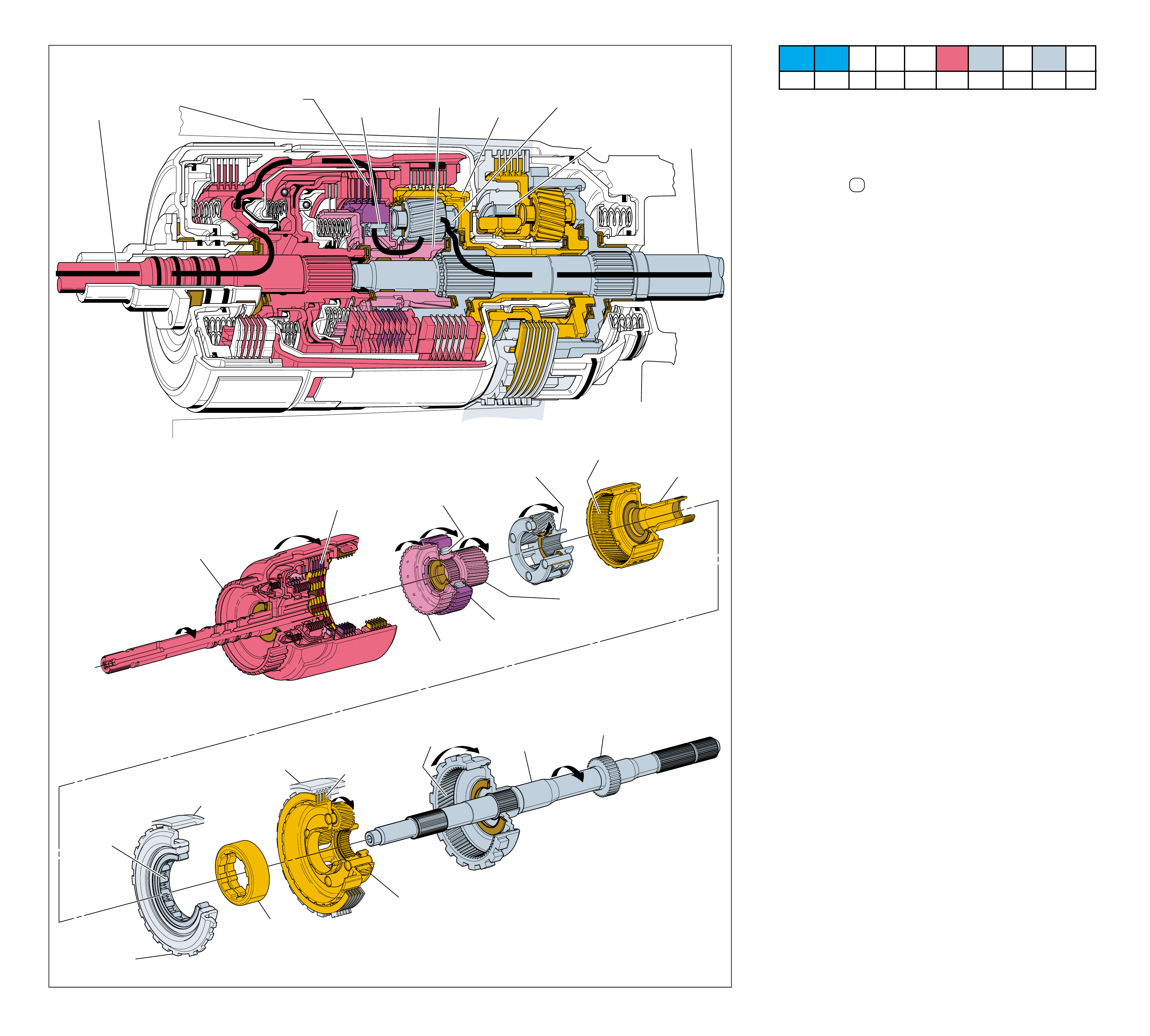
54 Figure 51
LOW AND
REVERSE
CLUTCH SUPPORT
ASSEMBLY
(679)
LOW AND REVERSE
ROLLER CLUTCH
ASSEMBLY
(678)
HOLDING
LOW AND REVERSE
ROLLER CLUTCH
RACE
(675)
HELD
MAIN
CASE
(103)
INPUT HOUSING
& SHAFT ASSEMBLY
(621)
OUTPUT
SHAFT
(687)
SPEED SENSOR
ROTOR
(699)
REACTION
INTERNAL
GEAR
(684)
FORWARD SPRAG
ASSEMBLY
(642)
HOLDING
OVERRUN
CLUTCH HUB
(639)
FORWARD CLUTCH
OUTER RACE
(644)
FORWARD SPRAG CLUTCH
INNER RACE AND INPUT
SUN GEAR ASSEMBLY
(640)
INPUT CARRIER
ASSEMBLY
(662)
INPUT
INTERNAL
GEAR
(664)
HELD
REACTION
CARRIER
SHAFT
(666)
HELD
LOW AND REVERSE
CLUTCH PLATE
ASSEMBLY
(682)
REACTION
CARRIER
ASSEMBLY
(681)
HELD
MAIN
CASE
(103)
FORWARD
CLUTCH
APPLIED
➤
➤
➤
➤
➤ ➤
➤
1
POWER FROM
TORQUE
CONVERTER
(1) POWER TO
DIFFERENTIAL
ASSEMBLY
3
FORWARD SPRAG
ASSEMBLY
(642)
HOLDING
2
FORWARD
CLUTCH
APPLIED
5
LOW AND
REVERSE
ROLLER
CLUTCH
ASSEMBLY
(678)
HOLDING
6
INPUT
INTERNAL
GEAR
HELD
7
INPUT
CARRIER
DRIVEN
4
INPUT
SUN GEAR
DRIVING
OVERDRIVE RANGE – FIRST GEAR
In Overdrive Range – First Gear, torque from the engine is multi-
plied through the torque converter and transmission gear sets to
the vehicle’s drive shaft. The planetary gears operate in reduction
to achieve a First gear starting ratio of approximately 3.06:1.
•The manual shaft (84) and manual valve (340) are in the
Overdrive D position.
1 Power from Torque Converter
The turbine shaft, connected to the input housing (621), is
driven by the converter turbine.
2 Forward Clutch Applied
The forward clutch is applied in all forward gear ranges.
The forward clutch plates (649) transfer engine torque from
the input housing to the forward clutch outer race (644).
3 Forward Sprag Assembly Holding
The sprag clutch (642), located between the forward clutch
outer race and the forward sprag inner race and input sun
gear assembly (640), locks and drives the forward sprag
inner race and input sun gear assembly.
4 Input Sun Gear Driving
The input sun gear drives the input carrier pinion gears
counterclockwise.
5 Low and Reverse Roller Clutch Assembly Holding
The low and reverse roller clutch (678) is located between
the low and reverse clutch support assembly (679) (which is
splined to the case) and the reaction carrier assembly. With
the reaction carrier attempting to rotate counterclockwise,
the roller clutch locks and prevents the reaction carrier,
reaction carrier shaft and input internal gear from rotating.
6 Input Internal Gear Held
The input carrier pinion gears, rotating counterclockwise on
their pins, walk clockwise around the stationary input internal
gear. This action drives the input carrier assembly (662)
clockwise.
7 Input Carrier Driven
The input carrier assembly is splined to and drives the output
shaft (687) clockwise in a First gear reduction of
approximately 3.06:1.
•
As a result of the output shaft rotating, the reaction internal gear
(684), reaction carrier pinion gears, reaction sun gear (673), reac-
tion sun shell (670), and reverse input clutch housing (605) all
rotate but do not affect the transmission’s mechanical power flow.
Coast Conditions
•When the throttle is released in Overdrive Range – First Gear
and engine RPM decreases, power from vehicle speed drives the
output shaft and input carrier (662) faster than engine torque is
driving the forward clutch outer race (644). This allows the
input carrier pinion gears to drive the forward sprag inner race
and input sun gear assembly (640) clockwise faster than the
forward clutch outer race. This causes the forward sprag inner
race and input sun gear assembly to overrun the sprag clutch and
allow the vehicle to coast freely without engine compression
slowing the vehicle.
•Also during coast conditions, the reaction internal gear drives
the reaction carrier pinion gears. This drives the reaction carrier
clockwise and overruns the low and reverse roller clutch.
As vehicle speed increases, less torque multiplication is needed
for maximum efficiency. Therefore, it is desirable to shift the
transmission to a lower gear ratio, or Second gear.
OVERDRIVE RANGE – FIRST GEAR
54A
1-2 SHIFT 2-3 SHIFT REVERSE FORWARD
SOLENOID SOLENOID 2-4 INPUT OVERRUN FORWARD SPRAG CL. 3-4 LO-ROLLER LO/REV
VALVE VALVE BAND CLUTCH CLUTCH CLUTCH ASSEMBLY CLUTCH CLUTCH CLUTCH
ON ON APPLIED HOLDING HOLDING
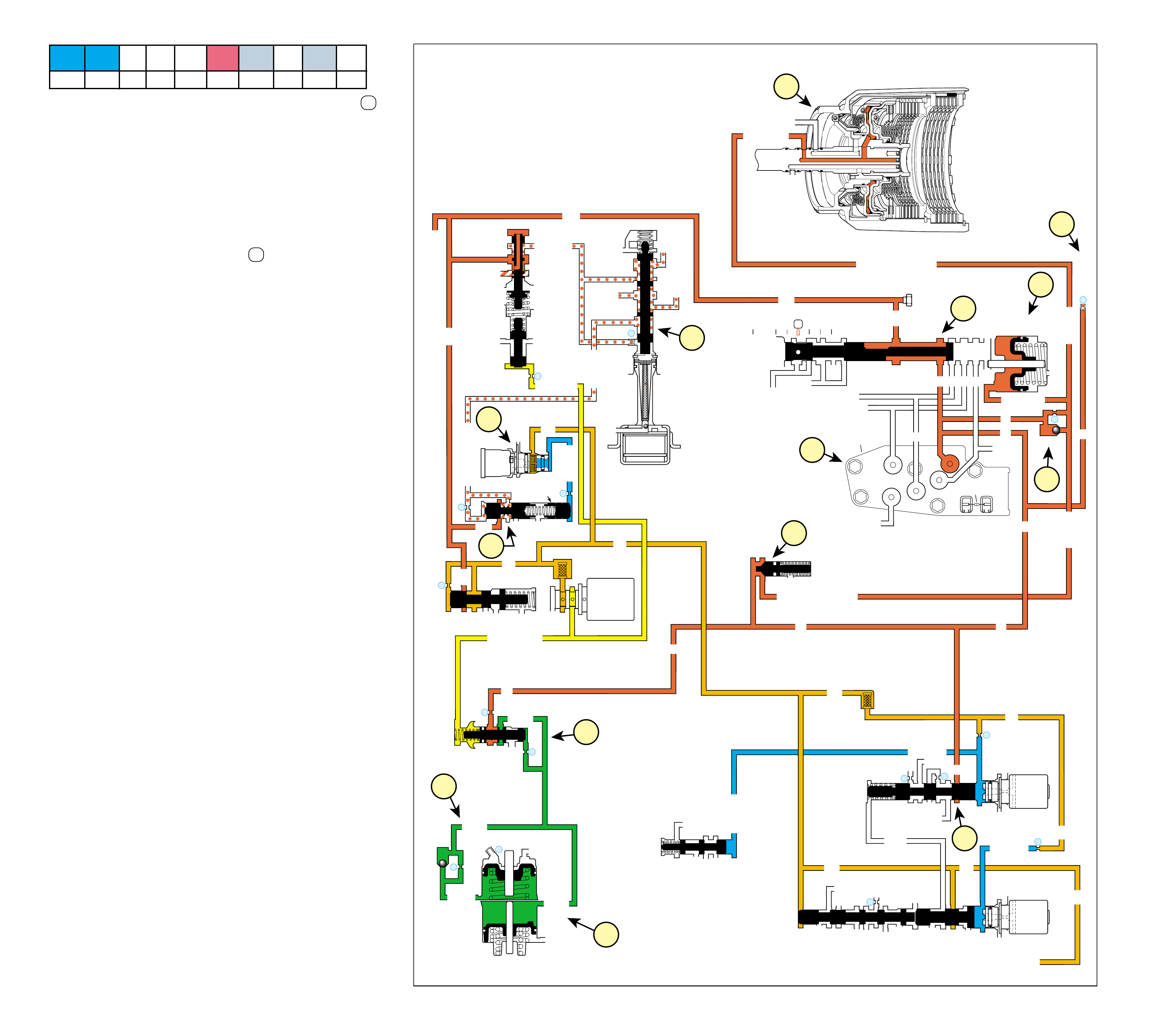
55
OVERDRIVE RANGE – FIRST GEAR
COMPLETE HYDRAULIC CIRCUIT
Page 80 Figure 52
When the gear selector lever is moved to the Overdrive Range D
position from the Neutral (N) position, the f ollowing changes occur
to shift the transmission into Over driv e Range – First Gear .
1 OVERDRIVE RANGE
1a Manual Valve:
In the Overdrive position the manual valve routes line pressure
into the D4 fluid circuit.
1b Transmission Fluid Pressure (TFP) Manual Valve
Position Switch:
D4 fluid is routed to the TFP manual valve position switch to
signal the powertrain control module (PCM) that the
transmission is in Overdrive Range D .
1c Rear Lube:
D4 fluid is also routed to the rear of the transmission case
where it is orficed (#24) into the rear lube fluid circuit to
lubricate the rear end of the transmission.
2 FORWARD CLUTCH APPLIES
2a Forward Clutch Accumulator Ball Check Valve (#12):
D4 fluid pressure seats the forward clutch accumulator ball
check valve (#12) and is orificed into the forward clutch feed
fluid circuit. This orifice (#22) helps control the forward
clutch apply when engine speed is approximately at idle.
2b Forward Abuse Valve:
When engine speed is above idle, D4 fluid acts on the forward
abuse valve to move the valve against spring force. This
allows D4 fluid to feed the forward clutch feed fluid circuit
quickly, bypassing the control of orifice #22.
2c Forward Clutch Assembly:
Forward clutch feed fluid is routed to the forward clutch piston
to apply the forward clutch plates and obtain a First gear ratio
through the transmission gear sets.
2d Forward Clutch Accumulator:
As the forward clutch applies, forward clutch feed fluid pressure
moves the forward clutch accumulator piston against spring
force. This action absorbs some of the initial increase of forward
clutch feed fluid pressure to cushion the forward clutch apply.
3 SHIFT ACCUMULATION
3a Accumulator Valve:
D4 fluid is also directed to the accumulator valve where it is
regulated into accumulator fluid pressure in response to torque
signal fluid pressure, orificed accumulator fluid pressure and
accumulator valve spring force.
3b 1-2 Accumulator:
Accumulator fluid is routed to and fills the 1-2 accumulator in
preparation for a 1-2 upshift.
3c 3-4 Accumulator:
Accumulator fluid also seats the #1 ball check valve, is forced
through orifice #18 into the orificed accumulator fluid circuit and
fills the 3-4 accumulator with fluid in preparation for a 3-4 upshift.
4 FLUID PRESSURE DIRECTED IN PREPARATION
FOR A SHIFT
4a 1-2 Shift Valve:
D4 fluid is routed to the 1-2 shift valve in preparation for an
upshift to second gear.
5 FLUID PRESSURE DIRECTED IN PREPARATION
FOR TCC APPLY
5a TCC PWM Solenoid Valve:
The solenoid duty cycle regulates actuator feed limit fluid
(AFL) into the CC signal circuit.
5b Regulated Apply Valve and Isolator Valve:
CC signal fluid works together with orficed regulated apply
fluid to regulate line pressure through the regulated apply valve,
into the regulated apply fluid circuit.
5c TCC Solenoid Valve:
Regulated apply fluid is routed to the converter clutch valve in
preparation for TCC apply.
1-2 SHIFT 2-3 SHIFT REVERSE FORWARD
SOLENOID SOLENOID 2-4 INPUT OVERRUN FORWARD SPRAG CL. 3-4 LO-ROLLER LO/REV
VALVE VALVE BAND CLUTCH CLUTCH CLUTCH ASSEMBLY CLUTCH CLUTCH CLUTCH
ON ON APPLIED HOLDING HOLDING
➤
INPUT CLUTCH
HOUSING ASSEMBLY
OVERRUN CLUTCH
FORWARD CLUTCH FEED
➤
➤
➤➤
➤
FWD CL FEED
D4
D4
FORWARD CLUTCH FEED
FWD CL FD FWD CL FD
D4
D4
D4
D4
D4
1-2 SIGNAL
D4
3-4 SIG
SERVO FD
AFL (To 3-2 Control Solenoid Valve)
2ND CL
ACCUM
ACCUM
3-4 CLUTCH
➤
➤
➤
➤
➤
➤
➤➤
➤
➤
➤➤
➤
➤
➤➤
➤
➤
➤
➤
➤➤➤
➤➤
➤
➤
➤
➤
➤
➤
➤➤
➤
➤
➤
➤
➤
➤
➤
REAR LUBE
3-4 ACCUM
OVERDRIVE RANGE – FIRST GEAR
➤
➤
➤
24
LINE
LINE
D4
REVERSE
PR
D3
D2
LO
D2
D3
D3
LO
FWD CL FEED
REV INPUT
LINE
PRESSURE
TAP
➤
➤
➤
➤
D2-N.C.
REV-N.O.
D3-N.C.
LO-N.O.
D4-N.O.
TEMP
SENSOR
➤
TFP
SWITCH
ASSEMBLY
➤
FORWARD CLUTCH
ACCUMULATOR
EX
PRND321
EX
EX
MANUAL VALVE
➤
➤
#12
22
➤
➤
➤
EX
FORWARD ABUSE
LO/1ST
AFL
AFL
AFL
1-2 SIGNAL
AFL
FILTER
(49)
➤
➤
➤➤
➤➤
➤
➤
➤
➤
➤➤➤ ➤
➤
AFL
AFL
25
26
27
29
EX
EX
EX
EX
D2
OVERRUN
D3
2ND
EX
2-3 SIGNAL
3-4 ACC
➤
2-3 SHIFT
SOLENOID
VALVE
N.O.
ON
LO
D4
D4-3-2
2ND
EX
EX
1-2 SHIFT
SOLENOID
VALVE
N.O.
ON
28
#1
18
➤
➤
3-4 ACCUMULATOR
1-2 ACCUMULATOR
19
EX
ORF ACC
➤
➤
D3
EX
3-4 SIGNAL
4TH SIG
30
EX
ACCUM
31
➤
➤
➤
➤
➤
➤
3a
5c
3c
5a
1a
2b
5b 2a
4a
2d
1b
1c
2c
3b
➤
➤
2-3 SHUTTLE 2-3 SHIFT VALVE
➤
➤
➤➤
➤
➤
➤
3-4 SHIFT VALVE
1-2 SHIFT VALVE
ACCUM VALVE
➤
➤
➤
➤
➤
➤
➤
➤
➤
➤
➤
➤➤
➤➤
➤
➤
➤
LINE
LINE
➤
➤➤
➤➤ ➤
LINE (From Pump)
➤
TORQUE SIGNAL
AFL
AFL
➤
➤
➤
➤
➤
➤
➤
➤
➤
➤
➤
➤
TCC
SOLENOID
N.O.
OFF
CONVERTER CLUTCH VALVE
COOLER
RELEASE
APPLY
EX
➤
EX
➤
4
➤
➤
➤
REG APPLY
BOOST VALVE PRESS REG
EX
TORQUE SIG
➤
EX
CONV FEED
➤
➤➤
REV INPUT
DECREASE
REV INPUT
10
LINE
REGULATED APPLY
➤
EX
EX
EX
CC SIGNAL
9
TCC PWM
SOLENOID
VALVE
N.C.
➤
8
ACTUATOR FEED LIMIT
EX
EX
EX
AFL
LINE
FILTER (50)
➤
➤
➤➤
➤
➤
➤
➤
➤
EX
PRESSURE
CONTROL
SOLENOID
VALVE
32
ISOLATOR VALVE
REG APPLY
54B
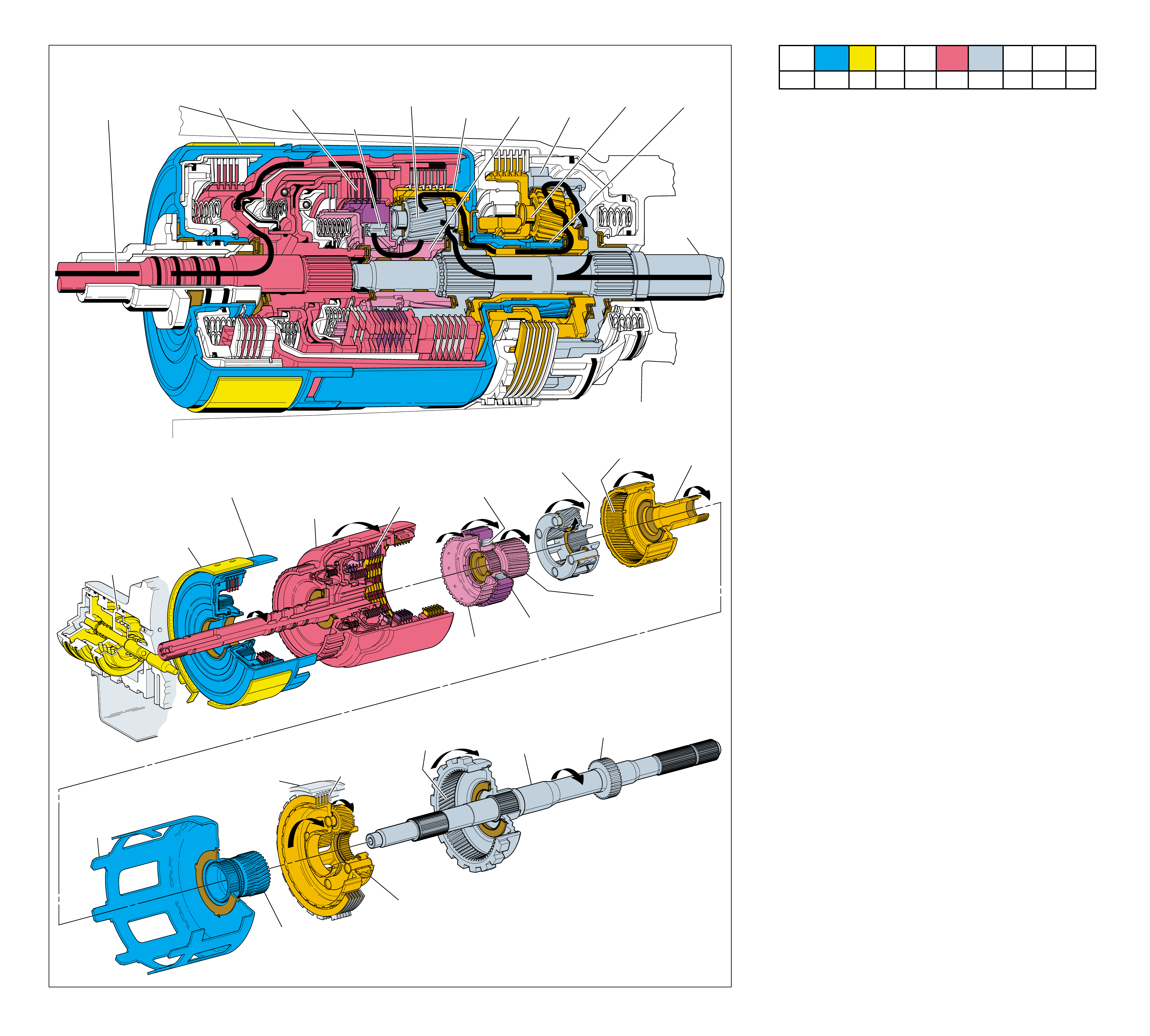
56
INPUT HOUSING
& SHAFT ASSEMBLY
(621)
OUTPUT
SHAFT
(687)
SPEED SENSOR
ROTOR
(699)
REACTION
INTERNAL
GEAR
(684)
FORWARD SPRAG
ASSEMBLY
(642)
HOLDING
OVERRUN
CLUTCH HUB
(639)
FORWARD CLUTCH
OUTER RACE
(644)
FORWARD SPRAG CLUTCH
INNER RACE AND
INPUT SUN GEAR ASSEMBLY
(640)
INPUT CARRIER
ASSEMBLY
(662)
INPUT
INTERNAL
GEAR
(664)
REACTION
CARRIER
SHAFT
(666)
SERVO
ASSEMBLY
APPLIED
2-4 BAND
ASSEMBLY
(602)
APPLIED
REVERSE INPUT
CLUTCH HOUSING
(605)
HELD
REACTION
SUN SHELL
(670)
HELD
REACTION
SUN GEAR
(673)
HELD
LOW AND REVERSE
CLUTCH PLATE
ASSEMBLY
(682)
REACTION
CARRIER
ASSEMBLY
(681)
MAIN
CASE
(103)
FORWARD
CLUTCH
APPLIED
➤
➤
➤
➤
➤
➤ ➤
➤
➤
➤
1
POWER FROM
TORQUE
CONVERTER
(1)
POWER TO
DIFFERENTIAL
ASSEMBLY
8
2-4 BAND
ASSEMBLY (602)
APPLIED
3
FORWARD
SPRAG
ASSEMBLY
(642)
HOLDING
2
FORWARD
CLUTCH
APPLIED
10
INPUT
INTERNAL
GEAR
DRIVING
5
INPUT
CARRIER
DRIVEN
4
INPUT
SUN
GEAR
DRIVING
6
REACTION
INTERNAL
GEAR
DRIVEN
7
REACTION
CARRIER
DRIVEN
9
REACTION
SUN GEAR
HELD
OVERDRIVE RANGE – SECOND GEAR
Figure 53
OVERDRIVE RANGE – SECOND GEAR
56A
As vehicle speed increases, input signals from the transmission
speed sensor, the throttle position (TP) sensor, and other vehicle
sensors are sent to the powertrain control module (PCM). The
PCM processes this information to determine the precise mo-
ment to shift the transmission. In Second gear, the planetary
gear sets continue to operate in reduction at a gear ratio of
approximately 1.63:1.
1 Power from Torque Converter
The turbine shaft, connected to the input housing (621), is
driven by the converter turbine.
2 Forward Clutch Applied
The forward clutch (649) is applied and the forward clutch
plates (649) transfer engine torque from the input housing to
the forward clutch outer race (644).
3 Forward Sprag Clutch Holding
The forward sprag assembly locks and drives the forward
sprag clutch inner race and input sun gear assembly (640).
4 Input Sun Gear Driving
The forward sprag clutch inner race and input sun gear
assembly (640) drives the input carrier pinion gears.
5 Input Carrier Driven
The input carrier assembly (662) is driven clockwise by the
input carrier pinion gears walking around the input internal
gear (664) as in First gear. This action drives the output
shaft (687) and the reaction internal gear (684).
6 Reaction Internal Driven
The reaction internal gear rotates with the output shaft and
drives the reaction carrier pinion gears in a clockwise direction.
7 Reaction Carrier Driven
The reaction carrier shaft (666) and input internal gear (664)
are driven clockwise by the reaction carrier assembly.
8 2-4 Band Assembly Applied
The 2-4 band (602) is applied and holds the reverse input
clutch housing (605) stationary to the transmission case.
9 Reaction Sun Gear Held
The reverse input clutch housing and the reaction sun gear
(673) are splined to the reaction sun shell (670). With the
2-4 band applied, the sun shell and reaction sun gear are
also held stationary.
10 Input Internal Gear Driving
The input internal gear drives the input carrier pinions, input
carrier and output shaft in a second reduction to achieve the
Second gear ratio of approximately 1.63:1.
Coast Conditions
•
Similar to Overdrive Range – First Gear, the forward sprag clutch
is overrun when the throttle is released. This action allows the
vehicle to coast freely in Overdrive Range – Second Gear.
As vehicle speed increases, less torque multiplication is needed
to move the vehicle efficiently. Therefore, it is desirable to shift
the transmission to a lower gear ratio, or Third gear.
1-2 SHIFT 2-3 SHIFT REVERSE FORWARD
SOLENOID SOLENOID 2-4 INPUT OVERRUN FORWARD SPRAG CL. 3-4 LO-ROLLER LO/REV
VALVE VALVE BAND CLUTCH CLUTCH CLUTCH ASSEMBLY CLUTCH CLUTCH CLUTCH
OFF ON APPLIED APPLIED HOLDING
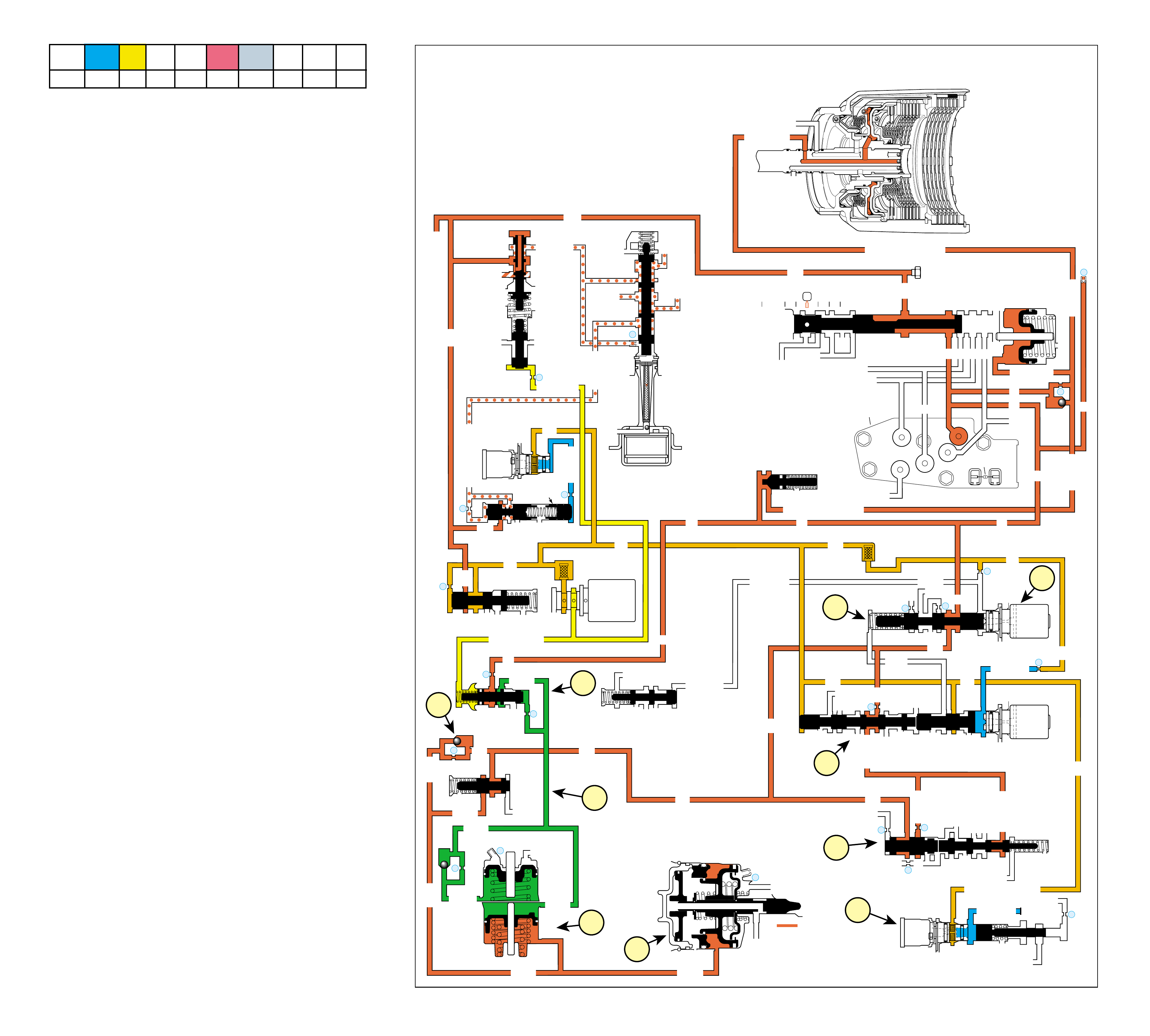
57
As vehicle speed increases, the powertrain control module (PCM)
receives input signals from the vehicle speed sensor, the throttle
position (TP) sensor and other vehicle sensors to determine the
precise moment to de-energize or “turn OFF” the 1-2 shift sole-
noid (SS) valve. The 1-2 SS valve is OFF when the PCM
eliminates the path to ground for that circuit.
1 2-4 BAND APPLIES
1a 1-2 Shift Solenoid (SS) Valve:
The 1-2 SS valve is de-energized, allowing 1-2 signal fluid
to exhaust from its circuit.
1b 1-2 Shift Valve:
Exhausting 1-2 signal fluid pressure allows 1-2 shift valve
spring force to move the 1-2 shift valve into the upshifted
position. D4 fluid is routed through the 1-2 shift valve and
into the 2nd fluid circuit.
1c #8 Ball Check Valve:
2nd fluid seats the #8 ball check valve, passes through an
orifice (#16) and enters the 2nd clutch fluid circuit.
1d 2nd & 4th Servo:
2nd clutch fluid is directed to the 2nd & 4th servo to move the
2nd apply piston against servo cushion and servo return spring
forces to apply the 2-4 band and achieve Second gear.
2 SHIFT ACCUMULATION
2a 1-2 Accumulator:
2nd clutch fluid is also sent to the 1-2 accumulator. 2nd
clutch fluid pressure, together with spring pressure, acts
against accumulator fluid pressure to absorb some of the
initial increase of 2nd clutch fluid pressure to cushion the
2-4 band apply.
2b Accumulator Valve:
Accumulator fluid is forced out of the 1-2 accumulator
when 2nd clutch fluid pressure and spring force move the
1-2 accumulator piston. Accumulator fluid flows back to
the accumulator valve and into the orificed accumulator
fluid circuits. Orificed accumulator fluid pressure and
accumulator spring force regulate the accumulator valve
against torque signal fluid pressure. This allows excess
accumulator fluid pressure to exhaust and provides
additional control of the 2-4 band apply.
3 FLUID PRESSURE DIRECTED IN PREPARATION
FOR A SHIFT
3a 2-3 Shift Valve:
2nd fluid is directed to the 2-3 shift valve in preparation for
an upshift to third gear. 2nd fluid also passes through the
2-3 shift valve into the servo feed fluid circuit and is directed
to the 3-4 relay and 4-3 sequence valves where it stops.
Servo feed fluid has no function in second gear.
3b 3-4 Relay Valve:
2nd fluid pressure is also directed to the 3-4 relay valve in
preparation for an upshift.
3c 3-2 Downshift Valve:
Spring force holds the valve closed, blocking 2nd fluid
pressure and 2nd clutch fluid pressure. This valve is used in
order to help control a 3-2 downshift.
3d 3-2 Control Solenoid Valve:
In second gear, the PCM energizes the normally closed
solenoid. This opens the actuator feed limit fluid circuit to
fill the 3-2 signal circuit. The 3-2 signal fluid pressure
moves the 3-2 control valve against spring force. This
action is done in preparation for control of a 3-2 downshift
and does not affect transmission operation in second gear.
OVERDRIVE RANGE – SECOND GEAR
COMPLETE HYDRAULIC CIRCUIT
Page 82 Figure 54
➤
➤
➤
➤
➤
➤
➤
➤
➤
➤
➤
➤➤
➤➤➤➤
➤ ➤➤➤➤➤➤ ➤ ➤
➤
➤
➤
➤
➤
➤
➤➤
➤
➤➤
➤➤
➤
➤
➤
INPUT CLUTCH
HOUSING ASSEMBLY
OVERRUN CLUTCH
LINE
LINE
➤
➤➤
➤➤ ➤
LINE (From Pump)
FORWARD CLUTCH FEED
➤
➤
➤➤
➤
FWD CL FEED
➤
D4
D4
FORWARD CLUTCH FEED
FWD CL FD FWD CL FD
D4
D4
D4
D4
D4
D4
TORQUE SIGNAL
1-2 SIGNAL
3-4 ACC
2ND
D4
1-2 SIGNAL
3-4 SIG
4TH
OVERRUN CL FD
OVERRUN CL
SERVO FEED
SERVO FD
SERVO FD
ACTUATOR FEED LIMIT
4TH SIG
2ND
2ND CL2ND CL
2ND CL
2ND CL 3-4 CL 2ND
2ND 2ND
ACCUM
ACCUM
3-4 CLUTCH
AFL
AFL
2ND CL
➤
➤
➤
➤
➤
➤
➤
➤
➤
➤
➤
➤
➤➤
➤
➤
➤➤
➤
➤
➤➤
➤
➤
➤
➤
➤
➤
➤➤
➤➤
➤
➤
➤
➤
➤➤
➤➤
➤
➤
➤
➤➤
➤➤
➤➤
➤➤
➤
➤
➤
➤
➤
➤➤
➤
➤
➤
➤
➤➤➤
➤
➤
➤➤
➤
➤
➤
➤➤ ➤
➤
➤
➤➤
➤
➤
➤
➤
➤
➤
REAR LUBE
➤
4TH SIGNAL
3-4 ACCUM
OVERDRIVE RANGE – SECOND GEAR
➤
➤
➤
EX
EX
3-4 RELAY 4-3 SEQUENCE VALVE
EXORF EX 5
67
TCC
SOLENOID
N.O.
OFF
CONVERTER CLUTCH VALVE
COOLER
RELEASE
APPLY
EX
➤
EX
➤
4
➤
➤
➤
REG APPLY
BOOST VALVE PRESS REG
EX
TORQUE SIG
➤
EX
CONV FEED
➤
➤➤
REV INPUT
DECREASE
REV INPUT
10
LINE
REGULATED APPLY
➤
EX
EX
EX
CC SIGNAL
9
TCC PWM
SOLENOID
VALVE
N.C.
➤
8
ACTUATOR FEED LIMIT
EX
EX
EX
AFL
LINE
FILTER (50)
➤
➤
➤➤
➤
➤
➤
➤
➤
EX
PRESSURE
CONTROL
SOLENOID
VALVE
32
24
LINE
LINE
D4
REVERSE
PR
D3
D2
LO
D2
D3
D3
LO
FWD CL FEED
REV INPUT
LINE
PRESSURE
TAP
➤
➤
➤
➤
D2-N.C.
REV-N.O.
D3-N.C.
LO-N.O.
D4-N.O.
TEMP
SENSOR
➤
TFP
SWITCH
ASSEMBLY
➤
FORWARD CLUTCH
ACCUMULATOR
EX
PRND321
EX
EX
MANUAL VALVE
➤
➤
#12
22
➤
➤
➤
EX
FORWARD ABUSE
LO/1ST
AFL
AFL
AFL
1-2 SIG
AFL
FILTER
(49)
➤
➤
➤
➤
➤
➤
➤
➤
➤
➤
➤➤➤ ➤
➤
AFL
AFL
25
26
27
29
EX
EX
EX
EX
D2
OVERRUN
D3
2ND
EX
2-3 SIGNAL
3-4 ACC
➤
2-3 SHIFT
SOLENOID
VALVE
N.O.
ON
LO
D4
D4-3-2
2ND
EX
EX
1-2 SHIFT
SOLENOID
VALVE
N.O.
OFF
28
1-2 SHIFT VALVE
14
3-4 CLUTCH
3RD ACCUMULATOR
EX
EX
3-2 SIGNAL
➤
#1
18
➤
➤
3-4 ACCUMULATOR
1-2 ACCUMULATOR
19
EX
ORF ACC
➤
➤
D3
EX
3-4 SIGNAL
4TH SIG
3-4 SHIFT VALVE
EX
30
EX
ACCUM
31
➤
➤
➤
➤
➤
➤
#8
16
➤
➤
1d
3b
3d
1c
2a
1a
1b
3a
2b
3c
➤
➤
2-3 SHUTTLE 2-3 SHIFT VALVE
ACCUM VALVE
➤
11 3RD ACCUM
➤
2ND & 4TH
SERVO
11
4TH
EX
EX
➤
➤
3-2 CONTROL
3-2
CONTROL
SOLENOID
VALVE
N.C.
ON
➤
3-2 DOWNSHIFT
ISOLATOR VALVE
REG APPLY
1-2 SHIFT 2-3 SHIFT REVERSE FORWARD
SOLENOID SOLENOID 2-4 INPUT OVERRUN FORWARD SPRAG CL. 3-4 LO-ROLLER LO/REV
VALVE VALVE BAND CLUTCH CLUTCH CLUTCH ASSEMBLY CLUTCH CLUTCH CLUTCH
OFF ON APPLIED APPLIED HOLDING
56B
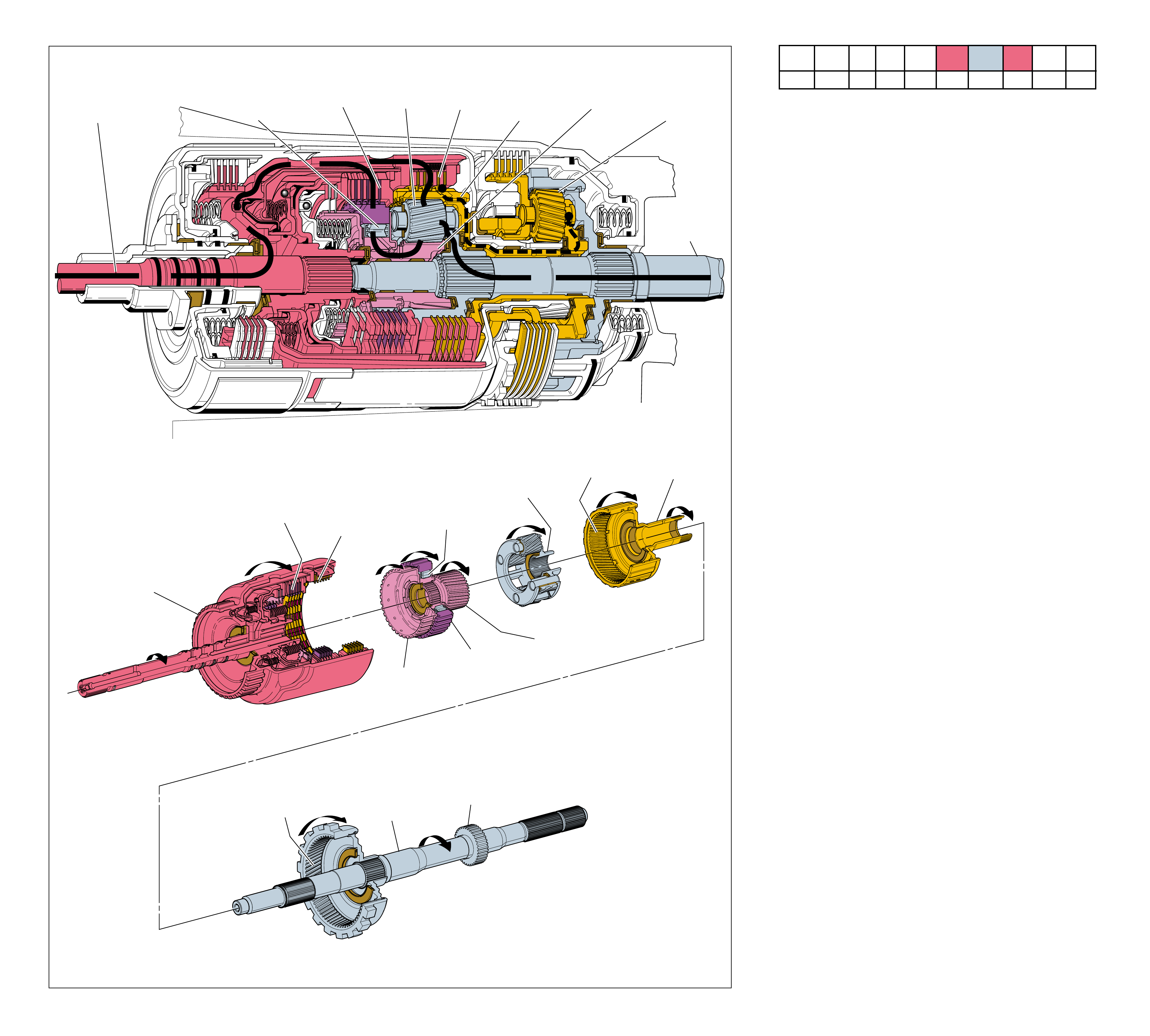
58
INPUT HOUSING
& SHAFT ASSEMBLY
(621)
OUTPUT
SHAFT
(687)
SPEED SENSOR
ROTOR
(699)
REACTION
INTERNAL
GEAR
(684)
FORWARD SPRAG
ASSEMBLY
(642)
HOLDING
OVERRUN
CLUTCH HUB
(639)
FORWARD CLUTCH
OUTER RACE
(644)
FORWARD SPRAG CLUTCH
INNER RACE AND
INPUT SUN GEAR
ASSEMBLY
(640)
INPUT CARRIER
ASSEMBLY
(662)
INPUT
INTERNAL
GEAR
(664)
REACTION
CARRIER
SHAFT
(666)
FORWARD
CLUTCH
APPLIED 3-4
CLUTCH
APPLIED
➤
➤
➤
➤
➤ ➤
➤
➤
1
POWER FROM
TORQUE
CONVERTER
(1)
POWER TO
DIFFERENTIAL
ASSEMBLY
3
FORWARD SPRAG
ASSEMBLY
(642)
HOLDING
2
FORWARD
CLUTCH
APPLIED
7
INPUT
CARRIER
DRIVEN
6
INPUT
INTERNAL
GEAR
DRIVING
4
INPUT
SUN GEAR
DRIVING
8
REACTION
PLANETARY
GEAR SET
DRIVEN
5
3-4
CLUTCH
APPLIED
OVERDRIVE RANGE – THIRD GEAR
Figure 55
OVERDRIVE RANGE – THIRD GEAR
58A
As vehicle speed increases further, input signals from the trans-
mission speed sensor, the throttle position (TP) sensor, and other
vehicle sensors are sent to the PCM. The PCM uses this informa-
tion to determine the precise moment to shift the transmission
into Third gear. In Third gear, both planetary gear sets, input and
reaction, rotate at the same speed and provide a 1:1 direct drive
gear ratio between the converter turbine and the output shaft.
1 Power from Torque Converter
The turbine shaft, connected to the input housing (621), is
driven by the converter turbine.
2 Forward Clutch Applied
The forward clutch (649) is applied and the forward clutch
plates (649) transfer engine torque from the input housing to
the forward clutch outer race (644).
3 Forward Sprag Clutch Holding
The forward sprag assembly locks and drives the forward
sprag clutch inner race and input sun gear assembly (640).
4 Input Sun Gear Driving
The forward sprag clutch inner race and input sun gear
assembly (640) drives the input carrier pinion gears.
5 3-4 Clutch Applied
The 3-4 clutch plates (654) are applied and transfer engine
torque from the input housing (621) to the input internal
gear (664).
6 Input Internal Gear Driving
Both the input internal gear and the input sun gear are
driven at the same speed. The input carrier pinion gears are
splined to these components and act as wedges to drive the
input carrier assembly (662).
7 Input Carrier Driven
The input carrier drives the output shaft (687) at converter
turbine speed to achieve direct drive in Third gear.
8 Reaction Planetary Gearset Driven
The reaction internal gear (684) is driven by the output
shaft. Also, the reaction carrier shaft (666) is driven by the
input planetary gear set and drives the reaction carrier
assembly (681). With the reaction carrier and reaction
internal gear rotating at the same speed, the pinion gears act
as wedges and drive the reaction sun gear (673) at the same
speed. As a result, the entire gear set rotates as one unit at
converter turbine speed.
Coast Conditions
•As in First and Second gears when the throttle is released, power
from vehicle speed drives the forward sprag clutch inner race
and input sun gear assembly (640) faster than engine torque
drives the forward clutch outer race (644). This action causes
the forward sprag clutch inner race and input sun gear assembly
(640) to overrun the sprag clutch (642) and allow the vehicle to
coast freely.
As vehicle speed increases, less torque multiplication is re-
quired to operate the engine efficiently. Therefore, it is desirable
to shift to an overdrive gear ratio, or Fourth gear.
1-2 SHIFT 2-3 SHIFT REVERSE FORWARD
SOLENOID SOLENOID 2-4 INPUT OVERRUN FORWARD SPRAG CL. 3-4 LO-ROLLER LO/REV
VALVE VALVE BAND CLUTCH CLUTCH CLUTCH ASSEMBLY CLUTCH CLUTCH CLUTCH
OFF OFF APPLIED HOLDING APPLIED
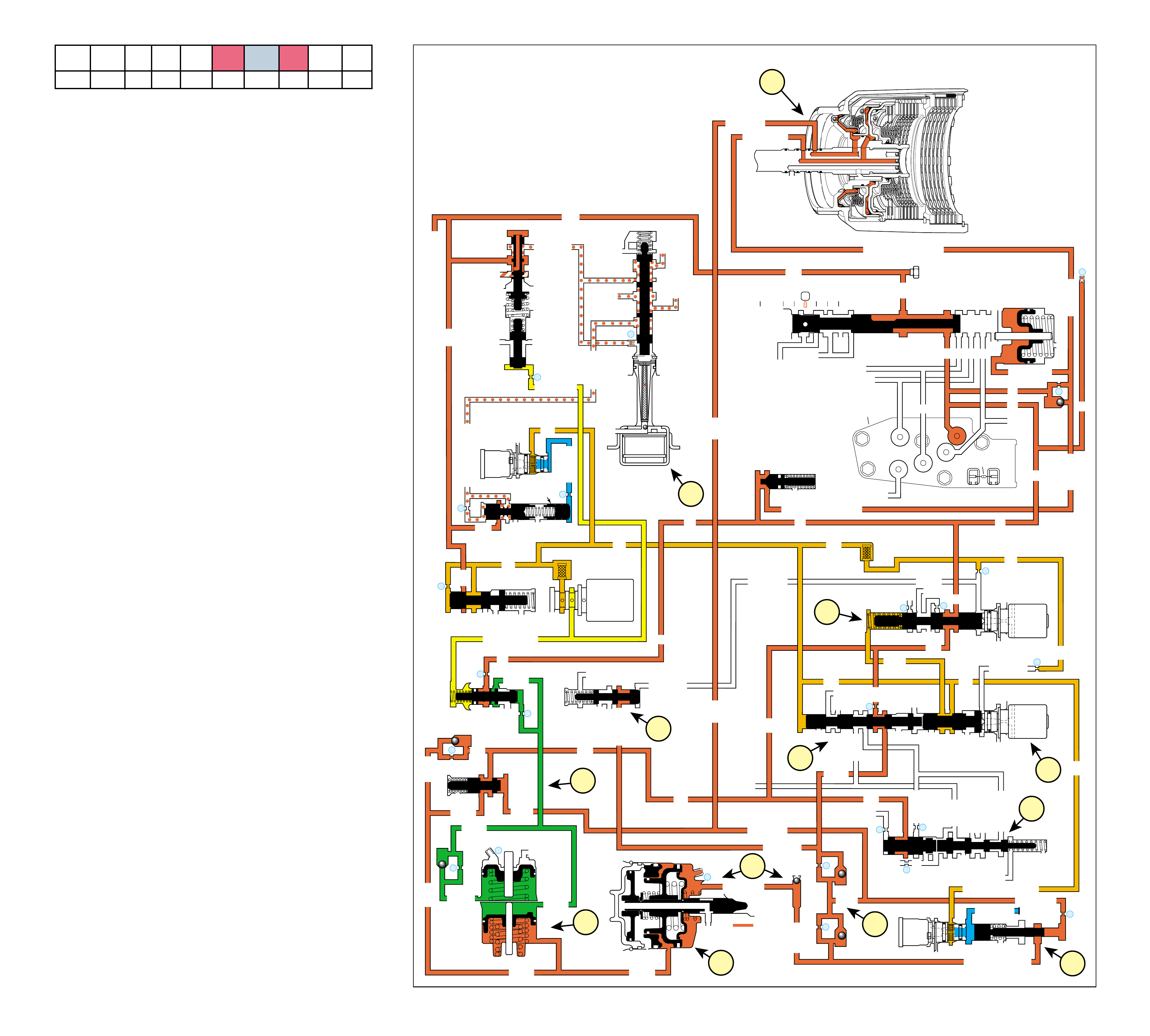
59
COMPLETE HYDRAULIC CIRCUIT
Page 84
OVERDRIVE RANGE – THIRD GEAR
Figure 56
➤
➤
➤
➤
➤
➤
➤
➤
➤
➤
➤
➤➤➤➤
➤➤
➤
➤➤
➤
➤
➤
➤
➤
➤
➤➤
➤➤
➤
➤
➤➤
➤
➤➤➤➤➤
➤➤
➤
➤
➤
➤➤
➤➤
➤
➤
➤
➤
➤
➤
➤
➤➤
➤➤
➤
➤
➤
INPUT CLUTCH
HOUSING ASSEMBLY
OVERRUN CLUTCH
➤
➤➤
LINE
LINE
➤
➤➤
➤➤ ➤
LINE (From Pump)
FORWARD CLUTCH FEED
➤
➤
➤➤
➤
FWD CL FEED
➤
D4
D4
FORWARD CLUTCH FEED
FWD CL FD FWD CL FD
D4
D4
D4
D4
D4
D4
TORQUE SIGNAL
1-2 SIGNAL
3-4 ACC
2ND
D4
1-2 SIGNAL
3-4 SIG
3-4 SIGNAL
3-4 CL
3-4 CLUTCH
3RD ACC
4TH
OVERRUN CL FD
OVERRUN CL
SERVO FEED
SERVO FD
ACTUATOR FEED LIMIT
4TH SIG
2ND
2ND CL2ND CL
2ND CL
2ND CL 3-4 CL 2ND
2ND 2ND
3-4 ACC
3-4 CL 3-4 CL
ACCUM
ACCUM
3-4 CLUTCH
AFL
AFL
2ND CL
➤
➤
➤
➤
➤
➤
➤
➤
➤
➤
➤
➤
➤➤
➤
➤
➤➤
➤
➤
➤➤
➤
➤
➤
➤
➤
➤
➤➤
➤➤
➤
➤
➤➤
➤
➤
➤
➤➤
➤➤
➤➤
➤➤
➤
➤
➤
➤
➤
➤➤
➤
➤
➤
➤
➤➤➤
➤
➤
➤
➤
➤
➤➤➤
➤
➤
➤
➤➤ ➤
➤
➤
➤
➤
➤
➤
➤
➤➤
➤
➤➤
➤
➤
➤➤
➤
➤
➤
➤➤
➤➤
➤➤
➤
➤
➤ ➤ ➤➤➤➤➤ ➤
➤
➤
➤
➤
REAR LUBE
➤
4TH SIGNAL
➤
➤
3-4 ACCUM
➤
➤
OVERDRIVE RANGE – THIRD GEAR
➤
➤
➤
➤
➤
EX
EX
3-4 RELAY 4-3 SEQUENCE VALVE
EXORF EX 5
67
TCC
SOLENOID
N.O.
OFF
CONVERTER CLUTCH VALVE
COOLER
RELEASE
APPLY
EX
➤
EX
➤
4
➤
➤
➤
REG APPLY
BOOST VALVE PRESS REG
EX
TORQUE SIG
➤
EX
CONV FEED
➤
➤➤
REV INPUT
DECREASE
REV INPUT
10
LINE
REGULATED APPLY
➤
EX
EX
EX
CC SIGNAL
9
TCC PWM
SOLENOID
VALVE
N.C.
➤
8
ACTUATOR FEED LIMIT
EX
EX
EX
AFL
LINE
FILTER (50)
➤
➤
➤➤
➤
➤
➤
➤
➤
EX
PRESSURE
CONTROL
SOLENOID
VALVE
32
24
LINE
LINE
D4
REVERSE
PR
D3
D2
LO
D2
D3
D3
LO
FWD CL FEED
REV INPUT
LINE
PRESSURE
TAP
➤
➤
➤
➤
D2-N.C.
REV-N.O.
D3-N.C.
LO-N.O.
D4-N.O.
TEMP
SENSOR
➤
TFP
SWITCH
ASSEMBLY
➤
FORWARD CLUTCH
ACCUMULATOR
EX
PRND321
EX
EX
MANUAL VALVE
➤
➤
#12
22
➤
➤
➤
EX
FORWARD ABUSE
LO/1ST
AFL
AFL
AFL
1-2 SIG
AFL FILTER
(49)
➤
➤
➤
➤
➤
➤
➤
➤
➤
➤
➤➤➤ ➤
➤
AFL
AFL
25
26
27
29
EX
EX
EX
EX
D2
OVERRUN
D3
2ND
EX
2-3 SIGNAL
3-4 ACC
➤
2-3 SHIFT
SOLENOID
VALVE
N.O. OFF
LO
D4
D4-3-2
2ND
EX
EX
1-2 SHIFT
SOLENOID
VALVE
N.O. OFF
28
1-2 SHIFT VALVE
2-3 SHUTTLE 2-3 SHIFT VALVE
14
3-4 CLUTCH
3RD ACCUMULATOR
EX
EX
3-2 SIGNAL
➤
➤
➤
#2
12
➤
➤
#4
13
➤
➤
EX
#7
11 3RD ACCUM
➤
2ND & 4TH
SERVO
11
4TH
EX
EX
➤
➤
➤
➤
#1
18
➤
➤
3-4 ACCUMULATOR
1-2 ACCUMULATOR
19
EX
ORF ACC
➤
➤
D3
EX
3-4 SIGNAL
4TH SIG
3-4 SHIFT VALVE
EX
➤
30
EX
ACCUM
31
➤
➤
➤
➤
➤
➤
#8
16
➤
➤
1d
1e
1c
5a
4a
5c
3a
5b 1a
1b
3-2 CONTROL
3-2
CONTROL
SOLENOID
VALVE
N.C.
ON
➤
2a
2b
3b
ACCUM VALVE
3-2 DOWNSHIFT
ISOLATOR VALVE
REG APPLY
As vehicle speed increases, the PCM receives input signals from the
vehicle speed sensor, the TP sensor and other vehicle sensors to
determine the precise moment to de-energize or “turn OFF” the 2-3
shift solenoid (SS) valve.
1 2-4 BAND RELEASES
1a 2-3 Shift Solenoid (SS) Valve:
The 2-3 SS valve is de-energized, allowing 2-3 signal fluid to
exhaust from its circuit.
1b 2-3 Shift Valve and 2-3 Shuttle Valve:
Exhausting 2-3 signal fluid pressure allows AFL fluid pressure to
move the 2-3 shift valve and the 2-3 shuttle valve into the upshifted
position. Orificed (#28) 2nd fluid is directed into the 3-4 signal
fluid circuit. Also, AFL fluid pressure fills the D432 fluid circuit.
1c #4 and #2 Ball Check Valves:
3-4 signal fluid unseats the 3-4 clutch exhaust ball check valve
(#4) and enters the 3-4 clutch fluid circuit. 3-4 clutch fluid
unseats the 3rd accumulator ball check valve (#2) and enters the
3rd accumulator fluid circuit.
1d 2nd & 4th Servo:
3rd accumulator fluid seats the 3rd accumulator exhaust ball
check valve (#7) and enters the 2nd & 4th servo. 3rd accumulator
fluid pressure assists servo return spring force to move the 2nd
apply piston and apply pin against 2nd clutch fluid pressure.
This action releases the 2-4 band.
1e 3-4 Relay Valve and 4-3 Sequence Valve:
Servo feed fluid is allowed to exhaust past the 3-4 relay and 4-3
sequence valves and through an orificed exhaust (#5).
2 3-4 CLUTCH APPLIES
2a 3-4 Clutch:
3-4 clutch fluid is directed to the 3-4 clutch piston to apply the 3-4
clutch plates and obtain Third gear.
2b 1-2 Shift Valve:
D432 fluid pressure from the 2-3 shift valve assists spring force
to hold the 1-2 shift valve in the upshifted position.
3 SHIFT ACCUMULATION
3a 2nd & 4th Servo:
With 3-4 clutch fluid feeding the 3rd accumulator fluid circuit,
the movement of the 2nd apply piston in the 2nd & 4th servo acts
as an accumulator by absorbing initial 3-4 clutch fluid to cushion
the 3-4 clutch apply.
3b 1-2 Accumulator:
The movement of the 2nd apply piston in the 2nd & 4th servo
also forces 2nd clutch fluid out of the servo and sends it to the
1-2 accumulator to further cushion the 3-4 clutch apply.
4 TORQUE CONVERTER CLUTCH RELEASED
4a TCC Solenoid Valve:
Under normal operating conditions, in Overdrive Range – Third
Gear, the PCM keeps the normally open TCC solenoid valve de-
energized. Converter feed fluid exhausts through the solenoid,
and spring force keeps the converter clutch valve in the release
position. However, at speeds above approximately 121 km/h (75
mph) the PCM will command TCC apply in third gear. Refer to
pages 62–63 for more information on TCC apply.
5 FLUID PRESSURE DIRECTED IN PREPARATION FOR A SHIFT
5a 3-4 Shift Valve:
3-4 signal fluid is also directed to the 3-4 shift valve where it is
blocked in preparation for a shift to 4th gear.
5b 3-2 Downshift Valve:
3-4 clutch fluid pressure moves the valve against spring force.
This opens the valve and allows 2nd fluid to feed the 2nd clutch
fluid circuit through the valve in preparation for a 3-2 downshift.
5c 3-2 Control Solenoid Valve:
The 3-2 control solenoid valve remains ON and maintains 3-2
signal fluid pressure to hold the 3-2 control valve against spring
force. This action is done in preparation for control of a 3-2
downshift and does not affect transmission operation in third gear.
1-2 SHIFT 2-3 SHIFT REVERSE FORWARD
SOLENOID SOLENOID 2-4 INPUT OVERRUN FORWARD SPRAG CL. 3-4 LO-ROLLER LO/REV
VALVE VALVE BAND CLUTCH CLUTCH CLUTCH ASSEMBLY CLUTCH CLUTCH CLUTCH
OFF OFF APPLIED HOLDING APPLIED
58B
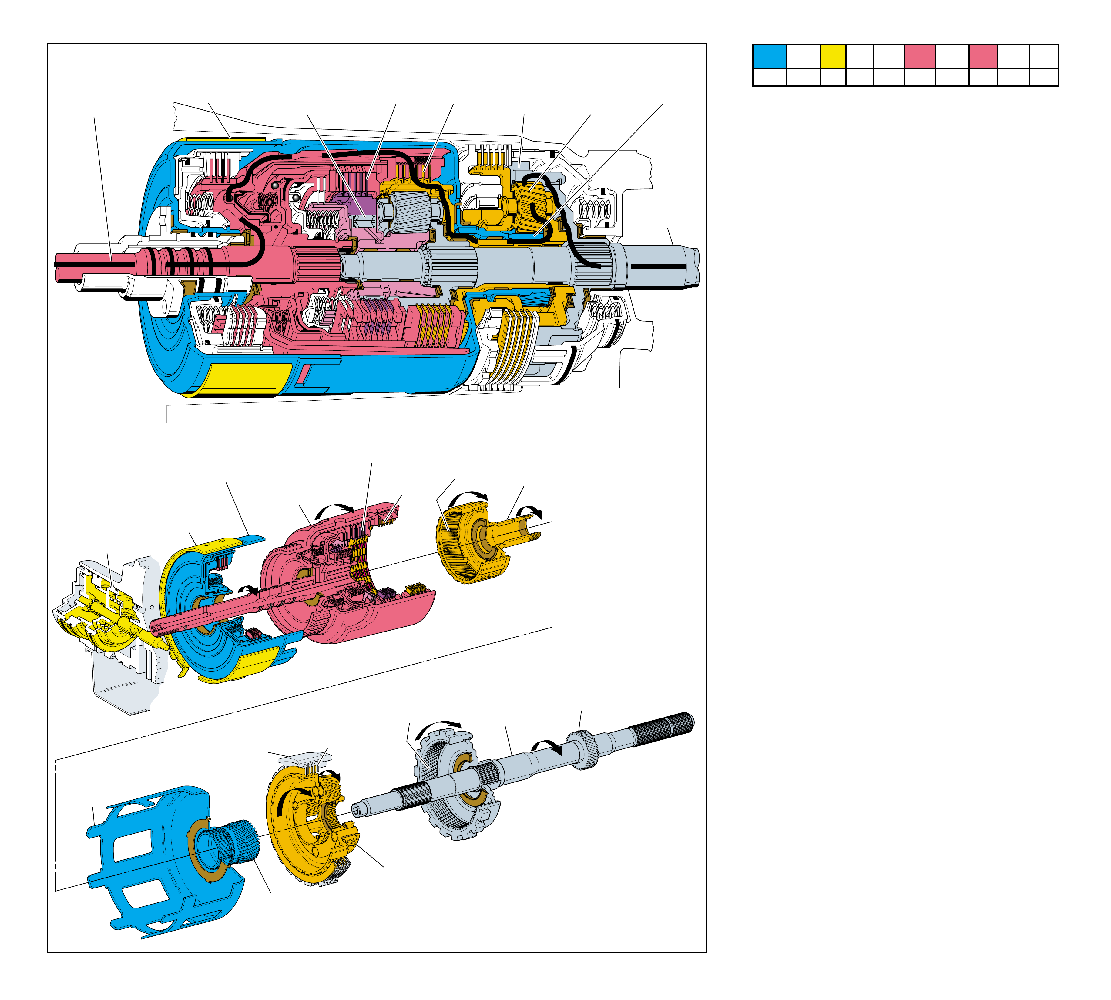
60
INPUT HOUSING
& SHAFT ASSEMBLY
(621)
OUTPUT
SHAFT
(687)
SPEED SENSOR
ROTOR
(699)
REACTION
INTERNAL
GEAR
(684)
INPUT
INTERNAL
GEAR
(664)
REACTION
CARRIER
SHAFT
(666)
SERVO
ASSEMBLY
APPLIED
2-4 BAND
ASSEMBLY
(602)
APPLIED
REVERSE INPUT
CLUTCH HOUSING
(605)
HELD
REACTION
SUN SHELL
(670)
HELD
REACTION
SUN GEAR
(673)
HELD
LOW AND REVERSE
CLUTCH PLATE
ASSEMBLY
(682)
REACTION
CARRIER
ASSEMBLY
(681)
MAIN
CASE
(103)
FORWARD
CLUTCH
APPLIED 3-4
CLUTCH
APPLIED
➤
➤
➤
➤
➤
➤➤
1
POWER FROM
TORQUE
CONVERTER
(1)
POWER TO
DIFFERENTIAL
ASSEMBLY
3
2-4 BAND
ASSEMBLY (602)
APPLIED
7
FORWARD SPRAG
ASSEMBLY
(642)
OVERRUNNING
8
FORWARD
CLUTCH
APPLIED
2
3-4
CLUTCH
APPLIED
6
REACTION
INTERNAL
GEAR
DRIVEN
5
REACTION
PLANETARY
PINIONS
DRIVING
4
REACTION
SUN GEAR
HELD
OVERDRIVE RANGE – FOURTH GEAR
Figure 57
OVERDRIVE RANGE – FOURTH GEAR
60A
To maximize engine performance and fuel economy, a Fourth
gear (Overdrive) is used to achieve an approximate ratio of
0.73:1 through the transmission gear sets to the vehicle drive
shaft. This allows the vehicle to maintain a given road speed
with less engine output speed.
•The converter clutch is applied and converter turbine speed
equals engine speed (see torque converter, page 12).
1 Power from Torque Converter
The turbine shaft, connected to the input housing (621), is
driven by the converter turbine.
2 3-4 Clutch Applied
The 3-4 clutch plates (654) remain applied in Fourth gear to
transfer engine torque from the input housing (621) to the
input internal gear (664) and reaction carrier shaft (666).
3 2-4 Band Applied
The 2-4 band (602) is applied and holds the reverse input
clutch housing (605) stationary to the transmission case.
4 Reaction Sun Gear Held
The reaction sun shell (670) is splined to the reverse input
clutch housing and the reaction sun gear (673) is splined to
the sun shell. Both the sun shell and reaction sun gear are
held stationary as a result of the 2-4 band being applied.
5 Reaction Planetary Pinions Driving
The reaction carrier shaft drives the reaction carrier assembly
(681) clockwise. The reaction carrier pinion gears rotate
clockwise on their pins as they walk clockwise around the
stationary reaction sun gear.
6 Reaction Internal Gear Driven
The reaction carrier pinion gears drive the reaction internal
gear (684) and output shaft (687) in an overdrive gear ratio
of approximately 0.73:1.
7 Forward Sprag Assembly Overrunning
The output shaft drives the input carrier assembly (662),
input pinion gears and forward sprag clutch inner race and
input sun gear assembly (640) faster than the forward clutch
is driving the forward clutch outer race (644). This allows
the forward sprag clutch inner race and input sun gear
assembly to overrun the forward sprag clutch (642).
8 Forward Clutch Applied
As a result, of the forward sprag clutch overrunning, the
forward clutch is ineffective in Fourth gear.
•Power flow from the forward clutch housing to the output
shaft (671) is the same as Overdrive Range – Third Gear.
Refer to page 58A for a description of this power flow.
•With power flow between the forward clutch housing and the
output shaft a 1:1 direct drive ratio, the overall transmission
gear ratio is 0.75:1.
Coast Conditions/Engine Compression Braking
•In Fourth gear, neither the forward sprag clutch nor the low and
reverse roller clutch are used to transfer engine torque during
acceleration. Therefore, there are no elements to overrun and
allow the vehicle to coast freely when the throttle is released.
This causes engine compression braking to slow the vehicle.
However, because of the Overdrive gear ratio, engine compres-
sion braking is not as noticeable by the driver in Fourth gear as
in the manual gear ranges.
1-2 SHIFT 2-3 SHIFT REVERSE FORWARD
SOLENOID SOLENOID 2-4 INPUT OVERRUN FORWARD SPRAG CL. 3-4 LO-ROLLER LO/REV
VALVE VALVE BAND CLUTCH CLUTCH CLUTCH ASSEMBLY CLUTCH CLUTCH CLUTCH
ON OFF APPLIED APPLIED APPLIED
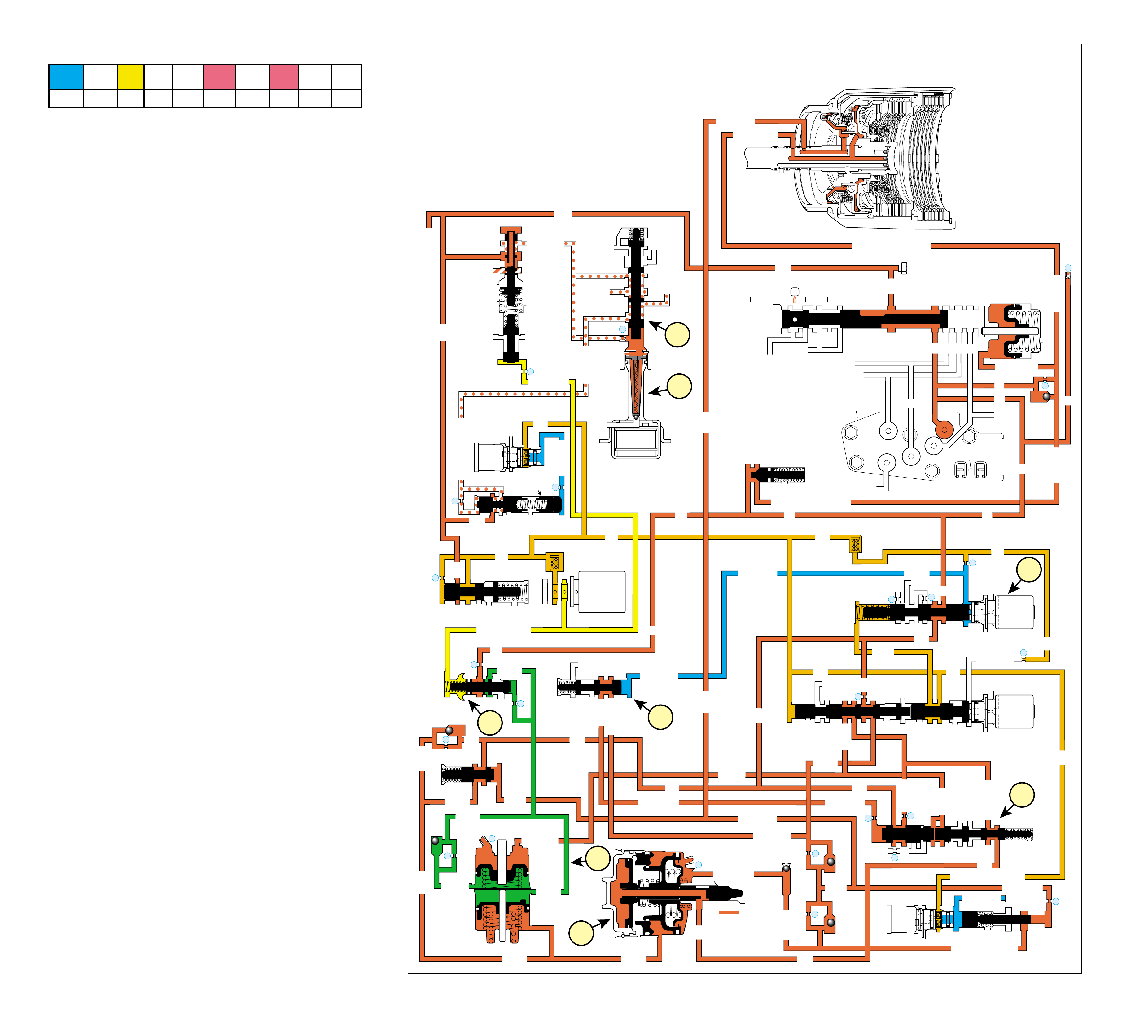
61
OVERDRIVE RANGE – FOURTH GEAR
(Torque Converter Clutch Applied)
COMPLETE HYDRAULIC CIRCUIT
Page 86 Figure 58
➤
➤
➤➤➤
➤
➤
➤
➤➤
➤
➤
➤
➤➤
➤➤
➤
➤
➤
➤
INPUT CLUTCH
HOUSING ASSEMBLY
OVERRUN CLUTCH
➤
LINE
LINE
➤
➤➤
➤➤ ➤
LINE (From Pump)
FORWARD CLUTCH FEED
➤
➤
➤➤
➤
FWD CL FEED
➤
D4
D4
FORWARD CLUTCH FEED
FWD CL FD FWD CL FD
D4
D4
D4
D4
D4
D4
TORQUE SIGNAL
1-2 SIGNAL
3-4 ACC
2ND
D4
1-2 SIGNAL
3-4 SIG
3-4 SIGNAL
3-4 CL
3-4 CLUTCH
3RD ACC
4TH
OVERRUN CL FD
OVERRUN CL
SERVO FEED
SERVO FD
ACTUATOR FEED LIMIT
4TH SIG
2ND
2ND CL2ND CL
2ND CL
2ND CL 3-4 CL 2ND
2ND 2ND
3-4 ACC
3-4 CL 3-4 CL
ACCUM
ACCUM
3-4 CLUTCH
AFL
AFL
2ND CL
➤
➤
➤
➤
➤
➤
➤
➤
➤
➤
➤
➤
➤➤
➤
➤
➤➤
➤
➤
➤➤
➤
➤
➤
➤
➤
➤
➤➤
➤➤
➤
➤
➤➤
➤
➤
➤
➤➤
➤➤
➤➤
➤➤
➤
➤
➤
➤
➤
➤➤
➤
➤
➤➤
➤
➤
➤➤ ➤ ➤
➤
➤
➤
➤
➤
➤
➤
➤
➤
➤➤
➤
➤
➤
➤➤➤
➤
➤
➤
➤
➤
➤➤➤
➤
➤
➤
➤➤ ➤
➤
➤
➤➤
➤
➤
➤
➤➤
➤
➤➤
➤
➤
➤➤
➤
➤
➤
➤➤
➤➤
➤➤
➤
➤
➤ ➤ ➤➤➤➤➤ ➤
➤
➤
➤➤➤
➤
➤
➤
➤
➤
REAR LUBE
➤
4TH SIGNAL
4TH
4TH SIGNAL
➤
➤
3-4 ACCUM
➤
➤
OVERDRIVE RANGE – FOURTH GEAR
(Torque Converter Clutch Applied)
➤
➤
➤
➤
➤
EX
EX
EXORF EX 5
67
TCC
SOLENOID
N.O.
ON
COOLER
RELEASE
APPLY
EX
EX
➤
4
➤
➤
➤
➤
REG APPLY
BOOST VALVE PRESS REG
EX
TORQUE SIG
➤
EX
CONV FEED
➤
➤➤
REV INPUT
DECREASE
REV INPUT
10
LINE
REGULATED APPLY
➤
EX
EX
EX
CC SIGNAL
9
TCC PWM
SOLENOID
VALVE
N.C.
➤
➤➤
➤
➤
➤
➤
➤
8
ACTUATOR FEED LIMIT
EX
EX
EX
AFL
LINE
FILTER (50)
➤
➤
➤➤
➤
➤
➤
➤
➤
EX
PRESSURE
CONTROL
SOLENOID
VALVE
32
24
LINE
LINE
D4
REVERSE
PR
D3
D2
LO
D2
D3
D3
LO
FWD CL FEED
REV INPUT
LINE
PRESSURE
TAP
➤
➤
➤
➤
D2-N.C.
REV-N.O.
D3-N.C.
LO-N.O.
D4-N.O.
TEMP
SENSOR
➤
TFP
SWITCH
ASSEMBLY
➤
FORWARD CLUTCH
ACCUMULATOR
EX
PRND321
EX
EX
MANUAL VALVE
➤
➤
#12
22
➤
➤
➤
EX
FORWARD ABUSE
LO/1ST
AFL
AFL
AFL
1-2 SIG
AFL
FILTER
(49)
➤
➤
➤
➤
➤
➤
➤
➤
➤
➤
➤➤➤ ➤
➤
AFL
AFL
25
26
27
29
EX
EX
EX
EX
D2
OVERRUN
D3
2ND
EX
2-3 SIGNAL
3-4 ACC
➤
2-3 SHIFT
SOLENOID
VALVE
N.O.
OFF
LO
D4
D4-3-2
2ND
EX
EX
1-2 SHIFT
SOLENOID
VALVE
N.O.
ON
28
1-2 SHIFT VALVE
2-3 SHUTTLE 2-3 SHIFT VALVE
14
3-4 CLUTCH
3RD ACCUMULATOR
EX
EX
3-2 SIGNAL
➤
➤
➤
#2
12
➤
➤
#4
13
➤
➤
EX
#7
11 3RD ACCUM
➤
2ND & 4TH
SERVO
11
4TH
EX
EX
➤
➤
#1
18
➤
➤
3-4 ACCUMULATOR
1-2 ACCUMULATOR
19
EX
ORF ACC
D3
EX
3-4 SIGNAL
4TH SIG
EX
➤
30
EX
ACCUM
31
➤
➤
➤
➤
➤
➤
#8
16
➤
➤
1d
1c
2a
3a
3b
1a
1b
2b
3-4 SHIFT VALVE
➤
➤
➤➤➤
➤
➤
3-4 RELAY 4-3 SEQUENCE VALVE
ACCUM VALVE
➤
➤
➤
➤
➤
CONVERTER CLUTCH VALVE
3-2 DOWNSHIFT
3-2 CONTROL
3-2
CONTROL
SOLENOID
VALVE
N.C.
ON
➤
ISOLATOR VALVE
REG APPLY
1-2 SHIFT 2-3 SHIFT REVERSE FORWARD
SOLENOID SOLENOID 2-4 INPUT OVERRUN FORWARD SPRAG CL. 3-4 LO-ROLLER LO/REV
VALVE VALVE BAND CLUTCH CLUTCH CLUTCH ASSEMBLY CLUTCH CLUTCH CLUTCH
ON OFF APPLIED APPLIED APPLIED
Overdrive Range – Fourth Gear is used to maximize engine
efficiency and fuel economy under most normal driving condi-
tions. In order to shift the transmission into Fourth gear, the
PCM receives input signals from the vehicle speed sensor, the
TP sensor and other vehicle sensors to determine the precise
moment to energize or “turn ON” the 1-2 shift solenoid (SS)
valve. The 1-2 SS valve is ON when the PCM provides a path to
ground for that electrical circuit. This prevents 1-2 signal fluid
from exhausting at the 1-2 SS valve, thereby increasing 1-2
signal fluid pressure.
1 2-4 BAND APPLIED
1a 1-2 Shift Solenoid (SS) Valve:
The 1-2 SS valve is energized (ON) blocking 1-2 signal
fluid from exhausting through the solenoid. This creates
pressure in the 1-2 signal fluid circuit.
1b 3-4 Shift Valve:
1-2 signal fluid pressure moves the valve into the upshifted
position routing 3-4 signal fluid into the 4th signal fluid circuit.
1c 3-4 Relay Valve and 4-3 Sequence Valve:
4th signal fluid pressure moves both valves into the upshifted
position causing the following changes.
•
Orificed (#7) 2nd fluid is routed through the 3-4 relay
valve and into the servo feed fluid circuit.
•Servo feed fluid is routed through the 4-3 sequence
valve and into the 4th fluid circuit.
•3-4 accumulator fluid routed from the 2-3 shuttle
valve is blocked by both valves.
1d 2nd & 4th Servo:
4th fluid pressure is routed through the center of the servo
apply pin and acts on the apply side of the 4th apply piston.
This action moves the apply pin and applies the 2-4 band in
order to obtain fourth gear.
2 3-4 SHIFT ACCUMULATION
2a 3-4 Accumulator Assembly:
3-4 accumulator fluid pressure moves the 3-4 accumulator
piston absorbing some of the initial increase of 4th clutch
apply fluid pressure in order to cushion the 2-4 band apply.
2b Accumulator Valve:
Accumulator fluid forced from the 3-4 accumulator is orificed
to the end of the accumulator valve. This regulates the
exhaust of excess accumulator fluid pressure through the
middle of the valve.
3 TORQUE CONVERTER CLUTCH APPLIED
3a TCC Solenoid Valve:
When operating conditions are appropriate, the PCM
energizes the normally open TCC solenoid valve. This
closes the solenoid, blocks converter feed fluid from
exhausting, and creates enough pressure in the converter
feed fluid circuit at the TCC solenoid valve to shift the
converter clutch valve.
3b Converter Clutch Apply Valve:
The converter clutch valve is shifted into the apply position
allowing release fluid to exhaust from the torque converter
clutch and regulated apply fluid to enter the apply fluid
circuit at the same time. This provides for smooth
engagement of the TCC.
60B
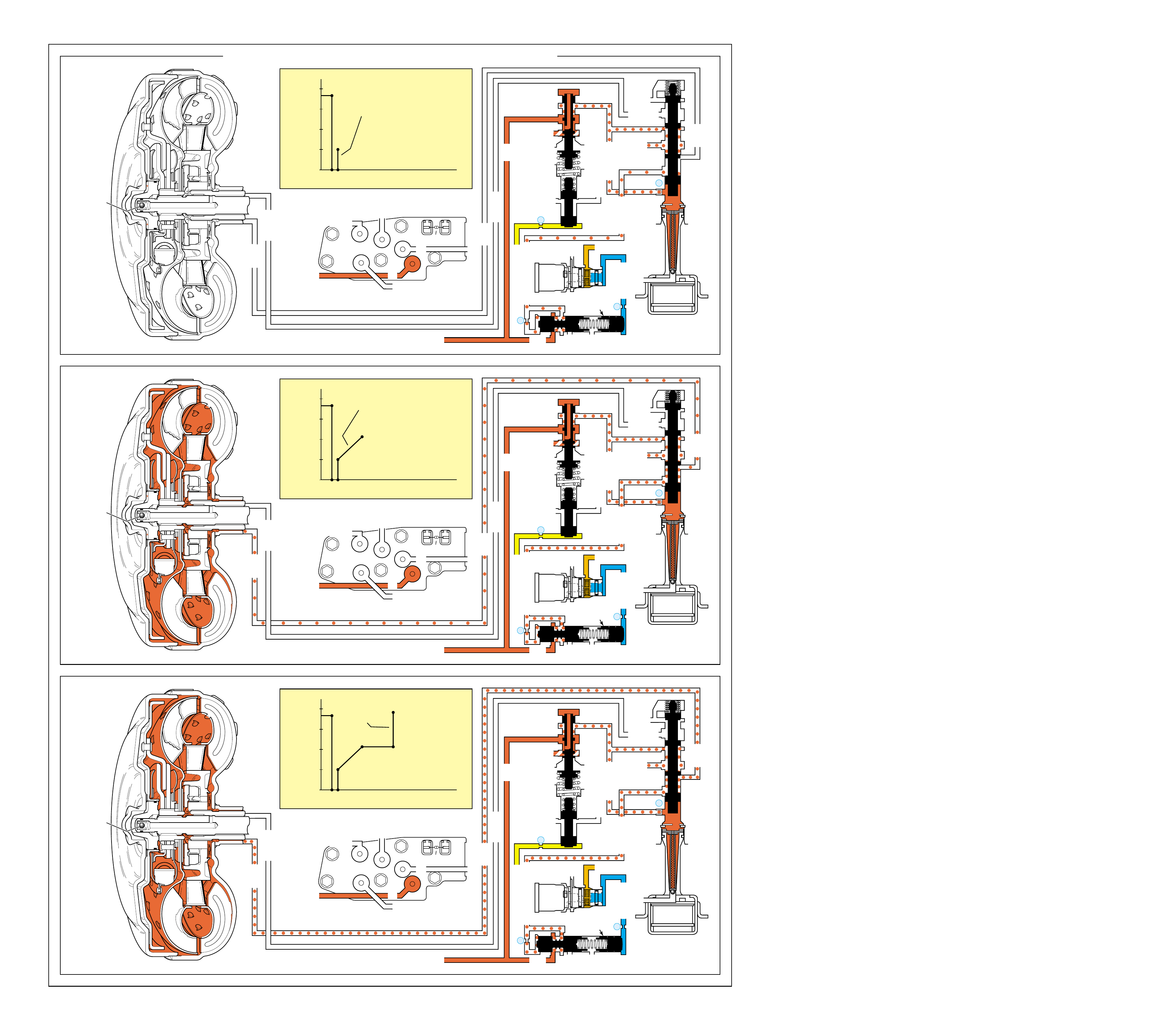
62
TIME
➤
100%
➤
0
25
50
75
TCC (ECCC) LOCK
PERCENT DUTY CYCLE
A
S
TCC (ECCC)
APPLY
FLUID
PRESSURE
DE
B
F
C
TIME
➤
100%
➤
0
25
50
75
TCC (ECCC) APPLY AND ECCC
PERCENT DUTY CYCLE
A
S
TCC (ECCC)
APPLY
FLUID
PRESSURE
D
B
C
TIME
➤
100%
➤
0
25
50
75
TCC (ECCC) APPLY
TCC (ECCC)
APPLY
FLUID
PRESSURE
PERCENT DUTY CYCLE
A
S
B
C
➤➤
➤
➤
➤
➤
➤
➤
➤
➤
➤
➤
➤
➤
➤
➤➤➤
➤➤➤➤➤
➤➤➤➤
➤➤➤
➤
➤➤
➤➤
➤
➤
➤
➤
➤
➤
➤
➤
➤
➤
➤
➤
➤
➤➤➤
➤➤➤➤➤
➤➤➤➤
➤➤➤
➤
➤➤
➤
➤
➤
➤➤
➤➤➤➤➤
➤➤➤➤➤
➤➤
➤
➤➤
➤
(Torque Converter Clutch from Released to Applied)
STAGE 1
(S - C)
STAGE 2
(C - D)
STAGE 3
(E - F)
OVERDRIVE RANGE – FOURTH GEAR
RELEASE
RELEASE
APPLY
APPLY
➤
➤➤➤
➤➤
➤➤
➤
TORQUE
CONVERTER
ASSEMBLY
#9
➤➤
LINE
➤
➤
LINE (From Pump) ➤➤
AFL
➤
TCC
SOLENOID
N.O.
ON
COOLER
RELEASE
APPLY
EX
EX
➤
➤
➤
➤
➤
➤
➤
➤
4
➤
➤
➤
REG APPLY
BOOST VALVE PRESS REG
EX
TORQUE SIG
➤
EX
CONV FEED
➤
➤➤
REV INPUT
DECREASE
REV INPUT
10
➤
➤
LINE
REGULATED APPLY
➤
EX
EX
EX
CC SIGNAL
9
TCC PWM
SOLENOID
VALVE
N.C.
➤
8
D3
REVERSE INPUT
D2-N.C.
REV-N.O. D3-N.C.
LO-N.O.
D4-N.O.
LO LO
TEMP
SENSOR
➤
TFP
SWITCH
ASSEMBLY
D2
D4D4
➤
➤
➤
➤
➤
➤
➤
CONVERTER CLUTCH VALVE
RELEASE
RELEASE
APPLY
APPLY
➤
➤➤➤
➤➤
➤➤
➤
TORQUE
CONVERTER
ASSEMBLY
#9
➤➤
LINE
➤
➤
LINE (From Pump) ➤➤
AFL
➤
TCC
SOLENOID
N.O.
ON
COOLER
RELEASE
APPLY
EX
EX
➤
➤
➤
➤
➤
➤
➤
➤
4
➤
➤
➤
REG APPLY
BOOST VALVE PRESS REG
EX
TORQUE SIG
➤
EX
CONV FEED
➤
➤➤
REV INPUT
DECREASE
REV INPUT
10
➤
➤
LINE
REGULATED APPLY
➤
EX
EX
EX
CC SIGNAL
9
TCC PWM
SOLENOID
VALVE
N.C.
➤
8
D3
REVERSE INPUT
D2-N.C.
REV-N.O. D3-N.C.
LO-N.O.
D4-N.O.
LO LO
TEMP
SENSOR
➤
TFP
SWITCH
ASSEMBLY
D2
D4D4
➤
➤
➤
➤
➤
➤
➤
RELEASE
RELEASE
APPLY
APPLY
TORQUE
CONVERTER
ASSEMBLY
#9
➤➤
➤
➤
➤
LINE
➤
➤
LINE (From Pump) ➤➤
AFL
➤
TCC
SOLENOID
N.O.
ON
COOLER
RELEASE
APPLY
EX
EX
4
➤
➤
➤
REG APPLY
BOOST VALVE PRESS REG
EX
TORQUE SIG
➤
EX
CONV FEED
➤
➤➤
REV INPUT
DECREASE
REV INPUT
10
➤
➤
LINE
REGULATED APPLY
➤
EX
EX
EX
CC SIGNAL
9
TCC PWM
SOLENOID
VALVE
N.C.
➤
8
D3
REVERSE INPUT
D2-N.C.
REV-N.O. D3-N.C.
LO-N.O.
D4-N.O.
LO LO
TEMP
SENSOR
➤
TFP
SWITCH
ASSEMBLY
D2
D4D4
➤
➤
➤
CONVERTER CLUTCH VALVE
STAGE
3
➤
ISOLATOR VALVE
REG APPLY
ISOLATOR VALVE
REG APPLY
➤
➤
➤
➤
➤
➤
➤
ISOLATOR VALVE
REG APPLY
STAGE
1
➤
STAGE
2
➤
CONVERTER CLUTCH VALVE
Figure 59
OVERDRIVE RANGE – FOURTH GEAR
(Torque Converter Clutch from Released to Applied)
When the powertrain control module (PCM) determines that the
engine and transmission are operating properly to engage the
torque converter clutch (TCC), the PCM energizes the TCC
solenoid valve and regulates the duty cycle of the TCC PWM
solenoid valve. The following events occur in order to apply
the torque converter clutch:
OFF At this time the Torque Converter Clutch is
considered to be disengaged (OFF), TCC solenoid valve
OFF, TCC PWM solenoid valve parked at 90% duty cycle.
PCM decision to apply TCC (see pages 39 and 43, in the
Electrical Components section, for more information).
Stage 1
The PCM immediately decreases the TCC PWM
solenoid valve duty cycle to 0% (from point S to point A)
then pulses the TCC PWM solenoid valve to approximately
25% duty cycle from point B to point C. Actuator feed limit
fluid at the TCC PWM solenoid is “pulsed” into the CC
signal fluid circuit. The CC signal fluid pressure at point C
regulates a line pressure branch which creates regulated apply
fluid. The PCM also energizes the TCC solenoid valve,
blocking converter feed fluid from exhausting through the
solenoid and causing pressure to build up and shift the
converter clutch valve to the apply position. With the converter
clutch valve in the apply position, Release fluid can exhaust
through the valve. This stage is designed to move the converter
clutch valve from the released to the applied position; there is
not enough pressure to apply the TCC.
Stage 2
The TCC PWM solenoid valve duty cycle is ramped
up from point C to point D to approximately 50%. Regulated
apply fluid pressure is now strong enough to cause the converter
apply to occur. Line pressure from the pump enters the regulated
apply circuit at the regulated apply valve. Regulated apply
fluid is routed to the converter clutch valve into the apply fluid
circuit. The pressure value in the regulated apply circuit should
now be high enough to fully apply the TCC pressure plate.
Slip speed should be at the correct value (near “0”).
In vehicles equipped with the Electronically Controlled
Clutch Capacity (ECCC) system, the pressure plate does
not fully lock to the torque converter cover. It is instead
precisely controlled to maintain a small amount of slippage
between the engine and the turbine, reducing driveline
torsional disturbances.
Stage 3 If it is determined by the PCM that it is desirable to
fully lock the TCC, regulated apply fluid pressure is increased.
This is caused by the TCC PWM solenoid valve duty cycle
being increased from point E to point F, to approximately
98%. This extra pressure ensures that the apply force on the
TCC pressure plate is not at the slip threshold, but a little
above it. TCC plate material is therefore protected from
excessive heat.
Note: The TCC PWM solenoid valve operates independently
from the TCC solenoid valv e. The TCC solenoid valve only
controls w hen the TCC is applied. The TCC PWM solenoid
valve only contr ols how the TCC is applied.
Note: Under normal operating conditions the tor que con verter
clutch is in the released position during first, second and
third gears. However, when the transmission fluid
temperatures exceed appr o ximately 121
°
C (250
°
F), the PCM
will apply the torque converter clutch in second and third
gears to help reduce fluid temperatur es.
62A
COMPLETE HYDRAULIC CIRCUIT
Page 86
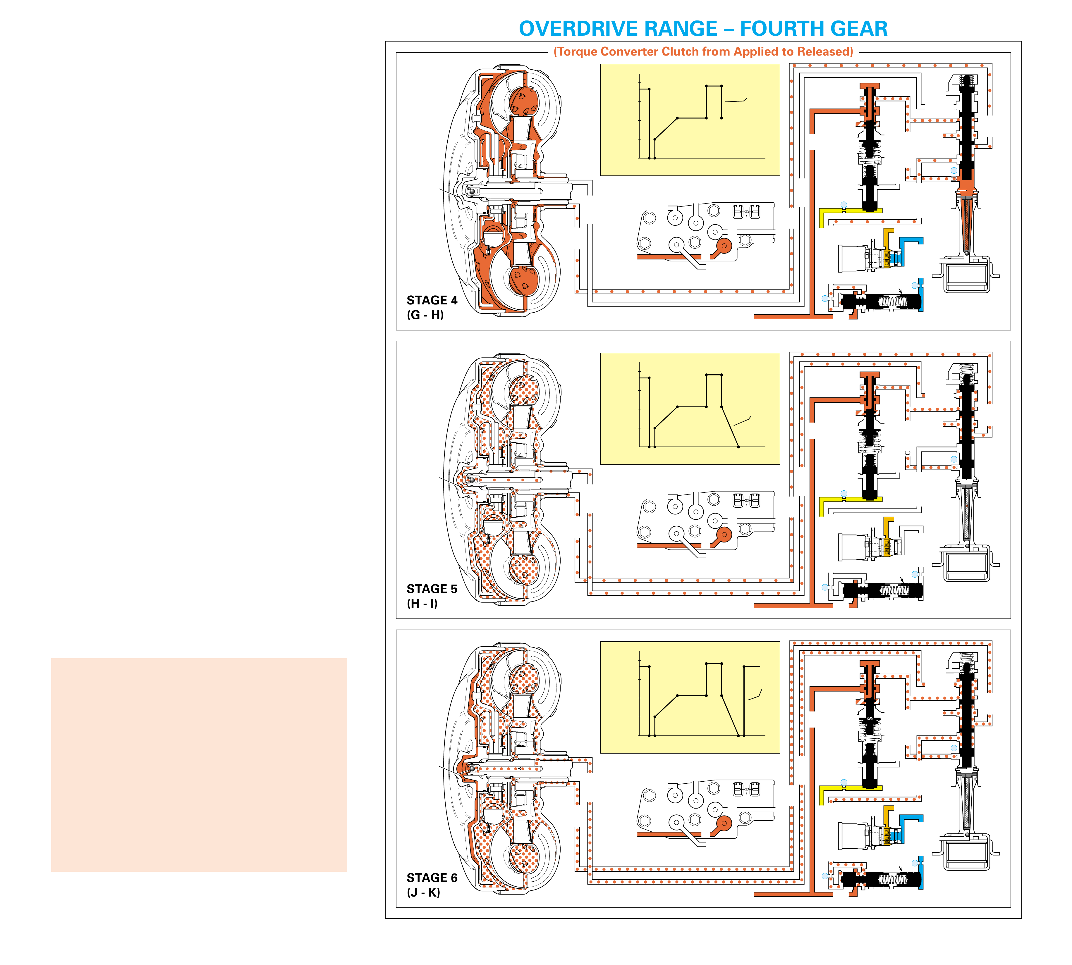
63
When the TCC pressure plate is applied, it is held against the
torque converter cover. Since it is splined to the converter
turbine hub, it provides a mechanical coupling (direct drive) of
the engine to the transmission gear sets. This mechanical
coupling eliminates the small amount of slippage that occurs in
the fluid coupling of a torque converter, resulting in a more
efficient transfer of engine torque through the transmission and
to the drive wheels.
ON At this time the Torque Converter Clutch is
considered to be engaged (ON).
PCM decision to release TCC (see pages 39 and 43, in the
Electrical Components section, for more information).
Stage 4 During this stage, the apply fluid pressure from the
regulated apply valve is decreased by the TCC PWM solenoid
valve duty cycle dropping from point G to point H, to
approximately 50%. Reduced CC signal fluid pressure from
the TCC PWM solenoid valve allows orificed regulated apply
fluid to move the regulated apply valve, decreasing the flow
of line fluid feeding the regulated apply circuit. This reduces
the apply force on the TCC pressure plate to the slip threshold.
This gets the TCC pressure plate ready for a smooth release.
Stage 5 The TCC PWM solenoid valve duty cycle is ramped
down to 0% from point H to point I through this stage. This
action allows the regulated apply pressure to start at the slip
threshold, and decrease to near “0” pressure over a very short
time to point I. The regulated apply pressure value from the
TCC regulator apply valve at this duty cycle (point I) should
fully release the TCC pressure plate. Slip speed should be at
the maximum value.
The PCM also de-energizes the TCC
solenoid allowing converter clutch valve spring force to shift
the converter clutch valve to the released position. Release
fluid is now directed back to the torque converter.
Stage 6
The PCM pulses the TCC PWM solenoid valve to a
value of “90”. This stage is designed to prepare the TCC
apply and release system for another apply of the TCC.
OFF At this time the Torque Converter Clutch is
considered to be disengaged (OFF).
(Some PCM calibrations may allow stages 4 - 6 to happen
very rapidly in almost a straight line down from point G to
point K.)
The PCM monitors for high TCC slip for most models.
Excessive slip is recognized by Diagnostic Trouble Code
(DTC) P1870. The transmission must be in hot mode or
experiencing a wide open throttle maneuver in order for the
TCC to be commanded on in second and third gear.
If the PCM detects a continuous open, short to ground, or
short to power in the TCC solenoid valve circuit, then DTC
P0740 will set and the PCM will illuminate the malfunction
indicator lamp (MIL), inhibit TCC operation, inhibit 4th gear
and freeze shift adapts. The DTC P0740 will then be stored
in PCM history.
If the PCM detects low TCC slip when the TCC is commanded
OFF, then DTC P0742 will set and the PCM will illuminate
the malfunction indicator lamp (MIL), increase line pressure
and freeze shift adapts. The DTC P0742 will then be stored
in PCM history.
OVERDRIVE RANGE – FOURTH GEAR
(Torque Converter Clutch from Applied to Released)
Figure 60
➤➤
➤➤
➤
➤
➤
TIME
➤
100%
➤
0
25
50
75
TCC (ECCC) OFF
PERCENT DUTY CYCLE
A
S
TCC (ECCC)
APPLY
FLUID
PRESSURE
DE
B
H
FG
CIJ
K
TIME
➤
100%
➤
0
25
50
75
TCC (ECCC) RELEASE
PERCENT DUTY CYCLE
A
S
TCC (ECCC)
APPLY
FLUID
PRESSURE
DE
B
H
FG
CI
TIME
➤
100%
➤
0
25
50
75
TCC (ECCC) RELEASE
PERCENT DUTY CYCLE
A
S
TCC (ECCC)
APPLY
FLUID
PRESSURE
DE
B
H
FG
C
;;
;;
;;;;
;;;;
;;;;
;;;;
;;;;
;;;;
;;;;
;;;;
;;;;
;;;;
;;;;
;;;;
;
;
;
;;
;;
;;;;
;;;;
;;;;
;;;;
;;;;
;;;;
;;;;
;;;;
;;;;
;;;;
;;;;
;
;
;
;;
;;
;;
;;
;;
;;
;;
;;
;;
;;
OVERDRIVE RANGE – FOURTH GEAR
(Torque Converter Clutch from Applied to Released)
STAGE 4
(G - H)
STAGE 5
(H - I)
STAGE 6
(J - K)
➤
➤
➤
➤
➤
➤
➤
RELEASE
RELEASE
APPLY
APPLY
➤➤
➤➤
➤➤
➤
➤➤➤
➤➤
➤➤
➤
➤
TORQUE
CONVERTER
ASSEMBLY
#9
➤➤
➤➤
➤➤
➤
➤
➤
LINE
➤
➤
LINE (From Pump) ➤➤
AFL
➤
TCC
SOLENOID
N.O.
OFF
CONVERTER CLUTCH VALVE
COOLER
RELEASE
APPLY
EX
➤
EX
➤
4
➤
➤
➤
REG APPLY
BOOST VALVE PRESS REG
EX
TORQUE SIG
➤
EX
CONV FEED
➤
➤➤
REV INPUT
DECREASE
REV INPUT
10
➤
➤
LINE
REGULATED APPLY
➤
EX
EX
EX
CC SIGNAL
9
TCC PWM
SOLENOID
VALVE
N.C.
➤
8
D3
REVERSE INPUT
D2-N.C.
REV-N.O. D3-N.C.
LO-N.O.
D4-N.O.
LO LO
TEMP
SENSOR
➤
TFP
SWITCH
ASSEMBLY
D2
D4D4
➤
➤
➤
➤
➤
➤
➤
➤
➤
RELEASE
RELEASE
APPLY
APPLY
➤➤
➤➤
➤➤
➤
➤➤➤
➤➤
➤➤
➤
➤
TORQUE
CONVERTER
ASSEMBLY
#9
➤➤
➤
➤
➤
➤
➤➤
➤➤
➤
➤
➤
➤
LINE
➤
➤
LINE (From Pump) ➤➤
AFL
➤
TCC
SOLENOID
N.O.
OFF
COOLER
RELEASE
APPLY
EX
➤
EX
➤
4
➤
➤
➤
REG APPLY
BOOST VALVE PRESS REG
EX
TORQUE SIG
➤
EX
CONV FEED
➤
➤➤
REV INPUT
DECREASE
REV INPUT
10
➤
➤
LINE
REGULATED APPLY
➤
EX
EX
EX
CC SIGNAL
9
TCC PWM
SOLENOID
VALVE
N.C.
➤
8
D3
REVERSE INPUT
D2-N.C.
REV-N.O. D3-N.C.
LO-N.O.
D4-N.O.
LO LO
TEMP
SENSOR
➤
TFP
SWITCH
ASSEMBLY
D2
D4D4
➤
➤
RELEASE
RELEASE
APPLY
APPLY
➤
➤➤➤
➤➤
➤➤
➤
TORQUE
CONVERTER
ASSEMBLY
#9
➤➤
➤
➤
➤
LINE
➤
➤
LINE (From Pump) ➤➤
AFL
➤
TCC
SOLENOID
N.O.
ON
COOLER
RELEASE
APPLY
EX
EX
➤
➤
➤
➤
➤
➤
➤
➤
4
➤
➤
➤
REG APPLY
BOOST VALVE PRESS REG
EX
TORQUE SIG
➤
EX
CONV FEED
➤
➤➤
REV INPUT
DECREASE
REV INPUT
10
➤
➤
LINE
REGULATED APPLY
➤
EX
EX
EX
CC SIGNAL
9
TCC PWM
SOLENOID
VALVE
N.C.
➤
8
D3
REVERSE INPUT
D2-N.C.
REV-N.O. D3-N.C.
LO-N.O.
D4-N.O.
LO LO
TEMP
SENSOR
➤
TFP
SWITCH
ASSEMBLY
D2
D4D4
➤
➤
➤
➤
➤
➤
➤CONVERTER CLUTCH VALVE
STAGE
4
➤
STAGE
5
➤
STAGE
6
➤
ISOLATOR VALVE
REG APPLY
ISOLATOR VALVE
REG APPLY
➤
➤
➤
➤
➤
➤
➤
ISOLATOR VALVE
REG APPLY
CONVERTER CLUTCH VALVE
COMPLETE HYDRAULIC CIRCUIT
Page 86
62B
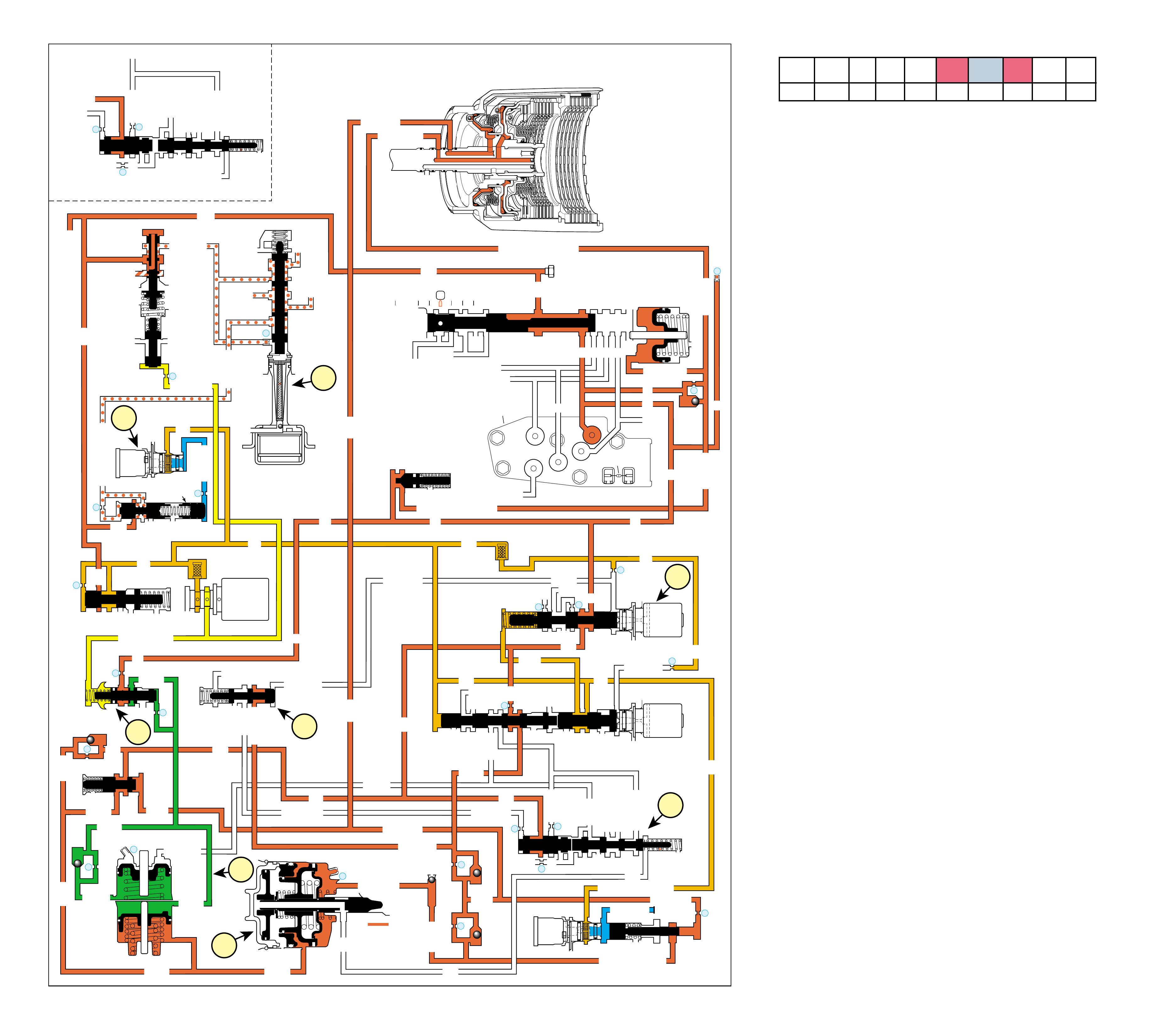
64
➤
➤
➤
➤
➤
➤
➤
➤
➤➤➤
➤
➤
➤
➤
➤
➤➤➤➤
➤➤
➤➤➤
➤
➤➤
➤
➤
➤
➤
➤
➤➤➤➤
➤➤
➤
➤➤
➤
➤
➤
➤
➤
➤
➤
➤➤➤➤
➤➤
➤➤
➤➤➤
➤➤
➤➤
➤
➤
➤➤
➤
➤➤➤➤➤➤➤➤➤➤ ➤➤
➤➤➤➤
➤➤➤
➤➤
➤➤
➤
➤
➤
➤
➤
➤➤
➤
➤
➤
➤➤
➤➤
➤
➤
➤
➤
➤
➤
➤
➤➤
➤➤
➤
➤
➤
➤
➤➤
➤
➤
➤➤
➤➤➤➤➤➤➤
➤
INPUT CLUTCH
HOUSING ASSEMBLY
OVERRUN CLUTCH
➤
➤➤➤
➤➤➤➤
➤ ➤ ➤ ➤ ➤➤➤ ➤ ➤
➤➤
LINE
LINE
➤
➤➤
➤➤ ➤
LINE (From Pump)
FORWARD CLUTCH FEED
➤
➤
➤➤
➤
FWD CL FEED
➤
D4
D4
FORWARD CLUTCH FEED
FWD CL FD FWD CL FD
D4
D4
D4
D4
D4
D4
TORQUE SIGNAL
1-2 SIGNAL
3-4 ACC
2ND
D4
1-2 SIGNAL
3-4 SIG
3-4 SIGNAL
3-4 CL
3-4 CLUTCH
3RD ACC
4TH
OVERRUN CL FD
OVERRUN CL
SERVO FEED
SERVO FD
ACTUATOR FEED LIMIT
4TH SIG
2ND
2ND CL2ND CL
2ND CL
2ND CL 3-4 CL 2ND
2ND 2ND
3-4 ACC
3-4 CL 3-4 CL
ACCUM
ACCUM
3-4 CLUTCH
AFL
AFL
2ND CL
➤
➤
➤
➤
➤
➤
➤
➤
➤
➤
➤
➤
➤➤
➤
➤
➤➤
➤
➤
➤➤
➤
➤
➤
➤
➤
➤
➤➤
➤➤
➤
➤
➤➤
➤
➤
➤
➤➤
➤➤
➤➤
➤➤
➤
➤
➤
➤
➤
➤➤
➤
➤
➤
➤
➤➤➤
➤
➤
➤
➤
➤
➤➤➤
➤
➤
➤
➤➤ ➤
➤
➤
➤➤
➤
➤
➤
➤➤
➤
➤➤
➤
➤
➤➤
➤
➤
➤
➤➤
➤➤
➤➤
➤
➤
➤ ➤ ➤➤➤➤➤ ➤
➤
➤
➤
➤
REAR LUBE
➤
4TH SIGNAL
4TH
4TH SIGNAL
➤
➤
3-4 ACCUM
➤
➤
#5 ORIFICE CONTROLLED EXHAUST
OVERDRIVE RANGE – 4-3 DOWNSHIFT
(Torque Converter Clutch Released)
➤
➤
➤
➤
➤
EX
EX
3-4 RELAY 4-3 SEQUENCE VALVE
EXORF EX 5
67
3-4 ACCUM
4TH
OVERRUN CL FD
OVERRUN CL
SERVO FEED
SERVO FD
2ND
➤
4TH SIG
EX
EX
3-4 RELAY
EXORF EX 5
67
4-3 SEQUENCE VALVE
TCC
SOLENOID
N.O.
OFF
CONVERTER CLUTCH VALVE
COOLER
RELEASE
APPLY
EX
➤
EX
➤
4
➤
➤
➤
REG APPLY
BOOST VALVE PRESS REG
EX
TORQUE SIG
➤
EX
CONV FEED
➤
➤➤
REV INPUT
DECREASE
REV INPUT
10
LINE
REGULATED APPLY
➤
EX
EX
EX
CC SIGNAL
9
TCC PWM
SOLENOID
VALVE
N.C.
➤
8
ACTUATOR FEED LIMIT
EX
EX
EX
AFL
LINE
FILTER (50)
➤
➤
➤➤
➤
➤
➤
➤
➤
EX
PRESSURE
CONTROL
SOLENOID
VALVE
32
24
LINE
LINE
D4
REVERSE
PR
D3
D2
LO
D2
D3
D3
LO
FWD CL FEED
REV INPUT
LINE
PRESSURE
TAP
➤
➤
➤
➤
D2-N.C.
REV-N.O.
D3-N.C.
LO-N.O.
D4-N.O.
TEMP
SENSOR
➤
TFP
SWITCH
ASSEMBLY
➤
FORWARD CLUTCH
ACCUMULATOR
EX
PRND321
EX
EX
MANUAL VALVE
➤
➤
#12
22
➤
➤
➤
EX
FORWARD ABUSE
LO/1ST
AFL
AFL
AFL
1-2 SIG
AFL
FILTER
(49)
➤
➤
➤
➤
➤
➤
➤
➤
➤
➤
➤➤➤ ➤
➤
AFL
AFL
25
26
27
29
EX
EX
EX
EX
D2
OVERRUN
D3
2ND
EX
2-3 SIGNAL
3-4 ACC
➤
2-3 SHIFT
SOLENOID
VALVE
N.O.
OFF
LO
D4
D4-3-2
2ND
EX
EX
1-2 SHIFT
SOLENOID
VALVE
N.O.
OFF
28
1-2 SHIFT VALVE
2-3 SHUTTLE 2-3 SHIFT VALVE
14
3-4 CLUTCH
3RD ACCUMULATOR
EX
EX
3-2 SIGNAL
➤
➤
➤
#2
12
➤
➤
#4
13
➤
➤
➤
➤
➤
➤➤➤
➤➤
EX
#7
11 3RD ACCUM
➤
2ND & 4TH
SERVO
11
4TH
EX
EX
➤
➤
➤
➤
#1
18
➤
➤
3-4 ACCUMULATOR
1-2 ACCUMULATOR
19
EX
ORF ACC
➤
➤
D3
EX
3-4 SIGNAL
4TH SIG
3-4 SHIFT VALVE
EX
➤
30
EX
ACCUM
31
➤
➤
➤
➤
➤
➤
ACCUM VALVE
#8
16
➤
➤
1d
1c
2a
3a
3b
1a
1b
2b
3-2 DOWNSHIFT
3-2 CONTROL
3-2
CONTROL
SOLENOID
VALVE
N.C.
ON
➤
ISOLATOR VALVE
REG APPLY
Figure 61
OVERDRIVE RANGE – 4-3 DOWNSHIFT
(Torque Converter Clutch Released)
64A
COMPLETE HYDRAULIC CIRCUIT
Page 88
1-2 SHIFT 2-3 SHIFT REVERSE FORWARD
SOLENOID SOLENOID 2-4 INPUT OVERRUN FORWARD SPRAG CL. 3-4 LO-ROLLER LO/REV
VALVE VALVE BAND CLUTCH CLUTCH CLUTCH ASSEMBLY CLUTCH CLUTCH CLUTCH
OFF OFF APPLIED HOLDING APPLIED
A forced 4-3 downshift in Overdrive range occurs by increasing
the throttle valve angle (percentage of accelerator pedal travel or
throttle position) while the vehicle is operating in Fourth gear. A
4-3 downshift can also occur when the vehicle is decelerating
during coast conditions or when load on the vehicle is increased.
Also, if the TCC is applied in Fourth gear it will release prior to
the transmission making a 4-3 downshift. Under normal operat-
ing conditions the PCM will keep the converter clutch released in
Third gear. The TCC also releases under minimum and heavy
throttle conditions. Figure 61 shows the TCC PWM solenoid
valve de-energized and the TCC released. Refer to pages 62A
and 62B for descriptions of the torque converter clutch hydraulic
and electrical circuits during release and apply.
A 4-3 downshift occurs when the PCM receives the appropriate
input signals to de-energize or “turn OFF” current supply to the
1-2 shift solenoid (SS) valve (opens the ground path of the
circuit). During a 4-3 downshift, the following changes occur to
the hydraulic system:
1 2-4 BAND RELEASES
1a 1-2 Shift Solenoid (SS) Valve:
De-energized by the PCM, the normally open solenoid opens
and 1-2 signal fluid exhausts through the solenoid.
1b 3-4 Shift Valve:
With the 1-2 signal fluid pressure exhausted, the spring
force moves the valve into the downshifted position. In this
position, the valve blocks the 3-4 signal fluid and the 4th
signal fluid exhausts past the valve.
1c 3-4 Relay Valve and 4-3 Sequence Valve:
Actuator feed limit fluid pressure and spring force move the
3-4 shift valve to the downshifted position. This blocks 4th
clutch feed at the 3-4 shift valve and opens the 4th clutch
fluid circuit to an orificed exhaust.
1d 2nd & 4th Servo:
The 4th fluid exhausts from the 4th apply piston in the servo
assembly. The apply pin spring moves the 4th apply piston
and the apply pin in order to release the band from the
reverse input drum and shift the transmission into third gear.
2 SHIFT ACCUMULATION
2a 3-4 Accumulator Assembly:
The 3-4 accumulator fluid exhausts from the 3-4 accumulator
piston. The orificed accumulator fluid pressure and the
spring force move the piston into a third gear position.
2b Accumulator Valve:
Biased by torque signal fluid pressure and spring force, the
accumulator valve regulates the D4 fluid into the accumulator
fluid circuit.
3 TORQUE CONVERTER
3a TCC PWM Solenoid Valve:
The PCM de-energizes the TCC solenoid valve, and operates
the duty cycle of the TCC PWM solenoid valve to release
the converter clutch for a smooth disengagement, prior to
initiating the 4-3 downshift.
3b TCC Solenoid Valve:
The TCC solenoid valve is de-energized by the PCM. This
causes converter feed fluid pressure to exhaust through the
solenoid and allows the converter clutch valve to shift to the
release position.
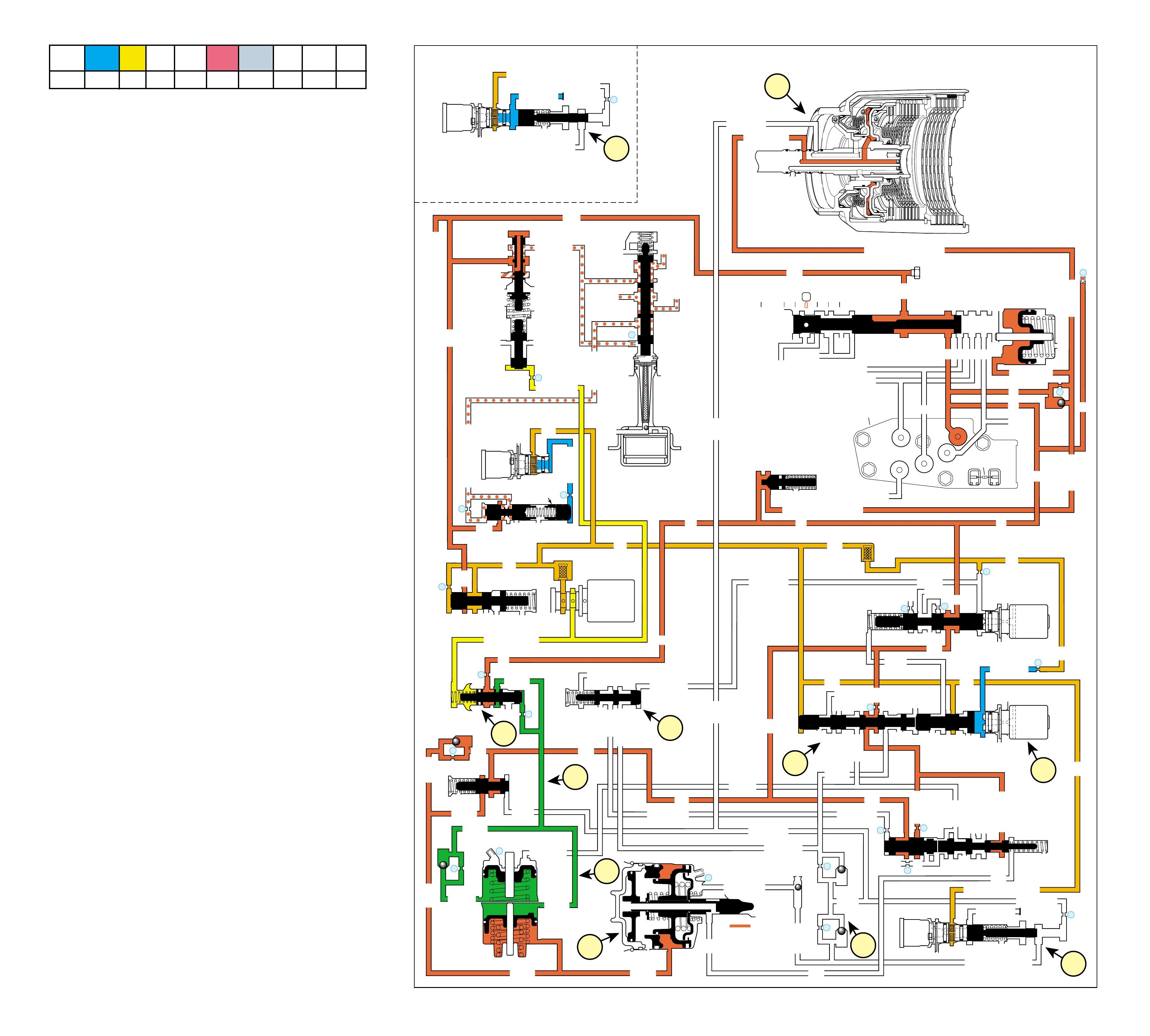
65
➤
➤
➤
➤
➤
➤
➤
➤
➤
➤➤
➤
➤
➤
➤
➤ ➤➤
➤
➤
➤
➤
➤
➤
➤➤➤
➤
➤
➤
➤
➤
➤
➤
➤
➤➤
➤➤
➤
➤
➤
INPUT CLUTCH
HOUSING ASSEMBLY
OVERRUN CLUTCH
LINE
LINE
➤
➤➤
➤➤ ➤
LINE (From Pump)
FORWARD CLUTCH FEED
➤
➤
➤➤
➤
FWD CL FEED
➤
D4
D4
FORWARD CLUTCH FEED
FWD CL FD FWD CL FD
D4
D4
D4
D4
D4
D4
TORQUE SIGNAL
1-2 SIGNAL
3-4 ACC
2ND
D4
1-2 SIGNAL
3-4 SIG
3-4 SIGNAL
3-4 CL
3-4 CLUTCH
3RD ACC
4TH
OVERRUN CL FD
OVERRUN CL
SERVO FEED
SERVO FD
ACTUATOR FEED LIMIT
4TH SIG
2ND
2ND CL2ND CL
2ND CL
2ND CL 3-4 CL 2ND
2ND 2ND
3-4 ACC
3-4 CL 3-4 CL
ACCUM
ACCUM
3-4 CLUTCH
AFL
AFL
2ND CL
➤
➤
➤
➤
➤
➤
➤
➤
➤
➤
➤
➤
➤➤
➤
➤
➤➤
➤
➤
➤➤
➤
➤
➤
➤
➤
➤
➤➤
➤➤
➤
➤
➤
➤
➤
➤
➤➤
➤
➤
➤
➤➤
➤➤
➤➤
➤➤
➤
➤
➤
➤
➤
➤➤
➤
➤
➤
➤
➤➤➤
➤
➤
➤➤➤
➤
➤
➤
➤➤ ➤
➤
➤
➤➤
➤
➤
➤
➤
➤
➤
REAR LUBE
➤
4TH SIGNAL
4TH
4TH SIGNAL
➤
3-4 ACCUM
➤
➤
➤
EX
EX
3-4 RELAY 4-3 SEQUENCE VALVE
EXORF EX 5
67
TCC
SOLENOID
N.O.
OFF
CONVERTER CLUTCH VALVE
COOLER
RELEASE
APPLY
EX
➤
EX
➤
4
➤
➤
➤
REG APPLY
BOOST VALVE PRESS REG
EX
TORQUE SIG
➤
EX
CONV FEED
➤
➤➤
REV INPUT
DECREASE
REV INPUT
10
LINE
REGULATED APPLY
➤
EX
EX
EX
CC SIGNAL
9
TCC PWM
SOLENOID
VALVE
N.C.
➤
8
ACTUATOR FEED LIMIT
EX
EX
EX
AFL
LINE
FILTER (50)
➤
➤
➤➤
➤
➤
➤
➤
➤
EX
PRESSURE
CONTROL
SOLENOID
VALVE
32
24
LINE
LINE
D4
REVERSE
PR
D3
D2
LO
D2
D3
D3
LO
FWD CL FEED
REV INPUT
LINE
PRESSURE
TAP
➤
➤
➤
➤
D2-N.C.
REV-N.O.
D3-N.C.
LO-N.O.
D4-N.O.
TEMP
SENSOR
➤
TFP
SWITCH
ASSEMBLY
➤
FORWARD CLUTCH
ACCUMULATOR
EX
PRND321
EX
EX
MANUAL VALVE
➤
➤
#12
22
➤
➤
➤
EX
FORWARD ABUSE
LO/1ST
AFL
AFL
AFL
1-2 SIG
AFL FILTER
(49)
➤
➤
➤
➤
➤
➤
➤
➤
➤
➤
➤➤➤ ➤
➤
AFL
AFL
25
26
27
29
EX
EX
EX
EX
D2
OVERRUN
D3
2ND
EX
2-3 SIGNAL
3-4 ACC
➤
2-3 SHIFT
SOLENOID
VALVE
N.O. ON
LO
D4
D4-3-2
2ND
EX
EX
1-2 SHIFT
SOLENOID
VALVE
N.O. OFF
28
1-2 SHIFT VALVE
2-3 SHUTTLE 2-3 SHIFT VALVE
14
3-4 CLUTCH
3RD ACCUMULATOR
EX
EX
3-2 SIGNAL
➤
#2
12
#4
13
EX
#7
11 3RD ACCUM
➤
2ND & 4TH
SERVO
11
4TH
EX
EX
#1
18
➤
➤
3-4 ACCUMULATOR
1-2 ACCUMULATOR
19
EX
ORF ACC
➤
➤
D3
EX
3-4 SIGNAL
4TH SIG
3-4 SHIFT VALVE
EX
➤➤➤➤➤➤
➤➤➤➤➤➤➤
➤➤
➤
➤
➤➤
➤➤
➤➤ ➤➤
➤
➤
➤➤
➤
➤
➤➤➤➤➤
➤➤➤➤➤➤➤
➤➤
➤➤
➤
➤
➤➤➤➤➤➤➤➤ ➤➤
➤➤
➤
➤
➤
➤
➤➤➤➤➤➤➤➤➤➤➤➤ ➤➤➤➤➤➤➤➤➤ ➤ ➤ ➤ ➤➤➤➤➤
➤➤ ➤
➤➤
➤
➤➤➤➤➤➤➤ ➤➤➤➤
➤➤➤
➤
➤
30
EX
ACCUM
31
➤
➤
➤
➤
➤
➤
ACCUM VALVE
#8
16
➤
➤
1c
1b
2a
1f
1g
1a
1e
1d
2b
1c
➤
➤
3-2 DOWNSHIFT
OVERDRIVE RANGE – 3-2 DOWNSHIFT
HIGH SPEED
CONTROLLED 3RD ACCUMULATOR EXHAUST
1e
ACTUATOR FEED LIMIT
14
3-4 CLUTCH
3RD ACCUMULATOR
EX
EX
3-2 SIGNAL
➤
➤
3-2
CONTROL
SOLENOID
VALVE
N.C.
ON
➤
➤
➤
➤
➤
3-2 CONTROL
3-2 CONTROL
3-2
CONTROL
SOLENOID
VALVE
N.C.
OFF
ISOLATOR VALVE
REG APPLY
OVERDRIVE RANGE – 3-2 DOWNSHIFT
Figure 62
COMPLETE HYDRAULIC CIRCUIT
Page 90
1-2 SHIFT 2-3 SHIFT REVERSE FORWARD
SOLENOID SOLENOID 2-4 INPUT OVERRUN FORWARD SPRAG CL. 3-4 LO-ROLLER LO/REV
VALVE VALVE BAND CLUTCH CLUTCH CLUTCH ASSEMBLY CLUTCH CLUTCH CLUTCH
OFF ON APPLIED APPLIED HOLDING
A forced 3-2 downshift occurs by increasing throttle valve angle
(percentage of accelerator pedal travel or throttle position) while
the vehicle is operating in Third gear. As with a 4-3 downshift,
a 3-2 downshift can also occur when the vehicle is decelerating
during coast conditions or when load on the vehicle increases.
A 3-2 downshift occurs when the PCM receives the appropriate
input signals to de-energize or “turn OFF” current supply to the
2-3 shift solenoid (SS) valve (open the ground path of the cir-
cuit). During a 3-2 downshift, the following changes occur to
the hydraulic system:
1 3-4 CLUTCH RELEASED
1a 2-3 Shift Solenoid (SS) Valve:
The 2-3 SS valve is energized (ON) blocking 2-3 signal
fluid from exhausting through the solenoid. This creates
pressure in the 2-3 signal fluid circuit.
1b 2-3 Shift Valve and 2-3 Shuttle Valve:
The 2-3 signal fluid pressure moves both valves to the
downshifted position. This causes the following changes.
•The AFL fluid is blocked from the D432 fluid circuit
causing the D432 fluid to exhaust past the 2-3 shuttle
valve.
•The 2nd fluid is blocked from feeding the 3-4 signal
fluid circuit and is routed into the servo feed fluid
circuit.
•The 3-4 signal fluid is exhausted past the valve. The
3-4 clutch fluid and the 3rd accumulator fluid also
exhaust.
1c 2nd & 4th Servo:
The 3rd accumulator fluid exhausts from the servo assembly.
The 2nd clutch fluid pressure moves the 2nd apply piston
against the servo return spring force in order to move the
apply pin and apply the 2-4 band.
1d 3-4 Shift Valve:
The 3-4 signal fluid pressure exhausts from the 3-4 shift
valve.
1e 3-2 Control Solenoid Valve and 3-2 Control Valve:
These components are used to increase the exhaust rate of
3rd accumulator fluid, as needed, depending on the vehicle
speed. The 3-2 control solenoid valve is a normally closed
On/Off solenoid controlled by the PCM. The PCM controls
the solenoid state during a 3-2 downshift according to
vehicle speed.
1f 3-2 Downshift Valve:
The 3-4 clutch fluid exhausts from the valve and the spring
force moves the valve into the second gear position.
1g 3rd Accumulator Ball Check Valve (#2):
The exhausting 3rd accumulator fluid seats the #2 ball check
valve and is forced through orifice #12. This fluid exhausts
through the 3-4 clutch and the 3-4 signal fluid circuits and
past the 2-3 shift valve. Orifice #12 slows the exhaust of the
3rd accumulator fluid and delays the 2-4 band apply rate.
2 2-4 BAND APPLIED
2a 3rd Accumulator:
3rd accumulator fluid pressure and 3rd accumulator spring
force move the 3rd accumulator piston to a Second gear
position.
2b Accumulator Valve:
The 3rd accumulator fluid circuit is supplied by accumulator
fluid through the orifice opposite the #5 ball check valve.
The accumulator valve regulates drive fluid into the
accumulator circuit.
64B

66
INPUT HOUSING
& SHAFT ASSEMBLY
(621)
OUTPUT
SHAFT
(687)
SPEED SENSOR
ROTOR
(699)
REACTION
INTERNAL
GEAR
(684)
FORWARD SPRAG
ASSEMBLY
(642)
HOLDING
OVERRUN
CLUTCH HUB
(639)
FORWARD CLUTCH
OUTER RACE
(644)
FORWARD SPRAG CLUTCH
INNER RACE AND
INPUT SUN GEAR
ASSEMBLY
(640)
INPUT CARRIER
ASSEMBLY
(662)
INPUT
INTERNAL
GEAR
(664)
REACTION
CARRIER
SHAFT
(666)
FORWARD
CLUTCH
APPLIED 3-4
CLUTCH
APPLIED
OVERRUN
CLUTCH
APPLIED
➤➤➤
➤
➤
➤
➤
➤
➤
POWER TO
TORQUE
CONVERTER
(1)
FOR ENGINE
BRAKING
1
POWER FROM
DIFFERENTIAL
ASSEMBLY
4
OVERRUN
CLUTCH
APPLIED
3
FORWARD SPRAG
ASSEMBLY
(642)
HOLDING
5
FORWARD
CLUTCH
APPLIED
2
3-4
CLUTCH
APPLIED
MANUAL THIRD – THIRD GEAR
(from Overdrive Range – Fourth Gear)
Figure 63
MANUAL THIRD – THIRD GEAR
(from Overdrive Range – Fourth Gear)
66A
Drive Range – Manual Third (D) is available to the driver when
vehicle operating conditions make it desirable to use only three
gear ratios. These conditions include city driving [where speeds
are generally below 72 km/h (45 mph)], towing a trailer, or
driving in hilly terrain. Manual Third also provides for engine
compression braking when descending slight grades and can be
used to retain Third gear when ascending slight grades for addi-
tional engine performance. Manual Third is also referred to as
Drive Range because it has a 1:1 direct drive gear ratio available
through the transmission gear sets.
In Manual Third, the transmission can upshift and downshift
between First, Second and Third gears in the same manner as
Overdrive Range. However, the transmission is prevented from
shifting into Fourth gear while operating in this gear selector
position. If the transmission is in Overdrive Range – Fourth
Gear when Manual Third is selected, the transmission will im-
mediately shift into Third gear.
Note: Transfer of engine torque during acceleration is identical
to Overdrive Range – Third Gear (refer to page 58A). The
power flow in Figure 63 and the following text describes condi-
tions during deceleration (zero or minimum throttle conditions)
and how engine compression braking is achieved.
Vehicle speed provides the torque input to the transmission
through the drive shaft and transmission output shaft (687).
This is shown by the direction of the power flow arrows in the
drawing at the top of Figure 63. Notice that this flow is identical
to Overdrive Range – Third Gear except that the arrows are in
the opposite direction.
1 Power From the Differential Assembly
Power flow is transferred back through the transmission
from the output shaft to the input clutch housing (621). Each
of the component’s function and rotation direction is the
same as during acceleration (compare Figures 55 and 63).
2 3-4 Clutch Applied
The 3-4 clutch is applied and power from the output shaft
travels to the input housing.
3 Forward Sprag Assembly Holding
Power from the output shaft also travels through the forward
sprag clutch inner race and input sun gear assembly (640) to
the forward sprag assembly (642). The inner race of the
forward sprag assembly is attached to the overrun clutch
hub. The inner race is held when the overrun clutch is applied,
and the outer race is held with the forward clutch applied.
4 Overrun Clutch Applied
With the overrun clutch applied, power from vehicle speed
is prevented from overrunning the forward sprag clutch when
the throttle is released. This power is transferred back through
the overrun clutch and to the engine, thereby allowing engine
compression to slow the vehicle when the throttle is released.
5 Forward Clutch Applied
The forward clutch is applied but is only effective in a coast
condition because the overrun clutch is applied.
In Manual Third range – First and Second gears, the forward
sprag assembly overruns and engine compression braking is not
available. First and Second gears operate the same as in Over-
drive Range, except for the overrun clutch being applied, and the
vehicle is allowed to coast freely when the throttle is released. To
obtain increased engine compression braking at slower speeds,
the gear selector must be moved to the Manual Second position.
1-2 SHIFT 2-3 SHIFT REVERSE FORWARD
SOLENOID SOLENOID 2-4 INPUT OVERRUN FORWARD SPRAG CL. 3-4 LO-ROLLER LO/REV
VALVE VALVE BAND CLUTCH CLUTCH CLUTCH ASSEMBLY CLUTCH CLUTCH CLUTCH
OFF OFF APPLIED APPLIED HOLDING APPLIED
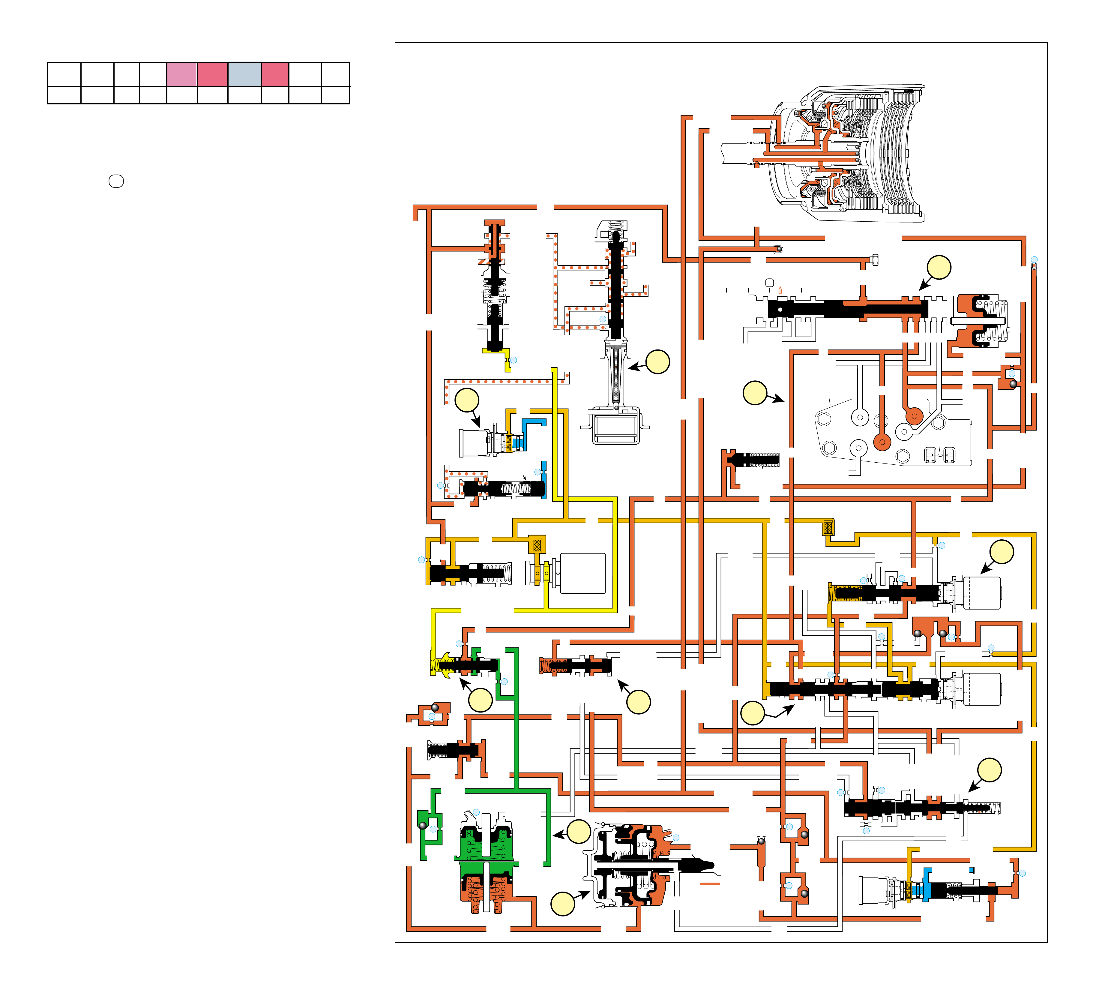
67
MANUAL THIRD – THIRD GEAR
(from Overdrive Range – Fourth Gear)
COMPLETE HYDRAULIC CIRCUIT
Page 92
Figure 64
➤
➤
➤
➤
➤
➤
➤
➤
➤
➤➤➤➤
➤➤
➤
➤➤
➤
➤
➤
➤
➤
➤
➤
➤➤➤➤
➤➤
➤➤
➤➤➤
➤➤
➤➤
➤
➤
➤➤
➤
➤➤➤➤➤➤➤➤➤➤ ➤➤
➤➤➤➤
➤➤➤
➤➤
➤➤
➤
➤
➤
➤
➤
➤➤
➤
➤
➤
➤➤
➤➤
➤
➤
➤
➤
➤
➤
➤
➤➤
➤➤
➤
➤
➤
➤
➤➤
➤
➤
➤➤
➤➤➤➤➤➤➤
➤
INPUT CLUTCH
HOUSING ASSEMBLY
OVERRUN CLUTCH
OVERRUN CLUTCHOVERRUN CLUTCH
➤
➤➤➤➤
➤➤➤➤
➤ ➤➤➤➤➤➤ ➤ ➤
➤➤
LINE
LINE
➤
➤➤
➤➤ ➤
LINE (From Pump)
FORWARD CLUTCH FEED
➤
➤
➤➤
➤
FWD CL FEED
➤
D4
D4
FWD CL FEED
FWD CL FD FWD CL FD
D4
D4
D4
D4
D4
D4
TORQUE SIGNAL
1-2 SIGNAL
3-4 ACC
2ND
D4
1-2 SIG
3-4 SIG
3-4 SIGNAL
3-4 CL
3-4 CLUTCH
3RD ACC
4TH
OVERRUN CL FD
OVERRUN CL FD
OVERRUN CL
SERVO FEED
SERVO FD
ACTUATOR FEED LIMIT
4TH SIG
2ND
2ND CL2ND CL
2ND CL
2ND CL 3-4 CL 2ND
2ND 2ND
3-4 ACC
3-4 CL 3-4 CL
ACCUM
ACCUM
3-4 CLUTCH
AFL
AFL
2ND CL
➤
➤
➤
➤
➤
➤
➤
➤
➤
➤
➤
➤
➤➤
➤
➤
➤➤
➤
➤
➤➤
➤
➤
➤
➤
➤
➤
➤➤
➤➤
➤
➤
➤➤
➤
➤
➤
➤➤
➤➤
➤➤
➤➤
➤
➤
➤
➤
➤
➤➤
➤
➤
➤
➤
➤➤➤ ➤
➤
➤
➤
➤
➤➤➤
➤
➤
➤
➤➤ ➤
➤
➤
➤➤
➤
➤
➤
➤➤
➤
➤➤
➤
➤
➤➤
➤
➤
➤
➤➤
➤➤
➤➤
➤
➤
➤ ➤ ➤➤➤➤➤ ➤
➤
➤
➤
➤
REAR LUBE
➤
4TH SIGNAL
4TH
4TH SIGNAL
➤
➤
3-4 ACCUM
➤
➤
MANUAL THIRD – THIRD GEAR
(from Overdrive Range – Fourth Gear)
➤
➤
➤
➤
➤
EX
EX
3-4 RELAY 4-3 SEQUENCE VALVE
EXORF EX 5
67
TCC
SOLENOID
N.O.
OFF
CONVERTER CLUTCH VALVE
COOLER
RELEASE
APPLY
EX
➤
EX
➤
4
➤
➤
➤
REG APPLY
BOOST VALVE PRESS REG
EX
TORQUE SIG
➤
EX
CONV FEED
➤
➤➤
REV INPUT
DECREASE
REV INPUT
10
LINE
REGULATED APPLY
➤
EX
EX
EX
CC SIGNAL
9
TCC PWM
SOLENOID
VALVE
N.C.
➤
8
ACTUATOR FEED LIMIT
EX
EX
EX
AFL
LINE
FILTER (50)
➤
➤
➤➤
➤
➤
➤
➤
➤
EX
PRESSURE
CONTROL
SOLENOID
VALVE
32
24
LINE
LINE
D4
REVERSE
PR
D3
D2
LO
D2
D3
D3
LO
FWD CL FEED
REV INPUT
LINE
PRESSURE
TAP
➤
➤
➤
➤
➤
➤
➤➤➤
➤
➤➤➤➤
➤
➤➤
D2-N.C.
REV-N.O.
D3-N.C.
LO-N.O.
D4-N.O.
TEMP
SENSOR
➤
TFP
SWITCH
ASSEMBLY
➤
FORWARD CLUTCH
ACCUMULATOR
EX
PRND321
EX
EX
MANUAL VALVE
➤
➤
#12
22
➤
➤
➤
EX
FORWARD ABUSE
LO/1ST
AFL
AFL
AFL
1-2 SIG
AFL
FILTER
(49)
➤
➤
➤➤
➤
➤
➤
➤
➤
➤
➤➤ ➤
➤
AFL
AFL
25
26
27
29
EX
EX
EX
EX
D2
D2
OVERRUN
D3 D3 D3
EX
2-3 SIGNAL
3-4 ACC
➤
2-3 SHIFT
SOLENOID
VALVE
N.O.
OFF
LO
D4
D4-3-2
2ND
EX
EX
1-2 SHIFT
SOLENOID
VALVE
N.O.
OFF
28
1-2 SHIFT VALVE
2-3 SHUTTLE 2-3 SHIFT VALVE
14
3-4 CLUTCH
3RD ACCUMULATOR
EX
EX
3-2 SIGNAL
➤
➤
➤
#2
12
➤
➤
#4
13
➤
➤
➤
➤
➤
➤➤➤
➤➤
EX
#7
11 3RD ACCUM
➤
2ND & 4TH
SERVO
11
4TH
EX
EX
➤
➤
➤
➤
#1
18
➤
➤
3-4 ACCUMULATOR
1-2 ACCUMULATOR
19
EX
ORF ACC
➤
➤
D3
EX
3-4 SIGNAL
4TH SIG
3-4 SHIFT VALVE
EX
➤
30
EX
ACCUM
31
➤
➤
➤
➤
➤
➤
ACCUM VALVE
#8
16
➤
➤
2c
2b
2a
1c
3a
4a
4b
1a
1b
3b 1d
#6
ORF D2
#5
20
➤➤
➤
➤
➤
EX
➤
➤➤➤➤➤
➤➤➤
➤
➤➤
➤
➤
➤
➤
➤
➤
➤➤
21
➤
➤
➤
3-2 DOWNSHIFT
3-2 CONTROL
3-2
CONTROL
SOLENOID
VALVE
N.C.
ON
➤
ISOLATOR VALVE
REG APPLY
1-2 SHIFT 2-3 SHIFT REVERSE FORWARD
SOLENOID SOLENOID 2-4 INPUT OVERRUN FORWARD SPRAG CL. 3-4 LO-ROLLER LO/REV
VALVE VALVE BAND CLUTCH CLUTCH CLUTCH ASSEMBLY CLUTCH CLUTCH CLUTCH
OFF OFF APPLIED APPLIED HOLDING APPLIED
Drive Range – Manual Third may be selected at any time while
the vehicle is being operated in a forward gear range. However,
the transmission's hydraulic system prevents the transmission
from shifting into Fourth gear regardless of PCM control. When
the gear selector lever is moved to Drive Range (D) from Over-
drive Range D , the manual valve also moves. Changes to the
hydraulic and electrical systems are as follows:
1 FOURTH GEAR PREVENTED
1a Manual Valve:
The gear selector lever, selector shaft and manual valve are
moved to Manual Third (D) position.
1b Transmission Fluid Pressure (TFP) Manual Valve
Position Switch:
D3 fluid is routed to the TFP manual valve position switch
and opens the normally closed D3 fluid pressure switch.
1c 2-3 Shift Valve Train:
With the 2-3 SS valve de-energized and open, AFL fluid
acting on the 2-3 shift valve holds both valves in the upshifted
position. D3 fluid feeds the overrun fluid circuit through
the 2-3 shift valve.
1d 3-4 Shift Valve:
D3 fluid pressure assists spring force to keep the valve in
the downshifted position. This blocks 3-4 signal fluid and
allows the 4th signal fluid circuit to exhaust. Therefore fourth
gear is hydraulically prevented.
2 OVERRUN CLUTCH APPLIES
2a 1-2 Shift Solenoid (SS) Valve:
When manual third is selected, the PCM de-energizes the
1-2 SS valve to immediately downshift the transmission
into third gear.
2b 3-4 Relay Valve and 4-3 Sequence Valve:
4th signal fluid pressure is exhausted. Overrun clutch feed
fluid pressure assists spring force and closes both valves
allowing it to fill the overrun clutch fluid circuit.
2c 2nd & 4th Servo:
The 4th fluid exhausts from the 4th apply piston in the servo
assembly. The apply pin spring moves the 4th apply piston
and the apply pin in order to release the band from the
reverse input drum and shift the transmission into third gear.
3 SHIFT ACCUMULATION – Same as 4-3 Downshift
4 TORQUE CONVERTER
4a TCC PWM Solenoid Valve:
The PCM de-energizes the TCC solenoid valve, and operates
the duty cycle of the TCC PWM solenoid valve to release
the converter clutch for a smooth disengagement, prior to
initiating the 4-3 downshift.
4b TCC Solenoid Valve:
The TCC solenoid valve is de-energized by the PCM. This
causes converter feed fluid pressure to exhaust through the
solenoid and allows the converter clutch valve to shift to the
release position.
66B
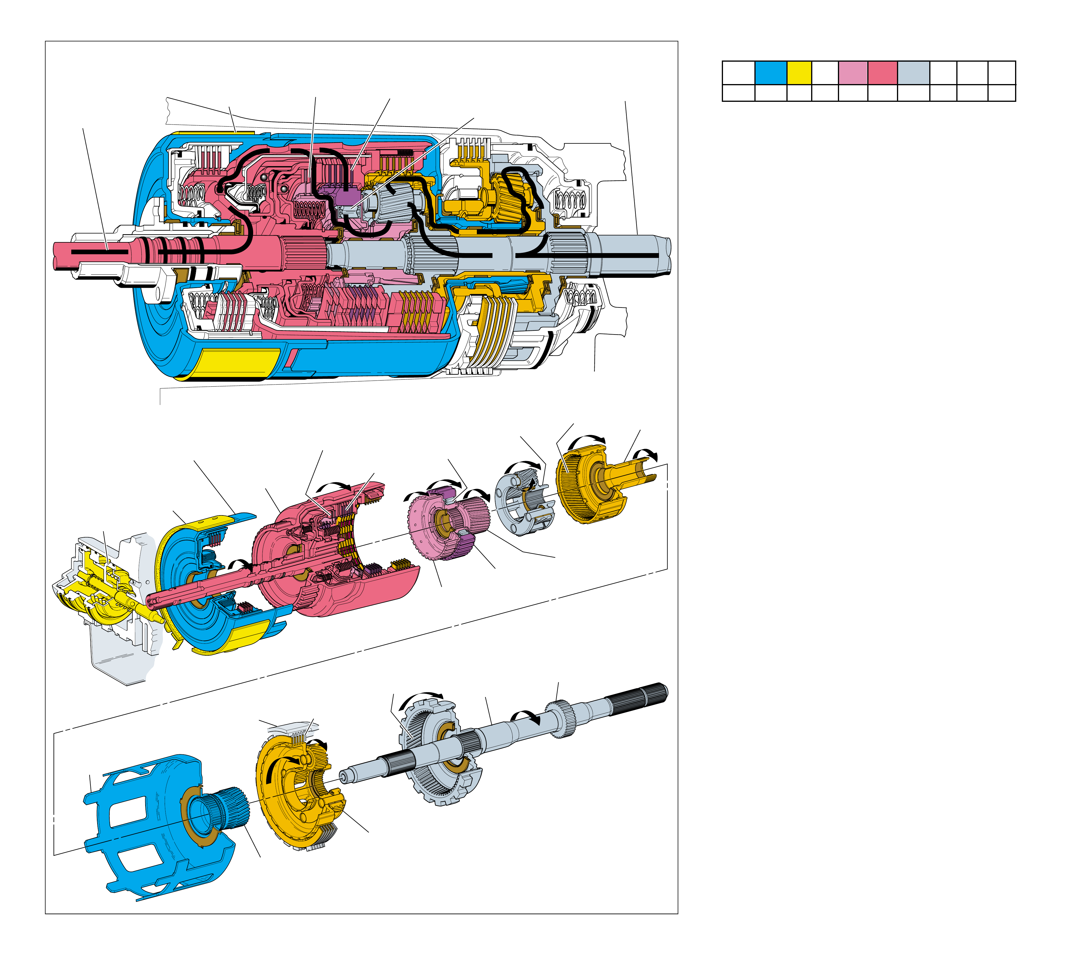
68
INPUT HOUSING
& SHAFT ASSEMBLY
(621)
OUTPUT
SHAFT
(687)
SPEED SENSOR
ROTOR
(699)
REACTION
INTERNAL
GEAR
(684)
FORWARD SPRAG
ASSEMBLY
(642)
HOLDING
OVERRUN
CLUTCH HUB
(639)
FORWARD CLUTCH
OUTER RACE
(644)
FORWARD SPRAG CLUTCH
INNER RACE AND
INPUT SUN GEAR
ASSEMBLY (640)
INPUT CARRIER
ASSEMBLY
(662)
INPUT
INTERNAL
GEAR
(664)
REACTION
CARRIER
SHAFT
(666)
SERVO
ASSEMBLY
APPLIED
2-4 BAND
ASSEMBLY
(602)
APPLIED
REVERSE INPUT
CLUTCH HOUSING
(605)
HELD
REACTION
SUN SHELL
(670)
HELD
REACTION
SUN GEAR
(673)
HELD
LOW AND REVERSE
CLUTCH PLATE
ASSEMBLY
(682)
REACTION
CARRIER
ASSEMBLY
(681)
MAIN
CASE
(103)
FORWARD
CLUTCH
APPLIED
OVERRUN
CLUTCH
APPLIED
➤➤
➤
➤
➤
➤
➤
➤
➤
➤
POWER TO
TORQUE
CONVERTER
(1)
FOR ENGINE
BRAKING
1
POWER FROM
DIFFERENTIAL
ASSEMBLY
2
2-4 BAND
ASSEMBLY
(602)
APPLIED
5
FORWARD
SPRAG
ASSEMBLY
(642)
HOLDING
4
FORWARD
CLUTCH
APPLIED
3
OVERRUN
CLUTCH
APPLIED
MANUAL SECOND – SECOND GEAR
(from Manual Third – Third Gear)
Figure 65
MANUAL SECOND – SECOND GEAR
(from Manual Third – Third Gear)
68A
1-2 SHIFT 2-3 SHIFT REVERSE FORWARD
SOLENOID SOLENOID 2-4 INPUT OVERRUN FORWARD SPRAG CL. 3-4 LO-ROLLER LO/REV
VALVE VALVE BAND CLUTCH CLUTCH CLUTCH ASSEMBLY CLUTCH CLUTCH CLUTCH
OFF ON APPLIED APPLIED APPLIED HOLDING
Manual Second (2) gear range is available to the driver when
vehicle operating conditions make it desirable to use only two gear
ratios. These conditions include descending a steep grade when
engine compression braking is needed, or to retain second gear
when ascending a steep grade for additional engine performance.
In Manual Second, the transmission can upshift and downshift
between First and Second gear but is prevented from shifting
into Third or Fourth gear. If the transmission is in Third or
Fourth gear when Manual Second is selected, the transmission
will shift immediately into Second gear.
Note:
First gear in the Manual Second gear selector position
is only available on some models at low speeds and under
heavy throttle.
Note: Transfer of engine torque during acceleration is identical
to Overdrive Range – Second Gear (refer to page 56A) to obtain
an approximate gear ratio reduction of 1.63:1 through the trans-
mission gear sets. The power flow in Figure 65 and the follow-
ing text describes conditions during deceleration (zero or mini-
mum throttle) and how engine compression braking is achieved.
Vehicle speed provides the torque input to the transmission
through the drive shaft and transmission output shaft (687).
This is shown by the direction of the power flow arrows in the
drawing at the top of Figure 65. Notice that this flow is identi-
cal to Overdrive Range – Second Gear except that the arrows
are in the opposite direction.
1 Power From the Differential Assembly
Vehicle speed attempts to drive the input carrier (662) faster
than engine speed is driving the input housing and shaft
assembly (621).
2 2-4 Band Assembly Applied
The 2-4 band is applied and holds the reverse input clutch
housing which is tanged to the reaction sun shell. The reaction
sun gear is splined to the reaction shell and is held by the 2-4
band. Power from the differential travels through the reaction
carrier and back to the input carrier to create second gear
reduction for engine compression braking.
3 Overrun Clutch Applied
With the overrun clutch applied, power from vehicle speed is
prevented from overrunning the forward sprag clutch when
the throttle is released. This power is transferred back through
the overrun clutch and to the engine, thereby allowing engine
compression to slow the vehicle when the throttle is released.
4 Forward Clutch Applied
The forward clutch is applied but only effective in a coast
condition because the overrun clutch is applied.
5 Forward Sprag Assembly Holding
Power from the output shaft also travels through the forward
sprag clutch inner race and input sun gear assembly to the
forward sprag assembly. The inner race of the forward sprag
assembly is attached to the overrun clutch hub. The inner
race is held when the overrun clutch is applied, and the
outer race is held with the forward clutch applied.
The overrun clutch remains applied in Manual Second – First
Gear to provide engine compression braking.
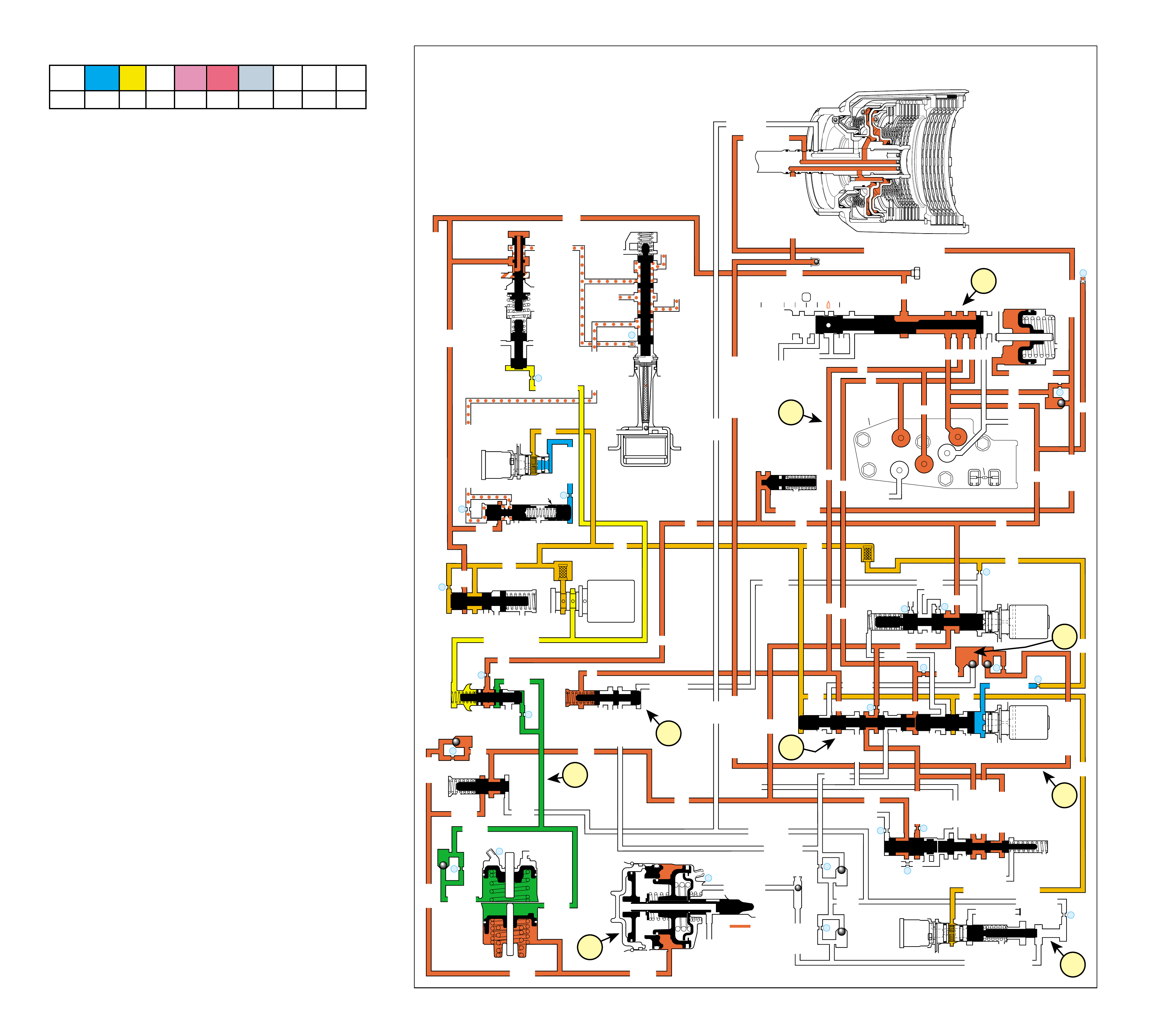
69
MANUAL SECOND – SECOND GEAR
(from Manual Third – Third Gear)
➤
➤
➤
➤
➤
➤
➤
➤
➤
➤➤
➤
➤
➤
➤
➤➤➤➤➤➤
➤➤➤➤➤➤➤
➤➤
➤
➤
➤➤
➤➤
➤➤ ➤➤
➤
➤
➤➤
➤
➤
➤➤➤➤➤
➤➤➤➤➤➤➤
➤➤
➤➤
➤
➤
➤➤➤➤➤➤➤➤ ➤➤
➤➤
➤
➤
➤
➤
➤➤➤➤➤➤➤➤➤➤➤➤ ➤➤➤➤➤➤➤➤➤➤➤➤ ➤➤➤➤➤
➤➤ ➤
➤➤
➤
➤➤➤➤➤➤➤ ➤➤➤➤
➤➤➤
➤
➤
➤➤
➤
➤➤➤ ➤
➤➤
➤
➤
➤
➤
➤
➤➤➤➤➤ ➤
➤
➤
➤
➤
➤
➤
➤
➤➤
➤➤
➤
➤
➤
INPUT CLUTCH
HOUSING ASSEMBLY
OVERRUN CLUTCH
OVERRUN CLUTCHOVERRUN CLUTCH
➤➤
LINE
LINE
➤
➤➤
➤➤ ➤
LINE (From Pump)
FORWARD CLUTCH FEED
➤
➤
➤➤
➤
FWD CL FEED
➤
D4
D4
FWD CL FEED
FWD CL FD FWD CL FD
D4
D4
D4
D4
D4
D4
TORQUE SIGNAL
1-2 SIGNAL
3-4 ACC
2ND
D4
1-2 SIG
3-4 SIG
3-4 SIGNAL
3-4 CL
3-4 CLUTCH
3RD ACC
4TH
OVERRUN CL FD
OVERRUN CL FD
OVERRUN CL
SERVO FEED
SERVO FD
ACTUATOR FEED LIMIT
4TH SIG
2ND
2ND CL
2ND CL
2ND CL 3-4 CL 2ND
2ND 2ND
3-4 ACCUM
3-4 CL 3-4 CL
ACCUM
ACCUM
3-4 CLUTCH
AFL
AFL
2ND CL
➤
➤
➤
➤
➤
➤
➤
➤
➤
➤
➤
➤
➤➤
➤
➤
➤➤
➤
➤
➤➤
➤
➤
➤
➤
➤
➤
➤➤
➤➤
➤
➤
➤
➤
➤
➤
➤➤
➤
➤
➤
➤➤
➤➤
➤➤
➤➤
➤
➤
➤
➤
➤
➤➤
➤
➤
➤
➤
➤➤➤
➤
➤
➤➤➤
➤
➤
➤
➤➤ ➤
➤
➤
➤➤
➤
➤
➤
➤
➤
➤
REAR LUBE
➤
4TH SIGNAL
3-4 ACCUM
MANUAL SECOND – SECOND GEAR
(from Manual Third – Third Gear)
➤
➤
➤
EX
EX
3-4 RELAY 4-3 SEQUENCE VALVE
EXORF EX 5
67
TCC
SOLENOID
N.O.
OFF
CONVERTER CLUTCH VALVE
COOLER
RELEASE
APPLY
EX
➤
EX
➤
4
➤
➤
➤
REG APPLY
BOOST VALVE PRESS REG
EX
TORQUE SIG
➤
EX
CONV FEED
➤
➤➤
REV INPUT
DECREASE
REV INPUT
10
LINE
REGULATED APPLY
➤
EX
EX
EX
CC SIGNAL
9
TCC PWM
SOLENOID
VALVE
N.C.
➤
8
ACTUATOR FEED LIMIT
EX
EX
EX
AFL
LINE
FILTER (50)
➤
➤
➤➤
➤
➤
➤
➤
➤
EX
PRESSURE
CONTROL
SOLENOID
VALVE
32
24
LINE
LINE
D4
REVERSE
PR
D3
D2
LO
D2
D3
D3
LO
FWD CL FEED
REV INPUT
LINE
PRESSURE
TAP
➤
➤
➤
➤
➤
➤
➤
➤
➤➤➤
➤
➤➤➤➤
➤
➤
➤➤
➤
D2-N.C.
REV-N.O.
D3-N.C.
LO-N.O.
D4-N.O.
TEMP
SENSOR
➤
TFP
SWITCH
ASSEMBLY
➤
FORWARD CLUTCH
ACCUMULATOR
EX
PRND321
EX
EX
MANUAL VALVE
➤
➤
#12
22
➤
➤
➤
EX
FORWARD ABUSE
LO/1ST
AFL
AFL
AFL
1-2 SIG
AFL FILTER
(49)
➤
➤
➤➤
➤
➤
➤
➤
➤
➤
➤
➤
➤➤ ➤
➤
AFL
AFL
25
26
27
29
EX
EX
EX
EX
D2
D2
OVERRUN
D3 D3 D3
EX
2-3 SIGNAL
3-4 ACC
➤
2-3 SHIFT
SOLENOID
VALVE
N.O. ON
LO
D4
D4-3-2
2ND
EX
EX
1-2 SHIFT
SOLENOID
VALVE
N.O. OFF
28
1-2 SHIFT VALVE
2-3 SHUTTLE 2-3 SHIFT VALVE
14
3-4 CLUTCH
3RD ACCUMULATOR
EX
EX
3-2 SIGNAL
➤
#2
12
#4
13
EX
#7
#1
18
➤
➤
3-4 ACCUMULATOR
1-2 ACCUMULATOR
19
EX
ORF ACC
➤
➤
D3
EX
3-4 SIGNAL
4TH SIG
3-4 SHIFT VALVE
EX
30
EX
ACCUM
31
➤
➤
➤
➤
➤
➤
ACCUM VALVE
#8
16
➤
➤
4c
4a
4b
3
4e
1
2
4f
4d
#6
ORF D2
#5
20
➤
➤
➤
➤
➤
EX
➤
➤➤➤➤➤
➤➤➤
➤
➤➤
➤
➤
➤
➤
➤
➤
➤➤
21
D2
➤➤
➤
➤
➤
➤
2ND CL
➤
11 3RD ACCUM
➤
2ND & 4TH
SERVO
11
4TH
EX
EX
➤
➤
3-2 DOWNSHIFT
3-2 CONTROL
3-2
CONTROL
SOLENOID
VALVE
N.C.
OFF
ISOLATOR VALVE
REG APPLY
Figure 66
COMPLETE HYDRAULIC CIRCUIT
Page 94
1-2 SHIFT 2-3 SHIFT REVERSE FORWARD
SOLENOID SOLENOID 2-4 INPUT OVERRUN FORWARD SPRAG CL. 3-4 LO-ROLLER LO/REV
VALVE VALVE BAND CLUTCH CLUTCH CLUTCH ASSEMBLY CLUTCH CLUTCH CLUTCH
OFF ON APPLIED APPLIED APPLIED HOLDING
Manual Second may be selected at any time while the vehicle is
being operated in a forward gear range. However, the
transmission's hydraulic system prevents the transmission from
upshifting above Second gear regardless of PCM control. When
the gear selector lever is moved to Manual Second (2) from
Manual Third – Third Gear, the manual valve also moves.
Changes to the hydraulic and electrical systems are as follows:
1 MANUAL VALVE
The selector lever moves the manual shaft and the manual valve
into the manual second (2) position. This allo ws the line pressure
to enter the D2 fluid circuit.
2 TRANSMISSION FLUID PRESSURE (TFP) SWITCH
The D2 fluid is routed to the TFP manual valve position switch
where it opens the normally closed D2 fluid pressure switch.
3 BALL CHECK VALVE #5
D2 fluid feeds the orificed D2 fluid circuit seating the #5 ball check
valve and exhausting overrun fluid through the 2-3 shift valve.
4 THIRD AND FOURTH GEARS PREVENTED
4a 2-3 Shift Solenoid (SS) Valve:
The PCM energizes the 2-3 SS valve and the AFL fluid
pressure holds the 2-3 shift valve in the downshifted
position. This electronically prevents operation of the third
and fourth gears.
4b 2-3 Shift Valve Train:
The D2 fluid is routed between the 2-3 shuttle valve and the
2-3 shift valve causing the following:
•The 2nd fluid is blocked from the entering the 3-4
signal fluid circuit and the 3-4 signal fluid circuit
is open to an exhaust port at the valve.
•The 3-4 clutch cannot apply with the 3-4 signal
fluid exhausted. Therefore, third and fourth gears
are hydraulically prevented.
•The 2nd fluid feeds the servo feed fluid circuit, but
has no function in manual second.
•The AFL fluid is blocked by the 2-3 shift valve and
the D432 fluid circuit is exhausted through the valve.
•The overrun fluid is exhausted through the 2-3 shift
valve.
4c 2nd & 4th Servo:
The 3rd accumulator fluid exhausts from the servo assembly.
The 2nd clutch fluid pressure moves the 2nd apply piston
against the servo return spring force in order to move the
apply pin and apply the 2-4 band.
4d 3-2 Control Solenoid Valve and 3-2 Control Valve:
These components are used to increase the exhaust rate of
3rd accumulator fluid, as needed, depending on the vehicle
speed. The 3-2 control solenoid valve is a normally closed
On/Off solenoid controlled by the PCM. The PCM controls
the solenoid state during a 3-2 downshift according to
vehicle speed.
4e 3-2 Downshift Valve:
The 3-4 clutch fluid exhausts from the valve and the spring
force moves the valve into the second gear position.
4f 3-4 Shift Valve:
The 3-4 signal fluid pressure exhausts from the 3-4 shift
valve but has no effect on the valve.
68B
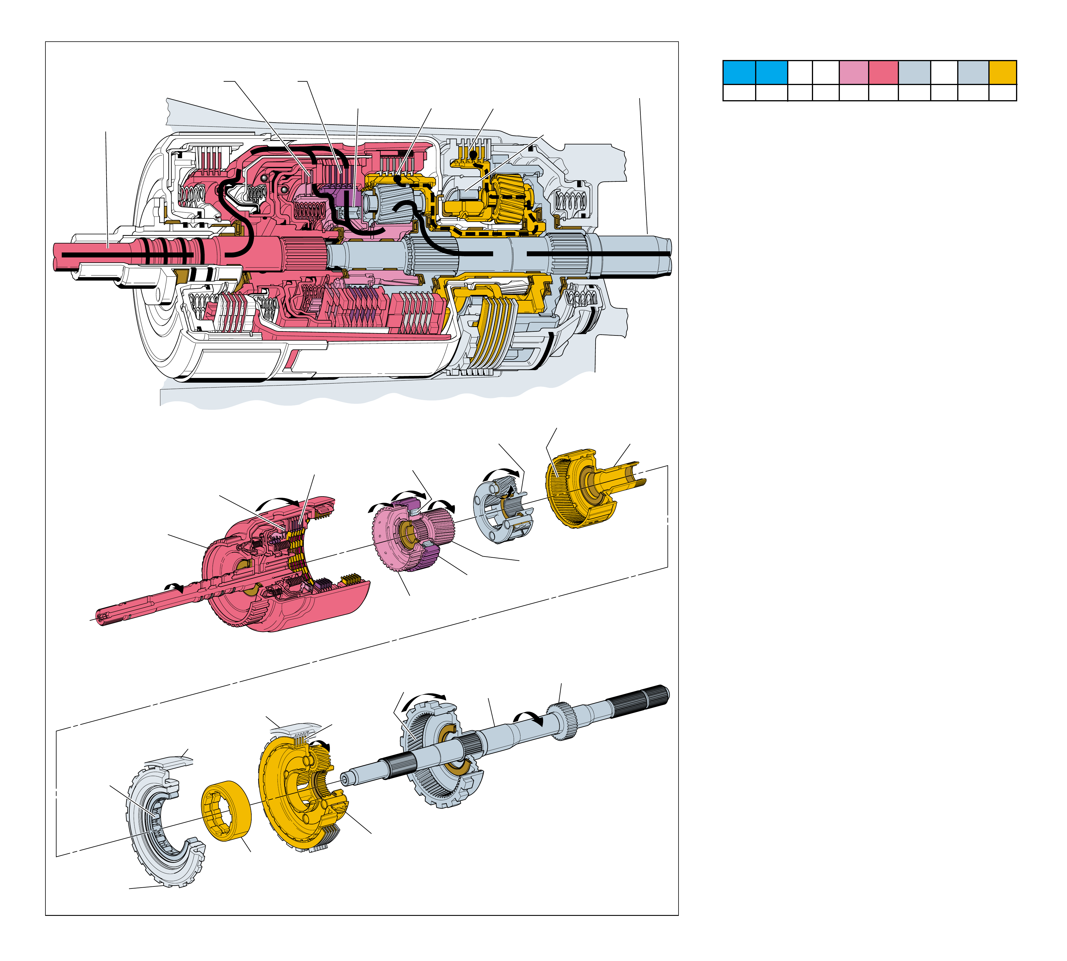
70 Figure 67
LOW AND
REVERSE
CLUTCH SUPPORT
ASSEMBLY
(679)
LOW AND REVERSE
ROLLER CLUTCH
ASSEMBLY
(678)
HOLDING
LOW AND REVERSE
ROLLER CLUTCH
RACE
(675)
HELD
MAIN
CASE
(103)
INPUT HOUSING
& SHAFT ASSEMBLY
(621)
OUTPUT
SHAFT
(687)
SPEED SENSOR
ROTOR
(699)
REACTION
INTERNAL
GEAR
(684)
FORWARD SPRAG
ASSEMBLY
(642)
HOLDING
OVERRUN
CLUTCH HUB
(639)
FORWARD CLUTCH
OUTER RACE
(644)
FORWARD SPRAG CLUTCH
INNER RACE AND
INPUT SUN GEAR ASSEMBLY
(640)
INPUT CARRIER
ASSEMBLY
(662)
INPUT
INTERNAL
GEAR
(664)
HELD
REACTION
CARRIER
SHAFT
(666)
HELD
LOW AND REVERSE
CLUTCH PLATE
ASSEMBLY
(682)
APPLIED
REACTION
CARRIER
ASSEMBLY
(681)
HELD
MAIN
CASE
(103)
FORWARD
CLUTCH
APPLIED
OVERRUN
CLUTCH
APPLIED
➤
➤
➤
➤
➤
➤
➤
POWER TO
TORQUE
CONVERTER
(1)
FOR ENGINE
BRAKING
1
POWER FROM
DIFFERENTIAL
ASSEMBLY
2
OVERRUN
CLUTCH
APPLIED
FORWARD SPRAG
ASSEMBLY
(642)
HOLDING
INPUT
INTERNAL
GEAR
HELD
FORWARD
CLUTCH
APPLIED
4
LOW AND
REVERSE
ROLLER
CLUTCH
ASSEMBLY
(678)
HOLDING
3
LOW AND
REVERSE
CLUTCH
APPLIED
MANUAL FIRST – FIRST GEAR
(from Manual Second – Second Gear)
MANUAL FIRST – FIRST GEAR
(from Manual Second – Second Gear)
70A
1-2 SHIFT 2-3 SHIFT REVERSE FORWARD
SOLENOID SOLENOID 2-4 INPUT OVERRUN FORWARD SPRAG CL. 3-4 LO-ROLLER LO/REV
VALVE VALVE BAND CLUTCH CLUTCH CLUTCH ASSEMBLY CLUTCH CLUTCH CLUTCH
ON ON APPLIED APPLIED HOLDING HOLDING APPLIED
Manual First is available to the driver when vehicle operating
conditions require maximum engine compression braking for
slowing the vehicle, or maximum engine torque transfer to the
wheels. These conditions include: descending a steep grade to
provide maximum engine compression braking and, to retain
First gear when ascending a steep grade or pulling a heavy load
for maximum engine power.
Under normal driving conditions, the transmission is prevented
from upshifting while operating in Manual First. If the transmis-
sion is in any other forward gear range when Manual First is
selected, the transmission will not shift into First gear until
vehicle speed is below approximately 52 km/h (33 mph). Above
this speed, the transmission will first shift into Second gear until
vehicle speed slows sufficiently.
Note: Transfer of engine torque through the transmission dur-
ing acceleration is identical to Overdrive Range – First Gear
(refer to page 54A) to obtain an approximate gear ratio reduc-
tion of 3.06:1. The power flow in Figure 67 and the following
text describes conditions during deceleration (zero or minimum
throttle) and how engine compression braking is achieved.
Vehicle speed provides the torque input to the transmission
through the drive shaft and transmission output shaft (687).
This is shown by the direction of the power flow arrows in the
drawing at the top of Figure 67. Notice that this flow is identi-
cal to Overdrive Range – First Gear except that the arrows are
in the opposite direction.
1 Power From the Differential Assembly
Vehicle speed attempts to drive the input carrier assembly
(662) faster than engine speed is driving the input housing
and shaft assembly (621).
2 Overrun Clutch Applied
The overrun clutch plates (645) are applied and prevent the
forward sprag clutch (642) from overrunning when the
throttle is released.
3 Low and Reverse Clutch Applied
The low and reverse clutch plates (682) are applied in Manual
First – First Gear. The low and reverse clutch holds the reaction
carrier assembly (681) stationary to the transmission case.
4 Low and Reverse Roller Clutch Holding
With the reaction carrier held stationary, the low and reverse
roller clutch (678) is prevented from being overrun when
the throttle is released. Without an element to overrun
during coast conditions, (either the sprag clutch or roller
clutch), engine compression slows the vehicle when the
throttle is released.
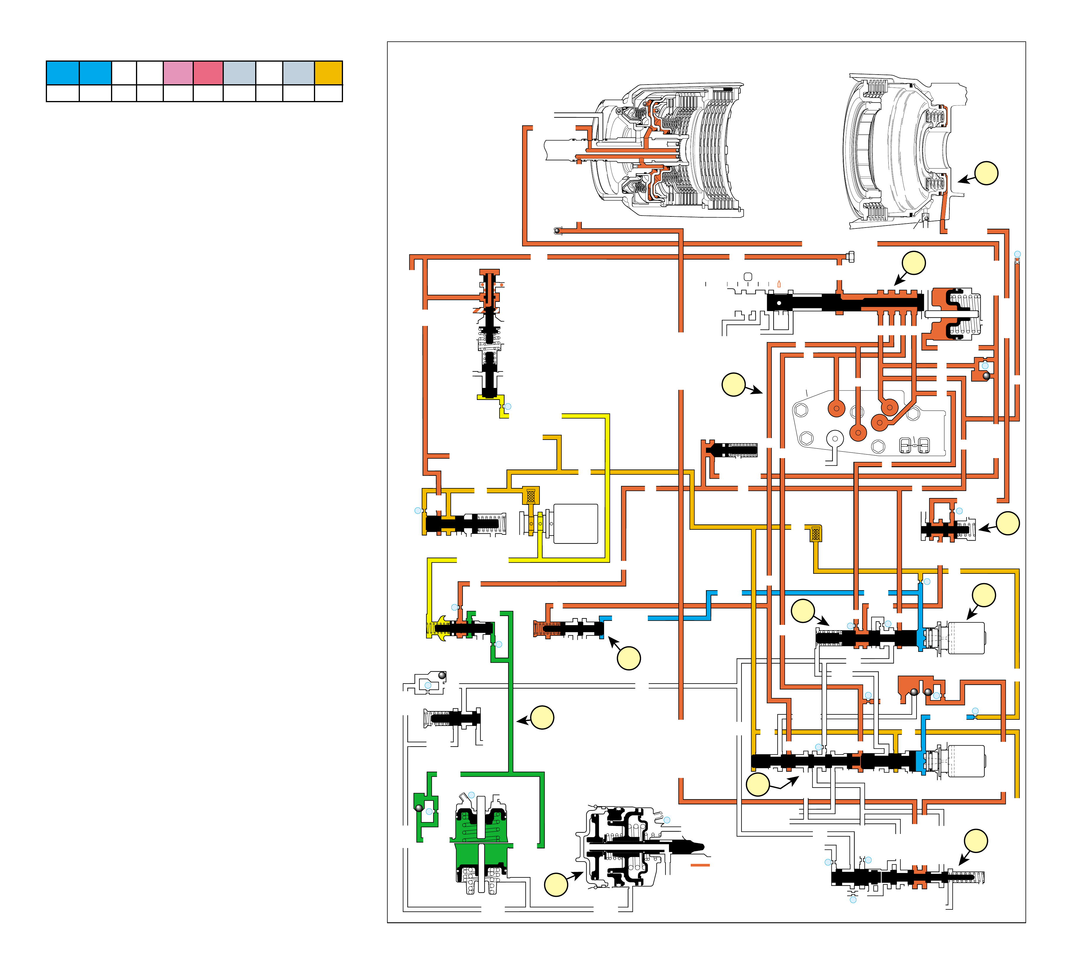
71
MANUAL FIRST – FIRST GEAR
(from Manual Second – Second Gear)
Figure 68
➤➤➤➤
➤
➤
➤
➤➤
➤
➤
➤
➤
➤
➤
➤➤➤➤➤
➤➤➤➤ ➤➤➤
➤➤
➤ ➤➤ ➤➤➤➤
➤
➤
➤
➤
➤
➤➤➤➤➤➤➤➤➤ ➤➤➤➤➤➤
➤
➤➤➤➤➤➤➤➤➤
➤➤➤➤➤ ➤ ➤ ➤ ➤➤
➤
➤
➤
➤
INPUT CLUTCH
HOUSING ASSEMBLY
OVERRUN CLUTCH
OVERRUN CLUTCHOVERRUN CLUTCH
LINE
LINE
➤
➤
➤➤ ➤
LINE (From Pump)
FORWARD CLUTCH FEED
➤
➤
➤➤
➤➤
FWD CL FEED
➤
D4
D4
FWD CL FEED
FWD CL FD FWD CL FD
D4
D4
D4
D4
D4
D4
TORQUE SIGNAL
1-2 SIGNAL
3-4 ACC
2ND
D4
1-2 SIG
3-4 SIG
4TH
OVERRUN CL FD
OVERRUN CL FD
OVERRUN CL
SERVO FEED
SERVO FD
4TH SIG
2ND
2ND CL
2ND CL
2ND CL 3-4 CL
2ND
2ND
3-4 ACCUM
ACCUM
ACCUM
3-4 CLUTCH
AFL
AFL (To TCC PWM Solenoid Valve)
2ND CL
➤
➤
➤
➤
➤
➤
➤
➤
➤➤
➤
➤
➤
➤
➤➤
➤
➤
➤➤
➤
➤
➤
➤
➤
➤
➤
➤➤➤
➤➤
➤
➤
➤
➤➤
➤
➤➤
➤➤
➤
➤
➤
➤
➤
➤
➤
REAR LUBE
➤
4TH SIGNAL
3-4 ACCUM
MANUAL FIRST – FIRST GEAR
(from Manual Second – Second Gear)
➤
➤
➤
EX
EX
3-4 RELAY 4-3 SEQUENCE VALVE
EXORF EX
5
67
BOOST VALVE PRESS REG
EX
TORQUE SIGNAL
➤
EX
CONV FEED
➤
REV INPUT
DECREASE
REV INPUT
10
LINE (To Reg Apply Valve)
ACTUATOR FEED LIMIT
EX
EX
EX
AFL
LINE
FILTER (50)
➤
➤
➤➤
➤
➤
➤
➤
➤
EX
PRESSURE
CONTROL
SOLENOID
VALVE
32
24
LINE
LINE
D4
REVERSE
PR
D3
D2
LO
D2
D3
D3
LO
LO
FWD CL FEED
REV INPUT
LINE
PRESSURE
TAP
➤
➤
➤
➤
➤
➤➤
➤
➤
➤
➤➤
➤
➤
➤
➤
➤
➤
➤
➤➤ ➤
➤
➤➤➤ ➤
➤
➤
➤➤
➤
D2-N.C.
REV-N.O.
D3-N.C.
LO-N.O.
D4-N.O.
TEMP
SENSOR
➤
TFP
SWITCH
ASSEMBLY
➤
FORWARD CLUTCH
ACCUMULATOR
EX
PRND321
EX
EX
MANUAL VALVE
➤
➤
#12
22
➤
➤
➤
EX
FORWARD ABUSE
LO/1ST
AFL
AFL
AFL
1-2 SIG
AFL
FILTER
(49)
➤
➤
➤
➤➤
➤➤
➤
➤
➤
➤
➤
➤
➤➤ ➤
➤
AFL
AFL (To 3-2 Control Solenoid Valve)
25
26
27
29
EX
EX
EX
EX
D2
D2
OVERRUN
D3
D3 D3
EX
2-3 SIGNAL
3-4 ACC
➤
2-3 SHIFT
SOLENOID
VALVE
N.O.
ON
LO
D4
D4-3-2
2ND
EX
EX
1-2 SHIFT
SOLENOID
VALVE
N.O.
ON
28
2-3 SHUTTLE 2-3 SHIFT VALVE
#1
18
➤
➤
3-4 ACCUMULATOR
1-2 ACCUMULATOR
19
EX
ORF ACC
➤
➤
D3
EX
3-4 SIGNAL
4TH SIG
EX
30
EX
ACCUM
31
➤
➤
➤
➤
➤
➤
ACCUM VALVE
#8
16
2c
2a
2f
2e
2d
1a
1b
1c
2b
1e
#6
ORF D2
#5
20
➤
➤➤
➤
➤
➤
EX
➤
➤➤➤➤➤
➤➤➤
➤
➤➤
➤
➤
➤
➤
➤
➤
➤➤
21
D2
➤➤
➤
➤
➤
➤
2ND CL
3RD ACCUM
2ND & 4TH
SERVO
LO/REVERSE
PR
#10
➤
LOW AND REVERSE
CLUTCH ASSEMBLY
➤
PR
LO/REVERSE
LO/1ST
EX
LO/REVERSE
➤
➤
➤
➤➤
1d
23
LO OVERRUN
1-2 SHIFT VALVE
➤
➤➤➤
➤
➤
➤
➤
➤
11
4TH
EX
EX
➤
3-4 SHIFT VALVE
3-2 DOWNSHIFT
COMPLETE HYDRAULIC CIRCUIT
Page 96
1-2 SHIFT 2-3 SHIFT REVERSE FORWARD
SOLENOID SOLENOID 2-4 INPUT OVERRUN FORWARD SPRAG CL. 3-4 LO-ROLLER LO/REV
VALVE VALVE BAND CLUTCH CLUTCH CLUTCH ASSEMBLY CLUTCH CLUTCH CLUTCH
ON ON APPLIED APPLIED HOLDING HOLDING APPLIED
Manual First (1) may be selected at any time while the vehicle is
being operated in a forward gear range. However, the downshift to
First gear is controlled electronically by the PCM which will not
energize the 1-2 shift solenoid (SS) valve (First gear state) until the
vehicle speed is below approximately 56 km/h (35 mph). Above
this speed, the transmission will operate in a Manual First – Second
Gear condition until vehicle speed slows sufficiently. Note that this
speed varies depending on vehicle application.
When the gear selector lever is moved to Manual First, the manual
valve also moves. With vehicle speed low enough, the following
hydraulic and electrical changes occur to achieve Manual First –
First Gear:
1 LOW AND REVERSE CLUTCH APPLIES
1a Manual Valve:
The selector lever moves the manual shaft and the manual
valve into the manual first (1) position. This allows the line
pressure to enter the lo fluid circuit.
1b TFP Manual Valve Position Switch:
Lo fluid is routed to the TFP manual valve position switch
where it closes the normally open lo pressure switch. This
signals to the PCM that manual first is selected.
1c 1-2 Shift Valve:
1-2 signal fluid pressure moves the valve into the downshifted
position. In this position, Lo fluid from the manual valve is
routed into the Lo/1st fluid circuit and D4 fluid is blocked
from entering the 2nd fluid circuit. The 2nd fluid exhausts
through an orifice and past the valve. This orifice (#26)
helps control the 2-4 band release during a 2-1 downshift.
1d Lo Overrun Valve:
The Lo/1st fluid is regulated through the Lo Overrun valve
and into the Lo/Reverse fluid circuit in order to control the
Low and Reverse clutch apply.
1e Low and Reverse Piston:
The Lo/Reverse fluid pressure acts on the inner area of the
piston in order to move the piston and to apply the Low and
Reverse clutch plates.
2 2-4 BAND RELEASES
2a 1-2 Shift Solenoid (SS) Valve:
Below approximately 48 to 56 km/h (30 to 35 mph) the
PCM energizes the normally open solenoid. This blocks the
1-2 signal fluid pressure from exhausting through the solenoid
and creates pressure in the 1-2 signal fluid circuit.
2b 3-4 Shift Valve:
1-2 signal fluid pressure to the 3-4 shift valve is not enough
to overcome the D3 fluid pressure or the 3-4 shift valve
spring pressure.
2c 2nd & 4th Servo:
The 2nd clutch fluid, which was fed by the 2nd fluid, exhausts
from the servo. This allows the spring force from the servo
cushion and the servo return springs to move the 2nd apply
piston and apply the pin to release the 2-4 band. These
spring forces help control the 2-4 band release.
2d 3-2 Downshift Valve:
2nd clutch fluid exhausts from the 3-2 downshift valve.
Exhausting 2nd clutch fluid unseats the 1-2 upshift ball check
valve (#8) for a quick exhaust into the 2nd fluid circuit.
2e 2-3 Shift Valve Train:
Held in the downshifted position by the 2-3 signal fluid
pressure from the solenoid, the valve train blocks the AFL
fluid from entering the D432 fluid circuit.
2f 3-4 Relay Valve and 4-3 Sequence Valve:
2nd fluid exhausts from the 3-4 relay valve and servo feed
fluid exhausts from the 4-3 sequence valve. Exhausting
servo feed fluid is routed through the downshifted 2-3 shift
valve and into the 2nd fluid circuit.
70B
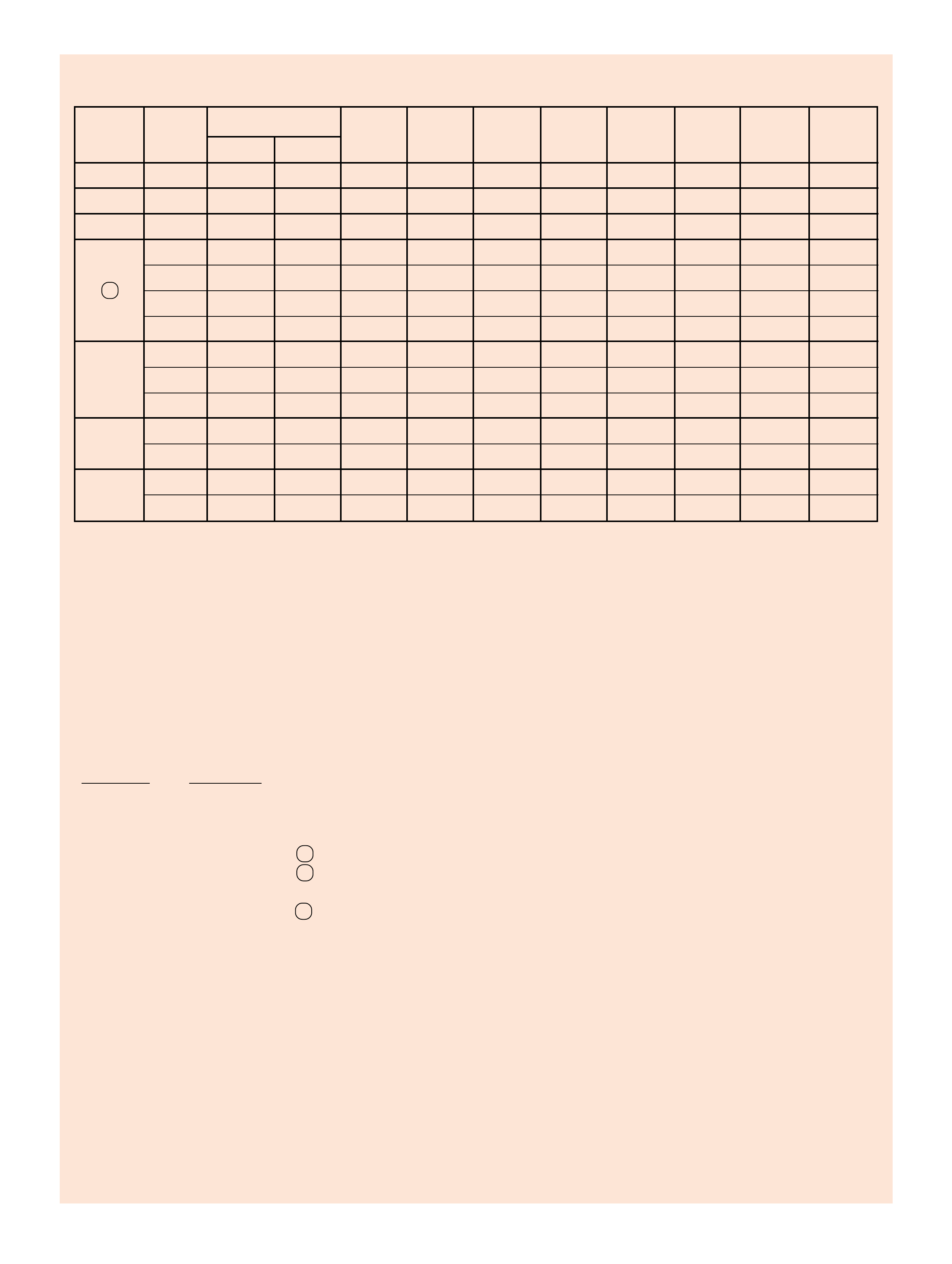
72
OPERATING CONDITIONS
Figure 69
RANGE REFERENCE CHART
NOTE: DESCRIPTIONS ABOVE EXPLAIN COMPONENT FUNCTION DURING ACCELERATION.
EXPECTED OPERATING CONDITION IF COMPONENT IN COLUMN NUMBER IS INOPERATIVE:
COLUMN # CONDITION
1 NO 2ND, NO 4TH GEAR.
2 NO REVERSE.
3 NO ENGINE BRAKING IN MANUAL 2ND, MANUAL 1ST, AND MANUAL 3RD (3RD GEAR).
4 NO FORWARD IN D AND MANUAL 3RD.
5 NO FORWARD IN D AND MANUAL 3RD.
6 NO 3RD GEAR, NO 4TH GEAR.
7 NO 1ST GEAR IN D , MANUAL 3RD, AND MANUAL 2ND.
8 NO REVERSE, NO ENGINE BRAKING IN MANUAL 1ST.
SHIFT SOLENOID VALVE ELECTRICAL CONDITIONS
If the PCM detects a continuous open or short to ground in the shift solenoids or shift solenoid circuits the following actions occur:
1-2 •The PCM commands maximum line pressure.
DTC •The PCM disables shift adapts.
P0753 •The PCM inhibits downshifts to 2nd gear if the vehicle speed is greater than 48 km/h (30 mph).
•The PCM illuminates the Malfunction Indicator Lamp (MIL).
2-3 •The PCM commands maximum line pressure.
DTC •The PCM disables shift adapts.
P0758 •The PCM commands 2nd gear.
•The PCM illuminates the Malfunction Indicator Lamp (MIL).
SHIFT SOLENOID VALVES 2-4 REVERSE OVERRUN FORWARD FORWARD 3-4 LO ROLLER LO/REV.
RANGE GEAR
1-2 2-3 BAND INPUT CLUTCH CLUTCH SPRAG CL. CLUTCH CLUTCH CLUTCH
CLUTCH ASSEMBLY
PARK
ON*ON*APPLIED
REVERSE
ON*ON*APPLIED APPLIED
NEUTRAL
ON*ON*
1st ON ON APPLIED HOLDING HOLDING
2nd OFF ON APPLIED APPLIED HOLDING
D
3rd OFF OFF APPLIED HOLDING APPLIED
4th ON OFF APPLIED APPLIED APPLIED
1st ON ON APPLIED HOLDING HOLDING
3
2nd OFF ON APPLIED APPLIED HOLDING
3rd OFF OFF APPLIED APPLIED HOLDING APPLIED
2
1st ** ON ON APPLIED APPLIED HOLDING HOLDING
*** 2nd OFF ON APPLIED APPLIED APPLIED HOLDING
1
1st ON ON APPLIED APPLIED HOLDING HOLDING APPLIED
*** 2nd OFF ON APPLIED APPLIED APPLIED HOLDING
*1-2 AND 2-3 SHIFT SOLENOID OPERATION AND THE SHIFT VALVE POSITIONING IN P, R, N RANGES ARE A FUNCTION OF THE
INPUT TO THE SOLENOIDS FROM THE VSS. UNDER NORMAL OPERATING CONDITIONS THE SOLENOIDS ARE ON IN P, R, N.
** A MANUAL SECOND - FIRST GEAR CONDITION IS ONLY AVAILABLE ON SOME MODELS. OTHERWISE, THIS CONDITION IS
ELECTRONICALLY PREVENTED.
*** IN MANUAL SECOND AND MANUAL FIRST, SOLENOID OPERATION IS A RESULT OF PCM CALIBRATION.
SOME CALIBRATIONS WILL ALLOW ALL THREE GEARS UNDER EXTREME CONDITIONS.
ON = SOLENOID ENERGIZED
OFF = SOLENOID DE-ENERGIZED
123 4 56 78
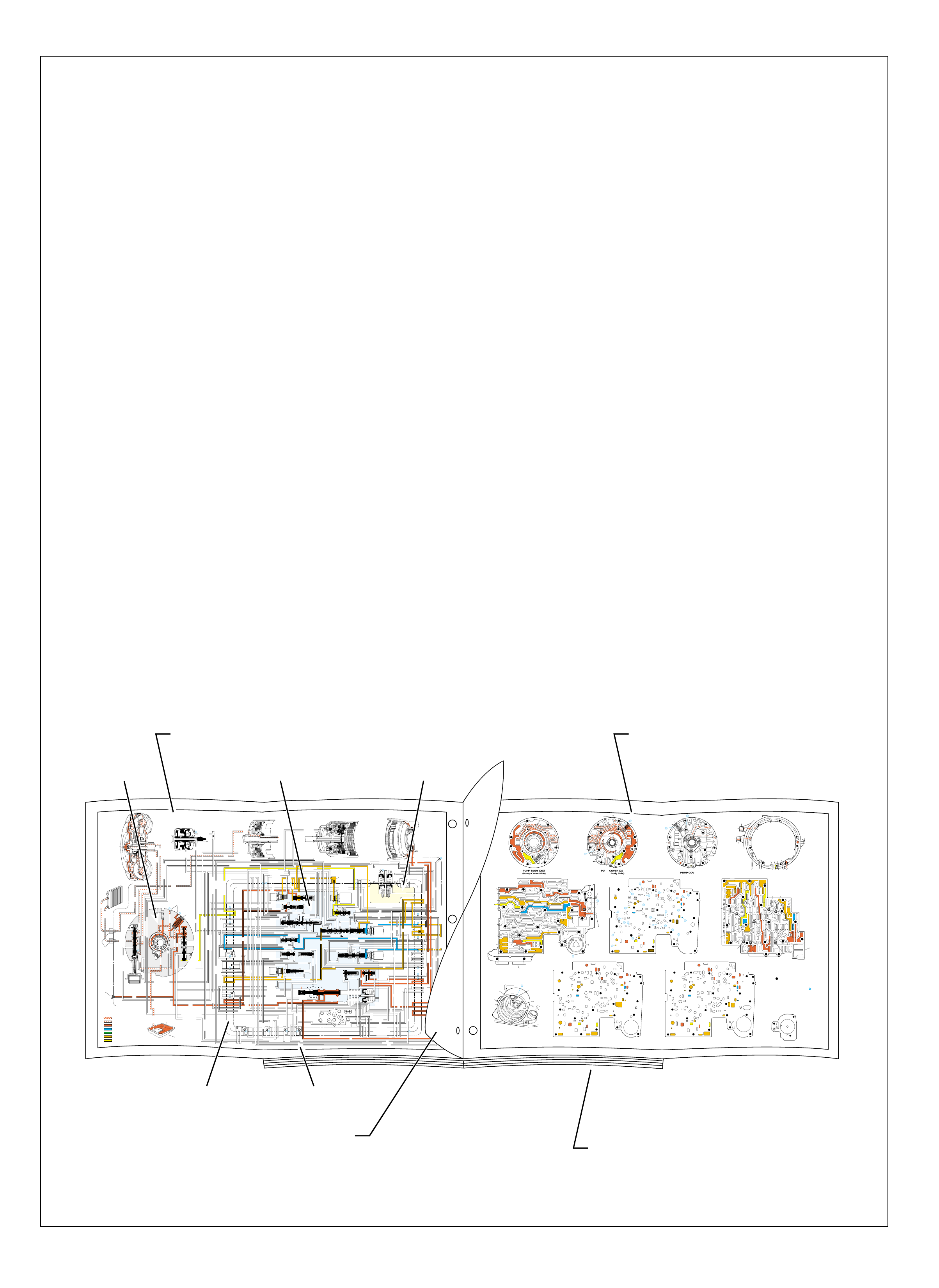
COMPLETE HYDRAULIC CIRCUITS
Figure 70
The hydraulic circuitry of the Hydra-matic
4L60-E transmission is better understood when
fluid flow can be related to the specific
components in which the fluid travels. In the
Power Flow section, a simplified hydraulic
schematic was given to show what hydraulically
occurs in a specific g ear range. The pur pose was
to isolate the hydraulics used in each gear range
in order to provide the user with a basic
understanding of the hydraulic system.
In contrast, this section shows a complete
hydraulic schematic with fluid passages acti ve in
the appropriate component for each gear range.
This is accomplished using two opposing foldout
pages that are separated by a half page of
supporting information.
The left side foldout contains the complete color
coded hydraulic circuit for the given gear range
along with the relative location of valves,
checkballs and orifices within specific
components. A brok en line is also used to separate
components such as the pump, valve body and
case to assist the user when following the
hydraulic circuits as they pass between them.
Also, the numbers shown in the circuits at the
broken lines reference specific holes and orifices
in the spacer plate on the right hand foldout. The
half page of information facing this foldout
identifies the components involved in this gear
range and a description of how they function.
The right side foldout shows a two-dimensional
line drawing of the fluid passages within each
component. The active fluid passages for each
gear range are appropriately colored to correspond
with the hydraulic schematic used for that range.
The half page of information facing this foldout
identifies the various fluid circuits with numbers
that correspond to the circuit numbers used on
the foldout page.
PASSAGE AIS LOCATED IN THE PUMP BODY (LIGHT GREY AREA)
PASSAGE BIS LOCATED IN THE VALVE BODY (LIGHT BLUE AREA)
PASSAGE CIS LOCATED ON THE SPACER PLATE (DASHED LINE)
PASSAGE DIS LOCATED IN CASE (WHITE AREA)
PASSAGE EIS LOCATED IN THE ACCUMULATOR HOUSING (LIGHT YELLOW AREA)
➤
➤➤
➤➤
➤
➤
➤
➤➤
➤
➤
➤
➤
➤➤
➤
➤
➤
➤
INPUT CLUTCH
HOUSING ASSEMBLY
24
REAR LUBE
FILTER
(49)
➤
➤
➤
➤
➤
➤
➤
RELEASE
APPLY
LO/REVERSE
PR
BOOST VALVE PRESS REG
BOTTOM
PAN
(SUMP)
(75)
FILTER
(72) REVERSE INPUT
REV INPUT
DECREASE
LINE
EX
FILTER
(232)
AIR
BLEED
(240)
1
SUCTION
LINE
EX
PRESSURE
RELIEF
VALVE
PUMP
ASSEMBLY
(4)
➤
➤➤
4
TCC
SOLENOID
(66)
N.O.
COOLER
LUBE
COOLER
SUCTION
CONVERTER & LUBE
MAINLINE
SOLENOID SIGNAL
ACCUMULATOR
ACTUATOR FEED LIMIT
TORQUE SIGNAL
FLUID PRESSURES
REVERSE INPUT
FORWARD CLUTCH FEED
#1
ACCUMULATOR
ORF ACC
2ND CLUTCH
3-4 ACCUMULATOR
1-2 ACCUMULATOR
19
3-4 ACCUM
ACCUM
EX
ORIFICED ACCUM
3-4 ACCUMULATOR
3-4 ACCUM
2ND CLUTCH
2ND CLUTCH
D3
REVERSE INPUT
D2-N.C.
REV-N.O. D3-N.C.
LO-N.O.
D4-N.O.
LO
TEMP
SENSOR
➤
TFP
SWITCH
ASSEMBLY
D2
D4
D3
D3
D3
EX
FORWARD ABUSE
FWD CL FD
3RD ACCUMULATOR EX
#7
11
3RD ACCUM
4TH
EX
EX
➤
4TH
2ND & 4TH
SERVO
REV ABUSE
EX
REVERSE
REVERSE INPUT
#12
D4
22
D4
D4
#4
13
3-4 SIGNAL
3-4 CL
3-4 CLUTCH
#2
12
3-4 CLUTCH
3RD ACCUM
3-4 CL
#8
16
2ND
2ND CL 2ND CL
2ND CL
2ND CL
2ND CLUTCH2ND CLUTCH
TORQUE SIG
FORWARD CLUTCH FEED
FORWARD
CLUTCH
ACCUMULATOR
EX
PR LO
LO
LO
FORWARD CLUTCH FEED
FORWARD CLUTCH FEED
FWD CL FEED
D3
D3
D3
14
3-4 CLUTCH
3RD ACCUMULATOR
3RD ACCUM
EX
AFL
3-2 SIGNAL
2ND
2ND
LINE
REGULATED APPLY
8
REG APPLY
1-2 SHIFT VALVE
26
LO
D4
O’ EX
D4-3-2 2ND
25
1-2 SIGNAL
LO/1ST
27
1-2 SIGNAL
EX
ORIFICED EX
ORIFICED EX
EX
LO/1ST D4-3-2
D4
D4
2
➤
➤
➤
➤➤
➤
EX
CONV FD
EX
EX
EX
LINE LINE
LINE
PRESSURE
TAP
(39)
➤
➤
REGULATED APPLY
➤
➤
LUBE
LUBE
LUBE
LUBE
CASE (8)
CASE (8)
GASKET (47)
SPACER PLATE (48)
GASKET (52)
VALVE BODY (60)
SUCTION
LINE
LINE
3a
3b
3c
➤
➤
➤
➤
➤
➤➤
➤
➤
➤
➤
➤
➤
➤
D3
EX
3-4 SIGNAL
1-2 SIGNAL
4TH SIGNAL
3-4 SHIFT VALVE
1-2 SIGNAL
3-4 CLUTCH
OVERRUN CLUTCH
OVERRUN CLUTCH
OVERRUN CLUTCH
OVERRUN CLUTCH
OVERRUN CLUTCH
OVERRUN CLUTCH
12a
12b
12c
12d
12e
EX
EX
EX
32
AFL
AFL
30
D4
EX
31
ACCUMULATOR
ACCUMULATOR
EX
TORQUE SIGNAL
FILTERED AFL
D4
AFLAFL FILTER
(50)
10
43a
43b 44
11b
11c
11a
14b
14a
14c
LO OVERRUN
23
PR
LO/REV
LO/1ST LO/REVERSE
LO/REVERSE
PR PR
EX
22 10c
23 10b
9n
9o
22b
22a
10a
➤
10 9k
9g
9m
44a
43c 44
41a
41b
41c
41d
42b
42a
13a
13b
OIL
COOLER
PIPE
CONNECTOR
(10)
➤
➤
18a
18b
18c
18 17a
18 17b
20b
48b
48a
REGULATED APPLY
30a
30b
32a
37a
9b
9e
10 9d
9c
9a
9f
9h
31a
31b
31c
OVERRUN CLUTCH FEED
3-4 ACCUM
SERVO FEED
SERVO FEED
6
7
4TH4TH
OVERRUN CL
4TH SIGNAL2ND
EX
EX
3-4 RELAY 4-3 SEQUENCE VALVE
5
EX
SERVO FD
ORF EX
CASE (8)
REV INPUT
EX
(237)
17d
17c
17e
17f
17g
21
21
20d
20e
21a
20a
20c
1-2 ACCUMULATOR COVER (57)
25g
33c
33a
33b
27d
27c
27b
29
29
27a
28a
29b
29a
29d
40
29c
29e
29g28
28
29f
24a
24b
24c
24d
24e
24f
24g
24h
25a
25b
25d
25e
25f
25
25
24m
24k
REVERSE INPUT
#3
17
REVERSE INPUT
15c
15b
16
16
REVERSE
REVERSE INPUT
16a
15d
15a
REVERSE
34f
34e
34d
34c
34a
34b
#6
OVERRUN CL FD
21
ORIFICED D2
#5
OVERRUN
OVERRUN OVERRUN
OVERRUN
36
36
35e
35d
39
35b
35c
36a
35a
38d
38e39
38c
38b
38a
EX
TORQUE SIGNAL
2ND CL
➤
➤
➤➤
➤
20
18
2-3 SHUTTLE 2-3 SHIFT VALVE
28
29
EX
EX
EX
EX
D2
OVERRUN
D3
D3
2ND
3-4 SIGNAL
EX
D4-3-2
2-3 SIGNAL
ACTUATOR FEED LIMIT
AFL
SERVO FD
3-4 ACC
FILTERED AFL
AFL
ACTUATOR FEED LIMIT
ACTUATOR FEED LIMIT
AFL
D2
2ND
2ND
2ND
2ND
D2
D2
D2
D2
ORIFICED D2
D2
D2
D2
VALVE BODY (60)
3-4 SIGNAL
➤
2ND
D4
PR 3-4 ACCUMULATOR
D4
EX
D4-3-2
LO
D4
2ND CLUTCH
D3
D3
FORWARD CLUTCH FEED ACTUATOR FEED LIMIT
TORQUE SIGNAL
SERVO FEED
➤
OVERRUN CLUTCH
LINE
9p
26a
➤
➤
➤➤
➤
➤
➤
➤
➤
➤➤➤
➤➤➤
➤
➤➤➤
➤
➤
➤
➤
➤
➤
➤
➤
➤
➤
➤
➤
➤
➤➤
➤
➤
➤➤➤
➤➤➤
➤
➤
➤
➤
➤
➤
➤
➤
➤
➤
➤➤
➤➤ ➤
➤
➤
➤➤➤
➤➤
PR
➤➤
➤
➤➤
➤
➤➤
➤➤➤➤➤
➤
➤
➤
➤
➤➤
➤
➤➤➤➤➤
➤➤
➤
➤
➤➤➤
OFF
CONVERTER CLUTCH VALVE
COOLER
RELEASE
APPLY
EX
➤
➤
➤
➤
➤
➤
EX
➤➤
➤
➤➤
➤
CONV FD
➤
➤
➤
➤
➤
➤
➤
➤
➤
➤
➤
REGULATED APPLY
3-2 CONTROL
EX
EX
CC SIGNAL
CC SIGNAL
ISOLATOR
REG APPLY
ACTUATOR FEED LIMIT
9
26b
TCC PWM
SOLENOID
VALVE
N.C.
1-2 SIGNAL
2ND
4TH SIGNAL
3-2
CONTROL
SOLENOID
VALVE
N.C.
OFF
#10
➤
LOW AND REVERSE
CLUTCH ASSEMBLY
REVERSE INPUT
CLUTCH ASSEMBLY
TORQUE
CONVERTER
ASSEMBLY
#9
➤➤
(237)
➤
(238)
➤
EX
2ND CLUTCH 3-4 CLUTCH
2ND
PRESSURE
CONTROL
SOLENOID
VALVE
2-3 SHIFT
SOLENOID
VALVE
N.O.
ON
EX
1-2 SHIFT
SOLENOID
VALVE
N.O.
ON
ACCUM VALVE
PRND321
D4
D4
REVERSE
D3
D2
LO
EX
EX
LINE
➤
➤
➤
➤
➤
➤➤➤➤
➤
➤
➤
➤
➤
➤
➤➤➤ ➤
➤
➤
➤
➤
➤
➤
➤
➤
➤
➤
➤
➤
➤
➤
➤
➤
➤
➤
➤
➤
➤
➤➤➤➤➤
➤
➤
➤
➤
➤
➤
➤
➤
➤
➤
➤
➤
MANUAL VALVE
PR
EXEX
3-2 DOWNSHIFT
FLUID FLOW THROUGH
COMPONENTS (FOLDOUT)
COMPLETE ILLUSTRATED
PARTS LIST
FLUID FLOW SCHEMATIC —
(FOLDOUT)
ABE
DC
HALF PAGE TEXT AND LEDGEND
Engine Running
With the selector lever in the Park (P)
position, line pressure from the oil
pump is directed to the following:
Pressure Regulator Valve(218): Reg-
ulates pump output (line pressure)
according to the transmission
requirements. When pump
output exceeds the demand
of line pressure, fluid from
the pressure regulator
PARK
PARK
Engine Running
68
Figure 64
D4
PR
➤
3
2
4
T
H
3
3
3
-
4
A
C
C
U
M
3
7
O
V
E
R
R
U
N
C
L
U
T
C
H
3
8
D
2
4
0
3
-
2
S
I
G
N
A
L
➤
Engine Running
FOLDOUT ➤ 69
Figure 65
➤
;
➤
➤
➤
➤
➤
➤
➤
➤
➤
➤
➤
➤ ➤
➤
➤
➤
➤
➤
➤
;;
;;
;;;;;;;;
;;;;;;;;
;;;;;;;;
;;;;;;;;
;;;;;;;;
➤ ➤
;;;
;;;
;;
;;
➤
➤
➤
➤➤
➤➤
➤
➤
;
;;;;
;;
;;
;;;;
;;
;;
PUMP BODY (200)
(Pump Cover Side) PUMP COVER (215)
(Pump Body Side) PUMP COVER (215)
(Case Side) CASE (103)
(Pump Cover Side)
CASE (103)
(Control Valve Body Side) SPACER PLATE (48)
(Case/Control Valve Body) CONTROL VALVE BODY (60)
(Case Side)
12 38
312
34
18
15
16
38
29
16
47 47
29 15 29
9
9
29
12
38 41 17
24
18
9
30
34
25 24
25 43 37
33
24
25
30 27 22 27
34
34
13
35
34
36
31 31
33
33
48
9
9
26 3
25
11
99
925
28 32
11
26
17 20 20
9
25
20
21 21
24
36 35
39
24
27
24
13
9
10
24 10
14
22
912 42
41 44
42
17
18
34
17
12 14
41
38
41
11
3
25
39
24 10
18
18
29
29
29
16
48
43
9
14
44
26
25
31
20
GASKET (47)
(Case/Spacer Plate) GASKET (52)
(Spacer Plate/Control Valve Body)
CASE (103)
(2-4 Servo Bore)
1-2 ACCUMULATOR COVER (57)
NOTE:
- INDICATES BOLT HOLES
- NON-FUNCTIONAL HOLES
HAVE BEEN REMOVED FROM
COMPONENT DRAWINGS TO
TO SIMPLIFY TRACING FLUID
FLOW.
- EXHAUST FLUID NOT SHOWN
21
25
25
20
28
#7/(40)
44
(11)
25
43
32
3
16
(237)
18
43
3
(240)
37
(237)
43
47
45
43
43
48
11
29
16
3
16
29 18
2
(240)
8
85
37
37
1
47
(232)
7
46
;;
;
45 47
3
3
8
43
5
4
2
4
4
48
43
3
6
1
43
2
7
47 46
43 11
3
16
37
37
5
37 8
29
18
29
1
(232)
2
43
47
16
(237)
37
(237)
4
(238)
2
(240)
PRESSURE RELIEF
VALVE BORE
➤
16
45
8
7
48
37
11 29 16
3
18
3
(39)
8
7
(10)
(10)
48 37 316291118
;;;;;;;
;;;;;;;
;;;;;;;
;;;;;;;
;;;;;;;
47 45
8
43
5
4
4
4
3
3
3
2
43
16
11
29
43
43
46
37 47
48
7
4
2
3
1
3
13V
12a 38b
3a
12b
34b
18b
38d
18c
13b
15d
16a
38c
15a
9m
9n
11c
29e
29d
9o
27b/29
29a
29f/28
15b/16
35a
22b
27d
30a
30b
34f
25a 24h
31c
25b
33c
24g 34e
31b
31a
27a
33a
33b
32a
37a
36a
3c
26b
11b
9c
25f
28a
9e
9p
9b
9d/10
(50)
48b
43a
25d
3b 11a
20c
25g
21a
9f
20e/21
17f 20a
9g
10a
35c/39
35b
35d/36
24f
24d 24c 13a
24a24b
41d
17c
41c
12c
17b/18 18a17d
42a
43c/44 9h 12e
22a 14b
10c/22
42b
14a
12d
17e
34a 41a
41b 38a
24m/25
47
9k/10
(49)
10b/23
20b
24e
17g
20d/21
25e
9a
48a
26a
43b/44
24k/25
34c
34d
29c
29b
29g/28
15c/16
17a/18 14c
44a
38e/39
27c/29
35e/36
➤
7
➤
5
➤
6
➤
16
➤
17
➤
8
➤
9
➤
32
➤
10
➤
12
➤
18
➤
20
➤
21
➤
22
➤
13
➤
14
➤
23
➤
25
➤
29
➤
30
➤
31
➤
26
➤
27
➤
28
➤
24
➤➤
1
➤➤
2
➤➤
2
➤➤
4
➤➤
11
12 38
3
18
38
16
28
29
15
34
29
9
9
15
29
11
929
40
15 43
35 34
31
31 33 33
22
27
30
34
30
25 24 24
2431
25 43
48
26
33 37
36 32
25
28
9
26
9
311
25 25 3
910
11 21 20
25
9
10
17 20
35 35/39
24
27 24 24
13
13
22
14
22
912 42
14
12
24
24
18
38 41 17
41
12 42
17
17
34
12 34 41
38
17
44
47
923
20
17
9
9
48 44
34
29
29 18
24
14
43
10
25
41
38
34
9
9
947
9
9
3
3
25
25
11
11
26
47
26
47
25
47
3
10
43
47 11
43
33
31
24
30
37 36
28
11
34
25
24
22
24
35
34
30 27
31 32
47 25
29
9
15
40
28 29 29 16
15
43
15 12
38
3
341 47
17 34
38
41
34
18
12
17
42
43
12
18
47
47
14
43
14 42
922
23
10
9
17
17
24
38
13 24
43
42
41
3
33
31 24 24
17 47
13
17 20 20
27
#8
#6 #5
#3
#2 #12
#4
FORWARD
CLUTCH
ACCUMULATOR
BORE
➤
17
47
47
35
47
43
47
47
47 48
48
47
47
47
47 9
26
47 12 38
3
3
29
38
16
47 29
15
29
11
18
30 27 27
18
34
47
34
25 24
31
33
43
37 37
48
47
47
47
47
47 47
9
25
311
32
28 32
25
21
20
33
33
25
9
39
35
35 24 47
24 22
22 10 47
14
12
9
99
44
17 47 42
41
17
14
12
12
18
34
34
41
9
9
9
36
9
17
17
12
14
11
9
11
34
16 16
22
13 13
#10
#1
#7
(40)
37
18
11
29
16
3
29
341
38
44
(38)
28
47
43
47
48
36
33
9
33
38
19
26
47
47
2-4 SERVO BORE
➤
REAR
LUBE
TO
LOW AND
REVERSE
CLUTCH
➤➤
19
➤
➤
➤
➤
➤
➤
FOLDOUT ➤ 73
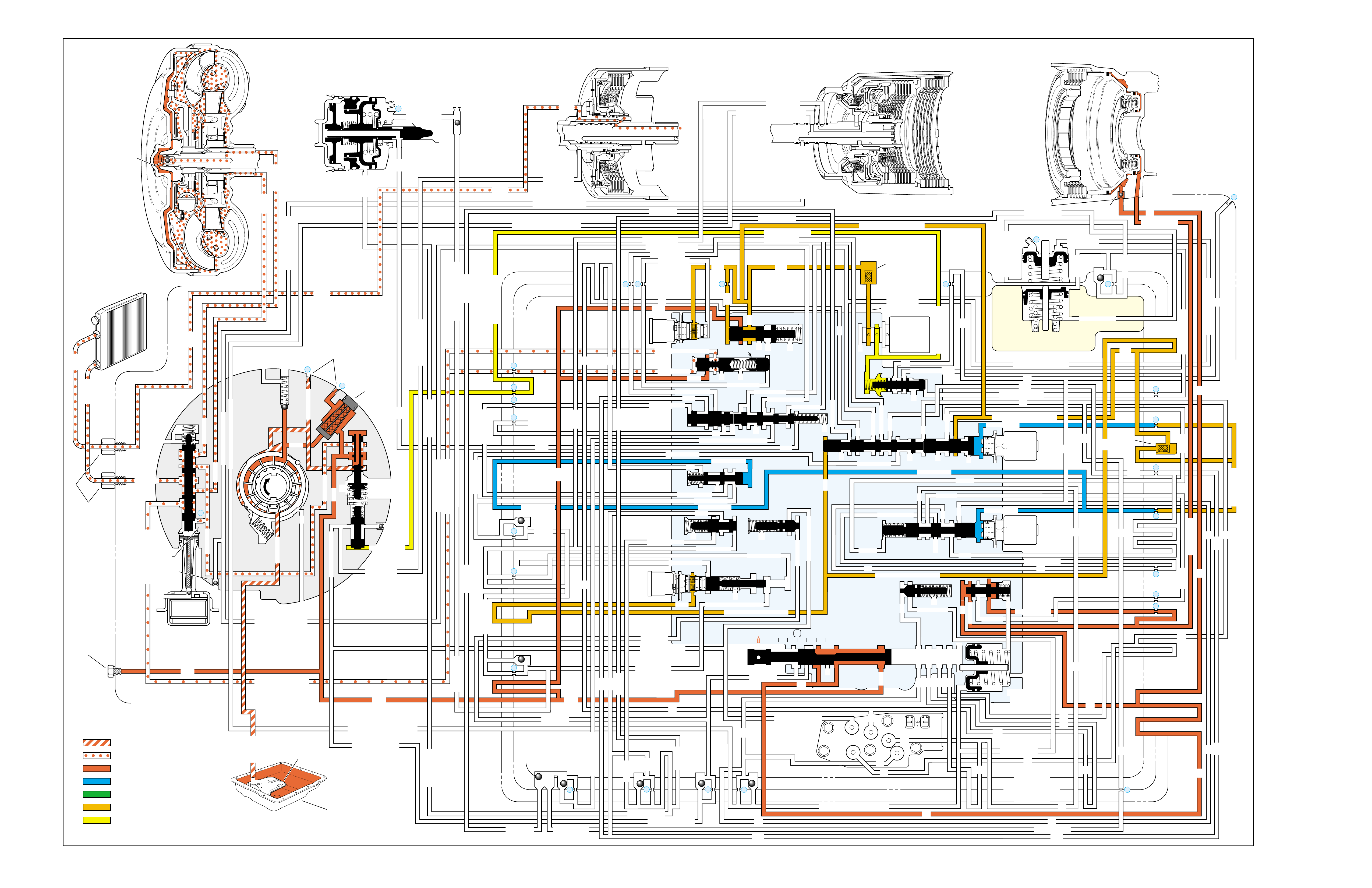
PARK
(Engine Running)
➤
➤➤
➤➤
➤
➤
➤
➤➤
➤
➤
➤
➤
INPUT CLUTCH
HOUSING ASSEMBLY
24
REAR LUBE
FILTER
(49)
➤
➤
➤
➤
➤
➤
➤
RELEASE
APPLY
LO/REVERSE
PR
BOOST VALVE PRESS REG
BOTTOM
PAN
(SUMP)
(75)
FILTER
(72) REVERSE INPUT
REV INPUT
DECREASE
LINE
EX
FILTER
(232)
AIR
BLEED
(240)
1
SUCTION
LINE
EX
PRESSURE
RELIEF
VALVE
PUMP
ASSEMBLY
(4)
➤
➤➤
4
TCC
SOLENOID
(66)
N.O.
COOLER
LUBE
COOLER
SUCTION
CONVERTER & LUBE
MAINLINE
SOLENOID SIGNAL
ACCUMULATOR
ACTUATOR FEED LIMIT
TORQUE SIGNAL
FLUID PRESSURES
REVERSE INPUT
FORWARD CLUTCH FEED
#1
ACCUMULATOR
ORF ACC
2ND CLUTCH
3-4 ACCUMULATOR
1-2 ACCUMULATOR
19
3-4 ACCUM
ACCUM
EX
ORIFICED ACCUM
3-4 ACCUMULATOR
3-4 ACCUM
2ND CLUTCH
2ND CLUTCH
D3
REVERSE INPUT
D2-N.C.
REV-N.O. D3-N.C.
LO-N.O.
D4-N.O.
LO
TEMP
SENSOR
➤
TFP
SWITCH
ASSEMBLY
D2
D4
D3
D3
D3
EX
FORWARD ABUSE
FWD CL FD
3RD ACCUMULATOR EX
#7
11
3RD ACCUM
4TH
EX
EX
➤
4TH
2ND & 4TH
SERVO
REV ABUSE
EX
REVERSE
REVERSE INPUT
#12
D4
22
D4
D4
#4
13
3-4 SIGNAL
3-4 CL
3-4 CLUTCH
#2
12
3-4 CLUTCH
3RD ACCUM
3-4 CL
#8
16
2ND
2ND CL 2ND CL
2ND CL
2ND CL
2ND CLUTCH2ND CLUTCH
TORQUE SIG
FORWARD CLUTCH FEED
FORWARD
CLUTCH
ACCUMULATOR
EX
PR LO
LO
LO
FORWARD CLUTCH FEED
FORWARD CLUTCH FEED
FWD CL FEED
D3
D3
D3
14
3-4 CLUTCH
3RD ACCUMULATOR
3RD ACCUM
EX
AFL
3-2 SIGNAL
2ND
2ND
LINE
REGULATED APPLY
8
REG APPLY
1-2 SHIFT VALVE
26
LO
D4
O’ EX
D4-3-2 2ND
25
1-2 SIGNAL
LO/1ST
27
1-2 SIGNAL
EX
ORIFICED EX
ORIFICED EX
EX
LO/1ST D4-3-2
D4
D4
2
➤
➤
➤
➤➤
➤
EX
CONV FD
EX
EX
EX
LINE LINE
LINE
PRESSURE
TAP
(39)
➤
➤
REGULATED APPLY
➤
➤
LUBE
LUBE
LUBE
LUBE
CASE (8)
CASE (8)
GASKET (47)
SPACER PLATE (48)
GASKET (52)
VALVE BODY (60)
SUCTION
LINE
LINE
3a
3b
3c
➤
➤
➤
➤
➤
➤➤
➤
➤
➤
➤
➤
➤
➤
D3
EX
3-4 SIGNAL
1-2 SIGNAL
4TH SIGNAL
3-4 SHIFT VALVE
1-2 SIGNAL
3-4 CLUTCH
OVERRUN CLUTCH
OVERRUN CLUTCH
OVERRUN CLUTCH
OVERRUN CLUTCH
OVERRUN CLUTCH
OVERRUN CLUTCH
12a
12b
12c
12d
12e
EX
EX
EX
32
AFL
AFL
30
D4
EX
31
ACCUMULATOR
ACCUMULATOR
EX
TORQUE SIGNAL
FILTERED AFL
D4
AFLAFL FILTER
(50)
10
43a
43b 44
11b
11c
11a
14b
14a
14c
LO OVERRUN
23
PR
LO/REV
LO/1ST LO/REVERSE
LO/REVERSE
PR PR
EX
22 10c
23 10b
9n
9o
22b
22a
10a
➤
10 9k
9g
9m
44a
43c 44
41a
41b
41c
41d
42b
42a
13a
13b
OIL
COOLER
PIPE
CONNECTOR
(10)
➤
➤
18a
18b
18c
18 17a
18 17b
20b
48b
48a
REGULATED APPLY
30a
30b
32a
37a
9b
9e
10 9d
9c
9a
9f
9h
31a
31b
31c
OVERRUN CLUTCH FEED
3-4 ACCUM
SERVO FEED
SERVO FEED
6
7
4TH4TH
OVERRUN CL
4TH SIGNAL2ND
EX
EX
3-4 RELAY 4-3 SEQUENCE VALVE
5
EX
SERVO FD
ORF EX
CASE (8)
REV INPUT
EX
(237)
17d
17c
17e
17f
17g
21
21
20d
20e
21a
20a
20c
1-2 ACCUMULATOR COVER (57)
25g
33c
33a
33b
27d
27c
27b
29
29
27a
28a
29b
29a
29d
40
29c
29e
29g28
28
29f
24a
24b
24c
24d
24e
24f
24g
24h
25a
25b
25d
25e
25f
25
25
24m
24k
REVERSE INPUT
#3
17
REVERSE INPUT
15c
15b
16
16
REVERSE
REVERSE INPUT
16a
15d
15a
REVERSE
34f
34e
34d
34c
34a
34b
#6
OVERRUN CL FD
21
ORIFICED D2
#5
OVERRUN
OVERRUN OVERRUN
OVERRUN
36
36
35e
35d
39
35b
35c
36a
35a
38d
38e39
38c
38b
38a
EX
TORQUE SIGNAL
2ND CL
➤
➤
➤➤
➤
20
18
2-3 SHUTTLE 2-3 SHIFT VALVE
28
29
EX
EX
EX
EX
D2
OVERRUN
D3
D3
2ND
3-4 SIGNAL
EX
D4-3-2
2-3 SIGNAL
ACTUATOR FEED LIMIT
AFL
SERVO FD
3-4 ACC
FILTERED AFL
AFL
ACTUATOR FEED LIMIT
ACTUATOR FEED LIMIT
AFL
D2
2ND
2ND
2ND
2ND
D2
D2
D2
D2
ORIFICED D2
D2
D2
D2
VALVE BODY (60)
3-4 SIGNAL
➤
2ND
D4
PR 3-4 ACCUMULATOR
D4
EX
D4-3-2
LO
D4
2ND CLUTCH
D3
D3
FORWARD CLUTCH FEED ACTUATOR FEED LIMIT
TORQUE SIGNAL
SERVO FEED
➤
OVERRUN CLUTCH
LINE
9p
26a
➤
➤
➤➤
➤
➤
➤
➤
➤
➤➤➤
➤➤➤
➤
➤➤➤
➤
➤
➤
➤
➤
➤
➤
➤
➤
➤
➤
➤
➤
➤➤
➤
➤
➤➤➤
➤➤➤
➤
➤
➤
➤
➤
➤
➤
➤
➤
➤
➤➤
➤➤ ➤
➤
➤
➤➤➤
➤➤
PR
➤➤
➤
➤➤
➤
➤➤
➤➤➤➤➤
➤
➤
➤
➤
➤➤
➤
➤➤➤➤➤
➤➤
➤
➤
➤➤➤
OFF
CONVERTER CLUTCH VALVE
COOLER
RELEASE
APPLY
EX
➤
➤
➤
➤
➤
➤
EX
➤➤
➤
➤➤
➤
CONV FD
➤
➤
➤
➤
➤
➤
➤
➤
➤
➤
➤
REGULATED APPLY
3-2 CONTROL
EX
EX
CC SIGNAL
CC SIGNAL
ACTUATOR FEED LIMIT
9
26b
TCC PWM
SOLENOID
VALVE
N.C.
1-2 SIGNAL
2ND
4TH SIGNAL
3-2
CONTROL
SOLENOID
VALVE
N.C.
OFF
#10
➤
LOW AND REVERSE
CLUTCH ASSEMBLY
REVERSE INPUT
CLUTCH ASSEMBLY
TORQUE
CONVERTER
ASSEMBLY
#9
➤➤
(237)
➤
(238)
➤
EX
2ND CLUTCH 3-4 CLUTCH
2ND
PRESSURE
CONTROL
SOLENOID
VALVE
2-3 SHIFT
SOLENOID
VALVE
N.O.
ON
EX
1-2 SHIFT
SOLENOID
VALVE
N.O.
ON
ACCUM VALVE
PRND321
D4
D4
REVERSE
D3
D2
LO
EX
EX
LINE
➤
➤
➤
➤
➤
➤➤➤➤
➤
➤
➤
➤
➤
➤
➤➤➤ ➤
➤
➤
➤
➤
➤
➤
➤
➤
➤
➤
➤
➤
➤
➤
➤
➤
➤
➤
➤
➤
➤
➤
➤
➤➤➤➤➤
➤
➤
➤
➤
➤
➤
➤
➤
➤
➤
➤
➤
MANUAL VALVE
PR
EXEX
3-2 DOWNSHIFT
ISOLATOR VALVE
REG APPLY
Figure 71
74

PARK
(Engine Running)
74A
HIGH LINE PRESSURE
•Pressure Regulator Valve (216), or
Reverse Boost Valve (219)
–Stuck, damaged
•2-3 Shift Valve (368)
–Stuck
•Pressure Relief Ball (228)
–Not seated or damaged.
•Pressure Control Solenoid Valve (377)
–Damage to pins.
LOW LINE PRESSURE
•Pressure Regulator Valve (216), Boost Valve (219),
or Spring (217)
–Stuck, damaged, broken
•Oil Pump (200)
–Cross channel air leak, body to cover or body to case
•Pump Valve Bores
–Excessive valve clearance due to wear
•Valve Body (350)
–Cross channel leaks
–Cross valve land leaks
•Gasket/Spacer Plate
–Damaged
–Missing
•Pressure Control Solenoid Valve (377)
–Valve is stuck On
–Broken clip causes leakage
–Wire is pinched to ground
–Screen is missing
•Cooler Lines
–Clogged or restricted.
The following conditions and component problems could happen in any
gear range, and are only some of the possibilities recommended to
diagnose hydraulic problems. Always refer to the appropriate vehicle
platform service manual when diagnosing specific concerns.
1-2 SHIFT 2-3 SHIFT REVERSE FORWARD
SOLENOID SOLENOID 2-4 INPUT OVERRUN FORWARD SPRAG CL. 3-4 LO-ROLLER LO/REV
VALVE VALVE BAND CLUTCH CLUTCH CLUTCH ASSEMBLY CLUTCH CLUTCH CLUTCH
ON ON APPLIED

PARK
(Engine Running)
74B
PASSAGES
1 SUCTION
2 DECREASE
3 LINE
4 CONVERTER FEED
5 RELEASE
6 APPLY
7 COOLER
8 LUBE
9 ACTUATOR FEED LIMIT
10 FILTERED ACTUATOR FEED
11 TORQUE SIGNAL
12 PR
13 D4-3-2
14 LO/REVERSE
15 REVERSE
16 REVERSE INPUT
17 D4
18 FORWARD CLUTCH FEED
19 REAR LUBE
20 ACCUMULATOR
21 ORIFICED ACCUMULATOR
22 1-2 SIGNAL
23 2-3 SIGNAL
24 2ND
25 2ND CLUTCH
26 C. C. SIGNAL
27 3-4 SIGNAL
28 3RD ACCUMULATOR
29 3-4 CLUTCH
30 4TH SIGNAL
31 SERVO FEED
32 4TH
33 3-4 ACCUMULATOR
34 D3
35 OVERRUN
36 OVERRUN CLUTCH FEED
37 OVERRUN CLUTCH
38 D2
39 ORIFICED D2
40 3-2 SIGNAL
41 LO
42 LO/1ST
43 EXHAUST
44 ORIFICED EXHAUST
45 VENT
46 SEAL DRAIN
47 VOID
48 REGULATED APPLY
COMPONENTS ( )
(8) REAR LUBE (ORIFICED CUP PLUG/REAR CASE)
(10) OIL COOLER PIPE CONNECTOR
(11) CASE SERVO ORIFICED PLUG
(38) ACCUMULATOR BLEED PLUG
(39) LINE PRESSURE TAP
(40) 3RD ACCUM. RETAINER AND BALL ASSEMBLY (#7)
(49) SHIFT SOLENOIDS SCREEN
(50) PRESSURE CONTROL SOLENOID SCREEN
(61) CHECKBALLS (#1, 2, 3, 4, 5, 6, 8, 12)
(91) CHECKBALL (#10)
(232) OIL PUMP COVER SCREEN
(237) CHECK VALVE RETAINER AND BALL ASSEMBLY
(238) CONVERTER CLUTCH SIGNAL ORIFICED CUP PLUG
(240) ORIFICED CUP PLUG

PARK (Engine Running)
➤
➤
➤
➤
➤
➤
➤
➤
➤
➤
➤
➤ ➤
➤
➤
➤
➤
➤
➤
➤ ➤
➤
➤
➤
➤➤
➤➤
➤
➤
PUMP BODY (200)
(Pump Cover Side)
PUMP COVER (215)
(Pump Body Side) PUMP COVER (215)
(Case Side)
CASE (103)
(Pump Cover Side)
CASE (103)
(Control Valve Body Side)
SPACER PLATE (48)
(Case/Control Valve Body) CONTROL VALVE BODY (60)
(Case Side)
12 38
312
34
18
15
16
38
29
16
47 47
29 15 29
9
9
29
12
38 41 17
24
18
9
30
34
25 24
25 43 37
33
24
25
30 27 22 27
34
34
13
35
34
36
31 31
33
33
48
9
9
26 3
25
11
99
925
28 32
11
26
17 20 20
9
25
20
21 21
24
36 35
39
24
27
24
13
9
10
24 10
14
22
912 42
41 44
42
17
18
34
17
12 14
41
38
41
11
3
25
39
24 10
18
18
29
29
29
16
48
43
9
14
44
26
25
31
20
GASKET (47)
(Case/Spacer Plate)
GASKET (52)
(Spacer Plate/Control Valve Body)
CASE (103)
(2-4 Servo Bore)
1-2 ACCUMULATOR COVER (57)
NOTE:
- INDICATES BOLT HOLES
- NON-FUNCTIONAL HOLES
HAVE BEEN REMOVED FROM
COMPONENT DRAWINGS
TO SIMPLIFY TRACING FLUID
FLOW.
- EXHAUST FLUID NOT SHOWN
21
25
25
20
28
#7/(40)
44
(11)
25
43
32
3
16
(237)
18
43
3
(240)
37
(237)
43
47
45
43
43
48
11
29
16
3
16
29 18
2
(240)
8
85
37
37
1
47
(232)
7
46
45 47
3
3
8
43
5
4
2
4
4
48
43
3
6
1
43
2
7
47 46
43 11
3
16
37
37
5
37 8
29
18
29
1
(232)
2
43
47
16
(237)
37
(237)
4
(238)
2
(240)
PRESSURE RELIEF
VALVE BORE
➤
16
45
8
7
48
37
11 29 16
3
18
3
(39)
8
7
(10)
(10)
48 37 316291118
47 45
8
43
5
4
4
4
3
3
3
2
43
16
11
29
43
43
46
37 47
48
7
4
2
3
1
3
13V
12a 38b
3a
12b
34b
18b
38d
18c
13b
15d
16a
38c
15a
9m
9n
11c
29e
29d
9o
27b/29
29a
29f/28
15b/16
35a
22b
27d
30a
30b
34f
25a 24h
31c
25b
33c
24g 34e
31b
31a
27a
33a
33b
32a
37a
36a
3c
26b
11b
9c
25f
28a
9e
9p
9b
9d/10
(50)
48b
43a
25d
3b 11a
20c
25g
21a
9f
20e/21
17f 20a
9g
10a
35c/39
35b
35d/36
24f
24d 24c 13a
24a24b
41d
17c
41c
12c
17b/18 18a17d
42a
43c/44 9h 12e
22a 14b
10c/22
42b
14a
12d
17e
34a 41a
41b 38a
24m/25
47
9k/10
(49)
10b/23
20b
24e
17g
20d/21
25e
9a
48a
26a
43b/44
24k/25
34c
34d
29c
29b
29g/28
15c/16
17a/18 14c
44a
38e/39
27c/29
35e/36
➤
7
➤
5
➤
6
➤
16
➤
17
➤
8
➤
9
➤
32
➤
10
➤
12
➤
18
➤
20
➤
21
➤
22
➤
13
➤
14
➤
23
➤
25
➤
29
➤
30
➤
31
➤
26
➤
27
➤
28
➤
24
➤➤
1
➤➤
2
➤➤
2
➤➤
4
➤➤
11
12 38
3
18
38
16
28
29
15
34
29
9
9
15
29
11
929
40
15 43
35 34
31
31 33 33
22
27
30
34
30
25 24 24
24 31
25 43
48
26
33 37
36 32
25
28
9
26
9
311
25 25 3
910
11 21 20
25
9
10
17 20
35 35/39
24
27 24 24
13
13
22
14
22
912 42
14
12
24
24
18
38 41 17
41
12 42
17
17
34
12 34 41
38
17
44
47
923
20
17
9
9
48 44
34
29
29 18
24
14
43
10
25
41
38
34
9
9
947
9
9
3
3
25
25
11
11
26
47
26
47
25
47
3
10
43
47 11
43
33
31
24
30
37 36
28
11
34
25
24
22
24
35
34
30 27
31 32
47 25
29
9
15
40
28 29 29 16
15
43
15 12
38
3
341 47
17 34 38 41
34
18
12
17
42
43
12
18
47
47
14
43
14 42
922
23
10
9
17
17
24
38
13 24
43
42
41
3
33
31 24 24
17 47
13
17 20 20
27
#8
#6 #5
#3
#2 #12
#4
FORWARD
CLUTCH
ACCUMULATOR
BORE
➤
17
47
47
35
47
43
47
47
47 48
48
47
47
47
47 9
26
47 12 38
3
3
29
38
16
47 29
15
29
11
18
30 27 27
18
34
47
34
25 24
31
33
43
37 37
48
47
47
47
47
47 47
9
25
311
32
28 32
25
21
20
33
33
25
9
39
35
35 24 47
24 22
22 10 47
14
12
9
99
44
17 47 42
41
17
14
12
12
18
34
34
41
9
9
9
36
9
17
17
12
14
11
9
11
34
16 16
22
13 13
#10
#1
#7
(40)
37
18
11
29
16
3
29
341
38
44
(38)
28
47
43
47
48
36
33
9
33
38
19
26
47
47
2-4 SERVO BORE
➤
REAR
LUBE
TO
LOW AND
REVERSE
CLUTCH
➤➤
19
Figure 72 FOLDOUT ➤ 75
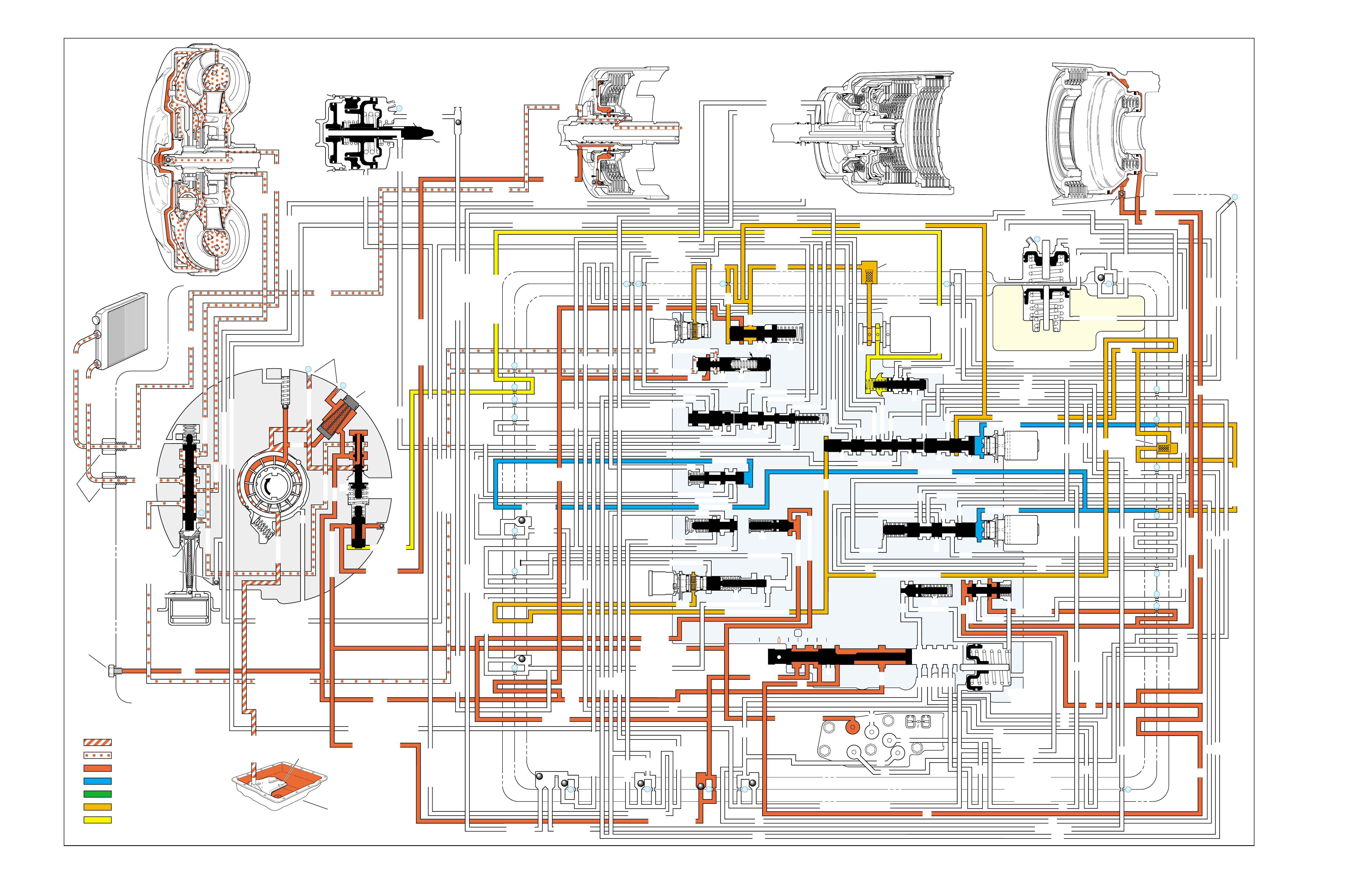
Figure 73
REVERSE
➤
➤➤
➤➤
➤
➤
➤
➤➤
➤
➤
➤
➤
➤
➤
INPUT CLUTCH
HOUSING ASSEMBLY
24
REAR LUBE
FILTER
(49)
➤
➤
➤
➤
➤
➤
➤
RELEASE
APPLY
LO/REVERSE
PR
BOOST VALVE PRESS REG
BOTTOM
PAN
(SUMP)
(75)
FILTER
(72) REVERSE INPUT
REV INPUT
DECREASE
LINE
EX
FILTER
(232)
AIR
BLEED
(240)
1
SUCTION
LINE
EX
PRESSURE
RELIEF
VALVE
PUMP
ASSEMBLY
(4)
➤
➤➤
4
TCC
SOLENOID
(66)
N.O.
COOLER
LUBE
COOLER
SUCTION
CONVERTER & LUBE
MAINLINE
SOLENOID SIGNAL
ACCUMULATOR
ACTUATOR FEED LIMIT
TORQUE SIGNAL
FLUID PRESSURES
REVERSE INPUT
FORWARD CLUTCH FEED
#1
ACCUMULATOR
ORF ACC
2ND CLUTCH
3-4 ACCUMULATOR
1-2 ACCUMULATOR
19
3-4 ACCUM
ACCUM
EX
ORIFICED ACCUM
3-4 ACCUMULATOR
3-4 ACCUM
2ND CLUTCH
2ND CLUTCH
D3
REVERSE INPUT
D2-N.C.
REV-N.O. D3-N.C.
LO-N.O.
D4-N.O.
LO
TEMP
SENSOR
➤
TFP
SWITCH
ASSEMBLY
D2
D4
D3
D3
D3
EX
FORWARD ABUSE
FWD CL FD
3RD ACCUMULATOR EX
#7
11
3RD ACCUM
4TH
EX
EX
➤
4TH
2ND & 4TH
SERVO
REV ABUSE
EX
REVERSE
REVERSE INPUT
#12
D4
22
D4
D4
#4
13
3-4 SIGNAL
3-4 CL
3-4 CLUTCH
#2
12
3-4 CLUTCH
3RD ACCUM
3-4 CL
#8
16
2ND
2ND CL 2ND CL
2ND CL
2ND CL
2ND CLUTCH2ND CLUTCH
TORQUE SIG
FORWARD CLUTCH FEED
FORWARD
CLUTCH
ACCUMULATOR
EX
PR LO
LO
LO
FORWARD CLUTCH FEED
FORWARD CLUTCH FEED
FWD CL FEED
D3
D3
D3
14
3-4 CLUTCH
3RD ACCUMULATOR
3RD ACCUM
EX
AFL
3-2 SIGNAL
2ND
2ND
LINE
REGULATED APPLY
8
REG APPLY
1-2 SHIFT VALVE
26
LO
D4
O’ EX
D4-3-2 2ND
25
1-2 SIGNAL
LO/1ST
27
1-2 SIGNAL
EX
ORIFICED EX
ORIFICED EX
EX
LO/1ST D4-3-2
D4
D4
2
➤
➤
➤
➤➤
➤
EX
CONV FD
EX
EX
EX
LINE LINE
LINE
PRESSURE
TAP
(39)
➤
➤
REGULATED APPLY
➤
➤
LUBE
LUBE
LUBE
LUBE
CASE (8)
CASE (8)
GASKET (47)
SPACER PLATE (48)
GASKET (52)
VALVE BODY (60)
SUCTION
LINE
LINE
3a
3b
3c
➤
➤
➤
➤
➤
➤➤
➤
➤
➤
➤
➤
➤
➤
D3
EX
3-4 SIGNAL
1-2 SIGNAL
4TH SIGNAL
3-4 SHIFT VALVE
1-2 SIGNAL
3-4 CLUTCH
OVERRUN CLUTCH
OVERRUN CLUTCH
OVERRUN CLUTCH
OVERRUN CLUTCH
OVERRUN CLUTCH
OVERRUN CLUTCH
12a
12b
12c
12d
12e
EX
EX
EX
32
AFL
AFL
30
D4
EX
31
ACCUMULATOR
ACCUMULATOR
EX
TORQUE SIGNAL
FILTERED AFL
D4
AFLAFL FILTER
(50)
10
43a
43b 44
11b
11c
11a
14b
14a
14c
LO OVERRUN
23
PR
LO/REV
LO/1ST LO/REVERSE
LO/REVERSE
PR PR
EX
22 10c
23 10b
9n
9o
22b
22a
10a
➤
10 9k
9g
9m
44a
43c 44
41a
41b
41c
41d
42b
42a
13a
13b
OIL
COOLER
PIPE
CONNECTOR
(10)
➤
➤
18a
18b
18c
18 17a
18 17b
20b
48b
48a
REGULATED APPLY
30a
30b
32a
37a
9b
9e
10 9d
9c
9a
9f
9h
31a
31b
31c
OVERRUN CLUTCH FEED
3-4 ACCUM
SERVO FEED
SERVO FEED
6
7
4TH4TH
OVERRUN CL
4TH SIGNAL2ND
EX
EX
3-4 RELAY 4-3 SEQUENCE VALVE
5
EX
SERVO FD
ORF EX
CASE (8)
REV INPUT
EX
(237)
17d
17c
17e
17f
17g
21
21
20d
20e
21a
20a
20c
1-2 ACCUMULATOR COVER (57)
25g
33c
33a
33b
27d
27c
27b
29
29
27a
28a
29b
29a
29d
40
29c
29e
29g28
28
29f
24a
24b
24c
24d
24e
24f
24g
24h
25a
25b
25d
25e
25f
25
25
24m
24k
REVERSE INPUT
#3
17
REVERSE INPUT
15c
15b
16
16
REVERSE
REVERSE INPUT
16a
15d
15a
REVERSE
34f
34e
34d
34c
34a
34b
#6
OVERRUN CL FD
21
ORIFICED D2
#5
OVERRUN
OVERRUN OVERRUN
OVERRUN
36
36
35e
35d
39
35b
35c
36a
35a
38d
38e39
38c
38b
38a
EX
TORQUE SIGNAL
2ND CL
➤
➤
➤➤
➤
20
18
2-3 SHUTTLE 2-3 SHIFT VALVE
28
29
EX
EX
EX
EX
D2
OVERRUN
D3
D3
2ND
3-4 SIGNAL
EX
D4-3-2
2-3 SIGNAL
ACTUATOR FEED LIMIT
AFL
SERVO FD
3-4 ACC
FILTERED AFL
AFL
ACTUATOR FEED LIMIT
ACTUATOR FEED LIMIT
AFL
D2
2ND
2ND
2ND
2ND
D2
D2
D2
D2
ORIFICED D2
D2
D2
D2
VALVE BODY (60)
3-4 SIGNAL
➤
2ND
D4
PR 3-4 ACCUMULATOR
D4
EX
D4-3-2
LO
D4
2ND CLUTCH
D3
D3
FORWARD CLUTCH FEED ACTUATOR FEED LIMIT
TORQUE SIGNAL
SERVO FEED
➤
OVERRUN CLUTCH
LINE
9p
26a
➤
➤
➤➤
➤
➤
➤
➤
➤
➤➤➤
➤➤➤
➤
➤➤➤
➤
➤
➤
➤
➤
➤
➤
➤
➤
➤
➤
➤
➤
➤➤
➤
➤
➤➤➤
➤➤➤
➤
➤
➤
➤
➤
➤
➤
➤
➤
➤
➤➤
➤➤ ➤
➤
➤
➤➤➤
➤➤
PR
➤➤
➤
➤➤
➤
➤➤
➤➤➤➤➤
➤
➤
➤
➤
➤➤
➤
➤➤➤➤➤
➤➤
➤
➤
➤➤➤
OFF
CONVERTER CLUTCH VALVE
COOLER
RELEASE
APPLY
EX
➤
➤
➤
➤
➤
➤
EX
➤➤
➤
➤➤
➤
CONV FD
➤
➤
➤
➤
➤
➤
➤
➤
➤
➤
➤
REGULATED APPLY
3-2 CONTROL
EX
EX
CC SIGNAL
CC SIGNAL
ACTUATOR FEED LIMIT
9
26b
TCC PWM
SOLENOID
VALVE
N.C.
1-2 SIGNAL
2ND
4TH SIGNAL
3-2
CONTROL
SOLENOID
VALVE
N.C.
OFF
#10
➤
LOW AND REVERSE
CLUTCH ASSEMBLY
REVERSE INPUT
CLUTCH ASSEMBLY
TORQUE
CONVERTER
ASSEMBLY
#9
➤➤
(237)
➤
(238)
➤
EX
2ND CLUTCH 3-4 CLUTCH
2ND
PRESSURE
CONTROL
SOLENOID
VALVE
2-3 SHIFT
SOLENOID
VALVE
N.O.
ON
EX
1-2 SHIFT
SOLENOID
VALVE
N.O.
ON
ACCUM VALVE
PRND321
D4
D4
REVERSE
D3
D2
LO
EX
EX
LINE
➤
➤
➤
➤
➤
➤➤➤➤
➤
➤
➤
➤
➤
➤
➤➤➤ ➤
➤
➤
➤
➤
➤
➤
➤
➤
➤
➤
➤
➤
➤
➤
➤
➤
➤
➤
➤
➤
➤
➤
➤➤➤➤➤
➤
➤
➤
➤
➤
➤
➤
➤
➤
➤
➤
MANUAL VALVE
PR
➤
➤➤➤
➤
➤➤➤
➤➤
➤
➤
➤
➤➤
➤
➤
➤
➤➤➤
➤
➤
➤➤
➤➤➤ ➤➤
➤
➤➤
➤➤➤➤
➤
➤
➤➤
➤
➤
➤
➤➤
➤
➤
EXEX
3-2 DOWNSHIFT
ISOLATOR VALVE
REG APPLY
76

REVERSE
76A
NO REVERSE OR SLIPS IN REVERSE
•Turbine Shaft Seal (618)
–Missing, cut or damaged
•2-3 Shift Valve (368)
–Stuck
•Low Overrun Valve (361)
–Stuck
•Orificed Cup Plug (240)
–Restricted, missing or damaged
•Reverse Input Housing and Drum Assembly (605)
–Cracked at weld
•Reverse Input Clutch Plate Retaining Ring (614)
–Out of groove
•Reverse Input Clutch Belleville Plate (611)
–Installed incorrectly
•Low and Reverse Clutch Piston (695)
–Porosity
ENGINE STALLS IN REVERSE
•Cooler Lines
–Pinched
1-2 SHIFT 2-3 SHIFT REVERSE FORWARD
SOLENOID SOLENOID 2-4 INPUT OVERRUN FORWARD SPRAG CL. 3-4 LO-ROLLER LO/REV
VALVE VALVE BAND CLUTCH CLUTCH CLUTCH ASSEMBLY CLUTCH CLUTCH CLUTCH
ON ON APPLIED APPLIED

REVERSE
76B
PASSAGES
1 SUCTION
2 DECREASE
3 LINE
4 CONVERTER FEED
5 RELEASE
6 APPLY
7 COOLER
8 LUBE
9 ACTUATOR FEED LIMIT
10 FILTERED ACTUATOR FEED
11 TORQUE SIGNAL
12 PR
13 D4-3-2
14 LO/REVERSE
15 REVERSE
16 REVERSE INPUT
17 D4
18 FORWARD CLUTCH FEED
19 REAR LUBE
20 ACCUMULATOR
21 ORIFICED ACCUMULATOR
22 1-2 SIGNAL
23 2-3 SIGNAL
24 2ND
25 2ND CLUTCH
26 C. C. SIGNAL
27 3-4 SIGNAL
28 3RD ACCUMULATOR
29 3-4 CLUTCH
30 4TH SIGNAL
31 SERVO FEED
32 4TH
33 3-4 ACCUMULATOR
34 D3
35 OVERRUN
36 OVERRUN CLUTCH FEED
37 OVERRUN CLUTCH
38 D2
39 ORIFICED D2
40 3-2 SIGNAL
41 LO
42 LO/1ST
43 EXHAUST
44 ORIFICED EXHAUST
45 VENT
46 SEAL DRAIN
47 VOID
48 REGULATED APPLY
COMPONENTS ( )
(8) REAR LUBE (ORIFICED CUP PLUG/REAR CASE)
(10) OIL COOLER PIPE CONNECTOR
(11) CASE SERVO ORIFICED PLUG
(38) ACCUMULATOR BLEED PLUG
(39) LINE PRESSURE TAP
(40) 3RD ACCUM. RETAINER AND BALL ASSEMBLY (#7)
(49) SHIFT SOLENOIDS SCREEN
(50) PRESSURE CONTROL SOLENOID SCREEN
(61) CHECKBALLS (#1, 2, 3, 4, 5, 6, 8, 12)
(91) CHECKBALL (#10)
(232) OIL PUMP COVER SCREEN
(237) CHECK VALVE RETAINER AND BALL ASSEMBLY
(238) CONVERTER CLUTCH SIGNAL ORIFICED CUP PLUG
(240) ORIFICED CUP PLUG
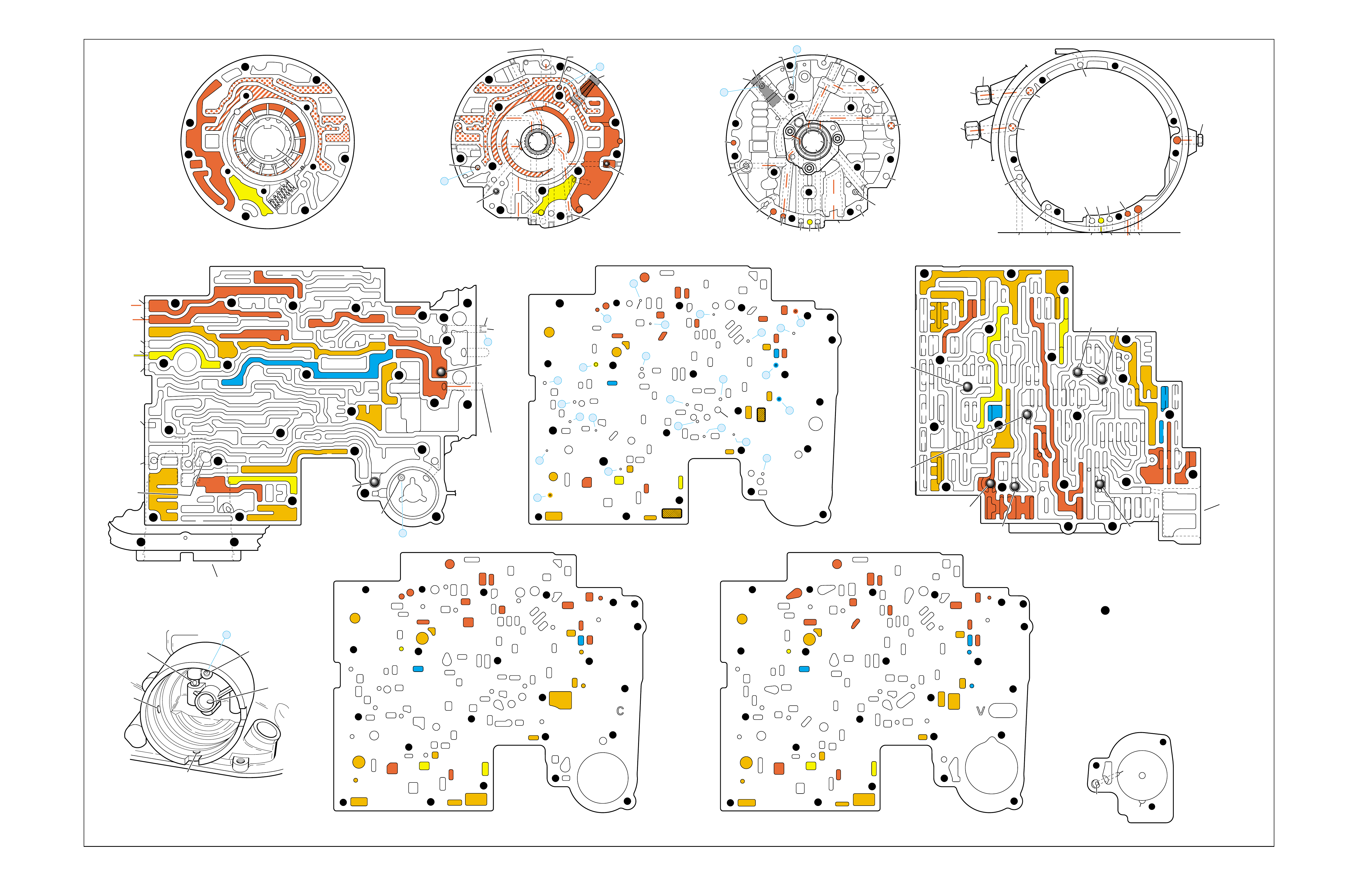
Figure 74
REVERSE
➤
➤
➤
➤➤
➤
➤
➤
➤➤
➤
➤
➤
➤
➤
➤
➤
➤
➤
➤
➤
➤
➤
➤
➤
➤
➤ ➤
➤
➤
➤
➤
➤ ➤
➤
➤
➤➤
➤➤
➤
➤
PUMP BODY (200)
(Pump Cover Side)
PUMP COVER (215)
(Pump Body Side) PUMP COVER (215)
(Case Side)
CASE (103)
(Pump Cover Side)
CASE (103)
(Control Valve Body Side)
SPACER PLATE (48)
(Case/Control Valve Body) CONTROL VALVE BODY (60)
(Case Side)
12 38
312
34
18
15
16
38
29
16
47 47
29 15 29
9
9
29
12
38 41 17
24
18
9
30
34
25 24
25 43 37
33
24
25
30 27 22 27
34
34
13
35
34
36
31 31
33
33
48
9
9
26 3
25
11
99
925
28 32
11
26
17 20 20
9
25
20
21 21
24
36 35
39
24
27
24
13
9
10
24 10
14
22
912 42
41 44
42
17
18
34
17
12 14
41
38
41
11
3
25
39
24 10
18
18
29
29
29
16
48
43
9
14
44
26
25
31
20
GASKET (47)
(Case/Spacer Plate)
GASKET (52)
(Spacer Plate/Control Valve Body)
CASE (103)
(2-4 Servo Bore)
1-2 ACCUMULATOR COVER (57)
NOTE:
- INDICATES BOLT HOLES
- NON-FUNCTIONAL HOLES
HAVE BEEN REMOVED FROM
COMPONENT DRAWINGS
TO SIMPLIFY TRACING FLUID
FLOW.
- EXHAUST FLUID NOT SHOWN
21
25
25
20
28
#7/(40)
44
(11)
25
43
32
3
16
(237)
18
43
3
(240)
37
(237)
43
47
45
43
43
48
11
29
16
3
16
29 18
2
(240)
8
85
37
37
1
47
(232)
7
46
45 47
3
3
8
43
5
4
2
4
4
48
43
3
6
1
43
2
7
47 46
43 11
3
16
37
37
5
37 8
29
18
29
1
(232)
2
43
47
16
(237)
37
(237)
4
(238)
2
(240)
PRESSURE RELIEF
VALVE BORE
➤
16
45
8
7
48
37
11 29 16
3
18
3
(39)
8
7
(10)
(10)
48 37 316291118
47 45
8
43
5
4
4
4
3
3
3
2
43
16
11
29
43
43
46
37 47
48
7
4
2
3
1
3
13V
12a 38b
3a
12b
34b
18b
38d
18c
13b
15d
16a
38c
15a
9m
9n
11c
29e
29d
9o
27b/29
29a
29f/28
15b/16
35a
22b
27d
30a
30b
34f
25a 24h
31c
25b
33c
24g 34e
31b
31a
27a
33a
33b
32a
37a
36a
3c
26b
11b
9c
25f
28a
9e
9p
9b
9d/10
(50)
48b
43a
25d
3b 11a
20c
25g
21a
9f
20e/21
17f 20a
9g
10a
35c/39
35b
35d/36
24f
24d 24c 13a
24a24b
41d
17c
41c
12c
17b/18 18a17d
42a
43c/44 9h 12e
22a 14b
10c/22
42b
14a
12d
17e
34a 41a
41b 38a
24m/25
47
9k/10
(49)
10b/23
20b
24e
17g
20d/21
25e
9a
48a
26a
43b/44
24k/25
34c
34d
29c
29b
29g/28
15c/16
17a/18 14c
44a
38e/39
27c/29
35e/36
➤
7
➤
5
➤
6
➤
16
➤
17
➤
8
➤
9
➤
32
➤
10
➤
12
➤
18
➤
20
➤
21
➤
22
➤
13
➤
14
➤
23
➤
25
➤
29
➤
30
➤
31
➤
26
➤
27
➤
28
➤
24
➤➤
1
➤➤
2
➤➤
2
➤➤
4
➤➤
11
12 38
3
18
38
16
28
29
15
34
29
9
9
15
29
11
929
40
15 43
35 34
31
31 33 33
22
27
30
34
30
25 24 24
24 31
25 43
48
26
33 37
36 32
25
28
9
26
9
311
25 25 3
910
11 21 20
25
9
10
17 20
35 35/39
24
27 24 24
13
13
22
14
22
912 42
14
12
24
24
18
38 41 17
41
12 42
17
17
34
12 34 41
38
17
44
47
923
20
17
9
9
48 44
34
29
29 18
24
14
43
10
25
41
38
34
9
9
947
9
9
3
3
25
25
11
11
26
47
26
47
25
47
3
10
43
47 11
43
33
31
24
30
37 36
28
11
34
25
24
22
24
35
34
30 27
31 32
47 25
29
9
15
40
28 29 29 16
15
43
15 12
38
3
341 47
17 34
38
41
34
18
12
17
42
43
12
18
47
47
14
43
14 42
922
23
10
9
17
17
24
38
13 24
43
42
41
3
33
31 24 24
17 47
13
17 20 20
27
#8
#6 #5
#3
#2 #12
#4
FORWARD
CLUTCH
ACCUMULATOR
BORE
➤
17
47
47
35
47
43
47
47
47 48
48
47
47
47
47 9
26
47 12 38
3
3
29
38
16
47 29
15
29
11
18
30 27 27
18
34
47
34
25 24
31
33
43
37 37
48
47
47
47
47
47 47
9
25
311
32
28 32
25
21
20
33
33
25
9
39
35
35 24 47
24 22
22 10 47
14
12
9
99
44
17 47 42
41
17
14
12
12
18
34
34
41
9
9
9
36
9
17
17
12
14
11
9
11
34
16 16
22
13 13
#10
#1
#7
(40)
37
18
11
29
16
3
29
341
38
44
(38)
28
47
43
47
48
36
33
9
33
38
19
26
47
47
2-4 SERVO BORE
➤
REAR
LUBE
TO
LOW AND
REVERSE
CLUTCH
➤➤
19
FOLDOUT ➤ 77

NEUTRAL
(Engine Running)
➤
➤➤
➤➤
➤
➤
➤
➤➤
➤
➤
➤
➤
➤
➤
INPUT CLUTCH
HOUSING ASSEMBLY
24
REAR LUBE
FILTER
(49)
➤
➤
➤
➤
➤
➤
➤
RELEASE
APPLY
LO/REVERSE
PR
BOOST VALVE PRESS REG
BOTTOM
PAN
(SUMP)
(75)
FILTER
(72) REVERSE INPUT
REV INPUT
DECREASE
LINE
EX
FILTER
(232)
AIR
BLEED
(240)
1
SUCTION
LINE
EX
PRESSURE
RELIEF
VALVE
PUMP
ASSEMBLY
(4)
➤
➤➤
4
TCC
SOLENOID
(66)
N.O.
COOLER
LUBE
COOLER
SUCTION
CONVERTER & LUBE
MAINLINE
SOLENOID SIGNAL
ACCUMULATOR
ACTUATOR FEED LIMIT
TORQUE SIGNAL
FLUID PRESSURES
REVERSE INPUT
FORWARD CLUTCH FEED
#1
ACCUMULATOR
ORF ACC
2ND CLUTCH
3-4 ACCUMULATOR
1-2 ACCUMULATOR
19
3-4 ACCUM
ACCUM
EX
ORIFICED ACCUM
3-4 ACCUMULATOR
3-4 ACCUM
2ND CLUTCH
2ND CLUTCH
D3
REVERSE INPUT
D2-N.C.
REV-N.O. D3-N.C.
LO-N.O.
D4-N.O.
LO
TEMP
SENSOR
➤
TFP
SWITCH
ASSEMBLY
D2
D4
D3
D3
D3
EX
FORWARD ABUSE
FWD CL FD
3RD ACCUMULATOR EX
#7
11
3RD ACCUM
4TH
EX
EX
➤
4TH
2ND & 4TH
SERVO
REV ABUSE
EX
REVERSE
REVERSE INPUT
#12
D4
22
D4
D4
#4
13
3-4 SIGNAL
3-4 CL
3-4 CLUTCH
#2
12
3-4 CLUTCH
3RD ACCUM
3-4 CL
#8
16
2ND
2ND CL 2ND CL
2ND CL
2ND CL
2ND CLUTCH2ND CLUTCH
TORQUE SIG
FORWARD CLUTCH FEED
FORWARD
CLUTCH
ACCUMULATOR
EX
PR LO
LO
LO
FORWARD CLUTCH FEED
FORWARD CLUTCH FEED
FWD CL FEED
D3
D3
D3
14
3-4 CLUTCH
3RD ACCUMULATOR
3RD ACCUM
EX
AFL
3-2 SIGNAL
2ND
2ND
LINE
REGULATED APPLY
8
REG APPLY
1-2 SHIFT VALVE
26
LO
D4
O’ EX
D4-3-2 2ND
25
1-2 SIGNAL
LO/1ST
27
1-2 SIGNAL
EX
ORIFICED EX
ORIFICED EX
EX
LO/1ST D4-3-2
D4
D4
2
➤
➤
➤
➤➤
➤
EX
CONV FD
EX
EX
EX
LINE LINE
LINE
PRESSURE
TAP
(39)
➤
➤
REGULATED APPLY
➤
➤
LUBE
LUBE
LUBE
LUBE
CASE (8)
CASE (8)
GASKET (47)
SPACER PLATE (48)
GASKET (52)
VALVE BODY (60)
SUCTION
LINE
LINE
3a
3b
3c
➤
➤
➤
➤
➤
➤➤
➤
➤
➤
➤
➤
➤
➤
D3
EX
3-4 SIGNAL
1-2 SIGNAL
4TH SIGNAL
3-4 SHIFT VALVE
1-2 SIGNAL
3-4 CLUTCH
OVERRUN CLUTCH
OVERRUN CLUTCH
OVERRUN CLUTCH
OVERRUN CLUTCH
OVERRUN CLUTCH
OVERRUN CLUTCH
12a
12b
12c
12d
12e
EX
EX
EX
32
AFL
AFL
30
D4
EX
31
ACCUMULATOR
ACCUMULATOR
EX
TORQUE SIGNAL
FILTERED AFL
D4
AFLAFL FILTER
(50)
10
43a
43b 44
11b
11c
11a
14b
14a
14c
LO OVERRUN
23
PR
LO/REV
LO/1ST LO/REVERSE
LO/REVERSE
PR PR
EX
22 10c
23 10b
9n
9o
22b
22a
10a
➤
10 9k
9g
9m
44a
43c 44
41a
41b
41c
41d
42b
42a
13a
13b
OIL
COOLER
PIPE
CONNECTOR
(10)
➤
➤
18a
18b
18c
18 17a
18 17b
20b
48b
48a
REGULATED APPLY
30a
30b
32a
37a
9b
9e
10 9d
9c
9a
9f
9h
31a
31b
31c
OVERRUN CLUTCH FEED
3-4 ACCUM
SERVO FEED
SERVO FEED
6
7
4TH4TH
OVERRUN CL
4TH SIGNAL2ND
EX
EX
3-4 RELAY 4-3 SEQUENCE VALVE
5
EX
SERVO FD
ORF EX
CASE (8)
REV INPUT
EX
(237)
17d
17c
17e
17f
17g
21
21
20d
20e
21a
20a
20c
1-2 ACCUMULATOR COVER (57)
25g
33c
33a
33b
27d
27c
27b
29
29
27a
28a
29b
29a
29d
40
29c
29e
29g28
28
29f
24a
24b
24c
24d
24e
24f
24g
24h
25a
25b
25d
25e
25f
25
25
24m
24k
REVERSE INPUT
#3
17
REVERSE INPUT
15c
15b
16
16
REVERSE
REVERSE INPUT
16a
15d
15a
REVERSE
34f
34e
34d
34c
34a
34b
#6
OVERRUN CL FD
21
ORIFICED D2
#5
OVERRUN
OVERRUN OVERRUN
OVERRUN
36
36
35e
35d
39
35b
35c
36a
35a
38d
38e39
38c
38b
38a
EX
TORQUE SIGNAL
2ND CL
➤
➤
➤➤
➤
20
18
2-3 SHUTTLE 2-3 SHIFT VALVE
28
29
EX
EX
EX
EX
D2
OVERRUN
D3
D3
2ND
3-4 SIGNAL
EX
D4-3-2
2-3 SIGNAL
ACTUATOR FEED LIMIT
AFL
SERVO FD
3-4 ACC
FILTERED AFL
AFL
ACTUATOR FEED LIMIT
ACTUATOR FEED LIMIT
AFL
D2
2ND
2ND
2ND
2ND
D2
D2
D2
D2
ORIFICED D2
D2
D2
D2
VALVE BODY (60)
3-4 SIGNAL
➤
2ND
D4
PR 3-4 ACCUMULATOR
D4
EX
D4-3-2
LO
D4
2ND CLUTCH
D3
D3
FORWARD CLUTCH FEED ACTUATOR FEED LIMIT
TORQUE SIGNAL
SERVO FEED
➤
OVERRUN CLUTCH
LINE
9p
26a
➤
➤
➤➤
➤
➤
➤
➤
➤
➤➤➤
➤➤➤
➤
➤➤➤
➤
➤
➤
➤
➤
➤
➤
➤
➤
➤
➤
➤
➤
➤➤
➤
➤
➤➤➤
➤➤➤
➤
➤
➤
➤
➤
➤
➤
➤
➤
➤
➤➤
➤➤ ➤
➤
➤
➤➤➤
➤➤
PR
➤➤➤➤➤➤➤➤➤➤
➤
➤➤
➤➤➤
➤➤➤➤➤➤➤
➤ ➤➤➤➤
➤ ➤ ➤➤ ➤➤➤➤➤➤➤➤ ➤
➤
➤➤
➤➤➤➤➤➤➤➤
➤➤➤➤➤➤➤➤➤ ➤➤➤➤➤➤ ➤
➤➤➤➤
➤
➤➤
➤➤➤➤➤ ➤
➤
➤
➤
➤➤ ➤
➤
➤
➤
➤➤➤ ➤
➤
➤
➤➤ ➤
➤
➤➤
➤➤ ➤➤➤
➤
➤
➤➤➤➤➤➤➤➤➤➤➤➤➤➤➤ ➤➤➤➤
➤➤
➤
➤➤
➤
➤
➤➤
➤
➤➤➤➤➤
➤➤
➤
➤
➤➤➤
OFF
CONVERTER CLUTCH VALVE
COOLER
RELEASE
APPLY
EX
➤
➤
➤
➤
➤
➤
EX
➤➤
➤
➤➤
➤
CONV FD
➤
➤
➤
➤
➤
➤
➤
➤
➤
➤
➤
REGULATED APPLY
3-2 CONTROL
EX
EX
CC SIGNAL
CC SIGNAL
ACTUATOR FEED LIMIT
9
26b
TCC PWM
SOLENOID
VALVE
N.C.
1-2 SIGNAL
2ND
4TH SIGNAL
3-2
CONTROL
SOLENOID
VALVE
N.C.
OFF
#10
➤
LOW AND REVERSE
CLUTCH ASSEMBLY
REVERSE INPUT
CLUTCH ASSEMBLY
TORQUE
CONVERTER
ASSEMBLY
#9
➤➤
(237)
➤
(238)
➤
EX
2ND CLUTCH 3-4 CLUTCH
2ND
PRESSURE
CONTROL
SOLENOID
VALVE
2-3 SHIFT
SOLENOID
VALVE
N.O.
ON
EX
1-2 SHIFT
SOLENOID
VALVE
N.O.
ON
ACCUM VALVE
PRND321
D4
D4
REVERSE
D3
D2
LO
EX
EX
LINE
➤
➤➤
➤➤➤➤➤
➤➤➤➤
➤➤ ➤➤➤➤➤
➤➤➤➤➤➤➤➤➤➤➤➤➤ ➤➤➤➤➤➤➤➤
➤➤➤➤
➤➤➤
➤
➤
➤➤➤➤
➤➤➤
➤➤
➤
➤➤ ➤
➤➤➤➤➤➤➤➤➤➤➤➤➤➤➤➤➤➤➤➤➤➤➤➤
➤➤➤➤
➤➤
➤
➤
➤
➤
➤
➤➤
➤
➤
➤
➤
➤
➤
➤
➤
➤
➤
➤
➤
➤
➤
➤
➤
➤
➤
➤➤➤➤➤
➤
➤
➤
➤
➤
➤
➤
➤
MANUAL VALVE
PR
➤
➤
➤
➤ ➤➤➤
➤
➤➤➤➤
➤
➤
➤➤
➤➤
➤➤
➤ ➤➤➤➤
➤
➤➤➤
➤➤
➤➤
➤
➤➤ ➤
➤
➤
➤
➤
➤
➤
➤
➤
➤
➤
➤
➤
➤
➤➤➤➤
➤➤➤➤ ➤➤➤➤➤➤➤➤
➤
➤➤➤➤➤
➤
➤
➤➤➤➤➤➤➤➤➤➤➤➤➤
➤➤
➤➤➤➤
➤➤➤➤➤➤➤➤➤➤
➤➤
➤➤
➤➤➤➤➤➤➤➤➤➤➤➤➤➤➤➤➤➤
➤➤➤➤➤➤➤➤
➤➤
➤
➤➤
➤
➤➤➤
➤
➤
➤➤➤➤➤➤➤➤➤
EXEX
3-2 DOWNSHIFT
ISOLATOR VALVE
REG APPLY
Figure 75
78

NEUTRAL
(Engine Running)
78A
DRIVES IN NEUTRAL
•Forward Clutch
–The clutch does not release.
•Manual Valve Link (89)
–Disconnected
•Case (103)
–The face is not flat.
–Internal leakage exists
ENGINE STALLS IN NEUTRAL
•TCC System
–Stuck On or dragging
1-2 SHIFT 2-3 SHIFT REVERSE FORWARD
SOLENOID SOLENOID 2-4 INPUT OVERRUN FORWARD SPRAG CL. 3-4 LO-ROLLER LO/REV
VALVE VALVE BAND CLUTCH CLUTCH CLUTCH ASSEMBLY CLUTCH CLUTCH CLUTCH
ON ON

NEUTRAL
(Engine Running)
78B
PASSAGES
1 SUCTION
2 DECREASE
3 LINE
4 CONVERTER FEED
5 RELEASE
6 APPLY
7 COOLER
8 LUBE
9 ACTUATOR FEED LIMIT
10 FILTERED ACTUATOR FEED
11 TORQUE SIGNAL
12 PR
13 D4-3-2
14 LO/REVERSE
15 REVERSE
16 REVERSE INPUT
17 D4
18 FORWARD CLUTCH FEED
19 REAR LUBE
20 ACCUMULATOR
21 ORIFICED ACCUMULATOR
22 1-2 SIGNAL
23 2-3 SIGNAL
24 2ND
25 2ND CLUTCH
26 C. C. SIGNAL
27 3-4 SIGNAL
28 3RD ACCUMULATOR
29 3-4 CLUTCH
30 4TH SIGNAL
31 SERVO FEED
32 4TH
33 3-4 ACCUMULATOR
34 D3
35 OVERRUN
36 OVERRUN CLUTCH FEED
37 OVERRUN CLUTCH
38 D2
39 ORIFICED D2
40 3-2 SIGNAL
41 LO
42 LO/1ST
43 EXHAUST
44 ORIFICED EXHAUST
45 VENT
46 SEAL DRAIN
47 VOID
48 REGULATED APPLY
COMPONENTS ( )
(8) REAR LUBE (ORIFICED CUP PLUG/REAR CASE)
(10) OIL COOLER PIPE CONNECTOR
(11) CASE SERVO ORIFICED PLUG
(38) ACCUMULATOR BLEED PLUG
(39) LINE PRESSURE TAP
(40) 3RD ACCUM. RETAINER AND BALL ASSEMBLY (#7)
(49) SHIFT SOLENOIDS SCREEN
(50) PRESSURE CONTROL SOLENOID SCREEN
(61) CHECKBALLS (#1, 2, 3, 4, 5, 6, 8, 12)
(91) CHECKBALL (#10)
(232) OIL PUMP COVER SCREEN
(237) CHECK VALVE RETAINER AND BALL ASSEMBLY
(238) CONVERTER CLUTCH SIGNAL ORIFICED CUP PLUG
(240) ORIFICED CUP PLUG
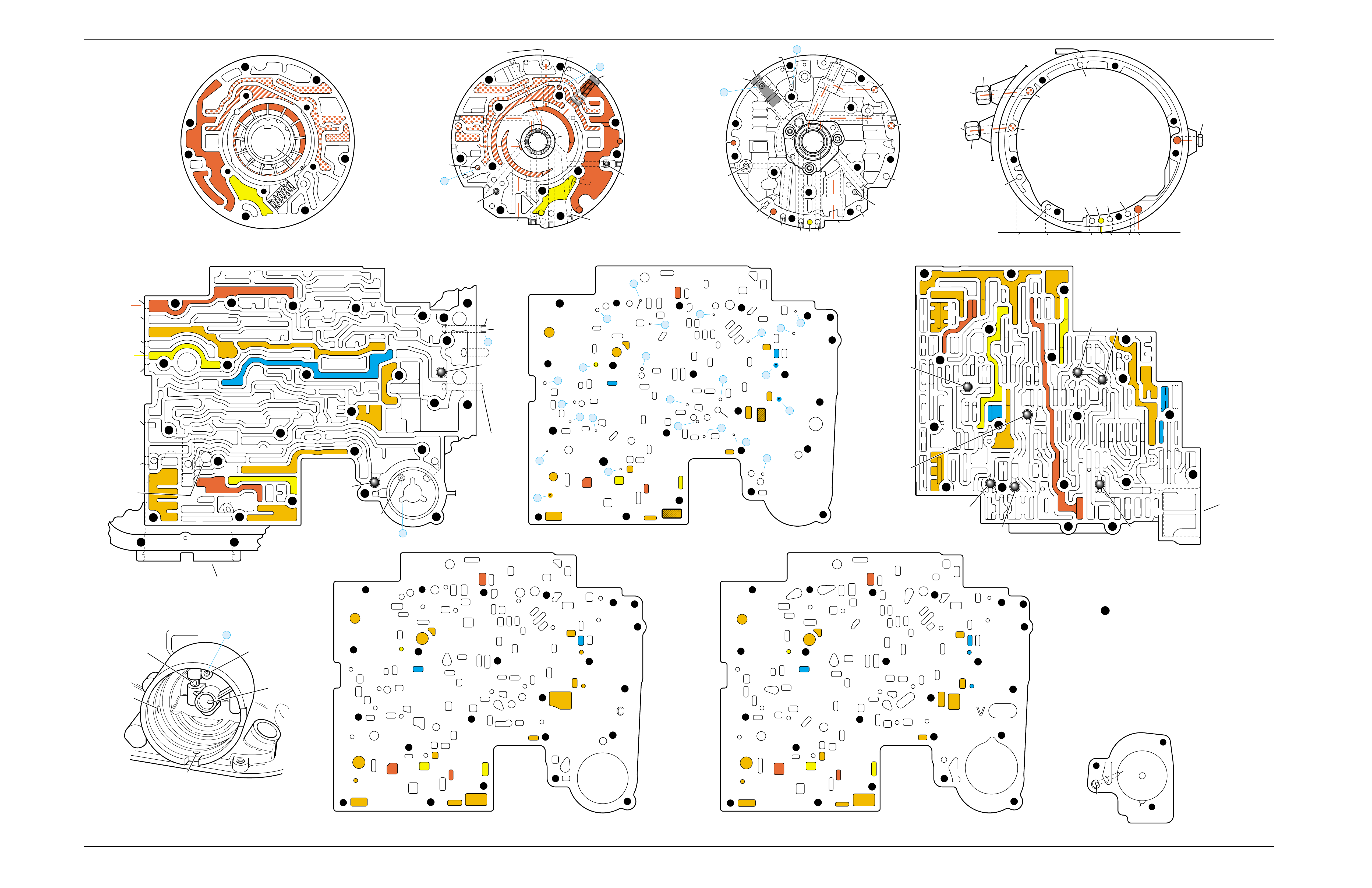
Figure 76
NEUTRAL (Engine Running)
➤
➤
➤
➤
➤
➤
➤
➤
➤
➤
➤
➤
➤
➤ ➤
➤
➤
➤
➤
➤ ➤
➤
➤
➤➤
➤➤
➤
➤
PUMP BODY (200)
(Pump Cover Side)
PUMP COVER (215)
(Pump Body Side) PUMP COVER (215)
(Case Side)
CASE (103)
(Pump Cover Side)
CASE (103)
(Control Valve Body Side)
SPACER PLATE (48)
(Case/Control Valve Body) CONTROL VALVE BODY (60)
(Case Side)
12 38
312
34
18
15
16
38
29
16
47 47
29 15 29
9
9
29
12
38 41 17
24
18
9
30
34
25 24
25 43 37
33
24
25
30 27 22 27
34
34
13
35
34
36
31 31
33
33
48
9
9
26 3
25
11
99
925
28 32
11
26
17 20 20
9
25
20
21 21
24
36 35
39
24
27
24
13
9
10
24 10
14
22
912 42
41 44
42
17
18
34
17
12 14
41
38
41
11
3
25
39
24 10
18
18
29
29
29
16
48
43
9
14
44
26
25
31
20
GASKET (47)
(Case/Spacer Plate)
GASKET (52)
(Spacer Plate/Control Valve Body)
CASE (103)
(2-4 Servo Bore)
1-2 ACCUMULATOR COVER (57)
NOTE:
- INDICATES BOLT HOLES
- NON-FUNCTIONAL HOLES
HAVE BEEN REMOVED FROM
COMPONENT DRAWINGS
TO SIMPLIFY TRACING FLUID
FLOW.
- EXHAUST FLUID NOT SHOWN
21
25
25
20
28
#7/(40)
44
(11)
25
43
32
3
16
(237)
18
43
3
(240)
37
(237)
43
47
45
43
43
48
11
29
16
3
16
29 18
2
(240)
8
85
37
37
1
47
(232)
7
46
45 47
3
3
8
43
5
4
2
4
4
48
43
3
6
1
43
2
7
47 46
43 11
3
16
37
37
5
37 8
29
18
29
1
(232)
2
43
47
16
(237)
37
(237)
4
(238)
2
(240)
PRESSURE RELIEF
VALVE BORE
➤
16
45
8
7
48
37
11 29 16
3
18
3
(39)
8
7
(10)
(10)
48 37 316291118
47 45
8
43
5
4
4
4
3
3
3
2
43
16
11
29
43
43
46
37 47
48
7
4
2
3
1
3
13V
12a 38b
3a
12b
34b
18b
38d
18c
13b
15d
16a
38c
15a
9m
9n
11c
29e
29d
9o
27b/29
29a
29f/28
15b/16
35a
22b
27d
30a
30b
34f
25a 24h
31c
25b
33c
24g 34e
31b
31a
27a
33a
33b
32a
37a
36a
3c
26b
11b
9c
25f
28a
9e
9p
9b
9d/10
(50)
48b
43a
25d
3b 11a
20c
25g
21a
9f
20e/21
17f 20a
9g
10a
35c/39
35b
35d/36
24f
24d 24c 13a
24a24b
41d
17c
41c
12c
17b/18 18a17d
42a
43c/44 9h 12e
22a 14b
10c/22
42b
14a
12d
17e
34a 41a
41b 38a
24m/25
47
9k/10
(49)
10b/23
20b
24e
17g
20d/21
25e
9a
48a
26a
43b/44
24k/25
34c
34d
29c
29b
29g/28
15c/16
17a/18 14c
44a
38e/39
27c/29
35e/36
➤
7
➤
5
➤
6
➤
16
➤
17
➤
8
➤
9
➤
32
➤
10
➤
12
➤
18
➤
20
➤
21
➤
22
➤
13
➤
14
➤
23
➤
25
➤
29
➤
30
➤
31
➤
26
➤
27
➤
28
➤
24
➤➤
1
➤➤
2
➤➤
2
➤➤
4
➤➤
11
12 38
3
18
38
16
28
29
15
34
29
9
9
15
29
11
929
40
15 43
35 34
31
31 33 33
22
27
30
34
30
25 24 24
24 31
25 43
48
26
33 37
36 32
25
28
9
26
9
311
25 25 3
910
11 21 20
25
9
10
17 20
35 35/39
24
27 24 24
13
13
22
14
22
912 42
14
12
24
24
18
38 41 17
41
12 42
17
17
34
12 34 41
38
17
44
47
923
20
17
9
9
48 44
34
29
29 18
24
14
43
10
25
41
38
34
9
9
947
9
9
3
3
25
25
11
11
26
47
26
47
25
47
3
10
43
47 11
43
33
31
24
30
37 36
28
11
34
25
24
22
24
35
34
30 27
31 32
47 25
29
9
15
40
28 29 29 16
15
43
15 12
38
3
341 47
17 34 38 41
34
18
12
17
42
43
12
18
47
47
14
43
14 42
922
23
10
9
17
17
24
38
13 24
43
42
41
3
33
31 24 24
17 47
13
17 20 20
27
#8
#6 #5
#3
#2 #12
#4
FORWARD
CLUTCH
ACCUMULATOR
BORE
➤
17
47
47
35
47
43
47
47
47 48
48
47
47
47
47 9
26
47 12 38
3
3
29
38
16
47 29
15
29
11
18
30 27 27
18
34
47
34
25 24
31
33
43
37 37
48
47
47
47
47
47 47
9
25
311
32
28 32
25
21
20
33
33
25
9
39
35
35 24 47
24 22
22 10 47
14
12
9
99
44
17 47 42
41
17
14
12
12
18
34
34
41
9
9
9
36
9
17
17
12
14
11
9
11
34
16 16
22
13 13
#10
#1
#7
(40)
37
18
11
29
16
3
29
341
38
44
(38)
28
47
43
47
48
36
33
9
33
38
19
26
47
47
2-4 SERVO BORE
➤
REAR
LUBE
TO
LOW AND
REVERSE
CLUTCH
➤➤
19
FOLDOUT ➤ 79
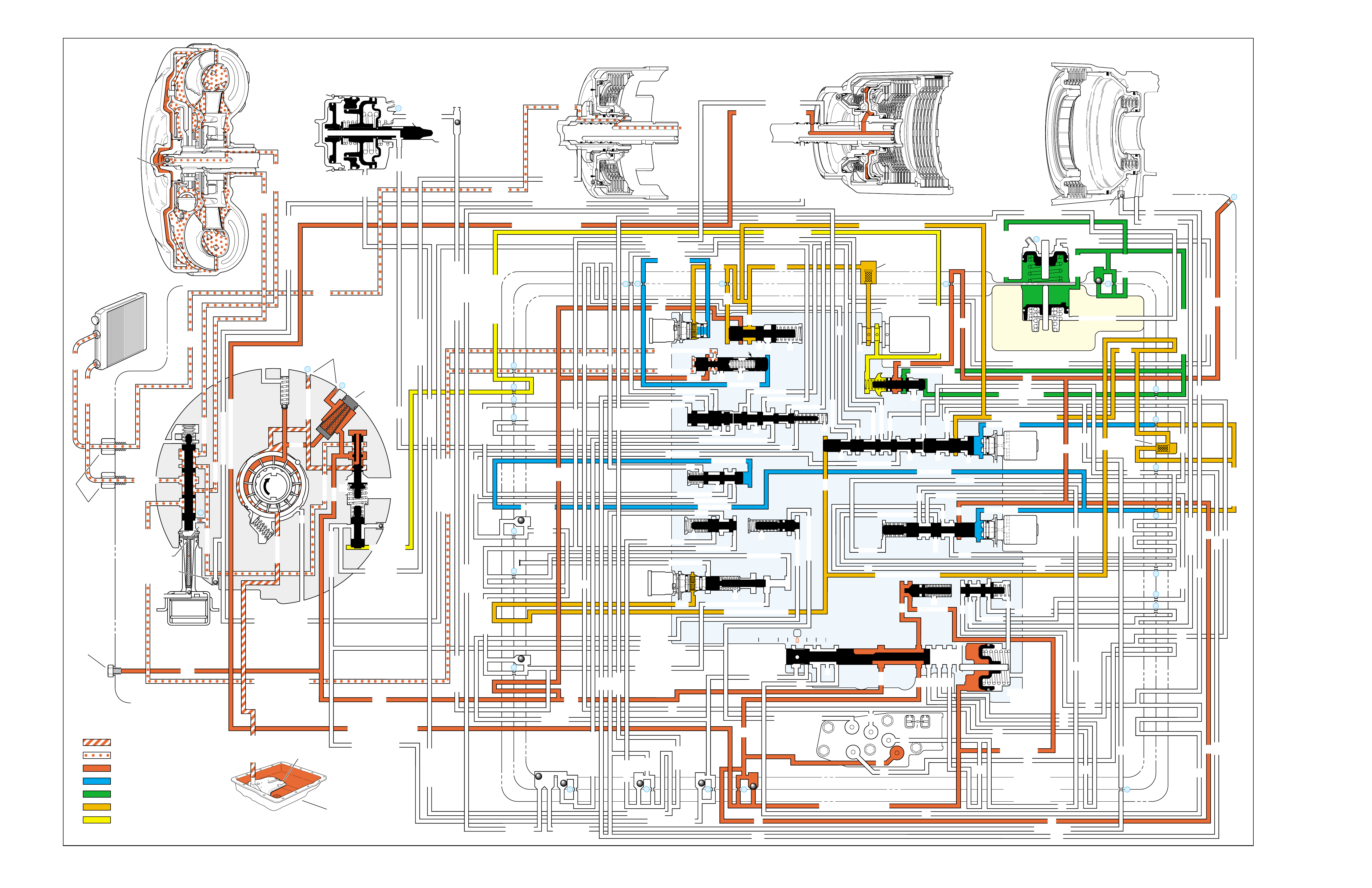
OVERDRIVE RANGE – FIRST GEAR
➤
➤➤
➤➤
➤
➤
➤
➤
➤➤
➤
➤
➤
➤
➤
➤
➤
➤
➤
➤
➤
➤➤ ➤
➤➤➤ ➤ ➤ ➤
➤➤ ➤➤
➤➤
➤➤ ➤➤
INPUT CLUTCH
HOUSING ASSEMBLY
24
REAR LUBE
FILTER
(49)
➤
➤
➤
➤
➤
➤
➤
RELEASE
APPLY
LO/REVERSE
PR
BOOST VALVE PRESS REG
BOTTOM
PAN
(SUMP)
(75)
FILTER
(72) REVERSE INPUT
REV INPUT
DECREASE
LINE
EX
FILTER
(232)
AIR
BLEED
(240)
1
SUCTION
LINE
EX
PRESSURE
RELIEF
VALVE
PUMP
ASSEMBLY
(4)
➤
➤➤
4
TCC
SOLENOID
(66)
N.O.
COOLER
LUBE
COOLER
SUCTION
CONVERTER & LUBE
MAINLINE
SOLENOID SIGNAL
ACCUMULATOR
ACTUATOR FEED LIMIT
TORQUE SIGNAL
FLUID PRESSURES
REVERSE INPUT
FORWARD CLUTCH FEED
#1
ACCUMULATOR
ORF ACC
2ND CLUTCH
3-4 ACCUMULATOR
1-2 ACCUMULATOR
19
3-4 ACCUM
ACCUM
EX
ORIFICED ACCUM
3-4 ACCUMULATOR
3-4 ACCUM
2ND CLUTCH
2ND CLUTCH
D3
REVERSE INPUT
D2-N.C.
REV-N.O. D3-N.C.
LO-N.O.
D4-N.O.
LO
TEMP
SENSOR
➤
TFP
SWITCH
ASSEMBLY
D2
D4
D3
D3
D3
EX
FORWARD ABUSE
FWD CL FD
3RD ACCUMULATOR EX
#7
11
3RD ACCUM
4TH
EX
EX
➤
4TH
2ND & 4TH
SERVO
REV ABUSE
EX
REVERSE
REVERSE INPUT
#12
D4
22
D4
D4
#4
13
3-4 SIGNAL
3-4 CL
3-4 CLUTCH
#2
12
3-4 CLUTCH
3RD ACCUM
3-4 CL
#8
16
2ND
2ND CL 2ND CL
2ND CL
2ND CL
2ND CLUTCH2ND CLUTCH
TORQUE SIG
FORWARD CLUTCH FEED
FORWARD
CLUTCH
ACCUMULATOR
EX
PR LO
LO
LO
FORWARD CLUTCH FEED
FORWARD CLUTCH FEED
FWD CL FEED
D3
D3
D3
14
3-4 CLUTCH
3RD ACCUMULATOR
3RD ACCUM
EX
AFL
3-2 SIGNAL
2ND
2ND
LINE
REGULATED APPLY
8
REG APPLY
1-2 SHIFT VALVE
26
LO
D4
O’ EX
D4-3-2 2ND
25
1-2 SIGNAL
LO/1ST
27
1-2 SIGNAL
EX
ORIFICED EX
ORIFICED EX
EX
LO/1ST D4-3-2
D4
D4
2
➤
➤
➤
➤➤
➤
EX
CONV FD
EX
EX
EX
LINE LINE
LINE
PRESSURE
TAP
(39)
➤
➤
REGULATED APPLY
➤
➤
LUBE
LUBE
LUBE
LUBE
CASE (8)
CASE (8)
GASKET (47)
SPACER PLATE (48)
GASKET (52)
VALVE BODY (60)
SUCTION
LINE
LINE
3a
3b
3c
➤
➤
➤
➤
➤
➤➤
➤
➤
➤
➤
➤
➤
➤
D3
EX
3-4 SIGNAL
1-2 SIGNAL
4TH SIGNAL
3-4 SHIFT VALVE
1-2 SIGNAL
3-4 CLUTCH
OVERRUN CLUTCH
OVERRUN CLUTCH
OVERRUN CLUTCH
OVERRUN CLUTCH
OVERRUN CLUTCH
OVERRUN CLUTCH
12a
12b
12c
12d
12e
EX
EX
EX
32
AFL
AFL
30
D4
EX
31
ACCUMULATOR
ACCUMULATOR
EX
TORQUE SIGNAL
FILTERED AFL
D4
AFLAFL FILTER
(50)
10
43a
43b 44
11b
11c
11a
14b
14a
14c
LO OVERRUN
23
PR
LO/REV
LO/1ST LO/REVERSE
LO/REVERSE
PR PR
EX
22 10c
23 10b
9n
9o
22b
22a
10a
➤
10 9k
9g
9m
44a
43c 44
41a
41b
41c
41d
42b
42a
13a
13b
OIL
COOLER
PIPE
CONNECTOR
(10)
➤
➤
18a
18b
18c
18 17a
18 17b
20b
48b
48a
REGULATED APPLY
30a
30b
32a
37a
9b
9e
10 9d
9c
9a
9f
9h
31a
31b
31c
OVERRUN CLUTCH FEED
3-4 ACCUM
SERVO FEED
SERVO FEED
6
7
4TH4TH
OVERRUN CL
4TH SIGNAL2ND
EX
EX
3-4 RELAY 4-3 SEQUENCE VALVE
5
EX
SERVO FD
ORF EX
CASE (8)
REV INPUT
EX
(237)
17d
17c
17e
17f
17g
21
21
20d
20e
21a
20a
20c
1-2 ACCUMULATOR COVER (57)
25g
33c
33a
33b
27d
27c
27b
29
29
27a
28a
29b
29a
29d
40
29c
29e
29g28
28
29f
24a
24b
24c
24d
24e
24f
24g
24h
25a
25b
25d
25e
25f
25
25
24m
24k
REVERSE INPUT
#3
17
REVERSE INPUT
15c
15b
16
16
REVERSE
REVERSE INPUT
16a
15d
15a
REVERSE
34f
34e
34d
34c
34a
34b
#6
OVERRUN CL FD
21
ORIFICED D2
#5
OVERRUN
OVERRUN OVERRUN
OVERRUN
36
36
35e
35d
39
35b
35c
36a
35a
38d
38e39
38c
38b
38a
EX
TORQUE SIGNAL
2ND CL
➤
➤
➤➤
➤
20
18
2-3 SHUTTLE 2-3 SHIFT VALVE
28
29
EX
EX
EX
EX
D2
OVERRUN
D3
D3
2ND
3-4 SIGNAL
EX
D4-3-2
2-3 SIGNAL
ACTUATOR FEED LIMIT
AFL
SERVO FD
3-4 ACC
FILTERED AFL
AFL
ACTUATOR FEED LIMIT
ACTUATOR FEED LIMIT
AFL
D2
2ND
2ND
2ND
2ND
D2
D2
D2
D2
ORIFICED D2
D2
D2
D2
VALVE BODY (60)
3-4 SIGNAL
➤
2ND
D4
PR 3-4 ACCUMULATOR
D4
EX
D4-3-2
LO
D4
2ND CLUTCH
D3
D3
FORWARD CLUTCH FEED ACTUATOR FEED LIMIT
TORQUE SIGNAL
SERVO FEED
➤
OVERRUN CLUTCH
LINE
9p
26a
➤
➤
➤➤
➤
➤
➤
➤
➤
➤➤➤
➤➤➤
➤
➤➤➤
➤
➤
➤
➤
➤
➤
➤
➤
➤
➤
➤
➤
➤
➤➤
➤
➤
➤➤➤
➤➤➤
➤
➤
➤
➤
➤
➤
➤
➤
➤
➤
➤➤
➤➤ ➤
➤
➤
➤➤➤
➤➤
PR
➤
➤
➤➤
➤
➤➤➤➤➤
➤➤
➤
➤
➤➤➤
OFF
CONVERTER CLUTCH VALVE
COOLER
RELEASE
APPLY
EX
➤
➤
➤
➤
➤
➤
EX
➤➤
➤
➤➤
➤
CONV FD
➤
➤
➤
➤
➤
➤
➤
➤
➤
➤
➤
REGULATED APPLY
3-2 CONTROL
EX
EX
CC SIGNAL
CC SIGNAL
ACTUATOR FEED LIMIT
9
26b
TCC PWM
SOLENOID
VALVE
N.C.
1-2 SIGNAL
2ND
4TH SIGNAL
3-2
CONTROL
SOLENOID
VALVE
N.C.
OFF
#10
➤
LOW AND REVERSE
CLUTCH ASSEMBLY
REVERSE INPUT
CLUTCH ASSEMBLY
TORQUE
CONVERTER
ASSEMBLY
#9
➤➤
(237)
➤
(238)
➤
EX
2ND CLUTCH 3-4 CLUTCH
2ND
PRESSURE
CONTROL
SOLENOID
VALVE
2-3 SHIFT
SOLENOID
VALVE
N.O.
ON
EX
1-2 SHIFT
SOLENOID
VALVE
N.O.
ON
ACCUM VALVE
PRND321
D4
D4
REVERSE
D3
D2
LO
EX
EX
LINE
➤
➤
➤
➤
➤
➤
➤
➤
➤
➤
➤
➤
➤
➤
➤
➤
➤
➤
➤
➤
➤➤➤➤➤
➤
➤
➤
➤
➤
➤
➤
➤
MANUAL VALVE
PR
➤
➤
➤➤
➤
➤
➤
➤➤➤➤➤
➤➤➤
➤➤
➤➤
➤
➤
➤
➤➤
➤
➤➤
➤
➤➤
➤➤
➤
➤
➤
➤➤
➤
➤
➤
➤
➤➤ ➤ ➤ ➤ ➤
➤➤➤➤
➤
➤
➤➤➤ ➤ ➤
➤
➤
➤➤
➤
➤
➤
➤
➤
➤
➤➤
➤➤
➤
➤
➤
➤➤ ➤ ➤
➤➤
➤
➤
➤
➤
➤
➤
➤
➤
➤
➤
➤
➤
➤➤
➤
➤➤➤
EXEX
3-2 DOWNSHIFT
ISOLATOR VALVE
REG APPLY
Figure 77
80

OVERDRIVE RANGE – FIRST GEAR
80A
1ST GEAR RANGE ONLY - NO UPSHIFT
•Valve Body Spacer Plate (48)
–Mispositioned or damaged
•Shift Solenoid Valves (379)
–Stuck or damaged
–Faulty electrical connection
•2-4 Band (602)
–Worn or damaged
SLIPS IN 1ST GEAR
•Forward Clutch Housing (628)
–Damaged
•1-2 Accumulator Valve (371)
–Stuck
•Torque Converter (1)
–Stator roller clutch not holding
1-2 SHIFT 2-3 SHIFT REVERSE FORWARD
SOLENOID SOLENOID 2-4 INPUT OVERRUN FORWARD SPRAG CL. 3-4 LO-ROLLER LO/REV
VALVE VALVE BAND CLUTCH CLUTCH CLUTCH ASSEMBLY CLUTCH CLUTCH CLUTCH
ON ON APPLIED HOLDING HOLDING

OVERDRIVE RANGE – FIRST GEAR
80B
PASSAGES
1 SUCTION
2 DECREASE
3 LINE
4 CONVERTER FEED
5 RELEASE
6 APPLY
7 COOLER
8 LUBE
9 ACTUATOR FEED LIMIT
10 FILTERED ACTUATOR FEED
11 TORQUE SIGNAL
12 PR
13 D4-3-2
14 LO/REVERSE
15 REVERSE
16 REVERSE INPUT
17 D4
18 FORWARD CLUTCH FEED
19 REAR LUBE
20 ACCUMULATOR
21 ORIFICED ACCUMULATOR
22 1-2 SIGNAL
23 2-3 SIGNAL
24 2ND
25 2ND CLUTCH
26 C. C. SIGNAL
27 3-4 SIGNAL
28 3RD ACCUMULATOR
29 3-4 CLUTCH
30 4TH SIGNAL
31 SERVO FEED
32 4TH
33 3-4 ACCUMULATOR
34 D3
35 OVERRUN
36 OVERRUN CLUTCH FEED
37 OVERRUN CLUTCH
38 D2
39 ORIFICED D2
40 3-2 SIGNAL
41 LO
42 LO/1ST
43 EXHAUST
44 ORIFICED EXHAUST
45 VENT
46 SEAL DRAIN
47 VOID
48 REGULATED APPLY
COMPONENTS ( )
(8) REAR LUBE (ORIFICED CUP PLUG/REAR CASE)
(10) OIL COOLER PIPE CONNECTOR
(11) CASE SERVO ORIFICED PLUG
(38) ACCUMULATOR BLEED PLUG
(39) LINE PRESSURE TAP
(40) 3RD ACCUM. RETAINER AND BALL ASSEMBLY (#7)
(49) SHIFT SOLENOIDS SCREEN
(50) PRESSURE CONTROL SOLENOID SCREEN
(61) CHECKBALLS (#1, 2, 3, 4, 5, 6, 8, 12)
(91) CHECKBALL (#10)
(232) OIL PUMP COVER SCREEN
(237) CHECK VALVE RETAINER AND BALL ASSEMBLY
(238) CONVERTER CLUTCH SIGNAL ORIFICED CUP PLUG
(240) ORIFICED CUP PLUG

Figure 78
OVERDRIVE RANGE – FIRST GEAR
➤
➤
➤
➤
➤➤
➤➤➤
➤
➤
➤
➤
➤
➤
➤
➤
➤
➤
➤
➤
➤
➤
➤ ➤
➤
➤
➤
➤
➤ ➤
➤
➤
➤ ➤
➤➤
➤➤
➤
➤
PUMP BODY (200)
(Pump Cover Side)
PUMP COVER (215)
(Pump Body Side) PUMP COVER (215)
(Case Side)
CASE (103)
(Pump Cover Side)
CASE (103)
(Control Valve Body Side)
SPACER PLATE (48)
(Case/Control Valve Body) CONTROL VALVE BODY (60)
(Case Side)
12 38
312
34
18
15
16
38
29
16
47 47
29 15 29
9
9
29
12
38 41 17
24
18
9
30
34
25 24
25 43 37
33
24
25
30 27 22 27
34
34
13
35
34
36
31 31
33
33
48
9
9
26 3
25
11
99
925
28 32
11
26
17 20 20
9
25
20
21 21
24
36 35
39
24
27
24
13
9
10
24 10
14
22
912 42
41 44
42
17
18
34
17
12 14
41
38
41
11
3
25
39
24 10
18
18
29
29
29
16
48
43
9
14
44
26
25
31
20
GASKET (47)
(Case/Spacer Plate)
GASKET (52)
(Spacer Plate/Control Valve Body)
CASE (103)
(2-4 Servo Bore)
1-2 ACCUMULATOR COVER (57)
NOTE:
- INDICATES BOLT HOLES
- NON-FUNCTIONAL HOLES
HAVE BEEN REMOVED FROM
COMPONENT DRAWINGS
TO SIMPLIFY TRACING FLUID
FLOW.
- EXHAUST FLUID NOT SHOWN
21
25
25
20
28
#7/(40)
44
(11)
25
43
32
3
16
(237)
18
43
3
(240)
37
(237)
43
47
45
43
43
48
11
29
16
3
16
29 18
2
(240)
8
85
37
37
1
47
(232)
7
46
45 47
3
3
8
43
5
4
2
4
4
48
43
3
6
1
43
2
7
47 46
43 11
3
16
37
37
5
37 8
29
18
29
1
(232)
2
43
47
16
(237)
37
(237)
4
(238)
2
(240)
PRESSURE RELIEF
VALVE BORE
➤
16
45
8
7
48
37
11 29 16
3
18
3
(39)
8
7
(10)
(10)
48 37 316291118
47 45
8
43
5
4
4
4
3
3
3
2
43
16
11
29
43
43
46
37 47
48
7
4
2
3
1
3
13V
12a 38b
3a
12b
34b
18b
38d
18c
13b
15d
16a
38c
15a
9m
9n
11c
29e
29d
9o
27b/29
29a
29f/28
15b/16
35a
22b
27d
30a
30b
34f
25a 24h
31c
25b
33c
24g 34e
31b
31a
27a
33a
33b
32a
37a
36a
3c
26b
11b
9c
25f
28a
9e
9p
9b
9d/10
(50)
48b
43a
25d
3b 11a
20c
25g
21a
9f
20e/21
17f 20a
9g
10a
35c/39
35b
35d/36
24f
24d 24c 13a
24a24b
41d
17c
41c
12c
17b/18 18a17d
42a
43c/44 9h 12e
22a 14b
10c/22
42b
14a
12d
17e
34a 41a
41b 38a
24m/25
47
9k/10
(49)
10b/23
20b
24e
17g
20d/21
25e
9a
48a
26a
43b/44
24k/25
34c
34d
29c
29b
29g/28
15c/16
17a/18 14c
44a
38e/39
27c/29
35e/36
➤
7
➤
5
➤
6
➤
16
➤
17
➤
8
➤
9
➤
32
➤
10
➤
12
➤
18
➤
20
➤
21
➤
22
➤
13
➤
14
➤
23
➤
25
➤
29
➤
30
➤
31
➤
26
➤
27
➤
28
➤
24
➤➤
1
➤➤
2
➤➤
2
➤➤
4
➤➤
11
12 38
3
18
38
16
28
29
15
34
29
9
9
15
29
11
929
40
15 43
35 34
31
31 33 33
22
27
30
34
30
25 24 24
24 31
25 43
48
26
33 37
36 32
25
28
9
26
9
311
25 25 3
910
11 21 20
25
9
10
17 20
35 35/39
24
27 24 24
13
13
22
14
22
912 42
14
12
24
24
18
38 41 17
41
12 42
17
17
34
12 34 41
38
17
44
47
923
20
17
9
9
48 44
34
29
29 18
24
14
43
10
25
41
38
34
9
9
947
9
9
3
3
25
25
11
11
26
47
26
47
25
47
3
10
43
47 11
43
33
31
24
30
37 36
28
11
34
25
24
22
24
35
34
30 27
31 32
47 25
29
9
15
40
28 29 29 16
15
43
15 12
38
3
341 47
17 34
38
41
34
18
12
17
42
43
12
18
47
47
14
43
14 42
922
23
10
9
17
17
24
38
13 24
43
42
41
3
33
31 24 24
17 47
13
17 20 20
27
#8
#6 #5
#3
#2 #12
#4
FORWARD
CLUTCH
ACCUMULATOR
BORE
➤
17
47
47
35
47
43
47
47
47 48
48
47
47
47
47 9
26
47 12 38
3
3
29
38
16
47 29
15
29
11
18
30 27 27
18
34
47
34
25 24
31
33
43
37 37
48
47
47
47
47
47 47
9
25
311
32
28 32
25
21
20
33
33
25
9
39
35
35 24 47
24 22
22 10 47
14
12
9
99
44
17 47 42
41
17
14
12
12
18
34
34
41
9
9
9
36
9
17
17
12
14
11
9
11
34
16 16
22
13 13
#10
#1
#7
(40)
37
18
11
29
16
3
29
341
38
44
(38)
28
47
43
47
48
36
33
9
33
38
19
26
47
47
2-4 SERVO BORE
➤
REAR
LUBE
TO
LOW AND
REVERSE
CLUTCH
➤➤
19
FOLDOUT ➤ 81

OVERDRIVE RANGE – SECOND GEAR
➤
➤➤
➤➤
➤
➤
➤
➤
➤
➤
➤
➤
➤
➤
➤
➤➤ ➤
➤➤➤ ➤ ➤ ➤
➤➤ ➤➤
➤➤
➤➤ ➤➤
➤
➤
➤
➤
➤
➤
INPUT CLUTCH
HOUSING ASSEMBLY
24
REAR LUBE
FILTER
(49)
➤
➤
➤
➤
➤
➤
➤
RELEASE
APPLY
LO/REVERSE
PR
BOOST VALVE PRESS REG
BOTTOM
PAN
(SUMP)
(75)
FILTER
(72) REVERSE INPUT
REV INPUT
DECREASE
LINE
EX
FILTER
(232)
AIR
BLEED
(240)
1
SUCTION
LINE
EX
PRESSURE
RELIEF
VALVE
PUMP
ASSEMBLY
(4)
➤
➤➤
4
TCC
SOLENOID
(66)
N.O.
COOLER
LUBE
COOLER
SUCTION
CONVERTER & LUBE
MAINLINE
SOLENOID SIGNAL
ACCUMULATOR
ACTUATOR FEED LIMIT
TORQUE SIGNAL
FLUID PRESSURES
REVERSE INPUT
FORWARD CLUTCH FEED
#1
ACCUMULATOR
ORF ACC
2ND CLUTCH
3-4 ACCUMULATOR
1-2 ACCUMULATOR
19
3-4 ACCUM
ACCUM
EX
ORIFICED ACCUM
3-4 ACCUMULATOR
3-4 ACCUM
2ND CLUTCH
2ND CLUTCH
D3
REVERSE INPUT
D2-N.C.
REV-N.O. D3-N.C.
LO-N.O.
D4-N.O.
LO
TEMP
SENSOR
➤
TFP
SWITCH
ASSEMBLY
D2
D4
D3
D3
D3
EX
FORWARD ABUSE
FWD CL FD
3RD ACCUMULATOR EX
#7
11
3RD ACCUM
➤
4TH
2ND & 4TH
SERVO
REV ABUSE
EX
REVERSE
REVERSE INPUT
#12
D4
22
D4
D4
#4
13
3-4 SIGNAL
3-4 CL
3-4 CLUTCH
#2
12
3-4 CLUTCH
3RD ACCUM
3-4 CL
#8
16
2ND
2ND CL 2ND CL
2ND CL
2ND CL
2ND CLUTCH2ND CLUTCH
TORQUE SIG
FORWARD CLUTCH FEED
FORWARD
CLUTCH
ACCUMULATOR
EX
PR LO
LO
LO
FORWARD CLUTCH FEED
FORWARD CLUTCH FEED
FWD CL FEED
D3
D3
D3
14
3-4 CLUTCH
3RD ACCUMULATOR
3RD ACCUM
EX
AFL
3-2 SIGNAL
2ND
2ND
LINE
REGULATED APPLY
8
REG APPLY
1-2 SHIFT VALVE
26
LO
D4
O’ EX
D4-3-2 2ND
25
1-2 SIGNAL
LO/1ST
27
1-2 SIGNAL
EX
ORIFICED EX
ORIFICED EX
EX
LO/1ST D4-3-2
D4
D4
2
➤
➤
➤
➤➤
➤
EX
CONV FD
EX
EX
EX
LINE LINE
LINE
PRESSURE
TAP
(39)
➤
➤
REGULATED APPLY
➤
➤
LUBE
LUBE
LUBE
LUBE
CASE (8)
CASE (8)
GASKET (47)
SPACER PLATE (48)
GASKET (52)
VALVE BODY (60)
SUCTION
LINE
LINE
3a
3b
3c
➤
➤
➤
➤
➤
➤➤
➤
➤
➤
➤
➤
➤
➤
D3
EX
3-4 SIGNAL
1-2 SIGNAL
4TH SIGNAL
3-4 SHIFT VALVE
1-2 SIGNAL
3-4 CLUTCH
OVERRUN CLUTCH
OVERRUN CLUTCH
OVERRUN CLUTCH
OVERRUN CLUTCH
OVERRUN CLUTCH
OVERRUN CLUTCH
12a
12b
12c
12d
12e
EX
EX
EX
32
AFL
AFL
30
D4
EX
31
ACCUMULATOR
ACCUMULATOR
EX
TORQUE SIGNAL
FILTERED AFL
D4
AFLAFL FILTER
(50)
10
43a
43b 44
11b
11c
11a
14b
14a
14c
LO OVERRUN
23
PR
LO/REV
LO/1ST LO/REVERSE
LO/REVERSE
PR PR
EX
22 10c
23 10b
9n
9o
22b
22a
10a
➤
10 9k
9g
9m
44a
43c 44
41a
41b
41c
41d
42b
42a
13a
13b
OIL
COOLER
PIPE
CONNECTOR
(10)
➤
➤
18a
18b
18c
18 17a
18 17b
20b
48b
48a
REGULATED APPLY
30a
30b
32a
37a
9b
9e
10 9d
9c
9a
9f
9h
31a
31b
31c
OVERRUN CLUTCH FEED
3-4 ACCUM
SERVO FEED
SERVO FEED
6
7
4TH4TH
OVERRUN CL
4TH SIGNAL2ND
EX
EX
3-4 RELAY 4-3 SEQUENCE VALVE
5
EX
SERVO FD
ORF EX
CASE (8)
REV INPUT
EX
(237)
17d
17c
17e
17f
17g
21
21
20d
20e
21a
20a
20c
1-2 ACCUMULATOR COVER (57)
25g
33c
33a
33b
27d
27c
27b
29
29
27a
28a
29b
29a
29d
40
29c
29e
29g28
28
29f
24a
24b
24c
24d
24e
24f
24g
24h
25a
25b
25d
25e
25f
25
25
24m
24k
REVERSE INPUT
#3
17
REVERSE INPUT
15c
15b
16
16
REVERSE
REVERSE INPUT
16a
15d
15a
REVERSE
34f
34e
34d
34c
34a
34b
#6
OVERRUN CL FD
21
ORIFICED D2
#5
OVERRUN
OVERRUN OVERRUN
OVERRUN
36
36
35e
35d
39
35b
35c
36a
35a
38d
38e39
38c
38b
38a
EX
TORQUE SIGNAL
2ND CL
➤
➤
➤➤
➤
20
18
2-3 SHUTTLE 2-3 SHIFT VALVE
28
29
EX
EX
EX
EX
D2
OVERRUN
D3
D3
2ND
3-4 SIGNAL
EX
D4-3-2
2-3 SIGNAL
ACTUATOR FEED LIMIT
AFL
SERVO FD
3-4 ACC
FILTERED AFL
AFL
ACTUATOR FEED LIMIT
ACTUATOR FEED LIMIT
AFL
D2
2ND
2ND
2ND
2ND
D2
D2
D2
D2
ORIFICED D2
D2
D2
D2
VALVE BODY (60)
3-4 SIGNAL
➤
2ND
D4
PR 3-4 ACCUMULATOR
D4
EX
D4-3-2
LO
D4
2ND CLUTCH
D3
D3
FORWARD CLUTCH FEED ACTUATOR FEED LIMIT
TORQUE SIGNAL
SERVO FEED
➤
OVERRUN CLUTCH
LINE
9p
26a
➤
➤
➤➤
➤➤ ➤ ➤ ➤➤➤ ➤ ➤
➤➤
➤
➤ ➤➤➤➤➤➤ ➤➤
➤➤➤➤➤➤ ➤ ➤ ➤ ➤ ➤➤➤➤➤
➤➤
➤➤
➤➤
➤➤➤➤➤➤➤ ➤➤➤➤
➤
➤
➤
➤
➤
➤
➤
➤
➤
➤
➤
➤
➤
➤➤
➤
➤
➤➤➤
➤➤➤
➤
➤
➤
➤
➤
➤
➤
➤
➤
➤
➤➤
➤➤ ➤
➤
➤
➤➤➤
➤➤
PR
➤
➤
➤➤
➤
➤➤➤➤➤
➤➤
➤
➤
➤➤➤
OFF
CONVERTER CLUTCH VALVE
COOLER
RELEASE
APPLY
EX
➤
➤
➤
➤
➤
➤
EX
➤➤
➤
➤➤
➤
CONV FD
➤
➤
➤
➤
➤
➤
➤
➤
➤
➤
➤
REGULATED APPLY
EX
EX
CC SIGNAL
CC SIGNAL
ACTUATOR FEED LIMIT
9
26b
TCC PWM
SOLENOID
VALVE
N.C.
1-2 SIGNAL
2ND
4TH SIGNAL
#10
➤
LOW AND REVERSE
CLUTCH ASSEMBLY
REVERSE INPUT
CLUTCH ASSEMBLY
TORQUE
CONVERTER
ASSEMBLY
#9
➤➤
(237)
➤
(238)
➤
EX
2ND CLUTCH 3-4 CLUTCH
2ND
PRESSURE
CONTROL
SOLENOID
VALVE
2-3 SHIFT
SOLENOID
VALVE
N.O.
ON
EX
1-2 SHIFT
SOLENOID
VALVE
N.O.
OFF
PRND321
D4
D4
REVERSE
D3
D2
LO
EX
EX
LINE
➤
➤
➤
➤
➤
➤
➤
➤
➤
➤
➤
➤
➤
➤
➤
➤
➤
➤
➤
➤
➤➤➤➤➤
➤
➤
➤
➤
➤
➤
➤
➤
MANUAL VALVE
PR
➤
➤
➤➤
➤
➤
➤
➤➤➤➤➤
➤➤➤
➤➤
➤➤
➤
➤
➤
➤➤
➤
➤➤
➤
➤➤
➤➤
➤
➤
➤
➤➤
➤
➤
➤
➤
➤➤ ➤ ➤ ➤ ➤
➤➤➤➤
➤
➤
➤➤➤ ➤ ➤
➤
➤
➤➤
➤
➤
➤
➤
➤
➤
➤➤
➤➤
➤
➤
➤
➤
➤➤➤
➤➤
➤
➤
➤
➤
➤
➤
➤
➤
➤
➤
➤
➤
➤➤
➤
➤➤➤
➤
➤➤ ➤
➤
➤➤
➤
➤
➤➤
➤
➤➤
➤
➤
11
4TH
EX
EX
➤
➤➤➤
➤
➤
➤
➤➤➤➤
➤➤➤➤➤➤
➤
➤
➤
➤
➤➤
➤
➤➤
➤
➤
➤
➤
➤
➤
➤
➤➤➤➤ ➤
➤
➤
➤➤➤
➤➤➤➤➤
➤➤➤➤
➤
➤
➤
➤➤
➤
➤
➤
➤➤➤
➤
➤
➤
➤
➤
➤
➤➤➤
➤
➤
➤
➤
➤
➤
➤
ACCUM VALVE
EXEX
3-2 DOWNSHIFT
3-2 CONTROL
3-2
CONTROL
SOLENOID
VALVE
N.C.
ON
➤
ISOLATOR VALVE
REG APPLY
Figure 79
82

OVERDRIVE RANGE – SECOND GEAR
82A
SLIPPING OR ROUGH 1-2 SHIFT
•1-2 Accumulator Valve (371)
–Stuck
•2nd Apply Piston Pin (13)
–Too long or too short
•1-2 Accumulator Housing (57)
–Nicks or burrs
2ND GEAR STARTS
•Forward Clutch Sprag Assembly (642)
–Installed backwards
1-2 SHIFT 2-3 SHIFT REVERSE FORWARD
SOLENOID SOLENOID 2-4 INPUT OVERRUN FORWARD SPRAG CL. 3-4 LO-ROLLER LO/REV
VALVE VALVE BAND CLUTCH CLUTCH CLUTCH ASSEMBLY CLUTCH CLUTCH CLUTCH
OFF ON APPLIED APPLIED HOLDING

OVERDRIVE RANGE – SECOND GEAR
82B
PASSAGES
1 SUCTION
2 DECREASE
3 LINE
4 CONVERTER FEED
5 RELEASE
6 APPLY
7 COOLER
8 LUBE
9 ACTUATOR FEED LIMIT
10 FILTERED ACTUATOR FEED
11 TORQUE SIGNAL
12 PR
13 D4-3-2
14 LO/REVERSE
15 REVERSE
16 REVERSE INPUT
17 D4
18 FORWARD CLUTCH FEED
19 REAR LUBE
20 ACCUMULATOR
21 ORIFICED ACCUMULATOR
22 1-2 SIGNAL
23 2-3 SIGNAL
24 2ND
25 2ND CLUTCH
26 C. C. SIGNAL
27 3-4 SIGNAL
28 3RD ACCUMULATOR
29 3-4 CLUTCH
30 4TH SIGNAL
31 SERVO FEED
32 4TH
33 3-4 ACCUMULATOR
34 D3
35 OVERRUN
36 OVERRUN CLUTCH FEED
37 OVERRUN CLUTCH
38 D2
39 ORIFICED D2
40 3-2 SIGNAL
41 LO
42 LO/1ST
43 EXHAUST
44 ORIFICED EXHAUST
45 VENT
46 SEAL DRAIN
47 VOID
48 REGULATED APPLY
COMPONENTS ( )
(8) REAR LUBE (ORIFICED CUP PLUG/REAR CASE)
(10) OIL COOLER PIPE CONNECTOR
(11) CASE SERVO ORIFICED PLUG
(38) ACCUMULATOR BLEED PLUG
(39) LINE PRESSURE TAP
(40) 3RD ACCUM. RETAINER AND BALL ASSEMBLY (#7)
(49) SHIFT SOLENOIDS SCREEN
(50) PRESSURE CONTROL SOLENOID SCREEN
(61) CHECKBALLS (#1, 2, 3, 4, 5, 6, 8, 12)
(91) CHECKBALL (#10)
(232) OIL PUMP COVER SCREEN
(237) CHECK VALVE RETAINER AND BALL ASSEMBLY
(238) CONVERTER CLUTCH SIGNAL ORIFICED CUP PLUG
(240) ORIFICED CUP PLUG
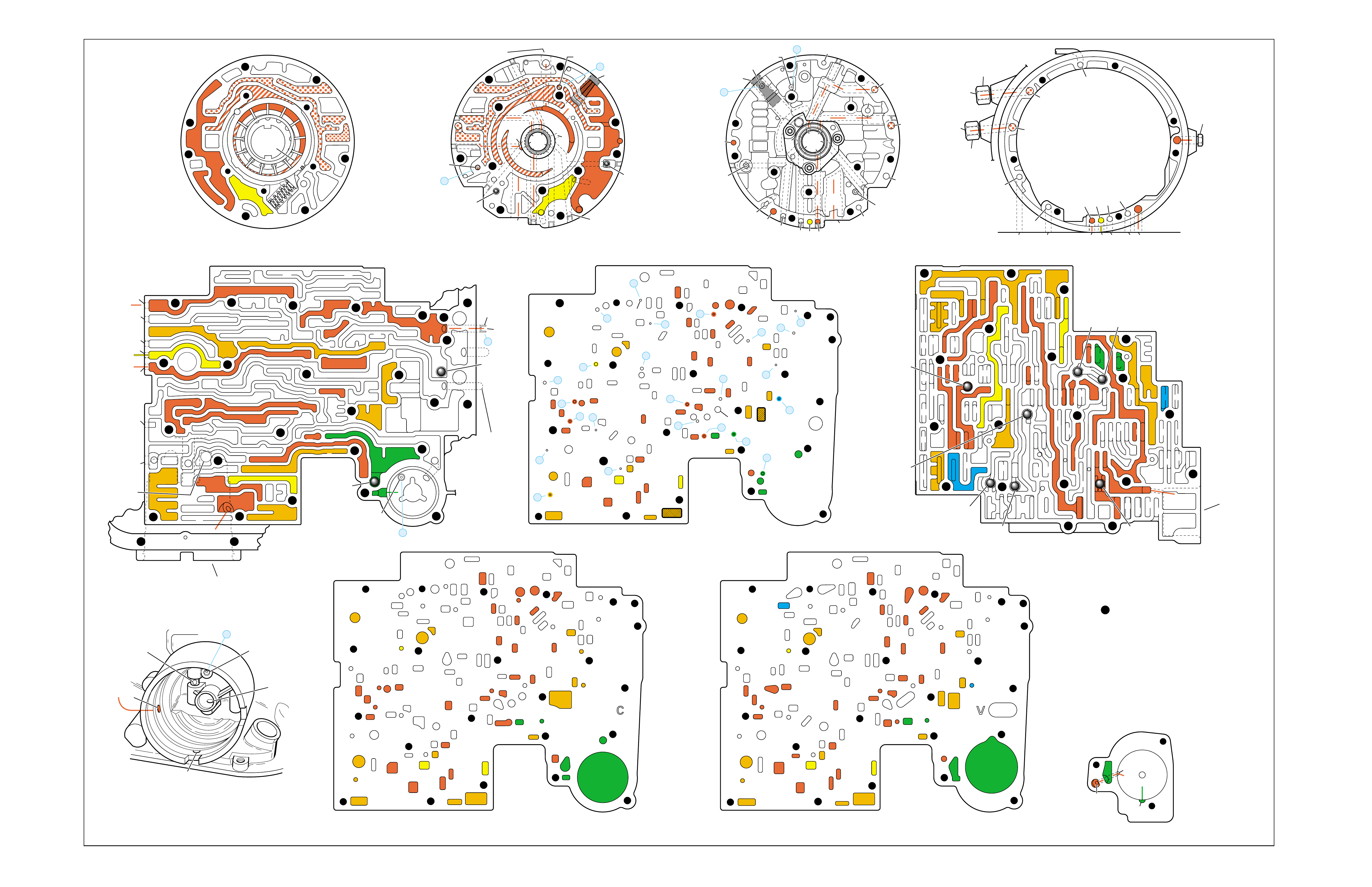
Figure 80
OVERDRIVE RANGE – SECOND GEAR
➤
➤
➤
➤
➤
➤
➤
➤➤
➤➤➤
➤
➤
➤
➤
➤
➤
➤
➤
➤
➤
➤
➤
➤
➤
➤ ➤
➤
➤
➤
➤
➤ ➤
➤
➤
➤ ➤
➤➤
➤➤
➤
➤
PUMP BODY (200)
(Pump Cover Side)
PUMP COVER (215)
(Pump Body Side) PUMP COVER (215)
(Case Side)
CASE (103)
(Pump Cover Side)
CASE (103)
(Control Valve Body Side)
SPACER PLATE (48)
(Case/Control Valve Body) CONTROL VALVE BODY (60)
(Case Side)
12 38
312
34
18
15
16
38
29
16
47 47
29 15 29
9
9
29
12
38 41 17
24
18
9
30
34
25 24
25 43 37
33
24
25
30 27 22 27
34
34
13
35
34
36
31 31
33
33
48
9
9
26 3
25
11
99
925
28 32
11
26
17 20 20
9
25
20
21 21
24
36 35
39
24
27
24
13
9
10
24 10
14
22
912 42
41 44
42
17
18
34
17
12 14
41
38
41
11
3
25
39
24 10
18
18
29
29
29
16
48
43
9
14
44
26
25
31
20
GASKET (47)
(Case/Spacer Plate)
GASKET (52)
(Spacer Plate/Control Valve Body)
CASE (103)
(2-4 Servo Bore)
1-2 ACCUMULATOR COVER (57)
NOTE:
- INDICATES BOLT HOLES
- NON-FUNCTIONAL HOLES
HAVE BEEN REMOVED FROM
COMPONENT DRAWINGS
TO SIMPLIFY TRACING FLUID
FLOW.
- EXHAUST FLUID NOT SHOWN
21
25
25
20
28
#7/(40)
44
(11)
25
43
32
3
16
(237)
18
43
3
(240)
37
(237)
43
47
45
43
43
48
11
29
16
3
16
29 18
2
(240)
8
85
37
37
1
47
(232)
7
46
45 47
3
3
8
43
5
4
2
4
4
48
43
3
6
1
43
2
7
47 46
43 11
3
16
37
37
5
37 8
29
18
29
1
(232)
2
43
47
16
(237)
37
(237)
4
(238)
2
(240)
PRESSURE RELIEF
VALVE BORE
➤
16
45
8
7
48
37
11 29 16
3
18
3
(39)
8
7
(10)
(10)
48 37 316291118
47 45
8
43
5
4
4
4
3
3
3
2
43
16
11
29
43
43
46
37 47
48
7
4
2
3
1
3
13V
12a 38b
3a
12b
34b
18b
38d
18c
13b
15d
16a
38c
15a
9m
9n
11c
29e
29d
9o
27b/29
29a
29f/28
15b/16
35a
22b
27d
30a
30b
34f
25a 24h
31c
25b
33c
24g 34e
31b
31a
27a
33a
33b
32a
37a
36a
3c
26b
11b
9c
25f
28a
9e
9p
9b
9d/10
(50)
48b
43a
25d
3b 11a
20c
25g
21a
9f
20e/21
17f 20a
9g
10a
35c/39
35b
35d/36
24f
24d 24c 13a
24a24b
41d
17c
41c
12c
17b/18 18a17d
42a
43c/44 9h 12e
22a 14b
10c/22
42b
14a
12d
17e
34a 41a
41b 38a
24m/25
47
9k/10
(49)
10b/23
20b
24e
17g
20d/21
25e
9a
48a
26a
43b/44
24k/25
34c
34d
29c
29b
29g/28
15c/16
17a/18 14c
44a
38e/39
27c/29
35e/36
➤
7
➤
5
➤
6
➤
16
➤
17
➤
8
➤
9
➤
32
➤
10
➤
12
➤
18
➤
20
➤
21
➤
22
➤
13
➤
14
➤
23
➤
25
➤
29
➤
30
➤
31
➤
26
➤
27
➤
28
➤
24
➤➤
1
➤➤
2
➤➤
2
➤➤
4
➤➤
11
12 38
3
18
38
16
28
29
15
34
29
9
9
15
29
11
929
40
15 43
35 34
31
31 33 33
22
27
30
34
30
25 24 24
24 31
25 43
48
26
33 37
36 32
25
28
9
26
9
311
25 25 3
910
11 21 20
25
9
10
17 20
35 35/39
24
27 24 24
13
13
22
14
22
912 42
14
12
24
24
18
38 41 17
41
12 42
17
17
34
12 34 41
38
17
44
47
923
20
17
9
9
48 44
34
29
29 18
24
14
43
10
25
41
38
34
9
9
947
9
9
3
3
25
25
11
11
26
47
26
47
25
47
3
10
43
47 11
43
33
31
24
30
37 36
28
11
34
25
24
22
24
35
34
30 27
31 32
47 25
29
9
15
40
28 29 29 16
15
43
15 12
38
3
341 47
17 34 38 41
34
18
12
17
42
43
12
18
47
47
14
43
14 42
922
23
10
9
17
17
24
38
13 24
43
42
41
3
33
31 24 24
17 47
13
17 20 20
27
#8
#6 #5
#3
#2 #12
#4
FORWARD
CLUTCH
ACCUMULATOR
BORE
➤
17
47
47
35
47
43
47
47
47 48
48
47
47
47
47 9
26
47 12 38
3
3
29
38
16
47 29
15
29
11
18
30 27 27
18
34
47
34
25 24
31
33
43
37 37
48
47
47
47
47
47 47
9
25
311
32
28 32
25
21
20
33
33
25
9
39
35
35 24 47
24 22
22 10 47
14
12
9
99
44
17 47 42
41
17
14
12
12
18
34
34
41
9
9
9
36
9
17
17
12
14
11
9
11
34
16 16
22
13 13
#10
#1
#7
(40)
37
18
11
29
16
3
29
341
38
44
(38)
28
47
43
47
48
36
33
9
33
38
19
26
47
47
2-4 SERVO BORE
➤
REAR
LUBE
TO
LOW AND
REVERSE
CLUTCH
➤➤
19
FOLDOUT ➤ 83

OVERDRIVE RANGE – THIRD GEAR
➤
➤➤
➤➤
➤
➤
➤
➤
➤➤
➤
➤
➤
➤
➤
➤
➤
➤
➤
➤
➤ ➤ ➤ ➤➤➤➤ ➤
➤➤ ➤ ➤ ➤➤➤ ➤ ➤
➤
➤➤➤➤➤
➤➤➤
➤➤➤ ➤ ➤➤➤
➤
➤
➤➤➤➤
➤➤➤➤➤➤➤➤➤
➤
➤➤➤➤➤➤➤➤
➤➤
➤
➤➤➤➤➤➤➤➤
➤➤➤➤➤➤➤
➤
➤
➤
➤
➤
➤
➤➤ ➤
➤
➤➤➤➤➤➤➤➤➤➤➤➤
➤
➤➤
➤
➤➤
➤➤
➤
➤
➤
➤
➤
➤
➤
➤➤ ➤
➤➤➤ ➤ ➤ ➤
➤➤ ➤➤
➤➤
➤➤ ➤➤
INPUT CLUTCH
HOUSING ASSEMBLY
24
REAR LUBE
FILTER
(49)
➤
➤
➤
➤
➤
➤
➤
RELEASE
APPLY
LO/REVERSE
PR
BOOST VALVE PRESS REG
BOTTOM
PAN
(SUMP)
(75)
FILTER
(72) REVERSE INPUT
REV INPUT
DECREASE
LINE
EX
FILTER
(232)
AIR
BLEED
(240)
1
SUCTION
LINE
EX
PRESSURE
RELIEF
VALVE
PUMP
ASSEMBLY
(4)
➤
➤➤
4
TCC
SOLENOID
(66)
N.O.
COOLER
LUBE
COOLER
SUCTION
CONVERTER & LUBE
MAINLINE
SOLENOID SIGNAL
ACCUMULATOR
ACTUATOR FEED LIMIT
TORQUE SIGNAL
FLUID PRESSURES
REVERSE INPUT
FORWARD CLUTCH FEED
#1
ACCUMULATOR
ORF ACC
2ND CLUTCH
3-4 ACCUMULATOR
1-2 ACCUMULATOR
19
3-4 ACCUM
ACCUM
EX
ORIFICED ACCUM
3-4 ACCUMULATOR
3-4 ACCUM
2ND CLUTCH
2ND CLUTCH
D3
REVERSE INPUT
D2-N.C.
REV-N.O. D3-N.C.
LO-N.O.
D4-N.O.
LO
TEMP
SENSOR
➤
TFP
SWITCH
ASSEMBLY
D2
D4
D3
D3
D3
EX
FORWARD ABUSE
FWD CL FD
3RD ACCUMULATOR EX
#7
11
3RD ACCUM
➤
4TH
2ND & 4TH
SERVO
REV ABUSE
EX
REVERSE
REVERSE INPUT
#12
D4
22
D4
D4
#4
13
3-4 SIGNAL
3-4 CL
3-4 CLUTCH
#2
12
3-4 CLUTCH
3RD ACCUM
3-4 CL
#8
16
2ND
2ND CL 2ND CL
2ND CL
2ND CL
2ND CLUTCH2ND CLUTCH
TORQUE SIG
FORWARD CLUTCH FEED
FORWARD
CLUTCH
ACCUMULATOR
EX
PR LO
LO
LO
FORWARD CLUTCH FEED
FORWARD CLUTCH FEED
FWD CL FEED
D3
D3
D3
14
3-4 CLUTCH
3RD ACCUMULATOR
3RD ACCUM
EX
AFL
3-2 SIGNAL
2ND
2ND
LINE
REGULATED APPLY
8
REG APPLY
1-2 SHIFT VALVE
26
LO
D4
O’ EX
D4-3-2 2ND
25
1-2 SIGNAL
LO/1ST
27
1-2 SIGNAL
EX
ORIFICED EX
ORIFICED EX
EX
LO/1ST D4-3-2
D4
D4
2
➤
➤
➤
➤➤
➤
EX
CONV FD
EX
EX
EX
LINE LINE
LINE
PRESSURE
TAP
(39)
➤
➤
REGULATED APPLY
➤
➤
LUBE
LUBE
LUBE
LUBE
CASE (8)
CASE (8)
GASKET (47)
SPACER PLATE (48)
GASKET (52)
VALVE BODY (60)
SUCTION
LINE
LINE
3a
3b
3c
➤
➤
➤
➤
➤
➤➤
➤
➤
➤
➤
➤
➤
➤
D3
EX
3-4 SIGNAL
1-2 SIGNAL
4TH SIGNAL
3-4 SHIFT VALVE
1-2 SIGNAL
3-4 CLUTCH
OVERRUN CLUTCH
OVERRUN CLUTCH
OVERRUN CLUTCH
OVERRUN CLUTCH
OVERRUN CLUTCH
OVERRUN CLUTCH
12a
12b
12c
12d
12e
EX
EX
EX
32
AFL
AFL
30
D4
EX
31
ACCUMULATOR
ACCUMULATOR
EX
TORQUE SIGNAL
FILTERED AFL
D4
AFLAFL FILTER
(50)
10
43a
43b 44
11b
11c
11a
14b
14a
14c
LO OVERRUN
23
PR
LO/REV
LO/1ST LO/REVERSE
LO/REVERSE
PR PR
EX
22 10c
23 10b
9n
9o
22b
22a
10a
➤
10 9k
9g
9m
44a
43c 44
41a
41b
41c
41d
42b
42a
13a
13b
OIL
COOLER
PIPE
CONNECTOR
(10)
➤
➤
18a
18b
18c
18 17a
18 17b
20b
48b
48a
REGULATED APPLY
30a
30b
32a
37a
9b
9e
10 9d
9c
9a
9f
9h
31a
31b
31c
OVERRUN CLUTCH FEED
3-4 ACCUM
SERVO FEED
SERVO FEED
6
7
4TH4TH
OVERRUN CL
4TH SIGNAL2ND
EX
EX
3-4 RELAY 4-3 SEQUENCE VALVE
5
EX
SERVO FD
ORF EX
CASE (8)
REV INPUT
EX
(237)
17d
17c
17e
17f
17g
21
21
20d
20e
21a
20a
20c
1-2 ACCUMULATOR COVER (57)
25g
33c
33a
33b
27d
27c
27b
29
29
27a
28a
29b
29a
29d
40
29c
29e
29g28
28
29f
24a
24b
24c
24d
24e
24f
24g
24h
25a
25b
25d
25e
25f
25
25
24m
24k
REVERSE INPUT
#3
17
REVERSE INPUT
15c
15b
16
16
REVERSE
REVERSE INPUT
16a
15d
15a
REVERSE
34f
34e
34d
34c
34a
34b
#6
OVERRUN CL FD
21
ORIFICED D2
#5
OVERRUN
OVERRUN OVERRUN
OVERRUN
36
36
35e
35d
39
35b
35c
36a
35a
38d
38e39
38c
38b
38a
EX
TORQUE SIGNAL
2ND CL
➤
➤
➤➤
➤
20
18
2-3 SHUTTLE 2-3 SHIFT VALVE
28
29
EX
EX
EX
EX
D2
OVERRUN
D3
D3
2ND
3-4 SIGNAL
EX
D4-3-2
2-3 SIGNAL
ACTUATOR FEED LIMIT
AFL
SERVO FD
3-4 ACC
FILTERED AFL
AFL
ACTUATOR FEED LIMIT
ACTUATOR FEED LIMIT
AFL
D2
2ND
2ND
2ND
2ND
D2
D2
D2
D2
ORIFICED D2
D2
D2
D2
VALVE BODY (60)
3-4 SIGNAL
➤
2ND
D4
PR 3-4 ACCUMULATOR
D4
EX
D4-3-2
LO
D4
2ND CLUTCH
D3
D3
FORWARD CLUTCH FEED ACTUATOR FEED LIMIT
TORQUE SIGNAL
SERVO FEED
➤
OVERRUN CLUTCH
LINE
9p
26a
➤
➤
➤
➤
➤
➤
➤
➤
➤
➤
➤
➤
➤
➤➤
➤
➤
➤➤➤
➤➤➤
➤
➤
➤
➤
➤
➤
➤
➤
➤
➤
➤➤
➤➤ ➤
➤
➤
➤➤➤
➤➤
PR
➤
➤
➤➤
➤
➤➤➤➤➤
➤➤
➤
➤
➤➤➤
OFF
CONVERTER CLUTCH VALVE
COOLER
RELEASE
APPLY
EX
➤
➤
➤
➤
➤
➤
EX
➤➤
➤
➤➤
➤
CONV FD
➤
➤
➤
➤
➤
➤
➤
➤
➤
➤
➤
REGULATED APPLY
EX
EX
CC SIGNAL
CC SIGNAL
ACTUATOR FEED LIMIT
9
26b
TCC PWM
SOLENOID
VALVE
N.C.
1-2 SIGNAL
2ND
4TH SIGNAL
#10
➤
LOW AND REVERSE
CLUTCH ASSEMBLY
REVERSE INPUT
CLUTCH ASSEMBLY
TORQUE
CONVERTER
ASSEMBLY
#9
➤➤
(237)
➤
(238)
➤
EX
2ND CLUTCH 3-4 CLUTCH
2ND
PRESSURE
CONTROL
SOLENOID
VALVE
2-3 SHIFT
SOLENOID
VALVE
N.O.
OFF
EX
1-2 SHIFT
SOLENOID
VALVE
N.O.
OFF
PRND321
D4
D4
REVERSE
D3
D2
LO
EX
EX
LINE
➤
➤
➤
➤
➤
➤
➤
➤
➤
➤
➤
➤
➤
➤
➤
➤
➤
➤
➤
➤
➤➤➤
➤➤
➤
➤
➤
➤
➤
➤
➤
➤
MANUAL VALVE
PR
➤
➤
➤➤
➤
➤
➤
➤➤➤➤➤
➤➤➤
➤➤
➤➤
➤
➤
➤
➤➤
➤
➤➤
➤
➤➤
➤➤
➤
➤
➤
➤➤
➤
➤
➤
➤
➤➤ ➤ ➤ ➤ ➤
➤➤➤➤
➤
➤
➤➤➤ ➤ ➤
➤
➤
➤➤
➤
➤
➤
➤
➤
➤
➤➤
➤➤
➤
➤
➤
11
4TH
EX
EX
➤
➤➤➤
➤
➤
➤
➤➤➤➤
➤➤➤➤➤➤
➤
➤
➤
➤
➤➤
➤
➤➤
➤
➤
➤
➤
➤
➤
➤
➤➤➤➤➤
➤
➤
➤➤➤
➤➤➤➤➤
➤➤➤➤
➤
➤
➤
➤➤
➤
➤
➤
➤➤➤
➤
➤
➤
➤
➤
➤
➤➤➤
➤
➤
➤
➤
➤
➤
➤➤➤➤
➤
➤
➤
➤
➤
➤➤➤➤➤ ➤
➤
➤
➤
➤
➤
➤
➤
➤➤➤
➤
➤
➤➤➤
➤➤➤➤
➤➤
➤
➤
➤
➤➤
➤
➤
➤
➤➤ ➤ ➤
➤
➤
➤
➤
➤
➤
➤➤➤
➤
➤➤➤
➤
➤
EXEX
3-2 DOWNSHIFT
3-2 CONTROL
3-2
CONTROL
SOLENOID
VALVE
N.C.
ON
➤
➤
➤➤➤
➤➤
➤
➤
➤
➤
➤
➤
➤
➤
➤
➤
➤
➤
➤➤
➤
➤➤➤
➤
➤
ACCUM VALVE
ISOLATOR VALVE
REG APPLY
Figure 81
84

OVERDRIVE RANGE – THIRD GEAR
84A
NO 2-3 SHIFT OR 2-3 SHIFT SLIPS, ROUGH OR HUNTING
•1-2 Accumulator Valve (371)
–Stuck
•2-4 Servo Assembly
–Restricted or missing oil passages
–Servo bore in case damaged
•2-4 Band (602)
–Worn or mispositioned
THIRD GEAR ONLY
•System Voltage
–12 volts not supplied to transmission
–Electrical short (pinched solenoid wire)
•3-2 Control Solenoid (394)
–Shorted or damaged
–Contamination
–Damaged Seal
1-2 SHIFT 2-3 SHIFT REVERSE FORWARD
SOLENOID SOLENOID 2-4 INPUT OVERRUN FORWARD SPRAG CL. 3-4 LO-ROLLER LO/REV
VALVE VALVE BAND CLUTCH CLUTCH CLUTCH ASSEMBLY CLUTCH CLUTCH CLUTCH
OFF OFF APPLIED HOLDING APPLIED

OVERDRIVE RANGE – THIRD GEAR
84B
PASSAGES
1 SUCTION
2 DECREASE
3 LINE
4 CONVERTER FEED
5 RELEASE
6 APPLY
7 COOLER
8 LUBE
9 ACTUATOR FEED LIMIT
10 FILTERED ACTUATOR FEED
11 TORQUE SIGNAL
12 PR
13 D4-3-2
14 LO/REVERSE
15 REVERSE
16 REVERSE INPUT
17 D4
18 FORWARD CLUTCH FEED
19 REAR LUBE
20 ACCUMULATOR
21 ORIFICED ACCUMULATOR
22 1-2 SIGNAL
23 2-3 SIGNAL
24 2ND
25 2ND CLUTCH
26 C. C. SIGNAL
27 3-4 SIGNAL
28 3RD ACCUMULATOR
29 3-4 CLUTCH
30 4TH SIGNAL
31 SERVO FEED
32 4TH
33 3-4 ACCUMULATOR
34 D3
35 OVERRUN
36 OVERRUN CLUTCH FEED
37 OVERRUN CLUTCH
38 D2
39 ORIFICED D2
40 3-2 SIGNAL
41 LO
42 LO/1ST
43 EXHAUST
44 ORIFICED EXHAUST
45 VENT
46 SEAL DRAIN
47 VOID
48 REGULATED APPLY
COMPONENTS ( )
(8) REAR LUBE (ORIFICED CUP PLUG/REAR CASE)
(10) OIL COOLER PIPE CONNECTOR
(11) CASE SERVO ORIFICED PLUG
(38) ACCUMULATOR BLEED PLUG
(39) LINE PRESSURE TAP
(40) 3RD ACCUM. RETAINER AND BALL ASSEMBLY (#7)
(49) SHIFT SOLENOIDS SCREEN
(50) PRESSURE CONTROL SOLENOID SCREEN
(61) CHECKBALLS (#1, 2, 3, 4, 5, 6, 8, 12)
(91) CHECKBALL (#10)
(232) OIL PUMP COVER SCREEN
(237) CHECK VALVE RETAINER AND BALL ASSEMBLY
(238) CONVERTER CLUTCH SIGNAL ORIFICED CUP PLUG
(240) ORIFICED CUP PLUG
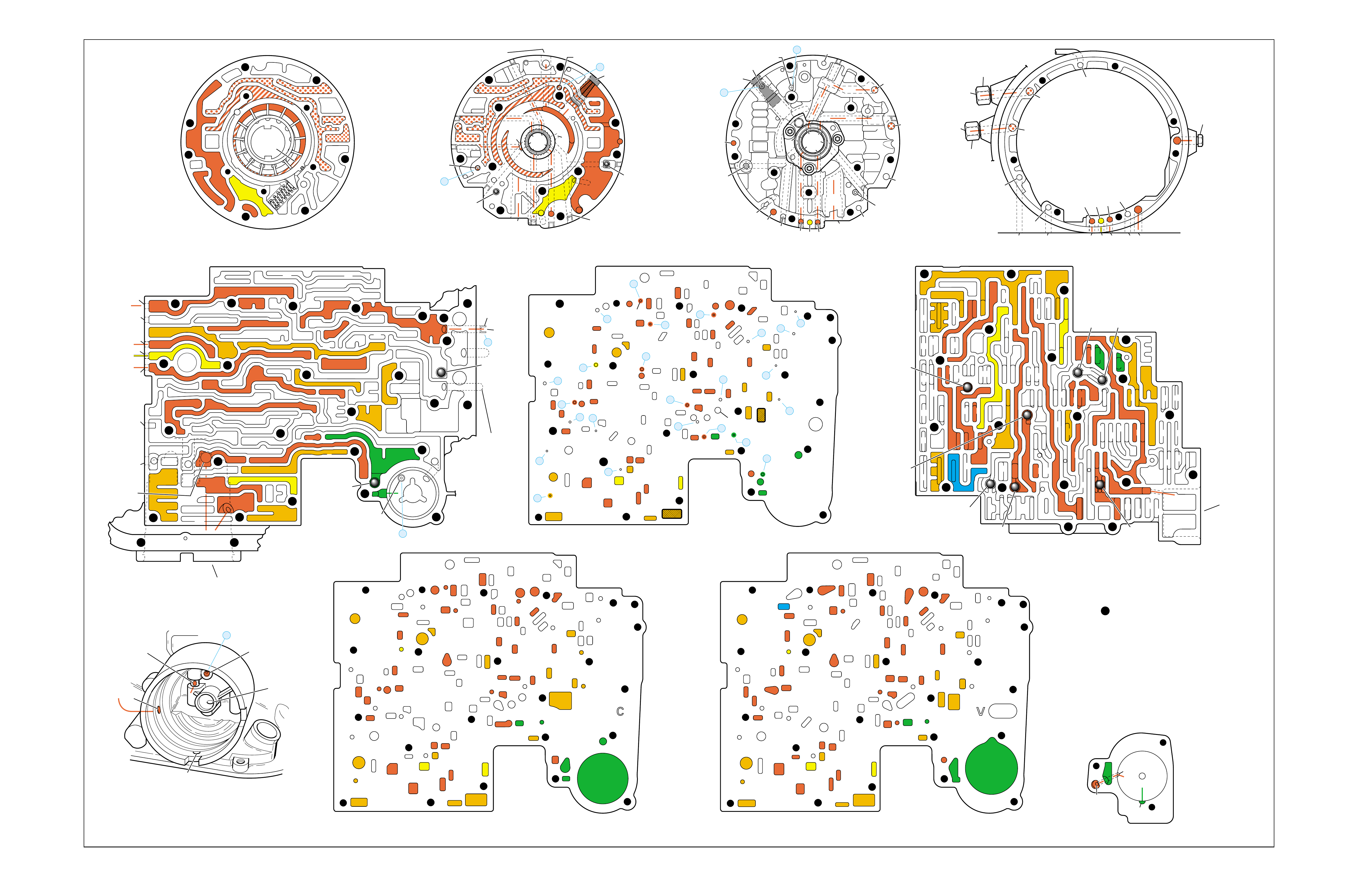
Figure 82
OVERDRIVE RANGE – THIRD GEAR
➤
➤
➤
➤
➤
➤➤
➤
➤➤
➤
➤
➤
➤
➤
➤➤
➤➤➤
➤
➤
➤
➤
➤
➤
➤
➤
➤
➤
➤
➤
➤
➤
➤
➤
➤ ➤
➤
➤
➤
➤
➤ ➤
➤
➤
➤ ➤
➤➤
➤➤
➤
➤
PUMP BODY (200)
(Pump Cover Side)
PUMP COVER (215)
(Pump Body Side) PUMP COVER (215)
(Case Side)
CASE (103)
(Pump Cover Side)
CASE (103)
(Control Valve Body Side)
SPACER PLATE (48)
(Case/Control Valve Body) CONTROL VALVE BODY (60)
(Case Side)
12 38
312
34
18
15
16
38
29
16
47 47
29 15 29
9
9
29
12
38 41 17
24
18
9
30
34
25 24
25 43 37
33
24
25
30 27 22 27
34
34
13
35
34
36
31 31
33
33
48
9
9
26 3
25
11
99
925
28 32
11
26
17 20 20
9
25
20
21 21
24
36 35
39
24
27
24
13
9
10
24 10
14
22
912 42
41 44
42
17
18
34
17
12 14
41
38
41
11
3
25
39
24 10
18
18
29
29
29
16
48
43
9
14
44
26
25
31
20
GASKET (47)
(Case/Spacer Plate)
GASKET (52)
(Spacer Plate/Control Valve Body)
CASE (103)
(2-4 Servo Bore)
1-2 ACCUMULATOR COVER (57)
NOTE:
- INDICATES BOLT HOLES
- NON-FUNCTIONAL HOLES
HAVE BEEN REMOVED FROM
COMPONENT DRAWINGS
TO SIMPLIFY TRACING FLUID
FLOW.
- EXHAUST FLUID NOT SHOWN
21
25
25
20
28
#7/(40)
44
(11)
25
43
32
3
16
(237)
18
43
3
(240)
37
(237)
43
47
45
43
43
48
11
29
16
3
16
29 18
2
(240)
8
85
37
37
1
47
(232)
7
46
45 47
3
3
8
43
5
4
2
4
4
48
43
3
6
1
43
2
7
47 46
43 11
3
16
37
37
5
37 8
29
18
29
1
(232)
2
43
47
16
(237)
37
(237)
4
(238)
2
(240)
PRESSURE RELIEF
VALVE BORE
➤
16
45
8
7
48
37
11 29 16
3
18
3
(39)
8
7
(10)
(10)
48 37 316291118
47 45
8
43
5
4
4
4
3
3
3
2
43
16
11
29
43
43
46
37 47
48
7
4
2
3
1
3
13V
12a 38b
3a
12b
34b
18b
38d
18c
13b
15d
16a
38c
15a
9m
9n
11c
29e
29d
9o
27b/29
29a
29f/28
15b/16
35a
22b
27d
30a
30b
34f
25a 24h
31c
25b
33c
24g 34e
31b
31a
27a
33a
33b
32a
37a
36a
3c
26b
11b
9c
25f
28a
9e
9p
9b
9d/10
(50)
48b
43a
25d
3b 11a
20c
25g
21a
9f
20e/21
17f 20a
9g
10a
35c/39
35b
35d/36
24f
24d 24c 13a
24a24b
41d
17c
41c
12c
17b/18 18a17d
42a
43c/44 9h 12e
22a 14b
10c/22
42b
14a
12d
17e
34a 41a
41b 38a
24m/25
47
9k/10
(49)
10b/23
20b
24e
17g
20d/21
25e
9a
48a
26a
43b/44
24k/25
34c
34d
29c
29b
29g/28
15c/16
17a/18 14c
44a
38e/39
27c/29
35e/36
➤
7
➤
5
➤
6
➤
16
➤
17
➤
8
➤
9
➤
32
➤
10
➤
12
➤
18
➤
20
➤
21
➤
22
➤
13
➤
14
➤
23
➤
25
➤
29
➤
30
➤
31
➤
26
➤
27
➤
28
➤
24
➤➤
1
➤➤
2
➤➤
2
➤➤
4
➤➤
11
12 38
3
18
38
16
28
29
15
34
29
9
9
15
29
11
929
40
15 43
35 34
31
31 33 33
22
27
30
34
30
25 24 24
24 31
25 43
48
26
33 37
36 32
25
28
9
26
9
311
25 25 3
910
11 21 20
25
9
10
17 20
35 35/39
24
27 24 24
13
13
22
14
22
912 42
14
12
24
24
18
38 41 17
41
12 42
17
17
34
12 34 41
38
17
44
47
923
20
17
9
9
48 44
34
29
29 18
24
14
43
10
25
41
38
34
9
9
947
9
9
3
3
25
25
11
11
26
47
26
47
25
47
3
10
43
47 11
43
33
31
24
30
37 36
28
11
34
25
24
22
24
35
34
30 27
31 32
47 25
29
9
15
40
28 29 29 16
15
43
15 12
38
3
341 47
17 34 38 41
34
18
12
17
42
43
12
18
47
47
14
43
14 42
922
23
10
9
17
17
24
38
13 24
43
42
41
3
33
31 24 24
17 47
13
17 20 20
27
#8
#6 #5
#3
#2 #12
#4
FORWARD
CLUTCH
ACCUMULATOR
BORE
➤
17
47
47
35
47
43
47
47
47 48
48
47
47
47
47 9
26
47 12 38
3
3
29
38
16
47 29
15
29
11
18
30 27 27
18
34
47
34
25 24
31
33
43
37 37
48
47
47
47
47
47 47
9
25
311
32
28 32
25
21
20
33
33
25
9
39
35
35 24 47
24 22
22 10 47
14
12
9
99
44
17 47 42
41
17
14
12
12
18
34
34
41
9
9
9
36
9
17
17
12
14
11
9
11
34
16 16
22
13 13
#10
#1
#7
(40)
37
18
11
29
16
3
29
341
38
44
(38)
28
47
43
47
48
36
33
9
33
38
19
26
47
47
2-4 SERVO BORE
➤
REAR
LUBE
TO
LOW AND
REVERSE
CLUTCH
➤➤
19
FOLDOUT ➤ 85
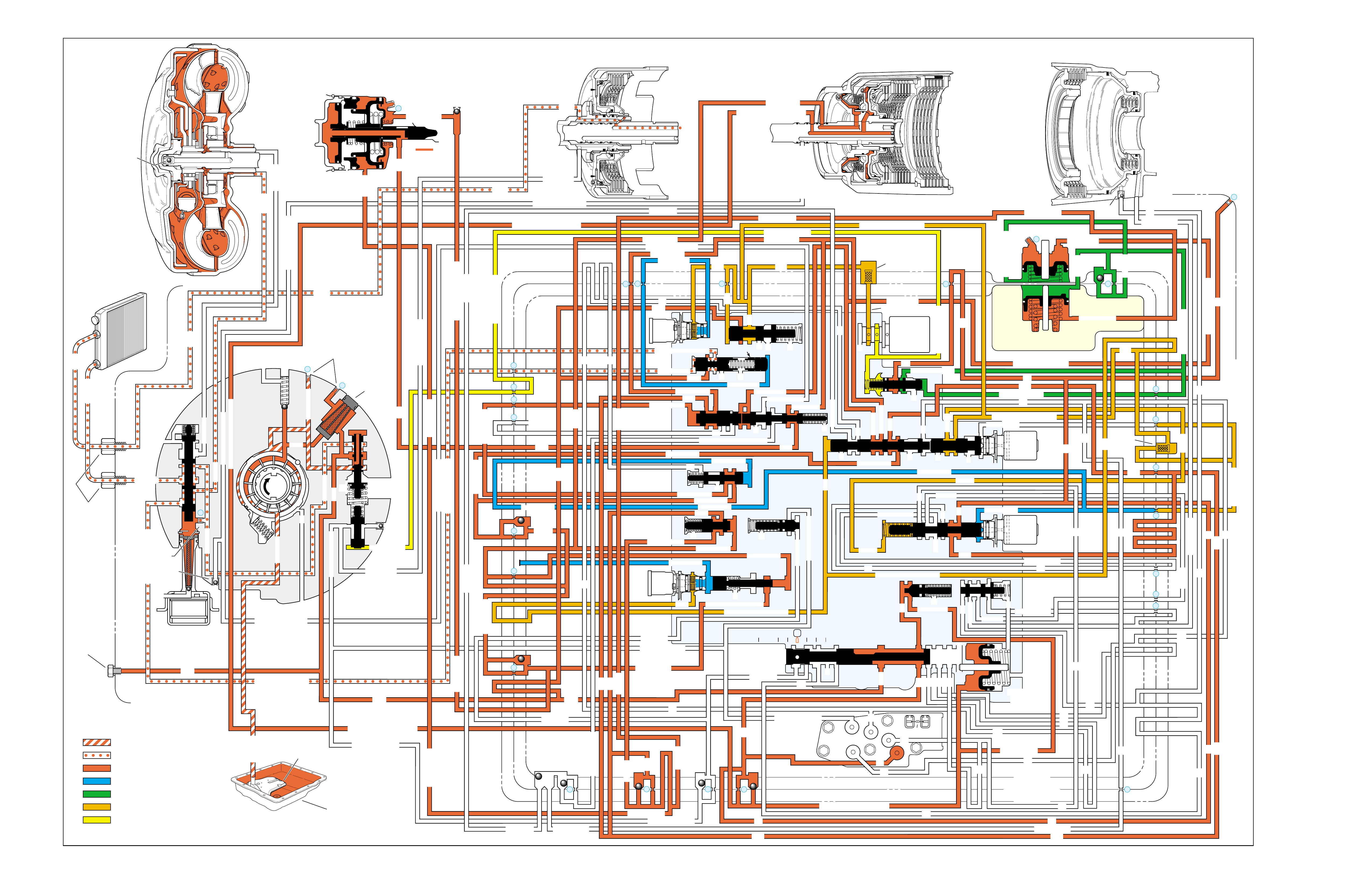
OVERDRIVE RANGE – FOURTH GEAR
(Torque Converter Clutch Applied)
➤
➤
➤➤
➤
➤
➤
➤
➤ ➤ ➤ ➤➤➤➤ ➤
➤➤➤➤
➤
➤
➤
➤
➤
➤
➤
➤➤
➤
➤
➤
➤
➤
➤
➤➤➤➤➤➤
➤➤➤➤
➤➤➤➤➤➤ ➤
➤
➤➤
➤
➤
INPUT CLUTCH
HOUSING ASSEMBLY
24
REAR LUBE
FILTER
(49)
RELEASE
APPLY
LO/REVERSE
PR
BOOST VALVE PRESS REG
BOTTOM
PAN
(SUMP)
(75)
FILTER
(72) REVERSE INPUT
REV INPUT
DECREASE
LINE
EX
FILTER
(232)
AIR
BLEED
(240)
1
SUCTION
LINE
EX
PRESSURE
RELIEF
VALVE
PUMP
ASSEMBLY
(4)
➤
➤➤
4
TCC
SOLENOID
(66)
N.O.
COOLER
LUBE
COOLER
SUCTION
CONVERTER & LUBE
MAINLINE
SOLENOID SIGNAL
ACCUMULATOR
ACTUATOR FEED LIMIT
TORQUE SIGNAL
FLUID PRESSURES
REVERSE INPUT
FORWARD CLUTCH FEED
#1
ACCUMULATOR
ORF ACC
2ND CLUTCH
3-4 ACCUMULATOR
1-2 ACCUMULATOR
19
3-4 ACCUM
ACCUM
EX
ORIFICED ACCUM
3-4 ACCUMULATOR
3-4 ACCUM
2ND CLUTCH
2ND CLUTCH
D3
REVERSE INPUT
D2-N.C.
REV-N.O. D3-N.C.
LO-N.O.
D4-N.O.
LO
TEMP
SENSOR
➤
TFP
SWITCH
ASSEMBLY
D2
D4
D3
D3
D3
EX
FORWARD ABUSE
FWD CL FD
3RD ACCUMULATOR EX
#7
11
3RD ACCUM
➤
4TH
2ND & 4TH
SERVO
REV ABUSE
EX
REVERSE
REVERSE INPUT
#12
D4
22
D4
D4
#4
13
3-4 SIGNAL
3-4 CL
3-4 CLUTCH
#2
12
3-4 CLUTCH
3RD ACCUM
3-4 CL
#8
16
2ND
2ND CL 2ND CL
2ND CL
2ND CL
2ND CLUTCH2ND CLUTCH
TORQUE SIG
FORWARD CLUTCH FEED
FORWARD
CLUTCH
ACCUMULATOR
EX
PR LO
LO
LO
FORWARD CLUTCH FEED
FORWARD CLUTCH FEED
FWD CL FEED
D3
D3
D3
14
3-4 CLUTCH
3RD ACCUMULATOR
3RD ACCUM
EX
AFL
3-2 SIGNAL
2ND
2ND
LINE
REGULATED APPLY
8
REG APPLY
1-2 SHIFT VALVE
26
LO
D4
O’ EX
D4-3-2 2ND
25
1-2 SIGNAL
LO/1ST
27
1-2 SIGNAL
EX
ORIFICED EX
ORIFICED EX
EX
LO/1ST D4-3-2
D4
D4
2
➤
➤
➤
➤➤
➤
EX
CONV FD
EX
EX
EX
LINE LINE
LINE
PRESSURE
TAP
(39)
➤
➤
REGULATED APPLY
➤
➤
LUBE
LUBE
LUBE
LUBE
CASE (8)
CASE (8)
GASKET (47)
SPACER PLATE (48)
GASKET (52)
VALVE BODY (60)
SUCTION
LINE
LINE
3a
3b
3c
➤
➤
➤
➤
➤
➤➤
➤
➤
➤
➤
➤
➤
➤
D3
EX
3-4 SIGNAL
1-2 SIGNAL
4TH SIGNAL
1-2 SIGNAL
3-4 CLUTCH
OVERRUN CLUTCH
OVERRUN CLUTCH
OVERRUN CLUTCH
OVERRUN CLUTCH
OVERRUN CLUTCH
OVERRUN CLUTCH
12a
12b
12c
12d
12e
EX
EX
EX
32
AFL
AFL
30
D4
EX
31
ACCUMULATOR
ACCUMULATOR
EX
TORQUE SIGNAL
FILTERED AFL
D4
AFLAFL FILTER
(50)
10
43a
43b 44
11b
11c
11a
14b
14a
14c
LO OVERRUN
23
PR
LO/REV
LO/1ST LO/REVERSE
LO/REVERSE
PR PR
EX
22 10c
23 10b
9n
9o
22b
22a
10a
➤
10 9k
9g
9m
44a
43c 44
41a
41b
41c
41d
42b
42a
13a
13b
OIL
COOLER
PIPE
CONNECTOR
(10)
➤
➤
18a
18b
18c
18 17a
18 17b
20b
48b
48a
REGULATED APPLY
30a
30b
32a
37a
9b
9e
10 9d
9c
9a
9f
9h
31a
31b
31c
OVERRUN CLUTCH FEED
3-4 ACCUM
SERVO FEED
SERVO FEED
6
7
4TH4TH
OVERRUN CL
4TH SIGNAL2ND
EX
EX
3-4 RELAY 4-3 SEQUENCE VALVE
5
EX
SERVO FD
ORF EX
CASE (8)
REV INPUT
EX
(237)
17d
17c
17e
17f
17g
21
21
20d
20e
21a
20a
20c
1-2 ACCUMULATOR COVER (57)
25g
33c
33a
33b
27d
27c
27b
29
29
27a
28a
29b
29a
29d
40
29c
29e
29g28
28
29f
24a
24b
24c
24d
24e
24f
24g
24h
25a
25b
25d
25e
25f
25
25
24m
24k
REVERSE INPUT
#3
17
REVERSE INPUT
15c
15b
16
16
REVERSE
REVERSE INPUT
16a
15d
15a
REVERSE
34f
34e
34d
34c
34a
34b
#6
OVERRUN CL FD
21
ORIFICED D2
#5
OVERRUN
OVERRUN OVERRUN
OVERRUN
36
36
35e
35d
39
35b
35c
36a
35a
38d
38e39
38c
38b
38a
EX
TORQUE SIGNAL
2ND CL
➤
➤
➤➤
➤
20
18
2-3 SHUTTLE 2-3 SHIFT VALVE
28
29
EX
EX
EX
EX
D2
OVERRUN
D3
D3
2ND
3-4 SIGNAL
EX
D4-3-2
2-3 SIGNAL
ACTUATOR FEED LIMIT
AFL
SERVO FD
3-4 ACC
FILTERED AFL
AFL
ACTUATOR FEED LIMIT
ACTUATOR FEED LIMIT
AFL
D2
2ND
2ND
2ND
2ND
D2
D2
D2
D2
ORIFICED D2
D2
D2
D2
VALVE BODY (60)
3-4 SIGNAL
➤
2ND
D4
PR 3-4 ACCUMULATOR
D4
EX
D4-3-2
LO
D4
2ND CLUTCH
D3
D3
FORWARD CLUTCH FEED ACTUATOR FEED LIMIT
TORQUE SIGNAL
SERVO FEED
➤
OVERRUN CLUTCH
LINE
9p
26a
➤
➤
➤
➤
➤
➤
➤
➤
➤
➤
➤
➤
➤
➤➤
➤
➤
➤➤➤
➤➤➤
➤
➤
➤
➤
➤
➤
➤
➤
➤
➤
➤➤
➤➤ ➤
➤
➤
➤➤➤
➤➤
PR
➤
➤
➤➤
➤
➤➤➤➤➤
➤➤
➤
➤
➤➤➤
ON
COOLER
RELEASE
APPLY
EX
EX
➤➤
➤
➤➤
➤
CONV FD
➤
➤
➤
➤
➤
➤
➤
➤
➤
➤
➤
REGULATED APPLY
EX
EX
CC SIGNAL
CC SIGNAL
ACTUATOR FEED LIMIT
9
26b
TCC PWM
SOLENOID
VALVE
N.C.
1-2 SIGNAL
2ND
4TH SIGNAL
#10
➤
LOW AND REVERSE
CLUTCH ASSEMBLY
REVERSE INPUT
CLUTCH ASSEMBLY
TORQUE
CONVERTER
ASSEMBLY
#9
➤➤
(237)
➤
(238)
➤
EX
2ND CLUTCH 3-4 CLUTCH
2ND
PRESSURE
CONTROL
SOLENOID
VALVE
2-3 SHIFT
SOLENOID
VALVE
N.O.
OFF
EX
1-2 SHIFT
SOLENOID
VALVE
N.O.
ON
PRND321
D4
D4
REVERSE
D3
D2
LO
EX
EX
LINE
➤
➤
➤
➤
➤
➤
➤
➤
➤
➤
➤
➤
➤
➤
➤
➤
➤
➤
➤
➤
➤➤➤
➤➤
➤
➤
➤
➤
➤
➤
➤
➤
MANUAL VALVE
PR
➤
➤
➤➤
➤
➤
➤
➤➤➤➤➤
➤➤➤
➤➤
➤➤
➤
➤
➤
➤➤
➤
➤➤
➤
➤➤
➤➤
➤
➤
➤
➤➤
➤
➤
➤
➤
➤➤ ➤ ➤ ➤ ➤
➤➤➤➤
➤
➤
➤➤➤ ➤ ➤
➤
➤
➤➤
➤
➤
➤
➤
➤
➤
➤➤
➤➤
➤
➤
➤
➤
➤➤➤
➤➤
➤
➤
➤
➤
➤
➤
➤
➤
➤
➤
➤
➤➤➤
➤
➤
11
4TH
EX
EX
➤
➤➤➤
➤
➤
➤
➤➤➤➤
➤➤➤➤➤➤
➤
➤
➤
➤
➤➤
➤
➤➤
➤
➤
➤
➤
➤
➤
➤
➤➤➤➤ ➤
➤
➤
➤➤➤
➤➤➤➤➤
➤➤➤➤
➤
➤
➤
➤➤
➤
➤
➤
➤➤➤
➤
➤
➤
➤
➤
➤
➤➤➤
➤
➤
➤
➤
➤
➤
➤➤➤➤
➤
➤
➤
➤
➤
➤➤➤➤➤ ➤
➤
➤
➤
➤
➤
➤➤➤
➤
➤
➤➤➤
➤➤➤➤
➤➤
➤
➤
➤
➤➤
➤
➤
➤
➤➤ ➤ ➤
➤
➤
➤
➤
➤
➤
➤➤➤
➤
➤➤➤
➤
➤
CONVERTER CLUTCH VALVE
➤
➤
➤
➤
➤
➤
➤
➤
➤
➤
➤➤
➤
➤
➤
➤➤ ➤
➤➤ ➤➤
➤➤ ➤
➤➤
➤
➤➤➤
3-4 SHIFT VALVE
➤
➤
➤
➤
➤
➤➤➤
➤➤➤
➤
➤➤➤
➤➤➤
➤
➤➤
➤
➤
➤
➤➤➤
➤
➤➤
➤
➤
➤➤
➤
➤➤
➤
➤➤
➤➤
➤
➤
➤➤
➤➤➤
➤
➤➤
➤
➤
➤
➤
ACCUM VALVE
➤
➤➤➤➤➤
➤➤ ➤
EXEX
3-2 DOWNSHIFT
3-2 CONTROL
3-2
CONTROL
SOLENOID
VALVE
N.C.
ON
➤
ISOLATOR VALVE
REG APPLY
Figure 83
86

OVERDRIVE RANGE – FOURTH GEAR
(Torque Converter Clutch Applied)
86A
NO TCC APPLY
•Torque Converter (1)
–Internal damage
•Converter Clutch Valve (224)
–Stuck or assembled backwards
•Orifice Cup Plug (240)
–Restricted or damaged
•Turbine Shaft O-ring Seal (618)
–Cut or damaged
NO 3-4 SHIFT, SLIPS OR ROUGH 3-4 SHIFT
•2-4 Servo Assembly
–Incorrect band apply pin
–Porosity in piston, cover or case
–Plugged or missing orifice cup plug
1-2 SHIFT 2-3 SHIFT REVERSE FORWARD
SOLENOID SOLENOID 2-4 INPUT OVERRUN FORWARD SPRAG CL. 3-4 LO-ROLLER LO/REV
VALVE VALVE BAND CLUTCH CLUTCH CLUTCH ASSEMBLY CLUTCH CLUTCH CLUTCH
ON OFF APPLIED APPLIED APPLIED

OVERDRIVE RANGE – FOURTH GEAR
(Torque Converter Clutch Applied)
86B
PASSAGES
1 SUCTION
2 DECREASE
3 LINE
4 CONVERTER FEED
5 RELEASE
6 APPLY
7 COOLER
8 LUBE
9 ACTUATOR FEED LIMIT
10 FILTERED ACTUATOR FEED
11 TORQUE SIGNAL
12 PR
13 D4-3-2
14 LO/REVERSE
15 REVERSE
16 REVERSE INPUT
17 D4
18 FORWARD CLUTCH FEED
19 REAR LUBE
20 ACCUMULATOR
21 ORIFICED ACCUMULATOR
22 1-2 SIGNAL
23 2-3 SIGNAL
24 2ND
25 2ND CLUTCH
26 C. C. SIGNAL
27 3-4 SIGNAL
28 3RD ACCUMULATOR
29 3-4 CLUTCH
30 4TH SIGNAL
31 SERVO FEED
32 4TH
33 3-4 ACCUMULATOR
34 D3
35 OVERRUN
36 OVERRUN CLUTCH FEED
37 OVERRUN CLUTCH
38 D2
39 ORIFICED D2
40 3-2 SIGNAL
41 LO
42 LO/1ST
43 EXHAUST
44 ORIFICED EXHAUST
45 VENT
46 SEAL DRAIN
47 VOID
48 REGULATED APPLY
COMPONENTS ( )
(8) REAR LUBE (ORIFICED CUP PLUG/REAR CASE)
(10) OIL COOLER PIPE CONNECTOR
(11) CASE SERVO ORIFICED PLUG
(38) ACCUMULATOR BLEED PLUG
(39) LINE PRESSURE TAP
(40) 3RD ACCUM. RETAINER AND BALL ASSEMBLY (#7)
(49) SHIFT SOLENOIDS SCREEN
(50) PRESSURE CONTROL SOLENOID SCREEN
(61) CHECKBALLS (#1, 2, 3, 4, 5, 6, 8, 12)
(91) CHECKBALL (#10)
(232) OIL PUMP COVER SCREEN
(237) CHECK VALVE RETAINER AND BALL ASSEMBLY
(238) CONVERTER CLUTCH SIGNAL ORIFICED CUP PLUG
(240) ORIFICED CUP PLUG
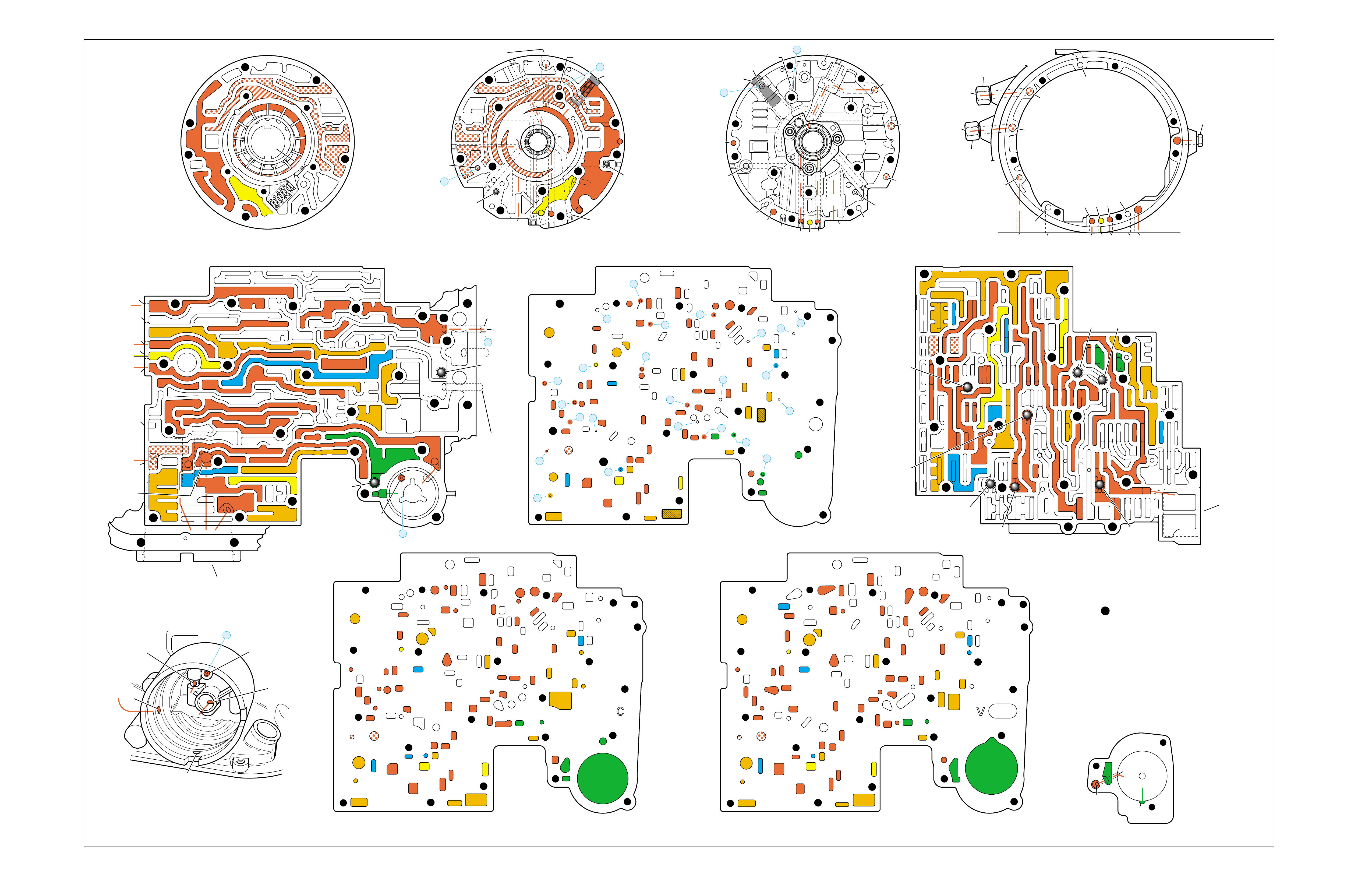
Figure 84
OVERDRIVE RANGE – FOURTH GEAR (Torque Converter Clutch Applied)
➤
➤
➤
➤
➤
➤
➤
➤➤
➤
➤➤
➤
➤
➤
➤
➤
➤➤
➤➤➤
➤
➤
➤
➤
➤
➤
➤
➤ ➤
➤
➤
➤
➤
➤
➤
➤
➤ ➤
➤
➤
➤
➤
➤ ➤
➤
➤
➤ ➤
➤➤
➤➤
➤
PUMP BODY (200)
(Pump Cover Side)
PUMP COVER (215)
(Pump Body Side) PUMP COVER (215)
(Case Side)
CASE (103)
(Pump Cover Side)
CASE (103)
(Control Valve Body Side)
SPACER PLATE (48)
(Case/Control Valve Body) CONTROL VALVE BODY (60)
(Case Side)
12 38
312
34
18
15
16
38
29
16
47 47
29 15 29
9
9
29
12
38 41 17
24
18
9
30
34
25 24
25 43 37
33
24
25
30 27 22 27
34
34
13
35
34
36
31 31
33
33
48
9
9
26 3
25
11
99
925
28 32
11
26
17 20 20
9
25
20
21 21
24
36 35
39
24
27
24
13
9
10
24 10
14
22
912 42
41 44
42
17
18
34
17
12 14
41
38
41
11
3
25
39
24 10
18
18
29
29
29
16
48
43
9
14
44
26
25
31
20
GASKET (47)
(Case/Spacer Plate)
GASKET (52)
(Spacer Plate/Control Valve Body)
CASE (103)
(2-4 Servo Bore)
1-2 ACCUMULATOR COVER (57)
NOTE:
- INDICATES BOLT HOLES
- NON-FUNCTIONAL HOLES
HAVE BEEN REMOVED FROM
COMPONENT DRAWINGS
TO SIMPLIFY TRACING FLUID
FLOW.
- EXHAUST FLUID NOT SHOWN
21
25
25
20
28
#7/(40)
44
(11)
25
43
32
3
16
(237)
18
43
3
(240)
37
(237)
43
47
45
43
43
48
11
29
16
3
16
29 18
2
(240)
8
85
37
37
1
47
(232)
7
46
45 47
3
3
8
43
5
4
2
4
4
48
43
3
6
1
43
2
7
47 46
43 11
3
16
37
37
5
37 8
29
18
29
1
(232)
2
43
47
16
(237)
37
(237)
4
(238)
2
(240)
PRESSURE RELIEF
VALVE BORE
➤
16
45
8
7
48
37
11 29 16
3
18
3
(39)
8
7
(10)
(10)
48 37 316291118
47 45
8
43
5
4
4
4
3
3
3
2
43
16
11
29
43
43
46
37 47
48
7
4
2
3
1
3
13V
12a 38b
3a
12b
34b
18b
38d
18c
13b
15d
16a
38c
15a
9m
9n
11c
29e
29d
9o
27b/29
29a
29f/28
15b/16
35a
22b
27d
30a
30b
34f
25a 24h
31c
25b
33c
24g 34e
31b
31a
27a
33a
33b
32a
37a
36a
3c
26b
11b
9c
25f
28a
9e
9p
9b
9d/10
(50)
48b
43a
25d
3b 11a
20c
25g
21a
9f
20e/21
17f 20a
9g
10a
35c/39
35b
35d/36
24f
24d 24c 13a
24a24b
41d
17c
41c
12c
17b/18 18a17d
42a
43c/44 9h 12e
22a 14b
10c/22
42b
14a
12d
17e
34a 41a
41b 38a
24m/25
47
9k/10
(49)
10b/23
20b
24e
17g
20d/21
25e
9a
48a
26a
43b/44
24k/25
34c
34d
29c
29b
29g/28
15c/16
17a/18 14c
44a
38e/39
27c/29
35e/36
➤
7
➤
5
➤
6
➤
16
➤
17
➤
8
➤
9
➤
32
➤
10
➤
12
➤
18
➤
20
➤
21
➤
22
➤
13
➤
14
➤
23
➤
25
➤
29
➤
30
➤
31
➤
26
➤
27
➤
28
➤
24
➤➤
1
➤➤
2
➤➤
2
➤➤
4
➤➤
11
12 38
3
18
38
16
28
29
15
34
29
9
9
15
29
11
929
40
15 43
35 34
31
31 33 33
22
27
30
34
30
25 24 24
24 31
25 43
48
26
33 37
36 32
25
28
9
26
9
311
25 25 3
910
11 21 20
25
9
10
17 20
35 35/39
24
27 24 24
13
13
22
14
22
912 42
14
12
24
24
18
38 41 17
41
12 42
17
17
34
12 34 41
38
17
44
47
923
20
17
9
9
48 44
34
29
29 18
24
14
43
10
25
41
38
34
9
9
947
9
9
3
3
25
25
11
11
26
47
26
47
25
47
3
10
43
47 11
43
33
31
24
30
37 36
28
11
34
25
24
22
24
35
34
30 27
31 32
47 25
29
9
15
40
28 29 29 16
15
43
15 12
38
3
341 47
17 34 38 41
34
18
12
17
42
43
12
18
47
47
14
43
14 42
922
23
10
9
17
17
24
38
13 24
43
42
41
3
33
31 24 24
17 47
13
17 20 20
27
#8
#6 #5
#3
#2 #12
#4
FORWARD
CLUTCH
ACCUMULATOR
BORE
➤
17
47
47
35
47
43
47
47
47 48
48
47
47
47
47 9
26
47 12 38
3
3
29
38
16
47 29
15
29
11
18
30 27 27
18
34
47
34
25 24
31
33
43
37 37
48
47
47
47
47
47 47
9
25
311
32
28 32
25
21
20
33
33
25
9
39
35
35 24 47
24 22
22 10 47
14
12
9
99
44
17 47 42
41
17
14
12
12
18
34
34
41
9
9
9
36
9
17
17
12
14
11
9
11
34
16 16
22
13 13
#10
#1
#7
(40)
37
18
11
29
16
3
29
341
38
44
(38)
28
47
43
47
48
36
33
9
33
38
19
26
47
47
2-4 SERVO BORE
➤
REAR
LUBE
TO
LOW AND
REVERSE
CLUTCH
➤➤
19
FOLDOUT ➤ 87
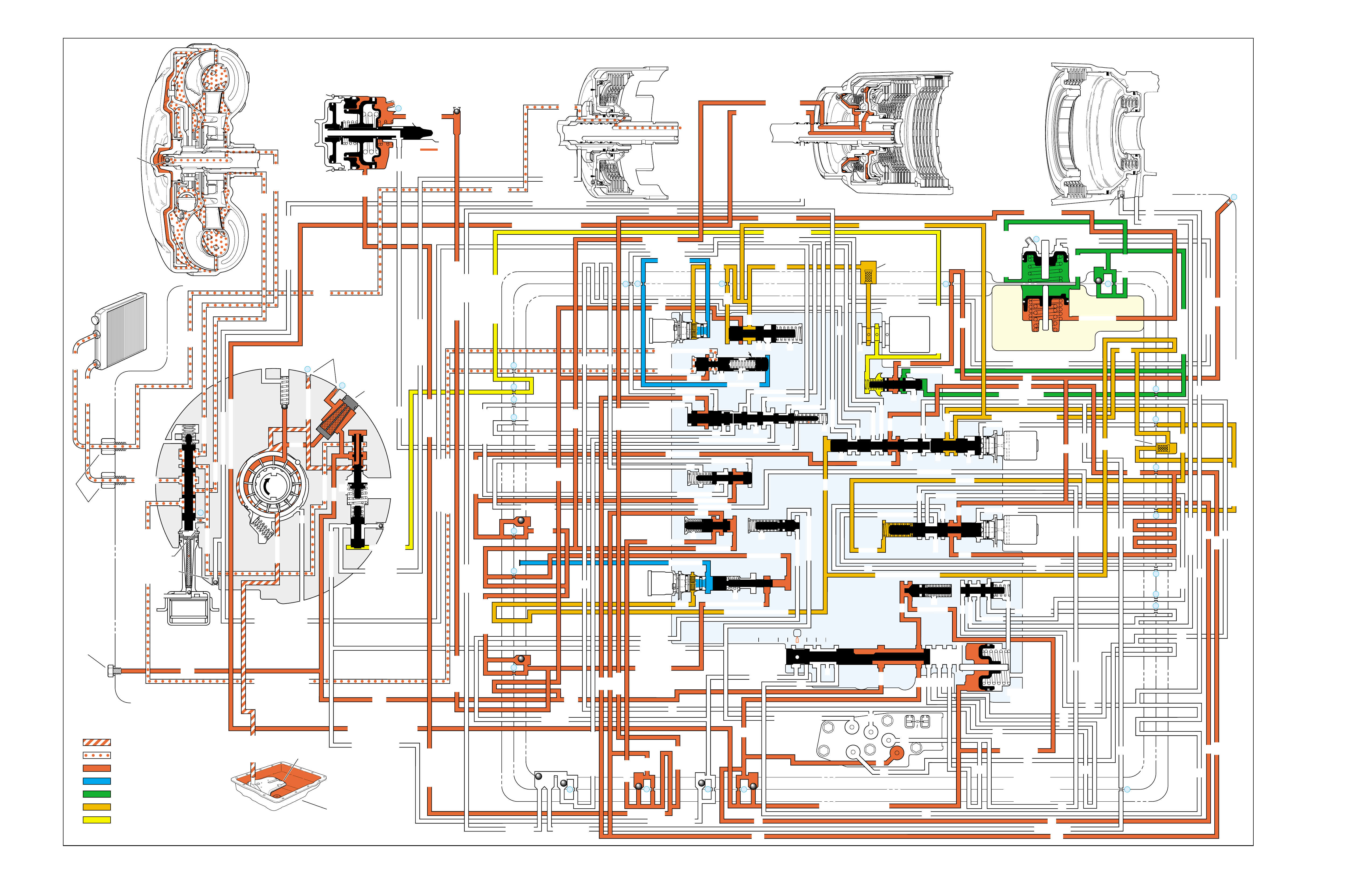
OVERDRIVE RANGE – 4-3 DOWNSHIFT
(Torque Converter Clutch Released)
➤
➤➤
➤➤
➤
➤
➤
➤
➤➤
➤
➤
➤
➤
➤
➤
➤
➤
➤
➤
➤ ➤ ➤ ➤➤➤➤ ➤
➤
➤➤➤ ➤ ➤➤➤➤➤➤
➤➤ ➤➤
➤➤➤ ➤ ➤ ➤ ➤ ➤ ➤
➤➤➤ ➤➤
➤➤➤
➤
➤➤
➤➤➤
➤➤➤ ➤ ➤➤➤
➤
➤
➤➤➤➤
➤➤➤➤➤➤➤➤➤
➤
➤➤➤➤➤➤➤➤
➤➤
➤
➤➤➤➤➤➤➤➤
➤➤➤➤➤➤➤
➤
➤
➤
➤
➤
➤
➤➤ ➤
➤
➤➤➤➤➤➤➤➤➤➤➤➤
➤
➤➤
➤
➤➤
➤➤
➤
➤ ➤ ➤ ➤➤➤ ➤ ➤ ➤
➤➤➤
➤➤➤ ➤ ➤➤➤➤➤ ➤
➤
➤
➤
➤
➤
➤
➤➤➤
➤➤➤➤➤➤➤➤➤➤➤➤➤➤ ➤
➤ ➤➤➤➤ ➤➤ ➤➤➤➤➤ ➤ ➤➤➤➤➤➤➤
➤➤
➤
➤
➤
➤➤ ➤ ➤ ➤➤➤ ➤ ➤
➤➤
➤
➤ ➤➤➤➤➤➤ ➤➤
➤➤➤➤➤➤ ➤ ➤ ➤ ➤ ➤➤➤➤➤
➤➤
➤➤
➤➤
➤➤➤➤➤➤➤ ➤➤➤➤
➤
➤
➤
➤
➤
➤
➤
➤➤ ➤
➤➤➤ ➤ ➤ ➤
➤➤ ➤➤
➤➤
➤➤ ➤➤
INPUT CLUTCH
HOUSING ASSEMBLY
24
REAR LUBE
FILTER
(49)
➤
➤
➤
➤
➤
➤
➤
RELEASE
APPLY
LO/REVERSE
PR
BOOST VALVE PRESS REG
BOTTOM
PAN
(SUMP)
(75)
FILTER
(72) REVERSE INPUT
REV INPUT
DECREASE
LINE
EX
FILTER
(232)
AIR
BLEED
(240)
1
SUCTION
LINE
EX
PRESSURE
RELIEF
VALVE
PUMP
ASSEMBLY
(4)
➤
➤➤
4
TCC
SOLENOID
(66)
N.O.
COOLER
LUBE
COOLER
SUCTION
CONVERTER & LUBE
MAINLINE
SOLENOID SIGNAL
ACCUMULATOR
ACTUATOR FEED LIMIT
TORQUE SIGNAL
FLUID PRESSURES
REVERSE INPUT
FORWARD CLUTCH FEED
#1
ACCUMULATOR
ORF ACC
2ND CLUTCH
3-4 ACCUMULATOR
1-2 ACCUMULATOR
19
3-4 ACCUM
ACCUM
EX
ORIFICED ACCUM
3-4 ACCUMULATOR
3-4 ACCUM
2ND CLUTCH
2ND CLUTCH
D3
REVERSE INPUT
D2-N.C.
REV-N.O. D3-N.C.
LO-N.O.
D4-N.O.
LO
TEMP
SENSOR
➤
TFP
SWITCH
ASSEMBLY
D2
D4
D3
D3
D3
EX
FORWARD ABUSE
FWD CL FD
3RD ACCUMULATOR EX
#7
11
3RD ACCUM
➤
4TH
2ND & 4TH
SERVO
REV ABUSE
EX
REVERSE
REVERSE INPUT
#12
D4
22
D4
D4
#4
13
3-4 SIGNAL
3-4 CL
3-4 CLUTCH
#2
12
3-4 CLUTCH
3RD ACCUM
3-4 CL
#8
16
2ND
2ND CL 2ND CL
2ND CL
2ND CL
2ND CLUTCH2ND CLUTCH
TORQUE SIG
FORWARD CLUTCH FEED
FORWARD
CLUTCH
ACCUMULATOR
EX
PR LO
LO
LO
FORWARD CLUTCH FEED
FORWARD CLUTCH FEED
FWD CL FEED
D3
D3
D3
14
3-4 CLUTCH
3RD ACCUMULATOR
3RD ACCUM
EX
AFL
3-2 SIGNAL
2ND
2ND
LINE
REGULATED APPLY
8
REG APPLY
1-2 SHIFT VALVE
26
LO
D4
O’ EX
D4-3-2 2ND
25
1-2 SIGNAL
LO/1ST
27
1-2 SIGNAL
EX
ORIFICED EX
ORIFICED EX
EX
LO/1ST D4-3-2
D4
D4
2
➤
➤
➤
➤➤
➤
EX
CONV FD
EX
EX
EX
LINE LINE
LINE
PRESSURE
TAP
(39)
➤
➤
REGULATED APPLY
➤
➤
LUBE
LUBE
LUBE
LUBE
CASE (8)
CASE (8)
GASKET (47)
SPACER PLATE (48)
GASKET (52)
VALVE BODY (60)
SUCTION
LINE
LINE
3a
3b
3c
➤
➤
➤
➤
➤
➤➤
➤
➤
➤
➤
➤
➤
➤
D3
EX
3-4 SIGNAL
1-2 SIGNAL
4TH SIGNAL
3-4 SHIFT VALVE
1-2 SIGNAL
3-4 CLUTCH
OVERRUN CLUTCH
OVERRUN CLUTCH
OVERRUN CLUTCH
OVERRUN CLUTCH
OVERRUN CLUTCH
OVERRUN CLUTCH
12a
12b
12c
12d
12e
EX
EX
EX
32
AFL
AFL
30
D4
EX
31
ACCUMULATOR
ACCUMULATOR
EX
TORQUE SIGNAL
FILTERED AFL
D4
AFLAFL FILTER
(50)
10
43a
43b 44
11b
11c
11a
14b
14a
14c
LO OVERRUN
23
PR
LO/REV
LO/1ST LO/REVERSE
LO/REVERSE
PR PR
EX
22 10c
23 10b
9n
9o
22b
22a
10a
➤
10 9k
9g
9m
44a
43c 44
41a
41b
41c
41d
42b
42a
13a
13b
OIL
COOLER
PIPE
CONNECTOR
(10)
➤
➤
18a
18b
18c
18 17a
18 17b
20b
48b
48a
REGULATED APPLY
30a
30b
32a
37a
9b
9e
10 9d
9c
9a
9f
9h
31a
31b
31c
OVERRUN CLUTCH FEED
3-4 ACCUM
SERVO FEED
SERVO FEED
6
7
4TH4TH
OVERRUN CL
4TH SIGNAL2ND
EX
EX
3-4 RELAY 4-3 SEQUENCE VALVE
5
EX
SERVO FD
ORF EX
CASE (8)
REV INPUT
EX
(237)
17d
17c
17e
17f
17g
21
21
20d
20e
21a
20a
20c
1-2 ACCUMULATOR COVER (57)
25g
33c
33a
33b
27d
27c
27b
29
29
27a
28a
29b
29a
29d
40
29c
29e
29g28
28
29f
24a
24b
24c
24d
24e
24f
24g
24h
25a
25b
25d
25e
25f
25
25
24m
24k
REVERSE INPUT
#3
17
REVERSE INPUT
15c
15b
16
16
REVERSE
REVERSE INPUT
16a
15d
15a
REVERSE
34f
34e
34d
34c
34a
34b
#6
OVERRUN CL FD
21
ORIFICED D2
#5
OVERRUN
OVERRUN OVERRUN
OVERRUN
36
36
35e
35d
39
35b
35c
36a
35a
38d
38e39
38c
38b
38a
EX
TORQUE SIGNAL
2ND CL
➤
➤
➤➤
➤
20
18
2-3 SHUTTLE 2-3 SHIFT VALVE
28
29
EX
EX
EX
EX
D2
OVERRUN
D3
D3
2ND
3-4 SIGNAL
EX
D4-3-2
2-3 SIGNAL
ACTUATOR FEED LIMIT
AFL
SERVO FD
3-4 ACC
FILTERED AFL
AFL
ACTUATOR FEED LIMIT
ACTUATOR FEED LIMIT
AFL
D2
2ND
2ND
2ND
2ND
D2
D2
D2
D2
ORIFICED D2
D2
D2
D2
VALVE BODY (60)
3-4 SIGNAL
➤
2ND
D4
PR 3-4 ACCUMULATOR
D4
EX
D4-3-2
LO
D4
2ND CLUTCH
D3
D3
FORWARD CLUTCH FEED ACTUATOR FEED LIMIT
TORQUE SIGNAL
SERVO FEED
➤
OVERRUN CLUTCH
LINE
9p
26a
➤
➤
➤
➤
➤
➤
➤
➤
➤
➤
➤
➤
➤
➤➤
➤
➤
➤➤➤
➤➤➤
➤
➤
➤
➤
➤
➤
➤
➤
➤
➤
➤➤
➤➤ ➤
➤
➤
➤➤➤
➤➤
PR
➤
➤
➤➤
➤
➤➤➤➤➤
➤➤
➤
➤
➤➤➤
OFF
CONVERTER CLUTCH VALVE
COOLER
RELEASE
APPLY
EX
➤
➤
➤
➤
➤
➤
EX
➤➤
➤
➤➤
➤
CONV FD
➤
➤
➤
➤
➤
➤
➤
➤
➤
➤
➤
REGULATED APPLY
EX
EX
CC SIGNAL
CC SIGNAL
ACTUATOR FEED LIMIT
9
26b
TCC PWM
SOLENOID
VALVE
N.C.
1-2 SIGNAL
2ND
4TH SIGNAL
#10
➤
LOW AND REVERSE
CLUTCH ASSEMBLY
REVERSE INPUT
CLUTCH ASSEMBLY
TORQUE
CONVERTER
ASSEMBLY
#9
➤➤
(237)
➤
(238)
➤
EX
2ND CLUTCH 3-4 CLUTCH
2ND
PRESSURE
CONTROL
SOLENOID
VALVE
2-3 SHIFT
SOLENOID
VALVE
N.O.
OFF
EX
1-2 SHIFT
SOLENOID
VALVE
N.O.
OFF
PRND321
D4
D4
REVERSE
D3
D2
LO
EX
EX
LINE
➤
➤
➤
➤
➤
➤
➤
➤
➤
➤
➤
➤
➤
➤
➤
➤
➤
➤
➤
➤
➤➤➤
➤➤
➤
➤
➤
➤
➤
➤
➤
➤
MANUAL VALVE
PR
➤
➤
➤➤
➤
➤
➤
➤➤➤➤➤
➤➤➤
➤➤
➤➤
➤
➤
➤
➤➤
➤
➤➤
➤
➤➤
➤➤
➤
➤
➤
➤➤
➤
➤
➤
➤
➤➤ ➤ ➤ ➤ ➤
➤➤➤➤
➤
➤
➤➤➤ ➤ ➤
➤
➤
➤➤
➤
➤
➤
➤
➤
➤
➤➤
➤➤
➤
➤
➤
11
4TH
EX
EX
➤
➤➤➤➤
➤
➤
➤
➤
➤
➤➤➤➤➤ ➤
➤
➤
➤
➤
➤
➤
➤
➤➤➤
➤
➤
➤➤➤
➤➤➤➤
➤➤
➤
➤
➤
➤➤
➤
➤
➤
➤➤ ➤ ➤
➤
➤
➤
➤
➤
➤
➤➤➤
➤
➤➤➤
➤
➤
EXEX
3-2 DOWNSHIFT
3-2 CONTROL
3-2
CONTROL
SOLENOID
VALVE
N.C.
ON
➤
➤
➤➤➤
➤
➤
➤
➤➤➤➤
➤➤➤➤➤➤
➤
➤
➤
➤
➤➤
➤
➤➤
➤
➤
➤
➤
➤
➤
➤
➤➤➤➤➤
➤
➤
➤➤➤
➤➤➤➤➤
➤➤➤➤
➤
➤
➤
➤➤
➤
➤
➤
➤➤➤
➤
➤
➤
➤
➤
➤
➤➤➤
➤
➤
➤
➤
➤
➤
➤➤➤
➤➤
➤
➤
➤
➤
➤
➤
➤
➤
➤
➤
➤
➤
➤➤
➤
➤➤➤
➤
➤
ACCUM VALVE
ISOLATOR VALVE
REG APPLY
Figure 85
88

OVERDRIVE RANGE – 4-3 DOWNSHIFT
(Torque Converter Clutch Released)
88A
With the transmission operating in Fourth gear, a 4-3 downshift can
occur due to minimum or heavy throttle conditions or increased load
on the engine. The TCC and 4th clutch release during a 4-3 downshift
and the TCC normally will not apply in Overdrive range Third gear.
NO 4-3 DOWNSHIFT
•1-2 Shift Solenoid Valve (367A)
–Stuck On
–Pinched wire to ground
•3-4 Shift Valve (385)
–Stuck in upshift position
•4-3 Sequence Valve (383)
–Stuck
TCC STUCK ON
•TCC PWM Solenoid Valve (396)
–Stuck On
–Pinched wire to ground
•Regulated Apply Valve (380)
–Stuck
1-2 SHIFT 2-3 SHIFT REVERSE FORWARD
SOLENOID SOLENOID 2-4 INPUT OVERRUN FORWARD SPRAG CL. 3-4 LO-ROLLER LO/REV
VALVE VALVE BAND CLUTCH CLUTCH CLUTCH ASSEMBLY CLUTCH CLUTCH CLUTCH
OFF OFF APPLIED HOLDING APPLIED

OVERDRIVE RANGE – 4-3 DOWNSHIFT
(Torque Converter Clutch Released)
88B
PASSAGES
1 SUCTION
2 DECREASE
3 LINE
4 CONVERTER FEED
5 RELEASE
6 APPLY
7 COOLER
8 LUBE
9 ACTUATOR FEED LIMIT
10 FILTERED ACTUATOR FEED
11 TORQUE SIGNAL
12 PR
13 D4-3-2
14 LO/REVERSE
15 REVERSE
16 REVERSE INPUT
17 D4
18 FORWARD CLUTCH FEED
19 REAR LUBE
20 ACCUMULATOR
21 ORIFICED ACCUMULATOR
22 1-2 SIGNAL
23 2-3 SIGNAL
24 2ND
25 2ND CLUTCH
26 C. C. SIGNAL
27 3-4 SIGNAL
28 3RD ACCUMULATOR
29 3-4 CLUTCH
30 4TH SIGNAL
31 SERVO FEED
32 4TH
33 3-4 ACCUMULATOR
34 D3
35 OVERRUN
36 OVERRUN CLUTCH FEED
37 OVERRUN CLUTCH
38 D2
39 ORIFICED D2
40 3-2 SIGNAL
41 LO
42 LO/1ST
43 EXHAUST
44 ORIFICED EXHAUST
45 VENT
46 SEAL DRAIN
47 VOID
48 REGULATED APPLY
COMPONENTS ( )
(8) REAR LUBE (ORIFICED CUP PLUG/REAR CASE)
(10) OIL COOLER PIPE CONNECTOR
(11) CASE SERVO ORIFICED PLUG
(38) ACCUMULATOR BLEED PLUG
(39) LINE PRESSURE TAP
(40) 3RD ACCUM. RETAINER AND BALL ASSEMBLY (#7)
(49) SHIFT SOLENOIDS SCREEN
(50) PRESSURE CONTROL SOLENOID SCREEN
(61) CHECKBALLS (#1, 2, 3, 4, 5, 6, 8, 12)
(91) CHECKBALL (#10)
(232) OIL PUMP COVER SCREEN
(237) CHECK VALVE RETAINER AND BALL ASSEMBLY
(238) CONVERTER CLUTCH SIGNAL ORIFICED CUP PLUG
(240) ORIFICED CUP PLUG

Figure 86
OVERDRIVE RANGE – 4-3 DOWNSHIFT
(Torque Converter Clutch Released)
➤
➤
➤
➤
➤
➤➤
➤
➤➤
➤
➤
➤
➤
➤
➤➤
➤➤➤
➤
➤
➤
➤
➤
➤
➤
➤
➤
➤
➤
➤
➤
➤
➤
➤
➤ ➤
➤
➤
➤
➤
➤ ➤
➤
➤
➤ ➤
➤➤
➤➤
➤
➤
PUMP BODY (200)
(Pump Cover Side)
PUMP COVER (215)
(Pump Body Side) PUMP COVER (215)
(Case Side)
CASE (103)
(Pump Cover Side)
CASE (103)
(Control Valve Body Side)
SPACER PLATE (48)
(Case/Control Valve Body) CONTROL VALVE BODY (60)
(Case Side)
12 38
312
34
18
15
16
38
29
16
47 47
29 15 29
9
9
29
12
38 41 17
24
18
9
30
34
25 24
25 43 37
33
24
25
30 27 22 27
34
34
13
35
34
36
31 31
33
33
48
9
9
26 3
25
11
99
925
28 32
11
26
17 20 20
9
25
20
21 21
24
36 35
39
24
27
24
13
9
10
24 10
14
22
912 42
41 44
42
17
18
34
17
12 14
41
38
41
11
3
25
39
24 10
18
18
29
29
29
16
48
43
9
14
44
26
25
31
20
GASKET (47)
(Case/Spacer Plate)
GASKET (52)
(Spacer Plate/Control Valve Body)
CASE (103)
(2-4 Servo Bore)
1-2 ACCUMULATOR COVER (57)
NOTE:
- INDICATES BOLT HOLES
- NON-FUNCTIONAL HOLES
HAVE BEEN REMOVED FROM
COMPONENT DRAWINGS
TO SIMPLIFY TRACING FLUID
FLOW.
- EXHAUST FLUID NOT SHOWN
21
25
25
20
28
#7/(40)
44
(11)
25
43
32
3
16
(237)
18
43
3
(240)
37
(237)
43
47
45
43
43
48
11
29
16
3
16
29 18
2
(240)
8
85
37
37
1
47
(232)
7
46
45 47
3
3
8
43
5
4
2
4
4
48
43
3
6
1
43
2
7
47 46
43 11
3
16
37
37
5
37 8
29
18
29
1
(232)
2
43
47
16
(237)
37
(237)
4
(238)
2
(240)
PRESSURE RELIEF
VALVE BORE
➤
16
45
8
7
48
37
11 29 16
3
18
3
(39)
8
7
(10)
(10)
48 37 316291118
47 45
8
43
5
4
4
4
3
3
3
2
43
16
11
29
43
43
46
37 47
48
7
4
2
3
1
3
13V
12a 38b
3a
12b
34b
18b
38d
18c
13b
15d
16a
38c
15a
9m
9n
11c
29e
29d
9o
27b/29
29a
29f/28
15b/16
35a
22b
27d
30a
30b
34f
25a 24h
31c
25b
33c
24g 34e
31b
31a
27a
33a
33b
32a
37a
36a
3c
26b
11b
9c
25f
28a
9e
9p
9b
9d/10
(50)
48b
43a
25d
3b 11a
20c
25g
21a
9f
20e/21
17f 20a
9g
10a
35c/39
35b
35d/36
24f
24d 24c 13a
24a24b
41d
17c
41c
12c
17b/18 18a17d
42a
43c/44 9h 12e
22a 14b
10c/22
42b
14a
12d
17e
34a 41a
41b 38a
24m/25
47
9k/10
(49)
10b/23
20b
24e
17g
20d/21
25e
9a
48a
26a
43b/44
24k/25
34c
34d
29c
29b
29g/28
15c/16
17a/18 14c
44a
38e/39
27c/29
35e/36
➤
7
➤
5
➤
6
➤
16
➤
17
➤
8
➤
9
➤
32
➤
10
➤
12
➤
18
➤
20
➤
21
➤
22
➤
13
➤
14
➤
23
➤
25
➤
29
➤
30
➤
31
➤
26
➤
27
➤
28
➤
24
➤➤
1
➤➤
2
➤➤
2
➤➤
4
➤➤
11
12 38
3
18
38
16
28
29
15
34
29
9
9
15
29
11
929
40
15 43
35 34
31
31 33 33
22
27
30
34
30
25 24 24
24 31
25 43
48
26
33 37
36 32
25
28
9
26
9
311
25 25 3
910
11 21 20
25
9
10
17 20
35 35/39
24
27 24 24
13
13
22
14
22
912 42
14
12
24
24
18
38 41 17
41
12 42
17
17
34
12 34 41
38
17
44
47
923
20
17
9
9
48 44
34
29
29 18
24
14
43
10
25
41
38
34
9
9
947
9
9
3
3
25
25
11
11
26
47
26
47
25
47
3
10
43
47 11
43
33
31
24
30
37 36
28
11
34
25
24
22
24
35
34
30 27
31 32
47 25
29
9
15
40
28 29 29 16
15
43
15 12
38
3
341 47
17 34
38
41
34
18
12
17
42
43
12
18
47
47
14
43
14 42
922
23
10
9
17
17
24
38
13 24
43
42
41
3
33
31 24 24
17 47
13
17 20 20
27
#8
#6 #5
#3
#2 #12
#4
FORWARD
CLUTCH
ACCUMULATOR
BORE
➤
17
47
47
35
47
43
47
47
47 48
48
47
47
47
47 9
26
47 12 38
3
3
29
38
16
47 29
15
29
11
18
30 27 27
18
34
47
34
25 24
31
33
43
37 37
48
47
47
47
47
47 47
9
25
311
32
28 32
25
21
20
33
33
25
9
39
35
35 24 47
24 22
22 10 47
14
12
9
99
44
17 47 42
41
17
14
12
12
18
34
34
41
9
9
9
36
9
17
17
12
14
11
9
11
34
16 16
22
13 13
#10
#1
#7
(40)
37
18
11
29
16
3
29
341
38
44
(38)
28
47
43
47
48
36
33
9
33
38
19
26
47
47
2-4 SERVO BORE
➤
REAR
LUBE
TO
LOW AND
REVERSE
CLUTCH
➤➤
19
FOLDOUT ➤ 89
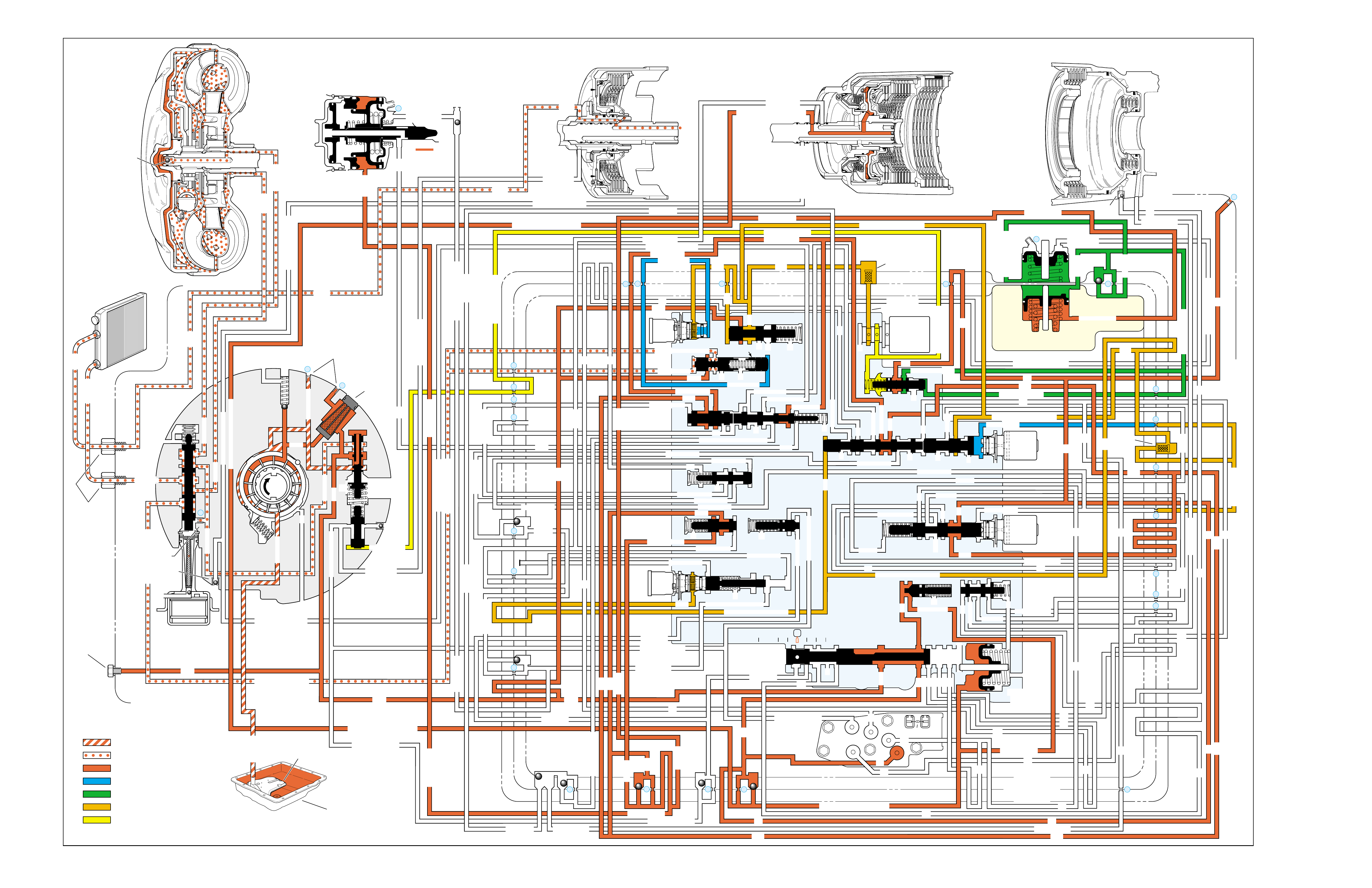
OVERDRIVE RANGE – 3-2 DOWNSHIFT
➤
➤➤
➤➤
➤
➤
➤
➤
➤➤ ➤ ➤ ➤➤➤ ➤ ➤
➤
➤
➤
➤
➤
➤
➤
➤ ➤
➤➤➤
➤ ➤ ➤ ➤ ➤ ➤ ➤ ➤ ➤ ➤ ➤ ➤ ➤ ➤ ➤ ➤ ➤
➤ ➤ ➤ ➤
➤ ➤ ➤ ➤ ➤ ➤ ➤ ➤ ➤ ➤ ➤
➤ ➤
➤
➤
➤
➤
➤➤
➤
➤
➤➤➤➤➤➤➤
➤➤➤➤ ➤
➤
➤➤➤
➤➤
➤➤
➤➤
➤
➤➤
➤➤➤➤➤ ➤➤➤➤➤➤➤
➤
➤
➤➤ ➤
➤➤➤➤➤➤➤➤➤➤ ➤➤➤➤➤➤
➤➤➤ ➤
➤
➤
➤
➤
➤
➤➤
➤➤➤ ➤
➤
➤
➤➤➤➤➤➤➤ ➤➤➤➤➤➤➤➤➤➤➤➤➤➤➤➤➤ ➤
➤➤➤➤➤
➤➤
➤➤
➤➤➤
➤➤
➤➤
➤ ➤➤➤➤
➤ ➤➤➤➤
➤➤➤➤➤ ➤ ➤
➤➤➤➤➤➤➤➤ ➤➤➤➤➤➤
➤
➤➤
➤
➤
➤
➤➤➤
➤➤
➤➤➤➤➤➤
➤
➤➤➤
➤
➤➤
➤➤➤➤
➤➤➤➤
➤
➤
➤➤
➤
➤
➤
➤
➤➤ ➤➤➤➤ ➤ ➤➤ ➤
➤
➤
➤
➤
➤
➤
➤
➤
➤
➤
➤➤ ➤
➤➤➤ ➤ ➤ ➤
➤➤ ➤➤
➤➤
➤➤ ➤➤
INPUT CLUTCH
HOUSING ASSEMBLY
24
REAR LUBE
FILTER
(49)
➤
➤
➤
➤
➤
➤
➤
RELEASE
APPLY
LO/REVERSE
PR
BOOST VALVE PRESS REG
BOTTOM
PAN
(SUMP)
(75)
FILTER
(72) REVERSE INPUT
REV INPUT
DECREASE
LINE
EX
FILTER
(232)
AIR
BLEED
(240)
1
SUCTION
LINE
EX
PRESSURE
RELIEF
VALVE
PUMP
ASSEMBLY
(4)
➤
➤➤
4
TCC
SOLENOID
(66)
N.O.
COOLER
LUBE
COOLER
SUCTION
CONVERTER & LUBE
MAINLINE
SOLENOID SIGNAL
ACCUMULATOR
ACTUATOR FEED LIMIT
TORQUE SIGNAL
FLUID PRESSURES
REVERSE INPUT
FORWARD CLUTCH FEED
#1
ACCUMULATOR
ORF ACC
2ND CLUTCH
3-4 ACCUMULATOR
1-2 ACCUMULATOR
19
3-4 ACCUM
ACCUM
EX
ORIFICED ACCUM
3-4 ACCUMULATOR
3-4 ACCUM
2ND CLUTCH
2ND CLUTCH
D3
REVERSE INPUT
D2-N.C.
REV-N.O. D3-N.C.
LO-N.O.
D4-N.O.
LO
TEMP
SENSOR
➤
TFP
SWITCH
ASSEMBLY
D2
D4
D3
D3
D3
EX
FORWARD ABUSE
FWD CL FD
3RD ACCUMULATOR EX
#7
11
3RD ACCUM
➤
4TH
2ND & 4TH
SERVO
REV ABUSE
EX
REVERSE
REVERSE INPUT
#12
D4
22
D4
D4
#4
13
3-4 SIGNAL
3-4 CL
3-4 CLUTCH
#2
12
3-4 CLUTCH
3RD ACCUM
3-4 CL
#8
16
2ND
2ND CL 2ND CL
2ND CL
2ND CL
2ND CLUTCH2ND CLUTCH
TORQUE SIG
FORWARD CLUTCH FEED
FORWARD
CLUTCH
ACCUMULATOR
EX
PR LO
LO
LO
FORWARD CLUTCH FEED
FORWARD CLUTCH FEED
FWD CL FEED
D3
D3
D3
14
3-4 CLUTCH
3RD ACCUMULATOR
3RD ACCUM
EX
AFL
3-2 SIGNAL
2ND
2ND
LINE
REGULATED APPLY
8
REG APPLY
1-2 SHIFT VALVE
26
LO
D4
O’ EX
D4-3-2 2ND
25
1-2 SIGNAL
LO/1ST
27
1-2 SIGNAL
EX
ORIFICED EX
ORIFICED EX
EX
LO/1ST D4-3-2
D4
D4
2
➤
➤
➤
➤➤
➤
EX
CONV FD
EX
EX
EX
LINE LINE
LINE
PRESSURE
TAP
(39)
➤
➤
REGULATED APPLY
➤
➤
LUBE
LUBE
LUBE
LUBE
CASE (8)
CASE (8)
GASKET (47)
SPACER PLATE (48)
GASKET (52)
VALVE BODY (60)
SUCTION
LINE
LINE
3a
3b
3c
➤
➤
➤
➤
➤
➤➤
➤
➤
➤
➤
➤
➤
➤
D3
EX
3-4 SIGNAL
1-2 SIGNAL
4TH SIGNAL
3-4 SHIFT VALVE
1-2 SIGNAL
3-4 CLUTCH
OVERRUN CLUTCH
OVERRUN CLUTCH
OVERRUN CLUTCH
OVERRUN CLUTCH
OVERRUN CLUTCH
OVERRUN CLUTCH
12a
12b
12c
12d
12e
EX
EX
EX
32
AFL
AFL
30
D4
EX
31
ACCUMULATOR
ACCUMULATOR
EX
TORQUE SIGNAL
FILTERED AFL
D4
AFLAFL FILTER
(50)
10
43a
43b 44
11b
11c
11a
14b
14a
14c
LO OVERRUN
23
PR
LO/REV
LO/1ST LO/REVERSE
LO/REVERSE
PR PR
EX
22 10c
23 10b
9n
9o
22b
22a
10a
➤
10 9k
9g
9m
44a
43c 44
41a
41b
41c
41d
42b
42a
13a
13b
OIL
COOLER
PIPE
CONNECTOR
(10)
➤
➤
18a
18b
18c
18 17a
18 17b
20b
48b
48a
REGULATED APPLY
30a
30b
32a
37a
9b
9e
10 9d
9c
9a
9f
9h
31a
31b
31c
OVERRUN CLUTCH FEED
3-4 ACCUM
SERVO FEED
SERVO FEED
6
7
4TH4TH
OVERRUN CL
4TH SIGNAL2ND
EX
EX
3-4 RELAY 4-3 SEQUENCE VALVE
5
EX
SERVO FD
ORF EX
CASE (8)
REV INPUT
EX
(237)
17d
17c
17e
17f
17g
21
21
20d
20e
21a
20a
20c
1-2 ACCUMULATOR COVER (57)
25g
33c
33a
33b
27d
27c
27b
29
29
27a
28a
29b
29a
29d
40
29c
29e
29g28
28
29f
24a
24b
24c
24d
24e
24f
24g
24h
25a
25b
25d
25e
25f
25
25
24m
24k
REVERSE INPUT
#3
17
REVERSE INPUT
15c
15b
16
16
REVERSE
REVERSE INPUT
16a
15d
15a
REVERSE
34f
34e
34d
34c
34a
34b
#6
OVERRUN CL FD
21
ORIFICED D2
#5
OVERRUN
OVERRUN OVERRUN
OVERRUN
36
36
35e
35d
39
35b
35c
36a
35a
38d
38e39
38c
38b
38a
EX
TORQUE SIGNAL
2ND CL
➤
➤
➤➤
➤
20
18
2-3 SHUTTLE 2-3 SHIFT VALVE
28
29
EX
EX
EX
EX
D2
OVERRUN
D3
D3
2ND
3-4 SIGNAL
EX
D4-3-2
2-3 SIGNAL
ACTUATOR FEED LIMIT
AFL
SERVO FD
3-4 ACC
FILTERED AFL
AFL
ACTUATOR FEED LIMIT
ACTUATOR FEED LIMIT
AFL
D2
2ND
2ND
2ND
2ND
D2
D2
D2
D2
ORIFICED D2
D2
D2
D2
VALVE BODY (60)
3-4 SIGNAL
➤
2ND
D4
PR 3-4 ACCUMULATOR
D4
EX
D4-3-2
LO
D4
2ND CLUTCH
D3
D3
FORWARD CLUTCH FEED ACTUATOR FEED LIMIT
TORQUE SIGNAL
SERVO FEED
➤
OVERRUN CLUTCH
LINE
9p
26a
➤
➤
➤➤
➤
➤
➤
➤
➤
➤
➤
➤
➤
➤
➤
➤
➤
➤➤
➤
➤
➤➤➤
➤➤➤
➤
➤
➤
➤
➤
➤
➤
➤
➤
➤
➤➤
➤➤ ➤
➤
➤
➤➤➤
➤➤
PR
➤
➤
➤➤
➤
➤➤➤➤➤
➤➤
➤
➤
➤➤➤
OFF
CONVERTER CLUTCH VALVE
COOLER
RELEASE
APPLY
EX
➤
➤
➤
➤
➤
➤
EX
➤➤
➤
➤➤
➤
CONV FD
➤
➤
➤
➤
➤
➤
➤
➤
➤
➤
➤
REGULATED APPLY
EX
EX
CC SIGNAL
CC SIGNAL
ACTUATOR FEED LIMIT
9
26b
TCC PWM
SOLENOID
VALVE
N.C.
1-2 SIGNAL
2ND
4TH SIGNAL
#10
➤
LOW AND REVERSE
CLUTCH ASSEMBLY
REVERSE INPUT
CLUTCH ASSEMBLY
TORQUE
CONVERTER
ASSEMBLY
#9
➤➤
(237)
➤
(238)
➤
EX
2ND CLUTCH 3-4 CLUTCH
2ND
PRESSURE
CONTROL
SOLENOID
VALVE
2-3 SHIFT
SOLENOID
VALVE
N.O.
ON
EX
1-2 SHIFT
SOLENOID
VALVE
N.O.
OFF
PRND321
D4
D4
REVERSE
D3
D2
LO
EX
EX
LINE
➤
➤
➤
➤
➤
➤
➤
➤
➤
➤
➤
➤
➤
➤
➤
➤
➤
➤
➤
➤
➤➤➤➤➤
➤
➤
➤
➤
➤
➤
➤
➤
MANUAL VALVE
PR
➤
➤
➤➤
➤
➤
➤
➤➤➤➤➤
➤➤➤
➤➤
➤➤
➤
➤
➤
➤➤
➤
➤➤
➤
➤➤
➤➤
➤
➤
➤
➤➤
➤
➤
➤
➤
➤➤ ➤ ➤ ➤ ➤
➤➤➤➤
➤
➤
➤➤➤ ➤ ➤
➤
➤
➤➤
➤
➤
➤
➤
➤
➤
➤➤
➤➤
➤
➤
➤
➤
➤➤ ➤
➤
➤➤
➤
➤
➤➤
➤
➤➤
11
4TH
EX
EX
➤
➤➤➤
➤
➤
➤
➤➤➤➤
➤➤➤➤➤➤
➤
➤
➤
➤
➤➤
➤
➤➤
➤
➤
➤
➤
➤
➤
➤
➤➤➤➤ ➤
➤
➤
➤➤➤
➤➤➤➤➤
➤➤➤➤
➤
➤
➤
➤➤
➤
➤
➤
➤➤➤
➤
➤
➤
➤
➤
➤
➤➤➤
➤
➤
➤
➤
➤
➤
➤
➤➤➤➤
➤➤
➤
➤
➤
➤
➤
➤
➤
➤
➤
➤
➤➤
➤
➤➤➤
ACCUM VALVE
3-2 CONTROL
3-2
CONTROL
SOLENOID
VALVE
N.C.
OFF
EXEX
3-2 DOWNSHIFT
ISOLATOR VALVE
REG APPLY
Figure 87
90

90A
OVERDRIVE RANGE – 3-2 DOWNSHIFT
3-2 FLARE OR TIE-UP
•3-2 Control Solenoid (394)
–Shorted or damaged
–Contamination
–Damaged seal
With the transmission operating in Third gear , a 3-2 downshift can
occur due to minimum or heavy throttle conditions or increased load on
the engine. A 3- 2 downshift occurs when the powertrain control module
(PCM) receives the appropriate input signals to de-energize (turn OFF)
the 2-3 shift solenoid valve.
1-2 SHIFT 2-3 SHIFT REVERSE FORWARD
SOLENOID SOLENOID 2-4 INPUT OVERRUN FORWARD SPRAG CL. 3-4 LO-ROLLER LO/REV
VALVE VALVE BAND CLUTCH CLUTCH CLUTCH ASSEMBLY CLUTCH CLUTCH CLUTCH
OFF ON APPLIED APPLIED HOLDING

90B
OVERDRIVE RANGE – 3-2 DOWNSHIFT
PASSAGES
1 SUCTION
2 DECREASE
3 LINE
4 CONVERTER FEED
5 RELEASE
6 APPLY
7 COOLER
8 LUBE
9 ACTUATOR FEED LIMIT
10 FILTERED ACTUATOR FEED
11 TORQUE SIGNAL
12 PR
13 D4-3-2
14 LO/REVERSE
15 REVERSE
16 REVERSE INPUT
17 D4
18 FORWARD CLUTCH FEED
19 REAR LUBE
20 ACCUMULATOR
21 ORIFICED ACCUMULATOR
22 1-2 SIGNAL
23 2-3 SIGNAL
24 2ND
25 2ND CLUTCH
26 C. C. SIGNAL
27 3-4 SIGNAL
28 3RD ACCUMULATOR
29 3-4 CLUTCH
30 4TH SIGNAL
31 SERVO FEED
32 4TH
33 3-4 ACCUMULATOR
34 D3
35 OVERRUN
36 OVERRUN CLUTCH FEED
37 OVERRUN CLUTCH
38 D2
39 ORIFICED D2
40 3-2 SIGNAL
41 LO
42 LO/1ST
43 EXHAUST
44 ORIFICED EXHAUST
45 VENT
46 SEAL DRAIN
47 VOID
48 REGULATED APPLY
COMPONENTS ( )
(8) REAR LUBE (ORIFICED CUP PLUG/REAR CASE)
(10) OIL COOLER PIPE CONNECTOR
(11) CASE SERVO ORIFICED PLUG
(38) ACCUMULATOR BLEED PLUG
(39) LINE PRESSURE TAP
(40) 3RD ACCUM. RETAINER AND BALL ASSEMBLY (#7)
(49) SHIFT SOLENOIDS SCREEN
(50) PRESSURE CONTROL SOLENOID SCREEN
(61) CHECKBALLS (#1, 2, 3, 4, 5, 6, 8, 12)
(91) CHECKBALL (#10)
(232) OIL PUMP COVER SCREEN
(237) CHECK VALVE RETAINER AND BALL ASSEMBLY
(238) CONVERTER CLUTCH SIGNAL ORIFICED CUP PLUG
(240) ORIFICED CUP PLUG
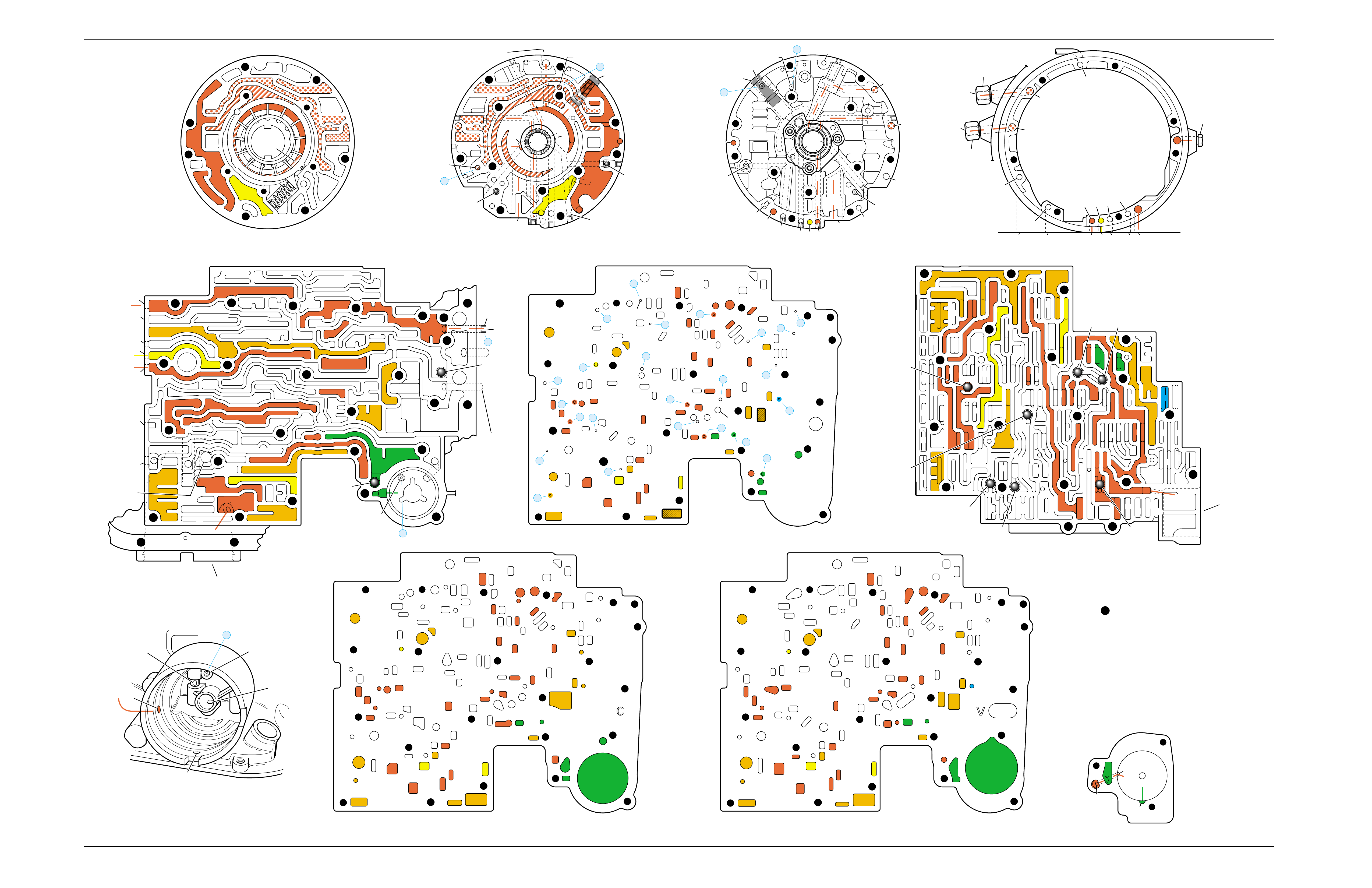
Figure 88
OVERDRIVE RANGE – 3-2 DOWNSHIFT
➤
➤
➤
➤
➤
➤
➤
➤➤
➤➤➤
➤
➤
➤
➤
➤
➤
➤
➤
➤
➤
➤
➤
➤
➤
➤ ➤
➤
➤
➤
➤
➤ ➤
➤
➤
➤ ➤
➤➤
➤➤
➤
➤
PUMP BODY (200)
(Pump Cover Side)
PUMP COVER (215)
(Pump Body Side) PUMP COVER (215)
(Case Side)
CASE (103)
(Pump Cover Side)
CASE (103)
(Control Valve Body Side)
SPACER PLATE (48)
(Case/Control Valve Body) CONTROL VALVE BODY (60)
(Case Side)
12 38
312
34
18
15
16
38
29
16
47 47
29 15 29
9
9
29
12
38 41 17
24
18
9
30
34
25 24
25 43 37
33
24
25
30 27 22 27
34
34
13
35
34
36
31 31
33
33
48
9
9
26 3
25
11
99
925
28 32
11
26
17 20 20
9
25
20
21 21
24
36 35
39
24
27
24
13
9
10
24 10
14
22
912 42
41 44
42
17
18
34
17
12 14
41
38
41
11
3
25
39
24 10
18
18
29
29
29
16
48
43
9
14
44
26
25
31
20
GASKET (47)
(Case/Spacer Plate)
GASKET (52)
(Spacer Plate/Control Valve Body)
CASE (103)
(2-4 Servo Bore)
1-2 ACCUMULATOR COVER (57)
NOTE:
- INDICATES BOLT HOLES
- NON-FUNCTIONAL HOLES
HAVE BEEN REMOVED FROM
COMPONENT DRAWINGS
TO SIMPLIFY TRACING FLUID
FLOW.
- EXHAUST FLUID NOT SHOWN
21
25
25
20
28
#7/(40)
44
(11)
25
43
32
3
16
(237)
18
43
3
(240)
37
(237)
43
47
45
43
43
48
11
29
16
3
16
29 18
2
(240)
8
85
37
37
1
47
(232)
7
46
45 47
3
3
8
43
5
4
2
4
4
48
43
3
6
1
43
2
7
47 46
43 11
3
16
37
37
5
37 8
29
18
29
1
(232)
2
43
47
16
(237)
37
(237)
4
(238)
2
(240)
PRESSURE RELIEF
VALVE BORE
➤
16
45
8
7
48
37
11 29 16
3
18
3
(39)
8
7
(10)
(10)
48 37 316291118
47 45
8
43
5
4
4
4
3
3
3
2
43
16
11
29
43
43
46
37 47
48
7
4
2
3
1
3
13V
12a 38b
3a
12b
34b
18b
38d
18c
13b
15d
16a
38c
15a
9m
9n
11c
29e
29d
9o
27b/29
29a
29f/28
15b/16
35a
22b
27d
30a
30b
34f
25a 24h
31c
25b
33c
24g 34e
31b
31a
27a
33a
33b
32a
37a
36a
3c
26b
11b
9c
25f
28a
9e
9p
9b
9d/10
(50)
48b
43a
25d
3b 11a
20c
25g
21a
9f
20e/21
17f 20a
9g
10a
35c/39
35b
35d/36
24f
24d 24c 13a
24a24b
41d
17c
41c
12c
17b/18 18a17d
42a
43c/44 9h 12e
22a 14b
10c/22
42b
14a
12d
17e
34a 41a
41b 38a
24m/25
47
9k/10
(49)
10b/23
20b
24e
17g
20d/21
25e
9a
48a
26a
43b/44
24k/25
34c
34d
29c
29b
29g/28
15c/16
17a/18 14c
44a
38e/39
27c/29
35e/36
➤
7
➤
5
➤
6
➤
16
➤
17
➤
8
➤
9
➤
32
➤
10
➤
12
➤
18
➤
20
➤
21
➤
22
➤
13
➤
14
➤
23
➤
25
➤
29
➤
30
➤
31
➤
26
➤
27
➤
28
➤
24
➤➤
1
➤➤
2
➤➤
2
➤➤
4
➤➤
11
12 38
3
18
38
16
28
29
15
34
29
9
9
15
29
11
929
40
15 43
35 34
31
31 33 33
22
27
30
34
30
25 24 24
24 31
25 43
48
26
33 37
36 32
25
28
9
26
9
311
25 25 3
910
11 21 20
25
9
10
17 20
35 35/39
24
27 24 24
13
13
22
14
22
912 42
14
12
24
24
18
38 41 17
41
12 42
17
17
34
12 34 41
38
17
44
47
923
20
17
9
9
48 44
34
29
29 18
24
14
43
10
25
41
38
34
9
9
947
9
9
3
3
25
25
11
11
26
47
26
47
25
47
3
10
43
47 11
43
33
31
24
30
37 36
28
11
34
25
24
22
24
35
34
30 27
31 32
47 25
29
9
15
40
28 29 29 16
15
43
15 12
38
3
341 47
17 34 38 41
34
18
12
17
42
43
12
18
47
47
14
43
14 42
922
23
10
9
17
17
24
38
13 24
43
42
41
3
33
31 24 24
17 47
13
17 20 20
27
#8
#6 #5
#3
#2 #12
#4
FORWARD
CLUTCH
ACCUMULATOR
BORE
➤
17
47
47
35
47
43
47
47
47 48
48
47
47
47
47 9
26
47 12 38
3
3
29
38
16
47 29
15
29
11
18
30 27 27
18
34
47
34
25 24
31
33
43
37 37
48
47
47
47
47
47 47
9
25
311
32
28 32
25
21
20
33
33
25
9
39
35
35 24 47
24 22
22 10 47
14
12
9
99
44
17 47 42
41
17
14
12
12
18
34
34
41
9
9
9
36
9
17
17
12
14
11
9
11
34
16 16
22
13 13
#10
#1
#7
(40)
37
18
11
29
16
3
29
341
38
44
(38)
28
47
43
47
48
36
33
9
33
38
19
26
47
47
2-4 SERVO BORE
➤
REAR
LUBE
TO
LOW AND
REVERSE
CLUTCH
➤➤
19
FOLDOUT ➤ 91
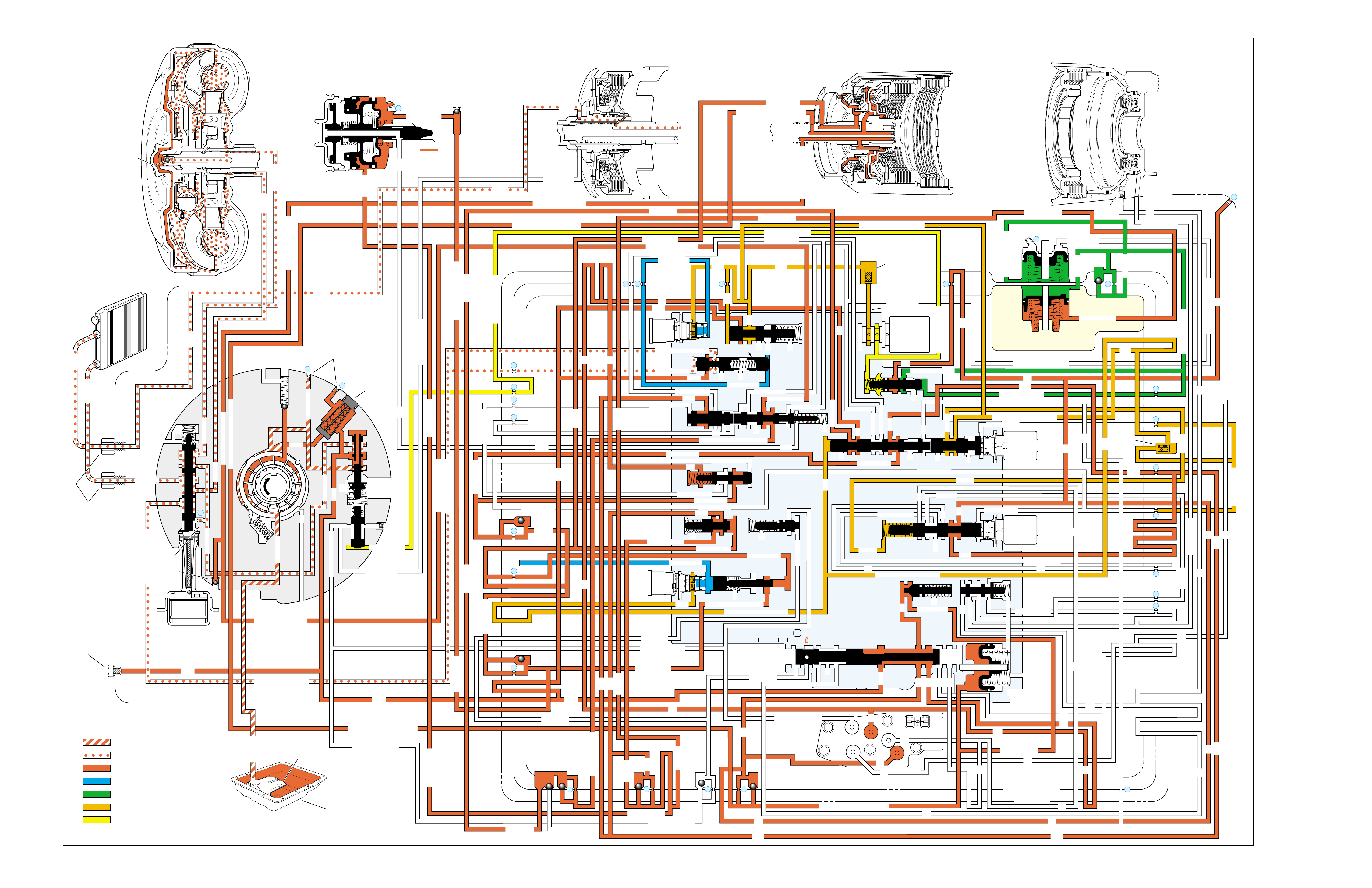
MANUAL THIRD – THIRD GEAR
(from Overdrive Range – Fourth Gear)
➤
➤➤
➤➤
➤
➤
➤
➤
➤➤
➤
➤
➤
➤
➤
➤
➤
➤
➤
➤
➤ ➤ ➤ ➤➤➤➤ ➤
➤
➤➤➤ ➤ ➤➤➤➤➤➤
➤➤ ➤➤
➤➤➤ ➤ ➤ ➤ ➤ ➤ ➤
➤➤➤ ➤➤
➤➤➤
➤
➤➤
➤➤➤
➤➤➤ ➤ ➤➤➤
➤
➤
➤➤➤➤
➤➤➤➤➤➤➤➤➤
➤
➤➤➤➤➤➤➤➤
➤➤
➤
➤➤➤➤➤➤➤➤
➤➤➤➤➤➤➤
➤
➤
➤
➤
➤
➤
➤➤ ➤
➤
➤➤➤➤➤➤➤➤➤➤➤➤
➤
➤➤
➤
➤➤
➤➤
➤
➤ ➤ ➤ ➤➤➤ ➤ ➤ ➤
➤➤➤
➤➤➤ ➤ ➤➤➤➤➤ ➤
➤
➤
➤
➤
➤
➤
➤➤➤
➤➤➤➤➤➤➤➤➤➤➤➤➤➤ ➤
➤ ➤➤➤➤ ➤➤ ➤➤➤➤➤ ➤ ➤➤➤➤➤➤➤
➤➤
➤
➤
➤
➤➤ ➤ ➤ ➤➤➤ ➤ ➤
➤➤
➤
➤ ➤➤➤➤➤➤ ➤➤
➤➤➤➤➤➤ ➤ ➤ ➤ ➤ ➤➤➤➤➤
➤➤
➤➤
➤➤
➤➤➤➤➤➤➤ ➤➤➤➤
➤
➤
➤
➤
➤
➤
➤
➤➤ ➤
➤➤➤ ➤ ➤ ➤
➤➤ ➤➤
➤➤
➤➤ ➤➤
INPUT CLUTCH
HOUSING ASSEMBLY
24
REAR LUBE
FILTER
(49)
➤
➤
➤
➤
➤
➤
➤
RELEASE
APPLY
LO/REVERSE
PR
BOOST VALVE PRESS REG
BOTTOM
PAN
(SUMP)
(75)
FILTER
(72) REVERSE INPUT
REV INPUT
DECREASE
LINE
EX
FILTER
(232)
AIR
BLEED
(240)
1
SUCTION
LINE
EX
PRESSURE
RELIEF
VALVE
PUMP
ASSEMBLY
(4)
➤
➤➤
4
TCC
SOLENOID
(66)
N.O.
COOLER
LUBE
COOLER
SUCTION
CONVERTER & LUBE
MAINLINE
SOLENOID SIGNAL
ACCUMULATOR
ACTUATOR FEED LIMIT
TORQUE SIGNAL
FLUID PRESSURES
REVERSE INPUT
FORWARD CLUTCH FEED
#1
ACCUMULATOR
ORF ACC
2ND CLUTCH
3-4 ACCUMULATOR
1-2 ACCUMULATOR
19
3-4 ACCUM
ACCUM
EX
ORIFICED ACCUM
3-4 ACCUMULATOR
3-4 ACCUM
2ND CLUTCH
2ND CLUTCH
D3
REVERSE INPUT
D2-N.C.
REV-N.O. D3-N.C.
LO-N.O.
D4-N.O.
LO
TEMP
SENSOR
➤
TFP
SWITCH
ASSEMBLY
D2
D4
D3
D3
D3
EX
FORWARD ABUSE
FWD CL FD
3RD ACCUMULATOR EX
#7
11
3RD ACCUM
➤
4TH
2ND & 4TH
SERVO
REV ABUSE
EX
REVERSE
REVERSE INPUT
#12
D4
22
D4
D4
#4
13
3-4 SIGNAL
3-4 CL
3-4 CLUTCH
#2
12
3-4 CLUTCH
3RD ACCUM
3-4 CL
#8
16
2ND
2ND CL 2ND CL
2ND CL
2ND CL
2ND CLUTCH2ND CLUTCH
TORQUE SIG
FORWARD CLUTCH FEED
FORWARD
CLUTCH
ACCUMULATOR
EX
PR LO
LO
LO
FORWARD CLUTCH FEED
FORWARD CLUTCH FEED
FWD CL FEED
D3
D3
D3
14
3-4 CLUTCH
3RD ACCUMULATOR
3RD ACCUM
EX
AFL
3-2 SIGNAL
2ND
2ND
LINE
REGULATED APPLY
8
REG APPLY
1-2 SHIFT VALVE
26
LO
D4
O’ EX
D4-3-2 2ND
25
1-2 SIGNAL
LO/1ST
27
1-2 SIGNAL
EX
ORIFICED EX
ORIFICED EX
EX
LO/1ST D4-3-2
D4
D4
2
➤
➤
➤
➤➤
➤
EX
CONV FD
EX
EX
EX
LINE LINE
LINE
PRESSURE
TAP
(39)
➤
➤
REGULATED APPLY
➤
➤
LUBE
LUBE
LUBE
LUBE
CASE (8)
CASE (8)
GASKET (47)
SPACER PLATE (48)
GASKET (52)
VALVE BODY (60)
SUCTION
LINE
LINE
3a
3b
3c
➤
➤
➤
➤
➤
➤➤
➤
➤
➤
➤
➤
➤
➤
D3
EX
3-4 SIGNAL
1-2 SIGNAL
4TH SIGNAL
3-4 SHIFT VALVE
1-2 SIGNAL
3-4 CLUTCH
OVERRUN CLUTCH
OVERRUN CLUTCH
OVERRUN CLUTCH
OVERRUN CLUTCH
OVERRUN CLUTCH
OVERRUN CLUTCH
12a
12b
12c
12d
12e
EX
EX
EX
32
AFL
AFL
30
D4
EX
31
ACCUMULATOR
ACCUMULATOR
EX
TORQUE SIGNAL
FILTERED AFL
D4
AFLAFL FILTER
(50)
10
43a
43b 44
11b
11c
11a
14b
14a
14c
LO OVERRUN
23
PR
LO/REV
LO/1ST LO/REVERSE
LO/REVERSE
PR PR
EX
22 10c
23 10b
9n
9o
22b
22a
10a
➤
10 9k
9g
9m
44a
43c 44
41a
41b
41c
41d
42b
42a
13a
13b
OIL
COOLER
PIPE
CONNECTOR
(10)
➤
➤
18a
18b
18c
18 17a
18 17b
20b
48b
48a
REGULATED APPLY
30a
30b
32a
37a
9b
9e
10 9d
9c
9a
9f
9h
31a
31b
31c
OVERRUN CLUTCH FEED
3-4 ACCUM
SERVO FEED
SERVO FEED
6
7
4TH4TH
OVERRUN CL
4TH SIGNAL2ND
EX
EX
3-4 RELAY 4-3 SEQUENCE VALVE
5
EX
SERVO FD
ORF EX
CASE (8)
REV INPUT
EX
(237)
17d
17c
17e
17f
17g
21
21
20d
20e
21a
20a
20c
1-2 ACCUMULATOR COVER (57)
25g
33c
33a
33b
27d
27c
27b
29
29
27a
28a
29b
29a
29d
40
29c
29e
29g28
28
29f
24a
24b
24c
24d
24e
24f
24g
24h
25a
25b
25d
25e
25f
25
25
24m
24k
REVERSE INPUT
#3
17
REVERSE INPUT
15c
15b
16
16
REVERSE
REVERSE INPUT
16a
15d
15a
REVERSE
34f
34e
34d
34c
34a
34b
#6
OVERRUN CL FD
21
ORIFICED D2
#5
OVERRUN
OVERRUN OVERRUN
OVERRUN
36
36
35e
35d
39
35b
35c
36a
35a
38d
38e39
38c
38b
38a
EX
TORQUE SIGNAL
2ND CL
➤
➤
➤➤
➤
20
18
2-3 SHUTTLE 2-3 SHIFT VALVE
28
29
EX
EX
EX
EX
D2
OVERRUN
D3
D3
2ND
3-4 SIGNAL
EX
D4-3-2
2-3 SIGNAL
ACTUATOR FEED LIMIT
AFL
SERVO FD
3-4 ACC
FILTERED AFL
AFL
ACTUATOR FEED LIMIT
ACTUATOR FEED LIMIT
AFL
D2
2ND
2ND
2ND
2ND
D2
D2
D2
D2
ORIFICED D2
D2
D2
D2
VALVE BODY (60)
3-4 SIGNAL
➤
2ND
D4
PR 3-4 ACCUMULATOR
D4
EX
D4-3-2
LO
D4
2ND CLUTCH
D3
D3
FORWARD CLUTCH FEED ACTUATOR FEED LIMIT
TORQUE SIGNAL
SERVO FEED
➤
OVERRUN CLUTCH
LINE
9p
26a
➤
➤
➤
➤
➤
➤
➤
➤
➤
➤
➤
➤
➤
➤➤
➤
➤
➤➤➤
➤➤➤
➤
➤
➤
➤
➤
➤
➤
➤
➤
➤
➤➤
➤➤ ➤
➤
➤
➤➤➤
➤➤
PR
➤
➤
➤➤
➤
➤➤➤➤➤
➤➤
➤
➤
➤➤➤
OFF
CONVERTER CLUTCH VALVE
COOLER
RELEASE
APPLY
EX
➤
➤
➤
➤
➤
➤
EX
➤➤
➤
➤➤
➤
CONV FD
➤
➤
➤
➤
➤
➤
➤
➤
➤
➤
➤
REGULATED APPLY
EX
EX
CC SIGNAL
CC SIGNAL
ACTUATOR FEED LIMIT
9
26b
TCC PWM
SOLENOID
VALVE
N.C.
1-2 SIGNAL
2ND
4TH SIGNAL
#10
➤
LOW AND REVERSE
CLUTCH ASSEMBLY
REVERSE INPUT
CLUTCH ASSEMBLY
TORQUE
CONVERTER
ASSEMBLY
#9
➤➤
(237)
➤
(238)
➤
EX
2ND CLUTCH 3-4 CLUTCH
2ND
PRESSURE
CONTROL
SOLENOID
VALVE
2-3 SHIFT
SOLENOID
VALVE
N.O.
OFF
EX
1-2 SHIFT
SOLENOID
VALVE
N.O.
OFF
PRND321
D4
D4
REVERSE
D3
D2
LO
EX
EX
LINE
➤
➤
➤
➤
➤
➤
➤
➤
➤
➤
➤
➤
➤
➤
➤
➤
➤
➤
➤
➤
➤➤➤
➤➤
➤
➤
➤
➤
➤
➤
➤
➤
MANUAL VALVE
PR
➤
➤
➤➤
➤
➤
➤
➤➤➤➤➤
➤➤➤
➤➤
➤➤
➤
➤
➤
➤➤
➤
➤➤
➤
➤➤
➤➤
➤
➤
➤
➤➤
➤
➤
➤
➤
➤➤ ➤ ➤ ➤ ➤
➤➤➤➤
➤
➤
➤➤➤ ➤ ➤
➤
➤
➤➤
➤
➤
➤
➤
➤
➤
➤➤
➤➤
➤
➤
➤
11
4TH
EX
EX
➤
➤➤➤➤
➤
➤
➤
➤
➤
➤➤➤➤➤ ➤
➤
➤
➤
➤
➤
➤
➤
➤➤➤
➤
➤
➤➤➤
➤➤➤➤
➤➤
➤
➤
➤
➤
➤
➤➤
➤
➤
➤
➤➤ ➤ ➤
➤
➤
➤
➤
➤
➤
➤➤➤
➤
➤➤➤
➤
➤
➤
➤
➤
➤➤
➤➤➤➤ ➤
➤➤➤ ➤ ➤
➤
➤
➤➤➤
➤➤
➤
➤➤ ➤
➤
➤
➤
➤
➤
➤
➤➤
➤➤ ➤➤
➤➤➤➤ ➤ ➤
➤
➤
➤➤➤
➤➤
➤
➤
➤➤
➤ ➤➤➤
➤➤ ➤ ➤➤
➤➤
➤➤➤
➤➤
➤
➤➤➤➤➤➤
➤
➤
➤
➤
➤
➤➤
➤
➤
➤
➤
➤
➤➤➤
➤
➤
➤
➤➤➤➤
➤➤➤➤➤➤
➤
➤
➤
➤
➤➤
➤
➤➤
➤
➤
➤
➤
➤
➤
➤
➤➤➤➤➤
➤
➤
➤➤➤
➤➤➤➤➤
➤➤➤➤
➤
➤
➤
➤➤
➤
➤
➤
➤➤➤
➤
➤
➤
➤
➤
➤
➤➤➤
➤
➤
➤
➤
➤
EXEX
3-2 DOWNSHIFT
3-2 CONTROL
3-2
CONTROL
SOLENOID
VALVE
N.C.
ON
➤
➤
➤➤➤
➤➤
➤
➤
➤
➤
➤
➤
➤
➤
➤
➤
➤
➤
➤➤
➤
➤➤➤
➤
➤
ACCUM VALVE
ISOLATOR VALVE
REG APPLY
Figure 89
92

MANUAL THIRD – THIRD GEAR
(from Overdrive Range – Fourth Gear)
92A
NO OVERRUN BRAKING-MANUAL 3-2-1
•External Linkage
–Not adjusted properly
•Input Clutch Assembly
–Turbine shaft oil passages plugged or not drilled
–Turbine shaft sealing balls loose or missing
–Overrun piston checkball not sealing
•Valve Body Assembly
–Checkball mispositioned
–4-3 sequence valve stuck
A manual 4-3 downshift can be accomplished by moving the gear
selector lever into the Manual Third position (D) when the transmission
is operating in Overdrive Range - Fourth Gear D .
1-2 SHIFT 2-3 SHIFT REVERSE FORWARD
SOLENOID SOLENOID 2-4 INPUT OVERRUN FORWARD SPRAG CL. 3-4 LO-ROLLER LO/REV
VALVE VALVE BAND CLUTCH CLUTCH CLUTCH ASSEMBLY CLUTCH CLUTCH CLUTCH
OFF OFF APPLIED APPLIED HOLDING APPLIED

MANUAL THIRD – THIRD GEAR
(from Overdrive Range – Fourth Gear)
92B
PASSAGES
1 SUCTION
2 DECREASE
3 LINE
4 CONVERTER FEED
5 RELEASE
6 APPLY
7 COOLER
8 LUBE
9 ACTUATOR FEED LIMIT
10 FILTERED ACTUATOR FEED
11 TORQUE SIGNAL
12 PR
13 D4-3-2
14 LO/REVERSE
15 REVERSE
16 REVERSE INPUT
17 D4
18 FORWARD CLUTCH FEED
19 REAR LUBE
20 ACCUMULATOR
21 ORIFICED ACCUMULATOR
22 1-2 SIGNAL
23 2-3 SIGNAL
24 2ND
25 2ND CLUTCH
26 C. C. SIGNAL
27 3-4 SIGNAL
28 3RD ACCUMULATOR
29 3-4 CLUTCH
30 4TH SIGNAL
31 SERVO FEED
32 4TH
33 3-4 ACCUMULATOR
34 D3
35 OVERRUN
36 OVERRUN CLUTCH FEED
37 OVERRUN CLUTCH
38 D2
39 ORIFICED D2
40 3-2 SIGNAL
41 LO
42 LO/1ST
43 EXHAUST
44 ORIFICED EXHAUST
45 VENT
46 SEAL DRAIN
47 VOID
48 REGULATED APPLY
COMPONENTS ( )
(8) REAR LUBE (ORIFICED CUP PLUG/REAR CASE)
(10) OIL COOLER PIPE CONNECTOR
(11) CASE SERVO ORIFICED PLUG
(38) ACCUMULATOR BLEED PLUG
(39) LINE PRESSURE TAP
(40) 3RD ACCUM. RETAINER AND BALL ASSEMBLY (#7)
(49) SHIFT SOLENOIDS SCREEN
(50) PRESSURE CONTROL SOLENOID SCREEN
(61) CHECKBALLS (#1, 2, 3, 4, 5, 6, 8, 12)
(91) CHECKBALL (#10)
(232) OIL PUMP COVER SCREEN
(237) CHECK VALVE RETAINER AND BALL ASSEMBLY
(238) CONVERTER CLUTCH SIGNAL ORIFICED CUP PLUG
(240) ORIFICED CUP PLUG
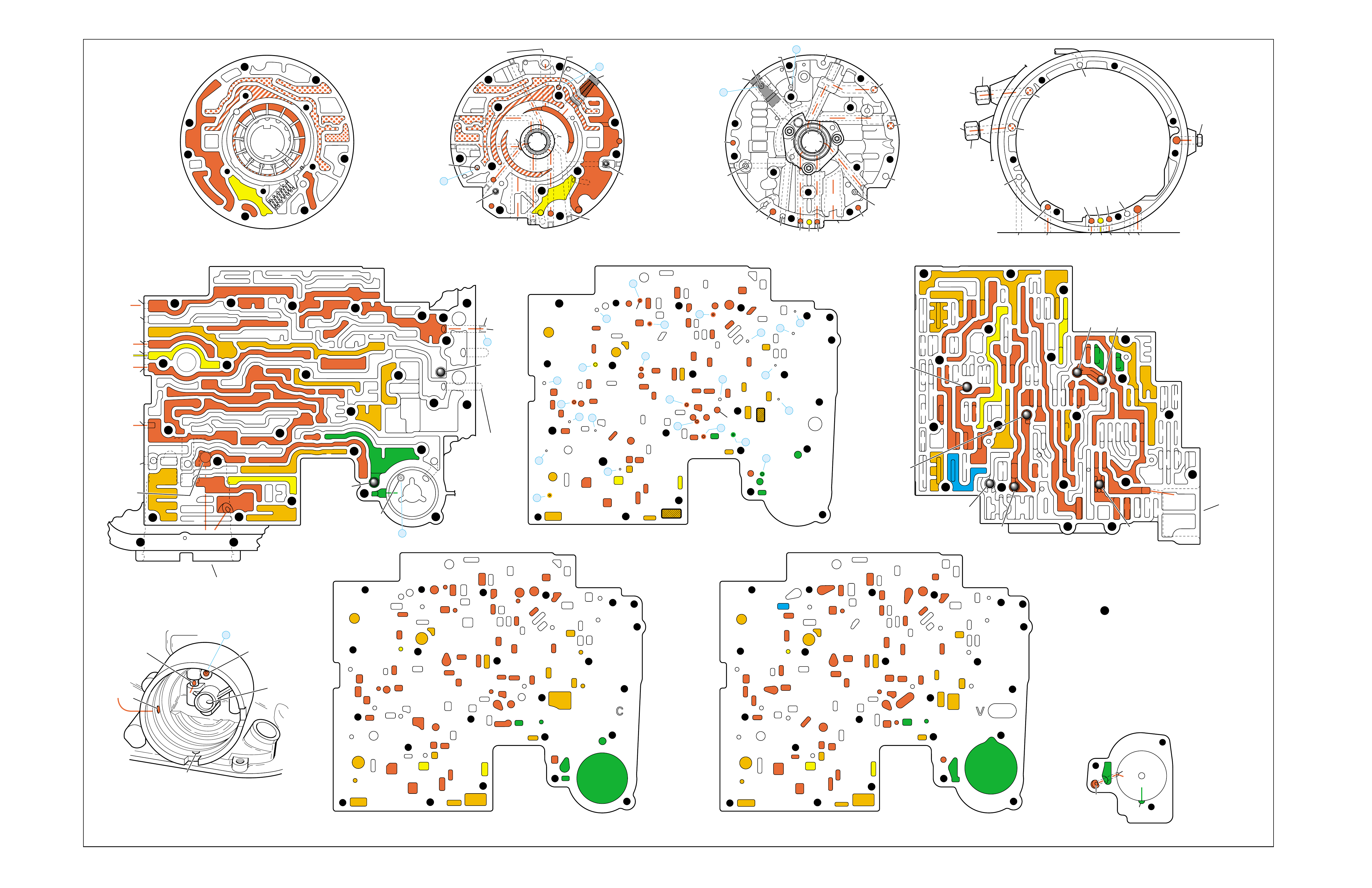
Figure 90
MANUAL THIRD – THIRD GEAR (from Overdrive Range – Fourth Gear)
➤
➤
➤
➤
➤
➤
➤
➤
➤
➤
➤➤
➤
➤➤
➤
➤
➤
➤
➤
➤➤
➤➤➤
➤
➤
➤
➤
➤
➤
➤
➤
➤
➤
➤
➤
➤
➤
➤
➤
➤
➤
➤ ➤
➤
➤
➤
➤
➤ ➤
➤
➤
➤ ➤
➤➤
➤➤
➤
➤
PUMP BODY (200)
(Pump Cover Side)
PUMP COVER (215)
(Pump Body Side) PUMP COVER (215)
(Case Side)
CASE (103)
(Pump Cover Side)
CASE (103)
(Control Valve Body Side)
SPACER PLATE (48)
(Case/Control Valve Body) CONTROL VALVE BODY (60)
(Case Side)
12 38
312
34
18
15
16
38
29
16
47 47
29 15 29
9
9
29
12
38 41 17
24
18
9
30
34
25 24
25 43 37
33
24
25
30 27 22 27
34
34
13
35
34
36
31 31
33
33
48
9
9
26 3
25
11
99
925
28 32
11
26
17 20 20
9
25
20
21 21
24
36 35
39
24
27
24
13
9
10
24 10
14
22
912 42
41 44
42
17
18
34
17
12 14
41
38
41
11
3
25
39
24 10
18
18
29
29
29
16
48
43
9
14
44
26
25
31
20
GASKET (47)
(Case/Spacer Plate)
GASKET (52)
(Spacer Plate/Control Valve Body)
CASE (103)
(2-4 Servo Bore)
1-2 ACCUMULATOR COVER (57)
NOTE:
- INDICATES BOLT HOLES
- NON-FUNCTIONAL HOLES
HAVE BEEN REMOVED FROM
COMPONENT DRAWINGS
TO SIMPLIFY TRACING FLUID
FLOW.
- EXHAUST FLUID NOT SHOWN
21
25
25
20
28
#7/(40)
44
(11)
25
43
32
3
16
(237)
18
43
3
(240)
37
(237)
43
47
45
43
43
48
11
29
16
3
16
29 18
2
(240)
8
85
37
37
1
47
(232)
7
46
45 47
3
3
8
43
5
4
2
4
4
48
43
3
6
1
43
2
7
47 46
43 11
3
16
37
37
5
37 8
29
18
29
1
(232)
2
43
47
16
(237)
37
(237)
4
(238)
2
(240)
PRESSURE RELIEF
VALVE BORE
➤
16
45
8
7
48
37
11 29 16
3
18
3
(39)
8
7
(10)
(10)
48 37 316291118
47 45
8
43
5
4
4
4
3
3
3
2
43
16
11
29
43
43
46
37 47
48
7
4
2
3
1
3
13V
12a 38b
3a
12b
34b
18b
38d
18c
13b
15d
16a
38c
15a
9m
9n
11c
29e
29d
9o
27b/29
29a
29f/28
15b/16
35a
22b
27d
30a
30b
34f
25a 24h
31c
25b
33c
24g 34e
31b
31a
27a
33a
33b
32a
37a
36a
3c
26b
11b
9c
25f
28a
9e
9p
9b
9d/10
(50)
48b
43a
25d
3b 11a
20c
25g
21a
9f
20e/21
17f 20a
9g
10a
35c/39
35b
35d/36
24f
24d 24c 13a
24a24b
41d
17c
41c
12c
17b/18 18a17d
42a
43c/44 9h 12e
22a 14b
10c/22
42b
14a
12d
17e
34a 41a
41b 38a
24m/25
47
9k/10
(49)
10b/23
20b
24e
17g
20d/21
25e
9a
48a
26a
43b/44
24k/25
34c
34d
29c
29b
29g/28
15c/16
17a/18 14c
44a
38e/39
27c/29
35e/36
➤
7
➤
5
➤
6
➤
16
➤
17
➤
8
➤
9
➤
32
➤
10
➤
12
➤
18
➤
20
➤
21
➤
22
➤
13
➤
14
➤
23
➤
25
➤
29
➤
30
➤
31
➤
26
➤
27
➤
28
➤
24
➤➤
1
➤➤
2
➤➤
2
➤➤
4
➤➤
11
12 38
3
18
38
16
28
29
15
34
29
9
9
15
29
11
929
40
15 43
35 34
31
31 33 33
22
27
30
34
30
25 24 24
24 31
25 43
48
26
33 37
36 32
25
28
9
26
9
311
25 25 3
910
11 21 20
25
9
10
17 20
35 35/39
24
27 24 24
13
13
22
14
22
912 42
14
12
24
24
18
38 41 17
41
12 42
17
17
34
12 34 41
38
17
44
47
923
20
17
9
9
48 44
34
29
29 18
24
14
43
10
25
41
38
34
9
9
947
9
9
3
3
25
25
11
11
26
47
26
47
25
47
3
10
43
47 11
43
33
31
24
30
37 36
28
11
34
25
24
22
24
35
34
30 27
31 32
47 25
29
9
15
40
28 29 29 16
15
43
15 12
38
3
341 47
17 34 38 41
34
18
12
17
42
43
12
18
47
47
14
43
14 42
922
23
10
9
17
17
24
38
13 24
43
42
41
3
33
31 24 24
17 47
13
17 20 20
27
#8
#6 #5
#3
#2 #12
#4
FORWARD
CLUTCH
ACCUMULATOR
BORE
➤
17
47
47
35
47
43
47
47
47 48
48
47
47
47
47 9
26
47 12 38
3
3
29
38
16
47 29
15
29
11
18
30 27 27
18
34
47
34
25 24
31
33
43
37 37
48
47
47
47
47
47 47
9
25
311
32
28 32
25
21
20
33
33
25
9
39
35
35 24 47
24 22
22 10 47
14
12
9
99
44
17 47 42
41
17
14
12
12
18
34
34
41
9
9
9
36
9
17
17
12
14
11
9
11
34
16 16
22
13 13
#10
#1
#7
(40)
37
18
11
29
16
3
29
341
38
44
(38)
28
47
43
47
48
36
33
9
33
38
19
26
47
47
2-4 SERVO BORE
➤
REAR
LUBE
TO
LOW AND
REVERSE
CLUTCH
➤➤
19
FOLDOUT ➤ 93
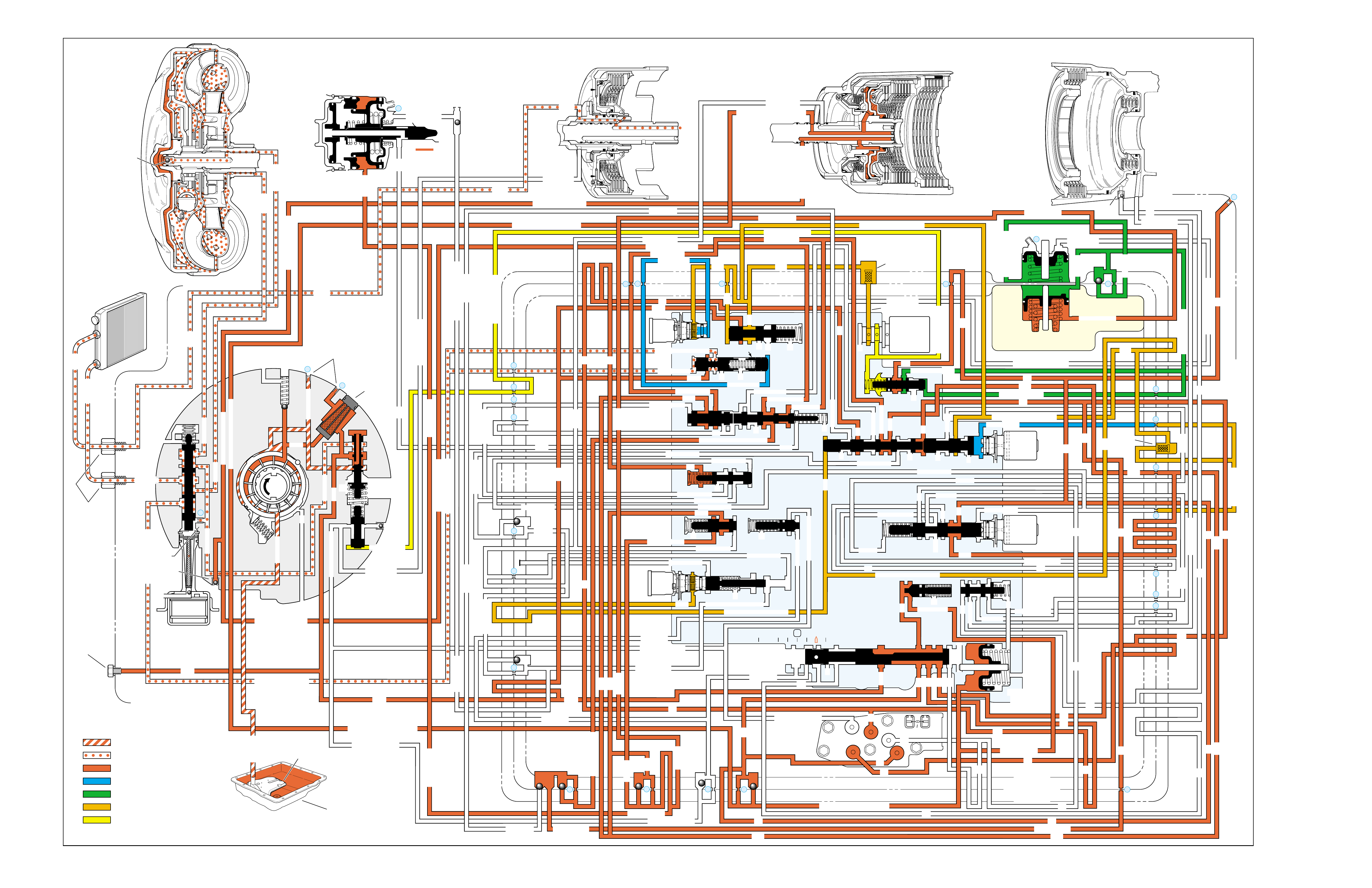
MANUAL SECOND – SECOND GEAR
(from Manual Third – Third Gear)
➤
➤➤
➤➤
➤
➤
➤
➤
➤➤ ➤ ➤ ➤➤➤ ➤ ➤
➤
➤
➤
➤
➤
➤
➤
➤ ➤
➤➤➤
➤ ➤ ➤ ➤ ➤ ➤ ➤ ➤ ➤ ➤ ➤ ➤ ➤ ➤ ➤ ➤ ➤
➤ ➤ ➤ ➤
➤ ➤ ➤ ➤ ➤ ➤ ➤ ➤ ➤ ➤ ➤
➤ ➤
➤
➤
➤
➤
➤➤
➤
➤
➤➤➤➤➤➤➤
➤➤➤➤ ➤
➤
➤➤➤
➤➤
➤➤
➤➤
➤
➤➤
➤➤➤➤➤ ➤➤➤➤➤➤➤
➤
➤
➤➤ ➤
➤➤➤➤➤➤➤➤➤➤ ➤➤➤➤➤➤
➤➤➤ ➤
➤
➤
➤
➤
➤
➤➤
➤➤➤ ➤
➤
➤
➤➤➤➤➤➤➤ ➤➤➤➤➤➤➤➤➤➤➤➤➤➤➤➤➤ ➤
➤➤➤➤➤
➤➤
➤➤
➤➤➤
➤➤
➤➤
➤ ➤➤➤➤
➤ ➤➤➤➤
➤➤➤➤➤ ➤ ➤
➤➤➤➤➤➤➤➤ ➤➤➤➤➤➤
➤
➤➤
➤
➤
➤
➤➤➤
➤➤
➤➤➤➤➤➤
➤
➤➤➤
➤
➤➤
➤➤➤➤
➤➤➤➤
➤
➤
➤➤
➤➤➤
➤➤➤➤➤➤➤➤➤➤➤➤ ➤➤➤➤➤➤➤➤➤➤➤ ➤ ➤ ➤ ➤ ➤ ➤
➤➤➤➤➤➤➤➤➤➤ ➤➤➤➤➤➤➤➤
➤➤➤➤➤➤➤➤➤➤ ➤
➤
➤
➤
➤
➤➤
➤
➤
➤
➤
➤➤ ➤➤➤➤ ➤ ➤➤ ➤
➤
➤
➤
➤
➤
➤
➤
➤
➤
➤
➤➤ ➤
➤➤➤ ➤ ➤ ➤
➤➤ ➤➤
➤➤
➤➤ ➤➤
INPUT CLUTCH
HOUSING ASSEMBLY
24
REAR LUBE
FILTER
(49)
➤
➤
➤
➤
➤
➤
➤
RELEASE
APPLY
LO/REVERSE
PR
BOOST VALVE PRESS REG
BOTTOM
PAN
(SUMP)
(75)
FILTER
(72) REVERSE INPUT
REV INPUT
DECREASE
LINE
EX
FILTER
(232)
AIR
BLEED
(240)
1
SUCTION
LINE
EX
PRESSURE
RELIEF
VALVE
PUMP
ASSEMBLY
(4)
➤
➤➤
4
TCC
SOLENOID
(66)
N.O.
COOLER
LUBE
COOLER
SUCTION
CONVERTER & LUBE
MAINLINE
SOLENOID SIGNAL
ACCUMULATOR
ACTUATOR FEED LIMIT
TORQUE SIGNAL
FLUID PRESSURES
REVERSE INPUT
FORWARD CLUTCH FEED
#1
ACCUMULATOR
ORF ACC
2ND CLUTCH
3-4 ACCUMULATOR
1-2 ACCUMULATOR
19
3-4 ACCUM
ACCUM
EX
ORIFICED ACCUM
3-4 ACCUMULATOR
3-4 ACCUM
2ND CLUTCH
2ND CLUTCH
D3
REVERSE INPUT
D2-N.C.
REV-N.O. D3-N.C.
LO-N.O.
D4-N.O.
LO
TEMP
SENSOR
➤
TFP
SWITCH
ASSEMBLY
D2
D4
D3
D3
D3
EX
FORWARD ABUSE
FWD CL FD
3RD ACCUMULATOR EX
#7
11
3RD ACCUM
➤
4TH
2ND & 4TH
SERVO
REV ABUSE
EX
REVERSE
REVERSE INPUT
#12
D4
22
D4
D4
#4
13
3-4 SIGNAL
3-4 CL
3-4 CLUTCH
#2
12
3-4 CLUTCH
3RD ACCUM
3-4 CL
#8
16
2ND
2ND CL 2ND CL
2ND CL
2ND CL
2ND CLUTCH2ND CLUTCH
TORQUE SIG
FORWARD CLUTCH FEED
FORWARD
CLUTCH
ACCUMULATOR
EX
PR LO
LO
LO
FORWARD CLUTCH FEED
FORWARD CLUTCH FEED
FWD CL FEED
D3
D3
D3
14
3-4 CLUTCH
3RD ACCUMULATOR
3RD ACCUM
EX
AFL
3-2 SIGNAL
2ND
2ND
LINE
REGULATED APPLY
8
REG APPLY
1-2 SHIFT VALVE
26
LO
D4
O’ EX
D4-3-2 2ND
25
1-2 SIGNAL
LO/1ST
27
1-2 SIGNAL
EX
ORIFICED EX
ORIFICED EX
EX
LO/1ST D4-3-2
D4
D4
2
➤
➤
➤
➤➤
➤
EX
CONV FD
EX
EX
EX
LINE LINE
LINE
PRESSURE
TAP
(39)
➤
➤
REGULATED APPLY
➤
➤
LUBE
LUBE
LUBE
LUBE
CASE (8)
CASE (8)
GASKET (47)
SPACER PLATE (48)
GASKET (52)
VALVE BODY (60)
SUCTION
LINE
LINE
3a
3b
3c
➤
➤
➤
➤
➤
➤➤
➤
➤
➤
➤
➤
➤
➤
D3
EX
3-4 SIGNAL
1-2 SIGNAL
4TH SIGNAL
3-4 SHIFT VALVE
1-2 SIGNAL
3-4 CLUTCH
OVERRUN CLUTCH
OVERRUN CLUTCH
OVERRUN CLUTCH
OVERRUN CLUTCH
OVERRUN CLUTCH
OVERRUN CLUTCH
12a
12b
12c
12d
12e
EX
EX
EX
32
AFL
AFL
30
D4
EX
31
ACCUMULATOR
ACCUMULATOR
EX
TORQUE SIGNAL
FILTERED AFL
D4
AFLAFL FILTER
(50)
10
43a
43b 44
11b
11c
11a
14b
14a
14c
LO OVERRUN
23
PR
LO/REV
LO/1ST LO/REVERSE
LO/REVERSE
PR PR
EX
22 10c
23 10b
9n
9o
22b
22a
10a
➤
10 9k
9g
9m
44a
43c 44
41a
41b
41c
41d
42b
42a
13a
13b
OIL
COOLER
PIPE
CONNECTOR
(10)
➤
➤
18a
18b
18c
18 17a
18 17b
20b
48b
48a
REGULATED APPLY
30a
30b
32a
37a
9b
9e
10 9d
9c
9a
9f
9h
31a
31b
31c
OVERRUN CLUTCH FEED
3-4 ACCUM
SERVO FEED
SERVO FEED
6
7
4TH4TH
OVERRUN CL
4TH SIGNAL2ND
EX
EX
3-4 RELAY 4-3 SEQUENCE VALVE
5
EX
SERVO FD
ORF EX
CASE (8)
REV INPUT
EX
(237)
17d
17c
17e
17f
17g
21
21
20d
20e
21a
20a
20c
1-2 ACCUMULATOR COVER (57)
25g
33c
33a
33b
27d
27c
27b
29
29
27a
28a
29b
29a
29d
40
29c
29e
29g28
28
29f
24a
24b
24c
24d
24e
24f
24g
24h
25a
25b
25d
25e
25f
25
25
24m
24k
REVERSE INPUT
#3
17
REVERSE INPUT
15c
15b
16
16
REVERSE
REVERSE INPUT
16a
15d
15a
REVERSE
34f
34e
34d
34c
34a
34b
#6
OVERRUN CL FD
21
ORIFICED D2
#5
OVERRUN
OVERRUN OVERRUN
OVERRUN
36
36
35e
35d
39
35b
35c
36a
35a
38d
38e39
38c
38b
38a
EX
TORQUE SIGNAL
2ND CL
➤
➤
➤➤
➤
20
18
2-3 SHUTTLE 2-3 SHIFT VALVE
28
29
EX
EX
EX
EX
D2
OVERRUN
D3
D3
2ND
3-4 SIGNAL
EX
D4-3-2
2-3 SIGNAL
ACTUATOR FEED LIMIT
AFL
SERVO FD
3-4 ACC
FILTERED AFL
AFL
ACTUATOR FEED LIMIT
ACTUATOR FEED LIMIT
AFL
D2
2ND
2ND
2ND
2ND
D2
D2
D2
D2
ORIFICED D2
D2
D2
D2
VALVE BODY (60)
3-4 SIGNAL
➤
2ND
D4
PR 3-4 ACCUMULATOR
D4
EX
D4-3-2
LO
D4
2ND CLUTCH
D3
D3
FORWARD CLUTCH FEED ACTUATOR FEED LIMIT
TORQUE SIGNAL
SERVO FEED
➤
OVERRUN CLUTCH
LINE
9p
26a
➤
➤
➤➤
➤
➤
➤
➤
➤
➤
➤
➤
➤
➤
➤
➤
➤
➤➤
➤
➤
➤➤➤
➤➤➤
➤
➤
➤
➤
➤
➤
➤
➤
➤
➤
➤➤
➤➤ ➤
➤
➤
➤➤➤
➤➤
PR
➤
➤
➤➤
➤
➤➤➤➤➤
➤➤
➤
➤
➤➤➤
OFF
CONVERTER CLUTCH VALVE
COOLER
RELEASE
APPLY
EX
➤
➤
➤
➤
➤
➤
EX
➤➤
➤
➤➤
➤
CONV FD
➤
➤
➤
➤
➤
➤
➤
➤
➤
➤
➤
REGULATED APPLY
EX
EX
CC SIGNAL
CC SIGNAL
ACTUATOR FEED LIMIT
9
26b
TCC PWM
SOLENOID
VALVE
N.C.
1-2 SIGNAL
2ND
4TH SIGNAL
#10
➤
LOW AND REVERSE
CLUTCH ASSEMBLY
REVERSE INPUT
CLUTCH ASSEMBLY
TORQUE
CONVERTER
ASSEMBLY
#9
➤➤
(237)
➤
(238)
➤
EX
2ND CLUTCH 3-4 CLUTCH
2ND
PRESSURE
CONTROL
SOLENOID
VALVE
2-3 SHIFT
SOLENOID
VALVE
N.O.
ON
EX
1-2 SHIFT
SOLENOID
VALVE
N.O.
OFF
PRND321
D4
D4
REVERSE
D3
D2
LO
EX
EX
LINE
➤
➤
➤
➤
➤
➤
➤
➤
➤
➤
➤
➤
➤
➤
➤
➤
➤
➤
➤
➤
➤➤➤➤➤
➤
➤
➤
➤
➤
➤
➤
➤
PR
➤
➤
➤➤
➤
➤
➤
➤➤➤➤➤
➤➤➤
➤➤
➤➤
➤
➤
➤
➤➤
➤
➤➤
➤
➤➤
➤➤
➤
➤
➤
➤➤
➤
➤
➤
➤
➤➤ ➤ ➤ ➤ ➤
➤➤➤➤
➤
➤
➤➤➤ ➤ ➤
➤
➤
➤➤
➤
➤
➤
➤
➤
➤
➤➤
➤➤
➤
➤
➤
➤
➤➤ ➤
➤
➤➤
➤
➤
➤➤
➤
➤➤
11
4TH
EX
EX
➤
➤➤➤
➤
➤
➤
➤➤➤➤
➤➤➤➤➤➤
➤
➤
➤
➤
➤➤
➤
➤➤
➤
➤
➤
➤
➤
➤
➤
➤➤➤➤ ➤
➤
➤
➤➤➤
➤➤➤➤➤
➤➤➤➤
➤
➤
➤
➤➤
➤
➤
➤
➤➤➤
➤
➤
➤
➤
➤
➤
➤➤➤
➤
➤
➤
➤
➤
➤
➤
➤➤➤➤
➤➤
➤
➤
➤
➤
➤
➤
➤
➤
➤
➤
➤➤
➤
➤➤➤
ACCUM VALVE
MANUAL VALVE
➤
➤
➤
➤➤
➤➤➤➤ ➤
➤➤➤ ➤ ➤
➤
➤
➤➤➤
➤➤
➤
➤➤ ➤
➤
➤
➤
➤
➤
➤
➤
➤
➤
➤
➤
➤➤➤
➤➤➤
➤
➤
➤➤➤➤
➤➤➤➤➤➤
➤
➤
➤
➤➤➤
➤
➤
➤
➤
➤➤➤
➤➤
➤
➤
➤➤
➤ ➤➤➤
➤➤ ➤ ➤➤
➤➤
➤➤➤
➤➤
➤
➤➤➤➤➤➤
➤
➤
➤
➤
➤
➤➤
➤
➤
➤
3-2 CONTROL
3-2
CONTROL
SOLENOID
VALVE
N.C.
OFF
EXEX
3-2 DOWNSHIFT
ISOLATOR VALVE
REG APPLY
Figure 91
94

MANUAL SECOND – SECOND GEAR
(from Manual Third – Third Gear)
94A
NO OVERRUN BRAKING-MANUAL 3-2-1
•External Linkage
–Not adjusted properly
•Input Clutch Assembly
–Turbine shaft oil passages plugged or not drilled
–Turbine shaft sealing balls loose or missing
–Overrun piston checkball not sealing
•Valve Body Assembly
–Checkball mispositioned
–4-3 sequence valve stuck
A manual 3-2 downshift can be accomplished by moving the gear
selector lever into the Manual Second (2) position when the transmis-
sion is operating in Third gear. This causes the transmission to shift
immediately into Second gear and prevents the transmission from
upshifting to either Third or Fourth gears.
1-2 SHIFT 2-3 SHIFT REVERSE FORWARD
SOLENOID SOLENOID 2-4 INPUT OVERRUN FORWARD SPRAG CL. 3-4 LO-ROLLER LO/REV
VALVE VALVE BAND CLUTCH CLUTCH CLUTCH ASSEMBLY CLUTCH CLUTCH CLUTCH
OFF ON APPLIED APPLIED APPLIED HOLDING

94B
MANUAL SECOND – SECOND GEAR
(from Manual Third – Third Gear)
PASSAGES
1 SUCTION
2 DECREASE
3 LINE
4 CONVERTER FEED
5 RELEASE
6 APPLY
7 COOLER
8 LUBE
9 ACTUATOR FEED LIMIT
10 FILTERED ACTUATOR FEED
11 TORQUE SIGNAL
12 PR
13 D4-3-2
14 LO/REVERSE
15 REVERSE
16 REVERSE INPUT
17 D4
18 FORWARD CLUTCH FEED
19 REAR LUBE
20 ACCUMULATOR
21 ORIFICED ACCUMULATOR
22 1-2 SIGNAL
23 2-3 SIGNAL
24 2ND
25 2ND CLUTCH
26 C. C. SIGNAL
27 3-4 SIGNAL
28 3RD ACCUMULATOR
29 3-4 CLUTCH
30 4TH SIGNAL
31 SERVO FEED
32 4TH
33 3-4 ACCUMULATOR
34 D3
35 OVERRUN
36 OVERRUN CLUTCH FEED
37 OVERRUN CLUTCH
38 D2
39 ORIFICED D2
40 3-2 SIGNAL
41 LO
42 LO/1ST
43 EXHAUST
44 ORIFICED EXHAUST
45 VENT
46 SEAL DRAIN
47 VOID
48 REGULATED APPLY
COMPONENTS ( )
(8) REAR LUBE (ORIFICED CUP PLUG/REAR CASE)
(10) OIL COOLER PIPE CONNECTOR
(11) CASE SERVO ORIFICED PLUG
(38) ACCUMULATOR BLEED PLUG
(39) LINE PRESSURE TAP
(40) 3RD ACCUM. RETAINER AND BALL ASSEMBLY (#7)
(49) SHIFT SOLENOIDS SCREEN
(50) PRESSURE CONTROL SOLENOID SCREEN
(61) CHECKBALLS (#1, 2, 3, 4, 5, 6, 8, 12)
(91) CHECKBALL (#10)
(232) OIL PUMP COVER SCREEN
(237) CHECK VALVE RETAINER AND BALL ASSEMBLY
(238) CONVERTER CLUTCH SIGNAL ORIFICED CUP PLUG
(240) ORIFICED CUP PLUG
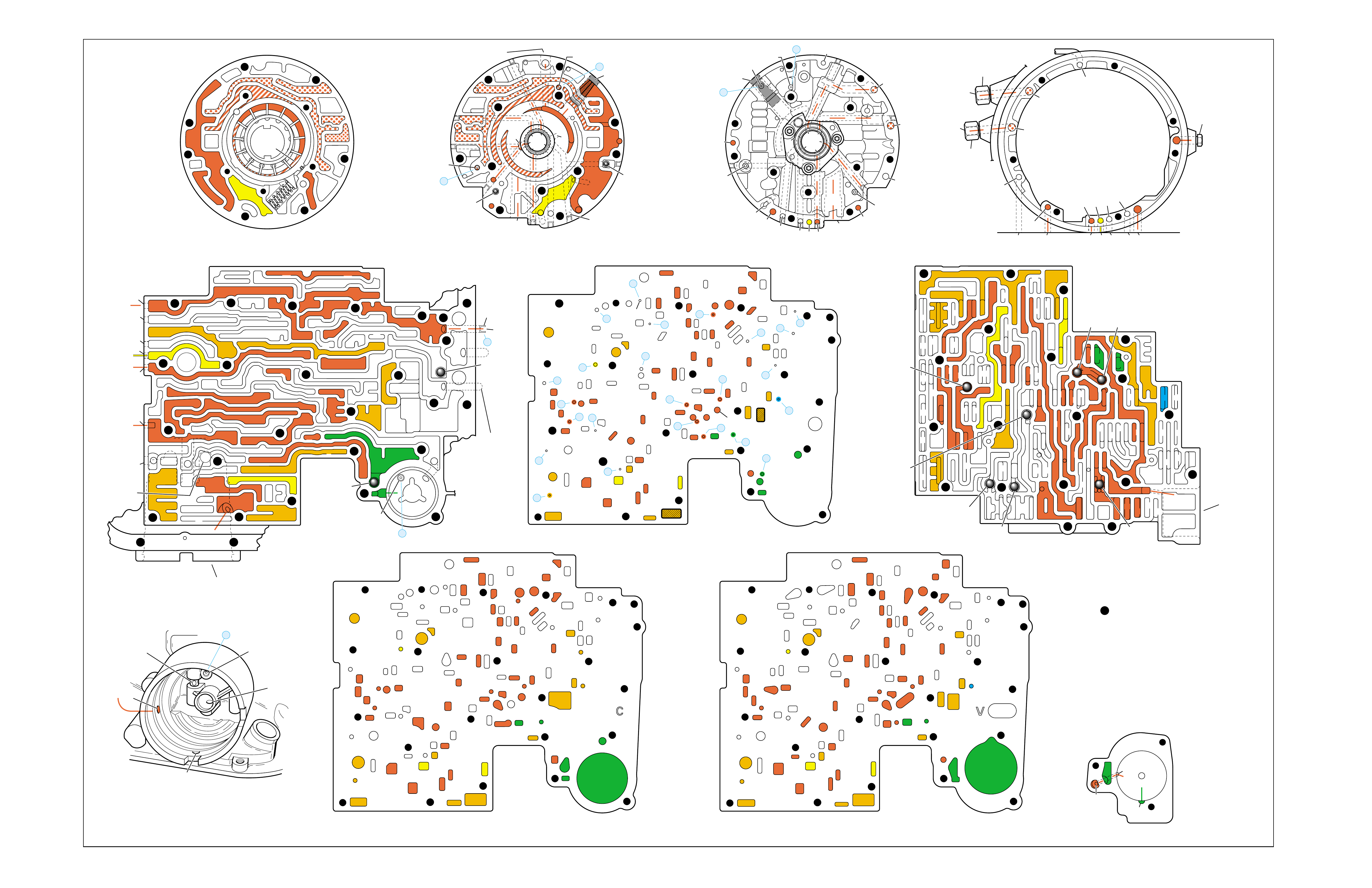
Figure 92
MANUAL SECOND – SECOND GEAR (from Manual Third – Third Gear)
➤
➤
➤
➤
➤
➤
➤
➤
➤
➤
➤
➤
➤
➤
➤➤
➤➤➤
➤
➤
➤
➤
➤
➤
➤
➤
➤
➤
➤
➤
➤
➤
➤ ➤
➤
➤
➤
➤
➤ ➤
➤
➤
➤ ➤
➤➤
➤➤
➤
➤
PUMP BODY (200)
(Pump Cover Side)
PUMP COVER (215)
(Pump Body Side) PUMP COVER (215)
(Case Side)
CASE (103)
(Pump Cover Side)
CASE (103)
(Control Valve Body Side)
SPACER PLATE (48)
(Case/Control Valve Body) CONTROL VALVE BODY (60)
(Case Side)
12 38
312
34
18
15
16
38
29
16
47 47
29 15 29
9
9
29
12
38 41 17
24
18
9
30
34
25 24
25 43 37
33
24
25
30 27 22 27
34
34
13
35
34
36
31 31
33
33
48
9
9
26 3
25
11
99
925
28 32
11
26
17 20 20
9
25
20
21 21
24
36 35
39
24
27
24
13
9
10
24 10
14
22
912 42
41 44
42
17
18
34
17
12 14
41
38
41
11
3
25
39
24 10
18
18
29
29
29
16
48
43
9
14
44
26
25
31
20
GASKET (47)
(Case/Spacer Plate)
GASKET (52)
(Spacer Plate/Control Valve Body)
CASE (103)
(2-4 Servo Bore)
1-2 ACCUMULATOR COVER (57)
NOTE:
- INDICATES BOLT HOLES
- NON-FUNCTIONAL HOLES
HAVE BEEN REMOVED FROM
COMPONENT DRAWINGS
TO SIMPLIFY TRACING FLUID
FLOW.
- EXHAUST FLUID NOT SHOWN
21
25
25
20
28
#7/(40)
44
(11)
25
43
32
3
16
(237)
18
43
3
(240)
37
(237)
43
47
45
43
43
48
11
29
16
3
16
29 18
2
(240)
8
85
37
37
1
47
(232)
7
46
45 47
3
3
8
43
5
4
2
4
4
48
43
3
6
1
43
2
7
47 46
43 11
3
16
37
37
5
37 8
29
18
29
1
(232)
2
43
47
16
(237)
37
(237)
4
(238)
2
(240)
PRESSURE RELIEF
VALVE BORE
➤
16
45
8
7
48
37
11 29 16
3
18
3
(39)
8
7
(10)
(10)
48 37 316291118
47 45
8
43
5
4
4
4
3
3
3
2
43
16
11
29
43
43
46
37 47
48
7
4
2
3
1
3
13V
12a 38b
3a
12b
34b
18b
38d
18c
13b
15d
16a
38c
15a
9m
9n
11c
29e
29d
9o
27b/29
29a
29f/28
15b/16
35a
22b
27d
30a
30b
34f
25a 24h
31c
25b
33c
24g 34e
31b
31a
27a
33a
33b
32a
37a
36a
3c
26b
11b
9c
25f
28a
9e
9p
9b
9d/10
(50)
48b
43a
25d
3b 11a
20c
25g
21a
9f
20e/21
17f 20a
9g
10a
35c/39
35b
35d/36
24f
24d 24c 13a
24a24b
41d
17c
41c
12c
17b/18 18a17d
42a
43c/44 9h 12e
22a 14b
10c/22
42b
14a
12d
17e
34a 41a
41b 38a
24m/25
47
9k/10
(49)
10b/23
20b
24e
17g
20d/21
25e
9a
48a
26a
43b/44
24k/25
34c
34d
29c
29b
29g/28
15c/16
17a/18 14c
44a
38e/39
27c/29
35e/36
➤
7
➤
5
➤
6
➤
16
➤
17
➤
8
➤
9
➤
32
➤
10
➤
12
➤
18
➤
20
➤
21
➤
22
➤
13
➤
14
➤
23
➤
25
➤
29
➤
30
➤
31
➤
26
➤
27
➤
28
➤
24
➤➤
1
➤➤
2
➤➤
2
➤➤
4
➤➤
11
12 38
3
18
38
16
28
29
15
34
29
9
9
15
29
11
929
40
15 43
35 34
31
31 33 33
22
27
30
34
30
25 24 24
24 31
25 43
48
26
33 37
36 32
25
28
9
26
9
311
25 25 3
910
11 21 20
25
9
10
17 20
35 35/39
24
27 24 24
13
13
22
14
22
912 42
14
12
24
24
18
38 41 17
41
12 42
17
17
34
12 34 41
38
17
44
47
923
20
17
9
9
48 44
34
29
29 18
24
14
43
10
25
41
38
34
9
9
947
9
9
3
3
25
25
11
11
26
47
26
47
25
47
3
10
43
47 11
43
33
31
24
30
37 36
28
11
34
25
24
22
24
35
34
30 27
31 32
47 25
29
9
15
40
28 29 29 16
15
43
15 12
38
3
341 47
17 34 38 41
34
18
12
17
42
43
12
18
47
47
14
43
14 42
922
23
10
9
17
17
24
38
13 24
43
42
41
3
33
31 24 24
17 47
13
17 20 20
27
#8
#6 #5
#3
#2 #12
#4
FORWARD
CLUTCH
ACCUMULATOR
BORE
➤
17
47
47
35
47
43
47
47
47 48
48
47
47
47
47 9
26
47 12 38
3
3
29
38
16
47 29
15
29
11
18
30 27 27
18
34
47
34
25 24
31
33
43
37 37
48
47
47
47
47
47 47
9
25
311
32
28 32
25
21
20
33
33
25
9
39
35
35 24 47
24 22
22 10 47
14
12
9
99
44
17 47 42
41
17
14
12
12
18
34
34
41
9
9
9
36
9
17
17
12
14
11
9
11
34
16 16
22
13 13
#10
#1
#7
(40)
37
18
11
29
16
3
29
341
38
44
(38)
28
47
43
47
48
36
33
9
33
38
19
26
47
47
2-4 SERVO BORE
➤
REAR
LUBE
TO
LOW AND
REVERSE
CLUTCH
➤➤
19
FOLDOUT ➤ 95
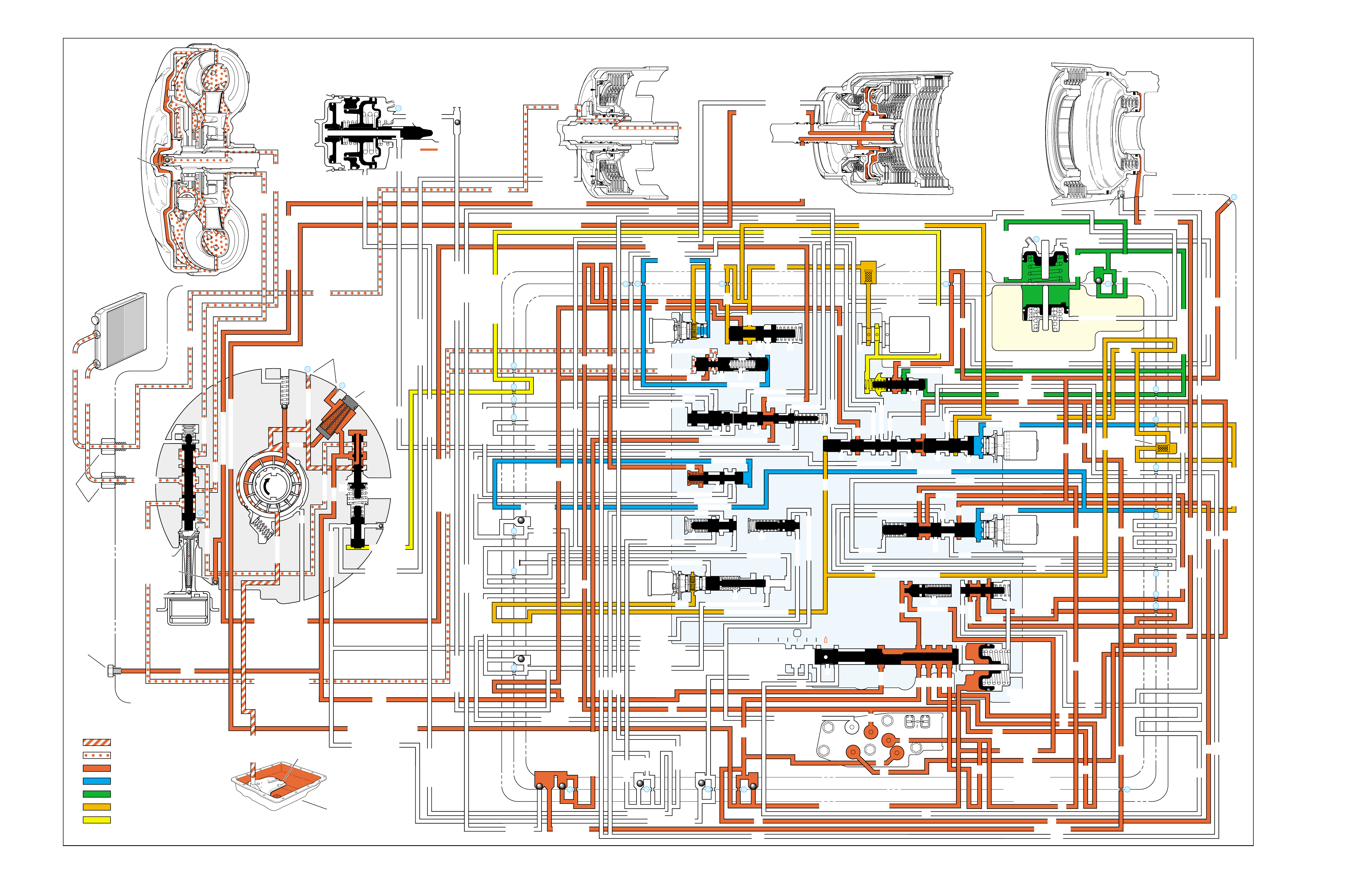
MANUAL FIRST – FIRST GEAR
(from Manual Second – Second Gear)
➤
➤➤
➤➤
➤
➤
➤
➤
➤
➤➤➤➤➤
➤➤➤
➤➤➤ ➤ ➤➤➤
➤
➤
➤➤➤➤
➤➤➤➤➤➤➤➤➤
➤
➤➤➤➤➤➤➤➤
➤➤
➤
➤
➤
➤➤
➤➤➤➤➤➤➤➤
➤➤➤
➤➤
➤➤
➤
➤➤➤➤➤➤➤➤➤➤➤
➤➤➤➤➤ ➤
➤➤➤
➤➤➤➤➤➤➤➤➤➤➤➤➤➤➤➤ ➤
➤➤➤➤ ➤ ➤ ➤➤➤➤➤➤➤➤➤
➤➤➤
➤➤ ➤➤
➤➤
➤
➤
➤
➤
➤
➤
➤
➤
➤
➤
➤
➤➤➤
➤➤➤➤➤➤➤➤➤➤➤➤➤➤➤➤➤
➤➤➤➤➤➤➤➤➤➤➤➤➤➤➤➤➤➤➤➤➤➤➤➤➤➤➤➤➤➤➤
➤➤➤➤➤
➤➤➤➤➤➤➤➤➤➤➤➤➤
➤➤
➤
➤
➤
➤➤➤
➤➤➤➤➤➤➤➤➤➤➤
➤➤➤➤➤➤➤➤➤➤➤➤➤➤➤➤➤➤➤➤➤➤➤➤➤➤
➤➤➤➤
➤➤➤➤
➤
➤
➤➤
➤➤➤
➤➤➤➤➤➤➤➤➤➤➤➤➤➤➤➤➤➤➤➤➤➤➤➤➤
➤➤➤➤➤➤➤➤➤➤➤➤➤➤➤➤➤
➤➤➤➤
➤
➤
➤➤➤
➤➤➤➤
➤➤➤➤➤➤
➤
➤➤➤
➤
➤➤➤➤➤➤➤➤➤➤➤
➤
➤➤➤➤
➤
➤
➤➤➤
➤
➤ ➤➤➤➤➤
➤➤➤➤➤➤➤➤➤➤➤➤➤➤➤➤➤➤➤➤➤
➤
➤
➤➤➤➤➤
➤
➤➤
➤
➤
➤
➤
➤
➤
➤
➤
➤
➤
➤
➤➤ ➤
➤➤➤ ➤ ➤ ➤
➤➤ ➤➤
➤➤
➤➤ ➤➤
INPUT CLUTCH
HOUSING ASSEMBLY
24
REAR LUBE
FILTER
(49)
➤
➤
➤
➤
➤
➤
➤
RELEASE
APPLY
LO/REVERSE
PR
BOOST VALVE PRESS REG
BOTTOM
PAN
(SUMP)
(75)
FILTER
(72) REVERSE INPUT
REV INPUT
DECREASE
LINE
EX
FILTER
(232)
AIR
BLEED
(240)
1
SUCTION
LINE
EX
PRESSURE
RELIEF
VALVE
PUMP
ASSEMBLY
(4)
➤
➤➤
4
TCC
SOLENOID
(66)
N.O.
COOLER
LUBE
COOLER
SUCTION
CONVERTER & LUBE
MAINLINE
SOLENOID SIGNAL
ACCUMULATOR
ACTUATOR FEED LIMIT
TORQUE SIGNAL
FLUID PRESSURES
REVERSE INPUT
FORWARD CLUTCH FEED
#1
ACCUMULATOR
ORF ACC
2ND CLUTCH
3-4 ACCUMULATOR
1-2 ACCUMULATOR
19
3-4 ACCUM
ACCUM
EX
ORIFICED ACCUM
3-4 ACCUMULATOR
3-4 ACCUM
2ND CLUTCH
2ND CLUTCH
D3
REVERSE INPUT
D2-N.C.
REV-N.O. D3-N.C.
LO-N.O.
D4-N.O.
LO
TEMP
SENSOR
➤
TFP
SWITCH
ASSEMBLY
D2
D4
D3
D3
D3
EX
FORWARD ABUSE
FWD CL FD
3RD ACCUMULATOR EX
#7
11
3RD ACCUM
4TH
EX
EX
➤
4TH
2ND & 4TH
SERVO
REV ABUSE
EX
REVERSE
REVERSE INPUT
#12
D4
22
D4
D4
#4
13
3-4 SIGNAL
3-4 CL
3-4 CLUTCH
#2
12
3-4 CLUTCH
3RD ACCUM
3-4 CL
#8
16
2ND
2ND CL 2ND CL
2ND CL
2ND CL
2ND CLUTCH2ND CLUTCH
TORQUE SIG
FORWARD CLUTCH FEED
FORWARD
CLUTCH
ACCUMULATOR
EX
PR LO
LO
LO
FORWARD CLUTCH FEED
FORWARD CLUTCH FEED
FWD CL FEED
D3
D3
D3
14
3-4 CLUTCH
3RD ACCUMULATOR
3RD ACCUM
EX
AFL
3-2 SIGNAL
2ND
2ND
LINE
REGULATED APPLY
8
REG APPLY
1-2 SHIFT VALVE
26
LO
D4
O’ EX
D4-3-2 2ND
25
1-2 SIGNAL
LO/1ST
27
1-2 SIGNAL
EX
ORIFICED EX
ORIFICED EX
EX
LO/1ST D4-3-2
D4
D4
2
➤
➤
➤
➤➤
➤
EX
CONV FD
EX
EX
EX
LINE LINE
LINE
PRESSURE
TAP
(39)
➤
➤
REGULATED APPLY
➤
➤
LUBE
LUBE
LUBE
LUBE
CASE (8)
CASE (8)
GASKET (47)
SPACER PLATE (48)
GASKET (52)
VALVE BODY (60)
SUCTION
LINE
LINE
3a
3b
3c
➤
➤
➤
➤
➤
➤➤
➤
➤
➤
➤
➤
➤
➤
D3
EX
3-4 SIGNAL
1-2 SIGNAL
4TH SIGNAL
3-4 SHIFT VALVE
1-2 SIGNAL
3-4 CLUTCH
OVERRUN CLUTCH
OVERRUN CLUTCH
OVERRUN CLUTCH
OVERRUN CLUTCH
OVERRUN CLUTCH
OVERRUN CLUTCH
12a
12b
12c
12d
12e
EX
EX
EX
32
AFL
AFL
30
D4
EX
31
ACCUMULATOR
ACCUMULATOR
EX
TORQUE SIGNAL
FILTERED AFL
D4
AFLAFL FILTER
(50)
10
43a
43b 44
11b
11c
11a
14b
14a
14c
LO OVERRUN
23
PR
LO/REV
LO/1ST LO/REVERSE
LO/REVERSE
PR PR
EX
22 10c
23 10b
9n
9o
22b
22a
10a
➤
10 9k
9g
9m
44a
43c 44
41a
41b
41c
41d
42b
42a
13a
13b
OIL
COOLER
PIPE
CONNECTOR
(10)
➤
➤
18a
18b
18c
18 17a
18 17b
20b
48b
48a
REGULATED APPLY
30a
30b
32a
37a
9b
9e
10 9d
9c
9a
9f
9h
31a
31b
31c
OVERRUN CLUTCH FEED
3-4 ACCUM
SERVO FEED
SERVO FEED
6
7
4TH4TH
OVERRUN CL
4TH SIGNAL2ND
EX
EX
3-4 RELAY 4-3 SEQUENCE VALVE
5
EX
SERVO FD
ORF EX
CASE (8)
REV INPUT
EX
(237)
17d
17c
17e
17f
17g
21
21
20d
20e
21a
20a
20c
1-2 ACCUMULATOR COVER (57)
25g
33c
33a
33b
27d
27c
27b
29
29
27a
28a
29b
29a
29d
40
29c
29e
29g28
28
29f
24a
24b
24c
24d
24e
24f
24g
24h
25a
25b
25d
25e
25f
25
25
24m
24k
REVERSE INPUT
#3
17
REVERSE INPUT
15c
15b
16
16
REVERSE
REVERSE INPUT
16a
15d
15a
REVERSE
34f
34e
34d
34c
34a
34b
#6
OVERRUN CL FD
21
ORIFICED D2
#5
OVERRUN
OVERRUN OVERRUN
OVERRUN
36
36
35e
35d
39
35b
35c
36a
35a
38d
38e39
38c
38b
38a
EX
TORQUE SIGNAL
2ND CL
➤
➤
➤➤
➤
20
18
2-3 SHUTTLE 2-3 SHIFT VALVE
28
29
EX
EX
EX
EX
D2
OVERRUN
D3
D3
2ND
3-4 SIGNAL
EX
D4-3-2
2-3 SIGNAL
ACTUATOR FEED LIMIT
AFL
SERVO FD
3-4 ACC
FILTERED AFL
AFL
ACTUATOR FEED LIMIT
ACTUATOR FEED LIMIT
AFL
D2
2ND
2ND
2ND
2ND
D2
D2
D2
D2
ORIFICED D2
D2
D2
D2
VALVE BODY (60)
3-4 SIGNAL
➤
2ND
D4
PR 3-4 ACCUMULATOR
D4
EX
D4-3-2
LO
D4
2ND CLUTCH
D3
D3
FORWARD CLUTCH FEED ACTUATOR FEED LIMIT
TORQUE SIGNAL
SERVO FEED
➤
OVERRUN CLUTCH
LINE
9p
26a
➤
➤
➤➤
➤
➤
➤
➤
➤
➤➤➤
➤➤➤
➤
➤➤➤
➤
➤
➤
➤
➤
➤
➤
➤
➤
➤
➤
➤
➤
➤➤
➤
➤
➤➤➤
➤➤➤
➤
➤
➤
➤
➤
➤
➤
➤
➤
➤
➤➤
➤➤ ➤
➤
➤
➤➤➤
➤➤
PR
➤
➤
➤➤
➤
➤➤➤➤➤
➤➤
➤
➤
➤➤➤
OFF
CONVERTER CLUTCH VALVE
COOLER
RELEASE
APPLY
EX
➤
➤
➤
➤
➤
➤
EX
➤➤
➤
➤➤
➤
CONV FD
➤
➤
➤
➤
➤
➤
➤
➤
➤
➤
➤
REGULATED APPLY
3-2 CONTROL
EX
EX
CC SIGNAL
CC SIGNAL
ACTUATOR FEED LIMIT
9
26b
TCC PWM
SOLENOID
VALVE
N.C.
1-2 SIGNAL
2ND
4TH SIGNAL
3-2
CONTROL
SOLENOID
VALVE
N.C.
OFF
#10
➤
LOW AND REVERSE
CLUTCH ASSEMBLY
REVERSE INPUT
CLUTCH ASSEMBLY
TORQUE
CONVERTER
ASSEMBLY
#9
➤➤
(237)
➤
(238)
➤
EX
2ND CLUTCH 3-4 CLUTCH
2ND
PRESSURE
CONTROL
SOLENOID
VALVE
2-3 SHIFT
SOLENOID
VALVE
N.O.
ON
EX
1-2 SHIFT
SOLENOID
VALVE
N.O.
ON
ACCUM VALVE
PRND321
D4
D4
REVERSE
D3
D2
LO
EX
EX
LINE
➤
➤
➤
➤
➤
➤
➤
➤
➤
➤
➤
➤
➤
➤
➤
➤
➤
➤
➤
➤
➤➤➤➤➤
➤
➤
➤
➤
➤
➤
➤
➤
PR
➤
➤
➤➤
➤
➤
➤
➤➤➤➤➤
➤➤➤
➤➤
➤➤
➤
➤
➤
➤➤
➤
➤➤
➤
➤➤
➤➤
➤
➤
➤
➤➤
➤
➤
➤
➤
➤➤ ➤ ➤ ➤ ➤
➤➤➤➤
➤
➤
➤➤➤ ➤ ➤
➤
➤
➤➤
➤
➤
➤
➤
➤
➤
➤➤
➤➤
➤
➤
➤
➤➤ ➤ ➤
➤➤
➤
➤
➤
➤
➤
➤
➤
➤
➤
➤
➤
➤
➤➤
➤
➤➤➤
MANUAL VALVE
➤
➤
➤
➤➤
➤➤➤➤ ➤
➤➤➤ ➤ ➤
➤
➤
➤➤➤
➤➤
➤
➤➤ ➤
➤
➤
➤
➤
➤
➤
➤
➤
➤
➤
➤
➤➤➤
➤➤➤
➤
➤
➤➤➤➤
➤➤➤➤➤➤
➤
➤
➤
➤➤➤
➤
➤
➤
➤
➤➤➤
➤➤
➤
➤
➤➤
➤ ➤➤➤
➤➤ ➤ ➤➤
➤➤
➤➤➤
➤➤
➤
➤➤➤➤➤➤
➤
➤
➤
➤
➤
➤➤
➤
➤
➤
➤➤
➤
➤
➤
➤➤➤➤
➤➤
➤
➤➤➤
➤
➤➤
➤
➤
➤
➤➤
➤
➤
➤➤
➤
➤➤
➤
➤➤
➤➤➤➤➤
➤
➤
EXEX
3-2 DOWNSHIFT
ISOLATOR VALVE
REG APPLY
Figure 93
96

MANUAL FIRST – FIRST GEAR
(from Manual Second – Second Gear)
96A
NO OVERRUN BRAKING-MANUAL 3-2-1
•External Linkage
–Not adjusted properly
•Input Clutch Assembly
–Turbine shaft oil passages plugged or not drilled
–Turbine shaft sealing balls loose or missing
–Overrun piston checkball not sealing
•Valve Body Assembly
–Checkball mispositioned
–4-3 sequence valve stuck
A manual 2-1 downshift can be accomplished by moving the gear
selector lever into the Manual First (1) position when the transmission
is operating in Second gear. If vehicle speed is below approximately 56
km/h (35 mph) the transmission will shift into First gear . Above this
speed, the transmission will shift into a Manual First - Second Gear
condition until vehicle speed slows sufficiently.
1-2 SHIFT 2-3 SHIFT REVERSE FORWARD
SOLENOID SOLENOID 2-4 INPUT OVERRUN FORWARD SPRAG CL. 3-4 LO-ROLLER LO/REV
VALVE VALVE BAND CLUTCH CLUTCH CLUTCH ASSEMBLY CLUTCH CLUTCH CLUTCH
ON ON APPLIED APPLIED HOLDING HOLDING APPLIED

MANUAL FIRST – FIRST GEAR
(from Manual Second – Second Gear)
96B
PASSAGES
1 SUCTION
2 DECREASE
3 LINE
4 CONVERTER FEED
5 RELEASE
6 APPLY
7 COOLER
8 LUBE
9 ACTUATOR FEED LIMIT
10 FILTERED ACTUATOR FEED
11 TORQUE SIGNAL
12 PR
13 D4-3-2
14 LO/REVERSE
15 REVERSE
16 REVERSE INPUT
17 D4
18 FORWARD CLUTCH FEED
19 REAR LUBE
20 ACCUMULATOR
21 ORIFICED ACCUMULATOR
22 1-2 SIGNAL
23 2-3 SIGNAL
24 2ND
25 2ND CLUTCH
26 C. C. SIGNAL
27 3-4 SIGNAL
28 3RD ACCUMULATOR
29 3-4 CLUTCH
30 4TH SIGNAL
31 SERVO FEED
32 4TH
33 3-4 ACCUMULATOR
34 D3
35 OVERRUN
36 OVERRUN CLUTCH FEED
37 OVERRUN CLUTCH
38 D2
39 ORIFICED D2
40 3-2 SIGNAL
41 LO
42 LO/1ST
43 EXHAUST
44 ORIFICED EXHAUST
45 VENT
46 SEAL DRAIN
47 VOID
48 REGULATED APPLY
COMPONENTS ( )
(8) REAR LUBE (ORIFICED CUP PLUG/REAR CASE)
(10) OIL COOLER PIPE CONNECTOR
(11) CASE SERVO ORIFICED PLUG
(38) ACCUMULATOR BLEED PLUG
(39) LINE PRESSURE TAP
(40) 3RD ACCUM. RETAINER AND BALL ASSEMBLY (#7)
(49) SHIFT SOLENOIDS SCREEN
(50) PRESSURE CONTROL SOLENOID SCREEN
(61) CHECKBALLS (#1, 2, 3, 4, 5, 6, 8, 12)
(91) CHECKBALL (#10)
(232) OIL PUMP COVER SCREEN
(237) CHECK VALVE RETAINER AND BALL ASSEMBLY
(238) CONVERTER CLUTCH SIGNAL ORIFICED CUP PLUG
(240) ORIFICED CUP PLUG
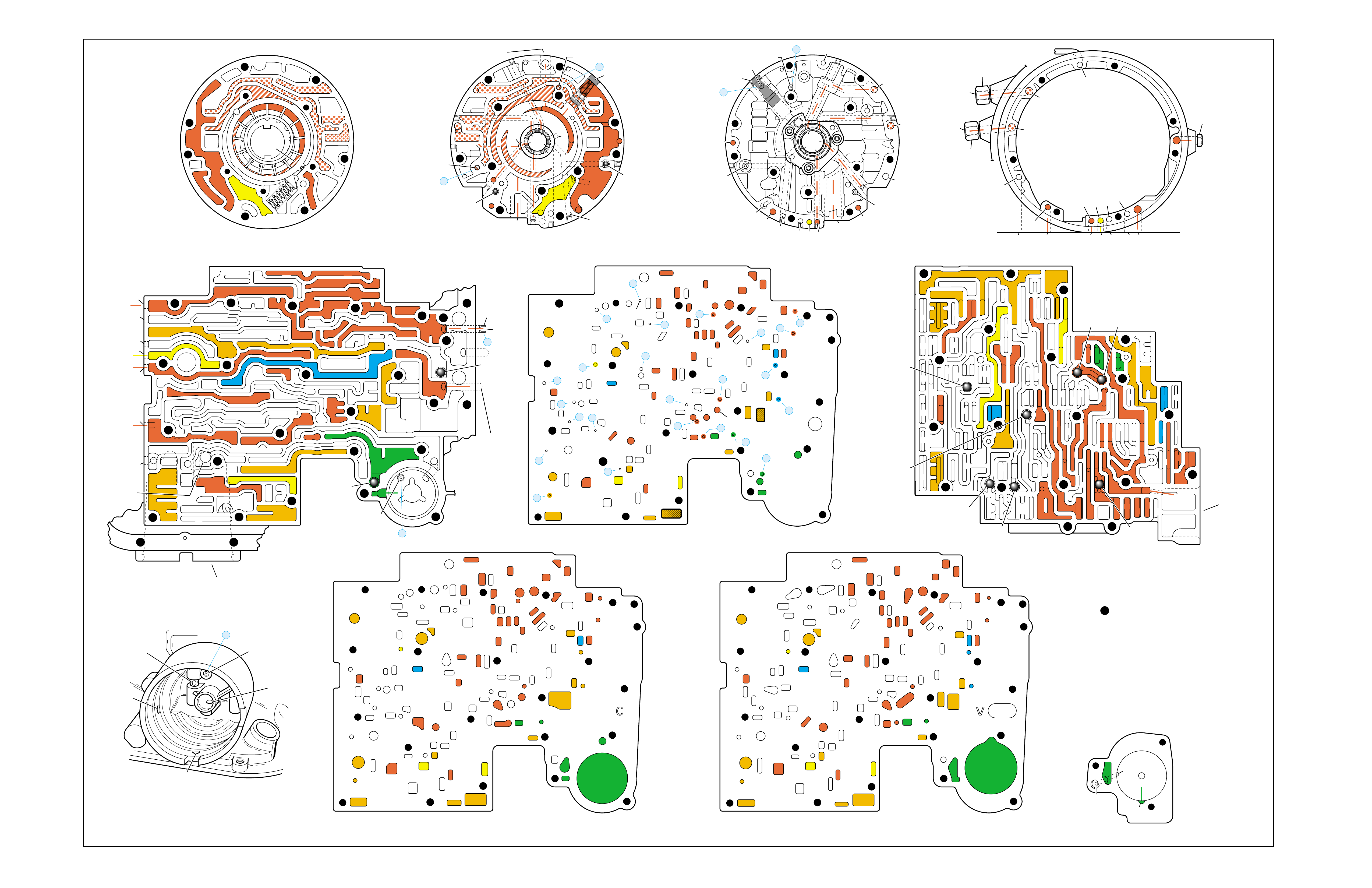
Figure 94
MANUAL FIRST – FIRST GEAR (from Manual Second – Second Gear)
➤
➤
➤
➤
➤
➤
➤
➤
➤
➤
➤
➤
➤➤
➤➤➤
➤
➤
➤
➤
➤
➤
➤
➤
➤
➤
➤
➤
➤
➤
➤ ➤
➤
➤
➤
➤
➤ ➤
➤
➤
➤ ➤
➤➤
➤➤
➤
➤
PUMP BODY (200)
(Pump Cover Side)
PUMP COVER (215)
(Pump Body Side) PUMP COVER (215)
(Case Side)
CASE (103)
(Pump Cover Side)
CASE (103)
(Control Valve Body Side)
SPACER PLATE (48)
(Case/Control Valve Body) CONTROL VALVE BODY (60)
(Case Side)
12 38
312
34
18
15
16
38
29
16
47 47
29 15 29
9
9
29
12
38 41 17
24
18
9
30
34
25 24
25 43 37
33
24
25
30 27 22 27
34
34
13
35
34
36
31 31
33
33
48
9
9
26 3
25
11
99
925
28 32
11
26
17 20 20
9
25
20
21 21
24
36 35
39
24
27
24
13
9
10
24 10
14
22
912 42
41 44
42
17
18
34
17
12 14
41
38
41
11
3
25
39
24 10
18
18
29
29
29
16
48
43
9
14
44
26
25
31
20
GASKET (47)
(Case/Spacer Plate)
GASKET (52)
(Spacer Plate/Control Valve Body)
CASE (103)
(2-4 Servo Bore)
1-2 ACCUMULATOR COVER (57)
NOTE:
- INDICATES BOLT HOLES
- NON-FUNCTIONAL HOLES
HAVE BEEN REMOVED FROM
COMPONENT DRAWINGS
TO SIMPLIFY TRACING FLUID
FLOW.
- EXHAUST FLUID NOT SHOWN
21
25
25
20
28
#7/(40)
44
(11)
25
43
32
3
16
(237)
18
43
3
(240)
37
(237)
43
47
45
43
43
48
11
29
16
3
16
29 18
2
(240)
8
85
37
37
1
47
(232)
7
46
45 47
3
3
8
43
5
4
2
4
4
48
43
3
6
1
43
2
7
47 46
43 11
3
16
37
37
5
37 8
29
18
29
1
(232)
2
43
47
16
(237)
37
(237)
4
(238)
2
(240)
PRESSURE RELIEF
VALVE BORE
➤
16
45
8
7
48
37
11 29 16
3
18
3
(39)
8
7
(10)
(10)
48 37 316291118
47 45
8
43
5
4
4
4
3
3
3
2
43
16
11
29
43
43
46
37 47
48
7
4
2
3
1
3
13V
12a 38b
3a
12b
34b
18b
38d
18c
13b
15d
16a
38c
15a
9m
9n
11c
29e
29d
9o
27b/29
29a
29f/28
15b/16
35a
22b
27d
30a
30b
34f
25a 24h
31c
25b
33c
24g 34e
31b
31a
27a
33a
33b
32a
37a
36a
3c
26b
11b
9c
25f
28a
9e
9p
9b
9d/10
(50)
48b
43a
25d
3b 11a
20c
25g
21a
9f
20e/21
17f 20a
9g
10a
35c/39
35b
35d/36
24f
24d 24c 13a
24a24b
41d
17c
41c
12c
17b/18 18a17d
42a
43c/44 9h 12e
22a 14b
10c/22
42b
14a
12d
17e
34a 41a
41b 38a
24m/25
47
9k/10
(49)
10b/23
20b
24e
17g
20d/21
25e
9a
48a
26a
43b/44
24k/25
34c
34d
29c
29b
29g/28
15c/16
17a/18 14c
44a
38e/39
27c/29
35e/36
➤
7
➤
5
➤
6
➤
16
➤
17
➤
8
➤
9
➤
32
➤
10
➤
12
➤
18
➤
20
➤
21
➤
22
➤
13
➤
14
➤
23
➤
25
➤
29
➤
30
➤
31
➤
26
➤
27
➤
28
➤
24
➤➤
1
➤➤
2
➤➤
2
➤➤
4
➤➤
11
➤➤
19
12 38
3
18
38
16
28
29
15
34
29
9
9
15
29
11
929
40
15 43
35 34
31
31 33 33
22
27
30
34
30
25 24 24
24 31
25 43
48
26
33 37
36 32
25
28
9
26
9
311
25 25 3
910
11 21 20
25
9
10
17 20
35 35/39
24
27 24 24
13
13
22
14
22
912 42
14
12
24
24
18
38 41 17
41
12 42
17
17
34
12 34 41
38
17
44
47
923
20
17
9
9
48 44
34
29
29 18
24
14
43
10
25
41
38
34
9
9
947
9
9
3
3
25
25
11
11
26
47
26
47
25
47
3
10
43
47 11
43
33
31
24
30
37 36
28
11
34
25
24
22
24
35
34
30 27
31 32
47 25
29
9
15
40
28 29 29 16
15
43
15 12
38
3
341 47
17 34 38 41
34
18
12
17
42
43
12
18
47
47
14
43
14 42
922
23
10
9
17
17
24
38
13 24
43
42
41
3
33
31 24 24
17 47
13
17 20 20
27
#8
#6 #5
#3
#2 #12
#4
FORWARD
CLUTCH
ACCUMULATOR
BORE
➤
17
47
47
35
47
43
47
47
47 48
48
47
47
47
47 9
26
47 12 38
3
3
29
38
16
47 29
15
29
11
18
30 27 27
18
34
47
34
25 24
31
33
43
37 37
48
47
47
47
47
47 47
9
25
311
32
28 32
25
21
20
33
33
25
9
39
35
35 24 47
24 22
22 10 47
14
12
9
99
44
17 47 42
41
17
14
12
12
18
34
34
41
9
9
9
36
9
17
17
12
14
11
9
11
34
16 16
22
13 13
#10
#1
#7
(40)
37
18
11
29
16
3
29
341
38
44
(38)
28
47
43
47
48
36
33
9
33
38
19
26
47
47
2-4 SERVO BORE
➤
REAR
LUBE
TO
LOW AND
REVERSE
CLUTCH
FOLDOUT ➤ 97
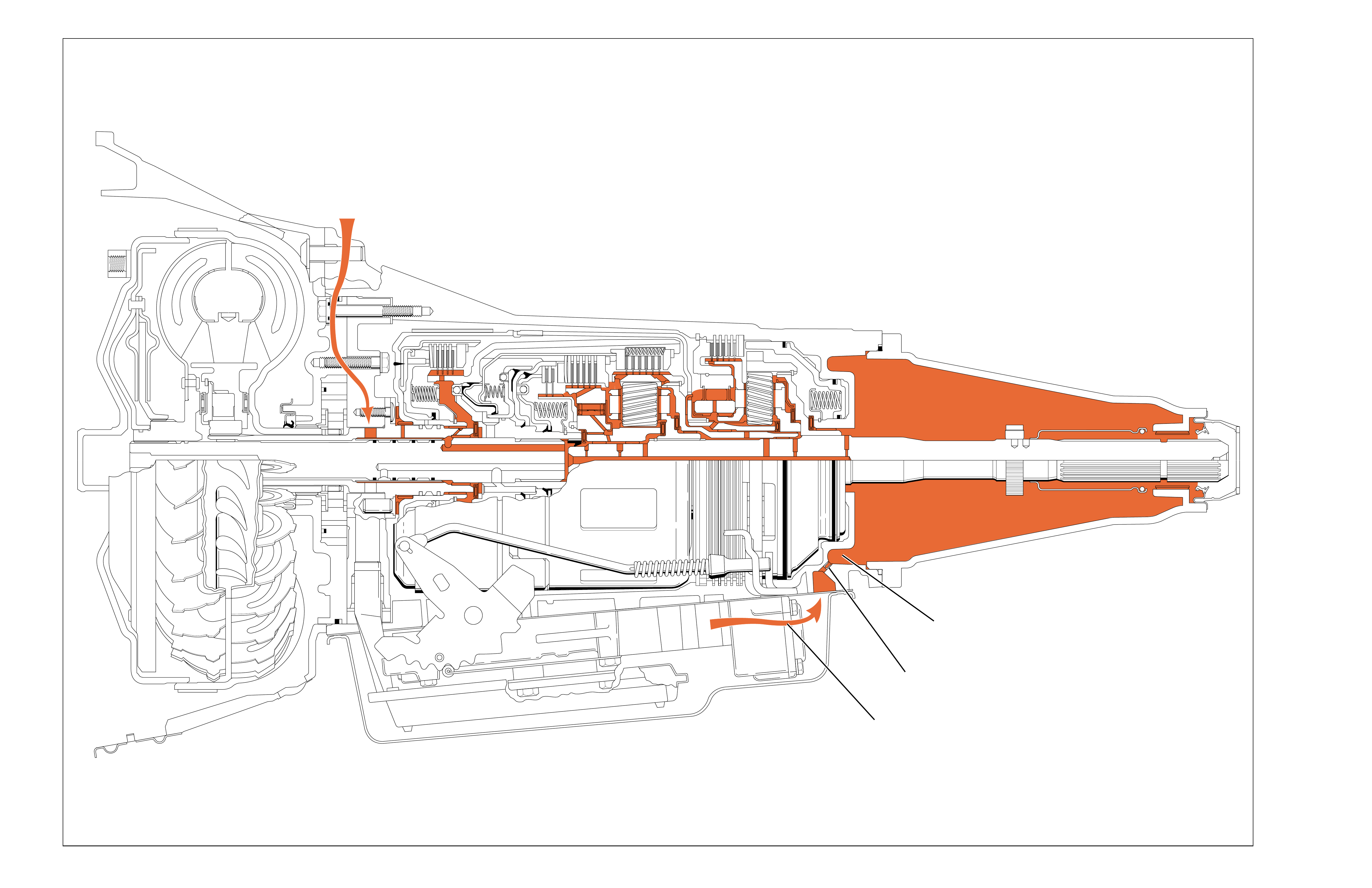
LUBRICATION POINTS
LUBE
FROM COOLER
D4
FLUID
ORIFICED
CUP
PLUG
REAR
LUBE
FLUID
COOLER AND LUBRICATION CIRCUITS
To maintain proper transmission fluid temperature,
the fluid is routed to the transmission fluid cooler
located in the vehicle radiator. After the fluid is
cooled it is routed back to the transmission and
into the lubrication fluid circuit. Lube fluid is
routed through the oil pump assembly, into the
turbine shaft and down the center axis of the
transmission. This fluid is routed into the various
clutch packs and onto the planetary gear sets to
cool and lubricate the various components.
The rear of the transmission is lubricated by D4
fluid feeding the rear lube fluid circuit through an
orifice cup plug (#24). Rear lube fluid is routed
into the transmission case extension housing (31)
to cool and lubricate the bushings and components
in the housing.
Figure 95
98
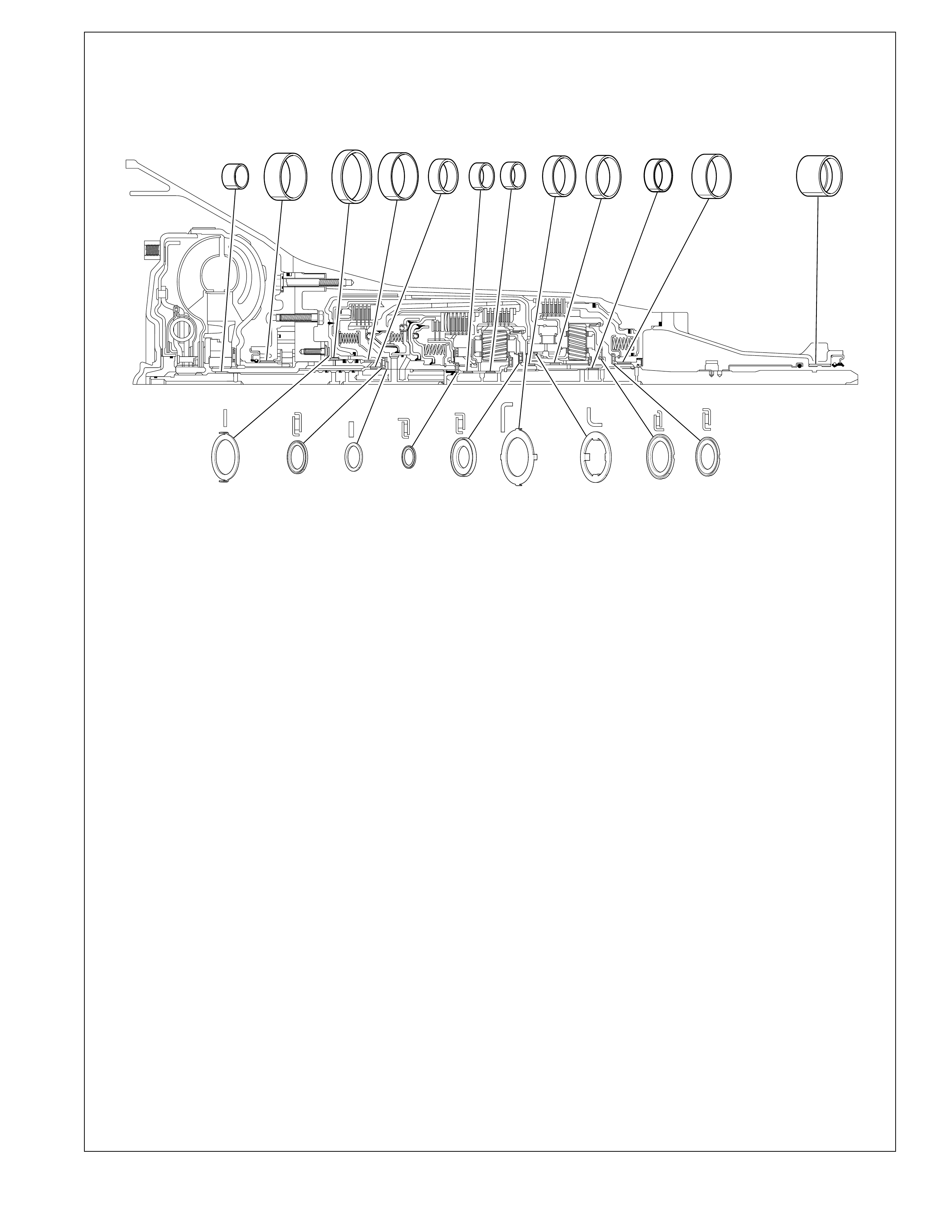
99
7 CASE BUSHING
33 CASE EXTENSION BUSHING
234 STATOR SHAFT BUSHING (FRONT)
241 STATOR SHAFT BUSHING (REAR)
242 OIL PUMP BODY BUSHING
601 THRUST WASHER (PUMP TO DRUM)
603 REVERSE INPUT CLUTCH BUSHING (FRONT)
606 REVERSE INPUT CLUTCH BUSHING (REAR)
615 STATOR SHAFT/ SELECTIVE WASHER BEARING
ASSEMBLY
616 THRUST WASHER (SELECTIVE)
637 INPUT SUN GEAR BEARING ASSEMBLY
WH13165-4L60-E
Bushing and Bearing Locations
Figure 96
234 242 603 241 657 659 665 672 667 7
606 33
601 615 616 637 663 669 674 683 692
657 INPUT SUN GEAR BUSHING (FRONT)
659 INPUT SUN GEAR BUSHING (REAR)
663 THRUST BEARING ASSEMBLY (INPUT CARRIER TO
REACTION SHAFT)
665 REACTION CARRIER SHAFT BUSHING (FRONT)
667 REACTION CARRIER SHAFT BUSHING (REAR)
669 THRUST WASHER (REACTION SHAFT/SHELL)
672 REACTION GEAR BUSHING
674 THRUST WASHER (RACE/REACTION SHELL)
683 THRUST BEARING ASSEMBLY (REACTION CARRIER/
SUPPORT)
692 REACTION GEAR SUPPORT TO CASE BEARING
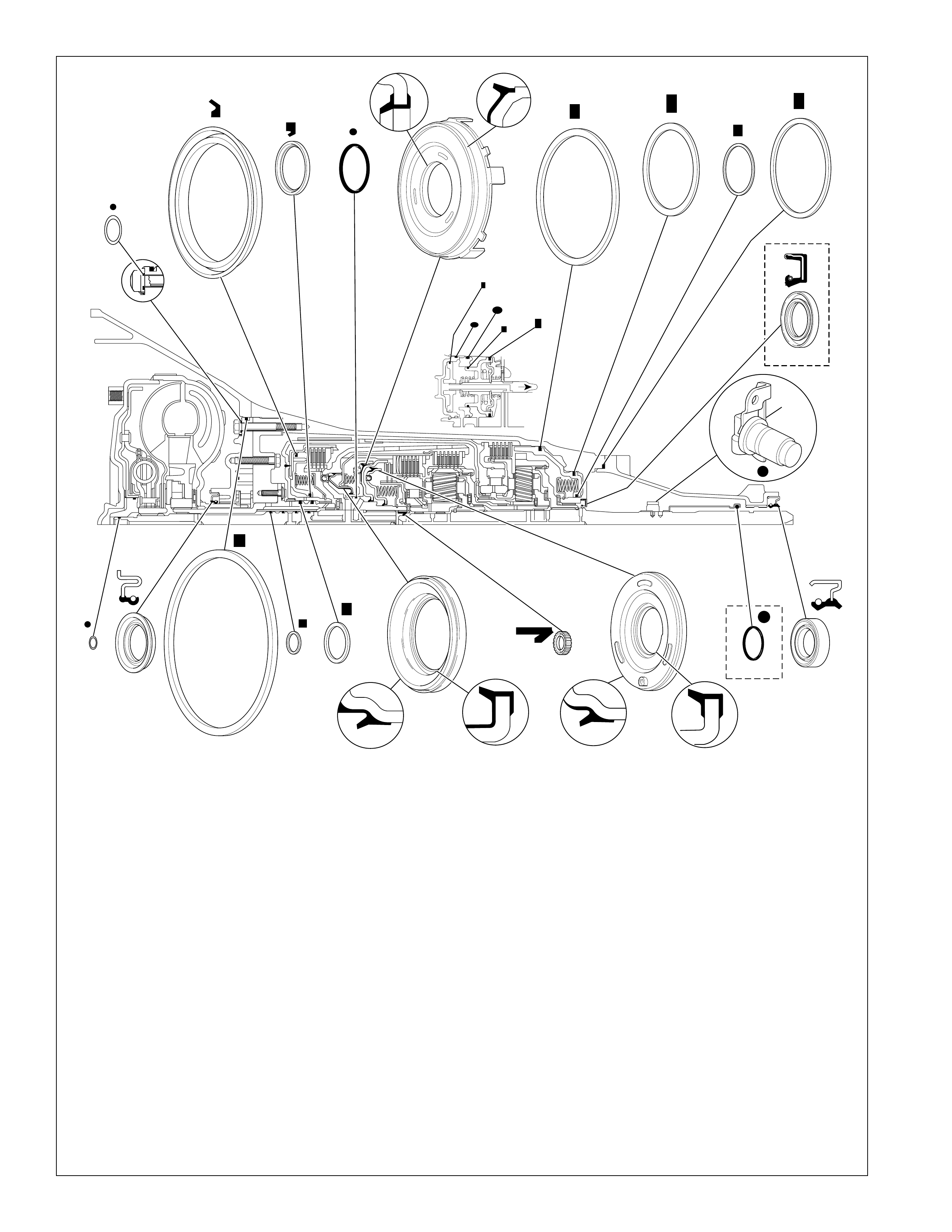
100
608A REVERSE INPUT CLUTCH SEAL (INNER)
608B REVERSE INPUT CLUTCH SEAL (OUTER)
618 O-RING SEAL (TURBINE SHAFT/ SELECTIVE WASHER)
619 OIL SEAL RING (SOLID)
622 INPUT TO FORWARD HOUSING O-RING SEAL
623 3RD AND 4TH CLUTCH PISTON
630 FORWARD CLUTCH PISTON
632 OVERRUN CLUTCH PISTON
636 INPUT HOUSING TO OUTPUT SHAFT SEAL
691 OUTPUT SHAFT SEAL (MODEL DEPENDENT)
696A LOW AND REVERSE CLUTCH SEAL (OUTER)
696B LOW AND REVERSE CLUTCH SEAL (CENTER)
696C LOW AND REVERSE CLUTCH SEAL (INNER)
3 PUMP TO CASE BOLT O-RING
5 OIL SEAL (PUMP TO CASE)
18 OIL SEAL RING (2ND APPLY PISTON - OUTER)
19 OIL SEAL RING (2ND APPLY PISTON - INNER)
21 O-RING SEAL
26 OIL SEAL RING (4TH APPLY PISTON - OUTER)
27 O-RING SEAL (2-4 SERVO COVER)
30 CASE EXTENSION TO CASE SEAL
34 CASE EXTENSION OIL SEAL ASSEMBLY
37 O-RING SEAL (ITSS TO CASE EXTENSION)
106 CASE OIL SEAL ASSEMBLY (Y CAR ONLY)
230 OIL SEAL RING (STATOR SHAFT)
243 OIL SEAL ASSEMBLY
608A
608B
622 630
632
696A 696B
696C
618
243
5
619 230
623
636 691
106
34
3
30
18
19
21
27
26
37
WH338497-4L60-E
Seal Locations
Figure 97

101
ILLUSTRATED PARTS LIST
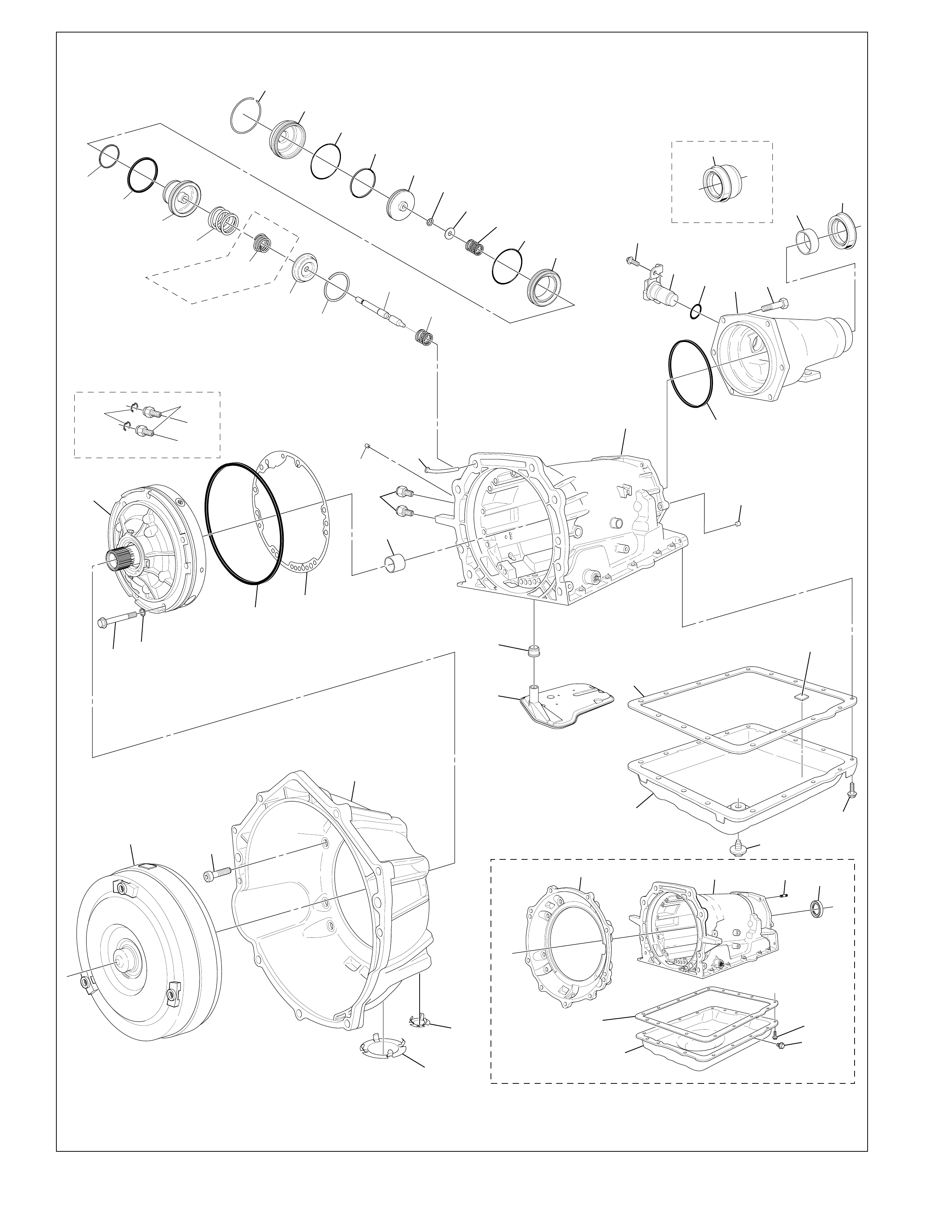
102
23
4
56
71
72
29 28 27
26
25 24 23 22 21 20
103
12
11
13
14
15
16
105
17
18
19
SOME
MODELS
9
10
7
SOME MODELS
96 95
SOME MODELS
SOME MODELS
102 103 100 106
73
75
76
101
34
33
32
31
37
30
99
34
36
35
75
73
74
76
107
94
102
1
98
97
YH586909-4L60-E
Case and Associated Parts (1 of 2)
Figure 98

103
1 TORQUE CONVERTER ASSEMBLY
(MODEL DEPENDENT)
2 PUMP TO CASE BOLT
3 PUMP TO CASE BOLT O-RING
4 OIL PUMP ASSEMBLY
5 OIL SEAL (PUMP TO CASE)
6 PUMP COVER TO CASE GASKET
7 CASE BUSHING
9 TRANSMISSION VENT ASSEMBLY
10 OIL COOLER PIPE CONNECTOR (MODEL DEPENDENT)
11 CASE SERVO PLUG
12 SERVO RETURN SPRING
13 2ND APPLY PISTON PIN
14 RETAINER RING (2ND APPLY PISTON)
15 SERVO CUSHION SPRING RETAINER
16 SERVO CUSHION SPRING (OUTER)
17 2ND APPLY PISTON
18 OIL SEAL RING (2ND APPLY PISTON - OUTER)
19 OIL SEAL RING (2ND APPLY PISTON - INNER)
20 SERVO PISTON HOUSING (INNER)
21 O-RING SEAL
22 SERVO APPLY PIN SPRING
23 SERVO APPLY PIN WASHER
24 RETAINER RING (APPLY PIN)
25 4TH APPLY PISTON
26 OIL SEAL RING (4TH APPLY PISTON - OUTER)
27 O-RING SEAL (2-4 SERVO COVER)
28 2-4 SERVO COVER
29 SERVO COVER RETAINING RING
30 CASE EXTENSION TO CASE SEAL
31 CASE EXTENSION (MODEL DEPENDENT)
32 CASE EXTENSION TO CASE BOLT
33 CASE EXTENSION BUSHING
34 CASE EXTENSION OIL SEAL ASSEMBLY
(MODEL DEPENDENT)
35 SPEED SENSOR RETAINING BOLT
36 INTERNAL TRANSMISSION SPEED SENSOR
37 O-RING SEAL (ITSS TO CASE EXTENSION)
71 FILTER SEAL
72 TRANSMISSION OIL FILTER ASSEMBLY
(MODEL DEPENDENT)
73 TRANSMISSION OIL PAN GASKET
74 CHIP COLLECTOR MAGNET
75 TRANSMISSION OIL PAN (MODEL DEPENDENT)
76 TRANSMISSION OIL PAN SCREW
94 CONVERTER HOUSING TO CASE BOLT
95 OIL COOLER QUICK CONNECTOR
(MODEL DEPENDENT)
96 OIL COOLER QUICK CONNECT CLIP
(MODEL DEPENDENT)
97 CONVERTER HOUSING ACCESS HOLE PLUG
(MODEL DEPENDENT)
98 CONVERTER BOLT INSPECTION PLATE
(MODEL DEPENDENT)
99 CUP D4 ORIFICE PLUG
100 A/TRANS. CASE STUD (Y-CAR ONLY)
101 A/TRANS. OIL PAN PLUG ASSEMBLY (Y-CAR ONLY)
102 CONVERTER HOUSING (MODEL DEPENDENT)
103 MAIN CASE SECTION (MODEL DEPENDENT)
105 SERVO CUSHION SPRING (INNER)
(MODEL DEPENDENT)
106 CASE OIL SEAL ASSEMBLY (Y-CAR ONLY)
107 PLUG ASSEMBLY A/TRANS. OIL PAN HEX HEAD
(C/K TRUCK ONLY)
Case and Associated Parts (1 of 2) Legend
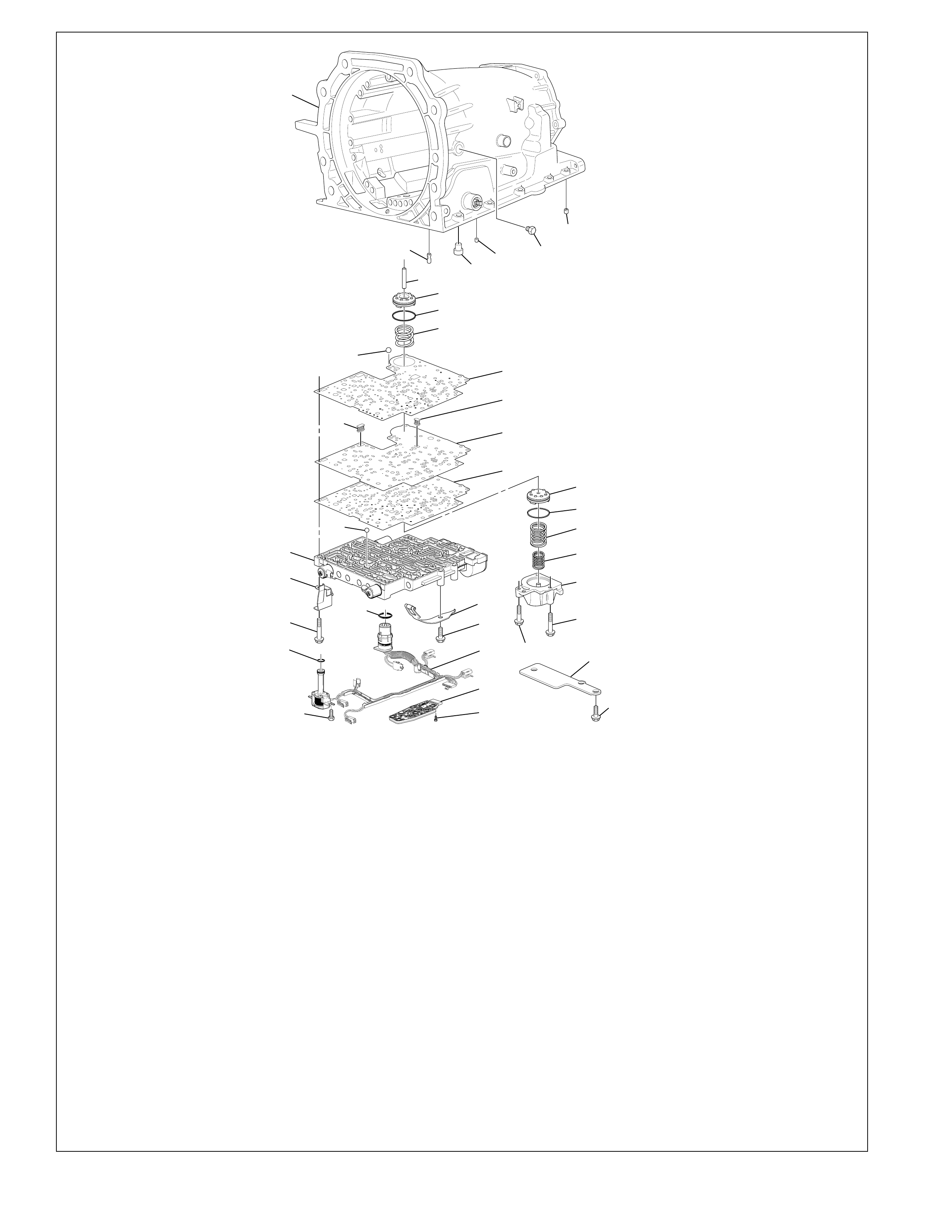
104
66
65
67
68
38
39
42
41
40
103
L
D3
R
D2
43 44
45
46
47
49
48
54
104
52
50
55
56
57
63
64
61
60
62
59
58
53
77
69
70
91
93
38 TRANSMISSION CASE PLUG (ACCUMULATOR BLEED)
39 PRESSURE PLUG
40 3RD ACCUMULATOR RETAINER AND BALL
ASSEMBLY (#7)
41 BAND ANCHOR PIN
42 RETAINER AND BALL ASSEMBLY (DOUBLE ORIFICE)
(#10)
43 ACCUMULATOR PISTON PIN
44 3-4 ACCUMULATOR PISTON
45 OIL SEAL RING (3-4 ACCUMULATOR PISTON)
46 3-4 ACCUMULATOR SPRING (MODEL DEPENDENT)
47 SPACER PLATE TO CASE GASKET
48 VALVE BODY SPACER PLATE
49 SHIFT SOLENOIDS SCREEN
50 PRESSURE CONTROL SOLENOID SCREEN
52 SPACER PLATE TO VALVE BODY GASKET
53 SPACER PLATE SUPPORT PLATE
54 1-2 ACCUMULATOR SPRING (OUTER)
55 OIL SEAL RING (1-2 ACCUMULATOR)
56 1-2 ACCUMULATOR PISTON
57 1-2 ACCUMULATOR COVER AND PIN ASSEMBLY
58 ACCUMULATOR COVER BOLT
59 ACCUMULATOR COVER BOLT
60 CONTROL VALVE BODY ASSEMBLY
61 CHECKBALL (#2, 3, 4, 5, 6, 8, 12)
62 VALVE BODY BOLT
63 MANUAL DETENT SPRING ASSEMBLY
64 MANUAL DETENT SPRING BOLT
65 WIRING HARNESS PASS-THRU CONNECTOR O-RING
SEAL
66 WIRING HARNESS SOLENOID ASSEMBLY
67 O-RING SEAL (SOLENOID)
68 HEX WASHER HEAD BOLT (SOLENOID)
69 TRANSMISSON FLUID PRESSURE MANUAL VALVE
POSITION SWITCH ASSEMBLY
70 PRESSURE SWITCH ASSEMBLY BOLT
77 SPACER PLATE SUPPORT BOLT
91 NUMBER 1 CHECKBALL
93 DIPSTICK STOP BRACKET (MODEL DEPENDENT)
103 MAIN CASE SECTION (MODEL DEPENDENT)
104 1-2 ACCUMULATOR SPRING (INNER)
YH283778-4L60-E
Case and Associated Parts (2 of 2)
Figure 99
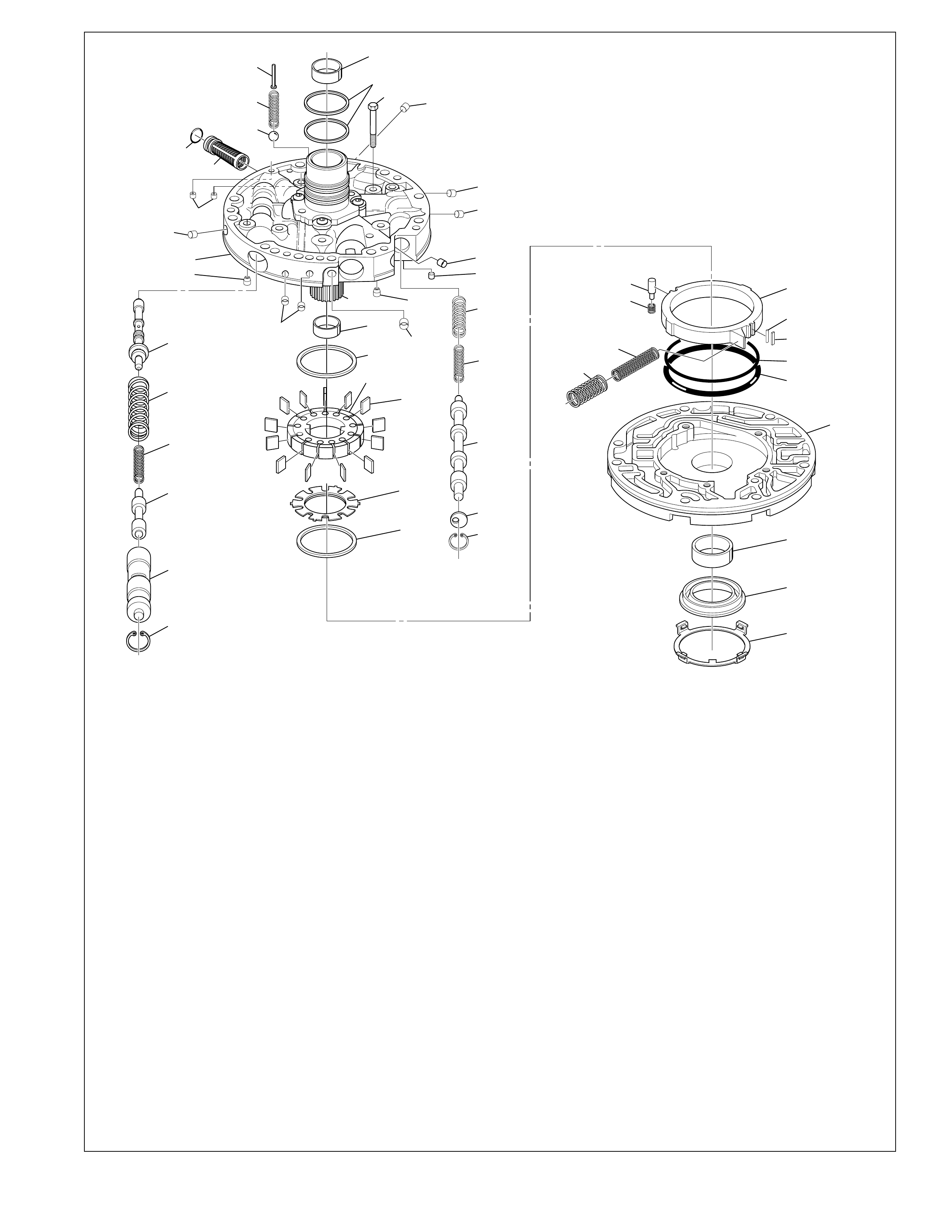
105
200 PUMP BODY
201 OIL SEAL RING (SLIDE TO WEAR PLATE)
202 O-RING SEAL (SLIDE SEAL BACK-UP)
203 PUMP SLIDE
204 PIVOT PIN SPRING
205 PIVOT SLIDE PIN
206 PUMP SLIDE SPRING (OUTER)
207 PUMP SLIDE SPRING (INNER)
208 PUMP SLIDE SEAL SUPPORT
209 PUMP SLIDE SEAL
210 PUMP VANE RING
211 ROTOR GUIDE
212 OIL PUMP ROTOR
213 PUMP VANE
214 STATOR SHAFT
215 PUMP COVER
216 PRESSURE REGULATOR VALVE
217 PRESSURE REGULATOR VALVE SPRING
218 PRESSURE REGULATOR ISOLATOR SPRING
219 REVERSE BOOST VALVE
220 REVERSE BOOST VALVE SLEEVE
221 OIL PUMP REVERSE BOOST VALVE RETAINING RING
222 OIL PUMP CONVERTER CLUTCH VALVE RETAINING
RING
223 STOP VALVE
224 CONVERTER CLUTCH VALVE
225 CONVERTER CLUTCH VALVE SPRING (INNER)
226 CONVERTER CLUTCH VALVE SPRING (OUTER)
227 PRESSURE RELIEF BOLT RIVET
228 PRESSURE RELIEF BALL
229 PRESSURE RELIEF SPRING
230 OIL SEAL RING (STATOR SHAFT)
231 OIL PUMP COVER SCREEN SEAL
232 OIL PUMP COVER SCREEN
233 COVER TO BODY BOLT
234 STATOR SHAFT BUSHING (FRONT)
235 OIL PUMP COVER PLUG (FWD CLUTCH FEED)
236 OIL PUMP COVER PLUG
237 CHECK VALVE RETAINER AND BALL ASSEMBLY
238 CONVERTER CLUTCH SIGNAL ORIFICE (CUP PLUG)
240 CUP ORIFICE PLUG
241 STATOR SHAFT BUSHING (REAR)
242 PUMP BODY BUSHING
243 OIL SEAL ASSEMBLY
244 FRONT HELIX RETAINER
215
236 240
232
231
228
229
227 241
230
233 236
236
238
237
236
236
236
237
235
234
210
212
213
211
210
203
208
209
202
201
200
242
243
244
226
225
224
223
222
216
217
218
219
220
221
205
204
206 207
214
XH405105-4L60-E
Oil Pump Assembly
Figure 100
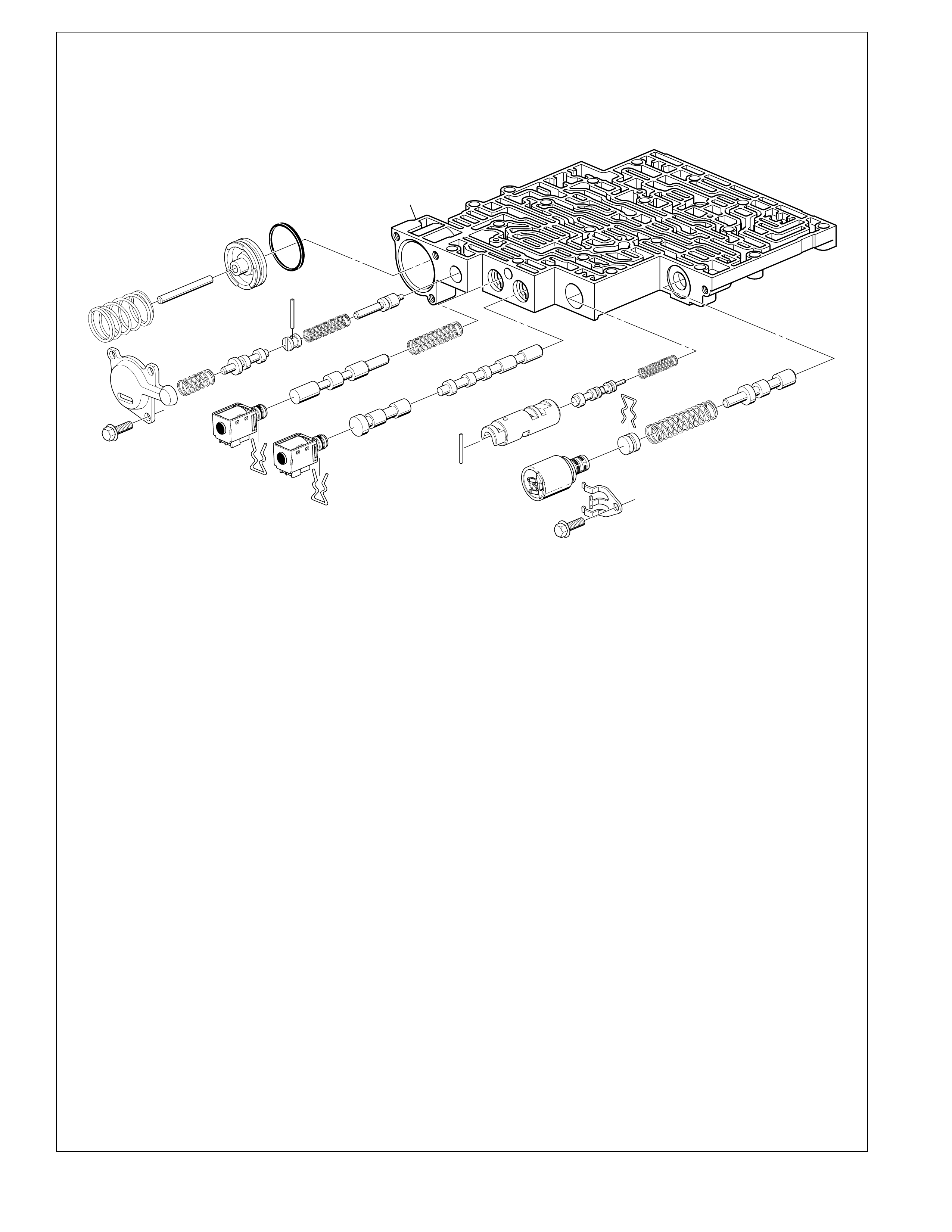
106
350
353
354
355
356 357
358
360
359
361
362
363
364
367A
366
365
368
369
367B
395
395
360
372
371
370
374
375
376
395
378
364
377
366 1-2 SHIFT VALVE
367A 1-2 SHIFT SOLENOID VALVE
367B 2-3 SHIFT SOLENOID VALVE
368 2-3 SHIFT VALVE
369 2-3 SHUTTLE VALVE
370 1-2 ACCUMULATOR VALVE SPRING
371 1-2 ACCUMULATOR VALVE
372 1-2 ACCUMULATOR VALVE SLEEVE
374 ACTUATOR FEED LIMIT VALVE
375 ACTUATOR FEED LIMIT VALVE SPRING
376 BORE PLUG
377 PRESSURE CONTROL SOLENOID VALVE
378 PRESSURE CONTROL SOLENOID RETAINER
395 BORE PLUG AND SOLENOID RETAINER
350 CONTROL VALVE BODY
353 FORWARD ACCUMULATOR OIL SEAL
354 FORWARD ACCUMULATOR PISTON
355 FORWARD ACCUMULATOR PIN
356 FORWARD ACCUMULATOR SPRING
357 FORWARD ABUSE VALVE
358 FORWARD ABUSE VALVE SPRING
359 BORE PLUG
360 COILED SPRING PIN
361 LOW OVERRUN VALVE
362 LOW OVERRUN VALVE SPRING
363 FORWARD ACCUMULATOR COVER
364 FORWARD ACCUMULATOR COVER BOLT
365 1-2 SHIFT VALVE SPRING
XH405111-4L60-E
Control Valve Body Assembly (1 of 2)
Figure 101
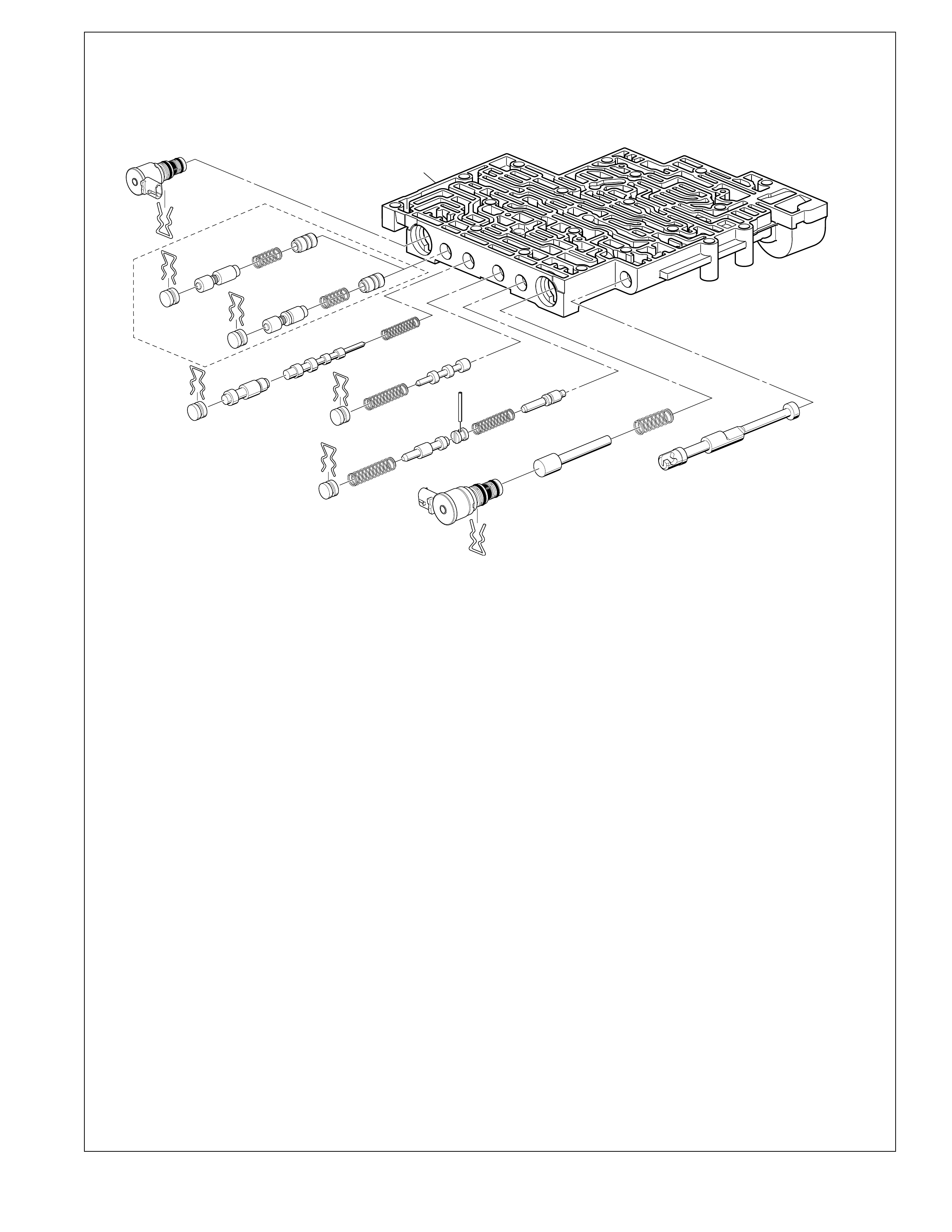
107
380
381 382
383
395
384
381
395
381
395
385
386
381
395 387
388
360
359
390
389 391
392
394
395
340
350
395
396
397
SOME
MODELS
398
380
381
395
397
398
340 MANUAL VALVE
350 CONTROL VALVE BODY
359 BORE PLUG
360 COILED SPRING PIN
380 REGULATOR APPLY VALVE (MODEL DEPENDENT)
381 BORE PLUG
382 4-3 SEQUENCE VALVE SPRING
383 4-3 SEQUENCE VALVE
384 3-4 RELAY VALVE
385 3-4 SHIFT VALVE
386 3-4 SHIFT VALVE SPRING
387 REVERSE ABUSE VALVE
388 REVERSE ABUSE VALVE SPRING
389 3-2 DOWNSHIFT VALVE
390 3-2 DOWNSHIFT VALVE SPRING
391 3-2 CONTROL VALVE
392 3-2 CONTROL VALVE SPRING
394 3-2 CONTROL SOLENOID VALVE
395 BORE PLUG AND SOLENOID RETAINER
396 TCC PWM SOLENOID VALVE
397 REGULATOR APPLY SPRING (MODEL DEPENDENT)
398 ISOLATOR VALVE (MODEL DEPENDENT)
XH405114-4L60-E
Control Valve Body Assembly (2 of 2)
Figure 102
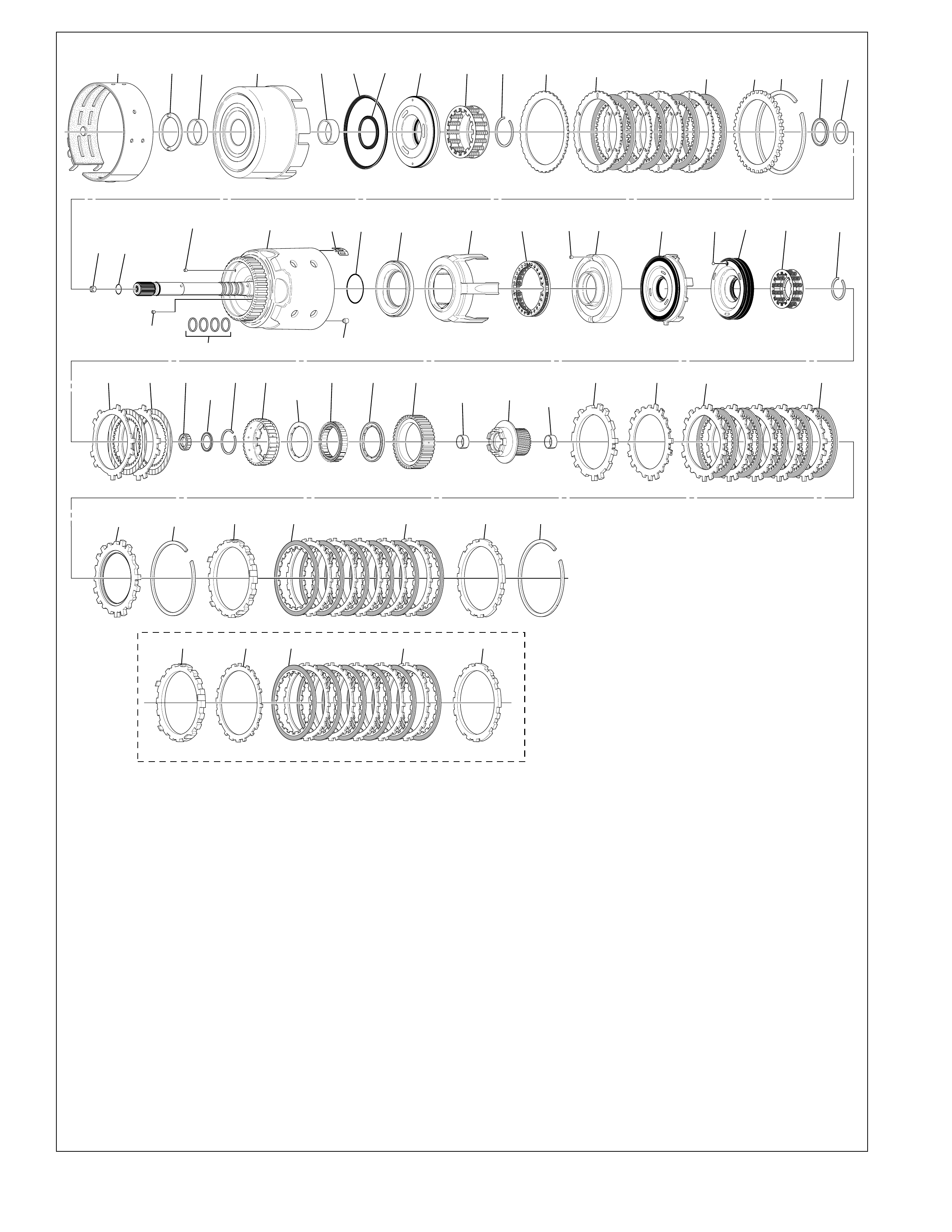
108
602 601 603 605 606 608B 608A 607 609 610 611 612A 612B 613 614 615 616
645A 645B 636 638 639 642
637 643 643 644 646 648 649A 649B
653651650 654A 654B 655 656
619
688 620
632 634 635
633
630
628627
626
625623622
600
621
698
618617
653 654A 654B 655652
640
657 659
SOME MODELS
YH213098-4L60-E
Internal Components (1 of 2)
Figure 103

109
600 3-4 CLUTCH BOOST SPRING ASSEMBLY (5)
601 THRUST WASHER (PUMP TO DRUM)
602 2-4 BAND ASSEMBLY
603 REVERSE INPUT CLUTCH BUSHING (FRONT)
605 REVERSE INPUT CLUTCH HOUSING AND DRUM
ASSEMBLY
606 REVERSE INPUT CLUTCH BUSHING (REAR)
607 REVERSE INPUT CLUTCH PISTON ASSEMBLY
608A REVERSE INPUT CLUTCH SEAL (INNER)
608B REVERSE INPUT CLUTCH SEAL (OUTER)
609 REVERSE INPUT CLUTCH SPRING ASSEMBLY
610 REVERSE INPUT CLUTCH SPRING RETAINER RING
611 REVERSE INPUT CLUTCH PLATE (BELLEVILLE)
612A REVERSE INPUT CLUTCH TURBULATOR PLATE
(STEEL)
612B REVERSE INPUT CLUTCH PLATE ASSEMBLY (FIBER)
613 REVERSE INPUT CLUTCH BACKING PLATE
(SELECTIVE)
614 REVERSE INPUT CLUTCH RETAINING RING
615 STATOR SHAFT/ SELECTIVE WASHER BEARING
ASSEMBLY
616 THRUST WASHER (SELECTIVE)
617 CHECK VALVE RETAINER AND BALL ASSEMBLY
618 O-RING SEAL (TURBINE SHAFT/ SELECTIVE WASHER)
(MODEL DEPENDENT)
619 OIL SEAL RING (SOLID)
620 RETAINER AND CHECKBALL ASSEMBLY
621 INPUT HOUSING AND SHAFT ASSEMBLY
(MODEL DEPENDENT)
622 O-RING SEAL INPUT TO FORWARD CLUTCH HOUSING
623 3RD AND 4TH CLUTCH PISTON
625 3RD AND 4TH CLUTCH RING (APPLY)
626 3RD AND 4TH CLUTCH SPRING ASSEMBLY
627 FORWARD CLUTCH HOUSING RETAINER AND BALL
ASSEMBLY
628 FORWARD CLUTCH HOUSING
630 FORWARD CLUTCH PISTON
632 OVERRUN CLUTCH PISTON
633 OVERRUN CLUTCH BALL
634 OVERRUN CLUTCH SPRING ASSEMBLY
635 OVERRUN CLUTCH SPRING RETAINER SNAP RING
636 INPUT HOUSING TO OUTPUT SHAFT SEAL
637 INPUT SUN GEAR BEARING ASSEMBLY
638 OVERRUN CLUTCH HUB RETAINING SNAP RING
639 OVERRUN CLUTCH HUB
640 FORWARD SPRAG CLUTCH INNER RACE AND INPUT
SUN GEAR ASSEMBLY
642 FORWARD SPRAG ASSEMBLY
643 SPRAG ASSEMBLY RETAINER RING
644 FORWARD CLUTCH RACE (OUTER)
645A OVERRUN CLUTCH PLATE (STEEL)
645B OVERRUN CLUTCH PLATE ASSEMBLY (FIBER)
646 FORWARD CLUTCH PLATE (APPLY)
648 FORWARD CLUTCH PLATE (WAVED)
649A FORWARD CLUTCH PLATE (STEEL)
649B FORWARD CLUTCH PLATE ASSEMBLY (FIBER)
650 FORWARD CLUTCH BACKING PLATE (SELECTIVE)
651 FORWARD CLUTCH BACKING PLATE RETAINER RING
652 3RD AND 4TH CLUTCH PLATE (STEEL)
(2.2L ENGINE ONLY)
653 3RD AND 4TH CLUTCH APPLY PLATE (STEPPED)
654A 3RD AND 4TH CLUTCH PLATE ASSEMBLY (FIBER)
(QUANTITY MODEL DEPENDENT)
654B 3RD AND 4TH CLUTCH PLATE (STEEL)
(QUANTITY MODEL DEPENDENT)
655 3RD AND 4TH CLUTCH BACKING PLATE (SELECTIVE)
(MODEL DEPENDENT)
656 3RD AND 4TH CLUTCH BACKING PLATE RETAINER
RING
657 INPUT SUN GEAR FRONT BUSHING
659 INPUT SUN GEAR REAR BUSHING
688 CUP PLUG
698 ORIFICED CUP PLUG
Internal Components (1 of 2) Legend
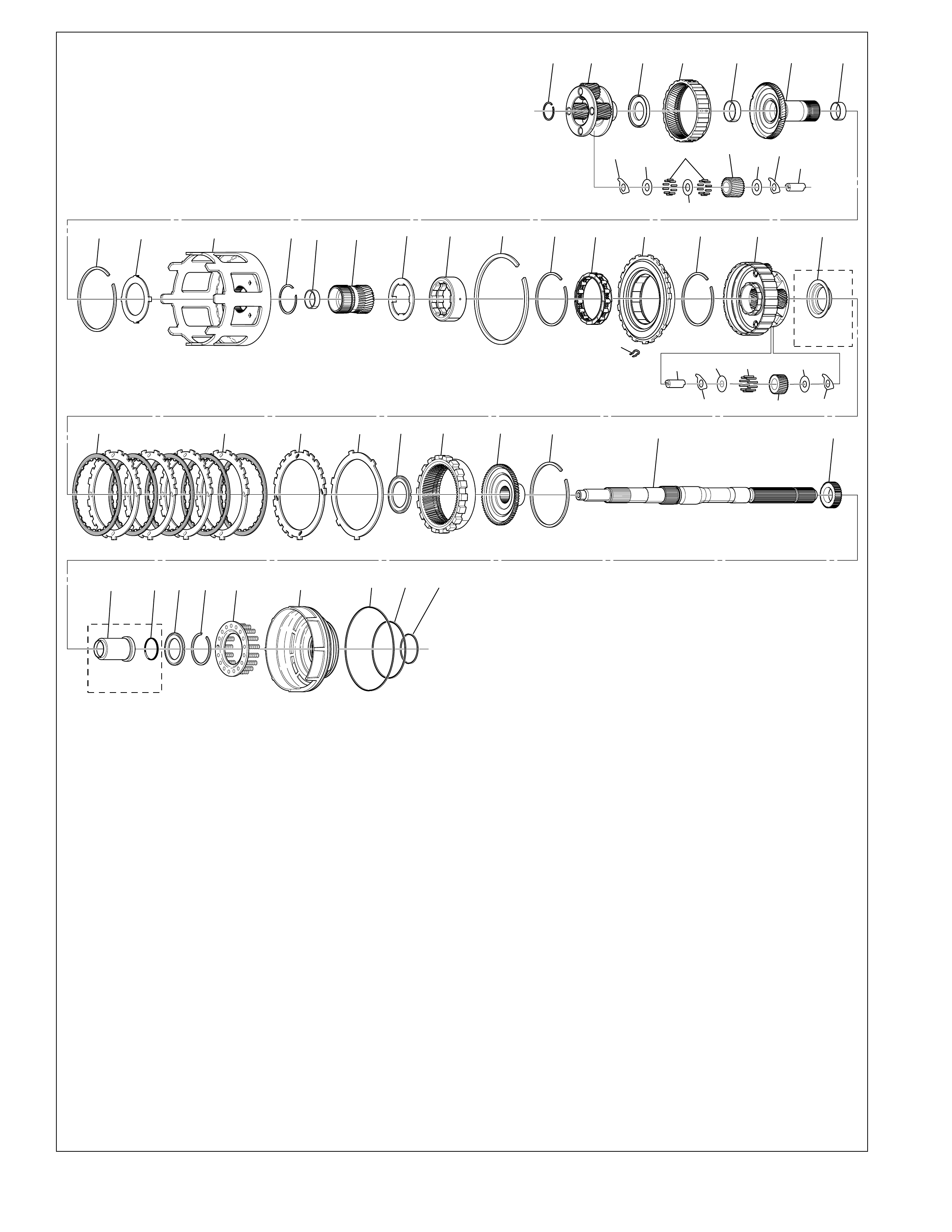
110
661 662 663 664 665 666 667
668 669 670 671 672 673 674 675 676 677 678 679 677 681 697
690 691 692 693 694 695 696A 696B 696C
SOME
MODELS
SOME
MODELS
682C 682B 682A 683 684682D 685 686 687 699
681A 681E 681D
681C
681C
681D
681B
680
662B
662F
662E
662D
662D 662A
662C662C
YH213103-4L60-E
Internal Components (2 of 2)
Figure 104
661 OUTPUT SHAFT TO INPUT CARRIER RETAINER
662 INPUT CARRIER ASSEMBLY
662A INPUT CARRIER PINION GEAR PIN
662B INPUT CARRIER PINION GEAR
662C INPUT CARRIER PINION WASHER
662D INPUT CARRIER PINION WASHER
662E INPUT CARRIER SPACER
662F INPUT CARRIER PINION/GEAR BEARING ROLLER
663 THRUST BEARING ASSEMBLY (INPUT CARRIER TO
REACTION SHAFT)
664 INPUT INTERNAL GEAR
665 REACTION CARRIER SHAFT FRONT BUSHING
666 REACTION CARRIER SHAFT
667 REACTION CARRIER SHAFT REAR BUSHING
668 REACTION SHAFT/INTERNAL GEAR RETAINER RING
669 THRUST WASHER (REACTION SHAFT SHELL)
670 REACTION SUN SHELL
671 REACTION SUN GEAR RETAINER RING
672 REACTION SUN BUSHING
673 REACTION SUN GEAR
674 THRUST WASHER (RACE/REACTION SHELL)
675 LOW AND REVERSE ROLLER CLUTCH RACE
676 LOW AND REVERSE SUPPORT TO CASE RETAINER
RING
677 LOW AND REVERSE ROLLER ASSEMBLY RETAINER
RING (CAM)
678 LOW AND REVERSE ROLLER CLUTCH ASSEMBLY
679 LOW AND REVERSE CLUTCH SUPPORT ASSEMBLY
680 LOW AND REVERSE CLUTCH SUPPORT RETAINER
SPRING
681 REACTION CARRIER ASSEMBLY
681A REACTION CARRIER PINION GEAR PIN
681B REACTION CARRIER PINION GEAR
681C REACTION CARRIER PINION BAT WINGED WASHER
681D REACTION CARRIER PINION WASHER
681E REACTION CARRIER PINION/GEAR NEEDLE ROLLER
682A LOW AND REVERSE CLUTCH PLATE (WAVED)
682B SPACER LOW AND REVERSE CLUTCH PLATE
(SELECTIVE)
682C LOW AND REVERSE CLUTCH PLATE ASSEMBLY
(FIBER)
682D LOW AND REVERSE CLUTCH TURBULATOR PLATE
(STEEL)
683 THRUST BEARING ASSEMBLY (REACTION CARRIER/
SUPPORT)
684 INTERNAL REACTION GEAR
685 INTERNAL REACTION GEAR SUPPORT
686 REACTION GEAR/SUPPORT RETAINER RING
687 OUTPUT SHAFT
690 OUTPUT SHAFT SLEEVE (MODEL DEPENDENT)
691 OUTPUT SHAFT SEAL (MODEL DEPENDENT)
692 REACTION GEAR SUPPORT TO CASE BEARING
693 LOW AND REVERSE CLUTCH RETAINER RING
694 LOW AND REVERSE CLUTCH SPRING ASSEMBLY
695 LOW AND REVERSE CLUTCH PISTON
696A LOW AND REVERSE CLUTCH SEAL (OUTER)
696B LOW AND REVERSE CLUTCH SEAL (CENTER)
696C LOW AND REVERSE CLUTCH SEAL (INNER)
697 OIL DEFLECTOR (HIGH OUTPUT MODELS ONLY)
699 INTERNAL TRANSMISSION SPEED SENSOR ROTOR
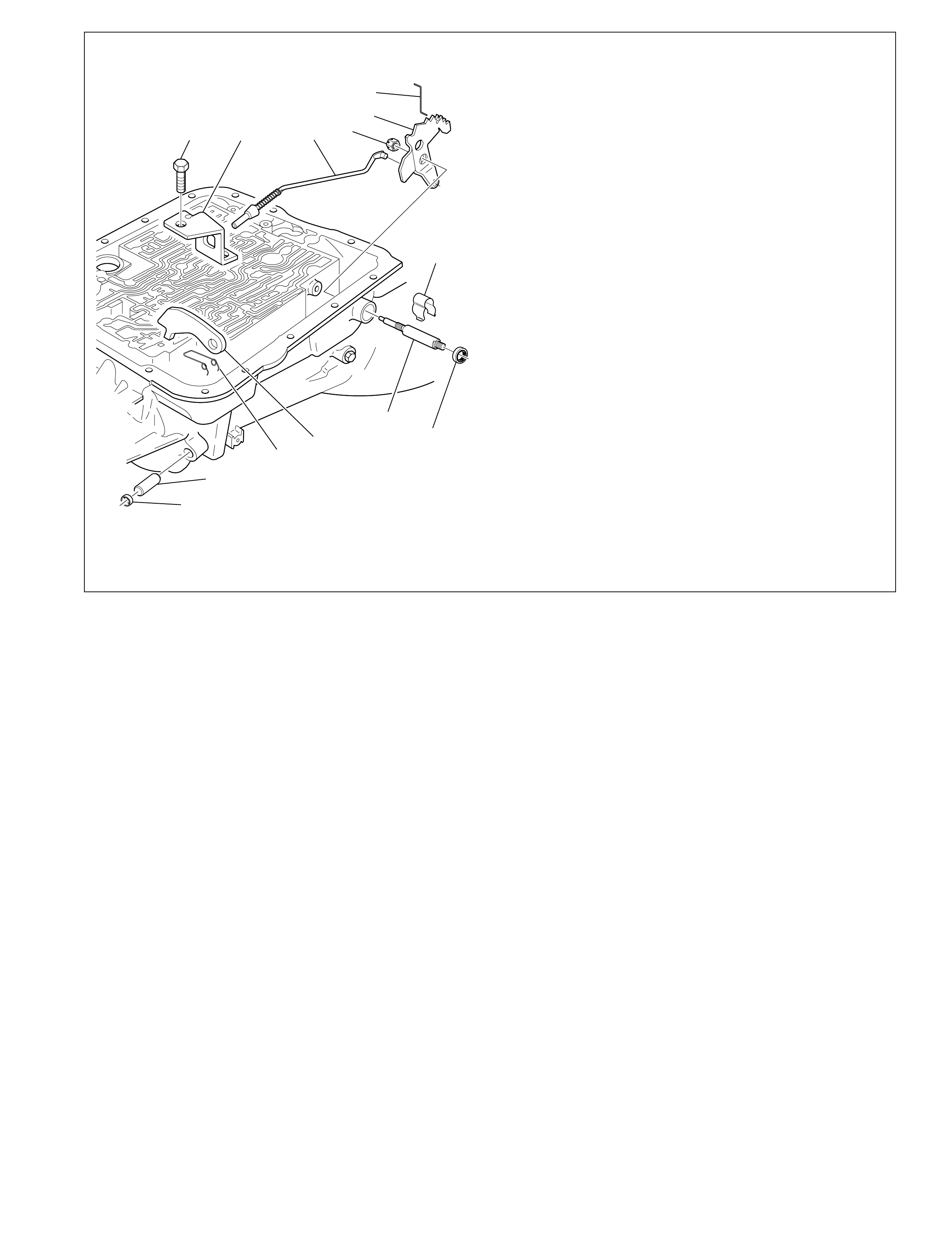
111
87 86 85 90 88
89
83
82
84
81
80
79
78
78 STEEL CUP PLUG
79 PARKING BRAKE PAWL SHAFT
80 PARKING PAWL RETURN SPRING
81 PARKING BRAKE PAWL
82 MANUAL SHAFT SEAL
83 MANUAL SHAFT RETAINER
84 MANUAL SHAFT (MODEL DEPENDENT)
85 PARKING LOCK ACTUATOR ASSEMBLY
86 PARKING LOCK BRACKET
87 PARKING LOCK BRACKET BOLT (2)
88 INSIDE DETENT LEVER
89 MANUAL VALVE LINK
90 HEX HEAD NUT
WH65111-4L60-E
Parking Pawl and Actuator Assembly
Figure 105
112
BASIC SPECIFICATIONS
Vehicles used in:
DIVISION MODEL
C/K Truck Chevrolet/GMC Pickup/Suburban
F Chevrolet/Pontiac Camaro/Firebird
G Van Chevrolet/GMC Express/Savana
M/L Van Chevrolet/GMC Astro/Safari
S/T Truck Chevrolet/GMC S10/Sonoma
Y Chevrolet Corvette
Transmission Drive
Rear Wheel Drive
4-Wheel Drive
All Wheel Dri ve
T r ansmission T ype
4L60-E = 4: Four Speed
L: Longitudinal Mount
60: Product Series
E: Electronically Controlled
Automatic Overdrive with a Torque Converter Clutch Assembly.
Current Engine Range
2.5 L to 5.7 L Gasoline
6.2 L Diesel
Control Systems
Shift Pattern –(2) Two-way on/off solenoids
Shift Quality –Pressure Control Solenoid
3-2 Control Solenoid
Torque Converter Clutch –Pulse Width Modulated
solenoid control
Gear Ratios
1st 3.059
2nd 1.625
3rd 1.000
4th 0.696
Rev 2.294
Maximum Engine Torque
475 N•m (350 lb ft)
Maximum Gearbox Torque
910 N•m (670 lb ft)
Maximum Shift Speed
1-2 6,000 RPM
2-3 6,000 RPM
3-4 6,000 RPM
Maximum Gross Vehicle Weight
3,900 kg (8,600 lb)
Transmission Fluid Type
Dexron® III
Transmission Fluid Capacities (Approximate)
245 mm Converter (Dry): 7.9 L (8.4 qt)
258 mm Converter (Dry): 8.8 L (9.3 qt)
298 mm Converter (Dry): 10.6 L (11.2 qt)
300 mm Converter (Dry): 10.6 L (11.2 qt)
T r ansmission W eight
245 mm Converter (Dry): 65.4 kg (144.30 lb)
(Wet): 72.4 kg (159.55 lb)
258 mm Converter (Dry): 79.9 kg (176.60 lb)
(Wet): 89.2 kg (197.70 lb)
298 mm Converter (Dry): 70.5 kg (155.70 lb)
(Wet): 80.5 kg (176.16 lb)
300 mm Converter (Dry): 70.5 kg (155.70 lb)
(Wet): 80.5 kg (176.16 lb)
Converter Sizes Available
245, 258, 298 and 300 mm Converter (Reference)
Converter Bolt Circle Diameters
For 245 and 258 mm Converter – 247.65 mm (Reference)
For 298 mm Converter – 273.05 mm (Reference)
For 300 mm Converter – 275.05 mm (Reference)
Converter Stall Torque Ratio Range
For 245 mm Converter – 1.63 to 2.70
For 258 mm Converter – 1.65 to 2.07
For 298 mm Converter – 1.84 to 2.34
For 300 mm Converter – 1.84 to 2.34
Converter “K” Factor Range
For 245 mm Converter – 122 to 240
For 258 mm Converter – 110 to 179
For 298 mm Converter – 100 to 140
For 300 mm Converter – 100 to 140
Not all “K” Factors are applicable across the range of Con ver ter Stall Torque Ratios.
Transmission Packaging Information*
Engine Mounting Face to Rear of Case
593.50 mm (Reference - Less Extension)
Overall Length
Current Minimum: 756.20 mm (Reference)
Current Maximum: 778.30 mm (Reference)
Case Extension Lengths
Determined by Customer Requirements
Current Minimum: 162.70 mm (Reference)
Current Maximum: 184.80 mm (Reference)
Current Converter Housings Available
245 mm and 258 mm (Small Bell Style)
298 mm and 300 mm (Large Bell Style)
Two-Piece Case with Separate Extension
Converter Housing
Main Case
*All dimensions shown are nominal.
Seven Position Quadrant
(P, R, N, D , D, 2, 1) / (P, R, N, D , 3, 2, 1)
Pressure Taps Available
Line Pressure
Information may vary with application. All information, illustrations and specifications
contained in this book are based on the latest product information available at the time of
publication. The right is reserved to mak e changes at any time without notice.
HYDRA-MATIC 4L60-E TRANSMISSION
RPO M30
HYDRA-MATIC 4L60-E
(FOUR-SPEED)
Produced at: Romulus, Michigan
Toledo, Ohio
U.S.A.
Mexico

113
HYDRA-MATIC 4L60-E
HYDRA-MATIC PRODUCT DESIGNATION SYSTEM
The product designation system used for all Hydra-matic
transaxles and transmissions consists of a series of numbers
and letters that correspond with the special features incorporated
in that product line. The first character is a number that
designates the number of forward gear ranges available in that
unit. For example: 4 = four forward gear ranges.
The second character is a letter that designates how the unit is
mounted in the vehicle. When the letter “T” is used, it
designates that the unit is transversely mounted and is used
primarily for front wheel drive vehicles. The letter “L”
designates that it is longitudinally mounted in the vehicle and
it is used primarily for rear wheel drive vehicles. The letter
“M” designates that the unit is a manual transaxle or
transmission but not specific to a front or rear wheel drive
vehicle application.
The third and fourth characters consists of a set of numbers,
(i.e. “60”), that designate the transaxle or transmission “Series”
number . This number signifies the relative torque capacity of
the unit.
The fifth character designates the major features incorporated
into this unit. For example , the letter “E” designates that the
unit has electronic controls.
By using this method of classification, the HYDRA-MATIC
4L60-E is a 4-speed, longitudinally mounted, 60 series unit,
with electronic controls.
HYDRA-MATIC 4 L 60 E
Number of Type: Series: Major Features:
Speeds: T - Transverse Based on E - Electronic Controls
3 L - Longitudinal Relative A - All Wheel Drive
4 M - Manual Torque HD - Heavy Duty
5 Capacity
V (CVT)

114
GLOSSARY OF TECHNICAL TERMS
Accumulator: A component of the transmission that
absorbs hydraulic pressure during the apply of clutch
or band. Accumulators are designed to control the
quality of a shift from one gear range to another.
Adaptive Learning: Programming within the PCM
that automatically adjusts hydraulic pressures in order
to compensate for changes in the transmission (i.e.
component wear).
Applied: An apply component that is holding another
component to which it is splined or assembled with.
Also referred to as “engaged”.
A pply Components:
Hydraulically operated clutc hes,
serv os, bands, and mechanical one-w ay roller or sprag
clutches that drive or hold members of a planetary
gear set.
Apply Plate: A steel clutch plate in a clutch pack
located next to the (apply) piston.
Backing Plate: A steel plate in a clutch pack that is
usually the last plate in that clutch assembly (farthest
from the clutch piston).
Ball Check Valve: A spherical hydraulically controlled
component (usually made of steel) that either seals or
opens fluid circuits. It is also referred to as a check
valve or checkball.
Band: An apply component that consists of a flexible
strip of steel and friction material that wraps around a
drum. When applied, it tightens around the drum and
prevents the drum from rotating.
Brake Switch: An electrical device that provides
signals to the Po wertrain Control Module (PCM) based
on the position of the brake pedal. The PCM uses this
information to apply or release the torque converter
clutch (TCC).
Centrifugal Force: A force that is imparted on an
object (due to rotation) that increases as that object
moves further away from a center/point of rotation.
Clutch Pack:
An assembly of components generally
consisting of clutch plates, an apply plate and a
backing plate.
Clutch Plate: A hydraulically activated component
that has two basic designs: (1) all steel, or (2) a steel
core with friction material bonded to one or two sides
of the plate.
Component: Any physical part of the transmission.
Control Valve Body: A machined metal casting that
contains valve trains and other hydraulically controlled
components that shift the transmission.
Coupling Speed: The speed at which a vehicle is
traveling and no longer requires torque multiplication
through the torque converter. At this point the stator
free wheels to allow fluid leaving the turbine to flow
directly to the pump. (See torque converter)
De-energize(d): To interrupt the electrical current that
flows to an electronically controlled device making it
electrically inoperable.
Direct Drive: A condition in a gear set where the
input speed and input torque equals the output speed
and torque. The g ear ratio through the gear set is 1:1.
Downshift: A change in a gear ratio where input
speed and torque increases.
Duty Cycle: In reference to an electronically controlled
solenoid, it is the amount of time (expressed as a
percentage) that current flo ws through the solenoid coil.
Energize(d): To supply a current to an electronically
controlled device enabling it to perform its designed
function.
Engine Compression Braking: A condition where
compression from the engine is used with the
transmission to decrease vehicle speed. Braking
(slowing of the vehicle) occurs w hen a lo wer g ear ratio
is manually selected by moving the gear selector lever.
Exhaust: The release of f luid pressure from a hydraulic
circuit. (The words exhausts and exhausting are also
used and have the same intended meaning.)
Fail-Safe Mode: A condition whereby a component
(i.e. engine or transmission) will partially function e ven
if its electrical system is disabled.
Fluid: Generally considered a liquid or gas. In this
publication fluid refers primarily to “transmission fluid”.
Fluid Pressure:
A pressure (in this textbook usually
transmission fluid) that is consistent throughout its circuit.
Force: A measurable ef fort that is ex erted on an object
(component).
Freewheeling: A condition where po wer is lost through
a dri ving or holding de vice (i.e. roller or sprag clutches).
Friction Material: A heat and wear resistant fibrous
material bonded to clutch plates and bands.

115
GLOSSARY OF TECHNICAL TERMS
Gear: A round, toothed device that is used for
transmitting torque through other components.
Gear Range: A specific speed to torque ratio at
which the transmission is operating (i.e. 1st gear,
2nd gear etc.).
Gear Ratio: Re volutions of an input gear as compared
to the revolutions of an output gear. It can also be
e xpressed as the number of teeth on a gear as compared
to the number of teeth on a gear that it is in mesh with.
Hydraulic Circuit: A fluid passage which often
includes the mechanical components in that circuit
designed to perform a specific function.
Input: A starting point f or torque, re volutions or ener gy
into another component of the transmission.
Internal Gear: The outermost member of a gear set
that has gear teeth in constant mesh with planetary
pinion gears of the gear set.
Internal Leak: Loss of fluid pressure in a hydraulic
circuit.
Land (Valve Land): The larger diameters of a spool
valve that contact the valve bore or bushing.
Line Pressure: The main fluid pressure in a hydraulic
system created by the pump and pressure regulator
valve.
Manual Valve: A spool valve that distributes fluid to
various hydraulic circuits and is mechanically linked
to the gear selector lever.
Orifice: A restricting device (usually a hole in the
spacer plate) for controlling pressure build up into
another circuit.
Overdrive: An operating condition in the gear set
allowing output speed to be higher than input speed
and output torque to be lower than input torque.
Overrunning: The function of a one-way mechanical
clutch that allows the clutc h to free wheel during certain
operating conditions of the transmission.
Pinion Gear: A small toothed gear that meshes with a
larger gear.
Planet Pinion Gears: Pinion gears (housed in a carrier)
that are in constant mesh with a circumferential internal
gear and centralized sun gear.
Planetary Gear Set: An assembly of gears that consists
of an internal gear, planet pinion gears with a carrier,
and a sun gear.
Powertrain Control Module (PCM): An electronic
device that manages most of the electrical systems
throughout the vehicle.
Pressure: A measurable force that is exerted on an
area and expressed as kilopascals (kPa) or pounds per
square inch (psi).
Pulse W idth Modulated (PWM): An electr onic signal
that continuously cycles the ON and OFF time of a
device (such as a solenoid) while varying the amount
of ON time.
Race (Inner or Outer): A highly polished steel surface
that contacts bearings or sprag or roller elements.
Reduction (Gear Reduction):
An operating condition
in the gear set allowing output speed to be lower
than input speed and output torque to be higher than
input torque.
Residual Fluid Pressure: Excess pressure contained
within an area after the supply pressure has been
terminated.
Roller Clutch: A mechanical clutch (holding device)
consisting of roller bearings assembled between inner
and outer races.
Servo: A spring loaded device consisting of a piston
in a bore that is operated (stroked) by hydraulic pressure
to apply or release a band.
Solenoid Valve: An electronic device used to control
transmission shift patterns or regula te fluid pressure.
Spool Valve: A cylindrical hydraulic control device
having a variety of land and valley diameters, used to
control fluid flow.
Sprag Clutch: A mechanical clutch (holding device)
consisting of figure eight like elements assembled
between inner and outer races.
Throttle Position: The travel of the throttle plate that
is expressed in percenta ges and measured by the throttle
position (TP) sensor.
Torque: A measurable twisting force expressed in
terms of Newton- meters (N•m), pounds feet (lbs ft) or
pounds inches (lbs in).
Torque Converter: A component of an automatic
transmission, (attached to the engine flywheel) that
transfers torque from the engine to the transmission
through a fluid coupling.
Variable Capacity Pump: The device that provides
fluid for operating the hydraulic circuits in the
transmission. The amount of fluid supplied varies
depending on vehicle operating conditions.

116
ABBREVIATIONS
AC - Alternating Current
A/C - Air Conditioning
ACC or ACCUM - Accumulator
AFL - Actuator Feed Limit
ALDL - Assembly Line Diagnostic Link
AMP - Amperage
ASM - Assembly
AT - Automatic Transmission
°C - Degrees Celsius
CC - Converter Clutch
CL - Clutch
CONT - Control
CONV - Converter
DC - Direct Current
D.C. - Duty Cycle
DLC - Diagnostic Link Connector
DRAC - Digital Ratio Adaptor Converter
DTC - Diagnostic Trouble Code
D2 - Drive 2 (circuit)
D3 - Drive 3 (circuit)
D4 - Drive 4 (circuit)
D432 - Drive 432 (circuit)
ECM - Electronic Control Module
ECT - Engine Coolant Temperature
EX - Exhaust
°F - Degrees Fahrenheit
FD - Feed
FWD - Forward
Hz - Hertz
ISS - Input Speed Sensor
KM/H - Kilometers per Hour
kPa - KiloPascals
MAP - Manifold Absolute Pressure
MPH - Miles per Hour
N - Neutral
NC - Normally Closed
N.m - Newton Meters
NO - Normally Open
ORF - Orificed
ORUN - Overrun
OSS - Output Speed Sensor
P - Park
PCM - Powertrain Control Module
PC - Pressure Control (solenoid)
PR - Park Reverse (circuit)
PRESS REG - Pressure Regulator
PSI - Pounds per Square Inch
PWM - Pulse Width Modulated
R - Reverse
REV - Reverse
RPM - Revolutions per Minute
SEL - Selective
SIG - Signal
SOL - Solenoid
SS - Shift Solenoid
TCC - Torque Converter Clutch
TFP - Transmission Fluid Pressure
TFT - Transmission Fluid Temperature
TP - Throttle Position (sensor)
TRANS - Transmission or Transaxle
V - Volts
VSS - Vehic le Speed Sensor
2WD - 2 Wheel Drive
4WD - 4 Wheel Drive

117
A
Abbreviations ........................................................................... 116
Accumulators......................................................................... 32-33
forward clutch accumulator............................................. 32
1-2 accumulator............................................................... 32
3-4 accumulator............................................................... 33
2-4 servo used as accumulator ........................................ 33
Accumulator Valve..................................................................... 30
Actuator Feed Limit Valve ......................................................... 30
Apply Components ................................................................ 15-23
forward clutch ................................................................. 19
forward sprag clutch........................................................ 21
low and reverse clutch..................................................... 23
low and reverse roller clutch ........................................... 22
overrun clutch ................................................................. 18
reverse input clutch ......................................................... 17
servo assembly and 2-4 band .......................................... 16
3-4 clutch......................................................................... 20
B
Ball Check Valves Location and Function ............................ 34-35
Band Assembly (2-4).................................................................. 16
Basic Specifications.................................................................. 112
Boost Valve ................................................................................ 29
Bushing and Bearing Locations.................................................. 99
C
Case and Associated Parts ................................................. 102-104
Clutch (3-4) ................................................................................ 20
Color Legend ....................................................................... 10A-B
Complete Hydraulic Circuits ................................................. 73-98
park............................................................................. 74-75
reverse ........................................................................ 76-77
neutral......................................................................... 78-79
overdrive range – first gear ........................................ 80-81
overdrive range – second gear.................................... 82-83
overdrive range – third gear ....................................... 84-85
overdrive range – fourth gear (TCC applied)............. 86-87
overdrive range – 4-3 downshift ................................ 88-89
overdrive range – 3-2 downshift ................................ 90-91
manual third – third gear ............................................ 92-93
manual second – second gear ..................................... 94-95
manual first – first gear .............................................. 96-97
lubrication points............................................................. 98
Contents, Table of ........................................................................ 2
Control Valve Body Assembly..........................................106-107
Cross Sectional Views ............................................................ 8-8A
D
Downshift Control Solenoid (3-2)........................................ 30, 41
E
Electrical Components........................................................... 36-44
component locations ....................................................... 36
fail safe mode .................................................................. 36
automatic transmission fluid pressure manual valve
position switch............................................................. 37
INDEX
vehicle speed sensor ........................................................ 38
transmission fluid temperature sensor............................. 38
torque converter clutch solenoid valve ........................... 39
shift solenoid valves ........................................................ 40
3-2 downshift control solenoid valve .............................. 41
pressure control solenoid valve ....................................... 42
TCC PWM solenoid valve .............................................. 43
components external to the transmission ........................ 44
Explanation of Gear Ranges ......................................................... 9
F
Fail Safe Mode ........................................................................... 36
First Gear (overdrive) .................................................54-55, 80-81
Forward Clutch ........................................................................... 19
Forward Sprag Clutch................................................................. 21
G
General Description...................................................................... 9
Glossary Of Technical Terms............................................ 114-115
H
How To Use This Book ............................................................. 4-5
Hydra-matic Product Designation System ............................... 113
Hydraulic Control Components............................................. 26-35
location of major components ......................................... 26
oil pump assembly .......................................................... 27
pressure regulation .......................................................... 28
valves located in the oil pump assembly......................... 29
valves located in the control valve body .................... 30-31
accumulators .............................................................. 32-33
ball check valves location and function ..................... 34-35
I
Illustrated Parts List...........................................................101-111
case and associated parts ........................................ 102-104
oil pump assembly ........................................................ 105
control valve body assembly .................................. 106-107
internal components ............................................... 108-110
parking pawl and actuator assembly ............................. 111
Introduction .................................................................................. 3
L
Low and Reverse Clutch ............................................................ 23
Low and Reverse Roller Clutch ................................................. 22
Lubrication Points ...................................................................... 98
M
Major Mechanical Components ................................................. 10
Manual First – First Gear ...........................................70-71, 96-97
Manual Second – Second Gear...................................68-69, 94-95
Manual Third – Third Gear ........................................66-67, 92-93
Manual Valve ............................................................................. 30
N
Neutral .....................................................................52-53, 78-79

118
INDEX
O
Oil Pump Assembly............................................................ 27, 105
Operating Conditions - Range Reference Chart ......................... 72
Overdrive Range – First Gear.....................................54-55, 80-81
Overdrive Range – Fourth Gear (TCC Released) ................. 60-61
Overdrive Range – Fourth Gear (TCC Applied) ........62-63, 86-87
Overdrive Range – Second Gear ................................56-57, 82-83
Overdrive Range – Third Gear ...................................58-59, 84-85
Overdrive Range – 4-3 Downshift .................................. 64, 88-89
Overdrive Range – 3-2 Downshift .................................. 65, 90-91
Overrun Clutch ........................................................................... 18
P
Park.............................................................................48-49, 74-75
Parking Pawl and Actuator Assembly ...................................... 111
Planetary Gear Sets................................................................ 24-25
description .................................................................... 24A
reduction....................................................................... 24A
direct drive ....................................................................24B
overdrive .......................................................................24B
reverse direction of rotation ..........................................24B
Power Flow............................................................................ 45-72
mechanical powerflow from TCC........................... 46-46A
common hydraulic functions................................... 46B-47
park............................................................................. 48-49
reverse ........................................................................ 50-51
neutral......................................................................... 52-53
overdrive range – first gear ........................................ 54-55
overdrive range – second gear.................................... 56-57
overdrive range – third gear ....................................... 58-59
overdrive range – fourth gear..................................... 60-61
overdrive fourth, TCC released to applied.............. 62-62A
overdrive fourth, TCC applied to released.............. 62B-63
overdrive range – 4-3 downshift ............................. 64-64A
overdrive range – 3-2 downshift ............................. 64B-65
manual third – third gear ............................................ 66-67
manual second – second gear..................................... 68-69
manual first – first gear .............................................. 70-71
Preface ....................................................................................... 1
Pressure Control Solenoid Valve.......................................... 30, 42
Pressure Regulation .................................................................... 28
Pressure Regulator Valve ........................................................... 29
Principles of Operation......................................................... 9A-44
major mechanical components ........................................ 10
color legend .............................................................. 10A-B
range reference chart ....................................................... 11
torque converter ......................................................... 12-14
apply components ...................................................... 15-23
planetary gear sets ...................................................... 24-25
hydraulic control components .................................... 26-35
electrical components................................................. 36-44
R
Range Reference Charts ....................................................... 11, 72
Reverse .....................................................................50-51, 76-77
Reverse Input Clutch .................................................................. 17
S
Seal Locations .......................................................................... 100
Servo Assembly.......................................................................... 16
Shift Solenoid Valves ................................................................. 40
Stator Assembly.......................................................................... 13
T
Table of Contents ......................................................................... 2
Torque Converter Clutch Solenoid............................................. 39
TCC PWM Solenoid Valve .................................................. 30, 43
Regulated Apply Valve .............................................................. 30
Torque Converter Clutch Apply Valve ...................................... 29
TFP Manual Valve Position Switch ........................................... 37
Third Gear (overdrive) ...............................................58-59, 84-85
Torque Converter Clutch ....................................................... 12-14
converter pump and turbine ............................................ 12
pressure plate................................................................... 12
stator assembly ................................................................ 13
torque converter apply and release.................................. 14
Torque Converter Clutch Applied ........................... 62B-63, 86-87
Torque Converter Clutch Released .................................... 62-62A
TFT sensor.................................................................................. 38
Transmission Adapt Function..................................................... 42
U
Understanding The Graphics .................................................. 6-8A
V
Valves Located In The Control Valve Body ......................... 30-31
3-4 shift valve.................................................................. 30
3-2 downshift valve......................................................... 30
reverse abuse valve ......................................................... 30
3-2 control solenoid valve............................................... 30
3-2 control valve ............................................................. 30
manual valve ................................................................... 30
pressure control solenoid valve ....................................... 30
actuator feed limit valve.................................................. 30
TCC PWM solenoid valve .............................................. 30
regulated apply valve and isolator valve......................... 30
3-4 relay valve and 4-3 sequence valve .......................... 30
accumulator valve ........................................................... 30
2-3 shift solenoid valve ................................................... 30
2-3 shift valve and 2-3 shuttle valve ............................... 30
1-2 shift solenoid valve ................................................... 31
1-2 shift valve.................................................................. 31
forward abuse valve ........................................................ 31
low overrun valve............................................................ 31
forward clutch accumulator............................................. 31
Valves Located In The Oil Pump Assembly .............................. 29
pressure regulator valve .................................................. 29
boost valve ...................................................................... 29
torque converter clutch apply valve ................................ 29
pressure relief ball ........................................................... 29
torque converter clutch solenoid ..................................... 29
retainer and checkball assemblies ................................... 29
orifice cup plugs.............................................................. 29
Vehicle Speed Sensor ................................................................. 38

119
NOTES

120
NOTES

121
NOTES

122
NOTES