Fuel System Page 8A1–1
Page 8A1–1
Section 8A1
Fuel System
ATTENTION
Before performing any service operation or other procedure described in this Section, refer to Section 00
Warnings, Cautions and Notes for correct workshop practices with regard to safety and/or property damage.
1 General Information ...............................................................................................................................3
1.1 Modular Fuel Pump and Sender Assembly ......................................................................................................... 3
Fuel Pump .............................................................................................................................................................. 4
Single Turbine Fuel Pump.................................................................................................................................. 4
Single Line Fuel Delivery System......................................................................................................................... 5
Pressure Regulator................................................................................................................................................ 6
Fuel Level Sender Assembly ................................................................................................................................ 6
Rollover Valve........................................................................................................................................................ 7
1.2 Fuel Filler Cap........................................................................................................................................................ 8
1.3 System Components............................................................................................................................................. 9
V6 Engine ............................................................................................................................................................. 10
GEN III V8 Engine................................................................................................................................................. 11
2 System Checks.....................................................................................................................................12
2.1 Fuel System Depressurisation............................................................................................................................ 12
Repressurise........................................................................................................................................................ 13
2.2 Fuel Pressure Test............................................................................................................................................... 14
Installation............................................................................................................................................................ 14
Test ....................................................................................................................................................................... 15
Removal................................................................................................................................................................ 15
2.3 Fuel Leak Test...................................................................................................................................................... 16
V6 Engine ............................................................................................................................................................. 16
GEN III V8 Engine................................................................................................................................................. 17
3 Service Operations...............................................................................................................................18
3.1 Quick-connect Fittings........................................................................................................................................ 18
Quick-connect Fittings (Metal Collar) ................................................................................................................ 18
Remove............................................................................................................................................................ 18
Reinstall ........................................................................................................................................................... 19
Quick-connect Fittings (Plastic Collar).............................................................................................................. 20
Remove............................................................................................................................................................ 20
Reinstall ........................................................................................................................................................... 22
Tool No. AU533 .................................................................................................................................................... 23
Remove............................................................................................................................................................ 23
Reinstall ........................................................................................................................................................... 25
Tool Nos. 7370 and 7371 ..................................................................................................................................... 26
Remove............................................................................................................................................................ 26
Reinstall ........................................................................................................................................................... 26
3.2 Fuel Tank.............................................................................................................................................................. 27
Remove................................................................................................................................................................. 27
Reinstall................................................................................................................................................................ 31
Techline

Fuel System Page 8A1–2
Page 8A1–2
3.3 Fuel Filter.............................................................................................................................................................. 32
Replace................................................................................................................................................................. 32
3.4 Modular Fuel Pump and Sender Assembly ....................................................................................................... 34
Remove................................................................................................................................................................. 34
Test ....................................................................................................................................................................... 38
Reinstall................................................................................................................................................................ 38
3.5 Fuel Pipes............................................................................................................................................................. 39
Remove................................................................................................................................................................. 39
Reinstall................................................................................................................................................................ 41
3.6 Evaporative Emission Control Canister............................................................................................................. 42
Remove................................................................................................................................................................. 42
Reinstall................................................................................................................................................................ 44
Service Checks .................................................................................................................................................... 45
4 Specifications.......................................................................................................................................46
5 Torque Wrench Specifications............................................................................................................47
6 Special Tools .................................................................................................................. ......................48

Fuel System Page 8A1–3
Page 8A1–3
1 General Information
The 75-litre fuel tank is a high-density multi-layer polyethylene construction with an integral fuel filler neck. The fuel tank
is fitted under the load compartment floor and is supp orted by three mounting straps.
A seal is fitted around the fuel filler neck where it protrudes through the vehicle body. The fuel tank is not repairable and,
if damaged, must be replaced.
An in-tank, modular fuel pump and sender a ssembly is used. The modular fuel pump and sender assembl y inc orporates
a fuel reservoir, the fuel sender, jet pump a nd the electric fuel pump; a rollover valve is also included.
The modular fuel pump an d sender unit incorporates a pressure regulat or; the modu lar fuel pump and sender is serviced
as a complete assembly only.
Quick-connect fittings are used for all fuel line connections, including the modular fuel pump and sender assembly,
evaporative emission control canister, fuel filter and the fuel feed line at both the fuel tank and engine ends.
Servicing details for these and other fuel tank and fuel l ine related items are covered in this Section.
For additional information regardi ng the pressure regulator and fuel s yste m electrical diagnostic procedures not
contained in this Section, refer to:
• Section 6C1-3 Engine Management – V6 – Service Operations, or
• Section 6C3-3 Powertrain Management GEN III – V8 – Service Operations.
1.1 Modular Fuel Pump and Sender
Assembly
The modular fuel pump an d sender assembly is designed to maintain an optimum fuel level in the reservoir. This ensures
a continuous fuel flow under all fuel lev el con ditio ns and vehicle attitudes. The modular fuel pump and sender assembly
also provides an accurate means of measur ing fuel level within the fuel tank.
Fuel System Page 8A1–4
Page 8A1–4
Fuel Pump
Single Turbine Fuel Pump
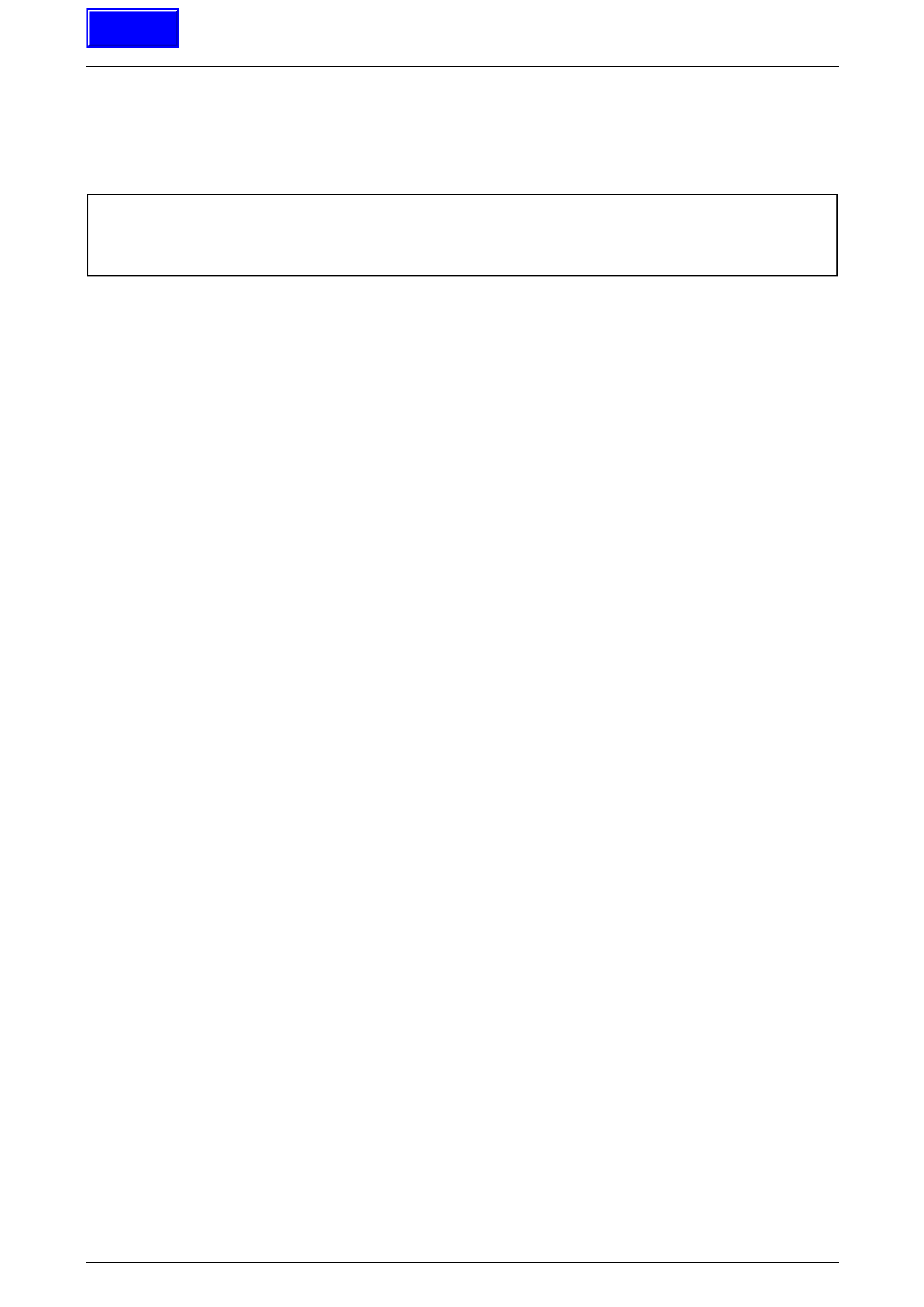
Figure 8A1 – 1 details fuel flow throug h the single turbine fuel pump.
Figure 8A1 – 1
Legend
Fuel
Vapour out
1 Inlet Body
2 Impeller Housing
3 Impeller
4 Fuel Pump Housing
Fuel System Page 8A1–5
Page 8A1–5
Fuel (A) is drawn into the modular fuel pump and sender
assembly reservoir from the fuel tank, through the primar y
umbrella valve (5) and into the fuel pump impeller, via the
internal strainer (4) at the fuel pump (1) inlet. At the impeller,
vapour (C) is separated from the fuel. The vapour is ejecte d
from the fuel pump into the reservoir via a po rt next to the
fuel pump inlet.
High-pressure fuel then flows through the end cap, the lower
connector and the flexible pipe. From the flexible pipe, fuel
exits the modular fuel pump and sender assembly through
the fuel feed port and flows on to the externally-mounted
fuel filter and the engine.
A fuel pressure regulator is located in th e modular fuel pump
and sender assembly; fuel no t used by the engine (B) is
returned to the modular fuel pump and sender assemb ly via
the fuel return line and the fuel return port in the modular
fuel pump and sender assembly cover. The return fuel
enters the jet pump standpipe (3) of the reservoir via the
return fuel tube.
Vehicle fuel line pressure is maintained by a pressure
regulator (2) located within the modular fuel pump and
sender assembly.
When the engine is switched off, the reservoir remains full of
fuel, due to the action of the primary umbrella valve. At high
fuel levels, fuel tank overflow enters the reservoir over the
top of the reservoir. Fuel level in the reservoir is also
maintained by returned engine fuel.
Electrical power is supplied to the fuel pump by a connector
secured to the modular fuel pump and send er assemb ly
cover. An internal harness (not shown) assembly completes
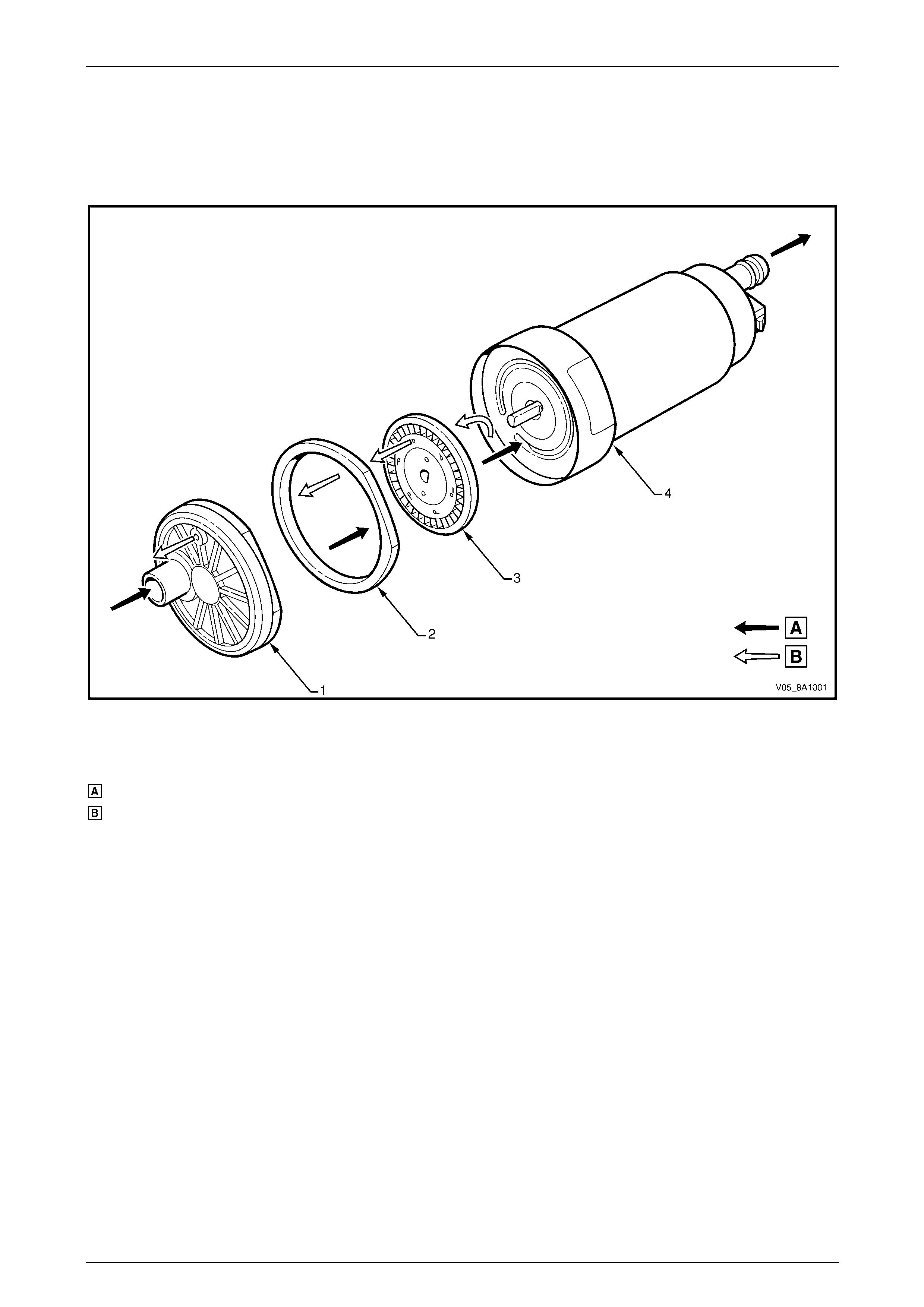
the connection to the pump. Figure 8A1 – 2
Single Line Fuel Delivery System
Fuel from the single turbine fuel pum p is forced through the
flexible pipe and exits the modular fuel pump and sender
assembly through the fuel feed port in the modu lar fuel
pump and sender assembly c over. F uel then flows through
the fuel filter (5) mounted to a bracket (3) secured to the
floor pan. From here, fuel is directed through the fuel filter
T-piece (2) and the flexible fuel feed hose (1) and on to the
engine bay and fuel rail. When fuel line pressure exceeds
410 kPa, the pressure regulator in the modul ar fuel pump
and sender assembly opens, allowing excess fuel at system
pressure to return to the fuel tank via the fuel return line (4).
This process occurs continuously while the fuel pump is
operating.
Figure 8A1 – 3

Fuel System Page 8A1–6
Page 8A1–6
Pressure Regulator
The pressure regulator is a diaphragm-operated relief valve
located in the modular fuel pump and sender assembly. On
one side of the diaphragm, fuel is subject to fuel pump
pressure; on the other side, fuel is subject to ambient tank
pressure combined with mechanical spri ng pressure. The
pressure regulator maintains a controlled pressure at the
injectors at all times by regulating fuel flow into the fuel
return line.
Figure 8A1 – 4
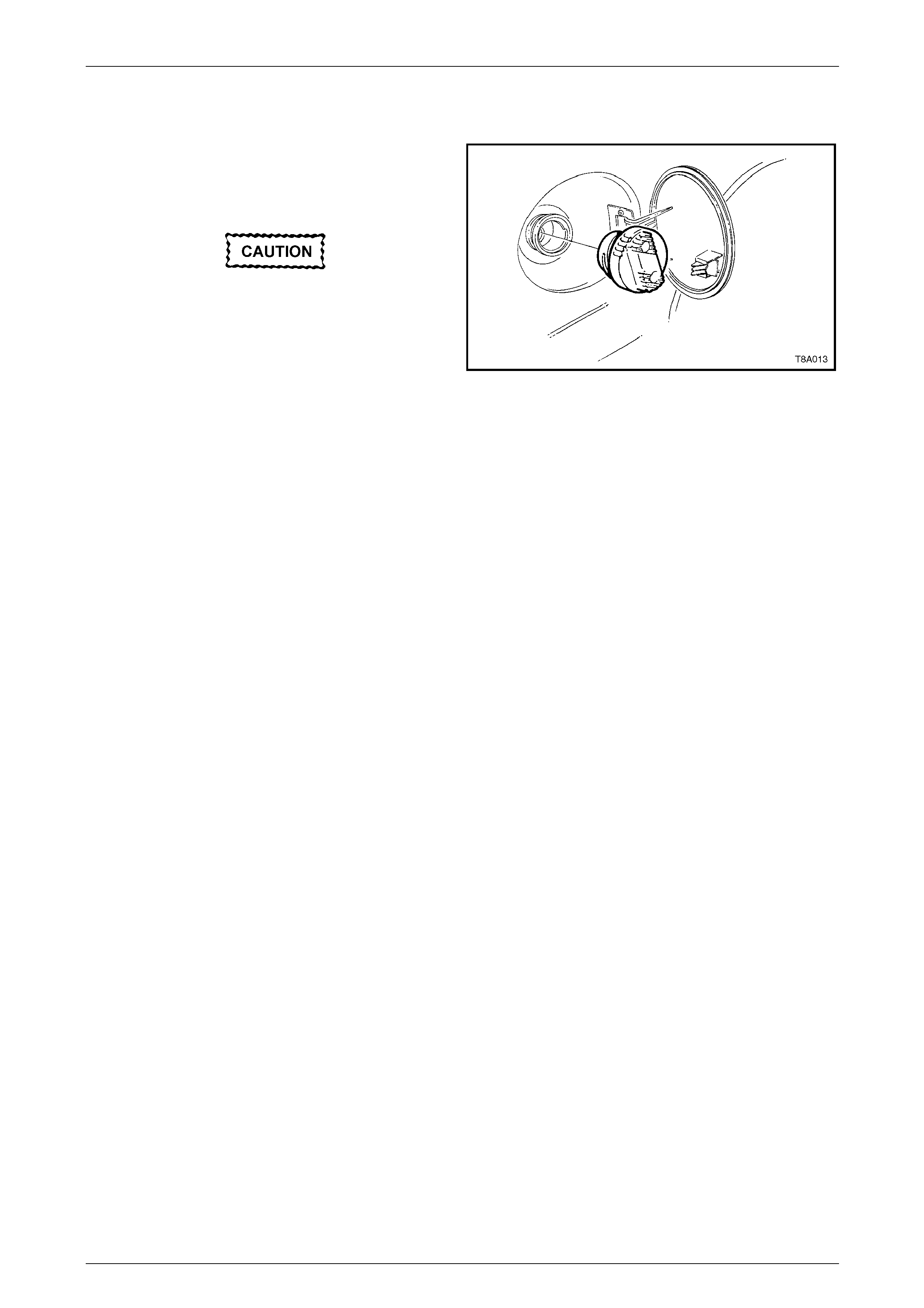
Fuel Level Sender Assembly
The fuel level sender assemb ly consists of a ceramic
variable resistor card (1), detachable nylon wiper piece (2),
fuel level sender float and arm (3), and a wiring harness (4).
These components convert the fuel lev el i n the fuel ta nk into
a variable electrical signal that provides the fuel level
information on the fuel gauge in the instrument panel.
The fuel level sender assembly mounting is part of the
modular fuel pump and sender assembly moulding. The fuel
level sender assembly is attached to the mounting and is
secured with a retainer. Two wires connect the ceramic
variable resistor card to the modular fuel pump and sender
assembly wiring harness.
The ceramic variable resistor card varies th e resistance,
dependent upon the position o f the fuel level sender float
and arm, and sends that signal via hard wire to the
instrument cluster. This resistance signal ch anges relative to
the wiper contact position on the conductive bars of the
ceramic variable resistor card.
Figure 8A1 – 5
Fuel System Page 8A1–7
Page 8A1–7
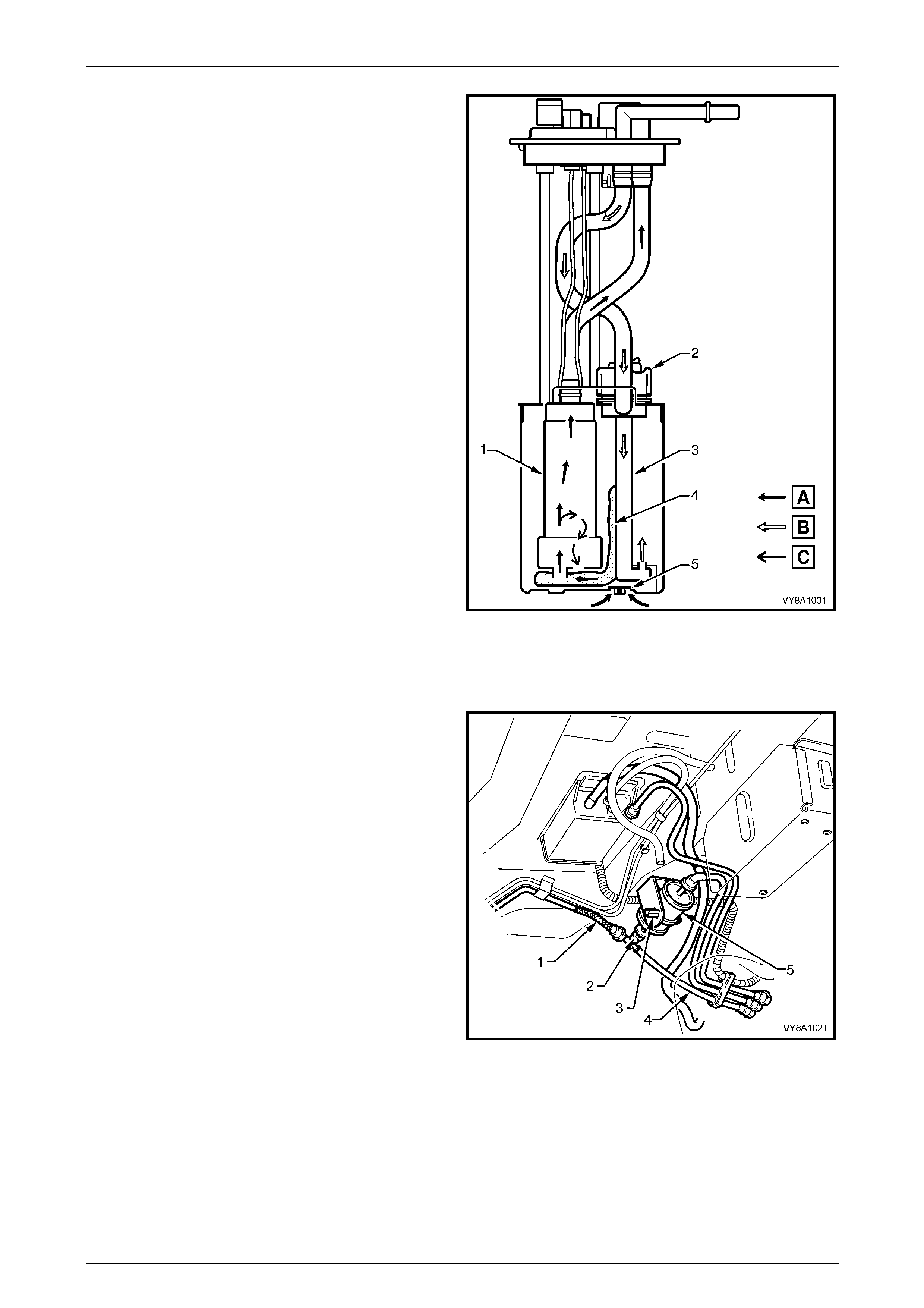
Rollover Valve
The modular fuel pump an d sender assembly incorporates a
rollover valve. The rollover va lve limits vapour venting to the
evaporative emission control canister using a fixed-sized
orifice that is normally open (View A). If the vehicle rolls over
(View B), the fuel tank vent line to the evaporative emission
control canister is safely shut off by the rollover valve,
preventing liquid fuel from flooding the evapo r ative emission
control canister.
NOTE
The rollover valve is not serviceable separately.
If it is faulty, the modular fuel pump and sender
assembly must be replaced.
Figure 8A1 – 6
Fuel System Page 8A1–8
Page 8A1–8
1.2 Fuel Filler Cap
The fuel filler cap is a 'screw on' type with a ratcheting
feature to prevent over-tightening. When installing the fuel
filler cap, tighten it until a ratcheting (clicking) sound is
audible, indicating it is tightened properly.
If a replacement fuel filler cap is required, use
only the correct black fuel cap. Using an
incorrect cap causes the emission control
system to malfunction.
NOTE
Vehicles using unleaded fuel have ‘UNLEADED
FUEL ONLY’ embossed into the top of the fuel
filler cap.
Figure 8A1 – 7

Fuel System Page 8A1–9
Page 8A1–9
1.3 System Components
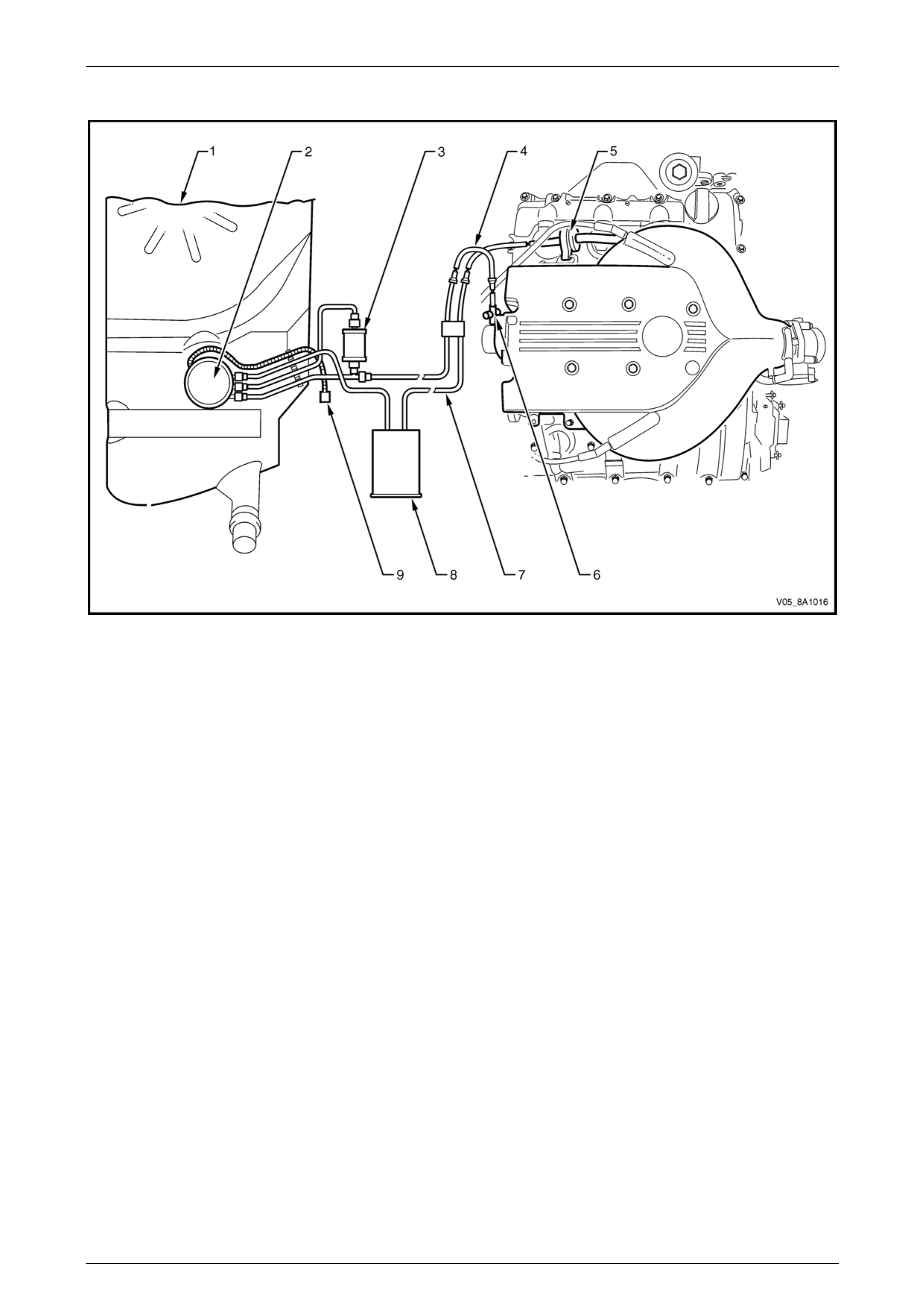
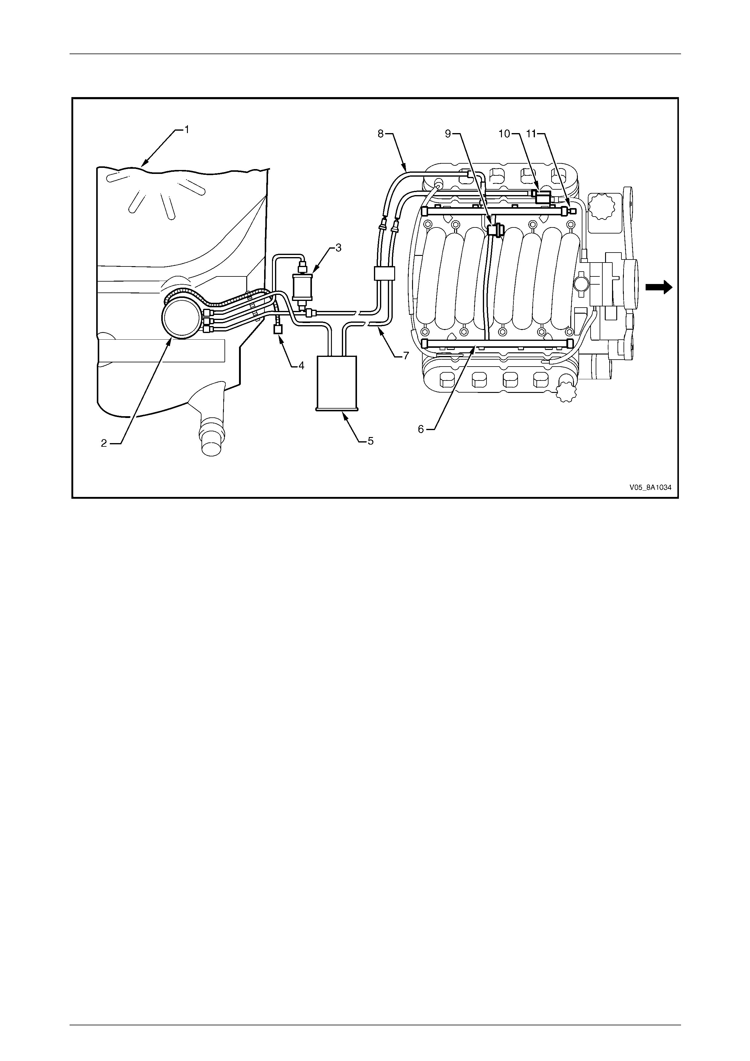
The Fuel Control System consists of the following components, refer to Figure 8A1 – 8 (for vehicles fitted with a
V6 engine) or Figure 8A1 – 9 (for vehicles fitted with a GEN III V8 engine):
• fuel tank;
• modular fuel pump and sender assembly, containing:
• pressure regulator,
• fuel pump assembly, and
• jet pump;
• fuel filter;
• fuel pump electrical connector;
• evaporative emission control canister;
• fuel rail;
• evaporative emission control canister purge line;
• evaporative emission control canister purge solenoid;
• fuel feed line;
• either:
• engine control module (ECM) on vehicles fitted with a V6 engine, or
• powertrain control module (PCM) on vehicles fitted with a GEN III V8 engine;
• fuel pump relay; and
• injectors.
Fuel System Page 8A1–10
Page 8A1–10
V6 Engine
Figure 8A1 – 8
Legend
1 Fuel Tank
2 Modular Fuel Pump and Sender
Assembly (including Pressure
Regulator)
3 Fuel Filter
4 Fuel Feed Line
5 Evaporative Emission Control
Canister Purge Solenoid
6 Evaporative Emission Control
Canister Purge Line Service Port
7 Fuel Vapour Line
8 Evaporative Emission Control
Canister
9 Fuel Pump Electrical Connector
Fuel System Page 8A1–11
Page 8A1–11
GEN III V8 Engine
Figure 8A1 – 9
Legend
1 Fuel Tank
2 Modular Fuel Pump and Sender
Assembly (including Pressure
Regulator)
3 Fuel Filter
4 Fuel Pump Electrical Connector
5 Evaporative Emission Control
Canister
6 Fuel Rail
7 Fuel Vapour Line
8 Fuel Feed Line
9 Fuel Pulse Dampener
10 Evaporative Emission Control
Canister Purge Solenoid
11 Evaporative Emission Control
Canister Purge Line Service Port
Fuel System Page 8A1–12
Page 8A1–12
2 System Checks
2.1 Fuel System Depressurisation
To reduce the risk of fire or personal injury,
depressurise the fuel system before ser vicing
any fuel system components.
1 Turn the ignition switch off.
2 Remove the fuel pump fuse and fuel pump relay, refer to Section 12O Fuses, Relays and Wiring Harnesses.
3 Loosen the fuel filler cap to relieve the fuel tank vapour pressure.
4 With the throttle closed, crank the engine.
NOTE
The engine may start and operate until the fuel
remaining in the fuel deliv ery system depletes.
5 When the engine stops, crank the engi ne for another 10 seconds to ensure the fuel feed l ine pressure has been
fully relieved.
6 Clean the area around the fuel pressure test point.
A small amount of fuel may be released when
pressing on the Schrader valve. Cover the
fitting with a shop towel to absorb any fuel
spillage before removing the Schrader valve
sealing cap. After the fuel pressure relief
procedure, place the soiled towel in an
approved container for disposal.
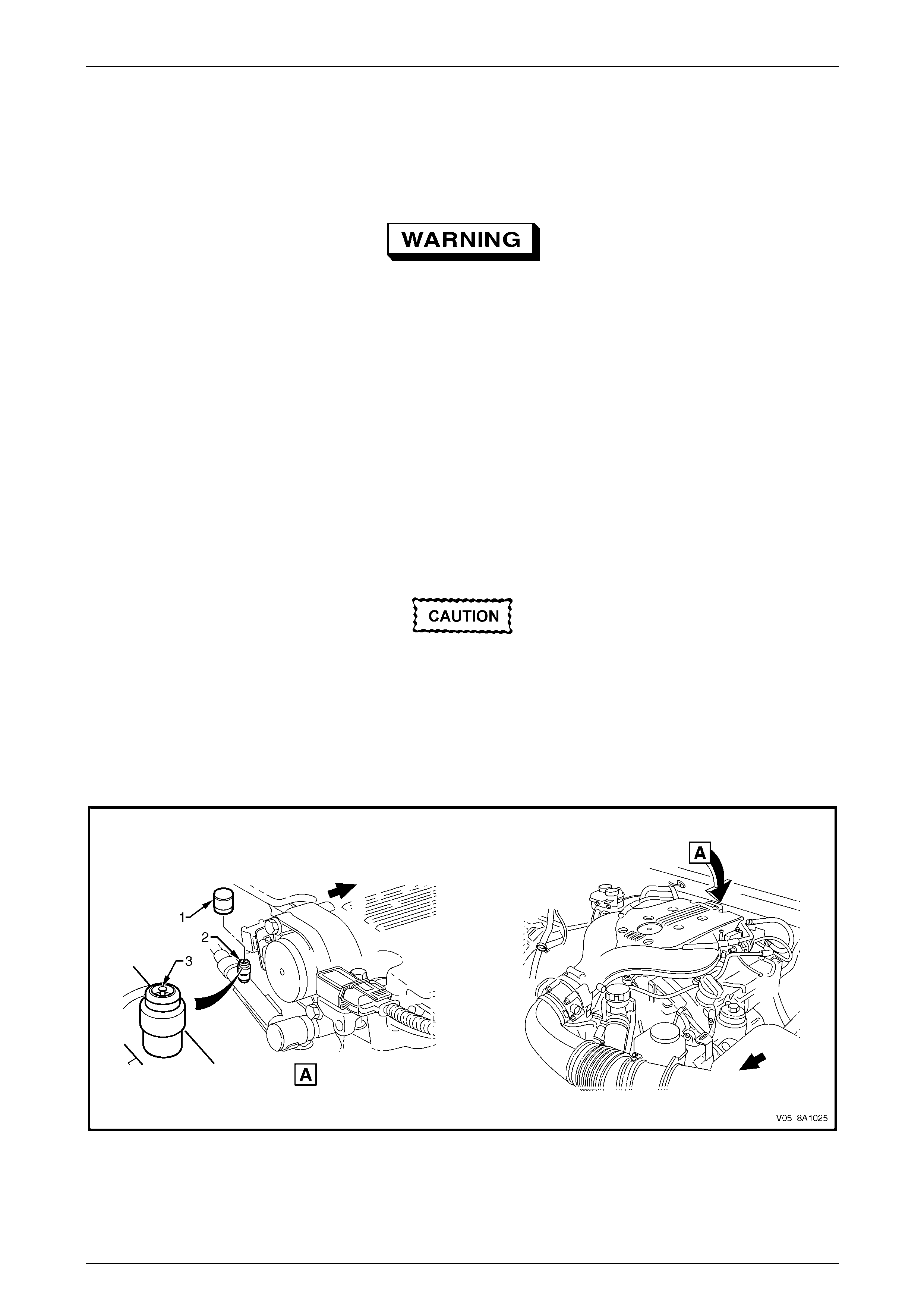
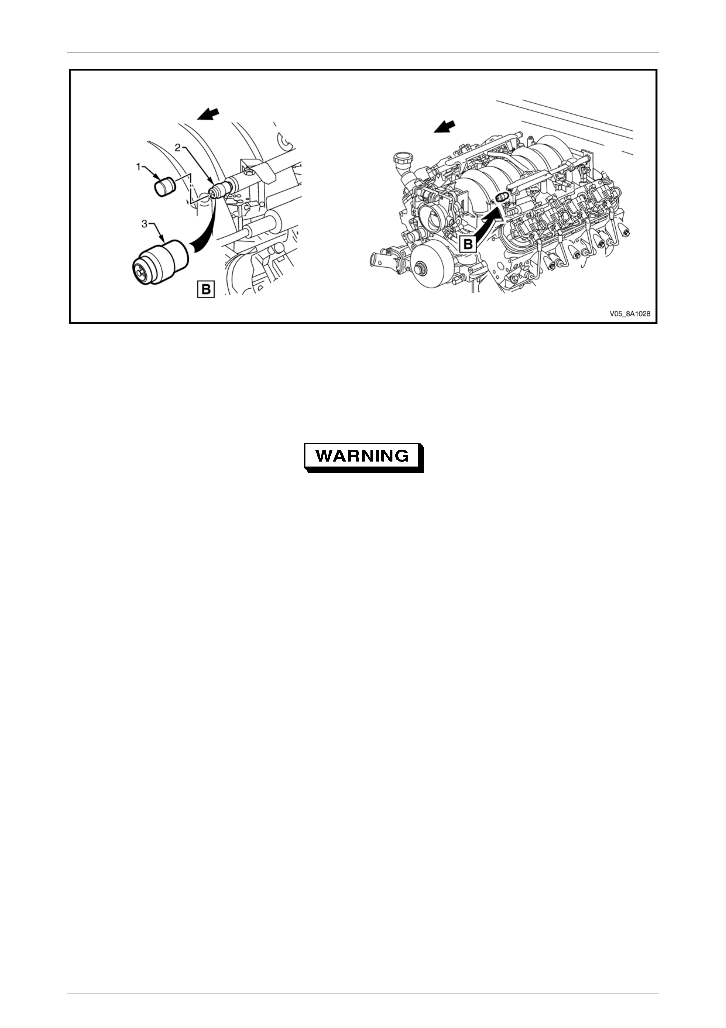
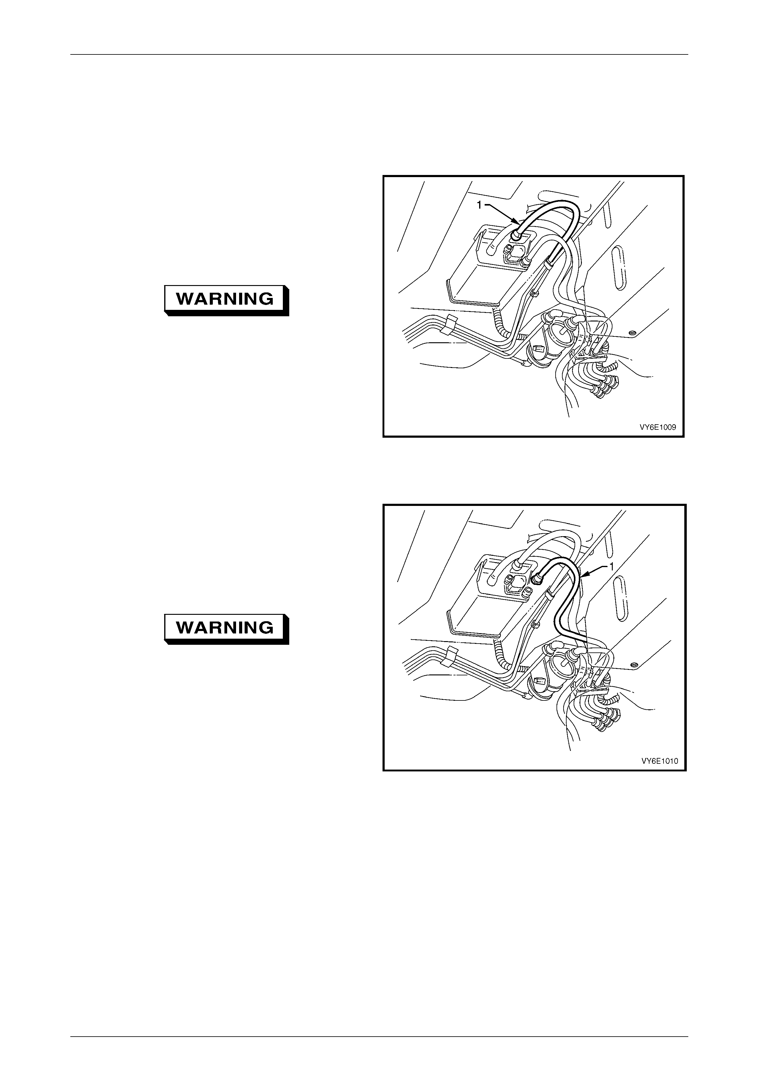
7 At the fuel pressure test point (2), remove the Schrader valve sealing cap (1), refer to Figure 8A1 – 10 (for vehic les
fitted with a V6 engine) or Figure 8A1 – 11 (for vehicles fitted with a GEN III V8 engine).
Figure 8A1 – 10
Legend
1 Schrader Valve Sealing Cap
2 Pressure Test Point 3 Schrader Valve
Fuel System Page 8A1–13
Page 8A1–13
Figure 8A1 – 11
Legend
1 Schrader Valve Sealing Cap
2 Pressure Test Point 3 Schrader Valve
Wear safety g lasses when performing the fuel
pressure relief procedure.
8 Use a small screwdriver to press the Schrader valve (3).
9 Remove the soiled shop towel and place in an approved container.
Repressurise
1 Reinstall the fuel pump rela y and fuel pump fuse.
2 Perform the following procedur e to inspect for leaks at the fuel pressure test point:
a Turn the ignition switch on for two seconds.
b Turn the ignition switch off for 10 seconds.
c Turn the ignition switch on.
d Check for leaks at the fuel pressure test point.
3 Tighten the fuel filler cap.
4 Start the engine and recheck for leaks.
5 Reinstall the Schrader valve sealing cap.
Fuel System Page 8A1–14
Page 8A1–14
2.2 Fuel Pressure Test
To reduce the risk of fire or personal injury,
depressurise the fuel system before ser vicing
any fuel system components, refer to
2.1 Fuel System Depressurisation.
Installation
1 Turn the ignition switch off.
2 Depressurise the fuel system, refer to 2.1 Fuel System Depressurisation.
A small amount of fuel may be released when
connecting the fuel p ressure gaug e to the fuel
pressure test point. Cover the fittings with a
shop towel to absorb any fuel spillage before
connecting the fuel pressure gauge. After the
fuel pressure test procedure, place the soiled
towel in an approved container for disposal.
3 At the fuel pressure test point, remove the Schrader valve s ealing cap.
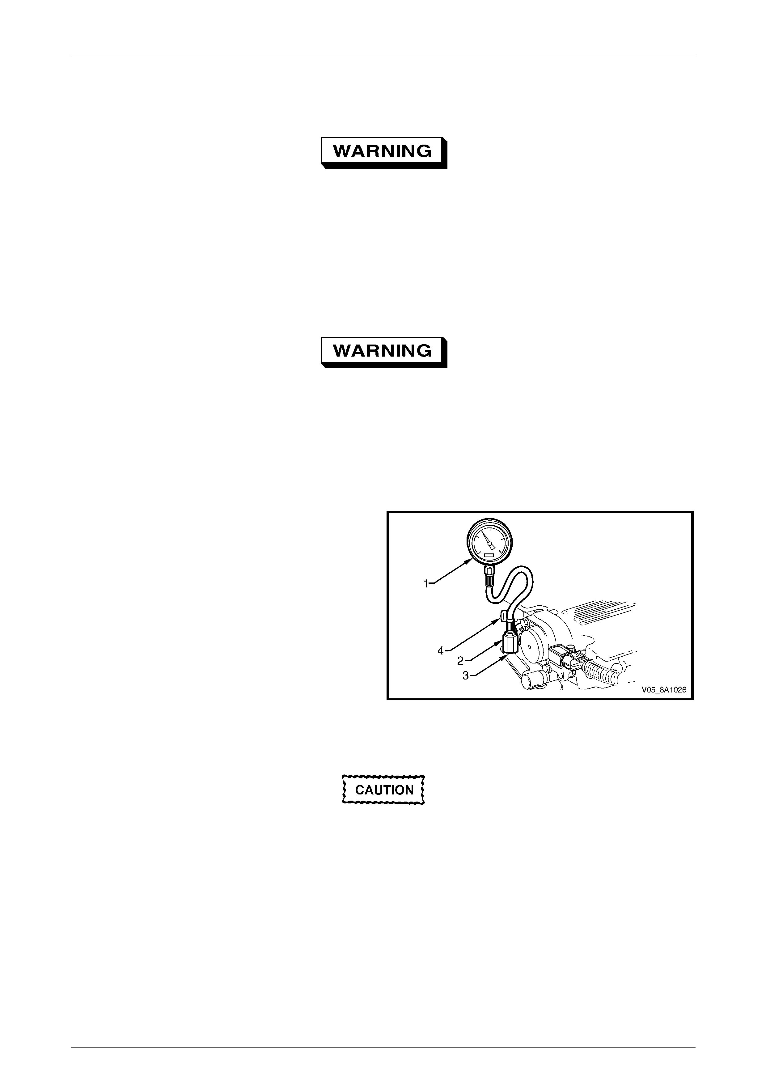
4 Connect the fuel pressure gauge (1) (tool
No. J 34730–1A) to the fuel gauge Schrader fitting
adapter (2) (tool No. AU453), then install to the fuel
pressure test port (3). Wrap a shop towel around the
fitting while connecting the fuel pressure ga uge to
avoid and/or capture any fuel spillage.
5 Route the bleed hose of the fuel gauge into an
approved fuel container.
NOTE
Figure 8A1 – 12 sho ws a fuel pressur e test on a
V6 engine. Refer to Figure 8A1 – 11 for the
location of the Schrader valve fitted to a GEN III
V8 engine.
Figure 8A1 – 12
After connecting the fuel pressure gauge and
pressurising the fuel system, inspect for fuel
leaks at the fuel pressure gauge and the fuel
pressure test point.
6 Either:
Using Tech 2, enable the fuel pump to pressurise the fuel system, refer to Section 0C Tech 2. Inspect for fuel leaks
at the fuel pressure gauge and fuel pressure test point, then bleed the air from the fuel pressure gauge.
or:
Reinstall the fuel pump rela y and fuel pump fuse, then open the fuel gauge bleed valve (4) to bleed the air from the
fuel pressure gauge.
7 Remove and place the shop towel in an approved container .
Fuel System Page 8A1–15
Page 8A1–15
Test
1 Start the engine and record the fuel pressure .
2 Turn the ignition switch off.
3 If required, perform any tests and/or diagnostic procedures:
• For the fuel system leak test, refer to 2.3 Fuel Leak Test.
• For the fuel injector leak-down test (for vehicles fitted with a V6 engine),
refer to Section 6C1-3 Engine Management – V6 – Service Operations.
• For the fuel injector leak-down test (for vehicles fitted with a GEN III V8 engine),
refer to Section 6C3-3 Powertrain Management GEN III – V8 – Service Ope r ations.
4 Depressurise the fuel system, refer to 2.1 Fuel System Depressurisation.
Removal
1 Turn the ignition switch off.
2 Depressurise the fuel system, refer to 2.1 Fuel System Depressurisation.
After relieving the fuel system pressure, a
small amount of fuel may be released when
servicing the fuel lines or connections. Cover
the fittings with a shop towel before
disconnecting. This catches any leaking fuel.
Place the soiled towel in an approved
container when disconnection is completed.
3 Wrap a shop towel around the fuel pressure test point to absorb any fuel spillag e.
4 Remove the fuel pressure gauge a nd drain any fuel remainin g in the fuel pressure gauge into an approved fuel
container.
5 Remove the shop towel and place in an approved container.
6 Repressurise the fuel system, refer to Repressurise.
7 Road-test the vehicle and check for correct operation.
Fuel System Page 8A1–16
Page 8A1–16
2.3 Fuel Leak Test
V6 Engine
After installing any fuel system component
and before starting the engine, check the fuel
system for leaks.
NOTE
For the fuel injector leak-down test (for vehicles
fitted with a V6 engine), refer to Section 6C1-3
Engine Management – V6 – Service Operations.
1 Remove both engine dress covers, refer to Section 6A1 Engine Mechanical – V6 Engine.
2 Turn the ignition switch on for two seconds.
3 Turn the ignition switch off for 10 seconds.
4 Turn the ignition switch on.
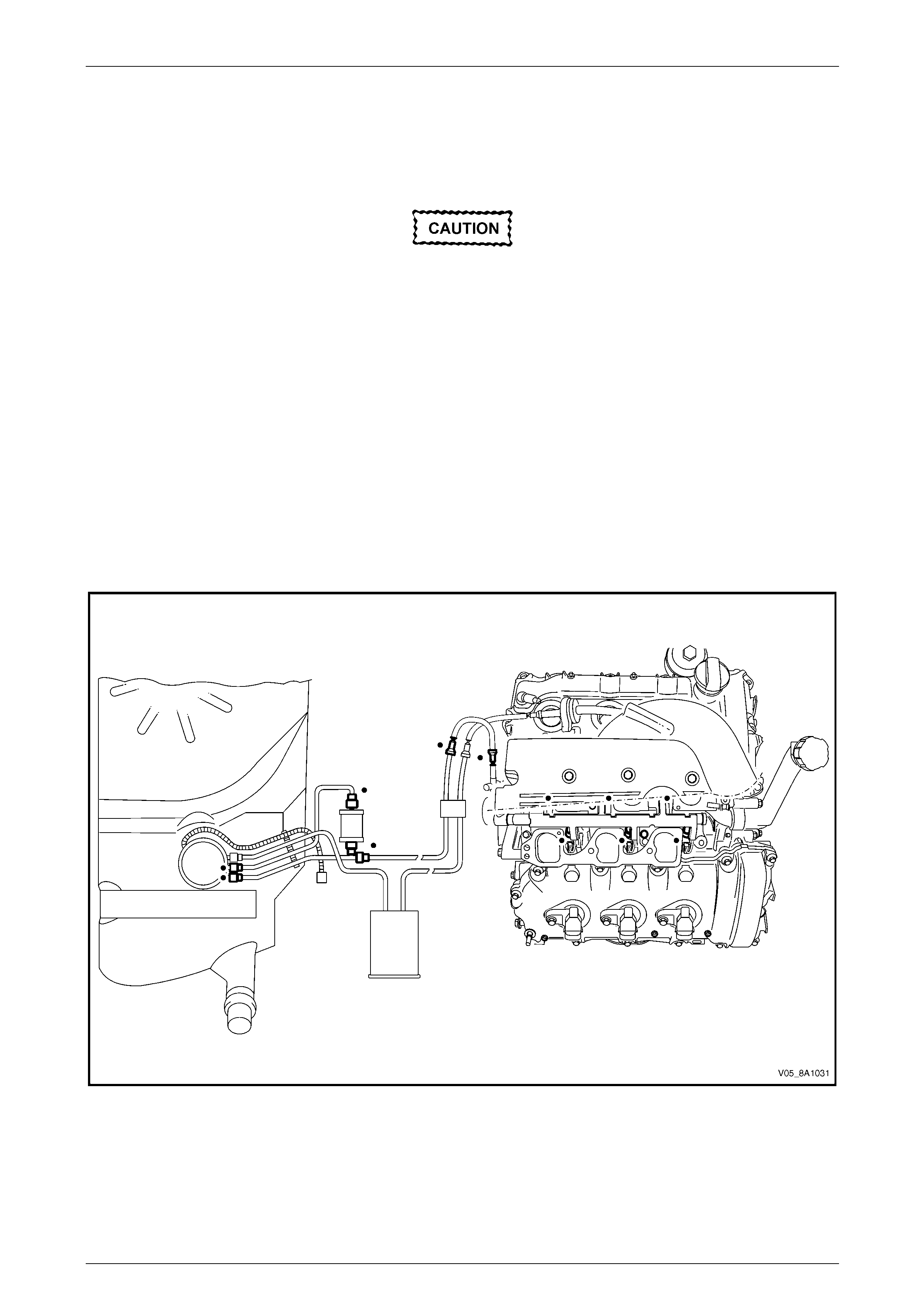
5 Check for fuel leaks, particularly at points marked z (that is, quick-connect fittings, fuel pulse damp en er, fuel rails,
fuel injectors, Schrader valve and evaporati v e emission control canister purge solenoi d), refer to Figure 8A1 – 13.
Figure 8A1 – 13
6 Replace any faulty components and repeat step 2 to step 5 inclusive.
7 Replace all engine compo ne nts removed to perform the fuel leak test,
refer to Section 6C1-3 Engine Management – V6 – Service Operations.
8 Reinstall both engine dress covers, refer to Section 6A1 Engine Mechanical – V6 Engine.

Fuel System Page 8A1–17
Page 8A1–17
GEN III V8 Engine
After installing any fuel system component
and before starting the engine, check the fuel
system for leaks.
NOTE
For the fuel injector leak-down test (for vehicles
fitted with a GEN III V8 engine), refer to
Section 6C3-3 Powertrain Management GEN III –
V8 – Service Operations.
1 Remove both engine dress covers, refer to Section 6A3 Engine Mechanical – GEN III V8.
2 Turn the ignition switch on for two seconds.
3 Turn the ignition switch off for 10 seconds.
4 Turn the ignition switch on.
5 Check for fuel leaks, particularly at points marked z (that is, quick-connect fittings, fuel pulse damp en er, fuel rails,
fuel injectors, Schrader valve and evaporati v e emission control canister purge solenoi d), refer to Figure 8A1 – 14.
Figure 8A1 – 14
6 Replace any faulty components and repeat step 2 to step 5 inclusive.
7 Replace all engine compo ne nts removed to perform the fuel leak test,
refer to Section 6C3-3 Powertrain Management GEN III – V8 – Service Ope r ations.
8 Reinstall both engine dress covers, refer to Section 6A3 Engine Mechanical – GEN III V8.
Fuel System Page 8A1–18
Page 8A1–18
3 Service Operations
3.1 Quick-connect Fittings
Quick-connect Fittings (Metal Collar)
LT Section No. — 03–075
Remove
To reduce the risk of fire or personal injury,
relieve the fuel system pressure before
servicing any fuel system components, refer
to 2.1 Fuel System Depressurisation.
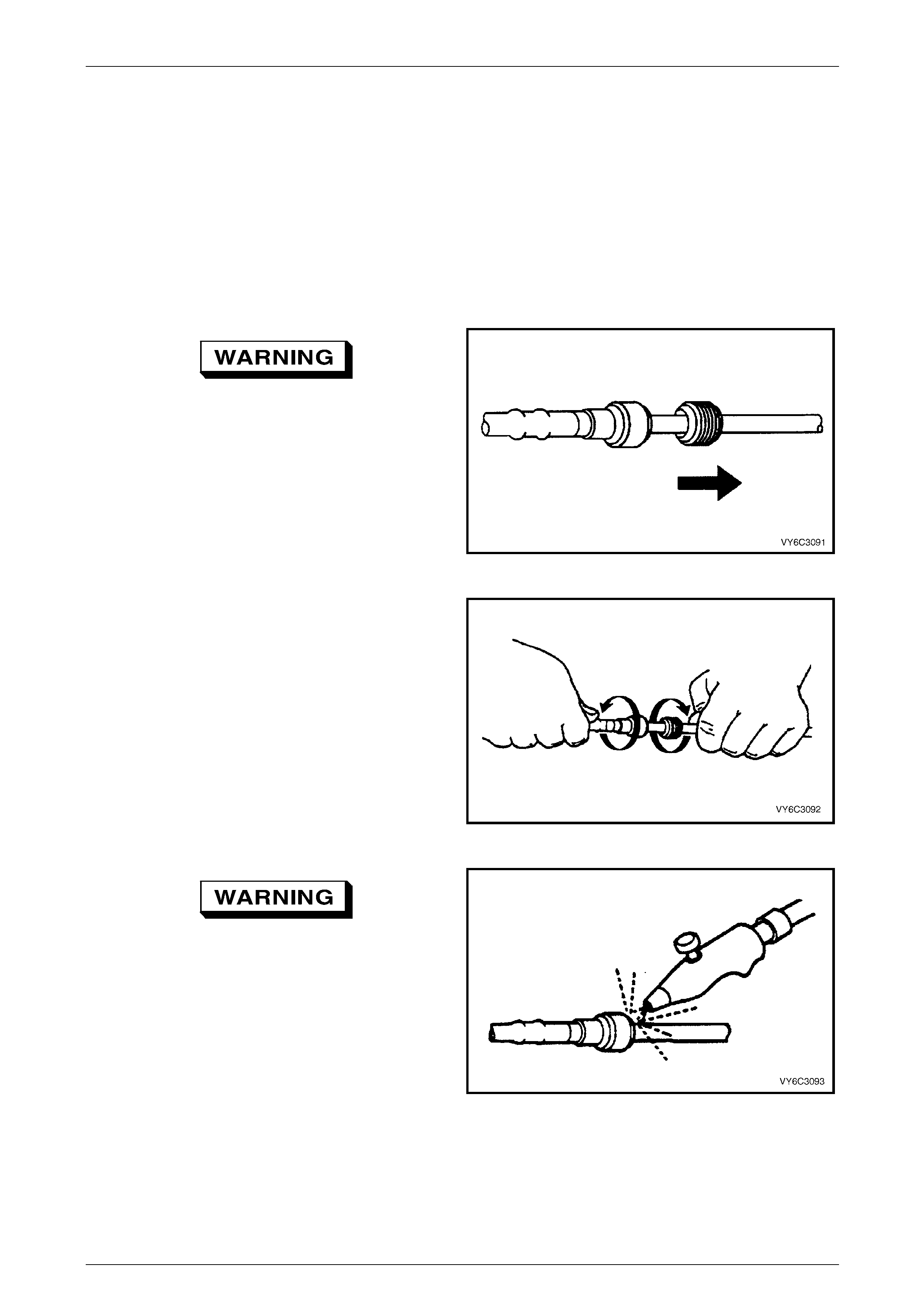
1 If fitted, slide the dust cover from the quick-connect
fitting.
Figure 8A1 – 15
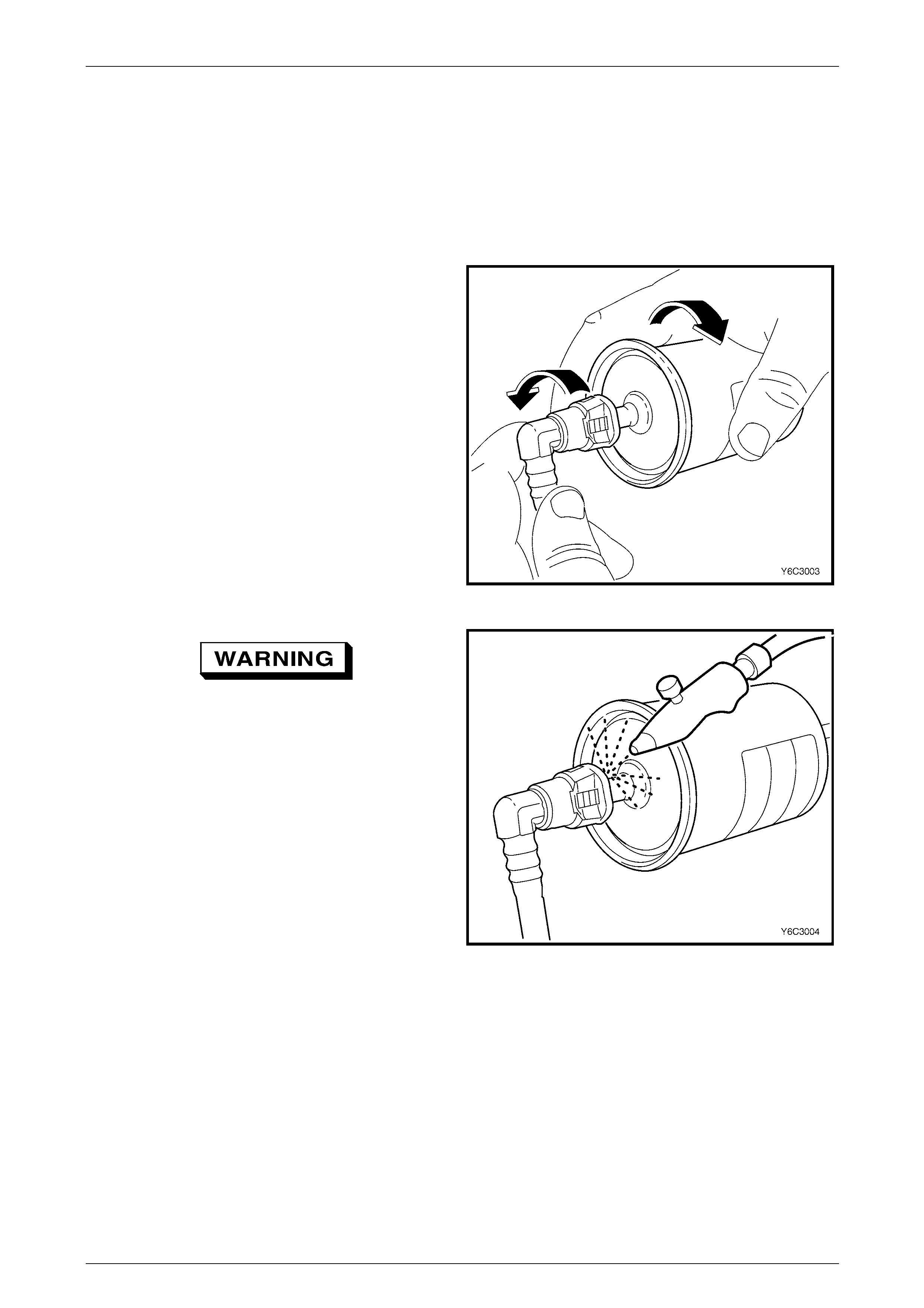
2 Grasp both sides of the quick-connect fitting. Twist the
female side of the quick-connect fitting 1/4 turn in each
direction to loosen any dirt.
Figure 8A1 – 16
Wear safety glasses w hen usin g compressed
air. Do not blow compressed air onto any
body part.
3 Use compressed air to ensure that all dirt and foreign
materials are removed from all fuel conn ections before
the parts are disconnected.
Figure 8A1 – 17
Fuel System Page 8A1–19
Page 8A1–19
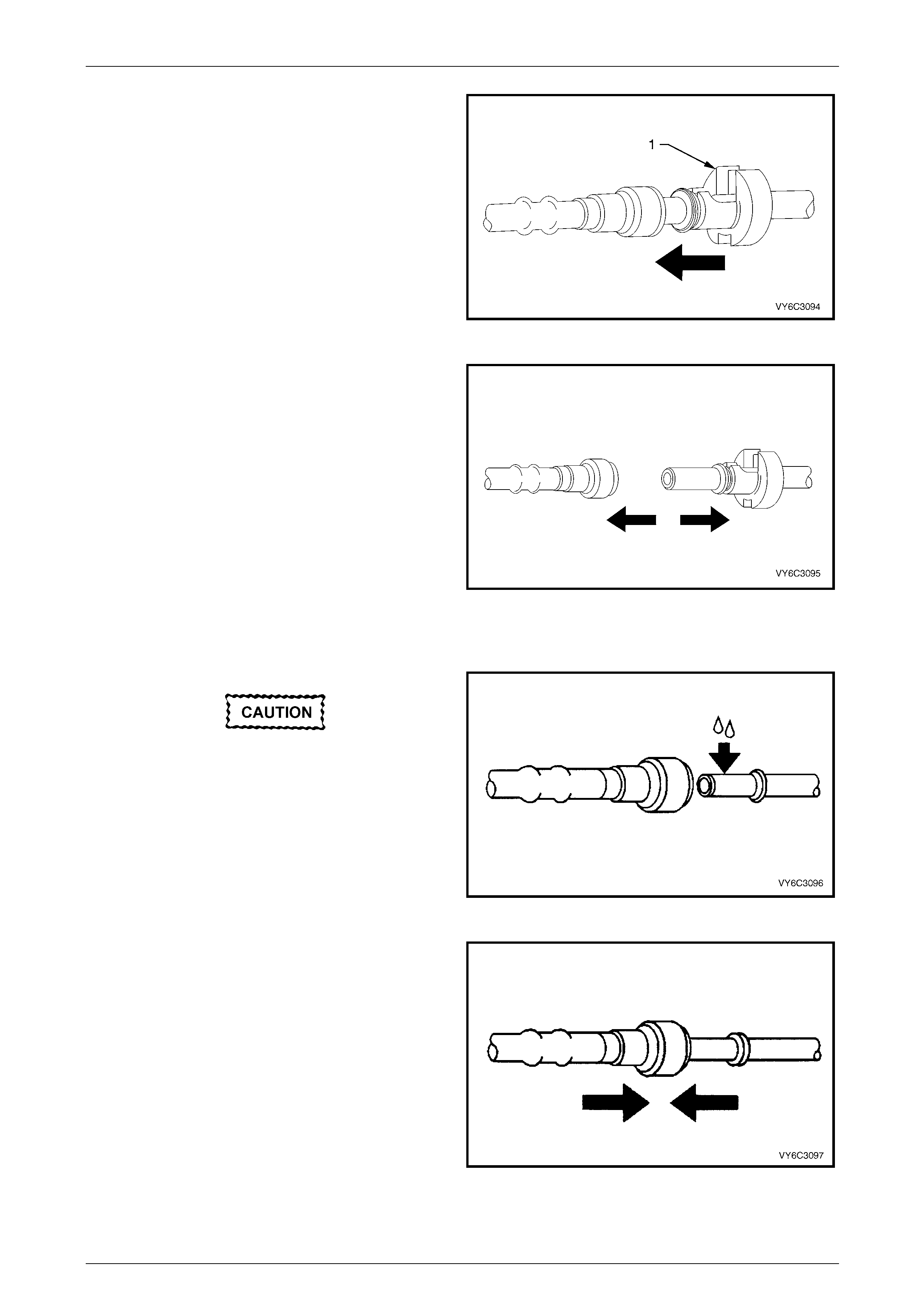
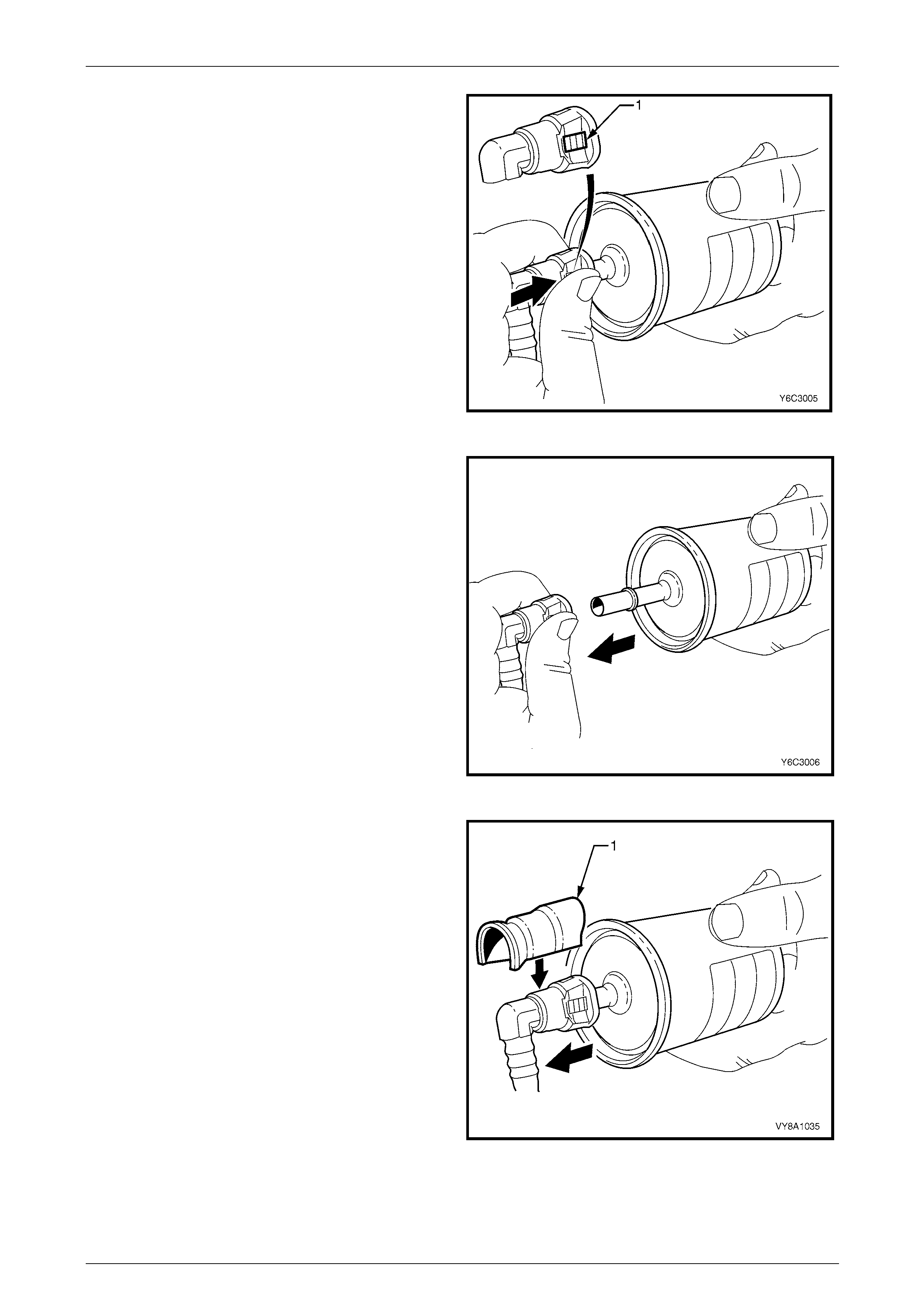
4 Choose the correct tool (1) to disconnect the quick-
connect fitting, refer to Tool Nos. 7370 and 7371.
Insert the tool into the female connector, then push
inward to release the locking t abs.
Figure 8A1 – 18
5 Pull the quick-connect fitting apart.
NOTE
If it is necessary to remove rust or burrs from a
fuel pipe, use emery cl oth in a radial motion with
the fuel pipe end to prevent damage to the
O-ring sealing surface.
6 Using a clean shop towel to wipe off the male pipe
end.
7 Inspect both ends of the fitting for dirt and burrs. Clean
or replace the components as required.
Figure 8A1 – 19
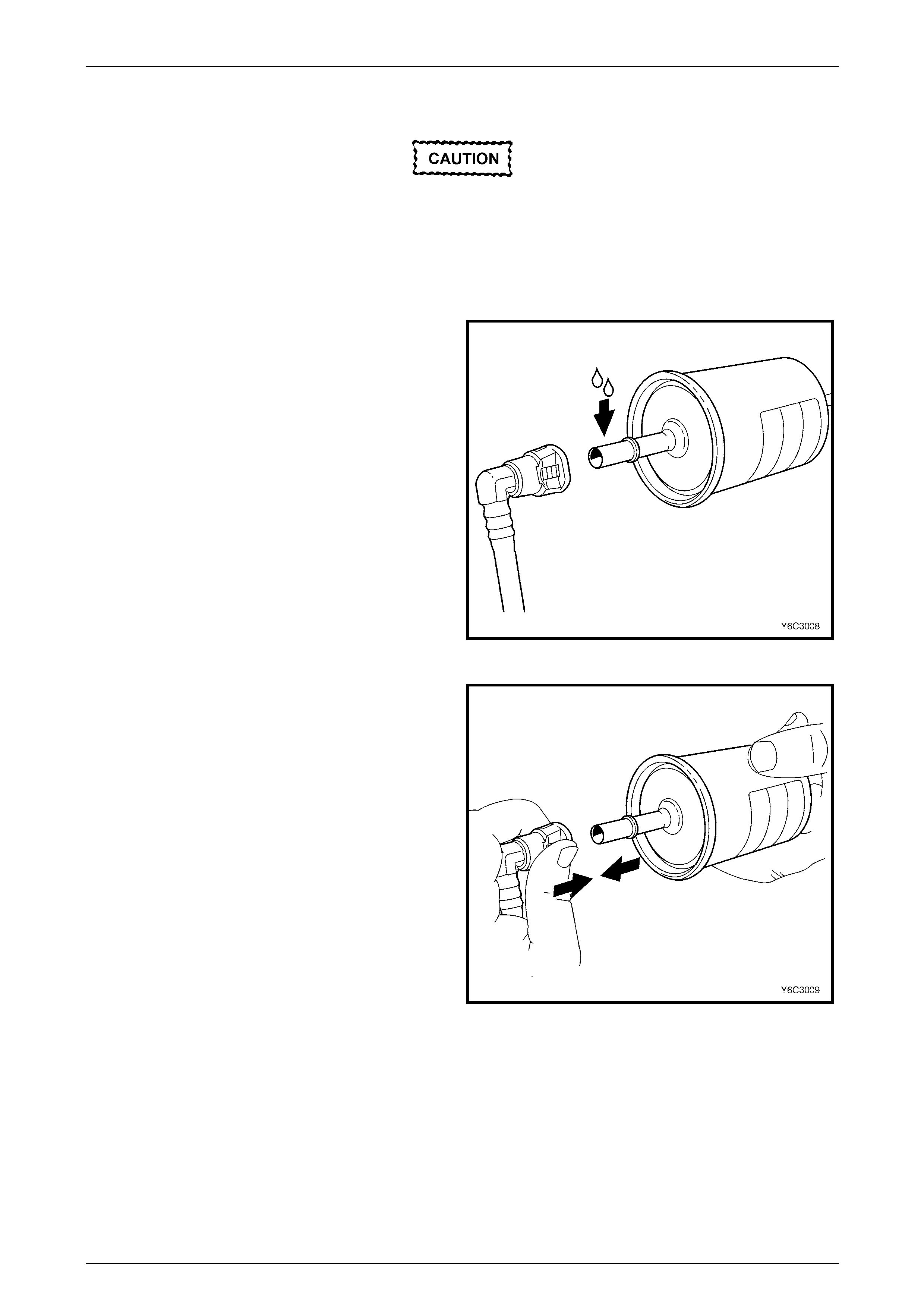
Reinstall
During normal operation, the O-ring located
in the female connector swells. To ensure
proper fitting, lubricate the male pipe end
before assembly.
1 Apply a few drops of clean engin e oil to the male pipe
end.
Figure 8A1 – 20
2 Push both sides of the quick-connect fitting together to
snap the retaining tabs into place.
Figure 8A1 – 21
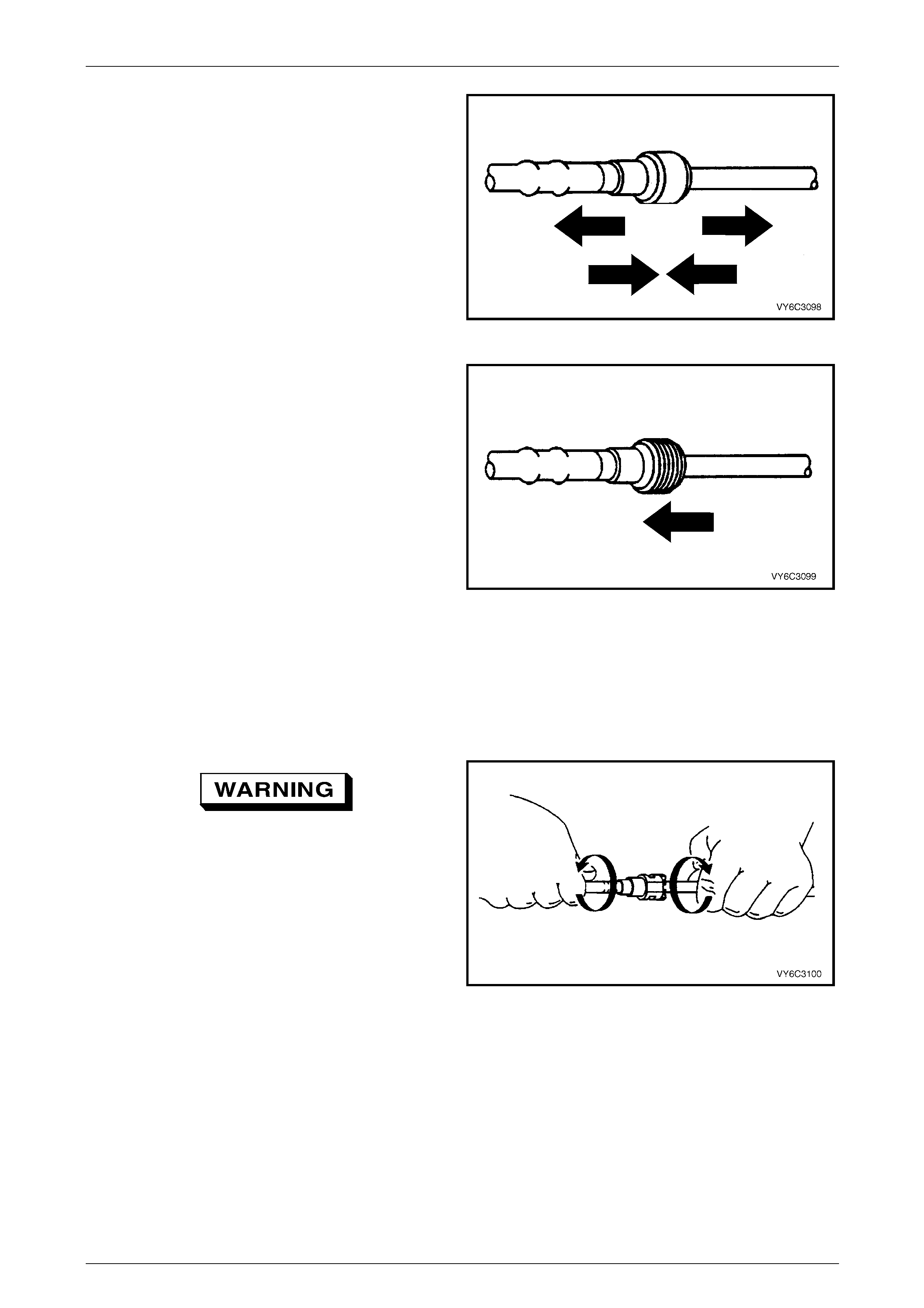
Fuel System Page 8A1–20
Page 8A1–20
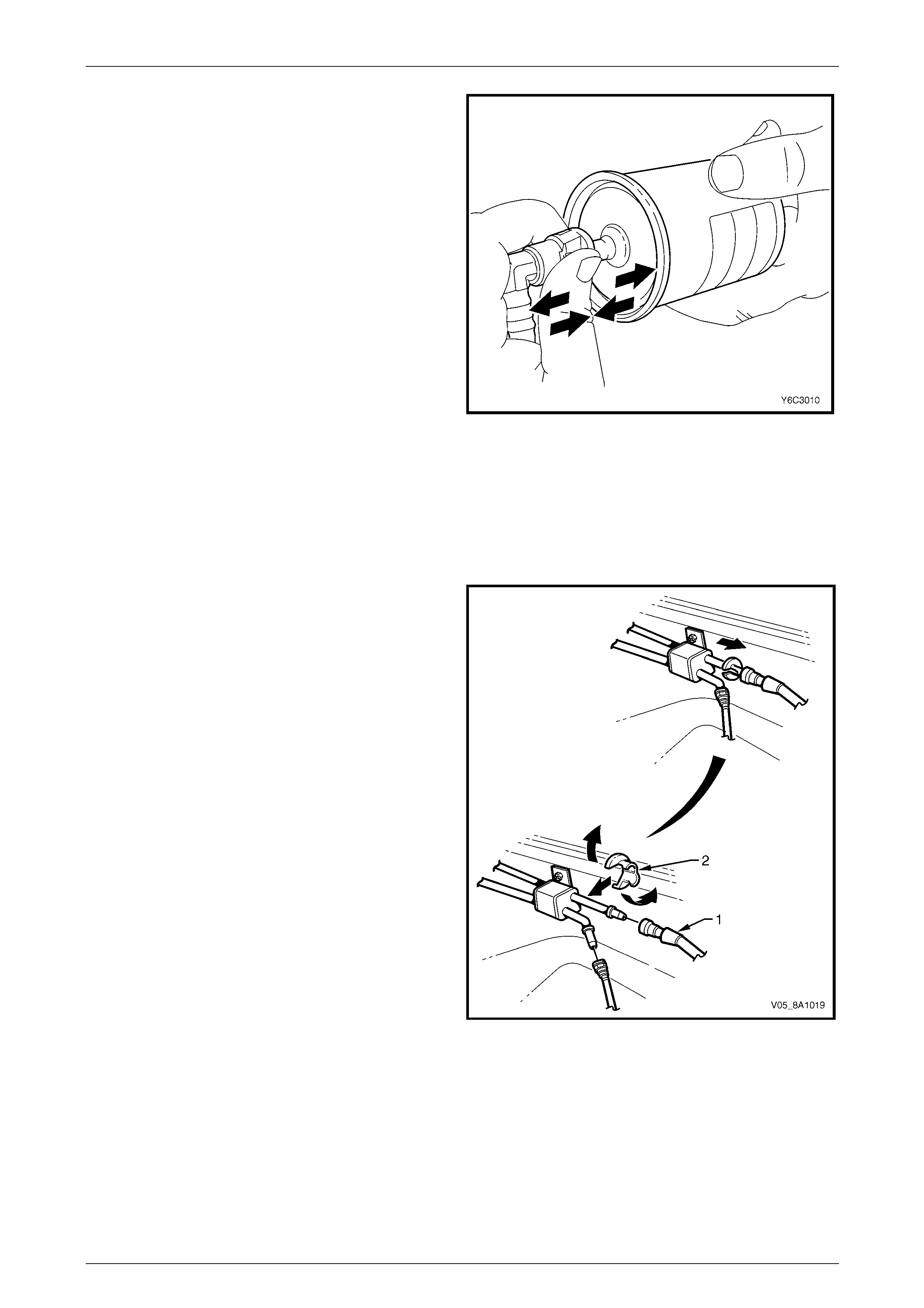
3 After installation, pull on both sides of the quick-
connect fitting to ensure the connection is secure.
Figure 8A1 – 22
4 Reposition the dust cover over the quick-con nect
fitting (if fitted).
Figure 8A1 – 23
Quick-connect Fittings (Plastic Collar)
LT Section No. — 03–075
Remove
To reduce the risk of fire or personal injury,
relieve the fuel system pressure before
servicing any fuel system components, refer
to 2.1 Fuel System Depressurisation.
1 Grasp both sides of the quick-connect fitting. Twist the
female side of the quick-connect fitting 1/4 turn in each
direction to loosen any dirt.
Figure 8A1 – 24

Fuel System Page 8A1–21
Page 8A1–21
Wear safety glasses w hen usin g compressed
air. Do not blow compressed air onto any
body part.
2 Use compressed air to ensure that all dirt and foreign
materials are removed from all fuel conn ections before
the parts are disconnected.
Figure 8A1 – 25
3 Squeeze the plastic retainer release tabs.
NOTE
Alternatively, use tool No. AU533 to release the
quick connect fitting:
• red = 5/16-inch fittings (fuel vapour lines), or
• blue = 3/8-inch fittings (fuel feed lines).
Figure 8A1 – 26
4 Pull the quick-connect fitting apart.
Figure 8A1 – 27
Fuel System Page 8A1–22
Page 8A1–22
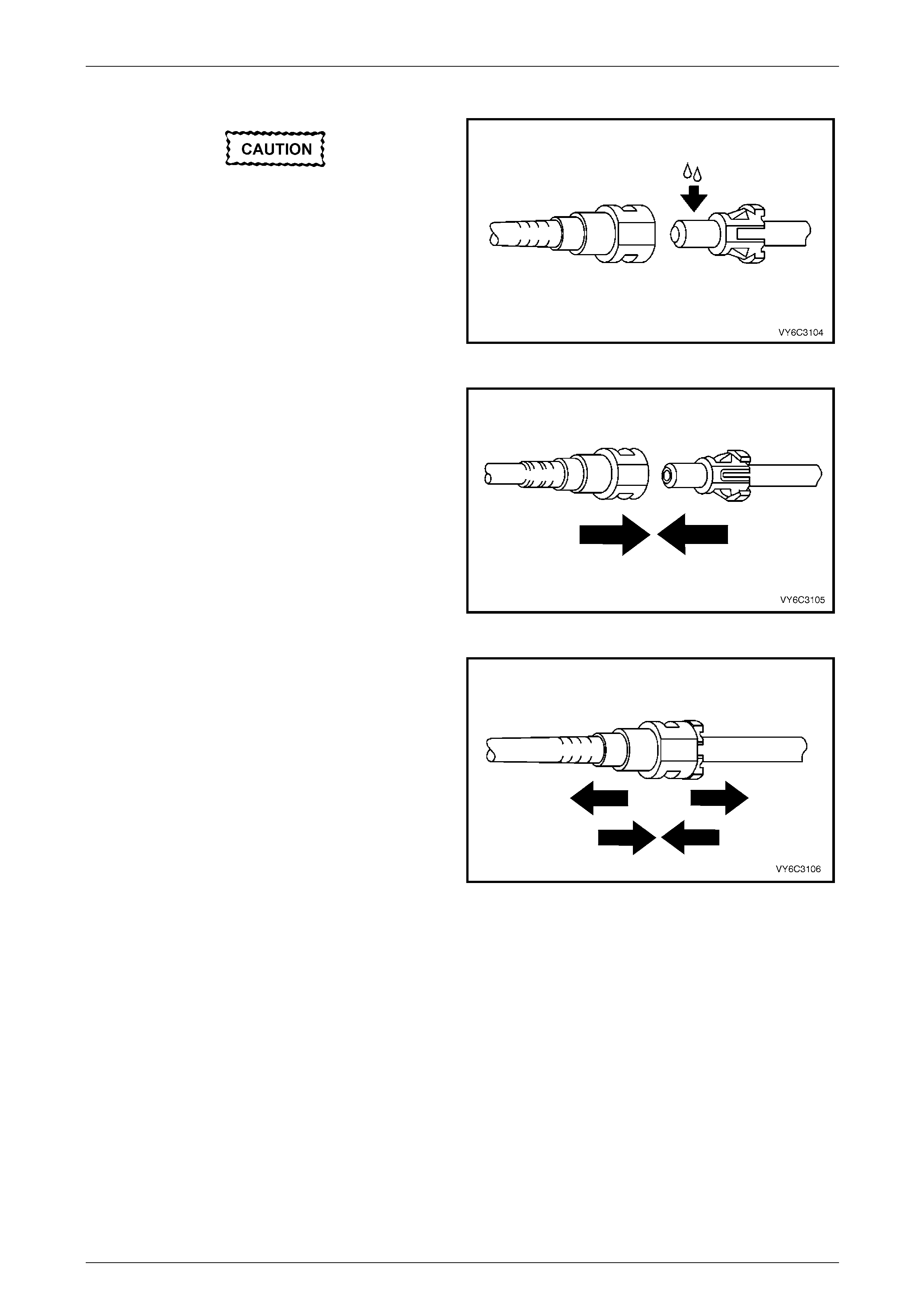
Reinstall
During normal operation, the O-ring located
in the female connector swells. To ensure
proper fitting, lubricate the male pipe end
before assembly.
1 Apply a few drops of clean engin e oil to the male pipe
end.
Figure 8A1 – 28
2 Push both sides of the quick-connect fitting together to
snap the retaining tabs into place.
Figure 8A1 – 29
3 After installation, pull on both sides of the quick-
connect fitting to ensure the connection is secure.
Figure 8A1 – 30
Fuel System Page 8A1–23
Page 8A1–23
Tool No. AU533
LT Section No. — XX–XXX
This procedure describes the removal of the quick-connect fittings on the fuel filter using tool No. AU533. This procedure
also applies to other quick-connect fittings.
Remove
1 Grasp both sides of the quick-connect fitting. Twist the
quick-connect fitting one quarter of a turn in e ach
direction to loosen any dirt within the quick-connect
fitting.
Figure 8A1 – 31
Wear safety glasses w hen usin g compressed
air. Do not blow compressed air onto any
body part.
2 Using compressed air, blow any dirt out of the quick-
connect fitting.
Figure 8A1 – 32
Fuel System Page 8A1–24
Page 8A1–24
3 Grasp the female part and firmly support the male
part.
4 Squeeze the plastic retainer release tabs (1) on each
side of the quick-connect fitting while pus hing the
quick-connect fitting firmly inwards to release an y
tension on the release tabs.
Figure 8A1 – 33
5 While pressing the releas e tabs, pull the quick-connect
fitting apart.
Figure 8A1 – 34
6 Alternatively, for step 3 to step 5 inclusive, use tool
No. AU533 (1) to squeeze the release tabs and
release the quick-connect fittings.
NOTE
Tool No. AU533 will work only with retainer tabs
that sit proud of the connector body. Some filter
connectors have flush retainers that can be
pressed only by hand.
Figure 8A1 – 35
Fuel System Page 8A1–25
Page 8A1–25
Reinstall
Before connecting quick-connect fittings,
apply a few drops of clean engine oil to the
male part. This ensures proper connection
and prevents a possible fuel leak. During
normal operation, the O-ring located in the
female part swells and may prevent proper
reconnection if not lubricated.
1 Apply a few drops of clean engine oil to each male
part.
Figure 8A1 – 36
2 Push both parts of the quick-connect fitting together so
the retaining tabs snap into place.
Figure 8A1 – 37
Fuel System Page 8A1–26
Page 8A1–26
3 After installation, pull and push on the quick-connect
fitting to ensure the connection is secure.
Figure 8A1 – 38
Tool Nos. 7370 and 7371
LT Section No. — XX–XXX
Remove
Use tool Nos. 7370 and 7371 to disconnect the fuel lines at
the engine as follows:
1 Open the quick-connect release tool (2) and place it
over the fuel line (1).
2 Close the quick-connect release tool and pull it into the
fuel line quick-connect fitting to disconnect the fuel line
from the fuel pipe.
NOTE
Do not disconnect the fuel lines at th e fuel rail. If
the fuel lines are removed from the fuel rail, the
fuel lines must be replaced.
Figure 8A1 – 39
Reinstall
Reinstallation of the disconnected quick-connect fittings using tool Nos. 7370 and 73 71 is the same as for tool
No. AU533, refer to Tool No. AU533.
Fuel System Page 8A1–27
Page 8A1–27
3.2 Fuel Tank
LT Section No. — 03–055
Remove
A depressurised fuel system contains fuel in
the fuel filter and fuel lines that can be spilled
during service operations.
Fuel vapour remains in the fuel tank even
when completely empty. Seal all openings in
the fuel tank using suitable material or a
plastic plug. Ensure no naked flames or other
ignition sources are nearby. Ensure all
cellular phones (and transmission devices
that may cause any metal objects to become
unintentional receiving antennas) are
switched off.
Place a dry chemical (Class B) fire
extinguisher nearby before performing any
on-vehicle service procedures. Failure to
follow these precautions may result in
personal injury.
Wear safety glasses when using compressed
air. Do not blow compressed air onto any
body part.
1 Remove the fuel pump relay, refer to Section 12O Fuses, Relays and Wiring Harnesses.
2 Depressurise the fuel system, refer to 2.1 Fuel System Depressurisation.
Never drain or store fuel into an open
container, due to the possibility of fire or
explosion.
3 Siphon the fuel tank, using commercially-available equipment.
4 Raise the vehicle, preferably on a hoist, refer to Section 0A General Information.
Fuel System Page 8A1–28
Page 8A1–28
5 Remove the right-hand rear wheelho use liner, refer to Section 1A1 Body.
Before proceedin g, clean all traces of dirt and
other foreign material from the top of the fuel
tank, near the modular fuel pump and sender
assembly.
6 Use compressed air to ensure that all dirt and foreign materials are removed from all fu el connections before the
parts are disconnected.
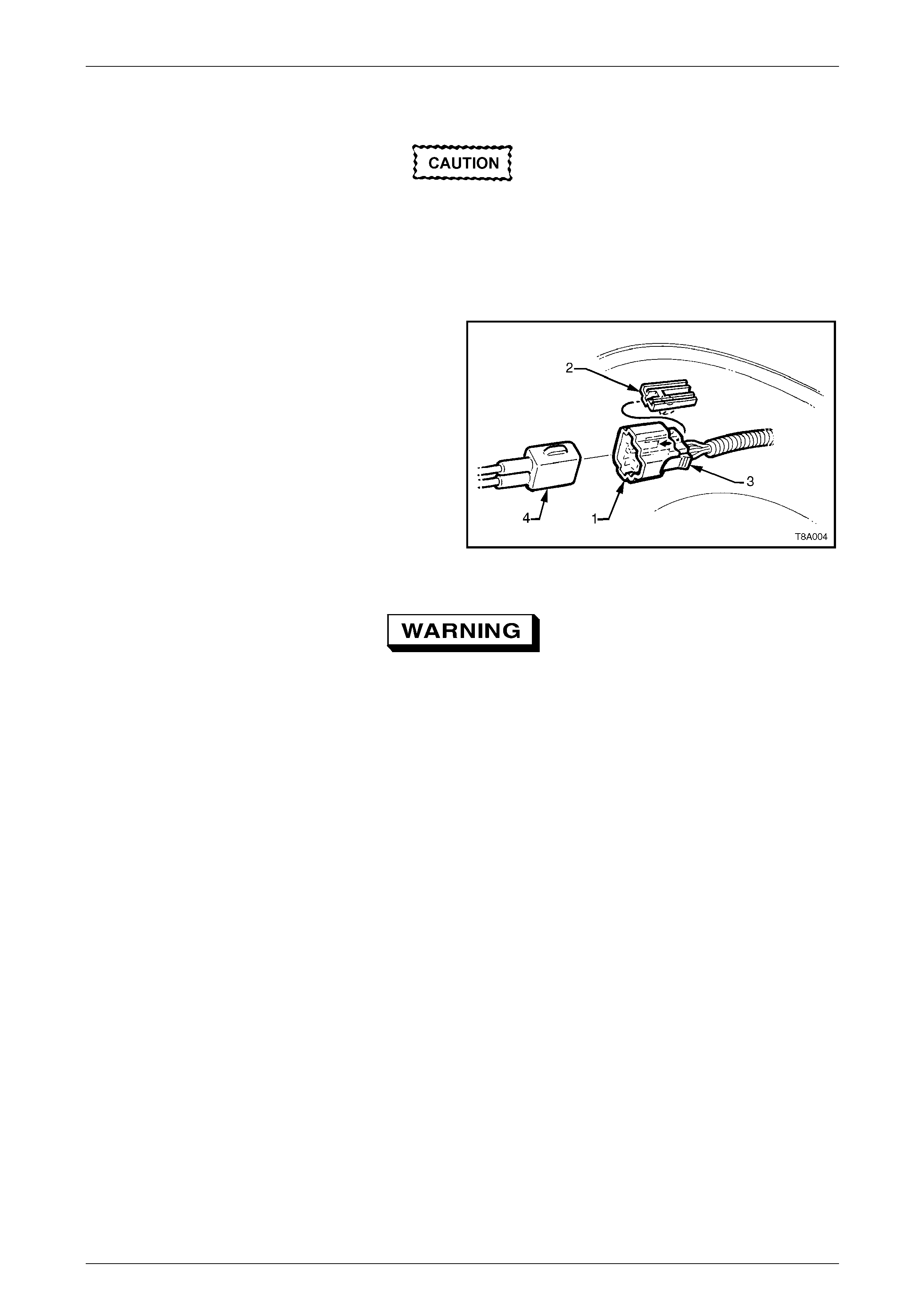
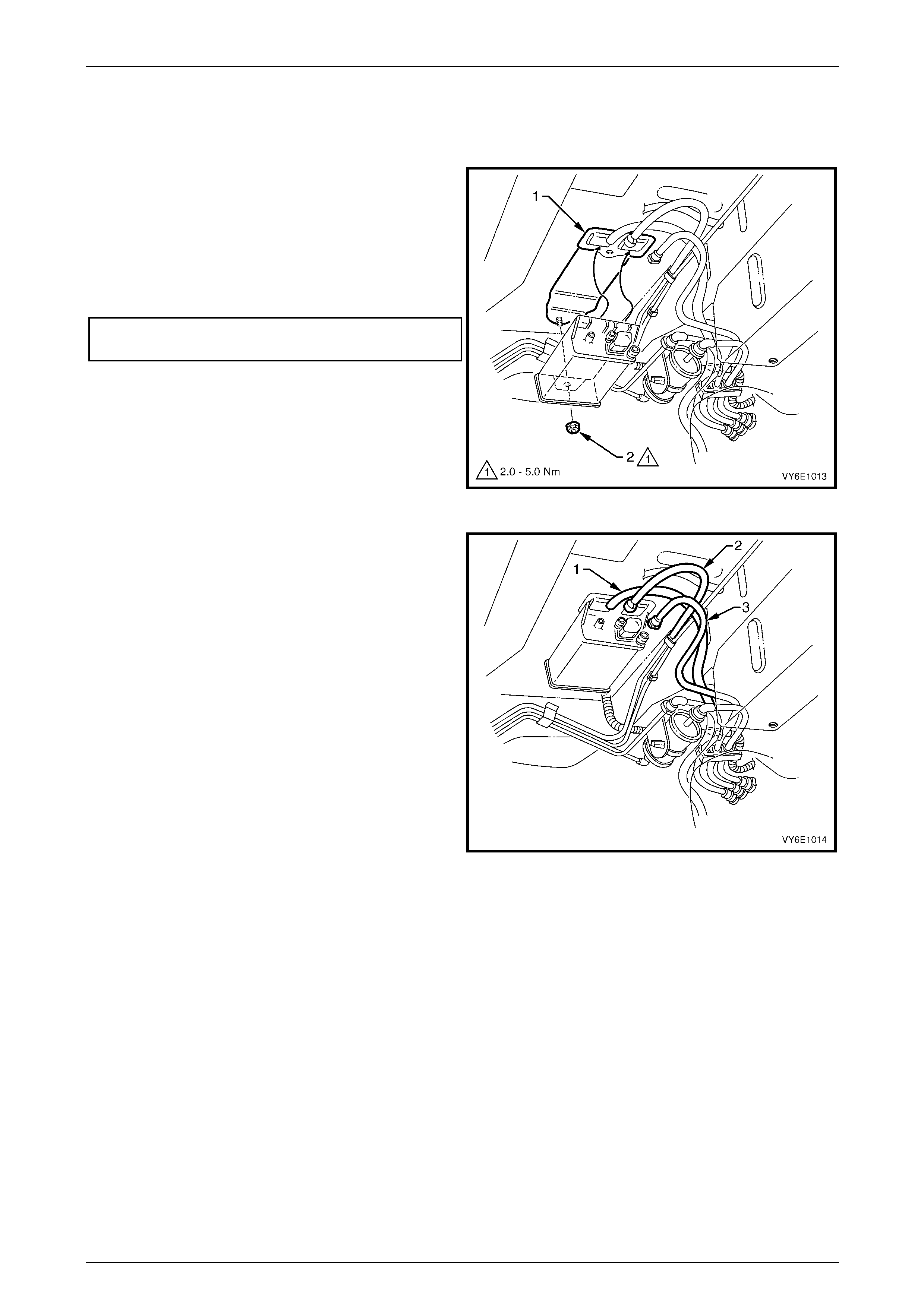
7 Remove the fuel pump electrical connector (1) from its
mounting (2) by pulling it for ward to dislod ge the
assembled connector. After releasing, press the
locking tab (3) and separate the con nector halves
(1 and 4).
8 Place a drain tray under the fuel filter are a.
Figure 8A1 – 40
Fuel can spill from the disconnected filter.
9 If required, remove the fuel filter (7) by disconnecting the fuel feed line quick-connect fitting (8), refer to
Figure 8A1 – 41. Press both fuel filter strap retaining tangs (5), then remove the fuel filter from the bracket.
10 Disconnect the fuel filter T-piece quick-c onnect fitting (4). Support the fuel filter during removal.
11 Disconnect the quick-connect fittings to the ev aporative emission control canister (1) by pushing inwards to release
the seal pressure; press the side tangs of the quick-connect fitting, then pull to disconnect. Alternatively, use tool
No. AU533 to assist in pressing the tangs on the quick-connect fittings, refer to 3.1 Quick-connect Fittings. Support
the fuel filter during removal.
12 Disconnect the evaporative emission control canister breather hose from the evaporative emission control
canister (2).
13 Disconnect the quick-connect fitting (3) at the flexible pipe and fuel filter T-piece, by supporting the quick-connect
fitting while pulling the fuel feed line from the quick-connect fitting.
Fuel System Page 8A1–29
Page 8A1–29
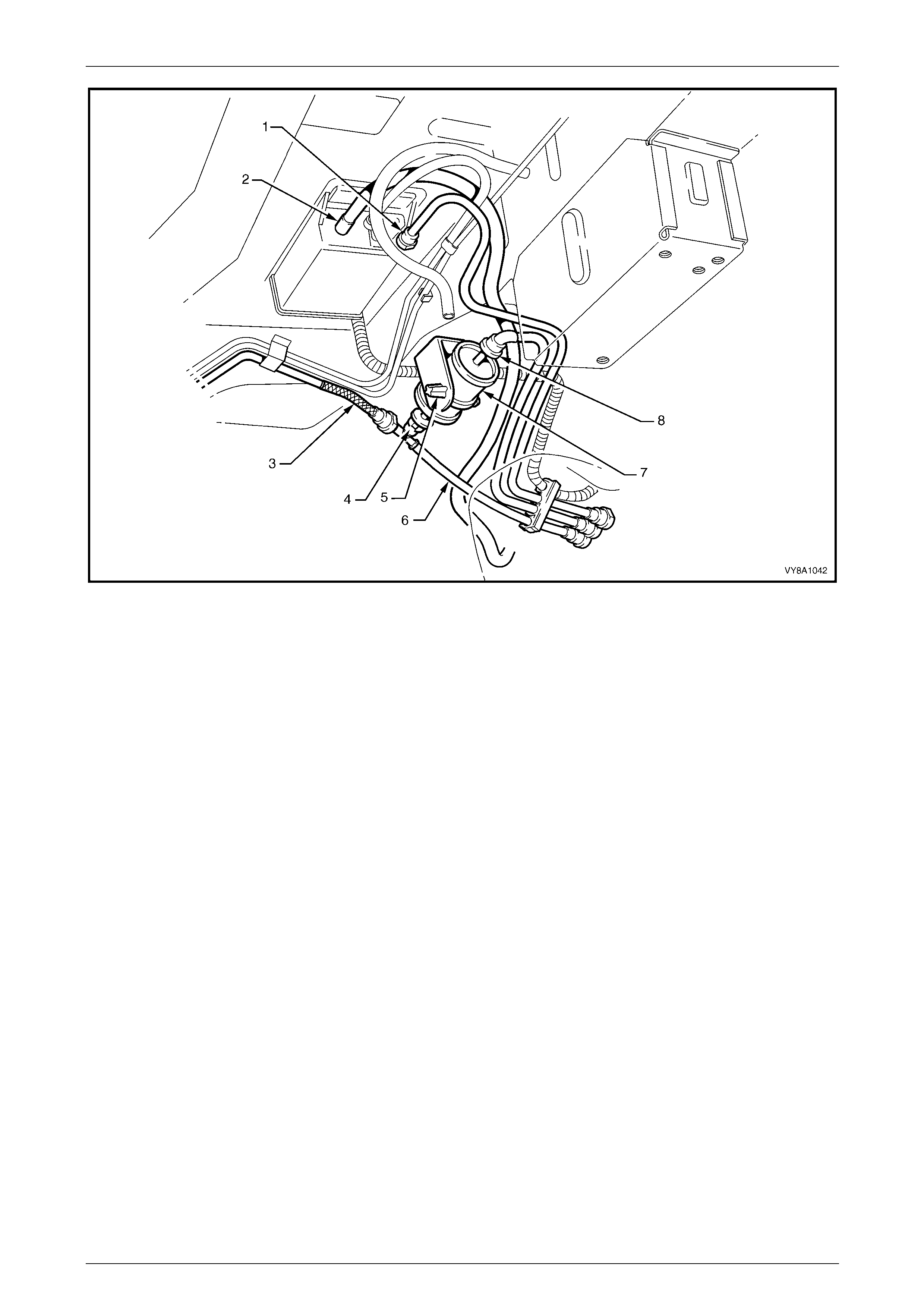
Figure 8A1 – 41
Legend
1 Fuel Tank Vapour Line to Evaporative Emission Control
Canister Quick-connect
2 Evaporative Emission Control Canister Breather Hose
3 Flexible Fuel Feed Line
4 Fuel Filter T-piece Quick-connect
5 Fuel Filter Strap Retaining Tang
6 Fuel Return Line
7 Fuel Filter
8 Fuel Feed Line Quick-connect
14 Disconnect the filler neck ground strap from the spa de connector (9, in view A and view E), located under the front
mounting bolt (4, in view A) of the right-hand fuel tank mount ing strap (3, in view A), refer to Figure 8A1 – 42.
15 While supporting the fuel tank in the centre, remove the fu el tank mounting straps:
a Remove the centre fuel tank mounting strap (2, view D) by removing the rear retai nin g nut (5) and
washer (10), then unhook the centre fuel tank mounting strap from the front support (view C).
b Remove the bolt at the front (view A) and unhook the right-hand fuel tank mounting strap from the rear
support (view B), then remove the right-han d fuel tank mounting strap (3).
c Remove the left-hand fuel tan k mounting strap (1) by unscrewing the bolt and washer from each end (view C
and view D).
16 Lower the left-hand side of the fuel tank from the vehicle to release the fuel filler neck from the body o pening. When
released, continue lowering the fuel tank.
Fuel System Page 8A1–30
Page 8A1–30
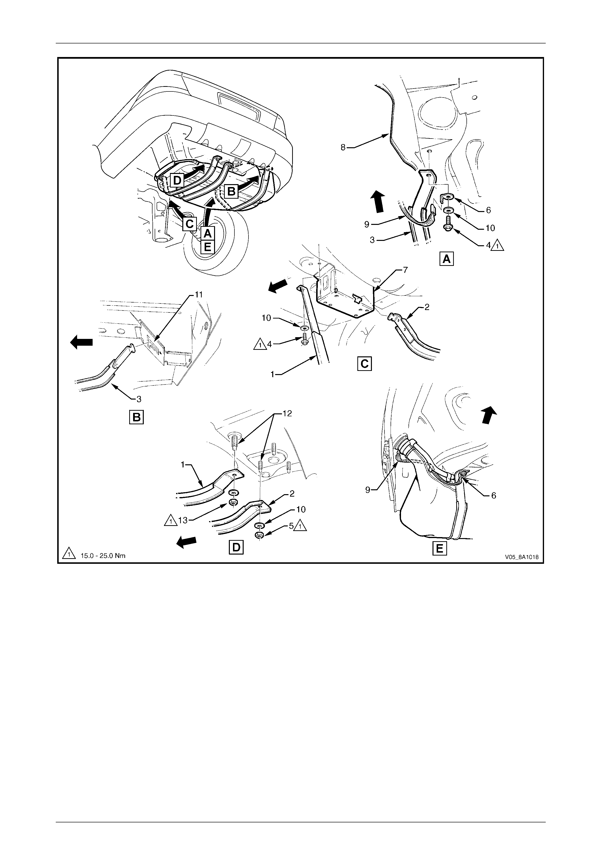
Figure 8A1 – 42
Legend
1 Left-hand Fuel Tank Mounting Strap
2 Centre Fuel Tank Mounting Strap
3 Right-hand Fuel Tank Mounting Strap
4 Left-hand Fuel Tank Mounting Strap
Front Bolt
5 Centre Fuel Tank Mounting Strap
Rear Attaching Nut
6 Ground Strap Spade Connector
7 Front Support
8 Rear Longitudinal Extension
9 Filler Neck Ground Strap
10 Tank Strap Support Washer
11 Rear Support
12 Fuel Tank Reinforcement Studs
13 Left-hand Strap Rear Attaching Nut
Fuel System Page 8A1–31
Page 8A1–31
Reinstall
Reinstallation of the fuel tank is the reverse of the removal procedure, noting the follo wing:
1 Check the insulation has not dislodged from the top of the fuel tank.
2 Lift the fuel tank, with the insulator attached, into position reinserting the fuel filler neck into the body openin g.
Raise the fuel tank into place.
3 Fit the fuel tank mounting straps in the following order, refer to F igure 8A1 – 42:
a Loosely reattach the two outer fuel tank mounting straps (1, in view D and 3, in view A), ensuring the ground
strap spade connector (6, in view A) is fitted correctly.
b Ensure the filler neck seal is correctly located in the body opening.
c While pushing the fuel tank firmly to the right-hand side, tighten the front bolt (4, in view C) and rear nut (1, in
view D) for the left-hand fuel tank mounting strap.
d Tighten the front mounting bolt (4, in view A) on the right-hand fuel tank mounting strap (3, in view A).
e Hook the centre fuel tank mounting strap (2, in vie w D) into the front retainer (7, in view C), and replace the
nut and washer (5, in view D).
4 Tighten all fuel tank mounting strap fasteners to the correct torque specification.
Fuel tank mounting strap
nut and bolt
torque specification.................................15.0 – 25.0 Nm
5 Replace the fuel pump electrical connector, ensuring both locking tabs are in plac e. Engage the fuel pump
electrical connector to its mounting foot and push rearwards to engage the locking tabs.
Install the fuel filter with the flow arrow on its
body pointing in the same direction as the
fuel flow to the front of the vehicle.
6 Install the disconnected quick-connect fittings to the fuel filter and evaporative emission control canister. Refer to
Figure 8A1 – 41 for the correct compone nt routeings using the following sequence:
a evaporative emission control canister breather hose (2) to evaporative emission control canister;
b fuel tank vent line (1) to evaporative emission control caniste r ;
c fuel feed line (3) to flexible pipe quick-conne ct;
d fuel filter to fuel filter T-piece quick-connect (4), then fuel filter strap retainer (5) to fuel filter bracket; and
e fuel filter to fuel feed line quick-connect (8).
7 Install the right-hand rear wheelhouse liner, tightening the mounting screws to the correct torqu e specification.
8 Before starting the vehicle, perform a fuel system leak test, refer to 2.3 Fuel Leak Test.
Fuel System Page 8A1–32
Page 8A1–32
3.3 Fuel Filter
LT Section No. —
Replace
A depressurised fuel system contains fuel in
the fuel filter and fuel lines that can be spilled
during service operations.
Ensure no naked flames or other ignition
sources are nearby. Ensure all cellular
phones (and transmission devices that may
cause any metal objects to become
unintentional receiving antennas) are
switched off.
Place a dry chemical (Class B) fire
extinguisher nearby before performing any
on-vehicle service procedures. Failure to
follow these precautions may result in
personal injury.
The fuel filter removal and installation
procedure must be performed correctly.
Failure to adhere to these instructions may
result in permanent damage to the flexible
fuel feed line, resulting in unnecessary parts
replacement a nd expense.
NOTE
For details on disconnecting the quick-connect
fittings from the fuel filter, refer to
3.1 Quick-connect Fittings.
1 Depressurise the fuel system, refer to 2.1 Fuel System Depressurisation.
Wear safety glasses when using compressed
air. Do not blow compressed air onto any
body part.
2 Use compressed air to ensure that all dirt and foreign materials are removed from all fu el connections before the
parts are disconnected.
Fuel System Page 8A1–33
Page 8A1–33
3 Push the fuel feed line quick-conn ect fitting (8) towards the filter and press the retainers together to disc onnect it
from the fuel filter (7), refer to Figure 8A1 – 43. Alternatively, use tool No. AU533 to assist in pressing the quick-
connect fitting locking tangs. Support the fuel filter during removal.
4 Press the fuel filter strap retaining tangs (5) on the retainer strap, then remove the filter from the bracket.
5 To avoid permanent dama ge to the flexible fuel feed line at the fuel filter T-piece end of the filter, support the fuel
filter T-piece then press the filter into it while releasing the quick-connect fitting (4). Alternatively, fit the tool
No. AU533 over the fuel filter T-piece connector to press the quick-connect fitting locking tangs.
6 Remove the fuel filter and retainer strap from the vehicle.
NOTE
Replacement fuel filters are supplied with a
retainer strap. Use only fuel filters with conductive
plastic retainer straps to ensure high-voltage
static electricity is dissipated without sparking.
7 Attach the support strap onto a replaceme nt fuel filter an d, while supporting the fuel filter T-piece, push the fuel
filter into the fuel filter T-piece quick-connect fitting until ful ly seated.
8 Install the filter strap retainer to the bracket. Install the quick-connect fitting to the remaining end of the filter.
9 Check each connector by firmly tugging on each on e to ensure it is in the locked position.
10 Before starting the vehicle, perform a fuel system leak test, refer to 2.3 Fuel Leak Test.
Figure 8A1 – 43
Legend
1 Fuel Tank Vapour Line to Evaporative Emission Control
Canister Quick-connect
2 Filler Neck Breather Hose
3 Flexible Fuel Feed Line
4 Fuel Filter T-piece Quick-connect
5 Fuel Filter Strap Retaining Tang
6 Fuel Return Line
7 Fuel Filter
8 Fuel Feed Line Quick-connect
Fuel System Page 8A1–34
Page 8A1–34
3.4 Modular Fuel Pump and Sender
Assembly
LT Section No. — 03–074
Remove
A depressurised fuel system contains fuel in
the fuel filter and fuel lines that can be spilled
during service operations.
Fuel vapour remains in the fuel tank even
when completely empty. Seal all openings in
the fuel tank using suitable material or a
plastic plug. Ensure no naked flames or other
ignition sources are nearby. Ensure all
cellular phones (and transmission devices
that may cause any metal objects to become
unintentional receiving antennas) are
switched off.
Place a dry chemical (Class B) fire
extinguisher nearby before performing any
on-vehicle service procedures. Failure to
follow these precautions may result in
personal injury.
Wear safety glasses when using compressed
air. Do not blow compressed air directly onto
any body part.
1 Depressurise the fuel system, refer to 2.1 Fuel System Depressurisation.
2 Remove the fuel pump relay, refer to Section 12O Fuses, Relays and Wiring Harnesses.
Never drain or store fuel into an open
container, due to the possibility of fire or
explosion.
Fuel System Page 8A1–35
Page 8A1–35
3 Siphon the fuel tank, using commercially-available equipment.
4 Remove the fuel tank, refer to 3.2 Fuel Tank.
Before proceedin g, clean all traces of dirt and
other foreign material from the top of the fuel
tank, near the modular fuel pump and sender
assembly.
5 Use compressed air to ensure all dirt and foreign materials are removed from all fuel connections before
disconnecting the parts.
Fuel can spill from the disconnected modular
fuel pump and sender assembly.
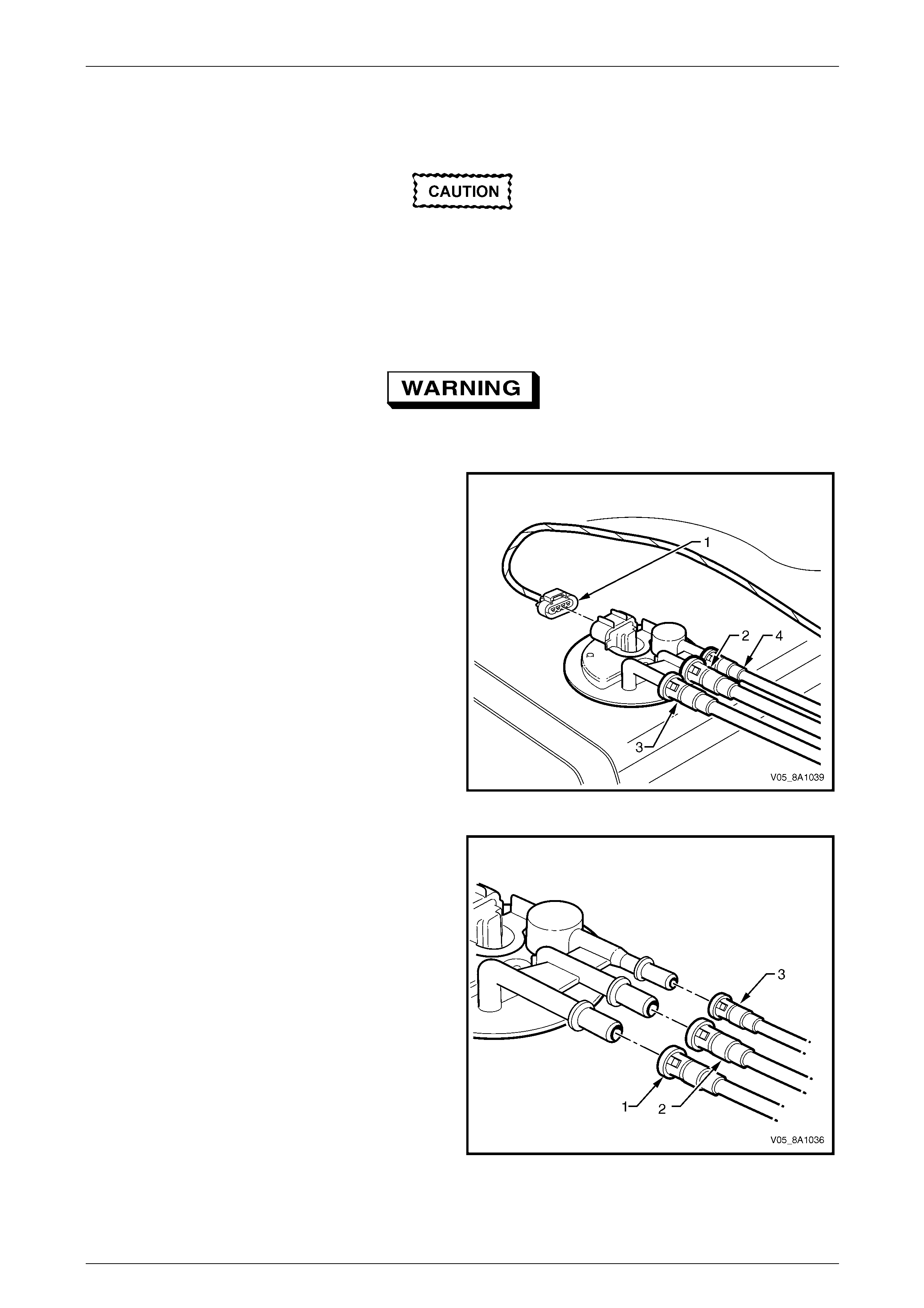
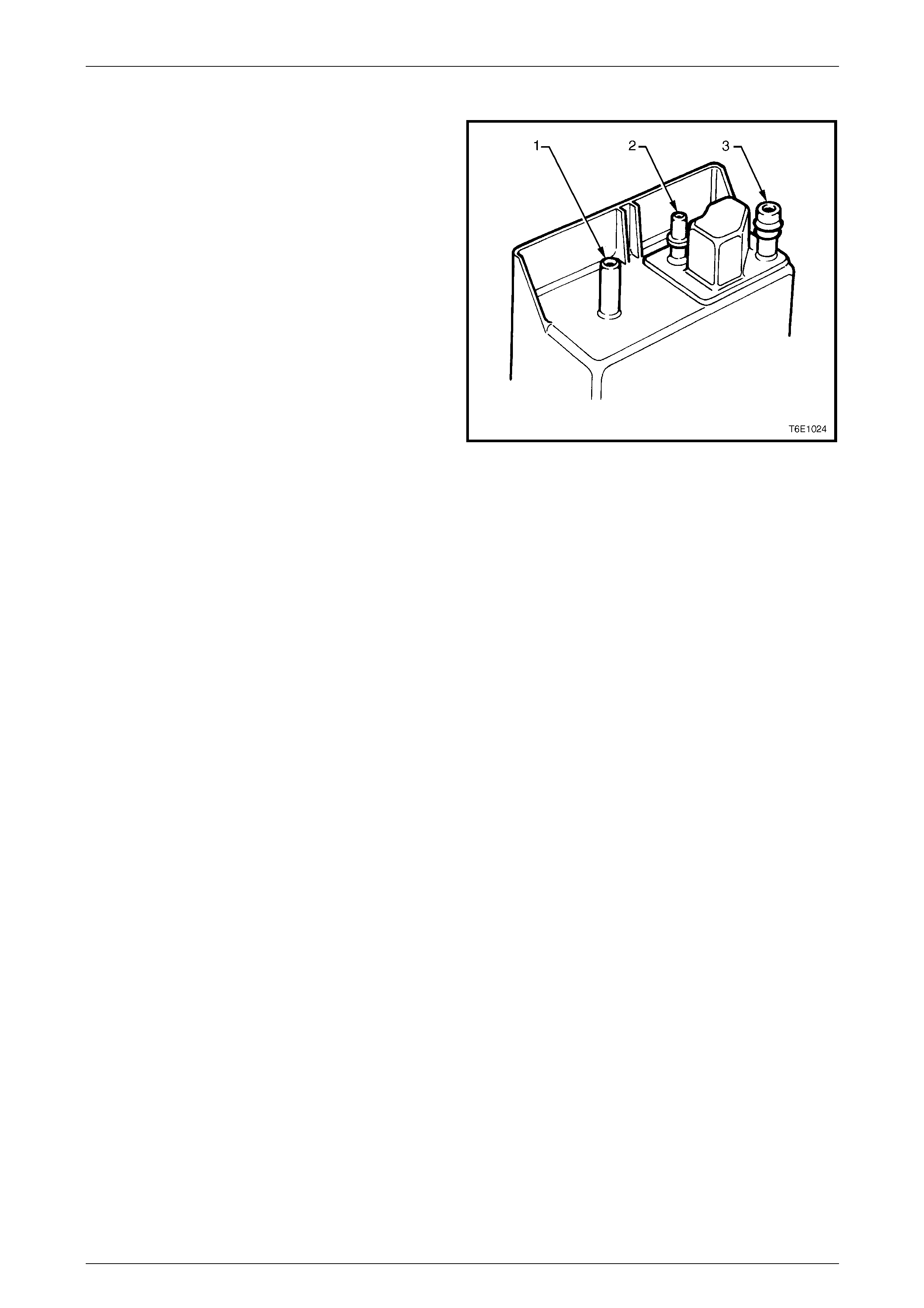
6 Disconnect the modular fuel pump and sen der
assembly harness connector (1).
7 Tag the fuel feed line connecting the fuel feed port (2)
on the modular fuel pump and sender assembly cover.
8 Tag the fuel return port (3) on the modular fuel pump
and sender assembly cover.
9 Tag the fuel tank vent line (4) on the modula r fuel
pump and sender assembly c over.
Figure 8A1 – 44
10 Disengage the fuel return line quick-connect fitting (1)
using tool No. AU533 (3/8-inch), refer to
3.1 Quick-connect Fittings.
11 Disengage the fuel feed line quick-connect fitting (2)
using tool No. AU533 (3/8-inch), refer to
3.1 Quick-connect Fittings.
12 Disengage the fuel tank vent li ne quick-connect
fitting (3) using tool No. AU533 (5/16-inch), refer to
3.1 Quick-connect Fittings.
Figure 8A1 – 45
Fuel System Page 8A1–36
Page 8A1–36
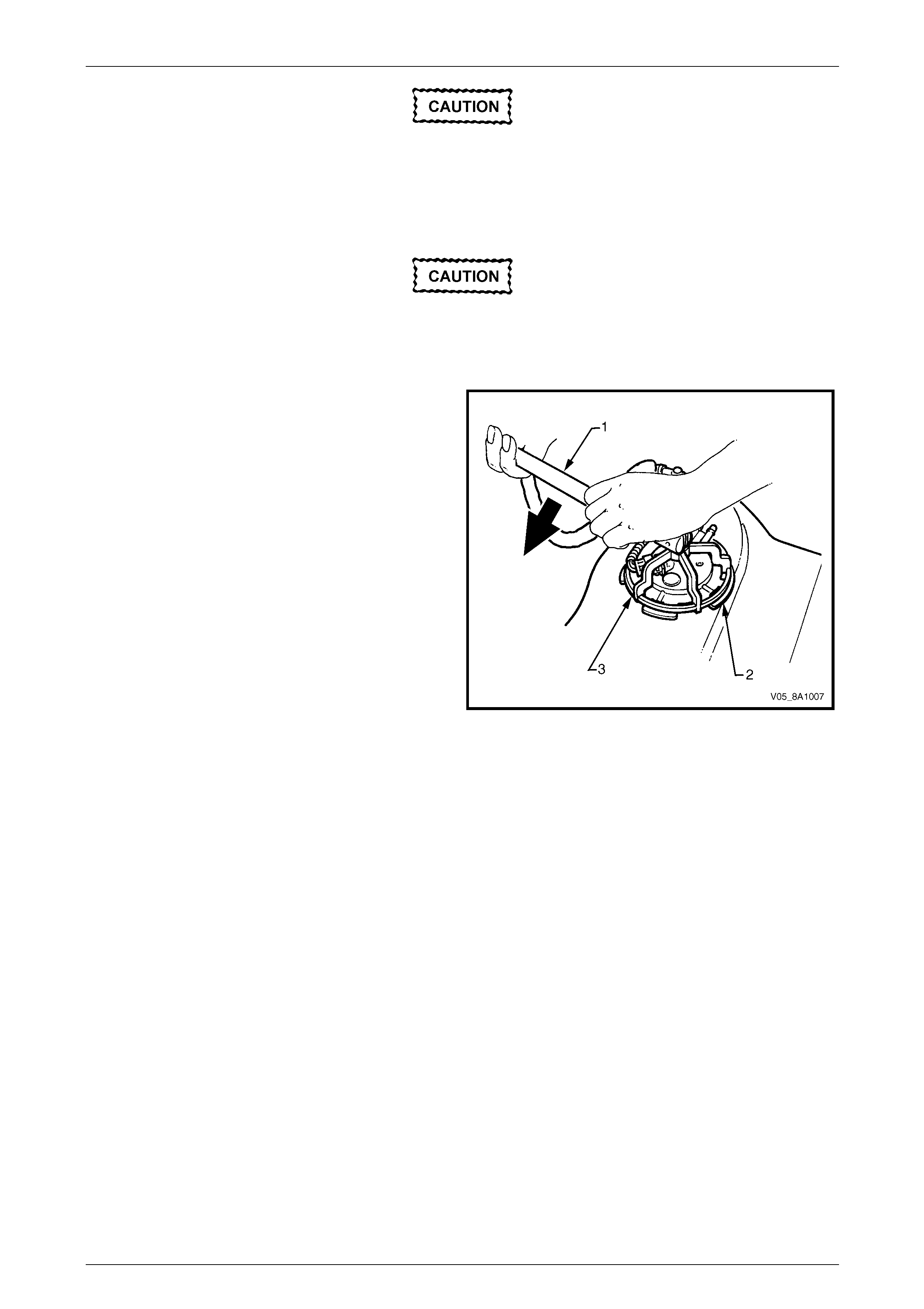
Ensure tool No. AU469 is seated firmly and
positively in the modular fuel pump and
sender assembly cover retainer lock ring
while removing the modular fuel pump and
sender assemb ly.
Assistance w ill be required to hold the tank in
position during this procedure; if not held
adequately, you may slip and damage the
modular fuel pump and sender assembly.
13 Using tool No. AU469 (3) and a half-i nch bre aker
bar (1), remove the modular fuel pump a nd sender
assembly cover retainer lock ring (2) by turning it
anticlockwise.
Figure 8A1 – 46
14 Remove the modular fuel pump and se nder assembly cover retainer lock ring.
Fuel System Page 8A1–37
Page 8A1–37
NOTE
The modular fuel pump and sender assembly
cover springs up when the retainer is remov ed.
The reservoir will be full of fuel. When the
modular fuel pump and sender assembly is
removed from the fuel tank, pour any
remaining fuel in the reser voir into a suitable
container. Do not drain or store fuel into an
open container, due to the possibility of fire
or explosion.
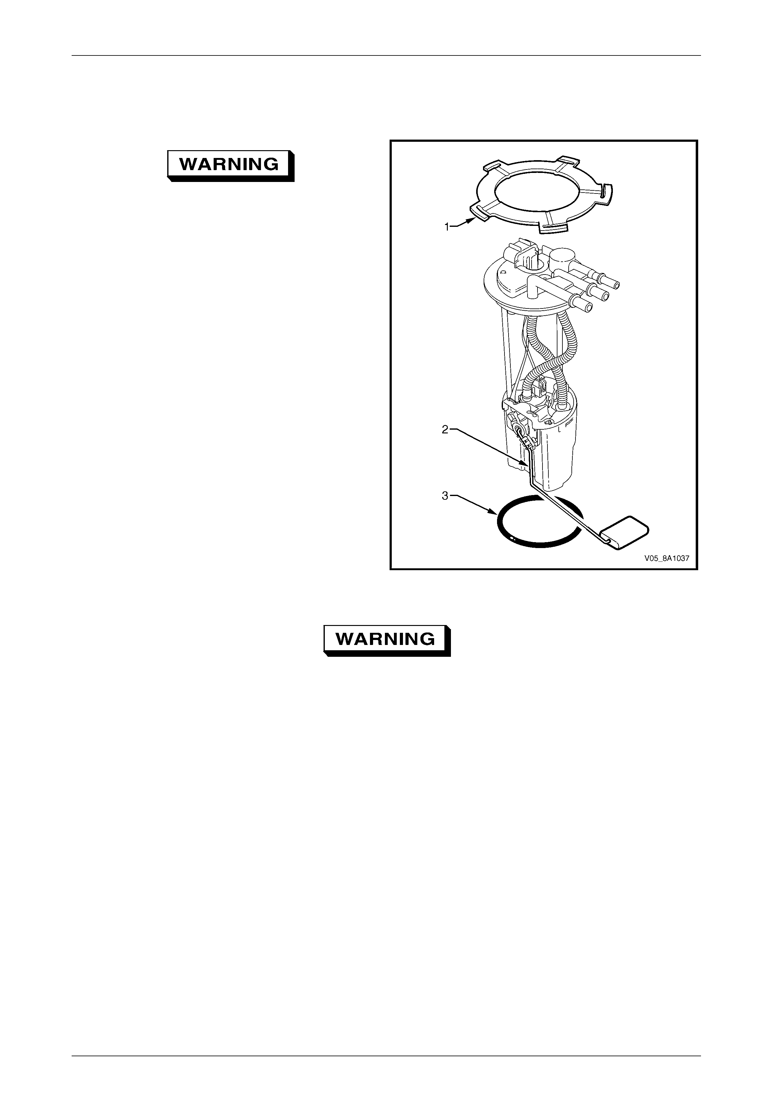
15 Place the modular fuel pump and sender assembly
cover retainer lock ring (1) in a safe location away
from the immediate worksite.
16 Carefully lift the modular fuel pump a nd sender
assembly from the fuel tank, taking care not to:
• damage the fuel level sender float and arm (2),
and
• spill any fuel remaining in the reservoir.
NOTE
The fuel sender float arm is not serviced
separately. If damaged, it is replaced as part of
the fuel level sender assembl y.
Figure 8A1 – 47
Fuel vapour remains in the fuel tank even
when completely empty. Seal all openings in
the fuel tank using suitable material or a
plastic plug. Ensure no naked flames or other
ignition sources are nearby. Ensure all
cellular phones (and transmission devices
that may cause any metal objects to become
unintentional receiving antennas) are
switched off.
17 Remove and discard the O-ring (3).
18 Place a suitable material over the opening in the fuel tank to prevent any foreign matter from entering the fuel
system.
Fuel System Page 8A1–38
Page 8A1–38
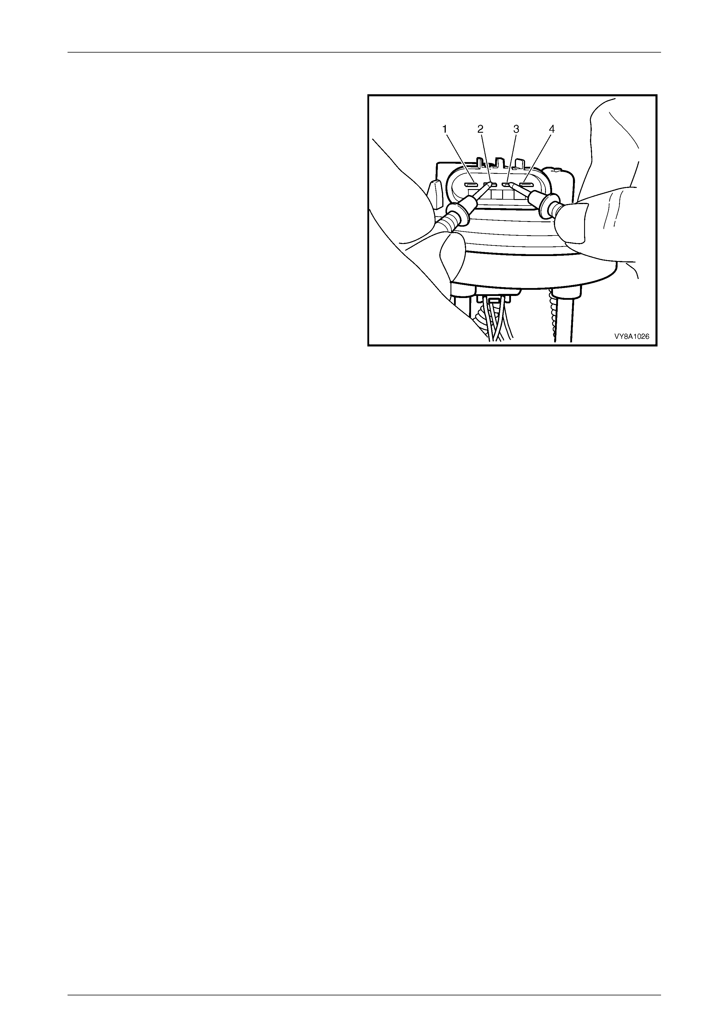
Test
1 Measure the resistance acros s terminals 2 and 3 of
the fuel pump motor connector. Take the follo wing
measurements:
a With the float arm assembly in the empty
position, the resistance should be ap proximately
250 Ω.
b With the float arm assembly rotated to the full
position, the resistance should be ap proximately
40 Ω.
2 If the resistance at either of these positions is not
within tolerance, replace the fuel level sender
assembly.
Figure 8A1 – 48
Reinstall
Reinstallation of the modul ar fuel pump and sender assembly is the reverse of the removal procedure, noting the
following:
1 Fit a new O-ring (3) to the modular fuel pump and sender assembl y, refer to F igure 8A1 – 47.
2 Install the modular fuel pump and sender assembly into the fuel tank, taking care not to damage the fuel sender
float or arm.
3 Ensure the locator in the pump cover enga ges in the slot in the fuel tank opening.
4 Install the modular fuel pump and sender assembly cover retainer lock ring (1).
Fuel System Page 8A1–39
Page 8A1–39
3.5 Fuel Pipes
LT Section No. — 03–075
Remove
A depressurised fuel system contains fuel in
the fuel filter and fuel lines that can be spilled
during service operations.
Fuel vapour remains in the fuel tank even
when completely empty. Seal all openings in
the fuel tank using suitable material or a
plastic plug. Ensure no naked flames or other
ignition sources are nearby. Ensure all
cellular phones (and transmission devices
that may cause any metal objects to become
unintentional receiving antennas) are
switched off.
Place a dry chemical (Class B) fire
extinguisher nearby before performing any
on-vehicle service procedures. Failure to
follow these precautions may result in
personal injury.
Wear safety glasses when using compressed
air. Do not blow compressed air onto any
body part.
1 Remove the fuel pump relay, refer to Section 12O Fuses, Relays and Wiring Harnesses.
2 Depressurise the fuel system, refer to 2.1 Fuel System Depressurisation.
Never drain or store fuel into an open
container, due to the possibility of fire or
explosion.
3 Raise the vehicle, preferably on a hoist, refer to Section 0A General Information.
Before proceedin g, clean all traces of dirt and
other foreign material from the fuel pipes.
4 Use compressed air to ensure that all dirt and foreign materials are removed from all fu el connections before the
parts are disconnected.
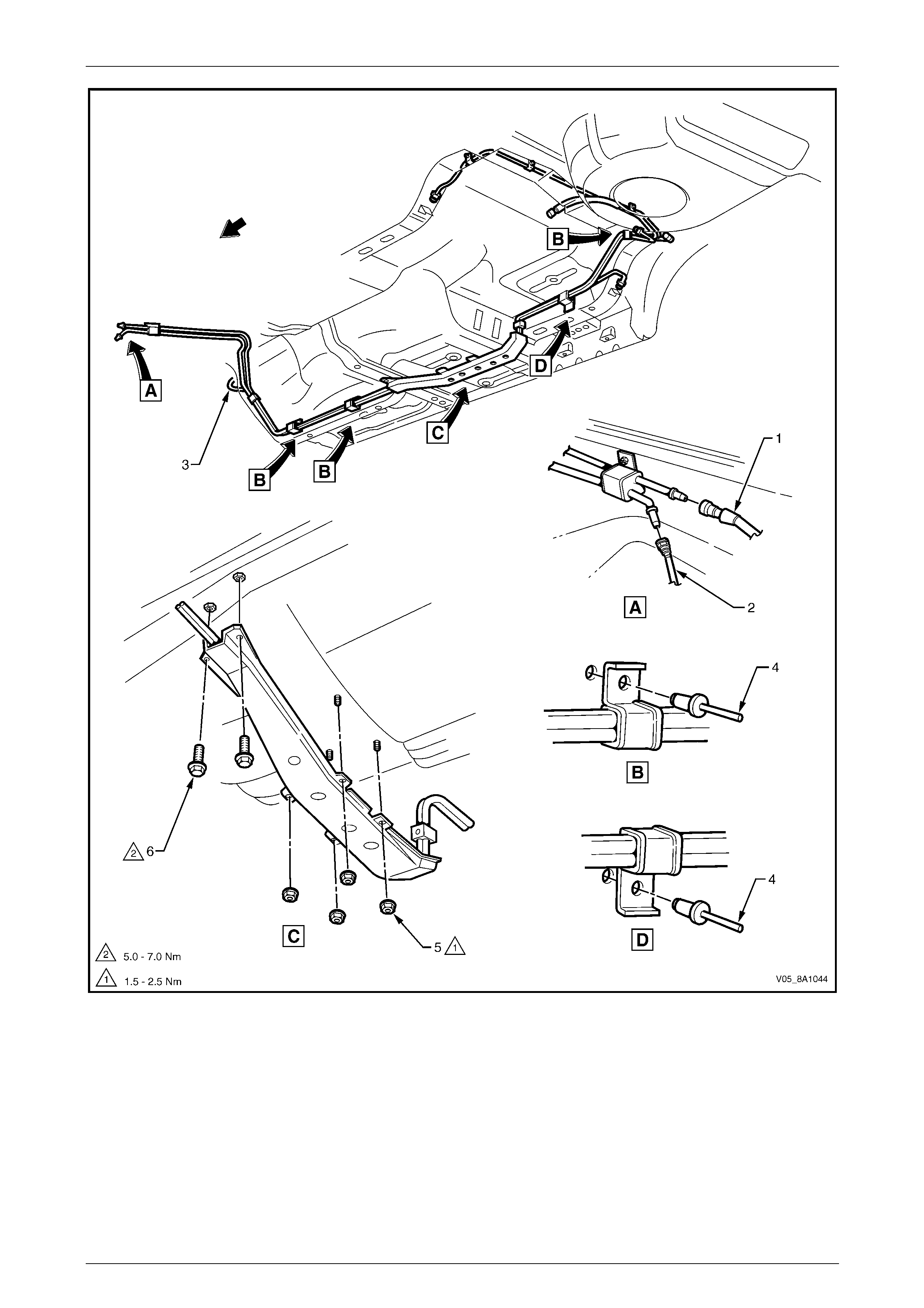
5 If required, remove the stone guards and fue l pipes. Use the following illustrations showing the fuel pipe l ayout and
location of other items relating to the fuel system as a guide, refer to Figure 8A1 – 49 and Figure 8A1 – 50.
Fuel System Page 8A1–40
Page 8A1–40
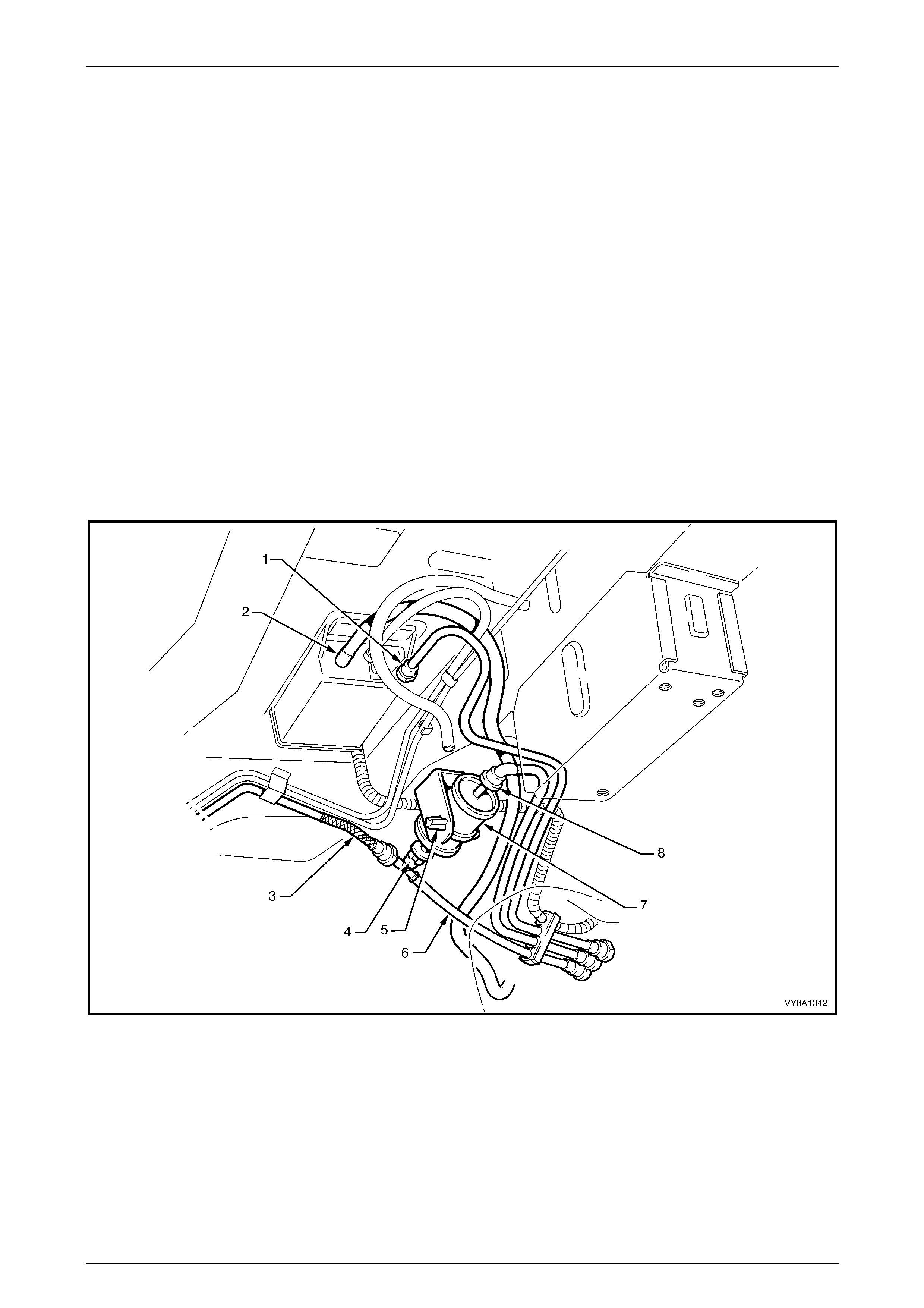
Figure 8A1 – 49
Legend
1 Fuel Feed / Fuel Return Line
2 Fuel Vapour Line 3 Brake Fluid Pipe
4 Fuel Line Bracket Pop Rivet 5 Stone Guard Securing Nut
6 Stone Guard Securing Bolt
NOTE
Use tool No. 7371 to remove the fuel feed line (1)
quick-connect fitting, refer to Figure 8A1 – 49.
Use tool No. AU533 to remove the fuel vapour
line quick-connect fitting (2), refer to
3.1 Quick-connect Fittings.
Fuel System Page 8A1–41
Page 8A1–41
Reinstall
Ensure the rubber in the fuel line brackets is
in good condition before proceeding. If not,
replace the affected b racket.
Reinstallation of the stone guards and fuel pipes is the reverse of the removal procedure, noting the following:
1 Tighten the stone guard securing nuts to the correct torque specification.
Stone guard securing nut
torque specification.....................................1.5 – 2.5 Nm
2 Tighten the stone guard securing bolts to the correct torque specification.
Stone guard securing bolt
torque specification.....................................5.0 – 7.0 Nm
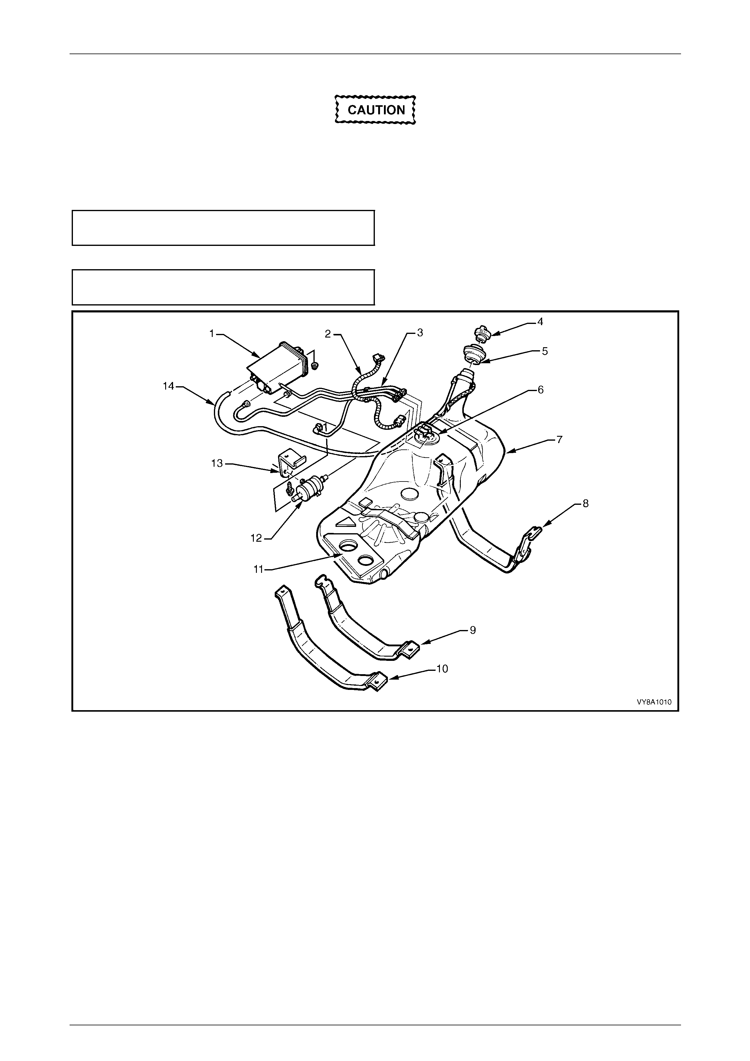
Figure 8A1 – 50
Legend
1 Evaporative Emission Control
Canister
2 Electrical Harness Connector
3 Fuel Return Line
4 Fuel Filler Cap
5 Fuel Filler Neck Insulator
6 Modular Fuel Pump and Sender
Assembly
7 Fuel Tank
8 Right-hand Side Fuel Tank Mounting
Strap
9 Centre Fuel Tank Mounting Strap
10 Left-hand Side Fuel Tank Mounting
Strap
11 Insulator Kit
12 Fuel Filter
13 Fuel Filter Mounting Bracket
14 Filler Neck Breather Hose
Fuel System Page 8A1–42
Page 8A1–42
3.6 Evaporative Emission Control Canister
Remove
LT Section No. — 03–165
1 Disconnect the evaporative emission control canister
purge line (1) by using the following procedure:
a Grasp both sides of the quick-connect fitting.
Twist the connector 1/4 turn in each direction in
order to loosen any dirt within the quick-conn ect
fitting.
Wear safety glasses w hen usin g compressed
air. Do not blow compressed air onto any
body part.
b Using compressed air, blow any dirt out of the
quick-connect fitting.
c Grasp the quick-connect fitting and push it
towards the canister.
d Squeeze the quick-connect fitting to release the
retaining tabs, then pull back on the connector to
remove the canister purge line from the canister.
Figure 8A1 – 51
2 Disconnect the fuel tank vent line (1) by using the
following procedure:
a Grasp both sides of the quick-connect fitting.
Twist the connector 1/4 turn in each direction in
order to loosen any dirt within the quick-conn ect
fitting.
Wear safety glasses w hen usin g compressed
air. Do not blow compressed air onto any
body part.
b Using compressed air, blow any dirt out of the
quick connect fitting.
c Grasp the quick-connect fitting and push it
towards the canister.
d Squeeze the quick-connect fitting to release the
retaining tabs, then pull back on the connector to
remove the tank vent line from the canister.
Figure 8A1 – 52

Fuel System Page 8A1–43
Page 8A1–43
3 Remove the canister vent line (1) from the canister by
twisting and pulling it off.
Figure 8A1 – 53
4 Remove the canister retaining nut (1).
5 Remove the canister from the retaining stud and then
slide the canister out of the retainer (2).
Figure 8A1 – 54
Fuel System Page 8A1–44
Page 8A1–44
Reinstall
1 Hoist the vehicle, refer to Section 0A General Information.
2 Reinstall the canister into the retainer (1) and over the
retaining stud.
3 Reinstall the canister retaini ng nut (2), then hand-
tighten.
4 Push the canister toward the centre of the vehicle and
tighten the canister retaining nut to the specified
torque.
Evaporative emission control canister
retaining nut torque specification ................2.0 – 5.0 Nm
Figure 8A1 – 55
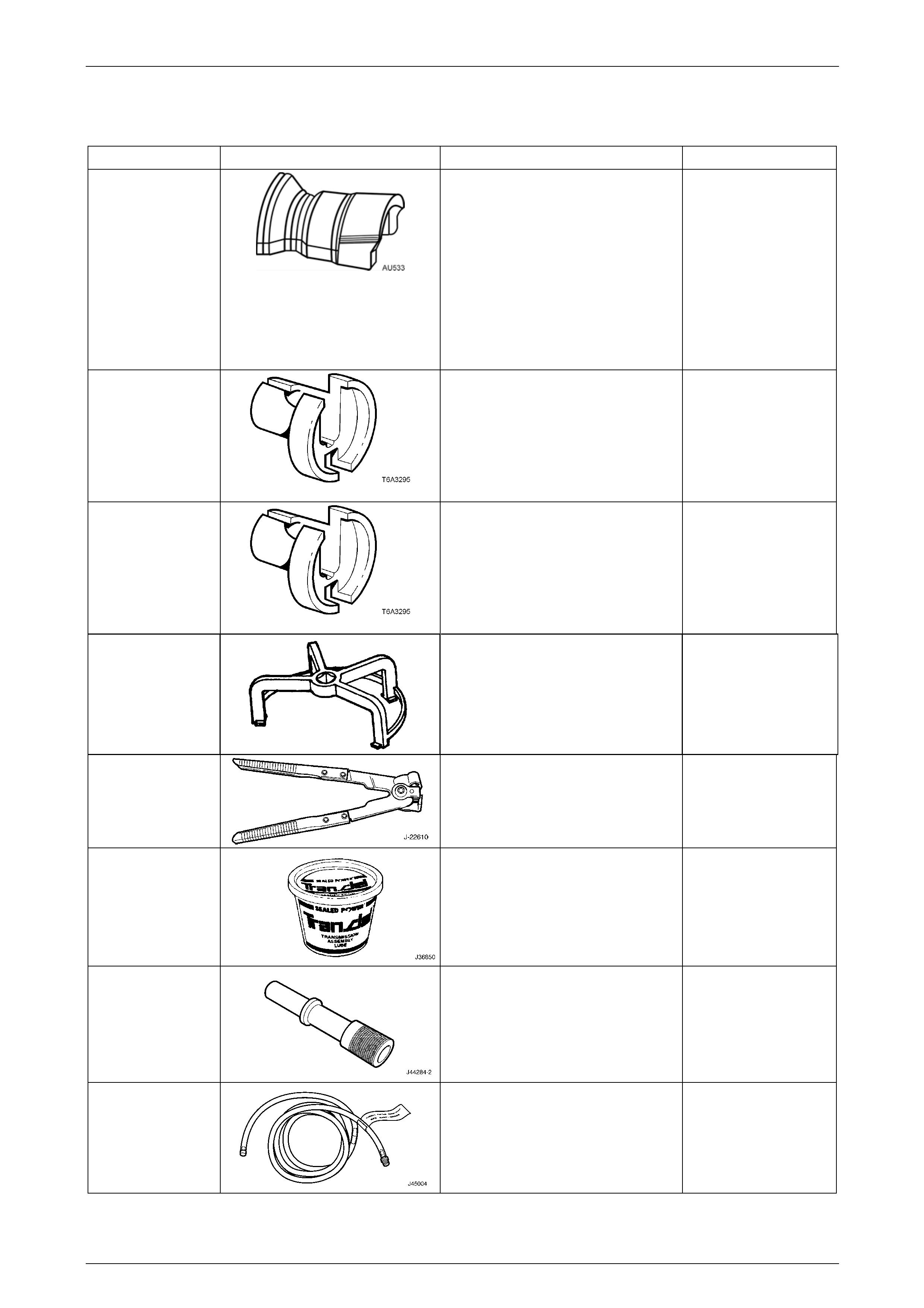
5 Reinstall the canister vent lin e (1).
6 Align the canister purge line quick-connect (2) with the
canister purge line port. Push the quick-connect firmly
onto the port.
7 Align the fuel tank vent line quick-co nnect (3) with the
fuel tank vent port. Push the quick-connect firmly onto
the port.
8 After installation, pull on each quick-c onnect to ensure
the connections are secure and lock ed in position.
Figure 8A1 – 56
Fuel System Page 8A1–45
Page 8A1–45
Service Checks
1 Remove the canister, refer to 3.6 Evaporative
Emission Control Canister.
2 Shake the canister. There should be no audible sound
of carbon movement.
3 Using low pressure compressed air (20–35 kPa), blow
into the tank vent port (3). Check that air flows freely
from the canister vent port (1). Block the canister vent
port (1); air should flow from the canister purge
port (2).
4 If airflow through the canister vent port (1) is limited,
clean the atmospheric filter b y blocking off the fuel
tank vent port (3) and blow compressed air at
approximately 300 kPa throug h the canister purge
port (2).
5 Check airflow through the filte r as in step 3. If airflow
through the canister vent port (1) is still limit ed, replace
the canister.
Figure 8A1 – 57
6 Block the canister vent port (1) and the canis t er purge port (2). Apply low-pressure compressed air
(20–35 kPa) to the tank vent port (3). If any air leaks from the canister (that is, around the ports or seams), replace
the canister.
NOTE
In dusty areas, an alternative is to block the
canister purge port (2). Blow air through the
canister vent (1) port and check that air is
expelled through the tank vent port (3).

Fuel System Page 8A1–46
Page 8A1–46
4 Specifications
Fuel Tank Capacity:
.....................................................................................................................................75 litres
Fuel Tank Material:
....................................................................................... High-density multi-layer polyethylene
Fuel Filler Location:
...................................................................................................Right-hand rear quarter panel
Fuel Pump Type:
...........................................................................................................................Single Turbine
Fuel Pump Location:
.......................................................................................................................................In tank
Fuel Pump Regulated Pressure:
............................................................................................................. approx. 410 kPa at idle
Minimum Fuel Pump Flow Capacity (at Regulated Pressure):
V6 Engine.............................................................................................1.7 L/min @ 13.5 volts
GEN III V8 Engine ................................................................................2.5 L/min @ 13.5 volts
Fuel Pump Current Draw (Steady State at Regulated Pressure):
V6 Engine................................................................................................. 7.4 Amps maximum
GEN III V8 Engine ....................................................................................9.6 Amps maximum

Fuel System Page 8A1–47
Page 8A1–47
5 Torque Wrench Specifications
Fuel Tank Mounting Strap Nuts/Bolts........................................15.0 – 25.0 Nm
Stone Guard Securing Nut ............................................................1.5 – 2.5 Nm
Stone Guard Securing Bolt............................................................5.0 – 7.0 Nm
Evaporative Emission Cont rol Canister Retaining Nut ..................2.0 – 5.0 Nm
Fuel System Page 8A1–48
Page 8A1–48
6 Special Tools
Tool Number Illustration Description Tool Classification
AU533
Quick-connect Fitting
Release Tool
Released in two sizes:
• red for 5/16-inch fittings
(fuel vapour lines), and
• blue for 3/8-inch fittings
(fuel feed lines).
Commercially available under
P/N AUSP45.
Previously released.
Desirable
7370
Quick-connect Release
Tool — 5/16-inch
Used for releasing fuel line qu ick
connects at the dash panel and fuel
rail connections, after the fuel system
has been depressurised.
Previously released.
Mandatory
7371
Quick-connect Release
Tool — 3/8-inch
Used for releasing fuel line qu ick
connects at the dash panel and fuel
rail connections, after the fuel system
has been depressurised.
Previously released.
Mandatory
AU469
(J39765)
Modular Fuel Pump and Sender
Assembly Remover / Installer
Previously released.
Mandatory
J22610
Keystone Clamp Pliers
Used to remove and fasten ear-type
clamps.
Available
J36850 TransJel Lubricant
Used to lubricate fuel tank siphon
hose during fuel tank drain/siphon
procedures.
Desirable
J44284–2 Fuel Flapper Door Holder
Holds open the fuel filler neck flapper
door to allow the fuel tank siphon
hose to be fed down into the fuel filler
neck.
Mandatory
J45004–1
Fuel Tank Siphon Hose
Flexible fuel siphoning hose with
grounding wire and threa de d vacuum
pump fitting.
Mandatory