
General Information Page 0A–1
Page 0A–1
Section 0A
General Information
ATTENTION
Before performing any Service Operation or other procedure described in this Section, refer to Section 00
Warnings, Cautions and Notes for correct workshop practices with regard to safety and / or property damage.
1 General Information............................................................................................................................... 2
1.1 Hoist Pad Locations...............................................................................................................................................3
2 Model Av ailab ility and Equipment ....................................................................................................... 4
3 Major Option Codes............................................................................................................................... 5
4 Powertrain .............................................................................................................................................. 6
5 Engine Data............................................................................................................................................ 7
6 Transmission Data.............................................................................................................. ................... 8
7 Transfer Case Data................................................................................................................................ 9
8 Exterior Dimensions............................................................................................................................ 10
9 Vehicle Weights ................................................................................................................................... 11
10 Fuel Consumption Label..................................................................................................................... 12
11 Serial Numbers..................................................................................................................................... 13
11.1 Location of Identification Plates.........................................................................................................................13
11.2 Safety Compliance Plate......................................................................................................................................14
11.3 Body and Option Identification Plate..................................................................................................................15
11.4 Vehicle Identif icati on Number.............................................................................................................................16
VIN Plates..............................................................................................................................................................16
VIN Body Stamping..............................................................................................................................................17
11.5 Vehicle Identification Numbering System..........................................................................................................18
11.6 Automatic Transmission Serial Number............................................................................................................19
11.7 Final Drive Assembly Serial Numbers................................................................................................................20
Front Final Drive...................................................................................................................................................20
Rear Final Drive....................................................................................................................................................20
11.8 Transfer Case Assembly Serial Number ............................................................................................................21
12 Special Tools........................................................................................................................................ 22
Transfer Case .......................................................................................................................................................23
Front Suspension.................................................................................................................................................24
Front Final Drive...................................................................................................................................................25
Techline
Techline
Techline
Techline
Techline

General Information Page 0A–2
Page 0A–2
1 General Information
The MY 2004 All Wheel Drive (AWD) Crewman Cross 8 Crew Cab is based upon the previously released 2WD Crewman
Crew Cab body style. Excluding the rear final drive assembly, it uses the same powertrain as that fitted to the MY 2004
AWD Wagon. Like the AWD Wagon, it is a constant AWD vehicle. It is available only with the GEN III V8 engine and
4L65-E heavy duty automatic transmission combination. The rear axle and rear suspension configuration is basically the
same as its 2WD equivalent although, the rear differential is a not a limited slip type.
The main features and changes for the MY 2004 AWD Crewman Cross 8 Crew Cab are summarised in the following list:
• Constant AWD powertrain.
• Heavy duty suspension to suit the AWD application.
• Heavy duty engine cooling fan system.
• Specific traction control system to suit the AWD application.
• Restyled front fascia incorporating fog lamps (as fitted to AWD Wagon).
• Extension mouldings on front and rear wheelhouses.
• Exterior colour range of five colours from MY 2004 VY Series.
• Front mounted aluminium plate and aluminium rocker panel inserts.
• Air conditioning as standard.
• Automatic air conditioning (Single zone Occupant Climate Control) optional as part of leather interior package.
• Inclinometer gauge assembly located on top centre of instrument panel (similar to AWD Wagon).
• Sports profile leather wrap steering wheel and alloy pedals.
• Leather wrap satin chrome gear knob and park brake lever.
• Additional badging to denote AWD model.
• Five spoke 17" alloy wheels and tyres (as fitted to AWD Wagon).
• Front tow attaching point and 'towing eye’ (as fitted to AWD Wagon).
• Driver, passenger and side aibags.
• Triple-window instrument cluster (as fitted to LX8 AWD Wagon).
• ‘In-dash’ cup holders (as part of optional leather interior package).
• ‘In-dash’ 6 disc CD changer as part of audio system.
General Information Page 0A–3
Page 0A–3
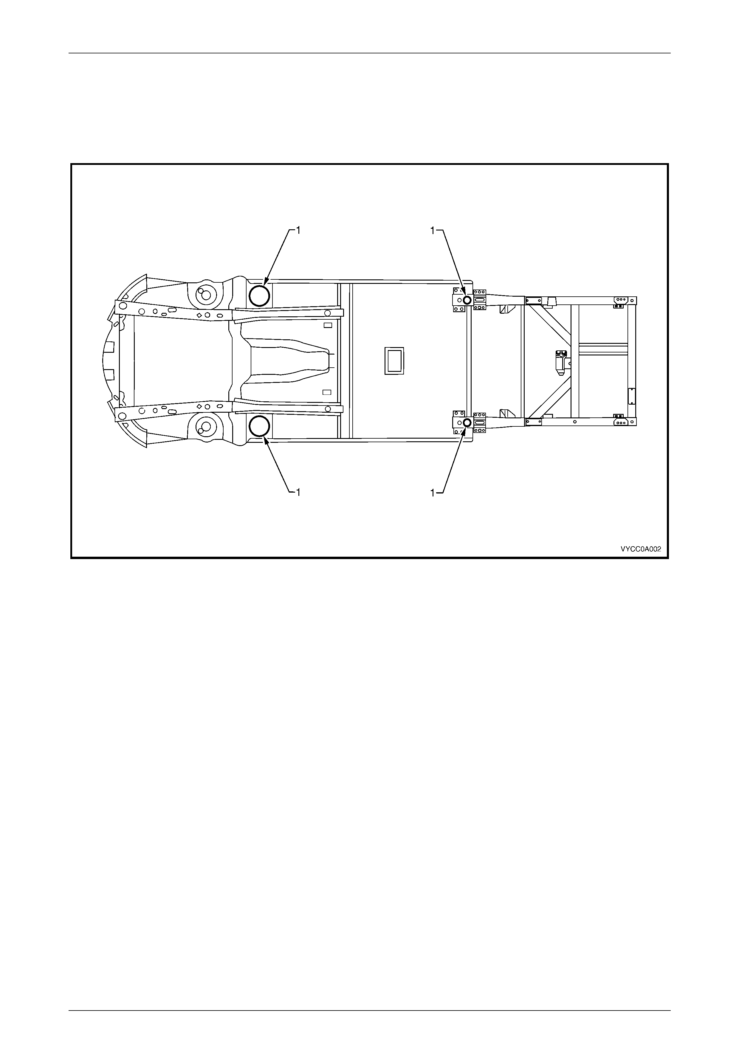
1.1 Hoist Pad Locations
When using a trolley jack to raise the vehicle, it is important that the jack be positioned under the suspension cross
member or hoist pad (1) locations. The vehicle should always be supported by jack stands at the hoist pad locations
when raised.
Figure 0A – 1

General Information Page 0A–4
Page 0A–4
2 Model Availability and
Equipment
NOTE
For tyre and wheel information, refer to
Section 10 Wheels and Tyres in this Service
Information.
Model Name Luxury Level
(Description) Model Code. Bod y Style
(Doors) Engine
Crewman
Cross 8
Level 1 or 2
(Sport) –
dependent on
options fitted
8VM43 Cab (4) V8
General Information Page 0A–5
Page 0A–5
3 Major Option Codes
Option Code Description Option Code Description
81I Anthracite Interior Trim JL9 Anti-Lock Brake System
A31 Power Windows (Front and Rear) MD6 4 Speed Auto Trans. H/Duty AWD
AH6 Driver’s Seat, 4-Way N88 7.5 JJ x17" Alloy wheel
AJ7 Driver, Passenger and Side Airbag N40 Power Steering
AQ9 Front Seat, Reclining Bucket NK4 Sports Leather Stee ring Wheel
AX2 Keys, 2 Key Set NW9 Traction Control (with ABS)
C61 Automatic Air Conditioning (OCC) QBB 225/55 R17 97H Tyre
C60 Manual Air Conditioning R5C Bridgestone Hybrid Tyre Design
DL6 Exterior Mi rrors Body Colour Scalp U1V Audio System, 60W 6 Disc CD
E18 Satin Chrome Interior Door Handles U75 Antenna, Power
F46 AWD Powertrain UE1 Holden Assist (Telematics)
FE1 Suspension – Soft Ride UJ8 Instrument Cluster
GS9 Axle, 3.46:1 Ratio Rear U08 Dual Note Horns
K30 Cruise Control UY4 Satellite Navigation System
K69 Keys, Additional Set W1Y Steering Wheel Radio Controls
LS1 225KW, 5.7 V8 EFI Petrol Engine XS4 Roo Bar
JF5 Alloy Pedals XW 6 Paint, Metallic Finish

General Information Page 0A–6
Page 0A–6
4 Powertrain
Component Designation / ID Code Type
Engine GEN III V8 V8 5.7 litre OHV PFI
Transmission 4L65-E 4 speed with Overdrive
Transfer Case NV124 Full time AWD, Gear Drive
Final Drive – Front DY Conventional, Ratio – 3.46:1
Final Drive – Rear STD AWD Conventional, Ratio – 3.46:1
General Information Page 0A–7
Page 0A–7
5 Engine Data
Engine Designation GEN III V8
Piston Displacement
Nominal – cm3 5667
Compression Ratio 10.1:1
Number of Cylinders 8
Bore x Stroke – mm 99 x 92
Taxable H.P.
RAC OR SAE 48.6
Power kW
ECE @ RPM 225 kW @ 5200
Torque N.m
ECE @ RPM 460 N.m @ 4000

General Information Page 0A–8
Page 0A–8
6 Transmission Data
Model 4L65-E
Torque converter 4 element (including lock-up clutch)
Pump 13 Vane, variable displacement
No. of clutch packs 5
No. of bands 1
No. of planetary gear sets 2
No. of solenoids 6
No. of electrical sensors 3
Ratios:
1st
2nd
3rd
4th
Reverse
3.06:1
1.63:1
1.00:1
0.70:1
2.29:1

General Information Page 0A–9
Page 0A–9
7 Transfer Case Data
Manufacturer New Venture Gear (NVG)
Model NV124
Type Full Time AWD
Torque Split 38 / 62 per cent, front to rear

General Information Page 0A–10
Page 0A–10
8 Exterior Dimensions
Dimension mm
Vehicle length 5323
Vehicle width 1954
Vehicle height (from kerb groundline) 1542
Wheelbase 3207
Overhang – front 944
Overhang – rear 1172
Track – front 1620
Track – rear 1623
Ground clearance 188

General Information Page 0A–11
Page 0A–11
9 Vehicle Weights
Weight kg
Kerb mass (Estimated including fluids) 1947
Gross Vehicle Mass (GVM) 2685
Front axle load 1230
Rear axle load 1460
Payload Refer Owner’s Handbook
NOTE
Payload figures include luggage, goods,
passengers and a full tank of fuel. When towing,
the weight on the tow bar ball must also be
included.
NOTE
Maximum rear axle load is the maximum for all
conditions.
General Information Page 0A–12
Page 0A–12
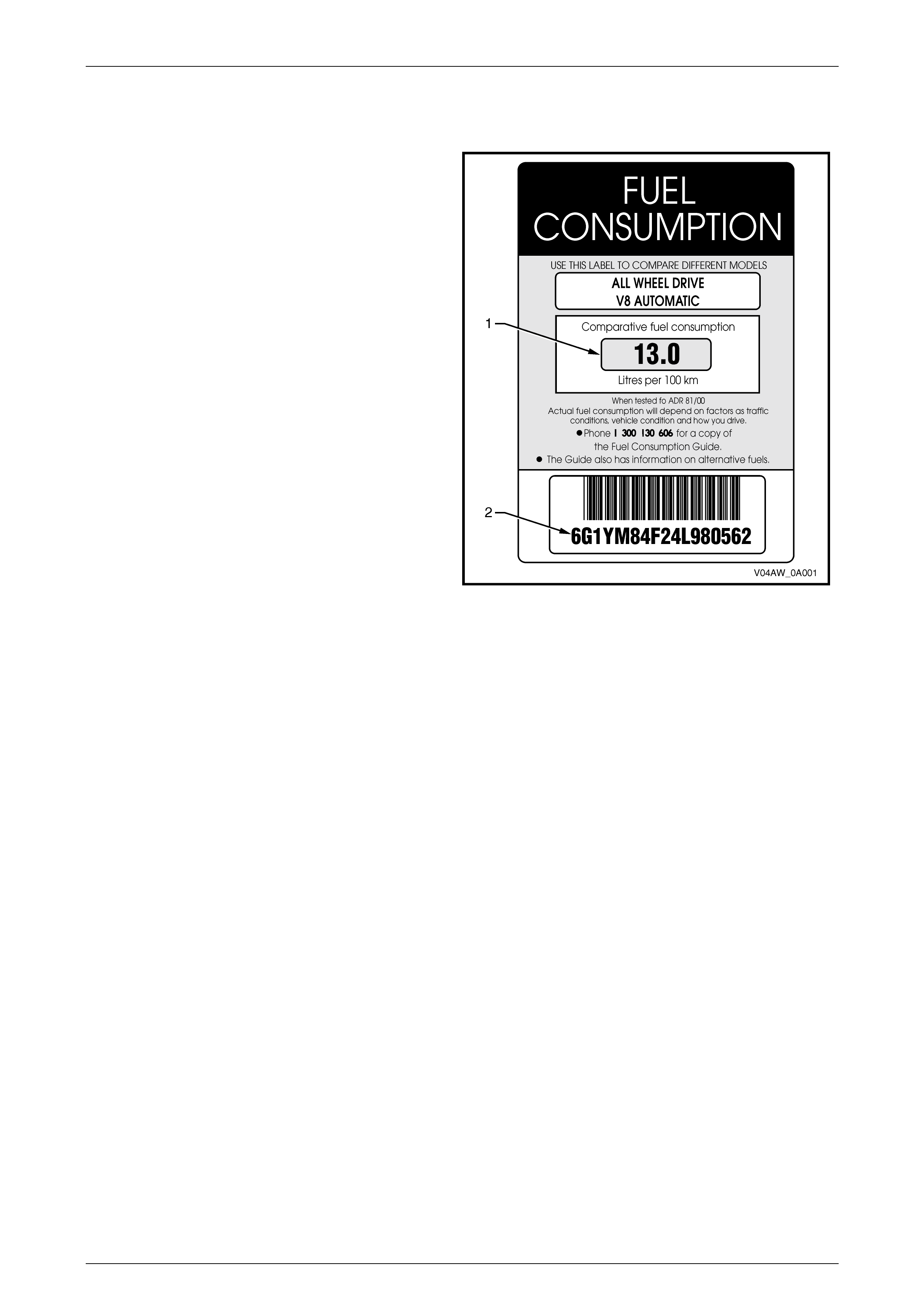
10 Fuel Consumpti on Label
ADR 81/00 required that from 1 January 2001, a label
similar to that show n in Figure 0A – 2, is attached to the
windscreen of any new domestic vehicle which is displayed
for sale.
The fuel consumption label figures (1) quoted are the
results of tests carried out in accordance with the City
Cycle test procedure of AS2877 – 1986, an Australian
standard for fuel consumption testing. Each vehicle is
tested under identical conditions. The tests therefore
enable a comparison to be made between vehicles.
The label should be removed from the windscreen
immediately prior to the vehicle being delivered to the
owner.
The number on the lower portion of the label (2) should
match the Vehi cle Identification Number.
Figure 0A – 2
General Information Page 0A–13
Page 0A–13
11 Serial Numbers
The complete vehicle and various components of the vehicle are identified by number plates or numbers stamped into
the body. It is essential that when compiling warranty claims or product and field reports, that the Vehicle Identification
Number (VIN) is quoted in conjunc tion w ith the identifi cat ion numb er of the compo nent affected.
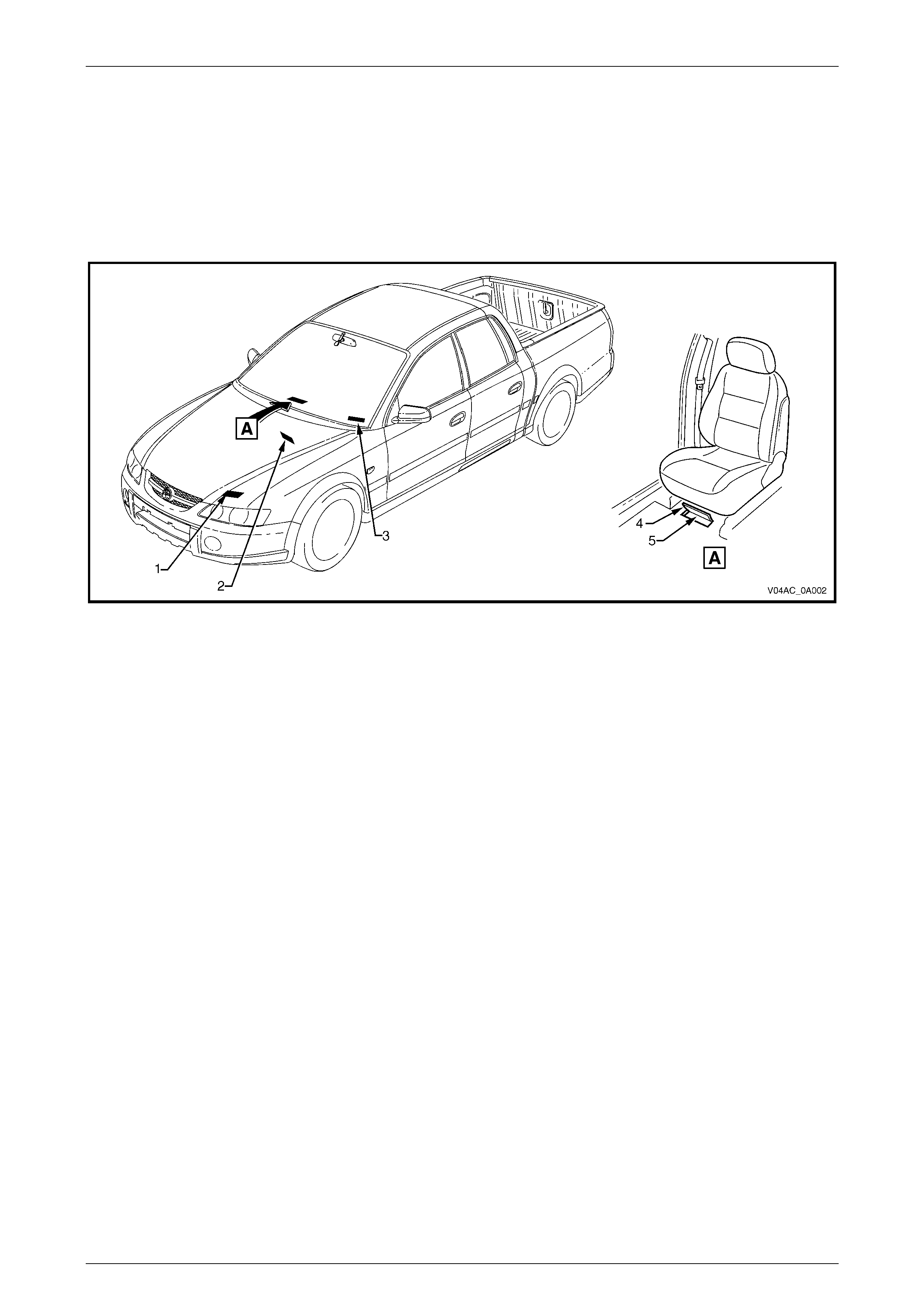
11.1 Location of Identification Plates
Figure 0A – 3
Legend
1 Body And Option Identification Plate – Left-hand
Side of the Front Panel Upper
2 Safety Compliance Plate – Dash Panel Assembly
3 Vehicle Identification Number Plate – Under
Windscreen
4 Carpet Flap
5 Vehicle Identification Number – Under Carpet Flap
Forward of Right-hand Side Front Seat.

General Information Page 0A–14
Page 0A–14
11.2 Safety Compliance Plate
The safety compliance plate (1) is located on the dash
panel assembly within the engine compartment.
Figure 0A – 4
The safety compliance plate is stamped with the following
information:
• Compliance plate approval number.
• Vehicle category code.
• Name appearing on compliance plate approval.
• Make / Model .
• Gross vehicle mass. This is the maximum loaded
mass at which the vehicle complies with the
approved design rules. Not required for passenger
vehicles. (Required for commercial vehicles.)
• Seating capacity.
• Number of adult positions for which seat belts are
provided.
• Date of manufacture.
• The day, month and year that the vehicle is
manufactured.
• Vehicle Identification Number (VIN).
Figure 0A – 5
General Information Page 0A–15
Page 0A–15
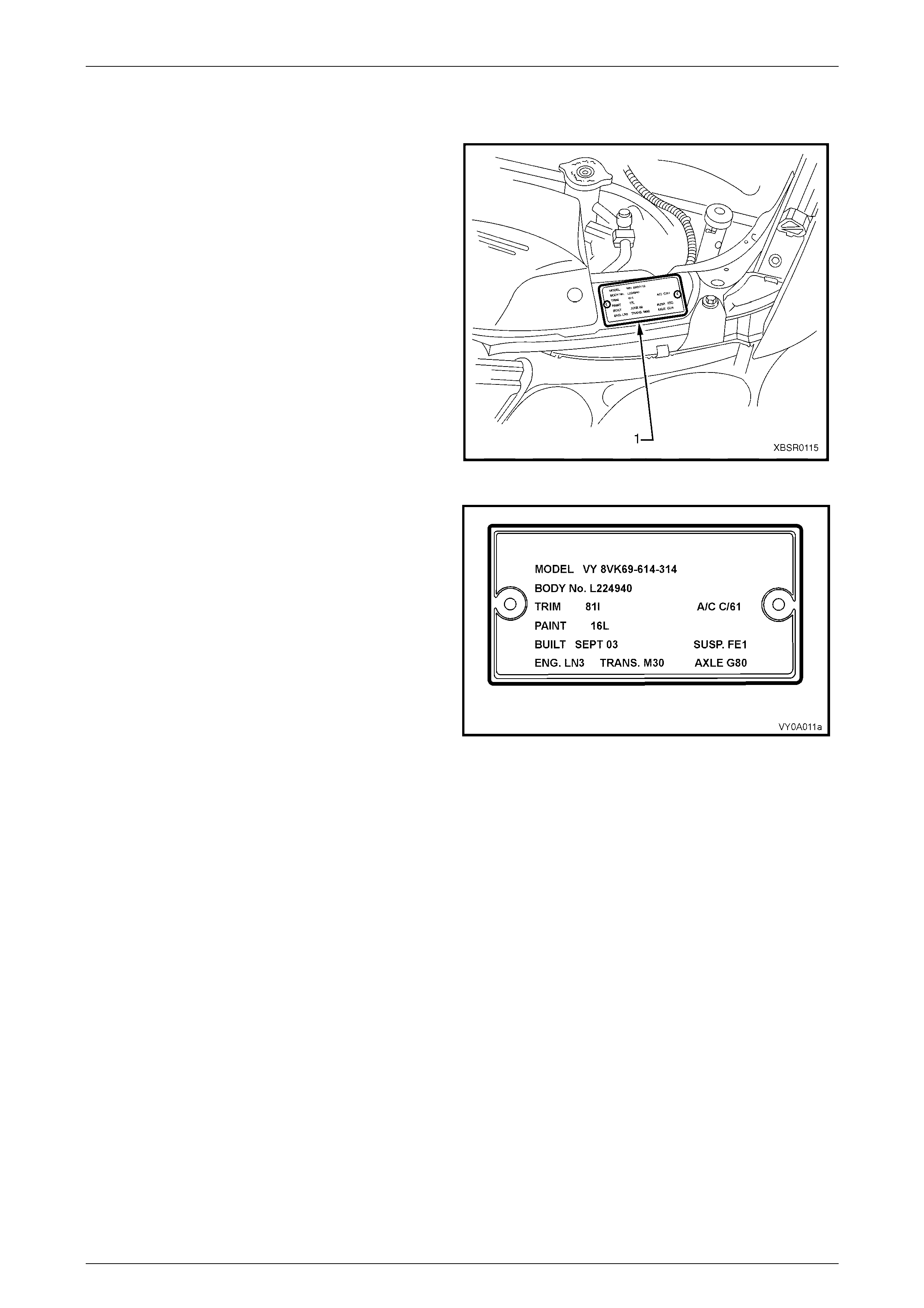
11.3 Body and Option Identification Plate
The Body and Option Identification Plate (1) is located on
the front panel assembly and is stamped with the following
information.
Model
Combination of letters and numbers identifying the body
style, the mechanical pack and smart pack options.
A listing of production and smart pack option numbers can
be found by referring to the latest spare parts information
for the applicable model.
Body
Production build number; run in continuous sequence
regardless of model, body type and series.
Trim
Trim combination.
Paint
Exterior paint material and colour identification.
Built
The date of manufacture by calendar month and year in
which the body shell and power train are conjoined and the
vehicle is driven or moved from the production line.
Susp
Suspension option code identification:
FE1 identifies vehicles with standard suspension.
FE2 identifies vehicles with sport suspension.
FR1 identifies vehicles with country pack suspension.
Engine, Transmission and Axle.
Identification option codes for specific engine, transmission
and rear axle (final drive).
A/C
C60 identifies vehicles fitted with air conditioning.
C61 Identifies vehicles fitted with single zone automatic
climate control air conditioning.
CJ2 identifies vehicles fitted with dual zone automatic
climate control air conditioning.
Figure 0A – 6
Figure 0A – 7
General Information Page 0A–16
Page 0A–16
11.4 Vehicle Identification Number
The Vehicle Identification Numbering (VIN) system is based on the uniform Car Model Designation System. This
identifies the vehicle in one coded series of characters.
The Vehicle Identification Number is positioned in the following locations.
1 VIN plate under the windscreen – viewed through the windscreen aperture.
2 Body and option identification plate – left-hand side of the front panel upper.
3 Safety compliance plate – dash panel.
4 Stamping in the front floor panel under the front right-hand seat.
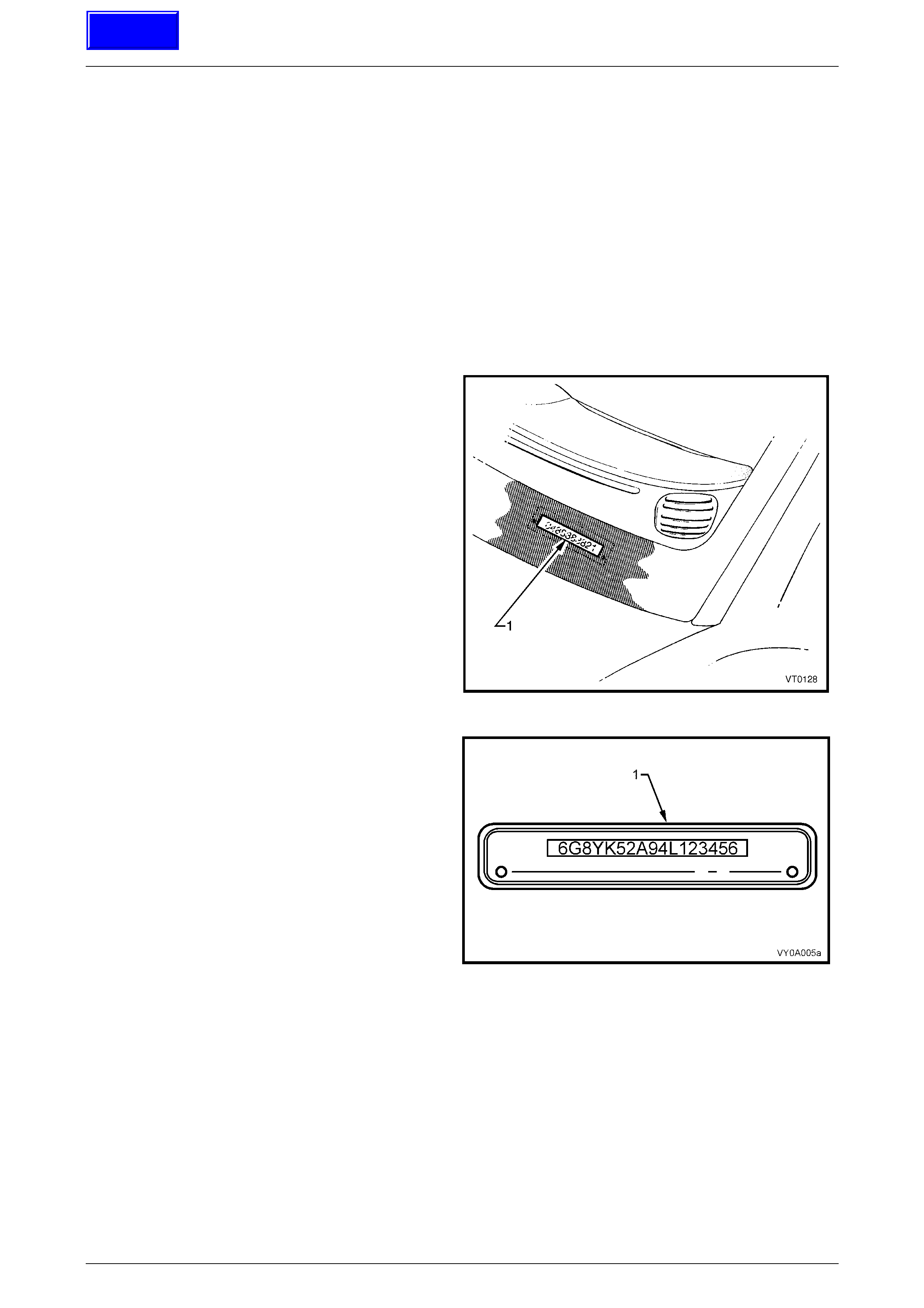
VIN Plates
The VIN Plate (1) is located under the windscreen and is
viewed through the windscreen aperture.
Figure 0A – 8
Figure 0A – 9 shows the VIN plate (1) that is located under
the windscreen aperture and is attached to the dash panel
assembly with unique rosette headed rivets.
Figure 0A – 9
Techline
General Information Page 0A–17
Page 0A–17
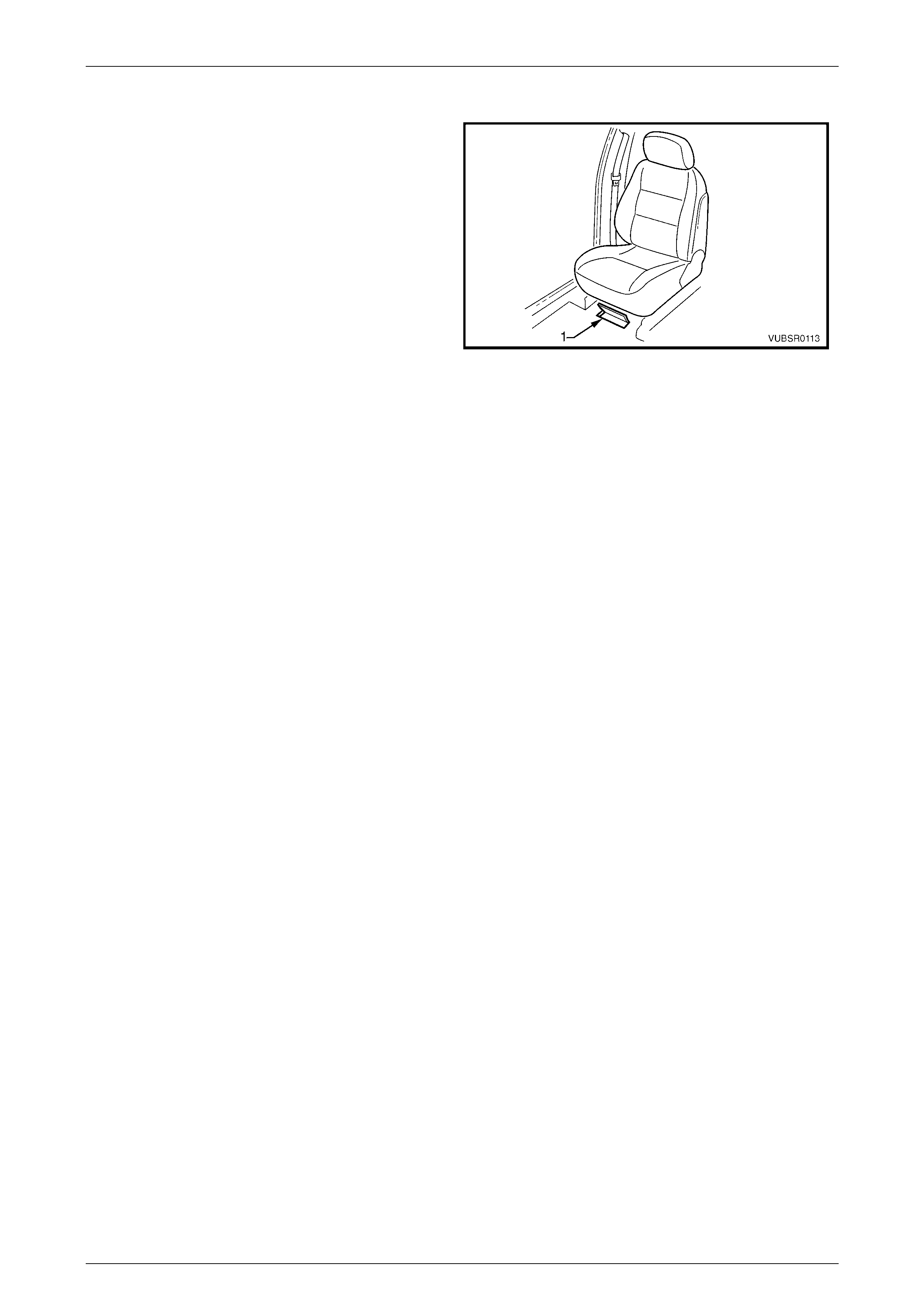
VIN Body Stamping
The VIN is stamped into the front floor panel under the
right-hand front seat. The VIN (1) is visible by lifting the
carpet flap.
NOTE
If the front floor panel assembly is to be
replaced, the VIN will be lost. Contact your local
Road Traffic Authority prior to replacing the
panel to obtain the correct procedure for
renumbering the vehicle.
NOTE
A replacement body shell assembly is stamped
during manufacture with a unique VIN that
identifies it as a replacement part.
NOTE
If an error is made to the VIN stamping during
manufacture, it is lined out so that it remains
legible and the correct number is stamped
underneath.
Figure 0A – 10
General Information Page 0A–18
Page 0A–18
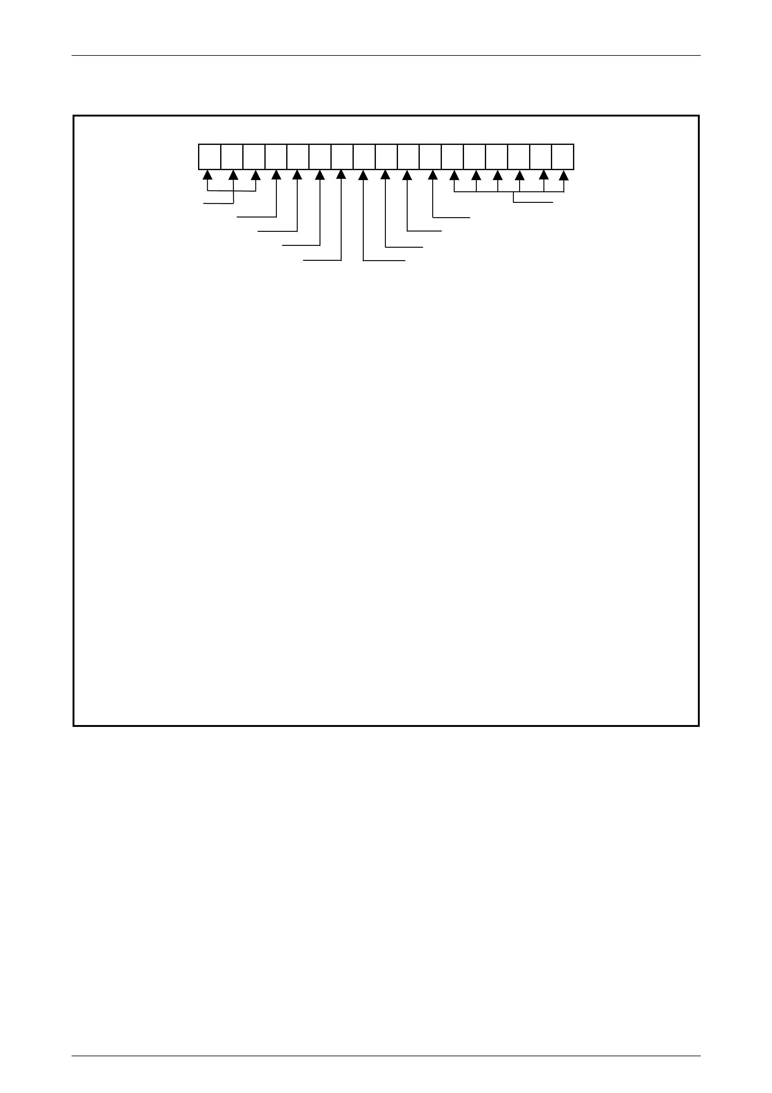
11.5 Vehicle Identification Numbering System
6 G 1 Y K 3 4 F 0 4 L 1 2 3 4 5 6
WMI CODE PRODUCTION
CARLINE PLANT SEQUENCE NUMBER
LUXURY LEVEL MODEL YEAR
BODY STYLE VIN CHECK DIGIT
RESTRAINT CODE ENGINE TYPE
WMI CODE: 6 – Oceania
G – Australia
1 – Holden
CARLINE: Y – VY Series
LUXURY LEVEL: K – SS
BODY STYLE: 3 – 4 door crew cab)
RESTRAINT CODE: 4 – Active (manual) seat belts with driver and passenger infl a table restrain t
system – frontal and side
ENGINE TYPE: F – 5.7 litre GEN III V8 engine
VIN CHECK DIGIT: Calculated check digit
MODEL YEAR: 4 – 2004
5 – 2005
PLANT: L – Adelaide (Elizabeth) South Australia
PRODUCTION SEQUENCE NUM BER:
123456 – Sequential Production Serial Number
NOTE
The production sequence number is sequentially allocated to each vehicle, regardless of vehicle type.
Figure 0A – 11
General Information Page 0A–19
Page 0A–19
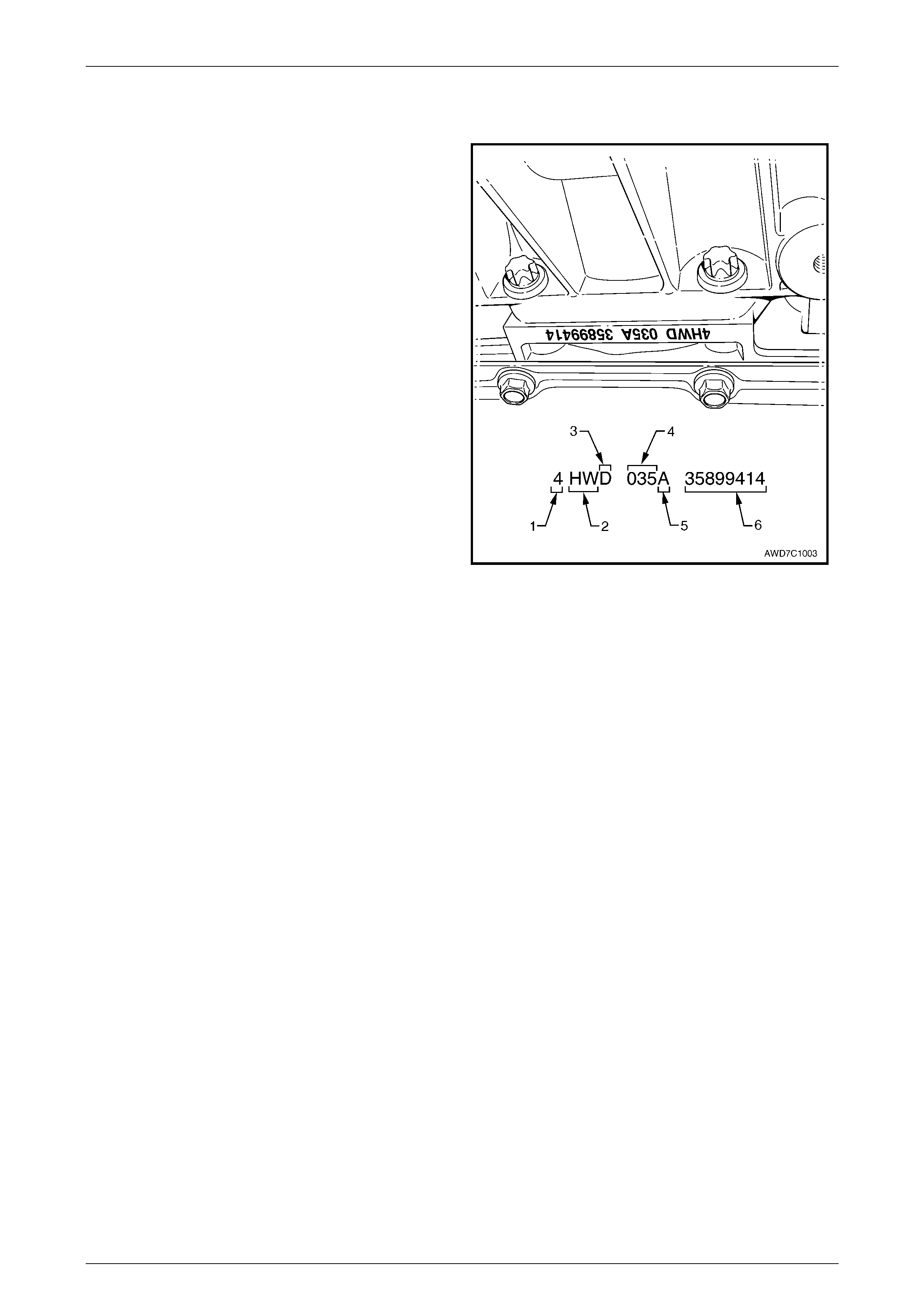
11.6 Automatic Transmission Serial Number
The automatic transmission serial number is stamped into
a machined surface located at the rear underside of the
transmission centre case, between the rear extension
housing and the tran smi ssion fluid pan.
Legend
1 Model Year (‘4’ = 2004)
2 Model: AWD and 5.7 litre GEN III V8 – 'HW'
3 Transmission Model Identifier (‘DR’ = 4L65-E)
4 Julian Date (Day of the Year)
5 Shift Build ‘A’, ‘B’, ‘J’ = First Shift;
‘C’, ‘H’, ‘W’ = Second Shift
6 Individual Transm is sion Serial Number
Figure 0A – 12
General Information Page 0A–20
Page 0A–20
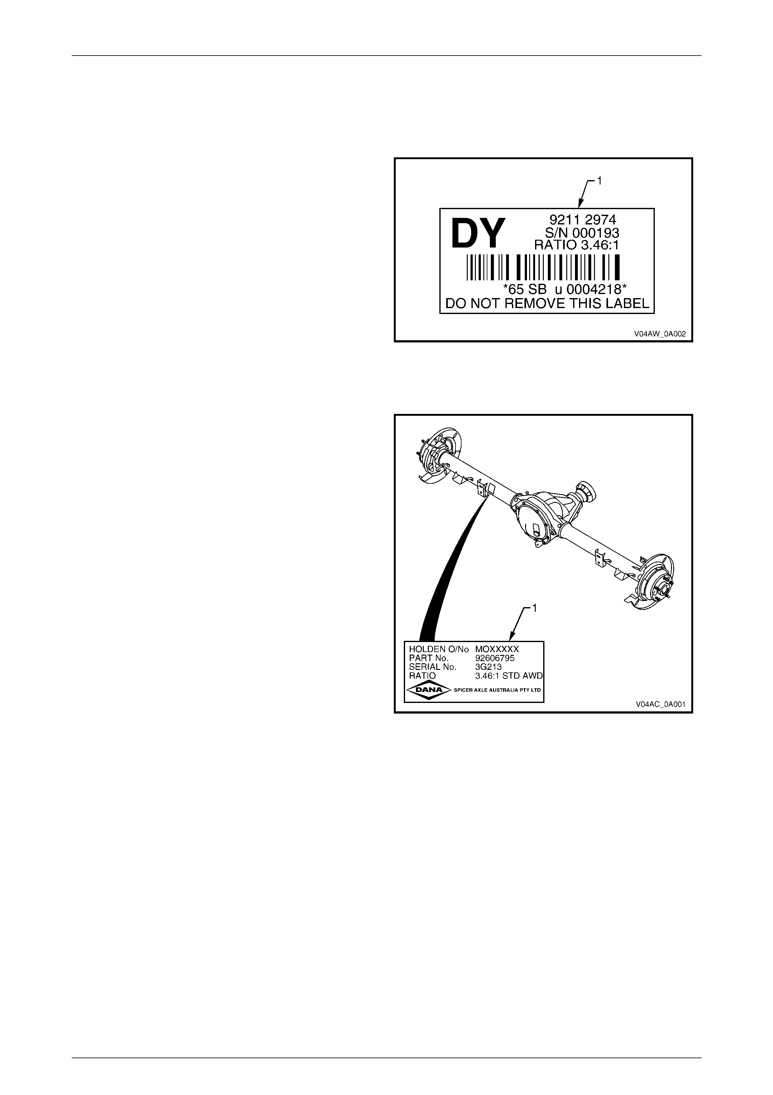
11.7 Final Drive Assembly Serial Numbers
Front Final Drive
An identification label (1) is adhered to the front final drive
assembly on the left side towards the rear of the housing.
The label contains the Holden Part Number for the
assembly, the serial number of the assembly as well as
the final drive ratio.
The front final drive assembly is attached to the left-hand
side of the engine oil pan.
Figure 0A – 13
Rear Final Drive
An identification label is adhered to the rear axle
assembly adjacent to the to left-hand side sway bar
mount. The label carries the Holden Part Number for the
assembly, the final drive ratio and the serial number of
the assembly.
Figure 0A – 14
General Information Page 0A–21
Page 0A–21
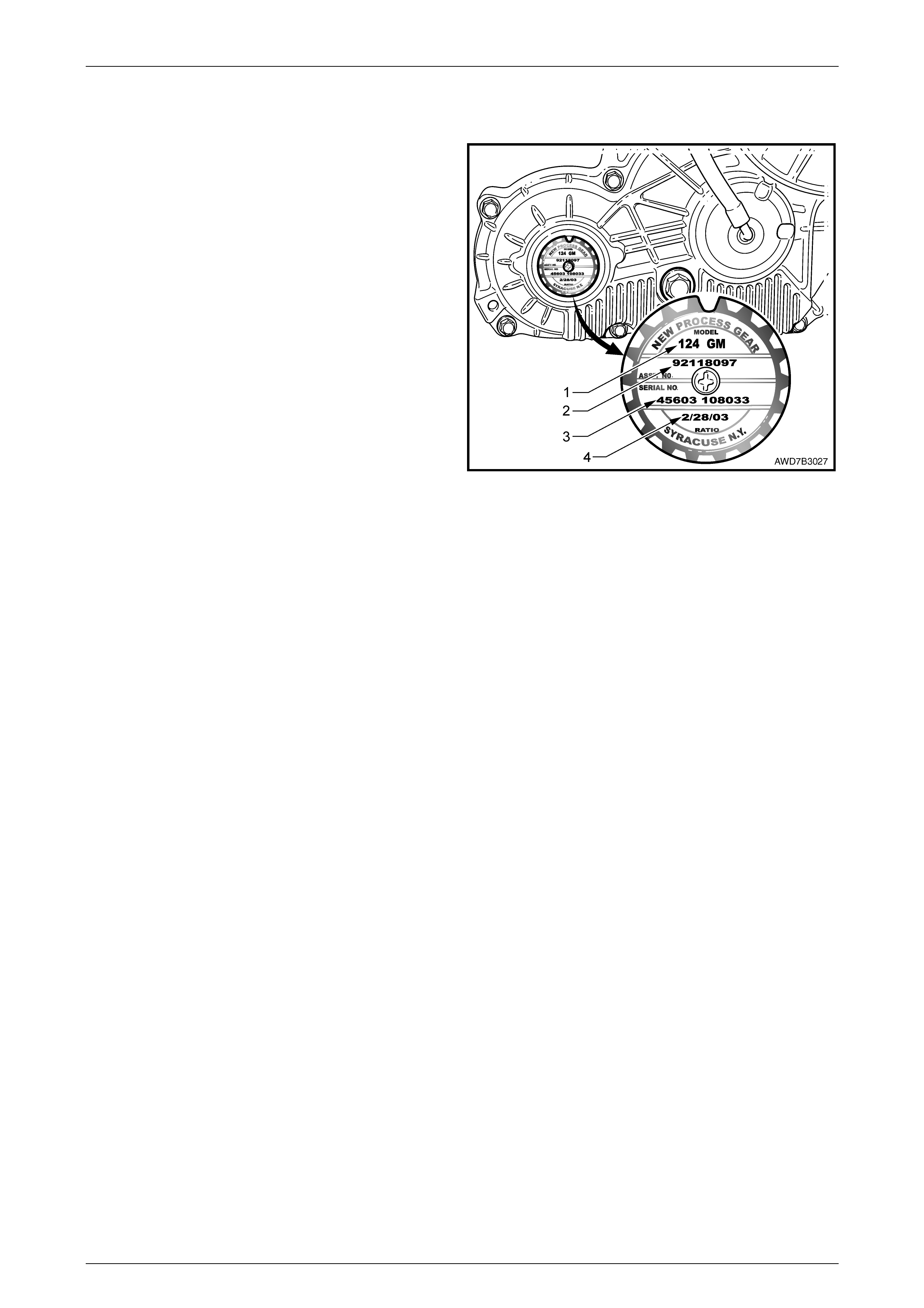
11.8 Transfer Case Assembly Serial Number
A
n identification tag is attached to the rear of the transfer
case housing, refer Figure 0A – 15. The information
contained on the tag provides the transfer case serial
number, build date and other information that may be
required for the correct procurement of service parts.
If the tag is removed or is dislodged during service
operations, the item is to be kept with the assembly.
Legend
1 Model Number ('124' )
2 Assembly Part Number
3 Serial Number
4 Build Date
Figure 0A – 15

General Information Page 0A–22
Page 0A–22
12 Special Tools
The following information lists the new Special Service Tools required for use on the MY 2004 AWD Crew Cab vehicles.
All other remaining Special Service Tools for us e on MY 2004 AWD Crew Cab vehicles carry over from the MY 2003 VY
and V2 Series. For all other Special Service Tools not listed in this Section, refer to Section 0A, 16 Consolidated Tool List
in the MY 2003 VY and V2 Series Service Information.
These new tools are grouped according to application (transfer case, front suspension and front final drive) and within
each group, are listed in tool number alphabetical / numerical order. They are also classified into the following categories:
• Mandatory: When required to perform routine maintenance operations and adjustments, or are required to carry
out fault diagnosis procedures.
• Desirable: These tools should be considered for purchase since their use will greatly facilitate performing
designat ed tas ks and perm it achieve ment of standard times.
• Unique: These tools are those that must be employed when overhauling major assemblies or performing relatively
large tasks.
• Available: Are those tools that are of general nature for which commercially available equivalents exists, or tools,
which have had previous application.
Unless otherwise specified, all Special Service Tools are availabl e from:
SPX Australia Pty. Ltd.
Service Solutions
28 Clayton Road
Notting Hill, Victoria, 3168
Telephone: (03) 9544 6222
Facsimile: (03) 9544 5222
Email: sales@spx.com.au
General Information Page 0A–23
Page 0A–23
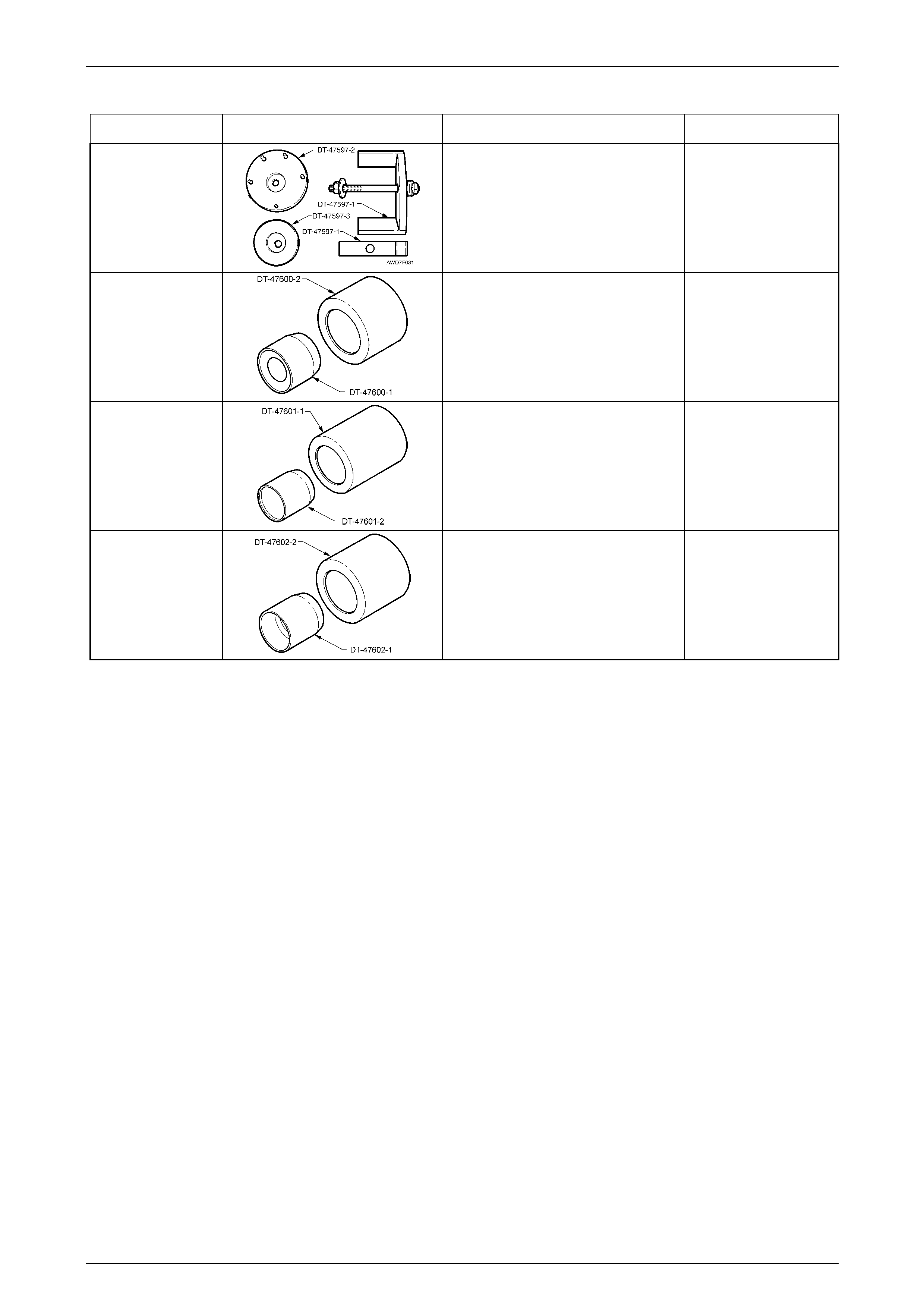
Transfer Case
Tool Number Illustration Description Tool Classification
DT-47597
Rear Mount Remover / Installer
Used to remove and install the rear
support mount from/to the tran sfer
case.
New release for AWD vehicles
Available
DT-47600
Seal Protector and Installer
Used to protect and install the front
input shaft oil seal to the transfer
case.
New release for AWD vehicles
Available
DT-47601
Seal Protector and Installer
Used to protect and install the rear
output shaft oil seal to the transfer
case.
New release for AWD vehicles
Available
DT-47602
Seal Protector and Installer
Used to protect and install the front
output shaft oil seal to the transfer
case.
New release for AWD vehicles
Available
General Information Page 0A–24
Page 0A–24
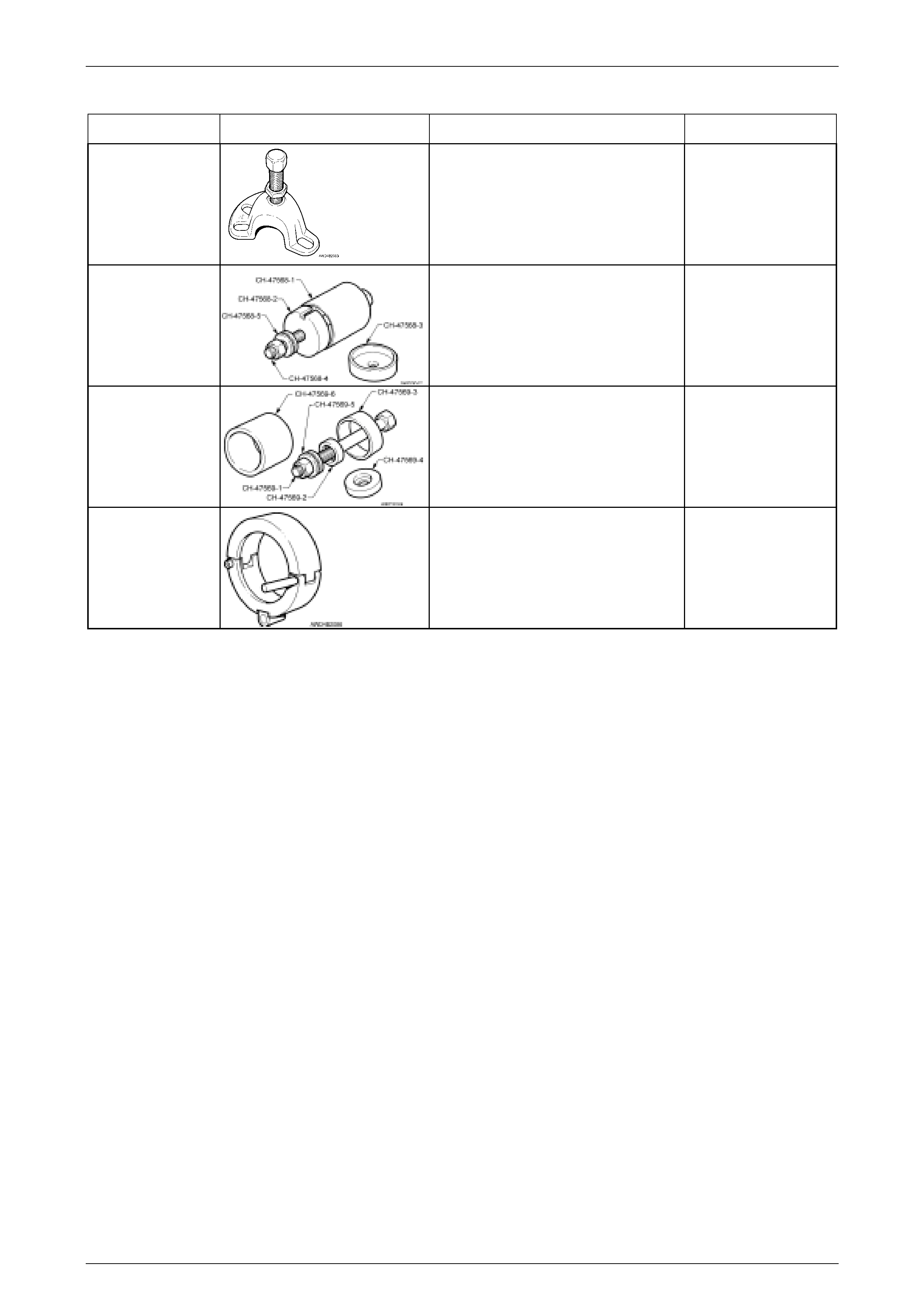
Front Suspension
Tool Number Illustration Description Tool Classification
7208
Hub Puller
Used to press the front driveshaft from
the front hub. Also used to check LSD
breakaway torque on final drives so
equipped.
Previously released
Mandatory
CH-47568 Remover / Installer Control Arm,
Front Isolator Bush
Used to remove and install the front
control arm, front hydraulic bushing
from/to the front suspension
crossmember cradle.
New release
for AWD vehicles
Available
CH-47569 Remover / Installer Control Arm,
Rear Bush
Used to remove and install the rear
bushing, from/to the front control arm.
New release for AWD vehicles
Available
DT-47570 Remover / Installer, Front
Driveshafts
Used in conjunction with slide hammer
J 6125-1B (and adaptor), or J 23907
slide hammer to remove and reinstall
the front driveshafts.
New release
for AWD vehicles
Mandatory
General Information Page 0A–25
Page 0A–25
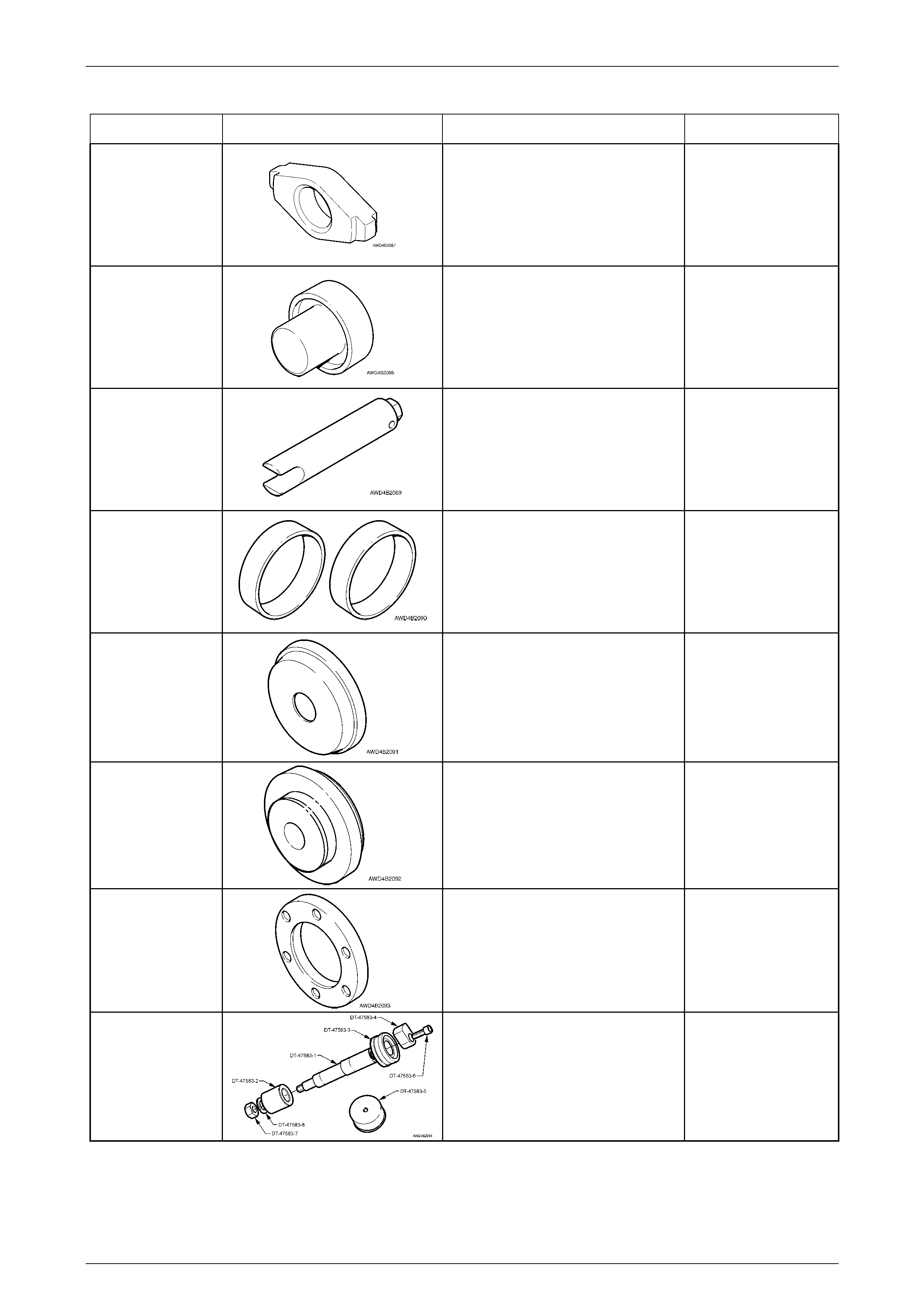
Front Final Drive
Tool Number Illustration Description Tool Classification
DT-47571
Cup Removal Adaptor
Used in conjunction with E9293 to
remove both pinion bearing cups from
the carrier housing.
New release for AWD vehicles
Available
DT-47572
Side Bearing Installer
Used with a hydraulic press to install
the differential carrier bearing cones.
New release for AWD vehicles
Available
DT-46573
Ring Gear Rotation Tool
Used to rotate differential housing to
measure bearing preload.
New release for AWD vehicles
Mandatory
DT-47577
Dummy Bearing Cups
Used when determining the
differential bearing preload and
position.
New release for AWD vehicles
Available
DT-47578
Bearing Cup Installer
Used in conjunction with bearing cup
alignment tool, DT-47579, to install
the ring gear carrier bearing cups to
the carrier and cover housings.
New release for AWD vehicles
Available
DT-47579
Bearing Cup Alignment Tool
Used in conjunction with bearing cup
installer, to ensure that bearing cups
are installed correctly.
New release for AWD vehicles
Available
DT-47580
Spacer Ring
Fitted into the pinion flange to act as a
spacer for holding tool J8614-01.
New release for AWD vehicles
Available
DT-47583
Dummy Pinion
Used to determine the pinion bearing
preload and position.
New release for AWD vehicles
Available