
Exterior Ornamentation Page 1A9–1
Page 1A9–1
Section 1A9
Exterior Ornamentation
ATTENTION
Before performing any service operation or other procedure described in this Section, refer to Section 00
Warnings, Cautions and Notes for correct workshop practices w ith regard to safety and/or property damage.
1 General Information............................................................................................................................... 2
1.1 Pictorial Index .........................................................................................................................................................3
Reference Chart .....................................................................................................................................................5
2 Service Operations................................................................................................................................ 6
2.1 Body Lock Pillar Trim Name Plate – CrossXTrac...............................................................................................6
Remove ...................................................................................................................................................................6
Reinstall..................................................................................................................................................................6
2.2 Endgate Name Plate – CrossX8............................................................................................................................7
Remove ...................................................................................................................................................................7
Reinstall..................................................................................................................................................................7
2.3 Body Side Moulding...............................................................................................................................................8
Remove ...................................................................................................................................................................8
Reinstall..................................................................................................................................................................8
2.4 Rocker Panel Moulding Assembly......................................................................................................................10
2.5 Rear Rocker Panel Moulding...............................................................................................................................11
Remove .................................................................................................................................................................11
Reinstall................................................................................................................................................................12
2.6 Rear Wheelhouse Opening Flare Extension......................................................................................................13
Remove .................................................................................................................................................................13
Reinstall................................................................................................................................................................13
2.7 Rear Wheelhouse Opening Flare........................................................................................................................14
Remove .................................................................................................................................................................14
Disassemble.....................................................................................................................................................14
Reassemble .....................................................................................................................................................15
Reinstall................................................................................................................................................................15
3 Torque Wrench Specifications........................................................................................................... 16

Exterior Ornamentation Page 1A9–2
Page 1A9–2
1 General Information
With the following exceptions, MY 2004 VY AWD Crew Cab Exterior Ornamentation information carries over from
MY 2004 VY Crew Cab and MY 2004 VY AWD Wagon vehicles. For exterior ornamentation information not contained
within this Section, refer to Section 1A9 Exterior Ornamentation in the MY 2004 VY Regular Cab and Crew Cab Service
Information or Section 1A9 in the MY 2004 VY AWD Wagon Service Information.
For a direct cross reference to each particular part, refer to 1.1 Pictorial Index.
• Body lock pillar trim name plate: CrossXTrac
• Body side moulding
• Rocker panel moulding assembly
• Rear rocker panel moulding
• Rear wheelhouse opening flare extension
• Rear wheelhouse opening flare
• Endgate name plate: CrossX8

Exterior Ornamentation Page 1A9–3
Page 1A9–3
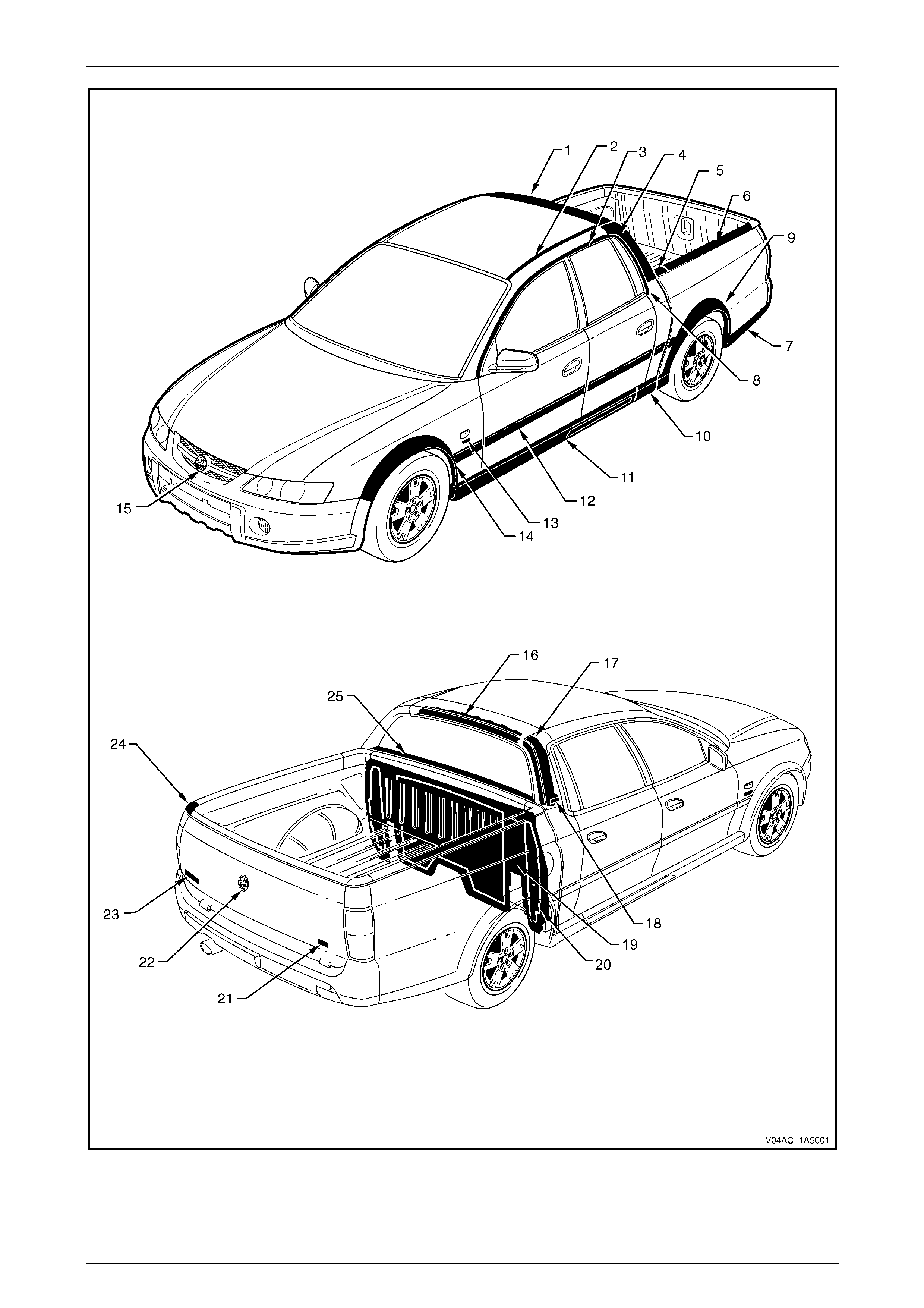
1.1 Pictorial Index
The following diagram provides a quick reference to the correct service procedures for exterior ornamentation
components.
Simply locate the component in Figure 1A9 – 1, cross-reference it in the accompanying table below the figure and using
the reference listed, go to the appropriate service procedure.
Many of the components are affixed to the
vehicle with double-sided adhesive tape or
urethane adhesive. It is imperative that the
correct materials, as specified in this Section,
are used when reassembling these parts. Use
of materials other than those specified may
lead to premature failure.
NOTE
Refer to the relevant MY 2004 VY AWD Crew
Cab Section for all external references contained
in the MY 2004 VY Regular Cab and Crew Cab,
Section 1A9 Exterior Ornamentation. This is to
verify that there are no differences in the MY
2004 VY AWD Crew Cab Service Information
that will affect the service procedures referenced
from MY 2004 VY Regular Cab and Crew Cab
Service Information.
NOTE
Refer to the relevant MY 2004 VY AWD Crew
Cab Section for all external references contained
in the MY 2004 VY AWD Wagon, Section 1A9
Exterior Ornamentation. This is to verify that
there are no differences in the MY 2004 VY AWD
Crew Cab Service Information that will affect the
service procedures referenced from MY 2004 VY
AWD Wagon Service Information.
Exterior Ornamentation Page 1A9–4
Page 1A9–4
Figure 1A9 – 1

Exterior Ornamentation Page 1A9–5
Page 1A9–5
Reference Chart
Item Description Refer to
1 Rear Header Trim Refer to Section 1A9, 2.6 Rear Header Trim in the MY 2004 VY
Regular Cab and Crew Cab Service Information
2 Roof Panel Joint Moulding Refer to Section 1A9, 2.8 Roof Panel Joint Moulding in the MY 2004
VY Regular Cab and Crew Cab Service Information
3 Door Opening Moulding Refer to Section 1A9, 2.3 Door Opening Moulding in the MY 2004 VY
Regular Cab and Crew Cab Service Information
4 Body Lock Pillar Trim Refer to Section 1A9, 2.4 Body Lock Pillar Trim in the MY 2004 VY
Regular Cab and Crew Cab Service Information
5 Rear Body Front Rail Cover Refer to Section 1A9, 2.15 Rear Body Front Rail Cover in the
MY 2004 VY Regular Cab and Crew Cab Service Information
6 Rear Body Rail Cove r Refer to Section 1A9, 2.14 Rear Body Rail Cover in the MY 2004 VY
Regular Cab and Crew Cab Service Information
7 Rear Body Rear Rocker Moulding Refer to Section 1A9, 2.13 Rear Body Rear Rocker Moulding in the
MY 2004 VY Regular Cab and Crew Cab Service Information
8 Body Lock Pillar Door Moulding Refer to Section 1A9, 2.2 Body Lock Pillar Door Moulding in the
MY 2004 VY Regular Cab and Crew Cab Service Information
9 Rear Wheelhouse Opening Flare
Rear wheelhouse opening flare
extension
Refer to 2.7 Rear Wheelhouse Opening Flare
Refer to 2.6 Rear Wheelhouse Opening Flare Extension
10 Rear Rocker Panel Moulding Refer to 2.5 Rear Rocker Panel Moulding
11 Rocker Panel Moulding Assembly Refer to 2.4 Rocker Panel Moulding Assembly
12 Body Side Moulding Refer to 2.3 Body Side Moulding
13 Fender Name Plate: V8 Refer to Section 1A9, 2.2 Fender Name Plate in the MY 2004 VY
AWD Wagon Service Information
14 Front Wheelhouse Opening Flare Refer to Section 1A9, 2.12 Wheelhouse Opening Flare Assembly in
the MY 2004 VY AWD Wagon Service Information
15 Radiator Grille Emblem: Holden Refer to Section 1A9, 2.1 Radiator Grille Emblem in the MY 2004 VY
AWD Wagon Service Information
16 Rear Header Trim Retainer Refer to Section 1A9, 2.7 Rear Header Trim Retainer in the MY 2004
VY Regular Cab and Crew Cab Service Information
17 Body Lock Pillar Finisher Refer to Section 1A9, 2.5 Body Lock Pillar Finisher in the MY 2004
VY Regular Cab and Crew Cab Service Information
18 Body Lock Pillar Trim Name Plate:
CrossXTrac Refer to 2.1 Body Lock Pillar Trim Name Plate – CrossXTrac
19 Rear Outer Trim Panel Refer to Section 1A9, 2.10 Rear Outer Trim Panel and NVH Foam in
the MY 2004 VY Regular Cab and Crew Cab Service Information
20 NVH Foam Refer to Section 1A9, 2.10 Rear Outer Trim Panel and NVH Foam in
the MY 2004 VY Regular Cab and Crew Cab Service Information
21 Endgate Name Plate: CrossX8 Refer to 2.2 Endgate Name Plate – CrossX8
22 Endgate Emblem: Holden Refer to Section 1A9, 4.4 Endgate Emblem in the MY 2003 VY and
V2 Series Service Information
23 Endgate Name Plate: Crewman Refer to Section 1A9, 2.16 Emblems and Name Plates in the
MY 2004 VY Regular Cab and Crew Cab Service Information
24 Rear Body Rail End Cap Refer to Section 1A9, 2.14 Rear Body Rail Cover and End Cap in the
MY 2004 VY regular Cab and Crew Cab Service Information
25 Rear Window Lower Finisher Refer to Section 1A9, 2.9 Rear Window Lower Finisher in the
MY 2004 VY Regular Cab and Crew Cab Service Information

Exterior Ornamentation Page 1A9–6
Page 1A9–6
2 Service Operations
2.1 Body Lock Pillar Trim Name Plate –
CrossXTrac
LT Section – 10-150
Remove
1 Protect the paint and bodywork with tape or a rag.
2 To assist removal, warm the body lock pillar trim
name plate (1) with a heat-lamp or heat-gun to soften
the adhesive.
3 Using a paint scraper or similar, carefully prise the
body lock pillar trim name plate from the body lock
pillar trim.
4 As required, remove any remaining double-sided tape
from the nameplate and/or body lock pillar trim and
clean the surface with Prepsol or equivalent.
Figure 1A9 – 2
Reinstall
1 If reusing the body lock pillar trim name plate (1),
apply new polyethylene double-sided tape, such as
3M 4428 or equivalent, to the back and trim the edges
of the double-sided tape slightly in from the edge.
2 Clean the body lock pillar trim surface with Prepsol or
equivalent.
3 Remove the backing from the double-sided tape.
4 Apply the body lock pillar trim name plate in the
position shown, measuring the distance from the front
edge of the body lock pillar trim.
5 Press firmly over the entire body lock pillar trim name
plate for at least ten seconds to ensure maximum
adhesion.
Figure 1A9 – 3
Exterior Ornamentation Page 1A9–7
Page 1A9–7
2.2 Endgate Name Plate – CrossX8
LT Section – 10-150
Remove
1 Protect the paint and bodywork with tape or a rag.
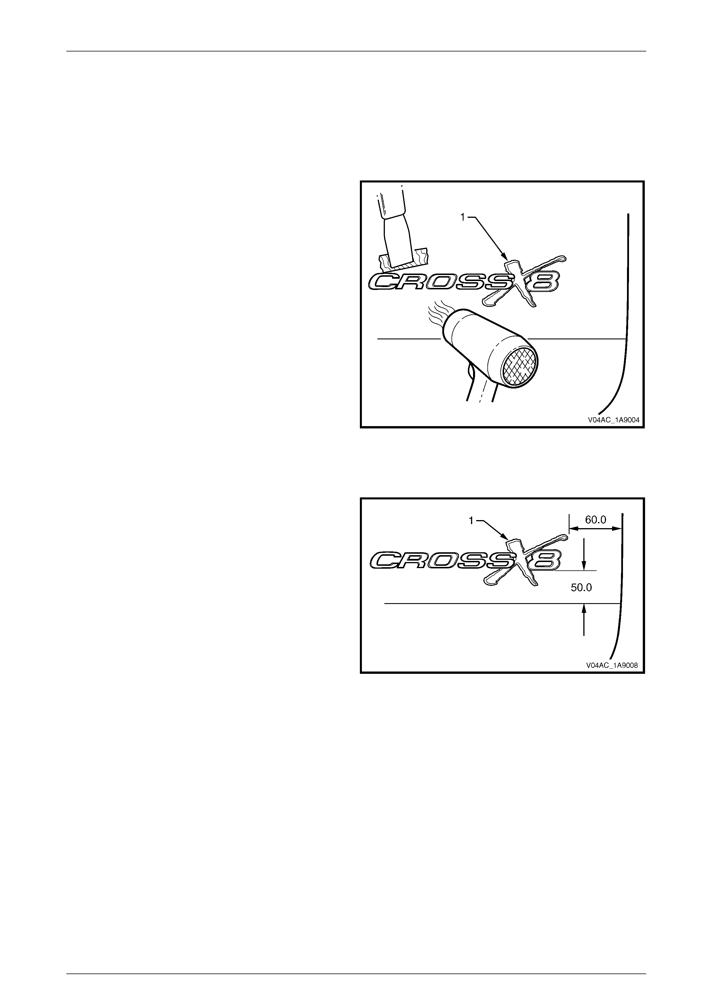
2 To assist removal, warm the endgate name plate (1)
with a heat-lamp or heat-gun to soften the adhesive.
3 Using a paint scraper or similar, carefully prise the
endgate name plate from the endgate.
4 As required, remove any remaining double-sided tape
from the nameplate and/or endgate and clean the
surface with Prepsol or equivalent.
Figure 1A9 – 4
Reinstall
1 If reusing the endgate name plate (1), apply new
polyethylene double-sided tape, such as 3M 4428 or
equivalent, to the back of the nameplate and trim the
edges of the double-sided tape slightly in from the
edge.
2 Clean the endgate surface with Prepsol or equivalent.
3 Remove the backing from the double-sided tape.
4 Apply the endgate name plate onto the lower section
of the endgate in the position shown.
5 Press firmly over the entire endgate name plate for at
least ten seconds to ensure maximum adhesion.
Figure 1A9 – 5
Exterior Ornamentation Page 1A9–8
Page 1A9–8
2.3 Body Side Moulding
LT Section – 10-250
Remove
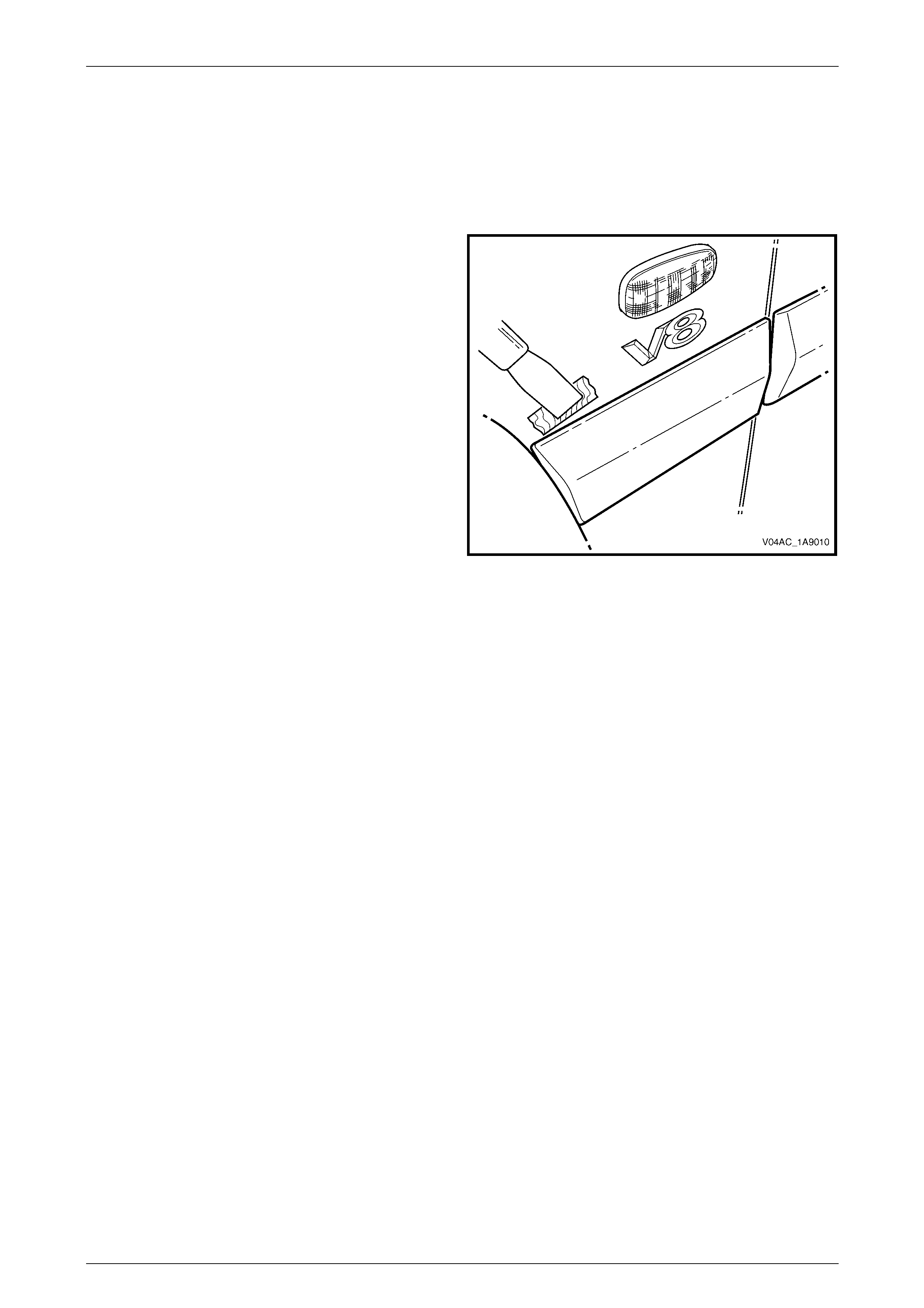
1 Protect the paint and bodywork with tape or a rag.
2 Using a paint scraper or similar, begin at one end of
the body side moulding and carefully prise the body
side moulding from the panel, cutting through the
double-sided tape and adhesive.
NOTE
To assist removal, use a heat-lamp or heat-gun
and warm the name plate slightly to soften the
adhesive.
NOTE
As an alternative, carefully use a length of piano
wire to cut the adhesive in a similar way to
removing a windshield.
3 As required, remove any remaining double-sided tape
and adhesive from the body side moulding and/or
panel. Clean the surfaces with Prepsol or equivalent.
Figure 1A9 – 6
Reinstall
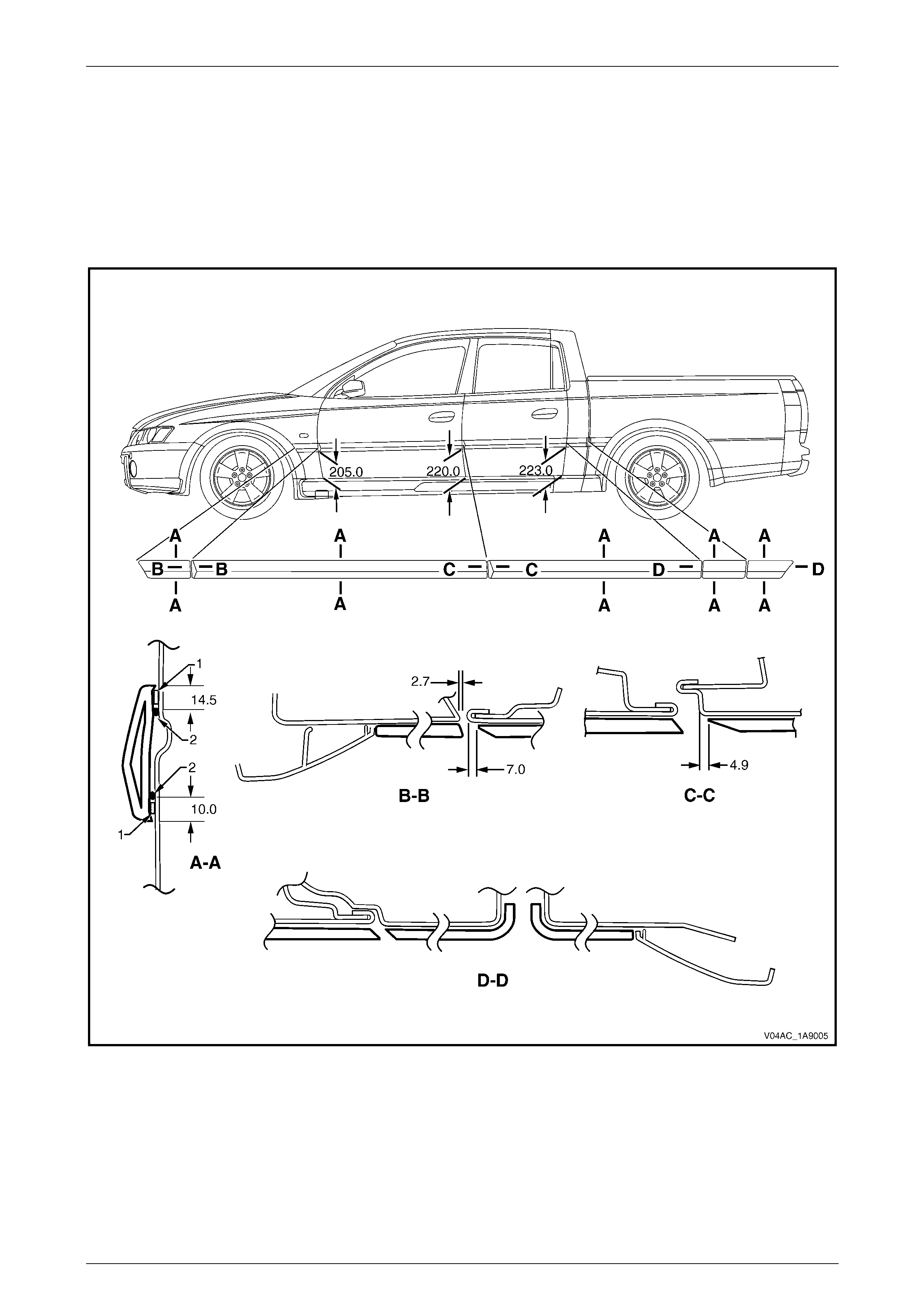
Reinstallation of the body side mouldings is the reverse of the removal procedure, noting the following:
1 To align the moulding, place a mark on the edge of the door panels and the front fender at the points shown, refer
to Figure 1A9 – 7.
a For the doors, measure a straight line upwards from the lower rear edge of each door panel at the points
shown.
b For the front fender, measure a straight line upwards from the lower rear edge of the fender at the point
shown.
c For the body lock pillar and rear body, continue the line formed by the points measured on the doors across
to the body lock panel and rear body.
2 If a complete set of mouldings is to be fitted, or as required, apply a length of masking tape along the side of the
vehicle level with the marks made in step 1.
3 Begin by affixing the tape to the fender, hold it taut and away from the vehicle, and affix it to each panel. Ensure
that the tape is straight and aligns with the marks on the doors and then, smooth it down along its length.
4 If reusing the body side moulding, apply new acrylic double-sided tape (1), such as 3M 5344 or equivalent, along
the back of the moulding.
5 Apply two 3.0 mm diameter beads of urethane adhesive (2), such as Expandite Betaseal 554.02, Sikaflex Drive or
equivalent, over the entire length of moulding.
NOTE
Refer to any further directions supplied with the
urethane adhesive.
6 Affix the moulding to the vehicle in the correct position, aligning the lower edge of the moulding with the masking
tape (if fitted) and:
• For the fender, align the rear edge of the fender body side moulding to the dimension at Section B-B. Ensure
that the body side moulding is positioned against the front wheelhouse opening flare assembly.
• For the front door, align the body side moulding with the front edge of the front door to the dimension at
Section B-B.
Exterior Ornamentation Page 1A9–9
Page 1A9–9
• For the rear door, align the body side moulding with front edge of the rear door to the dimension at
Section C-C.
• For the body lock pillar, align the body side moulding with the rear of the body lock pillar as shown in
Section D-D.
• For the rear body, align the body side moulding with the front of the rear body as shown in Section D-D.
Ensure that the body side moulding is positioned against the rear wheelhouse opening flare assembly.
7 Press firmly over the length of the body side moulding(s) at the double-sided tape for at least 10 seconds to
ensure maximum adhesion.
Figure 1A9 – 7

Exterior Ornamentation Page 1A9–10
Page 1A9–10
2.4 Rocker Panel Moulding Assembly
LT Section – 10-300
Although the MY 2004 AWD Crew Cab rocker panel moulding assembly is slightly shorter to allow the fitment of a
unique rear rocker panel moulding and uses one less retainer at the rear, service information carries over from MY 2004
VY AWD Wagon vehicles. Refer to Section 1A9, 2.13 Rocker Panel Moulding Assembly in the MY 2004 VY AWD
Wagon Service Information.
Exterior Ornamentation Page 1A9–11
Page 1A9–11
2.5 Rear Rocker Panel Moulding
LT Section – 10-300
Remove
1 If required, loosen or remove the rocker panel moulding assembly, refer to 2.4 Rocker Panel Moulding Assembly.
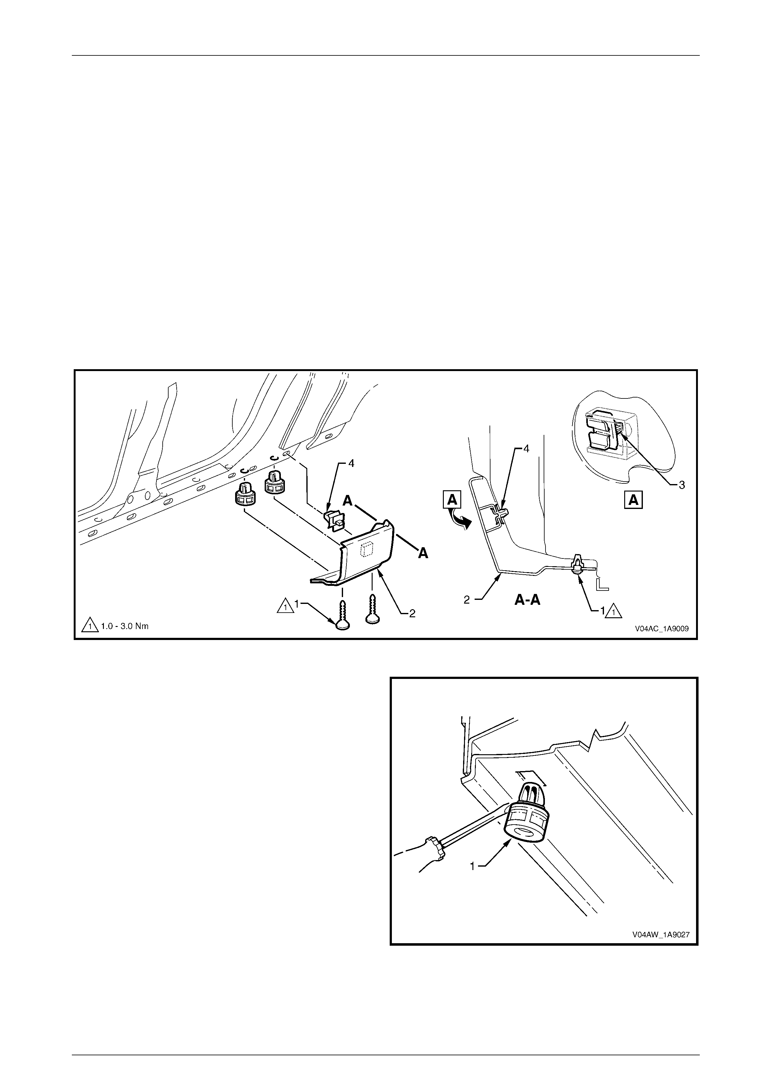
2 Remove the screw and cup (1), in two places, from the underside of the body lock pillar lower moulding (2), refer
to Figure 1A9 – 8, then slide the rear rocker panel moulding towards the rear of the vehicle.
NOTE
If access cannot be gained to the retainer (4),
then lever the retainer from the body. If this is
done, then the retainer will need to be replaced.
4 If required, slide the retainer (4) out to one side to remove it from the body lock pillar lower moulding.
Figure 1A9 – 8
5 If required, remove the retainer (1), in two places as
follows:
a Protect the paint and bodywork with a rag.
b Gently lever out the retainers, taking care not to
damage the paint work.
Figure 1A9 – 9

Exterior Ornamentation Page 1A9–12
Page 1A9–12
Reinstall
Reinstallation of the body lock pillar lower moulding is the reverse of the removal procedure, noting the following:
1 Locate and press the body lock pillar lower moulding onto the body lock pillar and clip it in position.
2 Tighten the screws to the correct torque specification.
Body lock pillar lower moulding screw
torque specification....................................1.0 – 3.0 Nm
Exterior Ornamentation Page 1A9–13
Page 1A9–13
2.6 Rear Wheelhouse Opening Flare
Extension
LT Section – XX-XXX
Remove
1 Remove the rear mudflap, refer to Section 1A1, 2.2 Rear Mudflap.
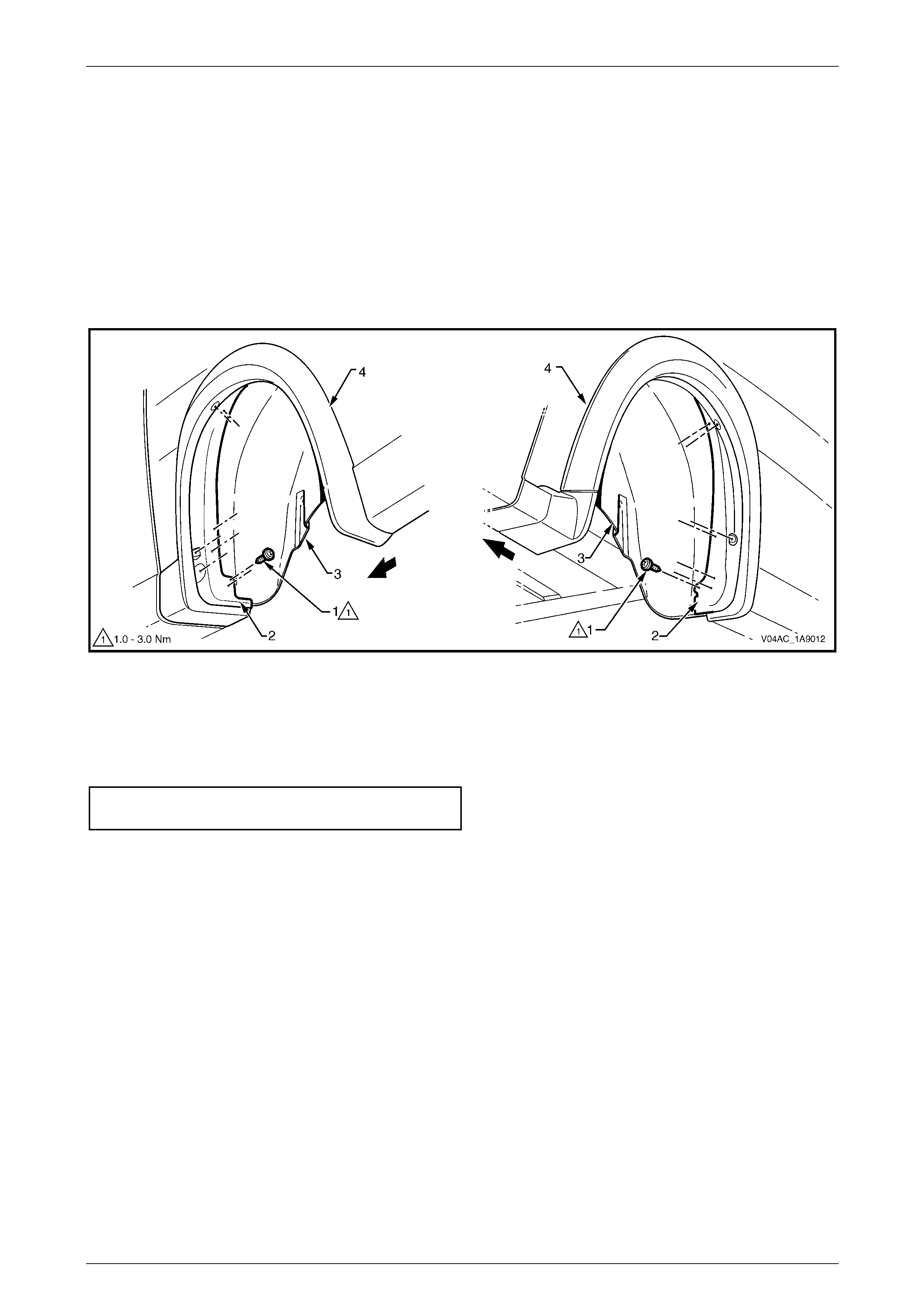
2 Remove the screw (1), 15 places, attaching the wheelhouse opening flare extension (2) to the wheelhouse liner (3)
and wheelhouse flare (4), then remove the flare extension, refer to Figure 1A9 – 10.
Figure 1A9 – 10
Reinstall
Reinstallation of the rear wheelhouse opening flare extension is the reverse of the removal procedure ensuring the
attaching screws are tightened to the correct torque specification.
Rear wheelhouse opening flare extension
attaching screw torque specification..........1.0 – 3.0 Nm
Exterior Ornamentation Page 1A9–14
Page 1A9–14
2.7 Rear Wheelhouse Opening Flare
LT Section – XX-XXX
Remove
1 As required, first remove the following components:
a Rear wheelhouse opening flare extension, refer to 2.6 Rear Wheelhouse Opening Flare Extension.
b Rear wheelhouse liner, refer to Section 1A1, 2.3 Rear Wheelhouse Liner.
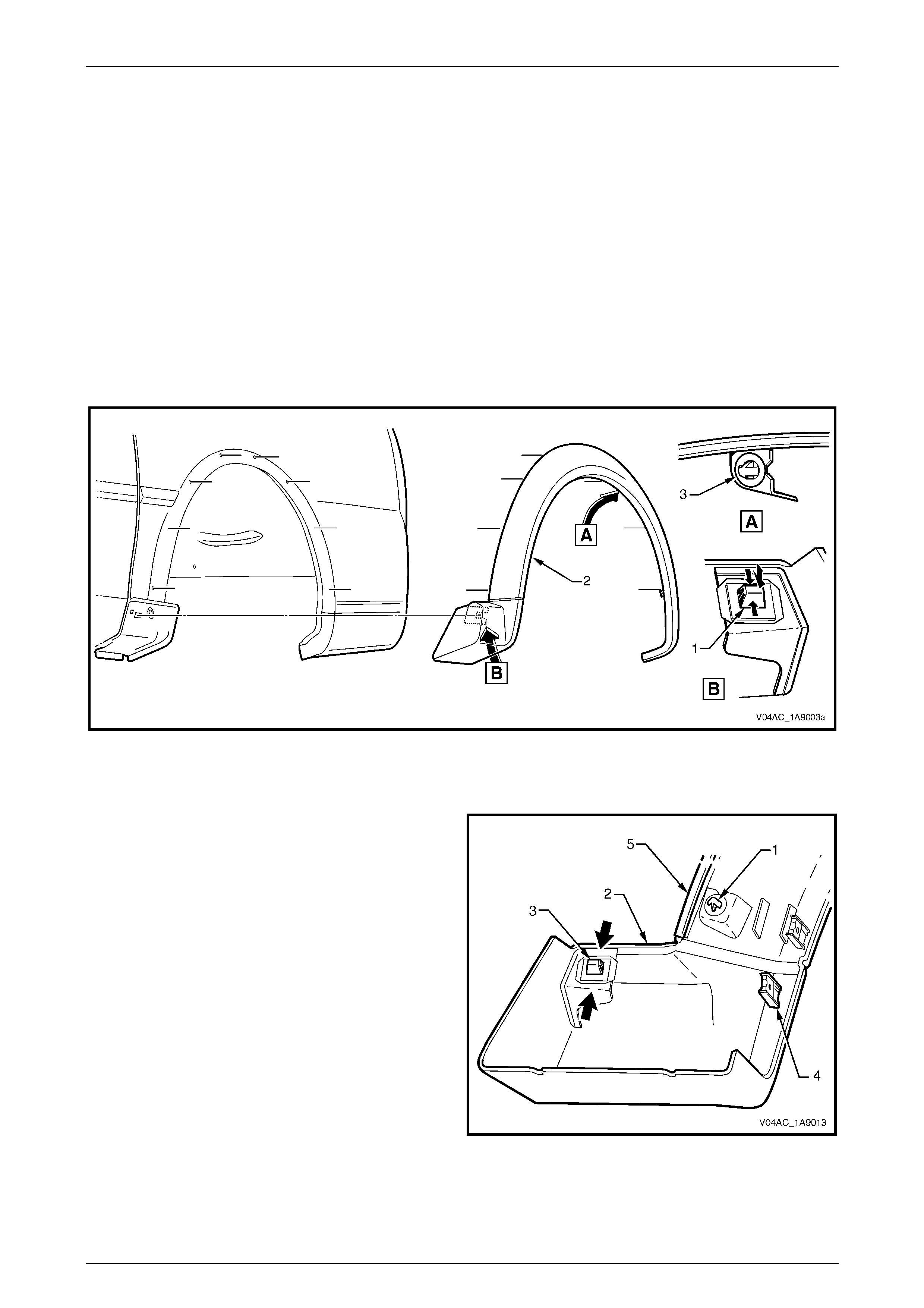
2 From inside the wheelhouse, press together the retainer tabs (1) attaching the lower front section of the wheel
opening flare (2) to the rear body and push the retainer clear of the body, refer to Figure 1A9 – 11.
3 From inside the wheelhouse, squeeze the clip (3), eight places, while gently pulling the rear wheelhouse opening
flare away from the rear body and remove the rear wheelhouse opening flare.
Figure 1A9 – 11
Disassemble
1 If required, remove the retaining clip (1), eight places
from the rear wheelhouse opening flare (2) by sliding
them from the boss.
2 Remove the retaining clip (3) by pushing the tangs
together and pushing the clip from the flare.
3 Remove the flare extension attaching screw U-nut (4),
eight places.
4 Remove the seal (5), by prising it out of the recess in
the flare.
5 Inspect the seal and U-nuts for damage and replace if
necessary.
Figure 1A9 – 12
Exterior Ornamentation Page 1A9–15
Page 1A9–15
Reassemble
Reassembly of the rear wheelhouse flare is the reverse of the disassemble procedure noting the following:
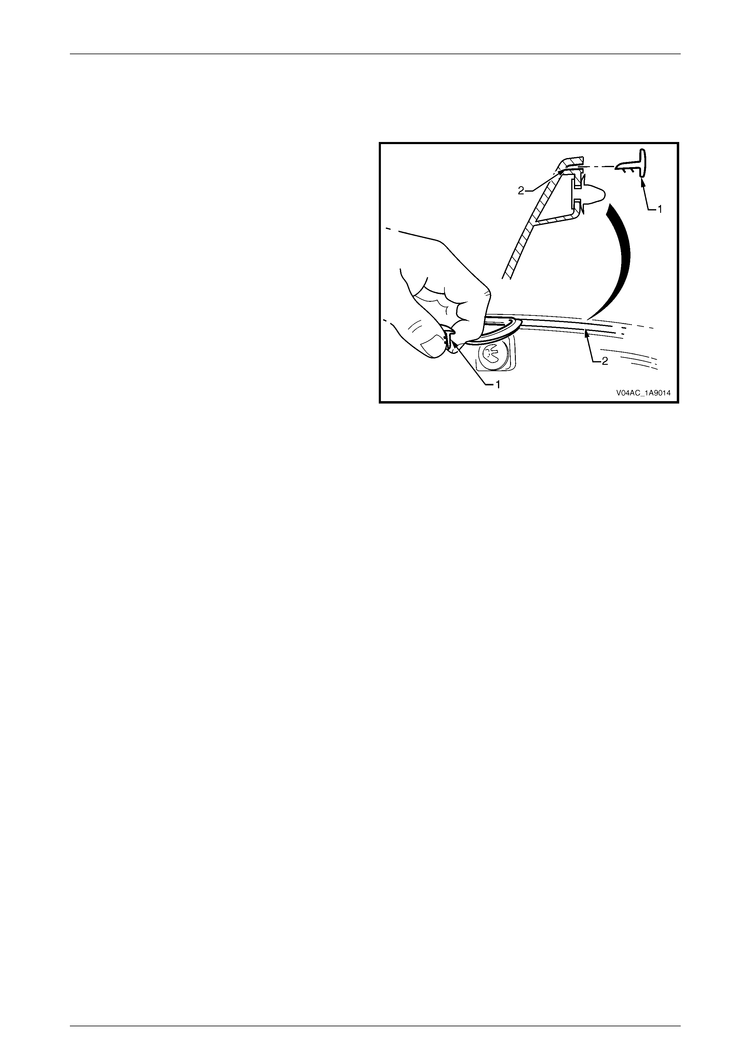
1 Ensure the retaining clips are located in the flare correctly.
2 Position the seal (1) to the recess in the flare (2),
ensuring the retaining lips on the seal are facing
towards the centre of the flare.
Figure 1A9 – 13
Reinstall
Reinstallation of the rear wheelhouse opening flare is the reverse of the removal procedure, noting the following:
1 Align the rear wheelhouse opening flare to the rear body, then carefully push the flare onto the body.
2 Ensure that all the retainers are correctly engaged and that the rear wheelhouse opening flare is correctly seated
on the rear body.
3 Reinstall the rear wheelhouse liner, refer to Section 1A1, 2.3 Rear Wheelhouse Liner .
4 Reinstall the rear wheelhouse opening flare extension, refer to 2.6 Rear Wheelhouse Opening Flare Extension .

Exterior Ornamentation Page 1A9–16
Page 1A9–16
3 Torque Wrench Specifications
Rear Rocker Panel Moulding Attaching Screw..............................1.0 – 3.0 Nm
Rear Wheel Opening Flare Extension Attaching Screw................1.0 – 3.0 Nm