
Rear Propeller Shaft & Universal Joints Page 4C1–1
Page 4C1–1
Section 4C1
Rear Propeller Shaft & Universal Joints
ATTENTION
Before performing any Service Operation or other procedure described in this Section, refer to Section 00
Cautions And Notes for correct workshop practices with regard to safety and/or property damage.
1 General Information............................................................................................................................... 2
2 Service Operations................................................................................................................................3
2.1 Propeller Shaft........................................................................................................................................................3
Remove ...................................................................................................................................................................3
Reinstall ..................................................................................................................................................................5
2.2 Rubber Coupling....................................................................................................................................................6
Replace ...................................................................................................................................................................6
2.3 Centre Fixed Type Constant Velocity Joint, Rubber Boot and Dust Shield......................................................7
Remove ...................................................................................................................................................................7
Inspect.....................................................................................................................................................................9
Reassemble ..........................................................................................................................................................10
Reinstall ................................................................................................................................................................12
2.4 Centre Bearing Assembly....................................................................................................................................14
Remove .................................................................................................................................................................14
Replace .................................................................................................................................................................16
2.5 Rear Plunge Type Constant Velocity Joint ........................................................................................................18
Remove .................................................................................................................................................................18
Inspect...................................................................................................................................................................20
Disassemble .........................................................................................................................................................21
Reassemble ..........................................................................................................................................................22
Reinstall ................................................................................................................................................................22
3 Specifications....................................................................................................................................... 24
4 Torque Wrench Specifications........................................................................................................... 25
5 Special Tools........................................................................................................................................ 26
Rear Propeller Shaft & Universal Joints Page 4C1–2
Page 4C1–2
1 General Information
The rear propeller shaft assembly fitted to the MY 2004 VY Series, AWD Crew Cab vehicle is a two piece tubular design
that incorpora tes the foll owing:
• A rubber coupling at the front.
• A centre support bearing.
• A fixed type, constant velocity joint near the centre support bearing.
• A plunging type, constant velocity joint at the rear.
For the MY 2004 VY Series, AWD Crew Cab vehicle, the rubber coupling fitted to the front of the propeller shaft, is bolted
to studs mounted in the transfer case rear output flange.
The centre support bearing is a sealed ball bearing, mounted in a reinforced rubber cup that is supported in a cup guide
attached to a carrier. This carrier is attached to the vehicle underbody brace by two bolts. The centre bearing is
lubricated for life and does not require any periodic lubrication. When a tow bar kit is fitted to the vehicle, a heat shield is
fitted to protect the bearing and the central constant velocity joint from the potential increase in radiant exhaust pipe heat.
Drive is transmitted between the two halves of the propeller shaft through a central constant velocity joint, that is a fixed
(non-plunging) type. Located and secured to each of the two propeller shaft halves by bolts and an internal circlip, the
central, fixed constant velocity joint is lubricated for life and does not require any periodic lubrication.
The plunge type, constant velocity joint at the rear of the propeller shaft is secured to the rear propeller shaft by an
internal circlip and bolted to the pinion drive flange on the front of the differential assembly. The plunging or sliding actio n
of this constant velocity joint allows for any variation in driveline length created by the torque reaction or ride height
changes of the rear suspension during normal driving conditions. The plunge type, constant velocity joint is also
lubricated for life and does not require any periodic lubrication.
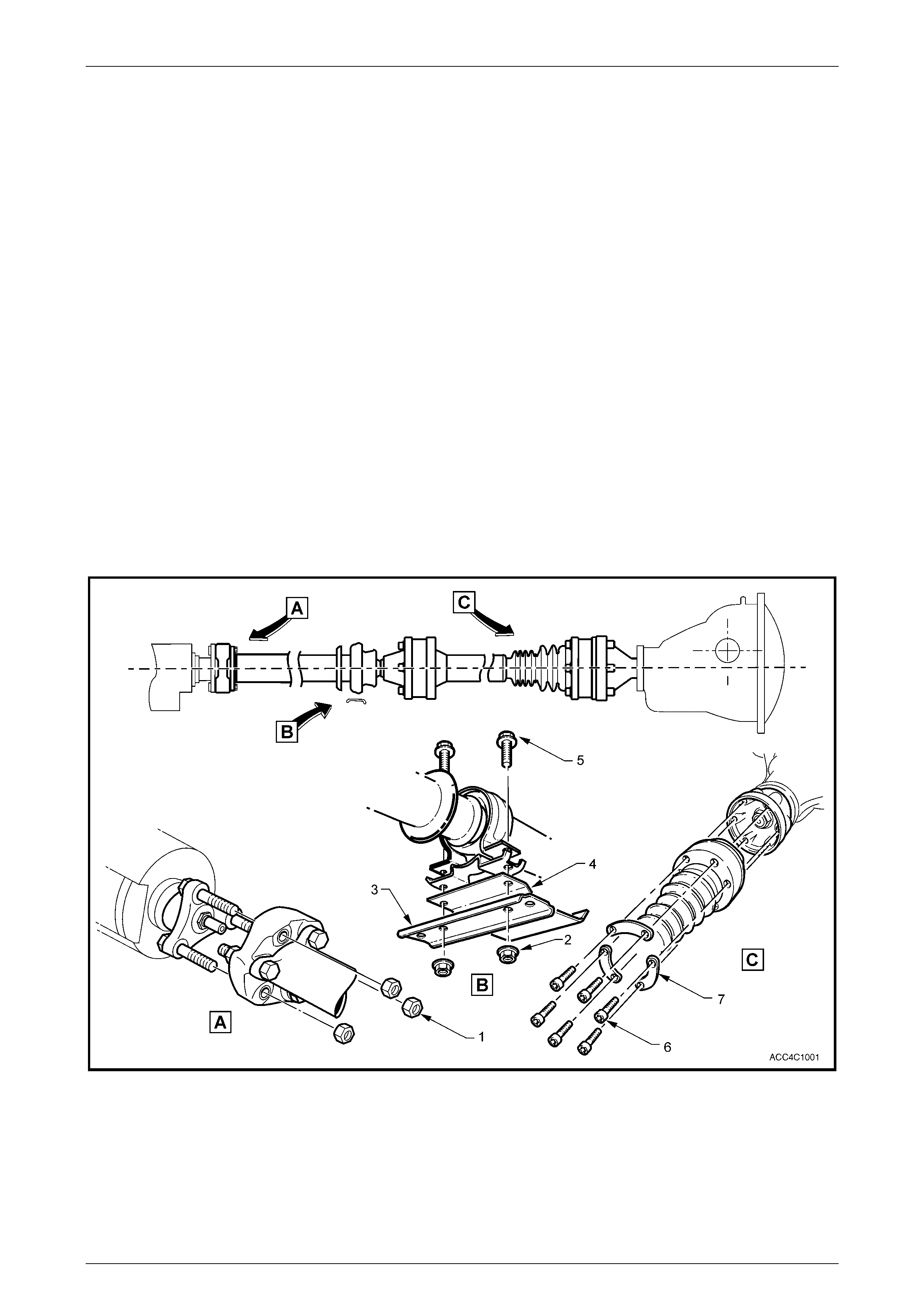
Figure 4C1 – 1
Legend
1 Front Coupling to Transfer Case Flange Nuts (3 Plac es)
2 Centre Bearing Carri er Attaching Bolts and Nuts (2 Places)
3 Centre Bearing Carri er
4 Heat Shiel d (Only required when the tow bar kit is fitted)
5 Centre Bearing Cup Guide - Upper and Lower
6 Rear Constant Vel ocity Joint, Torx Headed Bolts (6 Places)
7 Rear Constant Vel ocity Joint Attaching Bolt Lock Plates
(3 Places)
Rear Propeller Shaft & Universal Joints Page 4C1–3
Page 4C1–3
2 Service Operations
ATTENTION
All fasteners are important attaching parts as they affect the performance of vital components and/or could
result in major repair expense. Where specified in this Section, fasteners MUST be replaced with parts of the
same part number or a GM approved equivalent. Do not use fasteners of an inferior quality or substitute
design.
Torque values must be used as specified during reassembly to ensure proper retention of all components.
Through out this Section, fastener torque wrench specifications may be accompanied by the following
identification sy mbols:
!
!!
! Fasteners must be replaced after loosening.
"
""
" Vehicle must be at curb height before final tightening.
#
##
# Fasteners either have micro encapsulated sealant applied or incorporate a mechanical thread lock and
should only be re-used once. If in doubt, replacement is recommended.
If one of these symbols is s hown with a fastener torque w rench specification, the recommendation regarding
that fastener must be followed.
2.1 Propeller Shaft
LT Section No: 05-050-1
ATTENTION
The following fasteners have either micro encapsulation or incorporate a mechanical thread lock and should
only be used once. If in doubt, replacement is recommended when performing this operation:
#$ Rear constant velocity joint to rear axle pinion flange attaching bolt.
#$ Centre support bearing carrier to the vehicle underbody brace bolts
The following fasteners MUST be replaced when performing this operation:
!
!!
! Front rubber coupling to manual transmission mainshaft flange attaching nuts.
Remove
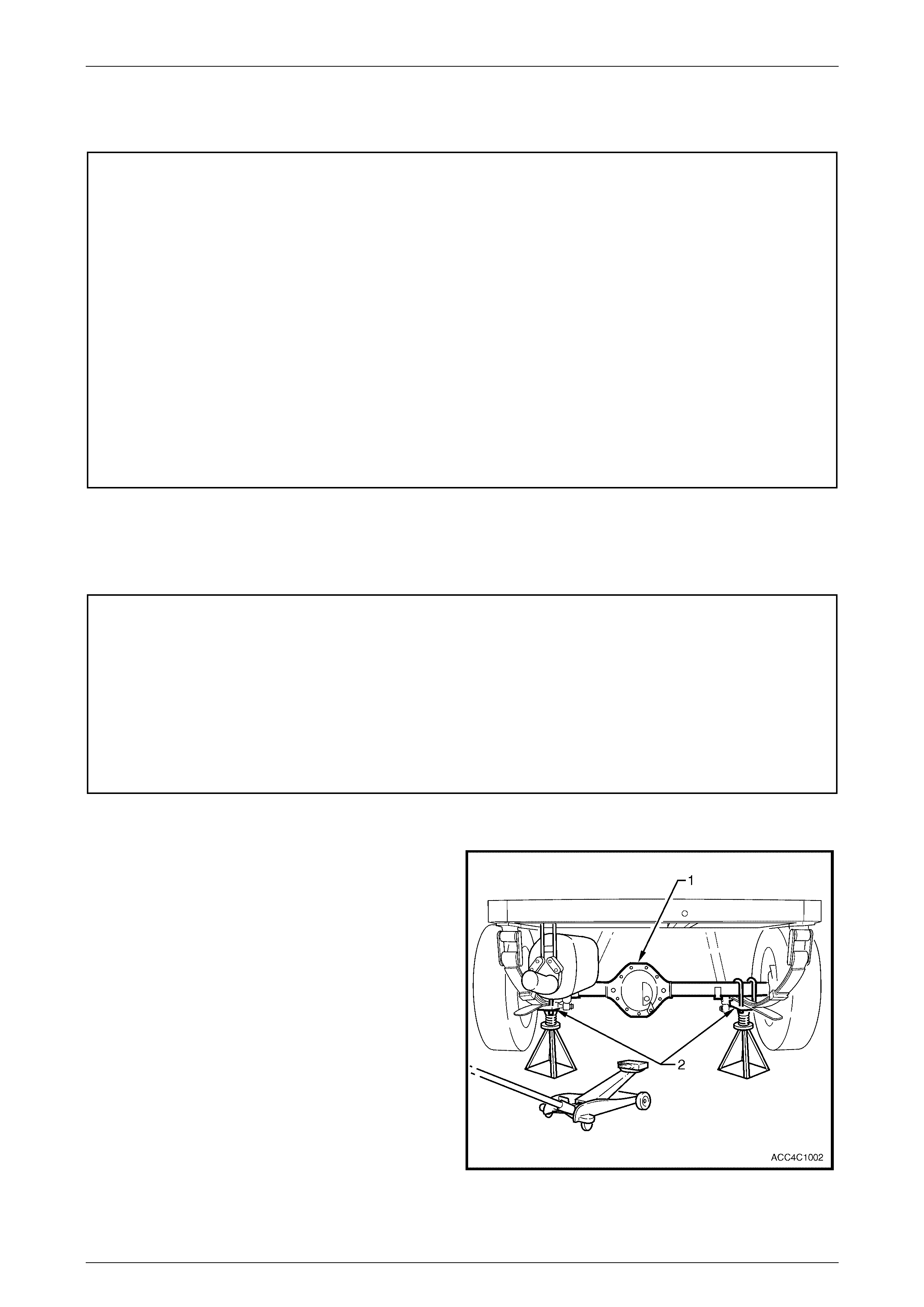
1 Using a floor jack under the centre of the rear final
drive assembly (1), jack up the rear of the vehicle,
then place the safety stands under the rear leaf spring
retainer plates (2) on each side to support the weight
of the vehicle as shown in Figure 4C1 – 2.
Figure 4C1 – 2
Rear Propeller Shaft & Universal Joints Page 4C1–4
Page 4C1–4
2 Select the Park position with the transmission selector
lever.
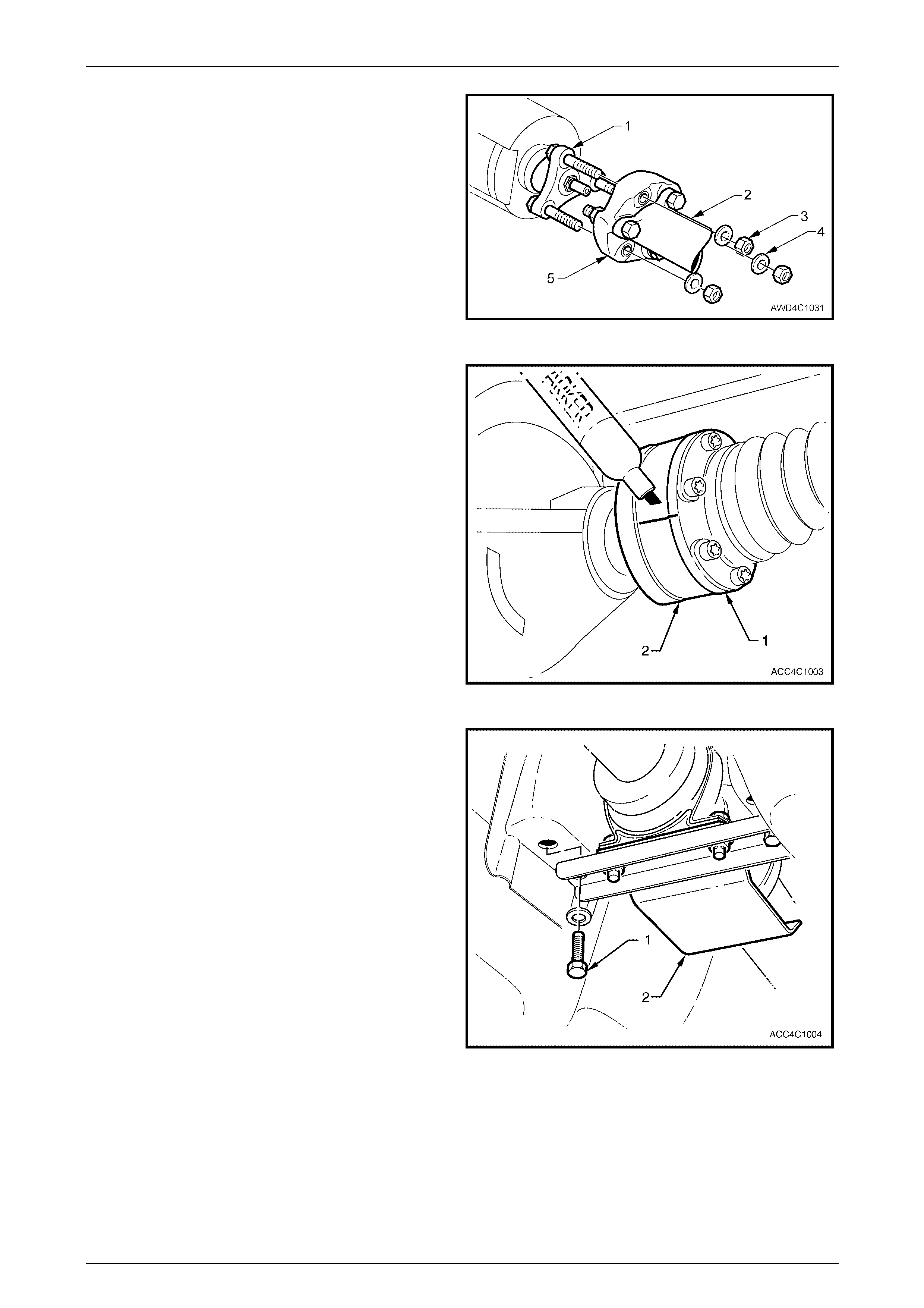
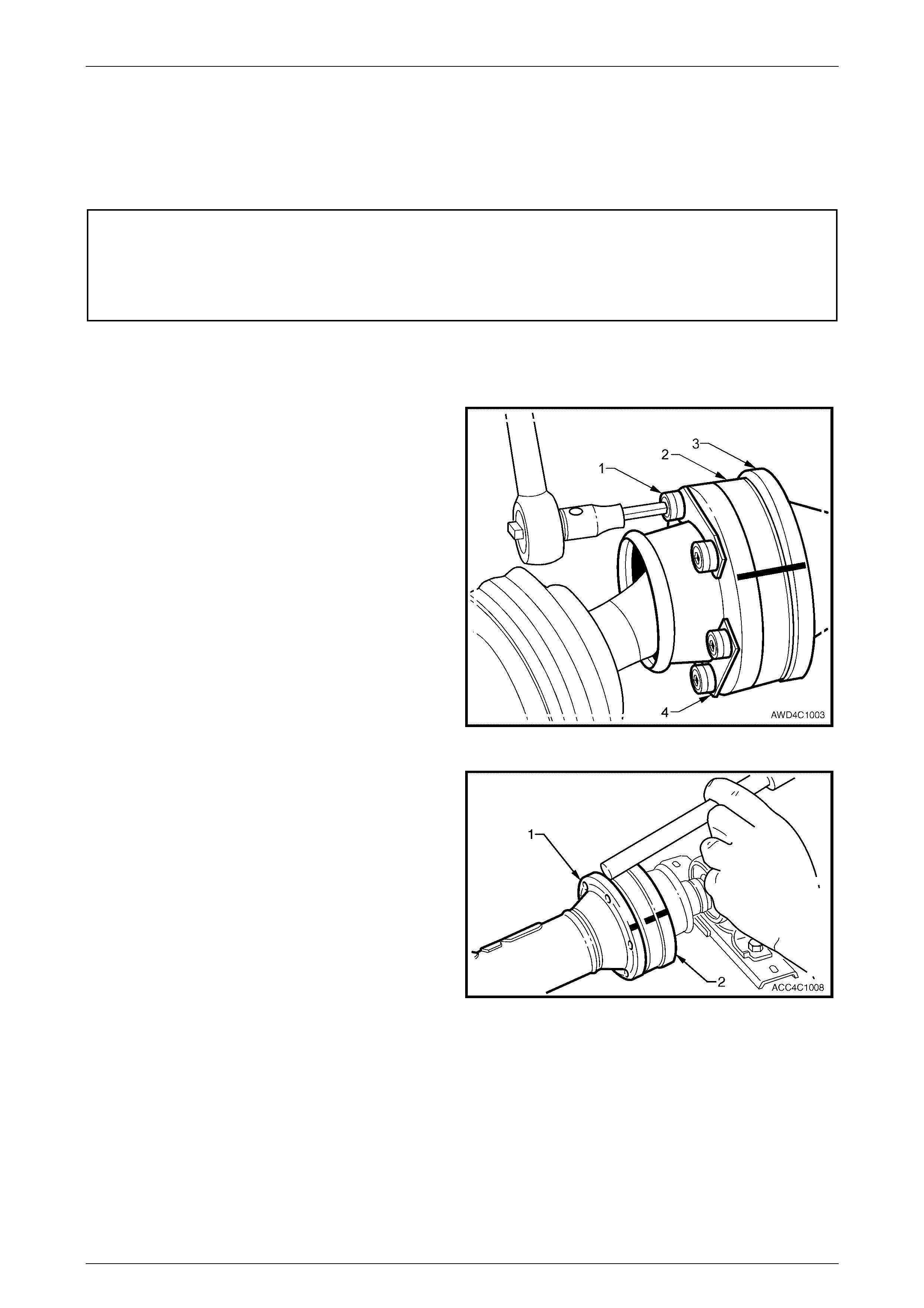
3 Loosen then remove the three nuts (3) and washers
(4) securing the front coupling (5) to the transfer case
output flange (1). Discard the removed nuts (3) as
they must be replaced on reassembly.
Figure 4C1 – 3
4 Use a suitable felt tipped marking pen to mark the
relationship of the rear constant velocity joint (1) to the
rear axle pinion flange (2).
5 Remove the propeller shaft rear constant velocity joint
(1) to rear axle pinion flange (2) attaching bolts and
locking plates. Refer to Figure 4C1 – 4.
NOTE
When removing the rear constant velocity joint
from the rear axle pinion flange, take care not to
disturb the end cap of the constant velocity joint.
The end cap has a gasket to prevent
contamination by foreign material.
Figure 4C1 – 4
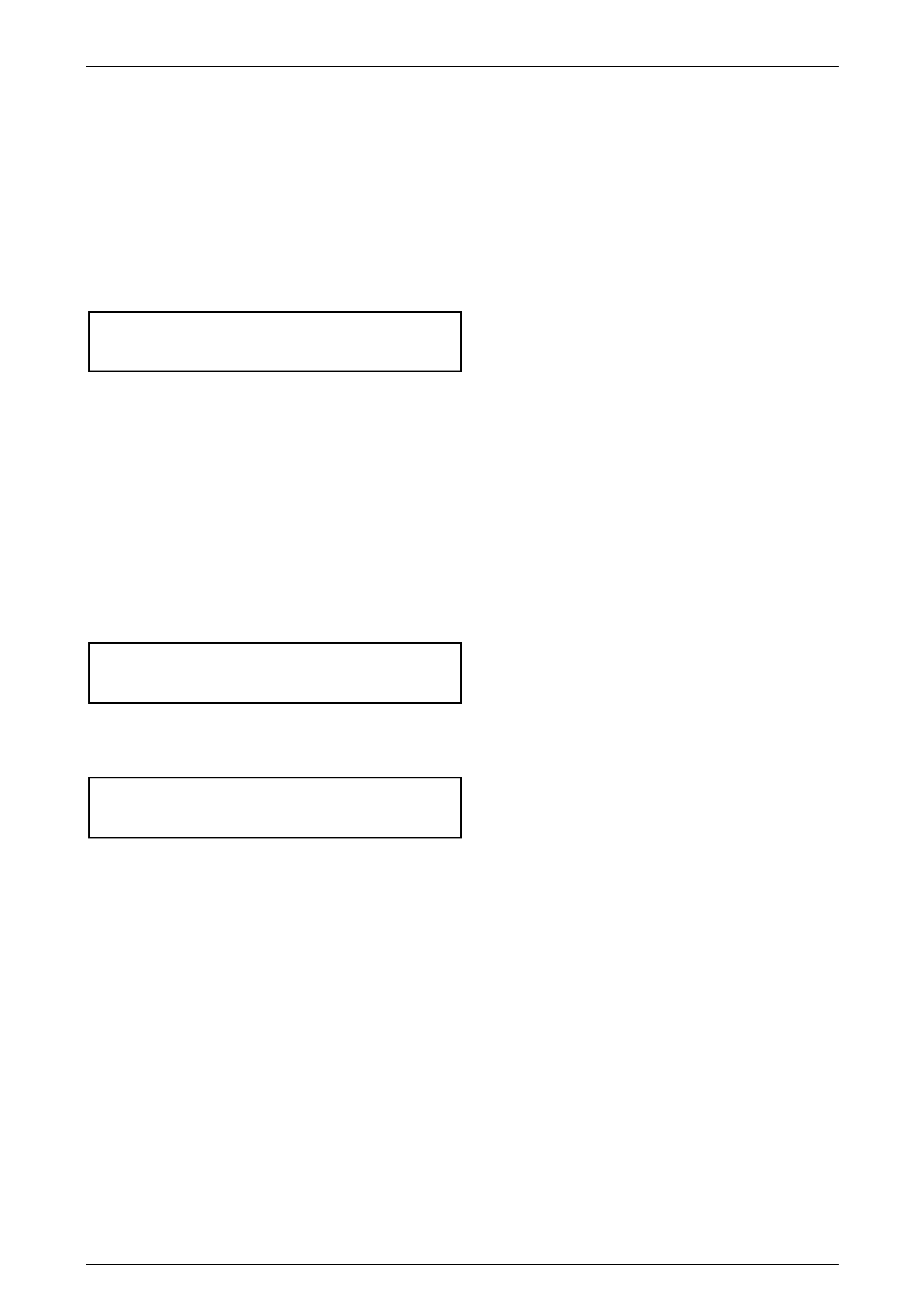
6 Loosen but do not fully remove the centre bearing
carrier bracket attaching bolts (1) at this stage.
7 To remove the propeller shaft assembly from the
vehicle:
a Carefully prise the rear constant velocity joint to
free it from the rear axle pinion flange, then push
forward to free the constant velocity joint from
the flange lip.
b While supporting the rear propeller shaft half and
the centre bearing, fully remove both centre
bearing carrier bolts. Refer to Figure 4C1 – 5.
c Lower the rear of the propeller shaft and move
rearward to free the front coupling from the
transfer case studs.
d Continue to move the propeller shaft rearwards,
manoeuvring past the exhaust system, then
remove the propeller shaft assembly from the
vehicle.
Figure 4C1 – 5
Rear Propeller Shaft & Universal Joints Page 4C1–5
Page 4C1–5
Reinstall
Reinstallation is the reverse of removal procedures, except for the following items:
1 Lubricate the transfer case rear output shaft spigot with a molybdenum disulphide grease such as Molybond GA10
or Shell ML10.
2 Clean the threads of the centre bearing carrier to underbody reinforcement bolts and underbody weld nuts, then
apply a thread sealant such as Loctite 242 or equivalent.
3 Reinstall the front of the propeller shaft assembly first, supporting the centre and rear sections.
4 While supporting the rear section, raise the centre bearing assembly and install the bolts and washers to secure to
the underbody reinforcement. Tighten both bolts to the correct torque specification.
( # ) Centre bearing carrier to
underbody reinforcement bolt
torque specific atio n ..............................................28 Nm
5 Slide the rear constant velocity joint assembly forward to allow access to the final drive pinion flange, then slide the
propeller shaft rearward to fully engage.
NOTE
Take care not to disturb the end cap of the
constant velocity joint. The end cap has a gasket
to prevent contamination by foreign material.
6 Before reinstalling the attaching bolts and locking plates into the rear constant velocity joint and pinion flange, align
the marks on the pinion flange and rear joint, that were made prior to removal, refer to Figure 4C1-4.
7 Clean the threads of the six, rear constant velocity joint to pinion flange bolts, apply a thread sealant such as
Loctite 242 or equivalent, then reinstall with locking plates and tighten to the correct torque specification, using a
T50 Torx bit and suitable socket equipment.
(#) Rear constant velocity joint to the
rear axle pinion flange attaching bolt
torque specific atio n ..............................................35 Nm
8 Secure the front rubber coupling to the transfer case rear output flange, using new retaining nuts and washers,
before tightening to the correct torque specification. When reinstalled correctly, the aligning triangular shapes on
the coupling outer surface ‘point’ to the propeller shaft flange. Refer Figure 4C1-7.
( ! ) Rubber coupling to transfer case
output shaft flange retaining nut
torque specific atio n ..............................................68 Nm
9 Check that the exhaust clearances are as specified in Section 8B Exhaust System in the MY 2003 VY Series, Cab
Chassis Service Information.
Rear Propeller Shaft & Universal Joints Page 4C1–6
Page 4C1–6
2.2 Rubber Coupling
LT Section No: 05-050-1
ATTENTION
The following fasteners MUST be replaced when performing these operations:
!
!!
! Rubber coupling to transfer case, rear output flange retaining bolts and nuts.
Fasteners either have micro encapsulated sealant applied or incorporate a mechanical thread lock and
should only be re-used once. If in doubt, replacement is recommended.
#
##
# Propeller shaft centre bearing bracket to the vehicle underbody, attaching bolts.
#
##
# Propeller shaft rear constant velocity joint to pinion flange bolts.
Replace
1 Remove the propeller shaft. Refer to 2.1 Propeller Shaft in this Section.
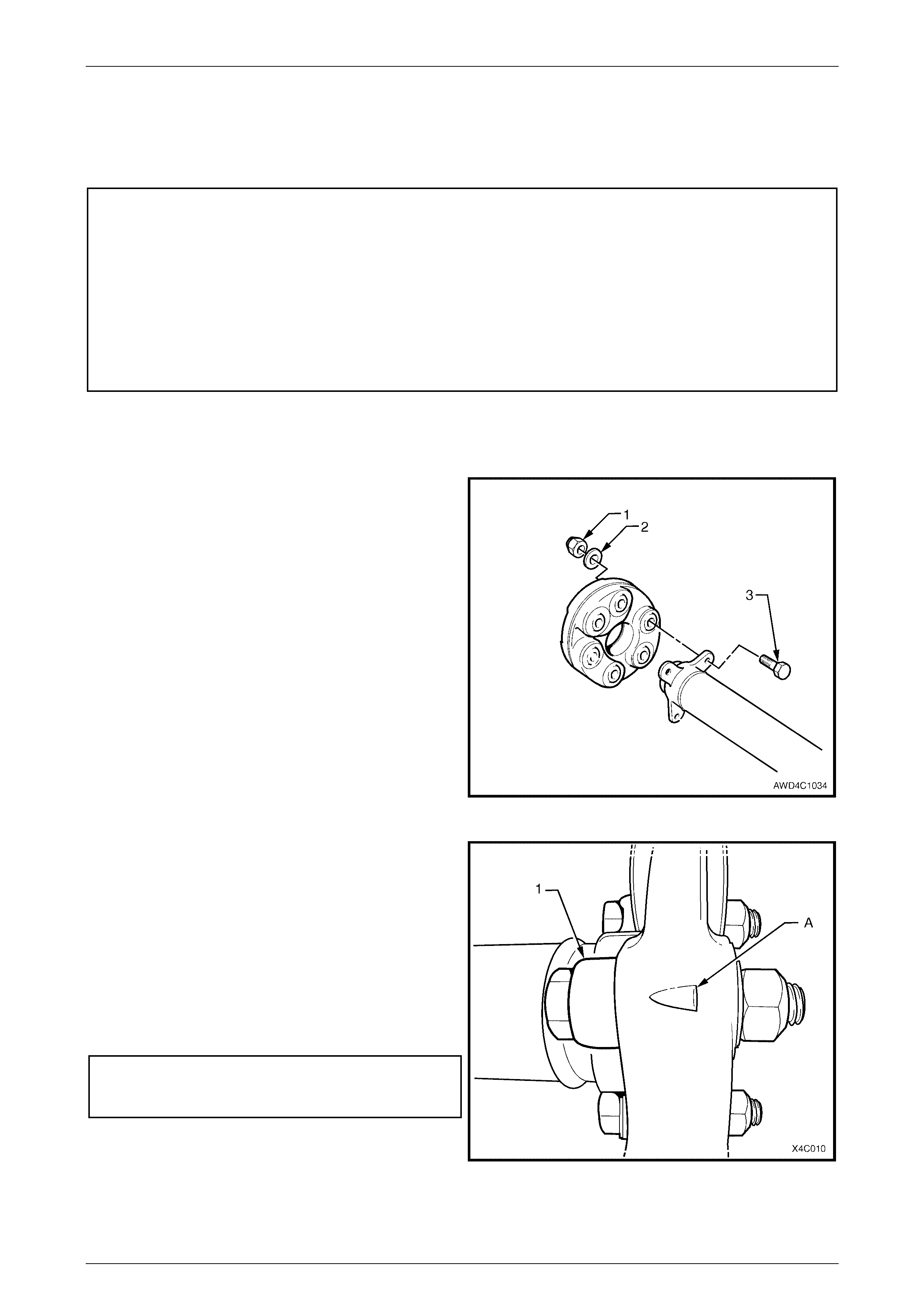
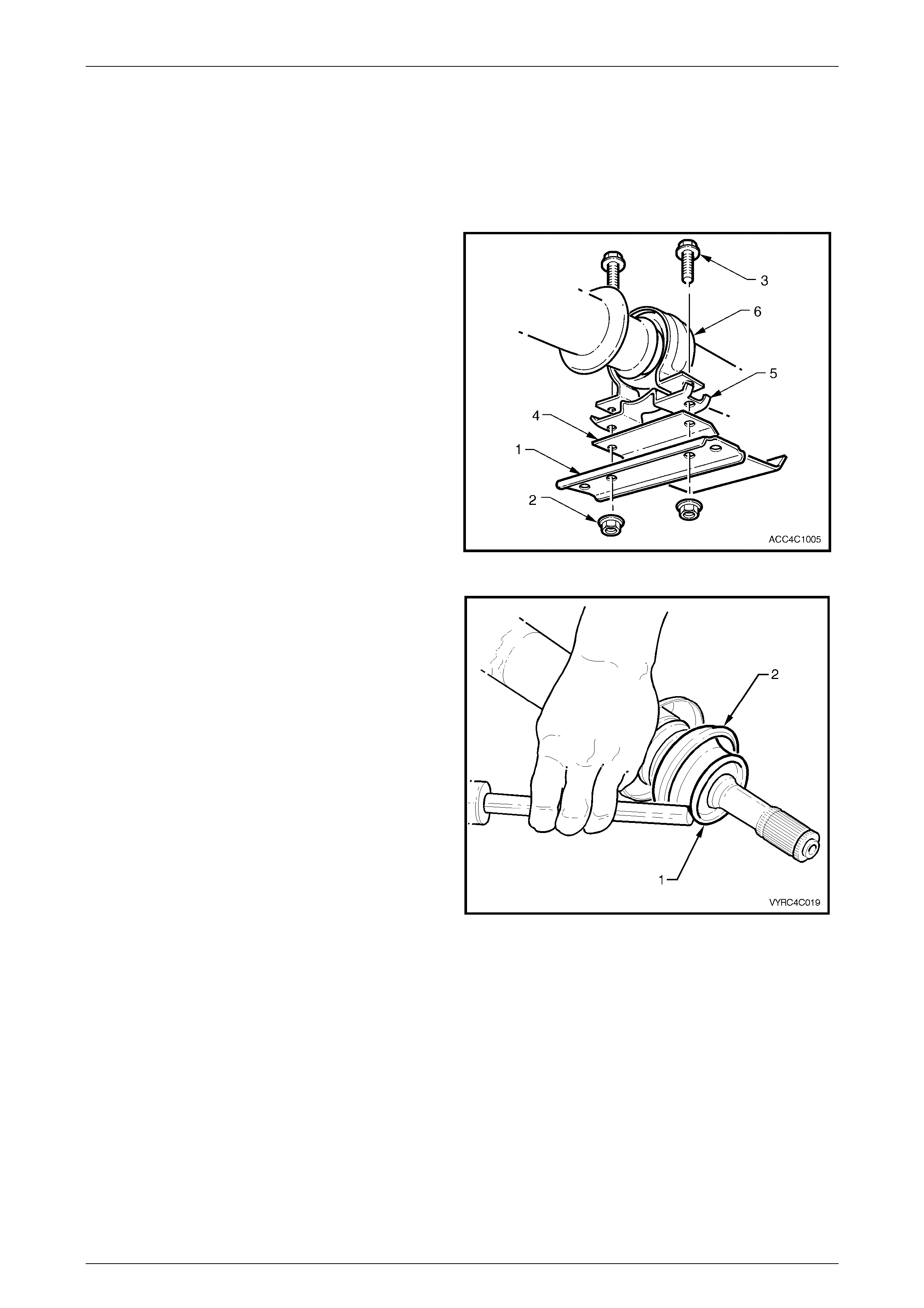
2 Using a back-up spanner on each of the three
propeller shaft to coupli ng bolts (3), loosen then
remove the nuts (1) and washers (2). Discard the
removed bolts, nuts and washers. Remove the
coupling from the front of the propeller shaft.
Figure 4C1 – 6
3 Apply 0.5 gm of molybdenum disu lph ide grease (such
as Molybond GA10 or Shell ML10) to the spigot bush
in the propeller shaft end.
4 Reinstall a replacement rubber coupling onto the end
of the propeller shaft, aligning the holes in such a way
that the triangular shape (‘A’) on the coupling ‘points’
to the propeller shaft flange (1), as shown.
5 Install NEW bolts, washers and nuts to secure the
coupling to the propeller shaft flange and tighten to the
correct torque specification, using a back-up spanner
on the bolt head.
( ! ) Propeller shaft to
rubber coupling nut
torque specific atio n ..............20 Nm, then 55° Turn Angle
6 Install the propeller shaft, as detailed in 2.1 Propeller
Shaft in this Section.
Figure 4C1 – 7
Rear Propeller Shaft & Universal Joints Page 4C1–7
Page 4C1–7
2.3 Centre Fixed Type Constant Velocity
Joint, Rubber Boot and Dust Shield
LT Section No: 05-050-1
ATTENTION
The following fasteners have either micro encapsulation or incorporate a mechanical thread lock and should
only be used once. If in doubt, replacement is recommended when performing this operation:
#$ Constant velocity joint to rear propeller shaft attaching bolts.
Remove
1 Remove the propeller shaft. Refer to 2.1 Propeller Shaft in this Section.
2 To ensure correct alignment of parts at reassembly,
scribe an aligning mark (or use a felt tipped pen) on
the constant velocity joint (2) and the rear propeller
shaft mounting flange (3).
3 While holding the rear half of the propeller shaft in a
vice fitted with soft jaws, remove the six, 6 mm Allen
key headed screws (1) and three lock plates (4), using
suitable socket equipment.
Figure 4C1 – 8
4 Using a brass drift and hammer gently tap the
propeller shaft companion flange, evenly to separate
the constant velocity joint (2) from the propeller shaft
(1).
Figure 4C1 – 9
Rear Propeller Shaft & Universal Joints Page 4C1–8
Page 4C1–8
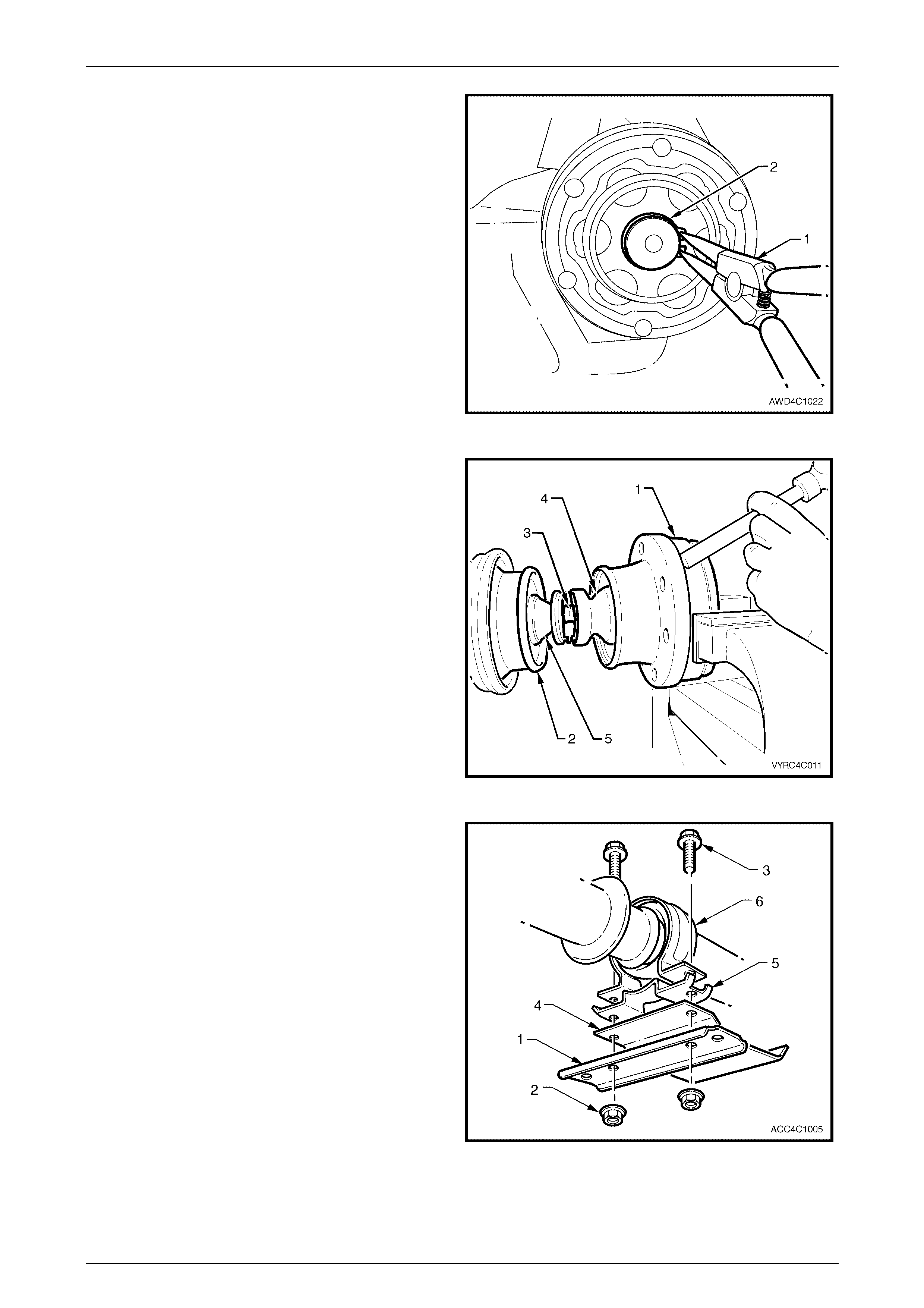
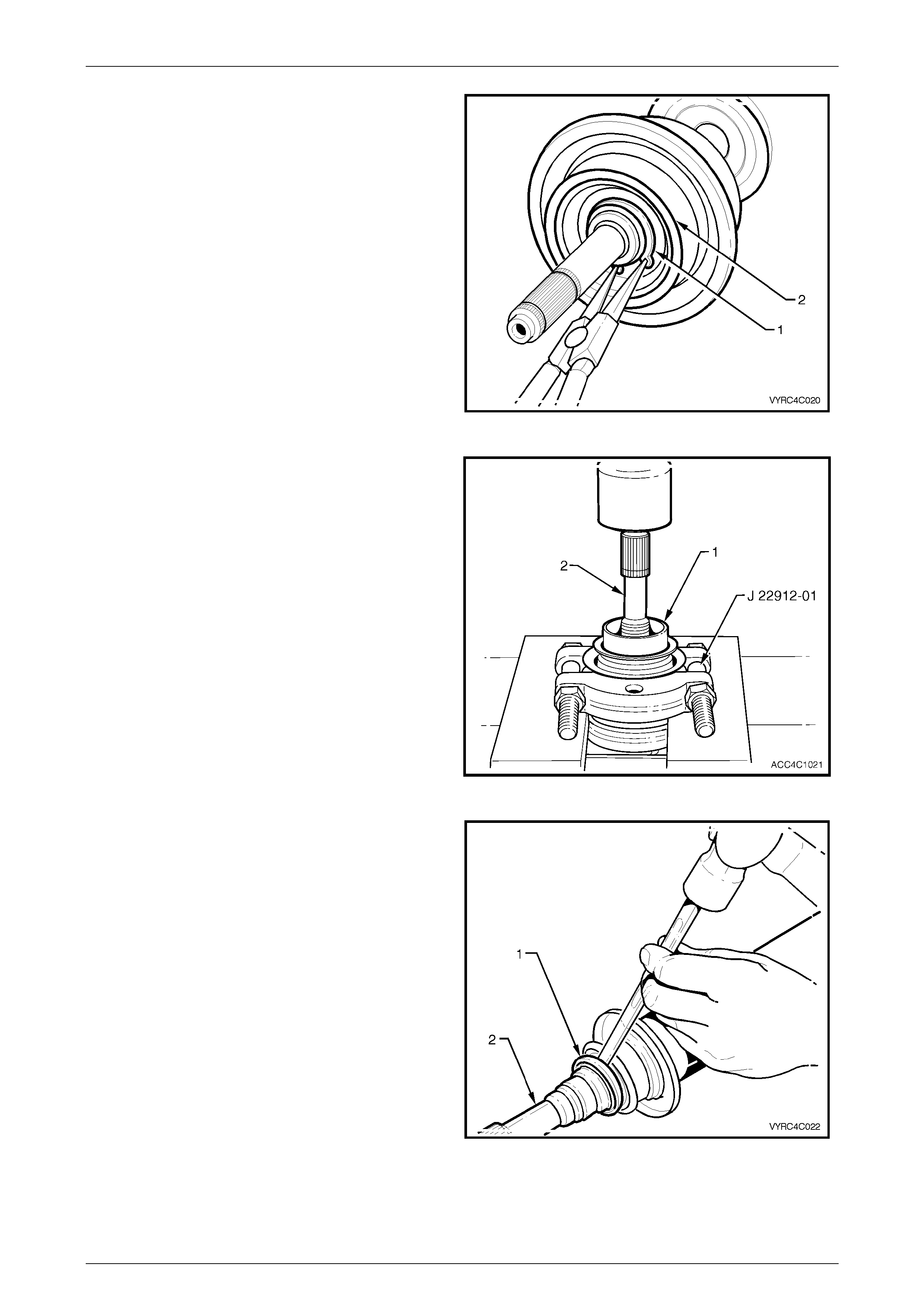
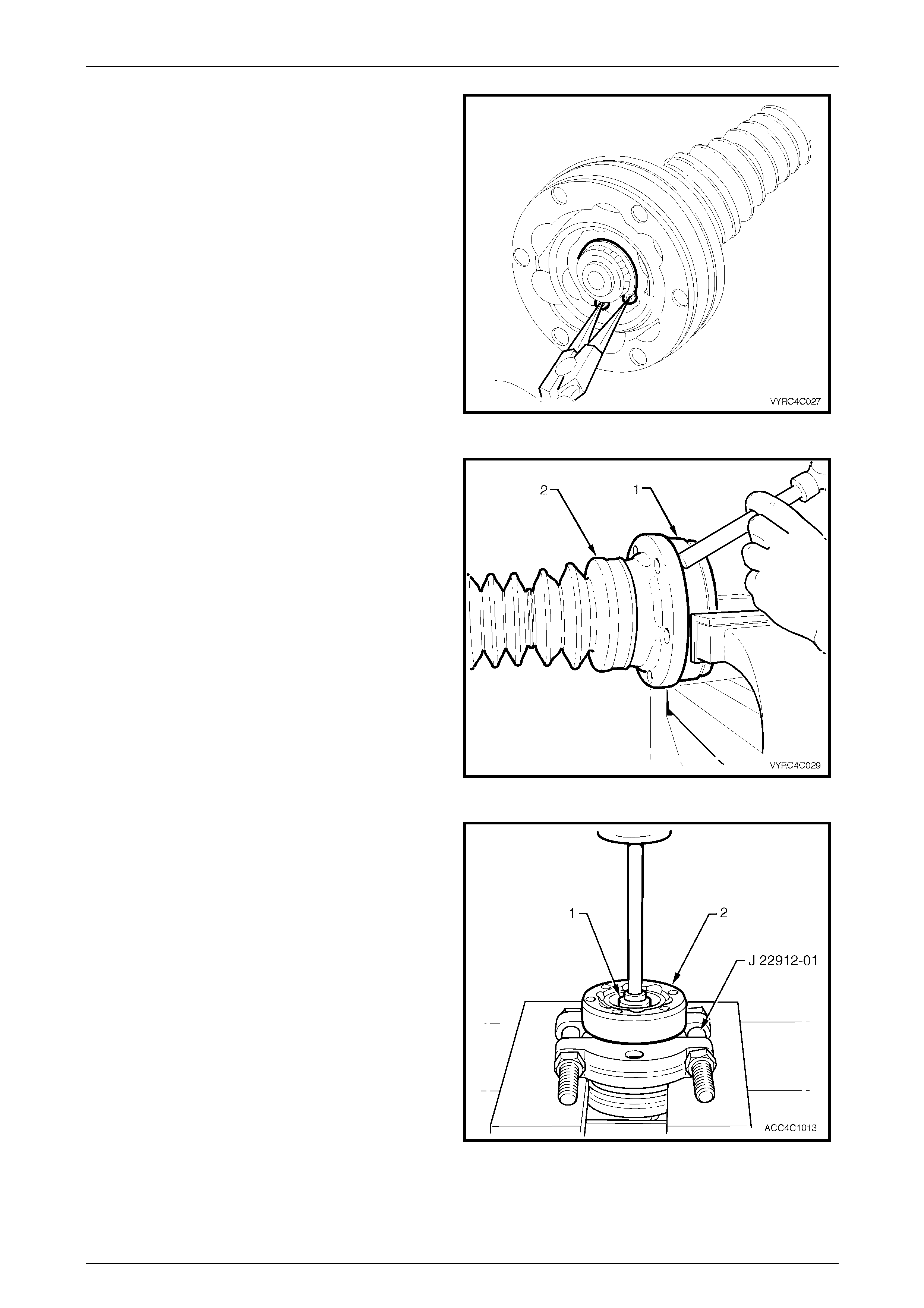
5 Using suitable circlip pliers (1), remove the constant
velocity joint, retaining circlip (2) from the front
propeller shaft spin dle.
Figure 4C1 – 10
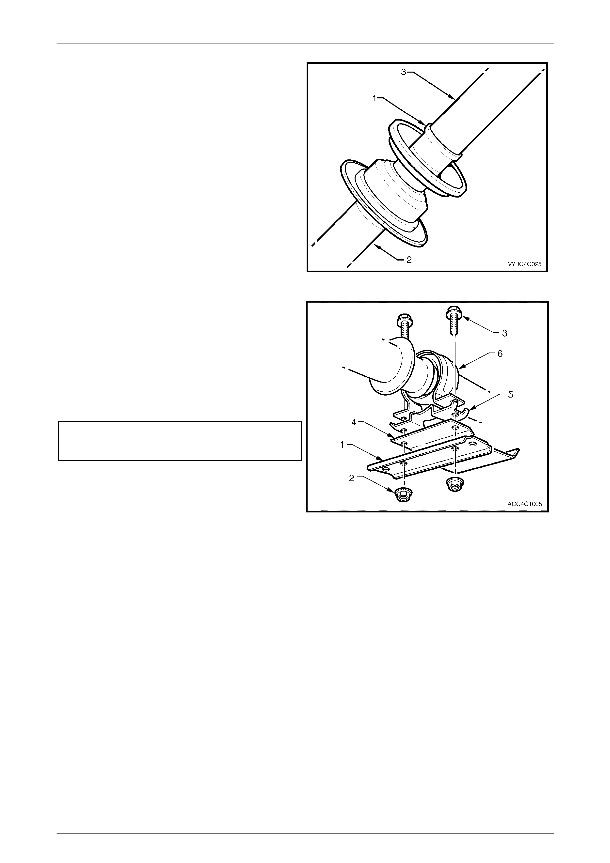
6 Support the constant velocity joint body (1) in a vice
fitted with soft jaws. Using a brass drift and hammer
gently tap the dust cover and rubber boot assembly
(4) from the body of the constant velocity joint.
7 Remove the retaining clamp (3) attaching the rubber
boot (4) to the front propeller shaft spindle (5) by
releasing the clamp tang with a small bladed
screwdriver.
8 Push the dust cover and rubber boot assembly (4)
back toward the propeller shaft centre bearing (2).
Figure 4C1 – 11
9 Remove the centre bearing carrier retaining nuts (2)
and bolts (3), the support carrier strap (1) and the
heat shield (4), if fitted.
10 Separate the centre bearing cup guide halves (5 and
6), removing them from the centre bearing assembly.
Figure 4C1 – 12
Rear Propeller Shaft & Universal Joints Page 4C1–9
Page 4C1–9
11 Remove the excess lubricant from the constant
velocity joint (1), wipe clean, then us e a felt tipped pen
or correction fluid (2), to identify the relationship of the
three joint componen ts.
12 Remove the gasket (3) between the propeller shaft
companion flange and the constant velocity joint.
Discard the removed gasket.
Figure 4C1 – 13
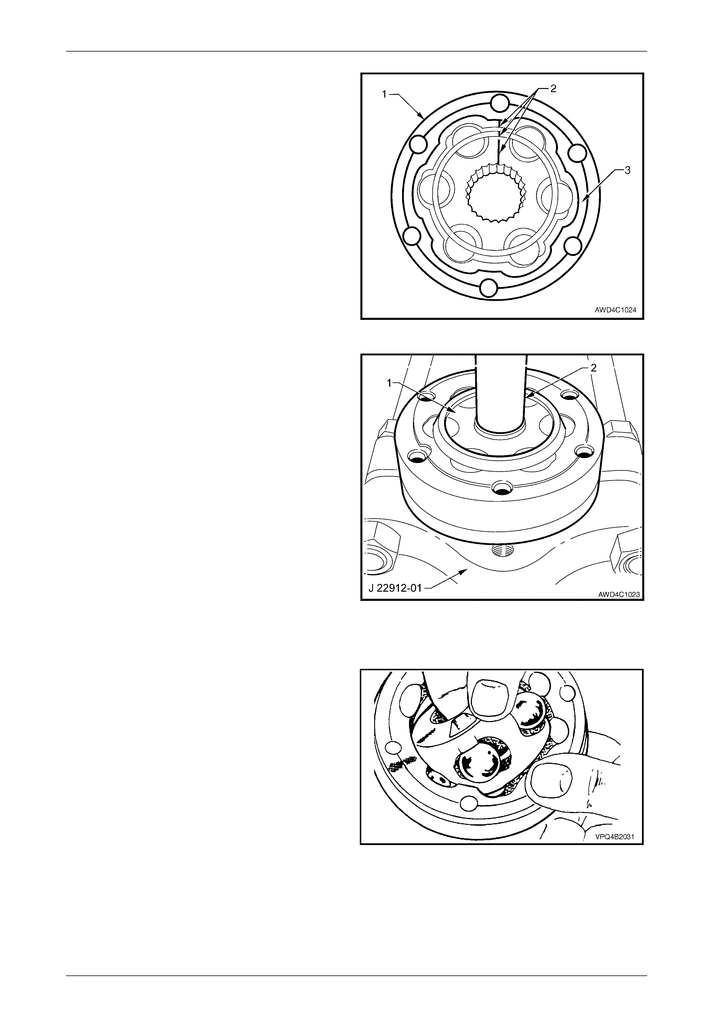
13 Push the cap and boot back along the propel ler shaf t,
enough to allow the fitment of press plates such as
J 22912-01.
14 Support the constant velocity joint inner race (1) with
the press plates (J 22912-01) then, using a suitable
mandrel (2), press the propeller shaft from the
constant velocity joint.
15 Remove the boot and dust shield from the propeller
shaft, being careful not to damage the boot on the
propeller shaft spli nes .
Figure 4C1 – 14
Inspect
1 Inspect the grease in the joint for signs of
contamination. If contamination is evident, then the
constant velocity joint will probably have suffered
damage, and should be replaced.
2 If ins pection shows tha t contaminati on has not
occurred, clean the joint by soaking it in a suitable
cleaning solvent.
If there is severe pitting, galling, play between
the balls and the cage windows, cracking or
damage to the cage, pitting or galling or chips in
the raceways, replace the constant velocity joint.
3 Inspect the internal components by tilting the inner
race to one side to expose each ball individually, while
observing the condition of each component.
NOTE
Take care that no balls become dislodged during
this inspection process.
Figure 4C1 – 15
Rear Propeller Shaft & Universal Joints Page 4C1–10
Page 4C1–10
Reassemble
During the removal, cleaning, inspection or
replacement of a constant velocity joint, it is
possible for the joint to become
disassembled. Should an inadvertent
disassembly of a constant velocity joint
occur, and notwithstanding the earlier
recommendation, it is possible to reassemble
the constant velocity joint, provided the
following procedure is followed EXACTLY.
1 Obtain a piece of wood or suitable tray with enough depressions in the surface to accommodate the six balls of the
constant velocity joint, marking one divot to indicate the ball closest to the alignment marks to retain the original
orientation of each ball to its working components.
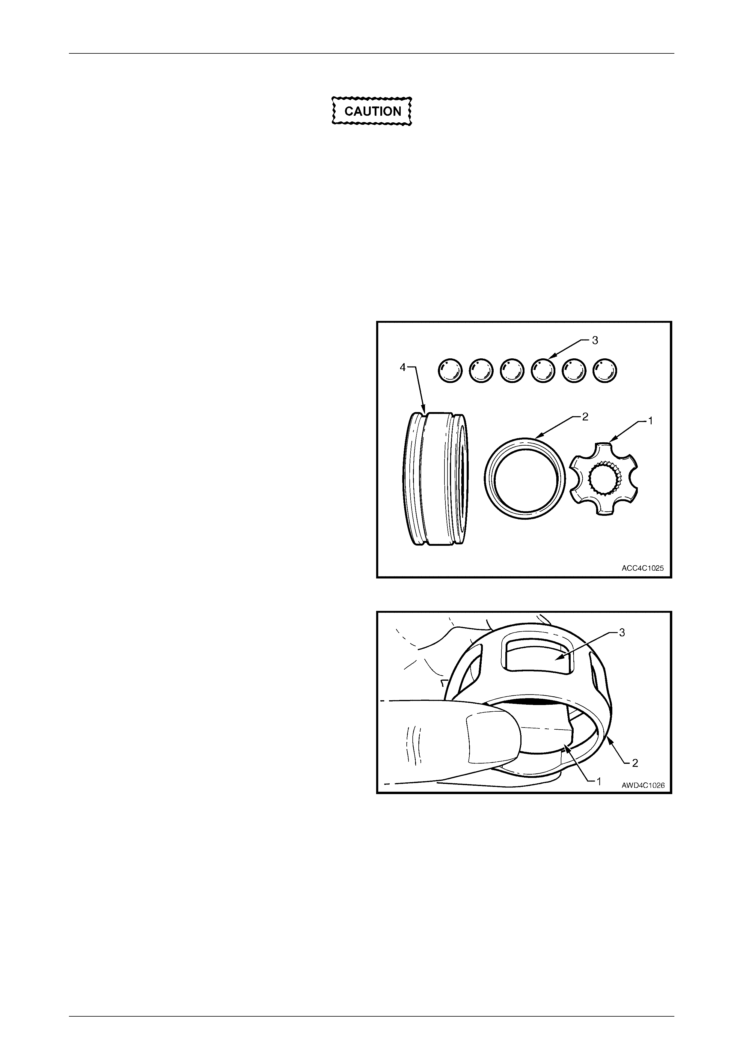
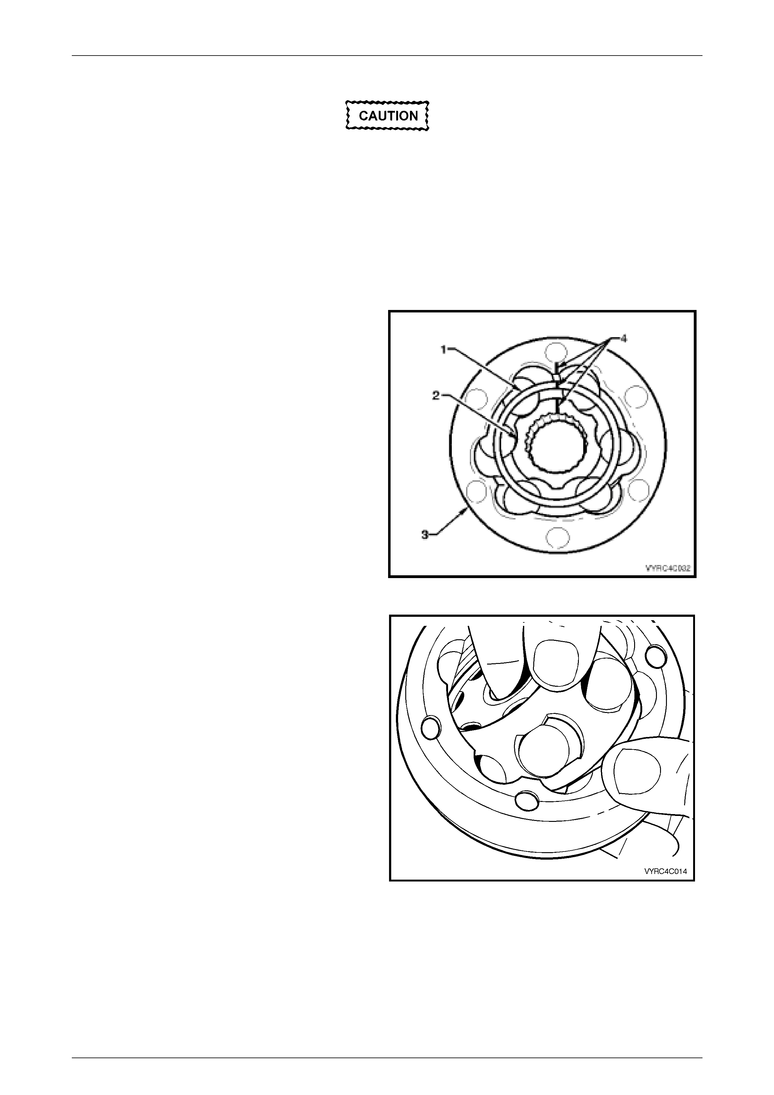
As shown in the exploded view of the fixed constant velocity
joint, the groove (4) is provided on the outer race to receive
the dust cover and boot assembly.
The fact that the ball grooves in both the outer and inner
races (1) are equally spaced, identifies this constant velocity
joint as a “fixed” type. Note also the fine groove on the front
edge of the ball cage (2) and the larger, plain chamfer on
the rear edge.
NOTES
• The inner race (1) and cage (2), together with
the individual balls (3), must be maintained in
their original locations to minimise the
creation of a noisy or binding joint.
• Under no circumstances are components
from one constant velocity joint to be mixed
with components from another constant
velocity joint.
Figure 4C1 – 16
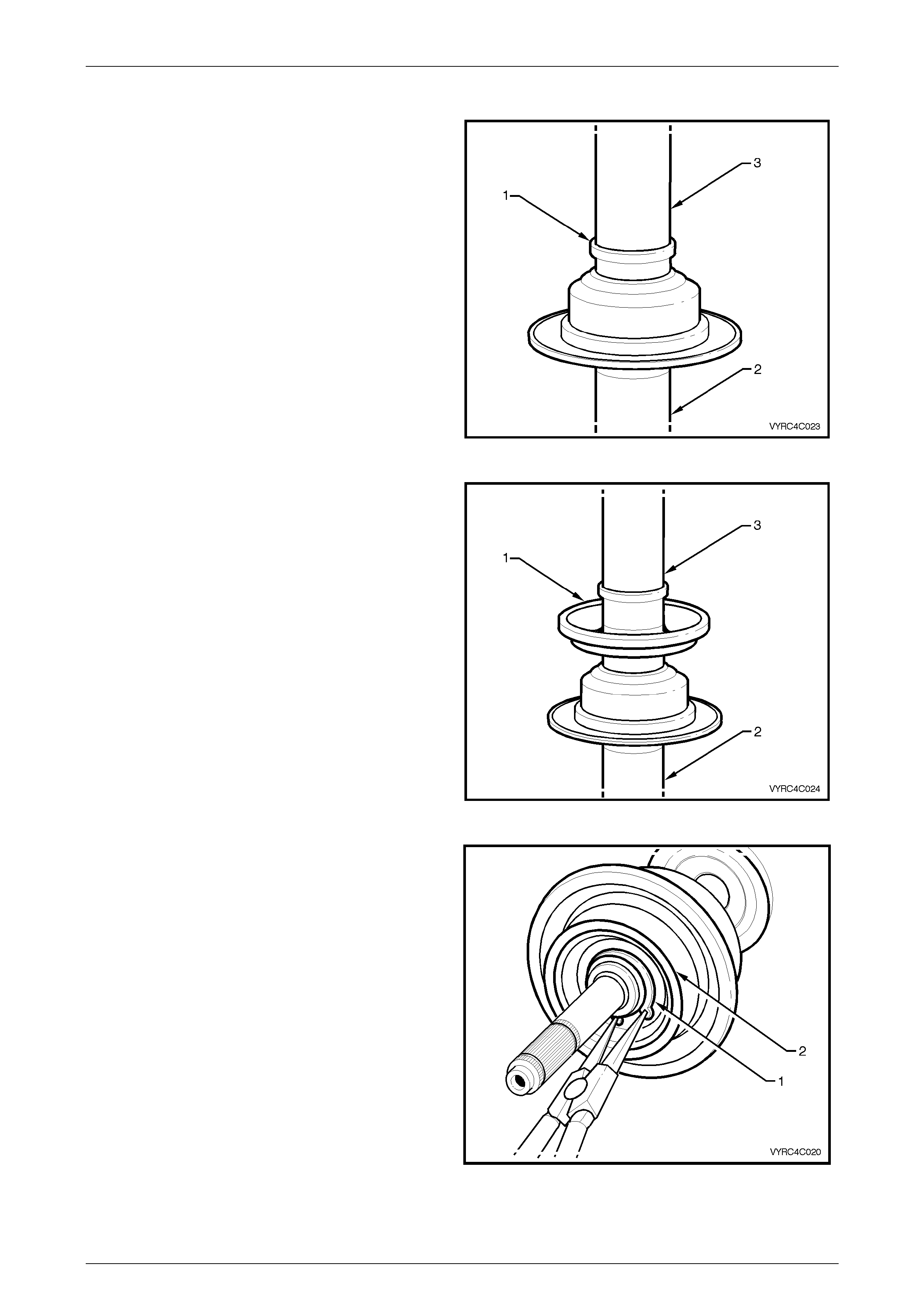
2 With the inner race (1) at 90° to the ball cage (2),
insert one 'leg' (3) of the inner race into one of the ball
holes, then manipu late the inn er race until ins tal led
inside the ball cage. Check that the relationship marks
are both on the same side.
NOTE
The fine groove on the inner edge of the ball
cage and the chamfered spline edge, should
both be opposite the relationship marks.
Figure 4C1 – 17

Rear Propeller Shaft & Universal Joints Page 4C1–11
Page 4C1–11
3 Reinstall the ball cage and inner race into the outer
race, following this next procedure:
a Locate the two reliefs in the ball grooves in the
outer race, indicated by 'A'. There will be similar
reliefs on the opposite side.
Figure 4C1 – 18
b With the ball cage and inner race at 90° to the
outer race, install at the relief points (as shown),
then manipulate the bal l cage t o fit inside the
outer race. Ensure that the relationship marks
are all on the same side and aligned.
Figure 4C1 – 19
4 Tilt the ball cage and inner race as shown, and fit the
balls, in their correct order, one at a time.
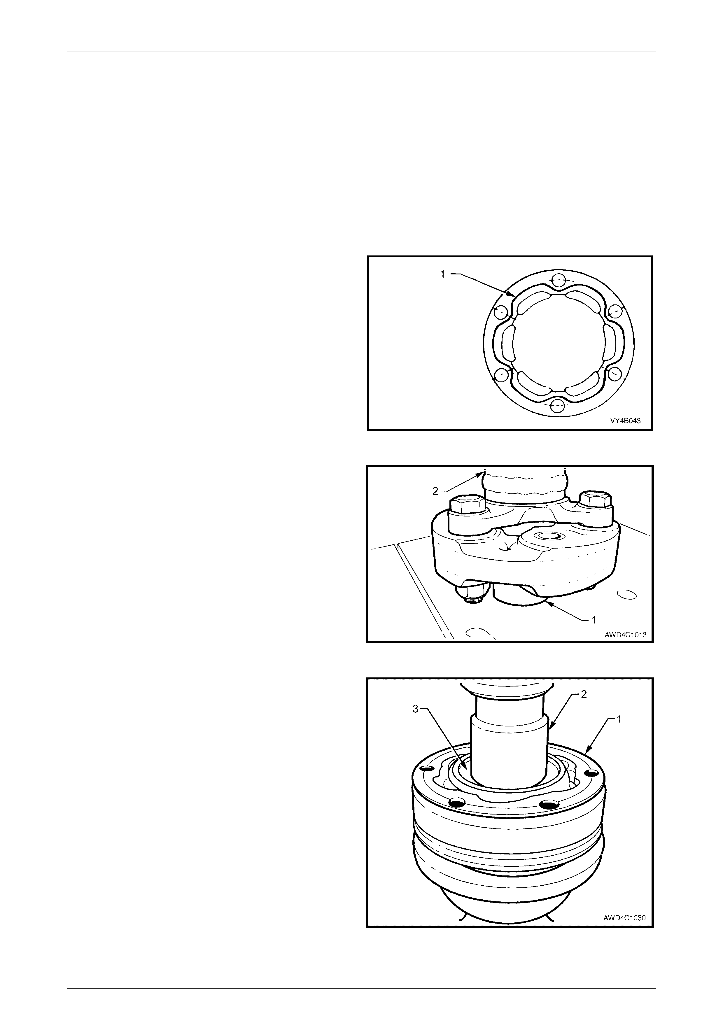
5 Check that the three relationship marks (1) are in
alignment.
6 Check that axial movement is minimal.
Figure 4C1 – 20
Rear Propeller Shaft & Universal Joints Page 4C1–12
Page 4C1–12
Reinstall
Reinstallation is the reverse of removal procedure, noting the following points:
1 Cleanliness of the constant velocity joint and associated parts is of prime importance to ensure maximum life of the
joint assembly.
2 Install a new small boot clamp over the splined propeller shaft splines, then install the boot and dust shield
assembly, taking care not to damage the boot on the propeller shaft splines.
3 Pack the constant velocity joint with half of the 36 g of lubricant supplied in either of the two available Repair Kits,
to the fixed joint and the dust shield. Work joint by hand to distribute grease onto all surfaces inside the joint. Pack
the remaining half of the lubricant into the adaptor recess.
4 Clean mating surfaces of constant velocity joint, dust shield and rear propeller shaft companion flange.
5 Apply a 2 mm bead of Loctite 510 High Temperature
Gasket Eliminator sealant or equivalent, to the dust
shield mating surface on the c onst ant vel oci ty joint, as
shown (1). Take care not to contaminate the constant
velocity joint grease with sealant.
Figure 4C1 – 21
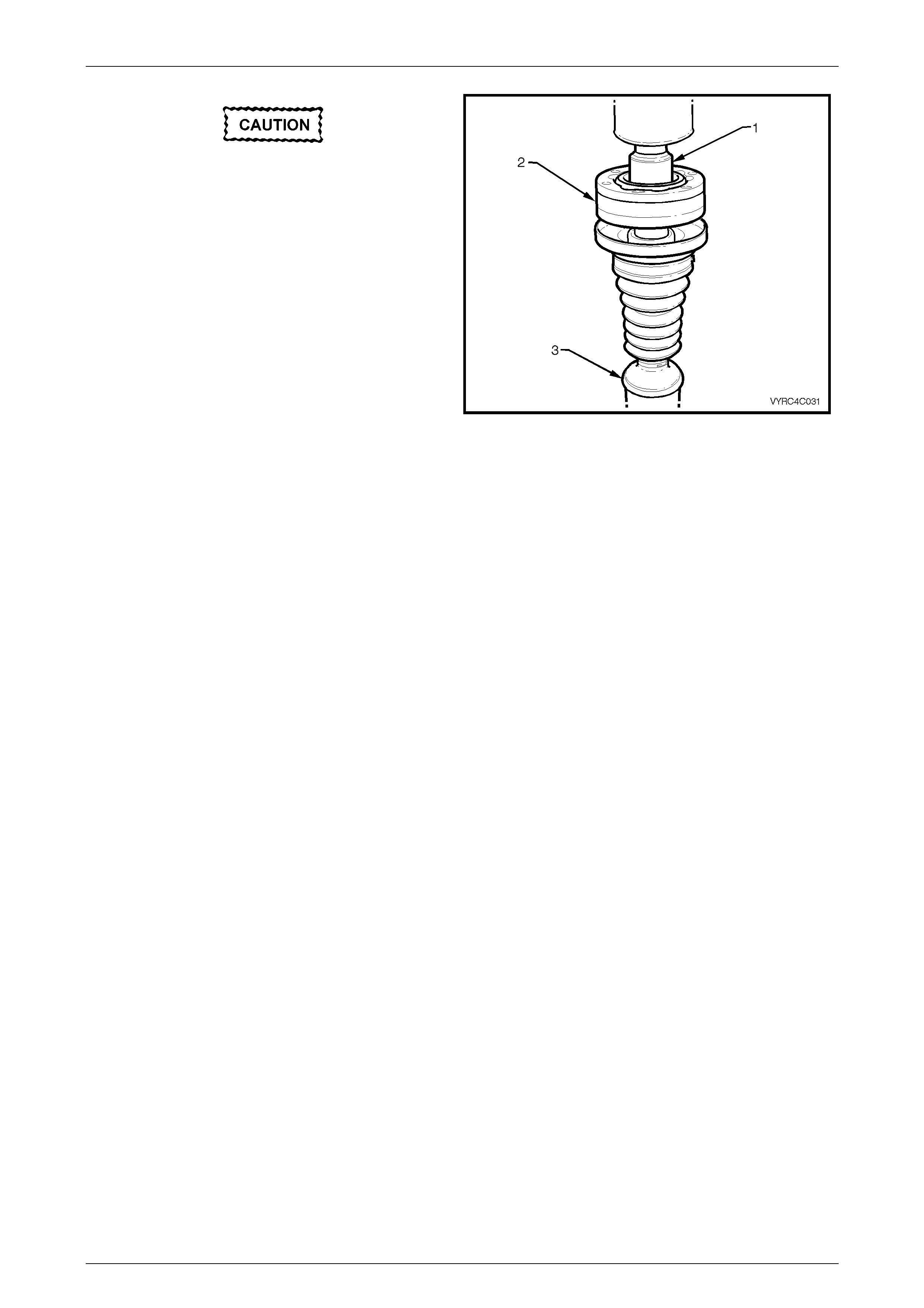
6 Before pressing the constant velocity joint onto the
front propeller shaft half splines, ensure that the front
of the propeller shaft (2) is supported on a suitable
length of tube (1) (dimensions; 48 mm OD, 32 mm ID
and at least 30 mm long), as shown.
Figure 4C1 – 22
7 Press constant velocity joint onto the rear propeller
shaft splines, using a suitable size socket or tube.
Ensure that socket or tube presses on inner race of
joint.
8 Secure the constant velocity joint with a new circlip,
being careful not to over-expand the circlip during the
installation process.
9 Install at least three of the constant velocity joint Allen
key headed bolts aligning the dust shield and boot
assembly to the constant velocity joint.
10 Using a plastic faced hammer, install the dust cap to
the constant velocity joint.
11 Reinstall new gasket to end of constant velocity joint.
Figure 4C1 – 23
Rear Propeller Shaft & Universal Joints Page 4C1–13
Page 4C1–13
12 Clean threads in rear propeller shaft companion flange and the six Allen head bolts. Apply Loctite 242 or equivalent
thread sealant to the bolt threads.
13 Ensure that the relationship marks on the constant velocity joint, dust boot flange and rear propeller shaft flange
(made before disassembly), are all aligned.
14 Reinstall and tighten the six Allen headed screws to the correct torque specification.
( # ) Centre constant velocity joint to
rear propeller shaft flange bolt
torque specific atio n ..............................................35 Nm
15 After locating the boot into the recess in the dust boot groove, install and tighten the new clamp, using keystone
clamp pliers such as J 22610 or commercial equivalent.
16 Reinstall propeller shaft. Refer to 2.1 Propeller Shaft in this Section.
Rear Propeller Shaft & Universal Joints Page 4C1–14
Page 4C1–14
2.4 Centre Bearing Assembly
LT Section No: 05-050-1
Remove
NOTE
The centre bearing cannot be removed from the
propeller shaft without causing damage to the
ball race and dust slinger. New parts must be
installed when the propeller shaft is being
reassembled.
1 Remove the propeller shaft. Refer to 2.1 Propeller
Shaft in this Section.
2 Remove the centre constant velocity joint, rubber boot
and dust shield. Refer to 2.3 Centre Constant Velocity
Joint Rubber Boot and Dust Shield in this Section.
3 Remove the centre bearing carrier retaining nuts (2)
and bolts (3), the support carrier strap (1) and the
heat shield (4), if fitted.
4 Separate the centre bearing cup guide halves (5 and
6), then remove them from the centre bearing
assembly.
Figure 4C1 – 24
NOTE
The centre bearing rear slinger once removed,
must be discarded. A new part MUST be
installed when the propeller shaft is being
reassembled.
5 Using a hammer and suitable punch, remove the rear
slinger (1) by tapping the edge of the slinger evenly
away from the centre bearing (2).
Figure 4C1 – 25
Rear Propeller Shaft & Universal Joints Page 4C1–15
Page 4C1–15
6 Remove the retaining circlip (1) from the centre
bearing (2), using suitable circlip pliers.
Figure 4C1 – 26
7 Using Tool No. J 22912-01 to support the centre
bearing (1), press the propeller shaft spindle (2) from
the centre bearing (1).
Figure 4C1 – 27
NOTE
The centre bearing front slinger once removed
must be discarded. A new part MUST be
installed when the propeller shaft is being
reassembled.
8 Using a hammer and suitable punch, remove the front
slinger (1) by tapping the edge of the slinger evenly
away from propeller shaft spindle (2).
Figure 4C1 – 28
Rear Propeller Shaft & Universal Joints Page 4C1–16
Page 4C1–16
Replace
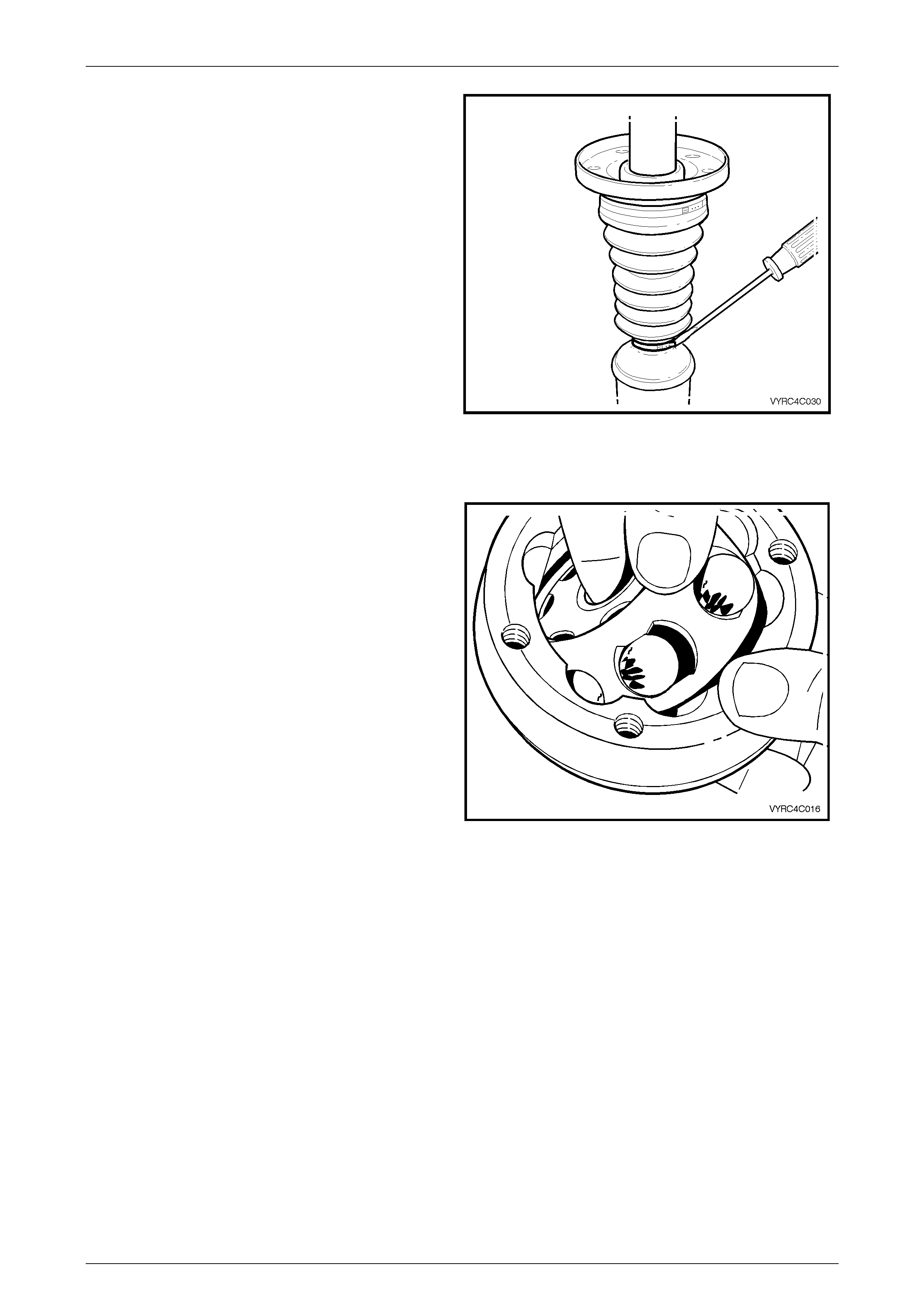
1 Install a new front slinger (1) onto the propeller shaft
spindle (2) using a suitable tube (3).
Figure 4C1 – 29
2 Install a new centre bearing (1) onto the propeller
shaft spindle (2) using a suitable tube (3).
Figure 4C1 – 30
3 Install a new retaining circlip (1) to the centre bearing
(2).
Figure 4C1 – 31
Rear Propeller Shaft & Universal Joints Page 4C1–17
Page 4C1–17
NOTE
Ensure the rear slinger is not installed too far
onto the propeller shaft spindle, as the slinger
and centre-bearing cup will rub.
4 Install a new rear slinger (1) onto the propeller shaft
spindle (2) using a suitable tube (3).
Figure 4C1 – 32
5 Install the centre constant velocity joint, rubber boot
and dust shield. Refer to 2.3 Centre Constant Velocity
Joint, Rubber Boot And Dust Shield in this Section.
6 Assemble the centre bearing cup guide halves (5 and
6), install the heat shield (4) (if removed) and support
carrier strap (1), securing all with the two bolts (3) and
nuts (2).
7 Tighten the carrier bracket attaching bolts (3) and
nuts (2) to the correct torque specification.
Centre bearing upper carrier bracket to
lower carrier bracket attaching
bolt torque specification........................................25 Nm
8 Reinstall the propeller shaft. Refer to 2.1 Propeller
Shaft in this Section.
Figure 4C1 – 33
Rear Propeller Shaft & Universal Joints Page 4C1–18
Page 4C1–18
2.5 Rear Plunge Type Constant Velocity
Joint
LT Section No: 05-050-1
ATTENTION
The following fasteners have either micro encapsulation or incorporate a mechanical thread lock and should
only be used once. If in doubt, replacement is recommended when performing this operation:
#$ Constant velocity joint to rear propeller shaft attaching bolts.
Remove
1 Remove the propeller shaft. Refer to 2.1 Propeller
Shaft in this Section.
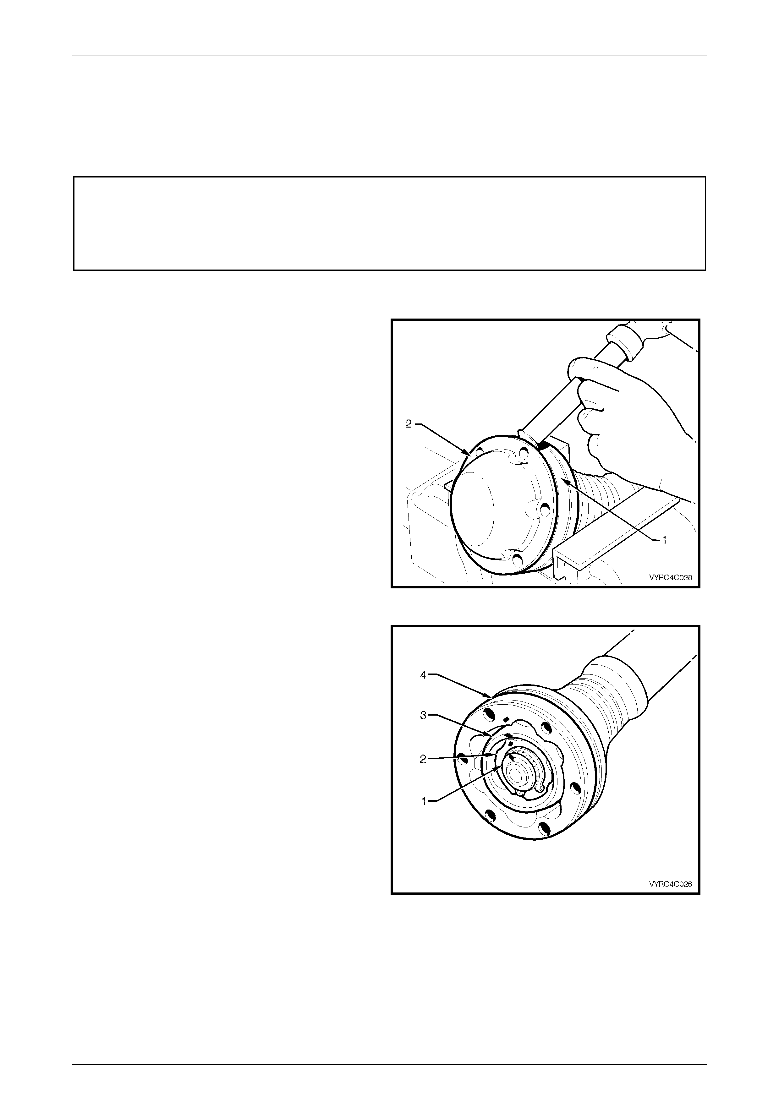
2 Support the constant velocity joint body (1) in a vice
fitted with protective soft metal jaws. Using a brass
drift and hammer gently tap the dust end cover (2)
from the body of the constant velocity joint.
Figure 4C1 – 34
3 Remove excess grease and wipe clean before
placing a daub of paint to mark the relationships of
the propeller shaft spindle (1), inner race (2), ball
guide (3) and outer race (4)
Figure 4C1 – 35
Rear Propeller Shaft & Universal Joints Page 4C1–19
Page 4C1–19
4 Using suitable circlip pliers, remove the constant
velocity joint, rear-retaining circlip.
Figure 4C1 – 36
5 Using a brass drift and hammer gently tap the dust
cover and rubber boot assembly (2) from the body of
the constant velocity joint (1).
6 Push the dust cover and rubber boot assembly back
toward the propeller shaft centre bearing.
Figure 4C1 – 37
7 Support the constant velocity joint with press plates,
Tool No J 22912-01 and press the propeller shaft
spindle (1) from the constant velocity joint (2).
Figure 4C1 – 38
Rear Propeller Shaft & Universal Joints Page 4C1–20
Page 4C1–20
8 Remove the dust shield and rubber boot assembly
retaining clamp. Remove the boot and dust shield
assembly from the propeller shaft.
Figure 4C1 – 39
Inspect
1 Inspect the grease in the joint for signs of
contamination. If contamination is present then the
constant velocity joint will have probably suffered
damage and should be replaced.
2 If no contamination is eviden t, clean the joint by
soaking it in a suitable cleaning solvent.
NOTE
If there is severe pitting, galling, play between
the balls and the cage windows, cracking or
damage to the cage, pitting or galling or chips in
the raceways, replace the constant velocity
joint.
3 Inspect the internal components by tilting the inner
race to one side to expose each ball individually,
while observing the condition of each component.
Figure 4C1 – 40
Rear Propeller Shaft & Universal Joints Page 4C1–21
Page 4C1–21
Disassemble
Disassembly of the constant velocity joint
beyond this point is not recommended. The
internal components are a precision fit and
during operation develop their own
characteristic wear patterns. Intermixing of
components could result in looseness,
binding and/or subsequent premature failure
of the constant velocity joint. If disassembly
must be attempted, then each component of
the joint must be returned to its original
orientation.
1 Ensure the aligning marks (4) made in step four of the
removal procedure are maintained at all times during
this procedure.
2 Obtain a piece of wood or suitable tray with enough
depressions in the surface to accommodate the six
balls of the joint, marking one divot to indicate the ball
closest to the alignment marks to retain the original
orientation of each ball to joint.
Figure 4C1 – 41
3 Taking care not to dislodge any balls from the joint,
pivot the inner race and ball guide at 90º to the centre
line of the outer race and lift the inner race and ball
guide from the outer race.
Figure 4C1 – 42

Rear Propeller Shaft & Universal Joints Page 4C1–22
Page 4C1–22
4 Using a screwdriver if required as a lever, remove
each ball in order from the ball guide and place the
balls on to the previously obtain piece of wood or tray
as detailed in step 2 of this procedure.
5 Pivot the inner race 90º to the centre line of the ball
guide and lift the inner race from the ball guide.
Figure 4C1 – 43
Reassemble
The reassembly procedure for the constant velocity joint is the reverse of the disassembly procedure, noting the following
points:
1 Ensure all alignment marks are aligned to return all components to their original orientation.
2 Check the multi-direction movement of the constant velocity joint for binding or restriction.
3 Check the plunge movement f or the consta nt velo city joint .
4 Ensure the reassembled constant velocity joint is kept free from contamination until required for reinstallation to the
propeller shaft.
Reinstall
The installation procedure is the reverse of the removal procedure, noting the following points:
1 Ensure the constant velocity joint and associated parts are clean to ensure maximum life expectancy.
2 Inspect the dust shield and boot assembly for cracks, tears or damage, replacing if necessary, then install it and a
new small clamp to the front propeller shaft spindle.
3 Pack half (~105 g) of the recommended lubricating grease into the boot, then work the rest (~125 g) thoroughly into
the constant velocity joint.
4 Prior to pressing the constant velocity joint onto the front propeller shaft spindle, ensure all alignment marks are in
their original orientat ion.
5 Ensure the mating surfaces of the constant velocity
joint, dust shield and rubber boot assembly are clean.
6 Apply a 2 mm bead of Loctite 510 High Temperature
Gasket Eliminator sealant or equivalent, to the dust
shield mating surface on the c onst ant vel oci ty joint, as
shown (1). Take care not to contaminate the constant
velocity joint grease with sealant.
Figure 4C1 – 44
Rear Propeller Shaft & Universal Joints Page 4C1–23
Page 4C1–23
Support the centre constant velocity joint
with press plate such as J 22912-01, under
the six Allen key headed attaching bolts
before pressing the rear constant velocity
joint onto the rear propeller shaft half.
7 Using a suitable socket or tube (1), press the constant
velocity joint (2) onto the propeller shaft (3), spindle
while ensuring the socket or tube presses on the
inner race of the joint only.
8 Secure the constant velocity joint with a new circlip,
being careful not to over-expand the circlip during the
installation process.
Figure 4C1 – 45
9 Install at least three of the rear constant velocity joint Torx bit headed bolts to align the dust shield and boot
assembly to the constant velocity joint.
10 Using a plastic faced hammer, install the dust cap to the constant velocity joint.
11 Install a new gasket between the constant velocity joint and the rear dust shield end cover.
12 Install the rubber boot to propeller shaft spindle retaining clip.
13 After locating the boot into the recess in the dust boot groove, install and tighten the new clamp, using keystone
clamp pliers such as J 22610 or commercial equivalent.
14 Press the domed end cover into place over the guide bolts, with press plates such as J 22912-01 (or equivalent)
supporting the dust shield, with a suitable sized sleeve acting on the outer edges of the end cap.
15 Reinstall the propeller shaft, as detailed in 2.1 Propeller Shaft in this Section.
Rear Propeller Shaft & Universal Joints Page 4C1–24
Page 4C1–24
3 Specifications
General
Propeller Shaft Assembly............................................................................Spilt Configuration
Drive Connection to Transfer Case.................................................Nut to Output Flange Stud
Centre Support Bearing ................................................ Rubber Encased Sealed Ball Bearing
Universal Type – Front...................................................................................Rubber Coupling
Universal Type – Centre .....................................................Constant Velocity – Non-Plunging
Universal Type – Rear ................................................................Constant Velocity – Plunging
Identification
ENGINE TRANSMISSION DRIVE
CONFIGURATION CODE
GEN III V8 Automatic AWD JY
Lubricants
Constant Velocity Lubricant Capacity (Fixed Type)............................................... 36 g ± 2. 5 g
Constant Velocity Lubricant Capacity (Plunging Type) ........................................ 230 g ± 10 g
Constant Velocity Lubricant Type..........................................Supplied in Tube/s as Part of the
Boot Repair and Major Overhaul Kits.
Sealants and Thread Locking Compound
Constant Velocity Joint to Dust Shield ....................................................................Loctite 510
(High Temperature Gasket Eliminator) or equivalent.
Propeller Shaft and Joint Fasteners................................................. Loctite 242 or equivalent.

Rear Propeller Shaft & Universal Joints Page 4C1–25
Page 4C1–25
4 Torque Wrench Specifications
ATTENTION
All Propeller Shaft and Universal Joints fasteners are important attaching parts as they affect the
performance of vital components and/or could result in major repair expense. Where specified in this Section,
fasteners MUST be replaced with parts of the same part number or a GM approved equivalent. Do not use
fasteners of an inferior quality or substitute design.
Torque values must be used as specified during reassembly to ensure proper retention of all steering
components.
Through out this Section, fastener torque wrench specifications may be accompanied with the following
Identification marks:
!
!!
! Fasteners must be replaced after loosening.
#
##
# Fasteners either have micro encapsulated sealant applied or incorporate a mechanical thread lock and
should only be re-used once. If in doubt, replacement is recommended.
If one of these identification marks is present alongside a fastener torque wrench specification, the
recommendation regarding that fastener must be adhered to.
# Centre Bearing Carrier Bracket to Vehicle Underbody Brace Bolts..............28 Nm
# Centre Bearing Upper Carrier to Lower Carrier Bracket Bolts and Nuts.......28 Nm
# Constant Velocity Joint to Rear Propeller Shaft Attaching Bolts...................35 Nm
! Front Rubber Coupling to Propeller Shaft attaching Nut And Bolt ................20 Nm
then 55° turn angle
! Front Rubber Coupling to Transfer Case Output Flange Nut........................68 Nm
# Rear Constant Velocity Joint to Rear Axle Pinion Flange Bolt......................35 Nm
Rear Propeller Shaft & Universal Joints Page 4C1–26
Page 4C1–26
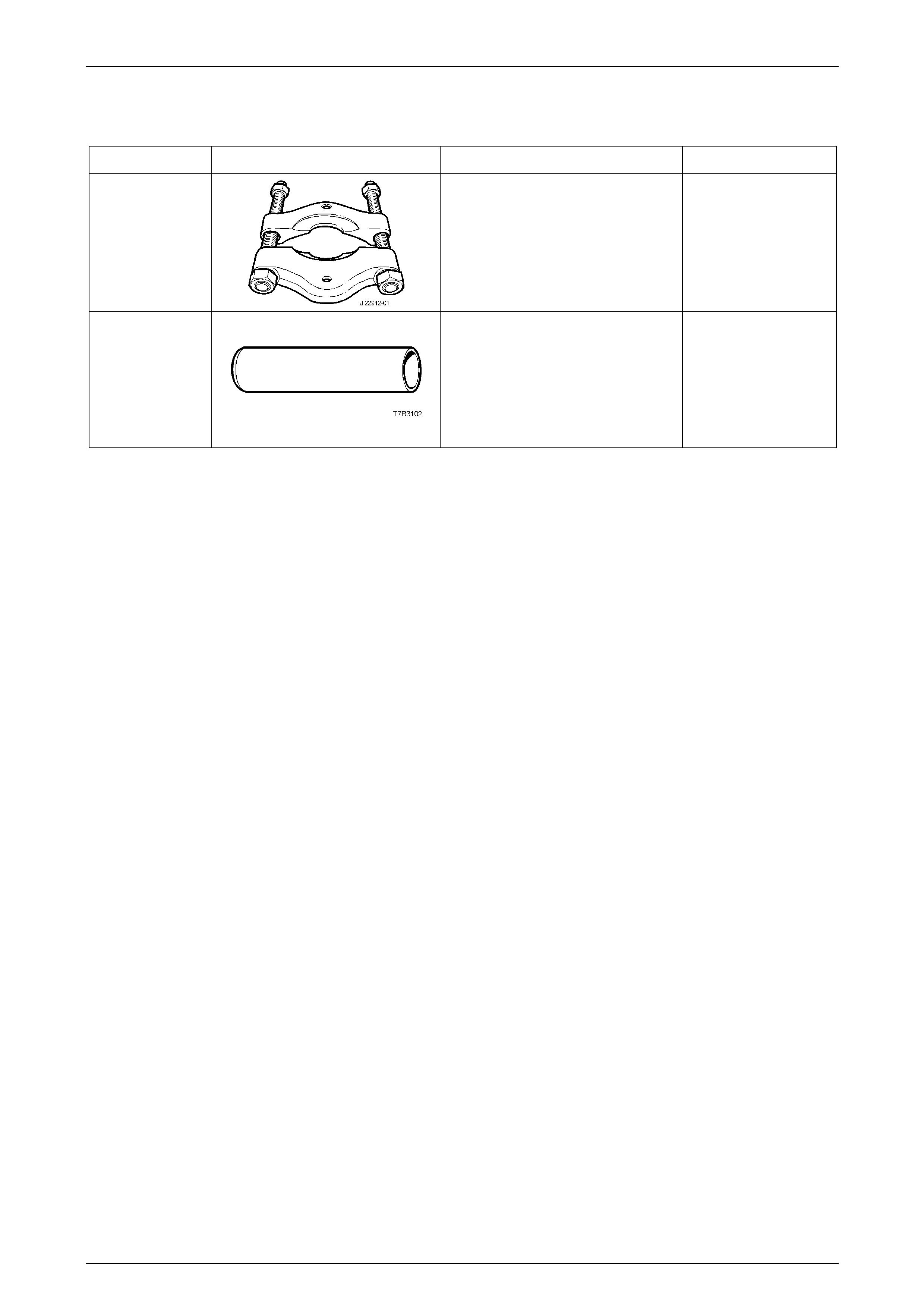
5 Special Tools
TOOL NUMBER ILLUSTRATION DESCRIPTION CLASSIFICATION
J 22912-01
PRESS TOOL
Used to remove rear wheel studs
from the Propeller Shaft and
Universal Joints flange.
Previously released.
Available
E3C10AER
CENTRE BEARING REPLACER
Used to install the centre bearing.
Previously released.
Available