
Hydra-Matic 4L65-E Automatic Transm issi on – General Information Page 7D1-1
Page 7D1-1
Section 7D1
Hydra-Matic 4L65-E Automatic Transm ission –
General Information
ATTENTION
Before performing any Service Operation or other procedure described in this Section, refer to Section 00
Warnings, Cautions And Notes for correct workshop practices with regard to safety and/or property damage.
1 Transmission Changes for MY 2004 AWD Crew Cab ........................................................................ 2
Transmission Identification Number....................................................................................................................2
Torque Converter Clutch Control .........................................................................................................................3
Torque Converter Clutch Pulse Width Modulated (TCC PWM) Solenoid Valve .................................................3
TCC PWM Solenoid Valve Operation.................................................................................................................3
Transmission Shift Points.....................................................................................................................................4
Neutral Safety and Back-Up (NSBU) Lamp Switch..............................................................................................4
Shift Selector Mechanism......................................................................................................................................5
Techline
Techline
Hydra-Matic 4L65-E Automatic Transm issi on – General Information Page 7D1-2
Page 7D1-2
1 Transmission Changes for
MY 2004 AWD Crew Cab
Apart from the minor changes detailed here, the 4L65-E automatic transmission fitted to this vehicle, carries over from
the assembly fitted to the MY2003 Regular Cab, with the GEN III V8 engine, with some updates introduced with the
release of VY Series II range of vehicles. For further information relating to this MY 2004 automatic transmission, refer to
the 7C Sections in the MY 2004 AWD Wagon or the 7C Sections in the MY 2003 VY Series Regular Cab, Service
Information.
Transmission Identification Number
With the mounting of the transfer case and the adaptor housing to the rear of the 4L65-E automatic transmission, the
mainshaft length has been altered. This has resulted in a different code number being assigned to this transmission.
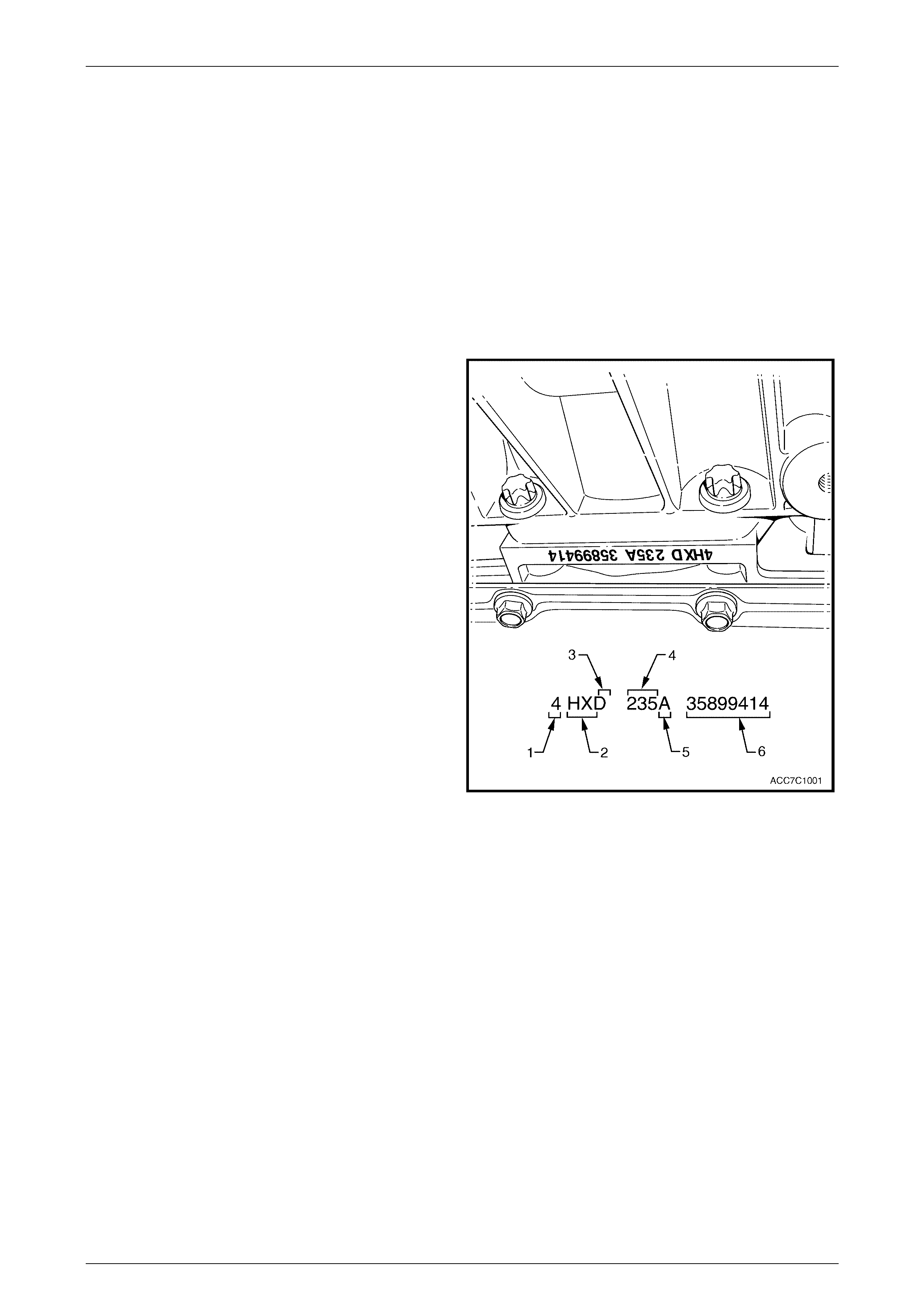
The 4L65-E automatic transmission application and
identificati on can be determined from the stamp ing on the
rear of the transmission ca se, i n the locati on show n.
The coded number can be interpreted from the following
breakdown;
Legend
1 Model Year (‘4’ = 2004)
2 Model: AWD Crew Cab & 5.7 litre GEN III V8 – 'HX'
3 Transmission Model Identifier (‘D’ = 4L65-E)
4 Julian Date (Day of the Year)
5 Shift Build ‘A’, ‘B’, ‘J’ = First Shift;
‘C’, ‘H’, ‘W’ = Second Shift
6 Individual Transm is sion Serial Number
Figure 7D1 – 1
Hydra-Matic 4L65-E Automatic Transm issi on – General Information Page 7D1-3
Page 7D1-3
Torque Converter Clutch Cont rol
First applied to MY 2003 VY Series Regular Cab vehicles fitted with automatic transmission and the GEN III V8 engine,
an Electronically Controlled Converter Clutch (ECCC), is now enabled for all VY Series II vehicles fitted with automatic
transmission and the GEN III V8 engine, including MY 2004 AWD Crew Cab.
Torque Converter Clutch Pulse Width Modulated (TCC PWM) Solenoid Valve
The TCC PWM solenoid valve is a normally closed, pulse
width modulated (PWM) solenoid used to control the apply
and release of the converter clutch. The Powertrain Control
Module (PCM) operates the solenoid with a negative duty
cycle at a fixed frequency of 32 Hz to control the rate of
TCC apply/release. The solenoid's ability to "ramp" the TCC
apply and release pressures results in a smoother TCC
operation.
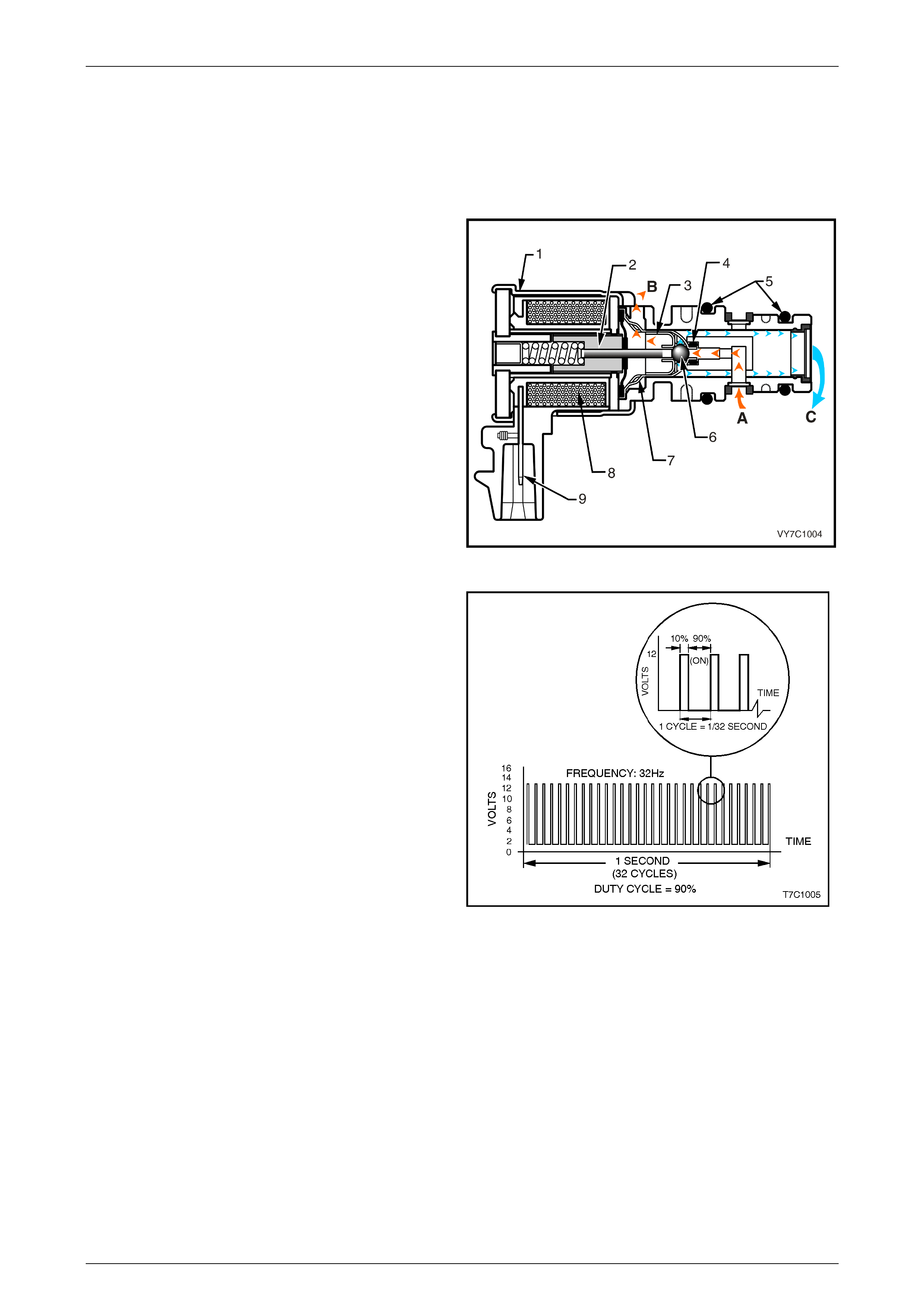
Legend:
1 Housing
2 Armature
3 Exhaust Seat
4 Internal O-Ring
5 O-Rings
6 Metering Ball
7 Inlet Seat
8 Coil Assembly
9 Connector Terminal
A Actuator Feed Limit (AFL) Fluid
B Exhaust
C Converter Clutch Signal (CC SIGNAL) Fluid Figure 7D1 – 2
Shown is an example of the TCC PWM solenoid, operating
with a 90% negative duty cycle at a constant operating
frequency of 32 Hz (cycles per second). The frequency
means that the solenoid is pulsed (energised) with current
from the PCM 32 times per second. The 90% negative duty
cycle means that during each of these 32 cycles the
solenoid is energised (ON) and 0 volts is measured on the
low (negative) sid e of the circu it, 90% of the time.
At road speeds below approximately 13 km/h, the negative
duty cycle will be 0%, which means that no current will flow
through the TCC PWM solenoid, deactivating it. When in
this condition, spring force will move the plunger (refer
Figure 7D1-2), seating the metering ball and blocking the
filtered Actuator Feed Limit (AFL) fluid from entering the
Converter Clutch Signal (CC SIGNAL) circuit. This action
opens the Converter Clutch Signal fluid circuit to exhaust
through the solenoid.
Above road speeds of approximately 13 km/h, the TCC
PWM solenoid will be operating at about a 90% duty cycle.
This action will cause the metering ball to close off the path
to exhaust, most of the time and allow AFL fluid to flow past
the metering ball and into the CC SIGNAL circuit, in
readiness for the apply of the torque converter clutch.
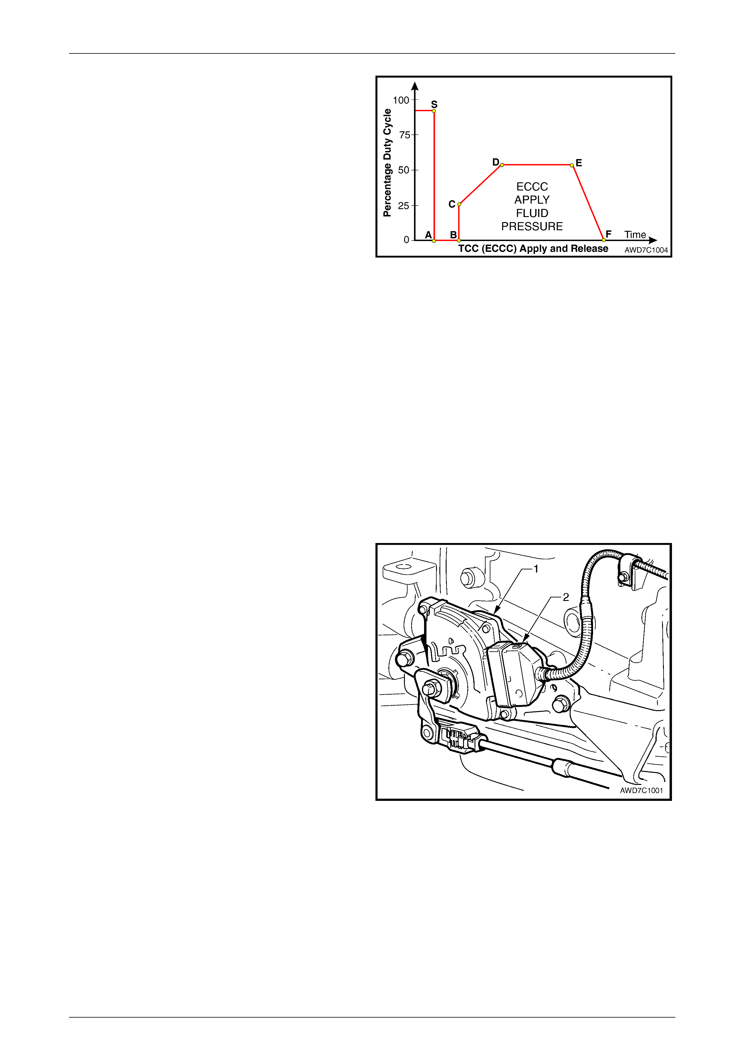
Figure 7D1 – 3
When the PCM signals TCC apply, the TCC PW M solenoid operates with a variable, negative duty cycle, ranging from
90% to 0%, with an operating frequency of 32 Hz. This allows the PCM to control the current flow through the solenoid
coil according to the duty cycle it sets. This has the effect of creating a variable magnetic field, that magnetises the
solenoid core, attracting the metering ball to seat against spring force. A high percentage duty cycle keeps the metering
ball will be seated more ofte n, thereby creat ing higher TCC signal fluid pr es sure s.
TCC PWM Solenoid Valve Operation
The TCC PWM solenoid valve is one of two electronic control components in the TCC apply and release system. The
other component is the TCC solenoid valve, which enables TCC 'ON' and 'OFF'. The other components are all hydraulic
control or regulating valves.
Hydra-Matic 4L65-E Automatic Transm issi on – General Information Page 7D1-4
Page 7D1-4
In first gear, at approximately 13 km/h, the PCM operates
the TCC PWM solenoid valve at approximately 90% duty
cycle (point 'S'). This duty cycle is maintained until a TCC
apply is commanded. When vehicle operating conditions are
appropriate to apply the TCC, the PCM immediately
decreases the duty cycle to 0% ('A') then, after a time (point
'B') increases it to approximately 25% ('C').
The PCM then ramps the duty cycle up to approximately
50% to achieve regulated apply pressure ('D'). With the
ECCC system, the pressure plate does not fully lock to the
torque converter, instead a consistent slip of approximately
20 rpm is regulated.
The rate at which the PCM increases the duty cycle controls
the TCC apply. Similarly, the PCM also ramps down the
TCC solenoid duty cycle to control TCC release ('E' to 'F'). Figure 7D1 – 4
Under some high torque or high vehicle speeds, the converter clutch is fully locked. For example, with the MY 2004 AWD
Crew Cab, the Full Lock position occurs at 121 km/h and Full Lock Release at 114 km/h.
NOTE
Duty cycles quoted are an example only. The
actual duty cycles will vary, both with vehicle
application and vehicle operating conditions.
Transmission Shift Points
With the MY 2004 AW D Crew Cab vehicle configuration, the shift points have also been modified from those published
for MY 2003 VY and V2 Series vehicle and are provided in Section 7C3 Mechanical/Hydraulic Diagnosis in the MY 2004
AWD Wagon Service Information.
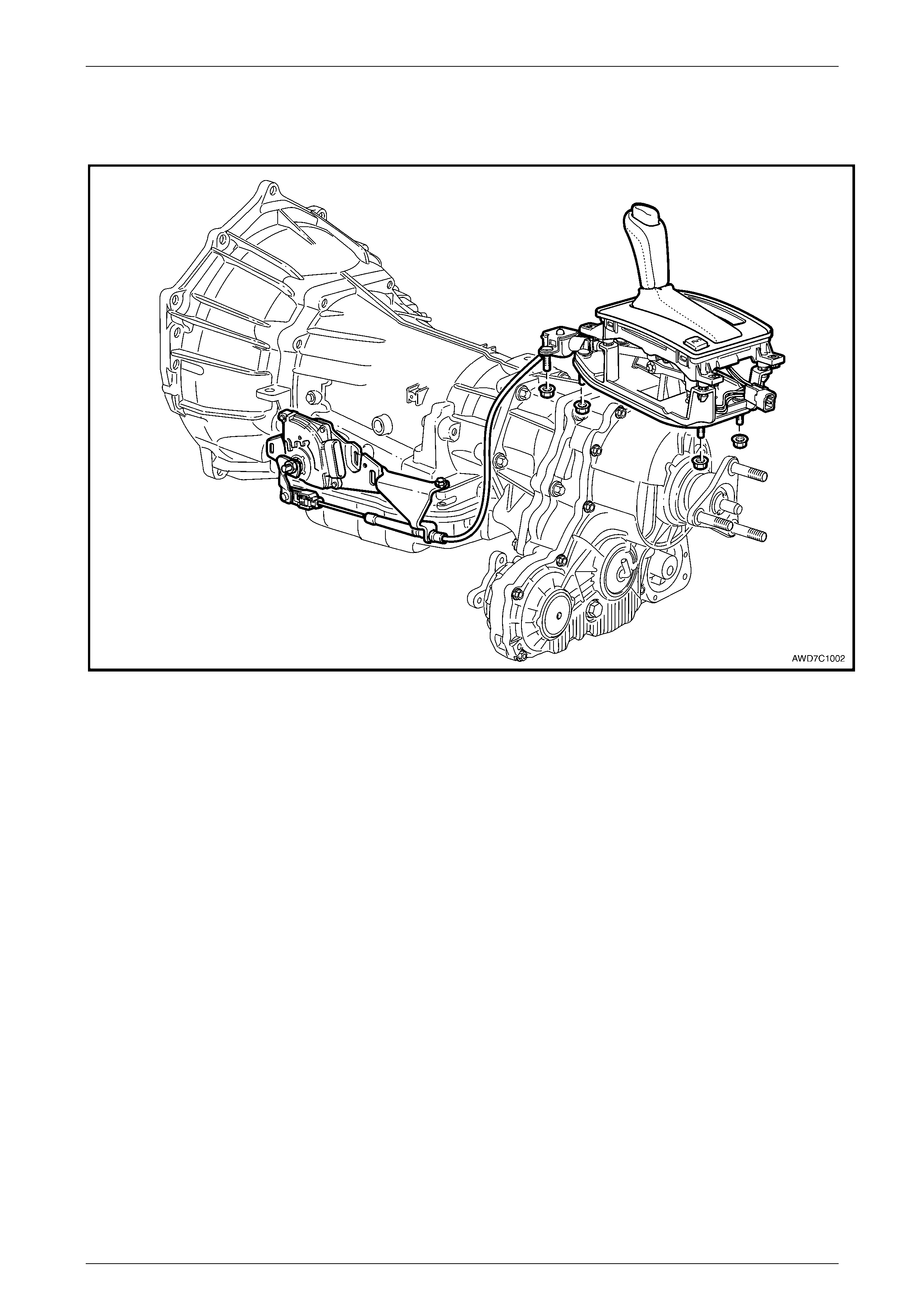
Neutral Safety and Back-Up (NSBU) Lamp Sw itch
The Neutral Safety and Back-up Lamp Switch (1) has been
changed, with a new supplier for this component. This has
also resulted in a single, positive lock wiring harness
connector (2) being used.
As a further security measure a Connector Protection
Assurance (CPA) (not shown), is also used to prevent the
lock from becoming dislodged.
Figure 7D1 – 5
Hydra-Matic 4L65-E Automatic Transm issi on – General Information Page 7D1-5
Page 7D1-5
Shift Selector Mechanism
The transmission selector mechanism has been changed from linkage to cable operation, together with a re-designed
shift selector mechanism, refer to Figure 7D1-6.
Figure 7D1 – 6