
SECTION 12B - LIGHTING SYSTEM
CAUTION:
This vehicle will be equipped with a Supplemental Restraint System (SRS). A SRS will consist of either
seat belt pre-tensioners and a driver's air bag, seat belt pre-tensioners and a driver's and front
passenger's air b ags o r seat b elt p re-t ension ers, driv er’s an d f ron t p asseng er’s air bag and left and righ t
hand side air bags. Refer to SAFETY PRECAUTIONS, Section 12M Supplemental Restraint System
before performing any se rvice operation on, or around any S RS components, the steering mechanism or
wiring. Failure to follow the SAFETY PRECAUTIONS could result in SRS deployment, resulting in
possible personal injury or unnecessary SRS system repairs.
1. GENERAL INFORMATION
NOTE: This Section only covers the lighting system fitted to vehicles during production.
With the addition of an interior lights out feature, the lighting system used on VT Series Models with Production
Options (P.O.) 9C1 and A8V is as detailed in Section 12B LIGHTING SYSTEM of the VT Series I Service
Information and Section 12B LIGHTING SYSTEM of the VT Series II Service Information.
When the interior lights out feature is ac tivated, the inter ior lights , inc luding the glove compar tment light, will not turn
on when either any of the doors or the glove compartment are opened.
On earlier VT Series Models, the interior lights out feature was activated by switching the dome lamp s witch to the
off position. This system consisted of an additional relay, an in-line fuse, and a diode and link incorporated in the
dome lamps printed circuit board.
As a running change, the inter ior lights out feature was c hanged. On the latter system, the f eature is activated by a
switch, located on the instrument panel facia. The later system does not require the additional components; i.e.
relay, in-line fuse, or the diode and link in the printed circuit board.

2. SERVICE OPERATIONS
All Service Oper ations f or the lighting system are as detailed in Sect ion 12B LIGHT ING SYST EM of the VT Series
I Service Information and Section 12B LIGHTING SYSTEM of the VT Series II Service Information, noting the
following:
For information relating to fuses, relays and wiring harnesses associated with the interior lights out feature, refer to
Section 12N FUSES, RELAYS AND WIRING HARNESSES of this Service Information CD.

2.1 INTERIOR LIGHTS OUT SWITCH (EARLY TYPE SYSTEM)
Activation of the interior lights out feature on earlier VT Series Models is via the dome lamp on / off switch,
therefore, there are no separate service procedures for this component
Refer to Section 12B LIGHTING SYSTEM of the VT Series I Service Information for information regarding the
dome and front reading lamp assembly.
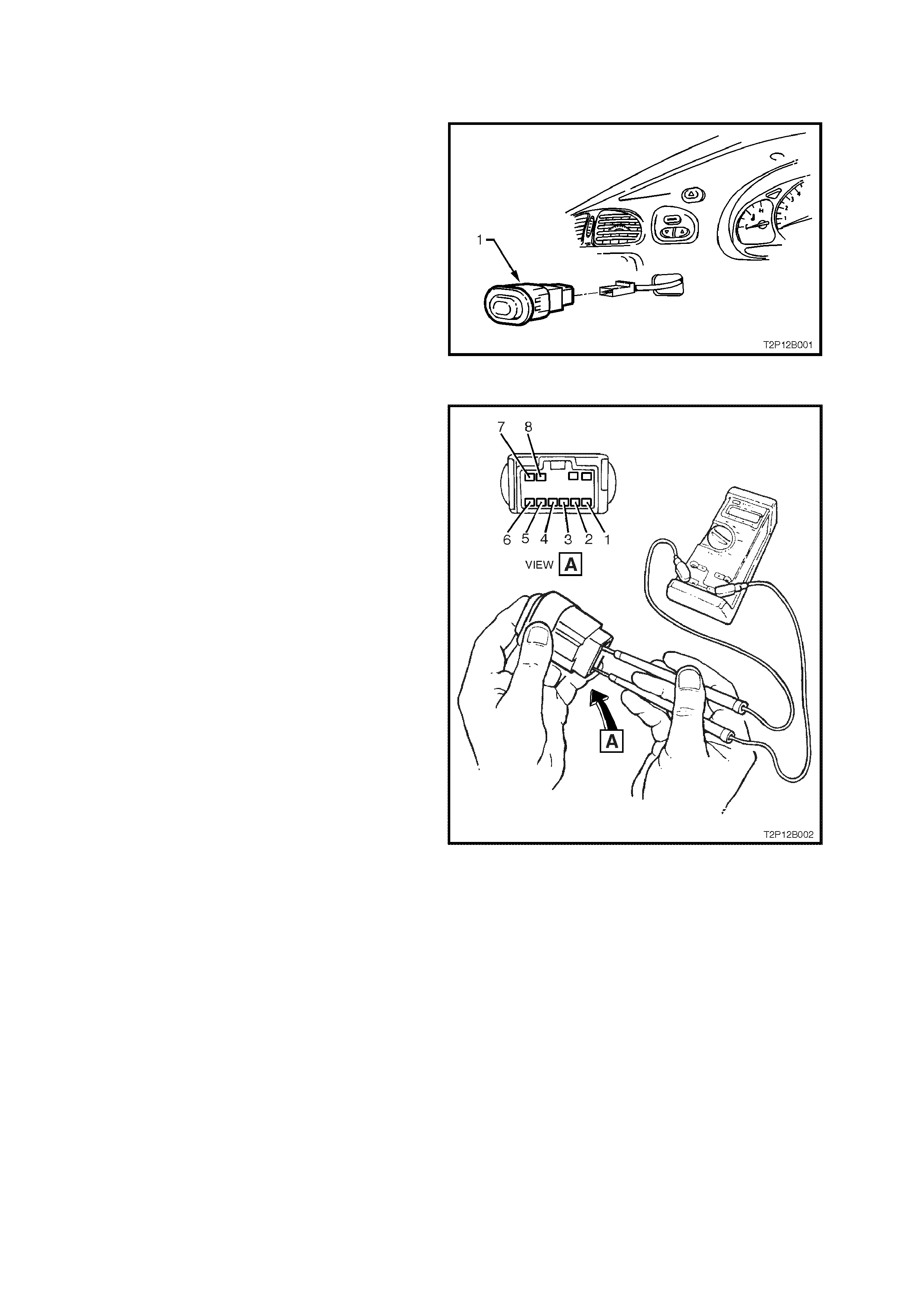
2.1 INTERIOR LIGHTS OUT SWITCH (LATTER TYPE SYSTEM)
REMOVE
1. Disconnect battery earth lead.
2. Remove instrument panel facia far enough to
gain access to switch connectors attached to
the instrument panel facia (interior lights out
switch (1), headlamp, fog lamp, trip computer
and hazard switch). Refer to Section 1A3
INSTRUMENT PANEL AND CONSOLE of the
VT Series I Service Information.
3. Disconnect wiring harness connectors from
instrument panel facia and remove facia.
4. From behind the instrument panel facia,
squeeze together the interior lights out switch
to instrument panel facia tangs and push
switch out from tangs. Figure 12B-1
TEST
1. Using an Ohmmeter connected to the interior
lights out switch, check for continuity between
the following terminals with the switch in the
OFF position (switch in – interior lights
functioning normally).
• Ter. 1 and Ter. 2
• Ter. 1 and Ter. 5
• Ter. 2 and Ter. 5
If the ohmmeter indicates an open circuit,
replace the switch.
2. With the switch in the ON position ( switch out –
interior lights isolated), check for continuity
between the following terminals.
• Ter. 1 and Ter. 2
• Ter. 1 and Ter. 5
• Ter. 2 and Ter. 5
If the ohmmeter indicates continuity, replace
the switch.
Figure 12B-2
REINSTALL
Reinstallation of the interior lights out switch is the
reverse of the removal procedure.