
SECTION 12N - FUSES, RELAYS AND
WIRING HARNESSES
CAUTION:
This vehicle will be equipped with a Supplemental Restraint System (SRS). A SRS will consist of either
seat belt pre-tensioners and a driver's air bag, seat belt pre-tensioners and a driver's and front
passenger's air b ags or seat belt pre-ten sioners, driv er’s and front passen ger’s air bag and left and right
hand side air bags. Refer to SAFETY PRECAUTIONS, Section 12M, Supplemental Restraint System
before performing any service operation on, or around any SRS components, the steering mechanism or
wiring. Failure to follow the SAFETY PRECAUTIONS could result in SRS deployment, resulting in
possible personal injury or unnecessary SRS system repairs.
CAUTION:
Whenever any component that forms part of the ABS or ABS/ETC (if fitted), is disturbed during Service
Operations, it is vital that the complete ABS or ABS/ETC system is checked, using the procedure as
detailed in 4. DIAGNOSIS, ABS or ABS/ETC FUNCT ION CHECK, in Section 12L ABS & ABS/ETC, in either
VT Series I Service Information or VT Series II Service Information.
1. GENERAL INFORMATION
Fuses, c ircuit breaker s, relays and wiring harness es for VT Series Models with Production Options (P.O .) 9C1 and
A8V are as described in Section 12N FUSES, RELAYS & WIRING HARNESSES of the VT Series I Service
Information or Section 12N FUSES, RELAYS & WIRING HARNESSES of the VT Series II Service Information,
with three notible additions:
1. All vehicles are fitted with an interior lights out feature. When this feature is activated, the interior lights,
including the glove compartment light, will not turn on when either any of the doors or the glove compartment
are opened.
On earlier VT Series Models, the interior lights out feature was activated by switching the dome lam p switch to
the off position. This system consisted of an additional relay, an in-line fuse, and a diode and link incorporated
in the dome lamps printed circuit board.
As a running change (March 5 1999, from TAG L434943), the interior lights out feature was changed. On the
later system, this f eature is activated by a switch, located on the instru ment panel f acia. This later system does
not require the additional components; i.e. relay, in-line fuse, or the diode and link in the printed circuit board.
2. The auxiliary power harness battery positive and negative connections are fastened to the battery terminal
clamp studs.
3. An auxiliary power harness is installed in the engine compartment. This harness is designed to allow for easy
and safe installation of accessory components, such as roof bar equipment, police exterior lights, radios etc.
NOTE: A 25 mm service hole is drilled through the LH side of the cockpit module to allow accessory wiring
harnesses to be routed from the auxiliary power harness in the engine compartment through to the interior of the
vehicle. Refer to Section 1E COCKPIT MODULE of this Service Information CD for the exact location of the
service hole.
1.1 FUSES AND CIRCUIT BREAKERS
All fuses and circuit breakers for VT Series Models with P.O. 9C1 and A8V are as described in Section 12N,
FUSES, RELAYS AND WIRING HARNESSES of the VT Series I Service Information and Section 12N, FUSES,
RELAYS AND WIRING HARNESSES of the VT Series II Service Information, noting the following:
FUSES
Interior lights override
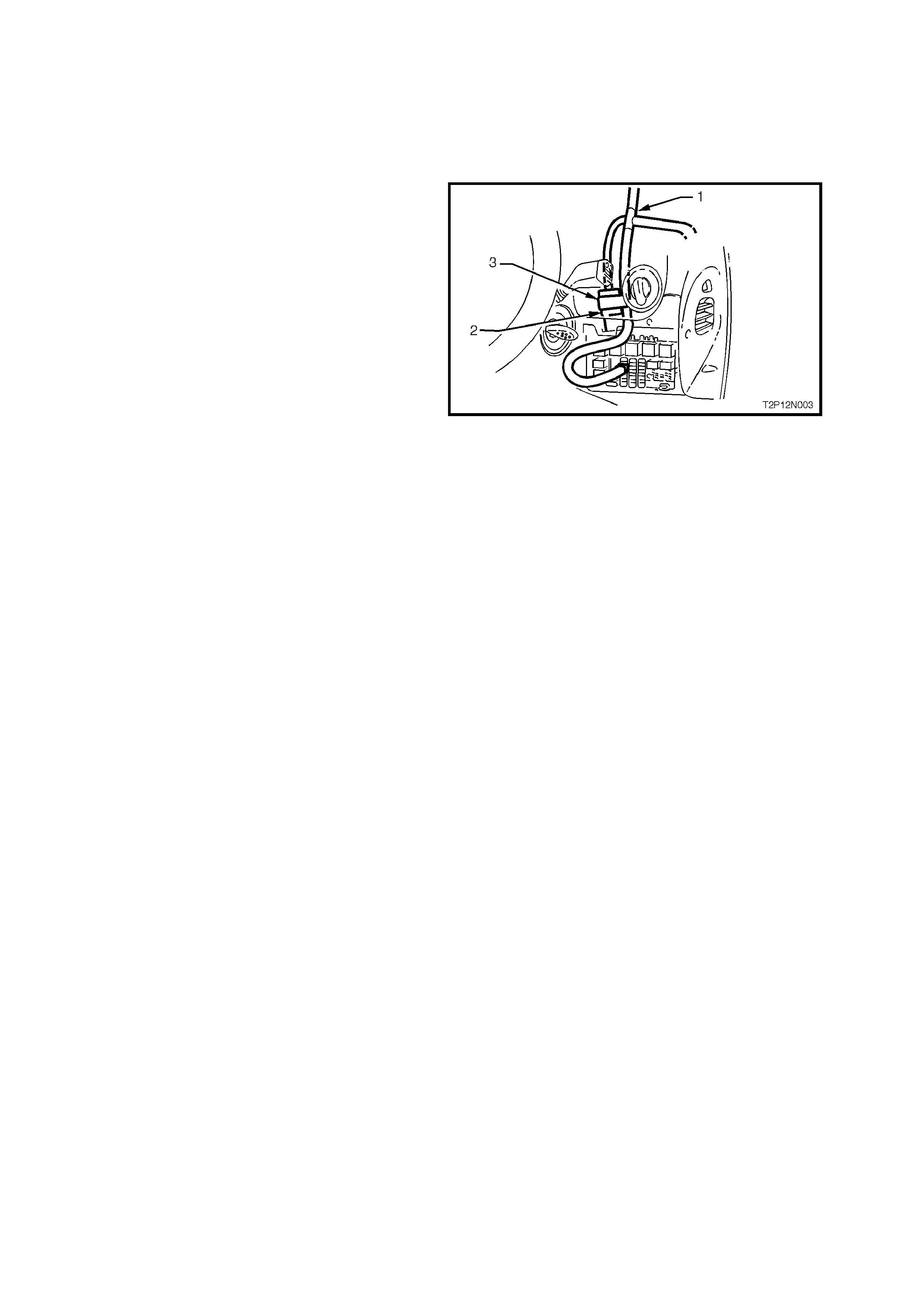
When the interior lights override harness is
installed into a VT Series Model, the interior
illumination fuse, fuse F6 in the passenger
compartment fuse and relay panel has to be
removed. Because of this, a 10 amp in-line fuse is
installed; the interior illumination / lights override
fuse. T his f use is taped back onto the interior lights
override wiring harness and is located slightly
above the passenger compartment fuse and relay
panel, refer Fig. 12N-.
1. Interior lights override wiring harness
2. In-line fuse connector – taped back to
harness
3. Interior illumination / lights override 10 amp
in-line fuse
Figure 12N-1
Auxiliary power harness
There are three auxiliary power harnesses available for VT Series Models; one for VT Series I Models and two for
VT Series II Models (one for V6 and one for GEN III V8). All harnesses are located in the engine compartment.
NOTE: Early VT Series II Models with a V6 engine may have the VT Series I auxiliary wiring harness fitted. The
introduction date of the Series II harness, for a vehicle with a V6 engine is approximately September 1999.
VT Series II harness es can be identif ied by a sticker adhered to the underside of the f use box cover, identifying the
fuse assignment. The VT Series I auxiliary power harness dose not have a sticker.
Electrical circuits of accessories connected to the auxiliary power harness are protected against damage, which
may occur due to s hort circ uits or over loads in the wiring system. Pr otection is provided by various rated blade type
fuses located in a fuse panel next to the LH strut tower. The cur rent rating of the fus e, in amps, is indic ated on top
of the fuse assembly, above the element.
Fig. 12N-2 illustrates the fuse panel assembly for the VT Series I auxiliary power harness, its location, and the
nominated fuse rating for the particular circuit it protects.
Fig. 12N-3 illustra tes the auxiliar y power harness fuse panel ass embly for VT Series II Models, its loc ation, and the
nominated fuse rating for the particular circuit it protects.
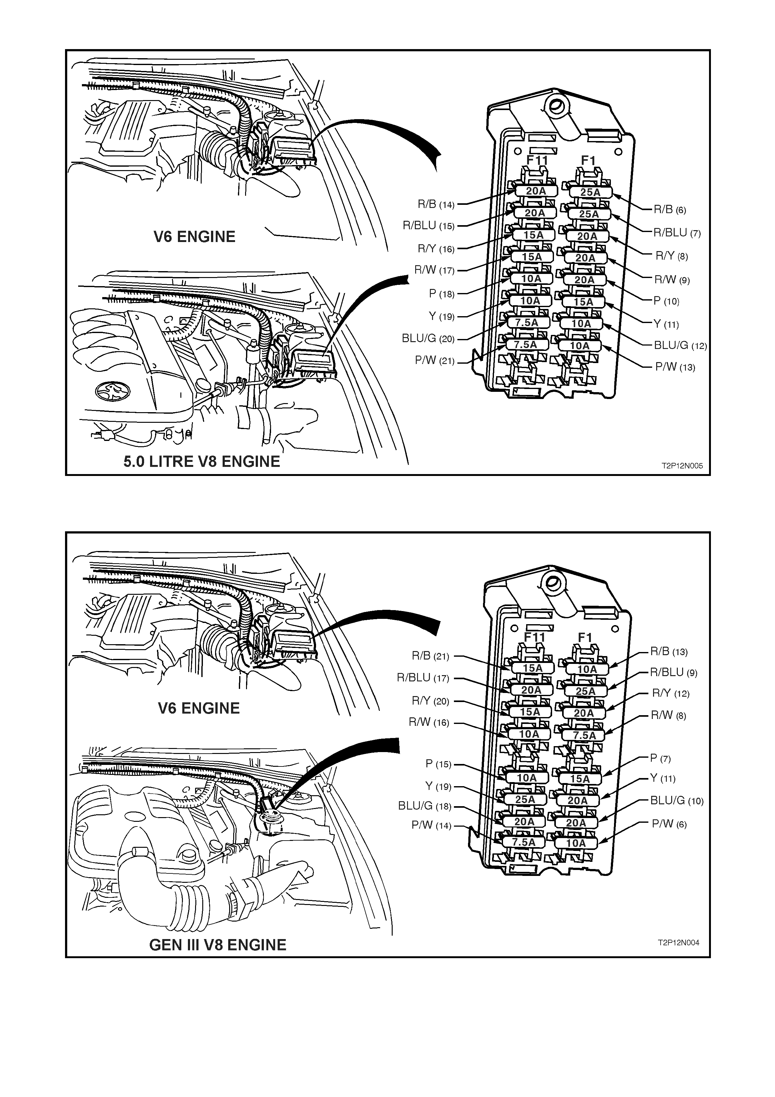
Figure 12N-2 VT SERIES I AUXILIARY POWER HARNESS
Figure 12N-3 VT SERIES II AUXILIARY POWER HARNESS
(Refer to NOTE on previous page for V6 auxiliary power harness introduction)
FUSIBLE LINKS
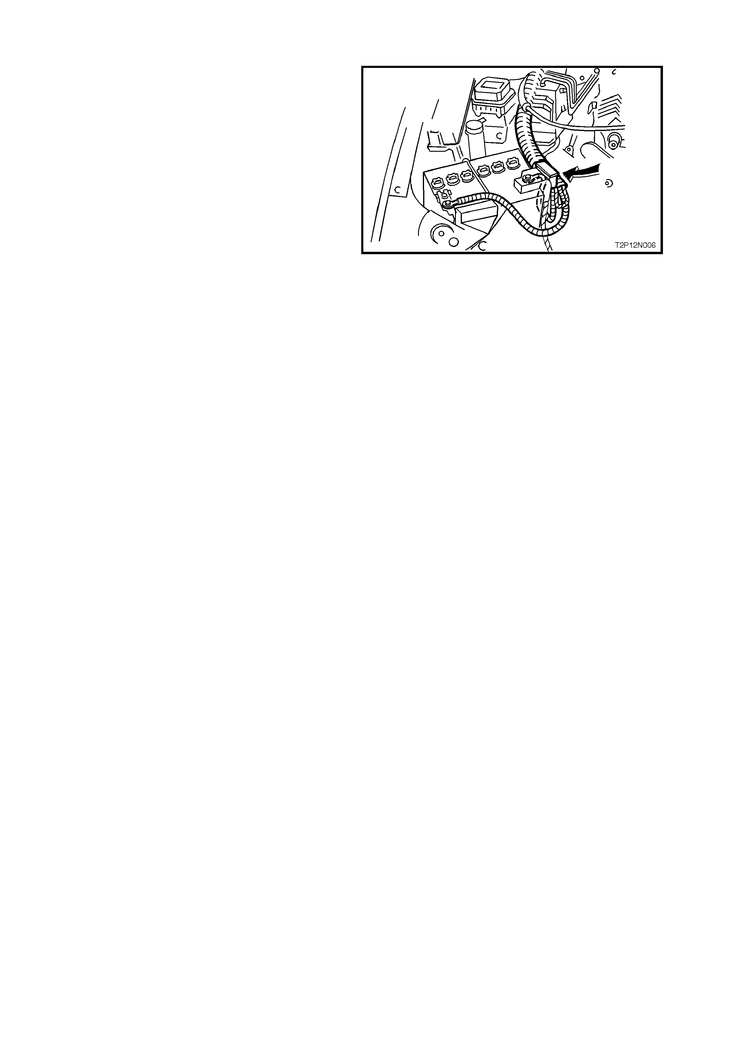
To protect the vehicle against the possibility of
short circuit damage within the auxiliary power
harness, two 50 amp fusible links have been
incorporated into the harness. Fig. 12N-4 shows
the location of the two fusible links.
The two fusible links can be removed from their
socket by simply pulling them out.
Figure 12N-4
1.2 RELAYS
All relays for VT Series Models with P.O. 9C1 and
A8V carryover from that desc ribed in Sectio n 12N,
FUSES, RELAYS AND WIRING HARNESSES, of
the VT Series II Service Information, except as
follows:
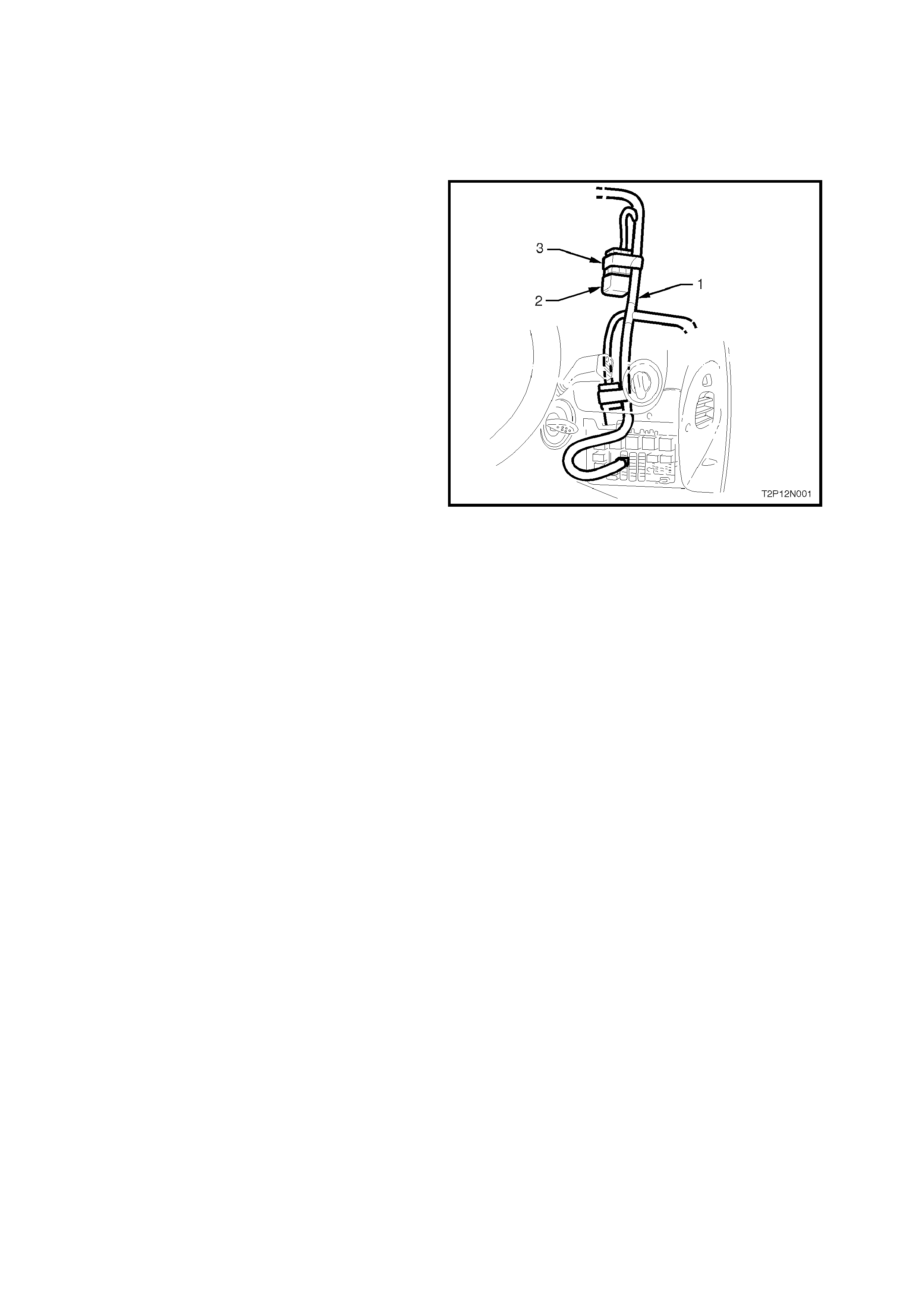
On earlier VT Series Models, with the dome lamp
switch operated interior lights out system, there is
an additional relay installed; the interior lights
override relay. This relay is taped back onto the
interior lights over ride wiring harness and is loc ated
above the headlamp switch, refer Fig. 12N-5.
1. Interior lights override wiring harness
2. Relay connector – taped back to harness
3. Interior lights override relay
Figure 12N-5


3. WIRING INSTALLATION DIAGRAMS
The following figures in this Section illustrate the unique wiring installation diagrams specific for VT Series Models
with P.O. 9C1 and A8V. All remaining wiring installation diagrams are as detailed in Sect ion 12N, FU SES, RELAYS
AND WIRING HARNESSES, of the VT Series I Service Information and Section 12N, FUSES, RELAYS AND
WIRING HARNESSES, of the VT Series II Service Information.
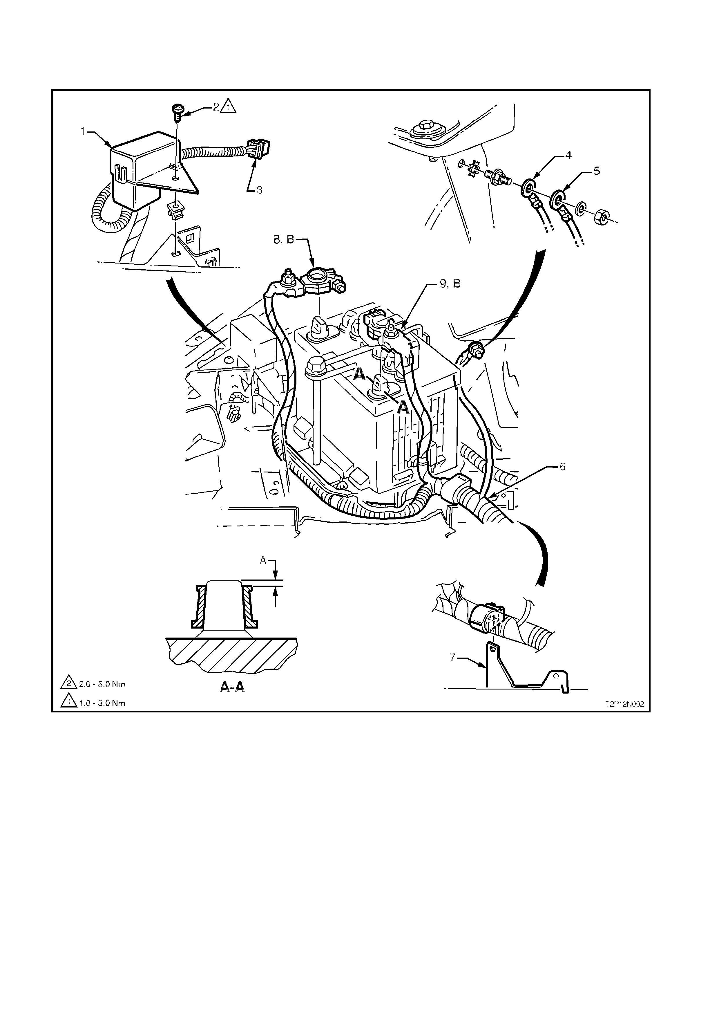
BATTERY HARNESS
All Models
Legend
1. Battery Harness Fusible link Housing
2. Screw
3. Battery Harness Engine Condenser Fan
Connector
4. Main Wiring Harness Body Earth Terminal
5. Battery Harness Body Earth Terminal
6. Battery Harness
7. Battery Harness to Side Rail Bracket
8. Battery Terminal Clamp and Auxiliary Power
Harness Negative Connection
9. Battery Terminal Clamp Retainer and Auxiliary
Power Harness Positive Connection
A-A Section through battery posts – 2 places
A. Battery cable terminal must be fitted below top of
battery post.
B. The auxiliary power harness positive and negative
connections are fastened to the battery terminal
clamp studs.
NOTE: For continuation of the battery harness, refer to
Section 12N FUSES, RELAYS & WIRING HARNESSES,
(V6 and 5.0 litre V8) or (GEN III V8).
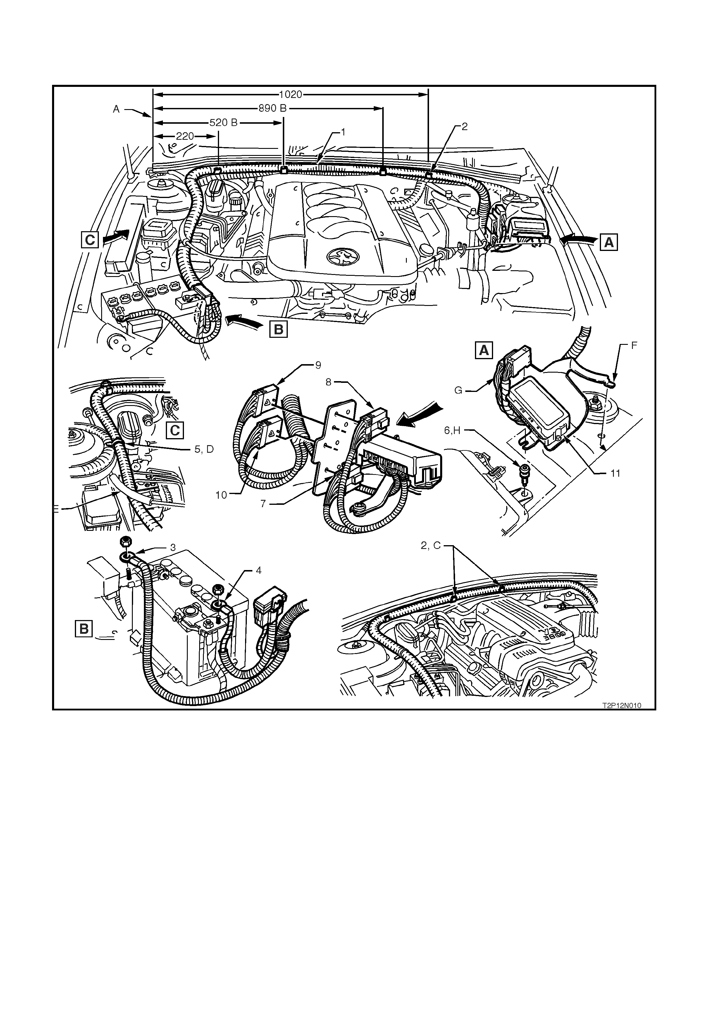
AUXILIARY POWER HARNESS – 1
All Models excluding Gen III V8 Engine (P.O. LS1)
NOTE: Fuse assignment was rearranged in September 1999 (approximately) for vehicles with a V6 engine. The
later type fuse box can be identified by an identification sticker (advising fuse assignment) under the fuse box cover.
Legend
1. Auxiliary Power Harness
2. Auxiliary Power Harness Retaining Clips (4
places)
3. Auxiliary Power Harness Battery Negative
Connector
4. Auxiliary Power Harness Battery Positive
Connector
5. Tie Strap
6. Retaining Screw
7. Auxiliary Power Harness Roof Bar Equipment and
Exterior Lights Powe r Connector – Grey
Connector
8. Auxiliary Power Harness Interior Equipment
Power Connector – W h ite Connector
9. Auxiliary Power Harness Earth Connector 1
10. Auxiliary Power Harness Earth Connector 2
11. Auxiliary Power Harness Fuse Panel
A. Retaining clips fit over the flange under the hood seal,
measurements (in mm) from edge of dash upper panel.
B. V8 retaining clips only, refer C for V6 location
C. V6 to have both central retaining clips aligned with the
V6 engine cover.
D. The auxiliary power harness is restrained to the main
wiring harness at the RH strut tower.
E. V8 engine only; ensure the auxiliary power harness is
routed under the throttle cable as shown.
F. The harness support bracket locates into the hole on
top of the LH strut tower.
G. Ensure wiring is flexed towards rear of engine to
maintain clearance from air cleaner box connector.
H. Harness support bracket is secured by the air cleaner
box retaining screw.
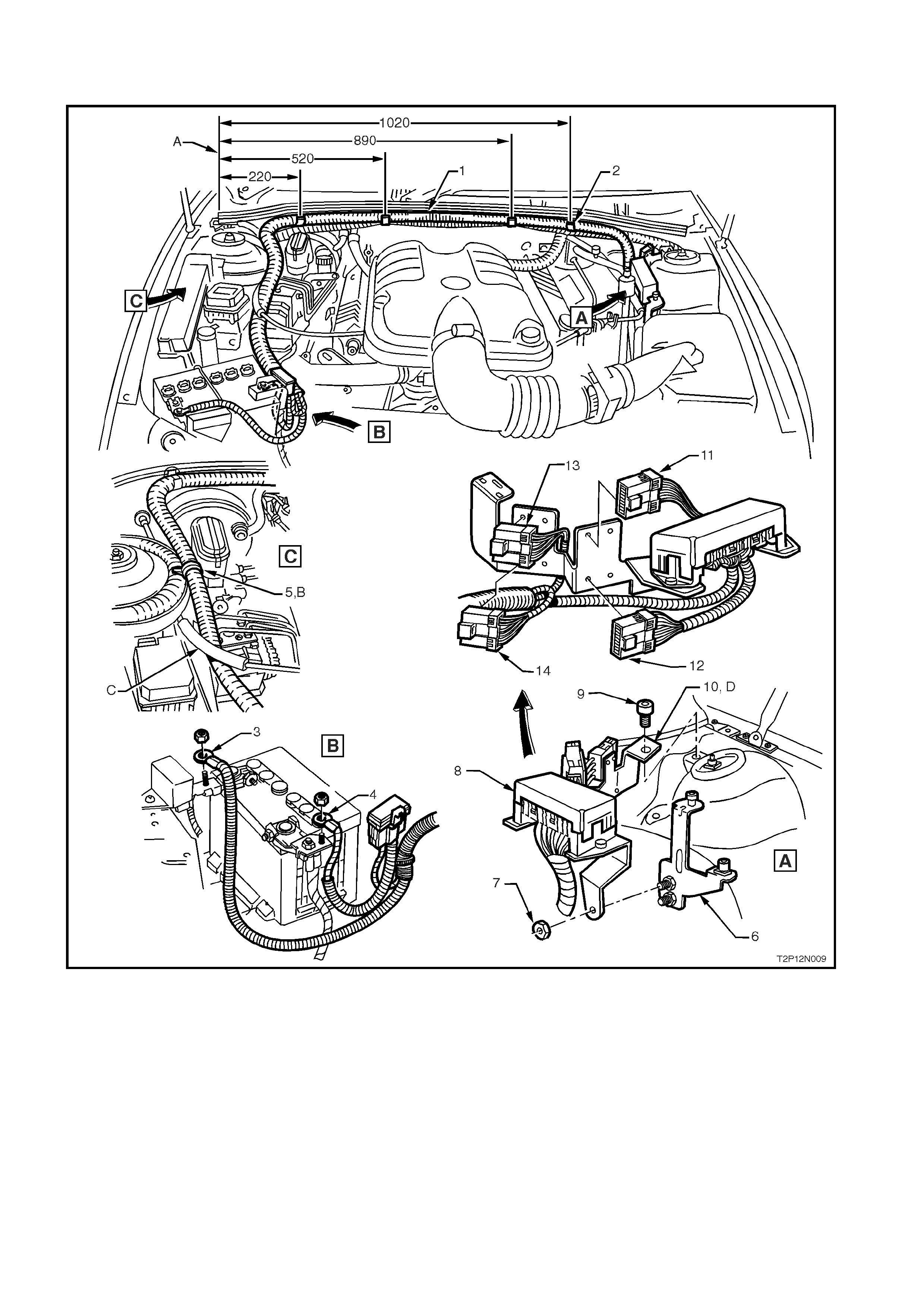
AUXILIARY POWER HARNESS – 2
All Models with Gen III V8 Engine
Legend
1. Auxiliary Power Harness
2. Auxiliary Power Harness Retaining Clips (4
places)
3. Auxiliary Power Harness Battery Negative
Connector
4. Auxiliary Power Harness Battery Positive
Connector
5. Tie Strap
6. Retaining Bracket
7. Nut
8. Auxiliary Power Harness Fuse Panel
9. Screw
10. Auxiliary Power Harness Support Bracket
11. Auxiliary Power Harness Connector (Grey)
12. Auxiliary Power Harness Connector (White)
13. Auxiliary Power Harness Earth Connector 1
14. Auxiliary Power Harness Earth Connector 2
A. Retaining clips fit over the flange under the hood seal,
measurements (in mm) from edge of dash upper panel.
B. The auxiliary power harness is restrained to the main
wiring harness at the RH strut tower.
C. Ensure the auxiliary power harness is routed under the
throttle cable as shown.
D. The harness support bracket attaches to the theft
deterrent horn bracket, behind the LH strut tower
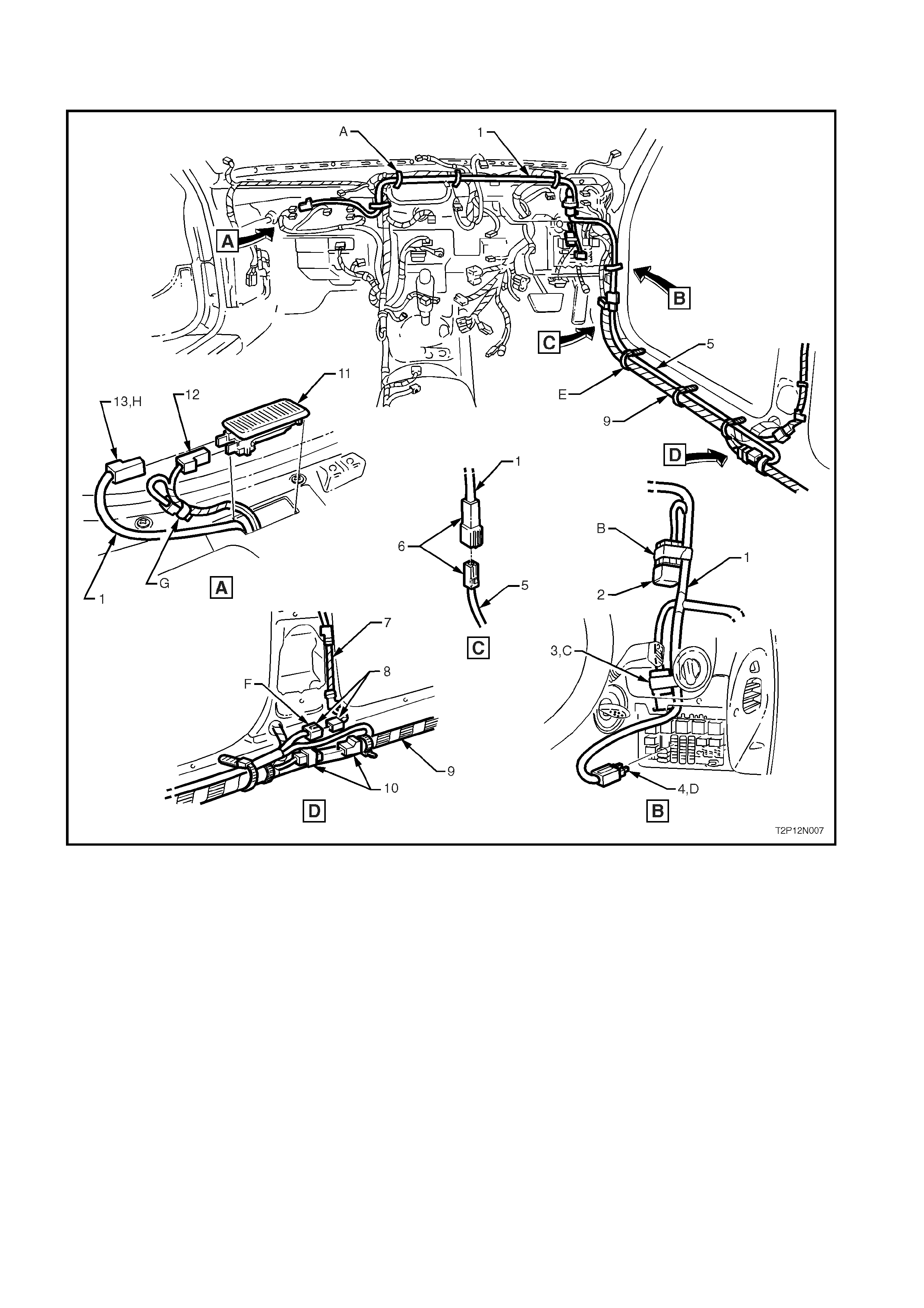
INTERIOR LIGHTS OVERRIDE HARNESS - 1
Earlier VT Models with Dome Light Switch Activation
Legend
1. Interior Lights Override Wiring Harness
2. Relay – Interior Lights Wiring Override
3. In-line Fuse – Interior Lights Wiring Override
4. Interior Lights Override Wiring Harness Fuse
Panel Connector
5. Dome Lamp Control Patch Wiring Harness
6. Interior Lights Override Wiring Harness to Dome
Lamp Patch Wiring Harness Connection
7. Roof Wiring Harness
8. Dome Lamp Patch Wiring Harness to Roof Wiring
Harness Connection
9. Body Wiring Harness
10. Body Wiring Harness to Dome Lamp Patch Wiring
Harness Connection
11. Glove Compartment Lamp (shown upside down
for clarity)
12. Glove Compartment Lamp Earth Connection
13. Interior Lights Override Wiring Harness Glove
Compartment Lamp Connection
A. Interior lights override wiring harness is secured to the
main wiring harness with tie straps as shown.
B. Interior lights override relay taped back to the interior
lights override wiring harness as shown.
C. Interior lights override in-line fuse is taped back to the
interior lights override wiring harness as shown.
D. Fuse F6 is removed from its cavity in the passenger
compartment relay and fuse panel and the interior
lights override wiring harness is installed.
E. Dome lamp control patch wiring harness is secured to
the body wiring harness as shown.
F. With the existing connection between the body wiring
harness and the roof wiring harness disconnected, the
dome lamp patch wiring harness is installed to
complete the circuit, as shown.
G. Existing glove compartment power feed connection is
disconnected and taped back to harness.
H. The interior lights override wiring harness glove
compartment lamp connection is connected as shown.
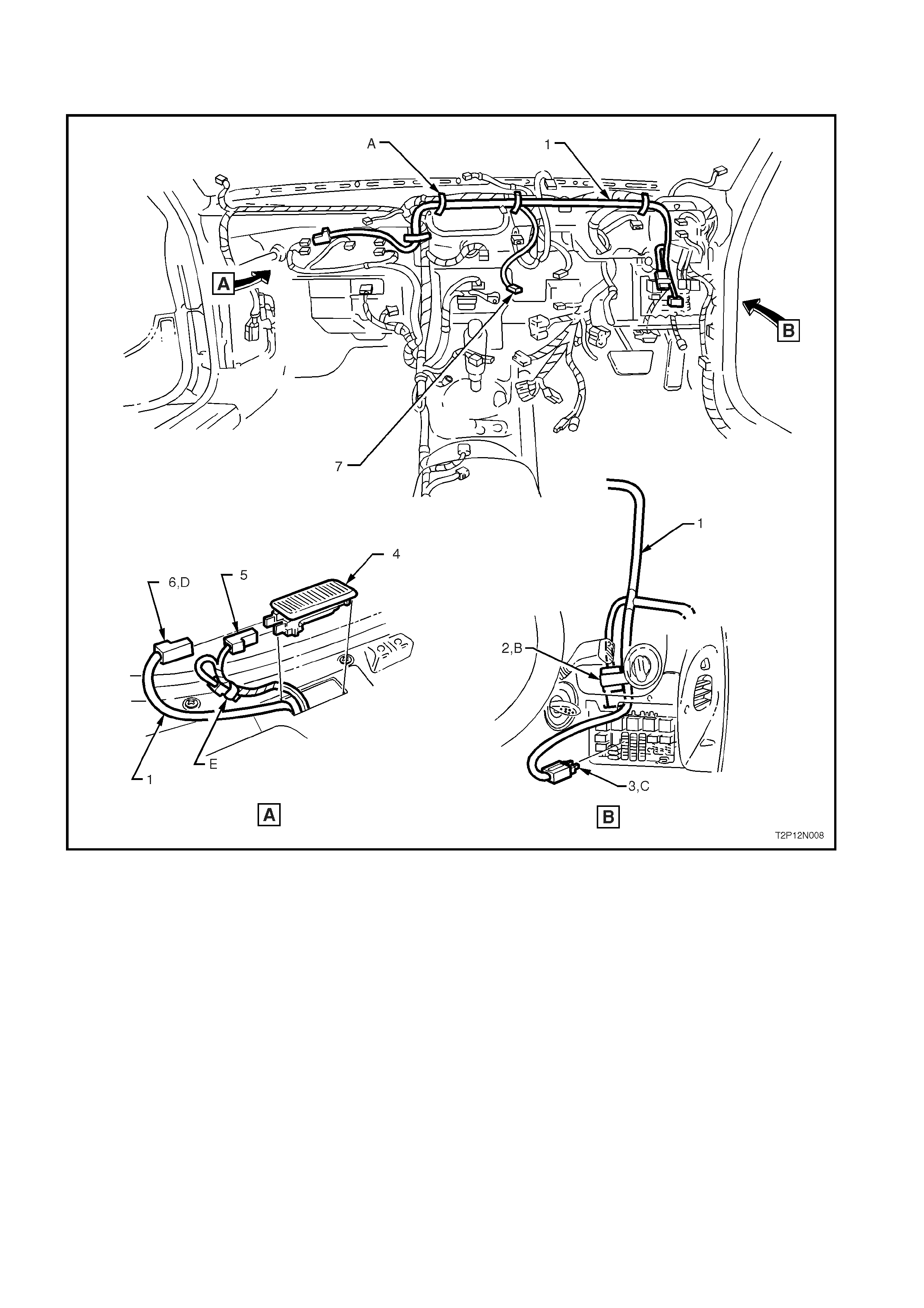
INTERIOR LIGHTS OVERRIDE HARNESS - 2
Later VT Models with Activation Switch in Instrument Panel Facia
Legend
1. Interior Lights Override Wiring Harness
2. In-line Fuse – Interior Lights Wiring Override
3. Interior Lights Override Wiring Harness Fuse
Panel Connector
4. Glove Compartment Lamp (shown upside
down for clarity)
5. Glove Compartment Lamp Earth Connection
6. Interior Lights Override Wiring Harness Glove
Compartment Lamp Connection
7. Interior Lights Override Switch Connector
A. Interior lights override wiring harness is secured to
the main wiring harness with tie straps as shown.
B. Interior lights override in-line fuse is taped back to
the interior lights override wiring harness as shown.
C. Fuse F6 is removed from its cavity in the passenger
compartment relay and fuse panel and the interior
lights override wiring harness is installed.
D. The interior lights override wiring harness glove
compartment lamp connection is connected as
shown.
E. Existing glove compartment power feed
connection is disconnected and taped back to
harness