SECTION 1E - COCKPIT MODULE
CAUTION:
This vehicle will be equipped with a Supplemental Restraint System (SRS). A SRS will consist of either
seat belt pre-tensioners and a driver's air bag, seat belt pre-tensioners and a driver's and front
passenger's air b ags o r seat b elt p re-t ension ers, driv er’s an d f ron t p asseng er’s air bag and left and righ t
hand side air bags. Refer to SAFETY PRECAUTIONS, Section 12M Supplemental Restraint System
before performing any se rvice operation on, or around any S RS components, the steering mechanism or
wiring. Failure to follow the SAFETY PRECAUTIONS could result in SRS deployment, resulting in
possible personal injury or unnecessary SRS system repairs.
1. GENERAL INFORMATION
All information relating to the cockpit module on VT Series Models with Production Options 9C1 and A8V carries
over from what has been published in Section 1E COCKPIT MODULE of the VT Series II Service Information,
noting the following:
If removal of the cockpit module assembly becomes necessary, ensure the following components are removed /
disconnected:
• Ensuring all acc essories harnes ses are m arked prior to r emoval, disconnec t and rem ove any accessor y wiring
harnesses that is routed through the cockpit module wiring harness service hole.
• Disconnect and remove the auxiliary wiring harness in the engine compartment, ensuring all accessories
connected to this harness are marked for correct reconnection. Refer to Section 12N FUSES, RELAYS AND
WIRING HARNESSES of the Police Options Servic e Supplement for inform ation relating to the auxiliary wiring
harness.
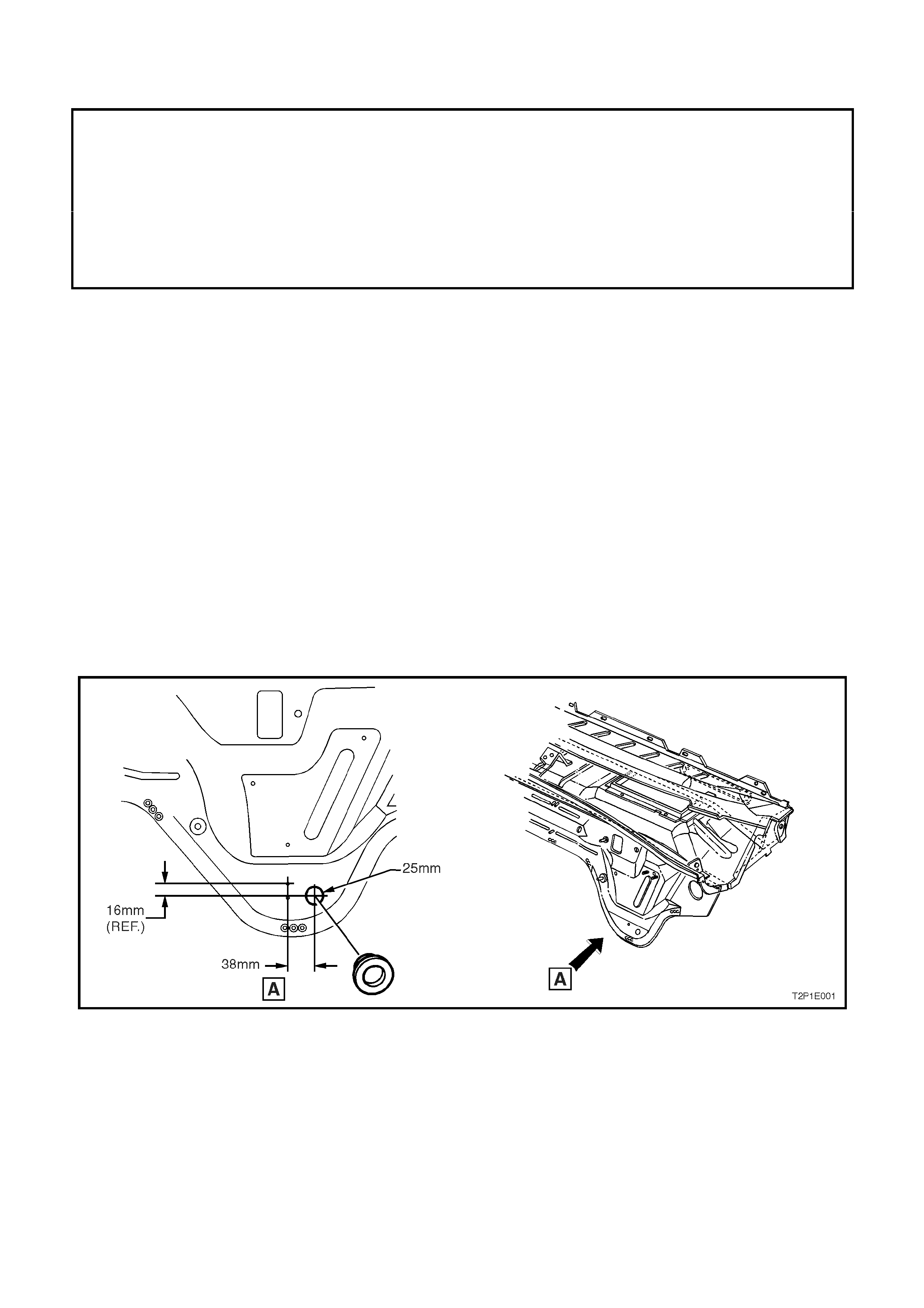
Whenever a cockpit m odule is to be replac ed, bef or e the new one is ins talled into the vehic le, a 25mm ser vice hole,
for auxiliary wiring harnesses , is to be drilled and if neces sary, a rubber grom m et (par t num ber 92138070) ins talled.
Refer to Fig. 1E-1 for the details on where to drill the 25mm service hole.
Figure 1E1-1