SECTION 4B - FINAL DRIVE AND DRIVE SHAFTS
CAUTION:
This v ehicle will be equipped w ith a Supplemental Restraint System (SRS). An SRS w ill consist of either
seat belt pre-tensioners and a driver's side air bag, or seat belt pre-tensioners and a driver's and front
passenger's side air bags. Refer to CAUTIONS, Section 12M, of the VT Series I Service Information
before performing any service operation on or around any SRS components, the steering mechanism or
wiring. Failure to follow the CAUTIONS could result in SRS deployment, resulting in possible personal
injury or unnecessary SRS system repairs.
CAUTION:
Whenever any component that forms part of the ABS or ABS/ETC (if fitted), is disturbed during Service
Operations, it is vital that the complete ABS or ABS/ETC system is checked, using the procedure as
detailed in 4. DIAGNOSIS, ABS or ABS/ETC FUNCTION CHECK, in Section 12L ABS & ABS/ETC, of the
VT Series I Service Information.
1. GENERAL INFORMATION
Independent rear suspension is fitted as standard equipment on all VT Series vehicles and all are f itted with a final
drive asse mbly, Production Option (P.O.) G U4. Additionally, P.O. G80, Limited Slip Dif f er ential ( LSD), (als o r ef er re d
to as Spin Resistant Differential - SRD) comes standard on all Models with P.O. 9C1 and A8V.
The type of diff erential f itted to the final drive as sem bly can be identified by referring to either the identif ication label
attached to the RHS of the c arr ier hous ing or f rom the lubr ication tag under the f iller plug on the rear cover . Ref er to
1.1 FINAL DRIVE ASSEMBLY IDENTIFICATION in this Section for additional information.
All information relating to the final drive and drive shafts fitted to VT Series vehicles with P.O. 9C1 and A8V, is as
detailed in Section 4B FINAL DRIVE AND DRIVE SHAFTS, of the VT Series I Service Information, noting the
following:
Due to omitted specifications for the 3.46:1 final drive assembly, specifications for this final drive assembly have
been published in full in this Section.
1.1 FINAL DRIVE ASSEMBLY IDENTIFICATION
The following chart provides a summary of the type of final drive assembly fitted to VT Series Models with
Production Options 9C1 and A8V.
Engine Body style Transmission Broadcast
code Ratio Type
Sedan All
Automatic EE 3.08:1 LSD
3.8 Lt V6 Wagon Manual
5.0 Lt V8 All All
All Automatic
EH 3.07:1 LSD
5.7 Lt
GEN III V8 Sedan Manual EP 3.46:1 LSD
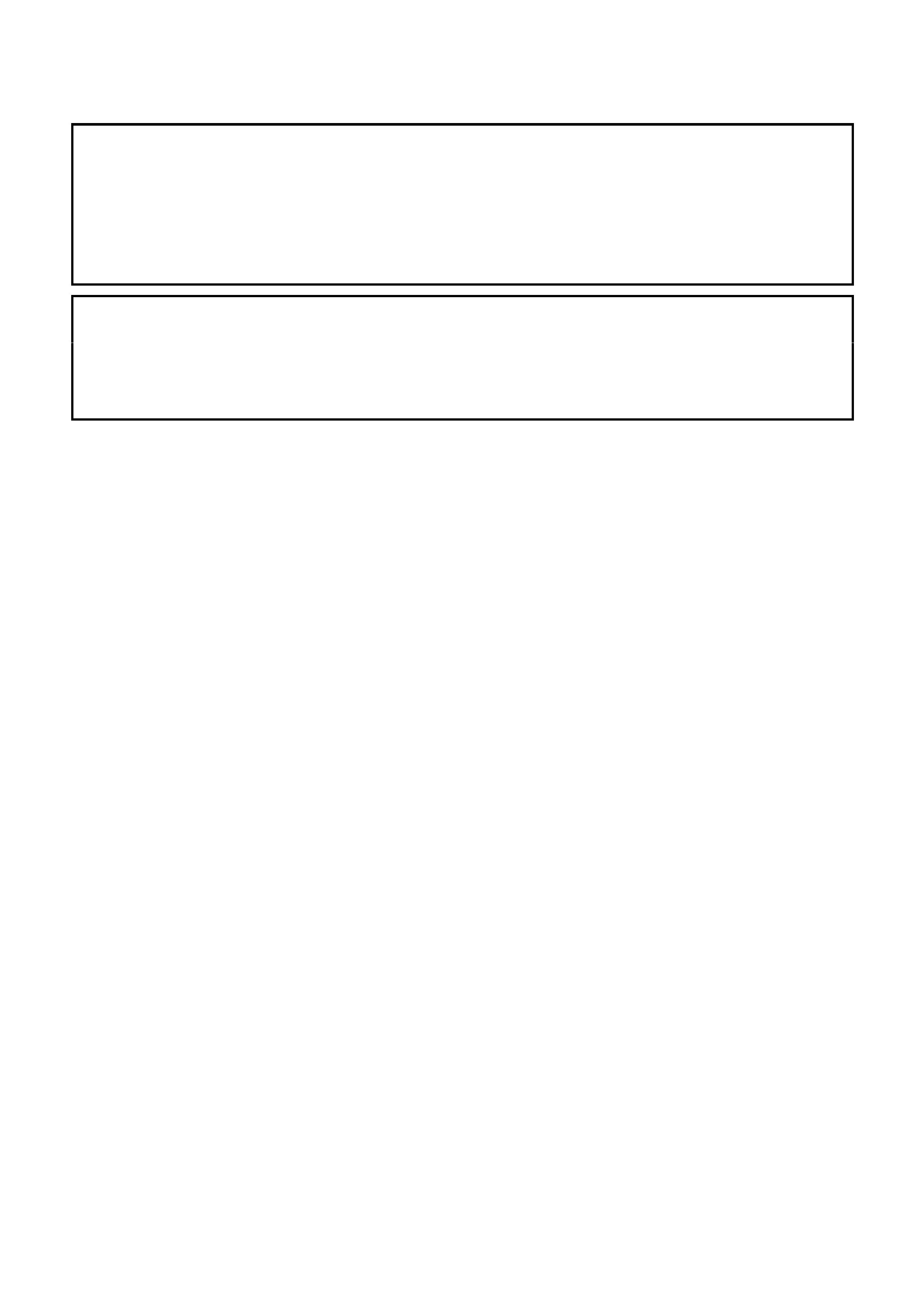
To identify the type of differential fitted to the final
drive assembly, refer to either the identification
label attached to the RHS of the carrier housing
(refer Fig. 4B-1) or from the lubrication tag under
the filler plug on the rear cover (refer Fig. 4B-2).
The identification tag carries the Holden part
number for the final drive assem bly, final drive ratio
and the serial number of the assembly.
The code number and bar code is used for
production identification of the final drive assembly.
Figure 4B-1
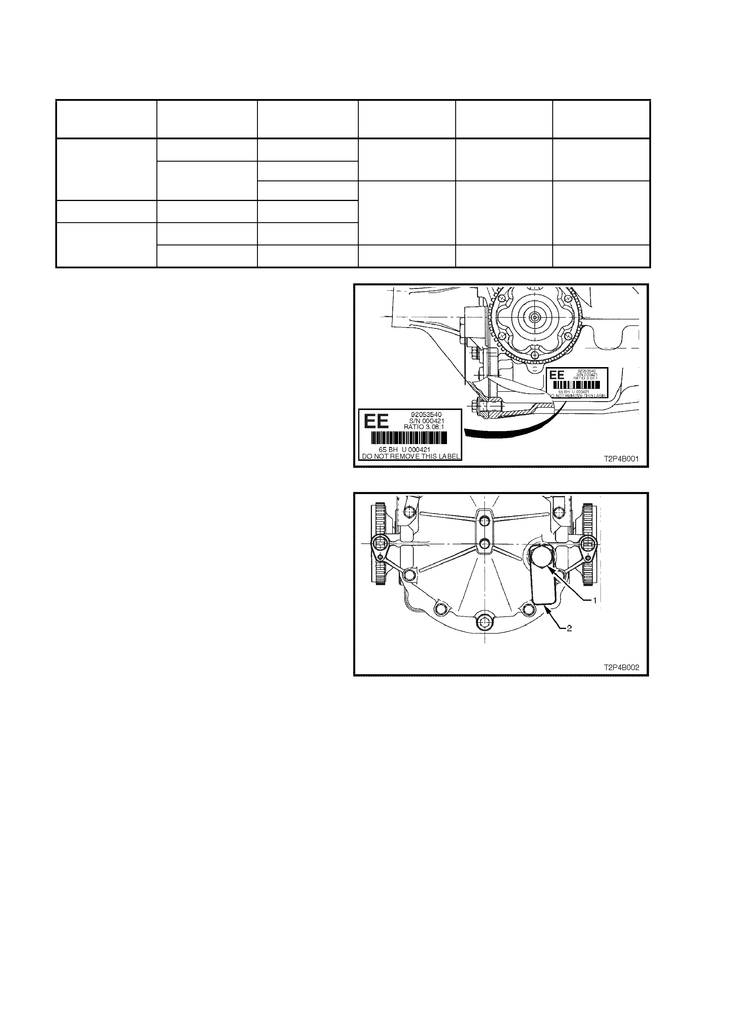
When fitted, the information on the lubrication tag
(2) under the filler plug (1), (refer Fig. 4B-2), will be;
• With V6 and LSD;
“SPIN RESISTANT DIFF. USE APPROVED
LUBRICANT ONLY”
• With V8 and LSD;
“LSD - HIGH PERFORMANCE. USE
APPROVED LUBRICANT ONLY”
Figure 4B-2

2. SPECIFICATIONS
NOTE: The following final drive specifications apply to vehicles with the GEN III V8 engine and 6 speed manual
transm iss ion only. Refer to Section 4B FINAL DRIVE AND DRIVE SHAFT S of the VT Series I Service Inf orm ation
for final drive specifications on other VT Series Models.
GENERAL
Rear Axle Assembly................................................................... BTRA - 80 Series
Axle Type ................................................................................... Independent Housing
STANDARD AND LSD AXLES
Gear Type .................................................................................. Hypoid
Gear Ratio.................................................................................. 3.46:1. (See I.D. tag attached to the carrier)
No. of Teeth: Ring Gear................................................. 45
Drive Pinion Gear..................................... 13
Ring Gear Diameter 203mm
LUBRICANT
Capacity..................................................................................... 1.6 litres
Type: ........................................................................................ Synthetic Hypoid Gear Oil to Holden Specification
HN2040.
DIFFERENTIAL GEARS
Type Straight Bevel
No. Teeth: Pinion Gears............................................. 10
Side Gears ............................................... 15
FINAL DRIVE PINION GEAR BEARINGS
Bearing Type.............................................................................. Adjustable Taper Roller
Bearing Adjustment.................................................................... Collapsible Spacer
Bearing Pre-Load Dummy pinion - New bearings ................. 1.4 - 2.0 Nm
Dummy pinion - Used bearings................ 0.7 - 1.0 Nm
New with oil seal....................................... 1.4 - 2.4 Nm
New without oil seal.................................. 1.4 - 2.0 Nm
Used with oil seal ..................................... 0.7 - 1.2 Nm
Used without oil seal ................................ 0.7 - 1.2 Nm
DIFFERENTIAL CARRIER SIDE BEARINGS
Type Adjustable Taper Roller
Adjustment................................................................................. Screw adjusters on each side of the carrier.
Bearing Pre-Load New Bearings........................................... 15 - 35 N Torque measured at the differential case,
Used Bearings.......................................... 8 - 18 N without inner axle shafts or final drive pinion
installed.
RUN-OUT SPECIFICATIONS
Trunnion Assembly Hub............................................................. 0.06 mm Total Indicated Run-out
Case Assembly (without ring gear attached).............................. 0.05 mm (maximum)
Ring Gear Rear Face (assembled onto case assembly) ........... 0.13 mm (maximum)
BACKLASH SPECIFICATIONS
Ring Gear to Drive Pinion...................................................... 0.10 - 0.18 mm (at the tightest point)
LSD TORQUE CHECK
Torque Check Specification................................................... 45 Nm (minimum)
ABS SENSOR
Air Gap (non-adjustable)....................................................... 0.4 - 1.5 mm
SEALANTS
Drive Shaft Dust Caps/Shield ..................................................... RTV 732 Sealant, to Holden Specification HN1373
Rear Cover to Carrier Housing................................................... Loctite 587 (‘Ultra Blue’) or equivalent, to Holden
Specification HN1973
As Required ............................................................................... Loctite 243 or equivalent, to Holden Specification HN1256,
Class 2, Type 1
LUBRICANTS
As Specified in Text.................................................................... Molybond HE50 or equivalent, to Holden Specification
HN1326
As Specified in Text.................................................................... Lithium Soap Based Grease to Holden Specification
HN1147