
SECTION 6D1-1 - CHARGING SYSTEM - V6 ENGINE
CAUTION:
This vehicle will be equipped with a Supplemental Restraint System (SRS). A SRS will consist of either
seat belt pre-tensioners and a driver's air bag, seat belt pre-tensioners and a driver's and front
passenger's air b ags o r seat b elt p re-t ension ers, driv er’s an d f ron t p asseng er’s air bag and left and righ t
hand side air bags. Refer to SAFETY PRECAUTIONS, Section 12M Supplemental Restraint System
before performing any se rvice operation on, or around any S RS components, the steering mechanism or
wiring. Failure to follow the SAFETY PRECAUTIONS could result in SRS deployment, resulting in
possible personal injury or unnecessary SRS system repairs.
1. GENERAL INFORMATION
VT Series Models with V6 engine and Production Option (P.O.) 9C1 built prior to May 20 1998 have the standard
100 amp Bosch generator fitted. For all information regarding this generator, refer to Section 6D1-1 CHARGING
SYSTEM – V6 ENGINE of the VT Series I Service Information.
VT Series Models with V6 engine and P.O. 9C1 built from May 20 1998 (Vehicle Tag No. L335798) have a
Mitsubishi 120 amp generator fitted. All information regarding this generator can be found in this Section.
The Mits ubishi 120 amp generator c an be identified by its exter nal appearance in that it does not have an ex ternal
cooling fan.
The generator is a 3-phase type, incorporating a rotor having six pole pairs fitted with two cooling fans, one on the
drive end and the other on the slip ring end. Rotor curr ent is conveyed to the rotor winding by a pair of s lip r ings and
carbon brushes via the voltage regulator. The r otor is supported by ball bearings in both the drive and slip ring end
housings. Surr ounding the rotor is a stator, which is of a three phas e star c onnected output winding constr uction on
a ring shaped lamination pack.
The output of the stator winding is rectified by six diodes which are contained within the slip ring end housing.
Excitation current is supplied to the rotor field coil via the voltage regulator, brushes and slip rings. The electronic
voltage regulator requires no adjustment in service.
The generator has four external connections; the ‘B+’ lead to the battery positive terminal, the ‘L’ lead to the
generator warning lamp (max. 2 watts), the ‘S’ lead for battery voltage sensing and an earth connection, refer to Fig.
6D1-1-1.
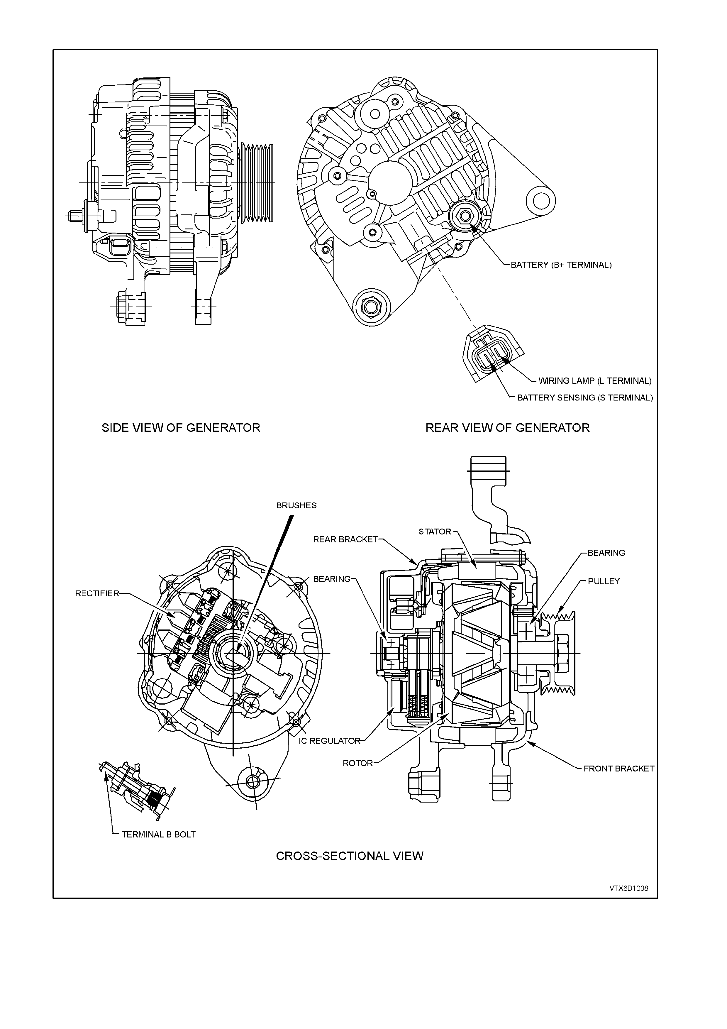
Figure 6D1-1-1
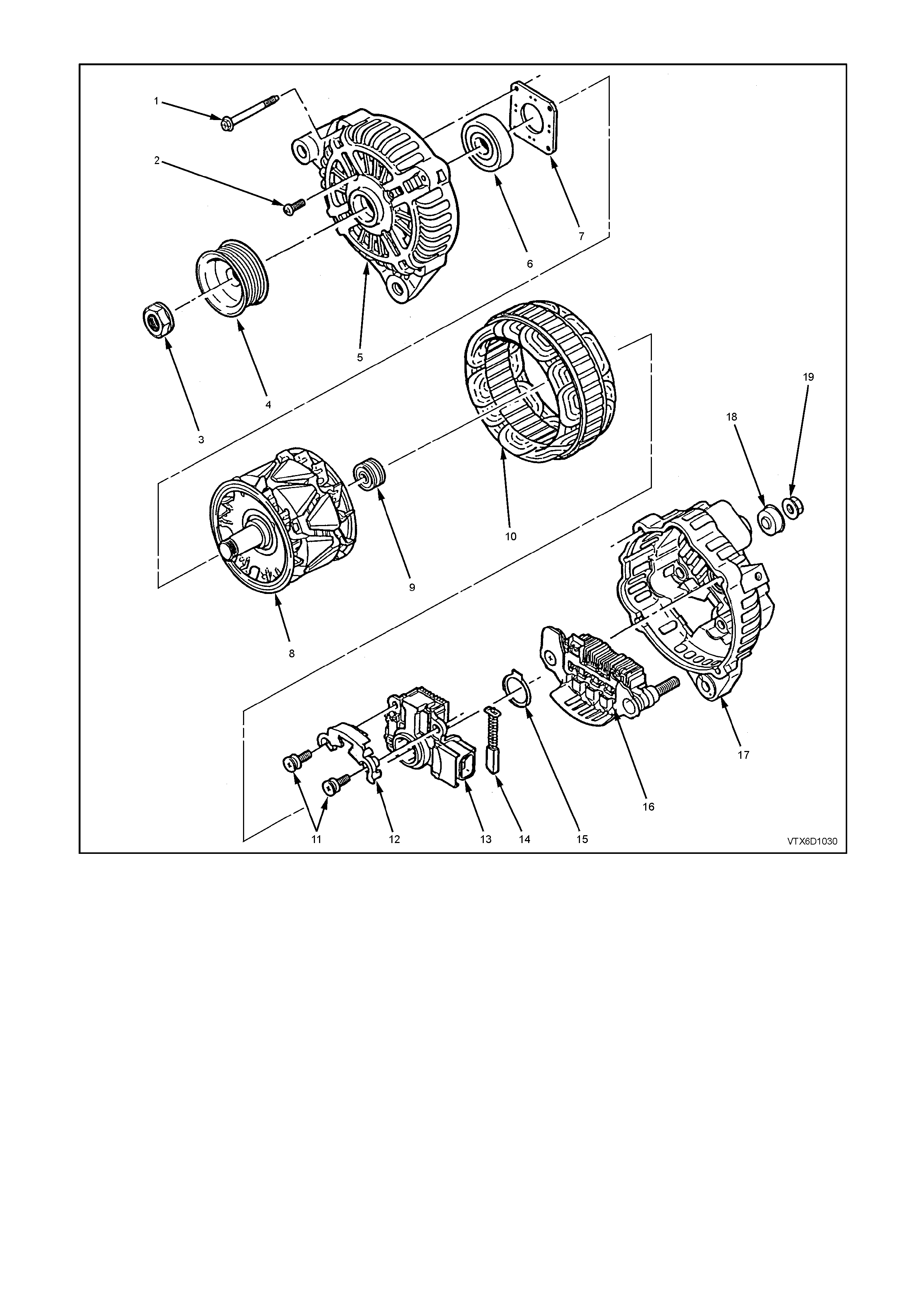
Figure 6D1-1-2
1 Through Bolt (4) 8 Rotor 15 Thrust Washer
2 Bearing Retaining Plate Screw (4) 9 Slip Ring End Bearing 16 Rectifier Assembly
3 Nut 10 Stator 17 Rear Bracket Assembly (Includes
4 Drive Pulley 11 Regulator and Brush Screws Items 11, 12, 13, 14, 15, 16, 17,
5 Front Bracket Assembly (Includes 12 Brush Retaining Plate 18 and 19)
Items 2, 5, 6 and 7) 13 Regulator 18 Terminal Cover Bush
6 Front Bearing 14 Brush 19 Nut
7 Bearing Retaining Plate

1.1 OPERATION
W ith the ignition switch turned to the on position, current is supplied via the warning lamp to the ‘L’ term inal of the
regulator. Current then flows from the ‘B+’ terminal through the rotor winding via the regulator brushes and the
collector emitter junction of the regulator switching transistor to earth, completing the circuit.
The c urrent in the rotor caus es a m agnetic field between adjacent poles to be created, this f ield is r otated and c uts
the windings of the stator at right angles inducing a voltage into them. As the speed is increased, this induced
voltage increases and results in current being rectified in the 3 phase diode bridge and supplied as DC to the B+
output and hence to the battery. When the voltage at the ‘B+’ terminal to the battery reaches approximately 14.2
volts, the ‘S’ term inal which is m onitoring this voltage, tur ns the regulator trans istor base c urrent off , rem oving rotor
current. T his results in a dec rease in output voltage to below the regulating voltage, turning the regulator tr ansistor
base current back on and the whole cycle is repeated very rapidly. An internal diode protects the transistor and the
regulator the against back voltage developed across the rotor winding when the regulator transistor turns off.
Should a situation arise where the m ain B+ c able or batter y sense wire (‘S’ ter m inal) bec om e dis connected or have
a high resistance, the regulator will limit the output voltage to a safe level (backup mode), approximately 1-3 volts
above the regulators normal setting.
When the ignition switch is turned on and the engine is not running, the current to the rotor is reduced by switching it
on and off at a 50% duty cycle (active stand by mode) , the frequenc y is approxim ately 4 kHz and may be audible at
times (this is normal). Once the engine is started, normal regulation commences.
Should the warning lamp fail, the generator will self excite by deriving a small current from the phase connection
allowing the voltage to build up to regulating level.
NOTE: No rotor winding current will flow when the engine is cranking.
The regulator incorporates internal diagnostics which will illuminate the warning lam p as a result of fault conditions
in the generator and/or external circuitry.
These conditions include:
1. An open circuit in the regulator battery sensing wire (‘S’ terminal).
2. An open circuit or excessive voltage drop in the B+ cable.
3. An open circuit in the generator phase connection.
4. Overcharging of the battery.
5. Regulator output stage short circuit.
6. Open circuit in the rotor winding.
The regulator com pares the voltage at the ‘B+’ term inal with the voltage sensed at the ‘S’ term inal connected to the
battery positive. If the voltage differential exceeds a predetermined threshold, the regulator will operate in backup
mode to limit the output voltage to a safe level. The warning lamp will remain illuminated as long as the fault
conditions prevail.
Sources of high resistance which will trigger the warning lamp are:
1. Poor contact in the wiring harness connectors.
2. Poor contact between the rectifier and the regulator.
3. High resistance in the fusible link assembly or battery terminals and cables.
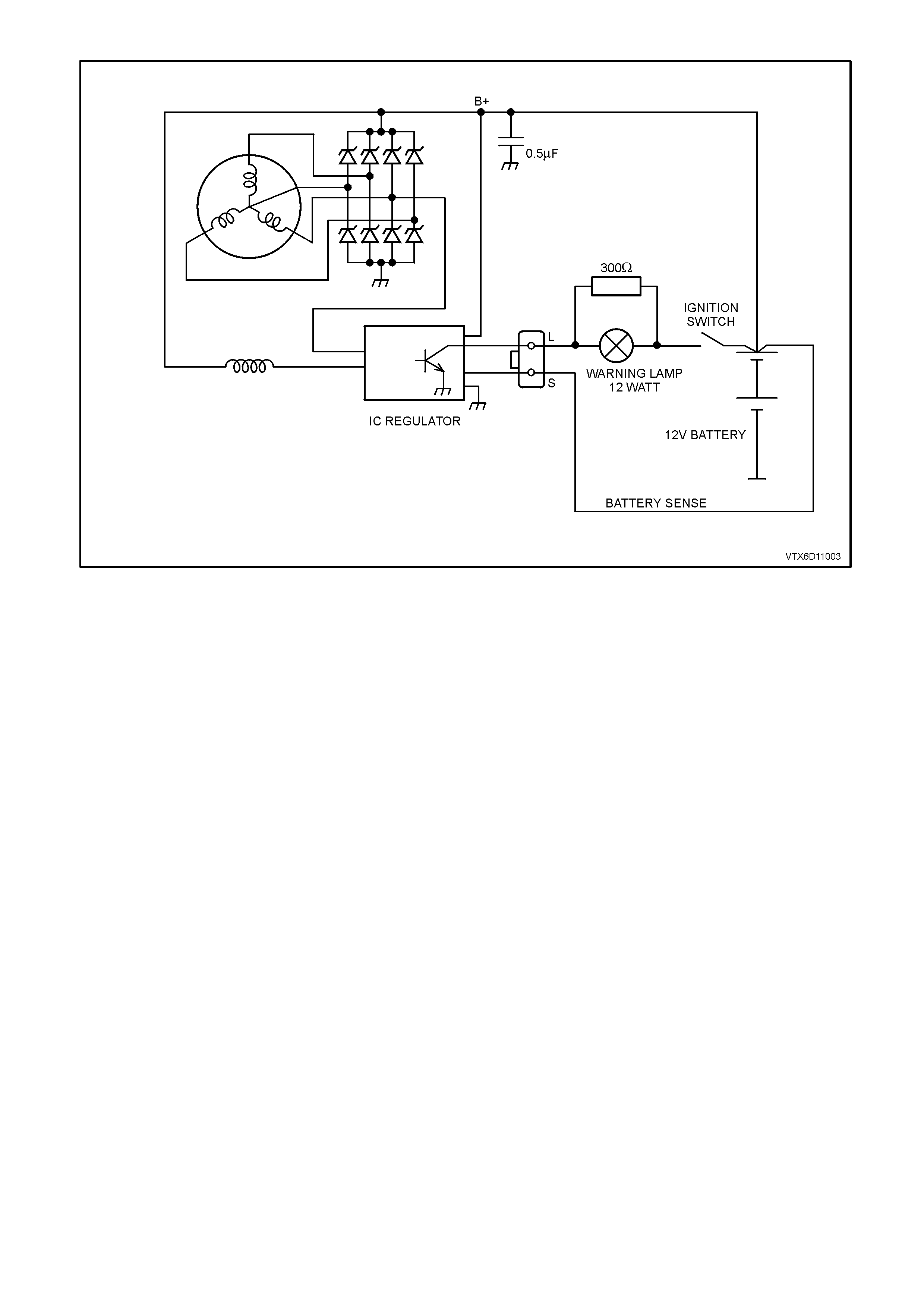
Figure 6D1-1-3

2. MI NOR SERVICE OPERATIONS
2.1 SAFETY PRECAUTIONS
Since the generator and voltage regulator are designed for use only on a negative earth system, the following
precautions must be observed. Failure to observe these precautions will result in serious damage to the generator.
1. When installing a battery, first fit positive ( +) cable to battery positive (+) term inal and then f it negative ( –) cable
to battery negative (–) terminal.
2. When a slave battery is utilised for starting purposes, ensure both batteries are connected in parallel, ie.
positive terminals together and negative terminals together.
3. When charging battery, disconnect both battery cables, thus isolating generator from battery and external
charging equipment.
4. The generator must not be operated on open circuit (this is without battery in circuit), and battery must not be
disconnected while the generator is running.
5. Do not attempt to polarise generator.
6. Always ensure that generator warning lamp glows when ignition switch is turned to the ON position.
NOTE: As this circuit is related to and assists in the excitation of the rotor field windings, do not proceed until any
faults in the generator warning lamp circ uit have been rectified. Ensur e the warning lam p wattage does not exceed
2 watts.
7. The ‘L’ terminal of generator should never be connected to battery or ignition circuit (12 volts), as this will
damage generator warning lamp circuit.
8. Some batter y powered tim ing lights c an produce high tr ansient voltages when connec ted or dis connected. Only
disconnect or connect timing lights when the engine is switched off.
2.2 MAINTENANCE AND ON-VEHICLE TESTING
At regular intervals, inspect the terminals of the generator for corrosion, loose connectors and the wiring for
damaged insulation. Check the mounting bolts for tightness, check the drive belt for alignment and wear and the
drive pulley for damage. The drive belt adj us tment f or the engine ancillar ies, s uc h as the generator and water pump
etc., is provided by a spring-loaded tensioner. The drive belt therefore, does not require any regular adjustment.
LUBRICATION
The ball bearings supporting the rotor shaf t ar e pr e-lubr icated and s ealed, ther ef or e no lubric ation is poss ible during
service.
The bearings used in this generator are high tolerance type. If the bearings are removed during the generator
disassembly, new bearings must be installed to restore the generator to original specification.
TESTING THE GENERATOR OUTPUT AND VOLTAGE REGULATOR
Testing Prerequisites
Before testing the generator output, m ake certain that the generator circuit is thoroughly check ed for loose or dirty
connections. The generator must always be connected to the battery during testing, otherwise damage to the
diodes could result.
The battery should be fully charged. Test the specific gravity of the individual cells. The readings should be within 10
points of each other. It is recommended that the average specific gravity should be 1.260 or higher.
A load test should be carried out to determine the ability of the battery to supply and accept c urrent. This is a good
indicator as to the general condition of the battery. Refer to Section 12A BATT ERY AND CABLES of the VT Series
I Service Information for details of battery testing.
The generator warning light, in addition to indicating that the generator is charging, is also nec essary for initial field
excitation.
Inspect drive belt and tensioner markings to determine if belt is within operating limits. Replace belt if it is
excessively worn or outside tensioner’s operating range, refer to Section 6A1 ENGINE MECHANICAL - V6
ENGINE of the VT Series I Service Information for details.
TESTING GENERATOR OUTPUT
Regulating Voltage Test On The Vehicle
1. Ensure that all the electrical equipment is
turned off, and the ignition switch is in the OFF
position.
2. Disconnect battery earth cable at battery.
3. Disconnect the generator positive lead (Red
wire) from the ‘B+’ generator terminal.
4. Connect the positive lead of an ammeter (0 –
100 amp scale) to the generator ‘B+’ terminal,
and the ammeter negative lead to the
disconnected generator positive lead (Red
wire).
5. Connect positive lead of a voltmeter (0 – 20
volt scale minimum) to the generator ‘B+’
term inal, and voltmeter negative lead to a good
earth connection on the generator housing.
CAUTION: INSULATE THE GENERATOR
POSITIVE LEAD (RED WIRE) TERMINAL TO
PREVENT CONTACT WITH ANY METAL PART
OF THE VEHICLE. IF THE TERMINAL IS
EARTHED, DAMAGE TO THE CHARGING
CIRCUIT WILL RESULT WHEN THE BATTERY
IS RECONNECTED.
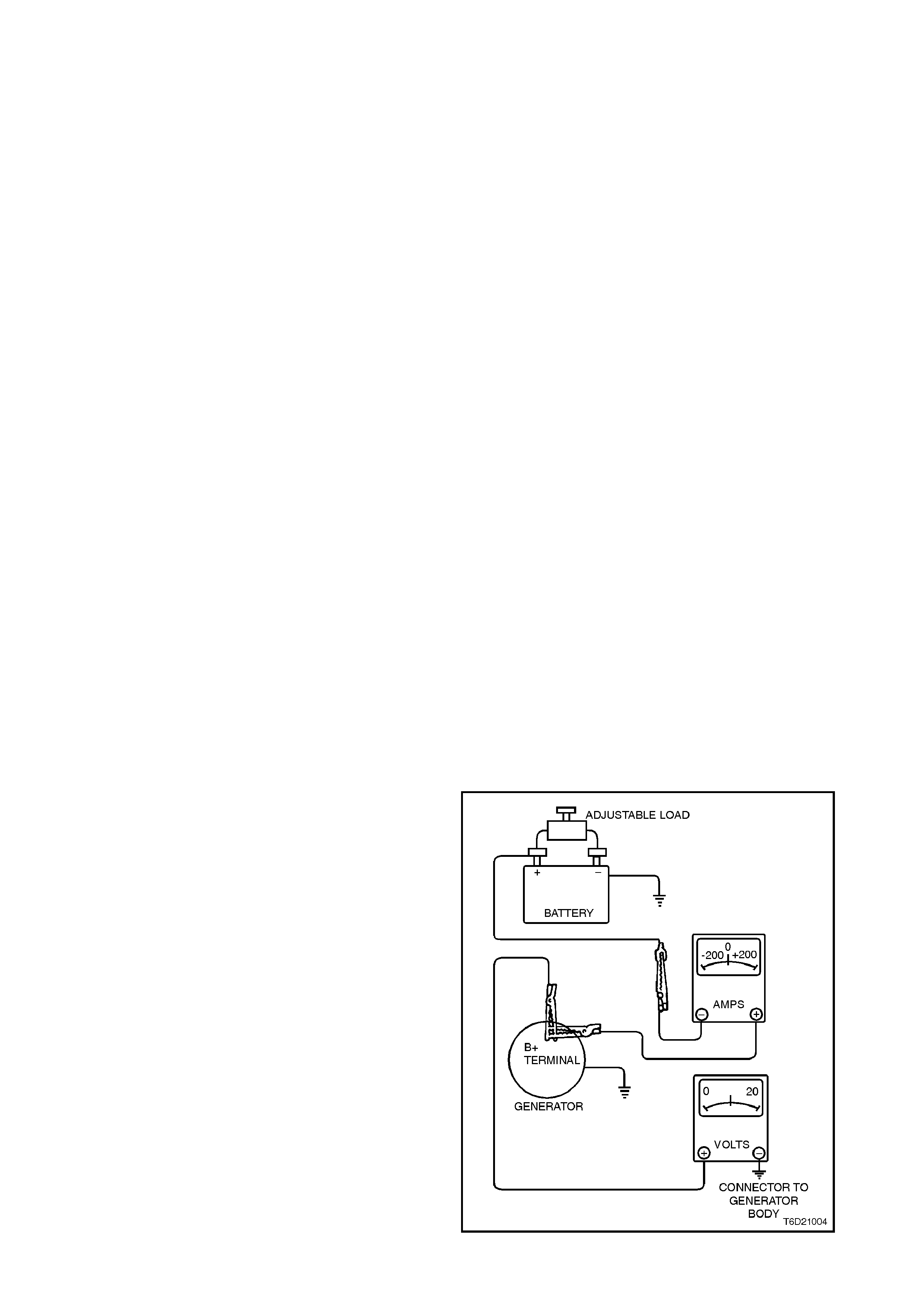
6. Reconnect the battery earth cable. Fit a loading
device across battery terminals, i.e. an
adjustable carbon pile.
NOTE: Loading device must have a minimum
power consumption of 1000 watts.
Figure 6D1-1-4

7. Record the voltmeter reading before starting
the engine. This reading should increase
when the engine is running, indicating
generator output.
8. Start engine, raise rpm and adjust load
(ammeter reading) to that nominated in the
following chart. Check generator output
(voltmeter reading) against specification.
Load Regulation Test
With the voltmeter, ammeter and carbon pile connected as in previous test, increase engine speed to 2350 rpm
(approxim ately 5000 generator rpm ) and incr ease load to approxim ately 108 amps (90% of full output). A decr ease
in the regulating voltage should not exceed 0.5 volt of the readings obtained in the previous test.
If the decrease in the regulating voltage is greater than 0.5 volt, the regulator is defective and must be replaced.
Generator Output Test At Full Load
With the voltmeter, ammeter and carbon pile connected as in previous tests, increase engine speed to 2350 rpm
(approximately 5000 generator rpm) and increase load until the generator output voltage drops to 13.5 volts and
note ammeter reading.
Full output (120 am ps) should be obtained under thes e conditions. It may be necess ary to adj ust the throttle so as
to maintain the desired engine speed.
NOTE: Keep the time for this test to a minimum so as to avoid undue heating and high engine speeds.
If the generator does not provide rated output, it should be removed for repair, refer to 3.1 GENERATOR in this
Section.
CAUTION: ON COMPLETION OF THE GENERATOR OUTPUT TESTING, TO PREVENT EXCESSIVE BATTERY
DISCHARGE OCCURRING, THE ENGINE SHOULD BE RETURNED TO IDLE SPEED AND THE LOADING
DEVICE DISCONNECTED FROM BATTERY TERMINALS.
9. Disconnect the battery earth cable at battery. Remove the voltmeter and ammeter, then reconnect the
generator positive lead (Red wire) to the generator ‘B+’ terminal. Reconnect the battery earth cable to the
battery.
Charging Circuit Voltage Drop Test
With normal connections made at generator, charging circuit can be checked for voltage drop as follows:
1. Connect a low range voltmeter between generator positive terminal and battery positive post.
2. Switch on headlamps, start engine and increase engine speed to approximately 2500 rpm and note voltmeter
reading.
3. Reduce engine speed and trans fer voltm eter connec tions, negative to generator housing and positive to battery
negative post. Increase engine speed to approximately 2500 rpm and again note voltmeter reading.
4. If readings exceed 0.5 volt on positive side and 0.25 volt on negative side, there is a high resistance in the
charging circuit which must be traced and corrected.
ENGINE RPM
LOAD
VOLTMETER READING
1300
5 AMPS
14.4 ±0.3 VOLTS
3. MAJOR SERVICE OPERATIONS
3.1 GENERATOR
REMOVE
1. Disconnect battery earth lead.
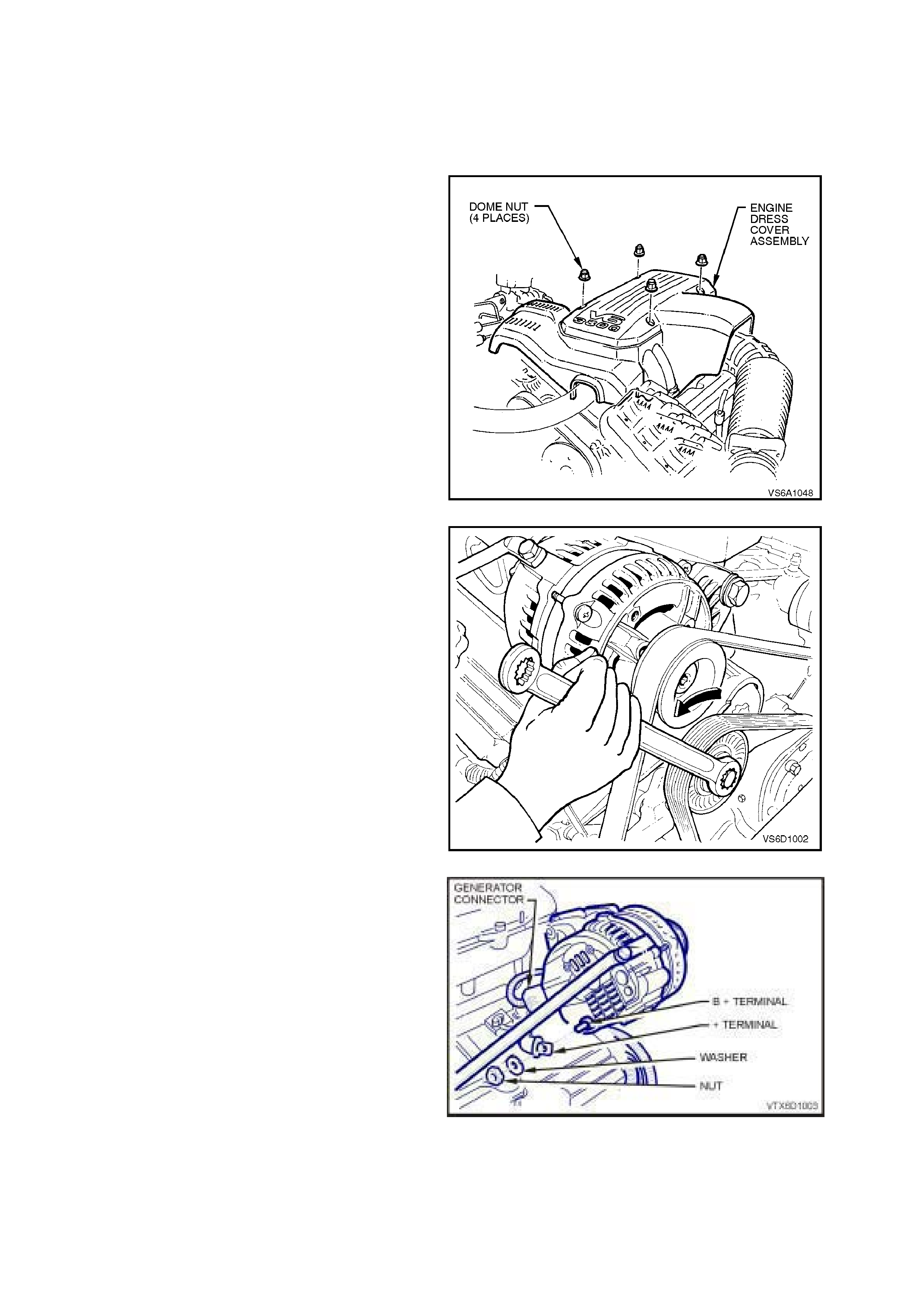
2. Remove four dome nuts securing the engine
dress cover assembly to the intake manifold
studs, lift off and remove the cover assembly .
Figure 6D1-1-5
3. Using a 15 mm ring spanner on drive belt
tensioner pulley pivot bolt, rotate tensioner
pulley assembly anti-clockwise and remove
drive belt from generator drive pulley. Release
drive belt tensioner.
Figure 6D1-1-6
4. Pull battery harness cap from ‘B+’ terminal,
remove nut, washer and positive lead (Red
wire).
Figure 6D1-1-7
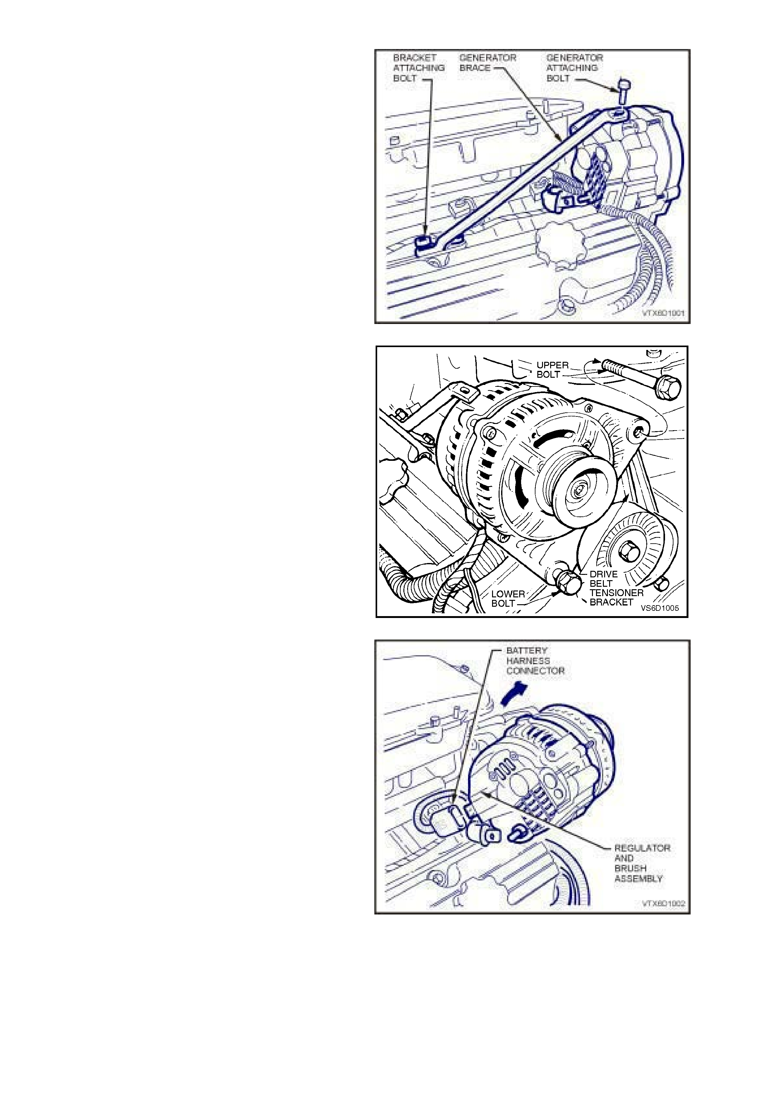
5. Remove generator brace to generator attaching
bolt and loosen brace to engine bracket
attaching bolt.
Figure 6D1-1-8
6. Remove generator to drive belt tensioner
bracket upper bolt and loosen lower bolt.
Figure 6D1-1-9
7. Swing generator away from the intake m anif old
and remove battery harness connector from
regulator and brush ass em bly terminal block by
depressing connector retainer and pulling
connector from generator.
8. Remove generator to drive belt tensioner
bracket lower bolt and remove generator
assembly.
Figure 6D1-1-10
REINSTALL
1. Assemble generator to drive belt tensioner
brack et and install lower m ounting bolt, leaving
it loose.
2. Install battery harness connector into
generator’s regular and brush assembly
terminal block, ensuring that connector’s
retainer locks into place.
3. Swing generator up toward intake m anif old and
install generator to drive belt tensioner bracket
attaching bolt.
4. Install generator brace onto generator housing
and install attaching bolt.
GENERATOR TO DRIVE BELT
TENSIONER LOWER
ATTACHING BOLT
TORQUE SPECIFICATION
40 - 50 Nm
GENERATOR TO DRIVE BELT
TENSIONER UPPER
ATTACHING BOLT
TORQUE SPECIFICATION
40 - 50 Nm
GENERATOR BRACE TO
GENERATOR ATTACHING
BOLT TORQUE SPECIFICATION 20 - 30 Nm
GENERATOR BRACE TO
ENGINE BRACKET ATTACHING
BOLT TORQUE SPECIFICATION 20 - 30 Nm
5. Install battery harness positive lead (Red wire),
washer and nut on ‘B+’ terminal. T ighten nut to
the correc t torque s pecif ication. Install c ap over
‘B+’ terminal.
‘B+’ TERMINAL NUT
TORQUE SPECIFICATION 5 - 12 Nm
6. W ith aid of a 15 mm ring spanner, rotate drive
belt tensioner anti-c lockwise and f it drive belt to
generator drive pulley. Release tensioner and
ensure that drive belt ribs are c orrec tly installed
into all accessory drive pulleys and crankshaft
balancer drive belt grooves.
7. Reconnect battery earth lead.
8. Start engine and check generator warning lamp
operation, drive belt alignment, generator
output and voltage regulator operation.
9. Install engine dress cover to intake manifold,
ensuring that stud grom m ets in the dress cover
remain in place. Install dome nuts and tighten
to the correct torque specifications.
ENGINE DRESS COVER TO
INTAKE MANIFOLD DOME NUT
TORQUE SPECIFICATION 4 - 6 NM
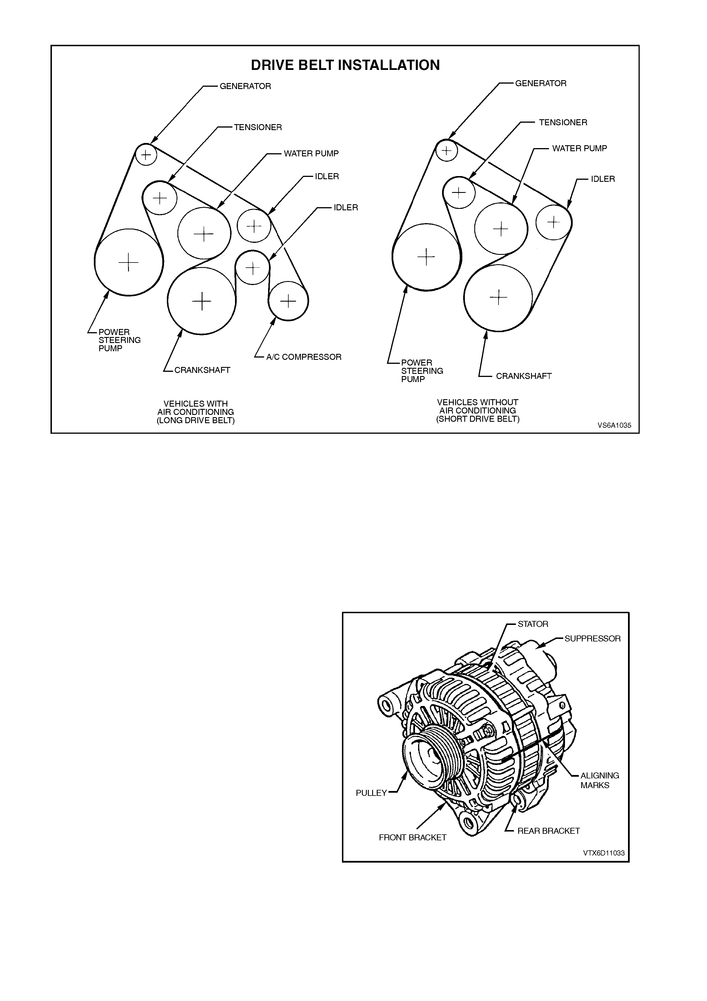
Figure 6D1-1-11
DISASSEMBLE
The following precautions must be noted before attempting to disassemble the generator and checking for faulty
components.
A. When testing the rectifier diodes with an AC type tester, the RMS output must not exceed 12.0 volts. It is
recommended that the stator should be disconnected before testing the diodes.
B. Insulation tests on the rotor and stator should use a voltage not exceeding 110 V for a series test lamp. The
rectifier must be disconnected from the stator prior to testing.
C. Due to the very low resistance value of the stator winding, it may not be possible to obtain accurate readings
using a conventional ohmmeter.
1. Mark relative positions of front bracket, stator
frame and rear bracket using a permanent
marking pen.
Figure 6D1-1-12
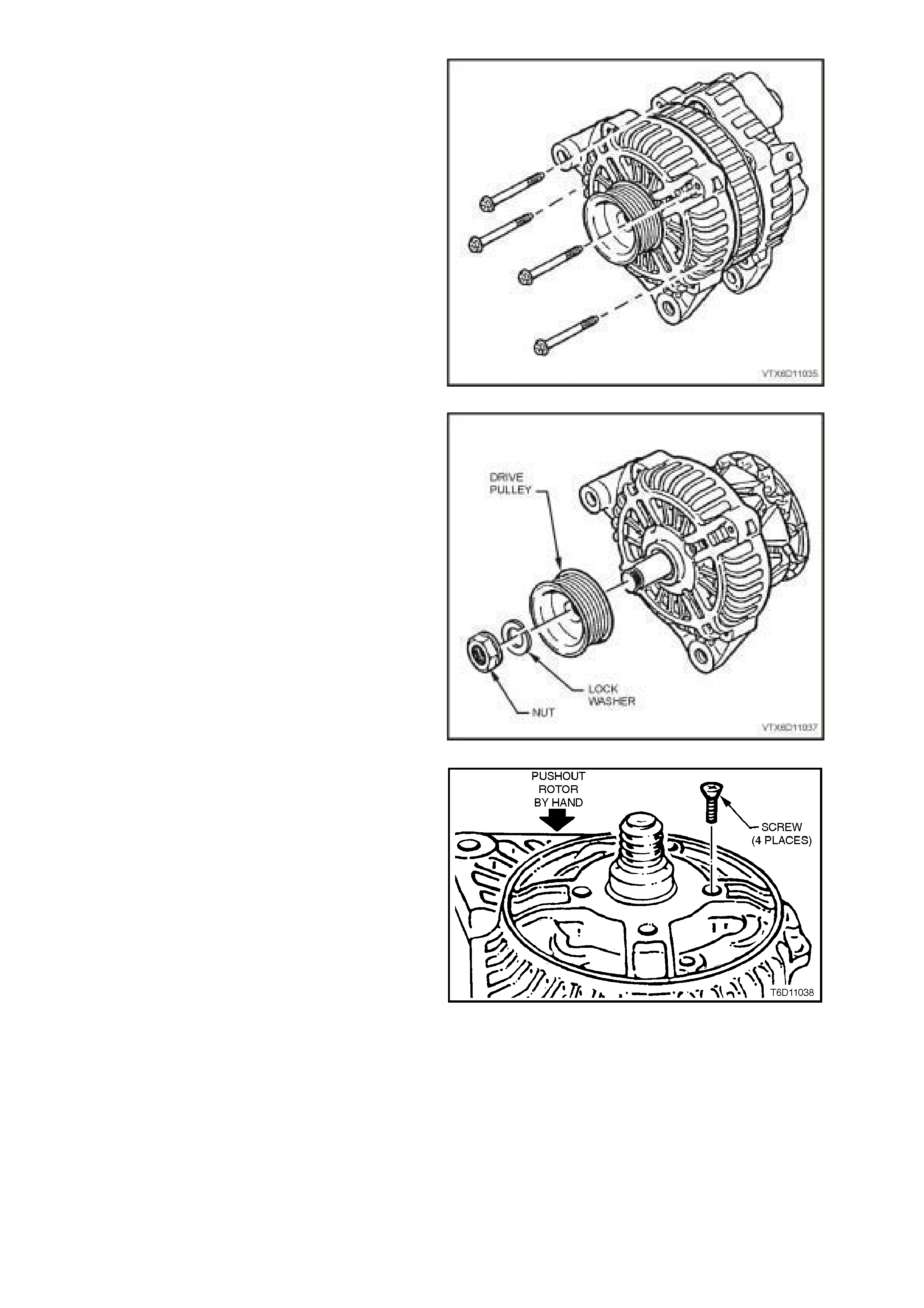
2. Remove four through bolts.
3. Using a screwdriver, carefully pry between the
stator and the front bracket, ensuring that the
screwdriver is not inserted too far or the stator
coil will be damaged. Separate the front
bracket, pulley and rotor assembly away from
the stator and rear bracket assembly.
Figure 6D1-1-13
4. Clamp rotor in a vise, ensuring that the rotor
poles are not distorted, and remove drive pulley
attaching nut, drive pulley and front bracket.
Figure 6D1-1-14
5. Remove four screws securing the bearing
retaining plate to front bracket.
6. Press the bearing from the front bracket with a
suitable socket.
NOTE: The bearing MUST be replaced with a new
bearing on assembly.
Figure 6D1-1-15
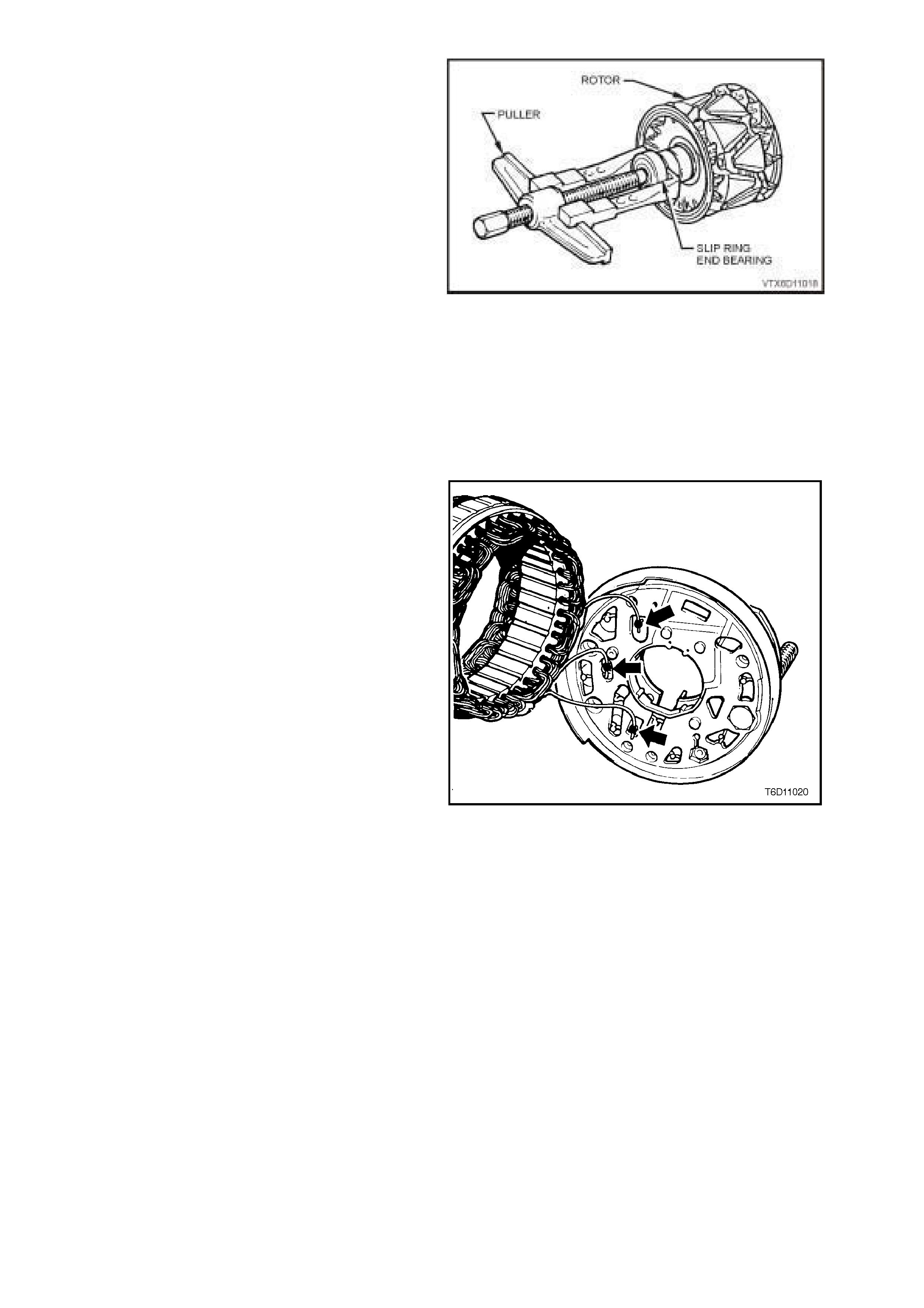
7. Using a bearing puller, remove slip ring end
bearing from rotor shaft, taking care not to
damage the plastic side of the slip ring or
distort the rear fan during the process.
NOTE: The bearing MUST be replaced with a new
bearing on assembly.
Figure 6D1-1-16
8. Remove nut, wave washer, flat washer and
insulating washer from the ‘B+’ terminal bolt.
9. Remove the rectifier retaining screw and two
brush holder retaining screws. Separate the
stator and rectifier assemblies as a unit from
the rear bracket.
10. Unsolder and remove each brush and spring
assembly.
11. Separate stator from rectifier assembly by
unsoldering the three s tator windings to r ec tif ier
connections.
CAUTION: USE ONLY AS MUCH HEAT AS
REQUIRED TO MELT THE SOLDER.
EXCESSIVE HEAT MAY DAMAGE THE DIODES.
NOTE: The rectifier assembly is serviced as an
assem bly only. Individual replacem ent parts ar e not
available.
Figure 6D1-1-17
12. Unsolder the two joints connecting the brush
holder and regulator assembly to the rectifier,
and remove the assembly from the rectifier.
CLEANING AND INSPECTION
With generator completely disassembled, components should be cleaned and inspected.
Wash all components except stator, rotor, rectifier and regulator in a suitable cleaning solvent.
Carefully clean rotor and stator with compressed air.
CAUTION: DO NOT CLEAN STATOR OR ROTOR WINDINGS WITH THE CLEANING SOLVENT OR DAMAGE
TO THE INSULA TION COULD RESULT.
CAUTION: CLEAN ALL PARTS OTHER THAN THOSE PREVIOUSLY NOMINATED USING A NON VOLATILE
OR LOW INFLAMMABLE AGENT IN A WELL VENTILATED AREA.
IT IS IM PORTANT THAT ALL PARTS ARE THOROUGHLY DRIED BEFORE ASSEMBLY, T AKING CARE NOT
TO BREATH IN ANY VAPOURS.
OBSERVE THE SAFETY REGULATIONS AND PRECAUTIONS ISSUED BY THE MANUFACTURER OF THE
CLEANING AGENT IN USE.
COMPONENT CHECKING
Brush Gear
Check the length of the brushes protruding from
the brush holder. Replace the brush and spring
assembly if the brush is worn down to the wear
limit. Also replace if abnormal wear or cracks are
noticed.
MINIMUM BRUSH
LENGTH 5.0
mm
Clean the brushes and brush holder, removing
particles by wiping with a clean cloth. Ensure that
the brush moves smoothly in the brush holder.
Replace if necessary.
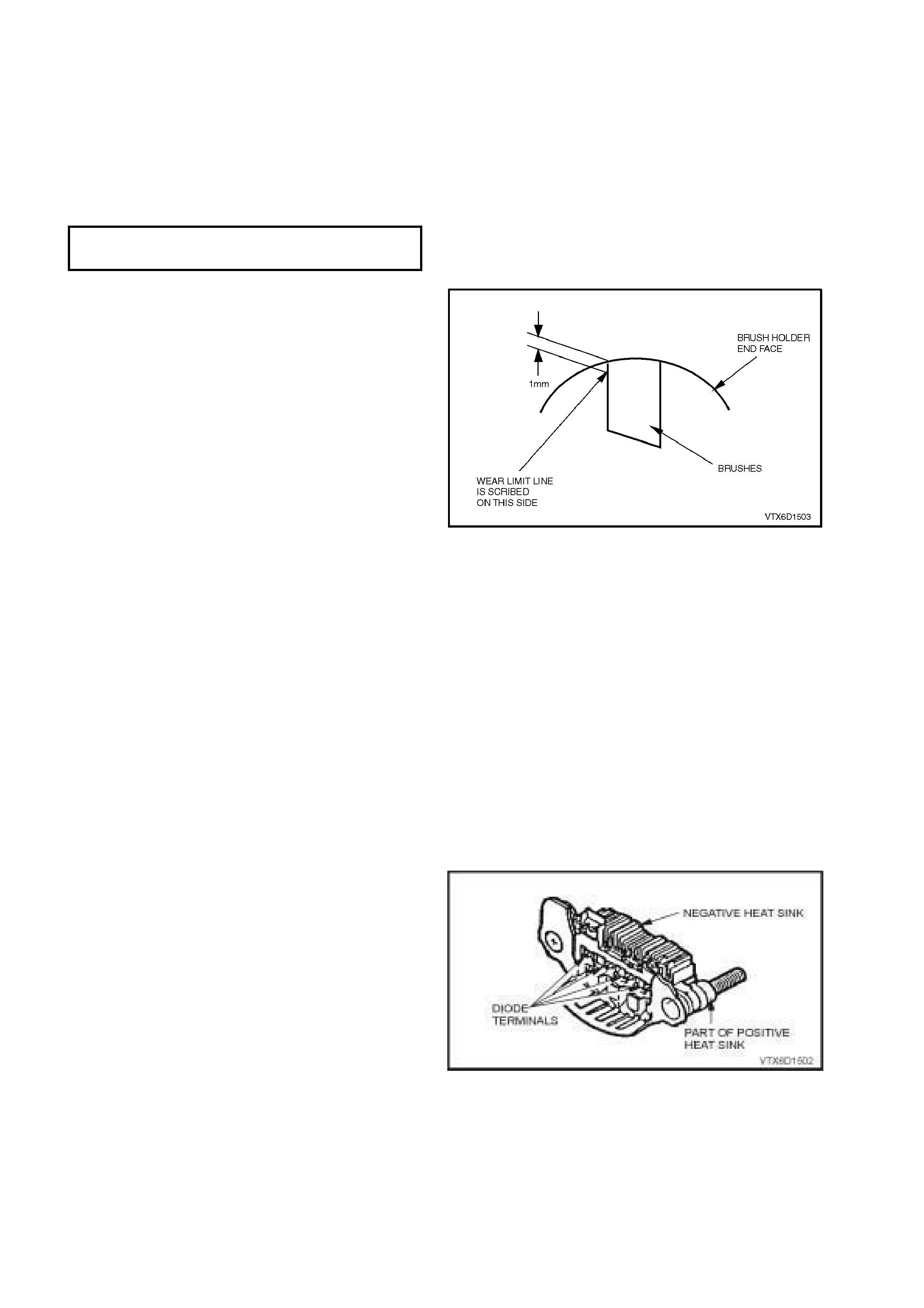
Check the brush spring function. Push the brush
into the brush holder until the wear limit line of the
brush protrudes 1 mm from the brush holder
moulding and check the spring is functioning
correctly. Replace if necessary.
Check that brushes move smoothly in and out of
holder by pushing on end of brushes, and then
releasing. Replace if necessary.
Figure 6D1-1-18
Diodes
NOTE: T he rectifier assem bly is not repairable and
should be replaced if any diodes proves to be
faulty.
The following commercially available test
equipment is essential for correctly testing the
diodes within the rectifier assembly.
A diode tester or multimeter with a diode test
feature where the DC output at the test pr obes
does not exceed 14 volts, or in the case of AC
testers, 12 volts RMS.
This is necessary so as to ensure that when
testing the diodes, the forward and reverse
voltage checks are completed and are not
masked by the diode turning on due to Zener
breakdown voltage.
NOTE: In Steps 1 and 2, ensure that the reverse
voltage applied is less than 14 volts DC, or 12 volts
RMS when using an AC tester.
1. Attach negative test probe of diode tester or
multimeter with diode test function to the
positive heatsink of the rectifier assembly and
the positive probe alternatively to positive diode
connections.
A low resistance reading, or the forward
voltage drop across the diode should be
obtained.
Reverse probe connections and repeat test to
check that current is passed in one direction
only (high resistance reading or higher reverse
voltage should be obtained).
If necessary, replace the rectifier assembly.
Figure 6D1-1-19
2. Repeat procedure on negative heatsink by
attaching positive test probe to the negative
heatsink and the negative probe alternatively to
negative diode connections.
A low resistance reading, or the forward
voltage drop across the diode should be
obtained.
Reverse probe connections and repeat test to
check that current is passed in one direction
only (high resistance reading or higher reverse
voltage should be obtained).
If necessary, replace the rectifier assembly.
Rotor
Clean any dirt or particles from the rotor with
compressed air or a clean cloth.
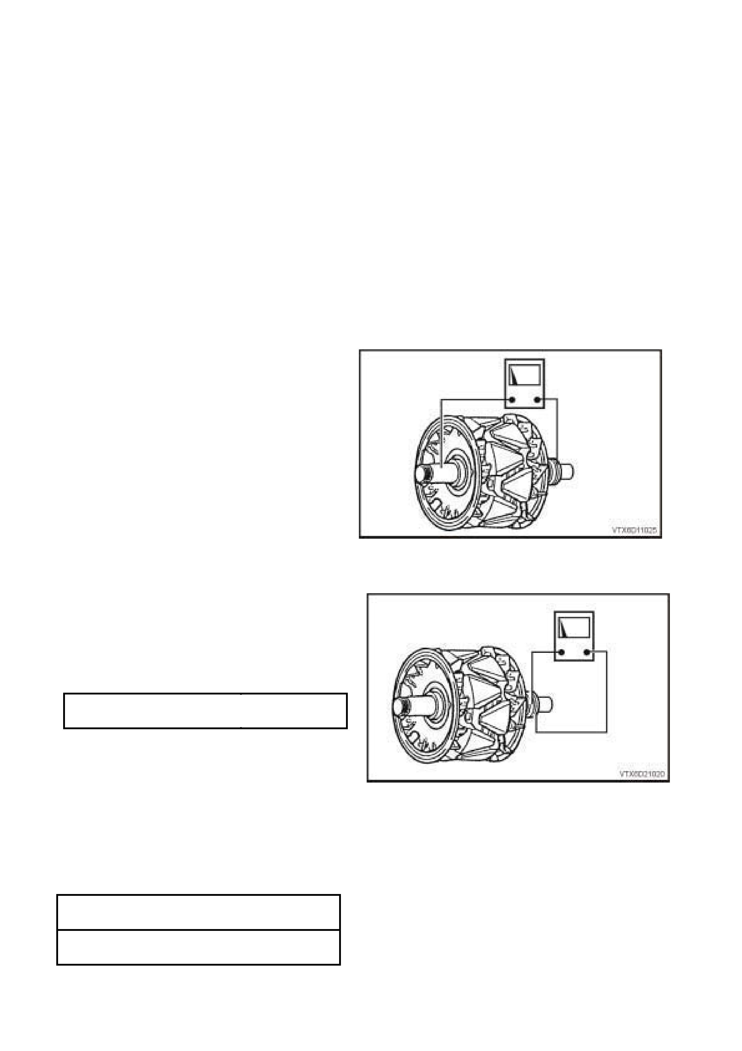
Insulation Test
Using an insulation test er, or a series tes t lam p (up
to 110 V), check insulation between slip rings and
rotor core or shaft. Test light should not glow or
insulation tester should indicate an open circuit
(greater than 1 Megaohm). If an open circuit does
not exist replace rotor.
Figure 6D1-1-20
Open Circuit Test
Slip Rings
Check slip rings for wear or damage. If the slip
rings are worn, damaged or out-of-round, the rotor
must be replaced.
SLIP RING
OUTER DIAMETER 22.7
mm
SLIP RING
SERVICE LIMIT 22.1
mm
Connect ohmmeter probes across slip rings and
measure resistance of rotor windings.
Rotor winding resistance values are given in the
following chart.
NOTE: If the resistance of the rotor winding is not to
specification, replace the rotor.
Figure 6D1-1-21
STATOR WINDING
RESISTANCE @ 20°C 1.7 - 2.1
ohms
Bearings
The bearings used in this generator are a high
tolerance type. Only genuine replacem ent bearings
are to be used. It is recommended that the
bearings be replaced during the reconditioning
process to restore the generator to original
specification.
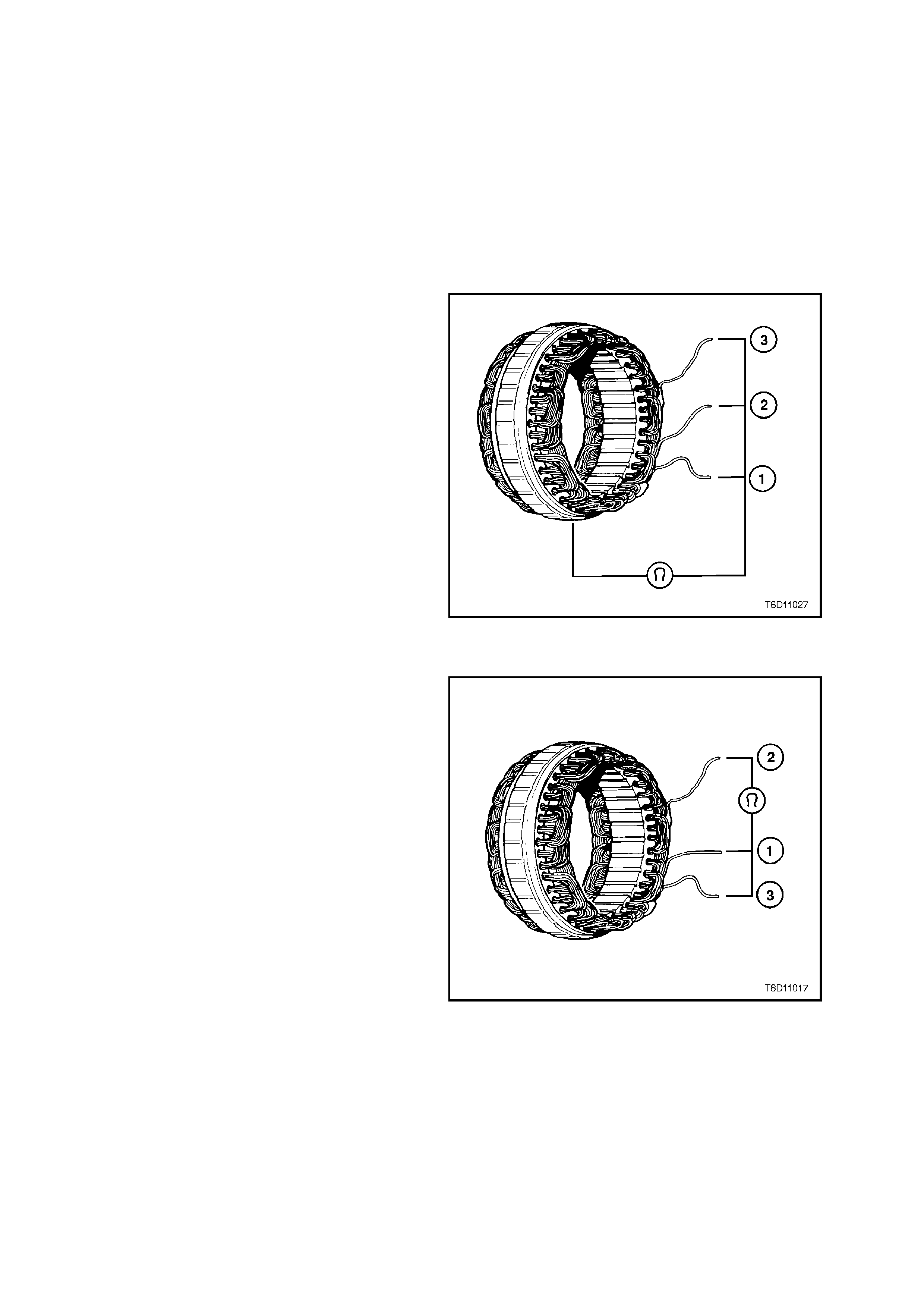
Stator
Inspect stator for damage, loose connections or
discoloured windings. Replace if necessary.
Insulation Test
Connect a powered test lamp (up to 40 V) or an
ohmmeter between any stator lead and stator
frame. If test lamp glows or ohmmeter reading is
low indicating that an open circuit does not exist,
replace stator.
Figure 6D1-1-22
Open Circuit Test
1. Connect ohmmeter to any two stator leads.
Ohmmeter should not register any significant
resistance.
2. Repeat test on remaining stator leads. If
resistances are high, replace the stator.
Figure 6D1-1-23
REASSEMBLE
Reassembly of the alternator is the reverse of the
disassembly procedure, noting the following:
1. Do not lubricate the bearings as they are pre-
lubricated.
2. For rotor bearings with resin bands, grease
should not be applied. Remove oil com pletely if
found on the bearing box to prevent bearing
creep.
3. Use high temperature solder (melting point
230°C) and a 180 – 270 W soldering iron. Do
not used excessive heat as damage to the
rectifier may result.
4. As the rotor bearing and rear bracket fitting is
tight, heat the area around the rear bracket
bearing box to 50 – 60°C before installing the
rotor into the rear bracket.
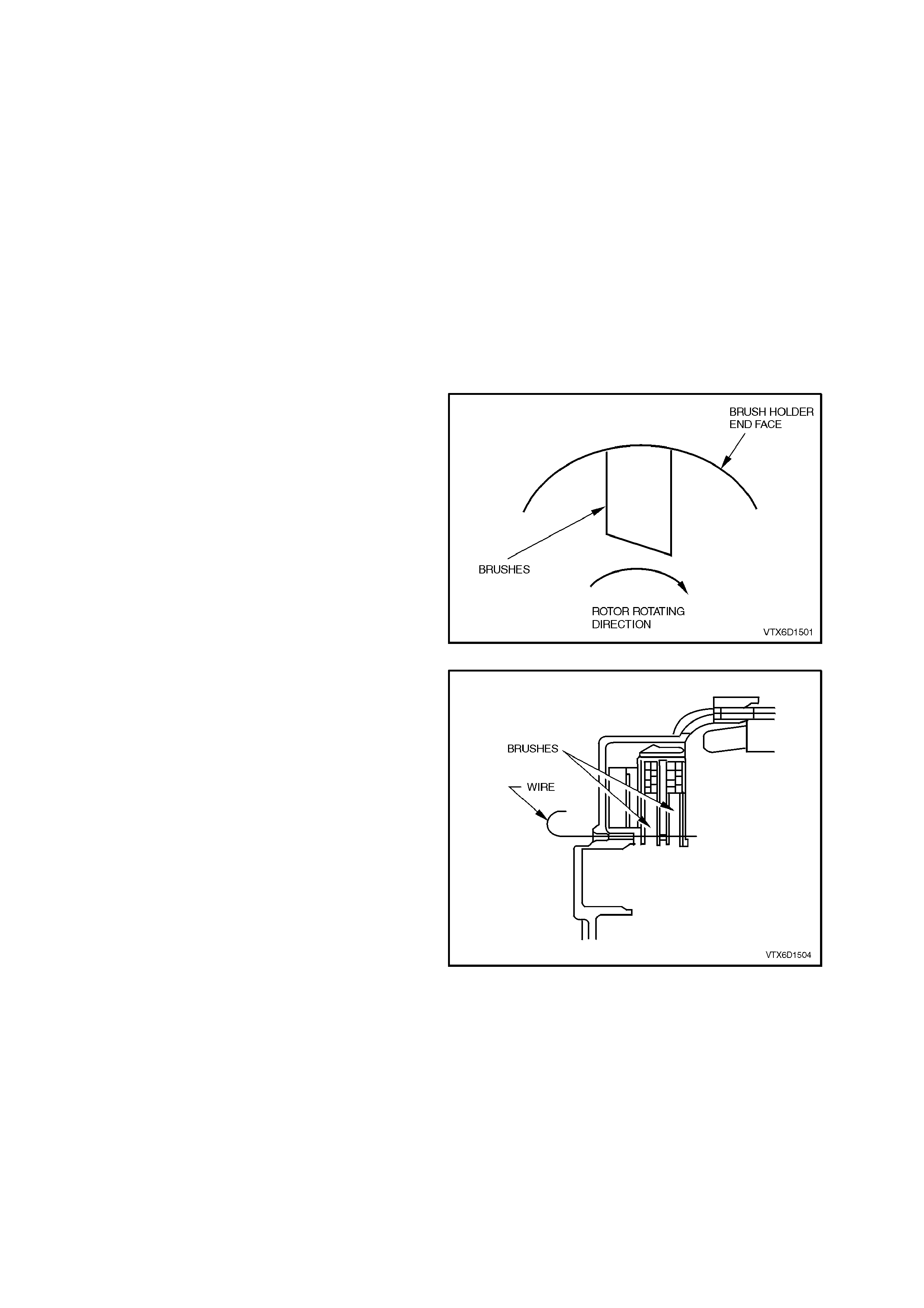
5. Position brushes in the brush holder as shown
in Figure 6D1-1-23.
Figure 6D1-1-24
6. Before installing the rotor, push brushes into
the brush holder and ins ert a wire to hold them
in the raised position. Install the rotor and
remove the w ire.
Figure 6D1-1-25
7. Do not over tighten the terminal ‘B+’ nut as
damage to the insulating washer will result.
8. After as s embly, rotate the pulley slowly by hand
to verify that the rotor turns smoothly.

9. Ensure all fasteners are tightened to the
correct torque specifications.
DRIVE PULLEY ATTACHING
NUT TIGHTENING TORQUE 99 – 137
Nm
THROUGH BOLTS
TIGHTENING TORQUE 3.5 – 5.3
Nm
BEARING RETAINER SCREWS
TIGHTENING TORQUE 2.0 – 5.3
Nm
BRUSH HOLDER RETAINING
SCREWS
TIGHTENING TORQUE
2.0 – 5.3
Nm
RECTIFIER RETAINING
SCREWS
TIGHTENING TORQUE
2.0 – 5.3
Nm
TERMINAL ‘B+’ NUT
TIGHTENING TORQUE 12.8 – 18.6
Nm
4. DIAGNOSIS
1. UNDERCHARGED BATTERY
a. Defective battery.
b. Loose connection in charging system.
c. Corroded connections in charging circuit.
d. Defective wiring.
e. Faulty generator.
f. Faulty voltage regulator.
2. OVERCHARGED BATTERY
a. Shorted battery cell.
b. Faulty voltage regulator.
c. Short circuit in rotor winding.
d. Voltage drop in sense wire.
3. FAULTY INDICATOR LIGHT OPERATION
(LIGHT DOES NOT GLOW)
a. Burnt out bulb.
b. Defective bulb socket.
c. Defective wiring.
d. Defective rectifier.
e. Defective regulator.
4. FAULTY INDICATOR LIGHT OPERATION
(LIGHT REMAINS ON)
a. Negative diode failure.
b. Defective voltage regulator.
c. Faulty generator.
d. ‘B+’ cable off or broken.
e. ‘S’ cable off or broken.
f. Battery overcharged.
g. Open circuit in rotor winding.
5. NOISY GENERATOR OPERATION
a. Normal magnetic hum.
b. Badly discharged battery.
c. Generator mounting brackets loose or bolts loose.
d. Worn or frayed drive belt.
e. Worn bearings.
f. Loose drive pulley attaching nut.
g. Open or shorted diodes.
h. Open or shorted stator winding.

5. SPECIFICATIONS
Earth Polarity......................................................................... Negative
Nominal Voltage.................................................................... 12 V
Nominal Output..................................................................... 120 Amps
Voltage Regulator Setting..................................................... 14.4 ±0.3 V
Stator Winding Resistance ................................................... 1.7 – 2.1 ohms
Slip Ring Outer Diameter...................................................... 22.7 mm
Slip Ring Service Limit.......................................................... 22.1 mm
Brush Length New ................................................................ 18.5 mm
Brush Length Service Limit................................................... 5.0 mm
Direction of Rotation (viewed from pulley)............................ Clockwise

6. TORQUE WRENCH SPECIFI CATIONS
Nm
Engine Dress Cover to Intake Manifold Dome Nut............... 4 – 6
Through Bolts........................................................................ 3.5 – 5.3
Drive Pulley Attaching Nut .................................................... 99 – 137
‘B+’ Terminal Nut .................................................................. 12.8 – 18.6
Battery Harness Terminal to ‘B+’ Terminal Nut .................... 5 – 12
Generator to Drive Belt Tensioner Attaching Bolts............... 40 – 50
Generator Support Brace Mounting Bolts............................. 20 – 30
Generator to Drive Belt Tensioner
Bracket Mounting Bolt........................................................... 20 – 34
Bearing Retainer Screws...................................................... 2.0 – 5.3
Brush Holder Retaining Screws............................................ 2.0 – 5.3
Rectifier Retaining Screws.................................................... 2.0 – 5.3