VS SERIES POLICE OPTIONS
ELECTRICAL SYSTEM
CAUTION:
This vehicle may be equipped w ith an AIRBAG. An AIRBAG is a Supplemental Restraint System (SRS).
Refer to CAUT IONS, Section 12M of the VS Series Service Supplement before performing any service
operation on or around SRS components, the steering mechanism or wiring.
Failure to follow the CAUTIONS could result in airbag deployment, resulting in possible personal
injury or unnecessary SRS system repairs.
1. GENERAL DESCRIPTION
This Service Manual Supplement describes the electrical wiring modifications for the Police Options Pack
production option 9C1, available with VS Series vehicles.
During vehicle production, the additional wiring harnes ses desc ribed in this Supplem ent are installed in the vehic le.
Each harness provides a specific function or enables the police department to add ancillary components such as
lights, sirens, etc., as required.
Also included with production option 9C1, but not included in this Supplement are:
- Heavy duty battery. Refer to Section 12A BATTERY & CABLES of the VS Series Service Information for
servicing of the battery.
- 100 amp generator (V6) or 120 amp generator (V8). Refer to Section 6D1-1 CHARGING SYSTEM - V6
ENGINE or Section 6D2-1 CHARGING SYSTEM - V8 ENGINE of the VS Series Service Information for
servicing of the generator.
- Revised over-speed warning module. Refer to Section 12C INSTRUMENT S, W IPERS/W ASHERS & HORN of
the VR Series Service Information for servicing of the over-speed warning module.
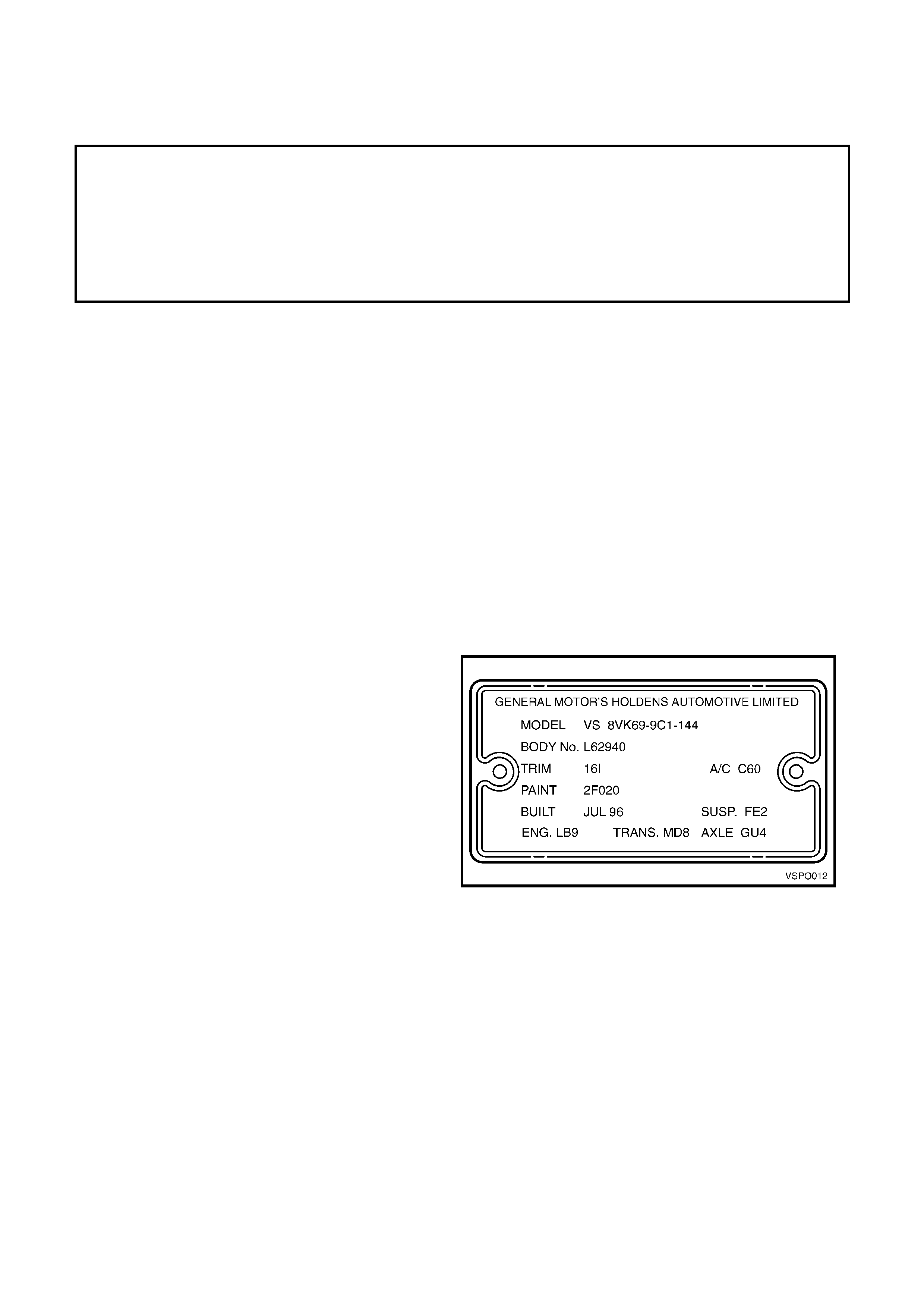
Vehicles f itted with Police Option 9C1 can be identif ied
by the body option identification plate mounted on the
upper dash panel in the engine compartment. Option
9C1 appears under the Model designation.
Figure 1A6-1
2. SERVICE OPERATIONS
2.1 SUPPRESSOR PATCH HARNESSES
The patch harnesses described in this Section provide additional interference noise suppression to the measures
undertaken to the standard vehicle.
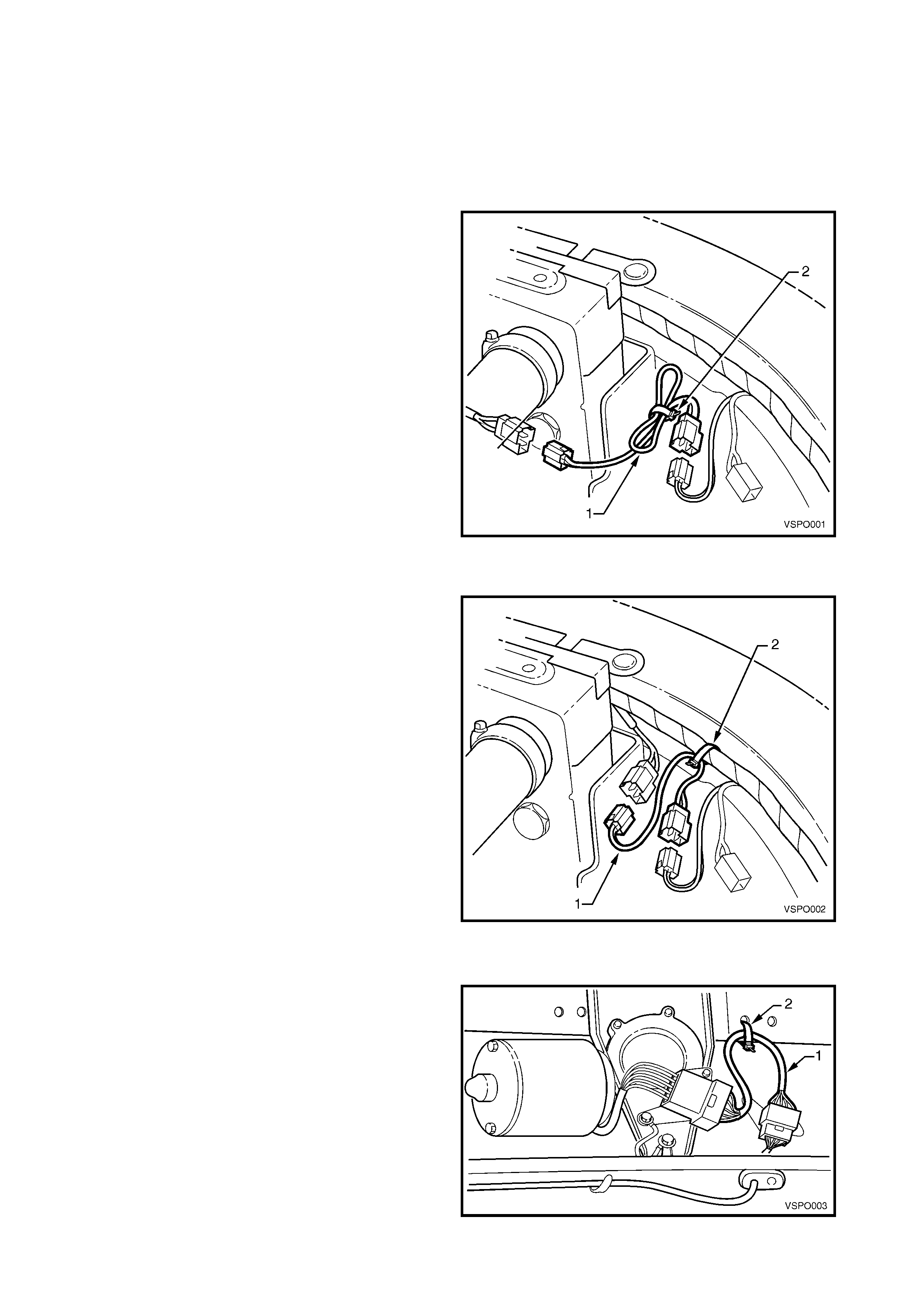
COOLING FAN MOTOR – V6
The c ooling fan motor s uppressor patch harnes s (1) is
installed between the engine cooling fan harness
connectors to the right of the radiator.
A tie-strap (2) is used to secure the patch harness to
the main harness.
Figure 1A6-2
COOLING FAN MOTOR – V8
The c ooling fan motor s uppressor patch harnes s (1) is
installed between the condenser cooling fan harness
connectors to the right of the radiator.
A tie-strap (2) is used to secure the patch harness to
the main harness.
Figure 1A6-3
WINDSCREEN WIPER MOTOR
The windscreen wiper motor suppressor patch
harness (1) is installed between the wiring connectors
at the wiper motor.
A tie-strap (2) is used to secure the patch harness to
the body.
NOTE: To access the patch harness, the wiper arm
assemblies and plenum chamber water deflector will
require removal. For further information refer to
Section 12C INSTRUMENTS, WIPERS/WASHERS &
HORN of the VR Series Service Information.
Figure 1A6-4
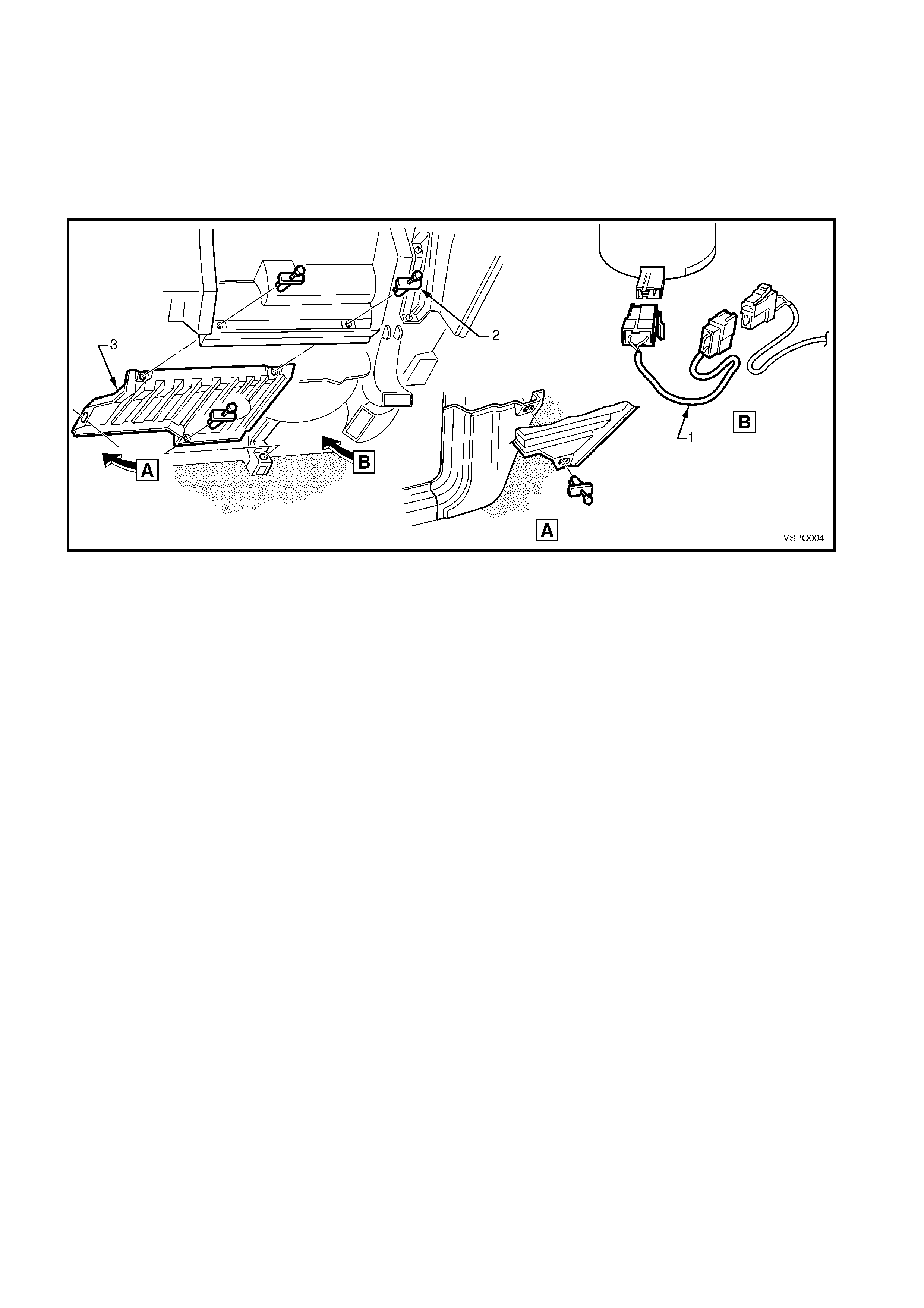
BLOWER FAN MOTOR
The blower fan motor suppressor patch harness (1) is
installed between the harness connectors at the blower
fan.
NOTE: To access the patch harness, remove the four
fasteners (2) and the LH instrument panel lower trim
(3). For further information refer to Section 1A3
INSTRUMENT PANEL of the VR Series Service
Information.
Figure 1A6-5
2.2 AUXILLIARY POWER HARNESS
An auxiliary power supply harness is fitted that provides constant 12V for ancillary components as required. Four
wiring connectors are attached to the auxiliary harness fuse box mounting bracket, rear of the LH strut tower,
providing c onnection of anc illary components. Two connectors c ontain individually fused positive c irc uit c onnections
and two contain negative circuit connections. Two fusible links are also provided in a holder which is tied back to the
auxiliary harness near the battery positive terminal.
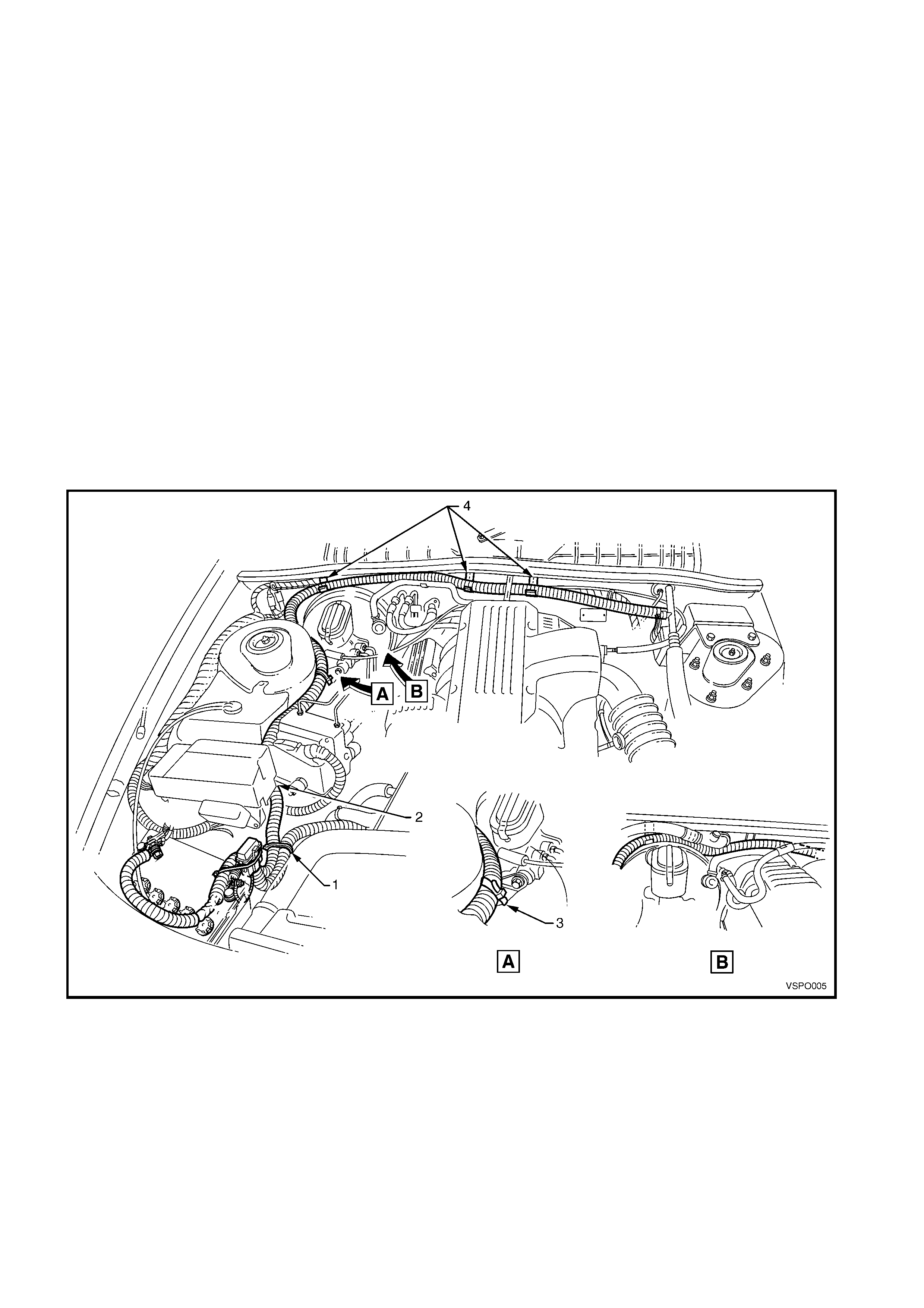
The auxiliary harness is routed from the battery along
the RH side and rear of the engine compartment as
shown in Fig. 1A6-6, noting the following points:
1. The auxiliary harness is tie-strapped around main
wiring harness near the battery (1).
2. The harness is routed under the relay panel and
between the coolant reservoir and ABS modulator
(2).
3. The harness is tie-strapped around the master
cylinder mounting bracket (3), View A.
4. Three cable clips (4) attach the harness along the
dash panel. The clips are hooked onto panel
flange under the seal.
NOTE: Ensure the harness is routed behind the brak e
booster vacuum line and throttle cable clip (V6) or
behind A/C pipe and over the booster (V8), View B.
Figure 1A6-6
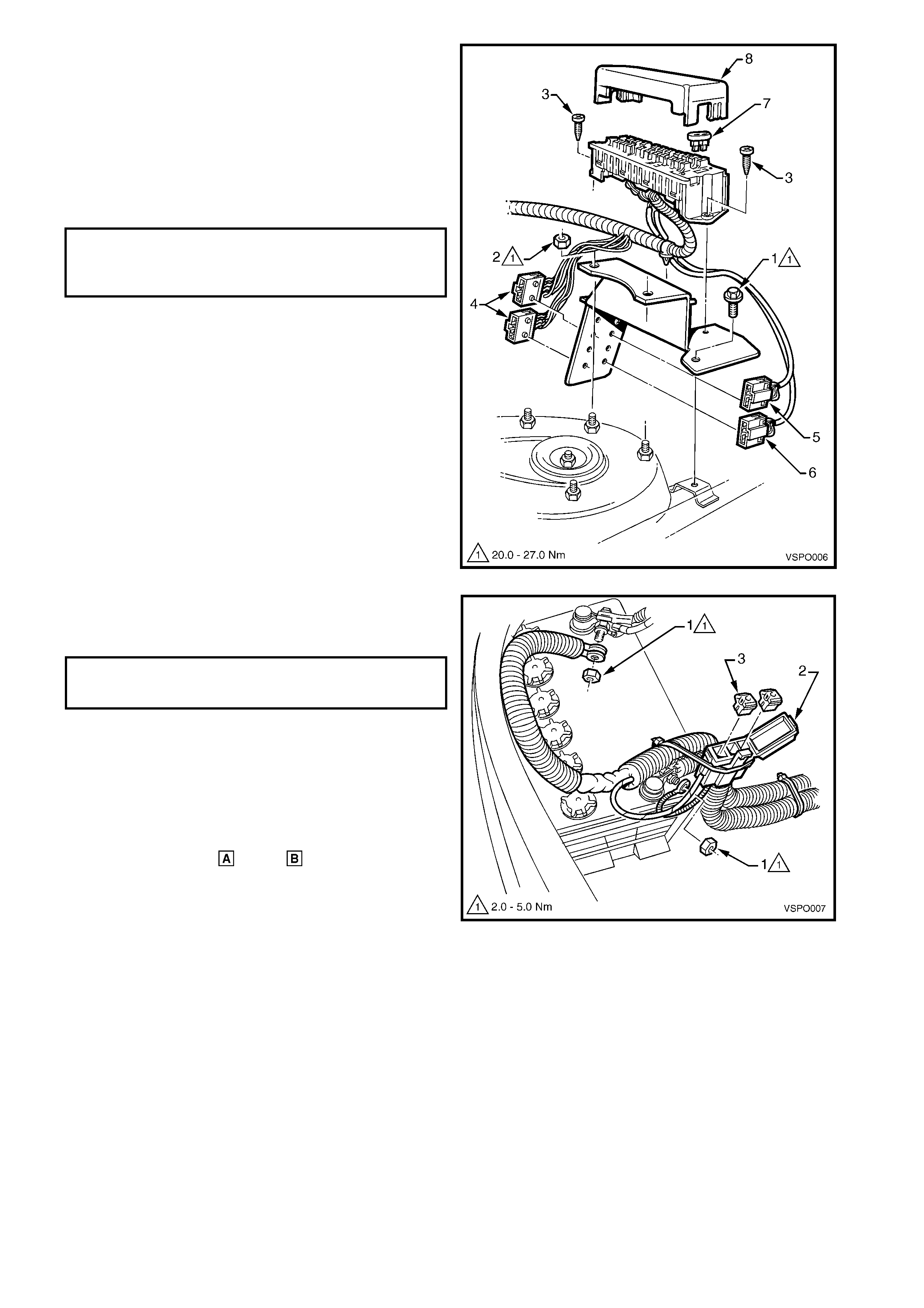
5. The auxiliary harness fuse panel and bracket
assembly is attached to the vehicle with a screw
(1), one place and two additional nuts (2) on the
suspension strut rear studs.
6. The auxiliary harness fus e panel is attached to the
mounting bracket with two screws (3).
7. The negative wiring connectors (4), positive wiring
connectors grey (5), white (6) and harness are
clipped to the bracket.
8. T o s ervice the f uses (7) the fus e panel cover (8) is
remove by unclipping.
Figure 1A6-7
9. The auxiliary harness is routed at the battery as
shown and is attached to the battery terminals with
additional nuts (1).
10. The fusible link holder (2) is tie-strapped back to
the auxiliary harness and contains two 50 amp
fusible links (3), one for each positive connector.
11. The auxiliary harness fuse box contains 16 fuses
(cavities 5, 10, 15 & 20 are not used). Each fuse
carries a unique am perage rating and relates to an
individual terminal in the positive wiring
connectors, white & grey , refer Fig 1A6-9.
12. If a device or circuit is (or is to be) connected to
the auxiliary power harness:
- the positive wire(s) of the device must be
connected to the terminal in either positive
connector that corresponds to a fuse of the
correct amperage, and
- the negative wire(s) of the device are to be
connected to any available pin in either of the
negative connectors.
Figure 1A6-8
AUXILIARY HARNESS FUSE BOX
MOUNTING BRACKET NUT & SCREW 20.0 – 27.0 Nm
TORQUE SPECIFICATION
AUXILIARY HARNESS TO BATTERY 2.0 – 5.0
TERMINAL TORQUE SPECIFICATION Nm
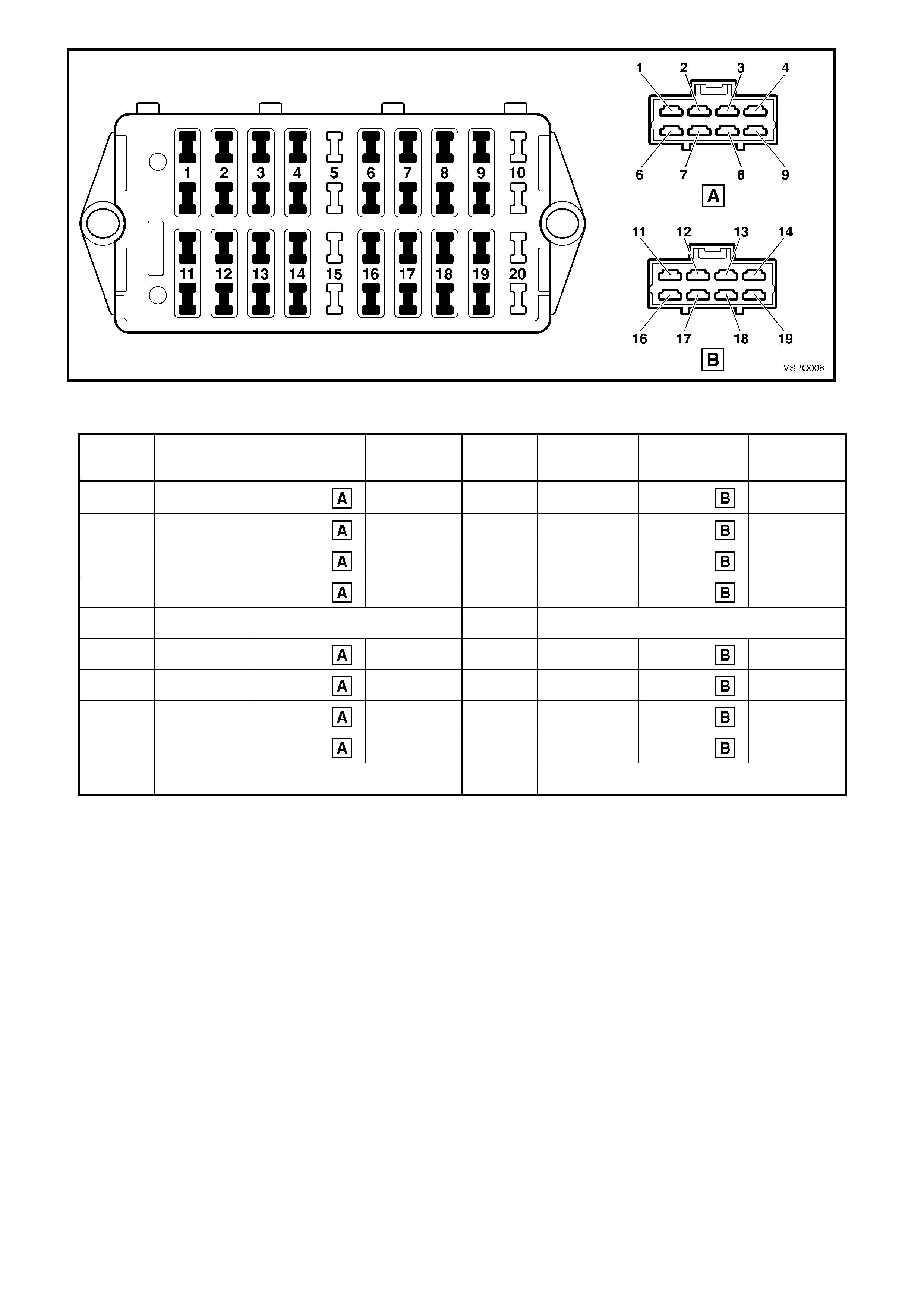
Figure 1A6-9
LEGEND
Fuse
No. Rating
(Amps) Connector /
Pin Wire
Colour Fuse
No. Rating
(Amps) Connector /
Pin Wire
Colour
1. 10 White / 1 Red / Black 11. 15 Grey / 11 Red / Black
2. 25 White / 2 Red / Blue 12. 20 Grey / 12 Red / Blue
3. 20 White / 3 Red / Yellow 13. 15 Grey / 13 Red / Yellow
4. 7.5 White / 4
Red / White 14. 10 Grey / 14 Red / White
5. NOT USED 15. NOT USED
6. 15 White / 6 Pink 16. 10 Grey / 16 Pink
7. 20 White / 7 Yellow 17. 25 Grey / 17 Yellow
8. 20 White / 8 Blue / Green 18. 20 Grey / 18 Blue / Green
9. 10 White / 9 Pink /White 19. 7.5 Grey / 19 Pink /White
10. NOT USED 20. NOT USED
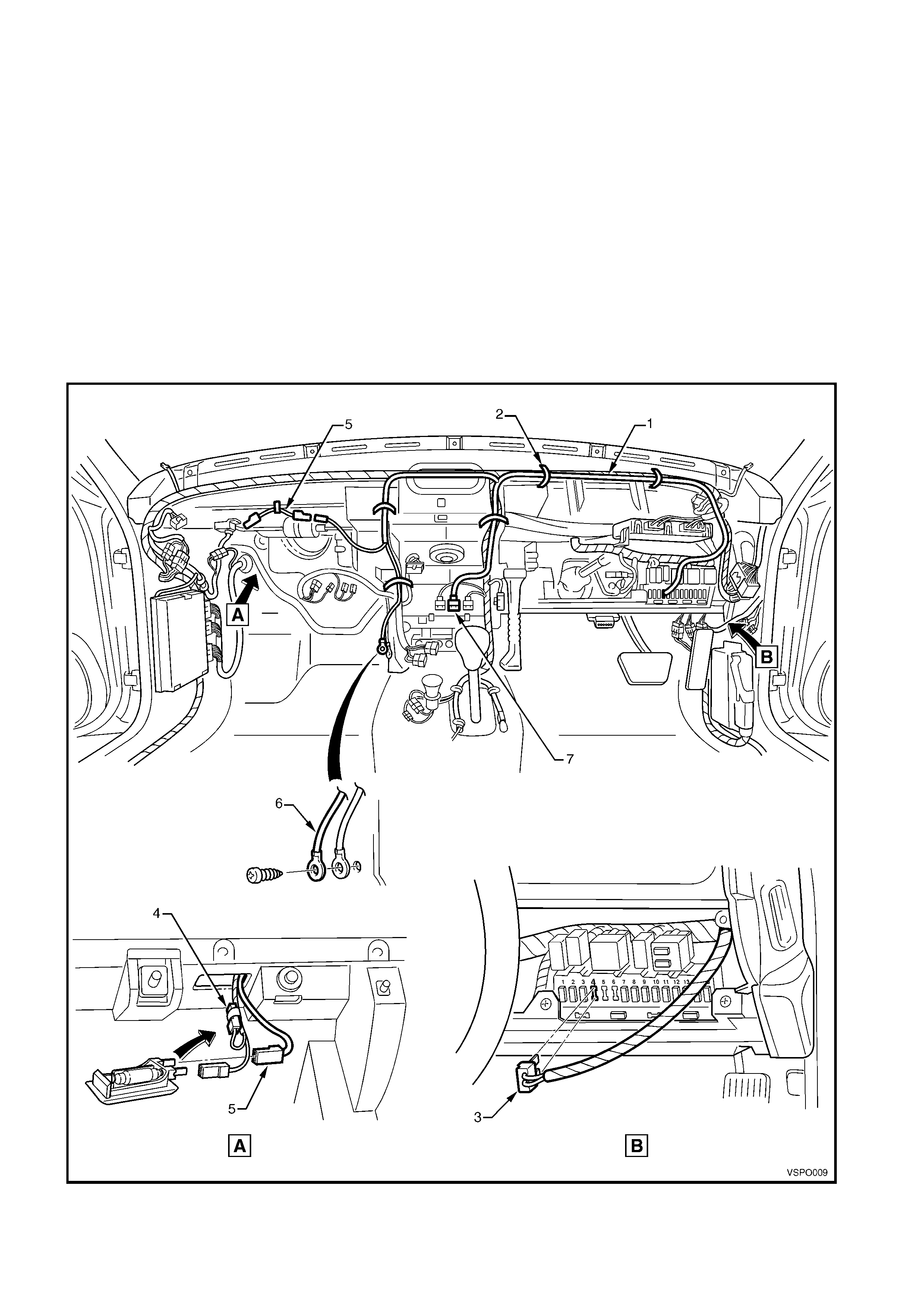
2.3 DOME LAMPS OVERRIDE HARNESS
The dome lamps override harness is used to provide manual override switching of the dome lamps, allowing the
doors to be opened without any lamps illuminating
1. The over ride har ness ( 1) is routed behind the das h
panel as shown and is tie-s trapped (2) to the m ain
harness, five places, refer Fig. 1A6-10.
2. Fuse No. 4 is removed (3) and the harness
installed into the fuse box cavity.
3. The existing orange/white glovebox lamp lead (4)
is taped back to the main wiring harness. A short
lead (5) is ins talled between the lamp and override
harness which is tie-strapped to the body.
4. An additional earth connection (6) is made at the
LH lower dash panel bracket.
5. The override switch wiring connector (7) is routed
to the rear of the centre escutcheon.
Figure 1A6-10
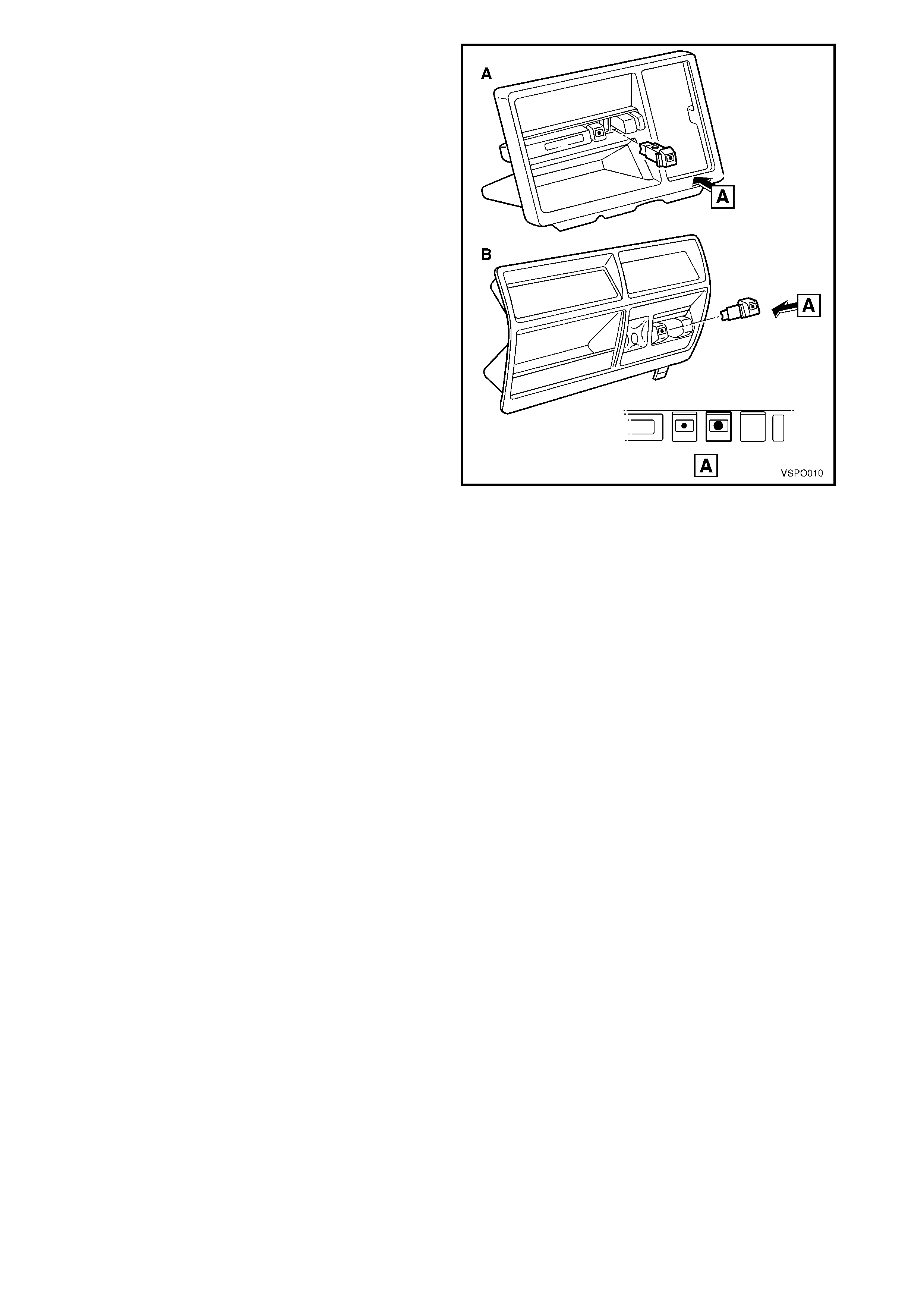
6. The override switch is added to the centre
escutcheon ‘A’ with bucket seats or ‘B’ with a
bench seat as shown.
7. For servicing of the override switch, refer to 2.11
DASH PANEL CENTRE FACIA ESCUTCHEON
SWITCHES in Section 12C INSTRUMENTS,
WIPERS/WASHERS & HORN of the VR Series
Service Information.
Figure 1A6-11
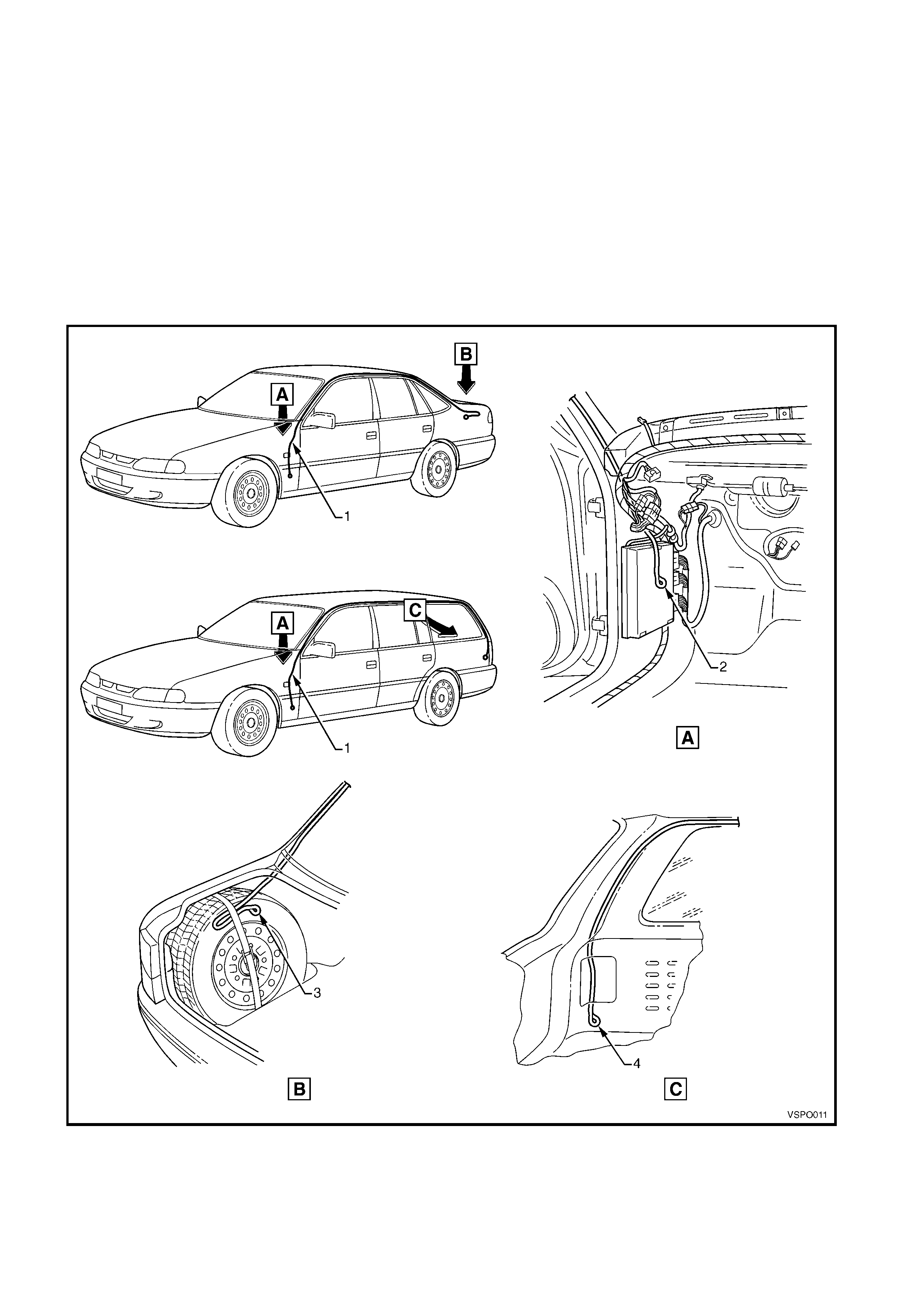
2.4 FEEDER WIRE
A feeder wire (1) is installed into the LH roof side rail,
down the A and D-pillars, refer Fig. 1A6-12.
The f eeder wire enables police dept. engineers to f eed
a wiring harness through the cavity to the rear of the
vehicle if required.
The front of the feeder wire is left to hang near the
engine / powertrain ECU (2).
For sedan models, the rear of the feeder wire is
secured to the spare wheel anchor strap (3).
For wagon models, the rear of the feeder wire is
located near the LH tail lamp, behind the rear
compartment trim (4).
Figure 1A6-12

3. TORQUE WRENCH SPECIFICATIONS
Nm
Auxiliary harness fuse box mounting bracket screw 20.0 – 27.0
Auxiliary harness fuse box mounting bracket nut 20.0 – 27.0
Auxiliary harness to battery terminal nut 2.0 – 5.0