
SECTION 0A - GENERAL INFORMATION
General Repair Instruction
Illustration Arrows
Identification
Lifting Instructions
Loading & Towing
Standard Bo lts Torque Specifications
Abbreviation s Charts
GENERAL REPAIR INSTRUCTION
1. If a floor jack i s used, the following precautions are
recommended.
• Park vehicle on level ground , “block" front or rear
wheels, set jack against the recommended lifting
points (see “Lifting Instructions" in this section),
raise vehicle and support with chassis stands and
then perform the service operations.
2. Before performing service operations, disconnect
ground c able from the bat tery to reduce the chance
of cable damage and burning due to short circuiting.
3. Use a cover on body, seats and floor to protect them
against dam age and contamina tion.
4. Brake fluid and anti–freeze solution must be
handled with reasonable care, as they can cause
paint damage.
5. The use of proper t ools and recommended essential
and available tools, where specified, is important for
efficient and reliable performance of service repairs.
6. Use genuine H olden parts.
7. Used cotter pins, plastic cl ips, gaskets, O–rings, oil
seals, lock was hers and s elf–locking n uts should b e
discarded and new ones should be installed, as
normal funct ion of the parts cannot be m aintained if
these parts are reused.
8. To facilitate proper and smooth reassembly
operation, keep disassembled parts neatly in
groups. Keeping fixing bolts and nuts separate is
very important, as they v ary in ha rdnes s and desig n
depending on position of installation.
9. Clean the parts before inspection or reassembly.
Also clean oil ports, etc. using compressed air, and
make certain they are free from restrictions.
10. Lubricate rotating and sliding faces of the parts with
oil or grease before installation.
11. When necessary, use a sealer on gaskets to
prevent leakage.
12. Carefully observe all specifications for bolt and nut
torques.
13. When removing or replacing parts that require
refrigerant to be discharged from the air
conditioning system, be sure to use the Vehicle
Refrigerant Recovery and Recycling Equipment
(VRRRE) to recover and recycle Refrigerant–134a.
14. When a service operation is completed, make a final
check to be sure the service has been done
properly and the problem has been corrected.
15. SUPPLEMENTAL REST RAINT SYSTEM
• The vehicle is equipped with a Supplemental
Restraint System (SRS) – Air Bags. Th is system
is not to be serviced without consulting the
appropriate service information. Consult Section
12M if work is to be done on the front of the
vehicle such as bumper, sheet metal, seats,
wiring, steering wheel or column. Also review
SRS system information if any arc welding is to
be done on the vehicle. The SRS system
equipped vehicle can be identified by:
1.“A IR BAG" warning light on the instrument
cluster.
2.“S RS” embossed on the steering wheel horn
pad.
3.SRS warning labeling on the interior sunvisor.
Techline
Techline
Techline
Techline
Techline
Techline
Techline
Techline
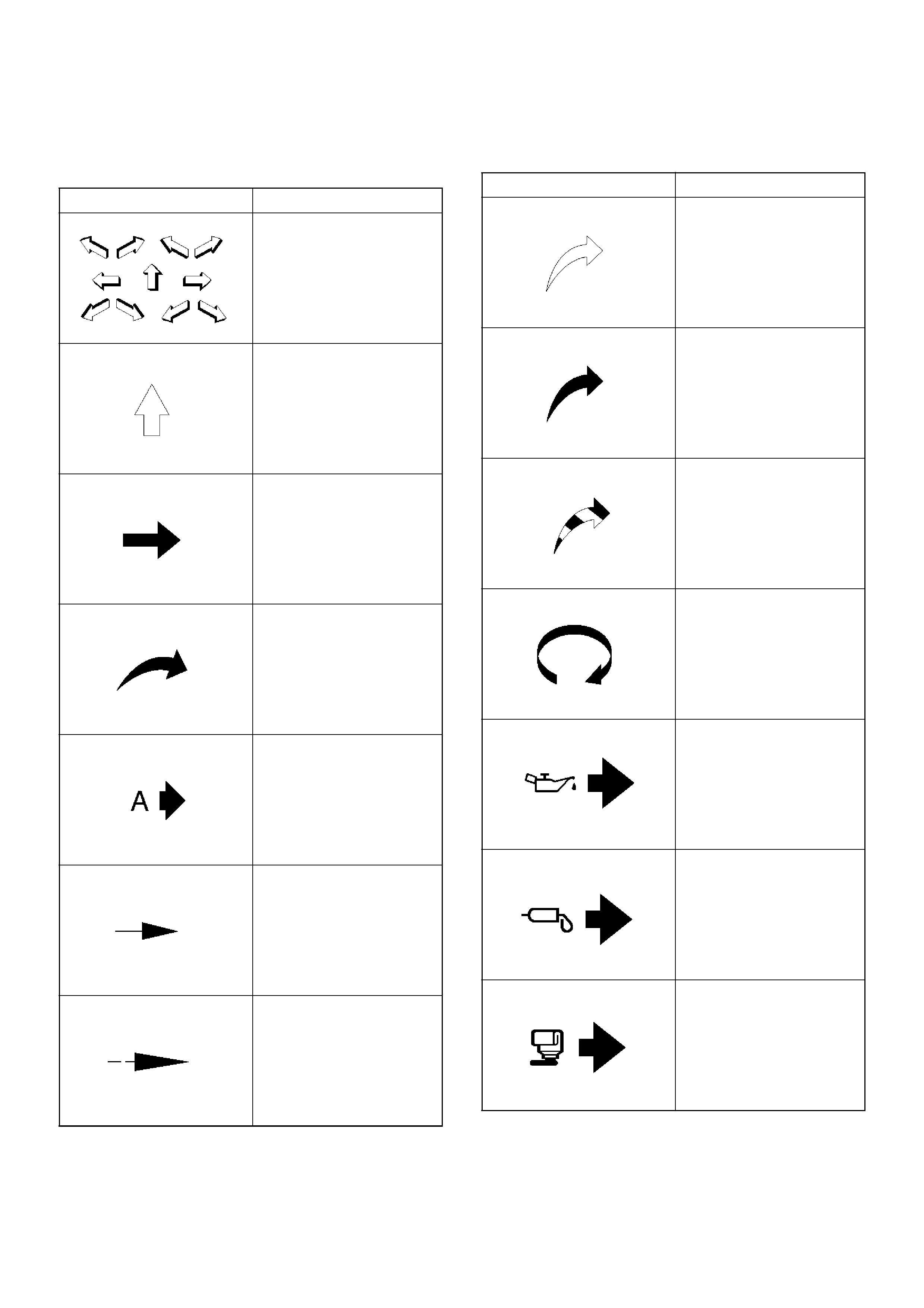
ILLUSTRATION ARROWS
Arrows are designed for specific purposes to aid your understanding of technical illustrations.
Arrow Type Application
Front of vehicle
Up Side
Task Relate d
View Detail
View Angle
Dimension (1:2)
Sectioning (1:3)
• Ambient/Clean air flow
• Cool air flow
• Gas other than
ambient air
• Hot air flow
• Ambient air mixed with
another gas
• Can indicate
temperature change
Motion or direction
Lubrication point oil or
fluid
Lubrication point grease
Lubrication point jelly
Arrow Type Application
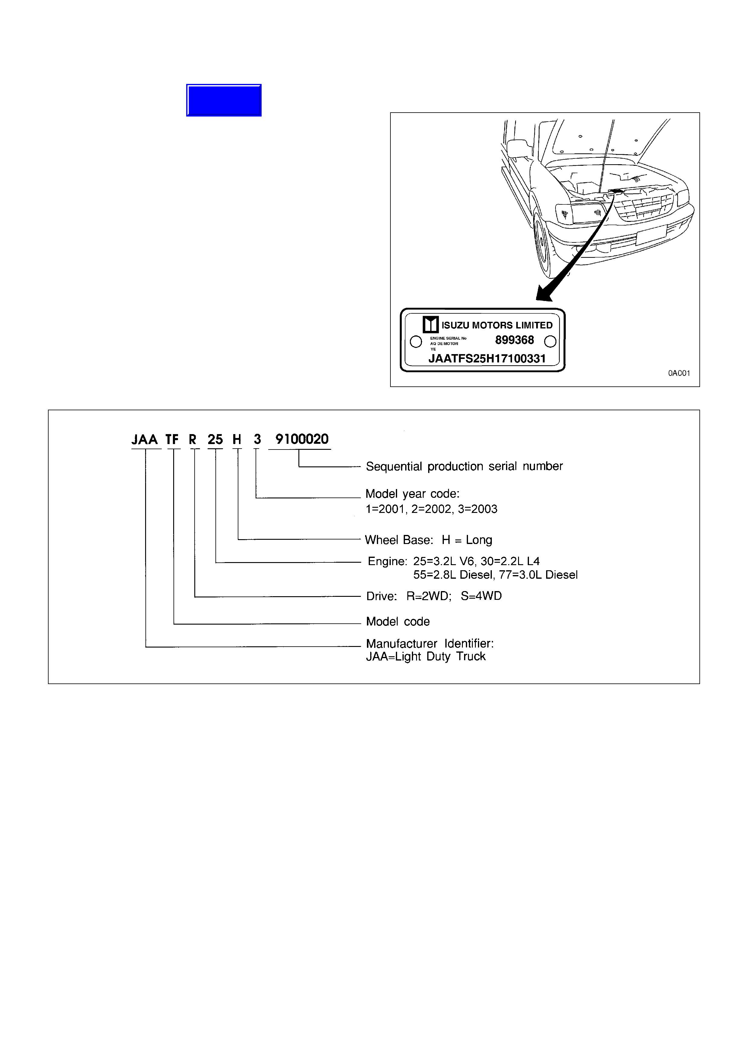
BODY AND OPTIONS PLATE
The Body and Options plate is located on the passenger
side of the dash panel in the engine compart men t.
It displays the VIN and codes for options that have been
built into t he ve hicle. F orr exam ple, t he body type , body
paint colour, trim level, engine and transmission codes
and model designation.
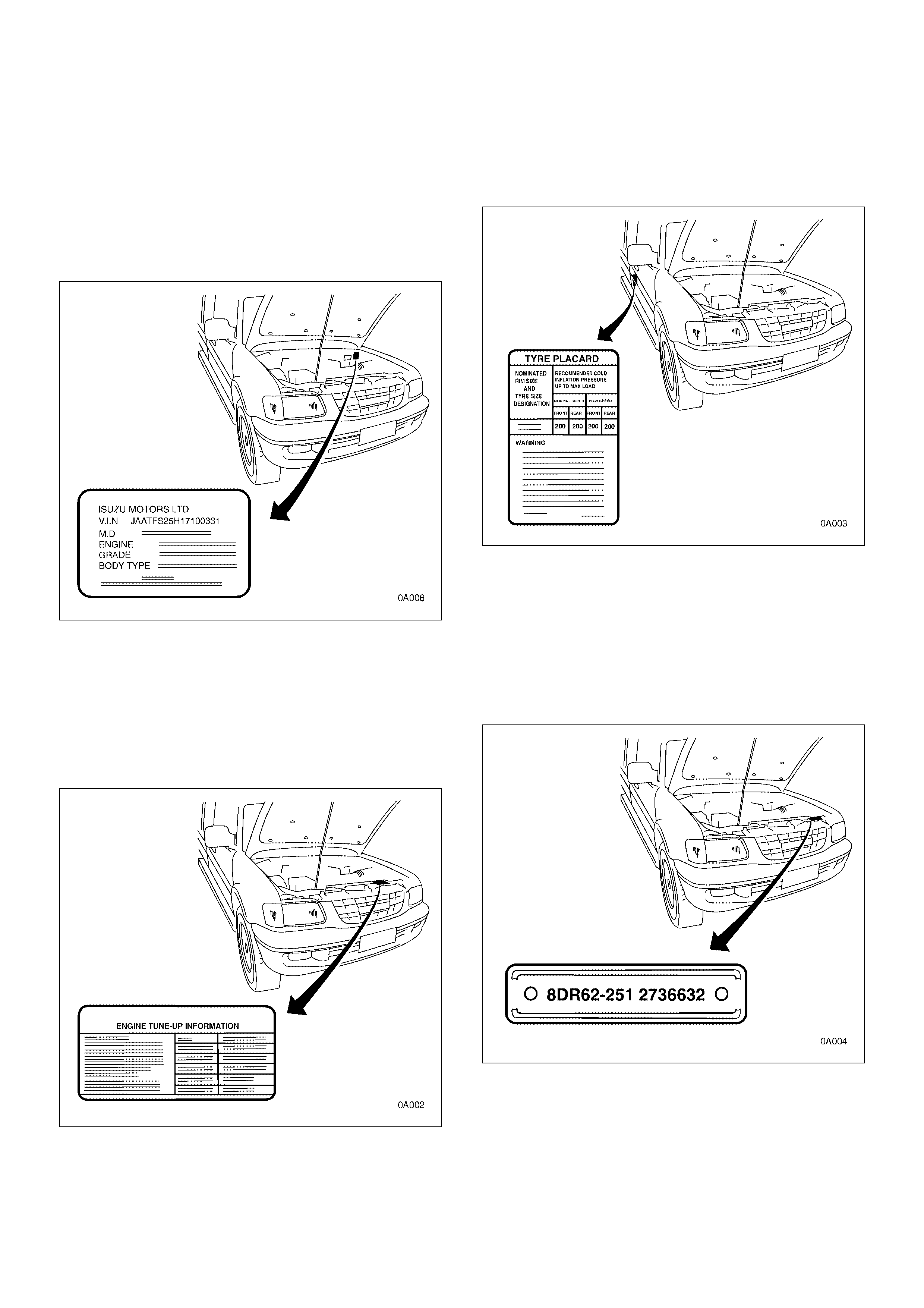
EMISSION LABEL
The Emiss ion label is located on the driver ’s side of the
dash panel in the engine compartment.
It shows the relevant tune-up information required to
maintain the minimum exhaus t emissions.
TYRE PLACARD
The Tyre Placard is located on the driver’s door lock
pillar, and is visible when the door is open.
HOLDEN IDENTIFICATION PLATE
The Holden identification Plate is riveted to the centre of
the radiator support panel in the engine compartment
It is used for warranty identification, roadside assist ance
identification etc.
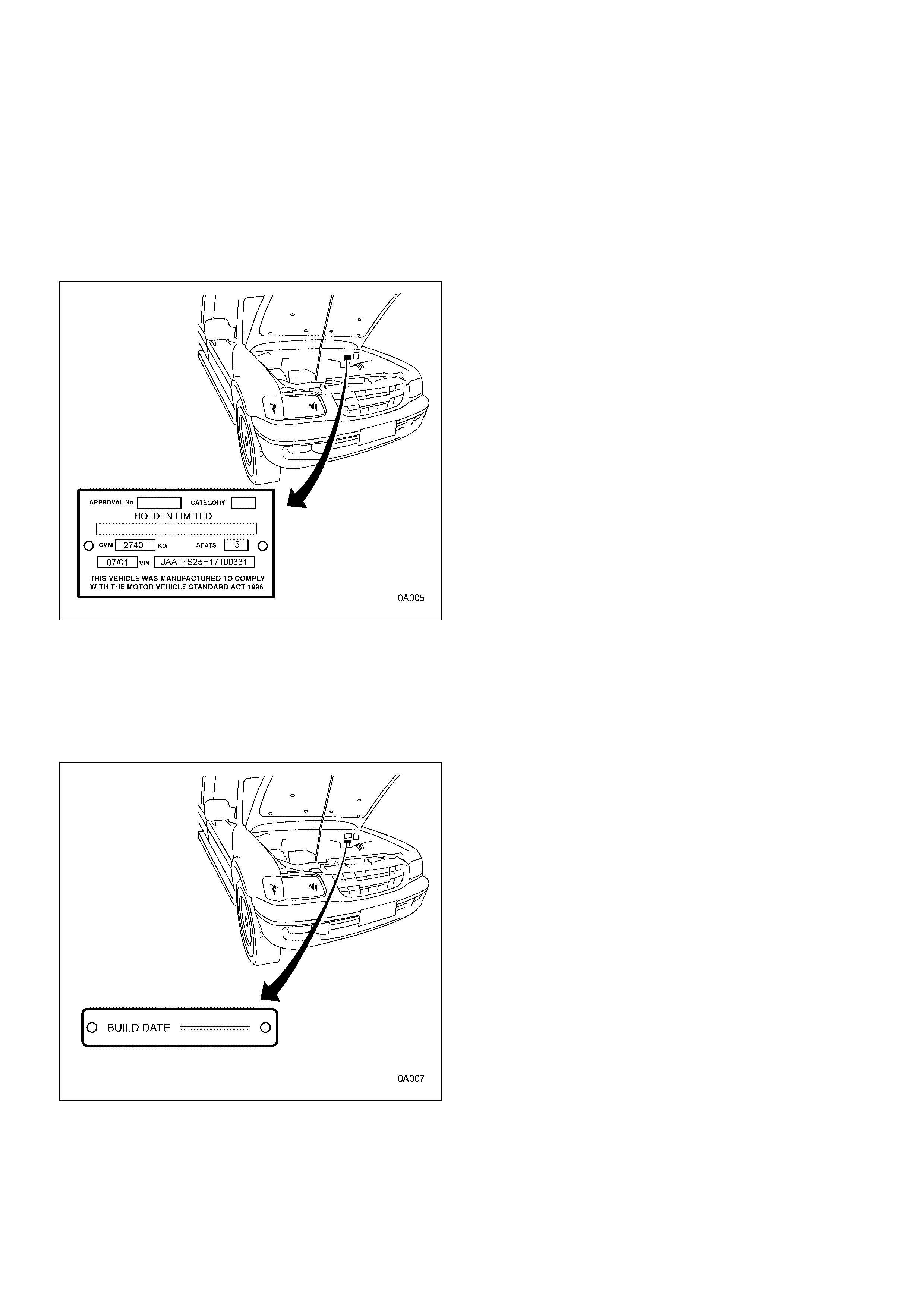
SAFETY COMPLIANCE (ADR) PLATE
The ADR plate is riveted to the passenger side of the
dash panel in the engine compartment.
It displays the approval numbers, category,
manufacturers name, model name and code, Gross
Vehicle Mass (GVM), seating capacity, build date and
VIN.
BUILD DATE PLATE
The B uild Date Plate is riveted to the passenger side of
the dash panel in the engine compartment, below the
Safety Com plianc e Plate.
It displays the date upon which the vehicle was built.
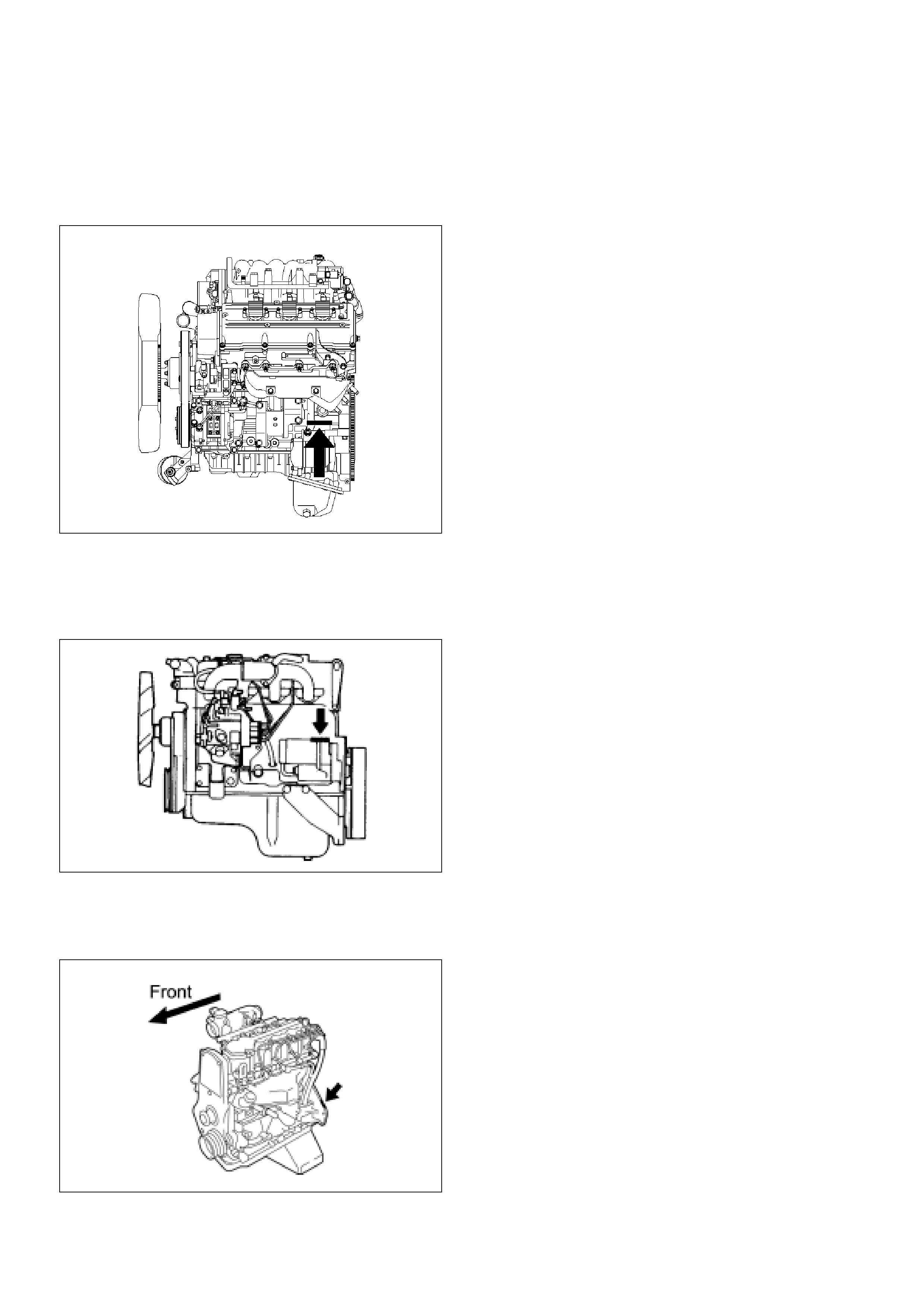
ENGINE SERIAL NUMBER
• 6VD1 Engine
Stamped on the left rear lower area of the cylinder block
above the starter.
F00R100002
• 4JB1T & 4JH1-TC Engines
On the left rear area of the cylinder block above the
starter.
• C22NE Engi ne
On the protrusion at the left rear of the cylinder block.
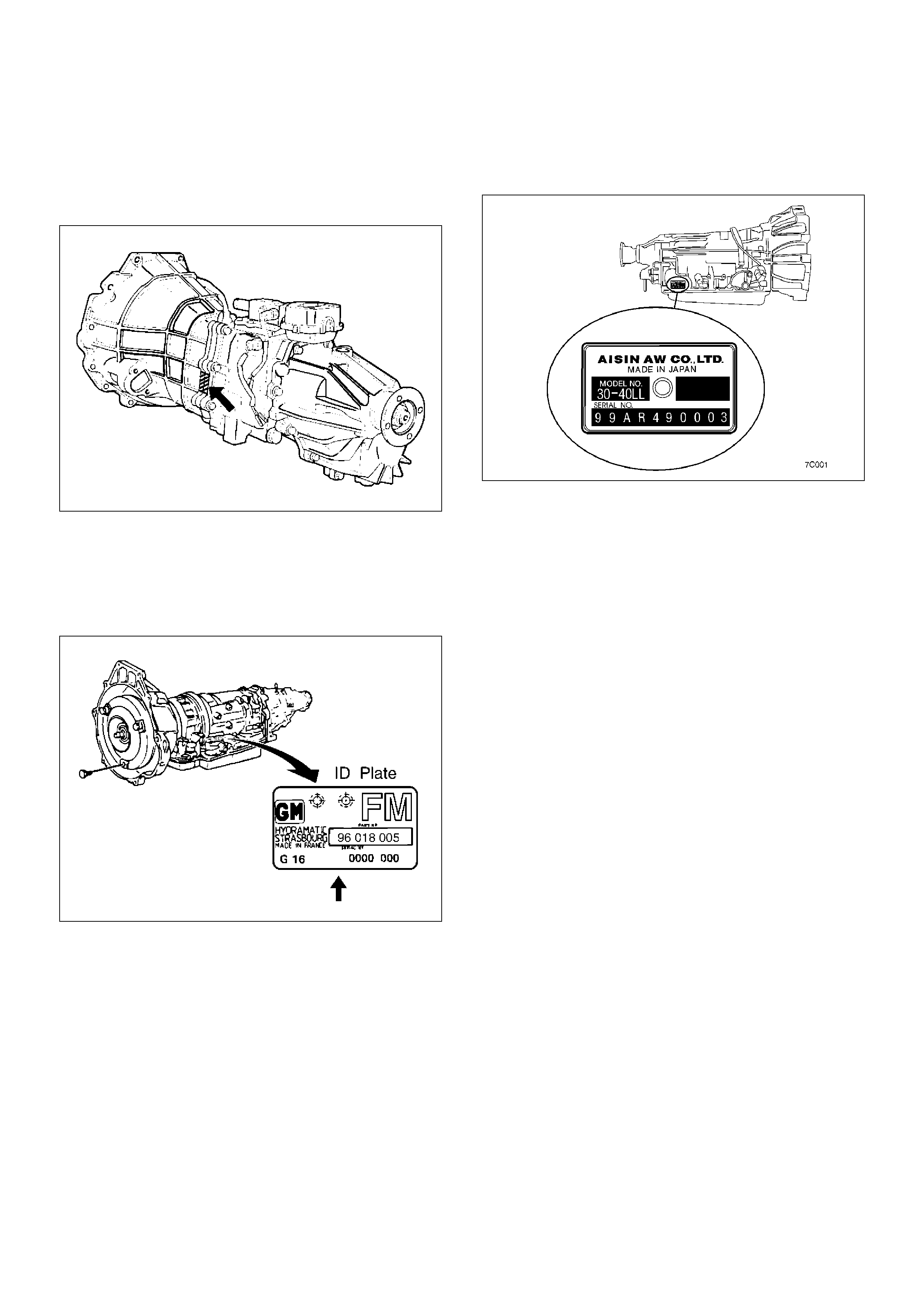
TRANSMISSION SERIAL NUMBER
• Manual - MUA Series
Stamped on the passenger side of the transmission
intermedia te plate.
220RS025
• Aut om at i c - TH M 4L 30E
Stamped on the identification plate, located on the
passenger side of the transmission above the mode
switch.
• Automati c - AW 30-40 LE
Stamped on the identification plate, l ocated on the driver
side of the transmission to the rear of the mode switch.
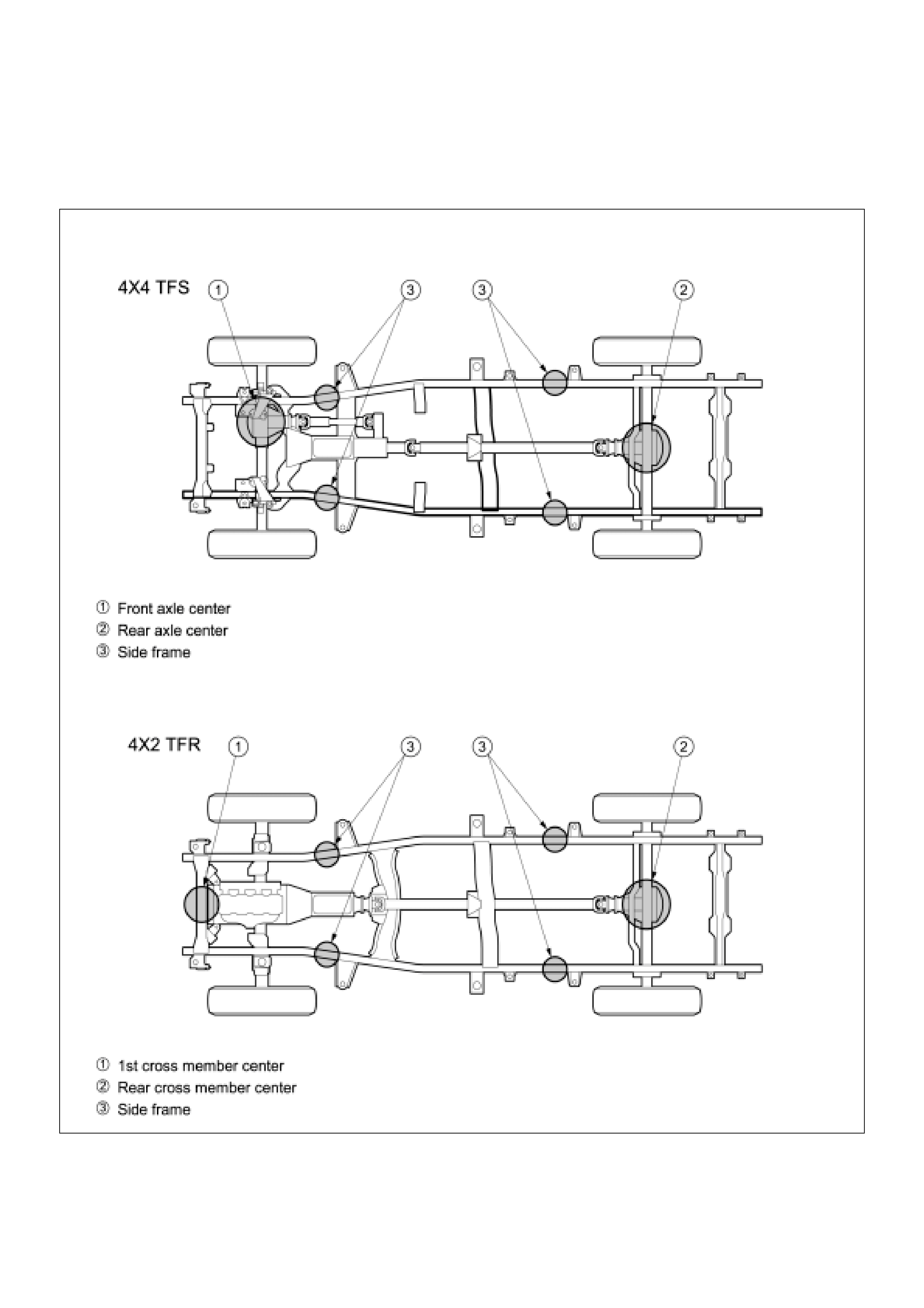
LIFTING INSTRUCTIONS
LIFTING POINTS AND SUPPORTABLE POINT LOCATIONS
CAUTION: IF A LIFTING DEVICE OTHER THAN THE OEM JACK IS USED, RAISING THE VEHICLE FROM ANY
OTHER POINT OTHER THAN THOSE SHOWN MAY RESULT IN SERIOUS DAMAGE.
C00RX002
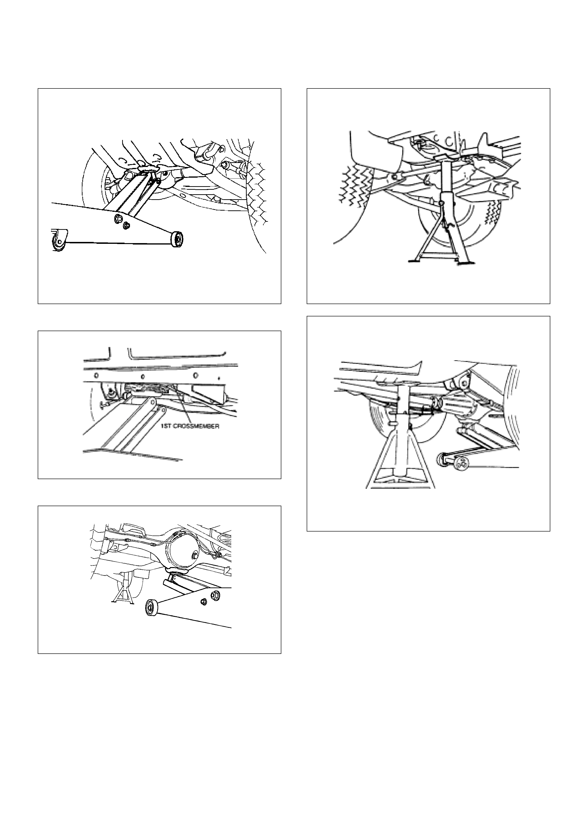
• Lift Point: Front (4x4)
• Lift Point: Front (4x2)
•Lift Point: Rear
420RS002
•Su pport Po in t : Front
• Support Po int : Rear

LOADING & TOWING
Trailers
The word “trailer” is used throughout this section. The word “trailer” is intended to include all types of towed vehicle,
such as a caravan, boat trailer or any other special purpose trailer, etc.
Overloading
Ove rloading is a s afet y hazard and could al so s horte n the life of t he v ehicle . Neve r exce ed the loads sp ecified for th e
vehicle or trailer, as specifi ed below.
Vehicle Capacities
Unladen Mass – the mass of the vehicle in running order, unoccupied and unladen with all fluid reservoirs filled to
nomin al capacity (including fuel) and with all standard equipment fitted. Refer to the following table.
TFR 4x2 Unladen Mass (kg)
TFS 4x4 Unladen Mass (kg)
* excludes rear body mass
NOTE: Add 15kg to the above weights if the vehicle is fitted with automatic transmissi on.
Gross Vehicle Mass Rating (GVMR) – the maximum allowable laden mass of the vehicle. Refer to the following
table.
Gross Combination Mass Rating (GCMR) – the maximum allowable sum of the masses of the towing vehicle and
the towed trailer. Refer to the following table.
Gross To wed Mass Rating (GTMR) – the maximum allowable mass of a trailer (including load) that may be towed by
the vehicle. Refer to the following table.
Front A xle Capacity and Rear Axle Capacity – the maximum allowable loads on the ground at the front and rear
axles. Refer to the following table.
PETROL DIESEL
CAB REAR BODY DX LX LX
Single Pick-up 1345 1513
Cab-chassis* 1200 1368 1295
Space Pick-up 1530
Cab-chassis* 1410
Crew Pick-up 1410 1583
PETROL DIESEL
CAB REAR BODY LX LX
Single Pick-up 1635 1635
Cab-chassis* 1490 1485
Space Pick-up 1640 1685
Cab-chassis* 1540
Crew Pick-up 1705 1715

Note: It may not be possible to tow a fully laden trailer (total trailer mass near or equal to the GTMR) with a fully
laden vehicle (total vehicle mass near or equal to the GVMR), because the total combined weight of the vehi-
cle–trailer combination may exceed the Gross Combination Mass Rating (GCMR). In such cases it is neces-
sary to reduce the load in either or both the towing vehicle and the trailer so that the combined mass of the
towing vehicle and trailer is less than the GCMR.
When towing, the driver must take into account the additional load the trailer puts on the vehicle. Particular
attention must be given to how the trailer changes the loads at the vehicle’s front and rear axles.
When the vehicle and trailer are at or near full load, it may be necessary to use a public weighbridge to check
that none of the vehicle’s, trailer’s or towing equipment’s capacities have been exceeded.
Handling, durability and economy may be affected by towing a trailer.
Country/State Regulations
Note that there are various regulations related to towing, and that these can vary between the different countries/
states. These regulations normally cover the maximum allowable mass of the trailer and the maximum allowable driv-
ing speeds. You must be familiar with the regulations for towing for each of the states in which you intend to tow.
Details of the regulations are available from the relevant state road traffic authorities or motoring associations.
Towing Equipment
The following table shows which towing equipment is essential, according to the total mass to be towed.
For occupant safety and the vehicle’s durability, all equipment marked “Essential” must be correctly installed and used.
Otherwise you may void the New Vehicle Warranty, to the extent that Holden considers the overloading, missing
equipment or misuse to have affected the specifications or quality of the vehicle.
The Holden Dealer can supply and install towing equipment to suit the towing needs.
The Holden towing package for TFR/S Rodeo includes the tow bar, tow bar “tongue” and wiring harness. A Load
Equalising Hitch if required, is sold separately.
Caution: Holden towing equipment is recommended where it is available. Where it is not available, no recommenda-
tion is made as to the make of equipment to be used. Holden will not accept liability for defects occurring in
towing equipm ent not marketed by Holden or for defects in the vehicle arising from the use of such equi p-
ment. T he use of such equipment m ay vo id the New Vehicle Wa rranty, to the e xtent that H olden con siders
the overloadi ng or missing equipme nt to have affected the spe cifications or quality of the vehicle.
4x2 TFR 4x4 TFS
GVMR (kg) 2730 2740
GCMR (kg) 3730 3740
GTMR (kg) 1800 1800
Max. Ball Load (kg) 180 180
Fr ont A xl e Ca pacit y (kg) 1050 1150
Rear Axle Capacity (kg) 1680 1680
Total Trai ler Mass 1800 kg Tow Bar Trailer Wiring Har-
ness Trailer Brakes Load Dist ribution
Hitch
Up to 900kg Essen ti al Essentia l Check State Laws -
Above 900 kg Essential Essential Essential Essential
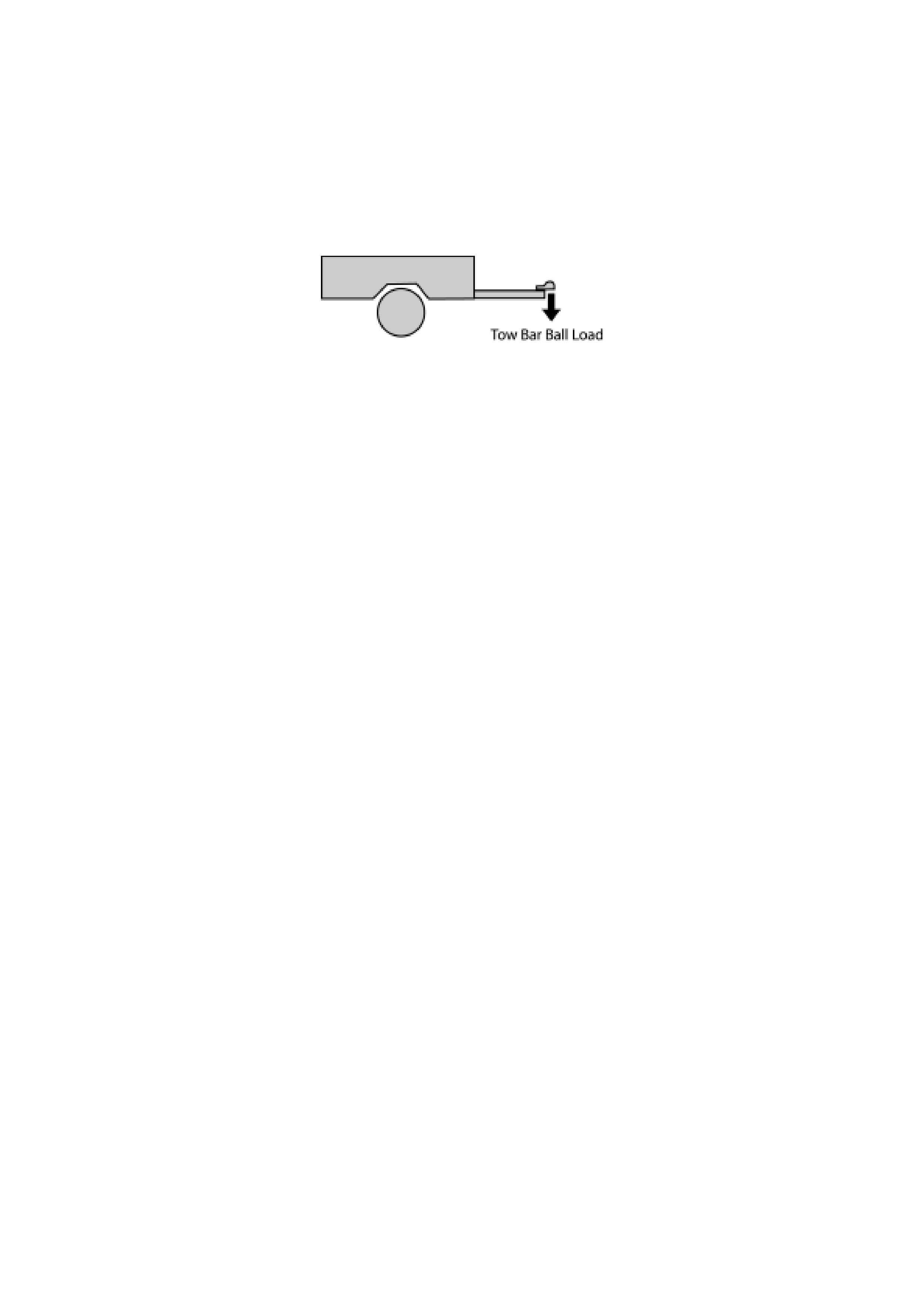
Tow Bar Ball Load
W hen a trailer is connecte d to the towing vehicle , some of the weight of the trailer is applied through the tow “b all” to
the tow bar and t owin g vehicle. T his wei ght is called t he “to w bar ball weight” or “ball load”. T he m ax imum ball load is
180kg.
If the “ball load” is too light or too heavy the steering, handli ng and ride characteristics of the vehicle can be adv ersely
affected.
As a general guideline , for singl e axle trailers, the “ball load” shoul d be appro ximately 10 % of the loaded t rail er mass.
For heavy trailers with more than one axle, the “ball load” should be in the range 5% - 10% of the loaded trailer mass.
Check the “ball load” capacity of the towing equipment. This may be called the “Maximum Down Load”, “Maximum
Vertical Load”, “M ax imum Ball Load” or similar a nd will be s pecifi ed on the tow ba r.
Establish a target “ball load” that is in accordance with the recommendations (above) and within the capacity of the
towing equipment.
Check the “ball load” (compare with the target) before coupling the trailer to the towing vehicle.
The “bal l lo ad” can be adj usted by redistributing the conte nts of th e trailer ie. by moving the co ntents of the trailer for-
ward or backward within the trailer so as to change the trailer ’s balance.
For further information contact the roads authority in the relevant country/state.
Load Equa l isin g Hitch
A Lo ad Distribution Hitch (sometim es called a “Load E qualising Hitch”) is designed to tra nsfer som e of the load f rom
the vehicle’s rear axle to the vehicle’s front axle and the axle(s) of the trailer.
A load distri bution hitch can also be used to restore the towing vehicle to a more normal (level) “attitude”. This reduces
the need to adjust headlight alignment and should provide the towing vehicle with more “normal” ride and handling.
For these reasons, the use of load distributing devices can make towing safer, more comfortable and more conve-
nient.
Adjust the load distribution hitch so that the vehicle is has about the same “attitude” (“stance” or “angle to the ground”)
as when it is unladen.
Roof Racks
For occupant safety, and to avoid damaging the vehicle’s roof, there is no released Holden approved roof rack system
for TF Rodeo.
Fitting Accessori es (Bull Bars , Driving Lamps, Insect Screens, etc.)
W hen fitting accessories take care not to restrict airflow through the air conditioner ’s condenser and the radiator, oth-
erwise engine overheating and/or poor air conditioning performance may result.
The mass of all accessories must be considered when ev aluating the vehicle’s overall loaded c ondition.
Remem ber that bull bars may affect air bag operation.

Running In Before Towing
Holden recommends driving the new vehicle for at least 1,500km before towing. If it is required to tow in the first 1,500
km of the vehicle’s life, the maximum vehicle speed should not exceed 80 km/h.
The same applies if the vehicle is equipped with a new or reconditioned engine, transmission or axle.
Off Road Loading And Towing
Driving the vehicle off-road may induce higher loads than normal on-road driving. To reduce the risk of damage to the
vehicle (and trailer) and improve safety when operating off-road, reduce the vehicle speed and minimise the load
being carried (and towed).
TOWING PRECAUTIONS
• The vehicle will handle differently when towing. It is a good idea to for the driver to make a couple of short-distance
trips with the trailer to become familiar with the handling characteristics of the vehicle when towing.
• The vehicle must be correctly maintained and serviced.
• Have the trailer maintained and serviced, with particula r attention to the condition of the brakes, tyres, suspension,
wheel bearings, lighting and the towing equipment.
• Driving speed should be reduced when towing.
• If the trailer has poor directional stability seek qualified advice eg. the trailer’s manufacturer or retailer. The use of
stabilising equipment should be considered.
• Ensure that all loads – in or on the towing vehicle and in the trailer - are properly secured.
• Use extended-arm rear vision mirrors when the trailer is wider than the towing vehicle.
• Headlights may need realignment after the loaded trailer has been hitched. The use of a load distribution hitch will
reduce the need for headlight realignment, making towing safer and more convenient.
• Slow the vehicle and select a lower gear before descending steep hills.
• When towing, inflate the vehicle’s tyres to the maximum recommended pressure.
• Be familiar with the regulations for towing for each of the states in which you intend to tow. Contact the road traffic
authority in each state for specific advice.
• The brakes on the trailer must be adequate for the braking needs of the trailer and must not adversely affect the
performance of the brakes of the towing vehicle.
• When a tow bar is removed, be certain to seal any mounting holes in the chassis frame or vehicle body to prevent
the possible entry of exhaust fumes, dust and water. Sealing mounting holes in the chassis frame will ensure that
the tow bar can be properly refitted at a later date.
• Ensure that no part of the tow bar (including the tongue or tow ball obscures the vehicle’s licence plate. If necessary,
remove the tow bar tongue when it is not in use.
• More frequent vehicle maintenance is required when using the vehicle to pull a trailer. Refer to
Section 0B - Lubrication and Servicing.
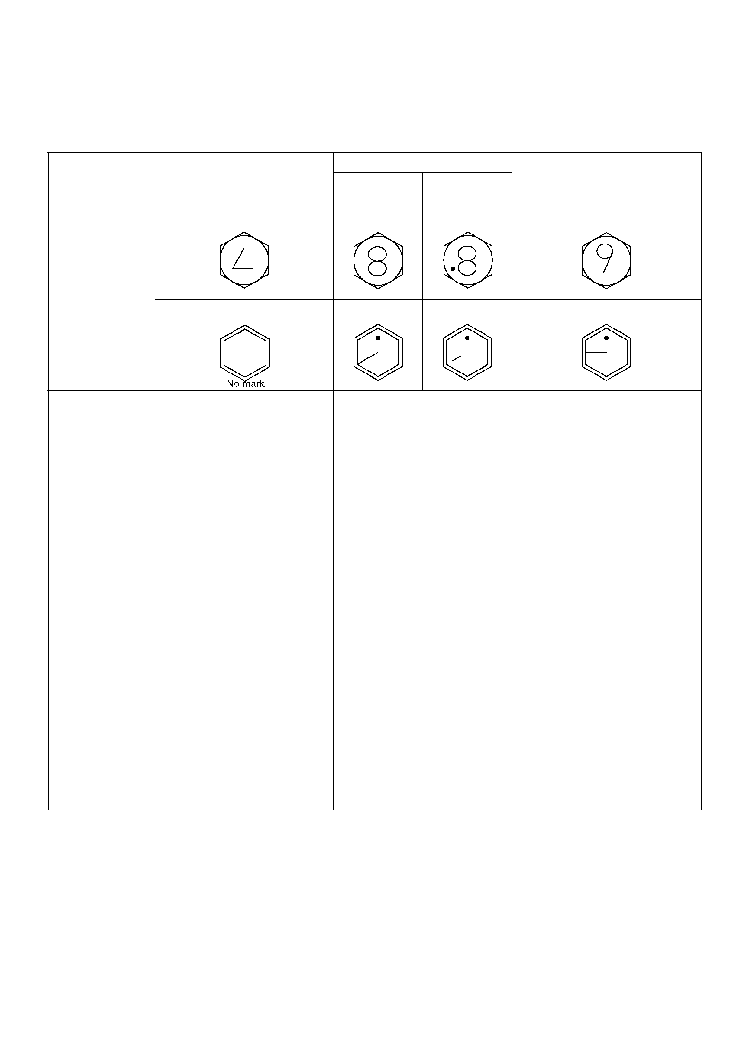
STANDARD BOLT TORQUE SPECIFICATIONS
NOTE: The torque values given in the following table should be applied where a particular torque is not specified.
The asterisk * indicates that the bolts are used for
female–threaded parts that are made of soft materials
such as castin g , etc.
1. Strength
Class 1. 4.8 1. 8.8 1. 9.8
1. Refined 1. Non-Refine
d
Bolt
Identification
Bolt Diameter ´
Pitch (mm)
2. M 6X1.0
3. M 8X1.25
4. M 10X1.25
5. * M10 X1.5
6. M12X1.25
7. * M12 X1.75
8. M14X1.5
9. * M14 X2.0
10. M16X1.5
11. * M16X2.0
12. M18X1.5
13. M20X1.5
14. M22X1.5
15. M24X2.0
16. 4 – 8 N·m (3 – 6 lb ft)
17. 8 – 18 N·m (6 – 13 lb ft)
18. 21 – 34 N·m (15 – 25 lb ft)
19. 20 – 33 N·m (14 – 25 lb ft)
20. 49 – 74 N·m (36 – 54 lb ft)
21. 45 – 69 N·m (33 – 51 lb ft)
22. 77 – 115 N·m (56 – 85 lb
ft)
23. 72 – 107 N·m (53 – 79 lb
ft)
24. 104 – 157 N·m (77 – 116
lb ft)
25. 100 – 149 N·m (74 – 110
lb ft)
26. 151 – 226 N· m (111 – 166
lb ft)
27. 206 – 310 N· m (152 – 229
lb ft)
28. 251 – 414 N· m (185 – 305
lb ft)
29. 359 – 539 N· m (265 – 398
lb ft)
30. 5 – 10 N·m (4 – 7 lb ft)
31. 12 – 23 N·m (9 – 17 lb ft)
32. 28 – 46 N·m (20 – 34 lb ft)
33. 28 – 45 N·m (20 – 33 lb ft)
34. 61 – 91 N·m (45 – 67 lb ft)
35. 57 – 84 N·m (42 – 62 lb ft)
36. 93 – 139 N· m (69 – 103 lb
ft)
37. 88 – 131 N·m (65 – 97 lb
ft)
38. 135 – 20 4 N·m (100 – 150
lb ft)
39. 130 – 194 N·m (95 – 143
lb ft)
40. 195 – 29 3 N·m (144 – 216
lb ft)
41. 270 – 40 5 N·m (199 – 299
lb ft)
42. 363 – 54 4 N·m (268 – 401
lb ft)
43. 431 – 711 N·m (318 – 524
lb ft)
44. –
45. 17 – 30 N·m (12 – 22 lb ft)
46. 37 – 63 N·m (27 – 46 lb ft)
47. 36 – 60 N·m (27 – 44 lb ft)
48. 76 – 114 N·m (56 – 84 lb ft)
49. 72 – 107 N·m (53 – 79 lb ft)
50. 114 – 171 N·m (84 – 126 lb
ft)
51. 107 – 160 N·m (79 – 118 lb
ft)
52. 160 – 240 N·m (118 – 177 lb
ft)
53. 153 – 230 N·m (113 – 169 lb
ft)
54. 230 – 345 N·m (169 – 255 lb
ft)
55. 317 – 476 N·m (234 – 351 lb
ft)
56. 425 – 637 N·m (313 – 469 lb
ft)
57. 554 – 831 N·m (409 – 613 lb
ft)

ABBREVIATIONS CHARTS
List of automotive abbreviations which may be used
in this ma nual
A — Ampere(s)
ABS — Antil ock Brake Sys te m
AC — A lternating C urrent
A/C — Air Conditioning
ACCEL — Accelerator
ACC — Accessory
ACL — A ir Cleaner
Adj — Adjust
A/F — Air Fuel Ratio
AIR — Secondary Air Injection Syste m
Alt — Altitude
AMP — Ampere(s)
ANT — Antenna
ASM — Assembly
A/T — A utomat ic Transmiss ion /Transaxle
ATDC — After Top Dead Center
ATF — Automatic Transmission Fluid
Auth — Authority
Auto — Automatic
BARO — Barometric Pressure
Bat — Batter y
B+ — Battery Positive Vo ltage
Bbl — Barrel
BHP — Brake Horsepowe r
BPT — Backpressure Transduc er
BTDC — Before Top Dead Center
° C — Degrees Celsius
CAC — Charge Air Cooler
Calif — California
cc — Cubic Centimeter
CID — Cubic Inch Displacement
CKP — Crankshaft Position
CL — Closed Loop
CLCC — Closed Loop Carburetor Control
CMP — Camshaft Position
CO — Carbon Monoxide
Coax — Coaxial
Conn — Connector
Conv — Converter
Crank — Crankshaf t
Cu. In. — Cubic Inch
CV — Constant Velo city
Cyl — Cylinder(s)
DI — Distributor Ignition
Diff — Differential
Dist — Distributor
DLC — Data Link Connector
DOHC — Double Overhead Camshaft
DTC — Diagnostic Trouble Code
DTM — Diagnostic Test Mode
DTT — Diag nostic Test Terminal
DVM — Digital Voltmeter (10 meg.)
DVOM — Digital Vol t Ohmmeter
EBCM — Electronic Brake Control Module
ECM — Engine Control Module
ECT — Engine Coolant Tempe rature
EEPROM — Electronically Erasable Programmable
Read Only Memory
EGR — Exhaust Gas Recirculation
EI — Electronic Ign ition
ETR — Electronically Tuned Receiver
EVAP — E vaporat ion Emission
Exh — Exhaust
° F — Degrees Fahrenheit
Fed — Federal (All States Except Calif.)
FF — Front Drive Front Engine
FL — Fusible Link
FLW — Fusib le Link Wire
FP — Fuel Pu mp
FRT — Fro nt
ft — Foot
FWD — Front Wheel Drive
4WD — Four Wheel Drive
4 x 4 — Four Wheel Drive
4 A/T — Four Sp eed Automa tic Transmission/Transaxle
Gal — Ga llon
GEN — Generat or
GND — Ground
Gov — Governor
g — Gram
Harn — Harness
HC — Hydrocarbons
HD — Heavy Duty
Hg — Hydrargyrum (Mercury)
HiAlt — High Altitude
HO2S — Heated Oxygen Sensor
HVAC — Heater–Vent–Air–Conditioning
IAC — Idle Air Con trol
IAT — In take Ai r Tem p era tu r e
IC — Integrated Circuit / Ignition Control
ID — Identification / Inside Diameter
IGN — Ignition
INJ — Injec tion
IP — Instrument Panel
IPC — Instrument Panel Cluster
Int — Intake
ISC — Idle Speed Control
J/B — Junction B lock
kg — Kilograms
km — Kilometers
km/h — Kilometer per Hour
kpa — Kilopascals
kV — Kilovolts (thousands of volts)
kW — Kilowatts
KS — Knock Sensor
L — Liter
lb ft — Foot Pounds
lb in — Inch Pounds
LF — Left Front
LH — Left Hand
LR — Left Rear
LS — Left Side
LWB — Lon g Wheel B ase
L–4 — In–Line Four Cylinde r Engine
MAF — Mass Air Flow
MAN — Manual

MAP — Manifold Absolute Pressure
Max — Maximum
MC — Mi xture Control
MFI — Mu ltiport Fuel Injection
MIL — Malfunction Indicator Lamp
Min — Minimum
mm — Millime ter
MPG — Miles Per Gallon
MPH — Miles Per Hour
M/T — Ma nual Transmission/Transaxle
MV — Millivo lt
N — Newtons
NA — Natural Aspirated
NC — Normally Closed
N·M — Newton Meters
NO — Normally Open
NOX — Nitrogen , Oxides of
OBD — On-Board Diagnostic
OD — Outside Diameter
O/D — Over Drive
OHC — Overhead Camshaft
OL — Open Loop
O2 — Oxygen
O2S — Oxygen Sensor
PAIR — Pulsed Secondary Air Injection System
P/B — Power Bra kes
PCM — Powertrain Control Module
PCV — Positive Crankcase Ventilation
PRESS — Pressure
PROM — P rogram mab le Read Only M emo ry
PNP — Park/Neutral Positi on
P/S — Power Steering
PSI — Pound s per Square Inch
PSP — Power Steer ing Pr e ssu re
Pt. — Pint
Pri — Primary
PWM — P ulse Width Modulate
Qt. — Quart
REF — Reference
RF — Right Front
RFI — Radio Frequency Interference
RH — Right Hand
RPM — Revolutions Pe r Minute
RPM Sensor — Engine Speed Sensor
RPO — Regular Production Option
RR — Right Rear
RS — Right Side
RTV — Room Temperature Vulcanizing
RWA L — Rear Whee l Antilock Brake
RWD — Rear Wheel Drive
SAE — Socie ty of Aut o mo tive Engineers
Sec — S ec ondary
SFI — S equential Multiport Fuel Inject ion
SI — System International
SIR — Supplemental Inflatable Restraint System
SOHC — Single Overhead Camshaft
Sol — Solenoid
SPEC — Specificati o n
Speedo — Speedometer
SRS — Supplemental Restraint System
ST — St art / Scan Tool
Sw — Switch
SWB — Short Wheel Base
SYN — Synchronize
Tach — Tac hom ete r
TB — Throttle Body
TBI — Throttl e Body Fuel Injection
TCC — Torque Converter Clutch
TCM — Transmission Control Mod ule
TDC — Top Dead Center
Term — Terminal
TEMP — Tem peratur e
TOD— Torque On Demand
TP — Throttle Position
TRANS — Transmission/Transaxle
TURBO — Turbocharger
TVRS — Televisio n & Radio Suppression
TVV — Th ermal Vacuum Valve
TWC — Three Way Cata l yt ic Converter
3 A/T — Three Speed Automatic Transmission/
Transaxle
2WD — Two Wheel Drive
4 x 2 — T wo Wheel Drive
U–jo int — U n iv er s al Join t
V — Volt ( s)
VAC — Vacuum
VIN — Vehi cle Identification Number
VRRRE — Vehicle Refrigerant Recovery and Recycling
Equipment
V–ref — ECM Reference V ol tage
VSS — Vehicle Speed Sensor
VSV — Vacuum Switch Valve
V–6 — Six Cylinder “V" Engine
V–8 — Eight Cylinder "V" Engine
W — Watt(s)
w/ — With
w/b — Wheel Base
w/o — Without
WOT — Wi de Open Th ro ttle