
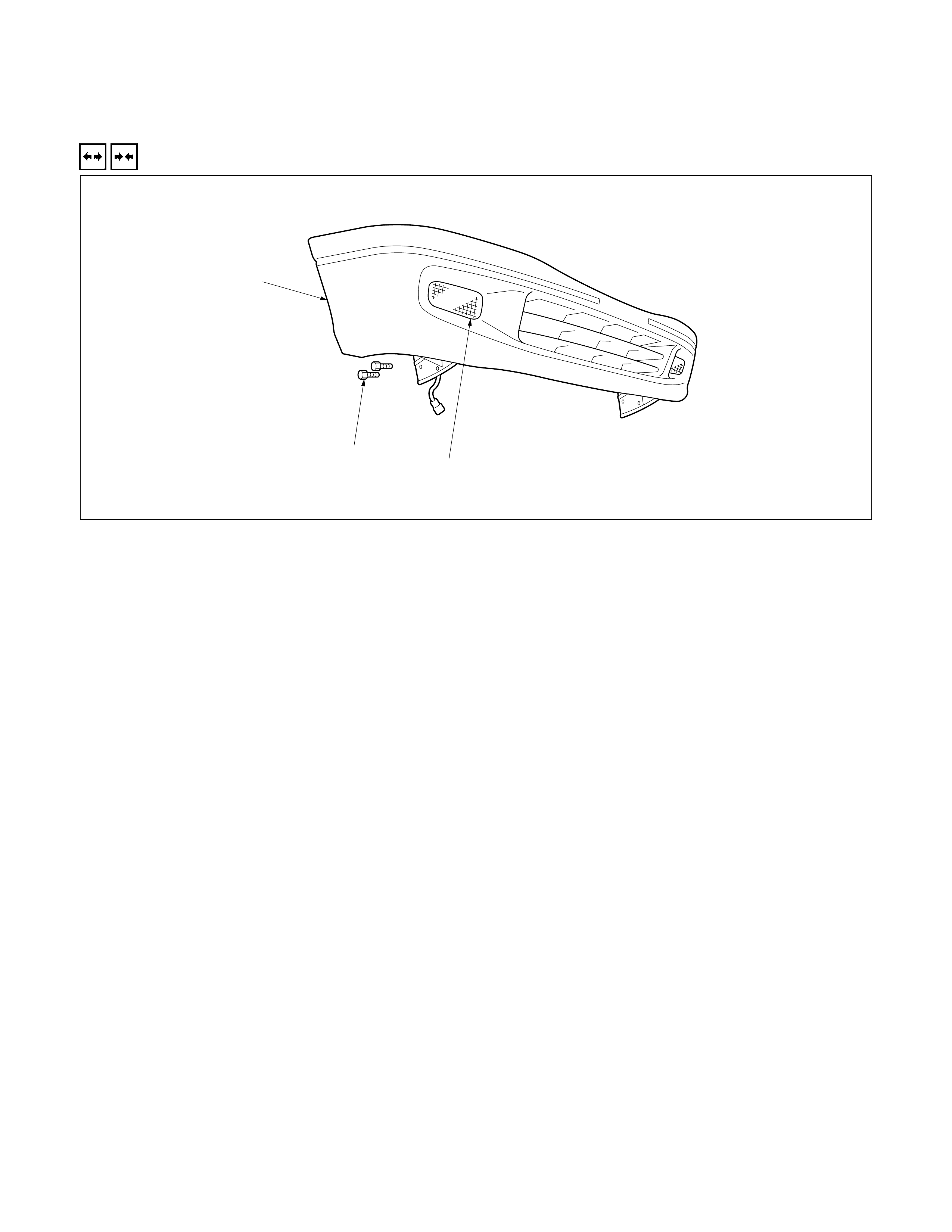
FRONT BUMPER
REMOVAL AND INSTALLATION
2
1
3
REMOVAL STEPS
▲1. Front combination light
2. Bolt
3. Front bumper assembly
INSTALLATION STEPS
3. Front bumper assembly
▲2. Bolt
1. Front combination light
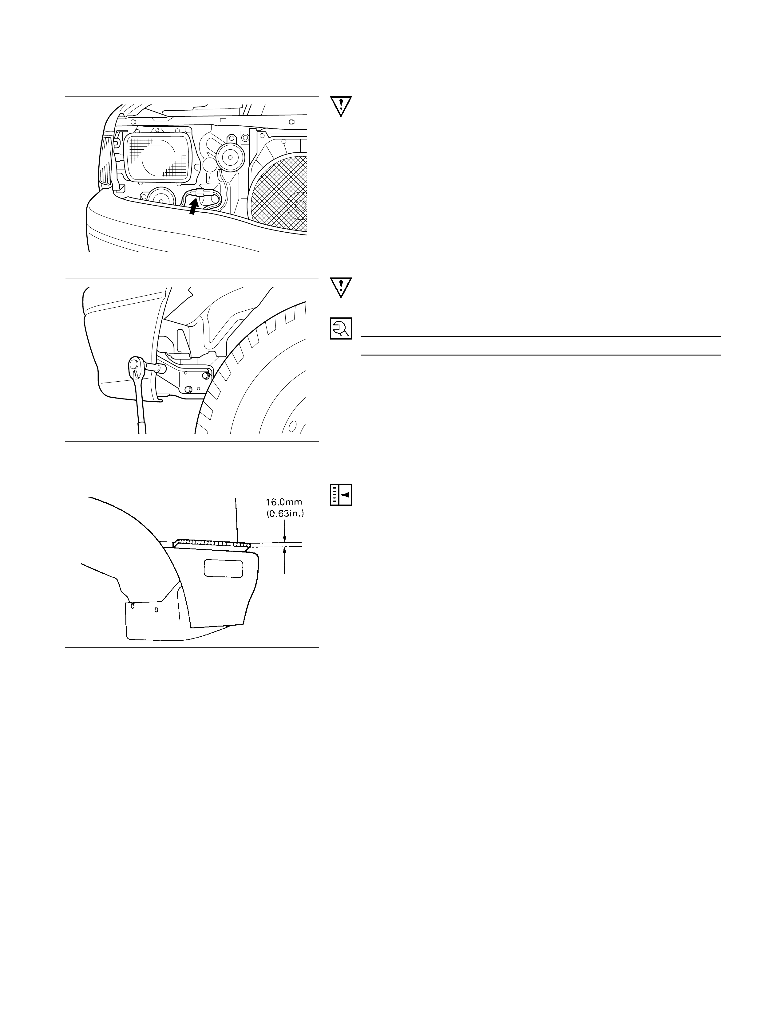
IMPORTANT OPERATION - REMOVAL
1. Front Combination Light
Disconnect the front combination light harness.
IMPORTANT OPERATION - INSTALLATION
2. Bolt
Torque N⋅m
134.9±17.2
ADJUSTMENT When the bolts fixing front bumper assembly are tightened,
adjustment should be made with shims fitted between the back
bar and front side bumper so that a clearance of 16.0 mm
(0.63 in.) is provided between the lower side of the fender and
the upper side of the front side bumper.

REAR BUMPER
REMOVAL AND INSTALLATION
4
4
1
2
3
3
5
2
2
REMOVAL STEPS
1. Bolt; back bar to frame
2. Back bar
3. Bolt; back bar to rear bumper
4. Cap; rear bumper
5. Rear bumper
INSTALLATION STEPS
5. Rear bumper
4. Cap; rear bumper
▲3. Bolt; back bar to rear bumper
2. Back bar
1. Bolt; back bar to frame
IMPORTANT OPERATION - INSTALLATION
3. Bolt; Back Bar to Rear Bumper
Torque N⋅m
103±9.8
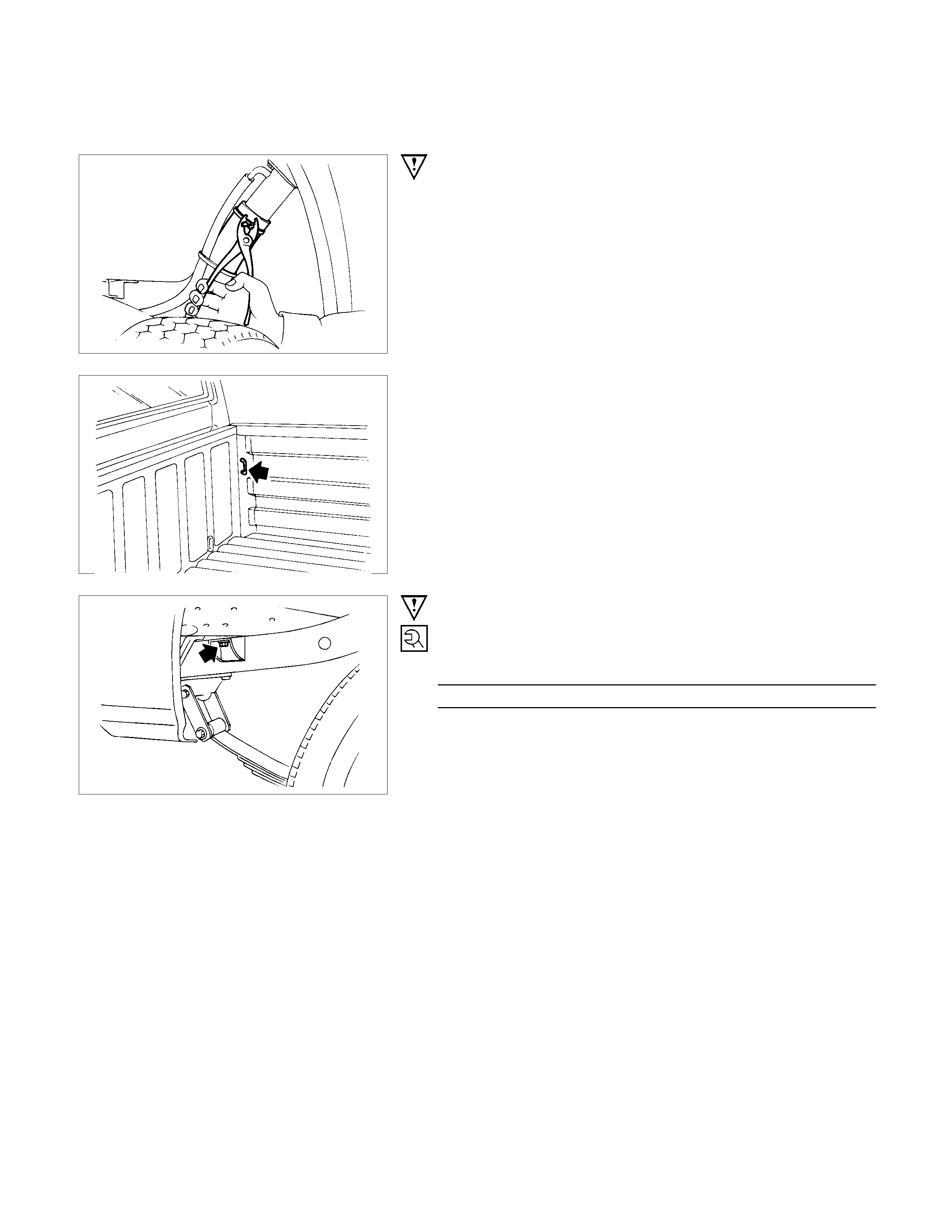
REAR BODY
REMOVAL AND INSTALLATION
REMOVAL STEPS
1. Battery ground cable
2. Rear combination lamp harness
▲3. Fuel filler pipe and evaporator hose
4. Spare tire
5. Bolt; frame to rear body
▲6. Rear body assembly
INSTALLATION STEPS
6. Rear body assembly
▲5. Bolt; frame to rear body
4. Spare tire
3. Fuel filler pipe and evaporator hose
2. Rear combination lamp harness
1. Battery ground cable
NOTE:
The rear body must be empty before removal.
IMPORTANT OPERATION - REMOVAL
3. Fuel Filler Pipe and Evaporator Hose
Disconnect the fuel filler pipe and evaporator hose.
6. Rear Body Assembly
Attach lifting wires to the rear body and raise the rear body.
Note:
In lifting up rear body, take care not to dash it against cab
body.
IMPORTANT OPERATION - INSTALLATION
5. Bolt; Frame to Body
Torque N⋅m
63.8±14.7
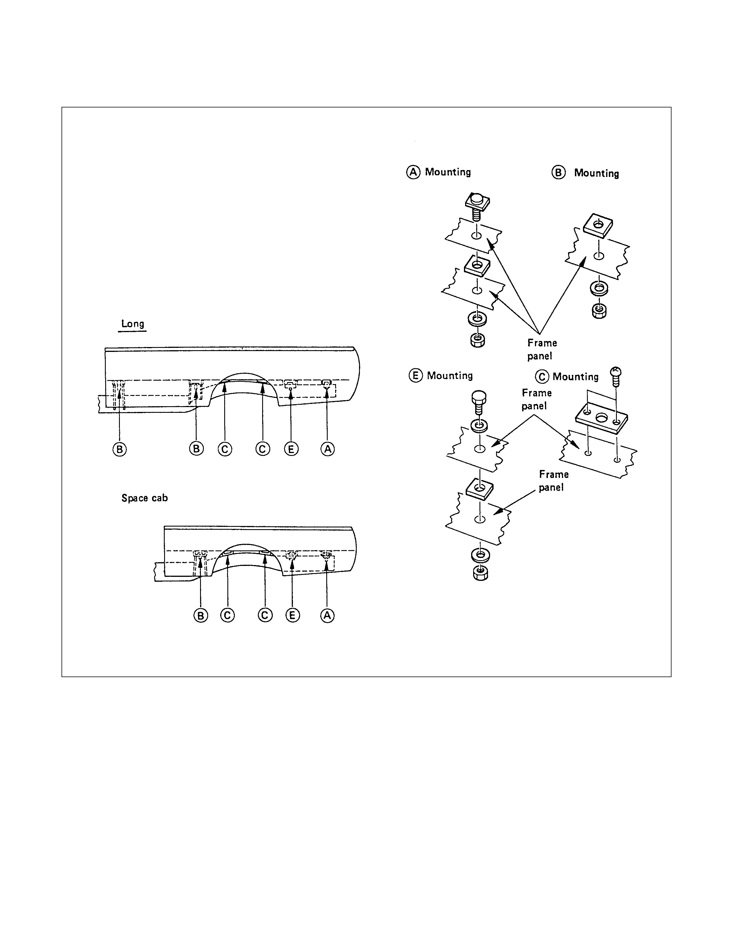
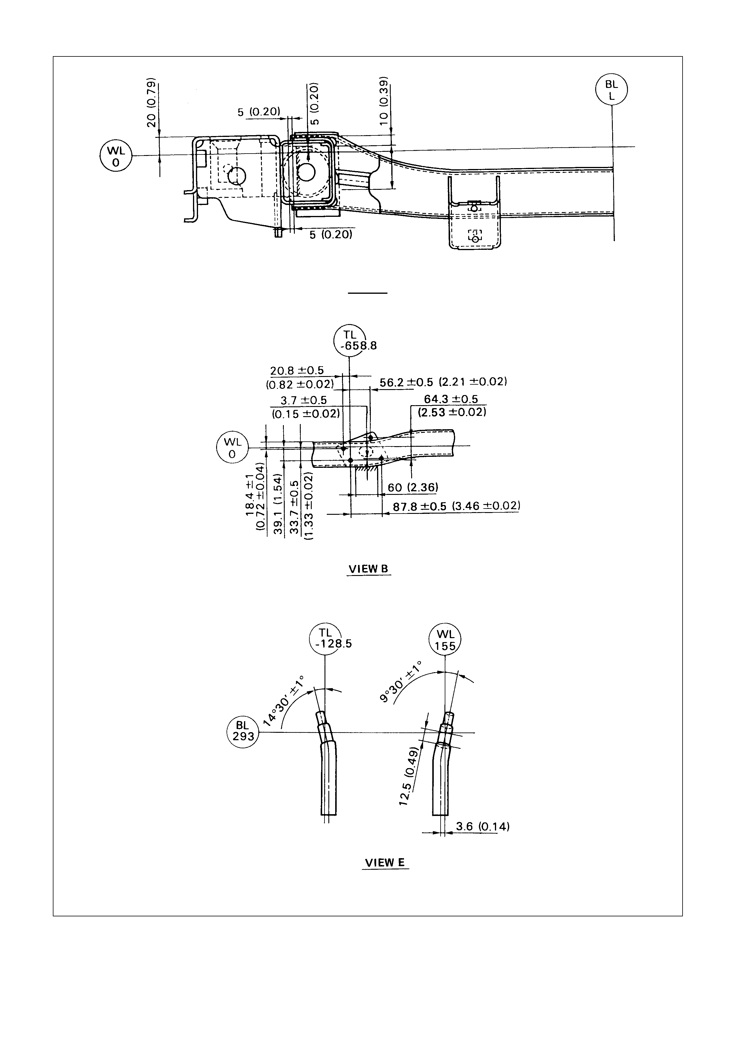
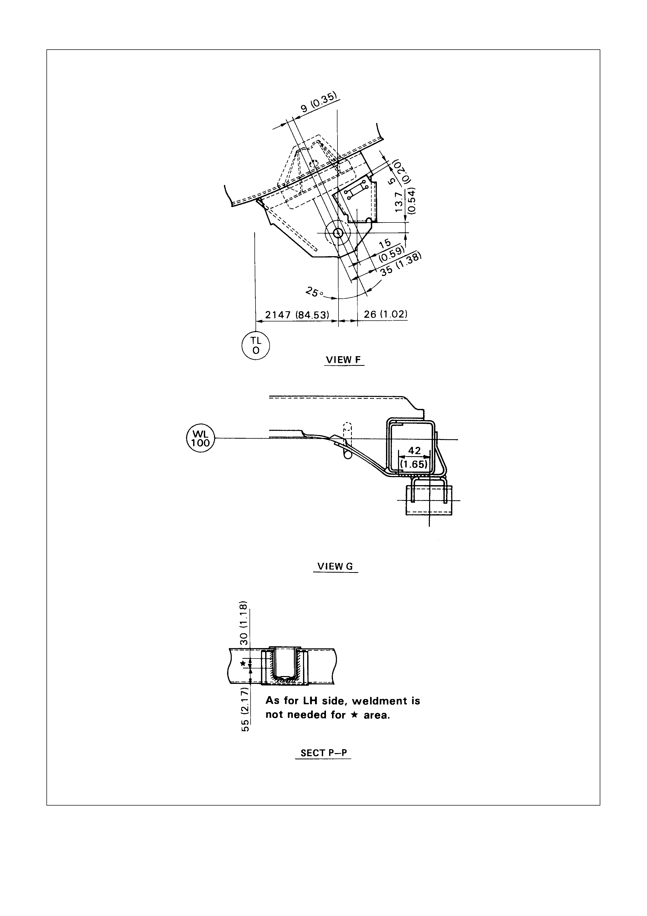
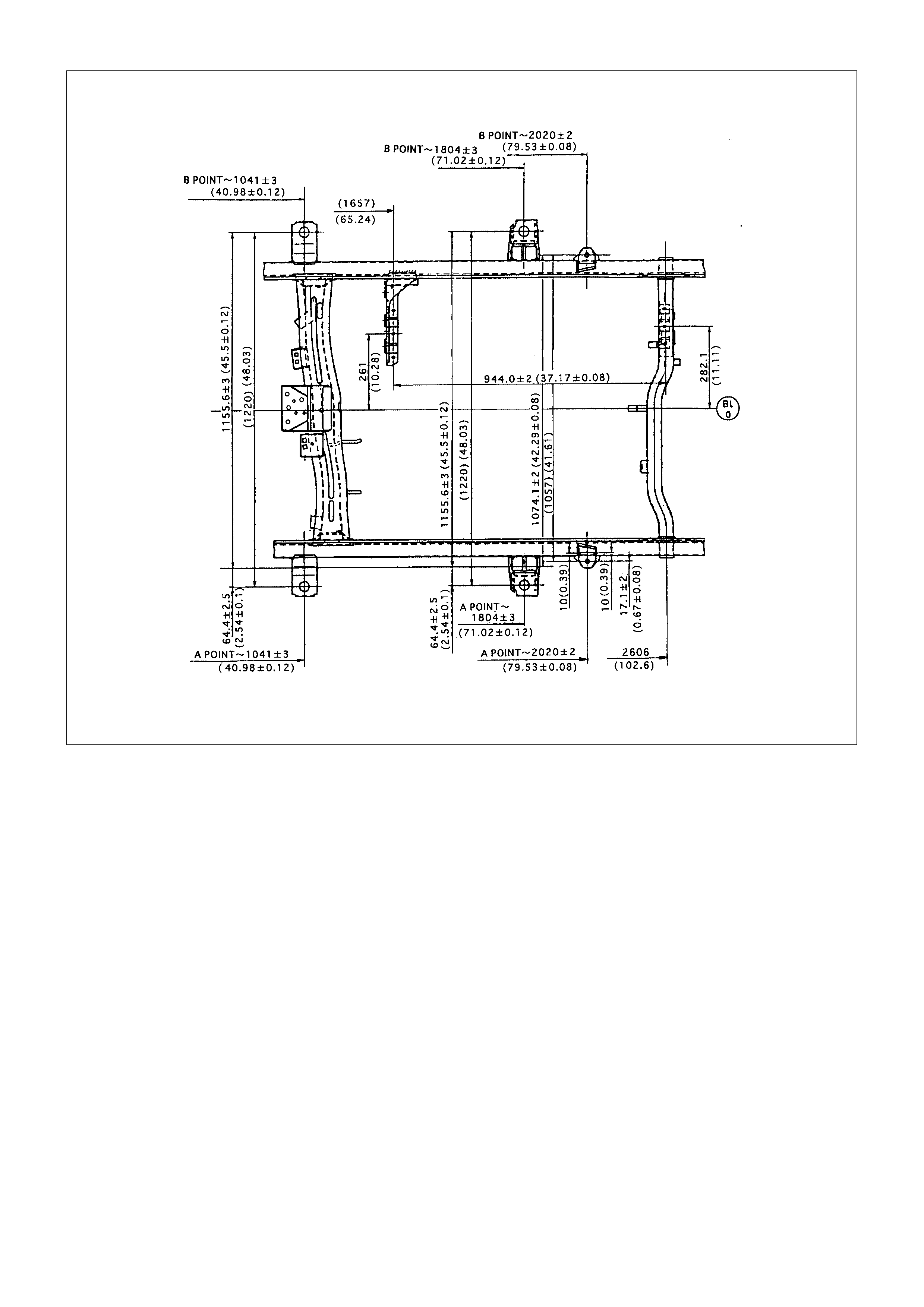
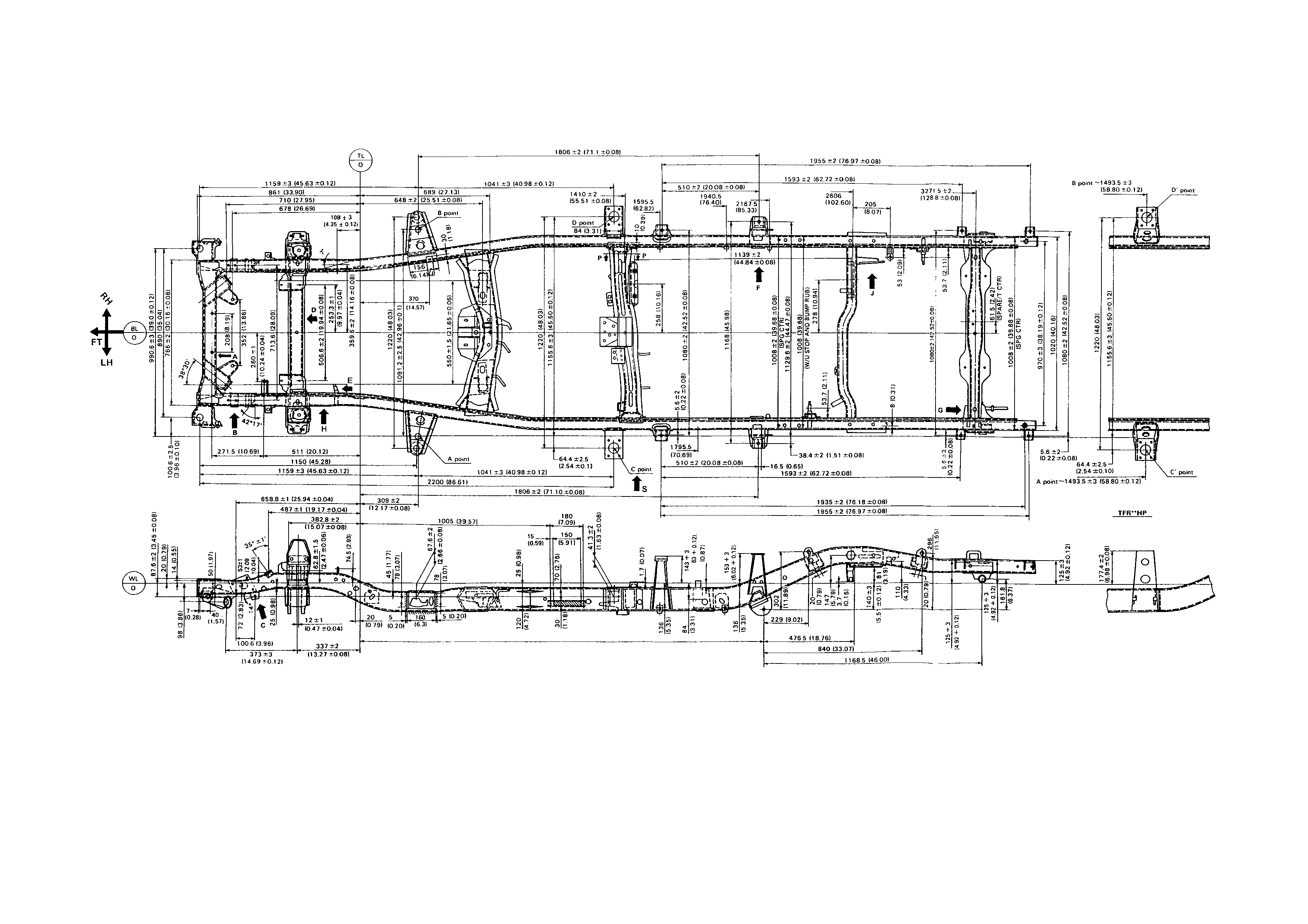
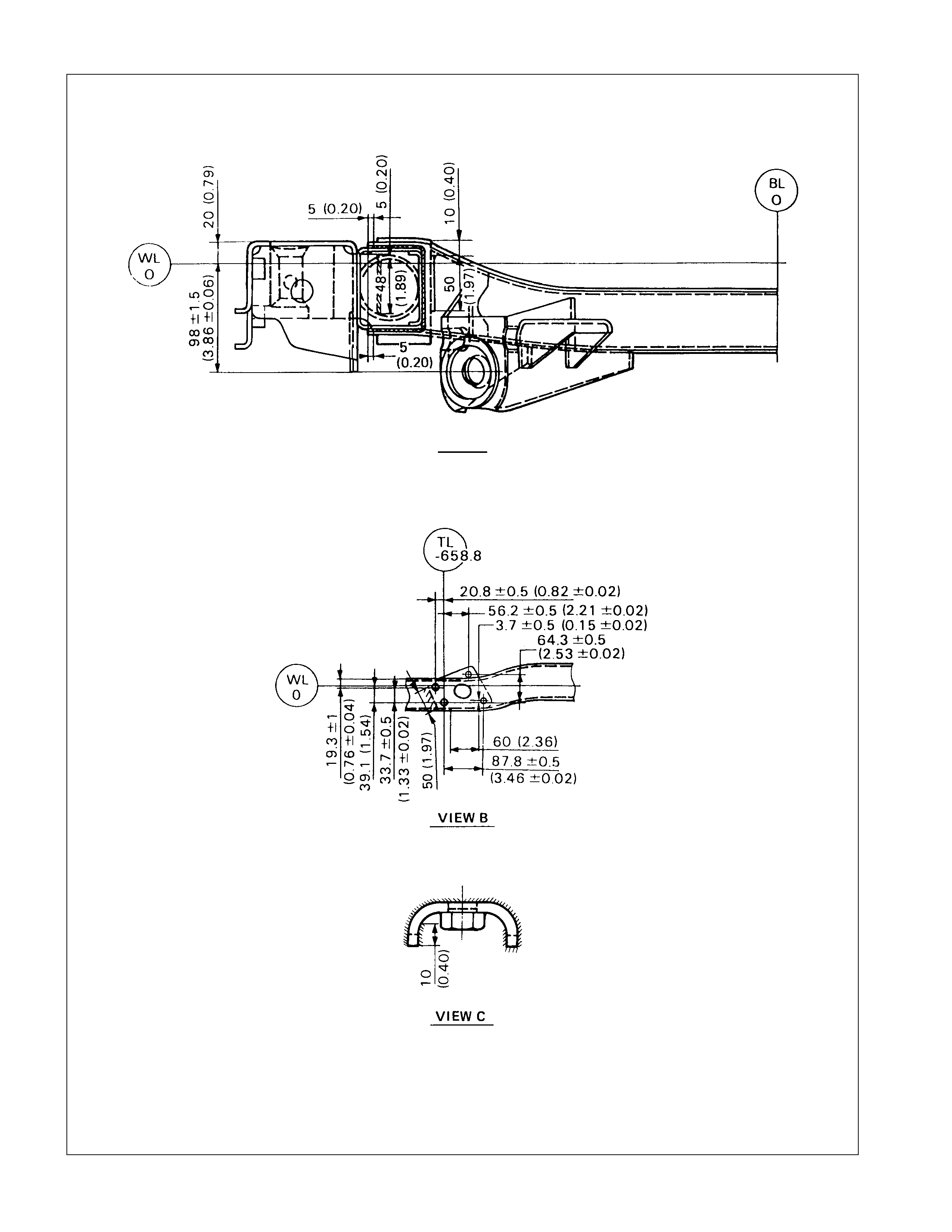
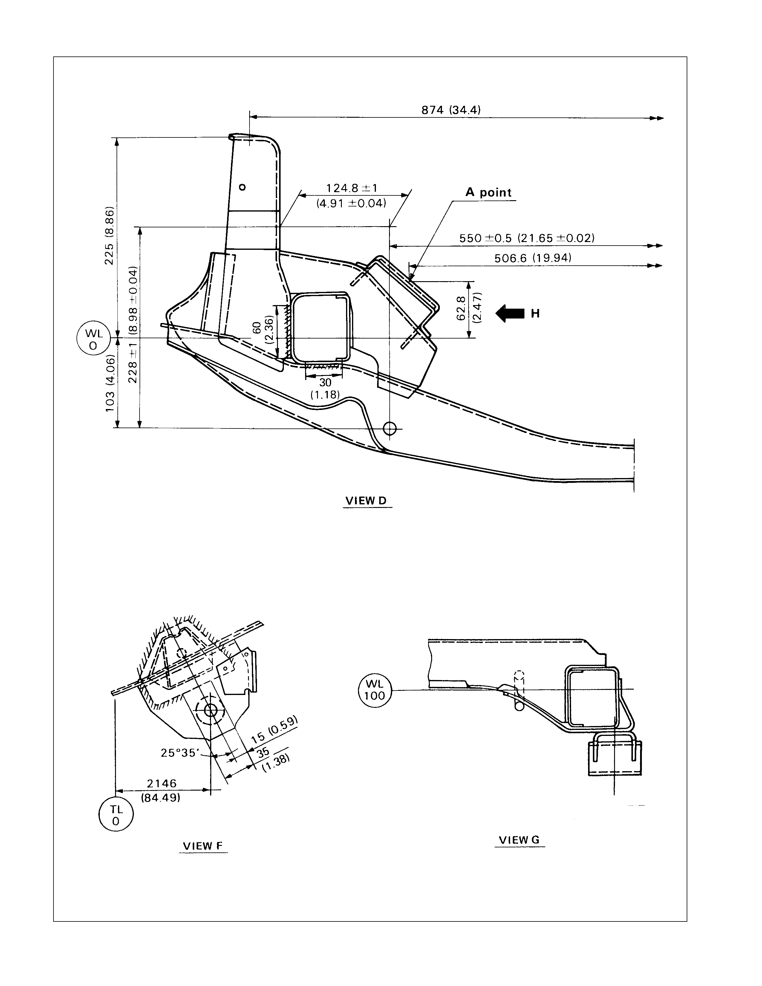
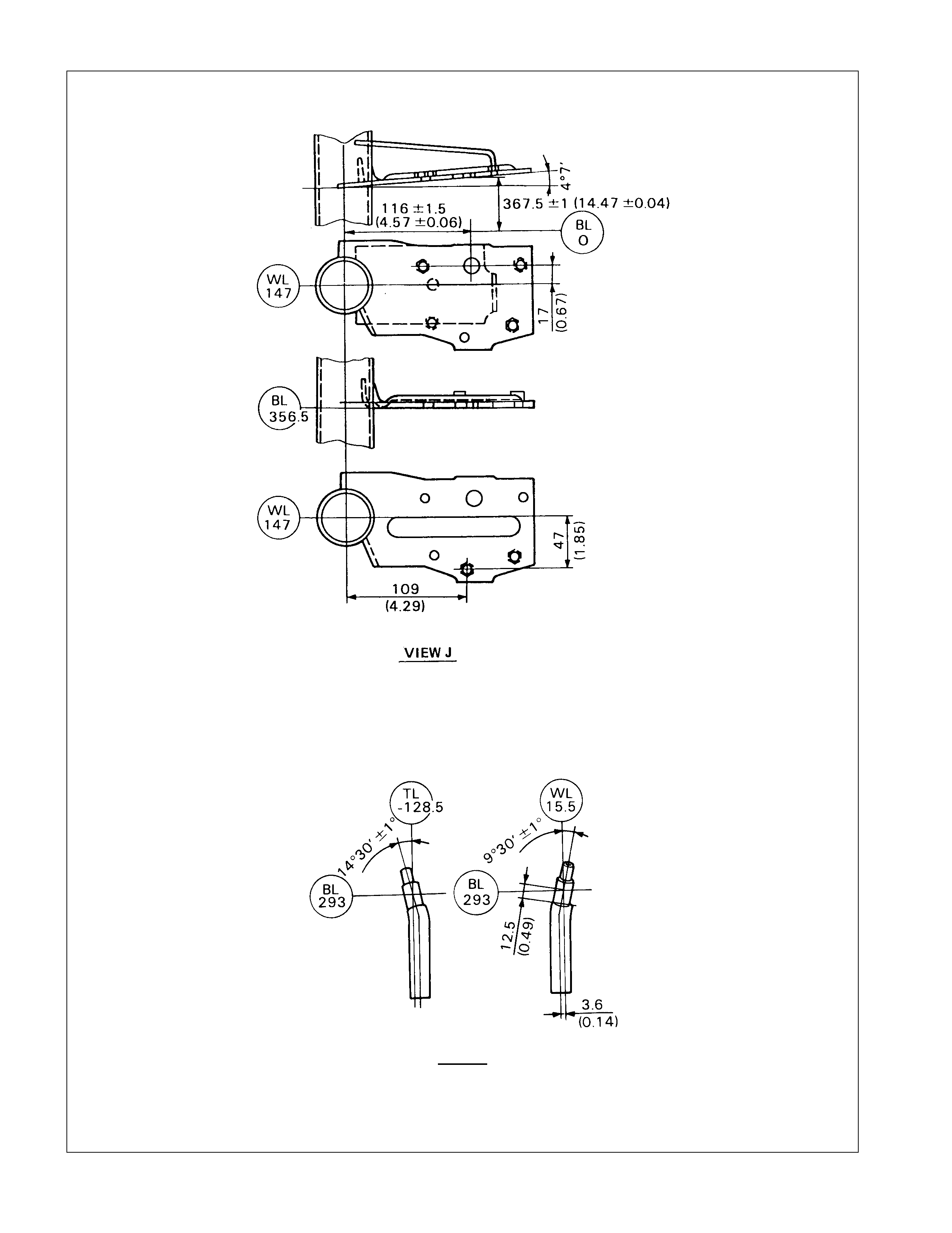
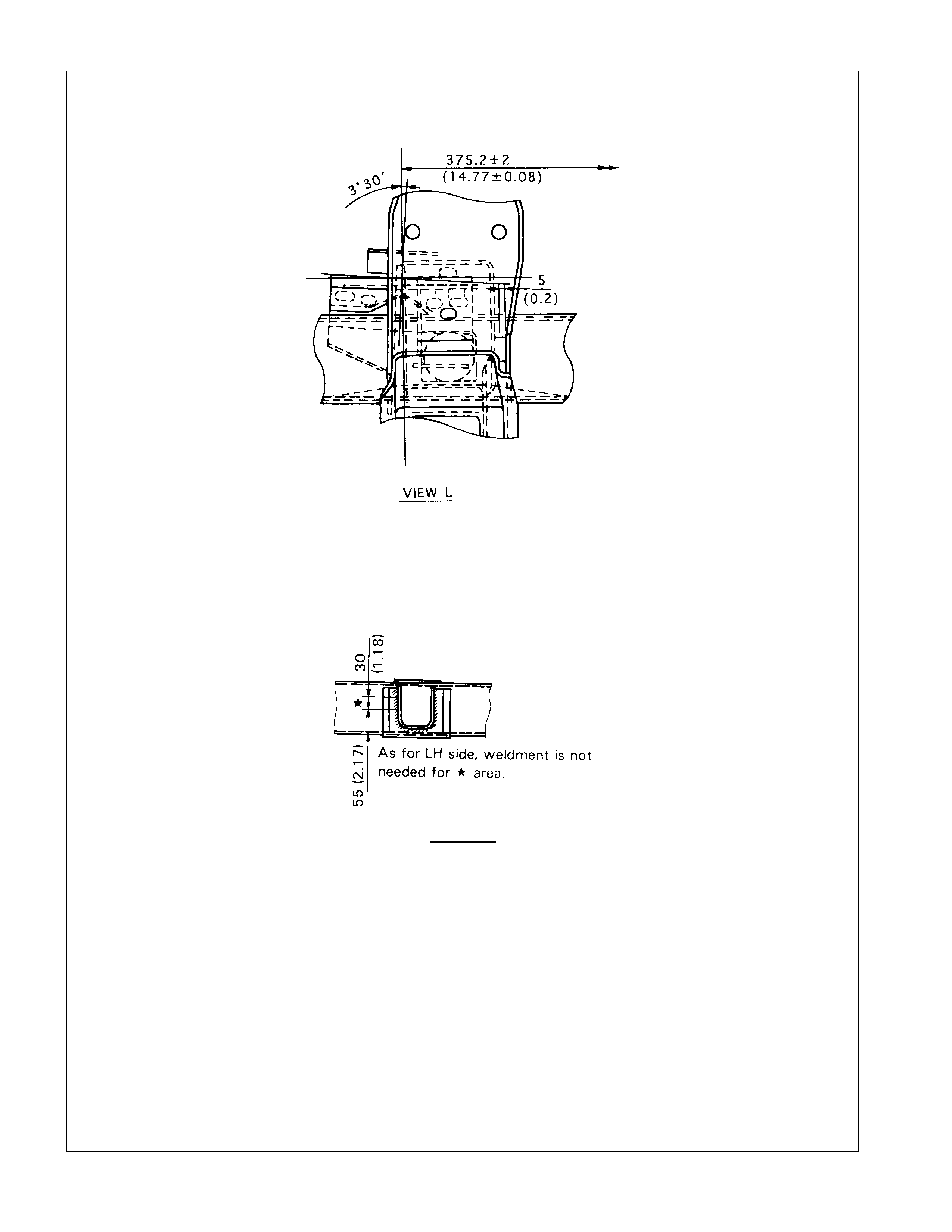
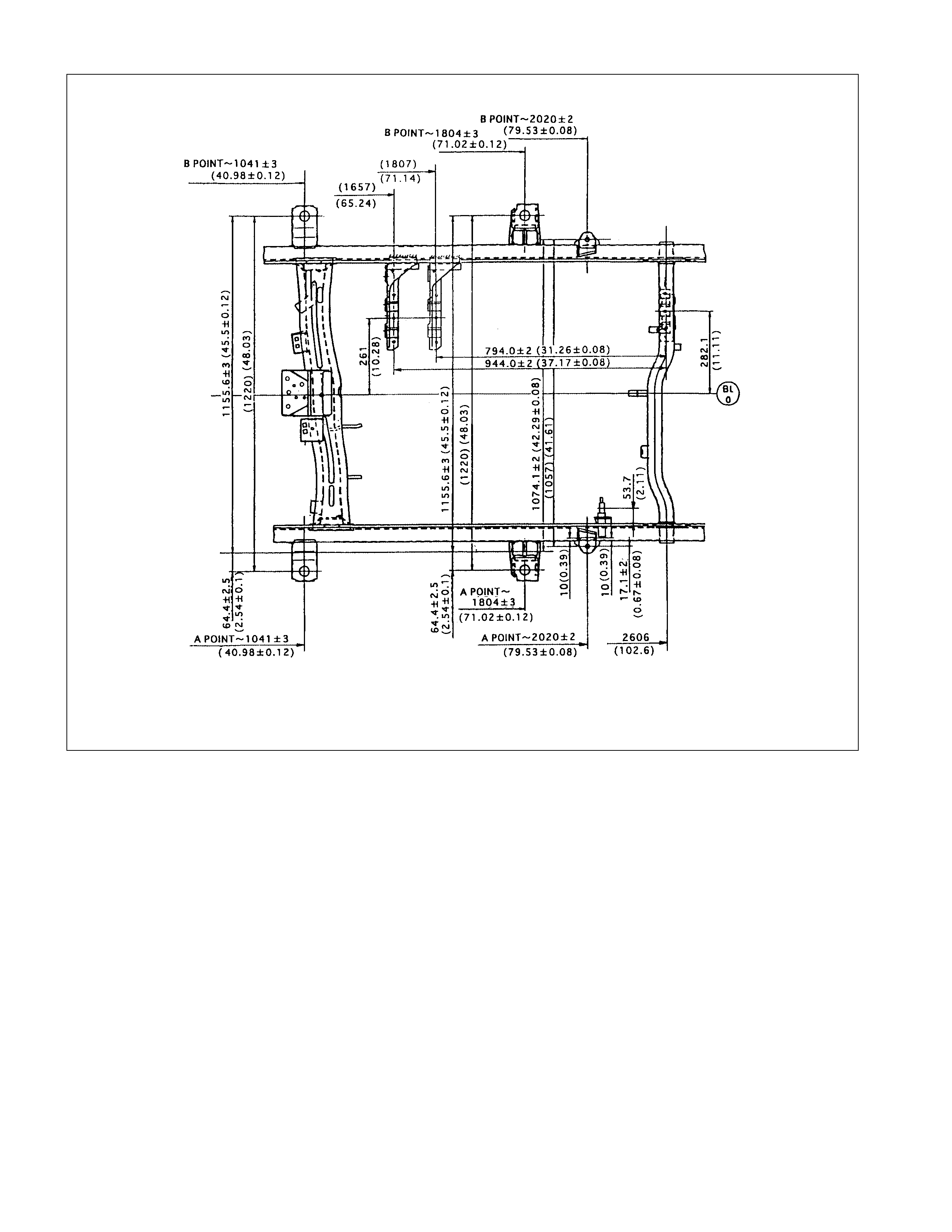
BODY MO UNTI NG

FRAME DIMENSIONS
(4×
××
×4, LONG WHEEL BASE MODEL)
VIEW A
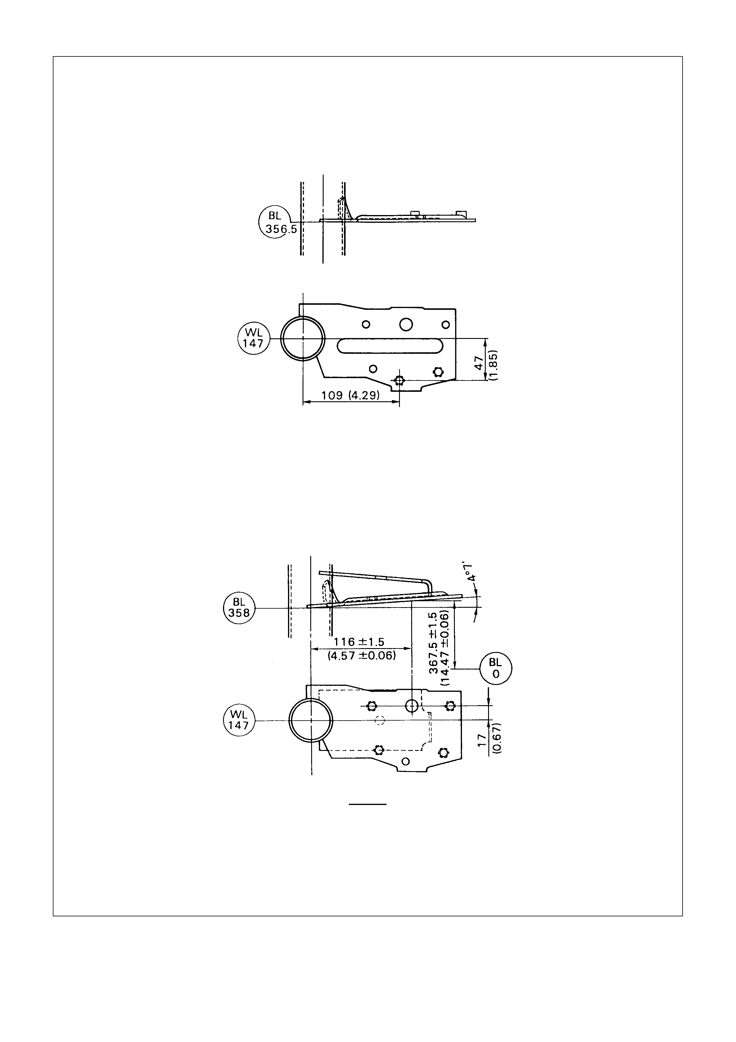
VIEW J
For Crew Cab
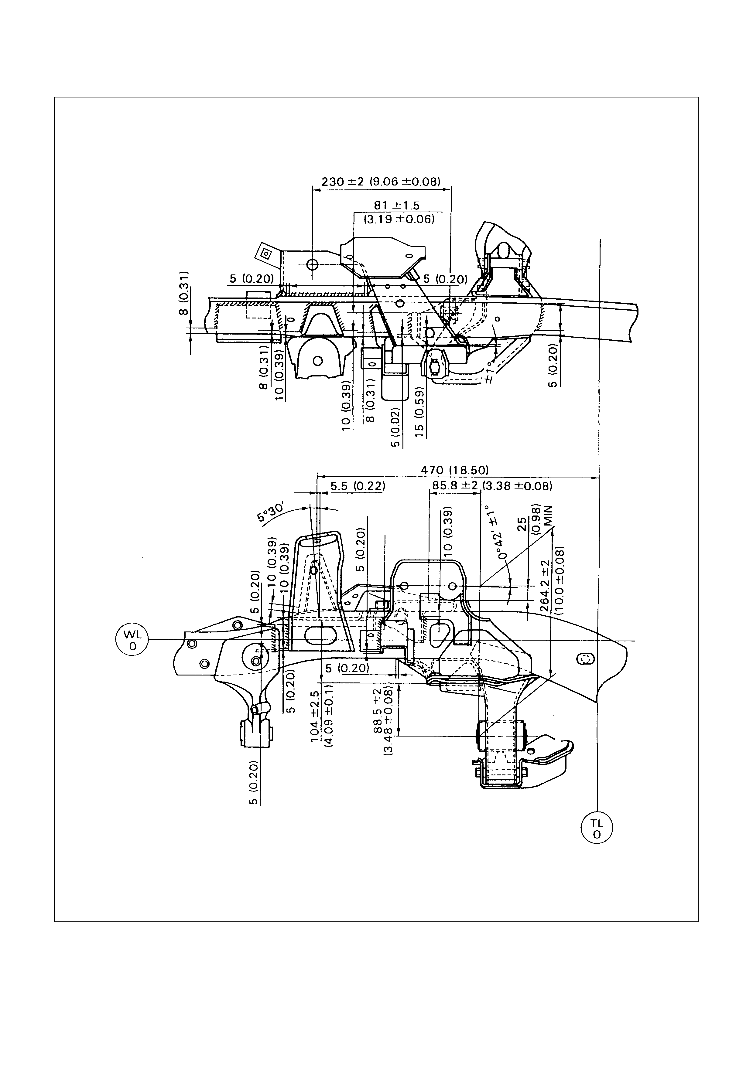
FRONT SUSPENSION DETAILS mm (in)
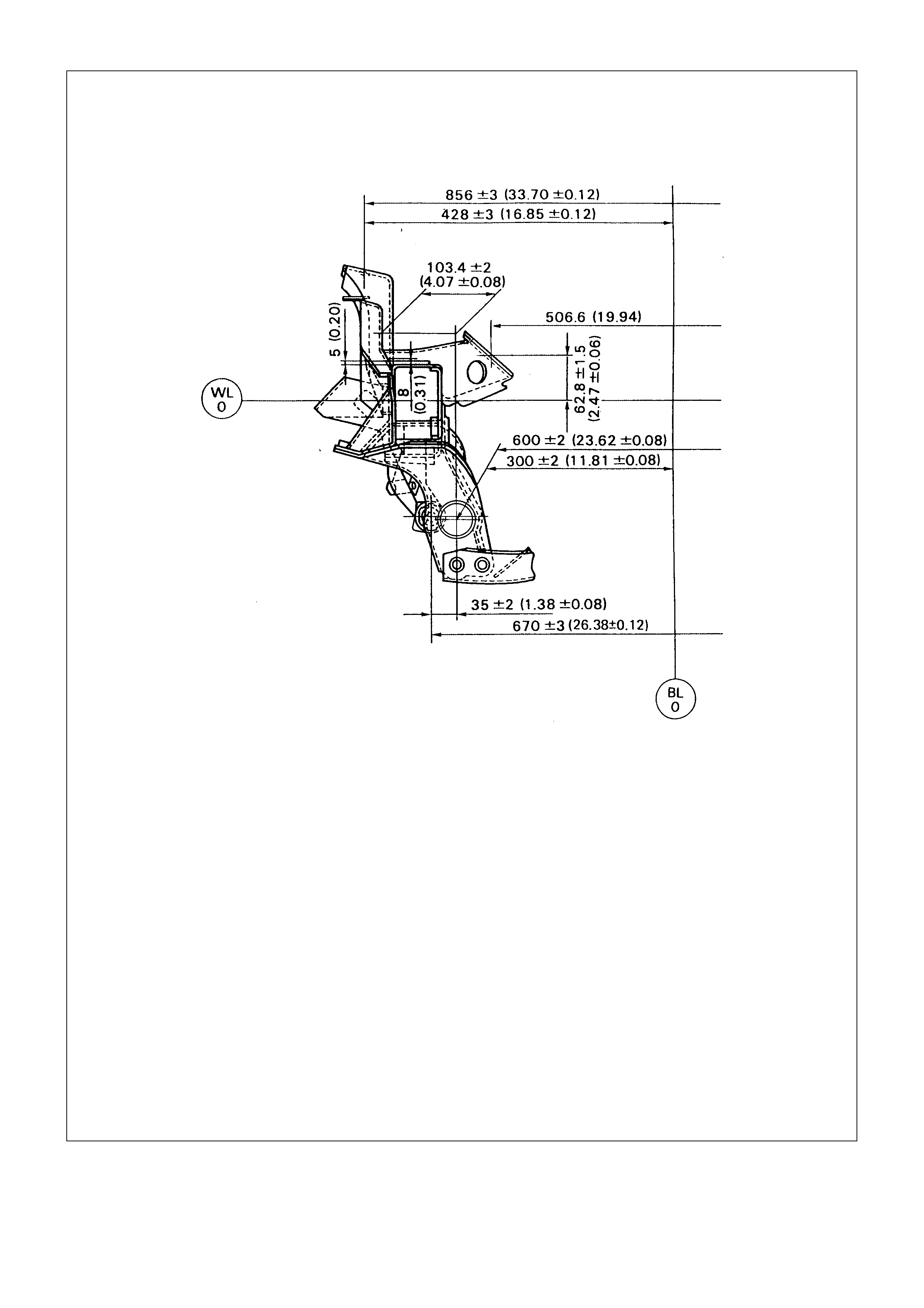
(4×
××
×2, LONG WHEEL BASE MODEL)
VIEW A
VIEW E
SECT K-K
For Crew Cab