
SECTION 1C - CAB
SERVICING
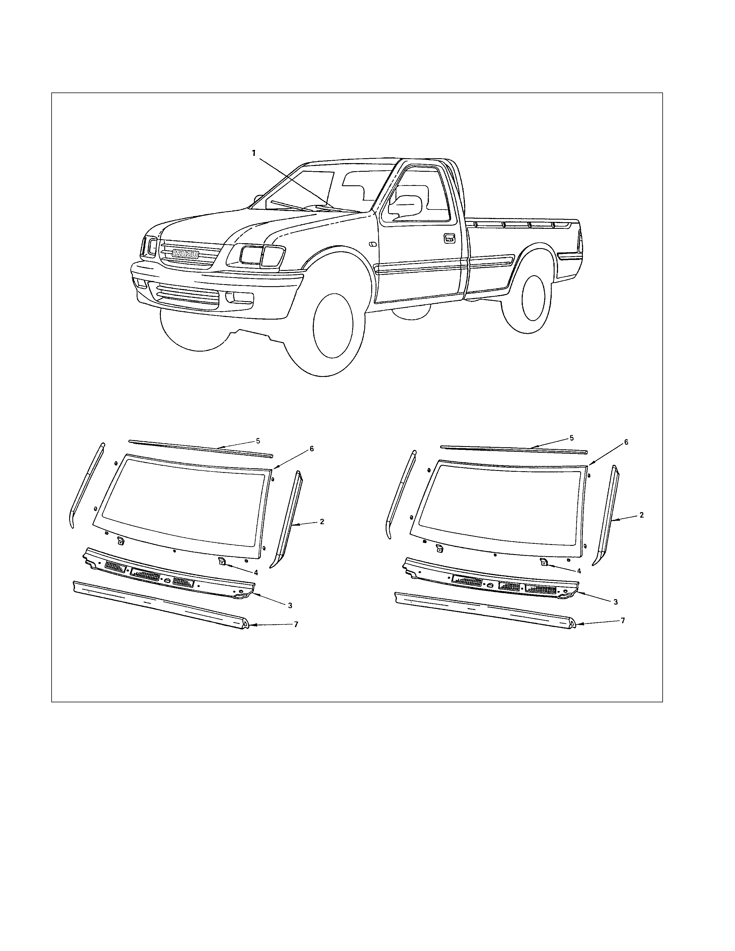
WINDSHIELD AND REAR WINDOW GLASSES
GENERAL DESCRIPTION
REMOVAL AND INSTALLATION
SLIDING REAR WINDOW ASSEMBLY
DISASSEMBLY
REASSEMBLY
DOORS
GENERAL DESCRIPTION
REMOVAL AND INSTALLATION
DISASSEMBLY
DISASSEMBLY AND REASSEMBLY
ADJUSTMENT (FRONT AND REAR)
REASSEMBLY
ADJUSTMENT (FRONT AND REAR)
INSTRUMENT PANEL
REMOVAL
INSTALLATION
CONSOLE BOX
REMOVAL AND INSTALLATION (4X4 S MODEL)
REMOVAL AND INSTALLATION (4X4 & 4X2 LS MODEL)
HEAD LINING
GENERAL DESCRIPTION
REMOVAL AND INSTALLATION
Techline
Techline

FUEL FILLER LID OPENER LEVER/CABLE
REMOVAL (DOUBLE CAB)
REMOVAL (SPACE CAB)
REMOVAL (SINGLE CAB)
INSTALLATION (DOUBLE CAB)
INSTALLATION (SPACE CAB)
INSTALLATION (SINGLE CAB)
QUARTE R GLASS (SPACE CAB)
REMOVAL AND INSTALLATION
FRONT SEAT
REMOVAL AND INSTALLATION
REAR SEAT
REMOVAL AND INSTALLATION
FRONT SEAT BELT
REMOVAL AND INSTALLATION
REAR SEAT BELT
REMOVAL AND INSTALLATION
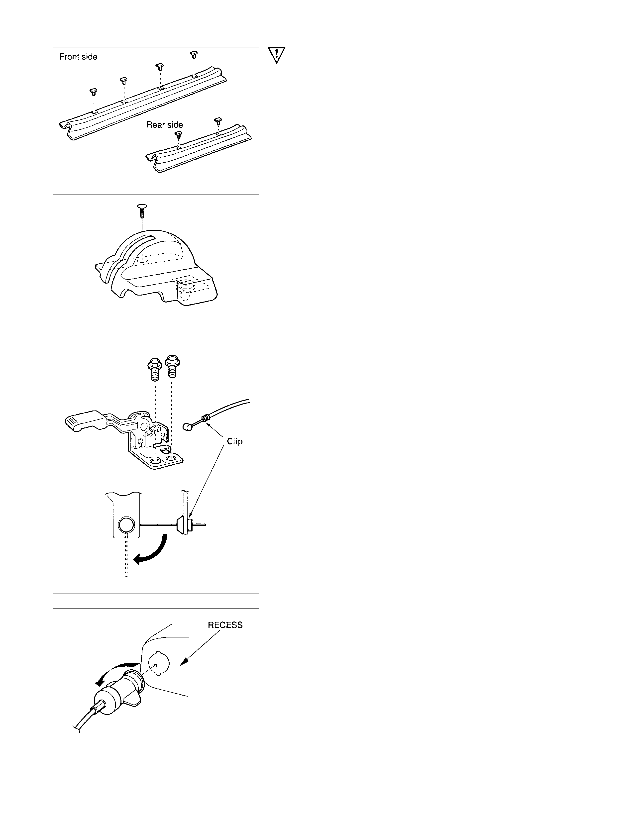
SERVICING
ENGINE HOOD LOCK
Align the engine hood lock with the installation holes.
ENGINE HOOD STRIKER
Apply a light coat of grease to the striker.
DOOR CHECKER ARM AND PI N
Apply a light coat of grease to the checker arm and pin.
WINDSHIELD AND REAR WINDOW GLASSES
GENERAL DESCRIPTION
This vehicle uses two types of safety glass: (1) laminated safety plate, for the windshield, and (2) solid tempered safety
plate, for the rear window glass.
The windshield glass is one-piece and is directly retained in the windshield opening by the adhesive.
When replacing a cracked windshield glass, it is very important that the cause of the glass breakage is determined and
the condition corrected before a new glass is installed. Otherwise, it is possible that a small obstruction or high spot
somewhere around the windshield opening will continue to crack or break the newly installed windshield. This is
especially true when the strain on the glass caused by this obstruction is increased by such conditions as wind
pressures, extremes of temperature, motion of the vehicle, etc. The procedure for removal of the windshield applies to
the complete windshield assembly.
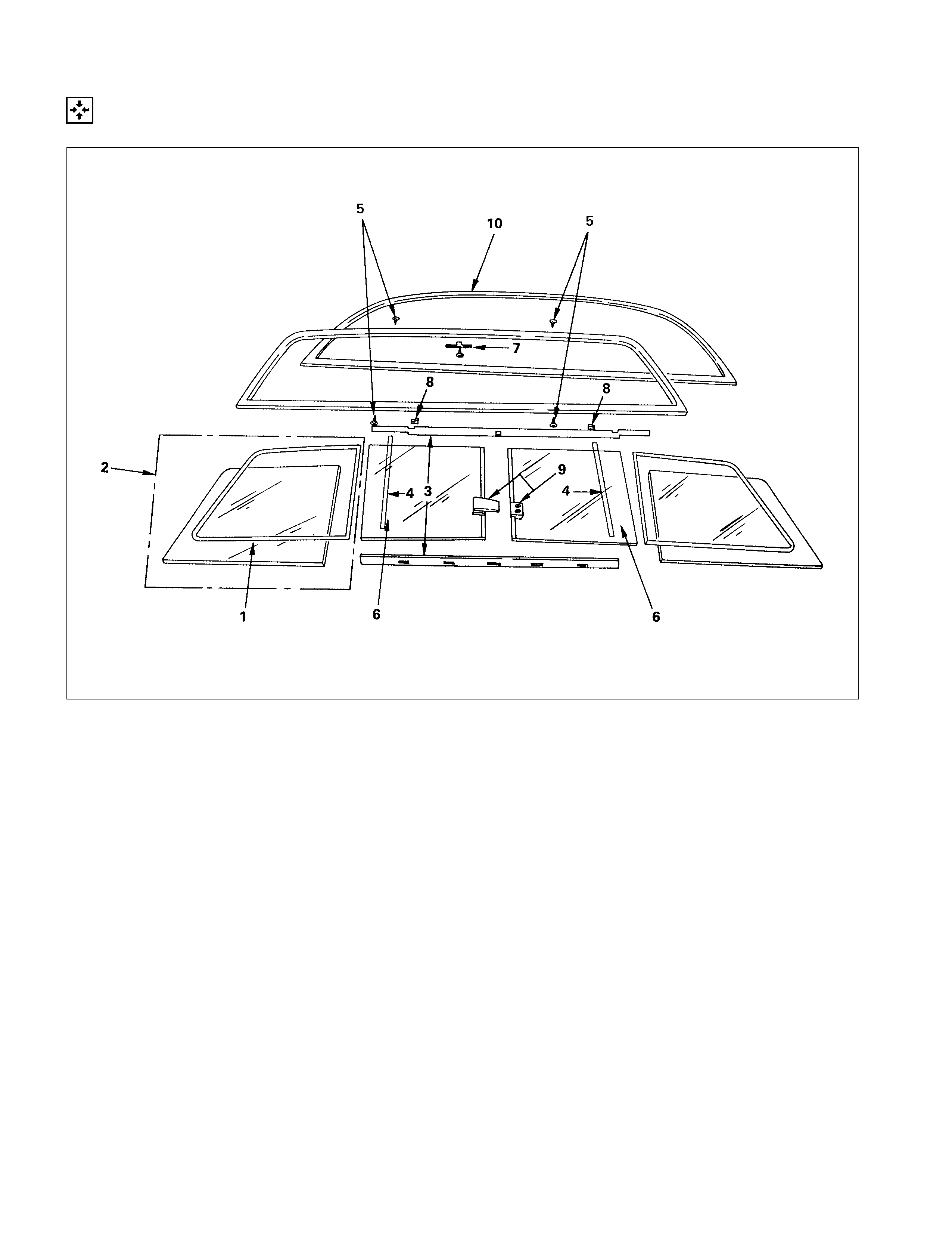
WINDSHIELD GLASS REAR WINDOW GLASS
Techline
REMOVAL AND INSTALLATION
For RHD model For LHD model
REMOVAL STEPS
1. Wiper arm assembly
2. Side moulding
3. Vent cowl cover
4. Windshield stopper
5. Upper moulding
▲6. Windshield glass
7. Engine hood rear seal
INSTALLATION STEPS
▲7. Engine hood rear seal
▲6. Windshield glass
▲5. Upper moulding
▲4. Windshield stopper
3. Vent cowl cover
▲2. Side moulding
1. Wiper arm assembly
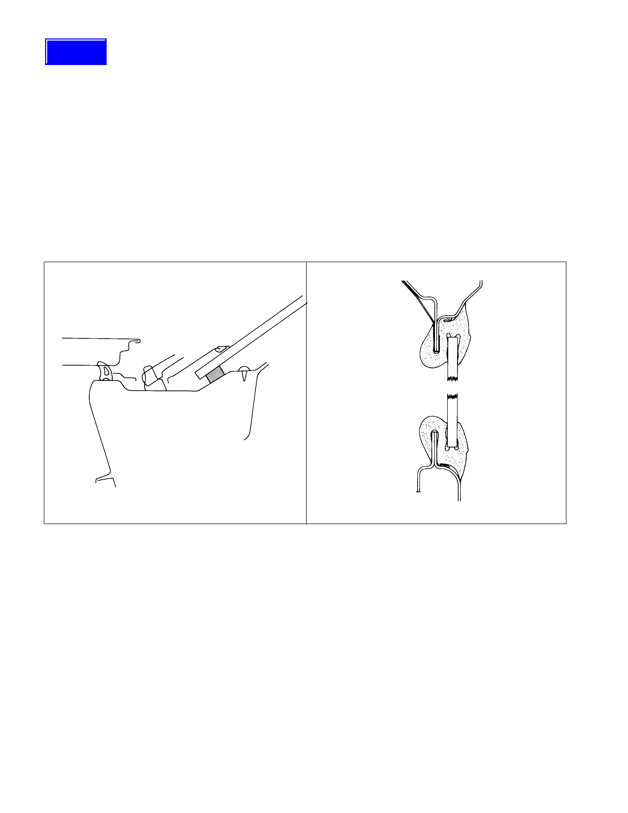
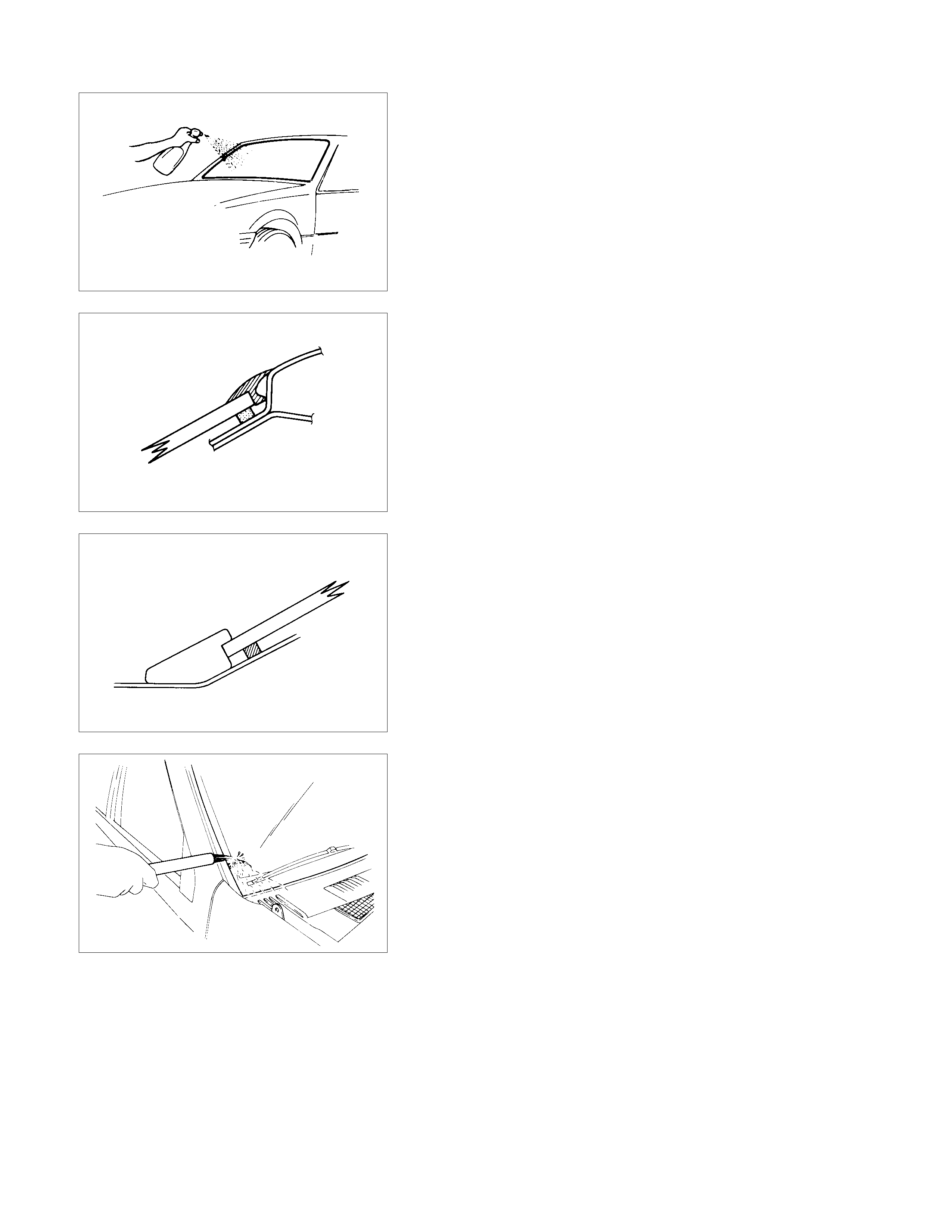
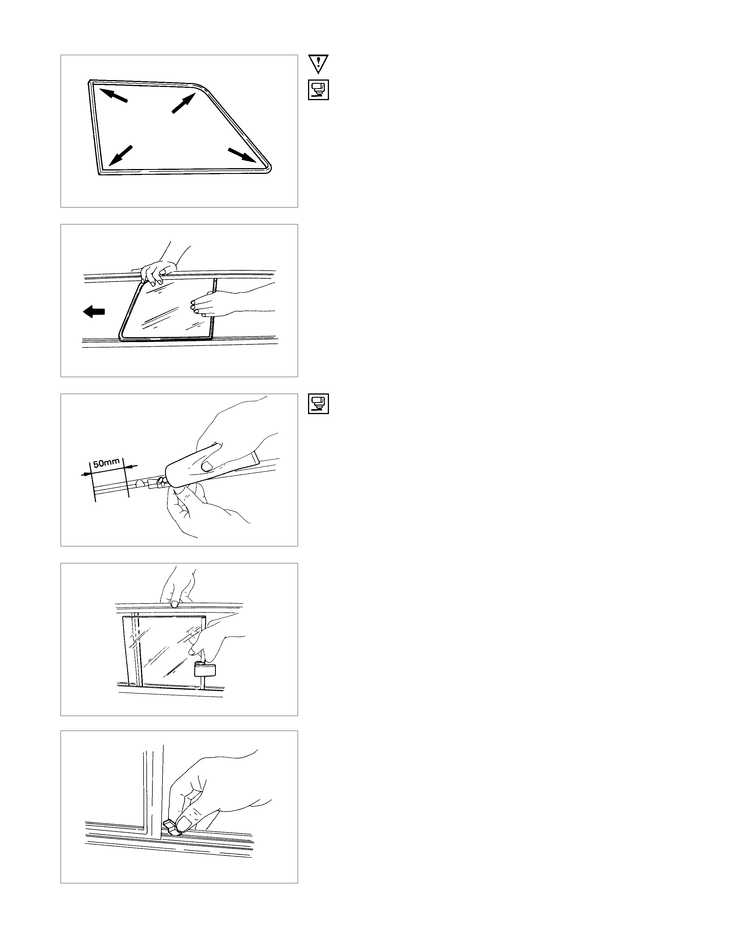
IMPORTANT OPERATION - REMOVAL
6. Windshield Glass
Remove the windshield glass, carefully following the steps
listed below :
1) Use a knife to cut through part of the adhesive caulking
material.
2) Secure one end of a piece of steel piano wire (0.02 inches
in diameter) to a piece of wood that can serve as a handle.
3) Use a pair of needle nose pliers to insert the other end o
f
the piano wire through the adhesive caulk ing m aterial at the
edge of the windshield glass.
4) Secure the other end of the piano wire to another piece o
f
wood.
5) With the aid of an assistant, carefully move the piano wire
with a sawing motion to cut through the adhesive caulking
material around the entire circumference of the windshield
glass.
6) Lift the windshield from the body.
7) Clean any remaining adhesive caulking material from the
area of the body, which holds the windshield.
8) Use a soft rag and unleaded gasoline to wipe off any
adhesive remaining on the windshield glass.
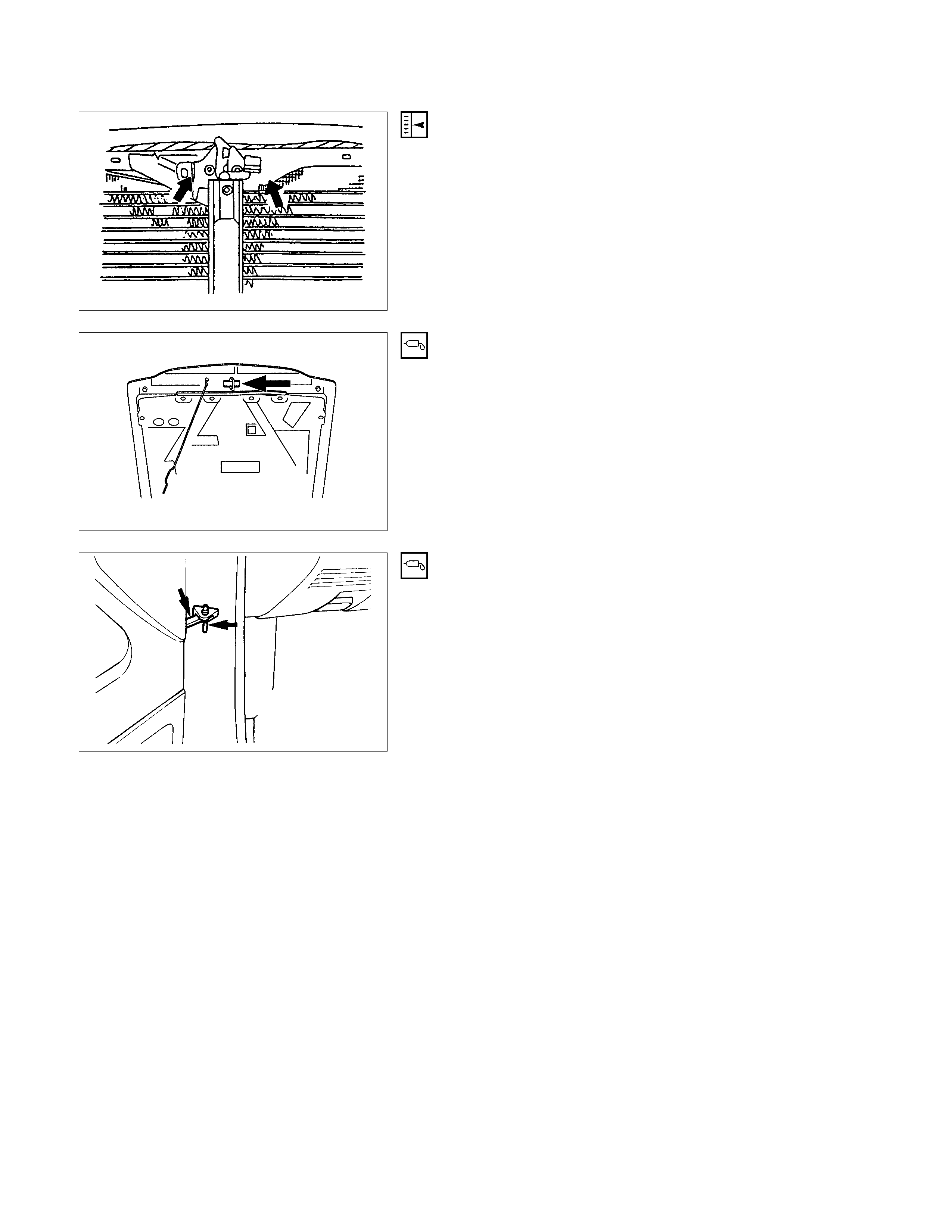
IMPORTANT OPERATIONS - INSTALLATION
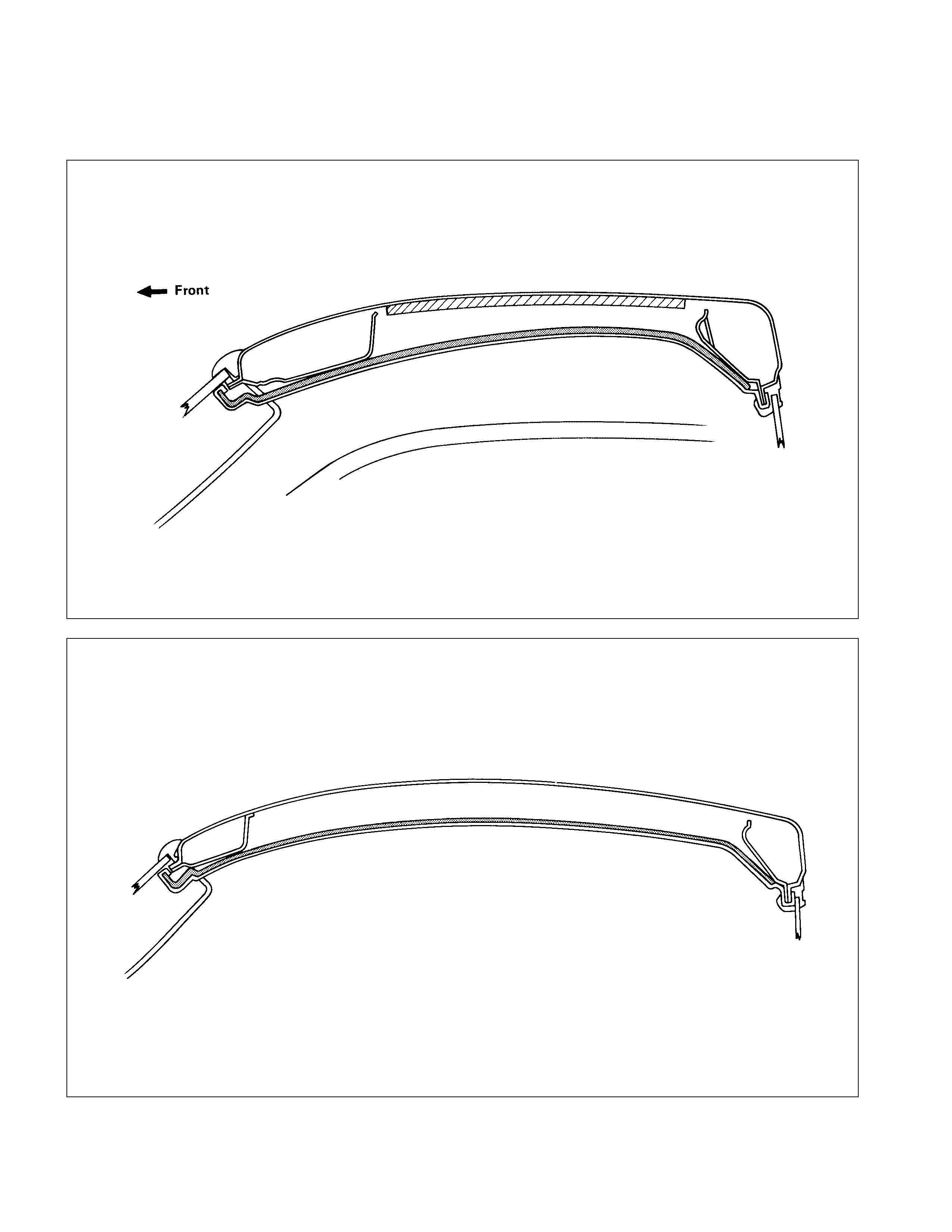
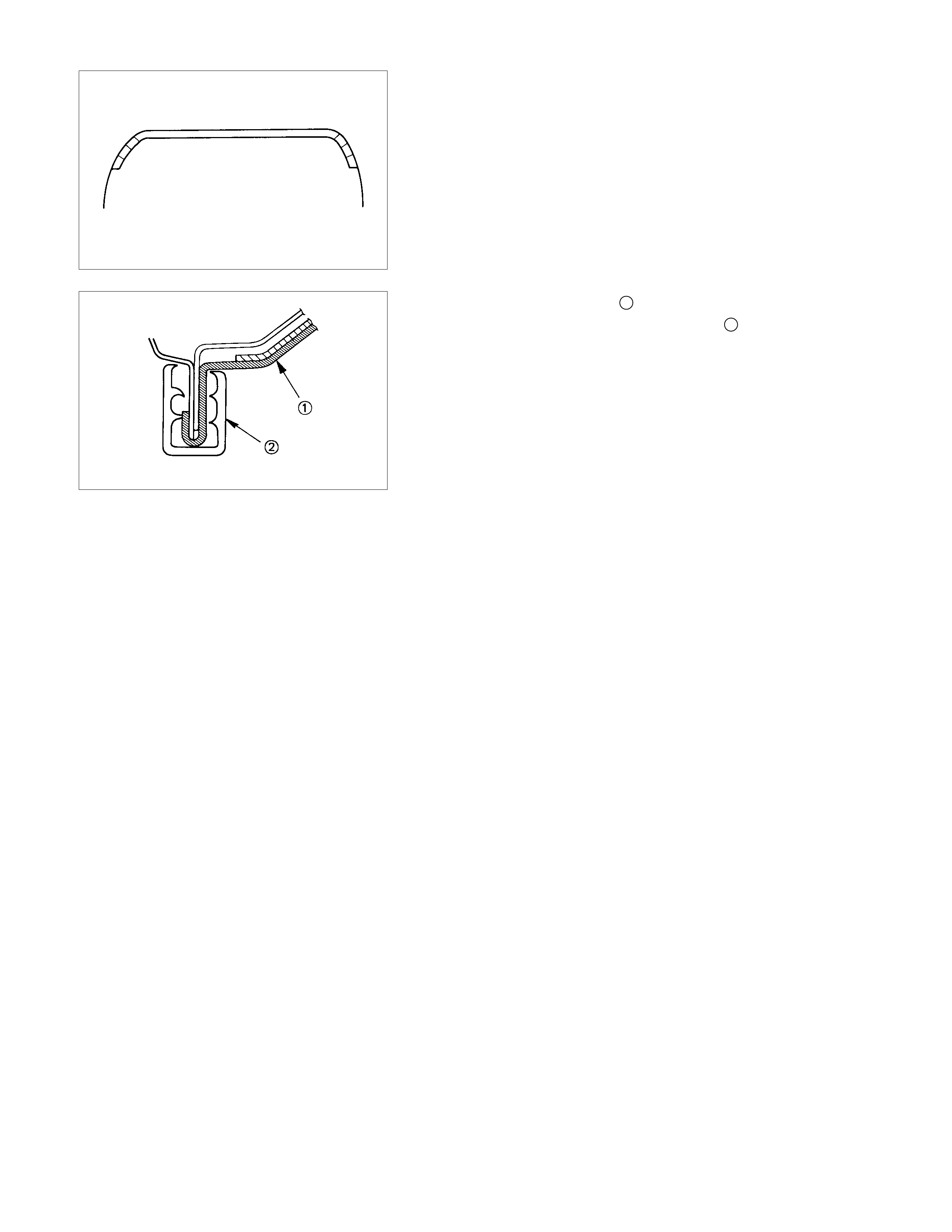
7. Engine Hood Rear Seal
Install the engine hood rear seal as shown in the illustration.
1 : Seal
2 : Clip
3 : Rear (windshield glass side)
4 : Front
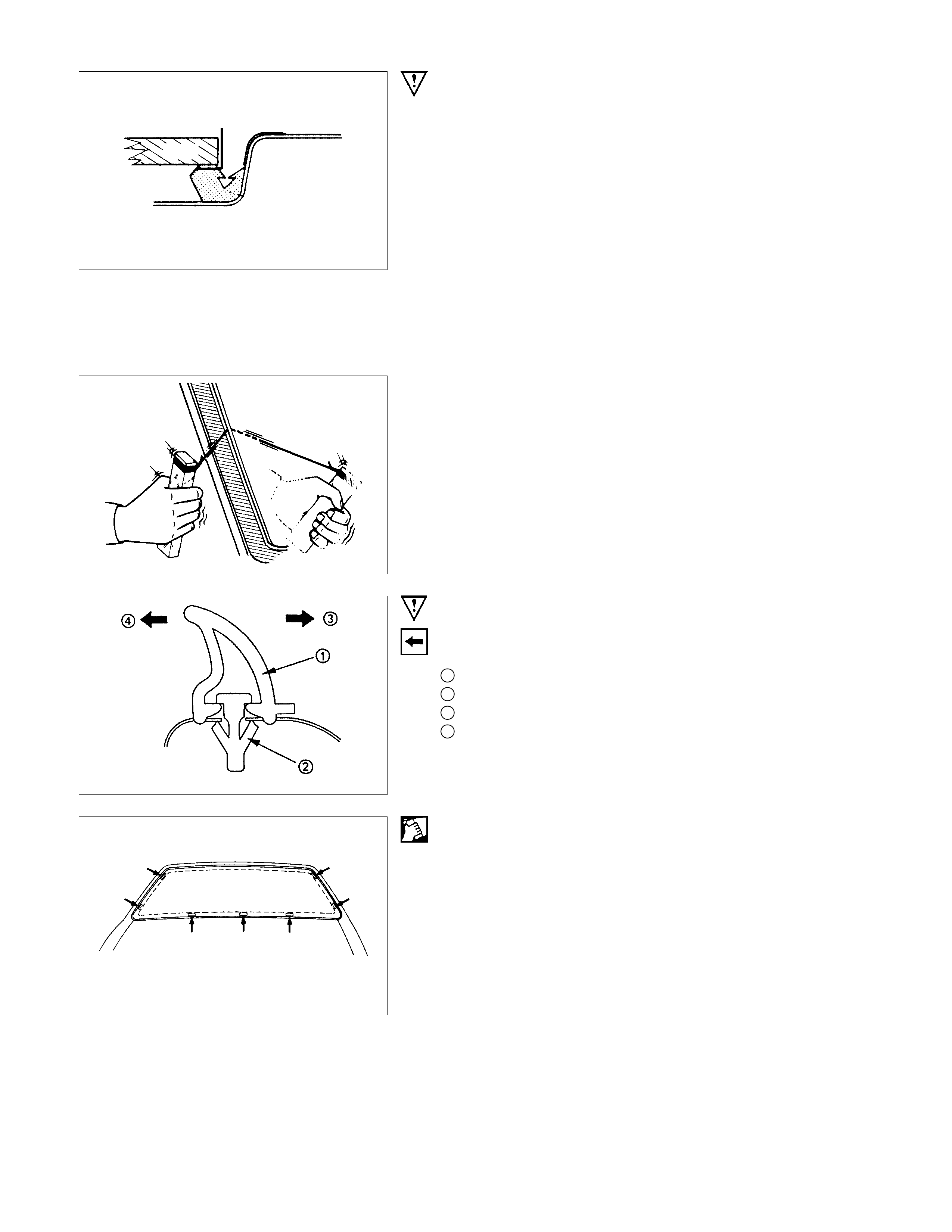
6. Windshield Glass
1) Clean the windshield glass bonding surface.
2) Use a soft rag and unleaded gasoline to wipe off any
adhesive remaining on the body.
3) Mount the body window glass as shown in the illustration.
Attach spacers at seven (7) locations.
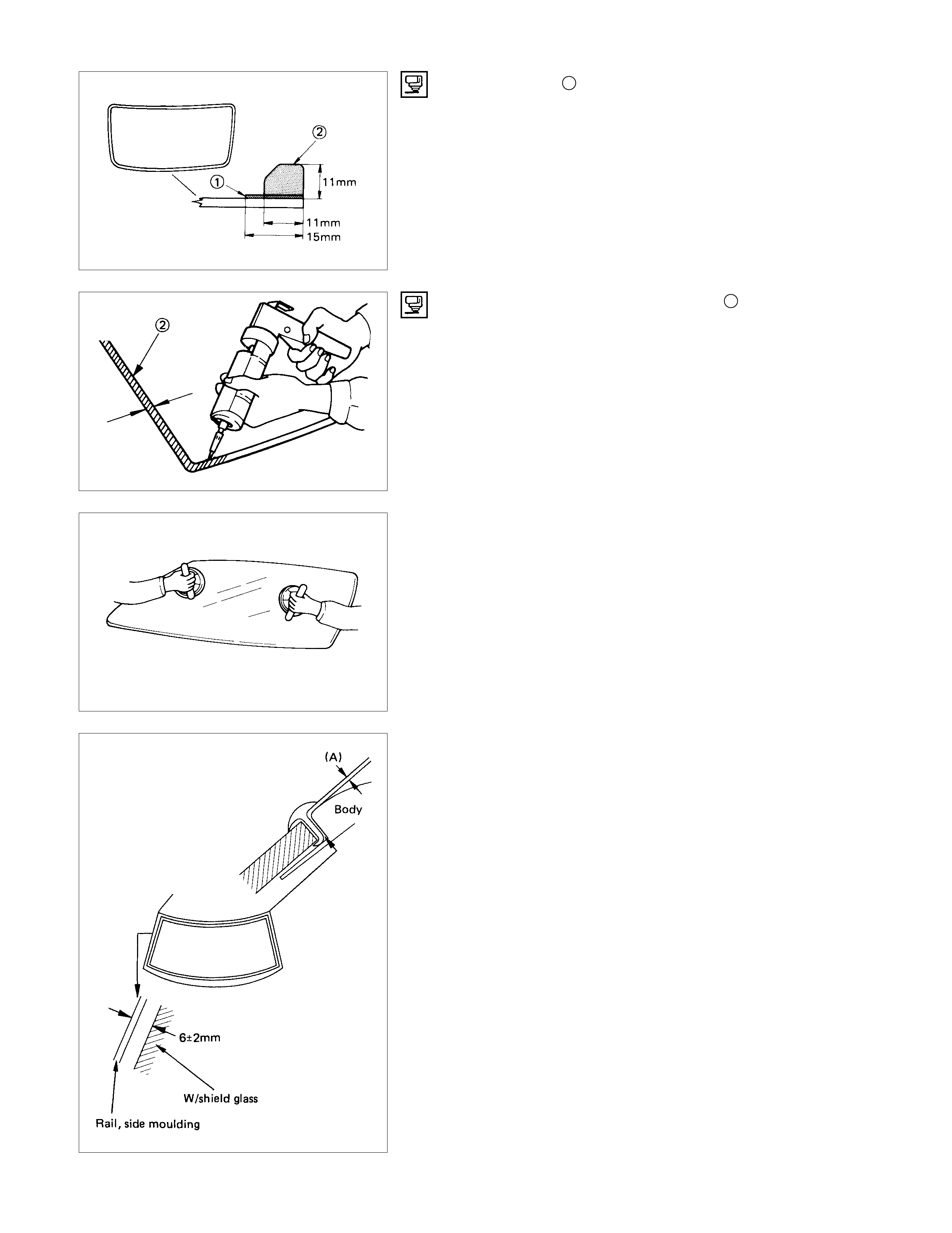
4) Apply primer 1 #435-95 or equivalent to the body side
bonding surface. The primer should extend 25 mm (1 in.).
Apply primer #435-40 or equivalent to the windshield glass
side bonding surface.
The primer should extend 15 mm (0.6 in.) from end of the
glass.
Apply the window glass sealing adhesive 2.
If you are using an air gun, air pressure should be maintained
at 147 - 294 kPa.
Note :
Open time (1 min. or more) should be set after application
of the primer.
Bonding shall be done within 5 minutes after the sealer
has been applied.
Adjust the setting of the windshield glass with suction discs.
The centre of the windshield glass should be in alignment with
the center of the windshield glass opening.
The clearance between body and upper moulding should be
within 0.5 mm (A).
Both of the clearance for RH and LH should be same. (6 mm ±
2 mm)
Note:
It is a good idea to perform the windshield installation
procedure from beginning to end without pausing. If you
allow time to elapse between steps, excessive amounts of
adhesive may be extruded from around the windshield.
5. Upper Moulding
1) Before installing the windshield moulding (at the upper part
of the windshield), spray hot water at a temperature o
f
about 140°F (60°C) onto the windshield glass and the
adhesive. This will cause curing.
2) Install the upper moulding as soon as hot water has been
applied. Using a roller push moulding in until it bottoms.
4. Windshield Stopper
Do this immediately after completing the gap adjustment.
2. Side Moulding
Use unleaded gasoline and a soft cloth to wipe away any
excess adhesive.
Cure the bonding at a temperature of 68° - 86°F (20 ° - 30°C)
for twenty-four hours.
Check that the windshield does not leak water.
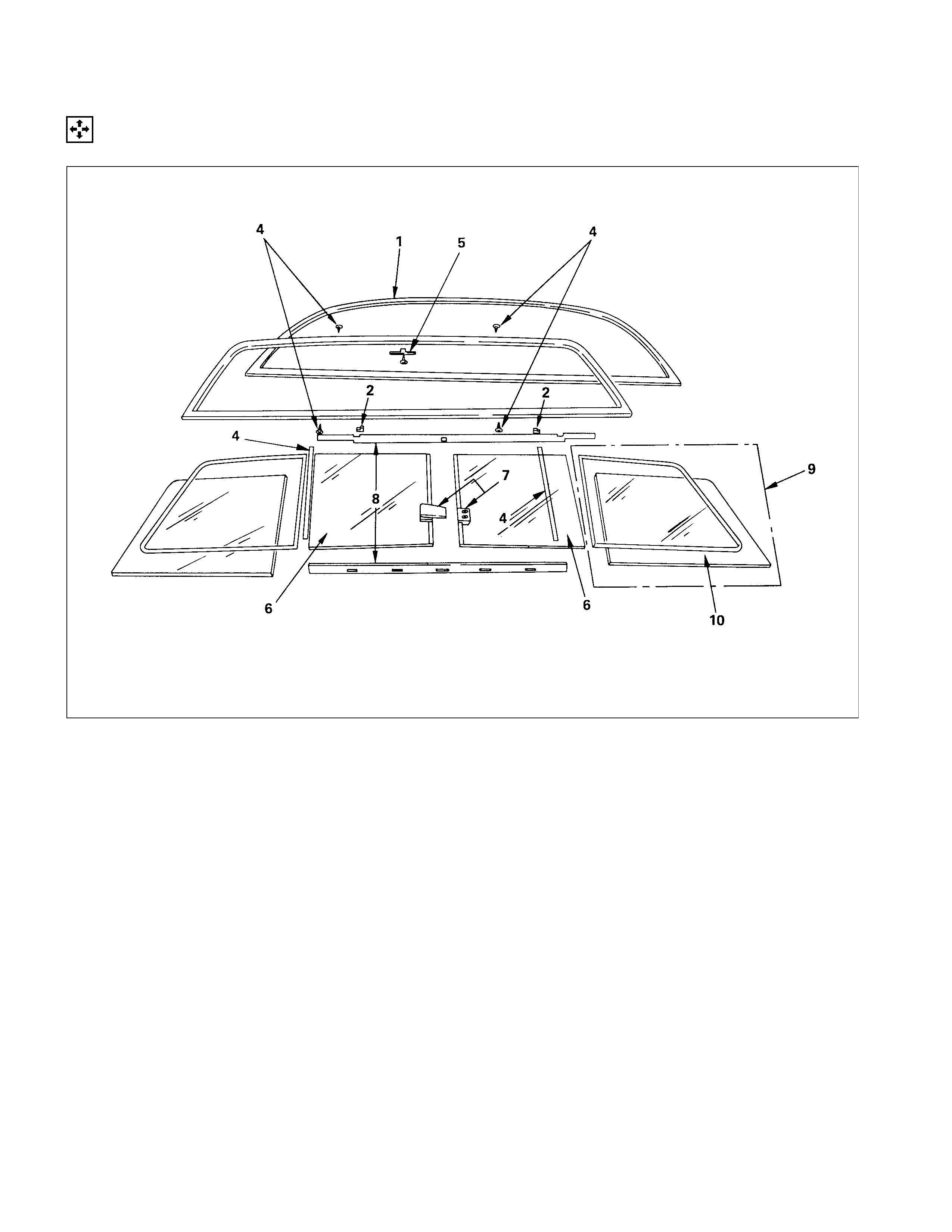
SLIDING REAR WINDOW ASSEMBLY
DISASSEMBLY
DISASSEMBLY STEPS
▲1. Weather strip
▲2. Packing ; rear window
3. Screw; binding
▲4. Frame ; rear window
5. Stopper
▲6. Rear window ; slide
7. Lock assembly with catchback window
8. Glass run
▲9. Glass ; rear window corner
1C. Weather strip ; rear window corner
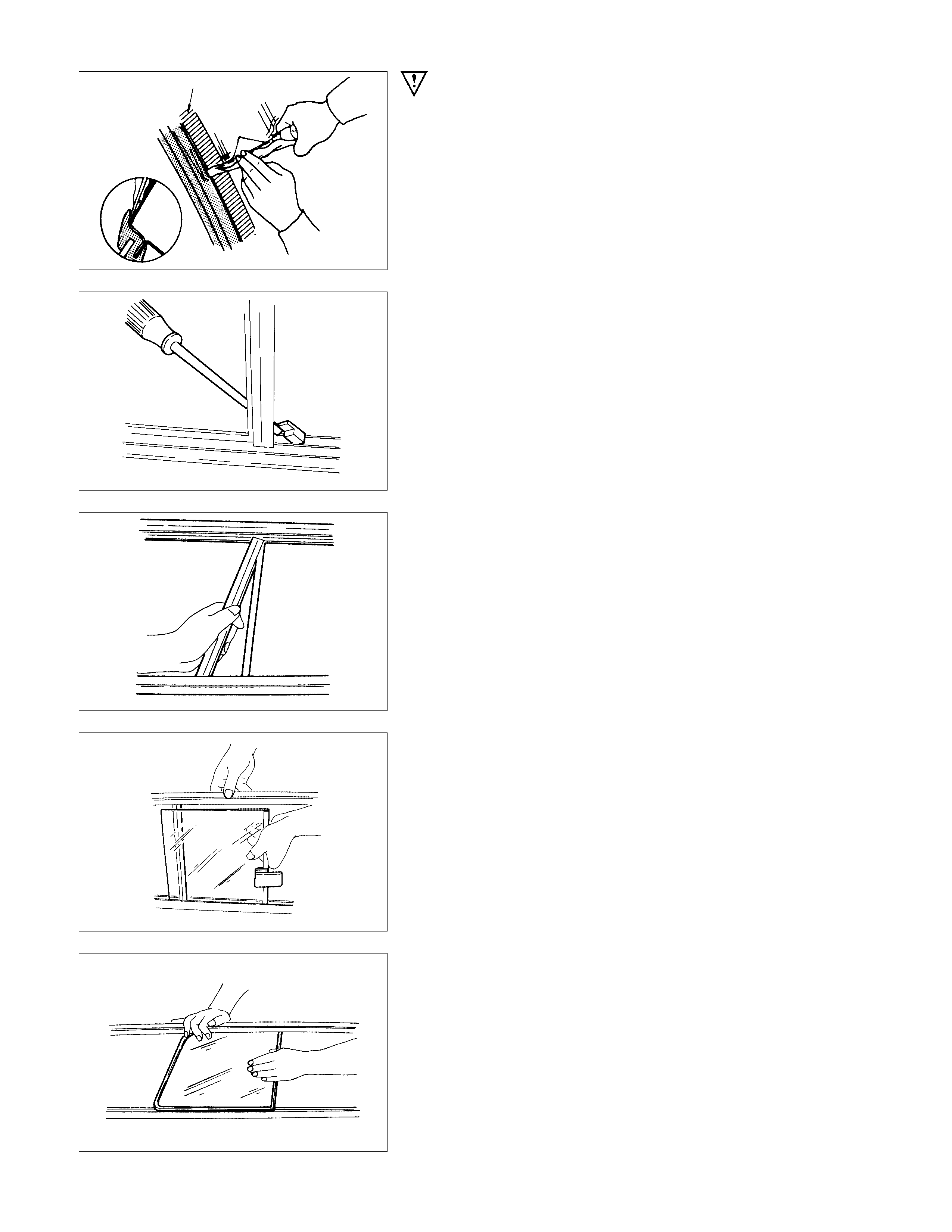
IMPORTANT OPERATION - REMOVAL
1. Weather Strip
Remove the weather strip with a knife.
2. Packing ; Rear Window
With a screwdriver or similar tool, remove the window stop.
4. Frame ; Rear Window
Place the window channel in a vertical position and remove the
frame rear by pulling on one end of it with your hand.
6. Rear Window ; Slide
With the window channel held in a vertical position, remove the
rear window slide.
9. Glass ; Rear Window Corner
Stand the window channel up and remove the glass: rear
window corner.
REASSEMBLY
REASSEMBLY STEPS
▲1. Weather strip ; rear window corner
▲2. Glass ; rear window corner
▲3. Glass run
4. Frame ; rear window
5. Screw; binding
▲6. Rear window ; slide
7. Stopper
▲8. Packing ; rear window
9. Lock assembly with catchback window
1C. Weather strip
IMPORTANT OPERATION - INSTALLATION
1. Weather Strip ; Rear Window Corner
Using Cemedein #560 (or equivalent to HN1068 spec.)
adhesive, glue the weather strip to the complete circumference
of the frame, paying close attention to the corner areas.
2. Glass ; Rear Window Corner
Apply soap and water to the rim as a lubricant.
Place the channel in a vertical position. With your hand, apply
pressure to expand the channel. Insert the window glass in the
center of the channel.
3. Glass Run
Apply Cemedein #560 (or equivalent to HN1068 spec.)
adhesive to the entire length of both the upper window glass
and the weather strip.
Apply adhesive to both sides of the extreme ends of the lower
portion for a distance of about 50 mm.
There should be no gap between the weather strip rear window
glass channel and the channel.
6. Rear Window ; Slide
Hold the window vertically. Apply an upward pressure to the
channel and insert the rear window slide.
8. Packing ; Rear Window
Apply a fast setting adhesive agent to both sides of the window
atop and insert it into the channel.
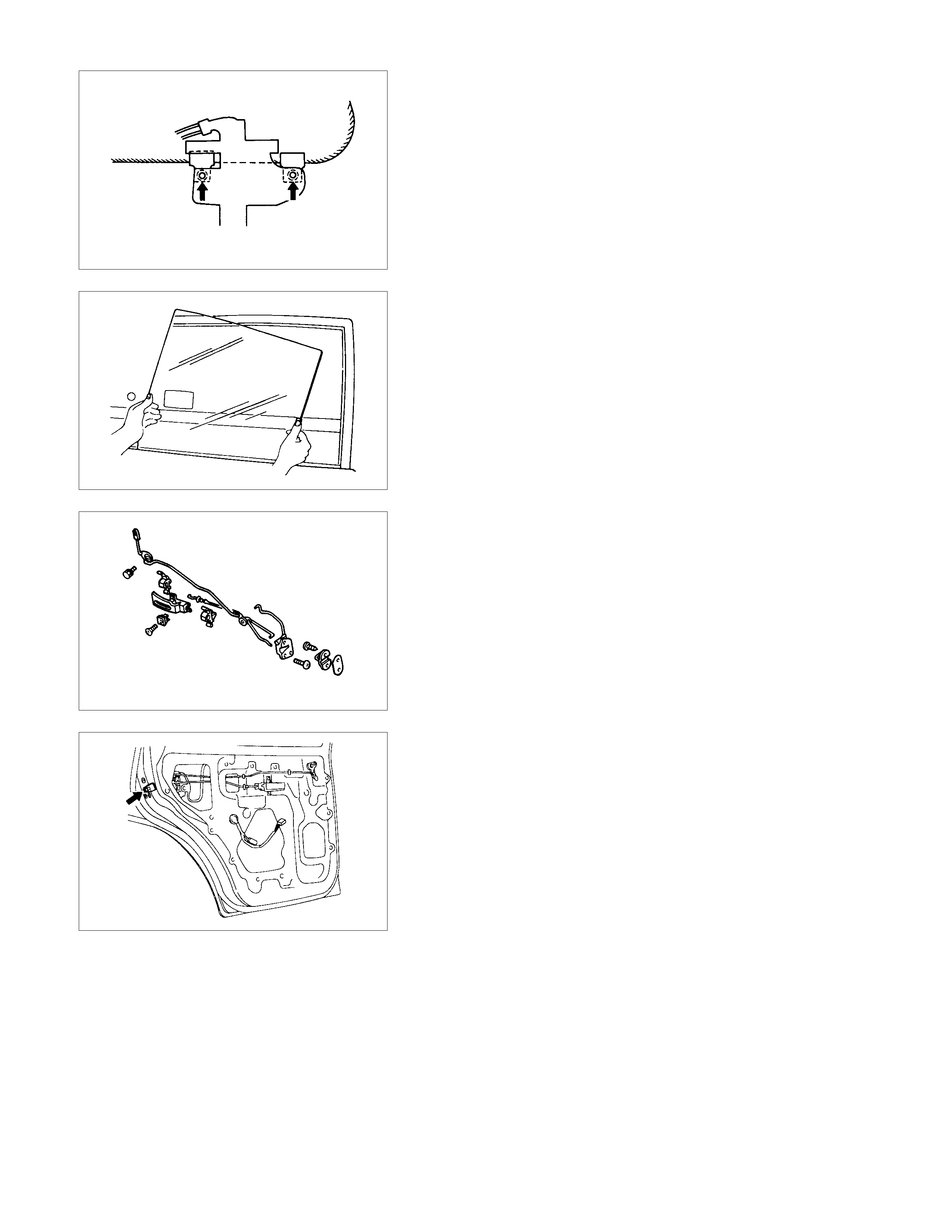
REMOVAL AND INSTALLATION
REMOVAL STEPS
▲1. Door harness
▲2. Checker pin
▲3. Lower hinge
4. Upper hinge
5. Door assembly
INSTALLATION STEPS
5. Door assembly
4. Upper hinge
3. Lower hinge
2. Checker pin
1. Door harness
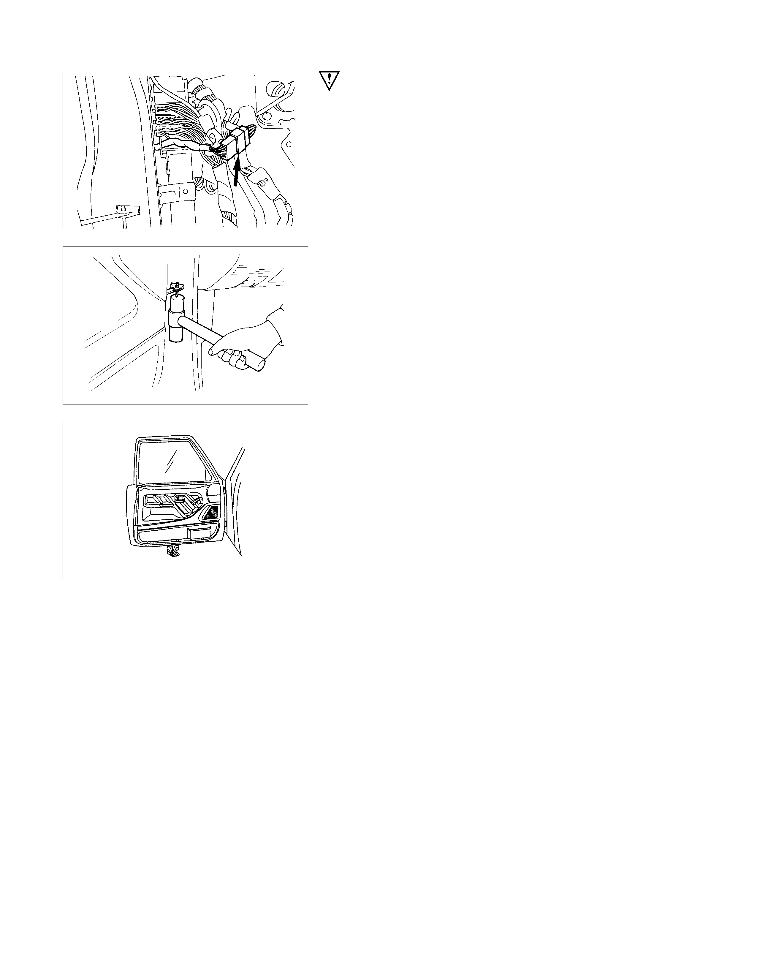
IMPORTANT OPERATION - REMOVAL
1. Door Harness
Disconnect the door harness.
2. Checker Pin
3. Lower Hinge
Position a wood block under the door for protection and
support the door assembly with hands at removal or
installation.
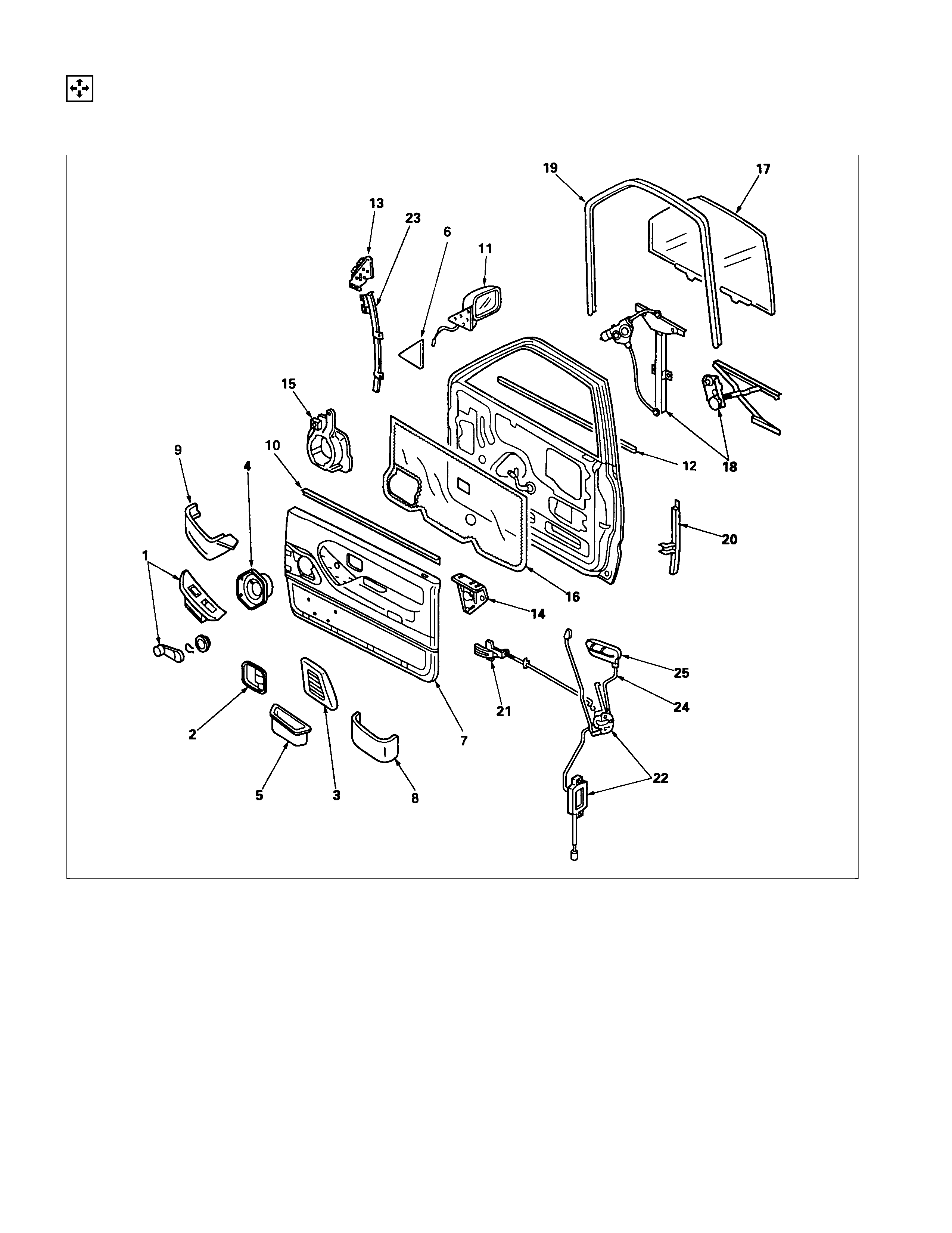
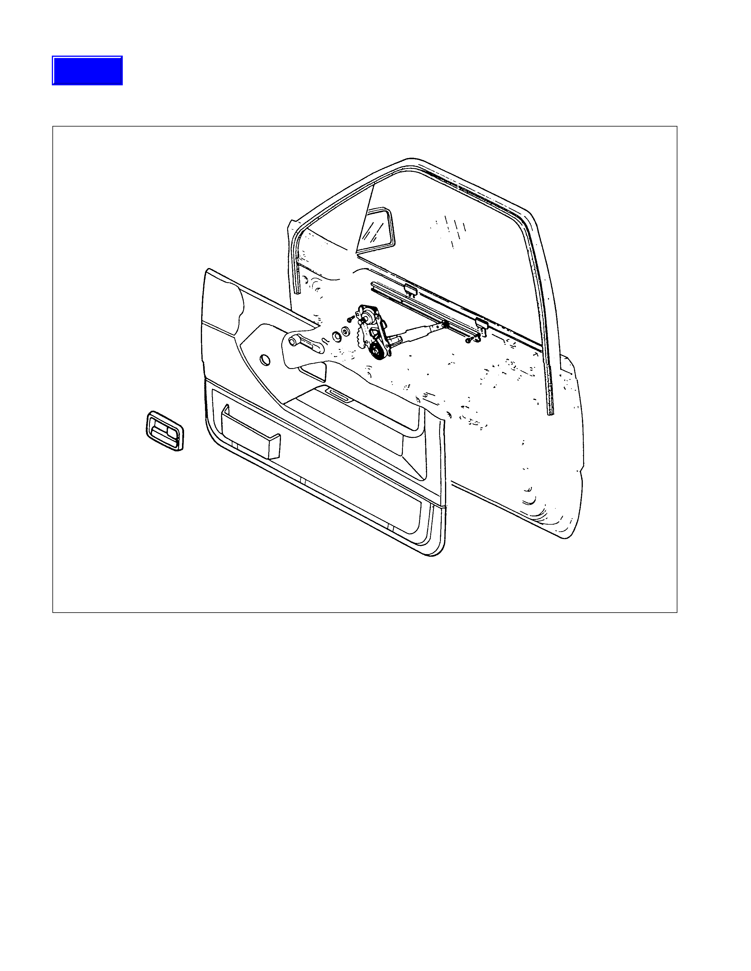
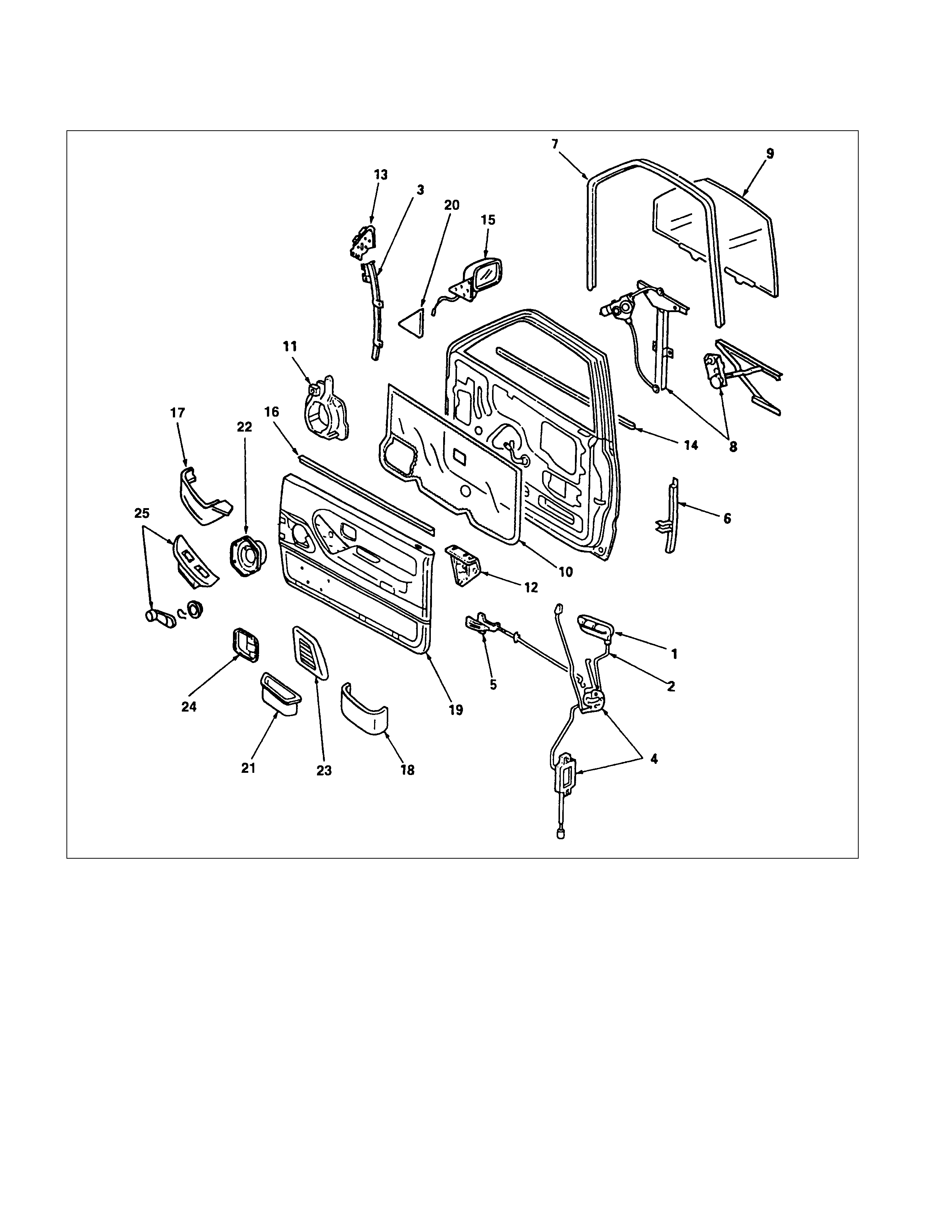
DISASSEMBLY
(FRONT DOOR)
DISASSEMBLY STEPS
▲1. Power window switch/Windows regulator handle
▲2. Bezel
▲3. Speaker grill
▲4. Speaker assembly
▲5. Door pull case
▲6. Door mirror cover
▲7. Door trim pad
▲8. Door pocket
▲9. Power window box
▲10. Inner waste seal
▲11. Door mirror assembly
▲12. Outer waste seal
▲13. Door mirror bracket
▲14. Bracket
▲15. Speaker box
▲16. Water-proof sheet
▲17. Window glass
▲18. Window regulator/Power window motor
▲19. Glass run
▲20. Glass run rear channel
▲21. Inside lever
▲22. Door lock assembly/Door lock actuator
▲23. Glass run front channel
▲24. Door lock cylinder
▲25. Outside handle
IMPORTANT OPERATIONS
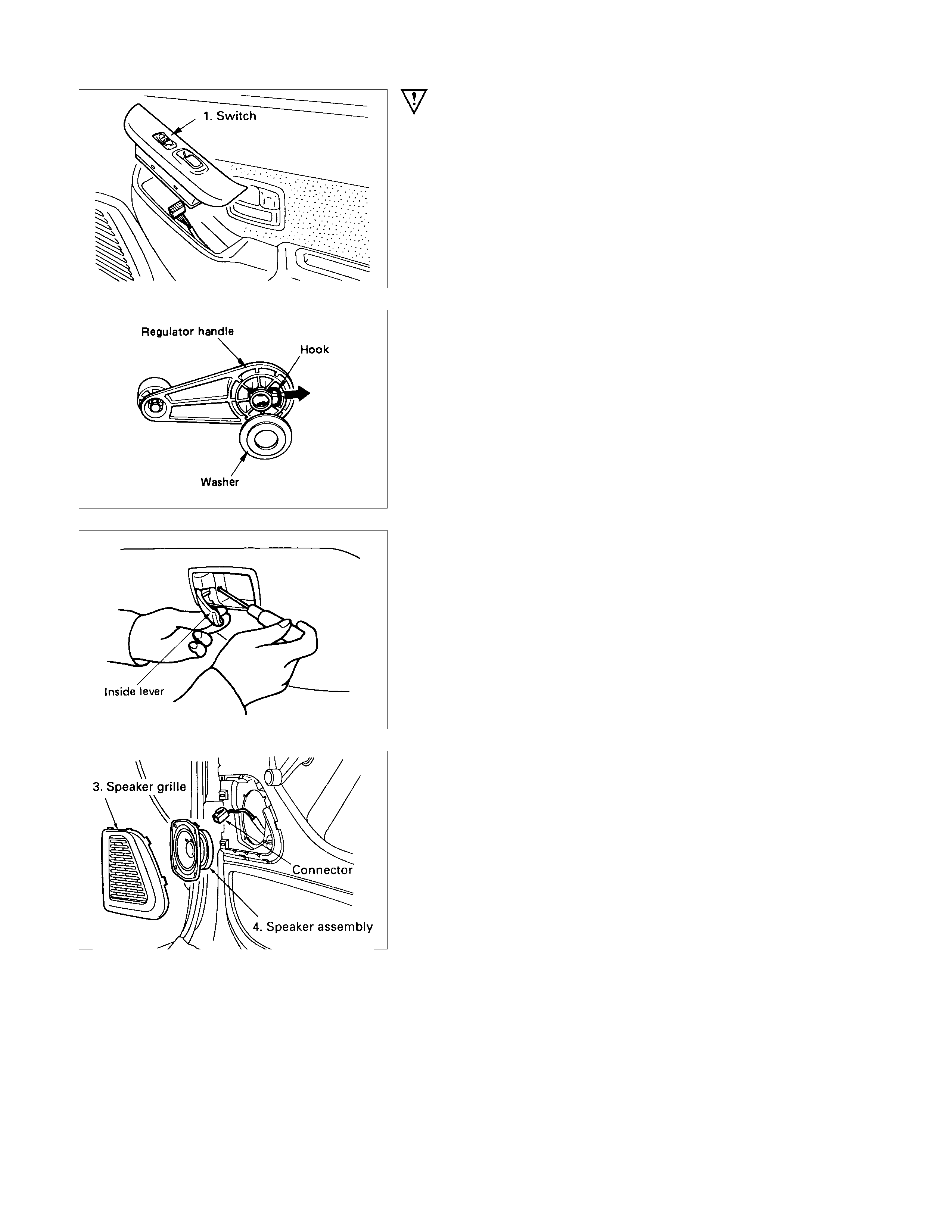
1. Power Window Switch/Window Regulator Handle
•Prise out the power window switch and remove the
connectors.
•To remove the regulator handle, remove the clip at the
root of the handle by using wire.
2. Bezel
•Remove the screw while pulling the inside lever toward
you.
3. Speaker Grill
•Pull out the clips.
4. Speaker Assembly
•Remove 4 screws and disconnect the speaker harness
connector.
5. Door Pull Case
•Remove the screw at the bottom of the case.
6.Door Mirror Cover
•Pull out the upper clip, and then tak e out the c atc h at the
lower section.
7.Door Trim Pad
•Remove the cover bottom of the trim pad (4 pcs), then
remove the screws.
8.Door Pocket
9.Power Window Box
10.Inner Waste Seal
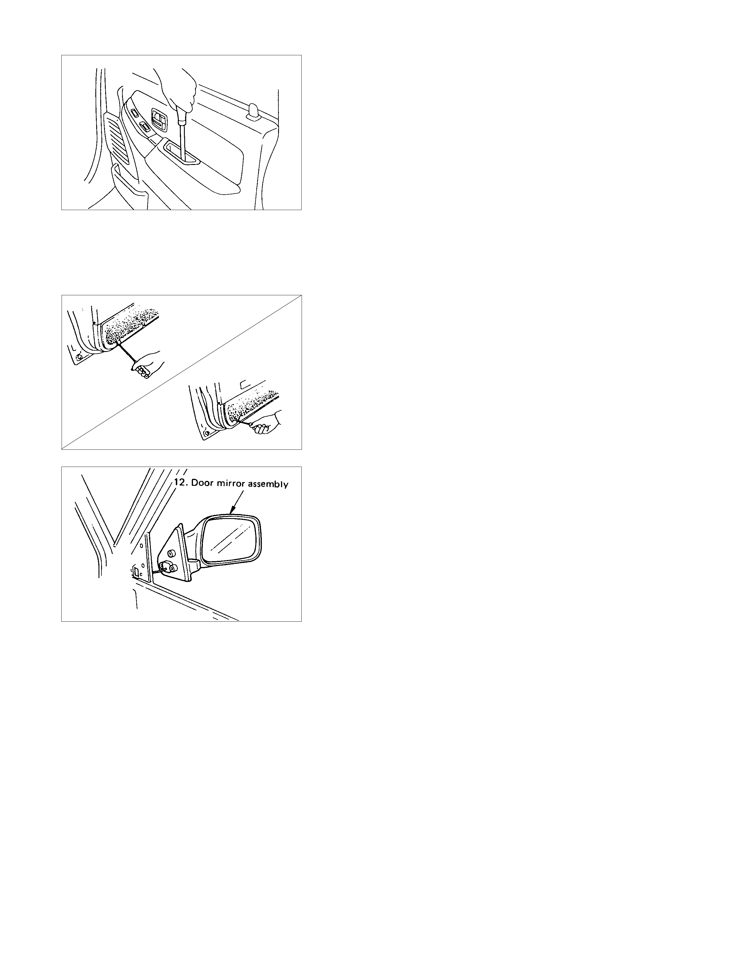
11.Door Mirror Assembly
•Remove 3 fixing bolts and then remove the connector.
12.Outer Waste Seal
13.Door Mirror Bracket
•Remove 2 bolts at the lower section, and then rem ove 2
screws in the weather strip.
14.Bracket
15.Speaker Box
•Remove 3 fixing bolts.
16.Water Proof Sheet
•Take care not to damage the sheet when peeling it off.
17.Window Glass
•Remove 2 screws through the access hole and pull out
the window glass upward.
18.Window Regulator/Power Window Motor
•Disconnect the power window motor connector.
19.Glass Run
•Pull it out of the door piller of the channel. (front/rear)
20.Glass Run Rear Channel
•Remove 2 screws.
21.Inside Lever
22.Door Lock Assembly/Door Lock Actuator
•Disconnect the linkage with the outside handle, the
inside lever and the lock cylinder.
23.Glass Run Front Channel
24.Door Lock Cylinder
•Remove the door lock cylinder by applying finge
r
pressure from inside while depressing the retaining clip.
25.Outside Handle
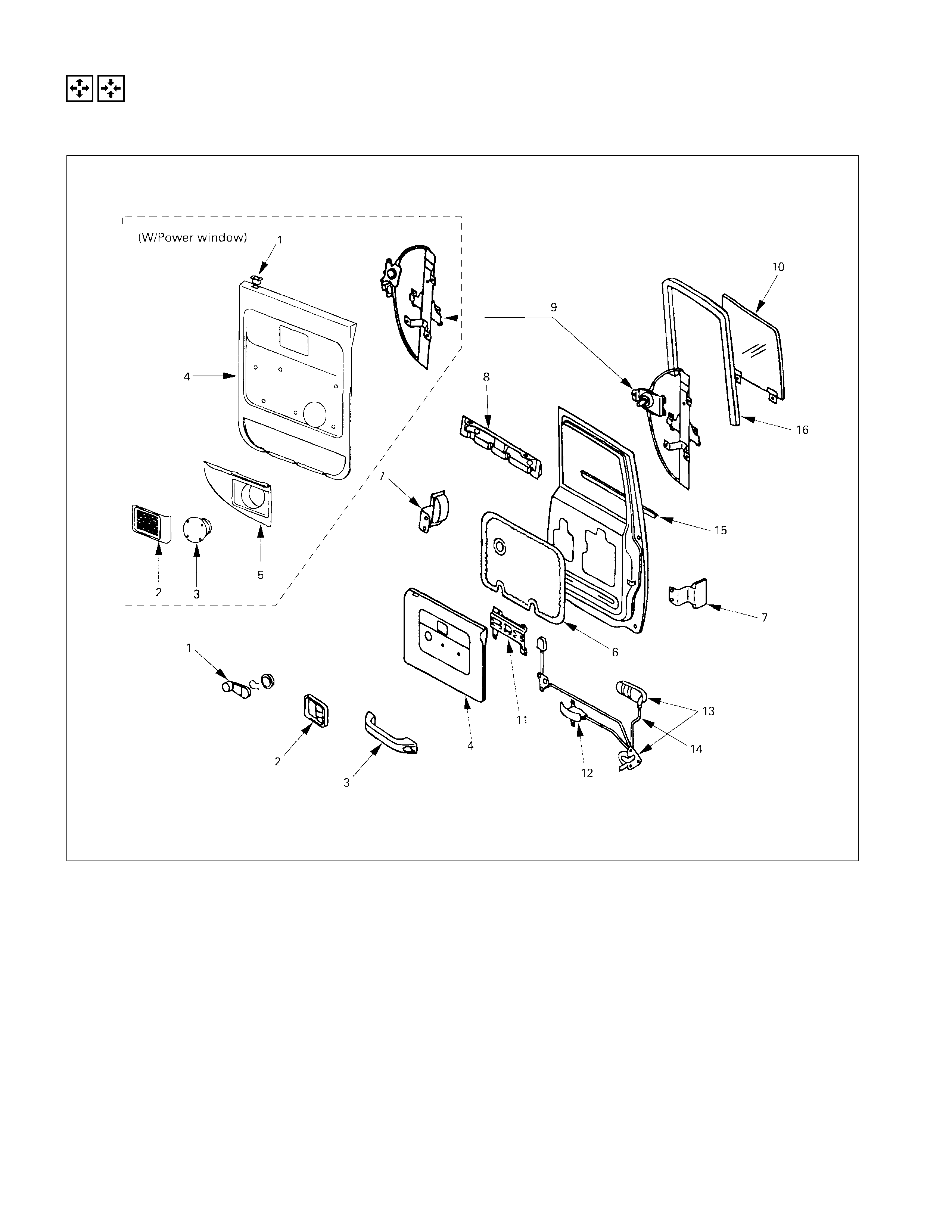
DISASSEMBLY AND REASSEMBLY
(REAR DOOR)
DISASSEMBLY STEPS
▲1. Power window switch/Window regurator
handle
▲2. Bezel/Speaker grill
3. Inside pull handole/Speaker
▲4. Door trim pad
5. Arm rest (W/Power window only)
6. Water proof sheet
7. Glass guide
8. Upper cover
▲9. Window regurator/Power window motor
▲10. Window glass
11. Bracket
12. Inside lever
13. Outside handle
▲14. Door lock cylinder
15. Outer waste seal
16. Glass run
REASSEMBLY STEPS
To reassemble, follow the disassembly steps
in the reverse order.

IMPORTANT OPERATIONS
1. Window Regulator Handle
•To remove the regulator handle, remove the clip at the
root of the handle by using wire.
2. Bezel
•Remove the screw while pulling the inside lever toward
you.
4. Door Trim Pad
•Remove the cover bottom of the trim pad (4 pcs), then
remove the screws.
9. Window Regulator
•Remove the 4 screws holding the regulator.
10.Window Glass
•First, align the height of regulator to the access hole.
Remove 2 screws attaching bottom channel and
regulator, then remove the glass.
•Remove the window glass by tilting it as necessary .
14.Door Lock Assembly
•Disconnect the linkage from the door outside handle,
inside lever and lock cylinder.
Remove the 2 bolts holding the outside handle from
inner side.
•Remove the 3 bolts holding the door lock assembly.
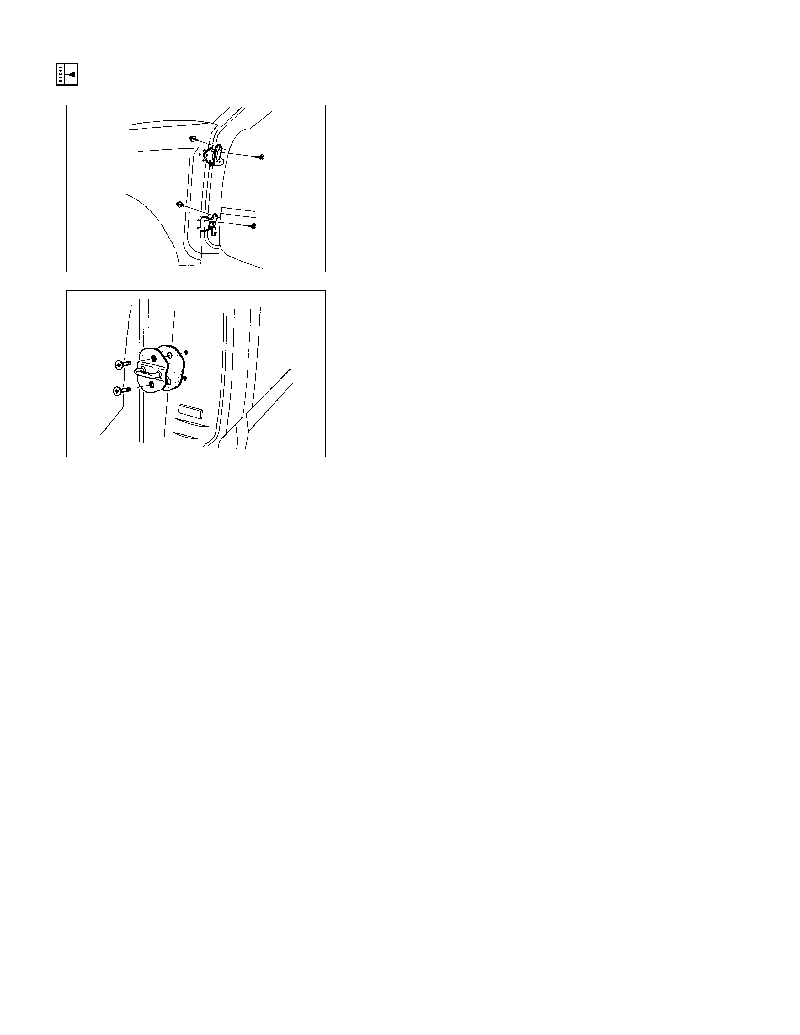
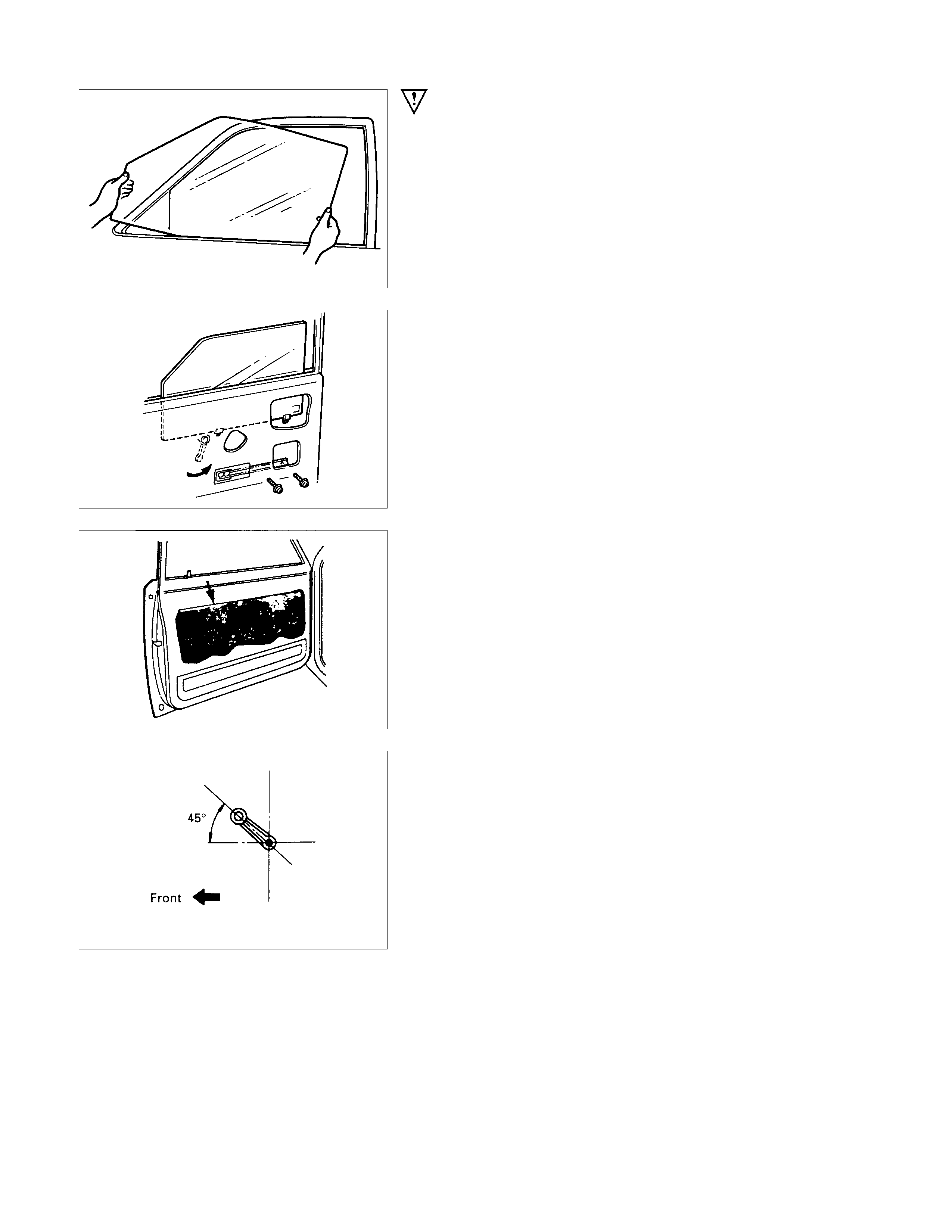
ADJUSTMENT (F RO NT AND REAR)
DOOR HINGE
Door alignment can be obtained by moving door hinges.
Prior to adjustment, remove the fender and set the door
temporarily.
Loosen hinge to door bolts when adjusting steps between the
door and body.
Loosen hinge to body bolts to adjust the clearance between the
door and body.
DOOR STRIKER
Loosen the striker screws and adjust the position of the striker
by holding a piece of wood against the striker and tapping it
with a hammer.
To obtain correct adjustment, move the position of the striker
vertically so that the lower face of the dovetail becomes parallel
to the striker.
Adjust the number of sheets to control engagement of the
striker with the door latch. One or two sheets are generally
used to obtain correct adjustment.
REASSEMBLY
(FRONT DOOR)
REASSEMBLY STEPS
1. Outside handle
2. Door lock cylinder
3. Glass run front channel
4. Door lock assembly/Door lock actuator
5. Inside lever
6. Glass run rear channel
7. Glass run
8. Window regulator/Power window motor
▲9. Window glass
▲10. Water proof sheet
11. Speaker box
12. Bracket
13. Door mirror bracket
14. Outer waste seal
15. Door mirror assembly
16. Inner waste seal
17. Power window box
18. Door pocket
19. Door trim pad
20. Door mirror cover
21. Door pull case
22. Speaker assembly
23. Speaker grill
24. Bezel
▲25. Power window sw itch/Windows regulator
handle
IMPORTANT OPERATIONS
9.Window Glass
•Insert the window glass into position by tilting it as
necessary, and then set it against the channel of the
window regulator.
•Attach the window glass to the window regulator with the
two screws.
10.Water Proof Sheet
•Place the butyl type on the door panel so as not to cove
r
the drain hole.
25.Regulator Handle
•Install the regulator handle as illustrated when closing
the window glass.
ADJUSTMENT (F RO NT AND REAR)
DOOR HINGE
Door alignment can be obtained by moving door hinges.
Prior to adjustment, remove the fender and set the door
temporarily.
Loosen hinge to door bolts when adjusting steps between the
door and body.
Loosen hinge to body bolts to adjust the clearance between the
door and body.
DOOR STRIKER
Loosen the striker screws and adjust the position of the striker
by holding a piece of wood against the striker and tapping it
with a hammer.
To obtain correct adjustment, move the position of the striker
vertically so that the lower face of the dovetail becomes parallel
to the striker.
Adjust the number of sheets to control engagement of the
striker with the door latch. One or two sheets are generally
used to obtain correct adjustment.
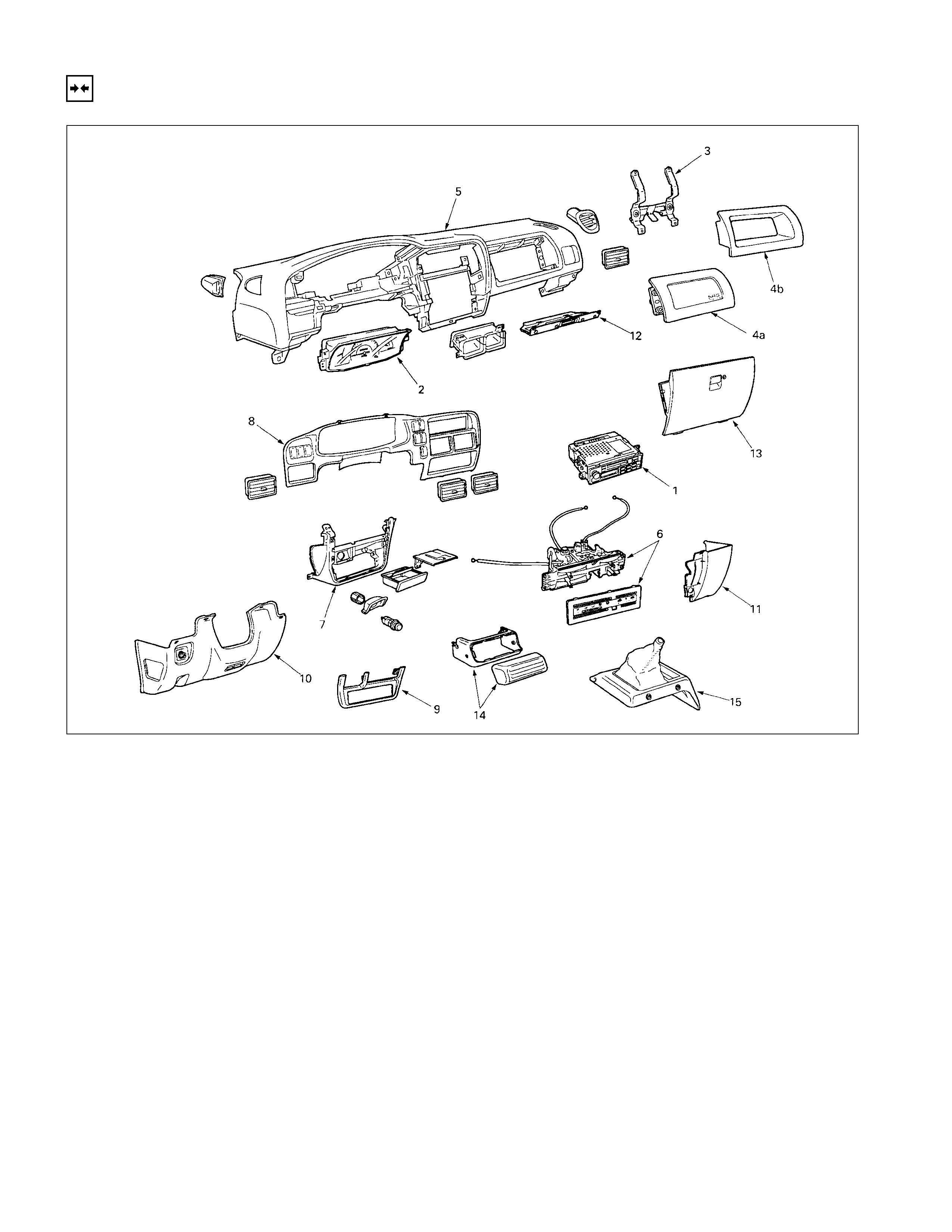
INSTRUMENT PANEL
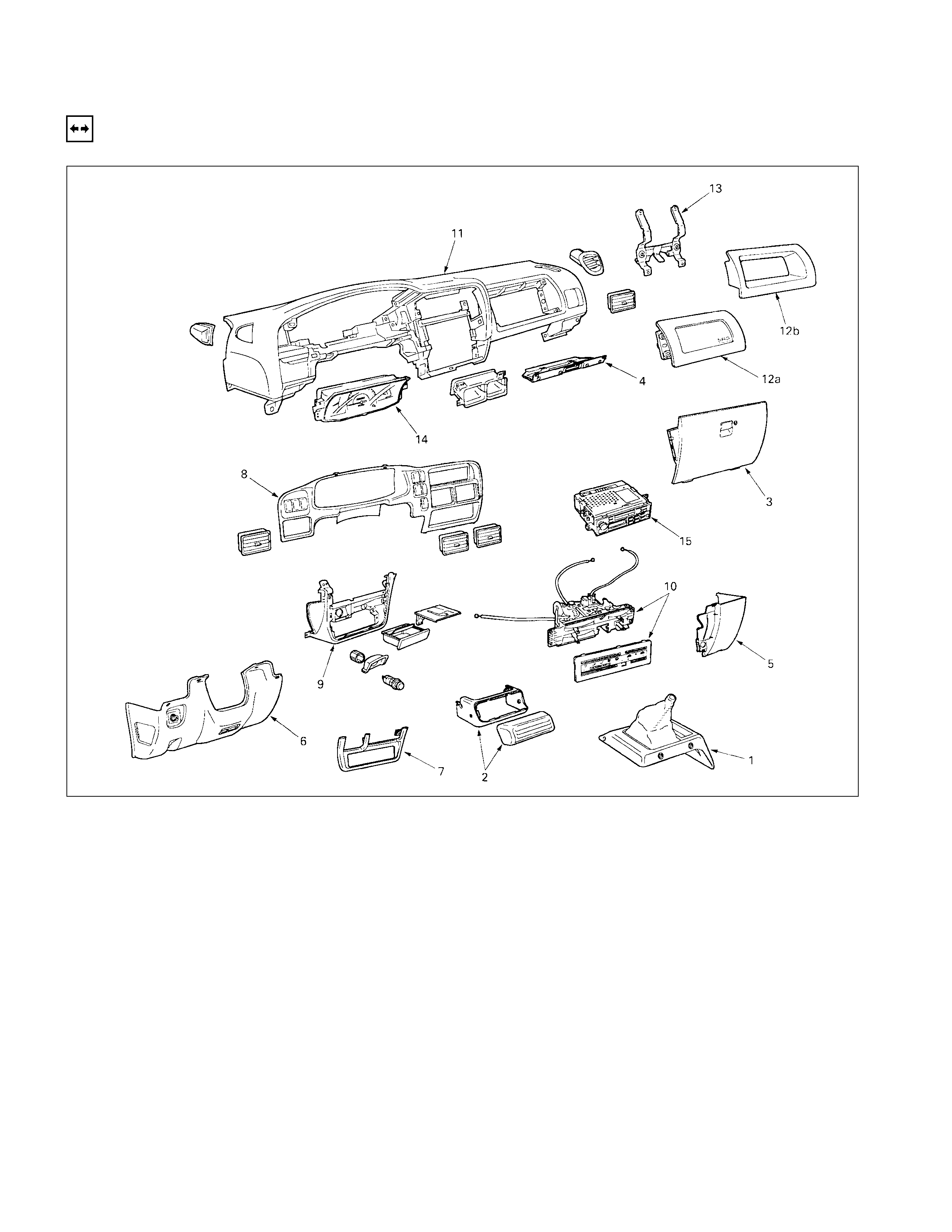
REMOVAL
DISASSEMBLY STEPS
▲1. Center console assembly
▲2. Control unit cover
▲3. Glove box
▲4. Glove box cover
▲5. Instrument panel passenger lower cover
assembly
▲6. Instrument panel driver lower cover
assembly
▲7. Lower cluster assembly
▲8. Meter cluster assembly
▲9. Instrument panel lower center cover
assembly
▲10. Control lever assembly
▲11. Instrument panel assembly
▲12a. Passenger air bag (if so equipped)
12b. Utility box
▲13. Passenger air bag reinforcement
assembly (W/SRS)
14. Meter assembly
15. Radio assembly
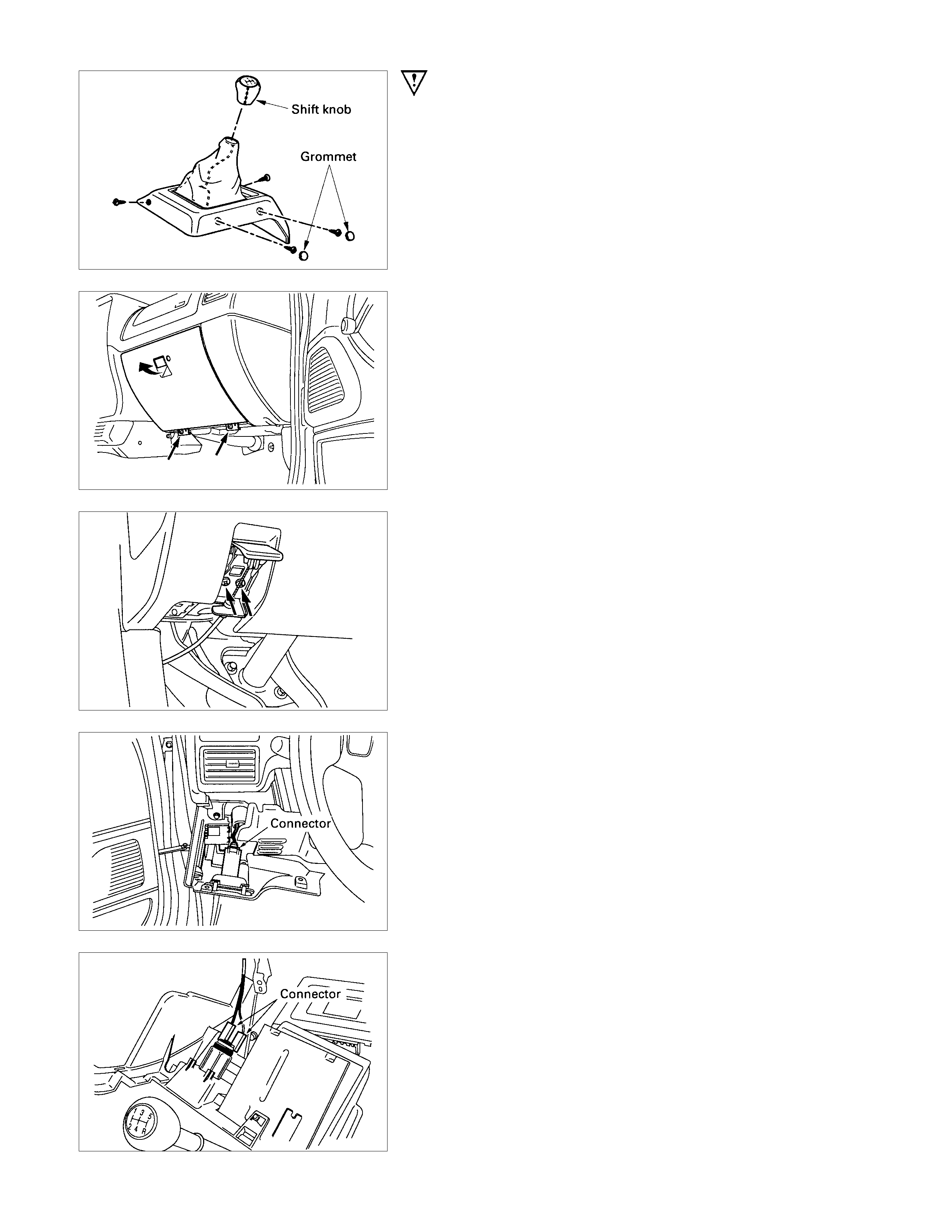
IMPORTANT OPERATIONS
1. Center Console Assembly
•Remove shift knob and 2 fixing screws (front side).
Open the grommet and remove 2 fixing screws (rea
r
side).
2. Control unit cover
3. Glove Box
•Remove 2 fixing screws and pulling the handle.
4. Glove Box Cover
•Remove 4 fixing screws and pull the cover toward you
and remove the clips at 2 positions.
5. Instrument Panel Passenger Lower Cover Assembly
•Remove 3 fixing screws and 1 clip.
6. Instrument Panel Driver Lower Cover Assembly
•Remove the engine hood opener 2 fixing screws and 6
fixing screws.
•Disconnect the connector of the illumination.
7. Lower Cluster Assembly
•Remove 3 fixing clips.
8. Meter Cluster Assembly
•Remove 3 fixing screws, 7 clips and switch connectors.
9. Instrument Panel Lower Center Cover Assembly
•Remove 7 fixing sc r ews and disc onnect the c onnec tor o
f
the cigarette lighter.
10.Control Lever Assembly
1) Disc onnect the c ontr ol c able f rom heater unit and blowe
r
unit.
2) Remove the control lever assembly fixing screws.
11.Instrument Panel
1) Remove the instrument panel fixing nuts and bolts.
2) Disconnect the instrument harness connectors.
3) Remove the instrument panel.
Caution:
For precautions on installation or removal of SRS-air bag
system, refer to Section 12M1 - AIR BAG.
12a. Passenger air bag assembly
•Remove 4 fixing bolts A and 2 nuts B.
Caution:
For precautions on installation or removal of SRS-air bag
system, refer to Section 12M1 - AIR BAG.
13.Passenger air bag reinforcement assembly (W/SRS)
•Remove 4 fixing screws C.
INSTALLATION
INSTALLATION STEPS
1. Radio assembly
2. Meter assembly
3. Passenger air bag reinforcement
assembly
4a. Passenger air bag
4b. Utility box
5. Instrument panel assembly
▲6. Control lever assembly
7. Instrument panel lower center cover
assembly
8. Meter cluster assembly
9. Lower cluster assembly
10. Instrument panel driver lower cover
assembly
11. Instrument panel passenger lower cover
assembly
12. Glove box cover
13. Glove box
14. Control unit cover
15. Center console assembly
IMPORTANT OPERATION - INSTALLATION
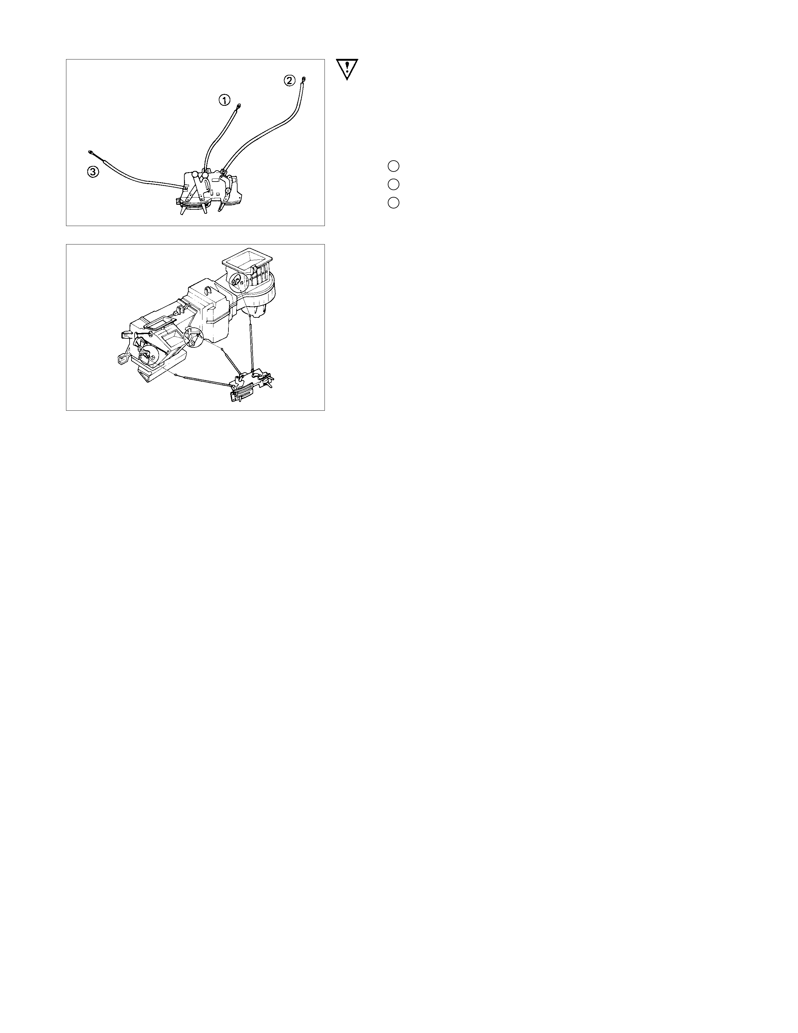
6. Control Lever Assembly
1) Set the temperature control lever and the airsource
select lever at the left-hand side end.
2) Set the air selector lever at the right-hand side end.
1 : Temperature control cable
2: Air source select cable
3: Air selector
3) Attach the cable, after the work 1) and 2) have been
completed.
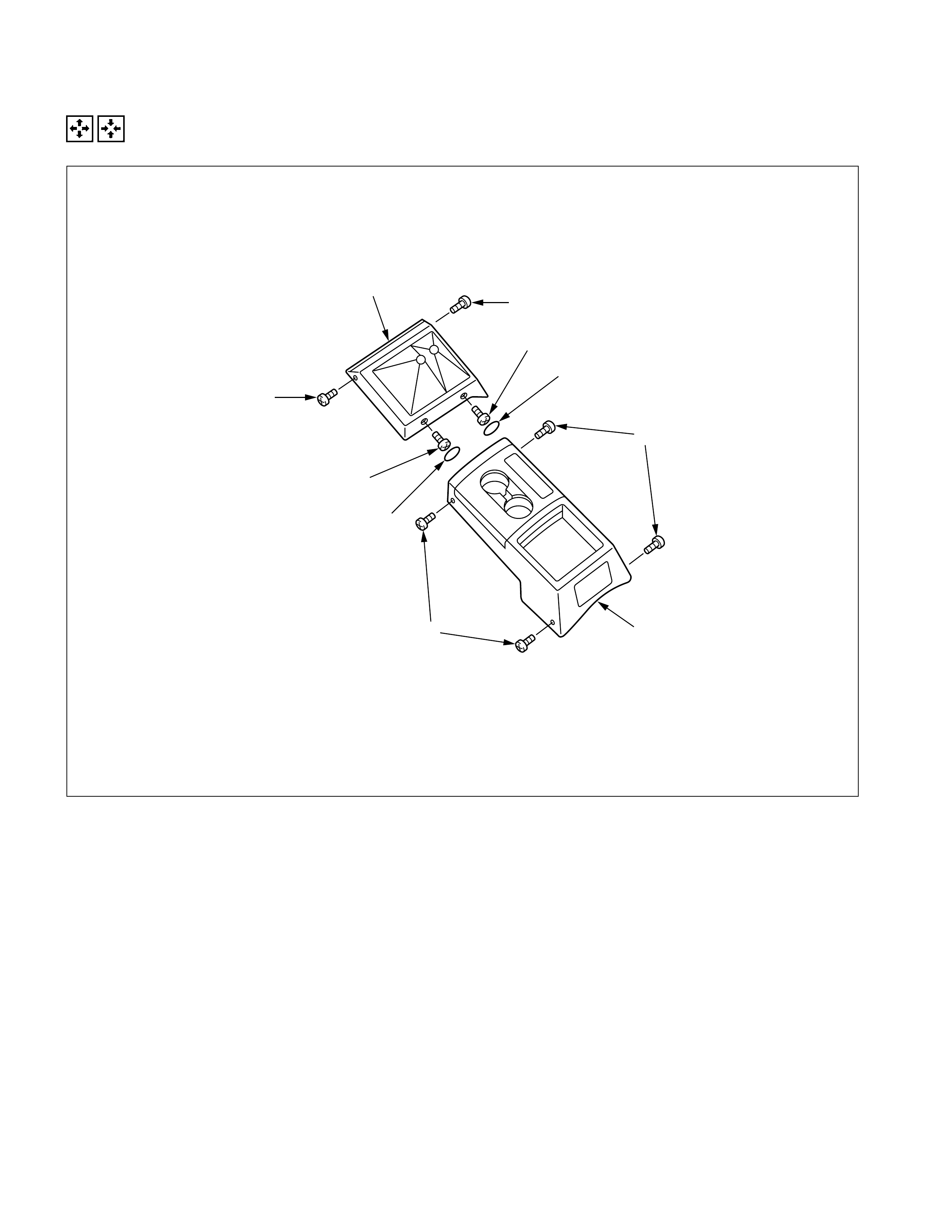
CONSOLE BOX
REMOVAL AND INSTALLATION (4×
××
×4 S MODEL)
1
1
2
2
3
3
4
5
5
6
REMOVAL STEPS
1. Hole cover ×2
2. Screw ×2
3. Screw ×2
4. Center console
5. Screw ×4
6. Rear console
INSTALLATION STEPS
6. Rear console
5. Screw ×4
4. Center console
3. Screw ×2
2. Screw ×2
1. Hole cover ×2
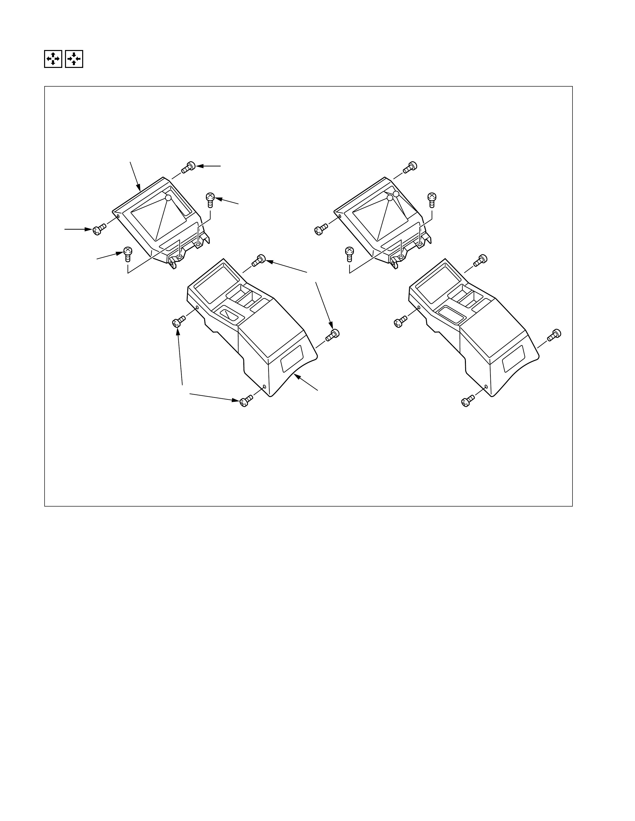
REMOVAL AND INSTALLATION (4X4 & 4X2 LS MODEL)
3
3
5
1
4x2 LS Model
1
2
4
4
4x4 LS Model
REMOVAL STEPS
1. Screw ×4
2. Rear console
3. Screw ×2
4. Screw ×2
5. Center console
INSTALLATION STEPS
5. Center console
4. Screw ×2
3. Screw ×2
2. Rear console
1. Screw ×4
HEAD LINING
GENERAL DESCRIPTION
STANDARD CAB
SPACE CAB (SPORTS CAB)
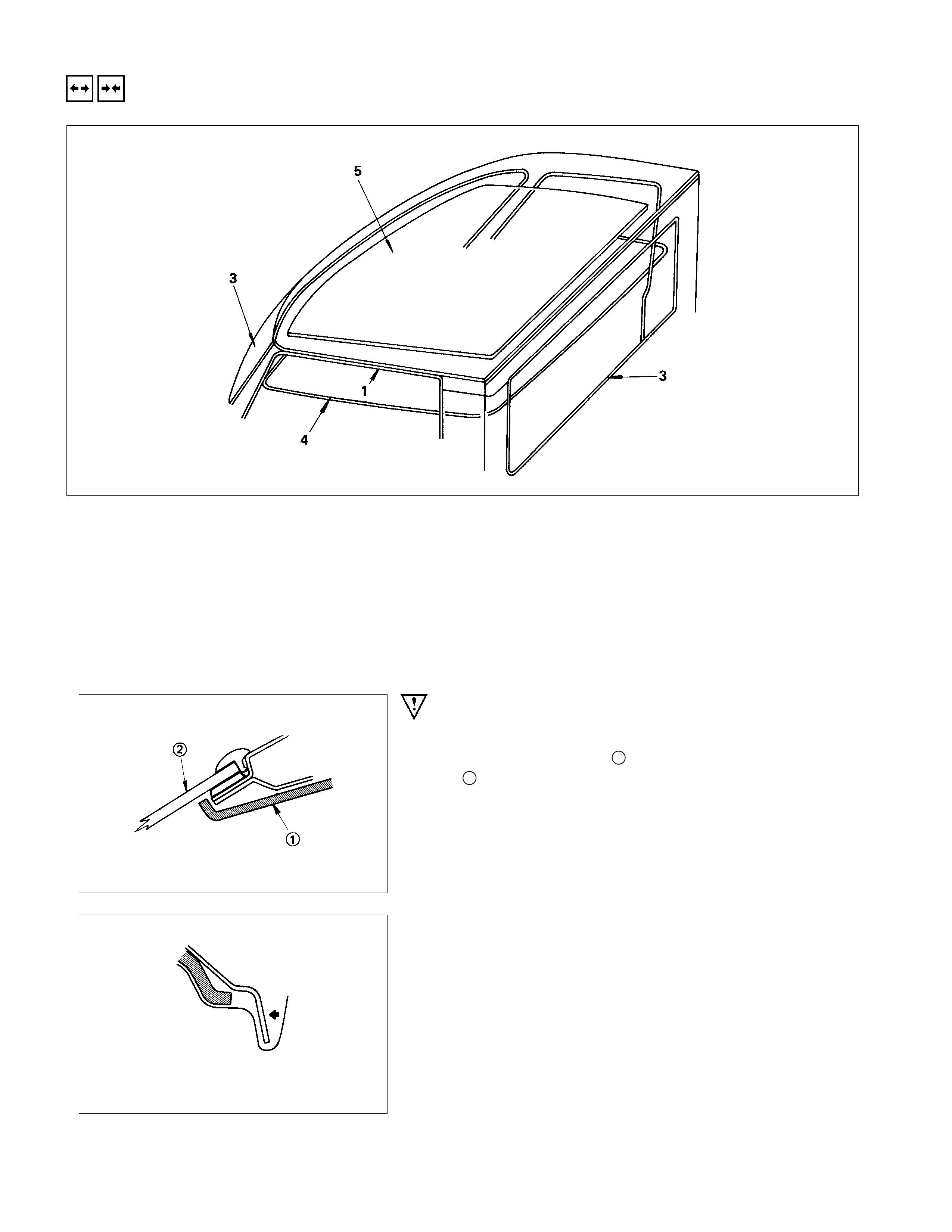
REMOVAL AND INSTALLATION
REMOVAL STEPS
1. Door finisher
2. Rear view mirror, sunvisor and dome
la mp assembly
3. Windshield and back light glass
4. Head lining
5. Insulation pad
INSTALLATION STEPS
5. Insulation pad
▲4. Head lining
3. Windshield and back light glass
2. Rear view mirror, sunvisor and dome
la mp assembly
1. Door finisher
IMPORTANT OPERATIONS - INSTALLATION
4. Head Lining
1) Install the head lining 1 to the body panel.
2 : Windshield glass
2) Roll up the head lining in the body side of the back light
glass and door opening.
3) Roll up the head lining provided with slits, in the corner.
4) Roll up the head lining 1 in the body side of door opening.
5) Fix to the door side, using the finisher 2.
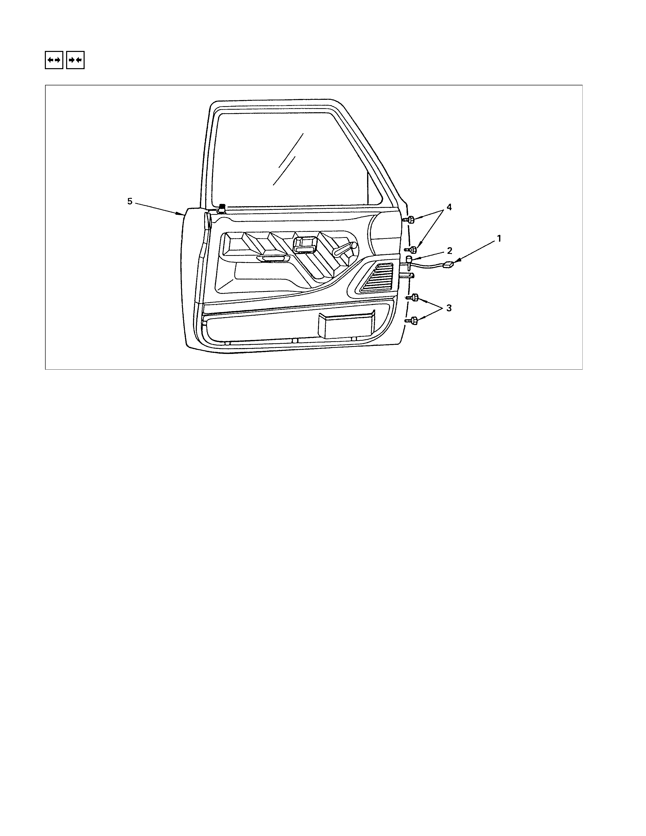
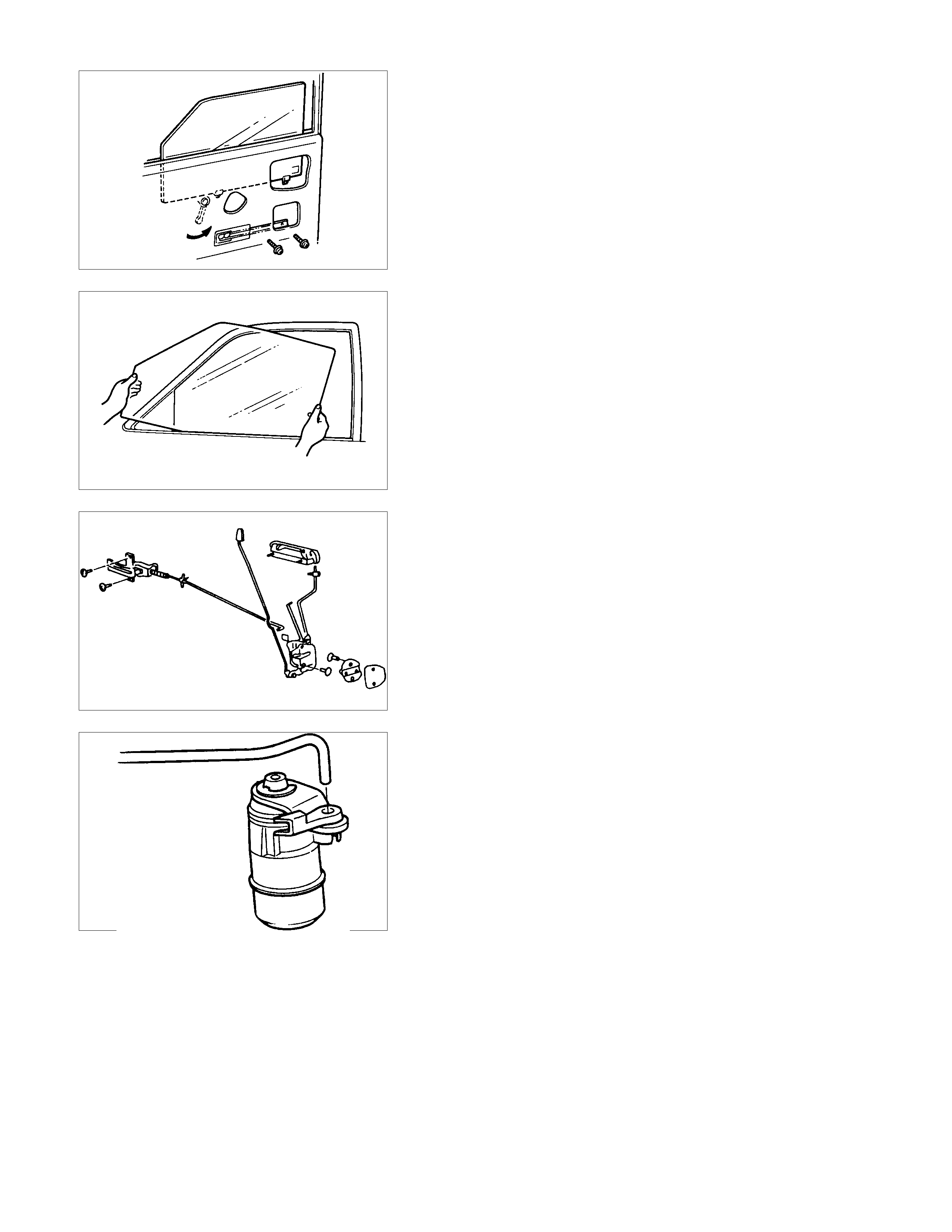
FUEL FILLER LID OPENER VELER/CABLE
REMOVAL (DOUBLE CAB)
REMOVAL STEPS
▲1. Front sill plate
▲2. Rear sill plate
3. Center pillar inner trim cover
▲4. Fuel filler lid opener cover
▲5. Fuel filler lid opener lever
6. Cover
▲7. Fuel filler lid cable assembly
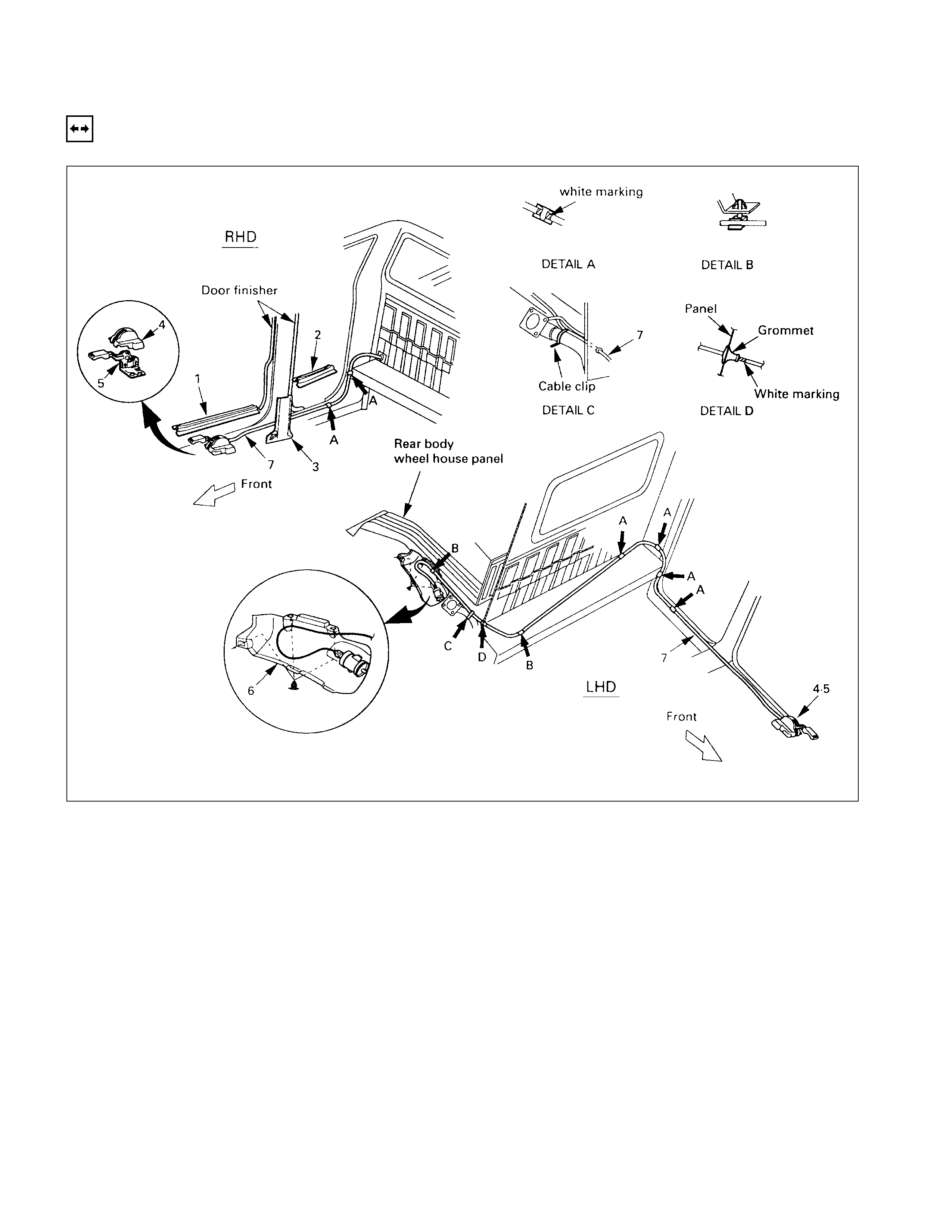
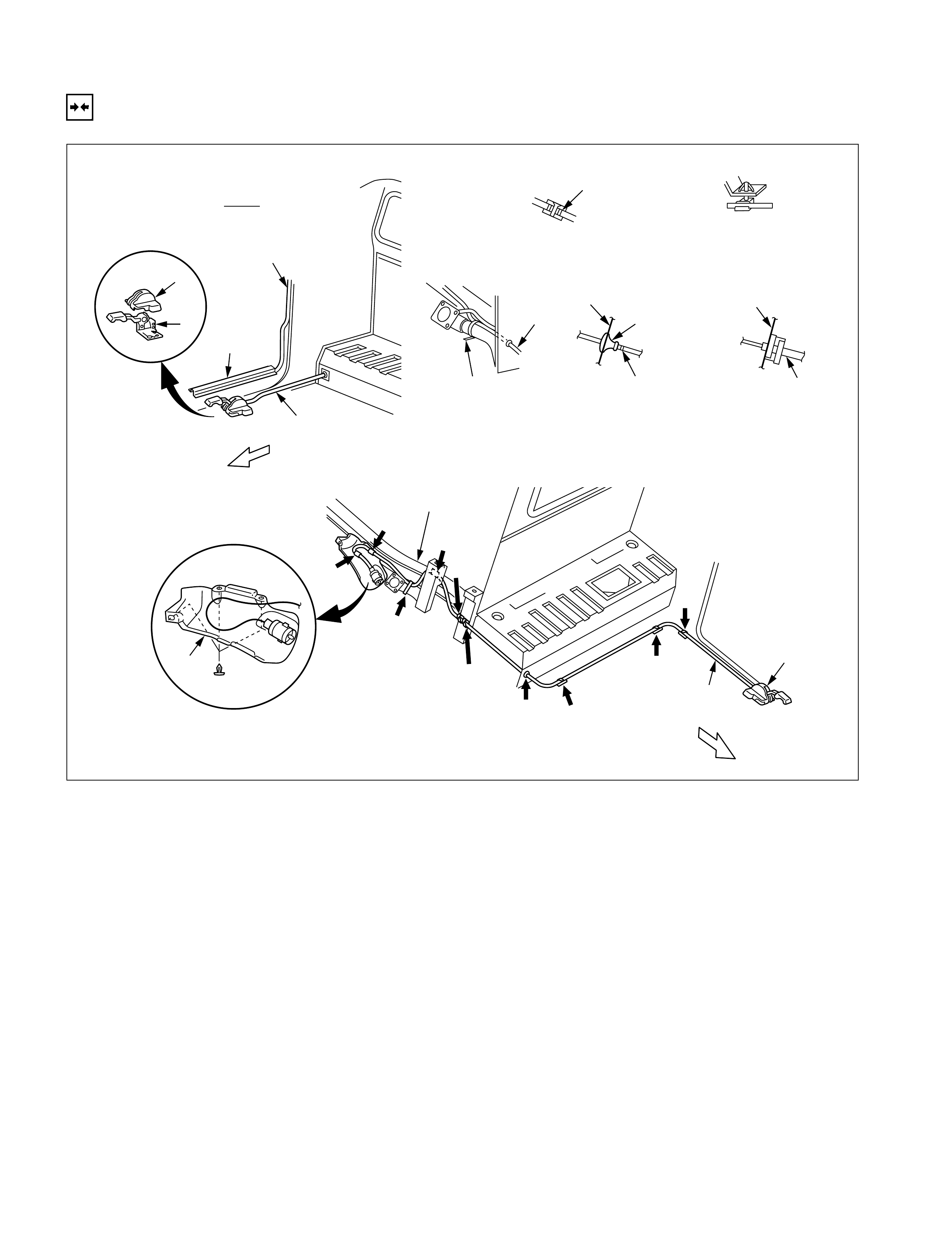
REMOVAL (SPACE CAB)
4
51
7
7
4,5
7
A
A
RHD
DETAIL C DETAIL D
Door finisher
Front
Cable clip
Panel Grommet
White marking
Cab mounting
White marking
DETAIL E
DETAIL BDETAIL A
Protector
Front
A
D
Rear body
wheel house panel
B
B
C
E
E
6
B
REMOVAL STEPS
▲1. Front sill plate
▲4. Fuel filler lid opener cover ▲5. Fuel filler lid opener lever
6. Cover
▲7. Fuel filler lid cable assembly
REMOVAL (SINGLE CAB)
Rear body
wheel house panel
B
B
C
E
E
6
B
4
51
7
7
RHD
DETAIL C DETAIL D
Door finisher
Front
Cable clip
Panel Grommet
White marking
Rear body mounting
White marking
DETAIL E
DETAIL BDETAIL A
Protector
4,5
7
A
A
Front
A
D
REMOVAL STEPS
▲1. Front sill plate
▲4. Fuel filler lid opener cover ▲5. Fuel filler lid opener lever
6. Cover
▲7. Fuel filler lid cable assembly
IMPO RTANT OPERATIONS - REMOVAL
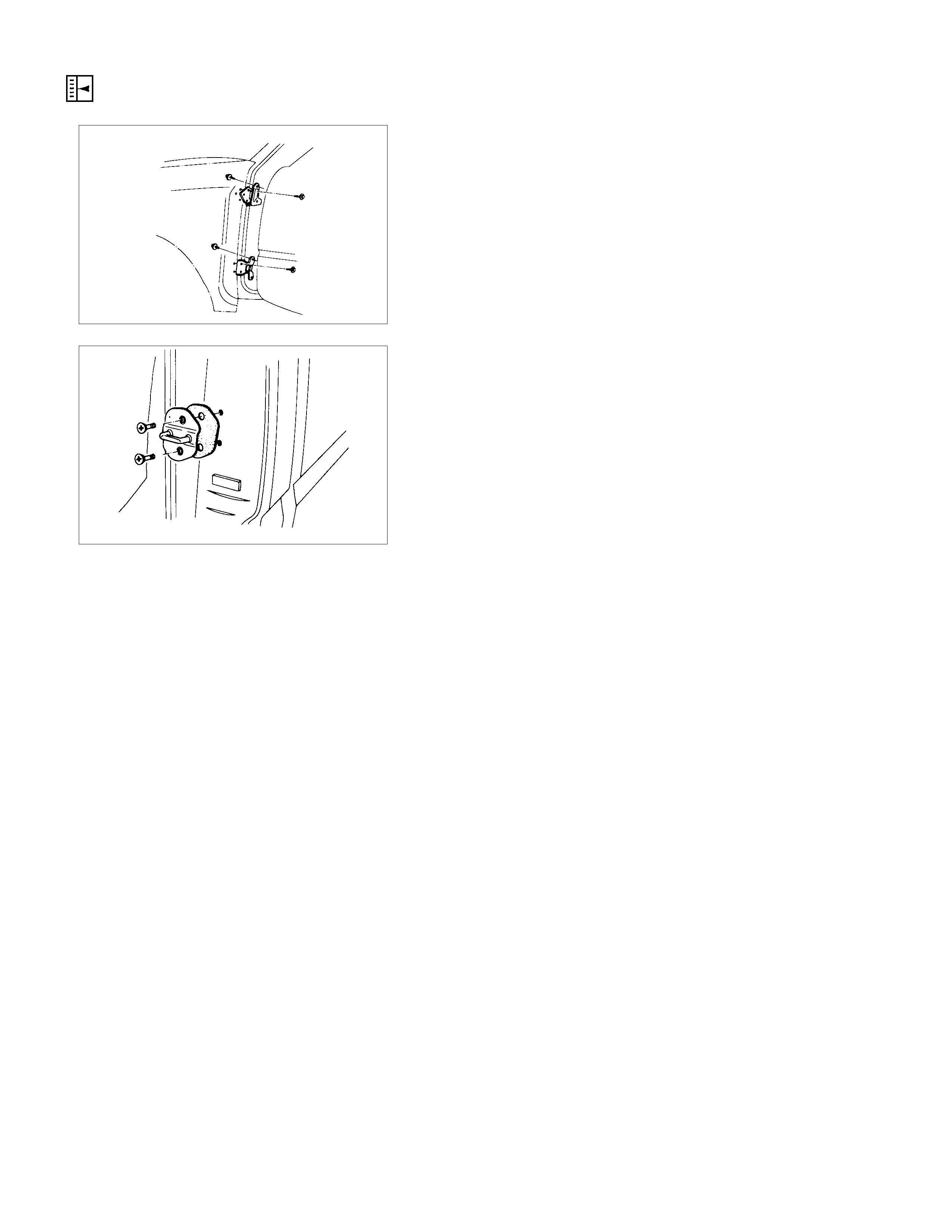
1. Front Sill Plate
•Remove the 4 clips.
2. Rear Sill Plate (Double Cab)
•Remove the 2 clips.
4. Fuel Filler Lid Opener Cover
•Remove the clip and release the fixed point.
5. Fuel Filler Lid Opener Lever
•Remove the 2 opener fixing bolts and disconnect the
cable.
7. Fuel Filler Lid Cable Assembly
•Remove some fixing clips, turn the cable holder on the
side of recess in 90° counterclockwise and remove it
from the recess. Pull out the grommet to rearward o
f
vehicle and remove the cable assembly.
• In case of LHD, remove the rear seat assembly before
removing the fuel filler lid cable assembly.
(Refer to Rear Seat in this section)

INSTALLATION (DOUBLE CAB)
INSTALLATION STEPS
▲1. Fuel filler lid cable assembly
2. Cover
3. Fuel filler lid opener lever
4. Fuel filler lid opener cover
5. Center pillar inner trim cover
6. Rear sill plate
7. Front sill plate
INSTALLATION (SPACE CAB)
4
37
1
1
1
A
A
RHD
DETAIL C DETAIL D
Door finisher
Front
Cable clip
Panel Grommet
White marking
Cab mounting
White marking
DETAIL E
DETAIL BDETAIL A
Protector
Front
A
D
Rear body
wheel house panel
B
B
C
E
E
2
B
3,4
INSTALLATION STEPS
▲1. Fuel filler lid cable assembly
2. Cover
3. Fuel filler lid opener lever
4. Fuel filler lid opener cover
7. Front sill plate

INSTALLATION (SINGLE CAB)
Rear body
wheel house panel
B
B
C
E
E
2
B
4
37
1
1
RHD
DETAIL C DETAIL D
Door finisher
Front
Cable clip
Panel Grommet
White marking
Rear body mounting
White marking
DETAIL E
DETAIL BDETAIL A
Protector
1
A
A
Front
A
D
3,4
INSTALLATION STEPS
▲1. Fuel filler lid cable assembly
2. Cover
3. Fuel filler lid opener lever
4. Fuel filler lid opener cover
7. Front sill plate
IMPORTANT OPERATIONS - INSTALLATION
1. Fuel Filler Lid Cable Assembly
•Install the cable holder of cable assembly to the recess
and push the grommet in to the back panel. Fix the
pointed places.
Note:
To install, follow the removal steps in the reverse order,
noting the following points.
•
••
•Do not make extreme curve on the cable.
•
••
•Install the cable from outside of the cab.

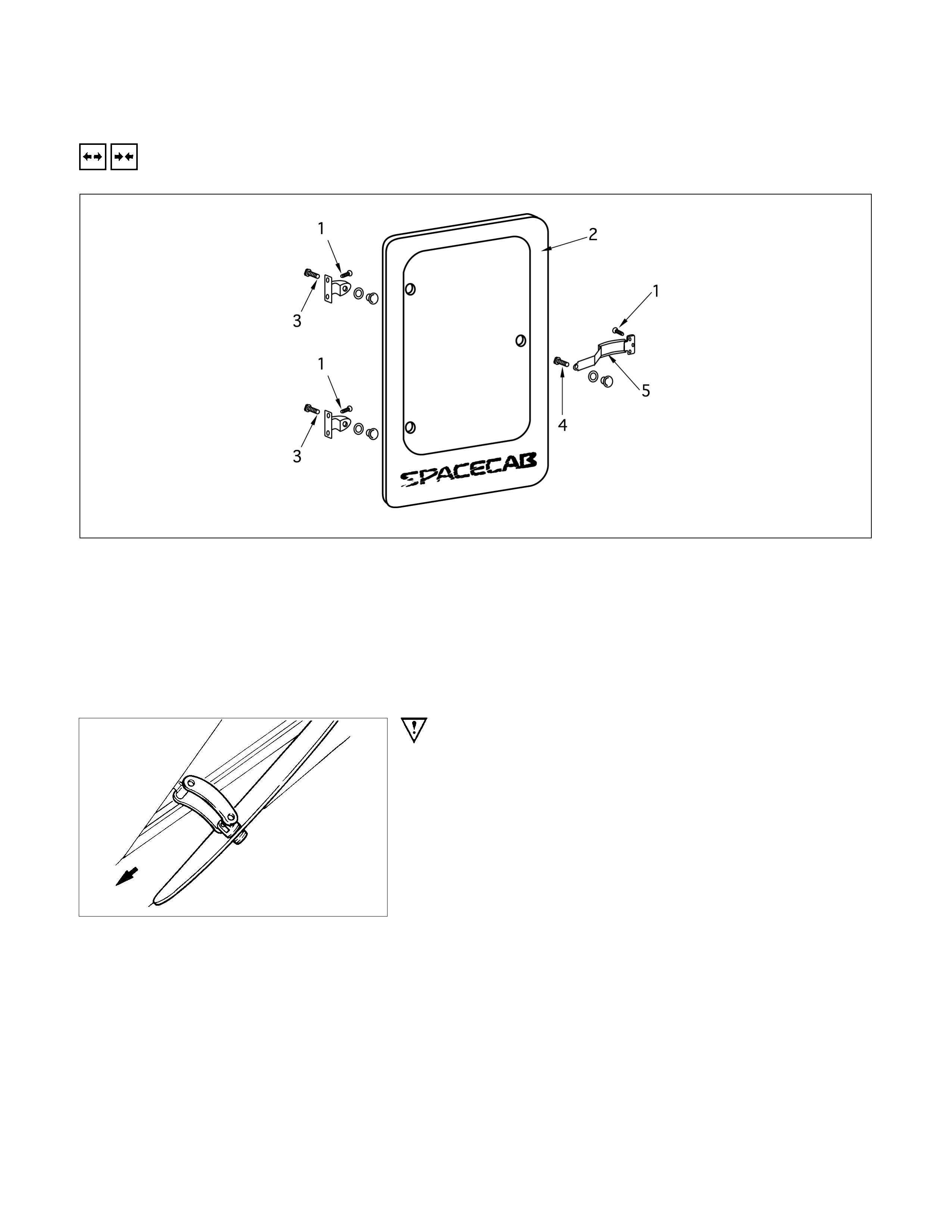
QUARTER GLASS (SPACE CAB)
REMOVAL AND INSTALLATION
REMOVAL STEPS
1. Screw bolt
▲2. Quarter glass
3. Screw bolt
4. Screw bolt
5. Fastener assembly
INSTALLATION STEPS
5. Fastener assembly
4. Screw bolt
3. Screw bolt
2. Quarter glass
1. Screw bolt
IMPO RTANT OPERATIONS - REMOVAL
2. Quarter Glass
Pull out the glass assembly towards the rear of the vehicle.
FRONT SEAT
SPECIAL PARTS FIXI NG BOLT N⋅
⋅⋅⋅m (kgf⋅
⋅⋅⋅m/lb⋅
⋅⋅⋅ft)
39.2±
±±
±9.8 (4±
±±
±1/28.9±
±±
±7.2)
39.2±
±±
±9.8 (4±
±±
±1/28.9±
±±
±7.2)
39.2±
±±
±9.8 (4±
±±
±1/28.9±
±±
±7.2)
REMOVAL AND INSTALLATION
REMOVAL STEPS
1. A djust cover
2. Bolt
3. Seat assembly
4. Adjuster
INSTALLATION STEPS
4. Adjuster
3. Seat assembly
▲2. Bolt
1. A djust cover
IMPORTANT OPERATION - INSTALLATION
2. Bolt
Torque N⋅m(kgf⋅m/lb⋅ft)
40.2 ± 9.8 (4.1 ± 0.6 / 29.6 ± 4.3)
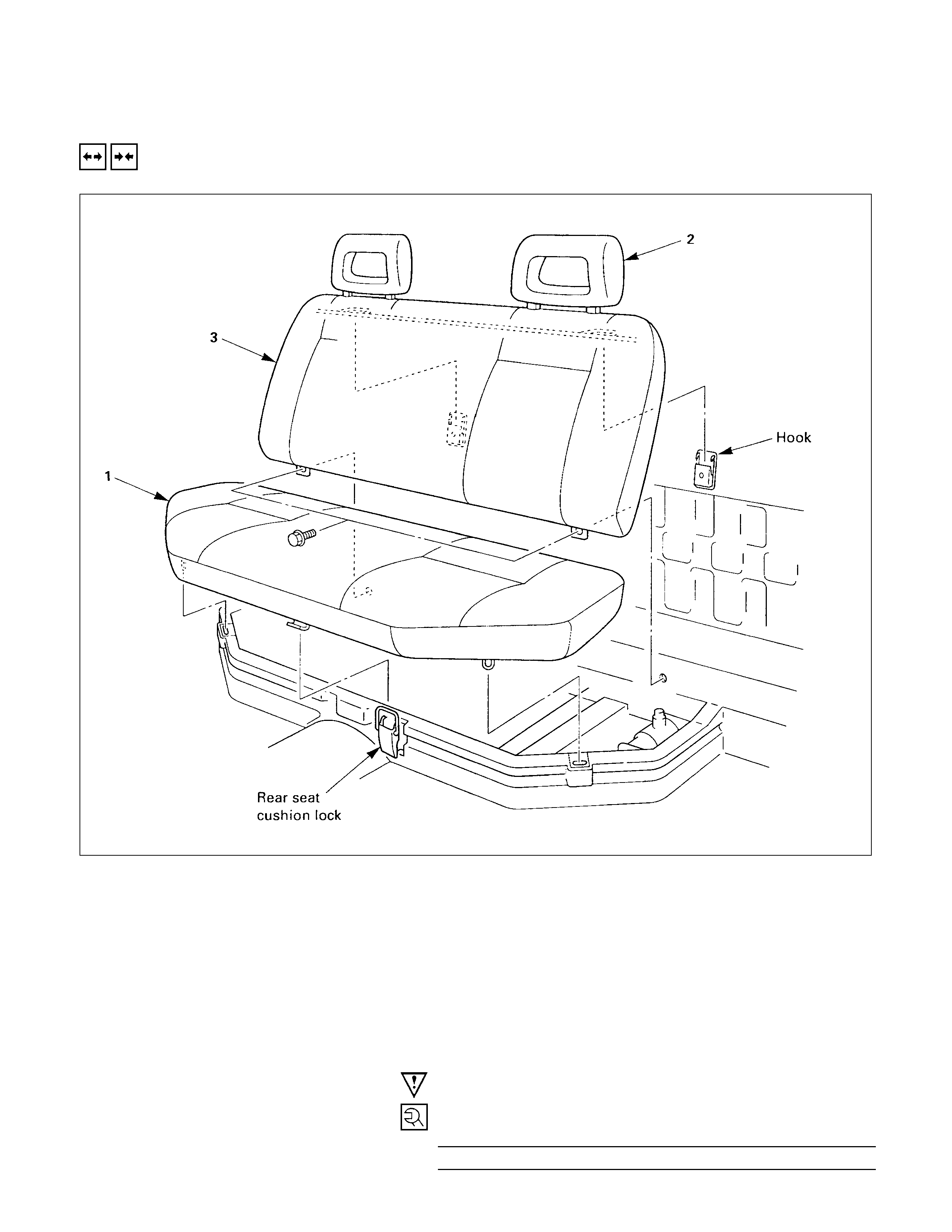
REAR SEAT
REMOVAL AND INSTALLATION
REMOVAL STEPS
1. Rear seat cushion assembly
•Release the lock, pull up the fixed
points.
2. Head rest
3. Rear seat back assembly
•After removing the 2 fixing bolts,
remove the wire of the back from the
hook.
INSTALLATION STEPS
▲3. Rear seat back assembly
2. Head rest
1. Rear seat cushion assembly
IMPORTANT OPERATION - INSTALLATION
3. Rear Seat Back Assembly
Bolt torque N⋅m(kgf⋅m/lb⋅ft)
19.6 ± 5 (2 ± 0.5 / 14.5 ± 3.6)

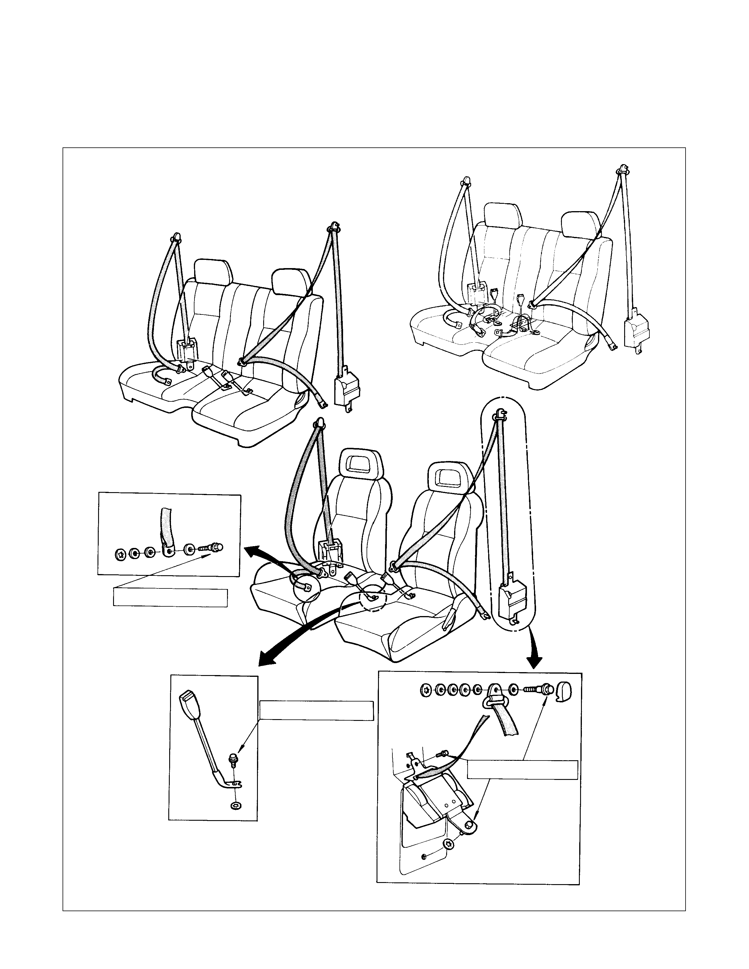
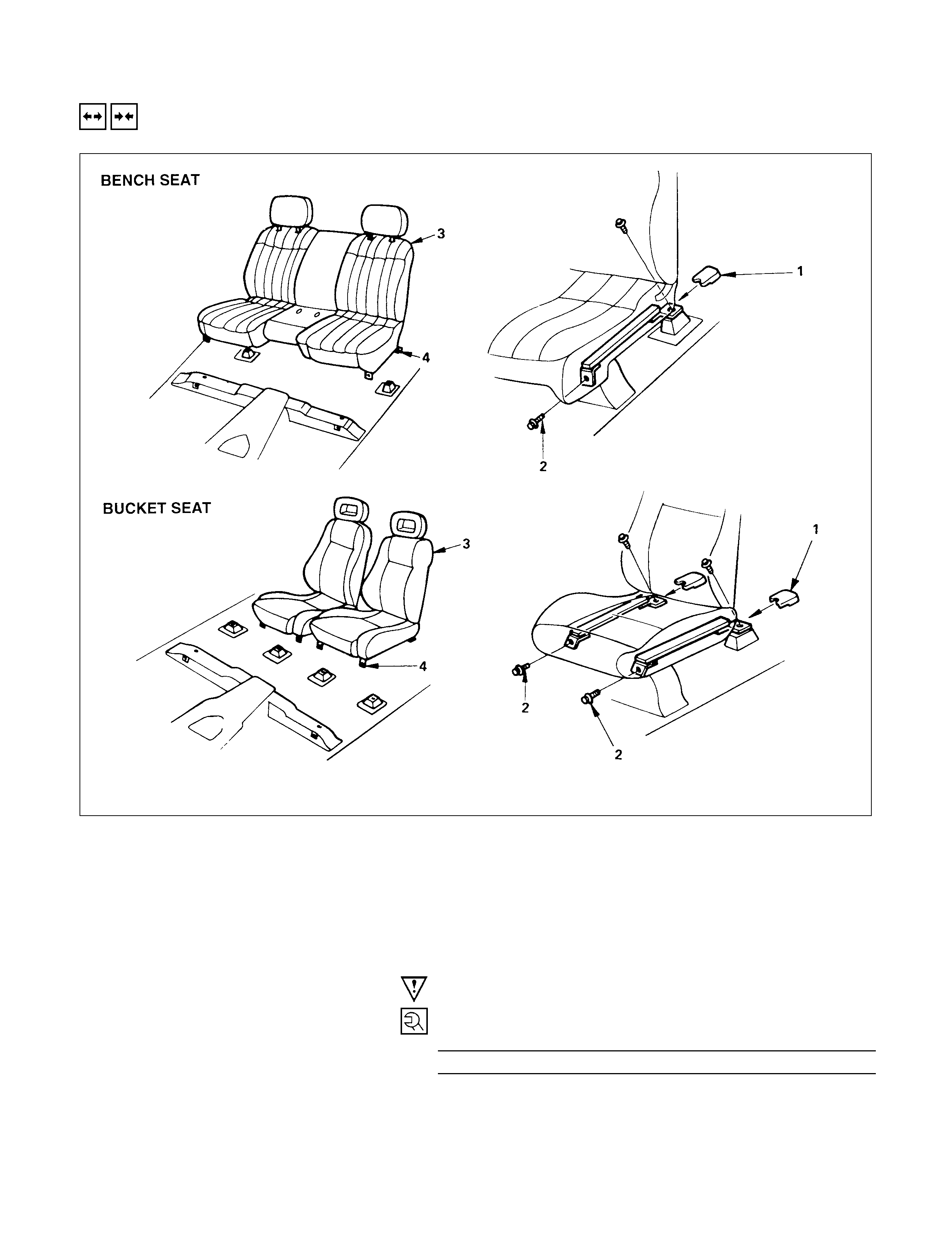
FRONT SEAT BELT
REMOVAL AND INSTALLATION
Removal Steps
1. Trim
2. Seat belt and retractor
Installation Steps
▲2. Seat belt and retractor
1. Trim
Important Oper ati on - Installati on
2. Seat Belt and Retractor
Bolt Torque N⋅m(kgf⋅m/lb⋅ft)
39.2 ± 9.8 (4 ± 1 / 28.9 ± 7.2)
REAR SEAT BELT
REMOVAL AND INSTALLATION
REMOVAL STEPS
1. Trim
2. Rear seat belt and retractor
3. Rear seat cushion
4. Center belt and buckle
INSTALLATION STEPS
▲4. Center seat belt and buckle
3. Rear seat cushion
▲2. Rear seat belt and retractor
1. Trim
IMPORTANT OPERATION - INSTALLATION
2. Rear Seat Belt and Retractor
Bolt Torque N⋅m(kgf⋅m/lb⋅ft)
39.2 ± 9.8 (4 ± 1 / 28.9 ± 7.2)
4. Center back Belt and buckle
Bolt Torque N⋅m(kgf⋅m/lb⋅ft)
39.2 ± 9.8 (4 ± 1 / 28.9 ± 7.2)