
SECTION 1D - BODY BUILDERS GUIDE
Introduction
Warran ty & Conditions
Chassis Frame
Important Guidelines
Holden Rodeo Accessory Weight & Commodity Mass
Guide
Recommended Sizes of Tray & Van Bodies
Rodeo 4x2 (TFR) & 4x4 (TFS) Single Cab
Rodeo 4x2 (TFR) & 4x4 (TFS) Crew Cab
Rodeo 4x2 (TFR) & (TFS) Space Cab
Cab Chassis Body Mounti ng - Typica l

Intorduction
This guide is published by Holden Limited.
The information it presents is of a general nature and is not specific to any particular Holden Rodeo model.
It must be emphasised that any major change to the basic vehicle may severely inhibit the ability of the
vehicle to perf orm its function. Mechanical failures, structural failures, component unreliability, vehicle insta-
bility and general dissatisfaction by the owner or operator can often be traced to inappropriate design and
application of body, equipment and/or accessories .
The informat ion contained withi n th is publi cati on t akes t he form of recommended i nstru cti ons to be f ollowed
when vehicle modifications are undertaken to ensure a totally sati sfactory product.
It must be remembered that certain modifications may invalidate Australian Design Rule Approval and
application for re-certification may be necessary.
THIS IS THE BODY BUILDERS RESPONSIBILITY
It is the Body Builder ’s responsibility to ensure compliance to the various vehicle and transport regulations
that may exist in the p articular vehicle’s area of operation.
All information relating to the technical specification of the vehicle should be obtained from the selling
Authorised Holden Dealer.

Warranty & Conditions
WARRANTY
The standard Warranty provided by Ho lden Limited applies to the basic vehicle only.
NOTE: Holden accepts no resp onsibility for al terations or the affects of alt erations to the original vehicle
and equipment as supplied by Holden.
CONDITIONS
1. Repair s o r repl acements are carr ied out under Warranty in making good any defects shall (unless
Holden decides otherwise) be carried out by an authorised Holden Dealership.
2. The Warranty applies if the defect complained of is one of materials or workmanship and is not
caused by:
(a) misuse or abuse of the vehicle such as by racing, rallying, overloading etc., or by neglect.
(b) operati on of the vehi cle after the defect is known.
(c) failure to carry out proper maintenance service in accordance with the schedules published by
Holden.
(d) use of incorrect types and grades of fuel, oil or lubricants.
(e) alteration of the vehicle by anyone not authorised by Holden.
(f) the fitting of parts or accessories not marked by Holden.
(g) any work carried out on the vehicle by anyone except an authorise d Holden Dealership.
Chassis Frame
CHASSIS FRAME MATERIAL
The Holden Rodeo features a box section frame chassis with cross members for added strength and dura-
bility. Material Specification of the chassis frame is SAPH41 – MILD STEEL.
CHASSIS FRAME MODIFICATIONS
Modificat ions to the original chassis design are not permitted.
NOTE:
The installation of special equipment can result in localisation of stresses on certain areas of the chassis
frame and may cause cracking or bending of the chassis frame members if the special equipment is not
properly installed.
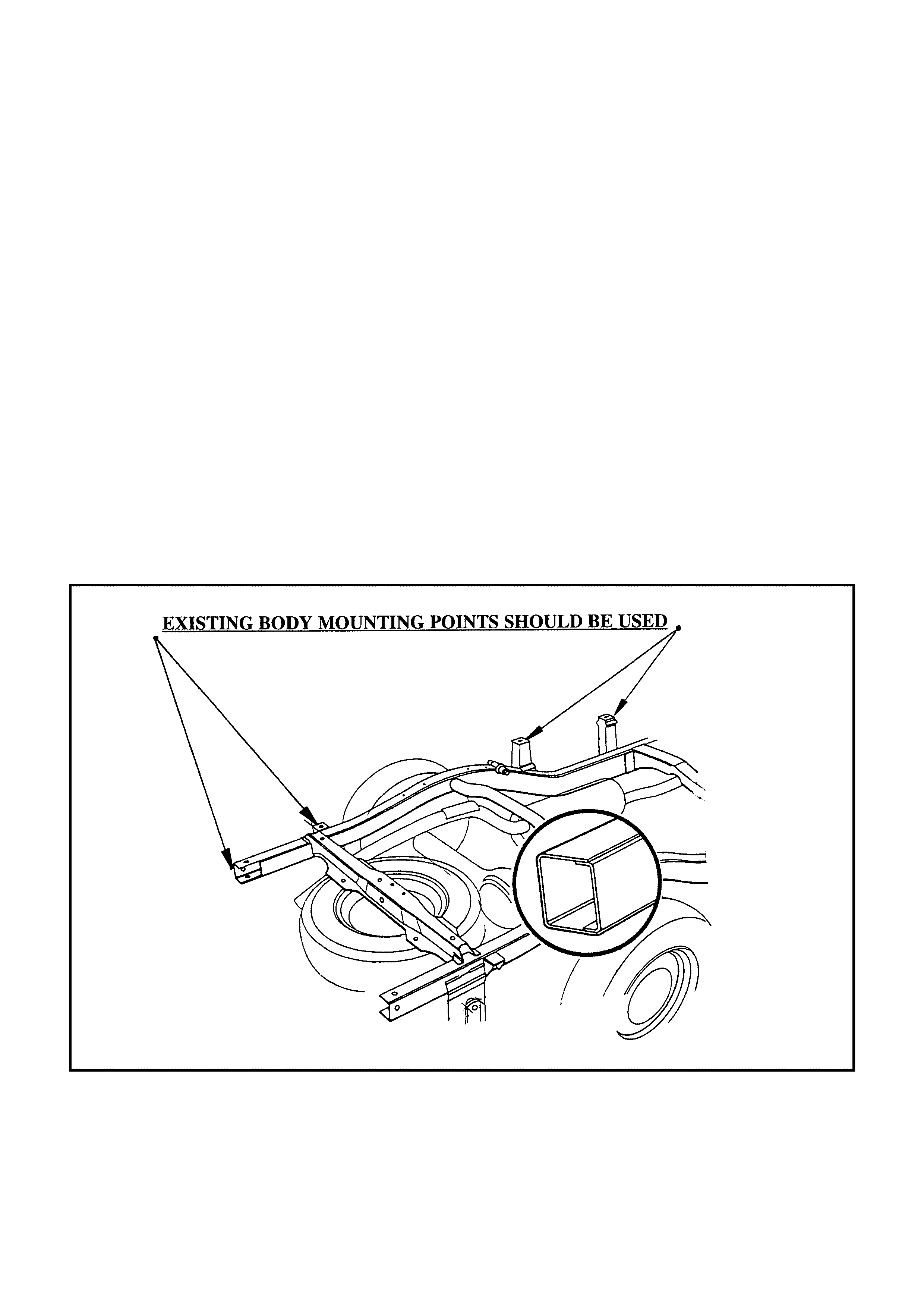
When mounting rigid bodies the designed chassis frame flexing must be allowed with the appropriate flexi-
ble mountings.
THE EXISTING BODY MOUNTING POINTS SHOULD BE USED – REFER TO ILLUSTRATION BELOW.
DRILLING AND WELDING
1. W eldi ng a nd dril ling is stri ctly n ot p ermi tted i n th e shaded area s of the chassis fr ame members a s shown
on the illustration below.
(Any porti ons within 20mm from edge of holes should not be welded)
2. Length of welding beads should be held within 30-50mm and at least 40mm spacing should be main-
tained between adjacent welding beads.
3. To make holes in frames do not use a gas flame. Drill all holes using sharp drills.
4. Use cold riveting only wh en attaching brackets with rivets.
5. Use high tensile bolts and appropriate nuts when bolted att a chments are used.
Bolt specifications:
SAE – Grade 8
Metric – Property class 8.8 or 10.9
Japanese – 7T or 9T
6. Deburr holes after drilling to fit bolts or rivets. Chamfer 1.0mm x 45 degree on the bolt head side of the
hole to facilit ate bolt seating.
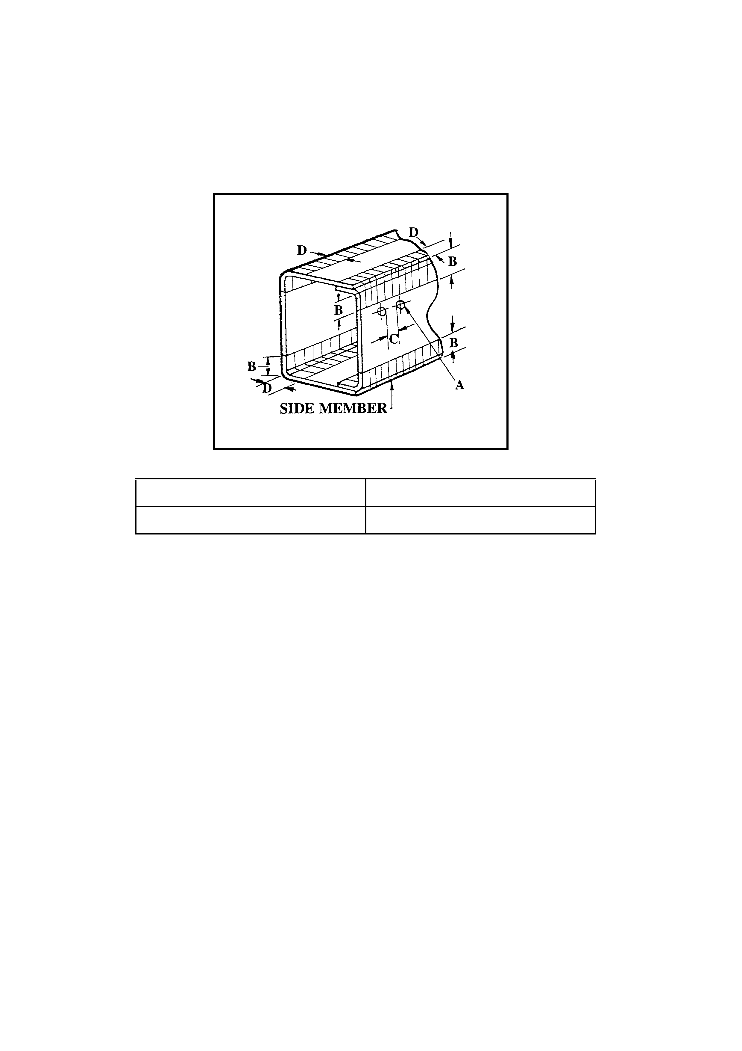
7. Holes must NOT be drilled near side member profile changes.
8. Existing holes in top and bottom flanges must NOT be bored out.
9. No more than two holes are to be drilled in a vertical line down the frame web.
A = Not more than 13mm diameter C = 25mm or more
B = 20mm or more D = 10mm or more

WELDING
General Precautions:
1. Before any arc wel ding is carried out on the vehicle disconnect the battery and other electrical/electronic
equipment, such as alt ernator, regulato r, radio, directional indicator unit , and interior lamp/s.
(Disconnecting battery leads may not always be adequate to overcome voltage surges that
occur during welding operations)
2. Weld earth points should be as close as practicable to the weld.
3. Ensure location of weld earth point s do not result in damage to bearings.
4. Keep reinforc ement plates and chassis frame members fr ee fr om mois ture and water.
5. Do not cool with water after welding.
6. Use a suitable means to protect pipes, wires, rubber parts, leaf springs, etc., against heat and the effect
of weld splatter.
7. Remove paint completely when welding pai nted areas.
8. Remove fuel tank assembly when welding portions near the fuel tank.

Important Gudielines
VEHICLE SELECTION
The following points should be considered when selecting a vehicle for use with known body or equipment:
Type of Load
All calculations are carried out by the Body Builder ’s Design Engineers assume that, within reasonable lim-
its, the load to be placed in the body will be evenly distributed along and across the body. If the body or
equipment to be mounted constitute an unevenly distributed load, calculations should be made with regard
to axle loads in laden, unladen and part laden conditions.
Body and Payload Weight
The type of body, its weight and the payload capa city required, must be determined.
Performance, Power and Gra deability
Calculations must be carried out to ensure that the complete vehicle meets the customers’ expectations
and requirements with respect to these characteristics. These must be met without interfering with or modi-
fying the base vehicle specifications.
Fuel Tank
A void unnecessary reloc ation of the fuel tank. If relocation is necessary ADR compliance may be aff ected.
The Following Points Should Be Noted:
• Adequate clearance should be maintained between the fuel tank and any other component.
• Use new fuel hoses when lengthening is required
• Care must be t a ken with the locati on o f the f uel t ank f i ller to ensur e t hat the spi llage o f fuel onto exh aust or
electri cal system components cannot occur.
Wheels And Tyres
Adequate clear ance must be provided bet ween the rea r tyres and the under side of the body. The clearance
must allow the axle to reach its maximum bump travel without the tyre fouling on the body.
EXPLANATION OF TERMS
Operating Mass: (GVM & GCM).
To ensure a Holden Rodeo performs satisfactorily and reliably, it is most important that the manufacturer’s
specified Gross Vehicle Mass and Gross Combination Mass for the specific vehicle are not exceeded.
The maximum GVM and GCM mass limits are specified on Sales Specifications sheets available from
Authorised Holden Dealerships. GVM is also stamped on the safety compliance plate affixed to t he vehicle.
GVM: Gross Vehicle Mass is the total weight that a vehicle is allowed to weight when fully loaded. This
must include luggage, passengers and a full tank of fuel. The maximum allowable GVM for the 1997 and
later model Holden Rodeo 2WD vehicles is 2730kg. and 4WD is 2740kg.
GCM: Gross Combination Mass is the maximum allowable combined weight of a vehicle (with passen-
gers, luggage and full tank of fuel) plus the weight of a loaded trailer or caravan. If the trailer or caravan is
fitted with brakes initiated by the driver (NOT over-run operated brakes) then the maximum allowable GCM
for 2WD is 3730kg. and 3740kg. for 4WD vehicles.
Note – if the trail er or caravan is not fitted with dr iver i nitiated br aking the maximum legal al lowable GCM for
2WD vehicles is 3230kg. and 3240kg. for 4WD vehicles.

Kerb Mass
The weight of the base vehicl e incl uding oil, water and 10 litres of fuel.
Load Capacity
Maximum load able to be carried. Usually expressed as difference between GVM and Kerb Mass:
eg: Holden Rodeo 4x2 single Cab Chassis
GVM – 2730kg.
(subtract) Kerb Mass- 1185kg.
Load Capacity = 1545kg.
(Include Body, Accessories, Full Fuel, Passengers,
Luggage Payload)
Payload
This varies with the weight of the rear body and number of accessories added. Payload is the maxi-
mum weight that can be loaded after rear body and all accessories and fittings are attached to the vehicle.
(Refer above cal culation)
Front and Rear Axle Loads
The maximum allowable front axle load for 2WD vehicles is 1050kg. 4WD is 1150kg. The maximum allow-
able rear axle load for both types is 1680kg. However, the combination for front and rear axle load should
never exceed the maximum GVM. Remember to take the towbar ball load into account when determining
the rear axle load. To ensure satisfactory driveability, it is recommended that a minimum front axle weight of
900kg. at full load is mainta ined.

Holden Rodeo Accessory Weight & Commodity Mass Guide
RODEO ACCESSORY WEIGHTS (APPROXIMAT E):
Tray: 8x6 Aluminium 100kg
8x6 Steel 230kg
Canopy: Crew Cab 27kg
Single Cab 45kg
Accessories: Air-Conditioning 26kg
Towbar & Tongue 28kg
Bull Bar 27kg
Cargo Liner 23kg
TRAILER WEIGHTS (APPROXIMATE):
6X4 Single Axle Trailer 240kg
8X5 Double Axle Steel 440kg
COMMON COMMODITY MASS GUIDE (APPROXIMATE):
kg per cubic metre
Basalt (Blue Metal) 2390kg
Granite Soli d 2145kg
Granite Crushed 1233kg
Marble Solid 2120kg
Marble Crushed 1233kg
Sand and Quartz (Dry) 1000kg
Cement 24 bags per tonne
Bricks 296 per tonne
Recommended Sizes of Tray & Van Bodies
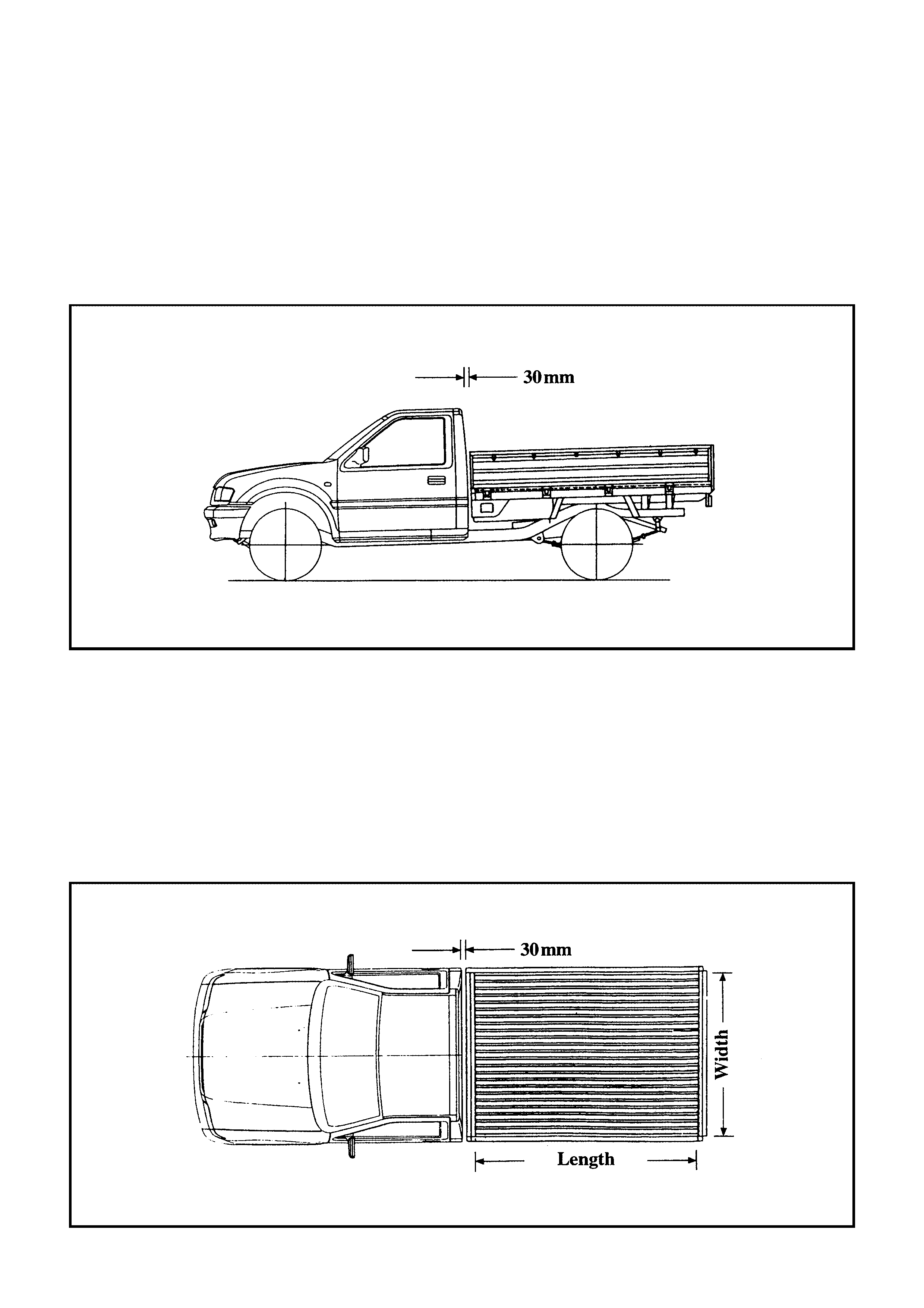
CLEARANCE BETWEEN CAB AND REAR BODY
(TRAY AND VAN BODIES)
To prevent direct cab to body contact due to flexing of the chassis frame, minimum necessary clearance of
30mm must be maintained between cab and rear body as specified in the il lustration below.
RODEO – RECOMMENDED MAXIMUM TRAY SIZES (mm)
MODEL LENGTH WIDTH
4X2 and 4x4 – Single Cab Models 2250 1850
4x2 and 4x4 – Space Cab Models 2030 1850
4x2 and 4x4 Crew Cab Models – conversion to a cab chassis model is not recommended. However, if this
is mandatory, the recommended maximum internal tray dime nsions are 1650mm long x 1850mm wide.
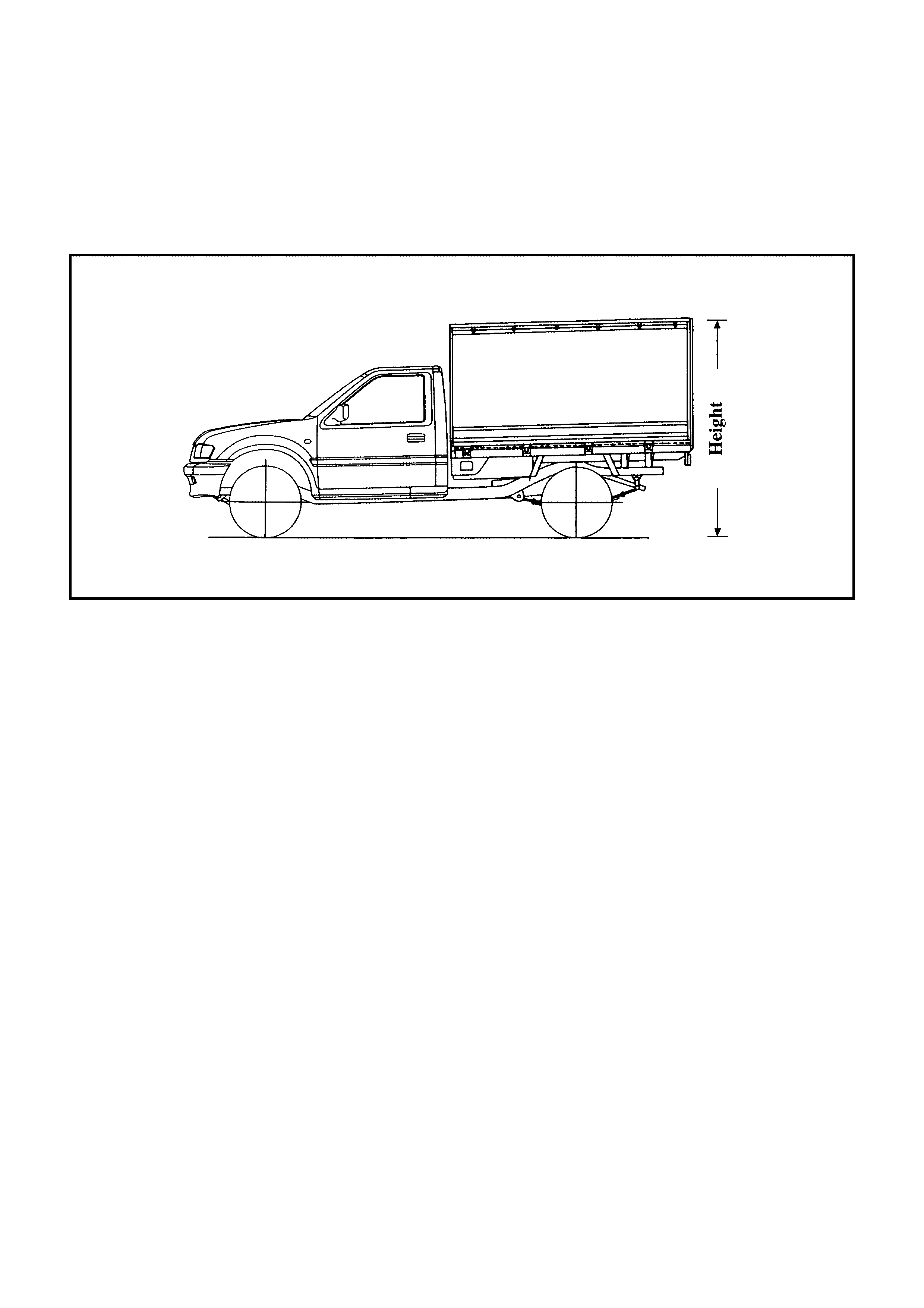
RODEO – RECOMMENDED MAXIMUM VAN SIZES (mm)
MODEL LENGTH WIDTH HEIGHT
4x2 and 4x4 – Single Cab Models 2250 1850 1950
4x2 and 4x4 – Space Cab Models 2030 1850 1950
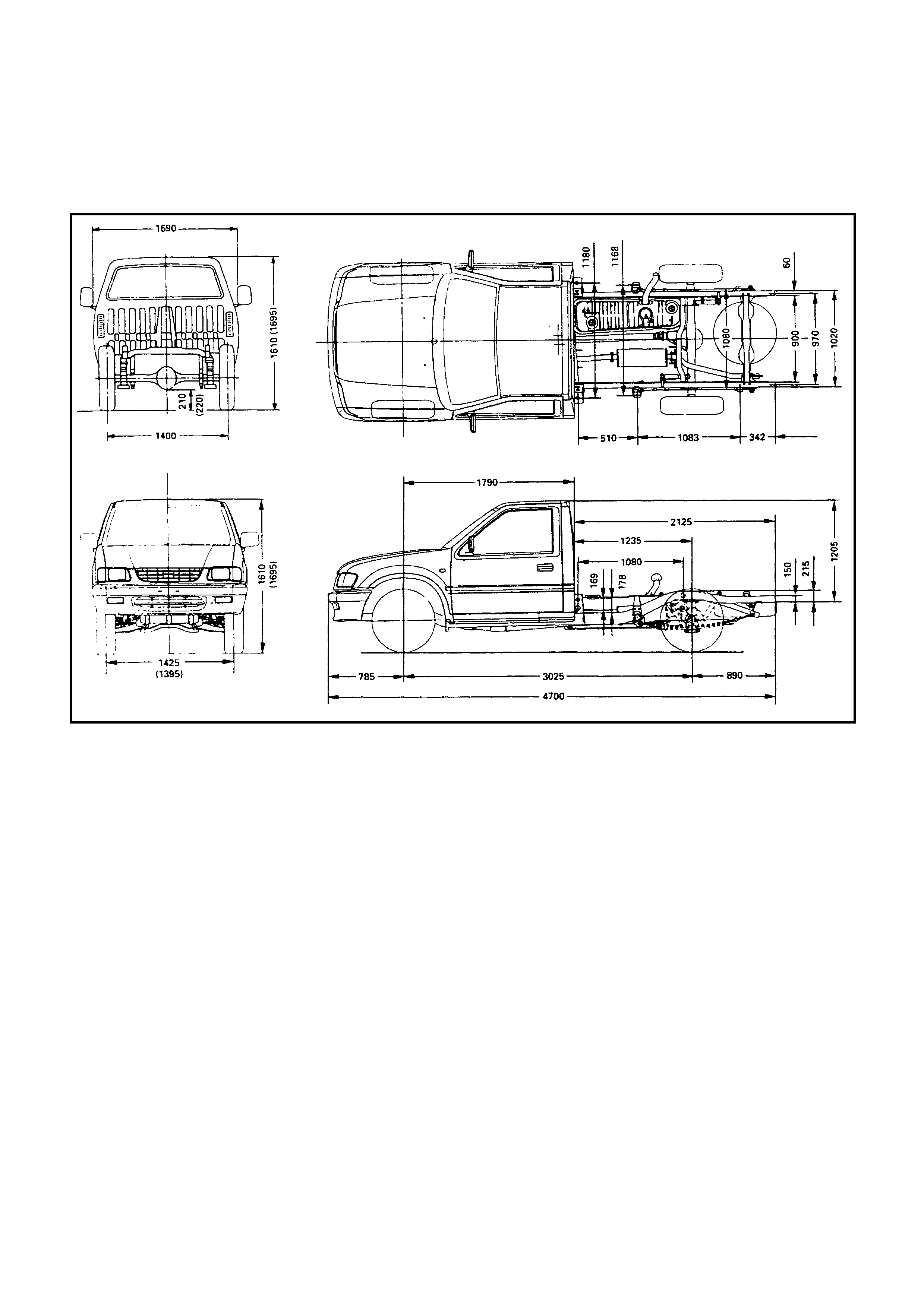
Rodeo 4x2 (TFR) & 4x4 (TFS) Single Cab
(Chassis Dimensional Drawings mm)
NOTE: Dimensions in brackets ( ) apply to 4x4 (TFS) models.
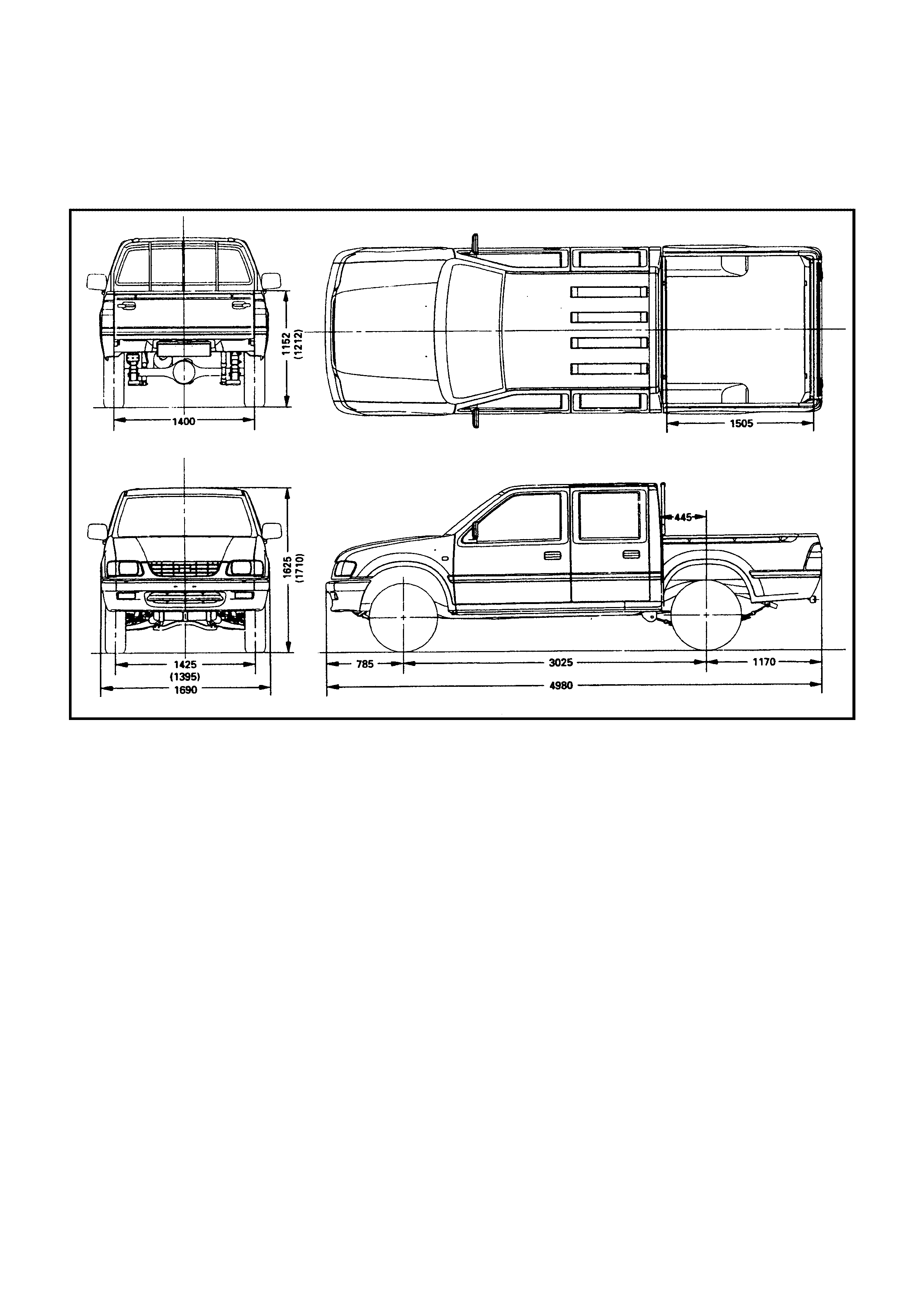
Rodeo 4x2 (TFR) & 4x4 (TFS) Crew Cab
(Chassis Dimensional Drawings mm)
NOTE: Dimensions in brac kets ( ) apply to 4x4 (TFS) models.
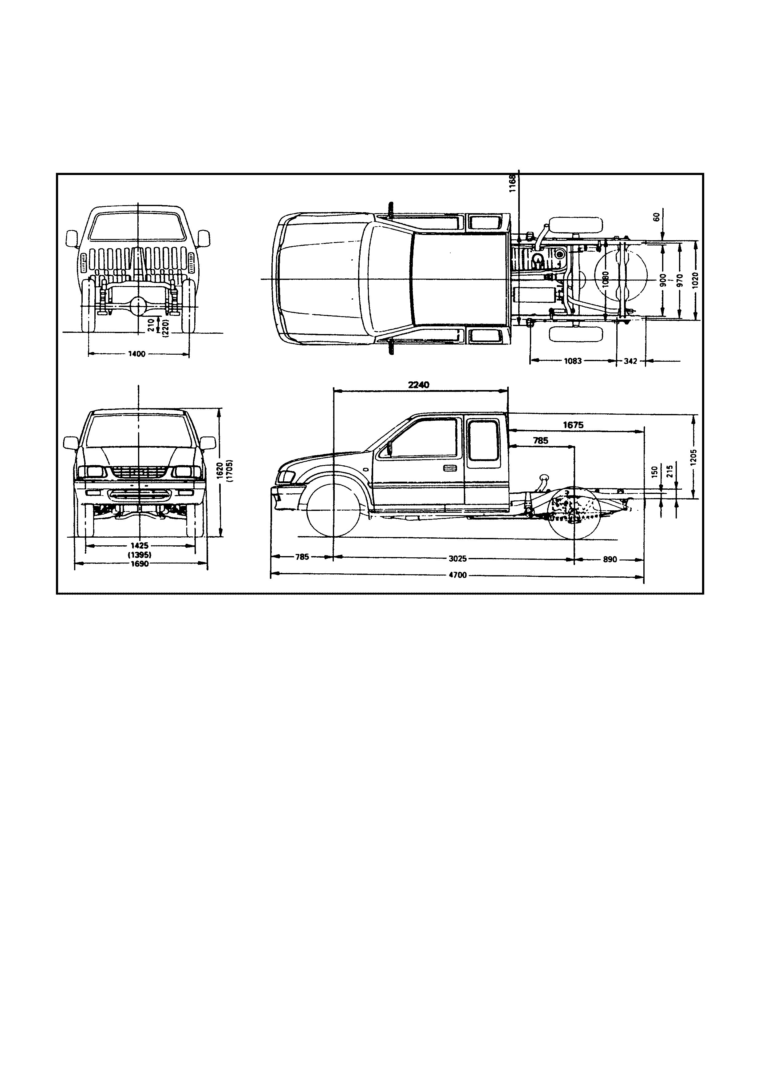
Rodeo 4x2 (TFR) & 4x4 (TFS) Space Cab
(Chassis Dimensional Drawings mm)
NOTE: Dimensions in brac kets ( ) apply to 4x4 (TFS) models.
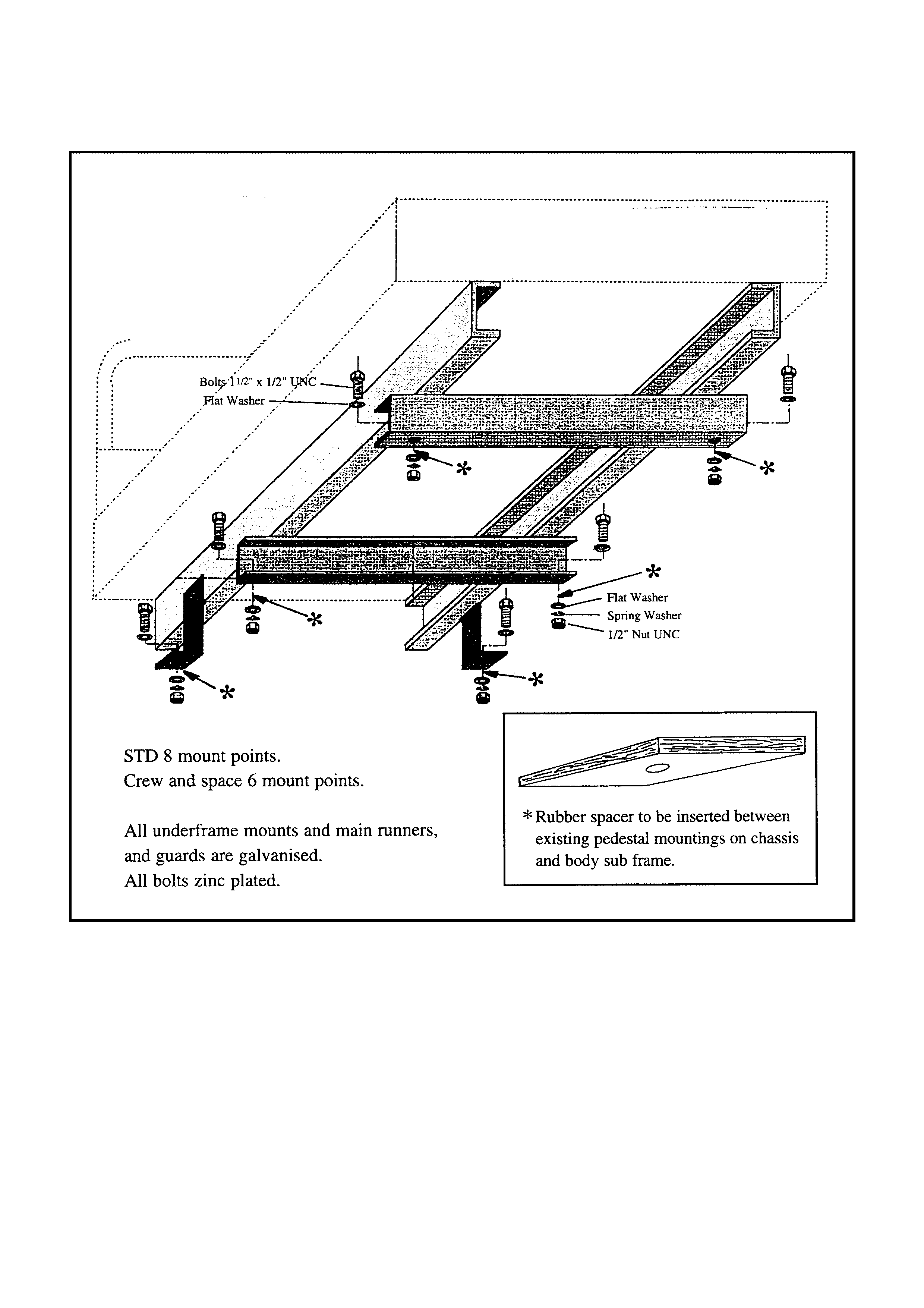
Cab Chassis Body Mounting - Typical
Bodies
should be mounted utilising each of the mounting points. There are 6 mounting points for Crew Cab and
Space Cab models and 8 for Sta ndard Cab Mod e ls.
Attaching Bolts
should be zinc plated high tensile. SAE Grade 8 specification and a rubber equivalent material should be
inserte d between the mount ing points and the body sub frame.
When mounting bodies of a rigid nature, such as steel trays with incorporated steel storage compartments
and work benches, the flexibility of the frame must not be restricted. This may necessitate the use of trun-
nion type mountings to avoid vehicle frame damage.